PSoC based Cosmic Muons Detector - PhysicsOpenLab
20
Lodovico Lappetito PSoC_MuonDetector_ENG - 26/09/2016 – Pag. 1 PSoC based Cosmic Muons Detector Using PSoC chip for cosmic muons detection and muon lifetime estimate Lodovico Lappetito
Transcript of PSoC based Cosmic Muons Detector - PhysicsOpenLab

Lodovico Lappetito PSoC_MuonDetector_ENG - 26/09/2016 – Pag. 1
PSoC based Cosmic Muons Detector
Using PSoC chip for cosmic muons detection and muon lifetime estimate
Lodovico Lappetito

Lodovico Lappetito PSoC_MuonDetector_ENG - 26/09/2016 – Pag. 2
Table of contents
Acknowledgments ............................................................................................................................................. 3
Introduction ....................................................................................................................................................... 4
Experimental Setup ........................................................................................................................................... 4
Signal Processing ............................................................................................................................................... 7
Trans-Impedance Amplifier ........................................................................................................................... 7
Fast Comparator ............................................................................................................................................ 8
PsoC Board ......................................................................................................................................................... 9
Firmware .......................................................................................................................................................... 11
Clock Signals ................................................................................................................................................ 11
Pulse Generator ........................................................................................................................................... 12
Pulse Counter .............................................................................................................................................. 12
Time Interval Measurements ...................................................................................................................... 13
Control Buttons ........................................................................................................................................... 13
Pulse Examples ................................................................................................................................................ 15
Software Interface ........................................................................................................................................... 19

Lodovico Lappetito PSoC_MuonDetector_ENG - 26/09/2016 – Pag. 3
” …
The muon—the short-lived cousin of the electron—could be the key to understanding relationships
between other fundamental particles. And it holds a mystery all its own.
In the 1930s, scientists thought they had matter figured out. Matter was atoms; atoms were protons,
neutrons and electrons; and that was that. Then they discovered the muon—a surprisingly heavy cousin of
the electron with no apparent purpose other than to baffle scientists. The muon was so unexpected that,
regarding its discovery, Nobel laureate Isidor Isaac Rabi famously quipped, “Who ordered that?”
Out of the 16 particles in the Standard Model, the muon is becoming the focus of research for more and
more physicists, who seek both to understand its unique properties and to use it as a probe of the rest of
the subatomic world. “Muons are special,” says Chris Polly, a Fermilab physicist involved in muon research.
“They are light enough to be produced copiously, yet heavy enough that we can use them experimentally
to uniquely probe the accuracy of the Standard Model.”
Even though the muon is one of the most accessible subatomic particles, it has its share of characteristics
that make it enigmatic and exciting.
Muons are about 200 times heavier than the electron. While this larger mass makes them interesting, it
also makes them unstable. Whereas electrons live forever, muons exist for only about two microseconds—
or two millionths of a second—before they decay. But for particle physicists, who work with particles
traveling close to the speed of light, two microseconds is, essentially, forever.
…”
From an article of Sarah Charley – Symmetry a Fermilab/SLAC publication
Acknowledgments
We wish to thank Prof. Coan and Prof. Ye for the software we have used and for their work on muons
detection which has inspired the present work.

Lodovico Lappetito PSoC_MuonDetector_ENG - 26/09/2016 – Pag. 4
Introduction
Cosmic rays, at sea level, have plenty of muons. They come from the interaction of primary cosmic with
nuclei of atmosphere. Cosmic muons can be detected rather simply with scintillation detectors and it is also
possible to measure the muon lifetime.
Now we want to describe the last equipment we built with the aim to measure with precision the muon
lifetime. It consists of a plastic scintillator coupled with a PMT and an electronic circuit based on a PsoC
which performs the time measure between the muon passage in the scintillator and the muon decay. The
data are stored in a SD Card and sent via serial communication to a PC which runs the software to acquire
data and to make the statistical analysis.
Experimental Setup
The image below shows the generation of the two light pulses (short arrows) used in determining the muon
lifetime. One light pulse is from the slowing muon (dotted line) and the other is from its decay into an
electron or positron (wavy line).
The muons that come to rest then live a relatively long time, on the order of order microseconds, inside
the scintillator; but eventually each of them decays in an electron (positron) plus a neutrino and a
antineutrino. Nearly all of the rest energy (105 MeV) of the stopped muons appears as kinetic energy of the
three particles; on average, the electron (positron) gets a third of this energy, about 35 MeV. (The two
neutrinos carry away the rest of the energy undetectably). But such an electron is a charged particle, itself
certain to cause ionization as it moves through the scintillator. Conveniently, the typical energy deposited
in this ionization process is about the same as that deposited by a muon-in-transit, or a muon stopping, so
the very same scintillator/PMT configuration is also suitable for detecting stopped muons subsequently
decaying at rest.
To measure the muon’s lifetime, we are interested in only those muons that enter, slow, stop and then
decay inside the plastic scintillator. Such muons have a total energy of only about 160 MeV as they enter
the tube. As a muon slows to a stop, the excited scintillator emits light that is detected by a
photomultiplier tube (PMT), eventually producing a logic signal that triggers a timing clock. A stopped
muon, after a bit, decays into an electron, a neutrino and an anti-neutrino. Since the electron mass is so
much smaller that the muon mass, mμ/me ~ 210, the electron tends to be very energetic and to produce
Lodovico Lappetito PSoC_MuonDetector_ENG - 26/09/2016 – Pag. 5
scintillator light essentially all along its path. The neutrino and anti-neutrino also share some of the muon’s
total energy but they entirely escape detection. This second burst of scintillator light is also seen by the
PMT and used to trigger the timing clock. The distribution of time intervals between successive clock
triggers for a set of muon decays is the physically interesting quantity used to measure the muon lifetime.
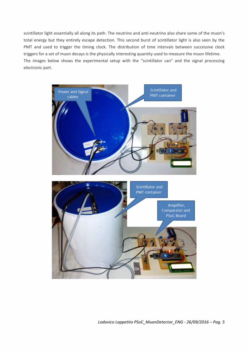
The images below shows the experimental setup with the “scintillator can” and the signal processing
electronic part.

Lodovico Lappetito PSoC_MuonDetector_ENG - 26/09/2016 – Pag. 6

Lodovico Lappetito PSoC_MuonDetector_ENG - 26/09/2016 – Pag. 7
Signal Processing
The image below shows the signal processing chain, from the PMT to the PC for data acquiring and data
processing.
Trans-Impedance Amplifier
The -negative- signal from the PMT, which is powered with a high voltage at around 1 kV, is amplified with
a trans impedance amplifier (TIA). The scheme below shows the schematic of the TIA, the operational
amplifier has to be very fast (wide band op amp) in order to preserve the timing of the original signal
produced by the PMT. The signal produced in output by the amplifier is inverted with respect the input, so
it has a positive swing from 0 level to about the maximum level of 2 V.

Lodovico Lappetito PSoC_MuonDetector_ENG - 26/09/2016 – Pag. 8
Fast Comparator
The amplified signal is sent to a fast comparator, with adjustable threshold, which has the aim to produce a
square pulse signal for the pulses generated by the muon passage inside the plastic scintillator. Acting on
the threshold it is easy to select only those pulses coming from muons excluding the “noise” from
background radioactivity, because the muons generate pulses rather high while the background pulses
remain below 100-200 mV. So we set the threshold at 300 mV. With this value we obtain a pulse rate of
around 5-7Hz, that is 300 – 400 CPM.

Lodovico Lappetito PSoC_MuonDetector_ENG - 26/09/2016 – Pag. 9
PsoC Board
PSoC (Programmable System-on-Chip) is a family of microcontroller integrated circuits by Cypress
Semiconductor. These chips include a CPU core and mixed-signal arrays of configurable integrated analog
and digital peripherals. A PSoC integrated circuit is composed of a core, configurable analog and digital
blocks, and programmable routing and interconnect. The configurable blocks in a PSoC are the biggest
difference from other microcontrollers. PSoC has three separate memory spaces: paged SRAM for data,
Flash memory for instructions and fixed data, and I/O Registers for controlling and accessing the
configurable logic blocks and functions.
PSoC resembles an ASIC: blocks can be assigned a wide range of functions and interconnected on-chip.
Unlike an ASIC, there is no special manufacturing process required to create the custom configuration —
only startup code that is created by Cypress’ PSoC Designer (for PSoC 1) or PSoC Creator (for PSoC 3 / 4 / 5)
IDE.
PSoC resembles an FPGA in that at power up it must be configured, but this configuration occurs by loading
instructions from the built-in Flash memory. PSoC most closely resembles a microcontroller combined with
a PLD and programmable analog. Code is executed to interact with the user-specified peripheral functions
(called “Components”), using automatically generated APIs and interrupt routines. PSoC Designer or PSoC
Creator generate the startup configuration code. Both integrate APIs that initialize the user selected
components upon the users needs in a Visual-Studio-like GUI.
In our application we used the model PSoC 5LP. For development we used both the CY8CKIT-059 kit
and the more complete board CY8CKIT-050, both are shown in the images below :

Lodovico Lappetito PSoC_MuonDetector_ENG - 26/09/2016 – Pag. 10
CY8CKIT-059
CY8CKIT-050
The aim of the PSoC component is mainly to acquire the pulse signals from the comparator, count them
and select the pulses which are coming from a muon decay; in this latter case the aim is to measure the
time interval between the two pulses, the first pulse from the muon and the second pulse from the
electron (positron) generated in the muon decay : this duration is the decay time of the muon.
In details the tasks accomplished by the PSoC are the followings :
Read and show on display the fast comparator threshold;
Acquire the muon pulses from the comparator and generate for each pulse a 40ns-fixed pulse;
Measure the time interval between two consecutive pulses (40ns pulses) : if this time is less than 20μs it is a muon decay event, otherwise it is not;
Count the muon pulses and calculate the rate value and the σ value;
Count the muon decay events and calculate the rate value and the σ value;
Show on display the data;
Write on SD card the acquired data;
Send the acquired data to the PC via serial communication;

Lodovico Lappetito PSoC_MuonDetector_ENG - 26/09/2016 – Pag. 11
Firmware
The PSoC 5LP (CY8CYKIT-059) has been programmed with the development system PSoC Creator, freely
downloadable from the manufacturer’s website. Using this tool, with a rich and simple graphical interface,
the chip is programmed and all the used components are defined and configured.
We go through the main points of the project.
Clock Signals
The system is synchronized by means of a series of clock signals, the main of which is the BUS_CLK that has
a frequency of 50MHz (this frequency is set in configuration and depends on the characteristics of the
circuit that is being achieved), it synchronizes the operation of all the components. The period of this signal
is 20ns , this is important because it corresponds to the minimum duration of the signals that can be
managed correctly by the system. Signals shorter than 20ns may be managed incorrectly or may not be
read by the system. In our project we have established for the signals a minimum duration of 40ns, well
above the limit of 20ns.

Lodovico Lappetito PSoC_MuonDetector_ENG - 26/09/2016 – Pag. 12
Pulse Generator
The pulses produced by the fast comparator are the input signals of the PSoC processing chain. Since the
pulses may have variable durations, downstream it is placed a D-type Flip Flop with external RC network to
obtain a clean pulse of 40ns. The latter also produces a further pulse of 0.01s used to turn on a LED in order
to give a visible feedback of the capturing event.
Pulse Counter
The pulses are sent to digital counters which perform the pulse counting. There is also a counter that
counts the seconds so as to measure the duration of the counting operations.

Lodovico Lappetito PSoC_MuonDetector_ENG - 26/09/2016 – Pag. 13
Time Interval Measurements
The time interval between two pulses is measured with a timer. The time interval is measured between
the rising edge of the pulses.
Control Buttons
The system is equipped with three buttons and a LED that lights up when you press any of the three buttons. The functions of the three buttons are as follows : – Reset Counters – Start / Stop Counting – Display Switch

Lodovico Lappetito PSoC_MuonDetector_ENG - 26/09/2016 – Pag. 14
The following images show the electronic part and the data shown on the display :

Lodovico Lappetito PSoC_MuonDetector_ENG - 26/09/2016 – Pag. 15
Pulse Examples
In the picture below you can see the typical PMT pulse produced by the muon passage in the scintillator.
The FWHM is about 40ns, while the amplitude is about 200mV.
The picture below shows various PMT pulses, with amplitude ranging from 100mV to 300mV and duration
ranging from 40ns to about 120ns.

Lodovico Lappetito PSoC_MuonDetector_ENG - 26/09/2016 – Pag. 16
The picture below shows both the PMT pulse and the output pulse of the amplifier. The duration is the
same while the signal amplitude, positive, goes up to 1,5V.
The picture below shows both the PMT pulse and the output pulse of the fast comparator.

Lodovico Lappetito PSoC_MuonDetector_ENG - 26/09/2016 – Pag. 17
The picture below shows both the PMT pulse and the 40ns pulse generated by the PSoC. The latter is
delayed with respect to the PMT pulse of around 40ns.
The picture below shows the jitter of the 40ns pulse generated by the PSoC. From the traces it can be
estimated in less than 20ns.

Lodovico Lappetito PSoC_MuonDetector_ENG - 26/09/2016 – Pag. 18
The picture below (obtained increasing the persistence of the scope display) shows the muon pulse plus
two pulses generated by the muon decay and the corresponding PSoC pulses.

Lodovico Lappetito PSoC_MuonDetector_ENG - 26/09/2016 – Pag. 19
Software Interface
The PSoC board is interfaced to the PC by means of a serial communication. In the PSoC project this is done
with the UART component. The serial connection is the same connection used for programming and
debugging.
The image below shows the entire setup with scintillator, electronics and PC for data acquisition.
The software used for data analysis is the application realized by Prof. Coan and Prof. Ye which can be
downloaded, with documentation, from their site www.mtphys.com.
The image below is a screenshot of the software.

Lodovico Lappetito PSoC_MuonDetector_ENG - 26/09/2016 – Pag. 20
The application reads and records the data which are sent from the PSoC. It performs the counting of
muons, the counting of muon decays, it calculates the rates and, mainly, it fits the decay data with
exponential law determining the muon lifetime.
In the image below we report the results after collecting about 5000 events.
The decay constant value is equal to a 2.080 ± 0.035 μs.
This value is between the value measured in vacuum, 2.197 μs, which is valid for the positive muons and the characteristic value of negative muons equal to 2.043 ± 0.003 μs, slightly less because of the interaction of negative muons with nuclei of the scintillator.
The measurements are in good agreement with the expected and predicted by theory.