PSIM Simulation of partial shading effect on photovoltaic ...
9
Zebiri & al./ Appl. J. Envir. Eng. Sci. 5 N°2(2019) 193-201 193 PSIM Simulation of partial shading effect on photovoltaic modules with bypass diode M. Zebiri 1,* , M. Mediouni 1 1 Laboratory of Engineering Sciences and Energy Management (LASIME), ENSA, University Ibn Zohr, PO Box 1136, 80000, Agadir, Morocco * * Corresponding author. E-mail: [email protected] Received 9Apr2019, Revised 3Jun2019, Accepted 21Jun 2019 Abstract. The production of renewable energy depends on weather conditions. In the case of a photovoltaic generator, the partial shading considerably reduces its output power capacity and can even cause the destruction of part or all of a panel. Once shaded, a cell is operating in reverse bias and it acts as a charge and dissipates energy, then the cell can be irreversibly damaged, we usually called these hot spot phenomena. In order to avoid this possible phenomenon, manufacturers have resorted to the use of bypass diodes and anti-return diodes. In this paper, we present a simulation of the shading effect of a photovoltaic generator composed of panels mounted in series and in parallel. We will compare the characteristics of power voltage (P-V) for different irradiances in the presence and absence of bypass diode. For the simulation, we will use the single diode model and PSIM software to perform the simulation. Key word: Photovoltaic, partial shading, modelling and simulation, bypass diode, PSIM software 1. Introduction The electrical power produced by a photovoltaic module is the sum of the powers delivered by all the cells that compose it [1]. But in reality, it depends on the meteorological conditions: solar irradiation, temperature, shadow, etc. the shading effect is one of the conditions that considerably affect this production; in this article, we will present its effects. Some modules or cells of a photovoltaic module can be in the shade because of clouds, buildings, trees, bird droppings ... Under these conditions, the characteristics (P-V) become more complex and not linear presenting several peaks, and they vary with solar irradiance. However, it is important to understand and plan for them to extract as much electrical power as possible. In this objective, over the years researchers have studied the characteristics of PV modules and the meteorological factors affecting them. Herin Patel [2] has compiled a list of the work done in the study of these characteristics.
Transcript of PSIM Simulation of partial shading effect on photovoltaic ...

Zebiri & al./ Appl. J. Envir. Eng. Sci. 5 N°2(2019) 193-201
193
PSIM Simulation of partial shading effect on photovoltaic modules
with bypass diode
M. Zebiri1,*
, M. Mediouni1
1 Laboratory of Engineering Sciences and Energy Management (LASIME), ENSA, University Ibn Zohr, PO Box 1136,
80000, Agadir, Morocco
*
* Corresponding author. E-mail: [email protected]
Received 9Apr2019, Revised 3Jun2019, Accepted 21Jun 2019
Abstract.
The production of renewable energy depends on weather conditions. In the case of a photovoltaic generator,
the partial shading considerably reduces its output power capacity and can even cause the destruction of part
or all of a panel. Once shaded, a cell is operating in reverse bias and it acts as a charge and dissipates energy,
then the cell can be irreversibly damaged, we usually called these hot spot phenomena. In order to avoid this
possible phenomenon, manufacturers have resorted to the use of bypass diodes and anti-return diodes. In this
paper, we present a simulation of the shading effect of a photovoltaic generator composed of panels mounted
in series and in parallel. We will compare the characteristics of power voltage (P-V) for different irradiances
in the presence and absence of bypass diode. For the simulation, we will use the single diode model and
PSIM software to perform the simulation.
Key word: Photovoltaic, partial shading, modelling and simulation, bypass diode, PSIM software
1. Introduction
The electrical power produced by a photovoltaic module is the sum of the powers delivered by all the cells
that compose it [1]. But in reality, it depends on the meteorological conditions: solar irradiation, temperature,
shadow, etc. the shading effect is one of the conditions that considerably affect this production; in this
article, we will present its effects. Some modules or cells of a photovoltaic module can be in the shade
because of clouds, buildings, trees, bird droppings ... Under these conditions, the characteristics (P-V)
become more complex and not linear presenting several peaks, and they vary with solar irradiance.
However, it is important to understand and plan for them to extract as much electrical power as possible. In
this objective, over the years researchers have studied the characteristics of PV modules and the
meteorological factors affecting them. Herin Patel [2] has compiled a list of the work done in the study of
these characteristics.

Zebiri & al./ Appl. J. Envir. Eng. Sci. 5 N°2(2019) 193-201
194
We will simulate six panels in different configurations that will be subjected to different irradiances and
compare the characteristics obtained with and without bypass diode.
2. Materials and methods
2.1. Equivalent model
In the literature a photovoltaic cell can be represented with an equivalent circuit model, operating in
various conditions (single diode, double diode, bishop model ...). The single-diode model is the most widely
used to represent a PV cell, thanks to its simplicity and precision [2, 3]. In this paper, we will use the single
diode to represent a PV cell figure 1. It consists of a current generator (Iph), a diode, an internal resistance
(Rs) and a shunt resistor (Rh). The model with by-pass diode figure 2, [4, 5, 6] is used to study the effect of
shading on the photovoltaic panels with this diode in anti parallel. For the simulation, without loss of
generality [5], we will place one bypass diode in anti-parallel with the whole module.
2.1.1. One diode model
Figure 1: Electrical model of a PV cell.
I = Iph - Id - Ih (1)
( ( )) ⁄ (2)
( (
) ) (3)
Where Vd = (V+IRs)
( )
( ( ( ))
)
(4)
Ih = (V+IRs) / Rh (5)
( (
) ) ( ) ⁄ [7] (6)
With Vt,d = NsaKT/q the thermal voltage (Ns is the number of cells connected in series, q, a, K and T
respectively are the charge of the cell electron, diode ideality factor, Boltzmann constant and p-n junction
temperature), and Iph is the photo-current of a cell, G is the sun irradiation, Ki is the temperature coefficient
of Isc, Id is the current of the diode of a cell, Isat,dis its inverse saturation current, Kv is the temperature
coefficient of Voc, V is the voltage across the cell, I is the cell current, Rs and Rsh are the series and shunt
resistors of the cell.
2.1.2 One diode model with bypass diode
This is the same model as in Figure 1 with a diode Db in anti-parallel (bypass diode).
Zebiri & al./ Appl. J. Envir. Eng. Sci. 5 N°2(2019) 193-201
195
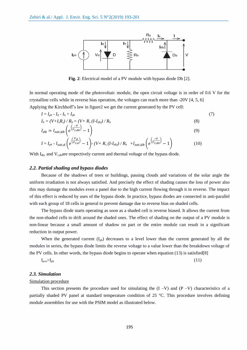
Fig. 2: Electrical model of a PV module with bypass diode Db [2].
In normal operating mode of the photovoltaic module, the open circuit voltage is in order of 0.6 V for the
crystalline cells while in reverse bias operation, the voltages can reach more than -20V [4, 5, 6]
Applying the Kirchhoff’s law in figure2 we get the current generated by the PV cell:
I = Iph - Id - Ih + Idb (7)
Ih = (V+IsRs) / Rh = (V+ Rs (I-Idb)) / Rh (8)
( (
) ) (9)
I = Iph - ( (
) )- (V+ Rs (I-Idb)) / Rh + (
(
) ) (10)
With Idb, and Vt,dbare respectively current and thermal voltage of the bypass diode.
2.2. Partial shading and bypass diodes
Because of the shadows of trees or buildings, passing clouds and variations of the solar angle the
uniform irradiation is not always satisfied. And precisely the effect of shading causes the loss of power also
this may damage the modules even a panel due to the high current flowing through it in reverse. The impact
of this effect is reduced by uses of the bypass diode. In practice, bypass diodes are connected in anti-parallel
with each group of 18 cells in general to prevent damage due to reverse bias on shaded cells.
The bypass diode starts operating as soon as a shaded cell is reverse biased. It allows the current from
the non-shaded cells to drift around the shaded ones. The effect of shading on the output of a PV module is
non-linear because a small amount of shadow on part or the entire module can result in a significant
reduction in output power.
When the generated current (Iph) decreases to a level lower than the current generated by all the
modules in series, the bypass diode limits the reverse voltage to a value lower than the breakdown voltage of
the PV cells. In other words, the bypass diode begins to operate when equation (13) is satisfied[8]
Ipva>Iph (11)
2.3. Simulation
Simulation procedure
This section presents the procedure used for simulating the (I –V) and (P –V) characteristics of a
partially shaded PV panel at standard temperature condition of 25 °C. This procedure involves defining
module assemblies for use with the PSIM model as illustrated below.
Zebiri & al./ Appl. J. Envir. Eng. Sci. 5 N°2(2019) 193-201
196
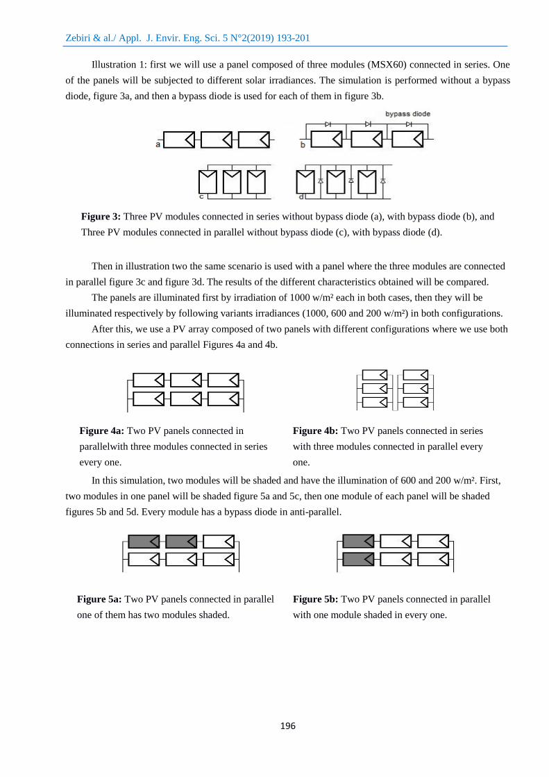
Illustration 1: first we will use a panel composed of three modules (MSX60) connected in series. One
of the panels will be subjected to different solar irradiances. The simulation is performed without a bypass
diode, figure 3a, and then a bypass diode is used for each of them in figure 3b.
Figure 3: Three PV modules connected in series without bypass diode (a), with bypass diode (b), and
Three PV modules connected in parallel without bypass diode (c), with bypass diode (d).
Then in illustration two the same scenario is used with a panel where the three modules are connected
in parallel figure 3c and figure 3d. The results of the different characteristics obtained will be compared.
The panels are illuminated first by irradiation of 1000 w/m² each in both cases, then they will be
illuminated respectively by following variants irradiances (1000, 600 and 200 w/m²) in both configurations.
After this, we use a PV array composed of two panels with different configurations where we use both
connections in series and parallel Figures 4a and 4b.
Figure 4a: Two PV panels connected in
parallelwith three modules connected in series
every one.
Figure 4b: Two PV panels connected in series
with three modules connected in parallel every
one.
In this simulation, two modules will be shaded and have the illumination of 600 and 200 w/m². First,
two modules in one panel will be shaded figure 5a and 5c, then one module of each panel will be shaded
figures 5b and 5d. Every module has a bypass diode in anti-parallel.
Figure 5a: Two PV panels connected in parallel
one of them has two modules shaded.
Figure 5b: Two PV panels connected in parallel
with one module shaded in every one.

Zebiri & al./ Appl. J. Envir. Eng. Sci. 5 N°2(2019) 193-201
197
Figure 5c:Two PV panels connected in series one
of them has two modules shaded.
Figure 5d:Two PV panels connected in series
with one module shaded in every one
Table1: Typical electrical characteristics of Solarex MSX60
Maximum power (Pmax) 60W
Voltage @ Pmax (Vmp) 17.1V
Current @ Pmax (Imp) 3.5A
Short-circuit current (Isc) 3.8A
Open-circuit voltage (Voc) 21.1V
Temperature coefficient of open-circuit voltage –(80±10)mV/°C
Temperature coefficient of short-circuit current (0.065±0.015)%/°C
Temperature coefficient of power –(0.5±0.05)%/°C
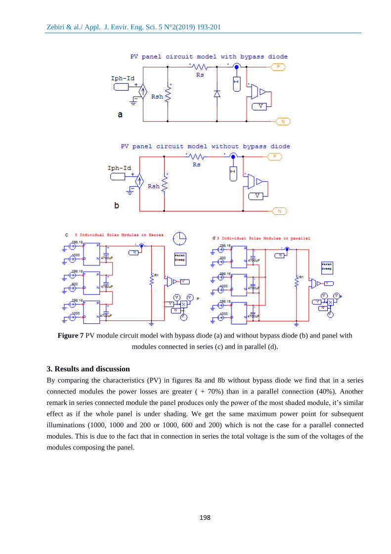
While figure 6 shows the mathematical model realized under PSIMenvironment [9, 10, 11] using (2),
(3) and (4) which is used to realize the photovoltaic module, figure 7 shows the PV module circuit model
with bypass diode (a) and without bypass diode (b). This module is used to constitute the studied panels.
Figure 6: Mathematical model built under PSIM and Parameters and specifications used.
Zebiri & al./ Appl. J. Envir. Eng. Sci. 5 N°2(2019) 193-201
198
Figure 7 PV module circuit model with bypass diode (a) and without bypass diode (b) and panel with
modules connected in series (c) and in parallel (d).
3. Results and discussion
By comparing the characteristics (PV) in figures 8a and 8b without bypass diode we find that in a series
connected modules the power losses are greater ( + 70%) than in a parallel connection (40%). Another
remark in series connected module the panel produces only the power of the most shaded module, it’s similar
effect as if the whole panel is under shading. We get the same maximum power point for subsequent
illuminations (1000, 1000 and 200 or 1000, 600 and 200) which is not the case for a parallel connected
modules. This is due to the fact that in connection in series the total voltage is the sum of the voltages of the
modules composing the panel.
Zebiri & al./ Appl. J. Envir. Eng. Sci. 5 N°2(2019) 193-201
199
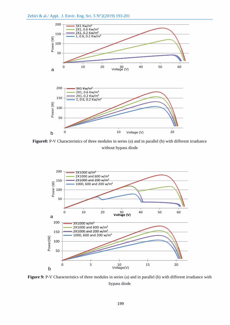
Figure8: P-V Characteristics of three modules in series (a) and in parallel (b) with different irradiance
without bypass diode
Figure 9: P-V Characteristics of three modules in series (a) and in parallel (b) with different irradiance with
bypass diode
0 10 20 30 40 50 60
50
100
150
200
a
3X1 Kw/m²2X1, 0.6 Kw/m²2X1, 0.2 Kw/m²1, 0.6, 0.2 Kw/m²
Voltage (V)
Po
we
r (W
)
0 10 20
50
100
150
200
b
3X1 Kw/m²2X1, 0.6 Kw/m²2X1, 0.2 Kw/m²1, 0.6, 0.2 Kw/m²
Voltage (V)
Po
we
r (W
)
0 10 20 30 40 50 60
50
100
150
200
a
3X1000 w/m²2X1000 and 600 w/m²2X1000 and 200 w/m²1000, 600 and 200 w/m²
Voltage (V)
Po
we
r (W
)
0 5 10 15 20
50
100
150
200
b
3X1000 w/m²2X1000 and 600 w/m²2X1000 and 200 w/m²1000, 600 and 200 w/m²
Voltage(V)
Po
we
r(W
)
Zebiri & al./ Appl. J. Envir. Eng. Sci. 5 N°2(2019) 193-201
200
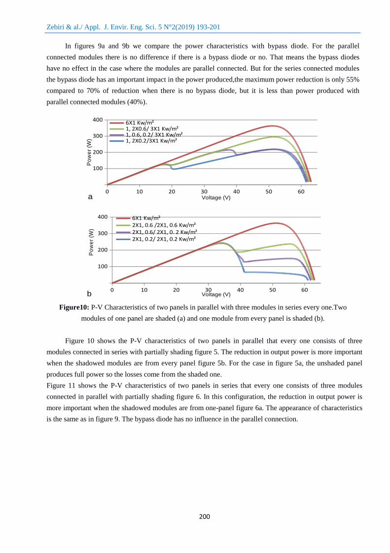
In figures 9a and 9b we compare the power characteristics with bypass diode. For the parallel
connected modules there is no difference if there is a bypass diode or no. That means the bypass diodes
have no effect in the case where the modules are parallel connected. But for the series connected modules
the bypass diode has an important impact in the power produced,the maximum power reduction is only 55%
compared to 70% of reduction when there is no bypass diode, but it is less than power produced with
parallel connected modules (40%).
Figure10: P-V Characteristics of two panels in parallel with three modules in series every one.Two
modules of one panel are shaded (a) and one module from every panel is shaded (b).
Figure 10 shows the P-V characteristics of two panels in parallel that every one consists of three
modules connected in series with partially shading figure 5. The reduction in output power is more important
when the shadowed modules are from every panel figure 5b. For the case in figure 5a, the unshaded panel
produces full power so the losses come from the shaded one.
Figure 11 shows the P-V characteristics of two panels in series that every one consists of three modules
connected in parallel with partially shading figure 6. In this configuration, the reduction in output power is
more important when the shadowed modules are from one-panel figure 6a. The appearance of characteristics
is the same as in figure 9. The bypass diode has no influence in the parallel connection.
0 10 20 30 40 50 60
100
200
300
400
a
6X1 Kw/m²1, 2X0.6/ 3X1 Kw/m²1, 0.6, 0.2/ 3X1 Kw/m²1, 2X0.2/3X1 Kw/m²
Voltage (V)
Po
we
r (W
)
0 10 20 30 40 50 60
100
200
300
400
b
6X1 Kw/m²2X1, 0.6 /2X1, 0.6 Kw/m²2X1, 0.6/ 2X1, 0. 2 Kw/m²2X1, 0.2/ 2X1, 0.2 Kw/m²
Voltage (V)
Po
we
r (W
)

Zebiri & al./ Appl. J. Envir. Eng. Sci. 5 N°2(2019) 193-201
201
Figure11: P-V Characteristics of two panels in series with three modules in parallel every one.Two
modules of one panel are shaded (a) and one module from every panel is shaded (b).
Conclusion
In this work, we studied the effect of different shading conditions and the difference between parallel and
series connected modules on the output power of PV modules. We used PSIM to perform our simulations
and used the Solarex MSX60 module specifications. The results obtained show clearly that the performance
of the panels varies and strongly depends on the shading effect and the type of connection use. We also
highlighted the role of the bypass diode in different configurations. The bypass diode is important for the
series connected module.
References
1 L. Bun, Détection et localisation de défauts pour un système PV, tel-00647189v1 (2011)
2 H. Patel, V. Agarwal, Senior Member IEEE, IEEE 23, ( march 2008)
3 K. Matter, H. J. El-Khozondar, R. J. El- Khozondar, T. Suntio, IRJET, 02 (02) (2015)
4 G. Notton, I. Caluianu, I. Colda et S. Caluianu,. R E R 13(2010)49 - 62,
5 G. Petrone, G. Spagnuolo, M. Vitelli. S E M & S C 9(2007) 1652-1657,
6 M.L. Orozco-Gutierrez, J.M. Ramirez-Scarpetta, G. Spagnuolo, C.A. Ramos-Paja. R E 55(2013) 417 - 427,
7 M. G. Villalva, J. R. Gazoli, E. R. Filho, IEEE Transactions on Power Electronics, 24 (5) MAY 2009
8 M. Seyedmahmoudian, S. Mekhilef, R. Rahmani, Y. Rubiyah, E. T. Renani, Energies, 6(2013) 128-144.
9 S. Motahhir, A. El Ghzizal, S. Sebti, A. Derouich, International Review of Automatic Control (I.RE.A.CO.), 9(2)
March (2016)
10 M. G. Villalva, J. R. Gazoli, E F. Ruppert,Brazilian journal of power electronics, 14(1)(2009)35 - 45
11 A. Karafil, H. Ozbay, M. Kesler, Journal of New Results in Science 12 (2016) 48-58.
0 10 20 30 40
100
200
300
400
a
6X1 Kw/m²1, 2X0.6/ 3X1 Kw/m²1, 2X0.2/ 3X1 Kw/m²1, 0.6, 0.2 / 3X1 Kw/m²
Voltage (V)
Po
we
r (W
)
0 10 20 30 40
100
200
300
400
b
6X1 Kw/m²2X1, 0.6/ 2X1, 0.6 Kw/m²2X1, 0.6/ 2X1, 0.2 Kw/m²2X1, 0.2/ 2X1, 0.2 Kw/m²
Voltage (V)
Po
we
r (W
)