psi rating series H - Home | Royal Westcoast CylindersME5 ) 10 H Rect. Blind End Head (ME6 ) 11 TR...
28
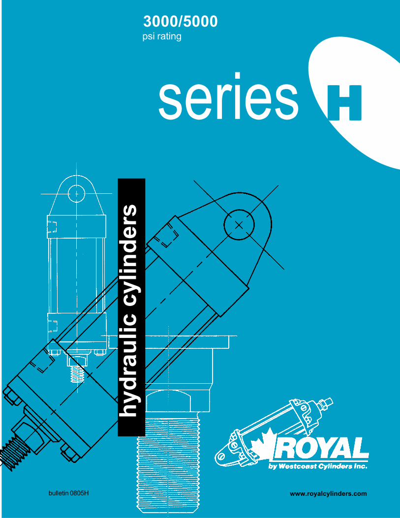
3000/5000 psi rating hydraulic cylinders bulletin 0805H series H H H H H www.royalcylinders.com
Transcript of psi rating series H - Home | Royal Westcoast CylindersME5 ) 10 H Rect. Blind End Head (ME6 ) 11 TR...
3000/5000psi rating
hydr
aulic
cyl
inde
rs
bulletin 0805H
series HHHHH
www.royalcylinders.com
i Contents
Fixed Clevis
Pivot Eye
Self-aligning Eye
No Mount
Extended Tie-rods Both Ends
Extended Tie-rods Gland End
Extended Tie-rods Blind End
4
64
74
75
6
Page Description1 Mounting Styles2 Features Description3 Features Drawing
Mounting Dimensions4 C Fixed Clevis (MP1)4 E Pivot Eye (MP3)4 MP Detachable Clevis
(MP2)5 W Self-aligning Eye
(MPU3)6 NM No Mount (MX0)6 NA Extended Tie-rods
Both Ends (MX1)7 NB Extended Tie-rods
Blind End (MX2)7 NC Extended Tie-rods
Gland End (MX3)8 R Rod End Rectangular
Flange (MF1)8 RS Rod End Square
Flange (MF5)9 B Blind End Rectangular
Flange (MF2)9 BS Blind End Square
Flange (MF6)10 G Rect. Gland End Head
(ME5 )10 H Rect. Blind End Head
(ME6 )11 TR Rod End Trunnion
(MT1)11 TB Blind End Trunnion
(MT2)12 T Mid Trunnion (MT4)12 HT Mid Trunnion (HT)13 F Foot Mount (MS2)13 S Side Tapped (MS4)14 D Double Rod (MD)15 CR Common Rod15 CH Common Head16 CHR Common Head /
Common Rod17-19 Rod End Styles, Accessories
Parts20 Parts List: 1.5 – 4” dia.21 Parts Drawing22 Parts List: 5 – 8” dia.23-25 Technical Data/Torque SpecsCover Cylinder Nomenclature
Westcoast Cylinders Inc.225 Edworthy WayNew Westminster BCCanada V3L 5G4Telephone: 604 527 1120Facsimile: 604 527 1170Phone Toll Free: 1-877-637-6925Fax Toll Free: 1-866-527-1170email: [email protected]: www.royalcylinders.com
Detachable Clevis

1Mounting Styles
Rod End Rectangular Flange8
8 Rod End Square Flange
Blind End Rectangular Flange
Blind End Square Flange
Rod End Trunnion
Blind End Trunnion9 11
9
10
10
11
Mid Trunnion12
12
13
13
HT Mid TrunnionRectangular Gland End Head
Foot MountRectangular Blind End Head
Side Tapped
14
15
Double Rod
Common Rod
Common Head15
bulle
tin 0
805H
2 Features Description
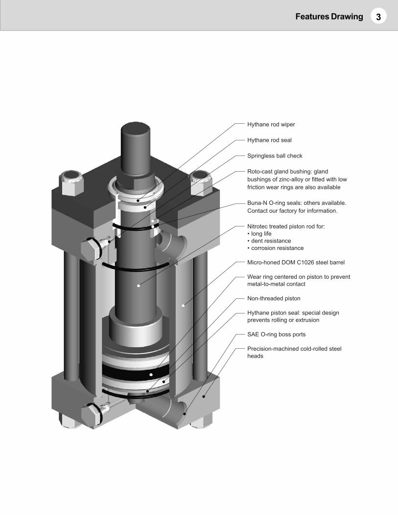
PISTON RODThe piston rod is Hiperchromium® 200 treated C1045 carbonsteel. Hiperchromium® 200 offers 200 hour corrosion resistanceto Saline atmospheric chamber testing.Other rod materials are available including chrome plated 316stainless steel and Nitrotec carbon steel. If you require a rodsize that is not included in this catalog contact our factory forinformation regarding availability and dimensions.
HYTHANE® SEALSHythane® piston seals are standard on the Royal H-Series. Ithas an exceptional temperature range of from -50 to 230°F. TheHythane®* rod seal is a high performance, high temperature sealcompound having ultra low friction and long seal life. TheHythane® rod wiper, with internal ribs for extra stability andprevention of pressure trapping, cleans the rod on the returnstroke. The static external seal is Buna-N material.
ROTOCAST BRONZE GLAND BUSHINGThe gland bushing is manufactured from Rotocast bronze for lowfriction and long bearing life. Other materials such as Zinc-alloyare available upon request. Optional gland bushings with wearrings may be available, contact our factory.
COLD FINISHED HEADSHeads are precision machined from high quality cold finishedsteel for perfect alignment of barrel and moving parts.
IMPROVED CUSHIONING:
Springless Ball ChecksThe Ball checks are designed to eliminate the need for a spring.As fluid flows through the check valve the ball is pulled into thelow pressure zone, sealing when required and allowing the fluidto bypass for fast break away from the cushions.2 1/2” and 3 1/4” bores with the #3 rod are now available withadjustable cushions both ends.Standard Needle valve position P4 Ball check position P2
ONE-PIECE PISTONThe piston is a one-piece design, incorporating a replaceablewear ring to prevent metal to metal contact and increase the life ofthe cylinder.
SAE PORTSSAE O-Ring Boss ports are the standard port on the H-Seriescylinders. SAE CODE 61 Flange ports are also available.Contact our factory for specific requirements. For NPTF ports,WCI will supply an SAE to NPTF Female adapter if you requireNPTF ports.
INTERNAL / EXTERNAL PISTON STOPStandard internal and optional external piston stops are availableto reduce side load stress on the piston rod, gland bushing andpiston for all cylinder sizes.
STROKE POSITION SENSORSWCI offers Proximity sensors fitted to H-Series cylinders, We havevarious levels of switches to meet your requirement, or we canmanufacture our cylinders to suit the proximity you would like tosupply. Contact our factory for details.
CYLINDER FLUSHINGA cylinder flushing service is available as a standard option. Tochoose this, select “-F” in the Options section of the CylinderNomenclature.
CUSTOM CYLINDERSIf our standard product does not meet your specifications,Westcoast Cylinders will manufacture custom cylinders to meetyour requirements. Please contact our factory.
SPARE PARTSGenuine Royal seal kits include all seal components, and wearrings. Please specify genuine Royal replacement parts to ensureyou will receive all feature benefits.
* Hythane® is a registered trademark of Hallite Seals International Ltd.
Westcoast Cylinders Inc.:The Company has beenmanufacturing high quality, reliableROYAL cylinders for over 40 years.Production started with a singlecylinder design and expanded to afull range of multi-use, hydraulic,pneumatic cylinders andaccessories.
Quality:WCI is a leader in the design andmanufacture of custom heavy dutycylinders. The materials, machinery andtools used to produce our products arecontinuously being updated. Ourcylinders are built to the higheststandards utilizing the latest technologyand processes.
Delivery:WCI maintains a large range ofstock parts which gives us theflexibility to respond to your needsin emergency situations. Pleasecontact the factory to expediteyour special requirements.
3Features Drawing
Hythane rod wiper
Hythane rod seal
Springless ball check
Roto-cast gland bushing: gland
bushings of zinc-alloy or fitted with low
friction wear rings are also available
Buna-N O-ring seals: others available.
Contact our factory for information.
Nitrotec treated piston rod for:
• long life
• dent resistance
• corrosion resistance
Micro-honed DOM C1026 steel barrel
Wear ring centered on piston to prevent
metal-to-metal contact
Hythane piston seal: special design
prevents rolling or extrusion
Precision-machined cold-rolled steel
heads
Non-threaded piston
SAE O-ring boss ports

4
Model HCFixed ClevisNFPA Style MP1
model HC, HE, HMP
Model HEPivot Eye
NFPA Style MP3
Notes:1. All dimensions in inches.2. EE standard port is SAE contact our factory if SAE flange or
Alternate port size is required.3. See Cylinder Nomenclature for thread options.
Model HMPDetachable Clevis
NFPA Style MP2
4. For Optional Rod Ends and dimensions see page18.5. Cushion 1 or 4, refer to cylinder nomenclature. When a cushion on
the gland end is specified for rod #3 the gland end head is longer,but NFPA dimensions remain constant.
ROD DIA HC HEBORE ROD MM KK CC A W XC XD E F G J L CB CB CD CW NPTF SAE MR
1 5/8 7/16-20 1/2-20 3/4 5/8 6 3/8 6 3/4 2 1/2 3/8 1 9/16 1 5/16 3/4 25/32 3/4 1/2 1/2 1/2 -08 1/22 1 3/4-16 7/8-14 1 1/8 1 6 3/4 7 1/81 1 3/4-16 7/8-14 1 1/8 3/4 7 1/4 N/A 3 5/8 1 15/32 1 7/32 1 1/4 1 9/32 1 1/4 3/4 5/8 1/2 -08 3/42 1 3/8 1-14 1 1/4-12 1 5/8 1 7 1/2 N/A
note 5 2 1 3/8 2 1/81 1 3/4-16 7/8-14 1 1/8 3/4 7 3/8 7 15/16 3 1/2 9/16 1 9/16 1 1/4 1 1/4 1 9/32 1 1/4 3/4 5/8 1/2 -08 3/42 1 3/8 1-14 1 1/4-12 1 5/8 1 7 5/8 8 3/163 1 3/4 1 1/4-12 1 1/2-12 2 1 1/4 7 7/8 8 7/16
note 5 3 1 3/4 2 3/161 1 3/8 1-14 1 1/4-12 1 5/8 7/8 8 5/8 9 3/8 4 1/2 3/4 1 25/32 1 17/32 1 1/2 1 17/32 1 1/2 1 3/4 3/4 -12 12 1 3/4 1 1/4-12 1 1/2-12 2 1 1/8 8 7/8 9 5/83 2 1 1/2-12 1 3/4-12 2 1/4 1 1/4 9 9 3/4
note 5 3 2 2 7/161 1 3/4 1 1/4-12 1 1/2-12 2 1 9 3/4 10 5/8 5 7/8 1 25/32 1 17/32 2 1/8 2 1/32 2 1 3/8 1 3/4 -12 1 3/82 2 1 1/2-12 1 3/4-12 2 1/4 1 1/8 9 7/8 10 3/43 2 1/2 1 7/8-12 2 1/4-12 3 1 3/8 10 1/8 111 2 1 1/2-12 1 3/4-12 2 1/4 1 1/8 10 1/2 11 3/8 6 1/2 7/8 1 25/32 1 17/32 2 1/4 2 17/32 2 1/2 1 3/4 1 1/4 3/4 -12 1 3/42 2 1/2 1 7/8-12 2 1/4-12 3 1 3/8 10 3/4 11 5/83 3 2 1/4-12 2 3/4-12 3 1/2 1 3/8 10 3/4 11 5/84 3 1/2 2 1/2-12 3 1/4-12 3 1/2 1 3/8 10 3/4 11 5/81 2 1/2 1 7/8-12 2 1/4-12 3 1 1/4 12 1/8 13 1/8 7 1/2 1 2 5/32 2 5/32 2 1/2 2 17/32 2 1/2 2 1 1/4 1 -16 22 3 2 1/4-12 2 3/4-12 3 1/2 1 1/4 12 1/8 13 1/83 3 1/2 2 1/2-12 3 1/4-12 3 1/2 1 1/4 12 1/8 13 1/81 3 2 1/4-12 2 3/4-12 3 1/2 1 1/4 13 3/4 14 3/4 8 1/2 1 2 17/32 2 17/32 3 3 1/32 3 2 1/2 1 1/2 1 1/4 -20 2 1/22 3 1/2 2 1/2-12 3 1/4-12 3 1/2 1 1/4 13 3/4 14 3/43 4 3-12 3 3/4-12 4 1 1/4 13 3/4 14 3/41 3 1/2 2 1/2-12 3 1/4-12 3 1/2 1 1/4 15 16 9 1/2 1 2 31/32 2 19/32 3 1/4 3 1/32 3 3 1 1/2 1 1/2 -24 2 3/42 4 3-12 3 3/4-12 4 1 1/4 15 163 4 1/2 3 1/4-12 4 1/4-12 4 1/2 1 1/4 15 16
EE
6
7
1 1/2
ADD STROKE
8
2 1/2
3 1/4
2
4
5

5model HW
Model HWSelf-aligning Eye
NFPA Style MPU3
Notes:1. All dimensions in inches.2. EE standard port is SAE contact our factory if SAE flange or
Alternate port size is required.3. See Cylinder Nomenclature for thread options.
4. For Optional Rod Ends and dimensions see page18.5. Cushion 1 or 4, refer to cylinder nomenclature. When a cushion on
the gland end is specified for rod #3 the gland end head is longer,but NFPA dimensions remain constant.
BORE CONTINUOUS INTERMITTENT1 1/2 1600 2100
2 2100 28002 1/2 1300 18003 1/4 1400 1800
4 1700 22005 1800 24006 1600 22007 1900 19008 2100 2100
*Pressure ratings are based on the Dynamic LoadCapacity of the bearing.
MAXIMUM OPERATING PRESSURE (PSI)MODEL HW *
ROD DIABORE ROD MM KK CC A W LB XH E F G J SL CD CK NPTF SAE MA X
1 5/8 7/16-20 1/2-20 3/4 5/8 5 6 3/8 2 1/2 3/8 1 9/16 1 5/16 3/4 1/2 7/16 1/2 -08 7/8 3/82 1 3/4-16 7/8-14 1 1/8 1 6 3/41 1 3/4-16 7/8-14 1 1/8 3/4 5 1/4 7 1/4 3 5/8 1 15/32 1 7/32 1 1/4 3/4 21/32 1/2 -08 1 1/4 1/22 1 3/8 1-14 1 1/4-12 1 5/8 1 7 1/2
note 5 2 1 3/8 2 1/81 1 3/4-16 7/8-14 1 1/8 3/4 5 3/8 7 3/8 3 1/2 9/16 1 9/16 1 1/4 1 1/4 3/4 21/32 1/2 -08 1 1/4 1/22 1 3/8 1-14 1 1/4-12 1 5/8 1 7 5/83 1 3/4 1 1/4-12 1 1/2-12 2 1 1/4 7 7/8
note 5 3 1 3/4 2 3/161 1 3/8 1-14 1 1/4-12 1 5/8 7/8 6 1/4 8 5/8 4 1/2 3/4 1 25/32 1 17/32 1 1/2 1 7/8 3/4 -12 1 1/2 5/82 1 3/4 1 1/4-12 1 1/2-12 2 1 1/8 8 7/83 2 1 1/2-12 1 3/4-12 2 1/4 1 1/4 9
note 5 3 2 2 7/161 1 3/4 1 1/4-12 1 1/2-12 2 1 6 5/8 9 3/4 5 7/8 1 25/32 1 17/32 2 1/8 1 3/8 1 3/16 3/4 -12 2 5/82 2 1 1/2-12 1 3/4-12 2 1/4 1 1/8 9 7/83 2 1/2 1 7/8-12 2 1/4-12 3 1 3/8 10 1/81 2 1 1/2-12 1 3/4-12 2 1/4 1 1/8 7 1/8 10 1/2 6 1/2 7/8 1 25/32 1 17/32 2 1/4 1 3/4 1 17/32 3/4 -12 2 3/4 7/82 2 1/2 1 7/8-12 2 1/4-12 3 1 3/8 10 3/43 3 2 1/4-12 2 3/4-12 3 1/2 1 3/8 10 3/44 3 1/2 2 1/2-12 3 1/4-12 3 1/2 1 3/8 10 3/41 2 1/2 1 7/8-12 2 1/4-12 3 1 1/4 8 3/8 12 1/8 7 1/2 1 2 5/32 2 5/32 2 1/2 2 1 3/4 1 -16 3 12 3 2 1/4-12 2 3/4-12 3 1/2 1 1/4 12 1/83 3 1/2 2 1/2-12 3 1/4-12 3 1/2 1 1/4 12 1/81 3 2 1/4-12 2 3/4-12 3 1/2 1 1/4 9 1/2 13 3/4 8 1/2 1 2 17/32 2 17/32 3 2 1/2 2 3/16 1 1/4 -20 3 1/2 1 1/82 3 1/2 2 1/2-12 3 1/4-12 3 1/2 1 1/4 13 3/43 4 3-12 3 3/4-12 4 1 1/4 13 3/41 3 1/2 2 1/2-12 3 1/4-12 3 1/2 1 1/4 10 1/2 15 9 1/2 1 2 31/32 2 19/32 3 1/4 3 2 5/8 1 1/2 -24 4 1 1/42 4 3-12 3 3/4-12 4 1 1/4 153 4 1/2 3 1/4-12 4 1/4-12 4 1/2 1 1/4 15
EE
6
7
1 1/2
ADD STROKE
8
2 1/2
3 1/4
2
4
5

6 model HNM, HNA
Model HNMNo Mount
NFPA Style MX0
Model HNAExtended Tie-Rods
both endsNFPA Style MX1
Notes:1. All dimensions in inches.2. EE standard port is SAE contact our factory if SAE flange or
Alternate port size is required.3. See Cylinder Nomenclature for thread options.4. For Optional Rod Ends and dimensions see page18.
5. Cushion 1 or 4, refer to cylinder nomenclature. When a cushionon the gland end is specified for rod #3 the gland end head islonger, but NFPA dimensions remain constant.
6. Due to the heavy wall thickness of Royal cylinders, dimensions‘AA’ and ‘R’ do not match NFPA standards for the 2” bore only.
ADDROD DIA STROKE
BORE ROD MM KK CC A W ZJ E F G J K R AA BB DD NPTF SAE1 5/8 7/16-20 1/2-20 3/4 5/8 5 5/8 2 1/2 3/8 1 9/16 1 5/16 1/2 1.63 2.30 1 3/8 3/8-24 1/2 -082 1 3/4-16 7/8-14 1 1/8 1 61 1 3/4-16 7/8-14 1 1/8 3/4 6 3 5/8 1 15/32 1 7/32 5/8 2.19 3.09 1 13/16 1/2-20 1/2 -082 1 3/8 1-14 1 1/4-12 1 5/8 1 6 1/4
note 5 2 1 3/8 2 1/81 1 3/4-16 7/8-14 1 1/8 3/4 6 1/8 3 1/2 9/16 1 9/16 1 1/4 5/8 2.55 3.60 1 13/16 1/2-20 1/2 -082 1 3/8 1-14 1 1/4-12 1 5/8 1 6 3/83 1 3/4 1 1/4-12 1 1/2-12 2 1 1/4 6 5/8
note 5 3 1 3/4 2 3/161 1 3/8 1-14 1 1/4-12 1 5/8 7/8 7 1/8 4 1/2 3/4 1 25/32 1 17/32 3/4 3.25 4.60 2 5/16 5/8-18 3/4 -122 1 3/4 1 1/4-12 1 1/2-12 2 1 1/8 7 3/83 2 1 1/2-12 1 3/4-12 2 1/4 1 1/4 7 1/2
note 5 3 2 2 7/161 1 3/4 1 1/4-12 1 1/2-12 2 1 7 5/8 5 7/8 1 25/32 1 17/32 3/4 3.82 5.41 2 5/16 5/8-18 3/4 -122 2 1 1/2-12 1 3/4-12 2 1/4 1 1/8 7 3/43 2 1/2 1 7/8-12 2 1/4-12 3 1 3/8 81 2 1 1/2-12 1 3/4-12 2 1/4 1 1/8 8 1/4 6 1/2 7/8 1 25/32 1 17/32 1 4.95 7.00 3 3/16 7/8-14 3/4 -122 2 1/2 1 7/8-12 2 1/4-12 3 1 3/8 8 1/23 3 2 1/4-12 2 3/4-12 3 1/2 1 3/8 8 1/24 3 1/2 2 1/2-12 3 1/4-12 3 1/2 1 3/8 8 1/21 2 1/2 1 7/8-12 2 1/4-12 3 1 1/4 9 5/8 7 1/2 1 2 5/32 2 5/32 1 1/8 5.73 8.10 3 5/8 1-14 1 -162 3 2 1/4-12 2 3/4-12 3 1/2 1 1/4 9 5/83 3 1/2 2 1/2-12 3 1/4-12 3 1/2 1 1/4 9 5/81 3 2 1/4-12 2 3/4-12 3 1/2 1 1/4 10 3/4 8 1/2 1 2 17/32 2 17/32 1 3/16 6.58 9.30 4 1/8 1 1/8-12 1 1/4 -202 3 1/2 2 1/2-12 3 1/4-12 3 1/2 1 1/4 10 3/43 4 3-12 3 3/4-12 4 1 1/4 10 3/41 3 1/2 2 1/2-12 3 1/4-12 3 1/2 1 1/4 11 3/4 9 1/2 1 2 31/32 2 19/32 1 7/16 7.50 10.60 4 1/2 1 1/4-12 1 1/2 -242 4 3-12 3 3/4-12 4 1 1/4 11 3/43 4 1/2 3 1/4-12 4 1/4-12 4 1/2 1 1/4 11 3/4
EE
6
7
8
2 1/2
3 1/4
2
1 1/2
4
5

7model HNB, HNC
Model HNBExtended Tie-Rods
Blind EndNFPA Style MX2
Model HNCExtended Tie-Rods
Gland EndNFPA Style MX3
Notes:1. All dimensions in inches.2. EE standard port is SAE contact our factory if SAE flange or
Alternate port size is required.3. See Cylinder Nomenclature for thread options.4. For Optional Rod Ends and dimensions see page18.
5. Cushion 1 or 4, refer to cylinder nomenclature. When a cushionon the gland end is specified for rod #3 the gland end head islonger, but NFPA dimensions remain constant.
6. Due to the heavy wall thickness of Royal cylinders, dimensions‘AA’ and ‘R’ do not match NFPA standards for the 2” bore only.
ADDROD DIA STROKE
BORE ROD MM KK CC A W ZJ E F G J K R AA BB DD NPTF SAE1 5/8 7/16-20 1/2-20 3/4 5/8 5 5/8 2 1/2 3/8 1 9/16 1 5/16 1/2 1.63 2.30 1 3/8 3/8-24 1/2 -082 1 3/4-16 7/8-14 1 1/8 1 61 1 3/4-16 7/8-14 1 1/8 3/4 6 3 5/8 1 15/32 1 7/32 5/8 2.19 3.09 1 13/16 1/2-20 1/2 -082 1 3/8 1-14 1 1/4-12 1 5/8 1 6 1/4
note 5 2 1 3/8 2 1/81 1 3/4-16 7/8-14 1 1/8 3/4 6 1/8 3 1/2 9/16 1 9/16 1 1/4 5/8 2.55 3.60 1 13/16 1/2-20 1/2 -082 1 3/8 1-14 1 1/4-12 1 5/8 1 6 3/83 1 3/4 1 1/4-12 1 1/2-12 2 1 1/4 6 5/8
note 5 3 1 3/4 2 3/161 1 3/8 1-14 1 1/4-12 1 5/8 7/8 7 1/8 4 1/2 3/4 1 25/32 1 17/32 3/4 3.25 4.60 2 5/16 5/8-18 3/4 -122 1 3/4 1 1/4-12 1 1/2-12 2 1 1/8 7 3/83 2 1 1/2-12 1 3/4-12 2 1/4 1 1/4 7 1/2
note 5 3 2 2 7/161 1 3/4 1 1/4-12 1 1/2-12 2 1 7 5/8 5 7/8 1 25/32 1 17/32 3/4 3.82 5.41 2 5/16 5/8-18 3/4 -122 2 1 1/2-12 1 3/4-12 2 1/4 1 1/8 7 3/43 2 1/2 1 7/8-12 2 1/4-12 3 1 3/8 81 2 1 1/2-12 1 3/4-12 2 1/4 1 1/8 8 1/4 6 1/2 7/8 1 25/32 1 17/32 1 4.95 7.00 3 3/16 7/8-14 3/4 -122 2 1/2 1 7/8-12 2 1/4-12 3 1 3/8 8 1/23 3 2 1/4-12 2 3/4-12 3 1/2 1 3/8 8 1/24 3 1/2 2 1/2-12 3 1/4-12 3 1/2 1 3/8 8 1/21 2 1/2 1 7/8-12 2 1/4-12 3 1 1/4 9 5/8 7 1/2 1 2 5/32 2 5/32 1 1/8 5.73 8.10 3 5/8 1-14 1 -162 3 2 1/4-12 2 3/4-12 3 1/2 1 1/4 9 5/83 3 1/2 2 1/2-12 3 1/4-12 3 1/2 1 1/4 9 5/81 3 2 1/4-12 2 3/4-12 3 1/2 1 1/4 10 3/4 8 1/2 1 2 17/32 2 17/32 1 3/16 6.58 9.30 4 1/8 1 1/8-12 1 1/4 -202 3 1/2 2 1/2-12 3 1/4-12 3 1/2 1 1/4 10 3/43 4 3-12 3 3/4-12 4 1 1/4 10 3/41 3 1/2 2 1/2-12 3 1/4-12 3 1/2 1 1/4 11 3/4 9 1/2 1 2 31/32 2 19/32 1 7/16 7.50 10.60 4 1/2 1 1/4-12 1 1/2 -242 4 3-12 3 3/4-12 4 1 1/4 11 3/43 4 1/2 3 1/4-12 4 1/4-12 4 1/2 1 1/4 11 3/4
EE
6
7
8
2 1/2
3 1/4
2
1 1/2
4
5

8 model HR, HRS
Model HRRod End
RectangularFlange
NFPA Style MF1
Model HRSRod EndSquareFlange
NFPA Style MF5
Notes:1. All dimensions in inches.2. EE standard port is SAE contact our factory if SAE flange or
Alternate port size is required.3. See Cylinder Nomenclature for thread options.
4. For Optional Rod Ends and dimensions see page 18.5. Cushion 1 or 4, refer to cylinder nomenclature. When a cushion on
the gland end is specified for rod #3 the gland end head is longer,but NFPA dimensions remain constant.
(bolt dia.)
(bolt dia.)
BORE PUSH PULL1 1/2 3000 3000
2 2500 30002 1/2 2000 30003 1/4 1500 3000
4 1500 30005 1000 20006 1000 20007 1000 20008 700 2000
Model HRMax. Pressure (PSI)
BORE PUSH PULL1 1/2 3000 3000
2 3000 30002 1/2 2500 30003 1/4 2200 3000
4 2100 30005 1400 20006 1800 20007 1000 20008 700 2000
Model HRSMax. Pressure (PSI)
ADDROD DIA STROKE
BORE ROD MM KK CC A W1 ZJ E F1 G J NPTF SAE R FB TF UF B V1 5/8 7/16-20 1/2-20 3/4 1/2 5 5/8 2 1/2 1/2 1 9/16 1 5/16 1/2 -08 1.63 3/8 3 7/16 4 1/4 1.125 1/162 1 3/4-16 7/8-14 1 1/8 7/8 6 1.563 1/81 1 3/4-16 7/8-14 1 1/8 3/4 6 3 5/8 1 15/32 1 7/32 1/2 -08 2.05 1/2 4 1/8 5 1/8 1.563 3/162 1 3/8 1-14 1 1/4-12 1 5/8 1 6 1/4 2.125 3/8
note 5 2 1 3/8 2 1/8 2.125 3/81 1 3/4-16 7/8-14 1 1/8 11/16 6 1/8 3 1/2 5/8 1 9/16 1 1/4 1/2 -08 2.55 1/2 4 5/8 5 5/8 1.563 3/162 1 3/8 1-14 1 1/4-12 1 5/8 15/16 6 3/8 2.125 3/83 1 3/4 1 1/4-12 1 1/2-12 2 1 3/16 6 5/8 2.375 1/2
note 5 3 1 3/4 2 3/161 1 3/8 1-14 1 1/4-12 1 5/8 7/8 7 1/8 4 1/2 3/4 1 25/32 1 17/32 3/4 -12 3.25 5/8 5 7/8 7 1/8 2.125 1/42 1 3/4 1 1/4-12 1 1/2-12 2 1 1/8 7 3/8 2.375 3/83 2 1 1/2-12 1 3/4-12 2 1/4 1 1/4 7 1/2 2.750 3/8
note 5 3 2 2 7/161 1 3/4 1 1/4-12 1 1/2-12 2 1 7 5/8 5 7/8 1 25/32 1 17/32 3/4 -12 3.81 5/8 6 3/8 7 5/8 2.375 1/42 2 1 1/2-12 1 3/4-12 2 1/4 1 1/8 7 3/4 2.750 1/43 2 1/2 1 7/8-12 2 1/4-12 3 1 3/8 8 3.250 7/161 2 1 1/2-12 1 3/4-12 2 1/4 1 1/8 8 1/4 6 1/2 7/8 1 25/32 1 17/32 3/4 -12 4.95 7/8 8 3/16 9 3/4 2.750 1/42 2 1/2 1 7/8-12 2 1/4-12 3 1 3/8 8 1/2 3.250 7/163 3 2 1/4-12 2 3/4-12 3 1/2 1 3/8 8 1/2 3.875 1/24 3 1/2 2 1/2-12 3 1/4-12 3 1/2 1 3/8 8 1/2 4.375 1/21 2 1/2 1 7/8-12 2 1/4-12 3 1 1/4 9 5/8 7 1/2 1 2 5/32 2 5/32 1 -16 5.73 1 9 7/16 11 1/4 3.250 5/162 3 2 1/4-12 2 3/4-12 3 1/2 1 1/4 9 5/8 3.875 3/83 3 1/2 2 1/2-12 3 1/4-12 3 1/2 1 1/4 9 5/8 4.375 5/161 3 2 1/4-12 2 3/4-12 3 1/2 1 1/4 10 3/4 8 1/2 1 2 17/32 2 17/32 1 1/4 -20 6.58 1 1/8 10 5/8 12 5/8 3.875 5/322 3 1/2 2 1/2-12 3 1/4-12 3 1/2 1 1/4 10 3/4 4.375 1/43 4 3-12 3 3/4-12 4 1 1/4 10 3/4 4.875 13/321 3 1/2 2 1/2-12 3 1/4-12 3 1/2 1 1/4 11 3/4 9 1/2 1 2 31/32 2 19/32 1 1/2 -24 7.50 1 1/4 11 13/16 14 4.375 1/42 4 3-12 3 3/4-12 4 1 1/4 11 3/4 4.875 1/43 4 1/2 3 1/4-12 4 1/4-12 4 1/2 1 1/4 11 3/4 5.750 1/4
2 1/2
2
EE
8
7
6
5
1 1/2
4
3 1/4

9model HB,HBS
Model HBSBlind EndSquareFlange
NFPA Style MF6
Model HBBlind End
RectangularFlange
NFPA Style MF2
(bolt dia.)
(bolt dia.)
Notes:1. All dimensions in inches.2. EE standard port is SAE contact our factory if SAE flange or
Alternate port size is required.3. See Cylinder Nomenclature for thread options.
4. For Optional Rod Ends and dimensions see page 18.5. Cushion 1 or 4, refer to cylinder nomenclature. When a cushion on
the gland end is specified for rod #3 the gland end head is longer,but NFPA dimensions remain constant.
BORE PUSH PULL1 1/2 3000 3000
2 3000 25002 1/2 3000 20003 1/4 3000 1500
4 3000 15005 2000 10006 2000 10007 2000 10008 2000 700
Model HBMax. Pressure (PSI)
BORE PUSH PULL1 1/2 3000 3000
2 3000 30002 1/2 3000 25003 1/4 3000 2200
4 3000 21005 2000 14006 2000 18007 2000 10008 2000 700
Model HBSMax. Pressure (PSI)
ROD DIABORE ROD MM KK CC A W ZF ZJ E F F1 G J NPTF SAE R FB TF
1 5/8 7/16-20 1/2-20 3/4 5/8 6 1/8 5 5/8 2 1/2 3/8 1/2 1 9/16 1 5/16 1/2 -08 1.63 3/8 3 7/162 1 3/4-16 7/8-14 1 1/8 1 6 1/2 61 1 3/4-16 7/8-14 1 1/8 3/4 6 5/8 6 3 5/8 5/8 1 15/32 1 7/32 1/2 -08 2.05 1/2 4 1/82 1 3/8 1-14 1 1/4-12 1 5/8 1 6 7/8 6 1/4
note 5 2 1 3/8 2 1/81 1 3/4-16 7/8-14 1 1/8 3/4 6 3/4 6 1/8 3 1/2 9/16 5/8 1 9/16 1 1/4 1/2 -08 2.55 1/2 4 5/82 1 3/8 1-14 1 1/4-12 1 5/8 1 7 6 3/83 1 3/4 1 1/4-12 1 1/2-12 2 1 1/4 7 1/4 6 5/8
note 5 3 1 3/4 2 3/161 1 3/8 1-14 1 1/4-12 1 5/8 7/8 7 7/8 7 1/8 4 1/2 3/4 3/4 1 25/32 1 17/32 3/4 -12 3.25 5/8 5 7/82 1 3/4 1 1/4-12 1 1/2-12 2 1 1/8 8 1/8 7 3/83 2 1 1/2-12 1 3/4-12 2 1/4 1 1/4 8 1/4 7 1/2
note 5 3 2 2 7/161 1 3/4 1 1/4-12 1 1/2-12 2 1 8 1/2 7 5/8 5 7/8 7/8 1 25/32 1 17/32 3/4 -12 3.82 5/8 6 3/82 2 1 1/2-12 1 3/4-12 2 1/4 1 1/8 8 5/8 7 3/43 2 1/2 1 7/8-12 2 1/4-12 3 1 3/8 8 7/8 81 2 1 1/2-12 1 3/4-12 2 1/4 1 1/8 9 1/8 8 1/4 6 1/2 7/8 7/8 1 25/32 1 17/32 3/4 -12 4.95 7/8 8 3/162 2 1/2 1 7/8-12 2 1/4-12 3 1 3/8 9 3/8 8 1/23 3 2 1/4-12 2 3/4-12 3 1/2 1 3/8 9 3/8 8 1/24 3 1/2 2 1/2-12 3 1/4-12 3 1/2 1 3/8 9 3/8 8 1/21 2 1/2 1 7/8-12 2 1/4-12 3 1 1/4 10 5/8 9 5/8 7 1/2 1 1 2 5/32 2 5/32 1 -16 5.73 1 9 7/162 3 2 1/4-12 2 3/4-12 3 1/2 1 1/4 10 5/8 9 5/83 3 1/2 2 1/2-12 3 1/4-12 3 1/2 1 1/4 10 5/8 9 5/81 3 2 1/4-12 2 3/4-12 3 1/2 1 1/4 11 3/4 10 3/4 8 1/2 1 1 2 17/32 2 17/32 1 1/4 -20 6.58 1 1/8 10 5/82 3 1/2 2 1/2-12 3 1/4-12 3 1/2 1 1/4 11 3/4 10 3/43 4 3-12 3 3/4-12 4 1 1/4 11 3/4 10 3/41 3 1/2 2 1/2-12 3 1/4-12 3 1/2 1 1/4 12 3/4 11 3/4 9 1/2 1 1 2 31/32 2 19/32 1 1/2 -24 7.50 1 1/4 11 13/162 4 3-12 3 3/4-12 4 1 1/4 12 3/4 11 3/43 4 1/2 3 1/4-12 4 1/4-12 4 1/2 1 1/4 12 3/4 11 3/4
8
ADD STROKE
2 1/2
3 1/4
2
1 1/2
4
5
EE
6
7
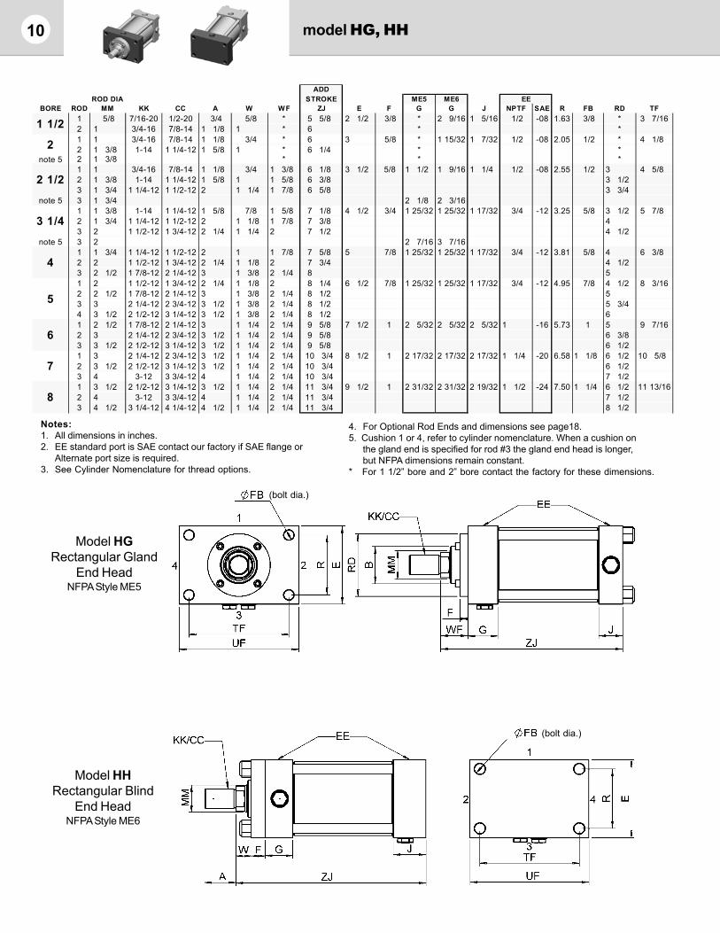
10 model HG, HH
Model HGRectangular Gland
End HeadNFPA Style ME5
Model HHRectangular Blind
End HeadNFPA Style ME6
Notes:1. All dimensions in inches.2. EE standard port is SAE contact our factory if SAE flange or
Alternate port size is required.3. See Cylinder Nomenclature for thread options.
4. For Optional Rod Ends and dimensions see page18.5. Cushion 1 or 4, refer to cylinder nomenclature. When a cushion on
the gland end is specified for rod #3 the gland end head is longer,but NFPA dimensions remain constant.
* For 1 1/2” bore and 2” bore contact the factory for these dimensions.
(bolt dia.)
(bolt dia.)
ADDROD DIA STROKE ME5 ME6
BORE ROD MM KK CC A W WF ZJ E F G G J NPTF SAE R FB RD TF1 5/8 7/16-20 1/2-20 3/4 5/8 * 5 5/8 2 1/2 3/8 * 2 9/16 1 5/16 1/2 -08 1.63 3/8 * 3 7/162 1 3/4-16 7/8-14 1 1/8 1 * 6 * *1 1 3/4-16 7/8-14 1 1/8 3/4 * 6 3 5/8 * 1 15/32 1 7/32 1/2 -08 2.05 1/2 * 4 1/82 1 3/8 1-14 1 1/4-12 1 5/8 1 * 6 1/4 * *
note 5 2 1 3/8 * * *1 1 3/4-16 7/8-14 1 1/8 3/4 1 3/8 6 1/8 3 1/2 5/8 1 1/2 1 9/16 1 1/4 1/2 -08 2.55 1/2 3 4 5/82 1 3/8 1-14 1 1/4-12 1 5/8 1 1 5/8 6 3/8 3 1/23 1 3/4 1 1/4-12 1 1/2-12 2 1 1/4 1 7/8 6 5/8 3 3/4
note 5 3 1 3/4 2 1/8 2 3/161 1 3/8 1-14 1 1/4-12 1 5/8 7/8 1 5/8 7 1/8 4 1/2 3/4 1 25/32 1 25/32 1 17/32 3/4 -12 3.25 5/8 3 1/2 5 7/82 1 3/4 1 1/4-12 1 1/2-12 2 1 1/8 1 7/8 7 3/8 43 2 1 1/2-12 1 3/4-12 2 1/4 1 1/4 2 7 1/2 4 1/2
note 5 3 2 2 7/16 3 7/161 1 3/4 1 1/4-12 1 1/2-12 2 1 1 7/8 7 5/8 5 7/8 1 25/32 1 25/32 1 17/32 3/4 -12 3.81 5/8 4 6 3/82 2 1 1/2-12 1 3/4-12 2 1/4 1 1/8 2 7 3/4 4 1/23 2 1/2 1 7/8-12 2 1/4-12 3 1 3/8 2 1/4 8 51 2 1 1/2-12 1 3/4-12 2 1/4 1 1/8 2 8 1/4 6 1/2 7/8 1 25/32 1 25/32 1 17/32 3/4 -12 4.95 7/8 4 1/2 8 3/162 2 1/2 1 7/8-12 2 1/4-12 3 1 3/8 2 1/4 8 1/2 53 3 2 1/4-12 2 3/4-12 3 1/2 1 3/8 2 1/4 8 1/2 5 3/44 3 1/2 2 1/2-12 3 1/4-12 3 1/2 1 3/8 2 1/4 8 1/2 61 2 1/2 1 7/8-12 2 1/4-12 3 1 1/4 2 1/4 9 5/8 7 1/2 1 2 5/32 2 5/32 2 5/32 1 -16 5.73 1 5 9 7/162 3 2 1/4-12 2 3/4-12 3 1/2 1 1/4 2 1/4 9 5/8 6 3/83 3 1/2 2 1/2-12 3 1/4-12 3 1/2 1 1/4 2 1/4 9 5/8 6 1/21 3 2 1/4-12 2 3/4-12 3 1/2 1 1/4 2 1/4 10 3/4 8 1/2 1 2 17/32 2 17/32 2 17/32 1 1/4 -20 6.58 1 1/8 6 1/2 10 5/82 3 1/2 2 1/2-12 3 1/4-12 3 1/2 1 1/4 2 1/4 10 3/4 6 1/23 4 3-12 3 3/4-12 4 1 1/4 2 1/4 10 3/4 7 1/21 3 1/2 2 1/2-12 3 1/4-12 3 1/2 1 1/4 2 1/4 11 3/4 9 1/2 1 2 31/32 2 31/32 2 19/32 1 1/2 -24 7.50 1 1/4 6 1/2 11 13/162 4 3-12 3 3/4-12 4 1 1/4 2 1/4 11 3/4 7 1/23 4 1/2 3 1/4-12 4 1/4-12 4 1/2 1 1/4 2 1/4 11 3/4 8 1/2
8
2 1/2
3 1/4
2
4
5
EE
6
7
1 1/2

11model HTR, HTB
Warning: Trunnion mounted cylinders swivel in one direction and are designed tocarry shear loads only. Pins must be held rigidly and in accurate alignment. Impropermounting may result in failure of mount.
Model HTBBlind End Trunnion
NFPA Style MT2
Notes:1. All dimensions in inches.2. EE standard port is SAE contact our factory if SAE flange or
Alternate port size is required.3. See Cylinder Nomenclature for thread options.
4. For Optional Rod Ends and dimensions see page18.5. Cushion 1 or 4, refer to cylinder nomenclature. When a cushion on
the gland end is specified for rod #3 the gland end head is longer,but NFPA dimensions remain constant.
6. XJ dimensions are not NFPA compliant for 2” through 8” bores.
Model HTRRod End Trunnion
NFPA Style MT1
ROD DIA HTR HTB HTR HTBBORE ROD MM KK CC A W W XG XJ ZJ ZJ E F G J G J NPTF SAE TD TL
1 5/8 7/16-20 1/2-20 3/4 5/8 5/8 1 7/8 4 7/8 5 5/8 5 5/8 2 1/2 3/8 1 9/16 1 5/16 1 9/16 1 5/16 1/2 -08 1 12 1 3/4-16 7/8-14 1 1/8 1 1 2 1/4 5 1/4 6 61 1 3/4-16 7/8-14 1 1/8 3/4 3/4 2 1/4 5 1/2 6 3/16 6 1/4 3 5/8 1 21/32 1 7/32 1 15/32 1 7/32 1/2 -08 1 3/8 1 3/82 1 3/8 1-14 1 1/4-12 1 5/8 1 1 2 1/2 5 3/4 6 7/16 6 1/2
note 5 2 1 3/8 2 5/16 2 1/81 1 3/4-16 7/8-14 1 1/8 3/4 3/4 2 1/4 5 11/16 6 5/16 6 7/16 3 1/2 9/16 1 3/4 1 1/4 1 9/16 1 9/16 1/2 -08 1 3/8 1 3/82 1 3/8 1-14 1 1/4-12 1 5/8 1 1 2 1/2 5 15/16 6 9/16 6 11/163 1 3/4 1 1/4-12 1 1/2-12 2 1 1/4 1 1/4 2 3/4 6 3/16 6 13/16 6 15/16
note 5 3 1 3/4 2 3/8 2 3/161 1 3/8 1-14 1 1/4-12 1 5/8 7/8 7/8 2 5/8 6 1/2 7 1/4 7 1/2 4 1/2 3/4 1 29/32 1 17/32 1 25/32 1 29/32 3/4 -12 1 3/4 1 3/42 1 3/4 1 1/4-12 1 1/2-12 2 1 1/8 1 1/8 2 7/8 6 3/4 7 1/2 7 3/43 2 1 1/2-12 1 3/4-12 2 1/4 1 1/4 1 1/4 3 6 7/8 7 5/8 7 7/8
note 5 3 2 2 9/16 2 7/161 1 3/4 1 1/4-12 1 1/2-12 2 1 1 2 7/8 7 1/4 7 13/16 8 3/16 5 7/8 1 31/32 1 17/32 1 25/32 2 1/32 3/4 -12 1 3/4 1 3/42 2 1 1/2-12 1 3/4-12 2 1/4 1 1/8 1 1/8 3 7 3/8 7 15/16 8 5/163 2 1/2 1 7/8-12 2 1/4-12 3 1 3/8 1 3/8 3 1/4 7 5/8 8 3/16 8 9/161 2 1 1/2-12 1 3/4-12 2 1/4 1 3/16 1 1/8 3 7 3/4 8 1/2 8 13/16 6 1/2 7/8 1 31/32 1 17/32 1 25/32 2 5/32 3/4 -12 1 3/4 1 3/42 2 1/2 1 7/8-12 2 1/4-12 3 1 7/16 1 3/8 3 1/4 8 8 3/4 9 1/163 3 2 1/4-12 2 3/4-12 3 1/2 1 7/16 1 3/8 3 1/4 8 8 3/4 9 1/164 3 1/2 2 1/2-12 3 1/4-12 3 1/2 1 7/16 1 3/8 3 1/4 8 8 3/4 9 1/161 2 1/2 1 7/8-12 2 1/4-12 3 1 1/4 1 1/4 3 3/8 8 9/16 9 3/4 9 5/8 7 1/2 1 2 9/32 2 5/32 2 5/32 2 5/32 1 -16 2 22 3 2 1/4-12 2 3/4-12 3 1/2 1 1/4 1 1/4 3 3/8 8 9/16 9 3/4 9 5/83 3 1/2 2 1/2-12 3 1/4-12 3 1/2 1 1/4 1 1/4 3 3/8 8 9/16 9 3/4 9 5/81 3 2 1/4-12 2 3/4-12 3 1/2 1 5/16 1 1/4 3 5/8 9 11/16 10 15/16 10 3/4 8 1/2 1 2 21/32 2 17/32 2 17/32 2 17/32 1 1/4 -20 2 1/2 2 1/22 3 1/2 2 1/2-12 3 1/4-12 3 1/2 1 5/16 1 1/4 3 5/8 9 11/16 10 15/16 10 3/43 4 3-12 3 3/4-12 4 1 5/16 1 1/4 3 5/8 9 11/16 10 15/16 10 3/41 3 1/2 2 1/2-12 3 1/4-12 3 1/2 1 1/4 1 1/4 3 3/4 10 11/16 11 7/8 12 5/32 9 1/2 1 3 3/32 2 19/32 2 31/32 3 1/16 1 1/2 -24 3 32 4 3-12 3 3/4-12 4 1 1/4 1 1/4 3 3/4 10 11/16 11 7/8 12 5/323 4 1/2 3 1/4-12 4 1/4-12 4 1/2 1 1/4 1 1/4 3 3/4 10 11/16 11 7/8 12 5/32
EE ADD STROKE
HTR HTB
6
7
8
2 1/2
3 1/4
21 1/2
4
5
(see note 6)

12 model HT, HHT
Model HHTMid-Trunnion (Split)
Model HT Mid-TrunnionNFPA Style MT4
Warning: Trunnion mounted cylinders swivel in one direction and are designed to carry shear loads only.Pins must be held rigidly and in accurate alignment. Improper mounting may result in failure of mount.
BORE BD TM UM UW
1 1/2 1 3/16 3 5 3
2 1 1/2 3 1/2 6 1/4 3 1/2
2 1/2 1 1/2 4 6 3/4 4
3 1/4 2 5 8 1/2 5
4 2 5 1/2 9 5 1/4
5 2 7 10 1/2 6 3/4
6 3 8 1/2 12 1/2 9
7 3 9 3/4 14 3/4 10
8 3 1/2 11 17 12
HT
BORE BD TM UM UW
1 1/2 1 3/4 4 6 4 7/16
2 1 3/4 5 7 3/4 5
2 1/2 1 3/4 5 1/2 8 1/4 5 1/2
3 1/4 2 1/4 7 10 1/2 7 1/4
4 2 1/2 7 1/2 11 8 1/2
5 3 1/2 9 12 1/2 9 3/4
6 4 10 1/2 14 1/2 11 13/16
HHT
Notes:1. All dimensions in inches.2. EE standard port is SAE contact our factory if SAE flange or
Alternate port size is required.3. See Cylinder Nomenclature for thread options.
4. For Optional Rod Ends and dimensions see page18.5. Cushion 1 or 4, refer to cylinder nomenclature. When a cushion on
the gland end is specified for rod #3 the gland end head is longer,but NFPA dimensions remain constant.
Note: All bore sizes of model HHT have a pressure limitation of 1200 psi.
ROD DIA HT HHT HT HHTBORE ROD MM KK CC A W XI (min) XI (min) XI (max) XI (max) ZJ E F G J NPTF SAE TD
1 5/8 7/16-20 1/2-20 3/4 5/8 3 5/32 3 11/16 3 23/32 3 3/16 5 5/8 2 1/2 3/8 1 9/16 1 5/16 1/2 -08 12 1 3/4-16 7/8-14 1 1/8 1 3 17/32 4 1/16 4 3/32 3 9/16 6 11 1 3/4-16 7/8-14 1 1/8 3/4 3 19/32 3 15/16 4 1/32 3 21/32 6 3 5/8 1 15/32 1 7/32 1/2 -08 1 3/82 1 3/8 1-14 1 1/4-12 1 5/8 1 3 27/32 4 3/16 4 9/32 3 29/32 6 1/4 1 3/8
note 5 2 1 3/8 4 1/2 4 5/8 4 9/32 3 29/32 2 1/81 1 3/4-16 7/8-14 1 1/8 3/4 3 5/8 4 4 1/8 3 3/4 6 1/8 3 1/2 9/16 1 9/16 1 1/4 1/2 -08 1 3/82 1 3/8 1-14 1 1/4-12 1 5/8 1 3 7/8 4 1/4 4 3/8 4 6 3/8 1 3/83 1 3/4 1 1/4-12 1 1/2-12 2 1 1/4 4 1/8 4 1/2 4 5/8 4 1/4 6 5/8 1 3/8
note 5 3 1 3/4 4 3/4 4 15/16 4 5/8 4 1/4 2 3/161 1 3/8 1-14 1 1/4-12 1 5/8 7/8 4 13/32 4 3/4 4 19/32 4 7/32 7 1/8 4 1/2 3/4 1 25/32 1 17/32 3/4 -12 1 3/42 1 3/4 1 1/4-12 1 1/2-12 2 1 1/8 4 21/32 5 4 27/32 4 15/32 7 3/8 1 3/43 2 1 1/2-12 1 3/4-12 2 1/4 1 1/4 4 25/32 5 1/8 4 31/32 4 19/32 7 1/2 1 3/4
note 5 3 2 5 7/16 4 31/32 4 19/32 2 7/161 1 3/4 1 1/4-12 1 1/2-12 2 1 4 21/32 5 1/8 5 3/32 4 19/32 7 5/8 5 7/8 1 25/32 1 17/32 3/4 -12 1 3/42 2 1 1/2-12 1 3/4-12 2 1/4 1 1/8 4 25/32 5 1/4 5 7/32 4 23/32 7 3/4 1 3/43 2 1/2 1 7/8-12 2 1/4-12 3 1 3/8 5 1/32 5 3/8 5 15/32 4 31/32 8 1 3/41 2 1 1/2-12 1 3/4-12 2 1/4 1 1/8 4 25/32 5 3/4 5 23/32 4 23/32 8 1/4 6 1/2 7/8 1 25/32 1 17/32 3/4 -12 1 3/42 2 1/2 1 7/8-12 2 1/4-12 3 1 3/8 5 1/32 6 5 31/32 4 31/32 8 1/2 1 3/43 3 2 1/4-12 2 3/4-12 3 1/2 1 3/8 5 1/32 6 5 31/32 4 31/32 8 1/2 1 3/44 3 1/2 2 1/2-12 3 1/4-12 3 1/2 1 3/8 5 1/32 6 5 31/32 4 31/32 8 1/2 1 3/41 2 1/2 1 7/8-12 2 1/4-12 3 1 1/4 5 29/32 6 5/8 5 31/32 5 7/32 9 5/8 7 1/2 1 2 5/32 2 5/32 1 -16 22 3 2 1/4-12 2 3/4-12 3 1/2 1 1/4 5 29/32 6 5/8 5 31/32 5 7/32 9 5/8 23 3 1/2 2 1/2-12 3 1/4-12 3 1/2 1 1/4 5 29/32 6 5/8 5 31/32 5 7/32 9 5/8 21 3 2 1/4-12 2 3/4-12 3 1/2 1 1/4 6 9/32 N/A 6 23/32 N/A 10 3/4 8 1/2 1 2 17/32 2 17/32 1 1/4 -20 2 1/22 3 1/2 2 1/2-12 3 1/4-12 3 1/2 1 1/4 6 9/32 N/A 6 23/32 N/A 10 3/4 2 1/23 4 3-12 3 3/4-12 4 1 1/4 6 9/32 N/A 6 23/32 N/A 10 3/4 2 1/21 3 1/2 2 1/2-12 3 1/4-12 3 1/2 1 1/4 6 31/32 N/A 7 13/32 N/A 11 3/4 9 1/2 1 2 31/32 2 19/32 1 1/2 -24 32 4 3-12 3 3/4-12 4 1 1/4 6 31/32 N/A 7 13/32 N/A 11 3/4 33 4 1/2 3 1/4-12 4 1/4-12 4 1/2 1 1/4 6 31/32 N/A 7 13/32 N/A 11 3/4 3
EE
6
2
1 1/2
ADD STROKE
7
8
2 1/2
3 1/4
4
5

13model HF,HS
Model HFFoot Mount
NFPA Style MS2
Model HSSide TappedNFPA Style MS4
Notes:1. All dimensions in inches.2. EE standard port is SAE contact our factory if SAE flange or
Alternate port size is required.3. See Cylinder Nomenclature for thread options.4. For Optional Rod Ends and dimensions see page18.
Bottom View
5. Cushion 1 or 4, refer to cylinder nomenclature. When a cushion onthe gland end is specified for rod #3 the gland end head is longer,but NFPA dimensions remain constant.
6. SU1 = SU and SW1 = SW except for 2 1/2” bore,where SU1 = 1 9/16” and SW1 = 11/16”.
ADDSTROKE
BORE NT TN SN
1 1/2 3/8-16 3/4 2 7/8
2 1/2-13 15/16 2 7/8
2 1/2 5/8-11 1 5/16 3
3 1/4 3/4-10 1 1/2 3 1/2
4 1-8 2 1/16 3 3/4
5 1-8 2 15/16 4 1/4
6 1 1/4-7 3 5/16 5 1/8
7 1 1/2-6 3 3/4 5 7/8
8 1 1/2-6 4 1/4 6 5/8
ROD DIA (min.) note 6 note 6BORE ROD MM KK CC A W W1 XS XT ZJ SS E F G J NPTF SAE ND SB SU SW ST TS US
1 5/8 7/16-20 1/2-20 3/4 5/8 5/8 1 3/8 2 5 5/8 3 7/8 2 1/2 3/8 1 9/16 1 5/16 1/2 -08 3/8 3/8 15/16 3/8 1/2 3 1/4 4 2 1 3/4-16 7/8-14 1 1/8 1 1 1 3/4 2 3/8 6 3 7/8 3/8 1 1 3/4-16 7/8-14 1 1/8 3/4 3/4 1 7/8 2 3/8 6 3 5/8 3 5/8 1 15/32 1 7/32 1/2 -08 7/16 1/2 1 1/4 1/2 3/4 4 5 2 1 3/8 1-14 1 1/4-12 1 5/8 1 1 2 1/8 2 5/8 6 1/4 3 5/8 7/16
note 5 2 1 3/8 2 1/8 7/161 1 3/4-16 7/8-14 1 1/8 3/4 3/4 2 1/16 2 3/8 6 1/8 3 3/8 3 1/2 9/16 1 9/16 1 1/4 1/2 -08 5/8 3/4 1 1/2 3/4 1 4 7/8 6 1/4 2 1 3/8 1-14 1 1/4-12 1 5/8 1 1 2 5/16 2 5/8 6 3/8 3 3/8 5/8 note 6 note 63 1 3/4 1 1/4-12 1 1/2-12 2 1 1/4 1 1/4 2 9/16 2 7/8 6 5/8 3 3/8 1/2
note 5 3 1 3/4 2 3/16 9/161 1 3/8 1-14 1 1/4-12 1 5/8 7/8 7/8 2 5/16 2 3/4 7 1/8 4 1/8 4 1/2 3/4 1 25/32 1 17/32 3/4 -12 3/4 3/4 1 9/16 11/16 1 5 7/8 7 1/4 2 1 3/4 1 1/4-12 1 1/2-12 2 1 1/8 1 1/8 2 9/16 3 7 3/8 4 1/8 3/43 2 1 1/2-12 1 3/4-12 2 1/4 1 1/4 1 1/4 2 11/16 3 1/8 7 1/2 4 1/8 5/8
note 5 3 2 2 7/16 1/21 1 3/4 1 1/4-12 1 1/2-12 2 1 1 1/16 2 3/4 3 7 9/16 4 5 7/8 1 25/32 1 17/32 3/4 -12 1 1 2 7/8 1 1/4 6 3/4 8 1/2 2 2 1 1/2-12 1 3/4-12 2 1/4 1 1/8 1 3/16 2 7/8 3 1/8 7 11/16 4 13 2 1/2 1 7/8-12 2 1/4-12 3 1 3/8 1 7/16 3 1/8 3 3/8 7 15/16 4 5/81 2 1 1/2-12 1 3/4-12 2 1/4 1 1/8 1 3/16 2 7/8 3 1/8 8 3/16 4 1/2 6 1/2 7/8 1 25/32 1 17/32 3/4 -12 1 1 2 7/8 1 1/4 8 1/4 10 2 2 1/2 1 7/8-12 2 1/4-12 3 1 3/8 1 7/16 3 1/8 3 3/8 8 7/16 4 1/2 13 3 2 1/4-12 2 3/4-12 3 1/2 1 3/8 1 7/16 3 1/8 3 3/8 8 7/16 4 1/2 14 3 1/2 2 1/2-12 3 1/4-12 3 1/2 1 3/8 1 7/16 3 1/8 3 3/8 8 7/16 4 1/2 7/81 2 1/2 1 7/8-12 2 1/4-12 3 1 1/4 1 1/4 3 3/8 3 1/2 9 5/8 5 1/8 7 1/2 1 2 5/32 2 5/32 1 -16 1 1/4 1 1/4 2 1/2 1 1/8 1 1/2 9 3/4 12 2 3 2 1/4-12 2 3/4-12 3 1/2 1 1/4 1 1/4 3 3/8 3 1/2 9 5/8 5 1/8 1 1/43 3 1/2 2 1/2-12 3 1/4-12 3 1/2 1 1/4 1 1/4 3 3/8 3 1/2 9 5/8 5 1/8 1 1/81 3 2 1/4-12 2 3/4-12 3 1/2 1 1/4 1 1/4 3 5/8 3 13/16 10 3/4 5 3/4 8 1/2 1 2 17/32 2 17/32 1 1/4 -20 1 1/2 1 1/2 2 7/8 1 3/8 1 1/2 11 1/4 14 2 3 1/2 2 1/2-12 3 1/4-12 3 1/2 1 1/4 1 1/4 3 5/8 3 13/16 10 3/4 5 3/4 1 1/23 4 3-12 3 3/4-12 4 1 1/4 1 1/4 3 5/8 3 13/16 10 3/4 5 3/4 1 7/161 3 1/2 2 1/2-12 3 1/4-12 3 1/2 1 1/4 1 1/4 3 5/8 3 15/16 11 3/4 6 3/4 9 1/2 1 2 31/32 2 19/32 1 1/2 -24 1 1/2 1 1/2 2 7/8 1 3/8 1 1/2 12 1/4 15 2 4 3-12 3 3/4-12 4 1 1/4 1 1/4 3 5/8 3 15/16 11 3/4 6 3/4 1 1/23 4 1/2 3 1/4-12 4 1/4-12 4 1/2 1 1/4 1 1/4 3 5/8 3 15/16 11 3/4 6 3/4 1 1/2
8
2 1/2
3 1/4
2
4
5
ADD STROKE EE
6
7
1 1/2

14 model HD
Model HDDouble Rod
Notes:1. All dimensions in inches.2. EE standard port is SAE contact our factory if SAE flange or Alternate port size is required.3. See Cylinder Nomenclature for thread options.4. For Optional Rod Ends and dimensions see page18.5. Cushion 1 or 4, refer to cylinder nomenclature. When a cushion on the gland end is specified
for rod #3 the gland end head is longer, but NFPA dimensions remain constant.6. Other standard mounting styles are available, add the required mounting code after the “D” for
Double rod in the cylinder nomenclature.H_DF_ Foot MountH_DS_ Side TappedH_DT_ Mid Trunnion (include XI in nomenclature)
7. For mounting styles not common to both ends, letter code after “D” for double rod is gland end,Letter following last is blind end.
H_DRC_ Rectangular Flange - No mountH_DTRC_ Gland end Trunnion - No mount
ADD ADDROD DIA STROKE STROKE X2
BORE ROD MM KK CC A W LD ZM E F G NPTF SAE1 5/8 7/16-20 1/2-20 3/4 5/8 5 5/8 6 7/8 2 1/2 3/8 1 9/16 1/2 -082 1 3/4-16 7/8-14 1 1/8 1 5 5/8 7 5/81 1 3/4-16 7/8-14 1 1/8 3/4 6 1/8 7 5/8 3 5/8 1 15/32 1/2 -082 1 3/8 1-14 1 1/4-12 1 5/8 1 6 1/8 8 1/8
note 5 2 1 3/8 2 1/81 1 3/4-16 7/8-14 1 1/8 3/4 6 1/4 7 3/4 3 1/2 9/16 1 9/16 1/2 -082 1 3/8 1-14 1 1/4-12 1 5/8 1 6 1/4 8 1/43 1 3/4 1 1/4-12 1 1/2-12 2 1 1/4 6 1/4 8 3/4
note 5 3 1 3/4 2 3/161 1 3/8 1-14 1 1/4-12 1 5/8 7/8 7 1/4 9 4 1/2 3/4 1 25/32 3/4 -122 1 3/4 1 1/4-12 1 1/2-12 2 1 1/8 7 1/4 9 1/23 2 1 1/2-12 1 3/4-12 2 1/4 1 1/4 7 1/4 9 3/4
note 5 3 2 2 7/161 1 3/4 1 1/4-12 1 1/2-12 2 1 7 3/4 9 3/4 5 7/8 1 25/32 3/4 -122 2 1 1/2-12 1 3/4-12 2 1/4 1 1/8 7 3/4 103 2 1/2 1 7/8-12 2 1/4-12 3 1 3/8 7 3/4 10 1/21 2 1 1/2-12 1 3/4-12 2 1/4 1 1/8 8 1/4 10 1/2 6 1/2 7/8 1 25/32 3/4 -122 2 1/2 1 7/8-12 2 1/4-12 3 1 3/8 8 1/4 113 3 2 1/4-12 2 3/4-12 3 1/2 1 3/8 8 1/4 114 3 1/2 2 1/2-12 3 1/4-12 3 1/2 1 3/8 8 1/4 111 2 1/2 1 7/8-12 2 1/4-12 3 1 1/4 9 3/8 11 7/8 7 1/2 1 2 5/32 1 -162 3 2 1/4-12 2 3/4-12 3 1/2 1 1/4 9 3/8 11 7/83 3 1/2 2 1/2-12 3 1/4-12 3 1/2 1 1/4 9 3/8 11 7/81 3 2 1/4-12 2 3/4-12 3 1/2 1 1/4 10 1/2 13 8 1/2 1 2 17/32 1 1/4 -202 3 1/2 2 1/2-12 3 1/4-12 3 1/2 1 1/4 10 1/2 133 4 3-12 3 3/4-12 4 1 1/4 10 1/2 131 3 1/2 2 1/2-12 3 1/4-12 3 1/2 1 1/4 11 7/8 14 3/8 9 1/2 1 2 31/32 1 1/2 -242 4 3-12 3 3/4-12 4 1 1/4 11 7/8 14 3/83 4 1/2 3 1/4-12 4 1/4-12 4 1/2 1 1/4 11 7/8 14 3/8
EE
6
7
8
2 1/2
3 1/4
2
1 1/2
4
5
15
Notes:1. All dimensions in inches.2. EE standard port is SAE contact our factory if SAE flange or
Alternate port size is required.3. See Cylinder Nomenclature for thread options.
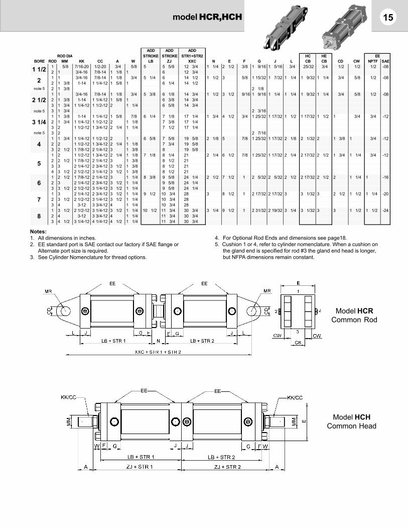
Model HCRCommon Rod
Model HCHCommon Head
model HCR,HCH
4. For Optional Rod Ends and dimensions see page18.5. Cushion 1 or 4, refer to cylinder nomenclature. When a cushion on
the gland end is specified for rod #3 the gland end head is longer,but NFPA dimensions remain constant.
ADD ADD ADDROD DIA STROKE STROKE STR1+STR2 HC HE
BORE ROD MM KK CC A W LB ZJ XXC N E F G J L CB CB CD CW NPTF SAE1 5/8 7/16-20 1/2-20 3/4 5/8 5 5 5/8 12 3/4 1 1/4 2 1/2 3/8 1 9/16 1 5/16 3/4 25/32 3/4 1/2 1/2 1/2 -082 1 3/4-16 7/8-14 1 1/8 1 6 12 3/41 1 3/4-16 7/8-14 1 1/8 3/4 5 1/4 6 14 1/2 1 1/2 3 5/8 1 15/32 1 7/32 1 1/4 1 9/32 1 1/4 3/4 5/8 1/2 -082 1 3/8 1-14 1 1/4-12 1 5/8 1 6 1/4 14 1/2
note 5 2 1 3/8 2 1/81 1 3/4-16 7/8-14 1 1/8 3/4 5 3/8 6 1/8 14 3/4 1 1/2 3 1/2 9/16 1 9/16 1 1/4 1 1/4 1 9/32 1 1/4 3/4 5/8 1/2 -082 1 3/8 1-14 1 1/4-12 1 5/8 1 6 3/8 14 3/43 1 3/4 1 1/4-12 1 1/2-12 2 1 1/4 6 5/8 14 3/4
note 5 3 1 3/4 2 3/161 1 3/8 1-14 1 1/4-12 1 5/8 7/8 6 1/4 7 1/8 17 1/4 1 3/4 4 1/2 3/4 1 25/32 1 17/32 1 1/2 1 17/32 1 1/2 1 3/4 3/4 -122 1 3/4 1 1/4-12 1 1/2-12 2 1 1/8 7 3/8 17 1/43 2 1 1/2-12 1 3/4-12 2 1/4 1 1/4 7 1/2 17 1/4
note 5 3 2 2 7/161 1 3/4 1 1/4-12 1 1/2-12 2 1 6 5/8 7 5/8 19 5/8 2 1/8 5 7/8 1 25/32 1 17/32 2 1/8 2 1/32 2 1 3/8 1 3/4 -122 2 1 1/2-12 1 3/4-12 2 1/4 1 1/8 7 3/4 19 5/83 2 1/2 1 7/8-12 2 1/4-12 3 1 3/8 8 19 5/81 2 1 1/2-12 1 3/4-12 2 1/4 1 1/8 7 1/8 8 1/4 21 2 1/4 6 1/2 7/8 1 25/32 1 17/32 2 1/4 2 17/32 2 1/2 1 3/4 1 1/4 3/4 -122 2 1/2 1 7/8-12 2 1/4-12 3 1 3/8 8 1/2 213 3 2 1/4-12 2 3/4-12 3 1/2 1 3/8 8 1/2 214 3 1/2 2 1/2-12 3 1/4-12 3 1/2 1 3/8 8 1/2 211 2 1/2 1 7/8-12 2 1/4-12 3 1 1/4 8 3/8 9 5/8 24 1/4 2 1/2 7 1/2 1 2 5/32 2 5/32 2 1/2 2 17/32 2 1/2 2 1 1/4 1 -162 3 2 1/4-12 2 3/4-12 3 1/2 1 1/4 9 5/8 24 1/43 3 1/2 2 1/2-12 3 1/4-12 3 1/2 1 1/4 9 5/8 24 1/41 3 2 1/4-12 2 3/4-12 3 1/2 1 1/4 9 1/2 10 3/4 28 3 8 1/2 1 2 17/32 2 17/32 3 3 1/32 3 2 1/2 1 1/2 1 1/4 -202 3 1/2 2 1/2-12 3 1/4-12 3 1/2 1 1/4 10 3/4 283 4 3-12 3 3/4-12 4 1 1/4 10 3/4 281 3 1/2 2 1/2-12 3 1/4-12 3 1/2 1 1/4 10 1/2 11 3/4 30 3/4 3 1/4 9 1/2 1 2 31/32 2 19/32 3 1/4 3 1/32 3 3 1 1/2 1 1/2 -242 4 3-12 3 3/4-12 4 1 1/4 11 3/4 30 3/43 4 1/2 3 1/4-12 4 1/4-12 4 1/2 1 1/4 11 3/4 30 3/4
EE
6
7
1 1/2
8
2 1/2
3 1/4
2
4
5
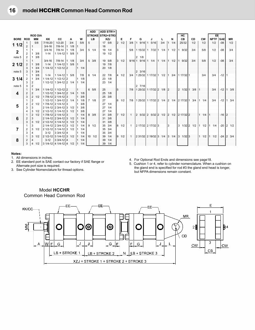
16 model HCCHR Common Head Common Rod
Model HCCHRCommon Head Common Rod
Notes:1. All dimensions in inches.2. EE standard port is SAE contact our factory if SAE flange or
Alternate port size is required.3. See Cylinder Nomenclature for thread options.
4. For Optional Rod Ends and dimensions see page18.5. Cushion 1 or 4, refer to cylinder nomenclature. When a cushion on
the gland end is specified for rod #3 the gland end head is longer,but NFPA dimensions remain constant.
ADD ADD STR1+ROD DIA STROKE STR2+STR3 HC
BORE ROD MM KK CC A W LB XZJ E F G J L N CB CD CW NPTF SAE MR1 5/8 7/16-20 1/2-20 3/4 5/8 5 17 5/8 2 1/2 3/8 1 9/16 1 5/16 3/4 1 1/4 25/32 1/2 1/2 1/2 -08 1/22 1 3/4-16 7/8-14 1 1/8 1 181 1 3/4-16 7/8-14 1 1/8 3/4 5 1/4 19 1/4 3 5/8 1 15/32 1 7/32 1 1/4 1 1/2 1 9/32 3/4 5/8 1/2 -08 3/42 1 3/8 1-14 1 1/4-12 1 5/8 1 19 1/2
note 5 2 1 3/8 2 1/81 1 3/4-16 7/8-14 1 1/8 3/4 5 3/8 19 5/8 3 1/2 9/16 1 9/16 1 1/4 1 1/4 1 1/2 1 9/32 3/4 5/8 1/2 -08 3/42 1 3/8 1-14 1 1/4-12 1 5/8 1 19 7/83 1 3/4 1 1/4-12 1 1/2-12 2 1 1/4 20 1/8
note 5 3 1 3/4 2 3/161 1 3/8 1-14 1 1/4-12 1 5/8 7/8 6 1/4 22 7/8 4 1/2 3/4 1 25/32 1 17/32 1 1/2 1 3/4 1 17/32 1 3/4 3/4 -12 12 1 3/4 1 1/4-12 1 1/2-12 2 1 1/8 23 1/83 2 1 1/2-12 1 3/4-12 2 1/4 1 1/4 23 1/4
note 5 3 2 2 7/161 1 3/4 1 1/4-12 1 1/2-12 2 1 6 5/8 25 5 7/8 1 25/32 1 17/32 2 1/8 2 2 1/32 1 3/8 1 3/4 -12 1 3/82 2 1 1/2-12 1 3/4-12 2 1/4 1 1/8 25 1/83 2 1/2 1 7/8-12 2 1/4-12 3 1 3/8 25 3/81 2 1 1/2-12 1 3/4-12 2 1/4 1 1/8 7 1/8 27 6 1/2 7/8 1 25/32 1 17/32 2 1/4 2 1/4 2 17/32 1 3/4 1 1/4 3/4 -12 1 3/42 2 1/2 1 7/8-12 2 1/4-12 3 1 3/8 27 1/43 3 2 1/4-12 2 3/4-12 3 1/2 1 3/8 27 1/44 3 1/2 2 1/2-12 3 1/4-12 3 1/2 1 3/8 27 1/41 2 1/2 1 7/8-12 2 1/4-12 3 1 1/4 8 3/8 31 3/8 7 1/2 1 2 5/32 2 5/32 2 1/2 2 1/2 2 17/32 2 1 1/4 1 -16 22 3 2 1/4-12 2 3/4-12 3 1/2 1 1/4 31 3/83 3 1/2 2 1/2-12 3 1/4-12 3 1/2 1 1/4 31 3/81 3 2 1/4-12 2 3/4-12 3 1/2 1 1/4 9 1/2 35 3/4 8 1/2 1 2 17/32 2 17/32 3 3 3 1/32 2 1/2 1 1/2 1 1/4 -20 2 1/22 3 1/2 2 1/2-12 3 1/4-12 3 1/2 1 1/4 35 3/43 4 3-12 3 3/4-12 4 1 1/4 35 3/41 3 1/2 2 1/2-12 3 1/4-12 3 1/2 1 1/4 10 1/2 39 1/4 9 1/2 1 2 31/32 2 19/32 3 1/4 3 1/4 3 1/32 3 1 1/2 1 1/2 -24 2 3/42 4 3-12 3 3/4-12 4 1 1/4 39 1/43 4 1/2 3 1/4-12 4 1/4-12 4 1/2 1 1/4 39 1/4
8
2 1/2
3 1/4
2
4
5
EE
6
7
1 1/2

Accessories 17
Notes:1. For use with Socket Head Cap Screws only.
* Tapped mounting holes this model only.
Detachable Clevis - MP2 Mount (NFPA)Mounts on cylinder and adapts to HM eye-type mounting bracketPART HMP2-15T HMP2-25T HMP2-32T HMP2-4T HMP2-5T HMP2-6T HMP2-7T HMP2-8TCB 0.76 0.76 1.51 2.03 2.53 2.53 3.03 3.03CD 1/2 3/4 1 1 3/8 1 3/4 2 2 1/2 3CW 1/2 5/8 3/4 1 1 1/4 1 1/4 1 1/2 1 1/2DD 3/8-24 1/2-20 5/8-18 5/8-18 7/8-14 1-14 1 1/8-12 1 1/4-12E 2 1/2 3 1/2 4 1/2 5 6 1/2 7 1/2 8 1/2 9 1/2F 3/8 5/8 3/4 7/8 7/8 1 1 1L 3/4 1 1/4 1 1/2 2 1/8 2 1/4 2 1/2 3 3 1/4MR 1/2 3/4 1 1 3/8 1 3/4 2 2 1/2 3R 1.63 2.56 3.25 3.81 4.94 5.75 6.59 7.50
Eye Type Mounting BracketAdapts to HC mount cylinder or HC rod clevisPART HM15 HM25 HM32 HM4 HM5 HM6 HM7 HM8 HM10 HM12CB 3/4 1 1/4 1 1/2 2 2 1/2 2 1/2 3 3 4 4 1/2CD 1/2 3/4 1 1 3/8 1 3/4 2 2 1/2 3 3 1/2 4DD 13/32 17/32 21/32 21/32 29/32 1 1/16 1 3/16 1 5/16 1 13/16 2 1/16E 2 1/2 3 1/2 4 1/2 5 6 1/2 7 1/2 8 1/2 9 1/2 12 5/8 14 7/8F 3/8 5/8 3/4 7/8 7/8 1 1 1 1 11/16 1 15/16FL 1 1/8 1 7/8 2 1/4 3 3 1/8 3 1/2 4 4 1/4 5 11/16 6 7/16MR 1/2 3/4 1 1 3/8 1 3/4 2 2 1/2 3 3 1/2 4R 1.63 2.56 3.25 3.81 4.95 5.75 6.59 7.50 9.62 11.50
Clevis Type Mounting BracketAdapts to HE mount cylinder or HE rod eyePART HCM15 HCM2 HCM32 HCM4 HCM5 HCM6 HCM7 HCM8 HCM10 HCM12CB 25/32 1 9/32 1 17/32 2 1/32 2 9/16 2 9/16 3 1/16 3 1/16 4 1/16 4 9/16CD 1/2 3/4 1 1 3/8 1 3/4 2 2 1/2 3 3 1/2 4CW 1/2 5/8 3/4 1 1 1/4 1 1/4 1 1/2 1 1/2 2 2DD 13/32 17/32 21/32 21/32 15/16 1 1/16 1 3/16 1 5/16 1 13/16 2 1/16E 3 1/2 5 6 1/2 7 1/2 9 1/2 12 3/4 12 3/4 12 3/4 15 1/2 17 1/2F 1/2 5/8 3/4 7/8 7/8 1 1 1 1 11/16 1 15/16FL 1 1/2 1 7/8 2 1/4 3 3 5/8 4 1/4 4 1/2 6 6 11/16 7 11/16MR 1/2 3/4 1 1 3/8 1 3/4 2 2 1/2 3 3 1/2 4R 2.55 3.82 4.95 5.73 7.50 9.40 9.40 9.40 12.00 13.75
Mounting Bracket for Self-Aligning Rod EyeAdapts to HW mount cylinder, HWE and HRES rod eyePART HWM15 HWM2-D HWM2* HWM32 HWM4 HWM5 HWM6 HWM7 HWM8CD 1/2 3/4 3/4 1 1 3/8 1 3/4 2 2 1/2 3CK 15/32 11/16 11/16 29/32 1 7/32 1 19/32 1 13/16 2 1/4 2 23/32CW 5/16 1/2 1/2 5/8 3/4 3/4 7/8 1 1/4 1 1/2DD 13/32 17/32 1/2"-20 21/32 21/32 15/16 1 1/16 1 3/16 1 5/16E 2 1/2 3 1/2 3 1/2 4 1/2 5 6 1/2 7 1/2 8 1/2 9 1/2F 3/8 9/16 9/16 11/16 13/16 15/16 15/16 15/16 1FL 1 1/2 2 1/16 2 1/16 2 7/16 3 1/16 3 15/16 4 3/16 4 11/16 5 1/4MR 1/2 3/4 3/4 1 1 3/8 1 3/4 2 2 1/2 3R 1.63 2.55 2.55 3.25 3.82 4.95 5.73 6.58 7.50

18 Accessories
Rod End Styles(See model dimensiontables for dimensionvalues)
AStandard Male Thread
NFPA Style SM
BOversize Male Thread
NFPA Style IM
DFemale ThreadNFPA Style SF
CFull Thread
NFPA Style FM
FRod End Coupler
Contact Our Factory forDetails
GRod Stud
NFPA Style SM
ENo Thread
Rod ClevisAdapts to male thread on piston rodPART HC15 HC15C HC2 HC2C HC32 HC4 HC5 HC5C HC6 HC7 HC8 HC7C HC10 HC10C HC12C HC12DA 3/4 3/4 1 1/8 1 5/8 1 5/8 2 2 1/4 3 3 3 1/2 3 1/2 3 1/2 3 1/2 3 1/2 4 4 1/2CB 0.781 0.781 1.281 1.531 1.531 2.031 2.563 2.563 2.563 3.063 3.063 3.063 4.063 4.063 4.531 4.531CD 1/2 1/2 3/4 1 1 1 3/8 1 3/4 2 2 2 1/2 3 3 3 1/2 3 1/2 4 4CE 1 1/2 1 1/2 2 3/8 3 1/8 3 1/8 4 1/8 4 1/2 5 1/2 5 1/2 6 1/2 6 3/4 6 3/4 7 3/4 7 3/4 8 1/2 9CW 1/2 1/2 5/8 3/4 3/4 1 1 1/4 1 1/4 1 1/4 1 1/2 1 1/2 1 1/2 2 2 2 1/4 2 1/4CR 1/2 1/2 3/4 1 1 1 3/8 1 3/4 2 2 2 1/2 2 3/4 2 3/4 3 1/2 3 1/2 4 4KK 7/16-20 1/2-20 3/4-16 7/8-14 1-14 1 1/4-12 1 1/2-12 1 3/4-12 1 7/8-12 2 1/4-12 2 1/2-12 2 3/4-12 3 1/4-12 3-12 3 3/4-12 4 1/4-12
Rod EyeAdapts to HCM clevis-type mounting bracketPART HE15 HE15C HE2 HE2C HE32 HE4 HE5 HE5C HE6 HE7 HE7C HE8 HE10 HE12C HE12DA 3/4 3/4 1 1/8 1 1/8 1 5/8 2 2 1/4 2 1/4 3 3 1/2 3 5/8 3 1/2 4 1/2 4 4 1/2CA 1/2 1/2 2 1/16 2 3/8 2 13/16 3 7/16 4 4 3/8 5 5 13/16 6 1/2 6 1/8 7 5/8 7 5/8 8 1/8CB 3/4 3/4 1 1/4 1 1/2 1 1/2 2 2 1/2 2 1/2 2 1/2 3 3 1/2 3 4 4 1/2 5CD 1/2 1/2 3/4 1 1 1 3/8 1 3/4 2 2 2 1/2 3 3 3 1/2 4 4ER 5/8 5/8 7/8 1 1/8 1 3/16 1 9/16 2 2 7/8 2 1/2 2 13/16 3 1/4 3 1/4 3 7/8 4 4KK 7/16-20 1/2-20 3/4-16 7/8-14 1-14 1 1/4-12 1 1/2-12 1 3/4-12 1 7/8-12 2 1/4-12 2 3/4-12 2 1/2-12 3 1/4-12 3 3/4-12 4 1/4-12
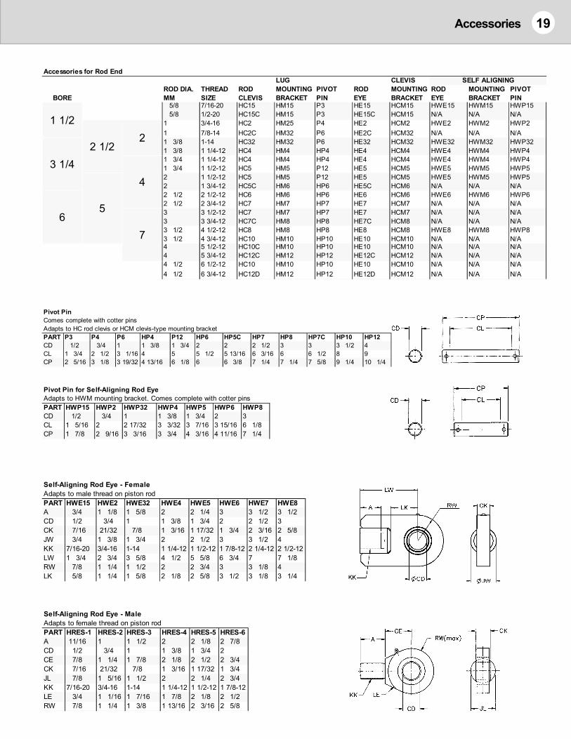
19Accessories
LUG CLEVIS SELF ALIGNINGROD DIA. THREAD ROD MOUNTING PIVOT ROD MOUNTING ROD MOUNTING PIVOT
BORE MM SIZE CLEVIS BRACKET PIN EYE BRACKET EYE BRACKET PIN5/8 7/16-20 HC15 HM15 P3 HE15 HCM15 HWE15 HWM15 HWP155/8 1/2-20 HC15C HM15 P3 HE15C HCM15 N/A N/A N/A
1 3/4-16 HC2 HM25 P4 HE2 HCM2 HWE2 HWM2 HWP21 7/8-14 HC2C HM32 P6 HE2C HCM32 N/A N/A N/A1 3/8 1-14 HC32 HM32 P6 HE32 HCM32 HWE32 HWM32 HWP321 3/8 1 1/4-12 HC4 HM4 HP4 HE4 HCM4 HWE4 HWM4 HWP41 3/4 1 1/4-12 HC4 HM4 HP4 HE4 HCM4 HWE4 HWM4 HWP41 3/4 1 1/2-12 HC5 HM5 P12 HE5 HCM5 HWE5 HWM5 HWP52 1 1/2-12 HC5 HM5 P12 HE5 HCM5 HWE5 HWM5 HWP52 1 3/4-12 HC5C HM6 HP6 HE5C HCM6 N/A N/A N/A2 1/2 2 1/2-12 HC6 HM6 HP6 HE6 HCM6 HWE6 HWM6 HWP62 1/2 2 3/4-12 HC7 HM7 HP7 HE7 HCM7 N/A N/A N/A3 3 1/2-12 HC7 HM7 HP7 HE7 HCM7 N/A N/A N/A3 3 3/4-12 HC7C HM8 HP8 HE7C HCM8 N/A N/A N/A3 1/2 4 1/2-12 HC8 HM8 HP8 HE8 HCM8 HWE8 HWM8 HWP83 1/2 4 3/4-12 HC10 HM10 HP10 HE10 HCM10 N/A N/A N/A4 5 1/2-12 HC10C HM10 HP10 HE10 HCM10 N/A N/A N/A4 5 3/4-12 HC12C HM12 HP12 HE12C HCM12 N/A N/A N/A4 1/2 6 1/2-12 HC10 HM10 HP10 HE10 HCM10 N/A N/A N/A4 1/2 6 3/4-12 HC12D HM12 HP12 HE12D HCM12 N/A N/A N/A
Accessories for Rod End
65
4
7
1 1/2
2 1/22
3 1/4
Pivot PinComes complete with cotter pinsAdapts to HC rod clevis or HCM clevis-type mounting bracketPART P3 P4 P6 HP4 P12 HP6 HP5C HP7 HP8 HP7C HP10 HP12CD 1/2 3/4 1 1 3/8 1 3/4 2 2 2 1/2 3 3 3 1/2 4CL 1 3/4 2 1/2 3 1/16 4 5 5 1/2 5 13/16 6 3/16 6 6 1/2 8 9CP 2 5/16 3 1/8 3 19/32 4 13/16 6 1/8 6 6 3/8 7 1/4 7 1/4 7 5/8 9 1/4 10 1/4
Pivot Pin for Self-Aligning Rod EyeAdapts to HWM mounting bracket. Comes complete with cotter pinsPART HWP15 HWP2 HWP32 HWP4 HWP5 HWP6 HWP8CD 1/2 3/4 1 1 3/8 1 3/4 2 3CL 1 5/16 2 2 17/32 3 3/32 3 7/16 3 15/16 6 1/8CP 1 7/8 2 9/16 3 3/16 3 3/4 4 3/16 4 11/16 7 1/4
Self-Aligning Rod Eye - FemaleAdapts to male thread on piston rodPART HWE15 HWE2 HWE32 HWE4 HWE5 HWE6 HWE7 HWE8A 3/4 1 1/8 1 5/8 2 2 1/4 3 3 1/2 3 1/2CD 1/2 3/4 1 1 3/8 1 3/4 2 2 1/2 3CK 7/16 21/32 7/8 1 3/16 1 17/32 1 3/4 2 3/16 2 5/8JW 3/4 1 3/8 1 3/4 2 2 1/2 3 3 1/2 4KK 7/16-20 3/4-16 1-14 1 1/4-12 1 1/2-12 1 7/8-12 2 1/4-12 2 1/2-12LW 1 3/4 2 3/4 3 5/8 4 1/2 5 5/8 6 3/4 7 7 1/8RW 7/8 1 1/4 1 1/2 2 2 3/4 3 3 1/8 4LK 5/8 1 1/4 1 5/8 2 1/8 2 5/8 3 1/2 3 1/8 3 1/4
Self-Aligning Rod Eye - MaleAdapts to female thread on piston rodPART HRES-1 HRES-2 HRES-3 HRES-4 HRES-5 HRES-6A 11/16 1 1 1/2 2 2 1/8 2 7/8CD 1/2 3/4 1 1 3/8 1 3/4 2CE 7/8 1 1/4 1 7/8 2 1/8 2 1/2 2 3/4CK 7/16 21/32 7/8 1 3/16 1 17/32 1 3/4JL 7/8 1 5/16 1 1/2 2 2 1/4 2 3/4KK 7/16-20 3/4-16 1-14 1 1/4-12 1 1/2-12 1 7/8-12LE 3/4 1 1/16 1 7/16 1 7/8 2 1/8 2 1/2RW 7/8 1 1/4 1 3/8 1 13/16 2 3/16 2 5/8

Parts List 1.5 - 4” dia.20
NO
TES:
A pa
rt no
. hav
ing
an u
nder
scor
e in
dica
tes
a m
odel
lette
r cod
e is
requ
ired.
See
tabl
es b
elow
.Pa
rt nu
mbe
rs te
rmin
atin
g in
a d
ash
mus
t hav
e th
e st
roke
valu
e ad
ded
imm
edia
tely
afte
rwar
d.
* Blin
d en
d cu
shio
n on
1-1
/2" b
ore
cylin
der i
s a
cush
ion
nut-s
pear
. Par
t #3H
152B
(Rod
#1)
, 3H
150B
(Rod
#2)
(Se
lf re
gula
ting
- no
need
le v
alve
)**
2",
2 1/
2" a
nd 3
1/4
" Bor
es C
ushi
oned
Rod
end
requ
ire (1
) std
bar
rel s
eal a
nd (1
) oth
er s
eal s
ee it
em #
21.
UN
IVER
SAL
SEAL
KIT
: Sea
l kit
cont
ains
all l
egac
y se
als
for o
bsol
ete
desi
gns
The
follo
win
g m
odel
s ha
ve u
niqu
e co
mpo
nent
s - c
onta
ct fa
ctor
y fo
r par
ts li
st:
4” a
nd 5
” bor
e H
S (S
ide-
tapp
ed) m
odel
.Al
l bor
es H
TR (R
od E
nd T
runn
ion)
mod
el.
2”, 2
1/2
” and
3 1
/4” b
ores
that
use
the
larg
est r
od s
ize
and
are
cush
ione
d on
the
glan
d en
d.
HEA
D P
AR
T N
UM
BER
STR
UC
TUR
E:1)
Use
“H” f
or S
erie
s - H
2)U
se ta
ble
(to ri
ght)
to s
elec
t hea
d m
ount
ing
styl
e.3)
BOR
E eg
3-1
/4" b
ore
use
32, 4
" bor
e us
e 4.
4)LO
CAT
ION
; B=B
lind
G=G
land
or R
od e
nd.
5)R
od S
ize
(Gla
nd e
nd o
nly)
1" =
10,
1-3
/4 =
17
etc.
6)C
US
HIO
NE
D =
“C”,
NO
NC
US
HIO
NE
D =
BLA
NK
7)PO
RT
SIZE
, SAE
-08
= SP
08, S
AE-1
2 =
SP12
SAE-
12 C
ode
61 =
SF1
2 et
c.eg
. Cyl
. Mod
el “H
RS”
, 3-1
/4" B
ore,
Cus
hion
edG
land
end
hea
d “H
C32
G13
CSP
12”
Bl
ind
end
head
“H
R32
BCSP
12”
SEE
PAG
E FO
LLO
WIN
G P
AR
TS D
RAW
ING
FO
R 5
”B
OR
E TH
RO
UG
H 8
” B
OR
E PA
RTS
AN
D T
IE-R
OD
PAR
T N
UM
BER
STR
UC
TUR
E.
DESC
RIPT
ION
QTY
1 1/
22
2 1/
23
1/4
4RO
D SI
ZE5/
81
11
3/8
11
3/8
1 3/
41
3/8
1 3/
42
1 3/
42
2 1/
21
PIST
ON
11H
2015
H1H
2215
H1H
202H
1H20
25H
1H20
321H
204H
3*C
USHI
ON
SLEE
VE
13H
152
3H20
23H
202
3H20
03H
252
3H25
033H
250
3H32
23H
323
3H32
03H
402
3H40
23H
400
4RO
D - M
ALE
14H
1325
-4H
134-
4H23
4-4H
2355
-4H
284-
4H28
55-
4H28
7-4H
3355
-4H
337-
4H33
8-4H
437-
4H43
8-4H
4310
-4
ROD
- FEM
ALE
"HD
" M
ODE
L1
26H1
325-
26H1
34-
26H2
34-
26H2
355-
26H2
84-
26H2
855-
26H2
87-
26H3
355-
26H3
37-
26H3
38-
26H4
37-
26H4
38-
26H4
310-
4RO
D C
OM
MO
N1
44H1
325-
44H1
34-
44H2
34-
44H2
355-
44H2
84-
44H2
855-
44H2
87-
44H3
355-
44H3
37-
44H3
38-
44H4
37-
44H4
38-
44H4
310-
4RO
D (C
USHI
ONE
D C
BE)
14H
1125
-4H
114-
4H20
4-4H
2055
-4H
254-
4H25
55-
4H25
7-4H
3055
-4H
307-
4H30
8-4H
407-
4H40
8-4H
4010
-5
BARR
EL (M
-HO
NED
STEE
L)1
5H01
5-5H
020-
5H02
5-5H
032-
5H04
0-5
BARR
EL H
T2 T
RUN.
MO
UNT
15H
2T01
5-5H
2T02
0-5H
2T02
5-5H
2T03
2-5H
2T04
0-6
GLA
ND B
USHI
NG1
6H15
62H
6H15
10H
6H20
10H
6H32
13H
6H20
10H
6H32
13H
6H25
17H
6H32
13H
6H40
17H
6H50
20H
6H40
17H
6H50
20H
6H60
25H
7NE
EDLE
VA
LVE
2N/
AN/
A7H
832-
2A7H
832-
2A7H
850-
3A7H
850-
3A8
TIE
ROD
(EA
) (ST
AND
ARD
)4
8H_1
56-
8H_2
08-
8H_2
58-
8H_3
210-
8H_4
010-
9PI
STO
N SE
AL
INTE
RNA
L1
N/A
9A11
39A
210
9A11
79A
215
9A22
010
PIST
ON
CUP
210
H755
-15
10H2
0H10
H25H
10H3
2H10
H40H
12G
LAND
BUS
HING
SEA
L1
9H21
89H
222
9H22
49H
227
9H22
49H
227
9H23
09H
227
9H23
09H
232
9H23
09H
232
9H23
613
ROD
SEA
L1
13H6
2H13
H10H
13H1
0H13
H13H
13H1
0H13
H13H
13H1
7H13
H13H
13H1
7H13
H20H
13H1
7H13
H20H
13H2
5H14
ROD
WIP
ER1
14H6
214
H10
14H1
014
H13
14H1
014
H13
14H1
714
H13
14H1
714
H20
14H1
714
H20
14H2
516
NEED
LE V
ALV
E SE
AL
2N/
AN/
A9A
013
9A01
39A
017
9A01
717
LOC
K NU
T - T
IE R
OD
4,8
19A
006
19A
008
19A
008
19A
010
19A
010
19LO
CK
NUT
- PIS
TON
119
A00
719
H008
19A
010
19A
012
19A
016
19H0
2021
BARR
EL S
EAL
29H
218
9H22
49H
228
**9H
228
9H23
2 **
9H23
49H
239
**9H
240
22HE
AD
BLIN
D EN
D (S
EE B
ELO
W)
1H_
15B
H_2B
H_25
BH_
32B
H_4B
23HE
AD
GLA
ND E
ND (S
EE B
ELO
W)
1H_
15G
62SP
08H_
15G
10SP
08H_
2G10
SP08
H_2G
13SP
08H_
25G
10SP
08H_
25G
13SP
08H_
25G
17SP
08H_
32G
13SP
12H_
32G
17SP
12H_
32G
20SP
12H_
4G17
SP12
H_4G
20SP
12H_
4G25
SP12
24TR
UNNI
ON
1HT
1.5
HT2
HT2.
5HT
3.25
HT4
24TR
UNNI
ON
(H2T
)1
H2T1
.5H2
T2H2
T2.5
H2T3
.25
H2T4
33C
HEC
K BA
LL2
N/A
N/A
33H1
833
H18
33A
3233
A32
35C
HEC
K PL
UG2
N/A
N/A
35H3
20-1
35H3
20-1
35H5
00-1
35H5
00-1
36C
HEC
K V
ALV
E SE
AL
2N/
AN/
A9A
013
9A01
39A
017
9A01
737
NEED
LE V
ALV
E HO
USIN
G2
N/A
N/A
7H83
2-2B
7H83
2-2B
7H85
0-3B
7H85
0-3B
37A
NEED
LE V
ALV
E HO
USIN
G S
EAL
2N/
AN/
A9A
008
9A00
89A
007
9A00
738
FRO
NT P
LATE
1FP
1562
FP15
10FP
2010
FP20
13FP
2510
FP25
13FP
2517
FP32
13FP
3217
FP32
20FP
4017
FP40
20FP
4025
40PI
STO
N W
EAR
STRI
P1
40H1
525
40H2
037
40H2
537
40H3
2340
H405
41SE
AL
KIT
1KH
1562
HKH
1510
HKH
2010
HKH
2013
HKH
2510
HKH
2513
HKH
2517
HKH
3213
HKH
3217
HKH
3220
HKH
4017
HKH
4020
HKH
4025
H42
SEA
L KI
T UN
IVER
SAL
1KH
1562
UKH
1510
UKH
2010
UKH
2013
UKH
2510
UKH
2513
UKH
2517
UKH
3213
UKH
3217
UKH
3220
UKH
4017
UKH
4020
UKH
4025
U
BORE
H-SE
RIES
PA
RTS
LIST
- 1
1/2"
BO
RE T
O 4
" BO
RE
MO
UNTI
NGG
LAND
BLIN
DBO
REC
ODE
ROD
DIA
.C
ODE
STYL
EHE
AD
HEA
D1
1/2
155/
862
BC
R2
21
10
BSC
R2
1/2
251
3/8
13
CC
C3
1/4
321
3/4
17
DC
n/a
44
220
EC
E5
52
1/2
25
FF
F6
63
30
GG
R7
73
1/2
35
HC
H8
84
40
MP
CR
4 1/
245
NAC
R
NBC
R
NCC
R
NMC
R
RC
R
RSC
R
SST
ST
TC
R
TBC
T
TRT
R
WC
W

21Parts Drawing
H-S
erie
s Pa
rts
Dra
win
g
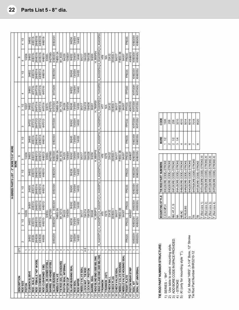
Parts List 5 - 8” dia.22
TIE
RO
D P
AR
T N
UM
BER
STR
UC
TUR
E:
1)SE
RIE
S -
“8H
”2)
Use
tabl
e to
sel
ect
mou
ntin
g st
yle.
3)AD
D B
OR
E C
OD
E IN
SPA
CE
PRO
VID
ED.
4)- S
TRO
KE5)
-XI (
only
for m
ount
ing
styl
e ‘T
’).
eg. C
yl. M
odel
“HR
S”,
3-1/
4" B
ore,
12"
Stro
keTi
e R
od P
art N
umbe
r 8H
R32
10-1
2
MO
UNTI
NG S
TYLE
TIE
ROD
PART
NUM
BERS
BORE
CO
DEC,
E,W
,MP,
H8H
C(BO
RE C
ODE
)-ST
ROKE
1 1/
215
06D
8HD(
BORE
CO
DE)-
STRO
KE2
208
NM, H
T, F
, S8H
F(BO
RE C
ODE
)-ST
ROKE
2 1/
225
8NA
8HA
(BO
RE C
ODE
)-ST
ROKE
3 1/
432
10NB
,NC
8HB(
BORE
CO
DE)-
STRO
KE4
4010
R,RS
,B,B
S8H
R(BO
RE C
ODE
)-ST
ROKE
550
14G
8HG
(BO
RE C
ODE
)-ST
ROKE
660
16TR
8HTR
(BO
RE C
ODE
)-ST
ROKE
770
18TB
8HT(
BORE
CO
DE)-
STRO
KE8
8020
T (R
od s
ize
1)8H
TA(B
ORE
CO
DE)-
STRO
KE-X
IT
(Rod
siz
e 2)
8HTB
(BO
RE C
ODE
)-ST
ROKE
-XI
T (R
od s
ize
3)8H
TC(B
ORE
CO
DE)-
STRO
KE-X
IT
(Rod
siz
e 4)
8HTD
(BO
RE C
ODE
)-ST
ROKE
-XI
H-SE
RIES
PA
RTS
LIST
- 5"
BO
RE T
O 8
" BO
RE
DESC
RIPT
ION
QTY
5RO
D SI
ZE2
2 1/
23
3 1/
22
1/2
33
1/2
33
1/2
41
PIST
ON
11H
205
1H20
61H
207
3C
USHI
ON
SLEE
VE
13H
502
3H50
33H
501
3H50
03H
602
3H60
33H
600
3H70
23H
802
3H80
34
ROD
- MA
LE1
4H53
8-4H
5310
-4H
5312
-4H
5314
-4H
6310
-4H
6312
-4H
6314
-4H
7312
-4H
7314
-4H
7316
-4
ROD
- FEM
ALE
"HD
" M
ODE
L1
26H5
38-
26H5
310-
26H5
312-
26H5
314-
26H6
310-
26H6
312-
26H6
314-
26H7
312-
26H7
314-
26H7
316-
4RO
D C
OM
MO
N1
44H5
38-
44H5
310-
44H5
312-
44H5
314-
44H6
310-
44H6
312-
44H6
314-
44H7
312-
44H7
314-
44H7
316-
4RO
D (C
USHI
ONE
D C
BE)
14H
508-
4H50
10-
4H50
12-
4H50
14-
4H60
10-
4H60
12-
4H60
14-
4H70
12-
4H70
14-
4H70
16-
5BA
RREL
(M-H
ONE
D ST
EEL)
15H
050-
5H06
0-5H
070-
6BA
RREL
(M-H
ONE
D ST
EEL)
25H
2T05
0-5H
2T06
0-5H
2T07
0-6
GLA
ND B
USHI
NG1
6H50
20H
6H60
25H
6H50
30H
6H50
35H
6H60
25H
6H60
30H
6H50
35H
6H70
30H
6H70
35H
6H70
40H
7NE
EDLE
VA
LVE
27H
850-
3A7H
850-
3A7H
850-
3A8
TIE
ROD
(EA
) (ST
AND
ARD
)4
8H_5
014-
8H_6
016-
8H_7
018-
9PI
STO
N SE
AL
INTE
RNA
L1
9A22
39A
225
9A22
910
PIST
ON
CUP
210
H50H
10H6
0H10
H70H
12G
LAND
BUS
HING
SEA
L1
9H23
29H
236
9H24
29H
245
9H23
69H
242
9H24
59H
242
9H24
69H
252
13RO
D SE
AL
113
H20H
13H2
5H13
H30H
13H3
5H13
H25H
13H3
0H13
H35H
13H3
0H13
H35H
13H4
0H14
ROD
WIP
ER1
14H2
014
H25
14H3
014
H35
14H2
514
H30
14H3
514
H30
14H3
514
H40
16NE
EDLE
VA
LVE
SEA
L2
9A01
79A
017
9A01
717
LOC
K NU
T - T
IE R
OD
4,8
19A
014
19A
016
19A
018
19LO
CK
NUT
- PIS
TON
119
A02
419
A02
819
H036
21BA
RREL
SEA
L2
9H24
89H
256
9H26
122
HEA
D BL
IND
END
(SEE
BEL
OW
)1
H_5B
SP12
H_6B
SP16
H_7B
SP20
23HE
AD
GLA
ND E
ND (S
EE B
ELO
W)
1H_
5G20
SP12
H_5G
25SP
12H_
5G30
SP12
H_5G
35SP
12H_
6G25
SP16
H_6G
30SP
16H_
6G35
SP16
H_7G
25SP
20H_
7G30
SP20
H_7G
35SP
2024
TRUN
NIO
N1
HT5
HT6
HT7
24TR
UNNI
ON
(H2T
)1
H2T5
H2T6
N/A
33C
HEC
K BA
LL2
33A
3233
A32
33A
3235
CHE
CK
PLUG
235
H500
-135
H500
-135
H500
-136
CHE
CK
VA
LVE
SEA
L2
9A01
79A
017
9A01
737
NEED
LE V
ALV
E HO
USIN
G2
7H85
0-3B
7H85
0-3B
7H85
0-3B
37A
NEED
LE V
ALV
E HO
USIN
G S
EAL
29A
007
9A00
79A
007
38FR
ONT
PLA
TE1
FP50
20FP
5025
FP50
30FP
5035
FP60
25FP
6030
FP60
35FP
7030
FP70
35FP
7040
40PI
STO
N W
EAR
STRI
P1
40H5
0740
H607
40H7
010
41SE
AL
KIT
1KH
5020
HKH
5025
HKH
5030
HKH
5035
HKH
6025
HKH
6030
HKH
6035
HKH
7030
HKH
7035
HKH
7040
H42
SEA
L KI
T UN
IVER
SAL
1KH
5020
UKH
5025
UKH
5030
UKH
5035
UKH
6025
UKH
6030
UKH
6035
UKH
7030
UKH
7035
UKH
7040
U
67
BORE
83
1/2
44
1/2
1H20
83H
802
3H80
33H
800
4H83
14-
4H83
16-
4H83
18-
26H8
314-
26H8
316-
26H8
318-
44H8
314-
44H8
316-
44H8
318-
4H80
14-
4H80
16-
4H80
18-
5H08
0-5H
2T08
0-6H
8035
H6H
8040
H6H
8045
H7H
850-
3A8H
_802
0-9A
229
10H8
0H9H
248
9H25
29H
256
13H3
5H13
H40H
13H4
5H14
H35
14H4
014
H45
9A01
719
A02
019
A03
69H
265
H_8B
SP24
H_8G
35SP
24H_
8G40
SP24
H_8G
45SP
24HT
8N/
A33
A32
35H5
00-1
9A01
77H
850-
3B9A
007
FP80
35FP
8040
FP80
4540
H801
0KH
8035
HKH
8040
HKH
8045
HKH
8035
UKH
8040
UKH
8045
U
23Cylinder Technical Data
WarningThese products are intended for industrial use only. Do not use these products in applicationswhere the pressure and temperature exceeds the values listed below.
Through misuse, age or malfunction, components used in fluid power systems can fail. Adesigner utilizing these products must consider all modes of failure when designing machinesand provide safeguards or warn the end user of possible modes of failure.
Cylinder Pressure and Temperature RatingsH-Series cylinders are rated to 3000 psig hydraulic pressure for normal use, and 5000 psi fornon-shock applications. Some mounting styles are downrated, see model pages for operatingpressures.Temperature ratings for cylinders are limited to the maximum published temperature range ofthe least resistant seal component. In most cases that would be the standard Buna-N O-ringseals. Buna-N temperature ratings: -30°F to 200°F (-34°C to 93°C). For higher temperaturesspecify a “V” in the Options box of the Cylinder Nomenclature.
Published Design DataWestcoast Cylinders Inc. reserves the right to change specifications and other informationincluded in this catalogue without notice. All information, data and dimension tables in thiscatalogue have been carefully compiled and thoroughly checked. However, no responsibility forpossible errors or omissions can be assumed.
WarrantyWestcoast Cylinders Inc. warrants the material and workmanship of our cylinders for one fullyear when used under normal conditions, subject to factory inspection. WCI will repair orreplace, at no cost, defective parts or cylinders. WCI will not assume expenses incurred in thefield, pertaining to such repairs or replacements, except upon written authority. For a completestatement of terms and warranty contact Westcoast Cylinders Inc.
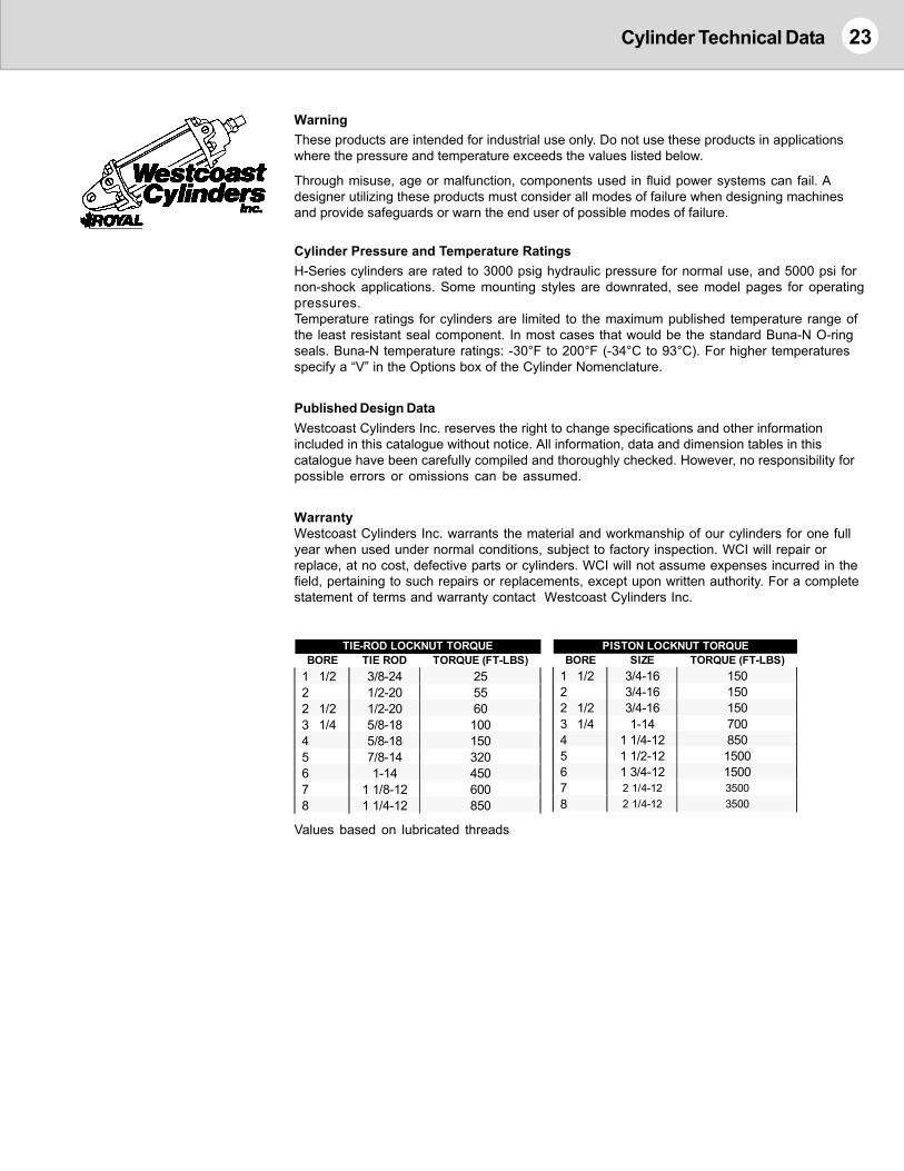
BORE TIE ROD TORQUE (FT-LBS)1 1/2 3/8-24 252 1/2-20 552 1/2 1/2-20 603 1/4 5/8-18 1004 5/8-18 1505 7/8-14 3206 1-14 4507 1 1/8-12 6008 1 1/4-12 850
TIE-ROD LOCKNUT TORQUE
Values based on lubricated threads
BORE SIZE TORQUE (FT-LBS)1 1/2 3/4-16 1502 3/4-16 1502 1/2 3/4-16 1503 1/4 1-14 7004 1 1/4-12 8505 1 1/2-12 15006 1 3/4-12 15007 2 1/4-12 35008 2 1/4-12 3500
PISTON LOCKNUT TORQUE
24 Cylinder Technical Data
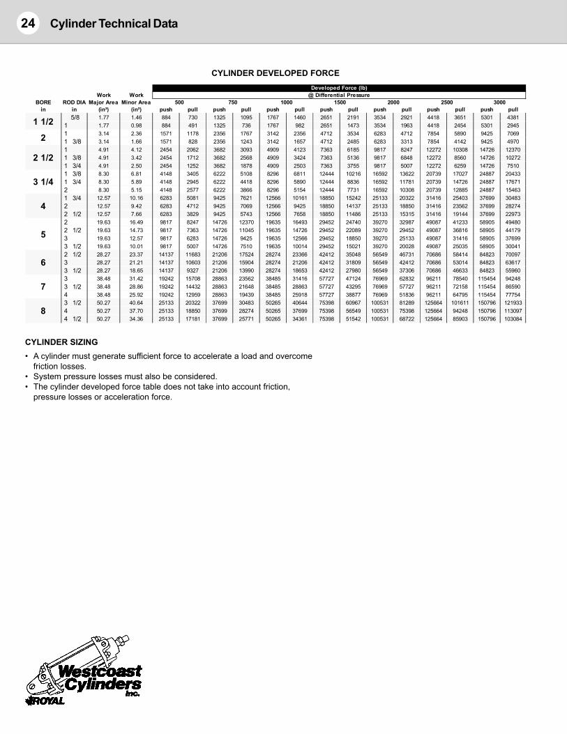
CYLINDER DEVELOPED FORCE
CYLINDER SIZING• A cylinder must generate sufficient force to accelerate a load and overcome
friction losses.• System pressure losses must also be considered.• The cylinder developed force table does not take into account friction,
pressure losses or acceleration force.
Work WorkBORE ROD DIA Major Area Minor Area
in in (in²) (in²) push pull push pull push pull push pull push pull push pull push pull5/8 1.77 1.46 884 730 1325 1095 1767 1460 2651 2191 3534 2921 4418 3651 5301 4381
1 1.77 0.98 884 491 1325 736 1767 982 2651 1473 3534 1963 4418 2454 5301 29451 3.14 2.36 1571 1178 2356 1767 3142 2356 4712 3534 6283 4712 7854 5890 9425 70691 3/8 3.14 1.66 1571 828 2356 1243 3142 1657 4712 2485 6283 3313 7854 4142 9425 49701 4.91 4.12 2454 2062 3682 3093 4909 4123 7363 6185 9817 8247 12272 10308 14726 123701 3/8 4.91 3.42 2454 1712 3682 2568 4909 3424 7363 5136 9817 6848 12272 8560 14726 102721 3/4 4.91 2.50 2454 1252 3682 1878 4909 2503 7363 3755 9817 5007 12272 6259 14726 75101 3/8 8.30 6.81 4148 3405 6222 5108 8296 6811 12444 10216 16592 13622 20739 17027 24887 204331 3/4 8.30 5.89 4148 2945 6222 4418 8296 5890 12444 8836 16592 11781 20739 14726 24887 176712 8.30 5.15 4148 2577 6222 3866 8296 5154 12444 7731 16592 10308 20739 12885 24887 154631 3/4 12.57 10.16 6283 5081 9425 7621 12566 10161 18850 15242 25133 20322 31416 25403 37699 304832 12.57 9.42 6283 4712 9425 7069 12566 9425 18850 14137 25133 18850 31416 23562 37699 282742 1/2 12.57 7.66 6283 3829 9425 5743 12566 7658 18850 11486 25133 15315 31416 19144 37699 229732 19.63 16.49 9817 8247 14726 12370 19635 16493 29452 24740 39270 32987 49087 41233 58905 494802 1/2 19.63 14.73 9817 7363 14726 11045 19635 14726 29452 22089 39270 29452 49087 36816 58905 441793 19.63 12.57 9817 6283 14726 9425 19635 12566 29452 18850 39270 25133 49087 31416 58905 376993 1/2 19.63 10.01 9817 5007 14726 7510 19635 10014 29452 15021 39270 20028 49087 25035 58905 300412 1/2 28.27 23.37 14137 11683 21206 17524 28274 23366 42412 35048 56549 46731 70686 58414 84823 700973 28.27 21.21 14137 10603 21206 15904 28274 21206 42412 31809 56549 42412 70686 53014 84823 636173 1/2 28.27 18.65 14137 9327 21206 13990 28274 18653 42412 27980 56549 37306 70686 46633 84823 559603 38.48 31.42 19242 15708 28863 23562 38485 31416 57727 47124 76969 62832 96211 78540 115454 942483 1/2 38.48 28.86 19242 14432 28863 21648 38485 28863 57727 43295 76969 57727 96211 72158 115454 865904 38.48 25.92 19242 12959 28863 19439 38485 25918 57727 38877 76969 51836 96211 64795 115454 777543 1/2 50.27 40.64 25133 20322 37699 30483 50265 40644 75398 60967 100531 81289 125664 101611 150796 1219334 50.27 37.70 25133 18850 37699 28274 50265 37699 75398 56549 100531 75398 125664 94248 150796 1130974 1/2 50.27 34.36 25133 17181 37699 25771 50265 34361 75398 51542 100531 68722 125664 85903 150796 103084
2500 3000
Developed Force (lb)@ Differential Pressure
5
6
7
8
4
2000500 750 1000 1500
1 1/2
2
2 1/2
3 1/4
Pinned &rigidlyguided
Pinned &rigidlyguided
Supported Pinned &rigidlyguided
Pinned &rigidlyguided
Pinned &rigidlyguided
Pinned &rigidlyguided
Pinned &rigidlyguided
Fixed &rigidlyguided
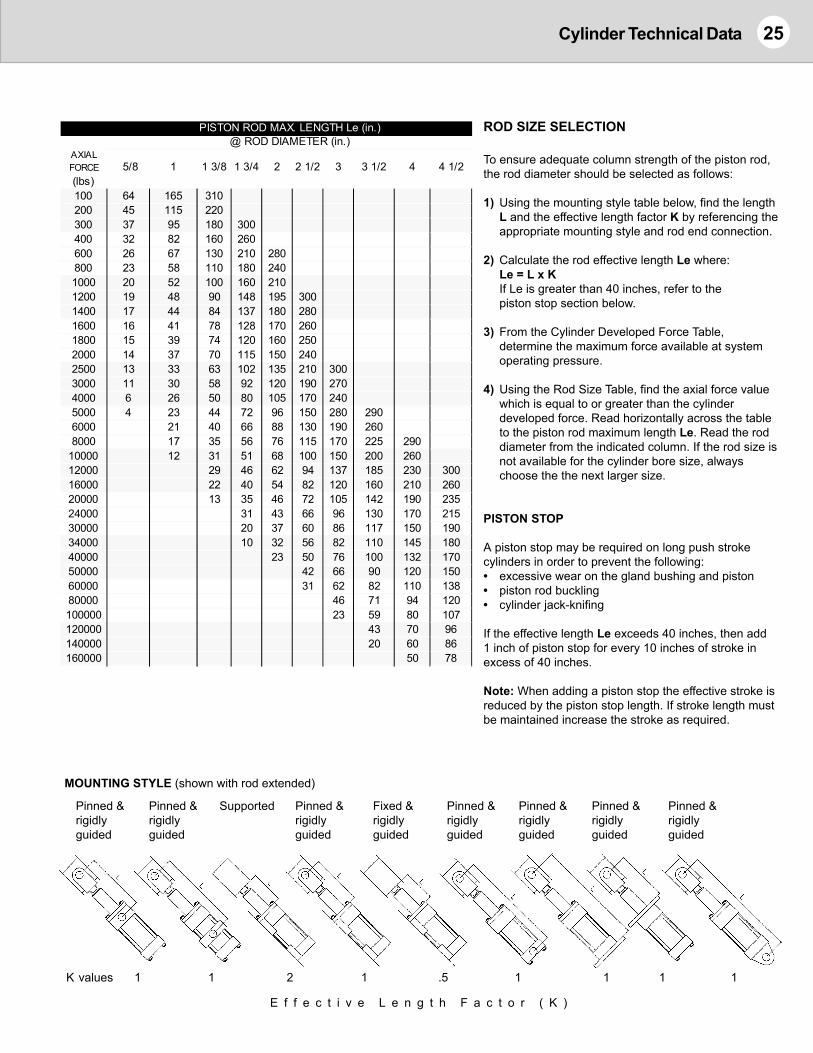
E f f e c t i v e L e n g t h F a c t o r ( K )
1 1 2 1 .5 1 1 1 1
25Cylinder Technical Data
ROD SIZE SELECTION
To ensure adequate column strength of the piston rod,the rod diameter should be selected as follows:
1) Using the mounting style table below, find the lengthL and the effective length factor K by referencing theappropriate mounting style and rod end connection.
2) Calculate the rod effective length Le where:Le = L x KIf Le is greater than 40 inches, refer to thepiston stop section below.
3) From the Cylinder Developed Force Table,determine the maximum force available at systemoperating pressure.
4) Using the Rod Size Table, find the axial force valuewhich is equal to or greater than the cylinderdeveloped force. Read horizontally across the tableto the piston rod maximum length Le. Read the roddiameter from the indicated column. If the rod size isnot available for the cylinder bore size, alwayschoose the the next larger size.
PISTON STOP
A piston stop may be required on long push strokecylinders in order to prevent the following:• excessive wear on the gland bushing and piston• piston rod buckling• cylinder jack-knifing
If the effective length Le exceeds 40 inches, then add1 inch of piston stop for every 10 inches of stroke inexcess of 40 inches.
Note: When adding a piston stop the effective stroke isreduced by the piston stop length. If stroke length mustbe maintained increase the stroke as required.
MOUNTING STYLE (shown with rod extended)
AXIAL FORCE 5/8 1 1 3/8 1 3/4 2 2 1/2 3 3 1/2 4 4 1/2(lbs)100 64 165 310200 45 115 220300 37 95 180 300400 32 82 160 260600 26 67 130 210 280800 23 58 110 180 2401000 20 52 100 160 2101200 19 48 90 148 195 3001400 17 44 84 137 180 2801600 16 41 78 128 170 2601800 15 39 74 120 160 2502000 14 37 70 115 150 2402500 13 33 63 102 135 210 3003000 11 30 58 92 120 190 2704000 6 26 50 80 105 170 2405000 4 23 44 72 96 150 280 2906000 21 40 66 88 130 190 2608000 17 35 56 76 115 170 225 290
10000 12 31 51 68 100 150 200 26012000 29 46 62 94 137 185 230 30016000 22 40 54 82 120 160 210 26020000 13 35 46 72 105 142 190 23524000 31 43 66 96 130 170 21530000 20 37 60 86 117 150 19034000 10 32 56 82 110 145 18040000 23 50 76 100 132 17050000 42 66 90 120 15060000 31 62 82 110 13880000 46 71 94 120100000 23 59 80 107120000 43 70 96140000 20 60 86160000 50 78
PISTON ROD MAX. LENGTH Le (in.)@ ROD DIAMETER (in.)
K values
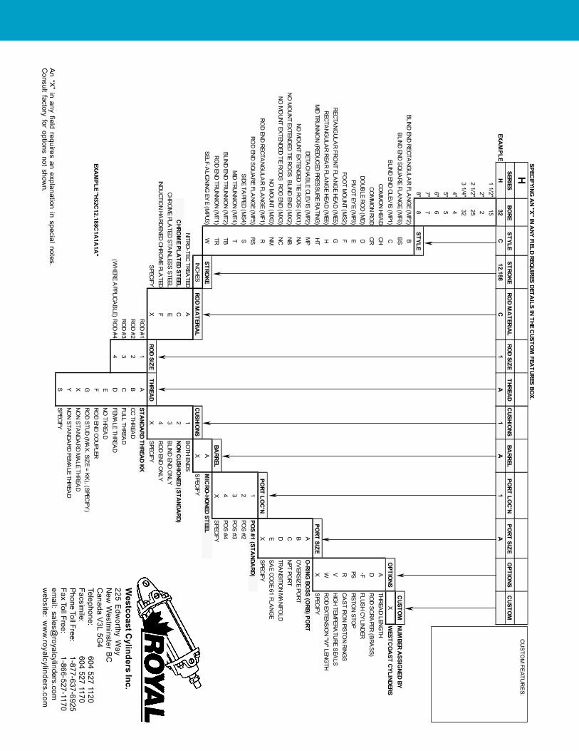
CU
STOM
FEATUR
ES:
An “X
” in any field requires an explanation in special notes.C
onsult factory for options not shown.
Westcoast C
ylinders Inc.225 E
dworthy W
ayN
ew W
estminster B
CC
anada V3L 5G
4Telephone:
604 527 1120Facsim
ile:604 527 1170
Phone Toll Free:
1-877-637-6925Fax Toll Free:
1-866-527-1170em
ail: [email protected]
website: w
ww
.royalcylinders.com
SPECIFYING
AN "X" IN A
NY FIELD REQUIRES DETA
ILS IN THE CUSTO
M FEA
TURES BOX.
HSERIESBO
RESTYLE
STROKE
ROD M
ATERIA
LRO
D SIZETHREA
DEXA
MPLE
H32
C12.188
C1
A 1 1/2"
152"
22 1/2"
253 1/4"
324"
45"
56"
67"
78"
8STYLE
BLIND END RECTANG
ULAR FLA
NGE (M
F2)B
BLIND END SQUA
RE FLANG
E (MF6)
BSBLIND END CLEV
IS (MP1)
CCO
MM
ON HEA
DCH
COM
MO
N ROD
CRDO
UBLE ROD (M
D)D
PIVO
T EYE (M
P3)E
FOO
T MO
UNT (MS2)
FRECTA
NGULA
R FRONT FLA
NGE HEA
D (ME5)
GRECTA
NGULA
R REAR FLA
NGE HEA
D (ME6)
HM
ID TRUNNION (REDUCED PRESSURE RA
TING)
HTDETA
CHABLE CLEV
IS (MP2)
MP
NO M
OUNT EXTENDED TIE RO
DS (MX1)
NANO
MO
UNT EXTENDED TIE RODS BLIND END (M
X2)NB
NO M
OUNT EXTENDED TIE RO
DS ROD END (M
X3)NC
NO M
OUNT (M
X0)NM
ROD END RECTA
NGULA
R FLANG
E (MF1)
RRO
D END SQUA
RE FLANG
E (MF5)
RSSIDE TA
PPED (MS4)
SM
ID TRUNNION (M
T4)T
BLIND END TRUNNION (M
T2)TB
ROD END TRUNNIO
N (MT1)
TRSELF-A
LIGNING
EYE (M
PU3)W
STROKE
INCHESRO
D MA
TERIAL
NITRO-TEC TREA
TEDA
CHRO
ME PLA
TED STEELC
CHROM
E PLATED STA
INLESS STEELE
INDUCTION HA
RDENED CHROM
E PLATED
FSPECIFY
XRO
D SIZETHREA
DRO
D #11
ARO
D #22
BRO
D #33
C(W
HERE APPLICA
BLE) ROD #4
4DE
EXAM
PLE "H32C12.188C
1A1A
1A"
FGXYS
CUSHIO
NSBA
RRELPO
RT LOC
'NPO
RT SIZEO
PTIONS
CUSTO
M1
A1
A
CUSTO
MNUM
BER ASSIG
NED BYO
PTIONS
XW
ESTCO
AST C
YLINDERSA
THREAD LENG
THD
ROD SCRA
PER (BRASS)
-FFLUSH CY
LINDERPS
PISTON STO
PR
CAST IRO
N PISTON RING
SV
HIGH TEM
PERATURE SEA
LSW
ROD EXTENSIO
N "W" LENG
THPO
RT SIZEX
SPECIFYA
O-RING
BOSS (O
RB) PORT
BO
VERSIZE PO
RTC
NPT PORT
DTRA
NSITION M
ANIFO
LDE
SAE CO
DE 61 FLANG
EPO
RT LOC
'NX
SPECIFY1
POS #1 (STA
NDARD)
2PO
S #23
POS #3
4PO
S #4BA
RRELX
SPECIFYA
MIC
RO-HO
NED STEELC
USHIONS
XSPECIFY
1BO
TH ENDS2
NON C
USHIONED (STA
NDARD)
3BLIND END O
NLY4
ROD END O
NLYX
SPECIFYSTA
NDARD THREA
D KKCC THREA
DFULL THREA
DFEM
ALE THREA
DNO
THREAD
ROD END CO
UPLERRO
D STUD (MA
X. SIZE = KK), (SPECIFY)
NON STA
NDARD M
ALE THREA
DNO
N STANDA
RD FEMA
LE THREAD
SPECIFY