PSC SQUARE BoDy 690/700 Volt SEMICoNDUCToR … · A.C. Rated Volts Rated Volts (070=700V)...
13
D Part Number Designation: 6,9 URD: European/IEC Mounting Style/Approval Tested @ 1.1 V n AO7O URD: North American Mounting Style/Approval Tested @ V n *V n = rated voltage Ferraz Shawmut 690/700V PSC fuse-links provide maximum flexibility in equipment design and ultimate protection for today’s power conversion equipment. These square body fuse-links are available in four different body sizes, each size having seven worldwide acceptable mounting styles. The different mounting styles and body sizes along with a broad range of ampere ratings allow greatest flexibility in equipment design. The Ferraz Shawmut PSC fuses have been engineered to provide state-of-the-art protection for SCR’s, diodes, thyristors, GTO’s and IGBT devices. They have pure silver, die-cut elements embedded in solidified sand, which helps control arcing characteristics for low I 2 t and high interrupting rating. All contact surfaces are silver plated and all hardware is non-magnetic. All fuse links are equipped with a low voltage trip-indicator. This trip-indicator can operate a field mountable microswitch which is easily mounted directly onto the fuse even while in service. Features / Benefits Choice of mounting styles gives wide choice for equipment design Broad range of ampere ratings in a given body size for design flexibility IEC 269-4 compliance for worldwide semiconductor applications * For Microswitch information see page J8 ➤ ➤ ➤ HIGHLIGHTS: Extremely Fast Acting Current Limiting Very Low I 2 t Worldwide Acceptability Superior Cycling Ability ➤ ➤ ➤ ➤ APPLICATIONS: Protection of rectifiers, inverters, DC drives, UPS Systems, reduced voltage motor starters, and other equipment in globally accepted applications ➤ ➤ PSC SQUARE BODY 690/700 Volt SEMICONDUCTOR PROTECTION FUSES AC: 40-2500A 500-700 VAC 200 kA IR DC: Consult Factory ➤ ➤ Ratings UL Recognized Component File E76491 Sizes 30, 31 ,32, 33 tested to IEC 269.4 ➤ ➤ Approvals North American Reference Numbering System A 070 URD 31 I 350 A.C. Rated Volts (070=700V) Class 30 Size 31 32 33 Mounting Types Straight-blade, short KI Straight-blade, long LI Flat-type, one hole (American) TTI Indicator Amp Rating European Reference Numbering System 6,9 URD 31 I 350 Rated Volts (6,9=690V) Class 30 Size 31 32 33 Mounting Types DIN 80 DO8A DIN 110 D11A Flat-type, one hole (metric) TTF French Blade EF Indicator Amp Rating
Transcript of PSC SQUARE BoDy 690/700 Volt SEMICoNDUCToR … · A.C. Rated Volts Rated Volts (070=700V)...
D ��D ��
J
HG
F
47.61.93
CB
Part Number Designation:
6,9 URD: European/IEC Mounting Style/Approval Tested @ 1.1 VnAO7O URD: North American Mounting Style/Approval Tested @ Vn
*Vn = rated voltage
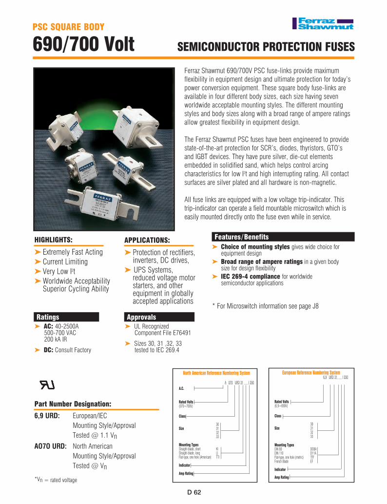
Ferraz Shawmut 690/700V PSC fuse-links provide maximum flexibility in equipment design and ultimate protection for today’s power conversion equipment. These square body fuse-links are available in four different body sizes, each size having seven worldwide acceptable mounting styles. The different mounting styles and body sizes along with a broad range of ampere ratings allow greatest flexibility in equipment design.
The Ferraz Shawmut PSC fuses have been engineered to provide state-of-the-art protection for SCR’s, diodes, thyristors, GTO’s and IGBT devices. They have pure silver, die-cut elements embedded in solidified sand, which helps control arcing characteristics for low I2t and high interrupting rating. All contact surfaces are silver plated and all hardware is non-magnetic.
All fuse links are equipped with a low voltage trip-indicator. This trip-indicator can operate a field mountable microswitch which is easily mounted directly onto the fuse even while in service.
Features/BenefitsChoice of mounting styles gives wide choice for equipment designBroad range of ampere ratings in a given body size for design flexibilityIEC 269-4 compliance for worldwide semiconductor applications
* For Microswitch information see page J8
➤
➤
➤
HIGHLIGHTS:
Extremely Fast Acting Current LimitingVery Low I2tWorldwide Acceptability Superior Cycling Ability
➤
➤
➤
➤
APPLICATIoNS:
Protection of rectifiers, inverters, DC drives, UPS Systems, reduced voltage motor starters, and other equipment in globally accepted applications
➤
➤
PSC SQUARE BoDy
690/700 Volt SEMICoNDUCToR PRoTECTIoN FUSES
AC: 40-2500A 500-700 VAC 200 kA IR
DC: Consult Factory
➤
➤
RatingsUL Recognized Component File E76491
Sizes 30, 31 ,32, 33 tested to IEC 269.4
➤
➤
Approvals
North American Reference Numbering System A 070 URD 31 I 350 A.C.
Rated Volts (070=700V) Class 30 Size 31 32 33 Mounting Types Straight-blade, short KI Straight-blade, long LI Flat-type, one hole (American) TTI Indicator Amp Rating
European Reference Numbering System 6,9 URD 31 I 350
Rated Volts (6,9=690V) Class 30 Size 31 32 33 Mounting Types DIN 80 DO8A DIN 110 D11A Flat-type, one hole (metric) TTF French Blade EF Indicator
Amp Rating
D
D ��
D
D ��
BODY DIMENSIONS - mm SIZE TYPE A B C D E F G
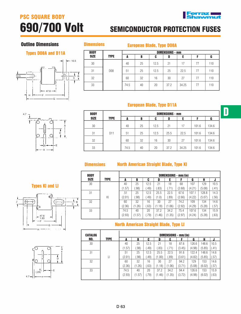
30 40 25 12.5 21 17 77 110 31 D08 51 25 12.5 25 22.5 77 110 32 60 32 16 30 27 77 110 33 74.5 40 20 37.2 34.25 77 110
PSC SQUARE BoDy
690/700 Volt SEMICoNDUCToR PRoTECTIoN FUSES
Outline Dimensions
Dimensions
BODY DIMENSIONS - mm/(in) SIZE TYPE A B C D E F G H J 30 40 25 12.5 21 18 68 107 129 10.5 (1.57) (.98) (.49) (.83) (.71) (2.68) (4.21) (5.08) (.41) 31 .51 25 12.5 25.5 22.5 67.6 107.1 128.8 14.3 KI (2.01) (.98) (.49) (1.0) (.89) (2.66) (4.22) (5.07) (.56) 32 60 32 16 30 27 74.2 109 134 14.6 (2.36) (1.26) (.63) (1.18) (1.06) (2.92) (4.29) (5.28) (.57) 33 74.5 40 20 37.2 34.2 75.4 107.6 134 15.9 (2.93) (1.57) (.79) (1.46) (1.35) (2.97) (4.24) (5.28) (.63)
North American Straight Blade, Type KI
Dimensions
BODY DIMENSIONS - mm SIZE TYPE A B C D E F G 30 40 25 12.5 21 17 101.6 134.6 31 D11 51 25 12.5 25.5 22.5 101.6 134.6
32 60 32 16 30 27 101.6 134.6
33 74.5 40 20 37.2 34.25 101.6 134.6
CATALOG DIMENSIONS - mm/(in) NO. TYPE A B C D E F G H J 30 40 25 12.5 21 18 87.6 126.6 148.6 10.5 (1.57) (.98) (.49) (.83) (.71) (3.45) (4.98) (5.85) (.41) 31 51 25 12.5 25.5 22.5 91.6 122.4 148.6 14.6 LI (2.01) (.98) (.49) (1.00) (.89) (3.61) (4.82) (5.85) (.57) 32 60 32 16 30 27 94.2 129 153 14.6 (2.36) (1.26) (.63) (1.18) (1.06) (3.71) (5.08) (6.02) (.57) 33 74.5 40 20 37.2 34.2 94.4 126.6 153 15.9 (2.93) (1.57) (.79) (1.46) (1.35) (3.72) (4.98) (6.02) (.63)
North American Straight Blade, Type LI
European Blade, Type D11A
European Blade, Type DO8A
10.5
10.5
H FG
CB
4.7
D
A
E
A6
47.6
Types DO8A and D11A
J
HG
F
47.61.93
CB
4.7
D
A
6(.24) E
Types KI and LI
PSC SQUARE BoDy
690/700 Volt SEMICoNDUCToR PRoTECTIoN FUSES
D ��D ��
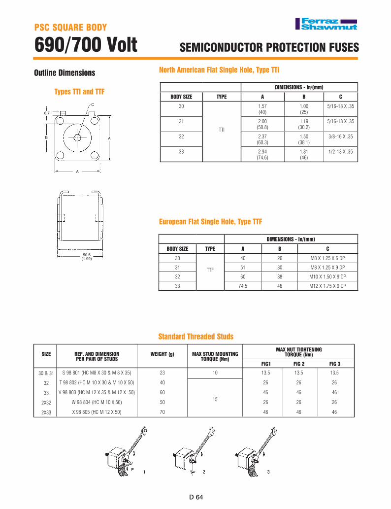
Outline Dimensions North American Flat Single Hole, Type TTI
6.7
B
C
A
A
50.6 (1.99)
European Flat Single Hole, Type TTF
PSC SQUARE BoDy
690/700 Volt SEMICoNDUCToR PRoTECTIoN FUSES
Types TTI and TTF
SIzE
30 & 31
32
33
2X32
2X33
Standard Threaded Studs
REF. AND DIMENSIoN PER PAIR oF STUDS
S 98 801 (HC M8 X 30 & M 8 X 35)
T 98 802 (HC M 10 X 30 & M 10 X 50)
V 98 803 (HC M 12 X 35 & M 12 X 50)
W 98 804 (HC M 10 X 50)
X 98 805 (HC M 12 X 50)
MAX STUD MoUNTING ToRQUE (Nm)
10
MAX NUT TIGHTENING ToRQUE (Nm)
FIG1 FIG 2 FIG 3
13.5 13.5 13.5
26 26 26
46 46 46
26 26 26
46 46 46
WEIGHT (g)
23
40
60
50
70
15
DIMENSIONS - In/(mm)
BODY SIZE TYPE A B C
30
TTI
1.57(40)
1.00(25)
5/16-18 X .35
31 2.00(50.8)
1.19(30.2)
5/16-18 X .35
32 2.37(60.3)
1.50(38.1)
3/8-16 X .35
33 2.94(74.6)
1.81(46)
1/2-13 X .35
DIMENSIONS - In/(mm)
BODY SIZE TYPE A B C
30
TTF
40 26 M8 X 1.25 X 6 DP
31 51 30 M8 X 1.25 X 9 DP
32 60 38 M10 X 1.50 X 9 DP
33 74.5 46 M12 X 1.75 X 9 DP
D
D ��
D
D ��
PSC SQUARE BoDy
690/700 Volt SEMICoNDUCToR PRoTECTIoN FUSES
Outline Dimensions
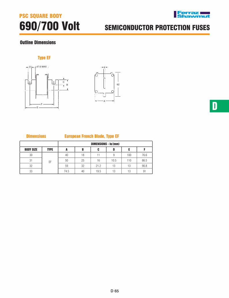
Dimensions European French Blade, Type EF
D 47.6 MAX
CB
FE
A
6
62
Type EF
PSC SQUARE BoDy
690/700 Volt SEMICoNDUCToR PRoTECTIoN FUSES
DIMENSIONS - In/(mm)
BODY SIZE TYPE A B C D E F
30
EF
40 18 11 9 100 76.6
31 50 25 16 10.5 110 86.5
32 59 32 21.2 13 13 90.8
33 74.5 40 19.5 13 13 91
D ��D ��
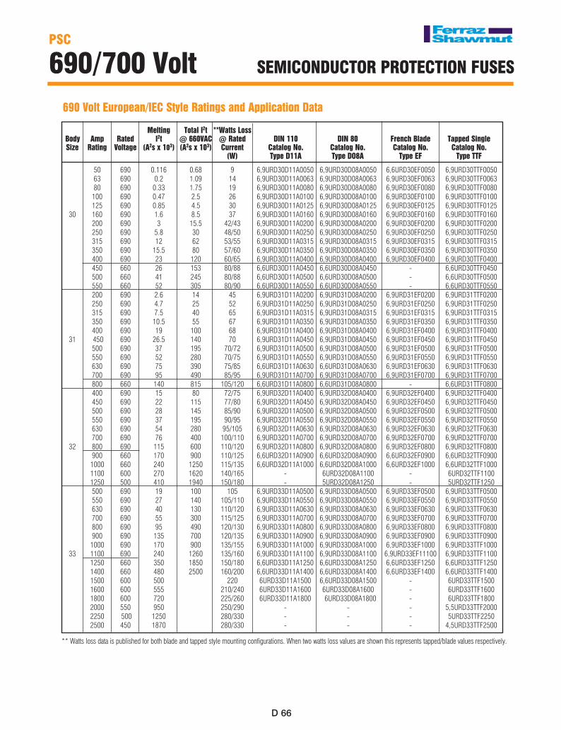
Melting Total I2t **Watts Loss Body Amp Rated I2t @ 660VAC @ Rated DIN 110 DIN 80 French Blade Tapped Single Size Rating Voltage (A2s x 103) (A2s x 103) Current Catalog No. Catalog No. Catalog No. Catalog No. (W) Type D11A Type DO8A Type EF Type TTF 50 690 0.116 0.68 9 6,9URD30D11A0050 6,9URD30D08A0050 6,6URD30EF0050 6,9URD30TTF0050 63 690 0.2 1.09 14 6,9URD30D11A0063 6,9URD30D08A0063 6,9URD30EF0063 6,9URD30TTF0063 80 690 0.33 1.75 19 6,9URD30D11A0080 6,9URD30D08A0080 6,9URD30EF0080 6,9URD30TTF0080 100 690 0.47 2.5 26 6,9URD30D11A0100 6,9URD30D08A0100 6,9URD30EF0100 6,9URD30TTF0100 125 690 0.85 4.5 30 6,9URD30D11A0125 6,9URD30D08A0125 6,9URD30EF0125 6,9URD30TTF0125 30 160 690 1.6 8.5 37 6,9URD30D11A0160 6,9URD30D08A0160 6,9URD30EF0160 6,9URD30TTF0160 200 690 3 15.5 42/43 6,9URD30D11A0200 6,9URD30D08A0200 6,9URD30EF0200 6,9URD30TTF0200 250 690 5.8 30 48/50 6,9URD30D11A0250 6,9URD30D08A0250 6,9URD30EF0250 6,9URD30TTF0250 315 690 12 62 53/55 6,9URD30D11A0315 6,9URD30D08A0315 6,9URD30EF0315 6,9URD30TTF0315 350 690 15.5 80 57/60 6,9URD30D11A0350 6,9URD30D08A0350 6,9URD30EF0350 6,9URD30TTF0350 400 690 23 120 60/65 6,9URD30D11A0400 6,9URD30D08A0400 6,9URD30EF0400 6,9URD30TTF0400 450 660 26 153 80/88 6,6URD30D11A0450 6,6URD30D08A0450 - 6,6URD30TTF0450 500 660 41 245 80/88 6,6URD30D11A0500 6,6URD30D08A0500 - 6,6URD30TTF0500 550 660 52 305 80/90 6,6URD30D11A0550 6,6URD30D08A0550 - 6,6URD30TTF0550 200 690 2.6 14 45 6,9URD31D11A0200 6,9URD31D08A0200 6,9URD31EF0200 6,9URD31TTF0200 250 690 4.7 25 52 6,9URD31D11A0250 6,9URD31D08A0250 6,9URD31EF0250 6,9URD31TTF0250 315 690 7.5 40 65 6,9URD31D11A0315 6,9URD31D08A0315 6,9URD31EF0315 6,9URD31TTF0315 350 690 10.5 55 67 6,9URD31D11A0350 6,9URD31D08A0350 6,9URD31EF0350 6,9URD31TTF0350 400 690 19 100 68 6,9URD31D11A0400 6,9URD31D08A0400 6,9URD31EF0400 6,9URD31TTF0400 31 450 690 26.5 140 70 6,9URD31D11A0450 6,9URD31D08A0450 6,9URD31EF0450 6,9URD31TTF0450 500 690 37 195 70/72 6,9URD31D11A0500 6,9URD31D08A0500 6,9URD31EF0500 6,9URD31TTF0500 550 690 52 280 70/75 6,9URD31D11A0550 6,9URD31D08A0550 6,9URD31EF0550 6,9URD31TTF0550 630 690 75 390 75/85 6,6URD31D11A0630 6,6URD31D08A0630 6,9URD31EF0630 6,9URD31TTF0630 700 690 95 490 85/95 6,9URD31D11A0700 6,9URD31D08A0700 6,9URD31EF0700 6,9URD31TTF0700 800 660 140 815 105/120 6,6URD31D11A0800 6,6URD31D08A0800 - 6,6URD31TTF0800 400 690 15 80 72/75 6,9URD32D11A0400 6,9URD32D08A0400 6,9URD32EF0400 6,9URD32TTF0400 450 690 22 115 77/80 6,9URD32D11A0450 6,9URD32D08A0450 6,9URD32EF0450 6,9URD32TTF0450 500 690 28 145 85/90 6,9URD32D11A0500 6,9URD32D08A0500 6,9URD32EF0500 6,9URD32TTF0500 550 690 37 195 90/95 6,9URD32D11A0550 6,9URD32D08A0550 6,9URD32EF0550 6,9URD32TTF0550 630 690 54 280 95/105 6,9URD32D11A0630 6,9URD32D08A0630 6,9URD32EF0630 6,9URD32TTF0630 700 690 76 400 100/110 6,9URD32D11A0700 6,9URD32D08A0700 6,9URD32EF0700 6,9URD32TTF0700 32 800 690 115 600 110/120 6,9URD32D11A0800 6,9URD32D08A0800 6,9URD32EF0800 6,9URD32TTF0800 900 660 170 900 110/125 6,6URD32D11A0900 6,6URD32D08A0900 6,6URD32EF0900 6,6URD32TTF0900 1000 660 240 1250 115/135 6,6URD32D11A1000 6,6URD32D08A1000 6,6URD32EF1000 6,6URD32TTF1000 1100 600 270 1620 140/165 - 6URD32D08A1100 - 6URD32TTF1100 1250 500 410 1940 150/180 - 5URD32D08A1250 - 5URD32TTF1250 500 690 19 100 105 6,9URD33D11A0500 6,9URD33D08A0500 6,9URD33EF0500 6,9URD33TTF0500 550 690 27 140 105/110 6,9URD33D11A0550 6,9URD33D08A0550 6,9URD33EF0550 6,9URD33TTF0550 630 690 40 130 110/120 6,9URD33D11A0630 6,9URD33D08A0630 6,9URD33EF0630 6,9URD33TTF0630 700 690 55 300 115/125 6,9URD33D11A0700 6,9URD33D08A0700 6,9URD33EF0700 6,9URD33TTF0700 800 690 95 490 120/130 6,9URD33D11A0800 6,9URD33D08A0800 6,9URD33EF0800 6,9URD33TTF0800 900 690 135 700 120/135 6,9URD33D11A0900 6,9URD33D08A0900 6,9URD33EF0900 6,9URD33TTF0900 1000 690 170 900 135/155 6,9URD33D11A1000 6,9URD33D08A1000 6,9URD33EF1000 6,9URD33TTF1000 33 1100 690 240 1260 135/160 6,9URD33D11A1100 6,9URD33D08A1100 6,9URD33EF11100 6,9URD33TTF1100 1250 660 350 1850 150/180 6,6URD33D11A1250 6,6URD33D08A1250 6,6URD33EF1250 6,6URD33TTF1250 1400 660 480 2500 160/200 6,6URD33D11A1400 6,6URD33D08A1400 6,6URD33EF1400 6,6URD33TTF1400 1500 600 500 220 6URD33D11A1500 6,6URD33D08A1500 - 6URD33TTF1500 1600 600 555 210/240 6URD33D11A1600 6URD33D08A1600 - 6URD33TTF1600 1800 600 720 225/260 6URD33D11A1800 6URD33D08A1800 - 6URD33TTF1800 2000 550 950 250/290 - - - 5,5URD33TTF2000 2250 500 1250 280/330 - - - 5URD33TTF2250 2500 450 1870 280/330 - - - 4,5URD33TTF2500
PSC
690/700 Volt SEMICoNDUCToR PRoTECTIoN FUSES
690 Volt European/IEC Style Ratings and Application Data
** Watts loss data is published for both blade and tapped style mounting configurations. When two watts loss values are shown this represents tapped/blade values respectively.
D
D ��
D
D ��
PSC
690/700 Volt SEMICoNDUCToR PRoTECTIoN FUSES
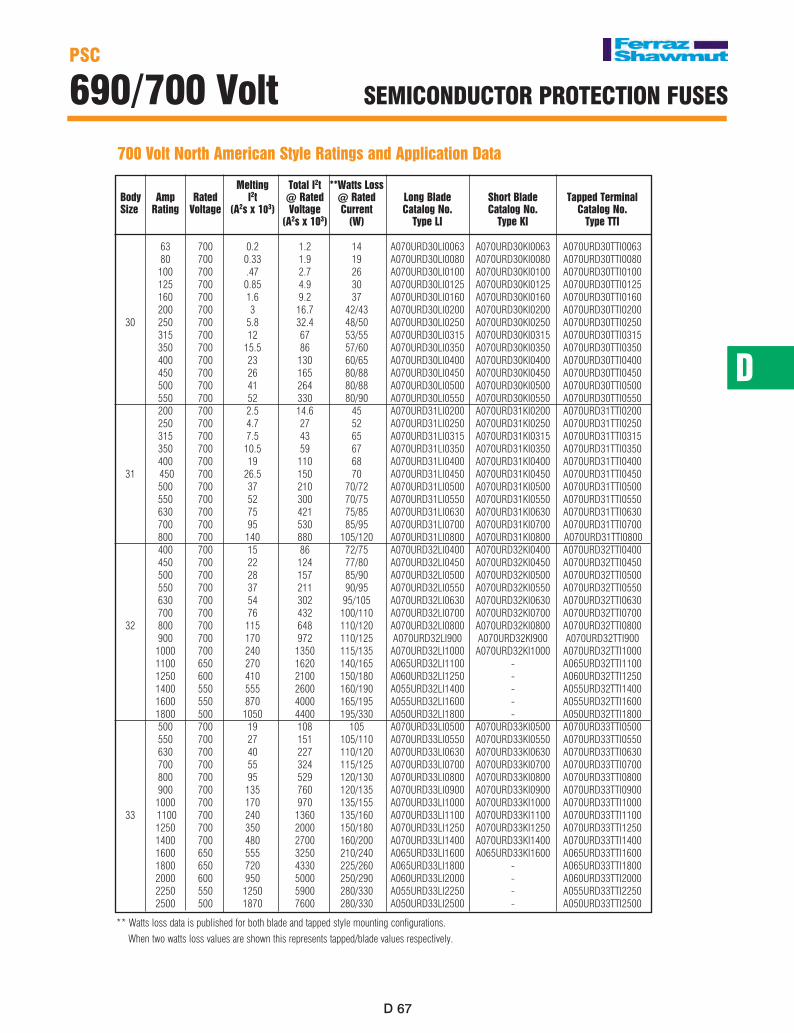
700 Volt North American Style Ratings and Application Data
Melting Total I2t **Watts Loss Body Amp Rated I2t @ Rated @ Rated Long Blade Short Blade Tapped Terminal Size Rating Voltage (A2s x 103) Voltage Current Catalog No. Catalog No. Catalog No. (A2s x 103) (W) Type LI Type KI Type TTI
63 700 0.2 1.2 14 A070URD30LI0063 A070URD30KI0063 A070URD30TTI0063 80 700 0.33 1.9 19 A070URD30LI0080 A070URD30KI0080 A070URD30TTI0080 100 700 .47 2.7 26 A070URD30LI0100 A070URD30KI0100 A070URD30TTI0100 125 700 0.85 4.9 30 A070URD30LI0125 A070URD30KI0125 A070URD30TTI0125 160 700 1.6 9.2 37 A070URD30LI0160 A070URD30KI0160 A070URD30TTI0160 200 700 3 16.7 42/43 A070URD30LI0200 A070URD30KI0200 A070URD30TTI0200 30 250 700 5.8 32.4 48/50 A070URD30LI0250 A070URD30KI0250 A070URD30TTI0250 315 700 12 67 53/55 A070URD30LI0315 A070URD30KI0315 A070URD30TTI0315 350 700 15.5 86 57/60 A070URD30LI0350 A070URD30KI0350 A070URD30TTI0350 400 700 23 130 60/65 A070URD30LI0400 A070URD30KI0400 A070URD30TTI0400 450 700 26 165 80/88 A070URD30LI0450 A070URD30KI0450 A070URD30TTI0450 500 700 41 264 80/88 A070URD30LI0500 A070URD30KI0500 A070URD30TTI0500 550 700 52 330 80/90 A070URD30LI0550 A070URD30KI0550 A070URD30TTI0550 200 700 2.5 14.6 45 A070URD31LI0200 A070URD31KI0200 A070URD31TTI0200 250 700 4.7 27 52 A070URD31LI0250 A070URD31KI0250 A070URD31TTI0250 315 700 7.5 43 65 A070URD31LI0315 A070URD31KI0315 A070URD31TTI0315 350 700 10.5 59 67 A070URD31LI0350 A070URD31KI0350 A070URD31TTI0350 400 700 19 110 68 A070URD31LI0400 A070URD31KI0400 A070URD31TTI0400 31 450 700 26.5 150 70 A070URD31LI0450 A070URD31KI0450 A070URD31TTI0450 500 700 37 210 70/72 A070URD31LI0500 A070URD31KI0500 A070URD31TTI0500 550 700 52 300 70/75 A070URD31LI0550 A070URD31KI0550 A070URD31TTI0550 630 700 75 421 75/85 A070URD31LI0630 A070URD31KI0630 A070URD31TTI0630 700 700 95 530 85/95 A070URD31LI0700 A070URD31KI0700 A070URD31TTI0700 800 700 140 880 105/120 A070URD31LI0800 A070URD31KI0800 A070URD31TTI0800 400 700 15 86 72/75 A070URD32LI0400 A070URD32KI0400 A070URD32TTI0400 450 700 22 124 77/80 A070URD32LI0450 A070URD32KI0450 A070URD32TTI0450 500 700 28 157 85/90 A070URD32LI0500 A070URD32KI0500 A070URD32TTI0500 550 700 37 211 90/95 A070URD32LI0550 A070URD32KI0550 A070URD32TTI0550 630 700 54 302 95/105 A070URD32LI0630 A070URD32KI0630 A070URD32TTI0630 700 700 76 432 100/110 A070URD32LI0700 A070URD32KI0700 A070URD32TTI0700 32 800 700 115 648 110/120 A070URD32LI0800 A070URD32KI0800 A070URD32TTI0800 900 700 170 972 110/125 A070URD32LI900 A070URD32KI900 A070URD32TTI900 1000 700 240 1350 115/135 A070URD32LI1000 A070URD32KI1000 A070URD32TTI1000 1100 650 270 1620 140/165 A065URD32LI1100 - A065URD32TTI1100 1250 600 410 2100 150/180 A060URD32LI1250 - A060URD32TTI1250 1400 550 555 2600 160/190 A055URD32LI1400 - A055URD32TTI1400 1600 550 870 4000 165/195 A055URD32LI1600 - A055URD32TTI1600 1800 500 1050 4400 195/330 A050URD32LI1800 - A050URD32TTI1800 500 700 19 108 105 A070URD33LI0500 A070URD33KI0500 A070URD33TTI0500 550 700 27 151 105/110 A070URD33LI0550 A070URD33KI0550 A070URD33TTI0550 630 700 40 227 110/120 A070URD33LI0630 A070URD33KI0630 A070URD33TTI0630 700 700 55 324 115/125 A070URD33LI0700 A070URD33KI0700 A070URD33TTI0700 800 700 95 529 120/130 A070URD33LI0800 A070URD33KI0800 A070URD33TTI0800 900 700 135 760 120/135 A070URD33LI0900 A070URD33KI0900 A070URD33TTI0900 1000 700 170 970 135/155 A070URD33LI1000 A070URD33KI1000 A070URD33TTI1000 33 1100 700 240 1360 135/160 A070URD33LI1100 A070URD33KI1100 A070URD33TTI1100 1250 700 350 2000 150/180 A070URD33LI1250 A070URD33KI1250 A070URD33TTI1250 1400 700 480 2700 160/200 A070URD33LI1400 A070URD33KI1400 A070URD33TTI1400 1600 650 555 3250 210/240 A065URD33LI1600 A065URD33KI1600 A065URD33TTI1600 1800 650 720 4330 225/260 A065URD33LI1800 - A065URD33TTI1800 2000 600 950 5000 250/290 A060URD33LI2000 - A060URD33TTI2000 2250 550 1250 5900 280/330 A055URD33LI2250 - A055URD33TTI2250 2500 500 1870 7600 280/330 A050URD33LI2500 - A050URD33TTI2500
** Watts loss data is published for both blade and tapped style mounting configurations.
When two watts loss values are shown this represents tapped/blade values respectively.
PSC
690/700 Volt SEMICoNDUCToR PRoTECTIoN FUSES
D ��D ��
Max
Pea
k Le
t Trh
u Cu
rren
t
Available Current in RMS Symmetrical Amperes
PSC
690/700 Volt SEMICoNDUCToR PRoTECTIoN FUSES
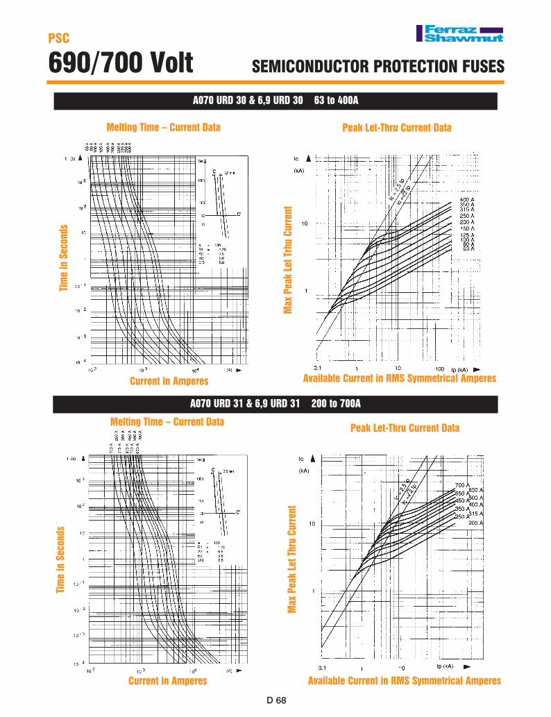
A070 URD 30 & 6,9 URD 30 63 to 400A
Melting Time – Current Data Peak Let-Thru Current Data
A070 URD 31 & 6,9 URD 31 200 to 700A
Melting Time – Current Data Peak Let-Thru Current Data
Tim
e in
Sec
onds
Current in Amperes
Tim
e in
Sec
onds
Max
Pea
k Le
t Thr
u Cu
rren
t
Current in Amperes Available Current in RMS Symmetrical Amperes
D
D ��
D
D ��
PSC
690/700 Volt SEMICoNDUCToR PRoTECTIoN FUSES
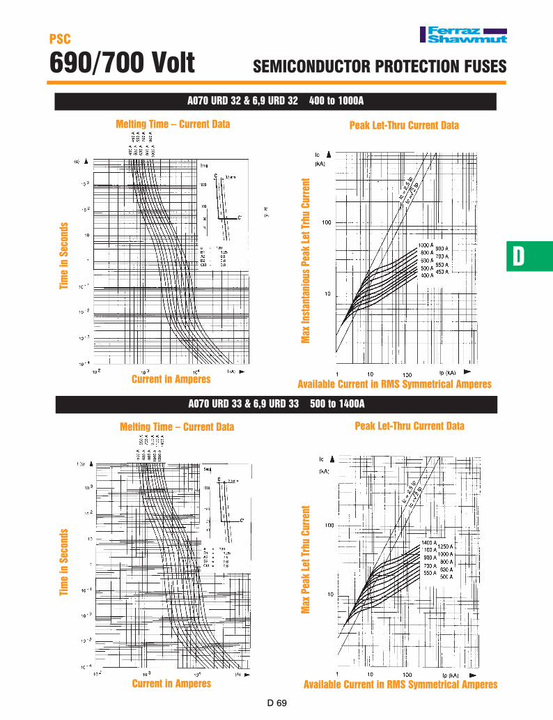
A070 URD 32 & 6,9 URD 32 400 to 1000A
Melting Time – Current Data Peak Let-Thru Current Data
A070 URD 33 & 6,9 URD 33 500 to 1400A
Melting Time – Current Data
Tim
e in
Sec
onds
Current in Amperes
Tim
e in
Sec
onds
Max
Inst
anta
niou
s Pe
ak L
et T
rhu
Curr
ent
Available Current in RMS Symmetrical Amperes
Current in Amperes
Max
Pea
k Le
t Trh
u Cu
rren
t
Peak Let-Thru Current Data
Available Current in RMS Symmetrical Amperes

D �0D �0
PSC
690/700 Volt SEMICoNDUCToR PRoTECTIoN FUSES
Application Information-All Sizes
Watts Loss vs. % Rated Current
Percent Rated Current (%)
Corr
ectio
n Fa
ctor
for
Wat
ts L
oss
Correction factor to determine the watts loss value of a fuse operating below its rated current
Maximum Arc Volts vs. System Voltage
Working Voltage (AC RMS Volts)
Peak
Arc
Vol
tage
(Vo
lts)
Determines the peak arc voltage across the fuse terminals as a function of the applied voltage
Ampere Rating Correction Factor vs. Air Flow Speed
Determines the current carrying correction factor based on the cooling air speed across the fuse
Clearing I2t vs. Operating Voltage
Working Voltage (AC RMS Volts)
Correction factor to determine the clearing I2t value for a fuse operating below its rated voltage
Corr
ectio
n Fa
ctor
Air Speed (m/s)
D
D �1
D
D �1
PSC SQUARE BoDy
690/700 Volt SEMICoNDUCToR PRoTECTIoN FUSES
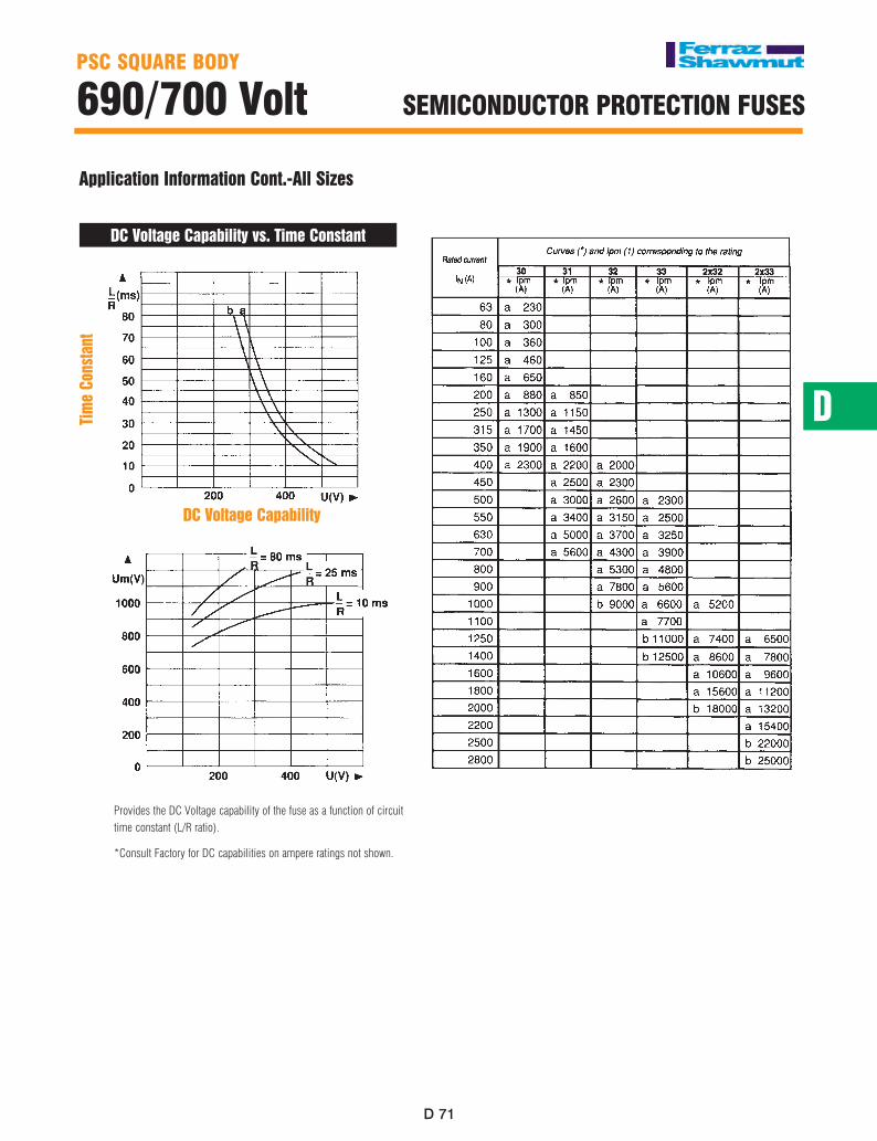
Application Information Cont.-All Sizes
DC Voltage Capability vs. Time Constant
Provides the DC Voltage capability of the fuse as a function of circuit time constant (L/R ratio).
*Consult Factory for DC capabilities on ampere ratings not shown.
Tim
e Co
nsta
nt
DC Voltage Capability
PSC
690/700 Volt SEMICoNDUCToR PRoTECTIoN FUSES
D ��D ��
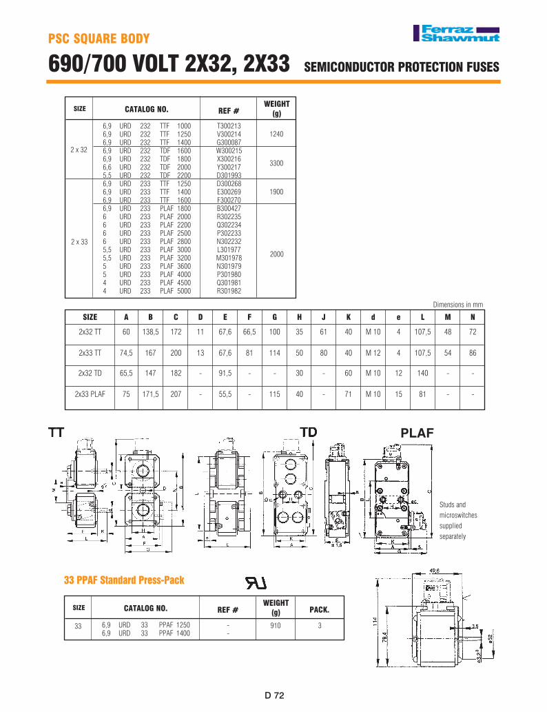
SIzE CATALoG No. REF #
6,9 URD 232 TTF 1000 6,9 URD 232 TTF 1250 6,9 URD 232 TTF 1400 6,9 URD 232 TDF 1600 6,9 URD 232 TDF 1800 6,6 URD 232 TDF 2000 5,5 URD 232 TDF 2200 6,9 URD 233 TTF 1250 6,9 URD 233 TTF 1400 6,9 URD 233 TTF 1600 6,9 URD 233 PLAF 1800 6 URD 233 PLAF 2000 6 URD 233 PLAF 2200 6 URD 233 PLAF 2500 6 URD 233 PLAF 2800 5,5 URD 233 PLAF 3000 5,5 URD 233 PLAF 3200 5 URD 233 PLAF 3600 5 URD 233 PLAF 4000 4 URD 233 PLAF 4500 4 URD 233 PLAF 5000
T300213V300214G300087W300215X300216Y300217D301993D300268E300269F300270B300427R302235Q302234P302233N302232L301977M301978N301979P301980Q301981R301982
WEIGHT(g)
2000
1900
3300
1240
2 x 32
2 x 33
SIzE A B C D E F G H J K d e L M N
2x32 TT 60 138,5 172 11 67,6 66,5 100 35 61 40 M 10 4 107,5 48 72
2x33 TT 74,5 167 200 13 67,6 81 114 50 80 40 M 12 4 107,5 54 86
2x32 TD 65,5 147 182 - 91,5 - - 30 - 60 M 10 12 140 - -
2x33 PLAF 75 171,5 207 - 55,5 - 115 40 - 71 M 10 15 81 - -
Dimensions in mm
SIzE CATALoG No. REF #
6,9 URD 33 PPAF 1250 6,9 URD 33 PPAF 1400
--
WEIGHT(g)
3
PACK.
91033
33 PPAF Standard Press-Pack
Studs andmicroswitchessupplied separately
PSC SQUARE BoDy
690/700 VoLT 2X32, 2X33 SEMICoNDUCToR PRoTECTIoN FUSES
PLAF
D
D ��
D
D ��
PSC SQUARE BoDy
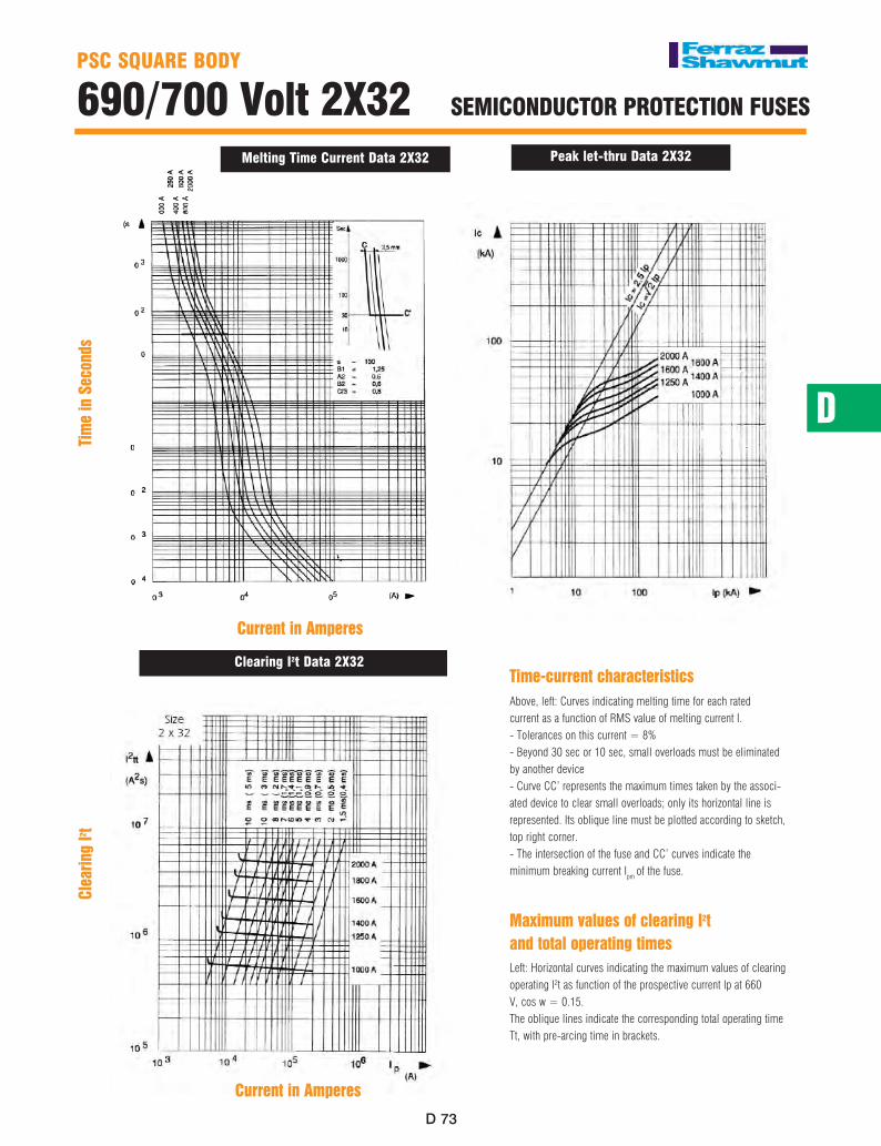
690/700 Volt 2X32 SEMICoNDUCToR PRoTECTIoN FUSES
Time-current characteristicsAbove, left: Curves indicating melting time for each ratedcurrent as a function of RMS value of melting current I.- Tolerances on this current = 8%- Beyond 30 sec or 10 sec, small overloads must be eliminatedby another device- Curve CC’ represents the maximum times taken by the associ-ated device to clear small overloads; only its horizontal line is represented. Its oblique line must be plotted according to sketch, top right corner.- The intersection of the fuse and CC’ curves indicate the minimum breaking current Ipm of the fuse.
Maximum values of clearing I2tand total operating timesLeft: Horizontal curves indicating the maximum values of clearingoperating I2t as function of the prospective current Ip at 660V, cos w = 0.15.The oblique lines indicate the corresponding total operating timeTt, with pre-arcing time in brackets.
Melting Time Current Data 2X32 Peak let-thru Data 2X32
Clearing I2t Data 2X32
Tim
e in
Sec
onds
Current in Amperes
Clea
ring
I2 t
Current in Amperes
D ��D ��
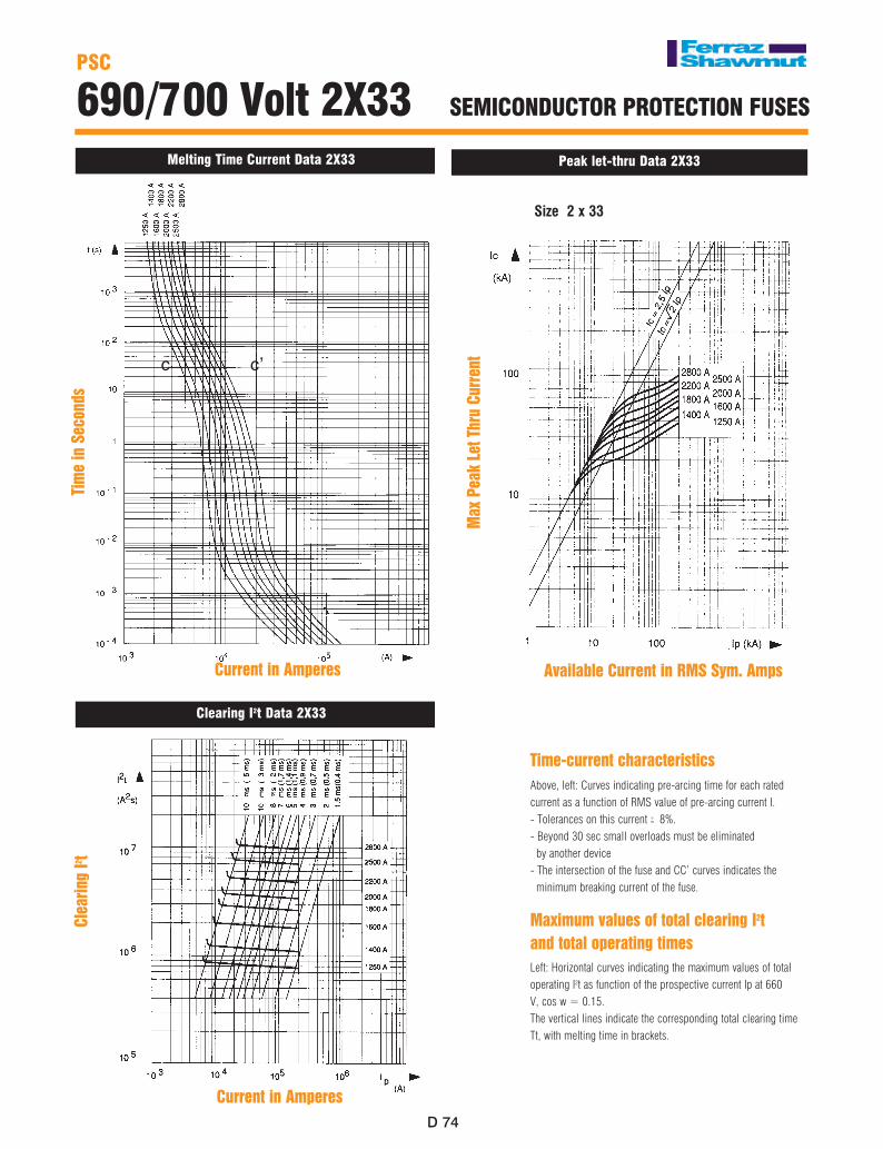
PSC
690/700 Volt 2X33 SEMICoNDUCToR PRoTECTIoN FUSES
Time-current characteristicsAbove, left: Curves indicating pre-arcing time for each ratedcurrent as a function of RMS value of pre-arcing current I.- Tolerances on this current 8%.- Beyond 30 sec small overloads must be eliminated by another device- The intersection of the fuse and CC’ curves indicates the minimum breaking current of the fuse.
Maximum values of total clearing I2tand total operating timesLeft: Horizontal curves indicating the maximum values of totaloperating I2t as function of the prospective current Ip at 660V, cos w = 0.15.The vertical lines indicate the corresponding total clearing timeTt, with melting time in brackets.
-+
Melting Time Current Data 2X33 Peak let-thru Data 2X33
Clearing I2t Data 2X33
c c’
Tim
e in
Sec
onds
Clea
ring
I2 t
Available Current in RMS Sym. Amps
Current in Amperes
Current in Amperes
Max
Pea
k Le
t Thr
u Cu
rren
t
Size 2 x 33