PSC-5S ENGLISH - c-o-k.ru · Follow the national regulations for the right assembly of the PSC-5S...
26
INSTALLATION AND OPERATION MANUAL MANUAL DE INSTALACIÓN Y FUNCIONAMIENTO INSTALLATIONS- UND BETRIEBSHANDBUCH MANUEL D’INSTALLATION ET DE FUNCTIONNEMENT MANUALE D’INSTALLAZIONE E D’USO MANUAL DE INSTALAÇÄO E DE FUNCIONAMENTO BRUGER- OG MONTERINGSVEJLEDNING INSTALLATIE- EN BEDIENINGSHANDLEIDING HANDBOK FÖR INSTALLATION OCH ANVÄNDING ÅÃ×ÅÉÑÉÄÉÏÅÃÊÁÔÁÓÔÁÓÇÓÊÁÉËÅÉÔÏÕÑÃÉÁÓ PSC-5S ENGLISH ESPAÑOL DEUTCH FRANÇAIS ITALIANO PORTUGUES DANSK SVENSKA NEDERLANDS Do not perform installation work, without referring to our installation manual. No realice la instalación de este equipo, sin antes consultar este manual de instalación. Bei der Installation unbedingt die Hinweise in der Installationsanleitung beachten. Consulter notre manuel avant de réaliser une quelconque installation. Realizzare l’installazione, seguendo quanto indicato in questo manuale. Nao inicie os trabalhos de montagem, sem consultar o nosso manual de montagem. Udfor ikke installationsarbejder uden forst at donsultere vores vejledning. Voer geen enkele handeling uit om de apparatuur alvorens deze hadleiding te hebben doorgelezen. Utför inte nagra installationsarbeten utan att först läsa var installationsmanual Ìçí Þóåôå óôçí åãêáôÜóôáóç, ÷ùñßò ðñéí íá Ý÷åôå óõìâïõëåõèåß áõôo ôï åã÷åéñßäéï åãêáôÜóôáóçò
-
Upload
phungduong -
Category
Documents
-
view
213 -
download
0
Transcript of PSC-5S ENGLISH - c-o-k.ru · Follow the national regulations for the right assembly of the PSC-5S...

INSTALLATION AND OPERATION MANUALMANUAL DE INSTALACIÓN Y FUNCIONAMIENTOINSTALLATIONS- UND BETRIEBSHANDBUCHMANUEL D’INSTALLATION ET DEFUNCTIONNEMENTMANUALE D’INSTALLAZIONE E D’USO
MANUAL DE INSTALAÇÄO E DEFUNCIONAMENTOBRUGER- OG MONTERINGSVEJLEDNINGINSTALLATIE- EN BEDIENINGSHANDLEIDINGHANDBOK FÖR INSTALLATION OCH ANVÄNDINGÅÃ×ÅÉÑÉÄÉÏÅÃÊÁÔÁÓÔÁÓÇÓÊÁÉËÅÉÔÏÕÑÃÉÁÓ
PSC-5S EN
GLIS
HE
SP
AÑ
OL
DE
UT
CH
FR
AN
ÇA
ISIT
ALIA
NO
PO
RT
UG
UE
SD
AN
SK
SV
EN
SK
AN
ED
ER
LA
ND
S
Do not perform installation work, without referring to our installation manual.No realice la instalación de este equipo, sin antes consultar este manual de instalación.Bei der Installation unbedingt die Hinweise in der Installationsanleitung beachten.Consulter notre manuel avant de réaliser une quelconque installation.Realizzare l’installazione, seguendo quanto indicato in questo manuale.Nao inicie os trabalhos de montagem, sem consultar o nosso manual de montagem.Udfor ikke installationsarbejder uden forst at donsultere vores vejledning.Voer geen enkele handeling uit om de apparatuur alvorens deze hadleiding te hebbendoorgelezen.Utför inte nagra installationsarbeten utan att först läsa var installationsmanualÌçí Þóåôå óôçí åãêáôÜóôáóç, ÷ùñßò ðñéí íá Ý÷åôå óõìâïõëåõèåß áõôo ôï åã÷åéñßäéï åãêáôÜóôáóçò


ESPAÑOL
DEUTSCH
FRANÇAIS
PORTUGUÊS
DANSK
NEDERLANDS
SVENSKA
ITALIANO
EΛΛHNIKA
ENGLISH
DANGER – Immediate hazard which WILL result in severe injury or death.PELIGRO – Peligros inmediatos que DARÁN como resultado graves lesiones o inclusola muerte.GEFAHR – Ernsthafte Gefahrenquelle, die zu schweren Verletzungen oder zum Tod führt.DANGER – Dangers instantanés de blessures personnelles sévères ou de mort.PERICOLO – Pericolo immediato che AVRÀ come esito lesioni gravi o il decesso.PERIGO – Problemas imediatos que IRÃO resultar em ferimentos pessoais graves ou morte.FARE – Overhængende fare, som VIL resultere i alvorlig personskade eller dødsfald.GEVAAR – Directe gevaren die ernstig letsel of de dood tot gevolg ZULLEN hebben.FARA – Omedelbar risk som medför svår personskada eller död.KINAYNO – Άµεσος κίνδυνος που ΘΑ έχει ως αποτέλεσµα σοβαρές σωµατικέςβλάβες ή θάνατο.
WARNING – Hazards or unsafe practices which COULD result in severe personal injuriesor death.ADVERTENCIA – Peligros o prácticas poco seguras que PODRÁN dar como resultadograves lesiones o incluso la muerte.WARNUNG – Gefahrenquellen oder leichtfertige Vorgehensweisen, die schwereVerletzungen verursachen oder zum Tod führen können.AVERTISSEMENT – Utilisation dangereuse ou sans garantie de sécurité qui PEUTprovoquer de sévères blessures ou la mort.AVVERTENZA – Pericoli o azioni pericolose che POTREBBERO avere come esito lesionifisiche gravi o il decesso.AVISO – Perigos e procedimentos perigosos que PODERÃO PROVOCAR danos pessoaisgraves ou morte.ADVARSEL – Farer eller farlig brug, som KAN resultere i alvorlig personskade eller dødsfald.WAARSCHUWING – Gevaren of onveilige praktijken die ernstig persoonlijk letsel of dedood tot gevolg KUNNEN hebben.VARNING – Risker eller osäkra tillvägagångssätt som KAN leda till svåra personskadoreller dödsfall.ΠΡΟΕΙ∆ΟΠΟΙΗΣΗ – Κίνδυνοι ή επικίνδυνες πρακτικές, οι οποίες ΜΠΟΡΕΙ να έχουν ωςαποτέλεσµα σοβαρές σωµατικές βλάβες ή θάνατο.
CAUTION – Hazards or unsafe practices which COULD result in minor personal injuryor product or property damage.PRECAUCIÓN – Riesgos o prácticas poco seguras que PODRÍAN provocar lesionespersonales de menor importancia o daños en el producto u otros bienes.VORSICHT – Gefahrenquellen oder leichtfertige Vorgehensweisen, die geringfügigeSchäden am Produkt oder an Sachen oder leichte Verletzungen verursachen können.ATTENTION – Utilisation dangereuse ou sans garantie de sécurité qui PEUT provoquerdes blessures mineures ou des dommages au produit ou aux biens.ATTENZIONE – Pericoli o azioni pericolose che POTREBBERO avere come esito lesionifisiche minori o danni al prodotto o ad altri beni.CUIDADO – Perigos e procedimentos perigosos que PODERÃO PROVOCAR danospessoais ligeiros ou danos em produtos e bens.FORSIGTIG – Farer eller farlig brug, som KAN resultere i mindre skade på personer, produkteller ejendom.LET OP – Gevaren of onveilige praktijken die licht persoonlijk letsel of beschadiging van hetproduct of eigendommen tot gevolg KUNNEN hebben.OBS! – Risker eller farliga tillvägagångssätt som KAN leda till mindre personskador ellerskador på produkten eller på egendom.ΠΡΟΣΟΧΗ – Κίνδυνοι ή επικίνδυνες πρακτικές που ΜΠΟΡΕΙ να έχουν ως αποτέλεσµαελαφριές σωµατικές βλάβες, υλικές ζηµιές ή ζηµιές στο προϊόν.

120 mm
120
mm
SAFETY SUMMARY 1/1
ENG
LISH
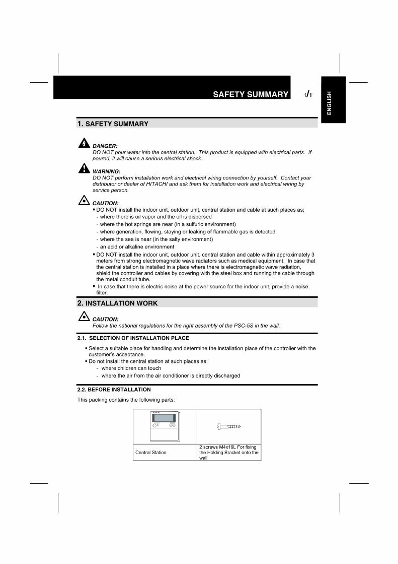
1. SAFETY SUMMARY
DANGER:DO NOT pour water into the central station. This product is equipped with electrical parts. Ifpoured, it will cause a serious electrical shock.
WARNING:DO NOT perform installation work and electrical wiring connection by yourself. Contact yourdistributor or dealer of HITACHI and ask them for installation work and electrical wiring byservice person.
CAUTION: DO NOT install the indoor unit, outdoor unit, central station and cable at such places as;- where there is oil vapor and the oil is dispersed- where the hot springs are near (in a sulfuric environment)- where generation, flowing, staying or leaking of flammable gas is detected- where the sea is near (in the salty environment)- an acid or alkaline environment DO NOT install the indoor unit, outdoor unit, central station and cable within approximately 3meters from strong electromagnetic wave radiators such as medical equipment. In case thatthe central station is installed in a place where there is electromagnetic wave radiation,shield the controller and cables by covering with the steel box and running the cable throughthe metal conduit tube. In case that there is electric noise at the power source for the indoor unit, provide a noisefilter.
2. INSTALLATION WORK
CAUTION:Follow the national regulations for the right assembly of the PSC-5S in the wall.
2.1. SELECTION OF INSTALLATION PLACE
Select a suitable place for handling and determine the installation place of the controller with thecustomer’s acceptance. Do not install the central station at such places as;
- where children can touch- where the air from the air conditioner is directly discharged
2.2. BEFORE INSTALLATION
This packing contains the following parts:
GROUP
HITACHI
Central Station2 screws M4x16L For fixingthe Holding Bracket onto thewall

2/2 INSTALLATION WORK
2.3. INSTALLATION SPACE
In case of installing the central stations in thevertical direction,keep a distance more than 50mm between thecentral stations vertically.If the distance is insufficient, the front cover ofthe central stationcan not open wide enough.
2.4. INSTALLATION PROCEDURES
1. Insert the edge of the screwdriver into the slot parts at the bottom of the case, push and turn thescrewdriver and remove the control part from the power supply part. Do not insert the screwdriverinto the nail near the slot part, or the nail will be damaged.
2. Attach the power supply part to the switchbox.
3. Attach the control part onto the power supplypart. At first, attach the upper side, and thenthe lower side.
More than 50mm
Slot Part
Control Part Power Supply Part
Nail
Figure Seen from Bottom Side
Slot Part
ScrewDriver
ScrewDriver
Approx. 6mm
ControlLine
PowerLine
Screw(x2)
Do not run the power line and thecontrol line through the same conduit
Switch Box with Cover(Field-Supplied)
Power Supply
GROUP
ELECTRICAL WIRING 3/3
ENG
LISH
3. ELECTRICAL WIRING
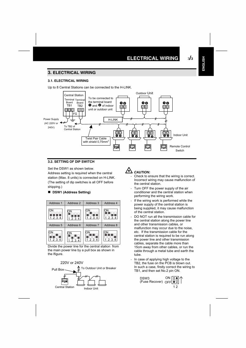
3.1. ELECTRICAL WIRING
Up to 8 Central Stations can be connected to the H-LINK.
3.2. SETTING OF DIP SWITCH
Set the DSW1 as shown below.Address setting is required when the centralstation (Max. 8 units) is connected on H-LINK.(The setting of dip switches is all OFF beforeshipping.)
DSW1 (Address Setting)
Address 1 Address 2 Address 3 Address 4
ON
1 2 3 4
ON
1 2 3 4
ON
1 2 3 4
ON
1 2 3 4
Address 5 Address 6 Address 7 Address 8
ON
1 2 3 4
ON
1 2 3 4
ON
1 2 3 4
ON
1 2 3 4
Divide the power line for the central station fromthe main power line by a pull box as shown inthe lfigure.
CAUTION:- Check to ensure that the wiring is correct.
Incorrect wiring may cause malfunction ofthe central station.
- Turn OFF the power supply of the airconditioner and the central station whenperforming the wiring work.
- If the wiring work is performed while thepower supply of the central station isbeing supplied, it may cause malfunctionof the central station.
- DO NOT run all the transmission cable forthe central station along the power lineand other transmission cables, ormalfunction may occur due to the noise,etc. If the transmission cable for thecentral station is required to be run alongthe power line and other transmissioncables, separate the cable more than15cm away from other cables, or run thecable through a metal tube and earth thetube.
- In case of applying high voltage to theTB2, the fuse on the PCB is blown out.In such a case, firstly correct the wiring toTB1, and then set No.2 pin ON.
Remote ControlSwitch
Outdoor Unit
Twist Pair Cablewith shield 0,75mm2
To be connected tothe terminal board
and of indoorunit or outdoor unit
Central StationTerminal
BoardTB1
Power Supply(AC 220V or
240V) To TB2 ofCentral Station
H-LINK
Indoor Unit
FG
TerminalBoardTB2
Pull Box
Indoor UnitCentral Station
To Outdoor Unit or Breaker
220V or 240V
ONOFF
1 2
DSW3(Fuse Recover)

4/4 GROUP SETTING
4. GROUP SETTINGIn case that group setting is not performed, the indication of the central station is as shown below forchecking indoor unit connection after turning ON the power supply.
NOTE:The checked number of connected indoor units may be more than the actual number accordingto the condition of transmission.After the connection check, the indications of “GROUP” and ”SET TEMP.” may be “- -”temporarily.
4.1. SYSTEM OF INDIVIDUAL CONTROL FOR UP TO 16 INDOOR UNITS
Group setting is automatically performed by the indoor unit address regardless of the refrigerantcycle address. Set the indoor unit address without duplication of address.
4.2. SYSTEM OF GROUP CONTROL BY REMOTE CONTROL SWITCH
In this case, the group setting by central station is required. Group setting is for master unit (directlyconnected to remote control switch) and slave unit (connected by extension cable).In case that the remote control switch is not connected, the group setting by remote control switch isnot available and only one master unit is controlled as one group.In case of up to 16 indoor units connected, the group setting is automatically performed as describedin “1. System of Individual Control for up to 16 Indoor Units”. In this case, correct the group settingby the procedure below.
Completion ofConnection Check
In Case of Item 1 Below(14 Units Connected) In Case of Item 2 BelowRefrigerant
Cycle onConnectionCheck
Number ofChecked IndoorUnits Connected inRefrigerant Cycleon ConnectionCheck
CentralStation
The setting “0” to “F” ofindoor unit RSW iscorresponding to thegroup No. “1” to “16” ofcentral station.(The setting can bechanged by theprocedure of “2.System of Group Controlby Remote ControlSwitch”)
Setting ofIndoor Unit RSW
Group Number0 1 2 3 41 2 3 4 5

GROUP SETTING 4/5
ENG
LISH
4.2.1. GROUP SETTING PROCEDURE
Changing to Group Setting Mode
1. Depress the “CHECK” switch for 3 seconds during the units of all groups are stopped. Thecentral station is changed to the check mode and the “CHECK” indication is turned ON. Andthe “1” (Main Unit Setting Mode) is indicated at the 7 segment indicator for checking.
2. Depress the “CHECK” switch, and the indication on the 7 segment indicator for checking ischanged to “2” (Sub Unit Setting Mode).
3. Depress the “RESET” switch, and the check mode is changed to the normal mode.
ATTENTION:- When there is a group in operation, the central station can not be changed to the check mode.- When the group setting is performed, use the check table for group setting (page 9), and you
can also write down the group number on the surface inside of the switch cover.
Setting of Master Unit
Indication of Master Unit Setting ModeWhen the central station is changed to the master unit setting mode, the LCD indication on thecentral station is as shown below. The indication of the group to be set is flickered. Therefrigerant cycle number (hereafter called “Ref. No.”) and the indoor unit address (hereafter called“I.U. Add.”) indicates the address of the indoor unit which is set as the master unit of the group tobe set. The “ ” indication of group flickers in case that the master unit of the group is set. Whenthe “SET” indication appears, the indoor unit indicated on LCD is set as the master unit. In casethat the master unit is not set, “- -” is indicated at Ref. No. nd I.U. Add., and the “SET” indicationdoes not appear.
CentralStation
Master Slave Slave
Master
Master Master
Refrigerant No. Setting 1 1 2 2 3 3Indoor Unit RSW Setting 0 1 0 1 0 1Group Number 1 2 3 4
Without RemoteControl Switch

4/6 GROUP SETTING
Procedure of Master Unit Setting
Set the master unit for each group as followings.
1. Selection of Group To Be Set:Select the group to be set by depressing “GROUP” switch.The flickering indication of group number is moved every timewhen the “GROUP” switch is depressed.When the main unit of the selected group is already set,the Ref. No. and I.U. Add. of the main unit already set areindicated and the “SET” indication appears.
The flickering indication of group number is moved (ex. Whenselecting group No.6).
“SET” turns OFF.
Condition of Master Unit Setting for Each Group( is ON: The master unit is set. / is OFF: Themaster unit is not set.)
“1” shows the master unit settingmode.
Ref. No. of Outdoor Unit To Be Set(Can be changed by depressing the “∇” (TEMP) switch.)
When the “SET” indication appears, theindicated indoor unit is set as the master unit.(When “SET” does not appear, the master unit isnot set.)
Group Number To Be Set
When the “CHECK”indication appears, thecentral station is in thecheck mode.
Address of Indoor Unit To Be Set(Can be changed by depressing the “∆” (TEMP)switch.)
GROUP SETTING 4/7
ENG
LISH
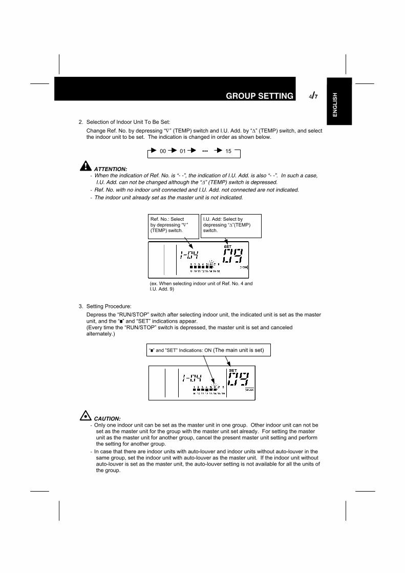
2. Selection of Indoor Unit To Be Set:Change Ref. No. by depressing “∇” (TEMP) switch and I.U. Add. by “∆” (TEMP) switch, and selectthe indoor unit to be set. The indication is changed in order as shown below.
ATTENTION:- When the indication of Ref. No. is “- -”, the indication of I.U. Add. is also “- -”. In such a case,
I.U. Add. can not be changed although the “∆” (TEMP) switch is depressed.- Ref. No. with no indoor unit connected and I.U. Add. not connected are not indicated.- The indoor unit already set as the master unit is not indicated.
3. Setting Procedure:Depress the “RUN/STOP” switch after selecting indoor unit, the indicated unit is set as the masterunit, and the “ ” and “SET” indications appear.(Every time the “RUN/STOP” switch is depressed, the master unit is set and canceledalternately.)
CAUTION:- Only one indoor unit can be set as the master unit in one group. Other indoor unit can not be
set as the master unit for the group with the master unit set already. For setting the masterunit as the master unit for another group, cancel the present master unit setting and performthe setting for another group.
- In case that there are indoor units with auto-louver and indoor units without auto-louver in thesame group, set the indoor unit with auto-louver as the master unit. If the indoor unit withoutauto-louver is set as the master unit, the auto-louver setting is not available for all the units ofthe group.
00 01 15•••
Ref. No.: Selectby depressing “∇”(TEMP) switch.
I.U. Add: Select bydepressing “∆”(TEMP)switch.
(ex. When selecting indoor unit of Ref. No. 4 andI.U. Add. 9)
“ ” and ”SET” Indications: ON (The main unit is set)

4/8 GROUP SETTING
Setting of Slave Unit
Indication of Slave Unit Setting ModeWhen the central station is changed to the slave unit setting mode, the LCD indication on thecentral station is as shown below. The indication of the group to be set is flickered. The Ref.No. and I.U. Add. indicates the address of the indoor unit with the smallest address among theslave units of the group to be set. The “ ” indication of group flickers in case that the slave unitsof the group are already set. In case that the slave units are not set, “- -” is indicated at Ref. No.and I.U. Add.
Procedure of Slave Unit SettingSet the master unit for each group as followings.
1. Selection of Group To Be SetSelect the group to be set by depressing “GROUP” switch.The flickering indication of group number is moved every timewhen the “GROUP” switch is depressed.The group with no setting of master unit can not beselected.
The flickering indication of group number is moved (ex. When selecting group No.10).
“2” shows the slave unitsetting mode.
Ref. No. of Indoor Unit To Be Set(Can be changed by depressing the “∇” (TEMP) switch.)
When the “SET” indication appears, theindicated indoor unit is set as the slave unit.(When “SET” does not appear, the slave unitis not set.)
Only the group with the master unitalready set is indicated. The group to beset is flickered.
When the “CHECK” indication appears, thecentral station is in the check mode.
“ ” shows the group with indoor units to be set (The abovefigure shows that the indoor unit of Ref. No.1 and I.U. Add. 2is set as the slave unit of No.4 group).
Address of Indoor Unit To Be Set(Can be changed by depressing the “∆ ”(TEMP) switch.)
GROUP SETTING 4/9
ENG
LISH
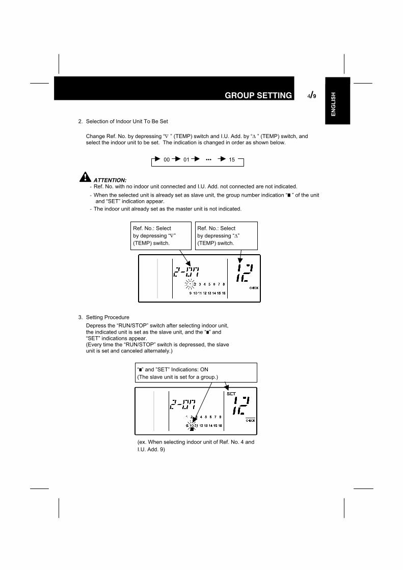
“ ” and ”SET” Indications: ON(The slave unit is set for a group.)
2. Selection of Indoor Unit To Be Set
Change Ref. No. by depressing “∇ ” (TEMP) switch and I.U. Add. by “∆ ” (TEMP) switch, andselect the indoor unit to be set. The indication is changed in order as shown below.
ATTENTION:- Ref. No. with no indoor unit connected and I.U. Add. not connected are not indicated.- When the selected unit is already set as slave unit, the group number indication “ ” of the unit
and “SET” indication appear.- The indoor unit already set as the master unit is not indicated.
3. Setting ProcedureDepress the “RUN/STOP” switch after selecting indoor unit,the indicated unit is set as the slave unit, and the “ ” and“SET” indications appear.(Every time the “RUN/STOP” switch is depressed, the slaveunit is set and canceled alternately.)
00 01 15•••
Ref. No.: Selectby depressing “∇”(TEMP) switch.
Ref. No.: Selectby depressing “∆”(TEMP) switch.
(ex. When selecting indoor unit of Ref. No. 4 andI.U. Add. 9)

5/10 INPUT/OUTPUT FUNCTION
CAUTION:- Up to 15 slave units can be set in one group (Max. 16 units (including the master unit) in one
group).- For changing the setting of slave unit to another group, cancel the present slave unit setting
and perform the setting for another group.- In case that all the units are set as the master unit, the central station can not be changed to
the slave unit setting mode.
5. INPUT/OUTPUT FUNCTION
The central station has two input functions and two output functions as shown below.
Table A. Input / Output Setting Mode and ConnectorSetting of DSW2
Mode Port
Input 1 CN2 1-2SimultaneousOperation/StoppageLevel Signal
SimultaneousOperation/Stoppage,Level Signal
SimultaneousOperation,Pulse Signal
Input 2 CN2 2-3 Demand Emergency StopSimultaneousStoppage,Pulse Signal
Output 1 CN3 1-2 Simultaneous Operation OutputOutput 2 CN3 1-3 Simultaneous Alarm Output
Specifications of Required Components:- DC12V Non-voltage A Connection- OMRON MY Relay- PCC-1A
As for demand input, the group to be controlled can be set when signal is input.
5.1. DEMAND SETTING PROCEDURE
1. Changing to Check ModeDepress the “CHECK” switch for more than 3 seconds, and the central station is changed to thecheck mode.
Cable with Connector (Option): PCC-1A
Cable More Than 0.5mm2 (Field-Supplied, Max. length: 70m)
CN2
CN3RYa
R
Non-Voltage A Connection Input
123
123
ONOFF
1
#2 pin:ON or OFFbothavailable
ONOFF
1 2 3 4
ONOFF
1 2 3 4

INPUT/OUTPUT FUNCTION 5/11
ENG
LISH
2. Changing to Demand Setting ModeDepress the “CHECK” switch and change the 7-segment indication for check to “5” (DemandSetting Mode). The LCD indication of the central station is as shown below.
3. Selection of Group To Be SetSelect the group to be set by depressing the “GROUP” switch. The flickering indication of groupnumber is moved every time the “GROUP” switch is depressed.The Ref. No. and I.U. Add. of the indoor unit set as main unit of the selected group to be set areindicated. The “ ” indication appears at the group already set with demand control, and the“DEMAND” indication appears.
4. Setting Procedure
Depress the “RUN/STOP” switch and the selected group is set with demand control, and the “ ”and “DEMAND” indications appear.(Every time the “RUN/STOP” switch is depressed, the demand control is set and canceledalternately.)
“5” shows the demand setting mode.Ref. No. of Indoor Unit Set asMaster Unit of Group To Be Set
When the “CHECK” indicationappears, the central station is in thecheck mode.
Address of Indoor Unit Set as MasterUnit of Group To Be Set
Only the group with the master unitalready set is indicated. The group to beset is flickered.
The group already set with demand control isindicated.( is ON: Demand is set. / is OFF: Demandis not set.)
The flickering indication of group number ismoved (ex. When selecting group No.3).
“ ” and ”SET” Indications: ON(The demand control is set.)

6/12 OPTION SETTING
6. OPTION SETTING
6.1. CHANGING TO OPTION SETTING MODE
Changing to Option Setting Mode
1. Depress the “CHECK” switch for more than 3 seconds while all the groups are stopped. Thecentral station is changed to the option setting mode and the “CHECK” indication appears, and“1” (Master Unit Setting Mode) is indicated on the 7-segment for check.
ATTENTION:When there is a group in operation, the central station can not be changed to the checkmode.
2. Depress the “CHECK” switch and change the indication of the 7-segment.
7-Segment FunctionA Fixing Operation Modeb Fixing Setting Temperaturec Fixing Cooling Onlyd Fixing Air FlowE Auto COOL / HEAT
3. Depress the “RESET” switch and the central station is changed to the normal mode.
Indication of Option Setting Mode
When the central station is changed to the slave unit setting mode, the LCD indication on thecentral station is as shown below. The indication of the group to be set is flickered. The Ref. No.and I.U. Add. indicates the address of the indoor unit which is set as the master unit of the groupto be set. The “ ” indication of group flickers in case that the option setting is already done.When the “SET” indication appears, the indoor unit indicated on LCD is already set with theoptional function.
“A” shows the option settingmode. Ref. No. of Indoor Unit Set as Master
Unit of Group To Be SetWhen the “SET” indication appears, theindicated indoor unit is set with the optionalfunction.
Group Number To BeSet
Condition of Option Setting forEach Group( is ON: Option is set. / isOFF: Option is not set.)
When the “CHECK” indicationappears, the central station is inthe check mode.
Address of Indoor Unit Set asMaster Unit of Group To Be Set

INITIALIZATION OF CENTRAL STATION 7/13
ENG
LISH
Setting Procedure
1. Depress the “CHECK” switch and select the setting item A – E.2. Select the group to be set by depressing the “GROUP” switch.3. Depress the “RUN/STOP” switch, the option setting is done. At that time, the “ ” indication
appears and the “SET” indication also appear. (Every time the “RUN/STOP” switch isdepressed, the optional function is set and canceled alternately.)
CAUTION:- In case that the optional functions are set by the central station, it is required to set the same
optional functions for the group by the remote control switch.- In case that the optional functions (items A – E as shown above) are set by the remote control
switch, it is required to set the same optional functions for the group by the central station.
7. INITIALIZATION OF CENTRAL STATION
The procedure for initialization of the group setting and the optional setting is as follows.
1. Changing to Self Check ModeDepress the “GROUP( and )” and ”MODE” switches simultaneously, the central station ischanged to the self check mode. In case that there is a group in operation, the “NO FUNCTION”is indicated and the central station can not be changed to the self check mode.After changing to the self check mode, the LCD indication is changed from (I) to (vi) as shownbelow.Before the indication is changed to (vi), depress the “GROUP( and )” and ”MODE” switchessimultaneously again, and the central station is changed to the initializing mode.
NOTE:In case that the “GROUP ( and )” and ”MODE” switches are not depressed again, theself check operation continues.
(i) (ii)
(iv)(iii) (v)
(vi)All Indications: ON
All Indications: OFF

7/14 INITIALIZATION OF CENTRAL STATION
2. InitializationWhen the central station is changed to the initializing mode, the LCD indication on the centralstation is as shown below. In this condition, depress the “RESET” switch, and the flickering “06”indication is changed to ON and the initialization is performed.(In case that initialization is not required, depress the “CHECK” switch, the LCD indication isautomatically changed as shown below.)
Group Setting Table of Central Station
Indoor Unit AddressRSW ofIndoor
Unit0 1 2 3 4 5 6 7 8 9 A B C D E F
Indicationof PSC-5S 0 1 2 3 4 5 6 7 8 9 10 11 12 13 14 15
00010203040506070809101112131415
Fill the group number (1-16) in the above table.Circle the unit number of the master unit.
Depress“RESET” or”CHECK”switch.
“06” flickers. Depress “RESET” switchand “06” is changed to ON.In case of EEPROM initialization, ittakes approximately 30 – 60 seconds.
To Connection Check
Ref
riger
ant N
umbe
r
SWITCH NAMES AND FUNCTIONS 8/15
ENG
LISH
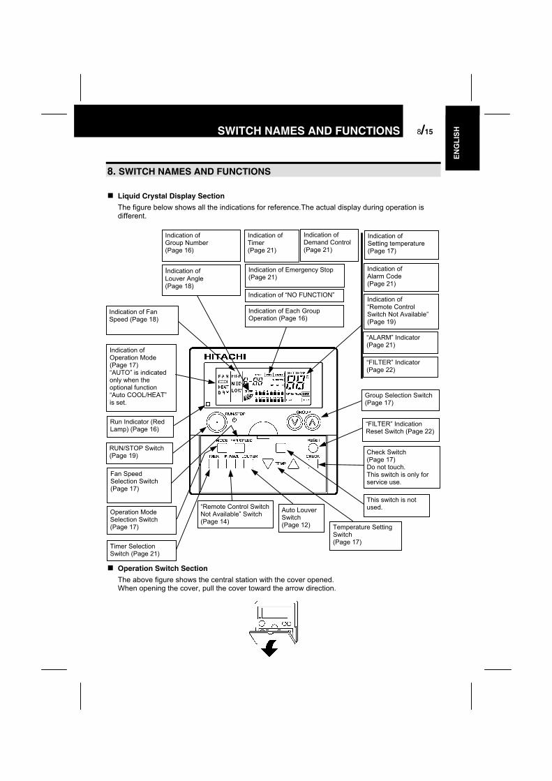
8. SWITCH NAMES AND FUNCTIONS
Liquid Crystal Display Section
The figure below shows all the indications for reference.The actual display during operation isdifferent.
Operation Switch Section
The above figure shows the central station with the cover opened.When opening the cover, pull the cover toward the arrow direction.
Timer SelectionSwitch (Page 21)
Auto LouverSwitch(Page 12) Temperature Setting
Switch(Page 17)
Group Selection Switch(Page 17)
“FILTER” IndicationReset Switch (Page 22)
Check Switch(Page 17)Do not touch.This switch is only forservice use.
This switch is notused.
Indication ofSetting temperature(Page 17)
Indication ofAlarm Code(Page 21)
Indication of“Remote ControlSwitch Not Available”(Page 19)
“ALARM” Indicator(Page 21)
“FILTER” Indicator(Page 22)
Indication ofGroup Number(Page 16)
Indication ofLouver Angle(Page 18)
Indication of FanSpeed (Page 18)
Indication ofOperation Mode(Page 17)“AUTO” is indicatedonly when theoptional function“Auto COOL/HEAT”is set.
Run Indicator (RedLamp) (Page 16)
Indication of “NO FUNCTION”
Indication of Each GroupOperation (Page 16)
RUN/STOP Switch(Page 19)
Fan SpeedSelection Switch(Page 17)
Operation ModeSelection Switch(Page 17)
“Remote Control SwitchNot Available” Switch(Page 14)
Indication ofTimer(Page 21)
Indication of Emergency Stop(Page 21)
Indication ofDemand Control(Page 21)

9/16 OPERATION PROCEDURE
9. OPERATION PROCEDURE
Group Selection and Monitoring Unit Operation Status
The central station can control up to 16 groups by each group or simultaneously.(The selected groups can be operated and the unit operation status of the groups can bemonitored.)
NOTE:The group number is changed by depressing the “GROUP” switch. The group without groupsetting is not indicated.
1. Supply power to the unit.
ATTENTION:- Supply power to the unit more than 12 hours before
unit operation for compressor protection.- Do not cut off power during the term of using air
conditioner.2. Depress the “GROUP” switch.
Every time the “GROUP” switch is depressed, the groupnumber to be controlled is changed in the order as shownbelow. In case of “AA”, all the units are controlledsimultaneously.
Group No. is changed.(ex. In case of selecting group 3)
3. When selecting the group, the setting conditions ofeach group are indicated.By operating by the remote control switch, the content ofthe setting is indicated.1 ~16 Show the operating conditions of each group asfollows;- Turned OFF ( ): Stop- Turned ON ( ): Operation- Flickering ( ): Abnormality
The Run indicator (Red Lamp) shows the following:- Turned OFF: All Groups Stop- Turned ON: More than 1 Group in Operation- Flickering: More than 1 Group in Abnormal Condition.
In case of group AA, the indications(operation mode, setting temperature,ail flow, louver angle and “RMT. SWNAVAL”) are indicated only when allgroups are in the same setting.
NOTE:The indication of setting temperature “- -” shows no setting of temperature.
Only Group Numbers Already Set areindicated.
Operating Conditions of Each Group(ex. In case of “COOL”, ”MED” and”28°C”)
Operating Conditions of Each Group(ex. In case of groups 1 ~ 3 inoperation)

OPERATION PROCEDURE 9/17
ENG
LISH
Setting of Operation Mode
<Function>“COOL” Operation: To cool the room temperature by distributing the cooled air.“HEAT” Operation: To heat the room temperature by distributing the heated air.“DRY” Operation: To dehumidify more than standard cooling operation.“FAN” Operation: To circulate the room air.NOTE:
The recommended temperature for each operation is as follows;“COOL” Operation: 27~29°C / “HEAT” Operation: 18~20°C / “DRY” Operation: 23~25°C
1. Depress the “GROUP” switch and select the group.(Refer to item 2 of “A. Group Selection and Monitoring UnitOperation Status” in page 16.)
The above figure shows the case ofselecting group 4.
2. Depress the “MODE” switch.The operation mode is changed in the following order.
FAN COOL HEAT DRYThe above figure shows the case ofsetting “HEAT” operation.
NOTE:- The above indications show the case of setting operation mode for group 4. The same setting
procedure shall be performed for other groups. In case of the same setting for all groups, select thegroup number of “AA”.
- Some operation modes can not be set according to the unit model. Contact to HITACHI dealer oryour distributor for details.
- The operation mode can be set while the unit is stopped or in operation.
Setting of Temperature, Fan Speed and Louver Angle
NOTE:- Do not touch the “CHECK” switch. The “CHECK” switch is only for service use.- When the “CHECK” switch is depressed by a mistake and the central station is changed to the check
mode, depress the “RESET” switch to cancel.
1. Depress the “GROUP” switch and select the group.(Refer to item 2 of “A. Group Selection and Monitoring UnitOperation Status” in page 11.)
The above figure shows the caseof selecting group 4.
<TEMPERATURE>Set temperature by depressing "TEMP" switch.Depressing "∆" switch, the temperature is increased by 1 °C(Maximum: 30 °C).Depressing "∇" switch, the temperature is decreased by 1 °C(Minimum: 19 °C, for Cool, Dry and Fan mode, and 17 °C for Heatmode). When depressing ∆ for 3 seconds at set temperature at 30 °C,or depressing ∇ for 3 seconds at the minimum temperature, thetemperature is not set and the indication of setting temperature is "--".In this case, depress ∆ or ∇, the indication of setting temperaturereturns to the minimum temperature or 30°C.The right figure shows thecase of setting 22 °C
NOTE:The above shows the setting range for standard model. The setting range may be different accordingto the connected unit model.
The above figure shows thecase of setting 22°C.

9/18 OPERATION PROCEDURE
<FAN SPEED>Depress the “FAN SPEED” switch.By depressing the “FAN SPEED” switch, the indication ischanged in the following order;
HIGH MED LOW
NOTE:- In case of dry operation, the fan speed is automatically changed and fixed at the “LOW” fan
speed.- In this case, the fan speed can not be changed (The indication remains at the setting
condition).
<LOUVER ANGLE>Depress the "AUTO LOUVER" switch.Every time the "AUTO LOUVER" switch is depressed, theindication of the louver angle is changed.Depress the "AUTO LOUVER" switch at the position of
, the indication is changed to and this indicationindicates the auto-swing. Depress the "AUTO LOUVER"
switch again, the indication is turned to
NOTE:- The above indications show the case of setting operation mode for group 4.- The same setting procedure shall be performed for other groups. In case of the same setting
for all groups, select the group number of “AA”.- The temperature, fan speed and louver angle can be set while the unit is stopped or in
operation.
In Case of 4-Way Cassette Type (Example)
LCDIndication
Air LouverAngle Approx.
25°Approx.
30°Approx.
35°Approx.
40°Approx.
50°Approx.
55°Approx.
60°
Cooling Dry
Heat
:Recommended Angle
NOTE:- The fixing angle of the louver shown above is the case of 4-way cassette type indoor unit. The
fixing angle is different according to unit model. Refer to the operation manual of each modelfor details.
- There exists a time lag between the indicated louver position on LCD and the actual louverangle in operation. Therefore, when fixing the louver, set the angle according to the indicatedlouver angle on LCD.
- When the “AUTO LOUVER” switch is depressed, the louver may not stop immediately.
The above figure shows the case ofsetting “HIGH” fan speed.
The above figure shows the case ofsetting auto-swing.
Angle Range
Angle Range

OPERATION PROCEDURE 9/19
ENG
LISH
ATTENTION:The louver angle is automatically changed during heating operation for unit control.
When heating operation isstartedWhen dry operation isstartedWhen temperaturecontroller is activated
The louver angleis automaticallychanged.
When the discharged airtemperature is increased over30°C, the louver angleautomatically return to the setposition.
The LCD indication remains at the setting condition.
Unit Operation
1. Depress the “GROUP” switch and select the group.(Refer to item 2 of “A. Group Selection and Monitoring UnitOperation Status” in page 16.)
The above figure shows thecase of selecting group 4.
2. Depress the “RUN/STOP” switch.In case that the selected group is in operation, the group isstopped by depressing “RUN/STOP” switch.In case that the group is not in operation, the group isstarted by depressing the “RUN/STOP” switch.In case of group “AA”, depress the “RUN/STOP” switch, and;- All the groups are stopped (When more than 1 group is in
operation (Run lamp is ON)).- All the groups are started operation (When all the groups
are stopped (Run lamp is OFF)).
The above figure shows thecase of group 4 operation.
NOTE:The above indications show the case of setting operation mode for group 4.The same setting procedure shall be performed for other groups. In case of the simultaneousoperation for all groups, select the group number of “AA”.
Turned ON

9/20 OPERATION PROCEDURE
Prohibiting Operation by Remote Control Switch
<Function>To prohibit the operation by the remote control switch.When this function is available, the “CENTRAL” indication appears on the LCD on the remote controlswitch and the operation by the remote control switch is not available.
1. Depress the “GROUP” switch and select the group.(Refer to item 2 of “A. Group Selection and MonitoringUnit Operation Status” in page 16.)
The above figure shows the caseof selecting group 4.
2. Depress the “RMT. SW NAVAL” switch. Every timethe “RMT. SW NAVAL” switch is depressed, the“RMT. SW NAVAL” indication is turned ON and OFFalternately.
ATTENTION:- The above indications show the case of setting operation mode for group 4. The same setting
procedure shall be performed for other groups. In case of the same setting for all groups,select the group number of “AA”.
- Although the “RMT. SW NAVAL” function is set, in case of operation by the central station, theunit can be stopped by the remote control switch, and in this case, the unit can be started againby the remote control switch.
- For the unit without remote control switch, the “RMT. SW NAVAL” function shall be set.- In case of using together with other controllers, do not set the “RMT. SW NAVAL” function.
Additionally, do not set the “RMT. SW NAVAL” function by other controller or the malfunctionmay occur.
- In case of no setting of temperature (“- -”), the temperature can be set by the remote controlswitch during the “RMT. SW NAVAL” function is available.
Turned ON

OPERATION PROCEDURE 9/21
ENG
LISH
Timer Operation
<Function>To set the schedule operation “available” or “not available” by the signal from the control timer incase of connection with the control timer (PSC-5T; Option).The schedule operation can be set “available” or “not available” individually for each unit, however,the operation schedule is all the same.
1.Depress the “GROUP” switch and select the group.(Refer to item 2 of “A. Group Selection andMonitoring Unit Operation Status” in page 16.)
The above figure shows the case ofselecting group 4.
2. Depress the “TIMER” switch. Every time the“TIMER” switch is depressed, the “TIMER”indication is turned ON and OFF alternately. Thegroup with timer setting is operated according tosetting schedule by the signal from the controltimer.
The above figure shows the case ofsetting timer operation.
NOTE:The above indications show the case of setting operation mode for group 4.The same setting procedure shall be performed for other groups. In case of the same settingfor all groups, select the group number of “AA”.
Other LCD Indications
Indication in Normal Conditions<EMERGENCY>The “EMERGENCY” is indicated when the emergencystop signal is input by the outside input function.During the emergency stoppage, indoor units arestopped and the operation by the remote control switchis not available.
Contact your distributor or dealer of HITACHI fordetails.
Turned ON

9/22 OPERATION PROCEDURE
<DEMAND>The “DEMAND” is indicated when the demand input isset bythe outside input function.The indication is indicated for the group with demandsetting and the “DEMAND” indication flickers when thedemand signal is input.
Contact your distributor or dealer of HITACHI fordetails.
<FILTER>Filter Clogging:When the “FILTER” indication is indicated, it showsthat the air filter of the indoor unit is clogged. Cleanthe air filter.After cleaning, depress the “RESET” switch and the“FILTER” indication is turned OFF.
Indication in Abnormal Conditions
<ABNORMAL>The Run lamp (Red lamp) is flickered when there is agroup in abnormal condition.The “ALARM” is indicated on the LCD.The “ ” indication of the group in abnormal condition isflickered.Depress the “GROUP” switch and select the group withalarm, the indication of unit No., model code, alarmcode and the normal indication is repeatedly indicated(There is a case that the model code may not beindicated according to the unit model).In case that multiple units are in abnormal conditions,the above indication is indicated by turns.
Check the contents of the LCD indication and contactyour distributor or dealer of HITACHI for details.
<POWER FAILURE>All the indications are disappeared.In case of unit stoppage due to the power failure, the unit is not started again after the powerrecovery. Perform the starting operation again.In case of instant power failure within 2 seconds, the unit is automatically started again.<ELECTRICAL NOISE>All the indications are disappeared, and the unit operation may be stopped for the deviceprotection due to the electrical noise. Perform the starting operation again.
Flickers
In Case of Demand Setting
In Case of Demand Signal Input
Ref. No. I.U. Add.
Model Code Alarm Code