PSA Norway - Optimising Subsea Assets
75
Document number: 26583U-1161480945-354 Revision number: 2.0 Approval date: 17.12.2018 1255 - PSA Norway - Bonded flexibles State of the art Bonded Flexible Pipes 2018
Transcript of PSA Norway - Optimising Subsea Assets
Document number: 26583U-1161480945-354 Revision number: 2.0 Approval date: 17.12.2018
1255 - PSA Norway - Bonded flexibles
State of the art Bonded Flexible Pipes 2018
4Subsea AS, Hagaløkkveien 26, N-1383 Asker 2 © Copyright 2019 4Subsea AS
State of the art Bonded Flexible Pipes 2018
Client:
PSA Norway
Technical Report
Project Project 1255 - PSA Norway - Bonded flexibles Client Reference NA Document Document Date 17.12.2018 Classification Open Total Number of pages including appendices 75 Document Number 26583U-1161480945-354 Revision log Revision no Document revision Date Author(s) Checked Approved
01 For comments 15.11.2018 SAL JM CNA 02 Final report 17.12.2018 SAL CNA ØK

State of the art Bonded Flexible Pipes 2018 26583U-1161480945-354, Revision 2.0, 17.12.2018
4Subsea AS, Hagaløkkveien 26, N-1383 Asker 3 © Copyright 2019 4Subsea AS
Abbreviations
API American Petroleum Institute
OCIMF Oil Companies International Marine Forum
GMPHOM Guide to Manufacturing and Purchasing Hoses for Offshore Moorings, (issued by OCIMF)
PSA Petroleum Safety Authority (Norway)
EN European Standard
MERL Independent research consultants in polymer engineering and material selection
MBC Marine Breakaway Coupling
LPG Liquefied Petroleum Gas
LNG Liquefied Natural Gas
FPSO Floating Production Storage and Offloading unit
MMS Mineral Management Service (US)
IOGP The International Organisation of Oil and Gas Producers
ITOPF The International Tanker Owners Pollution Federation
HSE Health and Safety Executive (UK)
State of the art Bonded Flexible Pipes 2018 26583U-1161480945-354, Revision 2.0, 17.12.2018
4Subsea AS, Hagaløkkveien 26, N-1383 Asker 4 © Copyright 2019 4Subsea AS
Table of Contents Abbreviations ........................................................................................................... 3 Table of Contents ..................................................................................................... 4 1 Summary .......................................................................................................... 4 2 Introduction ...................................................................................................... 7 3 Background ....................................................................................................... 8
3.1 Issues with bonded flexible pipes ........................................................................ 9 3.2 Oil spills ..................................................................................................... 10 3.3 Sources of information ................................................................................... 13
4 Bonded flexible pipe types .................................................................................. 15 4.1 Bonded flexible risers and topside jumpers .......................................................... 16 4.2 Loading hoses .............................................................................................. 17 4.3 Cryogenic hoses ............................................................................................ 22 4.4 Seawater intake hoses .................................................................................... 24 4.5 High pressure hoses used for exploration ............................................................. 25 4.6 Other bonded hoses for the oil and gas industry .................................................... 26
5 Design ............................................................................................................ 28 5.1 Bonded hose design ....................................................................................... 28 5.2 Design specifications ...................................................................................... 31 5.3 Elastomer Materials ....................................................................................... 35
6 Failure mode review .......................................................................................... 36 6.1 Overview .................................................................................................... 36 6.2 Manufacturing, storage and transport ................................................................. 36 6.3 In-service overload and handling failure modes ..................................................... 39 6.4 Long term degradation ................................................................................... 50
7 Integrity management ........................................................................................ 56 7.1 Information handling ...................................................................................... 56 7.2 Risk Based Inspection Planning.......................................................................... 58 7.3 Inspection, testing and monitoring ..................................................................... 61 7.4 Offloading systems ........................................................................................ 64 7.5 Exploration hoses .......................................................................................... 67 7.6 Repair........................................................................................................ 68
8 Experience and Observations ................................................................................ 69 8.1 Operational observations ................................................................................ 69 8.2 Exchange of information ................................................................................. 73 8.3 Knowledge gaps and trends for the future ............................................................ 74
9 References ...................................................................................................... 75
1 Summary
State of the art Bonded Flexible Pipes 2018 26583U-1161480945-354, Revision 2.0, 17.12.2018
4Subsea AS, Hagaløkkveien 26, N-1383 Asker 5 © Copyright 2019 4Subsea AS
State of the art Bonded Flexible Pipes 2018 covers most bonded flexible pipes and hose types used in the oil and gas industry. PSA Norway has listed items which should be addressed;
• Overview of Bonded Flexible Pipe development globally, including technologies in use,designs, operational experience
• Overview of important issues (Norway and globally)• Relevant degradation mechanisms and failure modes• State of the art knowledge and knowledge gaps• Trends including look ahead• Inspection and monitoring• Recommendation related to improvement, sharing of information etc• Standards, state of the art and gaps
The following observations should be noted:
1) Bonded flexible pipes have contributed to the success of FLNG (Floating LNG productionunit) through the long and large bore seawater intake hoses and the LNG offloading hoses.No known issues with these hose types have been reported. However, as FLNG is a relativelynew technology, the experience is limited.
2) Crude offloading hoses have recently been used in demanding application. Even thoughextensive qualification programs have been executed there are several examples of new in-service failure modes not identified in the qualification. Both oil spill and costly productiondown time has resulted from this.
3) The reliability of the type approved bonded flexibles is generally good (API monogrammedhoses, GMPHOM 2009 hoses and type approved hoses). There are several examples of hosefailures related to use of low-quality hoses, hoses operated outside design specification orfailure due to inadequate maintenance. The industry should work with improvements here.
4) Life Time Extension (LTE) of hose systems, in particular crude offloading hoses, is morefrequent now than before. The safe remaining life for hoses delivered without service lifedocumentation is difficult to access. There are examples of import and export terminalsusing GMPHOM hoses where large test facilities are established for regular inspection andtesting, typically yearly or biannually inspections to document hose status. There are otherexamples where LTE is primarily based on a minimum evaluation of potential failure modescombined with inspection and standard tests. It is recommended that purchasers of hoseswhere Life Time Extension may be relevant in the future consider buying hoses with servicelife documentation, e.g. API 17K hoses and include evaluation of efficient hose replacementequipment. With LTE and hose replacement considered in design it is possible to performefficient hose replacement and thereby avoid the cost of production down time.
5) There are differences in the basis behind and updating of the various design specificationsused for bonded flexible pipes:
a. API 17K hoses; Updating of API 17K (2017) was coordinated by a technicalcommittee where all hose manufacturers, important purchasers and technicalexperts contributed. The exchange of information and updating of the specificationwas handled in a consistent manner. Delivery of API 17K hoses require API approvedhose design methodology and API approved manufacturing. API 17K hoses areengineered to a given application and service life in this application is documented.
b. GMPHOM 2009(Marine offloading hoses), EN1762 (LPG hoses) and EN1474(LNG hoses)are standard hoses, type approved by standard tests. These specifications open upfor, and recommend to, agree project specific requirements betweenpurchaser/owner and vendor. If the purchaser wants to know the safe service life ina given application, then the purchaser and vendor have to agree how to documentthis. The purchaser will hence need to know the challenges with the products andagree with the vendor how to document that the product is fit for long termoperation in the intended service. Often vendor recommendations on hosereplacement intervals are used as an alternative.
c. For other bonded flexibles, type approval with third party approval is commonlyused. However, for cost reasons hoses without any form of type approval is stillused in many oil and gas applications.
State of the art Bonded Flexible Pipes 2018 26583U-1161480945-354, Revision 2.0, 17.12.2018
4Subsea AS, Hagaløkkveien 26, N-1383 Asker 6 © Copyright 2019 4Subsea AS
6) The exchange of operational experience and product limitations could be improved
a. All Operators of Crude Oil offloading systems require that the risk for oil spill shallbe very low, mainly due to environment and reputation. The consequence of thishas been discussed with several operators that have experienced serious issues withtheir crude oil offloading systems and the following is noted:
i. The learning from such issues is not well communicated to the industry,details remains confidential
ii. Use of API 17K is considered the best option for reducing risk for hosedefects. However, none of the operators that have experienced seriouschallenges with offloading hoses has implemented consistent use of API 17Khoses in their crude oil offloading systems, however, some oil companies,e.g. Equinor, are adopting API 17K widely
iii. LTE and/or hose replacement is costly and normally required within the lifeof the oil field. Improved inspection tools and acceptance criteria for LTE ison the wish list for the operators,
b. Dunlop Oil and Marine arrange technical seminars regularly where they educate theindustry on their technical solutions and hose operators present experience andother view related to Dunlop hoses. The seminar is well attended and is animportant forum for exchange of information on Dunlop hoses.
c. 4Subsea is running FlexShare, a joint industry initiative, now entering anoperational phase. FlexShare overall objective is to facilitate efficientindustry experience-sharing related to all types of flexible pipes. The initial JIPphase involved 10 operators of flexible pipes, but the operational phase aims atrecruiting even more members. FlexShare is currently concentrated on non-bondedflexible pipes, but the intention is to include bonded pipes in the future.
d. PSA Norway prepare state of the art reports like this one which are published.Feedback from the industry indicate that the knowledge about this is notwidespread.
e. Industry comments to updating of the specifications are important arenas forexchange of information. However, as such updating is not a continuous activity, itmay not be the ideal forum for exchange of information.
f. There are several examples of industrial hose failures due to hoses used inapplications they were not designed for, e.g. failure of short hoses with reduceddiameter used as a flexible connection between piping at loading terminals andhoses operated outside their design temperature.
7) Inspection tools. Both manufacturer and operators have considered measures to reduce riskfor hose failure. Marine hoses are operated with double carcass systems such that leak frombore is contained within the secondary carcass. Further several initiatives relatedmonitoring of hose loads exist. Direct measurements of stresses or defects in the hose wallhas been proposed but no reliable commercial method exist today. The most common andstill considered the best inspection methods remain Visual Inspection, geometricalmeasurements, pressure testing and vacuum testing. Systematic use of such inspectioncombined with clearly defined acceptance criteria seems to work. However, there is a lackof industrial standardization related to this and often challenging to establish acceptancecriteria.
8) Recertification of hoses. Bonded flexible hoses are normally recertified based on Visualinspection, Pressure testing and Vacuum testing. If several hoses are to be recertified it iscommon to burst test one hose to verify that the burst capacity (structural strength of hose)remain acceptable. The hoses are then typically recertified for a period which is often inline with manufacturer recommendation. This method is frequently used for standardhoses, however, the requirements for such recertification are unclear and to a large extentup to hose owner decision.
For API 17K hoses requirements to LTE is addressed in general terms, however no specificrecommendations for testing are given.
State of the art Bonded Flexible Pipes 2018 26583U-1161480945-354, Revision 2.0, 17.12.2018
4Subsea AS, Hagaløkkveien 26, N-1383 Asker 7 © Copyright 2019 4Subsea AS
To our knowledge there are no indications of increased risk with operation of recertified hoses.
9) Some experience-based recommendations for operation of bonded flexible hose are noted
a. Pressure testing of damaged hoses, hoses on the reel with un-known residualtension or hoses that have been kinked or crushed should not be performed aspremature burst or end-fitting blow off may occur.
b. A bonded hose should only be used for the intended service.
c. The manufacturer guidance on service limitation, storage, handling, inspection,testing and maintenance should be followed.
d. Premature failure of both bonded and non-bonded flexible pipes used on drag chainand other demanding jumper applications has occurred and design of such systemsshould be performed in close dialogue with hose manufacturer.
2 Introduction 4Subsea has been awarded preparation of a state-of-the-art report for bonded flexible pipes from PSA Norway (Petroleum Safety Authority). The report is based on 4Subsea knowledge and input from various sources, however, the report is not necessarily complete and should not be interpreted as anything else than 4Subsea view of the present state of the art for non-bonded flexible pipes.
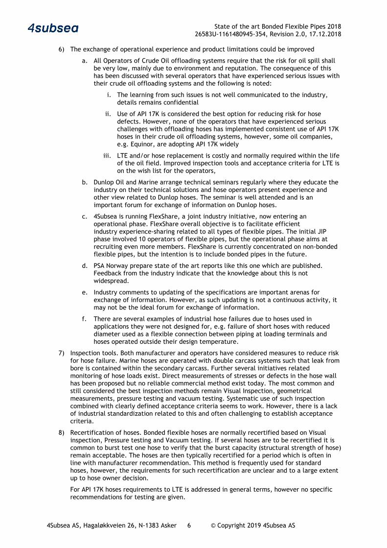
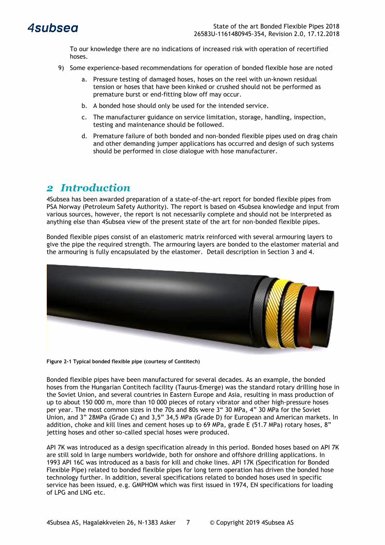
Bonded flexible pipes consist of an elastomeric matrix reinforced with several armouring layers to give the pipe the required strength. The armouring layers are bonded to the elastomer material and the armouring is fully encapsulated by the elastomer. Detail description in Section 3 and 4.
Figure 2-1 Typical bonded flexible pipe (courtesy of Contitech)
Bonded flexible pipes have been manufactured for several decades. As an example, the bonded hoses from the Hungarian Contitech facility (Taurus-Emerge) was the standard rotary drilling hose in the Soviet Union, and several countries in Eastern Europe and Asia, resulting in mass production of up to about 150 000 m, more than 10 000 pieces of rotary vibrator and other high-pressure hoses per year. The most common sizes in the 70s and 80s were 3“ 30 MPa, 4” 30 MPa for the Soviet Union, and 3” 28MPa (Grade C) and 3,5” 34,5 MPa (Grade D) for European and American markets. In addition, choke and kill lines and cement hoses up to 69 MPa, grade E (51.7 MPa) rotary hoses, 8” jetting hoses and other so-called special hoses were produced.
API 7K was introduced as a design specification already in this period. Bonded hoses based on API 7K are still sold in large numbers worldwide, both for onshore and offshore drilling applications. In 1993 API 16C was introduced as a basis for kill and choke lines. API 17K (Specification for Bonded Flexible Pipe) related to bonded flexible pipes for long term operation has driven the bonded hose technology further. In addition, several specifications related to bonded hoses used in specific service has been issued, e.g. GMPHOM which was first issued in 1974, EN specifications for loading of LPG and LNG etc.
State of the art Bonded Flexible Pipes 2018 26583U-1161480945-354, Revision 2.0, 17.12.2018
4Subsea AS, Hagaløkkveien 26, N-1383 Asker 8 © Copyright 2019 4Subsea AS
PSA has previously issued reports covering non-bonded and bonded flexible pipes Reference 1, Reference 2, Reference 3, Reference 4. This document is primarily addressing the following bonded flexible pipes and hoses:
• Production and injection hoses, mainly jumpers but also some flexible risers and flexible flow-lines
• Offshore loading of crude oil and liquefied petroleum gases (LPG, LNG) • Flexible hoses used for exploration e.g. drilling applications • Seawater Intake hoses • Bunkering and service hose for the oil and gas industry is briefly covered.
Bonded pipes are in addition used in several other applications such as mining, low pressure pumping, fire water, hydraulic systems etc. These areas fall outside the scope of this study and are not addressed in any detail.
3 Background Bonded flexible pipes have several advantages:
• Inherent flexibility of rubber, small bend radius • Hose connection in narrow space • Short and reliable couplings • Short lengths are produced individually, special requirements can be considered, e.g.
special bending stiffness distribution within one section etc. o Integral bend stiffener at the coupling, if needed extra reinforcement can be added o Additional layers for fire resistance or external armouring can be added when
manufactured o Built in location collars for floaters or integral floatation can be incorporated
The disadvantages are the following:
• Limited length per segment, long lengths will require joints. • Generally lower crush resistance than non-bonded flexibles • Generally lower axial (external) pulling capacity than non-bonded flexibles • Low resistance to rapid gas decompression • Thermal and chemical restrictions
The in-service experience with bonded flexible pipes used for production of hydrocarbons is mainly related to topside jumpers, drag chain hoses for FPSO turrets and short length riser systems. However, there are a few examples of relatively long length riser application in relatively deep water. Bonded flexible hoses are frequently used for offshore loading of hydrocarbons, such as export oil and LPG. Large bore bonded flexible hoses are standard for offloading of crude to tankers, with sizes ranging from 12” to 24” diameter hoses. Short hose sections, typically 12m long, are joined to long lengths, up to several hundred meters, either as floating hoses, submerged catenary hoses or suspended in air. Such hoses are typically used once a week and stored in the period between. High pressure bonded flexible hoses for exploration and drilling are used in the following applications:
• Kill and choke jumpers • Rotary hoses used in the derrick of the drilling rig • Cementing hoses
In general, such hoses are used periodically and inspected and pressure tested before use. The hose pressure rating is the same as for the drilling equipment. Typically 5 kpsi (345bar) or 7.5 kpsi (517bar) for rotary hoses, 10 kpsi (690bar) or 15 kpsi (1035bar) for cement, kill and choke.
State of the art Bonded Flexible Pipes 2018 26583U-1161480945-354, Revision 2.0, 17.12.2018
4Subsea AS, Hagaløkkveien 26, N-1383 Asker 9 © Copyright 2019 4Subsea AS
Flexible Seawater intake hose requirements are covered in API 17K, rev3, Reference 9. Use of large bore and long length seawater intake hoses is commercially attractive in several applications e.g. FLNG and due to large diameter and vacuum issues the design loads may be challenging. Bonded hoses are frequently used for loading of LPG. Recently flexible pipes for offshore loading of LNG have been qualified and are now commercially available. Some of these products are combining composite hose and bonded hose technology. Overall bonded hoses are important products for the oil and gas industry, the following examples illustrate this
• Most FPSOs have oil export systems with bonded hoses • Many oil import and export terminals all around the world rely on bonded hoses, one
example is the LOOP terminal in Louisiana where a large fraction of foreign crude to USA is off-loaded from tankers (70 000BPD imported through marine hoses)
• Service hoses and bunkering hoses are required in most oil and gas facilities • Bonded hoses may be enabling for new developments, e.g. FLNG where deep water
seawater intake hoses and offshore loading of LNG are attractive
3.1 Issues with bonded flexible pipes 3.1.1 Overview Based on the input to this study, ref section 3.3, and interviews of several users of bonded flexible pipes the following should be noted:
• Personnel injury
o No incidents with major personnel injury have been reported lately
o The high failure elongation of bonded hoses results in high energy release in case of tensile rupture. Personal injuries have occurred when hoses have been accidentally stretched to failure. Most manufacturer recommend restricted access in vicinity of hoses under load
o Handling of bonded hoses involve risk as much energy may be released if the hose fails or is rapidly depressurized
• Economic consequences
o For systems where the bonded flexible part is a vital part, it seems that the industry purchases high quality products and the design specification would normally result in reliable products, however some issues should be noted
o Issues with offloading hoses has resulted in several weeks of production shut down with significant economic consequences
o One reported hose issue may have been the cause for shut down of a well and postponed drilling on an oil field
o For non-critical systems it seems that use of low-quality hoses with relatively high failure rate is accepted in the industry
• Environmental and reputational consequences
o Most of the issues with bonded flexible parts are related to oil spill. Oil spill can lead to pollution and negative input to reputation for the operator of the system. Examples are damage to crude offloading hoses where hose failure has resulted in major oil spills and influenced the reputation to both hose manufacturer and system operators. Another example is operation in environmentally sensitive areas where oil any spill will get very high attention. Oils spill is addressed in section 3.2
3.1.2 Drilling hoses Bonded and non-bonded flexible jumpers are used for kill & choke and mud/cement service in drilling operations. These are high pressure applications and the consequence of failure in such a jumper will normally be reported.
State of the art Bonded Flexible Pipes 2018 26583U-1161480945-354, Revision 2.0, 17.12.2018
4Subsea AS, Hagaløkkveien 26, N-1383 Asker 10 © Copyright 2019 4Subsea AS
PSA Norway has performed a search in their database on reported drilling and well issues since 1998. 8 of 165 reported issues were related to hoses, it is difficult to distinguish between bonded and non-bonded flexible jumpers, however the issues are such that such differentiation is not important. The following should be noted:
• 5 of the 8 issues are related to leaks
o 1 leak is due to maloperation where a low-pressure hose has been exposed to high pressure
o 1 leak may be seal leak or other components than the hose
• 1 issue is related to failure in the hose support assembly, no leak was reported
• 1 unexpected wear issue resulting in shut down of a well
• 1 personnel incident resulting from whipping of a pressurised flexible which should have been de-pressurised before handling
• No hose issues have been reported before 2007.The database may hence be incomplete
• None of the reported drilling related hose issues has escalated
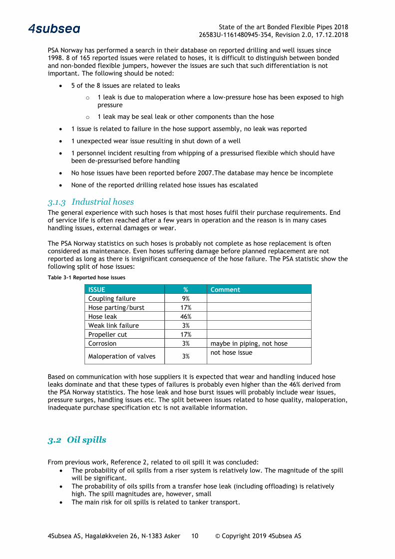
3.1.3 Industrial hoses The general experience with such hoses is that most hoses fulfil their purchase requirements. End of service life is often reached after a few years in operation and the reason is in many cases handling issues, external damages or wear. The PSA Norway statistics on such hoses is probably not complete as hose replacement is often considered as maintenance. Even hoses suffering damage before planned replacement are not reported as long as there is insignificant consequence of the hose failure. The PSA statistic show the following split of hose issues:
Table 3-1 Reported hose issues
ISSUE % Comment Coupling failure 9% Hose parting/burst 17% Hose leak 46% Weak link failure 3% Propeller cut 17% Corrosion 3% maybe in piping, not hose
Maloperation of valves 3% not hose issue
Based on communication with hose suppliers it is expected that wear and handling induced hose leaks dominate and that these types of failures is probably even higher than the 46% derived from the PSA Norway statistics. The hose leak and hose burst issues will probably include wear issues, pressure surges, handling issues etc. The split between issues related to hose quality, maloperation, inadequate purchase specification etc is not available information.
3.2 Oil spills
From previous work, Reference 2, related to oil spill it was concluded: • The probability of oil spills from a riser system is relatively low. The magnitude of the spill
will be significant. • The probability of oils spills from a transfer hose leak (including offloading) is relatively
high. The spill magnitudes are, however, small • The main risk for oil spills is related to tanker transport.
State of the art Bonded Flexible Pipes 2018 26583U-1161480945-354, Revision 2.0, 17.12.2018
4Subsea AS, Hagaløkkveien 26, N-1383 Asker 11 © Copyright 2019 4Subsea AS
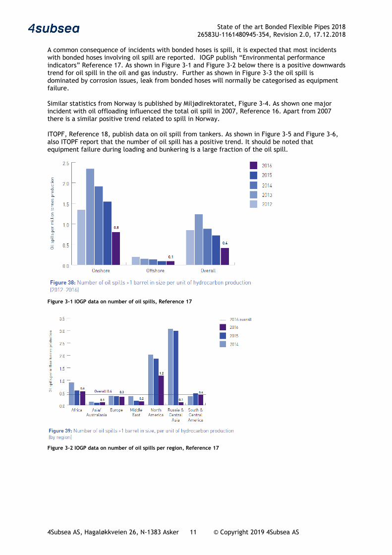
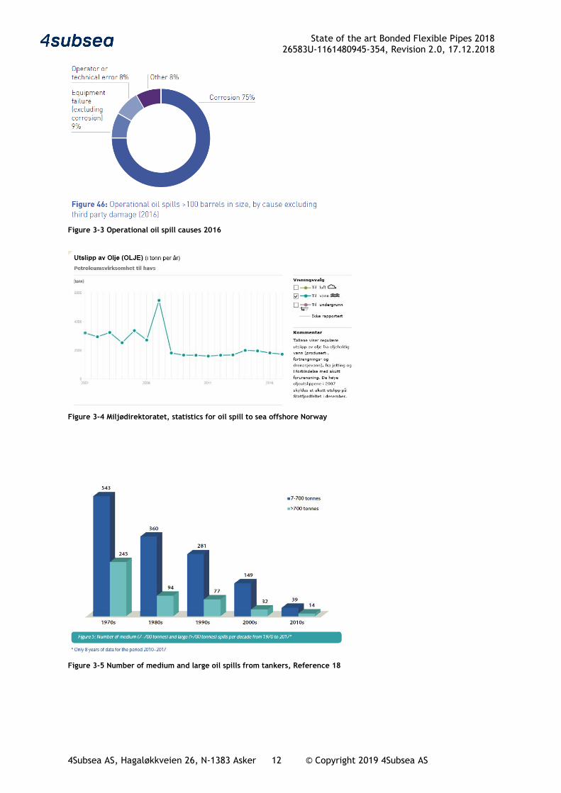
A common consequence of incidents with bonded hoses is spill, it is expected that most incidents with bonded hoses involving oil spill are reported. IOGP publish “Environmental performance indicators” Reference 17. As shown in Figure 3-1 and Figure 3-2 below there is a positive downwards trend for oil spill in the oil and gas industry. Further as shown in Figure 3-3 the oil spill is dominated by corrosion issues, leak from bonded hoses will normally be categorised as equipment failure. Similar statistics from Norway is published by Miljødirektoratet, Figure 3-4. As shown one major incident with oil offloading influenced the total oil spill in 2007, Reference 16. Apart from 2007 there is a similar positive trend related to spill in Norway. ITOPF, Reference 18, publish data on oil spill from tankers. As shown in Figure 3-5 and Figure 3-6, also ITOPF report that the number of oil spill has a positive trend. It should be noted that equipment failure during loading and bunkering is a large fraction of the oil spill.
Figure 3-1 IOGP data on number of oil spills, Reference 17
Figure 3-2 IOGP data on number of oil spills per region, Reference 17
State of the art Bonded Flexible Pipes 2018 26583U-1161480945-354, Revision 2.0, 17.12.2018
4Subsea AS, Hagaløkkveien 26, N-1383 Asker 12 © Copyright 2019 4Subsea AS
Figure 3-3 Operational oil spill causes 2016
Figure 3-4 Miljødirektoratet, statistics for oil spill to sea offshore Norway
Figure 3-5 Number of medium and large oil spills from tankers, Reference 18

State of the art Bonded Flexible Pipes 2018 26583U-1161480945-354, Revision 2.0, 17.12.2018
4Subsea AS, Hagaløkkveien 26, N-1383 Asker 13 © Copyright 2019 4Subsea AS
Figure 3-6 Cause for medium and large oil spills from tankers, Reference 18
3.3 Sources of information This study has been based on search in the PSA database, information on the internet and direct contact with selected companies and personnel who were known to have information about bonded flexible pipes. The basis for selection of companies and individuals has been in-house experience in 4Subsea, companies with API 17K approvals and telephone meetings with PSA. 4Subsea are grateful for all the valuable information received when compiling this report. With respect to specifications the following should be noted;
• OCIMF has issued "Guide to manufacturing and purchasing Hoses for offshore moorings" in 2009
• API 17K was revised in 2017 and is now in rev 3. Previously the specification had an equivalent ISO standard, this is no longer the case as the revision of API specifications are no longer co-ordinated with ISO
• EN standards for LPG and LNG hoses • One Oil company specification for industrial hoses has been considered

State of the art Bonded Flexible Pipes 2018 26583U-1161480945-354, Revision 2.0, 17.12.2018
4Subsea AS, Hagaløkkveien 26, N-1383 Asker 14 © Copyright 2019 4Subsea AS
Table 3-2 Sources of information
Source Data Comment PSA Codam incident database search
The following incidents related to bonded flexible hoses were identified:
- Incidents with offshore loading hoses - Incident with a drag chain hose for production of
hydrocarbons - Incidents with HP-mud and rotary hoses - Incidents with bunkering hoses and industrial
hoses in the oil and gas industry
Incidents where the only consequence is that a hose must be replaced, or hose replaced after inspection will normally not be reported to this database.
ITOPF Various publications on internet Bonded flexible pipe manufacturers and trading houses
4 bonded hose suppliers and one Norwegian trade house have supplied information
Oil companies Interviews with bonded flexible pipe experts
Hose users Experience data and maintenance information API 17K committee General info Report author is
member of API committee
Specifications and guidelines
- API 17K - API 16C - API 7K - OCIMF GMPHOM - EN 1474-2 - EN 1762
4Subsea In-house data - Previous version of this report, and other work for PSA Norway, Reference 1 - Reference 4
- Projects where bonded flexible pipes are used - Flexible pipe research, engineering and
verification - Failure investigations including dissections - Recertification of offloading hoses
State of the art Bonded Flexible Pipes 2018 26583U-1161480945-354, Revision 2.0, 17.12.2018
4Subsea AS, Hagaløkkveien 26, N-1383 Asker 15 © Copyright 2019 4Subsea AS
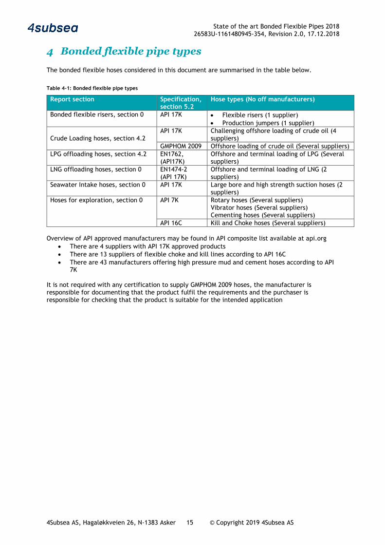
4 Bonded flexible pipe types The bonded flexible hoses considered in this document are summarised in the table below.
Table 4-1: Bonded flexible pipe types
Report section Specification, section 5.2
Hose types (No off manufacturers)
Bonded flexible risers, section 0 API 17K • Flexible risers (1 supplier) • Production jumpers (1 supplier)
Crude Loading hoses, section 4.2
API 17K Challenging offshore loading of crude oil (4 suppliers)
GMPHOM 2009 Offshore loading of crude oil (Several suppliers) LPG offloading hoses, section 4.2 EN1762,
(API17K) Offshore and terminal loading of LPG (Several suppliers)
LNG offloading hoses, section 0 EN1474-2 (API 17K)
Offshore and terminal loading of LNG (2 suppliers)
Seawater Intake hoses, section 0 API 17K Large bore and high strength suction hoses (2 suppliers)
Hoses for exploration, section 0 API 7K Rotary hoses (Several suppliers) Vibrator hoses (Several suppliers) Cementing hoses (Several suppliers)
API 16C Kill and Choke hoses (Several suppliers) Overview of API approved manufacturers may be found in API composite list available at api.org
• There are 4 suppliers with API 17K approved products • There are 13 suppliers of flexible choke and kill lines according to API 16C • There are 43 manufacturers offering high pressure mud and cement hoses according to API
7K It is not required with any certification to supply GMPHOM 2009 hoses, the manufacturer is responsible for documenting that the product fulfil the requirements and the purchaser is responsible for checking that the product is suitable for the intended application
State of the art Bonded Flexible Pipes 2018 26583U-1161480945-354, Revision 2.0, 17.12.2018
4Subsea AS, Hagaløkkveien 26, N-1383 Asker 16 © Copyright 2019 4Subsea AS
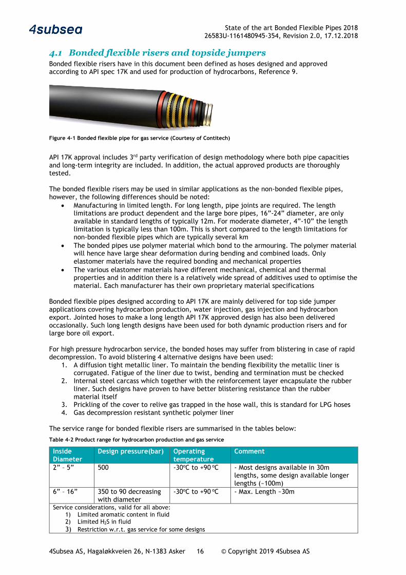
4.1 Bonded flexible risers and topside jumpers Bonded flexible risers have in this document been defined as hoses designed and approved according to API spec 17K and used for production of hydrocarbons, Reference 9.
Figure 4-1 Bonded flexible pipe for gas service (Courtesy of Contitech)
API 17K approval includes 3rd party verification of design methodology where both pipe capacities and long-term integrity are included. In addition, the actual approved products are thoroughly tested. The bonded flexible risers may be used in similar applications as the non-bonded flexible pipes, however, the following differences should be noted:
• Manufacturing in limited length. For long length, pipe joints are required. The length limitations are product dependent and the large bore pipes, 16”-24” diameter, are only available in standard lengths of typically 12m. For moderate diameter, 4”-10” the length limitation is typically less than 100m. This is short compared to the length limitations for non-bonded flexible pipes which are typically several km
• The bonded pipes use polymer material which bond to the armouring. The polymer material will hence have large shear deformation during bending and combined loads. Only elastomer materials have the required bonding and mechanical properties
• The various elastomer materials have different mechanical, chemical and thermal properties and in addition there is a relatively wide spread of additives used to optimise the material. Each manufacturer has their own proprietary material specifications
Bonded flexible pipes designed according to API 17K are mainly delivered for top side jumper applications covering hydrocarbon production, water injection, gas injection and hydrocarbon export. Jointed hoses to make a long length API 17K approved design has also been delivered occasionally. Such long length designs have been used for both dynamic production risers and for large bore oil export. For high pressure hydrocarbon service, the bonded hoses may suffer from blistering in case of rapid decompression. To avoid blistering 4 alternative designs have been used:
1. A diffusion tight metallic liner. To maintain the bending flexibility the metallic liner is corrugated. Fatigue of the liner due to twist, bending and termination must be checked
2. Internal steel carcass which together with the reinforcement layer encapsulate the rubber liner. Such designs have proven to have better blistering resistance than the rubber material itself
3. Prickling of the cover to relive gas trapped in the hose wall, this is standard for LPG hoses 4. Gas decompression resistant synthetic polymer liner
The service range for bonded flexible risers are summarised in the tables below:
Table 4-2 Product range for hydrocarbon production and gas service
Inside Diameter
Design pressure(bar) Operating temperature
Comment
2” – 5” 500 -30oC to +90 oC - Most designs available in 30m lengths, some design available longer lengths (~100m)
6” – 16” 350 to 90 decreasing with diameter
-30oC to +90 oC - Max. Length ~30m
Service considerations, valid for all above: 1) Limited aromatic content in fluid 2) Limited H2S in fluid 3) Restriction w.r.t. gas service for some designs

State of the art Bonded Flexible Pipes 2018 26583U-1161480945-354, Revision 2.0, 17.12.2018
4Subsea AS, Hagaløkkveien 26, N-1383 Asker 17 © Copyright 2019 4Subsea AS
4.2 Loading hoses Loading hoses cover a wide range of hoses, however, as part of this document the range is limited to hoses used in the oil and gas industry, with diameter above 4” and with pressure rating of minimum 15bar. Figure 4-2 shows one typical loading hose design including termination.
Figure 4-2 Oil offloading hose (Courtesy of Dunlop)
The loading hoses used in the oil and gas industry are often delivered according to OCIMF GMPHOM specification, Reference 12. This specification is covering hoses for the following service:
• Offshore loading of oil • Diameter in the range 150mm to 600mm • Pressure rating of 15 bar, pressure of 19 and 21 bar are addressed • Crude oil or liquid petroleum products at temp -20oC to 82oC, not petroleum gas • Max flow velocity of 21m/sec
The OCIMF specification have specific test requirements which the product must meet such as pressure tests. An important change in the industry was the release of GMPHOM 2009. Most hoses supplied since 2012 are manufactured to these guidelines. Amongst many other changes and updates, the guidelines provided better definition on what is a single and double carcass hose; introduced fatigue testing of the prototypes and introduced a 21 bars pressure rating. The double carcass designs have an additional reinforcement layer which has capacity to withstand the design pressure in case the primary pipe starts to leak. In between the two reinforcement carcasses a leak detection device must be used. Figure 4-3 show examples of this from Dunlop
Figure 4-3 Double Carcass 3D FEM model, courtesy Dunlop Oil & Marine.
State of the art Bonded Flexible Pipes 2018 26583U-1161480945-354, Revision 2.0, 17.12.2018
4Subsea AS, Hagaløkkveien 26, N-1383 Asker 18 © Copyright 2019 4Subsea AS
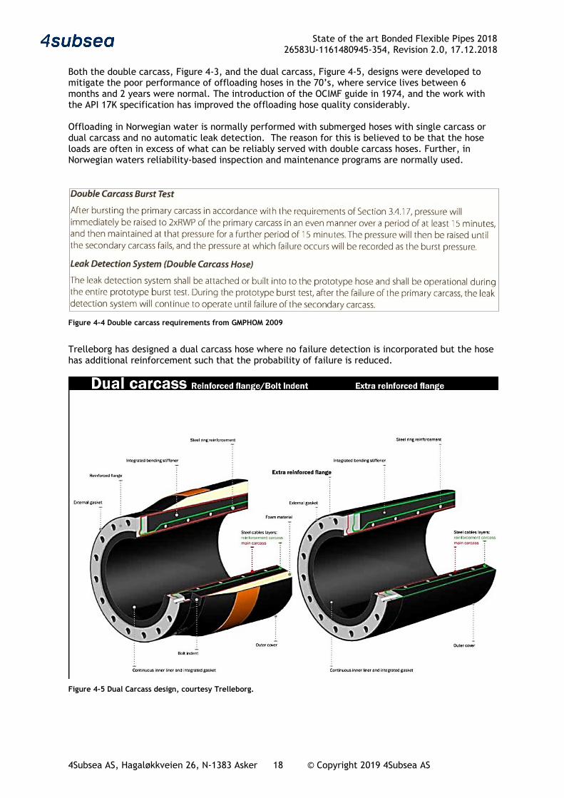
Both the double carcass, Figure 4-3, and the dual carcass, Figure 4-5, designs were developed to mitigate the poor performance of offloading hoses in the 70’s, where service lives between 6 months and 2 years were normal. The introduction of the OCIMF guide in 1974, and the work with the API 17K specification has improved the offloading hose quality considerably. Offloading in Norwegian water is normally performed with submerged hoses with single carcass or dual carcass and no automatic leak detection. The reason for this is believed to be that the hose loads are often in excess of what can be reliably served with double carcass hoses. Further, in Norwegian waters reliability-based inspection and maintenance programs are normally used.
Figure 4-4 Double carcass requirements from GMPHOM 2009
Trelleborg has designed a dual carcass hose where no failure detection is incorporated but the hose has additional reinforcement such that the probability of failure is reduced.
Figure 4-5 Dual Carcass design, courtesy Trelleborg.
State of the art Bonded Flexible Pipes 2018 26583U-1161480945-354, Revision 2.0, 17.12.2018
4Subsea AS, Hagaløkkveien 26, N-1383 Asker 19 © Copyright 2019 4Subsea AS
For demanding applications or applications where site specific safe service life is required the more comprehensive bonded flexible pipe specification, API 17K may be used, ref. section 5.2.1. There are 4 suppliers of crude offloading hoses according to API 17K specification. All these companies are part of larger rubber manufacturing units offering a large variety of bonded hoses and other rubber products. All API 17K suppliers have an API approved QA system and supply a product range which has been validated by an independent verification agent, the pressure rating and use limitation are hence not standardised.
Table 4-3 Product range for crude loading hoses
Inside Diameter
Design pressure(bar) Operating temperature
Comment
6” – 24” Normally 15bar, however 50-70 bar is achievable if required
-20 oC to +80 oC - Max. Length 12.2m
Service considerations, valid for all above: 1) Sweet service 2) Stabilised crude oil
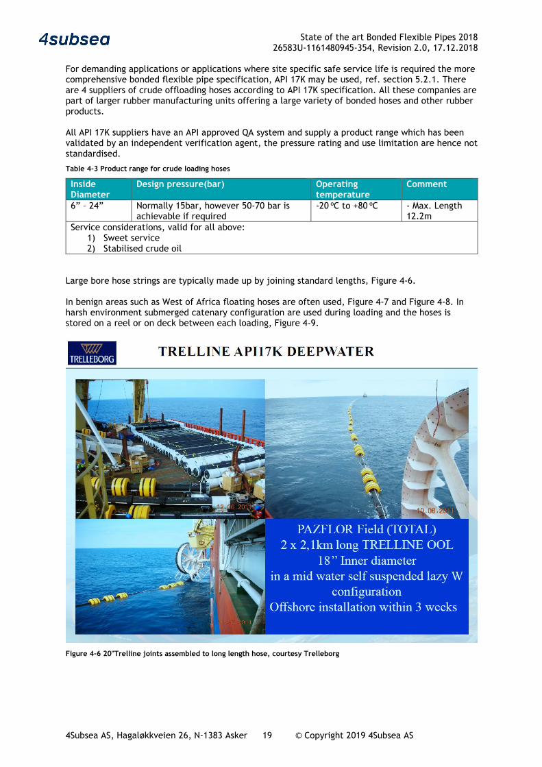
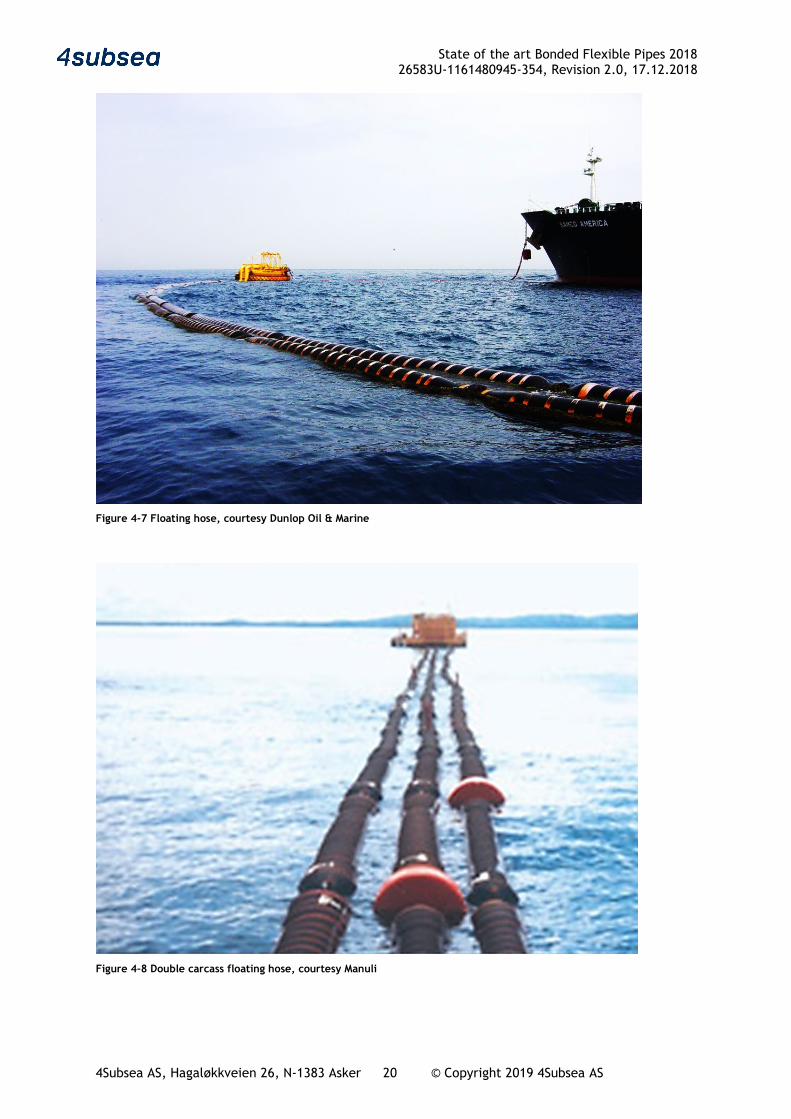
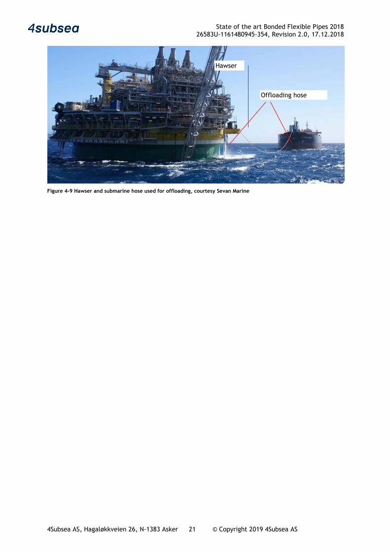
Large bore hose strings are typically made up by joining standard lengths, Figure 4-6. In benign areas such as West of Africa floating hoses are often used, Figure 4-7 and Figure 4-8. In harsh environment submerged catenary configuration are used during loading and the hoses is stored on a reel or on deck between each loading, Figure 4-9.
Figure 4-6 20"Trelline joints assembled to long length hose, courtesy Trelleborg
State of the art Bonded Flexible Pipes 2018 26583U-1161480945-354, Revision 2.0, 17.12.2018
4Subsea AS, Hagaløkkveien 26, N-1383 Asker 20 © Copyright 2019 4Subsea AS
Figure 4-7 Floating hose, courtesy Dunlop Oil & Marine
Figure 4-8 Double carcass floating hose, courtesy Manuli
State of the art Bonded Flexible Pipes 2018 26583U-1161480945-354, Revision 2.0, 17.12.2018
4Subsea AS, Hagaløkkveien 26, N-1383 Asker 21 © Copyright 2019 4Subsea AS
Figure 4-9 Hawser and submarine hose used for offloading, courtesy Sevan Marine
Hawser
Offloading hose

State of the art Bonded Flexible Pipes 2018 26583U-1161480945-354, Revision 2.0, 17.12.2018
4Subsea AS, Hagaløkkveien 26, N-1383 Asker 22 © Copyright 2019 4Subsea AS
4.3 Cryogenic hoses
API 17K may be used for liquefied petroleum gases, LPG and LNG, however, specific requirements for this type of service are not included
EN 1474-2:2008 is intended for LNG hoses, Reference 21
EN1762:2017 is intended for rubber hoses in LPG applications, Reference 20
GMPHOM 2009 is not covering LPG hoses, however a commentary related to LPG hose design is included
Figure 4-10 Commentary related to LPG hoses from OCIMF GMPHOM2009
LPG hoses are normally made with polymer liners. The polymer selected must withstand the temperature and have adequate resistance against blistering in rapid gas decompression (RGD) events. Prickling of the outer cover is often used to avoid pressure build up in the hose wall and risk for blistering. Prickling is addressed in some specifications e.g. EN1762, Reference 20.
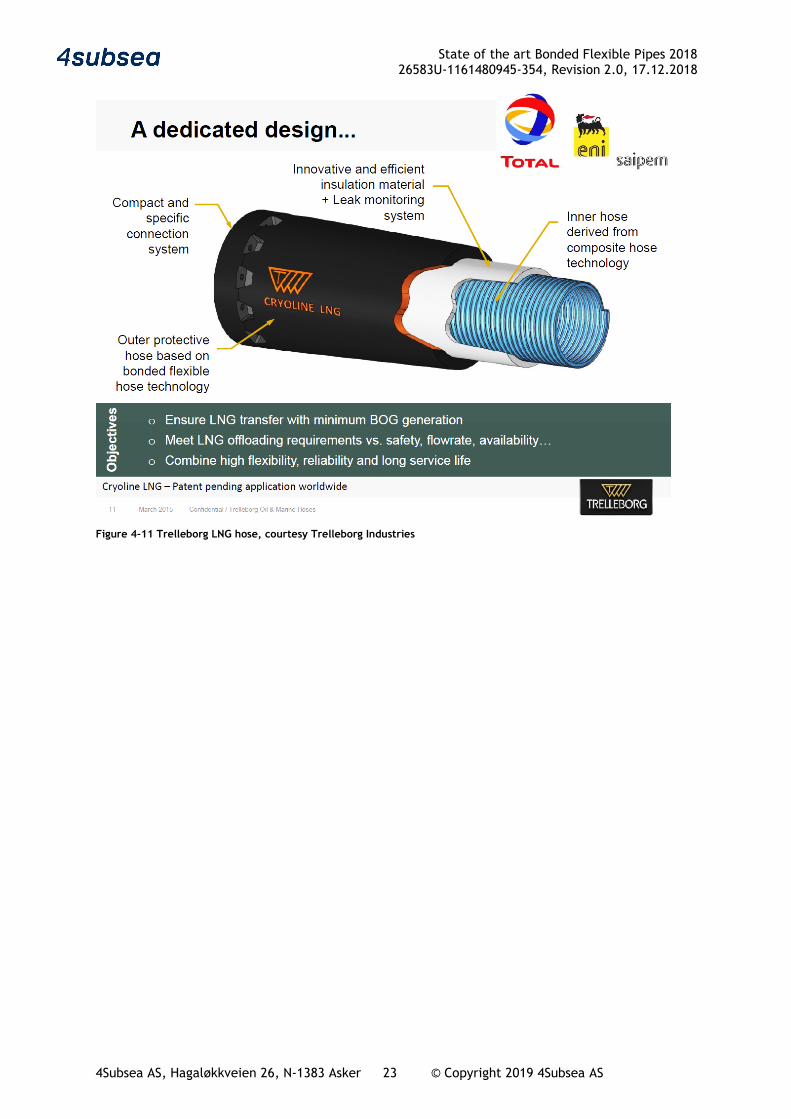
LNG hoses are used to transport fluids with temperature that cannot be serviced with a polymer liner. The theoretical limit for polymer liner is about -100oC, in practice higher temperature limitation must be expected. Some composites, synthetic cord, austenitic steel, aluminum and titan may be used at cryogenic temperatures. 3 different hose designs are offered:
- Composite hose core with thermal insulation and rubber reinforcement externally
- Composite hoses made from stainless steel(austenitic) spirals and fibre reinforced tapes wrapped together without any bonding. Such products are offered by several companies e.g. Contitech, Gutteling, Senior Flexonic. These products may serve the same application as bonded flexibles, however as they are not bonded flexibles they are not further addressed here.
- Corrugated hose, double wall with insulation or vacuum between. These products may serve the same application as bonded flexibles, however as they are not bonded flexibles they are not further addressed here.
Trelleborg has a partly bonded LNG hose based on a hose in hose technology, Figure 4-11, according to EN 1474-2.
State of the art Bonded Flexible Pipes 2018 26583U-1161480945-354, Revision 2.0, 17.12.2018
4Subsea AS, Hagaløkkveien 26, N-1383 Asker 23 © Copyright 2019 4Subsea AS
Figure 4-11 Trelleborg LNG hose, courtesy Trelleborg Industries
State of the art Bonded Flexible Pipes 2018 26583U-1161480945-354, Revision 2.0, 17.12.2018
4Subsea AS, Hagaløkkveien 26, N-1383 Asker 24 © Copyright 2019 4Subsea AS
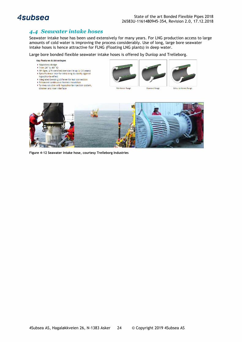
4.4 Seawater intake hoses Seawater intake hose has been used extensively for many years. For LNG production access to large amounts of cold water is improving the process considerably. Use of long, large bore seawater intake hoses is hence attractive for FLNG (Floating LNG plants) in deep water.
Large bore bonded flexible seawater intake hoses is offered by Dunlop and Trelleborg.
Figure 4-12 Seawater Intake hose, courtesy Trelleborg Industries
State of the art Bonded Flexible Pipes 2018 26583U-1161480945-354, Revision 2.0, 17.12.2018
4Subsea AS, Hagaløkkveien 26, N-1383 Asker 25 © Copyright 2019 4Subsea AS
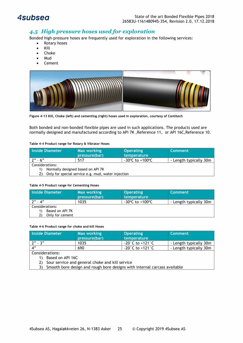
4.5 High pressure hoses used for exploration Bonded high-pressure hoses are frequently used for exploration in the following services:
• Rotary hoses • Kill • Choke • Mud • Cement
Figure 4-13 Kill, Choke (left) and cementing (right) hoses used in exploration, courtesy of Contitech
Both bonded and non-bonded flexible pipes are used in such applications. The products used are normally designed and manufactured according to API 7K ,Reference 11, or API 16C,Reference 10.
Table 4-4 Product range for Rotary & Vibrator Hoses
Inside Diameter Max working pressure(bar)
Operating temperature
Comment
2” – 6” 517 -30oC to +100oC - Length typically 30m Considerations:
1) Normally designed based on API 7K 2) Only for special service e.g. mud, water injection
Table 4-5 Product range for Cementing Hoses
Inside Diameter Max working pressure(bar)
Operating temperature
Comment
2” – 4” 1035 -30oC to +100oC - Length typically 30m Considerations:
1) Based on API 7K 2) Only for cement
Table 4-6 Product range for choke and kill Hoses
Inside Diameter Max working pressure(bar)
Operating temperature
Comment
2” – 3” 1035 -20°C to +121°C - Length typically 30m 4” 690 -20°C to +121°C - Length typically 30m Considerations:
1) Based on API 16C 2) Sour service and general choke and kill service 3) Smooth bore design and rough bore designs with internal carcass available
State of the art Bonded Flexible Pipes 2018 26583U-1161480945-354, Revision 2.0, 17.12.2018
4Subsea AS, Hagaløkkveien 26, N-1383 Asker 26 © Copyright 2019 4Subsea AS
4.6 Other bonded hoses for the oil and gas industry
4.6.1 Overview This section is mainly related to medium and low-pressure hoses for supply, bunkering and similar purposes in the oil and gas industry, not including hydraulic hoses. Such hoses are extensively used. Manufacturing of such hoses is done all over the world, including Europe, US and far east. The purchaser may be oil companies, oil service companies, ship-owners, refineries etc.
4.6.2 Technical specification Standard bonded hoses for the offshore oil and gas industry are often purchased based on dimension, pressure rating and price. There is often no requirement for type approval or delivery according to a specification. Often handling, wear and external damages are governing for hose life, then the lowest life cycles cost will often be with the cheapest hose. For hoses in long term operation, there seems to be a relation between life-cycle cost and hose quality. Type approved high quality hoses will normally last longer. Purchase of type approved hoses will often give the lowest life cycle cost if handling and wear damages are avoided. Some purchasers focus on reliability when purchasing industrial hoses and some companies have prepared specifications for this e.g. Equinor TR1803. Items covered in TR1803 may serve as an example of items to be considered when purchasing industrial hoses in the oil and gas industry
• Handling and storage, manufacturer recommendations to be followed for storage, coiling etc
• Planning and installation must address
o Pressure, normal, surge, accidental. Standard rating often specified, purchaser to ensure that the specified rating is adequate
o Permissible bending radius o No contact with sharp edges or similar o Twisting o Wear and additional protection o External loads e.g. lifting o Fastening o Suspension of loads and/or support during operation o Routing o Temperature o Fire and explosion o Electrical continuity, earthing and consequence of sparks
• Selection of hose type and coupling
o Standard requirements are often specified for the various hose types and adequate couplings, e.g.
Hoses for water, LP (Low Pressure) and HP (High Pressure) Non-metallic hoses for steam Metal hoses for steam Hoses for various gas services (LP & HP), N2, air, CO2 etc. HC hoses High Pressure HC hoses Hydraulic hoses, various pressure ratings Metal hoses for LPG Diesel, Helifuel Firewater, collapsible (flat) hose Methanol and Glycol hoses Chemical hoses Breathing air Bunkering hose
State of the art Bonded Flexible Pipes 2018 26583U-1161480945-354, Revision 2.0, 17.12.2018
4Subsea AS, Hagaløkkveien 26, N-1383 Asker 27 © Copyright 2019 4Subsea AS
o Colour coding and marking of hoses and couplings o Weak link and breakaway coupling o Swivel
• Loading station for bunkering hoses
o Floats o Hose reel o Reel connection o Reel power requirement
• Inspection and maintenance
o Visual Validate marking Date of manufacturing versus expected end of life for the type of hose Damages, including couplings, including misalignment and transition from
hose to couplings o Personnel qualification for design, specification, testing, handling and installation
of hoses o Repair normally not acceptable o Pressure testing normally required o Electrical continuity test
The general, experience with such hoses is that most hoses fulfil their purchase requirements. End of service life is often reached after a few years in operation and the reason is in many cases external damages or wear, ref section 3.1.3. Experience show that end segments and hoses designed for contact with other structures e.g. tanker rail hoses, require more frequent replacement than main-line hoses.
State of the art Bonded Flexible Pipes 2018 26583U-1161480945-354, Revision 2.0, 17.12.2018
4Subsea AS, Hagaløkkveien 26, N-1383 Asker 28 © Copyright 2019 4Subsea AS
5 Design
5.1 Bonded hose design
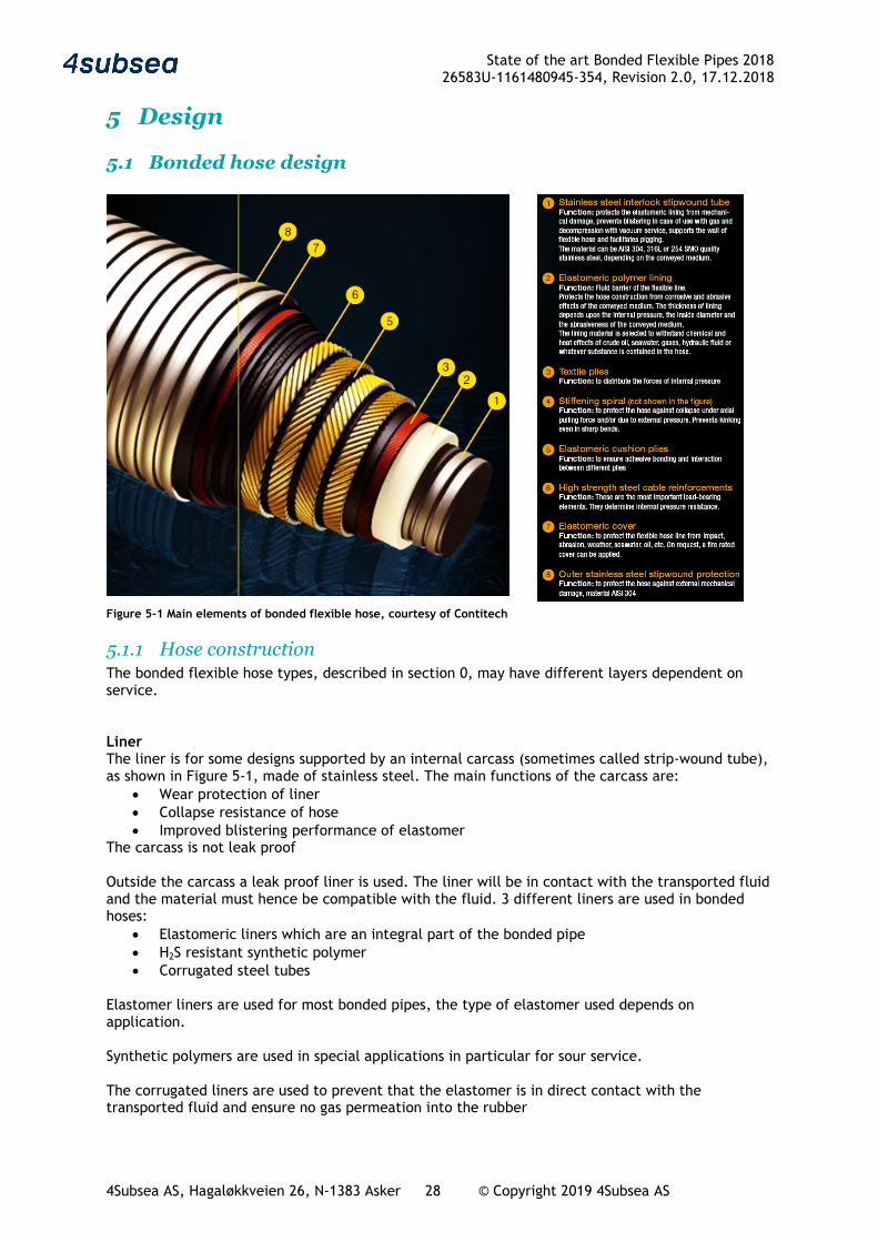
Figure 5-1 Main elements of bonded flexible hose, courtesy of Contitech
5.1.1 Hose construction The bonded flexible hose types, described in section 0, may have different layers dependent on service. Liner The liner is for some designs supported by an internal carcass (sometimes called strip-wound tube), as shown in Figure 5-1, made of stainless steel. The main functions of the carcass are:
• Wear protection of liner • Collapse resistance of hose • Improved blistering performance of elastomer
The carcass is not leak proof Outside the carcass a leak proof liner is used. The liner will be in contact with the transported fluid and the material must hence be compatible with the fluid. 3 different liners are used in bonded hoses:
• Elastomeric liners which are an integral part of the bonded pipe • H2S resistant synthetic polymer • Corrugated steel tubes
Elastomer liners are used for most bonded pipes, the type of elastomer used depends on application. Synthetic polymers are used in special applications in particular for sour service. The corrugated liners are used to prevent that the elastomer is in direct contact with the transported fluid and ensure no gas permeation into the rubber
State of the art Bonded Flexible Pipes 2018 26583U-1161480945-354, Revision 2.0, 17.12.2018
4Subsea AS, Hagaløkkveien 26, N-1383 Asker 29 © Copyright 2019 4Subsea AS
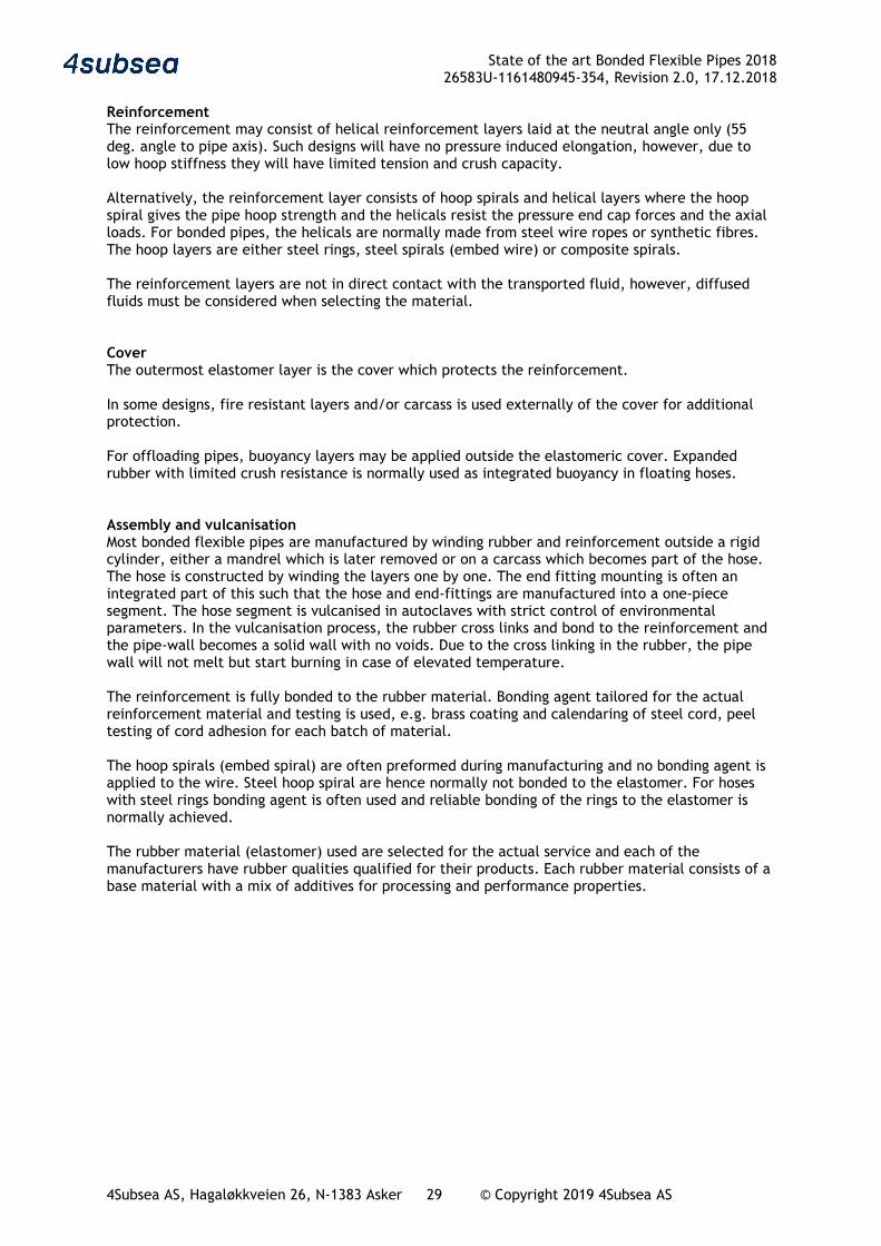
Reinforcement The reinforcement may consist of helical reinforcement layers laid at the neutral angle only (55 deg. angle to pipe axis). Such designs will have no pressure induced elongation, however, due to low hoop stiffness they will have limited tension and crush capacity. Alternatively, the reinforcement layer consists of hoop spirals and helical layers where the hoop spiral gives the pipe hoop strength and the helicals resist the pressure end cap forces and the axial loads. For bonded pipes, the helicals are normally made from steel wire ropes or synthetic fibres. The hoop layers are either steel rings, steel spirals (embed wire) or composite spirals. The reinforcement layers are not in direct contact with the transported fluid, however, diffused fluids must be considered when selecting the material. Cover The outermost elastomer layer is the cover which protects the reinforcement. In some designs, fire resistant layers and/or carcass is used externally of the cover for additional protection. For offloading pipes, buoyancy layers may be applied outside the elastomeric cover. Expanded rubber with limited crush resistance is normally used as integrated buoyancy in floating hoses. Assembly and vulcanisation Most bonded flexible pipes are manufactured by winding rubber and reinforcement outside a rigid cylinder, either a mandrel which is later removed or on a carcass which becomes part of the hose. The hose is constructed by winding the layers one by one. The end fitting mounting is often an integrated part of this such that the hose and end-fittings are manufactured into a one-piece segment. The hose segment is vulcanised in autoclaves with strict control of environmental parameters. In the vulcanisation process, the rubber cross links and bond to the reinforcement and the pipe-wall becomes a solid wall with no voids. Due to the cross linking in the rubber, the pipe wall will not melt but start burning in case of elevated temperature. The reinforcement is fully bonded to the rubber material. Bonding agent tailored for the actual reinforcement material and testing is used, e.g. brass coating and calendaring of steel cord, peel testing of cord adhesion for each batch of material. The hoop spirals (embed spiral) are often preformed during manufacturing and no bonding agent is applied to the wire. Steel hoop spiral are hence normally not bonded to the elastomer. For hoses with steel rings bonding agent is often used and reliable bonding of the rings to the elastomer is normally achieved. The rubber material (elastomer) used are selected for the actual service and each of the manufacturers have rubber qualities qualified for their products. Each rubber material consists of a base material with a mix of additives for processing and performance properties.
State of the art Bonded Flexible Pipes 2018 26583U-1161480945-354, Revision 2.0, 17.12.2018
4Subsea AS, Hagaløkkveien 26, N-1383 Asker 30 © Copyright 2019 4Subsea AS
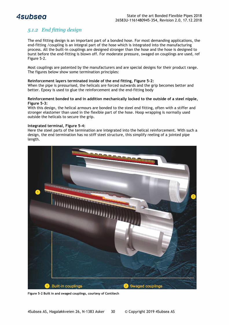
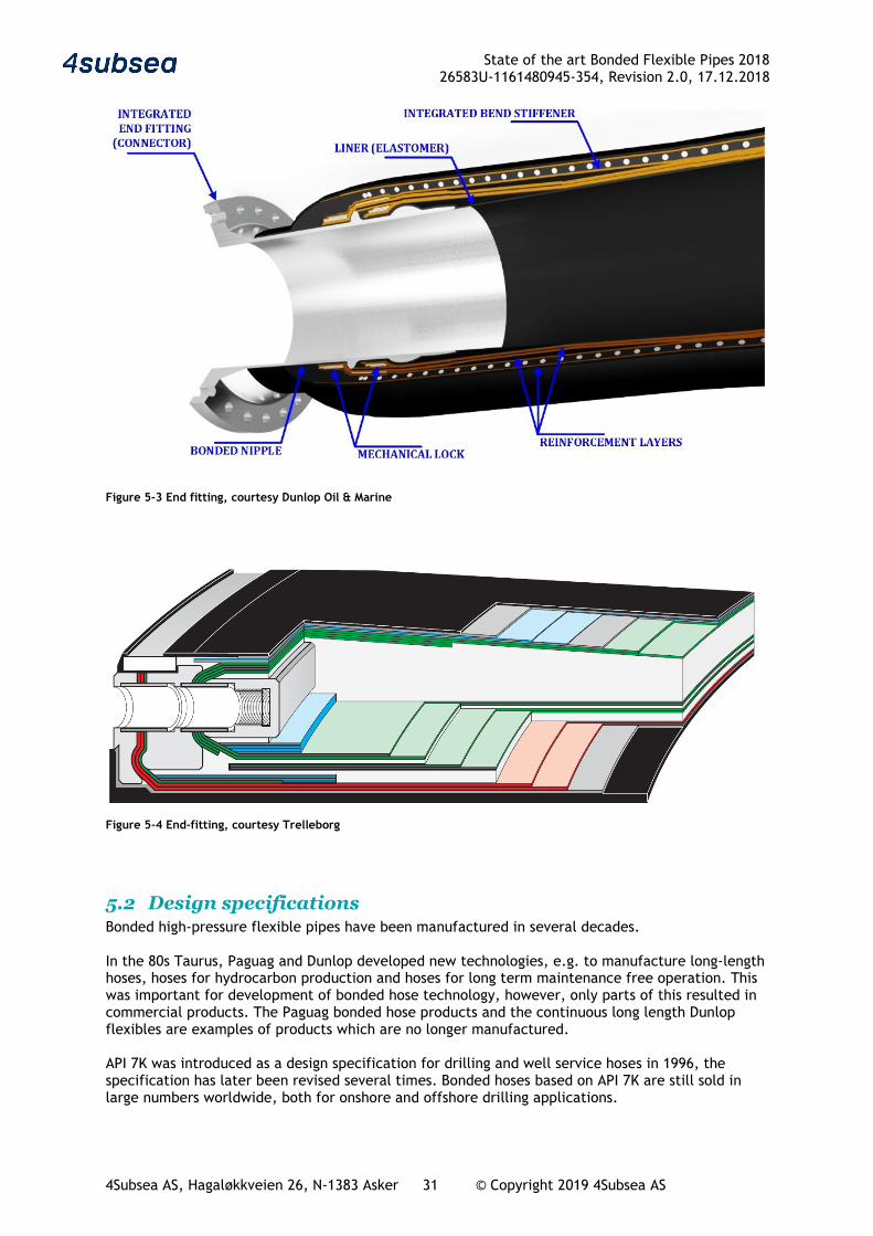
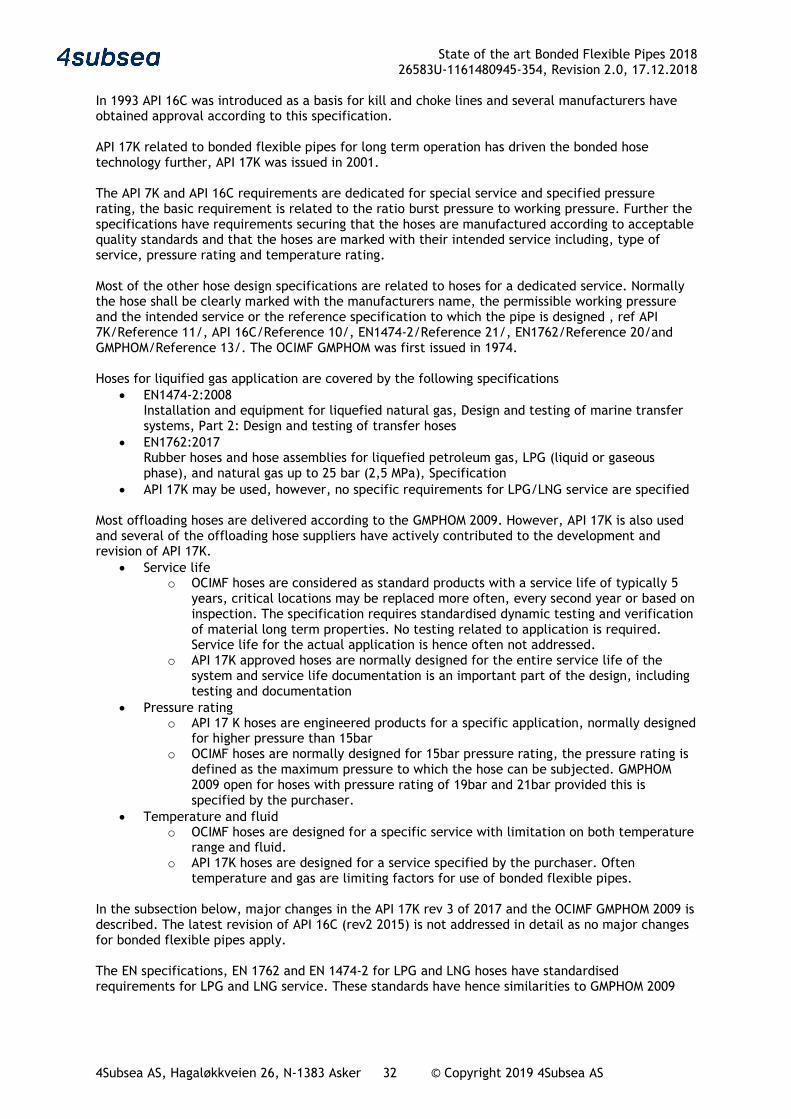
5.1.2 End fitting design The end fitting design is an important part of a bonded hose. For most demanding applications, the end-fitting /coupling is an integral part of the hose which is integrated into the manufacturing process. All the built-in couplings are designed stronger than the hose and the hose is designed to burst before the end-fitting is blown off. For moderate pressure, swaged on couplings are used, ref Figure 5-2. Most couplings are patented by the manufacturers and are special designs for their product range. The figures below show some termination principles: Reinforcement layers terminated inside of the end fitting, Figure 5-2: When the pipe is pressurised, the helicals are forced outwards and the grip becomes better and better. Epoxy is used to glue the reinforcement and the end-fitting body Reinforcement bonded to and in addition mechanically locked to the outside of a steel nipple, Figure 5-3: With this design, the helical armours are bonded to the steel end fitting, often with a stiffer and stronger elastomer than used in the flexible part of the hose. Hoop wrapping is normally used outside the helicals to secure the grip. Integrated terminal, Figure 5-4: Here the steel parts of the termination are integrated into the helical reinforcement. With such a design, the end termination has no stiff steel structure, this simplify reeling of a jointed pipe length.
Figure 5-2 Built in and swaged couplings, courtesy of Contitech
State of the art Bonded Flexible Pipes 2018 26583U-1161480945-354, Revision 2.0, 17.12.2018
4Subsea AS, Hagaløkkveien 26, N-1383 Asker 31 © Copyright 2019 4Subsea AS
Figure 5-3 End fitting, courtesy Dunlop Oil & Marine
Figure 5-4 End-fitting, courtesy Trelleborg
5.2 Design specifications Bonded high-pressure flexible pipes have been manufactured in several decades. In the 80s Taurus, Paguag and Dunlop developed new technologies, e.g. to manufacture long-length hoses, hoses for hydrocarbon production and hoses for long term maintenance free operation. This was important for development of bonded hose technology, however, only parts of this resulted in commercial products. The Paguag bonded hose products and the continuous long length Dunlop flexibles are examples of products which are no longer manufactured. API 7K was introduced as a design specification for drilling and well service hoses in 1996, the specification has later been revised several times. Bonded hoses based on API 7K are still sold in large numbers worldwide, both for onshore and offshore drilling applications.
State of the art Bonded Flexible Pipes 2018 26583U-1161480945-354, Revision 2.0, 17.12.2018
4Subsea AS, Hagaløkkveien 26, N-1383 Asker 32 © Copyright 2019 4Subsea AS
In 1993 API 16C was introduced as a basis for kill and choke lines and several manufacturers have obtained approval according to this specification. API 17K related to bonded flexible pipes for long term operation has driven the bonded hose technology further, API 17K was issued in 2001. The API 7K and API 16C requirements are dedicated for special service and specified pressure rating, the basic requirement is related to the ratio burst pressure to working pressure. Further the specifications have requirements securing that the hoses are manufactured according to acceptable quality standards and that the hoses are marked with their intended service including, type of service, pressure rating and temperature rating. Most of the other hose design specifications are related to hoses for a dedicated service. Normally the hose shall be clearly marked with the manufacturers name, the permissible working pressure and the intended service or the reference specification to which the pipe is designed , ref API 7K/Reference 11/, API 16C/Reference 10/, EN1474-2/Reference 21/, EN1762/Reference 20/and GMPHOM/Reference 13/. The OCIMF GMPHOM was first issued in 1974. Hoses for liquified gas application are covered by the following specifications
• EN1474-2:2008 Installation and equipment for liquefied natural gas, Design and testing of marine transfer systems, Part 2: Design and testing of transfer hoses
• EN1762:2017 Rubber hoses and hose assemblies for liquefied petroleum gas, LPG (liquid or gaseous phase), and natural gas up to 25 bar (2,5 MPa), Specification
• API 17K may be used, however, no specific requirements for LPG/LNG service are specified Most offloading hoses are delivered according to the GMPHOM 2009. However, API 17K is also used and several of the offloading hose suppliers have actively contributed to the development and revision of API 17K.
• Service life o OCIMF hoses are considered as standard products with a service life of typically 5
years, critical locations may be replaced more often, every second year or based on inspection. The specification requires standardised dynamic testing and verification of material long term properties. No testing related to application is required. Service life for the actual application is hence often not addressed.
o API 17K approved hoses are normally designed for the entire service life of the system and service life documentation is an important part of the design, including testing and documentation
• Pressure rating o API 17 K hoses are engineered products for a specific application, normally designed
for higher pressure than 15bar o OCIMF hoses are normally designed for 15bar pressure rating, the pressure rating is
defined as the maximum pressure to which the hose can be subjected. GMPHOM 2009 open for hoses with pressure rating of 19bar and 21bar provided this is specified by the purchaser.
• Temperature and fluid o OCIMF hoses are designed for a specific service with limitation on both temperature
range and fluid. o API 17K hoses are designed for a service specified by the purchaser. Often
temperature and gas are limiting factors for use of bonded flexible pipes. In the subsection below, major changes in the API 17K rev 3 of 2017 and the OCIMF GMPHOM 2009 is described. The latest revision of API 16C (rev2 2015) is not addressed in detail as no major changes for bonded flexible pipes apply. The EN specifications, EN 1762 and EN 1474-2 for LPG and LNG hoses have standardised requirements for LPG and LNG service. These standards have hence similarities to GMPHOM 2009
State of the art Bonded Flexible Pipes 2018 26583U-1161480945-354, Revision 2.0, 17.12.2018
4Subsea AS, Hagaløkkveien 26, N-1383 Asker 33 © Copyright 2019 4Subsea AS
5.2.1 API 17K rev 3 The basis for revision 3 of API 17K was:
• API 17J specification for un-bonded flexible pipe was revised in 2014 and several of the changes were relevant to API 17K as well.
• The flexible pipe Recommended practise, API 17B, which are common for API 17J and API 17K was revised in 2014 and there were inconsistencies with the previous revision of API 17K
• About 100 industry comments to the previous API 17K revision
The revision process was handled by a work group with members from:
• Oil companies
• Manufacturers
• Engineering/Expert companies
The following changes should be noted:
• API 17K rev3 is an API spec only, ISO13628-10 is not revised
• Non-metallic reinforcement layers are covered, including creep, degradation and test procedure
• Rev02 was not intended used for pipes with DP<15bar, rev03 has removed this limitation
• Service life requirements for polymers have been clarified
• The permissible structural utilisation has been harmonised with API 17J (un-bonded flexible pipes)
• Seawater intake hoses are covered, including specific tensile testing, collapse calculation etc.
• General requirements suitable for bonded LPG and LNG hoses included, however, no specific requirements for such service
• Specific criteria for offloading hoses are introduced, e.g. requirements for reeling, storage radius, handling, surge pressure etc
• No link to OCIMF GMPHOM in rev03 of API 17K
• FAT of assembled hose string addressed
State of the art Bonded Flexible Pipes 2018 26583U-1161480945-354, Revision 2.0, 17.12.2018
4Subsea AS, Hagaløkkveien 26, N-1383 Asker 34 © Copyright 2019 4Subsea AS
5.2.2 OCIMF GMPHOM 2009 The Oil Companies International Marine Forum (OCIMF) is a voluntary association of oil companies having an interest in shipment and terminalling of crude oil and oil products. OCIMF issue several guides including Guide to Manufacturing and purchasing Hoses for Offshore Moorings(GMPHOM2009), Reference 13
The GMPHOM 5th edition from 2009 reflects a major review and enhancement of the 4th edition for the purpose of providing technical recommendations and guidance to ensure the satisfactory performance of elastomer reinforced, smooth bore, oil suction and discharge hose commonly used at offshore moorings. The following are among the new or significantly changed topics that are included in this latest edition:
• The guidance for Reeling Hose Systems are addressed for the first time with particular attention being given to the potential for hoses being subjected to crush loading
• LPG hoses are not covered, however a commentary comparing the design and operating guidance of ‘oil’ hose and hose specifically designed for LPG is included to assist operators when considering hose used in the offshore transfer of LPG
• The Safe Working Loads guidance for hose lifting lugs have been re-assessed based on the weights of Double Carcass Hoses equipped with typical fittings
• The design specification for Double Carcass Hoses has been clarified, together with the guidance for leak detection
• Acceptance tests include new guidance for material tests and the process for stiffness testing has been revised
• The circumstances that prompt prototype tests have been clarified and new tests addressing materials, torsion, tensile loading, crushing and lifting lugs have been introduced into the prototype test program. This program now also includes guidance for the dynamic testing of prototype hoses.
• Metric units are used for all dimensions including nominal diameter and standard length
• Hoses constructed and tested in accordance with recommendations and guidance in this Guide may be stamped ‘GMPHOM 2009’. OCIMF are not involved with any verification or quality control process relating to the manufacture and/or testing of hoses. OCIMF does not control or regulate in any way the stamping of ‘GMPHOM 2009’ on hoses and therefore, prospective purchasers are recommended to undertake a due diligence process to ensure that the hose specification is as claimed by the Manufacturer/Seller and that the specification is suitable for their intended application.
State of the art Bonded Flexible Pipes 2018 26583U-1161480945-354, Revision 2.0, 17.12.2018
4Subsea AS, Hagaløkkveien 26, N-1383 Asker 35 © Copyright 2019 4Subsea AS
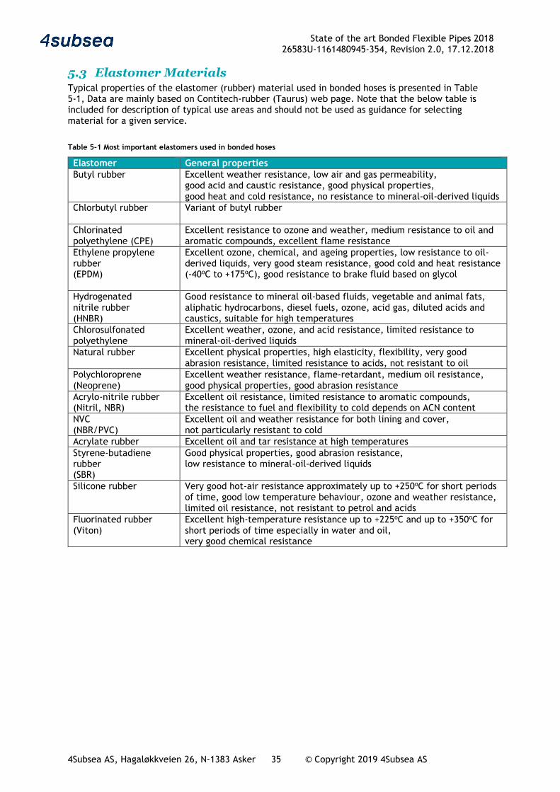
5.3 Elastomer Materials Typical properties of the elastomer (rubber) material used in bonded hoses is presented in Table 5-1, Data are mainly based on Contitech-rubber (Taurus) web page. Note that the below table is included for description of typical use areas and should not be used as guidance for selecting material for a given service.
Table 5-1 Most important elastomers used in bonded hoses
Elastomer General properties Butyl rubber
Excellent weather resistance, low air and gas permeability, good acid and caustic resistance, good physical properties, good heat and cold resistance, no resistance to mineral-oil-derived liquids
Chlorbutyl rubber
Variant of butyl rubber
Chlorinated polyethylene (CPE)
Excellent resistance to ozone and weather, medium resistance to oil and aromatic compounds, excellent flame resistance
Ethylene propylene rubber (EPDM)
Excellent ozone, chemical, and ageing properties, low resistance to oil-derived liquids, very good steam resistance, good cold and heat resistance (-40oC to +175oC), good resistance to brake fluid based on glycol
Hydrogenated nitrile rubber (HNBR)
Good resistance to mineral oil-based fluids, vegetable and animal fats, aliphatic hydrocarbons, diesel fuels, ozone, acid gas, diluted acids and caustics, suitable for high temperatures
Chlorosulfonated polyethylene
Excellent weather, ozone, and acid resistance, limited resistance to mineral-oil-derived liquids
Natural rubber
Excellent physical properties, high elasticity, flexibility, very good abrasion resistance, limited resistance to acids, not resistant to oil
Polychloroprene (Neoprene)
Excellent weather resistance, flame-retardant, medium oil resistance, good physical properties, good abrasion resistance
Acrylo-nitrile rubber (Nitril, NBR)
Excellent oil resistance, limited resistance to aromatic compounds, the resistance to fuel and flexibility to cold depends on ACN content
NVC (NBR/PVC)
Excellent oil and weather resistance for both lining and cover, not particularly resistant to cold
Acrylate rubber Excellent oil and tar resistance at high temperatures Styrene-butadiene rubber (SBR)
Good physical properties, good abrasion resistance, low resistance to mineral-oil-derived liquids
Silicone rubber
Very good hot-air resistance approximately up to +250oC for short periods of time, good low temperature behaviour, ozone and weather resistance, limited oil resistance, not resistant to petrol and acids
Fluorinated rubber (Viton)
Excellent high-temperature resistance up to +225oC and up to +350oC for short periods of time especially in water and oil, very good chemical resistance
State of the art Bonded Flexible Pipes 2018 26583U-1161480945-354, Revision 2.0, 17.12.2018
4Subsea AS, Hagaløkkveien 26, N-1383 Asker 36 © Copyright 2019 4Subsea AS
6 Failure mode review
6.1 Overview
6.1.1 General The failure modes for bonded flexible pipes may be grouped in two:
• Manufacturing, storage and transport • In service, including handling and long term degradation
Installation which is important for permanent riser systems is here replaced by handling as most of the bonded pipes are connected, disconnected, handled and inspected frequently during their service life. Large bore offloading lines has been used in demanding applications and some new challenges has been observed in the last 10 years. In addition, bonded flexible pipes have in the last decade been used in new applications. For seawater intake hoses and LNG offloading hoses, the economic consequence of failure is large and major efforts has hence been put in product qualification. No unexpected failure modes with these new products have been identified.
6.1.2 New failure modes experienced the last 10 years Manufacturing, storage and transport
No new failure modes identified, the relevant failure modes are described in section 6.2.
In service overload including handling and long-term degradation
No new in-service overload or handling failure modes identified.
New long-term degradation failure modes have been experienced in demanding Crude offloading systems. These include permanent installed systems with demanding loads and new systems for direct offloading from FPSOs with longer hoses and higher loads. The economic consequence of failure for these applications is high and large efforts have been put into qualification. In most of the demanding applications API 17K hoses have been used. Neither of these were identified in the hose qualification or had previously been observed.
• Rubber cracking and cord corrosion, ref section 6.4.6
• Rubber creep induced delamination, ref section 6.4.5
• Aggressive local corrosion of steel nipple, ref section 6.4.4
• Liner degradation after cut, ref section 6.4.7
6.2 Manufacturing, storage and transport Manufacturing of bonded flexible pipes is to a large extent reliant on good workmanship. The manufacturing involves several operator controlled manufacturing steps covering:
• Elastomer compounding and quality checking • Preparation of mandrel, liner and end-termination before winding • Layer by layer construction of the pipe including fixation to the end-termination and “built
in bend-stiffeners” • Vulcanisation
Long length manufacturing is possible, however this requires a stepwise vulcanisation or hardening process for the elastomer. None of the manufacturers for large bore and high pressure bonded flexible pipes offer this type of products anymore. Previous experience with stepwise vulcanization
State of the art Bonded Flexible Pipes 2018 26583U-1161480945-354, Revision 2.0, 17.12.2018
4Subsea AS, Hagaløkkveien 26, N-1383 Asker 37 © Copyright 2019 4Subsea AS
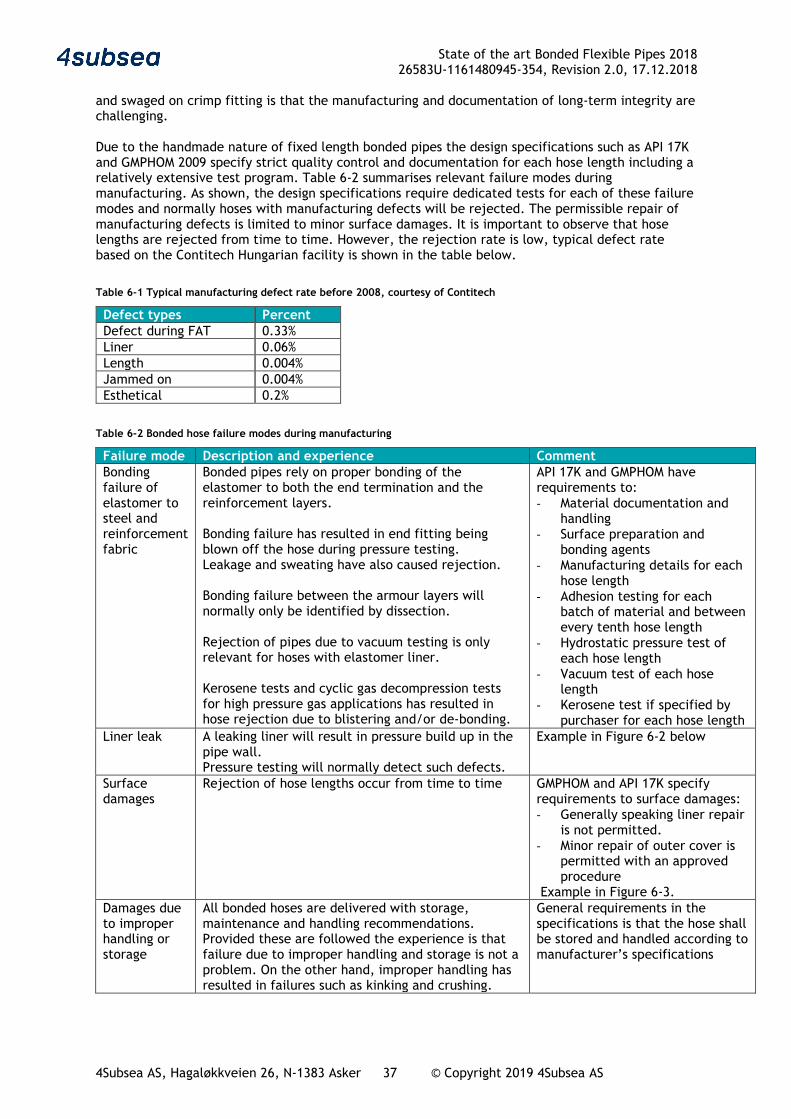
and swaged on crimp fitting is that the manufacturing and documentation of long-term integrity are challenging. Due to the handmade nature of fixed length bonded pipes the design specifications such as API 17K and GMPHOM 2009 specify strict quality control and documentation for each hose length including a relatively extensive test program. Table 6-2 summarises relevant failure modes during manufacturing. As shown, the design specifications require dedicated tests for each of these failure modes and normally hoses with manufacturing defects will be rejected. The permissible repair of manufacturing defects is limited to minor surface damages. It is important to observe that hose lengths are rejected from time to time. However, the rejection rate is low, typical defect rate based on the Contitech Hungarian facility is shown in the table below.
Table 6-1 Typical manufacturing defect rate before 2008, courtesy of Contitech
Defect types Percent Defect during FAT 0.33% Liner 0.06% Length 0.004% Jammed on 0.004% Esthetical 0.2%
Table 6-2 Bonded hose failure modes during manufacturing
Failure mode Description and experience Comment Bonding failure of elastomer to steel and reinforcement fabric
Bonded pipes rely on proper bonding of the elastomer to both the end termination and the reinforcement layers. Bonding failure has resulted in end fitting being blown off the hose during pressure testing. Leakage and sweating have also caused rejection. Bonding failure between the armour layers will normally only be identified by dissection. Rejection of pipes due to vacuum testing is only relevant for hoses with elastomer liner. Kerosene tests and cyclic gas decompression tests for high pressure gas applications has resulted in hose rejection due to blistering and/or de-bonding.
API 17K and GMPHOM have requirements to: - Material documentation and
handling - Surface preparation and
bonding agents - Manufacturing details for each
hose length - Adhesion testing for each
batch of material and between every tenth hose length
- Hydrostatic pressure test of each hose length
- Vacuum test of each hose length
- Kerosene test if specified by purchaser for each hose length
Liner leak A leaking liner will result in pressure build up in the pipe wall. Pressure testing will normally detect such defects.
Example in Figure 6-2 below
Surface damages
Rejection of hose lengths occur from time to time GMPHOM and API 17K specify requirements to surface damages: - Generally speaking liner repair
is not permitted. - Minor repair of outer cover is
permitted with an approved procedure
Example in Figure 6-3. Damages due to improper handling or storage
All bonded hoses are delivered with storage, maintenance and handling recommendations. Provided these are followed the experience is that failure due to improper handling and storage is not a problem. On the other hand, improper handling has resulted in failures such as kinking and crushing.
General requirements in the specifications is that the hose shall be stored and handled according to manufacturer’s specifications

State of the art Bonded Flexible Pipes 2018 26583U-1161480945-354, Revision 2.0, 17.12.2018
4Subsea AS, Hagaløkkveien 26, N-1383 Asker 38 © Copyright 2019 4Subsea AS
Figure 6-1 Bonding defect near end fitting detected in pressure test, courtesy of Contitech
Figure 6-2 Pressure test with leaking liner, courtesy of Contitech
State of the art Bonded Flexible Pipes 2018 26583U-1161480945-354, Revision 2.0, 17.12.2018
4Subsea AS, Hagaløkkveien 26, N-1383 Asker 39 © Copyright 2019 4Subsea AS
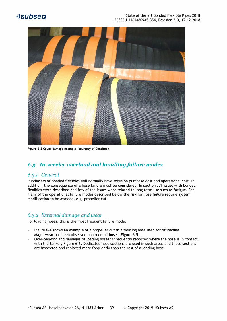
Figure 6-3 Cover damage example, courtesy of Contitech
6.3 In-service overload and handling failure modes
6.3.1 General Purchasers of bonded flexibles will normally have focus on purchase cost and operational cost. In addition, the consequence of a hose failure must be considered. In section 3.1 issues with bonded flexibles were described and few of the issues were related to long term use such as fatigue. For many of the operational failure modes described below the risk for hose failure require system modification to be avoided, e.g. propeller cut
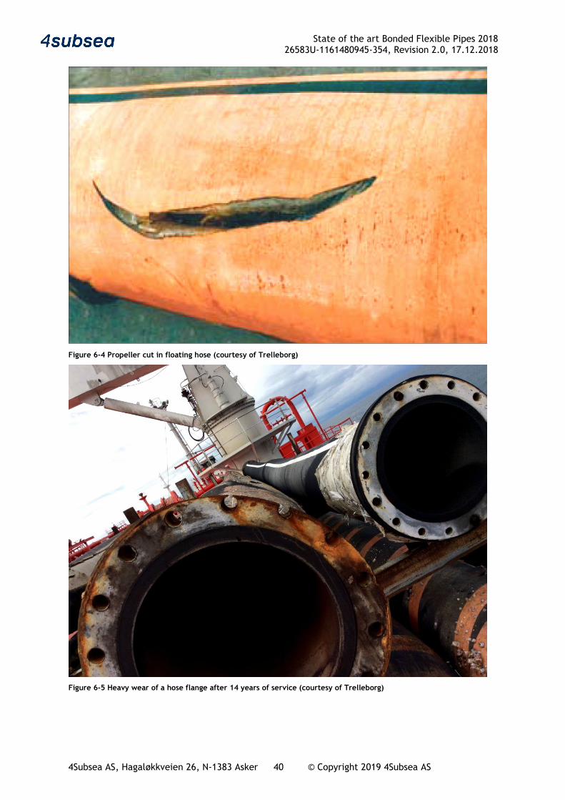
6.3.2 External damage and wear For loading hoses, this is the most frequent failure mode. - Figure 6-4 shows an example of a propeller cut in a floating hose used for offloading. - Major wear has been observed on crude oil hoses, Figure 6-5 - Over-bending and damages of loading hoses is frequently reported where the hose is in contact
with the tanker, Figure 6-6. Dedicated hose sections are used in such areas and these sections are inspected and replaced more frequently than the rest of a loading hose.
State of the art Bonded Flexible Pipes 2018 26583U-1161480945-354, Revision 2.0, 17.12.2018
4Subsea AS, Hagaløkkveien 26, N-1383 Asker 40 © Copyright 2019 4Subsea AS
Figure 6-4 Propeller cut in floating hose (courtesy of Trelleborg)
Figure 6-5 Heavy wear of a hose flange after 14 years of service (courtesy of Trelleborg)
State of the art Bonded Flexible Pipes 2018 26583U-1161480945-354, Revision 2.0, 17.12.2018
4Subsea AS, Hagaløkkveien 26, N-1383 Asker 41 © Copyright 2019 4Subsea AS
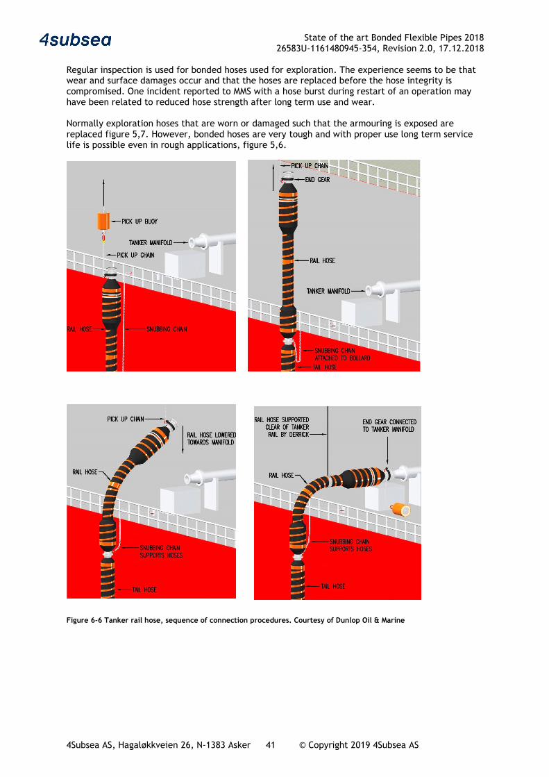
Regular inspection is used for bonded hoses used for exploration. The experience seems to be that wear and surface damages occur and that the hoses are replaced before the hose integrity is compromised. One incident reported to MMS with a hose burst during restart of an operation may have been related to reduced hose strength after long term use and wear. Normally exploration hoses that are worn or damaged such that the armouring is exposed are replaced figure 5,7. However, bonded hoses are very tough and with proper use long term service life is possible even in rough applications, figure 5,6.
Figure 6-6 Tanker rail hose, sequence of connection procedures. Courtesy of Dunlop Oil & Marine

State of the art Bonded Flexible Pipes 2018 26583U-1161480945-354, Revision 2.0, 17.12.2018
4Subsea AS, Hagaløkkveien 26, N-1383 Asker 42 © Copyright 2019 4Subsea AS
Figure 6-7 Old rotary hose, manufactured 1994, photo 2003 , courtesy of Contitech
For production jumpers the bonded hoses are permanently connected and if properly designed, wear and external damage should be controlled. However, in certain applications wear and contact with other structures is unavoidable, e.g. tanker rail hoses and drag chain jumpers used on turret moored FPSOs. Drag chain systems with large bore and high-pressure flexible pipes have experienced problems and such designs are not that frequently used anymore.
Figure 6-8 Excessive cover damage, courtesy of Contitech
Several bonded hose suppliers offer designs with an external carcass protecting the hose, Figure 6-9 shows an example.
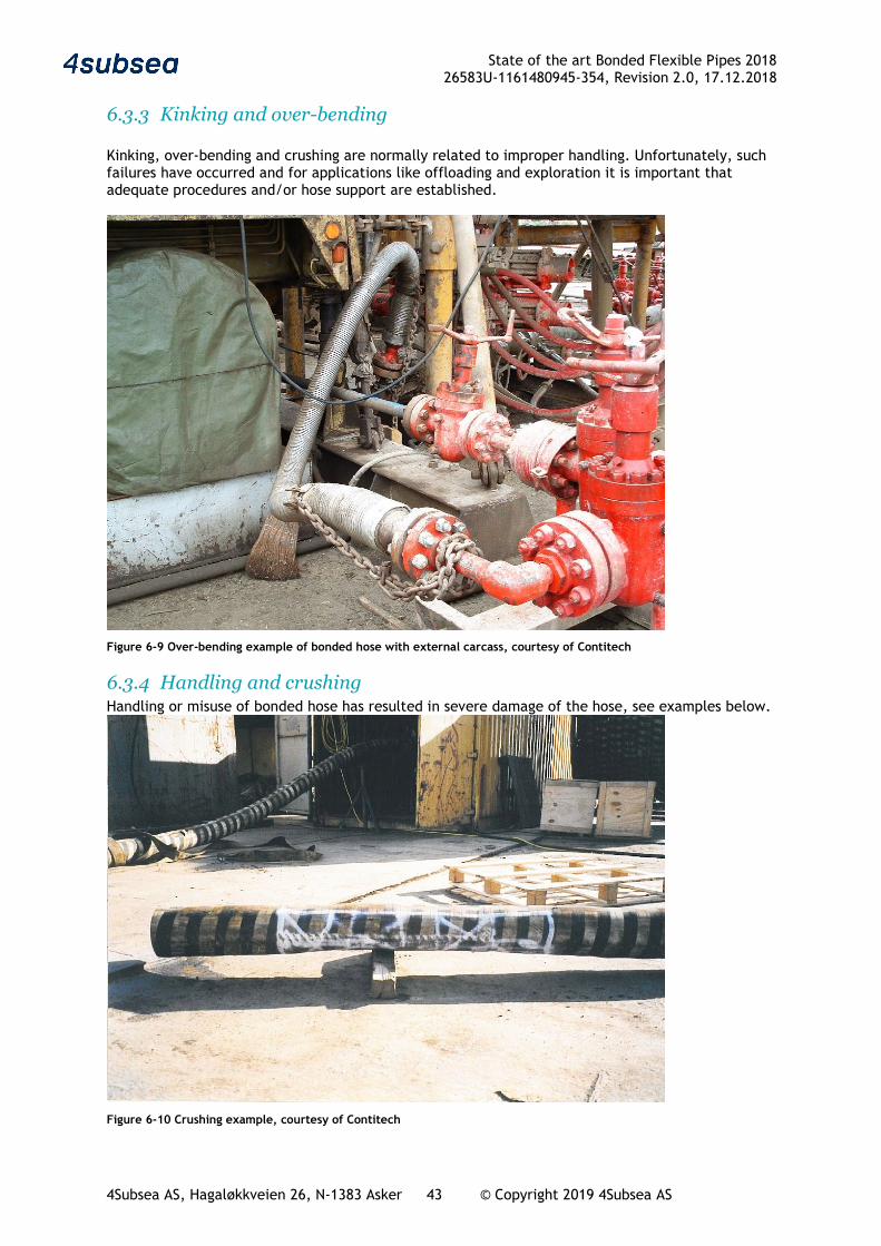
State of the art Bonded Flexible Pipes 2018 26583U-1161480945-354, Revision 2.0, 17.12.2018
4Subsea AS, Hagaløkkveien 26, N-1383 Asker 43 © Copyright 2019 4Subsea AS
6.3.3 Kinking and over-bending Kinking, over-bending and crushing are normally related to improper handling. Unfortunately, such failures have occurred and for applications like offloading and exploration it is important that adequate procedures and/or hose support are established.
Figure 6-9 Over-bending example of bonded hose with external carcass, courtesy of Contitech
6.3.4 Handling and crushing Handling or misuse of bonded hose has resulted in severe damage of the hose, see examples below.
Figure 6-10 Crushing example, courtesy of Contitech
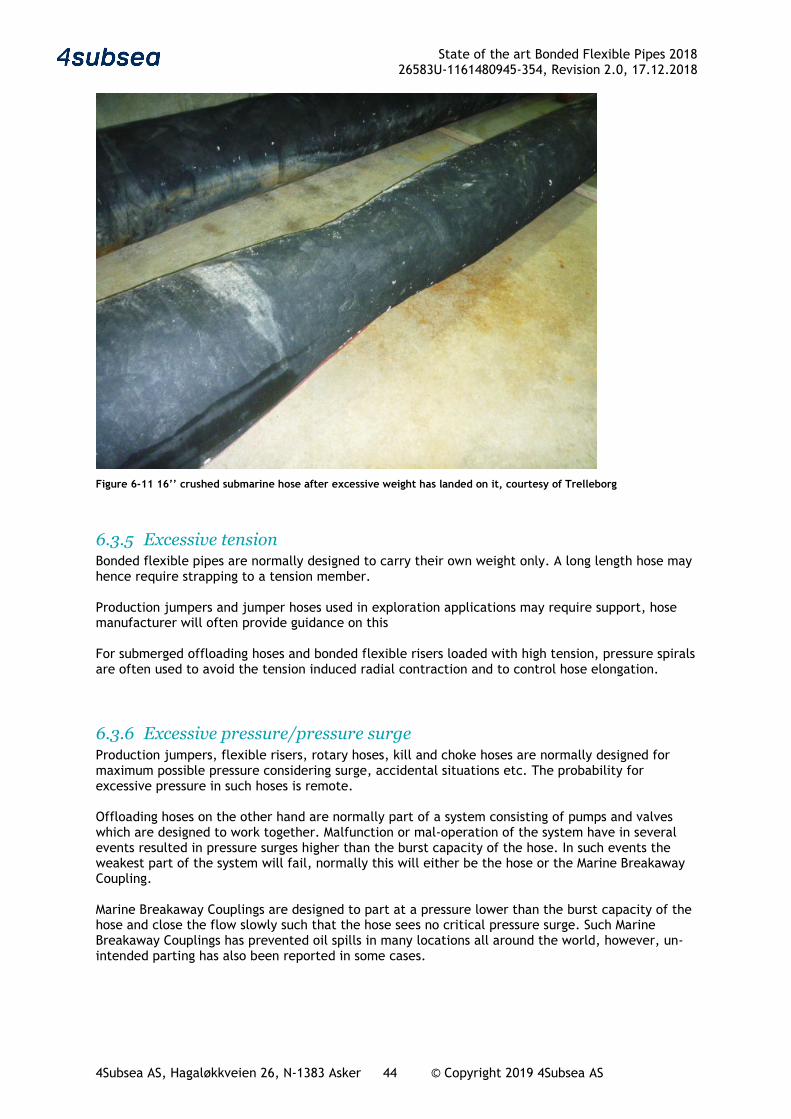
State of the art Bonded Flexible Pipes 2018 26583U-1161480945-354, Revision 2.0, 17.12.2018
4Subsea AS, Hagaløkkveien 26, N-1383 Asker 44 © Copyright 2019 4Subsea AS
Figure 6-11 16’’ crushed submarine hose after excessive weight has landed on it, courtesy of Trelleborg
6.3.5 Excessive tension Bonded flexible pipes are normally designed to carry their own weight only. A long length hose may hence require strapping to a tension member. Production jumpers and jumper hoses used in exploration applications may require support, hose manufacturer will often provide guidance on this For submerged offloading hoses and bonded flexible risers loaded with high tension, pressure spirals are often used to avoid the tension induced radial contraction and to control hose elongation.
6.3.6 Excessive pressure/pressure surge Production jumpers, flexible risers, rotary hoses, kill and choke hoses are normally designed for maximum possible pressure considering surge, accidental situations etc. The probability for excessive pressure in such hoses is remote. Offloading hoses on the other hand are normally part of a system consisting of pumps and valves which are designed to work together. Malfunction or mal-operation of the system have in several events resulted in pressure surges higher than the burst capacity of the hose. In such events the weakest part of the system will fail, normally this will either be the hose or the Marine Breakaway Coupling. Marine Breakaway Couplings are designed to part at a pressure lower than the burst capacity of the hose and close the flow slowly such that the hose sees no critical pressure surge. Such Marine Breakaway Couplings has prevented oil spills in many locations all around the world, however, un-intended parting has also been reported in some cases.
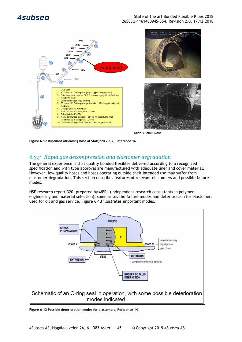
State of the art Bonded Flexible Pipes 2018 26583U-1161480945-354, Revision 2.0, 17.12.2018
4Subsea AS, Hagaløkkveien 26, N-1383 Asker 45 © Copyright 2019 4Subsea AS
Figure 6-12 Ruptured offloading hose at Statfjord 2007, Reference 16
6.3.7 Rapid gas decompression and elastomer degradation The general experience is that quality bonded flexibles delivered according to a recognized specification and with type approval are manufactured with adequate liner and cover material. However, low quality hoses and hoses operating outside their intended use may suffer from elastomer degradation. This section describes features of relevant elastomers and possible failure modes. HSE research report 320, prepared by MERL (Independent research consultants in polymer engineering and material selection), summarises the failure modes and deterioration for elastomers used for oil and gas service, Figure 6-13 illustrates important modes.
Figure 6-13 Possible deterioration modes for elastomers, Reference 14
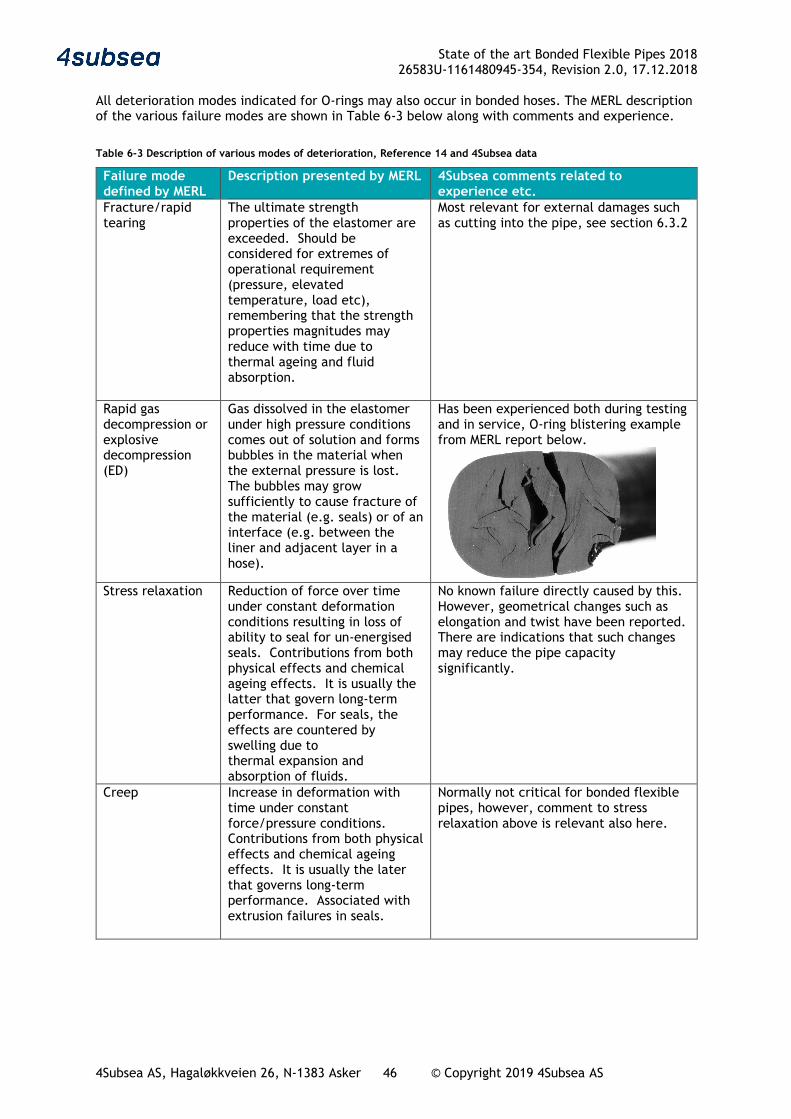
State of the art Bonded Flexible Pipes 2018 26583U-1161480945-354, Revision 2.0, 17.12.2018
4Subsea AS, Hagaløkkveien 26, N-1383 Asker 46 © Copyright 2019 4Subsea AS
All deterioration modes indicated for O-rings may also occur in bonded hoses. The MERL description of the various failure modes are shown in Table 6-3 below along with comments and experience.
Table 6-3 Description of various modes of deterioration, Reference 14 and 4Subsea data
Failure mode defined by MERL
Description presented by MERL
4Subsea comments related to experience etc.
Fracture/rapid tearing
The ultimate strength properties of the elastomer are exceeded. Should be considered for extremes of operational requirement (pressure, elevated temperature, load etc), remembering that the strength properties magnitudes may reduce with time due to thermal ageing and fluid absorption.
Most relevant for external damages such as cutting into the pipe, see section 6.3.2
Rapid gas decompression or explosive decompression (ED)
Gas dissolved in the elastomer under high pressure conditions comes out of solution and forms bubbles in the material when the external pressure is lost. The bubbles may grow sufficiently to cause fracture of the material (e.g. seals) or of an interface (e.g. between the liner and adjacent layer in a hose).
Has been experienced both during testing and in service, O-ring blistering example from MERL report below.
Stress relaxation
Reduction of force over time under constant deformation conditions resulting in loss of ability to seal for un-energised seals. Contributions from both physical effects and chemical ageing effects. It is usually the latter that govern long-term performance. For seals, the effects are countered by swelling due to thermal expansion and absorption of fluids.
No known failure directly caused by this. However, geometrical changes such as elongation and twist have been reported. There are indications that such changes may reduce the pipe capacity significantly.
Creep
Increase in deformation with time under constant force/pressure conditions. Contributions from both physical effects and chemical ageing effects. It is usually the later that governs long-term performance. Associated with extrusion failures in seals.
Normally not critical for bonded flexible pipes, however, comment to stress relaxation above is relevant also here.

State of the art Bonded Flexible Pipes 2018 26583U-1161480945-354, Revision 2.0, 17.12.2018
4Subsea AS, Hagaløkkveien 26, N-1383 Asker 47 © Copyright 2019 4Subsea AS
Failure mode defined by MERL
Description presented by MERL
4Subsea comments related to experience etc.
Swelling
Absorption of fluids over time resulting in excessive stress if constrained (e.g. seal) or excessive deformation and weakening of the elastomer if unconstrained. Enhanced by thermal expansion effects. Governed by the compatibility of the fluid with the material. A small amount can be beneficial, e.g. in low pressure gas line seals, abandonment permanent plugs.
Relevant in particular for high pressure gas service where swelling and/or explosive decompression has resulted in collapse of the internal carcass. For gas service there will be gas absorption in the pipe wall. To control the cover layer bonding, it is required to control the pressure in the wall by either gas draining or reduced gas permeation through liner, Figure 6-15.
Thermal contraction
Caused by reductions in temperature which may also result in hardening and increased stress relaxation; the combined effect may result in loss of sealing force in seals at low temperatures. Associated with the Tg of the elastomer.
Cracking of bonded flexible pipes may occur at low temperatures, however as long as the pipe is used within the specified temperature range, this is normally not a problem. Bonded flexible hoses are frequently used for LPG loading and adequate elastomer are available for most services down to about -50 deg C
Chemical degradation (ageing)
Chemical changes due to attack either by a constituent of the contacting fluid, including environmental oxygen (aerobic ageing) or ongoing vulcanisation (anaerobic ageing). Resultant changes in mechanical properties might include stiffness changes that may affect functional performance, e.g. an increase in stiffness resulting from ageing may result in excessive fatigue forces being generated in flexible joints.
Selection of adequate elastomer for a given service is important. Example of surface fracturing of HNBR in contact with treatment chemical from MERL below.
UV and ozone cracking
Component surfaces exposed to UV and ozone prior to installation or during service must be sufficiently resistant, e.g. hose covers.
Provided manufacturer recommendations are considered and the pipe is inspected in adequate intervals this will normally not result in failure of a bonded hose
Fatigue crack growth in elastomer
Crack growth under repeated strain cycling in dynamically loaded components (flexible joints, hoses). Fatigue resistance of elastomers may be reduced by elevated temperatures, ageing and swelling by fluids.
Fatigue failures in corrugated liners resulting in the elastomer being exposed to an aggressive fluid have also been reported. Cracking of the external sheet has also been experienced, see Figure 6-14
Abrasion/erosion
Loss of material over time by rubbing against another surface or fluid flow with and abrasive medium.
Material loss of the pipe cover is only critical if it leads to exposure of the armouring. This is one of the most frequent failure modes for bonded flexible pipes

State of the art Bonded Flexible Pipes 2018 26583U-1161480945-354, Revision 2.0, 17.12.2018
4Subsea AS, Hagaløkkveien 26, N-1383 Asker 48 © Copyright 2019 4Subsea AS
Failure mode defined by MERL
Description presented by MERL
4Subsea comments related to experience etc.
Bond failure
Hose end fittings and the metal plates in flexible joints are bonded to elastomer layers. Appropriate bonding agents for the type of elastomer and metal should be used. The bond is formed during the curing (vulcanization) process. Inadequate bond strength may be a result of inadequate manufacturing conditions or degradation caused by fluid ingress and corrosion.
The experience with these type of failure modes is addressed in Table 6-2
Overstressing or degradation of polymer in end fitting
Several principles are used for termination of the armouring in the end-fitting.: - Hard rubber with high shear
strength and efficient load transfer from armours to end termination
- Mechanical grip on the wires either as swaging directly on the armour wires or be hoop wrapping outside the armours to force the armours to follow a profiled nipple.
- Use of epoxy - Combination If cracking in the polymer occur the hose will normally fail either by leaking or bursting. The polymers used in the end-fitting are not exposed to the same strain as the rubber in the hose, however, the mechanical load may be significant and materials with adequate long-term strength has to be used.
The pipe qualification process shall in principle ensure that end termination is stronger than the hose. However, for combined loads like high tension and pressure pull-off failures for entire end-fittings has been observed. Further liner leaks due to e.g. fatigue of corrugated pipes will often propagate a crack through the end-fitting polymer.

State of the art Bonded Flexible Pipes 2018 26583U-1161480945-354, Revision 2.0, 17.12.2018
4Subsea AS, Hagaløkkveien 26, N-1383 Asker 49 © Copyright 2019 4Subsea AS
Figure 6-14 Cracking in outer cover, courtesy of Contitech
Figure 6-15 Bubble due to absorbed gas, pipe was not designed for gas service, courtesy of Contitech

State of the art Bonded Flexible Pipes 2018 26583U-1161480945-354, Revision 2.0, 17.12.2018
4Subsea AS, Hagaløkkveien 26, N-1383 Asker 50 © Copyright 2019 4Subsea AS
6.4 Long term degradation
6.4.1 General When designing for a safe service life of Bonded flexible pipes, the following factors are considered:
• Fatigue of reinforcement and steel • Rubber cracking • Ageing • Weathering • Chemical degradation
In addition, the experience is that handling and use is often equally important as the long term integrity of the bonded flexible pipe may be reduced by handling and use issues like;
• Wear • Cuts • Kinking • Ovalisation
For bonded flexible pipes designed according to API 17K it is required that all relevant issues affecting the safe service life is addressed in the design phase.
For standard hoses the approach is often experience based. The assumption is that a set of requirements to the construction, combined with standard performance test and guidance for use is sufficient to specify a replacement interval for the bonded hose. This method is most common for bonded flexible hoses used for loading of crude, LPG and LNG.
For drilling hoses (7K and 16C hoses) regular inspection and testing is often used and the hose can continue service until defects are discovered.
6.4.2 Fatigue of metallic parts The following fatigue failure of bonded flexibles are relevant:
• Fatigue in armouring, steel wire ropes or synthetic armours • Fatigue in metallic liner • Fatigue in end fitting including welding to piping • Fatigue in polymer parts of pipe
All steel materials may fail due to fatigue, however for cold drawn wires the time for initiation of a fatigue crack is normally long compared to the crack growth period. When a crack has been initiated, it will hence normally grow rapidly to a full wire failure. To avoid such type of fatigue failure, it is hence normal to keep the stresses in the wires at a moderate level such that under normal use fatigue cracks are not initiated. For bonded flexible pipes where the armours are not exposed to any aggressive fluids such as H2S, water etc. fatigue failure is unlikely. However, diffused gas, cover damage, blistering and loss of adhesion have resulted in fatigue failure of armour wires. The armour fatigue capacity is then reduced due to exposure to the aggressive fluid and fatigue have been observed even at moderate loads. In many applications rust deposit is a clear sign that fatigue failure may develop. Repair of the polymer to prevent further exposure to the aggressive fluid may not be sufficient mitigation as the wire may have significantly reduced capacity even after short term exposure. Normally, any hose in service with exposed armour/pressure retaining wires showing signs of corrosion/rust must be condemned. Fatigue in metallic liners has been experienced. There are two different metallic liners used; gas tight corrugated pipes (bellows) and open carcass. For corrugated pipes the following fatigue failure modes has been observed: - Fatigue in the weld connecting the corrugated liner to the end-fitting - Torsional induced failure, unclear if the failure is fatigue or repeated yielding due to torsional
un-balance of the armouring - Bending induced fatigue of the corrugated pipe has been observed in dynamic tests For carcasses, the consequence of a fatigue crack is normally insignificant as most reported carcass fatigue crack has been observed in the circumferential direction. Such cracks will normally not compromise the carcass function. However, combined with wear and or corrosion the structural
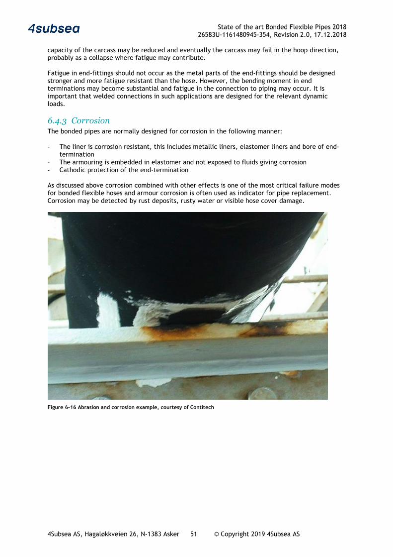
State of the art Bonded Flexible Pipes 2018 26583U-1161480945-354, Revision 2.0, 17.12.2018
4Subsea AS, Hagaløkkveien 26, N-1383 Asker 51 © Copyright 2019 4Subsea AS
capacity of the carcass may be reduced and eventually the carcass may fail in the hoop direction, probably as a collapse where fatigue may contribute. Fatigue in end-fittings should not occur as the metal parts of the end-fittings should be designed stronger and more fatigue resistant than the hose. However, the bending moment in end terminations may become substantial and fatigue in the connection to piping may occur. It is important that welded connections in such applications are designed for the relevant dynamic loads.
6.4.3 Corrosion The bonded pipes are normally designed for corrosion in the following manner: - The liner is corrosion resistant, this includes metallic liners, elastomer liners and bore of end-
termination - The armouring is embedded in elastomer and not exposed to fluids giving corrosion - Cathodic protection of the end-termination As discussed above corrosion combined with other effects is one of the most critical failure modes for bonded flexible hoses and armour corrosion is often used as indicator for pipe replacement. Corrosion may be detected by rust deposits, rusty water or visible hose cover damage.
Figure 6-16 Abrasion and corrosion example, courtesy of Contitech
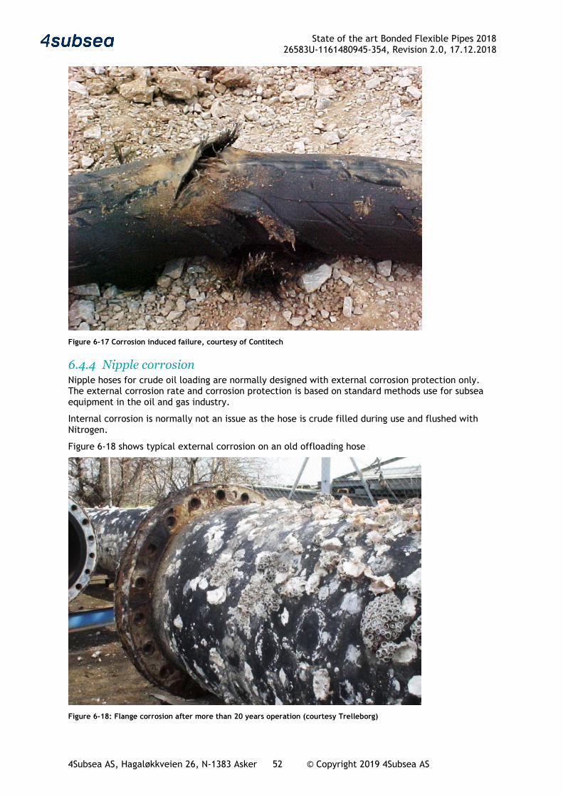
State of the art Bonded Flexible Pipes 2018 26583U-1161480945-354, Revision 2.0, 17.12.2018
4Subsea AS, Hagaløkkveien 26, N-1383 Asker 52 © Copyright 2019 4Subsea AS
Figure 6-17 Corrosion induced failure, courtesy of Contitech
6.4.4 Nipple corrosion Nipple hoses for crude oil loading are normally designed with external corrosion protection only. The external corrosion rate and corrosion protection is based on standard methods use for subsea equipment in the oil and gas industry.
Internal corrosion is normally not an issue as the hose is crude filled during use and flushed with Nitrogen.
Figure 6-18 shows typical external corrosion on an old offloading hose
Figure 6-18: Flange corrosion after more than 20 years operation (courtesy Trelleborg)
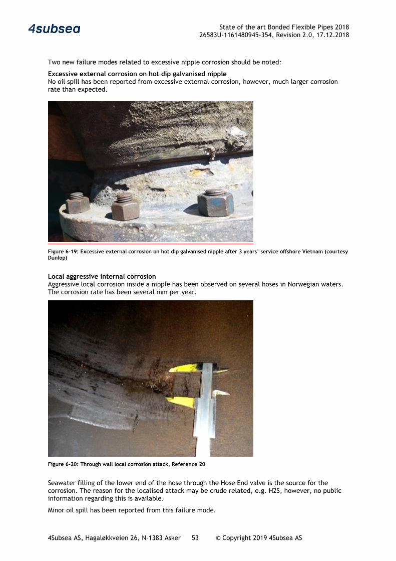
State of the art Bonded Flexible Pipes 2018 26583U-1161480945-354, Revision 2.0, 17.12.2018
4Subsea AS, Hagaløkkveien 26, N-1383 Asker 53 © Copyright 2019 4Subsea AS
Two new failure modes related to excessive nipple corrosion should be noted:
Excessive external corrosion on hot dip galvanised nipple No oil spill has been reported from excessive external corrosion, however, much larger corrosion rate than expected.
Figure 6-19: Excessive external corrosion on hot dip galvanised nipple after 3 years’ service offshore Vietnam (courtesy Dunlop)
Local aggressive internal corrosion Aggressive local corrosion inside a nipple has been observed on several hoses in Norwegian waters. The corrosion rate has been several mm per year.
Figure 6-20: Through wall local corrosion attack, Reference 20
Seawater filling of the lower end of the hose through the Hose End valve is the source for the corrosion. The reason for the localised attack may be crude related, e.g. H2S, however, no public information regarding this is available.
Minor oil spill has been reported from this failure mode.
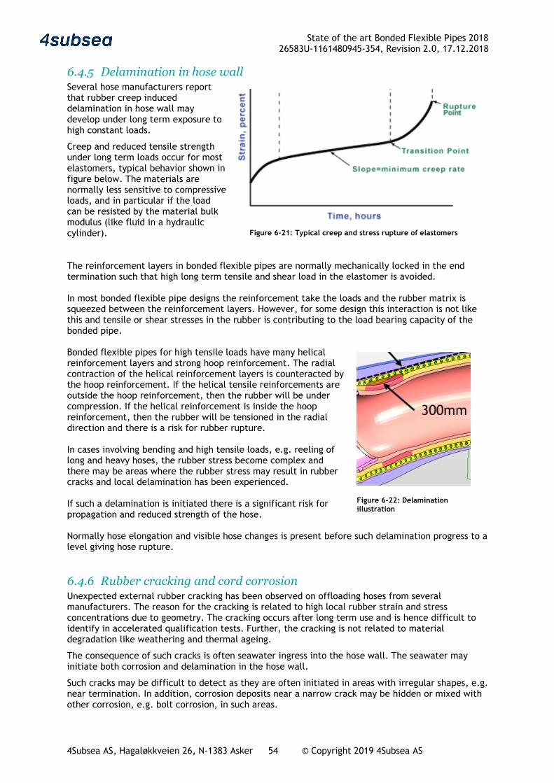
State of the art Bonded Flexible Pipes 2018 26583U-1161480945-354, Revision 2.0, 17.12.2018
4Subsea AS, Hagaløkkveien 26, N-1383 Asker 54 © Copyright 2019 4Subsea AS
6.4.5 Delamination in hose wall Several hose manufacturers report that rubber creep induced delamination in hose wall may develop under long term exposure to high constant loads.
Creep and reduced tensile strength under long term loads occur for most elastomers, typical behavior shown in figure below. The materials are normally less sensitive to compressive loads, and in particular if the load can be resisted by the material bulk modulus (like fluid in a hydraulic cylinder).
The reinforcement layers in bonded flexible pipes are normally mechanically locked in the end termination such that high long term tensile and shear load in the elastomer is avoided. In most bonded flexible pipe designs the reinforcement take the loads and the rubber matrix is squeezed between the reinforcement layers. However, for some design this interaction is not like this and tensile or shear stresses in the rubber is contributing to the load bearing capacity of the bonded pipe. Bonded flexible pipes for high tensile loads have many helical reinforcement layers and strong hoop reinforcement. The radial contraction of the helical reinforcement layers is counteracted by the hoop reinforcement. If the helical tensile reinforcements are outside the hoop reinforcement, then the rubber will be under compression. If the helical reinforcement is inside the hoop reinforcement, then the rubber will be tensioned in the radial direction and there is a risk for rubber rupture. In cases involving bending and high tensile loads, e.g. reeling of long and heavy hoses, the rubber stress become complex and there may be areas where the rubber stress may result in rubber cracks and local delamination has been experienced. If such a delamination is initiated there is a significant risk for propagation and reduced strength of the hose. Normally hose elongation and visible hose changes is present before such delamination progress to a level giving hose rupture.
6.4.6 Rubber cracking and cord corrosion Unexpected external rubber cracking has been observed on offloading hoses from several manufacturers. The reason for the cracking is related to high local rubber strain and stress concentrations due to geometry. The cracking occurs after long term use and is hence difficult to identify in accelerated qualification tests. Further, the cracking is not related to material degradation like weathering and thermal ageing.
The consequence of such cracks is often seawater ingress into the hose wall. The seawater may initiate both corrosion and delamination in the hose wall.
Such cracks may be difficult to detect as they are often initiated in areas with irregular shapes, e.g. near termination. In addition, corrosion deposits near a narrow crack may be hidden or mixed with other corrosion, e.g. bolt corrosion, in such areas.
Figure 6-21: Typical creep and stress rupture of elastomers
Figure 6-22: Delamination illustration
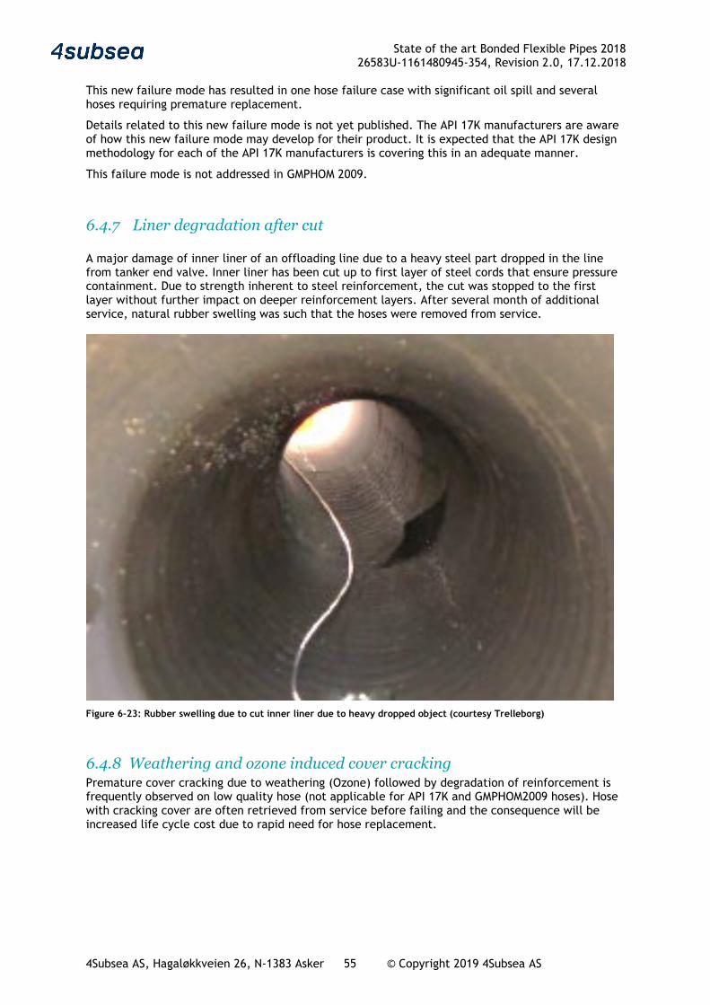
State of the art Bonded Flexible Pipes 2018 26583U-1161480945-354, Revision 2.0, 17.12.2018
4Subsea AS, Hagaløkkveien 26, N-1383 Asker 55 © Copyright 2019 4Subsea AS
This new failure mode has resulted in one hose failure case with significant oil spill and several hoses requiring premature replacement.
Details related to this new failure mode is not yet published. The API 17K manufacturers are aware of how this new failure mode may develop for their product. It is expected that the API 17K design methodology for each of the API 17K manufacturers is covering this in an adequate manner.
This failure mode is not addressed in GMPHOM 2009.
6.4.7 Liner degradation after cut A major damage of inner liner of an offloading line due to a heavy steel part dropped in the line from tanker end valve. Inner liner has been cut up to first layer of steel cords that ensure pressure containment. Due to strength inherent to steel reinforcement, the cut was stopped to the first layer without further impact on deeper reinforcement layers. After several month of additional service, natural rubber swelling was such that the hoses were removed from service.
Figure 6-23: Rubber swelling due to cut inner liner due to heavy dropped object (courtesy Trelleborg)
6.4.8 Weathering and ozone induced cover cracking Premature cover cracking due to weathering (Ozone) followed by degradation of reinforcement is frequently observed on low quality hose (not applicable for API 17K and GMPHOM2009 hoses). Hose with cracking cover are often retrieved from service before failing and the consequence will be increased life cycle cost due to rapid need for hose replacement.

State of the art Bonded Flexible Pipes 2018 26583U-1161480945-354, Revision 2.0, 17.12.2018
4Subsea AS, Hagaløkkveien 26, N-1383 Asker 56 © Copyright 2019 4Subsea AS
7 Integrity management
7.1 Information handling The integrity management of bonded flexible pipes should follow normal good practice in the industry, e.g. in line with the Flexible Pipe Handbook, Reference 22. The integrity management system and related information handling should be fully integrated with the user’s systems and be aligned with established work processes. This will ensure better experience transfer and easier system upgrade and maintenance. A generic cycle for integrity management is shown below.
Figure 7-1 Integrity management process
The bonded flexible pipes often see rough handling and tough operating conditions. Therefore, the pipes in some applications are seen as consumables and hence replaced frequently. For other applications, the pipes are permanently installed, inspected, tested and maintained, and thereby able to operate safely over the full field life time. Certainly, most cases will be found in-between these two extremes. In some cases, operational safety will benefit largely from a proper integrity management program, while in other cases the cost savings by reduced replacements will be the driving factor. In most cases, both safety and economy will gain from a well-planned integrity programme. Inspections, testing and monitoring are all key elements for a successful integrity management program. Details in what to do and how to do this will be different between pipe types, and recommendations may vary from the different vendors. For all applications the vendor experiences and recommendations should be implemented in the integrity management program. Experiences gained throughout the operational life should be basis for improvements, both within the user’s organization and preferable also shared with a broader audience, e.g. manufacturers
Perform system improvements and mitigations
Update program for inspection, testing and monitoring
Perform monitoring,
inspections and tests
Evaluate information
and update risk assessment
Information handling
Initial information acquisition, inspection, testing and status/risk evaluation
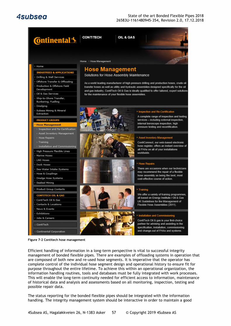
State of the art Bonded Flexible Pipes 2018 26583U-1161480945-354, Revision 2.0, 17.12.2018
4Subsea AS, Hagaløkkveien 26, N-1383 Asker 57 © Copyright 2019 4Subsea AS
Figure 7-2 Contitech hose management
Efficient handling of information in a long-term perspective is vital to successful integrity management of bonded flexible pipes. There are examples of offloading systems in operation that are composed of both new and re-used hose segments. It is imperative that the operator has complete control of the individual hose segment design and operational history to ensure fit for purpose throughout the entire lifetime. To achieve this within an operational organization, the information handling routines, tools and databases must be fully integrated with work processes. This will enable the long-term continuity needed for efficient access to information, maintenance of historical data and analysis and assessments based on all monitoring, inspection, testing and possible repair data. The status reporting for the bonded flexible pipes should be integrated with the information handling. The integrity management system should be interactive in order to maintain a good
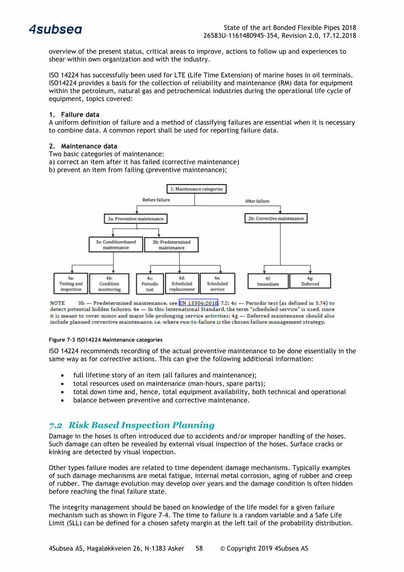
State of the art Bonded Flexible Pipes 2018 26583U-1161480945-354, Revision 2.0, 17.12.2018
4Subsea AS, Hagaløkkveien 26, N-1383 Asker 58 © Copyright 2019 4Subsea AS
overview of the present status, critical areas to improve, actions to follow up and experiences to shear within own organization and with the industry. ISO 14224 has successfully been used for LTE (Life Time Extension) of marine hoses in oil terminals. ISO14224 provides a basis for the collection of reliability and maintenance (RM) data for equipment within the petroleum, natural gas and petrochemical industries during the operational life cycle of equipment, topics covered: 1. Failure data A uniform definition of failure and a method of classifying failures are essential when it is necessary to combine data. A common report shall be used for reporting failure data. 2. Maintenance data Two basic categories of maintenance: a) correct an item after it has failed (corrective maintenance) b) prevent an item from failing (preventive maintenance);
Figure 7-3 ISO14224 Maintenance categories
ISO 14224 recommends recording of the actual preventive maintenance to be done essentially in the same way as for corrective actions. This can give the following additional information:
• full lifetime story of an item (all failures and maintenance); • total resources used on maintenance (man-hours, spare parts); • total down time and, hence, total equipment availability, both technical and operational • balance between preventive and corrective maintenance.
7.2 Risk Based Inspection Planning Damage in the hoses is often introduced due to accidents and/or improper handling of the hoses. Such damage can often be revealed by external visual inspection of the hoses. Surface cracks or kinking are detected by visual inspection. Other types failure modes are related to time dependent damage mechanisms. Typically examples of such damage mechanisms are metal fatigue, internal metal corrosion, aging of rubber and creep of rubber. The damage evolution may develop over years and the damage condition is often hidden before reaching the final failure state. The integrity management should be based on knowledge of the life model for a given failure mechanism such as shown in Figure 7-4. The time to failure is a random variable and a Safe Life Limit (SLL) can be defined for a chosen safety margin at the left tail of the probability distribution.
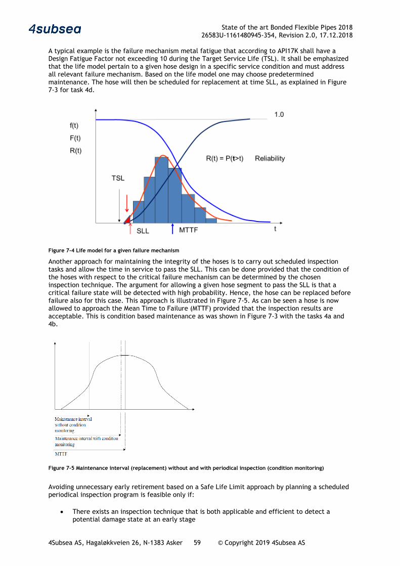
State of the art Bonded Flexible Pipes 2018 26583U-1161480945-354, Revision 2.0, 17.12.2018
4Subsea AS, Hagaløkkveien 26, N-1383 Asker 59 © Copyright 2019 4Subsea AS
A typical example is the failure mechanism metal fatigue that according to API17K shall have a Design Fatigue Factor not exceeding 10 during the Target Service Life (TSL). It shall be emphasized that the life model pertain to a given hose design in a specific service condition and must address all relevant failure mechanism. Based on the life model one may choose predetermined maintenance. The hose will then be scheduled for replacement at time SLL, as explained in Figure 7-3 for task 4d.
Figure 7-4 Life model for a given failure mechanism
Another approach for maintaining the integrity of the hoses is to carry out scheduled inspection tasks and allow the time in service to pass the SLL. This can be done provided that the condition of the hoses with respect to the critical failure mechanism can be determined by the chosen inspection technique. The argument for allowing a given hose segment to pass the SLL is that a critical failure state will be detected with high probability. Hence, the hose can be replaced before failure also for this case. This approach is illustrated in Figure 7-5. As can be seen a hose is now allowed to approach the Mean Time to Failure (MTTF) provided that the inspection results are acceptable. This is condition based maintenance as was shown in Figure 7-3 with the tasks 4a and 4b.
Figure 7-5 Maintenance interval (replacement) without and with periodical inspection (condition monitoring) Avoiding unnecessary early retirement based on a Safe Life Limit approach by planning a scheduled periodical inspection program is feasible only if:
• There exists an inspection technique that is both applicable and efficient to detect a potential damage state at an early stage
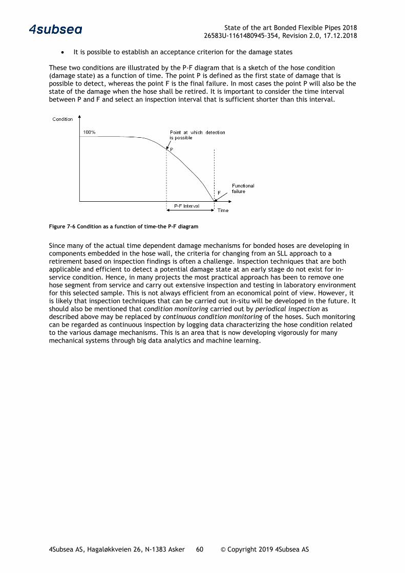
State of the art Bonded Flexible Pipes 2018 26583U-1161480945-354, Revision 2.0, 17.12.2018
4Subsea AS, Hagaløkkveien 26, N-1383 Asker 60 © Copyright 2019 4Subsea AS
• It is possible to establish an acceptance criterion for the damage states These two conditions are illustrated by the P-F diagram that is a sketch of the hose condition (damage state) as a function of time. The point P is defined as the first state of damage that is possible to detect, whereas the point F is the final failure. In most cases the point P will also be the state of the damage when the hose shall be retired. It is important to consider the time interval between P and F and select an inspection interval that is sufficient shorter than this interval.
Figure 7-6 Condition as a function of time-the P-F diagram
Since many of the actual time dependent damage mechanisms for bonded hoses are developing in components embedded in the hose wall, the criteria for changing from an SLL approach to a retirement based on inspection findings is often a challenge. Inspection techniques that are both applicable and efficient to detect a potential damage state at an early stage do not exist for in-service condition. Hence, in many projects the most practical approach has been to remove one hose segment from service and carry out extensive inspection and testing in laboratory environment for this selected sample. This is not always efficient from an economical point of view. However, it is likely that inspection techniques that can be carried out in-situ will be developed in the future. It should also be mentioned that condition monitoring carried out by periodical inspection as described above may be replaced by continuous condition monitoring of the hoses. Such monitoring can be regarded as continuous inspection by logging data characterizing the hose condition related to the various damage mechanisms. This is an area that is now developing vigorously for many mechanical systems through big data analytics and machine learning.
State of the art Bonded Flexible Pipes 2018 26583U-1161480945-354, Revision 2.0, 17.12.2018
4Subsea AS, Hagaløkkveien 26, N-1383 Asker 61 © Copyright 2019 4Subsea AS
7.3 Inspection, testing and monitoring
7.3.1 Monitoring One of the key activities in the integrity management program for bonded flexible pipes is the monitoring of operational parameters. Typically, this could be continuous monitoring of pressure and temperature, frequent sampling of fluid composition, H2S, CO2, monitoring of dynamics and environmental parameters. Bonded flexible pipes are often used in short periods and stored in between, e.g. loading hoses. The handling and use history including observations and inspections are important. For bonded flexible pipes in gas applications, the pressure cycling or more precisely the large pressure relief may be vital for the performance. Good operational routines and careful monitoring of adherence to these routines could be important for successful long-term operation of these pipes. Some bonded flexible pipes may be especially sensitive to torsion e.g. thin walled internal steel liners. For some special applications of these type of bonded flexible pipes, monitoring of vessel motions may be of special importance. The use of any chemicals in injection or production lines should be closely monitored and carefully checked against the relevant material compatibility charts. The monitored parameters should be reviewed regularly and seen in relation to the other inspection and testing activities. Early actions should be taken if the bonded flexible pipe is operated outside or very close to established limits. Further such data are important for extended life evaluations and possible premature failure investigations.
7.3.2 Inspection Visual inspection Visual inspection is the most commonly used inspection technique for bonded flexible pipes. If this inspection reveals any irregularities a closer investigation should be performed. The close visual inspection could either be targeted at areas identified as critical during the planning phase or be a result of findings in a general visual inspection. All external surface irregularities of the bonded flexible pipes and areas around the end fittings shall be carefully documented by photos and measurements. Comparisons with known failure modes and previous inspection records should form basis for further actions. Internal video inspection of bonded flexible pipes should be performed. The frequency of the inspection may be adjusted according to vendor recommendations and relevant experiences for similar pipes in similar applications. The pipe should preferably be carefully flushed prior to internal visual inspection. The development of new and efficient internal pipe inspection tools is ongoing and possibilities for identifying actual failure modes using such tools should be reviewed regularly. Many failure modes may be detected by internal inspection, e.g. blistering, liner cracking, liner damage, corrosion and internal deformations (buckling, ovalisation).

State of the art Bonded Flexible Pipes 2018 26583U-1161480945-354, Revision 2.0, 17.12.2018
4Subsea AS, Hagaløkkveien 26, N-1383 Asker 62 © Copyright 2019 4Subsea AS
Figure 7-7 Offshore internal inspection by the 4Subsea UPIT tool, courtesy 4Subsea
Geometrical measurements Bonded hoses will often get permanent elongation with time under load, partly due to creep and partly due to gradual compaction of the elastic composite wall. Further there may be other measurable geometrical changes related to specific failure modes, e.g. ovalisation due to crushing on a reel. Acceptance criteria for geometrical challenges may be hard to establish and it is recommended to the extent possible to use controlled test and detail analysis to establish this, e.g. hose qualification.
State of the art Bonded Flexible Pipes 2018 26583U-1161480945-354, Revision 2.0, 17.12.2018
4Subsea AS, Hagaløkkveien 26, N-1383 Asker 63 © Copyright 2019 4Subsea AS
7.3.3 Testing Pressure testing The pressure tests may typically be planned to confirm leak tightness of the pipe and related connections, or the test could be focused on confirming structural integrity of the pipe. The leak tests could be performed at operating pressure, while pressure tests will typically be performed at 1.2 to 1.5 times the design pressure. When planning a RBI (Risk Based Inspection) program, it is often found that pressure testing is insufficient to use for checking integrity as several relevant failure modes like collapse and elongation cannot be verified by internal pressure testing. It is hence often found that the main purpose of pressure testing is to verify no leaks. Vacuum testing Vacuum testing is done to verify that no blisters or voids are present in the liner. In the vacuum test transparent plates are mounted in each hose end and vacuum is established inside the hose. The state of the inner liner is inspected by looking through the transparent end plates. Vacuum testing is normally performed for new offloading hoses and during hose recertification, ref GMPHOM 2009. Tension testing For applications where the bonded flexible is exposed to tension it is required to document both tensile capacity and long-term elongation. Many applications require tension capacity of the hose and this type of testing is frequently performed for prototype testing, however, seldom used for integrity management. Bonded flexible pipes have often large tensile capacity and high elongation at break. The energy released in tensile hose failure is hence large and severe incidents has occurred in hose tensile failure events. It is hence important that hose failure tension and elongation to break are known when designing a system with bonded flexibles. Other tests There are several other prototype and recertification tests used in the bonded hose industry, e.g. electric continuity test, crush test, peel test of material bonding, material tests etc. Such tests are normally not part of an integrity management program and is not addressed further here. For LTE and failure investigation such additional testing may be considered if the Reliability Centered Maintenance planning show that such testing is required, ref section 7.2
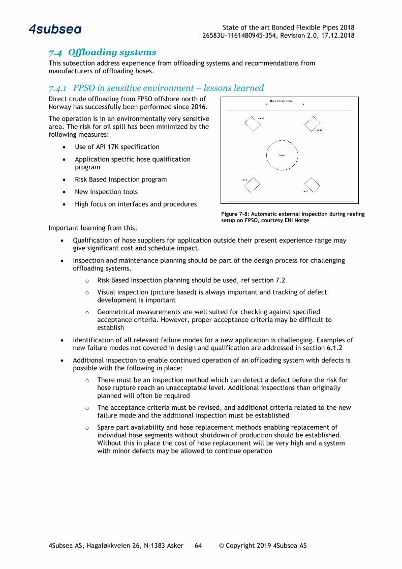
State of the art Bonded Flexible Pipes 2018 26583U-1161480945-354, Revision 2.0, 17.12.2018
4Subsea AS, Hagaløkkveien 26, N-1383 Asker 64 © Copyright 2019 4Subsea AS
7.4 Offloading systems This subsection address experience from offloading systems and recommendations from manufacturers of offloading hoses.
7.4.1 FPSO in sensitive environment – lessons learned Direct crude offloading from FPSO offshore north of Norway has successfully been performed since 2016.
The operation is in an environmentally very sensitive area. The risk for oil spill has been minimized by the following measures:
• Use of API 17K specification
• Application specific hose qualification program
• Risk Based Inspection program
• New inspection tools
• High focus on interfaces and procedures
Important learning from this;
• Qualification of hose suppliers for application outside their present experience range may give significant cost and schedule impact.
• Inspection and maintenance planning should be part of the design process for challenging offloading systems.
o Risk Based Inspection planning should be used, ref section 7.2
o Visual inspection (picture based) is always important and tracking of defect development is important
o Geometrical measurements are well suited for checking against specified acceptance criteria. However, proper acceptance criteria may be difficult to establish
• Identification of all relevant failure modes for a new application is challenging. Examples of new failure modes not covered in design and qualification are addressed in section 6.1.2
• Additional inspection to enable continued operation of an offloading system with defects is possible with the following in place:
o There must be an inspection method which can detect a defect before the risk for hose rupture reach an unacceptable level. Additional inspections than originally planned will often be required
o The acceptance criteria must be revised, and additional criteria related to the new failure mode and the additional inspection must be established
o Spare part availability and hose replacement methods enabling replacement of individual hose segments without shutdown of production should be established. Without this in place the cost of hose replacement will be very high and a system with minor defects may be allowed to continue operation
Figure 7-8: Automatic external inspection during reeling setup on FPSO, courtesy ENI Norge
State of the art Bonded Flexible Pipes 2018 26583U-1161480945-354, Revision 2.0, 17.12.2018
4Subsea AS, Hagaløkkveien 26, N-1383 Asker 65 © Copyright 2019 4Subsea AS
7.4.2 Lessons learned from other operators of demanding offloading systems • There is a risk for major oil spill from offloading systems. Use of submerged systems which
cannot be regularly inspected hence have a potential for major oil spills. Two major oil spills have been reported since 2007
• Use of API 17K approved hoses is considered the best measure to minimize the risk for hose failure. However, the experience shows that there is a residual risk for oil spill even if the hoses are API 17K approved and the hoses are operated within the specified service life and service conditions
• The additional purchase cost of API 17K hoses compared to GMPHOM 2009 hoses result in that most offloading systems use GMPHOM 2009 hoses.
• Verification of hose status, LTE (Life Time Extension) and inspection planning of GMPHOM 2009 hoses is difficult as no application specific evaluation of critical items are available. Only general recertification procedures based on GMPHOM 2009 and manufacture recommendations are available and the risk for overlooking issues is significant. GMPHOM 2009 hoses are often recertified based on visual inspection, pressure testing and vacuum testing, this is normally adequate for standard systems.
• The available inspection tools are presently not fully capable of giving early warning in a manner to eliminate the risk for oil spill. More reliable hoses and better inspection tools are wanted
7.4.3 Hose Manufacturer input Hose Designs with integrated integrity management features
a) Wear indicator layer within hose design cover matrix used by several manufacturers
b) GMPHOM double carcass leak detection systems supplied by the manufacturers of double carcass hoses
The following manufacturer comments related to Inspection tools are noted
• Inspection based on instrumented pigs giving 3D internal measurement should be investigated by the industry and developed. This type of pig already exists for rigid pipes and could be adapted to bonded hoses, especially for submarine lines where dismantling operations are demanding operations. It could bring valuable information to assess submarine line integrity.
• Internal visual inspection does not always bring very useful information as quality of the record is often not of good resolution and usually severely impacted by transparency of the media present in the line during inspection. Finally, even if the visibility and video resolution are good enough, possible wax deposit on the inner liner prevent from getting valuable and accurate observations.
• Integrity management services are available from some manufacturers at client request, ref Figure 7-2, including support services, system design, inspection & testing, training, repairs etc.
• Other feature like positioning system can be implemented by winker lights or clamp-on device. Even if this bring information to the operator, it will not always enhance hose operation.
• Processing big amount of data could be used to enhance global knowledge of bonded hoses, in particular for GMPHOM09 applications but would require the operators to proceed to regular inspection as well as systematic burst test, or any other relevant investigations, when hoses are removed from service.
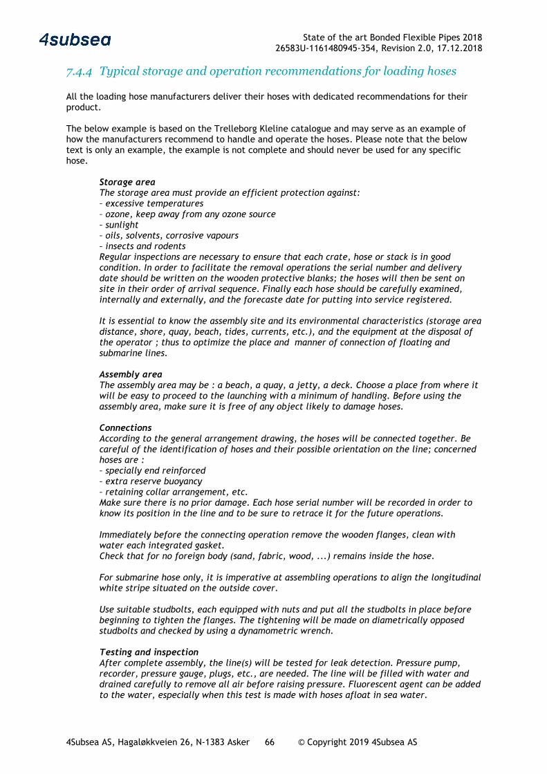
State of the art Bonded Flexible Pipes 2018 26583U-1161480945-354, Revision 2.0, 17.12.2018
4Subsea AS, Hagaløkkveien 26, N-1383 Asker 66 © Copyright 2019 4Subsea AS
7.4.4 Typical storage and operation recommendations for loading hoses All the loading hose manufacturers deliver their hoses with dedicated recommendations for their product. The below example is based on the Trelleborg Kleline catalogue and may serve as an example of how the manufacturers recommend to handle and operate the hoses. Please note that the below text is only an example, the example is not complete and should never be used for any specific hose.
Storage area The storage area must provide an efficient protection against: – excessive temperatures – ozone, keep away from any ozone source – sunlight – oils, solvents, corrosive vapours – insects and rodents Regular inspections are necessary to ensure that each crate, hose or stack is in good condition. In order to facilitate the removal operations the serial number and delivery date should be written on the wooden protective blanks; the hoses will then be sent on site in their order of arrival sequence. Finally each hose should be carefully examined, internally and externally, and the forecaste date for putting into service registered. It is essential to know the assembly site and its environmental characteristics (storage area distance, shore, quay, beach, tides, currents, etc.), and the equipment at the disposal of the operator ; thus to optimize the place and manner of connection of floating and submarine lines. Assembly area The assembly area may be : a beach, a quay, a jetty, a deck. Choose a place from where it will be easy to proceed to the launching with a minimum of handling. Before using the assembly area, make sure it is free of any object likely to damage hoses. Connections According to the general arrangement drawing, the hoses will be connected together. Be careful of the identification of hoses and their possible orientation on the line; concerned hoses are : – specially end reinforced – extra reserve buoyancy – retaining collar arrangement, etc. Make sure there is no prior damage. Each hose serial number will be recorded in order to know its position in the line and to be sure to retrace it for the future operations. Immediately before the connecting operation remove the wooden flanges, clean with water each integrated gasket. Check that for no foreign body (sand, fabric, wood, ...) remains inside the hose. For submarine hose only, it is imperative at assembling operations to align the longitudinal white stripe situated on the outside cover. Use suitable studbolts, each equipped with nuts and put all the studbolts in place before beginning to tighten the flanges. The tightening will be made on diametrically opposed studbolts and checked by using a dynamometric wrench. Testing and inspection After complete assembly, the line(s) will be tested for leak detection. Pressure pump, recorder, pressure gauge, plugs, etc., are needed. The line will be filled with water and drained carefully to remove all air before raising pressure. Fluorescent agent can be added to the water, especially when this test is made with hoses afloat in sea water.
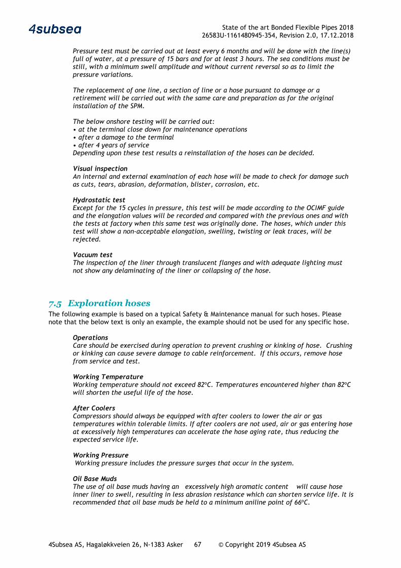
State of the art Bonded Flexible Pipes 2018 26583U-1161480945-354, Revision 2.0, 17.12.2018
4Subsea AS, Hagaløkkveien 26, N-1383 Asker 67 © Copyright 2019 4Subsea AS
Pressure test must be carried out at least every 6 months and will be done with the line(s) full of water, at a pressure of 15 bars and for at least 3 hours. The sea conditions must be still, with a minimum swell amplitude and without current reversal so as to limit the pressure variations. The replacement of one line, a section of line or a hose pursuant to damage or a retirement will be carried out with the same care and preparation as for the original installation of the SPM. The below onshore testing will be carried out: • at the terminal close down for maintenance operations • after a damage to the terminal • after 4 years of service Depending upon these test results a reinstallation of the hoses can be decided. Visual inspection An internal and external examination of each hose will be made to check for damage such as cuts, tears, abrasion, deformation, blister, corrosion, etc. Hydrostatic test Except for the 15 cycles in pressure, this test will be made according to the OCIMF guide and the elongation values will be recorded and compared with the previous ones and with the tests at factory when this same test was originally done. The hoses, which under this test will show a non-acceptable elongation, swelling, twisting or leak traces, will be rejected. Vacuum test The inspection of the liner through translucent flanges and with adequate lighting must not show any delaminating of the liner or collapsing of the hose.
7.5 Exploration hoses The following example is based on a typical Safety & Maintenance manual for such hoses. Please note that the below text is only an example, the example should not be used for any specific hose.
Operations Care should be exercised during operation to prevent crushing or kinking of hose. Crushing or kinking can cause severe damage to cable reinforcement. If this occurs, remove hose from service and test. Working Temperature Working temperature should not exceed 82oC. Temperatures encountered higher than 82oC will shorten the useful life of the hose. After Coolers Compressors should always be equipped with after coolers to lower the air or gas temperatures within tolerable limits. If after coolers are not used, air or gas entering hose at excessively high temperatures can accelerate the hose aging rate, thus reducing the expected service life. Working Pressure Working pressure includes the pressure surges that occur in the system. Oil Base Muds The use of oil base muds having an excessively high aromatic content will cause hose inner liner to swell, resulting in less abrasion resistance which can shorten service life. It is recommended that oil base muds be held to a minimum aniline point of 66oC.
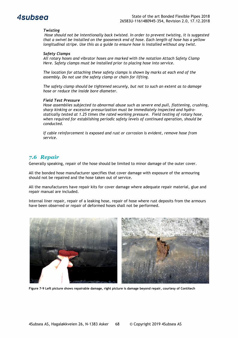
State of the art Bonded Flexible Pipes 2018 26583U-1161480945-354, Revision 2.0, 17.12.2018
4Subsea AS, Hagaløkkveien 26, N-1383 Asker 68 © Copyright 2019 4Subsea AS
Twisting Hose should not be intentionally back twisted. In order to prevent twisting, it is suggested that a swivel be installed on the gooseneck end of hose. Each length of hose has a yellow longitudinal stripe. Use this as a guide to ensure hose is installed without any twist. Safety Clamps All rotary hoses and vibrator hoses are marked with the notation Attach Safety Clamp Here. Safety clamps must be installed prior to placing hose into service. The location for attaching these safety clamps is shown by marks at each end of the assembly. Do not use the safety clamp or chain for lifting. The safety clamp should be tightened securely, but not to such an extent as to damage hose or reduce the inside bore diameter. Field Test Pressure Hose assemblies subjected to abnormal abuse such as severe end pull, flattening, crushing, sharp kinking or excessive pressurization must be immediately inspected and hydro-statically tested at 1.25 times the rated working pressure. Field testing of rotary hose, when required for establishing periodic safety levels of continued operation, should be conducted. If cable reinforcement is exposed and rust or corrosion is evident, remove hose from service.
7.6 Repair Generally speaking, repair of the hose should be limited to minor damage of the outer cover. All the bonded hose manufacturer specifies that cover damage with exposure of the armouring should not be repaired and the hose taken out of service. All the manufacturers have repair kits for cover damage where adequate repair material, glue and repair manual are included. Internal liner repair, repair of a leaking hose, repair of hose where rust deposits from the armours have been observed or repair of deformed hoses shall not be performed.
Figure 7-9 Left picture shows repairable damage, right picture is damage beyond repair, courtesy of Contitech
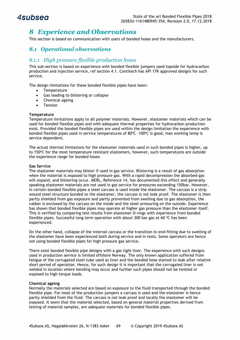
State of the art Bonded Flexible Pipes 2018 26583U-1161480945-354, Revision 2.0, 17.12.2018
4Subsea AS, Hagaløkkveien 26, N-1383 Asker 69 © Copyright 2019 4Subsea AS
8 Experience and Observations This section is based on communication with users of bonded hoses and the manufacturers.
8.1 Operational observations
8.1.1 High pressure flexible production hoses This sub-section is based on experience with bonded flexible jumpers used topside for hydrocarbon production and injection service, ref section 4.1. Contitech has API 17K approved designs for such service. The design limitations for these bonded flexible pipes have been:
• Temperature • Gas leading to blistering or collapse • Chemical ageing • Tension
Temperature Temperature limitations apply to all polymer materials. However, elastomer materials which can be used for bonded flexible pipes and with adequate thermal properties for hydrocarbon production exist. Provided the bonded flexible pipes are used within the design limitation the experience with bonded flexible pipes used in service temperatures of 80oC– 100oC is good, max working temp is service dependent. The actual thermal limitations for the elastomer materials used in such bonded pipes is higher, up to 150oC for the most temperature resistant elastomers, however, such temperatures are outside the experience range for bonded hoses. Gas Service The elastomer materials may blister if used in gas service. Blistering is a result of gas absorption when the material is exposed to high pressure gas. With a rapid decompression the absorbed gas will expand, and blistering occur. MERL, Reference 14, has documented this effect and generally speaking elastomer materials are not used in gas service for pressures exceeding 150bar. However, in certain bonded flexible pipes a steel carcass is used inside the elastomer. The carcass is a strip wound steel structure bonded to the elastomer, the carcass is not leak proof. The elastomer is then partly shielded from gas exposure and partly prevented from swelling due to gas absorption, the rubber is enclosed by the carcass on the inside and the steel armouring on the outside. Experience has shown that bonded flexible pipes may operate at higher gas pressure than the elastomer itself. This is verified by comparing test results from elastomer O-rings with experience from bonded flexible pipes. Successful long term operation with about 300 bar gas at 60 oC has been experienced. On the other hand, collapse of the internal carcass or the transition to end-fitting due to swelling of the elastomer have been experienced both during service and in tests. Some operators are hence not using bonded flexible pipes for high pressure gas service. There exist bonded flexible pipe designs with a gas tight liner. The experience with such designs used in production service is limited offshore Norway. The only known application suffered from fatigue of the corrugated steel tube used as liner and the bonded hose started to leak after relative short period of operation. Hence, for such design it is important that the corrugated liner is not welded in location where bending may occur and further such pipes should not be twisted or exposed to high torque loads. Chemical ageing Normally the materials selected are based on exposure to the fluid transported through the bonded flexible pipe. For most of the production jumpers a carcass is used and the elastomer is hence partly shielded from the fluid. The carcass is not leak proof and locally the elastomer will be exposed. It seem that the material selected, based on general material properties derived from testing of material samples, are adequate materials for bonded flexible pipes.
State of the art Bonded Flexible Pipes 2018 26583U-1161480945-354, Revision 2.0, 17.12.2018
4Subsea AS, Hagaløkkveien 26, N-1383 Asker 70 © Copyright 2019 4Subsea AS
General ageing Reduced pressure capacity of bonded flexible pipes after some time in operation has been experienced. Neither the degradation rate nor the general ageing process is known in any detail. Tension Standard bonded hoses are designed with a limited tension capacity. The manufacturer guidance is normally to limit the tension to the weight of one hose segment. For topside jumpers this is normally not a governing criterion. For riser applications on the other hand, tension capacity and additional reinforcement must be considered. Drag chain application The following statements with relevance for bonded hoses have been copied from “A summary Report on FPSO, Lessons Learned, gathered from 5 Norwegian FPSOs, May 2002 - 20 September 2002”, Prepared for the Norwegian Oil Industry Association, OLF, Reference 15. Several FPSO’s have drag chains as an alternative to a swivel. Specific problems experienced include hose and electric cable failure due to wear from bending, wear pads worn out, difficulty of access, and damage caused by running into the end stops. In addition, the drag chain limits the free rotation of the vessel requiring thrusters to be serviceable at all times.
8.1.2 Offloading hoses Crude oil offloading through bonded flexible pipes is common for floating offshore oil production units, FPSOs in particular, however bonded flexible pipes are also used for crude loading from fixed platforms. Reference is made to section 4.2.
Most of the offshore production units have limited storage capacity and rupture of an offloading hose may quickly lead to shut down of the production and large economic losses.
Reliable hoses, reliability centered maintenance and spare part availability reduce the risk for hose failure induced downtime.
Recently, several production shut downs due to issues with the crude loading hoses has occurred offshore Norway. In two cases, where the economic losses were significant, the hose issues were related to new failure modes of API 17K hoses qualified for the actual application.
Input from 3 oil companies may be summarized as:
• The economic and reputation consequence of offloading hose failure is such that great efforts on high reliability of the offloading system are required
• API 17K hoses are considered to give better control of reliability as the hoses are delivered with service life documentation for the actual application and are manufactured with the best possible quality
• Even though it is generally agreed that the cost of “buying the best” is moderate compared to the operational risk, the use of API 17K hoses is limited.
• The major issues with offloading hoses in demanding applications have all been related to unexpected failure modes which were not addressed in the hose qualification and engineering process. The economic consequences of these issues have been significant and they have led to production shut down.
Manufacturer input: Long service life from 10 to 20 years may be achieved for submarine applications where environmental limitations and the loading methods are properly established. Long service life can also be achieved for floating hoses, but the occurrence of unpredictable/accidental events (bad handling, ships crossing the line, wearing against hawser, chains and other hoses) can shorten the service life. OCIMF hoses have been designed to withstand the pressure/tension and bending loads generated by most of the usual offloading application.
State of the art Bonded Flexible Pipes 2018 26583U-1161480945-354, Revision 2.0, 17.12.2018
4Subsea AS, Hagaløkkveien 26, N-1383 Asker 71 © Copyright 2019 4Subsea AS
Offloading systems are designed with a moderate pressure rating governed by the offloading pump capacity. Most offloading system are designed such that pressure surge will be controlled. The most common way of doing this is to introduce a MBC (Marine Breakaway Coupling). The MBC will part at a given pressure or tension and slowly close the hose ends and thereby limiting the leak to an absolute minimum and ensuring no critical surge pressure. For “North Sea tankers” all valves are designed for sequential slow closure. However, mal-functional valves have resulted in excessive pressure surges and rupture of offloading hoses. On the specific occasions, no weaknesses in the hoses have been identified. The oil spill rate from bunkering operations is high. It is expected that many of these are related to improper hose management programs and improper procedures. Reeling of long length hoses and in particular submerged hoses may require high axial tension. Most bonded hoses have limited tension capacity and will elongate when tensioned. It is important that the hose and reel is designed for such tension. Premature burst failure during testing of hoses reeled with high tension has been observed and pressure testing on reel should be used with care. Hose operation experience For new and challenging applications where hose qualification is required there is a risk for unexpected failure modes and both oil spill and production shut down have been experienced due to this. Inspection and monitoring should be used for such systems. Interfaces, in particular for applications where new and conventional equipment are combined may introduce unexpected challenges, e.g. new offloading systems used together with conventional Bow Loading systems on Shuttle Tankers. Risk for inleak of seawater, e.g through Hose End Valve need to be considered. There are examples of hose system rejected after manufacturing due to corrosion risk related to inleak of seawater and also examples of aggressive corrosion.
8.1.3 Exploration hoses, including, mud, cement, kill and choke Exploration hoses are inspected, tested and replaced based on findings. Reference is made to section 4.5. The hoses are used in an extremely demanding service. The general experience may be summarised as:
• Kill and choke jumpers on drilling rigs should have relatively high bending stiffness to avoid excessive bending when the hose is in axial compression. Some operators prefer the stiffer non-bonded jumpers in such applications
• Rotary hoses, mud hoses and cement hoses are normally bonded hoses. In these applications bonded hoses are preferred due their flexibility
• Spill of oil based mud have been reported in a number of events offshore Norway. In addition personal injury due to hose burst has been reported by MMS
• The actual maintenance program followed by the users of such hoses is unclear to 4Subsea
8.1.4 Other oil and gas hoses The general experience with such hoses is that most hoses fulfil their purchase requirements. Reference is made to section 4.6. End of service life is often reached after a few years in operation and the reason is in many cases external damages or wear, ref section 3.1.3.
Hose design
• Low quality hoses are frequently used. Premature cover cracking due to weathering (Ozone) followed by degradation of reinforcement is frequently observed. Hose with cracking cover are often retrieved from service before failing and the only consequence will be increased life cycle cost due to rapid need for hose replacement
• Many hose manufacturers prefer to deliver type approved, high quality hoses for a specified
application to avoid premature failure and misuse of the hoses, however due to price competition other hoses are often used
State of the art Bonded Flexible Pipes 2018 26583U-1161480945-354, Revision 2.0, 17.12.2018
4Subsea AS, Hagaløkkveien 26, N-1383 Asker 72 © Copyright 2019 4Subsea AS
• Fatigue or long-term material degradation is normally not limiting the service life for high
quality hoses. The service life for standard hoses is typically a few years, increasing to 4-5 years for high quality hoses. Fatigue service life and long-term degradation is normally not expected to be governing before 10 years, however, the hose manufacturers will normally not have information and technology to document this as both long term hose properties and long term load/exposure distribution is required input
• Re-termination of hoses should be done by authorised personnel. Improper mounting and
use of non-standard terminals have been experienced
Hose systems
• Failure of hoses in a system have been experienced due to: o Use of inadequate hoses, e.g. use of composite hoses in an application where
bending stiffness or hose support is required. Composite hoses are made by fabric wrapping in between metal helixes and are hence not bonded hoses, however, due to their flexibility composite hoses and bonded flexible hose may serve the same application
o Hose dimension must reflect flow rate. Use of a flexible, small bore hose may give excessive flow velocity and pressure drop in the hose, choke and water hammer effects
• Floating hose configurations must reflect the following experienced challenges:
o Hoses in propellers is a high frequency issue, use of floats will often eliminate the risk for propeller cut. Hoses in propeller may be critical as it involve both damages to hose and vessel. Reeling of hoses with floats may be a challenge both due to reel limitation and to local hose loads
o Clamp-on equipment may give local hot spot stresses and adequate equipment must be used, several hose leaks due to local wear near clamp-on equipment has been observed
o Tanker rail hoses or other hose elements exposed to high termination loads or local wear must be given adequate support and proper reinforcement
• Hose storage on reels will normally improve service life of hoses as hose bending is
controlled and there is reduced risk for handling damages. The reel design and operation must however consider the following:
o The reel must have adequate diameter and must be designed such that jamming on the reel is avoided
o High loads on the hose termination on the reel must be considered both in design and operating procedures
o Hose wear for hoses stored on reel has been observed due to vibrations
• Pressure surge and flow restrictions have caused hose ruptures and should be considered when purchasing hoses
• Some purchasers prepare specifications and have focus on reliability and life cycle cost.
Other purchasers are less concerned with life cycle cost. It is expected that the reasons for this is an expected need for frequent hose replacement anyhow
Operation of hoses
• Foreign objects have been found in hoses with liner damage. The foreign object may typically be welding rod, metal boxes (tins), textiles. A malfunctional valve or temporal blockage may result in pressure surges, excessive temperature etc.
• Most of the hose leaks are a result of wear and handling. Mitigations may include;
o Use of proper hose reels o Hose configuration design e.g. reduced risk for hose in propeller o Specification of protection and/or support in critical locations
State of the art Bonded Flexible Pipes 2018 26583U-1161480945-354, Revision 2.0, 17.12.2018
4Subsea AS, Hagaløkkveien 26, N-1383 Asker 73 © Copyright 2019 4Subsea AS
8.2 Exchange of information
8.2.1 General The international cooperation through organisations like OCIMF, API, ISO and others have strongly contributed to improving the quality of bonded hoses. The dialogue between the operators and the manufacturers during the preparation of API 17K is a good example. Industry comments to updating of the specifications are important arenas for exchange of information. However, as such updating is not a continuous activity, it may not be the ideal forum for exchange of information.
There are several issues, particularly from industrial hoses, with use of hoses in applications they were not designed for, e.g. failure of short terminal hoses with reduced diameter used as a flexible connection between terminal and tanker piping (choke and water hammer effect not considered), and hoses operated outside design temperature.
4Subsea is not aware of any ongoing project which promote communication related to bonded hose technology or revision of specifications where both operators and the manufacturers for bonded hoses contribute. Hence, the communication today is mainly related to purchase or operation of bonded hoses.
8.2.2 Crude offloading The risk for oil spill been discussed with several operators that have experienced serious issues with their crude oil offloading systems and the following is noted:
• Operators of Crude Oil offloading systems require that the risk for oil spill shall be very low, both to protect environment and for their own reputation
• The learning from issues with bonded hoses is not well communicated to the industry, often details remains confidential
• Use of API 17K is considered the best option for reducing risk for hose defects. However, none of the operators that have experienced serious challenges with offloading hoses has implemented consistent use of API 17K hoses in their crude oil offloading systems, however, some oil companies, e.g. Equinor, are adopting API 17K widely
• LTE and hose replacement is costly and normally required within the life of the oil or gas field. Improved inspection tools and acceptance criteria for LTE is on the wish list for the operators
Dunlop Oil and Marine arrange technical seminars where they educate the industry on their technical solutions and hose operators present experience and other view related to Dunlop hoses. The seminar is well attended and is an important forum for exchange of information on Dunlop hoses and information on marine hose operations.
8.2.3 Ongoing exchange of information fora 4Subsea is running FlexShare, a joint industry initiative with the overall objective to facilitate efficient industry experience-sharing related to all types of flexible pipes. The first JIP phase involved 10 operators of flexible pipes, but the continued operation of FlexShare aims at recruiting even more members. The FlexShare initiative is currently concentrated on non-bonded flexible pipes, but the intention is to include bonded pipes in the future.
When needed, PSA Norway invite the industry to seminars or prepare reports on various topics prepare state of the art reports like this one which are published. Feedback from the industry indicate that the knowledge about this is not widespread.
State of the art Bonded Flexible Pipes 2018 26583U-1161480945-354, Revision 2.0, 17.12.2018
4Subsea AS, Hagaløkkveien 26, N-1383 Asker 74 © Copyright 2019 4Subsea AS
8.3 Knowledge gaps and trends for the future Bonded flexible pipes include proprietary design issues and materials. Sharing of information may in some instances be in conflict with proprietary information, and in other instances expose a manufacturer with bad reputation. However, the whole industry will benefit from improved reliability, more accurate knowledge of service life and extension of the product range for bonded flexible pipe products. The manufacturers have provided vital input to API 17K rev3, GMPHOM 2009, PSA Norway state of the art report from 2009.
Trelleborg and DOM’s views on these matters are summarized in the sections below:
8.3.1 Trelleborg From a material point of view, Trelleborg oil transfer products (TRELLLINE, KLELINE, REELINE) are based on a selection of field proven rubbers and steel grades. Trelleborg continuously work in these materials to improve knowledge and test data to enhance design. Nevertheless, due to long track record and stability of type of material used for hoses fabrication, no real gap is identified.
The arrangement of end terminations for TRELLEBORG products are unique on the market, i.e. compact flange that may include Integrated Bending Stiffener, when required. Trelleborg base their knowledge on an extensive track record of field proven application and full-scale fatigue test. This enable Trelleborg to predict behaviour of the end termination, in particular where the application generates a combination of tension and high bending loadings which is the domain of excellence of TRELLEBORG compact flange. TRELLEBORG built in gasket prevent failure, with thousands of connections in the past ten years. Sealing performance of Trelleborg built in gasket cannot be challenged. About bolting, Trelleborg accurately control their pre-tension by torqueing and can predict accurately the loss of pre-tension due to composite nature of their flanges. It shall be noted that bolting failures has never been experienced by TRELLEBORG.
8.3.2 Dunlop Oil and Marine (DOM) DOM is pleased to support and provide vital information during the definition of these standards and industry reports with the aim to achieve improved safety and reliability of the products.
Some hose manufacturers are seeking to reduce the test criteria within GMPHOM guidelines (torsion test from 2° to 1°/m). DOM’s view is that this would be a backwards step in terms of ensuring hose quality in the industry.
In DOM’s view, PSA Norway and ITOPF statistics are not well publicised within the offshore hose manufacturing industry and more could be done to raise awareness. The DOM annual seminar is well attended and provides a good opportunity for hose users to exchange information. A number of guest speakers are invited each year to talk on industry related topics.
DOM’s view is that GMPHOM guidelines and API 17K serve different needs within the industry and that merging is not necessary. API 17K standard should be considered for demanding applications where a project specific product is required and the associated additional costs can be borne. A large majority of systems can be served with good service lives utilising the GMPHOM hose products.
State of the art Bonded Flexible Pipes 2018 26583U-1161480945-354, Revision 2.0, 17.12.2018
4Subsea AS, Hagaløkkveien 26, N-1383 Asker 75 © Copyright 2019 4Subsea AS
9 References Reference 1; PSA-NORWAY / Seaflex, “Flexible Pipes - Failure Modes, Inspection, testing and monitoring”, http://www.ptil.no/getfile.php/PDF/P5996RPT01REV02cSeaflex_JanMuren.pdf
Reference 2; PSA Norway/ 4subsea: PSA Norway State of the art Bonded Flexible Pipes, 4Subsea doc 2008-4SUB-0189, doc 5662, rev 2 05/03/2009, http://www.ptil.no/getfile.php/139949/PDF/report%20on%20bonded%20flexible%20pipes2009.pdf, Reference 3; PSA-NORWAY / 4Subsea, “Unbonded Flexible Risers – Recent Field Experience and Actions for Increased Robustness” 31.12.2013, http://www.ptil.no/getfile.php/1326003/PDF/Rapporter/4Subsea_%20PSA-Norway_Flexibles-rev5.pdf Reference 4; 4Subsea presentation, “PSA Norway Flexible riser seminar Growing old gracefully -Realistic for flexible risers” Nov2013, http://www.ptil.no/getfile.php/1325077/PDF/Seminar%202013/Temadag%20om%20fleksible%20stiger%C3%B8yr/2%20-%204Subsea%2C%20Flexible%20risers%20%E2%80%93%20Growing%20old%20gracefully.pdf
Reference 5; Frequency analysis of accidental oil releases from FPSO operations in the Gulf of Mexico, MMS 1435-01-99-CT-3092, DNV January 2001
Reference 6; The International Tanker Owners Pollution Federation Ltd, ITOPF, Handbook 2007/2008
Reference 7; OGP publication 316, “Input to the North Sea from the offshore oil & gas industry 1989 to 1998, report 2.82/316 feb. 2001
Reference 8; HSE RESEARCH REPORT 047 ,Health & Safety Executive, “Analysis of accident statistics for floating monohull and fixed installations”, Prepared by Martin Muncer 2003.
Reference 9; API spec 17K Specification for Bonded Flexible Pipe
Reference 10; API spec 16C, Specification for Choke and Kill Systems
Reference 11; API spec 7K Specification for Drilling and Well Servicing Equipment
Reference 12; OCIMF, "Guide to purchasing, manufacturing and testing of loading and discharge hoses for offshore moorings", 4thn edition 1991
Reference 13 ; OCIMF, "Guide to manufacturing and purchasing Hoses for offshore moorings", 5th edition 2009
Reference 14; “Elastomers for fluid containment in offshore oil and gas production: Guidelines and review”, MERL Ltd for the Health and Safety Executive 2005
Reference 15; “A summary Report on FPSO, Lessons Learned, gathered from 5 Norwegian FPSOs, May 2002 - 20 September 2002”, Prepared for the Norwegian Oil Industry Association, OLF
Reference 16; Granskings rapport: ”Oljeutslipp Statfjord OLS-A 12.12.2007” http://www.ptil.no/getfile.php/Presentasjoner/Sikkerhetsforum-referat%2001-08/Gransking-Statfjord-Ptil.pdf
Reference 17; IOGP report 2016e “Environmental performance indicators – 2016” Nov 2017
Reference 18; The International Tanker Owners Pollution Federation Ltd; Oil Tanker Spill Statistics 2017”
Reference 19; Granskings rapport: «Gransking av akutt oljeforurensning fra Statfjord OLS-B i forbindelse med lasting av råolje til skytteltankskipet Hilda Knutsen den 8.10.2015» http://www.ptil.no/granskinger/gransking-av-oljeutslipp-fra-statfjord-ols-b-article12338-717.html
Reference 20 EN1762:2017, “Rubber hoses and hose assemblies for liquified petroleum gas, LPG, and natural gas up to 25bar” March 2017
Reference 21; EN1474-2:2008, “Installation and equipment for liquified natural gas – Design and testing of marine transfer systems – Part 2: Design and Testing of transfer hoses” 2018
Reference 22; 4Subsea, NTNU and Marintek, Handbook on Design and Operation of Flexible Pipes, 2014.