PS SERIES - · PDF filePS SERIES. 1. Applications Waterworks, Irrigation, Drainage pumping...
12
Single Stage Double Suction Split Casing Centrifugal Pump ARAGON U M P S PS SERIES
Transcript of PS SERIES - · PDF filePS SERIES. 1. Applications Waterworks, Irrigation, Drainage pumping...
Single Stage Double Suct ionSpl i t Cas ing Centr i fugal Pump
A R A G O NU M P S
PS SERIES

1. ApplicationsWaterworks, Irrigation, Drainage pumping stations,Power stations, Industrial water supply systems & firefighting applications in refineries.
2. Operating dataPump sizes DN 80 to 900mmCapacities Q up to 5000I/sTotal heads H up to 200mOperating pressure P up to 30barOperating temperature t up to +105°C
3. Model codePS 200 –125 –290 V
SeriesSuction(mm)Discharge(mm)Nominal Impeller diameter(mm)Vertical type
4. Pump CasingThe casing is axially split, which permits removal ofthe complete rotor without disturbing either piping orthe motor.
Pumps generating high heads have double volutesto reduce radial forces, ensuring minimal shaftdeflection and low bearing loads.
Replaceable wear rings protect the casing at theimpeller running clearances. High head pumps arealso fitted with replaceable impeller wear rings.
Flanges drilled to ISO, DIN, BS or ANSI.
5. ImpellerThe closed impellers have double curved vanes. Thedouble suction design gives practically zero axialforces. Each impeller is statically and dynamicallybalanced according to ISO 1940.
General and Construction
8. Materials
DINVolute casing
Cast iron GG–25Ductile cast iron GGG–40Cast steel GS–C25
Impeller
Cast iron GG–25Bronze G–CuSn10ZnStainless steel 1.4581 or 1.4028
Shaft
C–steel C45NCr–steel 1.4021
Casing wear rings
Cast iron GG–25Bronze G–CuSn5ZnPbBrass G–CuZn15Si4
Note: 304 or 316 stainless steel pump are also available.
6. BearingsBoth sides are grease lubricated deep groove ballbearings, sealed for life. Oil lubrication are alsoavailable as optional.
7. Shaft sealUncooled soft - packed stuffing box or uncooled singleacting. Unbalanced mechanical seal. According to DIN24960, independent of direction of rotation.
For operating pressure ≥ 16 bar balanced mechanicalseal is used.
PS SERIESPS SERIES
1
PS SERIESPS SERIES
Application-orientated seals● asbestos-free, potable water quality
soft-packed stuffing boxes● optional: mechanical seals
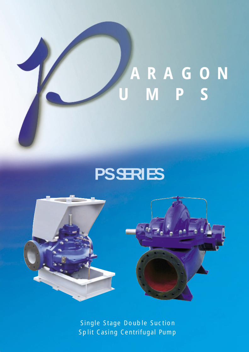
Advantages
1. Your technical advantageInnovative casing
● in-line design● short distance between bearings and
correspondingly short shaft● leak-tight due to compact joint flange
with long, prestressed bolts● counter-rotation possible with similar
parts● double volute version for appropriate
total heads● easy mounting-self-aligning upper
casing
Excellent efficienciesOutstanding NPSH● computer-optimized double entry impellers● smooth surfaces inside the casing and on the impeller● smooth, quiet running also guaranteed by a large impeller
eye area● no drop in efficiency due to cost effective replaceable
casing wear rings and impeller wear rings● smooth, low loss running due to a swirl-free inlet
High-performance impeller● minimal axial thrust due to
double-entry impeller● optional impeller wear rings● new vane passage with
excellent hydrauliccharacteristics
2. Your service advantageService – friendly shaft
● completely sealed and dry for zerocorrosion
● short and rigid with negligible vibrations● replaceable shaft protecting sleeves● no threads exposed to pumped medium,
long operating life and no corrosion● adjustment-free assembly● quick and easy assembly/dismantling of
the rotor components due to elasticallyprestressed mountings
Long-life bearing● covered, sealed for life grease
lubricated antifriction bearingsfor a long service life
● open gland, i.e. enough spacefor service activities
● optional: oil lubrication withconstant level oiler
2
PS SERIESPS SERIES
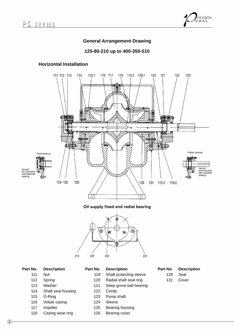
General Arrangement Drawing
125-80-210 up to 400-350-510
Part No. Description Part No. Description Part No. Description111 Nut 119 Shaft protecting sleeve 128 Seal112 Spring 120 Radial shaft seal ring 131 Cover113 Washer 121 Deep grove ball bearing114 Shaft seal housing 122 Circlip115 O-Ring 123 Pump shaft116 Volute casing 124 Sleeve117 Impeller 125 Bearing housing118 Casing wear ring 126 Bearing cover
Horizontal Installation
3
PS SERIESPS SERIES
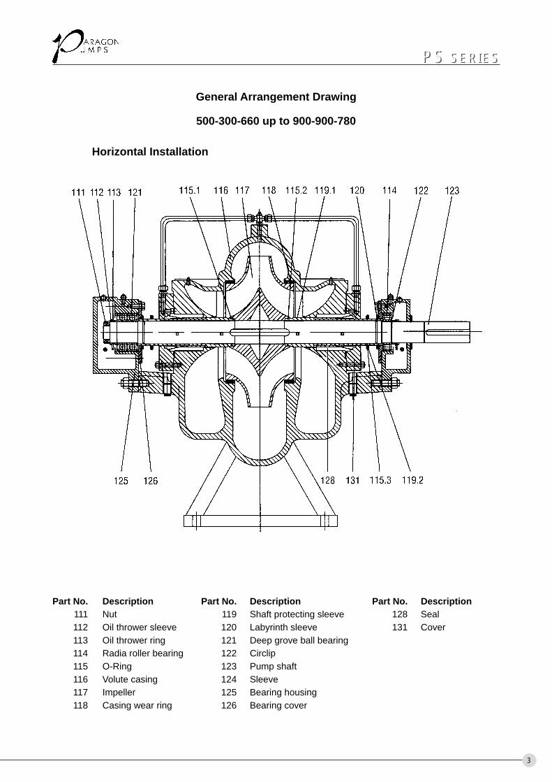
General Arrangement Drawing
500-300-660 up to 900-900-780
Horizontal Installation
Part No. Description Part No. Description Part No. Description111 Nut 119 Shaft protecting sleeve 128 Seal112 Oil thrower sleeve 120 Labyrinth sleeve 131 Cover113 Oil thrower ring 121 Deep grove ball bearing114 Radia roller bearing 122 Circlip115 O-Ring 123 Pump shaft116 Volute casing 124 Sleeve117 Impeller 125 Bearing housing118 Casing wear ring 126 Bearing cover
4
PS SERIESPS SERIES
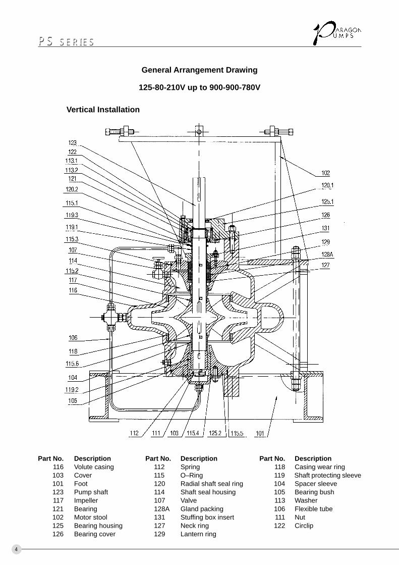
General Arrangement Drawing
125-80-210V up to 900-900-780V
Vertical Installation
Part No. Description Part No. Description Part No. Description116 Volute casing 112 Spring 118 Casing wear ring103 Cover 115 O–Ring 119 Shaft protecting sleeve101 Foot 120 Radial shaft seal ring 104 Spacer sleeve123 Pump shaft 114 Shaft seal housing 105 Bearing bush117 Impeller 107 Valve 113 Washer121 Bearing 128A Gland packing 106 Flexible tube102 Motor stool 131 Stuffing box insert 111 Nut125 Bearing housing 127 Neck ring 122 Circlip126 Bearing cover 129 Lantern ring
5
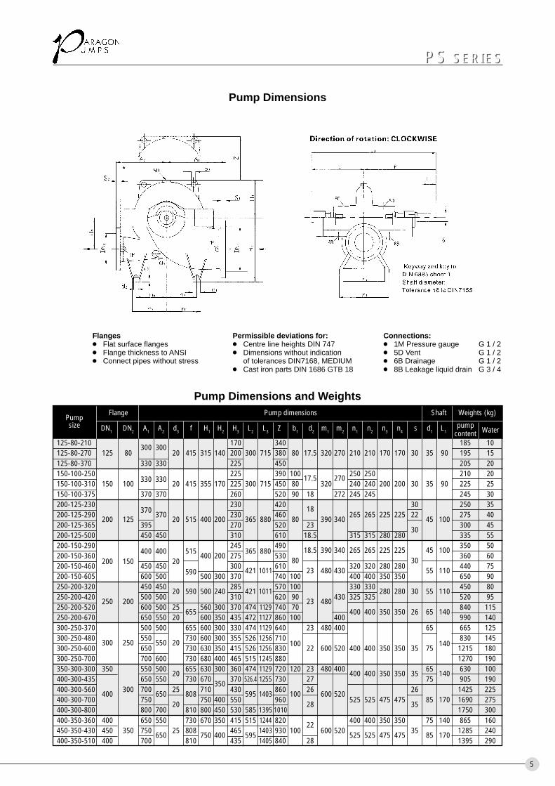
Pump Dimensions
Pump Dimensions and Weights
125-80-210 300 300 170 340 185 10125-80-270 125 80 20 415 315 140 200 300 715 380 80 17.5 320 270 210 210 170 170 30 35 90 195 15125-80-370 330 330 225 450 205 20150-100-250
330 330225 390 100 17.5 270 250 250 210 20
150-100-310 150 100 20 415 355 170 225 300 715 450 80 320 240 240 200 200 30 35 90 225 25150-100-375 370 370 260 520 90 18 272 245 245 245 30200-125-230
370230 420 18 30 250 35
200-125-290200 125
37020 515 400 200
230365 880
46080 390 340
265 265 225 225 2245 100
275 40200-125-365 395 270 520 23
30300 45
200-125-500 450 450 310 610 18.5 315 315 280 280 335 55200-150-290
400 400 515245
365 880490
18.5 390 340 265 265 225 225 45 100350 50
200-150-360200 150 20
400 200 275 53080 30
360 60200-150-460 450 450
590300 421 1011 610 23 480 430 320 320 280 280 55 110 440 75
200-150-605 600 500 500 300 370 740 100 400 400 350 350 650 90250-200-320 450 450
20 590 500 240285
421 1011570 100 330 330
280 280 30 55 110450 80
250-200-420 250 200 500 500 310 620 90 23 480 430 325 325 520 95250-200-520 600 500 25
655560 300 370 474 1129 740 70
400 400 350 350 26 65 140840 115
250-200-670 650 550 20 600 350 435 472 1127 860 100 400 990 140300-250-370 500 500 655 600 300 330 474 1129 640 23 480 400 65 665 125300-250-480
300 250550
550 20730 600 300 355 526 1256 710 830 145
300-250-600 650 730 630 350 415 526 1256 830100
22 600 520 400 400 350 350 35 75140
1215 180300-250-700 700 600 730 680 400 465 515 1245 880 1270 190350-300-300 350 550 500
20655 630 300 360 474 1129 720 120 23 480 400
400 400 350 350 3565
140630 100
400-300-435 650 550 730 670350
370 526.4 1255 730 27 75 905 190400-300-560 400 300 700 650 25 808 710 430 595 1403 860 100 26 600 520 26 1425 225400-300-700 750
20750 400 550 960
28525 525 475 475
3585 170 1690 275
400-300-800 800 700 810 800 450 530 585 1395 1010 1750 300400-350-360 400 650 550 730 670 350 415 515 1244 820 22 400 400 350 350 75 140 865 160450-350-430 450 350 750
65025 808
750 400465
5951403 930 100 600 520
525 525 475 47535
85 1701285 240
400-350-510 400 700 810 435 1405 840 28 1395 290
Flanges Permissible deviations for: Connections:● Flat surface flanges ● Centre line heights DIN 747 ● 1M Pressure gauge G 1 / 2● Flange thickness to ANSI ● Dimensions without indication ● 5D Vent G 1 / 2● Connect pipes without stress of tolerances DIN7168, MEDIUM ● 6B Drainage G 1 / 2
● Cast iron parts DIN 1686 GTB 18 ● 8B Leakage liquid drain G 3 / 4
PS SERIESPS SERIES
Pumpsize
Flange Pump dimensions Shaft Weights (kg)
DN1 DN2 A1 A2 d3 f H1 H2 H3 L2 L3 Z b1 d2 m1 m2 n1 n2 n3 n4 s d1 L1pump
Watercontent
6
PS SERIESPS SERIES
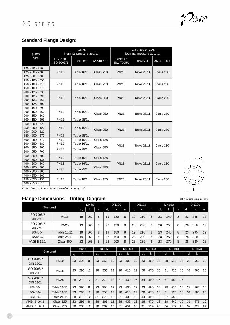
Standard Flange Design:
125 - 80 - 210125 - 80 - 270 PN16 Table 16/11 Class 250 PN25 Table 25/11 Class 250125 - 80 - 370150 - 100 - 250150 - 100 - 310 PN16 Table 16/11 Class 250 PN25 Table 25/11 Class 250150 - 100 - 375200 - 125 - 230200 - 125 - 290
PN16 Table 16/11 Class 250 PN25 Table 25/11 Class 250200 - 125 - 365200 - 125 - 500200 - 150 - 290200 - 150 - 360 PN16 Table 16/11
Class 250 PN25 Table 25/11 Class 250200 - 150 - 460200 - 150 - 605 PN25 Table 25/11250 - 200 - 320250 - 200 - 420 PN16 Table 16/11
Class 250 PN25 Table 25/11 Class 250250 - 200 - 520250 - 200 - 670 PN25 Table 25/11300 - 250 - 370 PN10 Table 10/11 Class 125300 - 250 - 480 PN16 Table 16/11
PN25 Table 25/11 Class 250300 - 250 - 600
PN25 Table 25/11Class 250
300 - 250 - 700350 - 300 - 300
PN10 Table 10/11 Class 125400 - 300 - 435400 - 300 - 560 PN16 Table 16/11 PN25 Table 25/11 Class 250400 - 300 - 700
PN25 Table 25/11Class 250
400 - 300 - 800400 - 350 - 360450 - 350 - 430 PN10 Table 10/11 Class 125 PN25 Table 25/11 Class 250400 - 350 - 510
GG25 GGG 40/GS–C25Nominal pressure acc. to: Nominal pressure acc. to:
DIN2501ISO 7005/2 BS4504 ANSIB 16.1
DIN2501ISO 7005/2 BS4504 ANSIB 16.1
Other flange designs are available on request
pumpsize
ISO 7005/2PN16 19 160 8 19 180 8 19 210 8 23 240 8 23 295 12
DIN 2501
ISO 7005/2 PN25 19 160 8 23 190 8 28 220 8 28 250 8 28 310 12DIN 2501
BS4504 Table 16/11 19 160 8 19 180 8 19 210 8 23 240 8 23 295 12
BS4504 Table 25/11 19 160 8 23 190 8 28 220 8 28 250 8 28 310 12
ANSI B 16.1 Class 250 23 168 8 23 200 8 23 235 8 23 270 8 28 330 12
Flange Dimensions – Drilling DiagramDN80 DN100 DN125 DN150 DN200
d2 k n d2 k n d2 k n d2 k n d2 k nStandard
ISO 7005/2PN10 23 295 8 23 350 12 23 400 12 23 460 16 28 515 16 28 565 20
DIN 2501
ISO 7005/2PN16 23 295 12 28 355 12 28 410 12 28 470 16 31 525 16 31 585 20
DIN 2501
ISO 7005/2 PN25 28 310 12 31 370 12 31 430 16 34 490 16 37 550 16DIN 2501
BS4504 Table 10/11 23 295 8 23 350 12 23 400 12 23 460 16 28 515 16 28 565 20
BS4504 Table 16/11 23 295 12 28 355 12 28 410 12 28 470 16 31 525 16 31 585 20
BS4504 Table 25/11 28 310 12 31 370 12 31 430 16 34 490 16 37 550 16
ANSI B 16. 1 Class 125 23 299 8 28 362 12 28 432 12 28 476 12 28 540 16 31 578 16
ANSI B 16. 1 Class 250 28 330 12 28 387 16 31 451 16 31 514 20 34 572 20 34 629 24
DN200 DN250 DN300 DN350 DN400 DN450
d2 k n d2 k n d2 k n d2 k n d2 k n d2 k nStandard
all dimensions in mm
7
PS SERIESPS SERIES
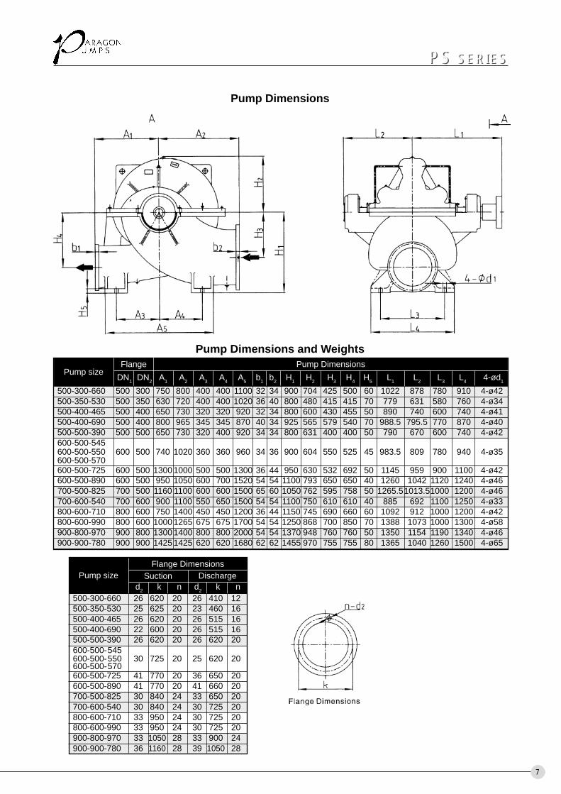
Pump Dimensions
500-300-660 26 620 20 26 410 12500-350-530 25 625 20 23 460 16500-400-465 26 620 20 26 515 16500-400-690 22 600 20 26 515 16500-500-390 26 620 20 26 620 20600-500-545600-500-550 30 725 20 25 620 20600-500-570600-500-725 41 770 20 36 650 20600-500-890 41 770 20 41 660 20700-500-825 30 840 24 33 650 20700-600-540 30 840 24 30 725 20800-600-710 33 950 24 30 725 20800-600-990 33 950 24 30 725 20900-800-970 33 1050 28 33 900 24900-900-780 36 1160 28 39 1050 28
Flange DimensionsPump size Suction Discharge
d2 k n d2 k n
Pump sizeFlange Pump Dimensions
DN1 DN2 A1 A2 A3 A4 A5 b1 b2 H1 H2 H3 H4 H5 L1 L2 L3 L4 4-ød1
500-300-660 500 300 750 800 400 400 1100 32 34 900 704 425 500 60 1022 878 780 910 4-ø42500-350-530 500 350 630 720 400 400 1020 36 40 800 480 415 415 70 779 631 580 760 4-ø34500-400-465 500 400 650 730 320 320 920 32 34 800 600 430 455 50 890 740 600 740 4-ø41500-400-690 500 400 800 965 345 345 870 40 34 925 565 579 540 70 988.5 795.5 770 870 4-ø40500-500-390 500 500 650 730 320 400 920 34 34 800 631 400 400 50 790 670 600 740 4-ø42600-500-545600-500-550 600 500 740 1020 360 360 960 34 36 900 604 550 525 45 983.5 809 780 940 4-ø35600-500-570600-500-725 600 500 1300 1000 500 500 1300 36 44 950 630 532 692 50 1145 959 900 1100 4-ø42600-500-890 600 500 950 1050 600 700 1520 54 54 1100 793 650 650 40 1260 1042 1120 1240 4-ø46700-500-825 700 500 1160 1100 600 600 1500 65 60 1050 762 595 758 50 1265.51013.51000 1200 4-ø46700-600-540 700 600 900 1100 550 650 1500 54 54 1100 750 610 610 40 885 692 1100 1250 4-ø33800-600-710 800 600 750 1400 450 450 1200 36 44 1150 745 690 660 60 1092 912 1000 1200 4-ø42800-600-990 800 600 1000 1265 675 675 1700 54 54 1250 868 700 850 70 1388 1073 1000 1300 4-ø58900-800-970 900 800 1300 1400 800 800 2000 54 54 1370 948 760 760 50 1350 1154 1190 1340 4-ø46900-900-780 900 900 1425 1425 620 620 1680 62 62 1455 970 755 755 80 1365 1040 1260 1500 4-ø65
Pump Dimensions and Weights
200-125-365
200
50 100 200 300 400 500 1000 2000 3000 Q [m.3/h]
500
H [ft]
200
100
5040
30
20
Q[l/s]10005004003002001005040302010
10
5
20
30
40
50
100
H [m] 200-125-290
200-125-230
150-100-250
150-100-310
125-80-270
125-80-210
150-100-375
8
PS SERIESPS SERIES
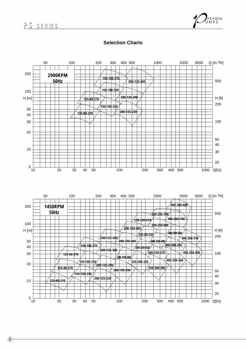
Selection Charts
2900RPM50Hz
400-300-800200
50 100 200 300 400 500 1000 2000 3000 Q [m.3/h]
500
H [ft]
200
100
5040
30
20
Q[l/s]10005004003002001005040302010
10
5
20
30
40
50
100
H [m]
125-80-210
200-150-460
200-150-605
400-350-360
250-200-670300-250-600
400-300-700
400-350-510
450-350-430
400-300-560
125-80-370
125-80-270
150-100-250
150-100-310
150-100-375
200-125-500
200-125-365
200-125-290
200-125-230
250-200-320200-150-360
350-300-300200-150-290
300-250-370250-200-420
250-200-520
300-250-480400-300-435
300-250-700
1450RPM50Hz
150240 540 900 1200 1500
500
H [ft]
200
100
5040
30
20
12006003001806015
25
50
100
H [m]
360 720 Q[m3/h]
1800 2400 3000 Q[l/S]500-500-390 600-500-545
500-400-465
500-350-530
600-500-550
800-600-710590rpm
500-300-660
500-400-690600
-500-570
700-600-540
800-600-710
900-900-780590rpm
600-500-725700-500-825
600-500-890 800-600-990590rpm
800-600-990
900-800-970
900-800-970590rpm
600-500-890
n=590RPM
n=980RPM n=740RPM
1800 2400 3000 3600 4200 4800 54006000 7500 9000
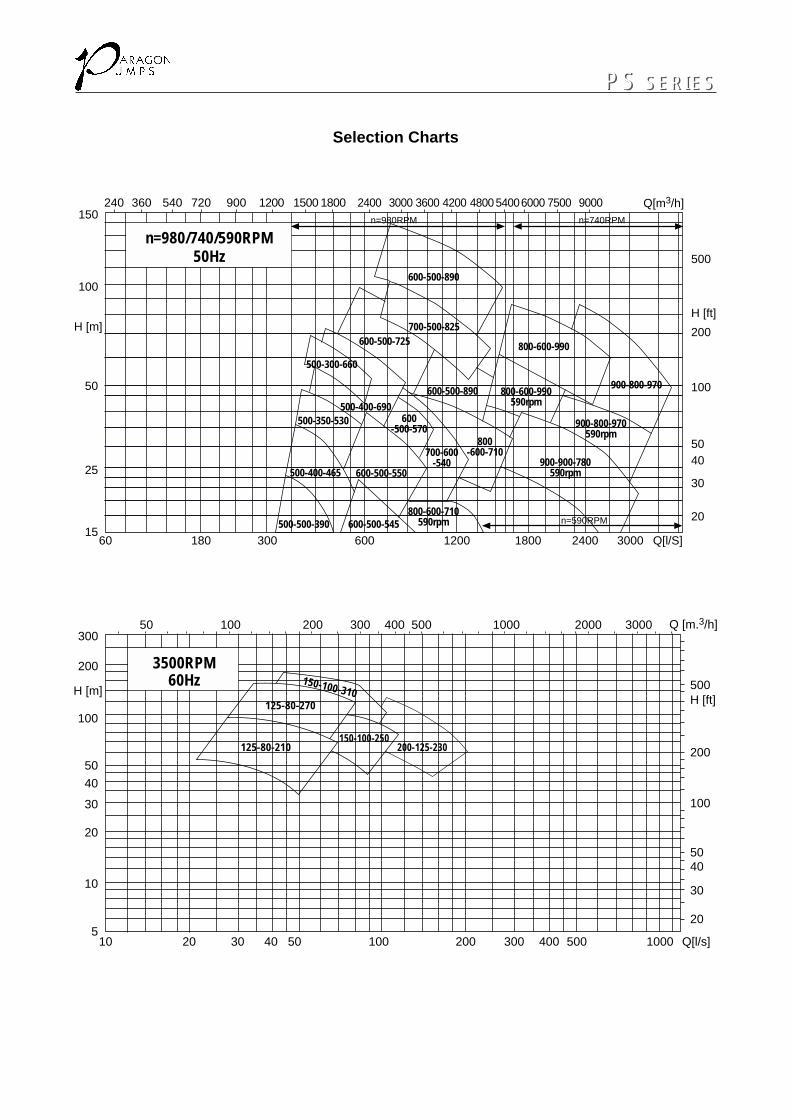
Selection Charts
200-125-230
150-100-310
150-100-250
125-80-270
30050 100 200 300 400 500 1000 2000 3000 Q [m.3/h]
500H [ft]
200
100
5040
30
20
Q[l/s]10005004003002001005040302010
10
5
30
40
50
100
200
H [m]
20
125-80-210
n=980/740/590RPM50Hz
3500RPM60Hz
PS SERIESPS SERIES
216288 648 Q [m.3/h]
360H [ft]
216
108
72Q[l/s]360028802160144072036021672
36
22
72
144
H [m]
648
500-500-390 600-500-545
500-400-465
500-350-530
500-400-690600
-500-570 800-600-710
600-500-725700-500-825
600-500-890 800-600-990710rpm
800-600-990
900-800-970
900-800-970710rpm
600-500-890
600-500-550700-600
-540
500-300-660
900-900-780710rpm
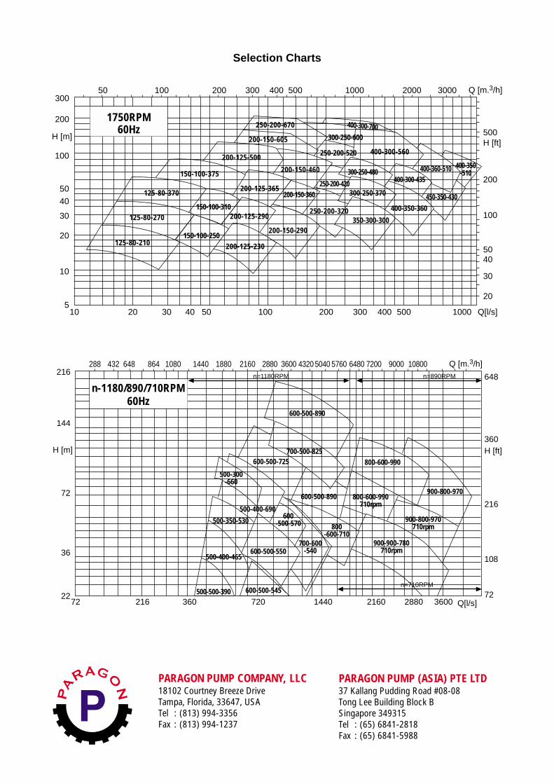
n=1180RPM n=890RPM
n=710RPM
432 864 1080 1440 1880 2160 2880 3600 4320 5040 5760 6480 7200 9000 10800
PARAGON PUMP COMPANY, LLC18102 Courtney Breeze DriveTampa, Florida, 33647, USATel : (813) 994-3356Fax : (813) 994-1237
PARAGON PUMP (ASIA) PTE LTD37 Kallang Pudding Road #08-08Tong Lee Building Block BSingapore 349315Tel : (65) 6841-2818Fax : (65) 6841-5988
Selection Charts
n-1180/890/710RPM60Hz
30050 100 200 300 400 500 1000 2000 3000 Q [m.3/h]
500H [ft]
200
100
5040
30
20
Q[l/s]10005004003002001005040302010
10
5
30
40
50
100
200
H [m]
20 150-100-250
125-80-270
125-80-370
150-100-310
150-100-375
125-80-210 200-125-230
200-150-290
200-125-290
200-125-365
200-125-500
200-150-360
250-200-320
200-150-460
200-150-605
250-200-670
250-200-420
300-250-600
250-200-520
300-250-370
350-300-300
300-250-480
400-300-560
400-350-360
400-300-435
400-300-700
400-360-510
450-350-430
400-350-510
1750RPM60Hz