PS Reference Handbook - Welcome to NCEES · PS Reference Handbook. ... send your correction using...
139
PS Reference Handbook Revised April 2016 The Principles and Practice of Surveying (PS) Exam is computer-based. It is closed-book with an electronic PS Reference Handbook. You will not be allowed to bring your personal copy of the Handbook with you to the exam. NCEES will periodically revise reference material. Each PS exam will be administered using the latest version of the PS Reference Handbook. The PS Reference Handbook may be printed for your personal use. For multiple copies or to reprint material copyrighted by NCEES, please email [email protected]. Revised pages: p. iii, Copyright page p. 1, Abbreviations and Acronyms p. 8, Geodesy: Radius in meridian p. 16, Minimum Standard Detail Requirements for ALTA/NSPS Land Title Surveys (2016) p. 35, FEMA Elevation Certificate (2016)
Transcript of PS Reference Handbook - Welcome to NCEES · PS Reference Handbook. ... send your correction using...

PS Reference Handbook Revised April 2016
The Principles and Practice of Surveying (PS) Exam is computer-based. It is closed-book with an
electronic PS Reference Handbook. You will not be allowed to bring your personal copy of the
Handbook with you to the exam.
NCEES will periodically revise reference material. Each PS exam will be administered using the latest
version of the PS Reference Handbook.
The PS Reference Handbook may be printed for your personal use. For multiple copies or to reprint
material copyrighted by NCEES, please email [email protected].
Revised pages:
p. iii, Copyright page
p. 1, Abbreviations and Acronyms
p. 8, Geodesy: Radius in meridian
p. 16, Minimum Standard Detail Requirements for ALTA/NSPS Land Title Surveys (2016)
p. 35, FEMA Elevation Certificate (2016)

PS REFERENCE HANDBOOK
This document may be printed from the NCEES website for your personal use, but NCEES material
may not be copied, reproduced, distributed electronically or in print, or posted online without
the express written permission of NCEES. Contact [email protected]
for more information.

Copyright ©2016 by NCEES®. All rights reserved. All NCEES material is copyrighted under the laws of the United States. Except for U.S. government material in the public domain, no part of this publication may be reproduced, stored in a retrieval system, or transmitted in any form or by any means without the prior written permission of NCEES. Requests for permissions should be addressed in writing to [email protected]. PO Box 1686 Clemson, SC 29633 800-250-3196 www.ncees.org ISBN 978-1-932613-75-9 Printed in the United States of America First printing May 2016 Edition 1.0

About the Handbook The Principles and Practice of Surveying (PS) exam is computer-based, and the PS Reference Handbook is the only resource material you may use during the exam. Reviewing it before exam day will help you become familiar with the charts, formulas, tables, and other reference information provided. You won't be allowed to bring your personal copy of the Handbook into the exam room. Instead, the computer-based exam will include a PDF version of the Handbook for your use. No printed copies of the Handbook will be allowed in the exam room. The PDF version of the PS Reference Handbook that you use on exam day will be very similar to the printed version. Pages not needed to solve exam questions—such as the cover and introductory material—will not be included in the PDF version. In addition, NCEES will periodically revise and update the Handbook, and each PS exam will be administered using the updated version. The PS Reference Handbook does not contain all the information required to answer every question on the exam. Basic theories, conversions, formulas, and definitions examinees are expected to know have not been included. Special material required for the solution of a particular exam question will be included in the question itself.
Updates on exam content and procedures NCEES.org is our home on the Web. Visit us there for updates on everything exam-related, including specifications, exam-day policies, scoring, and practice tests. A PDF version of the PS Reference Handbook similar to the one you will use on exam day is also available there.
Errata To report errata in this book, send your correction using our chat feature on NCEES.org. We will also post errata on the website. Examinees are not penalized for any errors in the Handbook that affect an exam question.

CONTENTS
Abbreviations and Acronyms .................................................................................................... 1
Conversions and Other Useful Relationships ............................................................................ 2
Metric Prefixes ........................................................................................................................... 2
Quadratic Equation .................................................................................................................... 2
Oblique Triangles ...................................................................................................................... 3
Spherical Triangles .................................................................................................................... 3 Probability and Statistics ........................................................................................................... 3 Confidence Intervals .................................................................................................................. 4 Horizontal Circular Curves ........................................................................................................ 5 Horizontal Spiral Curves ........................................................................................................... 6 Vertical Curve Formulas ............................................................................................................ 7
Photogrammetry ........................................................................................................................ 7 Physics ....................................................................................................................................... 8 Curvature and Refraction ........................................................................................................... 8 Geodesy ..................................................................................................................................... 8
State Plane Coordinates ............................................................................................................. 9
Electronic Distance Measurement ............................................................................................. 9
Atmospheric Correction ............................................................................................................. 9
Area Formulas ........................................................................................................................... 9
Earthwork Formulas .................................................................................................................. 9
Tape Correction Formulas ....................................................................................................... 10
Stadia ....................................................................................................................................... 10
Unit Normal Distribution Table ............................................................................................... 11
t-Distribution Table ................................................................................................................. 12
Critical Values of the F Distribution Table ............................................................................. 12
Economics ................................................................................................................................ 14
Minimum Standard Detail Requirements for ALTA/NSPS Land Title Surveys .................... 16
United States National Map Accuracy Standards .................................................................... 26
FGCS Specifications and Procedures to Incorporate Electronic Digital/Bar-Code Leveling Systems ..................................................................................................................... 29
FEMA Elevation Certificate and Instructions ......................................................................... 33
Geospatial Positioning Accuracy Standards
Part 1: Reporting Methodology ......................................................................................... 48
Part 2: Standards for Geodetic Networks .......................................................................... 61
Part 3: National Standard for Spatial Data Accuracy ........................................................ 69
Part 4: Standards for Architecture, Engineering, Construction (A/E/C) and Facility Management .................................................................................................. 97
Part 5: Standards for Nautical Charting Hydrographic Surveys ...................................... 120

ABBREVIATIONS AND ACRONYMS ALTA American Land Title Association ALTA/NSPS ALTA/NSPS Land Title Surveys. Formerly, ALTA/ACSM
BLM Bureau of Land Management CADD computer-aided design and drafting DOD Department of Defense DOI Department of the Interior DOT Department of Transportation DTM digital terrain modeling EPA Environmental Protection Agency FEMA Federal Emergency Management Agency FGCS Federal Geodetic Control Subcommittee GLO General Land Office GNSS Global Navigation Satellite Systems GPS global positioning system NAVD North American Vertical Datum NGVD National Geodetic Vertical Datum NGS National Geodetic Survey NOAA National Oceanic and Atmospheric Administration NSPS National Society of Professional Surveyors, successor organization to the
American Congress on Surveying and Mapping (ACSM) USGS United States Geological Survey
1

CONVERSIONS AND OTHER USEFUL RELATIONSHIPS
* 1 U.S. survey foot =
* 1 international foot = 0.3048 m
* 1 in. = 25.4 mm (international)
1 mile = 1.60935 km
* 1 acre = 43,560 ft2 = 10 square chains
* 1 ha = 10,000 m2 = 2.47104 acres
* 1 rad =
1 kg = 2.2046 lb
1 L = 0.2624 gal
1 ft3 = 7.481 gal
1 gal of water weighs 8.34 lb
1 ft3 of water weighs 62.4 lb
1 atm = 29.92 in. Hg = 14.696 psi
Gravity acceleration (g) = 9.807 m/s2 = 32.174 ft/sec2
Speed of light in a vacuum (c) = 299,792,458 m/s = 186,282 miles/sec
C = (F – 32)/1.8
1 min of latitude () 1 nautical mile
1 nautical mile = 6,076 ft
Mean radius of the earth 20,906,000 ft 6,372,000 m * Denotes exact value. All others correct to figures shown.
METRIC PREFIXES METRIC PREFIXES Multiple Prefix Symbol Multiple Prefix Symbol
10–18 10–15 10–12 10–9 10–6 10–3 10–2 10–1
atto femto pico nano
micro milli centi deci
a f p n
m c d
101 102 103 106 109 1012 1015 1018
deka hecto kilo
mega giga tera peta exa
da h k M G T P E
QUADRATIC EQUATION
ax2 + bx + c = 0
12m
39.37
180
2b b 4acRoots
2a
2

A
B
C
a
b
c
A
B
C
ab
c
OBLIQUE TRIANGLES
Law of sines
Law of cosines
Area =
Area =
Area =
where s = (a + b + c)/2 SPHERICAL TRIANGLES
where R = Mean radius of the earth
PROBABILITY AND STATISTICS
where:
= Standard deviation (sometimes referred to as standard error)
= Sum of the squares of the residuals (deviation from the mean)
n = Number of observations
= Mean of the observations (individual measurements xi)
Relative weights are inversely proportional to variances, or:
Weighted mean:
where:
= Weighted mean
= Sum of individual weights times their measurements
= Sum of the weights
a b c
sin A sin B sin C
2 2 2
2 2 2
a b c 2bccos A
or
b c acos A2bc
absin C
22a sin Bsin C
2sin A
s s a s b s c
Law of sines
sin a sin b sin c
sin A sin B sin C
2
3
6 2
Law of cosinescos a = cos b cos c + sin b sin c cos A
Area of sphere 4 R4
Volumeof sphere R3
bc sin ASpherical excess in sec =
9.7 10 R
2 2i(x x) v
n 1 n 1
2v
x
2 2 2sum 1 2 n
series n
meann
2 2 2 2product ab
2x xy
2xy y
xy2 2x y
2tan 2
where the counterclockwiseangle from the x axis
a 2a
1W
wWMMW
wM
WM
W
3

CONFIDENCE INTERVALS
Confidence Interval for the Mean of a Normal Distribution
(A) Standard deviation is known
(B) Standard deviation is known
where t/2 corresponds to n–1 degrees of freedom.
Confidence Interval for the Mean 2 of a Normal Distribution
Confidence Interval for the Ratio of Two Normal Distribution Variances
Values of Z/2 Confidence
Interval Z/2
80% 1.2816 90% 1.6449 95% 1.9600 96% 2.0537 98% 2.3263 99% 2.5758
/2 /2
X Z X Zn n
/2 /2 s s
X t X tn n
2 22
2 2/2, 1 1 /2, 1
1 1
n n
n s n s
x x
1 2 2
2 2 21 1 1
2 2 22 , 1 2 2 , 1
n n n n
S S
S F S F
4

A C
B
R R
2a2b
ba
a+bb
HORIZONTAL CIRCULAR CURVES
D = Degree of curve, arc definition
Dc = Degree of curve, chord definition
L = Length of curve from P.C. to P.T.
c = Length of sub-chord
ℓ = Length of arc for sub-chord
d = Central angle for sub-chord
I or = Angle of interior or delta
Area between curve and tangents
Equation of a circle, X2 + Y
2 = R
2
5,729.58D
R
50Radius by chord definition, R
sin 1/ 2 D
T = R tan I/2
IL RI 100
180 D
LC = 2R sin I/2
c = 2R sin d/2
d D /100
M = R 1 cos I/2
1E = R 1
cos(I/2)
2R L R IArea of sector
2 360
2 2R I R sin IArea of segment
360 2
R T L/ 2
AC
R2 sin a b
P.I.
T
P.C. c P.T.
RR
T
Dd
I/2 I/2
I (OR Δ)
NOT TO SCALE
L.CM
E
100.00
I (OR Δ)
5

Δ
Δ
Δ
Δ
Δ
Δ
Δ
Δ Δ
θ3s
s
s
c
c
0
P.I.
T.S.
32 s
S.C. C.S.
CPI
S.T.
SPI
ST
T s
R
PY
L s
s s
T c Tc
LT
LC
Xq
1SPI
FORWARD TANGENTBACK T
ANGEN
T
2
R
LC – Long chord
q – Distance along tangent to a point at right angle to ghost bc (marginally less than Ls/2)
P – Distance from tangent that the curve (ghost bc) has been offset
Tc – Circular curve tangent
CPI – Circular curve P.I.
SPI – Spiral curve P.I.
P.I. – Point of intersection of curve tangents
Lc – Length of circular curve
L – Length of curve system – T.S. to S.T.
T.S. – Tangent to spiral
S.C. – Spiral to curve
C.S. – Curve to spiral
S.T. – Spiral to tangent
Ts – Spiral tangent
X – Distance along tangent from T.S. to point at right angle to S.C.
Y – Right angle distance from tangent to S.C.
LT – Long tangent (spiral)
ST – Short tangent (spiral)
Ls – Length of spiral (arc)
HORIZONTAL SPIRAL CURVES
6

L
TANGENTOFFSET
x PVI
BACK
TANGENT
PVCg 1
YPVC
DATUM
Ey
VERTICAL CURVE FORMULASNOT TO SCALE
FORWARDTANGENT
PVT g2
VERTICAL CURVE FORMULAS
L = Length of curve (horizontal)
PVC = Point of vertical curvature
PVI = Point of vertical intersection
PVT = Point of vertical tangency
g1 = Grade of back tangent
g2 = Grade of forward tangent
x = Horizontal distance from PVC
(or point of tangency) to point on curve
a = Parabola constant
y = Tangent offset
E = Tangent offset at PVI
r = Rate of change of grade
Tangent elevation = YPVC + g1x
and = YPVI + g2 (x – L/2)
Curve elevation = YPVC + g1x + ax2
= YPVC + g1x + [(g2 – g1)/(2L)]x2
Horizontal distance to min/max elevation on curve,
xm =
PHOTOGRAMMETRY
H = C-factor contour interval
Parallax equations:
where: f = Focal length
h = Height above datum
H = Flying height above datum
r = Radial distance from principal point
p = Parallax measured on stereo pair
B = Airbase of stereo pair
x, y = Coordinates measured on left photo
x′ = Coordinate measured on right photo
X, Y = Ground coordinates
2y ax ; 2 1g ga ;
2L
2LE a ;
2 =
2 1 _ g gr =
L
1 1
1 2
g g L
2a g g
ab fScale vertical photograph
AB H h
rhRelief displacement = vertical photograph
H
2 12 1 1
2
p x xxBXp
yBY
pf B
h Hp(p p )
h h (H h )p
7

PHYSICS
Lens equation:
where: o = Object distance
i = Image distance
f = Focal length
Snell's laws: n sin = n′ sin ′ where:
n = Refractive index
= Angle of incidence
CURVATURE AND REFRACTION
Curvature (c) and atmospheric refraction (r) corrections for vertical angles: c 4.905 sec/1,000 ft c 16.192 sec/1 km (c & r) 4.244 sec/1,000 ft (c & r) 13.925 sec/1 km and for level rod readings:
c 0.0240 D2 ft c 0.0785 K
2 m
(c & r) 0.0206 D2 ft (c & r) 0.0675 K
2 m
where: D = Thousands of ft
K = Kilometers
c 0.667 M2
(c & r) 0.574 M2
where: M = Distance in miles Allowable angular error for an individual angle:
1tan
10,000
GEODESY
Ellipsoid
a = Semimajor axis
b = Semiminor axis
2 22
2
2
3 22 2
1 22 2
1 22 2
rad
a bFlattening, f usually published as 1/f
aa b
Eccentricity, ea
a 1 eRadius in meridian, M
1 e sin
aRadius in prime vertical, N
1 e sin
Angular convergence of meridians
d tan 1 e sin
aLinear convergence
1 22 2
of meridians
d tan 1 e sin
a
where: = Latitude
d = Distance along parallel at latitude
= Length along meridians separated by d
Ellipsoid definitions: GRS80: a = 6,378,137.0 m
1/f = 298.25722101 Clark 1866: a = 6,378,206.4 m
1/f = 294.97869821
Orthometric correction: Correction = 0.005288 sin2 h arc1 where:
= Latitude at starting point
h = Datum elevation in meters or feet at starting point
= Change in latitude in minutes between the two points (+ in the direction of increasing latitude or towards the pole)
h H + N where:
h = Ellipsoid height
N = Geiod undulation
H = Orthometric height
1 1 1
o i f
φ'
NORMAL
MEDIUM 1 (n)MEDIUM 2 (n')
φ
8

STATE PLANE COORDINATES
Reduce horizontal ground distance (DH) to geodetic (ellipsoidal) distance (DE) DE = DH EF where:
EF = Elevation factor
=
and: R = Ellipsoid radius
H = Orthometric height
N = Geoid height
Reduce geodetic (ellipsoidal) distance (DE) to grid distance (DG)
DG = DE SF where:
SF = Projection scale factor For precisions less than 1/200,000, may use approximate ellipsoid radius R 20,906,000 ft and neglect geoid height Arc distance (AR) to chord distance (CH) correction
where R is radius of the arc distance ELECTRONIC DISTANCE MEASUREMENT
where: V = Velocity of light through the atmosphere
(m/s)
c = Velocity of light in a vacuum
n = Index of refraction
= Wave length (m)
f = Modulated frequency in hertz (cycles/sec)
D = Distance measured
m = Integer number of full wavelengths
d = Fractional part of the wavelength
ATMOSPHERIC CORRECTION
A 10C temperature change or a pressure difference of 1 in. of mercury produces a distance correction of approximately 10 parts per million (ppm). AREA FORMULAS
EARTHWORK FORMULAS
Average end area formula Volume = L(A1 + A2)/2 Prismoidal formula Volume = L(A1 + 4Am + A2)/6 Pyramid or cone Volume = h(Area of Base)/3
R
R H N
3
2
CHAR CH
24 R
V c/n
V/f
m dD
2
n n
i i 1 i i 1i 1 i 1
Area bycoordinates where i is point orderin a closed polygon.
1Area X Y X Y
2
1 n2 3 4 n 1
Trapezoidal Rule
h hArea w h h h … h
2
1 odds evens n
Simpson's1/3 Rule
Area w h 2 h 4 h h / 3
9

TAPE CORRECTION FORMULAS
Correction for temperature
Ct = 6.5 10–6 (T – Ts)L Correction for tension
Cp = (P – Ps)L/(AE) Correction for sag
Cs = where:
T = Temperature of tape during measurement, F
Ts = Temperature of tape during calibration, F
L = Distance measured, ft
P = Pull applied during measurement, lb
Ps = Pull applied during calibration, lb
A = Cross-sectional area of tape, in2
E = Modulus of elasticity of tape, psi
w = Weight of tape, lb/ft
= Length of unsupported span, ft
STADIA
Horizontal distance = KS cos2
Vertical distance = KS sin cos where:
K = Stadia interval factor (usually 100)
S = Rod intercept
= Slope angle measured from horizontal
2 3 2(w ) / (24P )
10
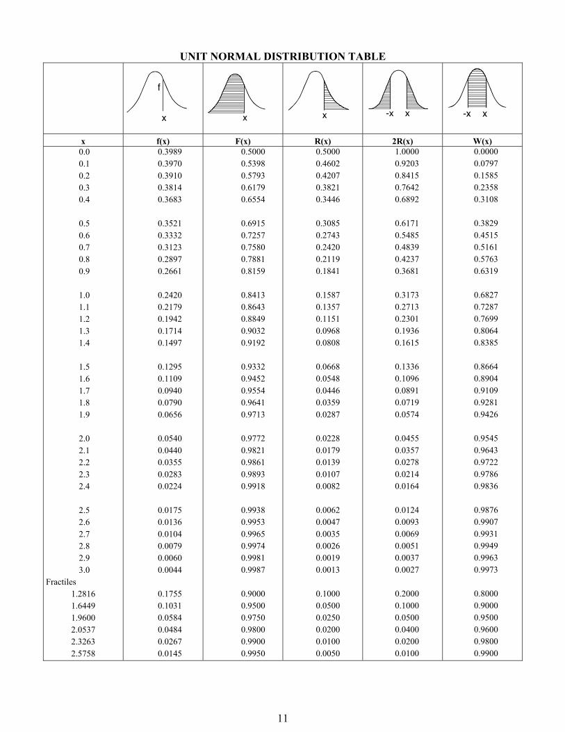
UNIT NORMAL DISTRIBUTION TABLE
x f(x) F(x) R(x) 2R(x) W(x) 0.0 0.1 0.2 0.3 0.4 0.5 0.6 0.7 0.8 0.9 1.0 1.1 1.2 1.3 1.4 1.5 1.6 1.7 1.8 1.9 2.0 2.1 2.2 2.3 2.4 2.5 2.6 2.7 2.8 2.9 3.0 Fractiles 1.2816 1.6449 1.9600 2.0537 2.3263 2.5758
0.3989 0.3970 0.3910 0.3814 0.3683 0.3521 0.3332 0.3123 0.2897 0.2661 0.2420 0.2179 0.1942 0.1714 0.1497 0.1295 0.1109 0.0940 0.0790 0.0656 0.0540 0.0440 0.0355 0.0283 0.0224 0.0175 0.0136 0.0104 0.0079 0.0060 0.0044 0.1755 0.1031 0.0584 0.0484 0.0267 0.0145
0.5000 0.5398 0.5793 0.6179 0.6554 0.6915 0.7257 0.7580 0.7881 0.8159 0.8413 0.8643 0.8849 0.9032 0.9192 0.9332 0.9452 0.9554 0.9641 0.9713 0.9772 0.9821 0.9861 0.9893 0.9918 0.9938 0.9953 0.9965 0.9974 0.9981 0.9987 0.9000 0.9500 0.9750 0.9800 0.9900 0.9950
0.5000 0.4602 0.4207 0.3821 0.3446 0.3085 0.2743 0.2420 0.2119 0.1841 0.1587 0.1357 0.1151 0.0968 0.0808 0.0668 0.0548 0.0446 0.0359 0.0287 0.0228 0.0179 0.0139 0.0107 0.0082 0.0062 0.0047 0.0035 0.0026 0.0019 0.0013 0.1000 0.0500 0.0250 0.0200 0.0100 0.0050
1.0000 0.9203 0.8415 0.7642 0.6892 0.6171 0.5485 0.4839 0.4237 0.3681 0.3173 0.2713 0.2301 0.1936 0.1615 0.1336 0.1096 0.0891 0.0719 0.0574 0.0455 0.0357 0.0278 0.0214 0.0164 0.0124 0.0093 0.0069 0.0051 0.0037 0.0027 0.2000 0.1000 0.0500 0.0400 0.0200 0.0100
0.0000 0.0797 0.1585 0.2358 0.3108 0.3829 0.4515 0.5161 0.5763 0.6319 0.6827 0.7287 0.7699 0.8064 0.8385 0.8664 0.8904 0.9109 0.9281 0.9426 0.9545 0.9643 0.9722 0.9786 0.9836 0.9876 0.9907 0.9931 0.9949 0.9963 0.9973 0.8000 0.9000 0.9500 0.9600 0.9800 0.9900
11

t-DISTRIBUTION TABLE VALUES OF t,n
n = 0.10 = 0.05 = 0.025 = 0.01 = 0.005 n 1 2 3 4 5 6 7 8 9 10 11 12 13 14 15 16 17 18 19 20 21 22 23 24 25 26 27 28 29
3.078 1.886 1.638 1.533 1.476 1.440 1.415 1.397 1.383 1.372 1.363 1.356 1.350 1.345 1.341 1.337 1.333 1.330 1.328 1.325 1.323 1.321 1.319 1.318 1.316 1.315 1.314 1.313 1.311 1.282
6.314 2.920 2.353 2.132 2.015 1.943 1.895 1.860 1.833 1.812 1.796 1.782 1.771 1.761 1.753 1.746 1.740 1.734 1.729 1.725 1.721 1.717 1.714 1.711 1.708 1.706 1.703 1.701 1.699 1.645
12.706 4.303 3.182 2.776 2.571 2.447 2.365 2.306 2.262 2.228 2.201 2.179 2.160 2.145 2.131 2.120 2.110 2.101 2.093 2.086 2.080 2.074 2.069 2.064 2.060 2.056 2.052 2.048 2.045 1.960
31.821 6.965 4.541 3.747 3.365 3.143 2.998 2.896 2.821 2.764 2.718 2.681 2.650 2.624 2.602 2.583 2.567 2.552 2.539 2.528 2.518 2.508 2.500 2.492 2.485 2.479 2.473 2.467 2.462 2.326
63.657 9.925 5.841 4.604 4.032 3.707 3.499 3.355 3.250 3.169 3.106 3.055 3.012 2.977 2.947 2.921 2.898 2.878 2.861 2.845 2.831 2.819 2.807 2.797 2.787 2.779 2.771 2.763 2.756 2.576
1 2 3 4 5 6 7 8 9 10 11 12 13 14 15 16 17 18 19 20 21 22 23 24 25 26 27 28 29
12

CRITICAL VALUES OF THE F DISTRIBUTION – TABLE
For a particular combination of
numerator and denominator degrees
of freedom, entry represents the
critical values of F corresponding
to a specified upper tail area (αα).
Denominator
df2
Numerator df1
1 2 3 4 5 6 7 8 9 10 12 15 20 24 30 40 60 120 ∞∞
1
2
3
4
5
6
7
8
9
10
11
12
13
14
15
16
17
18
19
20
21
22
23
24
25
26
27
28
29
30
40
60
120
∞
161.4
18.51
10.13
7.71
6.61
5.99
5.59
5.32
5.12
4.96
4.84
4.75
4.67
4.60
4.54
4.49
4.45
4.41
4.38
4.35
4.32
4.30
4.28
4.26
4.24
4.23
4.21
4.20
4.18
4.17
4.08
4.00
3.92
3.84
199.5
19.00
9.55
6.94
5.79
5.14
4.74
4.46
4.26
4.10
3.98
3.89
3.81
3.74
3.68
3.63
3.59
3.55
3.52
3.49
3.47
3.44
3.42
3.40
3.39
3.37
3.35
3.34
3.33
3.32
3.23
3.15
3.07
3.00
215.7
19.16
9.28
6.59
5.41
4.76
4.35
4.07
3.86
3.71
3.59
3.49
3.41
3.34
3.29
3.24
3.20
3.16
3.13
3.10
3.07
3.05
3.03
3.01
2.99
2.98
2.96
2.95
2.93
2.92
2.84
2.76
2.68
2.60
224.6
19.25
9.12
6.39
5.19
4.53
4.12
3.84
3.63
3.48
3.36
3.26
3.18
3.11
3.06
3.01
2.96
2.93
2.90
2.87
2.84
2.82
2.80
2.78
2.76
2.74
2.73
2.71
2.70
2.69
2.61
2.53
2.45
2.37
230.2
19.30
9.01
6.26
5.05
4.39
3.97
3.69
3.48
3.33
3.20
3.11
3.03
2.96
2.90
2.85
2.81
2.77
2.74
2.71
2.68
2.66
2.64
2.62
2.60
2.59
2.57
2.56
2.55
2.53
2.45
2.37
2.29
2.21
234.0
19.33
8.94
6.16
4.95
4.28
3.87
3.58
3.37
3.22
3.09
3.00
2.92
2.85
2.79
2.74
2.70
2.66
2.63
2.60
2.57
2.55
2.53
2.51
2.49
2.47
2.46
2.45
2.43
2.42
2.34
2.25
2.17
2.10
236.8
19.35
8.89
6.09
4.88
4.21
3.79
3.50
3.29
3.14
3.01
2.91
2.83
2.76
2.71
2.66
2.61
2.58
2.54
2.51
2.49
2.46
2.44
2.42
2.40
2.39
2.37
2.36
2.35
2.33
2.25
2.17
2.09
2.01
238.9
19.37
8.85
6.04
4.82
4.15
3.73
3.44
3.23
3.07
2.95
2.85
2.77
2.70
2.64
2.59
2.55
2.51
2.48
2.45
2.42
2.40
2.37
2.36
2.34
2.32
2.31
2.29
2.28
2.27
2.18
2.10
2.02
1.94
240.5
19.38
8.81
6.00
4.77
4.10
3.68
3.39
3.18
3.02
2.90
2.80
2.71
2.65
2.59
2.54
2.49
2.46
2.42
2.39
2.37
2.34
2.32
2.30
2.28
2.27
2.25
2.24
2.22
2.21
2.12
2.04
1.96
1.88
241.9
19.40
8.79
5.96
4.74
4.06
3.64
3.35
3.14
2.98
2.85
2.75
2.67
2.60
2.54
2.49
2.45
2.41
2.38
2.35
2.32
2.30
2.27
2.25
2.24
2.22
2.20
2.19
2.18
2.16
2.08
1.99
1.91
1.83
243.9
19.41
8.74
5.91
4.68
4.00
3.57
3.28
3.07
2.91
2.79
2.69
2.60
2.53
2.48
2.42
2.38
2.34
2.31
2.28
2.25
2.23
2.20
2.18
2.16
2.15
2.13
2.12
2.10
2.09
2.00
1.92
1.83
1.75
245.9
19.43
8.70
5.86
4.62
3.94
3.51
3.22
3.01
2.85
2.72
2.62
2.53
2.46
2.40
2.35
2.31
2.27
2.23
2.20
2.18
2.15
2.13
2.11
2.09
2.07
2.06
2.04
2.03
2.01
1.92
1.84
1.75
1.67
248.0
19.45
8.66
5.80
4.56
3.87
3.44
3.15
2.94
2.77
2.65
2.54
2.46
2.39
2.33
2.28
2.23
2.19
2.16
2.12
2.10
2.07
2.05
2.03
2.01
1.99
1.97
1.96
1.94
1.93
1.84
1.75
1.66
1.57
249.1
19.45
8.64
5.77
4.53
3.84
3.41
3.12
2.90
2.74
2.61
2.51
2.42
2.35
2.29
2.24
2.19
2.15
2.11
2.08
2.05
2.03
2.01
1.98
1.96
1.95
1.93
1.91
1.90
1.89
1.79
1.70
1.61
1.52
250.1
19.46
8.62
5.75
4.50
3.81
3.38
3.08
2.86
2.70
2.57
2.47
2.38
2.31
2.25
2.19
2.15
2.11
2.07
2.04
2.01
1.98
1.96
1.94
1.92
1.90
1.88
1.87
1.85
1.84
1.74
1.65
1.55
1.46
251.1
19.47
8.59
5.72
4.46
3.77
3.34
3.04
2.83
2.66
2.53
2.43
2.34
2.27
2.20
2.15
2.10
2.06
2.03
1.99
1.96
1.94
1.91
1.89
1.87
1.85
1.84
1.82
1.81
1.79
1.69
1.59
1.50
1.39
252.2
19.48
8.57
5.69
4.43
3.74
3.30
3.01
2.79
2.62
2.49
2.38
2.30
2.22
2.16
2.11
2.06
2.02
1.98
1.95
1.92
1.89
1.86
1.84
1.82
1.80
1.79
1.77
1.75
1.74
1.64
1.53
1.43
1.32
253.3
19.49
8.55
5.66
4.40
3.70
3.27
2.97
2.75
2.58
2.45
2.34
2.25
2.18
2.11
2.06
2.01
1.97
1.93
1.90
1.87
1.84
1.81
1.79
1.77
1.75
1.73
1.71
1.70
1.68
1.58
1.47
1.35
1.22
254.3
19.50
8.53
5.63
4.36
3.67
3.23
2.93
2.71
2.54
2.40
2.30
2.21
2.13
2.07
2.01
1.96
1.92
1.88
1.84
1.81
1.78
1.76
1.73
1.71
1.69
1.67
1.65
1.64
1.62
1.51
1.39
1.25
1.00
13

ECONOMICS
Factor Name Converts Symbol Formula Single Payment Compound Amount
to F given P (F/P, i%, n) (1 + i)n
Single Payment Present Worth
to P given F (P/F, i%, n) (1 + i) –n
Uniform Series Sinking Fund
to A given F (A/F, i%, n)
Capital Recovery to A given P (A/P, i%, n)
Uniform Series Compound Amount
to F given A (F/A, i%, n)
Uniform Series Present Worth
to P given A (P/A, i%, n)
Uniform Gradient Present Worth
to P given G (P/G, i%, n)
Uniform Gradient † Future Worth
to F given G (F/G, i%, n)
Uniform Gradient Uniform Series
to A given G (A/G, i%, n)
Nomenclature and Definitions A Uniform amount per interest period B Benefit BV Book Value C Cost d Combined interest rate per interest period Dj Depreciation in year j F Future worth, value, or amount f General inflation rate per interest period G Uniform gradient amount per interest period i Interest rate per interest period ie Annual effective interest rate m Number of compounding periods per year n Number of compounding periods; or the expected life of an asset P Present worth, value, or amount r Nominal annual interest rate Sn Expected salvage value in year n
Subscripts j at time j n at time n † F/G = (F/A – n)/i = (F/A) (A/G)
11 ni
i
11
1
n
n
i
ii
i
i n 11
n
n
ii
i
1
11
nn
n
ii
n
ii
i
11
112
i
n
i
i n
2
11
11
1
ni
n
i
14

Nonannual Compounding
Book Value BV = Initial cost – Dj
Depreciation
Straight line
Accelerated Cost Recovery System (ACRS)
Dj = (factor from table below) C
MODIFIED ACRS FACTORS
Year
Recovery Period (Years)
3 5 7 10
Recovery Rate (%)
1 2 3 4 5 6 7 8 9 10 11
33.3 44.5 14.8 7.4
20.0 32.0 19.2 11.5 11.5 5.8
14.3 24.5 17.5 12.5 8.9 8.9 8.9 4.5
10.0 18.0 14.4 11.5 9.2 7.4 6.6 6.6 6.5 6.5 3.3
Capitalized Costs Capitalized costs are present worth values using an assumed perpetual period of time.
Capitalized costs = P =
1 1 m
erim
nj
C SD =
n
i
A
15

American Land Title Association® (ALTA®) Minimum Standard Detail Requirements National Society of Professional Surveyors (NSPS) For ALTA/NSPS Land Title Surveys
16 Copyright 2016. All rights reserved. American Land Title Association and National Society of Professional Surveyors
MINIMUM STANDARD DETAIL REQUIREMENTS FOR ALTA/NSPS LAND TITLE SURVEYS
(Effective February 23, 2016)
©2016, American Land Title Association and National Society of Professional Surveyors
All publications of the American Land Title Association®, including ALTA® policy forms, endorsements, and related documents, are copyrighted and are reprinted herein by specific permission from American Land Title
Association® (ALTA®), 1800 M Street, N.W., Suite 300S, Washington, DC 20036 Phone: 202-296-3671 E-mail: [email protected] Web: www.alta.org
Also reprinted with permission from: National Society of Professional Surveyors (NSPS)
5119 Pegasus Court, Suite Q, Frederick, MD 21704. nsps.us.com
16

MINIMUM STANDARD DETAIL REQUIREMENTS FOR ALTA/NSPS LAND TITLE SURVEYS
(Effective February 23, 2016) NOTE: Attention is directed to the fact that the National Society of Professional Surveyors, Inc. (NSPS) is the legal successor organization to the American Congress on Surveying and Mapping (ACSM) and that these 2016 Minimum Standard Detail Requirements for ALTA/NSPS Land Title Surveys are the next version of the former Minimum Standard Detail Requirements for ALTA/ACSM Land Title Surveys. 1. Purpose–Members of the American Land Title Association® (ALTA®) have specific needs, unique to title insurance
matters, when asked to insure title to land without exception as to the many matters which might be discoverable from survey and inspection, and which are not evidenced by the public records.
For a survey of real property, and the plat, map or record of such survey, to be acceptable to a title insurance company for the purpose of insuring title to said real property free and clear of survey matters (except those matters disclosed by the survey and indicated on the plat or map), certain specific and pertinent information must be presented for the distinct and clear understanding between the insured, the client (if different from the insured), the title insurance company (insurer), the lender, and the surveyor professionally responsible for the survey. In order to meet such needs, clients, insurers, insureds, and lenders are entitled to rely on surveyors to conduct surveys and prepare associated plats or maps that are of a professional quality and appropriately uniform, complete, and accurate. To that end, and in the interests of the general public, the surveying profession, title insurers, and abstracters, the ALTA and the NSPS jointly promulgate the within details and criteria setting forth a minimum standard of performance for ALTA/NSPS Land Title Surveys. A complete 2016 ALTA/NSPS Land Title Survey includes:
(i) the on-site fieldwork required pursuant to Section 5, (ii) the preparation of a plat or map pursuant to Section 6 showing the results of the fieldwork and its relationship to
documents provided to or obtained by the surveyor pursuant to Section 4, (iii) any information from Table A items requested by the client, and (iv) the certification outlined in Section 7.
2. Request for Survey–The client shall request the survey, or arrange for the survey to be requested, and shall provide a
written authorization to proceed from the person or entity responsible for paying for the survey. Unless specifically authorized in writing by the insurer, the insurer shall not be responsible for any costs associated with the preparation of the survey. The request shall specify that an "ALTA/NSPS LAND TITLE SURVEY" is required and which of the optional items listed in Table A, if any, are to be incorporated. Certain properties or interests in real properties may present issues outside those normally encountered on an ALTA/NSPS Land Title Survey (e.g., marinas, campgrounds, trailer parks; easements, leases, other non-fee simple interests). The scope of work related to surveys of such properties or interests in real properties should be discussed with the client, lender, and insurer; and agreed upon in writing prior to commencing work on the survey. The client may need to secure permission for the surveyor to enter upon the property to be surveyed, adjoining properties, or offsite easements.
3. Surveying Standards and Standards of Care
A. Effective Date–The 2016 Minimum Standard Detail Requirements for ALTA/NSPS Land Title Surveys are effective February 23, 2016. As of that date, all previous versions of the Minimum Standard Detail Requirements for ALTA/ACSM Land Title Surveys are superseded by these standards.
B. Other Requirements and Standards of Practice–Many states and some local jurisdictions have adopted statutes, administrative rules, and/or ordinances that set out standards regulating the practice of surveying within their jurisdictions. In addition to the standards set forth herein, surveyors shall also conduct their surveys in accordance with applicable jurisdictional survey requirements and standards of practice. Where conflicts between the standards set forth herein and any such jurisdictional requirements and standards of practice occur, the more stringent shall apply.
C. The Normal Standard of Care–Surveyors should recognize that there may be unwritten local, state, and/or regional standards of care defined by the practice of the "prudent surveyor" in those locales.
D. Boundary Resolution–The boundary lines and corners of any property being surveyed as part of an ALTA/NSPS Land Title Survey shall be established and/or retraced in accordance with appropriate boundary law principles governed by the set of facts and evidence found in the course of performing the research and fieldwork.
17

E. Measurement Standards–The following measurement standards address Relative Positional Precision for the monuments or witnesses marking the corners of the surveyed property. i. "Relative Positional Precision" means the length of the semi-major axis, expressed in feet or meters, of the error
ellipse representing the uncertainty due to random errors in measurements in the location of the monument, or witness, marking any corner of the surveyed property relative to the monument, or witness, marking any other corner of the surveyed property at the 95 percent confidence level. Relative Positional Precision is estimated by the results of a correctly weighted least squares adjustment of the survey.
ii. Any boundary lines and corners established or retraced may have uncertainties in location resulting from (1) the availability, condition, history and integrity of reference or controlling monuments, (2) ambiguities in the record descriptions or plats of the surveyed property or its adjoiners, (3) occupation or possession lines as they may differ from the written title lines, or (4) Relative Positional Precision. Of these four sources of uncertainty, only Relative Positional Precision is controllable, although, due to the inherent errors in any measurement, it cannot be eliminated. The magnitude of the first three uncertainties can be projected based on evidence; Relative Positional Precision is estimated using statistical means (see Section 3.E.i. above and Section 3.E.v. below).
iii. The first three of these sources of uncertainty must be weighed as part of the evidence in the determination of where, in the surveyor’s opinion, the boundary lines and corners of the surveyed property should be located (see Section 3.D. above). Relative Positional Precision is a measure of how precisely the surveyor is able to monument and report those positions; it is not a substitute for the application of proper boundary law principles. A boundary corner or line may have a small Relative Positional Precision because the survey measurements were precise, yet still be in the wrong position (i.e., inaccurate) if it was established or retraced using faulty or improper application of boundary law principles.
iv. For any measurement technology or procedure used on an ALTA/NSPS Land Title Survey, the surveyor shall (1) use appropriately trained personnel, (2) compensate for systematic errors, including those associated with instrument calibration, and (3) use appropriate error propagation and measurement design theory (selecting the proper instruments, geometric layouts, and field and computational procedures) to control random errors such that the maximum allowable Relative Positional Precision outlined in Section 3.E.v. below is not exceeded.
v. The maximum allowable Relative Positional Precision for an ALTA/NSPS Land Title Survey is 2 cm (0.07 feet) plus 50 parts per million (based on the direct distance between the two corners being tested). It is recognized that in certain circumstances, the size or configuration of the surveyed property, or the relief, vegetation, or improvements on the surveyed property, will result in survey measurements for which the maximum allowable Relative Positional Precision may be exceeded. If the maximum allowable Relative Positional Precision is exceeded, the surveyor shall note the reason as explained in Section 6.B.x. below.
4. Records Research–It is recognized that for the performance of an ALTA/NSPS Land Title Survey, the surveyor will be
provided with appropriate and, when possible, legible data which can be relied upon in the preparation of the survey. The request for an ALTA/NSPS Land Title Survey shall set forth the current record description of the property to be surveyed or, in the case of an original survey prepared for purposes of locating and describing real property that has not been previously separately described in documents conveying an interest in the real property, the current record description of the parent parcel that contains the property to be surveyed.
In order to complete an ALTA/NSPS Land Title Survey, the surveyor must be provided with complete copies of the most recent title commitment or, if a title commitment is not available, other title evidence satisfactory to the title insurer. In addition, the surveyor must be provided with the following:
(i) The following records established under state statutes for the purpose of imparting constructive notice of matters relating to real property (public records): (a) The current record descriptions of any adjoiners to the property to be surveyed, except where such
adjoiners are lots in platted, recorded subdivisions; (b) Any recorded easements benefitting the property; (c) Any recorded easements, servitudes, or covenants burdening the property;
(ii) Any unrecorded documents affecting the property being surveyed and containing information to which the survey shall make reference, if desired by the client.
Except, however, if the documents outlined above in (i) and (ii) of this section are not provided to the surveyor or if non-public or quasi-public documents are required to complete the survey, the surveyor shall be required to conduct only that research which is required pursuant to the statutory or administrative requirements of the jurisdiction where the property being surveyed is located and that research (if any) which is negotiated and outlined in the terms of the contract between the surveyor and the client.
18
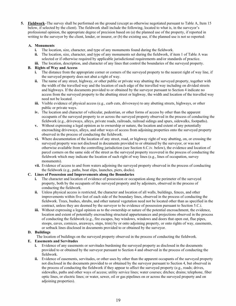
5. Fieldwork–The survey shall be performed on the ground (except as otherwise negotiated pursuant to Table A, Item 15 below, if selected by the client). The fieldwork shall include the following, located to what is, in the surveyor’s professional opinion, the appropriate degree of precision based on (a) the planned use of the property, if reported in writing to the surveyor by the client, lender, or insurer, or (b) the existing use, if the planned use is not so reported:
A. Monuments
i. The location, size, character, and type of any monuments found during the fieldwork. ii. The location, size, character, and type of any monuments set during the fieldwork, if item 1 of Table A was
selected or if otherwise required by applicable jurisdictional requirements and/or standards of practice. iii. The location, description, and character of any lines that control the boundaries of the surveyed property.
B. Rights of Way and Access i. The distance from the appropriate corner or corners of the surveyed property to the nearest right of way line, if
the surveyed property does not abut a right of way. ii. The name of any street, highway, or other public or private way abutting the surveyed property, together with
the width of the travelled way and the location of each edge of the travelled way including on divided streets and highways. If the documents provided to or obtained by the surveyor pursuant to Section 4 indicate no access from the surveyed property to the abutting street or highway, the width and location of the travelled way need not be located.
iii. Visible evidence of physical access (e.g., curb cuts, driveways) to any abutting streets, highways, or other public or private ways.
iv. The location and character of vehicular, pedestrian, or other forms of access by other than the apparent occupants of the surveyed property to or across the surveyed property observed in the process of conducting the fieldwork (e.g., driveways, alleys, private roads, railroads, railroad sidings and spurs, sidewalks, footpaths).
v. Without expressing a legal opinion as to ownership or nature, the location and extent of any potentially encroaching driveways, alleys, and other ways of access from adjoining properties onto the surveyed property observed in the process of conducting the fieldwork.
vi. Where documentation of the location of any street, road, or highway right of way abutting, on, or crossing the surveyed property was not disclosed in documents provided to or obtained by the surveyor, or was not otherwise available from the controlling jurisdiction (see Section 6.C.iv. below), the evidence and location of parcel corners on the same side of the street as the surveyed property recovered in the process of conducting the fieldwork which may indicate the location of such right of way lines (e.g., lines of occupation, survey monuments).
vii. Evidence of access to and from waters adjoining the surveyed property observed in the process of conducting the fieldwork (e.g., paths, boat slips, launches, piers, docks).
C. Lines of Possession and Improvements along the Boundaries i. The character and location of evidence of possession or occupation along the perimeter of the surveyed
property, both by the occupants of the surveyed property and by adjoiners, observed in the process of conducting the fieldwork.
ii. Unless physical access is restricted, the character and location of all walls, buildings, fences, and other improvements within five feet of each side of the boundary lines, observed in the process of conducting the fieldwork. Trees, bushes, shrubs, and other natural vegetation need not be located other than as specified in the contract, unless they are deemed by the surveyor to be evidence of possession pursuant to Section 5.C.i.
iii. Without expressing a legal opinion as to the ownership or nature of the potential encroachment, the evidence, location and extent of potentially encroaching structural appurtenances and projections observed in the process of conducting the fieldwork (e.g., fire escapes, bay windows, windows and doors that open out, flue pipes, stoops, eaves, cornices, areaways, steps, trim) by or onto adjoining property, or onto rights of way, easements, or setback lines disclosed in documents provided to or obtained by the surveyor.
D. Buildings The location of buildings on the surveyed property observed in the process of conducting the fieldwork.
E. Easements and Servitudes i. Evidence of any easements or servitudes burdening the surveyed property as disclosed in the documents
provided to or obtained by the surveyor pursuant to Section 4 and observed in the process of conducting the fieldwork.
ii. Evidence of easements, servitudes, or other uses by other than the apparent occupants of the surveyed property not disclosed in the documents provided to or obtained by the surveyor pursuant to Section 4, but observed in the process of conducting the fieldwork if they appear to affect the surveyed property (e.g., roads; drives, sidewalks, paths and other ways of access; utility service lines; water courses; ditches; drains; telephone, fiber optic lines, or electric lines; or water, sewer, oil or gas pipelines on or across the surveyed property and on adjoining properties).
19

iii. Surface indications of underground easements or servitudes on or across the surveyed property observed in the process of conducting the fieldwork (e.g., utility cuts, vent pipes, filler pipes).
iv. Evidence on or above the surface of the surveyed property observed in the process of conducting the fieldwork, which evidence may indicate utilities located on, over or beneath the surveyed property. Examples of such evidence include pipeline markers, manholes, valves, meters, transformers, pedestals, clean-outs, utility poles, overhead lines and guy wires.
F. Cemeteries As accurately as the evidence permits, the perimeter of cemeteries and burial grounds, and the location of isolated gravesites not within a cemetery or burial ground, (i) disclosed in the documents provided to or obtained by the surveyor, or (ii) observed in the process of conducting the fieldwork.
G. Water Features i. The location of springs, ponds, lakes, streams, rivers, canals, ditches, marshes, and swamps on, running
through, or outside, but within five feet of the perimeter boundary of, the surveyed property, observed during the process of conducting the fieldwork.
ii. The location of any water feature forming a boundary of the surveyed property. The attribute(s) of the water feature located (e.g., top of bank, edge of water, high water mark) should be congruent with the boundary as described in the record description or, in the case of an original survey, in the new description (see Section 6.B.vi. below).
6. Plat or Map–A plat or map of an ALTA/NSPS Land Title Survey shall show the following information. Where
dimensioning is appropriate, dimensions shall be annotated to what is, in the surveyor’s professional opinion, the appropriate degree of precision based on (a) the planned use of the property, if reported in writing to the surveyor by the client, lender, or insurer, or (b) existing use, if the planned use is not so reported. A. The evidence and locations gathered, and the monuments and lines located during the fieldwork pursuant to
Section 5 above, with accompanying notes if deemed necessary by the surveyor or as otherwise required as specified below.
B. Boundary, Descriptions, Dimensions, and Closures i. (a) The current record description of the surveyed property, or
(b) In the case of an original survey, the current record description of the parent tract that contains the surveyed property.
ii. Any new description of the surveyed property that was prepared in conjunction with the survey, including a statement explaining why the new description was prepared. Except in the case of an original survey, preparation of a new description should be avoided unless deemed necessary or appropriate by the surveyor and insurer. Preparation of a new description should also generally be avoided when the record description is a lot or block in a platted, recorded subdivision. Except in the case of an original survey, if a new description is prepared, a note shall be provided stating (a) that the new description describes the same real estate as the record description or, if it does not, (b) how the new description differs from the record description.
iii. The point of beginning, the remote point of beginning or point of commencement (if applicable) and all distances and directions identified in the record description of the surveyed property (and in the new description, if one was prepared). Where a measured or calculated dimension differs from the record by an amount deemed significant by the surveyor, such dimension shall be shown in addition to, and differentiated from, the corresponding record dimension. All dimensions shown on the survey and contained in any new description shall be ground dimensions unless otherwise noted.
iv. The directional, distance and curve data necessary to compute a mathematical closure of the surveyed boundary. A note if the record description does not mathematically close. The basis of bearings and, where it differs from the record basis, the difference.
v. The remainder of any recorded lot or existing parcel, when the surveyed property is composed of only a portion of such lot or parcel, shall be graphically depicted. Such remainder need not be included as part of the actual survey, except to the extent necessary to locate the lines and corners of the surveyed property, and it need not be fully dimensioned or drawn at the same scale as the surveyed property.
vi. When the surveyed property includes a title line defined by a water boundary, a note on the face of the plat or map noting the date the boundary was measured, which attribute(s) of the water feature was/were located, and the caveat that the boundary is subject to change due to natural causes and that it may or may not represent the actual location of the limit of title. When the surveyor is aware of natural or artificial realignments or changes in such boundaries, the extent of those changes and facts shall be shown or explained.
20

vii. The relationship of the boundaries of the surveyed property with its adjoiners (e.g., contiguity, gaps, overlaps), where ascertainable from documents provided to or obtained by the surveyor pursuant to Section 4 and/or from field evidence gathered during the process of conducting the fieldwork. If the surveyed property is composed of multiple parcels, the extent of any gaps or overlaps between those parcels shall be identified. Where gaps or overlaps are identified, the surveyor shall, prior to or upon delivery of the final plat or map, disclose this to the insurer and client.
viii. When, in the opinion of the surveyor, the results of the survey differ significantly from the record, or if a fundamental decision related to the boundary resolution is not clearly reflected on the plat or map, the surveyor shall explain this information with notes on the face of the plat or map.
ix. The location of all buildings on the surveyed property, located pursuant to Section 5.D., dimensioned perpendicular to those perimeter boundary lines that the surveyor deems appropriate (i.e., where potentially impacted by a setback line) and/or as requested by the client, lender or insurer.
x. A note on the face of the plat or map explaining the site conditions that resulted in a Relative Positional Precision that exceeds the maximum allowed pursuant to Section 3.E.v.
xi. A note on the face of the plat or map identifying areas, if any, on the boundaries of the surveyed property, to which physical access within five feet was restricted (see Section 5.C.ii.).
xii. A note on the face of the plat or map identifying the source of the title commitment or other title evidence provided pursuant to Section 4, and the effective date and the name of the insurer of same.
C. Easements, Servitudes, Rights of Way, Access, and Documents i. The location, width, and recording information of all plottable rights of way, easements, and servitudes
burdening and benefitting the property surveyed, as evidenced by documents provided to or obtained by the surveyor pursuant to Section 4.
ii. A summary of all rights of way, easements and servitudes burdening the property surveyed and identified in the title evidence provided to or obtained by the surveyor pursuant to Section 4. Such summary shall include the record information of each such right of way, easement or servitude, a statement indicating whether or not it is shown on the plat or map, and a related note if: (a) the location cannot be determined from the record document; (b) there was no observed evidence at the time of the fieldwork; (c) it is a blanket easement; (d) it is not on, or does not touch, the surveyed property; (e) it limits access to an otherwise abutting right of way; (f) the documents are illegible; or (g) the surveyor has information indicating that it may have been released or otherwise terminated. In cases where the surveyed property is composed of multiple parcels, indicate which of such parcels the various rights of way, easements, and servitudes cross or touch.
iii. A note if no physical access to a public way was observed in the process of conducting the fieldwork. iv. The locations and widths of rights of way abutting or crossing the surveyed property, and the source of such
information, (a) where available from the controlling jurisdiction, or (b) where disclosed in documents provided to or obtained by the surveyor pursuant to Section 4.
v. The identifying titles of all recorded plats, filed maps, right of way maps, or similar documents which the survey represents, wholly or in part, with their recording or filing data.
vi. For non-platted adjoining land, recording data identifying adjoining tracts according to current public records. For platted adjoining land, the recording data of the subdivision plat.
vii. Platted setback or building restriction lines which appear on recorded subdivision plats or which were disclosed in documents provided or obtained by the surveyor.
D. Presentation i. The plat or map shall be drawn on a sheet of not less than 8 ½ by 11 inches in size at a legible, standard
engineering scale, with that scale clearly indicated in words or numbers and with a graphic scale. ii. The plat or map shall include:
(a) The boundary of the surveyed property drawn in a manner that distinguishes it from other lines on the plat or map.
(b) If no buildings were observed on the surveyed property in the process of conducting the fieldwork, a note stating "No buildings observed."
(c) A north arrow (with north to the top of the drawing when practicable). (d) A legend of symbols and abbreviations. (e) A vicinity map showing the property in reference to nearby highway(s) or major street intersection(s). (f) Supplementary or detail diagrams when necessary.
21

(g) Notes explaining any modifications to Table A items and the nature of any additional Table A items (e.g., 21(a), 21(b), 21(c)) that were negotiated between the surveyor and client.
(h) The surveyor’s project number (if any), and the name, registration or license number, signature, seal, street address, telephone number, company website, and email address (if any) of the surveyor who performed the survey.
(i) The date(s) of any revisions made by the surveyor who performed the survey. (j) Sheet numbers where the plat or map is composed of more than one sheet. (k) The caption "ALTA/NSPS Land Title Survey."
iii. When recordation or filing of a plat or map is required by law, such plat or map shall be produced in recordable form.
7. Certification–The plat or map of an ALTA/NSPS Land Title Survey shall bear only the following certification,
unaltered, except as may be required pursuant to Section 3.B. above: To (name of insured, if known), (name of lender, if known), (name of insurer, if known), (names of others as negotiated with the client):
This is to certify that this map or plat and the survey on which it is based were made in accordance with the 2016 Minimum Standard Detail Requirements for ALTA/NSPS Land Title Surveys, jointly established and adopted by ALTA and NSPS, and includes Items ___________ of Table A thereof. The fieldwork was completed on ___________ [date].
Date of Plat or Map: ___________ (Surveyor’s signature, printed name and seal with Registration/License Number) 8. Deliverables–The surveyor shall furnish copies of the plat or map of survey to the insurer and client and as otherwise
negotiated with the client. Hard copies shall be on durable and dimensionally stable material of a quality standard acceptable to the insurer. A digital image of the plat or map may be provided in addition to, or in lieu of, hard copies pursuant to the terms of the contract. When required by law or requested by the client, the plat or map shall be produced in recordable form and recorded or filed in the appropriate office or with the appropriate agency.
22

TABLE A
OPTIONAL SURVEY RESPONSIBILITIES AND SPECIFICATIONS NOTE: The twenty (20) items of Table A may be negotiated between the surveyor and client. Any additional items negotiated between the surveyor and client shall be identified as 21(a), 21(b), etc. and explained pursuant to Section 6.D.ii.(g). Notwithstanding Table A Items 5 and 11, if an engineering design survey is desired as part of an ALTA/NSPS Land Title Survey, such services should be negotiated under Table A, Item 21. If checked, the following optional items are to be included in the ALTA/NSPS LAND TITLE SURVEY, except as otherwise qualified (see note above): 1. _____ Monuments placed (or a reference monument or witness to the corner) at all major corners of the boundary
of the property, unless already marked or referenced by existing monuments or witnesses in close proximity to the corner.
2. _____ Address(es) of the surveyed property if disclosed in documents provided to or obtained by the surveyor, or
observed while conducting the fieldwork. 3. _____ Flood zone classification (with proper annotation based on federal Flood Insurance Rate Maps or the state
or local equivalent) depicted by scaled map location and graphic plotting only. 4. _____ Gross land area (and other areas if specified by the client). 5. _____ Vertical relief with the source of information (e.g., ground survey, aerial map), contour interval, datum, and
originating benchmark identified. 6. _____ (a) If set forth in a zoning report or letter provided to the surveyor by the client, list the current zoning
classification, setback requirements, the height and floor space area restrictions, and parking requirements. Identify the date and source of the report or letter.
_____ (b) If the zoning setback requirements are set forth in a zoning report or letter provided to the surveyor by the client, and if those requirements do not require an interpretation by the surveyor, graphically depict the building setback requirements. Identify the date and source of the report or letter.
7. _____ (a) Exterior dimensions of all buildings at ground level. (b) Square footage of: _____ (1) exterior footprint of all buildings at ground level. _____ (2) other areas as specified by the client. _____ (c) Measured height of all buildings above grade at a location specified by the client. If no location is
specified, the point of measurement shall be identified. 8. _____ Substantial features observed in the process of conducting the fieldwork (in addition to the improvements
and features required pursuant to Section 5 above) (e.g., parking lots, billboards, signs, swimming pools, landscaped areas, substantial areas of refuse).
9. _____ Number and type (e.g., disabled, motorcycle, regular and other marked specialized types) of clearly
identifiable parking spaces on surface parking areas, lots and in parking structures. Striping of clearly identifiable parking spaces on surface parking areas and lots.
23

10. _____ (a) As designated by the client, a determination of the relationship and location of certain division or party walls with respect to adjoining properties (client to obtain necessary permissions).
_____ (b) As designated by the client, a determination of whether certain walls are plumb (client to obtain
necessary permissions). 11. _____ Location of utilities existing on or serving the surveyed property as determined by:
observed evidence collected pursuant to Section 5.E.iv. evidence from plans requested by the surveyor and obtained from utility companies, or provided by
client (with reference as to the sources of information), and markings requested by the surveyor pursuant to an 811 utility locate or similar request
Representative examples of such utilities include, but are not limited to:
Manholes, catch basins, valve vaults and other surface indications of subterranean uses; Wires and cables (including their function, if readily identifiable) crossing the surveyed property, and
all poles on or within ten feet of the surveyed property. Without expressing a legal opinion as to the ownership or nature of the potential encroachment, the dimensions of all encroaching utility pole crossmembers or overhangs; and
Utility company installations on the surveyed property. Note to the client, insurer, and lender - With regard to Table A, item 11, source information from plans and
markings will be combined with observed evidence of utilities pursuant to Section 5.E.iv. to develop a view of the underground utilities. However, lacking excavation, the exact location of underground features cannot be accurately, completely, and reliably depicted. In addition, in some jurisdictions, 811 or other similar utility locate requests from surveyors may be ignored or result in an incomplete response, in which case the surveyor shall note on the plat or map how this affected the surveyor’s assessment of the location of the utilities. Where additional or more detailed information is required, the client is advised that excavation and/or a private utility locate request may be necessary.
12. _____ As specified by the client, Governmental Agency survey-related requirements (e.g., HUD surveys, surveys
for leases on Bureau of Land Management managed lands). 13. _____ Names of adjoining owners according to current tax records. If more than one owner, identify the first
owner’s name listed in the tax records followed by "et al." 14. _____ As specified by the client, distance to the nearest intersecting street. 15. _____ Rectified orthophotography, photogrammetric mapping, remote sensing, airborne/mobile laser scanning
and other similar products, tools or technologies as the basis for the showing the location of certain features (excluding boundaries) where ground measurements are not otherwise necessary to locate those features to an appropriate and acceptable accuracy relative to a nearby boundary. The surveyor shall (a) discuss the ramifications of such methodologies (e.g., the potential precision and completeness of the data gathered thereby) with the insurer, lender, and client prior to the performance of the survey, and (b) place a note on the face of the survey explaining the source, date, precision, and other relevant qualifications of any such data.
16. _____ Evidence of recent earth moving work, building construction, or building additions observed in the process
of conducting the fieldwork. 17. _____ Proposed changes in street right of way lines, if such information is made available to the surveyor by the
controlling jurisdiction. Evidence of recent street or sidewalk construction or repairs observed in the process of conducting the fieldwork.
18. _____ If there has been a field delineation of wetlands conducted by a qualified specialist hired by the client, the
surveyor shall locate any delineation markers observed in the process of conducting the fieldwork and show them on the face of the plat or map. If no markers were observed, the surveyor shall so state.
24

19. _____ Include any plottable offsite (i.e., appurtenant) easements or servitudes disclosed in documents provided to or obtained by the surveyor as a part of the survey pursuant to Sections 5 and 6 (and applicable selected Table A items) (client to obtain necessary permissions).
20. _____ Professional Liability Insurance policy obtained by the surveyor in the minimum amount of
$____________ to be in effect throughout the contract term. Certificate of Insurance to be furnished upon request, but this item shall not be addressed on the face of the plat or map.
21. _____ ___________________________________________________________________ Adopted by the Board of Governors, American Land Title Association, on October 8, 2015. American Land Title Association, 1800 M St., N.W., Suite 300S, Washington, D.C. 20036-5828. www.alta.org Adopted by the Board of Directors, National Society of Professional Surveyors, on October 9, 2015. National Society of Professional Surveyors, Inc., 5119 Pegasus Court, Suite Q, Frederick, MD 21704. http://www.nsps.us.com/
25

UNITED STATES NATIONAL MAP ACCURACY STANDARDS With a view to the utmost economy and expedition in producing maps which fulfill not only the broad needs for standard or principal maps, but also the reasonable particular needs of individual agencies, standards of accuracy for published maps are defined as follows: 1. Horizontal accuracy. For maps on publication scales larger than 1:20,000, not more than 10 percent of the points tested shall be in error by more than 1/30 inch, measured on the publication scale; for maps on publication scales of 1:20,000 or smaller, 1/50 inch. These limits of accuracy shall apply in all cases to positions of well-defined points only. Well-defined points are those that are easily visible or recoverable on the ground, such as the following: monuments or markers, such as bench marks, property boundary monuments; intersections of roads, railroads, etc.; corners of large buildings or structures (or center points of small buildings); etc. In general what is well defined will be determined by what is plottable on the scale of the map within 1/100 inch. Thus while the intersection of two road or property lines meeting at right angles would come within a sensible interpretation, identification of the intersection of such lines meeting at an acute angle would obviously not be practicable within 1/100 inch. Similarly, features not identifiable upon the ground within close limits are not to be considered as test points within the limits quoted, even though their positions may be scaled closely upon the map. In this class would come timber lines, soil boundaries, etc.
2. Vertical accuracy, as applied to contour maps on all publication scales, shall be such that not more than 10 percent of the elevations tested shall be in error more than one-half the contour interval. In checking elevations taken from the map, the apparent vertical error may be decreased by assuming a horizontal displacement within the permissible horizontal error for a map of that scale.
3. The accuracy of any map may be tested by comparing the positions of points whose locations or elevations are shown upon it with corresponding positions as determined by surveys of a higher accuracy. Tests shall be made by the producing agency, which shall also determine which of its maps are to be tested, and the extent of the testing.
4. Published maps meeting these accuracy requirements shall note this fact on their legends, as follows: “This map complies with National Map accuracy Standards.”
5. Published maps whose errors exceed those aforestated shall omit from their legends all mention of standard accuracy.
6. When a published map is a considerable enlargement of a map drawing (manuscript) or of a published map, that fact shall be stated in the legend. For example, “This map is an enlargement of a 1:20,000-scale map drawing,” or “This map is an enlargement of a 1:24,000-scale published map.”
7. To facilitate ready interchange and use of basic information for map construction among all Federal mapmaking agencies, manuscript maps and published maps, wherever economically feasible and consistent with the uses to which the map is to be put, shall conform to latitude and longitude boundaries, being 15 minutes of latitude and longitude, or 7.5 minutes, or 3-3/4 minutes in size.
Issued June 10, 1941 U.S. BUREAU OF THE BUDGET Revised April 26, 1943 Revised June 17, 1947
26

FGCSVERT (ver. 4.1 5/27/2004) 1
FGCS Specifications and Procedures to IncorporateElectronic Digital/Bar-Code Leveling Systems*
3.5 Geodetic Leveling
Geodetic leveling is a measurement system comprised of elevation differencesobserved between nearby rods. Geodetic leveling is used to extend vertical control.
Network Geometry_______________________________________________________________________
Order First First Second Second ThirdClass I II I II
Bench mark spacing not more than (km) 3 3 3 3 3
Average bench mark spacing not more than (km) 1.6 1.6 1.6 3.0 3.0
Line length between network control points not more than (km) 300 100 50 50 25a a a a b
Minimum bench mark ties 6 6 4 4 4_______________________________________________________________________
Electronic Digital/Bar-Code Leveling Systems, 25 kma
Electronic Digital/Bar-Code Leveling Systems, 10 kmb
As specified in above table, new surveys are required to tie to existing networkbench marks at the beginning and end of the leveling line. These network bench marks musthave an order (and class) equivalent to or better than the intended order (and class) ofthe new survey.
First-order surveys are required to perform valid check connections to a minimum ofsix bench marks, three at each end. All other surveys require a minimum of four validcheck connections, two at each end.
A valid "check connection" means that the observed elevation difference agrees withthe published adjusted elevation difference within the tolerance limit of the new survey. Checking the elevation difference between two bench marks located on the same structure,or so close together that both may have been affected by the same localized disturbance,is not considered a proper check.
In addition, the survey is required to connect to any network control points within3 km of its path. However, if the survey is run parallel to existing control, then thefollowing table specifies the maximum spacing of extra connections between the survey andthe existing control.
When using Electronic Digital/Bar-Code Leveling Systems for area projects, theremust be at least 4 contiguous loops and the loop size must not exceed 25 km. (Note: Thisspecification may be amended at a future date after sufficient data have been evaluatedand it is proven that there are no significant uncorrected systematic errors remaining inElectronic Digital/Bar-Code Leveling Systems.)
_________________________
* NGS' analyses of the data will be the final determination if the data meetthe desired FGCS order and class standards.
27

FGCSVERT (ver. 4.1 5/27/2004) 2
Surveys Run Parallel to Existing Control Network
Distance, survey Maximum spacing ofto control network extra connections (km)________________________________________________________________________
less than 0.5 km 5
0.5 km to 2.0 km 10
2.0 km to 3.0 km 20
Instrumentation
Order First First Second Second ThirdClass I II I II
Leveling instrument
Minimum repeatability of line of sight 0.25" 0.25" 0.50" 0.50" 1.00"c c c d
Leveling rod construction IDS IDS IDS ISS Wood org g e
or ISS Metal
Instrument and rod resolution (combined)
Least count(mm) 0.1 0.1 0.5-1.0 1.0 1.0c c c,f d d
IDS -- Invar, double-scaleISS -- Invar, single-scale
For Electronic Digital/Bar-Code Leveling Systems, 0.40" and 0.01 mm.c
For Electronic Digital/Bar-Code Leveling Systems, 0.80" and 0.1 mm.d
If optical micrometer is used.e
1.0 mm if 3-wire method; 0.5 mm if optical micrometer.f
For Electronic Digital/Bar-Code Leveling Systems, Invar, single-scale.g
Leveling rods must be one piece. A turning point consisting of a steel turning pinwith a driving cap should be utilized. If a steel pin cannot be driven, then a turningplate ("turtle") weighing at least 7 kg should be substituted. In situations allowingneither turning pins nor turning plates (sandy or marshy soils), a long wooden stake witha double-headed nail should be driven to a firm depth.
According to at least one manufacturer's specifications, the electronic digitalleveling instrument should not be exposed to direct sunlight. The manufacturer recommendsusing an umbrella in bright sunlight.
28

FGCSVERT (ver. 4.1 5/27/2004) 3
Calibration Procedures
Order First First Second Second ThirdClass I II I II
Leveling instrument
Maximum collimation error, single line of sight (mm/m) 0.05 0.05 0.05 0.05 0.10
Maximum collimation error, reversible compensator-type instruments, mean of two lines of sight (mm/m) 0.02 0.02 0.02 0.02 0.04
Time interval between collimation error determinations not longer than (days) Reversible compensator 7 7 7 7 7 Other types 1 1 1 1 7h
Maximum angular difference between two lines of sight, reversible compensator 40" 40" 40" 40" 60"
Leveling rod
Minimum scale calibration standard N N N M Mi i i
Time interval between scale calibrations (yr) 3 3 -- -- --
Leveling rod bubble verticality maintained to within 10' 10' 10' 10' 10'
N -- U.S. National standardM -- Manufacturer's standard
For Electronic Digital/Bar-Code Systems, collimation error determinations are h
required at the beginning of each day (0.05 mm/m = 10 arc seconds). Collimation data must be recorded with the leveling data and the daily updated value must be used during the daily data capture.
For Electronic Digital/Bar-Code Rods, until the U.S. National Standard Testingi
Procedure is implemented, manufacturer's scale calibration standard is acceptable, provided the data used during the calibration are furnished in digital format.
Compensator-type instruments should be checked for proper operation at least every 2weeks of use. Rod calibration should be repeated whenever the rod is dropped or damagedin any way. Rod levels should be checked for proper alignment once a week. Themanufacturer's calibration standard should, as a minimum, describe scale behavior withrespect to temperature.
29

FGCSVERT (ver. 4.1 5/27/2004) 4
Field Procedures
Order First First Second Second ThirdClass I II I II
Minimal observation method microm- microm- microm- 3-wire centerj
eter eter eter or wirej j j j
3 wire
Section running DR, DR, DR DR DRk
DS, or DS, or MDS MDS
Difference of forward and backward sight lengths never to exceed:
per setup (m) 2 5 5 10 10
per section (m) 4 10 10 10 10
Maximum sight length (m) 50 60 60 70 90l
Minimum ground clearance of line of sight (m) 0.5 0.5 0.5 0.5 0.5
Even number of setups when not using leveling rods with detailed
calibration yes yes yes yes ---
Determine temperature gradient for the vertical range of the line of sight at each setup yes yes yes --- ---
Maximum section misclosure (mm) 3�D 4�D 6�D 8�D 12�D
Maximum loop misclosure (mm) 4�E 5�E 6�E 8�E 12�E
3-wire method
Reading check (difference between top and bottom intervals) for one setup not to exceed (tenths of rod units) --- --- 2 2 3
Read rod 1 first in alternate setup method --- --- yes yes yes
Micrometer single- difference method
Reading check (difference between low and high scale) for one setup not to exceed (micrometer units) --- --- 3 4 5
Read rod 1 first in alternate setup method --- --- yes yes yes
(continued)
30

FGCSVERT (ver. 4.1 5/27/2004) 5
Field Procedures (continued)
Order First First Second Second ThirdClass I II I II
Electronic Digital/Bar-Code method
1 2�h - �h for one setup not to exceed (mm) for MDS procedure 0.30 0.30 0.60 0.70 1.30
Use multiple reading option to obtain each observation - minimum number of readings 3 3 3 3 3m
Double-scale rods, DS procedure
Low-high scale elevation difference for one setup not to exceed (mm) With reversible compensator 0.40 1.00 1.00 2.00 2.00
Other instrument types: Half-centimeter rods 0.25 0.30 0.60 0.70 1.30
Full-centimeter rods 0.30 0.30 0.60 0.70 1.30
DS -- Double Simultaneous procedure; see summary of observing sequencesMDS - Modified, Double Simultaneous procedure; see summary of observing sequencesDR -- Double-RunSP -- SPur, must be less than 25 km, must be double-runD --- shortest one-way length of section in kmE --- length of loop in km
Electronic Digital/Bar-Code method permitted.j
For establishing a height of a new bench mark, double-run procedures must be used.k
Single-run methods can be used to relevel existing work provided the new work meets the allowable section misclosure.
Maximum sight length permitted unless the manufacturer recommends a maximum sightl
length which is less.
If the standard deviation of the mean exceeds 0.1 mm, continue making readingsm
until it is less than 0.1 mm or repeat observation.
Double-run leveling may always be used, but single-run leveling procedures can onlybe used where it can be evaluated using published height values, i.e., the difference inpublished height values can be substituted for the backward running. DS and MDSprocedures are recommended for all single-run leveling, but single-difference proceduresare permitted.
Rods must be leap-frogged between setups (alternate setup method). The date,beginning and ending times, cloud coverage, air temperature (to the nearest degree),temperature scale, and average wind speed should be recorded for each section, plus anychanges in the date, instrumentation, observer, or time zone.
When using the DS and MDS procedures, the instrument need not be off leveled/releveled between observing the high and low scales when using an instrument with areversible compensator. The low-high scale difference tolerance for a reversiblecompensator is used only for the control of blunders.
31
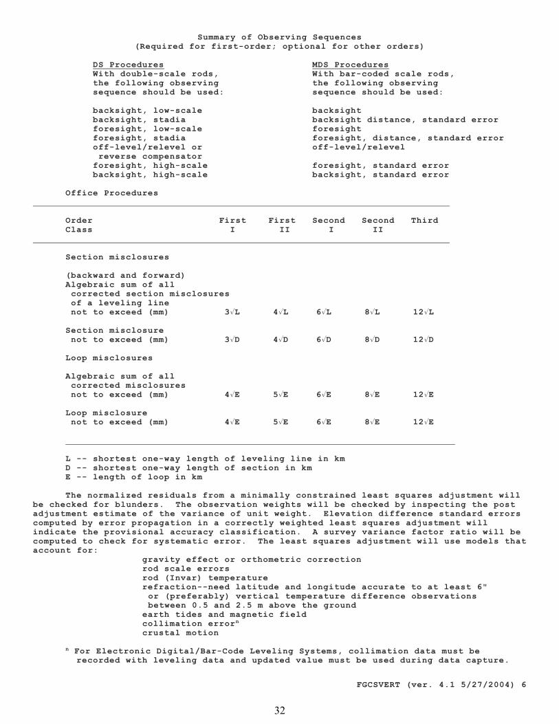
FGCSVERT (ver. 4.1 5/27/2004) 6
Summary of Observing Sequences(Required for first-order; optional for other orders)
DS Procedures MDS Procedures With double-scale rods, With bar-coded scale rods, the following observing the following observing sequence should be used: sequence should be used:
backsight, low-scale backsight backsight, stadia backsight distance, standard error foresight, low-scale foresight foresight, stadia foresight, distance, standard error off-level/relevel or off-level/relevel reverse compensator foresight, high-scale foresight, standard error backsight, high-scale backsight, standard error
Office Procedures
Order First First Second Second ThirdClass I II I II
Section misclosures
(backward and forward)Algebraic sum of all corrected section misclosures of a leveling line not to exceed (mm) 3�L 4�L 6�L 8�L 12�L
Section misclosure not to exceed (mm) 3�D 4�D 6�D 8�D 12�D
Loop misclosures
Algebraic sum of all corrected misclosures not to exceed (mm) 4�E 5�E 6�E 8�E 12�E
Loop misclosure not to exceed (mm) 4�E 5�E 6�E 8�E 12�E
L -- shortest one-way length of leveling line in kmD -- shortest one-way length of section in kmE -- length of loop in km
The normalized residuals from a minimally constrained least squares adjustment willbe checked for blunders. The observation weights will be checked by inspecting the postadjustment estimate of the variance of unit weight. Elevation difference standard errorscomputed by error propagation in a correctly weighted least squares adjustment willindicate the provisional accuracy classification. A survey variance factor ratio will becomputed to check for systematic error. The least squares adjustment will use models thataccount for:
gravity effect or orthometric correction rod scale errors rod (Invar) temperature refraction--need latitude and longitude accurate to at least 6"
or (preferably) vertical temperature difference observations between 0.5 and 2.5 m above the ground
earth tides and magnetic field collimation errorn
crustal motion
For Electronic Digital/Bar-Code Leveling Systems, collimation data must ben
recorded with leveling data and updated value must be used during data capture.
32
FEMA Form 086-0-33 (7/15) Page 1 of 15Replaces all previous editions.
National Flood Insurance Program
ELEVATION CERTIFICATE
AND
INSTRUCTIONS
33
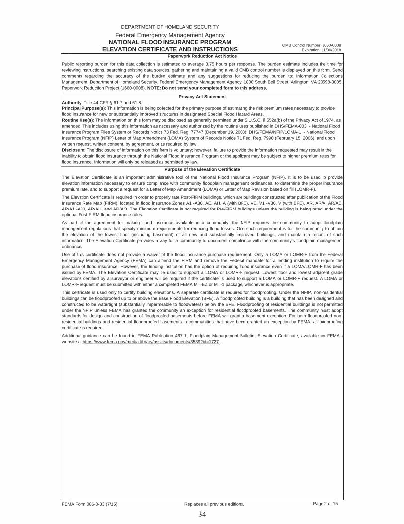
FEMA Form 086-0-33 (7/15) Page 2 of 15Replaces all previous editions.
OMB Control Number: 1660-0008 Expiration: 11/30/2018
DEPARTMENT OF HOMELAND SECURITY
Federal Emergency Management AgencyNATIONAL FLOOD INSURANCE PROGRAM
ELEVATION CERTIFICATE AND INSTRUCTIONS Paperwork Reduction Act Notice
Public reporting burden for this data collection is estimated to average 3.75 hours per response. The burden estimate includes the time for reviewing instructions, searching existing data sources, gathering and maintaining a valid OMB control number is displayed on this form. Send comments regarding the accuracy of the burden estimate and any suggestions for reducing the burden to: Information Collections Management, Department of Homeland Security, Federal Emergency Management Agency, 1800 South Bell Street, Arlington, VA 20598-3005,Paperwork Reduction Project (1660-0008). NOTE: Do not send your completed form to this address.
Privacy Act StatementAuthority: Title 44 CFR § 61.7 and 61.8. Principal Purpose(s): This information is being collected for the primary purpose of estimating the risk premium rates necessary to provide flood insurance for new or substantially improved structures in designated Special Flood Hazard Areas. Routine Use(s): The information on this form may be disclosed as generally permitted under 5 U.S.C. § 552a(b) of the Privacy Act of 1974, as amended. This includes using this information as necessary and authorized by the routine uses published in DHS/FEMA-003 - National Flood Insurance Program Files System or Records Notice 73 Fed. Reg. 77747 (December 19, 2008); DHS/FEMA/NFIP/LOMA-1 - National FloodInsurance Program (NFIP) Letter of Map Amendment (LOMA) System of Records Notice 71 Fed. Reg. 7990 (February 15, 2006); and uponwritten request, written consent, by agreement, or as required by law. Disclosure: The disclosure of information on this form is voluntary; however, failure to provide the information requested may result in theinability to obtain flood insurance through the National Flood Insurance Program or the applicant may be subject to higher premium rates for flood insurance. Information will only be released as permitted by law.
Purpose of the Elevation Certificate
The Elevation Certificate is an important administrative tool of the National Flood Insurance Program (NFIP). It is to be used to provide elevation information necessary to ensure compliance with community floodplain management ordinances, to determine the proper insurancepremium rate, and to support a request for a Letter of Map Amendment (LOMA) or Letter of Map Revision based on fill (LOMR-F).
The Elevation Certificate is required in order to properly rate Post-FIRM buildings, which are buildings constructed after publication of the Flood Insurance Rate Map (FIRM), located in flood insurance Zones A1 -A30, AE, AH, A (with BFE), VE, V1 -V30, V (with BFE), AR, AR/A, AR/AE, AR/A1 -A30, AR/AH, and AR/AO. The Elevation Certificate is not required for Pre-FIRM buildings unless the building is being rated under the optional Post-FIRM flood insurance rules.
As part of the agreement for making flood insurance available in a community, the NFIP requires the community to adopt floodplainmanagement regulations that specify minimum requirements for reducing flood losses. One such requirement is for the community to obtain the elevation of the lowest floor (including basement) of all new and substantially improved buildings, and maintain a record of such information. The Elevation Certificate provides a way for a community to document compliance with the community's floodplain managementordinance.
Use of this certificate does not provide a waiver of the flood insurance purchase requirement. Only a LOMA or LOMR-F from the FederalEmergency Management Agency (FEMA) can amend the FIRM and remove the Federal mandate for a lending institution to require the purchase of flood insurance. However, the lending institution has the option of requiring flood insurance even if a LOMA/LOMR-F has been issued by FEMA. The Elevation Certificate may be used to support a LOMA or LOMR-F request. Lowest floor and lowest adjacent gradeelevations certified by a surveyor or engineer will be required if the certificate is used to support a LOMA or LOMR-F request. A LOMA or LOMR-F request must be submitted with either a completed FEMA MT-EZ or MT-1 package, whichever is appropriate.
This certificate is used only to certify building elevations. A separate certificate is required for floodproofing. Under the NFIP, non-residential buildings can be floodproofed up to or above the Base Flood Elevation (BFE). A floodproofed building is a building that has been designed and constructed to be watertight (substantially impermeable to floodwaters) below the BFE. Floodproofing of residential buildings is not permitted under the NFIP unless FEMA has granted the community an exception for residential floodproofed basements. The community must adoptstandards for design and construction of floodproofed basements before FEMA will grant a basement exception. For both floodproofed non-residential buildings and residential floodproofed basements in communities that have been granted an exception by FEMA, a floodproofingcertificate is required.
Additional guidance can be found in FEMA Publication 467-1, Floodplain Management Bulletin: Elevation Certificate, available on FEMA's website at https://www.fema.gov/media-library/assets/documents/3539?id=1727.
34

FEMA Form 086-0-33 (7/15) Page 3 of 15Replaces all previous editions.
DEPARTMENT OF HOMELAND SECURITYFederal Emergency Management Agency
ELEVATION CERTIFICATE IMPORTANT: FOLLOW THE INSTRUCTIONS ON PAGES 9-16 OMB Control Number: 1660-0008
Expiration: 11/30/2018
SECTION A - PROPERTY INFORMATION FORM INSURANCE COMPANY USE
Policy Number:
Company NAIC Number:
A1. Building Owner's Name
A2. Building Street Address (including Apt., Unit, Suite, and/or Bldg. No.) or P.O. Route and Box No.
City State Zip Code
A3. Property Description (Lot and Block Numbers, Tax Parcel Number, Legal Description, etc.)
A4. Building Use (e.g., Residential, Non-Residential, Addition, Accessory, etc.)
A5. Latitude/Longitude: Lat. Long. Horizontal Datum: NAD 1927 NAD 1983
A6. Attach at least 2 photographs of the building if the Certificate is being used to obtain flood insurance.
A8. For a building with a crawlspace or enclosure(s):
A7. Building Diagram Number
a) Square footage of crawlspace or enclosure(s)
b) Number of permanent flood openings in the crawlspace or enclosure(s) within 1.0 foot above adjacent grade
c) Total net area of flood openings in A8.b
d) Engineered flood openings? Yes No
sq ft
sq in
A9. For a building with an attached garage:
a) Square footage of attached garage sq ft
b) Number of permanent flood openings in the attached garage within 1.0 foot above adjacent grade
c) Total net area of flood openings in A9.b
d) Engineered flood openings? Yes No
sq in
SECTION B - FLOOD INSURANCE RATE MAP (FIRM) INFORMATIONB1. NFIP Community Name & Community Number B2. County Name B3. State
B4. Map/Panel Number B5. Suffix B6. FIRM Index Date B7. FIRM Panel Effective/ Revised Date
B8. Flood Zone(s) B9. Base Flood Elevation(s) (Zone AO, use base flood depth
B10. Indicate the source of the Base Flood Elevation (BFE) data or base flood depth entered in Item B9:
FIS Profile FIRM Community Determined Other/Source:
B11. Indicate elevation datum used for BFE in Item B9: NGVD 1929 NAVD 1988 Other/Source:
B12. Is the building located in a Coastal Barrier Resources System (CBRS) area or Otherwise Protected Area (OPA)? Yes No
Designation Date: CBRS OPA
SECTION C - BUILDING ELEVATION INFORMATION (SURVEY REQUIRED)C1. Building elevations are based on: Construction Drawings* Building Under Construction* Finished ConstructionC2. Elevations - Zones A1 - A30, AE, AH, A (with BFE), VE, V1 - V30, V (with BFE), AR, AR/A, AR/AE, AR/A1 - A30, AR/AH, AR/AO.Complete Items C2.a -h below according to the building diagram specified in Item A7. In Puerto Rico only, enter meters.
Benchmark Utilized: Vertical Datum:
Indicate elevation datum used for the elevations in items a) through h) below. NGVD 1929 NAVD 1988
Other/Source:
* A new Elevation Certificate will be required when construction of the building is complete.
Datum used for building elevations must be the same as that used for the BFE.
a) Top of bottom floor (including basement, crawlspace, or enclosure floor) - feet meters
Check the measurement used.
b) Top of the next higher floor -
c) Bottom of the lowest horizontal structural member (V Zones only) -
-d) Attached garage (top of slab)
e) Lowest elevation of machinery or equipment servicing the building (Describe type of equipment and location in Comments)
-
-f) Lowest adjacent (finished) grade next to building (LAG)
g) Highest adjacent (finished) grade next to building (HAG) -
h) Lowest adjacent grade at lowest elevation of deck or stairs, including structural support
-
feet meters
feet meters
feet meters
feet meters
feet meters
feet meters
feet meters
Copy all pages of this Elevation Certificate and all attachments for (1) community official, (2) insurance agent/company, and (3) building owner.
35
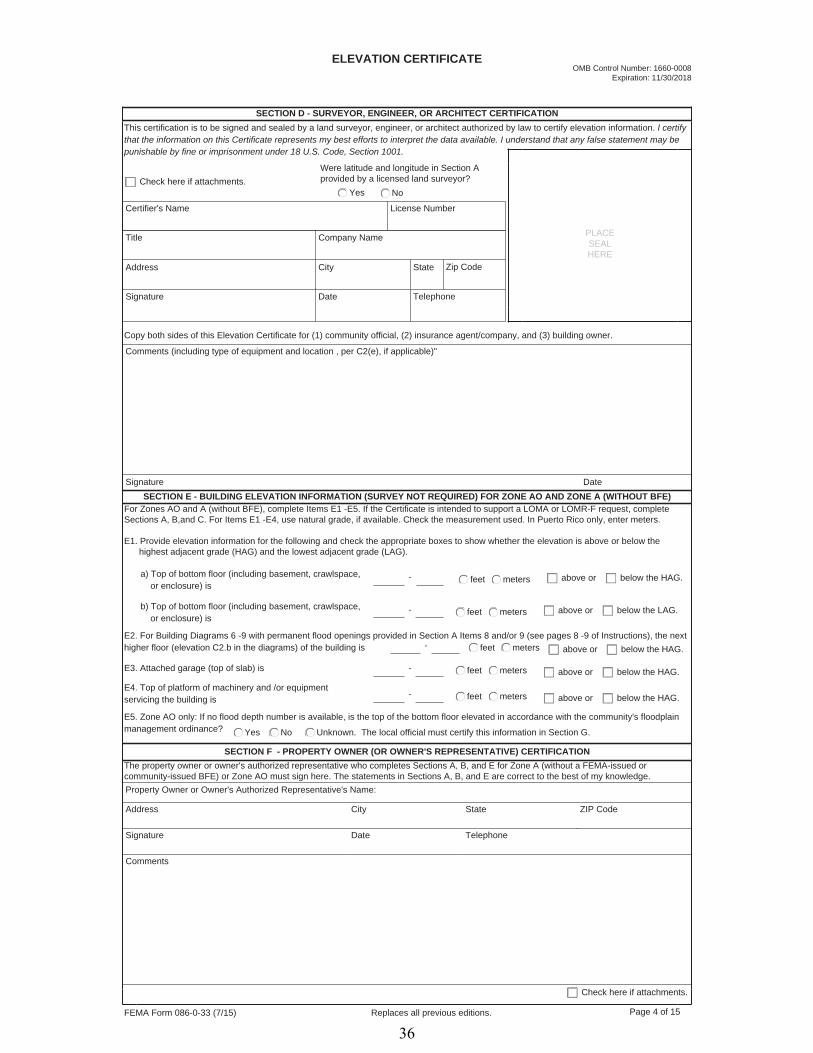
FEMA Form 086-0-33 (7/15) Page 4 of 15Replaces all previous editions.
SECTION D - SURVEYOR, ENGINEER, OR ARCHITECT CERTIFICATIONThis certification is to be signed and sealed by a land surveyor, engineer, or architect authorized by law to certify elevation information. I certify that the information on this Certificate represents my best efforts to interpret the data available. I understand that any false statement may be punishable by fine or imprisonment under 18 U.S. Code, Section 1001.
Check here if attachments.Were latitude and longitude in Section Aprovided by a licensed land surveyor?
Yes No
Certifier's Name License Number
Title Company Name
Address City State Zip Code
Signature Date Telephone
PLACESEALHERE
Comments (including type of equipment and location , per C2(e), if applicable)"
Copy both sides of this Elevation Certificate for (1) community official, (2) insurance agent/company, and (3) building owner.
Signature DateSECTION E - BUILDING ELEVATION INFORMATION (SURVEY NOT REQUIRED) FOR ZONE AO AND ZONE A (WITHOUT BFE)
For Zones AO and A (without BFE), complete Items E1 -E5. If the Certificate is intended to support a LOMA or LOMR-F request, completeSections A, B,and C. For Items E1 -E4, use natural grade, if available. Check the measurement used. In Puerto Rico only, enter meters.
E1. Provide elevation information for the following and check the appropriate boxes to show whether the elevation is above or below the highest adjacent grade (HAG) and the lowest adjacent grade (LAG).
a) Top of bottom floor (including basement, crawlspace, or enclosure) is
b) Top of bottom floor (including basement, crawlspace, or enclosure) is
-
-
feet meters above or below the HAG.
feet meters above or below the LAG.
E2. For Building Diagrams 6 -9 with permanent flood openings provided in Section A Items 8 and/or 9 (see pages 8 -9 of Instructions), the next higher floor (elevation C2.b in the diagrams) of the building is - feet meters above or below the HAG.
E3. Attached garage (top of slab) is - feet meters above or below the HAG.
E4. Top of platform of machinery and /or equipmentservicing the building is - feet meters above or below the HAG.
E5. Zone AO only: If no flood depth number is available, is the top of the bottom floor elevated in accordance with the community's floodplain management ordinance? Yes No Unknown. The local official must certify this information in Section G.
SECTION F - PROPERTY OWNER (OR OWNER'S REPRESENTATIVE) CERTIFICATIONThe property owner or owner's authorized representative who completes Sections A, B, and E for Zone A (without a FEMA-issued orcommunity-issued BFE) or Zone AO must sign here. The statements in Sections A, B, and E are correct to the best of my knowledge.Property Owner or Owner's Authorized Representative's Name:
Address City State ZIP Code
Signature Date Telephone
ELEVATION CERTIFICATE
Comments
Check here if attachments.
OMB Control Number: 1660-0008 Expiration: 11/30/2018
36

FEMA Form 086-0-33 (7/15) Page 5 of 15Replaces all previous editions.
SECTION G - COMMUNITY INFORMATION (OPTIONAL)
The local official who is authorized by law or ordinance to administer the community's floodplain management ordinance can complete Sections A, B, C (or E), and G of this Elevation Certificate. Complete the applicable item(s) and sign below. Check the measurement used in Items G8 -G10. In Puerto Rico only, enter meters.
G1.
G2.
G3.
G4. Permit Number G5. Date Permit Issued G6. Date Certificate of Compliance/Occupancy Issued
G7. This permit has been issued for: New Construction Substantial Improvement
The information in Section C was taken from other documentation that has been signed and sealed by a licensed surveyor, engineer,or architect who is authorized by law to certify elevation information. (Indicate the source and date of the elevation data in theComments area below.)
A community official completed Section E for a building located in Zone A (without a FEMA-issued or community-issued BFE) or ZoneAO.
The following information (Items G4 -G10) is provided for community floodplain management purposes.
G8. Elevation of as-built lowest floor (including basement) of the building:
- feet meters Datum
G9. BFE or (in Zone AO) depth of flooding at the building site:
- feet meters Datum
G10. Community's design flood elevation: - feet meters Datum
Local Official's Name Title
Community Name Telephone
Signature
Comments
Date
Check here if attachments.
OMB Control Number: 1660-0008 Expiration: 11/30/2018
37

FEMA Form 086-0-33 (7/15) Page 6 of 15Replaces all previous editions.
IMPORTANT: In these spaces, copy the corresponding information from Section A.
Building Street Address (including Apt., Unit, Suite, and/or Bldg. No.) or P.O. Route and Box No.
City State Zip Code
FOR INSURANCE COMPANY USE
Policy Number:
Company NAIC Number:
If using the Elevation Certificate to obtain NFIP flood insurance, affix at least 2 building photographs below according to the instructions for Item A6. Identify all photographs with date taken; "Front view" and Rear view"; and, if required, "Right Side View" and "Left Side View." When applicable, photographs must show the foundation with representative examples of the flood openings or vents, as indicated in Section A8. If submitting more photographs than will fit on this page, use the Continuation Page.
BUILDING PHOTOGRAPHS See instructions for Item A6 OMB Control Number: 1660-0008
Expiration: 11/30/2018
38
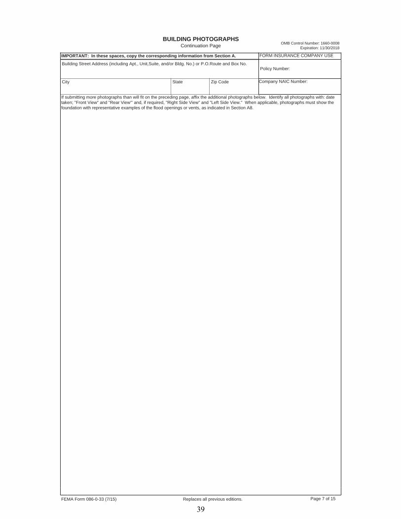
FEMA Form 086-0-33 (7/15) Page 7 of 15Replaces all previous editions.
IMPORTANT: In these spaces, copy the corresponding information from Section A.
Building Street Address (including Apt., Unit,Suite, and/or Bldg. No.) or P.O.Route and Box No.
City State Zip Code
FORM INSURANCE COMPANY USE
Policy Number:
BUILDING PHOTOGRAPHS Continuation Page
If submitting more photographs than will fit on the preceding page, affix the additional photographs below. Identify all photographs with: date taken; "Front View" and "Rear View"' and, if required, "Right Side View" and "Left Side View." When applicable, photographs must show the foundation with representative examples of the flood openings or vents, as indicated in Section A8.
Company NAIC Number:
OMB Control Number: 1660-0008 Expiration: 11/30/2018
39

FEMA Form 086-0-33 (7/15) Page 8 of 15Replaces all previous editions.
Instructions for Completingthe Elevation CertificateNational Flood Insurance Program
The Elevation Certificate is to be completed by a land surveyor, engineer, or architect who is authorized by law to certify elevation information when elevation information is required for Zones A1 -A30, AE, AH, A (with BFE), VE, V1 -V30, V (with BFE), AR, AR/A, AR/AE, AR/A1 -A30, AR/AH, or AR/AO. Community officials who are authorized by law or ordinance to provide floodplain management information may alsocomplete this form. For Zones AO and A (without BFE), a community official, a property owner, or an owner's representative may provideinformation on this certificate, unless the elevations are intended for use in supporting a request for a LOMA or LOMR-F. Certified elevations must be included if the purpose of completing the Elevation Certificate is to obtain a LOMA or LOMR-F.
The property owner, the owner's representative, or local official who is authorized by law to administer the community floodplain ordinance can complete Section A and Section B. The partially completed form can then be given to the land surveyor, engineer, or architect to complete Section C. The land surveyor, engineer, or architect should verify the information provided by the property owner or owner's representative to ensure that this certificate is complete.
In Puerto Rico only, elevations for building information and flood hazard information may be entered in meters.
SECTION A - PROPERTY INFORMATIONItems A1 -A4. This section identifies the building, its location, and its owner. Enter the name(s) of the building owner(s), the building's completestreet address, and the lot and block numbers. If the building's address is different from the owner's address, enter the address of the building being certified. If the address is a rural route or a Post Office box number, enter the lot and block numbers, the tax parcel number, the legal description, or an abbreviated location description based on distance and direction from a fixed point of reference. For the purposes of this certificate, "building" means both a building and a manufactured (mobile) home.
A map may be attached to this certificate to show the location of the building on the property. A tax map, FIRM, or detailed community map is appropriate. If no map is available, provide a sketch of the property location, and the location of the building on the property. Include appropriate landmarks such as nearby roads, intersections, and bodies of water. For building use, indicate whether the building is residential, non-residential, an addition to an existing residential or non-residential building, an accessory building (e.g., garage), or other type of structure. Use the Comments area of the appropriate section if needed, or attach additional comments.
Item A5. Provide latitude and longitude coordinates for the center of the front of the building. Use either decimal degrees (e.g., 39.5043°,-110.7585°) or degrees, minutes, seconds (e.g., 39° 30' 15.5", -110° 45' 30.7") format. If decimal degrees are used, provide coordinates to at least 5 decimal places or better. When using degrees, minutes, seconds, provide seconds to at least 1 decimal place or better. The latitude and longitude coordinates must be accurate within 66 feet. When the latitude and longitude are provided by a surveyor, check the "Yes" box in Section D and indicate the method used to determine the latitude and longitude in the Comments area of Section D. If the Elevation Certificate is being certified by other than a licensed surveyor, engineer, or architect, this information is not required. Provide the type of datum used to obtain the latitude and longitude. FEMA prefers the use of NAD 1983.
Item A6. If the Elevation Certificate is being used to obtain flood insurance through the NFIP, the certifier must provide at least 2 photographsshowing the front and rear of the building taken within 90 days from the date of certification. The photographs must be taken with views confirming the building description and diagram number provided in Section A. To the extent possible, these photographs should show the entire building including foundation. If the building has split-level or multi-level areas, provide at least 2 additional photographs showing side views of the building. In addition, when applicable, provide a photograph of the foundation showing a representative example of the flood openings or vents. All photographs must be in color and measure at least 3" × 3". Digital photographs are acceptable.
Item A7. Select the diagram on pages 7 -9 that best represents the building. Then enter the diagram number and use the diagram to identifyand determine the appropriate elevations requested in Items C2.a -h. If you are unsure of the correct diagram, select the diagram that most closely resembles the building being certified.
Item A8.a Provide the square footage of the crawlspace or enclosure(s) below the lowest elevated floor of an elevated building with or withoutpermanent flood openings. Take the measurement from the outside of the crawlspace or enclosure(s). Examples of elevated buildingsconstructed with crawlspace and enclosure(s) are shown in Diagrams 6 -9 on pages 8 -9. Diagram 2, 4, or 9 should be used for a buildingconstructed with a crawlspace floor that is below the exterior grade on all sides.
Items A8.b -d Enter in Item A8.b the number of permanent flood openings in the crawlspace or enclosure(s) that are no higher than 1.0 foot above the higher of the exterior or interior grade or floor immediately below the opening. (A permanent flood opening is a flood vent or other opening that allows the free passage of water automatically in both directions without human intervention.) If the interior grade elevation is used, note this in the Comments area of Section D. Estimate the total net area of all such permanent flood openings in square inches,excluding any bars, louvers, or other covers of the permanent flood openings, and enter the total in Item A8.c. If the net area cannot be reasonably estimated, provide the size of the flood openings without consideration of any covers and indicate in the Comments area the type of cover that exists in the flood openings. Indicate in Item A8.d whether the flood openings are engineered. If applicable, attach a copy of the Individual Engineered Flood Openings Certification or an Evaluation Report issued by the International Code Council Evaluation Service (ICC ES), if you have it. If the crawlspace or enclosure(s) have no permanent flood openings, or if the openings are not within 1.0 foot above adjacent grade, enter "0" (zero) in Items A8.b -c.
Item A9.a Provide the square footage of the attached garage with or without permanent flood openings. Take the measurement from the outside of the garage.
Items A9.b -d Enter in Item A9.b the number of permanent flood openings in the attached garage that are no higher than 1.0 foot above the higher of the exterior or interior grade or floor immediately below the opening. (A permanent flood opening is a flood vent or other opening that allows the free passage of water automatically in both directions without human intervention.) If the interior grade elevation is used, note this in the Comments area of Section D. This includes any openings that are in the garage door that are no higher than 1.0 foot above the adjacent grade. Estimate the total net area of all such permanent flood openings in square inches and enter the total in Item A9.c. If the net area cannot be reasonably estimated, provide the size of the flood openings without consideration of any covers and indicate in the Comments area the type of cover that exists in the flood openings. Indicate in Item A9.d whether the flood openings are engineered. If applicable, attach a copy of the Individual Engineered Flood Openings Certification or an Evaluation Report issued by the International Code Council Evaluation Service (ICC ES), if you have it. If the garage has no permanent flood openings, or if the openings are not within 1.0 foot above adjacent grade, enter "0" (zero) in Items A9.b -c.
OMB Control Number: 1660-0008 Expiration: 11/30/2018
40

FEMA Form 086-0-33 (7/15) Page 9 of 15Replaces all previous editions.
SECTION B - FLOOD INSURANCE RATE MAP (FIRM) INFORMATION
Complete the Elevation Certificate on the basis of the FIRM in effect at the time of the certification.
The information for Section B is obtained by reviewing the FIRM panel that includes the building's location. Information about the current FIRM is available from the Federal Emergency Management Agency (FEMA) by calling 1-800-358-9616. If a Letter of Map Amendment (LOMA) or Letter of Map Revision (LOMR-F) has been issued by FEMA, please provide the letter date and case number in the Comments area ofSection D or Section G, as appropriate.
For a building in an area that has been annexed by one community but is shown on another community's FIRM, enter the community nameand 6-digit number of the annexing community in Item B1, the name of the county or new county, if necessary, in Item B2, and the FIRM index date for the annexing community in Item B6. Enter information from the actual FIRM panel that shows the building location, even if it is the FIRM for the previous jurisdiction, in Items B4, B5, B7, B8, and B9.
If the map in effect at the time of the building's construction was other than the current FIRM, and you have the past map information pertaining to the building, provide the information in the Comments area of Section D.
Item B1. NFIP Community Name & Community Number. Enter the complete name of the community in which the building is located and the associated 6-digit community number. For a newly incorporated community, use the name and 6-digit number of the new community. Underthe NFIP, a "community" is any State or area or political subdivision thereof, or any Indian tribe or authorized native organization, that has authority to adopt and enforce floodplain management regulations for the areas within its jurisdiction. To determine the current community number, see the NFIP Community Status Book, available on FEMA's web site at https://www.fema.gov/national-flood-insurance-program/national-flood-insurance-program-community-status-book, or call 1-800-358-9616.
Item B2. County Name. Enter the name of the county or counties in which the community is located. For an unincorporated area of a county,enter "unincorporated area." For an independent city, enter "independent city."
Item B3. State. Enter the 2-letter state abbreviation (for example, VA, TX, CA).
Items B4 -B5. Map/Panel Number and Suffix. Enter the 10-character "Map Number" or "Community Panel Number" shown on the FIRM where the building or manufactured (mobile) home is located. For maps in a county-wide format, the sixth character of the "Map Number" is the letter "C" followed by a 4-digit map number. For maps not in a county-wide format, enter the "Community Panel Number" shown on the FIRM.
Item B6. FIRM Index Date. Enter the effective date or the map revised date shown on the FIRM Index.
Item B7. FIRM Panel Effective/Revised Date. Enter the map effective date or the map revised date shown on the FIRM panel. This will be thelatest of all dates shown on the map. The current FIRM panel effective date can be determined by calling 1-800-358-9616.
Item B8. Flood Zone(s). Enter the flood zone, or flood zones, in which the building is located. All flood zones containing the letter "A" or "V" are considered Special Flood Hazard Areas. The flood zones are A, AE, A1 -A30, V, VE, V1 -V30, AH, AO, AR, AR/A, AR/AE, AR/A1 -A30, AR/AH, and AR/AO. Each flood zone is defined in the legend of the FIRM panel on which it appears.
Item B9. Base Flood Elevation(s). Using the appropriate Flood Insurance Study (FIS) Profile, Floodway Data Table, or FIRM panel, locate theproperty and enter the BFE (or base flood depth) of the building site. If the building is located in more than 1 flood zone in Item B8, list all appropriate BFEs in Item B9. BFEs are shown on a FIRM or FIS Profile for Zones A1 -A30, AE, AH, V1 -V30, VE, AR, AR/A, AR/AE, AR/A1 -A30, AR/AH, and AR/AO; flood depth numbers are shown for Zone AO. Use the AR BFE if the building is located in any of Zones AR/A, AR/AE, AR/A1-A30, AR/AH, or AR/AO. In A or V zones where BFEs are not provided on the FIRM, BFEs may be available from another source.For example, the community may have established BFEs or obtained BFE data from other sources for the building site. For subdivisions and other developments of more than 50 lots or 5 acres, establishment of BFEs is required by the community's floodplain management ordinance.If a BFE is obtained from another source, enter the BFE in Item B9. In an A Zone where BFEs are not available, complete Section E and enter N/A for Section B, Item B9. Enter the BFE to the nearest tenth of a foot (nearest tenth of a meter, in Puerto Rico).
Item B10. Indicate the source of the BFE that you entered in Item B9. If the BFE is from a source other than FIS Profile, FIRM, or community,describe the source of the BFE.
Item B11. Indicate the elevation datum to which the elevations on the applicable FIRM are referenced as shown on the map legend. The vertical datum is shown in the Map Legend and/or the Notes to Users on the FIRM.
Item B12. Indicate whether the building is located in a Coastal Barrier Resources System (CBRS) area or Otherwise Protected Area (OPA). (OPAs are portions of coastal barriers that are owned by Federal, State, or local governments or by certain non-profit organizations and used primarily for natural resources protection.) Federal flood insurance is prohibited in designated CBRS areas or OPAs for buildings or manufactured (mobile) homes built or substantially improved after the date of the CBRS or OPA designation. For the first CBRS designations,that date is October 1, 1983. Information about CBRS areas and OPAs may be obtained on the FEMA web site at https://www.fema.gov/national-flood-insurance-program/coastal-barrier-resources-system.
Instructions for Completingthe Elevation Certificate (Continued) OMB Control Number: 1660-0008
Expiration: 11/30/2018
41

FEMA Form 086-0-33 (7/15) Page 10 of 15Replaces all previous editions.
SECTION C - BUILDING ELEVATION INFORMATION (SURVEY REQUIRED)
Complete Section C if the building is located in any of Zones A1 -A30, AE, AH, A (with BFE), VE, V1 -V30, V (with BFE), AR, AR/A, AR/AE, AR/A1 -A30, AR/AH, or AR/AO, or if this certificate is being used to support a request for a LOMA or LOMR-F. If the building is located in Zone AO or Zone A (without BFE), complete Section E instead. To ensure that all required elevations are obtained, it may be necessary to enter the building (for instance, if the building has a basement or sunken living room, split-level construction, or machinery and equipment).
Surveyors may not be able to gain access to some crawlspaces to shoot the elevation of the crawlspace floor. If access to the crawlspace is limited or cannot be gained, follow one of these procedures.
• Use a yardstick or tape measure to measure the height from the floor of the crawlspace to the "next higher floor," and then subtract the crawlspace height from the elevation of the "next higher floor." If there is no access to the crawlspace, use the exterior grade next to the structure to measure the height of the crawlspace to the "next higher floor."
• Contact the local floodplain administrator of the community in which the building is located. The community may have documentation of the elevation of the crawlspace floor as part of the permit issued for the building.
• If the property owner has documentation or knows the height of the crawlspace floor to the next higher floor, try to verify this by looking inside the crawlspace through any openings or vents.
In all 3 cases, provide the elevation in the Comments area of Section D on the back of the form and a brief description of how the elevation was obtained.
Item C1. Indicate whether the elevations to be entered in this section are based on construction drawings, a building under construction, or finished construction. For either of the first 2 choices, a post-construction Elevation Certificate will be required when construction is complete. If the building is under construction, include only those elevations that can be surveyed in Items C2.a -h. Use the Comments area of Section D to provide elevations obtained from the construction plans or drawings. Select "Finished Construction" only when all machinery and/or equipment such as furnaces, hot water heaters, heat pumps, air conditioners, and elevators and their associated equipment have been installed and the grading around the building is completed.
Item C2. A field survey is required for Items C2.a -h. Most control networks will assign a unique identifier for each benchmark. For example, the National Geodetic Survey uses the Permanent Identifier (PID). For the benchmark utilized, provide the PID or other unique identifier assigned by the maintainer of the benchmark. For GPS survey, indicate the benchmark used for the base station, the Continuously Operating Reference Stations (CORS) sites used for an On-line Positioning User Service (OPUS) solution (also attach the OPUS report), or the name of the Real Time Network used.
Also provide the vertical datum for the benchmark elevation. All elevations for the certificate, including the elevations for Items C2.a -h, must use the same datum on which the BFE is based. Show the conversion from the field survey datum used if it differs from the datum used for the BFE entered in Item B9 and indicate the conversion software used. Show the datum conversion, if applicable, in the Comments area of Section D.
For property experiencing ground subsidence, the most recent reference mark elevations must be used for determining building elevations.However, when subsidence is involved, the BFE should not be adjusted. Enter elevations in Items C2.a -h to the nearest tenth of a foot (nearest tenth of a meter, in Puerto Rico).
Items C2.a -d Enter the building elevations (excluding the attached garage) indicated by the selected building diagram (Item A7) in Items C2.a-c. If there is an attached garage, enter the elevation for top of attached garage slab in Item C2.d. (Because elevation for top of attached garage slab is self-explanatory, attached garages are not illustrated in the diagrams.) If the building is located in a V zone on the FIRM, complete Item C2.c. If the flood zone cannot be determined, enter elevations for all of Items C2.a -h. For buildings in A zones, elevations a, b, d, and e should be measured at the top of the floor. For buildings in V zones, elevation c must be measured at the bottom of the lowest horizontal structural member of the floor (see drawing below). For buildings elevated on a crawlspace, Diagrams 8 and 9, enter the elevation of the top of the crawlspace floor in Item C2.a, whether or not the crawlspace has permanent flood openings (flood vents). If any item does not apply to the building, enter "N/A" for not applicable.
Instructions for Completingthe Elevation Certificate (Continued) OMB Control Number: 1660-0008
Expiration: 11/30/2018
42

FEMA Form 086-0-33 (7/15) Page 11 of 15Replaces all previous editions.
Instructions for Completingthe Elevation Certificate (Continued)
Item C2.e Enter the lowest platform elevation of at least 1 of the following machinery and equipment items: elevators and their associatedequipment, furnaces, hot water heaters, heat pumps, and air conditioners in an attached garage or enclosure or on an open utility platform that provides utility services for the building. Note that elevations for these specific machinery and equipment items are required in order to rate the building for flood insurance. Local floodplain management officials are required to ensure that all machinery and equipment servicing the building are protected from flooding. Thus, local officials may require that elevation information for all machinery and equipment, including ductwork, be documented on the Elevation Certificate. If the machinery and/or equipment is mounted to a wall, pile, etc., enter the platform elevation of the machinery and/or equipment. Indicate machinery/equipment type and its general location, e.g., on floor inside garage or on platform affixed to exterior wall, in the Comments area of Section D or Section G, as appropriate. If this item does not apply to the building, enter "N/A" for not applicable.
Items C2.f -g Enter the elevation of the ground, sidewalk, or patio slab immediately next to the building. For Zone AO, use the natural gradeelevation, if available. This measurement must be to the nearest tenth of a foot (nearest tenth of a meter, in Puerto Rico) if this certificate is being used to support a request for a LOMA or LOMR-F.
Item C2.h Enter the lowest grade elevation at the deck support or stairs. For Zone AO, use the natural grade elevation, if available. Thismeasurement must be to the nearest tenth of a foot (nearest tenth of a meter, in Puerto Rico) if this certificate is being used to support a request for a LOMA or LOMR-F.
SECTION E - BUILDING ELEVATION INFORMATION (SURVEY NOT REQUIRED) FOR ZONE AO AND ZONE A (WITHOUT BFE)
Complete Section E if the building is located in Zone AO or Zone A (without BFE). Otherwise, complete Section C instead. Explain in the Section F Comments area if the measurement provided under Items E1 -E4 is based on the "natural grade."
Items E1.a and b Enter in Item E1.a the height to the nearest tenth of a foot (tenth of a meter in Puerto Rico) of the top of the bottom floor (asindicated in the applicable diagram) above or below the highest adjacent grade (HAG). Enter in Item E1.b the height to the nearest tenth of a foot (tenth of a meter in Puerto Rico) of the top of the bottom floor (as indicated in the applicable diagram) above or below the lowest adjacent grade (LAG). For buildings in Zone AO, the community's floodplain management ordinance requires the lowest floor of the building be elevated above the highest adjacent grade at least as high as the depth number on the FIRM. Buildings in Zone A (without BFE) may qualify for a lower insurance rate if an engineered BFE is developed at the site.
Item E2. For Building Diagrams 6 -9 with permanent flood openings (see pages 8 -9), enter the height to the nearest tenth of a foot (tenth of a meter in Puerto Rico) of the next higher floor or elevated floor (as indicated in the applicable diagram) above or below the highest adjacent grade (HAG).
Item E3. Enter the height to the nearest tenth of a foot (tenth of a meter in Puerto Rico), in relation to the highest adjacent grade next to the building, for the top of attached garage slab. (Because elevation for top of attached garage slab is self-explanatory, attached garages are not illustrated in the diagrams.) If this item does not apply to the building, enter "N/A" for not applicable.
Item E4. Enter the height to the nearest tenth of a foot (tenth of a meter in Puerto Rico), in relation to the highest adjacent grade next to the building, of the platform elevation that supports the machinery and/or equipment servicing the building. Indicate machinery/equipment type in the Comments area of Section F. If this item does not apply to the building, enter "N/A" for not applicable.
Item E5. For those communities where this base flood depth is not available, the community will need to determine whether the top of thebottom floor is elevated in accordance with the community's floodplain management ordinance.
Complete as indicated. This section of the Elevation Certificate may be signed by only a land surveyor, engineer, or architect who is authorized by law to certify elevation information. Place your license number, your seal (as allowed by the State licensing board), your signature, and the date in the box in Section D. You are certifying that the information on this certificate represents your best efforts to interpret the data available and that you understand that any false statement may be punishable by fine or imprisonment under 18 U.S. Code, Section 1001. Use the Comments area of Section D, on the back of the certificate, to provide datum, elevation, openings, or other relevant information not specified on the front.
SECTION D - SURVEYOR, ENGINEER, OR ARCHITECT CERTIFICATION
SECTION F - PROPERTY OWNER (OR OWNER'S REPRESENTATIVE) CERTIFICATION
Complete as indicated. This section is provided for certification of measurements taken by a property owner or property owner's representative when responding to Sections A, B, and E. The address entered in this section must be the actual mailing address of the property owner or property owner's representative who provided the information on the certificate.
SECTION G - COMMUNITY INFORMATION (OPTIONAL)
Complete as indicated. The community official who is authorized by law or ordinance to administer the community's floodplain managementordinance can complete Sections A, B, C (or E), and G of this Elevation Certificate. Section C may be filled in by the local official as provided in the instructions below for Item G1. If the authorized community official completes Sections C, E, or G, complete the appropriate item(s) and sign this section.
Check Item G1 if Section C is completed with elevation data from other documentation that has been signed and sealed by a licensed surveyor, engineer, or architect who is authorized by law to certify elevation information. Indicate the source of the elevation data and the date obtained in the Comments area of Section G. If you are both a community official and a licensed land surveyor, engineer, or architectauthorized by law to certify elevation information, and you performed the actual survey for a building in Zones A1 -A30, AE, AH, A (with BFE), VE, V1 -V30, V (with BFE), AR, AR/A, AR/A1 -A30, AR/AE, AR/AH, or AR/AO, you must also complete Section D.
Check Item G2 if information is entered in Section E by the community for a building in Zone A (without a FEMA-issued or community-issued BFE) or Zone AO.
Check Item G3 if the information in Items G4 -G10 has been completed for community floodplain management purposes to document the as-built lowest floor elevation of the building. Section C of the Elevation Certificate records the elevation of various building components but does not determine the lowest floor of the building or whether the building, as constructed, complies with the community's floodplain management ordinance. This must be done by the community. Items G4 -G10 provide a way to document these determinations.
Item G4. Permit Number. Enter the permit number or other identifier to key the Elevation Certificate to the permit issued for the building.
OMB Control Number: 1660-0008 Expiration: 11/30/2018
43

FEMA Form 086-0-33 (7/15) Page 12 of 15Replaces all previous editions.
Item G4. Permit Number. Enter the permit number or other identifier to key the Elevation Certificate to the permit issued for the building.
Item G5. Date Permit Issued. Enter the date the permit was issued for the building.
Item G6. Date Certificate of Compliance/Occupancy Issued. Enter the date that the Certificate of Compliance or Occupancy or similar writtenofficial documentation of as-built lowest floor elevation was issued by the community as evidence that all work authorized by the floodplain development permit has been completed in accordance with the community's floodplain management laws or ordinances.
Item G7. New Construction or Substantial Improvement. Check the applicable box. "Substantial Improvement" means any reconstruction, rehabilitation, addition, or other improvement of a building, the cost of which equals or exceeds 50 percent of the market value of the building before the start of construction of the improvement. The term includes buildings that have incurred substantial damage, regardless of the actual repair work performed.
Item G8. As-built lowest floor elevation. Enter the elevation of the lowest floor (including basement) when the construction of the building is completed and a final inspection has been made to confirm that the building is built in accordance with the permit, the approved plans, and the community's floodplain management laws or ordinances. Indicate the elevation datum used.
Item G9. BFE. Using the appropriate FIRM panel, FIS Profile, or other data source, locate the property and enter the BFE (or base flood depth)of the building site. Indicate the elevation datum used.
Item G10. Community's design flood elevation. Enter the elevation (including freeboard above the BFE) to which the community requires thelowest floor to be elevated. Indicate the elevation datum used.
Enter your name, title, and telephone number, and the name of the community. Sign and enter the date in the appropriate blanks.
Instructions for Completingthe Elevation Certificate (Continued) OMB Control Number: 1660-0008
Expiration: 11/30/2018
44

FEMA Form 086-0-33 (7/15) Page 13 of 15Replaces all previous editions.
DIAGRAM 1B All raised-slab-on-grade or slab-on-stem-wall-with-fill single- and multiple-floor buildings (other than split-level), either detached or row type (e.g., townhouses); with or without attached garage.
DIAGRAM 1A All slab-on-grade single- and multiple - floor buildings (other than split-level) and high-rise buildings, either detached or row type (e.g., townhouses); with or without attached garage.
DIAGRAM 2B All single-and multiple-floor buildings with basement (other than split-level) and high-rise buildings with basement, either detached or row type (e.g., townhouses); with or without attached garage).
DIAGRAM 2A All single- and multiple-floor buildings with basement (other than split-level) and high-rise buildings with basement, either detached or row type (e.g., townhouses); with or without attached garage.
Building Diagrams
The following diagrams illustrate various types of buildings. Compare the features of the building being certified with the features shown in the diagrams and select the diagram most applicable. Enter the diagram number in Item A7, the square footage of crawlspace or enclosure(s) and the area of flood openings in square inches in Items A8.a -c, the square footage of attached garage and the area of flood openings in square inches in Items A9.a -c, and the elevations in Items C2.a -h.
In A zones, the floor elevation is taken at the top finished surface of the floor indicated; in V zones, the floor elevation is taken at the bottom of the lowest horizontal structural member (see drawing in instructions for Section C).
* A floor that is below ground level (grade) on all sides is considered a basement even if the floor is used for living purposes, or as an office, garage, workshop, etc.
Instructions for Completingthe Elevation Certificate (Continued)
Distinguishing Feature - The bottom floor is at or above ground level (grade) on at least 1 side.*
Distinguishing Feature - The bottom floor is at or above ground level (grade) on at least 1 side.*
Distinguishing Feature - The bottom floor (basement or underground garage) is below ground level (grade ) on all sides.*
Distinguishing feature - The bottom floor (basement or under ground garage) is below ground level (grade) on all sides; most of the height of the walls are below ground level on all sides and the door and area of egress is also below ground level on all sides.*
OMB Control Number: 1660-0008 Expiration: 11/30/2018
45

FEMA Form 086-0-33 (7/15) Page 14 of 15Replaces all previous editions.
DIAGRAM 6 All buildings elevated on piers, posts, piles, columns, or parallel shear walls with full or partial enclosure below the elevated floor.
DIAGRAM 3 All split-level buildings that are slab-on-grade, either detached or row type (e.g., townhouses); with or without attached garage.
DIAGRAM 4 All split-level buildings (other than slab-on-grade), either detached or row type (e.g., townhouses); with or without attached garage.
* A floor that is below ground level (grade) on all sides is considered a basement even if the floor is used for living purposes, or as an office, garage, workshop, etc.
** An "opening" is a permanent opening that allows for the free passage of water automatically in both directions without human intervention. Under the NFIP, a minimum of 2 openings is required for enclosures or crawlspaces. The openings shall provide a total net area of not less than 1 square inch for every square foot of area enclosed, excluding any bars, louvers, or other covers of the opening. Alternatively, an Individual Engineered Flood Openings Certification or an Evaluation Report issued by the International Code Council Evaluation Service (ICC ES) must be submitted to document that the design of the openings will allow for the automatic equalization of hydrostatic flood forces on exterior walls. A window, a door, or a garage door is not considered an opening; openings may be installed in doors. Openings shall be on at least 2 sides of the enclosed area. If a building has more than 1 enclosed area, each area must have openings to allow floodwater to directly enter. The bottom of the openings must be no higher than 1.0 foot above the higher of the exterior or interior grade or floor immediately below the opening. For more guidance on openings, see NFIP Technical Bulletin 1.
Instructions for Completingthe Elevation Certificate (Continued)
Distinguishing Feature - the bottom floor (excluding garage) is at or above ground level (grade) on at least 1 side. *
Distinguishing Feature - The bottom floor (basement or underground garage) is below ground level (grade) on al sides. *
DIAGRAM 5 All buildings elevated on piers, posts, piles, columns, or parallel shear walls. No obstructions below the elevated floor.
Distinguishing Feature - For all zones, the area below the elevated floor is open, with no obstruction to flow of floodwaters (open lattice work and /or insect screening is permissible).
Distinguishing Feature - For all zones, the area below the elevated floor is enclosed, either partially or fully. In A Zones, the partially or fully enclosed area below the elevated floor is with or without openings ** present in the walls of the enclosure. Indicate information about enclosure size and openings in Section A - Property Information.
OMB Control Number: 1660-0008 Expiration: 11/30/2018
46
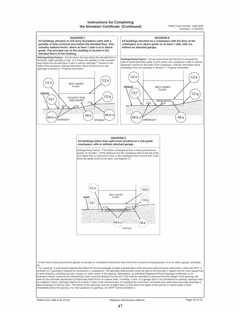
FEMA Form 086-0-33 (7/15) Page 15 of 15Replaces all previous editions.
DIAGRAM 7 All buildings elevated on full-story foundation walls with a partially or fully enclosed area below the elevated floor. This includes walkout levels, where at least 1 side is at or above grade. The principal use of this building is located in the elevated floors of the building.
* A floor that is below ground level (grade) on all sides is considered a basement even if the floor is used for living purposes, or as an office, garage, workshop, etc.** An "opening" is a permanent opening that allows for the free passage of water automatically in both directions without human intervention. Under the NFIP, a minimum of 2 openings is required for enclosures or crawlspaces. The openings shall provide a total net area of not less than 1 square inch for every square foot of area enclosed, excluding any bars, louvers, or other covers of the opening. Alternatively, an Individual Engineered Flood Openings Certification or an Evaluation Report issued by the International Code Council Evaluation Service (ICC ES) must be submitted to document that the design of the openings will allow for the automatic equalization of hydrostatic flood forces on exterior walls. A window, a door, or a garage door is not considered an opening; openings may be installed in doors. Openings shall be on at least 2 sides of the enclosed area. If a building has more than 1 enclosed area, each area must have openings to allow floodwater to directly enter. The bottom of the openings must be no higher than 1.0 foot above the higher of the exterior or interior grade or floor immediately below the opening. For more guidance on openings, see NFIP Technical Bulletin 1.
Instructions for Completingthe Elevation Certificate (Continued)
Distinguishing Feature - For all zones, the area below the elevated floor is enclosed, either partially or fully. In A Zones, the partially or fully enclosed area below the elevated floor is with or without openings ** present in the walls of the enclosure. Indicate information about enclosure size and openings in Section A - Property Information.
DIAGRAM 8 All buildings elevated on a crawlspace with the floor of the crawlspace at or above grade on at least 1 side, with our without an attached garage.
Distinguishing Feature - For all zones below the first floor is enclosed by solid or partial perimeter walls. In all A zones, the crawlspace is with or without openings** present in the walls of the crawlspace. Indicate information about crawlspace size and openings in Section A - Property Information.
DIAGRAM 9 All buildings (other than split-level) elevated on a sub-grade crawlspace, with or without attached garage.
Distinguishing Feature - The bottom (crawlspace) floor is below ground level (grade) on all sides. * (If the distance from the crawlspace floor to the top of the next higher floor is more than 5 feet, or the crawlspace floor is more than 2 feet below the grade (LAG) on all sides, use Diagram 2.)
OMB Control Number: 1660-0008 Expiration: 11/30/2018
47

Rep
ortin
g M
etho
dolo
gy
Federal Geographic Data CommitteeDepartment of Agriculture • Department of Commerce • Department of Defense • Department of Energy
Department of Housing and Urban Development • Department of the Interior • Department of StateDepartment of Transportation • Environmental Protection AgencyFederal Emergency Management Agency • Library of Congress
National Aeronautics and Space Administration • National Archives and Records AdministrationTennessee Valley Authority
FGDC-STD-007.1-1998
Geospatial Positioning Accuracy StandardsPart 1: Reporting Methodology
Federal Geodetic Control SubcommitteeFederal Geographic Data Committee
48
rthompson
Rectangle

1-ii
Federal Geographic Data Committee
Established by Office of Management and Budget Circular A-16, the Federal Geographic Data Committee(FGDC) promotes the coordinated development, use, sharing, and dissemination of geographic data.
The FGDC is composed of representatives from the Departments of Agriculture, Commerce, Defense,Energy, Housing and Urban Development, the Interior, State, and Transportation; the EnvironmentalProtection Agency; the Federal Emergency Management Agency; the Library of Congress; the NationalAeronautics and Space Administration; the National Archives and Records Administration; and theTennessee Valley Authority. Additional Federal agencies participate on FGDC subcommittees andworking groups. The Department of the Interior chairs the committee.
FGDC subcommittees work on issues related to data categories coordinated under the circular. Subcommittees establish and implement standards for data content, quality, and transfer; encourage theexchange of information and the transfer of data; and organize the collection of geographic data to reduceduplication of effort. Working groups are established for issues that transcend data categories.
For more information about the committee, or to be added to the committee's newsletter mailing list,please contact:
Federal Geographic Data Committee Secretariatc/o U.S. Geological Survey
590 National CenterReston, Virginia 22092
Telephone: (703) 648-5514Facsimile: (703) 648-5755
Internet (electronic mail): [email protected] FTP: ftp://fgdc.er.usgs.gov/pub/gdc/
World Wide Web: http://fgdc.er.usgs.gov/fgdc.html
49

Rep
ortin
g M
etho
dolo
gy
Federal Geographic Data Committee FGDC-STD-007.1-1998Geospatial Positioning Accuracy StandardsPart 1: Reporting Methodology
1-iii
CONTENTS
Page
1.1 Introduction . . . . . . . . . . . . . . . . . . . . . . . . . . . . . . . . . . . . . . . . . . . . . . . . . . . . . . . . . . . . . . 1-11.1.1 Objective . . . . . . . . . . . . . . . . . . . . . . . . . . . . . . . . . . . . . . . . . . . . . . . . . . . . . . . . . 1-11.1.2 Scope . . . . . . . . . . . . . . . . . . . . . . . . . . . . . . . . . . . . . . . . . . . . . . . . . . . . . . . . . . . 1-11.1.3 Applicability . . . . . . . . . . . . . . . . . . . . . . . . . . . . . . . . . . . . . . . . . . . . . . . . . . . . . . 1-21.1.4 Related Standards . . . . . . . . . . . . . . . . . . . . . . . . . . . . . . . . . . . . . . . . . . . . . . . . . . 1-3
1.1.4.1 FGDC Standards . . . . . . . . . . . . . . . . . . . . . . . . . . . . . . . . . . . . . . . . . . . . 1-31.1.4.2 ISO Technical Committee (TC) 211 Geographic Information/Geomatics
Standards . . . . . . . . . . . . . . . . . . . . . . . . . . . . . . . . . . . . . . . . . . . . . . . . . . 1-31.1.5 Standards Development Procedures . . . . . . . . . . . . . . . . . . . . . . . . . . . . . . . . . . . . . 1-31.1.6 Maintenance Authority . . . . . . . . . . . . . . . . . . . . . . . . . . . . . . . . . . . . . . . . . . . . . . . 1-5
1.2 Accuracy Standard . . . . . . . . . . . . . . . . . . . . . . . . . . . . . . . . . . . . . . . . . . . . . . . . . . . . . . . . . 1-6
1.3 References . . . . . . . . . . . . . . . . . . . . . . . . . . . . . . . . . . . . . . . . . . . . . . . . . . . . . . . . . . . . . . . 1-7
Appendices
Appendix 1-A Glossary of Terms (informative) . . . . . . . . . . . . . . . . . . . . . . . . . . . . . . . . . . . . . . . . . 1-8
50
rthompson
Rectangle

Federal Geographic Data Committee FGDC-STD-007.1-1998Geospatial Positioning Accuracy StandardsPart 1: Reporting Methodology
1-1
1.1 Introduction
1.1.1 Objective
This document provides a common methodology for reporting the accuracy of horizontalcoordinate values and vertical coordinate values for clearly defined features where the location isrepresented by a single point coordinate: examples are survey monuments, such as brass disksand rod marks; prominent landmarks, such as church spires, standpipes, radio towers, tallchimneys, and mountain peaks; and targeted photogrammetric control points. It provides ameans to directly compare the accuracy of coordinate values obtained by one method (e.g., acartographically-derived value) with that obtained by another method (e.g., a Global PositioningSystem (GPS) geodetic network survey) for the same point. It is increasingly important for usersto not only know the coordinate values, but also the accuracy of those coordinate values, so userscan decide which coordinate values represent the best estimate of the true value for theirapplications.
1.1.2 Scope
Activities which collect or produce data coordinates include geodetic network and crustal motionsurveys; national, regional, state, and county topographic mapping; bathymetric mapping andnautical charting; engineering, construction, and facilities management mapping and drawing;cadastral and boundary surveying; etc. These activities support geospatial data applications inareas such as transportation, community development, agriculture, emergency response,environmental management, and information technology.
This document is being developed in parts to address various activities. Each data activity willapply the same general accuracy standard to develop a reporting classification scheme for itsparticular data. The following parts have been submitted to date:
Part 2, STANDARDS FOR GEODETIC NETWORKS. Geodetic control surveys are usuallyperformed to establish a basic control network (framework) from which supplemental surveyingand mapping work, covered in other parts of this document, are performed. Geodetic networksurveys are distinguished by use of redundant, interconnected, permanently monumented controlpoints that comprise the framework for the National Spatial Reference System (NSRS) or areoften incorporated into the NSRS. These surveys must be performed to far more rigorousaccuracy and quality assurance standards than control surveys for general engineering,construction, or topographic mapping. Geodetic network surveys included in the NSRS must beperformed to meet automated data recording, submission, project review, and least squaresadjustment requirements established by the National Geodetic Survey (NGS). The lead agencyis the Department of Commerce, National Oceanic and Atmospheric Administration, NationalOcean Service, NGS; the responsible FGDC unit is the Federal Geodetic Control Subcommittee(FGCS).
Part 3, NATIONAL STANDARD FOR SPATIAL DATA ACCURACY. The National Standardfor Spatial Data Accuracy (NSSDA) implements a testing and statistical methodology forpositional accuracy of fully georeferenced maps and digital geospatial data, in either raster, point,
51

Rep
ortin
g M
etho
dolo
gy
Federal Geographic Data Committee FGDC-STD-007.1-1998Geospatial Positioning Accuracy StandardsPart 1: Reporting Methodology
1-2
or vector format, derived from sources such as aerial photographs, satellite imagery, and groundsurveys. The NSRS is the framework that references positions to the national datums. Positionalaccuracy of geodetically surveyed points in the National Spatial Reference System is reportedaccording to Part 2, Standards for Geodetic Control Networks, Geospatial Positioning AccuracyStandards. NSRS points may also be selected as an independent source of higher accuracy totest positional accuracy of maps and geospatial data according to the NSSDA. The lead agencyis the Department of the Interior, U.S. Geological Survey, National Mapping Division. Theresponsible FGDC unit is the Subcommittee on Base Cartographic Data.
In addition, two other parts have been identified for inclusion in this document and are underdevelopment:
Part 4, ENGINEERING, CONSTRUCTION, AND FACILITIES MANAGEMENT. This partwill provide accuracy standards for engineering surveys and maps used to support planning,design, construction, operation, maintenance, and management of facilities, installations,structures, transportation systems, and related projects. It uses the NSSDA for accuracy testingand verification of fully georeferenced maps for A/E/C and Facility Management applicationssuch as preliminary site planning and reconnaissance mapping. It will also provide guidance indeveloping positional accuracy specifications for geospatial data products, such as architecturaland engineering drawings, construction site plans, regional master planning maps, and relatedGeographical Information Systems (GIS), Computer-Aided Drafting and Design (CADD), andAutomated Mapping/Facility Management (AM/FM) products, that may not be referenced to anational datum and where accuracy is based on survey closure ratios or elevation differences. The lead agency is the Department of Defense, U.S. Army Corps of Engineers. The responsibleFGDC unit is the Facilities Working Group.
Part 5, NAVIGATION CHARTS AND HYDROGRAPHIC SURVEYS. This part will specifyminimum standards for hydrographic surveys so that hydrographic (sounding) data aresufficiently accurate and spatial uncertainty is adequately quantified for safe use by mariners. The accuracy of hydrographic surveying is highly dependent upon knowledge of tidal datumplanes and the special accuracy requirements to support safe navigation. This part will provide astandardized methodology for evaluating survey data and reporting resultant data quality througha standard statistical approach. It will be based on the recently revised InternationalHydrographic Organization (IHO) Standard for Hydrographic Surveys, which is in the finalstages of review by the international community. The lead agency is Department of Commerce,National Oceanic and Atmospheric Administration, National Ocean Service, Office of the CoastSurvey. The responsible FGDC subcommittee is the Bathymetric and Nautical ChartSubcommittee.
1.1.3 Applicability
Use Geospatial Positioning Accuracy Standards to evaluate and report the positional accuracy ofspatial data produced, revised, or disseminated by or for the Federal Government. According toExecutive Order 12906, Coordinating Geographic Data Acquisition and Access: the NationalSpatial Data Infrastructure (Clinton, 1994, Sec. 4. Data Standards Activities, item d), “Federalagencies collecting or producing geospatial data, either directly or indirectly (e.g. through
52
rthompson
Rectangle
rthompson
Rectangle
Federal Geographic Data Committee FGDC-STD-007.1-1998Geospatial Positioning Accuracy StandardsPart 1: Reporting Methodology
1-3
grants, partnerships, or contracts with other entities), shall ensure, prior to obligating funds forsuch activities, that data will be collected in a manner that meets all relevant standards adoptedthrough the FGDC process.”
1.1.4 Related Standards
1.1.4.1 FGDC Standards
The Spatial Data Transfer Standard (SDTS) (ANSI-NCITS, 1998) specifies that a data qualityreport accompany the data in a standard transfer. Because the quality report will function in theassessment for fitness of use, it must also be obtainable in its entirety and separately from theactual data. The quality report consists of five portions: lineage, positional accuracy, attributeaccuracy, logical consistency, and completeness. Positional accuracy reported according toGeospatial Positioning Accuracy Standards will be included in the data quality report.
Part 2, Data Quality Information, of Content Standards for Digital Geospatial Metadata (FederalGeographic Data Committee, 1998) adopts the five elements of data quality specified by SDTS. Consequently, positional accuracy reported according to Geospatial Positioning AccuracyStandards will be encoded in Metadata.
1.1.4.2 ISO Technical Committee (TC) 211 Geographic Information/Geomatics Standards
ISO Standard 15046-13, Geographic Information - Quality Principles defines a data qualitymodel and identifies positional accuracy as a data quality element and various subelements ofpositional accuracy. It provides a means of measuring how well the data set maps geospatialphenomena according to its product specification.
ISO Standard 15046-14, Geographic Information - Quality - Evaluation Procedures providesdata quality evaluation models for both data producers and data users. The procedures are usedto determine data quality results consistent with the data quality model defined by ISO Standard15046-13. They establish a framework to report data quality results in metadata and whennecessary, in a separate data quality report.
1.1.5 Standards Development Procedures
Part 2, Standards for Geodetic Networks and Part 3, National Standard for Spatial Data Accuracy(NSSDA) were originally developed independently. Following the first public review of theNSSDA, in its previous version as National Cartographic Standards for Spatial Accuracy, theNSSDA was aligned with emerging standards from the Federal Geodetic Control Subcommittee(FGCS). The FGCS has broad participation from various Federal agencies. Noting howindividual FGDC subcommittees and working groups were developing accuracy standards, theFGCS membership agreed to sponsor an FGDC standards project to compile the various accuracystandards into one document and minimize redundancies. The FGDC Standards WorkingGroup has endorsed this approach. This is the first FGDC standards project to integratestandards for various data themes and applications.
53

Rep
ortin
g M
etho
dolo
gy
Federal Geographic Data Committee FGDC-STD-007.1-1998Geospatial Positioning Accuracy StandardsPart 1: Reporting Methodology
1-4
1.1.6 Maintenance Authority
The U.S. Department of Commerce, National Oceanic and Atmospheric Administration,National Ocean Service, National Geodetic Survey, maintains Part 1, Reporting Methodology,Geospatial Positioning Accuracy Standards for the Federal Geographic Data Committee. Addressquestions concerning Part 1, Reporting Methodology, Geospatial Positioning Accuracy Standardsto: Director, National Geodetic Survey, NOAA, N/NGS, 1315 East-West Highway, SilverSpring, Maryland 20910.
54
rthompson
Rectangle

Federal Geographic Data Committee FGDC-STD-007.1-1998Geospatial Positioning Accuracy StandardsPart 1: Reporting Methodology
1-5
1.2 Accuracy Standard
All spatial data activities should develop a classification scheme following the standard givenbelow. The standard for reporting positional accuracy is defined for horizontal and/or verticalcoordinates, depending on the characteristics of the data sets.
Horizontal: The reporting standard in the horizontal component is the radius of a circle ofuncertainty, such that the true or theoretical location of the point falls within that circle95-percent of the time.
Vertical: The reporting standard in the vertical component is a linear uncertainty value, suchthat the true or theoretical location of the point falls within +/- of that linear uncertainty value95-percent of the time. The reporting accuracy standard should be defined in metric(International System of Units, SI) units. However, accuracy will be reported in English(inch-pound) units where the point coordinates or elevations are reported in English units.
The method used to evaluate accuracy should be described. Examples include: statisticaltesting, least squares adjustment results, comparison with values of higher accuracy, repeatmeasurements, estimation, etc. The accuracy standard for point data in each part of thedocument will identify the type of application and if applicable, the accuracy level recommendedfor that application.
Coordinate values should be based on National datums. Horizontal coordinate values shouldpreferably be referenced to the North American Datum of 1983 (NAD 83). Vertical coordinatevalues should preferably be referenced to North American Vertical Datum of 1988 (NAVD 88). However, it is recognized that many legacy maps and geospatial data are referenced to oldernational datums, such as the North American Datum of 1927 (NAD 27) and the NationalGeodetic Vertical Datum of 1929 (NGVD 29).
If coordinate values are not referenced to the National datum but their relationship to the nationaldatum is known, identify the datum and its relationship to a National datum. If the relationshipbetween the local datum and the National datum is not specified, identify the datum, but statethat its relationship to a National datum is unspecified.
55

Rep
ortin
g M
etho
dolo
gy
Federal Geographic Data Committee FGDC-STD-007.1-1998Geospatial Positioning Accuracy StandardsPart 1: Reporting Methodology
1-6
1.3 References
American National Standards Institute, Information Technology - Spatial Data Transfer Standard (SDTS)(ANSI-NCITS 320:1998): New York, New York.
Clinton, William J., 1994, Coordinating Geographic Data Acquisition and Access: The National Spatial Data Infrastructure. Washington, D.C., Federal Register, Volume 59, Number 71, pp. 17671-17674.
Federal Geographic Data Committee, 1998, Content Standards for Digital Geospatial Metadata (version2.0), FGDC-STD-001-1998: Washington, D.C., Federal Geographic Data Committee, 66 p.
Geodetic Survey Division, 1996, Accuracy Standards for Positioning, Version 1.0: Ottawa, Canada, Natural Resources Canada, 28 p.
National Geodetic Survey, 1986, Geodetic Glossary: Rockville, Maryland, National Geodetic Survey, 274 p.
Subcommittee for Base Cartographic Data, 1998, Final Draft Content Standards for Digital Gridded Land Elevation Data: Reston, Virginia, U.S. Geological Survey, 37 p.
Draft standards not released to the public:
ISO/Technical Committee 211 Geographic information/Geomatics, Working Group 3 - Geospatial DataAdministration, ISO Standard 15046-13 Geographic Information - Quality - Principles
ISO/Technical Committee 211 Geographic information/Geomatics, Working Group 3 - Geospatial DataAdministration, ISO Standard 15046-14 Geographic Information - Quality - EvaluationProcedures
56
rthompson
Rectangle

Federal Geographic Data Committee FGDC-STD-007.1-1998Final Draft Geospatial Positioning Accuracy StandardsPart 1: Reporting MethodologyAppendix 1-A (informative): Glossary of Terms
1-7
Appendix 1-AGlossary of Terms
(informative)
57

Rep
ortin
g M
etho
dolo
gy
Federal Geographic Data Committee FGDC-STD-007.1-1998Final Draft Geospatial Positioning Accuracy StandardsPart 1: Reporting MethodologyAppendix 1-A (informative): Glossary of Terms
1-8
The following are definitions of various terms used throughout the Geospatial Positioning AccuracyStandards.
accuracy - closeness of an estimated (e.g., measured or computed) value to a standard or accepted [true] valueof a particular quantity. (National Geodetic Survey, 1986).
NOTE Because the true value is not known, but only estimated, the accuracy of the measuredquantity is also unknown. Therefore, accuracy of coordinate information can only be estimated(Geodetic Survey Division, 1996).
accuracy testing - process by which the accuracy of a data set may be checked.
check point - one of the points in the sample used to estimate the positional accuracy of the data set againstan independent source of higher accuracy.
component accuracy - positional accuracy in each x, y, and z component.
confidence level - the probability that the true (population) value is within a range of given values.
NOTE in the sense of this standard, the probability that errors are within a range of given values.
dataset - identifiable collection of related data.
datum - any quantity or set of such quantities that may serve as a basis for calculation of other quantities.(National Geodetic Survey, 1986)
elevation - height of a point with respect to a defined vertical datum.
ellipsoidal height - distance between a point on the Earth’s surface and the ellipsoidal surface, as measuredalong the perpendicular to the ellipsoid at the point and taken positive upward from the ellipsoid.
NOTE also called geodetic height (National Geodetic Survey, 1986)
horizontal accuracy - positional accuracy of a dataset with respect to a horizontal datum. (Adapted fromSubcommittee for Base Cartographic Data, 1998)
horizontal error - magnitude of the displacement of a feature's recorded horizontal position in a dataset fromits true or more accurate position, as measured radially and not resolved into x, y.
independent source of higher accuracy - data acquired independently of procedures to generate the datasetthat is used to test the positional accuracy of a dataset.
NOTE the independent source of higher accuracy shall be of the highest accuracy feasible andpracticable to evaluate the accuracy of the data set.
58
rthompson
Rectangle

Federal Geographic Data Committee FGDC-STD-007.1-1998Final Draft Geospatial Positioning Accuracy StandardsPart 1: Reporting MethodologyAppendix 1-A (informative): Glossary of Terms
1-9
local accuracy - The local accuracy of a control point is a value that represents the uncertainty in thecoordinates of the control point relative to the coordinates of other directly connected, adjacent control pointsat the 95-percent confidence level. The reported local accuracy is an approximate average of the individuallocal accuracy values between this control point and other observed control points used to establish thecoordinates of the control point.
network accuracy - The network accuracy of a control point is a value that represents the uncertainty in thecoordinates of the control point with respect to the geodetic datum at the 95-percent confidence level. ForNSRS network accuracy classification, the datum is considered to be best expressed by the geodetic values atthe Continuously Operating Reference Stations (CORS) supported by NGS. By this definition, the local andnetwork accuracy values at CORS sites are considered to be infinitesimal, i.e., to approach zero.
orthometric height - distance measured along the plumb line between the geoid and a point on the Earth’ssurface, taken positive upward from the geoid. (adapted from National Geodetic Survey, 1986).
positional accuracy - describes the accuracy of the position of features (adapted from ISO Standard 15046-13)
precision - in statistics, a measure of the tendency of a set of random numbers to cluster about a numberdetermined by the set. (National Geodetic Survey, 1986).
NOTE If appropriate steps are taken to eliminate or correct for biases in positional data, precisionmeasures may also be a useful means of representing accuracy. (Geodetic Survey Division, 1996).
root mean square error (RMSE) - square root of the mean of squared errors for a sample.
spatial data - information that identifies the geographic location and characteristics of natural or constructedfeatures and boundaries of earth. This information may be derived from, among other things, remote sensing,mapping, and surveying technologies (Federal Geographic Data Committee, 1998).
NOTE also known as geospatial data.
vertical accuracy - measure of the positional accuracy of a data set with respect to a specified vertical datum.(adapted from Subcommittee for Base Cartographic Data, 1998).
vertical error - displacement of a feature's recorded elevation in a dataset from its true or more accurateelevation.
well-defined point - point that represents a feature for which the horizontal position is known to a highdegree of accuracy and position with respect to the geodetic datum.
59

Stan
dard
s fo
r G
eode
tic N
etw
orks
Federal Geographic Data CommitteeDepartment of Agriculture • Department of Commerce • Department of Defense • Department of Energy
Department of Housing and Urban Development • Department of the Interior • Department of StateDepartment of Transportation • Environmental Protection AgencyFederal Emergency Management Agency • Library of Congress
National Aeronautics and Space Administration • National Archives and Records AdministrationTennessee Valley Authority
FGDC-STD-007.2-1998
Geospatial Positioning Accuracy StandardsPart 2: Standards for Geodetic Networks
Federal Geodetic Control SubcommitteeFederal Geographic Data Committee
60
rthompson
Rectangle

2-ii
Federal Geographic Data Committee
Established by Office of Management and Budget Circular A-16, the Federal Geographic Data Committee(FGDC) promotes the coordinated development, use, sharing, and dissemination of geographic data.
The FGDC is composed of representatives from the Departments of Agriculture, Commerce, Defense,Energy, Housing and Urban Development, the Interior, State, and Transportation; the EnvironmentalProtection Agency; the Federal Emergency Management Agency; the Library of Congress; the NationalAeronautics and Space Administration; the National Archives and Records Administration; and theTennessee Valley Authority. Additional Federal agencies participate on FGDC subcommittees andworking groups. The Department of the Interior chairs the committee.
FGDC subcommittees work on issues related to data categories coordinated under the circular. Subcommittees establish and implement standards for data content, quality, and transfer; encourage theexchange of information and the transfer of data; and organize the collection of geographic data to reduceduplication of effort. Working groups are established for issues that transcend data categories.
For more information about the committee, or to be added to the committee's newsletter mailing list,please contact:
Federal Geographic Data Committee Secretariatc/o U.S. Geological Survey
590 National CenterReston, Virginia 22092
Telephone: (703) 648-5514Facsimile: (703) 648-5755
Internet (electronic mail): [email protected] FTP: ftp://fgdc.er.usgs.gov/pub/gdc/
World Wide Web: http://fgdc.er.usgs.gov/fgdc.html
61

Stan
dard
s fo
r G
eode
tic N
etw
orks
Federal Geographic Data Committee FGDC-STD-007.2-1998Draft Geospatial Positioning Accuracy StandardsPart 2: Standards for Geodetic Networks
2-iii
CONTENTS
Page
2.1 Introduction . . . . . . . . . . . . . . . . . . . . . . . . . . . . . . . . . . . . . . . . . . . . . . . . . . . . . . . . . . . . . . 2-12.1.1 Objective . . . . . . . . . . . . . . . . . . . . . . . . . . . . . . . . . . . . . . . . . . . . . . . . . . . . . . . . . 2-12.1.2 Scope . . . . . . . . . . . . . . . . . . . . . . . . . . . . . . . . . . . . . . . . . . . . . . . . . . . . . . . . . . . . 2-12.1.3 Applicability . . . . . . . . . . . . . . . . . . . . . . . . . . . . . . . . . . . . . . . . . . . . . . . . . . . . . . 2-12.1.4 Related Standards . . . . . . . . . . . . . . . . . . . . . . . . . . . . . . . . . . . . . . . . . . . . . . . . . . 2-12.1.5 Standards Development Procedures . . . . . . . . . . . . . . . . . . . . . . . . . . . . . . . . . . . . . 2-22.1.6 Maintenance . . . . . . . . . . . . . . . . . . . . . . . . . . . . . . . . . . . . . . . . . . . . . . . . . . . . . . 2-2
2.2 Testing Methodology and Reporting Requirements . . . . . . . . . . . . . . . . . . . . . . . . . . . . . . . . 2-32.2.1 Accuracy Standards . . . . . . . . . . . . . . . . . . . . . . . . . . . . . . . . . . . . . . . . . . . . . . . . . 2-32.2.2 Accuracy Determination . . . . . . . . . . . . . . . . . . . . . . . . . . . . . . . . . . . . . . . . . . . . . . 2-42.2.3 Accuracy Reporting . . . . . . . . . . . . . . . . . . . . . . . . . . . . . . . . . . . . . . . . . . . . . . . . . 2-5
2.3 References . . . . . . . . . . . . . . . . . . . . . . . . . . . . . . . . . . . . . . . . . . . . . . . . . . . . . . . . . . . . . . . 2-6
Table
2.1 Accuracy Standards - Horizontal, Ellipsoid Height, and Orthometric Height . . . . . . . . . . . . . 2-3
62
rthompson
Rectangle

Federal Geographic Data Committee FGDC-STD-007.2-1998Draft Geospatial Positioning Accuracy StandardsPart 2: Standards for Geodetic Networks
2-1
2.1 Introduction
2.1.1 Objective
This document provides a common methodology for determining and reporting the accuracy ofhorizontal coordinate values and vertical coordinate values for geodetic control pointsrepresented by survey monuments, such as brass disks and rod marks. It provides a means todirectly compare the accuracy of coordinate values obtained by one method (e.g., a classical line-of-sight traverse) with the accuracy of coordinate values obtained by another method (e.g., aGlobal Positioning System (GPS) geodetic network survey) for the same point.
2.1.2 Scope
Geodetic control surveys are usually performed to establish a basic control network (framework)from which supplemental surveying and mapping work, covered in other parts of this document,is performed. Geodetic network surveys are distinguished by use of redundant, interconnected,permanently monumented control points that comprise the framework for the National SpatialReference System (NSRS) or are often incorporated into the NSRS.
These surveys must be performed to far more rigorous accuracy and quality assurance standardsthan those for control surveys for general engineering, construction, or topographic mappingpurposes. Geodetic network surveys included in NSRS must be performed to meet automateddata recording, submittal, project review, and least squares adjustment requirements establishedby the Federal Geodetic Control Subcommittee (FGCS).
2.1.3 Applicability
Geodetic network surveys are often employed when large geopolitical area (e.g., county-level orlarger) mapping control is required, and where seamless connection with adjacent political areasis critical. Accurate network control may also be required for controlling interstatetransportation corridors (highways, pipelines, railroads, etc.); long-span bridge constructionalignment; geophysical studies; structural deformation monitoring of dams, buildings, andsimilar facilities.
2.1.4 Related Standards
Part 6: Point Profile, The Spatial Data Transfer Standard (FGDC, 1998) defines the format to beused to transfer geodetic coordinate data, including the accuracy of the coordinate values,between geographic information systems.
Part 3, National Standard for Spatial Data Accuracy (NSSDA), Geospatial Positioning AccuracyStandards (FGDC, 1998)provides the statistical and testing methodology for estimating theaccuracy of point coordinate values produced from maps and other digital geospatial data withrespect to geo-referenced ground positions of higher accuracy.
63

Stan
dard
s fo
r G
eode
tic N
etw
orks
Federal Geographic Data Committee FGDC-STD-007.2-1998Draft Geospatial Positioning Accuracy StandardsPart 2: Standards for Geodetic Networks
2-2
The public review draft of Part 4, Standards for A/E/C and Facility Management, GeospatialPositioning Accuracy standards, uses the NSSDA for accuracy testing and verification. TheNSSDA may be used for fully geo-referenced maps for A/E/C and Facility Managementapplicaitons such as preliminary site planning and reconnaissance mapping.
2.1.5 Standards Development Procedures
Draft accuracy standards for geodetic networks were developed by the FGCS Methodology WorkGroup, Federal Geographic Data Committee. The draft accuracy standards were released forpublic review through the FGCS and evolved into the final form presented in Table 2.1 of thispublication.
2.1.6 Maintenance
The U.S. Department of Commerce, National Oceanic and Atmospheric Administration,National Ocean Service, National Geodetic Survey, maintains accuracy standards for geodeticnetworks for the Federal Geodetic Control Subcommittee, Federal Geographic Data Committee. Address questions concerning accuracy standards for geodetic networks to: Director, NationalGeodetic Survey, NOAA, N/NGS, 1315 East-West Highway, Silver Spring, Maryland 20910.
64
rthompson
Rectangle

Federal Geographic Data Committee FGDC-STD-007.2-1998Draft Geospatial Positioning Accuracy StandardsPart 2: Standards for Geodetic Networks
2-3
2.2 Testing Methodology And Reporting Requirements
2.2.1 Accuracy Standards
Note that the following accuracy standards supersede and replace the accuracy standards found inFGCC 1984 and FGCC 1988 (see Section 2.3). The classification standard for geodetic networksis based on accuracy. Accuracies are categorized separately according to Table 2.1 forhorizontal, ellipsoid height, and orthometric height. Note: although the largest entry in Table2.1 is 10 meters, the accuracy standards can be expanded to larger numbers if needed.
Table 2.1 -- Accuracy Standards Horizontal, Ellipsoid Height, and Orthometric Height
--------------------------------------------- Accuracy 95-Percent Classification Confidence ---------------------------------------------
Less Than or Equal to:
1-Millimeter 0.001 meters 2-Millimeter 0.002 " 5-Millimeter 0.005 "
1-Centimeter 0.010 " 2-Centimeter 0.020 " 5-Centimeter 0.050 "
1-Decimeter 0.100 " 2-Decimeter 0.200 " 5-Decimeter 0.500 "
1-Meter 1.000 " 2-Meter 2.000 " 5-Meter 5.000 "
10-Meter 10.000 "
----------------------------------------------
When control points in a survey are classified, they have been verified as being consistent withall other points in the network, not merely those within that particular survey. It is notobservation closures within a survey which are used to classify control points, but the ability ofthat survey to duplicate already established control values. This comparison takes into accountmodels of crustal motion, refraction, and any other systematic effects known to influence surveymeasurements.
65

Stan
dard
s fo
r G
eode
tic N
etw
orks
Federal Geographic Data Committee FGDC-STD-007.2-1998Draft Geospatial Positioning Accuracy StandardsPart 2: Standards for Geodetic Networks
2-4
2.2.2 Accuracy Determination
The classification standard for NSRS is based on Table 2.1.
The procedure leading to classification involves four steps:
l. The survey measurements, field records, sketches, and other documentation areexamined to verify compliance with the specifications for the intended accuracy of thesurvey. This examination may lead to a modification of the intended accuracy.
2. Results of a minimally constrained, least squares adjustment of the surveymeasurements are examined to ensure correct weighting of the observations and freedomfrom blunders.
3. Local and network accuracy measures computed by random error propagation determinethe provisional accuracy. In contrast to a constrained adjustment where coordinates areobtained by holding fixed the datum values of the existing network control, accuracymeasures are computed by weighting datum values in accordance with the networkaccuracies of the existing network control.
4. The survey accuracy is checked by comparing minimally constrained adjustment resultsagainst established control. The result must meet a 95 percent confidence level. Thiscomparison takes into account the network accuracy of the existing control, as well assystematic effects such as crustal motion or datum distortion. If the comparison fails,then both the survey and network measurements must be scrutinized to determine thesource of the problem.
Users with specialized applications that require more exacting accuracy estimates at the CORSsites should contact NGS. It is not necessary to directly connect to a CORS to compute thenetwork accuracy of a control point. However, it is necessary that the survey be properlyconnected to existing NSRS control points with established network accuracy values.
By supporting both local accuracy and network accuracy, the diverse requirements of NSRS userscan be met. Local accuracy is best adapted to check relations between nearby control points. Forexample, a surveyor checking closure between two NSRS points is mostly interested in a localaccuracy measure. On the other hand, someone constructing a Geographic or Land InformationSystem (GIS/LIS) will often need some type of positional tolerance associated with a set ofcoordinates. Network accuracy measures how well coordinates approach an ideal, error-freedatum.
Thus, for control points in the NSRS, both local accuracy and network accuracy will be reportedfor each geodetic component (horizontal control, ellipsoidal height, and orthometric height).
66
rthompson
Rectangle

Federal Geographic Data Committee FGDC-STD-007.2-1998Draft Geospatial Positioning Accuracy StandardsPart 2: Standards for Geodetic Networks
2-5
2.2.3 Accuracy Reporting
When providing geodetic point coordinate data, a statement should be provided that the datameets a particular accuracy standard for both the local accuracy and the network accuracy. Forexample, these geodetic control data meet the 2-centimeter local accuracy standard for thehorizontal coordinate values and the 5-centimeter local accuracy standard for the verticalcoordinate values (heights) at the 95-percent confidence level. A similar statement should beprovided for these same data reporting the network accuracy.
Note: In the above statement the data may comply with one accuracy value for the horizontalcomponent and a different accuracy value for the vertical component. If a dataset does notcontain elevation data, label it for horizontal accuracy only; conversely, when a dataset does notcontain horizontal data, label it for vertical accuracy only.
It is preferred that accuracy value(s) be reported in metric units; however, feet shall be used whenthe dataset coordinates are in feet (i.e., State Plane Coordinates in feet). The number ofsignificant digits for the accuracy value(s) shall be consistent with the number of significantdigits for the dataset point coordinates. For most geodetic control network applications,centimeters should be used for reporting local accuracy and network accuracy values.
67

Stan
dard
s fo
r G
eode
tic N
etw
orks
Federal Geographic Data Committee FGDC-STD-007.2-1998Draft Geospatial Positioning Accuracy StandardsPart 2: Standards for Geodetic Networks
2-6
2.3 References
Federal Geodetic Control Committee, 1984, Standards and Specifications for Geodetic Control Networks:Silver Spring, Maryland, National Geodetic Survey, National Oceanic and AtmosphericAdministration, 29 p.
Federal Geodetic Control Committee, 1988, Geometric Geodetic Accuracy Standards and Specificationsfor Using GPS Relative Positioning Techniques, Version 5.0, reprinted with corrections, August1, 1989: Silver Spring, Maryland, National Geodetic Survey, National Oceanic and AtmosphericAdministration.
Federal Geodetic Control Subcommittee, 1994, Input Formats and Specifications of the NGS Data Base,Vol. I, Horizontal: Silver Spring, Maryland, National Geodetic Survey, National Oceanic andAtmospheric Administration.
Federal Geographic Data Committee, 1998, Part 1, Reporting Methodology, Geospatial PositioningAccuracy Standards, FGDC-STD-007.1-1998: Washington, D.C., Federal Geographic DataCommittee, 10 p.
Federal Geographic Data Committee, 1998, Part 3, National Standard for Spatial Data Accuracy,Geospatial Positioning Accuracy Standards, FGDC-STD-007.3-1998: Washington, D.C., FederalGeographic Data Committee, 28 p.
Federal Geographic Data Committee, 1998, Part 6, Point Profile, Spatial Data Transfer Standard, FGDC-STD-002.6: Washington, D.C., Federal Geographic Data Committee.
68
cheneya
Typewritten Text
cheneya
Typewritten Text
cheneya
Typewritten Text
cheneya
Typewritten Text
cheneya
Typewritten Text
cheneya
Typewritten Text
rthompson
Rectangle

Nat
iona
l Sta
ndar
d fo
r Sp
atia
l Dat
a A
ccur
acy
Federal Geographic Data CommitteeDepartment of Agriculture • Department of Commerce • Department of Defense • Department of Energy
Department of Housing and Urban Development • Department of the Interior • Department of StateDepartment of Transportation • Environmental Protection AgencyFederal Emergency Management Agency • Library of Congress
National Aeronautics and Space Administration • National Archives and Records AdministrationTennessee Valley Authority
FGDC-STD-007.3-1998
Geospatial Positioning Accuracy StandardsPart 3: National Standard for Spatial Data Accuracy
Subcommittee for Base Cartographic DataFederal Geographic Data Committee
69
rthompson
Rectangle

3-ii
Federal Geographic Data Committee
Established by Office of Management and Budget Circular A-16, the Federal Geographic Data Committee(FGDC) promotes the coordinated development, use, sharing, and dissemination of geographic data.
The FGDC is composed of representatives from the Departments of Agriculture, Commerce, Defense,Energy, Housing and Urban Development, the Interior, State, and Transportation; the EnvironmentalProtection Agency; the Federal Emergency Management Agency; the Library of Congress; the NationalAeronautics and Space Administration; the National Archives and Records Administration; and theTennessee Valley Authority. Additional Federal agencies participate on FGDC subcommittees andworking groups. The Department of the Interior chairs the committee.
FGDC subcommittees work on issues related to data categories coordinated under the circular. Subcommittees establish and implement standards for data content, quality, and transfer; encourage theexchange of information and the transfer of data; and organize the collection of geographic data to reduceduplication of effort. Working groups are established for issues that transcend data categories.
For more information about the committee, or to be added to the committee's newsletter mailing list,please contact:
Federal Geographic Data Committee Secretariatc/o U.S. Geological Survey
590 National CenterReston, Virginia 22092
Telephone: (703) 648-5514Facsimile: (703) 648-5755
Internet (electronic mail): [email protected] FTP: ftp://fgdc.er.usgs.gov/pub/gdc/
World Wide Web: http://fgdc.er.usgs.gov/fgdc.html
70

Nat
iona
l Sta
ndar
d fo
r Sp
atia
l Dat
a A
ccur
acy
Federal Geographic Data Committee FGDC-STD-007.3-1998Geospatial Positioning Accuracy StandardsPart 3: National Standard for Spatial Data Accuracy
3-iii
CONTENTSPage
3.1 Introduction . . . . . . . . . . . . . . . . . . . . . . . . . . . . . . . . . . . . . . . . . . . . . . . . . . . . . . . . . . . . . . 3-13.1.1 Objective . . . . . . . . . . . . . . . . . . . . . . . . . . . . . . . . . . . . . . . . . . . . . . . . . . . . . . . . . 3-13.1.2 Scope . . . . . . . . . . . . . . . . . . . . . . . . . . . . . . . . . . . . . . . . . . . . . . . . . . . . . . . . . . . . 3-13.1.3 Applicability . . . . . . . . . . . . . . . . . . . . . . . . . . . . . . . . . . . . . . . . . . . . . . . . . . . . . . 3-13.1.4 Related Standards . . . . . . . . . . . . . . . . . . . . . . . . . . . . . . . . . . . . . . . . . . . . . . . . . . 3-13.1.5 Standards Development Procedures . . . . . . . . . . . . . . . . . . . . . . . . . . . . . . . . . . . . . 3-23.1.6 Maintenance . . . . . . . . . . . . . . . . . . . . . . . . . . . . . . . . . . . . . . . . . . . . . . . . . . . . . . 3-3
3.2 Testing Methodology And Reporting Requirements . . . . . . . . . . . . . . . . . . . . . . . . . . . . . . . . 3-43.2.1 Spatial Accuracy . . . . . . . . . . . . . . . . . . . . . . . . . . . . . . . . . . . . . . . . . . . . . . . . . . . 3-43.2.2 Accuracy Test Guidelines . . . . . . . . . . . . . . . . . . . . . . . . . . . . . . . . . . . . . . . . . . . . . 3-43.2.3 Accuracy Reporting . . . . . . . . . . . . . . . . . . . . . . . . . . . . . . . . . . . . . . . . . . . . . . . . . 3-5
3.3 NSSDA and Other Map Accuracy Standards . . . . . . . . . . . . . . . . . . . . . . . . . . . . . . . . . . . . . 3-7
References . . . . . . . . . . . . . . . . . . . . . . . . . . . . . . . . . . . . . . . . . . . . . . . . . . . . . . . . . . . . . . . . . . . . . . 3-8
Appendices
Appendix 3-A. Accuracy Statistics (normative) . . . . . . . . . . . . . . . . . . . . . . . . . . . . . . . . . . . . . . . . . . 3-9
Appendix 3-B Horizontal Accuracy Computations (informative) . . . . . . . . . . . . . . . . . . . . . . . . . . . . 3-12
Appendix 3-C. Testing guidelines (informative) . . . . . . . . . . . . . . . . . . . . . . . . . . . . . . . . . . . . . . . . 3-16
Appendix 3-D. Other Accuracy Standards (informative) . . . . . . . . . . . . . . . . . . . . . . . . . . . . . . . . . . 3-19
Tables
1. Accuracy Calculations for Crider, Kentucky USGS 1:24,000-scale Topographic QuadrangleRMSE = RMSE assumed . . . . . . . . . . . . . . . . . . . . . . . . . . . . . . . . . . . . . . . . . . . . . . . . . . 3-14x y
2. Accuracy Computations for Crider, Kentucky USGS 1:24,000-scale Topographic QuadrangleRMSE RMSE . . . . . . . . . . . . . . . . . . . . . . . . . . . . . . . . . . . . . . . . . . . . . . . . . . . . . . . . . 3-15x y
3. ASPRS Accuracy Standards for Large-Scale Maps, Class 1 horizontal (x or y) limiting RMSE forvarious map scales at ground scale for feet units . . . . . . . . . . . . . . . . . . . . . . . . . . . . . . . . . 3-23
4. ASPRS Accuracy Standards for Large-Scale Maps, Class 1 horizontal (x or y) limiting RMSE forvarious map scales at ground scale for metric units . . . . . . . . . . . . . . . . . . . . . . . . . . . . . . . 3-24
71
rthompson
Rectangle

Federal Geographic Data Committee FGDC-STD-007.3-1998Geospatial Positioning Accuracy StandardsPart 3: National Standard for Spatial Data Accuracy
3-1
3.1 Introduction
3.1.1 Objective
The National Standard for Spatial Data Accuracy (NSSDA) implements a statistical and testingmethodology for estimating the positional accuracy of points on maps and in digital geospatial data,with respect to georeferenced ground positions of higher accuracy.
3.1.2 Scope
The NSSDA applies to fully georeferenced maps and digital geospatial data, in either raster, point,or vector format, derived from sources such as aerial photographs, satellite imagery, and groundsurveys. It provides a common language for reporting accuracy to facilitate the identification ofspatial data for geographic applications.
This standard is classified as a Data Usability Standard by the Federal Geographic Data CommitteeStandards Reference Model . A Data Usability Standard describes how to express “the applicabilityor essence of a dataset or data element” and includes “data quality, assessment, accuracy, andreporting or documentation standards” (FGDC, 1996, p. 8)
This standard does not define threshold accuracy values. Agencies are encouraged to establishthresholds for their product specifications and applications and for contracting purposes. Ultimately,users identify acceptable accuracies for their applications. Data and map producers must determinewhat accuracy exists or is achievable for their data and report it according to NSSDA.
3.1.3 Applicability
Use the NSSDA to evaluate and report the positional accuracy of maps and geospatial data produced,revised, or disseminated by or for the Federal Government. According to Executive Order 12906,Coordinating Geographic Data Acquisition and Access: the National Spatial Data Infrastructure(Clinton, 1994, Sec. 4. Data Standards Activities, item d), “Federal agencies collecting or producinggeospatial data, either directly or indirectly (e.g. through grants, partnerships, or contracts withother entities), shall ensure, prior to obligating funds for such activities, that data will be collectedin a manner that meets all relevant standards adopted through the FGDC process.”
Accuracy of new or revised spatial data will be reported according to the NSSDA. Accuracy ofexisting or legacy spatial data and maps may be reported, as specified, according to the NSSDA orthe accuracy standard by which they were evaluated.
3.1.4 Related Standards
Data producers may elect to use conformance levels or accuracy thresholds in standards such as theNational Map Accuracy Standards of 1947 (U.S. Bureau of the Budget, 1947) or Accuracy Standardsfor Large-Scale Maps [American Society for Photogrammetry and Remote Sensing (ASPRS)Specifications and Standards Committee, 1990] if they decide that these values are truly applicable
72
Nat
iona
l Sta
ndar
d fo
r Sp
atia
l Dat
a A
ccur
acy
Federal Geographic Data Committee FGDC-STD-007.3-1998Geospatial Positioning Accuracy StandardsPart 3: National Standard for Spatial Data Accuracy
3-2
for digital geospatial data.
Positional accuracy of geodetically surveyed points is reported according to Part 2, Standards forGeodetic Control Networks (Federal Geographic Data Committee, 1998), Geospatial PositioningAccuracy Standards. Ground coordinates of points collected according to Standards andSpecifications for Geodetic Control Networks (Federal Geodetic Control Committee, 1984) are usedin the National Spatial Reference System (NSRS). NSRS is a consistent national coordinate systemthat defines latitude, longitude, height, scale, gravity, and orientation throughout the Nation, andhow these values change with time. Consequently, it ties spatial data to georeferenced positions. NSRS points may be selected as an independent source of higher accuracy to test positional accuracyof maps and geospatial data according to the NSSDA.
Part 4, Standards for A/E/C and Facility Management (Facilities Working Group, 1997), uses theNSSDA for accuracy testing and verification. The NSSDA may be used for fully georeferencedmaps for A/E/C and Facility Management applications such as preliminary site planning andreconnaissance mapping.
3.1.5 Standards Development Procedures
The National Standard for Spatial Data Accuracy was developed by the FGDC ad hoc workinggroup on spatial data accuracy, with the intent to update the United States National Map AccuracyStandards (NMAS) (U.S. Bureau of the Budget, 1947). The ASPRS Accuracy Standards for Large-Scale Maps (ASPRS Specifications and Standards Committee, 1990) formed the basis for updateof the NMAS. The NSSDA, in its former version as the draft National Cartographic Standards forSpatial Accuracy (NCSSA), extended the ASPRS Accuracy Standards to map scales smaller than1:20,000. The NCSSA were released for public review through the Federal Geographic DataCommittee and were substantially rewritten as a result.
The geospatial data community has diversified to include many data producers with different productspecifications and many data users with different application requirements. The NSSDA wasdeveloped to provide a common reporting mechanism so that users can directly compare datasets fortheir applications. It was realized that map-dependent measures of accuracy, such as publicationscale and contour interval, were not fully applicable when digital geospatial data can be readilymanipulated and output to any scale or data format. Principal changes included requirements toreport numeric accuracy values; a composite statistic for horizontal accuracy, instead of component(x,y) accuracy, and alignment with emerging Federal Geographic Control Subcommittee (FGCS)accuracy standards (FGDC, 1998). The NCSSA was renamed the National Standard for Spatial DataAccuracy to emphasize its applicability to digital geospatial data as well as graphic maps.
73
rthompson
Rectangle

Federal Geographic Data Committee FGDC-STD-007.3-1998Geospatial Positioning Accuracy StandardsPart 3: National Standard for Spatial Data Accuracy
3-3
3.1.6 Maintenance
The U.S. Department of the Interior, U.S. Geological Survey (USGS), National Mapping Division,maintains the National Standard for Spatial Data Accuracy (NSSDA) for the Federal GeographicData Committee. Address questions concerning the NSSDA to: Chief, National Mapping Division,USGS, 516 National Center, Reston, VA 20192.
74

Nat
iona
l Sta
ndar
d fo
r Sp
atia
l Dat
a A
ccur
acy
Federal Geographic Data Committee FGDC-STD-007.3-1998Geospatial Positioning Accuracy StandardsPart 3: National Standard for Spatial Data Accuracy
see Appendix 3-A1
see Appendix 3-C, section 22
see Appendix 3-C, section 13
see Appendix 3-C, section 34
3-4
3.2 Testing Methodology And Reporting Requirements
3.2.1 Spatial Accuracy
The NSSDA uses root-mean-square error (RMSE) to estimate positional accuracy. RMSE is thesquare root of the average of the set of squared differences between dataset coordinate values andcoordinate values from an independent source of higher accuracy for identical points . 1
Accuracy is reported in ground distances at the 95% confidence level. Accuracy reported at the 95%confidence level means that 95% of the positions in the dataset will have an error with respect to trueground position that is equal to or smaller than the reported accuracy value. The reported accuracyvalue reflects all uncertainties, including those introduced by geodetic control coordinates,compilation, and final computation of ground coordinate values in the product.
3.2.2 Accuracy Test Guidelines
According to the Spatial Data Transfer Standard (SDTS) (ANSI-NCITS, 1998), accuracy testing byan independent source of higher accuracy is the preferred test for positional accuracy. Consequently, the NSSDA presents guidelines for accuracy testing by an independent source ofhigher accuracy. The independent source of higher accuracy shall the highest accuracy feasible andpracticable to evaluate the accuracy of the dataset.2
The data producer shall determine the geographic extent of testing. Horizontal accuracy shall betested by comparing the planimetric coordinates of well-defined points in the dataset with3
coordinates of the same points from an independent source of higher accuracy. Vertical accuracyshall be tested by comparing the elevations in the dataset with elevations of the same points asdetermined from an independent source of higher accuracy.
Errors in recording or processing data, such as reversing signs or inconsistencies between the datasetand independent source of higher accuracy in coordinate reference system definition, must becorrected before computing the accuracy value.
A minimum of 20 check points shall be tested, distributed to reflect the geographic area of interestand the distribution of error in the dataset. When 20 points are tested, the 95% confidence level4
allows one point to fail the threshold given in product specifications.
75
rthompson
Rectangle

Federal Geographic Data Committee FGDC-STD-007.3-1998Geospatial Positioning Accuracy StandardsPart 3: National Standard for Spatial Data Accuracy
3-5
If fewer than twenty points can be identified for testing, use an alternative means to evaluate theaccuracy of the dataset. SDTS (ANSI-NCITS, 1998) identifies these alternative methods fordetermining positional accuracy:
Deductive Estimate
Internal Evidence
Comparison to Source
3.2.3 Accuracy Reporting
Spatial data may be compiled to comply with one accuracy value for the vertical component andanother for the horizontal component. If a dataset does not contain elevation data, label forhorizontal accuracy only. Conversely, when a dataset, e.g. a gridded digital elevation dataset orelevation contour dataset, does not contain well-defined points, label for vertical accuracy only.
A dataset may contain themes or geographic areas that have different accuracies. Below areguidelines for reporting accuracy of a composite dataset:
If data of varying accuracies can be identified separately in a dataset, compute and reportseparate accuracy values. If data of varying accuracies are composited and cannot be separately identified AND thedataset is tested, report the accuracy value for the composited data. If a composited dataset is not tested, report the accuracy value for the least accurate datasetcomponent.
Positional accuracy values shall be reported in ground distances. Metric units shall be used whenthe dataset coordinates are in meters. Feet shall be used when the dataset coordinates are in feet. The number of significant places for the accuracy value shall be equal to the number of significantplaces for the dataset point coordinates.
Accuracy reporting in ground distances allows users to directly compare datasets of differing scalesor resolutions. A simple statement of conformance (or omission, when a map or dataset is non-conforming) is not adequate in itself. Measures based on map characteristics, such as publicationscale or contour interval, are not longer adequate when data can be readily manipulated and outputto any scale or to different data formats.
Report accuracy at the 95% confidence level for data tested for both horizontal and vertical accuracyas:
Tested ____ (meters, feet) horizontal accuracy at 95% confidence level ____ (meters, feet) vertical accuracy at 95% confidence level
76

Nat
iona
l Sta
ndar
d fo
r Sp
atia
l Dat
a A
ccur
acy
Federal Geographic Data Committee FGDC-STD-007.3-1998Geospatial Positioning Accuracy StandardsPart 3: National Standard for Spatial Data Accuracy
3-6
Use the “compiled to meet” statement below when the above guidelines for testing by an independentsource of higher accuracy cannot be followed and an alternative means is used to evaluate accuracy.Report accuracy at the 95% confidence level for data produced according to procedures that havebeen demonstrated to produce data with particular horizontal and vertical accuracy values as:
Compiled to meet ____ (meters, feet) horizontal accuracy at 95% confidence level ____ (meters, feet) vertical accuracy at 95% confidence level
Report accuracy for data tested for horizontal accuracy and produced according to procedures thathave been demonstrated to comply with a particular vertical accuracy value as:
Tested ____ (meters, feet) horizontal accuracy at 95% confidence levelCompiled to meet ____ (meters, feet) vertical accuracy at 95% confidence level
Show similar labels when data are tested for vertical accuracy and produced according to proceduresthat have been demonstrated to produce data with a particular horizontal accuracy value.
For digital geospatial data, report the accuracy value in digital geospatial metadata (FederalGeographic Data Committee, 1998, Section 2), as appropriate to dataset spatial characteristics:
(Data_Quality_Information/Positional_Accuracy/Horizontal_Positional_Accuracy/Horizontal_Positional_Accuracy_Assessment/Horizontal_Positional_Accuracy_Value)and/or(Data_Quality_Information/Positional_Accuracy/Vertical_Positional_Accuracy/Vertical_Positional_Accuracy_Assessment/Vertical_Positional_Accuracy_Value)
Enter the text “National Standard for Spatial Data Accuracy” for these metadata elements (FederalGeographic Data Committee, 1998, Section 2), as appropriate to dataset spatial characteristics:
(Data_Quality_Information/Positional_Accuracy/Horizontal_Positional_Accuracy/Horizontal_Positional_Accuracy_Assessment/Horizontal_Positional_Accuracy_Explanation)and/or(Data_Quality_Information/Positional_Accuracy/Vertical_Positional_Accuracy/Vertical_Positional_Accuracy_Assessment/Vertical_Positional_Accuracy_Explanation)
Regardless of whether the data was tested by a independent source of higher accuracy or evaluatedfor accuracy by alternative means, provide a complete description on how the values were determinedin metadata, as appropriate to dataset spatial characteristics (Federal Geographic Data Committee,1998, Section 2):
(Data_Quality_Information/Positional_Accuracy/Horizontal_Positional_Accuracy/Horizontal_Positional_Accuracy_Report)and/or(Data_Quality_Information/Positional_Accuracy/Vertical_Positional_Accuracy/Vertical_Positional_Accuracy_Report)
77
rthompson
Rectangle

Federal Geographic Data Committee FGDC-STD-007.3-1998Geospatial Positioning Accuracy StandardsPart 3: National Standard for Spatial Data Accuracy
3-7
3.3 NSSDA and Other Map Accuracy Standards
Accuracy of new or revised spatial data will be reported according to the NSSDA. Accuracy ofexisting or legacy spatial data and maps may be reported, as specified, according to the NSSDA orthe accuracy standard by which they were evaluated. Appendix 3-D describes root mean squareerror (RMSE) as applied to individual x-, y- components, former NMAS, and ASPRS AccuracyStandards for Large-Scale Maps. These standards, their relationships to NSSDA, and accuracylabeling are described to ensure that users have some means to assess positional accuracy of spatialdata or maps for their applications.
If accuracy reporting cannot be provided using NSSDA or other recognized standards, provideinformation to enable users to evaluate how the data fit their applications requirements. Thisinformation may include descriptions of the source material from which the data were compiled,accuracy of ground surveys associated with compilation, digitizing procedures, equipment, andquality control procedures used in production.
No matter what method is used to evaluate positional accuracy, explain the accuracy of coordinatemeasurements and describe the tests in digital geospatial metadata (Federal Geographic DataCommittee, 1998, Section 2) , as appropriate to dataset spatial characteristics:
(Data_Quality_Information/Positional_Accuracy/Horizontal_Positional_Accuracy/Horizontal_Positional_Accuracy_Report)and/or
(Data_Quality_Information/Positional_Accuracy/Vertical_Positional_Accuracy/Vertical_Positional_Accuracy_Report)
Provide information about the source data and processes used to produce the dataset in data elementsof digital geospatial metadata (Federal Geographic Data Committee, 1998, Section 2) under(Data_Quality_Information/Lineage).
78

Nat
iona
l Sta
ndar
d fo
r Sp
atia
l Dat
a A
ccur
acy
Federal Geographic Data Committee FGDC-STD-007.3-1998Geospatial Positioning Accuracy StandardsPart 3: National Standard for Spatial Data Accuracy
3-8
References
American National Standards Institute, Information Technology - Spatial Data Transfer Standard (SDTS)(ANSI-NCITS 320:1998): New York, New York.
American Society for Photogrammetry and Remote Sensing (ASPRS) Specifications and StandardsCommittee, 1990, ASPRS Accuracy Standards for Large-Scale Maps: Photogrammetric Engineeringand Remote Sensing, v. 56, no. 7, p. 1068-1070.
Clinton, William J., 1994, Executive Order 12906, Coordinating Geographic Data Acquisition and Access:The National Spatial Data Infrastructure: Washington, DC, Federal Register, Volume 59, Number71, pp. 17671-17674.
Facilities Working Group, 1997, Part 4, Draft Standards for Architecture, Engineering, Construction (A/E/C)and Facility Management, Geospatial Positioning Accuracy Standards: Washington, DC, U.S. ArmyCorps of Engineers, 21 p.
Federal Geodetic Control Committee, 1984, Standards and Specifications for Geodetic Control Networks:Silver Spring, Md., National Geodetic Survey, National Oceanic and Atmospheric Administration,29 p.
Federal Geographic Data Committee, 1998, Content Standards for Digital Geospatial Metadata (version 2.0),FGDC-STD-001-1998: Washington, D.C., Federal Geographic Data Committee, 66 p.
Federal Geographic Data Committee, 1998, Part 2, Standards for Geodetic Networks, Geospatial PositioningAccuracy Standards, FGDC-STD-007.2-1998: Washington, D.C., Federal Geographic DataCommittee, 9 p.
Federal Geographic Data Committee, 1996, FGDC Standards Reference Model: Reston, Va., FederalGeographic Data Committee, 24 p.
Greenwalt, C.R. and M.E. Schultz, 1968, Principles and Error Theory and Cartographic Applications, ACIC Technical Report No. 96: St. Louis, Mo., Aeronautical Chart and Information Center, U.S.Air Force, 89 p.
National Mapping Division, 1987, Procedure Manual for Map Accuracy Testing (draft): U.S. GeologicalSurvey, Reston, Va.
U.S. Bureau of the Budget, 1947, United States National Map Accuracy Standards: U.S. Bureau of the Budget,Washington, D.C.
79
rthompson
Rectangle

Federal Geographic Data Committee FGDC-STD-007.3-1998Geospatial Positioning Accuracy StandardsPart 3: National Standard for Spatial Data Accuracy Appendix 3-A (normative): Accuracy Statistics
3-9
Appendix 3-A.Accuracy Statistics
(normative)
80

Nat
iona
l Sta
ndar
d fo
r Sp
atia
l Dat
a A
ccur
acy
Federal Geographic Data Committee FGDC-STD-007.3-1998Geospatial Positioning Accuracy StandardsPart 3: National Standard for Spatial Data Accuracy Appendix 3-A (normative): Accuracy Statistics
3-10
EXPLANATORY COMMENTS
1. Horizontal Accuracy
Let:
RMSE = sqrt[ (x - x ) /n]x data, i check, i2
RMSE = sqrt[ (y - y ) /n]y data, i check, i2
where:x , y are the coordinates of the i th check point in the datasetdata, i data, i
x , y are the coordinates of the i th check point in the independent source of highercheck, i check, i
accuracyn is the number of check points testedi is an integer ranging from 1 to n
Horizontal error at point i is defined as sqrt[(x - x ) +(y - y ) ]. Horizontal RMSEdata, i check, i data, i check, i2 2
is:
RMSE = sqrt[ ((x - x ) +(y - y ) )/n]r data, i check, i data, i check, i2 2
= sqrt[RMSE + RMSE ]x y2 2
Case 1: Computing Accuracy According to the NSSDA when RMSE = RMSEx y
If RMSE = RMSE ,x y
RMSE = sqrt(2*RMSE ) = sqrt(2*RMSE )r x y2 2
= 1.4142*RMSE = 1.4142*RMSEx y
It is assumed that systematic errors have been eliminated as best as possible. If error is normallydistributed and independent in each the x- and y-component and error, the factor 2.4477 is used tocompute horizontal accuracy at the 95% confidence level (Greenwalt and Schultz, 1968). When thepreceding conditions apply, Accuracy , the accuracy value according to NSSDA, shall be computedr
by the formula:
Accuracy = 2.4477 * RMSE = 2.4477 * RMSEr x y
= 2.4477 * RMSE /1.4142r
Accuracy = 1.7308 * RMSEr r
81
rthompson
Rectangle

Federal Geographic Data Committee FGDC-STD-007.3-1998Geospatial Positioning Accuracy StandardsPart 3: National Standard for Spatial Data Accuracy Appendix 3-A (normative): Accuracy Statistics
3-11
Case 2: Approximating circular standard error when RMSE RMSE x y
If RMSE /RMSE is between 0.6 and 1.0 (where RMSE is the smaller value between RMSEmin max min x
and RMSE and RMSE is the larger value), circular standard error (at 39.35% confidence) mayy max
be approximated as 0.5*(RMSE + RMSE ) (Greenwalt and Schultz, 1968). If error is normallyx y
distributed and independent in each the x- and y-component and error, the accuracy value accordingto NSSDA may be approximated according to the following formula:
Accuracy ~ 2.4477 * 0.5 * (RMSE + RMSE )r x y
2. Vertical Accuracy
Let:
RMSE = sqrt[ (z - z ) /n]z data i check i2
where
z is the vertical coordinate of the i th check point in the dataset.data i
z is the vertical coordinate of the i th check point in the independent source of higher accuracycheck i
n = the number of points being checkedi is an integer from 1 to n
It is assumed that systematic errors have been eliminated as best as possible. If vertical error isnormally distributed, the factor 1.9600 is applied to compute linear error at the 95% confidence level(Greenwalt and Schultz, 1968). Therefore, vertical accuracy, Accuracy , reported according to thez
NSSDA shall be computed by the following formula:
Accuracy = 1.9600 *RMSE .z z
82

Nat
iona
l Sta
ndar
d fo
r Sp
atia
l Dat
a A
ccur
acy
Federal Geographic Data Committee FGDC-STD-007.3-1998Geospatial Positioning Accuracy StandardsPart 3: National Standard for Spatial Data AccuracyAppendix 3-B (informative): Horizontal Accuracy Computations
3-12
Appendix 3-BHorizontal Accuracy Computations
(informative)
83
rthompson
Rectangle

Federal Geographic Data Committee FGDC-STD-007.3-1998Geospatial Positioning Accuracy StandardsPart 3: National Standard for Spatial Data AccuracyAppendix 3-B (informative): Horizontal Accuracy Computations
3-13
Horizontal Accuracy Computations
The data for horizontal accuracy computations come from the draft National Mapping Program (NMP)Technical Instructions, Procedure Manual for Map Accuracy Testing (National Mapping Division, 1987). Positions on the Crider, Kentucky 1:24,000-scale USGS topographic quadrangle were tested against atriangulated solution of positions independent of the control solution used to produce the map. Thephotography used to collect the independent source was different from that used for the map compilation,and a different control configuration was utilized.
Coordinates are on the State Plane Coordinate System (south zone), based on NAD 27. Units arein feet.x (computed) and y (computed) are coordinate values from the triangulated solution.x (map) and y (map) are coordinate values for map positions.
Table 1 assumes that RMSE = RMSE . Therefore, the accuracy value according to the NSSDA, at 95%x y
confidence, is computed by the formula given in Case 1 in Appendix 3-A (normative). The accuracyvalue according to the NSSDA is 35 feet. Of twenty-five points tested, only point # 10360 has a positionalerror that exceeds 35 feet.
Table 2 uses the formula given in Case 2 in Appendix 3-A (normative) to estimate accuracy when RMSEx
RMSE . The accuracy value according to the NSSDA, at 95% confidence, is 35 feet. y
84

3-14
Table 1. Accuracy Calculations for Crider, Kentucky USGS 1:24,000-scale Topographic Quadrangle
RMSE = RMSE assumedx y
Number Description x (computed) x (map) diff in x squared diff in x y (computed) y (map) diff in y squared diff in y (1) +(2) square root of(1) (2) [(1) +(2)]
10351 T-RD-W 1373883 1373894 11 121 298298 298297 -1 1 122 11.0510352 T-RD-E 1370503 1370486 -17 289 303727 303747 20 400 689 26.2510353 RD AT RR 1361523 1361537 14 196 302705 302705 0 0 196 14.0010354 T-RD-SW 1357653 1357667 14 196 298726 298746 20 400 596 24.4110355 T-RD-SE 1348121 1348128 7 49 299725 299755 30 900 949 30.8110356 RD AT RR 1345601 1345625 24 576 309911 309910 -1 1 577 24.0210357 T-RD-E 1350505 1350507 2 4 318478 318477 -1 1 5 2.2410358 X-RD 1351781 1351792 11 121 307697 307698 1 1 122 11.0510359 T-RD-E 1352361 1352379 18 324 311109 311099 -10 100 424 20.5910360 X-RD 1360657 1360645 -12 144 316720 316761 41 1681 1825 42.7210361 Y-RD-SW 1368215 1368202 -13 169 309842 309869 27 729 898 29.9710362 T-RD-W 1370299 1370282 -17 289 316832 316849 17 289 578 24.0410363 T-RD-S 1373855 1373839 -16 256 319893 319886 -7 49 305 17.4610364 Y-RD-W 1379981 1379962 -19 361 311641 311633 -8 64 425 20.6210365 T-RD-E 1378625 1378628 3 9 334995 335010 15 225 234 15.3010366 T-RD-SE 1374735 1374742 7 49 333909 333922 13 169 218 14.7610367 T-RD-NW 1370581 1370576 -5 25 324098 324095 -3 9 34 5.8310368 Y-RD-SE 1359379 1359387 8 64 328690 328691 1 1 65 8.0610369 T-RD-S 1346459 1346479 20 400 330816 330812 -4 16 416 20.4010370 T-RD-E 1347101 1347109 8 64 335869 335850 -19 361 425 20.6210371 T-RD-SE 1350733 1350748 15 225 332715 332725 10 100 325 18.0310372 T-RD-N 1354395 1354411 16 256 335337 335345 8 64 320 17.8910373 T-RD-S 1358563 1358570 7 49 335398 335406 8 64 113 10.6310374 X-RD 1365561 1365574 13 169 333873 333877 4 16 185 13.6010375 X-RD 1373645 1373643 -2 4 339613 339609 -4 16 20 4.47
sum 10066average 402.64RMSEr 20.07
Accuracy per NSSDA 35(2.4477 * RMSEr)
85

3-15
Table 2.Accuracy Computations for Crider, Kentucky USGS 1:24,000-scale Topographic Quadrangle
RMSE RMSEx y
Number Description x (computed) x (map) diff in x squared diff in x y (computed) y (map) diff in y squared diff in y10351 T-RD-W 1373883 1373894 11 121 298298 298297 -1 110352 T-RD-E 1370503 1370486 -17 289 303727 303747 20 40010353 RD AT RR 1361523 1361537 14 196 302705 302705 0 010354 T-RD-SW 1357653 1357667 14 196 298726 298746 20 40010355 T-RD-SE 1348121 1348128 7 49 299725 299755 30 90010356 RD AT RR 1345601 1345625 24 576 309911 309910 -1 110357 T-RD-E 1350505 1350507 2 4 318478 318477 -1 110358 X-RD 1351781 1351792 11 121 307697 307698 1 110359 T-RD-E 1352361 1352379 18 324 311109 311099 -10 10010360 X-RD 1360657 1360645 -12 144 316720 316761 41 168110361 Y-RD-SW 1368215 1368202 -13 169 309842 309869 27 72910362 T-RD-W 1370299 1370282 -17 289 316832 316849 17 28910363 T-RD-S 1373855 1373839 -16 256 319893 319886 -7 4910364 Y-RD-W 1379981 1379962 -19 361 311641 311633 -8 6410365 T-RD-E 1378625 1378628 3 9 334995 335010 15 22510366 T-RD-SE 1374735 1374742 7 49 333909 333922 13 16910367 T-RD-NW 1370581 1370576 -5 25 324098 324095 -3 910368 Y-RD-SE 1359379 1359387 8 64 328690 328691 1 110369 T-RD-S 1346459 1346479 20 400 330816 330812 -4 1610370 T-RD-E 1347101 1347109 8 64 335869 335850 -19 36110371 T-RD-SE 1350733 1350748 15 225 332715 332725 10 10010372 T-RD-N 1354395 1354411 16 256 335337 335345 8 6410373 T-RD-S 1358563 1358570 7 49 335398 335406 8 6410374 X-RD 1365561 1365574 13 169 333873 333877 4 1610375 X-RD 1373645 1373643 -2 4 339613 339609 -4 16
sum 4409 5657average 176.36 226.28
RMSE 13.28 15.04RMSE /RMSE 0.88min max
Since RMSE /RMSE is between 0.6 and 1.0, the formula Accuracy ~ 2.4477 * 0.5 * (RMSE + RMSE ) may be used to estimate accuracy according to the NSSDA. min max r x yAccuracy ~35 feet.r
86

Nat
iona
l Sta
ndar
d fo
r Sp
atia
l Dat
a A
ccur
acy
Federal Geographic Data Committee FGDC-STD-007.3-1998Geospatial Positioning Accuracy StandardsPart 3: National Standard for Spatial Data AccuracyAppendix 3-C (informative): Testing guidelines
3-16
Appendix 3-C.Testing guidelines
(informative)
87
rthompson
Rectangle

Federal Geographic Data Committee FGDC-STD-007.3-1998Geospatial Positioning Accuracy StandardsPart 3: National Standard for Spatial Data AccuracyAppendix 3-C (informative): Testing guidelines
3-17
1. Well-Defined Points
A well-defined point represents a feature for which the horizontal position is known to a highdegree of accuracy and position with respect to the geodetic datum. For the purpose of accuracytesting, well-defined points must be easily visible or recoverable on the ground, on theindependent source of higher accuracy, and on the product itself. Graphic contour data anddigital hypsographic data may not contain well-defined points.
The selected points will differ depending on the type of dataset and output scale of the dataset.For graphic maps and vector data, suitable well-defined points represent right-angle intersectionsof roads, railroads, or other linear mapped features, such as canals, ditches, trails, fence lines,and pipelines. For orthoimagery, suitable well-defined points may represent features such assmall isolated shrubs or bushes, in addition to right-angle intersections of linear features. Formap products at scales of 1:5,000 or larger, such as engineering plats or property maps, suitablewell-defined points may represent additional features such as utility access covers andintersections of sidewalks, curbs, or gutters.
2. Data acquisition for the independent source of higher accuracy
The independent source of higher accuracy shall be acquired separately from data used in theaerotriangulation solution or other production procedures. The independent source of higheraccuracy shall be of the highest accuracy feasible and practicable to evaluate the accuracy of thedataset.
Although guidelines given here are for geodetic ground surveys, the geodetic survey is only oneof many possible ways to acquire data for the independent source of higher accuracy. Geodeticcontrol surveys are designed and executed using field specifications for geodetic control surveys(Federal Geodetic Control Committee, 1984). Accuracy of geodetic control surveys is evaluatedusing Part 2, Standards for Geodetic Networks (Federal Geographic Data Committee, 1998). Toevaluate if the accuracy of geodetic survey is sufficiently greater than the positional accuracyvalue given in the product specification, compare the FGCS network accuracy reported for thegeodetic survey with the accuracy value given by the product specification for the dataset.
Other possible sources for higher accuracy information are Global Positioning System (GPS)ground surveys, photogrammetric methods, and data bases of high accuracy point coordinates.
3. Check Point Location
Due to the diversity of user requirements for digital geospatial data and maps, it is not realistic toinclude statements in this standard that specify the spatial distribution of check points. Dataand/or map producers must determine check point locations. This section provides guidelines fordistributing the check point locations.
Check points may be distributed more densely in the vicinity of important features and moresparsely in areas that are of little or no interest. When data exist for only a portion of the dataset,confine test points to that area. When the distribution of error is likely to be nonrandom, it may
88

Nat
iona
l Sta
ndar
d fo
r Sp
atia
l Dat
a A
ccur
acy
Federal Geographic Data Committee FGDC-STD-007.3-1998Geospatial Positioning Accuracy StandardsPart 3: National Standard for Spatial Data AccuracyAppendix 3-C (informative): Testing guidelines
3-18
be desirable to locate check points to correspond to the error distribution.
For a dataset covering a rectangular area that is believed to have uniform positional accuracy,check points may be distributed so that points are spaced at intervals of at least 10 percent of thediagonal distance across the dataset and at least 20 percent of the points are located in eachquadrant of the dataset.
89
rthompson
Rectangle

Federal Geographic Data Committee FGDC-STD-007.3-1998Geospatial Positioning Accuracy StandardsPart 3: National Standard for Spatial Data AccuracyAppendix 3-D (informative): Other Accuracy Standards
3-19
Appendix 3-D.Other Accuracy Standards
(informative)
90
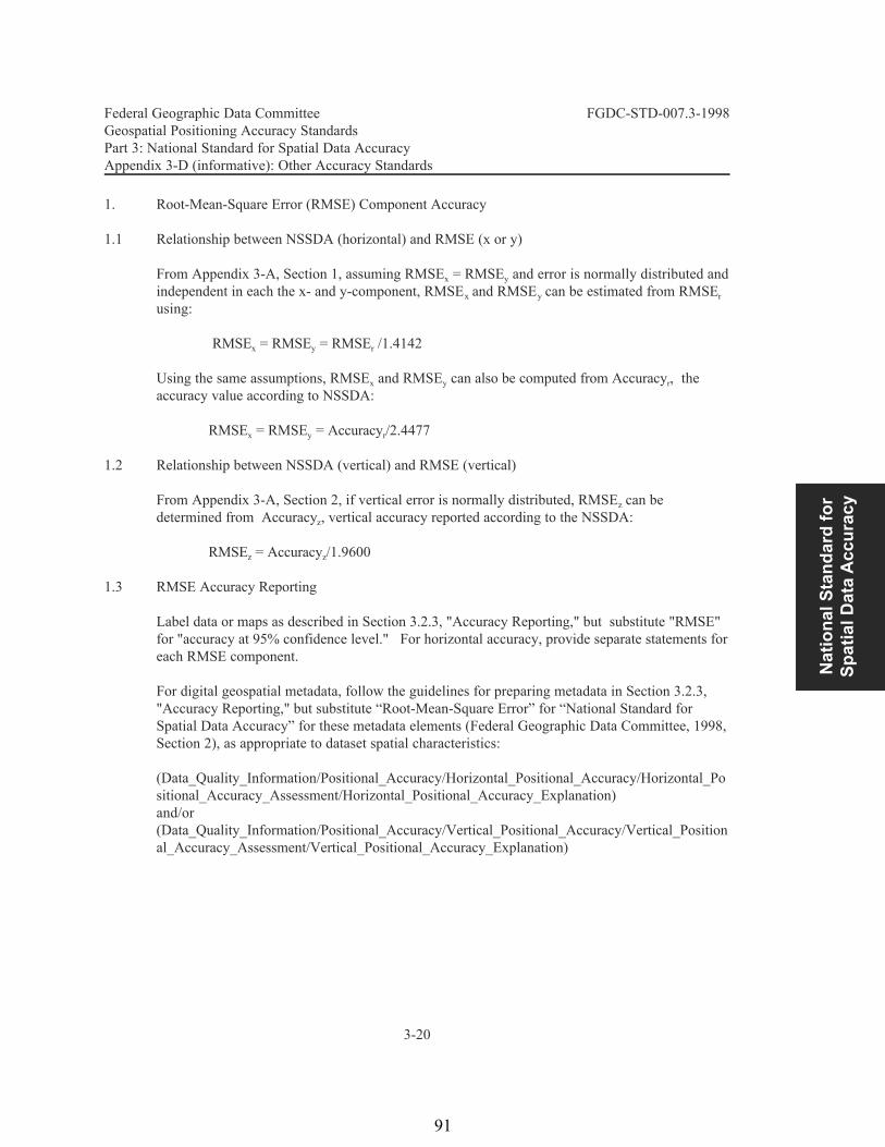
Nat
iona
l Sta
ndar
d fo
r Sp
atia
l Dat
a A
ccur
acy
Federal Geographic Data Committee FGDC-STD-007.3-1998Geospatial Positioning Accuracy StandardsPart 3: National Standard for Spatial Data AccuracyAppendix 3-D (informative): Other Accuracy Standards
3-20
1. Root-Mean-Square Error (RMSE) Component Accuracy
1.1 Relationship between NSSDA (horizontal) and RMSE (x or y)
From Appendix 3-A, Section 1, assuming RMSE = RMSE and error is normally distributed andx yindependent in each the x- and y-component, RMSE and RMSE can be estimated from RMSEx y rusing:
RMSE = RMSE = RMSE /1.4142 x y r
Using the same assumptions, RMSE and RMSE can also be computed from Accuracy , thex y raccuracy value according to NSSDA:
RMSE = RMSE = Accuracy /2.4477x y r
1.2 Relationship between NSSDA (vertical) and RMSE (vertical)
From Appendix 3-A, Section 2, if vertical error is normally distributed, RMSE can bezdetermined from Accuracy , vertical accuracy reported according to the NSSDA:z
RMSE = Accuracy /1.9600z z
1.3 RMSE Accuracy Reporting
Label data or maps as described in Section 3.2.3, "Accuracy Reporting," but substitute "RMSE"for "accuracy at 95% confidence level." For horizontal accuracy, provide separate statements foreach RMSE component.
For digital geospatial metadata, follow the guidelines for preparing metadata in Section 3.2.3,"Accuracy Reporting," but substitute “Root-Mean-Square Error” for “National Standard forSpatial Data Accuracy” for these metadata elements (Federal Geographic Data Committee, 1998,Section 2), as appropriate to dataset spatial characteristics:
(Data_Quality_Information/Positional_Accuracy/Horizontal_Positional_Accuracy/Horizontal_Positional_Accuracy_Assessment/Horizontal_Positional_Accuracy_Explanation)and/or(Data_Quality_Information/Positional_Accuracy/Vertical_Positional_Accuracy/Vertical_Positional_Accuracy_Assessment/Vertical_Positional_Accuracy_Explanation)
91
rthompson
Rectangle

Federal Geographic Data Committee FGDC-STD-007.3-1998Geospatial Positioning Accuracy StandardsPart 3: National Standard for Spatial Data AccuracyAppendix 3-D (informative): Other Accuracy Standards
3-21
2. Former National Map Accuracy Standards (NMAS)
2.1 Relationship between NSSDA and NMAS (horizontal)
NMAS (U.S. Bureau of the Budget, 1947) specifies that 90% of the well-defined points that aretested must fall within a specified tolerance:
For map scales larger than 1:20,000, the NMAS horizontal tolerance is 1/30 inch,measured at publication scale.
For map scales of 1:20,000 or smaller, the NMAS horizontal tolerance is 1/50 inch,measured at publication scale.
If error is normally distributed in each the x- and y-component and error for the x-component isequal to and independent of error for the y-component, the factor 2.146 is applied to computecircular error at the 90% confidence level (Greenwalt and Schultz, 1968). The circular mapaccuracy standard (CMAS) based on NMAS is:
CMAS = 2.1460 * RMSE = 2.1460 * RMSEx y= 2.1460 * RMSE /1.4142r= 1.5175 * RMSE r
The CMAS can be converted to accuracy reported according to NSSDA, Accuracy , usingrequations from Appendix 3-A, Section 1:
Accuracy = 2.4477/2.1460 * CMAS = 1.1406 * CMAS.r
Therefore, NMAS horizontal accuracy reported according to the NSSDA is:
1.1406* [S * (1/30")/12"] feet, or 0.0032 * S, for map scales larger than 1:20,000 1.1406* [S * (1/50")/12"] feet, or 0.0019 * S, for map scales of 1:20,000 or smaller
where S is the map scale denominator.
2.2 Relationship between NSSDA and NMAS (vertical)
NMAS (U.S. Bureau of the Budget, 1947) specifies the maximum allowable vertical tolerance tobe one half the contour interval, at all contour intervals. If vertical error is normally distributed,the factor 1.6449 is applied to compute vertical accuracy at the 90% confidence level (Greenwaltand Schultz, 1968). Therefore, the Vertical Map Accuracy Standard (VMAS) based on NMAS is estimated by the following formula:
VMAS = 1.6449 * RMSEz
92

Nat
iona
l Sta
ndar
d fo
r Sp
atia
l Dat
a A
ccur
acy
Federal Geographic Data Committee FGDC-STD-007.3-1998Geospatial Positioning Accuracy StandardsPart 3: National Standard for Spatial Data AccuracyAppendix 3-D (informative): Other Accuracy Standards
3-22
The VMAS can be converted to Accuracy , accuracy reported according to the NSSDA usingzequations from Appendix 3-A, Section 2:
Accuracy = 1.9600/1.6449 * VMAS = 1.1916 * VMAS. z
Therefore, vertical accuracy reported according to the NSSDA is (1.1916)/2 * CI = 0.5958 * CI,where CI is the contour interval.
2.3 NMAS Reporting
Map labels provide a statement of conformance with NMAS, rather than reporting the accuracyvalue. Label maps, as appropriate to dataset spatial characteristics:
This map complies with National Map Accuracy Standards of 1947 for horizontalaccuracy ORThis map complies with National Map Accuracy Standards of 1947 for vertical accuracyORThis map complies with National Map Accuracy Standards of 1947 for horizontal andvertical accuracy
For digital geospatial data evaluated by the NMAS, follow the guidelines for preparing metadatain Section 3.2.3, "Accuracy Reporting," but substitute “U.S. National Map Accuracy Standards of1947" for “National Standard for Spatial Data Accuracy” for these metadata elements (FederalGeographic Data Committee, 1998, Section 2), as appropriate to dataset spatial characteristics:
(Data_Quality_Information/Positional_Accuracy/Horizontal_Positional_Accuracy/Horizontal_Positional_Accuracy_Assessment/Horizontal_Positional_Accuracy_Explanation)and/or(Data_Quality_Information/Positional_Accuracy/Vertical_Positional_Accuracy/Vertical_Positional_Accuracy_Assessment/Vertical_Positional_Accuracy_Explanation)
3. American Society for Photogrammetry and Remote Sensing (ASPRS) Accuracy Standards forLarge-Scale Maps
3.1 Explanation of ASPRS Accuracy Standards for Large-Scale Maps
ASPRS Accuracy Standards for Large-Scale Maps (ASPRS Specifications and StandardsCommittee, 1990) provide accuracy tolerances for maps at 1:20,000-scale or larger “prepared forspecial purposes or engineering applications.” RMSE is the statistic used by the ASPRSstandards. Accuracy is reported as Class 1, Class 2, or Class 3. Class 1 accuracy for horizontaland vertical components is discussed below. Class 2 accuracy applies to maps compiled withinlimiting RMSE’s twice those allowed for Class 1 maps. Similarly, Class 3 accuracy applies to
93
rthompson
Rectangle

Federal Geographic Data Committee FGDC-STD-007.3-1998Geospatial Positioning Accuracy StandardsPart 3: National Standard for Spatial Data AccuracyAppendix 3-D (informative): Other Accuracy Standards
3-23
maps compiled within limiting RMSE’s three times those allowed for Class 1 maps.
3.2 Relationship between NSSDA and ASPRS Accuracy Standards for Large-Scale Maps(horizontal)
ASPRS Accuracy Standards for Large-Scale Maps (ASPRS Specifications and StandardsCommittee, 1990) evaluates positional accuracy for the x-component and the y-componentindividually. Positional accuracy is reported at ground scale. Table 3 shows Class 1 planimetriclimiting RMSE in feet associated with typical map scales, while Table 4 shows Class 1planimetric limiting RMSE in meters associated with typical map scales.
Table 3ASPRS Accuracy Standards for Large-Scale Maps
Class 1 horizontal (x or y) limiting RMSE for various map scalesat ground scale for feet units
Class 1 Planimetric Accuracy, Map Scalelimiting RMSE (feet)
0.05 1:60
0.1 1:120
0.2 1:240
0.3 1:360
0.4 1:480
0.5 1:600
1.0 1:1,200
2.0 1:2,400
4.0 1:4,800
5.0 1:6,000
8.0 1:9,600
10.0 1:12,000
16.7 1:20,000
94
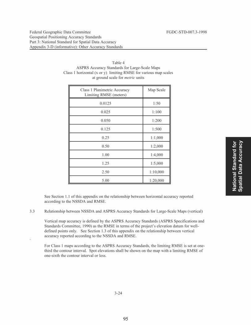
Nat
iona
l Sta
ndar
d fo
r Sp
atia
l Dat
a A
ccur
acy
Federal Geographic Data Committee FGDC-STD-007.3-1998Geospatial Positioning Accuracy StandardsPart 3: National Standard for Spatial Data AccuracyAppendix 3-D (informative): Other Accuracy Standards
3-24
Table 4ASPRS Accuracy Standards for Large-Scale Maps
Class 1 horizontal (x or y) limiting RMSE for various map scalesat ground scale for metric units
Class 1 Planimetric Accuracy Map ScaleLimiting RMSE (meters)
0.0125 1:50
0.025 1:100
0.050 1:200
0.125 1:500
0.25 1:1,000
0.50 1:2,000
1.00 1:4,000
1.25 1:5,000
2.50 1:10,000
5.00 1:20,000
See Section 1.1 of this appendix on the relationship between horizontal accuracy reportedaccording to the NSSDA and RMSE.
3.3 Relationship between NSSDA and ASPRS Accuracy Standards for Large-Scale Maps (vertical)
Vertical map accuracy is defined by the ASPRS Accuracy Standards (ASPRS Specifications andStandards Committee, 1990) as the RMSE in terms of the project’s elevation datum for well-defined points only. See Section 1.3 of this appendix on the relationship between verticalaccuracy reported according to the NSSDA and RMSE.
`For Class 1 maps according to the ASPRS Accuracy Standards, the limiting RMSE is set at one-third the contour interval. Spot elevations shall be shown on the map with a limiting RMSE ofone-sixth the contour interval or less.
95
rthompson
Rectangle

Federal Geographic Data Committee FGDC-STD-007.3-1998Geospatial Positioning Accuracy StandardsPart 3: National Standard for Spatial Data AccuracyAppendix 3-D (informative): Other Accuracy Standards
3-25
3.4 ASPRS Accuracy Standards for Large-Scale Maps Reporting
Maps evaluated according to ASPRS Accuracy Standards for Large-Scale Maps are labeled by aconformance statement, rather than a numeric accuracy value.
Label maps produced according to this standard:
THIS MAP WAS COMPILED TO MEET THE ASPRSSTANDARD FOR CLASS (1., 2., 3.) MAP ACCURACY
Label maps checked and found to confirm to this standard:
THIS MAP WAS CHECKED AND FOUND TO CONFORMTO THE ASPRS
STANDARD FOR CLASS (1., 2., 3.) MAP ACCURACY
96

Stan
dard
s fo
r A/E
/C a
nd
Faci
lity
Man
agem
ent
Federal Geographic Data Committee Department of Agriculture Department of Commerce Department of Defense Department of Energy Department of Housing and Urban Development Department of the Interior Department of State Department of Transportation Environmental Protection Agency
Federal Emergency Management Agency Library of Congress National Aeronautics and Space Administration National Archives and Records Administration
Tennessee Valley Authority
FGDC-STD-007.4-2002
Geospatial Positioning Accuracy Standards
PART 4: Standards for Architecture, Engineering, Construction (A/E/C) and Facility Management Facilities Working Group Federal Geographic Data Committee
NSDI
National Spatial Data Infrastructure
97
rthompson
Rectangle

4-ii
Federal Geographic Data Committee Established by Office of Management and Budget Circular A-16, the Federal Geographic Data Committee (FGDC) promotes the coordinated development, use, sharing, and dissemination of geographic data.
The FGDC is composed of representatives from the Departments of Agriculture, Commerce, Defense, Energy, Housing and Urban Development, the Interior, State, and Transportation; the Environmental Protection Agency; the Federal Emergency Management Agency; the Library of Congress; the National Aeronautics and Space Administration; the National Archives and Records Administration; and the Tennessee Valley Authority. Additional Federal agencies participate on FGDC subcommittees and working groups. The Department of the Interior chairs the committee. FGDC subcommittees work on issues related to data categories coordinated under the circular. Subcommittees establish and implement standards for data content, quality, and transfer; encourage the exchange of information and the transfer of data; and organize the collection of geographic data to reduce duplication of effort. Working groups are established for issues that transcend data categories.
For more information about the committee, or to be added to the committee's newsletter mailing list, please contact:
Federal Geographic Data Committee Secretariat
c/o U.S. Geological Survey 590 National Center
Reston, Virginia 22092
Telephone: (703) 648-5514 Facsimile: (703) 648-5755
Internet (electronic mail): [email protected] Anonymous FTP: ftp://fgdc.er.usgs.gov/pub/gdc/
World Wide Web: http://fgdc.er.usgs.gov/fgdc.html
98
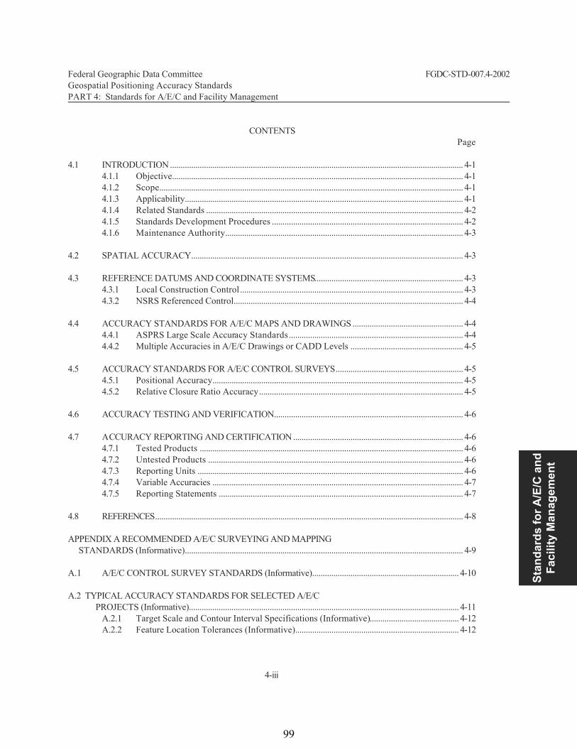
Stan
dard
s fo
r A/E
/C a
nd
Faci
lity
Man
agem
ent
Federal Geographic Data Committee FGDC-STD-007.4-2002 Geospatial Positioning Accuracy Standards PART 4: Standards for A/E/C and Facility Management
4-iii
CONTENTS Page 4.1 INTRODUCTION .......................................................................................................................................... 4-1
4.1.1 Objective......................................................................................................................................... 4-1 4.1.2 Scope............................................................................................................................................... 4-1 4.1.3 Applicability................................................................................................................................... 4-1 4.1.4 Related Standards ......................................................................................................................... 4-2 4.1.5 Standards Development Procedures .......................................................................................... 4-2 4.1.6 Maintenance Authority................................................................................................................ 4-3
4.2 SPATIAL ACCURACY................................................................................................................................ 4-3 4.3 REFERENCE DATUMS AND COORDINATE SYSTEMS...................................................................... 4-3
4.3.1 Local Construction Control......................................................................................................... 4-3 4.3.2 NSRS Referenced Control............................................................................................................ 4-4
4.4 ACCURACY STANDARDS FOR A/E/C MAPS AND DRAWINGS .................................................... 4-4
4.4.1 ASPRS Large Scale Accuracy Standards.................................................................................. 4-4 4.4.2 Multiple Accuracies in A/E/C Drawings or CADD Levels ..................................................... 4-5
4.5 ACCURACY STANDARDS FOR A/E/C CONTROL SURVEYS............................................................ 4-5
4.5.1 Positional Accuracy...................................................................................................................... 4-5 4.5.2 Relative Closure Ratio Accuracy................................................................................................ 4-5
4.6 ACCURACY TESTING AND VERIFICATION......................................................................................... 4-6 4.7 ACCURACY REPORTING AND CERTIFICATION................................................................................ 4-6
4.7.1 Tested Products ............................................................................................................................ 4-6 4.7.2 Untested Products ........................................................................................................................ 4-6 4.7.3 Reporting Units ............................................................................................................................. 4-6 4.7.4 Variable Accuracies ...................................................................................................................... 4-7 4.7.5 Reporting Statements ................................................................................................................... 4-7
4.8 REFERENCES................................................................................................................................................. 4-8 APPENDIX A RECOMMENDED A/E/C SURVEYING AND MAPPING STANDARDS (Informative)................................................................................................................................... 4-9 A.1 A/E/C CONTROL SURVEY STANDARDS (Informative)..................................................................... 4-10 A.2 TYPICAL ACCURACY STANDARDS FOR SELECTED A/E/C PROJECTS (Informative)............................................................................................................................... 4-11
A.2.1 Target Scale and Contour Interval Specifications (Informative).......................................... 4-12 A.2.2 Feature Location Tolerances (Informative)............................................................................. 4-12
99
rthompson
Rectangle

Federal Geographic Data Committee FGDC-STD-007.4-2002 Geospatial Positioning Accuracy Standards PART 4: Standards for A/E/C and Facility Management
4-iv
A.3 A/E/C TOPOGRAPHIC SURVEYS AND CONSTRUCTION SITE PLANS (Informative)................ 4-13
A.3.1 Reconnaissance Topographic Surveys (Informative)........................................................... 4-13 A.3.2 General/Preliminary Site Plans................................................................................................... 4-13 A.3.3 Detailed Topographic Surveys for Construction Plans ........................................................ 4-13 A.3.4 As-Built Surveys and AM/FM Mapping................................................................................ 4-13
TABLES A-1 Minimum Closure Standards for Engineering and Construction Control Surveys........................... 4-11 A-2 Minimum Elevation Closure Standards for Vertical Control Surveys ................................................. 4-11 A-3 Recommended Surveying and Mapping Accuracy-- Engineering, Construction,
and Facility Operation and Maintenance Projects ................................................................ 4-14
100

Stan
dard
s fo
r A/E
/C a
nd
Faci
lity
Man
agem
ent
Federal Geographic Data Committee FGDC-STD-007.4-2002 Geospatial Positioning Accuracy Standards PART 4: Standards for A/E/C and Facility Management
4-1
4.1 INTRODUCTION 4.1.1 Objective
PART 4 provides accuracy standards for engineering drawings, maps, and surveys used to support planning, design, construction, operation, maintenance, and management of facilities, installations, structures, transportation systems, and related projects. It is intended to support geospatial mapping data used in various engineering documents, such as architectural, engi-neering, and construction (A/E/C) drawings, site plans, regional master planning maps, and related Geographical Information System (GIS), Computer-Aided Drafting and Design (CADD), and Automated Mapping/Facility Management (AM/FM) products. These products are typically created from terrestrial, satellite, acoustic, or aerial mapping techniques that output planimetric, topographic, hydrographic, or feature attribute data.
4.1.2 Scope
This standard defines accuracy criteria, accuracy testing methodology, and accuracy reporting criteria for object features depicted on A/E/C spatial data products and related control surveys. It references established voluntary standards that may be used for some smaller-scale A/E/C mapping applications. In addition, Appendix A contains general guidance for specifying accuracy criteria for selected types of A/E/C features or control surveys. Using the standards and guidance contained in this section, end users of A/E/C products (e.g., planners, designers, constructors) can specify surveying and mapping accuracy requirements needed for their projects or specific CADD/GIS layers, levels, or entities. From these specifications, data producers (e.g., surveyors, mappers, photogrammetrists) can determine the instrumentation, procedures, and quality control processes required to obtain and verify the defined accuracies.
4.1.3 Applicability
These standards are applicable to geospatial data products used on various A/E/C or facilities management projects. A/E/C projects are normally confined to small geographical areas typically less than 4,000 ha (10,000 acres) where simple survey techniques are employed to establish project control points, perform topographic or photogrammetric mapping, or provide construction layout and alignment control. Unlike geospatial map products covered under PART 3, A/E/C data products are often only locally referenced within a project site, may not contain absolute georeferenced coordinates, and are typically compiled at scales larger than 1:20,000 (1 in = 1,667 ft). These standards may apply to the following types of engineering applications: transportation systems (roads, railroads, airfields, canals); utility systems (water supply, sanitary sewer, fuel, communication, electrical, mechanical); residential, commercial, recreational, and industrial struc-tures and facilities; flood control and navigation systems (dams, levees, locks); architectural site or landscape plans; engineering master planning studies; environmental mapping, modeling, and assessment studies; hydraulic and hydrological studies; geophysical exploration surveys; and construction measurement and payment surveys. These standards do not generally apply to -architectural, mechanical, or electrical detail data inside of a building or structure that are typically used with a CADD system for engineering and design.
101
rthompson
Rectangle

Federal Geographic Data Committee FGDC-STD-007.4-2002 Geospatial Positioning Accuracy Standards PART 4: Standards for A/E/C and Facility Management
4-2
4.1.4 Related Standards
This standard was largely taken from existing U.S. Army Corps of Engineers engineering, surveying, and mapping standards, and from Department of Defense Tri-Service Facility Engineering CADD/GIS standards--see References. The American Society for Photogrammetry and Remote Sensing (ASPRS) “Accuracy Standards for Large-Scale Maps” outlined in PART 3, Appendix B, also is directly applicable to PART 4--see paragraph 4.4.1 for specific relationships between ASPRS and Part 4.
This PART 4 may be used in conjunction with, or independent of, other Parts of the overall Geospatial Positioning Accuracy Standard.
PART 1 Reporting Methodology applies directly to this Part, in particular, accuracy standard reporting. Certain portions of Part 2, Standards for Geodetic Networks, apply to A/E/C projects or features within an A/E/C project that are connected by control surveys to an established regional geodetic control network (i.e., geo-referenced). PART 2 does not apply to engineering, construction, topographic, or photogrammetric mapping surveys that are referenced to boundary control or physical features (streets, structures, etc.) within, or adjacent, to the project site. If A/E/C projects, or sub features within a project, are connected by control surveys to an established regional geodetic control network (i.e., geo-referenced), then certain portions of PART 2 may be applicable.
PART 3, National Standard for Spatial Data Accuracy, applies to those A/E/C map products that are fully geo-referenced. The spatial accuracy definitions, accuracy testing, and accuracy reporting criteria in PART 3 may be used for georeferenced A/E/C map products. PART 4 applies to engineering drawings, maps, and surveys used to support planning, design, construction, operation, maintenance, and management of facilities, installations, structures, transportation systems, and related projects. Part 4 also applies to marine construction and dredging of navigation channels, including related hydrographic surveying support. PART 5 should be consulted for hydrographic surveying standards applicable to preparation of nautical charts.
4.1.5 Standards Development Procedures
This standard was developed and periodically reviewed by the FGDC Facilities Working Group during the period 1996-1998. The initial draft of the standard was taken from U.S. Army Corps of Engineers Engineer Circular 1110-1-87, Standards for Maps, Drawings, Engineering Surveys, Construction Site Plans, and Related Geospatial Data Products.
102
Stan
dard
s fo
r A/E
/C a
nd
Faci
lity
Man
agem
ent
Federal Geographic Data Committee FGDC-STD-007.4-2002 Geospatial Positioning Accuracy Standards PART 4: Standards for A/E/C and Facility Management
4-3
4.1.6 Maintenance Authority
The U.S. Army Corps of Engineers is responsible for developing and maintaining the A/E/C geospatial positional accuracy data standards for the Facilities Working Group of the Federal Geo-graphic Data Committee. Address questions concerning the standards to: Headquarters, U.S. Army Corps of Engineers, ATTN: CECW-EP, 20 Massachusetts Avenue NW, Washington, D.C. 20314-1000.
4.2 SPATIAL ACCURACY
As defined in PART 1, horizontal spatial accuracy is the circular error of a data set's horizontal coordinates at the 95% confidence level. Vertical spatial accuracy is defined by the linear error of a data set's vertical coordinates at the 95% confidence level. A spatial data set may include CADD/GIS object features, such as points, lines, areas, volumes. Accuracy reported at the 95% confidence level means that 95% of positional accuracies will be equal to or smaller than the reported accuracy value. The reported accuracy value is the cumulative result of all uncertainties, including those introduced by local project control coordinates, field topographic surveys, photogrammetric compilation, or final extraction of ground coordinate values in the spatial data. The reference scheme for radial or linear errors must be defined as relative to absolute geospatial reference networks or local (internal construction) schemes. Spatial data may be compiled to comply with one level of accuracy in the vertical component and another in the horizontal component.
4.3 REFERENCE DATUMS AND COORDINATE SYSTEMS
A/E/C projects should be referenced to local boundary control, spatial datums, plane coordinate grids, or vertical reference planes commonly used in the project area. Where practical and feasible, A/E/C projects should be referenced to national coordinate systems: horizontal coordinates should be in a system (e.g., State Plane Coordinate System, Universal Transverse Mercator Grid) based upon the North American Datum of 1927 (NAD 27) or North American Datum of 1983 (NAD 83), and vertical coordinates should be based on the National Geodetic Vertical Datum of 1929 (NGVD 29) or the North American Vertical Datum of 1988 (NAVD 88)--see PART 2. In most instances, however, A/E/C projects are not referenced to geodetic datums but are accurately tied into existing project or boundary control schemes relevant to the work. Reference datums and coordinate systems used shall be clearly identified in reporting A/E/C project data sets--see PART 1.
4.3.1 Local Construction Control
Projects that are not referenced to national coordinate systems based on geodetic datums shall be classified and reported as having a local reference or construction control system--local X-Y grid, chainage-offset, local reference benchmark elevation, etc. Accuracies of spatial data points are determined, reported, and certified relative to this local construction control scheme. If the
103
rthompson
Rectangle
Federal Geographic Data Committee FGDC-STD-007.4-2002 Geospatial Positioning Accuracy Standards PART 4: Standards for A/E/C and Facility Management
4-4
relationship between the local coordinate system and a National coordinate system is known, describe the relationship between the two systems. If the relationship between the local coordinate system and a National coordinate system is unknown, identify the local coordinate system but state that the relationship in "UNKNOWN"--see PART 1.
4.3.2 NSRS Referenced Control
Accuracies of A/E/C data set coordinates that are referenced to a National coordinate system are determined and reported relative to NSRS accuracies.
4.4 ACCURACY STANDARDS FOR A/E/C MAPS AND DRAWINGS
A/E/C drawings and related spatial data sets may have accuracy standards specified relative to (1) a required performance standard based on detailed project requirements, or (2) an establis hed standard such as National Map Accuracy Standard (NMAS) or ASPRS. Typically, detailed site plan drawings at scales as large as 1:360 (1 in = 30 ft) have acceptable quality levels relative to critical construction specifications (e.g., required accuracy of invert elevations, road/curb grades, building locations, etc.). Preliminary planning or reconnaissance maps at smaller scales typically use general industry standards, such as ASPRS, NMAS, etc. Both types of standards may be specified for portions of CADD levels on the same project. Accuracy is evaluated and reported based on intended field data acquisition methodology or independent tests. For most A/E/C mapping, performance-based (outcome-based) specifications detail the end results to be achieved (i.e., map feature accuracy or accuracy standard) and not the means, or technical procedures, used to achieve those results. Performance specifications define the required accuracy criteria standards for each feature, object, class, layer, level, etc. of topographic and planimetric features depicted, along with related mapping limits, feature location and attribute requirements, scale, contour interval, map format, sheet layout, final data transmittal, archiving or storage requirements, and quality assurance procedures that will be used to verify conformance with the specified accuracy. Table A-3 in Appendix A provides examples of accuracy specifications commonly used for various types of A/E/C projects.
4.4.1 ASPRS Large-Scale Accuracy Standards
For generalized A/E/C site mapping work at scales from 1:2,400 (1 in = 200 ft) to 1:20,000 (1 in = 1,667 ft), the ASPRS "Accuracy Standards for Large-Scale Maps" may be used as a reference accuracy standard. The ASPRS accuracy standard is linearly dependent on the target horizontal scale or target contour interval; thus it is only applicable to mapped features that are compiled using a consistent type of data acquisition process (e.g., photogrammetry) where all spatial objects receive approximately the same accuracy. The ASPRS standard may not be especially applicable to detailed CADD/GIS features at larger scales down to 1:240 (1 in. = 20 ft) where CADD/GIS accuracies are usually project dependent, not scale dependent, and where accuracy standards are best defined based on project needs. As described in PART 3, the ASPRS standard defines map accuracy by comparing the mapped location of selected well-defined points to their "true" location, as determined by a more accurate, independent field survey. Alternately, when no independent
104

Stan
dard
s fo
r A/E
/C a
nd
Faci
lity
Man
agem
ent
Federal Geographic Data Committee FGDC-STD-007.4-2002 Geospatial Positioning Accuracy Standards PART 4: Standards for A/E/C and Facility Management
4-5
check is feasible or practicable, a map's accuracy may be estimated based on the accuracy of the technique used to locate mapped features--e.g., photogrammetry, GPS, total station, planetable. The ASPRS standard may be specified for site plans that are developed using conventional ground topographic surveying techniques (i.e., electronic total stations, planetables, kinematic DGPS).
4.4.2 Multiple Accuracies in A/E/C Drawings or CADD Levels 4.4.2.1 Horizontal and Vertical Accuracies
Spatial data may have different accuracies in the horizontal and vertical components. 4.4.2.2 A/E/C CADD/GIS Feature Layer/Level Accuracies
A/E/C data is often separated into various layers or levels in CADD/GIS systems. For example, planimetric features, utility invert elevations, and topographic elevations are often separated into three different levels or layers. These layers often contain objects or geographic areas that were surveyed/compiled to widely differing accuracies--e.g., utility invert elevations accurate to 0.05 ft versus topographic contours accurate to only 5 ft . If readily available, useful, and practical, these variable accuracies may be retained as an attribute to the layer or feature. In addition, accuracy information about these layers or features should be recorded in the accuracy section of the metadata for this database.
4.5 ACCURACY STANDARDS FOR A/E/C CONTROL SURVEYS
Control surveys are performed to locate, align, and stake out construction for civil and military pro-jects, e.g., buildings, utilities, roadways, runways, flood control and navigation projects, training ranges, etc. They provide the base horizontal and vertical control used for preliminary studies, photogrammetric and topographic mapping, detailed site plan drawings for construction plans, construction stake out, construction measurement and payment, preparing as-built drawings, installation master planning mapping, and future maintenance and repair activities. Two types of survey accuracies may be specified: (1) Positional accuracy or (2) Relative closure ratio accuracy. PART 2 geodetic survey accuracy standards are not applicable to locally referenced A/E/C projects covered under this PART 4 standard.
4.5.1 Positional Accuracy
Base control surveys should be performed to a 95% positional confidence level consistent with the engineering or construction application or specifications. In general, horizontal and vertical control point accuracies should be twice as accurate as positional or elevation tolerances required for features or objects on the site plans or maps. Determination and verification of 95% radial positional accuracies will require use of rigorous least-squares adjustment techniques similar to that required under PART 2.
105
rthompson
Rectangle

Federal Geographic Data Committee FGDC-STD-007.4-2002 Geospatial Positioning Accuracy Standards PART 4: Standards for A/E/C and Facility Management
4-6
4.5.2 Relative Closure Ratio Accuracy
The accuracy of A/E/C control surveys may be evaluated, classified, and reported based on closure ratios for the horizontal point or the vertical elevation difference, as obtained in the field when points or benchmarks are redundantly occupied. This relative accuracy standard is appli-cable to most types of survey equipment and practices (e.g., total station traverses, differential GPS, differential spirit leveling). Many state codes and/or state minimum technical standards require that accuracies of A/E/C surveys be evaluated and reported using survey closure ratios. Tables A-1 and A-2 in Appendix A contain orders of closure commonly specified in A/E/C work. There is no simple correlation between relative closure accuracies and 95% radial positional accuracies; thus, determining a closure order based on a specified feature accuracy requirement is, at best, only an approximate process (see guidance in Appendix A). Where practical and allowable, positional accuracy standards should be used instead of closure accuracy standards.
4.6 ACCURACY TESTING AND VERIFICATION
Project specifications will specify the geographic extent of data to be tested and the amount of testing (if any). Map testing should be performed within a fixed time period after delivery. Normally, a mapping organization will perform quality control tests under quality assurance oversight by the requesting agency. Accuracies of A/E/C features are reported at the 95% confidence level. Field observed X, Y or Z coordinate differences are converted to 95% confidence errors following the procedures outlined in PART 3. Horizontal accuracy is tested by comparing the planimetric coordinates of well-defined ground points with coordinates of the same points from an independent source of higher accuracy, following the methodology outlined under PART 3. Vertical accuracy is tested by comparing the elevations of well-defined points with elevations of the same points as determined from a source of higher accuracy, also following the methodology outlined in PART 3. Both ground surface topography and object elevations may be tested.
4.7 ACCURACY REPORTING AND CERTIFICATION 4.7.1 Tested Products
Maps, surveys, and related geospatial data that are tested and found to comply with a specified standard shall have a certification statement. If applicable, the statement shall clearly indicate the target map scale at which the map or feature layer was developed.
4.7.2 Untested Products
Due to the high cost of field testing, not all deliverable map products will be tested. In such cases, the statement shall clearly indicate that the procedural ground surveying or aerial mapping specifi-cations were designed and performed to meet a certain accuracy standard (project dependent, ASPRS, NMAS, etc.), but that the accuracy is estimated. An estimated accuracy statement is espe-cially applicable to CADD, GIS, or FM databases that may be compiled from a variety of sources containing known or unknown accuracy reliability.
106

Stan
dard
s fo
r A/E
/C a
nd
Faci
lity
Man
agem
ent
Federal Geographic Data Committee FGDC-STD-007.4-2002 Geospatial Positioning Accuracy Standards PART 4: Standards for A/E/C and Facility Management
4-7
4.7.3 Reporting Units
Report accuracy of A/E/C spatial data in ground units using either metric (SI) units or English (IP) units, consistent with the project units.
4.7.4 Variable Accuracies
Report varying accuracies in the same spatial data set if information exists that relates accuracy to individual portions/objects of the data set, and only if such detailed sub-feature data set reporting is practical and warranted. If data of varying accuracies are composited and cannot be separately identified AND the data set is tested, report the accuracy value for the composited data. If a composited data set is not tested, report the accuracy value for the least accurate data set component.
4.7.5 Reporting Statements
Report tested and non-tested accuracies following general guidance provided in PART 3 (Accuracy Reporting).
107
rthompson
Rectangle

Federal Geographic Data Committee FGDC-STD-007.4-2002 Geospatial Positioning Accuracy Standards PART 4: Standards for A/E/C and Facility Management
4-8
4.8 REFERENCES
American Society for Photogrammetry and Remote Sensing (ASPRS) Specifications and Standards Committee, 1990, ASPRS Accuracy Standards for Large-Scale Maps: Photogrammetric Engineering and Remote Sensing, v. 56, no. 7, p. 1,068-1,070.
Federal Geographic Data Committee, Part 1, Reporting Methodology, Geospatial Positioning Accuracy Standards, FGDC-STD-0007.1-1998, Washington, D.C., 1998.
Federal Geographic Data Committee, Part 2., Standards for Geodetic Networks, Geospatial Positioning Accuracy Standards, FGDC-STD-007.2-1998: Washington, D.C., 1998.
Federal Geographic Data Committee, Part 3., National Standard for Spatial Data Accuracy, Geospatial Positioning Accuracy Standards, FGDC-STD-007.3-1998: Washington, D.C., 1998.
U.S. Army Corps of Engineers, Engineer Circular 1110-1-87, Standards for Maps, Drawings, Engineering Surveys, Construction Site Plans, and Related Geospatial Data Products, 1 July 1996.
U.S. Department of Defense, Tri-Service CADD/GIS Technology Center, Tri-Service A/E/C CADD Standards and Spatial Data Standards, (latest version at <http://tsc.wes.army.mil>)
108

Stan
dard
s fo
r A/E
/C a
nd
Faci
lity
Man
agem
ent
Federal Ge ographic Data Committee FGDC-STD-007.4-2002 Geospatial Positioning Accuracy Standards PART 4: Standards for A/E/C and Facility Management APPENDIX A Recommended A/E/C Surveying and Mapping Standards
4-9
APPENDIX A
RECOMMENDED A/E/C SURVEYING AND MAPPING STANDARDS
(Informative)
109
rthompson
Rectangle

Federal Ge ographic Data Committee FGDC-STD-007.4-2002 Geospatial Positioning Accuracy Standards PART 4: Standards for A/E/C and Facility Management APPENDIX A Recommended A/E/C Surveying and Mapping Standards
4-10
A.1 A/E/C CONTROL SURVEY STANDARDS Engineering and construction surveys are normally specified, classified, and reported based on the horizontal (linear) point closure ratios or the vertical elevation difference closures. This perfor-mance criterion is most commonly specified in Federal agency, State, and local surveying standards. These control surveys are performed to establish control, location, alignment, and grad-e of various types of construction. Local accuracy standards for survey control will vary with the type of construction. Commonly specified and reported Orders of horizontal closure accuracy standards are shown in Table A-1. Relative accuracy closure ratios for horizontal A/E/C surveys typically range from a minimum of 1:2,500 up to 1:20,000. Lower accuracies (1:2,500-1:5,000) are acceptable for earthwork, dredging, embankment, beach fill, and levee alignment stakeout and grading, and some site plan, curb and gutter, utility building foundation, sidewalk, and small roadway stakeout. Moderate accuracies (1:5,000) are used in most pipeline, sewer, culvert, catch basin, and manhole stakeouts, and for general residential building foundation and footing construction, major highway pavement, bridges, and concrete runway stakeout work. Somewhat higher accuracies (1:10,000-1:20,000) are used for aligning longer bridge spans, tunnels, and large commercial structures. For extensive bridge or tunnel projects, 1:50,000 or even 1:100,000 relative accuracy alignment work may be specified. Orders of elevation closure ratio standards are shown in Table A-2. Most construction work is performed to Third-Order standards. These standards are applicable to most types of engineering and construction survey equipment and practices (e.g., total station traverses, differential GPS, differential spirit leveling).
110

Stan
dard
s fo
r A/E
/C a
nd
Faci
lity
Man
agem
ent
Federal Ge ographic Data Committee FGDC-STD-007.4-2002 Geospatial Positioning Accuracy Standards PART 4: Standards for A/E/C and Facility Management APPENDIX A Recommended A/E/C Surveying and Mapping Standards
4-11
Table A-1Minimum Closure Standards for Engineeringand Construction Control Surveys Classification Order Closure Standard Engr & Const Distance Angle Control (Ratio) (Secs) Second-Order, Class I 1:50,000 3oN 1
Second-Order, Class II 1:20,000 5oN
Third-Order, Class I 1:10,000 10oN
Third-Order, Class II 1: 5,000 20oN
Construction 1: 2,500 60oN (Fourth-Order) 1 N = Number of angle stations
Table A-2Minimum Elevation Closure Standards forVertical Control Surveys
Elevation Closure Standard Classification Order (ft)1 (mm) First-Order, Class I 0.013oM 3oK
First-Order, Class II 0.017oM 4oK
Second-Order, Class I 0.025oM 6oK
Second-Order, Class II 0.035oM
8oK
Third-Order 0.050oM 12oK
Construction Layout 0.100oM 24oK 1 oM or oK = square root of distance in Miles or Kilometers A.2 TYPICAL ACCURACY STANDARDS FOR SELECTED A/E/C PROJECTS
General guidance for determining project-specific mapping accuracy standards is contained in Table A-3 at the end of this Appendix. This table may be used in developing specifications for map scales, feature location and elevation tolerances, and contour intervals for typical A/E/C projects. Since Table A-3 is based on current industry practices (and primarily those used by the Corps of Engineers), the scales and corresponding 95% positional tolerances shown in this table will differ from the ASPRS positional or elevation accuracy standards. Where available, project-
111
rthompson
Rectangle

Federal Ge ographic Data Committee FGDC-STD-007.4-2002 Geospatial Positioning Accuracy Standards PART 4: Standards for A/E/C and Facility Management APPENDIX A Recommended A/E/C Surveying and Mapping Standards
4-12
specific accuracy standards should be used rather than generic standards such as ASPRS. Metric (SI) conversions from IP units are only approximate since standardized use of SI units is still under development.
A.2.1 Target Scale and Contour Interval Specifications
Table A-3 provides commonly used map scales and contour intervals for a variety of A/E/C ap-plications. The selected target scale for a map or construction plan should be based on the detail necessary to portray the project site. Topographic elevation density or related contour intervals are specified consis tent with existing site gradients and the accuracy needed to define site layout, drainage, grading, etc., or perform quantity take offs. Photogrammetric mapping flight altitudes or ground topographic survey accuracy and density requirements are determined from the design map target scale and contour interval. In practice, design or real property features are located or layed out during construction to a far greater relative accuracy than that which can be scaled at the target (plot) scale, such as property corners, utility alignments, first-floor or invert elevations, etc. Coordinates/elevations for such items are usually directly input as feature attributes in a CADD or AM/FM database.
A.2.2 Feature Location Tolerances
Table A-3 indicates recommended positional and elevation tolerances of planimetric features at the 95% confidence level. These tolerances define the primary topographic mapping effort necessary to delineate physical features on the ground. A/E/C feature tolerances are defined relative to adja-cent points within the confines of a specific area, map sheet, or structure--not to the overall project, installation boundaries, or an external geodetic control network. These relative accuracy tolerances are determined between two points that must functionally maintain a given accuracy tolerance be-tween themselves, such as adjacent property corners; adjacent utility lines; adjoining buildings, bridge piers, approaches, or abutments; overall building or structure site construction limits; runway ends; catch basins; levee baseline sections; etc. Feature tolerances indicated are determined from the functional requirements of a typical project/structure (e.g., field construc-tion/fabrication, field stakeout or layout, alignment, etc.). Few A/E/C projects require that relative accuracies be rigidly maintained beyond the range of the detailed design drawing for a pro-ject/structure (or its equivalent CADD design file limit). In many instances, a construction feature may need to be located to an accuracy well in excess of its plotted/scaled accuracy on a con-struction site plan; therefore, feature location tolerances should not be used to determine the re-quired scale of a drawing. In these instances, surveyed coordinates, internal CADD grid coordi-nates, or rigid relative dimensions are used.
112

Stan
dard
s fo
r A/E
/C a
nd
Faci
lity
Man
agem
ent
Federal Ge ographic Data Committee FGDC-STD-007.4-2002 Geospatial Positioning Accuracy Standards PART 4: Standards for A/E/C and Facility Management APPENDIX A Recommended A/E/C Surveying and Mapping Standards
4-13
A.3 A/E/C TOPOGRAPHIC SURVEYS AND CONSTRUCTION SITE PLANS
Topographic surveys and construction site plan surveys are performed for the master planning, de-sign, and construction of installations, buildings, housing complexes, roadways, airport facilities, flood control structures, navigation locks, etc. Construction plans are developed using elec-tronic/DGPS total stations, plane tables, or low-altitude photogrammetric mapping methods. Some of the more common surveys are described below:
A.3.1 Reconnaissance Topographic Surveys
Reconnaissance surveys are typically performed at scales from 1:4,800 (1 in = 400 ft) to 1:12,000 (1 in = 1,000 ft). They provide a basis for general studies, site suitability decisions, or preliminary site layouts. General location of existing roads and facilities are depicted, and only limited feature and rough elevation detail is shown – 5- to 10-foot contour intervals usually being adequate. Enlarged USGS 1:24,000 maps may be substituted in many cases.
A.3.2 General/Preliminary Site Plans.
General or Preliminary site plans are performed at scales from 1:2,400 (1 in = 200 ft) to 1:4,800 (1 in = 400 ft). They depict general layout for potential construction, proposed transportation systems, training areas, and existing facilities.
A.3.3 Detailed Topographic Surveys for Construction Plans
These surveys are performed at scales from 1:240 (1 in = 20 ft) to 1:2,400 (1 in = 200 ft) and at contour intervals of 0.2 m or 0.5 m (1 or 2 ft). They are performed to prepare a base map for detailed site plans (general site layout plan, utility plan, grading plan, paving plan, airfield plan, demolition plan, etc.). The scope of mapping is confined to an existing/proposed building area. These drawings are used as a base for subsequent as-built drawings of facilities and utility layout maps (i.e., AM/FM databases).
A.3.4 As-Built Surveys and AM/FM Mapping
As-built drawings may require topographic surveys of constructed features, especially when field modifications are made to original designs. These surveys, along with original construction site plans, should be used as a base framework for a facility's AM/FM database. Periodic topographic surveys also may be required during maintenance and repair projects in order to update the AM/FM database.
113
rthompson
Rectangle

Federal Ge ographic Data Committee FGDC-STD-007.4-2002 Geospatial Positioning Accuracy Standards PART 4: Standards for A/E/C and Facility Management APPENDIX A Recommended A/E/C Surveying and Mapping Standards
4-14
Table A-3. RECOMMENDED ACCURACIES AND TOLERANCES:ENGINEERING, CONSTRUCTION, AND FACILITY MANAGEMENT PROJECTS
Target Feature Position Tolerance Contour Map Scale Horizontal Vertical Interval
Project or Activity SI/IP SI/IP SI/IP SI/IP DESIGN, CONSTRUCTION, OPERATION & MAINTENANCE OF MILITARY FACILITIES Maintenance and Repair (M&R)/Renovation of Existing Installation Structures, Roadways, Utilities, Etc General Construction Site Plans & Specs: 1:500 100 mm 50 mm 250 mm Feature & Topographic Detail Plans 40 ft/in 0.1-0.5 ft 0.1-0.3 ft 1 ft
Surface/subsurface Utility Detail Design Plans 1:500 100 mm 50 mm N/A Elec, Mech, Sewer, Storm, etc 40 ft/in 0.2-0.5 ft 0.1-0.2 ft Field construction layout 0.1 ft 0.01-0.1 ft Building or Structure Design Drawings 1:500 25 mm 50 mm 250 mm
40 ft/in 0.05-0.2 ft 0.1-0.3 ft 1 ft Field construction layout 0.01 ft 0.01 ft Airfield Pavement Design Detail Drawings 1:500 25 mm 25 mm 250 mm
40 ft/in 0.05-0.1 ft 0.05-0.1 ft 0.5-1 ft Field construction layout 0.01 ft 0.01 ft Grading and Excavation Plans 1:500 250 mm 100 mm 500 mm Roads, Drainage, Curb, Gutter etc. 30-100 ft/in 0.5-2 ft 0.2-1 ft 1-2 ft Field construction layout 1 ft 0.1 ft Recreational Site Plans 1:1,000 500 mm 100 mm 500 mm Golf courses, athletic fields, etc. 100 ft/in 1-2 ft 0.2-2 ft 2-5 ft Training Sites, Ranges, and 1:2,500 500 mm 1,000 mm 500 mm Cantonment Area Plans 100-200 ft/in 1-5 ft 1-5 ft 2 ft General Location Maps for Master Planning 1:5,000 1,000 mm 1,000 mm 1,000 mm AM/FM and GIS Features 100-400 ft/in 2-10 ft 1-10 ft 2-10 ft Space Management Plans 1:250 50 mm N/A N/A Interior Design/Layout 10-50 ft/in 0.05-1 ft As-Built Maps: Military Installation 100 mm 100 mm 250 mm Surface/Subsurface Utilities (Fuel, Gas, 0.2-1 ft 0.2 ft 1 ft Electricity, Communications, Cable,
114

Stan
dard
s fo
r A/E
/C a
nd
Faci
lity
Man
agem
ent
Federal Ge ographic Data Committee FGDC-STD-007.4-2002 Geospatial Positioning Accuracy Standards PART 4: Standards for A/E/C and Facility Management APPENDIX A Recommended A/E/C Surveying and Mapping Standards
4-15
Table A-3 (Contd). RECOMMENDED ACCURACIES AND TOLERANCES:ENGINEERING, CONSTRUCTION, AND FACILITY MANAGEMENT PROJECTS
Target Feature Position Tolerance ContourMap Scale Horizontal Vertical Interval
Project or Activity SI/IP SI/IP SI/IP SI/IP
Storm Water, Sanitary, Water Supply, 1:1000 or 50-100 ft/in (Army) Treatment Facilities, Meters, etc.) 1:500 or 50 ft/in (USAF)
Housing Management GIS (Family Housing, 1:5,000 10,000 mm N/A N/A Schools, Boundaries, and Other Installation 100-400 ft/in 10-15 ft Community Services) Environmental Mapping and Assessment 1:5,000 10,000 mm N/A N/A Drawings/Plans/GIS 200-400 ft/in 10-50 ft Emergency Services Maps/GIS 1:10,000 25,000 mm N/A N/A Military Police, Crime/Accident Locations, 400-2000 ft/in 50-100 ft Post Security Zoning, etc. Cultural, Social, Historical Plans/GIS 1:5000 10,000 mm N/A N/A 400 ft/in 20-100 ft Runway Approach and Transition Zones: 1:2,500 2,500 mm 2,500 mm 1,000 mm General Plans/Section 100-200 ft/in 5-10 ft 2-5 ft 5 ft Approach maps 1:5,000 (H) 1:1,000 (V) Approach detail 1:5,000 (H) 1:250 (V) DESIGN, CONSTRUCTION, OPERATIONS AND MAINTENANCE OF CIVIL
TRANSPORTATION & WATER RESOURCE PROJECTS Site Plans, Maps & Drawings for Design Studies, Reports, Memoranda, and Contract Plans and Specifications, Construction plans & payment
General Planning and Feasibility Studies, 1:2,500 1,000 mm 500 mm 1,000 mmReconnaissance Reports 100-400 ft/in 2-10 ft 0.5-2 ft 2-10 ft Flood Control and MultipurposeProject Planning, Floodplain Mapping, 1:5,000 10,000 mm 100 mm 1,000 mmWater Quality Analysis, and Flood 400-1000 ft/in 20-100 ft 0.2-2 ft 2-5 ftControl Studies
115
rthompson
Rectangle

Federal Ge ographic Data Committee FGDC-STD-007.4-2002 Geospatial Positioning Accuracy Standards PART 4: Standards for A/E/C and Facility Management APPENDIX A Recommended A/E/C Surveying and Mapping Standards
4-16
Table A-3 (Contd). RECOMMENDED ACCURACIES AND TOLERANCES:ENGINEERING, CONSTRUCTION, AND FACILITY MANAGEMENT PROJECTS
Target Feature Position Tolerance ContourMap Scale Horizontal Vertical Interval
Project or Activity SI/IP SI/IP SI/IP SI/IP
Soil and Geological Classification Maps 1:5,000 10,000 mm N/A N/A 400 ft/in 20-100 ft
Land Cover Classification Maps 1:5,000 10,000 mm N/A N/A
400-1,000 ft/in 50-200 ft
Archeological or Structure Site Plans & Details (Including Non-topographic, Close Range, 1:10 5 mm 5 mm 100 mm Photogrammetric Mapping) 0.5-10 ft/in 0.01-0.5 ft 0.01-0.5 ft 0.1-1 ft Cultural and Economic Resource Mapping 1:10,000 10,000 N/A N/A Historic Preservation Projects 1000 ft/in 50-100 ft Land Utilization GIS Classifications 1:5,000 10,000 mm N/A N/A Regulatory Permit Locations 400-1000 ft/in 50-100 ft Socio-Economic GIS Classifications 1:10,000 20,000 mm N/A N/A
1000 ft/in 100 ft Grading & Excavation Plans 1:1,000 1,000 mm 100 mm 1,000 mm
100 ft/in 0.5-2 ft 0.2-1 ft 1-5 ft Flood Control Structure Clearing & Grading 1:5,000 2,500 mm 250 mm 500 mm Plans (e.g., revetments) 100-400 ft/in 2-10 ft 0.5 ft 1-2 ft
Federal Emergency Management 1:5,000 1,000 mm 250 mm 1,000 mmAgency Flood Insurance Studies 400 ft/in 20 ft 0.5 ft 4 ft Locks, Dams, & Control Structures 1:500 25 mm 10 mm 250 mm Detail Design Drawings 20-50 ft/in 0.05-1 ft 0.01-0.5 ft 0.5-1 ft Spillways & Concrete Channels 1:1,000 100 mm 100 mm 1,000 mm Design Plans 50-100 ft/in 0.1-2 ft 0.2-2 ft 1-5 ft Levees and Groins: New Construction or 1:1,000 500 mm 250 mm 500 mm Maintenance Design Drawings 100 ft/in 1-2 ft 0.5-1 ft 1-2 ft
116
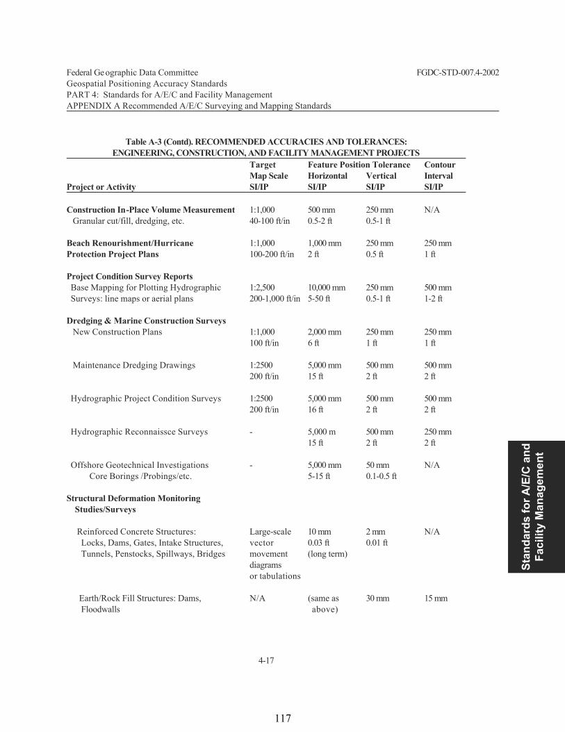
Stan
dard
s fo
r A/E
/C a
nd
Faci
lity
Man
agem
ent
Federal Ge ographic Data Committee FGDC-STD-007.4-2002 Geospatial Positioning Accuracy Standards PART 4: Standards for A/E/C and Facility Management APPENDIX A Recommended A/E/C Surveying and Mapping Standards
4-17
Table A-3 (Contd). RECOMMENDED ACCURACIES AND TOLERANCES:ENGINEERING, CONSTRUCTION, AND FACILITY MANAGEMENT PROJECTS
Target Feature Position Tolerance ContourMap Scale Horizontal Vertical Interval
Project or Activity SI/IP SI/IP SI/IP SI/IP Construction In-Place Volume Measurement 1:1,000 500 mm 250 mm N/A Granular cut/fill, dredging, etc. 40-100 ft/in 0.5-2 ft 0.5-1 ft Beach Renourishment/Hurricane 1:1,000 1,000 mm 250 mm 250 mm Protection Project Plans 100-200 ft/in 2 ft 0.5 ft 1 ft Project Condition Survey Reports Base Mapping for Plotting Hydrographic 1:2,500 10,000 mm 250 mm 500 mm Surveys: line maps or aerial plans 200-1,000 ft/in 5-50 ft 0.5-1 ft 1-2 ft
Dredging & Marine Construction Surveys New Construction Plans 1:1,000 2,000 mm 250 mm 250 mm 100 ft/in 6 ft 1 ft 1 ft Maintenance Dredging Drawings 1:2500 5,000 mm 500 mm 500 mm
200 ft/in 15 ft 2 ft 2 ft Hydrographic Project Condition Surveys 1:2500 5,000 mm 500 mm 500 mm
200 ft/in 16 ft 2 ft 2 ft Hydrographic Reconnaissce Surveys - 5,000 m 500 mm 250 mm
15 ft 2 ft 2 ft Offshore Geotechnical Investigations - 5,000 mm 50 mm N/A
Core Borings /Probings/etc. 5-15 ft 0.1-0.5 ft Structural Deformation Monitoring Studies/Surveys Reinforced Concrete Structures: Large-scale 10 mm 2 mm N/A Locks, Dams, Gates, Intake Structures, vector 0.03 ft 0.01 ft Tunnels, Penstocks, Spillways, Bridges movement (long term)
diagrams or tabulations
Earth/Rock Fill Structures: Dams, N/A (same as 30 mm 15 mm Floodwalls above)
117
rthompson
Rectangle

Federal Ge ographic Data Committee FGDC-STD-007.4-2002 Geospatial Positioning Accuracy Standards PART 4: Standards for A/E/C and Facility Management APPENDIX A Recommended A/E/C Surveying and Mapping Standards
4-18
Table A-3 (Contd). RECOMMENDED ACCURACIES AND TOLERANCES:ENGINEERING, CONSTRUCTION, AND FACILITY MANAGEMENT PROJECTS
Target Feature Position Tolerance ContourMap Scale Horizontal Vertical Interval
Project or Activity SI/IP SI/IP SI/IP SI/IP
Levees, etc. -- slope/crest stability & 0.1 ft 0.05 ft alignment (long term)
Crack/Joint & Deflection Measurements: tabulations 0.2 mm N/A N/A piers/monoliths--precision micrometer 0.01 inch
REAL ESTATE ACTIVITIES: ACQUISITION, DISPOSAL, MANAGEMENT, AUDIT Maps, Plans, & Drawings Associated with Military and Civil Projects Tract Maps, Individual, Detailing Installation or Reservation Boundaries, 1:1,000 10 mm 100 mm 1,000 mm Lots, Parcels, Adjoining Parcels, and 1:1,200 (Army) Record Plats, Utilities, etc. 50-400 ft/in 0.05-2 ft 0.1-2 ft 1-5 ft Condemnation Exhibit Maps 1:1,000 10 mm 100 mm 1,000 mm
50-400 ft/in 0.05-2 ft 0.1-2 ft 1-5 ft
Guide Taking Lines/Boundary Encroachment 1:500 50 mm 50 mm 250 mm Maps: Fee and Easement Acquisition 20-100 ft/in 0.1-1 ft 0.1-1 ft 1 ft
General Location or Planning Maps 1:24,000 10,000 mm 5,000 mm 2,000 mm 2,000 ft/in 50-100 ft 5-10 ft 5-10 ft
GIS or LIS Mapping, General Land Utilization and Management, Forestry 1:5,000 10,000 mm N/A N/A
Management, Mineral Acquisition 200-1,000 ft/in 50-100 ft Easement Areas and Easement 1:1,000 50 mm 50 mm - Delineation Lines 100 ft/in 0.1-0.5 ft 0.1-0.5 ft HAZARDOUS, TOXIC, RADIOACTIVE WASTE (HTRW) SITE INVESTIGATION,MODELING, AND CLEANUP General Detailed Site Plans 1:500 100 mm 50 mm 100 mm
HTRW Sites, Asbestos, etc. 5-50 ft/in 0.2-1 ft 0.1-0.5 ft 0.5-1 ft
118
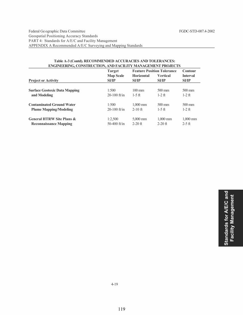
Stan
dard
s fo
r A/E
/C a
nd
Faci
lity
Man
agem
ent
Federal Ge ographic Data Committee FGDC-STD-007.4-2002 Geospatial Positioning Accuracy Standards PART 4: Standards for A/E/C and Facility Management APPENDIX A Recommended A/E/C Surveying and Mapping Standards
4-19
Table A-3 (Contd). RECOMMENDED ACCURACIES AND TOLERANCES:ENGINEERING, CONSTRUCTION, AND FACILITY MANAGEMENT PROJECTS
Target Feature Position Tolerance ContourMap Scale Horizontal Vertical Interval
Project or Activity SI/IP SI/IP SI/IP SI/IP
Surface Geotoxic Data Mapping 1:500 100 mm 500 mm 500 mm and Modeling 20-100 ft/in 1-5 ft 1-2 ft 1-2 ft Contaminated Ground Water 1:500 1,000 mm 500 mm 500 mm Plume Mapping/Modeling 20-100 ft/in 2-10 ft 1-5 ft 1-2 ft General HTRW Site Plans & 1:2,500 5,000 mm 1,000 mm 1,000 mm Reconnaissance Mapping 50-400 ft/in 2-20 ft 2-20 ft 2-5 ft
119
rthompson
Rectangle

Stan
dard
s fo
r Nau
tical
C
hart
ing
Hyd
rogr
aphi
c Su
rvey
s
Federal Geographic Data Committee Department of Agriculture Department of Commerce Department of Defense Department of Energy Department of Housing and Urban Development Department of the Interior Department of State Department of Transportation Environmental Protection Agency
Federal Emergency Management Agency Library of Congress National Aeronautics and Space Administration National Archives and Records Administration
Tennessee Valley Authority
FGDC Document Number FGDC-STD-007.5-2005
Geospatial Positioning Accuracy Standards
Part 5: Standards for Nautical Charting Hydrographic Surveys Subcommittee on Marine and Coastal Spatial Data Federal Geographic Data Committee
120
rthompson
Rectangle

5-ii
Federal Geographic Data Committee
Established by Office of Management and Budget Circular A-16, the Federal Geographic Data Committee (FGDC) promotes the coordinated development, use, sharing, and dissemination of geographic data.
The FGDC is composed of representatives from the Departments of Agriculture, Commerce, Defense, Energy, Housing and Urban Development, the Interior, State, and Transportation; the Environmental Protection Agency; the Federal Emergency Management Agency; the Library of Congress; the National Aeronautics and Space Administration; the National Archives and Records Administration; and the Tennessee Valley Authority. Additional Federal agencies participate on FGDC subcommittees and working groups. The Department of the Interior chairs the committee. FGDC subcommittees work on issues related to data categories coordinated under the circular. Subcommittees establish and implement standards for data content, quality, and transfer; encourage the exchange of information and the transfer of data; and organize the collection of geographic data to reduce duplication of effort. Working groups are established for issues that transcend data categories.
For more information about the committee, or to be added to the committee's newsletter mailing list, please contact:
Federal Geographic Data Committee Secretariat
c/o U.S. Geological Survey 590 National Center
Reston, Virginia 22092
Telephone: (703) 648-5514 Facsimile: (703) 648-5755
Internet (electronic mail): [email protected] Anonymous FTP: ftp://fgdc.er.usgs.gov/pub/gdc/
World Wide Web: http://fgdc.er.usgs.gov/fgdc.html
121

Stan
dard
s fo
r Nau
tical
C
hart
ing
Hyd
rogr
aphi
c Su
rvey
s
Federal Geographic Data Committee FGDC Document Number FGDC-STD-007.5-2005 Draft Geospatial Positioning Accuracy Standards Part 5: Standards for Nautical Charting Hydrographic Surveys
5-iii
CONTENTS Page
5.1 Introduction ................................................................................................................................................... 5-1
5.1.1 Objective......................................................................................................................................... 5-1 5.1.2 Scope............................................................................................................................................... 5-1 5.1.3 Applicability................................................................................................................................... 5-1 5.1.4 Related Standards ......................................................................................................................... 5-1 5.1.5 Standards Development Procedures .......................................................................................... 5-2 5.1.6 Maintenance .................................................................................................................................. 5-2
5.2 Spatial Accuracy ........................................................................................................................................... 5-3 5.3 Reference Datums ........................................................................................................................................ 5-3 5.4 Classification of Surveys ............................................................................................................................ 5-3
5.4.1 Special Order.................................................................................................................................. 5-3 5.4.2 Order 1............................................................................................................................................. 5-3 5.4.3 Order 2............................................................................................................................................. 5-4 5.4.4 Order 3............................................................................................................................................. 5-4
5.5 Positioning .................................................................................................................................................... 5-6 5.6 Depths............................................................................................................................................................. 5-7 5.7 Sounding Density ......................................................................................................................................... 5-8 5.8 Bottom Sampling ........................................................................................................................................... 5-8 5.9 Tidal Observations........................................................................................................................................ 5-8 5.10 Metadata......................................................................................................................................................... 5-9 5.11 Elimination of Doubtful Data....................................................................................................................... 5-9 5.12 Quality Control............................................................................................................................................ 5-10 References .................................................................................................................................................................... 5-11 Tables Table 1 Summary of Minimum Standards for Hydrographic Surveys................................................................... 5-5 Table 2 Summary of Minimum Standards for Positioning of Navigation Aids and Important Features ......... 5-7
122
rthompson
Rectangle

Federal Geographic Data Committee FGDC Document Number FGDC-STD-007.5-2005 Draft Geospatial Positioning Accuracy Standards Part 5: Standards for Nautical Charting Hydrographic Surveys
5-1
5.1 Introduction 5.1.1 Objective
This document provides minimum standards for the horizontal and vertical accuracy of features associated with hydrographic surveys that support nautical charting. Such features include, but are not limited to, water depths, objects on the seafloor, navigational aids, and shoreline.
5.1.2 Scope
For the purposes of this Standard, hydrographic surveys are defined as those surveys conducted to determine the configuration of the bottom of water bodies and to identify and locate all features, natural and man-made, that may affect navigation. Nautical charts are compilations of data from numerous sources, principally hydrographic surveys, designed specifically to meet the requirements of marine navigation. The scope of these standards includes the coastal waters of the U.S. and its territories.
5.1.3 Applicability
These standards are intended to be used by federal agencies and their contractors for conducting hydrographic surveys that will be used for updating nautical charts. They do not apply to hydrographic surveys for river and harbor navigation projects or surveys for project construction which are covered by Part 4 of the FGDC Geospatial Positioning Accuracy Standards. Local authorities may also prescribe these standards for high quality surveys for other purposes.
5.1.4 Related Standards
These standards may be used in conjunction with, or independent of, other Parts of the overall Geospatial Positioning Accuracy Standard. Part 1 (Reporting Methodology) applies directly to this part with the exception that vertical coordinate values should be referenced to the applicable chart datum and not one of the geodetic vertical datums (NAVD 88 or NGVD 29). See section 5.3.
There may be occasions where geodetic control points need to be established to support hydrographic surveys. In such instances, the specifications in Part 2 (Standards for Geodetic Networks) should be referenced. The accuracy testing described in Part 3 (National Standard for Spatial Data Accuracy) is generally inapplicable to this Part 5 since the referenced features are not repeatedly measured. Part 4 (Standards for Architecture, Engineering, Construction (A/E/C) and Facility Management) provide accuracy standards for other categories of hydrographic surveys (Contract Payment, Project Condition and Reconnaissance) that are not explicitly conducted to support nautical charts.
123

Stan
dard
s fo
r Nau
tical
C
hart
ing
Hyd
rogr
aphi
c Su
rvey
s
Federal Geographic Data Committee FGDC Document Number FGDC-STD-007.5-2005 Draft Geospatial Positioning Accuracy Standards Part 5: Standards for Nautical Charting Hydrographic Surveys
5-2
5.1.5 Standards Development Procedures
This standard was developed by the FGDC Bathymetric Subcommittee during 1998 and generally follows the Standards for Hydrographic Surveys adopted by the International Hydrographic Organization in April 1998.
5.1.6 Maintenance
The U.S. Department of Commerce, National Oceanic and Atmospheric Administration, National Ocean Service, Office of Coast Survey, is responsible for developing and maintaining Standards for Nautical Charting Hydrographic Surveys for the FGDC Subcommittee on Marine and Coastal Spatial Data. Address questions concerning the standards to: Director, Office of Coast Survey, NOAA, N/CS, 1315 East-West Highway, Silver Spring, Maryland 20910.
124
rthompson
Rectangle
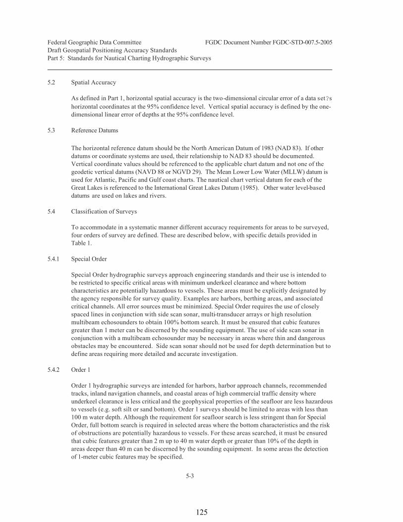
Federal Geographic Data Committee FGDC Document Number FGDC-STD-007.5-2005 Draft Geospatial Positioning Accuracy Standards Part 5: Standards for Nautical Charting Hydrographic Surveys
5-3
5.2 Spatial Accuracy
As defined in Part 1, horizontal spatial accuracy is the two-dimensional circular error of a data set s horizontal coordinates at the 95% confidence level. Vertical spatial accuracy is defined by the one-dimensional linear error of depths at the 95% confidence level.
5.3 Reference Datums
The horizontal reference datum should be the North American Datum of 1983 (NAD 83). If other datums or coordinate systems are used, their relationship to NAD 83 should be documented. Vertical coordinate values should be referenced to the applicable chart datum and not one of the geodetic vertical datums (NAVD 88 or NGVD 29). The Mean Lower Low Water (MLLW) datum is used for Atlantic, Pacific and Gulf coast charts. The nautical chart vertical datum for each of the Great Lakes is referenced to the International Great Lakes Datum (1985). Other water level-based datums are used on lakes and rivers.
5.4 Classification of Surveys
To accommodate in a systematic manner different accuracy requirements for areas to be surveyed, four orders of survey are defined. These are described below, with specific details provided in Table 1.
5.4.1 Special Order
Special Order hydrographic surveys approach engineering standards and their use is intended to be restricted to specific critical areas with minimum underkeel clearance and where bottom characteristics are potentially hazardous to vessels. These areas must be explicitly designated by the agency responsible for survey quality. Examples are harbors, berthing areas, and associated critical channels. All error sources must be minimized. Special Order requires the use of closely spaced lines in conjunction with side scan sonar, multi-transducer arrays or high resolution multibeam echosounders to obtain 100% bottom search. It must be ensured that cubic features greater than 1 meter can be discerned by the sounding equipment. The use of side scan sonar in conjunction with a multibeam echosounder may be necessary in areas where thin and dangerous obstacles may be encountered. Side scan sonar should not be used for depth determination but to define areas requiring more detailed and accurate investigation.
5.4.2 Order 1
Order 1 hydrographic surveys are intended for harbors, harbor approach channels, recommended tracks, inland navigation channels, and coastal areas of high commercial traffic density where underkeel clearance is less critical and the geophysical properties of the seafloor are less hazardous to vessels (e.g. soft silt or sand bottom). Order 1 surveys should be limited to areas with less than 100 m water depth. Although the requirement for seafloor search is less stringent than for Special Order, full bottom search is required in selected areas where the bottom characteristics and the risk of obstructions are potentially hazardous to vessels. For these areas searched, it must be ensured that cubic features greater than 2 m up to 40 m water depth or greater than 10% of the depth in areas deeper than 40 m can be discerned by the sounding equipment. In some areas the detection of 1-meter cubic features may be specified.
125

Stan
dard
s fo
r Nau
tical
C
hart
ing
Hyd
rogr
aphi
c Su
rvey
s
Federal Geographic Data Committee FGDC Document Number FGDC-STD-007.5-2005 Draft Geospatial Positioning Accuracy Standards Part 5: Standards for Nautical Charting Hydrographic Surveys
5-4
5.4.3 Order 2
Order 2 hydrographic surveys are intended for areas with depths less than 200 m not covered by Special Order and Order 1 and where a general description of the bathymetry is sufficient to ensure there are no obstructions on the seafloor that will endanger the type of vessel expected to transit or work the area. It is the criteria for a variety of maritime uses for which higher order hydrographic surveys cannot be justified. Full bottom search may be required in selected areas where the bottom characteristics and the risk of obstructions may be potentially hazardous to vessels.
5.4.4 Order 3
Order 3 hydrographic surveys are intended for all areas not covered by Special Order, and Orders 1 and 2 in water depths in excess of 200 m.
126
rthompson
Rectangle

Federal Geographic Data Committee FGDC Document Number FGDC-STD-007.5-2005 Draft Geospatial Positioning Accuracy Standards Part 5: Standards for Nautical Charting Hydrographic Surveys
5-5
])d*(b+a[ 22
TABLE 1Summary of Minimum Standards for Hydrographic Surveys
ORDER Special 1 2 3 Examples of Typical Areas
Harbors, berthing areas, and associated critical channels with minimum underkeel clearances
Harbors, harbor approach channels, recommended tracks and some coastal areas with depths up to 100 m
Areas not described in Special Order and Order 1, or areas up to 200 m water depth
Offshore areas not described in Special Order, and Orders 1 and 2
Horizontal Accuracy (95% Confidence Level)
2 m
5 m + 5% of depth
20 m + 5% of depth
150 m + 5% of depth
Depth Accuracy for (1)
Reduced Depths (95% Confidence Level) (2)
a = 0.25 m b = 0.0075
a = 0.5 m b = 0.013
a = 1.0 m b = 0.023
Same as Order 2
100% Bottom Search (3)
Compulsory
Required in selected areas
May be required in selected areas
Not applicable
System Detection Capability
Cubic features > 1 m
Cubic features > 2 m in depths up to 40 m; 10% of depth beyond 40 m
Same as Order 1
Not applicable
Maximum LineSpacing (4)
Not applicable, as 100% search compulsory
3 x average depth or 25 m, whichever is greater
3-4 x average depth or 200 m, whichever is greater
4 x average depth
(1) To calculate the error limits for depth accuracy the corresponding values of a and b listed in Table 1 should be introduced into: where: a is a constant depth error, i.e. the sum of all constant errors, b*d is the depth dependent error, i.e. the sum of all depth
dependent errors where b is a factor of depth dependent error, and d is depth.
(2) The confidence level percentage is the probability that an error will not exceed the specified maximum value. (3) A method of exploring the seabed which attempts to provide complete coverage of an area for the purpose of detecting all
features addressed in this publication. (4) The line spacing can be expanded if procedures for ensuring an adequate sounding density are used The rows of Table 1 are explained as follows: Row 1 "Examples of Typical Areas" gives examples of areas to which an order of survey might typically be applied. Row 2 "Horizontal Accuracy" lists positioning accuracies to be achieved to meet each order of survey. Row 3 "Depth Accuracy" specifies parameters to be used to calculate accuracies of reduced depths to be achieved to meet each
order of survey. Row 4 "100% Bottom Search" specifies occasions when full bottom search should be conducted. Row 5 "System Detection Capability" specifies the detection capabilities of systems used for bottom search. Row 6 "Maximum Line Spacing" is to be interpreted as either (1) spacing of sounding lines for single beam sounders or (2) distance between the outer limits of swaths for swath sounding systems
127

Stan
dard
s fo
r Nau
tical
C
hart
ing
Hyd
rogr
aphi
c Su
rvey
s
Federal Geographic Data Committee FGDC Document Number FGDC-STD-007.5-2005 Draft Geospatial Positioning Accuracy Standards Part 5: Standards for Nautical Charting Hydrographic Surveys
5-6
5.5 Positioning
The horizontal accuracy, as specified in Table 1, is the accuracy of the position of soundings, dangers, and all other significant submerged features with respect to a geodetic reference frame, specifically NAD 83. The exception to this are Order 2 and Order 3 surveys using single-beam echo sounders where it is the positional accuracy of the sounding system sensor. In such cases, the agency responsible for the survey quality should determine the accuracy of the positions of soundings on the seafloor.
If the accuracy of a position is affected by different parameters, the contributions of all parameters to the total position error should be accounted for. A statistical method, combining different error sources, for determining positioning accuracy should be adopted. The position error, at 95% confidence level, should be recorded together with the survey data. Although this should preferably be done for each individual sounding, the error estimate may also be derived for a number of soundings or even for an area, provided differences between error estimates can be safely expected to be negligible.
It is strongly recommended that whenever positions are determined by terrestrial systems, redundant lines of position should be observed. Standard calibration techniques should be completed prior to and after the acquisition of data. Satellite systems should be capable of tracking at least five satellites simultaneously; integrity monitoring for Special Order and Order 1 surveys is recommended.
Primary shore control points should be located by ground survey methods to a relative accuracy of 1 part in 100,000. When geodetic satellite positioning methods are used to establish such points, the error should not exceed 10 cm at 95% confidence level. Secondary stations for local positioning, which will not be used for extending the control, should be located such that the error does not exceed 1 part in 10,000 for ground survey techniques or 50 cm using geodetic satellite positioning.
The horizontal positions of navigation aids and other important features should be determined to the accuracy stated in Table 2, at 95% confidence level.
128
rthompson
Rectangle
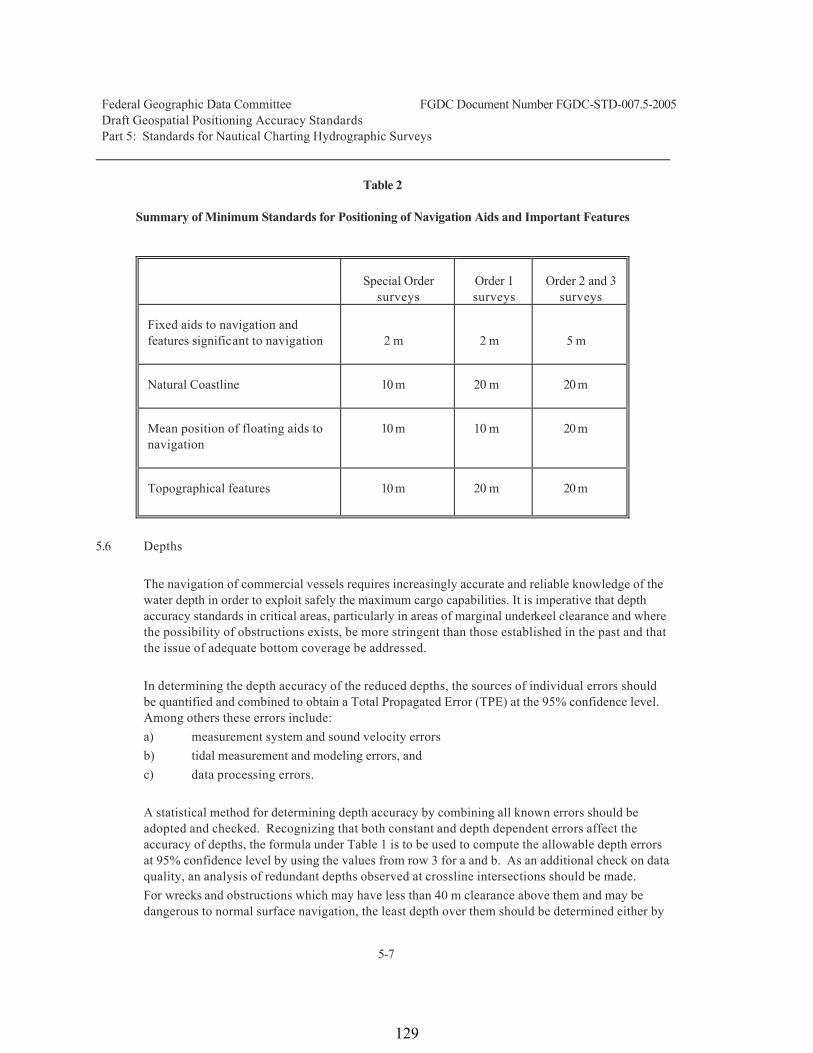
Federal Geographic Data Committee FGDC Document Number FGDC-STD-007.5-2005 Draft Geospatial Positioning Accuracy Standards Part 5: Standards for Nautical Charting Hydrographic Surveys
5-7
Table 2
Summary of Minimum Standards for Positioning of Navigation Aids and Important Features
Special Order
surveys
Order 1 surveys
Order 2 and 3
surveys Fixed aids to navigation and features significant to navigation
2 m
2 m
5 m
Natural Coastline
10 m
20 m
20 m
Mean position of floating aids to navigation
10 m
10 m
20 m
Topographical features
10 m
20 m
20 m
5.6 Depths
The navigation of commercial vessels requires increasingly accurate and reliable knowledge of the water depth in order to exploit safely the maximum cargo capabilities. It is imperative that depth accuracy standards in critical areas, particularly in areas of marginal underkeel clearance and where the possibility of obstructions exists, be more stringent than those established in the past and that the issue of adequate bottom coverage be addressed.
In determining the depth accuracy of the reduced depths, the sources of individual errors should be quantified and combined to obtain a Total Propagated Error (TPE) at the 95% confidence level. Among others these errors include: a) measurement system and sound velocity errors b) tidal measurement and modeling errors, and c) data processing errors.
A statistical method for determining depth accuracy by combining all known errors should be adopted and checked. Recognizing that both constant and depth dependent errors affect the accuracy of depths, the formula under Table 1 is to be used to compute the allowable depth errors at 95% confidence level by using the values from row 3 for a and b. As an additional check on data quality, an analysis of redundant depths observed at crossline intersections should be made. For wrecks and obstructions which may have less than 40 m clearance above them and may be dangerous to normal surface navigation, the least depth over them should be determined either by
129

Stan
dard
s fo
r Nau
tical
C
hart
ing
Hyd
rogr
aphi
c Su
rvey
s
Federal Geographic Data Committee FGDC Document Number FGDC-STD-007.5-2005 Draft Geospatial Positioning Accuracy Standards Part 5: Standards for Nautical Charting Hydrographic Surveys
5-8
high definition sonar examination or physical examination (diving). Mechanical sweeping may be used when guaranteeing a minimum safe clearance depth.
All anomalous features previously reported in the survey area and those detected during the survey should be examined in greater detail and, if confirmed, their least depth should be determined. The agency responsible for survey quality may define a depth limit beyond which a detailed seafloor investigation, and thus an examination of anomalous features, is not required.
Measured depths should be reduced to chart or survey datum, by the application of tidal or water level height. Tidal reductions should not be applied to depths greater than 200 m, except when tides contribute significantly to the TPE.
5.7 Sounding Density
In planning the density of soundings, both the nature of the seabed in the area and the requirements of the users have to be taken into account to ensure adequate bottom coverage. It should be noted that no method, not even 100% search, guarantees by itself the reliability of a survey nor can it disprove with certainty the existence of hazards to navigation, such as isolated natural hazards or man made objects such as wrecks, between survey lines.
Line spacing for the various orders of hydrographic surveys is proposed in Table 1. The results of a survey should be assessed using procedures developed by the agency responsible for the survey quality. Based on these procedures the adequacy of the sounding density should be determined and the line spacing reduced if warranted.
5.8 Bottom Sampling
The nature of the seabed should be determined by sampling or may be inferred from other sensors (e.g. single beam echo sounders, side scan sonar, sub-bottom profiler, video, etc.) up to the depth required by local anchoring or trawling conditions. Under normal circumstances sampling is not required in depths greater than 200 meters. Samples should be spaced according to the seabed geology, but should normally be 10 times that of the main scheme line spacing. In areas intended for anchorages, density of sampling should be increased. Any inference technique should be substantiated by physical sampling.
5.9 Tidal Observations
Tidal height observations should be made throughout the course of a survey for the purpose of providing tidal reductions for soundings, and providing data for tidal analysis and subsequent prediction. Observations should extend over the longest possible period, and if possible, for not less than 29 days. Tidal heights should be observed so that the total measurement error at the tide gauge, including timing error, does not exceed +/- 5 cm at 95% for Special Order surveys. For other surveys +/- 10 cm should not be exceeded.
130
rthompson
Rectangle

Federal Geographic Data Committee FGDC Document Number FGDC-STD-007.5-2005 Draft Geospatial Positioning Accuracy Standards Part 5: Standards for Nautical Charting Hydrographic Surveys
5-9
5.10 Metadata
To allow a comprehensive assessment of the quality of survey data it is necessary to record or document certain information together with the survey data. Such information is important to allow exploitation of survey data by a variety of users with different requirements, especially as requirements may not be known when survey data is collected. The information describing the data is called metadata. Examples of metadata include overall quality, data set title, source, positional accuracy and copyright. Metadata is data implicitly attached to a collection of data.
Metadata should comprise at least the following information: - the survey in general (e.g. date, area, equipment used, name of survey platform) - the horizontal and vertical datum - calibration procedures and results - sound velocity for corrections to echo soundings - tidal datum and reduction procedures - accuracies achieved and the respective confidence levels.
Metadata should preferably be in digital form in compliance with the FGDC-endorsed Content Standard for Digital Geospatial Metadata (version 2.0), FGDC-STD-001-1998, and an integral part of the survey record. Shoreline metadata should comply with the Metadata Profile for Shoreline Data. If this is not feasible, similar information should be included in the documentation of a survey. It is recommended that agencies responsible for the survey quality systematically develop and document a list of metadata used for their survey data.
It is understood that each sensor (i.e. positioning, depth, heave, pitch, roll, heading, seabed characteristic sensors, water column parameter sensors, tidal reduction sensor, data reduction models etc.) possesses unique error characteristics. Each survey system should be uniquely analyzed to determine appropriate procedure(s) to obtain the required spatial statistics. These analysis procedure(s) should be documented or referenced in the survey record.
5.11 Elimination of Doubtful Data
To improve the safety of navigation it is desirable to eliminate doubtful data, i.e. data which are usually denoted on charts by PA (Position Approximate), PD (Position Doubtful), ED (Existence Doubtful), SD (Sounding Doubtful) or as "reported danger". To confirm or disprove the existence of such data it is necessary to carefully define the area to be searched and subsequently survey that area according to the standards outlined in this publication. No empirical formula for defining the search area can suit all situations. For this reason, it is recommended that the search radius should be 3 times the estimated position error of the reported hazard at the 95% confidence level as determined by a thorough investigation of the report on the doubtful data by a qualified hydrographic surveyor. If such report is incomplete or does not exist at all, the position error must be estimated by other means as, for example, a more general
131

Stan
dard
s fo
r Nau
tical
C
hart
ing
Hyd
rogr
aphi
c Su
rvey
s
Federal Geographic Data Committee FGDC Document Number FGDC-STD-007.5-2005 Draft Geospatial Positioning Accuracy Standards Part 5: Standards for Nautical Charting Hydrographic Surveys
5-10
assessment of posit ioning and depth measurement errors during the era when the data in question was collected.
The methodology for conducting the search should be based on the area in which the doubtful data is reported and the estimated danger of the hazard to navigation. Once this has been established, the search procedure should be that of conducting a hydrographic survey of the extent defined in the preceding paragraph, to the standards established in this publication. If not detected, the agency responsible for the survey quality shall decide whether to retain the hazard as charted or to expunge it.
5.12 Quality Control
To ensure that the required accuracies are achieved it is necessary to check and monitor performance. Establishing quality control procedures which ensure that data or products meet certain standards and specifications should be a high priority for hydrographic authorities. This section provides guidelines for the implementation of such procedures.
Quality control for positioning ideally involves observing redundant lines of position and/or monitor stations which are then analyzed to obtain a position error estimate. If the positioning system offers no redundancy or other means of monitoring system performance, rigorous and frequent calibration is the only means of ensuring quality.
A standard quality control procedure should be to check the validity of soundings by conducting additional depth measurements. Differences should be statistically tested to ensure compliance of the survey with the standards given in Table 1. Anomalous differences should be further examined with a systematic analysis of contributing error sources. All discrepancies should be resolved, either by analysis or re-survey during progression of the survey task. Crosslines intersecting the principal sounding lines should always be run to confirm the accuracy of positioning, sounding, and tidal reductions. Crosslines should be spaced so that an efficient and comprehensive control of the principal sounding lines can be effected. As a guide it may be assumed that the interval between crosslines should normally be no more than 15 times that of the selected sounding lines.
The proposed line spacing from Table 1 may be altered depending on the configuration of the seafloor and the likelihood of dangers to navigation. In addition, if side scan sonar is used in conjunction with single beam or multibeam sonar systems, the specified line spacing may be increased. Multibeam sonar systems have great potential for accurate seafloor coverage if used with proper survey and calibration procedures. An appropriate assessment of the accuracy of measurements with each beam is necessary for use in areas surveyed to Special Order and Order 1 standards. If any of the outer beams have unacceptable errors, the related data may be used for reconnaissance but the depths should be otherwise excluded from the final data set. All swaths should be
132
rthompson
Rectangle
Federal Geographic Data Committee FGDC Document Number FGDC-STD-007.5-2005 Draft Geospatial Positioning Accuracy Standards Part 5: Standards for Nautical Charting Hydrographic Surveys
5-11
intersected, at least once, by a crossline to confirm the accuracy of positioning, depth measurements and depth reductions.
References International Hydrographic Organization, April 1998, IHO Standards for Hydrographic Surveys, Special
Publication No. 44, 4th Edition, 23p.
133