PS 3.15-2004 Digital Imaging and Communications in ...
75
- Standard - PS 3.15-2004 Digital Imaging and Communications in Medicine (DICOM) Part 15: Security and System Management Profiles Published by National Electrical Manufacturers Association 1300 N. 17th Street Rosslyn, Virginia 22209 USA © Copyright 2004 by the National Electrical Manufacturers Association. All rights including translation into other languages, reserved under the Universal Copyright Convention, the Berne Convention or the Protection of Literacy and Artistic Works, and the International and Pan American Copyright Conventions.
Transcript of PS 3.15-2004 Digital Imaging and Communications in ...

- Standard -
PS 3.15-2004
Digital Imaging and Communications in Medicine (DICOM)
Part 15: Security and System Management Profiles
Published by
National Electrical Manufacturers Association 1300 N. 17th Street Rosslyn, Virginia 22209 USA
© Copyright 2004 by the National Electrical Manufacturers Association. All rights including translation into other languages, reserved under the Universal Copyright Convention, the Berne Convention or the Protection of Literacy and Artistic Works, and the International and Pan American Copyright Conventions.
PS 3.15-2004 Page 2
NOTICE AND DISCLAIMER
The information in this publication was considered technically sound by the consensus of persons engaged in the development and approval of the document at the time it was developed. Consensus does not necessarily mean that there is unanimous agreement among every person participating in the development of this document.
NEMA standards and guideline publications, of which the document contained herein is one, are developed through a voluntary consensus standards development process. This process brings together volunteers and/or seeks out the views of persons who have an interest in the topic covered by this publication. While NEMA administers the process and establishes rules to promote fairness in the development of consensus, it does not write the document and it does not independently test, evaluate, or verify the accuracy or completeness of any information or the soundness of any judgments contained in its standards and guideline publications.
NEMA disclaims liability for any personal injury, property, or other damages of any nature whatsoever, whether special, indirect, consequential, or compensatory, directly or indirectly resulting from the publication, use of, application, or reliance on this document. NEMA disclaims and makes no guaranty or warranty, expressed or implied, as to the accuracy or completeness of any information published herein, and disclaims and makes no warranty that the information in this document will fulfill any of your particular purposes or needs. NEMA does not undertake to guarantee the performance of any individual manufacturer or seller’s products or services by virtue of this standard or guide.
In publishing and making this document available, NEMA is not undertaking to render professional or other services for or on behalf of any person or entity, nor is NEMA undertaking to perform any duty owed by any person or entity to someone else. Anyone using this document should rely on his or her own independent judgment or, as appropriate, seek the advice of a competent professional in determining the exercise of reasonable care in any given circumstances. Information and other standards on the topic covered by this publication may be available from other sources, which the user may wish to consult for additional views or information not covered by this publication.
NEMA has no power, nor does it undertake to police or enforce compliance with the contents of this document. NEMA does not certify, test, or inspect products, designs, or installations for safety or health purposes. Any certification or other statement of compliance with any health or safety–related information in this document shall not be attributable to NEMA and is solely the responsibility of the certifier or maker of the statement.

PS 3.15-2004 Page 3
Table of Contents
NOTICE AND DISCLAIMER......................................................................................................................... 2 FOREWORD................................................................................................................................................. 5 1 Scope and field of application ................................................................................................................ 7
1.1 SECURITY POLICIES AND MECHANISMS.................................................................................... 7 1.2 SYSTEM MANAGEMENT PROFILES ............................................................................................. 8
2 Normative references ............................................................................................................................. 8 3 Definitions ............................................................................................................................................. 10
3.1 REFERENCE MODEL DEFINITIONS..................................................................................... 10 3.2 REFERENCE MODEL SECURITY ARCHITECTURE DEFINITIONS.................................... 10 3.3 ACSE SERVICE DEFINITIONS .............................................................................................. 10 3.4 SECURITY DEFINITIONS....................................................................................................... 10 3.5 DICOM INTRODUCTION AND OVERVIEW DEFINITIONS................................................... 11 3.6 DICOM CONFORMANCE DEFINITIONS............................................................................... 11 3.7 DICOM INFORMATION OBJECT DEFINITIONS ................................................................... 11 3.8 DICOM SERVICE CLASS DEFINITIONS............................................................................... 11 3.9 DICOM COMMUNICATION SUPPORT DEFINITIONS.......................................................... 11 3.10 DICOM SECURITY PROFILE DEFINITIONS......................................................................... 11
4 Symbols and abbreviations .................................................................................................................. 11 5 Conventions.......................................................................................................................................... 13 6 Security and System Management Profile Outlines............................................................................. 13
6.1 SECURE USE PROFILES ...................................................................................................... 13 6.2 SECURE TRANSPORT CONNECTION PROFILES.............................................................. 13 6.3 DIGITAL SIGNATURE PROFILE ............................................................................................ 14 6.4 MEDIA STORAGE SECURITY PROFILES ............................................................................ 14 6.5 NETWORK ADDRESS MANAGEMENT PROFILES.............................................................. 14 6.6 TIME SYNCHRONIZATION PROFILES ................................................................................. 15 6.7 APPLICATION CONFIGURATION MANAGEMENT PROFILES ........................................... 15
7 Configuration Profiles ........................................................................................................................... 15 7.1 ACTORS.................................................................................................................................. 16 7.2 TRANSACTIONS .................................................................................................................... 17
Annex A SECURE USE PROFILES (Normative) .................................................................................. 20 A.1 ONLINE ELECTRONIC STORAGE SECURE USE PROFILE ............................................... 20
A.1.1 SOP Instance Status......................................................................................................... 20 A.2 BASIC DIGITAL SIGNATURES SECURE USE PROFILE ..................................................... 22 A.3 BIT-PRESERVING DIGITAL SIGNATURES SECURE USE PROFILE ................................. 22
Annex B SECURE TRANSPORT CONNECTION PROFILES (Normative) .......................................... 23 B.1 THE BASIC TLS SECURE TRANSPORT CONNECTION PROFILE..................................... 23 B.2 ISCL SECURE TRANSPORT CONNECTION PROFILE ....................................................... 24 B.3 THE AES TLS SECURE TRANSPORT CONNECTION PROFILE ........................................ 24
Annex C DIGITAL SIGNATURE PROFILES (Normative)...................................................................... 26

PS 3.15-2004 Page 4
C.1 BASE RSA DIGITAL SIGNATURE PROFILE......................................................................... 26 C.2 CREATOR RSA DIGITAL SIGNATURE PROFILE................................................................. 26 C.3 AUTHORIZATION RSA DIGITAL SIGNATURE PROFILE..................................................... 27
ANNEX D– MEDIA STORAGE SECURITY PROFILES (Normative) ..................................................... 28 D.1 BASIC DICOM MEDIA SECURITY PROFILE......................................................................... 28
D.1.1 Encapsulation of a DICOM File in a Secure DICOM File ................................................. 28 ANNEX E - ATTRIBUTE CONFIDENTIALITY PROFILES......................................................................... 29
E.1 BASIC APPLICATION LEVEL CONFIDENTIALITY PROFILE............................................... 29 Annex F Network Address Management Profiles ...................................................................................... 34
F.1 BASIC NETWORK ADDRESS MANAGEMENT PROFILE .................................................... 34 F.1.1 Resolve Hostname............................................................................................................ 34 F.1.2 Configure DHCP Server.................................................................................................... 37 F.1.3 Find and Use DHCP Server.............................................................................................. 38 F.1.4 Maintain Lease.................................................................................................................. 40 F.1.5 DDNS Coordination .......................................................................................................... 40 F.1.6 DHCP Security Considerations (Informative) ................................................................... 41 F.1.7 DHCP Implementation Considerations (Informative)........................................................ 42 F.1.8 Conformance..................................................................................................................... 42
Annex G Time Synchronization Profiles .................................................................................................... 43 G.1 BASIC TIME SYNCHRONIZATION PROFILE........................................................................ 43
G.1.1 Find NTP Servers ............................................................................................................. 43 G.1.2 Maintain Time.................................................................................................................... 45 G.1.3 NTP Security Considerations (Informative) ...................................................................... 46 G.1.4 NTP Implementation Considerations (informative)........................................................... 46 G.1.5 Conformance..................................................................................................................... 46
Annex H Application Configuration Management Profiles......................................................................... 47 H.1 APPLICATION CONFIGURATION MANAGEMENT PROFILE.............................................. 47
H.1.1 Data Model Component Objects....................................................................................... 47 H.1.2 Application Configuration Data Model Hierarchy.............................................................. 54 H.1.3 LDAP Schema for Objects and Attributes......................................................................... 56 H.1.4 Transactions...................................................................................................................... 66 H.1.5 LDAP Security Considerations (Informative) .................................................................... 70 H.1.6 Implementation Considerations (Informative) ................................................................... 72 H.1.7 Conformance..................................................................................................................... 73
Index ................................................................................................................................................. 74

PS 3.15-2004 Page 5
FOREWORD
The American College of Radiology (ACR) and the National Electrical Manufacturers Association (NEMA) formed a joint committee to develop a standard for Digital Imaging and Communications in Medicine (DICOM). This DICOM Standard was developed according to the NEMA procedures.
This standard is developed in liaison with other standardization organizations including CEN TC251 in Europe, and JIRA and MEDIS-DC in Japan, with review also by other organizations including IEEE, HL7 and ANSI in the USA.
The DICOM Standard is structured as a multi-part document using the guidelines established in the following document:
ISO/IEC Directives, 1989 Part 3 : Drafting and Presentation of International Standards.
This document is one part of the DICOM Standard, which consists of the following parts:
PS 3.1: Introduction and Overview
PS 3.2: Conformance
PS 3.3: Information Object Definitions
PS 3.4: Service Class Specifications
PS 3.5: Data Structures and Encoding
PS 3.6: Data Dictionary
PS 3.7: Message Exchange
PS 3.8: Network Communication Support for Message Exchange
PS 3.9: Retired
PS 3.10: Media Storage and File Format for Media Interchange
PS 3.11: Media Storage Application Profiles
PS 3.12: Formats and Physical Media
PS 3.13: Retired
PS 3.14: Grayscale Standard Display Function
PS 3.15: Security and System Management Profiles

PS 3.15-2004 Page 6
PS 3.16: Content Mapping Resource
PS 3.17; Explanatory Information
PS 3.18: Web Access to DICOM Persistent Objects (WADO)
These parts are related but independent documents. Their development level and approval status may differ. Additional parts may be added to this multi-part standard. PS 3.1 should be used as the base reference for the current parts of this standard.

PS 3.15-2004 Page 7
1 Scope and field of application
This part of the DICOM Standard specifies Security and System Management Profiles to which implementations may claim conformance. Security and System Management Profiles are defined by referencing externally developed standard protocols, such as TLS, ISCL, DHCP, and LDAP, with attention to their use in a system that uses DICOM Standard protocols for information interchange.
1.1 SECURITY POLICIES AND MECHANISMS
The DICOM standard does not address issues of security policies, though clearly adherence to appropriate security policies is necessary for any level of security. The standard only provides mechanisms that could be used to implement security policies with regard to the interchange of DICOM objects between Application Entities. For example, a security policy may dictate some level of access control. This Standard does not consider access control policies, but does provide the technological means for the Application Entities involved to exchange sufficient information to implement access control policies.
This Standard assumes that the Application Entities involved in a DICOM interchange are implementing appropriate security policies, including, but not limited to access control, audit trails, physical protection, maintaining the confidentiality and integrity of data, and mechanisms to identify users and their rights to access data. Essentially, each Application Entity must insure that their own local environment is secure before even attempting secure communications with other Application Entities.
When Application Entities agree to interchange information via DICOM through association negotiation, they are essentially agreeing to some level of trust in the other Application Entities. Primarily Application Entities trust that their communication partners will maintain the confidentiality and integrity of data under their control. Of course that level of trust may be dictated by local security and access control policies.
Application Entities may not trust the communications channel by which they communicate with other Application Entities. Thus, this Standard provides mechanisms for Application Entities to securely authenticate each other, to detect any tampering with or alteration of messages exchanged, and to protect the confidentiality of those messages while traversing the communications channel. Application Entities can optionally utilize any of these mechanisms, depending on the level of trust they place in the communications channel.
This Standard assumes that Application Entities can securely identify local users of the Application Entity, and that user’s roles or licenses. Note that users may be persons, or may be abstract entities, such as organizations or pieces of equipment. When Application Entities agree to an exchange of information via DICOM, they may also exchange information about the users of the Application Entity via the Certificates exchanged in setting up the secure channel. The Application Entity may then consider the information contained in the Certificates about the users, whether local or remote, in implementing an access control policy or in generating audit trails.
This Standard also assumes that Application Entities have means to determine whether or not the “owners” (e.g. patient, institution) of information have authorized particular users, or classes of users to access information. This Standard further assumes that such authorization might be considered in the access control provided by the Application Entity. At this time, this Standard does not consider how such authorization might be communicated between Application Entities, though that may be a topic for consideration at some future date.
This Standard also assumes that an Application Entity using TLS has secure access to or can securely obtain X.509 key Certificates for the users of the application entity. In addition, this standard assumes
PS 3.15-2004 Page 8
that an Application Entity has the means to validate an X.509 certificate that it receives. The validation mechanism may use locally administered authorities, publicly available authorities, or some trusted third party.
This Standard assumes that an Application Entity using ISCL has access to an appropriate key management and distribution system (e.g. smartcards). The nature and use of such a key management and distribution system is beyond the scope of DICOM, though it may be part of the security policies used at particular sites.
1.2 SYSTEM MANAGEMENT PROFILES
The System Management Profiles specified in this Part are designed to support automation of the configuration management processes necessary to operate a system that uses DICOM Standard protocols for information interchange.
This Part assumes that the Application Entities may operate in a variety of network environments of differing complexity. These environments may range from a few units operating on an isolated network, to a department-level network with some limited centralized network support services, to an enterprise-level network with significant network management services. Note that the System Management Profiles are generally addressed to the implementation, not to Application Entities. The same Profiles need to be supported by the different applications on the network.
2 Normative references
The following standards contain provisions that, through reference in this text, constitute provisions of this Standard. At the time of publication, the editions indicated were valid. All standards are subject to revision, and parties to agreements based on this Standard are encouraged to investigate the possibilities of applying the most recent editions of the standards indicated below.
ANSI X9.52 American National Standards Institute. ANSI X9.52-1998, Triple Data Encryption Algorithm Modes of Operation. 1998.
ECMA 235, The ECMA GSS-API Mechanism
FIPS PUB 46 Data Encryption Standard
FIPS PUB 81 DES Modes of Operation
IETF Internet X.509 Public Key Infrastructure; Time Stamp Protocols; March 2000
ISO/IEC Directives, 1989 Part 3 - Drafting and Presentation of International Standards
ISO/IEC 10118-:1998 Information technology – Security techniques – Hash-functions – Part 3: Dedicated hash-functions (RIPEMD-160 reference)
Note: The draft RIPEMD-160 specification and sample code are also available at ftp://ftp.esat.kuleuven.ac.be/pub/bosselae/ripemd
ISO 7498-1, Information Processing Systems - Open Systems Interconnection - Basic Reference Model
ISO 7498-2, Information processing systems – Open Systems Interconnection – Basic reference Model – Part 2: Security Architecture

PS 3.15-2004 Page 9
ISO/TR 8509, Information Processing Systems - Open Systems Interconnection - Service Conventions
ISO 8649:1987, Information Processing Systems - Open Systems Interconnection - Service Definition for the Association Control Service Element
Integrated Secure Communication Layer V1.00 MEDIS-DC
ITU-T Recommendation X.509 (03/00) “Information technology - Open Systems Interconnection - The directory: Public-key and attribute certificate frameworks”
Note: ITU-T Recommendation X.509 is similar to ISO/IEC 9594-8 1990. However, the ITU-T recommendation is the more familiar form, and was revised in 1993 and 2000, with two sets of corrections in 2001. ITU-T was formerly known as CCITT.
RFC 1035 Domain Name System (DNS)
RFC 1305 Network Time Protocol (Version 3) Specification, Implementation
RFC 2030 Simple Network Time Protocol (SNTP) Version 4
RFC 2131 Dynamic Host Configuration Protocol
RFC 2132 Dynamic Host Configuration Protocol Options
RFC 2136 Dynamic Updates in the Domain Name System (DNS UPDATE)
RFC 2181 Clarifications to the DNS Specification
RFC 2219 Use of DNS Aliases for Network Services
RFC 2246, Transport Layer Security (TLS) 1.0 Internet Engineering Task Force Note: TLS is derived from SSL 3.0, and is largely compatible with it.
RFC 2251 Lightweight Directory Access Protocol (v3)
RFC-2313 PKCS #1: RSA Encryption, Version 1.5, March 1998.
RFC 2563 DHCP Option to Disable Stateless Auto-Configuration in IPv4 Clients
RFC 2782 A DNS RR for specifying the location of services (DNS SRV)
RFC 2849 The LDAP Data Interchange Format (LDIF)
RFC 3268 Advanced Encryption Standard (AES) Ciphersuites for Transport Layer Security (TLS), June 2002.
RFC 3447 PKCS #1 RSA Cryptography Specifications Version 2.1, February 2003 Note: The RSA Encryption Standard is also defined in informative annex A of ISO/IEC 9796, and
in Normative Annex A of the CEN/TC251 European Prestandard prENV 12388:1996.
RFC 3369 Cryptographic Message Syntax, August 2002
RFC 3370 Cryptographic Message Syntax (CMS) Algorithms, August 2002
RFC 3565 Use of the Advanced Encryption Standard (AES) Encryption Algorithm in Cryptographic Message Syntax (CMS), July 2003
SHA-1 National Institute of Standards and Technology, FIPS Pub 180-1: Secure Hash Standard, 17 April 1995
Note: Normative RFC’s are frequently updated by issuance of subsequent RFC’s. The original older RFC is not
modified to include references to the newer RFC.
PS 3.15-2004 Page 10
3 Definitions
For the purposes of this Standard the following definitions apply.
3.1 REFERENCE MODEL DEFINITIONS
This part of the Standard makes use of the following terms defined in ISO 7498-1:
a. Application Entity b. Protocol Data Unit or Layer Protocol Data Unit c. Transport Connection
3.2 REFERENCE MODEL SECURITY ARCHITECTURE DEFINITIONS
This Part of the Standard makes use of the following terms defined in ISO 7498-2:
a. Data Confidentiality
Note: The definition is “the property that information is not made available or disclosed to unauthorized
individuals, entities or processes.”
b. Data Origin Authentication
Note: The definition is “the corroboration that the source of data received is as claimed.”
c. Data Integrity
Note: The definition is “the property that data has not been altered or destroyed in an unauthorized manner.”
d. Key Management
Note: The definition is “the generation, storage, distribution, deletion, archiving and application of keys in accordance with a security policy.”
e. Digital Signature
Note: The definition is “Data appended to, or a cryptographic transformation of, a data unit that allows a recipient of the data unit to prove the source and integrity of that unit and protect against forgery e.g. by the recipient.”
3.3 ACSE SERVICE DEFINITIONS
This part of the Standard makes use of the following terms defined in ISO 8649:
a. Association or Application Association
3.4 SECURITY DEFINITIONS
This Part of the Standard makes use of the following terms defined in ECMA 235:
a. Security Context

PS 3.15-2004 Page 11
Note: The definition is “security information that represents, or will represent a Security Association to an initiator or acceptor that has formed, or is attempting to form such an association.”
3.5 DICOM INTRODUCTION AND OVERVIEW DEFINITIONS
This Part of the Standard makes use of the following terms defined in PS 3.1:
a. Attribute
3.6 DICOM CONFORMANCE DEFINITIONS
This Part of the Standard makes use of the following terms defined in PS 3.2:
a. Security Profile
3.7 DICOM INFORMATION OBJECT DEFINITIONS
This Part of the Standard makes use of the following terms defined in PS 3.3:
a. Module
3.8 DICOM SERVICE CLASS DEFINITIONS
This Part of the Standard makes use of the following terms defined in PS 3.4:
a. Service Class b. Service-Object Pair (SOP) Instance
3.9 DICOM COMMUNICATION SUPPORT DEFINITIONS
This Part of the Standard makes use of the following terms defined in PS 3.8:
a. DICOM Upper Layer
3.10 DICOM SECURITY PROFILE DEFINITIONS
The following definitions are commonly used in this Part of the DICOM Standard:
Secure Transport Connection: a Transport Connection that provides some level of protection against tampering, eavesdropping, masquerading.
Message Authentication Code: A digest or hash code derived from a subset of Data Elements.
Certificate: An electronic document that identifies a party and that party’s public encryption algorithm, parameters, and key. The Certificate also includes, among other things, the identity and a digital signature from the entity that created the certificate. The content and format of a Certificate are defined by ITU-T Recommendation X.509.
4 Symbols and abbreviations
The following symbols and abbreviations are used in this Part of the Standard.

PS 3.15-2004 Page 12
ACR American College of Radiology AE Application Entity AES Advanced Encryption Standard ANSI American National Standards Institute CEN TC251 Comite European de Normalisation-Technical Committee 251-Medical
Informatics CBC Cipher Block Chaining CCIR Consultative Committee, International Radio CN Common Name DES Data Encryption Standard DHCP Dynamic Host Configuration Protocol DICOM Digital Imaging and Communications in Medicine DN Distinguished Name DNS Domain Name System DDNS Dynamic Domain Name System ECMA European Computer Manufacturers Association EDE Encrypt-Decrypt-Encrypt HL7 Health Level 7 IEC International Electrical Commission IEEE Institute of Electrical and Electronics Engineers IETF Internet Engineering Task Force IOD Information Object Definition ISCL Integrated Secure Communication Layer ISO International Standards Organization JIRA Japan Industries association of RAdiological systems LDAP Lightweight Directory Access Protocol LDIF LDAP Interchange Format MAC Message Authentication Code MD-5 Message Digest - 5 MEDIS-DC Medical Information System Development Center MTU Maximum Transmission Unit NEMA National Electrical Manufacturers Association NTP Network Time Protocol OID Object Identifier (analogous to UID) PDU Protocol Data Unit RDN Relative Distinguished Name RFC Request For Comment (used for standards issued by the IETF) RR Resource Record (when used in the context of DNS) RSA Rivest-Shamir-Adleman SCP Service Class Provider SCU Service Class User SHA Secure Hash Algorithm SNTP Simple Network Time Protocol

PS 3.15-2004 Page 13
SOP Service-Object Pair SSH Secure Shell SSL Secure Sockets Layer TLS Transport Layer Security UID Unique Identifier UTC Universal Coordinated Time
5 Conventions
Terms listed in Section 3 Definitions are capitalized throughout the document.
6 Security and System Management Profile Outlines
An implementation may claim conformance to any of the Security and System Management Profiles individually. It may also claim conformance to more than one Security or System Management Profile. It shall indicate in its Conformance Statement how it chooses which profiles to use for any given transaction.
6.1 SECURE USE PROFILES
An implementation may claim conformance to one or more Secure Use Profiles. Such profiles outline the use of attributes and other Security Profiles in a specific fashion.
Secure Use Profiles are specified in Annex A.
6.2 SECURE TRANSPORT CONNECTION PROFILES
An implementation may claim conformance to one or more Secure Transport Connection Profiles.
A Secure Transport Connection Profile includes the following information:
a. Description of the protocol framework and negotiation mechanisms b. Description of the entity authentication an implementation shall support
1. The identity of the entities being authenticated 2. The mechanism by which entities are authenticated 3. Any special considerations for audit log support
c. Description of the encryption mechanism an implementation shall support 1. The method of distributing session keys 2. The encryption protocol and relevant parameters
d. Description of the integrity check mechanism an implementation shall support
Secure Transport Connection Profiles are specified in Annex B.

PS 3.15-2004 Page 14
6.3 DIGITAL SIGNATURE PROFILE
An implementation may claim conformance to one or more Digital Signature Profiles.
A Digital Signature profile consists of the following information:
a. The role that the Digital Signature plays, including: 1. Who or what entity the Digital Signature represents. 2. A description of the purpose of the Digital Signature. 3. The conditions under which the Digital Signature is included in the Data Set.
b. A list of Attributes that shall be included in the Digital Signature. c. The mechanisms that shall be used to generate or verify the Digital Signature, including:
1. The algorithm and relevant parameters that shall be used to create the MAC or hash code, including the Value to be used for the MAC Algorithm (0400,0015) Attribute.
2. The encryption algorithm and relevant parameters that shall be used to encrypt the MAC or hash code in forming the Digital Signature.
3. The certificate type or key distribution mechanism that shall be used, including the Value to be used for the Certificate Type (0400,0110) Attribute.
4. Any requirements for the Certified Timestamp Type (0400,305) and Certified Timestamp (0400,310) Attributes.
d. Any special requirements for identifying the signatory. e. The relationship with other Digital Signatures, if any. f. Any other factors needed to create, verify, or interpret the Digital Signature
Digital Signature Profiles are specified in Annex C.
6.4 MEDIA STORAGE SECURITY PROFILES
An implementation may claim conformance to one or more Media Storage Application Profiles which in turn require conformance to one or more Media Storage Security Profiles.
Note: An implementation may not claim conformance to a Media Storage Security Profile without claiming conformance to a Media Storage Application Profile.
A Media Storage Security Profile includes the following specifications:
a. What aspects of security are addressed by the profile. b. The restrictions on the types of DICOM Files that can be secured, if any. c. How the DICOM Files will be encapsulated and secured.
Media Storage Security Profiles are specified in Annex D.
6.5 NETWORK ADDRESS MANAGEMENT PROFILES
An implementation may claim conformance to one or more Network Address Management Profiles. Such profiles outline the use of non-DICOM network protocols to obtain the network addresses for the implementation.
Network Address Management Profiles are specified in Annex F.

PS 3.15-2004 Page 15
6.6 TIME SYNCHRONIZATION PROFILES
An implementation may claim conformance to one or more Time Synchronization Profiles. Such profiles outline the use of non-DICOM protocols to set the current time for the implementation.
Time Synchronization Profiles are specified in Annex G.
6.7 APPLICATION CONFIGURATION MANAGEMENT PROFILES
An implementation may claim conformance to one or more Application Configuration Management Profiles. Such profiles outline the use of non-DICOM network protocols to obtain the descriptions, addresses and capabilities of other devices with which the implementation may communicate using the DICOM Protocol. They also specify the use of those non-DICOM protocols for the implementation to publish or announce its description, addresses and capabilities. They also specify how implementation specific configuration information can be obtained by devices.
Application Configuration Management Profiles are specified in Annex H.
7 Configuration Profiles
Configuration management support is implemented by means of protocols defined in standards other than the DICOM standard. These protocols are described here in terms of actors, transactions, and profiles.
Actors are analogous to the Application Entities used within the DICOM profile. An actor is a collection of hardware and software processes that perform a particular role. When a device provides or uses a service it will include an actor to handle the relevant network activity. DICOM Configuration actors may co-exist with other Application Entities on a device. Some DICOM Configuration actors exist as parts of general use IT equipment. Like the Application Entity, specification of an Actor does not imply anything about the details of the actual implementation.
The actor interactions are defined in terms of Transactions. Each transaction is given a name. The transaction may in turn comprise a variety of activity. All transactions are defined in terms of actors that are communicating. The relationships between actors in a transaction may be more complex than the simple SCU and SCP roles in DICOM activities. When the transaction includes interactions with a person, the transactions may be implemented by user interfaces, removable media. and other mechanisms. The person is described in terms of being an actor from the perspective of the transaction use case model. More typically the transactions are a series of network activities that perform a specific operation.
A transaction includes both mandatory and optional components. An Actor that is implementing a transaction is required to implement all of the mandatory components.
Some transactions include human actors in the transaction definition. These actors are not defined as actors elsewhere, nor are they included in profile descriptions. They exist to specify that some sort of mechanism must be provided to permit these people to interact with the computer actor. Other details of how that user interface is provided are not specified by this standard. For an example, see the definition of the Configure DHCP transaction.
Conformance is further managed by means of Profiles. A Profile is defined in terms of what transactions are required for an actor and what transactions are optional. An implementation of a specific actor is documented by specifying what optional transactions and transaction components have been

PS 3.15-2004 Page 16
implemented. An implementation that omits any required transactions or components cannot claim to be an implementation of that Actor.
For example, in the Network Address Management Profile the DHCP Server is required to perform the three Transactions to configure the DHCP server, find and use DHCP servers, and maintain the DHCP leases. It may also support the transaction to update the DNS server by means of DDNS coordination.
A Profile includes definitions for more than one Actor. It specifies the transactions for all of the actors that cooperate to perform a function. For example, the Network Address Management Profile covers the DHCP Server actor, the DHCP client Actor, and the DNS Server actor. There must be at least one DHCP Server and one DHCP Client for the system to be useful. The DNS Server itself is optional because the DHCP Server need not implement the DDNS Coordination transaction. If the DNS Server is part of the system, the DDNS coordination is required and the DHCP Server will be expected to participate in the DDNS Coordination transaction.
Note: There may be a DNS server present on the same network as a DHCP Server, but if it is not providing the DNS Server actor from this profile it is not part of the DICOM Configuration activities.
The profiles, actors, and transactions are summarized in the following sections. The detailed description of actor and transactions for each specific profile are described in annexes for each profile. The transactions are documented in terms of parameters and terms from their original standards document, e.g. an RFC for Internet protocols. The full details of the transaction are not described in the annex, only particular details that are relevant to the DICOM application of that transaction. The complete details for these external protocols are documented in the relevant standards documents for the external protocols. Compliance with the requirements of a particular profile shall include compliance with these external protocol documents.
7.1 ACTORS
DHCP Server
The DHCP Server is a computer/software feature that is provided with a network configuration description, and that provides startup configuration services in accordance with the DHCP protocol.
DHCP Client
The DHCP Client is a software feature that is used to obtain TCP/IP parameters during the startup of a computer. It continues operation to maintain validity of these parameters.
DNS Server
The DNS server is a computer/software feature that provides IP related information in response to queries from clients utilizing the DNS protocol. It is a part of a federated database facility that maintains the current database relating machine names to IP address information. The DNS server may also be isolated from the worldwide federated database and provide only local DNS services.
DNS Client
The DNS client as a computer/software feature that utilizes the DNS protocols to obtain IP information when given hostnames. The hostnames may be in configuration files or other files instead of explicit IP addresses. The hostnames are converted into IP addresses dynamically when necessary. The DNS client uses a DNS server to provide the necessary information.
NTP Server

PS 3.15-2004 Page 17
The NTP server is a computer/software feature that provides time services in accordance with the NTP or SNTP protocol.
NTP Client
The NTP client is software that obtains time information from an NTP server and maintains the client time in synchronization with the time signals from the NTP server.
SNTP Client
The SNTP client is software that obtains time information from an NTP server and maintains the client time in approximate synchronization with time signals from the NTP server. The SNTP client synchronization is not maintained with the accuracy or precision that NTP provides.
LDAP Server
The LDAP server is a computer/ software feature that maintains an internal database of various directory information. Some of this directory information corresponds to DICOM Configuration schema. The LDAP server provides network access to read and update the directory information. The LDAP server provides a mechanism for external loading, unloading, and backup of directory information. The LDAP server may be part of a federated network of servers that provides a coordinated view of a federated directory database in accordance with the rules of the LDAP protocols.
LDAP Client
The LDAP client utilizes the LDAP protocol to make queries to an LDAP server. The LDAP server maintains a database and responds to these queries based on the contents of this database.
7.2 TRANSACTIONS
The following transactions are used to provide communications between actors in accordance with one or more of the DICOM Configuration protocols.
Configure DHCP Server
This transaction changes the configuration on a DHCP server to reflect additions, deletions, and changes to the IP parameters that have been established for this network.
Find and Use DHCP Server
This transaction is a sequence of network messages that comply with the rules of the DHCP protocol. It allows a DHCP client to find available DHCP servers and select the server appropriate for that client. This transaction obtains the mandatory IP parameter information from the DHCP server and obtains additional optional parameters from the DHCP server.
Configure Client
The service staff uses this transaction to set the initial configuration for a client.
Maintain Lease
This transaction deals with how the DHCP client should behave when its IP lease is not renewed.
DDNS Coordination
PS 3.15-2004 Page 18
This transaction documents whether the DHCP server is coordinating with a DNS server so that access to the DHCP client can be maintained using the hostname assigned to the DHCP client.
Resolve Hostname
This transaction obtains the IP address for a computer when given a hostname.
Maintain Time
These transactions are the activities needed for an NTP or SNTP client to maintain time synchronization with a master time service.
Find NTP Server
This transaction is the autodiscovery procedure defined for NTP. This may use either a broadcast method or a DHCP supported method.
Find LDAP Server
In this transaction the DNS server is queried to obtain the IP address, port, and name of the LDAP server.
Query LDAP Server
In this transaction the LDAP server is queried regarding contents of the LDAP database.
Client Update LDAP Server
This transaction updates the configuration database using LDAP update instructions from the client being configured.
Maintain LDAP Server
This transaction updates the configuration database using local services of the LDAP server.
Figure 7.1-1 shows the actors and their transactions. The usual device will have an NTP Client, DHCP Client, and LDAP client in addition to the other applications actors. The transactions “Configure DHCP Server”, “Configure Client”, and “Maintain LDAP Server” are not shown because these transactions are between a software actor and a human actor. DICOM does not specify the means or user interface. It only requires that certain capabilities be supported.

PS 3.15-2004 Page 19
Resolve Hostname
NTP Client NTP Server
DHCP Client DHCP Server DNS Server
LDAP Client LDAP Server
Maintain Time
Find NTP Server (DHCP)
SNTP Client
DDNS Coordination
Find DHCP and Use Server
MaintainLease
Find LDAP Server
Query LDAP Server, Client Update LDAP Server
One or more Client actors will be in the same device
Find NTP Server (Broadcast)
Maintain Time
One or more Server actors may be in the same device
DNS Client
Resolve Hostname
OR
Figure 7.1-1 Transactions and Actors
PS 3.15-2004 Page 20
Annex A SECURE USE PROFILES (Normative)
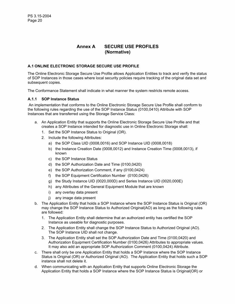
A.1 ONLINE ELECTRONIC STORAGE SECURE USE PROFILE
The Online Electronic Storage Secure Use Profile allows Application Entities to track and verify the status of SOP Instances in those cases where local security policies require tracking of the original data set and subsequent copies.
The Conformance Statement shall indicate in what manner the system restricts remote access.
A.1.1 SOP Instance Status An implementation that conforms to the Online Electronic Storage Secure Use Profile shall conform to the following rules regarding the use of the SOP Instance Status (0100,0410) Attribute with SOP Instances that are transferred using the Storage Service Class:
a. An Application Entity that supports the Online Electronic Storage Secure Use Profile and that creates a SOP Instance intended for diagnostic use in Online Electronic Storage shall: 1. Set the SOP Instance Status to Original (OR). 2. Include the following Attributes:
a) the SOP Class UID (0008,0016) and SOP Instance UID (0008,0018) b) the Instance Creation Date (0008,0012) and Instance Creation Time (0008,0013), if
known c) the SOP Instance Status d) the SOP Authorization Date and Time (0100,0420) e) the SOP Authorization Comment, if any (0100,0424) f) the SOP Equipment Certification Number (0100,0426) g) the Study Instance UID (0020,000D) and Series Instance UID (0020,000E) h) any Attributes of the General Equipment Module that are known i) any overlay data present j) any image data present
b. The Application Entity that holds a SOP Instance where the SOP Instance Status is Original (OR) may change the SOP Instance Status to Authorized Original(AO) as long as the following rules are followed: 1. The Application Entity shall determine that an authorized entity has certified the SOP
Instance as useable for diagnostic purposes. 2. The Application Entity shall change the SOP Instance Status to Authorized Original (AO).
The SOP Instance UID shall not change. 3. The Application Entity shall set the SOP Authorization Date and Time (0100,0420) and
Authorization Equipment Certification Number (0100,0426) Attributes to appropriate values. It may also add an appropriate SOP Authorization Comment (0100,0424) Attribute.
c. There shall only be one Application Entity that holds a SOP Instance where the SOP Instance Status is Original (OR) or Authorized Original (AO). The Application Entity that holds such a SOP instance shall not delete it.
d. When communicating with an Application Entity that supports Online Electronic Storage the Application Entity that holds a SOP Instance where the SOP Instance Status is Original(OR) or

PS 3.15-2004 Page 21
Authorized Original(AO) may transfer that SOP Instance to another Application Entity that also conforms to the Online Electronic Storage Secure Use Profile as long as the following rules are followed: 1. The transfer shall occur on a Secure Transport Connection. 2. The two Application Entities involved in the transfer shall authenticate each other and shall
confirm via the authentication that the other supports the Online Electronic Storage Secure Use Profile.
3. The receiving Application Entity shall reject the storage request and discard the received SOP Instance if the data integrity checks done after the transfer indicate that the SOP Instance was altered during transmission.
4. The transfer shall be confirmed using the push model of the Storage Commitment Service Class. Until it has completed this confirmation, the receiving Application Entity shall not forward the SOP Instance or Authorized Copies of the SOP instance to any other Application Entity.
5. Once confirmed that the receiving Application Entity has successfully committed the SOP Instance to storage, the sending Application Entity shall do one of the following to its local copy of the SOP Instance: a) delete the SOP Instance, b) change the SOP Instance Status to Not Specified (NS), c) if the SOP Instance Status was Authorized Original (AO), change the SOP Instance
Status to Authorized Copy (AC). e. When communicating with an Application Entity that supports Online Electronic Storage an
Application Entity that holds a SOP Instance whose SOP Instance Status is Authorized Original (AO) or Authorized Copy (AC) may send an Authorized Copy of the SOP Instance to another Application Entity as long as the following rules are followed: 1. The transfer shall occur on a Secure Transport Connection. 2. The two Application Entities involved in the transfer shall authenticate each other, and shall
confirm via the authentication that the other supports the Online Electronic Storage Secure Use Profile.
3. The sending Application Entity shall set the SOP Instance Status to either Not Specified (NS) or Authorized Copy (AC) in the copy sent. The SOP Instance UID shall not change.
4. The receiving Application Entity shall reject the storage request and discard the copy if data integrity checks done after the transfer indicate that the SOP Instance was altered during transmission.
f. If communicating with a system that does not support the Online Electronic Storage Secure Use Profile, or if communication is not done over a Secure Transport Connection, then 1. A sending Application Entity that conforms to this Security Profile shall either set the SOP
Instance Status to Not Specified (NS), or leave out the SOP Instance Status and associated parameters of any SOP Instances that the sending Application Entity sends out over the unsecured Transport Connection or to systems that do not support the Online Electronic Storage Secure Use Profile.
2. A receiving Application Entity that conforms to this Security Profile shall set the SOP Instance Status to Not Specified (NS) of any SOP Instance received over the unsecured Transport Connection or from systems that do not support the Online Electronic Storage Secure Use Profile.
g. The receiving Application Entity shall store SOP Instances in accordance with Level 2 as defined in the Storage Service Class (i.e., all Attributes, including Private Attributes), as required by the Storage Commitment Storage Service Class, and shall not coerce any Attribute other than SOP Instance Status, SOP Authorization Date and Time, Authorization Equipment Certification Number, and SOP Authorization Comment.

PS 3.15-2004 Page 22
h. Other than changes to the SOP Instance Status, SOP Authorization Date and Time, Authorization Equipment Certification Number, and SOP Authorization Comment Attributes, as outlined above, or changes to group length Attributes to accommodate the aforementioned changes, the Application Entity shall not change any Attribute values.
A.2 BASIC DIGITAL SIGNATURES SECURE USE PROFILE
An implementation that validates and generates Digital Signatures may claim conformance to the Basic Digital Signatures Secure Use Profile. Any implementation that claims conformance to this Security Profile shall obey the following rules in handling Digital Signatures:
a. The implementation shall store any SOP Instances that it receives in such a way that it guards against any unauthorized tampering of the SOP Instance.
b. Wherever possible, the implementation shall validate the Digital Signatures within any SOP Instance that it receives.
c. If the implementation sends the SOP Instance to another Application Entity, it shall do the following: 1. remove any Digital Signatures that may have become invalid due to any allowed variations to
the format of Attribute Values (e.g. trimming of padding, alternate representations of numbers),
2. generate one or more new Digital Signatures covering the Data Elements that the implementation was able to verify when the SOP Instance was received.
A.3 BIT-PRESERVING DIGITAL SIGNATURES SECURE USE PROFILE
An implementation that stores and forwards SOP Instances may claim conformance to the Bit-Preserving Digital Signatures Secure Use Profile. Any implementation that claims conformance to this Security Profile shall obey the following rules in handling Digital Signatures:
a. The implementation shall store any SOP Instances that it receives in such a way that when the SOP instance is forwarded to another Application Entity, the Value fields of all Attributes are bit-for-bit duplicates of the fields originally received.
b. The implementation shall not change the order of Items in a Sequence. c. The implementation shall not remove or change any Data Element of any SOP Instance that it
receives when sending that SOP Instance on to another Application Entity via DICOM. This includes any Digital Signatures received.
Note: Implementations may add new Data Elements that do not alter any existing Digital Signatures. d. The implementation shall utilize an explicit VR Transfer Syntax. Note: Implementations that cannot use an explicit VR Transfer Syntax cannot conform to this Secure Use
Profile, since it may not be able to verify Digital Signatures that are received with an implicit VR Transfer Syntax.
e. The implementation shall not change the VR of any Data Element that it receives when it transmits that object to another Application Entity.
PS 3.15-2004 Page 23
Annex B SECURE TRANSPORT CONNECTION PROFILES (Normative)
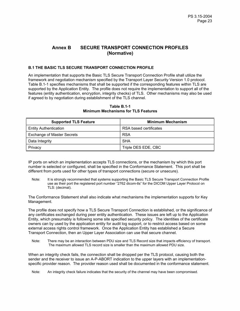
B.1 THE BASIC TLS SECURE TRANSPORT CONNECTION PROFILE
An implementation that supports the Basic TLS Secure Transport Connection Profile shall utilize the framework and negotiation mechanism specified by the Transport Layer Security Version 1.0 protocol. Table B.1-1 specifies mechanisms that shall be supported if the corresponding features within TLS are supported by the Application Entity. The profile does not require the implementation to support all of the features (entity authentication, encryption, integrity checks) of TLS. Other mechanisms may also be used if agreed to by negotiation during establishment of the TLS channel.
Table B.1-1 Minimum Mechanisms for TLS Features
Supported TLS Feature Minimum Mechanism
Entity Authentication RSA based certificates Exchange of Master Secrets RSA Data Integrity SHA Privacy Triple DES EDE, CBC
IP ports on which an implementation accepts TLS connections, or the mechanism by which this port number is selected or configured, shall be specified in the Conformance Statement. This port shall be different from ports used for other types of transport connections (secure or unsecure).
Note: It is strongly recommended that systems supporting the Basic TLS Secure Transport Connection Profile use as their port the registered port number “2762 dicom-tls” for the DICOM Upper Layer Protocol on TLS: (decimal).
The Conformance Statement shall also indicate what mechanisms the implementation supports for Key Management.
The profile does not specify how a TLS Secure Transport Connection is established, or the significance of any certificates exchanged during peer entity authentication. These issues are left up to the Application Entity, which presumably is following some site specified security policy. The identities of the certificate owners can by used by the application entity for audit log support, or to restrict access based on some external access rights control framework. Once the Application Entity has established a Secure Transport Connection, then an Upper Layer Association can use that secure channel.
Note: There may be an interaction between PDU size and TLS Record size that impacts efficiency of transport. The maximum allowed TLS record size is smaller than the maximum allowed PDU size.
When an integrity check fails, the connection shall be dropped per the TLS protocol, causing both the sender and the receiver to issue an A-P-ABORT indication to the upper layers with an implementation-specific provider reason. The provider reason used shall be documented in the conformance statement.
Note: An integrity check failure indicates that the security of the channel may have been compromised.
PS 3.15-2004 Page 24
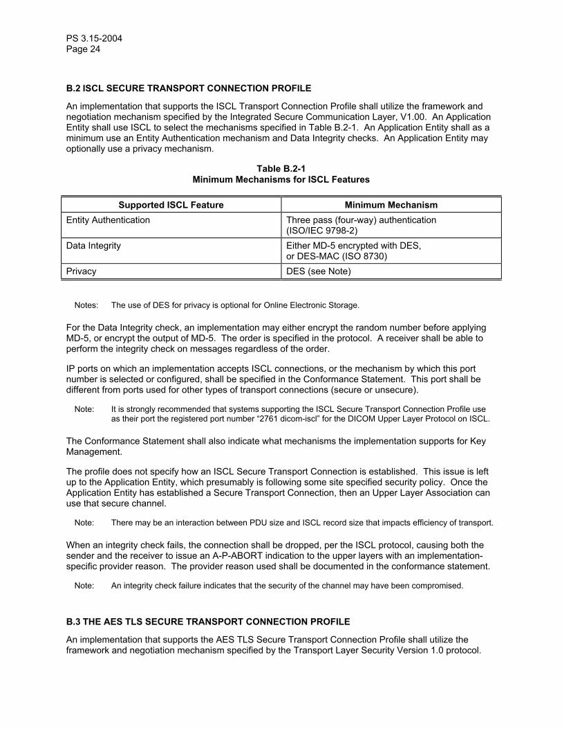
B.2 ISCL SECURE TRANSPORT CONNECTION PROFILE
An implementation that supports the ISCL Transport Connection Profile shall utilize the framework and negotiation mechanism specified by the Integrated Secure Communication Layer, V1.00. An Application Entity shall use ISCL to select the mechanisms specified in Table B.2-1. An Application Entity shall as a minimum use an Entity Authentication mechanism and Data Integrity checks. An Application Entity may optionally use a privacy mechanism.
Table B.2-1 Minimum Mechanisms for ISCL Features
Supported ISCL Feature Minimum Mechanism
Entity Authentication Three pass (four-way) authentication (ISO/IEC 9798-2)
Data Integrity Either MD-5 encrypted with DES, or DES-MAC (ISO 8730)
Privacy DES (see Note)
Notes: The use of DES for privacy is optional for Online Electronic Storage.
For the Data Integrity check, an implementation may either encrypt the random number before applying MD-5, or encrypt the output of MD-5. The order is specified in the protocol. A receiver shall be able to perform the integrity check on messages regardless of the order.
IP ports on which an implementation accepts ISCL connections, or the mechanism by which this port number is selected or configured, shall be specified in the Conformance Statement. This port shall be different from ports used for other types of transport connections (secure or unsecure).
Note: It is strongly recommended that systems supporting the ISCL Secure Transport Connection Profile use as their port the registered port number “2761 dicom-iscl” for the DICOM Upper Layer Protocol on ISCL.
The Conformance Statement shall also indicate what mechanisms the implementation supports for Key Management.
The profile does not specify how an ISCL Secure Transport Connection is established. This issue is left up to the Application Entity, which presumably is following some site specified security policy. Once the Application Entity has established a Secure Transport Connection, then an Upper Layer Association can use that secure channel.
Note: There may be an interaction between PDU size and ISCL record size that impacts efficiency of transport.
When an integrity check fails, the connection shall be dropped, per the ISCL protocol, causing both the sender and the receiver to issue an A-P-ABORT indication to the upper layers with an implementation-specific provider reason. The provider reason used shall be documented in the conformance statement.
Note: An integrity check failure indicates that the security of the channel may have been compromised.
B.3 THE AES TLS SECURE TRANSPORT CONNECTION PROFILE
An implementation that supports the AES TLS Secure Transport Connection Profile shall utilize the framework and negotiation mechanism specified by the Transport Layer Security Version 1.0 protocol.

PS 3.15-2004 Page 25
Table B.3-1 specifies mechanisms that shall be supported if the corresponding features within TLS are supported by the Application Entity. The profile does not require the implementation to support all of the features (entity authentication, encryption, integrity checks) of TLS. Other mechanisms may also be used if agreed to by negotiation during establishment of the TLS channel.
Table B.3-1 Minimum Mechanisms for TLS Features Supported TLS Feature Minimum Mechanism
Entity Authentication RSA based Certificates
Two cyphersuite options shall be offered during TLS negotiation by applications that comply with this profile:
TLS_RSA_WITH_AES_128_CBC_SHA TLS_RSA_WITH_3DES_EDE_CBC_SHA The application shall offer both options. The AES version shall be preferred. The fallback to 3DES is offered so that this profile can interoperate easily with applications that only support the 3DES cyphersuite.
IP ports on which an implementation accepts TLS connections, or the mechanism by which this port number is selected or configured, shall be specified in the Conformance Statement. This port shall be different from ports used for other types of transport connections (secure or unsecure).
Note: It is strongly recommended that systems supporting the AES TLS Secure Transport Connection Profile use as their port the registered port number “2762 dicom-tls” for the DICOM Upper Layer Protocol on TLS: (decimal).
The Conformance Statement shall also indicate what mechanisms the implementation supports for Key Management.
The profile does not specify how a TLS Secure Transport Connection is established, or the significance of any certificates exchanged during peer entity authentication. These issues are left up to the Application Entity, which presumably is following some site specified security policy. The identities of the certificate owners can by used by the application entity for audit log support, or to restrict access based on some external access rights control framework. Once the Application Entity has established a Secure Transport Connection, then an Upper Layer Association can use that secure channel.
Note: There may be an interaction between PDU size and TLS Record size that impacts efficiency of transport. The maximum allowed TLS record size is smaller than the maximum allowed PDU size.
When an integrity check fails, the connection shall be dropped per the TLS protocol, causing both the sender and the receiver to issue an A-P-ABORT indication to the upper layers with an implementation-specific provider reason. The provider reason used shall be documented in the conformance statement.
Note: An integrity check failure indicates that the security of the channel may have been compromised.

PS 3.15-2004 Page 26
Annex C DIGITAL SIGNATURE PROFILES (Normative)
C.1 BASE RSA DIGITAL SIGNATURE PROFILE
The Base RSA Digital Signature Profile outlines the use of RSA encryption of a MAC to generate a Digital Signature. This Profile does not specify any particular set of Data Elements to sign. Other Digital Signature profiles may refer to this profile, adding specifications of which Data Elements to sign or other customizations.
The creator of a digital signature shall use one of the RIPEMD-160, MD5, or SHA-1 hashing functions to generate a MAC, which is then encrypted using a private RSA key. All validators of digital signatures shall be capable of using a MAC generated by any of three hashing functions specified (RIPEMD-160, MD5, or SHA-1).
Note: The use of MD5 is not recommended by its inventors, RSA. See: ftp://ftp.rsasecurity.com/pub/pdfs/bulletn4.pdf
The MAC to be signed shall be padded to a block size matching the RSA key size, as directed in RFC 2437 (PKCS #1). The Value of MAC Algorithm (0400,0015) shall be set to either "RIPEMD160", “MD5”, or “SHA1”. The public key associated with the private key as well as the identity of the Application Entity or equipment manufacturer that owns the RSA key pair shall be transmitted in an X.509 (1993) signature certificate. The Value of the Certificate Type (0400,0110) Attribute shall be set to "X509_1993_SIG". A site-specific policy determines how the X.509 certificates are generated, authenticated, and distributed. A site may issue and distribute X.509 certificates directly, may utilize the services of a Certificate Authority, or use any reasonable method for certificate generation and verification.
If an implementation utilizes timestamps, it shall use a Certified Timestamp Type (0400,0305) of “CMS_TSP”. The Certified Timestamp (0400,0310) shall be generated as described in “Internet X.509 Public Key Infrastructure; Time Stamp Protocols; March 2000”.
C.2 CREATOR RSA DIGITAL SIGNATURE PROFILE
The creator of a DICOM SOP Instance may generate signatures using the Creator RSA Digital Signature Profile. The Digital Signature produced by this Profile serves as a lifetime data integrity check that can be used to verify that the pixel data in the SOP instance has not been altered since its initial creation. An implementation that supports the Creator RSA Digital Signature Profile may include a Creator RSA Digital Signature with every SOP Instance that it creates; however, the implementation is not required to do so.
As a minimum, an implementation shall include the following attributes in generating the Creator RSA Digital Signature:
a. the SOP Class and Instance UIDs b. the SOP Creation Date and Time, if present c. the Study and Series Instance UIDs d. any attributes of the General Equipment module that are present e. any attributes of the Overlay Plane, Curve or Graphic Annotation modules that are present f. any attributes of the General Image and Image Pixel modules that are present g. any attributes of the SR Document General and SR Document Content modules that are present
PS 3.15-2004 Page 27
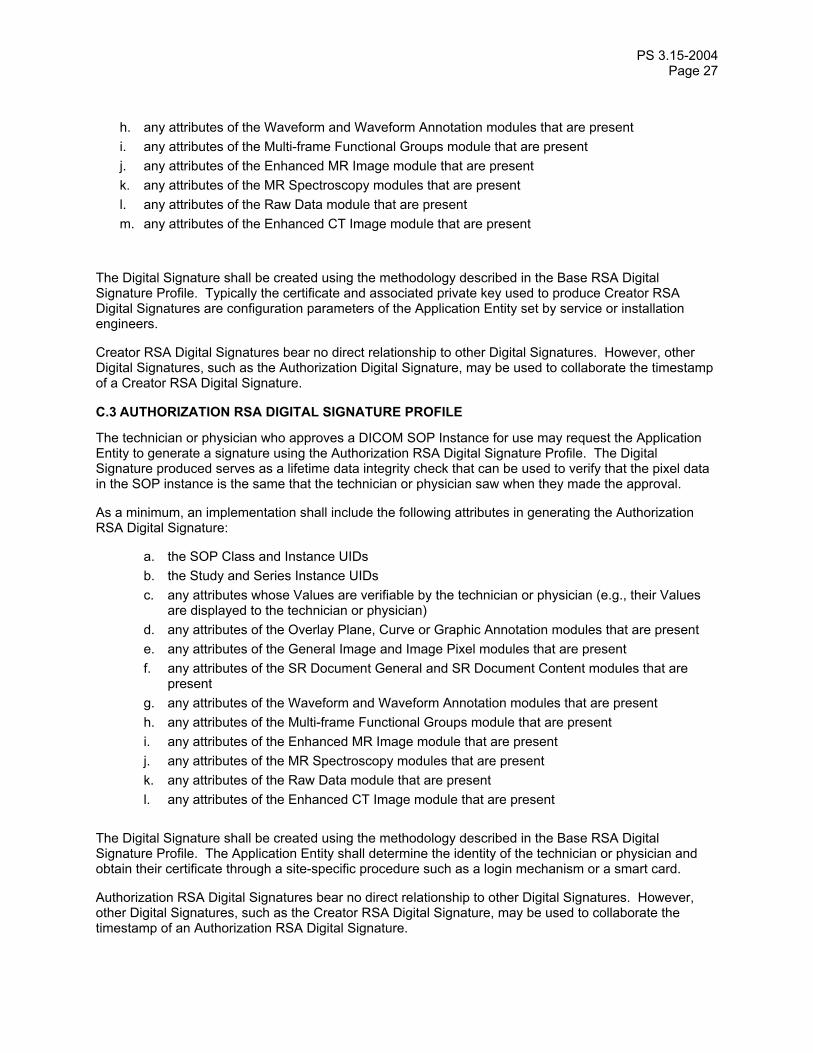
h. any attributes of the Waveform and Waveform Annotation modules that are present i. any attributes of the Multi-frame Functional Groups module that are present j. any attributes of the Enhanced MR Image module that are present k. any attributes of the MR Spectroscopy modules that are present l. any attributes of the Raw Data module that are present m. any attributes of the Enhanced CT Image module that are present
The Digital Signature shall be created using the methodology described in the Base RSA Digital Signature Profile. Typically the certificate and associated private key used to produce Creator RSA Digital Signatures are configuration parameters of the Application Entity set by service or installation engineers.
Creator RSA Digital Signatures bear no direct relationship to other Digital Signatures. However, other Digital Signatures, such as the Authorization Digital Signature, may be used to collaborate the timestamp of a Creator RSA Digital Signature.
C.3 AUTHORIZATION RSA DIGITAL SIGNATURE PROFILE
The technician or physician who approves a DICOM SOP Instance for use may request the Application Entity to generate a signature using the Authorization RSA Digital Signature Profile. The Digital Signature produced serves as a lifetime data integrity check that can be used to verify that the pixel data in the SOP instance is the same that the technician or physician saw when they made the approval.
As a minimum, an implementation shall include the following attributes in generating the Authorization RSA Digital Signature:
a. the SOP Class and Instance UIDs b. the Study and Series Instance UIDs c. any attributes whose Values are verifiable by the technician or physician (e.g., their Values
are displayed to the technician or physician) d. any attributes of the Overlay Plane, Curve or Graphic Annotation modules that are present e. any attributes of the General Image and Image Pixel modules that are present f. any attributes of the SR Document General and SR Document Content modules that are
present g. any attributes of the Waveform and Waveform Annotation modules that are present h. any attributes of the Multi-frame Functional Groups module that are present i. any attributes of the Enhanced MR Image module that are present j. any attributes of the MR Spectroscopy modules that are present k. any attributes of the Raw Data module that are present l. any attributes of the Enhanced CT Image module that are present
The Digital Signature shall be created using the methodology described in the Base RSA Digital Signature Profile. The Application Entity shall determine the identity of the technician or physician and obtain their certificate through a site-specific procedure such as a login mechanism or a smart card.
Authorization RSA Digital Signatures bear no direct relationship to other Digital Signatures. However, other Digital Signatures, such as the Creator RSA Digital Signature, may be used to collaborate the timestamp of an Authorization RSA Digital Signature.

PS 3.15-2004 Page 28
ANNEX D– MEDIA STORAGE SECURITY PROFILES (Normative)
D.1 BASIC DICOM MEDIA SECURITY PROFILE
The Basic DICOM Media Security Profile allows encapsulation of a DICOM File into a Secure DICOM File such that the following aspects of security are addressed:
— confidentiality, — integrity, — data origin authentication (optional).
This profile specifies the use of either AES or Triple-DES for content encryption and RSA for the key transport of the content-encryption keys. The encrypted content is a DICOM File which can either
— be signed with one or more digital signatures, using SHA-1 as the digest algorithm and RSA as the signature algorithm, or
— be digested with SHA-1 as digest algorithm, without application of digital signatures. D.1.1 Encapsulation of a DICOM File in a Secure DICOM File A Secure DICOM File conforming to this security profile shall contain an Enveloped-data content type of the Cryptographic Message Syntax defined in RFC 3369, 3370 and 3565. The enveloped data shall use RSA [RFC 3447] for the key transport of the content-encryption keys. Creators of a Secure DICOM File conforming to this security profile may use either AES or Triple-DES for content-encryption. Readers claiming conformance to this profile shall be capable of decrypting Secure DICOM Files using either AES or Triple-DES. The AES key length may be any length allowed by the RFCs. The Triple-DES key length is 168 bits as defined by ANSI X9.52. Encoding shall be performed according to the specifications for RSA Key Transport and Triple DES Content Encryption in RFC-3370, and for AES Content Encryption in RFC-3565. The encrypted content of the Enveloped-data content type shall be of the following choices:
— Signed-data content type; — Digested-data content type.
In both cases, SHA-1 [SHA-1] shall be used as the digest algorithm. In case of the Signed-data content type, RSA [RFC 2313] shall be used as the signature algorithm.
Notes: 1. RSA key transport of the content-encryption keys is specified as a requirement in the European Prestandard ENV 13608-2: Health Informatics - Security for healthcare communication – Part 2: Secure data objects.
2. No requirements on the size of the asymmetric key pairs used for RSA key transport are defined in this profile.
3. No requirements or restrictions on the use of the SignedAttributes element of the Signed-data content type’s SignerInfo structure are defined in this profile. SignedAttributes might for example be used to specify the signing time or SMIME capabilities, as required by ENV 13608-2.
PS 3.15-2004 Page 29
ANNEX E - ATTRIBUTE CONFIDENTIALITY PROFILES
E.1 BASIC APPLICATION LEVEL CONFIDENTIALITY PROFILE
This Basic Application Level Confidentiality Profile addresses the following aspects of security:
— Data Confidentiality at the application level. Other aspects of security not addressed by this profile, that may be addressed elsewhere in the standard include:
— Confidentiality in other layers of the DICOM model; — Data Integrity.
This Profile is targeted toward creating a special purpose, de-identified version of an already-existing Data Set. It is not intended to replace the original SOP Instance from which the de-identified SOP Instance is created, nor is it intended to act as the primary representation of clinical Data Sets in image archives. The de-identified SOP Instances are useful, for example, in creating teaching or research files, where the identity of the patient should be protected, but still be accessible to authorized personnel.
E.1.1 De-Identifier An Application may claim conformance to the Basic Application Level Confidentiality Profile as a de-identifier if it protects all Attributes that might be used by unauthorized entities to identify the patient. Protection in this context is defined as the following process:
1. The application may create one or more instances of the Encrypted Attributes Data Set and copy Attributes to be protected into the (single) item of the Modified Attributes Sequence (0400,0550) of one or more of the Encrypted Attributes Data Set instances.
Note: A complete reconstruction of the original Data Set may not be possible; however, Attributes (e.g. SOP Instance UID) in the Modified Attributes Sequence of an Encrypted Attributes Data Set may refer back to the original SOP Instance holding the original Data Set.
2. Each Attribute to be protected shall then either be removed from the dataset, or have its value
replaced by a different “replacement value” which does not allow identification of the patient.
Note: 1. It is the responsibility of the de-identifier to ensure that this process does not negatively affect the integrity of the Information Object Definition, i. e. Dummy values may be necessary for Type 1 Attributes that are protected but may not be sent with zero length, and are to be stored or exchanged in encrypted form by applications that may not be aware of the security machanism.
2. The standard does not mandate the use of any particular dummy value, and indeed it may have some meaning, for example in a data set that may be used for teaching purposes, where the real patient identifying information is encrypted for later retrieval, but a meaningful alternative form of identification is provided. For example, a dummy Patient’s Name (0010,0010) may convey the type of pathology in a teaching case. It is the responsibility of the de-identifier to ensure that the dummy values cannot be used to identify the patient.
3. It is the responsibility of the de-identifier to ensure the consistency of dummy values for Attributes such as Study Instance UID (0020,000D) or Frame of Reference UID (0020,0052) if multiple related SOP Instances are protected.
4. This standard does not allow selective protection of parts of a Sequence of Items. If an Attribute to be protected is contained in a Sequence of Items, the complete Sequence of Items needs to be protected.
5. The de-identifier should ensure that identifying information that is burned in to the image pixel data is “blackened” (removed). The means by which identifying information is located and removed is outside the scope of this standard.

PS 3.15-2004 Page 30
3. At the discretion of the de-identifier, Attributes may be added to the dataset to be protected.
Note: As an example, the Attribute Patient’s Age (0010,1010) might be introduced as a replacement for Patient’s Birth Date (0010,0030) if the patient’s age is of importance.
4. All instances of the Encrypted Attributes Data Set shall be encoded with a DICOM Transfer Syntax,
encrypted , and stored in the dataset to be protected as an Item of the Encrypted Attributes Sequence (0400,0500). The encryption shall be done using RSA [RFC 2313] for the key transport of the content-encryption keys. A de-identifier conforming to this security profile may use either AES or Triple-DES for content-encryption. The AES key length may be any length allowed by the RFCs. The Triple-DES key length is 168 bits as defined by ANSI X9.52. Encoding shall be performed according to the specifications for RSA Key Transport and Triple DES Content Encryption in RFC-3370 and for AES Content Encryption in RFC-3565.
Note: 1. Each item of the Encrypted Attributes Sequence (0400,0500) consists of two Attributes, Encrypted
Content Transfer Syntax UID (0400,0510) containing the UID of the Transfer Syntax that was used to encode the instance of the Encrypted Attributes Data Set, and Encrypted Content (0400,0520) containing the block of data resulting from the encryption of the Encrypted Attributes Data Set instance. 2. RSA key transport of the content-encryption keys is specified as a requirement in the European Prestandard ENV 13608-2: Health Informatics - Security for healthcare communication – Part 2: Secure data objects.
3. No requirements on the size of the asymmetric key pairs used for RSA key transport are defined in this confidentiality scheme.Implementations claiming conformance to the Basic Application Level Confidentiality Profile as a de-identifier shall always protect (e.g. encrypt and replace) the SOP Instance UID (0008,0018) Attribute as well as all references to other SOP Instances, whether contained in the main dataset or embedded in an Item of a Sequence of Items, that could potentially be used by unauthorized entities to identify the patient.
Note: In the case of a SOP Instance UID embedded in an item of a sequence, this means that the enclosing Attribute in the top-level data set must be encrypted in its entirety.
The Attributes listed in Table E.1-1 contained in Standard IODs typically need to be protected to provide a minimal level of confidentiality from identification. An implementation claiming conformance to the Basic Application Level Confidentiality Profile as a de-identifier shall protect all instances of the Attributes listed in Table E.1-1, whether contained in the main dataset or embedded in an Item of a Sequence of Items, unless the implementation can ensure that the content of these Attributes cannot be used by unauthorized entities to identify the patient.
Notes: 1. The Attributes listed in Table E.1-1 may not be sufficient to guarantee confidentiality of patient identity. In particular, identifying information may be contained in Private Attributes, Curves or Overlays. It is the responsibility of the de-identifier to ensure that all identifying information is removed.
2. It should be noted that conformance to the Basic Application Level Confidentiality Profile does not necessarily guarantee confidentiality. Any encryption scheme may be vulnerable to attack. Also, an organization’s Security Policy and Key Management policy are recognized to have a much greater impact on the effectiveness of protection.
3. If the image pixel data contains ‘burned in’ identifications, the de-identifier may ‘black’ them out to de-identify the pixel data.
4. National and local regulations, which may vary, might require that additional attributes be de-identified.

PS 3.15-2004 Page 31
Table E.1-1 Basic Application Level Confidentiality Profile Attributes
Attribute Name Tag Instance Creator UID (0008,0014) SOP Instance UID (0008,0018) Accession Number (0008,0050) Institution Name (0008,0080) Institution Address (0008,0081) Referring Physician’s Name (0008,0090) Referring Physician’s Address (0008,0092) Referring Physician’s Telephone Numbers
(0008,0094)
Station Name (0008,1010) Study Description (0008,1030) Series Description (0008,103E) Institutional Department Name (0008,1040) Physician(s) of Record (0008,1048) Performing Physicians’ Name (0008,1050) Name of Physician(s) Reading Study (0008,1060) Operators’ Name (0008,1070) Admitting Diagnoses Description (0008,1080) Referenced SOP Instance UID (0008,1155) Derivation Description (0008,2111) Patient’s Name (0010,0010) Patient ID (0010,0020) Patient’s Birth Date (0010,0030) Patient’s Birth Time (0010,0032) Patient’s Sex (0010,0040) Other Patient Ids (0010,1000) Other Patient Names (0010,1001) Patient’s Age (0010,1010) Patient’s Size (0010,1020) Patient’s Weight (0010,1030) Medical Record Locator (0010,1090) Ethnic Group (0010,2160) Occupation (0010,2180) Additional Patient’s History (0010,21B0) Patient Comments (0010,4000) Device Serial Number (0018,1000)

PS 3.15-2004 Page 32
Protocol Name (0018,1030) Study Instance UID (0020,000D
) Series Instance UID (0020,000E) Study ID (0020,0010) Frame of Reference UID (0020,0052) Synchronization Frame of Reference UID (0020,0200) Image Comments (0020,4000) Request Attributes Sequence (0040,0275) UID (0040,A124) Content Sequence (0040,A730) Storage Media File-set UID (0088,0140) Referenced Frame of Reference UID (3006,0024) Related Frame of Reference UID (3006,00C2
) E.1.2 Re-Identifier An Application may claim conformance to the Basic Application Level Confidentiality Profile as a re-identifier if it is capable of removing the protection from a protected SOP instance given that the recipient keys required for the decryption of one or more of the Encrypted Content (0400,0520) Attributes within the Encrypted Attributes Sequence (0400,0500) of the SOP instance are available. Removal of protection in this context is defined as the following process:
1. The application shall decrypt, using its recipient key, one instance of the Encrypted Content (0400,0520) Attribute within the Encrypted Attributes Sequence (0400,0500) and decode the resulting block of bytes into a DICOM dataset using the Transfer Syntax specified in the Encrypted Content Transfer Syntax UID (0400,0510). Re-identifiers claiming conformance to this profile shall be capable of decrypting the Encrypted Content using either AES or Triple-DES in all possible key lengths specified in this profile.
Note: If the application is able to decode more than one instance of the Encrypted Content (0400,0520) Attribute within the Encrypted Attributes Sequence (0400,0500), it is at the discretion of the application to choose any one of them.
2. The application shall move all Attributes contained in the single item of the Modified Attributes Sequence (0400,0550) of the decoded dataset into the main dataset, replacing“dummy value” Attributes that may be present in the main dataset.
Notes: 1. Re-identification does not imply a complete reconstruction of the original SOP Instance, since it is not required that all Attributes being protected be part of the Encrypted Attributes Data Set. If the original UIDs are part of the Encrypted Attributes Data Set, they might be usable to gain access to the original, unprotected SOP Instance.
2. The presence of an encrypted data set that cannot be decrypted indicates that some or all of the attribute values in the message may not be real (they are dummies). Therefore, the recipient must not assume that any value in the message is diagnostically relevant.

PS 3.15-2004 Page 33
E.1.3 Conformance Requirements The Conformance Statement of an application that claims conformance to the Basic Application Level Confidentiality Profile shall describe:
— which Attributes are removed during protection; — which Attributes are replaced by dummy values and how the dummy values are generated; — which Attributes are included in Encrypted Attributes Data Sets for later re-identification, and
any pertinent details about how keys are selected for performing the encryption; — whether or not the application is able to ensure integrity of dummy values for references such
as SOP Instance UID, Frame of Reference UID, etc. if multiple SOP instances are protected; — which Attributes and Attribute values are inserted during protection of a SOP instance; — which Transfer Syntaxes are supported for encoding/decoding of the Encrypted Attributes
Data Set; — which Confidentiality Schemes are supported; — any additional restrictions (e. g. key sizes for public keys).

PS 3.15-2004 Page 34
Annex F Network Address Management Profiles
F.1 BASIC NETWORK ADDRESS MANAGEMENT PROFILE
The Basic Network Address Management Profile utilizes DHCP to provide services to assign and manage IP parameters for machines remotely. The DHCP server is manually configured to establish the rules for assigning IP addresses to machines. The rules may be explicit machine by machine assignments and may be assignment of a block of IP addresses to be assigned dynamically as machines are attached and removed from the network. The DHCP client can obtain its IP address and a variety of related parameters such as NTP server address from the DHCP server during startup. The DHCP server may dynamically update the DNS server with new relationships between IP addresses and DNS hostnames.
The DNS Client can obtain the IP number for another host by giving the DNS hostname to a DNS Server and receive the IP number in response. This transaction may be used in other profiles or in implementations that do not conform to the Basic Network Address Management Profile.
The Basic Network Address Management Profile applies to the actors DHCP Server, DHCP Client, DNS Server, and DNS Client. The mandatory and optional transactions are described in the table and sections below.
Table F.1-1- Basic Network Address Management Profile
Actor Transaction Optionality Section DHCP Server Configure DHCP Server M F.1.2 Find and Use DHCP Server M F.1.3 Maintain Lease M F.1.4 Resolve Hostname M F.1.1 DDNS Coordination O F.1.5 DHCP Client Find and Use DHCP Server M F.1.3 Maintain Lease M F.1.4 DNS Server DDNS Coordination O F.1.5 Resolve Hostname M F.1.1 DNS Client Resolve Hostname M F.1.1
F.1.1 Resolve Hostname F.1.1.1 Scope The DNS Client can obtain the IP number for a host by giving the DNS hostname to a DNS Server and receive the IP number in response.
F.1.1.2 Use Case Roles

PS 3.15-2004 Page 35
Resolve Hostname
DNS Client
DNS Server
Figure F.1-1 Resolve Hostname
Actor: DNS Client
Role: Needs IP address, has the DNS Hostname
Actor: DNS Server
Role: Provides current IP address when given the DNS Hostname
F.1.1.3 Referenced Standards The standards and their relationships for the family of DNS protocols are shown in Figure F.1-2 . The details of transactions, transaction diagrams, etc. are contained within the referenced RFC’s.
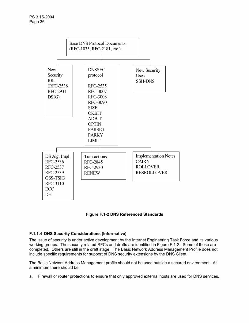
PS 3.15-2004 Page 36
Base DNS Protocol Documents:
(RFC-1035, RFC-2181, etc.)
New Security RRs (RFC-2538 RFC-2931 DSIG)
DNSSEC protocol RFC-2535 RFC-3007 RFC-3008 RFC-3090 SIZE OKBIT ADBIT OPTIN PARSIG PARKY LIMIT
New Security Uses SSH-DNS
DS Alg. Impl RFC-2536 RFC-2537 RFC-2539 GSS-TSIG RFC-3110 ECC DH
Transactions RFC-2845 RFC-2930 RENEW
Implementation Notes CAIRN ROLLOVER RESROLLOVER
Figure F.1-2 DNS Referenced Standards
F.1.1.4 DNS Security Considerations (Informative) The issue of security is under active development by the Internet Engineering Task Force and its various working groups. The security related RFCs and drafts are identified in Figure F.1-2. Some of these are completed. Others are still in the draft stage. The Basic Network Address Management Profile does not include specific requirements for support of DNS security extensions by the DNS Client.
The Basic Network Address Management profile should not be used outside a secured environment. At a minimum there should be:
a. Firewall or router protections to ensure that only approved external hosts are used for DNS services.
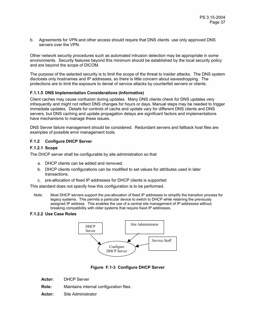
PS 3.15-2004 Page 37
b. Agreements for VPN and other access should require that DNS clients use only approved DNS servers over the VPN.
Other network security procedures such as automated intrusion detection may be appropriate in some environments. Security features beyond this minimum should be established by the local security policy and are beyond the scope of DICOM.
The purpose of the selected security is to limit the scope of the threat to insider attacks. The DNS system discloses only hostnames and IP addresses, so there is little concern about eavesdropping. The protections are to limit the exposure to denial of service attacks by counterfeit servers or clients.
F.1.1.5 DNS Implementation Considerations (Informative) Client caches may cause confusion during updates. Many DNS clients check for DNS updates very infrequently and might not reflect DNS changes for hours or days. Manual steps may be needed to trigger immediate updates. Details for controls of cache and update vary for different DNS clients and DNS servers, but DNS caching and update propagation delays are significant factors and implementations have mechanisms to manage these issues.
DNS Server failure management should be considered. Redundant servers and fallback host files are examples of possible error management tools.
F.1.2 Configure DHCP Server F.1.2.1 Scope The DHCP server shall be configurable by site administration so that
a. DHCP clients can be added and removed. b. DHCP clients configurations can be modified to set values for attributes used in later
transactions. c. pre-allocation of fixed IP addresses for DHCP clients is supported
This standard does not specify how this configuration is to be performed.
Note: Most DHCP servers support the pre-allocation of fixed IP addresses to simplify the transition process for legacy systems. This permits a particular device to switch to DHCP while retaining the previously assigned IP address. This enables the use of a central site management of IP addresses without breaking compatibility with older systems that require fixed IP addresses.
F.1.2.2 Use Case Roles
Configure DHCP Server
DHCP Server
Site Administrator
Service Staff
Figure F.1-3 Configure DHCP Server
Actor: DHCP Server
Role: Maintains internal configuration files.
Actor: Site Administrator
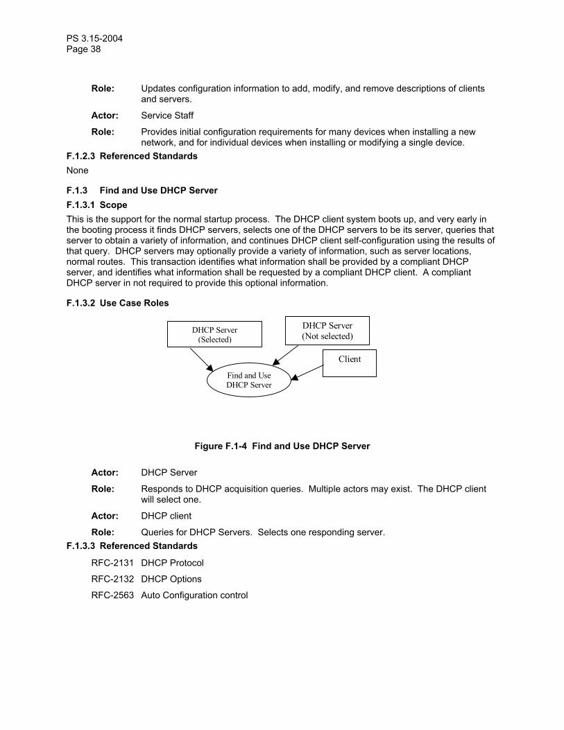
PS 3.15-2004 Page 38
Role: Updates configuration information to add, modify, and remove descriptions of clients and servers.
Actor: Service Staff
Role: Provides initial configuration requirements for many devices when installing a new network, and for individual devices when installing or modifying a single device.
F.1.2.3 Referenced Standards None
F.1.3 Find and Use DHCP Server F.1.3.1 Scope This is the support for the normal startup process. The DHCP client system boots up, and very early in the booting process it finds DHCP servers, selects one of the DHCP servers to be its server, queries that server to obtain a variety of information, and continues DHCP client self-configuration using the results of that query. DHCP servers may optionally provide a variety of information, such as server locations, normal routes. This transaction identifies what information shall be provided by a compliant DHCP server, and identifies what information shall be requested by a compliant DHCP client. A compliant DHCP server in not required to provide this optional information.
F.1.3.2 Use Case Roles
Find and Use DHCP Server
DHCP Server (Selected)
DHCP Server (Not selected)
Client
Figure F.1-4 Find and Use DHCP Server
Actor: DHCP Server
Role: Responds to DHCP acquisition queries. Multiple actors may exist. The DHCP client will select one.
Actor: DHCP client
Role: Queries for DHCP Servers. Selects one responding server. F.1.3.3 Referenced Standards
RFC-2131 DHCP Protocol
RFC-2132 DHCP Options
RFC-2563 Auto Configuration control
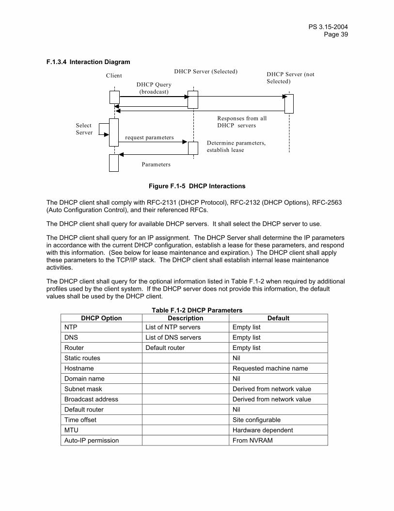
PS 3.15-2004 Page 39
F.1.3.4 Interaction Diagram
Client DHCP Server (Selected)
DHCP Query (broadcast)
request parameters
DHCP Server (not Selected)
Parameters
Determine parameters, establish lease
Responses from all DHCP servers Select
Server
Figure F.1-5 DHCP Interactions
The DHCP client shall comply with RFC-2131 (DHCP Protocol), RFC-2132 (DHCP Options), RFC-2563 (Auto Configuration Control), and their referenced RFCs.
The DHCP client shall query for available DHCP servers. It shall select the DHCP server to use.
The DHCP client shall query for an IP assignment. The DHCP Server shall determine the IP parameters in accordance with the current DHCP configuration, establish a lease for these parameters, and respond with this information. (See below for lease maintenance and expiration.) The DHCP client shall apply these parameters to the TCP/IP stack. The DHCP client shall establish internal lease maintenance activities.
The DHCP client shall query for the optional information listed in Table F.1-2 when required by additional profiles used by the client system. If the DHCP server does not provide this information, the default values shall be used by the DHCP client.
Table F.1-2 DHCP Parameters DHCP Option Description Default
NTP List of NTP servers Empty list DNS List of DNS servers Empty list Router Default router Empty list Static routes Nil Hostname Requested machine name Domain name Nil Subnet mask Derived from network value Broadcast address Derived from network value Default router Nil Time offset Site configurable MTU Hardware dependent Auto-IP permission From NVRAM

PS 3.15-2004 Page 40
The DHCP client shall make this information available for other actors within the DHCP client machine.
F.1.4 Maintain Lease F.1.4.1 Scope The DHCP client normally maintains the IP lease in compliance with the RFCs. Sometimes the server will not renew the lease. Non-renewal is usually part of network service operations. The loss of the IP lease requires connections using that IP address to cease.
F.1.4.2 Use Case Roles
Maintain Lease
DHCP Client
DHCP Server
Figure F.1-6 Maintain Lease
Actor: DHCP client
Role: Deals with lease renewal and expiration.
Actor: DHCP Server
Role: Renewing or deliberately letting leases expire (sometimes done as part of network service operations).
F.1.4.3 Referenced Standards
RFC-2131 DHCP Protocol
RFC-2132 DHCP Options F.1.4.4 Normal Interaction The DHCP client shall maintain a lease on the IP address in accordance with the DHCP protocol as specified in RFC-2131 and RFC-2132. There is a possibility that the DHCP Server may fail, or may choose not to renew the lease.
In the event that the DHCP lease expires without being renewed, any still active DICOM connections may be aborted (AP-Abort).
Note: There is usually a period (typically between several minutes and several days) between the request for lease extension and actual expiration of the lease. The application might take advantage of this to perform a graceful association release rather than the abrupt shutdown of an AP-Abort.
F.1.5 DDNS Coordination F.1.5.1 Scope DHCP servers may coordinate their IP and hostname assignments with a DNS server. This permits dynamic assignment of IP addresses without interfering with access to DHCP Clients by other systems.

PS 3.15-2004 Page 41
The other systems utilize the agreed hostname (which DHCP can manage and provide to the client) and obtain the current IP address by means of DNS lookup.
A DHCP Server is in compliance with this optional part of the Basic Network Address Management Profile profile if it maintains and updates the relevant DNS server so as to maintain the proper hostname/IP relationships in the DNS database.
F.1.5.2 Use Case Roles
DDNS Coordination
DHCP Server
DNS Server
Figure F.1-7 DDNS Coordination
Actor: DHCP Server
Role: Responded to DHCP acquisition queries and assigned IP address to client.
Actor: DNS Server
Role: Maintains the DNS services for the network. F.1.5.3 Referenced Standards
RFC-2136 Dynamic Updates in the Domain Name System F.1.5.4 Basic Course of Events After the DHCP server has assigned an IP address to a DHCP client, the DHCP server uses DDNS to inform the DNS server that the hostname assigned to the DHCP client has been given the assigned IP address. The DNS Server updates the DNS database so that subsequent DNS queries for this hostname are given the assigned IP address. When the lease for the IP address expires without renewal, the DHCP server informs the DNS server that the IP address and hostname are no longer valid. The DNS server removes them from the DNS database.
F.1.6 DHCP Security Considerations (Informative) The Basic Network Address Management Profile Profile has two areas of security concerns:
a. Protection against denial of service attacks against the DHCP client/server traffic. b. Protection against denial of service attacks against the DHCP server to DDNS server update
process.
The Basic Network Address Management Profile Profile should not be used outside a secured environment. At a minimum there should be:

PS 3.15-2004 Page 42
a. Firewall and or router protections to ensure that only approved hosts are used for DHCP and DNS services.
b. Agreements for VPN and other access should require that DNS clients on the hospital network use only approved DHCP or DNS servers over the VPN.
Other network security procedures such as automated intrusion detection may be appropriate in some environments. Security features beyond this minimum should be established by the local security policy and are beyond the scope of DICOM.
The purpose of the selected security is to limit the scope of the threat to insider attacks. The DHCP and DNS systems disclose only hostnames and IP addresses, so there is little concern about eavesdropping. The protections are to limit the exposure to denial of service attacks by counterfeit servers or clients. The specific DNS security extensions are described in SectionF.1.1.4. This profile does not utilize the DHCP security extensions because they provide very limited added security and the attacks are insider denial of service attacks. Intrusion detection and other network level protection mechanisms are the most effective next level of protections for the DHCP process.
The DNS update is optional in this profile to accommodate the possibility that the DHCP server and DNS server cannot reach a mutually acceptable security process. Support of this option may require support of the DNS security protocols that are in the process of development. See Section F.1.1.4 for a discussion of the DNS security profile standards and drafts.
F.1.7 DHCP Implementation Considerations (Informative) The DHCP configuration file can be a very useful form of documentation for the local network hardware configuration. It can be prepared in advance for new installations and updated as clients are added. Including information for all machines, including those that do not utilize DHCP, avoids accidental IP address conflicts and similar errors.
Most DHCP servers have a configuration capability that permits control of the IP address and other information provided to the client. These controls can pre-allocate a specific IP address, etc. to a machine based on the requested machine name or MAC address. These pre-allocated IP addresses then ensure that these specific machines are always assigned the same IP address. Legacy systems that do not utilize DNS can continue to use fixed tables with IP addresses when the DHCP server has pre-allocated the IP addresses for those services.
F.1.8 Conformance The Conformance Statement for an LDAP Client shall describe its use of LDAP to configure the local AE titles. Any conformance to the Update LDAP Server option shall be specified, together with the values for all component object attributes in the update sent to the LDAP Server. Any use of LDAP to configure the remote device addresses and capabilities shall be described. The LDAP queries used to obtain remote device component object attributes shall be specified.
Note: In particular, use of LDAP to obtain the AE Title, TCP port, and IP address for specific system actors (e.g., an Image Archive, or a Performed Procedure Step Manager) should be detailed, as well as how the LDAP information for remote devices is selected for operational use.
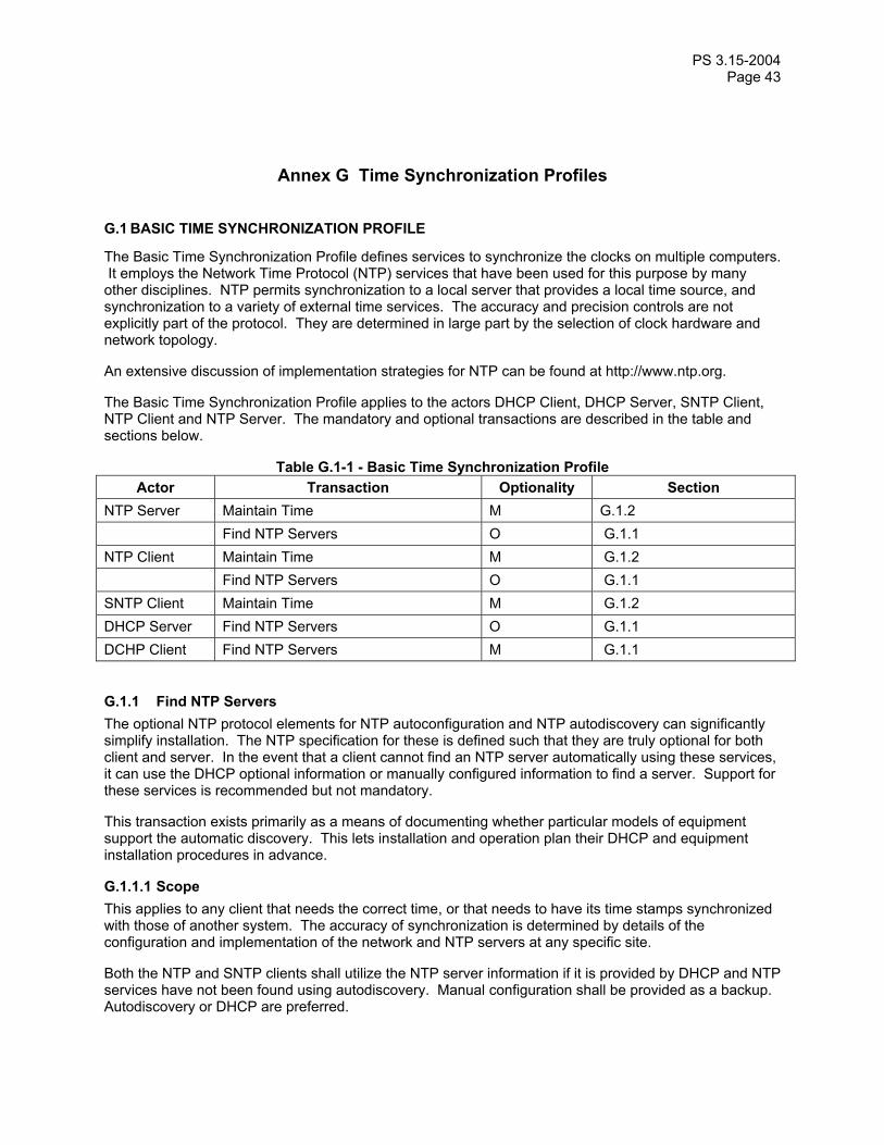
PS 3.15-2004 Page 43
Annex G Time Synchronization Profiles
G.1 BASIC TIME SYNCHRONIZATION PROFILE
The Basic Time Synchronization Profile defines services to synchronize the clocks on multiple computers. It employs the Network Time Protocol (NTP) services that have been used for this purpose by many other disciplines. NTP permits synchronization to a local server that provides a local time source, and synchronization to a variety of external time services. The accuracy and precision controls are not explicitly part of the protocol. They are determined in large part by the selection of clock hardware and network topology.
An extensive discussion of implementation strategies for NTP can be found at http://www.ntp.org.
The Basic Time Synchronization Profile applies to the actors DHCP Client, DHCP Server, SNTP Client, NTP Client and NTP Server. The mandatory and optional transactions are described in the table and sections below.
Table G.1-1 - Basic Time Synchronization Profile Actor Transaction Optionality Section
NTP Server Maintain Time M G.1.2 Find NTP Servers O G.1.1 NTP Client Maintain Time M G.1.2 Find NTP Servers O G.1.1 SNTP Client Maintain Time M G.1.2 DHCP Server Find NTP Servers O G.1.1 DCHP Client Find NTP Servers M G.1.1
G.1.1 Find NTP Servers The optional NTP protocol elements for NTP autoconfiguration and NTP autodiscovery can significantly simplify installation. The NTP specification for these is defined such that they are truly optional for both client and server. In the event that a client cannot find an NTP server automatically using these services, it can use the DHCP optional information or manually configured information to find a server. Support for these services is recommended but not mandatory.
This transaction exists primarily as a means of documenting whether particular models of equipment support the automatic discovery. This lets installation and operation plan their DHCP and equipment installation procedures in advance.
G.1.1.1 Scope This applies to any client that needs the correct time, or that needs to have its time stamps synchronized with those of another system. The accuracy of synchronization is determined by details of the configuration and implementation of the network and NTP servers at any specific site.
Both the NTP and SNTP clients shall utilize the NTP server information if it is provided by DHCP and NTP services have not been found using autodiscovery. Manual configuration shall be provided as a backup. Autodiscovery or DHCP are preferred.

PS 3.15-2004 Page 44
G.1.1.2 Use Case Roles
Find NTP Servers
NTP Client NTP Servers
DHCP Client DHCP Server
SNTP Client
Figure G.1-1 Find NTP Servers
DHCP Server Provides UTC offset, provides list of NTP servers
DHCP Client Receives UTC offset and list of NTP servers
NTP Client Maintains client clock
SNTP Client Maintains client clock
NTP Servers External time servers. These may have connections to other time servers, and may be synchronized with national time sources.
G.1.1.3 Referenced Standards
RFC-1305 Network Time Protocol (NTP) standard specification
RFC-2030 Simple NTP G.1.1.4 Basic Course of Events. The DHCP server may have provided a list of NTP servers or one may be obtained through optional NTP discovery mechanisms. If this list is empty and no manually configured NTP server address is present, the client shall select its internal clock as the time source (see below). If the list is not empty, the client shall attempt to maintain time synchronization with all those NTP servers. The client may attempt to use the multi-cast, manycast, and broadcast options as defined in RFC-1305. It shall utilize the point to point synchronization option if these are not available. The synchronization shall be in compliance with either RFC-1305 (NTP) or RFC-2030 (SNTP).
If the application requires time synchronization of better than 1s mean error, the client should use NTP. SNTP cannot ensure a more accurate time synchronization.
The DHCP server may have provided a UTC offset between the local time at the machine and UTC. If this is missing, the UTC offset will be obtained in a device specific manner (e.g. service, CMOS). If the UTC offset is provided, the client shall use this offset for converting between UTC and local time.
G.1.1.5 Alternative Paths If there is no UTC offset information from the DHCP server, then the NTP client will use its preset or service set UTC offset.

PS 3.15-2004 Page 45
If there is no NTP time server, then the NTP client will select its internal battery clock as the source of UTC. These may have substantial errors. This also means that when there are multiple systems but no NTP source, the multiple systems will not attempt to synchronize with one another.
G.1.1.6 Assumptions The local battery clock time is set to UTC, or the local operating system has proper support to manage both battery clock time, NTP clock time, and system clock time. The NTP time is always in UTC.
G.1.1.7 Postconditions The client will remain synchronized with its selected time source. In an environment with one or more NTP servers, this will be good time synchronization. In the absence of NTP servers, the selected source will be the internal client clock, with all its attendant errors.
G.1.2 Maintain Time G.1.2.1 Scope This applies to any client that needs the correct time, or that needs to have its time stamps synchronized with those of another system. The accuracy of synchronization is determined by details of the configuration and implementation of the network and NTP servers at any specific site.
G.1.2.2 Use Case Roles
Maintain Time
NTP Client NTP Server
Figure G.2-1 Maintain Time
NTP/SNTP Client Maintains client clock
NTP Servers External time servers. These may have connections to other time servers, and may be synchronized with national time sources.
G.1.2.3 Referenced Standards
RFC-1305 Network Time Protocol (NTP) standard specification
RFC-2030 Simple NTP
G.1.2.4 Basic Course of Events. All the full detail is in RFC-1305 and RFC-2030. The most common and mandatory minimum mode for NTP operation establishes a ping pong of messages between client and servers. The client sends requests to the servers, which fill in time related fields in a response, and the client performs optimal estimation of the present time. The RFCs deal with issues of lost messages, estimation formulae, etc.

PS 3.15-2004 Page 46
Once the clocks are in synchronization these ping pong exchanges typically stabilize at roughly 1000 second intervals.
The client machine typically uses the time estimate to maintain the internal operating system clock. This clock is then used by applications that need time information. This approach eliminates the application visible difference between synchronized and unsynchronized time. The RFCs provide guidance on proper implementations.
G.1.3 NTP Security Considerations (Informative) The Basic Time Synchronization profile should not be used outside a secured environment. At a minimum there should be:
a. Firewall and or router protections to ensure that only approved hosts are used for NTP services. b. Agreements for VPN and other access should require that use only approved NTP servers over the
VPN.
This limits the risks to insider denial of service attacks. The service denial is manipulation of the time synchronization such that systems report the incorrect time. The NTP protocols incorporate secure transaction capabilities that can be negotiated. This profile assumes that the above protections are sufficient and does not require support of secure transactions, but they may be supported by an implementation. The SNTP client does not support the use of secured transactions.
Sites with particular concerns regarding security of external network time sources may choose to utilize a GPS or radio based time synchronization. Note that when selecting GPS and radio time sources, care must be taken to establish the accuracy and stability provided by the particular time source. The underlying time accuracy of GPS and radio sources is superb, but some receivers are intended for low accuracy uses and do not provide an accurate or stable result.
G.1.4 NTP Implementation Considerations (informative) NTP servers always support both NTP and SNTP clients. The difference is one of synchronization accuracy, not communications compatibility. Although in theory both NTP and SNTP clients could run at the same time on a client this is not recommended. The SNTP updates will simply degrade the time accuracy. When other time protocol clients, such as IRIG, are also being used these clients must be coordinated with the NTP client to avoid synchronization problems.
RFC-1305 includes specifications for management of intermittent access to the NTP servers, broken servers, etc. The NTP servers do not need to be present and operational when the NTP process begins. NTP supports the use of multiple servers to provide backup and better accuracy. RFC-1305 specifies the mechanisms used by the NTP client. The site www.ntp.org provides extensive guidance and references regarding the most effective configurations for backups and multiple server configurations.
The local battery clock and client operating system must be properly UTC aware. NTP synchronization is in UTC. This can be a source of confusion because some computers are configured with their hardware clocks set to local time and the operating system set (incorrectly) to UTC. This is a common error that only becomes apparent when the devices attempt to synchronize clocks.
G.1.5 Conformance The Conformance Statement for the NTP Server and NTP Client shall state whether secure transactions are supported.
The Conformance Statement for the NTP Server shall state whether it is also an NTP Client.

PS 3.15-2004 Page 47
Annex H Application Configuration Management Profiles
H.1 APPLICATION CONFIGURATION MANAGEMENT PROFILE
The Application Configuration Management Profile applies to the actors LDAP Server, LDAP Client, and DNS Server. The mandatory and optional transactions are described in the table and sections below.
Table H.1-1 – Application Configuration Management Profiles Actor Transaction Optionality Section
LDAP Server Query LDAP Server M H.1.4.2 Update LDAP Server O H.1.4.3 Maintain LDAP Server M H.1.4.4 LDAP Client Find LDAP Server M H.1.4.1 Query LDAP Server M H.1.4.2 Update LDAP Server O H.1.4.3 DNS Server Find LDAP Server M H.1.4.1
H.1.1 Data Model Component Objects The normative definition of the schema can be found in Section H.1.3. This section gives additional informative descriptions of the objects and information defined in that schema and makes normative statements regarding DICOM system behavior.
The Application Configuration Data Model has the following component objects:
Device – The description of the device
Network AE – The description of the network application entity
Network Connection – The description of the network interface
Transfer Capability – The description of the SOP classes and syntaxes supported by a Network AE.

PS 3.15-2004 Page 48
Device Contains Network Connections
Provides
Application Entities
Available on
1 1..M
1
1..N 1..N
1..M
Transfer Capability Has
1..N 1
Figure H.1-1 Application Configuration Data Model
In addition there are a number of other objects used in the LDAP schema (see section H.1.2 and Figure H. 1-2) :
DICOM Configuration Root – The root of DICOM Configuration Hierarchy
DICOM Devices Root – The root of the DICOM Devices Hierarchy
DICOM Unique AE-Title Registry Root – The root of the Unique DICOM AE-Title Registry
DICOM Unique AE Title – A unique AE Title within the AE Title Registry LDAP permits extensions to schema to support local needs (i.e. an object may implement a single structural and multiple auxiliary LDAP classes). DICOM does not mandate client support for such extensions. Servers may support such extensions for local purposes. DICOM Clients may accept or ignore extensions and shall not consider their presence an error.
H.1.1.1 Device The “device” is set of components organized to perform a task rather than a specific physical instance. For simple devices there may be one physical device corresponding to the Data Model device. But for complex equipment there may be many physical parts to one “device”.
The “device” is the collection of physical entities that supports a collection of Application Entities. It is uniquely associated with these entities and vice versa. It is also uniquely associated with the network connections and vice versa. In a simple workstation with one CPU, power connection, and network connection the “device” is the workstation.
An example of a complex device is a server built from a network of multiple computers that have multiple network connections and independent power connections. This would be one device with one application entity and multiple network connections. Servers like this are designed so that individual component computers can be replaced without disturbing operations. The Application Configuration Data Model does not describe any of this internal structure. It describes the network connections and the network visible Application Entities. These complex devices are usually designed for very high availability, but in the unusual event of a system shutdown the “device” corresponds to all the parts that get shut down.

PS 3.15-2004 Page 49
Table H.1-2 Attributes of Device Object Information Field Multiplicity Description
Device Name 1 A unique name (within the scope of the LDAP database) for this device. It is restricted to legal LDAP names, and not constrained by DICOM AE Title limitations.
Description 0..1 Unconstrained text description of the device. Manufacturer 0..1 Should be the same as the value of
Manufacturer (0008,0070) in SOP instances created by this device.
Manufacturer Model Name 0..1 Should be the same as the value of Manufacturer Model Name (0008,1090) in SOP instances created by this device.
Software Version 0..N Should be the same as the values of Software Versions (0018,1020) in SOP instances created by this device.
Station Name 0..1 Should be the same as the value of Station Name (0008,1010) in SOP instances created by this device.
Device Serial Number 0..1 Should be the same as the value of Device Serial Number (0018,1000) in SOP instances created by this device.
Primary Device Type 0..N Represents the kind of device and is most applicable for acquisition modalities. Types should be selected from the list of code values (0008,0100) for Context ID 30 in PS3.16 when applicable.
Institution Name 0..N Should be the same as the value of Institution Name (0008,0080) in SOP Instances created by this device.
Institution Address 0..N Should be the same as the value of Institution Address (0008,0081) attribute in SOP Instances created by this device.
Institutional Department Name 0..N Should be the same as the value of Institutional Department Name (0008,1040) in SOP Instances created by this device.
Issuer of Patient ID 0..1 Default value for the Issuer of Patient ID (0010,0021) for SOP Instances created by this device. May be overridden by the values received in a worklist or other source.
Related Device Reference 0..N The DNs of related device descriptions outside the DICOM Configuration hierarchy. Can be used to link the DICOM Device object to additional LDAP objects instantiated from other schema and used for separate administrative purposes.
Authorized Node Certificate Reference
0..N The DNs for the certificates of nodes that are authorized to connect to this device. The DNs need not be within the DICOM configuration

PS 3.15-2004 Page 50
Information Field Multiplicity Description hierarchy.
This Node Certificate Reference 0..N The DNs of the public certificate(s) for this node. The DNs need not be within the DICOM configuration hierarchy.
Vendor Device Data 0..N Device specific vendor configuration information
Installed 1 Boolean to indicate whether this device is presently installed on the network. (This is useful for pre-configuration, mobile vans, and similar situations.)
The “Authorized Node Certificate Reference” is intended to allow the LDAP server to provide the list of certificates for nodes that are authorized to communicate with this device. These should be the public certificates only. This list need not be complete. Other network peers may be authorized by other mechanisms.
The “This Node Certificate Reference” is intended to allow the LDAP server to provide the certificate(s) for this node. These may also be handled independently of LDAP.
Note: A device may have multiple Primary Device Type entries. It may be a multifunctional device, e.g. combined PET and CT. It may be a cascaded device, e.g. image capture and ultrasound.
Table H.1-3 Child Objects of Device Object
Information Field Multiplicity Description Network Application Entity 1..N The application entities available on this device
(see Section H.1.1.2) Network Connection 1..N The network connections for this device (see
Section H.1.1.3)
H.1.1.2 Network Application Entity A Network AE is an application entity that provides services on a network. A Network AE will have the same functional capability regardless of the particular network connection used. If there are functional differences based on selected network connection, then these are separate Network AEs. If there are functional differences based on other internal structures, then these are separate Network AEs.
Table H.1-4 Attributes of Network AE Object Information Field Multiplicity Description
AE Title 1 Unique AE title for this Network AE Description 0..1 Unconstrained text description of the application
entity. Vendor Data 0..N AE specific vendor configuration information Application Cluster 0..N Locally defined names for a subset of related
applications. E.g. “neuroradiology”. Preferred Called AE Title 0..N AE Title(s) that are preferred for initiating
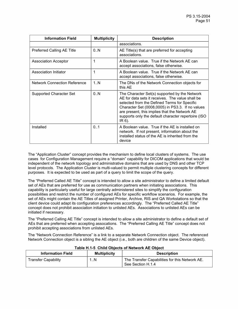
PS 3.15-2004 Page 51
Information Field Multiplicity Description associations.
Preferred Calling AE Title 0..N AE Title(s) that are preferred for accepting associations.
Association Acceptor 1 A Boolean value. True if the Network AE can accept associations, false otherwise.
Association Initiator 1 A Boolean value. True if the Network AE can accept associations, false otherwise.
Network Connection Reference 1..N The DNs of the Network Connection objects for this AE
Supported Character Set 0..N The Character Set(s) supported by the Network AE for data sets it receives. The value shall be selected from the Defined Terms for Specific Character Set (0008,0005) in PS3.3. If no values are present, this implies that the Network AE supports only the default character repertoire (ISO IR 6).
Installed 0..1 A Boolean value. True if the AE is installed on network. If not present, information about the installed status of the AE is inherited from the device
The “Application Cluster” concept provides the mechanism to define local clusters of systems. The use cases for Configuration Management require a “domain” capability for DICOM applications that would be independent of the network topology and administrative domains that are used by DNS and other TCP level protocols. The Application Cluster is multi-valued to permit multiple clustering concepts for different purposes. It is expected to be used as part of a query to limit the scope of the query.
The “Preferred Called AE Title” concept is intended to allow a site administrator to define a limited default set of AEs that are preferred for use as communication partners when initiating associations. This capability is particularly useful for large centrally administered sites to simplify the configuration possibilities and restrict the number of configured AEs for specific workflow scenarios. For example, the set of AEs might contain the AE Titles of assigned Printer, Archive, RIS and QA Workstations so that the client device could adapt its configuration preferences accordingly. The “Preferred Called AE Title” concept does not prohibit association initiation to unlisted AEs. Associations to unlisted AEs can be initiated if necessary.
The “Preferred Calling AE Title” concept is intended to allow a site administrator to define a default set of AEs that are preferred when accepting assocations. The “Preferred Calling AE Title” concept does not prohibit accepting associations from unlisted AEs.
The “Network Connection Reference” is a link to a separate Network Connection object. The referenced Network Connection object is a sibling the AE object (i.e., both are children of the same Device object).
Table H.1-5 Child Objects of Network AE Object Information Field Multiplicity Description
Transfer Capability 1..N The Transfer Capabilities for this Network AE. See Section H.1.4
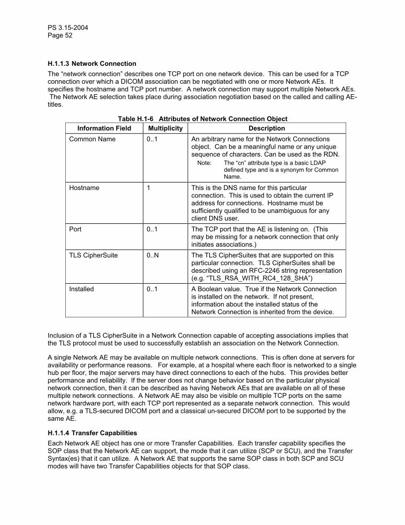
PS 3.15-2004 Page 52
H.1.1.3 Network Connection The “network connection” describes one TCP port on one network device. This can be used for a TCP connection over which a DICOM association can be negotiated with one or more Network AEs. It specifies the hostname and TCP port number. A network connection may support multiple Network AEs. The Network AE selection takes place during association negotiation based on the called and calling AE-titles.
Table H.1-6 Attributes of Network Connection Object Information Field Multiplicity Description
Common Name 0..1 An arbitrary name for the Network Connections object. Can be a meaningful name or any unique sequence of characters. Can be used as the RDN.
Note: The “cn” attribute type is a basic LDAP defined type and is a synonym for Common Name.
Hostname 1 This is the DNS name for this particular connection. This is used to obtain the current IP address for connections. Hostname must be sufficiently qualified to be unambiguous for any client DNS user.
Port 0..1 The TCP port that the AE is listening on. (This may be missing for a network connection that only initiates associations.)
TLS CipherSuite 0..N The TLS CipherSuites that are supported on this particular connection. TLS CipherSuites shall be described using an RFC-2246 string representation (e.g. “TLS_RSA_WITH_RC4_128_SHA”)
Installed 0..1 A Boolean value. True if the Network Connection is installed on the network. If not present, information about the installed status of the Network Connection is inherited from the device.
Inclusion of a TLS CipherSuite in a Network Connection capable of accepting associations implies that the TLS protocol must be used to successfully establish an association on the Network Connection.
A single Network AE may be available on multiple network connections. This is often done at servers for availability or performance reasons. For example, at a hospital where each floor is networked to a single hub per floor, the major servers may have direct connections to each of the hubs. This provides better performance and reliability. If the server does not change behavior based on the particular physical network connection, then it can be described as having Network AEs that are available on all of these multiple network connections. A Network AE may also be visible on multiple TCP ports on the same network hardware port, with each TCP port represented as a separate network connection. This would allow, e.g. a TLS-secured DICOM port and a classical un-secured DICOM port to be supported by the same AE.
H.1.1.4 Transfer Capabilities Each Network AE object has one or more Transfer Capabilities. Each transfer capability specifies the SOP class that the Network AE can support, the mode that it can utilize (SCP or SCU), and the Transfer Syntax(es) that it can utilize. A Network AE that supports the same SOP class in both SCP and SCU modes will have two Transfer Capabilities objects for that SOP class.

PS 3.15-2004 Page 53
Table H.1-7 Attributes of Transfer Capability Object Information Field Multiplicity Description
Common Name 0..1 An arbitrary name for the Transfer Capability object. Can be a meaningful name or any unqiue sequence of characters. Can be used as the RDN.
SOP Class 1 SOP Class UID Role 1 Either “SCU” or “SCP” Transfer Syntax 1..N The transfer syntax(es) that may be requested as
an SCU or that are offered as an SCP.
H.1.1.5 DICOM Configuration Root This structural object class represents the root of the DICOM Configuration Hierarchy. Only a single object of this type should exist within an organizational domain. Clients can search for an object of this class to locate the root of the DICOM Configuration Hierarchy.
Table H.1-8 Attributes of the DICOM Configuration Root Object Information Field Multiplicity Description
Common Name 1 The Name for the Configuration Root. Should be used as the RDN. The name shall be “DICOM Configuration”.
Description 0..1 Unconstrained text description.
Table H.1-9 Child Objects of DICOM Configuration Root Object Information Field Multiplicity Description
Devices Root 1 The root of the DICOM Devices Hierarchy Unique AE Titles Registry Root 1 The root of the Unique AE Titles Registry
H.1.1.6 Devices Root This structural object class represents the root of the DICOM Devices Hierarchy. Only a single object of this type should exist as a child of DICOM Configuration Root. Clients can search for an object of this class to locate the root of the DICOM Devices Hierarchy.
Table H.1-10 Attributes of the Devices Root Object Information Field Multiplicity Description
Common Name 1 The Name for the Devices Root. Should be used as the RDN. The name shall be “Devices”.
Description 0..1 Unconstrained text description.
Table H.1-11 Child Objects of Devices Root Object Information Field Multiplicity Description
Device 0..N The individual devices installed within this organizational domain.

PS 3.15-2004 Page 54
H.1.1.7 Unique AE Titles Registry Root This structural object class represents the root of the Unique AE-Titles Registry Hierarchy. Only a single object of this type should exist as a child of the DICOM Configuration Root. Clients can search for an object of this class to locate the root of the Unique AE Titles Registry.
Table H.1-12 Attributes of the Unique AE Titles Registry Root Object Information Field Multiplicity Description
Common Name 1 The Name for the Unique AE Titles Registry Root. Should be used as the RDN. The name shall be “Unique AE Titles Registry”.
Description 0..1 Unconstrained text description.
Table H.1-13 Child Objects of Unique AE Titles Registry Root Object Information Field Multiplicity Description
Unique AE Title 0..N The unique AE Titles installed within this organizational domain (see Section H.1.8)
H.1.1.8 Unique AE Title This structural object class represents a Unique Application Entity Title. Objects of this type should only exist as children of the Unique AE-Titles Registry Root. The sole purpose of this object class is to enable allocation of unique AE Titles. All operational information associated with an AE Title is maintained within a separate Network AE object.
Table H.1-14 Attributes of the Unique AE Title Object Information Field Multiplicity Description
AE Title 1 The Unique AE Titles.
H.1.2 Application Configuration Data Model Hierarchy The LDAP structure is built upon a hierarchy of named objects. This hierarchy can vary from site to site. The DICOM configuration management function needs to find its objects within this hierarchy in a predictable manner. For this reason, three specific object classes are defined for the three objects at the top of the DICOM hierarchy. These three object classes must not be used in this tree relationship anywhere else in the LDAP hierarchy.
The DICOM portion of the hierarchy shall begin at a root object of class dicomConfigurationRoot with a Common Name of “DICOM Configuration”. Below this object shall be two other objects:
a. An object of class dicomDevicesRoot with a Common Name of “Devices”. This is the root of the tree of objects that correspond to the Application Configuration Data Model structure of Section H.1.1.
b. An object of class dicomUniqueAETitlesRegistryRoot with a common name of “Unique AE Titles Registry”. This is the root of a flat tree of objects. Each of these objects is named with one of the AE titles that are presently assigned. This is the mechanism for finding available AE titles.

PS 3.15-2004 Page 55
The three object classes dicomConfigurationRoot, dicomDevicesRoot, and dicomUniqueAETitleRegistryRoot are used by LDAP clients to establish the local root of the DICOM configuration information within an LDAP hierarchy that may be used for many other purposes.
Note: During system startup it is likely that the DICOM configuration application will do an LDAP search for an entry of object class dicomConfigurationRoot and then confirm that it has the dicomDevicesRoot and dicomUniqueAETitlesRegistryRoot entries directly below it. When it finds this configuration, it can then save the full location within the local LDAP tree and use that as the root of the DICOM tree.
The objects underneath the dicomUniqueAETitlesRegistryRoot are used to provide the uniqueness required for DICOM AE-titles. The dicomUniqueAETitle objects have a single attribute representing a unique AE Title. When a new AE-Title is required, a tentative new name is selected. The new name is reserved by using the LDAP create facility to create an object of class dicomUniqueAETitle with the new name under the AE-Title object. If this name is already in use, the create will fail. Otherwise, this reserves the name. LDAP queries can be used to obtain the list of presently assigned AE-titles by obtaining the list of all names under the dicomUniqueAETitlesRegistryRoot object.
DICOM Configuration
Unique AE Titles RegistryDevices
Device A
Network AEs
Connections
hospital, organization, country, root
Transfer Capabilities
Unique AE Title
Figure H.1-2 DICOM Configuration Hierarchy Notes: 1. LDAP uses a root and relative hierarchical naming system for objects. Every object name is fully
unique within the full hierarchy. This means that the names of the objects beneath “Unique AE Titles Registry” will be unique. It also means that the full names of Network AEs and Connections will be within their hierarchy context. E.g., the DN for one of the Network AEs in Figure H.1-2 would be:
dicomAETitle=CT_01, dicomDeviceName=Special Research CT, cn=Devices, cn=DICOM Configuration, o=Sometown Hospital
2. In theory, multiple independent DICOM configuration hierarchies could exist within one organization. The LDAP servers in such a network should constrain local device accesses so that DICOM configuration clients have only one DICOM Configuration Hierarchy visible to each client.

PS 3.15-2004 Page 56
3. The merger of two organizations will require manual configuration management to merge DICOM Configuration hierarchies. There are likely to be conflicts in AE-titles, roles, and other conflicts.
H.1.3 LDAP Schema for Objects and Attributes The individual LDAP attribute information is summarized in the comments at the beginning of the schema below. The formal definition of the objects and the attributes is in the schema below. This schema may be extended by defining an additional schema that defines auxiliary classes, sub-classes derived from this schema, or both.
The formal LDAP schema for the Application Configuration Data Model and the DICOM Configuration Hierarchy is:
# 3 Attribute Type Definitions # # The following attribute types are defined in this document: # # Name Syntax Multiplicity # -------------------------------- ------ ------------ # dicomDeviceName string Single # dicomDescription string Single # dicomManufacturer string Single # dicomManufacturerModelName string Single # dicomSoftwareVersion string Multiple # dicomVendorData binary Multiple # dicomAETitle string Single # dicomNetworkConnectionReference DN Multiple # dicomApplicationCluster string Multiple # dicomAssociationInitiator bool Single # dicomAssociationAcceptor bool Single # dicomHostname string Single # dicomPort integer Single # dicomSOPClass OID Single # dicomTransferRole string Single # dicomTransferSyntax OID Multiple # dicomPrimaryDeviceType string Multiple # dicomRelatedDeviceReference DN Multiple # dicomPreferredCalledAETitle string Multiple # dicomTLSCipherSuite string Multiple # dicomAuthorizedNodeCertificateReference DN Multiple # dicomThisNodeCertificateReference DN Multiple # dicomInstalled bool Single # dicomStationName string Single # dicomDeviceSerialNumber string Single # dicomInstitutionName string Multiple # dicomInstitutionAddress string Multiple # dicomInstitutionDepartmentName string Multiple # dicomIssuerOfPatientID string Single # dicomPreferredCallingAETitle string Multiple # dicomSupportedCharacterSet string Multiple # # 3.1 dicomDeviceName string Single # # This attribute stores the unique name (within the scope of the LDAP database) # for a DICOM Device. # # It is a single-valued attribute. # This attribute's syntax is 'Directory String'. # Its case is not significant for equality and substring matches. # attributetype ( 1.2.840.10008.15.0.3.1 NAME 'dicomDeviceName' DESC 'The unique name for the device' EQUALITY caseIgnoreMatch SUBSTR caseIgnoreSubstringsMatch SYNTAX 1.3.6.1.4.1.1466.115.121.1.15

PS 3.15-2004 Page 57
SINGLE-VALUE ) # 3.2 dicomDescription string Single # # This attribute stores the (unconstrained) textual description for a DICOM entity. # # It is a single-valued attribute. # This attribute's syntax is 'Directory String'. # Its case is not significant for equality and substring matches. # attributetype ( 1.2.840.10008.15.0.3.2 NAME 'dicomDescription' DESC 'Textual description of the DICOM entity' EQUALITY caseIgnoreMatch SUBSTR caseIgnoreSubstringsMatch SYNTAX 1.3.6.1.4.1.1466.115.121.1.15 SINGLE-VALUE ) # 3.3 dicomManufacturer string Single # # This attribute stores the Manufacturer name for a DICOM Device. # Should be identical to the value of the DICOM attribute Manufacturer (0008,0070) [VR=LO] # contained in SOP Instances created by this device. # # It is a single-valued attribute. # This attribute's syntax is 'Directory String'. # Its case is not significant for equality and substring matches. # attributetype ( 1.2.840.10008.15.0.3.3 NAME 'dicomManufacturer' DESC 'The device Manufacturer name' EQUALITY caseIgnoreMatch SUBSTR caseIgnoreSubstringsMatch SYNTAX 1.3.6.1.4.1.1466.115.121.1.15 SINGLE-VALUE ) # 3.4 dicomManufacturerModelName string Single # # This attribute stores the Manufacturer Model Name for a DICOM Device. # Should be identical to the value of the DICOM attribute Manufacturer # Model Name (0008,1090) [VR=LO] # contained in SOP Instances created by this device. # # It is a single-valued attribute. # This attribute's syntax is 'Directory String'. # Its case is not significant for equality and substring matches. # attributetype ( 1.2.840.10008.15.0.3.4 NAME 'dicomManufacturerModelName' DESC 'The device Manufacturer Model Name' EQUALITY caseIgnoreMatch SUBSTR caseIgnoreSubstringsMatch SYNTAX 1.3.6.1.4.1.1466.115.121.1.15 SINGLE-VALUE ) # 3.5 dicomSoftwareVersion string Multiple # # This attribute stores the software version of the device and/or its subcomponents. # Should be the same as the values of Software Versions (0018,1020) in # SOP instances created by this device. # # It is a multi-valued attribute. # This attribute's syntax is 'Directory String'. # Its case is not significant for equality and substring matches. # attributetype ( 1.2.840.10008.15.0.3.5 NAME 'dicomSoftwareVersion'
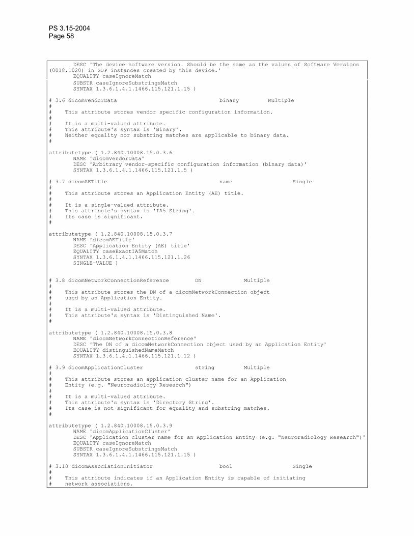
PS 3.15-2004 Page 58
DESC 'The device software version. Should be the same as the values of Software Versions (0018,1020) in SOP instances created by this device.' EQUALITY caseIgnoreMatch SUBSTR caseIgnoreSubstringsMatch SYNTAX 1.3.6.1.4.1.1466.115.121.1.15 ) # 3.6 dicomVendorData binary Multiple # # This attribute stores vendor specific configuration information. # # It is a multi-valued attribute. # This attribute's syntax is 'Binary'. # Neither equality nor substring matches are applicable to binary data. # attributetype ( 1.2.840.10008.15.0.3.6 NAME 'dicomVendorData' DESC 'Arbitrary vendor-specific configuration information (binary data)' SYNTAX 1.3.6.1.4.1.1466.115.121.1.5 ) # 3.7 dicomAETitle name Single # # This attribute stores an Application Entity (AE) title. # # It is a single-valued attribute. # This attribute's syntax is 'IA5 String'. # Its case is significant. # attributetype ( 1.2.840.10008.15.0.3.7 NAME 'dicomAETitle' DESC 'Application Entity (AE) title' EQUALITY caseExactIA5Match SYNTAX 1.3.6.1.4.1.1466.115.121.1.26 SINGLE-VALUE ) # 3.8 dicomNetworkConnectionReference DN Multiple # # This attribute stores the DN of a dicomNetworkConnection object # used by an Application Entity. # # It is a multi-valued attribute. # This attribute's syntax is 'Distinguished Name'. # attributetype ( 1.2.840.10008.15.0.3.8 NAME 'dicomNetworkConnectionReference' DESC 'The DN of a dicomNetworkConnection object used by an Application Entity' EQUALITY distinguishedNameMatch SYNTAX 1.3.6.1.4.1.1466.115.121.1.12 ) # 3.9 dicomApplicationCluster string Multiple # # This attribute stores an application cluster name for an Application # Entity (e.g. "Neuroradiology Research") # # It is a multi-valued attribute. # This attribute's syntax is 'Directory String'. # Its case is not significant for equality and substring matches. # attributetype ( 1.2.840.10008.15.0.3.9 NAME 'dicomApplicationCluster' DESC 'Application cluster name for an Application Entity (e.g. "Neuroradiology Research")' EQUALITY caseIgnoreMatch SUBSTR caseIgnoreSubstringsMatch SYNTAX 1.3.6.1.4.1.1466.115.121.1.15 ) # 3.10 dicomAssociationInitiator bool Single # # This attribute indicates if an Application Entity is capable of initiating # network associations.

PS 3.15-2004 Page 59
# # It is a single-valued attribute. # This attribute's syntax is 'Boolean'. # attributetype ( 1.2.840.10008.15.0.3.10 NAME 'dicomAssociationInitiator' DESC 'Indicates if an Application Entity is capable of initiating network associations' EQUALITY booleanMatch SYNTAX 1.3.6.1.4.1.1466.115.121.1.7 SINGLE-VALUE ) # 3.11 dicomAssociationAcceptor bool Single # # This attribute indicates if an Application Entity is capable of accepting # network associations. # # It is a single-valued attribute. # This attribute's syntax is 'Boolean'. # attributetype ( 1.2.840.10008.15.0.3.11 NAME 'dicomAssociationAcceptor' DESC 'Indicates if an Application Entity is capable of accepting network associations' EQUALITY booleanMatch SYNTAX 1.3.6.1.4.1.1466.115.121.1.7 SINGLE-VALUE ) # 3.12 dicomHostname string Single # # This attribute stores a DNS hostname for a connection. # # It is a single-valued attribute. # This attribute's syntax is 'Directory String'. # Its case is not significant for equality and substring matches. # attributetype ( 1.2.840.10008.15.0.3.12 NAME 'dicomHostname' DESC 'DNS hostname' EQUALITY caseIgnoreMatch SUBSTR caseIgnoreSubstringsMatch SYNTAX 1.3.6.1.4.1.1466.115.121.1.15 SINGLE-VALUE ) # 3.13 dicomPort integer Single # # This attribute stores a TCP port number for a connection. # # It is a single-valued attribute. # This attribute's syntax is 'Integer'. # attributetype ( 1.2.840.10008.15.0.3.13 NAME 'dicomPort' DESC 'TCP Port number' EQUALITY integerMatch SYNTAX 1.3.6.1.4.1.1466.115.121.1.27 SINGLE-VALUE ) # 3.14 dicomSOPClass OID Single # # This attribute stores a SOP Class UID # # It is a single-valued attribute. # This attribute's syntax is 'OID'. # attributetype ( 1.2.840.10008.15.0.3.14 NAME 'dicomSOPClass' DESC 'A SOP Class UID'

PS 3.15-2004 Page 60
EQUALITY objectIdentifierMatch SYNTAX 1.3.6.1.4.1.1466.115.121.1.38 SINGLE-VALUE ) # 3.15 dicomTransferRole String Single # # This attribute stores a transfer role (either "SCU" or "SCP"). # # It is a single-valued attribute. # This attribute's syntax is 'Directory String'. # Its case is not significant for equality and substring matches. # attributetype ( 1.2.840.10008.15.0.3.15 NAME 'dicomTransferRole' DESC 'Transfer role (either "SCU" or "SCP")' EQUALITY caseIgnoreMatch SUBSTR caseIgnoreSubstringsMatch SYNTAX 1.3.6.1.4.1.1466.115.121.1.15 SINGLE-VALUE ) # 3.16 dicomTransferSyntax OID Multiple # # This attribute stores a Transfer Syntax UID # # It is a multi-valued attribute. # This attribute's syntax is 'OID'. # attributetype ( 1.2.840.10008.15.0.3.16 NAME 'dicomTransferSyntax' DESC 'A Transfer Syntax UID' EQUALITY objectIdentifierMatch SYNTAX 1.3.6.1.4.1.1466.115.121.1.38 ) # 3.17 dicomPrimaryDeviceType string Multiple # # This attribute stores the primary type for a DICOM Device. # Types should be selected from the list of code values (0008,0100) # for Context ID 30 in DICOM Part 16 when applicable. # # It is a multiple-valued attribute. # This attribute's syntax is 'IA5 String'. # Its case is significant. # attributetype ( 1.2.840.10008.15.0.3.17 NAME 'dicomPrimaryDeviceType' DESC 'The device Primary Device type' EQUALITY caseExactIA5Match SYNTAX 1.3.6.1.4.1.1466.115.121.1.26 ) # 3.18 dicomRelatedDeviceReference DN Multiple # # This attribute stores a reference to a related device description outside # the DICOM Configuration Hierachy. Can be used to link the DICOM Device object to # additional LDAP objects instantiated from other schema and used for # separate administrative purposes. # # This attribute's syntax is 'Distinguished Name'. # It is a multiple-valued attribute. # attributetype ( 1.2.840.10008.15.0.3.18 NAME 'dicomRelatedDeviceReference' DESC 'The DN of a related device description outside the DICOM Configuration Hierachy' EQUALITY distinguishedNameMatch SYNTAX 1.3.6.1.4.1.1466.115.121.1.12 )

PS 3.15-2004 Page 61
# 3.19 dicomPreferredCalledAETitle string Multiple # # AE Title(s) to which associations may be preferably initiated. # # It is a multiple-valued attribute. # This attribute's syntax is 'IA5 String'. # Its case is significant. # attributetype ( 1.2.840.10008.15.0.3.19 NAME 'dicomPreferredCalledAETitle' DESC 'AE Title(s) to which associations may be preferably initiated.' EQUALITY caseExactIA5Match SYNTAX 1.3.6.1.4.1.1466.115.121.1.26 ) # 3.20 dicomTLSCipherSuite string Multiple # # The attribute stores the supported TLS CipherSuites. # TLS CipherSuites shall be described using a RFC-2246 string representation # (e.g. "TLS_RSA_WITH_RC4_128_SHA"). # # It is a multiple-valued attribute. # This attribute's syntax is 'IA5 String'. # Its case is significant. # attributetype ( 1.2.840.10008.15.0.3.20 NAME 'dicomTLSCipherSuite' DESC 'The supported TLS CipherSuites' EQUALITY caseExactIA5Match SYNTAX 1.3.6.1.4.1.1466.115.121.1.26 ) # 3.21 dicomAuthorizedNodeCertificateReference DN Multiple # # This attribute stores a reference to a TLS public certificate for a DICOM # node that is authorized to connect to this node. The certificate # is not necessarily stored within the DICOM Hierarchy # # This attribute's syntax is 'Distinguished Name'. # It is a multiple-valued attribute. # attributetype ( 1.2.840.10008.15.0.3.21 NAME 'dicomAuthorizedNodeCertificateReference' DESC 'The DN of a Certificate for a DICOM node that is authorized to connect to this node' EQUALITY distinguishedNameMatch SYNTAX 1.3.6.1.4.1.1466.115.121.1.12 ) # 3.22 dicomThisNodeCertificateReference DN Multiple # # This attribute stores a reference to a TLS public certificate for # this node. It is not necessarily stored as part of # the DICOM Configuration Hierachy. # # This attribute's syntax is 'Distinguished Name'. # It is a multiple-valued attribute. # attributetype ( 1.2.840.10008.15.0.3.22 NAME 'dicomThisNodeCertificateReference' DESC 'The DN of a related device description outside the DICOM Configuration Hierachy' EQUALITY distinguishedNameMatch SYNTAX 1.3.6.1.4.1.1466.115.121.1.12 ) # 3.23 dicomInstalled bool Single # # This attribute indicates whether the object is presently installed. # # It is a single-valued attribute. # This attribute's syntax is 'Boolean'.

PS 3.15-2004 Page 62
# attributetype ( 1.2.840.10008.15.0.3.23 NAME 'dicomInstalled' DESC 'Indicates if the DICOM object (device, Network AE, or Port) is presently installed' EQUALITY booleanMatch SYNTAX 1.3.6.1.4.1.1466.115.121.1.7 SINGLE-VALUE ) # 3.24 dicomStationName string Single # # This attribute stores the station name of the device. # Should be the same as the value of Station Name (0008,1010) in # SOP instances created by this device. # # It is a single-valued attribute. # This attribute's syntax is 'Directory String'. # attributetype ( 1.2.840.10008.15.0.3.24 NAME 'dicomStationName' DESC 'Station Name of the device. Should be the same as the value of Station Name (0008,1010) in SOP instances created by this device.' EQUALITY caseIgnoreMatch SUBSTR caseIgnoreSubstringsMatch SYNTAX 1.3.6.1.4.1.1466.115.121.1.15 SINGLE-VALUE) # 3.25 dicomDeviceSerialNumber string Single # # This attribute stores the serial number of the device. # Should be the same as the value of Device Serial Number (0018,1000) # in SOP instances created by this device. # # It is a single-valued attribute. # This attribute's syntax is 'Directory String'. # attributetype ( 1.2.840.10008.15.0.3.25 NAME 'dicomDeviceSerialNumber' DESC 'Serial number of the device. Should be the same as the value of Device Serial Number (0018,1000) in SOP instances created by this device.' EQUALITY caseIgnoreMatch SUBSTR caseIgnoreSubstringsMatch SYNTAX 1.3.6.1.4.1.1466.115.121.1.15 SINGLE-VALUE) # 3.26 dicomInstitutionName string Multiple # # This attribute stores the institution name of the device. # Should be the same as the value of Institution Name (0008,0080) # in SOP Instances created by this device. # # It is a multi-valued attribute. # This attribute's syntax is 'Directory String'. # attributetype ( 1.2.840.10008.15.0.3.26 NAME 'dicomInstitutionName' DESC 'Institution name of the device. Should be the same as the value of Institution Name (0008,0080) in SOP Instances created by this device.' EQUALITY caseIgnoreMatch SUBSTR caseIgnoreSubstringsMatch SYNTAX 1.3.6.1.4.1.1466.115.121.1.15 ) # 3.27 dicomInstitutionAddress string Multiple # # This attribute stores the institution address of the device. # Should be the same as the value of Institution Address (0008,0081) # attribute in SOP Instances created by this device. # # It is a multi-valued attribute. # This attribute's syntax is 'Directory String'.

PS 3.15-2004 Page 63
# attributetype ( 1.2.840.10008.15.0.3.27 NAME 'dicomInstitutionAddress' DESC 'Institution address of the device. Should be the same as the value of Institution Address (0008,0081) attribute in SOP Instances created by this device.' EQUALITY caseIgnoreMatch SUBSTR caseIgnoreSubstringsMatch SYNTAX 1.3.6.1.4.1.1466.115.121.1.15 ) # 3.28 dicomInstitutionDepartmentName string Multiple # # This attribute stores the institution department name of the device. # Should be the same as the value of Institutional Department Name (0008,1040) # in SOP Instances created by this device. # # It is a multi-valued attribute. # This attribute's syntax is 'Directory String'. # attributetype ( 1.2.840.10008.15.0.3.28 NAME 'dicomInstitutionDepartmentName' DESC 'Institution department name of the device. Should be the same as the value of Institutional Department Name (0008,1040) in SOP Instances created by this device.' EQUALITY caseIgnoreMatch SUBSTR caseIgnoreSubstringsMatch SYNTAX 1.3.6.1.4.1.1466.115.121.1.15 ) # 3.29 dicomIssuerOfPatientID string Single # # This attribute stores the Default value for the Issuer of Patient ID (0010,0021) # for SOP Instances created by this device. May be overridden by the values # received in a worklist or other source. # # It is a multi-valued attribute. # This attribute's syntax is 'Directory String'. # attributetype ( 1.2.840.10008.15.0.3.29 NAME 'dicomIssuerOfPatientID' DESC 'Default value for the Issuer of Patient ID (0010,0021) for SOP Instances created by this device. May be overridden by the values received in a worklist or other source.' EQUALITY caseIgnoreMatch SUBSTR caseIgnoreSubstringsMatch SYNTAX 1.3.6.1.4.1.1466.115.121.1.15 ) # 3.30 dicomPreferredCallingAETitle string Multiple # # AE Title(s) to which associations may be preferably accepted. # # It is a multiple-valued attribute. # This attribute's syntax is 'IA5 String'. # Its case is significant. # attributetype ( 1.2.840.10008.15.0.3.30 NAME 'dicomPreferredCallingAETitle' DESC 'AE Title(s) to which associations may be preferably accepted.' EQUALITY caseExactIA5Match SYNTAX 1.3.6.1.4.1.1466.115.121.1.26 ) # 3.31 dicomSupportedCharacterSet string Multiple # # The Character Set(s) supported by the Network AE for data sets it receives. # Contains one of the Defined Terms for Specific Character Set (0008,0005). # If not present, this implies that the Network AE supports only the default # character repertoire (ISO IR 6). # # It is a multiple-valued attribute. # This attribute's syntax is 'IA5 String'. # Its case is significant.

PS 3.15-2004 Page 64
# attributetype ( 1.2.840.10008.15.0.3.31 NAME 'dicomSupportedCharacterSet' DESC 'The Character Set(s) supported by the Network AE for data sets it receives.' EQUALITY caseExactIA5Match SYNTAX 1.3.6.1.4.1.1466.115.121.1.26 ) # 4 Object Class Definitions # # The following object classes are defined in this document. All are # structural classes. # # Name Description # --------------------------- -------------------------- # dicomConfigurationRoot root of the DICOM Configuration Hierarchy # dicomDevicesRoot root of the DICOM Devices Hierarchy # dicomUniqueAETitlesRegistryRoot root of the Unique DICOM AE-Titles Registry Hierarchy # dicomDevice Devices # dicomNetworkAE Network AE # dicomNetworkConnection Network Connections # dicomUniqueAETitle Unique AE Title # dicomTransferCapability Transfer Capability # # 4.1 dicomConfigurationRoot # # This structural object class represents the root of the DICOM Configuration Hierarchy. # Only a single object of this type should exist within an organizational domain. # Clients can search for an object of this class to locate the root of the # DICOM Configuration Hierarchy. # objectclass ( 1.2.840.10008.15.0.4.1 NAME 'dicomConfigurationRoot' DESC 'Root of the DICOM Configuration Hierarchy' SUP top STRUCTURAL MUST ( cn ) MAY ( description ) ) # # 4.2 dicomDevicesRoot # # This structural object class represents the root of the DICOM Devices Hierarchy. # Only a single object of this type should exist as a child of dicomConfigurationRoot. # objectclass ( 1.2.840.10008.15.0.4.2 NAME 'dicomDevicesRoot' DESC 'Root of the DICOM Devices Hierarchy' SUP top STRUCTURAL MUST ( cn ) MAY ( description ) ) # # 4.3 dicomUniqueAETitlesRegistryRoot # # This structural object class represents the root of the Unique DICOM AE-Titles # Registry Hierarchy. # Only a single object of this type should exist as a child of dicomConfigurationRoot. # objectclass ( 1.2.840.10008.15.0.4.3 NAME 'dicomUniqueAETitlesRegistryRoot' DESC 'Root of the Unique DICOM AE-Title Registry Hierarchy' SUP top
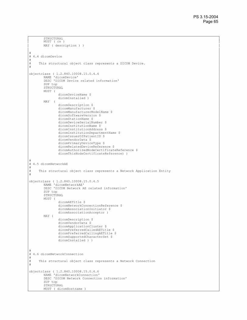
PS 3.15-2004 Page 65
STRUCTURAL MUST ( cn ) MAY ( description ) ) # # 4.4 dicomDevice # # This structural object class represents a DICOM Device. # objectclass ( 1.2.840.10008.15.0.4.4 NAME 'dicomDevice' DESC 'DICOM Device related information' SUP top STRUCTURAL MUST ( dicomDeviceName $ dicomInstalled ) MAY ( dicomDescription $ dicomManufacturer $ dicomManufacturerModelName $ dicomSoftwareVersion $ dicomStationName $ dicomDeviceSerialNumber $ dicomInstitutionName $ dicomInstitutionAddress $ dicomInstitutionDepartmentName $ dicomIssuerOfPatientID $ dicomVendorData $ dicomPrimaryDeviceType $ dicomRelatedDeviceReference $ dicomAuthorizedNodeCertificateReference $ dicomThisNodeCertificateReference) ) # # 4.5 dicomNetworkAE # # This structural object class represents a Network Application Entity # objectclass ( 1.2.840.10008.15.0.4.5 NAME 'dicomNetworkAE' DESC 'DICOM Network AE related information' SUP top STRUCTURAL MUST ( dicomAETitle $ dicomNetworkConnectionReference $ dicomAssociationInitiator $ dicomAssociationAcceptor ) MAY ( dicomDescription $ dicomVendorData $ dicomApplicationCluster $ dicomPreferredCalledAETitle $ dicomPreferredCallingAETitle $ dicomSupportedCharacterSet $ dicomInstalled ) ) # # 4.6 dicomNetworkConnection # # This structural object class represents a Network Connection # objectclass ( 1.2.840.10008.15.0.4.6 NAME 'dicomNetworkConnection' DESC 'DICOM Network Connection information' SUP top STRUCTURAL MUST ( dicomHostname )

PS 3.15-2004 Page 66
MAY ( cn $ dicomPort $ dicomTLSCipherSuite $ dicomInstalled ) ) # # 4.7 dicomUniqueAETitle # # This structural object class represents a Unique Application Entity Title # objectclass ( 1.2.840.10008.15.0.4.7 NAME 'dicomUniqueAETitle' DESC 'A Unique DICOM Application Entity title' SUP top STRUCTURAL MUST ( dicomAETitle ) ) # # 4.8 dicomTransferCapability # # This structural object class represents Transfer Capabilities for an Application Entity # objectclass ( 1.2.840.10008.15.0.4.8 NAME 'dicomTransferCapability' DESC 'Transfer Capabilities for an Application Entity' SUP top STRUCTURAL MUST ( dicomSOPClass $ dicomTransferRole $ dicomTransferSyntax) MAY ( cn) )
H.1.4 Transactions H.1.4.1 Find LDAP Server H.1.4.1.1 Scope The RFC-2782 A DNS RR for specifying the location of services (DNS SRV) specifies a mechanism for requesting the names and rudimentary descriptions for machines that provide network services. The DNS client requests the descriptions for all machines that are registered as offering a particular service name. In this case the service name requested will be “LDAP”. The DNS server may respond with multiple names for a single request.
H.1.4.1.2 Use Case Roles

PS 3.15-2004 Page 67
Find LDAP Server
LDAP Client DNS Server
Figure H.1-3 Find LDAP Server
DNS Server Provides list of LDAP servers
LDAP Client Requests list of LDAP servers H.1.4.1.3 Referenced Standards
RFC-2181 Clarifications to the DNS Specification
RFC-2219 Use of DNS Aliases for Network Services
RFC-2782 A DNS RR for specifying the location of services (DNS SRV)
other RFC’s are included by reference from RFC-2181, RFC-2219, and RFC-2782. H.1.4.1.4 Interaction Diagram
LDAP Client DNS Server
Request all LDAP servers
List of servers, priority, ports, etc.
Select server
Figure H.1-4 Select LDAP Server
The DNS client shall request a list of all the LDAP servers available. It will use the priority, capacity, and location information provided by DNS to select a server. (RFC-2782 recommends the proper use of these parameters.) It is possible that there is no LDAP server, or that the DNS server does not support the SRV RR request.

PS 3.15-2004 Page 68
Notes: 1. Multiple LDAP servers providing access to a common replicated LDAP database is a commonly supported configuration. This permits LDAP servers to be located where appropriate for best performance and fault tolerance. The DNS server response information provides guidance for selecting the most appropriate server.
2. There may also be multiple LDAP servers providing different databases. In this situation the client may have to examine several servers to find the one that supports the DICOM configuration database. Similarly a single LDAP server may support multiple base DNs, and the client will need to check each of these DNs to determine which is the DICOM supporting tree.
H.1.4.1.5 Alternative Paths The client may have a mechanism for manual default selection of the LDAP server to be used if the DNS server does not provide an LDAP server location.
H.1.4.2 Query LDAP Server H.1.4.2.1 Scope The RFC-2251 “Lightweight Directory Access Protocol (v3)” specifies a mechanism for making queries of a database corresponding to an LDAP schema. The LDAP client can compose requests in the LDAP query language, and the LDAP server will respond with the results for a single request.
H.1.4.2.2 Use Case Roles
Query LDAP server
LDAP Client LDAP Server
Figure H.1-5 Query LDAP Server
LDAP Server Provides query response
LDAP Client Requests LDAP information H.1.4.2.3 Referenced Standards
RFC-2251 Lightweight Directory Access Protocol (v3). LDAP support requires compliance with other RFC’s invoked by reference.
H.1.4.2.4 Interaction Description The LDAP client may make a wide variety of queries and cascaded queries using LDAP. The LDAP client and server shall support the Application Configuration Data Model .
Note: Multiple LDAP servers providing access to a common replicated LDAP database is a commonly supported configuration. This permits LDAP servers to be located where appropriate for best performance and fault tolerance. The replications rules chosen for the LDAP servers affect the visible data consistency. LDAP permits inconsistent views of the database during updates and replications.

PS 3.15-2004 Page 69
H.1.4.3 Update LDAP Server H.1.4.3.1 Scope The RFC-2251 “Lightweight Directory Access Protocol (v3)” specifies a mechanism for making updates to a database corresponding to an LDAP schema. The LDAP client can compose updates in the LDAP query language, and the LDAP server will respond with the results for a single request. Update requests may be refused for security reasons.
H.1.4.3.2 Use Case Roles
Update LDAP Server
LDAP Client LDAP Server
Figure H.1-6 Update LDAP Server
LDAP Server Maintains database
LDAP Client Updates LDAP information H.1.4.3.3 Referenced Standards
RFC-2251 Lightweight Directory Access Protocol (v3). LDAP support requires compliance with other RFC’s invoked by reference.
H.1.4.3.4 Interaction Description The LDAP client may make a request to update the LDAP database. The LDAP client shall support the data model described above. The LDAP server may choose to refuse the update request for security reasons. If the LDAP server permits update requests, is shall support the data model described above.
Note: Multiple LDAP servers providing access to a common replicated LDAP database is a commonly supported configuration. This permits LDAP servers to be located where appropriate for best performance and fault tolerance. Inappropriate selection of replication rules in the configuration of the LDAP server will result in failure for AE-title uniqueness when creating the AE-titles objects.
H.1.4.3.5 Special Update for Network AE Creation The creation of a new Network AE requires special action. The following steps shall be followed:
a. A tentative AE title shall be selected. Various algorithms are possible, ranging from generating a random name to starting with a preset name template and incrementing a counter field. The client may query the Unique AE Titles Registry sub-tree to obtain the complete list of names that are presently in use as part of this process.
b. A new Unique AE Title object shall be created in the Unique AE Titles Registry portion of the hierarchy with the tentative name. The LDAP server enforces uniqueness of names at any specific point in the hierarchy.
c. If the new object creation was successful, this shall be the AE Title used for the new Network AE.
d. If the new object creation fails due to non-unique name, return to a) and select another name.
PS 3.15-2004 Page 70
H.1.4.4 Maintain LDAP Server The LDAP server shall support a separate manual or automated means of maintaining the LDAP database contents. The LDAP server shall support the RFC-2849 file format mechanism for updating the LDAP database. The LDAP Client or service installation tools shall provide RFC-2849 formatted files to update LDAP server databases manually. The LDAP server may refuse client network updates for security reasons. If this is the case, then the maintenance process will be used to maintain the LDAP database.
The manual update procedures are not specified other than the requirement above that at least the minimal LDAP information exchange file format from RFC 2849 be supported. The exact mechanisms for transferring this information remain vendor and site specific. In some situations, for example the creation of AE-titles, a purely manual update mechanism may be easier than exchanging files.
The conformance statement shall document the mechanisms available for transferring this information. Typical mechanisms include:
a. floppy disk b. CD-R c. SSH d. Secure FTP e. FTP f. email g. HTTPS
Notes: 1. There are many automated and semi-automatic tools for maintaining LDAP databases. Many
LDAP servers provide GUI interfaces and updating tools. The specifics of these tools are outside the scope of DICOM. The LDAP RFC-2849 requires at least a minimal data exchange capability. There are also XML based tools for creating and maintaining these files.
2. This mechanism may also be highly effective for preparing a new network installation by means of a single pre-planned network configuration setup rather than individual machine updates.
H.1.5 LDAP Security Considerations (Informative) H.1.5.1 Threat Assessment The threat and value for the LDAP based configuration mechanisms fall into categories:
a. AE-uniqueness mechanism b. Finding (and updating) Network AE descriptions c. Finding (and updating) device descriptions
These each pose different vulnerabilities to attack. These are:
a. Active Attacks 1. The AE-title uniqueness mechanism could be attacked by creating vast numbers of spurious
AE-titles. This could be a Denial of Service (DoS) attack on the LDAP server. It has a low probability of interfering with DICOM operations.
2. The Network AE information could be maliciously updated. This would interfere with DICOM operations by interfering with finding the proper server. It could direct connections to malicious nodes, although the use of TLS authentication for DICOM connections would detect such misdirection. When TLS authentication is in place this becomes a DoS attack.

PS 3.15-2004 Page 71
3. The device descriptions could be maliciously modified. This would interfere with proper device operation.
b. Passive Attacks 1. There is no apparent value to an attacker in obtaining the current list of AE-titles. This does
not indicate where these AE-titles are deployed or on what equipment. 2. The Network AE information and device descriptions might be of value in determining the
location of vulnerable systems. If it is known that a particular model of equipment from a particular vendor is vulnerable to a specific attack, then the Network AE Information can be used to find that equipment.
H.1.5.2 Available LDAP Security Mechanisms The security mechanisms for LDAP are highly variable in actual implementations. They are a mixture of administrative restrictions and protocol implementations. The widely available options for security methods are:
a. Anonymous access, where there is no restriction on performing this function over the network. b. Basic, where there is a username and password exchange prior to granting access to this function.
The exchange is vulnerable to snooping, spoofing, and man in the middle attacks. c. TLS, where there is an SSL/TLS exchange during connection establishment. d. Manual, where no network access is permitted and the function must be performed manually at the
server, or semi-automatically at the server. The semi-automatic means permit the use of independently exchanged files (e.g. via floppy) together with manual commands at the server.
The categories of functions that may be independently controlled are:
a. Read related, to read, query, or otherwise obtain a portion of the LDAP directory tree b. Update related, to modify previously existing objects in the directory tree c. Create, to create new objects in the directory tree.
Finally, these rules may be applied differently to different subtrees within the overall LDAP structure. The specific details of Access Control Lists (ACLs), functional controls, etc. vary somewhat between different LDAP implementations.
H.1.5.3 Recommendations (Informative) The LDAP server should be able to specify different restrictions for the AE-Title list and for the remainder of the configuration information. To facilitate interoperability, Table H.1-15 defines several patterns for access control. They correspond to different assessments of risk for a network environment.
Table H.1-15 LDAP Security Patterns TLS TLS-
Manual Basic Basic-
Manual Anonymous Anonymous-
Manual Read AE-title Anonymous
, TLS Anonymous, TLS
Anonymous, Basic
Anonymous, Basic
Anonymous Anonymous
Create AE-Title TLS Manual Basic Manual Anonymous Manual Read Config TLS TLS Basic Basic Anonymous Anonymous Update Config TLS Manual Basic Manual Anonymous Manual Create Config TLS Manual Basic Manual Anonymous Manual

PS 3.15-2004 Page 72
TLS This pattern provides SSL/TLS authentication and encryption between client and server. It requires additional setup during installation because the TLS certificate information needs to be installed onto the client machines and server. Once the certificates are installed the clients may then perform full updating operations.
TLS-Manual
This pattern provides SSL/TLS controls for read access to information and require manual intervention to perform update and creation functions.
Basic This pattern utilizes the LDAP basic security to gain access to the LDAP database. It requires the installation of a password during client setup. It does not provide encryption protection. Once the password is installed, the client can then perform updates.
Basic-Manual
This pattern utilizes basic security protection for read access to the configuration information and requires manual intervention to perform update and creation functions.
Anonymous
This pattern permits full read/update access to all machines on the network.
Anonymous-Manual
This pattern permits full read access to all machines on the network, but requires manual intervention to perform update and creation.
A client or server implementation may be capable of being configured to support multiple patterns. This should be documented in the conformance claim. The specific configuration in use at a specific site can then be determined at installation time.
H.1.6 Implementation Considerations (Informative) The LDAP database can be used as a documentation tool. Documenting the configuration for both managed and legacy machines makes upgrading easier and reduces the error rate for manually configured legacy equipment.
There are various possible implementation strategies for clients performing lookups within the LDAP database. For example, before initiating a DICOM association to a specific AE, a client implementation could either:
a. Query the LDAP database to obtain hostname and port for the specific AE Title immediately prior to initiating a DICOM association.
b. Maintain a local cache of AE Title, hostname and port information and only query the LDAP database if the specific AE Title is not found in the local cache.
The advantages of maintaining a local cache include performance (by avoiding frequent lookups) and reliability (should the LDAP server be temporarily unavailable). The disadvantage of a cache is that it can become outdated over time. Client implementations should provide appropriate mechanisms to purge locally cached information.
Client caches may cause confusion during updates. Manual steps may be needed to trigger immediate updates. LDAP database replication also may introduce delays and inconsistencies. Database replication may also require manual intervention to force updates to occur immediately.
One strategy to reduce client cache problems is to re-acquire new DNS and LDAP information after any network association information. Often the first symptom of stale cache information is association failures due to the use of obsolete configuration information.

PS 3.15-2004 Page 73
Some LDAP servers do not support a “modify DN” operation. For example, in the case of renaming a device on such a server, a tree copy operation may be needed to create a new object tree using the new name, followed by removal of the old object tree. After such a rename the device may need to search using other attributes when finding its own configuration information, e.g. the device serial number.
H.1.7 Conformance The Conformance Statement for an LDAP Client or LDAP Server implementation shall specify the security pattern(s) that it supports.

PS 3.15-2004 Page 74
Index
(0008,0014), 31 (0008,0018), 30, 31 (0008,0050), 31 (0008,0080), 31 (0008,0081), 31 (0008,0090), 31 (0008,0092), 31 (0008,0094), 31 (0008,1010), 31 (0008,1030), 31 (0008,103E), 31 (0008,1040), 31 (0008,1048), 31 (0008,1050), 31 (0008,1060), 31 (0008,1070), 31 (0008,1080), 31 (0008,1155), 31 (0008,2111), 31 (0010,0010), 31 (0010,0020), 31 (0010,0030), 30, 31 (0010,0032), 31 (0010,0040), 31 (0010,1000), 31 (0010,1001), 31 (0010,1010), 30, 31 (0010,1020), 31 (0010,1030), 31 (0010,1090), 31 (0010,2160), 31 (0010,2180), 31 (0010,21B0), 31 (0010,4000), 31 (0018,1000), 31 (0018,1030), 32 (0020,000D), 29, 32 (0020,000E), 32 (0020,0010), 32 (0020,0052), 29, 32 (0020,0200), 32 (0020,4000), 32 (0040, A124), 32 (0040,0275), 32 (0040,A730), 32 (0088,0140), 32 (0400,0500), 30, 32 (0400,0510), 30, 32 (0400,0520), 30, 32
(0400,0550), 29, 32 (3006,0024), 32 (3006,00C2), 32 0008,0012, 20 0008,0013, 20 0008,0016, 20 0008,0018, 20 0020,000D, 20 0020,000E, 20 0100,0410, 20 0100,0420, 20 0100,0424, 20 0100,0426, 20

PS 3.15-2004 Page 75