Proton Exchange Membrane Fuel Cell (PEMFC) … (PEMFC) Modeling in PSCAD/ EMTDC Paper Session:...
28
IEEE EPEC 2011 October 2011 1 L.Luckose, N.J.Urlaub, N.J.Wiedeback, H.L.Hess, B.K.Johnson University of Idaho Proton Exchange Membrane Fuel Cell (PEMFC) Modeling in PSCAD/ EMTDC Paper Session: Microgrids October 4, 2011
Transcript of Proton Exchange Membrane Fuel Cell (PEMFC) … (PEMFC) Modeling in PSCAD/ EMTDC Paper Session:...

IEEE EPEC 2011 October 2011 1
L.Luckose, N.J.Urlaub, N.J.Wiedeback, H.L.Hess,
B.K.Johnson
University of Idaho
Proton Exchange Membrane Fuel Cell (PEMFC) Modeling in PSCAD/
EMTDC
Paper Session: Microgrids October 4, 2011
IEEE EPEC 2011 October 2011 2
Background
• The US Navy Acoustic Research Detachment » Base on Lake Pend Oreille, Idaho
• Research vessel with electric propulsion » Diesel generator for transit to test area » Battery operation for test runs » Quiet operation is priority
• Batteries fully charged when leave dock » Need to recharge on the lake – time issues

IEEE EPEC 2011 October 2011 3
Operational Modes

IEEE EPEC 2011 October 2011 4
Limitations of Current System
• Diesel Generator » Limited power production » Sensitivity to harmonic current draw from
battery charger » Produces acoustic noise and exhaust that is
objectionable and interferes with testing

IEEE EPEC 2011 October 2011 5
Limitations with Batteries
• Recharge time of ~14 hours and runtime of ~3 hours
• Battery charging system » introduces harmonic distortion to generator » current-limited » requires a substantial amount of space
• The batteries take large amount of space » Currently lead acid batteries

IEEE EPEC 2011 October 2011 6
Why Consider a Fuel Cell?
• Sponsor considering adding fuel cell to the vessel » Navy research program into fuel cell » Use the vessel as a proof of concept » Possibly extend test duration before charging
• Earlier project looked at fuel cell alternatives » Proton Exchange Membrane Fuel Cell (PEMFC) » Best met sponsors requirements
IEEE EPEC 2011 October 2011 7
System Configuration
• Options explored included: » Replace diesel and all batteries » Replace only batteries » Replace diesel and retain all or some batteries
• Batteries combined with fuel cells gave better overall performance

IEEE EPEC 2011 October 2011 8
Fuel Cell Model Development
• Current propulsion system model developed in PSCAD/EMTDC
• Needed compatible fuel cell model • Detailed Matlab/Simulink model of PEMFC
developed by H. Nehrir and C. Wang » Experimentally verified
• This model was ported to PSCAD/EMTDC with some modification
IEEE EPEC 2011 October 2011 9
PEMFC Modeling • One-dimensional treatment of fuel cell • Ideal and uniform distribution of gases • Constant pressure in the fuel-cell gas flow
channels • The fuel cells operate at a temperature
under 100 0C » the reaction occurs in the liquid phase

IEEE EPEC 2011 October 2011 10
PEMFC Modeling • The fuel mix uses humidified air. • Thermodynamic properties evaluated
» at the average stack temperature » neglecting temperature variation across the
stack • Parameters for individual cells in stack
lumped together to represent entire fuel cell
IEEE EPEC 2011 October 2011 11
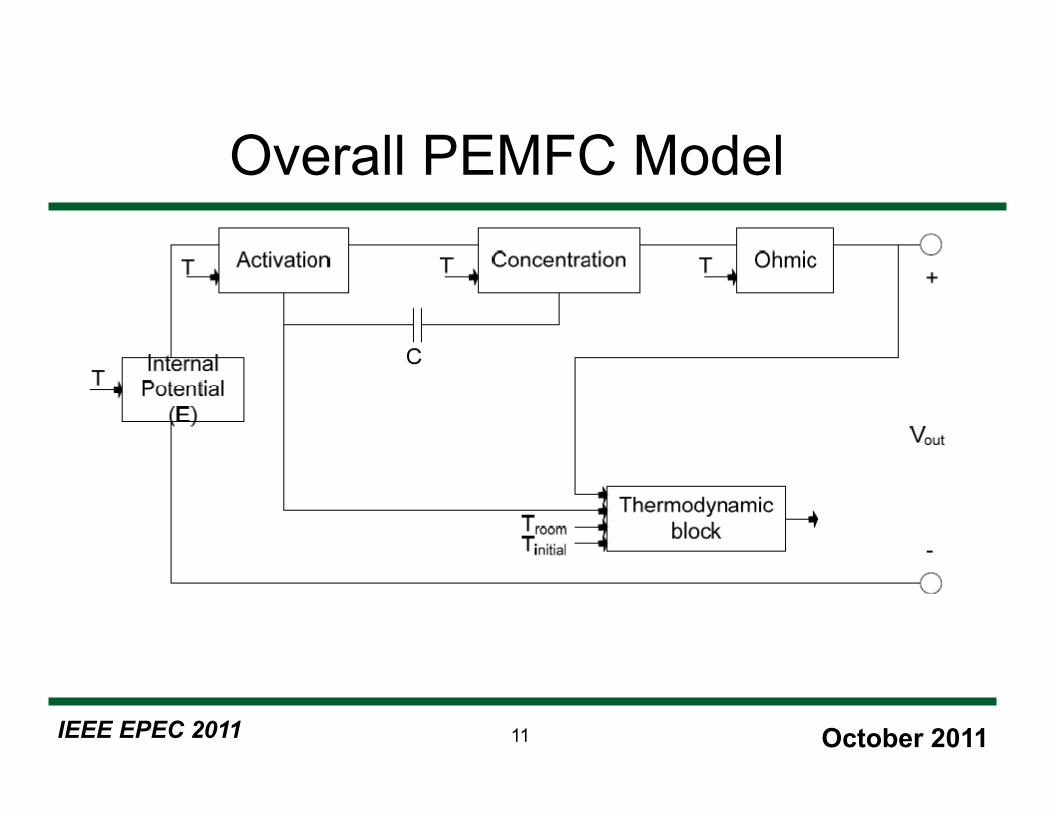
Overall PEMFC Model
IEEE EPEC 2011 October 2011 12
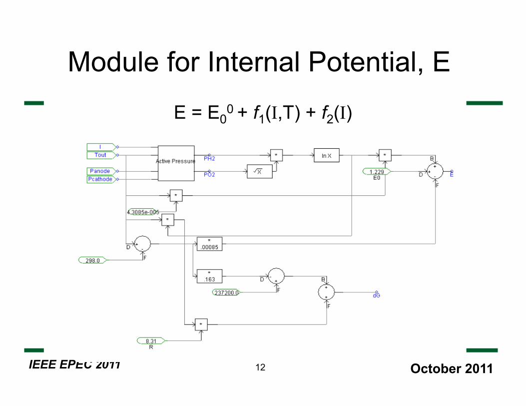
Module for Internal Potential, E
E = E00 + f1(I,T) + f2(I)

IEEE EPEC 2011 October 2011 13
Activation Loss Modules
Vact1 = η0 + f3(T) Vact2 = I (Ract0 + Ract1(I) + Ract2(I,T))
Convert to PSCAD equations

IEEE EPEC 2011 October 2011 14
Activation Loss Modules

IEEE EPEC 2011 October 2011 15
Double layer Charge Effect Module
» The gain G of the block transfer function is 1 and the time constant T is 40 seconds
» Represents “faster” response of fuel cell

IEEE EPEC 2011 October 2011 16
Calculation of Terminal Voltage

IEEE EPEC 2011 October 2011 17
Representation of Thermodynamic Behavior: Circuit Equivalent

IEEE EPEC 2011 October 2011 18
Inner Fuel Cell Loop

IEEE EPEC 2011 October 2011 19
Overall System: Fuel Cell Plus Battery Storage
IEEE EPEC 2011 October 2011 20
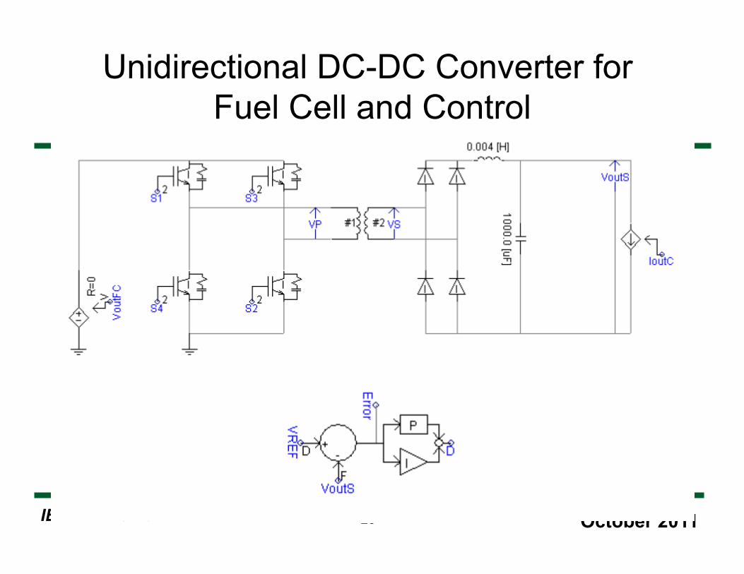
Unidirectional DC-DC Converter for Fuel Cell and Control

IEEE EPEC 2011 October 2011 21
Bi-directional DC-DC Converter for Battery Storage and Control

IEEE EPEC 2011 October 2011 22
Representation of Lead-Acid Batteries
IEEE EPEC 2011 October 2011 23
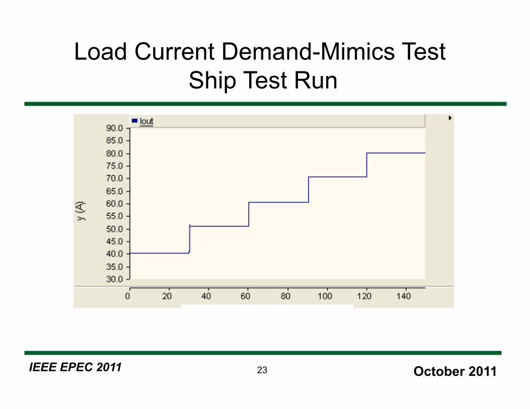
Load Current Demand-Mimics Test Ship Test Run

IEEE EPEC 2011 October 2011 24
Fuel Cell Output Voltage (blue) and Main DC Bus Voltage (green)

IEEE EPEC 2011 October 2011 25
Duty Ratio Variation for Fuel Cell
IEEE EPEC 2011 October 2011 26
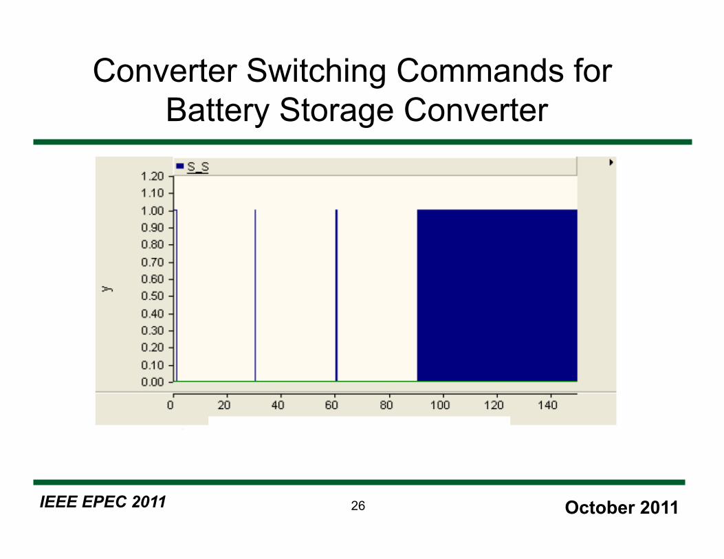
Converter Switching Commands for Battery Storage Converter
IEEE EPEC 2011 October 2011 27
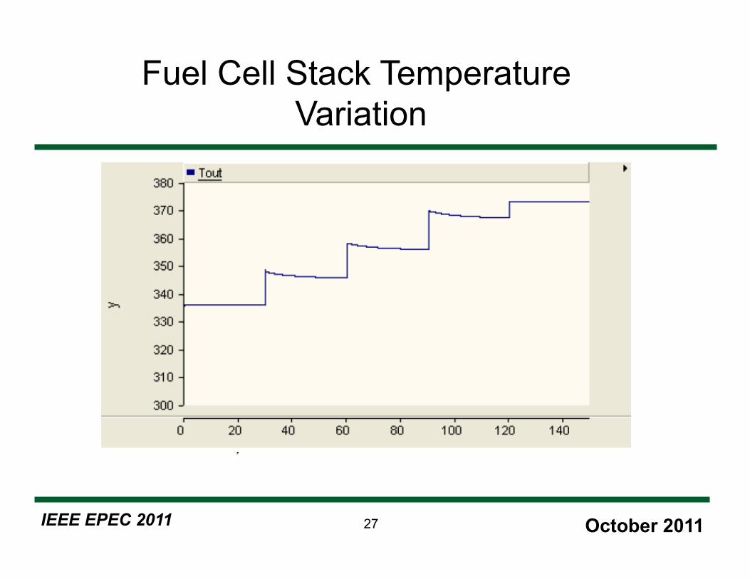
Fuel Cell Stack Temperature Variation

IEEE EPEC 2011 October 2011 28
Conclusions
• PSCAD/EMTDC of PEMFC based on verified
• Implemented in simulation model of electric research vessel
• Combined with battery energy storage to respond to fast load changes
• The test showed response to an operational load profile


![PSCAD/EMTDC CVCF Micro-grid · 2019-05-20 · 2018년한국산학기술학회추계학술발표논문집-179-[ 1]CVCF그림 인버터기반Micro-grid의보호협조개념도 3.PSCAD/EMTDC](https://static.fdocuments.net/doc/165x107/5e81a459466d0016fd48ee32/pscademtdc-cvcf-micro-2019-05-20-2018eoeeeoeeeoeoeee-179-.jpg)