
Protocols, Standards, and Techniquescdn.eleinfo.ir/96/Wireless_Technology.pdf · Protocols,...
547
Transcript of Protocols, Standards, and Techniquescdn.eleinfo.ir/96/Wireless_Technology.pdf · Protocols,...


Protocols, Standards, and Techniques
WIRELESSTECHNOLOGY
© 2002 by CRC Press LLC
E:\Java for Engineers\VP Publication\Java for Engineers.vpThursday, April 25, 2002 9:27:36 AM
Color profile: DisabledComposite Default screen
CRC PR ESSBoca Raton London New York Washington, D.C.
Protocols, Standards, and Techniques
WIRELESSTECHNOLOGY
Michel Daoud Yacoub
© 2002 by CRC Press LLC
E:\Java for Engineers\VP Publication\Java for Engineers.vpThursday, April 25, 2002 9:27:36 AM
Color profile: DisabledComposite Default screen

This book contains information obtained from authentic and highly regarded sources. Reprinted materialis quoted with permission, and sources are indicated. A wide variety of references are listed. Reasonableefforts have been made to publish reliable data and information, but the author and the publisher cannotassume responsibility for the validity of all materials or for the consequences of their use.
Neither this book nor any part may be reproduced or transmitted in any form or by any means, electronicor mechanical, including photocopying, microfilming, and recording, or by any information storage orretrieval system, without prior permission in writing from the publisher.
The consent of CRC Press LLC does not extend to copying for general distribution, for promotion, forcreating new works, or for resale. Specific permission must be obtained in writing from CRC Press LLCfor such copying.
Direct all inquiries to CRC Press LLC, 2000 N.W. Corporate Blvd., Boca Raton, Florida 33431.
Trademark Notice:
Product or corporate names may be trademarks or registered trademarks, and areused only for identification and explanation, without intent to infringe.
Visit the CRC Press Web site at www.crcpress.com
© 2002 by CRC Press LLC
No claim to original U.S. Government worksInternational Standard Book Number 0-8493-0969-7
Printed in the United States of America 1 2 3 4 5 6 7 8 9 0Printed on acid-free paper
Library of Congress Cataloging-in-Publication Data
Catalog record is available from the Library of Congress
Disclaimer_61/8X91/4 Page 1 Tuesday, November 20, 2001 2:01 PM
© 2002 by CRC Press LLC
E:\Java for Engineers\VP Publication\Java for Engineers.vpThursday, April 25, 2002 9:27:36 AM
Color profile: DisabledComposite Default screen

P1: FDJ
book CRC-Wireless November 16, 2001 11:33 Char Count= 1047
Dedication
Technology has its time; knowledge is timeless.
Technowledge boosts Technowledge.
To those who idealize, conceive, standardize, implement, test, operate, main-tain, upgrade; to those professionals, for whose knowledge and work we owethe technology and all it conveys—to those technowledgers—I pay my mostsincere tribute.
I dedicate this book to my beloved family. Thank you, Maria Nıdia, my pre-cious wife, and thank you, Alexandre, Helena, Carolina, Ricardo, Vinıcius,and Elisa, my wonderful children, for your love, patience, and unconditionalsupport.
© 2002 by CRC Press LLC
E:\Java for Engineers\VP Publication\Java for Engineers.vpThursday, April 25, 2002 9:27:36 AM
Color profile: DisabledComposite Default screen

P1: FDJ
book CRC-Wireless November 16, 2001 11:33 Char Count= 1047
Preface
We can always wait a bit longer to write a better book on technology. We canalways wait . . .
In this ever-changing technological scenario, keeping pace with the rapidevolution of wireless technology is a formidable, exciting, and indispensabletask more than a challenge. The work is indeed herculean and often dis-couraging, for technology is vast, the number of topics to be approached isimmense, the documentation on standards and recommendations comprisespiles of uncountable pages, and we often find we are leaving something im-portant behind when selecting the appropriate subject matter to explore. Theconsolation, if any, is that as we explore the technologies, we find that muchcommonality exists among them, although particular features are rather dif-ferent in each.
The challenge of writing a book in such a “hot” and vivacious field is toprovide a clear and concise resource to accommodate the learning process ofthe basic functions of the main technologies. I did try to keep this in mindthroughout the course of selection and description of the topics included inthis book. I hope I have succeeded, at least to a certain extent.
The book, divided into five parts, describes protocols, standards, and tech-niques for 2G and 3G technologies, including those specific to wireless mul-timedia. The first part—Introduction—contains three chapters and covers thebasic principles of wireless communications. The second part—2G Systems—consists of two chapters and describes two leading technologies of the secondgeneration. The third part—Wireless Data—comprises one chapter and intro-duces three main wireless data technologies. The fourth part—3G Systems—encompasses three chapters and details the general concepts of third-generation systems as well as two chief third-generation technologies. Thefifth part—Appendices—provides a glimpse at some telecommunication is-sues that are relevant to the understanding of the main text and that are notcovered in the introductory part of the book. A more detailed description ofthe book structure follows.
Part I: Introduction
Chapter 1—Wireless Network —develops the wireless network concepts withinthe Intelligent Network framework and describes the basic functions a tele-communication system must provide so that wireless and mobile capabili-ties can be implemented. General network and protocol architectures andchannel structures are described that are common to the main systems. These
© 2002 by CRC Press LLC
E:\Java for Engineers\VP Publication\Java for Engineers.vpThursday, April 25, 2002 9:27:36 AM
Color profile: DisabledComposite Default screen
P1: FDJ
book CRC-Wireless November 16, 2001 11:33 Char Count= 1047
descriptions are based on ITU Recommendations, which generalize those con-cepts that have been used for the various cellular networks. Specific solutionsare then detailed in the other chapters.
Chapter 2—Cellular Principles—introduces the cellular technology funda-mentals, providing a unified approach of these concepts for narrowbandand wideband solutions. Topics explored in this chapter include universalfrequency reuse, sectorization, power control, handoff, voice activity, inter-ference, and others. Besides the traditional hexagonal tessellation for macro-cellular networks, the chapter examines the subject of reuse pattern for micro-cellular systems. In addition, hierarchical cell structure, overall mean capacityfor multirate systems, and the main features of narrowband and widebandnetworks are also addressed.
Chapter 3—Multiple Access—analyzes a considerable number of multipleaccess control techniques. Several conventional and more advanced duplex-ing and multiple access protocols are detailed that comply with the variousclasses of traffic and multirate transmission utilized in broadband services.The access and duplexing methods are explored in the frequency domain,time domain, code domain, and space domain. The performance of the tech-niques is investigated in terms of channel capacity, throughput, and delay.
Part II: 2G Systems
Chapter 4—GSM—describes the Global System for Mobile Communicationcellular network in terms of its features and services, architecture, phy-sical channels, logical channels, signaling messages, call management, andparticular features.
Chapter 5—cdmaOne—details the features and services, architecture, phys-ical channels, logical channels, signaling messages, call management, andparticular features for TIA/EIA/IS-95-A as well as for its evolved versionTIA/EIA/IS-95-B.
Part III: Wireless Data
Chapter 6—Wireless Data Technology—depicts three data technologies ap-plied to wireless networks, namely, General Packet Radio Service (GPRS),TIA/EIA/IS-95B, and High Data Rate (HDR). These technologies are de-scribed in terms of their basic architectures and achievable data transmissionrates.
Part IV: 3G Systems
Chapter 7—IMT-2000—introduces the topic on third-generation wireless net-works based on the International Mobile Telecommunications-2000 (IMT-2000) concept. It describes the functional subsystems, the IMT-2000 familyconcept, and the capability set concept. It also develops the network func-tional model for IMT-2000.
© 2002 by CRC Press LLC
E:\Java for Engineers\VP Publication\Java for Engineers.vpThursday, April 25, 2002 9:27:36 AM
Color profile: DisabledComposite Default screen

P1: FDJ
book CRC-Wireless November 16, 2001 11:33 Char Count= 1047
Chapter 8—UTRA—details the IMT-2000 radio interface for directsequence code division multiple access, the so-called Universal TerrestrialRadio Access (UTRA) or Wideband CDMA (WCDMA) 3G radio transmis-sion technology. Descriptions include its FDD as well as its TDD options.
Chapter 9—cdma2000—details the IMT-2000 CDMA multicarrier radiointerface, the so-called cdma2000 3G radio transmission technology. Des-criptions include its various radio configurations, the 1xEV-DO radio con-figuration option being one of them.
Part V: Appendices
These Appendices provide tutorial information on topics such as OSI Refer-ence Model, Signaling System Number 7, Spread Spectrum, and Positioningof Interferers in a Microcellular Grid.
The book is suitable as text as well as a reference. As a textbook, it fits intoa semester course for both undergraduate and graduate levels in electricalengineering, wireless communications, and more generally in informationtechnology. As a reference, it serves systems engineers and analysts, hard-ware and software developers, researchers, and engineers responsible forthe operation, maintenance, and management of wireless communicationsystems.
© 2002 by CRC Press LLC
E:\Java for Engineers\VP Publication\Java for Engineers.vpThursday, April 25, 2002 9:27:36 AM
Color profile: DisabledComposite Default screen
P1: FDJ
book CRC-Wireless November 16, 2001 11:33 Char Count= 1047
Acknowledgments
I am grateful to a number of people who have generously helped with thecompletion of this book. Some provided me with updated material and origi-nal results, others revised parts of the manuscript, and still others stimulateddiscussions and lent me their ideas, suggestions, incentive, encouragement,motivation, and so many distinct forms of assistance. In the endeavor to citetheir names, I may inadvertently leave some out, for they are many and mymemory will certainly deceive me. To these who are not quoted here, myforgiveness.
I thank Professor Kenneth W. Cattermole, Professor Attılio J. Giarola, Pro-fessor Helio Waldman, Professor Dalton S. Arantes, Professor Rui F. de Souza,Professor Ivan L. M. Ricarte, Dr. Antonio F. de Toledo, Dr. Ailton A. Shinoda,Dr. Omar C. Branquinho, Dr. Cesar K. d’Avila, Dr. Ernesto L. A. Neto, Dr. PaulaR. C. Gomez, Alexandre R. Esper, Alexandre R. Romero, Antonio V. Rodrigues,Claudio R. C. M. da Silva, Edigar Alves, Fabbryccio A. C. M. Cardoso, andGustavo Fraidenraich. I am also indebted to my colleagues of the Departmentof Communications (DECOM), School of Electrical Engineering (FEEC), atThe State University of Campinas (UNICAMP).
I would like to express my gratitude to FEEC, CPqD, CelTec/CelPlan, Eric-sson, IBM, Telesp Celular, Motorola, Instituto Eldorado, Lucent Technologies,CNPq, CAPES, and FAPESP for supporting my research efforts in wirelesscommunications over the years.
Finally, I am very thankful to the CRC Press staff for their support andincentive and for the opportunity to publish this book.
© 2002 by CRC Press LLC
E:\Java for Engineers\VP Publication\Java for Engineers.vpThursday, April 25, 2002 9:27:36 AM
Color profile: DisabledComposite Default screen

P1: FDJ
book CRC-Wireless November 16, 2001 11:33 Char Count= 1047
Contents
Part I Introduction
1 Wireless Network1.1 Introduction1.2 Intelligent Network
1.2.1 IN Protocol Architecture1.2.2 IN Elements1.2.3 Wireless Service Requirements1.2.4 Wireless IN Services1.2.5 IN Standards
1.3 Network Architecture1.4 Protocol Architecture1.5 Channel Structure
1.5.1 RF Channel1.5.2 Physical Channel1.5.3 Logical Channel
1.6 Narrowband and Wideband Systems1.7 Multiple Access
1.7.1 Frequency Division Multiple Access1.7.2 Time Division Multiple Access1.7.3 Code Division Multiple Access1.7.4 Space Division Multiple Access
1.8 Summary
2 Cellular Principles2.1 Introduction2.2 Cellular Hierarchy2.3 System Management
2.3.1 Link Quality Measurement2.3.2 Cell Selection2.3.3 Channel Selection/Assignment2.3.4 Handover2.3.5 Mobility Support
2.4 System Performance2.4.1 Interference Control2.4.2 Diversity Strategies
© 2002 by CRC Press LLC
E:\Java for Engineers\VP Publication\Java for Engineers.vpThursday, April 25, 2002 9:27:36 AM
Color profile: DisabledComposite Default screen

P1: FDJ
book CRC-Wireless November 16, 2001 11:33 Char Count= 1047
2.4.3 Variable Data Rate Control2.4.4 Capacity Improvement Techniques2.4.5 Battery-Saving Techniques
2.5 Cellular Reuse Pattern2.6 Macrocellular Reuse Pattern
2.6.1 Reuse Factor (Number of Cells per Cluster)2.6.2 Reuse Ratio2.6.3 Positioning of the Co-Cells
2.7 Microcellular Reuse Pattern2.7.1 Reuse Factor (Number of Cells per Cluster)2.7.2 Reuse Ratio2.7.3 Positioning of the Co-Cells
2.8 Interference in Narrowband and Wideband Systems2.9 Interference in Narrowband Macrocellular Systems
2.9.1 Downlink Interference—Omnidirectional Antenna2.9.2 Uplink Interference—Omnidirectional Antenna2.9.3 Downlink Interference—Directional Antenna2.9.4 Uplink Interference—Directional Antenna2.9.5 Examples
2.10 Interference in Narrowband Microcellular Systems2.10.1 Propagation2.10.2 Uplink Interference2.10.3 Downlink Interference2.10.4 Examples
2.11 Interference in Wideband Systems2.11.1 Uplink Interference2.11.2 Downlink Interference
2.12 Network Capacity2.12.1 Narrowband Systems2.12.2 Wideband Systems2.12.3 Uplink Load Factor2.12.4 Downlink Load Factor
2.13 Summary
3 Multiple Access3.1 Introduction3.2 Signal Domains
3.2.1 Frequency Domain3.2.2 Time Domain3.2.3 Code Domain3.2.4 Space Domain3.2.5 Brief Remarks on Signal Domains
© 2002 by CRC Press LLC
E:\Java for Engineers\VP Publication\Java for Engineers.vpThursday, April 25, 2002 9:27:36 AM
Color profile: DisabledComposite Default screen

P1: FDJ
book CRC-Wireless November 16, 2001 11:33 Char Count= 1047
3.3 Duplexing3.3.1 Frequency Division Duplexing3.3.2 Time Division Duplexing3.3.3 Code Division Duplexing 3.3.4 Space Division Duplexing3.3.5 Brief Remarks on Duplexing Techniques
3.4 Multiple-Access Categories3.5 Scheduled Multiple Access
3.5.1 Frequency Division Multiple Access3.5.2 Time Division Multiple Access3.5.3 Code Division Multiple Access3.5.4 Space Division Multiple Access3.5.5 Brief Remarks on Scheduled Multiple-Access
Techniques3.6 Random Multiple Access
3.6.1 ALOHA3.6.2 Splitting Algorithms3.6.3 Carrier Sense Multiple Access3.6.4 Brief Remarks on Random Multiple-Access
Techniques3.7 Controlled Multiple Access
3.7.1 Polling Controlled3.7.2 Token Controlled3.7.3 Brief Remarks on Controlled Multiple-Access
Techniques3.8 Hybrid Multiple Access
3.8.1 Reservation-ALOHA (R-ALOHA)3.8.2 Packet Reservation Multiple Access (PRMA)3.8.3 Distributed Queuing Request Update Multiple
Access (DQRUMA)3.8.4 Dynamic Slot Assignment (DSA++)3.8.5 Dynamic TDMA with Piggyback
Reservation (DTDMA/PR)3.8.6 Mobile Access Scheme Based on Contention
and Reservation for ATM (MASCARA)3.8.7 Dynamic TDMA with Time Division
Duplex (DTDMA/TDD)3.8.8 Resource Auction Multiple
Access (RAMA)3.8.9 Brief Remarks on Hybrid Multiple-Access
Techniques3.9 Summary
© 2002 by CRC Press LLC
E:\Java for Engineers\VP Publication\Java for Engineers.vpThursday, April 25, 2002 9:27:36 AM
Color profile: DisabledComposite Default screen
P1: FDJ
book CRC-Wireless November 16, 2001 11:33 Char Count= 1047
Part II 2G Systems
4 GSM4.1 Introduction4.2 Features and Services
4.2.1 Teleservices4.2.2 Bearer Services4.2.3 Supplementary Services
4.3 Architecture4.3.1 Mobile Station Subsystem4.3.2 Base Station Subsystem 4.3.3 Network and Switching Subsystem4.3.4 Operation and Support Subsystem 4.3.5 Open Interfaces
4.4 Multiple Access4.4.1 Signal Processing4.4.2 Multiple Access 4.4.3 Physical Channels4.4.4 Burst Formats4.4.5 Logical Channels 4.4.6 Multiframes
4.5 The Logical Channels4.5.1 Traffic Channels4.5.2 Frequency Correction Channel 4.5.3 Synchronization Channel4.5.4 Broadcast Control Channel4.5.5 Paging Channel4.5.6 Access Grant Channel4.5.7 Random Access Channel4.5.8 Stand-Alone Dedicated Control Channel4.5.9 Slow Associated Control Channel4.5.10 Fast Associated Control Channel
4.6 Messages4.6.1 DLC Messages4.6.2 RRM Messages4.6.3 CM Messages4.6.4 MM Messages
4.7 Call Management4.7.1 Mobile Initialization4.7.2 Location Update4.7.3 Authentication4.7.4 Ciphering4.7.5 Mobile Station Termination
© 2002 by CRC Press LLC
E:\Java for Engineers\VP Publication\Java for Engineers.vpThursday, April 25, 2002 9:27:36 AM
Color profile: DisabledComposite Default screen

P1: FDJ
book CRC-Wireless November 16, 2001 11:33 Char Count= 1047
4.7.6 Mobile Station Origination 4.7.7 Handover4.7.8 Call Clearing
4.8 Frequency Hopping4.9 Discontinuous Transmission4.10 Power Control4.11 Spectral Efficiency4.12 Summary
5 cdmaOne5.1 Introduction5.2 Features and Services
5.2.1 Voice Features 5.2.2 Short Message Service Features
5.3 Architecture5.3.1 Mobile Station5.3.2 Base Station5.3.3 Mobile Switching Center 5.3.4 Home Location Register 5.3.5 Visitor Location Register5.3.6 Authentication Center5.3.7 Equipment Identity Register5.3.8 Message Center5.3.9 Short Message Entity5.3.10 Data Message Handler5.3.11 Operations System 5.3.12 Interworking Function 5.3.13 External Networks 5.3.14 Interface Reference Points
5.4 Multiple-Access Structure5.4.1 Forward Link5.4.2 Reverse Link5.4.3 Physical Channels5.4.4 Logical Channels
5.5 The Logical Channels5.5.1 Pilot Channel5.5.2 Sync Channel 5.5.3 Paging Channel5.5.4 Access Channel5.5.5 Traffic Channel—Forward and
Reverse Links5.6 Signaling Format5.7 Messages, Orders, and Parameters
© 2002 by CRC Press LLC
E:\Java for Engineers\VP Publication\Java for Engineers.vpThursday, April 25, 2002 9:27:36 AM
Color profile: DisabledComposite Default screen

P1: FDJ
book CRC-Wireless November 16, 2001 11:33 Char Count= 1047
5.8 Messages and Orders and Logical Channels5.8.1 Pilot Channel5.8.2 Sync Channel5.8.3 Paging Channel5.8.4 Access Channel5.8.5 Traffic Channel: Forward and Reverse Links5.8.6 Forward Traffic Channel 5.8.7 Reverse Traffic Channel
5.9 Mobile Station Call Processing5.9.1 Mobile Station Initialization State5.9.2 Mobile Station Idle State5.9.3 System Access State5.9.4 Mobile Station Control on the Traffic Channel State
5.10 Base Station Call Processing5.10.1 Pilot and Sync Channel Processing5.10.2 Paging Channel Processing5.10.3 Access Channel Processing5.10.4 Traffic Channel Processing
5.11 Authentication, Message Encryption, and Voice Privacy5.12 Authentication
5.12.1 Updating the Shared Secret Data5.12.2 Mobile Station Registrations5.12.3 Mobile Station Originations5.12.4 Mobile Station Terminations5.12.5 Mobile Station Data Burst 5.12.6 Unique Challenge-Response Procedure
5.13 Message Encryption5.14 Voice Privacy5.15 Roaming5.16 Handoff
5.16.1 Types of Handoff5.16.2 Handoff and Pilot Sets5.16.3 Handoff Parameters5.16.4 Handoff Messages5.16.5 Pilot Sets Updating
5.17 Power Control5.17.1 Reverse-Link Power Control5.17.2 Forward-Link Power Control
5.18 Call Procedures5.18.1 Mobile Station Origination5.18.2 Mobile Station Termination5.18.3 Call Disconnect
5.19 EIA/TIA/IS-95B
© 2002 by CRC Press LLC
E:\Java for Engineers\VP Publication\Java for Engineers.vpThursday, April 25, 2002 9:27:36 AM
Color profile: DisabledComposite Default screen

P1: FDJ
book CRC-Wireless November 16, 2001 11:33 Char Count= 1047
5.19.1 Increase in the Transmission Rate5.19.2 Power Control5.19.3 Soft Handoff Criteria5.19.4 Hard Handoff5.19.5 Idle Handoff5.19.6 Conclusions
5.20 Summary
Part III Wireless Data
6 Wireless Data Technology6.1 Introduction6.2 General Packet Radio Service
6.2.1 Network Architecture 6.2.2 Protocol Architecture6.2.3 Data Flow and Data Structure6.2.4 Physical Channels and Logical Channels 6.2.5 Medium Access6.2.6 Data Transfer Procedure6.2.7 Mobile-Originated Data Transfer6.2.8 Mobile-Terminated Data Transfer6.2.9 Throughput Performance6.2.10 GPRS—Summary
6.3 EIA/TIA/IS-95B6.4 High Data Rate
6.4.1 HDR Solution6.4.2 Network Architecture6.4.3 Protocol Architecture6.4.4 Channels and Channel Structure6.4.5 Medium Access 6.4.6 Throughput Performance6.4.7 Handoff Features6.4.8 HDR Summary
6.5 Summary
Part IV 3G Systems
7 IMT-20007.1 Introduction 7.2 Some Definitions
© 2002 by CRC Press LLC
E:\Java for Engineers\VP Publication\Java for Engineers.vpThursday, April 25, 2002 9:27:36 AM
Color profile: DisabledComposite Default screen

P1: FDJ
book CRC-Wireless November 16, 2001 11:33 Char Count= 1047
7.3 Frequency Allocation7.4 Features and Services 7.5 Traffic Classes 7.6 IMT-2000 System and IMT-2000 Family
7.6.1 Interfaces 7.6.2 Global Roaming
7.7 Specific Functions7.7.1 Overall System Access Control Functions7.7.2 Radio Resource Management and Control Functions 7.7.3 Random-Access Functions 7.7.4 Radio Resource Request Acceptability Functions7.7.5 Channel Coding Function 7.7.6 Handover Function 7.7.7 Location Management and Geographic
Position–Finding Functions 7.7.8 Mobile Call Handling Functions 7.7.9 Data Coding and Compression Functions 7.7.10 Network Intelligence and Service Control Functions 7.7.11 User Privacy and Network Security Functions 7.7.12 Emergency Services Functions7.7.13 Charging Functions 7.7.14 Support of Users Function 7.7.15 Subscriber Data Management Functions7.7.16 Messaging Service Management Functions7.7.17 Software-Configurable Terminals Functions
7.8 Network Architecture 7.8.1 Physical Entities—Reference Model7.8.2 Interface—Reference Points
7.9 Physical Entities and Functional Entities7.9.1 User Identity Module7.9.2 Mobile Terminal7.9.3 Base Station7.9.4 Radio Network Controller7.9.5 Authentication Center7.9.6 Drift MSC7.9.7 Gateway Location Register7.9.8 Gateway MSC7.9.9 Home Location Register7.9.10 Intelligent Peripheral7.9.11 Mobile Switching Center7.9.12 Packet Data Gateway Node7.9.13 Packet Data Serving Node7.9.14 Service Control Point
© 2002 by CRC Press LLC
E:\Java for Engineers\VP Publication\Java for Engineers.vpThursday, April 25, 2002 9:27:36 AM
Color profile: DisabledComposite Default screen

P1: FDJ
book CRC-Wireless November 16, 2001 11:33 Char Count= 1047
7.9.15 Service Data Point7.9.16 Visitor Location Register
7.10 Functional Entities and Their Interrelations7.11 Application of the IMT-2000 Family Member Concept
7.11.1 Radio Transmission Technology7.11.2 Core Network 7.11.3 Radio Transmission Technologies and
Core Networks7.12 Toward 3G
7.12.1 An Overview7.12.2 Network Architecture
7.13 Summary
8 UTRA8.1 Introduction8.2 Network Architecture 8.3 Protocol Architecture
8.3.1 Radio Network Layer8.3.2 Transport Network Layer
8.4 Radio Interface Protocol Architecture8.4.1 Layer 38.4.2 Layer 28.4.3 Layer 1
8.5 Logical Channels8.6 Transport Channels and Indicators8.7 Physical Channels and Physical Signals
8.7.1 UTRA FDD Physical Channels8.7.2 UTRA TDD Physical Channels
8.8 Mapping of Channels8.9 Physical Layer Transmission Chain8.10 Channel and Frame Structures
8.10.1 UTRA FDD Uplink Physical Channels8.10.2 UTRA FDD Downlink Physical Channels8.10.3 UTRA TDD-3.848.10.4 UTRA TDD-1.28
8.11 Spreading and Modulation8.11.1 Uplink Spreading8.11.2 Downlink Spreading
8.12 Spreading Codes8.12.1 Channelization Codes8.12.2 Uplink Scrambling Codes8.12.3 Downlink Scrambling Codes
8.13 UTRA Procedures
© 2002 by CRC Press LLC
E:\Java for Engineers\VP Publication\Java for Engineers.vpThursday, April 25, 2002 9:27:36 AM
Color profile: DisabledComposite Default screen

P1: FDJ
book CRC-Wireless November 16, 2001 11:33 Char Count= 1047
8.13.1 Cell Search8.13.2 Common Physical Channel Synchronization8.13.3 Radio Link Establishment and Monitoring8.13.4 Uplink DPCCH and DPDCH Reception8.13.5 Uplink Power Control8.13.6 Downlink Power Control8.13.7 Paging Procedure8.13.8 Random-Access Procedure8.13.9 CPCH Access Procedure8.13.10 Transmit Diversity8.13.11 Handover Procedure8.13.12 Timing Advance 8.13.13 Dynamic Channel Allocation
8.14 Interference Issues8.15 Summary
9 cdma20009.1 Introduction9.2 Network Architecture
9.2.1 Network Entities9.2.2 Reference Points
9.3 Radio Interface Protocol Architecture9.3.1 Upper Layers9.3.2 Layer 29.3.3 Layer 1
9.4 Logical Channels9.5 Physical Channels9.6 Mapping of Channels9.7 Achievable Rates9.8 Forward Link
9.8.1 General9.8.2 Spreading Rate9.8.3 Physical Channels9.8.4 Radio Configuration9.8.5 Power Control9.8.6 Transmit Diversity9.8.7 Transmission Block
9.9 Reverse Link9.9.1 General9.9.2 Spreading Rate9.9.3 Physical Channels9.9.4 Radio Configuration9.9.5 Transmission Block
© 2002 by CRC Press LLC
E:\Java for Engineers\VP Publication\Java for Engineers.vpThursday, April 25, 2002 9:27:36 AM
Color profile: DisabledComposite Default screen

P1: FDJ
book CRC-Wireless November 16, 2001 11:33 Char Count= 1047
9.10 Forward Physical Channels9.10.1 Forward Pilot Channel9.10.2 Forward Transmit Diversity Pilot Channel9.10.3 Forward Auxiliary Pilot Channel9.10.4 Forward Auxiliary Transmit Diversity
Pilot Channel9.10.5 Forward Dedicated Auxiliary Pilot Channel9.10.6 Forward Synchronization Channel9.10.7 Forward Paging Channel9.10.8 Forward Broadcast Control Channel9.10.9 Forward Quick Paging Channel9.10.10 Forward Common Control Channel9.10.11 Forward Common Assignment Channel9.10.12 Forward Common Power Control Channel9.10.13 Forward Fundamental Channel and Forward
Supplemental Code Channel9.10.14 Forward Fundamental Channel and Forward
Supplemental Channel9.10.15 Forward Dedicated Control Channel
9.11 Reverse Physical Channels9.11.1 Reverse Access Channel9.11.2 Reverse Enhanced Access Channel9.11.3 Reverse Common Control Channel9.11.4 Reverse Pilot Channel and Reverse Power
Control Subchannel9.11.5 Reverse Fundamental Channel and Reverse
Supplemental Code Channel9.11.6 Reverse Fundamental Channel and Reverse
Supplemental Channel9.11.7 Reverse Dedicated Control Channel
9.12 High-Rate Packet Data Access 9.12.1 Forward Link—General9.12.2 Forward-Link Channels9.12.3 Forward-Link Quadrature Spreading9.12.4 Forward-Link Data Rates and Modulation
Parameters9.12.5 Forward-Link Transmission9.12.6 Reverse Link—General9.12.7 Reverse-Link Channels9.12.8 Reverse-Link Quadrature Spreading9.12.9 Reverse-Link Data Rates and Modulation
Parameters9.12.10 Reverse-Link Transmission
© 2002 by CRC Press LLC
E:\Java for Engineers\VP Publication\Java for Engineers.vpThursday, April 25, 2002 9:27:36 AM
Color profile: DisabledComposite Default screen

P1: FDJ
book CRC-Wireless November 16, 2001 11:33 Char Count= 1047
9.12.11 Open-Loop Power Control Operation9.12.12 Closed-Loop Power Control Operation
9.13 Summary
Part V Appendices
A Open Systems Interconnection
B Signaling System Number 7
C Spread SpectrumC.1 CorrelationC.2 Pseudonoise SequencesC.3 Walsh CodesC.4 Orthogonal Variable Spreading Factor CodesC.5 Rake ReceiverC.6 Processing GainC.7 Direct Sequence Spread SpectrumC.8 Frequency Hopping Spread Spectrum
D Positioning of the Interferers in a Microcellular GridD.1 Collinear TypeD.2 Even Noncollinear TypeD.3 Odd Nonprime Noncollinear TypeD.4 Prime Noncollinear Type
© 2002 by CRC Press LLC
E:\Java for Engineers\VP Publication\Java for Engineers.vpThursday, April 25, 2002 9:27:36 AM
Color profile: DisabledComposite Default screen

P1: FDJ
book CRC-Wireless November 8, 2001 10:33 Char Count= 252
Part I
Introduction
© 2002 by CRC Press LLC
E:\Java for Engineers\VP Publication\Java for Engineers.vpThursday, April 25, 2002 9:27:36 AM
Color profile: DisabledComposite Default screen

P1: FDJ
book CRC-Wireless November 8, 2001 10:33 Char Count= 252
1Wireless Network
1.1 Introduction
First-generation (1G) wireless networks were established in the late 1970swith the primary aim of providing voice telephony services to mobile sub-scribers. 1G systems are basically characterized by the use of analog frequencymodulation (FM) for voice transmission and frequency division multiple ac-cess (FDMA) as its multiple access architecture. Several 1G networks wereindependently developed in various regions of the world, with the mainsystems represented by the following major technologies: Advanced MobilePhone Service (AMPS) in North America; Total Access Communication Sys-tem (TACS), European TACS (ETACS), and Nordic Mobile Telephone system(NMT) in Europe; and Japan TACS (JTACS) and Nippon TACS (NTACS) inJapan.
Second-generation (2G) wireless networks emerged in the early 1990s andwere totally based on digital transmission techniques. 2G systems aimed atproviding a better spectral efficiency, a more robust communication, voiceand low-speed data services, voice privacy, and authentication capabilities.Three major technologies are based on the 2G principles: Global System forMobile communications (GSM), TIA/EIA/IS-136 (IS-136) or Digital AMPS(D-AMPS), and TIA/EIA/IS-95A (IS-95A). GSM and IS-136 use time divisionmultiple access (TDMA), whereas IS-95A uses code division multiple access(CDMA) as multiple access architectures.
Although 2G systems are entirely based on digital technology, their datatransmission capability is rather modest. The advent of the Internet and theincrease of the demand for mobile access to Internet applications boosted thedevelopment of wireless technologies that, as an evolution of the existing 2Gsystems, support data transmission. Within this framework, General PacketRadio Service (GPRS), IS-95B, and High Data Rate (HDR) emerged as wireless
© 2002 by CRC Press LLC
E:\Java for Engineers\VP Publication\Java for Engineers.vpThursday, April 25, 2002 9:27:36 AM
Color profile: DisabledComposite Default screen

P1: FDJ
book CRC-Wireless November 8, 2001 10:33 Char Count= 252
data technologies. GPRS coupled with GSM or with IS-136, IS-95B—an evolu-tion of IS-95A—, and HDR fulfill the aspirations of the incorporation of datatransmission capabilities into wireless systems. HDR, in particular, providesfor data rates as required by third-generation (3G) systems.
3G wireless network conception is embodied by the International MobileTelecommunications–2000 (IMT-2000). IMT-2000 standards and specificationshave been developed by various standards organizations worldwide underthe auspices of the International Telecommunications Union (ITU). A wideand ambitious range of user sectors, radio technology, radio coverage, anduser equipment is covered by IMT-2000. In essence, a 3G system must pro-vide for multimedia services, in circuit-mode and packet-mode operations,for user sectors such as private, public, business, residential, local loop, andothers, for terrestrial-based and satellite-based networks, for personal pocket,vehicle-mounted, or any other special terminal. Two major radio transmis-sion technologies may be cited that fulfill the 3G requirements: UniversalTerrestrial Radio Access (UTRA) and CDMA Multi-Carrier radio interface(cdma2000).
A wireless network is defined in terms of standards and specifications thatare developed by different standardization organizations or industry associ-ations. Hence, standards and specifications vary for different technologies.On the other hand, a common framework exists that characterizes the wire-less systems. This chapter describes the wireless networks in terms of theircommon features. The main concepts developed here are based on an ITUrecommendation for IMT-2000,[1] which generalizes those concepts that havebeen used for conventional cellular networks. Specific solutions are then de-tailed in the following chapters.
1.2 Intelligent Network
Wireless technology has gained universal acceptance, with the number ofwireless subscriptions already exceeding the number of fixed lines in manycountries. With the wireless market becoming increasingly competitive, rapiddeployment of innovative solutions arise as the kernel of any successful wire-less strategy. This can be achieved by means of the intelligent network (IN)concept.
“In an IN, the logic for controlling telecommunications services migratesfrom the traditional switching points to computer-based, service-independentplatforms.”[2] This greatly contrasts to the traditional public-switched tele-phone network, where the hierarchy of switching equipment and softwaremust be upgraded in the event a new service is added. In the IN concept,
© 2002 by CRC Press LLC
E:\Java for Engineers\VP Publication\Java for Engineers.vpThursday, April 25, 2002 9:27:36 AM
Color profile: DisabledComposite Default screen

P1: FDJ
book CRC-Wireless November 8, 2001 10:33 Char Count= 252
services are separated from switching equipment. A centralized system isthen organized so that major modifications need not be performed on multi-ple switches with the introduction of new services.
The implementation of the IN concept is based on the following steps:
� Creation of separate service data in a centralized database outside theswitching node
� Separation of the service programs, or service logic, and definitionof a protocol that allows interaction between switching systems andintelligent nodes containing the service logic and data
In such a case, open platforms are created that encompass generic servicecomponents, with these components able to interoperate with elements fromdifferent vendors. Based on the IN concept, rapid creation and deploymentof enhanced services and new features are substantially eased. Note that inIN, services are detached from switching equipment, which opens marketsfor telecommunication-service creators and switching-equipment providers.
1.2.1 IN Protocol Architecture
The IN architecture is based on the Signaling System 7 (SS7) and its protocolarchitecture. The IN protocol, from the bottom of the stack upward, containsthe following elements (see Appendix A and Appendix B for the OSI/ISOReference Model and SS7, respectively):
� Message Transfer Part (MTP). The MTP is a common signaling transportcapability that handles the physical layer, data link layer, and networklayer.
� Signaling Connection Control Part (SCCP). The SCCP provides bothconnectionless-oriented and connection-oriented message transportand enables addressing capabilities for message routing.
� Transaction Capabilities Application Part (TCAP). The TCAP is respon-sible for providing procedures for real-time transaction control.
� Intelligent Network Application Protocol (INAP). The INAP defines thenecessary operations between the various IN elements.
1.2.2 IN Elements
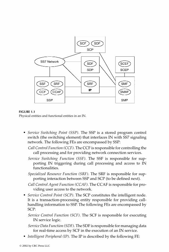
In an IN, several physical entities (PEs), comprising functional entities (FEs),are identified. These PEs, represented by rectangles, and their correspondingFEs, represented by ellipses, are depicted in Figure 1.1 and briefly describedas follows.
© 2002 by CRC Press LLC
E:\Java for Engineers\VP Publication\Java for Engineers.vpThursday, April 25, 2002 9:27:36 AM
Color profile: DisabledComposite Default screen
P1: FDJ
book CRC-Wireless November 8, 2001 10:33 Char Count= 252
FIGURE 1.1Physical entities and functional entities in an IN.
� Service Switching Point (SSP). The SSP is a stored program controlswitch (the switching element) that interfaces IN with SS7 signalingnetwork. The following FEs are encompassed by SSP:Call Control Function (CCF). The CCF is responsible for controlling the
call processing and for providing network connection services.Service Switching Function (SSF). The SSF is responsible for sup-
porting IN triggering during call processing and access to INfunctionalities.
Specialized Resource Function (SRF). The SRF is responsible for sup-porting interaction between SSP and SCP (to be defined next).
Call Control Agent Function (CCAF). The CCAF is responsible for pro-viding user access to the network.
� Service Control Point (SCP). The SCP constitutes the intelligent node.It is a transaction-processing entity responsible for providing call-handling information to SSP. The following FEs are encompassed bySCP:Service Control Function (SCF). The SCF is responsible for executing
IN service logic.Service Data Function (SDF). The SDF is responsible for managing data
for real-time access by SCF in the execution of an IN service.� Intelligent Peripheral (IP). The IP is described by the following FE:
© 2002 by CRC Press LLC
E:\Java for Engineers\VP Publication\Java for Engineers.vpThursday, April 25, 2002 9:27:36 AM
Color profile: DisabledComposite Default screen

P1: FDJ
book CRC-Wireless November 8, 2001 10:33 Char Count= 252
Specialized Resource Function (SRF). The SRF is responsible for sup-porting specialized network resources. These resources are usuallyassociated with caller interaction.
� Service Management Point (SMP). The SMP is described by the follow-ing FEs:Service Management Function (SMF). The SMF is responsible for sup-
porting ongoing operation. It also supports deployment and pro-vision of IN services.
Service Management Access Function (SMAF). The SMAF is responsiblefor interfacing services managers and SMF.
� Service Creation Environment Point (SCEP). The SCEP is described bythe following FE:Service Creation Environment (SCE). The SCE is responsible for sup-
porting the definition, development, and test of IN services to beinput into SMF.
� Service Data Point (SDP). The SDP is described by the following FE:Service Data Function (SDF). The SDF is responsible for managing data
for real-time access by SCF in the execution of an IN service.
The communication between the several PEs relies on out-of-band signalingor on SS7 protocols. The SS7 protocols provide means to:
� Place service logic and service data into network elements responsiblefor handling control and connection remotely
� Enable the communication between intelligent applications and otherapplications
� Access databases located in various parts of the network
1.2.3 Wireless Service Requirements
Some service requirements that are unique or essential to wireless networkscall for IN concepts, as exemplified below:
� Roaming. Mobility, a feature inherent to a wireless network, createssituations in which subscribers may roam out of their local callingarea or out of their service provider’s area. To enable subscribers tostill make use of their wireless services while in a roaming condition,a seamless network must be conceived. This can be accomplishedwith the IN concept by exchanging information between the variousdevices involved in the communication. In particular, the use of SS7
© 2002 by CRC Press LLC
E:\Java for Engineers\VP Publication\Java for Engineers.vpThursday, April 25, 2002 9:27:36 AM
Color profile: DisabledComposite Default screen

P1: FDJ
book CRC-Wireless November 8, 2001 10:33 Char Count= 252
makes it possible for message validations and billing reciprocation ofwireless calls.
� Carrier Select. Carrier-select services allow providers to select the net-work to be used to handle a call. In the same way, they allow sub-scribers to route their calls selectively through their network of prefer-ence. The exchange of messages in these cases requires IN technology.
� Hands-Free Operation. Hands-free services require that special featuresbe implemented within the network. For voice-activated dialing andfeature activation, voice recognition technology must be available. Insuch a case, messages or voice signals must be collected, translatedinto data, and routed to the required device, the so-called intelligentperipheral (IP). In such a case, special routing features or intelligentnetworking are necessary. The IP is then activated to implement therequired task.
� Fee Structure. The interaction among the various networks involvedin a call, both wired and wireless, renders billing a difficult task. INflags can be used to facilitate the billing. They can be included into thecall record so that billing reflects the specific call handling and feescan be processed more easily.
� Data-Service Capability. Short Message Service (SMS) is a very popu-lar wireless feature. Wireless phones are allowed to send and receivemessages in addition to making or taking telephone calls. SMS workslike a pager, and requires SS7 messages for the several tasks involvedin its implementation: access to database, authentication, message en-capsulation, paging, routing, etc. IN procedures are certainly requiredto implement SMS.
1.2.4 Wireless IN Services
The IN protocols and concepts can be used to implement enhanced wirelessservices rapidly and to have these services available across serving areas inan untethered wireless network. Some of these services are listed below:
� Voice-Based User Identification. This service employs a form of auto-matic speech recognition to validate the identity of the speaker. Ac-cess to services can then be restricted to the user whose voice (phrase)has been used to train the recognition device.
� Voice-Based Feature Control. This service allows the authorized userto specify feature operations, which can be carried out via feature-control strings by means of spoken commands.
© 2002 by CRC Press LLC
E:\Java for Engineers\VP Publication\Java for Engineers.vpThursday, April 25, 2002 9:27:36 AM
Color profile: DisabledComposite Default screen

P1: FDJ
book CRC-Wireless November 8, 2001 10:33 Char Count= 252
� Voice-Control Dialing. This service allows the subscriber to place a callusing spoken commands.
� Voice-Controlled Services. This feature allows the subscriber to controlfeatures and services using spoken commands.
� Incoming Call-Restriction/Control. This service allows users to imposerestrictions to an incoming call as follows: it may terminate normallyto the subscriber; it may terminate to the subscriber with normalalerting; it may terminate to the subscriber with special alerting; itmay be forwarded to another number; it may be forwarded to voicemail; it may be routed to any specific announcement; or it may beblocked.
� Calling Name Presentation. This service provides the name identifica-tion of the calling party (personal name, company name, restricted,not available) as well as the date and the time of the call.
� Password Call Acceptance. This service allows the subscriber to restrictincoming calls only to those callers who can provide valid passwords.
� Selective Call Acceptance. This service allows the subscriber to restrictincoming calls only to those calling parties whose numbers are in therestricted list.
� Short Message Service. This service allows the short message entities(SMEs)—the short message users—to receive or send short messages(packet of data).
� Speech-to-Text Conversion. This service allows the user to create a shortalphanumeric message by means of spoken phrases.
� Prepaid Phone. This service allows the user to pay before calling, i.e., notto be billed (postpaid). This can take a number of forms, for example,a debit card, a connection to a smart card, and others.
1.2.5 IN Standards
The merge of mobility systems with IN for 2G systems is a reality and takesa uniform approach.
In North America, the movement to develop a wireless intelligent network(WIN) was triggered by the Cellular Telecommunications Industry Associa-tion. In Europe, the same movement for GSM-based networks was carried outthrough the Customized Applications for Mobile Network Enhanced Logic(CAMEL).
3G systems—IMT2000—are already entirely based and described in termsof the IN architecture.
© 2002 by CRC Press LLC
E:\Java for Engineers\VP Publication\Java for Engineers.vpThursday, April 25, 2002 9:27:36 AM
Color profile: DisabledComposite Default screen

P1: FDJ
book CRC-Wireless November 8, 2001 10:33 Char Count= 252
1.3 Network Architecture
Different wireless networks are specified by different standardization or-ganizations and exhibit different architectures. However, a common frame-work may be identified in all wireless systems. Thus, some IN elements areused as the basis for an architecture common to all wireless networks. Fig-ure 1.2 identifies the main components of a wireless system, which are asfollows:
� Mobile Station (MS). The MS terminates the radio path on the user sideof the network enabling the user to gain access to services from thenetwork. It incorporates user interface functions, radio functions, andcontrol functions, with the most common equipment implemented inthe form of a mobile telephone. It can work as a stand-alone deviceor it may accept other devices connected to it (e.g., fax machines,personal computers, etc.). For such a purpose it may be split into theterminal equipment (TE), the terminal adapter (TA), and the mobiletermination (MT). A TE may be a fax, a computer, etc.; an MT is the
FIGURE 1.2The main components of a wireless system.
© 2002 by CRC Press LLC
E:\Java for Engineers\VP Publication\Java for Engineers.vpThursday, April 25, 2002 9:27:36 AM
Color profile: DisabledComposite Default screen
P1: FDJ
book CRC-Wireless November 8, 2001 10:33 Char Count= 252
equipment that realizes the wireless functions; and a TA works as aninterface between the TE and the MT.
� Base Station (BS). The BS terminates the radio path on the networkside and provides connection to the network. It is composed of twoelements:Base Transceiver Station (BTS). The BTS consists of a radio equip-
ment (transmitter and receiver–transceiver) and provides the radiocoverage for a given cell or sector.
Base Station Controller (BSC). The BSC incorporates a control capabilityto manage one or more BTSs, executing the interfacing functionsbetween BTSs and the network. The BSC may be co-located witha BTS or else independently located.
� Mobile Switching Center (MSC). The MSC provides an automaticswitching between users within the same network or other publicswitched networks, coordinating calls and routing procedures. In gen-eral, an MSC controls several BSCs, but it may also serve in differentcapacities. The MSC provides the SSP function in a wireless IN.
� Visitor Location Register (VLR). The VLR is a database containing tem-porary records associated with subscribers under the status of a vis-itor. A subscriber is considered a visitor if such a subscriber is beingserved by another system within the same home service area or by an-other system away from the respective home service area (in a roam-ing condition). The information within the VLR is retrieved from theHLR. An VLR is usually co-located with an MSC.
� Home Location Register (HLR). The HLR is the primary database forthe home subscriber. It maintains information records on subscribercurrent location, subscriber identifications (electronic serial number,international mobile station identification, etc.), user profile (servicesand features), and so forth. An HLR may be co-located with an MSCor it may be located independently of the MSC. It may even be dis-tributed over various locations and it may serve several MSCs. AnHLR usually operates on a centralized basis and serves many MSCs.
� Gateway (GTW). The GTW serves as an interface between the wirelessnetwork and the external network.
� Service Control Point (SCP). The SCP provides a centralized elementto control service delivery to subscribers. It is responsible for higher-level services that are usually carried out by the MSC in wirelessnetworks not using IN facilities.
� Service Transfer Point (STP). The STP is a packet switch device thathandles the distribution of control signals between different elementsin the network.
© 2002 by CRC Press LLC
E:\Java for Engineers\VP Publication\Java for Engineers.vpThursday, April 25, 2002 9:27:36 AM
Color profile: DisabledComposite Default screen
P1: FDJ
book CRC-Wireless November 8, 2001 10:33 Char Count= 252
� Intelligent Peripheral (IP). The IP processes the information of the sub-scribers (credit card information, personal identification number,voice-activated information, etc.) in support of IN services withina wireless network.
� External Network. The external network constitutes the ISDN (Inte-grated Services Digital Networks), CSPDN (Circuit-Switched Pub-lic Data Network), PSPDN (Packed-Switched Public Data Network),and, of course, PSTN (Public-Switched Telephone Network).
Note that a wireless network can be grossly split into a radio access network(RAN) and a core network (CN). The RAN implements functions related tothe radio access to the network, whereas the CN implements functions relatedto routing and switching. The RAN comprises the BSC, BTS, MT, and controlfunctionalities of the MS. The CN comprises the MSC, HLR, VRL, GTW, andother devices implementing the switching and routing functions. This book isprimarily concerned with the radio aspects—the radio interface—of a wirelessnetwork.
1.4 Protocol Architecture
A radio interface implements the wireless electromagnetic interconnec-tion between a mobile station and a base station.[1] A general radio pro-tocol contains the three lowest layers of the OSI/ISO Reference Model, asfollows:
� Physical Layer. The physical layer is responsible for providing a radiolink over the radio interface. Such a radio link is characterized by itsthroughput and data quality. It is defined for the BTS and for the MT.
� Data Link Layer. The data link layer comprises two sublayers, asfollows:Medium Access Control (MAC) sublayer. The MAC sublayer is respon-
sible for controlling the physical layer. It performs link qualitycontrol and mapping of data flow onto this radio link. It is definedfor the BTS and for the MT. It may or may not exist in the BSC andin the control functionalities of an MS.
Link Access Control (LAC) sublayer. The LAC sublayer is responsiblefor performing functions essential to the logical link connectionsuch as setup, maintenance, and release of a link. It is defined forBSC, BTS, MT, and control functionalities of the MS.
© 2002 by CRC Press LLC
E:\Java for Engineers\VP Publication\Java for Engineers.vpThursday, April 25, 2002 9:27:36 AM
Color profile: DisabledComposite Default screen
P1: FDJ
book CRC-Wireless November 8, 2001 10:33 Char Count= 252
� Network Layer. The network layer contains functions dealing with callcontrol, mobility management, and radio resource management. It ismostly independent of radio transmission technology. Such a layercan be transparent for user data in certain user services. It is definedfor BSC, BTS, MT, and control functionalities of the MS.
1.5 Channel Structure
A channel provides means of conveying information between two networkelements. Within the radio interface, three types of channels are specified:radio frequency (RF) channel, physical channel, and logical channel.[1] Thesechannels are defined in the forward direction (downlink)—from BS to MS—orin the reverse direction (uplink)—from MS to BS.
1.5.1 RF Channel
An RF channel is defined in terms of a carrier frequency centered withina specified bandwidth, representing a portion of the RF spectrum. The RFchannel constitutes the means of carrying information over the radio interface.It can be shared in the frequency domain, time domain, code domain, or spacedomain.
1.5.2 Physical Channel
A physical channel corresponds to a portion of one or more RF channelsused to convey any given information. Such a portion is defined in terms offrequency, time, code, space, or a combination of these. A physical channelmay be partitioned into a frame structure, with the specific timing definedin accordance with the control and management functions to be performed.Fixed or variable frame structures may be used.
1.5.3 Logical Channel
A logical channel is defined by the type of information it conveys. The logi-cal channels are mapped onto one or more physical channels. Logical chan-nels are usually grouped into control channels and traffic channels. Furtherspecifications concerning these channels vary according to the wireless net-work. Logic channels may be combined by means of a multiplexing process,using a frame structure. The following division and definitions are based onReference 1, and such a division, as depicted in Figure 1.3, reflects the basicstructure used in most wireless networks.
© 2002 by CRC Press LLC
E:\Java for Engineers\VP Publication\Java for Engineers.vpThursday, April 25, 2002 9:27:36 AM
Color profile: DisabledComposite Default screen

P1: FDJ
book CRC-Wireless November 8, 2001 10:33 Char Count= 252
FIGURE 1.3Logical channels.
Traffic Channels
Traffic channels convey user information streams including data and voice.Two types of traffic channels are specified:
� Dedicated Traffic Channel (DTCH). The DTCH conveys user informa-tion. It may be defined in one or both directions.
� Random Traffic Channel (RTCH). The RTCH conveys packet-type datauser information. It is usually defined in one direction.
Control Channels
Control channels convey signaling information related to call management,mobility management, and radio resource management. Two groups ofcontrol channels are defined—dedicated control channels and common con-trol channels:
© 2002 by CRC Press LLC
E:\Java for Engineers\VP Publication\Java for Engineers.vpThursday, April 25, 2002 9:27:36 AM
Color profile: DisabledComposite Default screen

P1: FDJ
book CRC-Wireless November 8, 2001 10:33 Char Count= 252
� Dedicated Control Channels (DCCH). A DCCH is a point-to-point chan-nel defined in both directions. Two DCCHs are specified:Associated Control Channel (ACCH). An ACCH is always allocated with
a traffic channel or with an SDCCH.Stand-Alone Dedicated Control Channel (SDCCH). An SDCCH is allo-
cated independently of the allocation of a traffic channel.� Common Control Channels (CCCH). A CCCH is a point-to-multipoint
or multipoint-to-point channel used to convey signaling information(connectionless messages) for access management purposes. Fourtypes of CCCHs are specified:Broadcast Control Channel (BCCH). The BCCH is a downlink channel
used to broadcast system information. It is a point-to-multipointchannel listened to by all MSs, from which information is obtainedbefore any access attempt is made.
Forward Access Channel (FACH). The FACH is a downlink channel con-veying a number of system management messages, including en-quiries to the MS and radio-related and mobility-related resourceassignment. It may also convey packet-type user data.
Paging Channel (PCH). The PCH is a downlink channel used for pagingMSs. A page is defined as the process of seeking an MS in the eventthat an incoming call is addressed to that MS.
Random Access Channel (RACH). The RACH is an uplink channel usedto convey messages related to call establishment requests and re-sponses to network-originated inquiries.
1.6 Narrowband and Wideband Systems
Wireless systems can be classified according to whether they have a narrow-band or wideband architecture. Narrowband systems support low-bit-ratetransmission, whereas wideband systems support high-bit-rate transmission.A system is defined as narrowband or wideband depending on the band-width of the transmission physical channels with which it operates. The sys-tem channel bandwidth is assessed with respect to the coherence bandwidth.The coherence bandwidth is defined as the frequency band within which allfrequency components are equally affected by fading due to multipath propa-gation phenomena. Systems operating with channels substantially narrowerthan the coherence bandwidth are known as narrowband systems. Wide-band systems operate with channels substantially wider than the coherence
© 2002 by CRC Press LLC
E:\Java for Engineers\VP Publication\Java for Engineers.vpThursday, April 25, 2002 9:27:36 AM
Color profile: DisabledComposite Default screen

P1: FDJ
book CRC-Wireless November 8, 2001 10:33 Char Count= 252
bandwidth. In narrowband systems, all the components of the signal areequally influenced by multipath propagation. Accordingly, although withdifferent amplitudes, the received narrowband signal is essentially the sameas the transmitted narrowband signal. In wideband systems, the variousfrequency components of the signal may be differently affected by fading.Narrowband systems, therefore, are affected by nonselective fading, whereaswideband systems are affected by selective fading.
The coherence bandwidth, Bc , depends on the environment. It is approxi-mately given by
Bc = (2πT)−1
in hertz, where T , in seconds, is the delay spread, as defined next. In a fadingenvironment, a propagated signal arrives at the receiver through multiplepaths. The time span between the arrival of the first and the last multipathsignals that can be sensed by the receiver is known as delay spread. The delayspread varies from tenths of microseconds, in rural areas, to tens of microsec-onds, in urban areas. As an example, consider an urban area where the delayspread is T = 5µs. In such an environment, the coherence bandwidth is calcu-lated as Bc = 32 kHz. Therefore, a system is considered to be narrowband if itoperates with channels narrower than 32 kHz. It is considered to be widebandif it operates with channels several times wider than 32 kHz.
Another important definition within this context concerns coherence time.The coherence time, Tc , is defined as the time interval during which the fad-ing characteristics of the channel remain approximately unchanged (slowchange). This is approximately given as
Tc = (2 fm)−1
where fm is the maximum Doppler shift. The Doppler shift, in hertz, is givenas v/λ, where v, in m/s, is the speed of the mobile terminal and λ, in m, is thewavelength of the signal.
1.7 Multiple Access
Wireless networks are multiuser systems in which information is conveyedby means of radio waves. In a multiuser environment, access coordination canbe accomplished via several mechanisms: by insulating the various signalssharing the same access medium, by allowing the signals to contend for theaccess, or by combining these two approaches. The choice for the appropriate
© 2002 by CRC Press LLC
E:\Java for Engineers\VP Publication\Java for Engineers.vpThursday, April 25, 2002 9:27:36 AM
Color profile: DisabledComposite Default screen

P1: FDJ
book CRC-Wireless November 8, 2001 10:33 Char Count= 252
scheme must take into account a number of factors, such as type of traffic un-der consideration, available technology, cost, complexity. Signal insulation iseasily attainable by means of a scheduling procedure in which signals are al-lowed to access the medium according to a predefined plan. Signal contentionoccurs exactly because no signal insulation mechanism is used. Access co-ordination may be carried out in different domains: the frequency domain,time domain, code domain, and space domain. Signal insulation in each do-main is attained by splitting the resource available into nonoverlapping slots(frequency slot, time slot, code slot, and space slot) and assigning each signala slot. Four main multiple access technologies are used by the wireless net-works: frequency division multiple access (FDMA), time division multipleaccess (TDMA), code division multiple access (CDMA), and space divisionmultiple access (SDMA).
1.7.1 Frequency Division Multiple Access
FDMA is certainly the most conventional method of multiple access and wasthe first technique to be employed in modern wireless applications. In FDMA,the available bandwidth is split into a number of equal subbands, each ofwhich constitutes a physical channel. The channel bandwidth is a function ofthe services to be provided and of the available technology and is identifiedby its center frequency, known as a carrier. In single channel per carrier FDMAtechnology, the channels, once assigned, are used on a non-time-sharing ba-sis. Thus, a channel allocated to a given user remains allocated until the endof the task for which that specific assignment was made.
1.7.2 Time Division Multiple Access
TDMA is another widely known multiple-access technique and succeededFDMA in modern wireless applications. In TDMA, the entire bandwidth ismade available to all signals but on a time-sharing basis. In such a case,the communication is carried out on a buffer-and-burst scheme so that thesource information is first stored and then transmitted. Prior to transmission,the information remains stored during a period of time referred to as a frame.Transmission then occurs within a time interval known as a (time) slot. Thetime slot constitutes the physical channel.
1.7.3 Code Division Multiple Access
CDMA is a nonconventional multiple-access technique that immediatelyfound wide application in modern wireless systems. In CDMA, the entirebandwidth is made available simultaneously to all signals. In theory, verylittle dynamic coordination is required, as opposed to FDMA and TDMA in
© 2002 by CRC Press LLC
E:\Java for Engineers\VP Publication\Java for Engineers.vpThursday, April 25, 2002 9:27:36 AM
Color profile: DisabledComposite Default screen

P1: FDJ
book CRC-Wireless November 8, 2001 10:33 Char Count= 252
which frequency and time management have a direct impact on performance.To accomplish CDMA systems, spread-spectrum techniques are used. (Ap-pendix C introduces the concept of spread spectrum.)
In CDMA, signals are discriminated by means of code sequences or sig-nature sequences, which correspond to the physical channels. Each pair oftransmitter–receivers is allotted one code sequence with which a communica-tion is established. At the reception side, detection is carried out by means of acorrelation operation. Ideally, the best performance is attained with zero cross-correlation codes, i.e., with orthogonal codes. In theory, for a synchronoussystem and for equal rate users, the number of users within a given band-width is dictated by the number of possible orthogonal code sequences. Ingeneral, CDMA systems operate synchronously in the forward direction andasynchronously in the reverse direction. The point-to-multipoint character-istic of the downlink facilitates the synchronous approach, because one ref-erence channel, broadcast by the base station, can be used by all mobile sta-tions within its service area for synchronization purposes. On the other hand,the implementation of a similar feature on the reverse link is not as simplebecause of its multipoint-to-point transmission characteristic. In theory, theuse of orthogonal codes eliminates the multiple-access interference. There-fore, in an ideal situation, the forward link would not present multiple-accessinterference. The reverse link, in turn, is characterized by multiple-access in-terference. In practice, however, interference still occurs in synchronous sys-tems, because of the multipath propagation and because of the other-cell sig-nals. The multipath phenomenon produces delayed and attenuated replicas ofthe signals, with these signals then losing the synchronism and, therefore, theorthogonality. The other-cell signals, in turn, are not time-aligned with thedesired signal. Therefore, they are not orthogonal with the desired signal andmay cause interference.
Channels in the forward link are identified by orthogonal sequences, i.e.,channelization in the forward link is achieved by the use of orthogonal codes.Base stations are identified by pseudonoise (PN) sequences. Therefore, in theforward link, each channel uses a specific orthogonal code and employs aPN sequence modulation, with a PN code sequence specific to each base sta-tion. Hence, multiple access in the forward link is accomplished by the useof spreading orthogonal sequences. The purpose of the PN sequence in theforward link is to identify the base station and to reduce the interference. Ingeneral, the use of orthogonal codes in the reverse link finds no direct appli-cation, because the reverse link is intrinsically asynchronous. Channelizationin the reverse link is achieved with the use of long PN sequences combinedwith some private identification, such as the electronic serial number of themobile station. Some systems, on the other hand, implement some sort of syn-chronous transmission on the reverse link, as shall be detailed in the chapters
© 2002 by CRC Press LLC
E:\Java for Engineers\VP Publication\Java for Engineers.vpThursday, April 25, 2002 9:27:36 AM
Color profile: DisabledComposite Default screen
P1: FDJ
book CRC-Wireless November 8, 2001 10:33 Char Count= 252
that follow. In such a case, orthogonal codes may also be used with channel-ization purposes in the reverse link.
Several PN sequences are used in the various systems, and they will bedetailed for the several technologies described in the following chapters. Twomain orthogonal sequences are used in all CDMA systems: Walsh codes andorthogonal variable spreading functions (OVSF) (see Appendix C).
1.7.4 Space Division Multiple Access
SDMA is a nonconventional multiple-access technique that finds applicationin modern wireless systems mainly in combination with other multiple-accesstechniques. The spatial dimension has been extensively explored by wirelesscommunications systems in the form of frequency reuse. The deploymentof advanced techniques to take further advantage of the spatial dimensionis embedded in the SDMA philosophy. In SDMA, the entire bandwidth ismade available simultaneously to all signals. Signals are discriminated spa-tially, and the communication trajectory constitutes the physical channels.The implementation of an SDMA architecture is based strongly on antennastechnology coupled with advanced digital signal processing. As opposed tothe conventional applications in which the locations are constantly illumi-nated by rigid-beam antennas, in SDMA the antennas should provide forthe ability to illuminate the locations in a dynamic fashion. The antennabeams must be electronically and adaptively directed to the user so that,in an idealized situation, the location alone is enough to discriminate theuser.
FDMA and TDMA systems are usually considered to be narrowband,whereas CDMA systems are usually designed to be wideband. SDMA sys-tems are deployed together with the other multiple-access technologies.
1.8 Summary
Wireless networks are multiuser systems in which information is conveyedby radio waves. Modern wireless networks have evolved through differentgenerations: 1G systems, based on analog technology, aimed at providingvoice telephony services; 2G systems, based on digital technology, aimed atproviding a better spectral efficiency, a more robust communication, voiceprivacy, and authentication capabilities; 2.5G systems, based on 2G systems,aimed at providing the 2G systems with a better data rate capability; and 3Gsystems that aim at providing for multimedia services in their entirety.
© 2002 by CRC Press LLC
E:\Java for Engineers\VP Publication\Java for Engineers.vpThursday, April 25, 2002 9:27:36 AM
Color profile: DisabledComposite Default screen
P1: FDJ
book CRC-Wireless November 8, 2001 10:33 Char Count= 252
References
1. Framework for the radio interface(s) and radio sub-system functionality forInternational Mobile Telecommunications-2000 (IMT-2000), RecommendationITU-R M.1035.
2. The international intelligent network (IN), The International Engineering Con-sortium, available at http://www.iec.org.
© 2002 by CRC Press LLC
E:\Java for Engineers\VP Publication\Java for Engineers.vpThursday, April 25, 2002 9:27:36 AM
Color profile: DisabledComposite Default screen

P1: FDJ
book CRC-Wireless November 16, 2001 13:56 Char Count= 254
2Cellular Principles
2.1 Introduction
The electromagnetic spectrum is a limited but renewable resource that, ifadequately managed, can be reused to expand wireless network capacity.Frequency reuse, in fact, constitutes the basic idea behind the cellular concept.In a cellular system, the service area is divided into cells and portions of theavailable spectrum are conveniently allocated to each cell. The main pur-pose of defining cells in a wireless network is to delimit areas within whichchannels or base stations are used at least preferentially. A cell, therefore, isdefined as the geographic area where a mobile station is preferentially servedby its base station. A mobile station moving out of its serving cell and into aneighboring cell must be provided with sufficient resources from these cellsso that the already established communication will not be discontinued. Sucha process is known as handoff or handover. A group of cells among which thewhole spectrum is shared and within which no frequency reuse exists con-stitutes a cluster. The number of cells per cluster defines the reuse pattern,and this is a function of the cellular geometry. In an ideal situation, for om-nidirectional transmission with antennas mounted high above the rooftops,mobile stations at the same distance from the base station receive the samemean signal power in all directions. In such a case, the cell shape can be de-fined as a circle. Its radius is determined so as to have a circular area withinwhich base station and mobile stations receive a signal power exceeding agiven threshold. Circles, on the other hand, cannot fill a plane without leavinggaps (holes) or exhibiting overlapped areas. The use of a circular geometrymay impose difficulties in the design of a cellular network. Regular poly-gons, such as equilateral triangles, squares, and regular hexagons do not exhibitthese constraints. The choice for one or another cellular format depends onthe application. In practice, the coverage area differs substantially from the
© 2002 by CRC Press LLC
E:\Java for Engineers\VP Publication\Java for Engineers.vpThursday, April 25, 2002 9:27:36 AM
Color profile: DisabledComposite Default screen

P1: FDJ
book CRC-Wireless November 16, 2001 13:56 Char Count= 254
idealized geometric figures and “amoeboid” cellular shapes are more likelyto occur.
This chapter defines the issues related to the cellular concepts. The maindefinitions that follow are based on an ITU Recommendation for IMT-2000.[1]
The concepts developed in Reference 1 generalize those that have been usedfor conventional cellular networks.
2.2 Cellular Hierarchy
To maximize spectral efficiency as well as to minimize the number of han-dovers, it is beneficial for the cells to be designed with different sizes andformats. The design of different cells depends on several parameters, such asmobility characteristics, output power, and types of services utilized. Cellularlayers are then defined with each layer containing cells of the same type in agiven service area. The layering of cells does not imply that all mobile stationsmust be able to connect to all base stations serving the geographic area wherethe mobile station is positioned. For example, the mobile station may not havesufficient output power to access a given layer or may not be entitled to theservice provided by the cells of a given layer. The cellular hierarchy makesuse of four categories of cells: mega cells, macro cells, micro cells, and picocells.[1]
Mega cells provide coverage to large areas and are characterized by cellspresenting radii in the range 100 to 500 km. They are particularly useful forremote areas with low traffic density or for areas without access to terrestrialtelecommunications networks. Mega cells are provided by low-orbit satellitesand the cell radius is a function of the satellite altitude, power, and antennaaperture. Note that in a mega cell the distances between mobile stations andthe base station are very large. Because of their sizes, these cells must be bothflexible and robust to accommodate a wide range of user scenarios. Theymust be able to support low-mobility as well as very high-mobility users.Note that for nongeostationary orbits, the cells move because the satellitesmove with respect to the Earth. Therefore, handovers may be necessary evenfor stationary mobile stations.
Macro cells provide coverage to large areas and are characterized by cellspresenting radii of up to 35 km. Larger cell radii may be provided with the useof directional antennas. The macro cells are outdoor cells that are illuminatedby high-power sites with the antennas mounted above the rooftops—on tow-ers or on the tops of buildings. They serve low to medium traffic density andsupport mobile speeds of up to 500 km/h.
Micro cells provide coverage to small areas and are characterized by cellspresenting radii of up to 1 km. They are outdoor cells that are illuminated© 2002 by CRC Press LLC
E:\Java for Engineers\VP Publication\Java for Engineers.vpThursday, April 25, 2002 9:27:36 AM
Color profile: DisabledComposite Default screen
P1: FDJ
book CRC-Wireless November 16, 2001 13:56 Char Count= 254
by low-power antennas with the antennas mounted below the rooftops—onlampposts or on building walls. They support medium to high traffic densityand mobile speeds of up to 100 km/h.
Pico cells provide coverage to small areas and are characterized by cellspresenting radii of up to 50 m. They are indoor cells supporting medium tohigh traffic density and mobile speeds of up to 10 km/h.
In the real world, mega cells, macro cells, micro cells, and pico cellscoexist in the same environment. Digital technology has made it possible forwireless systems to take full advantage of such a coexistence so that coverageis improved, capacity is increased, load is balanced, and users are providedwith different services according to the mobility characteristics. More gen-erally, pico, micro, macro, and mega cells are displaced in a hierarchy, theso-called hierarchical cellular structure (HCS). In HCS wireless systems, verylow to very high mobility and in-building to satellite coverage provide forthe multimedia–anywhere–anytime wireless services. In HCS, several layersof cells may coexist with the smallest cells occupying the lowest layer in thehierarchy. The mobility and the class of service of the user determine the layerwithin which the required service is to be provided. In a multilayered cellularenvironment, the selection of which cell to serve a given call should be basedon criteria such as speed of the mobile station relative to the base station, cellavailability, and required transmission power to and from the mobile station.
2.3 System Management
The phases of a communication between mobile station and base stationencompass the establishment, maintenance, and release of the connection.The management of these phases is carried out by several functions. Thesefunctions include link quality measurement, cell selection, channel selection/assignment, handover, and mobility support.[1]
2.3.1 Link Quality Measurement
During any given connection, forward and reverse links are continually moni-tored to assess the radio link quality. The assessment is based on parameterssuch as the received signal quality and the bit error rates.
2.3.2 Cell Selection
In advanced wireless networks, cell selection is a feature that can be provided.Cell selection may be based on several criteria, including mobility and classof service to be provided. It starts with the choice of the operator, a phase thatoccurs as the mobile station is powered up. The selection of the operator may© 2002 by CRC Press LLC
E:\Java for Engineers\VP Publication\Java for Engineers.vpThursday, April 25, 2002 9:27:36 AM
Color profile: DisabledComposite Default screen
P1: FDJ
book CRC-Wireless November 16, 2001 13:56 Char Count= 254
be based on user preferences, available networks, mobile station capabilities,network capabilities, mobile station mobility, and service requirements. Oncea system has been selected by the mobile station, a base station is then searchedand its broadcast control channel monitored. Cell reselection may also occur,and the following circumstances may trigger the reselection: unsuitabilityof current cell due to interference or output power requirements, radio linkfailure, network request, traffic load considerations, and user request.
2.3.3 Channel Selection/Assignment
Channel assignment algorithms are used to ascertain conveniently the avail-able channels and to assign one or more of these channels to a call. The algo-rithms vary in accordance with specific allocation policies, but they usuallytake into account the following: system load, traffic patterns, service types,service priorities, and interference situations. Channel assignment algorithmsare added-on features that differ for different system providers.
2.3.4 Handover
Handover is defined as “the change of Physical Channel(s) involved in a callwhilst maintaining the call.”[1] Handover constitutes a diversity techniqueused to prevent mobile calls from being released when the mobile stationsexperience a degraded radio condition. Many factors affect the received sig-nal quality, one of which is the distance between mobile and base stations. Asignal degradation may occur, particularly when the mobile stations cross thecell boundaries. Handovers may take place in several conditions: within thecell (intracell handover), between cells in the same cell layer (intercell han-dover), between cells of different layers (interlayer handover), or betweencells of different networks (internetwork handover).
In FDMA and TDMA wireless networks, handovers are “hard” (hard hand-over). In hard handover, the communication with the old base station througha given channel is discontinued, and a new communication with a new basestation, and necessarily through another channel, is established. Internetworkhandovers and handovers between systems of different technologies arealways hard handover.
In CDMA wireless networks, handovers are “soft,” and three kinds of soft-type handovers are identified: soft handover, softer handover, and soft-softerhandover. In soft handover, the mobile station maintains communication si-multaneously with the old base station and with one or more new base sta-tions, provided that all base stations have CDMA channels with an identicalfrequency assignment. Note that the soft handover constitutes a means of di-versity for both the forward and reverse paths, and is supposed to occur in thevicinities of the boundary of the cell, where the signal is presumably weaker. Insofter handover, the mobile station maintains communication simultaneously© 2002 by CRC Press LLC
E:\Java for Engineers\VP Publication\Java for Engineers.vpThursday, April 25, 2002 9:27:36 AM
Color profile: DisabledComposite Default screen

P1: FDJ
book CRC-Wireless November 16, 2001 13:56 Char Count= 254
with two or more sectors of the same base station and certainly within thesame CDMA channel of that base station. Similar to the soft handover, thesofter handover also constitutes a means of diversity and is supposed to oc-cur in the vicinities of the boundary of the coverage area of the sectors. Insoft-softer handover, the mobile station maintains communication simulta-neously with two or more sectors of the same base station and with one ormore base stations (or their sectors).
Note that, whereas in the hard-type handover the number of resources uti-lized remains unchanged, in the soft-type handover this is not true. In thehard-type handover, the new resource is utilized only after the old resourcehas been released. In the soft-type handover, a communication with more thanone resource is maintained throughout the duration of the process. However,in the uplink direction only one channel is used by the mobile station. Insuch a case, the involved base station receives this very channel and the selec-tion of the best communication is performed by the mobile switching center.In the downlink direction, on the other hand, each base station supportingthe handover transmits to the same mobile station, and the combination ofthe received signals is carried out by the mobile station. Therefore, the in-volved base stations must provide for additional channels for soft handoverpurposes, with these additional channels used in the forward direction only.
From the transmission point of view, the handover process comprises twophases: the evaluation phase and the execution phase. In the evaluation phase,the rationale for performing a handover is continually assessed. Handoversmay be initiated for such reasons as operation and maintenance, radio chan-nel capacity optimization, poor radio transmission conditions, signal levelvariability, significant amount of interference, etc. The following criteria maybe used to initiate a handover for radio transmission reasons: signal strengthmeasurements, signal-to-interference ratio, bit error rates, distance betweenmobile station and base station, mobile station speed, mobile station mobilitytrends, and others. The handover is actually performed in the execution phase.A handover may be initiated by the base station or by the mobile station.
Three handover strategies are possible: mobile-controlled handover(MCHO); mobile-assisted handover (MAHO); and base-controlled handover(BCHO). In MCHO, the mobile station controls the handover evaluation phaseas well as the handover execution phase. In MAHO, the base station controlsthe handover process with the support of the mobile station (e.g., measure-ments carried out by the mobile station). In BCHO, the base station controlsthe handover evaluation phase as well as the handover execution phase.
2.3.5 Mobility Support
User mobility is supported by the following processes: logon–logoff and lo-cation updating. In logon–logoff, messages are transmitted from the mobilestation to the network to notify the network of the terminal status. Such a© 2002 by CRC Press LLC
E:\Java for Engineers\VP Publication\Java for Engineers.vpThursday, April 25, 2002 9:27:36 AM
Color profile: DisabledComposite Default screen

P1: FDJ
book CRC-Wireless November 16, 2001 13:56 Char Count= 254
procedure may be initiated by the mobile station as well as by the network. Inlocation updating, messages are exchanged between the mobile station andthe network to identify the area within which the mobile station is located. Alocation area is defined as the geographic area, containing a group of cells, inwhich the mobile station is to be sought by the network. The location updateis performed whenever a mobile station moves into a new location area. Notethat the smaller the location area, the higher the chance of locating the mobilestation within the network. On the other hand, the smaller the location area,the higher the frequency with which the exchange of updating messages mustbe carried out.
2.4 System Performance
Several aspects that affect the performance of the system must be addressed:interference control, diversity strategies, variable data rate control, capacityimprovement techniques, and battery-saving techniques.
2.4.1 Interference Control
Synchronization is certainly one of the issues that must be examined for in-terference control purposes. Some technologies require that base stations be-longing to the same system must be synchronized. This is particularly true forTDMA systems and some CDMA systems. In the same way, time synchroniza-tion between base stations in different but geographically co-located systemsand time synchronization between user terminals and base stations are ele-ments that have a great impact on interference. Power control is another im-portant issue in interference control. Power control must be exercised becauseof the near–far phenomenon, a feature inherent to mobile communications.Because of the mobility feature, the powers of desired and interfering sig-nals may vary according to the location of the mobile stations. Power controlmust be performed so that intra- and intersystem interference is minimized.The near–far phenomenon is more relevant in the multipoint-to-point trans-mission (mobile stations to base station) than in the point-to-multipoint one(base station to mobile stations). In the first case (multipoint-to-point), becausethe mobile stations may be at different distances from the base station, thevarious signals arriving at the base will have different strengths. In the secondcase (point-to-multipoint), the various signals transmitted by the base reach agiven mobile station with approximately the same power loss, thus main-taining power proportionality. In practice, however, both reverse link andforward link require power control: the reverse link for the reasons already
© 2002 by CRC Press LLC
E:\Java for Engineers\VP Publication\Java for Engineers.vpThursday, April 25, 2002 9:27:36 AM
Color profile: DisabledComposite Default screen
P1: FDJ
book CRC-Wireless November 16, 2001 13:56 Char Count= 254
outlined, and the forward link to compensate for poor reception conditionsencountered by the mobile station.
2.4.2 Diversity Strategies
Diversity strategies are used to combat fading. The diversity methods takeadvantage of the fact that fades occurring on independent channels (knownas branches) constitute independent events. Therefore, if certain informationis redundantly available on two or more branches, simultaneous fades are lesslikely to occur. By appropriately combining the various branches, the qualityof the received signal is improved. Diversity may be achieved in several ways,such as in space (spaced antennas), frequency, and time.
2.4.3 Variable Data Rate Control
Variable data rates may be accomplished by several means: direct support ofvariable data rates over the air interface, variation of the number of bearerchannels so that multiple bearer channels are combined to deliver the desireduser rate, or packet access. Different wireless networks use different variabledata rate technologies.
2.4.4 Capacity Improvement Techniques
Network capacity may be improved by means of such techniques as slow fre-quency hopping; dynamic power control; dynamic channel allocation; dis-continuous transmission for voice, including voice activity detection, andnonvoice services; and others. The applicability of one or another techniqueis dependent on the multiple-access technology chosen.
2.4.5 Battery-Saving Techniques
Digital technologies facilitate the use of battery-saving techniques. These tech-niques include output power control, discontinuous reception, and disconti-nuous transmission.
2.5 Cellular Reuse Pattern
For quite a while, since the inception of modern wireless networks, the cellulargrid has been dominated by macro cells. The macrocellular network makesuse of a hexagonal cell array with the reuse pattern established with thesupposition that reuse distances are isotropic and that a cluster comprises a
© 2002 by CRC Press LLC
E:\Java for Engineers\VP Publication\Java for Engineers.vpThursday, April 25, 2002 9:27:36 AM
Color profile: DisabledComposite Default screen

P1: FDJ
book CRC-Wireless November 16, 2001 13:56 Char Count= 254
group of contiguous cells. In theory, high-power sites, combined with basestation antennas positioned well above the rooftops, provide for propaga-tion symmetry, in which case, for system planning purposes, the hexagonalcoverage grid has proved appropriate. Further, macro cells are adequate forlow-capacity systems.
The expansion and the evolution of wireless networks can only be supportedby an ample microcellular structure, not only to satisfy the high traffic demandin dense urban regions but also to provide for services requiring low mobi-lity. The microcellular network concept differs from that of the macrocellularconcept widely employed in wireless systems. In microcellular systems, withlow-power sites and antennas mounted at street level (below the rooftops),the supposed propagation symmetry of the macrocellular network no longerapplies and the hexagonal cell pattern does not make sense. The “micro-scopic” structure of the environment (e.g., street orientation, width of thestreets, layout of the buildings, among others) constitutes a decisive elementinfluencing system performance. With the antennas mounted at street level,the buildings lining each side of the street work as “waveguides,” in the radialdirection, and as obstructors, in the perpendicular direction. Therefore, thepropagation direction of the radio waves is greatly influenced by the envi-ronment. Assuming the base stations to be positioned at the intersection ofthe streets, a cell in such an environment is more likely to have a diamondshape with the radial streets as the diagonals. In fact, a number of field meas-urements and investigations[2–8] show that an urban micro cell service areacan be reasonably well approximated by a square diamond.
The ubiquitous coverage of a service area based on a microcellular networkrequires a much greater number of base stations as compared with the num-ber of base stations required by macrocellular systems. Therefore, among theimportant factors to be accounted for in microcellular system planning (costof the site, size of the service area, etc.), the per-subscriber cost is determi-nant. This cost is intimately related to how efficiently the radio resources arereutilized in a given service area. Reuse efficiency depends on the interferingenvironment of the network and on how the involved technology can copewith the interfering sources.
The study of interference in macrocellular systems is greatly eased by theintrinsic symmetry of the problem. In the microcellular case, the inherentasymmetry due to the microscopic structures introduces an additional com-plication. In such a case, the interference is dependent not only on the distancebetween transmitter and receiver but also, and mainly, on the line-of-sight(LOS) condition of the radio path. Assume, for example, that base stations arelocated at street intersections. Mobiles on streets running radially from thebase station may experience an interference pattern changing along the streetas they depart from the vicinity of their serving base station and approach newstreet intersections. Near the serving base station, the desired signal is strong
© 2002 by CRC Press LLC
E:\Java for Engineers\VP Publication\Java for Engineers.vpThursday, April 25, 2002 9:27:36 AM
Color profile: DisabledComposite Default screen
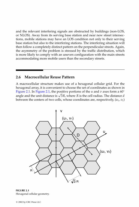
P1: FDJ
book CRC-Wireless November 16, 2001 13:56 Char Count= 254
and the relevant interfering signals are obstructed by buildings (non-LOS,or NLOS). Away from its serving base station and near new street intersec-tions, mobile stations may have an LOS condition not only to their servingbase station but also to the interfering stations. The interfering situation willthen follow a completely distinct pattern on the perpendicular streets. Again,the asymmetry of the problem is stressed by the traffic distribution, whichis more likely to comply with an uneven configuration with the main streetsaccommodating more mobile users than the secondary streets.
2.6 Macrocellular Reuse Pattern
A macrocellular structure makes use of a hexagonal cellular grid. For thehexagonal array, it is convenient to choose the set of coordinates as shown inFigure 2.1. In Figure 2.1, the positive portions of the u and v axes form a 60◦
angle and the unit distance is√
3R, where R is the cell radius. The distance dbetween the centers of two cells, whose coordinates are, respectively, (u1, v1)
u
(u2, v2)
(u1, v1)
R3
R
v
D
FIGURE 2.1Hexagonal cellular geometry.
© 2002 by CRC Press LLC
E:\Java for Engineers\VP Publication\Java for Engineers.vpThursday, April 25, 2002 9:27:36 AM
Color profile: DisabledComposite Default screen

P1: FDJ
book CRC-Wireless November 16, 2001 13:56 Char Count= 254
and (u2, v2), is
d2 = 3R2[(u1 − u2)2 + (v2 − v1)2 − 2 cos (60◦) (u1 − u2) (v2 − v1)]
Defining i = u2 − u1, j = v2 − v1, and √
3R = 1, then
d2 = i2 + i j + j2 (2.1)
where i and j range over the integers.
2.6.1 Reuse Factor (Number of Cells per Cluster)
Let D be the reuse distance, that is, the distance between two co-cells. There-fore, for any given co-cells
D2 = i2 + i j + j2 (2.2)
Considering that reuse distances are isotropic and that a cluster is a groupof contiguous cells, the format of the clusters must be hexagonal. For twoadjacent clusters, D represents the distance between the centers of any twoco-cells within these clusters. Therefore, D is also the distance between thecenters of these two adjacent hexagonal clusters, D/2 their apothems, and(D/2)/ cos 30◦ their radii. Let A be the area of the hexagonal cluster and a thearea of the hexagonal cell. Then,
A =3√
32
×(
D/2cos 30◦
)2
=
√3D2
2
and
a =3√
32
× R2 =
√3
2
The number N of cells per cluster is N = A/a = D2. Therefore,
N = i2 + i j + j2 (2.3)
Because i and j range over the integers, the clusters will accommodate onlya certain number of cells, such as 1, 3, 4, 7, 9, 12, 13, 16, 19, etc.
The layout of the cells within the cluster is attained having as principaltargets symmetry and compactness. Figure 2.2 shows some hexagonal repeatpatterns. The tessellation over the entire plane is then achieved by replicatingthe cluster in an isotropic manner. In other words, if the chosen reuse pattern
© 2002 by CRC Press LLC
E:\Java for Engineers\VP Publication\Java for Engineers.vpThursday, April 25, 2002 9:27:36 AM
Color profile: DisabledComposite Default screen

P1: FDJ
book CRC-Wireless November 16, 2001 13:56 Char Count= 254
FIGURE 2.2Some hexagonal repeat patterns (N = 3, 4, 7, 12 macro cells per cluster).
is such that i = p and j = q , then for the reference cell located at the coordi-nates (0, 0) the six corresponding equidistant co-cells are positioned at (p, q ),(p + q , −p), (−q , p + q ), (−p, −q ), (−p − q , p), and (q , −p − q ). The six sur-rounding adjacent clusters are then replicated from these reference co-cells.Figure 2.3 illustrates this for the case (i, j) = (1, 2), and therefore reuse ofN = 7. An equivalent procedure is to use a system of six positive axes i ,j , k, l, m, n with each consecutive pair of axes i and j , j and k, k and l, land m, m and n, and n and i at 60◦, as shown in Figure 2.3. The coordinates(p, q ) are then positioned using the six possible pairs of consecutive axes, i.e.,(i, j) = (p, q ), ( j, k) = (p, q ), (k, l) = (p, q ), (l, m) = (p, q ), (m, n) = (p, q ), and(n, i) = (p, q ), as illustrated in Figure 2.3 for the reuse of 7.
2.6.2 Reuse Ratio
An important parameter in the cellular systems is the co-channel reuse ratio.This is defined as D/R, the ratio between the co-channel reuse distance andthe cell radius. From the above equations
DR
=√
3N (2.4)
© 2002 by CRC Press LLC
E:\Java for Engineers\VP Publication\Java for Engineers.vpThursday, April 25, 2002 9:27:36 AM
Color profile: DisabledComposite Default screen

P1: FDJ
book CRC-Wireless November 16, 2001 13:56 Char Count= 254
(1,2)
(1,2)
(1,2)
(1,2)
(1,2)
(1,2)i
n
j
k
l
m
FIGURE 2.3Partial hexagonal tessellation for reuse of 7.
The reuse ratio gives a qualitative measure of the signal quality (carrier-to-inter ference ratio) as a function of the cluster size. The larger the reuse ratio,the better the signal quality. On the other hand, the larger the reuse distance,the smaller the spectrum efficiency (fewer channels per cell).
2.6.3 Positioning of the Co-Cells
Given a reference cell, concentric rings, or tiers, of co-cells are formed aroundthe reference cell. There are 6n co-cells on the nth tier, among which 6 areexactly at a distance of nD and the remaining 6(n− 1) are at distances slightlysmaller than nD. For a reference cell centered at (0, 0) of an orthogonal systemof x and y axes, the (xl(n), yl(n)) coordinates of those 6 co-cells are
xl (n) = nD cos (θl) (2.5)yl (n) = nD sin (θl) (2.6)
© 2002 by CRC Press LLC
E:\Java for Engineers\VP Publication\Java for Engineers.vpThursday, April 25, 2002 9:27:36 AM
Color profile: DisabledComposite Default screen

P1: FDJ
book CRC-Wireless November 16, 2001 13:56 Char Count= 254
where l = 1, 2, . . . , 6, θl = φ(N) + (l − 1)π/3, and φ(N) is a function of thecluster size. It is given by φ(N) = 0, π/6, cot−1(
√3), π/6, and 0 for N = 3, 4, 7, 9,
and 12, respectively.
2.7 Microcellular Reuse Pattern
A microcellular structure makes use of a square cellular grid.[8] For the squarearray, it is convenient to choose the set of orthogonal coordinates as shown inFigure 2.4. In Figure 2.4, the orthogonal axes are u and v and the unit distanceis
√2R, where R is the cell radius. The distance d between the centers of two
cells, whose coordinates are, respectively, (u1, v1) and (u2, v2), is
d2 = 2R2[(u2 − u1)2 + (v2 − v1)2]
Defining i = u2 − u1, j = v2 − v1, and√
2R = 1, then
d2 = i2 + j2 (2.7)
where i and j range over the integers.
D
u
v
R2
R
(u1, v1)
(u2, v2)
FIGURE 2.4Square cellular geometry.
© 2002 by CRC Press LLC
E:\Java for Engineers\VP Publication\Java for Engineers.vpThursday, April 25, 2002 9:27:36 AM
Color profile: DisabledComposite Default screen

P1: FDJ
book CRC-Wireless November 16, 2001 13:56 Char Count= 254
2.7.1 Reuse Factor (Number of Cells per Cluster)
Let D be the reuse distance, that is, the distance between two co-cells. There-fore, for any given co-cells
D2 = i2 + j2 (2.8)
Considering that reuse distances are isotropic and that a cluster is a group ofcontiguous cells, the format of the clusters must be a square. For two adjacentclusters D represents the distance between the centers of any two co-cellswithin these clusters. Therefore, D is also the distance between the centers ofthese two adjacent square clusters and D is also their sides. Let A be the areaof the square cluster and a the area of the square cell. Then,
A = D2
and
a = (2R cos 45◦)2 = 2R2 = 1
The number N of cells per cluster is N = A/a = D2. Therefore,
N = i2 + j2 (2.9)
Because i and j range over the integers, the clusters will accommodate onlya certain number of cells, such as 1, 2, 4, 5, 8, 9, 10, 13, 16, etc.
The layout of the cells within the cluster is attained having as principaltargets symmetry and compactness. Figure 2.5 shows some square repeatpatterns. The tessellation over the entire plane is then achieved by replicatingthe cluster in an isotropic manner. In other words, if the chosen reuse patternis such that i = p and j = q , then for the reference cell located at the coordi-nates (0, 0) the four corresponding equidistant co-cells are positioned at (p, q ),(−q , p), (−p, −q ), and (q , −p). The four surrounding adjacent clusters are thenreplicated from these reference co-cells. Figure 2.6 illustrates this for the case(i, j) = (1, 2), and therefore reuse of N = 5; and for the case (i, j) = (2, 3), andtherefore reuse of N = 13.
2.7.2 Reuse Ratio
The reuse ratio for the square grid is obtained using the above equations.Thus,
DR
=√
2N (2.10)
© 2002 by CRC Press LLC
E:\Java for Engineers\VP Publication\Java for Engineers.vpThursday, April 25, 2002 9:27:36 AM
Color profile: DisabledComposite Default screen

P1: FDJ
book CRC-Wireless November 16, 2001 13:56 Char Count= 254
.
.
.
.
...
.
...
. ...
.
...
. ....
.
...
....
..
.
. .
. .
. ...
.
..
.. .
..
.
(1,2)(-2,1)
(-1,-2)
i
j
(2,-1)
FIGURE 2.5Square repeat patterns (N = 1, 2, 4, 5, 8, 9, 10, 13 micro cells per cluster).
.
. .
. .
. ..
.
.
.
.
.
.
. .
. .
. ..
.
.
.
.
.
.
. .
. .
. ..
.
.
.
.
. (2,3)
(-3,2)
(3,-2)
j
i.
.
.
. .
. ..
.
.
.
.
.
.
. .
. ..
.
.
. . .. .(-2,-3)
.
. .
.
.
.
. .
.
.
.
. .
.
.
(1,2) (-2,1)
(2,-1)
i
j
.
. .
.
.
.
. .
.
.(-1,-2)
FIGURE 2.6Partial square tessellation for reuse of 5 and reuse of 13.
© 2002 by CRC Press LLC
E:\Java for Engineers\VP Publication\Java for Engineers.vpThursday, April 25, 2002 9:27:36 AM
Color profile: DisabledComposite Default screen
P1: FDJ
book CRC-Wireless November 16, 2001 13:56 Char Count= 254
Because of the inherent asymmetry of the square grid, there is not a direct rela-tion among the reuse ratio, the signal quality, and the cluster size, as was thecase for the hexagonal grid. A larger reuse ratio does not necessarily yieldbetter signal quality (better carrier-to-interference ratio). This will greatlydepend on how the LOS and NLOS conditions are experienced by the mobilestations in the various clusters.
2.7.3 Positioning of the Co-Cells
The exact positions of the co-cells are given in Appendix D.
2.8 Interference in Narrowband and Wideband Systems
Narrowband and wideband systems are affected differently by interference.In narrowband systems, interference is caused by a small number of high-power signals. Moreover, macrocellular and microcellular networks undergodifferent interference patterns. In addition, whereas in macrocellular systemsuplink and downlink present approximately the same interference perfor-mance, in microcellular systems the interference performance of uplink anddownlink is rather dissimilar. In both cases, the uplink performance is alwaysworse than the downlink performance, but the difference between the per-formances of both links is drastically different in microcellular systems. Formacrocellular systems, the larger the reuse pattern, the better the interferenceperformance. For microcellular systems, it can be said that, in general, thelarger the reuse pattern, the better the performance. In wideband systems,interference is caused by a large number of low-power signals. In such a case,the traffic profile as well as the channel activity have a great influence on theinterference. Here again, uplink and downlink perform differently.
The interference performance of cellular systems is investigated here interms of the carrier-to-interference ratio (C/I ) and the efficiency of the fre-quency reuse ( f ). These are explored in the following sections.
2.9 Interference in Narrowband Macrocellular Systems
Propagation in a macrocellular environment is characterized by an NLOScondition. In this case, the mean power P received at a distance d from thetransmitter is given as
P = K d−α (2.11)
© 2002 by CRC Press LLC
E:\Java for Engineers\VP Publication\Java for Engineers.vpThursday, April 25, 2002 9:27:36 AM
Color profile: DisabledComposite Default screen
P1: FDJ
book CRC-Wireless November 16, 2001 13:56 Char Count= 254
where K is a proportionality constant and α is the propagation path loss co-efficient, usually in the range 2 ≤ α ≤ 6. The constant K is a function ofseveral parameters including the frequency, the base station antenna height,the mobile station antenna height, the base station antenna gain, the mobilestation antenna gain, the propagation environment, and others. For the pur-poses of the calculations that follow it is assumed that all these parametersremain constant.
The interference performance of narrowband macrocellular systems is in-vestigated here in terms of the C/I parameter and for the mobile stationpositioned for the worst-case condition, i.e., at the border of the serving cell(distance R from the base station). In the downlink direction, C/I is calculatedat the mobile station. In such a case, of interest is investigation of the ratio be-tween the signal power C received from the serving base station and the sumI of the signal powers received from the interfering base stations (co-cells).In the uplink direction, C/I is calculated at the base station. In this case, ofinterest is investigation of the ratio between the signal power C received fromthe wanted mobile station and the sum I of the signal powers received fromthe interfering mobile stations from the various co-cells.
In a macrocellular network, it is convenient to investigate the effects ofinterference with the use of omnidirectional antennas as well as directionalantennas. As already mentioned in a previous subsection, there are 6n co-cellson the nth tier of a hexagonal cellular grid. With omnidirectional antennas,therefore, the number of interferers from each tier is given by 6n (all possibleinterferers), where n is the number of the interfering tier (layer). The use ofdirectional antennas reduces the number of interferers by approximately s,the number of sectors used in the cell. With directional antennas, therefore,the number of interferers from the nth tier is reduced to approximately 6n/s.
2.9.1 Downlink Interference—Omnidirectional Antenna
For the worst-case condition, the mobile station is positioned at a distanceR from the base station. In addition, we assume that the 6n interfering basestations in the nth ring are approximately at a distance of nD. Therefore, C/Ican be estimated as
CI
=R−α
∞∑n=1
6n (nD)−α
(2.12)
By using the relation D/R =√
3N,
CI
=(√
3N)α
6�(α − 1)(2.13)
© 2002 by CRC Press LLC
E:\Java for Engineers\VP Publication\Java for Engineers.vpThursday, April 25, 2002 9:27:36 AM
Color profile: DisabledComposite Default screen
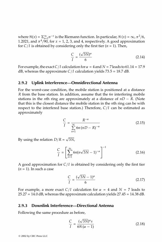
P1: FDJ
book CRC-Wireless November 16, 2001 13:56 Char Count= 254
where �(x) = �∞n=1n−x is the Riemann function. In particular, � (x) = ∞, π2/6,
1.2021, and π4/90, for x = 1, 2, 3, and 4, respectively. A good approximationfor C/I is obtained by considering only the first tier (n = 1). Then,
CI
=(√
3N)α
6(2.14)
For example, the exact C/I calculation for α = 4 and N = 7 leads to 61.14 = 17.9dB, whereas the approximate C/I calculation yields 73.5 = 18.7 dB.
2.9.2 Uplink Interference—Omnidirectional Antenna
For the worst-case condition, the mobile station is positioned at a distanceR from the base station. In addition, assume that the 6n interfering mobilestations in the nth ring are approximately at a distance of nD − R. (Notethat this is the closest distance the mobile station in the nth ring can be withrespect to the interfered base station.) Therefore, C/I can be estimated asapproximately
CI
=R−α
∞∑n=1
6n (nD − R)−α
(2.15)
By using the relation D/R =√
3N,
CI
=
[ ∞∑n=1
6n(n√
3N − 1)−α
]−1
(2.16)
A good approximation for C/I is obtained by considering only the first tier(n = 1). In such a case
CI
=(√
3N − 1)α
6(2.17)
For example, a more exact C/I calculation for α = 4 and N = 7 leads to25.27 = 14.0 dB, whereas the approximate calculation yields 27.45 = 14.38 dB.
2.9.3 Downlink Interference—Directional Antenna
Following the same procedure as before,
CI
=(√
3N)αs6� (α − 1)
(2.18)
© 2002 by CRC Press LLC
E:\Java for Engineers\VP Publication\Java for Engineers.vpThursday, April 25, 2002 9:27:36 AM
Color profile: DisabledComposite Default screen

P1: FDJ
book CRC-Wireless November 16, 2001 13:56 Char Count= 254
The approximation using the first tier (n = 1) yields
CI
=(√
3N)αs6
(2.19)
For the same conditions as before (α = 4, N = 7) and for a three-sector cellsystem (s = 3), the more exact solution yields C/I = 183.42 = 22.6 dB, whereasthe approximate one gives C/I = 220.5 = 23.4 dB.
2.9.4 Uplink Interference—Directional Antenna
Following the same procedure as before,
CI
=
[ ∞∑n=1
6ns
(n√
3N − 1)−α
]−1
(2.20)
A good approximation for C/I is obtained by considering only the first tier.Then,
CI
=(√
3N − 1)αs6
(2.21)
For the same conditions as before (α = 4, N = 7), the more exact solution yieldsC/I = 75.81 = 18.8 dB, whereas the approximate one gives C/I = 82.35 =19.16 dB.
2.9.5 Examples
Table 2.1 gives some examples of C /I figures for α = 4 and for several re-use patterns, with omnidirectional and directional (120◦ antennas, or three-sectored cells). Note how the use of directional antennas substantially
TABLE 2.1
Examples of C/I for the Various Cluster Sizes in aMacrocellular Environment
Uplink (dB) Downlink (dB)
N Omni Directional Omni Directional
3 4.0 8.7 10.5 15.34 7.5 12.3 13.0 17.77 14.0 18.7 17.9 22.79 16.7 21.5 20.0 24.7
12 19.8 24.5 22.5 27.3
© 2002 by CRC Press LLC
E:\Java for Engineers\VP Publication\Java for Engineers.vpThursday, April 25, 2002 9:27:36 AM
Color profile: DisabledComposite Default screen

P1: FDJ
book CRC-Wireless November 16, 2001 13:56 Char Count= 254
improves the C /I performance. The choice of one or another pattern dependson how tolerant the technology is of interference. A widely deployed reusepattern is N = 7 with three-sectored cells. This pattern is usually referred toas 7 ×21. Another widely deployed reuse pattern is N = 4 with three-sectoredcells. This pattern is usually referred to as 4 × 12.
2.10 Interference in Narrowband Microcellular Systems
In the performance analysis of the various microcellular reuse patterns, a para-meter of interest is the distance between the interferers positioned at the co-cell of the Lth co-cell layer and at the target cell, with the target cell takenas the reference cell.[8] We define such a parameter as nL and, for ease ofmanipulation, normalize it with respect to the cell radius, i.e., nL is given innumber of cell radii. We observe that this parameter is greatly dependenton the reuse pattern. It can be obtained by a simple visual inspection, butcertainly for a very limited number of cell layers. For the overall case, a moregeneral formulation is required and this is shown in Appendix D.
The performance analysis to be carried out here considers a square cellularpattern with base stations positioned at every other intersection of the streets.This means that base stations are collinear and that each microcell covers asquare area comprising four 90◦ sectors, each sector corresponding to half ablock, with the streets running on the diagonals of this square. Figure 2.7 shows
FIGURE 2.7Microcellular layout in an urban area.
© 2002 by CRC Press LLC
E:\Java for Engineers\VP Publication\Java for Engineers.vpThursday, April 25, 2002 9:27:36 AM
Color profile: DisabledComposite Default screen

P1: FDJ
book CRC-Wireless November 16, 2001 13:56 Char Count= 254
A
BC
D E
A
BC
D E
A
BC
D E
A
BC
D E
A
BC
D E A
BC
D E
A
BC
D E
A
BC
D E
A
BC
D E
A
BC
D E
A
BC
D E A
BC
D E A
BC
D E A
BC
D E
A
BC
D E
A
BC
D E
A
BC
D E A
BC
D E
A
BC
D E A
BC
D E
A
BC
D E
A
BC
D E
A
BC
D E
A
BC
D E
A
BC
D E
A
BC
D E
A
BC
D E
A
BC
D E
A
B
E
A
D E
ABC
A
C
D
A
BC
D E
FIGURE 2.8Five-micro-cell cluster tessellation—prime non-collinear group (see Appendix D).
the microcellular layout with respect to the streets. In Figure 2.7, the horizon-tal and vertical lines represent the streets and the diagonal lines represent theborders of the micro cells. The central micro cell is highlighted in Figure 2.7.
To provide insight into how the performance calculations are carried out,Figures 2.8 and 2.9 illustrate the complete tessellation for clusters containing5 (Figure 2.8), 8, 9, 10, and 13 (Figure 2.9) micro cells, in which the highlightedcluster accommodates the target cell, and the other dark cells correspondto the co-micro-cells that at a certain time may interfere with the mobile orbase station of interest. Within a microcellular structure, distinct situationsare found that affect in a different manner the performance of the downlink
© 2002 by CRC Press LLC
E:\Java for Engineers\VP Publication\Java for Engineers.vpThursday, April 25, 2002 9:27:36 AM
Color profile: DisabledComposite Default screen

P1: FDJ
book CRC-Wireless November 16, 2001 13:56 Char Count= 254
(a)
(b)
FIGURE 2.9(a) Eight-micro-cell cluster tessellation—collinear i = j group; (b) nine-micro-cell cluster tes-sellation—collinear group.
© 2002 by CRC Press LLC
E:\Java for Engineers\VP Publication\Java for Engineers.vpThursday, April 25, 2002 9:27:36 AM
Color profile: DisabledComposite Default screen

P1: FDJ
book CRC-Wireless November 16, 2001 13:56 Char Count= 254
(c)
(d)
FIGURE 2.9 (continued)(c) ten-micro-cell cluster tessellation—even noncollinear; (d) 13-micro-cell cluster tessellation—prime noncollinear group (see Appendix D).
© 2002 by CRC Press LLC
E:\Java for Engineers\VP Publication\Java for Engineers.vpThursday, April 25, 2002 9:27:36 AM
Color profile: DisabledComposite Default screen
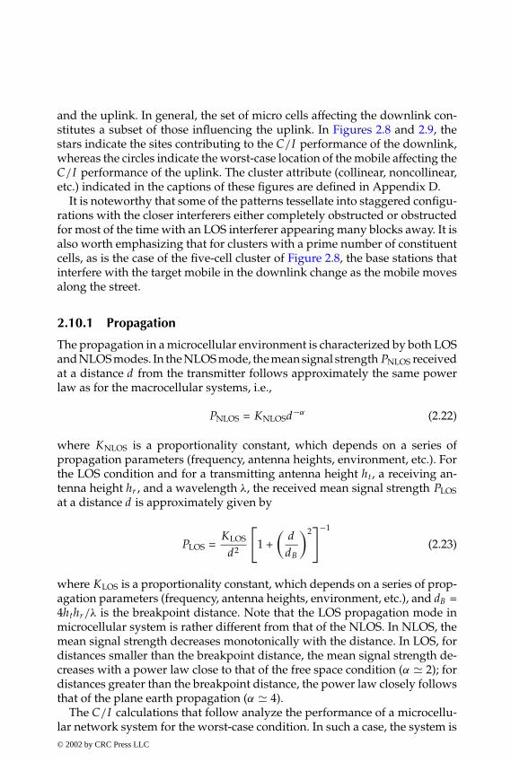
P1: FDJ
book CRC-Wireless November 16, 2001 13:56 Char Count= 254
and the uplink. In general, the set of micro cells affecting the downlink con-stitutes a subset of those influencing the uplink. In Figures 2.8 and 2.9, thestars indicate the sites contributing to the C /I performance of the downlink,whereas the circles indicate the worst-case location of the mobile affecting theC /I performance of the uplink. The cluster attribute (collinear, noncollinear,etc.) indicated in the captions of these figures are defined in Appendix D.
It is noteworthy that some of the patterns tessellate into staggered configu-rations with the closer interferers either completely obstructed or obstructedfor most of the time with an LOS interferer appearing many blocks away. It isalso worth emphasizing that for clusters with a prime number of constituentcells, as is the case of the five-cell cluster of Figure 2.8, the base stations thatinterfere with the target mobile in the downlink change as the mobile movesalong the street.
2.10.1 Propagation
The propagation in a microcellular environment is characterized by both LOSand NLOS modes. In the NLOS mode, the mean signal strength PNLOS receivedat a distance d from the transmitter follows approximately the same powerlaw as for the macrocellular systems, i.e.,
PNLOS = KNLOSd−α (2.22)
where KNLOS is a proportionality constant, which depends on a series ofpropagation parameters (frequency, antenna heights, environment, etc.). Forthe LOS condition and for a transmitting antenna height ht, a receiving an-tenna height hr , and a wavelength λ, the received mean signal strength PLOSat a distance d is approximately given by
PLOS =KLOS
d2
[1 +
(ddB
)2]−1
(2.23)
where KLOS is a proportionality constant, which depends on a series of prop-agation parameters (frequency, antenna heights, environment, etc.), and dB =4hthr/λ is the breakpoint distance. Note that the LOS propagation mode inmicrocellular system is rather different from that of the NLOS. In NLOS, themean signal strength decreases monotonically with the distance. In LOS, fordistances smaller than the breakpoint distance, the mean signal strength de-creases with a power law close to that of the free space condition (α 2); fordistances greater than the breakpoint distance, the power law closely followsthat of the plane earth propagation (α 4).
The C/I calculations that follow analyze the performance of a microcellu-lar network system for the worst-case condition. In such a case, the system is© 2002 by CRC Press LLC
E:\Java for Engineers\VP Publication\Java for Engineers.vpThursday, April 25, 2002 9:27:36 AM
Color profile: DisabledComposite Default screen
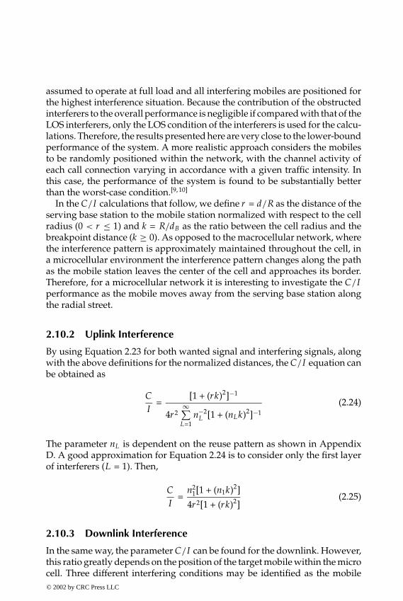
P1: FDJ
book CRC-Wireless November 16, 2001 13:56 Char Count= 254
assumed to operate at full load and all interfering mobiles are positioned forthe highest interference situation. Because the contribution of the obstructedinterferers to the overall performance is negligible if compared with that of theLOS interferers, only the LOS condition of the interferers is used for the calcu-lations. Therefore, the results presented here are very close to the lower-boundperformance of the system. A more realistic approach considers the mobilesto be randomly positioned within the network, with the channel activity ofeach call connection varying in accordance with a given traffic intensity. Inthis case, the performance of the system is found to be substantially betterthan the worst-case condition.[9, 10]
In the C/I calculations that follow, we define r = d/R as the distance of theserving base station to the mobile station normalized with respect to the cellradius (0 < r ≤ 1) and k = R/dB as the ratio between the cell radius and thebreakpoint distance (k ≥ 0). As opposed to the macrocellular network, wherethe interference pattern is approximately maintained throughout the cell, ina microcellular environment the interference pattern changes along the pathas the mobile station leaves the center of the cell and approaches its border.Therefore, for a microcellular network it is interesting to investigate the C/Iperformance as the mobile moves away from the serving base station alongthe radial street.
2.10.2 Uplink Interference
By using Equation 2.23 for both wanted signal and interfering signals, alongwith the above definitions for the normalized distances, the C/I equation canbe obtained as
CI
=[1 + (rk)2]−1
4r2∞∑
L=1n−2
L [1 + (nLk)2]−1(2.24)
The parameter nL is dependent on the reuse pattern as shown in AppendixD. A good approximation for Equation 2.24 is to consider only the first layerof interferers (L = 1). Then,
CI
=n2
1[1 + (n1k)2]
4r2[1 + (rk)2](2.25)
2.10.3 Downlink Interference
In the same way, the parameter C/I can be found for the downlink. However,this ratio greatly depends on the position of the target mobile within the microcell. Three different interfering conditions may be identified as the mobile© 2002 by CRC Press LLC
E:\Java for Engineers\VP Publication\Java for Engineers.vpThursday, April 25, 2002 9:27:36 AM
Color profile: DisabledComposite Default screen

P1: FDJ
book CRC-Wireless November 16, 2001 13:56 Char Count= 254
station moves along the street: (1) at the vicinity of the serving base station,(2) away from the vicinity of the serving base station and away from the cellborder, and (3) near the cell border.
At the vicinity of the serving base station, more specifically at the intersec-tion of the streets (r ≤ normalized distance from the cell site to the beginningof the block), the mobile station experiences the following propagation con-dition: it has a good radio path to its serving base station, but it also has radiopaths to the interfering base stations on both crossing streets. Then,
CI
= r −2[1 + (rk)2]−1
∞∑L=1
{(nL + r )−2 [1 + (nL + r )2 k2]−1 + (nL − r )−2 [1 + (nL − r )2 k2]−1
+2 (n2
L + r 2 )−1 [1 +
(n2
L + r 2 )
k2 ]−1
}
(2.26)
Away from the vicinity of the serving base station and away from the cellborder, which corresponds to most of the path, the mobile station enters theblock and loses LOS to those base stations located on the perpendicular street.Then,
CI
= r −2[1 + (rk)2]−1
∞∑L=1
{(nL + r )−2 [1 + (nL + r )2 k2]−1 + (nL − r )−2 [1 + (nL − r )2 k2]−1 }(2.27)
At the border of the cell, new interferers appear in an LOS condition.However, this is not the case for all reuse patterns. This phenomenon onlyhappens for clusters with a prime number of cells as, for example, in thecase of a five-cell cluster as illustrated in Figure 2.8. Hence, for clusters with aprime number of cells and for the mobile away from its serving base station(1 − r ≤ normalized distance from the site to the beginning of the block), it isfound that
CI
=r−2[1 + (rk)2]−1
∞∑L=1
{(nL + r )−2 [1 + (nL + r )2 k2]−1 + (nL − r )−2 [1 + (nL − r )2 k2]−1
+(n2
L + r2)−1 [1 +
(n2
L + r2) k2]−1
}
(2.28)
where r = 1 − r and nL is defined in Appendix D.A good approximation for the downlink C/I can be obtained by considering
the first layer of interferers only (L = 1).
© 2002 by CRC Press LLC
E:\Java for Engineers\VP Publication\Java for Engineers.vpThursday, April 25, 2002 9:27:36 AM
Color profile: DisabledComposite Default screen

P1: FDJ
book CRC-Wireless November 16, 2001 13:56 Char Count= 254
2.10.4 Examples
We now illustrate the C /I performance for clusters with 5, 8, 9, 10, and 13micro cells. The performance has been evaluated with the central micro cellas the target cell and with the mobile user departing from the cell centertoward its edge. This is indicated by the arrow in the respective cell in Figure2.8. Figure 2.8 also shows, in gray, the co-micro-cells that at a certain time mayinterfere with the wanted mobile in an LOS condition.
For the numerical results, the calculations consider the radius of the microcell as R = 100 m, a street width of 15 m, the transmitter and receiver antennasheights, respectively, equal to ht = 4 m and hr = 1.5 m, an operation frequencyof 890 MHz (λ = 3/8.9), these leading to k = 1.405, and a network consistingof an infinite number of cells (in practice, 600 layers of interfering cells). Notethat k = 1.405 indicates that the cell radius is 40.5% greater than the breakpointdistance.
Figures 2.10 and 2.11, respectively, show the uplink and downlink perfor-mances for the cases of 5-, 8-, 9-, 10-, and 13-micro-cell clusters as a functionof the normalized distance. In general, the larger the cluster, the better thecarrier-to-interference ratio, as expected. However, the five-micro-cell cluster
0.2 0.4 0.6 0.8 1.0
10
20
30
40
50
60
70
Uplink 5Uplink 8Uplink 9Uplink 10Uplink 13
Car
rier/
Inte
rfer
ence
[dB
]
Normalized Distance from Site
FIGURE 2.10C/I ratio as a function of normalized distance: uplink.
© 2002 by CRC Press LLC
E:\Java for Engineers\VP Publication\Java for Engineers.vpThursday, April 25, 2002 9:27:36 AM
Color profile: DisabledComposite Default screen

P1: FDJ
book CRC-Wireless November 16, 2001 13:56 Char Count= 254
0.2 0.4 0.6 0.8 1.010
20
30
40
50
60
70
80
90 Downlink 5
Downlink 8
Downlink 9
Downlink 10
Downlink 13
Car
rier/
Inte
rfer
ence
[dB
]
Normalized Distance from Site
FIGURE 2.11C/I ratio as a function of normalized distance: downlink.
exhibits notably outstanding behavior, with its C /I coinciding with that of theeight-micro-cell cluster for the uplink (lower curve in Figure 2.10) and withthat of the ten-micro-cell cluster for the downlink for most of the extensionof the path (curve below the upper curve in Figure 2.11), with the separationof the curves in the latter occurring at the edge of the micro cell, where twonew interferers appear in an LOS condition. In Figure 2.10, the C /I curves ofthe nine- and thirteen-micro-cell clusters are also coincident.
There is a significant difference in performance for the uplink and downlink;this difference becomes progressively smaller with an increase in the size ofthe cluster. This can be better observed in Figure 2.12, where the five- andten-micro-cell clusters are compared.
It is interesting to examine the influence of the number of interfering lay-ers on the performance. For this purpose we analyze the performance of aone-layer network (L = 1 in Equations 2.24 through 2.28). Figures 2.13 and2.14 show the performances for the uplink and downlink as a function of thenormalized distance to the base station using both the exact (infinite num-ber of layers) and the simplified (one-layer) methods for clusters of five andeight cells, respectively. The dotted lines correspond to the results for thecase of an infinite number of interferers, and the solid lines represent the re-sults for the simplified calculations. Analyzing the graphs and the numericalresults, we observe that the difference between the C/I ratio for an infinite-cellnetwork and for a one-interfering-layer network is negligible. This conclusion© 2002 by CRC Press LLC
E:\Java for Engineers\VP Publication\Java for Engineers.vpThursday, April 25, 2002 9:27:36 AM
Color profile: DisabledComposite Default screen

P1: FDJ
book CRC-Wireless November 16, 2001 13:56 Char Count= 254
0.2 0.4 0.6 0.8 1.0
10
20
30
40
50
60
70
Uplink 5
Downlink 5
Uplink 10
Downlink 10
Car
rier/
Inte
rfer
ence
[dB
]
Normalized Distance from Site
FIGURE 2.12C/I ratio as a function of normalized distance for uplink and downlink compared.
0.2 0.4 0.6 0.8 1.0
10
20
30
40
50
60
70
Five-Cell Clusters
Uplink oo layers
Uplink 1 layer
Downlink oo layers
Downlink 1 layer
Car
rier/
Inte
rfer
ence
[dB
]
Normalized Distance from Site
FIGURE 2.13Performance considering an infinite number of interferers and a single layer of interferers forfive-cell clusters.
© 2002 by CRC Press LLC
E:\Java for Engineers\VP Publication\Java for Engineers.vpThursday, April 25, 2002 9:27:36 AM
Color profile: DisabledComposite Default screen

P1: FDJ
book CRC-Wireless November 16, 2001 13:56 Char Count= 254
0.2 0.4 0.6 0.8 1.0
10
20
30
40
50
60
Eight-Cell Clusters
Uplink oo layers
Uplink 1 layer
Downlink oo layers
Downlink 1 layer
Car
rier/
Inte
rfer
ence
[dB
]
Normalized Distance from Site
FIGURE 2.14Performance considering an infinite number of interferers and a single layer of interferers foreight-cell clusters.
also applies to the other patterns, with the largest difference found in bothmethods for all reuse patterns that are less than 0.35 dB.
Therefore, for the worst-case condition, the C/I ratio can be estimated byconsidering only the interfering layer that is closest to the target cell.
2.11 Interference in Wideband Systems
Wideband systems operate with a unity frequency reuse factor. This meansthat a carrier frequency used in a given cell is reused in other cells, includingthe neighboring cells. As already introduced in Chapter 1, the channelizationin this case is carried out by means of code sequences. In an ideal situation,with the use of orthogonal code sequences and with the orthogonality kept inall circumstances, no interference occurs. In such a case, the efficiency of thefrequency reuse is 100%. We note, however, that such an ideal situation doesnot hold and the systems are led to operate in an interference environment.The efficiency of the reuse factor in this case is less than 100%.
Let IS be the total power of the signals within the target cell (same cell)and IO the interference power due to the signals of all the other cells. The
© 2002 by CRC Press LLC
E:\Java for Engineers\VP Publication\Java for Engineers.vpThursday, April 25, 2002 9:27:36 AM
Color profile: DisabledComposite Default screen

P1: FDJ
book CRC-Wireless November 16, 2001 13:56 Char Count= 254
frequency reuse efficiency f is defined as
f =IS
IS + IO(2.29)
Let I = IO /IS be the (other-cell to same-cell) interference ratio. Thus,
f =1
1 + I (2.30)
or, equivalently, I = (1 − f ) / f . Because within a system the traffic may varyfrom cell to cell, the frequency reuse efficiency can be defined per cell. Assumean N-cell system. Let j be the target cell and i the interfering cell. Therefore,for cell j , IO = �N
i=1 Ii , i = j , and IS = I j . The frequency reuse efficiency f j forcell j can now be written as
f j =I j
I j +N∑
i=1,i = jIi
or, equivalently,
f j =
(N∑
i=1
Ii, j
)−1
(2.31)
where Ii, j = Ii /I j .In wideband systems, the interference conditions for the uplink and for the
downlink are rather dissimilar.The multipoint-to-point communication (reverse link) operates asynchron-
ously. In such a case, the orthogonality of codes used to separate the usersis lost and all the users are potentially interferers. Efficient power controlalgorithms must be applied in a way that optimizes the reverse link capacitywith all users contributing with the same interference power.
The point-to-multipoint communication (forward link) operates synchro-nously, and, ideally, because the downlink uses orthogonal codes to separateusers, for any given user the interference from other users within the same cellis nil. However, because of the multipath propagation, and if there is sufficientdelay spread in the radio channel, orthogonality is partially lost and the targetmobile receives interference from other users within the same cell.
2.11.1 Uplink Interference
The interference condition in the reverse link is illustrated in Figure 2.15.Because of power control, the signals of all active mobile users within a givencell arrive at the serving base station with a constant and identical power. Let
© 2002 by CRC Press LLC
E:\Java for Engineers\VP Publication\Java for Engineers.vpThursday, April 25, 2002 9:27:36 AM
Color profile: DisabledComposite Default screen

P1: FDJ
book CRC-Wireless November 16, 2001 13:56 Char Count= 254
interferingmobile station
desiredmobile station
target cell interfering cell
jir ,
iir ,
FIGURE 2.15Interference in the reverse link.
κ be such a power. The total power from the active users within the cell isκ times the number of active users within the cell. Therefore, for cell j
I j = κ
∫ϒ
(Aj
)d Aj (2.32)
where ϒ(
Aj)
is the traffic density (users per area) of cell j whose area is Aj .
Given that, for any active user i , κ is the power at its serving base station i ,then the power transmitted from the mobile station distant rii from its servingbase station is κrα
i i . The power received at the base station j (interfered basestation), distant ri j from mobile station i , is proportionally attenuated by thecorresponding distance. Therefore, the interfering power is κrα
i i r−αi j . Note that
each interfering user i contributes with a power equal to κrαi i r
−αi j . For all users
in cell i the total interfering power at base station j is
Ii = κ
∫ϒ (Ai ) rα
i i r−αi j d Ai (2.33)
where Ai is the area of cell i . Hence,
f j =
∫ϒ
(Aj
)d Aj
N∑i=1
∫ϒ (Ai ) rα
i i r−αi j d Ai
(2.34)
Note that∫
ϒ (An) d An = Mn, where Mn is the number of active userswithin cell n. For uniform traffic distribution, ϒ (An) = Mn/An. Note furtherthat the frequency reuse efficiency depends on both the traffic distributionas well as on the propagation conditions (path loss and fading). For uniformtraffic distribution and for an infinite number of cells, all cells present the samefrequency reuse efficiency. Therefore, it suffices to determine such a parameterfor one cell only. The calculations in this case can be performed using only thegeometry of the cellular grid. Some values for frequency reuse efficiency are
© 2002 by CRC Press LLC
E:\Java for Engineers\VP Publication\Java for Engineers.vpThursday, April 25, 2002 9:27:36 AM
Color profile: DisabledComposite Default screen

P1: FDJ
book CRC-Wireless November 16, 2001 13:56 Char Count= 254
TABLE 2.2
Examples of Frequency Reuse Efficiency forthe Reverse Link: Uniform TrafficDistribution
α σ (dB) f
3 0 0.55783 7 0.43403 8 0.33923 9 0.24154 0 0.69934 7 0.62534 8 0.52784 9 0.40935 0 0.77395 7 0.73015 8 0.64435 9 0.5291
presented in Table 2.2 for different path loss coefficient α, lognormal standarddeviation σ , and for uniform traffic distribution.
A common practice in cellular design is to use f = 0.6. A simple method-ology to calculate the exact frequency reuse efficiency for nonuniform traf-fic distributions and for realistic conditions can be found in References 11through 13.
2.11.2 Downlink Interference
The interference condition in the forward link is illustrated in Figure 2.16. Theconstant-power situation, as experienced in the reverse link, no longer applies.The interference now is a function of the distance of the mobile station to theinterferers. The frequency reuse efficiency f j (x, y), therefore, is a function ofthe mobile position variables (x, y). We may define a mean frequency reuse
interferingbase stationdesired
base station
target cell interfering cell
jir ,iir ,
FIGURE 2.16Interference in the forward link.
© 2002 by CRC Press LLC
E:\Java for Engineers\VP Publication\Java for Engineers.vpThursday, April 25, 2002 9:27:36 AM
Color profile: DisabledComposite Default screen

P1: FDJ
book CRC-Wireless November 16, 2001 13:56 Char Count= 254
TABLE 2.3
Examples of Frequency Reuse Efficiency forthe Forward Link: Uniform TrafficDistribution
α σ (dB) f
2 8 0.46213 8 0.65844 8 0.76875 8 0.8283
efficiency as
f j (x, y) =1Aj
∫ ∫f j (x, y) dxdy (2.35)
Note that, as already mentioned, the own-cell interference at the mobilestation depends on the degree of orthogonality of the codes. For an ideal con-dition, i.e., orthogonality is fully maintained, no own-cell interference occurs.The frequency reuse efficiency is 1. For a complete loss of orthogonality, theown-cell interference reaches its maximum and the reuse efficiency its min-imum. Some values for frequency reuse efficiency are presented in Table 2.3for different path loss coefficient α, lognormal standard deviation σ = 8 dB,and for uniform traffic distribution.
Here, again, a common practice in cellular design is to use f = 0.6.
2.12 Network Capacity
A measure of network capacity can be provided by the spectrum efficiency.The spectrum efficiency (η), as used here, is defined as the number of simultane-ous conversations per cell (M) per assigned bandwidth (W). In cellular networks,efficiency is directly affected by two families of technologies: compressiontechnology (CT) and access technology (AT).
CTs increase the spectrum efficiency by packing signals into narrower-frequency bands. Low-bit-rate source coding and bandwidth-efficient modu-lations are examples of CTs. ATs may be used to increase the spectrumefficiency by providing the signals with a better tolerance for interference.Within the AT family are included the reuse factor and the several digitalsignal processing (DSP) techniques that provide for higher signal robustness.
Narrowband systems as well as wideband systems make use of CTs andDSP solutions to improve system capacity and provide for signal robustness.© 2002 by CRC Press LLC
E:\Java for Engineers\VP Publication\Java for Engineers.vpThursday, April 25, 2002 9:27:36 AM
Color profile: DisabledComposite Default screen
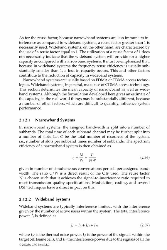
P1: FDJ
book CRC-Wireless November 16, 2001 13:56 Char Count= 254
As for the reuse factor, because narrowband systems are less immune to in-terference as compared to wideband systems, a reuse factor greater than 1 isnecessarily used. Wideband systems, on the other hand, are characterized bythe use of a reuse factor equal to 1. The utilization of a reuse factor of 1 doesnot necessarily indicate that the wideband system will provide for a highercapacity as compared with narrowband systems. It must be emphasized that,because in wideband systems the frequency reuse efficiency is usually sub-stantially smaller than 1, a loss in capacity occurs. This and other factorscontribute to the reduction of capacity in wideband systems.
Narrowband systems are usually based on FDMA or TDMA access techno-logies. Wideband systems, in general, make use of CDMA access technology.This section determines the mean capacity of narrowband as well as wide-band systems. Although the formulation developed here gives an estimate ofthe capacity, in the real world things may be substantially different, becausea number of other factors, which are difficult to quantify, influence systemperformance.
2.12.1 Narrowband Systems
In narrowband systems, the assigned bandwidth is split into a number ofsubbands. The total time of each subband channel may be further split intoa number of slots. Let C be the total number of resources of the system,i.e., number of slots per subband times number of subbands. The spectrumefficiency of a narrowband system is then obtained as
η =MW
=C
NW(2.36)
given in number of simultaneous conversations per cell per assigned band-width. The ratio C/W is a direct result of the CTs used. The reuse factorN is chosen such that it achieves the signal-to-interference ratio required tomeet transmission quality specifications. Modulation, coding, and severalDSP techniques have a direct impact on this.
2.12.2 Wideband Systems
Wideband systems are typically interference limited, with the interferencegiven by the number of active users within the system. The total interferencepower It is defined as
It = IS + IO + IN (2.37)
where IN is the thermal noise power, IS is the power of the signals within thetarget cell (same cell), and IO the interference power due to the signals of all the© 2002 by CRC Press LLC
E:\Java for Engineers\VP Publication\Java for Engineers.vpThursday, April 25, 2002 9:27:36 AM
Color profile: DisabledComposite Default screen

P1: FDJ
book CRC-Wireless November 16, 2001 13:56 Char Count= 254
other cells, as already defined. The number of active users, their geographicdistribution, and their channel activity affect the interference conditions of thesystem. Therefore, the frequency reuse efficiency as well as the interferenceratio are all affected by these same factors.
Define PN as the signal power required for an adequate operation of thereceiver in the absence of interference. Let PI be the signal power requiredfor an adequate operation of the receiver in the presence of interference. Theratio NR between these two powers given as
NR =Pt
PN(2.38)
is known as noise rise. Clearly,
Pt
PN=
It
IN(2.39)
Therefore, we may define the noise rise as the ratio between the total widebandpower and the thermal noise power, i.e.,
NR =It
IN(2.40)
In the absence of interference, It = IN, NR = 1, and Pt = PN, i.e., the powerrequired for an adequate operation of the receiver is the power required inthe presence of thermal noise. Using Equation 2.37 in Equation 2.40, we findthat
NR =1
1 − ρ (2.41)
where
ρ =IS + IO
IS + IO + IN(2.42)
is defined as the load factor. Note that 0 ≤ ρ < 1. The condition ρ = 0 signifiesno active users within the system. Note that ρ increases with the increaseof the number of users. Note also that as ρ approaches unity the noise risetends to infinity, and the system reaches its pole capacity. A system is usuallydesigned to operate with a loading factor smaller than 1 (typically ρ 0.5,or equivalently 3 dB of noise rise). Figure 2.17 illustrates the noise rise as afunction of the load factor.
The load factor is calculated differently for the uplink and for the downlink.
2.12.3 Uplink Load Factor
Let γi = Ei/Ni be the ratio between the energy per bit and the noise spectraldensity for user i . Define Gi = W/Ri as the processing gain for user i , given© 2002 by CRC Press LLC
E:\Java for Engineers\VP Publication\Java for Engineers.vpThursday, April 25, 2002 9:27:36 AM
Color profile: DisabledComposite Default screen

P1: FDJ
book CRC-Wireless November 16, 2001 13:56 Char Count= 254
0.0 0.2 0.4 0.6 0.8 1.00
2
4
6
8
10
Traffic Load (r )
Noi
se R
ise
(dB
)
FIGURE 2.17Noise rise as a function of the load factor.
as the ratio between the chip rate of the system (system bandwidth) and thebit rate for user i . The energy per bit is obtained as Ei = Pi Ti = Pi/Ri , wherePi , Ti and Ri = 1/Ti are, respectively, the signal power received from user i ,the bit period of user i , and the bit rate of user i . The noise spectral density iscalculated as Ni = IN/W = (It − Pi ) /W. Note that these parameters assumea 100% channel activity. For a channel activity equal to ai , 0 ≤ ai ≤ 1, andusing the above definitions
Ei
Ni=
WPi
ai Ri (It − Pi )
or, equivalently,
γi =Gi Pi
ai (It − Pi )
Solving for Pi ,
Pi = ρi It (2.43)
where
ρi =(
1 +Gi
aiγi
)−1
(2.44)
© 2002 by CRC Press LLC
E:\Java for Engineers\VP Publication\Java for Engineers.vpThursday, April 25, 2002 9:27:36 AM
Color profile: DisabledComposite Default screen

P1: FDJ
book CRC-Wireless November 16, 2001 13:56 Char Count= 254
Manipulating Equation 2.42, we obtain
ρ = (1 + I )IS
It(2.45)
The power IS can be calculated as
IS =M∑
i=1
Pi (2.46)
where M is the number of users within the cell. From Equations 2.46, 2.43,and 2.45 we obtain
ρ =M∑
i=1
ρi = (1 + I )M∑
i=1
(1 +
Gi
aiγi
)−1
(2.47)
which is the uplink load factor for a multirate wideband system. For a givenload factor, Equation 2.47 yields the uplink capacity M.[14] Note that such acapacity is dependent on the required energy per bit and the noise spectraldensity γi on the activity factor ai , and on the type of service that is reflectedon the processing gain Gi . A load factor ρ = 1 gives the pole capacity of thesystem.
Typically,[14] ai assumes the value 0.67 for speech and 1.0 for data; thevalue of γi depends on the service, bit rate, channel fading conditions, receiveantenna diversity, mobile speed, etc.; W depends on the channel bandwidth;Ri depends on the service; and I can be taken as 0.55.
Of course, other factors, such as power control efficiency pi , 0 ≤ pi ≤ 1,and gain s due to the use of s-sector directional antennas (s sectors per cell),can be included in the capacity Equation 2.47. The power control efficiency pi
diminishes the capacity by a factor of pi , whereas the use of sectored antennasincreases the capacity by a factor approximately equal to the number s ofsectors per cell.
For a classical all-voice network, such as the 2G CDMA system, all M usersshare the same type of constant-bit-rate service. In this case, Equation 2.47reduces to
M =ρ × p × s × G(1 + I ) × a × γ
(2.48)
where the parameters are those already defined, but with the index dropped,and where we have assumed the condition psG
aγ� 1. The spectrum efficiency
© 2002 by CRC Press LLC
E:\Java for Engineers\VP Publication\Java for Engineers.vpThursday, April 25, 2002 9:27:36 AM
Color profile: DisabledComposite Default screen
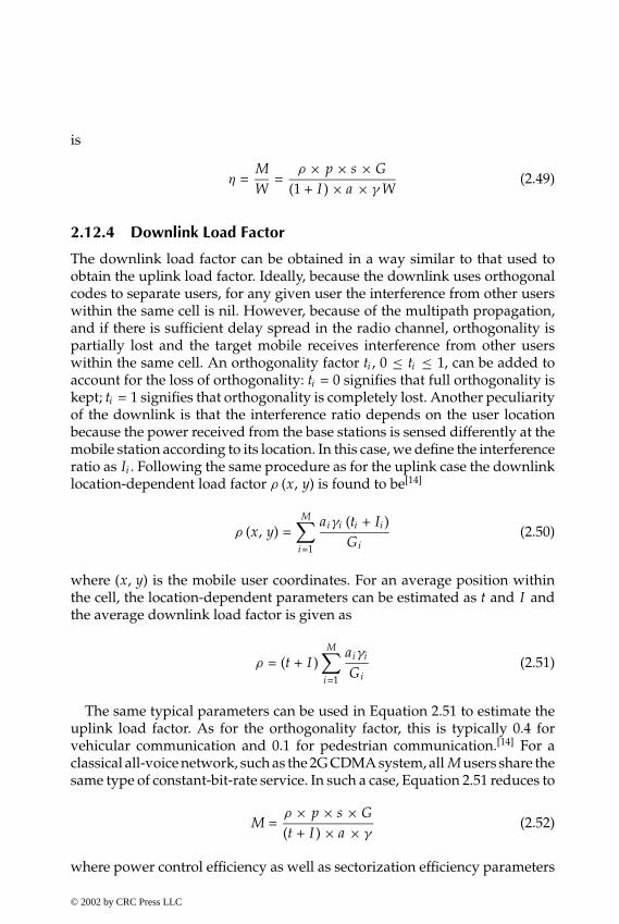
P1: FDJ
book CRC-Wireless November 16, 2001 13:56 Char Count= 254
is
η =MW
=ρ × p × s × G
(1 + I ) × a × γ W(2.49)
2.12.4 Downlink Load Factor
The downlink load factor can be obtained in a way similar to that used toobtain the uplink load factor. Ideally, because the downlink uses orthogonalcodes to separate users, for any given user the interference from other userswithin the same cell is nil. However, because of the multipath propagation,and if there is sufficient delay spread in the radio channel, orthogonality ispartially lost and the target mobile receives interference from other userswithin the same cell. An orthogonality factor ti , 0 ≤ ti ≤ 1, can be added toaccount for the loss of orthogonality: ti = 0 signifies that full orthogonality iskept; ti = 1 signifies that orthogonality is completely lost. Another peculiarityof the downlink is that the interference ratio depends on the user locationbecause the power received from the base stations is sensed differently at themobile station according to its location. In this case, we define the interferenceratio as Ii . Following the same procedure as for the uplink case the downlinklocation-dependent load factor ρ (x, y) is found to be[14]
ρ (x, y) =M∑
i=1
aiγi (ti + Ii )Gi
(2.50)
where (x, y) is the mobile user coordinates. For an average position withinthe cell, the location-dependent parameters can be estimated as t and I andthe average downlink load factor is given as
ρ = (t + I )M∑
i=1
aiγi
Gi(2.51)
The same typical parameters can be used in Equation 2.51 to estimate theuplink load factor. As for the orthogonality factor, this is typically 0.4 forvehicular communication and 0.1 for pedestrian communication.[14] For aclassical all-voice network, such as the 2G CDMA system, all M users share thesame type of constant-bit-rate service. In such a case, Equation 2.51 reduces to
M =ρ × p × s × G(t + I ) × a × γ
(2.52)
where power control efficiency as well as sectorization efficiency parameters
© 2002 by CRC Press LLC
E:\Java for Engineers\VP Publication\Java for Engineers.vpThursday, April 25, 2002 9:27:36 AM
Color profile: DisabledComposite Default screen
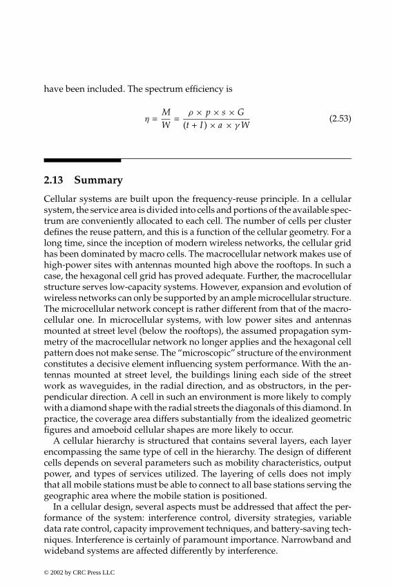
P1: FDJ
book CRC-Wireless November 16, 2001 13:56 Char Count= 254
have been included. The spectrum efficiency is
η =MW
=ρ × p × s × G
(t + I ) × a × γ W(2.53)
2.13 Summary
Cellular systems are built upon the frequency-reuse principle. In a cellularsystem, the service area is divided into cells and portions of the available spec-trum are conveniently allocated to each cell. The number of cells per clusterdefines the reuse pattern, and this is a function of the cellular geometry. For along time, since the inception of modern wireless networks, the cellular gridhas been dominated by macro cells. The macrocellular network makes use ofhigh-power sites with antennas mounted high above the rooftops. In such acase, the hexagonal cell grid has proved adequate. Further, the macrocellularstructure serves low-capacity systems. However, expansion and evolution ofwireless networks can only be supported by an ample microcellular structure.The microcellular network concept is rather different from that of the macro-cellular one. In microcellular systems, with low power sites and antennasmounted at street level (below the rooftops), the assumed propagation sym-metry of the macrocellular network no longer applies and the hexagonal cellpattern does not make sense. The “microscopic” structure of the environmentconstitutes a decisive element influencing system performance. With the an-tennas mounted at street level, the buildings lining each side of the streetwork as waveguides, in the radial direction, and as obstructors, in the per-pendicular direction. A cell in such an environment is more likely to complywith a diamond shape with the radial streets the diagonals of this diamond. Inpractice, the coverage area differs substantially from the idealized geometricfigures and amoeboid cellular shapes are more likely to occur.
A cellular hierarchy is structured that contains several layers, each layerencompassing the same type of cell in the hierarchy. The design of differentcells depends on several parameters such as mobility characteristics, outputpower, and types of services utilized. The layering of cells does not implythat all mobile stations must be able to connect to all base stations serving thegeographic area where the mobile station is positioned.
In a cellular design, several aspects must be addressed that affect the per-formance of the system: interference control, diversity strategies, variabledata rate control, capacity improvement techniques, and battery-saving tech-niques. Interference is certainly of paramount importance. Narrowband andwideband systems are affected differently by interference.
© 2002 by CRC Press LLC
E:\Java for Engineers\VP Publication\Java for Engineers.vpThursday, April 25, 2002 9:27:36 AM
Color profile: DisabledComposite Default screen

P1: FDJ
book CRC-Wireless November 16, 2001 13:56 Char Count= 254
In narrowband systems, interference is caused by a small number of high-power signals. Moreover, macrocellular and microcellular networks undergodifferent interference patterns. In addition, whereas in macrocellular systemsuplink and downlink present approximately the same interference perfor-mance, in microcellular systems the interference performance of uplink anddownlink is dissimilar. In both cases, the uplink performance is always worsethan the downlink performance, but the difference between the performancesof both links is drastically different in microcellular systems. For macrocellularsystems, the larger the reuse pattern, the better the interference performance.For microcellular systems, it can be said that, in general, the larger the reusepattern, the better the performance.
In wideband systems, interference is caused by a large number of low-power signals. In such a case, the traffic profile as well as the channel activityhas a great influence on the interference. Here again, uplink and downlinkperform differently.
Capacity is another issue that varies substantially for narrowband andwideband systems. In the first case, capacity is established given the totalamount of resources and the reuse pattern. In the second case, a number ofadditional parameters, such as the traffic profile, channel activity, and others,may influence system capacity.
References
1. Framework for the radio interface(s) and radio sub-system functionality for Inter-national Mobile Telecommunications-2000 (IMT-2000), Recommendation ITU-RM.1035.
2. Whitteker, J. H., Measurements of path loss at 910 MHz for proposed microcellurban mobile systems, IEEE Trans. Veh. Technol., 37, 125–129, Aug. 1988.
3. Rustako, A. J., Erceg, V., Roman, R. S., et al. Measurements of microcellular prop-agation loss at 6 GHz and 2 GHz over nonline-of-sight paths in the city of Boston,in GLOBECOM’95 Conf., Singapore, 1995, 758–762.
4. Erceg, V., Rustako, A. J., Jr., and Roman, R. S., Diffraction around corners and itseffects of the microcell coverage area in urban and suburban environments at 900MHz, 2 GHz, and 6 GHz, IEEE Trans. Veh. Technol., 43, 762–766, Aug. 1994.
5. Clark, M. V., Erceg, V., and Greenstein, L. J., Reuse efficiency in urban microcellularnetworks, IEEE Trans. Veh. Technol., 46, 279–288, May 1997.
6. Goldsmith, A. and Greenstein, L. J., A measurement-based model for predictingcoverage areas of urban microcells, IEEE J. Select. Areas Commun., 11, 1013–1022,Sept. 1993.
7. Erceg V. et al., Urban/suburban out-of-sight propagation modeling, IEE Commun.Mag., 30, 56–61, June 1992.
© 2002 by CRC Press LLC
E:\Java for Engineers\VP Publication\Java for Engineers.vpThursday, April 25, 2002 9:27:36 AM
Color profile: DisabledComposite Default screen
P1: FDJ
book CRC-Wireless November 16, 2001 13:56 Char Count= 254
8. Yacoub, M. D., Toledo, A. F., Gomez, P. R. C., et al., Reuse pattern for microcellularnetworks, Int. J. Wireless Inf. Networks, 6 (1), 1–7, Jan. 1999.
9. Gomez, P. R. C., Yacoub, M. D., and Toledo, A. F., Performance of a microcellu-lar network in a more realistic condition, Presented as 11th IEEE InternationalSymposium on Personal Indoor and Mobile Radio Communications, 2000.
10. Gomez, P. R. C., Yacoub, M. D., and Toledo, A. F., Interference in wireless networkswith a new reuse pattern [in Portuguese], Presented as Brazilian Telecommuni-cations Symposium (Simposio Brasileiro de Telecomunicacoes), SBT99, Vitoria,Brazil, 1999.
11. d’Avila, C. K. and Yacoub, M. D., Reuse efficiency for non-uniform traffic distri-butions in CDMA systems, IEE Electron. Lett., 34 (13), 1293–1294, June 1998.
12. d’Avila, C. K. and Yacoub, M. D., The linear method to evaluate the frequencyreuse efficiency of cellular CDMA systems, Presented as IEEE Global Telecom-munications Conference, Globecom General Conference, Globecom’99, Rio deJaneiro, Dec. 1999.
13. d’Avila, C. K. and Yacoub, M. D., Reuse efficiency in a quasi-real CDMA network,Presented as 11th International Symposium on Personal, Indoor and Mobile RadioCommunications, PIMRC’2000, London, Sept. 2000.
14. Holma, H. and Toskalla, A., WDMA for UMTS: Radio Access for Third GenerationMobile Communications, John Wiley, Chichester, U.K., 2000.
© 2002 by CRC Press LLC
E:\Java for Engineers\VP Publication\Java for Engineers.vpThursday, April 25, 2002 9:27:36 AM
Color profile: DisabledComposite Default screen

P1: FDJ
book CRC-Wireless November 16, 2001 13:42 Char Count= 294
3Multiple Access
3.1 Introduction
Wireless communication systems are multiuser systems in which informa-tion is conveyed by means of radio waves. The radio channel is essentiallya broadcast medium. Therefore, the transmitted information is potentiallyavailable to all receivers. Although useful in some applications, such as inbroadcast networks, nonetheless in some others, such as in wireless systems,this inherent high connectivity implies a natural source of interference, andsome sort of access control must be exercised for successful communication.Access coordination can be accomplished by several mechanisms: by insu-lating the various signals sharing the same access medium, by allowing thesignals to contend for the access, or by combining these two approaches. Thechoice of the appropriate scheme will have to take into account a number offactors such as type of traffic under consideration, available technology, cost,complexity, etc.
Signal insulation is easily attainable by using a scheduling procedure inwhich signals are allowed to access the medium according to a predefinedplan. Signal contention occurs if a signal insulation mechanism is not used.Certainly, access coordination must be exercised in each direction of the com-munication: from the central point, hereinafter referred to as access point,down to the terminals (users)—downlink or forward link—and from the ter-minals (users) up to the access point—uplink or reverse link. Similarly, itmust be performed in both directions for a two-way communication. Accesscontrol in the downlink direction can be implemented with techniques sim-pler than those used to control access in the uplink direction. The reason isobvious: because, in the first case, the communication is characterized by apoint-to-multipoint transmission mechanism, the access point may exercisecomplete control over the access; in the second case, the communication is
© 2002 by CRC Press LLC
E:\Java for Engineers\VP Publication\Java for Engineers.vpThursday, April 25, 2002 9:27:36 AM
Color profile: DisabledComposite Default screen

P1: FDJ
book CRC-Wireless November 16, 2001 13:42 Char Count= 294
multipoint-to-point, therefore rendering the coordination among indepen-dent terminals more complex.
Access coordination may be carried out in different domains:[1] the fre-quency domain, time domain, code domain, and space domain. Signal in-sulation in each domain is attained by splitting the resource available intononoverlapping slots (frequency slot, time slot, code slot, and space slot) andassigning each signal a slot. The nonoverlapping (disjoint, orthogonal) slotsconstitute the physical channels, which are essentially the physical mediumthrough which information is actually conveyed. In this context, it is instruc-tive to recall the concept of another type of channel—the logical channel. Thelogical channels make use of the physical channels to perform logical func-tions within the network. One logical channel can use one or several phys-ical channels and, conversely, one or several logical channels can use onephysical channel. Orthogonality among physical channels is an imperious re-quirement in order for the information conveyed on these channels to be uni-vocally separable (distinguishable, resolvable) at the receiver. For maximuminsulation, paired channels, i.e., a forward-link channel and a reverse-linkchannel in a two-way communication, are kept apart from each other by thefarthest distance possible in each domain. This is achieved by organizing allforward channels in a contiguous group of channels and all reverse channelsin another contiguous group of channels and in both groups numbering allthe channels in the same sequence. For maximum packing, adjacent channelsare arranged one immediately after the other. Implementation of such a phi-losophy, however, is impaired by practical problems. Available resources maynot appear in a contiguous manner and, to account for the imperfection of themedium as well as of the equipment, a guard distance between adjacent chan-nels must be maintained. Figure 3.1 illustrates the concepts developed here for
Slot1
Slot2
Slotk
Slot1
Slot2
Slotk
Paired Channels
Reverse ChannelsForward ChannelsSignal Domain
(one out of {frequency,time, code, space})
Complementof SignalDomain
FIGURE 3.1Signal insulation in the various signal domains.
© 2002 by CRC Press LLC
E:\Java for Engineers\VP Publication\Java for Engineers.vpThursday, April 25, 2002 9:27:36 AM
Color profile: DisabledComposite Default screen

P1: FDJ
book CRC-Wireless November 16, 2001 13:42 Char Count= 294
an ideal situation in which the separation guard between adjacent channels isnil. Note from Figure 3.1 that only one dimension of these domains is shown.Practical networks may take advantage of the different domains to imple-ment a further level of signal insulation. In such a case, a multidimensionalrepresentation may be necessary to illustrate the possible combinations.
In contrast to conventional wired networks, in a wireless communicationenvironment signals from different terminals may arrive at the access pointwith different power levels due to two basic phenomena: path loss and fading.The path loss phenomenon establishes that the signal power decreases withdistance d as d−α , with α usually within the range 2 ≤ α ≤ 6. Therefore, sig-nals sent by terminals placed at different distances from the access point willarrive with different power levels, characterizing what is known as the near–far effect. The fading phenomenon establishes that the signal power fluctuatesrandomly due to the different environments (shadowing) and also due tothe scatterers (multipath propagation) encountered along the radio paths.Contrary to what is usually expected, in some situations these phenomenamay have a favorable effect in the overall multiple access performance be-cause they constitute a natural means of splitting the terminals into differ-ent classes of access power. In other situations, however, the effects may bedisastrous.
3.2 Signal Domains
The signal may be described in several domains, and an appropriate manip-ulation of the signals within these domains may lead to effective use of thetransmission medium. The signal domains most commonly used for accesspurposes are frequency, time, code, and space.
3.2.1 Frequency Domain
The radio spectrum is a precious resource, the quintessence of wireless com-munication systems. Because radio propagation does not recognize geopolit-ical boundaries and because political, economic, and social aspirations mayvary from country to country, international cooperation leading to an intel-ligent and efficient use of the frequency spectrum is mandatory. Because ofthe explosion of the demand for and the diversification of wireless services,special attention have been given to spectrum allocation issues. Wireless com-munications systems have been driven to use high frequencies due to thecongestion at the lower portion of the frequency spectrum, where the avail-able bandwidth is insufficient to satisfy the great demand for mobile services.
© 2002 by CRC Press LLC
E:\Java for Engineers\VP Publication\Java for Engineers.vpThursday, April 25, 2002 9:27:36 AM
Color profile: DisabledComposite Default screen
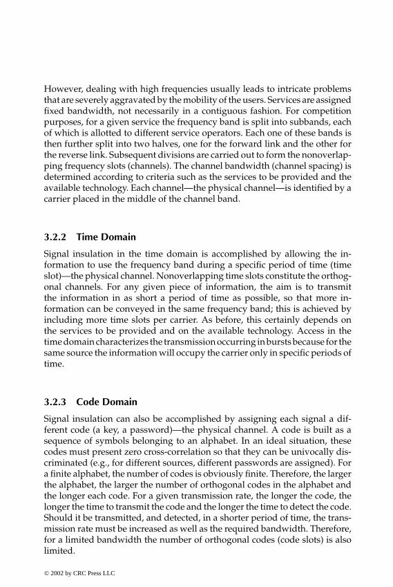
P1: FDJ
book CRC-Wireless November 16, 2001 13:42 Char Count= 294
However, dealing with high frequencies usually leads to intricate problemsthat are severely aggravated by the mobility of the users. Services are assignedfixed bandwidth, not necessarily in a contiguous fashion. For competitionpurposes, for a given service the frequency band is split into subbands, eachof which is allotted to different service operators. Each one of these bands isthen further split into two halves, one for the forward link and the other forthe reverse link. Subsequent divisions are carried out to form the nonoverlap-ping frequency slots (channels). The channel bandwidth (channel spacing) isdetermined according to criteria such as the services to be provided and theavailable technology. Each channel—the physical channel—is identified by acarrier placed in the middle of the channel band.
3.2.2 Time Domain
Signal insulation in the time domain is accomplished by allowing the in-formation to use the frequency band during a specific period of time (timeslot)—the physical channel. Nonoverlapping time slots constitute the orthog-onal channels. For any given piece of information, the aim is to transmitthe information in as short a period of time as possible, so that more in-formation can be conveyed in the same frequency band; this is achieved byincluding more time slots per carrier. As before, this certainly depends onthe services to be provided and on the available technology. Access in thetime domain characterizes the transmission occurring in bursts because for thesame source the information will occupy the carrier only in specific periods oftime.
3.2.3 Code Domain
Signal insulation can also be accomplished by assigning each signal a dif-ferent code (a key, a password)—the physical channel. A code is built as asequence of symbols belonging to an alphabet. In an ideal situation, thesecodes must present zero cross-correlation so that they can be univocally dis-criminated (e.g., for different sources, different passwords are assigned). Fora finite alphabet, the number of codes is obviously finite. Therefore, the largerthe alphabet, the larger the number of orthogonal codes in the alphabet andthe longer each code. For a given transmission rate, the longer the code, thelonger the time to transmit the code and the longer the time to detect the code.Should it be transmitted, and detected, in a shorter period of time, the trans-mission rate must be increased as well as the required bandwidth. Therefore,for a limited bandwidth the number of orthogonal codes (code slots) is alsolimited.
© 2002 by CRC Press LLC
E:\Java for Engineers\VP Publication\Java for Engineers.vpThursday, April 25, 2002 9:27:36 AM
Color profile: DisabledComposite Default screen

P1: FDJ
book CRC-Wireless November 16, 2001 13:42 Char Count= 294
3.2.4 Space Domain
Signal insulation in the space domain can be achieved in two possible dimen-sions: distance and angle—the physical channels. The distance dimensionexploits the fact that the propagation loss increases with the increase of thedistance between transmitter and receiver. Thus, signals using the same fre-quency but transmitted by sources sufficiently apart from each other maynot strongly interfere with each other. In the same way, a given signal mayreach the receiver through different paths (due to multiple reflections, forexample). Each multipath signal suffers different attenuations and differentdelays, according to the length of the path traveled. Therefore, both attenua-tion and delay, jointly or independently, can be used to detect each multipathsignal. The angle dimension exploits the fact that, by illuminating wedgesof a circular area, signals simultaneously using the same frequency may bediscriminated by these very wedges within which they are located. Smartantennas may be used to keep track of these signals.
3.2.5 Brief Remarks on Signal Domains
The most commonly used and most straightforward way of accomplishingradio signal insulation is by assigning different frequency carriers to differ-ent signals. This technique is widely employed by both analog and digitalwireless systems. Insulation in the time domain has been boosted by the dig-ital technology and is widely used in wireless communications. Insulationin the code domain is a well-known technique that has long been used formilitary as well as satellite communications applications. The move towardhigh-capacity wireless systems has found great support in this technique.Insulation in the space domain is widely used in wireless communications.More specifically, the cellular concept with its frequency reuse philosophyconstitutes an example of such an application. Other examples are presentedin this chapter.
3.3 Duplexing
Wireless communication systems have evolved through several stages ofmultiple-access control. The foremost controllable resource has always beenthe frequency spectrum. Other resources such as time, code, and space wereinitially manipulated in a very precarious and, therefore, ineffective manner.The early systems operated in the simplex mode in the forward link. Half-duplex systems soon appeared, in which forward link and reverse link sharedthe same channel. Access control was performed on a push-to-talk basis with
© 2002 by CRC Press LLC
E:\Java for Engineers\VP Publication\Java for Engineers.vpThursday, April 25, 2002 9:27:36 AM
Color profile: DisabledComposite Default screen

P1: FDJ
book CRC-Wireless November 16, 2001 13:42 Char Count= 294
the access point still competing with the terminals for access. Double half-duplex systems, in which forward link uses one channel and reverse linkanother channel, granted the access point the privilege of not having to con-tend for access. The push-to-talk procedure was the access control mechanismused on the reverse channel. The full-duplex mode, or simply duplex mode,was then the last stage in this evolutionary cycle in which push-to-talk accesscontrol was no longer necessary.
Duplex communication can be implemented by means of frequency divi-sion, time division, code division, and space division methods.
3.3.1 Frequency Division Duplexing
In frequency division duplexing (FDD), forward and reverse channels useseparate frequencies. Therefore, a duplex channel is in fact a set of twodistinct carriers, which constitute the physical channels. Because forwardand reverse channels are continuously on and share the same antenna, theuse of a duplexer (a filter between transmitter and receiver) is necessary sothat reverse and forward channels do not interfere with each other. In thesame way, sharp filters with strong out-of-band rejection must be used toreduce adjacent-channel interference. Adjacent-channel interference is alsominimized by allowing for a guard band within each channel. For a givencontinuous spectrum, insulation between forward and reverse channels ismaximized if paired channels are separated by half of the spectrum. FDD isa well-known technology, widely used in wireless systems.
3.3.2 Time Division Duplexing
In time division duplexing (TDD), forward and reverse channels share thesame frequency band but occupy this band in nonoverlapping periods oftime (slots), also known as windows. Therefore, a duplex channel is in fact aset of two nonoverlapping windows within a given carrier, which constitutesthe physical channels. Because transmission and reception alternate in time,this scheme does not require the use of a duplexer. The number of possibleaccess points (windows) within the same frequency band is a function ofthe technology available. As can be inferred, TDD makes more efficient useof the spectrum as compared with FDD and is more flexible. Usually, butnot necessarily, an equal number of windows is dedicated to the forwardchannels and to the reverse channels, with paired windows symmetricallyplaced in time for maximum insulation. On the other hand, asymmetricalwindow assignment is also possible and necessary in asymmetrical trafficoperation conditions, and in this case special attention must be paid regardinginterference issues.© 2002 by CRC Press LLC
E:\Java for Engineers\VP Publication\Java for Engineers.vpThursday, April 25, 2002 9:27:36 AM
Color profile: DisabledComposite Default screen
P1: FDJ
book CRC-Wireless November 16, 2001 13:42 Char Count= 294
3.3.3 Code Division Duplexing
In code division duplexing (CDD), forward and reverse channels simulta-neously share the same frequency band but are discriminated by means oforthogonal codes. Therefore, a duplex channel is in fact a set of two orthogonalcodes within a given carrier, which constitutes the physical channels. Practi-cal implementation of such a scheme may render the circuitry very complex.Because transmission and reception occur simultaneously and continuouslywithin the same band and because the transmitted signal is at a much greaterpower than the received signal, the level of interference may impair such acommunication scheme. Some sort of interference cancellation mechanism isnecessary to realize this scheme.
3.3.4 Space Division Duplexing
In space division duplexing (SDD), forward and reverse channels share thesame frequency band but are discriminated in space. Therefore, a duplexchannel is in fact a set of two distinct locations where signals share the samefrequency band. In a line-of-sight condition, directional antennas provide forthe required insulation of the signals and can be used in SDD communication.In a non-line-of-sight condition, smart antennas are necessary.
3.3.5 Brief Remarks on Duplexing Techniques
FDD is certainly the duplexing technique most commonly used in wirelessnetworks; it has been employed in all the first-generation wireless systems, inmost of the second-generation systems, and its deployment in higher genera-tions is without question. TDD is used in some second-generation systems, aswell as in higher generations. CDD alone does not seem to lend itself to easyimplementation for sophisticated interference cancellation mechanisms maybe required. SDD alone can be used in diverse system applications mainlyto increase capacity. Combination of some of these techniques is a commonpractice.
3.4 Multiple-Access Categories
Depending on how much coordination is required to access the shared re-sources, the access methods may fall into the following categories:
� Scheduled Multiple-Access Methods. The access methods in this categorymake use of the signal insulation principle in which the information ofdifferent sources is transmitted on nonoverlapping channels. In this
© 2002 by CRC Press LLC
E:\Java for Engineers\VP Publication\Java for Engineers.vpThursday, April 25, 2002 9:27:36 AM
Color profile: DisabledComposite Default screen
P1: FDJ
book CRC-Wireless November 16, 2001 13:42 Char Count= 294
case, collision does not occur. The methods providing for scheduledmultiple-access capabilities in the frequency domain, time domain,code domain, and space domain are, respectively, frequency division(FDMA), time division (TDMA), code division (CDMA), and spacedivision multiple access (SDMA).
� Random Multiple-Access Methods. The access methods in this cate-gory make use of a contention scheme in which no or little coor-dination is provided. The information of different sources is castonto a common channel, and collision may occur. Collision is usu-ally detected by an acknowledgment mechanism in which the ter-minal sending the packet waits for a confirmation of the success-ful reception of it. The widely used methods providing for randommultiple-access capabilities are Pure ALOHA, Slotted ALOHA, TreeAlgorithm, FCFS Algorithm, CSMA (nonslotted, slotted, 1-persistent.p-persistent), CSMA/BT, CSMA/DT, CSMA/CD, and CSMA/CA.
� Controlled Multiple-Access Methods. The access methods in this cate-gory make use of a deterministic or contentionless strategy in which,by means of a control signal, permission to send is granted to termi-nals individually, so that only one terminal is allowed to access themedium at a time. The main access schemes here are polling, tokenring, and token bus.
� Hybrid Multiple-Access Methods. The access methods in this categorymake use of a combination of scheduled, contention, and determin-istic schemes in which some degree of coordination is included intothe random-access mechanisms or some other more sophisticated de-terministic methods are employed. Examples of such schemes includeR-ALOHA, Original PRMA, PRMA++, Aggressive PRMA, Fast PRMA,Multirate PRMA, PRMA/DA, PRMA/ATDD, DQRUMA, DSA++,DTDMA/PR, MASCARA, DTDMA/TDD, Pure RAMA, T-RAMA,F-RAMA, and D-RAMA.
For stream, steady-flow traffic, the available resources are more efficientlyutilized if allotted on a scheduled access basis. This is because contention inthis case may lead to a significant amount of packet loss. For intermittent,burst (random) traffic, better efficiency can be achieved if the available re-sources are seized on a random-access basis. This is because scheduled allo-cation in this case may lead to an inefficient use of the resources. For inter-mittent, random traffic if a high incidence of packet collision occurs, the useof controlled-access methods is recommended. For stream traffic and burstytraffic simultaneously sharing the same resource, hybrid access methods maybe applied.
In a multiuser system, capacity is certainly a sensitive issue. The efficiencywith which the available resources are used determines the number of users© 2002 by CRC Press LLC
E:\Java for Engineers\VP Publication\Java for Engineers.vpThursday, April 25, 2002 9:27:36 AM
Color profile: DisabledComposite Default screen

P1: FDJ
book CRC-Wireless November 16, 2001 13:42 Char Count= 294
the system can support. Higher efficiency is achieved if the resources are madeavailable to all users and they are assigned on a demand basis. This charac-terizes what is known as demand-assigned multiple-access (DAMA) or, simply,multiple access. The assignment of the resources on a demand basis sug-gests that some initial protocol be established before the resource is actuallyassigned. Handshaking protocols usually typify bursty traffic, whereas pay-load information can be characterized by either bursty or steady-flow traffic.Certainly, the ultimate aim of any communication network is provision of re-sources to convey payload information. Overhead traffic, although necessary,should be kept to a minimum to increase efficiency. The initial access proto-cols may use the same physical resources as those used to convey payloadinformation. However, splitting the resources into two distinct groups—onefor initial access purposes and another for payload information purposes—isa practice common to networks where a great amount of signaling is required.And this is true of wireless systems. The proportion of channels dedicated toeach function varies according to the needs.
3.5 Scheduled Multiple Access
The scheduled multiple-access techniques are more efficiently utilized if ap-plied to steady-flow traffic, in which case the resources, although seized on ademand basis, are allotted for the duration of the communication. This sectiondescribes the various techniques providing for scheduled multiple-access ca-pabilities in the frequency, time, code, and space domains, namely, frequencydivision multiple access, time division multiple access, code division multipleaccess, and space division multiple access.
One interesting topic to investigate is the capacity of each technique for agiven bandwidth. The capacity issue can be approached in terms of numberof users (system capacity) or in terms of information rate (channel capacity).The first approach—number of users per bandwidth—reveals a fertile fieldif explored together with the wireless architecture. In this chapter, however,we shall explore the second approach—information rate per bandwidth. Thefirst approach was explored in Chapter 2.
We assume that each access method supports k users and that the physicalchannel can be modeled as an ideal band-limited additive white Gaussiannoise (AWGN) channel. From the Shannon capacity formula and for a singleuser,[2]
Cb = B log2
(1 +
SN
)(3.1)
© 2002 by CRC Press LLC
E:\Java for Engineers\VP Publication\Java for Engineers.vpThursday, April 25, 2002 9:27:36 AM
Color profile: DisabledComposite Default screen
P1: FDJ
book CRC-Wireless November 16, 2001 13:42 Char Count= 294
where Cb is the channel capacity in bits per second, B is the channel bandwidthin hertz, S is the signal power, in watts, and N is noise power, in watts. It isuseful to write this formula in terms of γ = Eb/N0, the ratio between the ener-gy per bit Eb and the power spectral density N0 of the additive noise. Thisis carried out by recognizing that power is equal to energy divided by time.Therefore, S = Cb Eb and N = B N0. Therefore, the normalized capacity (di-mensionless) C = Cb/B is given by
C = log2 (1 + γ C) (3.2)
In the descriptions and analyses that follow, the techniques are consideredin only one dimension, i.e., in one domain only. Combinations of access andduplexing techniques in various ways are possible, but these will not be inves-tigated here. Therefore, only communication in one direction is considered.
3.5.1 Frequency Division Multiple Access
FDMA is certainly the most conventional method of multiple access and wasthe first technique to be employed in modern wireless applications. In FDMA,the available bandwidth is split into a number of equal subbands, each ofwhich constitutes a physical channel. The channel bandwidth is a function ofthe services to be provided and of the available technology. It is identified byits center frequency, known as a carrier. In the single channel per carrier FDMAtechnology, the channels, once assigned, are used on a non-time-sharing basis.A channel allocated to a given user remains so allocated until the end of thetask for which that specific assignment was made.
Nonlinear Effects
At the access point, where broadcast occurs, the various channels share acommon antenna. This can be implemented in two possible ways: either eachchannel has its own power amplifier and all the amplifiers are connected toa power combiner, which feeds the antenna, or all the channels share a com-mon power amplifier, which feeds the antenna. Both the power combiner andthe power amplifier present nonlinear properties, usually in the form of a satu-ration at high power levels. The nonlinearities may cause spectral spreading,modulation transfer, signal suppression, and intermodulation. A signal af-fected by the spectral spreading phenomenon exceeds its own bandwidth,therefore causing adjacent channel interference. A nonlinear change in theenvelope of a multicarrier system gives rise to a change in phase of each sig-nal component, and this is known as modulation transfer. In the same way,an amplifier operating in its nonlinear region yields an output gain that issmaller than the gain achieved if the amplifier operates in its linear region.In this case, there can be no signal enhancement, no matter the nonlinearity.
© 2002 by CRC Press LLC
E:\Java for Engineers\VP Publication\Java for Engineers.vpThursday, April 25, 2002 9:27:36 AM
Color profile: DisabledComposite Default screen

P1: FDJ
book CRC-Wireless November 16, 2001 13:42 Char Count= 294
This phenomenon is known as signal suppression. A nonlinear device whoseinput is a sum of narrowband band-pass signals yields as outputs these veryinput signals, amplified by a certain gain, in addition to intermodulation prod-ucts, which are unwanted signal-dependent spectral components within thebandwidth of the wanted signals. This is known as intermodulation. The ef-fects of nonlinearities can be minimized by means of a power back-off so thatthe equipment operates away from its saturation point.
Channel Capacity
In FDMA, the bandwidth allocated to each user is B/k. The noise powerwithin the allocated bandwidth is N = (B/k)N0. By carrying out some simplealgebraic manipulations in Equation 3.1, the channel capacity Ck per usernormalized with respect to the bandwidth B is obtained as
Ck =1k
log2 (1 + γ kCk) (3.3)
The total capacity per bandwidth of the system is defined as CFDMA = kCk .Therefore,
CFDMA = log2 (1 + γ CFDMA) (3.4)
which has the same form as Equation 3.2. Note that the total capacity kCk ofthe FDMA system is equal to the capacity of a single channel whose aver-age power is equal to k times its individual power. Note, however, that theindividual capacity Ck decreases as k increases, because each user is allocateda smaller bandwidth.
3.5.2 Time Division Multiple Access
TDMA is another widely known multiple-access technique, which succeededFDMA in modern wireless applications. In TDMA, the entire bandwidth ismade available to all signals but on a time-sharing basis. In such a case,the communication is carried out on a buffer-and-burst scheme so that thesource information is first stored and then transmitted. Prior to transmission,the information remains stored during a period of time referred to as frame.Transmission then occurs within a time interval known as a (time) slot. Inorder not to lose information, if k signals are to be transmitted within a frameduration of T units of time, the transmission bandwidth must exceed k/Tunits of frequency, the inverse of which constitutes the time slot. Certainly,the available bandwidth B must be large enough to accommodate such atransmission bandwidth. The time slot constitutes the physical channel.
© 2002 by CRC Press LLC
E:\Java for Engineers\VP Publication\Java for Engineers.vpThursday, April 25, 2002 9:27:36 AM
Color profile: DisabledComposite Default screen
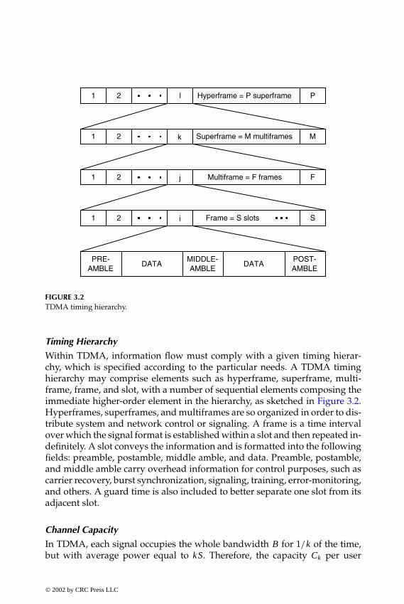
P1: FDJ
book CRC-Wireless November 16, 2001 13:42 Char Count= 294
1 2 l Hyperframe = P superframe P
1 2 k Superframe = M multiframes M
1 2 j Multiframe = F frames F
1 2 i Frame = S slots S
PRE-AMBLE
DATAMIDDLE-AMBLE
DATAPOST-AMBLE
FIGURE 3.2TDMA timing hierarchy.
Timing Hierarchy
Within TDMA, information flow must comply with a given timing hierar-chy, which is specified according to the particular needs. A TDMA timinghierarchy may comprise elements such as hyperframe, superframe, multi-frame, frame, and slot, with a number of sequential elements composing theimmediate higher-order element in the hierarchy, as sketched in Figure 3.2.Hyperframes, superframes, and multiframes are so organized in order to dis-tribute system and network control or signaling. A frame is a time intervalover which the signal format is established within a slot and then repeated in-definitely. A slot conveys the information and is formatted into the followingfields: preamble, postamble, middle amble, and data. Preamble, postamble,and middle amble carry overhead information for control purposes, such ascarrier recovery, burst synchronization, signaling, training, error-monitoring,and others. A guard time is also included to better separate one slot from itsadjacent slot.
Channel Capacity
In TDMA, each signal occupies the whole bandwidth B for 1/k of the time,but with average power equal to kS. Therefore, the capacity Ck per user
© 2002 by CRC Press LLC
E:\Java for Engineers\VP Publication\Java for Engineers.vpThursday, April 25, 2002 9:27:36 AM
Color profile: DisabledComposite Default screen

P1: FDJ
book CRC-Wireless November 16, 2001 13:42 Char Count= 294
normalized with respect to the bandwidth B is
Ck =1k
log2 (1 + γ kCk) (3.5)
The total capacity per bandwidth of the system is defined as CTDMA = kCk .Hence,
CTDMA = log2 (1 + γ CTDMA) (3.6)
which is the same as that for FDMA. Note, however, that this is achievedif the transmitted power is sustained at the level of kS, which may becomeimpracticable as k increases.
3.5.3 Code Division Multiple Access
CDMA is a nonconventional multiple-access technique that immediatelyfound wide application in modern wireless systems. In CDMA, the entirebandwidth is made available simultaneously to all signals. In theory, verylittle dynamic coordination is required, as opposed to FDMA and TDMA inwhich frequency and time management has a direct impact on performance.Signals are discriminated by means of code sequences or signature sequences,which correspond to the physical channels. Each pair of transmitter–receiversis allotted one code sequence with which a communication is established. Atthe reception side, detection is carried out by means of a correlation operation.Ideally, the best performance is attained with zero-cross correlation codes, i.e.,with orthogonal codes. In theory, for a synchronous system and for equal rateusers, the number of users within a given bandwidth is dictated by the num-ber of possible orthogonal code sequences. In practice, orthogonality is verydifficult to achieve. Even though the codes may be designed to present zerocross-correlation, the impairments imposed by the communication channelmay introduce a certain level of correlation among the codes. Hence, after thecorrelation procedure has taken place, the unwanted signals appear as noise,which is the noise due to multiple access. The multiple-access noise would benil for an ideal orthogonal access. Therefore, the noise due to multiple accessthat affect the wanted signal is linearly proportional to the number of userswithin the system. Note that in such a case the degradation in the communi-cation is graceful and increases with the successive admission of users withinthe system. Such a reasoning presupposes all signals to arrive at the receiverwith identical power. In fact, because the multiple-access noise is proportionalto the signal strength, an unwanted signal whose power exceeds the averagesignal power by a factor of p is equivalent to p signals, i.e., a user in such a
© 2002 by CRC Press LLC
E:\Java for Engineers\VP Publication\Java for Engineers.vpThursday, April 25, 2002 9:27:36 AM
Color profile: DisabledComposite Default screen

P1: FDJ
book CRC-Wireless November 16, 2001 13:42 Char Count= 294
condition is seen by the system as p users. Therefore, in CDMA, power con-trol is fundamental for satisfactory operation. To accomplish CDMA, spreadspectrum techniques are used.
Spread Spectrum
Spread spectrum is defined as a communication technique in which the sig-nals are spread over a bandwidth in excess of the minimum bandwidth re-quired for their transmission. It has its origin in the military scenario whererobustness in communications is vital. In particular, two principal require-ments must be satisfied: (1) detectability of the signal by the enemy must bemade difficult and (2) enemy-introduced interference must be made easy tocombat (strange expressions for a peaceful technical material!). Systems pre-senting these characteristics are referred to, respectively, as low-probability ofintercept (LPI) and antijam communications (AJM) systems. Spread spectrumis accomplished by the use of wideband encoding signals at the transmitter,which is required to operate in synchronism with the receiver where the en-coding signals, at least for the intended information, are also known. Coding,therefore, is an important element in the design of spread-spectrum signals.By allowing the signals to occupy a bandwidth in excess of the requiredbandwidth for their transmission, spread-spectrum signals can be givenpseudorandom characteristics, which cause the signals to have a noiselikeappearance.
The LPI characteristic of spread-spectrum communications can be attainedby several means, such as by transmitting at a very low power level (thelowest possible), by limiting the transmission time to very small time intervals(the smallest possible), and by giving the signal a noiselike appearance. It ispossible to reduce the signal power to a level below the ambient thermalnoise power so that an unintended listener may find it difficult to determinethat a transmission is taking place. Besides reducing the transmission time tovery short time intervals, the position of these intervals within the total timecan be made pseudorandom so that an unintended listener has difficultylearning the hopping pattern. Noiselike appearance is imprinted by the useof pseudorandom sequences in the modulation process.
The AJM characteristic of spread-spectrum communications is attained asfollows. Spreading the signal at the transmitter and despreading the receivedsignal at the receiver would not lend any better performance if the commu-nication channel had not been affected by some sort of narrowband inter-ference. Assuming that spreading and despreading operations are identicalinverses of each other, the detected signal after the despreading would beidentical to the transmitted signal prior to spreading. However, consider-able gain is obtained in the presence of a narrowband interference, consid-ering the interference being introduced after the spreading operation. In this
© 2002 by CRC Press LLC
E:\Java for Engineers\VP Publication\Java for Engineers.vpThursday, April 25, 2002 9:27:36 AM
Color profile: DisabledComposite Default screen

P1: FDJ
book CRC-Wireless November 16, 2001 13:42 Char Count= 294
case, the composite signal arriving at the receiver constitutes a widebandsignal (wanted signal) and a narrowband interference (unwanted signal).The despreading operation at the receiver restores the wanted signal to itsoriginal bandwidth, whereas the interference is spread by the same amountwith which the wanted signal had been shrunk. Therefore, the power den-sity of the interference is diminished by the same amount, thus reducing itseffect.
Spread-spectrum principles are introduced in Appendix C.
Channel Capacity
In CDMA, each of the k signals occupies the whole bandwidth B during theentire time of the channel with average power equal to S. Channel capacitydepends on the level of coordination implemented. In a totally coordinatedsystem, transmission is synchronous in time, i.e., the symbol transition timesof all users are aligned. In such a case, the advantage of using orthogonal codesequences as spreading sequences is apparent, although this may be question-able because the initial alignment is bound to be broken by the channel. In anoncoordinated system, transmission is asynchronous, i.e., the symbol tran-sition times of the users are not aligned. In such a case, the use of orthogonalcode sequences as spreading sequences certainly renders no advantage, andthe utilization of code sequences presenting small cross-correlation seemsmore appropriate. Synchronous architectures are simpler to implement in theforward link direction, because of the inherent facility the system exhibits indistributing synchronism from the access point. Asynchronous architecturesare more applicable to the reverse link, in which case time alignment amongusers is more difficult to achieve.
In both cases, the achievable rate Ri of user i is
Ri ≤ B log2
(1 +
SN
)(3.7)
And for k users the achievable rate is
k∑i=1
Ri ≤ B log(
1 +kSN
)(3.8)
Coordinated System. In a totally coordinated system, where perfect align-ment among users exists and where accesses are discriminated by means oforthogonal code sequences, the despreading operation at the receiver restoresthe intended signal in its entirety with the interference of all other users com-pletely eliminated. If all users operate with the same rate within the given
© 2002 by CRC Press LLC
E:\Java for Engineers\VP Publication\Java for Engineers.vpThursday, April 25, 2002 9:27:36 AM
Color profile: DisabledComposite Default screen

P1: FDJ
book CRC-Wireless November 16, 2001 13:42 Char Count= 294
bandwidth Ri/B = Ck , 1 ≤ i ≤ k, then
Ck =1k
log2 (1 + γ kCk) (3.9)
The total capacity per bandwidth of the system is defined as CCDMA = kCk .Therefore,
CCDMA = log2 (1 + γ CCDMA) (3.10)
which is identical to the capacity of both FDMA and TDMA. Therefore, as faras channel capacity is concerned, CDMA, in its synchronous version, yields noimprovement over the other multiple-access techniques. On the other hand,if some sort of cooperation among users is possible, then an enhancement incapacity is achieved. For example, if the multiuser receiver bears the spread-ing waveforms of all users and can jointly demodulate and detect all thereceived signals, the effect of the unintended signals can be eliminated fromthe intended signal by a simple subtraction operation.
Noncoordinated System. In a noncoordinated system, because some corre-lation among spreading sequences exists, the despreading operation at thereceiver, besides restoring the intended signal, cannot eliminate the influenceof the unintended signals. In such a case, the k −1 unwanted signals appear asinterference. Assuming a perfect power control, the power of the unintendedsignals is given by (k − 1) S. Therefore,
Cb = B log2
(1 +
SN + (k − 1)S
)(3.11)
or, equivalently,
Ck = log2
[1 +
γ Ck
1 + (k − 1) γ Ck
](3.12)
The total capacity per bandwidth of the system is defined as CCDMA = kCk .Therefore,
CCDMA = k log2
[1 +
γ CCDMA
k + (k − 1) γ CCDMA
](3.13)
Here, again, if some sort of cooperation among users is possible, then anenhancement in capacity is achieved.
© 2002 by CRC Press LLC
E:\Java for Engineers\VP Publication\Java for Engineers.vpThursday, April 25, 2002 9:27:36 AM
Color profile: DisabledComposite Default screen

P1: FDJ
book CRC-Wireless November 16, 2001 13:42 Char Count= 294
3.5.4 Space Division Multiple Access
SDMA is a nonconventional multiple-access technique that finds applicationin modern wireless systems mainly if combined with other multiple-accesstechniques. The spatial dimension has been extensively explored by wirelesscommunications systems in the form of frequency reuse. The deployment ofadvanced techniques in order to take further advantage of the spatial dimen-sion is embedded in the SDMA philosophy. In SDMA, the entire bandwidth ismade available simultaneously to all signals. Signals are discriminated spa-tially and the communication trajectory constitutes the physical channels.The implementation of an SDMA architecture is strongly based on antennatechnology coupled with advanced digital signal processing techniques.
As opposed to the conventional applications in which locations are con-stantly illuminated by rigid-beam antennas, in SDMA the antennas shouldprovide for the ability to illuminate the locations in a dynamic fashion. Theantenna beams must be electronically and adaptively directed to the user sothat, in an idealized situation, the location alone is enough to discriminatethe user. Figure 3.3 illustrates the SDMA principle. Several references treat
FIGURE 3.3SDMA principle.
© 2002 by CRC Press LLC
E:\Java for Engineers\VP Publication\Java for Engineers.vpThursday, April 25, 2002 9:27:36 AM
Color profile: DisabledComposite Default screen
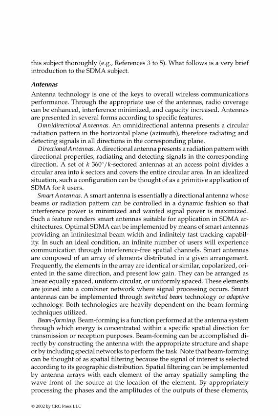
P1: FDJ
book CRC-Wireless November 16, 2001 13:42 Char Count= 294
this subject thoroughly (e.g., References 3 to 5). What follows is a very briefintroduction to the SDMA subject.
Antennas
Antenna technology is one of the keys to overall wireless communicationsperformance. Through the appropriate use of the antennas, radio coveragecan be enhanced, interference minimized, and capacity increased. Antennasare presented in several forms according to specific features.
Omnidirectional Antennas. An omnidirectional antenna presents a circularradiation pattern in the horizontal plane (azimuth), therefore radiating anddetecting signals in all directions in the corresponding plane.
Directional Antennas. A directional antenna presents a radiation pattern withdirectional properties, radiating and detecting signals in the correspondingdirection. A set of k 360◦/k-sectored antennas at an access point divides acircular area into k sectors and covers the entire circular area. In an idealizedsituation, such a configuration can be thought of as a primitive application ofSDMA for k users.
Smart Antennas. A smart antenna is essentially a directional antenna whosebeams or radiation pattern can be controlled in a dynamic fashion so thatinterference power is minimized and wanted signal power is maximized.Such a feature renders smart antennas suitable for application in SDMA ar-chitectures. Optimal SDMA can be implemented by means of smart antennasproviding an infinitesimal beam width and infinitely fast tracking capabil-ity. In such an ideal condition, an infinite number of users will experiencecommunication through interference-free spatial channels. Smart antennasare composed of an array of elements distributed in a given arrangement.Frequently, the elements in the array are identical or similar, copolarized, ori-ented in the same direction, and present low gain. They can be arranged aslinear equally spaced, uniform circular, or uniformly spaced. These elementsare joined into a combiner network where signal processing occurs. Smartantennas can be implemented through switched beam technology or adaptivetechnology. Both technologies are heavily dependent on the beam-formingtechniques utilized.
Beam-forming. Beam-forming is a function performed at the antenna systemthrough which energy is concentrated within a specific spatial direction fortransmission or reception purposes. Beam-forming can be accomplished di-rectly by constructing the antenna with the appropriate structure and shapeor by including special networks to perform the task. Note that beam-formingcan be thought of as spatial filtering because the signal of interest is selectedaccording to its geographic distribution. Spatial filtering can be implementedby antenna arrays with each element of the array spatially sampling thewave front of the source at the location of the element. By appropriatelyprocessing the phases and the amplitudes of the outputs of these elements,
© 2002 by CRC Press LLC
E:\Java for Engineers\VP Publication\Java for Engineers.vpThursday, April 25, 2002 9:27:36 AM
Color profile: DisabledComposite Default screen
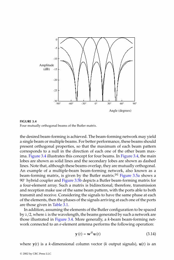
P1: FDJ
book CRC-Wireless November 16, 2001 13:42 Char Count= 294
-90° -60° -30° 0° 30° 60° 90°
-5
0
-10
-15
-20
-25
-30
Angle (degrees)
Amplitude(dB)
FIGURE 3.4Four mutually orthogonal beams of the Butler matrix.
the desired beam-forming is achieved. The beam-forming network may yielda single beam or multiple beams. For better performance, these beams shouldpresent orthogonal properties, so that the maximum of each beam patterncorresponds to a null in the direction of each one of the other beam max-ima. Figure 3.4 illustrates this concept for four beams. In Figure 3.4, the mainlobes are shown as solid lines and the secondary lobes are shown as dashedlines. Note that, although these beams overlap, they are mutually orthogonal.An example of a multiple-beam beam-forming network, also known as abeam-forming matrix, is given by the Butler matrix.[6] Figure 3.5a shows a90◦ hybrid coupler and Figure 3.5b depicts a Butler beam-forming matrix fora four-element array. Such a matrix is bidirectional; therefore, transmissionand reception make use of the same beam pattern, with the ports able to bothtransmit and receive. Considering the signals to have the same phase at eachof the elements, then the phases of the signals arriving at each one of the portsare those given in Table 3.1.
In addition, assuming the elements of the Butler configuration to be spacedby λ/2, where λ is the wavelength, the beams generated by such a network arethose illustrated in Figure 3.4. More generally, a k-beam beam-forming net-work connected to an e-element antenna performs the following operation:
y (t) = wHu (t) (3.14)
where y(t) is a k-dimensional column vector (k output signals), u(t) is an
© 2002 by CRC Press LLC
E:\Java for Engineers\VP Publication\Java for Engineers.vpThursday, April 25, 2002 9:27:36 AM
Color profile: DisabledComposite Default screen

P1: FDJ
book CRC-Wireless November 16, 2001 13:42 Char Count= 294
o90 o90
(a)
o45 o45
hybrid hybrid
hybrid hybrid
2 4 1 3
1 2 3 4 Elements
(b)Ports
FIGURE 3.5(a) A 90◦ hybrid coupler. (b) A Butler beam-forming matrix for a four-element array.
e-dimensional row vector of signals (e input signals), w is an e ×k-dimensionalweight matrix, and H represents Hermitian transpose (transpose of the com-plex conjugate). With a suitable manipulation of the weights w, the beam isformed within the desired direction. At the transmission side, this is trans-lated into transmitting the signal in the desired direction. At the receptionside, this is translated into coherently adding the signals arriving from thedesired direction. Orthogonal beams are produced by means of mutuallyorthogonal weight vectors, i.e., the desired direction is selected and the cor-responding signals detected. From Table 3.1 it can be seen that the weightvectors corresponding to each port are mutually orthogonal. (The dot prod-uct for any pair of rows is always nil, e.g., for the first and the second rows:e− j45◦
e j0◦+ e− j180◦
e− j45◦+ e j45◦
e− j90◦+ e− j90◦
e− j135◦= 0.)
TABLE 3.1
Element Phasing for the Butler Matrix
Element Element Element Element1 2 3 4
Port 1 −45◦ −180◦ 45◦ −90◦Port 2 0◦ −45◦ −90◦ −135◦Port 3 −135◦ −90◦ −45◦ 0◦Port 4 −90◦ −45◦ −180◦ −45◦
© 2002 by CRC Press LLC
E:\Java for Engineers\VP Publication\Java for Engineers.vpThursday, April 25, 2002 9:27:36 AM
Color profile: DisabledComposite Default screen
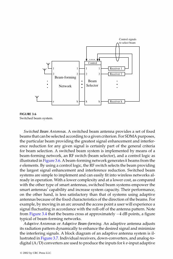
P1: FDJ
book CRC-Wireless November 16, 2001 13:42 Char Count= 294
Beam-forming
Network
1
2
1
2
e k
BeamSelector
Control
1 1
2 2
k k
Receiver 1
Receiver 2
Receiver k
Control signalsto select beam
FIGURE 3.6Switched beam system.
Switched Beam Antennas. A switched beam antenna provides a set of fixedbeams that can be selected according to a given criterion. For SDMA purposes,the particular beam providing the greatest signal enhancement and interfer-ence reduction for any given signal is certainly part of the general criteriafor beam selection. A switched beam system is implemented by means of abeam-forming network, an RF switch (beam selector), and a control logic asillustrated in Figure 3.6. A beam-forming network generates k beams from thee elements. By using a control logic, the RF switch selects the beam providingthe largest signal enhancement and interference reduction. Switched beamsystems are simple to implement and can easily fit into wireless networks al-ready in operation. With a lower complexity and at a lower cost, as comparedwith the other type of smart antennas, switched beam systems empower thesmart antennas’ capability and increase system capacity. Their performance,on the other hand, is less satisfactory than that of systems using adaptiveantennas because of the fixed characteristics of the direction of the beams. Forexample, by moving in an arc around the access point a user will experience asignal fluctuating in accordance with the roll-off of the antenna pattern. Notefrom Figure 3.4 that the beams cross at approximately −4 dB points, a figuretypical of beam-forming networks.
Adaptive Antennas or Adaptive Beam-forming. An adaptive antenna adjustsits radiation pattern dynamically to enhance the desired signal and minimizethe interfering signals. A block diagram of an adaptive antenna system is il-lustrated in Figure 3.7. Individual receivers, down-converters, and analog-to-digital (A/D) converters are used to produce the inputs for k e-input adaptive
© 2002 by CRC Press LLC
E:\Java for Engineers\VP Publication\Java for Engineers.vpThursday, April 25, 2002 9:27:36 AM
Color profile: DisabledComposite Default screen
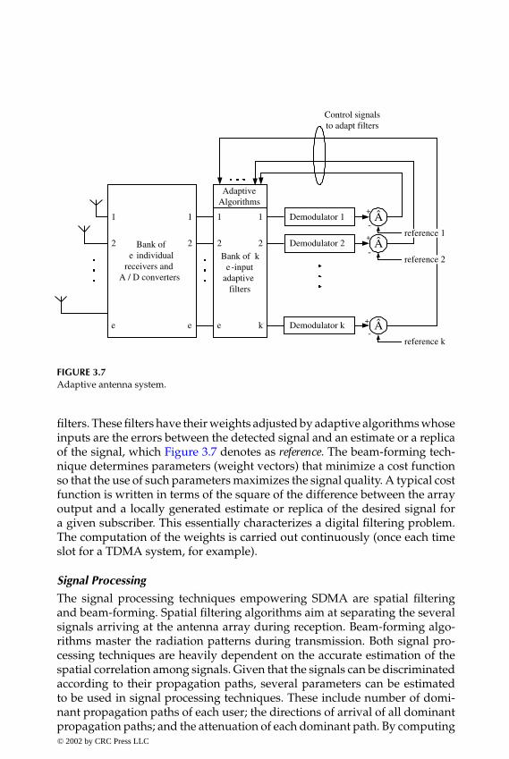
P1: FDJ
book CRC-Wireless November 16, 2001 13:42 Char Count= 294
Bank ofe individual
receivers andA / D converters
1
2
1
2
e e
Bank of ke-input
adaptivefilters
AdaptiveAlgorithms
1 1
2 2
e k
Demodulator 1
Control signalsto adapt filters
Demodulator 2
Demodulator k
+
-+
-
reference 1
reference 2
+
-reference k
Â
Â
Â
FIGURE 3.7Adaptive antenna system.
filters. These filters have their weights adjusted by adaptive algorithms whoseinputs are the errors between the detected signal and an estimate or a replicaof the signal, which Figure 3.7 denotes as reference. The beam-forming tech-nique determines parameters (weight vectors) that minimize a cost functionso that the use of such parameters maximizes the signal quality. A typical costfunction is written in terms of the square of the difference between the arrayoutput and a locally generated estimate or replica of the desired signal fora given subscriber. This essentially characterizes a digital filtering problem.The computation of the weights is carried out continuously (once each timeslot for a TDMA system, for example).
Signal Processing
The signal processing techniques empowering SDMA are spatial filteringand beam-forming. Spatial filtering algorithms aim at separating the severalsignals arriving at the antenna array during reception. Beam-forming algo-rithms master the radiation patterns during transmission. Both signal pro-cessing techniques are heavily dependent on the accurate estimation of thespatial correlation among signals. Given that the signals can be discriminatedaccording to their propagation paths, several parameters can be estimatedto be used in signal processing techniques. These include number of domi-nant propagation paths of each user; the directions of arrival of all dominantpropagation paths; and the attenuation of each dominant path. By computing© 2002 by CRC Press LLC
E:\Java for Engineers\VP Publication\Java for Engineers.vpThursday, April 25, 2002 9:27:36 AM
Color profile: DisabledComposite Default screen

P1: FDJ
book CRC-Wireless November 16, 2001 13:42 Char Count= 294
the weights for beam-forming purposes, the phases at the antenna elementsare adjusted to steer the main beam pointing direction toward the estimateddirection of arrival of the desired user. Because these weights are computedfrom the parameters of the signals arriving at the antenna, a good reciprocitybetween forward and reverse channels must exist for better performance.Good reciprocity can be achieved in TDD systems but not in FDD systems, inwhich forward and reverse channels are usually kept apart from each otherfor half of the total bandwidth. In this case, the algorithms must compensatefor different frequencies.
Channel Capacity
The implementation of SDMA requires sophisticated techniques and technol-ogy. Channel capacity becomes a very sensitive issue and cannot be evaluatedin a straightforward manner. The brief calculations that follow are shown fordidactic purposes only. Assume an ideal SDMA, implemented in such a waythat coverage requirements are perfectly accomplished in k perfectly disjointand contiguous wedges illuminated by directional antennas with gain equalto k. Each signal occupies the whole bandwidth B for 1/k of the space, but withaverage power equal to kS. Therefore, the capacity Ck per user normalizedwith respect to the bandwidth B is
Ck = 1k
log2 (1 + γ kCk) (3.15)
The total capacity per bandwidth of the system is defined as CSDMA = kCk .Therefore,
CSDMA = log2 (1 + γ CSDMA) (3.16)
which is the same as that for FDMA.
3.5.5 Brief Remarks on Scheduled Multiple-Access Techniques
FDMA is a very popular technique used in all 1G and 2G wireless systems;its deployment in higher generations is unequivocal. TDMA, CDMA, and asimple form of SDMA have always been used in conjunction with FDMA. Infact, although not widely known as such, frequency reuse can be thought ofas a primitive form of SDMA. The same comment applies for the use of direc-tional antennas. TDMA and CDMA appeared in second-generation wirelessnetworks. A more sophisticated form of SDMA can be used in conjunctionwith any one of the other multiple-access techniques with the aim at increas-ing capacity. Figure 3.8 plots the capacity per user normalized with respectto the bandwidth for FDMA, TDMA, CDMA, and SDMA. The upper curve© 2002 by CRC Press LLC
E:\Java for Engineers\VP Publication\Java for Engineers.vpThursday, April 25, 2002 9:27:36 AM
Color profile: DisabledComposite Default screen

P1: FDJ
book CRC-Wireless November 16, 2001 13:42 Char Count= 294
0 5 100
2
4
6
k=2,3,4,5
NS
k=2,3,4,5
CS
CS - k=1
NS - k=1
Legend:
CS - Coordinated System
NS - Noncoordinated System
Cap
acity
per
use
r pe
r ba
ndw
idth
10Log(γ)
FIGURE 3.8Capacity per user normalized with respect to the bandwidth for FDMA, TDMA, CDMA, andSDMA.
corresponds to the capacity of a single user for all scheduled multiple-accessschemes. This is the same as the total capacity of each of the schemes with theexception of noncoordinated CDMA. Channel capacity, as analyzed in thissection, applies for Gaussian channels and is determined in terms of bits persecond. In a radio communication environment, where signal transmissionencounters harsher conditions, what has been found here may be viewed asan upper bound performance.
3.6 Random Multiple Access
The random multiple-access techniques are more efficiently utilized if appliedto bursty (random) traffic. In this case, the resources are seized as demandarises, therefore on a random basis, and are allotted for the duration of theaccess only. Because the protocols in this category sustain no rigid disciplinein accessing the medium, collisions may occur. Terminals can find they are
© 2002 by CRC Press LLC
E:\Java for Engineers\VP Publication\Java for Engineers.vpThursday, April 25, 2002 9:27:36 AM
Color profile: DisabledComposite Default screen

P1: FDJ
book CRC-Wireless November 16, 2001 13:42 Char Count= 294
involved in a collision in several ways. They can listen to the channel toverify if the information sent is distorted or not, or they can wait for anacknowledgment from the access point.
Because these protocols are primarily used for initial access purposes theirperformance must be assessed in terms of parameters related to message(packet) transmission. In this case, throughput and delay are the applicableperformance measures. The throughput S is defined as the number of suc-cessfully transmitted messages per time unit. The delay D corresponds to thetime taken for the message to be successfully transmitted. For many random-access protocols the throughput can be obtained in a closed-form expression.The delay, defined as the sum of queueing delay, propagation delay, and trans-mission time, constitutes a more complex issue. For very simple algorithms itcan be obtained in a closed-form formula. More generally, simulation mech-anisms are the common means used to achieve the measures of throughputand delay.
The performance of the protocols is affected by many factors. In addition tothose factors commonly influencing the performance of any wireless networksuch as near–far effect and multipath propagation, the vulnerable period, afactor specific to access methods for which the degree of coordination is nottight, is a decisive element. The vulnerable period T of a protocol is the timeinterval susceptible to collision. It depends on the duration of the packet andalso on the propagation delay time a across the bus length.
For fixed-length messages (packets) the parameters can be normalized withrespect to the packet time. Throughput then is given as the number of success-fully transmitted packets per packet time (0 ≤ S ≤ 1). Delay and vulnerableperiod are given in units of packet times. In the same way, the offered traffic G,which represents all the traffic in the network, is given in packets per packettime and includes both newly generated packets and retransmitted packets.Therefore, for a given probability p of successful packet transmission:
S = pG (3.17)
For the generation of packets following a Poisson distribution, the proba-bility pk that k packets are generated in T packet time is
pk =(TG)k
k!exp (−TG) (3.18)
This section describes some of the various random multiple-access meth-ods, those more closely related to the practical wireless networks, such aspure ALOHA, slotted ALOHA, tree, FCFS, and the various forms of CSMAaccess protocols. It then determines the throughput and the delay of some ofthe protocols.
© 2002 by CRC Press LLC
E:\Java for Engineers\VP Publication\Java for Engineers.vpThursday, April 25, 2002 9:27:36 AM
Color profile: DisabledComposite Default screen
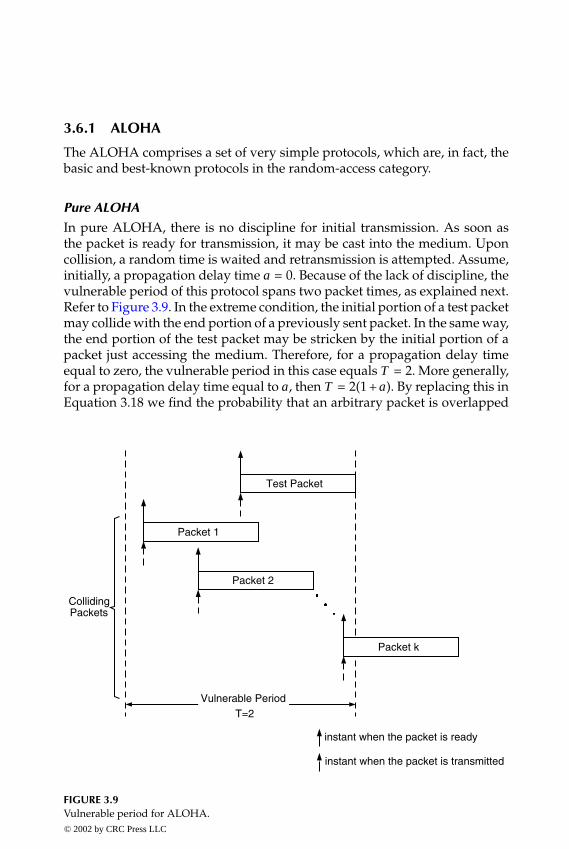
P1: FDJ
book CRC-Wireless November 16, 2001 13:42 Char Count= 294
3.6.1 ALOHA
The ALOHA comprises a set of very simple protocols, which are, in fact, thebasic and best-known protocols in the random-access category.
Pure ALOHA
In pure ALOHA, there is no discipline for initial transmission. As soon asthe packet is ready for transmission, it may be cast into the medium. Uponcollision, a random time is waited and retransmission is attempted. Assume,initially, a propagation delay time a = 0. Because of the lack of discipline, thevulnerable period of this protocol spans two packet times, as explained next.Refer to Figure 3.9. In the extreme condition, the initial portion of a test packetmay collide with the end portion of a previously sent packet. In the same way,the end portion of the test packet may be stricken by the initial portion of apacket just accessing the medium. Therefore, for a propagation delay timeequal to zero, the vulnerable period in this case equals T = 2. More generally,for a propagation delay time equal to a , then T = 2(1 + a ). By replacing this inEquation 3.18 we find the probability that an arbitrary packet is overlapped
Packet 1
Test Packet
Packet 2
Vulnerable PeriodT=2
Packet k
CollidingPackets
instant when the packet is ready
instant when the packet is transmitted
FIGURE 3.9Vulnerable period for ALOHA.© 2002 by CRC Press LLC
E:\Java for Engineers\VP Publication\Java for Engineers.vpThursday, April 25, 2002 9:27:36 AM
Color profile: DisabledComposite Default screen

P1: FDJ
book CRC-Wireless November 16, 2001 13:42 Char Count= 294
by k packets, such that
pk =[2 (1 + a ) G]k
k!exp [−2 (1 + a ) G] (3.19)
The probability of a successful transmission in T packet times is the proba-bility that no message is generated within T , i.e., p = p0 = exp [−2 (1 + a ) G].Therefore, from Equation 3.17, the throughput of the ALOHA protocol is
S = G exp [−2 (1 + a ) G] (3.20)
The maximum throughput, obtained by performing d S/dG = 0 in Equation3.20, is found to be
G =1
2 (1 + a )
packet per packet time, for which
S =1
2 (1 + a ) e
And S ≈ 0.184 for propagation delay time equal to zero.As mentioned previously, the delay is determined by the addition of three
terms: queueing delay, propagation delay, and transmission time. This can beestimated in an approximated fashion as follows. We consider the queueingdelay time as the total time spent in unsuccessful transmissions (total time be-fore a successful transmission), which is obtained by multiplying the expectednumber of transmissions times the average delay δ for one transmission. Thepropagation delay is simply a and the transmission time is equal to 1. Giventhat the probability of a successful transmission is p = p0 = exp [−2 (1 + a ) G],then the probability of a collision is 1 − p = 1 − exp [−2 (1 + a ) G]. The prob-ability pk−attempts of a transmission requiring exactly k attempts (i.e., k − 1collisions followed by one success) is
pk−attempts = exp [−2 (1 + a ) G] {1 − exp [−2 (1 + a ) G]}k−1
The expected number of transmissions is
E [k] =∞∑
k=1
kpk−attempts = exp [2 (1 + a ) G]
And the expected number of retransmission is the expected number oftransmission minus one, i.e., exp [2 (1 + a ) G] − 1. Therefore, the delay isgiven by
D = {exp [2 (1 + a ) G] − 1}δ + a + 1© 2002 by CRC Press LLC
E:\Java for Engineers\VP Publication\Java for Engineers.vpThursday, April 25, 2002 9:27:36 AM
Color profile: DisabledComposite Default screen

P1: FDJ
book CRC-Wireless November 16, 2001 13:42 Char Count= 294
The parameter δ (delay for one transmission), by its turn, equals four terms:the time 1 + a taken for the packet to reach its destination; the time w thereceiver takes to generate the acknowledgment; the propagation time a for theacknowledgment to reach the terminal; and the time r taken for the terminal todecide for the retransmission. Therefore, δ = 1+2a + w + r . The time r dependson the retransmission policy (known as back-off algorithm) whose aim is tospread retransmissions out over an interval of time to ensure that an increasein traffic load does not trigger a decrease in throughput. If r is selected froma uniform distribution ranging from 0 to f packet transmission times, thenr = f /2. Note that the minimum value of δ is 1 obtainable for a = w = r = 0.In this case D = exp (2G). If the time taken to generate the acknowledgmentand the time taken for the terminal to decide for retransmission are nil, thenD = (1 + 2a ) exp [2 (1 + a ) G] − a .
Slotted ALOHA
The slotted ALOHA introduces some sort of discipline to reduce the vulner-able period. The time is divided into fixed-length time slots, with the timeslot chosen to be equal to the packet transmission time and with the packetallowed to be sent only at the beginning of a time slot. Assume, initially, apropagation delay time a = 0. In this case, as can be visualized in Figure 3.10,the vulnerable period is equal to one packet time, i.e., T = 1. More generally,for a propagation delay time equal to a , then T = 1 + a . By replacing this inEquation 3.18 we find the probability that an arbitrary packet is overlappedby k packets, such that
pk =[(1 + a ) G]k
k!exp[−(1 + a )G] (3.21)
The probability of a successful transmission in T packet times is the proba-bility that no message is generated within T , i.e., p = p0 = exp [− (1 + a ) G].From Equation 3.17, the throughput of the slotted ALOHA is
S = G exp[−(1 + a )G] (3.22)
In this case, the maximum throughput is obtained for
G =1
1 + a
packet per packet time, for which
S =1
(1 + a ) e
and S ≈ 0.368 for a propagation delay time equal to zero.
© 2002 by CRC Press LLC
E:\Java for Engineers\VP Publication\Java for Engineers.vpThursday, April 25, 2002 9:27:36 AM
Color profile: DisabledComposite Default screen

P1: FDJ
book CRC-Wireless November 16, 2001 13:42 Char Count= 294
Test Packet
Packet 1
Packet 2
Packet k
Vulnerable PeriodT=1T=1
CollidingPackets
instant when the packet is ready
instant when the packet is transmitted
FIGURE 3.10Vulnerable period for slotted ALOHA.
A reasoning similar to that used for the pure ALOHA can be applied to theslotted ALOHA to estimate the delay. In such a case,
D = {exp [(1 + a ) G] − 1}δ + a + 1.5
where δ = 1.5 + 2a + w + r . In this case, we have assumed that, on average, thepacket is ready for transmission, or retransmission, in the middle of the timeslot. Note that the minimum value of δ is 1.5 (obtained for a = w = r = 0),for which D = 1.5 exp (G). If the time taken to generate the acknowledgmentand the time taken for the terminal to decide for retransmission are nil thenD = (1.5 + 2a ) exp [2 (1 + a ) G] − a .
3.6.2 Splitting Algorithms
The splitting algorithms comprise a set of protocols whose common featureis the application of some sort of segregation to resolve the conflicts.
© 2002 by CRC Press LLC
E:\Java for Engineers\VP Publication\Java for Engineers.vpThursday, April 25, 2002 9:27:36 AM
Color profile: DisabledComposite Default screen

P1: FDJ
book CRC-Wireless November 16, 2001 13:42 Char Count= 294
Tree
The tree algorithm is based on the following strategy. At the occurrence ofa collision, the terminals not involved in the collision enter a waiting state.Those involved are split into two groups according to a given criterion (e.g.,by flipping a coin). The first group is permitted to use one time slot, andthe second group can use the next time slot, if the first group is successful.However, if another collision occurs, a further splitting is carried out until,eventually, a group with only one active terminal will be allowed to transmitsuccessfully. This algorithm yields a maximum performance slightly betterthan the previous protocol (S ≈ 0.47 for a propagation delay time equal tozero[7]).
First-Come First-Served (FCFS)
The FCFS algorithm is based on the following strategy. At each time slot, say,time slot k, only the packet arriving within a specified allocation time interval,(say, from T (k) to T (k) + t(k)) is entitled to be transmitted. If a collision oc-curs, the allocation interval is split into two equal subintervals—from T (k) toT (k) + t(k)/2 and from T (k) + t(k)/2 to T (k) + t(k)—and a packet that arrivedin the first subinterval is sent. In case of another collision, a further split-ting (t(k)/4) is required, and so on, until the transmission is successful. Thisalgorithm yields a maximum performance slightly better than the previousprotocol (S ≈ 0.487 for a propagation delay time equal to zero[8]).
3.6.3 Carrier Sense Multiple Access
Carrier sense multiple access (CSMA) comprises a class of protocols whosecommon feature is the sensing of the status (busy or idle) of the transmissionmedium before any transmission decision policy is exercised. This does notnecessarily require the use of a carrier but simply the ability to detect idleor busy periods. Note, however, that a terminal may sense the medium idlealthough, in fact, a packet may be traveling through it and, because of the buslength, the bus occupancy is not detected at the time of the sensing. Theseprotocols may appear in nonslotted and slotted versions. In the nonslottedvariant, there is no rigid time to initiate the transmission of the packet. Inthe slotted mode, the time axis is divided into slots, whose length is chosento be equal to a submultiple of the packet time, and the packet transmissionwill always occur at the beginning of a slot. In such a case, the status of themedium is sensed at the beginning of the slot next to the time of a packetarrival at the terminal. The performance analyses derived for these protocolsassume the sensing time to be nil. For details of the derivations, the reader isreferred to References 8 and 9.
© 2002 by CRC Press LLC
E:\Java for Engineers\VP Publication\Java for Engineers.vpThursday, April 25, 2002 9:27:36 AM
Color profile: DisabledComposite Default screen

P1: FDJ
book CRC-Wireless November 16, 2001 13:42 Char Count= 294
Nonslotted Nonpersistent CSMA
In this protocol, the listen-before-talk strategy is used. If the terminal sensesthe medium to be idle, the packet is transmitted immediately. Otherwise, arandom time is waited and the process is reinitiated. The throughput in thiscase is given by
S =G exp (−aG)
(1 + 2a ) G + exp (−aG)(3.23)
Slotted Nonpersistent CSMA
In this protocol, the listen-before-talk strategy is again used. If the terminalfinds the medium idle the packet is transmitted immediately. Otherwise, theprocess is reinitiated (the medium is sensed again in the next slot). Recallthat the medium is sensed at the beginning of the time slot and transmissionoccurs synchronously with the slot. The throughput in this case is given by
S =aG exp (−aG)
1 + a − exp (−aG)(3.24)
Nonslotted 1-Persistent CSMA
In this protocol, the listen-before-talk strategy is again used. If the terminalfinds the medium idle, the packet is transmitted immediately, i.e., transmis-sion occurs with probability 1. Otherwise, the process is reinitiated. Note herethat the medium is constantly being sensed until it is found idle for the trans-mission. Note also that if one or more terminals sense the medium to be busy,collision will certainly occur. This is because these terminals will sense themedium to be idle at the same time and will then transmit their packets. Thethroughput in this case is given by
S =G [1 + G + aG (1 + G + aG/2)] exp [−(1 + 2a )G]
(1 + 2a ) G − [1 − exp(−aG)] + (1 + aG) exp [−(1 + a )G](3.25)
Slotted 1-Persistent CSMA
In this protocol, the listen-before-talk strategy is again used. If the terminalfinds the medium idle the packet is transmitted immediately. Otherwise, theprocess is reinitiated. Note here that the medium is constantly sensed untilit is found to be idle for transmission. But note also that these events occursynchronously with the time slot. The throughput in this case is given by
S =G[1 + a − exp (−aG)] exp [−(1 + a )G]
(1 + a ) [1 − exp (−aG)] + a exp [−(1 + a )G](3.26)
© 2002 by CRC Press LLC
E:\Java for Engineers\VP Publication\Java for Engineers.vpThursday, April 25, 2002 9:27:36 AM
Color profile: DisabledComposite Default screen
P1: FDJ
book CRC-Wireless November 16, 2001 13:42 Char Count= 294
p-Persistent CSMA
In this protocol, which is applicable to slotted channels, the listen-before-talkstrategy is again used. If the terminal finds the medium to be idle the packet istransmitted with probability p. With probability 1− p transmission is deferredto the next slot. This process is repeated until either the packet is transmittedor the channel is sensed to be busy. In such a case, a random time is waited andthe process is reinitiated, which, in the same way, corresponds to the actiontaken when a collision occurs. At the first transmission, when the medium issensed to be busy the access procedure is deferred to the next slot. Note thatthis protocol reduces to the 1-persistent if p is chosen to be equal to 1.
Busy Tone CSMA (CSMA/BT) or Busy Tone Multiple Access (BTMA)
In this protocol, the listen-before-talk strategy is again used. A busy tone istransmitted by the access point on the forward channel to indicate that thereverse channel is in use. Note that this protocol assumes a network with acentralized topology. The aim of the busy tone approach is to solve the hiddenterminal problem, as explained next. In packet radio networks, some terminalsare within range and line-of-sight of each other, but some are not. Thosewithin range may successfully sense the medium to be busy and thereforemay use the access protocol as prescribed. On the other hand, those out ofrange cannot detect whether or not the medium is in use. Therefore, for anaccess point whose position is conveniently chosen to be within range ofall terminals, the CSMA protocol can be applied as defined. The basic CSMAprotocols (nonpersistent, 1-persistent, and p-persistent, with their slotted andnonslotted versions) can be used here.
Digital Busy Tone CSMA (CSMA/DT) or Digital (or Data)Sense Multiple Access (DSMA)
In this protocol, the listen-before-talk strategy is again used. A busy/idle bitis transmitted by the access point on the forward channel to indicate that thereverse channel is in use. Note that this is just a slight variation on the busytone CSMA protocol; the difference is the use of a busy/idle bit instead of atone. It applies for digital networks where a busy/idle bit is included withinthe forward channel frame structure for the purposes of indicating the occu-pancy status of the reverse channel. The basic CSMA protocols (nonpersistent,1-persistent, and p-persistent, with their slotted and nonslotted versions) canbe used here.
CSMA with Collision Detection (CSMA/CD)
In this protocol, in addition to the listen-before-talk scheme, the listen-while-talk strategy is also used. This means that, besides sensing the channel prior totransmission, the medium continues to be monitored by the terminals while
© 2002 by CRC Press LLC
E:\Java for Engineers\VP Publication\Java for Engineers.vpThursday, April 25, 2002 9:27:36 AM
Color profile: DisabledComposite Default screen

P1: FDJ
book CRC-Wireless November 16, 2001 13:42 Char Count= 294
their own transmissions are on course. As soon as a collision is detected,transmission is ceased and a jamming signal is sent to force collision consen-sus among users. A retransmission back-off procedure is initiated. Collisiondetection can be easily performed on a wired network by simply sensing volt-age levels. In this case, if the sensed voltage level is different from the voltagelevel of the initial transmission, then collision has occurred. For a wirelessnetwork, this simple procedure is not applicable. Detecting the received sig-nal and comparing it with its own transmitted signal is not effective sincethe signal of the terminal overrules all other signals received in its vicinity.Any better solution would certainly lead to complex signal processing tech-niques to compensate for this discrepancy. Typically, an acknowledgment forcollision detection, as used in all the other protocols, is the simplest solutionto this problem. The basic CSMA protocols (nonpersistent, 1-persistent, andp-persistent, with their slotted and nonslotted versions) can be used here.
CSMA with Collision Avoidance (CSMA/CA), Multiple Access with CollisionAvoidance (MACA), or Multiple Access with Collision Avoidanceand Acknowledgment (MACAW)
In this protocol, the listen-before-talk strategy is used. Unlike the other pro-tocols in which an access attempt is carried out by casting the informationpacket itself onto the medium, this protocol provides for access in two steps:first by outputting a short frame—a request to send (RTS) message—and sec-ond, after receiving an acknowledgment—a clear to send (CTS) message—bytransmitting the information packet. Both messages, RTS and CTS, encom-pass the data length to be sent after CTS has been successfully received. Thisprotocol is basically designed for wireless applications. Suppose terminal Asends an RTS to B to initiate a communication. Terminals within reach of Acan hear this RTS and therefore be able to follow the progress of the communi-cation without interfering. In similar manner, terminals within reach of B canhear the CTS and be able to follow the progress of the communication so asnot to interfere. Certainly, a collision may occur when more than one terminalattempts to send an RTS. In such a case, if no CTS is received within a giventime, a random time is waited and access is retried. Performance is furtherimproved by including an acknowledgment after the information message issuccessfully received (the MACA protocol is then renamed MACAW).
3.6.4 Brief Remarks on Random Multiple-Access Techniques
Several aspects can be looked into when dealing with contention-based proto-cols. In particular, stability considerations and capture effects are two relevantissues that can be explored to choose the appropriate protocol for any givenapplication.
© 2002 by CRC Press LLC
E:\Java for Engineers\VP Publication\Java for Engineers.vpThursday, April 25, 2002 9:27:36 AM
Color profile: DisabledComposite Default screen

P1: FDJ
book CRC-Wireless November 16, 2001 13:42 Char Count= 294
Stability Analysis
The performance analysis of the contention-based protocols, as examinedhere, assumes an infinite number of users and a statistical equilibrium, withthe offered traffic modeled as a Poisson process with a fixed average arrivalrate. This certainly simplifies the derivation of the expressions.
Refer to Figure 3.11 where the plots show the throughput vs. offered trafficfor the various random multiple-access techniques. For any of the contention-based protocols, assume, initially, that the system operates at some steadyvalue G of traffic, 0 < G Gmax, where Gmax is the traffic for which thethroughput is maximum. Consider that a sudden increase of the traffic oc-curs and that the increase is such that the throughput is still kept below themaximum throughput. An increase in the traffic results in an increase of thethroughput which, in turn, produces a decrease in the backlog of messagesto be retransmitted. This leads to a decrease in the offered traffic, thus takingthe system to operate around the initial steady-state value of the offered traf-fic. The region of the curve for traffic G within the range 0 < G Gmax isrecognized as that within which the operation of the system is stable.
1E-3 0.01 0.1 1 10 100 1000
0.0
0.2
0.4
0.6
0.8
1.0
Nonslotted Nonpersistent CSMA
Pure ALOHA
Slotted ALOHA
{Nonslotted 1-Persistent CSMASlotted 1-Persistent CSMA
Slotted Nonpersistent CSMA
Upper bound performance of the Slotted ALOHA
S-T
hrou
ghpu
t
Log(G)
FIGURE 3.11Throughput vs. offered traffic for the various random multiple-access techniques (a = 0.01).
© 2002 by CRC Press LLC
E:\Java for Engineers\VP Publication\Java for Engineers.vpThursday, April 25, 2002 9:27:36 AM
Color profile: DisabledComposite Default screen

P1: FDJ
book CRC-Wireless November 16, 2001 13:42 Char Count= 294
Consider now that the system is led to operate at a value of traffic G,Gmax < G < ∞, and that an increase in the offered traffic occurs. In such acase, a decrease in the throughput also occurs, i.e., fewer packets are success-fully transmitted with more collisions taking place. This leads to an increase inthe number of retransmissions, thus in the offered traffic, which, as already ob-served, leads to a smaller throughput, and so on, until eventually the traffic es-calates to infinity and the throughput goes to zero. The region of the curve fortraffic G within the range Gmax < G < ∞ is recognized as that within whichthe operation of the system is unstable.
The considerations on stability carried out here apply for all contention-based protocols operating with an infinite number of users. The infinitenumber of users condition implies that the number of messages to be retrans-mitted has no influence in the number of new messages being generated, i.e.,the number of messages of both types can increase without limit. For a finitenumber of terminals, on the other hand, if the number of collisions increases,some terminals may choose to leave the game, thence reducing the offeredtraffic. Back-off algorithms may be adequately used so that the retransmis-sions occur in a time conveniently chosen to restore stability.
Delay
Figure 3.12 shows the delay vs. offered traffic. The increase in the delay withthe increase of the traffic is related to the fact that, as the traffic increases, morecollisions occur and more retransmissions are attempted. As can be observedin the formulation presented here, the performance of the protocols is depen-dent on the propagation delay. For the signal assumed to propagate at thespeed of the light 1 km is traveled within 3.33 µs, i.e., the propagation delayis approximately 3.33 µs/km. In wireless applications, the duration of a timeslot is usually on the order of several hundreds of microseconds. Therefore,the propagation delay is indeed a very small proportion of the duration of atime slot. Figure 3.13 plots the throughput vs. the propagation delay for max-imum throughput traffic. Note that, apart from ALOHA and slotted ALOHA,the throughput of all the other protocols is very sensitive to the propagationdelay.
Capture Effect
The expressions for throughput as shown previously are derived on the as-sumption that if collisions occur, the packets involved in the collision are ren-dered unusable and retransmission takes place. Note that such an assumptionis plausible if a perfect power control mechanism is used, in which case thepackets competing for access are given equal chances. In a wireless commu-nications environment, as mentioned before, signals from different terminalsmay arrive at the access point with different power levels as a result of pathloss and fading. Path loss and fading act independently on the users, naturally
© 2002 by CRC Press LLC
E:\Java for Engineers\VP Publication\Java for Engineers.vpThursday, April 25, 2002 9:27:36 AM
Color profile: DisabledComposite Default screen

P1: FDJ
book CRC-Wireless November 16, 2001 13:42 Char Count= 294
0.0 0.5 1.0 1.5 2.0 2.5 3.0
50
100
150
200
a=0.05 a=0.05
a=0
Slotted ALOHA
Pure ALOHA
a=0
G
Del
ay
FIGURE 3.12Delay vs. offered traffic (r = w = 0).
1E-3 0.01 0.1 1
0.0
0.2
0.4
0.6
0.8
1.0
Slotted 1-Persistent CSMA
Nonslotted 1-Persistent CSMA
Slotted Nonpersistent CSMA
Nonslotted Nonpersistent CSMA
Slotted ALOHA
Pure ALOHA
Normalized propagation delay - a
Sm
ax -
Thr
ough
put
FIGURE 3.13Throughput vs. propagation delay for maximum throughput traffic (G = Gmax).
© 2002 by CRC Press LLC
E:\Java for Engineers\VP Publication\Java for Engineers.vpThursday, April 25, 2002 9:27:36 AM
Color profile: DisabledComposite Default screen
P1: FDJ
book CRC-Wireless November 16, 2001 13:42 Char Count= 294
splitting them into classes of access power. Therefore, the wireless chan-nel imposes an intrinsic priority in the accesses with this priority changingdynamically.
Given that the terminals are naturally split into classes of access, it may bepossible that in case k + 1 users are competing for access one of the packets issuccessfully received, i.e., capture occurs. The k unsuccessful packets are saidto have been captured by the successful packet. The capture phenomenon de-pends on a series of factors such as modulation technique, coding scheme, av-erage signal-to-noise ratio, the minimum power-to-interference ratio (captureratio or capture parameter), and channel characteristics.
This subsection estimates the upper- and lower-bound performances ofthe slotted ALOHA in the presence of the capture effect. The approach usedhere is certainly a very simple one.[10] It is shown with an aim at illustratingthe phenomenon and can be easily extended to other types of protocols. Amore rigorous derivation may be found, for example, in Reference 11. For pro-tocols using fixed-length packets, for which the parameters can be normalizedwith respect to the packet time, the throughput represents the probability ofa successful packet reception. For example, for both ALOHA and slottedALOHA, the throughput can be obtained directly from Equations 3.19 and3.21, respectively, by fixing k = 1− the probability of having one packet in thesystem. Now assume that k + 1 packets are competing for access, with oneof them the wanted packet and the remaining k the interfering packets. Letpk−capture be the probability that the wanted packet captures the k interferingpackets. The probability of a successful reception given that k packets are cap-tured is pk+1|k−capture. The unconditional probability of a successful receptionis the throughput, such that
S =∞∑
k=0
pk+1|k−capture × pk−capture (3.27)
The conditional probability pk+1|k−capture depends on the access protocol.Specifically, for the ALOHA protocol it is given by Equation 3.19 and forthe slotted ALOHA protocol it is given by Equation 3.21. The probabilitypk−capture, as already mentioned, depends on several factors including themodulation technique, coding scheme, channel conditions, and others andequals the unity for k = 0, always (p0−capture = 1).
At one extreme, upon collision all colliding packets are destroyed. Inthis case, successful reception is achieved if no collision occurs. Therefore,pk−capture = 0 ∀ k = 0. Hence, S = p1|0−capture. For the slotted ALOHA, Equa-tion 3.21 is used to yield:
S = G exp [−(1 + a )G] (3.28)
© 2002 by CRC Press LLC
E:\Java for Engineers\VP Publication\Java for Engineers.vpThursday, April 25, 2002 9:27:36 AM
Color profile: DisabledComposite Default screen
P1: FDJ
book CRC-Wireless November 16, 2001 13:42 Char Count= 294
as in Equation 3.22, representing the lower-bound performance (no capture)of the slotted ALOHA in a wireless medium. At the other extreme, upon col-lision one packet survives the collisions with the k interfering packets. There-fore, pk −capture = 1 ∀ k. Hence, S =
∑∞k=0 pk+1|k −capture. For slotted ALOHA,
Equation 3.21 is used to yield:
S = 1 − exp [−(1 + a )G] (3.29)
representing the upper-bound performance (perfect capture) of the slottedALOHA in a wireless medium. Equations 3.28 and 3.29 are plotted inFigure 3.11. As already mentioned, Equation 3.28, which represents the lower-bound performance of slotted ALOHA, coincides with Equation 3.22, whichyields the throughput if no capture is considered. Equation 3.29, which givesthe upper-bound performance of slotted ALOHA, shows that the through-put tends to unity as the traffic load goes to infinity. This is because for aperfect capture any small difference in signal power is enough to resolve thecontention.
3.7 Controlled Multiple Access
Intermittent traffic bursts require a high degree of flexibility for resource as-signment purposes in low traffic conditions, and such a flexibility is providedby random multiple-access methods. As the traffic increases, because of thelack of a proper access coordination, a high incidence of packet collision oc-curs and delay becomes a critical factor leading to performance degradation.In this case, controlled multiple-access methods are recommended. The accessmethods in this category make use of deterministic or noncontention strate-gies in which, by means of a control signal, permission to send is granted toterminals individually, so that only one terminal is permitted to access themedium at a time. The access control can be performed on a centralized ba-sis or on a distributed basis. The methods in the first case are referred to aspolling controlled whereas those in the second case are referred to as tokencontrolled.
3.7.1 Polling Controlled
Polling-controlled access comprises a set of centralized control access tech-niques through which terminals take turns to access the medium. A masterstation—a controller—periodically polls all the terminals in some prescribedorder to determine whether or not they require access. In the positive case,
© 2002 by CRC Press LLC
E:\Java for Engineers\VP Publication\Java for Engineers.vpThursday, April 25, 2002 9:27:36 AM
Color profile: DisabledComposite Default screen
P1: FDJ
book CRC-Wireless November 16, 2001 13:42 Char Count= 294
the respective terminal sends its packet; otherwise the next terminal in the listis polled. The sequence with which the terminals are queried is determinedin a such way that a high efficiency may be achieved. For example, a giventerminal may be polled more than once before all the terminals are polled.Note that polling is highly dependent on the exchange of overhead messagesbetween controller and terminals.
3.7.2 Token Controlled
Token-controlled access comprises a set of distributed control access tech-niques through which a token circulating among nodes is used as an accesscontrol to the medium. Tokens are special packets composed of bits arrangedin a predefined pattern, identifiable by all terminals. In the absence of traffic,the token circulates from node to node so that whenever a terminal requiresaccess to the medium it removes the token from circulation and holds it. Withthe token under its custody, exclusive access to the network is granted. Theterminal then may transmit its packets immediately.
Token Ring
In a token ring, terminals are logically and physically ordered into a ring,with transmission occurring from one terminal to the next in a sequentialmanner. Therefore, a ring is not a broadcast medium, but an aggregate ofindividual point-to-point links laid in a circle. A bit stream received from thepreceding terminal whose destination is not the present terminal is relayedto the subsequent terminal with at least one bit delay. This allows for theinformation to be read and regenerated, if necessary. A packet addressedto a given terminal will reach its destination after being received by andrelayed to as many terminals in the path as required. Therefore, all nodes mustprovide for store-and-forward operation. The responsibility of withdrawinga packet from circulation is left to the originating station and this occurswhen the packet reaches the originating station back after the round-trip iscompleted.
Token Bus
In a token bus, terminals are logically organized into a ring but physicallyattached to a broadcast medium, a bus, which can be of the bidirectionalor unidirectional type. In the bidirectional configuration, the token-passingprocedure requires that an address be appended to the token message sothat the broadcast message may be captured by the appropriate terminal. Aterminal is permitted to transmit if it receives a free token addressed to it.After transmitting, the terminal directs the idle token to the next terminal.In the unidirectional configuration, an implicit token-passing procedure isused. The bus in this case comprises an inbound channel and an outbound
© 2002 by CRC Press LLC
E:\Java for Engineers\VP Publication\Java for Engineers.vpThursday, April 25, 2002 9:27:36 AM
Color profile: DisabledComposite Default screen

P1: FDJ
book CRC-Wireless November 16, 2001 13:42 Char Count= 294
channel, the latter used for transmitting data and the former for reading thetransmitted data. Both channels are connected in such a way that the informa-tion transmitted on the outbound channel is repeated on the inbound channel,thereby accomplishing broadcast communication among terminals. A natu-ral ordering among terminals is provided because of the asymmetry createdby the signal propagating unidirectionally. A round-robin access protocol canbe easily implemented.
3.7.3 Brief Remarks on Controlled Multiple-Access Techniques
The polling techniques perform well if the following conditions are fulfilled:the round-trip propagation delay is not critical, the overhead due to pollingmessages is small, and the number of terminals is not excessive. It is notdifficult to infer why in case any one of the mentioned conditions is notfulfilled performance is degraded. The token ring system has a known worst-case time to send the packets. If there are k terminals and a packet takes a timet to be sent, then the maximum time a packet will have to wait to be sent is kt.Note, however, that the ring itself does not provide for robustness, because abreak in the chain brings the entire network down. A bus ring implementationin such a case is more appropriate.
3.8 Hybrid Multiple Access
The scheduled multiple-access techniques, with their rigid resource assign-ment, efficiently support stream, steady-flow traffic given a number of si-multaneous users with a specific traffic profile sharing the resources. If thenumber of active users falls below that number or if the traffic changes intoa different profile, those resources become inadequately used. The randommultiple-access techniques, with their flexible resource assignment, efficientlysupport bursty traffic and perform adequately in low-traffic conditions withlow average data rate and potentially high peaks, and operate with little orno centralized control. On the other hand, they can become very inefficient asthe traffic load increases with the throughput degrading and the delay aug-menting. The controlled multiple-access techniques, although overcoming thelimitations of the random-access methods, serve very specific applications.
As communications networks evolve to support a variety of services in anintegrated fashion, the choice of an appropriate access method among thosesupporting the conventional services becomes a challenge. Audio, video, anddata and their various combinations may be characterized by steady flow traf-fic at one instant and by random traffic at another instant. Both constant bit
© 2002 by CRC Press LLC
E:\Java for Engineers\VP Publication\Java for Engineers.vpThursday, April 25, 2002 9:27:36 AM
Color profile: DisabledComposite Default screen

P1: FDJ
book CRC-Wireless November 16, 2001 13:42 Char Count= 294
rate and variable bit rate and the provision for different qualities of service arerequirements of these networks. Therefore, choosing one access method, ei-ther scheduled or random-access, will lead to unsatisfactory system perfor-mance. More advanced access schemes, especially designed to accommodatetraffic of dissimilar sources, must be considered.
Although in the long run the individual streams of traffic composing mul-timedia traffic exhibit a diverse behavior, in a given short term they can bemade similar. For example, by eliminating the speechless (quiet) periods ofa conversation the steady flow, continuous characteristic of the voice signalis destroyed. The voice signal in such a case is composed of talkspurts andcan be transmitted in packets and, therefore, is able to share both a trans-mission medium and a switching network common to the traffic of differentsources. Although data packets can experience delays in the case of systemcongestion, conversational speech requires packet delivery within a maxi-mum permissible delay. The various multiple-access methods in this hybridcategory attempt to control the transmission delay as well as access to themedium. Because these protocols comply with traffic of different sources,in addition to throughput a performance parameter of interest is thenumber of simultaneous conversations that can take place with satisfactoryperformance.
The extension of broadband services to the wireless environment has led tothe introduction of the wireless asynchronous transfer mode (W-ATM) intothe network. Besides its ability to handle both asynchronous and synchronousservices, ATM provides for an end-to-end multimedia capability with guaran-teed quality of service (QoS). Certainly, there may be quantitative differencesin the achievable service characteristics because of the fundamental limita-tions of the radio medium, but the great flexibility of the ATM philosophymust be kept within the W-ATM. In particular, a subset of available bit rate(ABR), constant bit rate (CBR), unspecified bit rate (UBR), and variable bitrate (VBR) services should be provided by this technology. The access con-trol methods, in this case, although they use different algorithms, heavilyrely on conventional protocols. This section describes some of the various hy-brid multiple-access methods, namely, R-ALOHA, Original PRMA, PRMA++,Aggressive PRMA, Fast PRMA, Multirate PRMA, PRMA/DA, PRMA/ATDD,DQRUMA, DSA++, DTDMA/PR, MASCARA, DTDMA/TDD, Pure RAMA,T-RAMA, F-RAMA, and D-RAMA. Unless otherwise specified, the methodsdescribed are essentially developed for an FDD configuration.
3.8.1 Reservation-ALOHA (R-ALOHA)
The R-ALOHA[12] can be thought of as a flexible TDMA in which slottedALOHA is combined with time division multiplexing. Several schemes existthat implement R-ALOHA.
© 2002 by CRC Press LLC
E:\Java for Engineers\VP Publication\Java for Engineers.vpThursday, April 25, 2002 9:27:36 AM
Color profile: DisabledComposite Default screen

P1: FDJ
book CRC-Wireless November 16, 2001 13:42 Char Count= 294
In one scheme, the time axis is divided into fixed-length frames, with theframe arranged into equal-duration slots, with the slot duration chosen to belonger than the longest propagation delay in the network. The protocol mayoperate in two modes: unreserved and reserved. In the unreserved mode, theslots are further divided into reservation subslots where the slotted ALOHAprotocol can be applied. The slots in this case are known as reservation slots.A terminal with packets to be sent requests slot allocation by sending a reser-vation request on one of these subslots. It then waits for an acknowledgmentand the corresponding assignment (one or more slots, as requested). The sys-tem thus switches to the reserved mode. In the reserved mode, in addition toa reservation slot, message slots to convey the information packets composethe frame. The proportion of reservation subslots to message slots is a de-sign parameter that depends on the traffic profile. Such a proportion shouldbe kept to a minimum so that resources are not wasted with transmissionoverhead.
In another scheme, the time axis is also divided into equal-length frames,which are organized into equal-length slots, with the slot duration chosento be equal to the packet transmission time. A slot reservation is grantedto a terminal in all subsequent frames if it succeeds in transmitting in thatslot in any given frame. The transmission attempt is carried out by meansof slotted ALOHA. Note, therefore, that resource reservation is achieved inan implicit manner by a successful transmission in the respective resource.A slot becomes available for a new access when it is no longer required, inwhich case it is released (goes empty).
3.8.2 Packet Reservation Multiple Access (PRMA)
The PRMA, like R-ALOHA, can be thought of as a flexible TDMA in whichslotted ALOHA is combined with time division multiplexing. It encompassesa family of protocols with the basic aim to increase the radio interface capacity.Originally, PRMA was designed to accommodate voice and data services only.The latest versions, however, aim at multimedia applications.
Original PRMA
In the original PRMA,[13] the channel bit stream is organized in slots andframes, as in TDMA. Each slot within a frame can either be idle (available forcontention) or busy (reserved). Terminals with new information to transmitcontend for access to the idle slots, as in slotted ALOHA. Once a terminal issuccessful in the contention for a time slot in one frame, this slot is reservedfor its exclusive use in subsequent frames, until it has no more packets tosend. Terminals are informed about the status (available or reserved) of eachtime slot by a continuous signal stream broadcast by the access point. Notethat such a protocol applies for a centralized network.
© 2002 by CRC Press LLC
E:\Java for Engineers\VP Publication\Java for Engineers.vpThursday, April 25, 2002 9:27:36 AM
Color profile: DisabledComposite Default screen
P1: FDJ
book CRC-Wireless November 16, 2001 13:42 Char Count= 294
More specifically PRMA works as follows. At the beginning of a talkspurt,the terminal randomly chooses an idle slot and, with a given probability—permission probability, a design parameter in PRMA—sends its first packet.In case of an unsuccessful transmission, either due to collision or due to ex-cessive error rate, this procedure is repeated until the packet is successfullytransmitted. An acknowledgment is sent by the access point and the corre-sponding slot is rendered reserved in the next frames. The terminal then sendsits packets in this slot with probability 1 until it has no more packets to send,at which point the slot is released. Two procedures can be used in the releaseprocess. In one of them—late release—an empty slot indicates that it is free.In another, a bit in the last talkspurt packet indicates that the slot is available.In both cases, the access point broadcasts a message that the slot has beenreleased.
In PRMA, each terminal provides for a first-in/first-out buffer where thepackets are stored prior to transmission. The size of the buffer depends onthe application. Voice applications require that voice packets remaining in aqueue must be discarded after some time so that a given grade of service can beachieved. Because PRMA guarantees slot reservation after a successful trans-mission is accomplished, old voice packets may be eliminated so that onlythe most recent packets are transmitted in a continuous mode. Voice qualityis controlled by a packet-dropping probability parameter that is related to themaximum time a voice packet can be held before being discarded.
Assume that the channel rate is c bits per second and that the source rate is sbits per second. In a conventional TDMA system, the capacity, defined as thenumber of simultaneous users kTDMA within the system, is given by kTDMA =c/s. The gain over TDMA obtained with the application of PRMA is thereforeGain = kPRMA/kTDMA, where kPRMA is the number of simultaneous users withinthe system with the application of PRMA. Assuming that the frame durationis f and that the frame comprises information of the source overhead messageof h bits, then the number of slots per frame is t = �c f/(s f + h)� where �x�indicates the largest integer less than or equal to x. For a buffer able to holdup to b time units of information the corresponding size of the buffer givenin number of slots is �tb/ f �.
An important element in PRMA is the voice activity detector (VAD). Byproperly identifying and adequately using the various activity states of a voicesignal, a statistical multiplexing gain can be achieved. In its simplest version—the slow version—a VAD identifies two states only: speech or silence. A moresophisticated version of a VAD—fast version—identifies other states such asmini-speech (syllabic activity) or mini-silence (intersyllabic activity). Mediumaccess contention occurs during the active period of the conversation.
The performance of PRMA depends on a series of design parameters suchas permission probability, frame duration, voice activity detection complexity,and others. If the permission probability is chosen to be small, an increase in
© 2002 by CRC Press LLC
E:\Java for Engineers\VP Publication\Java for Engineers.vpThursday, April 25, 2002 9:27:36 AM
Color profile: DisabledComposite Default screen

P1: FDJ
book CRC-Wireless November 16, 2001 13:42 Char Count= 294
the packet loss may occur because terminals will be likely to wait a long timebefore a new transmission is attempted. A long delay in packet transmissionmay imply that the packet must be discarded. A large permission probabilityimposes less restriction on the transmission attempts and more packets willbe cast onto the medium, increasing the chances of packet collision and, thus,decreasing the capacity. Depending on the traffic profile an optimum permis-sion probability may be encountered, but as the traffic changes dynamically, inorder to have the protocol operating adequately, such a parameter would alsohave to change dynamically. By varying the frame duration, and assuming aconstant overhead, the following effect in the performance may be expected.If the frame duration is made small the number of slots per frame is corre-spondingly small (1/h, in the limit), thus increasing the probability of packetcollision. A large frame duration (c/ f , in the limit) yields a correspondinglylarge number of slots per frame and, for a fixed buffer size in units of time, asmall buffer size in number of slots. With a small buffer size, the probabilityof a terminal being granted a slot before the packet is discarded increases,therefore increasing the packet loss. As for the influence of the VAD, it is ob-served that a fast VAD provides a larger gain as compared with that givenby a slow VAD in case the frame duration is kept small. In the same way,the gain is smaller otherwise. For a channel rate c = 720 kbit/s, a source rates = 32 kbit/s, a frame duration f = 16 ms, and an overhead h = 64 bits, thenumber of slots per frame equals t = 20; the time slot is 0.8 ms; and the buffersize is 40 slots. For a permission probability of 0.3 and a packet-droppingprobability of 0.01, the number of simultaneous conversation is found to bekPRMA = 37. The corresponding TDMA capacity is kTDMA = 720/32 = 22.5. Insuch a case Gain = 37/22.5 = 1.644.[13]
Note that in the original PRMA the same slot is used for contention and forinformation flow purposes. Therefore, in high-traffic conditions the reserva-tion bandwidth may reduce to zero.
PRMA++, Aggressive PRMA, Fast PRMA, Multirate PRMA
In PRMA++,[14] a slot is split into minislots, which are used for reservationpurposes. Terminals contend for access on these minislots and the successfulterminal will have a slot reserved for its packet transmission. Note that inthis case the reservation bandwidth is always kept to a minimum, improvingthe stability problem of original PRMA. In aggressive PRMA,[17] a preemptivealgorithm is used, in which voice services are given priority over data services.In fast PRMA,[15, 16] the terminal has its slot allotted immediately after it hassuccessfully accessed the medium. In multirate PRMA, the access point grantsmore or less bandwidth according to the traffic demand of the terminals.
PRMA with Dynamic Allocation (PRMA /DA)
In PRMA/DA,[18] data traffic, CBR, and VBR services are supported. Frameson the uplink are designed to be of equal duration and are divided into four© 2002 by CRC Press LLC
E:\Java for Engineers\VP Publication\Java for Engineers.vpThursday, April 25, 2002 9:27:36 AM
Color profile: DisabledComposite Default screen

P1: FDJ
book CRC-Wireless November 16, 2001 13:42 Char Count= 294
variable-duration subframes each of which encompasses different quanti-ties of equal-duration slots. The four subframes contain, respectively, datareservation slots, available reservation slots, CBR reservation slots, and VBRreservation slots. The downlink frames comply with the TDM format andoperate on a contention-free basis. Access is carried out as follows. All ter-minals are initialized in the inactive state. Upon generation of a packet thatis to be sent, the terminal then moves into the contending state and utilizesthe slotted ALOHA procedure for this purpose, randomly choosing one ofthe available slots. It remains in this state until the terminal is successful orelse the maximum setup time is exceeded. In the latter, unsuccessful, case,the packet is discarded and the terminal returns to the initial state. In the for-mer, successful, case, the terminal then moves into the reserving state, whereit will be assigned a certain number of slots in a given subframe. The typeof service and the required bandwidth (number of slots) are specified in theinitial access. The slots remain assigned to the terminal until the end of itsactive session. The dynamic allocation mode of operation of this method isbased on four parameters: number of available slots, number of slots wherecontention occurred, number of slots where successful access occurred, num-ber of unused slots. Generally speaking, if the number of collisions increases,then the number of available slots also increases; conversely, if the numberof successful access attempts increases, then the number of available slotsdecreases.
One interesting feature of this method is certainly the provision for dy-namic allocation of bandwidth with the aim to adapt the resource allocationto the traffic demand. On the contrary, because access attempts are carriedout with packets already conveying payload information, i.e., no slots orminislots specially dedicated to contention purposes exist, an access attemptby itself demands a considerable bandwidth. As already observed in the per-formance of the protocols with this same characteristic, whereas this solutionis satisfactory for low traffic load, it is certainly inadequate for heavy traffic.
PRMA with Adaptive TDD (PRMA /ATDD)
In PRMA/ATDD,[19] ABR, CBR, and VBR services are supported. As the nameimplies, the TDD scheme is used, where a frame is composed of a downlinksubframe and an uplink subframe. The TDD frame is designed to supportasymmetric subframes although the frame itself has a constant duration (fixednumber of time slots). A slot, here referred to as an extended cell, comprisesone ATM cell plus overhead for wireless transmission purposes. The first slotof the frame is used for synchronization and the second slot conveys broad-cast information such as number of slots in one of the subframes, terminalsvs. slot mapping, PRMA parameters, and others. The remaining slots carryinformation packets.
Four network elements are directly related to the multiple-access controllayer: the static list handler (SLH), dynamic list handler (DLH), broadcast© 2002 by CRC Press LLC
E:\Java for Engineers\VP Publication\Java for Engineers.vpThursday, April 25, 2002 9:27:36 AM
Color profile: DisabledComposite Default screen

P1: FDJ
book CRC-Wireless November 16, 2001 13:42 Char Count= 294
packet generator (BPG), and PRMA parameter computer (PPC). The SLHdeals with the parameters to be stored in the static list. These parameters in-clude call identifier, maximum allowable delay in the downlink, maximumallowable delay in the uplink, maximum bit rate, and others. These param-eters are updated on a call-by-call basis for each call. The DLH deals withthe dynamic parameters to be stored in the dynamic list. These parameterscontain information about a specific ATM packet waiting in the access pointbuffer or in the terminal buffer. An example of such a parameter includes themaximum allowable delay to be complied with before the packet is discarded.The BPG generates the broadcast packets with the information available fromthe various sources (DLH, PPC, access point, and others). The PPC, based onthe instantaneous traffic levels and on the QoS requirements, computes thepermission probabilities related to the various transport services and to thenumber of available slots per frame.
One interesting feature of this method is the provision for two different listhandlers, one with parameters used for the duration of the call, and anotherfor the current packet within the buffer. By means of these lists, prioritiesto ATM packets can be appropriately handled so that the smallest numberof packets is discarded. Like PRMA/DA, this protocol does not provide forslots, or minislots, specially dedicated to contention.
3.8.3 Distributed Queuing Request Update Multiple Access(DQRUMA)
In DQRUMA,[20] both ABR and VBR services are treated as bursty trafficfor which no priority mechanism is provided. DQRUMA makes use of thetime-slotted approach but no frame reference is specified. The uplink stream isdivided into request access channels (RAC) and packet transmission channels(PTC), whereas the downlink stream is split into acknowledgment channels(AKC) and packet transmission channels. Each PTC is provided by one slot.The other two channels (RAC and AKC) are subslots within a given slot. Infact, any slot can be converted into a number of slots for these respective pur-poses, as required. A successful access, which is the result of the applicationof a contention protocol, is immediately followed by an acknowledgment inthe appropriate AKC. Permission to transmit, however, is granted by the ac-cess point based on the current traffic load and on a round-robin policy. EachATM packet transmission then may include a piggyback message in case theterminal has more packets to be transmitted. An absence of the piggybackmessage determines the end of the slot reservation.
Note that in this algorithm the reception of the acknowledgment is car-ried out on a slot-by-slot basis, which speeds the process. The inclusion of apiggyback reservation field saves bandwidth by avoiding further requests.The use of the minislot scheme for access contention increases the chances
© 2002 by CRC Press LLC
E:\Java for Engineers\VP Publication\Java for Engineers.vpThursday, April 25, 2002 9:27:36 AM
Color profile: DisabledComposite Default screen

P1: FDJ
book CRC-Wireless November 16, 2001 13:42 Char Count= 294
of successful access by decreasing the probability of collision (the smallerthe contention packet, the smaller the chances of collision). In the same way,the loss of a contention packet has a small impact on channel utilization. Thedisadvantage of this protocol is that it treats ABR and VBR as bursty traffic.
3.8.4 Dynamic Slot Assignment (DSA++)
In DSA++,[21] terminals are allotted resources according to the QoS and in-stantaneous capacity requirements. ABR, CBR, VBR, and UBR services aresupported. DSA++ makes use of variable-duration frames with downlinkand uplink frames having the same duration and with each slot being of anATM packet size plus overhead. The uplink frame contains message slotsand random-access slots. The random-access slots are divided into mini-slots, which are used for access request purposes, which are carried out on acontention basis. The downlink frame conveys information such as a reserva-tion message for each uplink slot, an announcement message for each down-link slot, signaling messages (collision resolution, paging, etc.), and feedbackmessages (empty, success, collision) for each random-access slot of the pre-vious signaling period. The order with which backlogged terminals waitingfor a feedback message are advised of the status of their requests is decidedby means of a splitting algorithm. Resource assignment is determined on apriority basis and takes into account a set of dynamic parameters transmittedby the terminal along with each packet; one of them is the number of ATMpackets and their due date. The dynamic parameters can be updated on re-quest, in response to which the terminal will either carry out a random-accessprocedure or attend to a polling, as prescribed beforehand. The number ofminislots for contention purposes to be provided in the next frame is de-termined according to a series of parameters, such as probability of a newpacket arrival at each terminal in the contention mode since the last trans-mission of its dynamic parameters; number of terminals in contention mode;and throughput of the random-access procedure. CBR, VBR, ABR, and UBRATM classes of services are assigned priorities in this very order.
Note that in this algorithm the broadcast of the information defining thenext signaling period renders the protocol very flexible. On the other hand, aloss of a broadcast packet compromises a whole signaling period.
3.8.5 Dynamic TDMA with Piggyback Reservation (DTDMA /PR)
In DTDMA/PR,[22] ABR, CBR, and VBR services are supported. In addition,fixed-duration frames containing fixed-duration slots are used. The uplink isdivided into three subframes, namely, reservation minislots subframe, long-term reservable slots subframe, and short-term reservable slots subframe withthe boundary between the long-term and the short-term reservable subframes
© 2002 by CRC Press LLC
E:\Java for Engineers\VP Publication\Java for Engineers.vpThursday, April 25, 2002 9:27:36 AM
Color profile: DisabledComposite Default screen

P1: FDJ
book CRC-Wireless November 16, 2001 13:42 Char Count= 294
adjustable according to the traffic load. A voice activity detector is used todetermine the active period of voice traffic. During any active period, CBRand VBR packets are generated periodically, the latter in groups of differentsizes with the number of packets in each group chosen according to a givenprobability distribution function. In contrast, ABR packets are generated inbursts. Terminals with packets to be sent randomly choose a minislot in thenext frame and transmit a reservation packet. At the end of the reservationperiod, the access point broadcasts a message containing the identification ofthe successful terminals, the number of slots assigned to each terminal, andthe assigned slot positions. Reservations for CBR and VBR services can onlyoccur in the long-term subframe and remain for the duration of the activeperiod. Reservations for ABR services occur in the short-term subframe withthe resource released immediately after the transmission of the packet. VBRtraffic is guaranteed service by means of the piggyback reservation message.This message is sent along with the VBR packet whenever the number ofassigned slots is smaller than the number of packets generated in the currentslot. Because the traffic is delay sensitive, packets making use of CBR and VBRfacilities are discarded after a waiting time limit is exceeded. Conversely, ABRpackets can be buffered until a slot is assigned for transmission. A rearrangingmechanism gathers all unused slots at the end of the frame.
Note that a high degree of flexibility is provided by this algorithm becauseof the movable-boundary subframes and because each subframe is dedicatedto a different type of traffic. On the other hand, it does not account for thedifferent QoS involved in each virtual channel. Hence, traffic with differentcharacteristics shares the same priority when competing for resources.
3.8.6 Mobile Access Scheme Based on Contention and Reservationfor ATM (MASCARA)
In MASCARA,[23] ABR, CBR, UBR, real-time VBR, and non-real-time VBRservices are supported. In addition, a hierarchical mode of operation is usedin which the master–slave scheduling functions, respectively, are performedby the access point and the terminals. MASCARA is developed for TDD appli-cations with its variable-duration frames containing variable-duration uplinkand downlink subframes. The subframes are subdivided into a variable num-ber of slots. A slot is defined so that it comprises one ATM packet. The uplinksubframe contains the contention period, for access purposes, and the upperiod, for information packet transportation purposes, both with variabledurations. In the same way, the downlink subframe, transmitted in a TDMmode, contains the frame header period, for overhead information purposes,and the down period, for information packet transportation purposes, bothwith variable durations. More specifically, the contention period is used bythe terminals to transmit reservation requests for subsequent frames or for
© 2002 by CRC Press LLC
E:\Java for Engineers\VP Publication\Java for Engineers.vpThursday, April 25, 2002 9:27:36 AM
Color profile: DisabledComposite Default screen

P1: FDJ
book CRC-Wireless November 16, 2001 13:42 Char Count= 294
some control information (e.g., registration). The frame header, transmitted atthe beginning of each frame, is used by the access point to broadcast the lengthof each period, the results of the contention accesses in the previous frame,and the slot allocation for each active terminal. The number of slots withineach period is determined as a function of the instantaneous traffic. In sucha case, the period operating in the reservation mode may be reduced to zeroslots, whereas that for contention purposes will always maintain a minimumnumber of slots to allow for registration. Payload information is transmittedby means of a cell train, which is a sequence of ATM packets belonging to aterminal with a common header. The payload information itself constitutesthe MASCARA protocol data unit (MPDU) and the terminal determines if itwill receive or transmit MPDUs in the current frame by means of the frameheader. The type and the volume of traffic to be transmitted in the next frameby the terminal is decided by taking into account the service class of the cur-rent ATM virtual channels, the negotiated QoS, the amount of traffic, andthe number of reservation requests. Transmissions over the radio are sched-uled by means of the priority regulated allocation delay–oriented scheduling(PRADOS) algorithm, which considers the priority class, the agreed charac-teristics, and the delay constraints of each active connection. Priorities aregiven in a decreasing order to CBR, real-time VBR, non-real-time VBR, ABR,and UBR services in that order.
Note that the introduction of the cell train concept renders the algorithmflexible with the provision of variable capacity to the terminals. Moreover,the allocation of slots on a frame-by-frame basis facilitates the fulfillment ofthe negotiated QoS parameters for each connection. On the other hand, eachaccess packet is relatively large (equivalent to two ATM packets—one forsynchronism and overhead and one for control information), which increasesthe probability of collision, thence reducing the throughput. Indeed, the use ofvariable-duration frames introduces an extra difficulty in assigning capacityto terminals with CBR services.
3.8.7 Dynamic TDMA with Time Division Duplex (DTDMA /TDD)
In DTDMA/TDD, ABR, CBR, UBR, and VBR services are supported.[24]
DTDMA/TDD, as the name implies, has been developed for TDD applica-tions with its fixed-duration frames containing variable-duration uplink anddownlink subframes, with the subframes subdivided into a variable numberof slots. The uplink subframe is divided into four slot groups: request group(RQG), dynamic allocation group (DAG), fixed and shared allocation group(SAG), and fixed allocation group (FAG). The RQG contains minislots for ac-cess request purposes. The DAG conveys ABR and UBR traffic, the SAG car-ries VBR traffic, and the FAC transports CBR traffic. The downlink subframe,transmitted in a TDM mode, consists of two parts: one containing control
© 2002 by CRC Press LLC
E:\Java for Engineers\VP Publication\Java for Engineers.vpThursday, April 25, 2002 9:27:36 AM
Color profile: DisabledComposite Default screen
P1: FDJ
book CRC-Wireless November 16, 2001 13:42 Char Count= 294
and feedback signals, and another used to transmit information packets. Likethe boundary between the uplink and downlink, the boundaries between thegroups within the subframes are also movable and they are adjusted dynam-ically in accordance with the traffic demand. Terminals with packets to betransmitted access the request slots through the slotted ALOHA algorithm.The result of the access, along with the slots to be assigned and other controlinformation, is transmitted by the downlink in the next subframe. Virtualchannels for CBR traffic are allotted on a permanent basis for the duration ofthe active period. Virtual channels for ABR and UBR are allotted on a burst-by-burst basis with the slots chosen dynamically for the ABR/UBR group andfrom the unused slot of the CBR or VBR groups. Virtual channels for VBR traf-fic are assigned on a fixed shared basis, where some of the slots are allottedfor the duration of an active period. In addition, some extra slots can be as-signed according to a usage parameter control. The DTDMA/TDD protocolcan be viewed as having two components, namely, the supervisory compo-nent (SC) and the core component (CC). The SC manages the call admissioncontrol, performs the channel scheduling, and builds a schedule table basedon the relevant QoS parameters. The CC interfaces the data link control withthe physical layer. In addition, for each virtual channel it (de)multiplexes thepackets for transmission into the wireless medium, with this carried out inaccordance with the schedule table supplied by the SC.
Note that the introduction of the data link control layer facilitates the in-clusion of control tasks related to the transmission link itself. For example, abuffer is included to guarantee that ATM packet jitter is kept below acceptablelimits. In the same way, for erroneous CBR packets retransmission is carriedout through ABR channels, therefore keeping the CBR channels reserved forthe transmission of new CBR packets. An upgrade of the protocol allows forretransmission of reservation packets to give priority to terminals requestingservice for CBR or real-time VBR traffic.
3.8.8 Resource Auction Multiple Access (RAMA)
The RAMA comprises a set of deterministic protocols in which contention isavoided and the resources are assigned to the terminals by means of an auctionmechanism. Terminals transmit their request through orthogonal, nonover-lapping signals within the same access medium so that these signals are uni-vocally separable at the access point. Originally, RAMA was designed toaccommodate voice and data services only. The latest versions, however, aimat multimedia applications. The best-known protocols within this family arePure RAMA, Tree-Search RAMA, Fair RAMA, and Dynamic Priority RAMA.
Pure RAMA
In Pure RAMA,[25] the auction mechanism declares as the winner theterminal with the highest identification number, but the process occurs on© 2002 by CRC Press LLC
E:\Java for Engineers\VP Publication\Java for Engineers.vpThursday, April 25, 2002 9:27:36 AM
Color profile: DisabledComposite Default screen

P1: FDJ
book CRC-Wireless November 16, 2001 13:42 Char Count= 294
a digit-by-digit basis as follows. Terminals requiring access transmit the mostsignificant digit of their identification. The access point then selects the largestdigit among those received and loops it back in a broadcast mode. Terminalswhose identification does not contain the broadcast digit are withdrawn fromthe process, whereas those whose identification contains the digit remainin the process. These terminals then transmit their second most significantdigit and this process is repeated until one and only one terminal is selected.The system may choose to carry out scheduled or nonscheduled auctions. Inthe first case, terminals with packets to be transmitted will have to wait forthe next auction to initiate the process. In the second case, an auction maystart as soon as the terminals require transmission. The access point may ormay not be equipped with a buffer. In the first case, in the occurrence of anauction and if no resource is available the winner may be placed on a waitinglist and assigned a resource as soon as one is made available. In the secondcase, the auction must be performed only if resources are available.
Note that in RAMA the information about the terminals that have beenturned down is lost and these terminals will have to reenter the next auctionprocess from the beginning. Note also that there is no equity in the processand terminals with low identity number will certainly have to take part inmore than one auction to be assigned a resource.
Tree-Search RAMA (T-RAMA)
In T-RAMA,[26] terminals contending for access remain in the process untilthey are all served. In particular, terminals requiring access transmit the mostsignificant digit of their identification. The access point then selects the largestdigit among those received and loops it back in a broadcast mode. At the sametime, the access point stores the remaining digits so that they can be usedlater in the process. Terminals whose identification contains the broadcastdigit transmit their second most significant digit and the same procedureas previously described follows. This process is repeated until a terminal isdeclared the winner and a resource is assigned to it. The access point thenresumes the auction process by broadcasting the least significant digit selectedamong the remaining digits. This is carried out until all terminals initiallyinvolved in the contention course are served. At this point, a new contentionprocess is initiated with new terminals now allowed to participate.
Note that in T-RAMA the auction cycles may vary considerably becausethey depend on the number of terminals participating in the process. In sucha case, periodicity makes no sense. (In RAMA, independently of the numberof terminals participating in the process, only one terminal is served per cycleand the others are discarded). On the other hand, as in RAMA, buffers canbe used so that an auction may be performed even though no resource isavailable. In this case, the identity of the winner remains in the buffer until aresource is released. It can be easily inferred that the time required to servea given number of terminals is substantially shorter in T-RAMA than it is in© 2002 by CRC Press LLC
E:\Java for Engineers\VP Publication\Java for Engineers.vpThursday, April 25, 2002 9:27:36 AM
Color profile: DisabledComposite Default screen
P1: FDJ
book CRC-Wireless November 16, 2001 13:42 Char Count= 294
RAMA. This is because, whereas in RAMA the information of the losers is lostand they have to start the access process from the beginning, in T-RAMA thelosers remain in the system and the access process starts from the point theywere discarded. T-RAMA also facilitates the partition of users into classes,so that users subscribing to special services may be grouped into classes ofservices. Within the same class, however, equity becomes a more-complicatedissue.
Fair RAMA (F-RAMA)
In F-RAMA,[27] the auction mechanism is replaced by a lottery process thatmakes the assignment procedure more equitable. Terminals requiring accesstransmit the most significant digit of their identification number. The accesspoint draws a number from a uniform distribution and selects the digit amongthose received that is closest to the drawn number and loops it back in a broad-cast mode. Terminals whose identification does not contain the broadcast digitare withdrawn from the process, whereas those whose identification containsthe digit remain in the process. These terminals then transmit their secondmost significant digit and this process is repeated until one and only oneterminal is selected. The system may choose to carry out scheduled or non-scheduled auctions. In the first case, terminals with packets to be transmittedwill have to wait for the next auction to initiate the process. In the second case,an auction may start as soon as the terminals require transmission. The accesspoint may or may not be equipped with a buffer. In the first case, in the occur-rence of an auction and if no resource is available the winner may be placed ona waiting list and assigned a resource as soon as one is made available. In thesecond case, the auction must be performed only if resources are available.
Note that F-RAMA is very similar to RAMA but its assignment procedureis more equitable.
Dynamic Priority RAMA (D-RAMA)
In D-RAMA,[28] a more complex auction mechanism is introduced. In parti-cular, besides the identification number of the terminal a priority parameteris included to meet the requirements of multimedia services. Terminals re-questing access transmit the most significant digit of their priority parameter.The access point then selects the largest digit among those received and loopsit back in a broadcast mode. Terminals whose priority parameter does notcontain the broadcast digit are withdrawn from the process, whereas thosewhose priority parameter contains the digit remain in the process. These ter-minals then transmit their second most significant digit and this process isrepeated until only the terminals sharing the same class of priority are kept.These terminals then send the most significant digit of their identification.The access point draws a number from a uniform distribution and selects thedigit among those received that is closest to the drawn number and loops itback in a broadcast mode. Terminals whose identification does not contain© 2002 by CRC Press LLC
E:\Java for Engineers\VP Publication\Java for Engineers.vpThursday, April 25, 2002 9:27:36 AM
Color profile: DisabledComposite Default screen

P1: FDJ
book CRC-Wireless November 16, 2001 13:42 Char Count= 294
the broadcast digit are withdrawn from the process, whereas those whoseidentification contains the digit remain in the process. These terminals thentransmit their second most significant digit and this process is repeated untilone and only one terminal is selected. After the terminal is selected, it in-dicates the number of slots required. Note that the first part of the auctionprocess follows the RAMA procedure, whereas the second part uses the F-RAMA scheme. A sensitive issue in this protocol is the priority parameter P .This is defined as
P = Pmin + �max {contention, buffer}� (3.30)
where Pmin defines the minimum priority for that particular access, contentiongives the number of times the access is being tried without success, bufferinforms the number of packets still in the buffer to be transmitted, and �x�signifies the smallest integer less than or equal to x. The parameter Pmin isgiven a nonzero value for voice transmission and a zero value for other typesof traffic. The protocol chooses to use integer values for the priority parameterto facilitate its encoding and to save bandwidth. The contention parameteris introduced to control the maximum number of slots a packet is allowed towait before it is discarded. The buffer parameter is used to control the loss ofpackets occurring for the number of packets exceeding the buffer size.
Note that D-RAMA is more complex than the other RAMA-type protocols,but it addresses the priority issue, which is certainly useful for multimediaapplications.
3.8.9 Brief Remarks on Hybrid Multiple-Access Techniques
The hybrid multiple-access techniques attempt to solve the question of in-tegration of traffic with dissimilar characteristics into a common stream inorder to use the wireless medium efficiently. With such a purpose the proto-cols in this category provide for flexibility and may use a variety of parame-ters. Because these protocols are usually evaluated in different environments,comparing their performances becomes a difficult task. Basically, it can besaid that the protocols in this category are of either the contention resolutiontype or the deterministic type. PRMA-based protocols belong to the first type,whereas RAMA-based protocols belong to the second type.
3.9 Summary
The inherent high connectivity provided by the radio channel, which is abroadcast medium, requires that adequate access control be provided so that© 2002 by CRC Press LLC
E:\Java for Engineers\VP Publication\Java for Engineers.vpThursday, April 25, 2002 9:27:36 AM
Color profile: DisabledComposite Default screen

P1: FDJ
book CRC-Wireless November 16, 2001 13:42 Char Count= 294
the wireless network may operate adequately. Access control can be accom-plished by several mechanisms: by insulating the various signals sharing thesame access medium, by allowing the signals to contend for access, or by com-bining these two approaches. It can carried out in the different domains, suchas frequency, time, code, and space. Certainly, access coordination must becarried out in the forward-link direction, in the reverse-link direction, and inboth directions simultaneously. The techniques providing for two-way com-munication are called duplexing techniques. In theory, these techniques canbe built over all the four domains, although, in general, only FDD and TDDfind application in practical networks. Depending on how much coordinationis required to access the shared resources, the access methods may fall into thefollowing categories: scheduled multiple-access methods, random multiple-accessmethods, controlled multiple-access methods, and hybrid multiple-access methods.The scheduled multiple-access techniques are more efficiently utilized if ap-plied to steady flow traffic, in which case the resources, although seized ona demand basis, are allotted for the duration of the communication. The ac-cess methods in this category make use of the signal insulation principlein which information of different sources is transmitted on nonoverlappingchannels. In this case, collision does not occur. The methods providing forscheduled multiple-access capabilities in each domain are named FDMA,TDMA, CDMA, and SDMA.
The random multiple-access techniques are more efficiently utilized if ap-plied to bursty (random) traffic, in which case the resources are seized on arandom access basis and are allotted for that specific access only. Becausethe protocols in this category sustain no rigid discipline in accessing themedium, collisions may occur. The widely used methods providing for ran-dom multiple-access capabilities are pure ALOHA, slotted ALOHA, tree algo-rithm, FCFS algorithm, CSMA (nonslotted, slotted, 1-persistent, p-persistent),CSMA/BT, CSMA/DT, CSMA/CD, and CSMA/CA.
The controlled multiple-access methods make use of deterministic or non-contention strategies. With a control signal, permission to send is grantedto terminals individually, so that only one terminal is allowed to access themedium at a time. They improve the delay performance of a burst-in-naturetraffic network operating at high traffic levels. Access control can be per-formed on a centralized basis or on a distributed basis. The methods in thefirst case are referred to as polling controlled, whereas those in the secondcase are referred to as token controlled, with the token ring and the token busthe best-known strategies of the token controlled type.
The hybrid multiple-access methods make use of a combination of sched-uled, contention, and deterministic schemes in which some degree ofcoordination is included in the random-access mechanisms or some othermore sophisticated deterministic methods are employed. They aim at com-bining streams of traffic of different nature such as voice, video, and data.
© 2002 by CRC Press LLC
E:\Java for Engineers\VP Publication\Java for Engineers.vpThursday, April 25, 2002 9:27:36 AM
Color profile: DisabledComposite Default screen

P1: FDJ
book CRC-Wireless November 16, 2001 13:42 Char Count= 294
The various multiple-access methods in this category attempt to control trans-mission delay as well as access to the medium. Because these protocols sup-port traffic of different sources, besides throughput a performance parameterof interest is the number of simultaneous conversations that can take placewith satisfactory performance. The extension of broadband services to thewireless environment has led to the introduction of the W-ATM into the net-work. In addition to its ability to handle both asynchronous and synchronousservices, ATM provides for an end-to-end multimedia capability with guar-anteed QoS. In particular, a subset of ABR, CBR, UBR, and VBR servicesshould be provided by this technology. Examples of such schemes include R-ALOHA, original PRMA, PRMA++, aggressive PRMA, fast PRMA, multiratePRMA, PRMA/DA, PRMA/ATDD, DQRUMA, DSA++, DTDMA/PR, MAS-CARA, DTDMA/TDD, pure RAMA, T-RAMA, F-RAMA, and D-RAMA.
References
1. Paris, P.P., Access methods, in The Mobile Communications Handbook, 2nd ed.,Gibson, J.D., Ed., CRC Press, Boca Raton, FL, 1998.
2. Proakis, J.G., Digital Communications, McGraw-Hill International, New York,1995.
3. Liberti, J.C. and Rappaport, T.S., Smart Antennas for Wireless Communications:IS-95 and Third Generation Cdma Applications, Prentice-Hall, Upper Saddle River,NJ, 1999.
4. Van Rooyen, P., Lotter, M.P., and Van Wyk, D., Space-Time Processing for CDMA Mo-bile Communications, Kluwer Academic Publishers, Dordrecht, the Netherlands,2000.
5. Litva, J., Digital Beamforming in Wireless Communications, Artech House, Norwood,MA, 1997.
6. Butler, J.L., Digital, matrix, and intermediate frequency scanning, in Hansen, R.C.,Ed., Microwave Scanning Arrays, Academic Press, New York, 1966.
7. Capetanakis, J.I., Tree algorithms for packet broadcasting channels, IEEE Trans.Inform. Theory, IT-25, 505–515, September 1979.
8. Bertsekas, D. and Gallager, R., Data Networks, 2nd ed., Prentice-Hall, EnglewoodCliffs, NJ, 1992.
9. Kleinrock, L. and Tobagi, F.A., Packet switching in radio channels: I. Carrier sensemultiple access models and their throughput delay characteristics, IEEE Trans.Commun., COM-23(12), 1400–1416, December 1975.
10. Pahlavan, K. and Levesque, A.H., Wireless Information Networks, John Wiley &Sons, New York, 1995.
11. Arnbak, J.C. and Van Blitterwijk, W., Capacity of slotted ALOHA in Rayleighfading channels, IEEE J. Selected Areas Commun., SAC-5(2), 261–269, February1987.
© 2002 by CRC Press LLC
E:\Java for Engineers\VP Publication\Java for Engineers.vpThursday, April 25, 2002 9:27:36 AM
Color profile: DisabledComposite Default screen
P1: FDJ
book CRC-Wireless November 16, 2001 13:42 Char Count= 294
12. Tasaka, S. and Ishibashi, Y., A reservation protocol for satellite packetcommunication—a performance analysis and stability considerations, IEEE Trans.Commun., COM-32 (8), 920–927, 1984.
13. Goodman, D.J. and Wei, S.X., Efficiency of packet reservation multiple access,IEEE Trans. Veh. Technol., VT-40(1), 170–176, February 1991.
14. Dunlop, J. et al., Performance of a statistically multiplexed access mechanism fora TDMA radio interface, IEEE Personal Commun., 2(3), 56–64, June 1995.
15. Jang, J.S. and Shin, B.C., Performance evaluation of fast PRMA protocol, Electron.Lett., 31(5), 347–349, March 1995.
16. Jang, J.S. and Shin, B.C., Performance evaluation of a voice/data integra-ted fast PRMA protocol, IEICE T. Commun., E80B(7), 1074–1089, July 1997.
17. Khan, F. et al., Analysis of aggressive reservation multiple access schemes forwireless PCS, in Proceedings of the IEEE International Conference on Communications,Dallas, TX, June 1996, 1750–1755.
18. Kim, J. and Widjaja, I., PRMA/DA: a new media access protocol for wireless ATM,in Proceedings of the IEEE International Conference on Communications, Dallas, TX,June 1996, 1–19.
19. Priscoli, F.D., Medium access control for MEDIAN system, in Proceedings of ACTSMobile Summit’96, Granada, Spain, November 1996, 1–8.
20. Karol, M.J., Liu, Z., and Eng, K.Y., Distributed-queuing request update multi-ple access (DQRUMA) for wireless packet (ATM) networks, in Proceedings IEEEINFOCOM’95, 1995, 1224–1231.
21. Petras, D. and Kramling, A., MAC protocol with polling and fast collision resolu-tion for an ATM air interface, presented as IEEE ATM Workshop, San Francisco,CA, August 1996.
22. Qiu, X., Li, V.O.K., and Ju, J.-H., A multiple access scheme for multimediatraffic in wireless ATM, J. Spec. Top. Mobile Networks Appl. (MONET), 1(3), 259–272,December 1996.
23. Bauchot, F. et al., MASCARA, a MAC protocol for wireless ATM, in Proceedings ofACTS Mobile Summit’96, Granada, Spain, November 1996, 1–8.
24. Raychaudhuri, D. et al., WATMnet: a prototype wireless ATM system for multi-media personal communication, J. Sel. Area Commun., 15(1), 83–95, January 1997.
25. Amitay, N., Resource auction multiple access (RAMA)—efficient method for fastresource assignment in decentralized wireless PCS, Electron. Lett. 28(8), 799–801,April 1992.
26. Karol, M.J. and Lin C., A protocol for fast resource assignment in wireless PCS,IEEE Trans. Veh. Technol., 43(3), 727–732, August 1994.
27. Pinheiro, A.L.A. and deMarca, J.R.B., Fair deterministic packet access protocol:F-RAMA (fair resource assignment multiple access), Electron. Lett. 32(25), 2310–2311, December 1996.
28. Santivanez, J. and deMarca, J.R.B., D-RAMA: a new media access protocolfor wireless communications, in Proceedings of IEEE ICUPC’97, Helsinki, 1997,1043–1048.
© 2002 by CRC Press LLC
E:\Java for Engineers\VP Publication\Java for Engineers.vpThursday, April 25, 2002 9:27:36 AM
Color profile: DisabledComposite Default screen

P1: FDJ
book CRC-Wireless November 8, 2001 14:38 Char Count= 397
Part II
2G Systems
© 2002 by CRC Press LLC
E:\Java for Engineers\VP Publication\Java for Engineers.vpThursday, April 25, 2002 9:27:36 AM
Color profile: DisabledComposite Default screen

P1: FDJ
book CRC-Wireless November 8, 2001 14:38 Char Count= 397
4GSM
4.1 Introduction
The existence of incompatible analog air interfaces for the cellular networksalready in operation in various countries was certainly a deterrent that hadto be removed if a truly economic integration were to be achieved in Europe.Full roaming in all countries was then a target to be pursued, but this was im-possible in light of the different standards adopted by each country. Table 4.1shows these standards and some of their features, such as operating bands,channel widths, and maximum number of channels.
A system that would serve this purpose would also have to provide fordifferent service plans to accommodate different needs and different poli-cies. In the early 1980s, stimulated by the authorities, the Conference ofEuropean Postal and Telecommunications (CEPT) administrations created theGroup Special Mobile with the aim of developing a Pan-European standardfor digital cellular communications. The project was named GSM and thesystem implementing the corresponding standard, Global System for Mo-bile Communications, was also referred to as GSM. The responsibility forthe development of the complete standard was transferred to the EuropeanTelecommunications Standard Institute (ETSI) and a memorandum of under-standing (MoU) was signed by the various network operators. The MoU de-tails the operational matters concerning the procedures to bring GSM systemsinto commercial service and to govern the business arrangements betweendifferent operators of GSM networks. Field trials were carried out in the mid-1980s and the system was finally put into operation in the beginning of the1990s.
From that time, GSM networks, either in the original GSM conception oras an evolution of it, spread worldwide and are unanimously considered avery successful project. Its success can be assessed not only by the number
© 2002 by CRC Press LLC
E:\Java for Engineers\VP Publication\Java for Engineers.vpThursday, April 25, 2002 9:27:36 AM
Color profile: DisabledComposite Default screen

P1: FDJ
book CRC-Wireless November 8, 2001 14:38 Char Count= 397
TABLE 4.1
European Analog Cellular Systems
Reverse Forward Channel No. ofSystem (MHz) (MHz) Width (kHz) Channels Countries
TACS 890–915 935–960 25 1000 Austria, Spain
ETACS 872–905 917–950 25 1240 United Kingdom,Italy
NMT–450 435–457.5 463–467.5 25 180 Nordic countries,France, Germany,The Netherlands,Spain
NMT–900 890–915 935–960 12.5 1999 Nordic countries,France, Germany,The Netherlands
C–450 450–455.74 460–465.74 10 573 Austria, Germany,Portugal
RTMS 450–455 460–465 25 200 Italy
Radiocom 192.5–199.5 200.5–207.5 12.5 560 France2000 215.5–233.5 207.5–215.5 640
165.2–168.4 169.8–173 256414.8–418 424.8–428 256
of GSM networks in operation but also by the number of books dedicatedto describing it.[1–15] GSM systems are found operating in frequency bandsaround 900 MHz (GSM-900), 1.8 GHz (GSM-1800), or 1.9 GHz (GSM-1900).GSM-900 is the original GSM cellular network initially conceived to servelarge areas (macro cells) and to operate with high power terminals. GSM-1800 and GSM-1900 incorporate the personal communication service con-cepts. GSM-1800 is designed to operate in Europe and GSM-1900 is designedto operate in America, and both comprise low power terminals and servesmall areas (micro cells). A new revision of the GSM specifications definean E-GSM system. In E-GSM, the original GSM-900 operating band is ex-tended and lower power terminals and smaller serving areas (micro cells) arespecified. GSM-900, E-GSM, GSM-1800, and GSM-1900 comprise the GSMfamily and their respective operating bands are shown in Table 4.2. The num-ber of channels shown in Table 4.2 indicates the maximum possible numberof GSM channels within the available band. In fact, because of interferenceproblems, a guard band is recommended and fewer channels are actuallyused.
© 2002 by CRC Press LLC
E:\Java for Engineers\VP Publication\Java for Engineers.vpThursday, April 25, 2002 9:27:36 AM
Color profile: DisabledComposite Default screen

P1: FDJ
book CRC-Wireless November 8, 2001 14:38 Char Count= 397
TABLE 4.2
GSM Bands
Reverse Forward Channel Max. No. ofSystem (MHz) (MHz) Width (kHz) Channels
GSM-900 890–915 935–960 200 125E-GSM 880–915 925–960 200 175GSM-1800 1710–1785 1805–1880 200 375GSM-1900 1850–1910 1930–1990 200 300
4.2 Features and Services
The GSM project embraces an ambitious set of targets:
� International roaming� Open architecture� High degree of flexibility� Easy installation� Interoperation with ISDN (Integrated Services Digital Networks),
CSPDN (Circuit-Switched Public Data Network), PSPDN (Packed-Switched Public Data Network), and PSTN (Public-Switched Tele-phone Network)
� High-quality signal and link integrity� High spectral efficiency� Low-cost infrastructure� Low-cost, small terminals� Security features
These objectives have been gradually achieved and a broad collection ofservices are provided. The GSM services are grouped into three categories:
1. Teleservices (TS)2. Bearer services (BS)3. Supplementary services (SS)
TS cover, in essence, telephony, BS encompass basically data transmission,and SS are the value-added features.
© 2002 by CRC Press LLC
E:\Java for Engineers\VP Publication\Java for Engineers.vpThursday, April 25, 2002 9:27:36 AM
Color profile: DisabledComposite Default screen

P1: FDJ
book CRC-Wireless November 8, 2001 14:38 Char Count= 397
4.2.1 Teleservices
Regular telephony, emergency calls, and voice messaging are within TS. Tele-phony, the old bidirectional speech calls, is certainly the most popular of allservices. An emergency call is a feature that allows the mobile subscriber tocontact a nearby emergency service, such as police, by dialing a unique num-ber. Voice messaging permits a message to be stored within the voice mailboxof the called party either because the called party is not reachable or becausethe calling party chooses to do so.
4.2.2 Bearer Services
Data services, short message service (SMS), cell broadcast, and local featuresare within BS. Rates up to 9.6 kbit/s are supported. With a suitable data ter-minal or computer connected directly to the mobile apparatus, data may besent through circuit-switched or packet-switched networks. Short messagescontaining as many as 160 alphanumeric characters can be transmitted to orfrom a mobile phone. In this case, a message center is necessary. The broad-cast mode (to all subscribers) in a given geographic area may also be usedfor short messages of up to 93 alphanumeric characters. Some local featuresof the mobile terminal may be used. These may include, for example, ab-breviated dialing, edition of short messages, repetition of failed calls, andothers.
4.2.3 Supplementary Services
Some of the SS are as follows:� Advice of charge. This SS details the cost of a call in progress.� Barring of all outgoing calls. This SS blocks outgoing calls.� Barring of international calls. This SS blocks incoming or outgoing
international calls as a whole or only those associated with a specificbasic service, as desired.
� Barring of roaming calls. This SS blocks all the incoming roaming callsor only those associated with a specific service.
� Call forwarding. This SS forwards all incoming calls, or only thoseassociated with a specific basic service, to another directory number.The forwarding may be unconditional or may be performed when themobile subscriber is busy, when there is no reply, when the mobilesubscriber is not reachable, or when there is radio congestion.
� Call hold. This SS allows interruption of a communication on an ex-isting call. Subsequent reestablishment of the call is permitted.
© 2002 by CRC Press LLC
E:\Java for Engineers\VP Publication\Java for Engineers.vpThursday, April 25, 2002 9:27:36 AM
Color profile: DisabledComposite Default screen

P1: FDJ
book CRC-Wireless November 8, 2001 14:38 Char Count= 397
� Call waiting. This SS permits the notification of an incoming call whenthe mobile subscriber is busy.
� Call transfer. This SS permits the transference of an established in-coming or outgoing call to a third party.
� Completion of calls to busy subscribers. This SS allows notification ofwhen a busy called subscriber becomes free. At this time, if desired,the call is reinitiated.
� Closed user group. This SS allows a group of subscribers to commu-nicate only among themselves.
� Calling number identification presentation/restriction. This SS per-mits the presentation or restricts the presentation of the calling party’sidentification number (or additional address information).
� Connected number identification presentation. This SS indicates thephone number that has been reached.
� Freephone service. This SS allocates a number to a mobile subscriber,and all calls to that number are free of charge for the calling party.
� Malicious call identification. This SS permits the registration of mali-cious, nuisance, and obscene incoming calls.
� Three-party service. This SS permits the establishment of conferencecalls.
4.3 Architecture
The Public Land Mobile Network System (PLMN) with GSM architecture isillustrated in Figure 4.1. It consists of four major blocks:
1. Mobile Station Subsystem (MSS)2. Base Station Subsystem (BSS)3. Network and Switching Subsystem (NSS)4. Operation and Support Subsystem (OSS)
The MSS consists of the apparatus supporting the interface between the userand the PLMN. The BSS provides and manages radio access between the MSSand the rest of the GSM network. The NSS is responsible for communicationwithin the same PLMN or with other networks, such as another PLMN, PSTN,ISDN, CSPDN, and PSPDN. The OSS provides the means for operation andmaintenance of the GSM network, which include monitoring, diagnoses, andtroubleshooting.
© 2002 by CRC Press LLC
E:\Java for Engineers\VP Publication\Java for Engineers.vpThursday, April 25, 2002 9:27:36 AM
Color profile: DisabledComposite Default screen

P1: FDJ
book CRC-Wireless November 8, 2001 14:38 Char Count= 397
MSS
TE
TAMT
SIM
BSS
BTS
BTS
BSC
Um
Abis
Abis
NSSOMS
OMC NMC
HLR VLR
AuC
EIR
MSCA
C B
HD
F
MSC
PSTN
PSPDN
CSPDN
ISDN
VLR
E
G
FIGURE 4.1GSM architecture.
4.3.1 Mobile Station Subsystem
The MSS is basically a human–machine interface performing functions to con-nect the user and the PLMN. These functions include voice and data trans-mission, synchronization, monitoring of signal quality, equalization, displayof short messages, location updates, and others. To carry out all its functions,an MSS includes the terminal equipment (TE), the terminal adapter (TA), themobile termination (MT), and a subscriber identity module (SIM). TE, TA, andMT compose the mobile equipment, and SIM enables the use of the mobileequipment.
Mobile Equipment
A TE may be a fax, a computer, or another nonspecific GSM device. An MTis the equipment that realizes the standard GSM mobile terminal functions.A TA works as an interface between the TE and the MT. These devices mayall be integrated into one piece or just partially integrated. In addition toits international equipment identification, the mobile equipment is identifiedthrough its classmark, which includes the following information:
� Revision level. This indicates the GSM specification version imple-mented within the terminal.
� Encryption capability. This indicates the type of cryptography sup-ported by the equipment.
� Frequency capability. This indicates the frequency band in which theequipment can operate.
© 2002 by CRC Press LLC
E:\Java for Engineers\VP Publication\Java for Engineers.vpThursday, April 25, 2002 9:27:36 AM
Color profile: DisabledComposite Default screen

P1: FDJ
book CRC-Wireless November 8, 2001 14:38 Char Count= 397
TABLE 4.3
Equipment Class and Their Maximum Power
GSM-900 GSM-1800 GSM-1900Class (watt) (watt) (watt)
I 20 1 1II 8 0.25 0.25II 5 4 2IV 2 — —V 0.8 — —
� Short message capability. This indicates whether or not the equipmentis able to receive/send short messages.
� RF power capability. This indicates the maximum RF power of theequipment.
Five different categories of MSSs are specified according to their maximumRF power. They are identified as Class I, II, III, IV, and V and their maximumpower levels are shown in Table 4.3.
Subscriber Identity Module
A GSM MSS is not associated with the subscriber, i.e., subscriber identity andequipment identity are independent elements. This is achieved through theSIM card, which is a removable card containing all subscriber specific data,such as identification numbers, contracted services, and personal features, aschosen by the subscriber. The user may never own an equipment set. It sufficesto have an SIM card that can be inserted into any type of GSM MSS. A valida-tion process is utilized with the insertion of SIM. This is accomplished whenthe subscriber provides the four-digit personal identification number (PIN),which should match that number stored within the SIM card. An SIM cardcan be found in credit card–sized or plug-in-sized formats. Note that this isin fact an incorporation of the personal communications services philosophywithin the cellular network. The SIM card makes it possible for the subscriberto be charged according to the subscriber’s identification. Except for emer-gency calls, any other call may only be performed with the use of the SIMcard.
A number of identification codes are used for authentication purposes.These include:
� International Mobile Subscriber Identity (IMSI). An IMSI is a 15-digitsubscriber’s directory number that includes the mobile country code(3 digits), the mobile network code (3 digits), and the PLMN mobile
© 2002 by CRC Press LLC
E:\Java for Engineers\VP Publication\Java for Engineers.vpThursday, April 25, 2002 9:27:36 AM
Color profile: DisabledComposite Default screen

P1: FDJ
book CRC-Wireless November 8, 2001 14:38 Char Count= 397
identification number (9 digits). The IMSI is used only at the initial-ization procedure (to be detailed later).
� Temporary Mobile Subscriber Identity (TMSI). A TMSI is an identifi-cation number assigned to a subscriber on a temporary basis (per-callbasis). It is mainly used for security reasons to avoid sending the IMSIover the air interface, thereby deterring fraudulent access.
� Mobile Station ISDN Number (MS-ISDN). An MS-ISDN is the sub-scriber ISDN number.
� Mobile Station Roaming Number (MSRN). An MSRN is a temporaryidentity assigned to a mobile subscriber in a roaming condition.
� International Mobile Equipment Identity (IMEI). An IMEI identifiesthe equipment itself. The pair IMEI–IMSI ensures that only authorizedusers are granted access to the system.
� Location Area Identity (LAI). An LAI identifies a group of cells. TheSIM stores the LAI of the group of cells that has most recently beenvisited by the terminal.
� Subscriber Authentication Key (Ki). A Ki is a secret assigned by theoperating company to a subscriber.
4.3.2 Base Station Subsystem
The BSS is responsible for the radio coverage of a given geographic regionand for appropriate signal processing. It is functionally and physically sepa-rated into two components: a base transceiver station (BTS) and base stationcontroller (BSC). A third element within the BSS (not shown in Figure 4.1) isthe transcoder (XCDR), also named transcoder/rate adapter unit (TRAU).
Base Station Transceiver
A BTS is responsible for the radio coverage itself and basically consists of theradio equipment. The BSC is responsible for functions concerning networkoperations and signal processing.
Base Station Controller
A BSC controls one or more (typically several) BTSs. Its functions includeradio resource management, signaling transmission, power control, handovercontrol, frequency hopping control, and others.
Transcoder/Rate Adapter Unit
A TRAU is a device placed between two GSM elements—BTS, BSC, or mobileswitching center (MSC)—and is used to conserve transmission resources. Ittakes four 13-kbit/s speech channels (to be defined later), inserts overhead
© 2002 by CRC Press LLC
E:\Java for Engineers\VP Publication\Java for Engineers.vpThursday, April 25, 2002 9:27:36 AM
Color profile: DisabledComposite Default screen

P1: FDJ
book CRC-Wireless November 8, 2001 14:38 Char Count= 397
information to bring each channel to 16 kbit/s, and combines the four channelsinto one data stream of 64 kbit/s. Channels with lower data rates are also raisedto 16 kbit/s and processed in a similar manner. The 30 64-kbit/s channels canbe multiplexed to form a 2.048-Mbit/s data stream. A TRAU can be physicallylocated within a BTS, a BSC, or an MSC; the second option is the most commonconfiguration.
4.3.3 Network and Switching Subsystem
The network and switching subsystem (NSS) carries out the GSM switchingprocedures and the manipulation of the databases for mobility managementof the subscribers. Its functions include coordination of call setup, paging,resource allocation, location registration, encryption, interfacing with othernetworks, handover control, billing, synchronization, and others. The NSSconsists of the MSC, the home location register (HLR), the visitor locationregister (VLR), the authentication center (AuC), and the equipment identityregister (EIR).
Mobile Switching Center
The MSC performs the switching functions and coordinates the calls androuting procedures within GSM. In general, an MSC controls several BSSs.Thus, it is responsible for traffic management and the radio coverage of agiven geographic area, the MSC area. A GSM network may have one or moreMSCs, depending on the traffic to be controlled. An MSC is responsible forseveral functions such as paging, coordination of call setup, allocation ofresources, interworking with other networks, handover management, billing,encryption, echo canceling, control, synchronization with BSSs, and others. Itinterfaces the GSM PLMN with the external networks such as PSTN, ISDN,CSPDN, and PSPDN. Such interfacing may be carried out through a gatewayMSC connected to a serving MSC.
Home Location Register
The HLR is a database containing a list of those subscribers belonging to oneor more MSC areas within which they have originally been registered. AnHLR, therefore, defines the subscription area. In the HLR, these subscribersare associated with information records relevant to call management. Bothpermanent and temporary data are held within the HLR. The permanentdata constitute data that are modified only for administrative reasons andare kept for every call. The temporary data comprise data that are modifiedto accommodate the transient status of the subscribers’ parameters and canbe changed from call to call. The permanent data include IMSI, MS-ISDN,information on roaming restriction, permitted supplementary services, andauthentication key for security procedures. The temporary data consist of
© 2002 by CRC Press LLC
E:\Java for Engineers\VP Publication\Java for Engineers.vpThursday, April 25, 2002 9:27:36 AM
Color profile: DisabledComposite Default screen

P1: FDJ
book CRC-Wireless November 8, 2001 14:38 Char Count= 397
MSRN, data related to ciphering, VLR address, MSC address, and informa-tion on roaming restriction. An HLR is usually centralized, but it can also bedistributed within the network, with the configuration chosen in accordancewith the operator’s needs.
Visitor Location Register
The VLR is a database containing a list of those subscribers belonging toanother subscription area, but who are now in a roaming condition to this MSCarea. In the VLR, these roaming subscribers are associated with informationrecords relevant to the call management. In essence, the VLR contains thesame information associated with the HLR. In fact, when a subscriber roamsinto another MSC area, the relevant data belonging to this subscriber storedin the HLR are transferred to the corresponding VLR. The data of the roamingsubscriber, retrieved from the HLR, remain in the respective VLR as long asthe subscriber is found in a roaming condition. A VLR is usually co-locatedwith the MSC.
Authentication Center
The AuC is a functional entity that manipulates the authentication functionsand encryption keys for each subscriber within the system. An authenticationkey, kept in the SIM card and in the AuC, is provided for each subscriber in thesystem and is never transmitted over the air. Instead, a random challenge andthe response to this challenge are transmitted (to be detailed later). The ran-dom challenge and the respective response are based on authentication keysand on some ciphering algorithms. Note that the contents of the informationexchanged in such a procedure may change for each call. This, in conjunctionwith the TMSI, constitutes an interesting procedure that renders GSM robustwith respect to unauthorized accesses. On the other hand, vulnerability ispresent when the authentication key must be transmitted from an HLR to aVLR in a roaming situation.
Equipment Identity Register
The EIR is a database containing the IMEIs of all subscribers. The IMEIs aregrouped in three categories as follows:
1. White List, containing the IMEIs known to belong to equipment withno problems
2. Black List, containing the IMEIs of equipment reported stolen3. Gray List, containing the IMEIs of equipment with some problems
not substantial enough to warrant barring
© 2002 by CRC Press LLC
E:\Java for Engineers\VP Publication\Java for Engineers.vpThursday, April 25, 2002 9:27:36 AM
Color profile: DisabledComposite Default screen

P1: FDJ
book CRC-Wireless November 8, 2001 14:38 Char Count= 397
4.3.4 Operation and Support Subsystem
The operation and support subsystem (OSS) performs the operation andmaintenance functions through two entities, namely, the operation and main-tenance center (OMC) and the network management center (NMC). The GSMstandards do not fully specify these elements. Therefore, different manu-facturers may have different implementations, which may be a problem forinteroperability between different GSM systems. The NSS uses lines leasedon the PSTN or other fixed networks to communicate with the GSM entities.Protocols used for data transfer are SS7 and X.25. In general, the operation andmanagement functions performed by the OSS include alarm handling, faultmanagement, performance management, configuration control, traffic dataacquisition, etc. In many circumstances, the actions may be taken remotelyand automatically and, upon detection of an abnormal operation, tests, di-agnoses, and fault removal can be carried out to place the system back inservice.
Operation and Maintenance Center
The network resources may be activated or deactivated via the OMC func-tions. There may be one or several OMCs depending on the size of the net-work. An OMC is a regional entity used for daily maintenance activities.
Network Management Center
The NMC serves the entire network. It performs a centralized network man-agement and is used for long-term planning.
4.3.5 Open Interfaces
A large number of open interfaces are specified within the GSM architec-ture. Open interfaces favor market competition with operators able to chooseequipment from different vendors. The various interfaces are identified asfollows.
� A-Interface: The interface between BSC and MSC. It supports signal-ing and traffic (voice and data) information transmitted by means ofone or more 2.048-Mbit/s transmission systems.
� Abis-Interface: The interface between BTS and BSC. It handles com-mon control functions within a BTS. It is physically supported by adigital link using the link access data protocol (LAPD).
� B-Interface: The interface between MSC and VLR.� C-Interface: The interface between MSC and HLR.� D-Interface: The interface between HLR and VLR.
© 2002 by CRC Press LLC
E:\Java for Engineers\VP Publication\Java for Engineers.vpThursday, April 25, 2002 9:27:36 AM
Color profile: DisabledComposite Default screen

P1: FDJ
book CRC-Wireless November 8, 2001 14:38 Char Count= 397
� E-Interface: The interface between MSCs.� F-Interface: The interface between MSC and EIR.� G-Interface: The interface between VLRs.� H-Interface: The interface between HLR and AuC.� Um-Interface: The interface between MSS and BSS.
The great majority of the GSM interfaces make use of those well-consolidated protocols such as SS7, X.25, and LAPD (the ISDN data link layer).The 2.048-Mbit/s E1 digital links are used to interconnect the several GSM el-ements and external elements. For example, E1 is used to interconnect MSCand PSTN, MSC and MSC, and BSC and MSC. Each E1 channel is then used toconvey payload information or control information. The control informationmay use protocols such as SS7, LAPD, and X.25.
4.4 Multiple Access
GSM is a fully digital system with a multiple-access architecture based on thenarrowband FDMA/TDMA/FDD technology. GSM-900 uses a total 50-MHzband, divided into two 25-MHz bands, with uplink and downlink separatedby 45 MHz. With a carrier spacing of 200 kHz the maximum number of carriersper direction is 25,000 ÷ 200 = 125. E-GSM adds 10 MHz, and correspondingly50 carriers, to each direction of transmission; the separation between uplinkand downlink (45 MHz) is maintained. GSM-1800 uses of a total 150-MHzband, divided into two 75-MHz bands. The same 200-kHz carrier spacing isused, this leading to a maximum of 75,000 ÷ 200 = 375 carriers per direction,with the separation between uplink and downlink 95 MHz. GSM-1900 makesuse of a total 120-MHz band, divided into two 30-MHz bands. The number ofcarriers per direction is 60,000 ÷ 200 = 300, with a separation between uplinkand downlink of 80 MHz. In all cases, each carrier is shared in time by eightaccesses.
4.4.1 Signal Processing
The signal processing operations in each direction (uplink and downlink) arebriefly described as follows. At the mobile station, and for the uplink direc-tion, the voice signal is A/D converted at a sampling rate of 8 kHz with eachsample using 13 bits for uniform encoding. The resulting 8 × 13 = 104 kbit/srate is reduced to 13 kbit/s by means of the regular pulse excitation–long-termprediction linear prediction coding (RPE-LTP-LPC) speech coding algorithm.
© 2002 by CRC Press LLC
E:\Java for Engineers\VP Publication\Java for Engineers.vpThursday, April 25, 2002 9:27:36 AM
Color profile: DisabledComposite Default screen

P1: FDJ
book CRC-Wireless November 8, 2001 14:38 Char Count= 397
A / D
13-bituniform
D / A
Encoder
RPE-LTP(speech)
Decoder
EncoderInterleaver
(channel)
De-interleaverDecoder
Modulator
GMSK
Demodulator
Tx
Duplexer
Rx
(MSS)
Tx
Duplexer
Rx
Modulator
GMSK
Demodulator
EncoderInterleaver
(channel)
De-interleaverDecoder
8-bit A lawto
13-bit uniform
13-bit uniformto
8-bit A law
MSC
(BSS)
FIGURE 4.2GSM transmission/reception chain.
Forward error correction code is then introduced and interleaving is appliedso that burst errors are minimized. The resulting data stream modulates thecarrier by means of the Gaussian minimum shift keying (GMSK) modulationscheme, and radio transmission occurs. At the base station, and still in theuplink direction, the received signal is demodulated, deinterleaved, error-corrected, decoded into a 13-bit/sample uniform code, and converted to thestandard A-Law 64 kbit/s. This is then transmitted to the MSC. For the down-link direction, the reverse operations are carried out culminating with the D/Aconversion at the mobile station. These operations are illustrated in Figure 4.2.
Speech Coding
The LPC-RPE speech coder manipulates blocks of speech data of 20 ms (160samples at 8 kHz). This is a period of time within which the vocal tract isconsidered to be reasonably stationary. Each 20-ms block is represented by260 bits divided as follows: 36 for the linear prediction coefficients, 36 bitsfor the long-term prediction, and 188 for excitation. These lead to a speechcoding rate of 260 ÷ 0.02 = 13 kbit/s. The 260 bits are split into three classesaccording to their significance for speech intelligibility:
1. Class 1a. Class 1a contains 50 bits identified as essential.2. Class 1b. Class 1b contains 132 bits identified as important.3. Class 2. Class 2 contains 78 bits identified as least important.
© 2002 by CRC Press LLC
E:\Java for Engineers\VP Publication\Java for Engineers.vpThursday, April 25, 2002 9:27:36 AM
Color profile: DisabledComposite Default screen

P1: FDJ
book CRC-Wireless November 8, 2001 14:38 Char Count= 397
Check Redundancy Cyclic Coding
The 50 Class 1a bits pass through a parity generator block, which uses cyclicredundancy check (CRC) coding. The CRC encoder adds three parity bits anduses the following generator polynomial:
g (D) = 1 + D + D3
The output of the CRC encoder, therefore, yields 53 bits.
Convolutional Coding
These 53 resulting bits are attached to the 132 Class 1b bits and to four all-zerotail bits. The resulting 189 bits are convolutionally encoded by a half-rate con-volutional encoder whose constraint length is 5. The generator polynomialsof such a convolutional encoder are
g0 (D) = 1 + D3 + D4
g1 (D) = 1 + D + D3 + D4
The output of the half-rate convolutional encoder, therefore, yields 378 bits.
4.4.2 Multiple Access
The FDMA/TDMA/FDD multiple-access scheme allows the terminal to trans-mit and receive simultaneously. In this particular case, transmission andreception make use of different carriers. GSM, on the other hand, adoptsthe solution of aligned frames on the downlink and uplink but with the timereference for the reverse link retarded by three time slots with respect to thetime reference of the forward direction. This eliminates the requirement forthe terminal to transmit and receive simultaneously.
GSM makes use of two types of channels: physical channels and logicalchannels. The physical channels constitute the physical medium throughwhich information flows. The logical channels support the logical functionswithin the network.
4.4.3 Physical Channels
Although the 25-MHz spectrum per direction for GSM-900 admits 125 200-kHz carriers, in order to allow for 100 kHz of guard bands at both edges ofthe spectrum, only 124 carriers are effectively specified. The absolute radiofrequency channel number (N) and the corresponding center frequency, inMHz, for the uplink and for the downlink are related to each other as
fuplink = 0.2N + 890fdownlink = 0.2N + 935
© 2002 by CRC Press LLC
E:\Java for Engineers\VP Publication\Java for Engineers.vpThursday, April 25, 2002 9:27:36 AM
Color profile: DisabledComposite Default screen

P1: FDJ
book CRC-Wireless November 8, 2001 14:38 Char Count= 397
with 1 ≤ N ≤ 124. For GSM-1800, the corresponding formulas are
fuplink = 0.2N + 1607.8fdownlink = 0.2N + 1702.8
with 512 ≤ N ≤ 885. And for GSM-1900, these are
fuplink = 0.2N + 1747.8fdownlink = 0.2N + 1827.8
with 512 ≤ N ≤ 810.The multiple-access structure is defined in terms of time slot, frame, multi-
frame, superframe, and hyperframe, as illustrated in Figure 4.3. One time slotcontains 156.25 bits and has a duration of 577 µs. Therefore, the bit dura-tion is 3.69 µs. Eight time slots compose one 4.615-ms frame. There are twotypes of multiframes: traffic multiframe, with 26 frames and a duration of 120ms, and control multiframe, with 51 frames and a duration of 235.4 ms. In
0 1 h 2,048
0 1 s 5126or
0 1 m 2651or
1 superframe = 6.12 s
1 hyperframe = 3 h 28 m 53.76 s
1 multiframe = 128 ms or 235.4 ms
0 1 f 7
1 frame = 4.615 ms
1 slot = 156.25 bits = 577 µs
1 bit = 3.69 µs
FIGURE 4.3GSM timing structure.
© 2002 by CRC Press LLC
E:\Java for Engineers\VP Publication\Java for Engineers.vpThursday, April 25, 2002 9:27:36 AM
Color profile: DisabledComposite Default screen

P1: FDJ
book CRC-Wireless November 8, 2001 14:38 Char Count= 397
the same way, there are two types of superframes, both with the same 6.12 sduration: traffic superframe, with 51 multiframes, and control superframes,with 26 multiframes. Finally, 2048 superframes compose a hyperframe (en-cryption hyperframe) with a total duration of 3 h 28 m 53.76 s.
The exact 120-ms traffic multiframe duration conforms with two basic timeintervals: that of some digital networks (125 ms for ISDN, for example), andthat of the duration of each block of speech (20 ms, as is the case of GSM speechcoding). Note that the GSM timing structure is very elaborate, with definitionsof time intervals ranging from one quarter of a bit (900 ns) to 3,394,560,000 bits(3 h 28 m 53.76 s). The GSM transmission rate can be obtained by dividing thenumber of bits per traffic multiframe (156.25 × 8 × 26 = 32,500) by the trafficmultiframe duration (120 ms, a round number), which gives 270.83333. . .
kbit/s. A physical channel is then specified by a carrier and a time slot withinthe whole multiple access structure.
4.4.4 Burst Formats
GSM specifies five different time slot formats (156.25 bits), or burst formats,to comply with the various functions to be performed:
1. Normal burst2. Frequency correction burst3. Synchronization burst4. Access burst5. Dummy burst
These bursts are used by the different logical channels according to specifictasks of these channels. The normal burst is used to carry user informationor network control information. The synchronization burst is used for timesynchronization of the terminal, i.e., it helps terminals synchronize their op-erations with the base station. The frequency correction burst is used forfrequency synchronization purposes of the terminal with respect to the basestation; during this burst, the BTS transmits a signal whose frequency is 67.7kHz above that of the carrier. The access burst is used by the terminals toinitiate a dialogue with the system through a signaling protocol. The dummyburst carries no information and is transmitted by the BTS. Details on burstformat usage will be given in the description of the logical channels. Theformats of these five bursts are shown in Figure 4.4. The following is a briefdescription of the various fields within the bursts.
� Data. Except for the normal burst, in which the data field may conveyuser information or network control information, in all the other burstformats this field conveys network control information only.
© 2002 by CRC Press LLC
E:\Java for Engineers\VP Publication\Java for Engineers.vpThursday, April 25, 2002 9:27:36 AM
Color profile: DisabledComposite Default screen

P1: FDJ
book CRC-Wireless November 8, 2001 14:38 Char Count= 397
Tail3
Data57
Flag1
Training26
Guard8.25
Flag1
Data57
Tail3
Normal Burst
Tail3
Guard8.25
All zeros142
Tail3
Frequency Correction Burst
Tail3
Data39
Synchronization64
Guard8.25
Data39
Tail3
Synchronization Burst
Tail8
Synchronization41
Guard68.25
Data36
Tail3
Access Burst
Tail3
Training26
Guard8.25
Mixed58
Tail3
Dummy Burst
Mixed58
FIGURE 4.4GSM burst formats.
� Flag. The flag indicates the type of information that is being transmit-ted (user information or control network information).
� Training. The training field carries a training sequence used by theadaptive equalizer to estimate the channel.
� Tail. The tail field contains all-zero bits used to indicate the start andthe end of the burst. They are also used by the adaptive equalizer asa start/stop bit pattern.
� Guard. The guard field serves several purposes. It uses a ramp time forthe transmitter to turn off at the end of the time slot and to turn on atthe beginning of the next time slot. It is also used to avoid overlappingbetween adjacent time slots. In the case of the access burst, it makesit possible for mobile transmissions from all parts of the cell to arriveat the base station within the duration of the burst.
� Synchronization. The synchronization field conveys a synchronizationsequence (a known bit pattern), which is used for time synchroniza-tion purposes.
© 2002 by CRC Press LLC
E:\Java for Engineers\VP Publication\Java for Engineers.vpThursday, April 25, 2002 9:27:36 AM
Color profile: DisabledComposite Default screen

P1: FDJ
book CRC-Wireless November 8, 2001 14:38 Char Count= 397
Some other specific information on these fields will be given in the descrip-tion of the logical channels.
4.4.5 Logical Channels
The tasks performed in a GSM platform are supported by a number of func-tional channels, the logical channels. These logical channels are of two types:traffic channels, which convey payload information (speech, data), and sig-naling channels, which carry overhead (control) information.
The traffic channels carrying speech information are of two types: fullrate traffic channel (TCH/F) and half rate traffic channel (TCH/H). The traf-fic channels carrying data information are named TCH/9.6, for 9.6 kbit/s;TCH/4.8, for 4.8 kbit/s; and TCH/2.4, for 2.4 kbit/s.
The signaling channels are grouped into three categories: broadcast chan-nels, common control channels, and dedicated control channels. The follow-ing are the broadcast channels: frequency correction channel (FCCH), syn-chronization channel (SCH), and broadcast control channel (BCCH). Thefollowing are the common control channels: paging channel (PCH), accessgrant channel (AGCH), and random-access channel (RACH). And the fol-lowing are the dedicated control channels: stand-alone dedicated controlchannel (SDCCH), slow associated control channel (SACCH), and fast as-sociated control channel (FACCH). These channels will be detailed later inthis chapter. The broadcast channels and the common control channels areone-way channels operating in the forward direction. They occupy time slot0 of some specific carriers, those defined as standard broadcast carriers. Inparticular, if necessary, the common control channels may also occupy timeslots 2, 4, and 6 of the same carriers. The dedicated control channels, on theother hand, are two-way channels. They may occupy any time slot, withthe exception of time slot 0 of those carriers defined as standard broadcastcarriers.
Figure 4.5 shows the logical channels specified by GSM.
4.4.6 Multiframes
There are two types of multiframes: traffic multiframe and control multi-frame. The traffic multiframe comprises 26 frames, 24 of which accommo-date traffic channels and the remaining two convey one signaling channel,the SACCH. The traffic channels occupy frames 0 to 11 and frames 13 to24, whereas the signaling channel occupies frames 12 and 25. A TCH al-ways has a SACCH associated with it. More specifically, a TCH/F occupiesone time slot in 24 frames in every multiframe and a SACCH associatedwith it occupies one time slot in only one frame, either 12 or 25. In other
© 2002 by CRC Press LLC
E:\Java for Engineers\VP Publication\Java for Engineers.vpThursday, April 25, 2002 9:27:36 AM
Color profile: DisabledComposite Default screen

P1: FDJ
book CRC-Wireless November 8, 2001 14:38 Char Count= 397
TCH/F
TCH/9.6
TCH/H
TCH/4.8
TCH/2.4
FCCH
SCH
BCCH
SDCCH
SACCH
FACCH
PCH
AGCH
RACH
SpeechChannels
TrafficChannels
BroadcastChannels
Common ControlChannels
DedicatedControl Channels
SignalingChannels
DataChannels
LogicalChannels
FIGURE 4.5GSM logical channels.
words, if a SACCH, which is associated with a given TCH/F, appears in aspecified time slot in a given frame (say, 12), then the corresponding timeslot in the other frame (25, in this example) is kept idle. In such a case, eachGSM carrier can convey eight TCH/Fs together with their correspondingSACCHs. On the other hand, a TCH/H occupies one time slot in 12 alter-nate consecutive frames, with the other 12 occupied by another TCH/H.Eight TCH/Hs will have their corresponding (eight) SACCHs in frame 12and the eight remaining TCH/Hs will have theirs in frame 25. In this case,the total capacity is doubled. The traffic multiframe structure is shown inFigure 4.6.
The control multiframe comprises 51 frames and appears in two formats. Inone of them (Format 1), the frames are occupied by SDCCHs and SACCHs.In the other one (Format 2), the frames comprise FCCHs, SCHs, BCCHs,PCHs, AGCHs, and RACHs. In Format 1, the SDCCHs occupy 32 consecutive
© 2002 by CRC Press LLC
E:\Java for Engineers\VP Publication\Java for Engineers.vpThursday, April 25, 2002 9:27:36 AM
Color profile: DisabledComposite Default screen
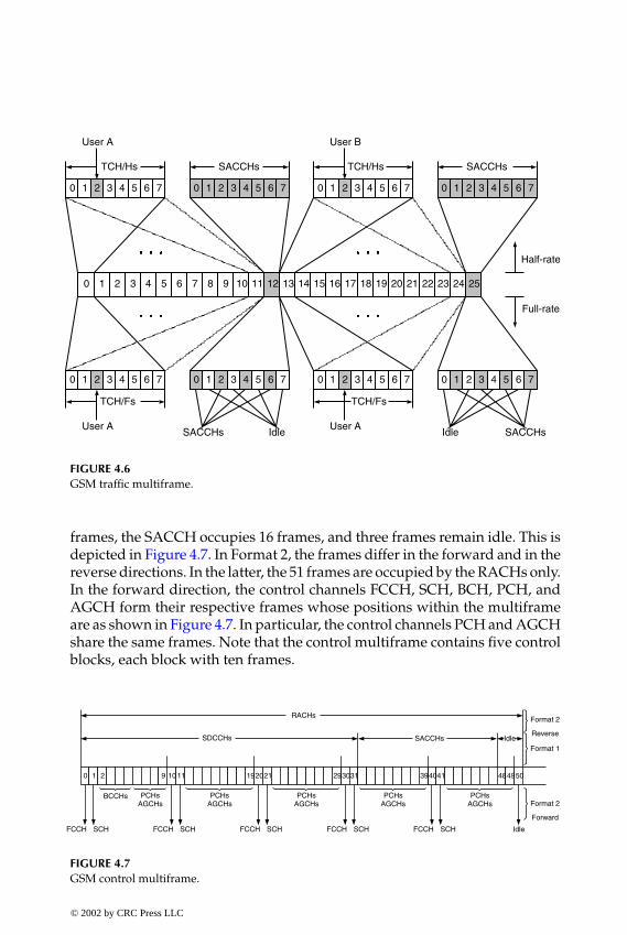
P1: FDJ
book CRC-Wireless November 8, 2001 14:38 Char Count= 397
0 1 2 3 4 5 6 7 8 9 10 11 12 13 14 15 16 17 18 19 20 21 22 23 24 25
0 1 2 3 4 5 6 7
TCH/Hs
0 1 2 3 4 5 6 7
SACCHs
0 1 2 3 4 5 6 7
TCH/Hs
0 1 2 3 4 5 6 7
SACCHs
0 1 2 3 4 5 6 7 0 1 2 3 4 5 6 7 0 1 2 3 4 5 6 7 0 1 2 3 4 5 6 7
User A User B
TCH/Fs
User A
TCH/Fs
User ASACCHs Idle SACCHsIdle
Half-rate
Full-rate
FIGURE 4.6GSM traffic multiframe.
frames, the SACCH occupies 16 frames, and three frames remain idle. This isdepicted in Figure 4.7. In Format 2, the frames differ in the forward and in thereverse directions. In the latter, the 51 frames are occupied by the RACHs only.In the forward direction, the control channels FCCH, SCH, BCH, PCH, andAGCH form their respective frames whose positions within the multiframeare as shown in Figure 4.7. In particular, the control channels PCH and AGCHshare the same frames. Note that the control multiframe contains five controlblocks, each block with ten frames.
0 1 2 9
FCCH SCH
BCCHs PCHsAGCHs
FCCH SCH
PCHsAGCHs
FCCH SCH
PCHsAGCHs
FCCH SCH
PCHsAGCHs
FCCH SCH
PCHsAGCHs
Idle
Format 2
Forward
SDCCHs SACCHs IdleFormat 1
RACHs Format 2
Reverse
5049484039302920191011 21 31 41
FIGURE 4.7GSM control multiframe.
© 2002 by CRC Press LLC
E:\Java for Engineers\VP Publication\Java for Engineers.vpThursday, April 25, 2002 9:27:36 AM
Color profile: DisabledComposite Default screen

P1: FDJ
book CRC-Wireless November 8, 2001 14:38 Char Count= 397
4.5 The Logical Channels
In this section, the GSM logical channels are described in more detail.
4.5.1 Traffic Channels
The traffic channels bear speech and data information. The traffic channelsare two-way channels using the normal burst format. They occupy time slots1 to 7 on each carrier and also time slot 0 on the carriers other than those spe-cially dedicated to signaling. A traffic channel is associated with a terminalwhen a call is established. GSM defines two types of traffic channels: full-rate and half-rate. As described before, a TCH/F occurs 24 times within thetraffic multiframe and has associated with it a SACCH to convey control in-formation. As stipulated in the normal burst format, 2 × 57 = 114 bits are usedfor data transmission purposes (data field in the normal burst). Therefore, theTCH/F rate is 24 ×114 ÷ 0.120 = 22.8 kbit/s. In the same way, a TCH/H occurs12 times within the traffic multiframe, which leads to a TCH/H bit rate of11 .4 kbit/s. A TCH/H also has a SACCH associated with it.
The traffic channel bit rate, as calculated before, is a consequence of the fol-lowing. The 13 kbit/s speech coder delivers blocks of 260 bits within a periodof 20 ms. The 50 Class 1a bits are CRC encoded and, as a consequence, threeparity bits are attached to this Class 1a block. The 53 bits together with the132 Class 1b bits and four all-zero tail bits (total of 189 bits) are half-rate con-volutionally encoded, the convolutional encoder yielding, therefore, 378 bits.These 378 bits are then multiplexed with 78 Class 2 bits, resulting in 456 bits perblock within the 20-ms speech block. These lead to a rate of 456 ÷ 0.02 = 22.8kbit/s, as calculated before. Two 456-bit blocks are interleaved (total of 912bits) and transmitted over 912 ÷ 114 = 8 frames. The interleaver is a 114 × 8memory into which data are written by rows and from which data are readby columns. The data from the eight columns of the interleaver, each of whichcontains 114 bits, are then transmitted, respectively, over eight frames. Fig-ure 4.8 shows the traffic channel structure.
4.5.2 Frequency Correction Channel
The FCCH bears information for frequency acquisition purposes. The FCCHis a one-way channel operating in the forward direction and using the fre-quency correction burst format. The 142 all-zero bits in this burst causes theGMSK modulator to deliver an unmodulated carrier for the entire durationof the time slot. The modulator produces a carrier with an offset of 1625 ÷ 24kHz above the nominal carrier frequency. Upon detecting this sine wave, the
© 2002 by CRC Press LLC
E:\Java for Engineers\VP Publication\Java for Engineers.vpThursday, April 25, 2002 9:27:36 AM
Color profile: DisabledComposite Default screen
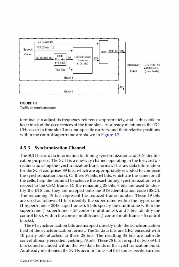
P1: FDJ
book CRC-Wireless November 8, 2001 14:38 Char Count= 397
Speech
CoderCRC
Encoder(+3 bits)
ConvolutionalEncoder(1/2 rate)
MUX
Interleaver
114x8
50 (Class 1a) 53 378
4x114= 456132 (Class 1b)
78 (Class 2)
4Tail Bits
Block 1
Block 2
456
912 = 8x114(8 frames)
(data fields)
FIGURE 4.8Traffic channel structure.
terminal can adjust its frequency reference appropriately, and is thus able tokeep track of the occurrences of the time slots. As already mentioned, the FC-CHs occur in time slot 0 of some specific carriers, and their relative positionswithin the control superframe are shown in Figure 4.7.
4.5.3 Synchronization Channel
The SCH bears data information for timing synchronization and BTS identifi-cation purposes. The SCH is a one-way channel operating in the forward di-rection and using the synchronization burst format. The raw data informationfor the SCH comprises 89 bits, which are appropriately encoded to composethe synchronization burst. Of these 89 bits, 64 bits, which are the same for allthe cells, help the terminal to achieve the exact timing synchronization withrespect to the GSM frame. Of the remaining 25 bits, 6 bits are used to iden-tify the BTS and they are mapped onto the BTS identification code (BSIC).The remaining 19 bits represent the reduced frame number. These 19 bitsare used as follows: 11 bits identify the superframe within the hyperframe(1 hyperframe = 2048 superframes); 5 bits specify the multiframe within thesuperframe (1 superframe = 26 control multiframes); and 3 bits identify thecontrol block within the control multiframe (1 control multiframe = 5 controlblocks).
The 64 synchronization bits are mapped directly onto the synchronizationfield of the synchronization format. The 25 data bits are CRC encoded with10 parity bits attached to these 25 bits. The resulting 35 bits are half-rateconvolutionally encoded, yielding 78 bits. These 78 bits are split in two 39-bitblocks and included within the two data fields of the synchronization burst.As already mentioned, the SCHs occur in time slot 0 of some specific carriers
© 2002 by CRC Press LLC
E:\Java for Engineers\VP Publication\Java for Engineers.vpThursday, April 25, 2002 9:27:36 AM
Color profile: DisabledComposite Default screen

P1: FDJ
book CRC-Wireless November 8, 2001 14:38 Char Count= 397
89-bitRaw
Message
CRCEncoder(+10 bits)
ConvolutionalEncoder(1/2 rate)
25 35
78
4Tail Bits
64
Data Fields
SynchronizationField
FIGURE 4.9Synchronization channel structure.
and their relative position within the control superframe are shown in Figure4.7. Figure 4.9 shows the synchronization channel structure.
4.5.4 Broadcast Control Channel
The BCCH bears data information for call setup purposes. The BCCH is aone-way channel operating in the forward direction and using the normalburst format. More specifically, it conveys the following information:
� Cell identity� Network identity� Control channel structure� List of channels in use� Congestion status� Details of the access protocol
The raw message containing this information uses 184 bits. These 184 bitsare protected by an error-correcting block code—a fire code—adding 40 bitsto the message. A fire code is specially used to detect and correct burstyerrors. The resulting 224 bits together with 4 tail bits are half-rate convolu-tionally encoded, yielding 456 bits. Finally, these 456 bits are split into 4 ×114 bits and sent in four time slots. As already mentioned, the BCCHs occurin time slot 0 of some specific carriers and their relative positions with thecontrol superframe are shown in Figure 4.7. Figure 4.10 shows the BCCHstructure.
4.5.5 Paging Channel
The PCH bears data information for paging purposes. The PCH is a one-waychannel operating in the forward direction and using the normal burst for-mat. The same coding scheme used for the BCCH is also used for the PCH,
© 2002 by CRC Press LLC
E:\Java for Engineers\VP Publication\Java for Engineers.vpThursday, April 25, 2002 9:27:36 AM
Color profile: DisabledComposite Default screen

P1: FDJ
book CRC-Wireless November 8, 2001 14:38 Char Count= 397
184-bitRaw
Message
FireEncoder(+40 bits)
ConvolutionalEncoder(1/2 rate)
184 224456
4Tail Bits
Data Fields
4 x 114(4 time slots)
FIGURE 4.10Broadcast control channel, paging channel, access grant channel, stand-alone dedicated controlchannel, slow associated control channel, and fast associated control channel structure.
as shown in Figure 4.10. Therefore, each paging message contains 4 ×114 bitsand occupies four time slots. Note, from Figure 4.7, that there are 36 pagingframes per control multiframe and, therefore, 36 ÷4 = 9 paging messages percontrol multiframe (235.4 ms). Both paging channel and access grant chan-nel share the same resources within the control multiframe. This is done byassigning blocks of four frames to either paging or access grant tasks, suchan assignment being informed through the BCCH. The PCH blocks are thendivided into groups. The terminal can therefore choose to monitor only therespective PCH groups to which it belongs, and this is a way of saving battery.This is the principle of the sleep-mode operation, in which the terminal is ononly for a fraction of the time.
4.5.6 Access Grant Channel
The AGCH bears data information for access acknowledgment purposes. TheAGCH is a one-way channel operating in the forward direction and using thenormal burst format. More specifically, it carries information on confirmationof a successful access and on the particular SDCCH assigned to a terminal.As mentioned before, the AGCH shares the physical resources with the PCH.The same coding scheme used for the BCCH is also used for the AGCH, asshown in Figure 4.10.
4.5.7 Random Access Channel
The RACH bears data information for access purposes. The RACH is a one-way channel operating in the reverse direction and using the access burstformat. More specifically, the terminal may use the RACH to perform thefollowing tasks:
� Call origination� Short message transmission� Acknowledgment to paging messages
© 2002 by CRC Press LLC
E:\Java for Engineers\VP Publication\Java for Engineers.vpThursday, April 25, 2002 9:27:36 AM
Color profile: DisabledComposite Default screen
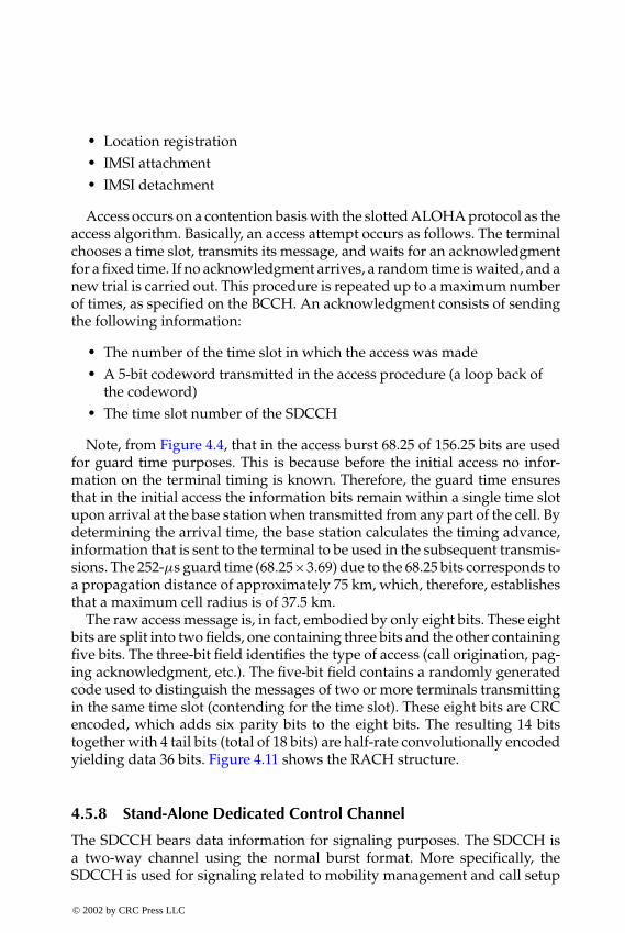
P1: FDJ
book CRC-Wireless November 8, 2001 14:38 Char Count= 397
� Location registration� IMSI attachment� IMSI detachment
Access occurs on a contention basis with the slotted ALOHA protocol as theaccess algorithm. Basically, an access attempt occurs as follows. The terminalchooses a time slot, transmits its message, and waits for an acknowledgmentfor a fixed time. If no acknowledgment arrives, a random time is waited, and anew trial is carried out. This procedure is repeated up to a maximum numberof times, as specified on the BCCH. An acknowledgment consists of sendingthe following information:
� The number of the time slot in which the access was made� A 5-bit codeword transmitted in the access procedure (a loop back of
the codeword)� The time slot number of the SDCCH
Note, from Figure 4.4, that in the access burst 68.25 of 156.25 bits are usedfor guard time purposes. This is because before the initial access no infor-mation on the terminal timing is known. Therefore, the guard time ensuresthat in the initial access the information bits remain within a single time slotupon arrival at the base station when transmitted from any part of the cell. Bydetermining the arrival time, the base station calculates the timing advance,information that is sent to the terminal to be used in the subsequent transmis-sions. The 252-µs guard time (68.25 ×3.69) due to the 68.25 bits corresponds toa propagation distance of approximately 75 km, which, therefore, establishesthat a maximum cell radius is of 37.5 km.
The raw access message is, in fact, embodied by only eight bits. These eightbits are split into two fields, one containing three bits and the other containingfive bits. The three-bit field identifies the type of access (call origination, pag-ing acknowledgment, etc.). The five-bit field contains a randomly generatedcode used to distinguish the messages of two or more terminals transmittingin the same time slot (contending for the time slot). These eight bits are CRCencoded, which adds six parity bits to the eight bits. The resulting 14 bitstogether with 4 tail bits (total of 18 bits) are half-rate convolutionally encodedyielding data 36 bits. Figure 4.11 shows the RACH structure.
4.5.8 Stand-Alone Dedicated Control Channel
The SDCCH bears data information for signaling purposes. The SDCCH isa two-way channel using the normal burst format. More specifically, theSDCCH is used for signaling related to mobility management and call setup
© 2002 by CRC Press LLC
E:\Java for Engineers\VP Publication\Java for Engineers.vpThursday, April 25, 2002 9:27:36 AM
Color profile: DisabledComposite Default screen

P1: FDJ
book CRC-Wireless November 8, 2001 14:38 Char Count= 397
8-bitRaw
Message
CRCEncoder(+6 bits)
ConvolutionalEncoder(1/2 rate)
8 1436
4Tail Bits
Data Fields
FIGURE 4.11Random-access channel structure.
management. The following tasks require the use of the SDCCH:
� Registration� Authentication� Location updates
The use of an SDCCH usually follows that of the RACH for access purposesand precedes the allocation of a TCH after the call setup signaling has beencompleted. The SDCCH employs a set of four time slots within the 51-framecontrol multiframe. Knowing that each time slot within a normal burst uses114 bits and that the duration of a superframe is 6.12 s, the SDCCH rate is4 × 114 × 26 ÷ 6.12 = 1937.25 bit/s. Like the TCH, the SDCCH also has associ-ated with it an SACCH for control purposes. The same coding scheme usedfor the BCCH is also used for the SDCCH, as shown in Figure 4.10.
4.5.9 Slow Associated Control Channel
The SACCH bears data information for control purposes. The SACCH is atwo-way channel using the normal burst format. A SACCH is always associ-ated with a TCH or with an SDCCH. It uses the same carrier frequency of thelogical channel with which it is associated. The SACCH is a continuous datachannel carrying control information from the terminal to the base station,and vice versa. In the forward link, it supports power level commands andtiming adjustments directives. In the reverse link, it conveys measurementsreports related to the signal quality of the serving base station and of theneighboring cells.
When associated with a TCH the SACCH occurs in frames 12 or 25 ofeach 26-frame traffic multiframe. It then occupies one time slot (114 bits) permultiframe (0.120 s). Therefore, the SACCH rate is 114 ÷ 0.120 = 950 bit/s.Each message comprises 456 bits, meaning that four traffic multiframes (480ms) are used to transmit a message. When associated with an SDCCH theSACCH occupies two time slots per control multiframe. It follows that in thiscase the SACCH rate is 2 × 114 × 26 ÷ 6.12 = 969 bit/s.
© 2002 by CRC Press LLC
E:\Java for Engineers\VP Publication\Java for Engineers.vpThursday, April 25, 2002 9:27:36 AM
Color profile: DisabledComposite Default screen
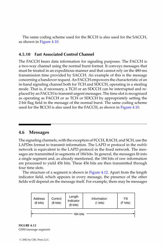
P1: FDJ
book CRC-Wireless November 8, 2001 14:38 Char Count= 397
The same coding scheme used for the BCCH is also used for the SACCH,as shown in Figure 4.10.
4.5.10 Fast Associated Control Channel
The FACCH bears data information for signaling purposes. The FACCH isa two-way channel using the normal burst format. It conveys messages thatmust be treated in an expeditious manner and that cannot rely on the 480-mstransmission time provided by SACCH. An example of this is the messageconcerning a handover request. An FACCH empowers the characteristic of anin-band signaling channel both for TCH and SDCCH, operating in a stealingmode. That is, if necessary, a TCH or an SDCCH can be interrupted and re-placed by an FACCH to transmit urgent messages. The time slot is recognizedas operating as FACCH or as TCH or SDCCH by appropriately setting the2-bit flag field in the message of the normal burst. The same coding schemeused for the BCCH is also used for the FACCH, as shown in Figure 4.10.
4.6 Messages
The signaling channels, with the exception of FCCH, RACH, and SCH, use theLAPDm format to transmit information. The LAPD m protocol in the mobilenetwork is equivalent to the LAPD protocol in the fixed network. The mes-sages are transmitted in segments of 184 bits. In general, the messages fit intoa single segment and, as already mentioned, the 184 bits of raw informationare processed to yield 456 bits. These 456 bits are then transmitted throughfour time slots.
The structure of a segment is shown in Figure 4.12. Apart from the lengthindicator field, which appears in every message, the presence of the otherfields will depend on the message itself. For example, there may be messages
Address(8 bits)
Control(8 bits)
LengthIndicator(8 bits)
Information(I bits)
Fill(F bits)
184 bits
FIGURE 4.12GSM message segment.
© 2002 by CRC Press LLC
E:\Java for Engineers\VP Publication\Java for Engineers.vpThursday, April 25, 2002 9:27:36 AM
Color profile: DisabledComposite Default screen
P1: FDJ
book CRC-Wireless November 8, 2001 14:38 Char Count= 397
with zero length, in which case, with the exception of the 8-bit length indicatorfield, all the other fields (176 bits) are filled with 1s.
Six of the bits in the length indicator field denote the number of octets inthe variable-length information field. Another bit in the length indicator fielddetermines whether or not the current message segment is the final segment inthe corresponding message. The address field contains the following fields:1 bit indicating whether the message is a command or a response; 3 bitsindicating the current version of the GSM protocol; 1 bit as an extension of theaddress (set to 0 in the initial version of GSM); and 3 bits indicating networkmanagement messages or short message service messages. The control fieldcontains 3 bits to indicate the sequence number of the current message andanother 3 bits to indicate the sequence number of the last message received bythe entity that is sending the present message. In case the complete messageencompasses fewer than 184 bits, the fill field is stuffed with 1s.
A number of network management messages are specified in GSM. Accord-ing to their specific functions the messages can be of three types: supervisory(S), unnumbered (U), and information (I). The S and U messages precede orfollow the I messages to control the flow of messages between terminals andbase stations. The I messages perform the main tasks concerning networkmanagement. An S message may request (re)transmission or may suspendtransmission of I messages. An U message may initiate or may terminate atransfer of I messages or may confirm a command. The S and U messagesare Layer 2 messages and, more specifically, data link control (DLC) mes-sages. The I messages are Layer 3 messages. More specifically, they carryout the network management operations such as radio resources manage-ment (RRM), mobility management (MM), and call management (CM). TheRRM messages involve interactions between mobile station, base station, andmobile switching center. The MM and CM messages use the base station asa relay node between mobile stations and MSC where they are effectivelytreated.
The next subsections summarize the main GSM messages.
4.6.1 DLC Messages
The main DLC messages and their respective purposes are listed below:� Set Asynchronous Balanced Mode. This is a U command message. It
initiates a transfer of I messages.� Disconnect. This is a U command message. It terminates a transfer of
I messages.� Unnumbered Acknowledgment. This is a U response message. It con-
firms a command.
© 2002 by CRC Press LLC
E:\Java for Engineers\VP Publication\Java for Engineers.vpThursday, April 25, 2002 9:27:36 AM
Color profile: DisabledComposite Default screen

P1: FDJ
book CRC-Wireless November 8, 2001 14:38 Char Count= 397
� Receive Ready. This is an S command or an S response message. Itrequests transmission of an I message.
� Receive Not Ready. This is an S command or an S response message. Itrequests retransmission of an I message.
� Reject. This is an S command or an S response message. It suspendstransmission of I messages.
4.6.2 RRM Messages
The main RRM messages and their respective purposes are listed below:� Sync Channel Information. This is a downlink message running on the
SCH. It conveys the base station identifier and the frame number, thelatter allowing the terminal to achieve time synchronization.
� System Information. This is a downlink message running on the BCCH.It contains the location area identifier, the number of the physical chan-nel carrying signaling information, the parameters of the random-access protocols, and the radio frequency carriers active in the neigh-boring cells.
� System Information. This is a downlink message running on the SACCH.It provides local system information to those active terminals that aremoving away from the cell where the call was originated.
� Channel Request. This is an uplink message running on the RACH. Itis used to respond to a page, to set up a call, to update the location,to attach the IMSI, to detach the IMSI.
� Paging Request. This is a downlink message running on the PCH. It isemployed to set up a call to a terminal.
� Immediate Assignment. This is a downlink message running on theAGCH. It is utilized to assign an SDCCH to a terminal at the setupprocedure as a result of a channel request message.
� Immediate Assignment Extended. This is a downlink message runningon the AGCH. It is utilized to assign two terminals to two differentphysical channels.
� Immediate Assignment Reject. This is a downlink message running onthe AFCH. It is utilized as a response to channel request messagesfrom as many as five terminals when the system is not able to providethese terminals with dedicated channels.
� Assignment Command. This is a downlink message running on theSDCCH. It is used at the end of the setup call process to move theterminal to a TCH.
© 2002 by CRC Press LLC
E:\Java for Engineers\VP Publication\Java for Engineers.vpThursday, April 25, 2002 9:27:36 AM
Color profile: DisabledComposite Default screen

P1: FDJ
book CRC-Wireless November 8, 2001 14:38 Char Count= 397
� Additional Assignment. This is downlink message running on theFACCH. It is used to assign another TCH to a terminal alreadyoperating on a TCH.
� Paging Response. This is an uplink message running on the SDCCH. Itis used to respond to a page with the aim of identifying the terminaland causing the initiation of the authentication procedure.
� Measurement Report. This is an uplink message running on the SACCH.It is used to indicate the signal level of the terminal and the signalquality of the active physical channel and of the channels of the sur-rounding cells, for intracell or intercell handover purposes.
� Handover Command. This is a downlink message running on theFACCH. It is used to move a call from one physical channel toanother physical channel. It is also used for the terminal to adjustits timing advance.
� Handover Access. This is an uplink message running on the TCH. Itis used to provide the base station with the necessary informationso that the base can instruct the terminal on the timing adjustmentneeded in a handover process.
� Physical Information. This is a downlink message running on theFACCH. It is used to transmit the timing adjustment the terminalrequires in a handover process.
� Handover Complete. This is an uplink message running on the FACCH.It is utilized after the terminal has adjusted its transmission timewithin the newly assigned physical channel.
� Ciphering Mode. This is a downlink message running on the FACCH.It indicates whether or not user information is to be encrypted.
� Channel Release. This is a downlink message running on the FACCH.It informs the terminal that a given channel is to be released.
� Frequency Redefinition. This is a downlink message running on theSACCH as well on the FACCH. It informs the terminal about the newhopping pattern to be used.
� Classmark Change. This is an uplink message running on the SACCHas well as on the FACCH. It informs the network about the terminal’snew class of transmission power. This message occurs, for example,when a phone is plugged in or removed from an external apparatuswith high power.
� Channel Mode Modify. This is a downlink message running on theFACCH. It commands the terminal to change from one channel mode(speech or data) to another. The channel mode defines the specificsource coder (for speech) or the data speed (for data).
© 2002 by CRC Press LLC
E:\Java for Engineers\VP Publication\Java for Engineers.vpThursday, April 25, 2002 9:27:36 AM
Color profile: DisabledComposite Default screen

P1: FDJ
book CRC-Wireless November 8, 2001 14:38 Char Count= 397
� RR Status. This is a two-way message running on the FACCH as wellas on the SACCH. It reports the error conditions of the radio resource(RR).
4.6.3 CM Messages
The main CM messages and their respective purposes are listed below:� Setup. This is a two-way message running on the SDCCH. It is used
to initiate a call.� Emergency Setup. This is an uplink message running on the SDCCH.
It is used to initiate a call.� Call Proceeding. This is a downlink message running on the SDCCH.
It is used as a response to a setup message.� Progress. This is a downlink message running on the SDCCH. It is
used to inform the calling party, through an audible tone, that the callis being transferred to a different network (from a public to a privateone, for example).
� Call Confirmed. This is an uplink message running on the SDCCH. Itis used as a response to a setup message.
� Alerting. This is a two-way message running on the SDCCH. It is usedto indicate to the calling party that the called party is being alerted.
� Connect. This is a two-way message running on the SDCCH. It is usedto indicate that the call is being accepted.
� Start DTMF. This is an uplink message running on the FACCH. Itis used to indicate that a button of the phone keypad has been pressed.This causes the network to send to the terminal a dual-tone multiplefrequency.
� Stop DTMF. This is an uplink message running on the FACCH. It isused to indicate that a button of the phone keypad has been released.This causes the network to turn off a dual-tone multiple frequency.
� Modify. This is a two-way message running on the FACCH. It is usedto indicate that the nature of the transmission is being modified (e.g.,from speech to facsimile).
� User Information. This is a two-way message running on the FACCH.It is used, for example, to carry user-to-user information as part ofGSM supplementary services.
� Disconnect/Release/Release Complete. This is a two-way message run-ning on the FACCH. It is used to end a call. For example, if the termi-nal is concluding a call, it sends a disconnect message to the network,
© 2002 by CRC Press LLC
E:\Java for Engineers\VP Publication\Java for Engineers.vpThursday, April 25, 2002 9:27:36 AM
Color profile: DisabledComposite Default screen

P1: FDJ
book CRC-Wireless November 8, 2001 14:38 Char Count= 397
which responds with a release message, and this causes the termi-nal to send a release complete message to the network. The samesequence of messages flow in the opposite direction if the other partyterminates the call.
� Disconnect. This is a two-way message running on the FACCH. It isused to indicate that a call is terminating.
� Release. This is a two-way message running on the FACCH. It is usedas a response to a disconnect message.
� Release Complete. This is a two-way message running on the FACCH.It is used as a response to a release message.
� Status. This is a two-way message running on the FACCH. It is usedas a response to a status enquiry message to describe error conditions.
� Status Enquiry. This is a two-way message running on the FACCH.It causes the network element (either the terminal or the base) torespond with a status message.
� Congestion Control. This is a two-way message running on the FACCH.It is used to initiate a flow control procedure, in which case the flowof call management messages is retarded.
The CM messages occur at different stages of a call. At the beginning of acall, the following messages run on the SDCCH:
� Setup� Emergency setup� Call proceeding� Progress� Call confirm� Alerting� Connect
During a call, the following messages run on the FACCH of the assignedchannel:
� Start DTMF� Stop DTMF� Modify� User Information
At the end of a call, the following messages run on the FACCH of theassigned channel:
© 2002 by CRC Press LLC
E:\Java for Engineers\VP Publication\Java for Engineers.vpThursday, April 25, 2002 9:27:36 AM
Color profile: DisabledComposite Default screen

P1: FDJ
book CRC-Wireless November 8, 2001 14:38 Char Count= 397
� Disconnect� Release� Release complete
During abnormal conditions, the following messages run on the FACCHof the assigned channel:
� Status� Status enquiry� Congestion control
4.6.4 MM Messages
The MM messages travel on the SDCCH. The MM messages and their respec-tive purposes are listed below.
� Authentication Request. This is a downlink message. It is used to senda 128-bit random number (RAND) to the terminal, which, by meansof an encryption algorithm, computes a 32-bit number to be sent toand checked up at the base.
� Authentication Response. This is an uplink message. It is used as aresponse to an authentication request message, conveying the 32-bitnumber generated out from the encryption algorithm.
� Authentication Reject. This is a downlink message. It is used to abortthe communication between the terminal and the network as a resultof an unsuccessful authentication.
� Identity Request. This is a downlink message. It is used to request anyof the three identifiers: IMSI (stored on the SIM), IMEI (stored in theterminal), and TMSI (assigned by the network to a visiting terminal).
� Identity Response. This is an uplink message. It is used as a responseto the identity request message.
� TMSI Reallocation Command. This is a downlink message. It is used toassign a new TMSI to the terminal.
� Location Updating Request. This is an uplink message. It is used by theterminal to register its location.
� Location Updating Accept. This is a downlink message. It is used toaccept a location registration.
� Location Updating Reject. This is a downlink message. It is used to rejecta location registration. A location updating may be rejected in any ofthe following events: unknown subscriber, unknown location area,roaming not allowed, or system failure.
© 2002 by CRC Press LLC
E:\Java for Engineers\VP Publication\Java for Engineers.vpThursday, April 25, 2002 9:27:36 AM
Color profile: DisabledComposite Default screen

P1: FDJ
book CRC-Wireless November 8, 2001 14:38 Char Count= 397
� IMSI Detach Indication. This is an uplink message. It is used to cancelthe terminal registration when the terminal is switched off.
� CM Service Request. This is an uplink message. It is used to initiatean MM operation. As a consequence, one or more MM messages willfollow.
� CM Re-Establishment Request. This is an uplink message. It is used toreinitiate an MM operation that has been interrupted.
� MM Status. This is a two-way message. It is used to report error con-ditions.
4.7 Call Management
This section outlines some call management procedures, namely, mobile ini-tialization, location update, authentication, ciphering, mobile station termi-nation, mobile station origination, handover, and call clearing.
4.7.1 Mobile Initialization
There are three main goals of the mobile initialization procedure:
1. Frequency synchronization2. Timing synchronization3. Overhead information acquisition
Frequency Synchronization. As the terminal is switched on, it scans over theavailable GSM RF channels and takes several readings of their RF levels toobtain an accurate estimate of the signal strengths. Starting with the channelwith the highest level, the terminal searches for the frequency correction burston the BCCH. If no frequency correction burst is detected, it then moves tothe next highest level signal and repeats the process until it is successful.In this event, the terminal will then synchronize its local oscillator with thefrequency reference of the base station transceiver.
Timing Synchronization. After frequency synchronization has been achieved,the terminal will search for the synchronization burst for the timing informa-tion present on the SCH. If it is not successful, it then moves to the next highestlevel signal and repeats the process starting from the frequency synchroniza-tion procedure until it is successful. In this event, it moves to the BCCH toacquire overhead system information.
© 2002 by CRC Press LLC
E:\Java for Engineers\VP Publication\Java for Engineers.vpThursday, April 25, 2002 9:27:36 AM
Color profile: DisabledComposite Default screen

P1: FDJ
book CRC-Wireless November 8, 2001 14:38 Char Count= 397
Overhead Information Acquisition. After timing synchronization has beenachieved, the terminal will search for overhead information on the BCCH.If the BCCH information does not include the current BCCH number, it willrestart the mobile initialization procedure. In a successful event, the termi-nal will have acquired, from the BCCH and through the system informationmessage present on the BCCH, the following main information:
� Country code� Network code� Location area code� Cell identity� Adjacent cell list� BCCH location� Minimum received signal strength
The terminal checks if the acquired identification codes coincide with thosein the SIM card. In a successful event, it will maintain the link and monitorthe PCH. Otherwise, it will start a location update procedure.
4.7.2 Location Update
A location update procedure is carried out in one of the following events:
� The terminal is switched on and verifies that the identification codespresent on the current BCCH do not coincide with those in the SIMcard.
� The terminal moves into a location area different from that withinwhich it is currently registered.
� There has been no activity for a preestablished amount of time. As partof the process used to speed the paging procedure, location reportsare used. These location reports are periodic reports used to updatethe location of the terminal so that, in the event of a page, the latestreported location is used as an initial guess to locate the terminal. Thetime span between location reports constitutes a system parameterwhose value is indicated on the BCCH, varying in accordance withthe network loading.
The location update procedure starts with the uplink channel request mes-sage on the RACH. The network answers with an immediate assignmentmessage on the AGCH indicating the SDCCH number to be used through-out the location update procedure. The terminal moves to this SDCCH andsends a location updating request message with its identification (IMSI or,
© 2002 by CRC Press LLC
E:\Java for Engineers\VP Publication\Java for Engineers.vpThursday, April 25, 2002 9:27:36 AM
Color profile: DisabledComposite Default screen

P1: FDJ
book CRC-Wireless November 8, 2001 14:38 Char Count= 397
preferably, TMSI). An authentication procedure is then carried out. In casethe authentication is unsuccessful, the procedure is aborted. In a successfulevent, the ciphering procedure is performed. The network then uses the lo-cation updating accept message to assign a new TMSI to the terminal. Theterminal stores its TMSI and responds with a TMSI allocation complete mes-sage. The location update is concluded with a channel release message fromthe network to the terminal. The terminal then resumes its PCH monitoringprocedure.
4.7.3 Authentication
An authentication procedure may be required at the location update pro-cedure or at the request of a new service. The authentication procedurestarts with the network sending an authentication request message to theterminal; the message conveys a 128-bit random number (RAND). The ter-minal uses the RAND, the secret key, Ki, stored at SIM, and the encryp-tion algorithm, referred to as A3, to compute a 32-bit number, referred toas a signed response (SRES). Another 64-bit key, the ciphering key, Kc, iscomputed using another encryption algorithm, referred to as A8. The Kcparameter is later used in the ciphering procedure. After these computa-tions, the terminal responds with an authentication response message, whichcontains the SRES. The network uses the same parameters and the samealgorithm to compute another SRES. The terminal SRES and the networkSRES are then compared with each other. If a match occurs, the network ac-cepts the user as an authorized subscriber. Otherwise, the authentication isrejected.
4.7.4 Ciphering
Ciphering (or encryption) is usually required for user transactions over the RFlink after authentication has been successful. The network transmits a cipher-ing mode message to the terminal indicating whether or not encryption is tobe applied. In case ciphering is to be performed, the secret key Kc (64 bits),which was generated previously in the authentication procedure, the framenumber (22 bits), and an encryption algorithm, referred to as A5, are usedto compute a 114-bit encryption mask. This mask is modulo-2 added to the2 × 57 = 114 bits of the data fields, in the bursts. Deciphering is obtained atthe base station by performing the same procedure. The terminal answerswith a ciphering mode acknowledgment message. Note that the cipheringto be used is continuously changing (on a frame-by-frame basis), because itdepends on the current frame number.
© 2002 by CRC Press LLC
E:\Java for Engineers\VP Publication\Java for Engineers.vpThursday, April 25, 2002 9:27:36 AM
Color profile: DisabledComposite Default screen

P1: FDJ
book CRC-Wireless November 8, 2001 14:38 Char Count= 397
4.7.5 Mobile Station Termination
After the mobile initialization procedure, the terminal camps on the PCH. Iteventually detects a paging request message conveying its TMSI. This impelsthe terminal to access the RACH to transmit a channel request message. Animmediate assignment with the SDCCH number is sent by the network on theAGCH. The terminal moves to SDCCH and the following occurs. The terminaltransmits a paging response message indicating the reason for the specificmessage (response to a paging). An authentication procedure is carried out,as already described. In a successful event, a ciphering procedure is accom-plished, as already described. The base station then sends a setup message.The terminal responds with a call confirmed message followed by an alertingmessage to indicate that the subscriber is being alerted. At the subscriber’s callacceptance, the terminal sends a connect message and removes the alertingtone. The network responds with an assignment command message indicat-ing the traffic channel number to be used for the conversation. The subscriber,still on the SDCCH, responds with an assignment acknowledgment messageand moves to the traffic channel that has been assigned. The network confirmsthe acceptance of the call by the other party by means of a connect acknowl-edgment message on the FACCH of the assigned TCH. And the conversationproceeds on the TCH.
4.7.6 Mobile Station Origination
The terminal detects a user-originated call. It then accesses the RACH tosend a channel request message. An immediate assignment with the SDCCHnumber is sent by the network on the AGCH. The terminal moves to thischannel and the following occurs. The terminal transmits a paging responsemessage indicating the reason for the specific message (call setup). The basestation responds with an unnumbered acknowledgment message. An authen-tication procedure is carried out, as already described. In a successful event,a ciphering procedure is performed, as already described. The terminal thensends a setup message. The base station responds with a call confirmed mes-sage followed by an alerting message in which case the terminal applies thering-back tone. At the called party’s call acceptance, the network sends an as-signment command message informing the traffic channel number to be usedfor the conversation. The subscriber, still on the SDCCH, responds with anassignment acknowledgment message and moves to the traffic channel thathas been assigned. The network confirms the acceptance of the call by theother party by means of a connect acknowledgment message on the FACCHof the assigned TCH. And the conversation proceeds on the TCH.
© 2002 by CRC Press LLC
E:\Java for Engineers\VP Publication\Java for Engineers.vpThursday, April 25, 2002 9:27:36 AM
Color profile: DisabledComposite Default screen

P1: FDJ
book CRC-Wireless November 8, 2001 14:38 Char Count= 397
4.7.7 Handover
The handover process in a GSM network has the mobile terminal as an integralpart of the procedure. The whole process is named mobile-assisted handover(MAHO). While making use of the traffic channel, the mobile monitors thesignal levels of its own channel, of the other channels of the same cell, andof the channels of six surrounding cells. The measurements are then reportedto the base on an SACCH. Concerning the control of the process, handoversmay occur:
� Within the same BTS or between BTSs controlled by the same BSC� Between different BSCs controlled by the same MSC� Between different BSCs controlled by different MSCs� Between different BSCs controlled by different MSCs belonging to
different PLMNs
In addition, there are two modes of handovers: synchronous or asynchro-nous. In the synchronous mode, the origin cell and the destination cell aresynchronized. By measuring the time difference between their respective timeslots, the mobile itself may compute the timing advance. This is used to adjustits transmissions on the new channel, therefore, speeding up the handoverprocess. In the asynchronous mode, the origin cell and the destination cellare unsynchronized. The timing advance, in this case, must be acquired bymeans of a procedure involving the terminal and the new BTS, as follows. Themobile terminal sends a series of access bursts with a zero timing advancethrough several handover access messages. The BTS then computes the re-quired timing advance using a round-trip time delay of the messages. On theaverage, the handover processing time in the synchronous mode (200 ms) istwice as long as that of the synchronous mode (100 ms).
Next a simple asynchronous handover procedure occurring between BTSsof the same BSC is described. While in conversation on a TCH, the terminalmonitors the signal levels of several channels. These measurements are re-ported to the base station on a periodic basis by means of the measurementreport message running on the SACCH. Whenever suitable, the base sends ahandover command message on the FACCH, indicating that a handover is totake place. The number of the new TCH is included within the message. Theterminal then moves to this new channel and sends a series of handover accessmessages so that the base may compute the timing advance to be transmittedto the terminal. This is done in the physical information message transmittedto the terminal on the FACCH. The timing adjustment is carried out and theterminal responds with a handover complete message.
© 2002 by CRC Press LLC
E:\Java for Engineers\VP Publication\Java for Engineers.vpThursday, April 25, 2002 9:27:36 AM
Color profile: DisabledComposite Default screen

P1: FDJ
book CRC-Wireless November 8, 2001 14:38 Char Count= 397
4.7.8 Call Clearing
The call clearing process may be initiated either by the network or by themobile. In either case, the channel used for the exchange of information is theBCCH. Assuming the network initiates the clearing, the base sends a discon-nect message to the terminal. The terminal responds with a release message.The base replies with a release complete message. If the terminal initiates theclearing, then the same messages flow, but in the opposite direction.
4.8 Frequency Hopping
GSM cellular reuse planning is given an additional level of sophisticationby the introduction of frequency hopping (FH). In FH, the signal in a giventime slot moves from one frequency to another according to a preestablishedhopping pattern. By changing frequencies periodically, the transmission be-comes less vulnerable to fading, because the probability of encountering morethan one faded frequency at the same time diminishes with the increase ofthe number of frequencies utilized. Therefore, the signal is affected by fadingonly during part of its time. Besides, FH may reduce co-channel interferenceif co-cells are assigned different hopping patterns.
As opposed to fast FH, in which the change of frequency (or frequencies)occurs during the symbol time, GSM uses slow FH with the hopping tak-ing place at each TDMA frame (one hopping at each 4.615 ms). The FH faci-lity is implemented in all GSM terminals. The application of FH, however, isdecided by the network operator. The hopping algorithm is based on suchparameters as the set of hopping frequencies, the hopping pattern, framenumber, and others, which are transmitted over the SCH. There are two pos-sible FH operation modes: cyclic and random. In the cyclic mode, the hoppingoccurs sequentially over the set of frequencies. In the random mode, the hop-ping is performed in a pseudorandom fashion according to one out of 63allowable patterns. Furthermore, the FH facility may be implemented at thebaseband or at the RF levels. The baseband FH implementation makes useof a number of transceivers, each of which operates on a fixed frequency. Inthis case, the FH occurs as the baseband information moves from one input ofone transceiver to the input of another transceiver, according to the preestab-lished hopping sequence. The RF FH implementation provides the FH atthe frequency synthesizer level for a given transceiver. In this case, the FHoccurs as the synthesizer changes its frequency in accordance with the givenhopping pattern.
© 2002 by CRC Press LLC
E:\Java for Engineers\VP Publication\Java for Engineers.vpThursday, April 25, 2002 9:27:36 AM
Color profile: DisabledComposite Default screen

P1: FDJ
book CRC-Wireless November 8, 2001 14:38 Char Count= 397
All carriers in the GSM band, with the exception of the standard broadcastcarriers, are entitled to hop. The standard broadcast carrier, also known asthe base channel, contains the FCCH, the SCH, and the BCCH, and is thebeacon upon which the terminals carry out their measurements and extractthe necessary information. All signals within a cell and also within a groupof cells hop in a coordinated manner. In other words, the hopping sequencesare chosen so that frequency overlapping is avoided (the hopping sequencesare orthogonal to each other). Both the uplink and the downlink operate withthe same FH sequence.
When a terminal is to use FH, it is informed about the available set ofhopping channels and the hopping sequence number.
4.9 Discontinuous Transmission
GSM equipment is designed for discontinuous transmission (DTx), a featureutilized to conserve battery power and to reduce interference. DTx takes ad-vantage of the fact that in a normal conversation, on average, the voice activityfactor is far less than 100% (typically less than 60%). Therefore, in theory, thetransmitter must be on only during the time the voice is effectively active,and off otherwise.
To implement this feature, the terminal is equipped with a voice activity de-tector (VAD). Upon detecting voice (in the presence of noise) or noise, the VADoutputs a corresponding signal that controls a transmitter switch. Therefore,the design of such a VAD plays a decisive role in transmission performance. Adecision in favor of a wrong detection will certainly produce annoying effectsin the transmission. In such a case, a clipping effect in speech may be noticed.Note that, as the transmitter is switched off between talkspurts, at the receiv-ing end the background acoustic noise present in the conversation abruptlydisappears. It has been observed that this can be annoying to the listener. Tominimize the effect of such a noise “modulation,” a synthetic signal, knownas comfort noise signal (CNS), with characteristics matching those of the back-ground noise, is introduced at the receiver. Note that the background noisethus generated is not standard noise. It tries to conform with the characteristicsof the background noise of the current transmission. To accomplish this, thenoise parameters are computed at the transmit end during a time span of fourframes after the VAD detects the end of a talkspurt. It is very unlikely that thespeech restarts during this time, so that the noise is present for the parameterevaluation. These parameters are sent to recompose the noise at the receiver.
Besides VAD and CNS functions, another function of the DTx feature isspeech frame extrapolation (SFE). The SFE aims to replace a speech frame
© 2002 by CRC Press LLC
E:\Java for Engineers\VP Publication\Java for Engineers.vpThursday, April 25, 2002 9:27:36 AM
Color profile: DisabledComposite Default screen
P1: FDJ
book CRC-Wireless November 8, 2001 14:38 Char Count= 397
badly corrupted by error with a preceding uncorrupted speech frame. Thisreplacement is based on the fact that consecutive speech frames are highly cor-related. Therefore, the use of SFE improves the signal quality or, equivalently,allows for a reduced carrier-to-interference ratio.
4.10 Power Control
GSM employs power control techniques to adjust the power of both mo-bile stations and base stations for better performance. Power control reducesco-channel interference and increases battery life. Mobile stations can havetheir power adjusted in steps of 2 dB with the power levels ranging over 30 dB,i.e., 16 power levels are permitted. The time span between power adjustmentsis 60 ms, corresponding to 13 frames. Base stations can also control their ownpower, this process involving the mobile station: the mobile station monitorsthe signal received from the base station and the base station transmittingpower can be changed to improve the signal reception at the mobile station.
4.11 Spectral Efficiency
GSM uses powerful interference counteraction techniques such as adaptiveequalization, powerful error-correcting codes, efficient modulation, speechframe extrapolation, and others. These render GSM system robust and ca-pable of operating at a low carrier-to-interference ratio, in which case, reusefactors of three or four cells per cluster, depending on the environment, areadmissible.
A number of spectral efficiency definitions are available. In accord withReference 12, the spectral efficiency parameter η is defined as
η = conversations/cell/spectrum
The number of physical channels in the 50-MHz GSM spectrum is 124 carriers× 8 channels/carrier = 992 (GSM-900). It can also be assumed that all these992 channels can be used for conversation. Therefore, for a reuse factor of 4:
η =992
4 × 50= 4.96
© 2002 by CRC Press LLC
E:\Java for Engineers\VP Publication\Java for Engineers.vpThursday, April 25, 2002 9:27:36 AM
Color profile: DisabledComposite Default screen

P1: FDJ
book CRC-Wireless November 8, 2001 14:38 Char Count= 397
And for a reuse factor of 3:
η =992
3 × 50= 6.61
The same calculations can be performed for the other GSM systems. Theresults will be very close to these.
4.12 Summary
GSM has emerged as a digital solution to the incompatible analog air inter-faces of the differing cellular networks operating in Europe. Among the set ofambitious targets to be pursued, full roaming was indeed a very important one.In addition, a large number of open interfaces have been specified within theGSM architecture. Open interfaces favor market competition with operatorsable to choose equipment from different vendors. GSM was the first system tostimulate the incorporation of the personal communication services philosophyinto a cellular network. These and other innovative features rendered GSMnetworks, either in the original GSM conception or as an evolution of it, a verysuccessful project with worldwide acceptance. GSM systems are found oper-ating in frequency bands around 900 MHz (GSM-900), 1.8 GHz (GSM-1800),or 1.9 GHz (GSM-1900). A new revision of the GSM specifications define an E-GSM that extends the original GSM-900 operation band and stipulates lowerpower terminals and smaller serving areas.
References
1. Eberspaecher, J., Bettstetter, C., and Vhogel, H.-J., GSM: Switching, Services andProtocols, John Wiley & Sons, New York, 2001.
2. Tisal, J., The GSM Network: The GPRS Evolution: One Step Towards UMTS, JohnWiley & Sons, New York, 2001.
3. Steele, R., Gould, P., and Chun, L. C., GSM, cdmaOne and 3G Systems, John Wiley& Sons, New York, 2000.
4. Nielsen, T. and Wigard, J., Performance Enhancements in a Frequency Hopping GSMNetwork, Kluwer Academic Publishers, Dordrecht, the Netherlands, 2000.
5. Heine, G. and Horrer, M., GSM Networks: Protocols, Terminology, and Implementation,Artech House, Norwood, MA, 1999.
© 2002 by CRC Press LLC
E:\Java for Engineers\VP Publication\Java for Engineers.vpThursday, April 25, 2002 9:27:36 AM
Color profile: DisabledComposite Default screen

P1: FDJ
book CRC-Wireless November 8, 2001 14:38 Char Count= 397
6. Zvonar, Z., Jung, P., and Kammerlander, K., GSM: Evolution towards 3rd GenerationSystems, Kluwer Academic Publishers, Dordrecht, the Netherlands, 1999.
7. Garg, V. K. and Wilkes, J. E., Principles and Applications of GSM, Prentice-Hall,Englewood Cliffs, NJ, 1998.
8. Redl, S., Weber, M., and Oliphant, M., GSM and Personal Communications Handbook,Artech House, Atlanta, 1998.
9. Levine, R. and Harte, L., GSM Superphones: Technologies and Services, McGraw-HillProfessional, New York, 1998.
10. Lamb, G., Lamb, B., and Batteau, Y., GSM Made Simple, Cordero Co., 1997.11. Mehrotra, A. K., GSM System Engineering, Artech House, Atlanta, 1997.12. Goodman, D. J., Wireless Personal Communications Systems, Addison-Wesley Long-
man, Reading, MA, 1997.13. Tisal, J., GSM Cellular Radio, John Wiley & Sons, New York, 1996.14. Redl, S., Weber, M., and Oliphant, M., An Introduction to GSM, Artech House,
Atlanta, 1998.15. Mouly, M. and Pautet, M.-B., The GSM System for Mobile Communications, Telecom
Publishing, Palaiseau, France, 1992.
© 2002 by CRC Press LLC
E:\Java for Engineers\VP Publication\Java for Engineers.vpThursday, April 25, 2002 9:27:36 AM
Color profile: DisabledComposite Default screen

P1: FDJ
book CRC-Wireless November 8, 2001 16:35 Char Count= 327
5cdmaOne
5.1 Introduction
The need for increased capacity was the great motivation for the advent ofAmerican digital cellular technology. As demand for wireless services in-creased, mainly in dense urban areas, the old analog standard, known asAMPS (Advance Mobile Phone Service), proved inadequate to satisfy the de-mand. Time Division Multiple Access technology, based on the EIA/TIA/IS-54 specifications (later on enhanced and renamed EIA/TIA/IS-136) was thefirst solution to the capacity problem of the old analog system. By offeringroughly a threefold increase in capacity by dividing each 30 kHz AMPS chan-nel into three time slots, this system was the first American response to theEuropean cellular second generation, the GSM.
This digital novelty, however, was not enough to soothe a number of ser-vice providers, who argued that such a technology would not be adequatefor future growth in service. Other alternatives were then considered, anda technical committee was formed to study and generate cellular standardsfor wideband services. In the late 1980s and early 1990s, QUALCOMM, Inc.of San Diego proposed a Code Division Multiple Access, CDMA, systemand together with Pacific Telesis demonstrated its operation. Extensive suc-cessful field trials and network refinement led the TelecommunicationIndustry Association (TIA) and the Electronic Industry Association (EIA) toadopt QUALCOMM system as their interim standard, the “TIA/EIA/IS-95—Mobile Station–Base Station Compatibility Standard for Dual-Mode Wide-band Spread Spectrum Cellular System.”[2, 3]
The TIA/EIA/IS-95 specifications establish that the system operate on adual-mode (analog and digital) basis, both modes within the same frequencyband. The dual-mode capability facilitates the transition from the analog en-vironment to a digital environment. Although compatible, analog and digital
© 2002 by CRC Press LLC
E:\Java for Engineers\VP Publication\Java for Engineers.vpThursday, April 25, 2002 9:27:36 AM
Color profile: DisabledComposite Default screen

P1: FDJ
book CRC-Wireless November 8, 2001 16:35 Char Count= 327
systems are rather different; details of the digital system are the subject of thischapter. TIA/EIA/IS-95 supports a direct sequence spread spectrum techno-logy with 1.25 MHz band duplex channels. Therefore, an operating companythat chooses this CDMA technology must deactivate about 42 contiguous30-kHz channels of its analog system. Coexistence of analog and digital sys-tems implies that dual-mode mobile stations are able to place and receivecalls in any system and, conversely, all systems are able to place and receivecalls from any mobile station. Handoff operations in such a scenario requiresome attention. A mobile station may initiate a call in the CDMA system and,while the call is still in progress, it may migrate to the analog system, if re-quired. The search for one or another system for the initial registration is notspecified by the standard and the exact action is dependent on the manufac-turer. In fact, the standard leaves a number of issues to be detailed by themanufacturer. Those recommendations in the standard appearing with theverbal forms “shall” and “shall not” identify the requirements from whichno deviation is permitted. Those with “should” and “should not” indicatethat several possibilities are permitted. There are still others with “may”and “need not” and “can” and “cannot,” which are certainly much less re-strictive. Therefore, solutions may be implemented differently by differentmanufacturers.
A number of innovations have been introduced in the CDMA system ascompared with earlier cellular systems. Soft handoff is certainly a great nov-elty. In soft handoff, handoff from one base station to another occurs in asmooth manner. In soft handoff, the mobile station keeps its radio link withthe original base station and establishes a connection with one or more basestations. The excess connections are given up only when and if the new linkhas sufficient quality. Another innovation introduced in the CDMA system isthe use of Global Positioning System (GPS) receivers at the base stations. GPSsare utilized so that base stations be synchronized, a feature vital to the softhandoff operation. Vocoders at variable rates are specified to accommodatedifferent voice activities aimed at controlling interference levels, thence in-creasing system capacity. Sophisticated power control mechanisms are usedso that the full benefit of spread spectrum technique is realized.
The first CDMA systems were employed under the TIA/EIA/IS-95A speci-fications. The A version of the specifications evolved to TIA/EIA/IS-95B, inwhich new features related to higher data rate transmission, soft handoffalgorithms, and power control techniques have been introduced. The namecdmaOne is then used to identify the CDMA technology operating with eitherspecification.
This chapter describes the cdmaOne specifications. Most of the descriptionsconcern TIA/EIA/IS-95A specifications. A final section describes the newfeatures included in TIA/EIA/IS-95B.
© 2002 by CRC Press LLC
E:\Java for Engineers\VP Publication\Java for Engineers.vpThursday, April 25, 2002 9:27:36 AM
Color profile: DisabledComposite Default screen
P1: FDJ
book CRC-Wireless November 8, 2001 16:35 Char Count= 327
5.2 Features and Services
TIA/EIA/IS-95 specifications establish two types of features: voice featuresand short message service features.
5.2.1 Voice Features
The following are the primary voice features.
� Call Delivery (CD). CD allows the reception of a call while in a roamingcondition.
� Call Forwarding Busy (CFB)/Call Forwarding Busy No Answer (CFNA)/Call Forwarding Busy Unconditional (CFU). CFB, CFNA, and CFUallow a called subscriber to have the system send incoming calls,addressed to the called subscriber’s directory number, to another di-rectory number (forward-to number), or to the called subscriber’sdesignated voice mailbox. This happens when the subscriber is en-gaged in a call or service (for CFB active), or when the subscriberdoes not respond to paging, does not answer the call within a spec-ified period after being alerted, or is otherwise inaccessible (CNFAactive). The inaccessibility may be characterized by the following: nopaging response, unknown subscriber’s location, inactive subscriber,CD not active for a roaming subscriber, Do Not Disturb active, etc. IfCFU is active, calls are forwarded regardless of the condition of thetermination.
� Call Transfer (CT). CT enables the subscriber to transfer an in-progressestablished call to a third party. The call to be transferred may be anincoming or outgoing call.
� Call Waiting (CW). CW provides notification to a controlling subscriberof an incoming call while the subscriber’s call is in the two-way state.Subsequently, the controlling subscriber can either answer or ignorethe incoming call. If the controlling subscriber answers the secondcall, it may alternate between the two calls.
� Calling Number Identification Presentation (CNIP)/Calling Number Iden-tification Presentation Restriction (CNIR). CNIP provides and CNIRrestricts the number identification of the calling party to the calledsubscriber. The termination network receives the calling number iden-tification (CNI) as part of the basic call setup. This CNI may in-clude one or two calling parties numbers (CPNs), a calling party
© 2002 by CRC Press LLC
E:\Java for Engineers\VP Publication\Java for Engineers.vpThursday, April 25, 2002 9:27:36 AM
Color profile: DisabledComposite Default screen
P1: FDJ
book CRC-Wireless November 8, 2001 16:35 Char Count= 327
subaddress (CPS), redirecting numbers (RNs), and a redirecting sub-address (RS).
� Conference Calling (CC). CC provides a subscriber with the ability toconduct a multiconnection call, i.e., a simultaneous communicationbetween three or more parties (conferees). If any of the conferees to aconference call disconnects, the remaining parties remain connecteduntil the controlling subscriber disconnects.
� Do Not Disturb (DND). DND prevents a called subscriber from re-ceiving calls. When this feature is active, no incoming calls shall beoffered to the subscriber. DND also blocks other types of alerting, suchas the CFU abbreviated (or reminder) alerting and message waitingnotification alerting. DND makes the subscriber inaccessible for calldelivery.
� Flexible Alerting (FA). FA causes a call to a pilot directory number tobranch the call into several legs to alert several termination addressessimultaneously. The first leg to be answered is connected to the callingparty and the other call legs are abandoned.
� Message Waiting Notification (MWN). MWN informs enrolled sub-scribers when a voice message is available for retrieval. MWN mayuse pip tone or alert pip tone to inform a subscriber of an unretrievedvoice message(s).
� Mobile Access Hunting (MAH). MAH causes a call to a pilot directorynumber to search a list of termination addresses for one that is idleand able to be alerted, in a way that only one termination address isalerted at a time.
� Password Call Acceptance (PCA). PCA is a call-screening feature thatallows a subscriber to limit incoming calls to only those calling partieswho are able to provide a valid PCA password (i.e., a series of digits).
� Preferred Language (PL). PL provides the subscriber with the ability tospecify the language for network services.
� Priority Access and Channel Assignment (PACA). PACA allows a sub-scriber to have priority access to voice or traffic channels on call origi-nation by queuing these subscribers’ originating calls when channelsare not available. The subscriber is assigned one of several prioritylevels and the invocation of PACA is determined to one of two options:permanent, in which the feature is always available, and demand, inwhich the feature is available only on request.
� Remote Feature Control (RFC). RFC allows a calling party to call aspecial RFC directory number to specify one or more featureoperations.
© 2002 by CRC Press LLC
E:\Java for Engineers\VP Publication\Java for Engineers.vpThursday, April 25, 2002 9:27:36 AM
Color profile: DisabledComposite Default screen

P1: FDJ
book CRC-Wireless November 8, 2001 16:35 Char Count= 327
� Selective Call Acceptance (SCA). SCA is a call-screening service that al-lows a subscriber to receive calls only from parties whose CNPs arein an SCA screening list of specified CNPs.
� Subscriber PIN Access (SPINA). SPINA allows subscribers to controlwhether their mobile station is allowed to access the network. Thisfeature may be used by subscribers to prevent unauthorized use oftheir own mobile station or fraudulent use by a clone.
� Subscriber PIN Intercept (SPINI). SPINI enables subscribers to restrictoutgoing calls originated from their mobile station. The subscriberrequires a SPINI PIN authorization code to originate calls meetingspecified criteria (e.g., international call type). SPINI PIN shall not berequired on unrestricted call types (e.g., emergency) and may not berequired for a list of frequently called numbers, regardless of their calltype.
� Three-Way Calling (3WC). 3WC provides the subscriber with the abil-ity to add a third party to an established two-party call, so that allthree parties may communicate in a three-way call.
� Voice Message Retrieval (VMR). VMR permits a subscriber to retrievemessages from a voice message system (VMS).
� Voice Privacy (VP). VP provides a degree of privacy for the subscriberover the base station to mobile station (BS–MS) radio link.
5.2.2 Short Message Service Features
The following are the primary short message service features:
� Short Message Delivery–Point-to-Point Bearer Service (SMD-PP). SMD-PP provides bearer service mechanisms for delivering a short messageas a packet of data between two service users, known as short mess-age entities (SMEs). The length of the bearer data may be up to 200octets. Implementations and service providers may further restrictthis length. The SMD-PP service attempts to deliver a message to anMS-based SME whenever the MS is registered even when the MS isengaged in a voice or data call.
� Cellular Paging Teleservice (CPT). CPT conveys short textual messages(up to 63 characters) to an SME for display or storage.
� Cellular Messaging Teleservice (CMT). CMT conveys and manages shortmessages to an SME for display or storage. This teleservice shouldcoordinate the use of the display and arbitrate between conflictingusers or services. Each message includes attributes for managementof the messages received by the SME.
© 2002 by CRC Press LLC
E:\Java for Engineers\VP Publication\Java for Engineers.vpThursday, April 25, 2002 9:27:36 AM
Color profile: DisabledComposite Default screen
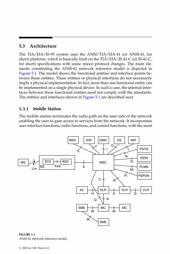
P1: FDJ
book CRC-Wireless November 8, 2001 16:35 Char Count= 327
5.3 Architecture
The TIA/EIA/IS-95 system uses the ANSI/TIA/EIA-41 (or ANSI-41, forshort) platform, which is basically built on the TIA/EIA/IS-41-C (or IS-41-C,for short) specifications with some minor protocol changes. The main ele-ments constituting the ANSI-41 network reference model is depicted inFigure 5.1. The model shows the functional entities and interface points be-tween these entities. These entities or physical interfaces do not necessarilyimply a physical implementation. In fact, more than one functional entity canbe implemented on a single physical device. In such a case, the internal inter-faces between these functional entities need not comply with the standards.The entities and interfaces shown in Figure 5.1 are described next.
5.3.1 Mobile Station
The mobile station terminates the radio path on the user side of the networkenabling the user to gain access to services from the network. It incorporatesuser interface functions, radio functions, and control functions, with the most
BSMS BTS BSC
MSC EIR
MSC
DMH
VLR
PSPDN
ISDN
PSTN
IWFOS
PLMN
VLRHLRAC
SME
MCMCSME
M
M M
H D G
N
C BPi
Mi
Di
Ai
A
LO
IF
E
AbisUm
Q
FIGURE 5.1ANSI-41 network reference model.
© 2002 by CRC Press LLC
E:\Java for Engineers\VP Publication\Java for Engineers.vpThursday, April 25, 2002 9:27:36 AM
Color profile: DisabledComposite Default screen

P1: FDJ
book CRC-Wireless November 8, 2001 16:35 Char Count= 327
common equipment implemented in the form of a mobile telephone. It canwork as a stand-alone device or it may accept other devices connected to it(e.g., fax machines, personal computers, etc.).
Mobile stations operating in the analog mode are identified by the mobileidentification number (MIN). The MIN is a 34-bit number composed of twofields, namely, MIN1 (24 bits) and MIN2 (10 bits). Mobile stations operatingin the CDMA mode use the international mobile station identity (IMSI). TheIMSI consists of up to 15 numerical characters (decimal numbers, 0 to 9),the first three digits comprising the mobile country code (MCC), and the re-maining digits corresponding to the national mobile station identity (NMSI).In particular, the NMSI contains the mobile network code (MNC) and themobile station identification number (MSIN). These identifications are pro-grammed into the mobile apparatus by the cellular service provider. Anotherkey identification is the electronic serial number (ESN). The ESN is a 32-bitbinary number that is factory-set and not readily alterable in the field. Itsalteration requires special facilities not normally available to subscribers.
Mobile stations also store the class-of-information, referred to as the stationclass mark. Among others, the station class mark specifies functions relatedto the mode of operation, such as dual mode (CDMA or CDMA and analog),slotted class (slotted or nonslotted), transmission (continuous or discontinu-ous), and power class (Class I, Class II, Class III). The power class is specifiedin terms of the effective radiated power at maximum output (ERPmax), whichmust be within the ranges as follows:
� 1.25 W ≤ ERPmax ≤ 6.3 W, for Class I� 0.5 W ≤ ERPmax ≤ 2.5 W, for Class II� 0.2 W ≤ ERPmax ≤ 1.0 W, for Class III
5.3.2 Base Station
The base station terminates the radio path on the network side and pro-vides connection to the network. It is composed of two elements: the basetransceiver system (BTS) and the base station controller (BSC). The BTS con-sists of radio equipment (transmitter and receiver = transceiver) and providesthe radio coverage for a given cell or sector. The BSC incorporates controlcapability to manage one or more BTSs, executing the interfacing functionsbetween BTSs and network. The BSC may be co-located with a BTS or elseindependently located.
All base stations transmissions are commonly referenced to the GPS time-scale. The GPS timescale is synchronous with and traceable to the universalcoordinated time (UTC), both differing from each other by an integer numberof seconds. In particular, this difference equals the number of leap second
© 2002 by CRC Press LLC
E:\Java for Engineers\VP Publication\Java for Engineers.vpThursday, April 25, 2002 9:27:36 AM
Color profile: DisabledComposite Default screen

P1: FDJ
book CRC-Wireless November 8, 2001 16:35 Char Count= 327
corrections added to UTC since January 6, 1980 00:00:00 UTC, which is thestart of both CDMA system time and of GPS time.
The base station transmit carrier frequency shall be maintained within ±5×10⁻⁸ of the CDMA frequency assignment. The maximum effective radiatedpower and antenna height above average terrain must be coordinated locallyon an ongoing basis.
5.3.3 Mobile Switching Center
The mobile switching center (MSC) provides automatic switching betweenusers within the same network or other public-switched networks, coordi-nating calls and routing procedures. In general, an MSC is found controllingseveral BSCs, but it may also serve in different capacities. Depending on thefunction performed, the MSC is identified by different names, as follows:
� Anchor MSC: The first MSC to serve a mobile station-originated or amobile station-terminated call.
� Border MSC or Neighbor MSC: The MSC controlling BSCs responsiblefor BTSs adjacent to the current serving system.
� Candidate MSC: The MSC considered for intersystem handoff pur-poses.
� Originating MSC: The MSC initiating the mobile station-terminatedcall delivery procedures.
� Receiving MSC: The MSC receiving the request for inter-MSC trunkrelease.
� Serving MSC or Visited MSC: The MSC currently serving the mobilestation.
� Tandem MSC: The MSC in the handoff chain providing only trunkconnections for the handoff process; it is neither the anchor MSC northe serving MSC.
� Target MSC: The MSC chosen by the serving MSC to carry out theserving MSC responsibilities in a handoff.
Each MSC within the network has an identification (MSC ID), which is aunique three-octet number, one octet to identify the switch number (SWNO)and two octets to identify the market (market ID). The SWNO identifies aspecific MSC within the market area and is allocated by the service provider.The market ID is split into system identification (SID) and billing identifica-tion (BID). The SID is a 15-bit value assigned by the Federal CommunicationsCommission (FCC) to each cellular geographic service area covered by a li-censed operator. The BID is a 15- or 16-bit value assigned by CIBERNET, a
© 2002 by CRC Press LLC
E:\Java for Engineers\VP Publication\Java for Engineers.vpThursday, April 25, 2002 9:27:36 AM
Color profile: DisabledComposite Default screen

P1: FDJ
book CRC-Wireless November 8, 2001 16:35 Char Count= 327
subsidiary of CTIA, to each cellular provider to identify the subset of theentire area represented by an SID for market purposes.
5.3.4 Home Location Register
The home location register (HLR) is the primary database for the homesubscriber. It maintains information records of subscriber current location,subscriber identifications (electronic serial number, IMSI, etc.), user profile(services and features), and others. An HLR may be co-located with an MSCor it may be located independently of the MSC. It may even be distributedover various locations and it may serve several MSCs.
5.3.5 Visitor Location Register
The visitor location register (VLR) is a database containing temporary recordsassociated with subscribers under the status of a visitor. A subscriber is con-sidered as a visitor if such a subscriber is being served by another systemwithin the same home service area, or by another system away from the re-spective home service area (in a roaming condition). The information withinthe VLR is retrievable by the HLR. A VLR may serve one or more MSCs.
5.3.6 Authentication Center
An authentication center (AC) is a functional unit performing authentica-tion tasks. It includes a database with encryption and authentication keysrelated to the mobile station. Encryption and authentication algorithms areperformed with the involvement of the AC.
5.3.7 Equipment Identity Register
The equipment identity register (EIR) is a database containing mobile stationequipment–related data (status of the equipment). These data are used toprevent fraudulent manipulation of the equipment (for example, stolen orcloned equipment may be denied access to the network).
5.3.8 Message Center
The message center (MC) is responsible for storing and forwarding shortmessages for SMS. As opposed to the voice services, which require real-timeoperation, the SMS is a store-and-forward service, and is, therefore, less re-strictive than voice calls. The MC operates with mobile station-originated orMS-terminated messages. SMS can be provided if an SME is implemented.
© 2002 by CRC Press LLC
E:\Java for Engineers\VP Publication\Java for Engineers.vpThursday, April 25, 2002 9:27:36 AM
Color profile: DisabledComposite Default screen
P1: FDJ
book CRC-Wireless November 8, 2001 16:35 Char Count= 327
5.3.9 Short Message Entity
The SME is a functional unit able to originate, terminate, or originate andterminate short messages. An SME may be associated with any one of theANSI-41 functional entities or with any of the external entities.
5.3.10 Data Message Handler
The data message handler (DMH) is responsible for collecting billing data.
5.3.11 Operations System
The operations system (OS), responsible for the operations, administration,maintenance, and provisioning of the system, is also referred to as an OAM&Psystem. The OAM&P systems are responsible for monitoring the system asa whole, carrying out addition and removal of equipment, hardware andsoftware tests, functional diagnosis, billing, and other tasks.
5.3.12 Interworking Function
The interworking function (IWF) provides means for the MSCs to interconnectwith other networks.
5.3.13 External Networks
The external networks with which interconnection is possible include thePublic Switched Telephone Network (PSTN), the Integrated Services DigitalNetwork (ISDN), the Public Land Mobile Network (PLMN), and the PublicSwitched Packet Data Network (PSPDN).
5.3.14 Interface Reference Points
The following are the interface reference points in ANSI. Some of these pointsare not completely defined.
� A-Interface: The interface between BS and MSC. It supports signalingand traffic (voice and data). Three protocols are standardized for use:SS7-based, frame relay-based, both defined in TIA/EIA/IS-634, andISDN-based, defined in TIA/EIA/IS-653.
� Abis-Interface: The interface between BTS and BSC.� Ai-Interface: The interface between MSC and PSTN. It is defined in
TIA/EIA/IS-93 as an analog interface that uses dual-tone multi-frequency (DTMF) signaling or multifrequency signaling (MF).
© 2002 by CRC Press LLC
E:\Java for Engineers\VP Publication\Java for Engineers.vpThursday, April 25, 2002 9:27:36 AM
Color profile: DisabledComposite Default screen

P1: FDJ
book CRC-Wireless November 8, 2001 16:35 Char Count= 327
� B-Interface: The interface between MSC and VLR, which is defined inTIA/EIA/IS-41-C.
� C-Interface: The interface between MSC and HLR, which is defined inTIA/EIA/IS-41-C.
� D-Interface: The interface between HLR and VLR. It is based on SS7and is defined in TIA/EIA/IS-41C.
� Di-Interface: A digital interface between MSC and ISDN. It uses Q-931signaling and is defined in TIA/EIA/IS-93.
� E-Interface: The interface between MSCs, i.e., between wireless net-works, which is defined in TIA/EIA/IS-93.
� F-Interface: The interface between MSC and EIR (not defined).� G-Interface: The interface between VLRs (not defined).� H-Interface: The interface between HLR and AC, which is defined in
TIA/EIA/IS-41C.� I-Interface: The interface between DMH and MSC.� L-Interface: The interface between MSC and IWF, which is defined by
the interworking function.� M-Interface: The interface between SME and SME, SME and MC, and
MC and MC, which is defined in TIA/EIA/IS-41C.� Mi-Interface: The interface between MSC and PLMN.� N-Interface: The interface between MC and HLR, which is defined in
TIA/EIA/IS-41C.� O-Interface: The interface between MSC and OS.� Pi-Interface: The interface between MSC and PSPDN.� Q-Interface: The interface between MC and MSC.� Um-Interface: The interface between MS and BS, which, specifically for
the CDMA system, is defined in TIA/EIA/IS-95. (Other standards areANSI/TIA/EIA-553-A, IS-91, and IS-136.)
5.4 Multiple-Access Structure
TIA/EIA/IS-95 is a dual-mode system with a multiple-access architecturebased on the narrowband FDMA/CDMA/FDD technology. A total 50-MHzband, divided into two 25-MHz bands, labeled A and B, constitutes the spec-trum available. For competition purposes each of these bands is allotted to adifferent operator. And for historical reasons these bands are not contiguous,with the A-band split into three segments named A, A′, and A′′, and the
© 2002 by CRC Press LLC
E:\Java for Engineers\VP Publication\Java for Engineers.vpThursday, April 25, 2002 9:27:36 AM
Color profile: DisabledComposite Default screen

P1: FDJ
book CRC-Wireless November 8, 2001 16:35 Char Count= 327
A''1 MHz
A10 MHz
B10 MHz
A'1.5 MHz
B'2.5 MHz
869 870 880 890 891.5 894
824 825 835 845 846.5 849
(MHz)
(MHz)
Forward Link
Reverse Link
FIGURE 5.2Frequency allocation for the AMPS and IS-95 systems.
B-band also split into three segments named B, B′, and B′′. Each band is fur-ther split into equal parts, one half band for the downlink or forward link (basestation to mobile station) and the other half band for the uplink or reverse link(mobile station to base station). Therefore, each link is allotted 12.5 MHz, withuplink and downlink separated by 45 MHz. The CDMA frequency spectrumis shown in Figure 5.2.
TIA/EIA/IS-95 specifies a CDMA carrier with a nominal bandwidth of1.25 MHz. The choice of such a bandwidth was partially influenced by thefact that a carrier should be chosen to fit within the A′ band (1.5 MHz), whichis the smallest contiguous segment of the allotted spectrum. Moreover, 1.25is a submultiple of 10. Thus, in theory, if no guard band is used, it is possibleto have up to ten carriers in each 12.5-MHz band, A, A′, A′′ or B, B′, B′′.
Forward and reverse links comprise different structures and features, de-tails of which are given later in this chapter. The main difference, however, liesin the fact that forward link operates synchronously and reverse link asyn-chronously. The point-to-multipoint characteristic of the downlink facilitatesthe synchronous approach, because one reference channel, broadcast by thebase station, can be used by all mobile stations within its service area for syn-chronization purposes. On the other hand, the implementation of a similarfeature on the reverse link is not as simple because of its multipoint-to-pointtransmission characteristic.
Multiple access is supported by functions providing for signal reference,synchronism information, paging, access, and traffic carrying. In TIA/EIA/IS-95, the following channels implement such functions: pilot channel, syncchannel, paging channel, access channel, and traffic channel.
5.4.1 Forward Link
The forward link is composed of the pilot channel, sync channel, paging chan-nel, and traffic channel. Figure 5.3 depicts the forward-link main blocks where
© 2002 by CRC Press LLC
E:\Java for Engineers\VP Publication\Java for Engineers.vpThursday, April 25, 2002 9:27:36 AM
Color profile: DisabledComposite Default screen
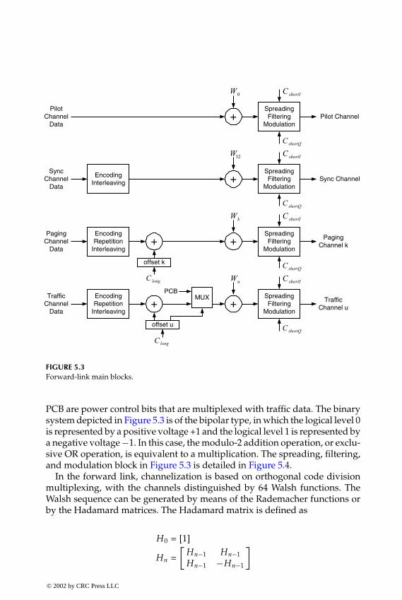
P1: FDJ
book CRC-Wireless November 8, 2001 16:35 Char Count= 327
SpreadingFiltering
ModulationPilot Channel+
SpreadingFiltering
ModulationSync Channel+Encoding
Interleaving
0W
32W
SpreadingFiltering
Modulation
PagingChannel k+
EncodingRepetition
Interleaving
kW
SpreadingFiltering
Modulation+
EncodingRepetition
Interleaving
uW
+
offset k
TrafficChannel u+
offset u
MUX
PilotChannel
Data
SyncChannel
Data
PagingChannel
Data
TrafficChannel
Data
PCB
longC
longCshortQC
shortQC
shortIC
shortIC
shortIC
shortQC
shortQC
shortIC
FIGURE 5.3Forward-link main blocks.
PCB are power control bits that are multiplexed with traffic data. The binarysystem depicted in Figure 5.3 is of the bipolar type, in which the logical level 0is represented by a positive voltage +1 and the logical level 1 is represented bya negative voltage −1. In this case, the modulo-2 addition operation, or exclu-sive OR operation, is equivalent to a multiplication. The spreading, filtering,and modulation block in Figure 5.3 is detailed in Figure 5.4.
In the forward link, channelization is based on orthogonal code divisionmultiplexing, with the channels distinguished by 64 Walsh functions. TheWalsh sequence can be generated by means of the Rademacher functions orby the Hadamard matrices. The Hadamard matrix is defined as
H0 = [1]
Hn =[
Hn−1 Hn−1Hn−1 −Hn−1
]
© 2002 by CRC Press LLC
E:\Java for Engineers\VP Publication\Java for Engineers.vpThursday, April 25, 2002 9:27:36 AM
Color profile: DisabledComposite Default screen

P1: FDJ
book CRC-Wireless November 8, 2001 16:35 Char Count= 327
+ BasebandFilter
X
+ BasebandFilter
X
∑ForwardChannel
t0cosω
t0ωshortQC
shortIC
sin
FIGURE 5.4Quadrature spreading modulation: spreading, filtering, and modulation for the forward-linkchannels.
The Walsh sequences are indexed by the row of the matrix. Hence, Wi
corresponds to the sequence in row i of the Hadamard matrix. Base sta-tions are identified by shifted versions of PN sequences, called short PNcodes, which modulate the forward-link waveforms to achieve the spreadspectrum characteristics. Two PN sequences, CshortI and CshortQ, at a chiprate of 1.2288 Mchip/s, are used, respectively, to modulate the in-phase(cosine) and quadrature (sine) RF carriers, leading to a form of quaternaryphase shift keying (QPSK) modulation. The same data stream is assignedto both in-phase and quadrature branches of the modulator, which corre-sponds to a form of diversity. Two pulse-shaping filters of the finite im-pulse response (FIR) type, one at the in-phase branch and the other at thequadrature branch, are used to confine the radiated spectrum within the 1.25bandwidth.
Except for the pilot channel, all forward channels use half-rate convolu-tional coding, symbol repetition, and 20-ms span interleaving. Coding andinterleaving combat burst error patterns. Symbol repetition adjusts the datarate to a maximum of 19.2 kbit/s. For traffic channels, vocoders at variabledata rates of 9.6, 4.8, 2.4, and 1.2 kbit/s for Rate Set 1, and 14.4, 7.2, 3.6, and1.8 kbit/s for Rate Set 2 are specified. The various transmission rates are usedto accommodate different voice activities. In addition to the specific Walshsequences, paging channels and traffic channels are further identified by longPN code sequences, specific for the respective channels.
The TIA/EIA/IS-95 system uses 64 Walsh sequences denoted Wi , i = 0,1, . . . , 63 and they are assigned to the respective channels as follows. W0 isassigned to the pilot channel; W1 to W7 are assigned to the paging chan-nels; W32 is assigned to the sync channel; and the remainder Wi code se-quences are assigned to traffic channels. The highest baseband data rate is
© 2002 by CRC Press LLC
E:\Java for Engineers\VP Publication\Java for Engineers.vpThursday, April 25, 2002 9:27:36 AM
Color profile: DisabledComposite Default screen

P1: FDJ
book CRC-Wireless November 8, 2001 16:35 Char Count= 327
19.2 ksymb/s which, combined with the assigned 64-chip Walsh sequence,yields a 64 × 19.2 ksymb/s = 1.2288 Mchip/s baseband data stream. Thein-phase PN code, CshortI , and quadrature PN code, CshortQ, are generatedby 15-stage linear feedback shift registers and have their offset phases chosenas a multiple of 64 chips. The codes are lengthened by the insertion of onechip per period, which implies that their period is 215 − 1 + 1 = 32, 768 chips.At a rate of 1.2288 Mchip/s these sequences repeat every 26.666. . . ms, or 75times per 2 s. Given that the offset phases are multiple of 64 chips, there are,therefore, 32, 768/64 = 512 possible code offsets that are used to identify thebase stations. The characteristic polynomials for the in-phase and quadraturebranches are given by
CshortI = 1 + x2 + x6 + x7 + x8 + x10 + x15 (5.1)
CshortQ = 1 + x3 + x4 + x5 + x9 + x10 + x11 + x12 + x15 (5.2)
The long PN code, Clong, is generated by 42-stage linear feedback shiftregisters and its offset phases are different for the paging channels and for thetraffic channels. For the paging channels the phase offset is chosen to identifythe base station and the particular paging channel. For the traffic channels thephase offset is chosen as a function of the electronic serial number (ESN) ofthe subscriber using that particular channel. The long PN codes run at 1.2288Mchip/s. They repeat after 242 − 1 chips. At a rate of 1.2288 Mchip/s thesesequences repeat every 41.4 days. The characteristic polynomial of the longcode is given by
Clong = 1 + x + x2 + x3 + x5 + x6 + x7 + x10 + x16 + x17 + x18
+ x19 + x21 + x22 + x25 + x26 + x27 + x31 + x33 + x35 + x42 (5.3)
5.4.2 Reverse Link
The reverse link is composed of the access channel and traffic channel. Inthe reverse link, channelization is based on a conventional spread spectrumCDMA, with the channels identified by distinct phases of a long PN codeClong, which is generated by the same characteristic polynomial used forthe forward link. Figure 5.5 depicts the reverse-link main blocks. The spread-ing, filtering, and modulation block shown in Figure 5.5 is detailed inFigure 5.6.
As in the forward-link case, the binary system depicted in Figure 5.5 is ofthe bipolar type, in which the logical 0 is represented by a positive voltage+1 and the logical 1 is represented by a negative voltage −1. In such casethe modulo-2 addition operation, or exclusive OR operation, is equivalent
© 2002 by CRC Press LLC
E:\Java for Engineers\VP Publication\Java for Engineers.vpThursday, April 25, 2002 9:27:36 AM
Color profile: DisabledComposite Default screen

P1: FDJ
book CRC-Wireless November 8, 2001 16:35 Char Count= 327
EncodingRepetition
InterleavingModulation
SpreadingFiltering
Modulation+
offset
AccessChannel
AccessChannel
Data
EncodingRepetition
InterleavingModulation
Randomizing
SpreadingFiltering
Modulation+
offset
TrafficChannel
TrafficChannel
Data
shortQC
shortIC
shortQC
shortIClongC
longC
FIGURE 5.5Reverse-link main blocks.
BasebandFiltering
X
BasebandFiltering
X
∑ReverseChannel
1/2 ChipDelay+
+
shortIC
shortQC
t0cosω
t0ωsin
FIGURE 5.6Quadrature spreading modulation: spreading, filtering, and modulation for the reverse-linkchannels.
© 2002 by CRC Press LLC
E:\Java for Engineers\VP Publication\Java for Engineers.vpThursday, April 25, 2002 9:27:36 AM
Color profile: DisabledComposite Default screen

P1: FDJ
book CRC-Wireless November 8, 2001 16:35 Char Count= 327
to a multiplication. The reverse-link data stream also experiences quadraturespreading, with the in-phase and quadrature branches modulated by the sametwo short PN codes of the forward link, respectively, CshortI and CshortQ. Allcodes run at a rate of 1.2288 Mchip/s. The quadrature branch, on the otherhand, is shifted by half a PN chip, generating a form of offset quaternaryphase shift keying (OQPSK) modulation. The main purpose of this chip delayis to prevent the signal envelope from instantaneously collapsing to zero, asoccurs in the QPSK modulation for the symbol transitions from (0,0) to (1,1)and from (0,1) to (1,0). By avoiding these transitions, and as consequencealways maintaining the signal envelope above a certain level, the amplifier isable to operate on the linear region over a small dynamic range. This savespower, as is desirable in a mobile terminal. Two pulse-shaping filters of theFIR type, one at the in-phase branch and the other at the quadrature branch,are used to confine the radiated spectrum within the 1.25 bandwidth. Unlikethe forward link, the 64 Walsh sequences in the reverse link are used fororthogonal modulation purposes. In this respect, each group of six binary datasymbols is represented by the corresponding row of the Hadamard matrix,i.e., by a 64-bit sequence. Therefore, a symbol (b0, b1, b2, b3, b4, b5) is representedby the Walsh sequence Wi , where i is computed as
i = b0 + 2b1 + 4b2 + 8b3 + 16b4 + 32b5
Note that this corresponds to a 64-ary orthogonal modulation. For the trafficchannels, vocoders at variable data rates of 9.6, 4.8, 2.4, and 1.2 kbit/s forRate Set 1 and 14.4, 7.2, 3.6, and 1.8 kbit/s for Rate Set 2 are specified toaccommodate different voice activities. One-third-rate convolutional codingand 20-ms span interleaving are used to combat burst error patterns.
For every paging channel on the forward link there must be at least one ac-cess channel, and up to a maximum of 32 access channels on the reverse link.The number of traffic channels on the reverse link equals that of the forward.The long PN code used to identify each channel is obtained by a 42-stagelinear feedback shift register with its phase determined by a mask specific foreach channel. For the access channel such a mask is chosen as a function of(1) the access channel number itself and of (2) the paging channel with whichit is associated. For the traffic channel the mask is chosen as a function of theESN of the subscriber using that particular channel. The orthogonal modula-tion implemented by mapping each group of six binary data symbols onto a64-bit sequence of the Hadamard matrix embodies an error correction capa-bility. Such encoding corresponds to using a code of the kind (64, 6, 32), where64 is the number of bits of the code word, 6 is the number of bits of informa-tion, and 32 is the minimum distance (therefore, the code is able to correct upto 15 bits). The OQPSK modulation scheme presents no transitions throughthe origin, providing for a relatively constant envelope. The same data stream
© 2002 by CRC Press LLC
E:\Java for Engineers\VP Publication\Java for Engineers.vpThursday, April 25, 2002 9:27:36 AM
Color profile: DisabledComposite Default screen
P1: FDJ
book CRC-Wireless November 8, 2001 16:35 Char Count= 327
is assigned to both the in-phase and quadrature branches of the modulator,which corresponds to a form of diversity.
5.4.3 Physical Channels
The frequency band used by TIA/EIA/IS-95 was initially allotted to theAMPS system. In AMPS, the channels are 30 kHz wide and, for a 50-MHzband, 832 bidirectional channels, 416 for each 25-MHz band, can be used. Thecorrespondence between each channel N and the center frequency, in MHz,fuplink for the uplink and fdownlink for the downlink are given, respectively, by
fuplink = 0.030N + 825 1 ≤ N ≤ 799
fuplink = 0.030 (N − 1023) + 825 990 ≤ N ≤ 1023
fdownlink = 0.030N + 870 1 ≤ N ≤ 799
fdownlink = 0.030 (N − 1023) + 870 990 ≤ N ≤ 1023
Note that a TIA/EIA/IS-95 (1.25-MHz) carrier encompasses 41.67 AMPScarriers. Therefore, the introduction of a CDMA carrier implies that, at least,42 analog channels must be deactivated. In addition, a guard band of approx-imately nine analog channels must be added whenever the CDMA carrier isadjacent to any other band used by another system.
The physical channel in a CDMA system is composed of a carrier and a bi-nary code sequence. More specifically, for the forward link the code sequenceis 1 of 64 possible rows of the 64 × 64 Hadamard matrix. In other words, thephysical channel is a 64-bit Walsh sequence within a CDMA carrier. For thereverse link, the binary code is a 42-bit-long code mask within a carrier.
Each CDMA system, namely, System A and System B, is allotted a primarychannel and a secondary channel. These channels, one of them as the firstoption and the other as the second option, are acquired by the terminal atthe initialization process as the terminal is powered on. The specific channelacquisition order is left to the mobile station manufacturer and may be set asprimary and secondary, or vice versa. TIA/EIA/IS-95 recommends that theprimary channel be channel 283 for System A and 384 for System B and thatthe secondary channel be channel 691 for System A and 777 for System B.
5.4.4 Logical Channels
The logical channels in TIA/EIA/IS-95 are composed of the followingchannels: pilot channel, sync channel, paging channel, access channel, andtraffic channel. Pilot channel, sync channel, paging channel, and traffic chan-nel constitute the forward-link logical channels. Access channel and traffic
© 2002 by CRC Press LLC
E:\Java for Engineers\VP Publication\Java for Engineers.vpThursday, April 25, 2002 9:27:36 AM
Color profile: DisabledComposite Default screen

P1: FDJ
book CRC-Wireless November 8, 2001 16:35 Char Count= 327
Pilot Channel
Access ChannelReverse
Link
ForwardLink
Sync Channel
Traffic Channel
Traffic Channel
Paging Channel
LogicalChannels
FIGURE 5.7Forward and reverse logical channels.
channel constitute the reverse-link logical channels. Figure 5.7 illustrates theTIA/EIA/IS-95 logical channels.
The pilot channel, in number of one per carrier and transmitted by the basestation, is used for coherent carrier phase and timing references at the mobilestations served by this base station. It is monitored by the terminals served byother base stations as part of the mobile-initiated handoff procedure. Thechannel is identified by the W0 Walsh sequence, which is a succession of 64zeroes.
The sync channel, in number of one per carrier and transmitted by thebase station, repeatedly broadcasts one message containing the followinginformation: system time (acquired from the GPS), time delay introduced intothe PN sequences, base station and network identifiers, the protocol revisionsupported by the base station, and the information rate of the base stationpaging channels. The channel is identified by the W32 Walsh sequence.
The paging channel, in number of up to seven per carrier and transmittedby the base station, conveys overhead and paging messages. The overheadmessages contain the system parameters and the paging messages containa page to one terminal or to a group of terminals. The paging channels areidentified by the Walsh sequences from W1 to W7.
The access channel, in number of at least one and up to 32 per pagingchannel and transmitted by the mobile station, is used by the terminal withone of the following purposes: to originate a call, to respond to a pagingmessage, or to register its location.
© 2002 by CRC Press LLC
E:\Java for Engineers\VP Publication\Java for Engineers.vpThursday, April 25, 2002 9:27:36 AM
Color profile: DisabledComposite Default screen
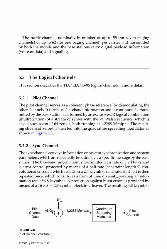
P1: FDJ
book CRC-Wireless November 8, 2001 16:35 Char Count= 327
The traffic channel, nominally in number of up to 55 (for seven pagingchannels) or up to 62 (for one paging channel) per carrier and transmittedby both the mobile and the base stations carry digital payload information(voice or data) and signaling.
5.5 The Logical Channels
This section describes the TIA/EIA/IS-95 logical channels in more detail.
5.5.1 Pilot Channel
The pilot channel serves as a coherent phase reference for demodulating theother channels. It carries no baseband information and is continuously trans-mitted by the base station. It is formed by an exclusive OR logical combination(multiplication) of a stream of zeroes with the W0 Walsh sequence, which isalso a succession of 64 zeroes, both running at 1.2288 Mchip/s. The result-ing stream of zeroes is then fed into the quadrature spreading modulator asshown in Figure 5.8.
5.5.2 Sync Channel
The sync channel conveys information on system synchronization and systemparameters, which are repeatedly broadcast via a specific message by the basestation. The baseband information is transmitted at a rate of 1.2 kbit/s andis error-control-protected by means of a half-rate (constraint length 9) con-volutional encoder, which results in a 2.4 ksymb/s data rate. Each bit is thenrepeated once, which constitutes a form of time diversity, yielding an infor-mation rate of 4.8 ksymb/s. A protection against burst errors is provided bymeans of a 16 × 8 = 128-symbol block interleaver. The resulting 4.8 ksymb/s
+QuadratureSpreadingModulator
1.2288 Mchip/sAll 0sPilot
ChannelData
PilotChannel
0W
FIGURE 5.8Pilot channel structure.
© 2002 by CRC Press LLC
E:\Java for Engineers\VP Publication\Java for Engineers.vpThursday, April 25, 2002 9:27:36 AM
Color profile: DisabledComposite Default screen

P1: FDJ
book CRC-Wireless November 8, 2001 16:35 Char Count= 327
QuadratureSpreadingModulator
1.2kbit/sSync
ChannelData
SyncChannel
ConvolutionalEncoder(1/2, 9)
2.4ksymb/s Symbol
Repetition(x2)
4.8ksymb/s Block
Interleaver(16x8)
4.8ksymb/s
+1.2288Mchip/s
32W
FIGURE 5.9Sync channel structure.
rate information is combined with the W32 Walsh sequence, which runs at arate of 1.2288 Mchip/s. The combined stream is then fed into the quadraturespreading modulator, as shown in Figure 5.9.
5.5.3 Paging Channel
The paging channels, as the name implies, are used for paging purposes.But more than this, the paging channels convey channel assignments andsystem overhead information. The baseband information is transmitted attwo possible rates: 4.8 or 9.6 kbit/s. The rate at which the paging channelruns is informed by the sync channel. Although there may be as many asseven paging channels serving a base station (sector), the mobile monitorsone paging channel only. As opposed to the pilot channel and to the syncchannel, the paging channels make use of a long PN code, which is generatedby a 42-stage linear feedback shift register with the respective characteristicpolynomial given by Equation 5.3. The phase offset is chosen such that itidentifies the base station and the particular paging channel. Beginning withthe most significant bit, the paging channel mask is given by
11000110011010000ppp000000000000bbbbbbbbb
where ppp indicates the paging channel number and bbbbbbbbb indicates thebase station pilot PN sequence offset index. The long PN code runs at a rateof 1.2288 Mchip/s but is decimated to a 19.2 ksymb/s rate by sampling every64th PN code chip (a decimation of 64:1). The resulting decimated long PNcode is further combined with a channel information running at the samerate, as detailed next.
The baseband information, at 4.8 or 9.6 kbit/s, is first error-control-protectedby means of a half-rate convolutional encoder (constraint length 9), which re-sults in a 9.6 or 19.2 ksymb/s data rate, respectively. Each symbol is thenrepeated once, for the initial rate of 4.8 kbit/s, or not, if the initial rate is9.6 kbit/s, yielding an information rate of 19.2 ksymb/s. A protection againstburst errors is provided by means of a 24 × 16 = 384-symbol block interleaver.The output of the interleaver runs at 19.2 ksymb/s rate and is combined with
© 2002 by CRC Press LLC
E:\Java for Engineers\VP Publication\Java for Engineers.vpThursday, April 25, 2002 9:27:36 AM
Color profile: DisabledComposite Default screen

P1: FDJ
book CRC-Wireless November 8, 2001 16:35 Char Count= 327
QuadratureSpreadingModulator
PagingChannel
Data
PagingChannel
ConvolutionalEncoder(1/2, 9)
9.6 ksymb/s4.8 ksymb/s
SymbolRepetition
(x1)(x2)
BlockInterleaver
(24x16)
+1.2288Mchip/s
19.2 ksymb/s9.6 ksymb/s 19.2 ksymb/s
Long CodeGenerator
Decimator64:1
1.2288 Mchip/sLong CodeMask forPaging
Channel k
19.2ksymb/s
+
kW
FIGURE 5.10Paging channel structure.
the decimated version of the masked long PN sequence, running at the samerate. The resulting 19.2 ksymb/s rate information is combined with one of theseven Walsh sequences, from W1 to W7, which identifies the specific pagingchannel and runs at a rate of 1.2288 Mchip/s. The combined 1.2288 Mchip/srate stream is then fed into the quadrature spreading modulator as shown inFigure 5.10.
5.5.4 Access Channel
The access channel is used by the mobile station to initiate a communicationwith the base station and to respond to a paging. The channel is identifiedby a long PN code, which is generated by a 42-stage linear feedback shiftregister with the respective characteristic polynomial given by Equation 5.3.The phase offset is chosen as a function of the access channel itself and ofthe paging channel with which the access channel is associated. The resultinglong PN sequence runs at 1.2288 Mchip/s.
The baseband information, running at 4.8 kbit/s, is first error-control-protected by means of a 1/3-rate convolutional encoder (constraint length 9)which results in a 14.4 ksymb/s data rate. Each bit is then repeated once,yielding an information rate of 28.8 ksymb/s. A protection against bursterrors is provided by means of a 32 × 18 = 576-symbol block interleaver.The output of the interleaver runs at 28.8 ksymb/s rate and is fed into the(64,6) Walsh encoder. In other words, each group of 6 bits of the interleavedinformation is encoded into 64-bit data and this results in a data rate of28.8 × 64/6 = 307.2 kchip/s. This is then combined with the masked longPN sequence, which runs at 1.2288 Mchip/s. The combined 1.2288 Mchip/srate stream is then fed into the quadrature spreading modulator as shown inFigure 5.11.
© 2002 by CRC Press LLC
E:\Java for Engineers\VP Publication\Java for Engineers.vpThursday, April 25, 2002 9:27:36 AM
Color profile: DisabledComposite Default screen
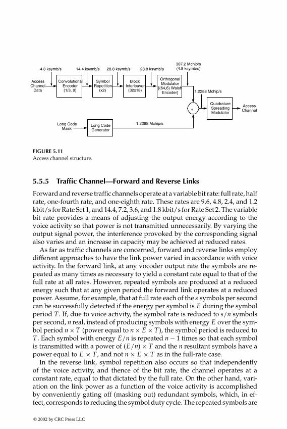
P1: FDJ
book CRC-Wireless November 8, 2001 16:35 Char Count= 327
QuadratureSpreadingModulator
AccessChannel
Data
AccessChannel
ConvolutionalEncoder(1/3, 9)
4.8 ksymb/s
SymbolRepetition
(x2)
BlockInterleaver
(32x18)
+
Long CodeGenerator
1.2288 Mchip/sLong CodeMask
OrthogonalModulator
[(64,6) WalshEncoder]
28.8 ksymb/s307.2 Mchip/s(4.8 ksymb/s)
1.2288 Mchip/s
28.8 ksymb/s14.4 ksymb/s
FIGURE 5.11Access channel structure.
5.5.5 Traffic Channel—Forward and Reverse Links
Forward and reverse traffic channels operate at a variable bit rate: full rate, halfrate, one-fourth rate, and one-eighth rate. These rates are 9.6, 4.8, 2.4, and 1.2kbit/s for Rate Set 1, and 14.4, 7.2, 3.6, and 1.8 kbit/s for Rate Set 2. The variablebit rate provides a means of adjusting the output energy according to thevoice activity so that power is not transmitted unnecessarily. By varying theoutput signal power, the interference provoked by the corresponding signalalso varies and an increase in capacity may be achieved at reduced rates.
As far as traffic channels are concerned, forward and reverse links employdifferent approaches to have the link power varied in accordance with voiceactivity. In the forward link, at any vocoder output rate the symbols are re-peated as many times as necessary to yield a constant rate equal to that of thefull rate at all rates. However, repeated symbols are produced at a reducedenergy such that at any given period the forward link operates at a reducedpower. Assume, for example, that at full rate each of the s symbols per secondcan be successfully detected if the energy per symbol is E during the symbolperiod T . If, due to voice activity, the symbol rate is reduced to s/n symbolsper second, n real, instead of producing symbols with energy E over the sym-bol period n × T (power equal to n × E × T), the symbol period is reduced toT . Each symbol with energy E/n is repeated n − 1 times so that each symbolis transmitted with a power of (E/n) × T and the n resultant symbols have apower equal to E × T , and not n × E × T as in the full-rate case.
In the reverse link, symbol repetition also occurs so that independentlyof the voice activity, and thence of the bit rate, the channel operates at aconstant rate, equal to that dictated by the full rate. On the other hand, vari-ation on the link power as a function of the voice activity is accomplishedby conveniently gating off (masking out) redundant symbols, which, in ef-fect, corresponds to reducing the symbol duty cycle. The repeated symbols are
© 2002 by CRC Press LLC
E:\Java for Engineers\VP Publication\Java for Engineers.vpThursday, April 25, 2002 9:27:36 AM
Color profile: DisabledComposite Default screen

P1: FDJ
book CRC-Wireless November 8, 2001 16:35 Char Count= 327
eliminated (masked out) in a pseudorandom manner by means of a data burstrandomizer, which yields the symbol masking pattern. The symbol maskingpattern is obtained as a function of the vocoder rate and of the control bitsdrawn from the long PN code sequence at a certain time. This pseudoran-dom masking guarantees that the elimination of the repeated symbols occursuniformly within the frame.
Observe that, to detect a symbol of the forward link, the receiver must per-form an integration during a period of n×T so that enough power is accumu-lated for the appropriate detection. Such a scheme is satisfactory in a link forwhich the speed requirement for power control is not critical. In other words,a delay in adjusting the link power upon monitoring the link quality does notcompromise the overall performance. As a matter of fact, the forward-linkquality measure is the frame error rate (FER). On the other hand, becausepower control is a very sensitive matter for the reverse link, the monitoring ofthe link quality must be carried out expeditiously, even when the vocoder isoperating at lower rates. Therefore, in the reverse link, the scheme used for theforward-link power variation as a function of the voice activity is inappropri-ate. As a matter of fact, the reverse-link quality parameter is the ratio of energyper bit to noise density, Eb/No , a quantity that is very quickly obtainable.
There may be as many as 55 (for seven paging channels) or as many as62 (for one paging channel) traffic channels per carrier. Besides primary dataand secondary data, the full-rate (only the full-rate) traffic channels also con-vey signaling messages. Primary data correspond to voice information andsecondary data correspond to data information. The multiplexing of voice,data, and signaling is carried out in two possible modes: blank and burstor dim and burst. In the blank-and-burst mode, the entire frame is used tocarry secondary data or signaling messages. (Primary data are completelyblanked out within the frame.) In the dim-and-burst mode, primary dataand secondary data or signaling messages are transmitted in the same frame.(Primary data are partially overwritten by either secondary data or signalingmessages within the frame. In other words, the frame is shared by voice anddata or voice and signaling.) The first bit in the frame indicates the type of databeing transmitted. If this bit is set to zero, then the frame conveys primarydata only. If it is set to one, then the next bit will indicate if the frame containsprimary data and secondary data or primary data and signaling messages.Two other bits instruct on the proportion of primary data to other types ofdata (secondary or signaling as applicable). Of course, the proportion zero(i.e., zero bits of voice) is also pertinent.
Traffic Channel—Forward Link
The vocoder yields variable data rate information, depending on the voiceactivity. For the Rate Set 1 these rates are 9.6, 4.8, 2.4, and 1.2 kbit/s. Forthe Rate Set 2 they are 14.4, 7.2, 3.6, and 1.8 kbit/s. These data are first
© 2002 by CRC Press LLC
E:\Java for Engineers\VP Publication\Java for Engineers.vpThursday, April 25, 2002 9:27:36 AM
Color profile: DisabledComposite Default screen
P1: FDJ
book CRC-Wireless November 8, 2001 16:35 Char Count= 327
error-control-protected by means of a half-rate (for Rate Set 1) or three quarter-rate (for Rate Set 2) convolutional encoder (constraint length 9). In both casesthe output of the convolutional encoder yields the respective rates of 19.2,9.6, 4.8, and 2.4 ksymb/s. Each symbol is then repeated conveniently so thatthe resultant rate is constant and equal to 19.2 ksymb/s. A protection againstburst errors is provided by means of a 24 ×16 = 384-symbol block interleaver.The output of the interleaver runs at 19.2 ksymb/s rate and is combined withthe decimated version of the masked long PN sequence, running at the samerate. This combination in fact corresponds to a data scrambling, which yieldsprivacy to the encoded voice. This 19.2 ksymb/s scrambled information isthen “multiplexed” with 800 bit/s power control bits (PCB). This is not reallya multiplexing but a “puncturing.” Multiplexing usually implies no loss ofinformation, which is achieved by means of an increase of the output datarate. In the present case, the output data rate remains the same and whatreally happens is a data puncturing in which the scrambled information isoverwritten by the PCBs, as detailed next.
The long PN code is generated by a 42-stage linear feedback shift registerwith the respective characteristic polynomial given by Equation 5.3. Its phaseoffset is obtained by a mask for user u given by the ESN of the subscriber usingthat particular channel. The long PN code runs at a rate of 1.2288 Mchip/sbut is decimated to a 19.2 ksymb/s rate by sampling every 64th PN codechip (64:1 decimation). This decimated PN code is combined with the outputof the interleaver, which also runs at 19.2 ksymb/s. A further decimation ofthe 19.2 ksymb/s decimated PN code is carried out by means of samplingevery 24th PN code chip (24:1 decimation). The four most significant bits ofthe resulting 800 bit/s decimator output are used to control the multiplexerwhose inputs are the scrambled information and the power control bits.
The resulting 19.2 kbit/s rate information (data and power control bits)is combined with one of W8 to W31 or W33 to W63 Walsh sequences, whichidentifies the specific traffic channel (user) and runs at a rate of 1.2288 kbit/s.The Walsh sequences that are not used for the paging channels may be utilizedby the traffic channels. The combined 1.2288 kbit/s rate stream is then fed intothe quadrature spreading modulator as shown in Figure 5.12.
Traffic Channel—Reverse Link
The vocoder yields variable data rate information, depending on the voiceactivity. For Rate Set 1 these rates are 9.6, 4.8, 2.4, and 1.2 kbit/s. For RateSet 2 they are 14.4, 7.2, 3.6, and 1.8 kbit/s. These data are first error-control-protected by means of a one third-rate (for Rate Set 1) or half-rate (for RateSet 2) convolutional encoder (constraint 9). In both cases the output of theconvolutional encoder yields the respective rates of 28.8, 14.4, 7.2, and3.6 ksymb/s. Each symbol is then repeated conveniently so that the resultant
© 2002 by CRC Press LLC
E:\Java for Engineers\VP Publication\Java for Engineers.vpThursday, April 25, 2002 9:27:36 AM
Color profile: DisabledComposite Default screen

P1: FDJ
book CRC-Wireless November 8, 2001 16:35 Char Count= 327
QuadratureSpreadingModulator
TrafficChannel
Data TrafficChannel
ConvolutionalEncoder(1/2, 9)
or(3/4, 9)
9.6 ksymb/s4.8 ksymb/s2.4 ksymb/s1.2 ksymb/s
SymbolRepetition
(x1)(x2)(x4)(x8)
BlockInterleaver
(24x16)
+
19.2 ksymb/s
Long CodeGenerator 1.2288 Mchip/s
Long CodeMask u
19.2 ksymb/s
14.4 ksymb/s7.2 ksymb/s3.6 ksymb/s1.8 ksymb/s
Rate set 1 or Rate set 2
19.2 ksymb/s9.6 ksymb/s4.8 ksymb/s2.4 ksymb/s
Decimator64:1 19.2 ksymb/s
Decimator24:1
MUX
800 bit/s
PCB800 bit/s
+
uW
FIGURE 5.12Forward traffic channel structure.
rate is constant and equal to 28.8 ksymb/s. Protection against burst errors isprovided by means of a 32 × 18 = 576-symbol block interleaver. The symbolsare written in by column and read out by row. This means that for the full-ratecase each row contains a different set of symbols. For the half-rate case twoconsecutive rows contain the same set of symbols. For the one fourth-rate casefour consecutive rows contain the same set of symbols. For the one eighth-ratecase, eight consecutive rows contain the same set of symbols. The output of theinterleaver runs at 28.8 ksymb/s rate and is fed into the (64, 6) Walsh encoder.In other words, each group of 6 bits of the interleaved information is encodedinto 64-bit data and this results in a data rate of 28.8 × 64/6 = 307.2 kchip/s.Note, therefore, that each row of 18 symbols of the interleaver generates threeWalsh-encoded orthogonal modulation symbols. And six modulation sym-bols compose what is called a power control group (PCG), a PCG containingsymbols of two rows of repeated symbols or two rows of nonrepeated sym-bols. Each PCG lasts 6 × 64/307.2 = 1.25 ms and 16 PCG compose a frame of20 ms. The rows of the interleaver are read out in such a way that in a frameone PCG of nonrepeated symbols alternates with 6(k − 1) PCGs of repeatedsymbols, where k is the order of repetition (k = 1 for full-rate–no repetition;k = 2 for half-rate–1 repetition; k = 4 for one fourth-rate–3 repetitions; k = 8for one eighth-rate–7 repetitions). The redundant 16(1 − 1/k) PCGs are thengated off in a pseudorandom manner by the data burst randomizer to reducethe total amount of power of the reverse link in accordance with the voice ac-tivity. The symbol masking pattern is determined as a function of the vocoderrate and of the control bits obtained out of the long PN code sequence bitsat a certain time. The output of the data burst randomizer is then combinedwith the long PN code, which is generated by a 42-stage linear feedback shiftregister with the respective characteristic polynomial given by Equation 5.3.
© 2002 by CRC Press LLC
E:\Java for Engineers\VP Publication\Java for Engineers.vpThursday, April 25, 2002 9:27:36 AM
Color profile: DisabledComposite Default screen
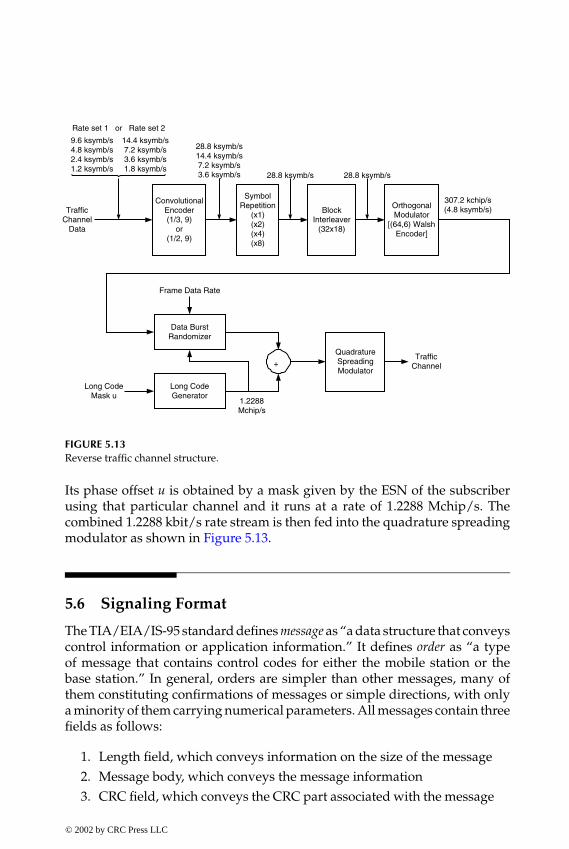
P1: FDJ
book CRC-Wireless November 8, 2001 16:35 Char Count= 327
QuadratureSpreadingModulator
TrafficChannel
Data
TrafficChannel
ConvolutionalEncoder(1/3, 9)
or(1/2, 9)
9.6 ksymb/s4.8 ksymb/s2.4 ksymb/s1.2 ksymb/s
SymbolRepetition
(x1)(x2)(x4)(x8)
BlockInterleaver
(32x18)
28.8 ksymb/s
Long CodeGenerator
Long CodeMask u
28.8 ksymb/s
14.4 ksymb/s7.2 ksymb/s3.6 ksymb/s1.8 ksymb/s
Rate set 1 or Rate set 2
28.8 ksymb/s14.4 ksymb/s7.2 ksymb/s3.6 ksymb/s
+
OrthogonalModulator
[(64,6) WalshEncoder]
307.2 kchip/s(4.8 ksymb/s)
Data BurstRandomizer
Frame Data Rate
1.2288Mchip/s
FIGURE 5.13Reverse traffic channel structure.
Its phase offset u is obtained by a mask given by the ESN of the subscriberusing that particular channel and it runs at a rate of 1.2288 Mchip/s. Thecombined 1.2288 kbit/s rate stream is then fed into the quadrature spreadingmodulator as shown in Figure 5.13.
5.6 Signaling Format
The TIA/EIA/IS-95 standard defines message as “a data structure that conveyscontrol information or application information.” It defines order as “a typeof message that contains control codes for either the mobile station or thebase station.” In general, orders are simpler than other messages, many ofthem constituting confirmations of messages or simple directions, with onlya minority of them carrying numerical parameters. All messages contain threefields as follows:
1. Length field, which conveys information on the size of the message2. Message body, which conveys the message information3. CRC field, which conveys the CRC part associated with the message
© 2002 by CRC Press LLC
E:\Java for Engineers\VP Publication\Java for Engineers.vpThursday, April 25, 2002 9:27:36 AM
Color profile: DisabledComposite Default screen
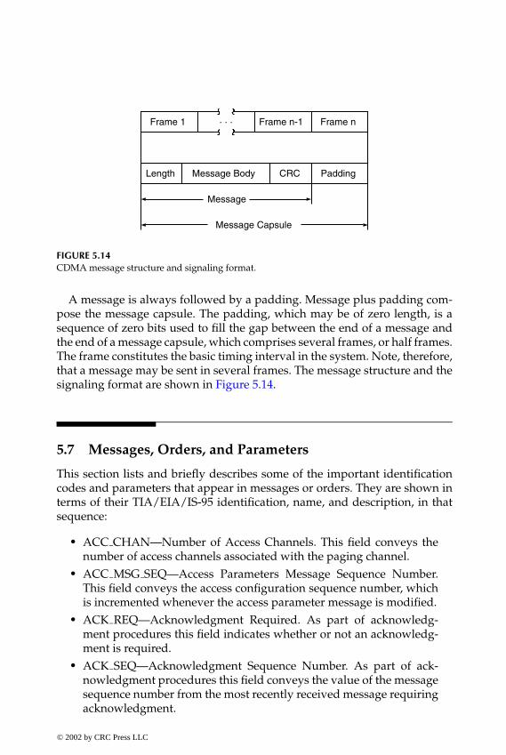
P1: FDJ
book CRC-Wireless November 8, 2001 16:35 Char Count= 327
Frame 1 Frame n-1 Frame n
Length Message Body CRC Padding
Message
Message Capsule
. . .
FIGURE 5.14CDMA message structure and signaling format.
A message is always followed by a padding. Message plus padding com-pose the message capsule. The padding, which may be of zero length, is asequence of zero bits used to fill the gap between the end of a message andthe end of a message capsule, which comprises several frames, or half frames.The frame constitutes the basic timing interval in the system. Note, therefore,that a message may be sent in several frames. The message structure and thesignaling format are shown in Figure 5.14.
5.7 Messages, Orders, and Parameters
This section lists and briefly describes some of the important identificationcodes and parameters that appear in messages or orders. They are shown interms of their TIA/EIA/IS-95 identification, name, and description, in thatsequence:
� ACC CHAN—Number of Access Channels. This field conveys thenumber of access channels associated with the paging channel.
� ACC MSG SEQ—Access Parameters Message Sequence Number.This field conveys the access configuration sequence number, whichis incremented whenever the access parameter message is modified.
� ACK REQ—Acknowledgment Required. As part of acknowledg-ment procedures this field indicates whether or not an acknowledg-ment is required.
� ACK SEQ—Acknowledgment Sequence Number. As part of ack-nowledgment procedures this field conveys the value of the messagesequence number from the most recently received message requiringacknowledgment.
© 2002 by CRC Press LLC
E:\Java for Engineers\VP Publication\Java for Engineers.vpThursday, April 25, 2002 9:27:36 AM
Color profile: DisabledComposite Default screen

P1: FDJ
book CRC-Wireless November 8, 2001 16:35 Char Count= 327
� ACTION TIME—Action Time. This field conveys the system time atwhich the action specific to the message should take effect.
� ANALOG CHAN—Analog Voice Channel Number. This field con-veys the channel number of the analog voice channel.
� ASSIGN MODE—Assignment Mode. This field informs the modewith which the channel assignment is to be performed. These modescomprise traffic channel assignment, page channel assignment, ac-quire analog system, analog voice channel assignment.
� AUTHBS—Challenge Response. As part of the authentication processAUTHBS is an 18-bit quantity obtained by the base station throughthe authentication signature procedure and sent to the mobilestation.
� AUTHU—Authentication Challenge Response. As part of the authen-tication process AUTHU is an 18-bit quantity obtained by the mobilestation through the authentication signature procedure and sent tothe base station.
� BASE CLASS—Base Station Class. This field conveys the class of ser-vice provided by the base station (public system or some other to bedefined).
� BASE ID—Base Station Identification. This field conveys the base sta-tion identification number.
� BASE LAT—Base Station Latitude. This field conveys the base stationlatitude in units of 0.25 s.
� BASE LONG—Base Station Longitude. This field conveys the basestation longitude in units of 0.25 s.
� BCAST INDEX—Broadcast Slot Cycle Index. This field conveys thebroadcast slot cycle index (in the range 1 to 7) when periodic broadcastpaging is enabled. The value zero in this field indicates that periodicpaging is disabled.
� BURST TYPE—Data Burst Type. This field indicates the type of databurst in the message. (This is defined in TSB58, Administration Pa-rameter Value Assignments for TIA/EIA Wideband Spread SpectrumStandards.)
� CDMA CHAN—CDMA Channel Number. Each occurrence of thisfield conveys the associated CDMA channel number.
� CDMA FREQ—CDMA Channel Frequency Assignment. The orderin which this field is included in the message indicates the CDMAchannel containing a paging channel that is supported by the base sta-tion. Each occurrence of this field is set to the CDMA channel numbercorresponding to the CDMA frequency.
© 2002 by CRC Press LLC
E:\Java for Engineers\VP Publication\Java for Engineers.vpThursday, April 25, 2002 9:27:36 AM
Color profile: DisabledComposite Default screen

P1: FDJ
book CRC-Wireless November 8, 2001 16:35 Char Count= 327
� CHARi—Dialed Digit or Character. This field conveys the dialed digitaccording to the DIGIT MODE.
� CODE CHAN—Code Channel. This field conveys the code channelindex (one out of 64 Walsh sequences).
� CONFIG MSG SEQ—Configuration Message Sequence Number.This field conveys the configuration sequence number, which is in-cremented whenever the base station modifies the system parametermessage, the neighbor list message, the CDMA channel list message,or, if sent, the extended system parameters message and the globalservice redirection message.
� DIGIT MODE—Digit Mode Indicator. This field indicates the codeused for the dialed digits (4-bit DTMF codes using unknown num-bering plan or 8-bit ASCII codes using a specified numbering plan).
� DIGITi—DTMF Digit. This field conveys the DTMF digit to be gener-ated by the base station.
� DTMF OFF LENGTH—DTMF Interdigit Interval Code. This fieldconveys the value of the requested minimum interval between DTMFpulses to be generated by the base station.
� DTMF ON LENGTH—DTMF Pulse Width Code. This field conveysthe value of the requested width of DTMF pulses to be generated bythe base station.
� ENCRYPT MODE—Message Encryption Mode. This field indicatesthe encrypting mode (encryption disabled or encrypt call control mes-sages) to be used for messages sent on the forward and reverse trafficchannels.
� ENCRYPTION—Message Encryption Indicator. This field conveysthe mode with which the current message is being encrypted. (Thisis maintained for retransmitted messages.) This is made equal to thecontent of the ENCRYPT MODE field of the last received channelassignment message, handoff direction message, or message encryp-tion mode order.
� ERRORS DETECTED—Number of Frame Errors Detected. This fieldconveys the number of bad frames in PWR MEAS FRAMES.
� ESN—Electronic Serial Number. As part of MSID this field containsthe electronic serial number assigned by the manufacturer to the mo-bile station.
� FEATURE—Feature Identifier. This field conveys the supplementaryservice or feature requested.
� FRAME OFFSET—Frame Offset. This field conveys the offset bywhich the forward and reverse traffic channel frames must be de-layed with respect to the system timing.
© 2002 by CRC Press LLC
E:\Java for Engineers\VP Publication\Java for Engineers.vpThursday, April 25, 2002 9:27:36 AM
Color profile: DisabledComposite Default screen

P1: FDJ
book CRC-Wireless November 8, 2001 16:35 Char Count= 327
� HARD INCLUDED—Hard Handoff Parameters Included. This fieldindicates whether or not the mobile station should change the para-meters relative to the hard handoff (FRAME OFFSET, PRIVATE LCM,ENCRYPT MODE, NOM PWR, BAND CLASS, CDMA FREQ).
� IMSI—International Mobile Station Identity. As part of the MSIDthis field contains the mobile station identification as specified inCCITT Recommendation E.212 for mobile station in the land mobileservice.
� INIT PWR—Initial Power Offset. This field conveys the correctionfactor to be used by the mobile stations in the open-loop power esti-mate for the initial transmission on the access channel.
� LC STATE—Long Code State. This field conveys the long code stateat the time given by the SYS TIME field of the message.
� LP SEC—Leap Seconds. This field indicates the leap seconds thathave occurred since the start of system time.
� MCC—Mobile Country Code. As part of the IMSI this field containsthe MCC.
� MEM—Message Encryption Mode Indicator. This field enables ordisables analog control message encryption on the analog voicechannels.
� MIN—Mobile Identification Number. As part of MSID this field con-tains the directory number assigned by the operating company to themobile station.
� MOB FIRM REV—Firmware Revision Number. This field indicatesthe firmware number of the mobile station assigned by the manufac-turer.
� MOB MFG CODE—Manufacturer Code. This field indicates themanufacturer of the mobile station.
� MOB MODEL—Model Number. This field conveys the model of themobile station assigned by the manufacturer.
� MOB P REV—Protocol Revision of the Mobile Station. This fieldindicates the TIA/EIA/IS-95 version supported by the mobile sta-tion.
� MOB TERM FOR NID—Foreign NID Roaming Registration EnableIndicator. This field indicates whether or not the mobile station isconfigured to receive terminated calls when it is a foreign NID roamer.
� MOB TERM FOR SID—Foreign SID Roaming Registration EnableIndicator. This field indicates whether or not the mobile station isconfigured to receive terminated calls when it is a foreign SIDroamer.
© 2002 by CRC Press LLC
E:\Java for Engineers\VP Publication\Java for Engineers.vpThursday, April 25, 2002 9:27:36 AM
Color profile: DisabledComposite Default screen

P1: FDJ
book CRC-Wireless November 8, 2001 16:35 Char Count= 327
� MOB TERM HOME—Home (Nonroaming) Registration Enable In-dicator. This field indicates whether the mobile station is configuredto receive terminated calls when not roaming or when roaming.
� MORE PAGE—More Slotted Pages to Follow Indicator. This field in-dicates whether or not more slotted page messages should followafter the current message.
� MSG NUMBER—Message Number. This field conveys the numberof the message within the data burst.
� MSG SEQ—Message Sequence Number. As part of acknowledgmentprocedures this field conveys the value of the message sequence num-ber for the message in which it appears.
� MSG TYPE—Message Type. This field identifies the type of messageor order within the channel. The types of messages or orders conveyedby the channel will be detailed later.
� MSID—Mobile Station Identifier. This field conveys the mobile stationidentification.
� NA CHAN TYPE—Analog Channel Type. This field indicates thetype of analog channel to be assigned. The types of analog channelscomprise narrow channel 10 kHz below ANALOG CHAN; narrowchannel 10 kHz above ANALOG CHAN; narrow channel centered onANALOG CHAN; and wide channel on ANALOG CHAN. This isto comply with the narrowband AMPS in which a 30-kHz channelencompasses 3 × 10 kHz channels. These are the narrow channels,whereas 30-kHz channels of the standard AMPS are identified as“wide” channels.
� NGHBR CONFIG—Neighbor Configuration. This field conveys theconfiguration of the neighbor base station (if its configuration is thesame as or different from this base station, if it has a paging channelon the current CDMA frequency assignment, etc.).
� NGHBR PN—Neighbor Pilot PN Sequence Offset Index. This fieldconveys the pilot PN sequence offset of the neighboring base station.
� NID—Network Identification. This field uniquely identifies a net-work within a cellular system. (A network is a subset of a cellularsystem. It may comprise a set of base stations set up to manage somespecial requirements.)
� NOM PWR—Nominal Transmit Power Offset. This field conveys thecorrection factor to be used by the mobile stations in the open-looppower estimate.
� NUM CHANS—Number of CDMA Channels. This field conveys thenumber of occurrences of the CDMA CHAN field.
© 2002 by CRC Press LLC
E:\Java for Engineers\VP Publication\Java for Engineers.vpThursday, April 25, 2002 9:27:36 AM
Color profile: DisabledComposite Default screen

P1: FDJ
book CRC-Wireless November 8, 2001 16:35 Char Count= 327
� NUM DIGITS—Number of DTMF Digits. This field conveys the num-ber of DTMF digits included in the message.
� NUM FIELDS—Number of Dialed Digits in the Message. This fieldconveys the number of dialed digits included in the message.
� NUM MSGS—Number of Messages in the Data Burst Stream. Thisfield conveys the number of messages in the data burst stream.
� NUM PILOTS—Number of Pilots. This field conveys the number ofpilots in the current active set.
� NUM STEP—Number of Access Probes. This field conveys the num-ber of access probes (to be defined later) in a single-access probe se-quence (access probe sequence will be defined later).
� ORDER—Order Code. This field conveys the type of order in themessage.
� PAGE CHAN—Number of Paging Channels. This field indicates thenumber of paging channels on the CDMA channel.
� PARAMETER—Parameter Value. This field conveys the parametersthat can be retrieved and set in the mobile station by means of specialmessages. Some of these parameters are defined by the TIA/EIA/IS-95 standard, whereas others are defined by the mobile station manu-facturers.
� PILOT PN—Pilot PN Sequence Offset. This field indicates the PNsequence offset, in number of 64 PN chips.
� PILOT PN PHASE—Pilot Measured Phase. This field conveys thephase of the pilot PN sequence relative to the zero offset pilot PNsequence of this pilot, in units of one PN chip.
� PILOT STRENGTH—Pilot Strength. This field conveys the strengthof the pilot used by the mobile station to derive its time reference.
� PM—Privacy Mode Indicator. This field indicates voice privacyrequested.
� PREF MSID TYPE—Preferred Access Channel Mobile StationIdentifier Type. This field conveys the type of MSID (IMSI, ESN,IMSI, and ESN) that the mobile station should use on the accesschannel.
� PRIVATE LCM—Private Long Code Mask Indicator. This field con-veys whether or not the private long code mask is to be used after ahard handoff.
� PWR MEAS FRAMES—Number of Forward Traffic Channel Framesin the Measurement Period. This field conveys the number of forwardtraffic channel frames monitored during a given period.
© 2002 by CRC Press LLC
E:\Java for Engineers\VP Publication\Java for Engineers.vpThursday, April 25, 2002 9:27:36 AM
Color profile: DisabledComposite Default screen

P1: FDJ
book CRC-Wireless November 8, 2001 16:35 Char Count= 327
� PWR PERIOD ENABLE—Period Report Mode Indicator. This fieldindicates whether or not the mobile station is to generate periodicpower measurement report messages.
� PWR REP DELAY—Power Report Delay. This field conveys the pe-riod the mobile station should wait before restarting frame countingfor power control purposes.
� PWR REP FRAMES—Power Control Reporting Frame Count. Thisfield conveys the number of frames over which mobile stations are tocount frame errors.
� PWR REP THRESH—Power Control Reporting Threshold. This fieldconveys the number of bad frames permitted to be received by themobile station in a measurement period before reporting bad framereception to the base station.
� PWR STEP—Power Increment. This field conveys the step value bywhich the mobile stations must increment their transmit power be-tween successive access probes (access probes will be defined later).
� PWR THRESH ENABLE—Threshold Report Mode Indicator. Thisfield indicates whether or not the mobile station is to generate meas-urement report messages.
� RAND—Random Challenge Memory. As part of the authenticationprocess RAND is a 32-bit random value challenge sent by the basestation (access parameters message) and held in the mobile station tobe used by the mobile station for authentication purposes.
� RANDC—Random Challenge Value. As part of the authenticationprocess RANDC corresponds to the eight most significant bits ofRAND.
� RANDSSD—Random Data for the Computation of SSD. As part of theauthentication process RANDSSD is a quantity stored in the HLR/ACassociated with the mobile station that is used to compute SSD.
� RANDU—Random Challenge Data. As part of the authentication pro-cess RANDU is a 24-bit quantity generated by the base station.
� RECORD TYPE—Information Record Type. This field conveys the in-formation record type such as display (information to be displayed bythe mobile station), called party number (identifies the called party’snumber), calling party number (identifies the calling party’s number),connected number (identifies the responding party to a call), signal(conveys information to a user by means of tones and other alertingsignals), message waiting (conveys the number of messages waiting).
� RECORD TYPE—Redirection Record Type. This field conveys theredirection record type such as redirection to an analog system orto a CDMA system.
© 2002 by CRC Press LLC
E:\Java for Engineers\VP Publication\Java for Engineers.vpThursday, April 25, 2002 9:27:36 AM
Color profile: DisabledComposite Default screen

P1: FDJ
book CRC-Wireless November 8, 2001 16:35 Char Count= 327
� REDIRECT ACCOLC—Redirected Access Overload Classes. Thisfield conveys the access overload classes of mobile stations that areto be redirected to a system to obtain service. The mobile stationoverload classes comprise the following: normal subscribers, test mo-bile stations, emergency mobile stations, and overload classes to bespecified.
� REF PN—Time Reference PN Sequence Offset. This field indicates thePN sequence offset of the pilot used by the mobile station to deriveits time reference.
� REG DIST—Registration Distance. This field conveys the distance be-yond which the mobile station should perform a distance-based regi-stration if the mobile station is to perform such a type of registration.The null value in this field indicates that this type of registrationshould not be performed.
� REG TYPE—Registration Type. This field indicates the type of eventgenerating the registration attempt.
� REG ZONE—Registration Zone. This field conveys the zone (groupof base stations within a given system or network) within which abase station is registered.
� RELEASE—Origination Completion Indicator. This field indicateswhether or not the message is used to complete an originationrequest.
� REQUEST MODE—Requested Mode Code. This field conveys thecurrent configuration mode (CDMA only, wide analog only, narrowanalog only, and combinations).
� RETURN IF FAIL—Return If Fail Indicator. This field indicateswhether or not the mobile station must return to the original sys-tem from which it is being redirected upon failure to obtain servicein the system to which it has been redirected.
� SCC—SAT Color Code. This field conveys the supervisory audio toneassociated with the designated analog voice channel.
� SCM—Station Class Mark. This field indicates the class withwhich the mobile station operates (CDMA mode, dual mode,slotted class, nonslotted class, power class—class I, class II, class III,etc.).
� SERVICE OPTION—Requested Service Option. This field indicatesthe type of special service requested. (This is defined in TSB58, Ad-ministration Parameter Value Assignments for TIA/EIA WidebandSpread Spectrum Standards.)
� SID—System Identification. This field uniquely identifies the cellularsystem.
© 2002 by CRC Press LLC
E:\Java for Engineers\VP Publication\Java for Engineers.vpThursday, April 25, 2002 9:27:36 AM
Color profile: DisabledComposite Default screen

P1: FDJ
book CRC-Wireless November 8, 2001 16:35 Char Count= 327
� SLOT CYCLE INDEX—Slot Cycle Index. This field conveys the slotcycle to be used by the mobile station to monitor the paging channel.This is only applicable to mobile stations operating in the slottedmode. (A mobile station operating in the slotted mode monitors thepaging channel for one or two slots per slot cycle.)
� SPECIAL SERVICE—Special Service Option Indicator. This field in-dicates whether special service or default service is requested.
� SRCH WIN A—Search Window Size for Active Set and CandidateSet. This field conveys the search window size (range of PN offsets)to be used by the mobile station to search for multipath componentsof the pilots in the active set and candidate set.
� SRCH WIN N—Search Window Size for Neighbor Set. This field con-veys the search window size (range of PN offsets) to be used by themobile station to search for components of pilots in the neighbor set.
� SRCH WIN R—Search Window Size for Remaining Set. This fieldconveys the search window size (range of PN offsets) to be used bythe mobile station to search for components of pilots in the remainingset.
� SSD—Shared Secret Data. As part of the authentication procedure,encryption, and voice privacy, SSD is 128-bit information stored inthe semipermanent memory of the mobile station. It is composedof two equal-sized parts: SSD A, used to support the authenticationprocedures, and SSD B, used to support voice privacy and messageencryption. SSD is not accessible to the user. SSD is generated accor-ding to a given cryptographic algorithm and is initialized with mobilestation specific information, random data, and the A-key of the mobilestation (a 64-bit secret key known only to the mobile station and to itsassociated HLR/AC).
� SYS ORDERING—System Ordering. This field conveys the order inwhich the mobile station should attempt to obtain service from theanalog system (System A only, System B only, System A first, thenSystem B if the first option was unsuccessful, etc.)
� SYS TIME—System Time. This field indicates the system time thatis the time reference used by the system. Except for leap seconds,the system time is synchronous with the UTC (universal coordinatedtime) using the same time origin as GPS time. SYS TIME is set by thebase station as four sync channel superframes after the end of the lastsuperframe containing any part of this sync channel message, minusthe pilot PN sequence offset, in units of 80 ms.
� T ADD—Pilot Detection Threshold. This field conveys the pilotstrength level above which a pilot is to be transferred to the candidate
© 2002 by CRC Press LLC
E:\Java for Engineers\VP Publication\Java for Engineers.vpThursday, April 25, 2002 9:27:36 AM
Color profile: DisabledComposite Default screen
P1: FDJ
book CRC-Wireless November 8, 2001 16:35 Char Count= 327
set. (The candidate set contains the pilots that are not currently inthe active set but have sufficient strength to indicate that the asso-ciated forward traffic channels could be successfully demodulated.)This triggers the mobile station to send a pilot strength measurementmessage.
� T COMP—Comparison Threshold. This field conveys the margin bywhich the strength of a pilot in the candidate set should exceed thatof the active set so that the mobile station can send a pilot strengthmeasurement message.
� T DROP—Pilot Drop Threshold. This field conveys the pilot strengthlevel below which the mobile station should start the handoff droptimer for pilots in the active set and in the candidate set. (The activeset contains the pilots associated with the forward traffic channelsassigned to the mobile station.)
� T TDROP—Drop Timer Value. This field conveys the timer value af-ter which one of the following actions can be taken by the mobilestation for pilots belonging to the active set or to the candidate setand whose signal strength has not become greater than T DROP: ifthe pilot is a member of the active set a pilot strength measurementmessage is issued; if the pilot is a member of the candidate set, thispilot is moved to the neighbor set. (The neighbor set contains the pi-lots that are not currently in the active set but are likely candidates forhandoff.)
� TOTAL-ZONES—Number of Registration Zones to Be Retained. Thisfield conveys the number of registration zones the mobile station isto retain for zone-based registration purposes.
� USE TIME—Use Action Time Indicator. This field indicates whetheran ACTION TIME is specified in the message.
� VMAC—Voice Mobile Station Attenuation Code. This field conveysthe power level associated with the analog voice channel.
5.8 Messages and Orders and Logical Channels
In this section, the CDMA channels, namely, pilot channel, sync channel,paging channel, forward traffic channel, access channel, and reverse trafficchannel, are described in terms of the messages and orders and parametersthey convey and in terms of the format in which these messages and ordersare encapsulated. The messages are described in terms of those fields thatare relevant to the task they perform. The orders, most of them constituting
© 2002 by CRC Press LLC
E:\Java for Engineers\VP Publication\Java for Engineers.vpThursday, April 25, 2002 9:27:36 AM
Color profile: DisabledComposite Default screen

P1: FDJ
book CRC-Wireless November 8, 2001 16:35 Char Count= 327
confirmation of messages or simple directions and having their names di-rectly associated with the task they perform, are either very briefly explainedor simply quoted. The purposes of the specific messages and orders are bet-ter understood in conjunction with the call processing descriptions. Mobilestation call processing and base station processing are the subjects of thefollowing sections.
5.8.1 Pilot Channel
The pilot channel conveys no baseband information. From the base station,it continuously transmits a stream of zeroes for coherent carrier phase andtiming reference purposes. Thus, messages and therefore message structureas previously described do not apply.
5.8.2 Sync Channel
The sync channel structure is organized in frames and a superframe thatcontains three-equal duration frames. A superframe accommodates 96 bits.At a rate of 1.2 kbit/s these 96 bits are transmitted in 80 ms, which is theduration of the superframe. A frame contains 32 bits and, therefore, lasts26.666. . . ms, exactly the same duration as the period of the short PN code.Each frame, and therefore the superframe, begins at the same time instant asthe short PN sequence. Hence, when synchronization is achieved through thepilot channel, the alignment for the sync channel becomes known. Note that,after being half-rate convolutional encoded and repeated once, an initial 32-bit piece of information (a frame) turns into a 32 × 4 = 128-bit stream, whichis the size of the block interleaver.
The sync channel conveys only one message: the sync channel message.The sync channel message may occupy more than one superframe but al-ways an integer number of superframes. The start of the message coincideswith the beginning of a superframe and is indicated by a bit one in its firstposition. Subsequent frames have a bit zero in its first position indicating thecontinuation of the message started at the beginning of the correspondingsuperframe. If necessary, padding of bits is used to complete the remainingpositions of that superframe.
The sync channel message may include the following main fields: systemidentification (SID), network identification (NID), pilot PN sequence offsetindex (PILOT PN), long code state (LC STATE), system time (SYS TIME),paging channel data rate (PRAT). After acquiring the sync channel message,the precise time to start running the long PN sequence is known. After startingrunning the long PN sequence, such a sequence can be accessed whenevernecessary. The field PRAT indicates whether the paging channel is runningat 4.8 or 9.6 kbit/s.
© 2002 by CRC Press LLC
E:\Java for Engineers\VP Publication\Java for Engineers.vpThursday, April 25, 2002 9:27:36 AM
Color profile: DisabledComposite Default screen

P1: FDJ
book CRC-Wireless November 8, 2001 16:35 Char Count= 327
5.8.3 Paging Channel
The paging channel structure is organized into half-frame, frame, slot, andslot cycle. A half-frame lasts 10 ms and contains 96 bits. Two half-framesconstitute one frame (20 ms, 192 bits). Four frames form one slot (80 ms, 768bits). And 2048 slots (163,840 ms, 1,572,864 bits) comprise the maximum slotcycle. The choice of a particular paging channel and of a particular slot withinthat channel is carried out by the base station in a random fashion but is basedon a hash function. Because the selection makes use of the mobile stationidentification number and of known system parameters, by computing thehash function the mobile station will be able to identify and then monitor thatparticular slot within the particular paging channel. The hash function aimsat balancing the load on all the active paging channels and on their slots.
The messages on the paging channel are of the synchronized or unsyn-chronized type. They may occupy more than one half-frame and may notnecessarily use integer number of half-frames. When a message ends 7 bitsor less before the end of the current half-frame a padding of bits is added tocomplete the half-frame. In the same way, if a message ends before the endof the current half-frame and the message to be sent is of the synchronizedtype, then a padding of bits is also included to complete the half-frame. Onthe other hand, if a message ends 8 bits or more before the end of the currenthalf-frame and the next message to be sent is of the unsynchronized type, thensuch a message is immediately transmitted. A bit one at the beginning of thehalf-frame indicates the start of a new message. A bit zero is set otherwise.
As far as information is concerned, there are basically two types of mes-sages: overhead and paging. A paging message alerts the mobile or a groupof mobiles of an incoming call. The paging messages include the generalpage message, the page message, and the slotted page message. An overheadmessage conveys information on system configuration, such as handoff pa-rameters, forward and reverse power control parameters, access parameters,list of neighboring sectors, and their pilot PN sequences, etc. Examples ofoverhead messages include system parameter message, access message, andneighbor list message. All messages on the paging channel convey the mobileidentification number (MIN), the ESN, and the IMSI.
Next listed and briefly described are the messages and orders on the pagingchannel.
Messages� System Parameters Message. Among others, this message may include
the following fields: PILOT PN, SID, NID, REG ZONE, TOTALZONES, BASE ID, BASE CLASS, PAGE CHAN, BASE LAT, BASELONG, SRCH WIN A, SRCH WIN N, SRCH WIN R, T ADD,T DROP, T COMP, T TDROP.
© 2002 by CRC Press LLC
E:\Java for Engineers\VP Publication\Java for Engineers.vpThursday, April 25, 2002 9:27:36 AM
Color profile: DisabledComposite Default screen

P1: FDJ
book CRC-Wireless November 8, 2001 16:35 Char Count= 327
� Access Parameters Message. This message defines the parameters usedby the mobile station when transmitting on the access channel. Amongothers, this message conveys the following fields: PILOT PN, ACCCHAN, NOM PWR, INIT PWR, PWR STEP, NUM STEP, RAND.
� Neighbor List Message. Among others, this message may include thefollowing fields: PILOT PN, NGHBR CONFIG, NGHBR PN.
� CDMA Channel List Message. Among others, this message may includethe following fields: PILOT PN, CDMA FREQ.
� Slotted Page Message. Among others, this message may include the fol-lowing fields: ACC MSG SEQ, CONFIG MSG SEQ, MORE PAGES,SPECIAL SERVICE, SERVICE OPTION.
� Page Message. Among others, this message may include the followingfields: ACC MSG SEQ, CONFIG MSG SEQ, MSG SEQ, SPECIALSERVICE, SERVICE OPTION.
� Order Message. Among others, this message may include the follow-ing fields: ACK SEQ, MSG SEQ, ACK REQ, ORDER, order-specificfields (field specific to the order message).
� Channel Assignment Message. Among others, this message may includethe following fields: ACK SEQ, MSG SEQ, ACK REQ, ASSIGNMODE, CODE CHAN, CDMA FREQ, FRAME OFFSET, PILOT PN,ANALOG CHAN.
� Date Burst Message. Among others, this message may include thefollowing fields: ACK SEQ, MSG SEQ, ACK REQ, MSG NUMBER,BURST TYPE.
� Authentication Challenge Message. Among others, this message mayinclude the following fields: ACK SEQ, MSG SEQ, ACK REQ,RANDU.
� SSD Update Message. Among others, this message may include thefollowing fields: ACK SEQ, MSG SEQ, ACK REQ, RANDSSD.
� Feature Notification Message. Among others, this message may in-clude the following parameters: ACK SEQ, MSG SEQ, ACK REQ,RELEASE, RECORD TYPE (information record type).
� Extended System Parameters Message. Among others, this message mayinclude the following fields: PILOT PN, MCC, PREF MSID TYPE,BCAST INDEX.
� Service Redirection Message. Among others, this message mayinclude the following fields: ACK SEQ, MSG SEQ, ACK REQ,RECORD TYPE (redirection record type), RETURN IF FAIL, SYSORDERING, NUM CHANS, CDMA CHANS.
� General Page Message. Among others, this message may include the
© 2002 by CRC Press LLC
E:\Java for Engineers\VP Publication\Java for Engineers.vpThursday, April 25, 2002 9:27:36 AM
Color profile: DisabledComposite Default screen

P1: FDJ
book CRC-Wireless November 8, 2001 16:35 Char Count= 327
following fields: CONFIG MSG SEQ, MSG SEQ, ACC MSG SEQ,SPECIAL SERVICE, SERVICE OPTION, MCC, BURST TYPE.
� Global Service Redirection Message. Among others, this message mayinclude the following fields: PILOT PN, CONFIG MSG SEQ,REDIRECT ACCOLC, RECORD TYPE (redirection record type),RETURN IF FAIL, SYS ORDERING, NUM CHANS, CDMACHANS.
Orders� Abbreviated Alert Order. This order causes the mobile station to emit
an audible tone.� Base Station Challenge Confirmation Order. As part of the authentication
procedure this order includes the AUTHBS field.� Reorder Order. As part of the call management procedures, this order
causes the mobile station to move to an idle state (to be defined later). Itmay be sent by the base station after receiving the origination messagesent by the mobile station.
� Audit Order. This order is used for operations, administration, andmaintenance purposes.
� Intercept Order. As part of the call management procedures, this ordercauses the mobile station to move to an idle state (to be defined later). Itmay be sent by the base station after receiving the origination messagesent by the mobile station.
� Base Station Acknowledgment Order. This order is used as a response toa message requiring acknowledgment.
� Lock until Power-Cycled Order. This order instructs the mobile stationto switch off its transmitter until an unlock order is received. Thisorder also indicates the lock reason.
� Maintenance Required Order. This order instructs the mobile station todisplay that maintenance is required. This order also indicates themaintenance reason.
� Unlock Order. This order instructs the mobile station to return to nor-mal operation.
� Release Order. This order is used as a simple direction (no reason given)or to indicate that the requested service option is rejected.
� Registration Accepted Order. This order is used to reject a registrationas a response to a registration message sent by the mobile station.
� Registration Request Order. This order is used by the base station tocommand the mobile station to register in the ordered registrationtype.
© 2002 by CRC Press LLC
E:\Java for Engineers\VP Publication\Java for Engineers.vpThursday, April 25, 2002 9:27:36 AM
Color profile: DisabledComposite Default screen

P1: FDJ
book CRC-Wireless November 8, 2001 16:35 Char Count= 327
� Registration Rejected Order. This order is used to accept a registrationas a response to a registration message sent by the mobile station.
� Local Control Order. This order is used to request a specific order asdesignated within the message and as determined by each system.
5.8.4 Access Channel
The access channel structure is organized into frame and slot. A frame lasts20 ms and contains 96 bits, leading to a rate of 4.8 kbit/s. Each slot contains amaximum number of frames, with this information conveyed on the pagingchannel through the access parameters message. Although a maximum num-ber of frames is allowed the mobile may choose to use fewer frames accordingto its own needs.
As far as information is concerned, there are basically two types of mess-ages: response and request. A response message occurs as a result of a pagingto the mobile. A request message occurs whenever the mobile is initiatinga communication with a base station. Some of the fields common to all themessages on the access channel include among others: ACK SEQ, MSG SEQ,ACK REQ, MSID, ESN, IMSI, MCC, RANDC.
Next listed and briefly described are the messages and orders on the accesschannel.
Messages� Registration Message. Among others, this message may include the fol-
lowing fields: REG TYPE, SLOT CYCLE INDEX, MOB P REV, SCM,MOB TERM.
� Order Message. Among others, this message may include the follow-ing fields: ORDER, order-specific fields (field specific to the ordermessage).
� Data Burst Message. Among others, this message includes the follow-ing fields: RANDC, MSG SEQ, BURST TYPE, NUM MSG, CHARi.
� Origination Message. Among others, this message includes the follow-ing fields: MOB TERM, SLOT CYCLE INDEX, MOB P REV,SCM, REQUEST MODE, SPECIAL SERVICE, SERVICE OPTION,PM.
� Page Response Message. Among others, this message includes thefollowing fields: RANDC, MOB TERM, SLOT CYCLE INDEX, MOBP VER, SCM, REQUEST MODE, SERVICE OPTION, PM.
� Authentication Challenge Response Message. Among others, this mess-age includes the following fields: MSID, AUTHU.
© 2002 by CRC Press LLC
E:\Java for Engineers\VP Publication\Java for Engineers.vpThursday, April 25, 2002 9:27:36 AM
Color profile: DisabledComposite Default screen

P1: FDJ
book CRC-Wireless November 8, 2001 16:35 Char Count= 327
Orders� Base Station Challenge Order. As part of the authentication procedure
this order includes the AUTHBS field.� SSD Update Confirmation Order. As part of the authentication pro-
cedure this order may be issued as a response to the base stationchallenge confirmation order sent by the base station.
� SSD Update Rejection Order. As part of the authentication procedurethis order may be issued as a response to the base station challengeconfirmation order sent by the base station.
� Mobile Station Acknowledgment Order. This order is used as a responseto a message requiring acknowledgment.
� Local Control Response Order. This order is used as a response to thelocal control order sent by the base station.
� Mobile Station Reject Order. This order is used to reject a message or anorder. The following constitute the reasons for rejection: unspecifiedreason, message not accepted in the present state, message field notin valid range, message type or order code not understood, requestedcapability not supported by the mobile station, message not handledby the current mobile station configuration.
5.8.5 Traffic Channel: Forward and Reverse Links
Forward and reverse links operate with 20-ms frames and, because the trans-mission bit rate is variable, the number of bits per frame vary according tothe rate. For example, for the 9.6 kbit/s rate the number of bits per frame is192 and for the 1.2 kbit/s rate the number is 24. All frames contain an 8-bitencoder tail whose objective is to ensure that the convolutional encoder re-turns to the all-zero state at the end of the frame. Additionally, the full-rateand the half-rate frames are encoded with a CRC block code.
5.8.6 Forward Traffic Channel
The field common to the messages running on the forward traffic channel in-clude among others: ACK SEQ, MSG SEQ, ACK REQ, ENCRYPTION. Nextlisted and briefly described are the messages and orders on the forward trafficchannel.
Messages� Order Message. Among others, this message includes the following
fields: USE TIME, ACTION TIME, ORDER.
© 2002 by CRC Press LLC
E:\Java for Engineers\VP Publication\Java for Engineers.vpThursday, April 25, 2002 9:27:36 AM
Color profile: DisabledComposite Default screen

P1: FDJ
book CRC-Wireless November 8, 2001 16:35 Char Count= 327
� Authentication Challenge Message. Among others, this message includesthe following field: RANDU.
� Alert with Information Message. Among others, this message includesthe following field: RECORD TYPE (information record type).
� Data Burst Message. Among others, this message includes the fol-lowing fields: MSG NUMBER, BURST TYPE, NUM MSGS, NUMFIELDS, CHARi.
� Handoff Direction Message. Among others, this message includes thefollowing fields: USE TIME, ACTION TIME, SRCH WIN A, T ADD,T DROP, T COMP, T TDROP, FRAME OFFSET, PRIVATE LCM,ENCRYPT MODE, CDMA FREQ, PILOT PN, CODE CHAN.
� Analog Handoff Direction Message. Among others, this message in-cludes the following fields: USE TIME, ACTION TIME, SID, VMAC,ANALOG CHAN, SCC, MEM.
� In-Traffic System Parameters Message. Among others, this message in-cludes the following fields: SID, NID, SRCH WIN A, SRCH WIN N,SRCH WIN R, T ADD, T DROP, T COMP, T TDROP.
� Neighbor List Update Message. Among others, this message includesthe following field: NGHBR PN.
� Send Burst DTMF Message. Among others, this message includes thefollowing fields: NUM DIGITS, DTMF ON LENGTH, DTMF OFFLENGTH, DIGITi.
� Power Control Parameters Message. Among others, this messageincludes the following fields: PWR REP THRESH, PWR REPFRAMES, PWR THRESH ENABLE, PWR PERIOD ENABLE, PWRREP DELAY.
� Retrieve Parameters Message. Among others, this message includes thefollowing field: PARAMETER.
� Set Parameters Message. Among others, this message includes the fol-lowing field: PARAMETER.
� SSD Update Message. Among others, this message includes the follow-ing field: RANDSSD.
� Flash with Information Message. Among others, this message includesthe following fields: RECORD TYPE (information record type), type-specific fields (fields specific to the message).
� Mobile Station Registered Message. Among others, this message in-cludes the following fields: SID, NID, REG ZONE, TOTAL ZONES,ZONE TIMER, BASE LAT, BASE LOGN, REG DIST.
� Extended Handoff Direction Message. Among others, this message inclu-des the following fields: USE TIME, ACTION TIME, SRCH WIN A,
© 2002 by CRC Press LLC
E:\Java for Engineers\VP Publication\Java for Engineers.vpThursday, April 25, 2002 9:27:36 AM
Color profile: DisabledComposite Default screen

P1: FDJ
book CRC-Wireless November 8, 2001 16:35 Char Count= 327
T ADD, T DROP, T COMP, T TDROP, HARD INCLUDED, FRAMEOFFSET, PRIVATE LCM, ENCRYPT MODE, NOM PWR, CDMAFREQ, PILOT PN, CODE CHAN.
Orders� Base Station Challenge Confirmation Order. As part of the authentication
procedure this order includes the AUTHBS field.� Message Encryption Mode Order. This order informs in its ENCRYPT
MODE field the encryption mode (encryption disabled or encrypt callcontrol messages) to be used for the messages.
� Parameter Update Order. This order directs the mobile station to up-date (increment) its call history parameter (COUNTs-p), which is amodulo-64 count held in the mobile station. This order is usually is-sued after a successful channel assignment procedure.
� Audit Order. This order is used for operations, administration, andmaintenance purposes.
� Maintenance Order. This order is used as a result of a malfunctiondetection by the base station.
� Base Station Acknowledgment Order. This order is used as a response toa message requiring acknowledgment.
� Pilot Measurement Request Order. This order is used by the base stationto direct the mobile station to send a pilot strength measurementmessage.
� Lock until Power-Cycled Order. This order instructs the mobile stationto switch off its transmitter until an unlock order is received. Thisorder also indicates the lock reason.
� Maintenance Required Order. This order instructs the mobile station todisplay that maintenance is required. This order also indicates themaintenance reason.
� Service Option Request Order. This order is used by the base station torequest a given service option. The service option code is informed inthe SERVICE OPTION field.
� Service Option Response Order. This order is used by the base stationeither to accept or to reject a service option request, whose code isinformed in the SERVICE OPTION field.
� Release Order. This order is used as a simple direction (no reason given)or to indicate that the requested service option is rejected.
� Long Code Transition Request Order. This order is used to request atransition to a private long code or to a public long code as a result ofa request for voice privacy.
© 2002 by CRC Press LLC
E:\Java for Engineers\VP Publication\Java for Engineers.vpThursday, April 25, 2002 9:27:36 AM
Color profile: DisabledComposite Default screen

P1: FDJ
book CRC-Wireless November 8, 2001 16:35 Char Count= 327
� Continuous DTMF Tone Order. This order conveys the DTMF tone.� Status Request Order. This order requests status information records
and causes the mobile station to respond with a status message.� Service Option Control Order. This order is used to invoke specific con-
trol as determined by each service option.� Local Control Order. This order is used to request a specific order as
designated within the message and as determined by each system.
5.8.7 Reverse Traffic Channel
The fields common to all the messages running on the reverse traffic channelinclude ACK SEQ, MSG SEQ, ACK REQ, ENCRYPTION. Next listed andbriefly described are the messages and orders on the reverse traffic channel.
Messages� Order Message. Among others, this message includes the following
field: ORDER.� Authentication Challenge Response Message. Among others, this mess-
age includes the following field: AUTHU.� Flash with Information Message. Among others, this message includes
the following field: RECORD TYPE (information record type).� Data Burst Message. Among others, this message includes the follow-
ing fields: MSG NUMBER, BURST TYPE, CHARi.� Pilot Strength Measurement Message. Among others, this message
includes the following fields: REF PN, PILOT STRENGTH, PILOTPN PHASE.
� Power Measurement Report Message. Among others, this messageincludes the following fields: ERRORS DETECTED, PWR MEASFRAMES, NUM PILOTS, PILOT STRENGTH.
� Send Burst DTMF Message. Among others, this message includes thefollowing fields: NUM DIGITS, DTMF ON LENGTH, DTMF OFFLENGTH, DIGITi.
� Status Message. Among others, this message includes the followingfield: RECORD TYPE (information record type).
� Origination Continuation Message. Among others, this message in-cludes the following fields: DIGIT MODE, NUM FIELDS, CHARi.
� Handoff Completion Message. Among others, this message includes thefollowing field: PILOT PN.
� Parameters Response Message. Among others, this message includes thefollowing field: PARAMETER.
© 2002 by CRC Press LLC
E:\Java for Engineers\VP Publication\Java for Engineers.vpThursday, April 25, 2002 9:27:36 AM
Color profile: DisabledComposite Default screen

P1: FDJ
book CRC-Wireless November 8, 2001 16:35 Char Count= 327
Orders� Base Station Challenge Order. As part of the authentication procedure,
this order includes the AUTHBS field.� SSD Update Confirmation Order. As part of the authentication pro-
cedure, this order may be issued as a response to the base stationchallenge confirmation order sent by the base station.
� SSD Update Rejection Order. As part of the authentication procedure,this order may be issued as a response to the base station challengeconfirmation order sent by the base station.
� Parameter Update Confirmation Order. This order is issued as a responseto the parameter update order sent by the base station.
� Request Wide Analog Service Order. This order is used by the mobilestation when the mobile station is directed by the user to operate inwide analog mode. In such a case, the base station may respond withan analog handoff direction message.
� Request Narrow Analog Service Order. This order is used by the mobilestation when the mobile station is directed by the user to operate innarrow analog mode. In such a case, the base station may respondwith an analog handoff direction message.
� Request Analog Service Order. This order is used by the mobile stationwhen the mobile station is directed by the user to operate in analogmode, allowing operation in either wide or narrow analog mode. Insuch a case, the base station may respond with an analog handoffdirection message.
� Mobile Station Acknowledgment Order. This order is used as a responseto a message requiring acknowledgment.
� Service Option Request Order. This order is used by the mobile stationto request a given service option. The service option code is informedin the SERVICE OPTION field.
� Service Option Response. This order is used by the base station eitherto accept or to reject a service option request, whose code is informedin the SERVICE OPTION field.
� Release Order. This order is used as a normal release or with a power-down indication.
� Long Code Transition Request Order. This order is used to request atransition to a private long code or to a public long code as a result ofa request for voice privacy.
� Long Code Transition Response Order. This order is used as a responseto the long code transition request order indicating that the mobile
© 2002 by CRC Press LLC
E:\Java for Engineers\VP Publication\Java for Engineers.vpThursday, April 25, 2002 9:27:36 AM
Color profile: DisabledComposite Default screen
P1: FDJ
book CRC-Wireless November 8, 2001 16:35 Char Count= 327
station accepts or not the long code transition requested in the longcode transition request order sent by the base station.
� Connect Order. This order is used by the mobile station when directedby the user to answer a call. The transmission of this order causesthe mobile station to move to a conversation state (to be detailedlater).
� Continuous DTMF Tone Order. This order is used to convey the DTMFtone or to stop the DTMF tone.
� Service Option Control Order. This order is used to invoke specific con-trol as determined by each service option.
� Local Control Response Order. This order is used as a response to thelocal control order sent by the base station.
� Mobile Station Reject Order. This order is used to reject a message oran order. The following constitute the possible reasons for such arejection: unspecified reason, message not accepted in the presentstate, message field not in valid range, message type or order code notunderstood, requested capability not supported by the mobile station,message not handled by the current mobile station configuration.
5.9 Mobile Station Call Processing
This section describes the states and procedures mobile stations go through toprocess a call. TIA/EIA/IS-95 specifies these states and procedures separatelyfor mobile stations and base stations. From the time the mobile station ispowered up until a traffic channel is used, a call processing goes throughfour different states in a sequential manner as illustrated in Figure 5.15. Thesestates are as follows:
1. Mobile Station Initialization State2. Mobile Station Idle State3. System Access State4. Mobile Station Control on the Traffic Channel State
When the mobile station is powered up it enters the mobile station initiali-zation state, where a system is selected and acquired. After system selectionand system acquisition, the mobile station moves to the mobile station idlestate, where the messages on the paging channel are monitored. If the mobilestation is unable to receive a paging channel message, it then returns to the
© 2002 by CRC Press LLC
E:\Java for Engineers\VP Publication\Java for Engineers.vpThursday, April 25, 2002 9:27:36 AM
Color profile: DisabledComposite Default screen

P1: FDJ
book CRC-Wireless November 8, 2001 16:35 Char Count= 327
Power Up
Mobile StationInitialization State
Mobile StationIdle State
Mobile StationAccess State
Mobile StationControl on the
Traffic Channel
FIGURE 5.15Mobile station call processing states.
mobile station initialization state. The system access state is reached fromthe mobile station idle state when the mobile station sends a message to thebase station through the access channel. Such a message may be due to anacknowledgment, a response, an origination of a call, or a registration. Themobile station moves into the mobile station control on the traffic channelstate when it is directed to a traffic channel. It remains in this state untilthe traffic channel is released, in which case it returns to the mobile stationinitialization state.
5.9.1 Mobile Station Initialization State
The mobile station enters the mobile station initialization state immediatelyafter it is powered up. This state contains four substates as follows:
© 2002 by CRC Press LLC
E:\Java for Engineers\VP Publication\Java for Engineers.vpThursday, April 25, 2002 9:27:36 AM
Color profile: DisabledComposite Default screen

P1: FDJ
book CRC-Wireless November 8, 2001 16:35 Char Count= 327
Power Up
SystemDetermination
Substate
Pilot ChannelAcquisition Substate
Sync ChannelAcquisition Substate
Timing ChangeSubstate
Mobile Station Initialization State
Mobile Station Idle State
FIGURE 5.16Mobile station initialization state.
1. System Determination Substate2. Pilot Channel Acquisition Substate3. Sync Channel Acquisition Substate4. Timing Change Substate
These states are visited in a sequential manner, as shown in Figure 5.16.
System Determination Substate
In this substate, the mobile station selects which cellular system to use inaccordance with the custom system selection process. The custom systemselection is left to the mobile station manufacturer and may be set as© 2002 by CRC Press LLC
E:\Java for Engineers\VP Publication\Java for Engineers.vpThursday, April 25, 2002 9:27:36 AM
Color profile: DisabledComposite Default screen

P1: FDJ
book CRC-Wireless November 8, 2001 16:35 Char Count= 327
(1) system A (or B) only; (2) system A (or B) preferred; (3) CDMA (or analog)system only; (4) CDMA (or analog) system preferred. If the selected systemis an analog system, the mobile shall enter an initialization task. If the se-lected system is a CDMA system, it sets the carrier number to the primaryor secondary CDMA carrier number and enters the pilot channel acquisitionsubstate.
Pilot Channel Acquisition Substate
In this substate, the mobile acquires the pilot channel of the selected CDMAsystem. With this purpose, it tunes to the CDMA carrier number, sets its codechannel for the pilot channel (which is always 0—Walsh sequence W0—forthe pilot channel), and searches for the pilot channel. If it fails to acquire theselected carrier within a specified maximum time (set to 15 s), it then movesto the other carrier before performing another system selection by returningto the system determination substate. In case it is successful, it then moves tothe sync channel acquisition substate.
Sync Channel Acquisition Substate
In this substate, the mobile station processes the sync channel message, whichconveys information on system configuration and timing. Thus, it sets itscode channel for the sync channel (which is always 32 for the sync channel—Walsh sequence W32). If the mobile fails to receive a valid sync channelmessage within a specified maximum time (set to 1 s), it then returns tothe system determination substate. If it is successful but the protocol revi-sion level supported by the mobile station is less than the minimum protocolrevision level supported by the base station, it then returns to the system de-termination substate. If the received sync channel message is valid and theprotocol revision level restriction is satisfied, the mobile then moves to thetiming change substate.
The following is the information conveyed by the sync channel message:
Protocol revision levelSystem identificationNetwork identificationPilot PN sequence offsetLong code stateSystem timePaging channel data rateNumber of leap seconds that have occurred since the start of the system
timeOffset of local time from system timeDaylight saving time indicator
© 2002 by CRC Press LLC
E:\Java for Engineers\VP Publication\Java for Engineers.vpThursday, April 25, 2002 9:27:36 AM
Color profile: DisabledComposite Default screen
P1: FDJ
book CRC-Wireless November 8, 2001 16:35 Char Count= 327
Timing Change Substate
In this substate, the mobile synchronizes its system timing and its long codetiming to those of the CDMA system. This is achieved by means of the corres-ponding parameters obtained from the sync channel message, namely, pilotPN sequence offset, long code state, and system time. The exit of the timingchange substate corresponds to the exit of the mobile station initializationstate, from which the mobile station idle state is reached.
5.9.2 Mobile Station Idle State
The mobile station enters the mobile station idle state after the initializationprocedures have been successfully completed within the mobile station ini-tialization state. Upon entering the mobile station idle state, the mobile setsits code channel for the paging channel and sets the data rate. In this mobilestation idle state, the mobile station performs a series of tasks as follows:
Paging channel monitoring proceduresMessage acknowledgment proceduresRegistration proceduresIdle handoff proceduresResponse to overhead information operationPage match operationMobile station order and message processing operationMobile station origination operationMobile station message transmission operationMobile station power-down operation
Paging Channel Monitoring Procedures
The paging channel is divided into 80-ms slots. Paging monitoring can becarried out in two modes: nonslotted mode and slotted mode. Paging orcontrol messages addressed to the mobile operating in the nonslotted modecan be received in any slot. In such a mode of operation, the mobile stationmust monitor all slots. Paging and control messages may also be scheduled tobe transmitted within certain assigned slots, and this characterizes the slottedmode of operation. In this latter case, because the mobile station is required tomonitor only the assigned slots, it can conserve battery power. In any modeof operation, whenever a message is received the mobile station checks itsintegrity and whether or not the message is addressed to the mobile. If thetimer set for the arrival of the message expires and no valid message arrives,the mobile declares loss of the paging channel. It is interesting to mention thatthe mobile station monitors the paging channel of one base station only.
© 2002 by CRC Press LLC
E:\Java for Engineers\VP Publication\Java for Engineers.vpThursday, April 25, 2002 9:27:36 AM
Color profile: DisabledComposite Default screen
P1: FDJ
book CRC-Wireless November 8, 2001 16:35 Char Count= 327
Message Acknowledgment Procedures
Messages sent to the mobile station on the paging channel may or may not re-quire an acknowledgment. The acknowledgment procedures provide a meansof improving the reliability of message exchanges between base and mobilestations. If a message is received that requires an acknowledgment in ad-dition to another message in response, the mobile station shall include theacknowledgment within the response. If only acknowledgment is required,the acknowledgment is then sent in a mobile station acknowledgment order.
Registration Procedures
The mobile station signalizes its presence within the system by means of aregistration procedure. In the registration process, information such as loca-tion, status, identification, slot cycle, class mark, common air interface revisionnumber, and others are passed over to the system so that the database relativeto that mobile station is updated. The possible forms of registration supportedby the system follow:
� Power-up registration. A registration occurs when the mobile stationpowers-on or changes from the analog to the CDMA system.
� Power-down registration. A registration occurs when the mobile stationpowers-off in a system within which it has been previously registered.
� Timer-based registration. A registration occurs when a timer expires.This causes the mobile station to register at regular time intervals.
� Distance-based registration. A registration occurs when the distancebetween the current base station and the base station in which themobile station last registered exceeds a certain threshold.
� Zone-based registration. A registration occurs when the mobile stationenters a new zone. A zone is defined as a group of base stations withina given system and network.
� Parameter-change registration. A registration occurs when the mobilestation modifies any of the following stored parameters: the preferredslot cycle index, the station class mark, the call termination enabledindicator.
� Ordered registration. A registration occurs when the base station com-mands a mobile station to register.
� Implicit registration. A registration implicitly occurs whenever an origi-nation message or a page response message is sent by the mobilestation, from which the location of the mobile station can be inferredby the base.
� Traffic channel registration. A registration notification is sent to the mo-bile station when a traffic channel is assigned to it.
© 2002 by CRC Press LLC
E:\Java for Engineers\VP Publication\Java for Engineers.vpThursday, April 25, 2002 9:27:36 AM
Color profile: DisabledComposite Default screen
P1: FDJ
book CRC-Wireless November 8, 2001 16:35 Char Count= 327
Idle Handoff Procedures
An idle handoff corresponds to a handoff occurring when the mobile stationis still in the mobile station idle state, i.e., a call has not been establishedyet. While in the mobile station idle state, the mobile station continuouslysearches for the strongest pilot channel signal on the current CDMA frequencyassignment whenever it monitors the paging channel. As it moves from thecoverage area of the serving base station into a coverage area of another basestation, it may find that the pilot channel signal from the new base station isstronger than that of the old base station and it determines that an idle handoffshould occur. As already mentioned, the mobile station monitors the pagingchannel of one base station only. Therefore, soft handoff is not applicable inthe mobile station idle state.
Response to Overhead Information Operation
The response to overhead information operation occurs whenever the mobilestation receives an overhead message. The overhead messages on the pagingchannel follow:
System Parameters MessageAccess Parameters MessageNeighbor List MessageCDMA Channel List MessageExtended System Parameters MessageGlobal Service Redirection Message
Whenever an overhead message is received on the paging channel, inter-nally stored information is compared with the contents of these messages. Ifthe comparison results in a match, the mobile station may ignore the message.If the comparison results in a mismatch, internal updates occur.
Page Match Operation
A page match operation is carried out by the mobile station whenever a pagemessage is received on the paging channel. The page messages on the pagingchannel follow:
Page MessageSlotted Page MessageGeneral Page Message
The records in these messages are processed according to a given procedureand a page match is declared whenever the parameters present in the records
© 2002 by CRC Press LLC
E:\Java for Engineers\VP Publication\Java for Engineers.vpThursday, April 25, 2002 9:27:36 AM
Color profile: DisabledComposite Default screen
P1: FDJ
book CRC-Wireless November 8, 2001 16:35 Char Count= 327
match those stored in the mobile station. Some of these parameters are IMSI,MIN, SID, and NID. If a page match is declared, the mobile station entersthe update overhead information substate of the system access state with apage response indication within a specified time (set to 0.3 s) after the pagemessage is received.
Mobile Station Order and Message Processing Operation
Except for the overhead messages and page messages all the other messagesand orders addressed to the mobile station are processed during the mobilestation order and message processing operation. The processing may resultin an acknowledgment, in an order/message response, or in an acknow-ledgment and order/message response, as appropriate. The processing mayalso result in a reject order if any field of the message is outside its permissiblerange (message field not in valid range or message not acceptable in thepresent state). The messages and orders received during the mobile stationorder and message processing operation follow:
Abbreviated Alert OrderAudit OrderAuthentication Challenge MessageBase Station Acknowledgment OrderBase Station Challenge Confirmation OrderChannel Assignment MessageData Burst MessageFeature Notification MessageLocal Control OrderLock until Power-Cycled OrderMaintenance Required OrderRegistration Accepted OrderRegistration Rejected OrderRegistration Request OrderService Redirection MessageSSD Update MessageUnlock Order
The authentication challenge message causes the mobile station to respondwith an authentication challenge response message and to enter the updateoverhead information substate of the system access state. The base stationchallenge confirmation order causes the mobile station to respond with an
© 2002 by CRC Press LLC
E:\Java for Engineers\VP Publication\Java for Engineers.vpThursday, April 25, 2002 9:27:36 AM
Color profile: DisabledComposite Default screen

P1: FDJ
book CRC-Wireless November 8, 2001 16:35 Char Count= 327
SSD update confirmation order or SSD update rejection order and to enterthe update overhead information substate of the system access state. Thechannel assignment message causes the mobile station to set its CDMA chan-nel to the CDMA channel specified in the assignment, to tune to the newfrequency assignment, to measure the strength of each pilot listed in the as-signment, and to set the pilot PN offset to the corresponding offset of thestrongest pilot in the list. The lock until power-cycled order causes the mobilestation not to enter the system access state until it has received the unlock or-der or until after the next mobile station power-up. (The user must be notifiedof the locked condition.) On the other hand, the mobile station may departfrom the mobile station idle state and move into the system determinationsubstate of the mobile station initialization state with a lock indication, whichpermits its operation in the analog mode while locked. The maintenance re-quired order causes the mobile station to remain in the locked condition, if ithas previously received a lock until power-cycled order, or in the unlockedcondition, otherwise. The registration rejected order causes the mobile sta-tion to enter the system determination substate with a registration-rejectedindication. This same substate is reached if the service redirection messageis received. The SSD update message causes the mobile station to enter theupdate overhead information substate of the system access state. The unlockorder causes the mobile to change its condition to unlocked and to enter thesystem determination substate of the mobile station initialization state withan unlocked indication. All the other messages and orders are processed bythe mobile station as previously described.
Mobile Station Origination Operation
The origination operation is performed when the mobile station is initiating acall. In such a case, the mobile station enters the update overhead informationsubstate of the system access state with an origination indication within aspecified time (set to 0.3 s).
Mobile Station Message Transmission Operation
The message transmission operation is performed when the mobile station isdirected by the user to transmit a data burst message. In this case, the mobilestation enters the update overhead information substate of the system accessstate with a message transmission indication within a specified time (set to0.3 s). The support of this operation is optional.
Mobile Station Power-Down Operation
The power-down operation is performed when the mobile station is directedby the user to power off. In such a case, the mobile station updates the storedparameters and performs other registration procedures.
© 2002 by CRC Press LLC
E:\Java for Engineers\VP Publication\Java for Engineers.vpThursday, April 25, 2002 9:27:36 AM
Color profile: DisabledComposite Default screen

P1: FDJ
book CRC-Wireless November 8, 2001 16:35 Char Count= 327
5.9.3 System Access State
The mobile station enters the system access state to perform those accessprocedures for which the access channel is required. An access channel isrequired whenever any of the following two types of messages are to be sentby the mobile: a response message and a request message. A response messageis transmitted in response to a base station message. A request message is sentautonomously by the mobile station.
For any given message to be transmitted by the mobile station, the accesschannel is chosen pseudorandomly among all the access channels associatedwith the current paging channel and is seized by the mobile station by meansof a random procedure. The process of sending one message and receivingor failing to receive an acknowledgment is known as access attempt. Eachtransmission of the same message on the access channel in an access attempt isknown as access probe. Several access probes compose the access probe sequence.Therefore, the access probe sequence is a sequence of transmissions of thesame message on the access channel in an access attempt. The access probesoccur at increasing power levels, the first power level given by the nominalopen-loop power level and the subsequent ones incremented by some givenpower step. Sequence or sequences of access probes occur as a consequenceof an unsuccessful communication between mobile station and base station.The failure of communication is declared if after transmitting an access probean acknowledgment is not received within a specified period of time.
The number of access probes within a probe sequence, limited to a maxi-mum of 16, is set by the system operator. In the same way, the number ofprobe sequences within an access attempt, limited to a maximum of 16, is setby the system operator, but may be set differently for the two types of mes-sages (response and request). An access attempt occurs on an access channelwhose long code mask is given by a number that has been randomly gene-rated within the range of zero to the number of access channels supported bythe current paging channel. An access probe occurs at the start of an accesschannel slot and the timing between access probes of an access probe se-quence is generated in a pseudorandom manner. More specifically, a back-offdelay, given in numbers of time slots after the failure of communication is de-clared, is pseudorandomly generated within the range from zero to 1 + probeback-off slots. In the same way, the timing between access probe sequences ispseudorandomly generated. In particular, for the response-type message thenumber of slots to be waited until the next access probe sequence is initiatedis obtained by a number randomly selected within the range from zero to1 + access channel back-off. For the request-type message an additional delayis imposed by the use of a persistence test. The persistence test is carried outfor each slot and consists of performing a pseudorandom test having as inputthe parameters characterizing the reason for the access attempt and the accessoverload class of the mobile station. If the test passes, the first access probe
© 2002 by CRC Press LLC
E:\Java for Engineers\VP Publication\Java for Engineers.vpThursday, April 25, 2002 9:27:36 AM
Color profile: DisabledComposite Default screen

P1: FDJ
book CRC-Wireless November 8, 2001 16:35 Char Count= 327
of the sequence begins in that slot; otherwise, the access probe sequence isdeferred until at least the next slot. The persistence test is not required for theresponse-type message because the base station can control the rate at whichit receives this type of message from the mobile station by controlling the rateat which it sends messages requiring response. The request-type message isgenerated autonomously by the mobile station and a persistence test imposesa further randomness in the rate at which it reaches the base station.
The transmit timing of each access attempt is determined by a PN ran-domizing procedure that consists of computing the number of PN chips bywhich the access attempt should be delayed. This number is determined from0 to 2TR − 1 using a hash function that depends on the ESN, where TR de-notes the time randomization. This delay adjustment includes the delays ofthe direct sequence spreading long code and of the quadrature spreading PNsequences. In effect, this procedure augments the apparent range from themobile station to the base station. Therefore, it increases the probability of thebase station to discern among mobile stations using the same access channelslot and encountered at similar distances from the base.
The system access state is composed of six substates as follows:
1. Update Overhead Information Substate2. Page Response Substate3. Mobile Station Order/Message Response Substate4. Mobile Station Origination Attempt Substate5. Registration Access Substate6. Mobile Station Message Transmission Substate
These substates are illustrated in Figure 5.17.
Update Overhead Information Substate
In this substate, the mobile station monitors the paging channel to checkfor the current configuration messages. It compares sequence numbers todetermine whether all the configuration messages are up-to-date. With thispurpose, the mobile station receives at least one message containing the accessmessage sequence field and, if necessary, waits for the access parametersmessage. The configuration messages are as follows:
System Parameters MessageNeighbor List MessageCDMA Channel List MessageExtended System Parameters MessageGlobal Service Redirection Message
© 2002 by CRC Press LLC
E:\Java for Engineers\VP Publication\Java for Engineers.vpThursday, April 25, 2002 9:27:36 AM
Color profile: DisabledComposite Default screen

P1: FDJ
book CRC-Wireless November 8, 2001 16:35 Char Count= 327
Mobile StationIdle State
Update OverheadInformation Substate
Mobile StationOrder / Message
Response Substate
Page ResponseSubstate
Registration AccessSubstate
Mobile StationOrigination Attempt
Substate
Mobile Station MessageTransmission Substate
Mobile StationControl on the Traffic
Channel State
FIGURE 5.17Mobile station access state.
The mobile station may also receive the general page message, the pagemessage, and the slotted page message. These messages contain the accessmessage sequence field.
Upon entering this substate, a timer is set to a specific value (4 s) whilethe mobile station monitors the paging channel and processes the receivedmessages. If the timer expires while in this substate, the mobile station entersthe system determination substate of the mobile initialization state indicatingsystem loss. In the same way, if the paging channel is declared lost, it en-ters the mobile station idle state. The page messages cause the current access
© 2002 by CRC Press LLC
E:\Java for Engineers\VP Publication\Java for Engineers.vpThursday, April 25, 2002 9:27:36 AM
Color profile: DisabledComposite Default screen

P1: FDJ
book CRC-Wireless November 8, 2001 16:35 Char Count= 327
message sequence to be set to the received access message sequence. Theyalso incite the mobile station to determine whether there is a page match.The timer is disabled when the mobile station finds that the stored configu-ration parameters are current and its current access message sequence andthe received access message sequence match each other and are not null.The mobile station will leave this substate if any of the following conditionsoccur:
1. If a page match is declared or if the substate was reached with apage response indication. In this case, the mobile station checks ifthe message resulting in the page match was received on the currentpaging channel. In the affirmative case, it enters the page responsesubstate. In the negative case, it enters the mobile station idle state.The page response substate is also reached from this substate if apage response retransmission indication exists.
2. If this substate was reached with an origination indication. In thiscase, the mobile station enters the mobile station origination attemptsubstate.
3. If this substate was reached with an order/message response indica-tion. In this case, the mobile station checks if the message resultingin the response was received on the current paging channel. In theaffirmative case, it enters the mobile station order/message responsesubstate. In the negative case, it discards the response and enters themobile station idle state.
4. If this substate was reached with a registration indication. In such acase, the mobile station enters the registration access substate.
5. If this substate was reached with a message transmission indication.In this case, the mobile station enters the mobile station messagetransmission substate.
The messages and orders received during the update overhead informationsubstate follow:
System Parameters MessageAccess Parameters MessageNeighbor List MessageCDMA Channel List MessageExtended System Parameters MessageGlobal Service Redirection MessageLock until Power-Cycled Order
© 2002 by CRC Press LLC
E:\Java for Engineers\VP Publication\Java for Engineers.vpThursday, April 25, 2002 9:27:36 AM
Color profile: DisabledComposite Default screen

P1: FDJ
book CRC-Wireless November 8, 2001 16:35 Char Count= 327
Except for the lock until power-cycled order, all the other messages havealready been mentioned and they are processed by the mobile station aspreviously described. The lock until power-cycled order causes the mobilestation to notify the user of the locked condition and to enter the systemdetermination substate of the mobile initialization state with a lock indication.The mobile station does not move into the system access state until an unlockorder is received.
Page Response Substate
In this substate, the mobile station sends a page response message in responseto page messages (general page message, page message, or slotted page mess-age) from the base station. The page response message is sent through theaccess attempt procedures, as already described. Therefore, the access attemptis ended upon the reception of an acknowledgment for it. While in this sub-state, the mobile station monitors the paging channel which may be declaredlost if no valid message arrives. In such a case, it disables its transmitter andenters the mobile station idle state.
A series of messages and orders may be received while the mobile is thissubstate. These include:
Authentication Challenge MessageBase Station Challenge Confirmation OrderChannel Assignment MessageData Burst MessageFeature Notification MessageLocal Control OrderLock until Power-Cycled OrderMaintenance Required OrderRegistration Accepted OrderRegistration Rejected OrderRelease OrderService Redirection OrderSSD Update Message
One of the important messages received in this substate is the channel as-signment message. This message is exhibited in several modes, each of whichcauses the mobile station to perform a succession of different actions. Thesemodes comprise the following: traffic channel assignment, paging channel as-signment, acquire analog system, analog voice channel assignment. In the traf-fic assignment mode, upon receiving the traffic channel assignment message,
© 2002 by CRC Press LLC
E:\Java for Engineers\VP Publication\Java for Engineers.vpThursday, April 25, 2002 9:27:36 AM
Color profile: DisabledComposite Default screen

P1: FDJ
book CRC-Wireless November 8, 2001 16:35 Char Count= 327
the mobile station stores the appropriate parameters from the message andenters the traffic channel initialization substate of the mobile station controlon the traffic channel state. In paging channel assignment mode, the mobilestation sets its CDMA frequency to the new the CDMA frequency assignment,tunes to the new CDMA frequency assignment, measures the strength of thepilot listed in the assignment, and sets the pilot PN sequence offset of thestrongest pilot in the neighbor set list. In the acquire analog mode and analogvoice assignment mode, the mobile station enters the initialization task witha page response indication or waits for a page indication.
The lock until power-cycled order causes the mobile station not to enterthe system access state until it has received the unlock order or until after thenext mobile station power-up. (The locked condition must be notified to theuser.) On the other hand, the mobile station may depart from the mobile sta-tion idle state and move into the system determination substate of the mobilestation initialization state with a lock indication, which permits its operationin the analog mode while locked. The maintenance required order causes themobile station to remain in the locked condition, if it has previously receiveda lock until power-cycled order, or in the unlocked condition, otherwise. Theregistration rejected order causes the mobile station to enter the system deter-mination substate with a registration-rejected indication. This same substateis reached if the service redirection message is received. The release ordercauses the mobile station to enter the mobile station idle state or the systemdetermination substate of the mobile station initialization state.
Note that the page response substate is reached from the update overheadinformation substate upon receiving the page messages. From this substate,besides the state transitions above described, the state to be reached is themobile station control on the traffic channel state.
Mobile Station Order/Message Response Substate
In this substate, the mobile station sends a message to the base station inresponse to a message received from it. The response message is sent throughthe access attempt procedures, as already described. Therefore, the accessattempt is terminated upon the reception of an acknowledgment for it. Whilein this substate, the mobile station monitors the paging channel, which may bedeclared lost if no valid message arrives. In this case, it disables its transmitterand enters the mobile station idle state. Except for the channel assignmentmessage and the release order, all the other messages and orders acceptedin the page response substate are also allowed in this mobile station order/message response substate and they are processed as already described.
Note that the mobile station order/message response substate is reachedfrom the update overhead information substate upon receiving messages ororders requiring acknowledgment or response. From this substate, besidesthe state transitions above described, the state to be reached is the mobilestation idle state.© 2002 by CRC Press LLC
E:\Java for Engineers\VP Publication\Java for Engineers.vpThursday, April 25, 2002 9:27:36 AM
Color profile: DisabledComposite Default screen

P1: FDJ
book CRC-Wireless November 8, 2001 16:35 Char Count= 327
Mobile Station Origination Attempt Substate
In this substate, the mobile station sends an origination message containingthe dialed digits using the access procedures, as already described. Therefore,the access attempt is ended upon the reception of an acknowledgment for it.While in this substate, the mobile station monitors the paging channel, whichmay be declared lost if no valid message arrives. In this case, it disablesits transmitter and enters the mobile station idle state. In addition to all themessages and orders accepted in the page response substate, the mobile origi-nation attempt substate also allows the intercept order and the reorder order.Both the intercept order and the reorder order cause the mobile station toenter the mobile station idle state. All the other messages are processed asalready described.
In case the mobile station is required to disconnect a call, the mobile stationaborts any access attempt in progress and enters the system determinationsubstate of the mobile station initialization state.
Note that the mobile station order/message response substate is reachedfrom the update overhead information substate when the user initiates a call.From this substate, besides the state transitions described above, the state tobe reached is the mobile station control on the traffic channel state.
Registration Access Substate
In this substate, the mobile station sends a registration message using the ac-cess procedures, as already described. Therefore, the access attempt is endedupon the reception of an acknowledgment for it. While in this substate, themobile station monitors the paging channel, which may be declared lost if novalid message arrives. In this case, it disables its transmitter and enters themobile station idle state. In addition to all the messages and orders accepted inthe mobile station order/message response substate the registration attemptsubstate also allows the release order. In case the mobile station is required tooriginate a call, the mobile station aborts any access attempt in progress andenters the mobile station origination attempt substate. In this substate, thepage messages may also be received. In case a page match is declared, anyaccess attempt in progress is aborted and the mobile station enters the pageresponse substate.
Note that the registration access substate is reached from the update over-head information substate when a registration is required. From this substate,besides the state transitions described above, the state to be reached is themobile station idle state.
Mobile Station Message Transmission Substate
In this substate, whose support is optional, the mobile station sends a databurst message using the access attempt procedure, as already described.Therefore, the access attempt is terminated upon the reception of anacknowledgment for it. While in this substate, the mobile station monitors the© 2002 by CRC Press LLC
E:\Java for Engineers\VP Publication\Java for Engineers.vpThursday, April 25, 2002 9:27:36 AM
Color profile: DisabledComposite Default screen

P1: FDJ
book CRC-Wireless November 8, 2001 16:35 Char Count= 327
paging channel, which may be declared lost if no valid message arrives. In thiscase, it disables its transmitter and enters the mobile station idle state. Exceptfor the Feature Notification Message, all the messages and orders acceptedin the mobile station order/message response substate are also allowed inthe mobile station message transmission substate, and they are processed asalready described. In this substate, the page messages may also be received.In case a page match is declared, any access attempt in progress is abortedand the mobile station enters the page response substate.
Note that the mobile station message transmission substate is reached fromthe update overload information substate when a data burst message is to besent. From this substate, besides the state transitions described above, thestate to be reached is the mobile station idle state.
5.9.4 Mobile Station Control on the Traffic Channel State
The mobile station enters the mobile station control on the traffic channel statedeparting from the system access state upon receiving the channel assignmentmessage. In this state, the mobile station uses the forward traffic channel andreverse traffic channel to communicate with the base station.
The mobile station control on the traffic channel state is composed of fivesubstates as follows:
1. Traffic Channel Initialization Substate2. Waiting for Order Substate3. Waiting for Mobile Station Answer Substate4. Conversation Substate5. Release Substate
These substates are described next and are illustrated in Figure 5.18.
Traffic Channel Initialization Substate
In this substate, the mobile station verifies if it can support the assignedCDMA channel and the assigned forward traffic code channel. In the negativecase, the mobile station enters the system determination substate of the mobileinitialization state with an error notification. In the affirmative case, the mobilestation performs the following actions:
It tunes to the assigned CDMA channel.It sets its code channel for the assigned forward traffic code channel.It sets its forward and reverse traffic channel frame offsets to the assigned
frame offset.It sets its forward and reverse traffic channel long code masks to the
public long code mask.© 2002 by CRC Press LLC
E:\Java for Engineers\VP Publication\Java for Engineers.vpThursday, April 25, 2002 9:27:36 AM
Color profile: DisabledComposite Default screen

P1: FDJ
book CRC-Wireless November 8, 2001 16:35 Char Count= 327
Traffic ChannelInitialization Substate
Waiting for OrderSubstate
Waiting for MobileStation Answer
Substate
ConversationSubstate
Release Substate
System AccessState
Mobile StationInitialization State
FIGURE 5.18Mobile station control on the traffic channel states.
In this state, among others, the mobile monitors the forward traffic channeland performs pilot strength measurements. In case the mobile station does notreceive a specified number of consecutive good frames (two good frames) orif an acknowledgment failure is declared, it enters the system determinationsubstate of the mobile initialization state with a system lost indication. In thesuccessful event, the mobile station moves to the waiting for order substate,if the call is terminated by the mobile station, or to the conversation substate,if the call is originated by the mobile station.
© 2002 by CRC Press LLC
E:\Java for Engineers\VP Publication\Java for Engineers.vpThursday, April 25, 2002 9:27:36 AM
Color profile: DisabledComposite Default screen

P1: FDJ
book CRC-Wireless November 8, 2001 16:35 Char Count= 327
Waiting for Order Substate
In this substate, the mobile station waits for an alert with information massage,which commands the mobile station to alert the subscriber of an incomingcall. Upon entering this substate, a timer is set to a specified value (5 s) and ifduring this period the mentioned message is not received the mobile stationdisables its transmitter and enters the system determination substate of themobile station initialization state. If the message is received, then the mo-bile station moves to the waiting for mobile station answer substate. In casethe mobile station is commanded by the user to power down, it enters therelease substate with a power-down indication. The messages and ordersreceived in this substate follow:
Alert with Information MessageAnalog Handoff Direction MessageAudit OrderAuthentication Challenge MessageBase Station Acknowledgment OrderBase Station Challenge Confirmation OrderData Burst MessageExtended Handoff Direction MessageHandoff Direction MessageIn-Traffic System Parameters MessageLocal Control OrderLock until Power-Cycled OrderLong Code Transition Request OrderMaintenance OrderMaintenance Required OrderMessage Encryption Mode OrderMobile Station Registered MessageNeighbor List Update MessageParameter Update OrderPilot Measurement Request OrderPower Control Parameters MessageRelease OrderRetrieve Parameters MessageService Option Control OrderService Option Request Order
© 2002 by CRC Press LLC
E:\Java for Engineers\VP Publication\Java for Engineers.vpThursday, April 25, 2002 9:27:36 AM
Color profile: DisabledComposite Default screen

P1: FDJ
book CRC-Wireless November 8, 2001 16:35 Char Count= 327
Service Option Response OrderSet Parameters MessageSSD Update MessageStatus Request Order
The alert with information message causes the mobile station to alert theuser and to enter the mobile station answer substate. The analog handoffdirection message causes the mobile station to process the message and toenter the waiting for order substate. The base station challenge confirma-tion order causes the mobile station to respond with an SSD update con-firmation order or an SSD update rejection order. The maintenance ordercauses the mobile station to move into the mobile station answer substate.The parameter update order causes the mobile station to send a parame-ter update confirmation order. The release order causes the mobile stationto enter the release substate with a release indication. The set parametersmessage causes the mobile station to set its parameters according to the spec-ification in the message, or to send a mobile reject order if these parametersare not acceptable. The status request order causes the mobile station to re-spond with a status message. All the other messages are processed as alreadydescribed.
Waiting for Mobile Station Answer Substate
In this substate, the mobile station waits for the user to answer the mobilestation terminated call. Upon entering this state, a timer is set to a specifiedvalue (65 s) and a series of tasks is performed. If the timer expires, the mobilestation disables its transmitter and enters the system determination substateof the mobile station initialization state indicating loss of the system. The samehappens if a loss of the forward traffic channel is declared or if the acknowl-edgment procedures fail. In case the mobile station is directed by the user toanswer the call, a connect order is sent to the base station and the mobile sta-tion moves to the conversation substate. If a power-down is to be carried outupon the user’s direction the mobile station enters the release substate witha power-down indication. All the messages accepted in the waiting for ordersubstate are also allowed in the waiting for mobile station answer substate,and they are processed as already described.
Conversation Substate
In this substate, the primary traffic service option application of the mobilestation exchanges primary traffic bits with the base station. This substate isreached from the traffic channel initialization substate, when the call is origi-nated by the mobile, and from the waiting for mobile station answer substate,when the call is terminated by the mobile. A series of tasks is performed by the
© 2002 by CRC Press LLC
E:\Java for Engineers\VP Publication\Java for Engineers.vpThursday, April 25, 2002 9:27:36 AM
Color profile: DisabledComposite Default screen

P1: FDJ
book CRC-Wireless November 8, 2001 16:35 Char Count= 327
mobile station while in this substate. One such task includes the supervisionof the forward traffic channel, in which if a loss is declared the mobile stationmoves to the system determination substate of the mobile station initializa-tion state with a system loss indication. The same happens upon failure of theacknowledgment procedures. Still in the conversation substate, the mobilestation may send the remaining dialed digits of a mobile-originated call forwhich not all digits had been sent at the call origination time. A data burstmessage may also be sent by the mobile station if directed by the user. Fromthe conversation substate, the release substate is reached upon a call discon-nection as directed by the user, in which case a release indication is set. In thesame way, if directed by the user to power down, the mobile station entersthe release state with a power-down indication. The messages allowed in thissubstate follow:
Alert with Information MessageAnalog Handoff Direction MessageAudit OrderAuthentication Challenge MessageBase Station Acknowledgment OrderBase Station Challenge Confirmation OrderContinuous DTMF Tone OrderData Burst MessageExtended Handoff Direction MessageFlash with Information MessageHandoff Direction MessageIn-Traffic System Parameters MessageLocal Control OrderLock until Power-Cycled OrderLong Code Transition Request OrderMaintenance OrderMaintenance Required OrderMessage Encryption Mode OrderMobile Station Registered MessageNeighbor List Update MessageParameter Update OrderPilot Measurement Request OrderPower Control Parameters MessageRelease Order
© 2002 by CRC Press LLC
E:\Java for Engineers\VP Publication\Java for Engineers.vpThursday, April 25, 2002 9:27:36 AM
Color profile: DisabledComposite Default screen

P1: FDJ
book CRC-Wireless November 8, 2001 16:35 Char Count= 327
Retrieve Parameters MessageSend Burst DTMF MessageService Option Control OrderService Option Request OrderService Option Response OrderSet Parameters MessageSSD Update MessageStatus Request Order
The support of the DTMF message or order is optional. All the messagesare processed as already described.
Release Substate
In this substate, the mobile station confirms the call disconnect. Upon enteringthis state, a timer is set to a specified value (65 s) and a series of tasks isperformed. If the timer expires, the mobile station disables its transmitter andenters the system determination substate of the mobile station initializationstate indicating loss of the system. The same happens if a loss of the forwardtraffic channel is declared or if the acknowledgment procedures fail. Uponentering the release substate, a release order is sent by the mobile station incase there is a power-down indication, or a base station release indication,or a mobile station release indication. In the first case, the mobile stationperforms a power-down registration procedure. And in the second case, themobile station disables its transmitter and enters the system determinationsubstate of the mobile station initialization state with a release indication. Themessages or orders allowed in the release substate follow:
Alert with Information MessageBase Station Acknowledgment OrderData Burst MessageExtended Handoff Direction MessageHandoff Direction MessageIn-Traffic System Parameters MessageLocal Control OrderLock until Power-Cycled OrderMaintenance Required OrderMobile Station Registered MessageNeighbor List Update MessagePower Control Parameters Message
© 2002 by CRC Press LLC
E:\Java for Engineers\VP Publication\Java for Engineers.vpThursday, April 25, 2002 9:27:36 AM
Color profile: DisabledComposite Default screen

P1: FDJ
book CRC-Wireless November 8, 2001 16:35 Char Count= 327
Release OrderRetrieve Parameters MessageService Option Control OrderStatus Request Order
All the messages are processed as already described.
5.10 Base Station Call Processing
This section describes the states and procedures a base station goes through toprocess a call. TIA/EIA/IS-95 specifies these states and procedures separatelyfor mobile stations and base stations. Four types of procedures compose thebase station call processing:
1. Pilot and Sync Channel Processing2. Paging Channel Processing3. Access Channel Processing4. Traffic Channel Processing
5.10.1 Pilot and Sync Channel Processing
The pilot and sync channel processing refers to the actions performed by thebase station for the transmission of the pilot and sync channels. As alreadymentioned, the pilot channel serves as a reference used by the mobile stationfor acquisition and timing purposes, and as phase reference for coherent de-modulation. In the same way, the sync channel provides the mobile stationwith system configuration and timing information. For every CDMA channelsupported by the base station there is a pilot channel and at most one syncchannel, the latter conveying the sync channel message in a continual way.
5.10.2 Paging Channel Processing
The paging channel processing refers to the actions performed by the basestation for the transmission of the paging channel. As already mentioned, thepaging channel is monitored by the mobile station while in the mobile stationidle state and system access state. As many as seven paging channels for eachCDMA channel can be transmitted by the base station. In the same way,for each sync channel, the base station should transmit a paging channel.
© 2002 by CRC Press LLC
E:\Java for Engineers\VP Publication\Java for Engineers.vpThursday, April 25, 2002 9:27:36 AM
Color profile: DisabledComposite Default screen
P1: FDJ
book CRC-Wireless November 8, 2001 16:35 Char Count= 327
And for each paging channel the base station should send valid paging chan-nel messages.
The resources assigned to the mobile station, namely, CDMA channel, pag-ing channel, and paging channel slots, are determined by the base stationthrough the use of a hash function with the appropriate inputs. These inputsinclude the mobile station identification number or the international mobilesubscriber number, the number of CDMA channels on which the base sta-tion transmits paging channels, the number of paging channels that the basestation transmits on assigned CDMA channel, and the maximum number ofpaging channel slots (2048).
The transmission of messages on the paging channel is made more reliableby means of acknowledgment procedures involving the access channel. Sucha mechanism is supported by adequately using the Layer 2 fields such as ac-knowledgment address type, acknowledgment sequence number, messagesequence number, acknowledgment required, and valid acknowledgment. Inthe same way, a message may be sent several times to increase the probabilitythat the message is received correctly. The retransmission of the same mes-sage should be concluded within a specific time (set to 2.2 s) after the firstretransmission. If a message is to be retransmitted after this specified time,another message sequence number should be used.
Apart from the general page message, page message, and slotted pagemessage, all the other messages on the page channel may be addressed toa specific mobile station, a specific mobile station identification number, ora specific IMSI. (These last two parameters can be active in more than onemobile station.) However, the page message and slotted page message canonly be addressed to a specific mobile identification number, whereas thegeneral page message can only be addressed to a specific IMSI.
System overhead messages are also sent on the paging channel and eachoccurs at least once per a specified time (set to 1.28 s). These messages include:
Access Parameters MessageCDMA Channel List MessageNeighbor List MessageSystem Parameters Message
A series of messages and orders directed to the mobile station may be sentby the base station. They include:
Abbreviated Alert OrderAudit OrderAuthentication Challenge Message
© 2002 by CRC Press LLC
E:\Java for Engineers\VP Publication\Java for Engineers.vpThursday, April 25, 2002 9:27:36 AM
Color profile: DisabledComposite Default screen

P1: FDJ
book CRC-Wireless November 8, 2001 16:35 Char Count= 327
Base Station Acknowledgment OrderBase Station Challenge Confirmation OrderChannel Assignment MessageData Burst MessageFeature Notification MessageGeneral Page MessageIntercept OrderLocal Control OrderLock until Power-Cycled OrderMaintenance Required OrderPage MessageRegistration Accepted OrderRegistration Rejected OrderRegistration Request OrderRelease OrderReorder OrderService Redirection MessageSlotted Page MessageSSD Update MessageUnlock Order
In addition, the data burst messages may be directed to broadcastaddresses.
5.10.3 Access Channel Processing
Access channel processing refers to the actions performed by the base stationas a consequence of the monitoring of the access channels. As already men-tioned, the access channel is transmitted by the mobile station while in thesystem access state. Each access channel is associated with a paging channel.And as many as 32 access channels can be associated with a paging channel.
The communication between base station and mobile station is made morereliable by means of transmission of messages and acknowledgment proce-dures involving the paging channel and the access channel. Such a mechanismis supported by adequately using the Layer 2 fields such as acknowledgmentaddress type, acknowledgment sequence number, message sequence number,acknowledgment requited, and valid acknowledgment.
A page response message sent over the access channel by the mobile sta-tion causes the base station to send a release order or a channel assignment
© 2002 by CRC Press LLC
E:\Java for Engineers\VP Publication\Java for Engineers.vpThursday, April 25, 2002 9:27:36 AM
Color profile: DisabledComposite Default screen

P1: FDJ
book CRC-Wireless November 8, 2001 16:35 Char Count= 327
message to the mobile station. In the same way, an origination message sentby the mobile station causes the base station to send an intercept order, or areorder order, or a release order, or a channel assignment message. Finally, aregistration message sent by the mobile station causes the mobile station tosend a registration accepted order or a registration reject order. In all cases,an authentication procedure may be started so that the identity of the mobilestation can be confirmed (the sets of shared secret data of both should match).
5.10.4 Traffic Channel Processing
The traffic channel processing refers to the actions taken by the base stationwhile using the forward traffic channel and reverse traffic channel to com-municate with the mobile station. As in the mobile station case, the trafficchannel processing has five substates:
1. Traffic Channel Initialization Substate2. Waiting for Order Substate3. Waiting for Answer Substate4. Conversation Substate5. Release Substate
Some special functions and actions are performed by the base station whilein traffic channel processing state. These include forward traffic channelpower control, service option, acknowledgment procedure, message actiontime, and long code transition request processing. Forward traffic channelpower control basically consists in reporting frame error rate statistics usingpower measurement report message. Service option refers to the several pri-mary traffic services supported by the base station and mobile station. Theseservice options may be negotiated between these two entities and the nego-tiation ends when they find a mutually acceptable service option or whenone of them rejects a service option requested by the other. Acknowledgmentprocedure refers to the protocols used by the base station and the mobile sta-tion to facilitate the reliable exchange of messages between them. Messageaction time refers to the action times a message should require to take effect.There may be two types of action time: implicit or explicit. A message with animplicit action time should take effect no later than the first 80 ms boundary,relative to system time, occurring at least 80 ms after the end of the framecontaining the last bit of the message. A message with an explicit action timeshould take effect when system time, in units of 80 ms modulo 64, becomesequal to the time specified within the message. Long code transition requestprocessing refers to action taken by the base station when a code transitionis requested. The transition may be to a private long code or to a public longcode, as specified in the origination message.© 2002 by CRC Press LLC
E:\Java for Engineers\VP Publication\Java for Engineers.vpThursday, April 25, 2002 9:27:36 AM
Color profile: DisabledComposite Default screen

P1: FDJ
book CRC-Wireless November 8, 2001 16:35 Char Count= 327
Traffic ChannelInitialization Substate
Waiting for OrderSubstate
Waiting for AnswerSubstate
ConversationSubstate
Release Substate
FIGURE 5.19Base station traffic channel processing state.
The substates of the traffic channel processing state are illustrated inFigure 5.19 and are described next.
Traffic Channel Initialization Substate
In this substate, the transmission on the forward traffic channel is started bythe base station while the acquisition of the reverse traffic channel is pursued.Upon entering this substate, the base station, among others, sets its forwardtraffic channel and reverse traffic channel long code masks to the public longcode mask and its forward traffic channel and reverse traffic channel frameoffsets to the frame offset assigned to the mobile station.
If the acquisition of the reverse traffic channel fails, the base station mayeither retransmit the channel assignment message on the paging channel and© 2002 by CRC Press LLC
E:\Java for Engineers\VP Publication\Java for Engineers.vpThursday, April 25, 2002 9:27:36 AM
Color profile: DisabledComposite Default screen

P1: FDJ
book CRC-Wireless November 8, 2001 16:35 Char Count= 327
remain in this same substate or else it disables transmission on the forwardtraffic channel and discontinues the traffic channel for the mobile station.If the acquisition is successful, the base station sends the base station ac-knowledgment order requiring an acknowledgment. For call terminated bythe mobile station it enters the waiting for order substate and for a mobilestation–originated call, it moves to the conversation substate.
Waiting for Order Substate
In this substate, the base station sends an alert with information message,which commands the mobile station to alert the subscriber of an incomingcall. Upon entering this substate, the base station processes the service op-tion request specified in the page response message. While in this substate,the base station, among others, transmits the power control subchannel, per-forms forward traffic channel power control, acknowledgment procedures,and authentication procedures. As part of the service option tasks, it mayprocess the received primary traffic bits or it may request a service option. Itmay also request a long code transition.
The base station may send the following messages or orders:
Alert with Information MessageAnalog Handoff Direction MessageAudit OrderAuthentication Challenge MessageBase Station Acknowledgment OrderBase Station Challenge Confirmation OrderData Burst MessageExtended Handoff Direction MessageHandoff Direction MessageIn-Traffic System Parameters MessageLocal Control OrderLock until Power-Cycled OrderLong Code Transition Request OrderMaintenance OrderMaintenance Required OrderMessage Encryption Mode OrderMobile Station Registered MessageNeighbor List Update MessageParameter Update OrderPilot Measurement Request Order
© 2002 by CRC Press LLC
E:\Java for Engineers\VP Publication\Java for Engineers.vpThursday, April 25, 2002 9:27:36 AM
Color profile: DisabledComposite Default screen

P1: FDJ
book CRC-Wireless November 8, 2001 16:35 Char Count= 327
Power Control Parameters MessageRelease OrderRetrieve Parameters MessageService Option Control OrderService Option Request OrderService Option Response OrderSet Parameters MessageSSD Update MessageStatus Request Order
After sending the alert with information message to the mobile station, thebase station moves into the waiting for answer substate. And after sendingthe maintenance order it enters the waiting for answer substate.
The base station may receive the following messages or orders:
Base Station Challenge OrderData Burst MessageHandoff Completion MessageLong Code Transition Request OrderMobile Station Acknowledgment OrderMobile Station Reject OrderParameters Response MessageParameter Update Confirmation OrderPilot Strength Measurement MessagePower Measurement Report MessageRelease OrderRequest Analog Service OrderRequest Narrow Analog Service OrderRequest Wide Analog Service OrderSSD Update Confirmation OrderSSD Update Rejection OrderService Option Control OrderService Option Request OrderService Option Response OrderStatus Response Order
© 2002 by CRC Press LLC
E:\Java for Engineers\VP Publication\Java for Engineers.vpThursday, April 25, 2002 9:27:36 AM
Color profile: DisabledComposite Default screen

P1: FDJ
book CRC-Wireless November 8, 2001 16:35 Char Count= 327
The release order causes the base station to send a release order to themobile station and to enter the release substate. Or it may send an alert withinformation message and enter the waiting for answer substate. In case a lossof reverse traffic channel continuity is declared by the base station, the basestation it sends a release order to the mobile station and moves into the releasesubstate.
Waiting for Answer Substate
In this substate, the base station waits for a connect order from the mobilestation. Most of the functions and actions performed by the base station whilein the waiting for order substate are also performed in this substate. In thesame way, the possible messages to be transmitted are the same. In additionto the possible messages to be received while in the waiting for order substate,the connect order may be received in the waiting for answer substate.
In case a loss of reverse traffic channel continuity is declared by the basestation, it sends a release order to the mobile station and moves into the releasesubstate. If it receives the connect order, it enters the conversation substate.
Conversation Substate
In this substate, the base station exchanges primary traffic bits with the mobilestation primary traffic service option application. Upon entering this substate,the base station processes the service option request present in the originationmessage. While in this substate, the base station, among others, transmits thepower control subchannel, performs forward traffic channel power control,acknowledgment procedures, and authentication procedures. As part of theservice option tasks, it may process the received primary traffic bits or it mayrequest a service option. It may also request a long code transition.
The base station may send the following messages or orders:
Alert with Information MessageAnalog Handoff Direction MessageAudit OrderAuthentication Challenge MessageBase Station Acknowledgment OrderBase Station Challenge Confirmation OrderContinuous DTMF Tone OrderData Burst MessageExtended Handoff Direction MessageFlash with Information MessageHandoff Direction Message
© 2002 by CRC Press LLC
E:\Java for Engineers\VP Publication\Java for Engineers.vpThursday, April 25, 2002 9:27:36 AM
Color profile: DisabledComposite Default screen

P1: FDJ
book CRC-Wireless November 8, 2001 16:35 Char Count= 327
In-Traffic System Parameters MessageLocal Control OrderLock until Power-Cycled OrderLong Code Transition Request OrderMaintenance OrderMaintenance Required OrderMessage Encryption Mode OrderMobile Station Registered MessageNeighbor List Update MessageParameter Update OrderPilot Measurement Request OrderPower Control Parameters MessageRelease OrderRetrieve Parameters MessageSend Burst DTMF MessageService Option Control OrderService Option Request OrderService Option Response OrderSet Parameters MessageSSD Update MessageStatus Request Order
After sending the alert with information message to the mobile station, thebase station moves into the waiting for answer substate. And after sendingthe maintenance order, it enters the waiting for answer substate.
The base station may receive the following messages or orders:
Base Station Challenge OrderContinuous DTMF Tone OrderData Burst MessageFlash with Information MessageHandoff Completion MessageLong Code Transition Request OrderMobile Station Acknowledgment OrderMobile Station Reject OrderOrigination Continuation MessageParameters Response Message
© 2002 by CRC Press LLC
E:\Java for Engineers\VP Publication\Java for Engineers.vpThursday, April 25, 2002 9:27:36 AM
Color profile: DisabledComposite Default screen
P1: FDJ
book CRC-Wireless November 8, 2001 16:35 Char Count= 327
Parameter Update Confirmation OrderPilot Strength Measurement MessagePower Measurement Report MessageRelease OrderRequest Analog Service OrderRequest Narrow Analog Service OrderRequest Wide Analog Service OrderSSD Update Confirmation OrderSSD Update Rejection OrderSend Burst DTMF Control OrderService Option Control OrderService Option Request OrderService Option Response OrderStatus Response Order
The release order causes the base station to send a release order to the mobilestation and to enter the release substate. Or it may send an alert with informa-tion message and enter the waiting for answer substate. In case a loss of reversetraffic channel continuity is declared by the base station, the base station sendsa release order to the mobile station and moves into the release substate.
Release Substate
In this substate, the base station executes the tasks related to call disconnec-tion. While in this substate, the base station, among others, performs forwardtraffic channel power control and acknowledgment procedures. It transmitsnull traffic channel data for a specified time, after which it stops transmittingon the forward traffic channel.
The base station may send the following messages or orders:
Alert with Information MessageAudit OrderBase Station Acknowledgment OrderData Burst MessageExtended Handoff Direction MessageHandoff Direction MessageIn-Traffic System Parameters MessageLocal Control OrderLock until Power-Cycled Order
© 2002 by CRC Press LLC
E:\Java for Engineers\VP Publication\Java for Engineers.vpThursday, April 25, 2002 9:27:36 AM
Color profile: DisabledComposite Default screen

P1: FDJ
book CRC-Wireless November 8, 2001 16:35 Char Count= 327
Maintenance OrderMaintenance Required OrderMobile Station Registered MessageNeighbor List Update MessageParameter Update OrderPower Control Parameters MessageRelease OrderRetrieve Parameters MessageService Option Control OrderStatus Request Order
After sending the alert with information message to the mobile station, thebase station moves into the waiting for answer substate. And after sendingthe maintenance order, it enters the waiting for answer substate.
The base station may receive the following messages or orders:
Base Station Challenge OrderConnect OrderContinuous DTMF Tone OrderData Burst MessageFlash with Information MessageHandoff Completion MessageLong Code Transition Request OrderMobile Station Acknowledgment OrderMobile Station Reject OrderOrigination Continuation MessageParameters Response MessageParameter Update Confirmation OrderPilot Strength Measurement MessagePower Measurement Report MessageRelease OrderRequest Analog Service OrderRequest Narrow Analog Service OrderRequest Wide Analog Service OrderSSD Update Confirmation OrderSSD Update Rejection OrderSend Burst DTMF Control Order
© 2002 by CRC Press LLC
E:\Java for Engineers\VP Publication\Java for Engineers.vpThursday, April 25, 2002 9:27:36 AM
Color profile: DisabledComposite Default screen
P1: FDJ
book CRC-Wireless November 8, 2001 16:35 Char Count= 327
Service Option Control OrderService Option Request OrderService Option Response OrderStatus Response Order
All these messages are processed as already described.
5.11 Authentication, Message Encryption, and Voice Privacy
TIA/EIA/IS-95 defines authentication as “the process by which informationis exchanged between mobile station and base station for the purpose ofconfirming the identity of the mobile station.” An authentication is said to besuccessful if the outcome of this process determines that both mobile stationand base station possess identical sets of shared secret data (SSD). Messageencryption is employed to protect sensitive information in certain fields of thesignaling messages. Voice privacy is achieved with special codes allocated toa conversation for which privacy is required.
Key to the authentication process is the SSD. As already defined, SSD isa 128-bit term of information stored in the semipermanent memory of themobile station. It is composed of two equal-sized parts: SSD A, used to sup-port the authentication procedures, and SSD B, used to support voice privacyand message encryption. SSD is not accessible to the user. SSD is generatedaccording to a given cryptographic algorithm and is initialized with mobilestation–specific information, random data, and the A-key of the mobile sta-tion. The A-key is a 64-bit secret key known only to the mobile station and to itsassociated HLR/AC. It is stored in the permanent security and identificationmemory of the mobile station.
5.12 Authentication
The following procedures require authentication:
� Updating the SSD� Mobile Station Registrations� Mobile Station Originations� Mobile Station Terminations� Mobile Station Data Burst� Unique Challenge-Response Procedure
© 2002 by CRC Press LLC
E:\Java for Engineers\VP Publication\Java for Engineers.vpThursday, April 25, 2002 9:27:36 AM
Color profile: DisabledComposite Default screen

P1: FDJ
book CRC-Wireless November 8, 2001 16:35 Char Count= 327
RAND_CHALLENGE(32 bits)
ESN(32 bits)
AUTH_DATA(24 bits)
SSD_AUTH(64 bits)
Auth_SignatureProcedure
AUTH_SIGNATURE(18 bits)
FIGURE 5.20Computation of the authentication signature for authentication purposes.
All these procedures make use of a signature algorithm whose inputs mayvary for each procedure. TIA/EIA/IS-95 names this signature algorithmAuth Signature Procedure, its four inputs as RAND CHALLENGE (32 bits),ESN (32 bits), AUTH DATA (24 bits), and SSD AUTH (64 bits), and its outputas AUTH SIGNATURE (18 bits), as shown in Figure 5.20. In addition to thesignature code, a further security mechanism is provided by controlling thecontent of an 8-bit memory register in the mobile station, the call-history regi-ster. The content of this register, named COUNT, is updated (incremented)every time the mobile station receives a parameter update message, trans-mitted on the paging channel or on the forward traffic channel by the basestation. At the appropriate time, as required, the mobile station sends the con-tent, COUNT, of this register to the base station, which is checked against thevalue stored at the base station. Note that, even when SSD is intercepted by anunauthorized terminal, the content of this register must be known so that thisterminal may obtain access to the system. And such a content, COUNT, willbe known in case this terminal intercepts all the parameter update messagesdirected to the authorized terminal.
5.12.1 Updating the Shared Secret Data
For security reasons, both base station and mobile station obtain a new SSDperiodically. The SSD-update process starts when the base station sends anSSD-update message to the mobile station. This message may go throughthe paging channel, if there is no call in progress, or through the forwardtraffic channel, if a call is in progress. The RANDSSD field of the updatemessage contains a 56-bit-long number, randomly generated at the HLR/AC.
© 2002 by CRC Press LLC
E:\Java for Engineers\VP Publication\Java for Engineers.vpThursday, April 25, 2002 9:27:36 AM
Color profile: DisabledComposite Default screen

P1: FDJ
book CRC-Wireless November 8, 2001 16:35 Char Count= 327
Upon receiving the SSD-update message, the mobile station computes a newSSD by means of a SSD Generation Procedure, for which the inputs are theinformation of the RANDSSD (56 bits), the ESN (32 bits), and the A-key (64bits). The new 128-bit-long SSD is then equally split into the SSD A and SSD B.
The mobile station generates a 32-bit random number to compose theRANDBS field of the base station challenge order. This order, which also con-tains the ESN, the IMSI, and the new SSD A, is sent to the base station either onthe access channel or on the reverse traffic channel. With the new SSD A andthe RANDBS, both base station and mobile station use the Auth SignatureProcedure (signature algorithm) whose inputs (RAND CHALLENGE, ESN,AUTH DATA, and SSD AUTH) are set as follows:
RAND CHALLENGE = RANDBSESN = ESNAUTH DATA = IMSI (24 most significant bits)SSD AUTH = new SSD A
The output AUTH SIGNATURE of the signature algorithm is assigned tothe AUTHBS field of the base station confirmation order, sent by the basestation to the mobile station. The mobile station compares its internally gen-erated 18-bit signature (internal AUTHBS) with the one received in this mes-sage order (received AUTHBS). If they match, an SSD-update confirmationorder is sent; otherwise, a SSD-update rejection is transmitted. Note that noneof the strategic information, namely, SSD and A-key, appears in the radiomessages.
5.12.2 Mobile Station Registrations
A registration attempt occurs when the mobile station sends a registrationmessage on the access channel. The fields in the registration message rele-vant to the authentication process are RANDC (eight most significant bits ofRAND), COUNT, ESN, IMSI, and AUTHR. The values of RAND and COUNTare held in the mobile station memory; ESN and IMSI identify the termi-nal; and AUTHR is the result (AUTH SIGNATURE) of the Auth SignatureProcedure (signature algorithm) whose inputs (RAND CHALLENGE, ESN,AUTH DATA, and SSD AUTH) are set as follows:
RAND CHALLENGE = RANDESN = ESNAUTH DATA = IMSI (24 most significant bits)SSD AUTH = SSD A
© 2002 by CRC Press LLC
E:\Java for Engineers\VP Publication\Java for Engineers.vpThursday, April 25, 2002 9:27:36 AM
Color profile: DisabledComposite Default screen

P1: FDJ
book CRC-Wireless November 8, 2001 16:35 Char Count= 327
Upon receiving the registration message, the base station computes thevalue of AUTHR using the same parameters and the same algorithm asused by the mobile station. It then compares the received values of RANDC,COUNT, and AUTHR with those internally stored RANDC, COUNT, andinternally generated AUTHR. If any of the comparisons fail, the base stationassumes that the registration attempt is unsuccessful. It then may initiate theunique challenge-response procedure or the process of updating the SSD.
5.12.3 Mobile Station Originations
A mobile station origination occurs when the mobile station attempts to origi-nate a call by sending an origination message on the access channel. Thefields in the origination message relevant to the authentication process areRANDC (eight most significant bits of RAND), COUNT, CHARi, ESN, IMSI,and AUTHR. The values of RAND and COUNT are held in the mobile stationmemory, CHARi contains the dialed digits, ESN and IMSI identify the termi-nal, and AUTHR is the result (AUTH SIGNATURE) of the Auth SignatureProcedure (signature algorithm) whose inputs (RAND CHALLENGE, ESN,AUTH DATA, and SSD AUTH) are set as follows:
RAND CHALLENGE = RANDESN = ESNAUTH DATA = last six digits in the CHARi fields or IMSI (24 most
significant bits) if fewer than six digits are included in the messageSSD AUTH = SSD A
Upon receiving the origination message, the base station computes thevalue of AUTHR using the same parameters and the same algorithm asused by the mobile station. It then compares the received values of RANDC,COUNT, and AUTHR with those internally stored RANDC, COUNT, andinternally generated AUTHR. If any of the comparisons fail, the base stationmay deny service and may initiate the unique challenge-response procedureor the process of updating the SSD. If the comparisons are successful, thebase station may start the channel assignment procedure. And after channelassignment, a parameter update order on the forward traffic channel may beissued to update the content of COUNT in the mobile station.
5.12.4 Mobile Station Terminations
A mobile station termination occurs when the mobile station responds toa page by sending a page response message on the access channel. Thefields in the page response message relevant to the authentication process
© 2002 by CRC Press LLC
E:\Java for Engineers\VP Publication\Java for Engineers.vpThursday, April 25, 2002 9:27:36 AM
Color profile: DisabledComposite Default screen

P1: FDJ
book CRC-Wireless November 8, 2001 16:35 Char Count= 327
are RANDC (eight most significant bits of RAND), COUNT, ESN, IMSI,and AUTHR. The values of RAND and COUNT are held in the mobile sta-tion memory, ESN and IMSI identify the terminal, and AUTHR is the result(AUTH SIGNATURE) of the Auth Signature Procedure (signature algorithm)whose inputs (RAND CHALLENGE, ESN, AUTH DATA, and SSD AUTH)are set as follows:
RAND CHALLENGE = RANDESN = ESNAUTH DATA = IMSI (24 most significant bits)SSD AUTH = SSD A
Upon receiving the page response message, the base station computesthe value of AUTHR using the same parameters and the same algorithm asused by the mobile station. It then compares the received values of RANDC,COUNT, and AUTHR with those internally stored RANDC, COUNT, andinternally generated AUTHR. If any of the comparisons fails, the base stationmay deny service and may initiate the unique challenge-response procedureor the process of updating the SSD. If the comparisons are successful, thebase station may start the channel assignment procedure. And after channelassignment, a parameter update order on the forward traffic channel may beissued to update the content of COUNT in the mobile station.
5.12.5 Mobile Station Data Burst
A mobile station data burst may occur when the mobile station attemptsto send a data burst message on the access channel. The fields in the databurst message relevant to the authentication process are RANDC (eight mostsignificant bits of RAND), COUNT, CHARi, ESN, IMSI, BURST TYPE, andAUTHR. The values of RAND and COUNT are held in the mobile stationmemory, CHARi contains the dialed digits, ESN and IMSI identify the ter-minal, BURST TYPE directs the burst procedure, and AUTHR is the result(AUTH SIGNATURE) of the Auth Signature Procedure (signature algorithm)whose inputs (RAND CHALLENGE, ESN, AUTH DATA, and SSD AUTH)are set as follows:
RAND CHALLENGE = RANDESN = ESNAUTH DATA = IMSI (24 most significant bits) partially or totally re-
placed by up to six 4-bit digits in CHARi as indicated in BURST TYPESSD AUTH = SSD A
© 2002 by CRC Press LLC
E:\Java for Engineers\VP Publication\Java for Engineers.vpThursday, April 25, 2002 9:27:36 AM
Color profile: DisabledComposite Default screen
P1: FDJ
book CRC-Wireless November 8, 2001 16:35 Char Count= 327
Upon receiving the page response message, the base station computesthe value of AUTHR using the same parameters and the same algorithm asused by the mobile station. It then compares the received values of RANDC,COUNT, and AUTHR with those internally stored RANDC, COUNT, andinternally generated AUTHR. If any of the comparisons fails, the base stationmay deny service and may initiate the unique challenge-response procedureor the process of updating the SSD. If the comparisons are successful, the basestation processes the message.
5.12.6 Unique Challenge-Response Procedure
The unique challenge-response procedure may be initiated by the base stationupon failure of one of the following procedures: mobile station registration,mobile station originations, mobile station terminations, and mobile stationdata burst. The unique challenge-response procedure is carried out eitheron the forward traffic channel and on reverse traffic channel, if a call is inprogress, or on the paging channel and on the access channel, otherwise.It is initiated by the base station with the transmission of the authentica-tion challenge message to the mobile station. The field in the authenticationchallenge message relevant to the authentication procedure is the RANDU,which contains a 24-bit quantity randomly generated by the base station.Upon receiving the authentication challenge message, the mobile stationcarries out the Auth Signature Procedure (signature algorithm) whose in-puts (RAND CHALLENGE, ESN, AUTH DATA, and SSD AUTH) are set asfollows:
RAND CHALLENGE = RANDU (24 bits) concatenated with IMSI (eightleast significant bits)
ESN = ESNAUTH DATA = IMSI (24 most significant bits)SSD AUTH = SSD A
The 18-bit output AUTH SIGNATURE of the Auth Signature Procedure isassigned to the AUTHU field of the authentication challenge response mes-sage, which is sent by the mobile station to the base station. Upon receivingthe authentication challenge response message, the base station computes thevalue of AUTHU using the same parameters and the same algorithm as usedby the mobile station. It then compares the received value of AUTHU with theinternally generated AUTHU. If the comparison fails, the base station maydeny service (further attempts, continuation of a call) to the mobile station orinitiate the process of updating the SSD.
© 2002 by CRC Press LLC
E:\Java for Engineers\VP Publication\Java for Engineers.vpThursday, April 25, 2002 9:27:36 AM
Color profile: DisabledComposite Default screen

P1: FDJ
book CRC-Wireless November 8, 2001 16:35 Char Count= 327
5.13 Message Encryption
Encryption may be applied to certain fields of selected messages runningon the traffic channels. Message encryption can be carried out only afterauthentication is performed. It is controlled individually for each call. TheENCRYPTION field is present in all the reverse traffic channel messages. Itindicates the encryption mode (encryption disabled or encrypt call controlmessages) prevalent when the message was created. The first message toindicate the initial encryption mode for the call is the channel assignmentmessage and such information is conveyed in its ENCRYPT MODE field.The following messages, with the ENCRYPT MODE field conveniently set,can turn off message encryption:
� Extended Handoff Direction Message� Handoff Direction Message� Message Encryption Mode Order
Afterchannelassignment, thesesame messages,withtheENCRYPT MODEfield conveniently set, can turn on message encryption. The control messageson the analog control channels can also be encrypted. In this case, the indica-tion to enable or not encryption is conveyed in the MEM field of the analoghandoff direction message.
5.14 Voice Privacy
Voice privacy is provided upon request. It is applied to information conveyedon the traffic channels only and after authentication is performed. It consists inassigning a private long code mask for PN spreading to replace the long codemask with which all calls are initiated. The request may occur during call setupor during traffic channel operation. In the first case, the voice privacy requestis indicated in the PM field of the origination message or in the same field ofthe page response message sent by the mobile station. In the second case, thelong code transition order is used either by the base station or by the mobilestation. Two other messages, namely, extended handoff direction messageand handoff direction message, sent by the base station, can implement voiceprivacy by indicating in their PRIVATE LCM field that privacy is or is notbeing requested.
© 2002 by CRC Press LLC
E:\Java for Engineers\VP Publication\Java for Engineers.vpThursday, April 25, 2002 9:27:36 AM
Color profile: DisabledComposite Default screen

P1: FDJ
book CRC-Wireless November 8, 2001 16:35 Char Count= 327
5.15 Roaming
For roaming purposes, a base station can be seen as a member of a net-work and a network as a member of a system. A system contains one ormore (usually a few) networks and a network one or more (usually several)base stations. A network is identified by NID, the network identification. Inthe same way, a system is identified by SID, the system identification. Themobile station has a list of (SID, NID) pairs. The mobile station is consideredas a home, i.e., nonroaming, mobile station if the base station with which itcommunicates has an (SID, NID) pair coinciding with one of the (SID, NID)pairs within the mobile station’s list. Therefore, a subscriber may move fromone network or system to another and still be considered a home subscriber.The mobile station is considered an NID roamer if the base station with whichit communicates has an (NID, SID) pair of which only the SID is within the(NID, SID) list of the mobile station. In a similar way, it is considered a foreignSID roamer if its base station has an SID that does not belong to any of the(NID, SID) pairs of the mobile station.
5.16 Handoff
Handoff in a CDMA system differs from that of other systems in many re-spects. As in other systems, the terminal plays an important role in the handoffprocess by performing measurements and reporting the respective results tothe base station. In this sense, the handoff is mobile-assisted (MAHO, or mo-bile assisted handoff). But as opposed to other systems, where the participa-tion of the mobile station in the handoff process is restricted to measurementsand reports, in the CDMA system a handoff can be initiated by the mobilestation. The initiation of the handoff process can take place when the mobilestation, by the analyses of the measurements, recognizes that a handoff mightbe necessary. The measurements are performed over the pilot channels and theparameter of interest in this case is the ratio between the pilot energy per chip,Ec , and the total received spectral density I0 (noise and signals). Many otherpeculiarities of the handoff process in the CDMA system are detailed next.
5.16.1 Types of Handoff
In a hybrid CDMA–analog system with dual-mode operation, five types ofhandoff may be supported: soft handoff, softer handoff, soft softer handoff,CDMA to CDMA hard handoff, and CDMA to Analog handoff.
© 2002 by CRC Press LLC
E:\Java for Engineers\VP Publication\Java for Engineers.vpThursday, April 25, 2002 9:27:36 AM
Color profile: DisabledComposite Default screen
P1: FDJ
book CRC-Wireless November 8, 2001 16:35 Char Count= 327
In soft handoff, the mobile station maintains communication simultane-ously with the old base station and with one or more new base stations, pro-vided that all base stations have CDMA channels with identical frequencyassignment. Note that soft handoff constitutes a means of diversity for bothforward traffic channel and reverse traffic channel paths. It is supposed tooccur in the vicinities of the boundary of the cell, where the signal is presum-ably weaker. On the forward link, diversity is accomplished by means of thetransmission of the same information through different forward traffic chan-nels each of which is supported by the respective base station involved in thehandoff process. In the mobile station, each forward traffic channel is corre-lated at one of the fingers of its RAKE receiver, and the received signals thenare combined to yield a single-output bit stream. On the reverse link, diversityis achieved by means of the reception of the reverse traffic channel by the basestations involved in the handoff process. Each base station demodulates thereceived signal and sends the results to the mobile switching center (MSC)on a frame-by-frame basis. The MSC then selects the best received frame, i.e.,the frame with the lower error rate, again on a frame-by-frame basis, and thisis sent to the source decoder. Note that, in the forward link case, diversity isachieved at the expense of extra forward traffic channels especially assignedfor soft handoff purposes. In the reverse link case, on the other hand, no extrareverse traffic channel is necessary. However, the base stations involved mustprovide for equipment to demodulate the received signal.
In softer handoff, the mobile station maintains communication simultane-ously with two or more sectors of the same base station and certainly withinthe same CDMA channel of that base station. As with soft handoff, softerhandoff also constitutes a means of diversity and is intended to occur in thevicinity of the boundaries of the sector coverage area. On the forward link, themobile station processes the signal in the same way as for the soft handoff case.On the reverse link, however, because only one base station is involved, thereceived signals are demodulated and selected within the same base stationand only one frame is transmitted to the MSC.
In soft softer handoff, the mobile station maintains communication simul-taneously with two or more sectors of the same base station and with one ormore base stations (or their sectors). The remarks about the previous situa-tions also apply for this situation.
In CDMA to CDMA hard handoff, also known as D-to-D handoff, the com-munication with the old base station through a given CDMA channel is dis-continued and a new communication with a new base station and necessarilythrough another CDMA channel is established. This may occur if the mobilestation moves between base stations supporting different frequency assign-ments or different frame offsets.
In CDMA to analog handoff, also known as D-to-A handoff, the com-munication with the old base station through a given CDMA channel is
© 2002 by CRC Press LLC
E:\Java for Engineers\VP Publication\Java for Engineers.vpThursday, April 25, 2002 9:27:36 AM
Color profile: DisabledComposite Default screen

P1: FDJ
book CRC-Wireless November 8, 2001 16:35 Char Count= 327
discontinued and a new communication with a new base station and nec-essarily through an analog channel is established.
5.16.2 Handoff and Pilot Sets
The monitoring of pilot channels is decisive in the handoff process. Within agiven CDMA frequency assignment, the mobile searches for pilots to detectCDMA channels. Each pilot is associated with the forward traffic channels inthe respective forward CDMA channel. A pilot with sufficient signal strengthand not associated with any of the forward traffic channels assigned to themobile station, when detected by it, causes the mobile station to send a pilotstrength measurement message to the base station. The base station, in turn,can direct the mobile station to perform a handoff. There are four sets of pilotsover which the searches are carried out: active set, candidate set, neighbor set,and remaining set.
The active set contains the pilots (as many as six pilots) associated with theforward traffic channels currently assigned to the mobile station. The candi-date set contains the pilots (as many as five pilots) that are not in the active set,but have sufficient strength to permit successful demodulation of the forwardtraffic channels associated with it. The neighbor set contains the pilots (at least20 pilots) that are neither in the active set nor in the candidate set but are likelyto be candidates to be moved to one of these sets. The remaining set containsall the pilots in the system that are not currently in any one of the other sets.
5.16.3 Handoff Parameters
As can be inferred, the pilots play a very important role in the entire handoffprocess. The search for pilots to detect the presence of CDMA channels toestablish the various pilot sets is first step in the handoff process. For eachpilot set a search window (range of PN offsets) is specified by the base station.Within the search window, which is centered at the earliest-arriving usablemultipath component of the pilot, the mobile station searches for usable mul-tipath components, those the mobile station can employ for the demodulationof the associated forward traffic channels. The window sizes are specified inthe system parameters message in the fields to be described next.
For pilots within both the active set and candidate set the search window isin the SRCH WIN A field. For pilots within the neighbor set the window sizeinformation is conveyed in the SRCH WIN N field. And for the remainingset the window size in given in the SRCH WIN R field. There are 16 possiblewindow sizes, numbered from 0 to 15. The window size fields convey oneof these numbers. The actual window size, given in PN chips, as a functionof these numbers, is shown in Table 5.1. Note that Table 5.1 gives the totalwindow size, such that, because the search window is centered at the earliest-arriving usable pilot component, the search is carried out within the range±PN chips/2. The window size should be set according to the propagation© 2002 by CRC Press LLC
E:\Java for Engineers\VP Publication\Java for Engineers.vpThursday, April 25, 2002 9:27:36 AM
Color profile: DisabledComposite Default screen

P1: FDJ
book CRC-Wireless November 8, 2001 16:35 Char Count= 327
TABLE 5.1
Search Window Sizes
SRCH WIN A SRCH WIN ASRCH WIN N Window Size SRCH WIN N Window SizeSRCH WIN R (PN Chips) SRCH WIN R (PN Chips)
0 4 8 601 6 9 802 8 10 1003 10 11 1304 14 12 1605 20 13 2266 28 14 3207 40 15 452
conditions. It should be large enough to detect all usable multipaths and assmall as possible to speed the search process.
According to the ratio between the pilot energy per chip Ec and the to-tal received spectral density I0 (noise and signals) accumulated within thesearch windows for each pilot in the pilot sets, these pilots will move fromone set to another. Actions concerning the handoff process are taken, basedon the parameters specified in the fields T ADD (pilot detection threshold),T DROP (pilot drop threshold), T COMP (comparison threshold), T TDROP(drop timer value) of some messages. T ADD, T DROP, and T COMP arerelated to signal strength, and T TDROP is associated with the time the sig-nal remains under a certain level. T ADD and T DROP are given in units of−0.5 dB Ec /I0; i.e., the threshold value is given by −0.5 × T ADD. T COMP isgiven in units of 0.5 dB; i.e., the threshold is given by 0 .5 × T COMP. T TDROPrefers to an expiration time of a timer whose enabling is triggered wheneverthe strength of any pilot in the active set or in the candidate set drops belowthe value in T DROP. The timer is considered expired within 10% of the ex-piration time values shown in Table 5.2. A handoff drop timer is maintained
TABLE 5.2
Handoff Expiration Time
Drop Timer Expiration Drop Timer ExpirationValue Time (s) Value Time(s)
0 0.1 8 271 1 9 392 2 10 553 4 11 794 6 12 1125 9 13 1596 13 14 2257 19 15 319
© 2002 by CRC Press LLC
E:\Java for Engineers\VP Publication\Java for Engineers.vpThursday, April 25, 2002 9:27:36 AM
Color profile: DisabledComposite Default screen

P1: FDJ
book CRC-Wireless November 8, 2001 16:35 Char Count= 327
for each pilot in the active set and in the candidate set. These parameters arefurther explained later in this section.
5.16.4 Handoff Messages
Five messages running on the forward traffic channel and two on the reversetraffic channel are associated with the handoff process. For the forward trafficchannel:
� Pilot Measurement Request Order� Handoff Direction Message� Analog Handoff Direction Message� Neighbor List Update Message� Extended Handoff Direction Message
For the reverse traffic channel:
� Pilot Strength Measurement Message� Handoff Completion Message
The pilot measurement request order, sent by the base station, causes themobile station to send, within a certain time (0.2 s), a pilot measurementmessage.
The handoff direction message, sent by the base station, causes the mobilestation to update the active set, the candidate set, and the neighbor set. Italso causes the mobile station to discontinue the forward traffic channels notassociated with pilots not listed in the message, to change the frame offsetas specified in the message, and to use the long code mask as specified inthe message. The mobile station may encrypt some fields of the message ifspecified, and perform soft handoff or CDMA to CDMA hard handoff as re-quired. It also stores the values of the fields SRCH WIN A, T ADD, T DROP,T COMP, T TDROP.
The analog handoff direction message, sent by the base station, directsthe mobile to perform a CDMA to analog handoff. If the mobile station hasnarrow analog capability (channel with one third of the conventional analogchannel), a narrow analog channel may be specified.
The neighbor list updated message, sent by the base station, causes themobile station to update the neighbor set with the pilots specified in themessage. If the addition of a pilot to the set exceeds its maximum capacity,the pilots remaining longer in the set are replaced.
The extended handoff direction message, sent by the base station, causes themobile station to perform actions as for the handoff direction message case.
© 2002 by CRC Press LLC
E:\Java for Engineers\VP Publication\Java for Engineers.vpThursday, April 25, 2002 9:27:36 AM
Color profile: DisabledComposite Default screen

P1: FDJ
book CRC-Wireless November 8, 2001 16:35 Char Count= 327
In contrast to the handoff direction message, the extended handoff directionmessage includes the HARD INCLUDED field, which indicates whether ornot the mobile station should change the parameters relative to the hardhandoff (FRAME OFFSET, PRIVATE LCM, ENCRYPT MODE, NOM PWR,BAND CLASS, CDMA FREQ).
The pilot strength measurement message is sent by the mobile station intwo situations: (1) as a response to the pilot measurement request order or(2) autonomously, which requires acknowledgment. The autonomous trans-mission of such a message is triggered by the following events:
� The strength of a pilot in the neighbor set or in the remaining set isfound to exceed the value in T ADD.
� The strength of a pilot in the candidate set exceeds that of a pilotin the active set by 0.5 × T COMP dB and a pilot strength measure-ment message conveying such information has not been sent since thelast arrival of the handoff direction message or the extended handoffdirection message.
� The handoff drop timer of a pilot in the active set has expired and apilot strength measurement message conveying such information hasnot been sent since the last arrival of the handoff direction messageor the extended handoff direction message.
The handoff completion message is sent by the mobile station as a responseto the handoff direction message or extended handoff direction message, i.e.,after the actions required by these messages have been completed.
5.16.5 Pilot Sets Updating
The updating of the various pilot sets is triggered by a series of events assummarized next.
Active Set. The active set, with a maximum size of six pilots, is initializedwhen the mobile station is first assigned a forward traffic channel, in whichcase it shall contain only the pilot associated with the assigned channel. Thereception of the handoff direction message or of the extended handoff direc-tion message triggers the mobile station to replace the pilots in the active setwith those listed in the message. All pilots in the active set have their strengthcontinuously monitored by the mobile station.
Candidate Set. The candidate set, with a maximum size of five pilots, isinitialized to contain no pilots. The update of the candidate set occurs asfollows.
� A pilot is moved from the neighbor set or from the remaining set tothe candidate set if the strength of this pilot exceeds T ADD.
© 2002 by CRC Press LLC
E:\Java for Engineers\VP Publication\Java for Engineers.vpThursday, April 25, 2002 9:27:36 AM
Color profile: DisabledComposite Default screen

P1: FDJ
book CRC-Wireless November 8, 2001 16:35 Char Count= 327
� A pilot from the active set is added to the candidate set if the re-ceived handoff direction message or extended handoff direction mes-sage does not contain that pilot and its handoff drop timer has notexpired.
� A pilot is moved from the candidate set to the active set if the receivedhandoff direction message or extended handoff direction messagecontains that pilot.
� A pilot is moved from the candidate set to the neighbor set if itshandoff drop timer expires.
� A pilot is removed from the candidate set if, by adding another pilotin the candidate set, its maximum size is exceeded. In such a case,the pilot chosen to be deleted is the one with its handoff drop timerclosest to the expiration time. If more than one pilot is found in thiscondition or if no pilot has its handoff drop timer enabled, then thepilot with the lowest strength is deleted.
Neighbor Set. The neighbor set, with a minimum size of 20 pilots, is ini-tialized to contain all the pilots specified in the last-received neighbor listmessage when the mobile is first assigned a forward traffic channel. An agingmechanism is employed by the mobile station to keep in the set those pilotsthat were most recently detected. In addition to the aging mechanism, theupdate of the neighbor set occurs as follows.
� A pilot from the candidate set is added to the neighbor set if its handoffdrop timer expires.
� A pilot from the active set is added to the neighbor set if the receivedhandoff direction message or extended handoff direction messagedoes not contain that pilot and its handoff drop timer has not expired.
� A pilot from the candidate set is added to the neighbor set if thispilot has been deleted from the candidate set because the number ofpilots in this set has exceeded its maximum allowable number at thecandidate set updating process.
� A pilot is deleted from the neighbor set if its strength exceeds T ADD.� A pilot is deleted from the neighbor set if the received handoff di-
rection message or extended handoff direction message contains thatpilot.
� A pilot is removed from the neighbor set if, by adding another pilot inthe neighbor set, its maximum size is exceeded. In this case, the pilotchosen to be deleted is the one that has remained longer in the set. Ifmore than one pilot is found in this condition, then the pilot with thelowest strength is deleted.
© 2002 by CRC Press LLC
E:\Java for Engineers\VP Publication\Java for Engineers.vpThursday, April 25, 2002 9:27:36 AM
Color profile: DisabledComposite Default screen

P1: FDJ
book CRC-Wireless November 8, 2001 16:35 Char Count= 327
5.17 Power Control
To achieve the best performance, CDMA technology requires equalization ofthe signal strengths of the mobile station arriving at the base station. Ideally,because the forward link operates coherently, only the reverse link, whichoperates incoherently, requires power control. The near–far phenomenon ef-fect is more relevant in multipoint-to-point transmission (mobile stationsto base station) than in point-to-multipoint transmission. In the first case(multipoint-to-point), because the mobile stations may be at different dis-tances from the base the various signals arriving at the base will have dif-ferent strengths: at the base station, the signal strength of a mobile stationnear a base station is equivalent to a number of mobile stations away fromthe base station. Therefore, if no power control is exercised, the near–far phe-nomenon will drastically affect system capacity. In the second case (point-to-multipoint), and in theory, the various signals transmitted by the basewill reach a given mobile station with the same power loss, thus maintain-ing power proportionality. In practice, however, both reverse link and for-ward link require power control, the reverse link for the reasons alreadyoutlined, and the forward link to compensate for poor reception conditionsencountered by the mobile station. TIA/EIA/IS-95 specifies detailed powercontrol algorithms for the reverse link. For the forward link, on the otherhand, only an exchange of information between base station and mobilestation is stipulated; specific procedures, however, are left to individualimplementations.
5.17.1 Reverse-Link Power Control
Two independent means of reverse-link power control are specified by theTIA/EIA/IS-95 standard: open-loop power control and closed-loop powercontrol.
Open-loop power control is so called because it is a purely mobile-controlledoperation (the base station is not involved). The power adjustment is basedon the pilot signal level measured at the mobile station: the larger the receivedpower at the terminal, suggesting proximity between base station and mo-bile station, the smaller the transmitted power from the terminal, and viceversa. Additional open-loop operation adjustments are carried out as the mo-bile station attempts to transmit on the access channel in the process knownas probing. As already explained in this chapter, each probe on the accesschannel is carried out at increasing power levels until successful access isaccomplished. The initial transmission on the reverse traffic channel, there-fore, accumulates the additional power due to the access probes. Note that
© 2002 by CRC Press LLC
E:\Java for Engineers\VP Publication\Java for Engineers.vpThursday, April 25, 2002 9:27:36 AM
Color profile: DisabledComposite Default screen
P1: FDJ
book CRC-Wireless November 8, 2001 16:35 Char Count= 327
open-loop power control assumes reciprocity between reverse link and for-ward link, i.e., it assumes that both links experience correlated fading.
Closed-loop power control is so called because it involves both base sta-tion and mobile station in the power adjustment process. By monitoring thereverse-link quality, the base station commands the mobile station to adjust itsoutput power to achieve the desired grade of service. The command is giventhrough the power control bits (PCBs) sent over the forward traffic channel,as explained previously. Closed-loop power control encompasses an innerloop control and an outer loop control. Only inner loop power control is spec-ified by EIA/TIA/IS-95. In inner loop control, the commands to increase orto diminish the output power of the mobile station are given based on the factthat a given ratio of energy per bit and total noise density, Eb/No , has beenestablished as the threshold for the required performance. In outer loop con-trol, the Eb/No level is adjusted to give the minimum acceptable frame errorrate (FER). Therefore, the output of the outer loop control process constitutesthe input for the inner loop control process, with both processes interactingdynamically to give the minimum output power of the mobile station for aminimum Eb/No to yield the desired FER.
Because of the large frequency separation between forward channels andreverse channels, forward and reverse links fade independently. Therefore,for an efficient power control mechanism, both open-loop power control andclosed-loop power control must interact. Open-loop power control may beconsidered coarse-tuning and closed-loop power control fine-tuning of theoverall reverse-link power adjustment process.
The temporal response of the mobile station to open-loop control is inten-tionally made nonlinear. If the mobile station perceives a sudden increase ofthe signal strength of a pilot, it immediately (within microseconds) respondswith a proportionally reduced output power. However, if the opposite oc-curs (a sudden decrease in received signal strength), it responds with a slow(within milliseconds) but proportional increase of its output power. The ra-tionale for this lies in the fact that, apart from fading, a higher received poweris a better estimate of the average link loss. In addition, if an improvement inthe radio path is found, a decrease of the output power of the mobile stationis imperious, so that undue interference and consequent decrease in capacityare avoided. In the same way, a sudden worsening of the radio path followedby an immediate increase of the output power of the mobile station may causeundue interference, and consequent decrease in capacity, because such a wors-ening may be due to fading occurring only on the forward link. Note that thisrule benefits the whole system performance to the detriment of the single user.
Regarding closed-loop power control, the temporal response of the mobilestation is immediate. The 800-bit/s PCB rate implies that once at each 1.25 msan action is taken with respect to the output power of the mobile station. A 0 inPCB causes a 1-dB increase and a 1 causes a 1-dB decrease in the overall power
© 2002 by CRC Press LLC
E:\Java for Engineers\VP Publication\Java for Engineers.vpThursday, April 25, 2002 9:27:36 AM
Color profile: DisabledComposite Default screen

P1: FDJ
book CRC-Wireless November 8, 2001 16:35 Char Count= 327
output. During soft handoff, however, there may be conflicting commandswith different base stations involved in the handoff instructing the mobilestation to act differently. The mobile station will power up if all the basestations involved in the handoff command it to do so; if at least one basestation commands a power-down, a power-down shall be done.
The overall power control formula is given by
mean output power = constant+ open loop adjustment+ closed loop adjustment (dBm) (5.4)
The parameters considered in the Equation 5.4 are specified in the accessparameters message and are obtained by the mobile station prior to trans-mitting. The constant in Equation 5.4 is given by the sum of the values ofNOM PWR (−8 dB ≤ NOM PWR ≤ 7 dB, nominally 0 dB), INIT PWR(−16 dB ≤ INIT PWR ≤ 15 dB, nominally 0 dB), and −73. The figure −73 isobtained as follows.[1] The link budget equation, in decibels, for the reverselink can be simplistically written as
base received SNR = mobile transmitted power− propagation losses− reverse noise and interference (5.5)
For the forward link:
mobile received SNR = base transmitted power− propagation losses− forward noise and interference (5.6)
Assuming that the propagation losses are the same for forward and reverselinks, then manipulating Equations 5.5 and 5.6 leads to
mobile transmitted power = (base received SNR+ forward and reverse noise and interference+ base transmitted power)− mobile received power (5.7)
For base-received SNR = −13 dB, forward and reverse noise and interference =−100dBm, and base transmitted power = 40 dBm (10 W), the terms betweenparentheses in Equation 5.7 yield −73 dBm.
NOM PWR is the adjustment to give the correct received power at thebase station if INIT PWR is 0 dB. And INIT PWR provides the adjustmentto the first access channel probe with the aim of providing at the base stationa received power somewhat less than the required signal power, which is aconservative measure to compensate for the partially decorrelated path losses
© 2002 by CRC Press LLC
E:\Java for Engineers\VP Publication\Java for Engineers.vpThursday, April 25, 2002 9:27:36 AM
Color profile: DisabledComposite Default screen
P1: FDJ
book CRC-Wireless November 8, 2001 16:35 Char Count= 327
between forward and reverse links. The open-loop adjustment in Equation 5.4is given by the sum of the mean input power and the accumulated increasein power due to the channel access probes. The increase power step is givenin PWR STEP (0 dB ≤ PWR STEP ≤ 7 dB). If n channel access probes arecarried out, then (n − 1) × PWR STEP is the total power increase at the endof the sequence. The closed-loop adjustment in Equation 5.4 is given by thenet value of the increase and decrease in power given by the PCBs. If n0 is thenumber of bits 0 received and n1 is the number of bits 1 received in the PCBs,then the mentioned net value is (n0 −n1). The final open-loop and closed-loopequation is
mean output power = −73 + NOM PWR + INIT PWR− mean input power + (n − 1)PWR STEP+ (n0 − n1) (dBm) (5.8)
5.17.2 Forward-Link Power Control
As mentioned previously, specific procedures for forward-link power controlalgorithms are not defined by EIA/TIA/IS-95. And these are left to individualimplementations. Some directions, on the other hand, are to be followed. Theyvary for the Rate Set 1 (9.6, 4.8, 2.4, and 1.2 kbit/s) and for the Rate Set 2(14.4, 7.2, 3.6, and 1.8 kbit/s) configurations. For both configurations, thequality of the reverse link is monitored by the mobile station and its conditionis reported back to the base station. In particular, for the Rate Set 1 the qualityof the forward link is assessed by its FER. The FER is then reported to thebase station in the power measurement report message either periodically (ateach 250 ms or less) or if it exceeds a certain threshold. Based on this report,the base station increases its power by a certain amount, nominally 0.5 dB,limited to ±6 dB about the nominal power. For the Rate Set 2, the forward-linkquality is assessed by means of the occurrence of a frame erasure. A frameerasure causes the mobile station to appropriately set an erasure indicatorbit in the corresponding frame of the reverse link for the pertinent action bythe base station. Note that the power tracking performance of the Rate Set 2configuration (once at each 20 ms, the duration of a frame) is much faster thanthat of the Rate Set 1 configuration.
5.18 Call Procedures
This section illustrates some simplified call procedures. Here, the abbrevia-tions MS, for Mobile Station, and BS, for Base Station, are used.© 2002 by CRC Press LLC
E:\Java for Engineers\VP Publication\Java for Engineers.vpThursday, April 25, 2002 9:27:36 AM
Color profile: DisabledComposite Default screen
P1: FDJ
book CRC-Wireless November 8, 2001 16:35 Char Count= 327
5.18.1 Mobile Station Origination
The following sequence of events occurs in an MS call origination.
1. MS detects user-originated call.2. MS sends the origination message, using the access channel and the
access procedure.3. BS detects the origination message and performs the authentication
verification process. (The steps concerning the authentication pro-cedure are not detailed here.) BS sets up the forward traffic channel.
4. BS sends an acknowledgment order on the paging channel.5. BS sends a sequence of 1s and 0s (the null traffic channel data) on
the designated forward traffic channel.6. BS sends the channel assignment message containing the channel in-
formation (ESN, code channel, CDMA frequency assignment, frameoffset). This is carried out on the paging channel.
7. MS detects the channel assignment message. It tunes to the assignedforward traffic channel and detects the null traffic channel data.
8. MS sends the traffic channel preamble using the reverse trafficchannel.
9. BS receives the traffic channel preamble. It then sends an acknow-ledgment order using the forward traffic channel.
10. MS detects the acknowledgment order. It then sends the null trafficchannel data using the forward traffic channel.
11. BS detects the null data and sends the service connect message usingthe forward traffic channel.
12. MS receives the service connect message. If the MS can fulfill theservice requirements specified in this message, it then sends a serv-ice connect completion message using the forward traffic channel.
13. BS detects the service connect completion message and sends thealert with information message using the forward traffic channel.This message contains information on the ring-back tone.
14. MS detects the alert with information message and applies the ring-back tone, as required.
15. BS is informed about the off-hook condition of the called party. Itsends the alert with information message on forward traffic channel.This message commands the ring-back tone off.
16. MS detects the alert with information message and removes thering-back tone.
17. Bidirectional conversation begins.
© 2002 by CRC Press LLC
E:\Java for Engineers\VP Publication\Java for Engineers.vpThursday, April 25, 2002 9:27:36 AM
Color profile: DisabledComposite Default screen

P1: FDJ
book CRC-Wireless November 8, 2001 16:35 Char Count= 327
5.18.2 Mobile Station Termination
The following sequence of events occurs in an MS call termination.
1. BS detects user-terminated call. It uses the paging channel to senda page message or a slotted page message, with information thatidentifies the user.
2. MS detects the (slotted) page message. It sends a page responsemessage using the access channel and the access procedure.
3. BS performs the authentication procedure. It sets up the forwardtraffic channel.
4. BS sends a sequence of 1s and 0s (the null traffic channel data) onthe designated forward traffic channel.
5. BS sends the channel assignment message containing the channel in-formation (ESN, code channel, CDMA frequency assignment, frameoffset). This is carried out on the paging channel.
6. MS detects the channel assignment message. It tunes to the assignedforward traffic channel and detects the null traffic channel data.
7. MS sends the traffic channel preamble using the reverse trafficchannel.
8. BS receives the traffic channel preamble. It then sends an acknow-ledgment order using the forward traffic channel.
9. MS detects the acknowledgment order. It then sends the null trafficchannel data using the forward traffic channel.
10. BS detects the null data and sends the service connect message usingthe forward traffic channel.
11. MS receives the service connect message. If the MS can fulfill theservice requirements specified in this message, it then sends a serv-ice connect completion message using the forward traffic channel.
12. BS detects the service connect completion message and sends thealert with information message using the forward traffic channel.This message contains information on the ring tone.
13. MS detects the alert with information message and applies the ringtone, as required.
14. MS detects hook-off condition of the user (user has answered). Itstops ringing and sends a connect order using the forward trafficchannel.
15. BS detects the connect order.16. Bidirectional conversation begins.
© 2002 by CRC Press LLC
E:\Java for Engineers\VP Publication\Java for Engineers.vpThursday, April 25, 2002 9:27:36 AM
Color profile: DisabledComposite Default screen
P1: FDJ
book CRC-Wireless November 8, 2001 16:35 Char Count= 327
5.18.3 Call Disconnect
A call disconnect procedure can be initiated by the MS or BS. The followingsequence of events occurs in a call procedure. The communication betweenMS and BS is carried out on the traffic channels.
1. MS (or BS) sends a release order message.2. BS (or MS) receives the release order message and sends a release
order message.3. MS (or BS) receives the release order.4. MS (or BS) enters the system determination substate of the initializa-
tion state.
5.19 EIA/TIA/IS-95B
The capacity of CDMA systems is rather different for forward and reverselinks. It was initially believed that the reverse link would be the capacity-limiting link. This belief was supported by the fact that the reverse link oper-ates asynchronously and the multiple users accessing the base station consti-tute multiple sources of interference. As for the forward link, because of itssynchronous mode of operation, a small number of interferers exist that affectthe link performance. These assumptions turned out to be incorrect and, inpractice, the forward link constitutes the capacity-limiting link. Three mainreasons can be cited for this.
1. The interference on the reverse link is provoked by a large numberof low-power transmitters (mobile stations). According to the law oflarge numbers, this tends to be statistically stable. The interferenceon the forward link is provoked by a small number of high-powertransmitters (base stations). This is critical at the borders of the cellswhere mobile stations may have equivalent radio paths to their serv-ing base as well as to interfering bases.
2. The use of soft handoff may alleviate the interference at the cellborders, but at the expense of the use of additional forward trafficchannels in the involved base stations.
3. The use of fast and accurate power control mechanisms for the re-verse link enhanced reverse-link capacity. Forward-link power con-trol, on the other hand, did not enjoy the same advantage, the slowpower control mechanisms greatly compromising forward-linkcapacity.
© 2002 by CRC Press LLC
E:\Java for Engineers\VP Publication\Java for Engineers.vpThursday, April 25, 2002 9:27:36 AM
Color profile: DisabledComposite Default screen
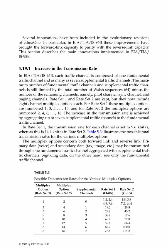
P1: FDJ
book CRC-Wireless November 8, 2001 16:35 Char Count= 327
Several innovations have been included in the evolutionary revisionsof cdmaOne. In particular, in EIA/TIA/IS-95B these improvements havebrought the forward-link capacity to parity with the reverse-link capacity.This section describes the main innovations implemented in EIA/TIA/IS-95B.
5.19.1 Increase in the Transmission Rate
In EIA/TIA/IS-95B, each traffic channel is composed of one fundamentaltraffic channel and as many as seven supplemental traffic channels. The maxi-mum number of fundamental traffic channels and supplemental traffic chan-nels is still limited by the total number of Walsh sequences (64) minus thenumber of the remaining channels, namely, pilot channel, sync channel, andpaging channels. Rate Set 1 and Rate Set 2 are kept, but they now includeeight channel multiplex options each. For Rate Set 1 these multiplex optionsare numbered 1, 3, 5, . . . , 15, and for Rate Set 2 the multiplex options arenumbered 2, 4, 6, . . . , 16. The increase in the transmission rate is achievedby aggregating up to seven supplemental traffic channels to the fundamentaltraffic channel.
In Rate Set 1, the transmission rate for each channel is set to 9.6 kbit/s,whereas this is 14.4 kbit/s in Rate Set 2. Table 5.3 illustrates the possible totaltransmission rates for the various multiplex options.
The multiplex options concern both forward link and reverse link. Pri-mary data (voice) and secondary data (fax, image, etc.) may be transmittedthrough one fundamental traffic channel aggregated with supplemental traf-fic channels. Signaling data, on the other hand, use only the fundamentaltraffic channel.
TABLE 5.3
Possible Transmission Rates for the Various Multiplex Options
Multiplex MultiplexOption Option Supplemental Rate Set 1 Rate Set 2
(Rate Set 1) (Rate Set 2) Channels (kbit/s) (kbit/s)
1 2 01.2, 2.44.8, 9.6
1.8, 3.67.2, 14.4
3 4 1 19.2 28.85 6 2 28.8 43.27 8 3 38.4 57.69 10 4 48.0 72.0
11 12 5 57.6 86.413 14 6 67.2 100.815 16 7 76.8 115.2
© 2002 by CRC Press LLC
E:\Java for Engineers\VP Publication\Java for Engineers.vpThursday, April 25, 2002 9:27:36 AM
Color profile: DisabledComposite Default screen
P1: FDJ
book CRC-Wireless November 8, 2001 16:35 Char Count= 327
In the reverse link, the fundamental traffic channel and the supplementaltraffic channels are transmitted with the same frame offset. Each carrier foreach reverse supplemental traffic channel is shifted by a fixed phase withrespect to the carrier of the fundamental traffic channel.
5.19.2 Power Control
A new power control algorithm has been implemented in EIA/TIA/IS-95B.In this new algorithm an interference correction factor as well as the inclusionof supplemental traffic channels are taken into account. The new formula forthe power control with all factors included is
mean output power = −73 + NOM PWR + INIT PWR− 16 × NOM PWR EXT+ interference correction+ 10 × log(1 + reverse supplemental channels)− mean input power + (n − 1)PWR STEP+ (n0 − n1) (dBm) (5.9)
The parameter NOM PWR EXT is equal to zero for Band Class 0 (800 MHz)mobile stations. The interference correction takes into account the Ec/I0 levelof the active pilot, measured over a span of the last 500 ms. It is given as
interference correction = min {max {−7 − ECIO,0} ,7} (5.10)
where ECIO is Ec/I0 level (dB) of the active pilot. Note from Equation 5.10that no correction is implemented for Ec/I0 within the range from 0 dB downto −7 dB. From −7 dB down to −14 dB an increase of 1 dB per −1 dB decreasein the Ec/I0 is implemented. Below −14 dB a constant correction of 7 dB isimplemented.
Note from Equation 5.10 that an increase in the power is performed as thenumber of supplemental traffic channel increases.
5.19.3 Soft Handoff Criteria
The main innovation in the soft handoff criteria is the definition of newthreshold levels to include or remove the pilots from the various lists. Inaddition to the well-known parameters, namely, T ADD, T COMP, T DROP,and T TDROP, three new parameters are defined: ADD INTERCEPT, DROPINTERCEPT, and SOFT SLOPE.
The inclusion of a pilot into the candidate set follows the same procedureas described earlier, i.e., if the Ec/I0 level of a pilot exceeds T ADD, this
© 2002 by CRC Press LLC
E:\Java for Engineers\VP Publication\Java for Engineers.vpThursday, April 25, 2002 9:27:36 AM
Color profile: DisabledComposite Default screen
P1: FDJ
book CRC-Wireless November 8, 2001 16:35 Char Count= 327
pilot is included within the candidate set. As opposed to EIA/TIA/IS-95A,in which the inclusion or removal of pilots into the active set is based onfixed thresholds, in EIA/TIA/IS-95B such an inclusion is based on a dynamicthreshold, which varies depending on the Ec/I0 levels of the active pilots. Aninclusion is allowed if
10 log PS ≥ ADD INTERCEPT2
+SOFT SLOPE
810 log
∑PSi
where PS is the Ec/I0 level of the candidate pilot and PSi is the Ec/I0 level ofthe active pilot i . Similarly, a pilot is removed from the active set if
10 log PS ≤ DROP INTERCEPT2
+SOFT SLOPE
810 log
∑PSi
Note that the admission criterion is now more stringent because it is nolonger based on the minimum signal level, but on the mean signal levelof the active pilots. Therefore, in EIA/TIA/IS-95B case, the pilots in theactive set present signal levels higher than those of the EIA/TIA/IS-95Acase.
It can be said that the new soft handoff criteria render the system moreflexible with the thresholds for inclusion and removal of pilots set dynami-cally. Therefore, unnecessary handoffs are avoided leading to an increase inthe system capacity.
5.19.4 Hard Handoff
The hard handoff process here concerns the D-to-D handoff, in which a hand-off between CDMA carriers occurs. In EIA/TIA/IS-95A, a D-to-D handoffis carried out via the handoff direction message and the process is knownas break-before-make. In break-before-make, the call is interrupted beforethe acquisition of the new carrier. If the acquisition is successful, the callcontinues; otherwise, the call is interrupted. In EIA/TIA/IS-95B, this un-comfortable situation is circumvented by means of the inclusion of severalinnovations.
Two new pilot lists have been created:
1. Candidate Frequency Neighbor, which is a list containing the pilotsof the CDMA candidate carrier.
2. Candidate Frequency Search Set, which is a list containing the pilotsof the CDMA candidate carrier to be searched under the commandof the base station.
© 2002 by CRC Press LLC
E:\Java for Engineers\VP Publication\Java for Engineers.vpThursday, April 25, 2002 9:27:36 AM
Color profile: DisabledComposite Default screen
P1: FDJ
book CRC-Wireless November 8, 2001 16:35 Char Count= 327
Four new messages have also been included:
1. Candidate Frequency Search Request Message (forward direction).This message is used to command the mobile station to performeither a periodic or single search for pilots of the candidate carrier.
2. Candidate Frequency Response Message (reverse direction). Thismessage is used by the base station to determine an appropriateperiod for the search for pilots of the candidate carrier.
3. Candidate Frequency Control Message (forward direction). This mes-sage is used to direct the mobile station to perform a single search,to initiate a periodic search, or to end a periodic search for the pilotof the candidate carrier.
4. Candidate Frequency Search Report Message (reverse direction). Thismessage contains the measures of the pilot signal strengths of thecandidate carrier.
Several hard handoff scenarios can be described, depending on the modewith which the search is performed and on the exchange of messages. In allthese scenarios, the main purpose is to avoid the break-before-make situation.For this purpose, the configuration of the current pilot set lists is saved, theD-to-D handoff is tried, and if it is not successful the saved configuration isrestored and no handoff is performed.
5.19.5 Idle Handoff
EIA/TIA/IS-95B allows the execution of idle handoffs in situations not per-mitted by EIA/TIA/IS-95A. These situations concern the access procedures,as follows:
Access Handoff. Access handoff may occur in two situations: while the mo-bile station is waiting for an answer from the base station or before sendinga response to the base station. The aim is to have the mobile station utilize apaging channel with a better signal level.
Access Probe Handoff. Access probe handoff may occur when the mobilestation declares loss of the paging channel during an access attempt. There-fore, the mobile station is permitted to carry out a handoff between accessprobes.
5.19.6 Conclusions
A number of innovations have been implemented in the evolved version ofEIA/TIA/IS-95A, the EIA/TIA/IS-95B, to increase capacity and provide forhigher data rate transmissions.
© 2002 by CRC Press LLC
E:\Java for Engineers\VP Publication\Java for Engineers.vpThursday, April 25, 2002 9:27:36 AM
Color profile: DisabledComposite Default screen

P1: FDJ
book CRC-Wireless November 8, 2001 16:35 Char Count= 327
5.20 Summary
TIA/EIA/IS-95 supports a direct sequence spread spectrum technology with1.25-MHz band duplex channels. Coexistence of analog and digital systemsimplies that dual-mode mobile stations are able to place and receive calls inany system and, conversely, all systems are able to place and receive callsfrom any mobile station. Handoff operations in such a scenario require someattention. A mobile station may initiate a call in the CDMA system and, whilethe call is still in progress, it may migrate to the analog system if required. Anumber of innovations have been introduced in the CDMA system as com-pared with earlier cellular systems. Soft handoff is certainly a great novelty.In soft handoff, handoff from one base station to another occurs in a smoothmanner. Another innovation introduced in the CDMA system is the use ofGPS receivers at the base stations. GPSs are utilized so that base stations aresynchronized, a feature vital to the soft handoff operation. Vocoders at vari-able rates are specified to accommodate different voice activities aiming atcontrolling interference levels, thus increasing system capacity. Sophisticatedpower control mechanisms are used so that the full benefit of the spreadspectrum technique is achieved. The first CDMA systems were employedunder the TIA/EIA/IS-95A specifications. The A version of the specificationsevolved to TIA/EIA/IS-95B, in which new features related to higher data ratetransmissions, soft handoff algorithms, and power control techniques havebeen introduced.
References
1. Lee, J. S. and Miller, L. E., CDMA Systems Engineering Handbook, Artech House,Boston, 1998.
2. Mobile Station–Base Station Compatibility Standard for Dual-Mode WidebandSpread Spectrum Cellular System (TIA/EIA-95-A), 1995.
3. Mobile Station–Base Station Compatibility Standard for Dual-Mode Spread Spec-trum Cellular System (TIA/EIA-95-B), 1988.
© 2002 by CRC Press LLC
E:\Java for Engineers\VP Publication\Java for Engineers.vpThursday, April 25, 2002 9:27:36 AM
Color profile: DisabledComposite Default screen

P1: FDJ
book CRC-Wireless November 8, 2001 16:4 Char Count= 303
Part III
Wireless Data
© 2002 by CRC Press LLC
E:\Java for Engineers\VP Publication\Java for Engineers.vpThursday, April 25, 2002 9:27:36 AM
Color profile: DisabledComposite Default screen

P1: FDJ
book CRC-Wireless November 8, 2001 16:4 Char Count= 303
6Wireless Data Technology
6.1 Introduction
The Internet is without doubt one of the major driving forces behind newdevelopments in the area of telecommunications networks. Wireless commu-nication has gained universal acceptance, with the number of wireless sub-scriptions already exceeding the number of fixed lines in many countries. Themerger of the two technologies—Internet and wireless—is an obvious stepand so is the increase of the demand for mobile access to Internet applications.To support efficiently the several types of traffic generated by the great varietyof applications, the resultant network must provide for packet data services.
Within this framework, three data technologies applied to wireless net-works appear as alternatives to be used for packet applications in wireless sys-tems: General Packet Radio Service (GPRS), TIA/EIA/IS–95B, and High DataRate (HDR). This chapter describes the basic architectures of GPRS and HDRand outlines throughputs at the application level that may be achieved bythese technologies. TIA/EIA/IS-95B has already been explored in Chapter 5,and only its achievable data rates are repeated in this chapter.
6.2 General Packet Radio Service
The discussions about GPRS started in the early 1990s with the focus onapplications related to road transport telematics and financial services. Theinitial work aimed at the GSM community. More recently, however, with thewidespread use of end-user applications, such as Web browsing and e-mail,the Internet has become the dominant driving force in the standardization
© 2002 by CRC Press LLC
E:\Java for Engineers\VP Publication\Java for Engineers.vpThursday, April 25, 2002 9:27:36 AM
Color profile: DisabledComposite Default screen

P1: FDJ
book CRC-Wireless November 8, 2001 16:4 Char Count= 303
of GPRS, and technologies other than GSM also incorporate GPRS. Based onpacket-switched principles, GPRS provides optimized access to the Internetwhile reusing to a large extent existing wireless infrastructure. Connection tothe Public Land Mobile Network (PLMN) is based on the Internet protocol(IP), and, on the air interface, the resources are assigned to the terminals on aper-IP packet basis.
The introduction of GPRS within the mobile radio network allows the fol-lowing:
� Both circuit-switched services and packet-switched services� Better use of radio resources� Efficient setup time and access time� Connection to other packet data networks� Services based on quality of service (QoS) requirements� Volume-based charging� Point-to-point and point-to-multipoint services
Five different parameters characterize the QoS profiles, namely, precedence,reliability, maximum bit rate, mean bit rate, and delay for packets of 128 octets.Precedence concerns the priority for transmission, with the priority ranked ashigh, normal, or low. Reliability concerns the packet loss probability, whichcan be fixed according to the needs (e.g., 10−9, 10−4, 10−2, etc.). Maximumbit rate concerns the maximum transmission rate, with the transmission rateranging from 8 kbit/s to 2 Mbit/s. Mean bit rate concerns the mean transmis-sion rate, which is specified to be within the range 0.22 bit/s to 111 kbit/s.Delay for packets of 128 octets concerns the maximum permitted delay, withthe delay specified according to the traffic classes. Four traffic classes are de-fined: conversational (Class 1), streaming (Class 2), interactive (Class 3), andbackground (Class 4). They are specified in terms of the maximum mean de-lay and maximum delay for 95% of the time. Specifically, the maximum meandelay and maximum delay, in seconds, are stipulated, respectively, as 0.5 and1.5 for Class 1 traffic, 5 and 25 for Class 2 traffic, 50 and 250 for Class 3 traffic,and best effort for Class 4.
For a detailed specification of GPRS, the reader is referred to References 1through 9.
6.2.1 Network Architecture
The GPRS network architecture is heavily based on the GSM architecturewhich, in turn, has inspired the ANSI-41 architecture. As such, GPRS can beseen as an extension of GSM or, equivalently, of ANSI-41. In addition to the
© 2002 by CRC Press LLC
E:\Java for Engineers\VP Publication\Java for Engineers.vpThursday, April 25, 2002 9:27:36 AM
Color profile: DisabledComposite Default screen

P1: FDJ
book CRC-Wireless November 8, 2001 16:4 Char Count= 303
SMS-GMSCSMS-IWMSC SM-SC
HLRMSC / VLR
SGSN
Other PLMN
GGSN
GGSN
EIRSGSN
BSCPDN
BTSAbis
BSS
MTTER
MSSGiGnGbUm
Gp Gn Gf
GcGrGs
A
Gd
E C
D
FIGURE 6.1GPRS architecture.
well-known elements of these standards, a new logical network node, namedGPRS support node (GSN), is introduced to provide independent packetrouting and transfer within the PLMN. One such node is the gateway GPRSsupport node (GGSN) and the other is the serving GPRS support node (SGSN).The remaining elements are those as already described in Chapter 4: mobilestation subsystem (MSS), which comprises the terminal equipment (TE), mo-bile terminal (MT), terminal adapter (TA), and subscriber identity module(SIM); base station subsystem (BSS), which comprises the base transceiverstation (BTS) and base station controller; mobile switching center (MSC); vis-itor location register (VLR); home location register (HLR); equipment iden-tity register (EIR); gateway MSC (GMSC); and short message service center(SMSC). Figure 6.1 depicts the GPRS network architecture with its respectiveblocks and interfaces (TA and SIM are not shown here). Next described are theGPRS-relevant functionalities. (For simplicity MSS shall be referred to as MS.)
The GGSN acts as a logical interface with the external packet data network(PDN), which includes the IP PDN or X.25/X.75 packet-switched PDN. Foran external IP network GGSN is seen as an ordinary IP router serving all IPaddresses of the MSs. In addition, it may include firewall and packet-filteringmechanisms and it provides means of assigning the correct SGSN to the MSdepending on its location.
© 2002 by CRC Press LLC
E:\Java for Engineers\VP Publication\Java for Engineers.vpThursday, April 25, 2002 9:27:36 AM
Color profile: DisabledComposite Default screen

P1: FDJ
book CRC-Wireless November 8, 2001 16:4 Char Count= 303
The SGSN acts as a logical interface with the radio access network, beingresponsible for the delivery of packets to the correct BSS. In addition, cipher-ing, authentication, session management, mobility management, and logicallink management to the mobile station are performed by the SGSN.
The MS is equipped with the GPRS protocol stack providing means ofconnecting the user to the GPRS network. Both circuit-switched and packet-switched facilities may be provided within the MS.
The BSS, as already mentioned, contains two elements, namely, the base sta-tion controller (BSC) and the base station transceiver (BTS). The BSC supportsall relevant GPRS protocols for communication over the air interface. In addi-tion, it includes the packet control unit (PCU) logical block, which may residephysically within the BSC itself, the BTS, or the SGSN. The PCU is responsiblefor tasks concerning the packet-switched calls, including setup, supervision,disconnection, handover, radio resource configuration, and channel assign-ment. As far as the GPRS protocols are concerned, the BTS functions as a relaystation performing tasks related to modulation and demodulation.
The MSC, GMSC, VLR, HLR, EIR, and SMSC are functional entities of theinitial circuit-switched network that are enhanced with GPRS subscriber dataand routing information.
6.2.2 Protocol Architecture
Figure 6.2 shows the GPRS protocol stack to the application layer accordingto the International Organization for Standardization/Open Systems Inter-connection (ISO/OSI) Reference Model. It can be seen that GPRS supports
Application
IP / X.25
SNDCP
LLC
GSM RF
Relay
LLC
BSSGP
L1 Bis
SNDCP GTP
NetworkService
UDP /TCP
IP
L2
L1
RLC
MAC
GSM RF L1 Bis
IP / X.25
UDP / TCP
IP
L2
L1
GTP
Um Gb Gn GiGGSNSGSNBSSMSS
NetworkService
MAC
Relay
BSSGPRLC
FIGURE 6.2GPRS protocol stack.
© 2002 by CRC Press LLC
E:\Java for Engineers\VP Publication\Java for Engineers.vpThursday, April 25, 2002 9:27:36 AM
Color profile: DisabledComposite Default screen
P1: FDJ
book CRC-Wireless November 8, 2001 16:4 Char Count= 303
applications based on IP and X.25 as well as other data protocols. Within theGPRS network, say, between two GSNs nodes (e.g., GGSN, SGSN) the GPRStunnel protocol (GTP) is used. The GTP encapsulates the protocol data units(PDUs) at the originating GSN and decapsulates them at the destination GSN.The GTP PDU is then routed over the IP-based GPRS backbone network usingeither the transmission control protocol (TCP), for X.25-based applications,or the user data protocol (UDP), for IP applications. The entire process, asdescribed, is known as GPRS tunneling. Between the serving SGSN and theMS, the Subnetwork Dependent Convergence Protocol (SNDCP) is used tomap the network layer characteristics onto the underlying network. It pro-vides functionalities such as multiplexing of network layer messages ontoa single virtual logical connection, encryption, segmentation, and compres-sion. The logical link control (LLC) provides the logical link between the MSand the SGSN and performs tasks such as ciphering, flow control, sequencecontrol, and error control. The LLC is used by the SNDCP to transfer networklayer PDUs; it is also used by the SMS protocol to transfer SMS messages;and it gives support to GPRS mobility management to transfer control data.The radio link control/multiple access control (RLC/MAC) layer is locatedwithin the PCU. It provides means for the transfer of LLC PDUs using ashared medium between multiple MSs and the network, with this mediumthe GPRS radio interface. In particular, the RLC layer is responsible for thesegmentation and reassembling of LLC PDUs. It may operate in two modes,namely, acknowledged or unacknowledged, in accordance with the requestedQoS. The acknowledged mode of operation provides for detection and recov-ery of transmission errors, whereas the unacknowledged mode of operationprovides for retransmission procedures for uncorrectable data blocks. TheMAC layer operates between the MSs and the BSS (BTS, more specifically). Itis responsible for the signaling procedures concerning radio channel access. Itperforms contention resolution between access attempts, arbitration betweenmultiple service requests from different MSs, and medium allocation to in-dividual users in response to service requests. In particular, procedures aredefined that allow one MSs to utilize several physical channels simultane-ously or several MSs to share one physical channel. The physical layer pro-vides means for information transfer over the physical channel between theMSs and the network. Tasks performed by the physical layer include forwarderror correction coding, interleaving, detection of physical link congestion,modulation and demodulation of physical waveforms, and others. The BSSGPRS protocol (BSSGP) operates between the BSS and the SGSN conveyingrouting and QoS-related information.
6.2.3 Data Flow and Data Structure
The network layer PDUs (or packets) received from the network layerare transmitted across the GPRS air interface using the LLC protocol. This is© 2002 by CRC Press LLC
E:\Java for Engineers\VP Publication\Java for Engineers.vpThursday, April 25, 2002 9:27:36 AM
Color profile: DisabledComposite Default screen

P1: FDJ
book CRC-Wireless November 8, 2001 16:4 Char Count= 303
Application PDU (arbitrary size)
TCP / IP PDU (64 k-octects)
SNDCP PDU (1.56 k-octects)
LLC PDU (1.556 k-octects)
MAC / RLC PDU (20-50 octects)
TCP / IP
SNDCP
MAC /
FIGURE 6.3Segmentation and encapsulation in GPRS (the figures in parentheses show the maximum PDUsize without the header).
accomplished by segmenting and encapsulating each PDU into several otherPDUs. The segmentation and encapsulation process results in considerableheader and signaling overhead such that, in general, 20 to 30% of the GPRS airinterface capacity is spent on protocol overhead.[10] Starting with an arbitraryPDU size for any given application, successive segmentations and encapsu-lations lead to IP PDUs of 64 kbytes, then to SNDCP PDUs of 1.56 kbytes,then to LLC PDUs of 1.556 kbytes, and finally to MAC/RLC PDUs of 20 to50 bytes,[10] as illustrated in Figure 6.3. The RLC/MAC layer provides meansfor information transfer over the physical layer of the GPRS radio interface. Inparticular, the RLC is responsible for the transmission of data blocks across theair interface and for the backward error correction procedures, which consistof selective retransmission of uncorrectable blocks (selective ARQ, S-ARQ).In S-ARQ, blocks in error are retransmitted until a complete frame is success-fully transferred across the RLC layer, in which case the error-free frame isforwarded to the LLC layer.
Given an information block—a segment—resulting from the segmentationof an LLC PDU as illustrated in Figure 6.3, a radio block containing suchinformation is configured for transmission. The processes involved in thisconfiguration include aggregation of overhead information to the segment,convolutional encoding of the resulting block, and puncturing of bits of theencoded message.
The aggregation of information includes a block header, a block check se-quence, and tail bits. The convolutional encoding is specified according to four
© 2002 by CRC Press LLC
E:\Java for Engineers\VP Publication\Java for Engineers.vpThursday, April 25, 2002 9:27:36 AM
Color profile: DisabledComposite Default screen

P1: FDJ
book CRC-Wireless November 8, 2001 16:4 Char Count= 303
different coding schemes (CS), namely, CS-1 (code rate of 1 /2), CS-2 (code rateof 2/3), CS-3 (code rate of 3/4), and CS-4 (code rate of 1). The resulting radioblock, in all cases, will always accommodate 456 bits and the radio block is sentin four time slots. The four time slots use the normal burst and are arrangedin four consecutive frames, the slots and frames following the GSM specifi-cations. The block header is different for control blocks and user data blocks.In the first case, only an MAC header is included. In the second case, bothan MAC header and an RLC header are included. The MAC header consistsof uplink state flag (USF), block type indicator (TI), and power control (PC)fields. The USF field, appearing in any given downlink channel, is used togrant the MS, to which it has been assigned permission to use the correspond-ing uplink channel after a connection is established. The TI field identifies themessage type. The PC field controls the transmission power. Several types ofmessages are identified. Among others, these messages include:
� Packet Data Block (PDB)� Packet Control Acknowledgment (PCA)� Packet Channel Request (PCR)� Packet Resource Request (PRR)� Packet Uplink Assignment (PUA)� Packet Uplink ACK/NACK (PUAck/NAck)� Packet Downlink ACK/NACK (PDAck/NAck)� Packet Paging Request� Packet Paging Response
The use of some of these messages is illustrated later in this chapter.A given network PDU is identified by a temporary flow identifier (TFI),
which is a data field included in all messages belonging to that particular PDU.Figure 6.4 shows the radio block structures for user data and control messages.It also illustrates the coding, encapsulation, and transmission processes. InFigure 6.4, the numbers indicate the bits in each field. Table 6.1 shows theGPRS coding schemes and the respective throughput rate.
As already mentioned, GPRS employs the same frame structure as GSM.Each frame has a duration of 4.615 ms and consists of eight equal-durationtime slots, with each time slot 0.577 ms long. The basic data transmission unitis called radio block and it is used for the transmission of the RLC/MAC PDUs.A radio block uses four time slots arranged in four consecutive frames. There-fore, a radio block has a duration of 2.3075 ms. The structure of a multiframecontaining 52 frames is defined so that every 13th frame, known as an idleburst, is used for purposes other than data transmission, such as measure-ments. Effectively, within a multiframe (52 frames) only 48 frames are used for
© 2002 by CRC Press LLC
E:\Java for Engineers\VP Publication\Java for Engineers.vpThursday, April 25, 2002 9:27:36 AM
Color profile: DisabledComposite Default screen

P1: FDJ
book CRC-Wireless November 8, 2001 16:4 Char Count= 303
TABLE 6.1
GPRS Coding Schemes
RLC Data Throughput RateCode Scheme Code Rate (octects) octets/20 ms (kbit/s)
CS-1 12 20 8
CS-2 23 30 12
CS-3 34 36 14.4
CS-4 1 50 20
USF TI PC RLC Header RLC Data BCS
MAC Header RLC Data Block Block CheckSequence
User Data
USF TI PC RLC / MAC Signaling Information BCS
MAC Header RLC / MAC Control Block Block CheckSequence
Control
attachment of tail bits
coding
puncturing
Radio Block 456
segmentation
114 114 114 114
encapsulation
Time slot x, Frame y+1156.25
Time slot x, Frame y156.25
Time slot x, Frame y+3156.25
Time slot x, Frame y+2156.25
T3
DATA57
F1
TRAIN26
F1
DATA57
T3
GUARD8.25
NormalBURST
T: Tail bitsF: Stealing flagDATA: Data bitsTRAIN: Training bitsGUARD: Guard bits
FIGURE 6.4GPRS radio block structures: user data and control messages; coding, encapsulation, and trans-mission processes.
© 2002 by CRC Press LLC
E:\Java for Engineers\VP Publication\Java for Engineers.vpThursday, April 25, 2002 9:27:36 AM
Color profile: DisabledComposite Default screen
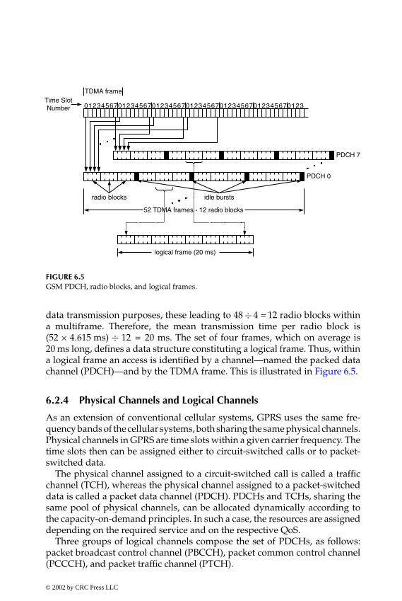
P1: FDJ
book CRC-Wireless November 8, 2001 16:4 Char Count= 303
0123456701234567012345670123456701234567012345670123
TDMA frame
PDCH 7
PDCH 0
radio blocks idle bursts
logical frame (20 ms)
Time SlotNumber
52 TDMA frames - 12 radio blocks
FIGURE 6.5GSM PDCH, radio blocks, and logical frames.
data transmission purposes, these leading to 48 ÷ 4 = 12 radio blocks withina multiframe. Therefore, the mean transmission time per radio block is(52 × 4.615 ms) ÷ 12 = 20 ms. The set of four frames, which on average is20 ms long, defines a data structure constituting a logical frame. Thus, withina logical frame an access is identified by a channel—named the packed datachannel (PDCH)—and by the TDMA frame. This is illustrated in Figure 6.5.
6.2.4 Physical Channels and Logical Channels
As an extension of conventional cellular systems, GPRS uses the same fre-quency bands of the cellular systems, both sharing the same physical channels.Physical channels in GPRS are time slots within a given carrier frequency. Thetime slots then can be assigned either to circuit-switched calls or to packet-switched data.
The physical channel assigned to a circuit-switched call is called a trafficchannel (TCH), whereas the physical channel assigned to a packet-switcheddata is called a packet data channel (PDCH). PDCHs and TCHs, sharing thesame pool of physical channels, can be allocated dynamically according tothe capacity-on-demand principles. In such a case, the resources are assigneddepending on the required service and on the respective QoS.
Three groups of logical channels compose the set of PDCHs, as follows:packet broadcast control channel (PBCCH), packet common control channel(PCCCH), and packet traffic channel (PTCH).
© 2002 by CRC Press LLC
E:\Java for Engineers\VP Publication\Java for Engineers.vpThursday, April 25, 2002 9:27:36 AM
Color profile: DisabledComposite Default screen

P1: FDJ
book CRC-Wireless November 8, 2001 16:4 Char Count= 303
� Packet Broadcast Control Channel. The PBCCH group contains only onechannel, the packet broadcast control channel itself. The PBCCH is adownlink channel conveying overhead information to all GPRS ter-minals within a cell.
� Packet Common Control Channel. The PCCCH group conveys all thenecessary control signaling for initiating packet transfer as well asuser data and dedicated signaling. It is composed of four channels asfollows:1. Packet Random Access Channel (PRACH). The PRACH is an uplink
channel used by the MS to initiate packet transfers or to respondto paging messages.
2. Packet Paging Channel (PPCH). The PPCH is a downlink channelused to page an MS prior to downlink packet transfer.
3. Packet Access Grant Channel (PAGCH). The PAGCH is a downlinkchannel used to convey resource assignments to an MS in thepacket transfer establishment phase.
4. Packet Notification Channel (PNCH). The PNCH is a downlink chan-nel used to send a point-to-multipoint-multicast (PTM-M) notifi-cation to a group of MSs prior to a PTM-M packet transfer. Such anotification has the form of a resource assignment.
� Packet Traffic Channel. The PTCH group is responsible for packet trans-fers and for the control of such transfers. It is composed of two chan-nels as follows:1. Packet Data Transfer Channel (PDTCH). The PDTCH works in the
uplink and downlink directions. It is used for data transfer pur-poses. Any given MS may use one or more PDTCHs for individualpacket transfers.
2. Packet Associated Control Channel (PACCH). The PACCH works inthe uplink and the downlink directions. It conveys signaling in-formation (e.g., acknowledgment, power control information) andresource (re)assignment messages related to a given MS. It is asso-ciated with one or several PDTCHs assigned to that MS.
The GPRS logical channels are depicted in Figure 6.6.
6.2.5 Medium Access
The GPRS radio interface comprises asymmetric and independent uplink anddownlink channels. Therefore, an uplink PDCH occupying a certain timeslot may convey information from a given MS, whereas a downlink PDCH
© 2002 by CRC Press LLC
E:\Java for Engineers\VP Publication\Java for Engineers.vpThursday, April 25, 2002 9:27:36 AM
Color profile: DisabledComposite Default screen

P1: FDJ
book CRC-Wireless November 8, 2001 16:4 Char Count= 303
Packet Broadcast Control Channel
Packet Random Access Channel
Packet Paging Channel
Packet Access Grant Channel
Packet Notification Channel
Packet Data Transfer Channel
Packet Associated Control Channel
Packet BroadcastControl Channels
Packet CommonControl Channels
Packet TrafficChannels
Packet DataChannels
FIGURE 6.6GPRS logical channels. The downward arrow indicates the downlink direction; the upwardarrow indicates the uplink direction.
occupying the same time slot may convey information to a different MS. Theassignment of PDCH resources in both downlink and uplink directions iscontrolled by the BSC, with the assignment carried out on a temporary basisto support the packet-switched principle.
Data transfer is accomplished by means of temporary block flow (TBF). ATBF corresponds to a virtual connection between an MS and the BSS support-ing unidirectional transfer of LLC PDUs on packet data physical channels.Such a virtual connection is maintained throughout the duration of the datatransfer, and the data transfer comprises all the blocks identified by the sameTFI (temporary flow identifier). A TFI is unique in each direction and is as-signed by the BSS. It is 7 bits long for the uplink and 5 bits long for thedownlink. A TBF can be of the closed-ended type (CET) or of the open-endedtype (OET). In a CET TBF, the amount of data to be transferred is negotiatedat the initial access. In the OET TBF, an arbitrary amount of data can be trans-ferred. A TBF is terminated after the completion of the data transfer, whenthe TFI is released. Such a resource allocation scheme is certainly appropriatefor packet transfer. It renders GPRS very flexible, allowing the TBF durationto vary in accordance with the amount of data to be transferred.
Downlink multiplexing is achieved by assigning each data transfer (TBF)a unique TFI. Therefore, data streams destined to different MSs can sharethe same resources because each data stream belonging to a given TBF is
© 2002 by CRC Press LLC
E:\Java for Engineers\VP Publication\Java for Engineers.vpThursday, April 25, 2002 9:27:36 AM
Color profile: DisabledComposite Default screen
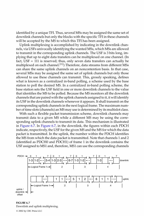
P1: FDJ
book CRC-Wireless November 8, 2001 16:4 Char Count= 303
identified by a unique TFI. Thus, several MSs may be assigned the same set ofdownlink channels but only the blocks with the specific TFI in these channelswill be accepted by the MS to which this TFI has been assigned.
Uplink multiplexing is accomplished by indicating in the downlink chan-nels, via USFs univocally identifying the wanted MSs, which MSs are allowedto transmit in the corresponding uplink channels. The USF is 3 bits long, im-plying that up to eight data transfers can be multiplexed on one channel. (Infact, USF = 111 is reserved; thus, only seven data transfers can actually bemultiplexed on each channel.[11]) Therefore, data streams from different MSscan share the same uplink channels on an noncontention basis. In that case,several MSs may be assigned the same set of uplink channels but only thoseallowed to use these channels can transmit. This, grossly speaking, defineswhat is known as a centralized in-band polling, a scheme used by the basestation to poll the desired MS. In a centralized in-band polling scheme, thebase station sets the USF field in one or more downlink channels to the valuethat identifies the MS to be polled. Because the MS monitors all the downlinkchannels that are paired with the uplink channels assigned to it, it will identifyits USF in the downlink channels whenever it appears. It shall transmit on thecorresponding uplink channels in the next logical frame. The maximum num-ber of time slots (channels) an MS may use is determined by its multislot class.
With such a flexible packet transmission scheme, downlink channels maytransmit data to a given MS while a different MS may be using the corre-sponding uplink channels to transmit its data. This mechanism is illustratedin Figure 6.7. In Figure 6.7, in the downlink, the figures within each PDCHindicate, respectively, the USF for the given MS and the MS for which the datapacket is transmitted. In the uplink, the number within the PDCH identifiesthe MS from which the data packet is transmitted. Note that channels 1 and 2(identified as PDCH0 and PDCH1) of frame 1 in the downlink contains theUSF assigned to MS1 and, therefore, MS1 can use the corresponding channels
1-3 1-2 5-4 1-3 2-3 6-7 1-3 1-2 1-3
0 1 7 0 0 01 1 17 7 7
Logical Frame 1 2 3 4
1 1 5 1 2 6 1 1
Logical Frame 1 2 3 4
uplink /downlink
offset
downlink
uplink
PDCH
FIGURE 6.7Downlink and uplink multiplexing.
© 2002 by CRC Press LLC
E:\Java for Engineers\VP Publication\Java for Engineers.vpThursday, April 25, 2002 9:27:36 AM
Color profile: DisabledComposite Default screen

P1: FDJ
book CRC-Wireless November 8, 2001 16:4 Char Count= 303
of frame 2 in the uplink. In the same channels (channels 1 and 2 of frame 1), inthe downlink, the packet data are transmitted to MS3 and MS2, respectively.Note also that while in channel 1 of frame 2 the permission to transmit isgiven to MS1, in channel 2 of the same frame this is given to MS2 (recall thatin the previous frame this was given to MS1). Other multiplexing situationsare illustrated in Figure 6.7.
6.2.6 Data Transfer Procedure
Two types of access procedures are permitted for data transfer: one-phaseaccess and two-phase access. In the one-phase procedure, data transfer andoverhead procedures, such as service negotiation and mobile verification, oc-cur concurrently within the same access. In the two-phase procedure, datatransfer occurs only after the overhead procedures are accomplished. Theone-phase procedure, therefore, can be faster than two-phase whenever an on-going service negotiation is acceptable from the system and application pointof view. The choice for one or another procedure is left to the system operator.
As detailed previously, once a TBF is established a very efficient data trans-fer procedure is accomplished and no concurrent accesses occur. On the otherhand, the initial uplink access, at the establishment of a TBF, may involvecontention. GPRS uses a slotted-ALOHA-based random-access procedure forcontention resolution. Initial access is certainly a critical phase in establish-ment of TBF and for this reason a special access burst format is specified. Insuch a format, five fields are defined as follows. The first field contains 8 bits(bits numbered from 0 to 7) corresponding to the extended tail bits. The sec-ond field contains 41 bits (bits numbered from 8 to 48) corresponding to theextended synchronization bits. The name extended refers to the bits in excessof 26, as 26 is the number of bits of the synchronization field in the normalburst. As already explained in Chapter 4, such an extension is provided be-cause at the initial access the MS may not have any timing information. Thethird field contains 36 bits (bits numbered from 49 to 84) corresponding tothe encrypted information content. Before coding and encryption, these bitstotal 8 or 11 in number. The information provided by these bits includes:
� Indication of the reason for the access, including one-phase access re-quest, two-phase access request, page response, measurement report,and others
� Indication of the MS class and the requested radio priority� Indication of the number of blocks to be transmitted
The fourth field contains 3 bits (bits numbered from 85 to 87) correspondingto the tail bits. The fifth field contains 68.25 bits (bits numbered from 88 to 156)corresponding to the extended guard period. Here, again, extended refers tothe bits in excess of 8.25, as 8.25 is the number of bits of the guard period field© 2002 by CRC Press LLC
E:\Java for Engineers\VP Publication\Java for Engineers.vpThursday, April 25, 2002 9:27:36 AM
Color profile: DisabledComposite Default screen

P1: FDJ
book CRC-Wireless November 8, 2001 16:4 Char Count= 303
in the normal burst. These bits, together with the extended synchronizationbits, help in the initial access when no timing information may be available.
In addition to the special burst format used for the initial access, an initialaccess also differs from an ordinary data transfer, in which the data blockoccupies four time slots, by using only one time slot. Therefore, if a PDCH isassigned one time slot per frame, there are four access opportunities in everylogical frame (20 ms).
6.2.7 Mobile-Originated Data Transfer
This subsection illustrates mobile-originated data transfer. The MS sends apacket channel request message to the BSS over the packet random accesschannel. In this message, among others, the access type (one-phase or two-phase) is specified. The BSS responds with an packet uplink assignment mes-sage over the packet access grant channel.
� One-Phase Procedure. In the one-phase procedure, the packet uplinkassignment message conveys the information regarding the resourceto be assigned to the MSs. This includes carrier, time slot, USF, TFI,open-ended or closed-ended TBF, packet-associated control channel,etc. Note that, at this point, the network has not yet been informedabout the MS identity or about the requested service. This is accom-plished when the MS communicates with the BSS using an extendedRLC header in the first few blocks to include, for example, the MS tem-porary logical link identifier (TLLI). The network then decodes theTLLI and sends an acknowledgment to the MS in the packet uplinkAck/NAck message. After the successful reception of this messageby the MS the contention resolution phase is completed on both sides(network and terminal). Figure 6.8 illustrates a simplified one-phaseaccess for uplink data transfer procedure. A TBF is terminated withthe packet control acknowledgment message.
� Two-Phase Procedure. In the two-phase procedure, the packet uplink as-signment message conveys the information regarding a single blockallocation. This includes the time slot number, TFI, power controlparameters, and the packet-associated control channel. The MS thensends a packet resource request over the packet-associated controlchannel detailing the information regarding the resource and the serv-ice to be requested. Such information includes the MS TLLI, peakthroughput class, radio priority, measurement report, and open-endedor closed-ended TBF. The BSS responds with a packet uplink assign-ment message indicating the time slot, TFI, USF, TLLI, and others.Data transfer then begins. Figure 6.9 illustrates a simplified two-phaseaccess for the uplink data transfer procedure. A TBF is terminated withthe packet control acknowledgment message.
© 2002 by CRC Press LLC
E:\Java for Engineers\VP Publication\Java for Engineers.vpThursday, April 25, 2002 9:27:36 AM
Color profile: DisabledComposite Default screen
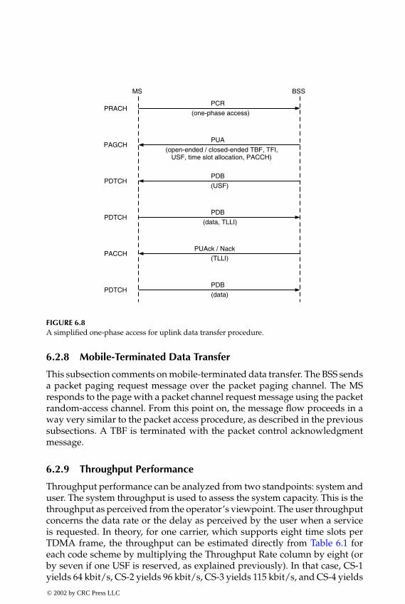
P1: FDJ
book CRC-Wireless November 8, 2001 16:4 Char Count= 303
PCR
(one-phase access)
PUA
(open-ended / closed-ended TBF, TFI,USF, time slot allocation, PACCH)
PDB
(USF)
PDB
(data, TLLI)
PUAck / Nack
(TLLI)
PDB
(data)
MS BSS
PRACH
PAGCH
PDTCH
PDTCH
PDTCH
PACCH
FIGURE 6.8A simplified one-phase access for uplink data transfer procedure.
6.2.8 Mobile-Terminated Data Transfer
This subsection comments on mobile-terminated data transfer. The BSS sendsa packet paging request message over the packet paging channel. The MSresponds to the page with a packet channel request message using the packetrandom-access channel. From this point on, the message flow proceeds in away very similar to the packet access procedure, as described in the previoussubsections. A TBF is terminated with the packet control acknowledgmentmessage.
6.2.9 Throughput Performance
Throughput performance can be analyzed from two standpoints: system anduser. The system throughput is used to assess the system capacity. This is thethroughput as perceived from the operator’s viewpoint. The user throughputconcerns the data rate or the delay as perceived by the user when a serviceis requested. In theory, for one carrier, which supports eight time slots perTDMA frame, the throughput can be estimated directly from Table 6.1 foreach code scheme by multiplying the Throughput Rate column by eight (orby seven if one USF is reserved, as explained previously). In that case, CS-1yields 64 kbit/s, CS-2 yields 96 kbit/s, CS-3 yields 115 kbit/s, and CS-4 yields
© 2002 by CRC Press LLC
E:\Java for Engineers\VP Publication\Java for Engineers.vpThursday, April 25, 2002 9:27:36 AM
Color profile: DisabledComposite Default screen

P1: FDJ
book CRC-Wireless November 8, 2001 16:4 Char Count= 303
PCR(two-phase access)
PUA(single block allocation; time slot, TFI,power control parameters, PACCH)
PRR
PUA(time slot allocation, TFI, USF, TLLI)
PDB(USF)
PDB
MS BSS
PRACH
PAGCH
PACCH
PACCH
PDTCH
PDTCH
(TLLI, peak throughput class, radio priority,open-ended / closed-ended TBF, measurement report)
FIGURE 6.9A simplified two-phase access for uplink data transfer procedure.
160 kbit/s. Nevertheless, if the overhead of all protocols and the phenomenainvolved in the transmission are accounted for, then the actual throughputswill be substantially smaller than these. Note that a great many parametersare involved in such a complex system. Therefore, a precise determinationof the achievable throughputs is a rather intricate task. Many works (e.g.,References 10, 12, and 13) attempt to estimate the GPRS throughput by meansof simulation. Although the figures may vary from one work to another due tothe different simulation platforms utilized, the main conclusions are similar.
The figures to be shown here are extracted from Reference 10. In Refer-ence 10, the simulator models only one cell and one carrier frequency, andmobility and handover scenarios are excluded. In addition, the traffic streamscomprise those used for typical Internet applications such as Web browsers,e-mail transfer, and file transfer. The number of PDCHs considered is eightand the carrier-to-interference ratio (C/I ) varies depending on the codescheme utilized. These values are chosen in such a way that each code schemeoperates to provide for low block error rates and good balance between for-ward error correction and automatic repeat request. The terminals operate inmultislot mode (MSM), in which case they are allowed to make use of more
© 2002 by CRC Press LLC
E:\Java for Engineers\VP Publication\Java for Engineers.vpThursday, April 25, 2002 9:27:36 AM
Color profile: DisabledComposite Default screen

P1: FDJ
book CRC-Wireless November 8, 2001 16:4 Char Count= 303
than one time slot. Specifically, in the simulations of Reference 10 the MSMallows the use of one, two, or four time slots (MSM1, MSM2, MSM4, respec-tively, as named here). The TCP segment size is specified to have 536 bytesand the mean Internet packet loss rate allowed is 2%. Given the asymmetry ofthe Web traffic, and because the uplink network load is not the critical aspectto be considered, the investigations tend to concentrate on the downlink per-formance. Details of the model and parameters used in the simulation maybe found in Reference 10.
System Throughput
The system throughput saturates as the number of Web sessions increases,with the saturation occurring at 44 kbit/s for CS-1 (C/I = 12 dB), 66 kbit/s forCS-2 (C/I = 16 dB), 75 kbit/s for CS-3 (C/I = 20 dB), and 100 kbit/s for CS-4(C/I = 24 dB). If these figures are compared to the theoretical throughputswe notice that losses of 31.25, 31.25, 34.9, and 37.5% for the respective codeschemes are found. The multislot mode feature affects the system through-put only for low traffic load condition (say, fewer than 20 Web users). Betterperformances are achieved by the modes with a greater number of slots. Forheavy traffic load (say, more than 30 Web users) the multislot feature doesnot affect the system throughput substantially, for all PDCHs are found fullyloaded most of the time. The channel conditions, as expected, play a decisiverole in the system performance. CS-1, the most robust code scheme, yieldsthe best performance only for C/I < 6 dB, an unrealistic operation condition.CS-2 yields the best performance for 6 dB < C/I <10 dB. CS-3 yields the bestperformance for 10 dB<C/I <17 dB. Finally, CS-4 performs better for C/I >17dB, i.e., for very good channel conditions. It has also been observed that thesystem throughput increases almost linearly with the increase of the numberof PDCHs, which suggests that better data capacity can be achieved with theaddition of transceivers within a cell.
User Throughput
The user throughput is measured in terms of packet bit rate, the object size(number of bits) divided by the time taken for its transmission (delay). Notethat this is measured during the activity period of the user. Because of thepacket transmission principle, in which the resources are allotted dynamicallyand only during the period of activity of the users, idle phases of some userscan be used for the transmission of data of those users that are active duringthese phases. Here, again, it is observed that the higher the traffic load theless the influence of the multislot mode feature on the user throughput; thesmaller the traffic load, the greater the influence of the multislot mode featureon the user throughput.
For example, for ten Web users MSM1 yields a user throughput that in-creases almost linearly from approximately 5 kbit/s for CS-1 to 12.5 kbit/s
© 2002 by CRC Press LLC
E:\Java for Engineers\VP Publication\Java for Engineers.vpThursday, April 25, 2002 9:27:36 AM
Color profile: DisabledComposite Default screen
P1: FDJ
book CRC-Wireless November 8, 2001 16:4 Char Count= 303
for CS-4; for MSM2 the increase is from 7.5 to 21 kbit/s; for MSM4 the in-crease is from 10 to 31 kbit/s. On the other hand, for high load (say, morethan 40 Web users) the user throughput is almost constant for all the multi-slot modes, still increasing slightly from 1 kbit/s for CS-1 to 4 kbit/s for CS-4(for all multislot modes). Specifically, for CS-2 and for ten Web users 8, 15,and 23 kbit/s are achieved, respectively, for MSM4, MSM2, and MSM1. Asthe number of users increases, for all the multislot modes the throughput de-creases almost linearly, yielding the same throughput of 4.5 kbit/s for 40 Webusers, decreasing further to 2.5 kbit/s for 60 users. In the case of 20 ongoingWeb sessions, for example, each MSM4 user achieves a mean packet bit rateof 15 kbit/s. Another interesting measure is the cumulative distribution ofthe packet bit rate for the several conditions. It is found that for low packetbit rates the distributions for different numbers of users are almost coinci-dent. This is explained by the fact that small objects present a relatively largeheader and protocol overhead (e.g., TCP connection setup) resulting in lowpacket rate. In addition, for lost IP packets, time-consuming retransmissionsare necessary. For fewer than 20 users the great majority of the Web objectsare received with data rates greater than 10 kbit/s. Large objects are usuallyreceived with higher data rates because the header and the relative protocoloverhead in this case are smaller compared with those for small objects.
6.2.10 GPRS—Summary
GPRS technology constitutes an efficient solution for data services. It can beaggregated into existing 2G cellular systems. It has been optimized to supportseveral classes of traffic allowing wireless users to access the Internet and carryout ordinary conversational connections. GPRS permits dynamic and flexi-ble radio resource allocation, this resulting in efficient multiplexing and highthroughput. Higher throughputs can still be accomplished by keeping GPRScore network and introducing new air interfaces. For example, in EDGE (en-hanced data rate for global evolution) a higher-level modulation (8-PSK), inaddition to the traditional GMSK, is introduced. This by itself may increasethe data rate to 384 kbit/s and the spectrum efficiency to 0.5 bit/Hz/base.
6.3 EIA/TIA/IS-95B
EIA/TIA/IS-95B was explored in Chapter 5. Here only the main data trans-mission features of this technology are summarized. In EIA/TIA/IS-95B, each traffic channel is composed of one fundamental traffic channeland as many as seven supplemental traffic channels. The maximum numberof fundamental traffic channels and supplemental traffic channels is still lim-ited by the total number of Walsh sequences (64) minus the number of the© 2002 by CRC Press LLC
E:\Java for Engineers\VP Publication\Java for Engineers.vpThursday, April 25, 2002 9:27:36 AM
Color profile: DisabledComposite Default screen

P1: FDJ
book CRC-Wireless November 8, 2001 16:4 Char Count= 303
TABLE 6.2
Possible Transmission Rates for the Various Multiplex Options
Multiplex MultiplexOption Option Supplemental Rate Set 1 Rate Set 2
Rate Set 1 Rate Set 2 Channels (kbit/s) (kbit/s)
1 2 01.2, 2.44.8, 9.6
1.8, 3.67.2, 14.4
3 4 1 19.2 28.85 6 2 28.8 43.27 8 3 38.4 57.69 10 4 48.0 72.0
11 12 5 57.6 86.413 14 6 67.2 100.815 16 7 76.8 115.2
remaining channels, i.e., pilot channel, sync channel, and paging channels.Rate Set 1 and Rate Set 2 are kept, but they include now eight channel multi-plex options each. For Rate Set 1 these multiplex options are numbered 1, 3,5, 15, and for Rate Set 2 the multiplex options are numbered 2, 4, 6, 16. Theincrease in the transmission rate is achieved by aggregating as many as sevensupplemental traffic channels to the fundamental traffic channel.
In Rate Set 1, the transmission rate for each channel is set to 9.6 kbit/s,whereas this is 14.4 kbit/s in Rate Set 2. Table 6.2 illustrates the possible totaltransmission rates for the various multiplex options.
The multiplex options concern both forward link and reverse link. Pri-mary data (voice) and secondary data (fax, image, etc.) may be transmittedthrough one fundamental traffic channel aggregated with supplemental traf-fic channels. Signaling data, on the other hand, use only the fundamentaltraffic channel.
In the reverse link, the fundamental traffic channel and the supplementaltraffic channels are transmitted with the same frame offset. Each carrier foreach reverse supplemental traffic channel is shifted by a fixed phase withrespect to the carrier of the fundamental traffic channel.
6.4 High Data Rate
The introduction of CDMA systems into the modern wireless market posednew challenges in the design and planning of cellular networks. The 2GCDMA technology was conceived primarily for two-way conversationalspeech, which requires strict adherence to symmetry and small latencies (lessthan 100 ms). Circuit-switched principles easily solve the latency question but,© 2002 by CRC Press LLC
E:\Java for Engineers\VP Publication\Java for Engineers.vpThursday, April 25, 2002 9:27:36 AM
Color profile: DisabledComposite Default screen

P1: FDJ
book CRC-Wireless November 8, 2001 16:4 Char Count= 303
depending on the access technology, full symmetry requires more elaboratesolutions. Downlink and uplink in 2G CDMA systems are inherently asym-metric with the reverse direction (uplink) initially believed to be the capacity-limiting link (bottleneck). This surmise turned out to be incorrect: the forwarddirection (downlink) constitutes the actual bottleneck. (The reader is referredto Chapter 5 for more information on this.) The evolutionary revisions ofcdmaOne (IS-95-B and cdma2000), which implement fast power control inthe forward link and introduce new criteria for enhanced soft handoff, haveconsiderably improved the forward-link performance, bringing its capacityto parity with that of the uplink. Although this may suffice for voice applica-tions, which are the main target of 2G systems, link symmetry is by no meansa solution for high-speed data applications. On the contrary, the downlinkdemand is likely to be several times greater than the uplink demand, forexample, whenever Internet applications are the focus.
cdmaOne provides an excellent solution for systems where low-rate chan-nels share a common bandwidth. For a small number of high-rate data userssharing the same bandwidth, however, better solutions may be found. ACDMA system providing for mixed low-rate data service (with voice theprimary service in this category) and high-rate data service requires an inno-vative solution. HDR is certainly one such innovative solution.
6.4.1 HDR Solution
HDR are stand-alone systems, designed to be highly interoperable with IS-95and multicarrier (MC) CDMA systems, with the design leveraging in manyways the lessons learned from the development and operation of IS-95 net-works. Along with the interoperability feature, HDR systems can reuse largeportions of components and designs already implemented in IS-95 products.Dual-mode terminals, therefore, can be implemented in a compact and cost-effective manner, allowing users to have access to both voice services, throughan IS-95 frequency carrier, and data services, through an HDR frequencycarrier.
The first fundamental design choice in HDR is to separate low-rate dataservices (voice) from high-rate data services by using nonoverlapping spec-trum allocations for these different services. In essence, the HDR solutionfor a CDMA system in which both types of services are provided uses sep-arate carriers for the respective services. An IS-95 RF carrier is used forvoice applications and a separate HDR RF carrier is utilized for data ap-plications. Within an HDR RF carrier, forward and reverse links are designedto operate in distinct modes. Packet transmissions on the HDR forward linkare time-division-multiplexed and occur at full power and at variable rates,with packets having variable durations (packets have variable sizes). Packettransmissions on the HDR reverse link are code-division-multiplexed and
© 2002 by CRC Press LLC
E:\Java for Engineers\VP Publication\Java for Engineers.vpThursday, April 25, 2002 9:27:36 AM
Color profile: DisabledComposite Default screen

P1: FDJ
book CRC-Wireless November 8, 2001 16:4 Char Count= 303
occur at variable rates, but with packets having fixed durations (packets havefixed sizes).
In HDR, the access terminal (user terminal) and the access point (basestation) jointly determine the highest rate a subscriber can support at anyinstant. This is accomplished by means of the deployment of a combinationof techniques based on channel measurement, channel control, and interfer-ence suppression and mitigation. In particular, each access terminal assessesthe quality of the signals (signal-to-noise ratio, or SNR) received from neigh-boring access points. The best access point is chosen and its SNR, or equiva-lently the supportable data rate value, is indicated to the corresponding accesspoint. Note that this may change continuously because of the nonstationarycondition of the wireless channel (motion of the user, change of the propa-gation conditions, etc.). Therefore, the monitoring of the SNRs of the variousaccess points and the selection of the best access point must be performedcontinuously, which has a direct implication for the supportable data rate.Packet transmissions on the forward link, then, occur with data rates andpacket durations that vary in accordance with the user channel conditions.Hence, it may be said that the HDR forward-link supports dynamic data rates.Packet transmissions on the reverse link, in turn, occur with variable rates butfixed packet duration. The HDR reverse link does not support dynamic datarates.
By always making use of the best SNR available, interference is reduced.Moreover, because data services tolerate latencies better than voice services,robust error-correction coding techniques (for example, turbo coding) can beemployed. Therefore, the system may operate at lower ratio of energy-per-bitto noise (Eb/N0) and hence lower SNR and higher interference levels. HDRdesigners[14] claim that the HDR peak data rate may reach 2457.6 kbit/s onthe forward link and 307.2 kbit/s on the reverse link.
6.4.2 Network Architecture
The basic elements of an HDR system are the access terminal and the accesspoint. Several network architectures may be selected to accommodate these el-ements and provide for wireless packet data communication. In Reference 15,the choice fell on the most ubiquitous packet data network, namely, the In-ternet. Basically, as far as air interface is concerned, the entire network maybe split into the user side and the network side.
The user side—the user terminal—contains two functional elements: dataterminal (e.g., a computer) and access terminal. These functional elementsmay physically reside in two devices or in one device. The functionalpartitioning method in the first case is referred to as network model, whereas inthe second case this is known as relay model. In the network model, the two el-ements may be connected by means of any standard interface (e.g., Ethernet,
© 2002 by CRC Press LLC
E:\Java for Engineers\VP Publication\Java for Engineers.vpThursday, April 25, 2002 9:27:36 AM
Color profile: DisabledComposite Default screen
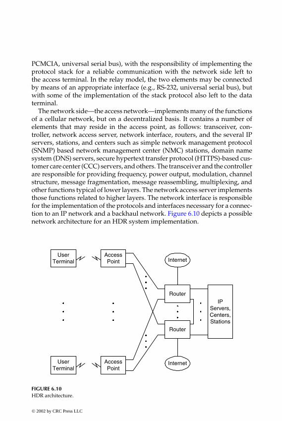
P1: FDJ
book CRC-Wireless November 8, 2001 16:4 Char Count= 303
PCMCIA, universal serial bus), with the responsibility of implementing theprotocol stack for a reliable communication with the network side left tothe access terminal. In the relay model, the two elements may be connectedby means of an appropriate interface (e.g., RS-232, universal serial bus), butwith some of the implementation of the stack protocol also left to the dataterminal.
The network side—the access network—implements many of the functionsof a cellular network, but on a decentralized basis. It contains a number ofelements that may reside in the access point, as follows: transceiver, con-troller, network access server, network interface, routers, and the several IPservers, stations, and centers such as simple network management protocol(SNMP) based network management center (NMC) stations, domain namesystem (DNS) servers, secure hypertext transfer protocol (HTTPS)-based cus-tomer care center (CCC) servers, and others. The transceiver and the controllerare responsible for providing frequency, power output, modulation, channelstructure, message fragmentation, message reassembling, multiplexing, andother functions typical of lower layers. The network access server implementsthose functions related to higher layers. The network interface is responsiblefor the implementation of the protocols and interfaces necessary for a connec-tion to an IP network and a backhaul network. Figure 6.10 depicts a possiblenetwork architecture for an HDR system implementation.
UserTerminal
AccessPoint
Router
Router
UserTerminal
AccessPoint
IPServers,Centers,Stations
Internet
Internet
FIGURE 6.10HDR architecture.
© 2002 by CRC Press LLC
E:\Java for Engineers\VP Publication\Java for Engineers.vpThursday, April 25, 2002 9:27:36 AM
Color profile: DisabledComposite Default screen

P1: FDJ
book CRC-Wireless November 8, 2001 16:4 Char Count= 303
6.4.3 Protocol Architecture
The HDR protocol stack layers and the respective default protocols are shownin Figure 6.11.[14] Next, these layers and protocols are briefly described.
� Physical Layer (PHYL). The PHYL is responsible for the provision of thechannel structure, frequency, power output, modulation, and encod-ing specifications for both the forward channels and reverse channels.
� Multiple Access Control Layer (MACL). The MACL is responsible forthe definition of the procedures used to transmit and receive over thePHYL. Four default protocols governing the operation of the variouschannels are defined within the MACL as follows (the channels aredescribed later in this chapter):Control Channel MAC Protocol (CMP). The CMP contains rules con-
cerning the control channel. It governs the following: access net-work transmission over the control channel; packet schedulingover the control channel; access terminal acquisition of the controlchannel; access terminal packet reception over the control channel;and inclusion of the access terminal address into the packets to betransmitted.
Access Channel MAC Protocol (AMP). The AMP contains rules concern-ing the access channel. It governs the following: access terminaltransmission timing; power characteristics; and rate selection.
Forward Traffic Channel MAC Protocol (FMP). The FMP contains rulesconcerning the forward traffic channel. In particular, the FMPsupports both variable operation and fixed operation of the
HMP PPP
SLP RLP-
STP
SBP SCP
LMP ISP DSP CSP
PCP RDP OMP
-
CMP FMP AMP RMP
Forward and Reverse Channels
APPL
STRL
SSSL
CNNL
SCTL
MACL
PHYL
ProtocolsLayers
FIGURE 6.11HDR protocol stack layers (default protocols).
© 2002 by CRC Press LLC
E:\Java for Engineers\VP Publication\Java for Engineers.vpThursday, April 25, 2002 9:27:36 AM
Color profile: DisabledComposite Default screen

P1: FDJ
book CRC-Wireless November 8, 2001 16:4 Char Count= 303
forward traffic channel. It governs tasks related to the data ratecontrol channel including access terminal data rate control chan-nel transmission and access network data rate control channelreception.
Reverse Traffic Channel MAC Protocol (RMP). The RMP contains rulesconcerning the reverse traffic channel. It governs the following:communication between the access terminal and the access net-work for the acquisition of the reverse traffic channel; and reversetraffic channel data rate selection.
� Security Layer (SCTL). The SCTL is simply a relay layer, responsible fortransferring packets between its adjacent layers. It does not provideany services.
� Connection Layer (CNNL). The CNNL is responsible for the control ofthe state of the HDR airlink and for the prioritization of the trafficsent over this layer. In particular, the access terminal may be foundin one of three possible states, namely, initialization state, idle state,and connected state. In the initialization state, the access terminal hasyet to acquire the network. In the idle state, the access terminal hasalready acquired the network but the connection is still closed. Inthe connected state, the access terminal has an open connection withthe network. Within CNNL, seven default protocols are defined asfollows.Air Link Management Protocol (LMP). The LMP is responsible for the
activation of the protocols that perform the different actions ac-cording to the states at which the access terminal is found. Eachstate is governed by one protocol. Therefore, three different stateprotocols, the next three described below, are defined.
Initialization State Protocol (ISP). The ISP is activated by the LMP per-forming the actions associated with the HDR network acquisition.
Idle State Protocol (DSP). The DSP is activated by the LMP perform-ing actions associated with access terminal location, connectionopening, and access terminal power conservation.
Connection State Protocol (CSP). The CSP is activated by the LMP per-forming actions associated with connection closing and link man-agement between access terminal and access network.
Packet Consolidation Protocol (PCP). The PCP is responsible for theconsolidation and prioritization of packets for transmission.
Route Update Protocol (RDP). The RDP is responsible for actions asso-ciated with access terminal location and link maintenance betweenaccess terminal and access network.
© 2002 by CRC Press LLC
E:\Java for Engineers\VP Publication\Java for Engineers.vpThursday, April 25, 2002 9:27:36 AM
Color profile: DisabledComposite Default screen

P1: FDJ
book CRC-Wireless November 8, 2001 16:4 Char Count= 303
Overhead Messages Protocol (OMP). The OMP is responsible for broad-casting essential parameters over the control channel.
� Session Layer (SSSL). The SSSL is responsible for providing protocolsused to negotiate a session between the access terminal and the accessnetwork. A session is defined as a state shared by the access termi-nal and the access network in which the following information isincluded: access terminal unicast address; airlink protocols for com-munication between the access terminal and the access network; con-figuration settings for airlink session protocols; and estimate of theaccess terminal location. Within SSSL, two default protocols are de-fined as follows.
Session Control Protocol (SCP). The SCP is responsible for the following:provision of means for session negotiation; provision of airlinkprotocols; provision of configuration parameters; and closing ofthe session.
Session Boot Protocol (SBP). The SBP is responsible for providingthe following: unicast address assignment to the access terminal;and means to negotiate the type of SCP to be used during thesession.
� Stream Layer (STRL). The STRL accommodates the stream protocol(STP). It is responsible for the provision of multiplexing of applicationstreams for one access terminal. It is also responsible for configurationmessages that map applications to streams.
� Application Layer (APPL). The APPL contains four default protocolsas follows.
HDR Messaging Protocol (HMP). The HMP is responsible for routingmessages to protocols.
Signaling Link Protocol (SLP). The SLP is responsible for the provisionof best effort and reliable message delivery for the HMP, mes-sage fragmentation, and duplicate detection and retransmissionfor messages using reliable delivery.
Radio Link Protocol (RLP). The RLP is responsible for providing an octetstream service with a satisfactorily low erasure rate so that higherlayer protocols (e.g., TCP) may operate adequately. The RLP makesuse of a NAck-based scheme and of an efficient retransmissionmechanism due to sequencing of octets rather than sequencingof frames. In that case, complex segmentation and reassemblingtasks are avoided in case retransmitted frames cannot fit into theavailable payload information field. Error rates in the order of 10−6
may be delivered by RLP.
© 2002 by CRC Press LLC
E:\Java for Engineers\VP Publication\Java for Engineers.vpThursday, April 25, 2002 9:27:36 AM
Color profile: DisabledComposite Default screen

P1: FDJ
book CRC-Wireless November 8, 2001 16:4 Char Count= 303
Point-to-Point Protocol (PPP). The PPP is responsible for providing anoctet stream to convey transmission of packets between the accessterminal and the access network.
6.4.4 Channels and Channel Structure
The HDR solution for a CDMA system in which voice and packet servicesare provided uses separate carriers for the respective services. An IS-95 RFcarrier is used for voice applications and a separate HDR RF carrier is used fordata applications. In contrast to the IS-95 system, in which the forward-linkpower is shared by all users, in HDR, there is no power sharing and packettransmissions are time-division-multiplexed and occur at full power. Packettransmissions on the forward link occur with data rates and packet lengthsthat vary in accordance with the user channel conditions. The HDR reverselink, on the other hand, enjoys a solution similar to that of the IS-95, enhancedto accommodate higher data rates. Packet transmissions on the reverse link,in turn, occur with variable data rates but with fixed packet lengths. In HDR,both forward link and reverse link use a pilot-aided, coherent demodulation,as opposed to IS-95 in which only the forward link presents such a feature.Several channels and subchannels, six on the forward link and seven on thereverse link, are defined, as illustrated in Figure 6.12.
Forward-Link Channel Structure
The HDR forward link contains four groups of time-division-multiplexedchannels: pilot channel, medium access channels, traffic channel, and controlchannel. The medium access channels are composed of the forward activ-ity channel, reverse activity channel, and reverse power control channel.
� Pilot Channel. The pilot channel is a common pilot transmitted at fullpower by each access point at predetermined intervals. It can be usedto estimate the channel conditions (SNR) and is received only in thepresence of pilots from other access points, and is not affected byinterference of data transmission.
� Forward Activity Channel. The forward activity channel indicates theactivity of the forward link. It is used to help the access point and theaccess terminal determine the optimum data rate for packet transmis-sion.
� Reverse Activity Channel. The reverse activity channel indicates the ac-tivity of the reverse link. It is used to help the access point and theaccess terminal determine the optimum data rate for packet transmis-sion.
© 2002 by CRC Press LLC
E:\Java for Engineers\VP Publication\Java for Engineers.vpThursday, April 25, 2002 9:27:36 AM
Color profile: DisabledComposite Default screen

P1: FDJ
book CRC-Wireless November 8, 2001 16:4 Char Count= 303
Pilot Channel
Forward Activity ChannelMAC
Channels
ForwardChannels
Traffic Channel
Control Channel
Reverse Activity Channel
Reverse Power Control Channel
Data Channel
MACChannels
ReverseChannels
Pilot Channel
Data Rate Control Channel
AccessChannels
TrafficChannels
Data Channel
MACChannels
Pilot Channel
Data Rate Control Channel
Reverse Rate Indicator Channel
HDRChannels
FIGURE 6.12HDR channels and subchannels.
� Reverse Power Control Channel. The reverse power control channel isused for reverse-link power control purposes.
� Traffic Channel. The traffic channel is used for packet data transmissionpurposes.
� Control Channel. The control channel combines the functions of theIS-95 sync and paging overhead channels. It is time set aside on theforward link at a given fixed rate, as explained next.
The HDR forward-link channel structure is based on 26.67 ms framesaligned to the PN rolls of the zero-offset PN sequences, a frame containing215 chips in accordance with the 1.2288 Mchip/s transmission rate. A frameis composed of 16 1.67 ms slots; each slot, therefore, encompasses 2048 chips.For control purposes, a frame is split into two half frames, each half frame
© 2002 by CRC Press LLC
E:\Java for Engineers\VP Publication\Java for Engineers.vpThursday, April 25, 2002 9:27:36 AM
Color profile: DisabledComposite Default screen

P1: FDJ
book CRC-Wireless November 8, 2001 16:4 Char Count= 303
Control Traffic Traffic Traffic Traffic Traffic Control
Frame 1 Frame 2 Frame 15
26.67 ms = 16 slots
400 ms = 240 slots
13.33 ms = 8 slots 13.33 ms = 8 slots
1 slot = 1.67 ms(2048 chips)
1/2 slot 1/2 slot
MAC and ControlPilot
MAC and Control
1 slot = 1.67 ms(2048 chips)
1/2 slot 1/2 slot
MAC and ControlPilot
MAC and Control
FIGURE 6.13HDR forward-link channel structure.
then comprising eight slots. At a frequency of 2.5 Hz, one such half frame istransmitted with control information, composing the control channel. Hence,the control channel is sent once every 400 ms for a duration of 13.33 ms.Within the same period, of the 30 half frames 29 are transmitted with data,composing the traffic channels. Note that the 400 ms encompasses 240 slots,eight dedicated to the control channel and 232 to the traffic channels. Each slotis further split into two half slots, each of which contains a pilot burst—thepilot channel. The pilot channel has a duration of 78.125 µs, or 96 chips, andis centered at the midpoint of the half slot. The remainder of the half slot isshared by the medium access control channels and either the control channelor the traffic channel, as appropriate. Whereas the traffic channels are trans-mitted at a variable bit rate ranging from 38.4 to 2457.6 kbit/s, the controlchannel is transmitted at a fixed rate of 76.8 kbit/s. Figure 6.13 illustrates theHDR forward-link channel structure.
Reverse-Link Channel Structure
The HDR reverse link contains two groups of code-multiplexed channels:traffic channel group and access channel group. The traffic channel groupcontains the pilot channel, the medium access control channel, and the datachannel. The access channel group contains the pilot channel, the medium ac-cess control channel, and the data channel. Within the traffic channel group,the medium access control channel includes the reverse rate indicator chan-nel and the data rate control channel. Within the access channel group, the
© 2002 by CRC Press LLC
E:\Java for Engineers\VP Publication\Java for Engineers.vpThursday, April 25, 2002 9:27:36 AM
Color profile: DisabledComposite Default screen
P1: FDJ
book CRC-Wireless November 8, 2001 16:4 Char Count= 303
medium access channel includes only the reverse rate indicator channel. Inboth the traffic channel group and the access channel group, the pilot channeland the medium access control channels are time-multiplexed and separatedfrom the data channel by means of codes.
� Pilot Channel (Traffic Channel group). The pilot channel is used for co-herent demodulation of the (traffic) data channel.
� Reverse Rate Indicator Channel (Traffic Channel group). The reverse rateindicator channel indicates the rate at which the (traffic) data channelis sent.
� Data Rate Control Channel (Traffic Channel group). The data rate controlchannel indicates the required rate at which data information is senton the (traffic) data channel.
� Data Channel (Traffic Channel group). The data channel conveys userdata for data transfer purposes.
� Pilot Channel (Access Channel group). The pilot channel is used forcoherent demodulation of the (access) data channel.
� Reverse Rate Indicator Channel (Access Channel group). The reverse rateindicator channel indicates the rate at which the (access) data channelis sent.
� Data Channel (Access Channel group). The data channel conveys dataconcerning user access.
The HDR reverse-link channel structure is based on fixed-duration packets,a deviation from the forward-link channel structure in which packets havevariable sizes. The reverse-link structure consists of 32 1.67-ms slots, with atotal duration of 53.33 ms. Each slot comprises 2048 chips and is further splitinto 32 64-chip subslots. The frames are multiples of 26.67 ms and traditionalIS-95 power control mechanisms and soft handoffs are supported. Whereasthe traffic data channel supports data rates ranging from 4.8 to 307.2 kbit/s,the data rate on the access data channel is fixed at 9.6 kbit/s. In both thetraffic channel group and access channel group, the pilot channel and the datarate control channel are time-division-multiplexed at a 50% duty cycle. Thereverse rate indicator channel, which is not included within the access channelgroup, appears as the preamble of the reverse-link frame. More specifically, thereverse rate indicator channel is time-multiplexed with the pilot channel anddate rate control channel, occupying only one subslot (64 chips). Figure 6.14illustrates the HDR reverse-link channel structure.
6.4.5 Medium Access
As already mentioned, HDR employs a time-shared forward link, and no for-ward power sharing is used, such that, when being served, an access terminal
© 2002 by CRC Press LLC
E:\Java for Engineers\VP Publication\Java for Engineers.vpThursday, April 25, 2002 9:27:36 AM
Color profile: DisabledComposite Default screen
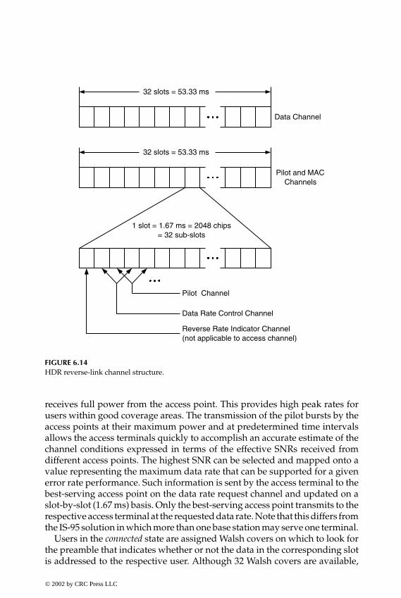
P1: FDJ
book CRC-Wireless November 8, 2001 16:4 Char Count= 303
32 slots = 53.33 ms
32 slots = 53.33 ms
Data Channel
Pilot and MACChannels
1 slot = 1.67 ms = 2048 chips= 32 sub-slots
Pilot Channel
Data Rate Control Channel
Reverse Rate Indicator Channel(not applicable to access channel)
FIGURE 6.14HDR reverse-link channel structure.
receives full power from the access point. This provides high peak rates forusers within good coverage areas. The transmission of the pilot bursts by theaccess points at their maximum power and at predetermined time intervalsallows the access terminals quickly to accomplish an accurate estimate of thechannel conditions expressed in terms of the effective SNRs received fromdifferent access points. The highest SNR can be selected and mapped onto avalue representing the maximum data rate that can be supported for a givenerror rate performance. Such information is sent by the access terminal to thebest-serving access point on the data rate request channel and updated on aslot-by-slot (1.67 ms) basis. Only the best-serving access point transmits to therespective access terminal at the requested data rate. Note that this differs fromthe IS-95 solution in which more than one base station may serve one terminal.
Users in the connected state are assigned Walsh covers on which to look forthe preamble that indicates whether or not the data in the corresponding slotis addressed to the respective user. Although 32 Walsh covers are available,
© 2002 by CRC Press LLC
E:\Java for Engineers\VP Publication\Java for Engineers.vpThursday, April 25, 2002 9:27:36 AM
Color profile: DisabledComposite Default screen

P1: FDJ
book CRC-Wireless November 8, 2001 16:4 Char Count= 303
only 29 can be assigned to the users, with the remaining three used for otherpurposes. Therefore, a maximum of 29 simultaneous users can actually be inthe connected state, actively transmitting or receiving packets. A larger num-ber of users may be supported depending on the channel activity. For burstytraffic, which is usually the case in Internet applications, some users may notbe actively using the link. In this case, the connection becomes dormant andmore users may be included within the system. Note that the total through-put of an HDR forward link is shared by all active users, with users allowedto transmit packets of variable lengths. Therefore, the smaller the number ofactive users, the higher the achievable throughput per user.
The HDR system makes use of a scheduling algorithm to maximize itsthroughput. The scheduling algorithm takes advantage of two facts as fol-lows. In general, different users require different services, therefore differentdata rate requirements. In addition, the channel conditions vary from userto user. Note that the different services in connection with the channel vari-ability lead to time-varying requested data rates. Basically, the schedulingalgorithm makes use of the proportional fairness scheduler (PFS) in whichonly those users near their peaks of requested rates are allowed to be served,and the disadvantaged users are not then served. PFS maximizes the productof the throughputs delivered to all of the users such that the increase of thethroughput of one user by a given proportion is accomplished at the expenseof the decrease of the cumulative throughput of all users by the same propor-tion. More specifically, the PFS is implemented as follows. The instantaneousdata rate requests on the data rate request channel are filtered over a certainnumber of slots (100 slots as specified in Reference 14) by means of the mov-ing average algorithm. The instantaneous data rate requests are comparedwith the filtered average and only those data rates requests above the fil-tered average will be served. It is claimed[14] that a substantial increase in thethroughput is obtained with the application of such an algorithm. “PFS takesadvantage of the channel variation over the short term to increase throughputbut maintain the grade of service fairness over longer periods.”[14]
6.4.6 Throughput Performance
HDR forward and reverse links operate in different modes, as already men-tioned. The forward link supports dynamic data rates, whereas the reverselink offers fixed data rates for a given connection. Table 6.3 shows the theoret-ical HDR forward-link throughput. Note that different modulations schemesare used. In particular, QPSK is used to achieve 38.4 through 1228.8 kbit/s,8-PSK for 1843.2 kbit/s, and 16-QAM for 2457.6 kbit/s. Based on simula-tion studies and according to Reference 14 the required SNRs, expressed interms of received signal energy density and the total nonorthogonal single-sided noise density (intercell interference, thermal noise, and nonorthogonal
© 2002 by CRC Press LLC
E:\Java for Engineers\VP Publication\Java for Engineers.vpThursday, April 25, 2002 9:27:36 AM
Color profile: DisabledComposite Default screen

P1: FDJ
book CRC-Wireless November 8, 2001 16:4 Char Count= 303
TABLE 6.3
HDR Forward-Link Throughput
Data Rate Packet Length Packet Duration Number Modulation(kbit/s) (bits) (ms) of Slots Scheme
38.4 1024 26.67 16 QPSK76.8 1024 13.33 8 QPSK
102.4 1024 10.00 6 QPSK153.6 1024 6.67 4 QPSK204.8 1024 5.00 3 QPSK307.2 1024 3.33 2 QPSK614.4 1024 1.67 1 QPSK921.6 3072 3.33 2 QPSK
1228.8 2048 1.67 1 QPSK1843.2 3072 1.67 1 8-PSK2457.6 4096 1.67 1 16-QAM
intracell interference), for the various rates are shown in Table 6.4. Table 6.5shows the theoretical HDR forward-link throughput. Note that BPSK is usedto achieve 4.8 through 153.6 kbit/s and QPSK for 307.2 kbit/s. The accessterminal is granted free permission to transmit at 4.8, 9.6, and 19.2 kbit/s. Inorder for the access terminal to transmit at rates above 19.2 kbit/s, permissionmust be granted by the access point, and this will depend on the link activity.
In Reference 14, the average throughput (bits/sector) of an HDR forward-link sector for a system consisting of two three-sector cells and one omni-cellsite is reported. The throughput has been observed to increase with the in-crease of the number of users, a consequence of the use of the schedulingalgorithm in which the more-advantaged users are preferentially served. Theincrease, however, seems to reach a saturation point around ten users per
TABLE 6.4
HDR Forward-Link Throughput and SNR
Data Rate (kbit/s) SNR (dB)
76.8 −9.5102.4 −8.5153.6 −6.5204.8 −5.7307.2 −4.0614.4 1.0921.6 1.3
1228.8 3.01843.2 7.22457.6 9.5
© 2002 by CRC Press LLC
E:\Java for Engineers\VP Publication\Java for Engineers.vpThursday, April 25, 2002 9:27:36 AM
Color profile: DisabledComposite Default screen

P1: FDJ
book CRC-Wireless November 8, 2001 16:4 Char Count= 303
TABLE 6.5
HDR Reverse-Link Throughput
Data Rate Packet Length Packet Duration Number Modulation(kbit/s) (bits) (ms) of Slots Scheme
4.8 256 53.33 32 BPSK9.6 512 53.33 32 BPSK
19.2 1024 53.33 32 BPSK38.4 2048 53.33 32 BPSK76.8 4096 53.33 32 BPSK
153.6 8192 53.33 32 BPSK307.2 8192 53.33 32 QPSK
sector. Single-antenna and dual-antenna access terminals with maximal ratiocombining have been tested. In the first case (single-antenna access terminal),the average throughput is reported to be 750 kbit/s for stationary users and500 kbit/s for nonstationary users. In the second case (dual-antenna accessterminal), the figures are reported to be 1.05 and 900 Mbit/s, respectively. Re-sults for indoor stationary users have been obtained by means of simulation;the average throughput is 650 kbit/s for a single-antenna access terminal and1.15 Mbit/s for a dual-antenna access terminal.
6.4.7 Handoff Features
In HDR systems, the downlink communication follows the best server rule. Inother words, the access terminal communicates with only one access point,the one presenting the highest SNR. Therefore, as opposed to IS-95 systems,in which the terminal may combine signals from different base stations forsoft handoff purposes, in HDR, only one access point—the best server—isselected at any instant, with the best server selection occurring rapidly fromone access point to another. Note that, whereas a variability in user throughputor in user latency is unacceptable for voice services, for packet data servicesthis is quite legitimate. And this is the reason soft handoff is a mandatoryfeature in IS-95 systems and totally dispensable in HDR networks. The uplinkcommunication in HDR systems enjoys the same feature as that of the IS-95networks. In other words, the access terminal may communicate with morethan one access point, and a frame selection procedure is carried out to havethe best frame selected.
Assuming dual-mode terminals, several handoff scenarios between HDRand IS-95—or its evolved 3G version (the so-called multicarrier or MC)—systems are envisaged. For ease of notation, both IS-95 and MC are herereferred to as simply MC.
© 2002 by CRC Press LLC
E:\Java for Engineers\VP Publication\Java for Engineers.vpThursday, April 25, 2002 9:27:36 AM
Color profile: DisabledComposite Default screen

P1: FDJ
book CRC-Wireless November 8, 2001 16:4 Char Count= 303
� HDR system and MC system with nonoverlapped service areas. Assumethat the access terminal is found within an area served by either anHDR system or an MC System. As it moves toward the other system,a handoff may be performed in the active mode or in the dormantmode. This occurs on the airlink side and on the network side. Onthe airlink side, the access terminal is informed that it is going outof range and that it should look for pilots from both systems. Thesystem with the strongest pilot is then chosen to host the subscriber.On the network side, the access terminal performs the registration, asrequired.
� HDR system and MC system with overlapped service areas. Assume thatthe access terminal is found within an area served by both an HDRsystem and an MC system. Consider that a page for an incomingvoice service instance from the MC system is received while the accessterminal is exchanging data within the HDR system. The followingmay be carried out: the access terminal may continue the data call onthe MC system; or the access terminal may abandon the HDR dataservices instance, handoff to the MC system, and continue with thevoice service only. The access terminal is able to detect the pagingbecause it monitors the MC system forward common channel eventhough a data connection is in process.
6.4.8 HDR Summary
HDR technology constitutes an efficient solution for data services that can beaggregated into existing 2G CDMA cellular systems. It is designed to be highlyinteroperable with CDMA networks, the design leveraging in many ways thelessons learned from the development and operation of IS-95 networks. HDRsystems separate low-rate data services (voice) from high-rate data servicesby using nonoverlapping spectrum allocations for these different services. Inessence, the HDR solution for a CDMA system in which both types of servicesare provided uses separate carriers for the respective services. An IS-95 RFcarrier is used for voice applications and a separate HDR RF carrier is used fordata applications. Within an HDR RF carrier, forward and reverse links aredesigned to operate in distinct modes. Packet transmissions on the forwardlink are time-division-multiplexed and occur at full power and at variablerates, with packets having variable durations (packets have variable sizes).Hence, it may be said that HDR forward link supports dynamic data rates.Packet transmissions on the reverse link are code-division-multiplexed andoccur at variable rates, but with packets having fixed durations (packets havefixed sizes). The HDR reverse link does not support dynamic data rates. HDRdesigners[14] claim that the HDR peak rate may reach 2457.6 kbit/s on theforward link and 307.2 kbit/s on the reverse link.
© 2002 by CRC Press LLC
E:\Java for Engineers\VP Publication\Java for Engineers.vpThursday, April 25, 2002 9:27:36 AM
Color profile: DisabledComposite Default screen
P1: FDJ
book CRC-Wireless November 8, 2001 16:4 Char Count= 303
6.5 Summary
The demand for mobile access to Internet applications has impelled design-ers to look for efficient solutions that provide for packet data services. Withinthis framework, three data technologies applied to wireless networks ap-pear as good alternatives to be used for packet applications in wireless sys-tems: GPRS, TIA/EIA/IS-95B, and HDR. GPRS technology aimed initiallyat the GSM community. More recently, however, with the widespread use ofend-user applications, such as Web browsing and e-mail, the Internet hasbecome the dominant driving force in the standardization of GPRS, and tech-nologies other than GSM also incorporate GPRS. Based on packet-switchedprinciples, GPRS provides optimized access to the Internet while reusing to alarge extent existing wireless infrastructure. TIA/EIA/IS-95B makes full useof the TIA/EIA/IS-95A platform and provides data rates compatible to GPRS.HDR technology, in turn, is designed to be highly interoperable with CDMAsystems, the design leveraging in many ways the lessons learned from thedevelopment and operation of IS-95 networks. The first fundamental designchoice in HDR is to separate low-rate data services (voice) from high-ratedata services by using non-overlapping spectrum allocations for these differ-ent services. In essence, the HDR solution for a CDMA system in which bothtypes of services are provided uses separate carriers for the respective serv-ices. An IS-95 RF carrier is used for voice applications and a separate HDRRF carrier is used for data applications. The HDR forward link supports dy-namic data rates, whereas the HDR reverse link operates with packets withfixed lengths.
References
1. Digital Cellular Telecommunications System (Phase 2+), General Packet RadioService, Channel Coding, Stage 2, GSM 05.03 v. 6.0.0, January 1998.
2. Digital Cellular Telecommunications System (Phase 2+), General Packet RadioService, GPRS Tunneling Protocol across Gn and Gp Interface, Stage 2, GSM 09.60v. 6.2.2, November 1998.
3. Digital Cellular Telecommunications System (Phase 2+), General Packet RadioService, Logical Link Control (LLC) layer specification, GSM 04.60 v. 6.3.0, March1999.
4. Digital Cellular Telecommunications System (Phase 2+), General Packet RadioService, Radio Link Control/Medium Access Control (RLC/MAC), GSM 04.64 v.6.3.0, March 1999.
© 2002 by CRC Press LLC
E:\Java for Engineers\VP Publication\Java for Engineers.vpThursday, April 25, 2002 9:27:36 AM
Color profile: DisabledComposite Default screen
P1: FDJ
book CRC-Wireless November 8, 2001 16:4 Char Count= 303
5. Digital Cellular Telecommunications System (Phase 2+), General Packet RadioService, Subnetwork Dependent Convergence Protocol (SNDCP), GSM 04.65 v.6.3.0, March 1999.
6. Digital Cellular Telecommunications System (Phase 2+), General Packet RadioService, Multiplexing and Multiple Access on the Radio Path, GSM 05.02 v. 6.6.0,March 1999.
7. Digital Cellular Telecommunications System (Phase 2+), General Packet RadioService (GPRS), Service Description, Stage 2, GSM 03.60 v. 6.3.0, April 1999.
8. Digital Cellular Telecommunications System (Phase 2+), General Packet RadioService, Overall Description of the GPRS Radio Interface, Stage 2, GSM 03.64 v.6.2.0, May 1999.
9. Digital Cellular Telecommunications System (Phase 2+), General Packet RadioService, Service Description, Stage 1, GSM 02.60 v. 6.2.1, August 1999.
10. Kalden, R., Meirick, I., and Meyer, M., Wireless internet access based on GPRS,IEEE Personal Commun., 8–18, April 2000.
11. Qiu, X., et al., RLC/MAC design alternatives for supporting integrated servicesover EGPRS, IEEE Personal Commun., 20–33, April 2000.
12. Meyer, M., TCP Performance over GPRS, IEEE Wireless Commun. Networking Conf.,New Orleans, LA, September 1999.
13. Hoff S., Meyer, M., and Sachs, J., Analysis of General Packet Radio Service (GPRS)of GSM as access to the Internet, ICUPC’98, Florence, Italy, October 1998.
14. 1× High Data Rate (1×HDR) Airlink Overview, Qualcomm, Inc., April 28, 2000,Revision 3.1.
15. Bender, P. et al., CDMA/HDR: a bandwidth efficient high speed wireless dataservice for nomadic users, IEEE Personal Commun., 20–33, April 2000.
© 2002 by CRC Press LLC
E:\Java for Engineers\VP Publication\Java for Engineers.vpThursday, April 25, 2002 9:27:36 AM
Color profile: DisabledComposite Default screen

P1: FNT
book CRC-Wireless November 8, 2001 18:23 Char Count= 268
Part IV
3G Systems
© 2002 by CRC Press LLC
E:\Java for Engineers\VP Publication\Java for Engineers.vpThursday, April 25, 2002 9:27:36 AM
Color profile: DisabledComposite Default screen

P1: FNT
book CRC-Wireless November 8, 2001 18:23 Char Count= 268
7IMT-2000
7.1 Introduction
The conception of third-generation (3G) wireless systems is embodied by theInternational Mobile Telecommunications-2000 (IMT-2000). IMT-2000 stan-dards and specifications have been developed by various standards organiza-tions worldwide under the auspices of the International TelecommunicationsUnion (ITU). 3G telecommunication services target both mobile and fixedusers, with the access provided via a wireless link. A wide and ambitiousrange of user sectors, radio technology, radio coverage, and user equipmentis covered by IMT-2000. In essence, a 3G system must provide for:
� Multimedia services, in circuit-mode and packet-mode operations� User sectors such as private, public, business, residential, local loop,
and others� Terrestrial-based and satellite-based networks� Personal pocket, vehicle-mounted, or any other special terminal
Moreover, global roaming and virtual home environment (VHE) are sup-ported by 3G systems. Global roaming capability allows users to roam acrossdifferent wireless networks, and the VHE characteristic provides roamerswith the set of services and features of their home network. The key featuresof IMT-2000, as specified in Reference 1, include:
� High degree of commonality of design worldwide� Compatibility of services within IMT-2000 and fixed networks� High quality� Small terminal for worldwide use� Capability for multimedia applications and wide range of services
and terminals
© 2002 by CRC Press LLC
E:\Java for Engineers\VP Publication\Java for Engineers.vpThursday, April 25, 2002 9:27:36 AM
Color profile: DisabledComposite Default screen
P1: FNT
book CRC-Wireless November 8, 2001 18:23 Char Count= 268
IMT-2000 may be implemented as a stand-alone network or as an integralpart of the fixed networks. In the first case, gateways and interfacing units mustbe provided so that internetworking operations can be supported. Note thatthis has been the standard solution for the internetworking operation be-tween conventional public land mobile and fixed networks and also betweenconventional mobile networks of different technologies. In the second case,the fixed network must accommodate the functionality specific to the mobilenetworks, such as location registration, paging, handover, and others. Thisis feasible with the development of IN (intelligent network) capability andthe use of exchanges with ISDN (Integrated Service Digital Network) andB-ISDN (Broadband-ISDN) capabilities.
3G systems provide for modularity in terms of both capacity and function-ality. A start-up network may gradually evolve from a simple and small 3Gsystem to a large network with complex 3G applications. In this sense, theIMT-2000 functional model is developed to be flexible to accommodate a widerange of 3G applications while meeting the necessary requirements of qualityof service (QoS).
As opposed to the fixed QoS (defined as best effort) in the 1G and 2G wirelesssystems, 3G systems provide for flexible QoS. Users and their applicationscan be assigned a default QoS with negotiations for a suitable QoS occur-ring as desired. Resources are then allotted depending on a series of param-eters such as QoS profiles authorized by subscription, system load, propa-gation conditions, type of traffic (which is dependent on the application),and others.
In summary, the key goals for 3G networks are the following:
� Universal adoption of a core set of standards for the air interface� Promotion of global roaming� Efficient support of a wide range of data services including multi-
media
In practical terms, 3G systems are deployed with two main objectives:
1. To support packet data services with speed and quality available onfixed networks
2. To provide Internet access
7.2 Some Definitions
This section lists the definitions of some terms[3] that are used in a morespecific sense in the context of this chapter.© 2002 by CRC Press LLC
E:\Java for Engineers\VP Publication\Java for Engineers.vpThursday, April 25, 2002 9:27:36 AM
Color profile: DisabledComposite Default screen

P1: FNT
book CRC-Wireless November 8, 2001 18:23 Char Count= 268
� Access Link. An access link constitutes an aggregation of logical chan-nels supporting a connection link between the mobile terminal andthe core network. It comprises two segments: the access radio linkand the BS approach link.
� Access Radio Link. An access radio link is the radio portion of the accesslink.
� Association between an IMT-2000 Terminal/User and the Network (Ter-minal/User Association). A terminal/user association corresponds toa logical association between the IMT-2000 terminal/user and thenetwork. Such an association is established at the first outgoing orincoming call of the terminal/user at the idle state. It is used by thenetwork to identify the IMT-2000 terminal/user among all the IMT-2000 terminals/users having control relationships with it. It is keptactive until all the calls and connections on the terminal are released.
� Authentication Data. Authentication data encompass authenticationparameters and authentication information as used for authenticationpurposes.
� Authentication Information. The authentication information constitutesthe information used for user authentication (e.g., the triplet chal-lenge, response, and ciphering key).
� Authentication Parameter. An authentication parameter constitutes se-cret data utilized for individual user authentication (e.g., authentica-tion key, shared secret data).
� Bearer. A bearer is a communication path between adjacent nodesassociated with a given connection.
� Bearer Control. The bearer control supports the node-to-node controlof network resources providing for an end-to-end carriage of infor-mation.
� BS Approach Link. A BS approach link is the segment of the access linkwhich, together with the access radio link, composes the access link.
� Call. A call is defined as an end-to-end logical association betweentwo or more parties. It is associated with a service request.
� Call Control. A call control constitutes a set of functions (service ne-gotiation, setup, modification, and release) performed to process acall as a result of a service request. One call may trigger connectionsranging from none to several connections.
� Camp on a Cell. A mobile terminal is said to “camp on a cell” whenit lodges temporarily within a cell after the cell selection/reselectionprocess is completed.
� Connection. A connection consists of an end-to-end association ofnetwork resources or entities to provide means for a transfer of
© 2002 by CRC Press LLC
E:\Java for Engineers\VP Publication\Java for Engineers.vpThursday, April 25, 2002 9:27:36 AM
Color profile: DisabledComposite Default screen

P1: FNT
book CRC-Wireless November 8, 2001 18:23 Char Count= 268
information between points within the network. A connection is es-tablished by the union of connection links.
� Connection Control. A connection control constitutes a set of functionsperformed to set up, maintain, and release a communication pathbetween users or between a user and a network entity.
� Connection Link. A connection link constitutes a part of a connectionbetween two connection control functions.
� Diversity Convergence Point. A diversity converging point is the pointinto which physical bit streams merge to form one logical informationstream.
� Diversity Branch. A diversity branch corresponds to a path divergingfrom the diversity point.
� Diversity Handover. Diversity handover is a handover that uses macro-diversity techniques.
� Diversity Link. A diversity link is a set of diversity paths.� Diversity Path. A diversity path is a branch of a diversity link.� Handover Branch. A handover branch constitutes an access radio link
branch that takes part in a handover.� Handover Path. A handover path constitutes a sequence of link ele-
ments that take part in a handover.� Link Element. A link element is a logical channel connecting two ad-
jacent functional nodes.� Macrodiversity. Macrodiversity is a kind of diversity in which the radio
paths of redundant information are separated by large distances ascompared to the propagated radio wavelength. In the uplink, thecommunication is characterized by a point-to-multipoint connectionwith the mobile terminal signal captured by several base stations. Inthe downlink, the communication is characterized by a multipoint-to-point connection with the signals from several base stations capturedby a single mobile terminal. The macrodiversity techniques includebase station diversity, diversity handover, simulcast, and others.
� Radio Resource. The radio resource is the portion of the radio spectrumavailable within the cell.
7.3 Frequency Allocation
The World Administrative Radio Conference 1992 (WARC 1992), Torremo-linos, Spain, identified two frequency bands, a total of 230 MHz, to be usedfor IMT-2000 applications. The identified frequency bands spanned from 1885© 2002 by CRC Press LLC
E:\Java for Engineers\VP Publication\Java for Engineers.vpThursday, April 25, 2002 9:27:36 AM
Color profile: DisabledComposite Default screen
P1: FNT
book CRC-Wireless November 8, 2001 18:23 Char Count= 268
to 2025 MHz and from 2110 to 2200 MHz. Later on, the World Radio Con-ference 2000 (WRC 2000), Istanbul, Turkey, identified three other frequencybands, an additional 519 MHz for IMT-2000 applications. These new bandsspanned from 806 to 960 MHz, from 1710 to 1885 MHz, and from 2500 to2690 MHz. These bands are intended to be available on a global basis forcountries wishing to implement IMT-2000 systems. Note that, by allowingthese bands to overlap with those bands already used for other wireless serv-ices, the 2G cellular systems included, a high degree of flexibility is providedwith the operators able to migrate toward IMT-2000 according to the marketand other national considerations.
7.4 Features and Services
The features and services provided by IMT-2000 systems are defined as servicecapabilities in the ITU-T Recommendations. An extensive list of features andservices of IMT-2000 networks, divided in several categories, are listed inReference 1 under the item Capability Set 1. This section presents the primarycapabilities. In the descriptions that follow, the terms system and family memberare used interchangeably; these concepts are better defined in the next section.
The capability categories and the respective capabilities are described next.
� Existing Capability. This category recommends that the 2G core fixedand mobile services and capabilities be kept or possibly enhanced.
� Long-Term Objectives. This category traces the long-term objectives ofIMT-2000 and establishes that distinct improvement over 2G systemsin the areas of voice, data messaging, image, and multimedia be sup-ported. In particular, enhanced roaming, increased data rates, andmultimedia and Internet wireless services are targeted.
� Bearer Capability. The following constitute some of the bearer capabil-ities:Terrestrial access with BER ≤ 10−6 for transmission rates of at least:1. 144 kbit/s in vehicular radio environment.2. 384 kbit/s in outdoor to indoor and pedestrian radio environment.3. 2048 kbit/s in indoor office environment, for both circuit and
packet services.Data rates for satellite access varying with the operating environment
and with the type of terminal and ranging from 9.6 to 144 kbit/s.QoS negotiated real time/non-real time basis and according to the
delay characteristics, maximum acceptable bit error rate, and bitrate/throughput.
© 2002 by CRC Press LLC
E:\Java for Engineers\VP Publication\Java for Engineers.vpThursday, April 25, 2002 9:27:36 AM
Color profile: DisabledComposite Default screen

P1: FNT
book CRC-Wireless November 8, 2001 18:23 Char Count= 268
Packet services on radio as well as on fixed interfaces.Communication configurations for bidirectional point-to-point and
point-to-multipoint services, the latter comprising broadcast andmulticast capabilities.
Types of communication including connectionless-oriented networkservice and connection-oriented network service.
Access links of the symmetric and asymmetric type.Fixed and variable bit rate traffic.
� Access Network Capability. The following constitute some of the accessnetwork capabilities:Packet services with negotiable parameters such as bit rate, delay
tolerance, and reliability classes (probability of data loss, out ofsequence delivery, etc.).
Constant bit rate with timing and variable bit rate with timing forconnection-oriented network, constant bit rate without timing andvariable bit rate without timing for connectionless-oriented net-work, and efficient link layer recovery.
Radio resource control capabilities including radio channel qualitymonitoring, macrodiversity monitoring, channel allocation, andpower control.
Fixed wireless access.� Core Network Capability. The following constitute some of the core
network capabilities:Constant bit rate with timing and variable bit rate with timing for
connection-oriented network, constant bit rate without timing andvariable bit rate without timing for connectionless-oriented net-work, and efficient link layer recovery.
Handling of voice, data, and video by means of both circuit and packetcommunication.
Internetworking with ISDN, B-ISDN, X.25 PDN (Packet Data Net-work), IP (Internet protocol) networks, and PSTN (Public SwitchedTelephone Network).
Terminal mobility, personal mobility, and service mobility.Internetworking with IP networks and provision of Internet-type
services.Global roaming and service interoperability between IMT-2000 family
members.Support of packet-switched and circuit-switched operations.Support of evolved family member network architecture.
© 2002 by CRC Press LLC
E:\Java for Engineers\VP Publication\Java for Engineers.vpThursday, April 25, 2002 9:27:36 AM
Color profile: DisabledComposite Default screen
P1: FNT
book CRC-Wireless November 8, 2001 18:23 Char Count= 268
Support of open interfaces with intelligent network servers, andothers.
� Network Capabilities—Call Control. The following constitute some ofthe network capabilities concerning call control:Multiple simultaneous calls per terminal or directory number, mul-
timedia calls, call internetworking procedures, emergency calls,and priority calls.
Geographic positioning of a terminal or user.Multiconnection calls independent of connection characteristics.
� Network Capabilities—Security Procedures. The following constitutesome of the network capabilities concerning security procedures:User authentication and ciphering, service-dependent authentication
and ciphering meconiums, and user–network mutual authentica-tion.
Terminal identification.Prevention of fraudulent (unauthorized) use.Privacy of data and user message.
� Network Capabilities—Resource Allocation. The following constitutesome of the network capabilities concerning resource allocation:Allocation based on QoS, overload control, mixed services configu-
rations, and route optimization.� Network Capabilities—Numbering and Addressing. The following con-
stitute some of the network capabilities concerning numbering andaddressing:Support of numbering and addressing portability.Support of conventional and advanced addressing and numbering
plans.Identity management for terminal, international mobile user, sub-
scriber ISDN, multicast group.� Network Capabilities—Charging and Accounting. The following consti-
tute some of the network capabilities concerning charging and ac-counting:Standardized billing and charging user profiles and new charging
mechanisms based, for example, on the traffic volume, QoS, time,etc.
Real-time charging, third-party charging, prepaid billing, location-dependent billing and charging, and real-time access to billinginformation.
© 2002 by CRC Press LLC
E:\Java for Engineers\VP Publication\Java for Engineers.vpThursday, April 25, 2002 9:27:36 AM
Color profile: DisabledComposite Default screen

P1: FNT
book CRC-Wireless November 8, 2001 18:23 Char Count= 268
Charging information generation for circuit-switched calls, packetdata transmission, and signaling traffic.
� Network Capabilities—Roaming. The following constitute some of thenetwork capabilities concerning roaming:Mobility and global roaming including location management, user
registration and cancellation, security and authentication databasemanagement and control, and others.
Ability to supplement mobility management and authentication con-trol with intelligent network–type service logic.
� Network Capabilities—Service Portability. The following constitutesome of the network capabilities concerning service portability:The capabilities under service portability basically concern the VHE
feature. VHE, as previously defined, provides roamers with theset of services and features of their home network.
� Network Services/Features—Handover. The following constitute someof the network services/features concerning handover:Support of hierarchical cell structure with call transfer and handover
across cell layers and location management within multiple celllayers.
� Network Services/Features—Service Provisioning. The following consti-tute some of the network services/features concerning service provi-sioning:Provision for over-the-air service such as support for voice and data,
and security and authentication.� Network Services/Features—Quality of Service. The following constitute
some of the network services/features concerning QoS:Support of QoS based on subscription, or on negotiation during a
service invocation, or on renegotiation during a service session.Provision for QoS equivalent to that of the wired access.Fulfillment of minimum delay requirements.
� Network Services/Features—Supplemental Support. The following con-stitute some of the network services/features concerning supplemen-tal support:Support of cordless telephone access, virtual private networks, IP-
based services, satellite access, media transparency, and operatorservices.
� Network Services/Features—Terminals and User Interface Modules. Thefollowing constitute some of the network services/features concern-ing terminals and user interface modules:
© 2002 by CRC Press LLC
E:\Java for Engineers\VP Publication\Java for Engineers.vpThursday, April 25, 2002 9:27:36 AM
Color profile: DisabledComposite Default screen

P1: FNT
book CRC-Wireless November 8, 2001 18:23 Char Count= 268
Provision for a network model to support uploading and download-ing of user profiles, data information capabilities, software config-urable terminals, future enhancements in software-defined radios.
Support of mobiles and user interface modules with downloadingcapabilities over the air for data and applications.
Support of multiple calls on a single terminal and multiple registra-tion of one user on several terminals for different services.
� Network Services/Features—Packet Transfer Control. The following con-stitute some of the network services/features concerning packet trans-fer control.Support of registration/authentication, static and dynamic address
assignment, sleep mode for battery power conservation, optimalpacket routing, multiprotocol, data compression, internetworking,location identification, load balancing across RF channels, multiplesimultaneous address registrations on a single terminal, priorityaccess, and multimedia sessions.
As mentioned before, the set of capabilities listed above corresponds towhat is called Capability Set 1 in the ITU-T Recommendations. Future capa-bility sets with enhanced and new capabilities shall be built upon the pre-vious capability sets and shall support backward and forward compatibilitybetween capability sets.
7.5 Traffic Classes
Four classes of traffic are defined to be supported by 3G systems: conversa-tional, streaming, interactive, and background.
� Conversational Class. The conversational class is the most familiar classof traffic. It preserves the time relation between information entitiesof the stream and demands a constant and short end-to-end delay. Anexample application is voice.
� Streaming Class. The streaming class preserves the time relation be-tween information entities of the stream. This class of traffic workswithin a small range of delays and throughput rates. It is characterizedby applications for which the processing of the traffic can be startedfor presentation to the user before the whole file is transmitted to thesubscriber. An example application is streaming video.
� Interactive Class. The interactive class requests response pattern andpreserves payload content. This class of traffic works with an
© 2002 by CRC Press LLC
E:\Java for Engineers\VP Publication\Java for Engineers.vpThursday, April 25, 2002 9:27:36 AM
Color profile: DisabledComposite Default screen
P1: FNT
book CRC-Wireless November 8, 2001 18:23 Char Count= 268
intermediate range of delays and throughput. It is used by onlineapplications in which a subscriber is allowed to interact with a server.Example applications include Web browsing, E-commerce, games,and location-based services.
� Background Class. The background class is characterized by applica-tions for which the destination is not expecting the data within acertain time. This class of traffic preserves payload content. It workswithin a wide range of throughput rates and is very tolerant of de-lays but relatively intolerant of errors. Example applications includebackground download of e-mails, short messaging services, and filedownloads.
7.6 IMT-2000 System and IMT-2000 Family
Two important concepts are formally defined within the IMT-2000 philoso-phy: IMT-2000 System and IMT-2000 Family.
An IMT-2000 System comprises a set of subsystems, entities, and interfacesdesigned to perform actions and interactions to provide its users with IMT-2000 capabilities as defined in the IMT-2000 Capability Set. Four functionalsubsystems, i.e., user identity module (UIM), mobile terminal (MT), radioaccess network (RAN), and core network (CN), compose an IMT-2000 System,as described next.
� User Identity Module. The UIM functional subsystem performs func-tions to support user security and user services. It may be imple-mented either as a removable physical card for an MT or it may beintegrated into the physical MT.
� Mobile Terminal. The MT subsystem performs functions to supportcommunication with the UIM and with the RAN. In addition, it sup-ports user mobility and user services.
� Radio Access Network. The RAN subsystem performs functions to sup-port communication with the MT and with the CN. It provides meansfor exchanging information between MT and CN, acting as a bridge,router, and gateway as required.
� Core Network. The CN subsystem performs functions to support com-munication with the RAN and with other CNs. It provides means tosupport user mobility and user services.
The implementation of each functional subsystem may require one or morephysical platforms and such an implementation may appear in a number ofarrangements. Figure 7.1 depicts the architecture of IMT-2000. In Figure 7.1,© 2002 by CRC Press LLC
E:\Java for Engineers\VP Publication\Java for Engineers.vpThursday, April 25, 2002 9:27:36 AM
Color profile: DisabledComposite Default screen
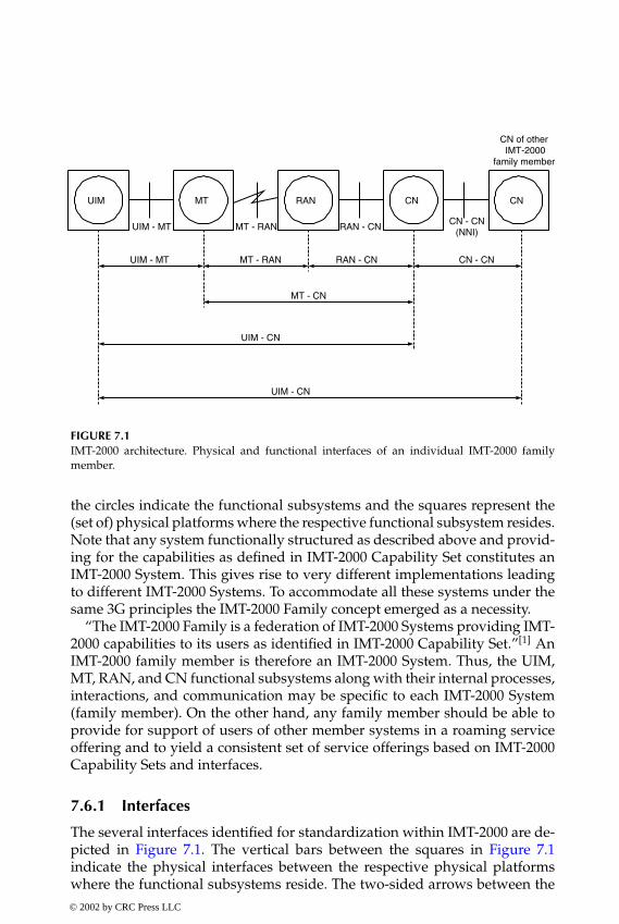
P1: FNT
book CRC-Wireless November 8, 2001 18:23 Char Count= 268
UIM MT RAN CNCN
UIM - MT MT - RAN RAN - CN CN - CN
(NNI)
CN - CNRAN - CNMT - RANUIM - MT
MT - CN
UIM - CN
UIM - CN
CN of other IMT-2000
family member
FIGURE 7.1IMT-2000 architecture. Physical and functional interfaces of an individual IMT-2000 familymember.
the circles indicate the functional subsystems and the squares represent the(set of) physical platforms where the respective functional subsystem resides.Note that any system functionally structured as described above and provid-ing for the capabilities as defined in IMT-2000 Capability Set constitutes anIMT-2000 System. This gives rise to very different implementations leadingto different IMT-2000 Systems. To accommodate all these systems under thesame 3G principles the IMT-2000 Family concept emerged as a necessity.
“The IMT-2000 Family is a federation of IMT-2000 Systems providing IMT-2000 capabilities to its users as identified in IMT-2000 Capability Set.”[1] AnIMT-2000 family member is therefore an IMT-2000 System. Thus, the UIM,MT, RAN, and CN functional subsystems along with their internal processes,interactions, and communication may be specific to each IMT-2000 System(family member). On the other hand, any family member should be able toprovide for support of users of other member systems in a roaming serviceoffering and to yield a consistent set of service offerings based on IMT-2000Capability Sets and interfaces.
7.6.1 Interfaces
The several interfaces identified for standardization within IMT-2000 are de-picted in Figure 7.1. The vertical bars between the squares in Figure 7.1indicate the physical interfaces between the respective physical platformswhere the functional subsystems reside. The two-sided arrows between the© 2002 by CRC Press LLC
E:\Java for Engineers\VP Publication\Java for Engineers.vpThursday, April 25, 2002 9:27:36 AM
Color profile: DisabledComposite Default screen
P1: FNT
book CRC-Wireless November 8, 2001 18:23 Char Count= 268
functional subsystems in Figure 7.1 indicate the functional interfaces betweenthe respective subsystems.
Physical Interfaces
Four physical interfaces, as shown in Figure 7.1, are identified in an individualIMT-2000 family member: UIM–MT, MT–RAN, RAN–CN, and CN–CN.
� UIM–MT Interface. The UIM–MT physical interface refers to the in-terface between the user-removable UIM and the MT. It is definedin terms of physical specifications including size, contacts, electricalspecifications, protocols, and others. It supports the UIM–MT andUIM–CN (home and visited) functional communications.
� MT–RAN Interface. The MT–RAN physical interface is the radio inter-face between MT and RAN. It supports the UIM–CN, MT–RAN, andMT–CN functional communications.
� RAN–CN Interface. The RAN–CN physical interface provides meansof connecting a RAN to different CNs or a CN to different RANs.Access technologies such as fixed radio, cordless terminal, satellite,and wireline may also be supported by this interface. It supports theUIM–CN, MT–CN, and RAN–CN functional communication.
� CN–CN Interface. The CN–CN interface is also referred to as network-to-network interface (NNI) in the ITU-T Recommendations. It pro-vides means to interconnect different CNs supporting the UIM–CN,MT–CN, RAN–CN, and the several CN–CN functional communica-tions.
Functional Interfaces
Seven functional interfaces, as shown in Figure 7.1, are identified in an individ-ual IMT-2000 family member: UIM–MT, UIM–CN (home), UIM–CN (visited),MT–RAN, MT–CN, RAN–CN, CN–CN.
� UIM–MT Interface, UIM–CN (home) Interface, and UIM–CN (visited)Interface. The communication between the UIM and the MT conveysinformation to be processed within the MT itself or to be transferred tothe CN (home or visited). Examples of classes of information flowingthrough these functional interfaces include:UIM access control (e.g., transfer of personal identification number
for authentication purposes)Identity management (e.g., transfer of internationally unique sub-
scriber identity)Authentication control (e.g., transfer of challenges and responses in
the authentication process)Service control (e.g., transfer of user service profiles)
© 2002 by CRC Press LLC
E:\Java for Engineers\VP Publication\Java for Engineers.vpThursday, April 25, 2002 9:27:36 AM
Color profile: DisabledComposite Default screen

P1: FNT
book CRC-Wireless November 8, 2001 18:23 Char Count= 268
Man–machine interface control (e.g., transfer of user-specific man–machine interface configuration)
A UIM–MT functional communication provides means for the ex-change of family-specific information between these two entities.Exchange of family-specific information is also supported by a UIM–CN (home) functional interface. A UIM–CN functional communi-cation can support services (e.g., profile services and data services)requiring software download over a pseudotransparent data path es-tablished across the network.
� MT–RAN Interface and MT–CN Interface. The MT–RAN functional com-munication supports data protection and resource management. TheMT–CN functional communication supports call control and mobil-ity management, whose information flows transparently through theRAN.
� RAN–CN Interface. The RAN–CN functional communication supportsbearer traffic (e.g., voice, data), control information (e.g., call, mobi-lity), data security information, management information, andothers.
� CN–CN Interface. The CN–CN functional communication comprises aset of three functional communications: Serving CN-Home CN func-tional communication, Serving CN-Transit CN functional communi-cation, and CN–CN functional communication for Packet Data. Thesefunctional communications support information exchange betweenhome, serving, and transit CNs, as required, for purposes such as:Authentication control, subscriber-specific service control (for the
VHE capability), and location informationEstablishment of mobile-terminated calls for a roaming user as well
as call and service control (e.g., call setup, negotiation of servicecapabilities)
Mobility management and delivery of bearer packet data
7.6.2 Global Roaming
The IMT-2000 architecture is conceived so that global roaming and VHE,two IMT-2000 key features, be fully supported. Global roaming is envis-aged basically as two alternatives: terminal mobility and UIM portability. Theglobal roaming terminal mobility alternative concerns the roaming of UIMand MT jointly. In this case, a UIM provided by the home network is usedwith an MT that is available both in the home network and in the visited net-work. The global roaming UIM portability alternative concerns the roamingof an UIM. In this case, a UIM provided by the home network is used withan MT provided by the visited network. These situations are illustrated in© 2002 by CRC Press LLC
E:\Java for Engineers\VP Publication\Java for Engineers.vpThursday, April 25, 2002 9:27:36 AM
Color profile: DisabledComposite Default screen

P1: FNT
book CRC-Wireless November 8, 2001 18:23 Char Count= 268
UIM MT RAN CNCN
Family Member A (Visited)
Inter-subsystem Intra-subsystem Inter-family
(Home)
Family Member B
UIM UIMMT
Inter-family
CN
Family Member B’
Intra-family
Compatible withVisited Networks
Home NetworkProvided
Compatible withHome and
Visited NetworksHome Network
Provided
FIGURE 7.2Global roaming.
Figure 7.2. Other features related to global roaming include routing/addressing,service portability, and user profile accessibility/transportability.
The global roaming routing/addressing feature concerns the ability of thenetwork to address and route communications and services not to a geo-graphic location or to a physical device but to roaming IMT-2000 users.The global roaming service portability feature concerns the ability of thenetwork to grant subscribers access to customized services within and be-tween any IMT-2000 systems. The global roaming user profile accessibility/transportability feature concerns the ability of the network to handle (access,transfer, download, modify) the user’s service profile independently of itslocation.
Figure 7.2 also illustrates the various interconnections between subsystemsand the possible signaling streams within and between IMT-2000 subsystemsand families. These interconnections and signaling are classified as being ofthe kind:[2] intra-subsystem, intersubsystem, intrafamily, and interfamily.
� Intrasubsystem. Intrasubsystem signaling is characterized by signalingflowing within a specific subsystem. For example, the signaling withina CN of a family member remains within the extent of the familymember. This is outside the scope of the ITU-T standardization.
� Intersubsystem. Intersubsystem signaling is characterized by signalingflowing between two subsystems, either contained within the sameor within different IMT-2000 family members. In the first case, theentity responsible for its specification is the respective family member
© 2002 by CRC Press LLC
E:\Java for Engineers\VP Publication\Java for Engineers.vpThursday, April 25, 2002 9:27:36 AM
Color profile: DisabledComposite Default screen

P1: FNT
book CRC-Wireless November 8, 2001 18:23 Char Count= 268
supplier, whereas in the second case the body responsible for its speci-fication is the ITU-T. Interconnections between subsystems such asUIM–MT, MT–RAN, RAN–CN are of the intersubsystem type.
� Intrafamily. Intrafamily signaling is characterized by signaling flow-ing between the same IMT-2000 family members and its specificationremains within the family member scope. In such a case ITU-T provesthe framework for commonality. An interconnection between the CNof family member B and the CN of family member B′ is of the in-trafamily type.
� Interfamily. Interfamily signaling is characterized by signaling flow-ing between two subsystems contained in different IMT-2000 familymember systems. The body responsible for its specification is ITU-T.An interconnection between the CN of family member A and the CNof family member B is of the interfamily type.
In the global roaming context, it is informative to define more formally thetypes of logical networks required to support the interconnections:
� Destination Network. A destination network is the target network foran outgoing call from an IMT-2000 user.
� Home Network. A home network is the network of subscription of theIMT-2000 user. It maintains location and service profile informationof the user on a permanent basis.
� Interrogating Network. An interrogating network is the network thatrequests routing data retrieval from the home network.
� Previously Visited Network. A previously visited network is the networkvisited by an IMT-2000 user immediately before entering the visited(serving) network.
� Supporting Network. A supporting network is the network that pro-vides services to the IMT-2000 user. These services include, for exam-ple, logic programs and data for IN supplementary services.
� Visited (Serving) Network. A visited network is the network serving anactive IMT-2000 user.
7.7 Specific Functions
To provide its users with IMT-2000 capabilities, as defined in IMT-2000 Ca-pability Set, several network functions are identified. However, only thosefunctions necessary to support the services chosen to be provided by a givenfamily member need to be implemented within the respective family member.© 2002 by CRC Press LLC
E:\Java for Engineers\VP Publication\Java for Engineers.vpThursday, April 25, 2002 9:27:36 AM
Color profile: DisabledComposite Default screen

P1: FNT
book CRC-Wireless November 8, 2001 18:23 Char Count= 268
Some of these functions are listed in Reference 3, where they are grouped ac-cording to their relations with the overall service and network capabilities.This section summarizes these functions.
7.7.1 Overall System Access Control Functions
The access to services and facilities of IMT-2000 are supported by functionscontrolling the means by which a user is connected to an IMT-2000 network.A system access may be initiated by the user (mobile-originated call) or bythe network (mobile-terminated call). The following functions are identified:
� System Access Information Broadcasting. This function is responsiblefor providing the mobile terminal with configuration information toenable it to camp on a cell, register, or initiate and receive calls.
� System Access Information Monitoring and Analysis. This function en-ables the mobile terminal to monitor and analyze the system access–related information transmitted by the network. Upon processingsuch information, the mobile terminal should be able to camp ona suitable cell, belonging to a suitable network or network operator.
� Cell Selection in Idle Mode. This function enables the mobile terminalto control the tracking of the active cell while in the idle mode. Thisprocess involves tasks such as knowledge of the system configuration,signal quality monitoring, acquisition and selection of surroundingcells, and others.
� Cell Selection in Packet Data Transfer Mode. This function enables themobile terminal to select the best cell when engaged in a packet datatransaction. This process involves tasks such as signal quality mon-itoring, detection of traffic condition within the candidate cells, andothers.
7.7.2 Radio Resource Management and Control Functions
Functions related to allocation and maintenance of physical channels aregrouped under this item. The following functions are identified:
� Synchronization Control. This function performs tasks to ensure correctsynchronization between the mobile terminal and the network.
� Access Radio Link Setup and Release. This function is responsible fortasks that take part in the processing of the setup and the release ofa connection upon request of a given entity. These tasks also includethe management and the maintenance of the radio link of such aconnection.
© 2002 by CRC Press LLC
E:\Java for Engineers\VP Publication\Java for Engineers.vpThursday, April 25, 2002 9:27:36 AM
Color profile: DisabledComposite Default screen

P1: FNT
book CRC-Wireless November 8, 2001 18:23 Char Count= 268
� Reservation and Release of Physical Channels. This function performsreservation or release of physical channels in situations such as radiolink setup or release requests, handover requests, service requests,and macrodiversity requests.
� Allocation and Deallocation of Physical Channels. This function is respon-sible for allocating or deallocating the physical channels that havebeen reserved.
� Packet Data Transfer over Radio. This function is responsible for tasksdealing with data transfer. In general, it provides for packet accesscontrol over radio channels, packet multiplexing over common phys-ical radio channels, packet discrimination within the mobile terminal,error detection and correction, flow control procedures, and load bal-ancing across RF channels.
� RF Power Control. This function controls the levels of transmittedpower of both the mobile terminal and the base station upon assessingthe radio channel quality.
� RF Power Setting. This function constitutes an intrinsic part of anypower control scheme. It is used to adjust the output power of thetransmitter.
7.7.3 Random-Access Functions
Functions related to random access are grouped under this item. The follow-ing functions are identified:
� Random-Access Initiation. This function initiates the specified random-access procedure when the mobile terminal accesses the network.
� Random-Access Detection and Handling. This function detects therandom-access initiation attempt carried out by the mobile terminal.It handles the random access by responding to the access attempt, byactivating procedures for collision resolution, by generating requestsfor resources allocation, etc.
7.7.4 Radio Resource Request Acceptability Functions
Functions related to radio resource request acceptability are grouped underthis item. The following functions are identified:
� Radio Resource Request Acceptability Information Setting. This functionchecks the availability of radio resources within a cell.
� Radio Resource Request Acceptability Information Broadcasting. This func-tion broadcasts, within a cell, the radio resource request acceptabilityinformation.
© 2002 by CRC Press LLC
E:\Java for Engineers\VP Publication\Java for Engineers.vpThursday, April 25, 2002 9:27:36 AM
Color profile: DisabledComposite Default screen

P1: FNT
book CRC-Wireless November 8, 2001 18:23 Char Count= 268
� Radio Resource Request Acceptability Judgment. This function uses theinformation on the availability of radio resources to initiate certainprocedures. In the network side, the concerned procedures are relatedto the allocation of resources on request. On the mobile terminal side,the concerned procedures are related to the permission to initiate aservice request.
7.7.5 Channel Coding Function
This item contains only one function as follows:� Radio Channel Source and Error Protection Coding and Decoding. This
function is related to the procedures used to protect the data trans-mission against errors. This is achieved by the use of convolutionalcodes for error detection and correction, of cyclic redundancy checkcodes for error detection, and of interleaving for error protection.
7.7.6 Handover Function
Functions related to handover are grouped under this item. The followingfunctions are identified:
� Radio Channel Quality Estimation. This function monitors the radiochannel conditions performing measurements to estimate parame-ters such as received signal strength, bit error rate, transmission range,Doppler spread, synchronization status, type of propagation environ-ment (high speed, low speed, satellite, etc.), and others.
� Cell Selection in Dedicated Mode. This function makes it possible fora mobile terminal engaged in a circuit-switched connection to selectthe best cell for access or handover operations. The selection is basedon the signal quality monitoring and on the traffic condition of thecandidate cells.
� Quality of Service Assessment. This function concerns the overall QoSassessment to recommend or not resource reallocation, use of macro-diversity, or handover execution. QoS metrics may include radio sig-nal quality, throughput, delay, and others.
� Resource Reallocation. This function carries out the reallocation of thoseresources that are being used. This is carried out to accomplish betterperformances.
� Handover Decision. This function generates a request for new or for dif-ferent resources. A handover decision may be initiated by the mobileterminal or by the network.
� Macrodiversity Control. This function controls both the distributionof replicas of information through diversity branches and the
© 2002 by CRC Press LLC
E:\Java for Engineers\VP Publication\Java for Engineers.vpThursday, April 25, 2002 9:27:36 AM
Color profile: DisabledComposite Default screen

P1: FNT
book CRC-Wireless November 8, 2001 18:23 Char Count= 268
combination of them, as appropriate. This is activated upon requestfrom the handover decision function or from the QoS assessmentfunction.
� Handover Execution. This function performs tasks such as reservation/activation of the new radio and wireline resources required for hand-over and final switching from the old to the new resources.
� Handover Completion. This function releases the resources that are nolonger needed.
� Handover Trigger. This function recognizes cells to be added to ordeleted from the access link.
7.7.7 Location Management and GeographicPosition–Finding Functions
Functions related to terminal paging, location data management, registrationand deregistration, and location registration are grouped under this item. Thefollowing functions are identified:
� Paging Decision and Control. This function is responsible for identi-fying the location area of the mobile terminal, for determining thestatus of the mobile terminal (e.g., busy, idle, active) to execute ornot the paging, and for processing the paging response by the mobileterminal.
� Paging Execution. This function carries out the paging of the mobileterminal.
� Paging Detection. This function detects a paging and responds to it.� Location Data Management Initiation. This function requests service fea-
tures related to location management, including terminal location up-dating, detach, and attach. This may be carried out on a periodic ordemand basis.
� Location Data Management. This function is responsible for procedurescontrolling the feature services related to location management. Ex-amples of tasks include location information updating, obtaining in-formation on the reachability of the mobile terminal, and others.The location of the mobile terminal may be recognized with differ-ent accuracy (e.g., location unknown, multiple cell accuracy, cell areaaccuracy).
� Terminal-Initiated Location Update. This function enables the mobileterminal to inform the network of its presence.
� Network-Initiated Location Update. This function enables the networkto request the mobile terminal to identify itself to the network.
© 2002 by CRC Press LLC
E:\Java for Engineers\VP Publication\Java for Engineers.vpThursday, April 25, 2002 9:27:36 AM
Color profile: DisabledComposite Default screen

P1: FNT
book CRC-Wireless November 8, 2001 18:23 Char Count= 268
� Location Registration for Call and Service Delivery. This function pro-vides for an interaction between serving (visited) and home networksto enable service transparency. In this case, service profile download-ing from the home network to the serving network may occur. Severalscenarios may be considered. For standardized IMT-2000 services, ifdownload occurs, the visited network will use the downloaded pro-file locally without requesting further information from the homenetwork; if download does not occur, the visited network will haveto request instructions from the home network.
� Geographic Position Determination. This function provides the networkand the mobile terminal with means to determine the position ofthe mobile terminal, by taking into account the dynamic informationavailable (e.g., signal strengths, time of arrival of the signals, angle ofarrival of the signals).
� Geographic Position Notification. This function enables the notificationof the position of the mobile terminal to the authorized entities.
7.7.8 Mobile Call Handling Functions
Functions related to call handling and routing are grouped under this item.The following functions are identified:
� Service Feature Analysis. This function checks the compatibility be-tween requested services, current subscription, and terminal capabi-lities.
� Provision of Terminal Capability Information. This function provides thenetwork with the information on the capabilities of the terminal.
� Negotiation of Data Rates and Quality of Service. This function handlesthe negotiation of data rates and QoS between the mobile terminaland the network.
� Access Restrictions. This function checks for restrictions to servicesaccording to subscription options, authorization, and networkconditions.
� Request Routing Information. This function activates the routing infor-mation handling function for mobile-terminated calls.
� Routing Information Handling. This function provides the network withthe necessary routing information for the call to be established.
� Routing of Packet-Data Mobile Communication Service. This function pro-vides means to support the routing of packet-data communicationservice. The routing may be carried out on a dial-up basis or on a serv-ice subscription-based manner. In the first case, the user is allowed toestablish an on-demand path of choice by providing the network with
© 2002 by CRC Press LLC
E:\Java for Engineers\VP Publication\Java for Engineers.vpThursday, April 25, 2002 9:27:36 AM
Color profile: DisabledComposite Default screen

P1: FNT
book CRC-Wireless November 8, 2001 18:23 Char Count= 268
the packet handler “address” as destination address information. Inthe second case, the user is allowed to specify the packet-handlingfunction of choice at the time of subscription with the home IMT-2000family member.
� Connections and Address Management of Mobile Data Packets. A numberof functions under this item provide means to support point-to-pointand point-to-multipoint services, dynamic and static address man-agement, Internet control message protocol, packet filtering, and dataprivacy.
� Handling of Multimedia Calls. This function provides the system withthe ability to support multimedia services. This includes the abil-ity to provide bearers with flexible QoS, parallel calls, and point-to-multipoint calls.
� Management of Circuit-Switched and Packet-Switched Communications.This function supports circuit-switched and packet-switched com-munication paths simultaneously.
7.7.9 Data Coding and Compression Functions
Functions related to data coding, signaling compression, and data compres-sion are grouped under this item. The following functions are identified:
� Data Coding. This function implements voice coding or compressionof image data.
� Signaling Compression. This function implements the compression ofsignaling information.
� Data Compression. This function implements the compression of net-work protocol packet contents.
7.7.10 Network Intelligence and Service Control Functions
Functions related to the network intelligence and service control in generalare grouped under this item. The following functions are identified:
� Support of UPT Users. This function grants users with a UPT (universalpersonal telecommunications) number the ability to access telecom-munication services from any terminal.
� Support of Service Portability, Supplementary Services, Virtual Home En-vironment, and Global Roaming. A number of functions provide thenetwork and the users with the ability to have transparent access totheir subscribed services while roaming.
� Support of IN. Several functions provide the network and the userswith the ability to support IN procedures.
© 2002 by CRC Press LLC
E:\Java for Engineers\VP Publication\Java for Engineers.vpThursday, April 25, 2002 9:27:36 AM
Color profile: DisabledComposite Default screen
P1: FNT
book CRC-Wireless November 8, 2001 18:23 Char Count= 268
7.7.11 User Privacy and Network Security Functions
Functions related to ciphering, authentication, fraud/abuse control, and iden-tity management are grouped under this item. The following functions areidentified:
� Confidentiality Control. This function is closely related to the authen-tication mechanisms. This is regarded as a centralized function. Itprovides the required information for the radio channel ciphering/deciphering functions.
� Physical Radio Channel Ciphering/Deciphering. These are pure compu-tational functions used to protect the radio-transmitted data againstnonauthorized third parties.
� Ciphering Execution Control. This function obtains ciphering informa-tion from the confidentiality control function and triggers cipheringand deciphering on the physical radio channel.
� Authentication Data Management. This function controls and managesthe authentication information used in the network.
� User Authentication Processing. This function triggers the user authen-tication procedure and processes the results.
� Network Fraud/Abuse Control. This function provides for mechanismsto protect the user and the network from fraudulent use of the system.This involves a combination of real-time and non-real-time analysesof events monitored by the networks. Monitored events typically in-clude call addressing, geographic position, subscriber identity, net-work element address, and supplementary service invocation.
� Identity Management. A number of functions are used to prevent apermanent user identity from eavesdropping over the radio inter-face. Confidentiality of the identity is kept by performing a series offunctions such as:Assigning a temporary identity to the mobile terminalPeriodically updating the assigned temporary identityRetrieving a permanent user identity from another network
7.7.12 Emergency Services Functions
Functions related to emergency services are grouped under this item. Thefollowing functions are identified:
� Identification of Emergency Calls. This function is responsible for recog-nizing calls to emergency services.
� Emergency Services Calls Handling. This function is responsible fortasks that handle calls to emergency services. These tasks include, for
© 2002 by CRC Press LLC
E:\Java for Engineers\VP Publication\Java for Engineers.vpThursday, April 25, 2002 9:27:36 AM
Color profile: DisabledComposite Default screen

P1: FNT
book CRC-Wireless November 8, 2001 18:23 Char Count= 268
example, the provision for priority access to identified emergencyservices calls, the use of different charging procedures, the provisionfor enhanced capabilities (e.g., such as call back), the provision forenhanced information about the users of such services, including lo-cation or geographic position, and others.
7.7.13 Charging Functions
Functions related to charging are grouped under this item. The followingfunctions are identified:
� Circuit-Switching Information Generation. This function collects charg-ing information parameters related to circuit-switching connections.This is carried out at instants such as call setup, during a call, and atcall release. Charging parameters include call duration, used band-width, invoked service instances, time-dependent charging rate, ac-cess charge rate, and registration charge rate.
� Packet Data Information Generation. This function collects charging in-formation parameters related to packet data transfer connections. Thisis carried out at such instants as registration or attach, packet transfer,and at deregistration or detach. Charging parameters include numberof exchanged packets, packet data rate or used bandwidth, averagepacket size, access charge rate, and registration charge rate.
� Charging Processing. This function processes the parameters receivedfrom the circuit-switching information generation function and packetdata information generation function to yield parameters that are rel-evant to the billing and accounting functions.
7.7.14 Support of Users Function
This item contains only one function, as follows:
� IMT-2000 Personal Mobility. This function supports the mobility ofUIM devices among mobile terminals. Note that UIM portabilityis possible only for situations in which UIM and mobile terminalsare physically separated. Because IMT-2000 supports both integratedUIM–MT and separated UIM–MT this function constitutes an op-tional capability. The personal mobility capability enables the userto access the telecommunication services specified within the user’sprofile from any IMT-2000 mobile terminal that accepts the portableUIM.
© 2002 by CRC Press LLC
E:\Java for Engineers\VP Publication\Java for Engineers.vpThursday, April 25, 2002 9:27:36 AM
Color profile: DisabledComposite Default screen

P1: FNT
book CRC-Wireless November 8, 2001 18:23 Char Count= 268
7.7.15 Subscriber Data Management Functions
Functions related to subscriber data management perform tasks concerningthe following: update and deletion of subscriber data within the serving net-work; fault recovery of subscriber data; and control of supplementary services(SS) data. The functions related to updating and deletion of subscriber datamay be activated by events, such as change of subscription of basic or sup-plementary services (carried out by the operator); change of subscriber data(carried out by the operator); application, change, or removal of call barring(carried out by the operator); change of data concerning the subscriber’s SSusing a subscriber procedure (carried out by the subscriber). The functionsrelated to fault recovery of subscriber data permits the recovery from faultysituations (e.g., invalid subscriber data, missing location data). The functionsrelated to control of SS data enable the subscriber, or the network on behalfof the subscriber, to control the SS. The following functions are identified:
� Insert Subscriber Data. This function updates certain subscriber data(e.g., change of the subscriber data associated with the subscriber’sbearer services, SS, VHE services, regional subscription, etc.).
� Delete Subscriber Data. This function deletes certain subscriber data(e.g., deletion of basic services, deletion of SS, or deletion of VHEservices).
� Reset. This function is used to announce to serving networks that afailure within the home network has occurred.
� Restore Data. This function is used by the serving network to informthe home network that the information associated with the providedIMUI (international mobile user identity) is not valid or not available.
� SS Data Handling. This function updates, retrieves, or deletes the SSdata.
� SS Activation. This function is used to activate or to deactivate the SSupon request of the subscriber.
� SS Password Protection. This function is activated to protect operationson SS requiring restricted access (e.g., registration of a password).
� SS Subscriber Data. This function enables the exchange of subscriberdata between the subscriber and the serving network.
� SS Invocation. This function invokes the subscriber SS.
7.7.16 Messaging Service Management Functions
Functions used to support short message service (SMS) and application datadelivery service (ADDS) are grouped under this item. SMS and ADDS makeuse of a message center acting as a store-and-forward center. SMS is a feature
© 2002 by CRC Press LLC
E:\Java for Engineers\VP Publication\Java for Engineers.vpThursday, April 25, 2002 9:27:36 AM
Color profile: DisabledComposite Default screen

P1: FNT
book CRC-Wireless November 8, 2001 18:23 Char Count= 268
supporting limited-size messages sent to or from the mobile terminal. ADDSis a feature supporting general-purpose wireless data delivery (application/teleservice messages between service users). The following functions are iden-tified:
� Message Delivery. This function is responsible for delivering the mes-sage to the mobile terminal.
� Message Handling. This function is responsible for receiving the mes-sage from the terminal and forwarding it to the message center.
� Message Alerting. This function is used to alert the home network abouta message being stored in the message center for a mobile terminal.
7.7.17 Software-Configurable Terminals Functions
The functions supporting the software-configurable terminals capability areresponsible for tasks controlling the mechanisms that allow applications tointeract and operate with any mobile terminal (MT). These applications to-gether with the related data may reside within the UIM, within the MT, withinan external device, or they may be downloaded by the CN.
� Capability Profile Exchange. This function supports the exchange ofservice capability information between UIM, MT, and CN. For exam-ple, services capability of one functional subsystem may be providedto another functional subsystem (e.g., from MT to UIM or to CN, fromUIM to MT or to CN, and from CN to MT or to UIM).
� Application Data Transfer. This function supports the exchange of appli-cations and associated data between UIM, MT, and CN. For example,data and applications of one subsystem may be provided to anothersubsystem (e.g., from MT to UIM or to CN, from UIM to MT or to CN,and from CN to MT or to UIM).
� Proactive Applications. This function supports mechanisms throughwhich applications can initiate actions to be taken by the MT. Thesemay include: “display text from UIM or CN to MT; send short mes-sage; set up a voice call to a number held by the UIM, MT, or anexternal device; set up a data call to a number with bearer capabilitiesheld by the UIM, MT, or external device; send a supplementary ser-vice control or service data; play tones in earpiece; initiate a dialoguewith the user; provide local information from the MT to the UIM orto the CN; provide help information on each command involved inthe dialogue with the user.”3
� Screening Service by UIM. This function, if activated, confers the UIMthe ability to allow, bar, or modify the call, the SS operation, or the serv-ice data operation at the time anyone of these services is requested.
© 2002 by CRC Press LLC
E:\Java for Engineers\VP Publication\Java for Engineers.vpThursday, April 25, 2002 9:27:36 AM
Color profile: DisabledComposite Default screen

P1: FNT
book CRC-Wireless November 8, 2001 18:23 Char Count= 268
� Security. This function provides those applications designed with thefeatures in this capability with data confidentiality, data integrity, datasender validation, or any subset of these.
7.8 Network Architecture
The functions implementing the IMT-2000 capabilities are distributed amongor grouped into functional entities (FEs). These FEs are then grouped intophysical entities (PEs) which, in turn, are distributed among the functionalsubsystems composing an IMT-2000 system, namely, UIM, MT, RAN, and CN.The FEs are detailed in the next section. The PEs implementing the functionalsubsystems are described as follows.
The UIM functional subsystem is implemented by means of the UIM PE.The MT functional subsystem is implemented by means of the MT PE. TheRAN functional subsystem is implemented by means of the base station (BS)and the radio network controller (RNC) PEs. The CN functional subsystemis implemented by means of the following PEs: authentication center (AC),drift MSC (DMSC), gateway location register (GLR), gateway MSC (GMSC ),home location register (HLR), intelligent peripheral (IP),∗ mobile switchingcenter (MSC), packet data gateway node (PDGN), packet data serving node(PDSN), serving control point (SCP), serving data point (SDP), and visitorlocation register (VLR).
7.8.1 Physical Entities—Reference Model
The PEs composing the functional subsystems are briefly described next. Adetailed specification of these PEs can be obtained by defining the set of FEscomposing each PE, which are described in the next section.
� UIM. The UIM is the only PE composing the UIM functional subsys-tem. It contains an FE that supports user security and user services.
� MT. The MT is the only PE composing the MT functional subsys-tem. It contains FEs that support call control agent, connection con-trol agent, mobile control, mobile geographic position, mobile radiotransmission and reception, packet service control agent, and radioaccess control agent.
∗ This chapter uses the bold notation IP for intelligent peripheral, and the normal notation for IPfor Internet protocol.
© 2002 by CRC Press LLC
E:\Java for Engineers\VP Publication\Java for Engineers.vpThursday, April 25, 2002 9:27:36 AM
Color profile: DisabledComposite Default screen

P1: FNT
book CRC-Wireless November 8, 2001 18:23 Char Count= 268
� BS. The BS is one of the PEs composing the RAN functional subsys-tem. It contains FEs that support radio frequency transmission andreception and system access information broadcast.
� RNC. The RNC is one of the PEs composing the RAN functional sub-system. It contains FEs that support radio access control, connectioncontrol, geographic positioning, and access link relay.
� AC. The AC is one of the PEs composing the CN functional subsystem.It contains an FE that supports authentication management.
� DMSC. The DMSC is one of the PEs composing the CN functionalsubsystem. It contains an FE that supports access link relay.
� GLR. The GLR is one of the PEs composing the CN functional sub-system. It contains FEs that support authentication management andlocation management. The GLR is an optional node between the VLRand the HLR used to enhance the subscriber location data across net-work boundaries. For subscribers roaming away from the home IMT-2000 network, the GLR functions as an HLR toward the VLR and asa VLR toward the HLR. The roaming process for subscribers withinthe home IMT-2000 network does not involve the GLR.
� GMSC. The GMSC is one of the PEs composing the CN functionalsubsystem. It contains FEs that support call control, connection con-trol, and service switching. The GMSC is used to contact the HLR forrouting information so that the call can be routed to the correspondingvisited MSC.
� HLR. The HLR is one of the PEs composing the CN functional sub-system. It contains FEs that support location management.
� IP. The IP is one of the PEs composing the CN functional subsystem.It contains an FE that supports specialized resources used for IN ser-vices, mobile multimedia services, application delivery services, andpacket data transfer services.
� MSC. The MSC is one of the PEs composing the CN functional sub-system. It contains FEs that support access link relay, call control, con-nection control, geographic positioning control, service access control,and service switching.
� PDGN. The PDGN is one of the PEs composing the CN functionalsubsystem. It contains an FE that supports packet service gatewaycontrol.
� PDSN. The PDSN is one of the PEs composing the CN functionalsubsystem. It contains FEs that support geographic position controland packet service control.
© 2002 by CRC Press LLC
E:\Java for Engineers\VP Publication\Java for Engineers.vpThursday, April 25, 2002 9:27:36 AM
Color profile: DisabledComposite Default screen

P1: FNT
book CRC-Wireless November 8, 2001 18:23 Char Count= 268
TABLE 7.1
Reference Points and Interfaces
G/VLR GMSC HLR MSC MT PDGN RNC SCP SDP
AC F I5BS U QDMSC E1 LG/VLR D2 B2 D1 B1 V4 I4GMSC B2 E3 C1 E2 I2HLR D1 C1 C2 V2 I3IP G2 G1 JMSC B1 E2 C2 P I1MTPDGN V4 V2PDSN V3 V1 N M I6RNC P RSCP I4 I2 I3 I1 S KSDP K WUIM H
� SCP. The SCP is one of the PEs composing the CN functional subsys-tem. It contains FEs that support service control and service data.
� SDP. The SDP is one of the PEs composing the CN functional subsys-tem. It contains an FE that supports service data.
� VLR. The VLR is one of the PEs composing the CN functional sub-system. It contains FEs that support authentication management andlocation management.
7.8.2 Interface—Reference Points
A number of reference points (34 all together) defining the interfaces betweenthe several PEs within an IMT-2000 network are specified. Table 7.1 shows,in matrix form, the PEs and the existing reference points (interfaces) betweenthese PEs.
7.9 Physical Entities and Functional Entities
The network functional model described in Reference 3 specifies a numberof FEs identified to support the IMT-2000 capabilities. Two approaches forthe allocation of functionalities related to call control and connection con-trol are possible: (1) integrated call control and connection control FEs and(2) separated call control and connection control FEs. The distribution of FEs© 2002 by CRC Press LLC
E:\Java for Engineers\VP Publication\Java for Engineers.vpThursday, April 25, 2002 9:27:36 AM
Color profile: DisabledComposite Default screen
P1: FNT
book CRC-Wireless November 8, 2001 18:23 Char Count= 268
into the PEs are depicted in Figure 7.3 where Tx signifies Transit Exchangeand the other abbreviations are as already previously defined. The ReferenceModel for IMT-2000 with integrated call control and connection control FEsis obtained in Figure 7.3 by eliminating the FEs shown in gray. The ReferenceModel for IMT-2000 with separated call control and connection control FEs isobtained in Figure 7.3 by including the FEs shown in gray.
The next subsections briefly describe the PEs in terms of their respectiveFEs. A detailed description of these FEs can be found in Reference 3.
7.9.1 User Identity Module
The following constitutes the FE within the UIM PE:
� UIMF, User Identification Management Module. The UIMF incorporatesfunctions that are responsible for tasks related to the identification,authentication, and service handling in the UIM. These functions storeuser identification information that is used by the network and by theservice provider to identify both the user and the MT. They also storelocation management-related information and security- and privacy-related information. The UIMF interacts with other FEs to exchangeapplication information, to provide serving system selection informa-tion on location area identity, service availability, service preferences,to generate ciphering key, and to perform authentication.
7.9.2 Mobile Terminal
The following constitute the FEs within the MT PE:
� CCAF′, Call Control Agent Function (enhanced). The CCAF′ interfacesuser with network call control functions providing service access forusers. Tasks performed by CCAF′ include interaction with the user toestablish, maintain, modify, and release a call or other service instance.
� CnCAF, Connection Control Agent Function. The CnCAF is an FE thatis implemented for the situation in which call and connection controlfunctions are separated. In this situation it interfaces the call controlagent function with the radio access control agent function. It interactswith other FEs to establish, maintain, modify, and release connections.It also maintains information on the connection state.
� MCF, Mobile Control Function. The MCF is responsible for the serviceaccess control logic and processing at the mobile side of the radio inter-face. It interacts with other FEs to establish and release the associationbetween an MT and the network; initiate location and MT status man-agement; set up, maintain, modify, and release a signaling connection
© 2002 by CRC Press LLC
E:\Java for Engineers\VP Publication\Java for Engineers.vpThursday, April 25, 2002 9:27:36 AM
Color profile: DisabledComposite Default screen

P1:FNT
bookC
RC
-Wireless
Novem
ber8,2001
18:23C
harC
ount=268
UIM MTCCAF, MCF,
MGPF, MRTR,PSCAF, RACAF.
CnCAF
UIM BS
RFTR, SIBF
RNC
ARF, GPF,RACF, SNCF
CnCF
RNC
ARF, GPF,RACF, SNCF
CnCF
RAN
UIM-MT Interface MT-RAN Interface
VLR/GLR
AMFv, LMFnLMFv
ACAMFn
HLRLMFn
MSC
ARF, CCF’/SSFCnCF, GPCF
SACF
PDSN
GPCF, PSCF
DMSC
ARF
IP
SRF
GMSCCCF’/SSF
CnCF
SCP
SCF, SDF
SDP
SDF
PDGN
PSGCF
CN-CNInterface
(NNI)HLR, SCPVLR/GLR
SCP PDSN MSC/GMSCPDSN, SCPVLR/GLR
MSC/GMSCSCP
HLR, IPMSC
SCP, Tx
GMSCHLR, IPSCP, Tx
AC, HLR, IPMSC/GMSC, SCP
SDP, VLR/GLR
HLRPDGN
SCPSDP
RAN-CNInterface
CN
FIGURE 7.3IMT-2000 reference model.
© 2002 by C
RC
Press LL
C
E:\Java for Engineers\VP Publication\Java for Engineers.vp
Thursday, April 25, 2002 9:27:36 AM
Color profile: Disabled
Composite Default screen

P1: FNT
book CRC-Wireless November 8, 2001 18:23 Char Count= 268
or an access channel; retrieve user identification information, locationmanagement–related information, and security- and privacy-relatedinformation; handle paging; manage unique authentication challengeactivities; perform serving system selection.
� MGPF, Mobile Geographic Position Function. The MGPF, on the MT side,is responsible for tasks leading to the determination of the geographicposition of the MT. Based on information received from the radioreceiver, or from the GPS, or even from the network, it performs thecomputations to determine the geographic coordinates of the MT. Itinteracts with other FEs to perform RF measurements or to modifythe transmitted RF signals so that the network can perform thesemeasurements.
� MRTR, Mobile Radio Transmission and Reception. The MRTR performsfunctions related to the control of the interconnection and adaptationof the access radio link to the rest of the MT. These functions includetasks such as maintenance of the state of an access radio link, radiochannel ciphering and deciphering, estimation of the quality of theradio channels in the active cell and in the neighboring cells, settingthe RF power, cell selection in the idle mode, and others.
� PSCAF, Packet Service Control Agent Function. The PSCAF is responsi-ble for the provision of the packet service control agent functionalityin the MT. Tasks performed by the PSCAF include control of the trans-port of data packets across the radio interface according to the chosenpacket service; control of the dynamic allocation of resources for thetransport of data across the radio interface; support of authenticationand of service control handling; provision of location managementinformation to another FE.
� RACAF, Radio Access Control Agent Function. The RACAF is themobile-side agent responsible for the association and access link con-trol between the MT and the network. Tasks performed by the RACAFinclude interaction with other FEs to allocate and reallocate physicalchannels for a branch of an access radio link and to set up, main-tain, modify, and release the access radio link; execution of handoverdecision; detection of paging; initiation of handover; RF power con-trol; judgment of service acceptability; control of measurements of thequality of radio channels; the selection of cells in the idle mode; andothers.
7.9.3 Base Station
The following constitute the FEs within the BS PE.
� RFTR, Radio Frequency Transmission and Reception. The RFTR is respon-sible for the control of the interconnection and adaptation of the access
© 2002 by CRC Press LLC
E:\Java for Engineers\VP Publication\Java for Engineers.vpThursday, April 25, 2002 9:27:36 AM
Color profile: DisabledComposite Default screen
P1: FNT
book CRC-Wireless November 8, 2001 18:23 Char Count= 268
radio link corresponding to the BS approach link. Tasks performedby the RFTR include estimation of the quality of the radio channel;setting of the RF power; detection and handling of random access;control of the interconnection of branches of an access radio link andmacrodiversity in a handover situation; realization of measurementsto determine the geographic position of the MT; modification of thetransmitted RF; and others.
� SIBF, System Access Information Broadcast Function. The SIBF is respon-sible for the tasks involving the broadcast of system access informa-tion. Such information may be provided to the SIBF by means of anoperation-and-maintenance function.
7.9.4 Radio Network Controller
The following constitute the FEs within the RNC PE.� ARF, Access Link Relay Function. The ARF is responsible for the control
of a branch of a BS approach link. Tasks performed by an ARF includeinteraction with FEs set up, release, maintain the state of, and obtainrouting instructions for a branch of a BS approach link.
� GPF, Geographic Position Function. The GPF is responsible for tasksconcerning the geographic positioning of the MT. These tasks includeRF measurements, modification of the RF signals, synchronization,reporting of the results, and others.
� CnCF, Connection Control Function. The CnCF is an FE that is imple-mented for the situation in which call and connection control func-tions are separated. It is responsible for the control of the connectionprocessing, interacting with other FEs to establish, maintain, modify,and release connection instances.
� RACF, Radio Access Control Function. The RACF is responsible for thecontrol of the association and access link between an MT and the net-work. Tasks performed by the RACF include interaction with otherFEs to allocate and reallocate physical channels for a branch of an ac-cess radio link and to set up, maintain, modify, and release a branch ofa BS approach link and associated access radio link; execution of han-dover decision; execution of handover; completion of handover; RFpower control; judgment of service acceptability; message delivery;scheduling of the delivery of messages; and others.
� SNCF, Satellite Network Control Function. The SCNF is responsible forthe dynamic control of the configuration of the radio network re-sources, particularly in satellite networks. Other networks may notrequire this FE.
© 2002 by CRC Press LLC
E:\Java for Engineers\VP Publication\Java for Engineers.vpThursday, April 25, 2002 9:27:36 AM
Color profile: DisabledComposite Default screen

P1: FNT
book CRC-Wireless November 8, 2001 18:23 Char Count= 268
7.9.5 Authentication Center
The following constitutes the FE within the AC PE:� AMFh, Authentication Management Function (home). The AMFh is re-
sponsible for functions related to authentication and confidentialitywithin the AC. Tasks performed by the AMFh include storage of au-thentication data; validation of received authentication data; user au-thentication; confidentiality control; authentication parameters con-trol; and others.
7.9.6 Drift MSC
The following constitutes the FE within the DMSC PE:� ARF, Access Link Relay Function. The ARF, as previously described, is
responsible for the control of a branch of a BS approach link. Tasksperformed by an ARF include interaction with FEs to set up, release,maintain the state of, and obtain routing instructions for a branch ofa BS approach link.
7.9.7 Gateway Location Register
The following constitute the FEs within the GLR PE:� AMFv, Authentication Management Function (visitor). The AMFv, like
the AMFh within the AC, is responsible for functions related to au-thentication and confidentiality within the GLR and the VLR. Tasksperformed by the AMFv include storage of authentication data; vali-dation of received authentication data; user authentication; confiden-tiality control; authentication parameters control; and others.
� LMFh, Location Management Function (home). The LMFh is responsi-ble for the support of location management, mobility management,activation status management, and identity management.
� LMFv, Location Management Function (visitor). The LMFv, like the LMFh,is responsible for the support of location management, mobility man-agement, activation status management, and identity management.
7.9.8 Gateway MSC
The following constitute the FEs within the GMSC PE:� CCF′, Call Control Function (enhanced). The CCF′ is responsible for
the provision of call processing control and connection processing
© 2002 by CRC Press LLC
E:\Java for Engineers\VP Publication\Java for Engineers.vpThursday, April 25, 2002 9:27:36 AM
Color profile: DisabledComposite Default screen

P1: FNT
book CRC-Wireless November 8, 2001 18:23 Char Count= 268
control. Tasks performed by CCF′ include the interaction with otherFEs to establish, maintain, modify, and release a call or connection in-stances; set up and release an access link; support IN services; receiverouting and profile information for mobile calls; and others.
� CnCF, Connection Control Function. The CnCF is an FE that is imple-mented for the situation in which call and connection control func-tions are separated. It is responsible for the control of the connectionprocessing, interacting with other FEs to establish, maintain, modify,and release connection instances.
� SSF, Service Switching Function. The SSF is associated with the CCF′
providing functions to enable the interaction between CCF′ and SCF.
7.9.9 Home Location Register
The following constitutes the FE within the HLR PE:
� LMFh, Location Management Function (home). The LMFh, as alreadydescribed, is responsible for the support of location management,mobility management, activation status management, and identitymanagement.
7.9.10 Intelligent Peripheral
The following constitutes the FE within the IP PE:
� SRF, Specialized Resource Function. The SRF is responsible for the provi-sion of specialized resources necessary for the support of IN services,mobile multimedia services, application delivery services, and packetdata transfer services.
7.9.11 Mobile Switching Center
The following constitute the FEs within the MSC PE:
� ARF, Access Link Relay Function. The ARF, as previously described, isresponsible for the control of a branch of a BS approach link. Tasksperformed by an ARF include interaction with FEs to set up, release,maintain the state of, and obtain routing instructions for a branch ofa BS approach link.
� CCF′, Call Control Function (enhanced). The CCF′, as previously de-scribed, is responsible for the provision of call processing control andconnection processing control. Tasks performed by CCF′ include the
© 2002 by CRC Press LLC
E:\Java for Engineers\VP Publication\Java for Engineers.vpThursday, April 25, 2002 9:27:36 AM
Color profile: DisabledComposite Default screen

P1: FNT
book CRC-Wireless November 8, 2001 18:23 Char Count= 268
interaction with other FEs to establish, maintain, modify, and releasea call or connection instances; set up and release an access link; sup-port IN services; receive routing and profile information for mobilecalls; and others.
� CnCF, Connection Control Function. The CnCF, as previously described,is an FE that is implemented for the situation in which call and connec-tion control functions are separated. It is responsible for the controlof the connection processing, interacting with other FEs to establish,maintain, modify, and release connection instances.
� GPCF, Geographic Position Control Function. The GPCF is the network-side agent responsible for the provision of the overall control for theGPF function. Tasks performed by the GPCF include reception of andresponse to requests to determine the geographic position of an MT;establishment, maintenance, and release of a service instance for ageographic positioning request; interaction with other FEs to requestthat RF measurements be performed or transmitted RF signals bemodified; and others.
� SACF, Service Access Control Function. The SACF is responsible for theprovision of processing and control of call-related and call-unrelatedservices. The SACF interact with other FEs to perform tasks, includ-ing establishment and release of association between an IMT-2000terminal/user and the network; provision of routing information forestablishment of calls and mobility management functionality; pro-vision of IN services; set up and release of an access link; set up andrelease of a branch of a BS approach link; detection and handling ofpaging response; request of paging execution; control of cipheringexecution; provision of paging strategy; support of location-basedservices; management of temporary routing numbers for roamers;control of supplementary services; delivery of messages; and others.
� SSF, Service Switching Function. The SSF, as previously described, isassociated with the CCF′ providing functions to enable the interactionbetween CCF′ and SCF.
7.9.12 Packet Data Gateway Node
The following constitutes the FE within the PDGN PE:
� PSGCF, Packet Service Gateway Control Function. The PSGCF is respon-sible for the provision of the gateway control functionality within theCN. Tasks performed by the PSGCF include interaction with otherpacket data networks; routing and relaying of data packets betweenother packet data networks and the PSCF; and others.
© 2002 by CRC Press LLC
E:\Java for Engineers\VP Publication\Java for Engineers.vpThursday, April 25, 2002 9:27:36 AM
Color profile: DisabledComposite Default screen
P1: FNT
book CRC-Wireless November 8, 2001 18:23 Char Count= 268
7.9.13 Packet Data Serving Node
The following constitute the FEs within the PDSN PE:
� GPCF, Geographic Position Control Function. The GPCF, as already de-scribed, is the network-side agent responsible for the provision ofthe overall control for the geographic position finding function. Tasksperformed by the GPCF include reception of and response to requeststo determine the geographic position of an MT; establishment, main-tenance, and release of a service instance for a geographic positioningrequest; interaction with other FEs to request that RF measurementsbe performed or transmitted RF signals be modified; and others.
� PSCF, Packet Service Control Function. The PSCF is responsible for theprovision of the control of packet service functionality within the CN.The PSCF interacts with other FEs to perform tasks, including pro-vision of updates on the packet data service; transfer of user databetween external packet data networks and the MT; authentication;confidentiality control, user authentication, and parameter updatefor packet data services; initiation of dynamic allocation of radio re-sources for the transport of data packets across the radio interface;ciphering execution control; location management; and others.
7.9.14 Service Control Point
The following constitute the FEs within the SCP PE:
� SCF, Service Control Function. The SCF encompasses the IN servicecontrol functionality in the network. It interacts with other FEs toperform tasks, including provision of mobility management–relatedIN services; provision of call-related and call-unrelated IN services;provision of specialized resources for IN services.
� SDF, Service Data Function. The SDF provides a logical data view tothe SCF, hiding from it the real data implementation. Tasks performedby the SDF include storage of service data; consistency checks ondata; application data management; exchange of service data; andgeneration and management of user service-related data.
7.9.15 Service Data Point
The following constitutes the FE within the SDP PE:
� SDF, Service Data Function. The SDF, as already described, provi-des a logical data view to the SCF, hiding from it the real data
© 2002 by CRC Press LLC
E:\Java for Engineers\VP Publication\Java for Engineers.vpThursday, April 25, 2002 9:27:36 AM
Color profile: DisabledComposite Default screen

P1: FNT
book CRC-Wireless November 8, 2001 18:23 Char Count= 268
implementation. Tasks performed by the SDF include storage of serv-ice data; consistency checks on data; application data management;exchange of service data; and generation and management of userservice-related data.
7.9.16 Visitor Location Register
The following constitute the FEs within the VLR PE:
� AMFv, Authentication Management Function (visitor). The AMFv, likethe AMFh within the AC, is responsible for functions related toauthentication and confidentiality within the GLR and VLR. Tasksperformed by the AMFv include storage of authentication data; vali-dation of received authentication data; user authentication; confiden-tiality control; authentication parameters control; and others.
� LMFh, Location Management Function (home). The LMFh is responsi-ble for the support of location management, mobility management,activation status management, and identity management.
� LMFv, Location Management Function (visitor). The LMFv, like theLMFh, is responsible for the support of location management,mobility management, activation status management, and identitymanagement.
7.10 Functional Entities and Their Interrelations
The FEs, as described in the previous section, implement all of the functionsrequired to support the capabilities specified in Reference 1 and cited in thischapter. However, only those functions necessary to support the services cho-sen to be offered by a given family member need be implemented.
Broadly speaking, the FEs can be bundled into two groups: one containingFEs that deal with radio access control and another containing FEs that dealwith communication and service control. The radio access control–related FEs aredependent on the transmission technology, whereas the communication andservice control–related FEs are independent of the transmission technology.Within the communication and service control group a subgroup containingFEs that deal with packet data service can be identified.
The interrelation among these FEs and the respective groups are illustratedin Figure 7.4.
© 2002 by CRC Press LLC
E:\Java for Engineers\VP Publication\Java for Engineers.vpThursday, April 25, 2002 9:27:36 AM
Color profile: DisabledComposite Default screen

P1:FNT
bookC
RC
-Wireless
Novem
ber8,2001
18:23C
harC
ount=268
SDF
SCF
CCF’/SSF
CnCF
GPCF
LMF
AMF
SRF
PSCF
PSGCF
SACF
CnCF
GPF
SNCF
SIBF
RACF
RFTR ARF
ARF
MGPF
PSCAF
CCAF’
CnCAF
MCF
RACAF
MRTR
UIM
UIMF
MT RAN CN
Communicationand Service Control
FEs
Radio AccessControl FEs
Packet DataService FEs
FIGURE 7.4FEs and their interrelations.
© 2002 by C
RC
Press LL
C
E:\Java for Engineers\VP Publication\Java for Engineers.vp
Thursday, April 25, 2002 9:27:36 AM
Color profile: Disabled
Composite Default screen

P1: FNT
book CRC-Wireless November 8, 2001 18:23 Char Count= 268
RTT-a RTT-b RTT-n
CN-a CN-b CN-n
Flexible Connection
Common NNI
IWF-a IWF-b IWF-n
FIGURE 7.5IMT-2000 interconnection model.
7.11 Application of the IMT-2000 Family Member Concept
In a multinetwork environment, effective internetworking can be achieved byusing a common NNI (CN–CN interface). With this solution, global roamingand VHE can be fully supported. In addition, benefits from existing invest-ment can be derived. The common NNI provides the means for CNs of differ-ent family members to be interconnected with the common NNI communi-cating with each family member through a particular interworking function(IWF). In this case, only one IWF per family member is required. This solutionprovides for transparency and modularity with changes in one family mem-ber not affecting other family members and with new family members easilyaccommodated in the network. This interconnection model and the familymember concept are illustrated in Figure 7.5. In Figure 7.5, the radio trans-mission technology (RTT) comprises all but the CN subsystems of a familymember. Note in Figure 7.5 that, in theory, any RTT can be accommodated intoany CN of different family members. This is possible by means of a flexibleconnection between radio modules and CNs based on operator needs.[2]
7.11.1 Radio Transmission Technology
IMT-2000 provides access to a wide range of telecommunications servicesvia several radio links. It consists of both terrestrial and satellite componentradio interfaces. This subsection is basically concerned with the terrestrialcomponent of IMT-2000. Five radio interfaces of the terrestrial component
© 2002 by CRC Press LLC
E:\Java for Engineers\VP Publication\Java for Engineers.vpThursday, April 25, 2002 9:27:36 AM
Color profile: DisabledComposite Default screen

P1: FNT
book CRC-Wireless November 8, 2001 18:23 Char Count= 268
of IMT-2000 are recommended by the ITU Radio Communication Assembly.These radio interfaces are identified as follows:
IMT-2000 CDMA Direct Spread
IMT-2000 CDMA Multicarrier
IMT-2000 CDMA TDD
IMT-2000 TDMA Single-Carrier
IMT-2000 FDMA/TDMA
The IMT-2000 CDMA direct spread radio interface is called universal ter-restrial radio access (UTRA), frequency division duplex (FDD), or widebandCDMA (WCDMA). As is implicit in its name, the radio access scheme of theIMT-2000 CDMA direct spread is direct-sequence CDMA, with the informa-tion transmitted with a chip rate of 3.84 Mchip/s, spread over a bandwidth ofapproximately 5 MHz. The radio protocol is flexible so that different servicessuch as speech, data, and multimedia can be simultaneously required by auser and multiplexed into a single carrier. The radio bearer services providefor real-time and non-real-time service support. QoS can be adjusted in termsof delay, bit error rate, and frame error rate. The radio interface for this tech-nology has been specified with the aim of achieving harmonization with theTDD component for maximum commonality. Maximum commonality is ac-complished by carefully harmonizing important parameters in the physicallayer and developing a common set of protocols in the higher layers for bothFDD and TDD.
The IMT-2000 CDMA multicarrier radio interface is called cdma2000, con-sisting of the 1X and 3X components, as explained next. It is a widebandspread spectrum radio interface designed to meet the requirements of the 3Gwireless systems as well as the requirements of the 3G evolution of the 2GTIA/EIA-95-B family standards. The physical layer of cdma2000 supports RFchannel bandwidths of N×1.25 MHz, where N is the spreading rate number.N has initially been specified to be equal to 1 and 3, but is easily extendable to6, 9, and 12. The radio interface encompasses radio configurations to supportthe specific spreading rates. In particular, six radio configurations for the re-verse link and nine radio configurations for the forward link are specified forspreading rates 1 and 3. Spreading rate 1 corresponds to the 1X componentand spreading rate 3 corresponds to the 3X component.
The IMT-2000 CDMA TDD radio interface is called UTRA time divisionduplex (TDD), and TD-SCDMA (time division-synchronous code divisionmultiple access). In fact, TD-SCDMA is referred to as UTRA TDD low chiprate option, and UTRA TDD represents the UTRA TDD high chip rate option.The radio access scheme for both technologies is direct-sequence CDMA,with the chip rate and the bandwidths varying for these technologies: UTRA
© 2002 by CRC Press LLC
E:\Java for Engineers\VP Publication\Java for Engineers.vpThursday, April 25, 2002 9:27:36 AM
Color profile: DisabledComposite Default screen

P1: FNT
book CRC-Wireless November 8, 2001 18:23 Char Count= 268
TDD operates with chip rate of 3.84 Mchip/s with the information spreadover approximately 5 MHz bandwidth; TD-SCDMA operates with chip rateof 1.28 Mchip/s with the information spread over approximately 1.6 MHzbandwidth. The radio bearer services provide for real-time and non-real-timeservice support. QoS can be adjusted in terms of delay, bit error rate, and frameerror rate. The radio interface for this technology has been specified withthe aim of achieving harmonization with the TDD component for maximumcommonality. TD-SCDMA has a significant commonality with UTRA TDD.
The IMT-2000 TDMA single-carrier radio interface is called universal wire-less communications 136 (UWC-136). It is a TDMA radio interface designedto meet the requirements of 3G wireless systems as well as the requirements ofthe 3G evolution of the 2G TIA/EIA-136 standard. UWC-136 was developedaiming at a maximum commonality between TIA/EIA-136 (designated 136)and GSM GPRS. The evolution from the TIA/EIA-136 technology toward a3G system is accomplished by means of four strategies: 136+, 136HS outdoor,136HS indoor, and 136EHS. The 136+ strategy is based on the enhancementof voice and data capabilities of the 30-kHz channels by the inclusion of theGPRS technology. The 136HS outdoor strategy is based on the addition of a200-kHz carrier component, as in EDGE (enhanced data rate for global evolu-tion), accommodating data rates of 384 kbit/s in high-mobility applications.The 136HS indoor strategy is based on the addition of 1.6-MHz carrier com-ponent, accommodating data rates of 2 Mbit/s in low-mobility applications.The 136EHS strategy is based on the inclusion of an additional alternative200-kHz carrier (EDGE) component for high-speed data. The specification ofthe combined strategies composes the UWC-136 radio interface. The evolu-tion of such a technology toward the 3G applications has been governed bythe compatibility principle, which facilitates the use of the already deployed136 platforms. Commercially effective evolution and global roaming are fur-ther strengthened by providing for flexible spectrum allocation and compat-ibility between 136EHS and GSM EGPRS (enhanced GPRS), where, in thelatter, the aggregation of carriers leads to higher data rates.
The IMT-2000 FDMA/TDMA radio interface is called digital enhancedcordless telecommunications (DECT). It is a TDMA radio interface with TDD.The carrier spacing is 1.728 MHz, with the equipment allowed to use four-level and/or eight-level modulation in addition to two-level modulation. TheRF bit rates, therefore, depend on the modulation scheme and are specifiedas 1.152, 2.304 , and 3.456 Mbit/s, for the two-level, four-level, and eight-levelmodulation schemes, respectively. Symmetric and asymmetric connections,connection-oriented and connectionless data transport, as well as variable bitrates up to 2.88 Mbit/s per carrier are supported by the standard. The ra-dio interface is a high-capacity digital technology, with the cell radii rangingfrom a few meters to several kilometers, as required. Therefore, the standardsupports applications ranging from simple residential cordless telephones
© 2002 by CRC Press LLC
E:\Java for Engineers\VP Publication\Java for Engineers.vpThursday, April 25, 2002 9:27:36 AM
Color profile: DisabledComposite Default screen

P1: FNT
book CRC-Wireless November 8, 2001 18:23 Char Count= 268
to large systems for a wide scope of telecommunications services, includingfixed wireless access.
7.11.2 Core Network
The CN for IMT-2000 must comply with the CN capabilities as described inthe section on features and services in this chapter. Five CNs accommodatingthe radio interfaces of the terrestrial component of IMT-2000 are identified asfollows:
Evolved GSM (MAP) CN
Evolved ANSI-41 CN
ANSI-41 UWC-136 CN
IP-Based CN
Future CN
The first three CNs—evolved GSM (MAP), evolved ANSI-41, and ANSI-41UWC-136—as is implicit in their names, are evolutions of those CNs largelyused for the 2G systems. Therefore, as these networks have been orientedprimarily toward voice applications, the packet data functionalities must beadded to implement the 3G capabilities. This can be achieved by the combina-tion of circuit-switched and GPRS packet-switched networks. An all-IP-basedCN is certainly an emerging alternative. Other CNs may also be accommo-dated within IMT-2000.
7.11.3 Radio Transmission Technologies and Core Networks
The IMT-2000 CDMA direct-spread and IMT-2000 TDD radio interfaces havebeen developed with the aim of interconnecting with the evolved GSM (MAP)CN. The resulting 3G network is known as the universal mobile telecommuni-cations system (UMTS). In UMTS, the UIM subsystem is called USIM (UMTSsubscriber identify module); the MT is called ME (mobile equipment); theRAN is called UTRAN (UTRA network or UMTS terrestrial RAN); the equiv-alent of the BS within UTRAN is called Node B and that of RNC is also theRNC. On the other hand, in the development of these interfaces, specificationsalso include the necessary capabilities for operation with an evolved ANSI-41CN. Conversely, the IMT-2000 CDMA multicarrier radio interface has beendeveloped to interconnect with the evolved ANSI-41 CN. On the other hand,in the development of this interface, specifications also include the necessarycapabilities for operation with an evolved GSM (MAP) CN.
© 2002 by CRC Press LLC
E:\Java for Engineers\VP Publication\Java for Engineers.vpThursday, April 25, 2002 9:27:36 AM
Color profile: DisabledComposite Default screen

P1: FNT
book CRC-Wireless November 8, 2001 18:23 Char Count= 268
7.12 Toward 3G
7.12.1 An Overview
The evolution of the 2G systems toward a truly 3G network includes an in-termediate step—the so-called 2.5G systems. GSM evolves toward the GSMPhase 2+ in which provision for high-data-rate transmission constitutes themain target. In this case, two technologies are included: HSCSD and GPRS.HSCSD stands for high-speed circuit-switched data and provides for high-data-rate services by means of circuit-switched technology. It increases thedata rate in GSM channels from 9.6 to 14.4 kbit/s and allows users to beassigned an asymmetric number of channels within uplink and downlink.GPRS stands for general packet radio service and provides for high-data-rate services by means of packet-switched technology. It overlays a packet-switched radio network on the wireless circuit-switched model. An extremelyprimitive version of GPRS is the CDPD technology. CDPD stands for cellu-lar digital packet data and appeared as a solution for packet data transmis-sion overlaying the analog AMPS. It was then implemented within ANSI-136and IS-95, but not very successfully. GPRS was originally conceived for GSMsystems, but ANSI-136 has also adopted this solution. Such a migration, to-gether with the adoption of similar vocoders, shows a clear convergencebetween the two standards, GSM and ANSI-136. The new generation ofthis TDMA system is referred to as TDMA-136+. GSM phase 2+ evolvestoward EDGE in which higher data rates are achieved. EDGE stands forenhanced data rates for global evolution and replaces GMSK modulationscheme with 8-PSK, which doubles normal bit rates and triples peak bitrates. It initially aimed at the GSM evolution and was previously spelledout as enhanced data rate for GSM evolution. GSM also evolves towardWCDMA. TDMA-136+ evolves toward UWC-136, which includes EDGE.IS-95 evolves toward IS-95B, in which handoff procedures and forward powercontrol procedures have been drastically improved and packet data trans-mission have been introduced. The next step of the evolution, the IS-95Cor, equivalently, IS-2000, constitutes a primitive version of the multicarriercdma2000.
To develop standards with a more global and collaborative scope, the wire-less industry has created three partnership projects: 3GPP, 3GPP2, and G3G.The concept of a partnership project was pioneered by the European Telecom-munications Standards Institute (ETSI) early in 1998 with the proposal tocreate the Third Generation Partnership Project (3GPP) focusing on GSM-based technology. Although discussions did take place between ETSI and theANSI-41 community with a view at consolidating collaboration efforts for all
© 2002 by CRC Press LLC
E:\Java for Engineers\VP Publication\Java for Engineers.vpThursday, April 25, 2002 9:27:36 AM
Color profile: DisabledComposite Default screen

P1: FNT
book CRC-Wireless November 8, 2001 18:23 Char Count= 268
ITU family members, in the end it was deemed appropriate that a parallelgroup, the Third Generation Partnership Project 2 (3GPP2), should be es-tablished. 3GPP2 is a collaborative 3G telecommunications standards-settingproject comprising North American and Asian interests with two main objec-tives: the development of global specifications for ANSI/TIA/EIA-41 “Cellu-lar Radio Telecommunication Intersystem Operations” network evolution to3G, and the development of global specifications for the radio transmissiontechnologies (RTTs) supported by ANSI/TIA/EIA-41. G3G has been createdwith the aim of harmonizing the proposals of the two other groups. Thesepartnership projects are supported by officially recognized standards devel-opment organizations (SDOs).
3GPP gathers the following SDOs:
� ARIB—Association of Radio Industries and Businesses (Japan)� CWTS—China Wireless Telecommunication Standards Group (China)� ETSI—European Telecommunications Standard Institute (Europe)� T1—Standards Committee T1 Telecommunications, sponsored by the
Alliance for Telecommunications Industry Solutions and accreditedby ANSI for interoperability standards (North America)
� TTA—Telecommunications Technology Association (Korea)� TTC—Telecommunications Technology Committee (Japan)
3GPP2 is a collaborative effort between the following SDOs:
� ARIB—Association of Radio Industries and Businesses (Japan)� CWTS—China Wireless Telecommunication Standards Group (China)� TIA—Telecommunications Industry Association (United States,
Canada, Mexico)� TTA—Telecommunications Technology Association (Korea)� TTC—Telecommunications Technology Committee (Japan)
For any given operator, the already installed 2G plant—the legacy system—constitutes a key factor to be accounted for in the introduction of new 3Gnetworks. Backward compatibility is facilitated and investment is minimizedif similar platforms are used for 2G and 3G systems. This is feasible for thosesystems making use of GSM and ANSI-41 platforms, which constitute thegreat majority of the installed systems. The Japanese Pacific (or Personal)Digital Cellular (PDC) is certainly an exception, for it is based on neither ofthese two platforms. Interoperability between 2G and 3G systems in this casewill have to rely on an infrastructure specially built for such an aim.
© 2002 by CRC Press LLC
E:\Java for Engineers\VP Publication\Java for Engineers.vpThursday, April 25, 2002 9:27:36 AM
Color profile: DisabledComposite Default screen

P1: FNT
book CRC-Wireless November 8, 2001 18:23 Char Count= 268
7.12.2 Network Architecture
Among the CNs for IMT-2000, as identified previously, the IP-based CN iscertainly the one more open to innovative proposals. Any IP-based CN wouldhave to support both stream and best effort services and the MT the IP-basedclients. The advent of the IP technology and the growth in data traffic im-pelled the wireless industries toward the development of an all-IP mobilenetwork. The two working groups, namely, 3GPP and 3GPP2, have differ-ent approaches concerning the IP network architecture[4] but a convergencebetween these approaches is possible.
3GPP IP-Based Network Architecture
The main feature of the 3GPP IP-based network is that it is supported by theGPRS technology and a clear separation between service control and connec-tion control exists.[4] Essentially, the 3GPP IP-based network architecture hasa core packet network that is overlaid with call control functions and gatewayfunctions to support voice over IP (VoIP) and other multimedia services. Thepacket network is based on GPRS technology and the functions are providedvia the Internet Engineering Task Force (IETF). The usual RAN is used toprovide the radio access, as necessary.
The function providing for VoIP capability is named the call state controlfunction (CSCF), which is a function analogous to that used for call control ina circuit-switched environment. Besides the usual call control functions, theCSCF also performs service switching functions, address translation func-tions, and vocoder negotiation functions. The communication between theMT and CSCF is carried out by means of a protocol that supports VoIP. Thecommunication between this CN and the PSTN and other legacy networksis provided by a gateway MSC. In the same way, roaming to 2G wirelessnetworks is supported by roaming gateway functions. A GPRS serving node,the SGSN, makes use of ordinary GSM registration and authentication pro-cedures, thus rendering itself dependent on access technology. An HLR, en-hanced to support IP services, is also used. A GPRS gateway node (GGSN)anchors the IP address of a data terminal making use of the packet network.A foreign agent (FA) is incorporated into the GGSN to provide mobility ofthe data terminal throughout other networks.
3GPP2 IP-Based Network Architecture
The main characteristic of the 3GPP2 IP-based network is that it is an all-IP net-work built on the CDMA 2G and 3G air interface data services.[4] Both the 3Ghigh data rates and the works in IETF on mobile IP have been used to enhancethe network architecture to provide IP capabilities. The use of globally ac-cepted IETF protocols facilitates internetworking and roaming and providesprivate network access via a mobile IP tunnel with IP security. By investing
© 2002 by CRC Press LLC
E:\Java for Engineers\VP Publication\Java for Engineers.vpThursday, April 25, 2002 9:27:36 AM
Color profile: DisabledComposite Default screen

P1: FNT
book CRC-Wireless November 8, 2001 18:23 Char Count= 268
in the synergies of Internet technologies, a single network for all servicescan be utilized. An all-IP network provides for an end-to-end IP connectiv-ity, distributed control and services, and gateways to legacy networks. TheIP connectivity reaches all the way to the IP-based RAN (IP-B-RAN), whichis a router-based IP node containing radio control functions such as powercontrol, soft handoff frame selection, etc. Other control functions, namely,call/session control, FA, mobility management, and gateway functions, re-side within the managed IP network. Gateway functions such as roaminggateway and PSTN gateway for roaming to 2G networks and internetwork-ing with the PSTN, respectively, are also provided.
For a given data session, the MT attaches to the FA, which establishesa mobile IP tunnel to the home agent (HA) for registration purposes. TheHA then accesses the home authorization, authentication, and accounting(HAAA) server for authentication purposes. The HA now anchors the IPaddress of the MT for the duration of the session. The data device attached tothe MT may be handed over to any other access device supporting mobile IP.
An Intermediate Step
The architecture of a truly all-IP network is significantly different from thatof legacy wireless systems. The descriptions given previously of an all-IP net-work are rather general and the actual implementation of it is subject to inter-pretations, because the requirements are not fully developed.[5] Packet and IPaccess can be introduced in legacy systems in a graceful fashion taking advan-tage of new technology built to be adapted within these systems. Replacementof existing blocks within existing networks, then, may occur gradually, as re-quired. The GSM community makes the transition to a 3G network in threesteps, as follows. In the first step, a packet-switched network—the GPRS—issuperimposed to the network, and the access blocks—base station controllerand mobile station subsystem—are kept virtually unchanged, except for theaddition of a packet control unit (PCU) in both. In the second step, the basestation subsystem is replaced by UTRAN—the UMTS terrestrial RAN. In thethird and final step, the complete UMTS handsets replace the GSM handsets.
7.13 Summary
IMT-2000 embodies the concepts of 3G networks. IMT-2000 standards andspecifications have been developed by various standards organizationsworldwide under the auspices of the International TelecommunicationsUnion. Mobile and fixed users are targeted and a wide and ambitious rangeof user sectors, radio technology, radio coverage, and user equipment iscovered by IMT-2000. In essence, a 3G system must provide for multimedia© 2002 by CRC Press LLC
E:\Java for Engineers\VP Publication\Java for Engineers.vpThursday, April 25, 2002 9:27:36 AM
Color profile: DisabledComposite Default screen

P1: FNT
book CRC-Wireless November 8, 2001 18:23 Char Count= 268
services, in circuit-mode and packet-mode operations, for user sectors such asprivate, public, business, residential, local loop, and others, for terrestrial-based and satellite-based networks, for personal pocket, vehicle-mounted, orany other special terminal. Global roaming and virtual home environmentconstitute two of the key features of IMT-2000. A start-up network may grad-ually evolve from a simple and small 3G system to a large network withcomplex 3G applications. In this sense, the IMT-2000 functional model is de-veloped to be flexible to accommodate a wide range of 3G applications whilemeeting the necessary requirements of QoS.
Two important concepts are formally defined within the IMT-2000 philoso-phy: IMT-2000 System and IMT-2000 Family. An IMT-2000 System comprisesa set of subsystems, entities, and interfaces designed to perform actions andinteractions to provide its users with IMT-2000 capabilities as defined in theIMT-2000 Capability Set. Four functional subsystems, i.e., user identity mod-ule, mobile terminal, radio access network, and core network, compose anIMT-2000 System. Any system functionally structured as described and pro-viding for the capabilities as defined in the IMT-2000 Capability Set constitutesan IMT-2000 System. This gives rise to the possibility of different implemen-tations leading to different IMT-2000 Systems. To accommodate all these sys-tems under the same 3G principles the IMT-2000 Family concept emerged asa necessity. “The IMT-2000 Family is a federation of IMT-2000 Systems pro-viding IMT-2000 capabilities to its users as identified in IMT-2000 CapabilitySet.”[1] An IMT-2000 family member is therefore an IMT-2000 System.
IMT-2000 consists of both terrestrial and satellite component radio inter-faces. Five radio interfaces of the terrestrial component of IMT-2000 are recom-mended by the ITU Radio Communication Assembly. These radio interfacesare identified as follows:
IMT-2000 CDMA Direct Spread
IMT-2000 CDMA Multicarrier
IMT-2000 CDMA TDD
IMT-2000 TDMA Single-Carrier
IMT-2000 FDMA/TDMA
The CNs for IMT-2000 must comply with the CN capabilities as describedin the section on features and services. Five CNs accommodating the radiointerfaces of the terrestrial component of IMT-2000 are identified as follows:
Evolved GSM (MAP) CN
Evolved ANSI-41 CN
ANSI-41 UWC-136 CN
IP-Based CN
Future CN© 2002 by CRC Press LLC
E:\Java for Engineers\VP Publication\Java for Engineers.vpThursday, April 25, 2002 9:27:36 AM
Color profile: DisabledComposite Default screen

P1: FNT
book CRC-Wireless November 8, 2001 18:23 Char Count= 268
To develop standards with a more global and collaborative scope, the wire-less industry has created three partnership projects: 3GPP, 3GPP2, and G3G.The 3GPP (3rd Generation Partnership Project) is a consortium for the devel-opment of 3G standards for GSM-based systems. The 3GPP2 is a consortiumfor the development of 3G standards for IS-95-based CDMA systems. The G3Ghas been created with the aim of harmonizing the proposals of the two othergroups. The advent of IP technology and the growth in data traffic impelledthe wireless industries toward the development of an all-IP mobile network.The two working groups 3GPP and 3GPP2 have different approaches con-cerning the IP network architectures,[4] but convergence of these approachesis possible.
References
1. ITU-T Recommendation Q.1701: Framework for IMT-2000 Networks, March 1999.2. Supplement to ITU-T Recommendation Q.1701 Framework for IMT-2000
Networks—Roadmap to IMT-2000 Recommendations, Standards and TechnicalSpecifications, June 2000.
3. ITU-T Recommendation Q.1711: Network Functional Model for IMT-2000, March1999.
4. Patel, P. and Dennett S., The 3GPP and 3GPP2 movements toward an all-IP mobilenetwork, IEEE Personal Commun., 62–64, August 2000.
5. 3GPP TR 23.922, Architecture for an All IP Network, December 1999.
© 2002 by CRC Press LLC
E:\Java for Engineers\VP Publication\Java for Engineers.vpThursday, April 25, 2002 9:27:36 AM
Color profile: DisabledComposite Default screen

P1: FDJ
book CRC-Wireless November 21, 2001 12:26 Char Count= 282
8UTRA
8.1 Introduction
The IMT-2000 radio interface for direct-sequence code division multiple ac-cess is referred to as universal terrestrial radio access (UTRA) or widebandCDMA (WCDMA). It has two modes of operation: frequency division duplex(FDD) and time division duplex (TDD). The radio interface specifications forboth UTRA FDD and UTRA TDD have been developed with the strong ob-jective of harmonization of these two components to achieve maximum com-monality.[1, 2] In this case, important physical parameters and higher-layerprotocols are common to both technologies. The core network (CN) speci-fications are based on an evolved GSM-MAP and capabilities are includedso that operation with an evolved ANSI-41 based CN is possible. The ra-dio interfaces are defined in such a way a wide range of services includingspeech, data, and multimedia can be simultaneously used by a subscriberand multiplexed on a single carrier. Therefore, circuit-switched services (e.g.,PSTN-based and ISDN-based networks) and packet-switched services (e.g.,IP-based networks) are efficiently supported, and real-time and non-real-timeoperations employing transparent or nontransparent data transport are speci-fied. The quality-of-service (QoS) is an important feature and is specified to beadjusted in terms of parameters such as delay, bit error rate, frame error rate,and others. Although the FDD and TDD components have been designed toachieve maximum commonality, some basic differences between them exist,and they are detailed in this chapter. One of them concerns macrodiversityapplied to soft handover situations. Whereas this constitutes an intrinsic fea-ture of UTRA FDD, macrodiversity is not necessary in UTRA TDD becauseof the TDMA component.
In UTRA FDD, the information is spread over approximately 5 MHz band-width with a chip rate of 3.84 Mchip/s. In UTRA TDD, two options are
© 2002 by CRC Press LLC
E:\Java for Engineers\VP Publication\Java for Engineers.vpThursday, April 25, 2002 9:27:36 AM
Color profile: DisabledComposite Default screen
P1: FDJ
book CRC-Wireless November 21, 2001 12:26 Char Count= 282
specified. In one of them, the information is spread over approximately 5 MHzbandwidth with a chip rate of 3.84 MHz. In the other, the information is spreadover approximately 1.6 MHz with a chip rate of 1.28 Mchip/s, and this al-ternative is mainly based on smart antenna technology. The first option isreferred to as simply UTRA TDD, whereas the second option is known astime division-synchronous code division multiple access (TD-SCDMA) or1.28 Mchip/s TDD. This chapter, for didactic purposes only, refers to the firstoption as UTRA TDD-3.84 and to the second as UTRA TDD-1.28. When nospecific reference is made to any particular technology, the description in thischapter is applicable to the three technologies, namely, UTRA FDD, UTRATDD-3.84, and UTRA TDD-1.28. Special attention, however, is given to UTRAFDD.
The integration of user equipment, UTRA, and a CN results in a 3Gsystem known as the universal mobile telecommunications system (UMTS).Although this chapter gives an overview of UMTS, it is mainly concernedwith the UTRA component. For information on the other elements and 3Gservices the reader is referred to Chapter 7. The descriptions that follow arebased on the technical specifications of References 8 through 18.
8.2 Network Architecture
The overall architecture of UMTS is shown in Figure 8.1. In accordance withthe IMT-2000 specifications, three basic blocks compose UMTS: user equip-ment (UE); UMTS terrestrial radio access network (UTRAN); and core net-work (CN). These elements are connected among themselves and to externalnetworks, as appropriate.
� User Equipment. The UE provides means for the user to access thesystem. It consists of the mobile equipment (ME) and of the UMTSsubscriber identity module (USIM):Mobile Equipment. The ME is the radio terminal performing functions
to support mobile radio access to the system.UMTS Subscriber Identity Module. The USIM is a smartcard perform-
ing functions to support user security and user services. It holdsthe subscriber identity and some subscription information, per-forms authentication procedures, and stores authentication andencryption keys.
� UMTS Terrestrial Radio Access Network. The UTRAN performs func-tions to support communication with the MT and with the CN. It
© 2002 by CRC Press LLC
E:\Java for Engineers\VP Publication\Java for Engineers.vpThursday, April 25, 2002 9:27:36 AM
Color profile: DisabledComposite Default screen

P1: FDJ
book CRC-Wireless November 21, 2001 12:26 Char Count= 282
FIGURE 8.1UMTS architecture.
provides means for exchanging information between MT and CN,acting as a bridge, router, and gateway, as required. It consists of a setof radio network subsystems (RNS), each of which contains a radionetwork controller (RNC) and one or more entities known as Node B:Node B. Node B is an entity supporting radio frequency transmission
and reception and system access information broadcast. It per-forms channel coding and interleaving, rate adaptation, spread-ing, radio resource management operation, as in inner loop power
© 2002 by CRC Press LLC
E:\Java for Engineers\VP Publication\Java for Engineers.vpThursday, April 25, 2002 9:27:36 AM
Color profile: DisabledComposite Default screen

P1: FDJ
book CRC-Wireless November 21, 2001 12:26 Char Count= 282
control, and others. Node B logically corresponds to the well-known entity base station. (The term Node B is one of those pro-visional names, initially adopted in the UMTS standardizationprocess, that now is permanent.) One Node B can handle one ormore cells, indicated as ellipses in Figure 8.1. Whenever applica-ble, Node B may comprise an optional combining and splittingfunctions to support macrodiversity within Node B itself.
Radio Network Controller. The RNC supports radio access control, con-nection control, geographic positioning, and access link relay. Itowns and controls the radio resources in its domain constitutingthe service access point for all services UTRAN provides to theCN. It logically corresponds to the well-known entity base stationcontroller (BSC). An RNC controlling one Node B is identified ascontrolling RNC (CRNC). In such a case, the CRNC responds forthe load control and congestion control of its own cells, executingadmission control and code allocation for the new radio links tobe established within those cells. In case a connection between oneUE and the UTRAN involves resources from more than one RNS(in a soft handover situation, for example), the RNCs implicatedin the process will play different logical roles for this connection.One of them will act as the serving RNC (SRNC) and the other asthe drift RNC (DRNC). The SRNC terminates the link for transportof user data; the corresponding radio access network applicationpart signaling; and signaling protocol between UE and UTRAN.Tasks performed by SRNC include the mapping of radio accessbearer parameters into air interface transport channel parameters,handover decision, outer loop power control, and all the basicradio resource management operations. The SRNC may serve asCRNC of some Node Bs. Note that only one SRNC is assigned forone connection. The DRNC is the RNC, other than the SRNC, con-trolling the cells used by the subscriber. Whenever applicable, theDRNC may comprise optional combining and splitting functionsto support macrodiversity between different Node Bs. It acts as arelay between the Node B and the SRNC whenever appropriate.One UE may have zero or more DRNCs. One physical RNC maycontain the functionalities of CRNC, SRNC, and DRNC.
� Core Network. The CN performs functions to support communicationwith the UTRAN and with other CNs. It provides means to sup-port user mobility and user services. Several elements, as describedin Chapter 7, may compose the CN. In particular, the elements forcircuit-switched services are those of the 2G systems, whereas the el-ements for packet-switched services are those of the general packet
© 2002 by CRC Press LLC
E:\Java for Engineers\VP Publication\Java for Engineers.vpThursday, April 25, 2002 9:27:36 AM
Color profile: DisabledComposite Default screen
P1: FDJ
book CRC-Wireless November 21, 2001 12:26 Char Count= 282
data service (GPRS) technology. The basic elements of a CN, however,are the mobile switching center/visitor location register (MSC/VLR),home location register (HLR), gateway MSC (GMSC), serving GPRSsupport node (SGSN), gateway GPRS support node (GGSN). The el-ements for intelligent network (IN) services are also part of CN, butare not considered here. The reader is referred to Chapter 1 for theconcepts and details of IN.Mobile Switching Center/Visitor Location Register. The MSC performs
the switching functions and coordinates the calls and routing pro-cedures within the network. The VLR is a database containing acopy of the service profile of the visiting subscriber as well as in-formation on the location of the subscriber within the system. Thecombination MSC/VLR serves the UE in its current location forcircuit-switched services.
Home Location Register. The HLR is a database residing within thehome system and contains a list of the home subscribers with theirrespective service profiles. In the HLR, these subscribers are asso-ciated with information records relevant to the call management.Both permanent and temporary data are held within the HLR, theformer constituting data that are only modified for administrativereasons, and are kept for every call, and the latter comprising datathat are modified to accommodate the transient status of the sub-scribers’ parameters, and can be changed from call to call. The HLRalso stores the UE location for the purposes of routing incomingtransactions (calls, short messages) to the UE.
Gateway MSC. The GMSC supports call control, connection control,and service switching. The GMSC is used to contact the HLR forrouting information so that the call can be routed to the corre-sponding visited MSC or any external circuit-switched network.Incoming and outgoing circuit-switched connections are servedby the GMSC.
Serving GPRS Support Node. The SGSN acts as a logical interface tothe UTRAN, responsible for the delivery of packets to the correctNode B. In addition, ciphering, authentication, session manage-ment, mobility management, and logical link management to themobile station are performed by the SGSN. Its functions are similarto those of MSC/VLR but for packet services only.
Gateway GPRS Support Node. The GGSN acts as a logical interface tothe external packet data network (PDN), which includes the IPPDN or X.25/X.75 packet-switched PDN. For an external IP net-work, GGSN is seen as an ordinary IP router. In addition, it mayinclude firewall and packet-filtering mechanisms. It also provides
© 2002 by CRC Press LLC
E:\Java for Engineers\VP Publication\Java for Engineers.vpThursday, April 25, 2002 9:27:36 AM
Color profile: DisabledComposite Default screen

P1: FDJ
book CRC-Wireless November 21, 2001 12:26 Char Count= 282
means of assigning the correct SGSN to the UE depending on itslocation. Its functions are similar to those of GMSC but for packetservices only.
As shown in Figure 8.1, connections to external networks include thosewith switched-circuit services, such as PLMN, PSTN, ISDN, and those withpacket-switched services, such as the Internet. The internal functionalities ofthe UMTS logical network elements are not specified in detail. On the otherhand, the various interfaces between these elements are defined; the mainopen interfaces are the Cu interface, Uu interface, Iu interface, Iur interface,and Iub interface,[3] as shown in Figure 8.1. The open interfaces allow theoperators to set up their equipment with elements acquired from differentmanufacturers.
� Cu Interface. This is the interface between USIM and ME and is definedin terms of physical specifications including size, contacts, electricalspecifications, protocols, and others. This interface follows the stan-dard format for smartcards.
� Uu Interface. This is the radio interface between ME and UTRAN,which is the main subject of this chapter.
� Iu Interface. This is the interface between UTRAN and CN. It is pre-sented in two instances, namely, Iu circuit switched (Iu CS) and Iupacket switched (Iu PS). Iu CS connects UTRAN to the circuit-switcheddomain of the CN, whereas the Iu PS connects UTRAN to the packet-switched domain of the CN. Some of the functions supported by Iuinclude:Relocation of SRNS functionality from one RNS to another without
changing the radio resources and without interrupting the userdata flow
Relocation of SRNS from one RNS to another with a change of radioresources for hard handover purposes
Setup, modification, and clearing of radio access bearerRelease of all resources from a given Iu instance related to the specified
UE, this including the RAN-initiated caseReport of unsuccessfully transmitted dataPagingManagement of the activities related to a specific UE–UTRAN con-
nectionTransparent transfer of UE–CN signaling messagesImplementation of the ciphering or integrity feature for any given
data transfer© 2002 by CRC Press LLC
E:\Java for Engineers\VP Publication\Java for Engineers.vpThursday, April 25, 2002 9:27:36 AM
Color profile: DisabledComposite Default screen

P1: FDJ
book CRC-Wireless November 21, 2001 12:26 Char Count= 282
Management of overloadReset of the UTRAN side and/or CN side of IuReporting of the location of a given UEFraming of data into segments of predefined sizes according to the
adaptive multirate codec speech frames or to the frame sizes de-rived from the data rate of a circuit-switched data call.
� Iur Interface. This is the interface between RNCs of different RNSs. Itcan be conveyed over physical direct connection between RNCs or viaany suitable transport network. Iur was initially designed to supportinter-RNC soft handover. More features, however, have been addedand four distinct functions are provided. These functions are definedin terms of four modules as follows: support of the basic inter-RNCmobility (Iur1); support of dedicated channel traffic (Iur2); support ofcommon channel traffic (Iur3); and support of global resource man-agement (Iur4).[3]
Iur1. The functions offered in Iur1 include support of SRNC relo-cation; support of inter-RNC cell and UTRAN registration areaupdate; support of inter-RNC packet paging; and reporting of pro-tocol errors.
Iur2. The functions offered in Iur2 include establishment, modifica-tion, and release of the dedicated channel in DRNC due to hardhandover and soft handover in the dedicated channel state; setupand release of dedicated transport connections across Iur; trans-fer of dedicated channel traffic transport blocks between SRNCand DRNC; management of the radio links in DRNS via dedicatedmeasurement report and power setting procedures.
Iur3. The functions offered in Iur3 include setup and release of thetransport connection across Iur for common channel data streamsseparation of the MAC layer between SRNC and DRNC; flow con-trol between the separated MAC layers.
Iur4. The functions offered in Iur4 include transfer of cell measure-ments between two RNCs; transfer of Node B timing informationbetween two RNCs.
� Iub Interface. This is the interface between Node B and RNC. Thisinterface supports all the procedures for the logical operation andmaintenance (O&M) of Node B, such as configuration and fault man-agement. It also supports all the signaling through dedicated controlports for the handling of a given UE context, after a radio link hasbeen set up for this UE. More specifically, the following functions areperformed: setup of the first radio link for one UE; cell configura-tion; initialization and reporting of cell or Node B specific measure-ments; fault management; handling of access channels and page
© 2002 by CRC Press LLC
E:\Java for Engineers\VP Publication\Java for Engineers.vpThursday, April 25, 2002 9:27:36 AM
Color profile: DisabledComposite Default screen

P1: FDJ
book CRC-Wireless November 21, 2001 12:26 Char Count= 282
channels; addition, release, and configuration of radio links for oneUE context; handling of dedicated and shared channels; handling ofsofter combining; initialization and reporting of radio link–specificmeasurement; radio link fault management.
8.3 Protocol Architecture
A general protocol model, as depicted in Figure 8.2, is defined for all UTRANterrestrial interfaces. The protocol architecture is modularly composed of lay-ers and planes that are logically independent of each other. Two main layersare defined, namely, radio network layer (RNL) and transport network layer(TNL). RNL contains all visible UTRAN-related issues, whereas TNL is com-posed of standard transport technology selected to be used for UTRAN. Fourplanes are defined: control plane (CP), user plane (UP), transport networkcontrol plane (TNCP), and transport network user plane (TNUP).
CP is responsible for all UMTS-specific control signaling, comprising the ap-plication protocol and the signaling bearer. UP is responsible for transmissionand reception of all user-related information, such as coded voice, in a voicecall, or packets, in an Internet connection, comprising the data stream andthe data bearer. TNCP performs functions related to control signaling withinTNL, with the corresponding transactions carried out between CP and UP. Itisolates CP from UP so that the communication between the application proto-col, in CP, and the data bearer, in UP, is intermediated by the access link controlapplication part (ALCAP) in TNCP. ALCAP is specific for the particularUP technology. In such a case, the application protocol can be completely
Radio NetworkLayer
ApplicationProtocol
ALCAP
Data Stream
Data BearerSignalingBearer
SignalingBearer
TransportNetwork
User Plane
TransportNetwork Layer
TransportNetworkControlPlane
TransportNetwork
User Plane
UserPlane
ControlPlane
Physical Layer
FIGURE 8.2Protocol architecture for UTRAN terrestrial interface.
© 2002 by CRC Press LLC
E:\Java for Engineers\VP Publication\Java for Engineers.vpThursday, April 25, 2002 9:27:36 AM
Color profile: DisabledComposite Default screen

P1: FDJ
book CRC-Wireless November 21, 2001 12:26 Char Count= 282
independent of the technology selected for the data bearer. For preconfigureddata bearers, however, no ALCAP signaling transactions are necessary, inwhich case TNCP becomes dispensable. It must be emphasized that ALCAPis not used for setting up the signaling bearer for the application protocolduring real-time operations. In addition, the signaling bearer for ALCAP andfor the application protocol may be of different types. The signaling bearer forALCAP is always set up by O&M actions. TNUP is responsible for the trans-port of user-related signaling and information comprising the data bearer, inUP, and the signaling bearer, in CP. The data bearer is controlled by TNCPduring real-time operations, whereas the signaling bearer, in UP, is set up forO&M actions.
The protocols and functions within each layer and plane are shown inTable 8.1, where RNL User Plane in the second row refers to the Transport
TABLE 8.1
Protocol for the Various Interfaces
IuCS IuPS Iur Iub
RNL RANAP RANAP RNSAP NBAPControlPlane
IuUPP IuUPP DCHFP DCHFPCCHFP
RNLUserPlane
RACHFPFACHFPPCHFPDSCHFPUSCHFP
TNLUserPlane
SCCPMTP3b
SSCF-NNISSCOPAAL5ATM
SCCPMTP3b M3UA
SSCF-NNI SCTPSSCOP IP
AAL5ATM
SCCPMTP3b M3UA
SSCF-NNI SCTPSSCOP IP
AAL5ATM
SSCF-NNISSCOPAAL5ATM
TNLControlPlane
Q.2630.1Q.2150.1MTP3b
SSCF-NNISSCOPAAL5ATM
—
Q.2630.1Q.2150.1
MTP3b M3UASSCF-NNI SCTP
SSCOP IPAAL5ATM
Q.2630.1Q.2150.1
SSCF-NNISSCOPAAL5ATM
TNLUserPlane
AAL2ATM
GTP-UUDP
IPAAL5ATM
AAL2ATM
AAL2ATM
© 2002 by CRC Press LLC
E:\Java for Engineers\VP Publication\Java for Engineers.vpThursday, April 25, 2002 9:27:36 AM
Color profile: DisabledComposite Default screen
P1: FDJ
book CRC-Wireless November 21, 2001 12:26 Char Count= 282
Network User Plane indicated in the left side of Figure 8.2, and RNL UserPlane in the fourth row refers to the Transport Network User Plane indicatedin the right side of Figure 8.2. The protocols in Table 8.1 are explained next.
8.3.1 Radio Network Layer
As mentioned before, the radio network layer contains application protocol, inCP, and data stream, in UP. Note that the application protocol is RANAP (RANapplication part) for IuCS and IuPS, RNSAP (RNS application part) for Iur,and NBAP (Node B application part) for Iub. RANAP, RNSAP, and NBAP aresignaling protocols whose functions are basically those already mentionedin the description of IuCS, IuPS, Iur, and Iub. The data stream comprisesthe IuUPP (Iu User plane protocol) for IuCS and IuPS, DCHFP (dedicatedchannel frame protocol) and CCHFP (control channel frame protocol) for Iur,and DCHFP (dedicated channel frame protocol), RACHFP (random-accesschannel frame protocol), FACHFP (forward access channel frame protocol),PCHFP (paging channel frame protocol), DSCHFP (downlink shared channelframe protocol), and USCHFP (uplink channel frame protocol) for Iub. IuUPPconveys user data related to radio-access bearer (RAB).
It may operate either in the support mode or in the transparent mode. Inthe first case, the protocol frames the user data into segment data units ofpredefined size and performs control procedures for initialization and ratecontrol. In the second case, the protocol performs neither framing nor con-trol and is applied to RABs not requiring such features. The various frameprotocols, namely, DCHFP, CCHFP, RACHFP, FACHFP, PCHFP, DSCHFP,and USCHFP, handle the respective channels DCH (dedicated channel), CCH(control channel), RACH (random-access channel), FACH (forward-accesschannel), PCH (paging channel), DSCH (downlink shared common channel),and USCH (uplink shared common channel), which are described later in thischapter.
8.3.2 Transport Network Layer
As mentioned before, the RNL comprises the signaling bearer and the databearer, in TNUP, ALCAP, and signaling bearer, in TNCP. In TNCP, ALCAPis implemented by means of Q.2630.1, and the adaptation is carried out byQ.2150.1. A number of broadband signaling system 7 (BB SS7) protocols areselected to implement the lower layers in CP and UP: SCCP (signaling connec-tion control part), MTP3b (message transfer part), and SAAL-NNI (signalingATM adaptation layer for network-to-network interfaces). SAAL-NNI is, infact, split into SSCF (service-specific coordination function), SSCOP (service-specific oriented protocol), and AAL 5 (ATM adaptation layer type 5) lay-ers. SSCF and SSCOP layers respond for the signaling transport in ATM
© 2002 by CRC Press LLC
E:\Java for Engineers\VP Publication\Java for Engineers.vpThursday, April 25, 2002 9:27:36 AM
Color profile: DisabledComposite Default screen
P1: FDJ
book CRC-Wireless November 21, 2001 12:26 Char Count= 282
networks, whereas AAL5 is responsible for the segmentation of data to com-pose the ATM cells. AAL2 (ATM adaptation layer type 2) deals with transferof a service data unit with variable bit rate, transfer of timing information,and indication of lost or errored information not recovered by type 2. Asan alternative to some BB SS7-based signaling bearers, an IP-based signalingbearer is specified. They consist of M3UA (SS7 MTP3—user adaptation layer),SCTP (simple control transmission protocol), and IP (Internet protocol), andthey are shown side-by-side with MTP3b, SSCF-NNI, and SSCOP in Table 8.1.The multiplexing of packets on one or several AAL5 predefined virtual con-nections (PVC) is provided by GTP-U (user plane part of the GPRS tunnelingprotocol), which is responsible for identifying individual data flows. The dataflow uses UDP (user datagram protocol) connectionless transport and IP ad-dressing. Note that all planes share a common ATM (asynchronous transfermode) transport. The physical layer constitutes the interface to the physicalmedium (optical fiber, radio link, copper cable) and can be implemented withstandard off-the-shelf transmission technologies (SONET, STM1, E1).
8.4 Radio Interface Protocol Architecture
The handling of the radio bearer services is performed by the radio interfaceprotocols. Generally speaking, the UTRA radio interface protocol architec-ture follows very closely the ITU-R protocol architecture as described in Ref-erence 4. The basic radio interface architecture encompassing the blocks andprotocols that are visible in UTRAN is illustrated in Figure 8.3. Only three lay-ers, specifically, Layer 3, network layer, represented by its lowest sublayer;Layer 2, data link layer; and Layer 1, physical layer, are of interest. The higher-layer signaling, namely, mobility management and call control, belong to theCN and are not described here. Note that Layer 3 and part of Layer 2 arepartitioned into CP and UP. The blocks in Figure 8.3 represent the instancesof the respective protocol and peer-to-peer communication are provided byservice access points (SAPs); some are shown in this figure in the form ofellipses.
Layer 3 contains no elements in this radio interface for UP. In its CP, onthe other hand, it encompasses the radio resource control (RRC) that offersservices to the nonaccess stratum (higher layers) through SAPs, with theseSAPs used by the higher-layer protocols in the UE side and by Iu RANAPin the UTRAN side. RRC encapsulates higher-layer signaling (mobility man-agement, call control, session management, etc.) into RRC messages to betransmitted over the radio interface. The control interfaces between RRC andthe lower layers are used to convey information and commands to perform
© 2002 by CRC Press LLC
E:\Java for Engineers\VP Publication\Java for Engineers.vpThursday, April 25, 2002 9:27:36 AM
Color profile: DisabledComposite Default screen
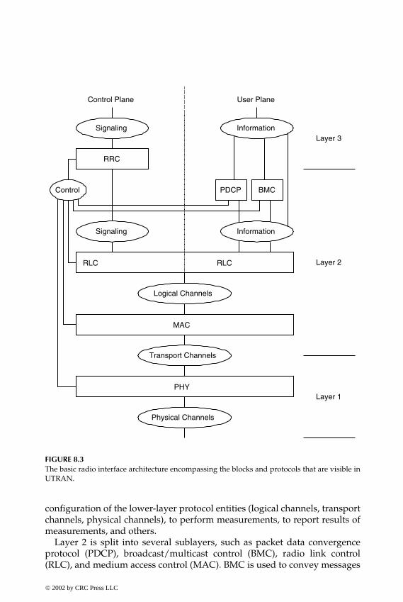
P1: FDJ
book CRC-Wireless November 21, 2001 12:26 Char Count= 282
Signaling
RRC
Information
Control PDCP BMC
InformationSignaling
RLC RLC
Logical Channels
MAC
PHY
Transport Channels
Physical Channels
Layer 1
Layer 2
Layer 3
Control Plane User Plane
FIGURE 8.3The basic radio interface architecture encompassing the blocks and protocols that are visible inUTRAN.
configuration of the lower-layer protocol entities (logical channels, transportchannels, physical channels), to perform measurements, to report results ofmeasurements, and others.
Layer 2 is split into several sublayers, such as packet data convergenceprotocol (PDCP), broadcast/multicast control (BMC), radio link control(RLC), and medium access control (MAC). BMC is used to convey messages
© 2002 by CRC Press LLC
E:\Java for Engineers\VP Publication\Java for Engineers.vpThursday, April 25, 2002 9:27:36 AM
Color profile: DisabledComposite Default screen

P1: FDJ
book CRC-Wireless November 21, 2001 12:26 Char Count= 282
originated from the cell broadcast center, including messages related to theshort message services. PDCP is responsible for header compression and isspecific to the packet-switched domain only. RLC provides services to RRC,on the CP side, and (radio bearers) to PDCP, BMC, and other higher layers, onthe UP. These services are provided by means of SAPs and are called signalingradio bearers in the CP and radio bearers for services that do not use eitherPDCP or BMC in the UP. MAC offers services to RLC by means of SAPs.
Layer 1 contains the physical layer (PHY), which provides services to MACby means of SAPs.
The main SAPs shown in Figure 8.3 are logical channels, transport channels,and physical channels. (The physical channels are not usually shown as SAPsin the ITU documents; however, here they are described as such only fordidactic purposes.) The logical channels constitute the SAPs between RLCand MAC and are characterized by the type of information transferred. Theyare grouped into control channels and traffic channels. The transport channelsconstitute the SAPs between MAC and PHY and are characterized by howthe information is transferred over the radio interface. The SAPs generatedby PHY are the physical channels to be transmitted over the air. They may bedefined in terms of carrier frequency, scrambling code, channelization code,relative phase, time slot, frame, and multiframe.
Figure 8.4 illustrates how higher-layer service data units (SDUs) and pro-tocol data units (PDUs) are segmented and multiplexed to transport blocks
RLC RLC
HL PDU HL PDU
RLC SDU RLC SDU
MAC MAC SDU MAC MAC SDU
CRC CRC
(RLC Segments)
(MAC PDUs orTransport Blocks)
Layer 1 Blocks
Seg
men
tatio
n
Rea
ssem
bly
Higher Layer(HL)
Layer 2RLC
Layer 2MAC
Layer 1
FIGURE 8.4Data flow for a given service (nontransparent RLC and nontransparent MAC).
© 2002 by CRC Press LLC
E:\Java for Engineers\VP Publication\Java for Engineers.vpThursday, April 25, 2002 9:27:36 AM
Color profile: DisabledComposite Default screen
P1: FDJ
book CRC-Wireless November 21, 2001 12:26 Char Count= 282
from Layer 3 through Layer 2 to be further treated by Layer 1. In Figure 8.4,Layer 2 is assumed to operate in the nontransparent mode, in which caseprotocol overhead is added to higher-layer PDUs. Next, the several blocks aredetailed.
8.4.1 Layer 3
As already mentioned, only the lowest sublayer of Layer 3, represented bythe RRC protocol, is visible in UTRAN.
Radio Resource Control
RRC is responsible for the CP signaling of Layer 3 between the UEs and theradio interface. It interacts with the upper layers, such as those for the CN, andperforms functions as described next. (The last four functions are performedin UTRA TDD only.)
� Broadcast of System Information. RRC performs system informationbroadcasting from the network to all UEs. Such information is pro-vided by both the nonaccess stratum (CN) and the access stratum.In the first case, the information may be cell specific and is transmit-ted on a regular basis, whereas in the second case the information istypically cell specific.
� Establishment, Maintenance, and Release of an RRC Connection betweenthe UE and the RAN. An RRC connection is initiated, and then estab-lished, by a request from higher layers at the UE side whenever thefirst signaling connection for the UE is required. The RRC connec-tion includes an optional cell reselection, an admission control, and aLayer 2 signaling link connection.
� Establishment, Reconfiguration, and Release of RABs. RRC establishes,reconfigures, and releases RABs of the UP on request of higher layers.The establishment and reconfiguration operations involve the real-ization of admission control and selection of parameters describingthe RAB processing in Layer 2 and Layer 1.
� Assignment, Reconfiguration, and Release of Radio Resources for the RRCConnection. RRC controls the assignment, reconfiguration, and releaseof the radio resources (e.g., codes) necessary for an RRC connection.
� RRC Connection Mobility Functions. RRC is responsible for the evalu-ation, decision, and execution of functions related to RRC connectionmobility during an established RRC connection. This includes han-dover, preparation of handover to other systems, cell reselection, andcell/paging area update procedures. These processes are based, forexample, on measurements carried out by the UE.
© 2002 by CRC Press LLC
E:\Java for Engineers\VP Publication\Java for Engineers.vpThursday, April 25, 2002 9:27:36 AM
Color profile: DisabledComposite Default screen

P1: FDJ
book CRC-Wireless November 21, 2001 12:26 Char Count= 282
� Paging/Notification. RRC is able to broadcast paging information fromthe network to selected UEs as well as to initiate paging during anestablished RRC connection.
� Control of Requested QoS. RRC is responsible for the accomplishment ofthe requested QoS for the access bearers. This includes the allocationof the necessary radio resources for the specific purpose.
� UE Measurement Reporting and Control of Reporting. RRC is responsi-ble for the control of the measurements (what and how to measureand how to report) performed by the UEs. It is also responsible forreporting the measurements from the UEs to the network.
� Outer Loop Power Control. RRC controls the setting of the target signal-to-interference ratio of the closed-loop power control.
� Control of Ciphering. RRC establishes procedures for setting (on/off)ciphering between the UE and the RAN.
� Initial Cell Selection and Reselection in Idle Mode. RRC is responsiblefor the selection of the most suitable cell based on the idle modemeasurements and cell selection criteria.
� Arbitration of the Radio Resource Allocation between Cells. RRC pro-vides means of ensuring an optimal performance of the overall RANcapacity.
� Contention Resolution (UTRA TDD). RRC reallocates and releases radioresources in the occurrence of collisions, as indicated by lower layers.
� Slow DCA (UTRA TDD). RRC performs allocation of radio resourcesbased on long-term decision criteria (slow dynamic channel alloca-tion, or slow DCA).
� Timing Advance Control (UTRA TDD-3.84). RRC controls the operationof timing advance.
� Active UE Positioning (UTRA TDD-1.28). RRC determines the posi-tion of the active UE according to the information received from thephysical layer.
8.4.2 Layer 2
Layer 2 is split into several sublayers including PDCP, BMC, RLC, and MAC.
Packet Data Convergence Protocol
PDCP is responsible for the transmission and reception of network PDUs. Itprovides for the mapping from one network protocol to one RLC entity. Inthe same way, it provides for compression (in the transmitting entity) anddecompression (in the receiving entity) of redundant network PDU control
© 2002 by CRC Press LLC
E:\Java for Engineers\VP Publication\Java for Engineers.vpThursday, April 25, 2002 9:27:36 AM
Color profile: DisabledComposite Default screen

P1: FDJ
book CRC-Wireless November 21, 2001 12:26 Char Count= 282
information (header compression/decompression). It is present only in theUP and its tasks are related to services within the PS domain only.
Broadcast/Multicast Control
BMC is responsible for broadcast/multicast transmission services on the ra-dio interface for common user data, appearing only in the UP. The follow-ing functionalities are handled by BMC: storage of cell broadcast messages,scheduling of BMC messages, transmission of BMC messages to UEs, deliv-ery of broadcast messages to the upper layer, monitoring of traffic volume,and request of radio resource for cell broadcast services.
Radio Link Control
RLC provides for the establishment and release of RLC connections as wellas for QoS setting and notification to higher layers in case of unrecoverableerrors. It is responsible for data transfer, which may occur in three possiblemodes, depending on the type of service: transparent mode, unacknowledgedmode, and acknowledged mode. The service provided by RLC in the CP iscalled signaling radio bearers, whereas in the UP this is called radio bearer.The communication of the RLC entities with the upper layer is provided bymeans of SAPs: TM-SAP, for the transparent mode; UM-SAP, for the unac-knowledged mode; and AM-SAP, for the acknowledged mode. The commu-nication with the lower layer (MAC) is provided by means of SAPs knownas transport channels.
Transparent Mode. In the transparent mode, higher-layer PDUs are trans-mitted without the inclusion of extra protocol information, with the exceptionof the segmentation and reassembling functionalities.
Unacknowledged Mode. In the unacknowledged mode, higher-layerPDUs are transmitted to the peer entity without guaranteeing delivery. Thefollowing characteristics are applicable to the unacknowledged mode.
� Immediate delivery. RLC delivers an SDU to the higher-layer receivingentity upon arrival of the SDU at the receiver.
� Unique delivery. RLC delivers each SDU to the higher-layer receivingentity only once, using duplication detection function.
� Detection of erroneous data. RLC delivers to the higher-layer receiv-ing entity only those SDUs that are free from transmission errors.This is achieved by means of the use of sequence-number checkfunctions.
Acknowledged Mode. In the acknowledged mode, higher-layer PDUs aretransmitted to the peer entity with guaranteed delivery and both in-sequence
© 2002 by CRC Press LLC
E:\Java for Engineers\VP Publication\Java for Engineers.vpThursday, April 25, 2002 9:27:36 AM
Color profile: DisabledComposite Default screen

P1: FDJ
book CRC-Wireless November 21, 2001 12:26 Char Count= 282
and out-of-sequence deliveries are supported. In case of unsuccessful trans-mission, the involved entity is notified. The following characteristics are ap-plicable to the acknowledged mode.
� Error-free delivery. RLC delivers error-free SDUs to the higher layers,which is accomplished by means of retransmission of data blockswhenever erroneous data are detected.
� Unique delivery. RLC delivers each SDU to the higher-layer receivingentity only once, using duplication detection function.
� In-sequence delivery. RLC delivers SDUs to the higher-layer receivingentity keeping the same order as that of SDUs submitted by the higher-layer entity to RLC.
� Out-of-sequence delivery. RLC delivers SDUs to the higher-layer receiv-ing entity without the need to keep the same order as that of SDUssubmitted by the higher-layer entity to RLC.
Medium Access Control
MAC handles data streams directed to it from RLC and RRC and providesan unacknowledged transfer mode to the upper layers. The communicationbetween RLC and MAC is carried out through SAPs known as logical chan-nels. In the same way, the communication between MAC and PHY is handledthrough SAPs known as transport channels. More specifically, the followingtasks are performed by MAC.
� Mapping of the different logical channels onto the appropriate Trans-port Channels
� Selection of appropriate transport formats for the transport channelson the instantaneous source bit rate basis
� Multiplexing of PDUs into transport blocks to be treated by PHY� Demultiplexing of PDUs from transport blocks delivered by PHY� Handling of priority issues for services to one UE according to infor-
mation from higher layers and PHY (e.g., available transmit powerlevel)
� Handling of priority between UEs by means of dynamic schedulingto improve spectrum efficiency
� Monitoring of traffic volume to be used by RRC so that, based onthe detected volume, a reconfiguration of radio bearers or transportchannels may be triggered.
© 2002 by CRC Press LLC
E:\Java for Engineers\VP Publication\Java for Engineers.vpThursday, April 25, 2002 9:27:36 AM
Color profile: DisabledComposite Default screen
P1: FDJ
book CRC-Wireless November 21, 2001 12:26 Char Count= 282
8.4.3 Layer 1
Layer 1 contains the physical layer that provides services to MAC by meansof SAPs known as transport channels. The SAPs generated by PHY are thephysical channels to be transmitted over the air. They are defined in termsof carrier frequency, code, and relative phase for the UTRA FDD, and interms of carrier frequency, code, time slot, and multiframe for UTRA TDD.The following functionalities are included within PHY. We note that somefunctionalities are particular to one or another UTRA technology, whereasothers are common to the three of them. Next the functionalities in Layer 1are cited. In the list that follows, those functionalities particular to any giventechnology will be appropriately indicated.
� Error detection on transport channels and indication to higher layers� Forward error control encoding/decoding of transport channels� Multiplexing of transport channels and demultiplexing of coded com-
posite transport channels� Rate matching� Mapping of coded composite transport channels onto physical chan-
nels� Power weighting and combining of physical channels� Modulation and spreading/demodulation and despreading of phys-
ical channels� Frequency and time (chip, bit, slot, frame) synchronization� Closed-loop power control� Radio frequency processing� Macrodiversity distribution/combining and soft handover execution
(UTRA FDD)� Macrodiversity distribution/combining and handover execution
(UTRA TDD-1.28)� Support of timing advance on uplink channels (UTRA TDD)� Radio characteristics measurements including frame error rate, signal-
to-interference ratio, interference power levels, direction of arrival(UTRA TDD-1.28) and indication to higher layers
� Subframe segmentation (UTRA TDD-1.28)� Random-access process (UTRA TDD-1.28)� Dynamic channel allocation (UTRA TDD-1.28)� Handover measurements (UTRA TDD-1.28)� Uplink synchronization (UTRA TDD-1.28)
© 2002 by CRC Press LLC
E:\Java for Engineers\VP Publication\Java for Engineers.vpThursday, April 25, 2002 9:27:36 AM
Color profile: DisabledComposite Default screen

P1: FDJ
book CRC-Wireless November 21, 2001 12:26 Char Count= 282
� Beam-forming for both uplink and downlink—smart antennas(UTRA TDD-1.28)
� UE location/positioning (UTRA TDD-1.28)
The physical layer is described in more depth in several sections of thischapter.
8.5 Logical Channels
Logical channels are SAPs located between RLC and MAC. They provide datatransfer services between these two entities. A logical channel is characterizedby the type of information it conveys. Broadly speaking, these channels canbe grouped into control channels and traffic channels. The logical channelsof the first group are used to convey CP information, whereas those in thesecond group are used to convey UP information.
The following are the logical channels of the control channel group:
� Broadcast Control Channel (BCCH). The BCCH is a downlink channelused to broadcast system control information.
� Common Control Channel (CCCH). The CCCH is a bidirectional channelused to convey control information between the network and the UEs.
� Dedicated Control Channel (DCCH). The DCCH is a point-to-point bidi-rectional channel used to convey dedicated control information be-tween the network and a UE. Such a channel is established during theRRC connection establishment procedure.
� Paging Control Channel (PCCH). The PCCH is a downlink channel usedto transmit paging information.
The following are the logical channels of the traffic channel group:
� Control Traffic Channel (CTCH). The CTCH is a point-to-multipointunidirectional channel used to convey dedicated user information toall UEs or to a specified group of UEs.
� Dedicated Traffic Channel (DTCH). The DTCH is a point-to-point chan-nel that can appear both in the downlink and uplink and is used toconvey information to one UE.
� Shared Channel Control Channel (SHCCH)—UTRA TDD only. TheSHCCH is a bidirectional channel used to convey information to andfrom shared transport channels.
© 2002 by CRC Press LLC
E:\Java for Engineers\VP Publication\Java for Engineers.vpThursday, April 25, 2002 9:27:36 AM
Color profile: DisabledComposite Default screen

P1: FDJ
book CRC-Wireless November 21, 2001 12:26 Char Count= 282
8.6 Transport Channels and Indicators
Transport channels are SAPs located between MAC and PHY. They providedata transfer services between these two entities. A transport channel ischaracterized by how the information is transferred over the radio inter-face and by the type of information it conveys. Broadly speaking, thesechannels can be grouped into common channels and dedicated channels.A transport channel of the first group is shared by all UEs or by a groupof UEs and contains an address field for address resolution purposes. Thetransport channel of the second group is used by a single UE and is de-fined by the physical channel; therefore, no specific address is needed forthe UE.
The following are the transport channels of the common channel group:
� Broadcast Channel (BCH). The BCH is a downlink transport channelused to broadcast system- and cell-specific information. Typically, theBCH conveys information such as the available random-access codes,available access slots, types of transmit diversity methods, etc. TheBCH is transmitted over the entire cell.
� Forward Access Channel (FACH). The FACH is a downlink transportchannel used to convey control information to a UE whose locationis known to the system. The FACH may also carry short packet data.There may exist one or more FACHs within a cell, one of them witha bit rate low enough to be detected by all UEs. The FACH doesnot make use of fast power control mechanisms. An in-band iden-tification information is included to ensure correct reception of themessage.
� Paging Channel (PCH). The PCH is a downlink transport channel usedto convey control information relevant to the paging procedure. Apaging message may be transmitted to one or more (up to a fewhundred) cells, depending on the system configuration.
� Random-Access Channel (RACH). The RACH is an uplink transportchannel used to convey control information from the UE to the net-work, typically for random-access purposes (requests to set up a con-nection). It may also be used to carry short packet data from a UEwith messages lasting no longer than one or two frames.
� Common Packet Channel (CPCH)—UTRA FDD. The CPCH is an uplinktransport channel used to convey short to medium-sized packet datafrom a UE. This is, in fact, an extension of the RACH; the main dif-ferences are the use of fast power control mechanisms, the longer
© 2002 by CRC Press LLC
E:\Java for Engineers\VP Publication\Java for Engineers.vpThursday, April 25, 2002 9:27:36 AM
Color profile: DisabledComposite Default screen

P1: FDJ
book CRC-Wireless November 21, 2001 12:26 Char Count= 282
duration of transmission (several frames), and the channel statusmonitoring for collision detection purposes.
� Downlink Shared Channel (DSCH). The DSCH is a shared downlinktransport channel used to convey dedicated user data and controlinformation to several users. The DSCH resembles in many aspectsthe FACH; the main differences are the use of fast power control aswell as variable bit rate on a frame-by-frame basis. It does not needto be received within the whole cell area. It can employ differentmodes of transmit antenna diversity methods and is associated witha downlink dedicated channel.
� Uplink Shared Channel (USCH)—UTRA TDD only. The USCH is ashared uplink transport channel used to convey dedicated user dataand control information from several users. This is, in fact, an exten-sion of the RACH; the main differences are the use of fast powercontrol mechanisms, the longer duration of transmission (severalframes), and the channel status monitoring for collision detectionpurposes.
The following is the transport channel of the dedicated channel group:
� Dedicated Channel (DCH). The DCH is the only transport channelwithin the dedicated channel group. It is an uplink or downlink trans-port channel conveying user information and control information.Note that, as opposed to 2G systems in which these two types ofinformation are conveyed by different channels (traffic channel andassociated control channel), the DCH carries both service data (e.g.,speech frames) and higher-layer control information (e.g., handovercommands, measurement reports). This is accomplished because vari-able bit rate and service multiplexing are supported. The DCH sup-ports the following: fast power control mechanisms; fast data ratechanged on a frame-by-frame basis; transmission to specific locationwithin the cell by use of adaptive antennas; and soft handover (UTRAFDD).
Indicators, on the other hand, are low-level signaling entities that do notuse information blocks of the transport channels. They are of the Booleanor three-valued type and are transmitted directly on the physical channelsknown as indicator channels. The following are the specified indicators: ac-quisition indicator (AI), access preamble indicator (API), channel assignmentindicator (CAI), collision detection indicator (CDI), page indicator (PI), andstatus indicator (SI).
© 2002 by CRC Press LLC
E:\Java for Engineers\VP Publication\Java for Engineers.vpThursday, April 25, 2002 9:27:36 AM
Color profile: DisabledComposite Default screen

P1: FDJ
book CRC-Wireless November 21, 2001 12:26 Char Count= 282
8.7 Physical Channels and Physical Signals
Physical channels may be defined in terms of carrier frequency, scramblingcode, channelization code, relative phase, time slot, subframe, frame, andmultiframe. Physical signals, on the other hand, are entities with the samebasic attributes as physical channels but with no transport channels or in-dicators mapped to them. They may be associated with physical channels tosupport functionalities of the physical channels. This section briefly describesthe functionalities of the physical channels, the details of their structures andspecific functionalities being given in a later subsection.
8.7.1 UTRA FDD Physical Channels
The following are the physical channels of UTRA FDD.
� Common Pilot Channel (CPICH). The CPICH is a downlink physicalchannel—unmodulated code channel—used as a phase reference forthe other downlink physical channels.
� Synchronization Channel (SCH). The SCH is a downlink physical chan-nel used for cell search purposes.
� Primary Common Control Physical Channel (P-CCPCH). The P-CCPCHis a downlink physical channel conveying control information at30 kbit/s (constant bit rate).
� Secondary Common Control Physical Channel (S-CCPCH). The S-CCPCHis a downlink physical channel conveying control information at avariable bit rate.
� Acquisition Indicator Channel (AICH). The AICH is a downlink physi-cal channel used to convey the acquisition indicator for the random-access procedure. It is used to indicate the reception, at the base sta-tion, of the random access channel signature sequence.
� Paging Indicator Channel (PICH). The PICH is a downlink physicalchannel used to convey page indicators to indicate the presence of apage message on the PCH.
� Physical Downlink Shared Channel (PDSCH). The PDSCH is a downlinkphysical channel used to convey data and control information on acommon basis. It is used in association with the downlink dedicatedchannel (downlink DCH) on which the information needed to decodethe PDSCH is carried to the UE.
� Access Preamble Acquisition Indicator Channel (AP-AICH), Collision-Detection/Channel-Assignment Indicator Channel (CD/CA-ICH), CPCHStatus Indicator Channel (CSICH). The AP-AICH, CD/CA-ICH, and
© 2002 by CRC Press LLC
E:\Java for Engineers\VP Publication\Java for Engineers.vpThursday, April 25, 2002 9:27:36 AM
Color profile: DisabledComposite Default screen

P1: FDJ
book CRC-Wireless November 21, 2001 12:26 Char Count= 282
CSICH are downlink physical channels used for the uplink commonpacket channel (CPCH) procedure. The CPCH procedure is describedlater in this chapter.
� Physical Random-Access Channel (PRACH). The PRACH is an uplinkphysical channel used to convey control information for access pur-poses. It also carries short user packets from the UE.
� Physical Common Packet Channel (PCPCH). The PCPCH is an uplinkphysical channel used to convey short to medium-sized user packets.This is a fast-setup and fast-release channel. It is handled similarly tothe RACH reception by the physical layer at the base station.
� Dedicated Physical Data Channel (DPDCH). This is an uplink and down-link physical channel used to convey user information.
� Dedicated Physical Control Channel (DPCCH). This is an uplink anddownlink physical channel used to convey control information.
8.7.2 UTRA TDD Physical Channels
The following are the physical channels of UTRA TDD. When no specificreference is made to any particular technology, the physical channels as de-scribed below are applicable to the two TDD technologies, UTRA TDD-3.84and UTRA TDD-1.28.
� Downlink Pilot Time Slot (DwPTS)—UTRA TDD-1.28. The DwPTS isa downlink physical channel used as a phase reference for the otherdownlink physical channels.
� Uplink Pilot Time Slot (UpPTS)—UTRA TDD-1.28. The UpPTS is anuplink physical channel used as a phase reference for the other uplinkphysical channels.
� Synchronization Channel (SCH). The SCH is a downlink physical chan-nel used for cell search purposes.
� Primary Common Control Physical Channel (P-CCPCH). The P-CCPCHis a downlink physical channel conveying control information at30 kbit/s (constant bit rate).
� Secondary Common Control Physical Channel (S-CCPCH). The S-CCPCHis a downlink physical channel conveying control information at avariable bit rate.
� Paging Indicator Channel (PICH)—UTRA TDD-3.84. The PICH is adownlink physical channel used to convey page indicators to indi-cate the presence of a page message on the PCH.
� Physical Random-Access Channel (PRACH). The PRACH is an uplinkphysical channel used to convey control information for access pur-poses. It also carries short user packets from the UE.
© 2002 by CRC Press LLC
E:\Java for Engineers\VP Publication\Java for Engineers.vpThursday, April 25, 2002 9:27:36 AM
Color profile: DisabledComposite Default screen
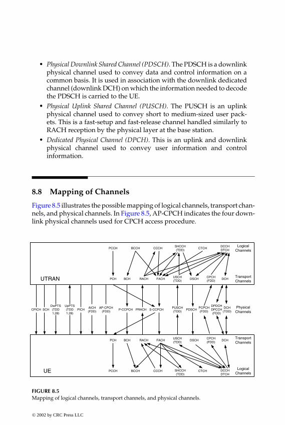
P1: FDJ
book CRC-Wireless November 21, 2001 12:26 Char Count= 282
� Physical Downlink Shared Channel (PDSCH). The PDSCH is a downlinkphysical channel used to convey data and control information on acommon basis. It is used in association with the downlink dedicatedchannel (downlink DCH) on which the information needed to decodethe PDSCH is carried to the UE.
� Physical Uplink Shared Channel (PUSCH). The PUSCH is an uplinkphysical channel used to convey short to medium-sized user pack-ets. This is a fast-setup and fast-release channel handled similarly toRACH reception by the physical layer at the base station.
� Dedicated Physical Channel (DPCH). This is an uplink and downlinkphysical channel used to convey user information and controlinformation.
8.8 Mapping of Channels
Figure 8.5 illustrates the possible mapping of logical channels, transport chan-nels, and physical channels. In Figure 8.5, AP-CPCH indicates the four down-link physical channels used for CPCH access procedure.
DCCHDTCH
CTCHSHCCH(TDD)
CCCHBCCHPCCH
CPCH(FDD)
DSCHUSCH(TDD)
FACHRACHBCHPCH DCH
DPDCHDPCCH(FDD)
PCPCH(FDD)
PDSCHPUSCH(TDD)
S-CCPCHPRACHP-CCPCHDCH
(TDD)
CPCH(FDD)
DSCHUSCH(TDD)
FACHRACHBCHPCH DCH
DCCHDTCH
CTCHSHCCH(TDD)
CCCHBCCHPCCH
AP-CPCH(FDD)
AICH(FDD)
PICHUpPTS(TDD1.28)
DwPTS(TDD1.28)
SCHCPICH
UE
UTRAN
LogicalChannels
TransportChannels
PhysicalChannels
LogicalChannels
TransportChannels
FIGURE 8.5Mapping of logical channels, transport channels, and physical channels.
© 2002 by CRC Press LLC
E:\Java for Engineers\VP Publication\Java for Engineers.vpThursday, April 25, 2002 9:27:36 AM
Color profile: DisabledComposite Default screen

P1: FDJ
book CRC-Wireless November 21, 2001 12:26 Char Count= 282
8.9 Physical Layer Transmission Chain
Figures 8.6 and 8.7 illustrate the physical layer transmission chain for UPdata, respectively, for uplink and downlink. Each chain starts at the transportchannel level and ends at the physical channel level. Note how several trans-port channels may be multiplexed onto one or more dedicated physical datachannels. The transmission chain is identical in both directions for UTRATDD and slightly different for UTRA FDD.
In the UTRA FDD uplink direction, the data stream is continuous withservices multiplexed dynamically. The symbols are sent with equal powerfor all services, which implies that the relative rates for the different servicesmust be adjusted to balance the power level requirements for the channelsymbols. In the UTRA FDD downlink direction, the data stream is givendiscontinuous transmission (DTX) capability. In this case, DTX indication bitsare inserted, but not transmitted over the air, and they inform the transmitterthe bit positions at which the transmission should be turned off. The insertionpoint of the DTX indication bits depends on whether fixed or flexible positionsof the transport channels in the radio frame is used. The decision whetherfixed or flexible positions are used during a connection is the responsibilityof UTRAN. There are two possible DTX insertion stages. The first insertionoccurs only if the positions of the transport channels in the radio frame arefixed. In the second insertion, the indication bits are placed at the end of theradio frame. In such a case, because an interleaving step occurs, DTX willbe distributed over all slots after the second interleaving. The transmissionchain illustrated in Figures 8.6 and in 8.7 is detailed next.
The transport block, received from higher layers, is given error detec-tion capability by means of cyclic redundancy check (CRC) attachment. De-pending on the service requirements, as signaled from higher layers, theCRC attachment can take the length of 0, 8, 12, 16, or 24 bits, with thecyclic generator polynomials for the nonzero lengths, respectively, givenby
GCRC8 (D) = D8 + D7 + D4 + D3 + D + 1GCRC12 (D) = D12 + D11 + D3 + D2 + D + 1GCRC16 (D) = D16 + D12 + D5 + 1GCRC24 (D) = D24 + D23 + D6 + D5 + D + 1
All transport blocks in a transmission time interval (TTI) are serially con-catenated. If the size of a TTI, measured in number of bits, is larger thanthe maximum size of a code block under consideration, then code block
© 2002 by CRC Press LLC
E:\Java for Engineers\VP Publication\Java for Engineers.vpThursday, April 25, 2002 9:27:36 AM
Color profile: DisabledComposite Default screen

P1: FDJ
book CRC-Wireless November 21, 2001 12:26 Char Count= 282
Channel Coding
CRC Attachment
Transport Block ConcatenationCode Block Segmentation
Radio Frame Equalization
First Interleaving
Radio Frame Segmentation
Rate Matching
Transport Channels Multiplexing
Physical Channel Segmentation
SecondInterleaving
SubframeSegmentation(TDD - 1.28)
PhysicalChannelMapping
Physical Channel 1 Physical Channel n
FIGURE 8.6Physical layer transmission chain for UP data for uplink.
© 2002 by CRC Press LLC
E:\Java for Engineers\VP Publication\Java for Engineers.vpThursday, April 25, 2002 9:27:36 AM
Color profile: DisabledComposite Default screen

P1: FDJ
book CRC-Wireless November 21, 2001 12:26 Char Count= 282
Channel Coding
CRC Attachment
Transport Block ConcatenationCode Block Segmentation
First Insertion of DTX Indication
First Interleaving
Radio Frame Segmentation
Rate Matching
Transport Channels Multiplexing
Physical Channel Segmentation
SecondInterleaving
PhysicalChannelMapping
Physical Channel 1 Physical Channel n
Second Insertion of DTX Indication
FIGURE 8.7Physical layer transmission chain for UP data for downlink.
segmentation is carried out after the concatenation has been performed. Themaximum size of the code blocks varies depending on the coding schemeused in the transport channel.
After concatenation/segmentation, the code blocks are delivered to thechannel coding block, where the following coding schemes can be applied to
© 2002 by CRC Press LLC
E:\Java for Engineers\VP Publication\Java for Engineers.vpThursday, April 25, 2002 9:27:36 AM
Color profile: DisabledComposite Default screen

P1: FDJ
book CRC-Wireless November 21, 2001 12:26 Char Count= 282
the transport channels: convolutional coding, turbo coding, or no coding.Real-time services make use of forward error correction (FEC) encoding,whereas non-real-time services make use of a combination of FEC and au-tomatic repeat request (ARQ). The possible convolutional coding rates are1/2 or 1/3 whereas the turbo code rate is 1/3. In the 1/2 rate case, the genera-tor polynomials are
G0 (D) = D8 + D6 + D5 + D4 + 1
for output 0 (G0 (D) = 561, in octal form), and
G1 (D) = D8 + D7 + D6 + D5 + D3 + D + 1
for output 1 (G1 (D) = 753, in octal form). In the 1/3 rate case, the generatorpolynomials are
G0 (D) = D8 + D6 + D5 + D3 + D2 + D + 1
for output 0 (G0 (D) = 557, in octal form),
G1 (D) = D8 + D7 + D5 + D4 + D + 1
for output 1 (G1 (D) = 663, in octal form) and
G2 (D) = D8 + D7 + D6 + D3 + 1
for output 2 (G2 (D) = 711, in octal form). Turbo encoding is used for data serv-ices requiring quality of service—bit error rate (BER)—within the range from10−3 to 10−6. For such a purpose, parallel concatenated convolutional code(PCCC) with eight-state constituent encoders is used. The transfer functionof the eight-state constituent code for PCCC is
G (D) =[
1,1 + D + D3
1 + D2 + D3
]
The initial value of the shift registers of the PCCC encoders is set to all zero.Its output is punctured to produce coded bits corresponding to the desired1/3 code rate.
The radio frame equalization function concerns the frame size equalization,which ensures that the output can be segmented into equal-sized segments
© 2002 by CRC Press LLC
E:\Java for Engineers\VP Publication\Java for Engineers.vpThursday, April 25, 2002 9:27:36 AM
Color profile: DisabledComposite Default screen

P1: FDJ
book CRC-Wireless November 21, 2001 12:26 Char Count= 282
to be transmitted in the TTI of the respective transport channel. Frame sizeequalization is carried out by means of padding the input bit sequence andis performed only in the uplink.
The first interleaving, or interframe interleaving, performs a block inter-leaving with intercolumn permutation and possible interleaving depths of10, 20, 40, and 80 ms.
After the first interleaving is performed, and if the transmission time in-terval is longer than 10 ms, the bit sequence is segmented and mapped ontoconsecutive equal-sized radio frames. Note that, following radio frame sizeequalization in the uplink and rate matching in the downlink, the input bitsequence length is guaranteed to have an integer multiple of the number ofradio frames in the respective TTI. When the TTI is longer than 10 ms, theinput bit sequence is segmented and mapped onto an integer number of con-secutive frames. The number of bits on a transport channel may vary betweendifferent TTIs. In the downlink, for example, the transmission is interruptedif the number of bits is smaller than the maximum.
To guarantee that, after transport channels multiplexing, the total bit rate isidentical to the total channel bit rate of the allocated dedicated physical chan-nels, rate matching is performed. Rate matching is used to accommodate thenumber of bits to be transmitted within the frame. This is accomplished byrepeating or puncturing bits of the transport channels. The rate-matching at-tribute is semistatic and can only be changed through higher-layer signaling.In the uplink direction, rate matching is a dynamic operation varying on aframe-by-frame basis. The multiplexing of several transport channels ontothe same frame involves a rate-matching operation to guarantee the use ofall symbols. In this case, a decrease of a symbol rate of a transport channelimplies an increase of the symbol rate of another transport channel. Notethat, by adjusting the rate-matching attribute, the quality of different ser-vices can be adjusted so that a near-equal symbol power level requirement isreached.
After rate matching, and at every 10 ms, each radio frame from each trans-port channel is delivered to the transport channel multiplexing block. Theseradio frames are serially multiplexed to yield a coded composite transportchannel (CCTrCH).
In case more than one physical channel is required for the transmission ofthe CCTrCH, a physical channel segmentation is performed so that data areevenly distributed among the respective physical channels.
A second interleaving is then applied jointly to all data bits transmitted dur-ing one frame, or separately within each time slot (for UTRA TDD) onto whichthe CCTrCH is mapped. The selection of the second interleaving scheme iscontrolled by a higher layer.
The final step in this transmission chain is the mapping of bits from thesecond interleaver onto physical channels.
© 2002 by CRC Press LLC
E:\Java for Engineers\VP Publication\Java for Engineers.vpThursday, April 25, 2002 9:27:36 AM
Color profile: DisabledComposite Default screen

P1: FDJ
book CRC-Wireless November 21, 2001 12:26 Char Count= 282
The multiplexing of different transport channels onto one CCTrCh and themapping of one CCTrCH onto physical channels follow some basic rules:
� Transport channels multiplexed onto one CCTrCH should have co-ordinated timings. This means that transport blocks arriving on dif-ferent transport channels of potentially different transmission timeintervals shall have aligned transmission time instants. If the possi-ble transmission time instants are multiple of �t ms, then a transportchannel of k�t ms will occupy k transmission time intervals startingat the allowed transmission time instants.
� Different CCTrCHs cannot be mapped onto the same physical chan-nel.
� One CCTrCH is mapped onto one or several physical channels.� Dedicated transport channels and common transport channels cannot
be multiplexed into the same CCTrCH.� Among the common transport channels only FACH and PCH may
belong to the same CCTrCH.� A CCTrCH carrying a BCH shall not carry any other transport channel.� A CCTrCH carrying a RACH shall not carry any other transport
channel.
Note that there are two types of CCTrCH: CCTrCH of the dedicated type,corresponding to the result of coding and multiplexing of one or more DCHs;and CCTrCH of the common type, corresponding to the result of the codingand multiplexing of a common channel, namely, RACH and USCH in theuplink, and DSCH, BCH, FACH, or PCH in the downlink.
8.10 Channel and Frame Structures
In this section, the frame structure and the channel structure of UTRA aredescribed. Special attention is given to the UTRA FDD technology, wherea detailed description of these structures is provided. These items are onlysuperficially explored for the UTRA TDD technologies.
8.10.1 UTRA FDD Uplink Physical Channels
This subsection describes the various UTRA FDD uplink physical channels.
© 2002 by CRC Press LLC
E:\Java for Engineers\VP Publication\Java for Engineers.vpThursday, April 25, 2002 9:27:36 AM
Color profile: DisabledComposite Default screen

P1: FDJ
book CRC-Wireless November 21, 2001 12:26 Char Count= 282
Dedicated Physical Data Channel and Dedicated Physical Control Channel
Two dedicated uplink physical channels are specified: dedicated physicaldata channel (DPDCH) and dedicated physical control channel (DPCCH).These two channels are code-multiplexed within each frame on an in-phaseand quadrature basis (I/Q code multiplexing). DPDCH is used to convey theDCH transport channel, whereas DPCCH is used to carry Layer 1 controlinformation. The number of DPDCHs may range from zero to six on eachradio link with a possible spreading factor ranging from 256 to 4. On theother hand, there is only one DPCCH on each link with a fixed spreadingfactor of 256. Note, therefore, that the DPCCH data rate is fixed, whereas theDPDCH data rate may vary on a frame-by-frame basis.
The information conveyed by the DPDCH corresponds to the higher-layerinformation, including user data. The Layer 1 control information conveyedby the DPCCH includes pilot bits, used to support channel estimation forcoherent detection; transmit power control (TPC) bits, used to carry powercontrol commands for the downlink power control; feedback information(FBI) bits, used to support techniques requiring feedback from the UE to theUTRAN access point, including closed-loop mode transmit diversity and siteselection diversity transmission; and transport format control information(TFCI) bits, used to inform the receiver about the instantaneous transportformat combination (rate information of the transport channels mapped ontothe DPDCH that is being multiplexed with the DPCCH carrying such controlinformation). The presence or not of TFCI within the uplink dedicated phys-ical channels characterizes, respectively, the several simultaneous services orthe fixed-rate services on the channel.
The radio frame is 10 ms long and contains 15 slots. Given that the trans-mission rate is 3.84 Mchip/s, the total number of chips is 38,400 per radioframe and 2560 per slot. A slot corresponds to one power control period andis 0.66666... ms long. The frame structure of the uplink dedicated physicalchannels is shown in Figure 8.8. The number of bits of the DPDCH Nbit/slotvaries in accordance with the seven possible slot formats, ranging from 10bits/slot, for slot format 0, to 640 bits/slot, for slot format 6. More specifically,
Nbit/slot = 10 × 28−log2(spreading factor)
where the spreading factor is
spreading factor = 28−(slot format)
or, equivalently,
Nbit/slot = 10 × 2slot format
© 2002 by CRC Press LLC
E:\Java for Engineers\VP Publication\Java for Engineers.vpThursday, April 25, 2002 9:27:36 AM
Color profile: DisabledComposite Default screen

P1: FDJ
book CRC-Wireless November 21, 2001 12:26 Char Count= 282
Slot0
Slot1
Sloti
Slot14
10 ms
Pilot TFCI FBI TPC
2560 chips
Data
DPCCH
DPDCH
FIGURE 8.8Frame structure of the uplink dedicated physical channels (DPCCH and DPDCH).
where the slot format assumes the values 0, 1, 2, 3, 4, 5, or 6. Table 8.2 showsthe DPDCH fields (the data rate shown corresponds to that immediatelybefore spreading).
As for the DPCCH, the number of bits per slot, the channel bit rate, thesymbol rate, and the spreading factor are constant and equal to 10 bits/slot,15 kbit/s, 15 kbit/s, and 256, respectively. The number of pilot bits, TPC bits,TFCI bits, and FBI bits vary in accordance with the slot format, but their sumis constant and equal to 10 always.
The uplink dedicated physical channels may operate on a multicode ba-sis, in which case several parallel DPDCHs are transmitted using differentchannelization codes. Even operating on a multicode basis, only one DPCCHper radio link is used.
TABLE 8.2
Uplink DPDCH Fields
ChannelSlot Spreading Bits per Bit Rate
Format Factor Slot (kbit/s)
0 256 10 151 128 20 302 64 40 603 32 80 1204 16 160 2405 8 320 4806 4 640 960
© 2002 by CRC Press LLC
E:\Java for Engineers\VP Publication\Java for Engineers.vpThursday, April 25, 2002 9:27:36 AM
Color profile: DisabledComposite Default screen

P1: FDJ
book CRC-Wireless November 21, 2001 12:26 Char Count= 282
Physical Random-Access Channel
The PRACH is used to convey the RACH. The access policy is based on aslotted-ALOHA algorithm with fast acquisition indication. Defined are 15access slots per two radio frames (15 access slots per 20 ms), spaced 5120chips apart, i.e., each access slot has 5120 chips. The UE may start the random-access transmission at the beginning of any access slot, with the informationon what access slots are available for random access transmission given byhigher layers. The structure of the random-access transmission consists of oneor more 4096-chip preambles and a 10- or 20-ms message part. The preamble iscomposed of 256 repetitions of a signature of length 16 chips, with a maximumof 16 available signatures. The message part of 10 ms duration consists of 15slots, each of which contains 2560 chips. Each slot is split into two parts, onethat conveys the RACH information and another that conveys the Layer 1control information. The message part of 20 ms is composed of two 10-msmessage parts. The data part consists of
Nbits = 10 × 2slot format
where the slot format assumes the values 0, 1, 2, or 3, corresponding tospreading factors, respectively, of 256, 128, 64, and 32. The control part con-sists of eight known pilot bits, for channel estimation and coherent detectionpurposes, and two bits for TFCI, which corresponds to a spreading factor of256. Note that the number of TFCI bits in the random-access message is 30(2 bits/slot × 15 slots/frame). The data part and the control part are code-multiplexed and transmitted in parallel. The frame structure of the PRACH isshown in Figure 8.9. Table 8.3 shows the PRACH fields (the data rate showncorresponds to that immediately before spreading).
Physical Common Packet Channel
The PCPCH is used to convey the CPCH. The access policy is based on thedigital (or data) sense multiple access with collision detection (DSMA-CD)algorithm with fast acquisition indication. Transmission from the UE may bestarted at the beginning of time intervals, defined with respect to the frameboundary of the received BCH of the current cell. The access transmissionof the PCPCH uses one or more 4096-chip access preambles, one 4096-chipcollision detection preamble, a 0 or 8-slot DPCCH power control preamble,and a variable-length message part. The access preamble part and the colli-sion detection preamble part are similar to the RACH preamble part and usepreamble signature sequences. The power control preamble presents a slotstructure containing 10 bits per slot defined by the pilot bits, the TPC bits, theTFCI bits, and the FBI bit, with a channel bit rate of 15 kbit/s and a spreadingfactor of 256. The message part consists of one or more 10-ms frames, with thenumber of frames defined by higher layers. A frame is split into 15 2560-chip
© 2002 by CRC Press LLC
E:\Java for Engineers\VP Publication\Java for Engineers.vpThursday, April 25, 2002 9:27:36 AM
Color profile: DisabledComposite Default screen
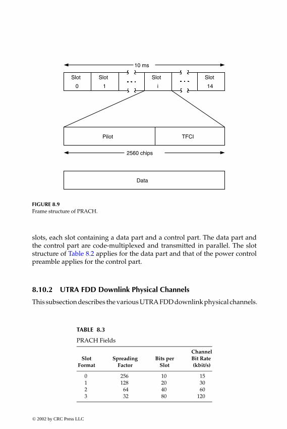
P1: FDJ
book CRC-Wireless November 21, 2001 12:26 Char Count= 282
Slot
0
Slot
1
Slot
i
Slot
14
10 ms
Pilot TFCI
2560 chips
Data
FIGURE 8.9Frame structure of PRACH.
slots, each slot containing a data part and a control part. The data part andthe control part are code-multiplexed and transmitted in parallel. The slotstructure of Table 8.2 applies for the data part and that of the power controlpreamble applies for the control part.
8.10.2 UTRA FDD Downlink Physical Channels
This subsection describes the various UTRA FDD downlink physical channels.
TABLE 8.3
PRACH Fields
ChannelSlot Spreading Bits per Bit Rate
Format Factor Slot (kbit/s)
0 256 10 151 128 20 302 64 40 603 32 80 120
© 2002 by CRC Press LLC
E:\Java for Engineers\VP Publication\Java for Engineers.vpThursday, April 25, 2002 9:27:36 AM
Color profile: DisabledComposite Default screen

P1: FDJ
book CRC-Wireless November 21, 2001 12:26 Char Count= 282
Dedicated Physical Data Channel and Dedicated Physical Control Channel
Two dedicated downlink physical channels are specified: dedicated physicaldata channel and dedicated physical control channel. The DPDCH is usedto convey the DCH transport channel, whereas the DPCCH is used to carryLayer 1 control information represented by the pilot bits, TFCI bits, and TPCbits. These two channels are time-multiplexed.
A radio frame is 10 ms long and contains 15 slots. Given that the trans-mission rate is 3.84 Mchip/s, the total number of chips is 38,400 per radioframe and 2560 per slot. A slot corresponds to one power control period andis 0.6666... ms long. The frame structure of the downlink dedicated physicalchannels is shown in Figure 8.10. The total number of bits per slot Nbit/slotranges from 10 to 1280 with the spreading factor varying from 512 to 4. Morespecifically,
Nbit/slot = 10 × 29−log2(spreading factor)
where the spreading factor is
spreading factor = 29−(slot format)
or, equivalently,
Nbit/slot = 10 × 2slot format
Slot0
Slot1
Sloti
Slot14
10 ms
DATA1 TFCI
2560 chips
TPC DATA2 Pilot
DPDCH DPCCH
FIGURE 8.10Frame structure of the downlink dedicated physical channels (DPCCH and DPDCH).
© 2002 by CRC Press LLC
E:\Java for Engineers\VP Publication\Java for Engineers.vpThursday, April 25, 2002 9:27:36 AM
Color profile: DisabledComposite Default screen

P1: FDJ
book CRC-Wireless November 21, 2001 12:26 Char Count= 282
TABLE 8.4
Downlink DPCH and DPCCH Fields
DPDCH DPCCH ChannelSpreading Bits per Bits per Bits per Bit Rate
Factor Slot Slot Slot (kbit/s)
512 10 2;4 8;6 15256 20 4;6;8;10;12;14;16 16;14;12;10;8;6;4 30128 40 16;20;24;26;28;30;32;34 24;20;16;14;12;10;8;6 60
64 80 52;56;60;64 28;24;20;16 12032 160 120;132;140 40;28;20 24016 320 280;288 40;32 480
8 640 576;600;608 64;40;32 9604 1280 1216;1240;1248 64;40;32 1920
where the slot format assumes the values 0, 1, 2, 3, 4, 5, 6, or 7. Table 8.4 showsthe DPDCH and DPCCH fields. The channel symbol rate is half of the channelbit rate, when both rates are obtained immediately before spreading.
Multicode transmission may also be employed in the downlink, in whichone CCTrCH is mapped onto more than one parallel downlink channels usingthe same spreading factor. The control part of the channel, i.e., the DPCCH, istransmitted only on the first downlink channel. On the additional downlinkchannels, the time period of the DPCCH is filled with DTX bits. It is alsopossible to have several CCTrCHs mapped onto different downlink channelsand transmitted to the same UE. In this case, different spreading factors canbe used. As before, the control information is sent only on the first channelwhile DTX bits are transmitted during the corresponding time period for theother channels.
There is also the downlink DPCCH (DL-DPCCH) for CPCH, which is aspecial case of dedicated physical channels using a spreading factor of 512. Theframe structure of DL-DPCCH is similar to that shown in Figure 8.10, but onlythe fields TPC, TFCI, pilot, and CCC (CPCH control commands) are present.The CCC bits are used to support CPCH signaling such as Layer 1 command(start of a message indicator) and higher layer command (emergency stopcommand). The channel bit rate, the channel symbol rate, and the number ofbits per slot are, respectively, 15, 7.5, and 10 bits.
Common Pilot Channel
The CPICH is an unmodulated code channel transmitted at a fixed rate of30 kbit/s (scrambling factor of 256), which conveys a predefined bit/symbolsequence. The frame structure of CPICH consists of 15 2560-chip slots and is 10ms long. A slot is composed of 20 bits, or equivalently 10 symbols. Two types of
© 2002 by CRC Press LLC
E:\Java for Engineers\VP Publication\Java for Engineers.vpThursday, April 25, 2002 9:27:36 AM
Color profile: DisabledComposite Default screen

P1: FDJ
book CRC-Wireless November 21, 2001 12:26 Char Count= 282
CPICHs are provided: the primary CPICH (P-CPICH) and secondary CPICH(S-CPICH). P-CPICH presents the same channelization code always, whereasS-CPICH may have an arbitrary channelization code of spreading factor equalto 256. P-CPICH is scrambled by the primary scrambling code (PSC), whereasS-CPICH is scrambled by either the PSC or secondary scrambling code (SSC).Each cell has one P-CPICH, but zero or more S-CPICHs. P-CPICH is broadcastthroughout the cell, whereas S-CPICH may be transmitted over the entire cellor only over a specific part of it.
P-CPICH is used as a phase reference for SCH, P-CCPCH, AICH, PICH,AP-AICH, CD/CA-ICH, CSICH, and S-CCPCH carrying PCH. Moreover, bydefault, P-PCICH is the phase reference for S-CCPCH carrying FACH onlyand downlink DPCH, but this default condition can be changed by higher-layer signaling.
S-CPICH may be used as a phase reference for S-CCPCH carrying FACHonly and/or downlink DPCH, but this is not the default condition.
Primary Common Control Physical Channel
The P-CCPCH is a fixed-rate channel transmitted at 30 kbit/s (scramblingfactor of 256) used to convey the BCH transport channel. The frame struc-ture of P-CCPCH consists of 15 2560-chip slots and is 10 ms long. A slot iscomposed of 20 bits but the initial two bits (256 chips) are not transmitted.The corresponding time interval is used to multiplex the primary SCH andsecondary SCH. The P-CCPCH is transmitted over the entire cell.
Secondary Common Control Physical Channel
The S-CCPCH is a variable-rate channel used to convey FACH and PCH,these channels appearing in the same S-CCPCH or separate S-CCPCHs. Theframe structure of S-CCPCH consists of 15 2560-chip slots and is 10 ms long.Each slot contains control and data information; the control part comprisesthe TFCI bits and the pilot bits. The total number of bits per slot Nbit/slot rangesfrom 20 to 1280 with the spreading factor varying from 256 to 4. Accordingly,the channel bit rate varies from 30 to 1920 kbit/s, with the channel symbolrate half the channel bit rate. More specifically,
Nbit/slot = 20 × 28−log2(spreading factor)
where the spreading factor is
spreading factor = 28−(slot format)
© 2002 by CRC Press LLC
E:\Java for Engineers\VP Publication\Java for Engineers.vpThursday, April 25, 2002 9:27:36 AM
Color profile: DisabledComposite Default screen

P1: FDJ
book CRC-Wireless November 21, 2001 12:26 Char Count= 282
or, equivalently,
Nbit/slot = 20 × 2slot format
where the slot format assumes the values 0, 1, 2, 3, 4, 5, or 6.S-CCPCH carrying FACH may be transmitted over part of a cell (narrow
lobe), if required. S-CCPCH may include TFCI or not, which is determinedby UTRAN. The TFCI value in each radio frame determines the transportformat combination of the FACHs and/or PCHs currently in use, and this isnegotiated at each FACH/PCH addition/removal.
Synchronization Channel
The SCH is used for cell search purposes. It consists of the primary SCH(P-SCH) and secondary SCH (S-SCH), which are code-multiplexed and trans-mitted in parallel. The frame structure of SCH consists of 15 2560-chip slotsand is 10 ms long. Of these 2560 chips in each slot, only the first 256 chips areused for SCH and the corresponding time interval is shared by P-CCPCH,as already mentioned. P-SCH consists of a modulated code transmitted onceevery time slot. Such a code, named primary synchronization code (PSC), isthe same for every cell within the system. S-SCH consists of a sequence of 15256-chip modulated codes, the secondary synchronization codes (SSC). Each256-chip block is transmitted within each respective slot of the frame. AnSSC is selected from a set of 16 codes of length 256. The sequence on S-SCHindicates the scrambling code group, out of 64 possible groups, to which thedownlink scrambling code of the cell belongs.
Physical Downlink Shared Channel
The PDSCH is used to convey DSCH and is allocated on a radio frame basis.The following illustrates the possible mode of operation of PDSCH. DifferentPDSCHs may be allocated to different UEs on a code multiplex basis; multi-ple parallel PDSCHs, with the same spreading factor, may be allocated to asingle UE; PDSCHs allocated to the same UE, but on different radio frames,may have different spreading factors. Each PDSCH is associated with thedownlink DPCH, which does not necessarily have the same spreading factor,nor is it frame-aligned with PDSCH. All relevant Layer 1 control informationconcerning PDSCH is conveyed by the DPCCH part of the associated DPCH.The frame structure of PDSCH consists of 15 2560-chip slots and is 10 mslong. Each slot contains data information only, with the control informationprovided by the associated downlink PDCH. The total number of bits per slotNbit/slot ranges from 20 to 1280 with the spreading factor varying from 256to 4. Accordingly, the channel bit rate varies from 30 to 1920 kbit/s, with the
© 2002 by CRC Press LLC
E:\Java for Engineers\VP Publication\Java for Engineers.vpThursday, April 25, 2002 9:27:36 AM
Color profile: DisabledComposite Default screen

P1: FDJ
book CRC-Wireless November 21, 2001 12:26 Char Count= 282
channel symbol rate half the channel bit rate. More specifically,
Nbit/slot = 20 × 28−log2(spreading factor)
where the spreading factor is
spreading factor = 28−(slot format)
or, equivalently,
Nbit/slot = 20 × 2slot format
where the slot format assumes the values 0, 1, 2, 3, 4, 5, or 6. The UE receivingthe associated DPCH is informed whether or not there are data to be decodedon the DSCH by means of either TFCI or higher-layer signaling.
Acquisition Indicator Channel
The AICH is used to convey the acquisition indicators that correspond to asignature on PRACH. The frame structure of AICH consists of 15 consecutive5120-chip access slots and is 20 ms long. An access slot contains an acquisitionindicator, which consists of 32 real-valued symbols (4096 chips), and a part,consisting of 1024 chips, reserved for possible use by CSICH or by anotherphysical channel to be specified. AICH runs at a fixed rate with a spreadingfactor of 256 and has as a phase reference the P-CPICH.
CPCH Access Preamble Acquisition Indicator Channel
The AP-AICH is used to convey AP acquisition indicator of CPCH; an APacquisition indicator corresponds to an AP signature transmitted by UE. Theframe structure of AICH consists of 15 consecutive 5120-chip access slots andis 20 ms long. An access slot contains an AP acquisition indicator, which con-sists of 32 real-valued symbols, and a part, consisting of 1024 chips, reservedfor possible use by CSICH or by another physical channel to be specified. TheAP-AICH runs at a fixed rate with a spreading factor of 256 and has as a phasereference the P-CPICH.
CPCH Collision Detection/Channel Assignment Indicator Channel
The CD/CA-ICH is used to convey CD indicator, if CA is not active, or CDindicator/CA indicator simultaneously if CA is active. (CA is described laterin this chapter.) The frame structure of CD/CA-ICH consists of 15 consecutive5120-chip access slots and is 20 ms long. An access slot contains the CD in-dicator/CA indicator, which consists of 32 real-valued symbols, and a part,consisting of 1024 chips, reserved for possible use by CSICH or by another
© 2002 by CRC Press LLC
E:\Java for Engineers\VP Publication\Java for Engineers.vpThursday, April 25, 2002 9:27:36 AM
Color profile: DisabledComposite Default screen

P1: FDJ
book CRC-Wireless November 21, 2001 12:26 Char Count= 282
physical channel to be specified. The AP-AICH runs at a fixed rate with aspreading factor of 256 and has as a phase reference the P-CPICH.
Paging Indicator Channel
The PICH is used to convey the paging indicators and is always associatedwith an S-CCPCH onto which the PCH transport channel is mapped. Theframe structure of PICH is 10 ms long and consists of 300 bits, with 288used for paging indication and 12 bits that are reserved for possible futureapplication. It runs at a fixed rate with a spreading factor of 256.
CPCH Status Indicator Channel
The CSICH runs in association with the physical channel used for transmis-sion of CPCH AP-AICH, making use of the same channelization and scram-bling codes. The frame structure of CSICH consists of 15 40-bit access slotsand is 20 ms long. An access slot contains a part with no information andanother consisting of the status indicator. The part with no information corre-sponds to 4096 chips and is reserved for use by AICH, AP-AICH, or CD/CA-ICH. The part containing the status indicator is 8 bits long. The CSICH runsat a fixed rate with spreading code of 256, having as a phase reference theP-CPICH.
8.10.3 UTRA TDD-3.84
UTRA TDD-3.84 timing is based on a multiframe structure. A multiframe con-tains n 10-ms-long frames, a frame encompassing 15 2560-chip slots. The timeslots may be allocated either to the uplink or to the downlink, as required bythe different environments and deployment scenarios. In particular, at leastone time slot must be allocated to the uplink and at least one time slot mustbe allocated to the downlink. Note that a highly asymmetric frame configu-ration may be encountered for a given application. The time slot structure—the burst structure—contains two data fields separated by a midamble field,which is used for both channel equalization (training sequence) and coher-ent detection at the receiver. TFCI field is also incorporated to indicate themultiplexing mode within the frame. Whenever applicable, TPC may alsobe included. Moreover, a guard period is provided at the end of the burst fortiming alignment purposes. The midambles reduce the user payload informa-tion, comprising training sequences of different users. The timing structureof UTRA TDD-3.84 is illustrated in Figure 8.11. UTRA TDD-3.84 allows forthe use of multicode and multiple time slots. Next described are some of themain UTRA TDD-3.84 physical channels.
© 2002 by CRC Press LLC
E:\Java for Engineers\VP Publication\Java for Engineers.vpThursday, April 25, 2002 9:27:36 AM
Color profile: DisabledComposite Default screen
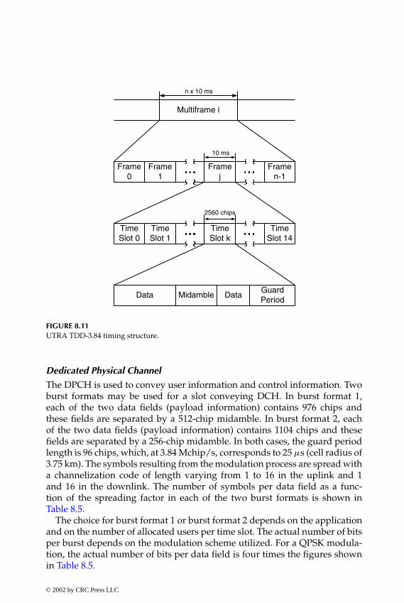
P1: FDJ
book CRC-Wireless November 21, 2001 12:26 Char Count= 282
TimeSlot 0
TimeSlot 1
TimeSlot k
TimeSlot 14
2560 chips
Data Midamble DataGuardPeriod
Frame0
Frame1
Framej
Framen-1
10 ms
Multiframe i
n x 10 ms
FIGURE 8.11UTRA TDD-3.84 timing structure.
Dedicated Physical Channel
The DPCH is used to convey user information and control information. Twoburst formats may be used for a slot conveying DCH. In burst format 1,each of the two data fields (payload information) contains 976 chips andthese fields are separated by a 512-chip midamble. In burst format 2, eachof the two data fields (payload information) contains 1104 chips and thesefields are separated by a 256-chip midamble. In both cases, the guard periodlength is 96 chips, which, at 3.84 Mchip/s, corresponds to 25 µs (cell radius of3.75 km). The symbols resulting from the modulation process are spread witha channelization code of length varying from 1 to 16 in the uplink and 1and 16 in the downlink. The number of symbols per data field as a func-tion of the spreading factor in each of the two burst formats is shown inTable 8.5.
The choice for burst format 1 or burst format 2 depends on the applicationand on the number of allocated users per time slot. The actual number of bitsper burst depends on the modulation scheme utilized. For a QPSK modula-tion, the actual number of bits per data field is four times the figures shownin Table 8.5.
© 2002 by CRC Press LLC
E:\Java for Engineers\VP Publication\Java for Engineers.vpThursday, April 25, 2002 9:27:36 AM
Color profile: DisabledComposite Default screen
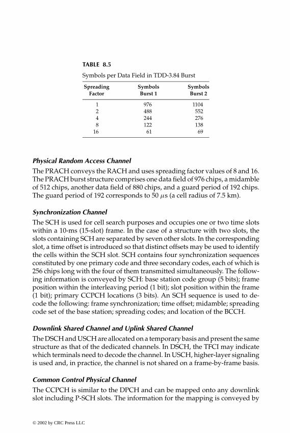
P1: FDJ
book CRC-Wireless November 21, 2001 12:26 Char Count= 282
TABLE 8.5
Symbols per Data Field in TDD-3.84 Burst
Spreading Symbols SymbolsFactor Burst 1 Burst 2
1 976 11042 488 5524 244 2768 122 138
16 61 69
Physical Random Access Channel
The PRACH conveys the RACH and uses spreading factor values of 8 and 16.The PRACH burst structure comprises one data field of 976 chips, a midambleof 512 chips, another data field of 880 chips, and a guard period of 192 chips.The guard period of 192 corresponds to 50 µs (a cell radius of 7.5 km).
Synchronization Channel
The SCH is used for cell search purposes and occupies one or two time slotswithin a 10-ms (15-slot) frame. In the case of a structure with two slots, theslots containing SCH are separated by seven other slots. In the correspondingslot, a time offset is introduced so that distinct offsets may be used to identifythe cells within the SCH slot. SCH contains four synchronization sequencesconstituted by one primary code and three secondary codes, each of which is256 chips long with the four of them transmitted simultaneously. The follow-ing information is conveyed by SCH: base station code group (5 bits); frameposition within the interleaving period (1 bit); slot position within the frame(1 bit); primary CCPCH locations (3 bits). An SCH sequence is used to de-code the following: frame synchronization; time offset; midamble; spreadingcode set of the base station; spreading codes; and location of the BCCH.
Downlink Shared Channel and Uplink Shared Channel
The DSCH and USCH are allocated on a temporary basis and present the samestructure as that of the dedicated channels. In DSCH, the TFCI may indicatewhich terminals need to decode the channel. In USCH, higher-layer signalingis used and, in practice, the channel is not shared on a frame-by-frame basis.
Common Control Physical Channel
The CCPCH is similar to the DPCH and can be mapped onto any downlinkslot including P-SCH slots. The information for the mapping is conveyed by
© 2002 by CRC Press LLC
E:\Java for Engineers\VP Publication\Java for Engineers.vpThursday, April 25, 2002 9:27:36 AM
Color profile: DisabledComposite Default screen
P1: FDJ
book CRC-Wireless November 21, 2001 12:26 Char Count= 282
the primary BCH. In fact, once synchronization is achieved, the timing andthe coding of the primary BCH are already known.
8.10.4 UTRA TDD-1.28
UTRA TDD-1.28 timing is based on a multiframe structure. A multiframecontains n 10-ms-long frames, a frame encompassing two 5-ms subframes.A subframe contains seven 675-µs time slots (normal time slots) and threespecial time slots: DwPTS (downlink pilot), G (guard period), and UpPTS(uplink pilot). A physical channel may be allocated one or more time slots ona continuous or discontinuous mode. In the first case, the allocation occurs inevery frame. In the second case, the allocation occurs in a subset of all frames.One time slot (time slot 0) among the seven available is always allocated asdownlink whereas another (time slot 1) is allocated as uplink. The remainingtime slots may be allocated as downlink or uplink, as required. Note that ahighly asymmetric frame configuration may be encountered for a given appli-cation. Downlink and uplink time slots are separated by a switching point butonly two switching points are possible within each subframe. The time slotstructure—the burst structure—contains two data fields separated by a mid-amble field, which is used for both channel equalization (training sequence)and coherent detection at the receiver. A guard period is provided at the endof the burst for timing alignment purposes. The midamble reduces the userpayload information, comprising training sequences of different users. Thetiming structure of UTRA TDD-1.28 is illustrated in Figure 8.12, where timeslots 2 and 3 are allocated as uplink and time slots 4, 5, and 6 are allocated asdownlink. UTRA TDD-1.28 allows for the use of multicode and multiple timeslots. Next, some of the UTRA TDD-1.28 physical channels are described.
Dedicated Physical Channel
The DPCH is used to convey user information and control information. Theburst format is composed of two data fields (payload information), bothamounting to 704 chips and separated by a 144-chip midamble, and a 16-chipguard period (12.5 µs, cell radius of 1.875 km). The symbols resulting fromthe modulation process are spread with a channelization code of length 16 inthe downlink and varying from 1 to 16 in the uplink. The number of symbolsper data field as a function of the spreading factor is shown in Table 8.6.
The burst type used allows the transmission of TFCI both in downlink anduplink. For each user the TFCI information is transmitted once every 10-msframe. The transmission of TPC is negotiated at the call setup and can berenegotiated during the call. For each user the TPC is transmitted once every5-ms subframe.
© 2002 by CRC Press LLC
E:\Java for Engineers\VP Publication\Java for Engineers.vpThursday, April 25, 2002 9:27:36 AM
Color profile: DisabledComposite Default screen

P1: FDJ
book CRC-Wireless November 21, 2001 12:26 Char Count= 282
Time Slot0
675 µs
Data352 Chips
Midamble144 Chips
Data352 Chips
Guard Period16 Chips
Frame0
Frame1
Framej
Framen-1
10 ms
Multiframe i
n x 10 ms
Subframe 0 Subframe 1
5 ms
Time Slot1
Time Slot2
Time Slot3
Time Slot4
Time Slot5
Time Slot6
DwPTS(96 chips)
GP(96 chips)
UpPTS(160 chips)
Switching point
Switching point
FIGURE 8.12UTRA TDD-1.28 timing structure.
Primary Common Control Physical Channel
The P-CCPCH conveys the BCH. There are two P-CCPCHs: P-CCPCH1 andP-CCPCH2. They are mapped onto the first two code channels of time slot 0and run at a spreading factor of 16.
TABLE 8.6
Symbols per Data Field in TDD-1.28 Burst
Spreading Symbols perFactor Data Field
1 3522 1764 888 44
16 22
© 2002 by CRC Press LLC
E:\Java for Engineers\VP Publication\Java for Engineers.vpThursday, April 25, 2002 9:27:36 AM
Color profile: DisabledComposite Default screen
P1: FDJ
book CRC-Wireless November 21, 2001 12:26 Char Count= 282
Secondary Common Control Physical Channel
The S-CCPCH conveys the PCH and FACH. There are two S-CCPCHs, namely,S-CCPCH1 and S-CCPCH2, which are mapped onto two code channels withspreading factor of 16. P-CCPCH and S-CCPCH can be time-multiplexed ontime slot 0 or they can be allocated on any other downlink time slots. The timeslot and the codes to be used are broadcast via cell information.
Physical Random Access Channel
The PRACH conveys the RACH. It uses a spreading factor of either 16 or 8. Itsconfiguration (time slot number and spreading codes) is broadcast throughBCH.
Synchronization Channel
There are two types of synchronization channels: DwPTS and UpPTS. DwPTSin each subframe is designed for both downlink pilot and SCH. It is trans-mitted omnidirectionally or sectorially at full power levels. It is composed of96 chips (75 µs), 64 of which are used for synchronization purposes and 32of which comprise the guard period. The PN code set is used to distinguishcells. UpPTS in each subframe is designed for both uplink pilot and SCH. Itis composed of 150 chips (125 µs), 125 of which are used for synchronizationpurposes and 32 of which comprise the guard period. The PN code set isdesigned to distinguish UEs in the access procedure. In the condition of airregistration or random access, the UE transmits the UpPTS first and, after anacknowledgment from the network, it then transmits RACH.
Physical Uplink Shared Channel
The PUSCH uses the same burst structure as that of DPCH. Informationconcerning power control, timing advance, or directive antenna settings arederived from FACH or DCH. TFCI may be transmitted within PUSCH.
Physical Downlink Shared Channel
The PDSCH uses the same burst structure as that of DPCH. Information con-cerning power control or directive antenna settings are derived from FACHor DCH. TFCI may be transmitted within PDSCH.
Paging Indicator Channel
The PICH conveys the paging indicators. It is always transmitted at the samereference power level and the same antenna pattern as for P-CCPCH. Thesame burst format is used for PICH throughout the cell.
© 2002 by CRC Press LLC
E:\Java for Engineers\VP Publication\Java for Engineers.vpThursday, April 25, 2002 9:27:36 AM
Color profile: DisabledComposite Default screen
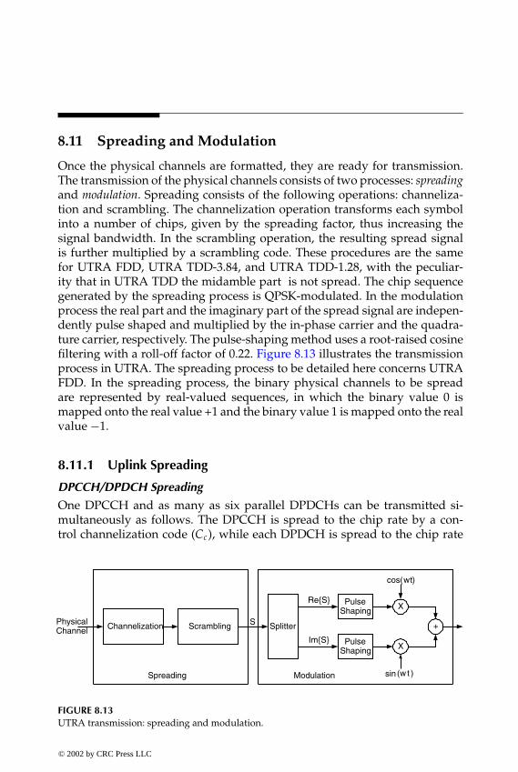
P1: FDJ
book CRC-Wireless November 21, 2001 12:26 Char Count= 282
8.11 Spreading and Modulation
Once the physical channels are formatted, they are ready for transmission.The transmission of the physical channels consists of two processes: spreadingand modulation. Spreading consists of the following operations: channeliza-tion and scrambling. The channelization operation transforms each symbolinto a number of chips, given by the spreading factor, thus increasing thesignal bandwidth. In the scrambling operation, the resulting spread signalis further multiplied by a scrambling code. These procedures are the samefor UTRA FDD, UTRA TDD-3.84, and UTRA TDD-1.28, with the peculiar-ity that in UTRA TDD the midamble part is not spread. The chip sequencegenerated by the spreading process is QPSK-modulated. In the modulationprocess the real part and the imaginary part of the spread signal are indepen-dently pulse shaped and multiplied by the in-phase carrier and the quadra-ture carrier, respectively. The pulse-shaping method uses a root-raised cosinefiltering with a roll-off factor of 0.22. Figure 8.13 illustrates the transmissionprocess in UTRA. The spreading process to be detailed here concerns UTRAFDD. In the spreading process, the binary physical channels to be spreadare represented by real-valued sequences, in which the binary value 0 ismapped onto the real value +1 and the binary value 1 is mapped onto the realvalue −1.
8.11.1 Uplink Spreading
DPCCH/DPDCH Spreading
One DPCCH and as many as six parallel DPDCHs can be transmitted si-multaneously as follows. The DPCCH is spread to the chip rate by a con-trol channelization code (Cc), while each DPDCH is spread to the chip rate
Channelization Scrambling
Spreading
PulseShaping
PulseShaping
Splitter
X
X
+
Re{S}
Im{S}
sinModulation
PhysicalChannel
)cos( tw
)( tw
S
FIGURE 8.13UTRA transmission: spreading and modulation.
© 2002 by CRC Press LLC
E:\Java for Engineers\VP Publication\Java for Engineers.vpThursday, April 25, 2002 9:27:36 AM
Color profile: DisabledComposite Default screen

P1: FDJ
book CRC-Wireless November 21, 2001 12:26 Char Count= 282
by a specific data channelization code (Cd ,i , 1 ≤ i ≤ 6). The real-valuedspread signals are multiplied by a gain factor (Gc for DPCCH and Gd for allthe DPDCHs). The ratio Gc /Gd is quantized into 4-bit words. Therefore,16 gain ratios can be represented and they are 15 /15, 14/15, . . . , 0/15. Theweighted streams of real-valued chips on the in-phase (I) and quadrature (Q)branches are added and treated as a complex-valued stream of chips. Thecomplex-valued stream of chips is scrambled by the complex-valued scram-bling code SDPCH,n, which is aligned with the radio frames (the first scram-bling chip starts at the beginning of a radio frame). Figure 8.14 illustrates theDPCCH/DPDCH spreading process.
FIGURE 8.14Uplink DPCCH/DPDCH spreading.
© 2002 by CRC Press LLC
E:\Java for Engineers\VP Publication\Java for Engineers.vpThursday, April 25, 2002 9:27:36 AM
Color profile: DisabledComposite Default screen

P1: FDJ
book CRC-Wireless November 21, 2001 12:26 Char Count= 282
X Gd
X Gc X
+ X
Cd
Cc j
I+jQ
SPRACH, n
PRACH MDP
PRACH MCP
FIGURE 8.15PRACH spreading.
PRACH Spreading
The PRACH message part is divided into a data part (PRACH MDP) anda control part (PRACH MCP). These two parts have different channeliza-tion codes and gain factors. The channelization code and the gain factorfor PRACH MDP are, respectively, Cd and Gd , whereas these are Cc and Gc
for PRACH MCP. The ratio Gc /Gd is quantized into 4-bit words. Therefore,16 gain ratios can be represented and they are 15 /15, 14/15, . . . , 0/15. Theweighted streams of real-valued chips on the in-phase (I) and quadrature (Q)branches are added and treated as a complex-valued stream of chips. And thecomplex-valued stream of chips are scrambled by the 10-ms complex-valuedscrambling code SPRACH,n, which is aligned with the 10-ms message part radioframes (the first scrambling chip starts at the beginning of a message radioframe). Figure 8.15 illustrates the PRACH spreading process.
PCPCH Spreading
The PCPCH message part is divided into a data part (PCPCH MDP) and acontrol part (PCPCH MCP). These two parts have different channelizationcodes and gain factors. The channelization code and the gain factor PCPCHMDP are, respectively, Cd and Gd , whereas these are Cc and Gc for PCPCHMCP. The ratio Gc/Gd is quantized into 4-bit words. Therefore, 16 gain ratioscan be represented and they are 15/15, 14/15, . . . , 0/15. The weighted streamsof real-valued chips on the in-phase (I) and quadrature (Q) branches areadded and treated as a complex-valued stream of chips. The complex-valuedstream of chips is scrambled by the 10-ms complex-valued scrambling codeSPCPCH,n, which is aligned with the 10-ms message part radio frames (the first
© 2002 by CRC Press LLC
E:\Java for Engineers\VP Publication\Java for Engineers.vpThursday, April 25, 2002 9:27:36 AM
Color profile: DisabledComposite Default screen

P1: FDJ
book CRC-Wireless November 21, 2001 12:26 Char Count= 282
X Gd
X Gc X
+ X
Cd
Cc j
I+jQ
SPCPCH, n
PCPCH MDP
PCPCH MCP
FIGURE 8.16PCPCH spreading.
scrambling chip starts at the beginning of a message radio frame). Figure 8.16illustrates the PCPCH spreading process.
8.11.2 Downlink Spreading
Except for SCH, the spreading operation is identical for all downlink phys-ical channels, namely, P-CCPCH, S-CCPCH, CPICH, AICH, PICH, PDSCH,and downlink DPCH. Except for the AICH symbols, the nonspread physicalchannel symbols can take on the values +1, −1, and 0, the null value indicat-ing discontinuous transmission. As for AICH, its symbol values depend onthe exact combination of acquisition indicators.
The spreading process for these channels (except SCH) is as follows. Eachpair of two consecutive symbols is serial-to-parallel converted, and theeven-numbered and odd-numbered symbols are mapped onto I and Q bran-ches, respectively. Each branch is then spread to the chip rate by the samechannelization code Cm. The stream of real-valued chips on the in-phase andquadrature branches is added and treated as a complex-valued stream ofchips. The complex-valued stream of chips is scrambled by the complex-valued scrambling code Sdw,n. The scrambling code for any downlink channelis always applied with its alignment referred to that of the scrambling codeused for P-CCPCH. The scrambling code for P-CCPCH is aligned with theP-CCPCH frame boundary (the first complex chip of the spread P-CCPCHframe is multiplied with chip number zero of the scrambling code).
The downlink channels are then combined, with each downlink channelweighted by a different gain factor Gi . The synchronism channels P-SCH and
© 2002 by CRC Press LLC
E:\Java for Engineers\VP Publication\Java for Engineers.vpThursday, April 25, 2002 9:27:36 AM
Color profile: DisabledComposite Default screen
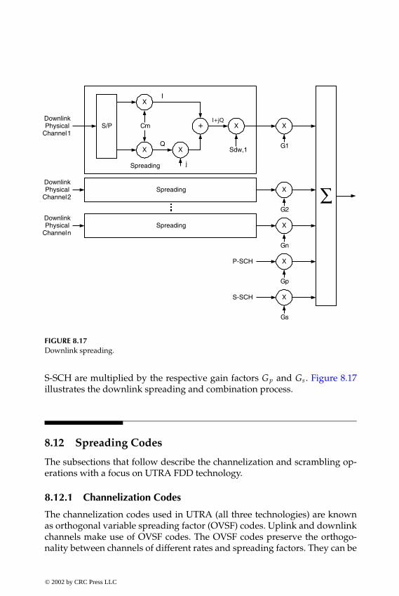
P1: FDJ
book CRC-Wireless November 21, 2001 12:26 Char Count= 282
∑
S/P
X
X X
+ X X
I
Q
jSpreading
DownlinkPhysical
Channel 1Cm
Sdw,1 G1
Spreading XDownlinkPhysical
Channel 2
G2
Spreading XDownlinkPhysical
Channel n
Gn
X
Gp
X
Gs
P-SCH
S-SCH
FIGURE 8.17Downlink spreading.
S-SCH are multiplied by the respective gain factors Gp and Gs . Figure 8.17illustrates the downlink spreading and combination process.
8.12 Spreading Codes
The subsections that follow describe the channelization and scrambling op-erations with a focus on UTRA FDD technology.
8.12.1 Channelization Codes
The channelization codes used in UTRA (all three technologies) are knownas orthogonal variable spreading factor (OVSF) codes. Uplink and downlinkchannels make use of OVSF codes. The OVSF codes preserve the orthogo-nality between channels of different rates and spreading factors. They can be
© 2002 by CRC Press LLC
E:\Java for Engineers\VP Publication\Java for Engineers.vpThursday, April 25, 2002 9:27:36 AM
Color profile: DisabledComposite Default screen

P1: FDJ
book CRC-Wireless November 21, 2001 12:26 Char Count= 282
defined as
C1,0 = [1][C2,0C2,1
]=
[C1,0 C1,0C1,0 −C1,0
]=
[1 11 −1
]
C2n+1,0C2n+1,1C2n+1,2C2n+1,3
...
C2n+1,2n+1 −2C2n+1,2n+1 −1
=
C2n,0 C2n,0C2n,0 −C2n,0C2n,1 C2n,1C2n,1 −C2n,1... ...
C2n,2n −1 C2n,2n −1C2n,2n −1 −C2n,2n −1
where Cspreading factor,k uniquely identifies the code and where 0 ≤ k ≤spreading factor − 1. The code tree of Figure 8.18 illustrates the OVSF codes.The leftmost value in each channelization code word corresponds to the chipfirst transmitted in time.
C1,0 = (1)
C2,0 = (1,1)
C2,1 = (1,-1)
C4,0 = (1,1,1,1)
C4,1 = (1,1,-1,-1)
C4,2 = (1,-1,1,-1)
C4,3 = (1,-1,-1,1)
FIGURE 8.18OVSF code tree.
© 2002 by CRC Press LLC
E:\Java for Engineers\VP Publication\Java for Engineers.vpThursday, April 25, 2002 9:27:36 AM
Color profile: DisabledComposite Default screen
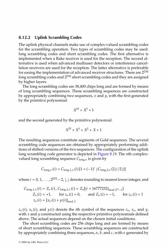
P1: FDJ
book CRC-Wireless November 21, 2001 12:26 Char Count= 282
8.12.2 Uplink Scrambling Codes
The uplink physical channels make use of complex-valued scrambling codesfor the scrambling operation. Two types of scrambling codes may be used:long scrambling codes and short scrambling codes. The first alternative isimplemented when a Rake receiver is used for the reception. The second al-ternative is used when advanced multiuser detectors or interference cancel-lation receivers are used for the reception. The latter alternative is preferablefor easing the implementation of advanced receiver structures. There are 2[24]
long scrambling codes and 2[24] short scrambling codes and they are assignedby higher layers.
The long scrambling codes are 38,400 chips long and are formed by meansof long scrambling sequences. These scrambling sequences are constructedby appropriately combining two sequences, x and y, with the first generatedby the primitive polynomial:
X25 + X3 + 1
and the second generated by the primitive polynomial:
X25 + X3 + X2 + X + 1
The resulting sequences constitute segments of Gold sequences. The severalscrambling code sequences are obtained by appropriately performing addi-tions of shifted versions of the two sequences. The configuration of the uplinklong scrambling code generator is depicted in Figure 8.19. The nth complex-valued long scrambling sequence Clong,n is given by
Clong,n (i) = Clong,1,n (i) [1 + (−1)i jClong,2,n (2�i/2�)]
where i = 0, 1, . . . , 2[25] −2, �.� denotes rounding to nearest lower integer, and
Clong,1,n (i) = Zn (i) , Clong,2,n (i) = Zn[(i + 16777232)mod 225−1]Zn (i) = +1, for zn (i) = 0, and Zn (i) = −1, for zn (i) = 1zn (i) = [xn (i) + y (i)]mod 2
zn (i), xn (i), and y (i) denote the ith symbol of the sequences zn, xn, and y,with x and y constructed using the respective primitive polynomials definedabove. The actual sequences depend on the chosen initial conditions.
The short scrambling codes are 256 chips long and are formed by meansof short scrambling sequences. These scrambling sequences are constructedby appropriately combining three sequences, a , b, and c, with a generated by
© 2002 by CRC Press LLC
E:\Java for Engineers\VP Publication\Java for Engineers.vpThursday, April 25, 2002 9:27:36 AM
Color profile: DisabledComposite Default screen

P1: FDJ
book CRC-Wireless November 21, 2001 12:26 Char Count= 282
+
+
+
+
+
+Clong,1,n
Clong,2,n
FIGURE 8.19Uplink scrambling sequence generator.
the polynomial:
X8 + X5 + 3X3 + X2 + 2X + 1
b generated by the polynomial:
X8 + X7 + X5 + X + 1
and c generated by the polynomial:
X8 + X7 + X5 + X4 + 1
The several scrambling code sequences are obtained by appropriately per-forming additions of shifted versions of the three sequences. The config-uration of the uplink short scrambling code generator is depicted in Fig-ure 8.20, where the mapper provides the mapping from zn (i) = 0, 1, 2, and 3onto the output binary sequences (Cshort,1,n(imod 256), Cshort,2,n(imod 256)) =(+1, +1), (−1, +1), (+1, −1), and (−1, −1). The nth complex-valued long scram-bling sequence Cshort,n is given by
Cshort,n(i) = Cshort,1,n(imod 256)[1 + (−1)i jCshort,2,n (2�(imod 256) /2�)]
where i = 0, 1, . . . , 254, �.� denotes rounding to nearest lower integer, and
zn (i) = a (i) + 2b (i) + 2c (i)
© 2002 by CRC Press LLC
E:\Java for Engineers\VP Publication\Java for Engineers.vpThursday, April 25, 2002 9:27:36 AM
Color profile: DisabledComposite Default screen

P1: FDJ
book CRC-Wireless November 21, 2001 12:26 Char Count= 282
X
+X
+ + +mod 2
+ + +mod 2
X XX
X
++++
32
33
Mapper
mod 4
mod 4
b(i)
a(i)
d(i)
Zn(i)Cshort,1,n (i)
Cshort,2,n (i)
+X
mod n addition
multiplication
2
FIGURE 8.20Uplink short sequence generator.
where a (i), b (i), and c (i) denotes the ith symbol of the sequences a , b, andc, which are constructed using the respective primitive polynomials definedabove.
Some of the scrambling sequences for the different physical channels aredefined as follows. DPCCH and DPDCH may use either long or short scram-bling codes. The nth uplink long scrambling code Slong,n (i) is given by
Slong,n (i) = Clong,n (i)
The nth uplink short scrambling code Sshort,n (i) is given by
Sshort,n (i) = Cshort,n (i)
In both cases i = 0, 1, . . . , 38399. The message part of PRACH uses a 10-msscrambling code chosen among 8192 scrambling codes. The nth scramblingcode in this case is given by
Sn (i) = Clong,n (i + 4096)
© 2002 by CRC Press LLC
E:\Java for Engineers\VP Publication\Java for Engineers.vpThursday, April 25, 2002 9:27:36 AM
Color profile: DisabledComposite Default screen
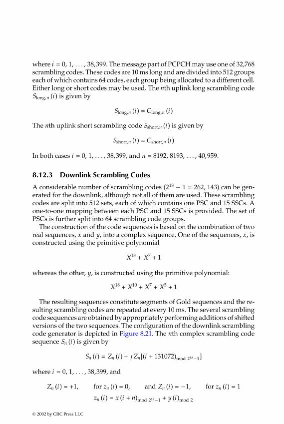
P1: FDJ
book CRC-Wireless November 21, 2001 12:26 Char Count= 282
where i = 0, 1, . . . , 38,399. The message part of PCPCH may use one of 32,768scrambling codes. These codes are 10 ms long and are divided into 512 groupseach of which contains 64 codes, each group being allocated to a different cell.Either long or short codes may be used. The nth uplink long scrambling codeSlong,n (i) is given by
Slong,n (i) = Clong,n (i)
The nth uplink short scrambling code Sshort,n (i) is given by
Sshort,n (i) = Cshort,n (i)
In both cases i = 0, 1, . . . , 38,399, and n = 8192, 8193, . . . , 40,959.
8.12.3 Downlink Scrambling Codes
A considerable number of scrambling codes (218 − 1 = 262, 143) can be gen-erated for the downlink, although not all of them are used. These scramblingcodes are split into 512 sets, each of which contains one PSC and 15 SSCs. Aone-to-one mapping between each PSC and 15 SSCs is provided. The set ofPSCs is further split into 64 scrambling code groups.
The construction of the code sequences is based on the combination of tworeal sequences, x and y, into a complex sequence. One of the sequences, x, isconstructed using the primitive polynomial
X18 + X7 + 1
whereas the other, y, is constructed using the primitive polynomial:
X18 + X10 + X7 + X5 + 1
The resulting sequences constitute segments of Gold sequences and the re-sulting scrambling codes are repeated at every 10 ms. The several scramblingcode sequences are obtained by appropriately performing additions of shiftedversions of the two sequences. The configuration of the downlink scramblingcode generator is depicted in Figure 8.21. The nth complex scrambling codesequence Sn (i) is given by
Sn (i) = Zn (i) + j Zn[(i + 131072)mod 218−1]
where i = 0, 1, . . . , 38,399, and
Zn (i) = +1, for zn (i) = 0, and Zn (i) = −1, for zn (i) = 1
zn (i) = x (i + n)mod 218−1 + y (i)mod 2
© 2002 by CRC Press LLC
E:\Java for Engineers\VP Publication\Java for Engineers.vpThursday, April 25, 2002 9:27:36 AM
Color profile: DisabledComposite Default screen

P1: FDJ
book CRC-Wireless November 21, 2001 12:26 Char Count= 282
FIGURE 8.21Downlink scrambling code generator.
where zn (i), x (i), and y (i) denote the ith symbol of the sequences zn, x, and y,with x and y constructed using the respective primitive polynomials definedabove. The actual sequences depend on the chosen initial conditions. Eachcell is allocated one, and only one, PSC. In particular, the physical channelsP-CCPCH, P-CPICH, PICH, AICH, AP-AICH, CD/CA-ICH, CSICH, and S-CCPCH carrying PCH use the PSC allocated to the corresponding cell. Theremaining downlink physical channels of the cell can use either PSC or oneSSC of the set associated with the PSC of the cell. It is possible to have amixture of PSC and SSC for one CCTrCH.
There are also the synchronization codes. In particular, there are one pri-mary synchronization code and 16 secondary synchronization codes. The pri-mary synchronization code is constructed as a hierarchical Golay sequenceand is chosen to present good aperiodic autocorrelation properties. It is acomplex-valued sequence, with identical real and imaginary components. Itis given by
(1 + j) × 〈a , a , a , −a , −a , a , −a , −a , a , a , a , −a , a , −a , a , a〉
where
a = 〈1, 1, 1, 1, 1, 1, −1, −1, 1, −1, 1, −1, 1, −1, −1, 1〉
Each of the 16 secondary synchronization codes is complex-valued, with
© 2002 by CRC Press LLC
E:\Java for Engineers\VP Publication\Java for Engineers.vpThursday, April 25, 2002 9:27:36 AM
Color profile: DisabledComposite Default screen
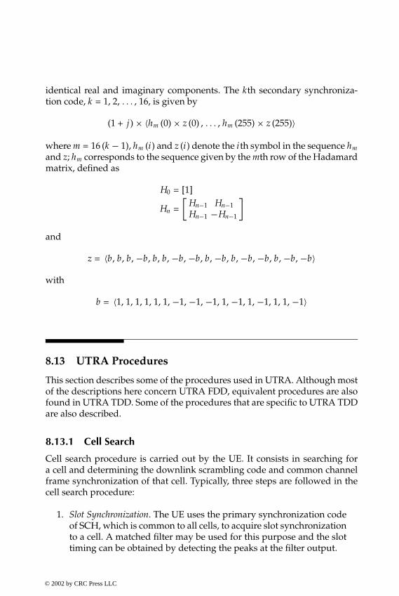
P1: FDJ
book CRC-Wireless November 21, 2001 12:26 Char Count= 282
identical real and imaginary components. The kth secondary synchroniza-tion code, k = 1, 2, . . . , 16, is given by
(1 + j) × 〈hm (0) × z (0) , . . . , hm (255) × z (255)〉
where m = 16 (k − 1), hm (i) and z (i) denote the ith symbol in the sequence hm
and z; hm corresponds to the sequence given by the mth row of the Hadamardmatrix, defined as
H0 = [1]
Hn =[
Hn−1 Hn−1Hn−1 −Hn−1
]
and
z = 〈b, b, b, −b, b, b, −b, −b, b, −b, b, −b, −b, b, −b, −b〉
with
b = 〈1, 1, 1, 1, 1, 1, −1, −1, −1, 1, −1, 1, −1, 1, 1, −1〉
8.13 UTRA Procedures
This section describes some of the procedures used in UTRA. Although mostof the descriptions here concern UTRA FDD, equivalent procedures are alsofound in UTRA TDD. Some of the procedures that are specific to UTRA TDDare also described.
8.13.1 Cell Search
Cell search procedure is carried out by the UE. It consists in searching fora cell and determining the downlink scrambling code and common channelframe synchronization of that cell. Typically, three steps are followed in thecell search procedure:
1. Slot Synchronization. The UE uses the primary synchronization codeof SCH, which is common to all cells, to acquire slot synchronizationto a cell. A matched filter may be used for this purpose and the slottiming can be obtained by detecting the peaks at the filter output.
© 2002 by CRC Press LLC
E:\Java for Engineers\VP Publication\Java for Engineers.vpThursday, April 25, 2002 9:27:36 AM
Color profile: DisabledComposite Default screen
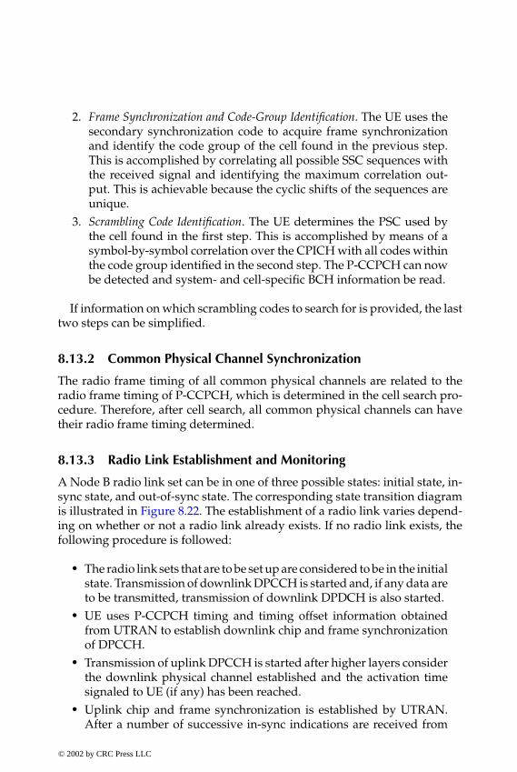
P1: FDJ
book CRC-Wireless November 21, 2001 12:26 Char Count= 282
2. Frame Synchronization and Code-Group Identification. The UE uses thesecondary synchronization code to acquire frame synchronizationand identify the code group of the cell found in the previous step.This is accomplished by correlating all possible SSC sequences withthe received signal and identifying the maximum correlation out-put. This is achievable because the cyclic shifts of the sequences areunique.
3. Scrambling Code Identification. The UE determines the PSC used bythe cell found in the first step. This is accomplished by means of asymbol-by-symbol correlation over the CPICH with all codes withinthe code group identified in the second step. The P-CCPCH can nowbe detected and system- and cell-specific BCH information be read.
If information on which scrambling codes to search for is provided, the lasttwo steps can be simplified.
8.13.2 Common Physical Channel Synchronization
The radio frame timing of all common physical channels are related to theradio frame timing of P-CCPCH, which is determined in the cell search pro-cedure. Therefore, after cell search, all common physical channels can havetheir radio frame timing determined.
8.13.3 Radio Link Establishment and Monitoring
A Node B radio link set can be in one of three possible states: initial state, in-sync state, and out-of-sync state. The corresponding state transition diagramis illustrated in Figure 8.22. The establishment of a radio link varies depend-ing on whether or not a radio link already exists. If no radio link exists, thefollowing procedure is followed:
� The radio link sets that are to be set up are considered to be in the initialstate. Transmission of downlink DPCCH is started and, if any data areto be transmitted, transmission of downlink DPDCH is also started.
� UE uses P-CCPCH timing and timing offset information obtainedfrom UTRAN to establish downlink chip and frame synchronizationof DPCCH.
� Transmission of uplink DPCCH is started after higher layers considerthe downlink physical channel established and the activation timesignaled to UE (if any) has been reached.
� Uplink chip and frame synchronization is established by UTRAN.After a number of successive in-sync indications are received from
© 2002 by CRC Press LLC
E:\Java for Engineers\VP Publication\Java for Engineers.vpThursday, April 25, 2002 9:27:36 AM
Color profile: DisabledComposite Default screen
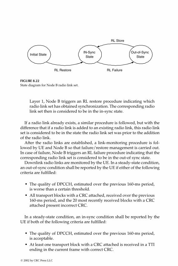
P1: FDJ
book CRC-Wireless November 21, 2001 12:26 Char Count= 282
Initial StateIN-Sync
StateOut-of-Sync
State
RL Restore RL Failure
RL Store
FIGURE 8.22State diagram for Node B radio link set.
Layer 1, Node B triggers an RL restore procedure indicating whichradio link set has obtained synchronization. The corresponding radiolink set then is considered to be in the in-sync state.
If a radio link already exists, a similar procedure is followed, but with thedifference that if a radio link is added to an existing radio link, this radio linkset is considered to be in the state the radio link set was prior to the additionof the radio link.
After the radio links are established, a link-monitoring procedure is fol-lowed by UE and Node B so that failure/restore management is carried out.In case of failure, Node B triggers an RL failure procedure indicating that thecorresponding radio link set is considered to be in the out-of sync state.
Downlink radio links are monitored by the UE. In a steady-state condition,an out-of-sync condition shall be reported by the UE if either of the followingcriteria are fulfilled:
� The quality of DPCCH, estimated over the previous 160-ms period,is worse than a certain threshold.
� All transport blocks with a CRC attached, received over the previous160-ms period, and the 20 most recently received blocks with a CRCattached present incorrect CRC.
In a steady-state condition, an in-sync condition shall be reported by theUE if both of the following criteria are fulfilled:
� The quality of DPCCH, estimated over the previous 160-ms period,is acceptable.
� At least one transport block with a CRC attached is received in a TTIending in the current frame with correct CRC.
© 2002 by CRC Press LLC
E:\Java for Engineers\VP Publication\Java for Engineers.vpThursday, April 25, 2002 9:27:36 AM
Color profile: DisabledComposite Default screen

P1: FDJ
book CRC-Wireless November 21, 2001 12:26 Char Count= 282
Uplink radio links are monitored by Node B. The synchronization statusof all radio link sets shall be checked by Layer 1 in Node B in every frame.Primitives are used to indicate such status to the RL failure/restored trigger-ing functions. Only one synchronization status indication shall be given perradio link set. The criteria used to indicate in-sync or out-of-sync conditionsare not subject to specification.
8.13.4 Uplink DPCCH and DPDCH Reception
Upon reception of the uplink dedicated channels, namely, DPDCH andDPCCH, the following tasks are performed by the receiver of the base station:
� Despreading of the DPCCH and buffering of the DPDCH using themaximum bit rate (smallest spreading factor)
� Estimation of the channel from the pilot bits received on the DPCCH(every slot)
� Estimation of the signal-to-interference ratio from the pilot bits (everyslot)
� Transmission of the TPC command in the downlink direction to con-trol the uplink transmission power (every slot)
� Decoding of the TPC bits to adjust the downlink power for the re-spective connection (every slot)
� Decoding of the FBI bits and adjustment of the diversity antennaphases, or phases and amplitudes, according to the transmission di-versity mode (over two or four slots)
� Decoding of the TFCI information from the DPCCH to detect thebit rate and channel decoding parameters for DPDCH (every 10-msframe)
� Decoding of the DPDCH according to the TTI (10, 20, 40, or 80 ms)
The reception in the downlink direction includes the functions as describedbefore, but some peculiarities are noted:
� The dedicated physical channels, DPDCH and DPCCH, have a con-stant spreading factor, but DSCH has a varying spreading factor.
� The FBI bits do not appear in the downlink direction.� A common pilot channel is used in addition to the pilot bits on
DPCCH.� In case of transmission diversity, the UE receives pilot patterns from
the two antennas, and the channel estimation is performed with thesetwo patterns.
© 2002 by CRC Press LLC
E:\Java for Engineers\VP Publication\Java for Engineers.vpThursday, April 25, 2002 9:27:36 AM
Color profile: DisabledComposite Default screen
P1: FDJ
book CRC-Wireless November 21, 2001 12:26 Char Count= 282
8.13.5 Uplink Power Control
Uplink inner-loop power control is used for the uplink physical channels.PRACH during random-access procedure and PCPCH during CPCH accessprocedure use specific power control algorithms. This is detailed later in thischapter. The power control procedure used for PCPCH is similar to that usedfor DPCCH/DPDCH.
The DPCCH initial transmit power and the relative transmit power offsetbetween DPCCH and DPDCHs are set by higher layers. Subsequent adjust-ments of power levels through the power control procedure affect both chan-nels equally so that the relative transmit power between these channels ismaintained. The UE transmit power is adjusted to maintain the received up-link signal-to-interference ratio (SIR) at Node B above a SIR target (SIRtarget).For such a purpose, the cell in the active set (serving cells) estimates the SIRof the received DPCH (SIRestimate). TPC commands are then generated by theserving cells and transmitted once per slot, as follows:
� If SIRestimate > SIRtarget, then the TPC is set to 0.� If SIRestimate < SIRtarget, then the TPC command is set to 1.
The UE receives one or more TPC commands per slot and derives a singleTPC command (TPC cmd) per slot. The transmit power is then adjusted witha step of �adjust = �TPC × TPC cmd, in decibels, where �TPC−, the step size,in decibels, is a Layer 1 parameter (1 or 2 dB).
8.13.6 Downlink Power Control
Downlink channels have their transmit power determined by the network.On the other hand, some rules exist concerning the ratio of the transmit powerbetween the different downlink channels, as briefly described next.
DPCCH/DPDCH
DPCCH and DPDCH undergo the same power control procedure, and therelative power between these two channels, as determined by the network, isnot affected by the power control algorithm.
In the power control process, the UE does not make any assumptions abouthow the downlink power control is set by UTRAN. The UE assists UTRANin this process by assessing the downlink SIR and recommending increase ordecrease in the transmitted power. The SIR is assessed by means of the pilotbits received within DPCCH at the UE. A TPC command is generated andsent in the first available TPC field in the uplink DPCCH in each slot. In fact,depending on the mode of operation, which is set by UTRAN, either a uniqueTPC command in each slot is sent or the same TPC command is sent over
© 2002 by CRC Press LLC
E:\Java for Engineers\VP Publication\Java for Engineers.vpThursday, April 25, 2002 9:27:36 AM
Color profile: DisabledComposite Default screen
P1: FDJ
book CRC-Wireless November 21, 2001 12:26 Char Count= 282
three slots. More specifically, the aim is to keep the received SIR above a SIRtarget (SIRtarget). A higher-layer outer loop adjusts SIRtarget independently foreach connection. The UE estimates the received downlink DPCCH/DPDCHpower as well as the received interference and an estimated SIR (SIRestimate)is determined. TPC commands are then generated as follows:
� If SIRestimate > SIRtarget, then the TPC is set to 0, requesting a transmitpower decrease.
� If SIRestimate < SIRtarget, then the TPC command is set to 1, requestinga transmit power increase.
Upon receiving the TPC command(s), the downlink DPCCH/DPDCHpower is adjusted accordingly. In the case of a unique TPC command, thepower is updated at every slot. In the case of three TPC commands, an es-timate of the TPC commands is carried out over three slots and the poweris updated accordingly at every three slots. The downlink power is then ad-justed to a new power P(k). This is obtained as a function of the current powerP(k − 1), of the kth power adjustment due to the inner loop power controlPTPC(k), and of a correction Pbal(k). Such a correction is obtained according tothe downlink power control procedure for balance radio link powers towarda common reference power. The power control function is given by
P (k) = P (k − 1) + PTPC (k) + Pbal (k)
where all the elements are in decibels. The correction power is
Pbal (i) = sign {(1 − r ) [PREF − P (i)]} × min{|(1 − r ) [PREF − P (i)]| , Pbal,max}
where 0 ≤ r ≤ 1 is a convergence coefficient, PREF is a reference transmissionpower in dBm (signaled by higher layers), Pbal,max is the maximum powerchange limit for radio link power balancing control (signaled by higher layersand set to be multiple of the power control step size �TPC) and sgn (x) is thesignal function (= −1, 0, +1 if x < 0, x = 0, x > 0, respectively). The actualtransmission power must be set to as close as possible to P (i). PTPC (k) assumesthe values +�TPC, 0, or −�TPC depending on the current estimated TPC, onPTPC (k) averaged over a certain window size, and on �TPC. The power controlstep size �TPC can take on the following values: 0.5, 1, 1.5, and 2 dB.
PDSCH
The PDSCH power control can be performed by one of the following options:inner-loop power control based on the power control commands sent by theUE on the uplink DPCCH or slow power control.
© 2002 by CRC Press LLC
E:\Java for Engineers\VP Publication\Java for Engineers.vpThursday, April 25, 2002 9:27:36 AM
Color profile: DisabledComposite Default screen
P1: FDJ
book CRC-Wireless November 21, 2001 12:26 Char Count= 282
AICH, PICH, and CSICH
Higher layers inform the UE about the relative power of AICH, PICH, andCSICH compared to the P-CPICH transmit power. The power of these chan-nels are measured as the power per transmitted acquisition indicator (forAICH), as the power over the paging indicators (for PICH), and as the powerper transmitted status indicator (for CSICH).
S-CCPCH
The power of the data field power and that of the TFCI and pilot fields maybe offset and the offset may vary in time.
8.13.7 Paging Procedure
Once registered within a network, an UE is allotted a paging group, forwhich paging indicators are dedicated. These paging indicators are periodi-cally transmitted on the PICH to indicate the presence of the paging messagebelonging to that paging group. After detecting a PI, the UE shall decode thenext PCH frame appearing on the S-CCPCH. The paging message appears onthe S-CCPCH 7680 chips after the end of transmission of paging indicatorson PICH. Note that the frequency with which the PIs are transmitted has adirect impact on the UE battery life. This is because to detect these PIs the UEmust leave the save battery mode (sleep mode).
8.13.8 Random-Access Procedure
A random-access procedure is initiated by the UE upon request originatedfrom the MAC sublayer. Before such a procedure can be initiated, severalpieces of information shall be available to Layer 1 from RRC. These include,among others:
� Preamble scrambling code� Message duration (10 or 20 ms)� Set of available RACH subchannels (out of 12 RACH subchannels)
for each access service class� Set of available signatures for each access service class� Power-ramping factor� Number of preamble retransmissions� Initial preamble power, the power offset between the preamble power� Random-access message power
© 2002 by CRC Press LLC
E:\Java for Engineers\VP Publication\Java for Engineers.vpThursday, April 25, 2002 9:27:36 AM
Color profile: DisabledComposite Default screen
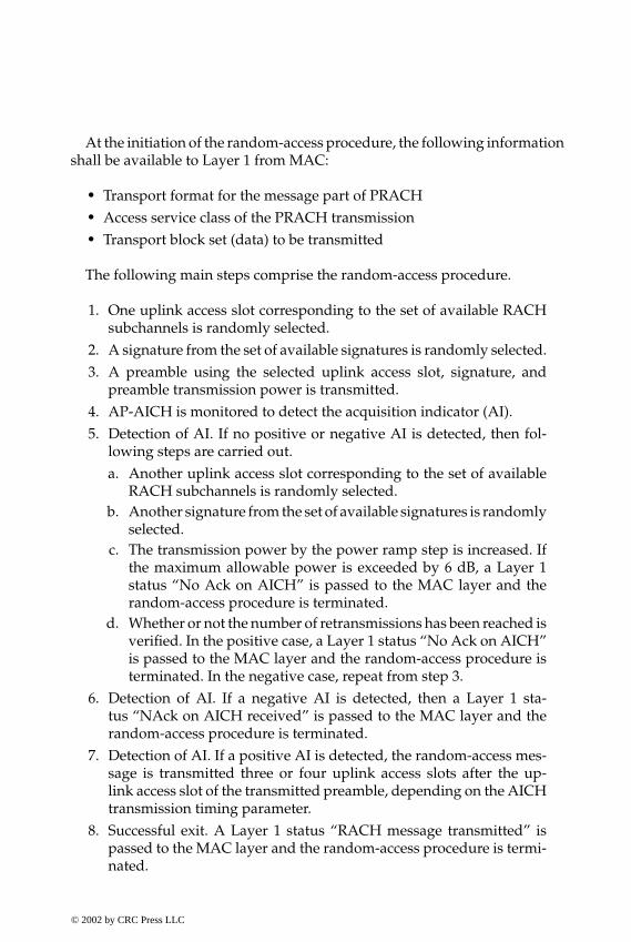
P1: FDJ
book CRC-Wireless November 21, 2001 12:26 Char Count= 282
At the initiation of the random-access procedure, the following informationshall be available to Layer 1 from MAC:
� Transport format for the message part of PRACH� Access service class of the PRACH transmission� Transport block set (data) to be transmitted
The following main steps comprise the random-access procedure.
1. One uplink access slot corresponding to the set of available RACHsubchannels is randomly selected.
2. A signature from the set of available signatures is randomly selected.3. A preamble using the selected uplink access slot, signature, and
preamble transmission power is transmitted.4. AP-AICH is monitored to detect the acquisition indicator (AI).5. Detection of AI. If no positive or negative AI is detected, then fol-
lowing steps are carried out.a. Another uplink access slot corresponding to the set of available
RACH subchannels is randomly selected.b. Another signature from the set of available signatures is randomly
selected.c. The transmission power by the power ramp step is increased. If
the maximum allowable power is exceeded by 6 dB, a Layer 1status “No Ack on AICH” is passed to the MAC layer and therandom-access procedure is terminated.
d. Whether or not the number of retransmissions has been reached isverified. In the positive case, a Layer 1 status “No Ack on AICH”is passed to the MAC layer and the random-access procedure isterminated. In the negative case, repeat from step 3.
6. Detection of AI. If a negative AI is detected, then a Layer 1 sta-tus “NAck on AICH received” is passed to the MAC layer and therandom-access procedure is terminated.
7. Detection of AI. If a positive AI is detected, the random-access mes-sage is transmitted three or four uplink access slots after the up-link access slot of the transmitted preamble, depending on the AICHtransmission timing parameter.
8. Successful exit. A Layer 1 status “RACH message transmitted” ispassed to the MAC layer and the random-access procedure is termi-nated.
© 2002 by CRC Press LLC
E:\Java for Engineers\VP Publication\Java for Engineers.vpThursday, April 25, 2002 9:27:36 AM
Color profile: DisabledComposite Default screen

P1: FDJ
book CRC-Wireless November 21, 2001 12:26 Char Count= 282
8.13.9 CPCH Access Procedure
A CPCH access procedure is initiated by the UE upon request originatedfrom MAC sublayer. Before such a procedure can be initiated several itemsof information shall be available to Layer 1 from RRC. Such information,available in the system information message for each PCPCH in a CPCH setallocated to a cell, includes:
� Uplink Access Preamble (AP) scrambling code� Uplink Preamble signature set� Access preamble slot subchannels group� AP-AICH preamble channelization code� Uplink collision detection (CD) preamble scrambling code� CD preamble signature� CD preamble slot subchannels group� CD-AICH preamble channelization code� CPCH uplink scrambling code� DL-DPCCH channelization code
Some physical layer parameters are made available by the RRC and MAClayers:
� Maximum number of retransmitted preambles� Initial open-loop power level, power step size� CPCH transmission timing parameter� Length of power control preamble (0 or 8 slots)� Number of frames for the transmission of start of message indicator
in DL-DPCCH for CPCH� Set of transport format parameters� Transport format of the message part� Data to be transmitted
The performance of CPCH access is improved with the use of CSICH.CSICH is a separate downlink channel used to indicate the occupation statusof different PCPCHs. The use of CISCH avoids unnecessary access attemptswhen all PCPCHs are occupied. A further improvement can be achieved withthe activation of the channel assignment (CA) functionality. In that case, be-sides the occupation indication of different PCPCHs, the CSICH also conveysthe CA message, which informs the maximum data rate of each PCPCH.
© 2002 by CRC Press LLC
E:\Java for Engineers\VP Publication\Java for Engineers.vpThursday, April 25, 2002 9:27:36 AM
Color profile: DisabledComposite Default screen

P1: FDJ
book CRC-Wireless November 21, 2001 12:26 Char Count= 282
The CA message is transmitted in parallel with the CD message. The follow-ing main steps comprise the CPCH access procedure, in which case the CAfunctionality is assumed to be active.
1. The status indicators of CSICH are detected. If the maximum avail-able data rate is less than the requested data rate, the access attemptis aborted and a failure message is sent to the MAC layer. The avail-ability of each PCPCH is retained.
2. CPCH-AP signature from the set of available signatures is randomlyselected.
3. An uplink access slot from the available CPCH-AP access slots israndomly selected.
4. The AP using the selected uplink access slot, signature, and pream-ble transmission power is transmitted.
5. AP-AICH is monitored to detect the acquisition indicator (AI).6. Detection of AI. If no positive or negative AI is detected, the UE
tests the value of the most recent transmission of the status indicatorcorresponding to the PCPCH selected immediately before the APtransmission. If it indicates “not available,” the access attempt isaborted and a failure message is sent to the MAC layer. Otherwise,the following steps are carried out:a. The next slot available in the subchannel group used is selected.
(A minimum separation of three or four access slots from the lasttransmission must exist, depending on the transmission timingparameter.)
b. The transmission power by the specified power step is increased.c. Whether or not the number of retransmissions has been reached
is verified. In the positive case, a Layer 1 failure message is passedto the MAC layer and the CPCH access procedure is terminated.
7. Detection of AI. If a negative AI is detected, then a Layer 1 failuremessage is passed to the MAC layer and the CPCH access procedureis terminated.
8. Detection of AI. If a positive AI is detected the UE randomly se-lects one CD signature and one CD access slot and transmits a CDpreamble. It then waits for the CD/CA-ICH and the CA messagefrom Node B.
9. Monitoring of CD/CA-ICH. If the UE does not receive a CD/CA-ICH in the designated slot or if it receives a CD/CA-ICH in thedesignated slot with a signature that does not match the signature
© 2002 by CRC Press LLC
E:\Java for Engineers\VP Publication\Java for Engineers.vpThursday, April 25, 2002 9:27:36 AM
Color profile: DisabledComposite Default screen
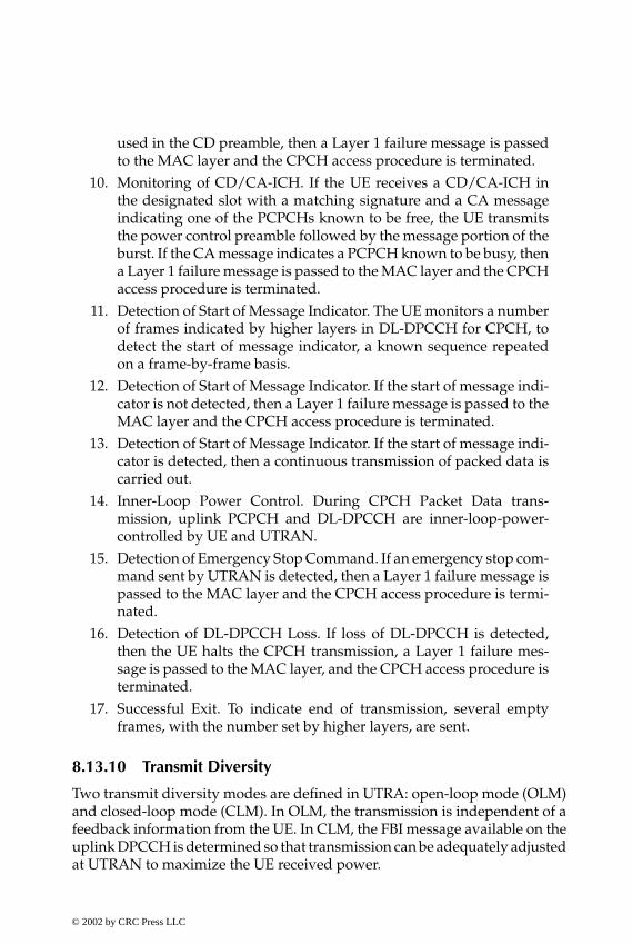
P1: FDJ
book CRC-Wireless November 21, 2001 12:26 Char Count= 282
used in the CD preamble, then a Layer 1 failure message is passedto the MAC layer and the CPCH access procedure is terminated.
10. Monitoring of CD/CA-ICH. If the UE receives a CD/CA-ICH inthe designated slot with a matching signature and a CA messageindicating one of the PCPCHs known to be free, the UE transmitsthe power control preamble followed by the message portion of theburst. If the CA message indicates a PCPCH known to be busy, thena Layer 1 failure message is passed to the MAC layer and the CPCHaccess procedure is terminated.
11. Detection of Start of Message Indicator. The UE monitors a numberof frames indicated by higher layers in DL-DPCCH for CPCH, todetect the start of message indicator, a known sequence repeatedon a frame-by-frame basis.
12. Detection of Start of Message Indicator. If the start of message indi-cator is not detected, then a Layer 1 failure message is passed to theMAC layer and the CPCH access procedure is terminated.
13. Detection of Start of Message Indicator. If the start of message indi-cator is detected, then a continuous transmission of packed data iscarried out.
14. Inner-Loop Power Control. During CPCH Packet Data trans-mission, uplink PCPCH and DL-DPCCH are inner-loop-power-controlled by UE and UTRAN.
15. Detection of Emergency Stop Command. If an emergency stop com-mand sent by UTRAN is detected, then a Layer 1 failure message ispassed to the MAC layer and the CPCH access procedure is termi-nated.
16. Detection of DL-DPCCH Loss. If loss of DL-DPCCH is detected,then the UE halts the CPCH transmission, a Layer 1 failure mes-sage is passed to the MAC layer, and the CPCH access procedure isterminated.
17. Successful Exit. To indicate end of transmission, several emptyframes, with the number set by higher layers, are sent.
8.13.10 Transmit Diversity
Two transmit diversity modes are defined in UTRA: open-loop mode (OLM)and closed-loop mode (CLM). In OLM, the transmission is independent of afeedback information from the UE. In CLM, the FBI message available on theuplink DPCCH is determined so that transmission can be adequately adjustedat UTRAN to maximize the UE received power.
© 2002 by CRC Press LLC
E:\Java for Engineers\VP Publication\Java for Engineers.vpThursday, April 25, 2002 9:27:36 AM
Color profile: DisabledComposite Default screen
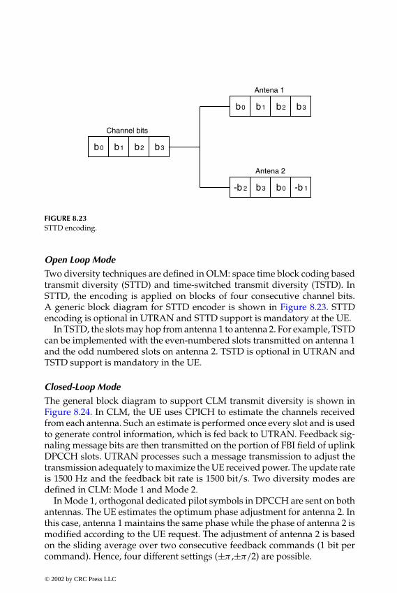
P1: FDJ
book CRC-Wireless November 21, 2001 12:26 Char Count= 282
b0 b2b1 b3
b0 b2b1 b3
-b 2 b0b3 -b 1
Channel bits
Antena 2
Antena 1
FIGURE 8.23STTD encoding.
Open Loop Mode
Two diversity techniques are defined in OLM: space time block coding basedtransmit diversity (STTD) and time-switched transmit diversity (TSTD). InSTTD, the encoding is applied on blocks of four consecutive channel bits.A generic block diagram for STTD encoder is shown in Figure 8.23. STTDencoding is optional in UTRAN and STTD support is mandatory at the UE.
In TSTD, the slots may hop from antenna 1 to antenna 2. For example, TSTDcan be implemented with the even-numbered slots transmitted on antenna 1and the odd numbered slots on antenna 2. TSTD is optional in UTRAN andTSTD support is mandatory in the UE.
Closed-Loop Mode
The general block diagram to support CLM transmit diversity is shown inFigure 8.24. In CLM, the UE uses CPICH to estimate the channels receivedfrom each antenna. Such an estimate is performed once every slot and is usedto generate control information, which is fed back to UTRAN. Feedback sig-naling message bits are then transmitted on the portion of FBI field of uplinkDPCCH slots. UTRAN processes such a message transmission to adjust thetransmission adequately to maximize the UE received power. The update rateis 1500 Hz and the feedback bit rate is 1500 bit/s. Two diversity modes aredefined in CLM: Mode 1 and Mode 2.
In Mode 1, orthogonal dedicated pilot symbols in DPCCH are sent on bothantennas. The UE estimates the optimum phase adjustment for antenna 2. Inthis case, antenna 1 maintains the same phase while the phase of antenna 2 ismodified according to the UE request. The adjustment of antenna 2 is basedon the sliding average over two consecutive feedback commands (1 bit percommand). Hence, four different settings (±π ,±π/2) are possible.
© 2002 by CRC Press LLC
E:\Java for Engineers\VP Publication\Java for Engineers.vpThursday, April 25, 2002 9:27:36 AM
Color profile: DisabledComposite Default screen

P1: FDJ
book CRC-Wireless November 21, 2001 12:26 Char Count= 282
DPCH(DPCCH/DPDCH)
X
Adjustment 1
Adjustment 2
FeedbackInformationProcessing
∑
∑
Antenna 2
Antenna 1
CPICH 2
CPICH 1
Spread /Scramble
FIGURE 8.24Closed-loop mode transmit diversity.
In Mode 2, the same dedicated pilot symbols in DPCCH are sent on bothantennas. The UE estimates the optimum phase as well as the amplitude ad-justments. The sliding average in this case is carried out over four consecutivefeedback commands (1 bit per command); 1 bit is used for amplitude adjust-ment, whereas 3 bits are used for phase adjustment. The amplitudes can beadjusted to 0.2 and 0.8 or to 0.8 and 0.2, for antennas 1 and 2, respectively.The phase difference between the two antennas can be set to 8 possible values(±π, ±π/4, ±π/2, ±3π/4).
Transmit Diversity
The application of transmit diversity follows the criteria described next.
� Simultaneous use of STTD and CLM on the same physical channel isnot possible.
� The application of transmit diversity to P-CCPCH and SCH is com-pulsory if it is used on any other downlink channel.
� The transmit diversity mode used for a PDSCH shall be the same asthat for DPCH associated with this PDSCH.
� The transmit mode (OLM or CLM) on the associated DPCH may notchange during the duration of the PDSCH frame and within the slotprior to the PDSCH frame. Within CLM, however, a change betweenthe two modes, Mode 1 and Mode 2, is allowed.
© 2002 by CRC Press LLC
E:\Java for Engineers\VP Publication\Java for Engineers.vpThursday, April 25, 2002 9:27:36 AM
Color profile: DisabledComposite Default screen
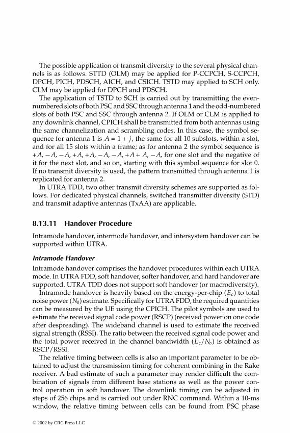
P1: FDJ
book CRC-Wireless November 21, 2001 12:26 Char Count= 282
The possible application of transmit diversity to the several physical chan-nels is as follows. STTD (OLM) may be applied for P-CCPCH, S-CCPCH,DPCH, PICH, PDSCH, AICH, and CSICH. TSTD may applied to SCH only.CLM may be applied for DPCH and PDSCH.
The application of TSTD to SCH is carried out by transmitting the even-numbered slots of both PSC and SSC through antenna 1 and the odd-numberedslots of both PSC and SSC through antenna 2. If OLM or CLM is applied toany downlink channel, CPICH shall be transmitted from both antennas usingthe same channelization and scrambling codes. In this case, the symbol se-quence for antenna 1 is A = 1 + j , the same for all 10 subslots, within a slot,and for all 15 slots within a frame; as for antenna 2 the symbol sequence is+A, −A, −A, +A, +A, −A, −A, +A + A, −A, for one slot and the negative ofit for the next slot, and so on, starting with this symbol sequence for slot 0.If no transmit diversity is used, the pattern transmitted through antenna 1 isreplicated for antenna 2.
In UTRA TDD, two other transmit diversity schemes are supported as fol-lows. For dedicated physical channels, switched transmitter diversity (STD)and transmit adaptive antennas (TxAA) are applicable.
8.13.11 Handover Procedure
Intramode handover, intermode handover, and intersystem handover can besupported within UTRA.
Intramode Handover
Intramode handover comprises the handover procedures within each UTRAmode. In UTRA FDD, soft handover, softer handover, and hard handover aresupported. UTRA TDD does not support soft handover (or macrodiversity).
Intramode handover is heavily based on the energy-per-chip (Ec) to totalnoise power (N0) estimate. Specifically for UTRA FDD, the required quantitiescan be measured by the UE using the CPICH. The pilot symbols are used toestimate the received signal code power (RSCP) (received power on one codeafter despreading). The wideband channel is used to estimate the receivedsignal strength (RSSI). The ratio between the received signal code power andthe total power received in the channel bandwidth (Ec/No) is obtained asRSCP/RSSI.
The relative timing between cells is also an important parameter to be ob-tained to adjust the transmission timing for coherent combining in the Rakereceiver. A bad estimate of such a parameter may render difficult the com-bination of signals from different base stations as well as the power con-trol operation in soft handover. The downlink timing can be adjusted insteps of 256 chips and is carried out under RNC command. Within a 10-mswindow, the relative timing between cells can be found from PSC phase
© 2002 by CRC Press LLC
E:\Java for Engineers\VP Publication\Java for Engineers.vpThursday, April 25, 2002 9:27:36 AM
Color profile: DisabledComposite Default screen

P1: FDJ
book CRC-Wireless November 21, 2001 12:26 Char Count= 282
(note that the code period is 10 ms). For a timing uncertainty larger than this,the system frame number (SFN) needs to be extracted from the P-CCPCH.Hard handovers do not require such accurate (chip-level) timing information.
The actual handover algorithms are left as an implementation issue.
Intermode Handover
Intermode handover comprises handover between the UTRA modes (FDDand TDD). For example, a dual-mode FDD-TDD UE operating on FDD modemeasures the power level from the TDD cells within the area. This is carriedout through the TDD CCPCH bursts, which are sent twice during the 10-ms TDD frame. Because the TDD cells within the same coverage area aresynchronized, finding one slot with the reference midamble implies that otherTDD cells bear the same burst timing with reference power.
Intersystem Handover
Intersystem handover comprises handover between the different cellulartechnologies (e.g., GSM, cdma2000). This type of handover requires that theUE receive information from the target system within compressed frames toallow measurements from other frequencies. Note that handover in such acase is always of the hard handover type.
8.13.12 Timing Advance
Timing advance is an UTRA TDD feature. Timing advance can be used tominimize interference between adjacent time slots in large cells. For example,in UTRA TDD-3.84 the guard period is 25 µs (96 chips), which yields a cell of3.75 km. If larger cells are required, then a timing advancement scheme maybe implemented to align the separate transmission instants in the base stationreceiver. In such cases, a 6-bit number, with an accuracy of 4 chips (1.042 µs)is used. The required timing advance is estimated by the base station, and theUE, under command from higher layers, adjusts its transmission accordingly.The application of the timing advance scheme may extend the cell radius to9.2 km.
8.13.13 Dynamic Channel Allocation
Dynamic channel allocation (DCA) is an UTRA TDD feature. As already men-tioned, the resource units in UTRA TDD constitute the channel frequency, timeslot, and code. The allocation of resources in UTRA TDD may be carried outon a dynamic basis with the support of the UE and the base station throughperiodic signal monitoring and reporting. Two types of DCA are supported:slow DCA and fast DCA.
© 2002 by CRC Press LLC
E:\Java for Engineers\VP Publication\Java for Engineers.vpThursday, April 25, 2002 9:27:36 AM
Color profile: DisabledComposite Default screen
P1: FDJ
book CRC-Wireless November 21, 2001 12:26 Char Count= 282
Slow DCA
The allocation of resources to the cells is defined as slow DCA. The slow DCAcan be terminated at any network entity above the base stations forming theseamless coverage area (having the same uplink/downlink partitioning). Thismeans that slow DCA is terminated at the RNC. The allocation of resources isthen carried out by means of negotiation between adjacent cells, to speed upthe handover process and to minimize interference. The slow DCA algorithmallocates the resource units in a cell-related preference list, which is thenused by the fast DCA algorithm. The list is updated on a frame-by-framebasis.
Fast DCA
The allocation of resources to bearer services is defined as fast DCA. The fastDCA is always terminated at the base station. The fast DCA uses the requiredresources available within the cell-related preference list, as previously pro-vided by slow DCA. Multirate services are supported by aggregating codes(multicode) or time slots (multislot) or codes and time slots. The allocationof resources may vary depending on different strategies. It may be possibleto allocate the resources based on the least interference condition; or to ag-gregate several time slots for diversity purposes; or vary time slot, code, andfrequency according to a predetermined scheme also for diversity purposes.The number of allocated codes varies in accordance with the channel char-acteristics, environment, and system implementation. The allocation strategyis also dependent on the services. For real-time services, resources must beallocated for the duration of the call, but the resources may vary to complywith the allocation criteria. For non-real-time services, the resources are allo-cated for the period of transmission of the data and the best-effort strategyis used.
8.14 Interference Issues
If UTRA TDD and UTRA FDD use separate frequency bands, the two tech-nologies may coexist with aggregated benefits. The coexistence of both tech-nologies, however, must be carefully planned to avoid mutual interference.Interference is necessarily a problem in case the spectrum allocations of thesetechnologies are contiguous. In this scenario, co-siting UTRA FDD and UTRATDD base stations seems not to be technically attractive because a guard bandwould be necessary to minimize mutual interference. Interference between
© 2002 by CRC Press LLC
E:\Java for Engineers\VP Publication\Java for Engineers.vpThursday, April 25, 2002 9:27:36 AM
Color profile: DisabledComposite Default screen

P1: FDJ
book CRC-Wireless November 21, 2001 12:26 Char Count= 282
the mobile stations of one technology to the base stations of another and be-tween mobile stations of different technologies is also possible, and this maybe minimized with intersystem and interfrequency handovers.
Interference within UTRA FDD basically follows the same principles asalready explored in other CDMA systems. In UTRA TDD, on the other hand,the sharing of the same frequency by both uplink and downlink rendersthe interference issue more complex. Implicitly, TDD systems must worksynchronously. Therefore, neighboring base stations of different operatorsmay interfere with each other if internetwork synchronization is not workedout. Moreover, because of the asymmetric nature of uplink and downlink,a different degree of asymmetry between uplink and downlink in adjacentcells, even if the respective base stations are synchronized, will cause in-terference. The use of DCA helps to reduce the interference in this case.In summary, frame-level synchronization between base stations within thesame system (operator) is required. Moreover, frame-level synchronizationbetween base stations of different systems (operators) within neighboring areais recommended. More than an optional feature, DCA is a necessity in TDDsystems.
8.15 Summary
The radio interface specifications for both UTRA FDD and UTRA TDD havebeen developed with the strong objective of harmonization of these two com-ponents to achieve maximum commonality. Here, important physical param-eters and higher-layer protocols are common to both technologies. On theother hand, because of the peculiarities of one or another technology, withthe physical layers having different parameters to control, in an actual imple-mentation the algorithms for both receiver and radio resource managementdiffer between these two technologies. In the UTRA TDD base station, ad-vanced receivers are necessary, whereas in the mobile station the solution forthe receiver depends on the details of the performance requirements.
The CN specifications are based on an evolved GSM-MAP architectureand capabilities are included so that operation with an evolved ANSI-41based CN is possible. The radio interfaces are defined to accommodate awide range of services including speech, data, and multimedia, with thesebeing simultaneously used by a subscriber and multiplexed on a single car-rier. Both UTRA FDD and UTRA TDD can provide data rate services withsimilar QoS. UTRA TDD cells, on the other hand, can be smaller than UTRAFDD cells for the same data rate services because of the TDMA duty cycle of
© 2002 by CRC Press LLC
E:\Java for Engineers\VP Publication\Java for Engineers.vpThursday, April 25, 2002 9:27:36 AM
Color profile: DisabledComposite Default screen
P1: FDJ
book CRC-Wireless November 21, 2001 12:26 Char Count= 282
UTRA TDD. However, this can be overcome if the timing advance feature isimplemented.
References
1. ITU-T Recommendation Q.1701: Framework for IMT-2000 Networks, March 1999.2. Supplement to ITU-T Recommendation Q.1701: Framework for IMT-2000
Networks—Roadmap to IMT-2000 Recommendations, Standards and TechnicalSpecifications, June 2000.
3. Holma, H. and Toskala, A., Eds., WCDMA for UMTS—Radio Access for Third Gen-eration Mobile Communications, John Wiley & Sons, Chichester, U.K., 2000.
4. ITU-R Recommendation M.1035: Framework for the Radio Interface(s) and Ra-dio Sub-system Functionality for International Mobile Telecommunications-2000(IMT-2000), 1994.
5. ITU-T Recommendation Q.1711: Network Functional Model for IMT-2000, March1999.
6. Patel, P. and Dennett S., The 3GPP and 3GPP2 movements toward an all-IP mobilenetwork, IEEE Personal Commun., 62–64, August 2000.
7. 3GPP TR 23.922, Architecture for an All IP Network, December 1999.8. 3GPP TS 25.211 v3.5.0 (2000-12), Physical Channels and Mapping of Transport
Channels onto Physical Channels (FDD).9. 3GPP TS 25.212 v3.5.0 (2000-12), Multiplexing and Channel Coding (FDD).
10. 3GPP TS 25.211 v3.4.0 (2000-12), Spreading and Modulation (FDD).11. 3GPP TS 25.211 v3.5.0 (2000-12), Physical Layer Procedures (FDD).12. CWTS TS C101 v3.1.1 (2000-9), Physical Layer—General Description.13. CWTS TS C102 v3.3.0 (2000-9), Physical Channels and Mapping of Transport
Channels onto Physical Channels.14. CWTS TS C103 v2.2.0 (1999-10), Multiplexing and Channel Coding.15. CWTS TS C102 v3.0.0 (1999-10), Physical Layer Procedures.16. CWTS TS C102 v3.0.0 (1999-10), MAC Protocol Specification17. CWTS TS C102 v2.1.0 (1999-10), RLC Protocol Specification.18. ETSI TS C125 321 v3.6.0 (2000-12), MAC Protocol Specification.
© 2002 by CRC Press LLC
E:\Java for Engineers\VP Publication\Java for Engineers.vpThursday, April 25, 2002 9:27:36 AM
Color profile: DisabledComposite Default screen

P1: FDJ
book CRC-Wireless November 18, 2001 14:38 Char Count= 264
9cdma2000
9.1 Introduction
The IMT-2000 CDMA multicarrier radio interface is referred to as cdma2000.It is a wideband spread spectrum radio interface designed to meet the re-quirements of 3G wireless systems as well as the requirements of 3G evo-lution of the 2G TIA/EIA-95-B family standards. cdma2000 provides fullbackward compatibility with TIA/EIA- 95-B. Backward compatibility permitscdma2000 infrastructure to support TIA/EIA-95-B mobile stations and allowscdma2000 mobile stations to operate in TIA/EIA-95-B systems. cdma2000proposes backward compatibility with cdmaOne to provide a smooth transi-tion from 2G to 3G networks. One important aspect of backward compatibilityis the ability to support an overlay of cdma2000 and cdmaOne networks inthe same spectrum.
A wide range of data rates is supported that accommodates the variouswireless services. These applications range from plain quality voice and low-rate packet data services to high-quality voice and high-rate data services,with voice and data services provided on a nonconcurrent or concurrent basis,as required.
cdma2000 accomplishes the wideband transmission requirements in twodifferent ways. The forward transmission may utilize either direct spread (DS)technology or multicarrier (MC) technology. The reverse link, on the otherhand, always uses DS technology. The MC implementation of the cdma2000forward link facilitates cdmaOne and cdma2000 overlay design. In an MCimplementation, an N×1.25 MHz cdma2000 system (N = 1, 3, 6, 9, or 12)can overlay N contiguous cdmaOne carriers, where N is the spreading rate(SR) number. SR 1 is referred to as 1× and SR 3 is referred to as 3×, whichare the two technologies defined in cdma2000 standards. The 1× componentincludes enhancements for high-rate packet data access. In addition to the
© 2002 by CRC Press LLC
E:\Java for Engineers\VP Publication\Java for Engineers.vpThursday, April 25, 2002 9:27:36 AM
Color profile: DisabledComposite Default screen
P1: FDJ
book CRC-Wireless November 18, 2001 14:38 Char Count= 264
different SRs and to meet the different quality-of-service (QoS) requirements,cdma2000 incorporates a number of radio configurations (RCs). These RCsare specified in terms of the achievable rate transmissions, frame duration,and prespreading modulation schemes. The RCs are different for downlinkand uplink. For SR 1 and 3, cdma2000 standards specify ten RCs, numberedsequentially from 1 to 10, for the downlink, and seven RCs, numbered se-quentially from 1 to 7, for the uplink. Collectively, these RCs form the radiointerface, which consists of the 1× and 3× components. Some of these RCs aredesigned to accomplish backward compatibility with cdmaOne. RCs from 1through 9 for the forward link and RCs from 1 to 6 for the reverse link ac-commodate a wide range of services and data rates. RC 10 for the forwardlink and RC 7 for the reverse link are specific for high rate packet data accessusing a separate carrier.
Different sets of channels are defined for these two SRs. A set of chan-nels transmitted between base station and mobile stations within a given fre-quency assignment is referred to as a CDMA channel. In the forward direction,this is known as the forward CDMA channel and in the reverse direction thisis referred to as the reverse CDMA channel. In both directions, long code PNsequences are used, but with different purposes. In the forward link, the longcode is used for scrambling on the forward CDMA channel, whereas in thereverse link it is used for spreading on the reverse CDMA channel. On bothforward and reverse CDMA channels, it provides limited privacy, althoughon the latter it uniquely identifies a mobile station. In addition to differentRCs used to achieve a wide range of transmission rates, Walsh functions withdifferent lengths are used with the same purpose.
Certain forward-link channels, such as the pilot channel, may be sharedby the overlay and underlay systems. The overlay implementation may takeadvantage of the reusability feature, in which case the cdmaOne networkelements or entities can be reused and upgraded to accommodate thecdma2000 technology. System planning and optimization tools developed forthe cdmaOne system can also be reused or upgraded for the cdma2000 sys-tem design. The cdma2000 radio transmission technology includes an N = 1option that supports all the features and performance enhancements that areprovided by higher-order options such as N = 3, 6, 9, or 12. Although it usesthe same bandwidth, cdma2000 with N = 1 may support twice as many voiceusers as compared with cdmaOne. In addition, data services are also moreefficiently treated in this new technology.
cdma2000 also supports the reuse of existing cdmaOne service standards,such as those concerning speech services, data services, short message serv-ices, and over-the-air provisioning and activation services. Full handoversof voice and data calls from one system to the other constitute one very in-teresting feature supported by cdmaOne and cdma2000. The ability to per-form smooth handovers between cdmaOne and cdma2000 systems allows
© 2002 by CRC Press LLC
E:\Java for Engineers\VP Publication\Java for Engineers.vpThursday, April 25, 2002 9:27:36 AM
Color profile: DisabledComposite Default screen

P1: FDJ
book CRC-Wireless November 18, 2001 14:38 Char Count= 264
operators to gradually build up cdma2000 networks in areas where additionalcapacity and enhanced services are needed. The operators are able to maintainservice continuity while offering advanced services in a selected portion oftheir service areas.
To be backward compatible with existing cdmaOne systems, the cdma2000radio interface retains many of the attributes of the cdmaOne air interfacedesign. Some of these air interface attributes are in support of the following:
� Synchronized base station operation to facilitate fast handovers be-tween cdmaOne and cdma2000 networks
� Chip rates that are multiples of the cdmaOne chip rate to allow com-patible frequency planning with cdmaOne and to simplify design ofcdmaOne/cdma2000 dual-mode terminals
� Frame structure and numerology consistent with cdmaOne� Code-multiplexed pilot signal from the base station to the mobile
station to facilitate fast acquisitions and handovers between cdmaOneand cdma2000 users.
Many other features are incorporated that provide for flexibility and improvethe performance.
The descriptions of the cdma2000 technology in this chapter are fully basedon References 1 through 8. Note that in the cdma2000 technology two dis-tinct groups of RCs can be formed: one for general-purpose RCs (RCs from1 through 9 for the forward link and for RCs from 1 through 6 for the re-verse link) and another for the high-rate packet data access RCs (RC 10 forthe forward link and RC 7 for the reverse link). That for high-rate packet dataaccess evolved from the high data rate (HDR) technology to the 1× evolvedhigh-speed data only (1×EV-DO) design: both projects present almost indis-tinguishable characteristics.
The great majority of the sections in this chapter describe the RCs of thefirst group. A specific section is dedicated for the description of the RCs ofthe second group.
9.2 Network Architecture
In the development of cdma2000, the core network specifications are based onan evolved ANSI-41 and Internet protocol (IP) network. These specificationsalso include the necessary capabilities for operation with an evolved GSM-MAP-based core network. The cdma2000 Reference Model is illustrated inFigure 9.1. Figure 9.1 identifies the network entities (NEs), represented by
© 2002 by CRC Press LLC
E:\Java for Engineers\VP Publication\Java for Engineers.vpThursday, April 25, 2002 9:27:36 AM
Color profile: DisabledComposite Default screen

P1: FDJ
book CRC-Wireless November 18, 2001 14:38 Char Count= 264
MT0
MT1
TAm
MT2
UIM
MWNE
OSF
BTS BSC
MSC
PSTN DCE
PDN
ISDN
TA
MC HLR VLR
SME AC OTAF
PDSN AAA
NPDB
EIR
IP SN
IWF
DF CDGP CSC
CDRPCF
CDCP
MS
ME
IAP CDIS WNE
BSTE2
TE2
TE2
TE1
Ur
R
S
Rx
W Rv
Di
S
X
J
I
Ke
d
o1
OSF
o2
TE1
TE2
TE2
Sm
Rm
Rm
Ui
Um
P1
P1
P1
Aquater
SME
MCM2
M3
M1
OTAFV
Abis
SCPT3 T7
VLR
BTS BSCAbis
MSC
BS
N D G
H N1D1
QC
B
A
Z E
F
Q1
Di
Pi
Ai
Ater
SCPT8
T4
T6
T2T1
T5
T9
FIGURE 9.1cdma2000 Wireless Network Reference Model.
squares and rectangles, and the associated reference points (RPs), representedby a line connecting the NEs.
An NE encompasses a group of functions implemented by a part of a phys-ical device, or by a physical device, or by a number of distributed physicaldevices. There are three types of NEs:
1. Specific Network Entity, which is an individual instance of the network2. Collective Entity, which contains encompassed NEs that are an in-
stance of the collective© 2002 by CRC Press LLC
E:\Java for Engineers\VP Publication\Java for Engineers.vpThursday, April 25, 2002 9:27:36 AM
Color profile: DisabledComposite Default screen

P1: FDJ
book CRC-Wireless November 18, 2001 14:38 Char Count= 264
3. Composite Entity, which contains encompassed NEs that are part ofthe composite
An RP is a conceptual point that divides two groups of functions, not nec-essarily constituting a physical interface. An RP becomes a physical interfaceonly when the NEs on either side of it are contained in different physicaldevices.
9.2.1 Network Entities
This subsection describes the various NEs of the reference model shown inFigure 9.1.
� Authentication, Authorization, and Accounting (AAA). The AAA pro-vides IP functionalities to support authentication, authorization, andaccounting. The AAA interacts with other AAA entities to performAAA functions when the home AAA is outside the serving mobilenetwork.
� Authentication Center (AC). The AC manages the authentication infor-mation related to the MS. The AC may or may not be located withinand be indistinguishable from an HLR. An AC may serve more thanone HLR.
� Base Station (BS). A BS provides the radio means for MSs to access thenetwork services. It includes two other NEs, namely, BSC and BTS.
� Base Station Controller (BSC). The BSC provides control and manage-ment functions for one or more BTSs. The BSC exchanges messageswith both the BTS and the MSC. Traffic and signaling informationconcerning call control, mobility management, and MS managementmay pass transparently through the BSC.
� Base Transceiver System (BTS). The BTS provides transmission capabil-ities across the Um RP. The BTS consists of radio devices, antennas,and equipment.
� Call Data Collection Point (CDCP). The CDCP collects the IS-124 formatcall detail information.
� Call Data Generation Point (CDGP). The CDGP provides call detailinformation to the CDCP in the IS-124 format. This may be the NEthat converts call detail information from a proprietary format intothe IS-124 format. All information from the CDGP to the CDCP mustbe in the IS-124 format.
� Call Data Information Source (CDIS). The CDIS can be the source of calldetail information. This information may be in proprietary format. Itis not required to be in IS-124 format.
© 2002 by CRC Press LLC
E:\Java for Engineers\VP Publication\Java for Engineers.vpThursday, April 25, 2002 9:27:36 AM
Color profile: DisabledComposite Default screen

P1: FDJ
book CRC-Wireless November 18, 2001 14:38 Char Count= 264
� Call Data Rating Point (CDRP). The CDRP takes the unrated IS-124format call detail information and applies the appropriate charge-and tax-related information. The charge and tax information is addedusing the IS-124 format.
� Collection Function (CF)—[Intercept]. The CF collects intercepted com-munications for a lawfully authorized law enforcement agency. TheCFs typically include:The ability to receive and process call contents information for each
intercept subjectThe ability to receive information regarding each intercept subject
� Customer Service Center (CSC). The CSC is an entity where serviceprovider representatives receive telephone calls from customers wish-ing to subscribe to initial wireless service or to request a change in thecustomer’s existing service. The CSC interfaces proprietarily with theover-the-air service provisioning function (OTAF) to perform networkand MS-related changes necessary to complete the service provision-ing request.
� Data Circuit Equipment (DCE). The DCE provides a non-ISDN user–network interface.
� Delivery Function (DF)—[Intercept]. The DF delivers intercepted com-munications to one or more collection functions. The DFs typicallyinclude:The ability to accept call contents for each intercept subject over one
or more channels from each access functionThe ability to deliver call contents for each intercept subject over one
or more channels to a collection function as authorized for eachlaw enforcement agency
The ability to accept information over one or more data channels andcombine that information into a single data flow for each interceptsubject
The ability to filter or select information on an intercept subject beforedelivery to a collection function as authorized for a particular lawenforcement agency
The optional ability to detect audio in-band DTMF digits for trans-lation and delivery to a collection function as authorized for aparticular law enforcement agency
The ability to duplicate and deliver information on the intercept sub-ject to one or more collection functions as authorized for each lawenforcement agency
The ability to provide security to restrict access
© 2002 by CRC Press LLC
E:\Java for Engineers\VP Publication\Java for Engineers.vpThursday, April 25, 2002 9:27:36 AM
Color profile: DisabledComposite Default screen

P1: FDJ
book CRC-Wireless November 18, 2001 14:38 Char Count= 264
� Equipment Identity Register (EIR). The EIR is the register to which userequipment identity may be assigned for record purposes.
� Home Location Register (HLR). The HLR is the location register to whicha user identity is assigned for record purposes. These include sub-scriber information such as electronic serial number (ESN), mobiledirectory number (MDN), profile information, current location, andauthorization period.
� Integrated Services Digital Network (ISDN). The ISDN is defined in ac-cordance with the appropriate ANSI T1 standards.
� Intelligent Peripheral (IP). The IP performs specialized resource taskssuch as playing announcements, collecting digits, performing speech-to-text or text-to-speech conversion, recording and storing voice mes-sages, facsimile services, data services, etc. (This chapter uses boldnotation IP for intelligent peripheral and the normal notation IP forInternet protocol.)
� Intercept Access Point (IAP). The IAP provides access to the communi-cations to, or from, the equipment, facilities, or services of an interceptsubject.
� Interworking Function (IWF). The IWF provides information conver-sion for one or more WNEs. An IWF may have an interface to a singleWNE providing conversion services. An IWF may augment an iden-tified interface between two WNEs, providing conversion services toboth WNEs.
� Managed Wireless Network Entity (MWNE). The MWNE is a wirelessentity within the collective entity or any specific NE with OS wirelessmanagement needs, including another OS.
� Message Center (MC). The MC stores and forwards short messages.The MC may also provide supplementary services for short messageservice.
� Mobile Station (MS). The MS is a wireless terminal used by subscribersto access network services over a radio interface. MSs include portableunits, units installed in vehicles, and fixed location MSs. The MS is theinterface equipment used to terminate the radio path at the subscriber.
� Mobile Switching Center (MSC). The MSC switches MS-originated orMS-terminated traffic. An MSC is usually connected to at least onebase station. It may connect to the other public networks (PSTN, ISDN,etc.), other MSCs in the same network, or MSCs in different networks.The MSC may store information to support these capabilities.
� Mobile Terminal 0 (MT0). The MT0 is a self-contained data-capable MStermination that does not support an external interface.
© 2002 by CRC Press LLC
E:\Java for Engineers\VP Publication\Java for Engineers.vpThursday, April 25, 2002 9:27:36 AM
Color profile: DisabledComposite Default screen

P1: FDJ
book CRC-Wireless November 18, 2001 14:38 Char Count= 264
� Mobile Terminal 1 (MT1). The MT1 is an MS termination that providesan ISDN user–network interface.
� Mobile Terminal 2 (MT2). The MT2 is an MS termination that providesa non-ISDN user–network interface.
� Number Portability Database (NPDB). The NPDB provides portabilityinformation for portable directory numbers.
� Operations Systems Function (OSF). The OSF is defined by the Telecom-munications Management Network (TMN) OSF. These functionsinclude the element management layer (EML), network managementlayer (NML), service management layer (SML), and business man-agement layer (BML), functions that span all operations system func-tions.
� Over-the-Air Service Provisioning Function (OTAF). The OTAF providesan interface to customer service centers (CSCs) to support serviceprovisioning activities.
� Packet Data Serving Node (PDSN). The PDSN provides IP functional-ity to the mobile network. A PDSN establishes, maintains, and ter-minates link layer sessions to the mobile station. A PDSN routes IPdatagrams to the packet data network (PDN). A PDSN may act asa mobile IP foreign agent in the mobile network. It may interfacewith one or more base stations to provide the link layer session. APDSN interacts with the AAA to provide IP authentication, autho-rization, and accounting support. A PDSN may interface to one ormore IP networks either public or intranet to provide IP networkaccess.
� Packet Data Network (PDN). A PDN, such as the Internet, provides apacket data transport mechanism between processing network enti-ties capable of using such services.
� Public-Switched Telephone Network (PSTN). The PSTN is defined in ac-cordance with the appropriate ANSI T1 standards.
� Service Control Point (SCP). The SCP acts as a real-time database andtransaction processing system that provides service control andservice data functionality.
� Service Node (SN). The SN provides service control, service data, spe-cialized resources, and call control functions to support bearer-relatedservices.
� Short Message Entity (SME). The SME composes and decomposes shortmessages. An SME may, or may not be located within and be indis-tinguishable from an HLR, MC, VLR, MS, or MSC.
� Terminal Adapter (TA). The TA converts signaling and user data be-tween a non-ISDN and an ISDN interface.
© 2002 by CRC Press LLC
E:\Java for Engineers\VP Publication\Java for Engineers.vpThursday, April 25, 2002 9:27:36 AM
Color profile: DisabledComposite Default screen

P1: FDJ
book CRC-Wireless November 18, 2001 14:38 Char Count= 264
� Terminal Adapter m (TAm). The TAm converts signaling and user databetween a non-ISDN and an ISDN interface.
� Terminal Equipment 1 (TE1). The TE1 is a data terminal that providesan ISDN user–network interface.
� Terminal Equipment 2 (TE2). The TE2 is a data terminal that providesa non-ISDN user–network interface.
� User Identity Module (UIM). The UIM contains subscription informa-tion such as the NAM and may contain subscription feature informa-tion. The UIM can be integrated into any mobile terminal or it may beremovable.
� Visitor Location Register (VLR). The VLR is the location register otherthan the HLR used by an MSC to retrieve information for handlingof calls to or from a visiting subscriber. The VLR may, or may not belocated within, and be indistinguishable from an MSC. The VLR mayserve more than one MSC.
� Wireless Network Entity (WNE). The WNE is an NE in the wirelesscollective entity.
9.2.2 Reference Points
This subsection describes the various RPs of the Reference Model shown inFigure 9.1. The Um RP is the only RP that is by definition a physical inter-face. The other RPs are physical interfaces if NEs on either side of them arecontained in different physical devices. An interface exists when two NEs areinterconnected through exactly one RP.
� RP A: the interface between BSC and MSC� RP Ai: the interface between IP and PSTN, plus the interface between
MSC and PSTN, plus the interface between SN and PSTN� RP Abis: the interface between BSC and BTS� RP Ater: the BS–BS interface� RP Aquater: the interface between PDSN and BS� RP B: the interface between MSC and VLR� RP C: the interface between MSC and HLR� RP D: the interface between VLR and HLR� RP d: the interface between IAP and DF� RP D 1: the interface between OTAF and VLR� RP D i: the interface between IP and ISDN, plus the interface between
IWF and ISDN, plus the interface between MSC and ISDN, plus theinterface between SN and ISDN
© 2002 by CRC Press LLC
E:\Java for Engineers\VP Publication\Java for Engineers.vpThursday, April 25, 2002 9:27:36 AM
Color profile: DisabledComposite Default screen

P1: FDJ
book CRC-Wireless November 18, 2001 14:38 Char Count= 264
� RP E: the interface between MSC and MSC� RP e: the interface between CF and DF� RP F: the interface between MSC and EIR� RP G: the interface between VLR and VLR� RP H: the interface between HLR and AC� RP I: the interface between CDIS and CDGP� RP J: the interface between CDGP and CDCP� RP K: the interface between CDGP and CDRP� RP L: Reserved� RP M1: the interface between SME and MC� RP2: the MC–MC interface� RP M 3: the SME–SME interface� RP N: the interface between HLR and MC� RP N 1: the interface between HLR and OTAF� RP O1: the interface between MWNE and OSF� RP O2: the OSF–OSF interface� RP Pi: the interface between MSC, IWF, PDSN, AAA, and PDN; this
RP is also the interface between PDSN and AAA� RP Q: the interface between MC and MSC� RP Q 1: the interface between MSC and OTAF� RP R: the interface between TA and TE2� RP Rm: the interface between TE2 and TAm plus the interface between
TE2 and MT2� RP Rv: the interface between DCE and TE2� RP Rx: the interface between PPDN and TE2� RP S: the interface between ISDN and TE1� RP m: the interface between TE1 and MT1 plus the interface between
TE1 and TAm� RP T1: the interface between MSC and SCP� RP T2: the interface between HLR and SCP� RP T3: the interface between IP and SCP� RP T4: the interface between HLR and SN� RP T5: the interface between IP and MSC� RP T6: the interface between MSC and SN� RP T7: the interface between SCP and SN
© 2002 by CRC Press LLC
E:\Java for Engineers\VP Publication\Java for Engineers.vpThursday, April 25, 2002 9:27:36 AM
Color profile: DisabledComposite Default screen

P1: FDJ
book CRC-Wireless November 18, 2001 14:38 Char Count= 264
� RP T8: the interface between SCP and SCP� RP T9: the interface between HLR and IP� RP Ui: the interface between integrated UIM and an MT� RP Um: the interface between BS and MS, which corresponds to the
air interface� RP Ur: the interface between the removable-UIM and an MT� RP V: the interface between OTAF and OTAF� RP W: the interface between DCE and PSTN� RP X: the interface between CSC and OTAF� RP Y: the interface between WNE and IWF� RP Z: the interface between MSC and NPDB
9.3 Radio Interface Protocol Architecture
Radio bearer services are handled by the radio interface protocols. cdma2000air interface protocols comply with ISO/OSI Reference Model layering re-quirements. A general protocol model, as depicted in Figure 9.2, is defined forcdma2000 radio interfaces. The protocol architecture is modularly composed
VoiceServices
Resource
Control
and
Resource
Configuration
Database
SignalingControl
Control
ControlStates
Control
SignalingServices
Signaling DATA
PPP
IP
TCP UDP
Packet DataApplication
Circuit DataApplication
High-SpeedCircuit Network
Services
Voice
Best Effort Delivery RLP
Mux and QoS
Physical Layer
PLDCF
PLICFMAC
LAC
Layer 1
Layer 2
Layers3-7
Control Plane Data Plane
FIGURE 9.2A general protocol model for cdma2000 radio interfaces.
© 2002 by CRC Press LLC
E:\Java for Engineers\VP Publication\Java for Engineers.vpThursday, April 25, 2002 9:27:36 AM
Color profile: DisabledComposite Default screen

P1: FDJ
book CRC-Wireless November 18, 2001 14:38 Char Count= 264
of layers and planes that are logically independent of each other. Two planesare defined: the control plane and the data plane. The control plane is respon-sible for all cdma2000-specific control signaling (signaling protocol). The dataplane is responsible for the transmission and reception of all user-related in-formation (user traffic), such as coded voice in a voice call, or packets in anInternet connection.
cdma2000 radio transmission technology provides protocols and servicesthat correspond to the bottom two layers of the ISO/OSI Reference Model,namely, Layer 1 and Layer 2. The upper layers, i.e., Layers 3 to 7, supportapplications and protocols that comply with IMT-2000 services and QoS re-quirements.
9.3.1 Upper Layers
In the data plane, Layers 3 to 7, the upper layers, provide signaling services,packet data applications, voice services, and circuit data applications. Sig-naling services provide signaling to support the mobile station operation.Packet data applications are supported by the following protocols: transmis-sion control protocol (TCP), user datagram protocol (UDP), Internet protocol(IP), and point-to-point protocol (PPP). Voice services include conventionalvoice telephony services through PSTN accesses as well as voice Internet tele-phony. Circuit data applications are supported by high-speed circuit networkservices. These three applications encompass the conception of a generalizedmultimedia service model. Virtually any concurrent combination of voice,packet data, and high-speed packet data services is allowed.
In the control plane, Layers 3 to 7 support signaling protocols.
9.3.2 Layer 2
Layer 2 is divided into two sublayers: link access control (LAC) and mediaaccess control (MAC). LAC and MAC are designed to provide the follow-ing:
� A wide range of upper layer services� High efficiency and low latency for data services� Advanced QoS delivery of circuit and packed data services (e.g., lim-
itations on acceptable delay, on bit error rate, on frame error rate, andcombination of these)
� Advanced multimedia services (concurrent voice, packet data, andcircuit data services with individual QoS requirements)
© 2002 by CRC Press LLC
E:\Java for Engineers\VP Publication\Java for Engineers.vpThursday, April 25, 2002 9:27:36 AM
Color profile: DisabledComposite Default screen
P1: FDJ
book CRC-Wireless November 18, 2001 14:38 Char Count= 264
Link Access Control
The LAC sublayer supports high point-to-point transmission over the air.Services supported by LAC include signaling and, optionally, circuit data.A high degree of flexibility is accomplished, with encoded voice data trans-ported in the form of packet data or circuit data traffic, as required. For voiceservices being transported directly by the physical layer, for backward com-patibility purposes, LAC services are considered to be null. If a QoS higherthan that provided by lower layers is required, LAC makes use of end-to-end reliable automatic repeat request (ARQ) protocols to guarantee error-freeinformation delivery. Alternatively, if an adequate QoS is provided by theselower layers, then LAC may be omitted. Layer 3 and LAC (Layer 2) commu-nicate with each other by means of service access points (SAPs). Service dataunits (SDUs) from Layer 3 are transferred to LAC through these SAPs. SDUsare then encapsulated into LAC protocol data units (LAC PDUs), which aresubject to segmentation and reassembly. LAC PDUs or encapsulated PDUfragments and interface control information are transferred to MAC in theform of PDU control status blocks (PCSBs). PCSBs contain relevant informa-tion about LAC PDUs or LAC PDU fragments, CDMA system time bound-aries (superframe, frame, time slots), error indicators, etc. All this processoccurs in the data plane, with the control of it carried out by the control plane.The communication between LAC and MAC is also provided by SAPs.
Media Access Control
The MAC sublayer is composed of the physical-layer-independent conver-gence function (PLICF) and the physical-layer-dependent convergence func-tion (PLDCF). MAC, by means of PLICF and PLDCF, supports three importanttasks:[9]
1. Best-Effort Delivery. A reliable transmission over the air link is sup-ported, with a best effort level of reliability provided by a radio linkprotocol (RLP).
2. MAC Control States. Sophisticated procedures for controlling the ac-cess of data services to the physical layer are used.
3. Multiplexing and QoS Control. Conflicting requests from competingservices and prioritization of access requests are enforced by negoti-ated QoS levels.
A simple active/inactive two-state control mechanism, as provided bycdmaOne, cannot cope with the requirements for high-speed data serviceswith many competing users. In such a simple mechanism, idle users in theactive state may cause excessive interference. In the same way, the relativelylong time and high system overhead required for a transition from the inactive
© 2002 by CRC Press LLC
E:\Java for Engineers\VP Publication\Java for Engineers.vpThursday, April 25, 2002 9:27:36 AM
Color profile: DisabledComposite Default screen

P1: FDJ
book CRC-Wireless November 18, 2001 14:38 Char Count= 264
state renders this scheme inefficient. cdmaOne circumvents this through a so-phisticated MAC control mechanism. Such a mechanism is supported by adata services state diagram, in which multiple instances of the state machineare supported, one for each active packet or circuit data instance. Figure 9.3illustrates the state transition diagram supported by MAC.
The null state is the default state in which an instance is encountered priorto the activation of a packet data service. After a packet service is invoked, ini-tialization procedures are required and a transition to the initialization stateoccurs. If this is unsuccessful, a transition back to the null state occurs. Inthe successful event, the control hold state is reached. In this state, a ded-icated control channel is established that provides means for MAC control
Null State
Initialization State
Packet ServiceDeactivated
Packet ServiceRequest
Service OptionConnected
Control Hold State
ReleaseTraffic Channel
Established
Active State
Reconnect State
Suspended State
TemporaryRelease
Dormant State
Service OptionConnected
ReleaseSuspended
TemporaryRelease
Release
Reconnection
Release
FIGURE 9.3Data services state diagram.
© 2002 by CRC Press LLC
E:\Java for Engineers\VP Publication\Java for Engineers.vpThursday, April 25, 2002 9:27:36 AM
Color profile: DisabledComposite Default screen

P1: FDJ
book CRC-Wireless November 18, 2001 14:38 Char Count= 264
commands to flow between user and base station with virtually no latency.High-speed data burst initiation and power control are examples of com-mands. The active state then is reached from the control hold state after theassignment of a traffic channel; the dedicated channel is kept. While in thisstate, if no data exchange occurs for a predefined period of time (Tactive), thetraffic channel is released and the instance returns to the control hold state.The dedicated control channel is kept for a fast traffic channel reassignment,if required. From the control hold state the suspended state is reached if nodata exchange occurs for another predefined period of time (Thold). In thesuspended state, the control channel is released, but it may be quickly re-assigned, if required, for the state information for RLP is kept. Therefore, avirtual active set is maintained by both base station and mobile station. Thisallows the base station or mobile station to choose the best base station tobe used in the event that a packed data traffic for the user occurs. From thesuspended state the return to the control hold state occurs after a control chan-nel is established. If no data exchange occurs for a period of time exceedinga predefined period (Tsuspend) the dormant state is attained. In the dormantstate, no base station or MSC resources are maintained. On the other hand, ashort data burst mode is provided to support the delivery of short messages.In this case, the overhead of a transition to the active state is avoided. Thedormant state is also reached from the control hold state if a release messageis sent but the PPP state is to be maintained. From the dormant state if datainformation is to be sent the move is to the reconnect state. From there adedicated control channel is assigned and the control hold state is attained.From the dormant state, if PPP is terminated, the instance returns to the nullstate.
9.3.3 Layer 1
Layer 1 comprises the physical layer. The physical layer is responsible for theinformation transport between base station and mobile stations. At the trans-mission side, it transforms the information into an over-the-air waveform. Atthe reception side, it performs the inverse operation. A detailed descriptionof the physical layer is provided in several sections of this chapter.
9.4 Logical Channels
A logical channel is an SAP providing a logical communication path betweenlogical instances. In particular, logical channels convey information betweenLayer 3 and the LAC sublayer. Logical channels are defined in terms of their
© 2002 by CRC Press LLC
E:\Java for Engineers\VP Publication\Java for Engineers.vpThursday, April 25, 2002 9:27:36 AM
Color profile: DisabledComposite Default screen
P1: FDJ
book CRC-Wireless November 18, 2001 14:38 Char Count= 264
intended use. Logical channels may perform the following tasks:
� Convey information from one or several sources� Deliver the information to a single target only or to multiple targets� Carry signaling or user data information� Transfer information in the forward direction or in the reverse direc-
tion
In cdma2000, logical channels are defined for the following purposes: syn-chronization, broadcast, general signaling, dedicated signaling, and access.Multiple instances of the same logical channel may be deployed.
A logical channel name consists of three lowercase letters followed by“ch” for channel. A hyphen is used after the first letter. The first letter in-dicates whether it is a forward (f ) or reverse (r) channel; the second letterindicates whether it is a dedicated (d) or common (c) channel; and the thirdletter indicates whether it is a traffic (t) or signaling (s) channel. cdma2000systems use the following types of logical channels to carry signaling in-formation: f-csch/r-csch (forward and reverse common signaling channel,respectively) and f-dsch/r-dsch (forward and reverse dedicated signalingchannel, respectively). The following is a description of the cdma2000 logicalchannels.
� Forward Dedicated Traffic Channel (f-dtch) and Reverse Dedicated TrafficChannel (r-dtch). f-dtch and r-dtch are point-to-point channels usedto convey user data traffic in the forward and reverse directions, re-spectively. They are allocated on a permanent basis throughout theduration of the active state of a data service. They convey informationto a single PLICF instance.
� Forward Common Traffic (f-ctch) and Reverse Common Traffic Channel (r-ctch). f-ctch and r-ctch are point-to-point channels used to conveyshort data bursts associated with the data service. They are allocatedfor use throughout the duration of the short bursts. Mobile stationsor several PLICF instances may share these channels.
� Forward Dedicated MAC Channel (f-dmch−control) and Reverse Dedi-cated MAC Channel (r-dmch−control). f-dmch−control and the f-dmch−control are point-to-point channels used to convey MAC messages.They are allocated during the active state and control hold state of adata service. They convey information to a single PLICF instance.
� Forward Common MAC Channel (f-cmch−control) and Reverse CommonMAC Channel (r-cmch−control). f-cmch−control is a point-to-multipointchannel used by the base station to convey MAC messages. r-cmch−control is a multipoint-to-point channel shared on a contention basis
© 2002 by CRC Press LLC
E:\Java for Engineers\VP Publication\Java for Engineers.vpThursday, April 25, 2002 9:27:36 AM
Color profile: DisabledComposite Default screen

P1: FDJ
book CRC-Wireless November 18, 2001 14:38 Char Count= 264
by mobile stations used to convey MAC messages. MAC messages areconveyed in the dormant state or suspended state of a data service.
� Dedicated Signaling Channel (dsch). dsch conveys upper layer signalingdata to a single PLICF instance.
� Common Signaling Channel (csch). csch conveys upper layer signalingdata from several mobile stations or PLICF instances.
9.5 Physical Channels
A physical channel provides a physical communication path between in-stances. Physical channels are defined in terms of their radio characteristicssuch as frequency, coding, timing, power control policies, etc. In cdma2000, aphysical channel has its name given in uppercase letters. The first letter indi-cates whether it is a Forward (F) or Reverse (R) channel, and this is followedby a hyphen. The remaining letters specify the functions of the channel, thelast two always being “CH” for channel. A number of physical channels aredefined within cdma2000 standards and this shall be listed in this section. Thedescription below does not approach the specific use of the channel nor doesit mention the spreading rate or radio configuration to which the channelbelongs. This is a brief description: the details are left to be given later in thischapter.
� Forward Pilot Channel (F-PICH). The F-PICH is an unmodulated,direct-sequence spread spectrum signal transmitted continuously byeach base station.
� Transmit Diversity Pilot Channel (F-TDPICH). The F-TDPICH is an un-modulated, direct-sequence spread spectrum signal transmitted con-tinuously by a CDMA base station to support forward-link transmitdiversity.
� Auxiliary Pilot Channel (F-APICH). The F-APICH is required forforward-link spot beam-forming networks using smart antennas.
� Auxiliary Transmit Diversity Pilot Channel (F-ATDPICH). TheF-ATDPICH is a transmit diversity pilot channel associated with anauxiliary pilot channel.
� Dedicated Auxiliary Pilot Channel (F-DAPICH). The F-DAPICH is anunmodulated, direct sequence spread spectrum signal transmittedcontinuously by a CDMA base station. It is used with antenna beam-forming application and beam-steering techniques to improve systemperformance.
© 2002 by CRC Press LLC
E:\Java for Engineers\VP Publication\Java for Engineers.vpThursday, April 25, 2002 9:27:36 AM
Color profile: DisabledComposite Default screen
P1: FDJ
book CRC-Wireless November 18, 2001 14:38 Char Count= 264
� Sync Channel (F-SYNCH). The F-SYNCH is a code channel that trans-ports the synchronization message for initial time synchronizationpurposes.
� Paging Channel (F-PCH). The F-PCH is a code channel used for trans-mission of control information and pages.
� Quick Paging Channel (F-QPCH). The F-QPCH is an uncoded, spread,and On-Off-Keying (OOK) modulated spread spectrum signal. It in-structs mobile stations operating in the slotted mode to receive eitherthe forward common control channel or the paging channel startingin their next respective frames.
� Broadcast Control Channel (F-BCCH). The F-BCCH is a code chan-nel used to convey broadcast overhead messages and short messageservice broadcast messages.
� Forward Common Control Channel (F-CCCH). The F-CCCH is used forcommunication of Layer 3 and MAC control messages from a basestation to one or more mobile stations.
� Common Assignment Channel (F-CACH). The F-CACH is used by thebase station to acknowledge a mobile station accessing the enhancedaccess channel. For the reservation access mode, it is used to trans-mit the address of a reverse common control channel and associatedcommon power control subchannel.
� Common Power Control Channel (F-CPCCH). The F-CPCCH is used totransmit power control bits to multiple mobile stations.
� Forward Fundamental Channel (F-FCH). The F-FCH is a portion of aforward traffic channel that carries a combination of higher-level dataand power control information.
� Forward Supplemental Code Channel (F-SCCH). The F-SCCH is aportion of the forward traffic channel that operates in conjunctionwith a forward fundamental channel to provide higher data rateservices.
� Forward Supplemental Channel (F-SCH). The F-SCH is a portion theforward traffic channel that operates in conjunction with a forwardfundamental channel or a forward dedicated control channel to pro-vide higher data rate services.
� Forward Dedicated Control Channel (F-DCCH). The F-DCCH is a portionof the forward traffic channel used for the transmission of higher-leveldata, control information, and power control information.
� Access Channel (R-ACH). The R-ACH is used for short signaling mes-sage exchanges, such as call originations, responses to pages, andregistrations.
© 2002 by CRC Press LLC
E:\Java for Engineers\VP Publication\Java for Engineers.vpThursday, April 25, 2002 9:27:36 AM
Color profile: DisabledComposite Default screen
P1: FDJ
book CRC-Wireless November 18, 2001 14:38 Char Count= 264
� Enhanced Access Channel (R-EACH). The R-EACH is used for transmis-sion of short messages, such as signaling, MAC messages, responseto pages, and call originations.
� Reverse Common Control Channel (R-CCCH). The R-CCCH is a portionof a reverse CDMA channel used for the transmission of digital controlinformation and data from one or more mobile stations to a basestation.
� Reverse Pilot Channel (R-PICH). The R-PICH is an unmodulated, direct-sequence spread spectrum signal transmitted continuously by aCDMA mobile station.
� Reverse Dedicated Control Channel (R-DCCH). The R-DCCH is a portionof reverse traffic channel used for the transmission of higher-level dataand control information from a mobile station to a base station whilea call is in progress.
� Reverse Fundamental Channel (R-FCH). The R-FCH is a portion of areverse traffic channel carrying higher-level data and control infor-mation from a mobile station to a base station.
� Reverse Supplemental Code Channel (R-SCCH). The R-SCCH is a portionof the reverse traffic channel that operates in conjunction with thereverse fundamental channel to provide higher data rate services.Optionally, it may also operate with other reverse supplemental codechannels for the same purpose.
� Reverse Supplemental Channel (R-SCH). The R-SCH is the reverse trafficchannel that operates in conjunction with the reverse fundamentalchannel or the reverse dedicated control channel to provide higherdata rate services.
9.6 Mapping of Channels
A logical channel can be mapped onto one or more physical channels. Themapping of channels occurs in the multiplex layer, which is a protocol layersituated between Layer 2 and Layer 1. A logical channel may have permanentand exclusive use of a physical channel (e.g., the synchronization channel). Itmay also have temporary, but still exclusive, use of a physical channel (e.g.,successive r-csch access probe sequences can be sent on different physicalaccess channels). Or it may share the physical channel with other logicalchannels (requiring a multiplex function to perform the mapping, possiblyon a PDU-by-PDU basis). In certain cases, a logical channel can be mapped
© 2002 by CRC Press LLC
E:\Java for Engineers\VP Publication\Java for Engineers.vpThursday, April 25, 2002 9:27:36 AM
Color profile: DisabledComposite Default screen

P1: FDJ
book CRC-Wireless November 18, 2001 14:38 Char Count= 264
f/r-cmch
f/r-csch
f/r-ctch
F/R-CCCH
F/R-PCH
f/r-dmch
f/r-dtch
f/r-dsch
F/R-DCCH
F/R-FCH
F/R-SCH
FIGURE 9.4Possible mapping of logical channels and physical channels.
onto another logical channel to form one effective logical channel capable ofcarrying different traffic types (e.g., the broadcast channel and the generalforward signaling channel are mapped onto one common logical channelcarrying signaling information). Because a logical channel can carry only onePDU at a time, there must be a serialization process at Layer 3 to ensure adeterministic behavior. Figure 9.4 illustrates the possible mapping of logicalchannels and physical channels. Next illustrated is how some voice and dataservices may use these channels.[10]
For plain-quality voice services, upper layer signaling frames on f/r-dsch,RLP frames on f/r-dtch, MAC messages on f/r-dmch, voice frames on f/r-dtch, and power control information are multiplexed into F/R-FCH. Themultiplexing may be carried out using the dim-and-burst or blank-and-burstmechanisms. For higher-quality voice services, upper layer signaling frameson f-dsch use the F/R-DCCH, whereas voice frames on f/r-dtch and powercontrol information are multiplexed into F/R-FCH.
For packet data services, upper layer signaling frames on r/f-dsch, MACmessages on f/r-dmch, and data frames on f/r-dtch are multiplexed into F/R-FCH. In this case, the MAC control is performed on a centralized basis becauseF/R-FCH may be in soft handover. As an alternative to this operation mode,packet data services may be offered through F/R-DCCH, which may or maynot be in soft handover. In this case, the MAC control can be performed eitheron a centralized or distributed basis.
For concurrent plain-quality voice service and data service, upper layersignaling frames on f/r-dsch, MAC messages on f/r-dmch, and low-rateRLP frames on f/r-dtch are multiplexed into dual-frame size (5 and 20 ms)F/R-FCH. RLP frames on f/r-dtch containing packet data are transmitted onthe F/R-SCH. For concurrent higher-quality voice service and data service a
© 2002 by CRC Press LLC
E:\Java for Engineers\VP Publication\Java for Engineers.vpThursday, April 25, 2002 9:27:36 AM
Color profile: DisabledComposite Default screen

P1: FDJ
book CRC-Wireless November 18, 2001 14:38 Char Count= 264
similar mapping occurs, but upper layer signaling frames and MAC messagesare multiplexed into F/R-DCCH.
9.7 Achievable Rates
A wide range of data rates is supported that accommodates various wire-less services. These applications range from plain-quality voice and low-ratepacket data services to high-quality voice and high-rate data services, withvoice and data services provided on a nonconcurrent or concurrent basis,as required. To meet the QoS requirements of various wireless services, anadequate combination of SRs, RCs, FCH, and SCH is required.
As already mentioned, the possible SRs are N = 1, 3, 6, 9, or 12, correspond-ing to a bandwidth of N × 1.25 = 1.25, 3.75, 7.5, 11.25, and 15 MHz, withSR 1 and SR 3 specified in the cdma2000 standards. The RCs are differentfor downlink and uplink. For SR 1 and 3, cdma2000 standards specify tenRCs, numbered sequentially from 1 to 10, for the downlink, and seven RCs,numbered sequentially from 1 to 7, for the uplink. RC 1 and RC 2 are back-ward compatible with cdmaOne. RC 1, 3, 4, 6, and 7 for the downlink andRC 1, 3, and 5 for the uplink are derived from Rate Set 1. RC 2, 5, 8, and 9 forthe downlink and RC 2, 4, and 6 for the uplink are derived from Rate Set 2.Rate Set 1 yields transmission rates of 1.2, 2.4, 4.8, and 9.6 kbit/s, whereasRate Set 2 yields transmission rates of 1.8, 3.6, 7.2, and 14.4 kbit/s. RC 10 forthe downlink and RC 7 for the uplink are specific for high-rate packet dataaccess and are detailed later in this chapter.
FCH complies with a channel structure similar to that defined in the TIA/EIA-95-B standard. Such a structure allows for variable-rate transmissionswith blind rate detection. The standard 20-ms frame duration is specified buta 5-ms frame option is also permitted. The latter option is used to accommo-date low-latency transmission of signaling messages over FCH in case sucha channel is used for this purpose.
SCH conveys data traffic in circuit or packet mode. Its transmission rateand its duration are scheduled by the base station and a wide range of datarates is supported. Multiple SCHs may be aggregated to support multipledata streams with different QoS requirements.
In both downlink and uplink, FCHs and SCHs are code-multiplexed andtransmitted in parallel. Therefore, independent coding, interleaving, andpower control mechanisms can be applied to these channels. In this case,different QoS requirements can be accommodated over these two physical
© 2002 by CRC Press LLC
E:\Java for Engineers\VP Publication\Java for Engineers.vpThursday, April 25, 2002 9:27:36 AM
Color profile: DisabledComposite Default screen
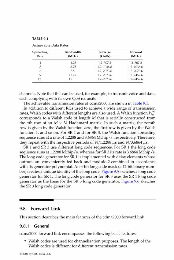
P1: FDJ
book CRC-Wireless November 18, 2001 14:38 Char Count= 264
TABLE 9.1
Achievable Data Rates
Spreading Bandwidth Reverse ForwardRate (MHz) (kbit/s) (MHz)
1 1.25 1.2–307.2 1.2–307.23 3.75 1.2–1036.8 1.2–1036.86 7.5 1.2–2073.6 1.2–2073.69 11.25 1.2–2073.6 1.2–2457.6
12 15 1.2–2073.6 1.2–2457.6
channels. Note that this can be used, for example, to transmit voice and data,each complying with its own QoS requisite.
The achievable transmission rates of cdma2000 are shown in Table 9.1.In addition to different RCs used to achieve a wide range of transmission
rates, Walsh codes with different lengths are also used. A Walsh function WMm
corresponds to a Walsh code of length M that is serially constructed fromthe nth row of an M × M Hadamard matrix. In such a matrix, the zerothrow is given by the Walsh function zero, the first row is given by the Walshfunction 1, and so on. For SR 1 and for SR 3, the Walsh function spreadingsequence runs at a rate of 1.2288 and 3.6864 Mchip/s, respectively. Therefore,they repeat with the respective periods of N/1.2288 µs and N/3.6864 µs.
SR 1 and SR 3 use different long code sequences. For SR 1 the long codesequence runs at 1.2288 Mchip/s, whereas for SR 3 its rate is 3.6864 Mchip/s.The long code generator for SR 1 is implemented with delay elements whoseoutputs are conveniently fed back and modulo-2-combined in accordancewith its generator polynomial. An n-bit long code mask (a 42-bit binary num-ber) creates a unique identity of the long code. Figure 9.5 sketches a long codegenerator for SR 1. The long code generator for SR 3 uses the SR 1 long codegenerator as the basis for the SR 3 long code generator. Figure 9.6 sketchesthe SR 3 long code generator.
9.8 Forward Link
This section describes the main features of the cdma2000 forward link.
9.8.1 General
cdma2000 forward link encompasses the following basic features:� Walsh codes are used for channelization purposes. The length of the
Walsh codes is different for different transmission rates.
© 2002 by CRC Press LLC
E:\Java for Engineers\VP Publication\Java for Engineers.vpThursday, April 25, 2002 9:27:36 AM
Color profile: DisabledComposite Default screen

P1: FDJ
book CRC-Wireless November 18, 2001 14:38 Char Count= 264
+ . . . +
. . .
. . .
Modulo - 2 Adder
Long Code (1.2288 Mchip/s)
n-bit Long Code Mask
FIGURE 9.5Long code generator for SR 1.
� Long code is used for scrambling on the forward CDMA channel.� Nonorthogonal codes are also used for channelization purposes, in
case the number of orthogonal Walsh codes is insufficient. These arequasi-orthogonal codes generated by appropriately masking orthog-onal Walsh functions (codes) with quasi-orthogonal (masking) func-tions (QOFs).
SR1Long CodeGenerator
1 SR1-chipDelay
1 SR1-chipDelay
M
U
X
LongCodeMask
LongCode
(3.6864Mchip/s)
FIGURE 9.6Long code generator for SR 3.
© 2002 by CRC Press LLC
E:\Java for Engineers\VP Publication\Java for Engineers.vpThursday, April 25, 2002 9:27:36 AM
Color profile: DisabledComposite Default screen
P1: FDJ
book CRC-Wireless November 18, 2001 14:38 Char Count= 264
� QPSK modulation is used prior to the spreading operation. The useof QPSK doubles the number of Walsh codes available.
� Convolutional codes, with constraint length of 9, are used for voiceand data.
� Turbo codes, with constraint length of 4, are used for data running onthe supplemental channels.
� Closed-loop fast power control (up to 800 updates per seconds) isused.
� 20-ms frames are used for signaling and user information and 5-msframes are used for control information.
� Transmit diversity is applicable.
Observe, however, that, in order for cdma2000 to be backward compatiblewith cdmaOne, some of the mentioned features are present only in certain SRsand RCs. For example, QPSK modulation does not appear in some RCs of SR 1.
9.8.2 Spreading Rate
Forward link achieves the wideband transmission by utilizing the directspread technology or multicarrier approach. In an MC implementation, themodulation symbols after coding and interleaving are demultiplexed ontoN × 1.25 MHz carriers (N = 1, 3, 6, 9, or 12), each carrier with a 1.2288 Mchip/srate. In the DS implementation, the modulation symbols after coding and in-terleaving are spread by a N × 1.2288 Mchip/s sequence, with the spreadsignal being modulated onto a carrier.
9.8.3 Physical Channels
The forward physical channels can be divided into two groups: forward ded-icated channels (F-DCHs) and Forward Common Channels (F-CCHs). TheF-DCHs convey information from the base station to a particular mobile ona point-to-point basis. The F-CCHs convey information from the base stationto a set of mobile stations on a point-to-multipoint basis.
The F-CCHs comprise the following channels: forward paging channel(F-PCH), forward quick paging channel (F-QPCH), forward broadcast controlchannel (F-BCCH), forward synchronization channel (F-SYNCH), forwardcommon control channel (F-CCCH), forward pilot channels (F-PiCHs), for-ward common assignment channel (F-CACH), and forward common powercontrol channel (F-CPCCH). The F-PiCHs encompass four channels: forwardpilot channel (F-PCH), forward auxiliary pilot channel (F-APICH), forwardtransmit diversity pilot channel (F-TDPICH), and forward auxiliary diversitypilot (F-ATDPICH).
© 2002 by CRC Press LLC
E:\Java for Engineers\VP Publication\Java for Engineers.vpThursday, April 25, 2002 9:27:36 AM
Color profile: DisabledComposite Default screen

P1: FDJ
book CRC-Wireless November 18, 2001 14:38 Char Count= 264
F-PCH
F-QPCH
F-TCHs
F-BCCH
F-SYNCH
F-CCCH
F-PiCHs
F-CACH
F-CPCCH
F-FCH
F-DCCH
F-SCCH
F-SCH
F-CSCH
F-PICH
F-APICH
F-TDPICH
F-ATDPICH
Forward PhysicalChannels
FIGURE 9.7Forward physical channels.
The F-DCHs comprise the forward traffic channels (F-TCHs). The F-TCHsencompass four channels: forward fundamental channel (F-FCH), forwarddedicated control channel (F-DCCH), forward supplemental code channel(F-SCCH), and forward supplemental channel (F-SCH).
Figure 9.7 illustrates the forward physical channels.The use of some channels varies depending on the SR as well as on the RC.
Table 9.2 indicates the range of valid channels for each channel type for SR 1and SR 3. Note that SR 3 encompasses fewer channels than SR 1. In particular,F-TDPICH, F-ATDPICH, F-PCH, and F-SCCH appear in SR 1 but not in SR3. Each of the code channels shown in Table 9.2 is spread by the appropriateWalsh function or quasi-orthogonal function. A quadrature spreading is thenapplied to each code channel, the quadrature pair of PN sequences runningat 1.2288 Mchip/s. Frequency division multiplexing may be used within thebase station for multiple forward CDMA channels. cdma2000 Revision Astandards state that if a base station transmits the F-CCCH on a forwardCDMA channel, the base station shall also transmit the F-BCCH on the sameforward CDMA channel.
9.8.4 Radio Configuration
cdma2000 standards specify ten RCs, numbered sequentially from 1 to 10,for the forward traffic channels. Table 9.3 shows some radio characteristicsof the RCs from 1 through 9 and SRs from 1 through 3 for the forward link.
© 2002 by CRC Press LLC
E:\Java for Engineers\VP Publication\Java for Engineers.vpThursday, April 25, 2002 9:27:36 AM
Color profile: DisabledComposite Default screen
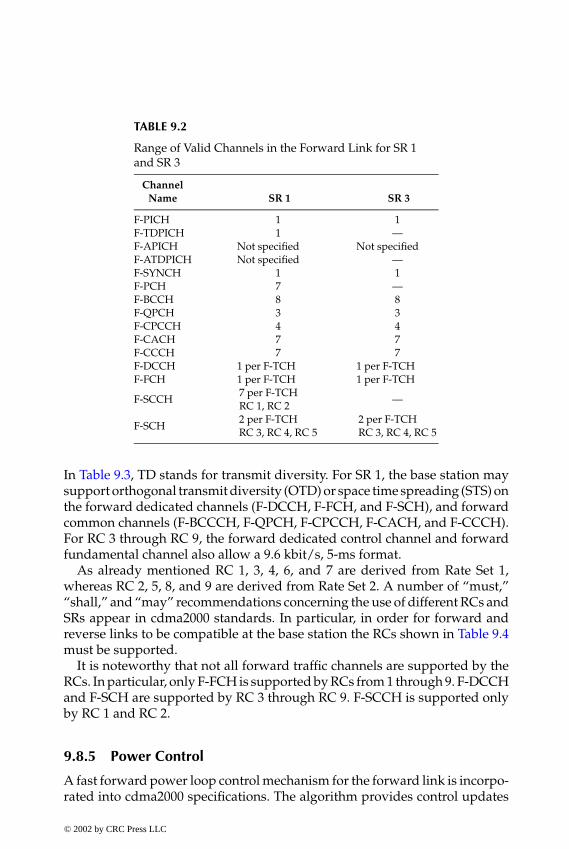
P1: FDJ
book CRC-Wireless November 18, 2001 14:38 Char Count= 264
TABLE 9.2
Range of Valid Channels in the Forward Link for SR 1and SR 3
ChannelName SR 1 SR 3
F-PICH 1 1F-TDPICH 1 —F-APICH Not specified Not specifiedF-ATDPICH Not specified —F-SYNCH 1 1F-PCH 7 —F-BCCH 8 8F-QPCH 3 3F-CPCCH 4 4F-CACH 7 7F-CCCH 7 7F-DCCH 1 per F-TCH 1 per F-TCHF-FCH 1 per F-TCH 1 per F-TCH
F-SCCH 7 per F-TCHRC 1, RC 2
—
F-SCH 2 per F-TCHRC 3, RC 4, RC 5
2 per F-TCHRC 3, RC 4, RC 5
In Table 9.3, TD stands for transmit diversity. For SR 1, the base station maysupport orthogonal transmit diversity (OTD) or space time spreading (STS) onthe forward dedicated channels (F-DCCH, F-FCH, and F-SCH), and forwardcommon channels (F-BCCCH, F-QPCH, F-CPCCH, F-CACH, and F-CCCH).For RC 3 through RC 9, the forward dedicated control channel and forwardfundamental channel also allow a 9.6 kbit/s, 5-ms format.
As already mentioned RC 1, 3, 4, 6, and 7 are derived from Rate Set 1,whereas RC 2, 5, 8, and 9 are derived from Rate Set 2. A number of “must,”“shall,” and “may” recommendations concerning the use of different RCs andSRs appear in cdma2000 standards. In particular, in order for forward andreverse links to be compatible at the base station the RCs shown in Table 9.4must be supported.
It is noteworthy that not all forward traffic channels are supported by theRCs. In particular, only F-FCH is supported by RCs from 1 through 9. F-DCCHand F-SCH are supported by RC 3 through RC 9. F-SCCH is supported onlyby RC 1 and RC 2.
9.8.5 Power Control
A fast forward power loop control mechanism for the forward link is incorpo-rated into cdma2000 specifications. The algorithm provides control updates
© 2002 by CRC Press LLC
E:\Java for Engineers\VP Publication\Java for Engineers.vpThursday, April 25, 2002 9:27:36 AM
Color profile: DisabledComposite Default screen
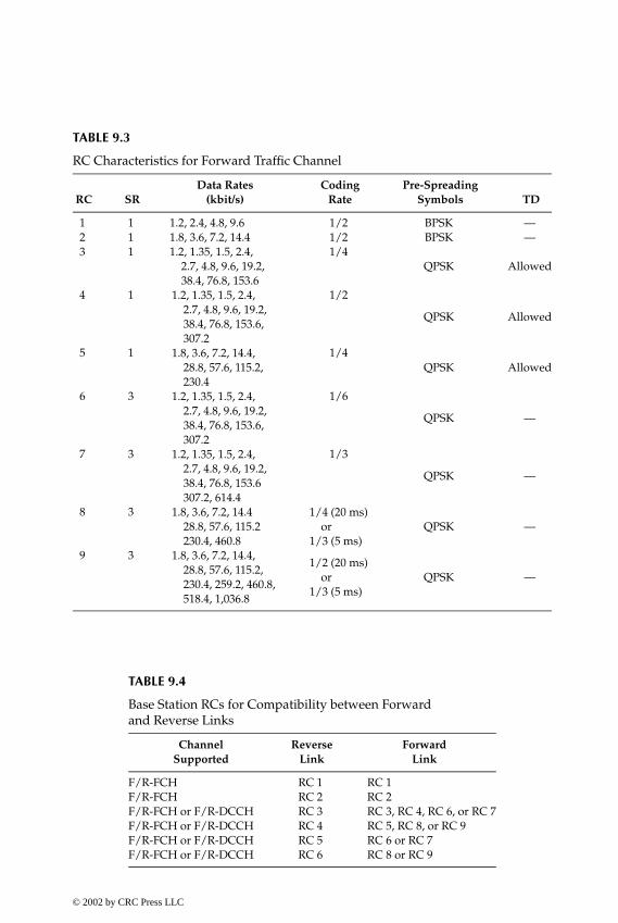
P1: FDJ
book CRC-Wireless November 18, 2001 14:38 Char Count= 264
TABLE 9.3
RC Characteristics for Forward Traffic Channel
Data Rates Coding Pre-SpreadingRC SR (kbit/s) Rate Symbols TD
1 1 1.2, 2.4, 4.8, 9.6 1/2 BPSK —2 1 1.8, 3.6, 7.2, 14.4 1/2 BPSK —3 1 1.2, 1.35, 1.5, 2.4, 1/4
2.7, 4.8, 9.6, 19.2, QPSK Allowed38.4, 76.8, 153.6
4 1 1.2, 1.35, 1.5, 2.4,2.7, 4.8, 9.6, 19.2,38.4, 76.8, 153.6,307.2
1/2
QPSK Allowed
5 1 1.8, 3.6, 7.2, 14.4,28.8, 57.6, 115.2,230.4
1/4QPSK Allowed
6 3 1.2, 1.35, 1.5, 2.4,2.7, 4.8, 9.6, 19.2,38.4, 76.8, 153.6,307.2
1/6
QPSK —
7 3 1.2, 1.35, 1.5, 2.4,2.7, 4.8, 9.6, 19.2,38.4, 76.8, 153.6307.2, 614.4
1/3
QPSK —
8 3 1.8, 3.6, 7.2, 14.428.8, 57.6, 115.2230.4, 460.8
1/4 (20 ms)or
1/3 (5 ms)QPSK —
9 3 1.8, 3.6, 7.2, 14.4,28.8, 57.6, 115.2,230.4, 259.2, 460.8,518.4, 1,036.8
1/2 (20 ms)or
1/3 (5 ms)QPSK —
TABLE 9.4
Base Station RCs for Compatibility between Forwardand Reverse Links
Channel Reverse ForwardSupported Link Link
F/R-FCH RC 1 RC 1F/R-FCH RC 2 RC 2F/R-FCH or F/R-DCCH RC 3 RC 3, RC 4, RC 6, or RC 7F/R-FCH or F/R-DCCH RC 4 RC 5, RC 8, or RC 9F/R-FCH or F/R-DCCH RC 5 RC 6 or RC 7F/R-FCH or F/R-DCCH RC 6 RC 8 or RC 9
© 2002 by CRC Press LLC
E:\Java for Engineers\VP Publication\Java for Engineers.vpThursday, April 25, 2002 9:27:36 AM
Color profile: DisabledComposite Default screen

P1: FDJ
book CRC-Wireless November 18, 2001 14:38 Char Count= 264
at the rate of up to 800 updates per second. It is similar to the power con-trol mechanism used for the reverse link in cdmaOne. The mobile stationmeasures the forward link traffic channel power and instructs the base stationto increase or decrease the power, as required. The power control commandis time-multiplexed on the reverse pilot channel. Note that the traffic chan-nel, in fact, comprises several channels. Therefore, as far as power control isconcerned, several options can be exercised. In one of them, the higher-ratechannel, chosen between F-FCH and F-SCH, is monitored for power controlpurposes. The gain setting for the other channel is then determined based onthe power relation between the two channels. In another option, F-FCH andF-SCH are monitored separately, with independent quality targets. The powergain for each one of these channels is then applied independently, as required.
9.8.6 Transmit Diversity
cdma2000 provides means for TD. TD is used to improve the link perfor-mance. For SR 1, the base station may support orthogonal transmit diver-sity (OTD) or space time spreading (STS) on the forward dedicated channels(F-DCCH, F-FCH, and F-SCH), and forward common channels (F-BCCCH,F-QPCH, F-CPCCH, F-CACH, and F-CCCH). For SR 3, the MC approach al-ready provides for TD. OTD and STS are optional forward-link transmissionmethods in which channel symbols are conveniently distributed between twoantennas. These symbols are then spread by a Walsh code or quasi-orthogonalfunction and transmitted using the same carrier.
For SR 1, in case no TD is provided, the channel symbols are demultiplexedand fed into the forward transmission block, as shown in Figure 9.8.
FIGURE 9.8Forward transmission without diversity (SR 1).
© 2002 by CRC Press LLC
E:\Java for Engineers\VP Publication\Java for Engineers.vpThursday, April 25, 2002 9:27:36 AM
Color profile: DisabledComposite Default screen

P1: FDJ
book CRC-Wireless November 18, 2001 14:38 Char Count= 264
FIGURE 9.9Forward OTD scheme (SR 1).
For the SR 1, if TD is provided, for both TD techniques (OTD and STS),encoding is applied on blocks of four consecutive channel bits. Such encodingencompasses bit repetition (2 ×), inversion of bit polarity, and, in the STS case,bit addition. The encoded bits are then I- and Q-mapped, spread, modulated,and transmitted by means of two antennas. Figure 9.9 illustrates the OTDprocess. Figure 9.10, below, sketches the STS scheme.
For SR 3, the serial coded information symbols are split into three parallelstreams, each of which is spread by a Walsh code and a long PN sequence.Each information stream is then transmitted using a different carrier. Figure9.11 shows the distribution of symbols for each transmission block.
The DEMUX functions in all transmission schemes distribute input sym-bols sequentially from the top to bottom output paths. Figures 9.8 through 9.11show that two types of DEMUX are used. The first serves channel struc-tures in which the symbols to be transmitted are not presented in the I/Qform. The second type is used for channel structures in which the symbols tobe transmitted are already presented in the I/Q form. This depends on thetype of channel to be transmitted and is explored in more depth later in thischapter.
© 2002 by CRC Press LLC
E:\Java for Engineers\VP Publication\Java for Engineers.vpThursday, April 25, 2002 9:27:36 AM
Color profile: DisabledComposite Default screen

P1: FDJ
book CRC-Wireless November 18, 2001 14:38 Char Count= 264
FIGURE 9.10STS transmit diversity scheme (SR 1).
9.8.7 Transmission Block
The forward transmission block is shown in Figure 9.12. Channelization isprovided by means of Walsh functions or quasi-orthogonal functions. Walshcodes are used preferentially, but if the forward link is running out of orthog-onal codes quasi-orthogonal functions can be used to increase the number ofusable codes. The code lengths vary to achieve different information rates. Afurther codification is included in the transmission chain with the in-phaseand quadrature signal components able to experience a 90◦ rotation. If rotationis applied, an I + j Q input signal is coded as −Q + j I . Another codification isimplemented by means of a complex spreading. For an I + j Q input signal, thein-phase arm of the complex multiplier yields I ×CshortI −Q×CshortQ, whereasthe quadrature arm of the complex multiplier gives I × CshortQ + Q × CshortI .CshortI and CshortQ are short in-phase and quadrature PN sequences. Notethat both codes and both signals are present in both arms of the complexmultiplier. Therefore, even if one of the signals is nil, as is the case of thecdmaOne signals, the quadrature spreading operation is still applied to the
© 2002 by CRC Press LLC
E:\Java for Engineers\VP Publication\Java for Engineers.vpThursday, April 25, 2002 9:27:36 AM
Color profile: DisabledComposite Default screen

P1: FDJ
book CRC-Wireless November 18, 2001 14:38 Char Count= 264
FIGURE 9.11Forward MC scheme (SR 3)—forward link.
other signal. Baseband filtering follows and finally modulation is applied. ForcdmaOne-compatible signals, a BPSK modulation is accomplished. For othersignals, a QPSK modulation is implemented. Note, however, that the mod-ulation block is exactly the same in both cases. The difference is obtained inthe demultiplexing operation carried out previously. For cdmaOne signals,one of the DEMUX outputs is nil, in which case the complex multiplier yieldsthe same symbol in both arms of the modulator. This leads to a BPSK mod-ulation. For a normal operation of the DEMUX, with the signals sequentiallypresented at its outputs, each two information bits are then mapped onto oneQPSK symbol. The use of a QPSK modulator doubles the number of Walshcodes available.
For cdmaOne applications, or if no diversity is applied, only one transmis-sion block is used. For diversity applications in SR 1, two transmission blocksare used, both with the same carrier. For SR 3 applications, three transmis-sion blocks are utilized, each of which uses a different carrier frequency. In allcases, two PN sequences, CshortI and CshortQ, at a chip rate of 1.2288 Mchip/s,are used to modulate the in-phase (cosine) and quadrature (sine) RF carriers,respectively. Two pulse shaping filters of the finite impulse response (FIR)
© 2002 by CRC Press LLC
E:\Java for Engineers\VP Publication\Java for Engineers.vpThursday, April 25, 2002 9:27:36 AM
Color profile: DisabledComposite Default screen

P1: FDJ
book CRC-Wireless November 18, 2001 14:38 Char Count= 264
FIGURE 9.12Forward link transmission block.
type, one at the in-phase branch and the other at the quadrature branch, areused to confine the radiated spectrum within the 1.25 bandwidth. The result-ing spreading leads to N×1.25 MHz, where N is the SR number. The in-phasePN code, CshortI , and quadrature PN code, CshortQ, are generated by 15-stagelinear feedback shift registers. They run at 1.2288 Mchip/s and have theircharacteristic polynomials given as
CshortI = 1 + x5 + x7 + x8 + x9 + x13 + x15 (9.1)
CshortQ = 1 + x3 + x4 + x5 + x6 + x10 + x11 + x12 + x15 (9.2)
The pilot PN sequence period is 215/1,228,800 = 26.666 . . . ms, with exactly75 pilot PN sequence repetitions occurring every 2 s.
The long PN code, Clong, is generated by 42-stage linear feedback shiftregisters running at 1.2288 Mchip/s. Its characteristic polynomial is
Clong = 1 + x + x2 + x3 + x5 + x6 + x7 + x10 + x16 + x17 + x18
+ x19 + x21 + x22 + x25 + x26 + x27 + x31 + x33 + x35 + x42 (9.3)
© 2002 by CRC Press LLC
E:\Java for Engineers\VP Publication\Java for Engineers.vpThursday, April 25, 2002 9:27:36 AM
Color profile: DisabledComposite Default screen
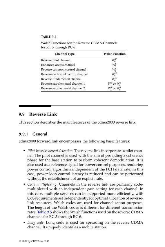
P1: FDJ
book CRC-Wireless November 18, 2001 14:38 Char Count= 264
TABLE 9.5
Walsh Functions for the Reverse CDMA Channelsfor RC 3 through RC 6
Channel Type Walsh Function
Reverse pilot channel W320
Enhanced access channel W82
Reverse common control channel W82
Reverse dedicated control channel W168
Reverse fundamental channel W164
Reverse supplemental channel 1 W21 or W4
2
Reverse supplemental channel 2 W42 or W8
6
9.9 Reverse Link
This section describes the main features of the cdma2000 reverse link.
9.9.1 General
cdma2000 forward link encompasses the following basic features:
� Pilot-based coherent detection. The reverse link incorporates a pilot chan-nel. The pilot channel is used with the aim of providing a coherencephase for the base station to perform coherent demodulation. It isalso used as a reference signal for power control purposes, renderingpower control algorithms independent of the FCH data rate. In thiscase, power loop control latency is reduced and can be performedwithout the establishment of an explicit rate.
� Code multiplexing. Channels in the reverse link are primarily code-multiplexed with an independent gain setting for each channel. Inthis case, multiple services can be supported more efficiently, withQoS requirements set independently for optimal allocation of reverse-link resources. Walsh codes are used for channelization purposes.The length of the Walsh codes is different for different transmissionrates. Table 9.5 shows the Walsh functions used on the reverse CDMAchannels for RC 3 through RC 6.
� Long code. Long code is used for spreading on the reverse CDMAchannel. It uniquely identifies a mobile station.
© 2002 by CRC Press LLC
E:\Java for Engineers\VP Publication\Java for Engineers.vpThursday, April 25, 2002 9:27:36 AM
Color profile: DisabledComposite Default screen

P1: FDJ
book CRC-Wireless November 18, 2001 14:38 Char Count= 264
� Continuous waveform. A continuous waveform is used for all data rates.This minimizes interference to biomedical devices (e.g., hearing aids,pacemakers, etc.) and allows a range increase at lower transmissionrates.
� Convolutional codes, with constraint length of 9, are used for voice anddata.
� Turbo codes, with constraint length of 4, are used for data running onthe supplemental channels.
� 20-ms frames are used for signaling and user information and 5-msframes are used for control information.
Observe, however, that in order for cdma2000 to be backward compatiblewith cdmaOne, some of the mentioned features are present only in certainSRs and RCs.
9.9.2 Spreading Rate
The reverse-link transmission achieves the wideband transmission by utiliz-ing the direct spread approach. In such a case, the modulation symbols aftercoding and interleaving are spread over an N×1.25 MHz band (N = 1, 3, 6,9, or 12). Each system spreads the modulated symbols by means of PN se-quences running at N × 1.2288 Mchip/s, with the spread signal modulatedonto a carrier.
9.9.3 Physical Channels
Reverse physical channels can be divided into two groups: reverse dedicatedchannels (R-DCHs) and reverse common channels (R-CCHs). The R-DCHsconvey information from a particular mobile station to the base station on apoint-to-point basis. The R-CCHs convey information from multiple mobilestations to the base station on a multipoint-to-point basis.
The R-CCHs comprise the following channels: reverse common controlchannel (R-CCCH), reverse enhanced access channel (R-EACH), and reverseaccess channel (R-ACH). The R-DCHs comprise the following channels: re-verse fundamental channel (R-FCH), reverse dedicated control channel (R-DCCH), reverse supplemental code channel (R-SCCH), reverse supplementalchannel (R-SCH), and reverse power control subchannel (R-PCSCH). In ad-dition, a reverse pilot channel (R-PICH) is included for channels operatingin RCs other than 1 and 2. Traffic-carrying operation for RC 3 to RC 6 isperformed by means of the following channels: R-FCH, R-SCH, R-DCCH,and R-PCSCH. For RC 1 and RC 2 this is performed by the following chan-nels: R-FCH and R-SCCH. Common control operation makes use of the
© 2002 by CRC Press LLC
E:\Java for Engineers\VP Publication\Java for Engineers.vpThursday, April 25, 2002 9:27:36 AM
Color profile: DisabledComposite Default screen

P1: FDJ
book CRC-Wireless November 18, 2001 14:38 Char Count= 264
R-PICH
R-CCCH
R-PICH
R-PCSCH
R-FCH
Reverse PhysicalChannels
R-SCH
R-PICH
R-EACH
R-FCH
R-SCH
R-ACH
CommonControl
Traffic(RC3 to RC6)
EnhancedAccess
Traffic(RC1 or RC2)
Access
FIGURE 9.13Reverse physical channels.
following channels: R-CCCH and R-PICH. Enhanced access operation iscarried out through the following channels: R-EACH and R-PICH. Accessoperation is performed by R-ACH. Figure 9.13 illustrates the reverse physicalchannels.
The use of some channels varies depending on the SR as well as on the RC.Table 9.6 indicates the range of valid channels for each channel type for SR 1
TABLE 9.6
Range of Valid Channels in the ReverseLink for SR 1 and SR 3
ChannelName SR 1 SR 3
R-PICH 1 1R–ACH 1 —R–EACH 1 —R–CCCH 1 1R–DCCH 1 1R–FCH 1 1
R–SCCH7
RC 1, RC 2—
R–SCH2
RC 3, RC 42
© 2002 by CRC Press LLC
E:\Java for Engineers\VP Publication\Java for Engineers.vpThursday, April 25, 2002 9:27:36 AM
Color profile: DisabledComposite Default screen

P1: FDJ
book CRC-Wireless November 18, 2001 14:38 Char Count= 264
and SR 3. Note that SR 3 encompasses fewer channels than SR 1. In particular,R-ACH, R-EACH, and R-SCCH appear in SR 1 but not in SR 3.
9.9.4 Radio Configuration
cdma2000 standards specify seven RCs, numbered sequentially from 1 to 7,for the reverse traffic channels. Table 9.7 shows some radio characteristicsof the RCs from 1 through 6 and SRs from 1 through 3 for the reverse link.In Table 9.7, “64-ary” refers to the 64-ary orthogonal modulation. For RC 3through RC 6, the reverse dedicated control channel and reverse fundamentalchannel also allow a 9.6 kbit/s, 5-ms format.
As already mentioned, RC 1, 3, and 5 are derived from Rate Set 1 and RC 2, 4,and 6 are derived from Rate Set 2. Rate Set 1 yields transmission rates of 1.2, 2.4,4.8, and 9.6 kbit/s, whereas Rate Set 2 yields transmission rates of 1.8, 3.6, 7.2,and 14.4 kbit/s. A number of “must,” “shall,” and “may” recommendationsconcerning the use of different RCs and SRs appear in cdma2000 standards.In particular, in order for forward and reverse links to be compatible at thebase station the RCs shown in Table 9.8 must be supported.
It is noteworthy that not all forward traffic channels are supported by theRCs. In particular, only R-FCH is supported by RCs from 1 through 6. R-DCCHand R-SCH are supported by RC 3 through RC 6. R-SCCH is supported onlyby RC 1 and RC 2.
TABLE 9.7
RC Characteristics for Reverse Traffic Channel
Data Rates Coding Pre-SpreadingRC SR (kbit/s) Rate Symbols Pilot
1 1 1.2, 2.4, 4.8, 9.6 1/3 64-ary —2 1 1.8, 3.6, 7.2, 14.4 1/2 64-ary —3 1 1.2, 1.35, 1.5, 2.4,
2.7, 4.8, 9.6, 19.2,38.4, 76.8, 153.6
1/4BPSK Inserted
3 1 307.2 1/2 BPSK Inserted4 1 1.8, 3.6, 7.2, 14.4,
28.8, 57.6, 115.2,230.4
1/4BPSK Inserted
5 3 1.2, 1.35, 1.5, 2.4,2.7, 4.8, 9.6, 19.2,38.4, 76.8, 153.6
1/4QPSK Inserted
5 3 307.2, 614.4 1/3 BPSK Inserted6 3 1.8, 3.6, 7.2, 14.4,
28.8, 57.6, 115.2,230.4, 460.8
1/4BPSK Inserted
6 3 1,036.8 1/2 BPSK Inserted
© 2002 by CRC Press LLC
E:\Java for Engineers\VP Publication\Java for Engineers.vpThursday, April 25, 2002 9:27:36 AM
Color profile: DisabledComposite Default screen
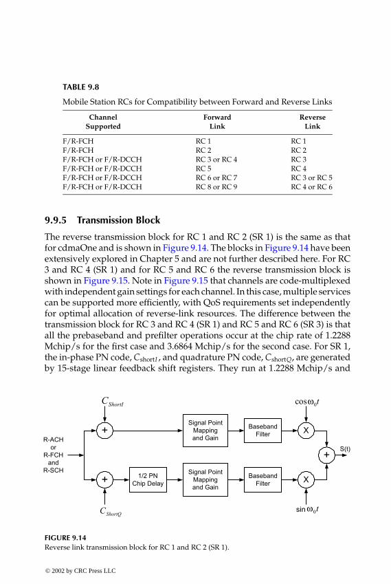
P1: FDJ
book CRC-Wireless November 18, 2001 14:38 Char Count= 264
TABLE 9.8
Mobile Station RCs for Compatibility between Forward and Reverse Links
Channel Forward ReverseSupported Link Link
F/R-FCH RC 1 RC 1F/R-FCH RC 2 RC 2F/R-FCH or F/R-DCCH RC 3 or RC 4 RC 3F/R-FCH or F/R-DCCH RC 5 RC 4F/R-FCH or F/R-DCCH RC 6 or RC 7 RC 3 or RC 5F/R-FCH or F/R-DCCH RC 8 or RC 9 RC 4 or RC 6
9.9.5 Transmission Block
The reverse transmission block for RC 1 and RC 2 (SR 1) is the same as thatfor cdmaOne and is shown in Figure 9.14. The blocks in Figure 9.14 have beenextensively explored in Chapter 5 and are not further described here. For RC3 and RC 4 (SR 1) and for RC 5 and RC 6 the reverse transmission block isshown in Figure 9.15. Note in Figure 9.15 that channels are code-multiplexedwith independent gain settings for each channel. In this case, multiple servicescan be supported more efficiently, with QoS requirements set independentlyfor optimal allocation of reverse-link resources. The difference between thetransmission block for RC 3 and RC 4 (SR 1) and RC 5 and RC 6 (SR 3) is thatall the prebaseband and prefilter operations occur at the chip rate of 1.2288Mchip/s for the first case and 3.6864 Mchip/s for the second case. For SR 1,the in-phase PN code, CshortI , and quadrature PN code, CshortQ, are generatedby 15-stage linear feedback shift registers. They run at 1.2288 Mchip/s and
FIGURE 9.14Reverse link transmission block for RC 1 and RC 2 (SR 1).
© 2002 by CRC Press LLC
E:\Java for Engineers\VP Publication\Java for Engineers.vpThursday, April 25, 2002 9:27:36 AM
Color profile: DisabledComposite Default screen
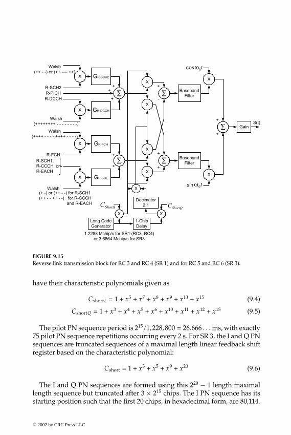
P1: FDJ
book CRC-Wireless November 18, 2001 14:38 Char Count= 264
FIGURE 9.15Reverse link transmission block for RC 3 and RC 4 (SR 1) and for RC 5 and RC 6 (SR 3).
have their characteristic polynomials given as
CshortI = 1 + x5 + x7 + x8 + x9 + x13 + x15 (9.4)
CshortQ = 1 + x3 + x4 + x5 + x6 + x10 + x11 + x12 + x15 (9.5)
The pilot PN sequence period is 215/1,228,800 = 26.666 . . . ms, with exactly75 pilot PN sequence repetitions occurring every 2 s. For SR 3, the I and Q PNsequences are truncated sequences of a maximal length linear feedback shiftregister based on the characteristic polynomial:
Cshort = 1 + x3 + x5 + x9 + x20 (9.6)
The I and Q PN sequences are formed using this 220 − 1 length maximallength sequence but truncated after 3 × 215 chips. The I PN sequence has itsstarting position such that the first 20 chips, in hexadecimal form, are 80,114.
© 2002 by CRC Press LLC
E:\Java for Engineers\VP Publication\Java for Engineers.vpThursday, April 25, 2002 9:27:36 AM
Color profile: DisabledComposite Default screen
P1: FDJ
book CRC-Wireless November 18, 2001 14:38 Char Count= 264
The Q PN sequence has its starting position equal to that of the I PN sequencedelayed by 219 −1 chips. The chip rate is 3.6864 Mchip/s and the PN sequenceperiod is obtained as 3×215/3, 686, 400 = 26.666 . . . ms. Here, again, exactly 75PN sequence repetitions occur every 2 s. The long PN code, Clong, is generatedby 42-stage linear feedback shift registers with its characteristic polynomialgiven as
Clong = 1 + x + x2 + x3 + x5 + x6 + x7 + x10 + x16 + x17 + x18
+ x19 + x21 + x22 + x25 + x26 + x27 + x31 + x33 + x35 + x42 (9.7)
9.10 Forward Physical Channels
This section describes the main characteristics of the forward physical chan-nels. As already mentioned, the forward physical channels can be groupedinto forward link common channels and forward link dedicated channels.The following channels belong to the first group: F-PCH, F-QPCH, F-BCCH),F-SYNCH, F-CCCH, F-PiCHs, F-CACH, and F-CPCCH. The F-PiCHs en-compass five channels: F-PCH, F-APICH, F-TDPICH, F-ATDPICH, and F-DAPICH. The second group contains the forward traffic channels, namely:F-FCH, F-DCCH, F-SCCH, F-SCH.
The five forward pilot channels are unmodulated, spread spectrum signalsused by mobile stations for synchronization, phase reference, and demodula-tion purposes. They carry neither payload information nor signaling informa-tion, essentially consisting of short PN chips. They define the cell boundaryand can be used as beacon signals to facilitate rapid pilot searches as well asto perform handoff measurements. All base stations use the same short PNcode and are distinguished by the different offsets of that code.
A forward traffic channel comprises one or more code channels used totransport user and signaling traffic from the base station to the mobile station.The number of code channels composing a forward traffic channel dependson the type of traffic to be carried and on the desirable rate, these varyingaccording to the SR and RC. For SR 1 and for RCs from 1 through 9 theremay be one F-FCH and one F-DCCH. In addition, and for RC 1 and RC 2only, there may be as many as seven F-SCCH. Still, for SR 1, and only forRC 3, RC 4, and RC 5 there may be as many as two F-SCH. For SR 3, theremay be one F-FCH, one F-DCCH, and as many as two F-SCH. These are codechannels received in parallel by the mobile station. The power levels and theQoS requirements of theses channels are set differently for each channel, as
© 2002 by CRC Press LLC
E:\Java for Engineers\VP Publication\Java for Engineers.vpThursday, April 25, 2002 9:27:36 AM
Color profile: DisabledComposite Default screen

P1: FDJ
book CRC-Wireless November 18, 2001 14:38 Char Count= 264
required. Their Walsh codes are not predetermined and are assigned on ademand basis.
In the description of the channels, a signal point mapping block is presentin all channel structures. The signal point mapping block maps the binarylevels 0 and 1 onto +1 and −1, respectively.
9.10.1 Forward Pilot Channel
The F-PICH is an unmodulated, direct-sequence spread spectrum signal trans-mitted continuously by each base station, unless the base station is classifiedas a hopping pilot beacon base station. The F-PICH prior to Walsh spreadingcontains a sequence of zeros. Such a sequence is combined with the Walshcode 0, length 64 (W64
0 ), which also encompasses a sequence of zeros. TheF-PICH allows a mobile station to acquire the timing of the forward CDMAchannel, provides a phase reference for coherent demodulation, and providesmeans for signal strength comparisons between base stations for handoff pur-poses. Only one F-PICH is used per forward CDMA channel for both SR 1and SR 3. Figure 9.16 depicts the F-PICH structure for both SR 1 and SR 3. Theoutputs SI and SQ shown in Figure 9.16 constitute the inputs of the DEMUXblocks shown in Figure 9.8, for SR 1, and Figure 9.11, for SR 3.
9.10.2 Forward Transmit Diversity Pilot Channel
The F-TDPICH is an unmodulated, direct-sequence spread spectrum signaltransmitted continuously by a CDMA base station. It is used to supportforward-link transmit diversity. F-PICH and F-TDPICH provide phase ref-erences for coherent demodulation of those forward-link CDMA channelsdeploying transmit diversity. The transmission of F-TDPICH does not implya decrease of the transmit power of F-PICH. On the contrary, the base stationshould continue to use sufficient power on the F-PICH to ensure that a mobilestation is able to acquire and estimate the forward CDMA channel without
Signal PointMappingand Gain
All 0sPilotChannels
Data
0
FIGURE 9.16Forward pilot channels structure.
© 2002 by CRC Press LLC
E:\Java for Engineers\VP Publication\Java for Engineers.vpThursday, April 25, 2002 9:27:36 AM
Color profile: DisabledComposite Default screen

P1: FDJ
book CRC-Wireless November 18, 2001 14:38 Char Count= 264
using energy from the F-TDPICH. F-TDPICH is transmitted with Walsh code16, length 128 (W128
16 ). Only one F-TDPICH is used per forward CDMA chan-nel, with this channel provided in SR 1 and not in SR 3. Its configuration isthe same as that shown in Figure 9.16.
9.10.3 Forward Auxiliary Pilot Channel
The F-APICH is used for forward-link spot beam-forming purposes in net-works with smart antennas. The utilization of F-APICH provides for high datarate applications in specific locations. It is used as a phase reference for co-herent demodulation of those forward-link CDMA channels associated withit. Zero or more F-APICHs can be transmitted by the base station on an activeforward CDMA channel. An F-APICH can be shared by a number of dis-tinct mobiles in the same spot beam. The locations served by F-APICHs mayvary, as required. Spot beams can be used to increase coverage of a particulargeographic point or to increase capacity of hot spots. Systems making useof such an option must provide for separate forward-link channels for thespecific area. F-APICHs are code-multiplexed with other forward-link chan-nels. This obviously reduces the number of Walsh codes available for traffic.To reduce this effect, long Walsh codes are used for these channels. The F-APICH is transmitted with Walsh code n, length N (WN
n ), where N ≤ 512 and1 ≤ n ≤ N − 1. The Walsh code number and Walsh code length are deter-mined by the base station. This channel is used in SR 1 and in SR 3, with thenumber of them per forward CDMA channel not specified. Its configurationis the same as that shown in Figure 9.16.
9.10.4 Forward Auxiliary Transmit Diversity Pilot Channel
The F-ATDPICH is a transmit diversity pilot channel associated with an F-APICH. F-ATDPICH and F-APICH provide phase references for coherentdemodulation of those forward-link CDMA channels associated with theF-APICH. F-ATDPICH is transmitted with Walsh code n + N/2, length N(WN
n + N/2), where N ≤ 512 and 1 ≤ n ≤ N − 1. The Walsh code number andWalsh code length are determined by the base station. This channel is usedin SR 1 and not in SR 3, with the number per forward CDMA channel notspecified. Its configuration is the same as that shown in Figure 9.16.
9.10.5 Forward Dedicated Auxiliary Pilot Channel
The F-DAPICH is an optional auxiliary pilot channel used on a dedicated basisfor a given mobile station. It is an unmodulated, direct-sequence spread spec-trum signal transmitted continuously by a CDMA base station. F-DAPICH iscode-multiplexed with other forward-link channels. Its Walsh code number
© 2002 by CRC Press LLC
E:\Java for Engineers\VP Publication\Java for Engineers.vpThursday, April 25, 2002 9:27:36 AM
Color profile: DisabledComposite Default screen

P1: FDJ
book CRC-Wireless November 18, 2001 14:38 Char Count= 264
and the corresponding Walsh code length are determined by the base station.F-DAPICH is employed aiming at antenna beam-forming applications andbeam-steering techniques to increase the coverage or date rate for a particularmobile station. Note that F-DAPICH cannot be considered a common channel.This channel is used for periodic channel estimations so that the forward-linkantenna pattern can be adequately adjusted for better performance.
9.10.6 Forward Synchronization Channel
The F-SYNCH is a code channel conveying the synchronization message. Sucha message is used by the mobile station to acquire initial time synchroniza-tion. F-SYNCH is implemented in cdma2000 as it is in cdmaOne. F-SYNCHis a low-powered, low-rate channel (1.2 kbit/s) that contains a single, re-peating message referred to as the sync channel message. This message iscontinuously broadcast by the cell and contains parameters, such as systemidentification number, network identification number, cell or sector Short PNoffset, system time, long code state, and paging channel data rate. This chan-nel is transmitted with Walsh code 32, length 64 (W64
32 ) for both SR 1 and SR3, one per forward CDMA channel. The F-SYNCH structure is depicted inFigure 9.17.
9.10.7 Forward Paging Channel
The F-PCH is a code channel used for transmission of control information andpages from a base station to the mobile stations. It conveys system overhead
Signal PointMappingand Gain
4.8 ksymb/s
IS
QS0
(SR1)
BlockInterleaver
(16x8)
SymbolRepetition
(x2)
ConvolutionalEncoder(1/2, 9)
1.2 kbit/s
32 bits/26.666 ms... frame
SyncChannel
Data
ModulationSymbol
(SR3)
To ForwardTransmission
Block ii = 1, 2, 3
or
FIGURE 9.17Forward synchronization channel structure.
© 2002 by CRC Press LLC
E:\Java for Engineers\VP Publication\Java for Engineers.vpThursday, April 25, 2002 9:27:36 AM
Color profile: DisabledComposite Default screen

P1: FDJ
book CRC-Wireless November 18, 2001 14:38 Char Count= 264
PagingChannel
Data
ConvolutionalEncoder(1/2, 9)
4.8 ksymb/s9.6 ksymb/s
SymbolRepetition
(x2)(x1)
BlockInterleaver
(24x16)
+
9.6 ksymb/s19.2 ksymb/s 19.2 ksymb/s
Long CodeGenerator
Decimator64:1
1.2288 Mchip/sLong CodeMask forPaging
Channel k
19.2 ksymb/s
Signal PointMappingand Gain
IS
QS0
ModulationSymbol
96 bits/20 ms192 bits/20 ms
FIGURE 9.18Forward paging channel structure.
information and mobile station specific messages. It is identical to the pagingchannel of cdmaOne. F-PCH transmits in the slotted mode, each slot with80 ms of duration. Mobile stations, on the other hand, may operate in eitherthe slotted mode or nonslotted mode. Paging and control messages for a mo-bile station operating in the nonslotted mode can be conveyed in any of theF-PCH slots. Therefore, the nonslotted mode of operation requires the mo-bile station to monitor all the slots. The slotted mode of operation requiresthe assignment of a specific slot to the mobile station; this feature is used tosave battery. There may be as many as seven F-PCHs per forward CDMA inSR 1. SR 3 does provide for F-PCH. The primary F-PCH is assigned Walshcode number 1, length 64 (W64
1 ), with the remaining F-PCHs of the samelength and numbered sequentially from 2 to 7 (W64
2−7). These channels operateat full rate (9.6 kbit/s) and at half rate (4.8 kbit/s). The F-PCH is illustratedin Figure 9.18.
9.10.8 Forward Broadcast Control Channel
The F-BCCH is a code channel used for transmission of control informationfrom a base station to the mobile stations. It conveys broadcast overhead mes-sages and short message service broadcast messages. (Mobile specific mes-sages are not sent on this channel, but on the F-CCCH.) There may be as manyas eight F-BCCHs per forward CDMA in both SR 1 and SR 3. The specific Walshcode used is determined by the base station and such information is conveyedby the F-SYNCH. In both SR 1 and SR 3, 744 bits are transmitted in slots of 40,80, or 160 ms. The 744 bits together with 16 quality indicator bits and eightencoder tail bits lead to data rates of, respectively, 19.2, 9.6, and 4.8 kbit/s.Different Walsh codes are used for the different F-BCCH structures. TheF-BCCH structure is illustrated in Figure 9.19.
© 2002 by CRC Press LLC
E:\Java for Engineers\VP Publication\Java for Engineers.vpThursday, April 25, 2002 9:27:36 AM
Color profile: DisabledComposite Default screen
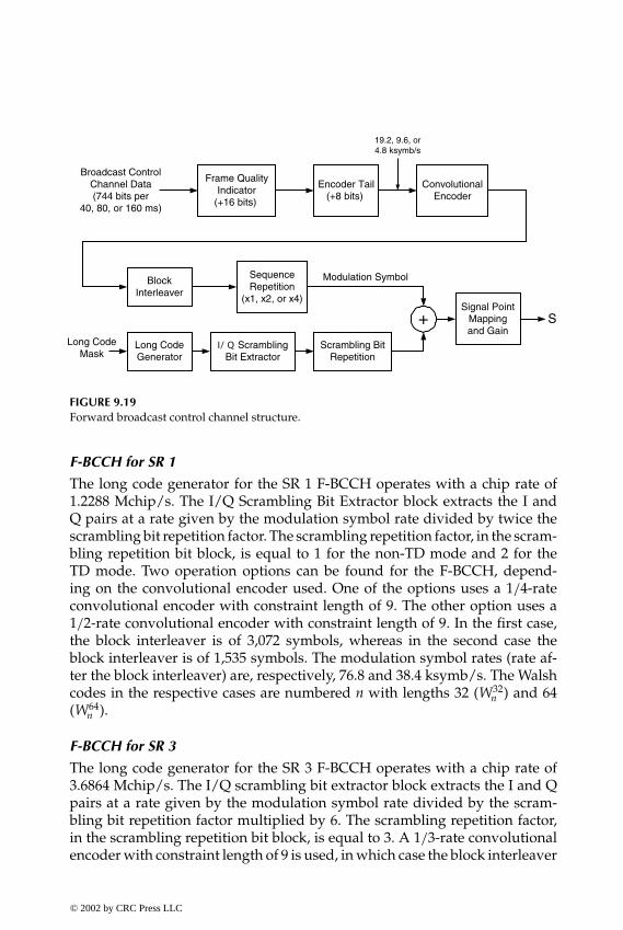
P1: FDJ
book CRC-Wireless November 18, 2001 14:38 Char Count= 264
Broadcast ControlChannel Data(744 bits per
40, 80, or 160 ms)
Encoder Tail(+8 bits)
ConvolutionalEncoder
19.2, 9.6, or4.8 ksymb/s
Long CodeGenerator
Long CodeMask
+
BlockInterleaver
SequenceRepetition
(x1, x2, or x4)Signal Point
Mappingand Gain
ScramblingBit Extractor
Scrambling BitRepetition
Modulation Symbol
S
Frame QualityIndicator
(+16 bits)
FIGURE 9.19Forward broadcast control channel structure.
F-BCCH for SR 1
The long code generator for the SR 1 F-BCCH operates with a chip rate of1.2288 Mchip/s. The I/Q Scrambling Bit Extractor block extracts the I andQ pairs at a rate given by the modulation symbol rate divided by twice thescrambling bit repetition factor. The scrambling repetition factor, in the scram-bling repetition bit block, is equal to 1 for the non-TD mode and 2 for theTD mode. Two operation options can be found for the F-BCCH, depend-ing on the convolutional encoder used. One of the options uses a 1/4-rateconvolutional encoder with constraint length of 9. The other option uses a1/2-rate convolutional encoder with constraint length of 9. In the first case,the block interleaver is of 3,072 symbols, whereas in the second case theblock interleaver is of 1,535 symbols. The modulation symbol rates (rate af-ter the block interleaver) are, respectively, 76.8 and 38.4 ksymb/s. The Walshcodes in the respective cases are numbered n with lengths 32 (W32
n ) and 64(W64
n ).
F-BCCH for SR 3
The long code generator for the SR 3 F-BCCH operates with a chip rate of3.6864 Mchip/s. The I/Q scrambling bit extractor block extracts the I and Qpairs at a rate given by the modulation symbol rate divided by the scram-bling bit repetition factor multiplied by 6. The scrambling repetition factor,in the scrambling repetition bit block, is equal to 3. A 1/3-rate convolutionalencoder with constraint length of 9 is used, in which case the block interleaver
© 2002 by CRC Press LLC
E:\Java for Engineers\VP Publication\Java for Engineers.vpThursday, April 25, 2002 9:27:36 AM
Color profile: DisabledComposite Default screen
P1: FDJ
book CRC-Wireless November 18, 2001 14:38 Char Count= 264
operates with 2,304 symbols. The modulation symbol rate (rate after the blockinterleaver) is, therefore, 57.6 ksymb/s. The Walsh codes are numbered n withlengths 128 (W128
n ).
9.10.9 Forward Quick Paging Channel
The F-QPCH is an uncoded, spread, and on-off-keying modulated spreadspectrum signal used in support of the operation of F-PCH and F-CCCH. It issent by the base station to inform mobile stations operating in the slotted modewhether to receive the F-PCH or the F-CCCH starting in their respective nextframes. The use of F-QPCH reduces the time a mobile station needs to processreceived data, resulting in increased battery life. This is because the mobiledoes not have to activate its processors to understand the messages of thechannel. Indicators are used to facilitate the task. These indicators are recog-nized by threshold-based detection. Therefore, if there is no new message forthe mobile station in the F-PCH or in the F-CCCH, it does not have to activateits processors to decode the message in the assigned slot. Data rates of 4.8 and2.4 ksymb/s can be used. Slots of 80 ms are specified to convey two indicatorsper mobile in each slot. The resulting indicator rates are, respectively, 9.6 and4.8 ksymb/s. The F-QPCH slots are aligned to initiate 20 ms before the startof the zero-offset pilot PN sequence. In SR 1, the symbols are repeated two orfour times to yield a constant rate of 19.2 ksymb/s. In SR 3, the repetition fac-tors are, respectively, 3 and 6, leading to a transmission rate of 28.8 ksymb/s.One of the indicators, the paging indicator, serves the purpose of instructinga slotted mode mobile station to monitor the F-PCH or the F-CCCH startingin the next frame. The other indicator, the configuration change indicator,serves the purpose of instructing a slotted-mode mobile station to monitorthe F-PCH, the F-CCCH, and the F-BCCH, after an idle handoff has been per-formed. This is carried out to determine whether the mobile station shouldupdate its stored parameters, in case the cell configuration parameters havechanged. There may be up to three F-QPCHs per forward CDMA both inSR 1 and SR 3. These channels are assigned the Walsh codes numbered 48,80, and 112, and length 128 (W128
48 , W12880 , and W128
112 , respectively). The F-QPCHstructure is illustrated in Figure 9.20.
9.10.10 Forward Common Control Channel
The F-CCCH conveys Layer 3 and MAC control messages from a base stationto one or more mobile stations. The coding parameters are identical to those ofF-PCH. It essentially replaces the F-PCHs for higher data rate configurationscarrying mobile station specific messages. Therefore, F-CCCHs are effectivelypaging channels optimized for packet services, in which case F-PCHs are not
© 2002 by CRC Press LLC
E:\Java for Engineers\VP Publication\Java for Engineers.vpThursday, April 25, 2002 9:27:36 AM
Color profile: DisabledComposite Default screen

P1: FDJ
book CRC-Wireless November 18, 2001 14:38 Char Count= 264
Signal PointMappingand Gain
SSymbol
Repetition
Indicator Rate 9.6 or 4.8 ksymb/s
Data Rate 4.8 or 2.4 ksymb/s
Quick Paging
Channel Data
FIGURE 9.20Forward quick paging channel structure.
used. An F-CCCH contains slots of 80-ms duration accommodating 20-, 10-,or 5-ms frames. Paging and control messages for a mobile station operating inthe nonslotted mode can be conveyed in any of the F-CCCH slots. Therefore,the nonslotted mode of operation requires the mobile station to monitor all theslots. The slotted mode of operation requires the assignment of a specific slotto the mobile station, a feature used to save battery. Although the data rate ofthe F-CCCHs may vary from frame to frame, for any given frame transmittedto the mobile station the data rate of that frame is previously known to thatmobile station. There may be as many as seven F-CCCHs per forward CDMAin both SR 1 and SR 3. The specific Walsh code used is determined by thebase station and such information is conveyed by the F-SYNCH. In both SR 1and SR 3, three data rates are possible: 9.6, 19.2, and 38.4 kbit/s. The F-CCCHstructure is illustrated in Figure 9.21.
Common ControlChannel Data
Encoder Tail(+8 bits)
ConvolutionalEncoder
Long CodeGenerator
LongCodeMask
+
BlockInterleaver
Signal PointMappingand Gain
ScramblingBit Extractor
Scrambling BitRepetition
Modulation Symbol
S
Frame QualityIndicator(+bits)
E
A
B
C D
FIGURE 9.21Forward common control channel structure.
© 2002 by CRC Press LLC
E:\Java for Engineers\VP Publication\Java for Engineers.vpThursday, April 25, 2002 9:27:36 AM
Color profile: DisabledComposite Default screen

P1: FDJ
book CRC-Wireless November 18, 2001 14:38 Char Count= 264
F-CCCH for SR 1
The long code generator for the SR 1 F-CCCH operates with a chip rate of1.2288 Mchip/s. The I/Q scrambling bit extractor block extracts the I andQ pairs at a rate given by the modulation symbol rate divided by twice thescrambling bit repetition factor. The scrambling repetition factor, in the scram-bling repetition bit block, is equal to one for the non-TD mode and two for theTD mode. Two operation options can be found for the F-BCCH, dependingon the convolutional encoder used. One of the options uses a 1 /4-rate convo-lutional encoder with constraint length of 9. The other option uses a 1/2-rateconvolutional encoder with constraint length of 9. The Walsh codes in therespective cases for the respective transmission rates are W16
n , W32n , and W64
n ,and W32
n , W64n , and W128
n . The various parameters for the points (A, B, C, D, E)shown in Figure 9.21 are specified in Table 9.9.
F-CCCH for SR 3
The long code generator for the SR 3 F-CCCH operates with a chip rate of3.6864 Mchip/s. The I/Q scrambling bit extractor block extracts the I and Qpairs at a rate given by the modulation symbol rate divided by the scram-bling bit repetition factor multiplied by 6. The scrambling repetition factor,
TABLE 9.9
Forward Common Control Channel Parameters
A B C D EConfiguration (bits/ms) (bits) (kbit/s) (symbols) (ksymb/s)
SR1 172/5 12 38.4 768 153.61/4 rate 172/10 12 19.2 768 76.8
360/10 16 38.4 1536 153.6172/20 12 9.6 768 38.4360/20 16 19.2 1536 76.8744/20 16 38.4 3072 153.6
SR1 172/5 12 38.4 384 76.81/2 rate 172/10 12 19.2 384 38.4
360/10 16 38.4 768 76.8172/20 12 9.6 384 19.2360/20 16 19.2 768 38.4744/20 16 38.4 1536 76.8
SR3 172/5 12 38.4 576 115.2172/10 12 19.2 576 57.6360/10 16 38.4 1152 115.2172/20 12 9.6 576 28.8360/20 16 19.2 1152 57.6744/20 16 38.4 2304 115.2
© 2002 by CRC Press LLC
E:\Java for Engineers\VP Publication\Java for Engineers.vpThursday, April 25, 2002 9:27:36 AM
Color profile: DisabledComposite Default screen

P1: FDJ
book CRC-Wireless November 18, 2001 14:38 Char Count= 264
in the scrambling repetition bit block, is equal to 3. A 1/3-rate convolu-tional encoder with constraint length of 9 is used. The Walsh codes for thethree transmission rates are, respectively, W64
n , W128n , and W256
n . The variousparameters for the points (A, B, C, D, E) shown in Figure 9.21 are specified inTable 9.9.
9.10.11 Forward Common Assignment Channel
The F-CACH is used by the base station to acknowledge a mobile stationaccessing the R-EACH. In the reservation access mode, it is used to conveythe address of an R-CCCH and the associated R-CPCSCH. This is the casein which the mobile station requests a channel for longer messaging. Themobile station then is informed of R-CCCH on the F-CACH. Concomitantly,an R-CPCSCH is also assigned for closed-loop power control purposes. TheF-CACH provides rapid reverse-link channel assignments to support random-access packet data transmission. The base station may choose not to supportF-CACHs, in which case F-BCCHs may be used instead. There may be asmany as seven F-CACHs per forward CDMA in both SR 1 and SR 3. The32 channel bits per 5 ms frame together with eight quality indicator bits andeight encoder tail bits lead to a data rate of 9.6 kbit/s. The F-CACH structureis illustrated in Figure 9.22. The signal point mapping block in this case mapsthe binary levels 0 and 1 onto +1 and −1, respectively, in the presence of amessage, or onto 0, in the absence of a message.
FIGURE 9.22Forward common assignment channel structure.
© 2002 by CRC Press LLC
E:\Java for Engineers\VP Publication\Java for Engineers.vpThursday, April 25, 2002 9:27:36 AM
Color profile: DisabledComposite Default screen

P1: FDJ
book CRC-Wireless November 18, 2001 14:38 Char Count= 264
F-CACH for SR 1
The long code generator for the SR 1 F-CACH operates with a chip rate of1.2288 Mchip/s. The I/Q scrambling bit extractor block extracts the I andQ pairs at a rate given by the modulation symbol rate divided by twice thescrambling bit repetition factor. The scrambling repetition factor, in the scram-bling repetition bit block, is equal to one for the non-TD mode and two forthe TD mode. Two operation options can be found for the F-BCCH, depend-ing on the convolutional encoder used. One of the options uses a 1/4-rateconvolutional encoder with constraint length of 9. The other option uses a1/2-rate convolutional encoder with constraint length of 9. In the first case,the block interleaver is of 192 symbols, whereas in the second case the blockinterleaver is of 96 symbols. The modulation symbol rates (rate after the blockinterleaver) are, respectively, 38.4 and 19.2 ksymb/s. The Walsh codes in therespective cases are W64
32 and W12832 .
F-CACH for SR 3
The long code generator for the SR 3 F-BCCH operates with a chip rate of3.6864 Mchip/s. The I/Q scrambling bit extractor block extracts the I and Qpairs at a rate given by the modulation symbol rate divided by the scram-bling bit repetition factor multiplied by 6. The scrambling repetition factor,in the scrambling repetition bit block, is equal to 3. A 1/3-rate convolutionalencoder with constraint length of 9 is used, in which case the block interleaveroperates with 144 symbols. The modulation symbol rates (rate after the blockinterleaver) is, therefore, 28.8 ksymb/s. The Walsh code is W256
32 .
9.10.12 Forward Common Power Control Channel
The F-CPCCH conveys power control bits (PCBs) to multiple mobile sta-tions operating in one of the following modes: power controlled access mode(PCAM), reservation access mode (RAM), or designated access mode (DAM).In PCAM, the mobile station accesses the R-EACH to transmit an enhancedaccess preamble, an enhanced access header, and enhanced access data inthe enhanced access probe using closed-loop power control. In RAM, themobile station accesses R-EACH and R-CCCH. On R-EACH, it transmits anenhanced access preamble and an enhanced access header in the enhancedaccess probe. On R-CCCH, it transmits the enhanced access data using closed-loop power control. In DAM, the mobile station responds to requests receivedon F-CCCH. Each PCB, known as common power control subchannel, con-sists of one common power control bit. These PCBs are used to adjust thepower levels of R-CCCH and R-EACH. The base station may support opera-tion on one to four F-CPCCHs. The PCBs (subchannels) are time-multiplexedon the F-CPCCH. Each subchannel controls an R-CCCH or an R-EACH. The
© 2002 by CRC Press LLC
E:\Java for Engineers\VP Publication\Java for Engineers.vpThursday, April 25, 2002 9:27:36 AM
Color profile: DisabledComposite Default screen

P1: FDJ
book CRC-Wireless November 18, 2001 14:38 Char Count= 264
FIGURE 9.23Forward common power control channel parameters.
F-CPCCH structure is depicted in Figure 9.23. The output data rate of the MUXblock in the I arm and in the Q arm is constant and equal to 9.6 kbit/s. Threeupdate rates are possible: 800, 400, and 200 bit/s. Given the 9.6 kbit/s fixedrate, the number of multiplexed subchannels is, respectively, 12, 24, and 48.
F-CPCCH for SR 1
The long code generator for the SR 1 F-CPCCH operates with a chip rate of1.2288 Mchip/s. The scrambling repetition factor, in the scrambling repetitionbit block, is equal to one for the non-TD mode and two for the TD modeyielding a symbol rate of 9.6 and 19.2 ksymb/s, respectively. The Walsh codesin the respective cases are W64
32 and W12832 .
F-BCCH for SR 3
The long code generator for the SR 3 F-BCCH operates with a chip rate of3.6864 Mchip/s. The scrambling repetition factor, in the scrambling repetitionbit block, is equal to three, yielding a symbol rate of 28.8 ksymb/s. The Walshcode W256
32 .
9.10.13 Forward Fundamental Channel and Forward SupplementalCode Channel
F-FCH and F-SCCH operate jointly as specified in RC 1 and RC 2 of SR 1. Sucha combination provides higher data rate services and backward compatibility© 2002 by CRC Press LLC
E:\Java for Engineers\VP Publication\Java for Engineers.vpThursday, April 25, 2002 9:27:36 AM
Color profile: DisabledComposite Default screen

P1: FDJ
book CRC-Wireless November 18, 2001 14:38 Char Count= 264
TrafficChannel
Data
Encoder Tail(+8 bits)
ConvolutionalEncoder(1/2, 9)
Long CodeGenerator
Long CodeMask u
+
BlockInterleaver
(24x16)Signal Point
Mappingand Gain
ModulationSymbol
Frame QualityIndicator(+bits)
Reserved Bit(+1 bit)
SymbolRepetition
SymbolPuncture(2 of 6)
Decimator64:1
Decimator24:1
GainPCB800 bit/s
MUX
19.2 ksymb/s
IS
QS0
A B C ED
FIGURE 9.24Forward fundamental channel and forward supplemental code control channel structure forRC 1 and RC 2 of SR 1.
with cdmaOne. RC 1 and RC 2, respectively, support Rate Set 1 and Rate Set 2of cdmaOne. One F-FCH and up to seven F-SCCH can be used simultaneouslyfor a forward traffic channel. These channels transmit at variable rates thechanges occurring on a frame-by-frame basis, in which case the receiver isrequired to provide for rate detection. The basic transmission rates are 1.2,2.4, 4.8, and 9.6 kbit/s for RC 1, and 1.8, 3.6, 7.2, and 14.4 kbit/s for RC 2.Figure 9.24 illustrates the F-FCH and F-SCCH channel structure. The dashed-line boxes in Figure 9.24 indicate the boxes present in RC 2 (but not in RC 1).The various parameters for the points (A, B, C, D, E) shown in Figure 9.24 arespecified in Table 9.10. In both configurations, the modulation symbol rate is19.2 ksymb/s. In the same way, the PCB rate is 800 bit/s. Note, however, thatPCBs are not punctured in for F-SCCHs, but only for F-FCHs.
9.10.14 Forward Fundamental Channel and ForwardSupplemental Channel
F-FCH and F-SCH operate jointly as specified in RC 3, RC 4, and RC 5, forSR 1, and in RC 6, RC 7, RC 8, and RC 9, for SR 3. These channels use framestructures in multiples of 20 ms. A 5-ms frame can also be utilized but onlyby F-FCH (not by F-SCH). In the same way, 40- and the 80-ms frames areused only for F-SCHs. The 5-ms structure is mainly used for signal carry-ing purposes, whereas the 20-ms structure is mostly utilized to convey user© 2002 by CRC Press LLC
E:\Java for Engineers\VP Publication\Java for Engineers.vpThursday, April 25, 2002 9:27:36 AM
Color profile: DisabledComposite Default screen

P1: FDJ
book CRC-Wireless November 18, 2001 14:38 Char Count= 264
TABLE 9.10
Forward Fundamental Channel and Forward Supplemental Code ControlChannel Parameters for RC 1 and RC 2 of SR 1
A B C D EConfiguration (bits/ms) (bits) (kbit/s) (factor) (ksymb/s)
RC 1 16/20 0 1.2 × 8 19.2(SR 1) 40/20 0 2.4 × 4 19.2
80/20 8 4.8 × 2 19.2172/20 12 9.6 × 1 19.2
RC 2 21/20 6 1.8 × 8 28.8(SR 1) 55/20 8 3.6 × 4 28.8
125/20 10 7.2 × 2 28.8267/20 12 14.4 × 1 28.8
information. Note, therefore, that an F-SCH does not transport signaling traf-fic. These channels use orthogonal variable length Walsh codes with theirlengths ranging from 2 to 128, depending on the desired data rate and on theQoS requirements. One F-FCH and up to two F-SCHs can be used simultane-ously for a forward traffic channel. These channels transmit at variable ratesthe changes occurring on a frame-by-frame basis, in which case the receiver isrequired to provide for rate detection. The QoS target can be set individuallyfor each channel, as required. When using 20-ms frames, configurations andparameters for the F-SCHs are the same as those for the F-FCH. In general,F-SCH carries data rates higher than F-FCH. This channel is transmitted atvariable rates on a frame-by-frame basis. Figure 9.25 illustrates the F-FCH andF-SCH channel structure. The various parameters for the points (A, B, C, D,E, F, G, H, I) shown in Figure 9.25 are specified in Table 9.11. A convolutionalencoder or turbo encoder is used depending on the number of encoder inputbits. Above a certain value, turbo encoding is used; otherwise, convolutionalencoding with a constraint length of 9 is used. RC 6 does not employ turboencoding. The dashed-line box in Figure 9.25 indicates the box present onlyin RC 5 and RC 9. In Table 9.11, n is the length of the frame in multiples of20 ms. In Figure 9.25, the long code generator runs at a chip rate of 1.2288Mchip/s for RC 3, RC 4, and RC 5 for SR 1, and at chip rate of 3.6864 Mchip/sfor RC 6, RC 7, RC 8, and RC 9 for SR 3. For RC 3, RC 4, and RC 5, the I/Qscrambling bit extractor block extracts the I and Q pairs at a rate given by themodulation symbol rate divided by twice the scrambling bit repetition factor.In the same way, the scrambling repetition factor, in the scrambling repetitionbit block, is equal to one for the non-TD mode and two for the TD mode. ForRC 6, RC 7, RC 8, and RC 9, the I/Q scrambling bit extractor block extracts
© 2002 by CRC Press LLC
E:\Java for Engineers\VP Publication\Java for Engineers.vpThursday, April 25, 2002 9:27:36 AM
Color profile: DisabledComposite Default screen

P1: FDJ
book CRC-Wireless November 18, 2001 14:38 Char Count= 264
FIGURE 9.25Forward fundamental channel and forward supplemental code channel structure for RC 3, RC 4,RC 5 of SR 1, and RC 6, RC 7, RC 8, and RC 9 of SR 3.
the I and Q pairs at a rate given by the modulation symbol rate divided by thescrambling bit repetition factor multiplied by 6. In the same way, the scram-bling repetition factor, in the scrambling repetition bit block, is equal to 3.
9.10.15 Forward Dedicated Control Channel
The F-DCCH is a portion of a forward traffic channel used for the transmissionof higher-level data, control information, and power control information. Itoperates in RC 3, RC 4, and RC 5 for SR 1, and in RC 6, RC 7, RC 8, and RC 9for SR 3, supporting data rates from 1.05 to 14.4 ksymb/s, depending on theRC. There may be one F-DCCH per forward traffic channel. It uses frames of5 or 20 ms for any of the RCs and Walsh codes W64
n , W128n , W64
n , W128n , W256
n ,W128
n , W256n for RC 3 to RC 9, respectively. The Walsh code channel number
for the F-DCCH is determined by the base station. Figure 9.26 illustrates theF-DCCH channel structure. The dashed-line box in Figure 9.26 indicates thebox present only in RC 5 and RC 9. The various parameters for the points
© 2002 by CRC Press LLC
E:\Java for Engineers\VP Publication\Java for Engineers.vpThursday, April 25, 2002 9:27:36 AM
Color profile: DisabledComposite Default screen

P1: FDJ
book CRC-Wireless November 18, 2001 14:38 Char Count= 264
TABLE 9.11
Forward Fundamental Channel and Forward Supplemental Code Control ChannelParameters for RC 3, RC 4, RC 5 of SR 1, and RC 6, RC 7, RC 8, and RC 9 of SR 3
A B C D E F G H IConfiguration (bits/ms) (bits) (bits) (kbit/s) (rate) (factor) (deletion) (symbols) (ksymb/s)
RC3 24/5 — 16 9.6 1/4 1× None 192 38.4(SR1) 16/20 — 6 1.5 1/4 8× 1 of 5 768 38.4
40/20n — 6 2.7/n 1/4 4× 1 of 9 768 38.4/n80/20n — 8 4.8/n 1/4 2× None 768 38.4/n
172/20n — 12 9.6/n 1/4 1× None 768 38.4/n360/20n — 16 19.2/n 1/4 1× None 1,536 76.8/n744/20n — 16 38.4/n 1/4 1× None 3,072 153.6/n
1,512/20n — 16 76.8/n 1/4 1× None 6,144 307.2/n3,048/20n — 16 153.6/n 1/4 1× None 12,288 614.4/n
1 to 3,047/20n — — — — — — — —
RC4 24/5 — 16 9.6 1/2 1× None 96 19.2(SR1) 16/20 — 6 1.5 1/2 8× 1 of 5 384 19.2
40/20n — 6 2.7/n 1/2 4× 1 of 9 384 19.2/n80/20n — 8 4.8/n 1/2 2× None 384 19.2/n
172/20n — 12 9.6/n 1/2 1× None 384 19.2/n360/20n — 16 19.2/n 1/2 1× None 768 38.4/n744/20n — 16 38.4/n 1/2 1× None 1,536 76.8/n
1,512/20n — 16 76.8/n 1/2 1× None 3,072 153.6/n3,048/20n — 16 153.6/n 1/2 1× None 6,144 307.2/n6,120/20n — 16 307.2/n 1/2 1× None 12,288 614.4/n
1 to 6119/20n — — — — — — — —
RC5 24/5 0 16 9.6 1/4 1× None 192 38.4(SR1) 21/20 1 6 1.8 1/4 8× 4 of 12 768 38.4
55/20n 1 8 3.6/n 1/4 4× 4 of 12 768 38.4/n125/20n 1 10 7.2/n 1/4 2× 4 of 12 768 38.4/n267/20n 1 12 14.4/n 1/4 1× 4 of 12 768 38.4/n552/20n 0 16 28.8/n 1/4 1× 4 of 12 1,536 76.8/n
1,128/20n 0 16 57.6/n 1/4 1× 4 of 12 3,072 153.6/n2,280/20n 0 16 115.2/n 1/4 1× 4 of 12 6,144 307.2/n4,584/20n 0 16 230.4/n 1/4 1× 4 of 12 12,288 614.4/n
1 to 3,048/20n — — — — — — — —
RC6 24/5 — 16 9.6 1/6 1× None 288 57.6(SR3) 16/20 — 6 1.5 1/6 8× 1 of 5 1,152 57.6
40/20n — 6 2.7/n 1/6 4× 1 of 9 1,152 57.6/n80/20n — 8 4.8/n 1/6 2× None 1,152 57.6/n
172/20n — 12 9.6/n 1/6 1× None 1,152 57.6/n360/20n — 16 19.2/n 1/6 1× None 2,304 115.2/n744/20n — 16 38.4/n 1/6 1× None 4,608 230.4/n
1,512/20n — 16 76.8/n 1/6 1× None 9,216 460.8/n3,048/20n — 16 153.6/n 1/6 1× None 18,432 921.6/n6,120/20n — 16 307.2/n 1/6 1× None 36,864 1,843.2/n
1 to 6119/20n — — — — — — — —
© 2002 by CRC Press LLC
E:\Java for Engineers\VP Publication\Java for Engineers.vpThursday, April 25, 2002 9:27:36 AM
Color profile: DisabledComposite Default screen

P1: FDJ
book CRC-Wireless November 18, 2001 14:38 Char Count= 264
TABLE 9.11
Continued
A B C D E F G H IConfiguration (bits/ms) (bits) (bits) (kbit/s) (rate) (factor) (deletion) (symbols) (ksymb/s)
RC7 24/5 — 16 9.6 1/3 1× None 144 28.8(SR3) 16/20 — 6 1.5 1/3 8× 1 of 5 576 28.8
40/20n — 6 2.7/n 1/3 4× 1 of 9 576 28.8/n80/20n — 8 4.8/n 1/3 2× None 576 28.8/n
172/20n — 12 9.6/n 1/3 1× None 576 28.8/n360/20n — 16 19.2/n 1/3 1× None 1,152 57.6/n744/20n — 16 38.4/n 1/3 1× None 2,304 115.2/n
1,512/20n — 16 76.8/n 1/3 1× None 4,608 230.4/n3,048/20n — 16 153.6/n 1/3 1× None 9,216 460.8/n6,120/20n — 16 307.2/n 1/3 1× None 18,432 921.6/n
12,264/20n — 16 614.4/n 1/3 1× None 36,864 1,843.2/n1 to 12,263/20n — — — — — — — —
RC8 24/5 0 16 9.6 1/3 2× — 288 57.6(SR3) 21/20 1 6 1.8 1/4 8× — 1,152 57.6
55/20n 1 8 3.6/n 1/4 4× — 1,152 57.6/n125/20n 1 10 7.2/n 1/4 2× — 1,152 57.6/n267/20n 1 12 14.4/n 1/4 1× — 1,152 57.6/n552/20n 0 16 28.8/n 1/4 1× — 2,304 115.2/n
1,128/20n 0 16 57.6/n 1/4 1× — 4,608 230.4/n2,280/20n 0 16 115.2/n 1/4 1× — 9,216 460.8/n4,584/20n 0 16 230.4/n 1/4 1× — 18,432 921.6/n9,192/20n 0 16 460.8/n 1/4 1× — 36,864 1,843.2/n
1 to 9,191/20n — — — — — — — —
RC9 24/5 0 16 9.6 1/3 1× None 144 28.8(SR3) 21/20 1 6 1.8 1/2 8× None 576 28.8
55/20n 1 8 3.6/n 1/2 4× None 576 28.8/n125/20n 1 10 7.2/n 1/2 2× None 576 28.8/n267/20n 1 12 14.4/n 1/2 1× None 576 28.8/n552/20n 0 16 28.8/n 1/2 1× None 1,152 57.6/n
1,128/20n 0 16 57.6/n 1/2 1× None 2,304 115.2/n2,280/20n 0 16 115.2/n 1/2 1× None 4,608 230.4/n4,584/20n 0 16 230.4/n 1/2 1× None 9,216 460.8/n9,192/20n 0 16 460.8/n 1/2 1× None 18,432 921.6/n
20,712/20n 0 16 1,036.8/n 1/2 1× 2 of 18 36,864 1,843.2/n1 to 18,408/20n — — — — — — — —
(A, B, C, D, E, F, G, H) shown in Figure 9.26 are specified in Table 9.12. In Fig-ure 9.26, the long code generator runs at a chip rate of 1.2288 Mchip/s for RC 3,RC 4, and RC 5 for SR 1, and at a chip rate of 3.6864 Mchip/s for RC 6, RC 7, RC8, and RC 9 for SR 3. For RC 3, RC 4, and RC 5, the I/Q scrambling bit extractorblock extracts the I and Q pairs at a rate given by the modulation symbol rate
© 2002 by CRC Press LLC
E:\Java for Engineers\VP Publication\Java for Engineers.vpThursday, April 25, 2002 9:27:36 AM
Color profile: DisabledComposite Default screen
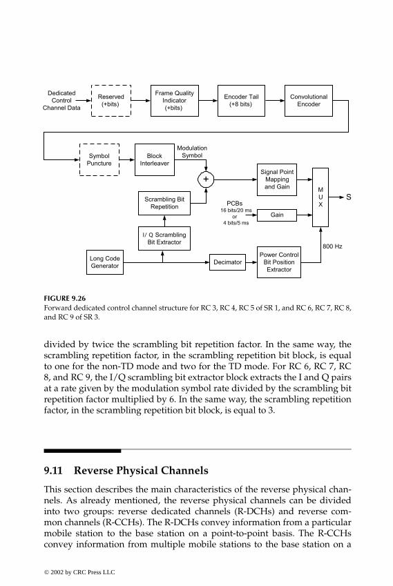
P1: FDJ
book CRC-Wireless November 18, 2001 14:38 Char Count= 264
FIGURE 9.26Forward dedicated control channel structure for RC 3, RC 4, RC 5 of SR 1, and RC 6, RC 7, RC 8,and RC 9 of SR 3.
divided by twice the scrambling bit repetition factor. In the same way, thescrambling repetition factor, in the scrambling repetition bit block, is equalto one for the non-TD mode and two for the TD mode. For RC 6, RC 7, RC8, and RC 9, the I/Q scrambling bit extractor block extracts the I and Q pairsat a rate given by the modulation symbol rate divided by the scrambling bitrepetition factor multiplied by 6. In the same way, the scrambling repetitionfactor, in the scrambling repetition bit block, is equal to 3.
9.11 Reverse Physical Channels
This section describes the main characteristics of the reverse physical chan-nels. As already mentioned, the reverse physical channels can be dividedinto two groups: reverse dedicated channels (R-DCHs) and reverse com-mon channels (R-CCHs). The R-DCHs convey information from a particularmobile station to the base station on a point-to-point basis. The R-CCHsconvey information from multiple mobile stations to the base station on a
© 2002 by CRC Press LLC
E:\Java for Engineers\VP Publication\Java for Engineers.vpThursday, April 25, 2002 9:27:36 AM
Color profile: DisabledComposite Default screen

P1: FDJ
book CRC-Wireless November 18, 2001 14:38 Char Count= 264
TABLE 9.12
Forward Dedicated Control Channel Parameters for RC 3, RC 4, RC 5 of SR 1,and RC 6, RC 7, RC 8, and RC 9 of SR 3
A B C D E F G H IConfiguration (bits/ms) (bits) (bits) (kbit/s) (rate) (factor) (deletion) (symbols) (ksymb/s)
RC3 24/5 — 16 9.6 — — — 192 38.4(SR1) 172/20 — 12 9.6 — — — 768 38.4
1 to 171/20 — 12 or 16 1.05 – — — — 768 38.49.55
RC4 24/5 — 16 9.6 — — — 96 19.2(SR1) 172/20 — 12 9.6 — — — 384 19.2
1 to 171/20 — 12 or 16 1.05 – — — — 384 19.29.55
RC5 24/5 0 16 9.6 — — None 192 38.4(SR1) 267/20 1 12 14.4 — — 4 of 12 768 38.4
1 to 268/20 0 12 or 16 1.05 – — — — 768 38.414.4
RC6 24/5 — 16 9.6 — — — 288 57.6(SR3) 172/20 — 12 9.6 — — — 1152 57.6
1 to 171/20 — 12 or 16 1.05 – — — — 1152 57.69.55
RC7 24/5 — 16 9.6 — — — 144 28.8(SR3) 172/20 — 12 9.6 — — — 576 28.8
1 to 171/20 — 12 or 16 1.05 – — — — 576 28.89.55
RC8 24/5 0 16 9.6 1/3 2× — 288 57.6(SR3) 267/20 1 12 14.4 1/4 1× — 1152 57.6
1 to 268/20 0 12 or 16 1.05 – 1/4 — — 1152 57.614.4
RC9 24/5 0 16 9.6 1/3 — — 144 28.8(SR3) 267/20 1 12 14.4 1/2 — — 576 28.8
1 to 268/20 0 12 or 16 1.05 – 1/2 — — 576 28.814.4
multipoint-to-point basis. The R-CCHs comprise the following channels: re-verse common control channel (R-CCCH), reverse enhanced access channel(R-EACH), and reverse access channel (R-ACH). The R-DCHs comprise thefollowing channels: reverse fundamental channel (R-FCH), reverse dedicatedcontrol channel (R-DCCH), reverse supplemental code channel (R-SCCH), re-verse supplemental channel (R-SCH), and reverse power control subchannel(R-PCSCH). In addition, a reverse pilot channel (R-PICH) is included forchannels operating in RCs other than RC 1 and RC 2.
© 2002 by CRC Press LLC
E:\Java for Engineers\VP Publication\Java for Engineers.vpThursday, April 25, 2002 9:27:36 AM
Color profile: DisabledComposite Default screen

P1: FDJ
book CRC-Wireless November 18, 2001 14:38 Char Count= 264
ReverseTransmission
Block
AccessChannel
Data88 bits/20 ms
S(t)
ConvolutionalEncoder(1/3, 9)
4.8 ksymb/s
SymbolRepetition
(x2)
BlockInterleaver
(32x18)
+
Long CodeGenerator
1.2288 Mchip/sLong CodeMask
OrthogonalModulator
[(64,6) WalshEncoder]
28.8 ksymb/s 307.2 kchip/s
EncoderTail
(+8 bits)
FIGURE 9.27Structure for the reverse access channel for SR 1.
9.11.1 Reverse Access Channel
The R-ACH is used to convey short signaling exchanges related to Layer 3and MAC messages. These messages are due to, for example, call origina-tions, responses to pages, and registrations. There is one R-ACH per reverseCDMA channel, with this R-ACH used in RC 1 and RC 2 for SR 1. It operateson a slotted random-access basis, with multiple access provided by meansof the slotted-ALOHA algorithm. To allow for backward compatibility withcdmaOne, R-ACH is identical to the access channel specified in cdmaOne.Thus, because cdmaOne does not support a pilot channel in the reverse link,R-PICH is not used to support R-ACH. The R-ACH structure is illustrated inFigure 9.27.
9.11.2 Reverse Enhanced Access Channel
The R-EACH, like the R-ACH, is used to convey short signaling exchangesrelated to Layer 3 and MAC messages. These messages are due to, for ex-ample, call originations, responses to pages, and registrations. In addition,it can be used to transmit moderate-sized data packets. R-EACH replacesR-ACH for RC 3, RC 4, RC 5, and RC 6, with one R-EACH provided per reverseCDMA channel. Access to R-EACH is provided by means of random-accessprotocols. An access probe in this channel comprises an enhanced accesspreamble (EAP), an enhanced access header (EAH), and the enhanced ac-cess data (EAD). Depending on how the access probe is transmitted, threemodes of operation are defined: basic access mode (BAM), power-controlledaccess mode (PCAM), and reservation access mode (RAM). In BAM, the accessprobe comprises EAP and EAD. In PCAM, the access probe consists of threeelements: EAP, EAH, and EAD. In RAM, the access probe encompasses EPAand EAH. To facilitate the detection process at the base station, R-PICH is
© 2002 by CRC Press LLC
E:\Java for Engineers\VP Publication\Java for Engineers.vpThursday, April 25, 2002 9:27:36 AM
Color profile: DisabledComposite Default screen

P1: FDJ
book CRC-Wireless November 18, 2001 14:38 Char Count= 264
ReverseTransmission
Block
EnhancedAccess
Channel Data32 bits per 5 ms
S(t)ConvolutionalEncoder(1/4, 9)
9.6 kbit/s
SymbolRepetition
(x4)
BlockInterleaver
(768symbols)
153.6 ksymb/s
EncoderTail
(+8 bits)
Frame QualityIndicator(+8 bits)
ModulationSymbol
...
FIGURE 9.28Channel structure for the header on the reverse enhanced access channel for SR 1 and SR 3.
transmitted during the enhanced access channel probe. The channel struc-ture of the header on the R-EACH is depicted in Figure 9.28. The channelstructure for the data on the R-EACH is shown in Figure 9.29. The variousparameters for the points (A, B, C, D, E, F) shown in Figure 9.29 are specifiedin Table 9.13. R-EACH uses Walsh code W8
2 .
9.11.3 Reverse Common Control Channel
The R-CCCH is used for transmission of control information and data fromone or more mobile stations. Typically, an R-CCCH is set up after permissionto transmit is obtained as a result of a request to transmit sent on R-EACH.R-CCCH can operate in two modes: reservation access mode (RAM) or desig-nated access mode (DAM). In RAM, the mobile station accesses R-EACH andR-CCCH. On R-EACH, it transmits an enhanced access preamble and an en-hanced access header in the enhanced access probe. On R-CCCH, it transmitsthe enhanced access data using closed-loop power control. In DAM, the mo-bile station responds to requests received on F-CCCH. R-CCCH can be powercontrolled in RAM or in DAM and may support soft handoff in RAM. EachR-CCCH is associated with a single F-CCCH, and can be used for signalingand user data if reverse traffic channels are not in use. Like R-EACH, R-CCCH
ReverseTransmission
Block
Common ControlChannel Data
orEnhanced Access
Channel Data
S(t)ConvolutionalEncoder(1/4, 9)
SymbolRepetition
BlockInterleaver
EncoderTail
(+8 bits)
Frame QualityIndicator(+bits)
ModulationSymbol
...
BA DC E F
FIGURE 9.29Channel structure for the data on the reverse enhanced access channel for SR 1 and SR 3.
© 2002 by CRC Press LLC
E:\Java for Engineers\VP Publication\Java for Engineers.vpThursday, April 25, 2002 9:27:36 AM
Color profile: DisabledComposite Default screen
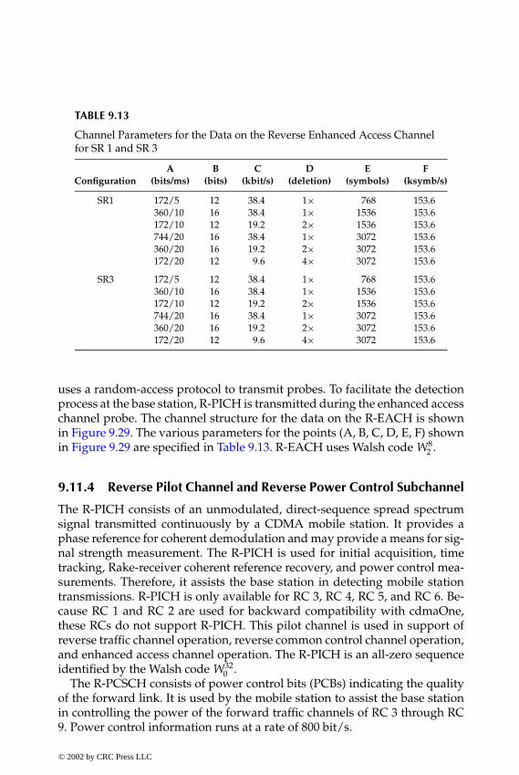
P1: FDJ
book CRC-Wireless November 18, 2001 14:38 Char Count= 264
TABLE 9.13
Channel Parameters for the Data on the Reverse Enhanced Access Channelfor SR 1 and SR 3
A B C D E FConfiguration (bits/ms) (bits) (kbit/s) (deletion) (symbols) (ksymb/s)
SR1 172/5 12 38.4 1× 768 153.6360/10 16 38.4 1× 1536 153.6172/10 12 19.2 2× 1536 153.6744/20 16 38.4 1× 3072 153.6360/20 16 19.2 2× 3072 153.6172/20 12 9.6 4× 3072 153.6
SR3 172/5 12 38.4 1× 768 153.6360/10 16 38.4 1× 1536 153.6172/10 12 19.2 2× 1536 153.6744/20 16 38.4 1× 3072 153.6360/20 16 19.2 2× 3072 153.6172/20 12 9.6 4× 3072 153.6
uses a random-access protocol to transmit probes. To facilitate the detectionprocess at the base station, R-PICH is transmitted during the enhanced accesschannel probe. The channel structure for the data on the R-EACH is shownin Figure 9.29. The various parameters for the points (A, B, C, D, E, F) shownin Figure 9.29 are specified in Table 9.13. R-EACH uses Walsh code W8
2 .
9.11.4 Reverse Pilot Channel and Reverse Power Control Subchannel
The R-PICH consists of an unmodulated, direct-sequence spread spectrumsignal transmitted continuously by a CDMA mobile station. It provides aphase reference for coherent demodulation and may provide a means for sig-nal strength measurement. The R-PICH is used for initial acquisition, timetracking, Rake-receiver coherent reference recovery, and power control mea-surements. Therefore, it assists the base station in detecting mobile stationtransmissions. R-PICH is only available for RC 3, RC 4, RC 5, and RC 6. Be-cause RC 1 and RC 2 are used for backward compatibility with cdmaOne,these RCs do not support R-PICH. This pilot channel is used in support ofreverse traffic channel operation, reverse common control channel operation,and enhanced access channel operation. The R-PICH is an all-zero sequenceidentified by the Walsh code W32
0 .The R-PCSCH consists of power control bits (PCBs) indicating the quality
of the forward link. It is used by the mobile station to assist the base stationin controlling the power of the forward traffic channels of RC 3 through RC9. Power control information runs at a rate of 800 bit/s.
© 2002 by CRC Press LLC
E:\Java for Engineers\VP Publication\Java for Engineers.vpThursday, April 25, 2002 9:27:36 AM
Color profile: DisabledComposite Default screen

P1: FDJ
book CRC-Wireless November 18, 2001 14:38 Char Count= 264
ReverseTransmission
Block
S(t)
...
MUX
All 0sReversePilot
PowerControl
PilotPowerControl
1152 x N
1 PCG = 1536 x N
FIGURE 9.30Channel structure for the reverse pilot channel and reverse power control subchannel.
R-PICH and R-PCSCH are time-multiplexed, and the total time of R-PICHand R-PCSCH represents the time of one power control group (PCG). OnePCG contains 1536 × N chips, where N is the SR number. One fourth of onePCG (384 × N chips) is composed of PCBs, whereas three fourths (1152 × Nchips) contains pilot channel bits. All PN chips sent on the R-PICH withinone PCG are transmitted at the same power level. R-PICH can be transmit-ted with the gated transmission mode enabled or disabled. When disabled,the mobile station shall transmit R-PCSCH in every PCG. When enabled, themobile station shall transmit R-PICH only in specific PCGs. The structures ofR-PICH and R-PCSCH are illustrated in Figure 9.30.
9.11.5 Reverse Fundamental Channel and Reverse SupplementalCode Channel
R-FCH and R-SCCH operate jointly as specified in RC 1 and RC 2 of SR 1.Such a combination provides higher data rate services and backward com-patibility with cdmaOne. RC 1 and RC 2, respectively, support Rate Set 1 andRate Set 2 of cdmaOne. One R-FCH and as many as seven R-SCCH can beused simultaneously for a reverse traffic channel. These channels transmit atvariable rates the changes occurring on a frame-by-frame basis. Therefore,the receiver is required to provide for rate detection. The basic transmissionrates are 1.2, 2.4, 4.8, and 9.6 kbit/s for RC 1, and 1.8, 3.6, 7.2, and 14.4 kbit/sfor RC 2. Figure 9.31 illustrates the R-FCH and R-SCCH channel structure.The dashed-line boxes in Figure 9.31 indicate the boxes present in RC 2 (butnot in RC 1). The various parameters for the points (A, B, C, D, E, F) shownin Figure 9.31 are specified in Table 9.14.
© 2002 by CRC Press LLC
E:\Java for Engineers\VP Publication\Java for Engineers.vpThursday, April 25, 2002 9:27:36 AM
Color profile: DisabledComposite Default screen

P1: FDJ
book CRC-Wireless November 18, 2001 14:38 Char Count= 264
FIGURE 9.31Reverse fundamental channel and reverse supplemental code control channel structure forRC 1 and RC 2 of SR 1.
9.11.6 Reverse Fundamental Channel and ReverseSupplemental Channel
R-FCH and R-SCH operate jointly as specified in RC 3 and RC 4 for SR 1, and inRC 5 and RC 6 for SR 3. These channels use frame structures in multiples of 20ms. A 5-ms frame can also be utilized but only by R-FCH (not by R-SCH).The5-ms structure is mainly used for signaling carrying purposes, whereas the 20-ms structure is mostly utilized to convey user information. Note, therefore,
TABLE 9.14
Reverse Fundamental Channel and Reverse Supplemental CodeControl Channel Parameters for RC 1 and RC 2 of SR 1.
A B C D E FConfiguration (bits/ms) (bits) (kbit/s) (rate) (factor) (ksymb/s)
RC1 16/20 0 1.2 1/3 8× 28.8(SR1) 40/20 0 2.4 1/3 4× 28.8
80/20 8 4.8 1/3 2× 28.8172/20 12 9.6 1/3 1× 28.8
RC2 21/20 6 1.8 1/2 8× 28.8(SR1) 55/20 8 3.6 1/2 4× 28.8
125/20 10 7.2 1/2 2× 28.8267/20 12 14.4 1/2 1× 28.8
© 2002 by CRC Press LLC
E:\Java for Engineers\VP Publication\Java for Engineers.vpThursday, April 25, 2002 9:27:36 AM
Color profile: DisabledComposite Default screen

P1: FDJ
book CRC-Wireless November 18, 2001 14:38 Char Count= 264
ReverseTransmission
Block
TrafficChannel Data
S(t)
Convolutionalor TurboEncoder
Reserved/Encoder Tail
(+8 bits)
FrameQuality
Indicator
ReservedBits
(+bits)
...Block
InterleaverSymbol
RepetitionSymbol
Puncture
ModulationSymbol
A DB C E
F G H I
FIGURE 9.32Reverse fundamental channel and reverse supplemental code channel structure for RC 3 andRC 4 of SR 1, and RC 5 and RC 6 of SR 3.
that an F-SCH does not transport signaling traffic. These channels use or-thogonal variable length Walsh codes with their lengths ranging from 2 to128, depending on the desired data rate and on the QoS requirements. OneR-FCH and up to two R-SCHs can be used simultaneously for a reverse traf-fic channel. These channels transmit at variable rates the changes occurringon a frame-by-frame basis. Therefore, the receiver is required to provide forrate detection. The QoS target can be set individually for each channel, asrequired. Figure 9.32 illustrates the R-FCH and R-SCH channel structure. Thevarious parameters for the points (A, B, C, D, E, F, G, H, I) shown in Figure 9.32are specified in Table 9.15. A convolutional encoder or turbo encoder is useddepending on the number of encoder input bits. Above a certain value turboencoding is used; otherwise, convolutional encoding with constraint lengthof 9 is used. The dashed-line box in Figure 9.32 indicates the box present onlyin RC 4 and RC 6. In Table 9.15, n is the length of the frame in multiplesof 20 ms.
9.11.7 Reverse Dedicated Control Channel
The R-DCCH is used for transmission of higher-level data and control infor-mation while a call is in progress. It is supported by RCs other than RC 1 andRC 2. The R-DCCH structure is illustrated in Figure 9.33. The various param-eters for the points (A, B, C, D, E, F, G) shown in Figure 9.33 are specified inTable 9.16.
© 2002 by CRC Press LLC
E:\Java for Engineers\VP Publication\Java for Engineers.vpThursday, April 25, 2002 9:27:36 AM
Color profile: DisabledComposite Default screen

P1: FDJ
book CRC-Wireless November 18, 2001 14:38 Char Count= 264
TABLE 9.15
Reverse Fundamental Channel and Reverse Supplemental Code ChannelParameters for RC 3 and RC 4 of SR 1, and RC 5 and RC 6 of SR 3
A B C D E F GConfiguration (bits/ms) (bits) (bits) (kbit/s) (deletion) (symbols) (ksymb/s)
RC3 24/5 — 16 9.6 — 384 76.8(SR1) 172/20 — 12 9.6 — 1536 76.8
1 to 171/20 — 12 or 16 1.05–9.55 — 1536 76.8
RC4 24/5 0 16 9.6 None 384 76.8(SR1) 267/20 1 12 14.4 8 of 24 1536 76.8
1 to 268/20 0 12 or 16 1.05–14.4 — 1536 76.8
RC5 24/5 — 16 9.6 — 384 76.8(SR3) 172/20 — 12 9.6 — 1536 76.8
1 to 171/20 — 12 or 16 1.05–9.55 — 1536 76.8
RC6 24/5 0 16 9.6 None 384 76.8(SR3) 267/20 1 12 14.4 8 of 24 1536 76.8
1 to 268/20 0 12 or 16 1.05–14.4 — 1536 76.8
9.12 High-Rate Packet Data Access
cdma 2000 1× systems use a dedicated RF channel for high-rate packet dataservices. Such a solution evolved from the high data rate (HDR) technol-ogy (see Chapter 6) to the 1× evolved high-speed data only (1×EV-DO) de-sign, both projects presenting almost indistinguishable characteristics. Thecdma2000 high-rate packet data air interface (also known as 1×EV-DO) isoptimized for non-real-time, high-speed packet data services and has beenincluded in the cdma2000 specifications to increase its data transmission ca-pability. The cdma2000 high-rate packet data access (HRPDA) feature com-pletes the set of cdma2000 RCs already explored in this chapter. In particular,HRPDA constitutes the RC 10 in the forward link and RC 7 in the reverselink.
In HRPDA, the access terminal (user terminal) and the access network(base station) jointly determine the highest rate a subscriber can support atany instant. This is accomplished by means of the deployment of a combi-nation of techniques based on channel measurement, channel control, andinterference suppression and mitigation. In particular, each access terminalassesses the quality of the signals (carrier-to-interference ratio, or CIR) re-ceived from neighboring access networks. The best access network is chosen
© 2002 by CRC Press LLC
E:\Java for Engineers\VP Publication\Java for Engineers.vpThursday, April 25, 2002 9:27:36 AM
Color profile: DisabledComposite Default screen

P1: FDJ
book CRC-Wireless November 18, 2001 14:38 Char Count= 264
ReverseTransmission
Block
DedicatedControl
Channel Data
S(t)
ConvolutionalEncoder(1/4, 9)
EncoderTail
(+8 bits)
FrameQuality
Indicator
CA B D
E
ReservedBits
(+bits)
...Block
Interleaver
SymbolRepetition
(x2)
SymbolPuncture
F G
ModulationSymbol
FIGURE 9.33Reverse dedicated control channel structure for RC 3 and RC 4 of SR 1, and RC 5 and RC 6 ofSR 3.
and its CIR, or equivalently the supportable data rate value, is conveyed tothe corresponding access network. Note that this may change continuouslybecause of the nonstationary condition of the wireless channel (motion of theuser, change of the propagation conditions, etc.). Therefore, the monitoringof the CIRs of the various access networks and the selection of the best accessnetwork must be performed continuously, this having a direct implicationon the supportable data rate. Packet transmissions on the forward link, then,occur with data rates and packet durations that vary in accordance with theuser channel conditions. Hence, it may be said that the HRPDA forward linksupports dynamic data rates. Packet transmissions on the reverse link, in turn,occur with variable rates but fixed packet duration. The HRPDA reverse linkdoes not support dynamic data rates.
In the descriptions that follow, and differently from what appears in theHRPDA documents, the same convention as that used to name the cdma2000physical channels has been adopted.
9.12.1 Forward Link—General
The forward CDMA channel, using a dedicated 1× RF channel for data trans-mission purposes, comprises the following time-multiplexed channels:
© 2002 by CRC Press LLC
E:\Java for Engineers\VP Publication\Java for Engineers.vpThursday, April 25, 2002 9:27:36 AM
Color profile: DisabledComposite Default screen

P1: FDJ
book CRC-Wireless November 18, 2001 14:38 Char Count= 264
TABLE 9.16
Reverse Dedicated Control Channel Structure for RC 3 and RC 4 of SR 1, and RC 5and RC 6 of SR 3
A B C D E F G H IConfiguration (bits/ms) (bits) (bits) (kbit/s) (rate) (factor) (deletion) (symbols) (ksymb/s)
RC3 24/5 — 16 9.6 1/4 2× None 384 76.8(SR1) 16/20 — 6 1.5 1/4 16× 1 of 5 1,536 76.8
40/20n — 6 2.7/n 1/4 8× 1 of 9 1,536 76.8/n80/20n — 8 4.8/n 1/4 4× None 1,536 76.8/n
172/20n — 12 9.6/n 1/4 2× None 1,536 76.8/n360/20n — 16 19.2/n 1/4 1× None 1,536 76.8/n744/20n — 16 38.4/n 1/4 1× None 3,072 153.6/n
1,512/20n — 16 76.8/n 1/4 1× None 6,144 307.2/n3,048/20n — 16 153.6/n 1/4 1× None 12,288 614.4/n6,120/20n — 16 307.2/n 1/4 1× None 12,288 614.4/n
1 to 6,119/20n — — — — — — — —
RC4 24/5 0 16 9.6 1/4 2× None 384 76.8(SR1) 21/20 1 6 1.8 1/4 16× 8 of 24 1,536 76.8
55/20n 1 8 3.6/n 1/4 8× 8 of 24 1,536 76.8/n125/20n 1 10 7.2/n 1/4 4× 8 of 24 1,536 76.8/n267/20n 1 12 14.4/n 1/4 2× 8 of 24 1,536 76.8/n552/20n 0 16 28.8/n 1/4 1× 4 of 12 1,536 76.8/n
1,128/20n 0 16 57.6/n 1/4 1× 4 of 12 3,072 153.6/n2,280/20n 0 16 115.2/n 1/4 1× 4 of 12 6,144 307.2/n4,584/20n 0 16 230.4/n 1.4 1× 4 of 12 12,288 614.4/n
1 to 3,048/20n — — — — — — — —
RC5 24/5 — 16 9.6 1/4 2× None 384 76.8(SR3) 16/20 — 6 1.5 1/4 16× 1 of 5 1,536 76.8
40/20n — 6 2.7/n 1/4 8× 1 of 9 1,536 76.8/n80/20n — 8 4.8/n 1/4 4× None 1,536 76.8/n
172/20n — 12 9.6/n 1/4 2× None 1,536 76.8/n360/20n — 16 19.2/n 1/4 1× None 1,536 76.8/n744/20n — 16 38.4/n 1/4 1× None 3,072 153.6/n
1,512/20n — 16 76.8/n 1/4 1× None 6,144 307.2/n3,048/20n — 16 153.6/n 1/4 1× None 12,288 614.4/n6,120/20n — 16 307.2/n 1/3 1× None 18,432 921.6/n
12,264/20n — 16 614.4/n 1/3 1× None 36,864 1843.2/n1 to 12,263/20n — — — — — — — —
RC6 24/5 0 16 9.6 1/4 2× None 384 76.8(SR3) 21/20 1 6 1.8 1/4 16× 8 of 24 1,536 76.8
55/20n 1 8 3.6/n 1/4 8× 8 of 24 1,536 76.8/n125/20n 1 10 7.2/n 1/4 4× 8 of 24 1,536 76.8/n267/20n 1 12 14.4/n 1/4 2× 8 of 24 1,536 76.8/n552/20n 0 16 28.8/n 1/4 1× None 2,304 115.2/n
1,128/20n 0 16 57.6/n 1/4 1× None 4,608 230.4/n
© 2002 by CRC Press LLC
E:\Java for Engineers\VP Publication\Java for Engineers.vpThursday, April 25, 2002 9:27:36 AM
Color profile: DisabledComposite Default screen

P1: FDJ
book CRC-Wireless November 18, 2001 14:38 Char Count= 264
TABLE 9.16
Continued
A B C D E F G H IConfiguration (bits/ms) (bits) (bits) (kbit/s) (rate) (factor) (deletion) (symbols) (ksymb/s)
2,280/20n 0 16 115.2/n 1/4 1× None 9,216 460.8/n4,584/20n 0 16 230.4/n 1/4 1× None 18,432 921.6/n9,192/20n 0 16 460.8/n 1/4 1× None 36,864 1843.2/n
20,712/20n 0 16 1036.8/n 1/2 1× 2 of 18 36,864 1843.2/n1 to 18,408/20n — — — — — — — —
� Pilot Channel (F-PICH). The F-PICH is used for synchronization pur-poses at the access terminal.
� Forward Medium Access Control (MAC) Channel (F-MACCH). TheF-MACCH consists of two subchannels:Reverse Power Control Channel (F-RPCCH). The F-RPCCH is used for
power control purposes.Reverse Activity Channel (F-RACH). The F-RACH conveys a reverse-
link activity bit stream.� Control Channel (F-CCH). The F-CCH conveys control messages as
well as user traffic.� Forward Traffic Channel (F-TCH). The F-TCH carries user data at vari-
able rate.
Each channel is further code-division-multiplexed into quadrature Walshchannels. Each slot in the forward link contains 2048 chips and, at a chiprate of 1.2288 Mchip/s, the corresponding slot duration is 2048 ÷ 1228.8 =1.66 . . . ms. Within each slot, F-PICH, F-MACCH, and F-CCH or F-TCH aretime-multiplexed and transmitted at the same power level. The data withinF-TCH and F-CCH are encoded into blocks, which in the HRPDA documentsare called physical layer packets. After the encoding operation, the follow-ing signal processing techniques are sequentially applied: scrambling, in-terleaving, modulation, sequence repetition, and puncturing. The resultingsequences are then demultiplexed into 16 pairs of parallel streams, a pairconstituted by the in-phase (I) and quadrature (Q) branches. These parallelstreams are covered with a distinct 16-ary Walsh function at a chip rate toyield Walsh symbols at 76.8 ksymb/s. These symbols are then added to com-pose a single I stream and a single Q stream running at a chip rate of 1.2288Mchip/s. Preamble, pilot channel, MAC channels, and traffic channels arethen time-multiplexed and quadrature-spread, modulated, and transmitted.The physical layer packets can be transmitted in 1 through 16 slots. If more
© 2002 by CRC Press LLC
E:\Java for Engineers\VP Publication\Java for Engineers.vpThursday, April 25, 2002 9:27:36 AM
Color profile: DisabledComposite Default screen
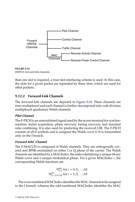
P1: FDJ
book CRC-Wireless November 18, 2001 14:38 Char Count= 264
ForwardHRPDA
Channels
MACChannels
Pilot Channel
Control Channel
Traffic Channel
Reverse Activity Channel
Reverse Power Control Channel
FIGURE 9.34HRPDA forward-link channels.
than one slot is required, a four-slot interlacing scheme is used. In this case,the slots for a given packet are separated by three slots, which are used forother packets.
9.12.2 Forward-Link Channels
The forward-link channels are depicted in Figure 9.34. These channels aretime-multiplexed and each channel is further decomposed into code divisionmultiplexed quadrature Walsh channels.
Pilot Channel
The F-PICH is an unmodulated signal used by the access terminal for synchro-nization, initial acquisition, phase recovery, timing recovery, and maximalratio combining. It is also used for predicting the received CIR. The F-PICHconsists of all-0 symbols and is assigned the Walsh cover 0. It is transmittedonly on the I branch.
Forward MAC Channel
The F-MACCH is composed of Walsh channels. They are orthogonally cov-ered and BPSK-modulated on either I or Q phase of the carrier. The Walshchannels are identified by a MACIndex, the index identifying a unique 64-aryWalsh cover and a unique modulation phase. For a given MACIndex i , thecorresponding Walsh functions are
W64i=2 for i = 0; 2; . . . ; 62
W64(i−1)=2+32 for i = 1; 3; . . . ; 63
The even-numbered MACIndex identifies the MAC channels to be assignedto the I branch, whereas the odd-numbered MACIndex identifies the MAC
© 2002 by CRC Press LLC
E:\Java for Engineers\VP Publication\Java for Engineers.vpThursday, April 25, 2002 9:27:36 AM
Color profile: DisabledComposite Default screen

P1: FDJ
book CRC-Wireless November 18, 2001 14:38 Char Count= 264
channels to be assigned to the Q branch. The symbols for the Walsh coversare transmitted four times per slot, with each burst containing 64 chips. Thebursts immediately precede or follow the pilot bursts of each slot.
Reverse Power Control Channel. The F-RPCCH is used for the transmission ofthe reverse power control (RPC) bit stream directed to a given access terminalwith an open connection. It is assigned to one of the MAC channels available.The F-RPCCH is transmitted at a rate of 600 bit/s, with each RPC symboltransmitted four times per slot, in bursts of 64 chips.
Reverse Activity Channel. The F-RACH is used for the transmission ofthe reverse activity bit (RAB) stream. It uses the MAC channel withMACIndex 4 and operates at a rate of 600/RABLength bit/s. RABLength is afield in the public data of the traffic channel assignment of the route updateprotocol.
Control Channel
The F-CCH is used to transmit broadcast messages as well as access-terminal-directed messages. The messages are transmitted at a rate of 76.8 or 38.4ksymb/s. Its modulation characteristics are the same as those for the F-TCHat the corresponding rates. The F-CCH has a preamble that is covered by abiorthogonal cover sequence with MACIndex 2 or 3, used, respectively, forrates 76.8 and 38.4 kbit/s.
Forward Traffic Channel
The F-TCH is used to convey physical layer packets. It is a packet-based,variable-rate channel operating at rates ranging from 38.4 to 2457.6 kbit/s.It makes use of a preamble, consisting of all-0 symbols transmitted on theI branch. The preamble sequence is covered by a 32-chip biorthogonal se-quence, which is specified in terms of the 32-ary Walsh functions and theirbit-by-bit complements. These Walsh functions are given, respectively, as
W32i=2 for i = 0; 2; . . . ; 62
W32(i−1)=2 for i = 1; 3; . . . ; 63
The physical layer packets transmitted on the F-TCH are encoded with coderates of 1/3 or 1/5 with 6 bits of the TAIL field discarded. A sequence of sig-nal processing techniques, such as turbo encoding, turbo interleaving, scram-bling, and channel interleaving, is applied before modulation. Different mod-ulation schemes, such as QPSK, 8-PSK, and 16-QAM, are used depending onthe data rate. After modulation, sequence repetition and symbols puncturing
© 2002 by CRC Press LLC
E:\Java for Engineers\VP Publication\Java for Engineers.vpThursday, April 25, 2002 9:27:36 AM
Color profile: DisabledComposite Default screen

P1: FDJ
book CRC-Wireless November 18, 2001 14:38 Char Count= 264
are applied. The I and Q streams are then demultiplexed into 16 parallelstreams. The individual streams at the demultiplexer output are assigned to 1of 16 distinct Walsh channels W16
k , k = 0; 1; . . . ; 15. The modulated symbols oneach branch are scaled to maintain a constant transmit power, independentlyof the data rate. The scaled Walsh chips are summed on a chip-by-chip basis.
9.12.3 Forward-Link Quadrature Spreading
The spreading sequence used for quadrature spreading has a length of 215 PNchips (32,768 chips). The characteristic polynomials for the I and Q branchesare given by
CshortI = 1 + x2 + x6 + x7 + x8 + x10 + x15
CshortQ = 1 + x3 + x4 + x5 + x9 + x10 + x11 + x12 + x15
9.12.4 Forward-Link Data Rates and Modulation Parameters
The date rates supported by the forward traffic channel are shown inTable 9.17. As already mentioned, the data rates supported by the controlchannel are 76.8 or 38.4 kbit/s. Table 9.17 also shows the modulation param-eters for the forward link.
9.12.5 Forward-Link Transmission
Figure 9.35 summarizes the transmission chain of the HRPDA forward link.
9.12.6 Reverse Link—General
The reverse CDMA channel, using a dedicated 1× RF channel for data trans-mission purposes, comprises the following channels:
� Reverse Traffic Channel (R-TCH). The R-TCH is used by the access termi-nal to transmit user-specific traffic or signaling information. It consistsof four channels:Pilot Channel (R-TPICH). The R-TPICH is used by the access network
for coherent demodulation of the R-TDCH.Reverse Rate Indicator Channel (R-RRICH). The R-RRICH is used to
indicate the data transmission rate on the R-TDCH.Data Rate Control (R-DRCCH). The R-DRCCH is used by the access
terminal to indicate to the access network the supportable F-TCHdata rate. It also informs the best-serving sector on the forwardCDMA channel.
© 2002 by CRC Press LLC
E:\Java for Engineers\VP Publication\Java for Engineers.vpThursday, April 25, 2002 9:27:36 AM
Color profile: DisabledComposite Default screen

P1: FDJ
book CRC-Wireless November 18, 2001 14:38 Char Count= 264
TABLE 9.17
RC Characteristics for Forward Traffic Channel andControl Channel.
PreamblePilot
MACData Rates Coding Modulation Data
(kbit/s) Bits Slots Rate Scheme (chips)
38.4 1024 16 1/5 QPSK
1,0243,0724,096
24,576
76.8 1024 8 1/5 QPSK
5121,5362,048
12,288
153.6 1024 4 1/5 QPSK
256768
1,0246,144
307.2 1024 2 1/5 QPSK
128384512
3,072
614.4 1024 1 1/3 QPSK
64192256
1,536
307.2 2048 4 1/3 QPSK
128768
1,0246,272
614.4 2048 2 1/3 QPSK
64384512
3,136
1228.8 2048 1 1/3 QPSK
64192256
1,536
921.6 3072 2 1/3 8-PSK
64384512
3,136
© 2002 by CRC Press LLC
E:\Java for Engineers\VP Publication\Java for Engineers.vpThursday, April 25, 2002 9:27:36 AM
Color profile: DisabledComposite Default screen

P1: FDJ
book CRC-Wireless November 18, 2001 14:38 Char Count= 264
TABLE 9.17
Continued
PreamblePilot
MACData Rates Coding Modulation Data
(kbit/s) Bits Slots Rate Scheme (chips)
1843.2 3072 1 1/3 8-PSK
64192256
1,536
1228.8 4096 2 1/3 16-QAM
64384512
3,136
2457.6 4096 1 1/3 16-QAM
64192256
1,536
Acknowledgment Channel (R-ACKCH). The R-ACKCH is used to in-form the access network about the success of the reception of thedata packet transmitted on the F-TCH.
Data Channel (R-TDCH). The R-TDCH is used by the access terminalfor the actual transmission of data.
� Access Channel (R-ACH). The R-ACH is used by the access terminalto initiate communication with the access network. It is also used torespond to an access terminal directed message. The R-ACH consistsof two channels:Pilot Channel (R-APICH). The R-APICH is used by the access network
for coherent demodulation of the R-ADCH.Data Channel (R-ADCH). The R-ADCH conveys data concerning user
access.
The R-RRICH symbols are time-division-multiplexed with the R-TPICH;the resulting channel is still referred to as pilot channel. The pilot channel,the R-DRCCH, the R-ACKCH, and the R-TDCH are orthogonally spread byWalsh functions of length 4, 8, or 16. Each R-TCH is identified by a user longcode. In the same way, the R-ACH for each sector is identified by a distinctaccess channel long code. The frame duration for the R-ACH and R-TCH is26.66... ms, with each frame consisting of 16 slots. Each slot contains 2048chips and has a duration of 1.66... ms.© 2002 by CRC Press LLC
E:\Java for Engineers\VP Publication\Java for Engineers.vpThursday, April 25, 2002 9:27:36 AM
Color profile: DisabledComposite Default screen
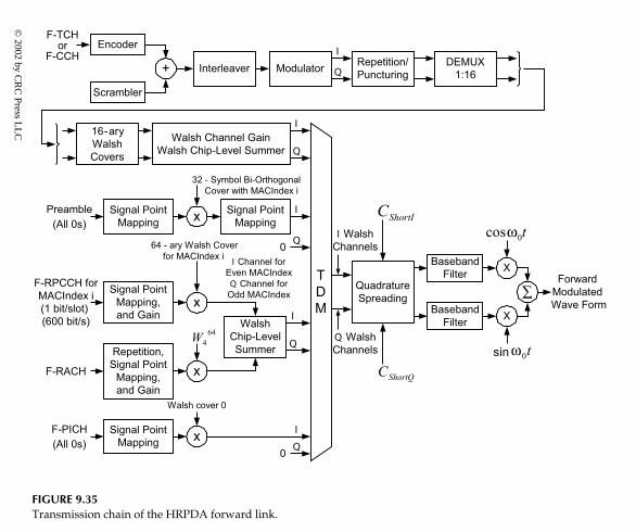
P1:FDJ
bookC
RC
-Wireless
Novem
ber18,2001
14:38C
harC
ount=264
FIGURE 9.35Transmission chain of the HRPDA forward link.
© 2002 by C
RC
Press LL
C
E:\Java for Engineers\VP Publication\Java for Engineers.vp
Thursday, April 25, 2002 9:27:36 AM
Color profile: Disabled
Composite Default screen

P1: FDJ
book CRC-Wireless November 18, 2001 14:38 Char Count= 264
ReverseHRPDA
Channels
MACChannels
Pilot Channel
Data Channel
Ack Channel
Reverse Rate Indicator Channel
Data Rate Control Channel
TrafficChannels
AccessChannels
Pilot Channel
Data Channel
FIGURE 9.36HRPDA reverse channels.
9.12.7 Reverse-Link Channels
The reverse-link channels are depicted in Figure 9.36.
Reverse Traffic Channel
The R-TCH is used by the access terminal to transmit user-specific traffic tothe network. In the same way, it is used to transmit signaling information. TheR-TCH is composed of the R-TPICH, R-RRICH, R-DRCCH, and R-ACKCH.
Pilot Channel. The R-TPICH is an unmodulated signal used by the accessnetwork for coherent demodulation of the R-TDCH. It consists of all-0 sym-bols and is time-multiplexed with the R-RRICH, both sharing the same Walshchannel and both being transmitted at the same power.
Reverse Rate Indicator Channel. The R-RRICH is used to indicate the datatransmission rate on the R-TDCH. The RRI symbol indicating such a ratecontains 3 bits and is transmitted at a rate of one symbol per 16-slot phys-ical layer packet. Each symbol is encoded into a 7-bit code word and eachcode word is repeated 37 times. After the repetition process, the last 3 bitsare discarded. Such operations yield 256 binary symbols per physical layerpacket. This is then time-multiplexed with the R-TPICH and spread with the16-chip Walsh function W16
0 , yielding 256 RRI chips per slot. These RRI chipsoccupy the first 256 chip positions of every slot and are transmitted on theI channel.
© 2002 by CRC Press LLC
E:\Java for Engineers\VP Publication\Java for Engineers.vpThursday, April 25, 2002 9:27:36 AM
Color profile: DisabledComposite Default screen

P1: FDJ
book CRC-Wireless November 18, 2001 14:38 Char Count= 264
Data Rate Control Channel. The R-DRCCH is used by the access terminal toindicate to the access network the supportable F-TCH data rate. It also informsthe selected serving sector on the forward CDMA channel. Four bits are usedto indicate the requested F-TCH data rate. The DRC values are transmitted ata rate of 600/DRCLength DRC values per second. The DRCLength parameteris conveyed by the forward traffic channel MAC protocol. The DRC valuesare block-encoded into 8-bit biorthogonal code words, and each code word istransmitted twice per slot. Each bit of the repeated code word is spread by theWalsh function W8
i , i = 0; 1; . . . ; 7, where i is the DRCCover. Each resultingWalsh chip is further spread by the Walsh function W16
8 and the R-DRCCH istransmitted on the Q channel.
Acknowledgment Channel. The R-ACKCH is used to inform the access net-work about the success of the reception of the data packet transmitted onthe F-TCH. An R-ACKCH is transmitted by the access terminal whenever anF-TCH directed to it is detected. The R-ACKCH is BPSK-modulated, a bit 0indicating a successful reception and a bit 1 indicating an unsuccessful re-ception. The success of a reception is assessed by means of the FCS (framecheck sum) mechanism. The R-ACKCH transmitted in response to an F-TCHoccurring on time slot n of the forward channel occupies the time slot n + 3 onthe reverse channel. It is identified by the Walsh function W8
4 and transmittedon the I channel.
Data Channel. The R-TDCH is used by the access terminal for the actualtransmission of data. Transmissions of the R-TDCH within a frame occur atslot FrameOffset; the FrameOffset is public data of the reverse traffic chan-nel MAC protocol. The data transmitted on the R-TCH are encoded, blockinterleaved, sequence repeated, and orthogonally spread by Walsh func-tion W4
2 .
Access Channel
The R-ACH is used by the access terminal to initiate communication withthe access network. It is also used to respond to an access terminal–directedmessage. The R-ACH consists of the R-APICH and R-ADCH. Access is car-ried out by means of access probes. An access probe consists of a preamblefollowed by a number of access channel physical layer packets. The pream-ble transmission makes use of the R-APICH only. On the other hand, duringthe access channel physical layer transmission, both R-APICH and R-ADCHare transmitted. During the preamble portion of the probe, the power of theR-APICH is higher than it is during the data portion of the probe. The phys-ical layer packets on the access channel are transmitted at a fixed rate of9.6 kbit/s.
© 2002 by CRC Press LLC
E:\Java for Engineers\VP Publication\Java for Engineers.vpThursday, April 25, 2002 9:27:36 AM
Color profile: DisabledComposite Default screen

P1: FDJ
book CRC-Wireless November 18, 2001 14:38 Char Count= 264
Pilot Channel. The R-APICH is used by the access network for coherent de-modulation of the R-ADCH. It is an unmodulated signal consisting of all-0symbols. It is transmitted continuously during the access channel transmis-sion. The R-APICH uses the Walsh function W16
0 and is transmitted on the Ichannel.
Data Channel. The R-ADCH conveys data concerning user access. Everyaccess probe is composed of one or more physical layer packets transmittedon the R-ADCH. These packets are transmitted at a fixed rate of 9.6 kbit/s onthe Q channel. The R-ADCH uses the Walsh function W4
2 .
9.12.8 Reverse-Link Quadrature Spreading
After the orthogonal spreading, the R-ACKCH, R-DRCH, and R-TDCH chipsequences are given a gain relative to that of the R-TPICH. A similar pro-cess occurs with the R-ADCH, with its gain relative to that of R-APICH. Anadequate combination of these channels forms the I channel and the Q chan-nel sequences, and these sequences are quadrature spread. The quadraturespreading occurs at a rate of 1.2288 Mchip/s and is equivalent to a com-plex multiplication operation of these I and Q channels and I and Q PNsequences. These PN sequences, in turn, are obtained as follows. The I PNsequence is the result of the multiplication of the I long-code PN sequenceand the I access terminal common short PN sequence. The Q PN sequence isobtained by the multiplication of the decimated Q long-code PN sequenceand the Q access terminal common short PN sequence. The access terminalcommon short-code PN sequences have a period of 215 chips (32,768 chips),with its I and Q components based on the following respective characteristicpolynomials:
CshortI = 1 + x5 + x7 + x8 + x9 + x13 + x15
CshortQ = 1 + x3 + x4 + x5 + x6 + x10 + x11 + x12 + x15
The long PN code, Clong, is generated by 42-stage linear feedback shiftregisters running at 1.2288 Mchip/s. Its characteristic polynomial is given as
Clong = 1 + x + x2 + x3 + x5 + x6 + x7 + x10 + x16 + x17 + x18
+ x19 + x21 + x22 + x25 + x26 + x27 + x31 + x33 + x35 + x42
Its I and Q components are generated by a modulo-2 inner product of the 42-bit state vector of the sequence generator and two 42-bit masks. These masksvary depending on the channel on which the access terminal is transmitting.
© 2002 by CRC Press LLC
E:\Java for Engineers\VP Publication\Java for Engineers.vpThursday, April 25, 2002 9:27:36 AM
Color profile: DisabledComposite Default screen
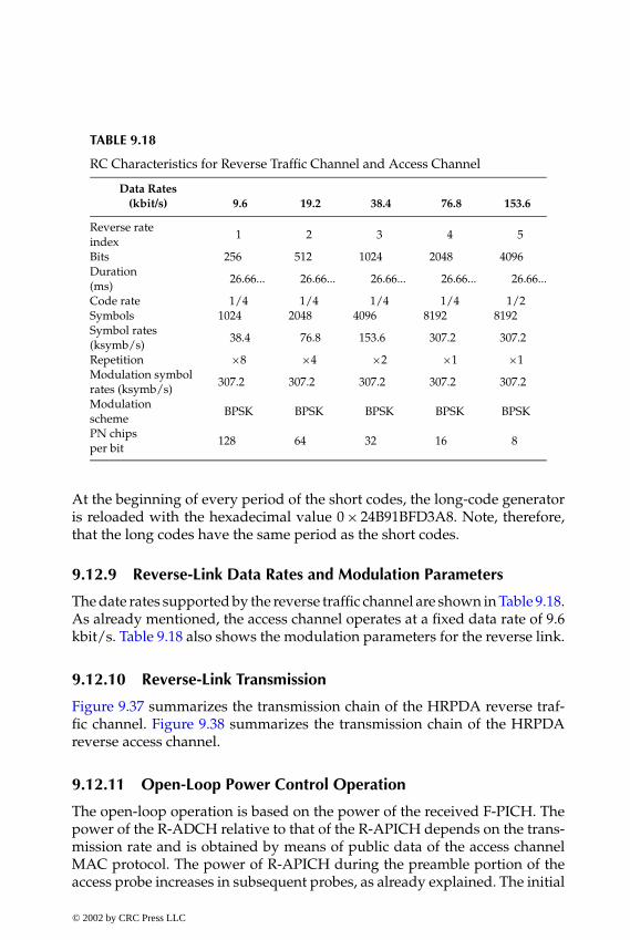
P1: FDJ
book CRC-Wireless November 18, 2001 14:38 Char Count= 264
TABLE 9.18
RC Characteristics for Reverse Traffic Channel and Access Channel
Data Rates(kbit/s) 9.6 19.2 38.4 76.8 153.6
Reverse rateindex
1 2 3 4 5
Bits 256 512 1024 2048 4096Duration(ms)
26.66... 26.66... 26.66... 26.66... 26.66...
Code rate 1/4 1/4 1/4 1/4 1/2Symbols 1024 2048 4096 8192 8192Symbol rates(ksymb/s)
38.4 76.8 153.6 307.2 307.2
Repetition ×8 ×4 ×2 ×1 ×1Modulation symbolrates (ksymb/s)
307.2 307.2 307.2 307.2 307.2
Modulationscheme
BPSK BPSK BPSK BPSK BPSK
PN chipsper bit
128 64 32 16 8
At the beginning of every period of the short codes, the long-code generatoris reloaded with the hexadecimal value 0 × 24B91BFD3A8. Note, therefore,that the long codes have the same period as the short codes.
9.12.9 Reverse-Link Data Rates and Modulation Parameters
The date rates supported by the reverse traffic channel are shown in Table 9.18.As already mentioned, the access channel operates at a fixed data rate of 9.6kbit/s. Table 9.18 also shows the modulation parameters for the reverse link.
9.12.10 Reverse-Link Transmission
Figure 9.37 summarizes the transmission chain of the HRPDA reverse traf-fic channel. Figure 9.38 summarizes the transmission chain of the HRPDAreverse access channel.
9.12.11 Open-Loop Power Control Operation
The open-loop operation is based on the power of the received F-PICH. Thepower of the R-ADCH relative to that of the R-APICH depends on the trans-mission rate and is obtained by means of public data of the access channelMAC protocol. The power of R-APICH during the preamble portion of theaccess probe increases in subsequent probes, as already explained. The initial
© 2002 by CRC Press LLC
E:\Java for Engineers\VP Publication\Java for Engineers.vpThursday, April 25, 2002 9:27:36 AM
Color profile: DisabledComposite Default screen

P1: FDJ
book CRC-Wireless November 18, 2001 14:38 Char Count= 264
FIGURE 9.37Transmission chain of the HRPDA reverse traffic channel.
© 2002 by CRC Press LLC
E:\Java for Engineers\VP Publication\Java for Engineers.vpThursday, April 25, 2002 9:27:36 AM
Color profile: DisabledComposite Default screen

P1: FDJ
book CRC-Wireless November 18, 2001 14:38 Char Count= 264
FIGURE 9.38Transmission chain of the HRPDA reverse access channel.
power of the R-TPICH is set to be equal to that of the R-APICH at the end ofthe last access probe minus the difference in the forward-link mean receivedsignal power from the end of the last access probe to the start of the reversetraffic channel transmission. The subsequent adjustments of the R-TPICH areobtained by means of the closed-loop power control operation. The initialpower of the R-APICH, X0, is set as
X0 = − Mean Received Power (dBm)+ OpenLoopAdjust+ ProbeInitialAdjust
© 2002 by CRC Press LLC
E:\Java for Engineers\VP Publication\Java for Engineers.vpThursday, April 25, 2002 9:27:36 AM
Color profile: DisabledComposite Default screen

P1: FDJ
book CRC-Wireless November 18, 2001 14:38 Char Count= 264
where Mean Received Power is the power of the received F-PICH, and Open-LoopAdjust and ProbeInitialAdjust are public data from the access channelMAC protocol.
9.12.12 Closed-Loop Power Control Operation
The closed-loop operation implements corrections to the power estimated inthe open-loop operation. In this case, the access terminal adjusts the meanoutput power of the R-TPICH in response to each power control bit receivedon the F-RPCCH. The step size used to increase or decrease the output poweris available as public data of the reverse traffic channel MAC protocol.
After a connection is established, the access network continuously monitorsthe reverse-link signal quality. Based on such monitoring, the access networksets the appropriate bit (RPC bit) on the F-RPCCH to increase (bit 0) or todecrease (bit 1) the access terminal output power. The RPC bit is consideredas received after the 64-chip MAC burst following the second pilot burst of aslot is received. By means of the softer handoff public data of the route updateprotocol, the access terminal is informed whether two different sectors aretransmitting the same RPC bit. The access terminal then provides diversitycombining of the identical F-RPCCHs and obtains one RPC bit from each setof identical F-RPCCHs. If all the RPC bits are 0, the access terminal increasesits output power. If any resulting RPC bit is 1, the access terminal decreasesits output power.
9.13 Summary
cdma2000 is a wideband spread spectrum radio interface designed to meetthe requirements of the 3G wireless systems as well as the requirements ofthe 3G evolution of the 2G TIA/EIA-95-B family standards. Full backwardcompatibility with TIA/EIA-95-B is provided that permits cdma2000 infra-structure to support TIA/EIA-95-B mobile stations. Backward compatibilityallows cdma2000 mobile stations to operate in TIA/EIA-95-B systems.
cdma2000 accomplishes the wideband transmission requirements in twodifferent ways. The forward transmission may utilize either direct spreadtechnology or multicarrier technology. The reverse link always uses DS tech-nology. The MC implementation of the cdma2000 forward link facilitatesthe cdmaOne and cdma2000 overlay design. In an MC implementation, anN×1.25 MHz cdma2000 system (N = 1, 3, 6, 9, or 12) can overlay N contiguouscdmaOne carriers, where N is the spreading rates (SR) number. In additionto the different SRs and to meet the different QoS requirements, cdma2000
© 2002 by CRC Press LLC
E:\Java for Engineers\VP Publication\Java for Engineers.vpThursday, April 25, 2002 9:27:36 AM
Color profile: DisabledComposite Default screen

P1: FDJ
book CRC-Wireless November 18, 2001 14:38 Char Count= 264
incorporates a number of radio configurations (RCs). These RCs are specifiedin terms of the achievable rate transmissions, frame duration, and prespread-ing modulation schemes.
SR 1 is referred to as 1× and SR 3 is referred to as 3×. For SR 1 and SR3, cdma2000 standards specify ten RCs, numbered sequentially from 1 to 10,for the downlink, and seven RCs, numbered sequentially from 1 to 7, for theuplink. Collectively, these RCs form the radio interface, which consists of the1× and 3× components. RCs from 1 through 9 for the forward link and RCsfrom 1 to 6 for the reverse link accommodate a wide range of services anddata rates. RC 10 for the forward link and RC 7 for the reverse link are specificfor high-rate packet data access using a separate carrier. That for high-ratepacket data access evolved from the high data rate (HDR) technology to the1× evolved high-speed data-only (1×EV-DO) design; both projects presentalmost indistinguishable characteristics.
References
1. 3GPP2 S.R0005-A, Network Reference Model for cdma2000 Spread Spectrum Sys-tems, December 13, 1999.
2. 3GPP2 S.R0003, 3GPP2 System Capability Guide, Release A, January 20, 2000.3. 3GPP2 C.S0001-A, Introduction to cdma2000 Standards for Spread Spectrum Sys-
tems, Release A, June 9, 2000.4. 3GPP2 C.S0004-A, Signaling Link Access Control (LAC) Specification for
cdma2000 Spread Spectrum Systems, Release A, June 9, 2000.5. 3GPP2 C.S0002-A, Physical Layer Standard for cdma2000 Spread Spectrum Sys-
tems, Release A, June 9, 2000.6. 3GPP2 C.S0003-A, Medium Access Control (MAC) Standard for cdma2000 Spread
Spectrum Systems, Release A, June 9, 2000.7. 3GPP2 C.S0024-Version 2.0, High Rate Packet Data Air Interface Specification,
October 27, 2000.8. Document 8F/334-E, Proposed Revision Material for Recommendation ITU-R
M.1457, June 19, 2001.9. Knisely, D. N, Li, Q. and S. Ramesh, N. S., cdma2000: a third-generation radio
transmission technology, Bell Labs Tech, J., 63–78, July–September 1998.10. Garg, V. K., IS-95 CDMA and cdma2000 Cellular/PCS Systems Implementation,
Prentice-Hall, Upper Saddle River, NJ, 2000.
© 2002 by CRC Press LLC
E:\Java for Engineers\VP Publication\Java for Engineers.vpThursday, April 25, 2002 9:27:36 AM
Color profile: DisabledComposite Default screen

P1: FDJ
book CRC-Wireless November 8, 2001 13:53 Char Count= 320
Part V
Appendices
© 2002 by CRC Press LLC
E:\Java for Engineers\VP Publication\Java for Engineers.vpThursday, April 25, 2002 9:27:36 AM
Color profile: DisabledComposite Default screen

P1: FDJ
book CRC-Wireless November 8, 2001 13:53 Char Count= 320
Appendix AOpen Systems Interconnection
The Open Systems Interconnection (OSI) Reference Model was formulated bythe International Standards Organization (ISO) in the early 1980s with com-puter networks as its target. The usefulness of such a model was soon rec-ognized by communications engineers and its application extended to othercomplex communications networks. The model simplifies the design of com-plex networks by means of the use of a modular and structured approachin which network functions are identified that can be implemented indepen-dently of one another. In the OSI Reference Model, network operability ispartitioned into seven layers and protocols implement the functionality as-signed to each layer. Each layer provides services to the layer above it anduses the services from the layer below it. At the transmitting side, each layeradds its own header to the message received from the layer above it and de-livers the composite message to the layer below it. On the receiving side, eachlayer removes the corresponding header from the message and delivers it tothe layer above it.
Figure A.1 illustrates the OSI Reference Model in which the communicationbetween two hosts (Host A and Host B) are depicted. In Figure A.1, the solidlines indicate a direct communication, whereas the broken lines indicate anindirect (virtual) communication. In such a reference model, the communi-cations paths are composed of nodes connected by links. The seven layers ofthe OSI Reference Model are briefly described as follows:
� Physical Layer (Layer 1). The physical layer handles the transmissionof raw bits. It specifies the necessary procedures for the transfer ofbits from one place in a network to another.
� Data Link Layer (Layer 2). The data link layer aggregates a stream ofbits into a frame.
� Network Layer (Layer 3). The network layer provides means for routingamong nodes within a packet-switched network.
© 2002 by CRC Press LLC
E:\Java for Engineers\VP Publication\Java for Engineers.vpThursday, April 25, 2002 9:27:36 AM
Color profile: DisabledComposite Default screen
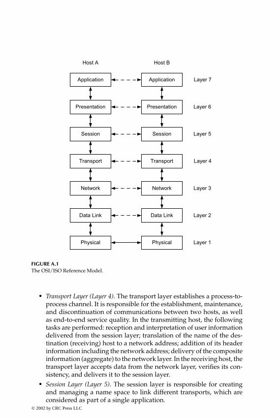
P1: FDJ
book CRC-Wireless November 8, 2001 13:53 Char Count= 320
FIGURE A.1The OSI/ISO Reference Model.
� Transport Layer (Layer 4). The transport layer establishes a process-to-process channel. It is responsible for the establishment, maintenance,and discontinuation of communications between two hosts, as wellas end-to-end service quality. In the transmitting host, the followingtasks are performed: reception and interpretation of user informationdelivered from the session layer; translation of the name of the des-tination (receiving) host to a network address; addition of its headerinformation including the network address; delivery of the compositeinformation (aggregate) to the network layer. In the receiving host, thetransport layer accepts data from the network layer, verifies its con-sistency, and delivers it to the session layer.
� Session Layer (Layer 5). The session layer is responsible for creatingand managing a name space to link different transports, which areconsidered as part of a single application.
© 2002 by CRC Press LLC
E:\Java for Engineers\VP Publication\Java for Engineers.vpThursday, April 25, 2002 9:27:36 AM
Color profile: DisabledComposite Default screen

P1: FDJ
book CRC-Wireless November 8, 2001 13:53 Char Count= 320
� Presentation Layer (Layer 6). The presentation layer is responsible forproviding a common format of data exchange between different typesof peers.
� Application Layer (Layer 7). The application layer implements the func-tionality of the application. It is related to the purpose of the commu-nication. Examples of application include e-mail, home banking, filetransfer, and others.
Note that Layer 1, Layer 2, Layer 3, and Layer 4 (lower layers) providemeans for transferring information between hosts. Layer 5, Layer 6, andLayer 7 (higher layers) provide means for user’s interaction with a partic-ular information service.
© 2002 by CRC Press LLC
E:\Java for Engineers\VP Publication\Java for Engineers.vpThursday, April 25, 2002 9:27:36 AM
Color profile: DisabledComposite Default screen
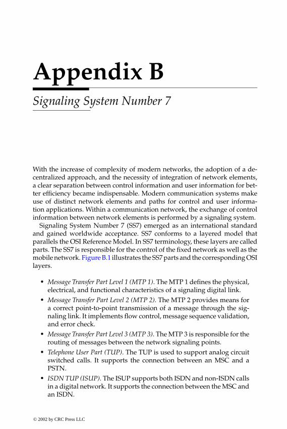
P1: FDJ
book CRC-Wireless November 8, 2001 13:53 Char Count= 320
Appendix BSignaling System Number 7
With the increase of complexity of modern networks, the adoption of a de-centralized approach, and the necessity of integration of network elements,a clear separation between control information and user information for bet-ter efficiency became indispensable. Modern communication systems makeuse of distinct network elements and paths for control and user informa-tion applications. Within a communication network, the exchange of controlinformation between network elements is performed by a signaling system.
Signaling System Number 7 (SS7) emerged as an international standardand gained worldwide acceptance. SS7 conforms to a layered model thatparallels the OSI Reference Model. In SS7 terminology, these layers are calledparts. The SS7 is responsible for the control of the fixed network as well as themobile network. Figure B.1 illustrates the SS7 parts and the corresponding OSIlayers.
� Message Transfer Part Level 1 (MTP 1). The MTP 1 defines the physical,electrical, and functional characteristics of a signaling digital link.
� Message Transfer Part Level 2 (MTP 2). The MTP 2 provides means fora correct point-to-point transmission of a message through the sig-naling link. It implements flow control, message sequence validation,and error check.
� Message Transfer Part Level 3 (MTP 3). The MTP 3 is responsible for therouting of messages between the network signaling points.
� Telephone User Part (TUP). The TUP is used to support analog circuitswitched calls. It supports the connection between an MSC and aPSTN.
� ISDN TUP (ISUP). The ISUP supports both ISDN and non-ISDN callsin a digital network. It supports the connection between the MSC andan ISDN.
© 2002 by CRC Press LLC
E:\Java for Engineers\VP Publication\Java for Engineers.vpThursday, April 25, 2002 9:27:36 AM
Color profile: DisabledComposite Default screen

P1: FDJ
book CRC-Wireless November 8, 2001 13:53 Char Count= 320
FIGURE B.1SS7 and the corresponding OSI layers.
� Signaling Connection Control Part (SCCP). The SCCP supports con-nection- or connectionless-oriented network services. It is also respon-sible for the global title translation (GTT) service, which translates aglobal title (e.g., a 0-800, 1-800) into a destination point and a subsys-tem number.
� Transaction Capabilities Application Part (TCAP). The TCAP provides aset of protocols and services used by an application process.
� Base Station System Management Application Part (BSSMAP). TheBSSMAP interfaces BSC with MSC.
� Direct Transfer Application Part (DTAP). The DTAP is used for messagetransfer between MSC and MS.
� BSSMAP and DTAP. These fuse into the BSSAP.� Mobile Application Part (MAP). The MAP is the highest SS7 layer. It
supports the connection between MSC, HLR, VLR, and some othernetwork elements. MAP has been added to SS7 to perform controloperations unique to mobile communication networks, specificallyto GSM. A similar entity has also been incorporated into ANSI-41, forAmerican cellular systems. The interfaces of MAP and ANSI-41 aredetailed in Chapters 4 and 5, respectively.
© 2002 by CRC Press LLC
E:\Java for Engineers\VP Publication\Java for Engineers.vpThursday, April 25, 2002 9:27:36 AM
Color profile: DisabledComposite Default screen

P1: FDJ
book CRC-Wireless November 8, 2001 13:53 Char Count= 320
Appendix CSpread Spectrum
Spread spectrum is defined as a communication technique in which the in-tended signal is spread over a bandwidth in excess of the minimum band-width required to transmit the signal. This is accomplished by the use ofa wideband encoding signal at the transmitter, which operates in synchro-nism with the receiver, where the encoding signal is also known. By allowingthe intended signal to occupy a bandwidth far in excess of the minimum band-width required to transmit it, the signal will have a noiselike appearance.
The spread spectrum function constitutes an additional block included in aconventional communication system. It implements a second-level, an addi-tional, modulation. Therefore, generating a spread spectrum signal involvestwo steps: first, the carrier is modulated by the baseband digital informationwith rate Rb = 1/Tb , where Rb is the information rate and Tb is the baseband(information) symbol duration; second, the modulated signal is used to mod-ulate a wideband function with rate Rc = 1/Tc , where Rc is known as chip rateand Tc is the chip duration. After the first modulation process, the resultingsignal is still a narrowband signal. After the second modulation process, theresulting signal is a wideband signal. The desired wideband signal arrives atthe receiver together with other wideband signals, interference, and noise. Ifthe set of spreading functions is chosen so that low cross-correlation amongthem exists, only the desired signal remains after the correlation process(see next section). Other waveforms are not correlated and will be spread,appearing as noise to the modulator. The correlated signal is then a band-pass signal, whereas the noise component is a wideband signal. Thus, by ap-plying the composite signal (wanted band-pass signal plus wideband noise)to a band-pass filter, with a bandwidth just large enough to accommodatethe wanted signal, the noise component is made band-pass. In this case, thefiltered noise appears with much less power. Consequently, a jammer or in-terference power density in the information bandwidth of the received signalwill be effective only if its total power is increased by the same amount as thebandwidth expansion of the signal.
© 2002 by CRC Press LLC
E:\Java for Engineers\VP Publication\Java for Engineers.vpThursday, April 25, 2002 9:27:36 AM
Color profile: DisabledComposite Default screen
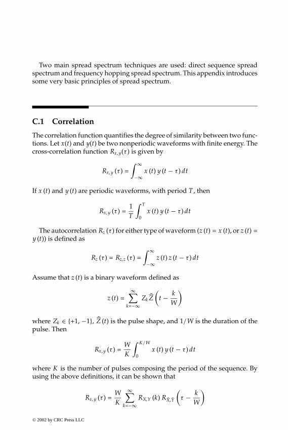
P1: FDJ
book CRC-Wireless November 8, 2001 13:53 Char Count= 320
Two main spread spectrum techniques are used: direct sequence spreadspectrum and frequency hopping spread spectrum. This appendix introducessome very basic principles of spread spectrum.
C.1 Correlation
The correlation function quantifies the degree of similarity between two func-tions. Let x(t) and y(t) be two nonperiodic waveforms with finite energy. Thecross-correlation function Rx, y(τ ) is given by
Rx, y (τ ) =∫ ∞
−∞x (t) y (t − τ ) dt
If x (t) and y (t) are periodic waveforms, with period T , then
Rx, y (τ ) =1T
∫ T
0x (t) y (t − τ ) dt
The autocorrelation Rz (τ ) for either type of waveform (z (t) = x (t), or z (t) =y (t)) is defined as
Rz (τ ) = Rz,z (τ ) =∫ ∞
−∞z (t) z (t − τ ) dt
Assume that z (t) is a binary waveform defined as
z (t) =∞∑
k=−∞Zk Z
(t − k
W
)
where Zk ∈ {+1, −1}, Z (t) is the pulse shape, and 1/W is the duration of thepulse. Then
Rx, y (τ ) =WK
∫ K/W
0x (t) y (t − τ ) dt
where K is the number of pulses composing the period of the sequence. Byusing the above definitions, it can be shown that
Rx, y (τ ) =WK
∞∑k=−∞
RX,Y (k) RX,Y
(τ − k
W
)
© 2002 by CRC Press LLC
E:\Java for Engineers\VP Publication\Java for Engineers.vpThursday, April 25, 2002 9:27:36 AM
Color profile: DisabledComposite Default screen

P1: FDJ
book CRC-Wireless November 8, 2001 13:53 Char Count= 320
where RX,Y (k) is the cross-correlation function of the two periodic binarysequences Xk and Yk , and R X, Y (τ ) is the nonperiodic cross-correlation functionfor the basic waveforms X (t) and Y (t). The cross-correlation between Xk andYk is defined as
RX,Y (k) =K −1∑i=0
Xi Yi −k
Note that the correlation between two sequences yields the difference betweenthe number of bit-by-bit position agreements minus the number of disagree-ments. The autocorrelation function RZ (k) of the sequence Zi is defined as
RZ (k) = RZ, Z (k) =K −1∑i=0
Zi Zi −k
The autocorrelation function for z (t) is
Rz (τ ) = Rz,z (τ ) = WK
∞∑k=−∞
RZ (k) R Z
(τ − k
W
)
Assume that the pulse shape Z (t) is a rectangle with amplitude equal to 1and duration P . The autocorrelation function R Z (τ ) is a triangle as shown inFigure C.1. Now, for a sequence of K binary symbols, in which the numberof +1s and −1s differ by one, the autocorrelation is K , for k = 0 and −1 fork �= 0. In such a case, the autocorrelation function for the complete waveformis as shown in Figure C.2.
Two real-valued waveforms are said to be orthogonal if Rx, y (0) = 0. In thesame way, two sequences are said to be orthogonal if RX,Y (0) = 0.
FIGURE C.1A rectangular pulse shape (a) and its autocorrelation function (b).
© 2002 by CRC Press LLC
E:\Java for Engineers\VP Publication\Java for Engineers.vpThursday, April 25, 2002 9:27:36 AM
Color profile: DisabledComposite Default screen
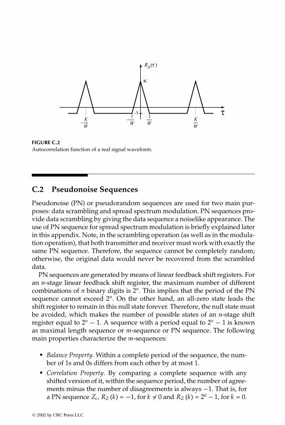
P1: FDJ
book CRC-Wireless November 8, 2001 13:53 Char Count= 320
FIGURE C.2Autocorrelation function of a real signal waveform.
C.2 Pseudonoise Sequences
Pseudonoise (PN) or pseudorandom sequences are used for two main pur-poses: data scrambling and spread spectrum modulation. PN sequences pro-vide data scrambling by giving the data sequence a noiselike appearance. Theuse of PN sequence for spread spectrum modulation is briefly explained laterin this appendix. Note, in the scrambling operation (as well as in the modula-tion operation), that both transmitter and receiver must work with exactly thesame PN sequence. Therefore, the sequence cannot be completely random;otherwise, the original data would never be recovered from the scrambleddata.
PN sequences are generated by means of linear feedback shift registers. Foran n-stage linear feedback shift register, the maximum number of differentcombinations of n binary digits is 2n. This implies that the period of the PNsequence cannot exceed 2n. On the other hand, an all-zero state leads theshift register to remain in this null state forever. Therefore, the null state mustbe avoided, which makes the number of possible states of an n-stage shiftregister equal to 2n − 1. A sequence with a period equal to 2n − 1 is knownas maximal length sequence or m-sequence or PN sequence. The followingmain properties characterize the m-sequences:
� Balance Property. Within a complete period of the sequence, the num-ber of 1s and 0s differs from each other by at most 1.
� Correlation Property. By comparing a complete sequence with anyshifted version of it, within the sequence period, the number of agree-ments minus the number of disagreements is always −1. That is, fora PN sequence Zi , RZ (k) = −1, for k �= 0 and RZ (k) = 2n − 1, for k = 0.
© 2002 by CRC Press LLC
E:\Java for Engineers\VP Publication\Java for Engineers.vpThursday, April 25, 2002 9:27:36 AM
Color profile: DisabledComposite Default screen

P1: FDJ
book CRC-Wireless November 8, 2001 13:53 Char Count= 320
C.3 Walsh Codes
The Walsh sequence can be generated by means of the Rademacher functionsor by the Hadamard matrices. The Hadamard matrix is defined as
H0 = [1]
Hn =[
Hn−1 Hn−1Hn−1 −Hn−1
]
The Walsh sequences are indexed by the row of the matrix. Hence, Wi corre-sponds to the sequence in row i of the Hadamard matrix. An example of theHadamard matrix for n = 2 is shown as follows:
H2 =
1 1 1 11 −1 1 −11 1 −1 −11 −1 −1 1
Thus, W1 = 1, −1, 1, −1. The Walsh sequences are orthogonal to each otherwhen correlated over their period.
C.4 Orthogonal Variable Spreading Factor Codes
Channelization in multirate CDMA systems can be provided by orthogonalvariable spreading factor (OVSF) codes. Uplink and downlink channels makeuse of OVSF codes. The OVSF codes preserve the orthogonality betweenchannels of different rates and spreading factors. They can be defined as
C1,0 = [1][C2,0C2,1
]=
[C1,0 C1,0C1,0 −C1,0
]=
[1 11 −1
]
© 2002 by CRC Press LLC
E:\Java for Engineers\VP Publication\Java for Engineers.vpThursday, April 25, 2002 9:27:36 AM
Color profile: DisabledComposite Default screen
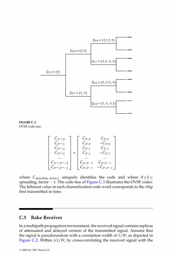
P1: FDJ
book CRC-Wireless November 8, 2001 13:53 Char Count= 320
FIGURE C.3OVSF code tree.
C2n+1,0C2n+1,1C2n+1,2C2n+1,3
...
C2n+1,2n+1 −2C2n+1,2n+1 −1
=
C2n,0 C2n,0C2n,0 −C2n,0C2n,1 C2n,1C2n,1 −C2n,1... ...
C2n,2n −1 C2n,2n −1C2n,2n −1 −C2n,2n −1
where Cspreading factor,k uniquely identifies the code and where 0 ≤ k ≤spreading factor − 1. The code tree of Figure C.3 illustrates the OVSF codes.The leftmost value in each channelization code word corresponds to the chipfirst transmitted in time.
C.5 Rake Receiver
In a multipath propagation environment, the received signal contains replicasof attenuated and delayed version of the transmitted signal. Assume thatthe signal is pseudorandom with a correlation width of 1/W, as depicted inFigure C.2. Within ±1/W, by cross-correlating the received signal with the
© 2002 by CRC Press LLC
E:\Java for Engineers\VP Publication\Java for Engineers.vpThursday, April 25, 2002 9:27:36 AM
Color profile: DisabledComposite Default screen

P1: FDJ
book CRC-Wireless November 8, 2001 13:53 Char Count= 320
FIGURE C.4Basic structure of a Rake receiver.
local replica of the signal, shifted by k /W, k an integer, the path with delayk /W, if any, is selected.
A Rake receiver is a tapped delay line, with delays equal to 1/W, and withthe output of each delay element connected to cross-correlators. These delayelements combined with the cross-correlators collect the signal energy fromall the signal paths that fall within the span of the delay line and combinethem optimally. A basic structure of the Rake receiver is shown in Figure C.4.
C.6 Processing Gain
Processing gain G is defined as the ratio between the bandwidth W of thespread signal and the bandwidth w of the unspread signal, i.e.,
G =Ww
which represents the gain achieved by processing a spread spectrum signalover an unspread signal. It can be obtained by the difference in decibels be-tween the output signal-to-noise ratio (SNRo , SNR of the spread information)and the input signal-to-noise ratio (SNRi , SNR of the unspread information),i.e.,
10 log G = SNRo − SNRi
© 2002 by CRC Press LLC
E:\Java for Engineers\VP Publication\Java for Engineers.vpThursday, April 25, 2002 9:27:36 AM
Color profile: DisabledComposite Default screen

P1: FDJ
book CRC-Wireless November 8, 2001 13:53 Char Count= 320
FIGURE C.5A simplified model of a DS/SS system.
C.7 Direct Sequence Spread Spectrum
Direct sequence (DS), direct spread (DS), or pseudonoise (PN) spread spec-trum (SS) uses a PN sequence to modulate a carrier (or a modulated car-rier). In principle, any modulation technique such as AM (pulse), FM, or PMcan be used. However, the most widespread form is the binary phase shiftkeying (BPSK) modulation. A simplified model of a DS/SS system is shownin Figure C.5. The information signal m (t) and the spreading sequence c (t)are combined before phase-modulating the carrier p (t). The PN code c (t) isa pseudorandom binary sequence with a chip rate Rc much larger than theinformation rate Rb . The multiplication of the PN code by the information sig-nal results in a frequency spectrum with a bandwidth approximately equal tothat of the PN sequence. The resultant signal is then modulated onto a carrierand transmitted. At the receiver, which is assumed to operate in synchronismwith the transmitter, an exact replica of the PN code is used to unspread thereceived signal.
© 2002 by CRC Press LLC
E:\Java for Engineers\VP Publication\Java for Engineers.vpThursday, April 25, 2002 9:27:36 AM
Color profile: DisabledComposite Default screen

P1: FDJ
book CRC-Wireless November 8, 2001 13:53 Char Count= 320
FIGURE C.6A simplified model of an FH/SS system.
C.8 Frequency Hopping Spread Spectrum
Frequency hopping (FH) is a spread spectrum (SS) technique in which thecarrier is allowed to hop from one frequency to another in a sequence dic-tated by a PN code. A simplified model of an FH/SS system is shown inFigure C.6. At any given time instant, the output of the FH transmitter is asingle frequency. Over a period of time, its output signal spectrum is ideallyrectangular, with the same amount of power in every frequency. In practice,however, the hopping process may generate spurious frequencies causinginterchannel interference (cross talk). At the receiver, which is assumed tooperate synchronously with the transmitter, the transmitted signal is mixedwith a locally generated replica of the transmitter frequency sequence, offsetby the intermediate frequency f I F .
There two basic FH systems: slow FH (SFH) and fast FH (FFH). In SFHsystems, several symbols of information are transmitted on each frequencyhop, where each symbol is a chip. In FFH, several hops occur during thetransmission of one symbol, where the chip is characterized by a hop.
© 2002 by CRC Press LLC
E:\Java for Engineers\VP Publication\Java for Engineers.vpThursday, April 25, 2002 9:27:36 AM
Color profile: DisabledComposite Default screen
P1: FDJ
book CRC-Wireless November 8, 2001 13:53 Char Count= 320
Appendix DPositioning of the Interferersin a Microcellular Grid
The number N of cells per cluster in a square cellular grid is given as N = i2+ j2,where {i, j} ∈ Z, Z defining the integer set. The clusters in a square grid canbe of the collinear type or noncollinear type, as follows.
� Collinear type:√N ∈ Z, i.e., i = 0 or j = 0 (perfect square clusters), or
i = j , i.e., N = 2x2, where x ∈ Z.� Noncollinear type:
N is even, orN is odd and nonprime, orN is prime.
Note that there four groups of clusters: collinear, even noncollinear, oddnonprime noncollinear, and prime noncollinear. For each of these groups,the distance between an interferer positioned at the co-cell of the Lth co-celllayer and another at the target cell, with the target cell taken as the referencecell, is calculated differently. Such a distance is defined here as nL , which isnormalized with respect to the cell radius, i.e., nL is given in number of cellradii. The relations that follow show the distance between the target cell andits interferers obtained for the mobile stations positioned for the worst-casecondition. These are determined for each of the groups defined above andfor the uplink and the downlink. The minimum distance between collinearco-cells is represented by the variable d, given in number of units of the cellradius. In the formulations that follow, the variable k is defined differentlythan it in the main text. Here, k is such that k = 1, 2, 3, 4 . . . (integer).
© 2002 by CRC Press LLC
E:\Java for Engineers\VP Publication\Java for Engineers.vpThursday, April 25, 2002 9:27:36 AM
Color profile: DisabledComposite Default screen

P1: FDJ
book CRC-Wireless November 8, 2001 13:53 Char Count= 320
D.1 Collinear Type
In the collinear type, choose m = i or m = j , whichever is non-nil. Then d = 2m.
� Uplink
nk = 2mk − 1
� Downlink
nk = 2mk
for both conditions, that is, at the vicinities of the base station and awayfrom it.
D.2 Even Noncollinear Type
In the even noncollinear type, d = N.
� Uplink
nk = 2Nk − 1
� Downlink
nk = 2Nk
for both conditions, that is, at the vicinities of the base station and awayfrom it.
D.3 Odd Nonprime Noncollinear Type
In the odd nonprime noncollinear type, N′ is determined such that N′ = N/m,where m ∈ Z. Then,
nk = mnk(N′)
© 2002 by CRC Press LLC
E:\Java for Engineers\VP Publication\Java for Engineers.vpThursday, April 25, 2002 9:27:36 AM
Color profile: DisabledComposite Default screen

P1: FDJ
book CRC-Wireless November 8, 2001 13:53 Char Count= 320
where nk(N′) is the distance between the interferers at the kth layer and thetarget cell for reuse pattern N′.
D.4 Prime Noncollinear Type
In the prime noncollinear, d = 2N. We define p as a parameter that desig-nates the prime number immediately prior to N, and that satisfies the relationp = i2 + j2. The only exception to this is when N = 5, for which p = 3.
� Uplink
n1+3(k−1) = p + 2N (k − 1)n2+3(k−1) = 2N − p + 2N (k − 1)n3+3(k−1) = 2Nk − 1
� Downlink
nk = 2Nk
for both conditions, that is, at the vicinities of the base station and away fromit. For the close-to-the-border condition:
nk = 2Nk
n1+2(k−1) = p + 2N (k − 1)n2+2(k−1) = 2N − p + 2N (k − 1)
© 2002 by CRC Press LLC
E:\Java for Engineers\VP Publication\Java for Engineers.vpThursday, April 25, 2002 9:27:36 AM
Color profile: DisabledComposite Default screen


