Protocol for the verification tests on ethylene oxide ...
55
Pilot project for the environmental technology verification In the field of ethylene oxide treatment technology Protocol for the verification tests on ethylene oxide treatment technology Sept. 11, 2003 Environmental Management Bureau, Ministry of the Environment
Transcript of Protocol for the verification tests on ethylene oxide ...

Pilot project for the environmental technology verification In the field of ethylene oxide treatment technology
Protocol for the verification tests on ethylene oxide treatment technology
Sept. 11, 2003
Environmental Management Bureau, Ministry of the Environment

i
Table of Contents
Main section 1
I. Introduction ........................................................................................................ 1 1. Target technologies ......................................................................................................1 2. Types and outline of verification tests ........................................................................1
(1) Types of verification tests ......................................................................................1 (2) Verification testing process....................................................................................1
3. Definitions of terms and phrases ................................................................................2
II. Verification test system ..................................................................................... 3 1. Ministry of the Environment.......................................................................................3 2. The committee on the pilot project for the environmental technology verification..3 3. Working group on the ethylene oxide treatment technology .....................................3 4. Verification Organizations...........................................................................................3 5. Technology Panels ........................................................................................................4 6. Environmental technology developers ........................................................................4
III. Selection of target verification technologies ................................................... 5 1. Application....................................................................................................................5 2. Selection of target verification technologies ...............................................................5
IV. Preparation for the verification tests ................................................................ 6 1. Determination of verification items ............................................................................6
(1) Verification items regarding waste gas treatment performance .........................6 (2) Verification items regarding environmental load.................................................6 (3) Verification items regarding operations and maintenance..................................6
2. Establishment of the Test Plan ...................................................................................7
V. Verification test methods................................................................................... 8 1. Operations and maintenance ......................................................................................8
(1) Regular operations and maintenance ...................................................................8 (2) Actions in the event of upset conditions ...............................................................8 (3) Cost estimation ......................................................................................................8
2. Test conditions..............................................................................................................9 (1) Types of tests ..........................................................................................................9 (2) Test conditions to be recorded .............................................................................14
3. Test methods...............................................................................................................14 (1) Test methods for verification items regarding waste gas treatment
performance..........................................................................................................14

ii
(2) Test methods for the verification items regarding environmental load............15 (3) Test methods for the verification items regarding operations and maintenance
16 4. Management of analytical accuracy..........................................................................17
(1) Performance evaluation and maintenance of apparatuses and equipment......17 (2) Evaluation of the reliability of measurements ...................................................19 (3) Management and evaluation of data ..................................................................21
VI. Preparation of the Verification Report ............................................................ 23
VII. Remarks in conducting the verification test .................................................. 24 1. Quality control of data ...............................................................................................24
(1) The method for quality control of data ...............................................................24 (2) Measurement and data acquisition.....................................................................24
2. Management, analysis, and presentation of data ....................................................24 (1) Data management................................................................................................24 (2) Data analysis and presentation ..........................................................................24
3. Environment, health and safety................................................................................25
Appendix 0: Quality management system to be constructed at the Verification Organizations ................................................................................... 26
Appendix 1: Application form for verification..................................................... 30
Appendix 2: Test Plan............................................................................................ 34
Appendix 3: Image of a brief summary of the verification test results ............. 36
Reference i I. Brief overview of the pilot project for the environmental technology verification..........i II. System for promotion of the “pilot project for the environmental technology
verification” ................................................................................................................ iii III. Flow of the pilot project for the environmental technology verification ..................iv IV. Prospectus for organizing the working group on the ethylene oxide treatment
technology in the committee on the pilot project for the environmental technology verification for 2003 .....................................................................................................v
V. Particulars discussed in the working group on the ethylene oxide treatment technology...................................................................................................................vii

1
Main section I. Introduction 1. Target technologies
The ethylene oxide waste gas treatment technologies specified in this protocol for the verification are those (equipment and others) that process the waste gas from an ethylene oxide sterilizer (approximately 50 to 200 L in capacity) used in medical institutions, pharmaceutical plants, and the like by combustion, catalytic oxidation, hydrolysis, and others, and that may be additionally installed.
2. Types and outline of verification tests
(1) Types of verification tests
In the verification test, waste gas treatment technologies specific to environmental technology developers are verified, and the results evaluated. In the verification test, the following items will be verified for each target verification apparatus.
Environmental protective effect under practical operational conditions in the range specified by an environmental technology developer
Energy, materials, and cost required for operation
Operational environment allowing normal operations
Labor for operations and maintenance (hereinafter referred to as the “O&M”)
(2) Verification testing process
The verification test will primarily be conducted according to the steps specified below.
i Planning The plan for the verification test (hereinafter referred to as the “Test Plan”) will be prepared before the test is conducted. The Test Plan will be prepared by a Verification Organization in cooperation with an environmental technology developer.
The main activities in the planning stage are as follows:
Specifying the individuals and organizations involved in the test
Specifying the general and technology-specific objectives of the test
Specifying verification items
Determining analytical and sampling methods and the test period
Establishing a Test Plan that includes specific procedures, a schedule, and the individuals in charge, based on the results of the above items
ii Verification test In this stage, a verification test will be conducted according to the Test Plan described above. The verification test verifies the conformity of a target verification apparatus with its objectives specified in the planning stage. The Verification Organization may, if necessary, subcontract part of the verification test to external test organizations.
iii Data assessment and reporting In the final stage, all data collected will be analyzed for verification, and a report on the verification test (hereinafter referred to as the “Verification Report”) will be compiled. A Verification Organization is responsible for analysis of the data and reporting. To accelerate the above process, the Verification Organization may subcontract an external organization to

2
prepare a draft of the Verification Report.
The Verification Report will be submitted by the Verification Organization to the Ministry of the Environment. In the report, the suitability of the verification tests will be discussed by the working group on the ethylene oxide treatment technology (hereinafter referred to as the “working group”) of the committee on the pilot project for the environmental technology verification. After being approved by the Ministry of the Environment, the report will be returned to the Verification Organization. The approved Verification Report will then be issued by the Verification Organization to the environmental technology developer and simultaneously disclosed to the public.
3. Definitions of terms and phrases
The definitions of the major terms and phrases are in accordance with those of the Japanese Industrial Standards (hereinafter referred to as “JIS”). The standards in JIS particularly relevant to this protocol for the verification (hereinafter referred to as “Protocol”) are as follows:
JIS K 0050 "General rules for chemical analysis"
JIS K 0114 "General rules for gas chromatographic analysis"
JIS K 0123 "General rules for analytical methods in gas chromatography mass spectrometry"
JIS K 0211 "Technical terms for analytical chemistry (General part)"
JIS K 0214 "Technical terms for analytical chemistry (Chromatography part)"
JIS K 0215 "Technical Terms for analytical chemistry (analytical instrument part)"
JIS B 8530 "Glossary of terms for pollution control equipment"
In addition, the terms and phrases used in this Protocol are defined as set forth in Table 1.
Table 1 Definition of terms and phrases used in the protocol for the verification
Term/Phrase Definition
Target verification technology
A method for treating ethylene oxide to be verified in the verification test. The target verification technology should have a clear scientific basis.
Target verification apparatus
An apparatus to be used in the verification test among the apparatuses / equipment representing the embodiments of the target verification technology
Verification items Items to be analyzed for determination of the performance of a target verification apparatus
Test Site An establishment where a target verification apparatus is to be installed and the verification test is to be conducted
Verification applicant
A person wishing to have his/her own technology verified. If the applied technology is selected as a target verification technology, the verification applicant will be referred to as an “environmental technology developer.”
Environmental technology developer
A person who possesses a target verification technology. Until the applied technology is selected as a target verification technology, the person is referred to as a “verification applicant.”
3
II. Verification test system 1. Ministry of the Environment
Comprehensively administers the entire pilot project for the environmental technology verification
Comprehensively discusses the verification test system
Selects target verification technology fields for the verification test
Establishes and administers the committee on the pilot project for the environmental technology verification and its working groups
Creates a protocol for the verification
Selects Verification Organizations
Financially supports Verification Organizations by bearing the expenses relevant to the verification tests
Approves reports on verification tests
Creates a Environmental Technologies Verification database (hereinafter referred to as “ETV database) for their dissemination
2. The committee on the pilot project for the environmental technology verification
Offers advice on the management of the entire pilot project for the environmental technology verification:
Offers advice on the comprehensive evaluation of verification test results
3. Working group on the ethylene oxide treatment technology
Offers advice on management of the entire pilot project for the environmental technology verification in the field of ethylene oxide treatment technology
Offers advice on creating a protocol for the verification
Offers advice on the selection of Verification Organizations
Offers advice on approval of the Verification Report
4. Verification Organizations
Administer all processes of the pilot project for the environmental technology verification in target verification technology fields under the auspices of the Ministry of the Environment
Construct the quality management system shown in Appendix 0
Invite the public to register the technologies and products that are suitable as the target of the verification test
Establish and administer respective Technology Panels
Establish a Test Plan in cooperation with environmental technology developers
Conduct and manage verification tests based on the Test Plan
Operate and maintain the target verification apparatuses according to the “O&M manuals” prepared by environmental technology developers. The persons in charge of O&M should be suitably qualified or experienced and have received adequate training.
Restrict entry to the location of verification tests during the test period.
Ensure the health and safety of all persons relevant to the verification tests at the Test Sites
Set and adjust the test schedule by assuring the means of communication among all participants in the verification test, and providing transportation assistance and technical

4
advice as necessary
When the verification test is subcontracted to an external organization, ensure that the quality management system which is required in the Protocol is indeed functioning properly at the subcontractor
Audit the procedures for the verification test
Take samples, inspection, measurement, and analysis in the verification test at the expense and under the responsibility of the Verification Organization
Manage the data / information obtained in the verification tests
Prepare The Verification Report based on analysis / evaluation of the data on the verification test
Register in the ETV database the contents of the approved Verification Report
5. Technology Panels
Offers advice on the Test Plan
Offers advice on the problems that may occur during the verification tests
Offers advice on the issuance of the Verification Report
Offers advice on dissemination of the technologies verified in the verification test
6. Environmental technology developers Cooperate with Verification Organizations in establishment of the Test Plan, such as by providing information required for the verification test
Provide as many target verification apparatuses that can be used at the Test Site as required. In addition, provide the Verification Organization with its “O&M manual.”
Bear the costs and responsibility for the transportation, installation, removal, and others of the target verification apparatus
Bear, in principle, the costs for O&M of the target verification apparatus. In addition, bear the costs for chemicals, supplies, and utilities that may be additionally required.
Provide technological support to the Verification Organization by assisting in the operation and measurement of the target verification apparatus during the verification test period, if necessary
Provide engineers for O&M of the target verification apparatus, if necessary. The engineers should be properly qualified or experienced and have received adequate training.
Provide existing relevant performance data for the target verification technology if it has been tested at other sites.
Cooperate with the Verification Organization in preparing the Verification Report

5
III. Selection of target verification technologies 1. Application
A verification applicant may apply to a Verification Organization for verification of the applicant’s proprietary technology / product. Items to be specified in the application form are described below. The verification applicant should fill in the necessary information in the “Application form for verification” set forth in Appendix 1, and submit the application form together with the designated documents to the Verification Organization.
a. Company name, Address, Division of person in charge, Name of person in charge, etc.
b. In-house test results
c. Product data
d. Developmental status and past delivery record
e. Other relevant or unique features (if any)
f. Technical specification for the target verification apparatus
g. O&M manual*
(Note) The documents designated with * should be attached to the application form.
2. Selection of target verification technologies Based on the description of the application and the advice from the Technology Panel, Verification Organization selects target verification technologies and obtains approval from the Ministry of the Environment. The selection criteria are as follows:
a. Technological requirements:
Does the applied technology fall under the category of target verification technology fields described in “1. Target technologies” on page 1?
Is the application form properly filled in?
Is the technology in a commercialization stage?
b. Possibility of verification
Is it possible to complete the verification from cost and organizational standpoints?
Is it possible to establish a suitable Test Plan?
c. Environmental protective effect, etc.
Is it possible to scientifically explain the principle and mechanism of the technology?
Is there any possibility of the technology causing side environmental issues?
Does it provide a high environmental protective effect?
Is it an innovative technology?
In the selection stage, a verification applicant can confer with the Verification Organization concerning the specific methods of verification, including the period and date of tests.

6
IV. Preparation for the verification tests 1. Determination of verification items
(1) Verification items regarding waste gas treatment performance The possible verification items regarding the waste gas treatment performance to be examined in the verification test are summarized in Table 2. These test items should be examined in the verification tests of all ethylene oxide treatment technologies. In addition to the test items specified above, the Verification Organization examines the necessity for other verification items and describes all of the verification items regarding the waste gas treatment performance specified in the Test Plan.
Table 2 Verification items regarding waste gas treatment performance
Test items Description Ethylene oxide concentration
Ethylene oxide concentrations at the inlet and outlet ducts of the ethylene oxide treating apparatus
Change in treatment efficiency
Change in ethylene oxide treatment efficiency calculated from the ethylene oxide concentrations at the inlet and outlet ducts of the ethylene oxide treating apparatus
Average treatment efficiency (mass balance)
Mass balance calculated from the total amounts of ethylene oxide entering into and discharged from the ethylene oxide treating apparatus
(2) Verification items regarding environmental load
The possible verification items regarding environmental load to be examined in the verification test are summarized in Table 3. In addition to the test items specified above, the Verification Organization examines the necessity for other verification items and describes all of the verification items regarding environmental load specified in the Test Plan.
Table 3 Verification items regarding environmental load
Category Verification items Description Major relevant cost
CO concentration CO concentration (ppm) in the waste gas -
NOx concentration
NOx concentration (ppm) in the waste gas -
Amount of secondary products
generated
Amount of secondary products generated per operation (if secondary products such as ethylene glycol and the like are generated)
Disposal cost
Environmental impact
Noise Noise level (dB) during operation of the apparatus (main unit) -
(3) Verification items regarding operations and maintenance The verification items presumably required for quantitative and qualitative evaluation of the performance in and cost for O&M are summarized in Table 4.
The Verification Organization will, in addition to discussing other verification items, describe the verification items regarding O&M thus determined in the Test Plan.

7
Table 4 Verification items regarding operations and maintenance
Category Verification items Description Major relevant cost
Electricity consumption Electricity consumption per operation (kWh/operation)
Cost for electricity
Fuel consumption Fuel consumption per operation (if a fuel such as town gas, LPG, or the like is consumed)
Cost for fuel
Water consumption Water consumption per operation (if water is consumed for treatment, cooling, and others)
Cost for water
Electricity use and material
consumption
Other chemical consumption such as
reactant
Chemical consumption per operation (if any chemicals such as reactant are consumed)
Cost for consumables
Number of operators, and the level of
operator skill required for O&M of the target verification apparatus
Maximum number of operators and working days (man-days) for each operational item The technicality and difficulty of O&M shall be described.
—
Safety of the target verification apparatus
Measures for ensuring safety (check valves, etc.) —
Measures in the event of emergency
Measures for ensuring safety in the event of failure in electricity or others and the inflow of a high concentration of ethylene oxide
—
Consistency of the treatment performance
Deterioration in treatment efficiency over extended use, the life and exchange frequency of the catalyst and other components, etc.
—
Method of restoring from problems
Ease of and problems in resumption —
O&M performance
Evaluation of O&M manual
Readability, understandability, and problems —
2. Establishment of the Test Plan
The Verification Organizations establish the Test Plan based on information provided by the environmental technology developers and the advice of the Technology Panel. If the environmental technology developers do not give approval for the Test Plans, the Verification Organizations will consult as needed with the Ministry of the Environment to determine the necessary actions.
The items to be included in the Test Plan are listed in Appendix 2.

8
V. Verification test methods 1. Operations and maintenance
The target verification apparatus should be inspected periodically and kept in suitable condition in order to maintain stable operation and thereby ensure proper operation and increase the efficiency of operation throughout the test period. Regardless of whether the Verification Organization or another organization is responsible for the O&M, all procedures involving inspection, O&M should be adjusted in advance by the Verification Organization, described in the Test Plan, and confirmed by the concerned parties.
(1) Regular operations and maintenance O&M to ensure proper operation of the target verification apparatus during the test period should be performed in accordance with the O&M manual.
Calibration should be performed in accordance with the O&M manual. Calibration should also be performed at least as frequently as specified in the O&M manual.
In selecting the verification items regarding O&M, the problems that may arise when an operator is not sufficiently capable of conducting O&M should also be considered.
(2) Actions in the event of upset conditions
The Verification Organization will inform the environmental technology developer as soon as possible in the event of upset conditions. The Verification Organization should take the actions for restoring the apparatus to stable operation specified by the environmental technology developer. In the event of unforeseen circumstances, the Verification Organization will take the actions together with the environmental technology developer.
The data obtained under the upset conditions will not be used in the statistical analysis for the Verification Report, but shall be described and analyzed in the Verification Report. As soon as stable operation is resumed, alternative samples will be taken.
The conditions, cause and result, and method for resumption under upset conditions shall be described in the Verification Report. When the cause is unclear or it is not possible to judge whether the conditions are indeed unusual, the data obtained during the period is used in the statistical analysis for the Verification Report.
The Verification Organizations should install experimental apparatuses that are modified to ensure the safety of the experimental environment and the operators, even if such modifications may lead to inadequate operation or inadequate performance of the target verification apparatuses.
(3) Cost estimation The Verification Organizations will collect and sort the data required for cost estimation for O&M, such as the costs for electricity and secondary products and for other consumables, in cooperation with the environmental technology developers.

9
2. Test conditions
(1) Types of tests The following two types of tests should be conducted in the verification tests of the ethylene oxide waste gas treatment technologies. However, it is not necessary to conduct the tests if these tests are not suitable due to specific features of the target verification apparatus.
The Verification Organizations will examine the test conditions in greater detail, taking into account the practical use conditions of the ethylene oxide sterilizer, such as in the case of humidifying ethylene oxide gas or the like, and determine the Test Plans. In addition, the Verification Organizations will conduct the tests by keeping aspects of the test environments such as the temperature or the like as constant as possible so that there will be no difference in test conditions among the test periods and sites of the verification tests.
1. Standard ethylene oxide gas treatment test
In the standard ethylene oxide gas treatment tests, an ethylene oxide gas properly diluted with air is supplied into a target verification apparatus at a certain flow rate for 1 hour, and the verification items regarding waste gas treatment performance and environmental load after treatment, such as the ethylene oxide concentration and the like in the waste gas, are determined.
The concentration and flow rate of the ethylene oxide gas supplied will be so set by the environmental technology developer that the maximum amount of gas processed in the target verification apparatus can be determined. The detailed test conditions should be set forth in the Test Plan.
2. Waste gas treatment test simulating an ethylene oxide sterilizer
In the waste gas treatment test simulating an ethylene oxide sterilizer, a gas preadjusted by a simulator, which reproduces the exhaust pattern of ethylene oxide gas from ethylene oxide sterilizers, is supplied into the target verification apparatus, and the verification items regarding waste gas treatment performance and environmental load after treatment, such as the ethylene oxide concentration and the like in the waste gas, are determined.
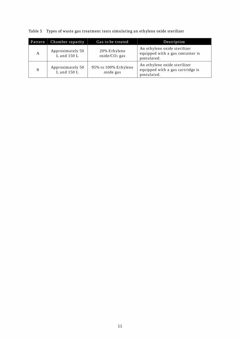
The exhaust patterns reproduced by the simulator include pattern A, wherein an ethylene oxide sterilizer equipped with a gas container is postulated, and pattern B, wherein an ethylene oxide sterilizer with a gas cartridge is postulated. For each pattern, a chamber with a capacity of approximately 50 L or 150 L is employed. Accordingly, the ethylene oxide treatment performance will be examined in a total of four patterns for a target verification apparatus.
However, if any of the chamber capacities are not suitable due to specific features of the target verification apparatus, it is not necessary to conduct a test for such capacity. In addition, a chamber with a capacity of approximately 100 L may be employed depending on the features of the target verification apparatus.
[Pattern A]
Adjust the ethylene oxide gas concentration in the chamber to approximately 700 mg/L, using 20% ethylene oxide/CO2 gas as the gas to be treated.
Use a dry pump, either built into the target verification apparatus or separately provided by the environmental technology developer, as the exhauster. However, a water-seal pump may be used instead if the wastewater from the water-seal pump is used repeatedly and is not discharged into sewage lines.

10
In pattern A, following depressurization (the pressure is set appropriately by the Verification Organization), pressurize the chamber to approximately 1,000 hPa (gauge pressure) by supplying ethylene oxide gas (gas pressurization), and maintain the same pressure for a certain period (sterilization). Following sterilization step, depressurize the chamber to approximately -700 hPa by evacuating the gas (gas evacuation), maintain the same pressure for a certain period (cleaning vacuumization), pressurize the chamber to atmospheric pressure (cleaning aeration), and maintain the atmospheric pressure for a certain period (cleaning). Subsequently, repeat the aeration process of evacuating to approximately-700 hPa (cleaning evacuation), performing cleaning vacuumization, performing cleaning aeration, and performing cleaning five times. If the Verification Organization judges that the ethylene oxide gas in the chamber is not completely exhausted even after five aeration processes, the number of aeration processes may be increased.
The time setting for the gas pressurization, sterilization, cleaning vacuumization, cleaning aeration, and cleaning steps will be determined by the Verification Organization. The time for the gas evacuation and cleaning evacuation steps will be determined based on the application submitted by the environmental technology developer. The time setting for each aeration step shall be the same in all aeration processes.
The accurate capacity of the chamber to be used in the test, detailed exhaust pattern, and others shall be described in the Test Plan.
[Pattern B]
Adjust the ethylene oxide gas concentration in the chamber to approximately 900 mg/L using 95% to 100% ethylene oxide gas as the gas to be treated.
Use an air ejector or dry pump as the exhauster. If an air ejector is used, use one with a flow rate of 100 L/min provided by the Verification Organization. If a dry pump is employed, use a dry pump either built into the target verification apparatus or separately provided by the environmental technology developer. However, a water-seal pump may be used instead if the wastewater from the water-seal pump is used repeatedly and is not discharged into sewage lines.
In pattern B, following depressurization, pressurize the chamber by supplying ethylene oxide gas (gas pressurization), and maintain the same pressure for a certain period (sterilization). The pressures in the depressurization and sterilization steps are set appropriately by the Verification Organization. Following the sterilization step, depressurize the chamber to approximately -800 hPa by evacuating the gas, open the valve of the chamber to allow air to enter at atmospheric pressure or below, and then conduct continuous ventilation (cleaning).
The time setting for the gas pressurization and sterilization steps will be determined by the Verification Organization. The time setting for the depressurization step will be determined based on the application submitted by the environmental technology developer. Air will be supplied in an amount 10 times larger than the capacity of the chamber in the cleaning step, but if the Verification Organization judges that the ethylene oxide gas in the chamber is not completely exhausted, the time for the cleaning step may be increased.
The accurate capacity of the chamber to be used in the test, detailed exhaust pattern, and others shall be described in the Test Plan.
11
Table 5 Types of waste gas treatment tests simulating an ethylene oxide sterilizer
Pattern Chamber capacity Gas to be treated Description
A Approximately 50 L and 150 L
20% Ethylene oxide/CO2 gas
An ethylene oxide sterilizer equipped with a gas container is postulated.
B Approximately 50 L and 150 L
95% to 100% Ethylene oxide gas
An ethylene oxide sterilizer equipped with a gas cartridge is postulated.

12
[Pattern A]
Fig. 1 Schematic illustration of the exhaust pattern
Pressure in chamber (Gauge
pressure)
Time
Gas evacuation Gas
pressur- ization
Sterilization
Clean- ing
v acuu-mization
Clean- ing
aerat- ion
Cleaning
Clean- ing
ev acu- ation
0 hPa
Approx. 1,000 hPa
Approx. -700 hPa
Repeat aeration five times.Depressur- ization
Clean- ing
aerat- ion
Aeration
Clean- ing
v acuu-mizatio
n
Cleaning
Step Time (min) Chamber inlet valve
Chamber outlet valve Note
Gas pressurization Open Closed Sterilization
Set by the Verification Organization Closed Closed
Gas evacuation Set by the environmental technology developer
Closed Open
Cleaning vacuumization Closed Closed Cleaning aeration Open Closed Cleaning
Set by the Verification Organization
Closed Closed
Cleaning evacuation
Set by the environmental technology developer
Closed Open
Cleaning vacuumization Closed Closed
Cleaning aeration Open Closed
Aeration
Cleaning
Set by the Verification Organization
Closed Closed
Repeat five times
Fig. 2 Schematic illustration of the test apparatus (example)
Chamber(50L, 150L)
Ethy
lene
oxi
de g
as
cont
aine
r
Prepare a pump separately if the target verification apparatus does not have a built-in pump.
Ethylene oxide gas Air
To the outside Target verification
apparatus
S
S
s: Sampling location: Pump
Chamber inlet valve
Chamber outlet valve

13
[Pattern B]
Fig. 3 Schematic illustration of the exhaust pattern
Pressure in chamber
(Gauge pressure)
Cleaning (continuous)
Gas pressuri-
zationSterilization Depressurization
Supply air in an amount 10 times larger than the capacity of the chamber.
0 hPa
Approx. -800 hPa
Gas evacuation
Time
Step Time (min) Chamber inlet valve
Chamber outlet valve Note
Gas pressurization Closed Closed Supply ethylene oxide gas
from the cartridge. Sterilization
Set by the Verification
Organization Closed Closed
Gas evacuation Set by the
environmental technology
developer
Closed Open
Cleaning (continuous) Closed Open
Continuous ventilation Supply air in an amount 10 times larger than the capacity of the chamber.
Fig. 4 Schematic illustration of the test apparatus (example)
Chamber(50L, 150L)
Ethylene oxide gas cartridge
Target verification apparatus
Air ejector, flow rate: 100 L/min
To the outside
Air
s
s
s: Sampling location : Pump
Chamber inlet valve
Chamber outlet valve

14
(2) Test conditions to be recorded
The Verification Organizations shall record the following parameters and describe them in the Verification Report.
The temperatures and static pressures of the waste gas in the inlet and outlet ducts of the target verification apparatus
The flow rates of the waste gas in the inlet and outlet ducts of the target verification apparatus
3. Test methods
(1) Test methods for verification items regarding waste gas treatment performance
The test methods for the verification items regarding waste gas treatment performance are summarized in Table 6.
Test methods for items other than the test items specified below will be specified in the Test Plan with reference to the relevant JIS standards and regulations.
Table 6 Test methods for verification items regarding waste gas treatment performance
Test items Method
Ethylene oxide concentration
Use a continuous total hydrocarbon analyzer for measurement of the ethylene oxide concentration in the inlet duct of target verification apparatus. Measure the ethylene oxide concentration in the outlet duct, using a continuous total hydrocarbon analyzer and by the solid absorption–solvent extraction–gas chromatography mass spectroscopy method. See the "Manual for measuring hazardous air pollutants (ethylene oxide)," (Air Pollution Control Division, Air Quality Bureau, Environment Agency, Mar. 1999) for details on the solid absorption–solvent extraction–gas chromatography mass spectroscopy method.
Change in treatment efficiency
Calculate the change in treatment efficiency from the ethylene oxide concentrations in the inlet and outlet ducts of target verification apparatus. Use, in principle, the data obtained by the continuous total hydrocarbon analyzer as the outlet concentration.
Average treatment efficiency (mass
balance)
Calculate the average treatment efficiency from the ethylene oxide concentrations and flow rates in the inlet and outlet ducts of the target verification apparatus. Use the data obtained by the continuous total hydrocarbon analyzer or gas chromatography mass spectrometer as the outlet concentration.
1) Sampling Take samples by the solid absorption sampling method using a sample tube in which a gas absorbent is packed, in accordance with the solid absorption–solvent extraction–gas chromatography mass spectroscopy method. Take a sample of the waste gas in the outlet duct of the target verification apparatus, absorb the gas in the sample tube and use it for determination of the gas concentration.
See JIS K 0095 (Method for sampling flue gas) for information on the sampling apparatus to be used.
2) Test conditions Measure the temperature, static pressure, and flow rate of the waste gas in the inlet and outlet ducts of the target verification apparatus with reference to JIS B 9914 (Method of

15
measuring performance for gas treatment equipment). In particular, in the standard ethylene oxide gas treatment tests, the measurement time to be specified in the Verification Report is 15 minutes after the start of the ethylene oxide gas treatment. Alternatively, in the waste gas treatment tests simulating an ethylene oxide sterilizer, the time to be specified is 1 minute after the gas evacuation and the start of the fifth cleaning evacuation (measurement time for flow rate to be specified is for 1 minute after the gas evacuation and the start of cleaning evacuation) in pattern A, while it is 1 minute after the start of gas evacuation and 10 minutes after the start of continuous ventilation (when pressure is constant) in pattern B.
(2) Test methods for the verification items regarding environmental load
The test methods for the verification items regarding environmental load are summarized in Table 7.
Test methods for items other than the test items specified below shall be specified in the Test Plan with reference to the relevant JIS standards and regulations. The Verification Organizations should describe the test items and test methods in the Verification Report.
Table 7 Test methods for the verification items regarding environmental load
Category Verification items Method
CO concentration Refer to JIS K 0098 (Methods for determination of carbon monoxide in flue gas)
NOx concentration
Refer to JIS K 0104 (Methods for determination of nitrogen oxides in flue gas) or JIS B 7982 (Automated measuring systems and analyzers for nitrogen oxides in flue gas).
Amount of secondary products generated Appropriately set by the Verification Organization Environmental
impact
Noise
Determine with reference to JIS Z 8731 (Acoustics - Description and measurement of environmental noise). When a blower is built in, determine the noise with reference to JIS B 8330 (Testing methods for turbo-fans). The detailed measurement conditions shall be set by the Verification Organization and described in the Test Plan.

16
(3) Test methods for the verification items regarding operations and maintenance
The test methods for the verification items regarding operations and maintenance are summarized in Table 8.
The unit prices used for estimation of the cost of electricity, water, and others shall be set appropriately by the Verification Organizations.
The Verification Organizations should describe the test items and test methods in the Verification Report.
Table 8 Test methods for the verification items regarding operations and maintenance
Category Verification items Method Electricity
consumption Determine from the value of the current integrators in all apparatuses (kWh/operation)
Fuel consumption Appropriately set by the Verification Organization Water consumption As above
Electricity use and material consumption
Other chemical consumption such as
reactant As above
Number of operators and the level of operator skill
required for O&M of the target verification
apparatus
Evaluate based on the results of actual operation.
Safety of the target verification apparatus
Evaluate the measures for ensuring safety (check valves, etc.) based on the technical specification submitted by the environmental technology developer.
Measures in the event of emergency
Evaluate the measures against electricity failures based on the test results submitted by the environmental technology developer in the events of (1) electricity failure of the sterilizers; (2) electricity failure of the target verification apparatuses; and (3) resumption of power supply (resumption of power supply to sterilizers, target verification apparatuses, or both sterilizers and target verification apparatuses). Evaluate the measures against the inflow of a high concentration of ethylene oxide based on the test results submitted by the environmental technology developer.
Consistency of the treatment
performance
Evaluate deterioration in treatment efficiency over extended use, the life and exchange frequency of the catalyst and other components, and the like based on the data submitted by the environmental technology developer.
Method of restoring from problems
Evaluate the ease of and problems in resumption based on the operations and maintenance manual and actual operational results.
O&M performance
Evaluation of O&M Evaluate based on the results of actual use.

17
4. Management of analytical accuracy
In order to ensure accuracy at a certain level in measurement of the targeted substance, the data should be managed properly during the entire test period, from sampling to analysis and quantitation. Conduct management to ensure analytical accuracy with reference to the "Manual for measuring hazardous air pollutants (ethylene oxide) (Environment Agency)," despite the fact that it does not specify the method for measuring waste gases but gases in general in the environmental air.
(Reference)
"Manual for measuring hazardous air pollutants (ethylene oxide) (Environment Agency)" (partially modified)
(1) Performance evaluation and maintenance of apparatuses and equipment
1) Sampling Confirm in advance that the apparatus, materials, and reagents required for sampling do not
interfere with measurement, and reduce the blank value of the targeted substance to be measured as much as possible, so that they will not produce measured values exceeding the targeted minimum limit of determination (0.01 µg/m3).
In order to maintain a consistent level of quality, the method for managing the apparatus, materials, and reagents used during sampling should be standardized, and the standard should be documented for explanatory purposes.
1. Preparation and storage of sample tubes
Confirm prior to use that the sample tubes are contamination-free, by analyzing the tubes by GC-MS at a certain rate. In principle, do not use the sample tubes if any tubes of the same lot provide blank values (as expressed in terms of the concentration in air) exceeding the targeted minimum limit of determination.
Store the sample tubes of the same lot that are confirmed to be contamination-free in sealed containers containing activated carbon. Use sample tubes of the same lot during sampling.
2. Sampling apparatus
Clean the apparatus and others to be used for sampling, to sufficiently reduce the chance of contamination from the apparatuses and others. In addition, confirm that there is no leakage from the apparatus.
As the pressure progressively drops as the flow rate of the gas passing through the sample tube increases during sampling, confirm in advance the relationship between the flow rate and the pressure drop.
3. Storage of samples
When transparent glass sample tubes are used, store and transfer the sample tubes sealed and protected from light by wrapping them with aluminum foil or the like, in a sealed container containing activated carbon. Preferably, analyze them as soon as possible after sampling.
4. Ensuring the reliability of sampling
To ensure the reliability of sampling, confirm in advance the absorption efficiency and others.
In sampling using sample tubes, the absorption capacity of the absorbents, physical properties of the targeted substance (molecular weight, boiling point, etc.), flow rate, sampling time, concomitant substances, and the concentration in samples affect the absorption efficiency and recovery rate of the targeted substance. Therefore, if data on the effect of these factors is not available, confirm in advance that the absorption efficiency and recovery rate are not less than 80%. Furthermore, it is important to discuss in advance the flow rate of the gas passing through the sample tube during sampling, in consideration of the

18
breakthrough capacity of the sample tube.
The solvent extraction method generally requires a larger absorption amount of gas and thus the absorption efficiency thereof is more susceptible to temperature, humidity, and other factors. Accordingly, divide the absorbent into two tiers and sample each tier to be measured using different vials, roughly once every 10 samplings, and confirm that the targeted substance is not observed in the vial containing the second tier in an amount exceeding the predetermined value. If the targeted substance is observed in an amount exceeding the predetermined value in the vial containing the second tier, reexamine the flow rate and other factors and conduct sampling once again, as breakthrough of the targeted substance may have occurred.
2) Instrumental measurement Confirm in advance that the apparatus, materials, and reagents required for sampling do not
interfere with measurement, and reduce the blank value of the targeted substance to be measured as much as possible.
In order to maintain a consistent level of quality, the method for managing the apparatus, materials, and reagents used during sampling should be standardized.
1. Reference and internal reference materials
In order to ensure the reliability of measured values, use reference materials with assured traceability as much as possible, as the measured values can only be obtained by comparing the results of measurement of the sample and the reference material.
2. Pretreatment
Suitable pretreatments are essential for analysis of the samples, and the suitability of the pretreatments affects the analytical results significantly. Accordingly, evaluate in advance the suitability of each procedure in the pretreatment process.
Confirm that the solvent used for extraction provides a blank value, as expressed in terms of the concentration in air, that is the targeted minimum limit of determination or less.
Attention should be paid to the extraction time, as the variation in it sometimes leads to changes in the recovery rate.
3. Adjustment of analytical instruments
For the analytical instruments to be used, set the most suitable conditions that allow optimal measurement of the samples with respect to their objects. During the adjustment, confirm the linearity and stability of sensitivity, the presence or absence of interfering factors that may lead to errors in measurement, and the method for correcting the interference.
i Tuning of MS
Introduce a reference material for mass calibration (PFTBA or PFK) into the MS and calibrate the mass patterns and resolution [1 mass unit (amu) or more in the range of mass numbers (m/z) of approximately 18 to 300] according to the mass calibration program therein, and check the principal functions of the mass spectrometer, such as sensitivity, and the like, at the same time.
Tune the MS in this way prior to measurement and in cases in which there is an abnormal response during continuous measurement. Always reconstruct a working curve after tuning, and measure the samples once again during continuous measurements, if necessary. The results of the tuning should be documented and stored.

19
ii Adjustment of GC
Set appropriate conditions, including the column chamber temperature, inlet port temperature, carrier gas flow rate, and others, and confirm that the responses are consistent, the retention time of the targeted substance is in the suitable range, and the relevant peaks are sufficiently separated. Set suitable values for the splitless time, purge gas flow rate, and others.
(2) Evaluation of the reliability of measurements
1) Variation in the sensitivity of instruments Measure periodically, at least once per day, a reference solution containing the reference
material at a concentration almost in the middle of the working curve, and confirm that the sensitivity of the internal reference material does not vary significantly from that when the working curve was prepared. In addition, confirm that the variation in relative sensitivity of the targeted and internal reference materials is within the range of ±20% from that when the working curve was prepared. If the relative sensitivity changes so as to be out of this range, remove the causes and repeat measurement of the samples measured previously. Furthermore, if the retention time gradually varies, such as due to deterioration of the separation column or the like, take necessary measures as needed. However, if it varies significantly in a shorter period of time (variation in retention time of ±5% or more a day, or in the ratio of the relative retention time between the targeted and internal reference materialss of ±2% or more a day), remove the causes and repeat measurement of the samples measured previously.
2) Determination of the minimum limit of detection and the minimum limit of determination
Conduct measurement in accordance with the predetermined procedures using the reference solution at the minimum concentration (close to the minimum limit of determination) used for preparation of the working curve, and determine the concentration expressed in terms of the concentration in the waste gas by converting the measured values according to the conversion equation for each measurement method. Measure 5 or more samples, calculate the standard deviation, and designate a value 3 times larger than it as the minimum limit of detection, and a value 10 times larger as the minimum limit of determination, as described below. When there is an operational blank value, measure the operational blank test solution in a similar manner, and calculate the standard deviation. Use the larger standard deviation obtained from the blank or minimum concentration sample mentioned above for calculation of the minimum limit of detection and determination.
Minimum limit of detection = 3 s (µg/m3)
Minimum limit of determination = 10 s (µg/m3)
Because the minimum limit of determination varies according to the apparatuses and conditions used for measurement, conduct measurement one or more times as needed when the analytical conditions for the instrument are set, and confirm that the blank value obtained is smaller than the targeted minimum limit of determination.
3) Measurement of operational blank values The object of the operational blank tests is to confirm the degree of contamination derived
from use of the sampling containers or sample tubes, or from the procedures for preparing test solutions or introducing the samples into analytical instruments, by conducting a series of procedures for sampling and measuring the targeted substance using zero gas samples, and thus to ensure a measurement environment that will not interfere with analysis of the samples. If the operational blank value, as expressed in terms of the concentration in the waste gas, exceeds 1/10 of the suppression standard limit for each targeted substance, sufficiently reexamine the sampling containers, analytical environment, analytical instrument, and the like in order to reduce the operational blank value, and repeat measurements.

20
4) Measurement and correction of traveling blank values The object of the traveling blank tests is to confirm the presence or absence of contamination
during the period from preparation for sampling to analysis of the samples, and to determine the traveling blank values by analyzing blank samples in a similar manner to that of the samples, except that the sampling procedures are not included. Conduct traveling blank tests on at least 3 samples or more at a frequency of approximately 10% of the total number of samples in a series of sampling, calculate the average (e) and standard deviation (s), and correct the measured values as follows: (See Fig. 1.)
1. If the average (e) of the traveling blank values (hereinafter referred to as the “traveling blank value”) may be regarded as equivalent (equal or smaller) (e≒ a) to the operational blank value (a), the contamination during transportation may be disregarded. Calculate the concentration by subtracting the operational blank value (a) from the measured value (d).
2. Alternatively, if the traveling blank value (e) is greater (e>a) than the operational blank value (a) due to contamination during transportation, in cases in which the minimum limit of determination (10 s), as expressed in terms of the concentration in air (f), calculated from the standard deviation (s) obtained through the measurement of traveling blank values, is the targeted minimum limit of determination (c) or less (f<=c), calculate the concentration by subtracting the traveling blank value (e) from the measured value (d).
3. If the minimum limit of determination derived from the traveling blank value (f) is greater (f>c) than the targeted minimum limit of determination (c) and the measured value of samples (d) is the minimum limit of determination derived from the traveling blank value (f) or more (d>=f), calculate the concentration by subtracting the traveling blank value (e) from the measured value (d).
4. However, if the minimum limit of determination derived from the traveling blank value (f) is greater (f>c) than the targeted minimum limit of determination (c) due to contamination during transportation (e>a) and the measured value of the sample (d) is smaller (d<f) than the minimum limit of determination derived from the traveling blank value (f), the reliability of the measured value is doubtful and, in principle, the data should be discarded. In such a case, investigate and remove the causes of contamination and repeat sampling.
5) Duplicate sampling In order to ensure the overall reliability of the analysis from sampling, pretreatment
procedures, and instrumental analysis, analyze two or more samples, which are taken under the same conditions and in the same manner, and confirm that the difference between the concentrations of the same targeted substance, as determined using samples containing it at a concentration exceeding the minimum limit of determination, is not greater than 30%. If the difference is greater than 30%, the reliability of the measured values is doubtful and, in principle, the data should be discarded. In such a case, check various factors, including the gas flow rate, presence of leaks in the system, analytical stability of the instrument, and others, and repeat analysis.
The duplicate sampling should be conducted at a frequency of approximately 10% of the total number of samples in a series of sampling.

21
(3) Management and evaluation of data
1) Precautions on sampling It is necessary to evaluate the data obtained, taking into account the use conditions of the
targeted substance and operational steps, as well as the location, date, time, and the like of sampling.
2) Handling of outliner and missing values If the sensitivity of analytical instruments varies significantly, if the traveling blank value is
large, indicating contamination of the samples, or if the results of duplicate sampling differ significantly, the reliability of the measured values is doubtful and it is therefore necessary to take proper actions, such as conducting repeated measurements or discarding the data and obtaining new samples, as described above. Such problems require a greater amount of labor, increased time, and higher costs, and the frequent incidence of outliner or missing values affects the reliability of all test results. Care should be taken to prevent the generation of outliner and missing values by checking carefully in advance or by other means. In addition, it is important to thoroughly examine and document the causes of the outliner and missing values and to use such data to prevent such occurrences in the future.

22
Fig. 5 Schematic illustration of accuracy control
Prepare sampling & analytical methods, various instruments, and SOPs.
Calculate the minimum limit of determination (b) from the operational blank value (a) and others.
Calculate the minimum limit of determination (f) from the traveling blank value (e).
Start analysis
Start sampling (Including the sampling of traveling blank and duplicate samples)
Compare the minimum limit of determination (b)
calculated from the operational blank value and others with the targeted minimum
limit of determination (c).
Variation in the sensitivity of analytical instruments Adjust the sensitivity.
Measured value (d)
Compare the traveling blank value (e) with the operational
blank value (a).
Calculate by subtracting the operational blank value (a).
Compare the result with the measured value in
duplicate sampling.
Calculate the measurement result.
Prepare Test Report
Compare the minimum limit of
determination (f) calculated from the traveling blank value with the
targeted minimum limit of determination (c).
Calculate by subtracting the traveling blank value (e) from the measured value (d).
Compare the measured value (d)
with the minimum limit of determination (f) calculated
from the traveling blank value.
Reexamine the method, adjustment of instruments, and the like.
b > c
> 20%
(Conduct analysis again.)
<= 20%
e > a
e ≒ a
(Obtain another sample.)
d < f
d => f
f <= c
f > c
<= 30% > 30%
* Targeted minimum limit of determination: A standard for judging the admissibility of the minimum limit
of determination, the operational blank value, and the like. It is set at 0.01 µg/m3 in the "Manual for measuring hazardous air pollutants (ethylene oxide).”
* Variation in the sensitivity of analytical instruments: (1) The variation in sensitivity in a series of measurements should be within the range of ±20% of that obtained when the working curve was prepared. (2) In GC-MS analysis, the intensity ratio obtained from the peak areas or peak heights measured by the mass number for quantitation and the mass number for confirmation of each targeted substance should be in the range of ±10% from that obtained when the working curve was prepared.

23
VI. Preparation of the Verification Report The results obtained in the verification test shall be reported in the Verification Report. All data, including the results of the verification test for the period from startup to the end of operation, all actions taken for O&M, and any changes during the test period, shall be described in the Verification Report.
The Verification Report shall contain the following:
Executive summary
Introduction and background
Identification and description of the target verification technology and apparatus (including capacity)
Manufacturer of product (Name, address, TEL)
Serial number
Period and Test Site
Conditions for the verification test and layout of apparatuses (including the layout of the target verification apparatus and others)
Procedures and methods for the verification test (including those for analysis at the Test Site)
Records of measurement procedures [sampling conditions (waste gas amount, waste gas temperature, detailed information on the source of release, etc.), various intermediate values before obtaining measured values, etc.]
Information on accuracy control (setting of the measurement conditions of analytical instruments and the results, measured values of the minimum limit of detection and of determination, results of the operational blank test and traveling blank test, etc.)
Report on the test period of the verification test (including observation, conditions, data summarized in graphs and tables, and results)
Results and discussions of the verification test (The verification test results are discussed. The data shall be summarized in graphs and tables.)
Other literature and data for reference
Appendix (Test Plan, O&M manual, records of sampling and its confirmation, photo of the target verification apparatus, records of sample analysis and its confirmation, outline of the quality management system, general description of the quality control of data, unprocessed data, etc.)
The Verification Organization prepares a draft of the Verification Report and, after obtaining the consent of the environmental technology developer concerning the description and discussions by the Technology Panel, finalizes the Verification Report. The Verification Report submitted to the Ministry of the Environment shall be discussed by the working group and approved by the Ministry of the Environment. In addition, the Verification Organization shall prepare a brief summary of the verification test results with reference to Appendix 3.

24
VII. Remarks in conducting the verification test 1. Quality control of data
(1) The method for quality control of data The quality of data obtained on the verification items should be managed in accordance with the method specified in section V. Verification test methods, 4. Management of analytical accuracy.
(2) Measurement and data acquisition
For quality control of data, the following requirements should be given during measurement and data acquisition:
Any assumptions on which the Test Plan is based, as well as all sampling locations and the samples to be collected there, should be reported to and approved by the Technology Panel during design of the Test Plan.
Any time sampling and analysis of samples are conducted, a record of these actions and confirmation should be kept.
Any non-standard sampling methods and devices or analytical methods and instruments that may affect the representativeness of data should be validated and documented.
The requirements for sample handling, storage location, and transportation should also be described. The description shall include sample labels, custody forms, and sample custody log.
All analytical methods and instruments used should be documented.
The requirements for the calibration of all analytical instruments and procedures, including the calibration standards, should be specified in the Test Plan.
Any type of data not obtained by measurement, such as that obtained through interviews and the like, should be examined to determine the limits of its use.
2. Management, analysis, and presentation of data The data obtained in the verification test includes quantitative data such as verification data on the consistency of waste gas treatment performance and data on the amount of waste gas, as well as qualitative data such as that on the reliability and operability of the system and operators demands. The methods for management, analysis, and presentation of these data are as follows:
(1) Data management
Data should be managed securely, as described in “Appendix 0: Quality management system to be constructed at the Verification Organizations, 3. Quality management system, (3) Control of documents and records” on page 27.
(2) Data analysis and presentation The data obtained in the verification test should be analyzed statistically and presented. The data not subjected to the statistical analisys (including that obtained under upset conditions) shall be included in the Verification Report as an appendix.
i Data analysis and presentation of concentration data Graph illustrating the change in gas concentration in the inlet duct
Graph illustrating the change in gas concentration in the outlet duct
Graph illustrating the change in the efficiency of treating ethylene oxide
Date and time of sampling, and sample number

25
ii Data on verification items regarding O&M Summary of observations
Summary of the operability and reliability of the target verification apparatus (indicating both stable operation and upset conditions)
Summary of the usefulness of the O&M manual
Summary of the reliability of the target verification apparatus and the variations in verification items regarding O&M observed during the verification test
Summary of the skills required for O&M
3. Environment, health and safety
The Verification Organization should take strict environment, health and safety measures with respect to the verification test. The environment, health and safety management program should be included in the Test Plan. In the management program, relevant environmental problems and potential hazards regarding the verification test and Test Site should be identified, and countermeasures against them should be specified. The Verification Organization should inform the personnel at the Test Site, including employers and employees who are not involved in the verification test, of the potential hazards and the countermeasures against them. The following items are to be discussed in the environment, health and safety management program:
Precaution regarding the operation of the target verification apparatus, emission of processed wastewater, and generation of secondary products
Biological, chemical and electrical hazards
Handling, storage and discharge of the chemicals relevant to the verification test
Handling and discharge of residues and waste relevant to the verification test
Material Safety Data Sheet
Compliance with local regulations regarding electricity and plumbing
Exhaust and ventilation systems, when gases are generated in the target verification apparatus
Prevention of fires
Confirmation of emergency contacts (emergency medical, fire fighting, etc.)
Ensuring of occupational health and safety
Others
The entire environment, health and safety management program, including Material Safety Data Sheets, should be properly stored and available for inspection by anyone at the Test Site. The address and phone number of emergency contacts, and of the nearest hospital should be listed on one page. The sheet should be displayed in a suitable location, protected with a transparent plastic cover.

26
Appendix 0: Quality management system to be constructed at the Verification Organizations
Introduction
The Verification Organizations participating in the pilot project for the environmental technology verification should desirably construct the quality management system in accordance with JIS Q 17025: 2000 (ISO/IEC17025: 1999) “General requirements for the competence of testing and calibration laboratories.” In this Appendix, some elements of the quality management system that are required to be constructed at Verification Organizations that do not have such a quality management system in accordance with the above standard will be described.
1. Scope The quality management system specified in this Appendix is applicable to all departments or procedures relevant to the verification test in the Verification Organization. In addition, if part of the verification test is subcontracted to an external organization, that organization is also included in the scope of application.
The Verification Organization in which all departments relevant to the verification test have already received the following certification, JIS Q 17025: 2000 (General requirements for the competence of testing and calibration laboratories) or JIS Q 9001: 2000 (Quality management systems - Requirements), will be regarded as satisfying the requirements specified in this Appendix.
2. References
JIS Q 17025: 2000 (IS0/IEC 17025: 1999) General requirements for the competence of testing and calibration laboratories
JIS Q 9001: 2000 (IS09001: 2000) Quality management systems - Requirements
3. Quality management system
(1) Organization and responsibility
The organization concerned shall be an entity that can be held legally responsible.
The responsibilities of key personnel in the organization relevant to the verification tests shall be clearly defined. Appoint a member of the staff as quality manager (however named) who, irrespective of his or her other duties and responsibilities, shall have defined responsibility and authority for ensuring that the quality system is implemented and followed at all times.
(2) Quality system The organization concerned shall establish, implement, and maintain a quality management system appropriate to the scope of its activities regarding the verification test.
27
In the quality management system, the quality policy regarding the verification test and the procedures for the quality management system shall be documented. These documents shall be communicated to and understood by the appropriate personnel.
The policy shall include the following:
a) The organization's commitment to ensuring the quality of verification tests
b) The organization's statement on the quality standard of the verification tests
c) The objectives of the quality system
d) A description of the construction and implementation of the quality management system
In addition, the system for promoting verification tests, as well as the role, responsibility, and authority of the personnel concerned, shall be documented.
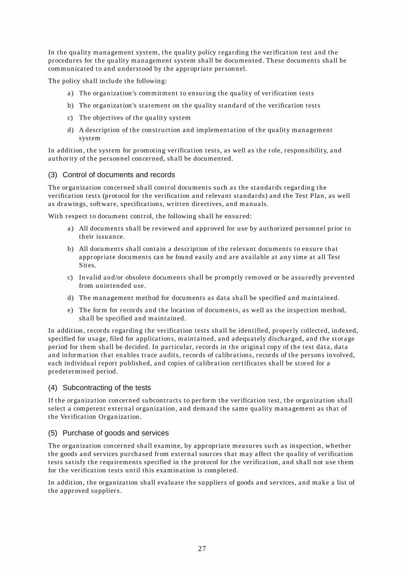
(3) Control of documents and records
The organization concerned shall control documents such as the standards regarding the verification tests (protocol for the verification and relevant standards) and the Test Plan, as well as drawings, software, specifications, written directives, and manuals.
With respect to document control, the following shall be ensured:
a) All documents shall be reviewed and approved for use by authorized personnel prior to their issuance.
b) All documents shall contain a description of the relevant documents to ensure that appropriate documents can be found easily and are available at any time at all Test Sites.
c) Invalid and/or obsolete documents shall be promptly removed or be assuredly prevented from unintended use.
d) The management method for documents as data shall be specified and maintained.
e) The form for records and the location of documents, as well as the inspection method, shall be specified and maintained.
In addition, records regarding the verification tests shall be identified, properly collected, indexed, specified for usage, filed for applications, maintained, and adequately discharged, and the storage period for them shall be decided. In particular, records in the original copy of the test data, data and information that enables trace audits, records of calibrations, records of the persons involved, each individual report published, and copies of calibration certificates shall be stored for a predetermined period.
(4) Subcontracting of the tests
If the organization concerned subcontracts to perform the verification test, the organization shall select a competent external organization, and demand the same quality management as that of the Verification Organization.
(5) Purchase of goods and services
The organization concerned shall examine, by appropriate measures such as inspection, whether the goods and services purchased from external sources that may affect the quality of verification tests satisfy the requirements specified in the protocol for the verification, and shall not use them for the verification tests until this examination is completed.
In addition, the organization shall evaluate the suppliers of goods and services, and make a list of the approved suppliers.

28
(6) Control of complaints and nonconforming tests
The organization concerned shall have a system and method that shall be implemented when any of its verification tests or the results of these tests do not conform to the protocol for the verification or other specifications for any reason. The organization shall have a system and method for handling contingencies such as complaints from environmental technology developers, the inhibition of impartiality, information leaks, and others. These systems shall include a person in charge and personnel required for the handling of such cases.
(7) Corrective and preventive actions When any of its verification tests or the results of these tests do not or may not conform to the protocol for the verification or other specifications, the organization concerned shall investigate the reasons therefor and take corrective or preventive actions.
(8) Audit
The organization concerned shall conduct audits to judge whether the verification test has been properly conducted. When the verification test is subcontracted to an external organization, the operations of the subcontracted organization shall be audited.
The audit shall be conducted at least once during the test period. If the verification test lasts 2 years or more, the audit shall be conducted periodically, and the frequency of audit shall desirably be more than once per year. In addition, the audit shall be conducted by personnel who are independent of the verification test to as great an extent as possible. The results of the audit shall be reported to the superintendent of the organization concerned.
4. Technical requirements
(1) Personnel
The organization concerned shall ensure the competence of all who operate specific equipment for the verification test, perform tests, evaluate results, and sign test reports. The personnel performing specific tasks shall be qualified on the basis of appropriate education, training, and/or demonstrated skills, as required.
(2) Accommodation and environmental conditions
The facilities for the verification test, including but not limited to energy sources, lighting, and environmental conditions, shall be such as to facilitate correct performance of the tests. The organization concerned shall ensure that the environmental conditions do not invalidate the results or adversely affect the required quality of any measurement. Particular care shall be taken when the verification test is undertaken at sites other than a permanent laboratory facility.
The organization concerned shall monitor, control, and record environmental conditions of the test in accordance with the protocol for the verification, the Test Plan, and other standards. Tests shall be stopped when the environmental conditions jeopardize the results of the tests.
(3) Test methods and method validation
The organization concerned shall use appropriate methods and procedures for all tests within its scope and determine the test methods in accordance with the protocol for the verification.

29
When the method to be used is not specified in the protocol for the verification, the organization concerned shall select either an appropriate method disclosed in international standards, regional or national standards, scientific texts, or the like, or a method specified by the manufacturer of the equipment. When it is necessary to use methods not covered by standard methods, these shall be subject to agreement with the verification applicant, and their validity shall be appropriately examined prior to use. Validation is the confirmation by examination that the requirements for a specific intended use are fulfilled. The validation shall be conducted based on discussion and subsequent approval by the Technology Panel.
When computers or automated equipment are used for data management, the organization concerned shall provide suitable environmental and operational conditions for the purpose of managing the computers and automated equipment properly, to ensure that there is no loss or improper conversion of data as a result of accidental erasure.
(4) Equipment
The organization concerned shall be furnished with (or leased) all items of the equipment required for the execution of verification tests. If a piece of equipment can only be operated by authorized personnel, the organization concerned shall specify the equipment. Equipment that has been subjected to overloading or mishandling, gives suspect results, or has been shown to be defective or outside specified limits, shall be taken out of service until it has been repaired and confirmed to perform correctly.
(5) Measurement traceability All equipment used for tests that has a significant effect on the accuracy or validity of the result of the verification test shall be calibrated before being put into service.
(6) Sampling
The organization concerned shall take samples of reagents, materials, or products in accordance with the protocol for the verification.
(7) Handling of test and calibration items If necessary, the organization concerned shall transport, receive, handle, protect, store, retain, and/or dispose of test items in accordance with the protocol for the verification.
(8) Verification of data and assurance of test result quality
The data resulting from the verification test shall be recorded in such a way that trends are detectable and, where practicable, statistical techniques shall be applied to the review of the results. This verification shall be conducted by a person other than the one who conducts the verification test.
(9) Reporting the results
The organization concerned shall report the results of the test conducted accurately, clearly, unambiguously, and objectively in accordance with the protocol of the verification tests.

30
Appendix 1: Application form for verification The verification applicant should submit the application form specified below. In particular, be sure to fill in the columns designated with *, which indicates important information for the selection of verification target technologies.
[Applicant]
Company name* Address* Division and name of person in charge*
TEL: FAX: Contact address* e-mail:
Name of technology/product*
1. In-house test results
Items Unit Measured value, etc. Test method
(Describe the method of determining concentration)
Treatment time min Gas to be treated
Sterilizer used Capacity of the sterilizer used L
Temperature °C Static pressure hPa
During gas evacuation Nm3/min
Test conditions
Influent gasFlow rate
During cleaning evacuation Nm3/min
During gas evacuation ppm Maximum
exhaust concentration
of ethylene oxide
During cleaning evacuation ppm
Temperature °C
Test results
Waste gas Static pressure hPa
Maximum amount of treatment per unit time g/min
* If continuously measured data on the exhaust concentration of ethylene oxide is available, attach the relevant data. * The influent gas is a gas supplied into the target verification apparatus for measurement of the treatment efficiency.

31
2. Product data (Submit a technical specification as an attached document.)
Items Description Name of the target verification apparatus*
Serial number
Name of the manufacturer*
TEL ( ) –
Website http://
E-mail @ Contact address*
FAX ( ) –
W(mm)
D(mm) Dimensions* H(mm)
Weight (kg)*
Capacity of sterilizer used (L)
Communication device required for operation
Not available - Available Specify the device in detail:
Requirements for compatible sterilizer, e.g.,
shape
Requirements for sterilizer to be connected
Special remarks, such as types of compatible
sterilizers
Necessity of pre- and post-treatment
Not necessary - Necessary Specify the treatment in detail:

32
Items Description
Additional equipment*
Not available - Available Specify the equipment in detail:
Life of the target verification apparatus*
Expense item Unit cost Quantity Total Initial cost Running cost (per operation)
Approximate cost
Examples of expense items of the initial cost: Installation cost, construction cost, etc.
Examples of expense items of the running cost:
Consumables, disposal of secondary products, electricity, etc
Yen/m3 of effluent
3. Developmental status and past delivery record
Check the number that best describes the current situation. 1. The apparatus is only available as a pilot unit and is not commercialized.
2. The apparatus has already been commercialized and is available as a product.
3. The apparatus has past delivery records.
Specify the past records in detail:
4. Other relevant or unique features (if any)

33
[Documents to be attached to this application form]
Basic technical specification for the target verification apparatus
Results of in-house performance tests [Attach not only the performance of treating ethylene oxide gas, but also the measures against electricity failure (during electricity failure of the sterilizers; electricity failure of the target verification apparatuses; and resumption of power supply (resumption of power supply to sterilizers, target verification apparatuses, or both)) and the results of tests on the inflow of a high concentration of ethylene oxide, and the like, if available.]
O&M manual
The O&M manual should include information on the following:
Installation of the target verification apparatus
Startup
Operation (standard operational pattern, required treatment time)
Maintenance and management
Restart of operation following an emergency stop
Calibration and exchange of components
Troubleshooting
Spare parts
Optimization of operation and environmental protection
Ability to handle variations in test conditions
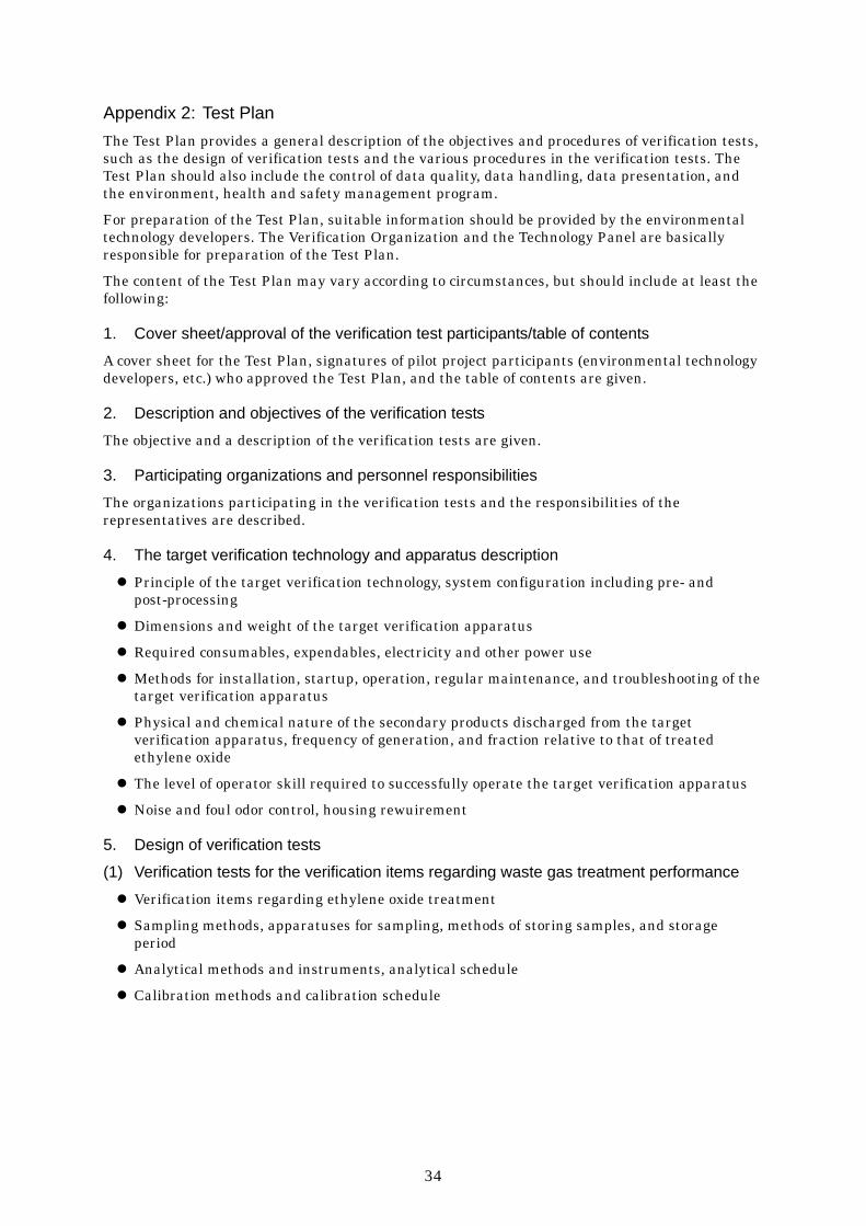
34
Appendix 2: Test Plan The Test Plan provides a general description of the objectives and procedures of verification tests, such as the design of verification tests and the various procedures in the verification tests. The Test Plan should also include the control of data quality, data handling, data presentation, and the environment, health and safety management program.
For preparation of the Test Plan, suitable information should be provided by the environmental technology developers. The Verification Organization and the Technology Panel are basically responsible for preparation of the Test Plan.
The content of the Test Plan may vary according to circumstances, but should include at least the following:
1. Cover sheet/approval of the verification test participants/table of contents
A cover sheet for the Test Plan, signatures of pilot project participants (environmental technology developers, etc.) who approved the Test Plan, and the table of contents are given.
2. Description and objectives of the verification tests
The objective and a description of the verification tests are given.
3. Participating organizations and personnel responsibilities
The organizations participating in the verification tests and the responsibilities of the representatives are described.
4. The target verification technology and apparatus description
Principle of the target verification technology, system configuration including pre- and post-processing
Dimensions and weight of the target verification apparatus
Required consumables, expendables, electricity and other power use
Methods for installation, startup, operation, regular maintenance, and troubleshooting of the target verification apparatus
Physical and chemical nature of the secondary products discharged from the target verification apparatus, frequency of generation, and fraction relative to that of treated ethylene oxide
The level of operator skill required to successfully operate the target verification apparatus
Noise and foul odor control, housing rewuirement
5. Design of verification tests
(1) Verification tests for the verification items regarding waste gas treatment performance
Verification items regarding ethylene oxide treatment
Sampling methods, apparatuses for sampling, methods of storing samples, and storage period
Analytical methods and instruments, analytical schedule
Calibration methods and calibration schedule

35
(2) Verification tests for the verification items regarding environmental load
Verification items regarding environmental load
Analytical methods and instruments, analytical schedule
(3) Verification tests for the verification items regarding operations and maintenance
Verification items regarding operations and maintenance
Operational schedule, person in charge, and documentation formats
Methods of evaluating the data provided by the environmental technology developer
Other verification items, evaluation methods, and information collection schedule
6. Quality control of data
Methods of documenting measurement procedures
Information on accuracy control
Necessity for supplying additional quality management information (All unprocessed data shall be stored as the Appendix of the Verification Report.)
7. Management, analysis and presentation of data
(1) Data management
The Test Plan should include a description of data management and handling. The methods for managing and handling various types of data that are produced in the verification tests, such as field notes, O&M forms, laboratory reports, computer worksheets, graphs, tables, photos, videos, and the like, should be specified.
The Verification Organization designates one data-quality manager.
(2) Analysis and presentation
The Test Plan should include a detailed description of the methods for analyzing and integrating data. Accordingly, statistical methods and equations for use in analysis, as well as data for use in the presentation and the presentation format of the data should be specified.
8. Audit
The Test Plan should also include information on the audit group.
9. Appendix
The following should be described in the Test Plan as an Appendix:
O&M manual provided by the environmental technology developer
Environmental, hygienic, and safety management program (including material safety data sheets)
Other literature and data for reference

36
Appendix 3: Image of a brief summary of the verification test results 1. Format for providing a brief summary of data
(1) Apparatus
Name of the target verification apparatus
Manufacturer Description of apparatus Test Site Name of the person in charge of measurement
Test period From to
(2) Verification items regarding waste gas treatment performance
[Standard ethylene oxide gas treatment test]
Items Unit Measured value Treatment time min
Ethylene oxide gas concentration % Temperature °C
Static pressure hPa
Test conditions
Influent gas Flow rate Nm3/min
Ethylene oxide average exhaust concentration ppm
Average treatment efficiency (mass balance) %
g/min (Maximum amount
of gas treated)
Amount of treatment per unit time g/min
(Average amount of gas treated)
Temperature °C
Test results
Waste gas Static pressure hPa

37
(Chart illustrating the change in ethylene oxide gas exhaust concentration)
Graph to be attached
(Chart illustrating the change in treatment efficiency)
Graph to be attached

38
[Waste gas treatment test simulating an ethylene oxide sterilizer]
(Pattern A: Prepare two chambers with capacities of approximately 50 L and 150 L)
Items Unit Measured value Treatment time min
Chamber capacity L Temperature °C
Static pressure hPa During gas evacuation Nm3/min
Test conditions
Influent gasFlow rate During
cleaning evacuation
Nm3/min
During gas evacuation ppm Ethylene oxide average exhaust
concentration
During cleaning evacuation ppm
Average treatment efficiency (mass balance) %
Temperature °C
Test results
Waste gas Static pressure hPa
(Exhaust pattern) Pressure in chamber
(Gauge pressure)
Time
Gas evacuation Gas Sterilization Clean-
ing vacuum-ization
Clean-ing
aerat-ion
Cleaning
Clean-ing
ev acu-ation
0 hPa
Approx. 1,000 hPa
Approx. -700 hPa
Repeat aeration f ive times.Depressuri- zation
Clean-ing
aerat-ion
Aeration
Cleaning vacuum-ization Cleaning
Step Time (min) Depressurization
Gas pressurization Sterilization
Gas evacuation Cleaning vacuumization
Cleaning aeration Cleaning
Cleaning evacuation
Cleaning vacuumization
Cleaning aeration
Aeration
Cleaning

39
(Chart illustrating the change in concentration)
Graph to be attached
(Chart illustrating the change in treatment efficiency)
Graph to be attached

40
(Pattern B:Prepare two chambers with capacities of approximately 50 L and 150 L.)
Exhauster: [Air ejector or dry pump]
Items Unit Measured value Treatment time min
Chamber capacity L Temperature °C
Static pressure hPa During gas evacuation Nm3/min
Test conditions
Influent gasFlow rate During
cleaning evacuation
Nm3/min
During gas evacuation ppm Ethylene oxide average exhaust
concentration
During cleaning evacuation ppm
Average treatment efficiency (mass balance) %
Temperature °C
Test results
Waste gas Static pressure hPa
(Exhaust pattern) Pressure in chamber
(Gauge pressure)
Cleaning (continuous)
Gas pressuri-
zation Sterilization Depressurization
Supply air in an amount 10 times larger than the capacity of the chamber.
0 hPa
Approx. -800 hPa
Gas evacuation
Time
Step Time (min) Depressurization
Gas pressurization Sterilization
Gas evacuation Cleaning (continuous)

41
(Chart illustrating the change in concentration)
Graph to be attached
(Chart illustrating the change in treatment efficiency)
Graph to be attached

42
(3) Verification items regarding environmental load
[Pattern A: Chamber capacity L]
Items Unit Measured value
CO concentration ppm
NOx concentration ppm
Amount of secondary products generated Arbitrary
Noise dB
[Pattern B: Chamber capacity L]
Items Unit Measured value
CO concentration ppm
NOx concentration ppm
Amount of secondary products generated Arbitrary
Noise dB
(4) Verification items regarding operations and maintenance
[Pattern A: Chamber capacity L]
Items Unit Measured value
Electricity consumption kWh/operation
Fuel consumption Arbitrary
Water consumption L/operation
Other chemical consumption such as reactant Arbitrary
[Pattern B: Chamber capacity L]
Items Unit Measured value
Electricity consumption kWh/operation
Fuel consumption Arbitrary
Water consumption L/operation
Other chemical consumption such as reactant Arbitrary

43
Items Findings
Number of operators and the level of operator expertise required for O&M of the
apparatus
Safety of the target verification apparatus
Measures in the event of emergency (during electricity failure)
(1) During electricity failure of the sterilizers: (2) During electricity failure of the target verification apparatuses: (3) During resumption of the power supply:
Measures in the event of emergency (During the inflow of high-concentration
ethylene oxide)
Consistency of treatment performance
Method of restoring from problems
Evaluation of O&M manual
Others (Heat generation in target verification
apparatus, etc.)

44
(5) Product data
Items Description Name of the target verification apparatus
Serial number
Name of manufacturer (distributing agent)
TEL ( ) –
Website http://
E-mail @ Contact address
FAX ( ) –
W(mm)
D(mm) Dimensions H(mm)
Weight (kg)
Capacity of the sterilizer used (L)
Communication device required for operation
Not available - Available Specify the device in detail:
Requirements for compatible sterilizer, e.g.,
shape
Requirements for the sterilizer to
be connected
Special remarks, such as types of compatible
sterilizers
Necessity of pre- and post-treatment
Not necessary - Necessary Specify the treatment in detail:
Additional equipment
Not available - Available Specify the equipment in detail:
Life of the target verification apparatus

45
Items Description Expense item Unit cost Quantity Total
Initial cost Running cost (Per operation, per unit amount of gas treated)
Approximate cost
Examples of expense items of the initial cost: Installation cost, construction cost, etc.
Examples of expense items of the running cost: Consumables, disposal of secondary products,
electricity, etc.
(6) Miscellaneous
Indicate points to keep in mind.

i
Reference I. Brief overview of the pilot project for the environmental technology verification 1. Objectives
Many innovative environmental technologies that are already in a practically applicable stage and seem to be useful have not come into wide use because end users, including local municipal entities, companies, consumers, and the like, cannot use the technologies with confidence due to the lack of objective evaluation of the environmental protective effect and the like.
Accordingly, in this pilot project for the environmental technology verification, with respect to the innovative environmental technologies that have not been widely accepted as described above, the environment protective effect and others will be objectively verified by an independent organization on an experimental basis.
It is hoped that the pilot project for the environmental technology verification will accelerate the dissemination of the environmental technologies developed by venture companies and the like, and contribute to the activation of economic activity through environmental protection and the advancement of regional environmental industries.
2. What the “verification” means
In the pilot project for the environmental technology verification, the environmental protective effect and the like of particular environmental technologies will be verified through the collection of objective data based on various tests and others. There is a similar term, “certification,” in which the suitability to the standard of an environmental technology is judged in terms of the performance that a technology should provide. The present project does not conduct such “certification.”
3. System for promoting the project
The pilot project for the environmental technology verification will be carried out by the Ministry of the Environment in cooperation with the “Verification Organizations” (local municipal entities, etc.), which are independent organizations that conduct technology verification under the entrustment and contract of the Ministry of the Environment.
4. Procedures of the project
The pilot project for the environmental technology verification will generally be conducted in accordance with the following procedures:
(1) The Ministry of the Environment will identify the needs of the technology developers / distributing agents, users, and others, through the use of questionnaires or the like.
(2) The Ministry of the Environment will select target verification technology fields based on discussions in the committee on the pilot project for the environmental technology verification.
(3) The Ministry of the Environment will prepare a “protocol for the verification,” which establishes the specific methods of technology verification regarding the selected target verification technology fields.
(4) The Ministry of the Environment will select the “Verification Organizations,” which are the independent organizations that conduct the verification tests.
(5) The Verification Organizations will invite applications from companies and the like for the technology to be verified.
(6) The Verification Organization will select the technologies to be verified in the project from among the applications, following discussion in a panel consisting of the specialists.
(7) The Verification Organizations will conduct verification tests on the selected technologies in accordance with the protocol for the verification.

ii
(8) The Verification Organizations will summarize the results of the test in report form, notify the technology developers/distributing agents of them, and report to the Ministry of the Environment. In addition, the report will be registered in a database on the Internet and made available to the public.

iii
II. System for promotion of the “pilot project for the environmental technology verification”
• Discussion and advice regarding the verification test
(IAI) National Institute for Environmental Studies • Development of the technology
relevant to verification tests
The Ministry of the Environment
Environmental Policy Bureau • Management of the entire pilot project • Preparation of implementation guidance • Selection of target technology fileds
Each division and department • Management of and advice on projects in
particular fields • Preparation of a protocol for the verification • Selection of verification organizations • Selection of candidate target technology fields
The committee on the pilot project for the environmental technology verification
• Discussion and advice regarding the pilot project
WGs in respective fields• Discussion and advice concerning
items regarding technology verifications in the respective fields
Database operating organization • Operation and management
of the ETV database • Registration of the outline
of the verification tests • Registration of the report on
the verification test results prepared by verification organizations
Verification organizations (environment-related divisions of local governments, etc.)
• Public offering and selection of target technologies • Establishment of the plan for the verification test • Execution of verification tests • Preparation of the report on the verification test • Report to the Ministry for the Environment and
registration of information with the database organization
Technology Panel

iv
III. Flow of the pilot project for the environmental technology verification
“Pilot project implementation guidance”
Basic reference for promotion of the project and its period of application
“Image of protocol for the verification”
“Protocol for the verification”
“Plan for the Verification test”
Flow of the project Responsible party
Selection of “target technology fields”
Preparation of an “Protocol for the verification”
Public offering and selection of “verification Organizations”
Public offering and selection of “target technologies”
Preparation of a “plan for the verification test ” if necessary
Execution of “verification tests”
Preparation of a “report on the verification test”
Registration of data to the ETV database and disclosure of the data
The committee on the pilot project for the environmental technology
verification, Ministry of the Environment
WGs in respective fields, Ministry of the Environment
WGs in respective fields, Ministry of the Environment
Verification Organizations, Technology Panels
Verification Organizations (subcontract in some cases)
Verification organizations and the database operating organization
Verification Organizations, Technology Panels
Verification Organizations, Technology Panels

v
IV. Prospectus for organizing the working group on the ethylene oxide treatment technology in the committee on the pilot project for the environmental technology verification for 2003
1. Objective of the working group
The working group on the ethylene oxide treatment technology is established for the purpose of discussing based on specialized knowledge the “ethylene oxide treatment technology” in the technology areas in which technology verification is scheduled to be conducted in 2003, in the pilot project for the environmental technology verification and thus promoting the project smoothly and efficiently.
2. Items to be investigated and discussed
(1) Fields of ethylene oxide treatment technology
i Preparation of a protocol for the verification ii Selection of Verification Organizations iii Confirmation of Verification Reports iv Other items relevant to execution of the project
(2) How future verification tests shall be conducted, and the selection of candidate technology fields
3. Organization and others
(1) The working group consists of 10 or fewer members.
(2) The working group has a chairperson.
(3) The chairperson will supervise the working group.
(4) The members will be appointed by UFJ Institute Ltd., from among academic experts, well-informed individuals, and the like relevant to verification tests on ethylene oxide treatment technology, with the approval of the Environmental Management Bureau of the Ministry of the Environment.
(5) The members will be under commission for the period from the date of appointment by UFJ Institute Ltd. to the end of the same fiscal year.
(6) In addition, participants and interested parties in the pilot project for the environmental technology verification may also attend the meetings of the working group as observers and the like, if necessary.
4. Disclosure of the discussion and others, etc.
Meetings of the working group will, in principle, be held in public. However, the chairperson may hold a closed meeting of the working group if a public meeting may cause significant obstacles to fair and neutral discussion, and provide particular individuals with unfair benefit or detriment.
5. Secretariat
The general affairs of the working group will be processed by UFJ Institute Ltd., with the consent of the Environmental Management Bureau of the Ministry of the Environment.
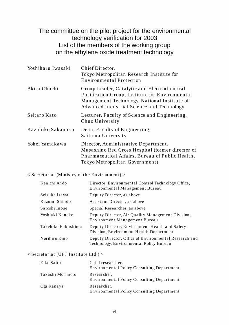
vi
The committee on the pilot project for the environmental technology verification for 2003
List of the members of the working group on the ethylene oxide treatment technology
Yoshiharu Iwasaki Chief Director, Tokyo Metropolitan Research Institute for Environmental Protection
Akira Obuchi Group Leader, Catalytic and Electrochemical Purification Group, Institute for Environmental Management Technology, National Institute of Advanced Industrial Science and Technology
Seitaro Kato Lecturer, Faculty of Science and Engineering, Chuo University
Kazuhiko Sakamoto Dean, Faculty of Engineering, Saitama University
Yohei Yamakawa Director, Administrative Department, Musashino Red Cross Hospital (former director of Pharmaceutical Affairs, Bureau of Public Health, Tokyo Metropolitan Government)
< Secretariat (Ministry of the Environment) > Kenichi Ando Director, Environmental Control Technology Office,
Environmental Management Bureau Seisuke Izawa Deputy Director, as above Kazumi Shindo Assistant Director, as above Satoshi Inoue Special Researcher, as above Yoshiaki Kaneko Deputy Director, Air Quality Management Division,
Environment Management Bureau Takehiko Fukushima Deputy Director, Environment Health and Safety
Division, Environment Health Department Norihiro Kino Deputy Director, Office of Environmental Research and
Technology, Environmental Policy Bureau
< Secretariat (UFJ Institute Ltd.) > Eiko Saito Chief researcher,
Environmental Policy Consulting Department Takashi Morimoto Researcher,
Environmental Policy Consulting Department Ogi Kanaya Researcher,
Environmental Policy Consulting Department

vii
V. Particulars discussed in the working group on the ethylene oxide treatment technology
First meeting: 10:00 to 12:00, July 15, 2003
Pilot project for the environmental technology verification
Ethylene oxide treatment technology
Protocol for the verification (draft)
Second meeting: 9:00 to 12:00, August 5, 2003
Opinions on the protocol for the verification (draft)
Shimakawa Seisakusho Co., Ltd.
Achieve Corporation
Miura Co., Ltd.
Sakura Seiki Co., Ltd.
Muraki Co., Ltd.
Pax Co., Ltd.
Protocol for the verification (draft)
Third meeting: 10:00 to 12:00, September 2, 2003
Protocol for the verification (second draft)
Public offering and selection of Verification Organizations