Protection of cell sites (4G / LTE)
8
Protection of cell sites (4G / LTE) 917
Transcript of Protection of cell sites (4G / LTE)
Protection of cell sites (4G / LTE)
917
LIGHTNING PROTECTION GUIDE 355www.dehn-international.com
Besides voice communication, mobile data communication gained momentum with the commercial introduction of UMTS technology in 2003. Due to this increased demand for data volumes, the global demand for bandwidth also grew. The increased use of smartphones and other mobile devices pushes current conventional network spectrums to their limits. The high investment costs for new network infrastructures and system technology as well as high maintenance and operating costs for existing cell sites are disadvantages mo-bile network operators using this modern and innovative technology have to deal with. Consequently, their aim is to efficiently reduce maintenance and operating costs and to provide an ever growing number of mobile phone users with considerably increased availability and reliability of mobile services.Mobile network operators and system technology manufac-turers worldwide increasingly use remote radio head / unit technology for UMTS (3G) and LTE (4G). Remote radio heads / units (RRHs / RRUs) are an enhancement of the third mobile radio generation. Remote radio head technology is not only used for commer-cial mobile radio applications, but also for the digital radio systems of security authorities (BOS) such as police depart-ments and rescue services since these systems require high reliability and availability.
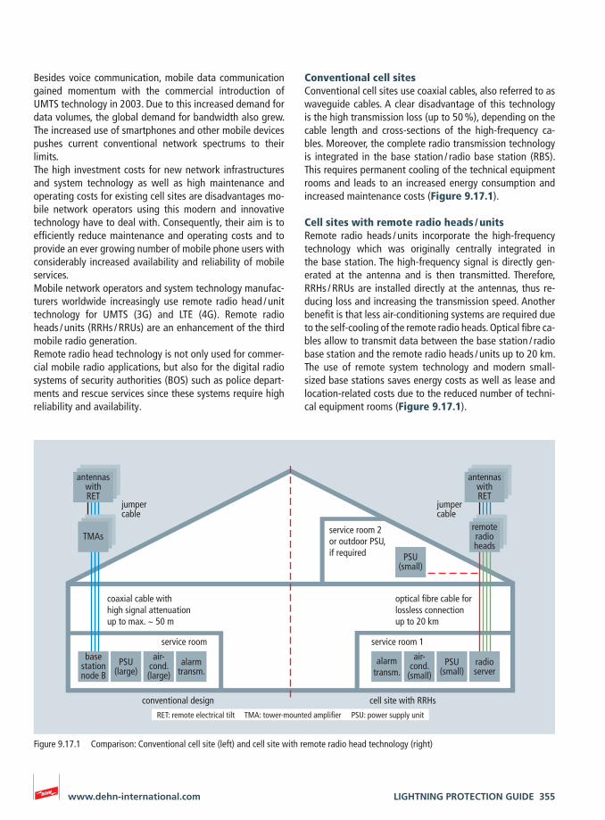
Conventional cell sitesConventional cell sites use coaxial cables, also referred to as waveguide cables. A clear disadvantage of this technology is the high transmission loss (up to 50 %), depending on the cable length and cross-sections of the high-frequency ca-bles. More over, the complete radio transmission technology is integrated in the base station / radio base station (RBS). This requires permanent cooling of the technical equipment rooms and leads to an increased energy consumption and increased maintenance costs (Figure 9.17.1).
Cell sites with remote radio heads / unitsRemote radio heads / units incorporate the high-frequency technology which was originally centrally integrated in the base station. The high-frequency signal is directly gen-erated at the antenna and is then transmitted. Therefore, RRHs / RRUs are installed directly at the antennas, thus re-ducing loss and increasing the transmission speed. Another benefit is that less air-conditioning systems are required due to the self-cooling of the remote radio heads. Optical fibre ca-bles allow to transmit data between the base station / radio base station and the remote radio heads / units up to 20 km. The use of remote system technology and modern small-sized base stations saves energy costs as well as lease and location-related costs due to the reduced number of techni-cal equipment rooms (Figure 9.17.1).
alarmtransm.
air-cond.
(small)PSU
(small)
PSU(small)
radioserver
basestationnode B
service room service room 1
service room 2or outdoor PSU,if required
coaxial cable with high signal attenuationup to max. ~ 50 m
optical fibre cable forlossless connection up to 20 km
air-cond.(large)
PSU(large)
alarmtransm.
remoteradioheads
antennaswithRET
TMAs
conventional design cell site with RRHs
antennaswithRET
jumpercable
jumpercable
RET: remote electrical tilt TMA: tower-mounted amplifier PSU: power supply unit
Figure 9.17.1 Comparison: Conventional cell site (left) and cell site with remote radio head technology (right)
356 LIGHTNING PROTECTION GUIDE www.dehn-international.com
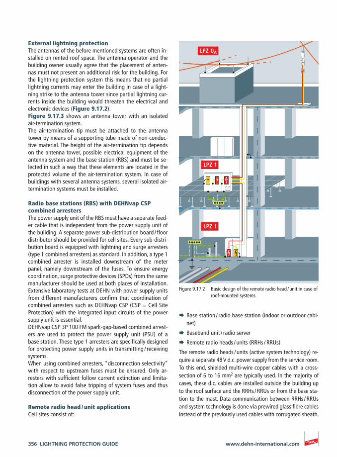
External lightning protectionThe antennas of the before mentioned systems are often in-stalled on rented roof space. The antenna operator and the building owner usually agree that the placement of anten-nas must not present an additional risk for the building. For the lightning protection system this means that no partial lightning currents may enter the building in case of a light-ning strike to the antenna tower since partial lightning cur-rents inside the building would threaten the electrical and electronic devices (Figure 9.17.2). Figure 9.17.3 shows an antenna tower with an isolated air-termination system.The air-termination tip must be attached to the antenna tower by means of a supporting tube made of non-conduc-tive material. The height of the air-termination tip depends on the antenna tower, possible electrical equipment of the antenna system and the base station (RBS) and must be se-lected in such a way that these elements are located in the protected volume of the air-termination system. In case of buildings with several antenna systems, several isolated air-termination systems must be installed.
Radio base stations (RBS) with DEHNvap CSP combined arrestersThe power supply unit of the RBS must have a separate feed-er cable that is independent from the power supply unit of the building. A separate power sub-distribution board / floor distributor should be provided for cell sites. Every sub-distri-bution board is equipped with lightning and surge arresters (type 1 combined arresters) as standard. In addition, a type 1 combined arrester is installed downstream of the meter panel, namely downstream of the fuses. To ensure energy coordination, surge protective devices (SPDs) from the same manufacturer should be used at both places of installation. Extensive laboratory tests at DEHN with power supply units from different manufacturers confirm that coordination of combined arresters such as DEHNvap CSP (CSP = Cell Site Protection) with the integrated input circuits of the power supply unit is essential.DEHNvap CSP 3P 100 FM spark-gap-based combined arrest-ers are used to protect the power supply unit (PSU) of a base station. These type 1 arresters are specifically designed for protecting power supply units in transmitting / receiving systems. When using combined arresters, “disconnection selectivity” with respect to upstream fuses must be ensured. Only ar-resters with sufficient follow current extinction and limita-tion allow to avoid false tripping of system fuses and thus disconnection of the power supply unit.
Remote radio head / unit applications Cell sites consist of:
¨ Base station / radio base station (indoor or outdoor cabi-net)
¨ Baseband unit / radio server
¨ Remote radio heads / units (RRHs / RRUs)
The remote radio heads / units (active system technology) re-quire a separate 48 V d.c. power supply from the service room. To this end, shielded multi-wire copper cables with a cross-section of 6 to 16 mm2 are typically used. In the majority of cases, these d.c. cables are installed outside the building up to the roof surface and the RRHs / RRUs or from the base sta-tion to the mast. Data communication between RRHs / RRUs and system technology is done via prewired glass fibre cables instead of the previously used cables with corrugated sheath.
Figure 9.17.2 Basic design of the remote radio head / unit in case of roof-mounted systems

LIGHTNING PROTECTION GUIDE 357www.dehn-international.com
power supply unit
base station (radio base station)
optical fibre cable
48 v d.c. feeder cable
telecommunication – information technology system
distribution network operator (DNO) 230/400 V
basebandunit (BBU)
mast
d.c. outdoor box
remoteradio head / unit
Figure 9.17.3 Remote radio head / unit and radio base station (RBS) in case of ground-mounted masts
358 LIGHTNING PROTECTION GUIDE www.dehn-international.com
No. in 9.17.3 Protection Type Part No.
a.c. power supply
Base station (230/400 V a.c.) DEHNvap CSP 3P 100 FM 900 360
d.c. power supply
Power supply unit (48 V d.c.) DEHNsecure DSE M 1 60 FM 971 126
Remote radio head (48 V d.c.) DEHNsecure DSE M 2P 60 FM 971 226
Fixed-line connection
Telecommunication linesBLITZDUCTOR XT BXT ML4 B 180+ BXT BAS base part
920 310920 300
External lightning protection
Ground-mounted system / roof-mounted system Equipotential bonding bar, 10 terminals 472 219
Ground-mounted system / roof-mounted system HVI Conductor III 819 025
Ground-mounted system / roof-mounted system GRP/Al supporting tube 105 300
Ground-mounted system / roof-mounted system Terminal plate 301 339
Ground-mounted system / roof-mounted system Pipe clamp for antennas 540 100
Ground-mounted system Stainless steel terminal bracket 620 915
Ground-mounted system Stainless steel earth rod 620 902
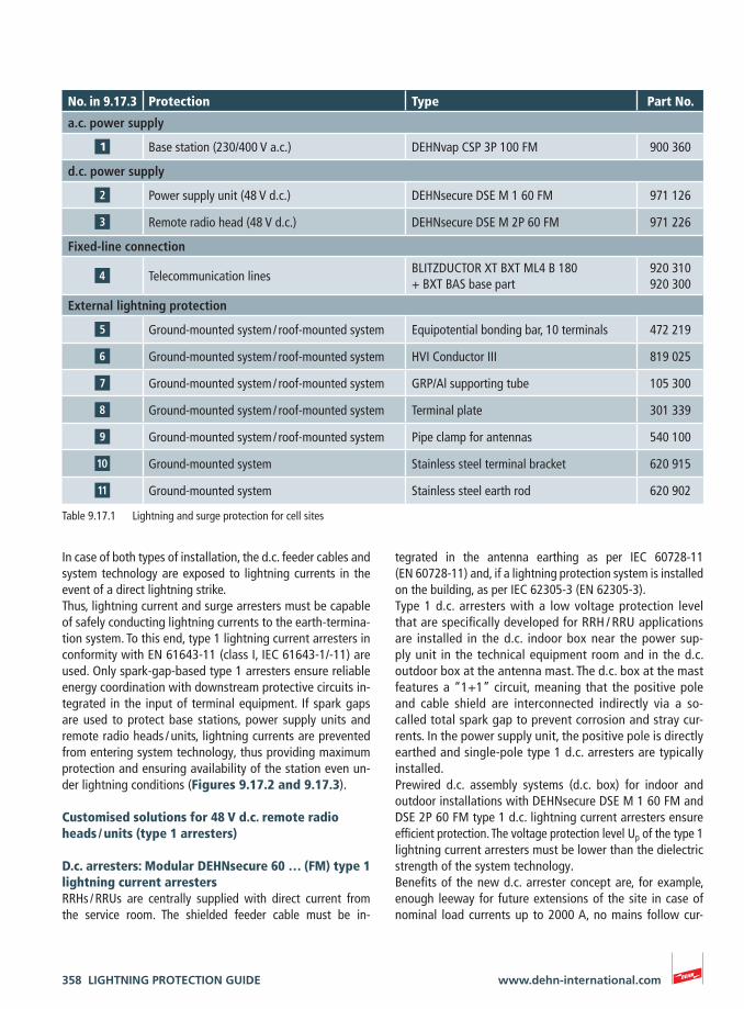
Table 9.17.1 Lightning and surge protection for cell sites
In case of both types of installation, the d.c. feeder cables and system technology are exposed to lightning currents in the event of a direct lightning strike.Thus, lightning current and surge arresters must be capable of safely conducting lightning currents to the earth-termina-tion system. To this end, type 1 lightning current arresters in conformity with EN 61643-11 (class I, IEC 61643-1/-11) are used. Only spark-gap-based type 1 arresters ensure reliable energy coordination with downstream protective circuits in-tegrated in the input of terminal equipment. If spark gaps are used to protect base stations, power supply units and remote radio heads / units, lightning currents are prevented from entering system technology, thus providing maximum protection and ensuring availability of the station even un-der lightning conditions (Figures 9.17.2 and 9.17.3). Customised solutions for 48 V d.c. remote radio heads / units (type 1 arresters)
D.c. arresters: Modular DEHNsecure 60 … (FM) type 1 lightning current arrestersRRHs / RRUs are centrally supplied with direct current from the service room. The shielded feeder cable must be in-
tegrated in the antenna earthing as per IEC 60728-11 (EN 60728-11) and, if a lightning protection system is installed on the building, as per IEC 62305-3 (EN 62305-3). Type 1 d.c. arresters with a low voltage protection level that are specifically developed for RRH / RRU applications are installed in the d.c. indoor box near the power sup-ply unit in the technical equipment room and in the d.c. outdoor box at the antenna mast. The d.c. box at the mast features a “1+1” circuit, meaning that the positive pole and cable shield are interconnected indirectly via a so-called total spark gap to prevent corrosion and stray cur-rents. In the power supply unit, the positive pole is directly earthed and single-pole type 1 d.c. arresters are typically installed.Prewired d.c. assembly systems (d.c. box) for indoor and outdoor installations with DEHNsecure DSE M 1 60 FM and DSE 2P 60 FM type 1 d.c. lightning current arresters ensure efficient protection. The voltage protection level Up of the type 1 lightning current arresters must be lower than the dielectric strength of the system technology.Benefits of the new d.c. arrester concept are, for example, enough leeway for future extensions of the site in case of nominal load currents up to 2000 A, no mains follow cur-
LIGHTNING PROTECTION GUIDE 359www.dehn-international.com
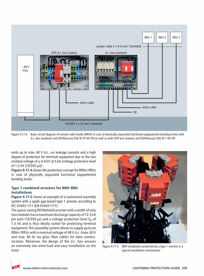
RRU 1
jumper cable 2 x 4 / 6 mm2 (shielded)
d.c. box (outdoor)OVP, d.c. box (indoor)
alarm cablealarm cable
– 48 VPSU
RRU 2 RRU 3
EB
NYCWY 2 x 16 mm2 (shielded)
rents up to max. 60 V d.c., no leakage currents and a high degree of protection for terminal equipment due to the low residual voltage of ≤ 0.4 kV at 5 kA (voltage protection level of 1.5 kV (10/350 µs)). Figure 9.17.4 shows the protection concept for RRHs / RRUs in case of physically separated functional equipotential bonding levels.
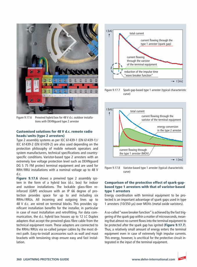
Type 1 combined arresters for RRH / RRU installationsFigure 9.17.5 shows an example of a customised assembly system with a spark-gap-based type 1 arrester according to IEC 61643-1/11 (EN 61643-1/11). The space-saving DEHNshield arrester with a width of only two modules has a maximum discharge capacity of 12.5 kA per pole (10/350 µs) and a voltage protection level Up of 1.5 kV and is thus ideally suited for protecting terminal equipment. This assembly system allows to supply up to six RRHs / RRUs with a nominal voltage of 48 V d.c. (max. 60 V and max. 80 A) via glass fibre cables for data commu-nication. Moreover, the design of the d.c. box ensures an extremely low wind load and easy installation on the mast.
Figure 9.17.4 Basic circuit diagram of remote radio heads (RRHs) in case of physically separated functional equipotential bonding levels with d.c. box (outdoor) and DEHNsecure DSE M 2P 60 FM as well as with OVP box (indoor) and DEHNsecure DSE M 1 60 FM
Figure 9.17.5 RRH installation protected by a type 1 arrester in a typical installation environment
360 LIGHTNING PROTECTION GUIDE www.dehn-international.com
Comparison of the protective effect of spark-gap-based type 1 arresters with that of varistor-based type 1 arrestersEnergy coordination with terminal equipment to be pro-tected is an important advantage of spark gaps used in type 1 arresters (10/350 µs) over MOVs (metal oxide varistors).
A so-called “wave breaker function” is achieved by the fast trig-gering of the spark gap within a matter of microseconds, mean-ing that almost no current flows into the terminal equipment to be protected after the spark gap has ignited (Figure 9.17.7). Thus, a relatively small amount of energy enters the terminal equipment even in case of extremely high impulse currents. This energy, however, is uncritical for the protective circuit in-tegrated in the input of the terminal equipment.
Customised solutions for 48 V d.c. remote radio heads / units (type 2 arresters)Type 2 assembly systems as per IEC 61439-1 (EN 61439-1) / IEC 61439-2 (EN 61439-2) are also used depending on the protection philosophy of mobile network operators and system manufacturers, technical specifications and country-specific conditions. Varistor-based type 2 arresters with an extremely low voltage protection level such as DEHNguard DG S 75 FM protect terminal equipment and are used for RRH / RRU installations with a nominal voltage up to 48 V d.c. Figure 9.17.6 shows a prewired type 2 assembly sys-tem in the form of a hybrid box (d.c. box) for indoor and outdoor installations. The lockable glass-fibre re-inforced (GRP) enclosure with an IP 66 degree of pro-tection provides space for up to and including six RRHs / RRUs. All incoming and outgoing lines up to 48 V d.c. are wired on terminal blocks. This provides sig-nificant installation benefits for the installer, in particular in case of mast installation and retrofitting. For data com-munication, the d.c. hybrid box houses up to 12 LC Duplex adapters that accept the prewired glass fibre cable from the technical equipment room. These adapters are connected to the RRHs / RRUs via so-called jumper cables by the most di-rect path. Easy-to-install accessories such as wall and mast brackets with tensioning strap ensure easy and fast instal-lation.
Figure 9.17.6 Prewired hybrid box for 48 V d.c. outdoor installa-tions with DEHNguard type 2 arrester
Figure 9.17.8 Varistor-based type 1 arrester (typical characteristic curve)
Figure 9.17.7 Spark-gap-based type 1 arrester (typical characteristic curve)
t [ms]
I [kA]total current
current flowing through the type 1 arrester (MOV)
current flowing through the varistor of the terminal equipment
energy conversion in the type 2 arrester
I [kA]
t [ms]
total current
current flowing through the type 1 arrester (spark gap)
current flowing through the varistor of the terminal equipment
reduction of the impulse time“wave breaker function”

LIGHTNING PROTECTION GUIDE 361www.dehn-international.com
If MOV-based surge protective devices are used, the current flows into the terminal equipment to be protected over the entire impulse duration. In many cases, the connected a.c. / d.c. power supply unit and system technology are damaged and in the worst case completely destroyed (Figure 9.17.8).
System tests with mobile radio equipment from different manufacturers clearly show that only spark gaps ensure the required degree of protection in this field of application.