PROPRIETARY NOTICE AND LIABILITY DISCLAIMER · iii Contents Preface .....xiii
155
First Printing — May 1996 Copyright 1996 Copyright 1996 NEC Technologies, Inc. NEC Corporation 1414 Massachusetts Avenue 7-1 Shiba 5-Chome, Minato-Ku Boxborough, MA 01719 Tokyo 108-01, Japan All Rights Reserved All Rights Reserved PROPRIETARY NOTICE AND LIABILITY DISCLAIMER The information disclosed in this document, including all designs and related materials, is the valuable property of NEC Corporation (NEC) and/or its licensors. NEC and/or its li- censors, as appropriate, reserve all patent, copyright and other proprietary rights to this document, including all design, manufacturing, reproduction, use, and sales rights thereto, except to the extent said rights are expressly granted to others. The NEC product(s) discussed in this document are warranted in accordance with the terms of the Warranty Statement accompanying each product. However, actual performance of each such product is dependent upon factors such as system configuration, customer data, and operator control. Since implementation by customers of each product may vary, the suitability of specific product configurations and applications must be determined by the customer and is not warranted by NEC. To allow for design and specification improvements, the information in this document is subject to change at any time, without notice. Reproduction of this document or portions thereof without prior written approval of NEC is prohibited. MultiSync and PowerMate are U.S. registered trademarks of NEC Technologies, Inc. FastFacts is a U.S. trademark of NEC Technologies, Inc. All other product, brand, or trade names used in this publication are the trademarks or registered trademarks of their respective trademark owners.
Transcript of PROPRIETARY NOTICE AND LIABILITY DISCLAIMER · iii Contents Preface .....xiii

First Printing — May 1996
Copyright 1996 Copyright 1996NEC Technologies, Inc. NEC Corporation
1414 Massachusetts Avenue 7-1 Shiba 5-Chome, Minato-KuBoxborough, MA 01719 Tokyo 108-01, Japan
All Rights Reserved All Rights Reserved
PROPRIETARY NOTICE AND LIABILITY DISCLAIMER
The information disclosed in this document, including all designs and related materials, isthe valuable property of NEC Corporation (NEC) and/or its licensors. NEC and/or its li-censors, as appropriate, reserve all patent, copyright and other proprietary rights to thisdocument, including all design, manufacturing, reproduction, use, and sales rights thereto,except to the extent said rights are expressly granted to others.
The NEC product(s) discussed in this document are warranted in accordance with the termsof the Warranty Statement accompanying each product. However, actual performance ofeach such product is dependent upon factors such as system configuration, customer data,and operator control. Since implementation by customers of each product may vary, thesuitability of specific product configurations and applications must be determined by thecustomer and is not warranted by NEC.
To allow for design and specification improvements, the information in this document issubject to change at any time, without notice. Reproduction of this document or portionsthereof without prior written approval of NEC is prohibited.
MultiSync and PowerMate are U.S. registered trademarks of NEC Technologies, Inc.
FastFacts is a U.S. trademark of NEC Technologies, Inc.
All other product, brand, or trade names used in this publication are the trademarks or registered trademarksof their respective trademark owners.
iii
Contents
Preface............................................................................................................................. xiii
Abbreviations .................................................................................................................. xv
Section 1 Technical Information
System Chassis................................................................................................................ 1-2
System Board .................................................................................................................. 1-3
Processor .................................................................................................................. 1-5
Secondary Cache...................................................................................................... 1-6
System and Video BIOS .......................................................................................... 1-6
Power Management.................................................................................................. 1-7
I/O Addressing ......................................................................................................... 1-7
System Memory ....................................................................................................... 1-8
Interrupt Controller .................................................................................................. 1-10
Integrated Graphics .................................................................................................. 1-11
Motion Video Controller ................................................................................. 1-11
Graphics Accelerator ....................................................................................... 1-11
Video Memory................................................................................................. 1-12
ISA Bus.................................................................................................................... 1-12
PCI Local Bus .......................................................................................................... 1-12
PCI Auto Configuration ........................................................................................... 1-13
PCI/IDE Ports .......................................................................................................... 1-13
Parallel Interface ...................................................................................................... 1-13
Serial Interface ......................................................................................................... 1-14
Power Supply .................................................................................................................. 1-15
Diskette Drive ................................................................................................................. 1-15
Hard Disk Drive .............................................................................................................. 1-15
Keyboard ......................................................................................................................... 1-15
Mouse.............................................................................................................................. 1-16
Multimedia Components................................................................................................. 1-16
Integrated Audio ...................................................................................................... 1-16
CD-ROM Reader ..................................................................................................... 1-16
Speakers ................................................................................................................... 1-17
Microphone .............................................................................................................. 1-17
Network Board ................................................................................................................ 1-17
Plug And Play.................................................................................................................. 1-17

iv Contents
Power Management......................................................................................................... 1-17
Desktop Management Interface....................................................................................... 1-18
DMI Components..................................................................................................... 1-18
Manageable Components......................................................................................... 1-18
CI Module ................................................................................................................ 1-19
DMI Browser ........................................................................................................... 1-19
Usage........................................................................................................................ 1-20
Troubleshooting ....................................................................................................... 1-21
Specifications .................................................................................................................. 1-22
Section 2 Setup and Operation
Unpacking and Repacking .............................................................................................. 2-1
Setup................................................................................................................................ 2-1
CD-ROM Reader ............................................................................................................ 2-6
System Configuration...................................................................................................... 2-7
Setup Utility ............................................................................................................. 2-7
How to Start Setup ................................................................................................... 2-8
How to Use Setup .................................................................................................... 2-9
Menu Bar ......................................................................................................... 2-9
Legend Bar....................................................................................................... 2-10
Field Help Window.......................................................................................... 2-11
General Help Window ..................................................................................... 2-11
Main Menu Options......................................................................................... 2-11
IDE Adapters ................................................................................................... 2-12
Memory Cache................................................................................................. 2-14
Memory Shadow.............................................................................................. 2-14
Boot Options.................................................................................................... 2-14
Numlock .......................................................................................................... 2-15
Advanced Menu ....................................................................................................... 2-16
Integrated Peripherals Menu ............................................................................ 2-16
Security Menu .......................................................................................................... 2-18
Power Menu ............................................................................................................. 2-19
Boot Menu ............................................................................................................... 2-20
Exit Menu ................................................................................................................ 2-21
Save Changes & Exit ....................................................................................... 2-21
Discard Changes & Exit .................................................................................. 2-21
Get Default Values........................................................................................... 2-22

Contents v
Load Previous Values ...................................................................................... 2-22
Save Changes................................................................................................... 2-22
BIOS Update Utility........................................................................................................ 2-22
NEC Bulletin Board Service .................................................................................... 2-23
Using the BIOS Update Utility ................................................................................ 2-24
Section 3 Option Installation
General Rules for Installing Options............................................................................... 3-1
Precautions ...................................................................................................................... 3-2
Removing the System Unit Cover ........................................................................... 3-3
Expansion Boards............................................................................................................ 3-4
Expansion Slot Locations ........................................................................................ 3-4
Expansion Board Installation ................................................................................... 3-5
Inside Slot Expansion Board Installation......................................................... 3-7
System Board Options..................................................................................................... 3-9
SIMM Upgrade ........................................................................................................ 3-9
Checking System Memory............................................................................... 3-9
SIMM Removal ............................................................................................... 3-11
SIMM Installation............................................................................................ 3-11
Video Upgrade ......................................................................................................... 3-12
Processor Upgrade ................................................................................................... 3-13
Processor Removal .......................................................................................... 3-14
Processor Installation....................................................................................... 3-14
Secondary Cache Upgrade .............................................................................................. 3-15
Data Storage Devices ...................................................................................................... 3-17
Device Slots ............................................................................................................. 3-17
Device Preparation................................................................................................... 3-18
Device Cables .......................................................................................................... 3-18
Diskette Drive Signal Cable ............................................................................ 3-19
IDE Signal Cables............................................................................................ 3-20
System Power Cables....................................................................................... 3-21
Device Cabling......................................................................................................... 3-22
Cabling an IDE Device .................................................................................... 3-22
Cabling a Diskette Drive.................................................................................. 3-22
Storage Device Installation ...................................................................................... 3-23
Removing the 3 1/2-Inch Drive Bracket .......................................................... 3-23
Installing the 3 1/2-Inch Drive......................................................................... 3-24

vi Contents
Removing the Front Panel ............................................................................... 3-25
Installing the 5 1/4-Inch Device....................................................................... 3-27
Replacing the Front Panel................................................................................ 3-28
Replacing the 3 1/2-Inch Drive Bracket .......................................................... 3-29
Adding External Options................................................................................................. 3-30
Parallel Printer ......................................................................................................... 3-30
RS-232C Device Connection................................................................................... 3-31
Section 4 Maintenance and Troubleshooting
Maintenance .................................................................................................................... 4-2
System Cleaning ...................................................................................................... 4-2
Keyboard Cleaning................................................................................................... 4-3
Mouse Cleaning ....................................................................................................... 4-3
Troubleshooting .............................................................................................................. 4-4
Diagnosing and Solving Problems........................................................................... 4-4
CMOS Battery Replacement.................................................................................... 4-9
Section 5 System Unit Repair
Disassembly And Reassembly ........................................................................................ 5-1
System Unit Cover Removal.................................................................................... 5-2
Expansion Board Removal ...................................................................................... 5-3
PCI/ISA Backboard Removal .................................................................................. 5-5
3 1/2-inch Diskette and Hard Disk Drive Removal ................................................. 5-5
Front Panel Assembly Removal............................................................................... 5-7
Blank Panel Removal............................................................................................... 5-8
Speaker Assembly Removal .................................................................................... 5-8
SIMM Removal ....................................................................................................... 5-9
5 1/4-Inch Device Removal ..................................................................................... 5-10
Power Supply Removal............................................................................................ 5-11
System Board Removal............................................................................................ 5-13
Illustrated Parts Breakdown ..................................................................................... 5-14
Appendix A Connector Pin Assignments
Serial Interface Connectors ............................................................................................. A-3
Parallel Interface Connector............................................................................................ A-4
VGA Interface Connector Pin Assignments ................................................................... A-6

Contents vii
Speaker Connector Pin Assignments .............................................................................. A-7
Power Supply Connector................................................................................................. A-7
Keyboard and Mouse Connectors ................................................................................... A-8
Suspend Button Connector.............................................................................................. A-8
Fan Connector ................................................................................................................. A-8
Diskette Drive Interface Pin Assignments ...................................................................... A-9
IDE Interface Connectors ................................................................................................ A-9
SIMM Sockets................................................................................................................. A-11
ISA/PCI-Bus Backboard Connector Pin Assignments.................................................... A-12
ISA Expansion Bus Connector Pin Assignments............................................................ A-14
CD Audio In Connector Pin Assignments ...................................................................... A-16
Appendix B System Board Jumpers
Jumper Locations ............................................................................................................ B-1
Changing Processor Jumper Settings .............................................................................. B-2
Setting The Cache Jumper .............................................................................................. B-3
Changing The Password.................................................................................................. B-4
Appendix C Hard Disk Drive Specifications and Jumper Settings
635-MB Hard Disk Drive Specifications And Jumper Settings ..................................... C-1
635-MB Hard Disk Drive Jumper Settings..................................................................... C-2
1.2-GB Hard Disk Drive Specifications And Jumper Settings ....................................... C-3
Appendix D CD-ROM Reader Specifications and Jumper Settings
CD-ROM Reader Specifications.................................................................................... D-1
CD-ROM Reader Connectors and Jumper Settings....................................................... D-2
List of Figures
1-1 System Controls and Storage Device Slots ............................................. 1-2
2-1 Voltage Selector Switch.......................................................................... 2-2
2-2 Peripheral Connections ........................................................................... 2-2
2-3 Network Board Connections ................................................................... 2-3
2-4 Assembling the Microphone Holder ....................................................... 2-4
2-5 Connecting the Microphone.................................................................... 2-4
2-6 Power Button, Lamps, and Suspend Button............................................ 2-5

viii Contents
2-7 Typical CD-ROM Reader Controls and Indicators ................................. 2-6
3-1 Removing Cover Screws......................................................................... 3-3
3-2 Releasing the Cover ................................................................................ 3-4
3-3 Locating Expansion Slots........................................................................ 3-5
3-4 Removing a Slot Cover ........................................................................... 3-6
3-5 Inserting the Board .................................................................................. 3-7
3-6 Removing the Slot Cover Support Screws.............................................. 3-8
3-7 Attaching the Slot Cover Support ........................................................... 3-8
3-8 System Board Upgrade Sockets and Connectors .................................... 3-9
3-9 Removing a SIMM.................................................................................. 3-11
3-10 Inserting the SIMM ................................................................................. 3-12
3-11 Aligning the Video DRAM Module with the Socket.............................. 3-13
3-12 Aligning the Cache Module with the Socket .......................................... 3-15
3-13 Locating Device Slots ............................................................................. 3-18
3-15 Optional Diskette Drive Signal Cable..................................................... 3-20
3-16 Optional IDE Cable Connectors.............................................................. 3-21
3-17 Power Cable Connectors ......................................................................... 3-21
3-18 Connecting IDE Device Cables............................................................... 3-22
3-19 Connecting 1.2-MB Diskette Drive Cables............................................. 3-23
3-20 Removing the 3 1/2-Inch Drive Bracket ................................................. 3-24
3-21 Securing a 3 1/2-Inch Drive .................................................................... 3-25
3-22 Removing the Front Panel....................................................................... 3-26
3-23 Locating the Blank Panel Tabs................................................................ 3-26
3-24 Securing the Device ................................................................................ 3-28
3-25 Aligning the Front Panel ......................................................................... 3-28
3-26 Securing the 3 1/2-Inch Drive Bracket.................................................... 3-29
3-27 Connecting a Printer Cable ..................................................................... 3-30
3-28 Connecting an RS-232C Cable to the Desktop ....................................... 3-31
4-1 Removing the Mouse Ball Cover ............................................................ 4-3
4-2 Battery Socket Location .......................................................................... 4-10
4-3 Battery Removal...................................................................................... 4-10
5-1 System Unit Cover Screws...................................................................... 5-3
5-2 Removing the System Unit Cover........................................................... 5-3
5-3 Expansion Slot Screw ............................................................................. 5-4

Contents ix
5-4 Inside Expansion Slot Screw................................................................... 5-4
5-5 PCI/ISA Backboard Screws .................................................................... 5-5
5-6 3 1/2-Inch Drive Bracket......................................................................... 5-6
5-7 3 1/2-Inch Diskette and Hard Disk Drive Screws ................................... 5-6
5-8 Indicator Panel Connectors ..................................................................... 5-7
5-9 Blank Panel Tabs..................................................................................... 5-8
5-10 Internal Speaker....................................................................................... 5-9
5-11 SIMM Socket .......................................................................................... 5-9
5-12 5 1/4-Inch Device Screws ....................................................................... 5-10
5-13 Power Button Screws .............................................................................. 5-11
5-14 Power Supply Screws.............................................................................. 5-12
5-15 System Board Connectors and Screws.................................................... 5-13
5-16 PowerMate Ve Illustrated Parts Breakdown* ......................................... 5-16
A-1 System Board Layout .............................................................................. A-1
A-2 Serial Interface ........................................................................................ A-3
A-3 Parallel Interface Connector.................................................................... A-4
A-4 VGA Interface Connector ....................................................................... A-6
A-5 Power Supply Connector Pin Assignments............................................. A-7
B-1 System Board Jumper Locations............................................................. B-1
B-2 Processor Upgrade Jumpers .................................................................... B-3
B-3 SRAM cache jumper ............................................................................... B-4
B-4 Password clear jumper ............................................................................ B-4
C-1 Western Digital 635-MB Jumper Settings .............................................. C-3
List of Tables
1-1 PowerMate Ve System Configurations ................................................... 1-1
1-2 System Board Chips ................................................................................ 1-5
1-3 System Memory Map .............................................................................. 1-6
1-4 I/O Address Map ..................................................................................... 1-7
1-5 SIMM Memory Upgrade Path................................................................. 1-9
1-6 Interrupt Level Assignments ................................................................... 1-10
1-7 Parallel Port Addressing and Interrupts .................................................. 1-13
1-8 Serial Port Addressing and Interrupts ..................................................... 1-14
1-9 Specifications .......................................................................................... 1-22

x Contents
2-1 Setup Key Functions ............................................................................... 2-10
2-2 Main Menu Parameters ........................................................................... 2-12
2-3 IDE Hard Disk Parameters ...................................................................... 2-13
2-4 Memory Cache Parameters ..................................................................... 2-14
2-5 Boot Parameters ...................................................................................... 2-15
2-6 Numlock Parameters ............................................................................... 2-15
2-7 Advanced Menu Parameters.................................................................... 2-16
2-8 Integrated Peripherals Parameters ........................................................... 2-17
2-9 System Security Options ......................................................................... 2-18
2-10 Power Management Parameters .............................................................. 2-20
3-1 Recommended Memory Upgrade Path ................................................... 3-10
4-1 NEC Service and Information Telephone Numbers................................ 4-1
4-2 Problems and Solutions........................................................................... 4-5
5-1 PowerMate Ve Disassembly Sequence ................................................... 5-1
5-2 PowerMate Ve Field-Replaceable Parts List........................................... 5-14
5-3 PowerMate Ve Optional Replacement Part ............................................ 5-17
5-4 PowerMate Ve Documentation and Packaging....................................... 5-17
A-1 System Board Connectors ....................................................................... A-2
A-2 RS-232C Serial Port Connector Pin Assignments .................................. A-3
A-3 Parallel Printer Port Connector Pin Assignments ................................... A-5
A-4 VGA Interface Connector Pin Assignments ........................................... A-6
A-5 Speaker Connector Pin Assignments ...................................................... A-7
A-6 Keyboard and Mouse Connector Pin Assignments................................. A-8
A-7 Suspend Connector Pin Assignments...................................................... A-8
A-8 Fan Connector Pin Assignments ............................................................. A-8
A-9 Diskette Drive Connector Pin Assignments............................................ A-9
A-10 IDE/PCI Connector Pin Assignments ..................................................... A-10
A-11 SIMM Socket Pin Assignments .............................................................. A-11
A-12 ISA/PCI-Bus Backboard Connector Pin Assignments............................ A-12
A-13 ISA Expansion Slot Pin Assignments ..................................................... A-14
A-14 CD Audio-In Connector .......................................................................... A-16

Contents xi
C-1 Specifications for 635-MB Hard Disk Drive .......................................... C-1
C-2 Specifications for 1.2-GB Hard Disk Drive ............................................ C-3
D-1 Specifications for NEC Quad-Speed CD-ROM Reader ......................... D-1

xiii
Preface
This service and reference manual contains the technical information necessary to set up,maintain, troubleshoot, and repair the NEC PowerMate Ve series computer systems. Italso provides hardware and interface information for users who need an overview of thecomputer system design. The manual is written for NEC-trained customer engineers,system analysts, service center personnel, and dealers.
The manual is organized as follows:
Section 1, Technical Information, provides an overview of the computer features,hardware design, interface ports, internal devices and system unit specifications.
Section 2, Setup and Operation, gives general setup and operation information. Includedis a description of the system Setup utility and the factory default configuration settings. Aprocedure is provided for logging onto the NEC Bulletin Board and obtaining the latest theFlash ROM BIOS.
Section 3, Options, provides safety precautions and installation procedures for installingoptions.
Section 4, Maintenance and Troubleshooting, includes a list of NEC service informationand telephone numbers that provide access to the NEC Bulletin Board System (BBS),FastFacts, and Technical Information Bulletins. Included are recommended maintenanceinformation and a lists possible problem and solutions for computer.
Section 5, System Unit Repair, provides disassembly and reassembly procedures alongwith an illustrated parts breakdown. NEC service and spare parts ordering information isalso provided.
Appendix A, Connector Pin Assignments, provides a list of the system boards’ internalconnector pin assignments and a list of external pin assignments for the keyboard/mouse,serial port, parallel port, and video port.
Appendix B, System Board Jumpers, provides jumper information for configuring thesystem for a particular requirement.
Appendix C, Hard Disk Drive Specifications and Jumper Settings, providesspecifications and jumper settings for the hard disk drives that ship with the PowerMate Veseries systems.
Appendix D, CD-ROM Reader Specifications and Jumper Settings, providesspecifications and jumper settings for the CD-ROM readers that ship with the PowerMateVe series systems.

xv
Abbreviations
A ampere
AC alternating current
AT advanced technology (IBM PC)
BBS Bulletin Board System
BCD binary-coded decimal
BCU BIOS Customized Utility
BIOS basic input/output system
bit binary digit
BUU BIOS Upgrade Utility
bpi bits per inch
bps bits per second
C capacitance
C centigrade
Cache high-speed buffer storage
CAM constantly addressable memory
CAS column address strobe
CD-ROM compact disk-ROM
CGA Color Graphics Adapter
CGB Color Graphics Board
CH channel
clk clock
cm centimeter
CMOS complementary metal oxidesemiconductor
COM communication
CONT contrast
CPGA ceramic pin grid array
CPU central processing unit
DAC digital-to-analog converter
DACK DMA acknowledge
db decibels
DC direct current
DIP dual in-line package
DMA direct memory access
DMAC DMA controller
DOS disk operating system
DRAM dynamic RAM
ECC error checking and correction
ECP enhanced capabilities port (ECP)
EGA Enhanced Graphics Adapter
EPP Enhanced Parallel Port
EPROM erasable and programmable ROM
EVGA Enhanced Video Graphics Array
F Fahrenheit
FAX facsimile transmission
FCC Federal CommunicationsCommission
FGframe ground
FIFO first-in/first-out
FM frequency modulation
FRU field-replaceable unit
GB gigabyte
GND ground
HEX hexadecimal
HGA Hercules Graphics Adapter
Hz hertz
IC integrated circuit
ID identification
IDE intelligent device electronics
in. inch
IPB illustrated parts breakdown
ISA Industry Standard Architecture
I/O input/output
IPC integrated peripheral controller
ips inches per second
IR infrared
IRQ interrupt request
K kilo (1024)
k kilo (1000)
KB kilobyte
kg kilogram
kHz kilohertz
lb pound
LED light-emitting diode
M mega
mA milliamps

xvi Abbreviations
max maximum
MB megabyte
MDA Monochrome Display Adapter
MFM modified frequency modulation
MHz megahertz
MIC microphone
MIDI musical instrument device interface
MPC multimedia PC
mm millimeter
MPEG Motion Picture Experts Group
ms millisecond
NASC National Authorized Service Center
NC not connected
NMI Non-maskable Interrupt
ns nanosecond
PAL programmable array logic
PC personal computer
PCI Peripheral Component Interconnect
PDA personal digital assistant
PFP plastic flat package
PIO parallel input/output
pixel picture element
PROM programmable ROM
RAM random-access memory
RAMDAC RAM digital-to-analog converter
RGB red green blue
RGBI red green blue intensity
ROM read-only memory
rpm revolutions per minute
R read
RTC real-time clock
R/W read/write
S slave
SCSI Small Computer System Interface
SGsignal ground
SIMM single inline memory module
SVGA Super Video Graphics Array
SW switch
TSC Technical Support Center
TTL transistor/transistor logic
tpi tracks per inch
V volt
Vac volts, alernating current
Vdc volts, direct current
VESA video electronics standardsassociation
VGA Video Graphics Array
VRAM video RAM
W watt
W write

Section 1
Technical Information
The PowerMate® Ve Series come standard with an Intel Pentium™ processor, a 3 1/2-inch1.44 megabyte (MB) diskette drive, 8- or 16-MB random access memory (RAM), and 1MB of video dynamic random access memory (DRAM).
The PowerMate Ve system configurations are listed in Table Section 1-1.
Table Section 1-1 PowerMate Ve System Configurations
Configurations
PowerMate V75e(75 MHz)
PowerMate V100e(100 MHz)
Diskless 3 1/2-Inch diskette drive only8 MB of RAM
3 1/2-Inch diskette drive only8 MB of RAM
Hard disk system 3 1/2-inch diskette drive635 MB hard disk or 1.2 GB with 8 MB or 16 MB of RAM
3 1/2-inch diskette drive635 MB hard disk or 1.2 GB with 8 MB or 16 MB of RAM
Network-ready system 3 1/2-inch diskette drive635 MB hard diskNetwork board8 MB of RAM
3 1/2-inch diskette drive635 MB hard diskNetwork board8 MB of RAM
Multimedia 3 1/2-inch diskette drive1.2 GB hard diskquad-speed CD-ROM readerSystem board w/audio16 MB of RAM5 Watt SpeakersMicrophone
3 1/2-inch diskette drive1.2 GB hard diskquad-speed CD-ROM readerSystem board w/audio16 MB of RAM5 Watt SpeakersMicrophone
Multimedia/Network ready 3 1/2-inch diskette drive1.2 GB hard diskQuad-speed CD-ROM readerNetwork boardSystem board w/audio16 MB of RAM5 Watt SpeakersMicrophone
3 1/2-inch diskette drive1.2 GB hard diskQuad-speed CD-ROM readerNetwork boardSystem board w/audio16 MB of RAM5 Watt SpeakersMicrophone

1-2 Technical Information
SYSTEM CHASSIS
The system chassis provides an enclosure for the system board, power supply, fourexpansion slots, a five-connector PCI/ISA backboard, and four storage device slots. Theexpansion slots include two 8-/16-bit ISA slots, one dedicated 32-bit PCI slot, and oneshared PCI/ISA (32-bit PCI or 8-/16-bit ISA) slot. For network-ready configurations, oneslot has a network board installed and the remaining slots are open. For multimediaconfigurations without a network board, all slots are open. For multimedia configurationswith a network board, one slot has a network board and the remaining slots are open.
The four storage device slots accommodate up to three accessible devices and one internalhard disk drive device. The accessible devices include the standard one-inch high 3 1/2-inch 1.44-MB diskette drive and up to two 1.6-inch high 5 1/4-inch storage devices. Thenon-multimedia hard disk systems ship with an accessible 3 1/2-inch diskette drive and aninternal 3 1/2-inch hard disk drive, leaving two accessible 5 1/4-inch storage device slotsavailable for optional devices. The multimedia systems ship with an accessible 3 1/2-inchdiskette drive, an internal 3 1/2-inch hard disk drive, and an accessible 5 1/4-inch CD-ROM reader, leaving one accessible 5 1/4-inch storage device slot available for an optionaldevice.
Figure 1-1 shows front panel features and locations of the accessible storage devices in adesktop system. Multimedia systems come with a CD-ROM reader installed in the topaccessible device slot.
Figure 1-1 System Controls and Storage Device Slots
3 1/2-InchDiskette Drive
System Controlsand Lamps
Power Button
3 1/2-Inch InternalHard Drive Slot(behind panel)
5 1/4-Inch AccessibleDevice Slots
Technical Information 1-3
SYSTEM BOARD
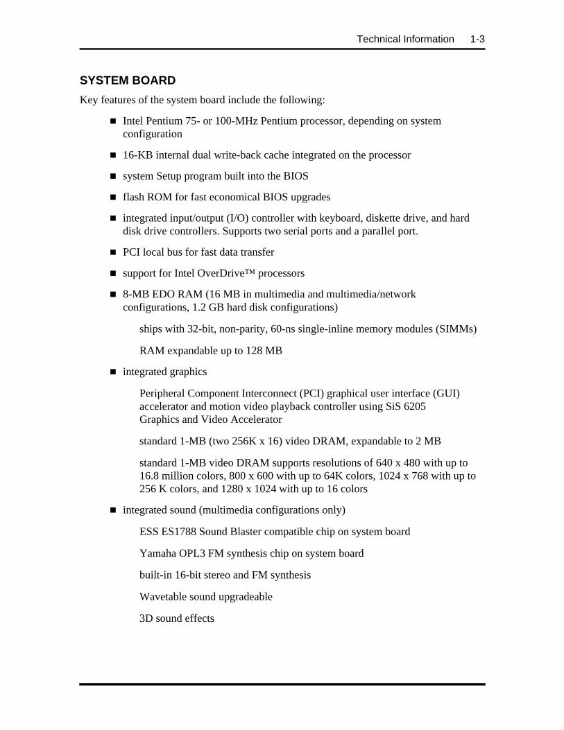
Key features of the system board include the following:
n Intel Pentium 75- or 100-MHz Pentium processor, depending on systemconfiguration
n 16-KB internal dual write-back cache integrated on the processor
n system Setup program built into the BIOS
n flash ROM for fast economical BIOS upgrades
n integrated input/output (I/O) controller with keyboard, diskette drive, and harddisk drive controllers. Supports two serial ports and a parallel port.
n PCI local bus for fast data transfer
n support for Intel OverDrive™ processors
n 8-MB EDO RAM (16 MB in multimedia and multimedia/networkconfigurations, 1.2 GB hard disk configurations)
ships with 32-bit, non-parity, 60-ns single-inline memory modules (SIMMs)
RAM expandable up to 128 MB
n integrated graphics
Peripheral Component Interconnect (PCI) graphical user interface (GUI)accelerator and motion video playback controller using SiS 6205Graphics and Video Accelerator
standard 1-MB (two 256K x 16) video DRAM, expandable to 2 MB
standard 1-MB video DRAM supports resolutions of 640 x 480 with up to16.8 million colors, 800 x 600 with up to 64K colors, 1024 x 768 with up to256 K colors, and 1280 x 1024 with up to 16 colors
n integrated sound (multimedia configurations only)
ESS ES1788 Sound Blaster compatible chip on system board
Yamaha OPL3 FM synthesis chip on system board
built-in 16-bit stereo and FM synthesis
Wavetable sound upgradeable
3D sound effects

1-4 Technical Information
n two intelligent drive electronics (IDE) interface channels
one fast IDE/PCI channel (primary connector) used by the hard disk drive totransfer data at the hard disk’s optimum rate
one standard IDE channel (secondary connector) for the CD-ROM reader
supports up to four IDE devices, two to each channel
n power management for placing system in power save mode when idle for aspecified amount of time
n 3 1/2-inch, 1.44-MB diskette drive standard all configurations
n four expansion slots: two ISA, one PCI, and one shared ISA/PCI connectors
n external connectors for connecting the following external devices:
VGA-compatible monitor (standard, super, high-resolution VGA)
personal system/2 (PS/2®)-style mouse
PS/2-style keyboard
bidirectional Enhanced Parallel Port (EPP) and enhanced capabilities port(ECP) are supported for a parallel printer
serial devices through two buffered 16C550 UART serial ports, eachsupporting up to 19.2 KB per second
external speakers, microphone, and headphone connectors (multimedia andnetwork/multimedia configurations only)
n MIDI/joystick connector on the system board for installation of an optionalMIDI/joystick kit
n Audio Wave upgrade connector on the system board for installation of anoptional Wave upgrade.
Table Section 1-2 lists the major chips on the system board. See Appendix A, ConnectorPin Assignments, for a list of the system board connectors. See Appendix B, System BoardJumpers, for a description of board jumpers.

Technical Information 1-5
Table Section 1-2 System Board Chips
Chip Description
P54C (CPGA) 75/50-MHz Intel Pentium processor100/66-MHz Intel Pentium processor
SiS PCI/ISA Chip Set 5511 5512 5513
System controllerPCI/ISA cache memory controllerPCI local data bufferPCI system I/O
SMC FDC37C665 Integrated Plug and Play Ultra I/O controller
SiS 6205 PCI GUI graphics controller
U24 128k x 8 Flash ROM
SiS 5513Toshiba CR2032 Coin Cell Battery
Real-time clock3 Volt Lithium CMOS battery (SMC 935)
ESS ES1788 Sound Chip(multimedia and multimedia/network systemsonly)
Onboard PC sound system
Yamaha OPL3-L Synthesizer Chip(multimedia and multimedia/network systemsonly)
Frequency modulated synthesizer
Processor
The PowerMate Ve series of computers use the following Pentium processors:
n PowerMate Ve75 — 75-MHz processor with internal speed of 75 MHz andexternal speed of 50 MHz.
n PowerMate Ve100 — 100-MHz processor with internal speed of 100 MHz andexternal speed of 66 MHz.
Each processor has 16 KB of write-back primary cache and a math coprocessor. The 16 KBprimary cache provides 8 KB for instructions and 8 KB for data.
The processor is an advanced pipelined 32-bit addressing, 64-bit data processor designed tooptimize multitasking operating systems. The 64-bit registers and data paths support 64-bitaddresses and data types.
The processor is compatible with 8-, 16-, and 32-bit software written for the Intel386™,Intel486™, and Pentium processors.
To accommodate future technologies and work requirements, the Pentium processor comesin a 320-pin zero insertion force (ZIF) socket. The socket provides an upgrade path to thenext generation processor.

1-6 Technical Information
Secondary Cache
The system board contains the connector for an optional 256 KB secondary cache, externalto the processor. The optional cache can be 15-ns asynchronous or 20-ns synchronouspipeline burst.
Cache allows data to be sent or received from cache with one wait state burst. Cachememory improves read performance by holding copies of code and data that are frequentlyrequested from the system memory by the processor. Cache memory is not considered partof the expansion memory.
System and Video BIOS
The system and video BIOS are stored in a 1 MB (128 KB by 8) flash memory device(Flash ROM). The system BIOS uses 64 KB, the video BIOS uses 32 KB, and 32 KB isreserved. The system BIOS is capable of being shadowed and cached through the system’sSetup utility (see Section 2 for Setup information). System BIOS is write protected andautomatically enabled.
The BIOS programs execute the Power-On Self-Test, initialize processor controllers, andinteract with the display, diskette drives, hard disks, communication devices, andperipherals. The system BIOS also contains the Setup utility. The hardware setup defaultcopies the ROM BIOS into RAM (shadowing) for maximum performance.
The Flash ROM allows the system and video BIOS to be upgraded with the BIOS Updateutility, without removing the ROM (see Section 2 for further information on the BIOSUpdate utility). The Flash ROM supports the reprogramming of the system BIOS and thevideo BIOS.
The system memory map is shown in Table Section 1-3.
Table Section 1-3 System Memory Map
Memory Space Size Function
FFF80000-FFFFFFFF 512 KB BIOS ROM
04000000-07FFFFFF 64 MB L2 cache (Non-Cacheable with less than 512 KBSRAM)L1 cache (Cacheable)
01000000-03FFFFFF 48 MB Always cachable
00F00000-00FFFFFF 1 MB Optional memory space gap
00100000-00EFFFFF 14 MB Cachable
000F0000-000FFFFF 64 KB System BIOS (Shadowed in DRAM)
000C8000-000EFFFF 160 KB Expansion region (Shadowed in DRAM)

Technical Information 1-7
Table 1-3 System Memory Map
Memory Space Size Function
000C0000-000C7FFF 32 KB Video BIOS (Shadowed in DRAM)
000A0000-000BFFFF 128 KB Video Buffer (SMM space Non-Cacheable)
00080000-0009FFFF 128 KB Optional memory space gap (DOS Apps)
00000000-0007FFFF 512 KB DOS applications (No read/write protect) (Alwayscacheable)
Power Management
Each system incorporates power management features that lower power consumption whenthere is no activity detected from the keyboard, mouse, diskette drive, CD-ROM reader, orhard disk drive after a pre-defined period of time. As soon as activity is detected the systemresumes where it left off.
With Power Management enabled (shipped enabled), the system automatically activates thepower-saving features and enters a suspend mode whenever inactivity is sensed.
I/O Addressing
The processor communicates with I/O devices by I/O mapping. The hexadecimal (hex)addresses of I/O devices are listed in Table Section 1-4.
Table Section 1-4 I/O Address Map
Address (Hex) I/O Device Name
0000-000F DMA controller 1 (channel 0-3)
0020-0021 Interrupt controller 1
0040-0043 Timer 1
0048-004B Timer 2
0060 Keyboard controller data byte
0061 NMI status and speaker control
0064 Keyboard controller cmd/status byte
0070-007F Real-time clock, NMI mask
0080-008F DMA page registers
00A0-00A1 Interrupt controller 2
00C0-00DE DMA controller 2
00E0-00EF Reserved

1-8 Technical Information
Table Section 1-4 I/O Address Map
Address (Hex) I/O Device Name
00F0 Clear math coprocessor error
00F1 Reset math coprocessor
0F8-0FF Math coprocessor
170-177 Secondary IDE channel
1F0-1F7 Primary IDE channel
200, 202, 207 Game I/O
220-22F Sound port
238-23F Serial port 4 (used for remapping)
278-27F Parallel port 2
2B0-2DF Alternate EGA adapter
2F8-2FF Serial port 2
338-33F Serial port 3 (used for remapping)
370-375 Floppy cont. (secondary address)
376 Secondary IDE channel CMD port
377 Secondary IDE channel stat port
378-37F Parallel port 1
3B0-3BF Mono display & printer adapter
3C0-3CF EGA adapter
3D0-3DF CGA adapter
3F0-3F5, 3F7 Floppy controller (primary)
3F8-3FF Serial port 1
CF8-CFF PCI configuration space
System Memory
Non-multimedia systems come standard with 8 MB of EDO memory: 640 KB of basememory and 7 MB of extended memory. All multimedia, 1.2 GB hard disk configurations,come standard with 16 MB of EDO memory: 640 KB of base memory and 15 MB ofextended memory. System memory can be expanded up to 128 MB, using optional singlein-line memory modules (SIMMs) installed in SIMM sockets on the system board.
Four SIMM sockets are integrated on the system board. Non-multimedia systems ship withtwo 4-MB SIMMs (8 MB total) installed in two sockets. The multimedia, 1.2 GB hard diskconfigurations, ship with two 8-MB SIMMs (16 MB total) installed in two sockets.

Technical Information 1-9
The SIMM memory sockets accept 32-bit (non-parity) 4-, 8-, 16-, or 32-MB 70 ns SIMMs.The SIMMs are 1 MB x 32 bit (4 MB), 2 MB x 32 bit (8 MB), 4 MB x 32 bit (16 MB), and8 MB x 32 bit (32 MB). When the standard SIMMs are removed, four 32-MB SIMMs maybe installed for a total of 128 MB.
CAUTION: SIMMs must match the tin metalplating used on the system board SIMM sockets.When adding SIMMs, use tin-plated SIMMs.
SIMMs install directly in the four sockets on the system board. The four sockets areassigned as SIMM 1 through SIMM 4. For non-multimedia configurations, the twostandard 4 MB SIMMs are installed in SIMM 1 and SIMM 2. For multimediaconfigurations, the two standard 8 MB SIMMs are installed in SIMM 1 and SIMM 2.SIMMs must be installed in pairs of the same memory type and speed. Jumpers are notrequired to set memory size or type as the system BIOS automatically detects the SIMMs.SIMM banks 1 and 2 must always be filled for the system to operate. Table Section 1-5shows the SIMM memory upgrade path.
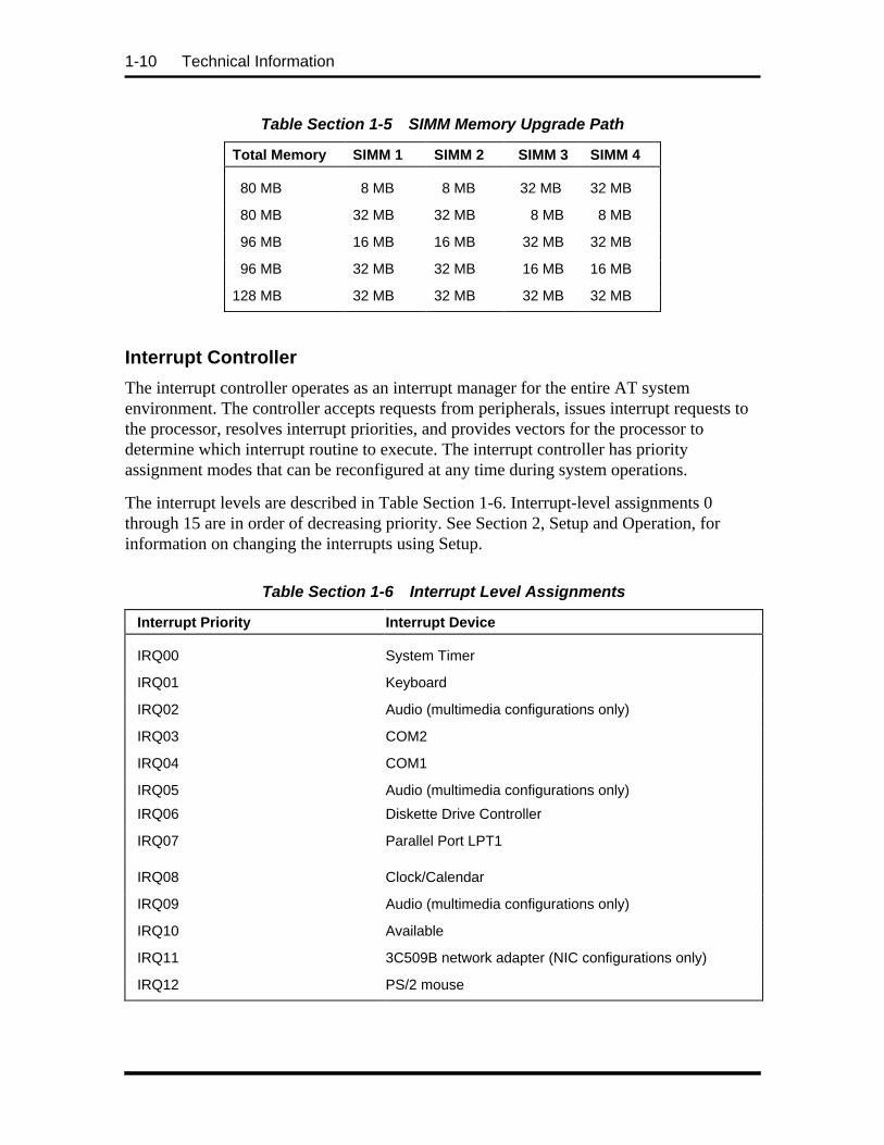
Table Section 1-5 SIMM Memory Upgrade Path
Total Memory SIMM 1 SIMM 2 SIMM 3 SIMM 4
8 MB 4 MB 4 MB Empty Empty
16 MB 4 MB 4 MB 4 MB 4 MB
16 MB 8 MB 8 MB Empty Empty
24 MB 4 MB 4 MB 8 MB 8 MB
24 MB 8 MB 8 MB 4 MB 4 MB
32 MB 8 MB 8 MB 8 MB 8 MB
32 MB 16 MB 16 MB Empty Empty
40 MB 4 MB 4 MB 16 MB 16 MB
40 MB 16 MB 16 MB 4 MB 4 MB
48 MB 8 MB 8 MB 16 MB 16 MB
48 MB 16 MB 16 MB 8 MB 8 MB
64 MB 16 MB 16 MB 16 MB 16 MB
64 MB 32 MB 32 MB Empty Empty
72 MB 4 MB 4 MB 32 MB 32 MB
72 MB 32 MB 32 MB 4 MB 4 MB
1-10 Technical Information
Table Section 1-5 SIMM Memory Upgrade Path
Total Memory SIMM 1 SIMM 2 SIMM 3 SIMM 4
80 MB 8 MB 8 MB 32 MB 32 MB
80 MB 32 MB 32 MB 8 MB 8 MB
96 MB 16 MB 16 MB 32 MB 32 MB
96 MB 32 MB 32 MB 16 MB 16 MB
128 MB 32 MB 32 MB 32 MB 32 MB
Interrupt Controller
The interrupt controller operates as an interrupt manager for the entire AT systemenvironment. The controller accepts requests from peripherals, issues interrupt requests tothe processor, resolves interrupt priorities, and provides vectors for the processor todetermine which interrupt routine to execute. The interrupt controller has priorityassignment modes that can be reconfigured at any time during system operations.
The interrupt levels are described in Table Section 1-6. Interrupt-level assignments 0through 15 are in order of decreasing priority. See Section 2, Setup and Operation, forinformation on changing the interrupts using Setup.
Table Section 1-6 Interrupt Level Assignments
Interrupt Priority Interrupt Device
IRQ00 System Timer
IRQ01 Keyboard
IRQ02 Audio (multimedia configurations only)
IRQ03 COM2
IRQ04 COM1
IRQ05 Audio (multimedia configurations only)
IRQ06 Diskette Drive Controller
IRQ07 Parallel Port LPT1
IRQ08 Clock/Calendar
IRQ09 Audio (multimedia configurations only)
IRQ10 Available
IRQ11 3C509B network adapter (NIC configurations only)
IRQ12 PS/2 mouse

Technical Information 1-11
Table Section 1-6 Interrupt Level Assignments
Interrupt Priority Interrupt Device
IRQ13 Coprocessor
IRQ14 Primary IDE
IRQ15 Secondary IDE
Integrated Graphics
The system has an SiS 6205 PCI local bus motion video playback controller and graphicsaccelerator integrated on the system board. State of the art techniques are used foroptimizing performance in computer graphic intensive applications and graphical userinterfaces (GUI).
The integrated graphics controller integrates a motion video controller, a high-performanceGUI accelerator, 24-bit high frequency DAC and clock generator, VESA®-compliantfeature connector, and 1 MB of fast 64-bit DRAM (upgradeable to 2 MB).
Motion Video Controller
The motion video controller integrates a powerful Windows® GUI engine and uniquemotion video playback hardware for superior performance. The graphics engine includesan on-chip color space converter to accelerate decompression and a hardware scaler toscale continuously from native size up to full screen at full speed. The graphics enginedelivers a full screen, smooth display of motion video data up to 30 frames per second(fps). Support includes MPEG-1 (multimedia systems only) and Video for Windows.
MPEG is a compression/decompression standard developed by the Motion Picture ExpertsGroup. MPEG produces full-screen 30 fps, broadcast-quality digital video. The videocontroller architecture maximizes the motion video performance and removes bandwidthbottlenecks to display multimedia data at its full speed.
Graphics Accelerator
The graphics accelerator is specifically designed for graphics-intensive operations, text andcolor pixel amplification, and scrolling. The graphics accelerator provides 64-bit, ultra-high performance for demanding True Color, High Color, and pseudocolor GUI and CADapplications.
The accelerator minimizes bus traffic by off-loading the tasks normally performed by theprocessor. The dedicated bit-block transfers (BitBLT) engine maximizes performance byspeeding the movement of large blocks of image data in video memory.

1-12 Technical Information
Video Memory
The system comes with 1 MB of on-board video DRAM, upgradeable to 2 MB. Thestandard 1 MB DRAM consists of two 256K by 16 DRAM devices soldered to the systemboard. The optional 1 MB of DRAM consists of two 256 KB by 16 modules that install intwo sockets on the system board.
With the standard 1 MB of video DRAM, the video hardware supports the followingresolutions, colors, and refresh rates:
n 1280 by 1024 pixels, 16 colors, 60 Hz
n 1024 by 768 pixels, 16/256 colors, 60 Hz, 70 Hz, 75 Hz, and 85 Hz
n 800 by 600 pixels, 16/256/64K colors, 56 Hz, 60 Hz, 72 Hz, 75 Hz, and 85 Hz
n 640 by 480 pixels, 16/256/64K/16 million colors, 60 Hz, 72 Hz, 75 Hz and 85 Hz
With 2 MB of video DRAM, the system supports the following additional resolutions,colors, and refresh rates:
n 1280 by 1024 pixels, 256 colors, 60 Hz and 75 Hz
n 1024 by 768 pixels, 64K/16 million colors, 60 Hz, 70 Hz, 75 Hz and 85 Hz
n 800 by 600 pixels, 16 million colors, 56 Hz, 60 Hz, 72 Hz, 75 Hz, and 85 Hz
n 640 by 480 pixels, 16 million colors, 60 Hz, 72 Hz, 75 Hz, and 85 Hz.
ISA Bus
The system board uses the ISA bus for transferring data between the processor and I/Operipherals and expansion boards. The ISA bus supports 16-bit data transfers and typicallyoperates at 8 MHz. ISA expansion slot connector pin assignments are provided inAppendix A.
PCI Local Bus
The 32-bit PCI-bus is the primary I/O bus for the system. The PCI-bus is a highly-integrated I/O interface that offers the highest performance local bus available for thePentium processor. The bus supports burst modes that send large chunks of data across thebus, allowing fast displays of high-resolution images.
The PCI-bus operates at half the Pentium’s processor speed, and supports memory transferrates of up to 105 MB per second for reads and up to 120 MB per second for writes,depending on processor configuration.
The high-bandwidth PCI-bus eliminates the data bottleneck found in traditional systems,maintains maximum performance at high clock speeds, and provides a clear upgrade pathto future technologies.

Technical Information 1-13
The PCI bus contains two embedded PCI devices, the PCI local bus IDE interface and thePCI video/graphics controller.
PCI expansion slot connector pin assignments are provided in Appendix A.
PCI Auto Configuration
The system comes with a PCI auto configuration utility that operates in conjunction withthe system’s Setup utility. The utilities automatically configure interrupts, DMA channels,I/O space, and other parameters to allow addition of PCI boards with minimal userintervention. (See Section 2 for Setup information.)
PCI/IDE Ports
The system board provides two high-performance PCI/IDE ports: a primary channel and asecondary channel. Each port supports up to two devices for a total of four IDE devices.The primary PCI/IDE port has an enhanced IDE interface which supports 11.1 MB persecond 32-bit wide data transfers on the high-performance PCI local bus. The installedhard disk drive is connected to the primary PCI/IDE port. The installed CD-ROM reader(multimedia, multimedia/network and 1.2 GB hard disk systems only) is connected to thesecondary PCI/IDE port.
Parallel Interface
The system has a 25-pin parallel bidirectional enhanced parallel port on the system board.Port specifications conform to the IBM-PC standards. The port supports EnhancedCapabilities Port (ECP) and Enhanced Parallel Port (EPP) modes for devices that requireECP or EPP protocols. The protocols allow high-speed bidirectional transfer over a parallelport and increase parallel port functionality by supporting more devices.
The BIOS has automatic ISA printer port sensing. If the BIOS detects an ISA printer portmapped to the same address, the built-in printer port is disabled. The BIOS also sets thefirst parallel interface port it finds as LPT1 and the second port it finds as LPT2. Theinterrupt is selected to either IRQ5 or IRQ7 via Setup. Software selectable base addressesare 3BCh, 378h, and 278h.
I/O addresses and interrupts for the parallel port are given in Table Section 1-7.
NOTE: Any interrupts used for the built-inparallel port are not available for ISA parallelports.

1-14 Technical Information
Table Section 1-7 Parallel Port Addressing and Interrupts
Starting I/O Address Interrupt Level Port
378 IRQ05 LPT1
278 IRQ05 LPT1 or LPT2
3BC IRQ07 LPT1 or LPT2
378 IRQ07 LPT1
278 IRQ07 LPT1 or LPT2
3BC IRQ07 LPT1 or LPT2
Parallel interface signals are output through the system board’s 25-pin, D-subconnector.The connector is located at the rear of the system unit. Pin locations for the parallelinterface connector are given in Appendix A.
Serial Interface
The system has two 16C550 UART compatible serial ports (COM1 and COM2) integratedon the I/O controller. The serial ports support the standard RS-232C interface (see TableSection 1-8). The buffered high-speed serial ports supports transfer rates up to 19.2 KB.These ports allow the installation of high-speed serial devices for faster data transfer rates.
I/O addresses and interrupt levels for the two channels are given Table Section 1-8. Theinterrupt level is selectable via Setup to either IRQ3 or IRQ4. Software selectable baseaddresses are 3F8h, 2F8h, 3E8h, and 2E8h.
NOTE: Any interrupts used for the built-inserial ports are not available for ISA parallelports.
Table Section 1-8 Serial Port Addressing and Interrupts
Starting I/O Address Interrupt Level Port
3F8h IRQ04 COM1*
2F8h IRQ03 COM2
3E8h IRQ04 COM3
2E8h IRQ03 COM4
* Disabled if fax/modem installed

Technical Information 1-15
Serial interface specifications include:
n Baud rate up to 19.2 KB per second
n Word length - 5, 6, 7, or 8 bits
n Stop bit - 1, 1.5, or 2 bits
n Start bit - 1 bit
n Parity bit - 1 bit (odd parity or even parity).
Serial interface signals are output through the system board’s 9-pin, D-subconnector. Theconnectors are located at the rear of the system unit. Pin locations for the serial interfaceconnector are shown in Appendix A.
POWER SUPPLY
The power supply is mounted inside the system unit. It supplies power to the system board,option boards, diskette drives, hard disks, keyboard, and mouse. A fan inside the powersupply provides system ventilation. The power supply supplies 145 watts of power.Connector locations are in Appendix A.
DISKETTE DRIVE
Up to two diskette drives are supported. The installed 3 1/2-inch diskette drive is connectedby a single ribbon cable with two drive connectors. The diskette drive cable plugs directlyinto the system board. Typically both diskette drives are terminated. Connector locationsare given in Appendix A.
HARD DISK DRIVE
Up to two IDE hard drives are supported. The system board has two IDE/PCI interfaceconnectors (primary and secondary) for connecting various storage devices such as harddisk drives. Each connector supports up to two IDE devices.
The system ships with one internal 3 1/2-inch hard disk drive (1-inch high, thin-height)installed behind the front panel. The drive cable plugs into the primary (fast) connector onthe system board.
KEYBOARD
The PS/2-style 104 key keyboard is standard equipment for the system. The keyboardprovides a numeric keypad, separate cursor control keys, and 12 function keys, capable ofup to 48 functions. Status lamps on the keyboard indicate: Num (Numeric) Lock, Caps(Capital) Lock, and Scroll Lock key status. The keyboard’s six-pin connector plugs into therear of the system. The keyboard connector pin assignments are given in Appendix A.

1-16 Technical Information
MOUSE
A PS/2-compatible mouse is standard equipment for the system. The mouse has a self-cleaning mechanism that prevents a buildup of dust or lint around the mouse ball andtracking mechanism. The mouse’s six-pin connector plugs into the rear of the system. Themouse connector pin assignments are given in Appendix A.
MULTIMEDIA COMPONENTS
Systems configured for multimedia come with audio integrated on the system board, a CD-ROM reader, a speaker set, and a microphone. The following briefly describes each.Information on setting up and operating the speakers, microphone, and CD-ROM reader isin Section 2, Setup and Operation.
Integrated Audio
Multimedia systems come with audio components integrated on the system board. Non-multimedia systems do not have the audio components on the system board. The audiocomponents include an ESS ES1788 Sound Blaster-compatible chip, a Yamaha OPL3 FMsynthesizer chip, and an SRS Labs Sound Retrieval System®. The system’s integratedaudio features the following:
n built-in 16-bit 128x oversampling Sigma-Delta Stereo Codec with 85dB S/Nratio
n built-in five-channel 16/32 step MPC compatible stereo mixer with mastervolume and sample rates up to 48 Hz stereo
n dual DMA channel and built-in FIFOs for full duplex simultaneous playback andrecord in 16-bit stereo
n WaveBlaster upgradeable for Wavetable synthesis
n 3D sound effects
n 20 voice FM synthesis.
The integrated components are compatible with the Sound Blaster™ board and theMicrosoft® Windows Sound System™ board. The components work with the pre-installedVoyetra AudioStation software.

Technical Information 1-17
CD-ROM Reader
The quad-speed IDE CD-ROM reader is pre-installed as drive E on multimedia andmultimedia/network configurations. The reader can be used to load programs from a CD orit can be used to play audio CDs. The reader operates at different speeds depending onwhether the CD contains music or data. The reader is fully compatible with KodakMultisession Photo CDs™ and standard CDs. The reader is set as the master device on thesecondary IDE/PCI connector port.
Speakers
The multimedia systems come with 5 W high-quality Goldtron stereo speakers, an ACadapter, and connecting wires. The speaker set features a volume control, power on/offswitch, power lamp, and a headphone jack. Volume is controlled from the speaker or fromthe preinstalled sound system software. The speaker set connects to the speaker line outjack on the back of the system.
Microphone
The microphone that comes with the multimedia systems allows recording of voice andsound into computer data files. The microphone connects to the MIC jack located on theback of the system. The microphone works in conjunction with the audio software shippedwith the system.
NETWORK BOARD
Network-ready systems are configured with an Ethernet 3C509B network interface board(NIC). The network board allows connection to an Ethernet network and communicationwith other computers. The network board has three connectors for coaxial and twisted-pairnetwork cabling:
n BNC connector — supports thin coaxial cables
n AUI connector — supports thick coaxial cables
n RJ-45 connector — supports twisted-pair 10BASE-T cables.
PLUG AND PLAY
The system comes with a Plug and Play BIOS which supports Plug and Play technology.Plug and Play eliminates complicated setup procedures for installing Plug and Playexpansion boards. With Plug and Play, adding a Plug and Play expansion board is done byturning off the system, installing the board, and turning on the system. There are nojumpers to set and no system resource conflicts to resolve. Plug and Play automaticallyconfigures the board.

1-18 Technical Information
POWER MANAGEMENT
Each system is Energy Star compliant and comes with the power-saving features enabled.If the keyboard, mouse, or drives are not used after 15 minutes, the screen goes blank andthe system goes into a partial power shutdown. A blinking power lamp indicates that thesystem is in the power-saving mode. As soon as activity is detected, the system resumeswhere it left off.
The system can be manually put into a Suspend power-saving mode by pressing thesuspend button. The Suspend mode provides the greatest power savings by putting thesystem in maximum power shutdown. When the system goes into Suspend mode, it savesdata and system status and then shuts off power to all possible components. A blinkingpower lamp indicates that the system is in the power-saving mode. As soon as activity isdetected, the system resumes where it left off.
The amount of inactive time is adjustable. Power management can also be disabled. Bothcan be set through Setup.
DESKTOP MANAGEMENT INTERFACE
The Desktop Management Interface (DMI) is the standard interface used to manage systemcomponents on the computer. DMI acts as a layer of abstraction between managementapplications and managed components such as systems, network cards, and printers.
With DMI, a management application (such as Hewlett Packards Openview), provides asimplified method to collect information from different vendors computers operating onthe network.
DMI is not a protocol but an interface that complements network protocols like the SimpleNetwork Management Protocol (SNMP).
DMI Components
The NEC DMI consists of two major functional components:
n the Component Interface (CI) module
n the NEC DMI Browser.
The CI module provides the instrumentation and interface between the BIOS and the DMIService Layer (SL). The DMI Browser displays and manages existing attributes in theManagement Information Format (MIF) database. The Desktop Management Task Force(DMTF) provides the DOS Service Layer, Windows Service Layer, and MIF databasestructure.

Technical Information 1-19
Manageable Components
Manageable components are hardware, software, and peripherals installed or attached to adesktop computer or network server. These include hard disks, word processors, CD-ROMs, printers, operating systems, graphics boards, modems, etc. Manageablecomponents can come with the system or be added later. Each component suppliesinformation to the MIF database that contains the product’s pertinent managementinformation.
Each product may or may not include an instrumentation module in order to provide real-time support.
CI Module
The Component Interface (CI) module is a Windows program that provides access to yoursystem and its components. It runs minimized in Windows and should only be canceled ifyou are uninstalling DMI.
CI module is comprised of programs written by the component manufacturer to providereal-time attribute values to the network Service Layer as requested.
DMI Browser
The NEC DMI Browser is a Windows application provided by NEC Technologies, Inc.The Browser uses the Management Interface (MI) to provide access to MIF attributes andtheir respective values. The Browser has the ability to set attributes and manage DMIcomponents.
The NEC Browser can only access the local MIF database. The Browser lets you accessMIF attributes according to the structure defined by the DMTF. It is not intended to be ageneral PC management application. If a more comprehensive management application isdesired, use a product such as Intel’s LANDesk Manager™.
The NEC DMI Browser has two sections: an Overview and a Detailed View. TheOverview displays pertinent information on the system. In addition, you can click on eachof eight buttons provided to obtain more information on each subject. The organization ofthe data in the Overview presents a comprehensive view of the system.
To display the Detailed View, select either the Detail tab or the Detail option on the Viewmenu. This initiates a hierarchical view of the MIF database and allows the user to makesome changes. For example, if a system is transferred to another department or user, theprimary user name, telephone number and system location can be updated.
In the Browser, components and groups are expanded or collapsed by selecting the desiredobject and double clicking. You can also use the toolbar to access information in the MIFfile.
The Browser provides seven buttons (Windows for Workgroups, only) in the toolbar whichare defined as follows:

1-20 Technical Information
n Expand to expand a component.
n Collapse to collapse a component.
n View Component Detail to review the selected component’s details.
n View Group Detail to review the selected groups details.
n View Attribute Detail to review the selected attribute’s details.
n DMI Browser Information to display program information, version number,and copyright.
n Help to display help information for clicked toolbar, buttons, and menus.
The Browser provides five buttons (Windows 95) in the toolbar which are defined asfollows:
n Overview to switch to Overview screen.
n Detailed View to switch to Detailed View screen.
n Print to print.
n DMI Browser Information to display program information, version number,and copyright.
n Help to display help information for clicked toolbar, buttons, and menus.
Upon exiting the Browser, the program saves the current viewing configuration. The nexttime you use the Browser, it restores all the viewing screens to the last known position.
Usage
To start the NEC DMI Viewer, simply double click on the NEC DMI icon in the NECUtilities group in Windows.
The initial display contains the system serial number, model number, asset tag number,processor information, serial and parallel ports and their status, video information, HDDinformation, and memory information. Click on any of the buttons to display even moreinformation on the eight topics.
The service topic option invokes the Windows utility SYSEDIT. This utility displays all ofthe important system files.

Technical Information 1-21
CAUTION: Using the SYSEDIT utility can puteither the system or Windows into a state whereit cannot operate. If you are not familiar with theuse of these files and their maintenance, do notmake any changes.

1-22 Technical Information
Troubleshooting
If trouble is experienced in using the NEC DMI Browser, here are a few suggestions tofollow.
Reboot the system after installation, otherwise you may have problems running the NECDMI Browser.
If the product name, serial number, system boot time, or other attribute returns a N/A,check the following:
n Look at the AUTOEXEC.BAT file to see if the lineDMIDIR%\WIN16\BIN\NECDMI.EXE is present.
n Make sure the file NECDMI.DAT is located in the DMIDIR%\WIN16\BINsubdirectory.
n Check that NECCI.EXE is running.

Technical Information 1-23
SPECIFICATIONS
System specifications are included in Table Section 1-9.
Table Section 1-9 Specifications
Item Specification
Dimensions and Weight Width: 17 inches (43.18 cm)Depth: 16 inches (40.64 cm)Height: 4 inches (10.6 cm)Weight: 22 lb (11.1 kg) (dependent upon options)
Keyboard Width: 19.0 inches (48.3 cm)Depth: 8.4 inches (21.3 cm)Height: 1.6 inches (4.1 cm)Weight: 3.5 to 4.0 lb. (1.6 to 1.8 kg)
Device Slots Two 5 1/4-inch, front accessible slotsOne 3 1/2-inch front access slotOne 3 1/2-inch internal slot
Expansion Slots Four slots: two 16-bit ISA slots one ISA/PCI shared slot one PCI slot
Peripheral Interface PS/2-style keyboard connector, rear panelPS/2-style mouse connector, rear panelTwo RS-232C serial ports, rear panelParallel printer port, rear panelVGA port, rear panel
Front Panel Power buttonPower indicator lampHard disk drive busy indicator lampSuspend buttonReset button
Processor Intel Pentium 75- or 100-MHz (dependent on system)
Cache Memory 16 KB of primary cache (8 KB data, 8 KB instruction) integratedin the processor, optional 256 KB secondary cache
Flash ROM 128 KB (28F001) Flash ROM
Chip Set SiS5511+/5512/5513 PCI/ISA
System Memory Standard Multimedia, Multimedia/Network and 1.2 GB Hard Disk Systems
8-MB EDO standard, expandable to 128 MB using SIMM sockets16-MB EDO standard, expandable to 128 MB using SIMMsockets
Optional SIMMs 4-, 8-, 16-, and 32-MB; 32-bit, non-parity, 70-ns SIMMs
Integrated Graphics SiS 6205 PCI Graphics & Video Accelerator 1-MB video DRAM standard, expandable to 2 MB

1-24 Technical Information
Table Section 1-9 Specifications
Item Specification Maximum resolution 1280 x 1024 pixels
Battery coin-type battery
Power Supply 145 Watt, 115 V/230V switch selectable
CD-ROM Reader(Multimedia andMultimedia/Network systemsonly)
See Appendix D for more specifications Disc format: ISO 9660 Data transfer rate: 600 KB/sec, PIO Mode 3 support Access time (typical): 500 msec Built-in buffer: 128 KB Host interface: IDE (ATAPI)
Integrated Sound Standard in multimedia systemsESS1688 Sound Blaster compatibleYamaha OPL3 FM SynthesisSRS Labs 3D sound solution16-bit 128x oversampling sigma-delta stereo CODEC with 85 dB S/N ratioStereo jacks for microphone: line in and line outWave Blaster upgradeable for wavetable synthesis
5 Watt Speakers(Goldtron Speakers)
Standard in multimedia systemsMagnetic shielded 5-watt stereo speakersPower on/off switch, power lamp, volume controlMini-stereo headphone jackBuilt in stereo amplifier9-volt AC power adapter
Network Interface Board(Network-ready systems only)
3Com EtherLink III 3C509B-COMBO Network interfaceIEEE 802.31 10Base-T and EthernetIEEE 802.3 industry standard for 10 Mbps CSMA/CD local area networkConnectors RJ-45 AUI BNC
Operating Environment Temperature 50oF to 95oF (10oC to 35oC)Relative Humidity 20% to 80%
Administrative Compliance UL 1950 - safetyCSA C22.2 No. 950-m89TUV EN60950: 1988FCC part 15, Subpart J, Class B - emissionsFCC part 68C.R.C., c.1374IEC 950 - safetyVDE 0871/6.78, Class B - emissions

Section 2
Setup and Operation
This section provides information on hardware setup and operation for the PowerMate Veseries systems. Setup includes unpacking, setting up, and powering on the system. It alsoincludes information for configuring the system with the setup program, using the NECbulletin board service, and running the BIOS update utility. Setting system board jumpersis described in Appendix B, System Board Jumpers.
UNPACKING AND REPACKING
Find an area away from devices that generate magnetic fields (electric motors,transformers, etc.). Place the carton on a sturdy surface, and carefully unpack the system.The carton contents for diskless systems include the system unit, keyboard, mouse, powercord, user documentation, and various software diskettes. The carton contents for non-multimedia configurations include the system unit, keyboard, mouse, power cord, and userdocumentation. The carton contents for multimedia and multimedia/network configurationsinclude the system unit with a CD-ROM player, keyboard, mouse, speakers, power cord,and user documentation.
Repack the system using the original shipping carton and packing material. Part numbersfor replacement shipping cartons and packing material are included in Section 5,“Illustrated Parts Breakdown.”
SETUP
Set up the system by making the following connections.
1. Set the voltage selector switch to 115V (U.S. and Canada) or 230V and plug thepower cord into the system power socket (see Figure Section 2-1).

2-2 Setup and Operation
Figure Section 2-1 Voltage Selector Switch
NOTE: The correct AC input voltage must beproperly set. Select the appropriate voltage withthe voltage selector switch located at the rear ofthe system.
2. Connect the keyboard, mouse, monitor, and printer cables to the back of thesystem unit (see Figure Section 2-2).
Figure Section 2-2 Peripheral Connections
Voltage SelectorSwitch
System PowerSwitch
Fan
Serial Port 1Serial Port 2
Printer Port
Mouse Port
Keyboard Port
Audio Connectors
VGA MonitorConnector

Setup and Operation 2-3
3. If setting up a network-ready system, connect the appropriate network cable tothe network board at the rear of the system (see Figure Section 2-3).
CAUTION: If adding a T-connector, be surethat other network users are logged off thesystem before connecting the cable.
4. If installing a multimedia system, connect the speakers as follows.
n Locate the right speaker (has the controls on the front) and the speaker cableattached to the back.
n Connect the speaker input cable to the line out jack on the back of the system(see Figure Section 2-5).
n Connect the AC adapter to the right speaker and to a surge protector or walloutlet.
n Press the power switch. The power lamp lights.
n Adjust the volume control as required.
RJ-45Connector
AUI Thick Ethernet Connector
BNC Thin Ethernet Connector
Figure Section 2-3 Network Board Connections

2-4 Setup and Operation
5. Assemble and connect the microphone (multimedia systems only) as follows.
n Slide the microphone holder into the slot in the microphone stand as far as itwill go (see Figure Section 2-4).
n Slide the microphone cable and microphone into the holder. Adjust themicrophone by pivoting it up and down and side to side.
Figure Section 2-4 Assembling the Microphone Holder
n Plug the microphone into the microphone in jack at the rear of the system (seeFigure Section 2-5).
Figure Section 2-5 Connecting the Microphone
MicrophoneHolder
MicrophoneCable
MicrophoneStand
Microphone
Line Out Jack
Line In Jack
Microphone InJack

Setup and Operation 2-5
6. Press the power button (see Figure Section 2-6) to power-on the system. Thepower lamp lights green, indicating that the system is in Full-Power On mode.
The system automatically goes into its Power-On Self-Test (POST), and checkssystem components. One beep indicates that the system has successfullycompleted its power-on test.
If a problem occurs, a series of beeps may sound. If this happens repeatedly afterpowering on, power off and troubleshoot the system.
NOTE: If the system displays a messageindicating that system settings have changed, runSetup (see System Configuration later in thissection).
Figure Section 2-6 Power Button, Lamps, and Suspend Button
7. Press the suspend button (see Figure Section 2-6) to place the unit in themaximum power saving mode.
A blinking power lamp indicates that the system is in the power-saving mode.
Pressing a key or moving the mouse places the system back in the Full-Powermode.
If the system is left alone for a preset time (15 minutes), it goes into theautomatic Standby mode. The screen goes blank and the system goes into thepower-saving mode of operation. Moving the mouse or pressing a key places thesystem back in the Full-Power mode.
Power Button
Power Lamp
Disk Lamp
Reset Button
Suspend Button

2-6 Setup and Operation
CD-ROM READER
An NEC 4X CD-ROM reader (see Figure Section 2-7) comes pre-installed as drive E in themultimedia configurations. The reader is set as a master device, and is connected to thesecondary IDE/PCI port on the system board.
NOTE: The CD-ROM reader installed in thesystem might look different than one shown inthe following figure. The locations of the otherfeatures may vary but the functions are the same.
Use the CD-ROM reader to load and start programs from a CD or to play audio CDs. TheCD-ROM reader has the following controls and indicators:
n jack for connecting headphones with a stereo mini-jack plug
n volume control for adjusting the headphone volume
n busy lamp that lights during read operations
n open/close button for opening or closing the CD tray when the power is on.When playing a CD, press the open/close button to stop the CD.
n emergency eject hole in the front panel for manually opening the CD tray ifpower is lost. Insert a jewelers screwdriver into the hole. Turn the screwcounterclockwise to open the tray and clockwise to close the tray.
CD TrayCD BusyLamp
HeadphoneJack
Volume ControlKnob
Open/CloseButton
EmergencyEject Hole
Figure Section 2-7 Typical CD-ROM Reader Controls and Indicators

Setup and Operation 2-7
To load a disc in the CD-ROM reader, follow these steps.
1. Press the open/close button. The CD tray opens.
2. Put the CD, printed side up, into the tray.
3. Press the open/close button again and the tray closes.
4. To remove the disc, press the open/close button. The tray opens, allowingremoval of the disc.
SYSTEM CONFIGURATION
This section describes the Setup utility program that allows the system configurationinformation to be viewed and changed.
NOTE: The system ships from the factory withthe correct system parameters for theconfiguration. Unless setting the time and date,setting security features, customizing the system,or adding optional hardware, Setup does notneed to be run.
System configuration information is stored in nonvolatile memory. Nonvolatile memory inthe system is a complementary metal-oxide semiconductor (CMOS) chip backed by a coin-type battery on the system board. The battery supplies continuous power to the CMOSmemory and maintains configuration information when system power is off.
Setup Utility
The Setup utility is used to view and set system parameters. Use the Setup utility to:
n set the time and date.
n update or check system parameters when adding or removing expansion options.
n change or set power management features.
n correct a hardware discrepancy when the Power-On-Self-Test (POST) displays anerror message and a prompt appears to run Setup.
n check the installation of optional memory by comparing the amount of memoryinstalled with the amount of memory displayed by Setup.
n change certain system operating parameters, such as boot device sequence orkeyboard parameters.

2-8 Setup and Operation
n configure system connections for peripherals such as the diskette drive, harddrives, and devices connected to the printer and serial ports.
n customize the system with security features such as passwords, diskette driverestriction, virus check reminder, and system backup reminder.
n set system parameters if the CMOS battery or real-time clock/battery moduleneeds replacing.
How to Start Setup
To start the Setup utility, follow these steps:
1. Turn on or reboot the system. Setup displays the following message:
Press <F2> to enter SETUP
2. Press F2. Setup’s Main Menu window appears similar to the following screen.
NOTE: The screen shown is typical of thesystem. The actual items on the Main Menudepend upon the hardware installed in thesystem.
Main Menu
PhoenixBIOS Setup — Copyright 1992-96 Phoenix Technologies Ltd.
Main Advanced Security Power Boot Exit
System Time [10 :19:20] Item Specific Help System Date [02/12/1996] Diskette A [1.44 MB, 3 ½"] <Tab>, <Shift-Tab>, or Diskette B [Not Installed] <Enter> selects field. > IDE Adapter 0 Master C: 1280 Mb > IDE Adapter 0 Slave None > IDE Adapter 1 Master None > IDE Adapter 1 Slave None Video System [EGA/VGA] > Memory Cache > Memory Shadow [Enabled] > Boot Options > Numlock [Auto] System Memory 640 KB Extended Memory 15 MB
F1 Help ↑↓ Select Item -/+ Change Values F9 Setup DefaultsESC Exit ←→ Select Menu Enter Select > Sub-Menu F10 Previous Values

Setup and Operation 2-9
How to Use Setup
The Setup utility has a Main Menu window and six top-level menus with submenus. TheMain Menu window contains the following areas:
n A title line the top line of the Main Menu. This line displays the Setup utilityname and copyright message.
n The menu bar the line under the Setup title line. The menu bar contains sixtop-level menus (Main, Advanced, Security, Power, Boot, Exit) for settingsystem parameters.
n A Main Menu summary window the center area on the left side of the screen.This area provides a summary of Main Menu Setup parameters. Main Menuparameters can be set directly from this window or from the Main menu option inthe legend bar.
n The Field Help window or Item Specific Help the area on the right side of thescreen. This help area provides help information for the Setup option currentlyselected.
n The legend bar the area at the bottom of the screen. The legend bar provides asummary of command keys for using Setup.
n The General Help window a window that appears any time during Setup afterpressing F1 or Alt H. This help window provides two pages of generalinformation about using Setup.
The following subsections describe how to use the Main Menu window to set systemparameters.
Menu Bar
The menu bar at the top of the Main Menu window lists these menus:
n Main Use this menu for basic system configuration. For example, select Mainto set the system time, system date, diskette drives, and video parameters. Usethis menu to check memory parameters, numlock, and boot options.
n Advanced Use this menu to set serial port and printer port addresses andinterrupts, to enable/disable the system’s diskette drive controller and dual-IDEcontrollers, and to enable a Plug and Play operating system such as Windows 95.
The Advanced menu also provides, for example, menu items for settingparameters for large disks (using large disks with Windows NT™),enable/disable onboard sound and surround sound, and enable/disable the mouseport.
Some of the Advanced features are accessible only with a Supervisor password.

2-10 Setup and Operation
n Security Use this menu to set User and Supervisor Passwords, diskette access,fixed disk boot sector, and the Backup and Virus-check reminders.
n Power Use this menu to configure Power Management features.
n Boot Use this menu to select the boot device (diskette drive, CD-ROM reader,or hard drive)
n Exit Exits the Setup utility with options to save or discard changes, loaddefaults, or load previous values.
To select an option from the menu bar, use the left and right arrow keys.
See “Exiting Setup” in this section for a description on exiting the Main Menu.
Legend Bar
Use the keys listed in the legend bar on the bottom of the Setup menu to make theselections or exit the current menu. Table Section 2-1 describes the legend keys and theiralternates.
Table Section 2-1 Setup Key Functions
Key Function
F1 or Alt-H Displays General Help window (described later in this section).
Esc Exits the menu.
← or → arrow keys Selects a different menu.
↑ or ↓ arrow keys Moves cursor up and down.
Tab or Shift-Tab Cycles cursor up and down.
Home or End Moves cursor to top or bottom of window.
Page Up or Page Down Moves cursor to next or previous page.
- (minus) Selects the Previous Value for the field.
+ (plus) Selects the Next Value for the field.
F9 Loads the Default Configuration values for this menu.
F10 Loads the Previous Configuration values for this menu.
Enter Executes a command or selects submenu.
Alt-R Refreshes screen.

Setup and Operation 2-11
n Selecting a Menu Item
To select a menu item, use the up or down arrow keys to move the cursor to thedesired field.
Use the tab key to cycle the cursor through the options.
Then use the value keys (F5, - , F6, +, or space bar) to cycle through the value forthat field. The Save Values command in the Exit Menu saves the values currentlydisplayed in all the menus.
n Displaying a Submenu
To display a submenu, use the arrow keys to move the cursor to the desiredsubmenu. Press Enter. A pointer (a right-pointing triangle) marks all selectablesubmenus.
Field Help Window
The Field Help window or Item Specific Help window on the right side of each menudisplays the help text for the currently selected Setup option. It updates as the cursor ismoved to each new field.
General Help Window
Pressing F1 or Alt H on any menu brings up the General Help window that describes thelegend keys and their alternates.
The scroll bar on the right of any window indicates that there is more than one page ofinformation in the window. Use Page Up and Page Down to display all the pages.Pressing Home and End displays the first and last page.
Press Esc to exit the current window.
Main Menu Options
Table Section 2-2 lists and describes the available parameters when the Main Menu isselected in the menu bar. Other Main Menu parameters are available by selectingsubmenus.
Parameters available directly from the Main Menu summary window have a right-pointingtriangle next to the parameter. Use the arrow keys to move the cursor to a parameter andpress Enter to select a submenu.
See the sections following the table for a description of Main Menu parameters from thesummary window.

2-12 Setup and Operation
Table Section 2-2 Main Menu Parameters
Parameter Options Description
System Time HH:MM:SS Sets the system time.
System Date MM/DD/YYYY Sets the system date.
Diskette A:Diskette B:
360KB, 5 1/4”1.2MB, 5 1/4”720KB, 3 1/2”1.44MB, 3 1/2”2.88MB, 3 1/2”Not Installed
Selects the type of diskette drive in the system.
Video System EGA/VGA (default)CGA 80x25Monochrome
Selects the default video device.
Memory Cache Described in the following sections.
Memory Shadow Enabled (default) Described in the following sections.
Boot Options Described in the following sections.
System Memory Automatically detectedby the system
Displays the amount of conventional memorydetected at power-on.
Extended Memory Automatically detectedby the system
Displays the amount of extended memorydetected at power-on.
IDE Adapters
IDE adapters control the IDE devices, such as IDE hard disk drives and IDE CD-ROMreaders, in the system. The system uses two IDE controllers integrated on the system board.
Setup supports up to four IDE devices, with an IDE adapter for each of the followingconfigurations:
1 Master1 Master, 1 Slave2 Masters2 Masters, 1 Slave2 Masters, 2 Slaves
The factory installed master/slave combination for configurations with an IDE hard diskconnected to the primary IDE/PCI port is “1 Master.” If a second hard disk is added to theprimary IDE/PCI port, the combination becomes “1 Master, 1 Slave.”
The factory installed master/slave combination for multimedia configurations with an IDEhard disk and a CD-ROM reader is “2 Masters.” The hard disk is connected to the primaryIDE/PCI port and the CD-ROM reader is connected to the secondary IDE/PCI port as amaster. If an IDE hard disk is added to the primary IDE/PCI port, the combination becomes“2 Masters, 1 Slave.”
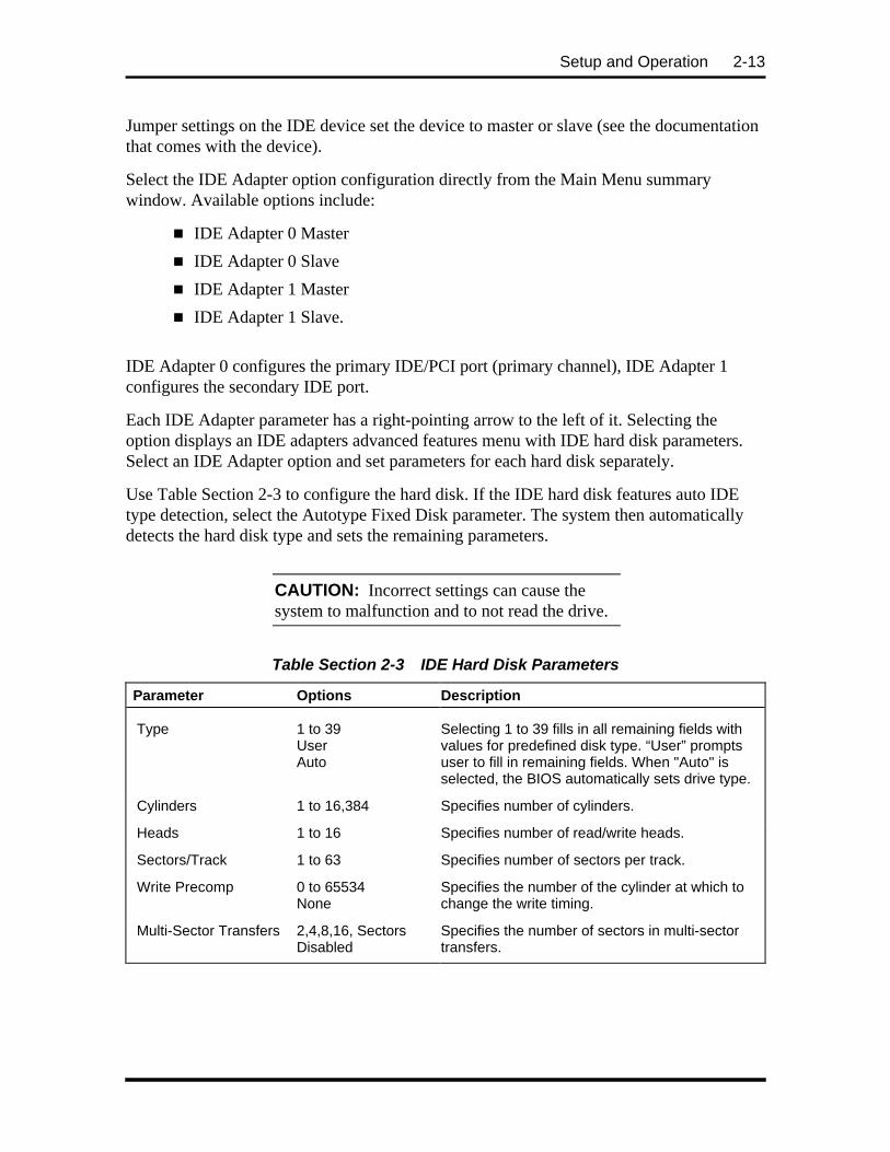
Setup and Operation 2-13
Jumper settings on the IDE device set the device to master or slave (see the documentationthat comes with the device).
Select the IDE Adapter option configuration directly from the Main Menu summarywindow. Available options include:
n IDE Adapter 0 Master
n IDE Adapter 0 Slave
n IDE Adapter 1 Master
n IDE Adapter 1 Slave.
IDE Adapter 0 configures the primary IDE/PCI port (primary channel), IDE Adapter 1configures the secondary IDE port.
Each IDE Adapter parameter has a right-pointing arrow to the left of it. Selecting theoption displays an IDE adapters advanced features menu with IDE hard disk parameters.Select an IDE Adapter option and set parameters for each hard disk separately.
Use Table Section 2-3 to configure the hard disk. If the IDE hard disk features auto IDEtype detection, select the Autotype Fixed Disk parameter. The system then automaticallydetects the hard disk type and sets the remaining parameters.
CAUTION: Incorrect settings can cause thesystem to malfunction and to not read the drive.
Table Section 2-3 IDE Hard Disk Parameters
Parameter Options Description
Type 1 to 39UserAuto
Selecting 1 to 39 fills in all remaining fields withvalues for predefined disk type. “User” promptsuser to fill in remaining fields. When "Auto" isselected, the BIOS automatically sets drive type.
Cylinders 1 to 16,384 Specifies number of cylinders.
Heads 1 to 16 Specifies number of read/write heads.
Sectors/Track 1 to 63 Specifies number of sectors per track.
Write Precomp 0 to 65534None
Specifies the number of the cylinder at which tochange the write timing.
Multi-Sector Transfers 2,4,8,16, SectorsDisabled
Specifies the number of sectors in multi-sectortransfers.

2-14 Setup and Operation
Table Section 2-3 IDE Hard Disk Parameters
Parameter Options Description
LBA Mode Control EnabledDisabled (default)
Sets LBA Mode Control on or off.
32-Bit I/O Enabled (default)Disabled
Sets 32 bit I/O to on or off.
Transfer Mode Standard (default)Fast PIO1Fast PIO2Fast PIO3
Specifies the transfer mode for moving data toand from the hard drive. Standard is the slowestmode but the most compatible. Fast PIO(programmed input/output) is the slowest of thethree enhanced modes. Fast PIO3 is the fastest ofthe enhanced modes.
Memory Cache
For memory caching parameters, select "Memory Cache" directly from the Main Menusummary window. See Table Section 2-4 for a description of memory cache parameters.
CAUTION: Incorrect settings can cause thesystem to malfunction.
Table Section 2-4 Memory Cache Parameters
Parameter Options Description
External cache EnabledDisabled (default)
Sets the state of external cache.
Cache Video BIOSArea
Enabled (default)Disabled
Controls caching of the video BIOS area.
Caching MemoryRegions
EnabledDisabled (default)
Default is disabled. Cache shadows optional ROMlocated in specified segments of memory and canimprove performance. CAUTION: Some add-inboards, particularly with on-board firmware, do notwork properly when shadowed.
Memory Shadow
Memory Shadow is always enabled. This parameter is not user-selectable.
Boot Options
The system might require a Supervisor password to set Boot parameters. Select “BootOptions” directly from the Main Menu summary window to display the “Boot Options”menu.

Setup and Operation 2-15
Use the legend keys to make the selections and exit to the Main Menu. Use Table Section2-5 to select the boot options.
Table Section 2-5 Boot Parameters
Parameters Options Description
Summary Screen Enabled (default)Disabled
Displays system configuration at the end of boot-up.
Floppy Check Enabled (default)Disabled
Verifies diskette type during boot-up. Disablingspeeds up boot time.
Last Boot Fail 3 (default)User-selectable settingsDisabled
Sets the number of times for user to boot system.If system fails to boot on number of tries, the"Previous Boot Incomplete" message appears andthe system boots with default settings.
The default setting, 3, give the user three tries toboot the system before the "Previous BootIncomplete" message" appears.
Numlock
Select “Numlock” directly from the Main Menu summary window to display the KeyboardFeatures menu.
Use the legend keys to make the selections and exit to the Main Menu. Use Table Section2-6 to configure the keyboard parameters.
Table Section 2-6 Numlock Parameters
Parameters Options Description
Numlock Auto (default)OnOff
On or Off turns NumLock on or off at bootup. Autoturns NumLock on if it finds a numeric key pad.
Keyboard Auto-Repeat rate
Fast (default)MediumSlow
Sets the delay time after the key is held downbefore it begins to repeat the keystroke.
Keyboard Auto-Repeat delay
1/4 sec1/2 sec (default)3/4 sec1 sec
Key Click EnabledDisabled (default)
Turns audible key click on or off.
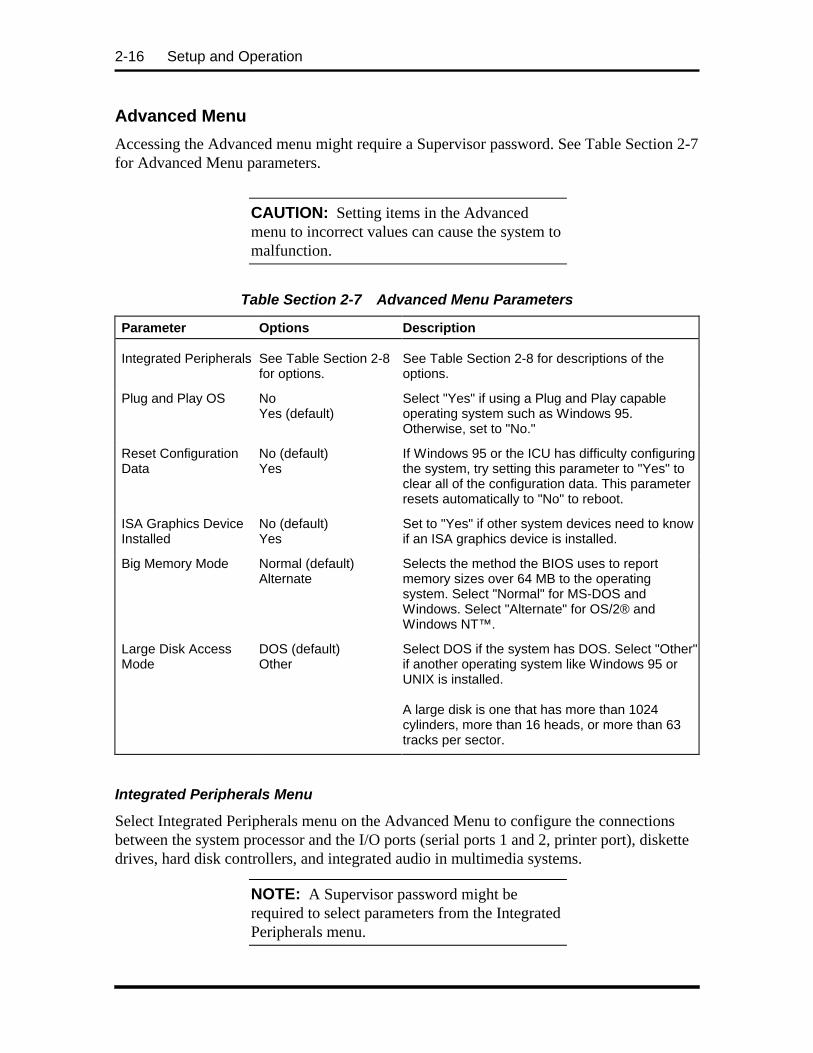
2-16 Setup and Operation
Advanced Menu
Accessing the Advanced menu might require a Supervisor password. See Table Section 2-7for Advanced Menu parameters.
CAUTION: Setting items in the Advancedmenu to incorrect values can cause the system tomalfunction.
Table Section 2-7 Advanced Menu Parameters
Parameter Options Description
Integrated Peripherals See Table Section 2-8for options.
See Table Section 2-8 for descriptions of theoptions.
Plug and Play OS NoYes (default)
Select "Yes" if using a Plug and Play capableoperating system such as Windows 95.Otherwise, set to "No."
Reset ConfigurationData
No (default)Yes
If Windows 95 or the ICU has difficulty configuringthe system, try setting this parameter to "Yes" toclear all of the configuration data. This parameterresets automatically to "No" to reboot.
ISA Graphics DeviceInstalled
No (default)Yes
Set to "Yes" if other system devices need to knowif an ISA graphics device is installed.
Big Memory Mode Normal (default)Alternate
Selects the method the BIOS uses to reportmemory sizes over 64 MB to the operatingsystem. Select "Normal" for MS-DOS andWindows. Select "Alternate" for OS/2® andWindows NT™.
Large Disk AccessMode
DOS (default)Other
Select DOS if the system has DOS. Select "Other"if another operating system like Windows 95 orUNIX is installed.
A large disk is one that has more than 1024cylinders, more than 16 heads, or more than 63tracks per sector.
Integrated Peripherals Menu
Select Integrated Peripherals menu on the Advanced Menu to configure the connectionsbetween the system processor and the I/O ports (serial ports 1 and 2, printer port), diskettedrives, hard disk controllers, and integrated audio in multimedia systems.
NOTE: A Supervisor password might berequired to select parameters from the IntegratedPeripherals menu.

Setup and Operation 2-17
Use the legend keys to make the selections and exit to the Main Menu. Use Table Section2-8 to configure the peripherals.
Table Section 2-8 Integrated Peripherals Parameters
Feature Options Description
COM A PortCOM B Port
DisabledUser-selectable settingsAuto
Selects a unique address and interrupt requestfor the listed COM ports. Auto selects the nextavailable combination.Factory settings:COM A port default: 3F8, IRQ 4COM B port default: 2F8, IRQ 3
LPT Port Disabled378, IRQ 7 (default)User-selectable settingsAuto
Selects a unique address and interrupt requestfor the LPT port. Auto selects the next availablecombination.
LPT Mode Output only (default)Bi-directionalECP
Enables parallel port to function normally (Outputonly), bidirectional, or in an enhanced capabilitiesport (ECP) mode. Check the printerdocumentation to set the correct LPT mode foryour printer.
ECP Channel DMA 0DMA 1DMA 3
Available when ECP is selected for the LPTmode.
Diskette Controller Enabled (default)Disabled
Enables the on-board diskette drive controller.
Local Bus IDEController
Both (default)PrimaryDisabled
Enables the on-board IDE controllers. "Both"enables the primary (fast) and secondary(standard) channels. The "Primary" optionenables only the primary (fast) channel
PS/2 Mouse Enabled (default)Disabled
Enables/disables the PS/2-style mouse.
On-board Sound Stereo with SRS(default)Stereo
This parameter is only available when the BIOSdetects integrated audio on the system board.When the audio is detected, stereo with surroundsound is the default.
If playing an audio file with SRS built-in, use theStereo setting.

2-18 Setup and Operation
Security Menu
Selecting “Security” from the Main Menu displays a menu with system security options.
NOTE: The Setup program can be entered witheither a User or Supervisor password. However,more Setup choices are available with theSupervisor password.
CAUTION: The features set in the Securitymenu affect the features that appear on theSecurity menu as well as on other Setup menus.
Enabling “Supervisor Password” requires a password for entering Setup. Passwords are notcase sensitive.
Pressing Enter at either Set Supervisor Password or Set User Password on the menudisplays a Set Password dialog box with the following prompts:
Enter new password: [ ]Re-enter new password: [ ]
To set a password, type the password and press Enter. Reenter the password and pressEnter.
See Table Section 2-9 for a description of the security features. Use the legend keys tomake the selections and exit to the Main Menu.
Table Section 2-9 System Security Options
Feature Options Description
Supervisor Password Disabled (default)Enabled
Must set to "Enabled" to set a Supervisorpassword.
User Password Disabled (default)Enabled
Must set to "Enabled" to set a User password.
Set SupervisorPassword
Up to sevenalphanumericcharacters
Pressing Enter displays dialog box for enteringthe supervisor password. This password givesFULL access to Setup menus.

Setup and Operation 2-19
Table Section 2-9 System Security Options
Feature Options Description
Set User Password Up to sevenalphanumericcharacters
Pressing Enter displays the dialog box forentering the user password. This password givesRESTRICTED access to Setup menus. Requiresprior setting of Supervisor password.
Password on boot Disabled (default)Enabled
Enabled requires a password on boot (cold bootonly, no password required for warm boot).Requires the prior setting of the Supervisorand/or User password.
If disabled, password(s) are required for enteringSetup but are not required for booting.
If Supervisor password is set and this option isdisabled, the BIOS boots without asking for apassword.
Diskette Access User (default)Supervisor
Supervisor setting restricts use of diskette drivesto supervisor. Requires setting the Supervisorpassword.
Fixed Disk Boot Sector Normal (default)Write Protected
Write protected helps prevent viruses. When writeprotected, operating systems (and viruses andapplication programs) which attempt to modify theboot sector will not be able to do so.
System BackupReminder and VirusCheck Reminder
Disabled (default)DailyWeeklyMonthly
When a schedule is specified, displays a messageduring bootup asking (Y/N) if thesystem has been backed up or scanned forviruses.
Message returns on each boot until you respondwith “Y”.
Daily displays the message on the first boot ofthe day, weekly on the first boot after Sunday, andmonthly on the first boot of the month.
Power Menu
Selecting “Power” from the menu bar displays a screen with the power managementparameters. Use the Power menu to specify the settings for Power Management. Theparameters are described in Table Section 2-10.
A power-management system reduces the amount of energy used after specified periods ofinactivity. The Power menu supports a Full On state, a Standby state with partial powerreduction, and a Suspend state with full power reduction.
Use the legend keys to make the selections and exit to the Main Menu.

2-20 Setup and Operation
Table Section 2-10 Power Management Parameters
Feature Options Description
APM Enabled (default)Disable
Advanced power management (APM) allowsAPM-aware software to better manage powersavings.
Power Savings Mode Customize (default)DisabledMaximumMediumMinimum
Maximum, Medium, and Minimum set power-management options with predefined values.Select Customize to make customize selections.Disabled turns off all power management.
Sleep Timeout 15 min (default)DisabledUser Selectable
Inactivity period required before partial powershutdown (Standby mode).
Deep SleepTimeout
15 minute (default)DisabledUser Selectable
Inactivity period required before Sleep timeout tomaximum power shutdown (Suspend mode).
Video in SleepMode
Off (default)On
Off, turns monitor off in Sleep mode.
IRQ to Monitor Enabled (default)Disabled
Allows you to select the following interrupts towake up the system. The default is Enabled foreach interrupt
IRQ3, IRQ4, IRQ5, IRQ7, IRQ9, IRQ10, andIRQ11
Keyboard Wakeup Enabled (default)|Disabled
Allows keyboard activity to wake up system.
Mouse Wakeup Enabled (default)Disabled
Allows mouse activity to wake up system.
Boot Menu
Selecting "Boot" from the Main menu displays the following list of boot devices.
1. Diskette drive
2. CD-ROM drive
3. Hard Drive
The BIOS loads the operating system from the devices in the sequence selected.

Setup and Operation 2-21
Exit Menu
Selecting “Exit” from the menu bar displays the following exit options.
n Save Changes & Exit
n Discard Changes & Exit
n Get Default Values
n Load Previous Values
n Save Changes.
The following subsections describe each of the options on the Exit Menu. Note that Escdoes not exit this menu. Select one of the items from the menu or menu bar to exit.
Save Changes & Exit
After making the selections on the Setup menus, always select Save Changes to Non-Volatile RAM (NVRAM) to make them operative.
Unlike standard RAM memory, NVRAM is sustained by an onboard battery and stays onwhen the system is turned off.
After saving the selections, the program displays this message:
NOTICEChanges have been saved[continue]
If an attempt is made to exit without saving, Setup asks if the changes should be savedbefore exiting.
During bootup, Setup attempts to load the values saved in NVRAM. If the values saved inNVRAM cause the system boot to fail, reboot and press F2 to enter Setup. In Setup, theROM default values (as described below) can be loaded or the values can be changed thatcaused the boot to fail.
Discard Changes & Exit
Use this option to exit Setup without recording any changes.

2-22 Setup and Operation
Get Default Values
To load all the default Setup values in the Setup menus, select Load ROM Default Valuesfrom the Main Menu. The program displays this message:
NOTICEDefault values have been loaded![continue]
If, during bootup, the BIOS program detects a problem in the integrity of values stored inNVRAM, it displays these messages:
System CMOS checksum bad - run SETUPPress <F1> to resume, <F2> to Setup
The CMOS values have been corrupted or modified incorrectly, perhaps by an applicationprogram that changes data stored in CMOS.
Press F1 to resume the boot or F2 to run Setup with the ROM default values already loadedinto the menus. Other changes can be made before saving the values to NVRAM.
Load Previous Values
During a Setup session, if a mistake has been made and has not yet been saved to NVRAM,the previously saved NVRAM values can be restored.
Selecting Load Previous Values on the Exit menu updates all the selections and displaysthis message:
NOTICEPrevious values have been loaded![continue]
Save Changes
Save Changes saves all the selections without exiting Setup. Other menus selections can bereviewed or changed.
BIOS UPDATE UTILITY
The system BIOS resides on a flash ROM in the system. The flash ROM can be updated,should it ever become necessary. This feature allows the ROM BIOS chip to be flashedwith a new BIOS code through software, rather than replacing the chip.
Performing an update is done with a BIOS flash diskette. The diskette, which contains thelatest version of the BIOS code, can be obtained from NEC Technologies or, if a modem isavailable, the latest BIOS can be downloaded from NEC's Bulletin Board Service (BBS).

Setup and Operation 2-23
If a modem is available, use the following procedure to access the BBS for the latestversion of the BIOS Update utility. How to flash the BIOS with a flash diskette isdescribed following the BBS access procedure.
NEC Bulletin Board Service
Log onto the BBS as follows.
NOTE: First time users must answer a new userquestionnaire.
1. From the Windows for Workgroups Program Manager, select Accessories anddouble click on Terminal.
2. From the Settings menu, click on Communications, check that the settings matchthe following BBS parameters, and click OK when done.
n Baud rate: select a baud rate that matches the modem
n Parity: none
n Data bits: 8
n Stop bits: 1
n Flow control: Xon/Xoff (select Hardware if using 14.4 bps or higher)
3. From the Phone menu, click on Dial, enter the BBS phonenumber (508 635-4706), and click OK. Your business phone or location mightrequire a 9 1 or 1 prefix.
4. Press Enter twice.
5. Enter your first name, last name, and password. Press Enter after each.
6. Follow the screen prompts until the NECTECH Main Menu is displayed.
7. At the Main Menu, press J to join a conference. Select Conference 1 for thedesktop conference.
8. From the Main Menu, select F and Enter for the File menu.
9. At the File menu, select F for a list of downloadable files. Follow the prompts toselect a file for downloading.

2-24 Setup and Operation
After completing downloading of the file, log off the BBS as follows.
1. Press Enter (to continue).
2. Press G (command for Goodbye/Hangup).
3. Press Enter.
Using the BIOS Update Utility
Update the BIOS from the BIOS flash diskette as follows.
1. Write down the Setup parameters currently set on the system.
2. Turn off the system.
3. Insert the flash diskette in drive A, and turn on the system.
4. The update procedes automatically and shows a BIOS Update successfullycompleted message when done.
5. Press any key to reboot the system.
6. Remove the flash diskette.

Section 3
Option Installation
This section provides instructions for installing the following options:
n expansion boards
n SIMM memory upgrade
n video memory upgrade
n processor upgrade
n L2 SRAM cache module
n data storage devices
n external options.
All options require that the system cover be removed. Procedures for removing the cover isincluded in this section.
GENERAL RULES FOR INSTALLING OPTIONS
Follow these general rules when installing system options.
n Turn off system power and unplug the power cable.
n Turn off and disconnect all peripherals.
n When handling boards or chips, touch the system unit frame to discharge static.
n Do not disassemble parts other than those specified in the procedure.
n All screws are Phillips-head, unless otherwise specified.
n Label any removed connectors. Note where the connector goes and in whatposition it was installed.

3-2 Option Installation
PRECAUTIONS
Take care when working inside the system and when handling computer components.Avoid electric shock or personal injury by observing the following warning.
WARNING: Before removing the system unitcover, turn off the power and unplug the systempower cable. Power is removed only when thepower cable is unplugged.
Static electricity and improper installation procedures can damage computer components.Protect computer components by following these safety instructions.
CAUTION: Electrostatic discharge can damagecomputer components. Discharge staticelectricity by touching a metal object beforeremoving the system unit cover.
n Avoid carpets in cool, dry areas. Leave an option, such as a board or chip, in itsanti-static packaging until ready to install it.
n Dissipate static electricity before handling any system components (boards, chips,and so on) by touching a grounded metal object, such as the system’s unpaintedmetal chassis.
If possible, use anti-static devices, such as wrist straps and floor mats.
n Always hold a chip or board by its edges. Avoid touching the components on thechip or board.
n Take care when connecting or disconnecting cables. A damaged cable can causea short in the electrical circuit. Misaligned connector pins can cause damage tosystem components at power-on.
When installing a cable, route the cable so it is not pinched by other componentsand is out of the path of the system unit cover. Prevent damage to the connectorsby aligning connector pins before you connect the cable.
n When disconnecting a cable, always pull on the cable connector or strain-reliefloop, not on the cable.

Option Installation 3-3
Removing the System Unit Cover
The following procedure describes how to remove the system unit cover.
WARNING: Before removing the system unitcover, turn off the power and unplug the systempower cable. Power is removed only when thepower cable is unplugged.
1. Turn off and unplug the system unit.
2. Disconnect the keyboard, mouse, monitor, and any other external options (suchas a printer) from the rear of the system unit.
CAUTION: Electrostatic discharge can damagecomputer components. Discharge staticelectricity by touching a metal object beforeremoving the system unit cover.
3. Remove the two cover screws from the rear of the system unit (see FigureSection 3-1).
Screws
Figure Section 3-1 Removing Cover Screws

3-4 Option Installation
4. From the rear of the system, grasp the sides and slide the cover about an inchaway from the front panel (see Figure Section 3-2).
NOTE: The cover fits tightly. Press the frontedge of the cover to release it from the frontpanel. Also press against the rear panel to slidethe cover one inch away from the front panel.
Figure Section 3-2 Releasing the Cover
5. Lift the cover up and away from the system unit.
6. Reinstall the cover by reversing steps 1 through 5, above.
Be sure that the cover tabs on the sides of the cover align inside the frame of theunit when positioning the cover over the chassis.
EXPANSION BOARDS
The computer supports ISA Plug and Play expansion boards. Plug and Play expansionboards allow installing a board in an expansion slot without changing the hardwaresettings. There are no system resource conflicts to resolve. Plug and Play automaticallyconfigures the board for the system.
Industry-standard 8- 16-bit, ISA and 32-bit PCI expansion boards are supported in thesystem unit. ISA expansion boards can either be Plug and Play or non-Plug and Playboards.
Expansion Slot Locations
The PowerMate system has four expansion slots (see Figure Section 3-4):
n two ISA slots
n one PCI slot
n one shared PCI/ISA slot.

Option Installation 3-5
ISA expansion slots support industry-standard 8-bit or 16-bit expansion boards. ThePCI/ISA slot also supports PCI expansion boards.
PCI expansion boards run at the system’s processor speed. The PCI bus handles 32 bits ofdata at a time, being wider as well as faster than the standard ISA bus. PCI boards can sendand receive data much faster which boosts system performance.
Figure Section 3-4 Locating Expansion Slots
Expansion Board Installation
Install expansion boards in the system as follows.
1. Remove the system unit cover as previously described.
2. Follow any preinstallation instructions that came with the expansion board (suchas setting switches or jumpers on the board).
3. If installing a board in the inside expansion slot (next to the power supply), see“Inside Slot Expansion Board Installation.” Otherwise, continue to the next step.
4. Remove the screw securing an expansion slot cover and remove the cover (seeFigure Section 3-6).
Save the screw for installing the expansion board. Save the slot cover for futureuse.
ISA Slot*
PCI Slot
PCI/ISA Slot
* In some models, anISA slot is occupied bya network interfaceboard
ISA Slot*

3-6 Option Installation
CAUTION: A slot cover can damage the systemboard or any option board if it falls into thesystem. Take care to keep the slot cover fromfalling when removing the screw.
If the slot cover does fall into the unit, remove itbefore replacing the cover.
Figure Section 3-6 Removing a Slot Cover
5. Hold the board by its edges and insert it into the expansion slot (see FigureSection 3-8). Align full-size expansion boards with the guide rail at the front ofthe system unit.
Press the board firmly into the expansion slot connector. Gently rock the boardfrom side-to-side to seat it into the connector.
6. Insert the screw removed earlier to secure the expansion board to the supportbracket.
Slot Cover

Option Installation 3-7
7. Attach any signal cables required by the expansion board.
8. Replace the system unit cover.
Inside Slot Expansion Board Installation
Use this procedure if installing an expansion board into the inside slot.
1. Remove the system unit cover as previously described.
2. Follow any preinstallation instructions that come with the expansion board (suchas setting switches or jumpers on the board).
3. Remove the two screws that secure the slot cover support and expansion slotcover to the rear of the system (see Figure Section 3-10).
Remove the slot cover support and slot cover from inside the system unit.
CAUTION: Take care not to drop the slot coverand support into the system.
Figure Section 3-8 Inserting the Board

3-8 Option Installation
Figure Section 3-10 Removing the Slot Cover Support Screws
4. Hold the board by its edges, component side down and the bracket end facing therear of the unit, and insert it into the expansion slot.
Press the board firmly into the expansion slot connector. Gently rock the boardfrom side-to-side to seat it into the connector.
5. Hold the slot cover support over the expansion board bracket and replace the twoscrews removed earlier (see Figure Section 3-12). The slot cover support securesthe expansion board in place.
Figure Section 3-12 Attaching the Slot Cover Support
6. Attach any signal cables required by the expansion board.
7. Replace the system unit cover.
Slot Cover
Slot Cover SupportScrews
Screws
Expansion BoardBracket
Slot CoverSupport

Option Installation 3-9
SYSTEM BOARD OPTIONS
SIMM, video, and processor OverDrives require locating the connector on the systemboard. See the following figure for connector locations.
Figure Section 3-14 System Board Upgrade Sockets and Connectors
SIMM Upgrade
SIMM sticks are installed into SIMM sockets on the system board. The system boardprovides four SIMM sockets and supports up to 128 MB of high-speed EDO memory. Thesystem supports the following 32-bit (non-parity) 70 ns SIMMs:
n 1-MB by 32-bit (4-MB stick)
n 2-MB by 32-bit (8-MB stick)
n 4-MB by 32-bit (16-MB stick)
n 8-MB by 32-bit (32-MB stick).
CAUTION: To avoid corrosion betweendifferent metals, only use tin-plated SIMMsticks.
Checking System Memory
Use the following procedure to:
n check the memory installed in the system
Audio WaveConnector
Video DRAMSockets
CacheSocket
ProcessorSocket
SIMMSocket 1
SIMMSocket 2
SIMMSocket 3
SIMMSocket 4

3-10 Option Installation
n determine the SIMM configuration needed to increase memory
n locate the sockets for SIMM installation.
1. Locate the four SIMM sockets on the system board (see Figure Section 3-14).
If any cables block access to the SIMM sockets, label and disconnect them. If anyboards block access to the sockets, remove them.
2. Use Table Section 3-1 to determine the SIMM configuration needed to upgradememory and to identify the sockets for SIMM installation.
Table Section 3-1 Recommended Memory Upgrade Path
Total SIMM SIMM
Memory Socket 1 Socket 2 Socket 3 Socket 4
8 MB* 4 MB 4 MB Empty Empty
16 MB 4 MB 4 MB 4 MB 4 MB
16 MB** 8 MB 8 MB Empty Empty
24 MB 4 MB 4 MB 8 MB 8 MB
24 MB 8 MB 8 MB 4 MB 4 MB
32 MB 8 MB 8 MB 8 MB 8 MB
32 MB 16 MB 16 MB Empty Empty
40 MB 4 MB 4 MB 16 MB 16 MB
40 MB 16 MB 16 MB 4 MB 4 MB
48 MB 8 MB 8 MB 16 MB 16 MB
48 MB 16 MB 16 MB 8 MB 8 MB
64 MB 16 MB 16 MB 16 MB 16 MB
64 MB 32 MB 32 MB Empty Empty
72 MB 4 MB 4 MB 32 MB 32 MB
72 MB 32 MB 32 MB 4 MB 4 MB
80 MB 8 MB 8 MB 32 MB 32 MB
80 MB 32 MB 32 MB 8 MB 8 MB
96 MB 16 MB 16 MB 32 MB 32 MB
96 MB 32 MB 32 MB 16 MB 16 MB
128 MB 32 MB 32 MB 32 MB 32 MB
*Standard configuration for 8-MB systems.**Standard configuration for 16-MB systems.

Option Installation 3-11
SIMM Removal
Remove a SIMM as follows.
CAUTION: Reduce static discharge bytouching the system’s metal chassis.
1. Remove the system unit cover as previously described.
2. Locate the SIMM sockets (see Figure Section 3-14).
3. Press the metal clips at the outer edges of the socket away from the SIMM.
4. Push the SIMM away from the locking tabs and remove it from the socket (seeFigure Section 3-15).
Figure Section 3-15 Removing a SIMM
5. Install a SIMM per the following procedure.
SIMM Installation
Install a SIMM as follows.
1. Remove the system unit cover as previously described.
2. Locate the SIMM sockets (see Figure Section 3-14).
Remove any currently installed SIMMs that are not needed.
Clips

3-12 Option Installation
CAUTION: Before installing a SIMM, reducestatic discharge by touching the system’s metalchassis.
3. Position the SIMM in the socket. The notched end of the SIMM allows only thecorrect positioning.
4. Insert the SIMM at an angle into the socket.
5. Tilt the SIMM towards the locking tabs using equal pressure at the ends of theSIMM until it locks into the socket (see Figure Section 3-17).
Figure Section 3-17 Inserting the SIMM
6. Replace any cables or boards that may have been removed.
7. Replace the system unit cover.
Video Upgrade
Upgrade the video memory by adding two 512-KB by 16-bit video DRAM modules asfollows.
1. Remove the system unit cover as previously described.
2. Locate the video DRAM sockets (see Figure Section 3-14).
If any expansion boards are obstructing your view of the sockets, remove theboards (see “Expansion Board Removal”).
Clip
Notched Endof SIMM

Option Installation 3-13
CAUTION: Reduce static discharge bytouching the system’s metal chassis.
3. Align the notched ends of the module and socket (see Figure Section 3-19).Using equal pressure, gently press the module into the socket. Repeat for thesecond module.
Figure Section 3-19 Aligning the Video DRAM Module with the Socket
4. Replace any boards that were removed.
5. Replace the system unit cover.
Processor Upgrade
The zero-insertion force (ZIF) socket accepts pin-grid-array (PGA) processors, such as theprimary processor or an OverDrive processor.
CAUTION: Incorrect installation of theprocessor can damage the processor, systemboard, or both. Follow the installationinstructions carefully.
The system requires a heatsink on the OverDriveprocessor. Verify that you have the correctheatsink for the processor.
When upgrading the processor, first remove the processor currently installed in the system,then install the OverDrive processor.
Notched Cornerof Socket
Notched End of Module

3-14 Option Installation
Processor Removal
Remove the installed processor on the system board as follows.
1. Remove the system unit cover as previously described.
2. Locate the processor socket (see Figure Section 3-14).
If any expansion boards are obstructing the socket, remove the boards.
3. Release the heatsink clip from the tabs on the socket.
4. Release the processor by pulling the lever on the socket away from the socket andas far back as it goes without forcing.
CAUTION: Before picking up the processor,reduce static discharge by touching the metalframe of the system unit.
5. Lift the processor out of the socket.
Processor Installation
1. Remove the processor currently in the system (described in the previousprocedure).
CAUTION: Before picking up the processor,reduce static discharge by touching the metalframe of the system unit.
2. Align the notched corner of the processor with the alignment corner in the socketand insert the processor.
3. Swing the lever down to lock the processor into the socket.
CAUTION: Remember to either reattach theheatsink used with the old processor or installthe new heatsink supplied with the OverDriveprocessor.
4. Install the heatsink on the processor and reattach the clip.
5. Check to see if the newly installed processor requires a system board jumperchange (see Appendix B, System Board Jumpers).

Option Installation 3-15
6. Replace any boards removed during this procedure.
7. Replace the system unit cover.
SECONDARY CACHE UPGRADE
The system comes with 16 KB of primary cache built into the processor. Your systemsupports an optional 256 KB of asynchronous or synchronous pipeline burst secondarySRAM cache module. The secondary cache installs into a cache socket on the systemboard. Secondary cache increases system performance.
NOTE: NEC recommends that you purchasethe NEC Cache Upgrade Kit when addingsecondary cache. The NEC option kit has beentested and approved to work correctly with yoursystem.
Use the following procedure to install the cache module.
1. Remove the system unit cover.
2. Locate the cache socket on the system board (see Figure Section 3-14).
If you have expansion boards obstructing the connector, remove the boards.
Figure Section 3-21 Aligning the Cache Module with the Socket
Pin 1 End of Module

3-16 Option Installation
CAUTION: Before you install a cache module,reduce static discharge by touching the system’smetal chassis.
3. Align the pin 1 end of the cache module with the pin 1 end of the secondarycache socket. Using equal pressure, gently press the module into the socket.
4. Check to see if the newly installed cache module requires a system board jumperchange. See Appendix B, System Board Jumpers.
5. Replace any boards that you may have removed during this procedure (see“Expansion Board Installation” earlier in this chapter).
6. Replace the system unit cover.

Option Installation 3-17
DATA STORAGE DEVICES
The system board in the computer supports the following storage devices:
n up to two diskette drives, including the standard 1.44-MB diskette drive
n up to four IDE devices such as IDE hard disks and an IDE CD-ROM reader.
Other storage devices might require the installation of a compatible controller board.
Device Slots
The PowerMate system has four storage device slots:
n a 3 1/2-inch accessible device slot which contains the standard 1.44-MB diskettedrive
n one 3 1/2-inch internal hard disk drive slots (1-inch high, thin-height)
Hard disk configurations come with an IDE hard disk installed.
n two 5 1/4-inch accessible device slots (1.6-inch high, half-height)
In multimedia models, one accessible device slot contains the standard CD-ROMreader.
Other accessible devices (diskette drive, tape drive, CD-ROM reader) can beinstalled in the 5 1/4-inch slots.
A hard disk with a 5 1/4-inch form factor can be installed in the 5 1/4-inch slots.

3-18 Option Installation
Figure Section 3-13 shows the device slot locations in the system.
Figure Section 3-13 Locating Device Slots
Device Preparation
Before installing a storage device in the system, follow any preinstallation instructions thatcome with the device. For example, check the following:
n Diskette drive remove any termination on the optional diskette drive. See thedocumentation that comes with the drive.
n IDE device check the jumper settings on the device before installing it. Seethe documentation that comes with the device for jumper setting information.
An IDE device, such as an IDE hard disk or IDE CD-ROM reader, must be setcorrectly as the first (master) or second (slave) device on the IDE channel.
The standard IDE hard disk (in hard disk models) is set as the master device onthe primary IDE connector. The CD-ROM reader in multimedia models is themaster device on the secondary IDE connector.
Device Cables
The cables used for installation of optional storage devices include:
n diskette drive signal cable
n IDE signal cables
n system power cables.
3 1/2-Inch Internal Slot(contains hard disk inhard disk configurations)
3 1/2-Inch Slot(contains 1.44-MBdiskette drive)
5 1/4-Inch AccessibleSlots*
* Top 5 1/4-inch slot is available in some configurations.
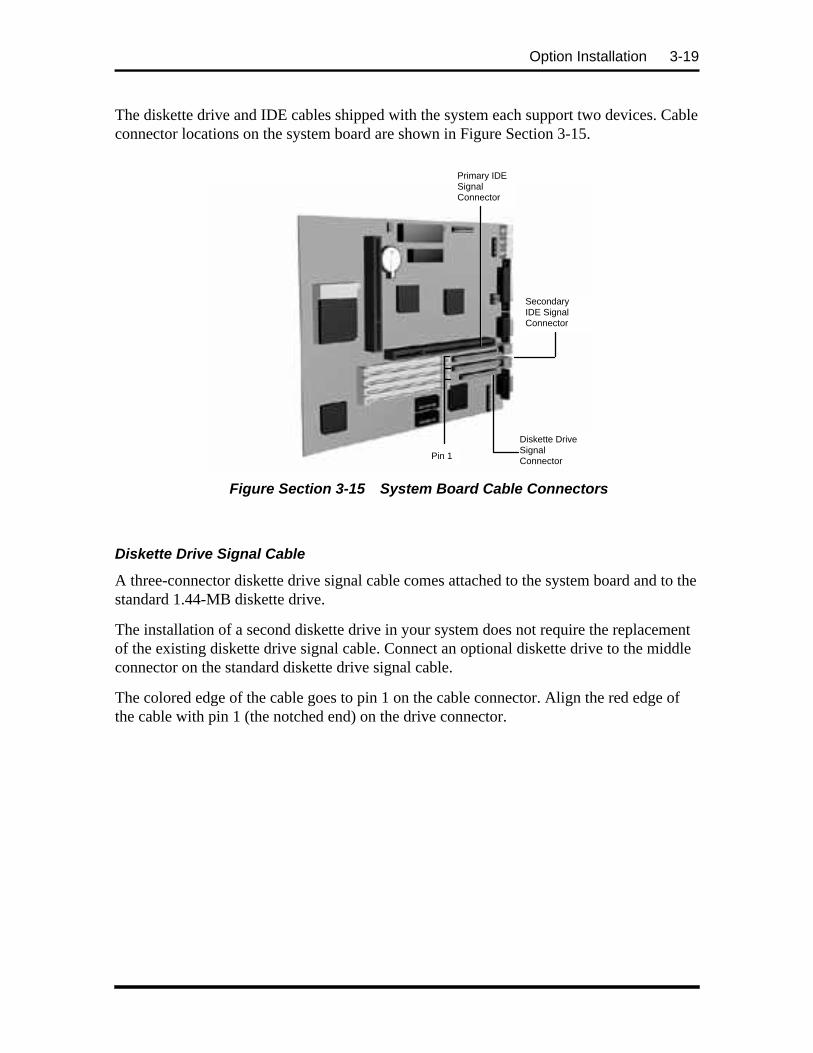
Option Installation 3-19
The diskette drive and IDE cables shipped with the system each support two devices. Cableconnector locations on the system board are shown in Figure Section 3-15.
Figure Section 3-15 System Board Cable Connectors
Diskette Drive Signal Cable
A three-connector diskette drive signal cable comes attached to the system board and to thestandard 1.44-MB diskette drive.
The installation of a second diskette drive in your system does not require the replacementof the existing diskette drive signal cable. Connect an optional diskette drive to the middleconnector on the standard diskette drive signal cable.
The colored edge of the cable goes to pin 1 on the cable connector. Align the red edge ofthe cable with pin 1 (the notched end) on the drive connector.
Primary IDESignalConnector
SecondaryIDE SignalConnector
Diskette DriveSignalConnectorPin 1

3-20 Option Installation
Figure Section 3-17 shows a three-connector diskette drive signal cable.
Figure Section 3-17 Optional Diskette Drive Signal Cable
IDE Signal Cables
Hard disk systems come with a three-connector IDE interface cable attached to the primaryIDE connector. Multimedia systems come with a second IDE cable connected to the CD-ROM reader and to the secondary IDE connector.
Each IDE connector on the system board supports two IDE devices. The addition of an IDEdevice to an IDE connector does not require the replacement of the existing IDE signalcable.
If installing an optional IDE CD-ROM reader, connect it to the secondary IDE connector.The primary (fast) IDE port should be reserved for hard disks.
Attaches to theSystem Board
Attaches to 1.2-MBDiskette Drive
Attaches to 1.44-MBDiskette Drive
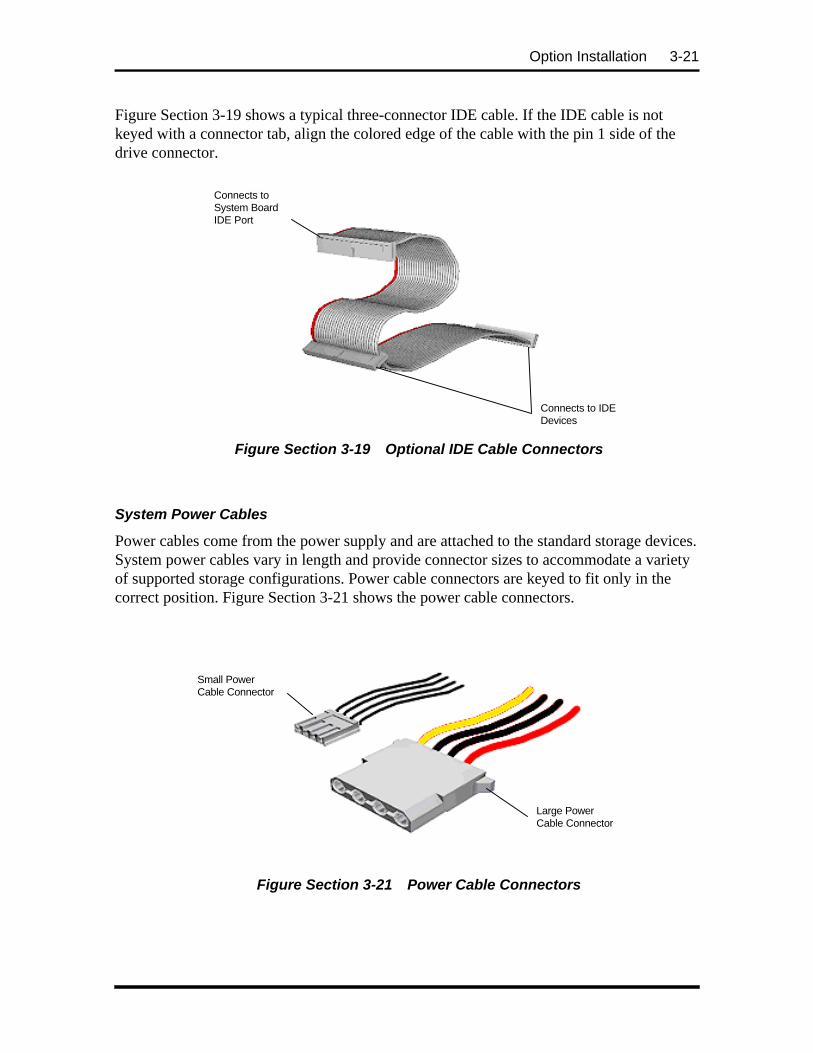
Option Installation 3-21
Figure Section 3-19 shows a typical three-connector IDE cable. If the IDE cable is notkeyed with a connector tab, align the colored edge of the cable with the pin 1 side of thedrive connector.
Figure Section 3-19 Optional IDE Cable Connectors
System Power Cables
Power cables come from the power supply and are attached to the standard storage devices.System power cables vary in length and provide connector sizes to accommodate a varietyof supported storage configurations. Power cable connectors are keyed to fit only in thecorrect position. Figure Section 3-21 shows the power cable connectors.
Figure Section 3-21 Power Cable Connectors
Connects to IDEDevices
Connects toSystem BoardIDE Port
Large PowerCable Connector
Small PowerCable Connector

3-22 Option Installation
Device Cabling
All storage devices require a power and signal cable connection. Devices shipped with thesystem are already connected. Cable optional devices as follows.
Cabling an IDE Device
1. Connect the IDE signal cable connector to the connector on the IDE device.
Take care to prevent bending drive connector pins. Align the IDE cable connectoras shown in Figure Section 3-23.
2. Locate an available power connector coming from the power supply.
3. Connect the appropriate power cable to the power connector on the IDE device.
Figure Section 3-23 Connecting IDE Device Cables
4. If installing an IDE CD-ROM reader, also connect the audio cable (see theinstructions that come with the reader).
Cabling a Diskette Drive
1. Connect the diskette drive signal cable connector to the signal connector on thediskette drive (see Figure Section 3-25).
2. Locate an available power connector.
3. Connect the power cable to the power connector on the device.
Power Cable
IDE Cable
Red Edge

Option Installation 3-23
Figure Section 3-25 Connecting 1.2-MB Diskette Drive Cables
Storage Device Installation
The following subsections describe how to install 3 1/2-inch and 5 1/4-inch drives. Theinstallation procedures include:
n removing the 3 1/2-inch drive bracket
n installing a 3 1/2-inch drive
n removing the front panel
n installing a 5 1/4-inch device
n replacing the front panel
n replacing the 3 1/2- inch drive bracket.
Removing the 3 1/2-Inch Drive Bracket
The 3 1/2-inch drive bracket containing the diskette drive must be removed beforeinstalling any 3 1/2-inch and 5 1/4-inch devices. Remove the bracket as follows.
1. Remove the desktop system cover as previously described.
2. Remove the screw securing the drive bracket to the chassis (see Figure Section 3-27).
3. Slide the bracket to the rear of the chassis to release it from the three bracket tabs.
4. Carefully lift the drive bracket up and place it on top of the power supply.
Red Edge
Diskette DriveSignal CableConnector
PowerCable
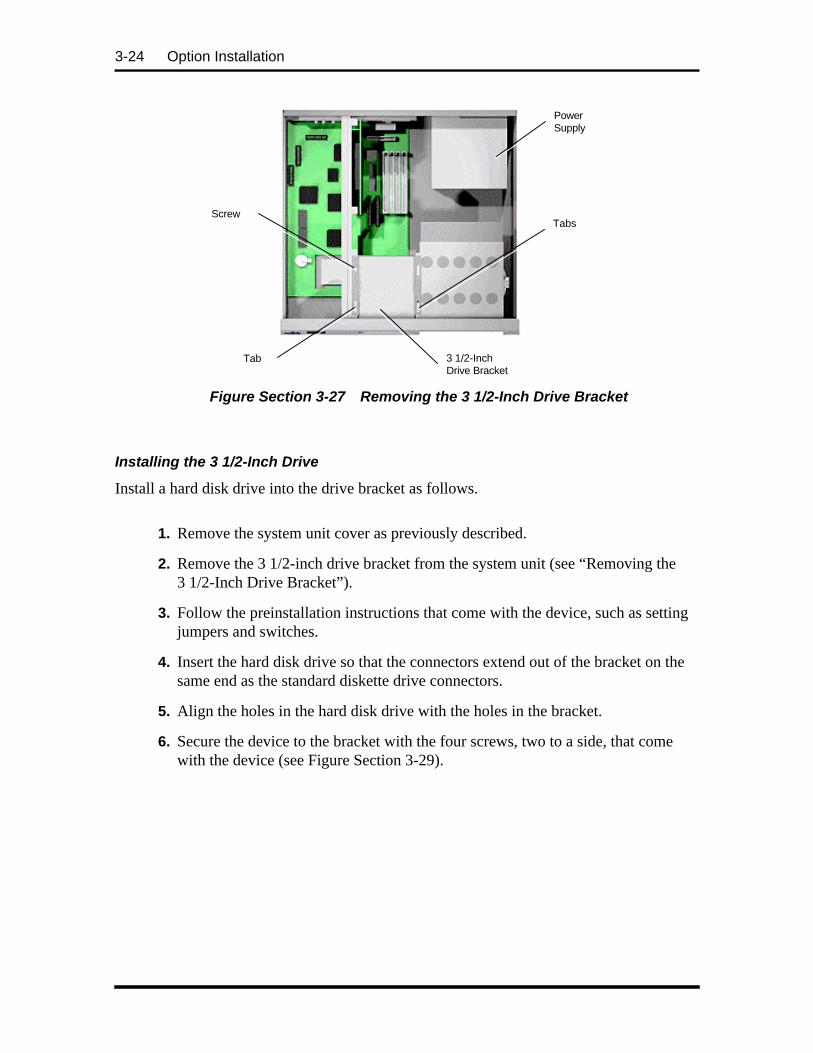
3-24 Option Installation
Figure Section 3-27 Removing the 3 1/2-Inch Drive Bracket
Installing the 3 1/2-Inch Drive
Install a hard disk drive into the drive bracket as follows.
1. Remove the system unit cover as previously described.
2. Remove the 3 1/2-inch drive bracket from the system unit (see “Removing the3 1/2-Inch Drive Bracket”).
3. Follow the preinstallation instructions that come with the device, such as settingjumpers and switches.
4. Insert the hard disk drive so that the connectors extend out of the bracket on thesame end as the standard diskette drive connectors.
5. Align the holes in the hard disk drive with the holes in the bracket.
6. Secure the device to the bracket with the four screws, two to a side, that comewith the device (see Figure Section 3-29).
3 1/2-InchDrive Bracket
Tabs
Tab
Screw
PowerSupply

Option Installation 3-25
Figure Section 3-29 Securing a 3 1/2-Inch Drive
7. Connect the drive cables.
8. Replace the 3 1/2-inch drive bracket (see “Replacing the 3 1/2-Inch DriveBracket”).
Removing the Front Panel
Remove the front panel only if installing a 5 1/4-inch device. The front panel does not needto be removed if installing a 3 1/2-inch hard disk drive.
If installing a 3 1/2-inch hard disk drive, see “Installing the 3 1/2-Inch Drive.”
1. Remove the system unit cover as previously described.
2. Remove the front panel by releasing the four tabs from the back of the front panel(see Figure Section 3-31).

3-26 Option Installation
Figure Section 3-31 Removing the Front Panel
3. Identify the slot for the device being installed.
4. Remove the blank panel from the selected slot by pressing the panel tabs frominside the front panel and pushing the blank panel out (see Figure Section 3-33).
Figure Section 3-33 Locating the Blank Panel Tabs
5. Remove the perforated metal plate from the selected slot on the chassis bypulling the metal plate back and forth until it releases.
Front PanelBlank Panel
Tabs(behind front panel)
Tabs(behind front panel)
Top BlankPanel Tabs
Bottom BlankPanel Tabs

Option Installation 3-27
6. Install the device (see “Installing the 5 1/4-Inch Device”).
Installing the 5 1/4-Inch Device
Install an accessible device into the device cage as follows.
1. Remove the 3 1/2-inch drive bracket from the system unit (see “Removing the3 1/2-Inch Drive Bracket”).
2. Remove the front panel (see “Removing the Front Panel”).
3. Follow the preinstallation instructions that come with the device, such as settingjumpers and switches.
NOTE: If the device comes with rails, do notattach them. Remove any rails already attached.
4. From the front of the system, insert the device, connector end first, into thedevice slot.
NOTE: To easily access device connectors forcabling, do not insert a 5 1/4-inch device all theway into the slot.
5. Connect the device cables.
6. Align the holes in the device with the holes in the cage.
7. Secure the device to the cage with the four screws, two to a side, that come withthe device (see Figure Section 3-35).

3-28 Option Installation
Figure Section 3-35 Securing the Device
8. Replace the drive bracket (see “Replacing the 3 1/2-Inch Drive Bracket”).
Replacing the Front Panel
Replace the front panel as follows.
1. Align the four front panel tabs with the holes in the front of the system unit.
2. Evenly press the front panel into position until the tabs lock the panel in place(see Figure Section 3-37).
Figure Section 3-37 Aligning the Front Panel
3. Continue to Step 5 in “Replacing the 3 1/2-Inch Drive Bracket.”
Two of FourScrews
Front PanelBlank Panel
Tabs(behind front panel)Tabs
(behind front panel)

Option Installation 3-29
Replacing the 3 1/2-Inch Drive Bracket
When replacing the 3 1/2-inch drive bracket, take care to prevent pulling and loosening thecable connections.
1. Place the 3 1/2-inch drive bracket in the 3 1/2-inch device slot.
2. Slide the 3 1/2-inch drive bracket toward the front of the chassis so that the tabssecure the bracket.
3. Use the previously removed bracket screw to secure the bracket in place (seeFigure Section 3-39).
3 1/2-InchDrive Bracket
Tabs
Tab
Screw
Figure Section 3-39 Securing the 3 1/2-Inch Drive Bracket
4. Replace the front panel (see “Replacing the Front Panel”).
5. Replace the system unit cover.
NOTE: If a 1.2-MB diskette drive was installed,remove the protective cardboard insert from thedrive.
6. Run the Setup program to set the new configuration.

3-30 Option Installation
ADDING EXTERNAL OPTIONS
This subsection includes installation procedures for a parallel printer and serial devices.Procedures for connecting the microphone and speakers are included in Section 2, Setupand Operation.
Parallel Printer
NOTE: Before connecting a printer to thesystem, be sure the printer is set up correctly.Follow the setup instructions that come with theprinter.
Connect a parallel printer to the system as follows.
1. Turn off power to the system and printer.
2. Connect the printer cable to the printer port on the rear of the system unit (seeFigure Section 3-41).
3. Secure the cable with the screws provided.
4. Connect the other end to the printer.
Figure Section 3-41 Connecting a Printer Cable
Printer Port
Printer CableScrews

Option Installation 3-31
RS-232C Device Connection
NOTE: Before connecting a serial device to thesystem, be sure the serial device is set upcorrectly. Follow the setup instructions thatcome with the option.
1. Turn off power to the system and to the serial device.
2. Connect one end of the serial cable to one of the two serial ports on the rear ofthe computer (see Figure Section 3-43).
3. Secure the cable with the screws provided.
4. Connect the other end to the serial device.
Figure Section 3-43 Connecting an RS-232C Cable to the Desktop
Serial Port 1
Serial CableScrews

Section 4
Maintenance and Troubleshooting
This section provides information on maintaining and troubleshooting the PowerMate VeSeries computers. Also included in this section are NEC service telephone numbers(Table Section 4-1) and procedures for replacing the CMOS battery.
Table Section 4-1 NEC Service and Information Telephone Numbers
Service Call
To order NEC spare parts, cross-shipments,status on orders, part numbers, contracts,extended warranties and customer serviceissues (dealers only)
In the U.S., call 1(800) 632-4525
To order NEC spare parts (for customers) In the U.S., call 1(800) 233-6321In Canada, call 1(800) 727-2787
To obtain option information, literature, dealerlocations, and sales leads
Call 1(800) NEC-INFO
To open a service call or speak to a technician In the U.S., call 1(800) 632-4565
To log onto the NEC Electronic Bulletin BoardSystem (BBS) for down loading software driversand the latest BIOS for ROM flashing
Call 1(508) 635-4706(see BIOS Update Utility in Section 2)
To acquire FastFacts™ about NEC productsto your fax machine 24 hours a day. Use thisautomated service to receive the latest TechnicalInformation Bulletins and more.
In the U.S., call 1(800) 366-0476Outside the U.S., call 1(708) 238-7800
To inquire about Canadian repairs Call 1(800) 268-4191

4-2 Maintenance and Troubleshooting
MAINTENANCE
This subsection contains general information for cleaning and checking the system,keyboard, and monitor.
The system, keyboard, and monitor require cleaning and checking at least once a year, andmore often if operating in a dusty environment. No other scheduled maintenance orlubrication is required.
WARNING: Unplug all power cords beforeperforming any maintenance. Voltage is presentinside the system and monitor even after thepower button is off. All voltage is removed onlywhen the power cord is unplugged.
System Cleaning
Use the following procedure for cleaning the system.
1. Power off the system and unplug all power cables.
2. Periodically wipe the outside of the system, keyboard, mouse, and monitor with asoft, clean cloth. Remove stains with a mild detergent. Do not use solvents orstrong, abrasive cleaners on any part of the system.
3. Clean the monitor screen with a commercial monitor screen cleaning kit. Or use aglass cleaner, then wipe with a clean lint-free cloth.
4. Local distributors and dealers may sell diskette drive head cleaning kits. Thesekits contain special diskettes and cleaning solution. Do not use the abrasive headcleaning kits (kits without cleaning solution). Insert the diskette immediatelyafter powering on the system, before the disk boot-up. Allow the diskette driveheads to clean for about 30 seconds.

Maintenance and Troubleshooting 4-3
Keyboard Cleaning
When necessary, inspect and clean the inside of the keyboard as follows:
1. Turn the keyboard upside-down.
2. Remove the screws holding the keyboard enclosure together.
NOTE: The keyboard and cable together areconsidered a whole-unit, field-replaceableassembly. Therefore, disassembly of thekeyboard is necessary only when cleaning theinside.
3. Separate the two halves of the enclosure. Clean the enclosure and keys with adamp cloth. A small, soft-bristle brush may be used to clean between the keys.Do not wet or dampen the keyboard's printed circuit board (PCB). If the PCBaccidentally gets wet, thoroughly dry it before reattaching the keyboard to thesystem unit.
Mouse Cleaning
Under normal conditions, the mouse has a self-cleaning mechanism that prevents a buildupof dust or lint around the mouse ball and tracking mechanism. Periodically, however, themouse ball must be cleaned. Use the following procedure to clean the mouse.
1. Unplug the mouse from the system.
2. Turn the mouse upside down and locate the mouse ball cover (see Figure Section4-1).
3. Turn the ball cover counterclockwise and remove the cover.
MouseBall Cover

4-4 Maintenance and Troubleshooting
Figure Section 4-1 Removing the Mouse Ball Cover
4. Turn the mouse over and remove the ball.
5. Clean the mouse as follows:
n Clean the mouse ball with tap water and a mild detergent, then dry it with alint-free cloth.
n Remove any dust and lint from the mouse socket.
6. Replace the mouse ball in its socket.
7. Replace the ball cover and turn it clockwise until it locks in place.
TROUBLESHOOTING
This subsection provides information that helps isolate and repair system malfunctions atthe field level. Step-by-step instructions for diagnosing and solving system hardwareproblems are provided.
If disassembly is required, see Section 5. Connector pin assignments are given inAppendix A. Jumper settings are given in Appendix B.
Diagnosing and Solving Problems
One beep indicates that the system has completed its POST test. If intermittent beepingoccurs, power off the system and try again. If the beeping persists, see Table Section 4-2.The table summarizes problems that may develop during system operation and lists (insequentialorder) suggested corrective actions.

Maintenance and Troubleshooting 4-5
Table Section 4-2 Problems and Solutions
Problem Symptom Solution
No power Power lamp on computerstatus panel will not light.
1. Check that the power cord is pluggedinto the AC connector on the computer.
Check that the other end of the cord isplugged into a live properly grounded ACpower outlet.
2. Check cable connections betweenpower supply and system board.
3. Systematically eliminate possibleshorted PCBs by removing cables andexpansion boards.
4. Check the +5 and +12 power supplyvoltages (see Appendix A, Connector PinAssignments). Measure voltages with thesystem board installed.
5. Replace power supply.
6. Replace system board.
Power supplymalfunction
Any one or more of thefollowing conditions couldoccur:
1. Perform steps 1 through 4 listed in thistable under No Power.
Front panel lamps out,diskette and/or hard drives donot spin, monitor blank,interface ports not working,and keyboard lamp out and/orcannot input from keyboard.
2. Check power supply voltages. Voltagesshould be measured with a load on them(system board plugged in). See AppendixA for connector pin assignments andSection 1 for the power supplyspecifications.
3. Replace power supply.

4-6 Maintenance and Troubleshooting
Table Section 4-2 Problems and Solutions
Problem Symptom Solution
Operating systemdoes not boot
Intermittent beeping at power-on. Computer beeps morethan once and is unable tocomplete boot-up.
1. Check system configuration and jumpersettings (refer to Appendix B).
2. Verify that drives are enabled.
3. Reseat SIMMs and option boards intheir connectors. Inspect system board fordropped objects.
4. Remove option boards and reboot.
5. Replace system board.
“Invalid Configuration”message displayed.
1. Press F1 to run Setup and correct theparameters.
2. Replace the CMOS battery if the dateand time must be set each time thecomputer is powered on.
Computer halts during loadingsequence.
1. Power the computer off. Check forproper jumper settings (see Section 2),then power-on the computer.
2. Check condition of selected bootloaddevice (diskette or hard disk) for bad boottrack or incorrect OS files.
3. Try booting OS from diskette or recopyOS files onto hard disk.
4. Verify correct hard disk is selected.
Diskette drive doesnot work
Lamp on drive panel does notlight when diskette is loaded.
1. Check power and signal cableconnections between diskette drive,system board, and power supply.
2. Check diskette drive jumpers.
3. Check power supply and replacediskette cable.
4. Replace diskette drive.
5. Replace system board.
Hard diskmalfunction
Hard disk drive lamp does notlight but hard disk drive canbe accessed.
1. Check cable connections between lampand system board.
Hard disk controller failuremessage displayed.
1. Check that the IDE port and hard diskdrives are enabled in Setup.

Maintenance and Troubleshooting 4-7
Table Section 4-2 Problems and Solutions
Problem Symptom Solution
Hard diskmalfunction (cont’d)
Cannot access hard disk. 1. Check signal/power connectionsbetween hard disk, PCB, power supply.
2. Check drive jumper settings.
3. Check power supply.
4. Check hard disk cable and hard disk.Replace as necessary.
5. Replace system board (or hard diskcontroller PCB if the system boardcontroller is not used).
Memorymalfunction
Total memory is notrecognized.
1. Reseat SIMMs.
2. Systematically swap SIMMs.
3. Check to see if the SIMM configurationis valid (see Section 3).
4. Replace SIMMs.
5. Replace system board.
Sound malfunction No output sounds. 1. Check interrupts. Refer to Section 1 forinterrupt settings.
2. Check DMA channels. Refer toSection 1 for DMA channel settings.
3. Replace system board.
Keyboard or mousemalfunction
Monitor has prompt, butcannot input data.
1. Check that keyboard/mouse is pluggedin.
2. Check password (see Section 2).
3. Disable password (see Appendix B).
4. Replace keyboard (or mouse).
5. Replace system board.
Monitor malfunction Unable to synchronizedisplay.
1. Adjust the monitor's synchronizationcontrols.
2. Check that the driver used matches thecapabilities of the video DRAM installed.
3. Check that the monitor's resolutionmatches the video setting and supportedvideo drivers used (see Section 1).
4. Check that the utility is not selecting arefresh rate/resolution that is notsupported by the monitor.
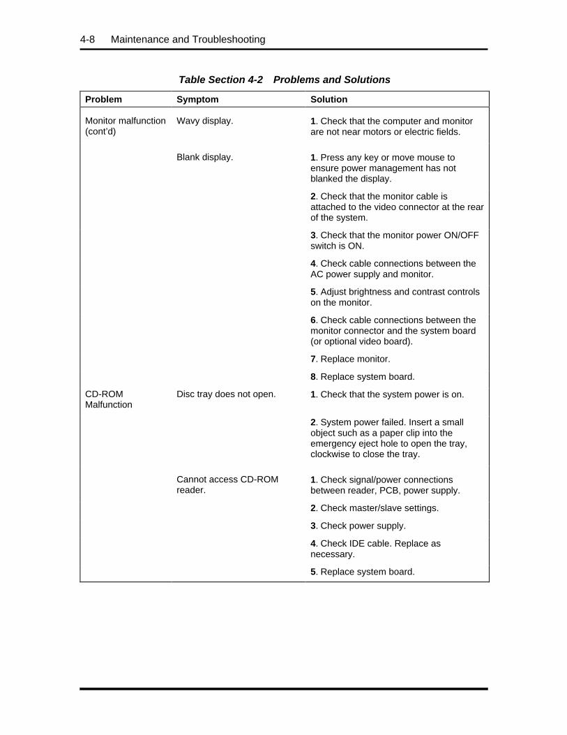
4-8 Maintenance and Troubleshooting
Table Section 4-2 Problems and Solutions
Problem Symptom Solution
Monitor malfunction(cont’d)
Wavy display. 1. Check that the computer and monitorare not near motors or electric fields.
Blank display. 1. Press any key or move mouse toensure power management has notblanked the display.
2. Check that the monitor cable isattached to the video connector at the rearof the system.
3. Check that the monitor power ON/OFFswitch is ON.
4. Check cable connections between theAC power supply and monitor.
5. Adjust brightness and contrast controlson the monitor.
6. Check cable connections between themonitor connector and the system board(or optional video board).
7. Replace monitor.
8. Replace system board.
CD-ROMMalfunction
Disc tray does not open. 1. Check that the system power is on.
2. System power failed. Insert a smallobject such as a paper clip into theemergency eject hole to open the tray,clockwise to close the tray.
Cannot access CD-ROMreader.
1. Check signal/power connectionsbetween reader, PCB, power supply.
2. Check master/slave settings.
3. Check power supply.
4. Check IDE cable. Replace asnecessary.
5. Replace system board.

Maintenance and Troubleshooting 4-9
Table Section 4-2 Problems and Solutions
Problem Symptom Solution
CD-ROMMalfunction (cont’d)
No sound from CDs. 1. Check that speaker power is on andvolume is adjusted.
2. Check audio software settings.
3. Check CD audio cable. Replace asnecessary.
4. Replace CD-ROM reader.
5. Replace system board.
CommunicationError
No or bad data whencommunicating.
1. Check cable connections betweensystem board and device.
2. Check that the interface port isselected.
3. Test or replace the device andinterface cable (see the devicedocumentation for troubleshooting).
4. Replace system board.
CMOS Battery Replacement
Remove the 3-volt lithium battery from system board as follows.
1. Turn off and unplug the system unit and any external option connected to it.
2. Remove the system unit cover.

4-10 Maintenance and Troubleshooting
3. Locate the battery socket on the system board.
Figure Section 4-2 Battery Socket Location
4. Carefully lift the battery from the socket tabs and out of the socket.
Battery
Clip
Figure Section 4-3 Battery Removal
5. With the positive (+) side facing up, press the new battery into the socket.
6. Replace the system unit cover.
7. Connect external peripherals and power cables.
8. Run Setup to reconfigure your system parameters.
Battery

Maintenance and Troubleshooting 4-11

Section 5
System Unit Repair
DISASSEMBLY AND REASSEMBLY
This section contains step-by-step disassembly procedures. The hard disk drive, and 3 1/2-inch diskette drive are installed and included in these disassembly procedures. Reassemblyis the reverse of disassembly. Each procedure is supported by a simplified disassembly il-lustration to facilitate removal. The detailed exploded-view diagram and parts lists areshown later in this section.
A Phillips-head screwdriver is the only required tool. For complete disassembly of thesystem unit, follow the disassembly order listed in Table Section 5-1. To reassemble, fol-low the table in reverse order.
Individual removal procedures do not require the total disassembly of the computer. Eachof the following subsections lists the parts that must be removed before beginning theremoval procedure. To reassemble, follow the procedure in reverse order.
Table Section 5-1 PowerMate Ve Disassembly Sequence
Sequence Part See Page
1 System unit cover 5-2
2 Expansion board(s) 5-3
3 PCI/ISA backboard 5-5
4 3 1/2-inch diskette and hard disk drives 5-5
5 Front panel assembly 5-7
6 Blank panel 5-8
7 Speaker assembly 5-8
8 SIMM memory 5-9
9 5 1/4-inch devices 5-10
10 Power supply 5-11
11 System board 5-13

5-2 System Unit Repair
When disassembling the system unit, follow these general rules.
n Disconnect all peripherals.
n When handling boards or chips, touch the system unit frame to discharge static.
n Do not disassemble parts other than those specified in the procedure.
n All screws are Phillips-head, unless otherwise specified.
n Label all removed connectors. Note where the connector goes and in what posi-tion it was installed.
On completion of any reassembly, perform a power-on test (see in Section 2, Setup andOperation). If a fault occurs, verify that the reassembly was performed correctly.
CAUTION: When handling boards or chips,ground yourself to release static.
System Unit Cover Removal
Remove the system unit cover as follows.
NOTE: Unplug the power cord before disas-sembling the system unit. Voltage is present in-side the system unit even after the power is off.All voltage is removed only when the powercord is unplugged.
1. Power off and unplug the keyboard, mouse, power and all other peripheral cablesattached to the system unit.

System Unit Repair 5-3
2. Remove the two cover screws shown in Figure Section 5-1.
Screws
Figure Section 5-1 System Unit Cover Screws
3. Slide the system unit cover toward the front about one inch.
4. Lift the system unit cover up and off (see Figure Section 5-2).
Figure Section 5-2 Removing the System Unit Cover
Expansion Board Removal
Remove any installed expansion board(s) using Figure Section 5-4 through Figure Section5-6 and the following steps.
1. Remove the system unit cover as previously described.
2. Disconnect any cables leading from the expansion board(s).
3. Remove the screw from the expansion slot bracket (see Figure Section 5-4).

5-4 System Unit Repair
To remove a board on the inside of the PCI/ISA backboard, remove the two slotcover support screws shown in Figure Section 5-6. The slot cover support securesthe expansion board in place.
Figure Section 5-4 Expansion Slot Screw
Screws
Expansion BoardBracket
Slot CoverSupport
Figure Section 5-6 Inside Expansion Slot Screw
4. Remove the board from the expansion slot connector and out of the system unit.
ExpansionBoard
Screw
ISA/PCI-BusBackboard

System Unit Repair 5-5
PCI/ISA Backboard Removal
Remove the PCI/ISA backboard from the system unit as follows.
1. Remove the system unit cover and all expansion slot boards as previously de-scribed.
2. Remove the two screws that secure the backboard to the support bracket (seeFigure Section 5-8).
3. Pull the backboard out from its connector on the system board and remove itfrom the system. Be careful not to overflex the system board when you removethe backboard.
Figure Section 5-8 PCI/ISA Backboard Screws
3 1/2-inch Diskette and Hard Disk Drive Removal
Remove the 3 1/2-inch diskette drive and 3 1/2-inch hard disk drive as follows.
1. Remove the system unit cover as previously described.
2. Unplug the diskette drive power cable and signal cable from the diskette drive.
3. Unplug the hard disk drive power cable and signal cable from the hard disk drive.
Support Bracket
Srews
System BoardConnector
PCI/ISABackboard

5-6 System Unit Repair
NOTE: When reinstalling the drives, note thatall power cables are keyed to fit only in the cor-rect position.
4. Remove the 3 1/2-inch drive bracket screw (see Figure Section 5-10).
Figure Section 5-10 3 1/2-Inch Drive Bracket
5. Remove the four 3 1/2-inch diskette drive screws; two on each side of the drivebracket (see Figure Section 5-12).
Remove the two 3 1/2-inch hard disk drive screws; two on each side of the drivebracket (see Figure Section 5-12).
6. Pull the drives out from the front of the bracket.
Figure Section 5-12 3 1/2-Inch Diskette and Hard Disk Drive Screws
3 1/2-InchDrive Bracket
Tabs
Tab
Screw
PowerSupply
Diskette Drive
Hard Disk Drive
Diskette DriveScrews
Diskette DriveScrews
Hard DiskDrive Screws
Hard DiskDrive Screws

System Unit Repair 5-7
Front Panel Assembly Removal
Remove the front panel assembly from the system unit as follows.
1. Remove the system unit cover and 3 1/2-inch drive bracket as previously de-scribed.
2. Unplug the following cables from their connectors (see Figure Section 5-14).
n Power lamp (connector J6)
n Hard disk drive busy lamp (connector J30)
n Reset button (connector J25)
3. Remove the five front panel screws (see Figure Section 5-14).
4. Feed the two lamp and reset cables through the hole in the front of system unitchassis when removing the front panel assembly.
5. Remove the front panel by releasing the four tabs from the back of the frontpanel.
Tabs(behind front panel)Tabs
(behind front panel)
Blank PanelFront Panel
Figure Section 5-14 Indicator Panel Connectors
6. Separate the lamps and reset button from the front panel assembly by pullingthem out from their socket in the panel assembly.

5-8 System Unit Repair
Blank Panel Removal
Remove the blank panels from the front panel as follows.
1. Remove the system unit cover and front panel as previously described.
2. Remove the blank panel from the selected slot by pressing the panel tabs from in-side the front panel and pushing the blank panel out (see Figure Section 5-16).
Top BlankPanel Tabs
Bottom BlankPanel Tabs
Figure Section 5-16 Blank Panel Tabs
Speaker Assembly Removal
Remove the speaker from the device cage as follows.
1. Remove the system unit cover as previously described.
2. Unplug the speaker from its connector on the system board (see Appendix A forconnector assignments).

System Unit Repair 5-9
3. Slide the speaker out from the tabs on the device cage (see Figure Section 5-18).
Figure Section 5-18 Internal Speaker
SIMM Removal
Remove SIMM sticks from the system board as follows.
1. Remove the system unit cover, and any full size expansion boards as previouslydescribed.
2. Spread apart the two clips at each end of the SIMM stick (the clips are part of thesystem board's connectors). Tilt the SIMM stick forward, allowing the post toslide out of the hole in the SIMM stick.
3. Remove the SIMM stick from the system board. Repeat step 2 for each SIMM tobe removed.
NOTE: If more information is needed, see theinstallation instructions in Section 3, Options.
Figure Section 5-20 SIMM Socket
Speaker
Speaker Cable toSystem Board
Clips

5-10 System Unit Repair
5 1/4-Inch Device Removal
Remove an 5 1/4-inch device from the 5 1/4-inch device cage per Figure Section 5-21, andthe following steps.
1. Remove the system unit cover, front panel, and 3 1/2-inch drive bracket aspreviously described.
2. Unplug all signal and power cables from the device(s) in the 5 1/4-inch devicecage (see Figure Section 5-21).
3. Remove the four device screws; two from each side of the 5 1/4-inch device cage(see Figure Section 5-21).
4. Remove the device out of the 5 1/4-inch device cage from the front of thesystem unit.
NOTE: When reinstalling the 5 1/4-inch device,note that all power cables are keyed to fit only inthe correct position.
Figure Section 5-21 5 1/4-Inch Device Screws
Two of FourScrews
Power and SignalCables (not shown)

System Unit Repair 5-11
Power Supply Removal
Remove the power supply from the system unit as follows.
1. Remove the system unit cover and front panel as previously described.
2. Unplug the two power cables attached to the system board's connectors.
3. Unplug the power cables from all installed devices.
4. Remove the two screws securing the power button to the front of the system unit(see Figure Section 5-23).
Figure Section 5-23 Power Button Screws
5. Remove the four screws holding the power supply to the system unit (seeFigure Section 5-25).
Power ButtonScrews

5-12 System Unit Repair
6. Slide the power supply toward the system board to release the two tabs at thefront, then lift it out of the system unit.
Figure Section 5-25 Power Supply Screws
Power SupplyScrews

System Unit Repair 5-13
System Board Removal
Remove the system board per Figure Section 5-27 and the following steps.
1. Remove the following components as previously described.
n system unit cover
n expansion slot boards
n PCI/ISA backboard
n 3 1/2-inch drive bracket
n SIMMs installed on the system board
NOTE: Remove the optional video DRAMchips if installed, see Section 3, Options.
2. Remove and label all cables connected to the system board Figure Section 5-27provides the general locations of the connectors for the system board. AppendixA provides the pin assignments for each connector.
3. Remove the seven screws that hold the system board to the system unit chassis(see Figure Section 5-27). Remove the system board out the side of the systemunit.
1 of 7Screws

5-14 System Unit Repair
Figure Section 5-27 System Board Connectors and Screws

5-14 System Unit Repair
Illustrated Parts Breakdown
This subsection contains the illustrated parts breakdown (IPB) and NEC part numbers forthe PowerMate Ve computer. Table Section 5-2 lists the field-replaceable parts for thecomputer. Figure Section 5-16 is the illustrated parts breakdown.
NOTE: Dealers in the U.S., should call 1(800)632-4525 to order NEC spare parts. All otheruser’s in the U.S. must call 1(800) 233-6321 forparts. To order options in the U.S., call the NECsales office at 1(800) NEC-INFO.
Table Section 5-2 PowerMate Ve Field-Replaceable Parts List*
Item Description Part Number
1 Mouse, PS/2 158-050789-000
2A 3 1/2-Inch 635 MB Hard Drive 158-050395-365
2B 3 1/2-Inch 1.2 GB Hard Drive 158-050395-366
3 3 1/2-Inch 1.44 MB Diskette Drive 158-050966-000
4 3 1/2-Inch Drive Bracket 158-030807-000
5 3 1/2-Inch Diskette Drive Signal Cable(3 connector)
158-050503-002
6 3 1/2-Inch Hard Drive IDE Signal Cable(3 connector)
158-050562-008
7 CD-ROM Reader IDE Signal Cable(2 connector)
158-050562-004
8 Ethernet Network Interface Card(network-ready systems only)
158-050796-000
9 PCI/ISA Backboard 158-026204-000A
10 System Unit Cover 158-050883-002
11A 4 MB, 1x32 EDO SIMMs (2) 158-082629-060
11B 8 MB, 2x32 EDO SIMMs (2) 158-082630-060
12 5 Watt External Speakers with Cables 158-050990-000
13 Power Supply 158-050730-000
14 CPU Heatsink (with clip) 158-060324-001
15A Pentium 75 MHz Processor 158-082502-006
____________* This data was prepared May 1996. For an up-to-date listing of spare parts, please call FastFacts (800) 366-0476 and order document number 42181406.

System Unit Repair 5-15
Table Section 5-2 PowerMate Ve Field-Replaceable Parts List*
Item Description Part Number
15B Pentium 100 MHz Processor 158-082502-008
16 Audio Cable (for CD-ROM) 158-050824-000
17A System Board, Multimedia (with audio) 158-050978-000A
17B System Board, Non-Multimedia(without audio)
158-050978-001A
18 CMOS 3 Volt Lithium Coin Battery 158-060367-000
19 Speaker Assembly (internal) 158-050685-003
20 Quad-Speed CD-ROM Reader CDR-273BR
21 5 1/4-Inch Blank Plastic Panel 158-050685-029
22A PowerMate V75e Logo 158-030872-009
22B PowerMate V100e Logo 158-030872-010
23 Front Bezel without IR 158-050992-000
24 Fan Assembly 158-050865-006
25 Card Edge Guide 158-050883-005
26 Microphone 158-050878-000
27 Keyboard, Chicony 158-050939-000
28 Power Cord 808-857649-101A
29 Second Serial Interface & Cable Assembly 158-050454-004

5-16 System Unit Repair
Figure Section 5-16 PowerMate Ve Illustrated Parts Breakdown*
____________* This data was revised May 1996. For an up-to-date listing of spare parts, please call FastFacts (800) 366-0476 and order document number 42181406.

System Unit Repair 5-17
Table Section 5-3 lists the PowerMate Ve replacement parts and Table Section 5-4 lists thePowerMate Ve options.
Table Section 5-3 PowerMate Ve Optional Replacement Part*
Item Description Part Number
1 256 KB 15 ns L2 Synchronous Cache 158-082737-015
2 Feature Connector Cable 158-050559-005
Table Section 5-4 lists PowerMate Ve documentation and packaging.
Table Section 5-4 PowerMate Ve Documentation and Packaging*
Description Part Number
PowerMate Ve Series System User's Guide 819-181404-000
PowerMate Ve Series Quick Setup/Roadmap 819-181403-000
PowerMate Ve Series Service and Reference Manual 819-181406-000
Network Board User’s Guide 819-181173-001
PowerMate Ve Shipping Carton (non-multimedia) 158-040442-008
PowerMate Ve Shipping Carton (multimedia) 158-040490-003
Shipping Carton Corner Inserts (4) 158-040395-004
____________* This data was prepared May 1996. For an up-to-date listing of spare parts, please call FastFacts (800) 366-0476 andorder document number 42181406.

Appendix A
Connector Pin Assignments
This appendix describes the system board connector pin assignments. Figure Appendix A-1shows the locations of the system board connectors. Table A-1 identifies the connectorfunction with the connector number. Descriptions of the connectors are provided in thefollowing subsections.
Figure Appendix A-1 System Board Layout
ProcessorSocket
SIMMSocket 4
SIMMSocket 2
SIMMSocket 3
SIMMSocket 1

A-2 Connector Pin Assignments
Table Appendix A-1 System Board Connectors
Function Connector Number Type
VGA Monitor J3 15 pin female sub D-shell
Microphone In J19 1/8-Inch banana connector
Speaker In PJ2 1/8-Inch banana connector
Line In J17 1/8-Inch banana connector
Line Out J26 1/8-Inch banana connector
Parallel Interface J16 25 pin female sub D-shell
Serial Interface COM1/COM2 J9, J10 9 pin D-shell
Mouse J8 6-pin PS/2 style connector
Keyboard J4 6-pin PS/2 style connector
Diskette Drive J5 2 x 17 pin header
Power Supply J1 1 x 12 pin locking header
SIMM Memory Sockets SIMM 1, 2, 3, 4 72 pin single inline connector
PCI/IDE Interface (primary) J7 2 x 20 pin header
IDE Interface (secondary) J6 2 x 20 pin header
Secondary Cache Module 160-pin single inline connector
Fan J35 1 x 3 pin header
Infrared (IRDA) J13 1 x 4 pin header
Suspend Button 1 x 2 pin header
Hard disk LED J30 1 x 4 pin header
Power LED J6 1 x 5 pin header
Reset Button J25 1 x 4 pin header
Speaker J23 1 x 4 pin header
ISA/PCI-Bus Backboard SLOT1 98-pin header
Video Feature J2 2x13 pin header
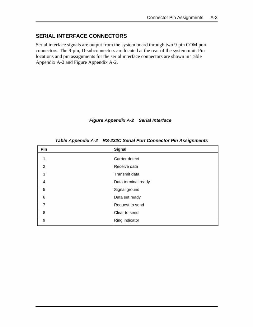
Connector Pin Assignments A-3
SERIAL INTERFACE CONNECTORS
Serial interface signals are output from the system board through two 9-pin COM portconnectors. The 9-pin, D-subconnectors are located at the rear of the system unit. Pinlocations and pin assignments for the serial interface connectors are shown in TableAppendix A-2 and Figure Appendix A-2.
Figure Appendix A-2 Serial Interface
Table Appendix A-2 RS-232C Serial Port Connector Pin Assignments
Pin Signal
1 Carrier detect
2 Receive data
3 Transmit data
4 Data terminal ready
5 Signal ground
6 Data set ready
7 Request to send
8 Clear to send
9 Ring indicator

A-4 Connector Pin Assignments
PARALLEL INTERFACE CONNECTOR
The system has a 25-pin parallel port on the system board. Parallel interface specificationsfor this port conform to the IBM-PC interface. Pin locations and pin assignments for theparallel interface connector are shown in Table Appendix A-4 and Figure Appendix A-4.
Figure Appendix A-4 Parallel Interface Connector

Connector Pin Assignments A-5
Table Appendix A-4 Parallel Printer Port Connector Pin Assignments
Pin Signal
1 Strobe
2 Data bit 0
3 Data bit 1
4 Data bit 2
5 Data bit 3
6 Data bit 4
7 Data bit 5
8 Data bit6
9 Data bit 7
10 Acknowledge
11 Busy
12 PE
13 Select
14 Auto feed XT
15 Error
16 Initialize
17 Select in
18
through Ground
25
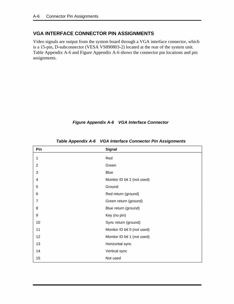
A-6 Connector Pin Assignments
VGA INTERFACE CONNECTOR PIN ASSIGNMENTS
Video signals are output from the system board through a VGA interface connector, whichis a 15-pin, D-subconnector (VESA VS890803-2) located at the rear of the system unit.Table Appendix A-6 and Figure Appendix A-6 shows the connector pin locations and pinassignments.
Figure Appendix A-6 VGA Interface Connector
Table Appendix A-6 VGA Interface Connector Pin Assignments
Pin Signal
1 Red
2 Green
3 Blue
4 Monitor ID bit 2 (not used)
5 Ground
6 Red return (ground)
7 Green return (ground)
8 Blue return (ground)
9 Key (no pin)
10 Sync return (ground)
11 Monitor ID bit 0 (not used)
12 Monitor ID bit 1 (not used)
13 Horizontal sync
14 Vertical sync
15 Not used

Connector Pin Assignments A-7
SPEAKER CONNECTOR PIN ASSIGNMENTS
Speaker connector pin locations and pin assignments are shown in Table Appendix A-8.
Table Appendix A-8 Speaker Connector Pin Assignments
Pin Signal
1 Speaker data out
2 Key
3 NC
4 +5 Volts
POWER SUPPLY CONNECTOR
Voltages from the power supply are input to the system board through the power supplyconnector. Figure Appendix A-8 shows the connector pin locations and pin assignments.
Figure Appendix A-8 Power Supply Connector Pin Assignments
+5 GND GND -12 +12 +5
12 7 6
-5
1
Power GoodSignal

A-8 Connector Pin Assignments
KEYBOARD AND MOUSE CONNECTORS
The keyboard and mouse use standard PS/2 connectors. Pin assignments are given inTable Appendix A-10.
Table Appendix A-10 Keyboard and Mouse Connector Pin Assignments
Pin Keyboard Connector Mouse Connector
1 Keyboard Data Mouse Data
2 N/C N/C
3 GND GND
4 +5V, (fused) +5V, (fused)
5 Keyboard Clk Mouse Clk
6 N/C N/C
SUSPEND BUTTON CONNECTOR
The suspend button connector pin assignments are given in Table A-7.
Table Appendix A-7 Suspend Connector Pin Assignments
Pin Signal
1 +5V
2 Power control
FAN CONNECTOR
Fan connector pin assignments are given in Table A-8.. The connector plugs into one of thepower supply cable connectors.
Table A-8 Fan Connector Pin Assignments
Pin Signal
1 Ground
2 +12V (fused)
3 Ground

Connector Pin Assignments A-9
DISKETTE DRIVE INTERFACE PIN ASSIGNMENTS
Table A-9 provides the pin assignments for the diskette drive interface.
A-9 Diskette Drive Connector Pin Assignments
Ground Pin Signal Pin I/O Signal Name
1 2 O FDHDIN
3 4 Not used
5* 6 FDEDIN
7 8 INDEX
9 10 MOTEN1
11 12 O DS2
13 14 O DS1
15 16 O MOTEN2
17 18 O DIR
19 20 O STEP
21 22 O WRT DATA
23 24 O WRT EN GATE
25 26 I TRK0
27 28 I WRT PROT
29 30 I READ DATA
31 32 O HS SEL
33 34 I DSKT CHG
*Pin 5 is reserved for connector polarization.
IDE INTERFACE CONNECTORS
All signal levels in the IDE interface are TTL compatible. A logic 1 is a signal whosevoltage level is between 2.0 and 5.0 V. A logic 0 is a signal measuring between 0.00 V and0.70 V.
The two system board IDE connectors are physically identical. Electrically the primaryIDE/PCI bus IDE connector is faster and the secondary IDE/PCI connector is slower. TableA-10 provides the IDE pin assignments. All signals on the Host interface have the prefixHOST. All negatively active signals are further prefixed with a “-” designation. Allpositively active signals are prefixed with a “+” designation.

A-10 Connector Pin Assignments
Table Appendix A-10 IDE/PCI Connector Pin Assignments
Pin Signal Pin Signal
01 HOST RESET 02 GND
03 +HOST DATA 7 04 +HOST DATA 8
05 +HOST DATA 6 06 +HOST DATA 9
07 +HOST DATA 5 08 +HOST DATA 10
09 +HOST DATA 4 10 +HOST DATA 11
11 +HOST DATA 3 12 +HOST DATA 12
13 +HOST DATA 2 14 +HOST DATA 13
15 +HOST DATA 1 16 +HOST DATA 14
17 +HOST DATA 0 18 +HOST DATA 15
19 GND 20 KEY
21 DRQ3 22 GND
23 HOST IOW 24 GND
25 HOST IOR 26 GND
27 IOCHRDY 28 +HOST ALE
29 DACK3 30 GND
31* +HOST IRQ14 32 HOST IO16
33 +HOST ADDR 1 34 GND
35 +HOST ADDR 0 36 +HOST ADDR 2
37 HOST CSO 38 HOST CS1
39 HOST SLV/ACT 40 GND
*The Primary IDE/PCI connector uses IRQ15

Connector Pin Assignments A-11
SIMM SOCKETS
Table A-11 provides the SIMM socket pin assignments.
Table Appendix A-11 SIMM Socket Pin Assignments
Pin Signal Pin Signal Pin Signal
1 GND 25 D22 49 D8
2 D0 26 D7 50 D24
3 D16 27 D23 51 D9
4 D1 28 A7 52 D25
5 D17 29 N/C 53 D10
6 D2 30 +5V 54 D26
7 D18 31 A8 55 D11
8 D3 32 A9 56 D27
9 D19 33 N/C 57 D12
10 +5V 34 RAS2 58 D28
11 N/C 35 MP2 59 +5V
12 A0 36 MP0 60 D29
13 A1 37 MP1 61 D13
14 A2 38 MP3 62 D30
15 A3 39 GND 63 D14
16 A4 40 CAS0* 64 D31
17 A5 41 CAS2* 65 D15
18 A6 42 CAS3* 66 N/C
19 N/C 43 CAS1* 67 PD0 (N/C)
20 D4 44 RAS0 68 PD1 (N/C)
21 D20 45 N/C 69 PD2 N/C
22 D5 46 N/C 70 PD3 N/C
23 D21 47 WE 71 N/C
24 D6 48 N/C 72 GND

A-12 Connector Pin Assignments
ISA/PCI-BUS BACKBOARD CONNECTOR PIN ASSIGNMENTS
Table A-12 provides the pin assignments for the ISA/PCI-bus backboard connector on thesystem board.
Table A-12 ISA/PCI-Bus Backboard Connector Pin Assignments
Pin Signal Pin Signal Pin Signal Pin Signal
A1 IOCHCK B1 GND E1 GND F1 GND
A2 SD07 B2 RSET DRV E2 GND F2 GND
A3 SD06 B3 +5V E3 PCIINT1 F3 PCIINT3
A4 SD05 B4 IRO09 E4 PCIINT2 F4 PCIINT4
A5 SD04 B5 5V E5 +5V F5 +5V
A6 SD03 B6 DRQ2 E6 Key F6 Key
A7 SD02 B7 12V E7 +5V F7 +5V
A8 SD01 B8 0WS E8 PCIRST F8 PCLKF
A9 SD00 B9 +12V E9 GNTO F9 GND
A10 IOCHRDY B10 GND E10 REQ0 F10 GNT1
A11 AEN B11 SMEMWR E11 GND F11 GND
A12 SA19 B12 SMEMRD E12 PCLKE F12 REQ1
A13 SA18 B13 IORD E13 GND F13 AD31
A14 SA17 B14 IOWR E14 AD30 F14 AD29
A15 SA16 B15 DACK3 E15 +3.3V F15 +3.3V
A16 SA15 B16 DRQ3 E16 Key F16 Key
A17 SA14 B17 DACK1 E17 +3.3V F17 +3.3V
A18 SA13 B18 DRQ1 E18 AD28 F18 AD27
A19 SA12 B19 REFRESH E19 AD26 F19 AD25
A20 SA11 B20 BCLK E20 AD24 F20 CBE3
A21 SA10 B21 IRQ07 E21 AD22 F21 AD23
A22 SA09 B22 IRQ06 E22 AD20 F22 AD21
A23 SA08 B23 IRQ05 E23 AD18 F23 AD19
A24 SA07 B24 IRQ04 E24 +3.3V F24 +3.3v
A25 SA06 B25 IRQ03 E25 Key F25 Key
A26 SA05 B26 DACK2 E26 +3.3V F26 +3.3V
A27 SA04 B27 T/C E27 AD16 F27 AD17

Connector Pin Assignments A-13
Table A-12 ISA/PCI-Bus Backboard Connector Pin Assignments
Pin Signal Pin Signal Pin Signal Pin Signal
A28 SA03 B28 BALE E28 FRAME F28 IRDY
A29 SA02 B29 +5V E29 CBE2 F29 DEVSEL
A30 SA01 B30 OSC E30 TRDY F30 PLOCK
A31 SA00 B31 GND E31 STOP F31 PERR
C1 SBHE D1 MEMCS16 G1 SDONE H1 SERR
C2 LAB23 D2 I/OCS16 G2 SB0 H2 AD15
C3 LAB22 D3 IRQ10 G3 CBE1 H3 AD14
C4 LAB21 D4 IRQ11 G4 PAR H4 AD12
C5 LAB20 D5 IRQ12 G5 GND H5 GND
C6 LAB19 D6 IRQ15 G6 Key H6 Key
C7 LAB18 D7 IRQ14 G7 GND H7 GND
C8 LAB17 D8 DACK0 G8 AD13 H8 AD10
C9 MEMRD D9 DRQ0 G9 AD11 H9 AD8
C10 MEMWR D10 DACK5 G10 AD9 H10 AD7
C11 SD08 D11 DRQ5 G11 CBE0 H11 AD5
C12 SD09 D12 DACK6 G12 AD6 H12 AD3
C13 SD10 D13 DRQ6 G13 AD4 H13 AD1
C14 SD11 D14 DACK7 G14 AD2 H14 AD0
C15 SD12 D15 DRQ7 G15 Key H15 Key
C16 SD13 D16 +5V G16 +5V H16 +5V
C17 SD14 D17 MASTER G17 +5V H17 +5V
C18 SD15 D18 GND G18 GND H18 GND

A-14 Connector Pin Assignments
ISA EXPANSION BUS CONNECTOR PIN ASSIGNMENTS
The expansion slots signals, voltages, and grounds are supplied through the bus connectors.There are no active components on the ISA/PCI-bus backboard. Table A-13 provides thepin assignments for the ISA expansion slots.
Table A-13 ISA Expansion Slot Pin Assignments
Pin Direction Signal Pin Direction Signal
A1 Input IOCHCK B1 Ground GND
A2 Input/Output SD07 B2 Output RSET DRV
A3 Input/Output SD06 B3 Power +5V
A4 Input/Output SD05 B4 Input IRO09
A5 Input/Output SD04 B5 Power 5V
A6 Input/Output SD03 B6 Input DRQ2
A7 Input/Output SD02 B7 Power 12V
A8 Input/Output SD01 B8 Input 0WS
A9 Input/Output SD00 B9 Power +12V
A10 Input IOCHRDY B10 Ground GND
A11 Output AEN B11 Output SMEMWR
A12 Input/Output SA19 B12 Output SMEMRD
A13 Input/Output SA18 B13 Input/Output IORD
A14 Input/Output SA17 B14 Input/Output IOWR
A15 Input/Output SA16 B15 Output DACK3
A16 Input/Output SA15 B16 Input DRQ3
A17 Input/Output SA14 B17 Output DACK1
A18 Input/Output SA13 B18 Input DRQ1
A19 Input/Output SA12 B19 Input/Output REFRESH
A20 Input/Output SA11 B20 Output BCLK
A21 Input/Output SA10 B21 Input IRQ07
A22 Input/Output SA09 B22 Input IRQ06
A23 Input/Output SA08 B23 Input IRQ05
A24 Input/Output SA07 B24 Input IRQ04
A25 Input/Output SA06 B25 Input IRQ03
A26 Input/Output SA05 B26 Output DACK2
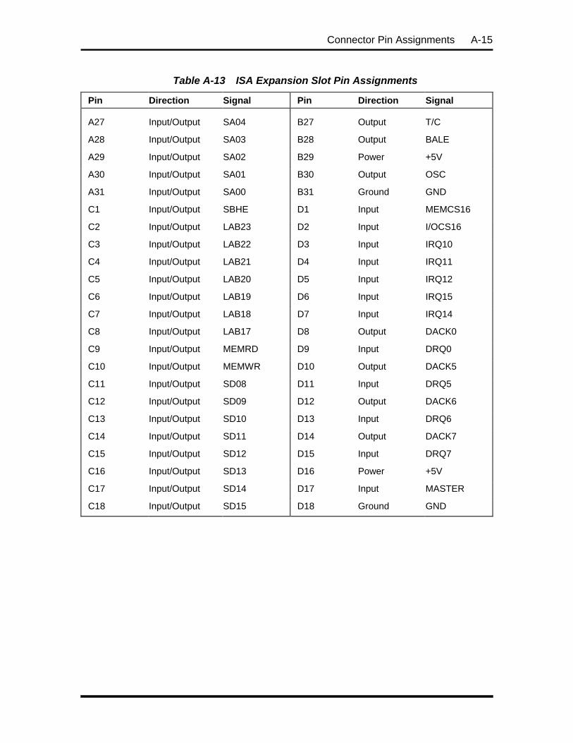
Connector Pin Assignments A-15
Table A-13 ISA Expansion Slot Pin Assignments
Pin Direction Signal Pin Direction Signal
A27 Input/Output SA04 B27 Output T/C
A28 Input/Output SA03 B28 Output BALE
A29 Input/Output SA02 B29 Power +5V
A30 Input/Output SA01 B30 Output OSC
A31 Input/Output SA00 B31 Ground GND
C1 Input/Output SBHE D1 Input MEMCS16
C2 Input/Output LAB23 D2 Input I/OCS16
C3 Input/Output LAB22 D3 Input IRQ10
C4 Input/Output LAB21 D4 Input IRQ11
C5 Input/Output LAB20 D5 Input IRQ12
C6 Input/Output LAB19 D6 Input IRQ15
C7 Input/Output LAB18 D7 Input IRQ14
C8 Input/Output LAB17 D8 Output DACK0
C9 Input/Output MEMRD D9 Input DRQ0
C10 Input/Output MEMWR D10 Output DACK5
C11 Input/Output SD08 D11 Input DRQ5
C12 Input/Output SD09 D12 Output DACK6
C13 Input/Output SD10 D13 Input DRQ6
C14 Input/Output SD11 D14 Output DACK7
C15 Input/Output SD12 D15 Input DRQ7
C16 Input/Output SD13 D16 Power +5V
C17 Input/Output SD14 D17 Input MASTER
C18 Input/Output SD15 D18 Ground GND

A-16 Connector Pin Assignments
CD AUDIO IN CONNECTOR PIN ASSIGNMENTS
The pin assignments for the CD audio-in connector are provided in Table A-14.
Table A-14 CD Audio In Connector
Pin Signal
1 Speaker Data
2 Key
3 NC
4 +5V

Appendix B
System Board Jumpers
This appendix provides jumper setting information for configuring the system for aparticular system requirement. Situations that require changing the jumper settings includethe following:
n upgrading the processor
n clearing a password
CAUTION: Jumpers are set correctly at thefactory for the shipped configuration. If thesystem requires a jumper change, change onlythe jumper setting for that condition. Otherwise,keep the jumpers at their factory settings.
JUMPER LOCATIONS
Figure Appendix B-1 shows the location of the system board jumpers.
Figure Appendix B-1 System Board Jumper Locations
VRE/VRL2 SRAMCache
CLR PASSWD
123
123
BF1BF1
JP5 JP4 JP7 JP3
BF0
123

B-2 System Board Jumpers
CHANGING PROCESSOR JUMPER SETTINGS
Use the following procedure when replacing the installed processor with a faster speedprocessor. Jumpers requiring setting changes include the Processor/Bus Speed.
1. Turn off and unplug the system and any connected external options.
WARNING: System power must be off beforeremoving the cover and changing a jumpersetting.
2. Remove the system unit cover (see Section 3, Option Installation, for coverremoval).
3. Replace the processor (see Section 3 for processor upgrade procedures).
4. Remove any expansion boards blocking access to the jumpers.
5. Locate the Processor/Bus Speed jumper blocks on the system board (see FigureAppendix B-1).
6. Set the Processor/Bus Speed jumpers per Figure Appendix B-2.
CAUTION: Unless updating the processor,leave the processor jumpers at the factorysetting. Changing the settings jumpers coulddamage the processor.

System Board Jumpers B-3
Figure Appendix B-2 Processor Upgrade Jumpers
7. Reinstall any removed expansion boards.
8. Reinstall the system cover.
9. Reconnect any disconnected peripherals and turn on the system.
SETTING THE CACHE JUMPER
If you install an optional cache module, you are required to set the cache jumper. Use thefollowing procedure to set the cache jumper.
CAUTION: Only change (or check) the cachejumper setting if you are installing optionalcache. Otherwise, keep the jumper at its factorysetting.
1. Power off and unplug the system and any peripherals.
2. Remove the system unit cover (see Section 3, Option Installation, for coverremoval).
3. Locate the L2 SRAM Cache jumper on the system board (see Figure AppendixB-1).
Processor/Bus Speed
75-MHz Processor/50-MHz Bus Speed
90-MHz Processor/50-MHz Bus Speed
100-MHz Processor/66-MHz Bus Speed
120-MHz Processor/60-MHz Bus Speed
133-MHz Processor/66-MHz Bus Speed
150-MHz Processor/60-MHz Bus Speed
166-MHz Processor/66-MHz Bus Speed
1-2 VRE
1
2-3 VR
1

B-4 System Board Jumpers
4. You may have to remove any installed expansion boards to access the jumper.
5. Set the L2 SRAM Cache jumper on pins 1−2 for an asynchronous cache moduleor on pins 2−3 for a synchronous pipeline burst cache module.
Figure Appendix B-4 SRAM cache jumper
6. If you removed any expansion boards, replace them.
7. Replace the system unit cover.
8. Reconnect any disconnected peripherals and turn on the system.
CHANGING THE PASSWORD
If a password is forgotten, use the following procedures to clear the current password andto set a new one.
1. Turn off and unplug the system and any connected external options.
WARNING: System power must be off beforeremoving the cover and changing a jumpersetting.
2. Remove the system unit cover (see Section 3, Option Installation, for coverremoval).
3. Locate the Password Clear jumper block on the system board (see FigureAppendix B-1). Remove any expansion boards blocking access to the jumper.
4. Set a jumper on the Password Clear jumper block pins.
Figure Appendix B-5 Password clear jumper
SRAM cache
1-2 Asynchronous
2-3 Synchronous Pipeline Burst
1
Password Clear
Normal (default)
Password Clear

System Board Jumpers B-5
5. Reinstall the system cover.
6. Connect system power cables and external options.
7. Turn on the system. The system boots up and clears the password.
8. Turn off the system and unplug the system and any connected peripherals.
9. Remove the system cover.
10. Remove the jumper from the Password Clear jumper block.
11. Reinstall any removed expansion boards.
12. Reinstall the system cover.
13. Connect and power up the system and any removed peripherals.
14. Rerun Setup to set a new password (see Section 2, Setup and Operation).

Appendix C
Hard Disk Drive Specifications andJumper Settings
This appendix provides specifications and jumper settings for the Western Digital 635-MB,and 1.2-GB hard disk drives used in the PowerMate Ve series computer configurations.Table 1-1 and Table 1-2 in Section 1 identifies which hard disk drives ship in whichconfigurations.
The standard IDE hard disk drives are mounted in the bottom front slot of the chassis. Thedrive is connected via a two-connector IDE cable to the primary IDE channel on the systemboard. The hard drive is set as the master device on the primary IDE channel.
The drive is auto-configurable, meaning that once the master/slave jumpers are set, thehard disk type is automatically detected by the system and the remaining drive parametersare automatically set by the system. (See Section 2, Setup and Operation, for informationon auto setup using the Autotype Fixed Disk parameter.)
NEC part numbers for the hard drives are provided in Section 5, System Unit Repair.
635-MB HARD DISK DRIVE SPECIFICATIONS AND JUMPER SETTINGS
Specifications for the 3 1/2 inch IDE hard disk drive are given in Table Appendix C-1.Jumper settings are described following Table Appendix C-1.
Table Appendix C-1 Specifications for 635-MB Hard Disk Drive
Features Western Digital WDAC2635 635-MB Hard Disk Drive
Physical Configuration
Dimensions (H x D x W) 1.0 x 5.75 x 4.00 in. (25.4 x 146.2 x 101.6 mm)
Weight 1 lb. (385 grams)
Formatted Capacity 639.9 MB
Interface 40 Pin AT
Actuator Type Rotary voice-coil
Number of Disks 2
Data Surfaces 3
Data Heads 3
Logical Organization 1240 cyl. x 16 hd. x 63 spt.
Servo Type Embedded

C-2 Hard Disk Drive Specifications and Jumper Settings
Table Appendix C-1 Specifications for 635-MB Hard Disk Drive
Features Western Digital WDAC2635 635-MB Hard Disk Drive
Track Density
Bytes per Sector 512
User Sectors per Drive 1,249,920
Recording Method 1, 7 Run Length Limited (RLL)
Recording Density
Flux Density
Head Parking Automatic
First Acceptable Revision Level CCC Revision C2
ECC Reed Solomon (24 bit On-the-fly)
Maximum Data Rate from Media 84 Mb/second
Performance
Track-to-track seekAverage seekMaximum seek
4 ms12.5 ms24 ms
Average Latency 6.67 ms
Rotation Speed 4500 rpm
Controller Overhead (ms) 0.3 ms average
Interleave 1:1
Data Transfer RateBuffer to Disk (Mbits/s)Buffer to Host (Mbytes/s)
51 maximumPIO Mode3, DMA MODE 2
Spindle Start Time (TYP) 9 sec
Spindle Start Time (MAX) 15 sec
Spindle Stop Time (TYP) 5 sec
Spindle Stop Time (MAX) 10 sec
Start/Stop Cycles 50,000 CSS
Buffer Size 64 KB
Interface IDE
635-MB HARD DISK DRIVE JUMPER SETTINGS
The 635-MB hard drive uses one user selectable jumper block to configure the master/slaveand cable select options of the hard drive. The jumper block has three jumper settings:MA (master), SL (slave), and CS (cable select). See Figure Appendix C-1 for jumpersettings.

Hard Disk Drive Specifications and Jumper Settings C-3
Connector Endof Drive
MA SL CS
DISK TWO OF TWO
Sets the drive as the second (slave) of two drives when you havetwo hard disks (master and slave) installed in the system.
ONLY DISK (FACTORY SETTING)
Sets the drive as the only hard disk (master only) in the system.This is the spare jumper locations
5
6
1
2
DISK ONE OF TWO
Sets the drive as the first (master) of two drives when you havetwo hard disks (master and slave) installed in the system.
MA SL CS
MA SL CS
MA SL CS
Figure Appendix C-1 Western Digital 635-MB Jumper Settings
1.2-GB HARD DISK DRIVE SPECIFICATIONS AND JUMPER SETTINGS
Specifications for the 3 1/2 inch IDE hard disk drive are given in Table Appendix C-2.Jumper settings are described following Table Appendix C-2.
Table Appendix C-2 Specifications for 1.2-GB Hard Disk Drive
Features Western Digital WDAC21200 1.2-GB Hard Disk Drive
Physical Configuration
Formatted Capacity 1.278 GB
Actuator Type Rotary voice-coil
Number of Disks 3
Data Heads 6
Servo Type Embedded
Tracks per Inch (tpi) 3,849 tpi
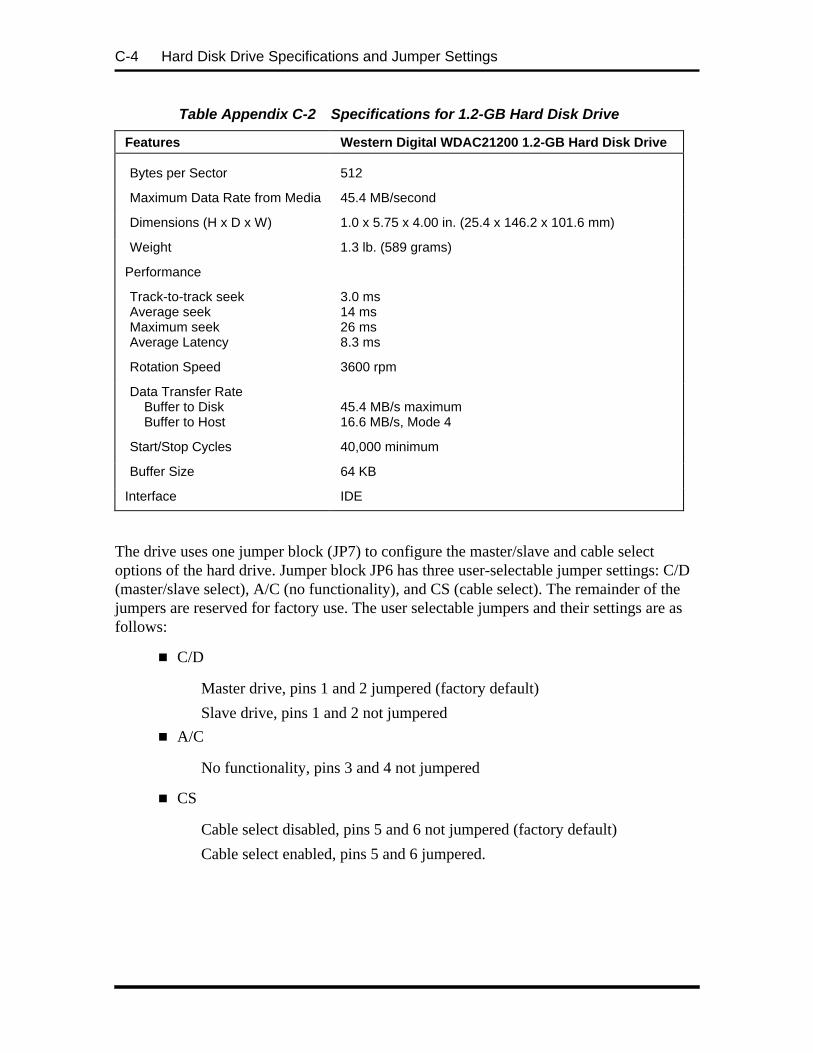
C-4 Hard Disk Drive Specifications and Jumper Settings
Table Appendix C-2 Specifications for 1.2-GB Hard Disk Drive
Features Western Digital WDAC21200 1.2-GB Hard Disk Drive
Bytes per Sector 512
Maximum Data Rate from Media 45.4 MB/second
Dimensions (H x D x W) 1.0 x 5.75 x 4.00 in. (25.4 x 146.2 x 101.6 mm)
Weight 1.3 lb. (589 grams)
Performance
Track-to-track seekAverage seekMaximum seekAverage Latency
3.0 ms14 ms26 ms8.3 ms
Rotation Speed 3600 rpm
Data Transfer RateBuffer to DiskBuffer to Host
45.4 MB/s maximum16.6 MB/s, Mode 4
Start/Stop Cycles 40,000 minimum
Buffer Size 64 KB
Interface IDE
The drive uses one jumper block (JP7) to configure the master/slave and cable selectoptions of the hard drive. Jumper block JP6 has three user-selectable jumper settings: C/D(master/slave select), A/C (no functionality), and CS (cable select). The remainder of thejumpers are reserved for factory use. The user selectable jumpers and their settings are asfollows:
n C/D
Master drive, pins 1 and 2 jumpered (factory default)
Slave drive, pins 1 and 2 not jumpered
n A/C
No functionality, pins 3 and 4 not jumpered
n CS
Cable select disabled, pins 5 and 6 not jumpered (factory default)
Cable select enabled, pins 5 and 6 jumpered.
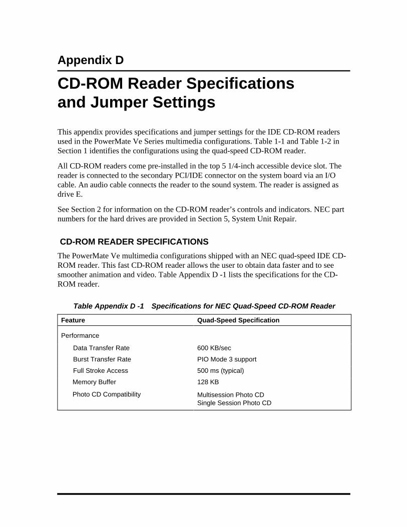
Appendix D
CD-ROM Reader Specificationsand Jumper Settings
This appendix provides specifications and jumper settings for the IDE CD-ROM readersused in the PowerMate Ve Series multimedia configurations. Table 1-1 and Table 1-2 inSection 1 identifies the configurations using the quad-speed CD-ROM reader.
All CD-ROM readers come pre-installed in the top 5 1/4-inch accessible device slot. Thereader is connected to the secondary PCI/IDE connector on the system board via an I/Ocable. An audio cable connects the reader to the sound system. The reader is assigned asdrive E.
See Section 2 for information on the CD-ROM reader’s controls and indicators. NEC partnumbers for the hard drives are provided in Section 5, System Unit Repair.
CD-ROM READER SPECIFICATIONS
The PowerMate Ve multimedia configurations shipped with an NEC quad-speed IDE CD-ROM reader. This fast CD-ROM reader allows the user to obtain data faster and to seesmoother animation and video. Table Appendix D -1 lists the specifications for the CD-ROM reader.
Table Appendix D -1 Specifications for NEC Quad-Speed CD-ROM Reader
Feature Quad-Speed Specification
Performance
Data Transfer Rate 600 KB/sec
Burst Transfer Rate PIO Mode 3 support
Full Stroke Access 500 ms (typical)
Memory Buffer 128 KB
Photo CD Compatibility Multisession Photo CDSingle Session Photo CD

D-2 Quad-Speed CD-ROM Reader Specifications and Jumper Settings
Table Appendix D -1 Specifications for NEC Quad-Speed CD-ROM Reader
Feature Quad-Speed Specification
General Specifications
Capacity 656 MB (Mode 1),748 MB (Mode 2)
Physical Format Audio disc: red bookData disc: yellow book (Mode 1 and Mode 2) orange book (read-only)
Logical Format Data disc: ISO 9660 file format
Weight 1.76 lb. (0.8 K grams)
Operating Temperature 5°C to 50°C
CD-ROM Reader Connectors and Jumper Settings
The back of the CD-ROM readers provides the following connectors and jumpers:
n Audio output connector — connects the reader to the system’s sound system viaan audio cable.
n Configuration jumpers — enables or disables the cable select feature, slavedevice configuration, or master device configuration. The CD-ROM reader is setas the master device on the secondary PCI/IDE channel.
n IDE connector — connects the reader to the secondary PCI/IDE connector on thesystem board via an I/O cable.
n Power connector — connects the reader to the power supply via a power supplycable.
There are two jumper blocks on the back of the CD-ROM reader. Jumpers on the blocknext to the IDE connector configures the reader as a master (factory set) or slave. Jumperson the second block enables or disables the eject function of the reader and sets test modes(factory use only). Descriptions of the jumpers are as follows:
n CSEL (cable select) — enables/disables the cable select feature. Factory set atdisabled (pins not jumpered).
n SL (slave) — enables/disables the slave feature. Factory set at disabled (pins notjumpered)
n MA (master) — enables/disables the master feature. Factory set at enabled (pinsjumpered)
n T0 (test mode) — used at the factory for hard drive tests. Factory set at disabled(pins not jumpered)

Quad-Speed CD-ROM Reader Specifications and Jumper Settings D-3
n T1 (test mode) — used at the factory for hard drive tests. Factory set at disabled(pins not jumpered)
n PRV/AlW (prevent/allow) — disables or enables the CD-ROM disc tray ejectfunction. Factory set at allow (pins jumpered).

Index-1
BBattery, 4-9Baud rate, 1-15BIOS update utility, 2-22
using, 2-24Boot menu, 2-20Boot sequence, 2-14Bulletin board service, 2-23
CCD-ROM reader, 1-16, 2-6
controls and indicators, 2-6operation, 2-7
Chassis, 1-2CMOS battery, 4-9
replacement, 4-9Configurations, 1-1
desktop chassis, 1-2setup, 2-7
Connections, 2-2Connectors, A-1
diskette drive, A-9fan, A-8IDE interface, A-9ISA expansion bus, A-14ISA/PCI bus backboard, A-12keyboard, A-8mouse, A-8parallel interface, A-4power supply, A-7serial interface, A-3SIMM socket, A-11speaker, A-7
suspend button, A-8VGA interface, A-6
Cover removal, 3-3
DDesktop management interface
CI module, 1-19DMI browser, 1-19DMI components, 1-18manageable products, 1-18troubleshooting, 1-21usage, 1-20
Disassemblypower supply, 5-11system board, 5-13
Diskette drive, 1-15
EExpansion board installation, 3-4External options, 3-30
parallel printer, 3-30serial devices, 3-31
FFlash ROM, 1-6
HHard disk drive, 1-15
II/O addressing, 1-7
address map, 1-7IDE adapters, 2-12Illustrated parts breakdown, 5-14Integrated Audio, 1-16
Index

Index-2
Integrated graphics, 1-11graphics accelerator, 1-11motion video controller, 1-11
Interrupt controller, 1-10ISA bus, 1-12
JJumpers, B-1
password, B-4processor upgrade, B-2
KKeyboard, 1-15Keyboard cleaning, 4-3
MMaintenance, 4-2
keyboard cleaning, 4-3mouse cleaning, 4-3system cleaning, 4-2
Memory, 1-8video, 1-12
Memory shadow, 2-14Microphone, 1-17Mouse, 1-16Mouse cleaning, 4-3Multimedia components, 1-16
CD-ROM reader, 1-16microphone, 1-17speakers, 1-17
Multimedia connections, 2-3
NNetwork board, 1-17Network connections
desktop, 2-3Numlock, 2-15
OOperation, 2-1Option installation, 3-1, 3-15
cover removal, 3-3expansion boards, 3-4external options, 3-30precautions, 3-2processor upgrade, 3-13secondary cache, 3-15SIMM memory, 3-9storage devices, 3-17Video memory, 3-12
PPacking, 2-1Parallel interface, 1-13
addressing and interrupts, 1-13Part numbers, 5-14Password, 2-18
options, 2-18supervisor, 2-18user, 2-18
PCI auto configuration, 1-13PCI local bus, 1-12PCI/IDE ports, 1-13Plug and Play, 1-17Power management, 1-7, 1-17
parameters, 2-19power menu, 2-19suspend button, 1-18, 2-5
Power supply, 1-15Processor, 1-5Processor upgrade, 3-13
SSecondary cache upgrade, 3-15Security, 2-18
options, 2-18

Index-3
supervisor password, 2-18Serial interface, 1-14
specifications, 1-15Setup, 2-1
connections, 2-2main menu parameters, 2-11voltage selector switch, 2-1
Setup and Operation, 2-1unpacking, 2-1
Setup utility, 2-7advanced menu, 2-16boot menu, 2-20boot options, 2-14exit menu, 2-21IDE adapters, 2-12integrated peripherals menu,
2-16main menu, 2-9main menu options, 2-11memory cache, 2-14numlock, 2-15parameters, 2-7power menu, 2-19security menu, 2-18startup, 2-8using, 2-9
SIMM installation, 3-11SIMM upgrade, 3-9SIMMs, 1-8Sound board
audio connector, A-16Speakers, 1-17Specifications, 1-22Storage device installation, 3-17,
3-23device cables, 3-18device preparation, 3-18device slots, 3-17
System board, 1-3chip sets, 1-4flash ROM, 1-6integrated audio, 1-16integrated graphics, 1-11interrupt controller, 1-10ISA bus, 1-12jumper settings, B-1parallel interface, 1-13PCI local bus, 1-12PCI/IDE ports, 1-13processor, 1-5video memory, 1-12
System cleaning, 4-2System configuration, 2-7System memory, 1-8
upgrade path, 1-9
TTroubleshooting, 4-4
problems and solutions, 4-4
UUnpacking, 2-1
VVideo memory, 1-12Video Resolutions, 1-12Video upgrade, 3-12Voltage selector switch, 2-1

Index-4

(For United States Use Only)
FEDERAL COMMUNICATIONS COMMISSIONRADIO FREQUENCY INTERFERENCE STATEMENT
WARNING: Changes or modifications to this unit not expressly approved by the partyresponsible for compliance could void the user’s authority to operate the equipment.
NOTE: This equipment has been tested and found to comply with the limits for a Class Bdigital device, pursuant to Part 15 of the FCC Rules. These limits are designed to providereasonable protection against harmful interference in a residential installation. Thisequipment generates, uses and can radiate radio frequency energy and, if not installed andused in accordance with the instructions, may cause harmful interference to radiocommunications.
However, there is no guarantee that interference will not occur in a particular installation. Ifthis equipment does cause harmful interference to radio or television reception, which canbe determined by turning the equipment off and on, the user is encouraged to try to correctthe interference by one or more of the following measures.
n Reorient or relocate the receiving antenna.
n Increase the separation between the equipment and receiver.
n Connect the equipment to an outlet on a circuit different from the one to which thereceiver is connected.
Use shielded and properly grounded I/O and power cables to ensure compliance of this unitto the specified limits of the rules.
(For Canadian Use Only)This Class B digital apparatus meets all requirements of the Canadian Interference-CausingEquipment Regulations.
Cet appareil numérique de la classe B repecte toutes les exigences du Règlement sur lematériel brouilleur du Canada.

BATTERY REPLACEMENT
A lithium battery in your computer maintains system configuration information. In theevent that the battery fails to maintain system configuration information, NEC recommendsthat you replace the battery. See Chapter 4 for battery replacement information.
WARNING: There is a danger of explosion if the battery is incorrectly replaced. Replaceonly with the same or equivalent type recommended by the manufacturer. Discard usedbatteries according to the manufacturer’s instructions.
ATTENTION: Il y a danger d’explosion s’il y a replacement incorrect de la batterie.Remplacer uniquement avec une batterie du même type ou d’un type recommandé par leconstructeur. Mettre au rébut les batteries usagées conformément aux instructions dufabricant.
BATTERY DISPOSAL
Do not place used batteries in your regular trash.
The nickel-cadmium or nickel metal-hydride batteries must be collected, recycled, ordisposed of in an environmentally-approved manner.
The incineration, landfilling, or mixing of batteries with the municipal solid waste streamis prohibited by law in most areas.
Return batteries to a federal or state approved battery recycler. This may be whereyou purchased the battery or a local seller of automotive batteries. In MINNESOTA, call1-800-225-PRBA if further disposal information is required.
Contact your local waste management officials for other information regarding theenvironmentally sound collection, recycling, and disposal of the batteries.