
Proposte di tesi - unipd.itautomatica.dei.unipd.it/tl_files/docs/ProposteTesi/TesiOboe.pdf ·...
9
Proposte di tesi Roberto Oboe Laboratorio di Meccatronica – Vicenza Email: [email protected] Phone: 0444‐998844
Transcript of Proposte di tesi - unipd.itautomatica.dei.unipd.it/tl_files/docs/ProposteTesi/TesiOboe.pdf ·...
Proposte di tesi Roberto Oboe
Laboratorio di Meccatronica – Vicenza Email: [email protected]
Phone: 0444‐998844

Controllo di brandeggi per telecamere Uso di sensori inerziali (accelerometri e giroscopi) e magneHci (bussola eleIronica) per mantenere il puntamento della telecamera, anche quando la base del brandeggio si muove
Applicazioni di videosorveglianza con base mobile (ad esempio su barca)

Uso dei MEMS nei brandegg
UsaH sinora nella soppressione aOva delle vibrazioni indoIe dal ripple di coppia dei motori

Controllo di sistemi termici ModellisHca, idenHficazione, controllo di un sistema di riscaldamento eleIrico – sviluppo di algoritmi “smart”, in grado di sHmare il Hpo di ambiente
Collaborazione con Zoppas e Bluewind
Da analisi termografiche si determina il modello del termosifone
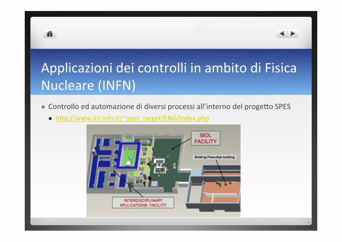
Applicazioni dei controlli in ambito di Fisica Nucleare (INFN) Controllo ed automazione di diversi processi all’interno del progeIo SPES
hIp://www.lnl.infn.it/~spes_target/ENG/index.php
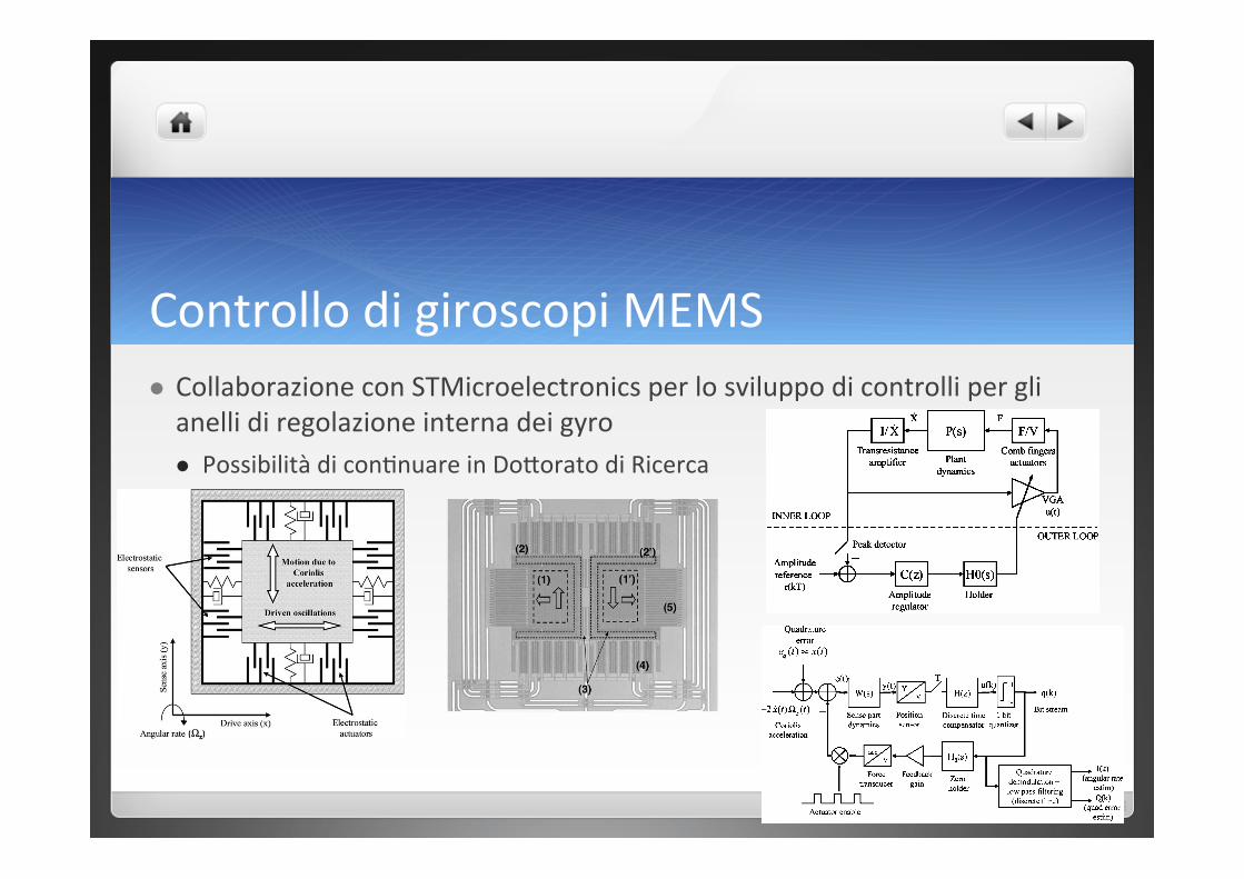
Controllo di giroscopi MEMS Collaborazione con STMicroelectronics per lo sviluppo di controlli per gli anelli di regolazione interna dei gyro Possibilità di conHnuare in DoIorato di Ricerca
364 IEEE/ASME TRANSACTIONS ON MECHATRONICS, VOL. 10, NO. 4, AUGUST 2005
Control of a Z-Axis MEMS Vibrational GyroscopeRoberto Oboe, Member, IEEE, Riccardo Antonello, Student Member, IEEE, Ernesto Lasalandra,
Guido Spinola Durante, and Luciano Prandi
Abstract—This paper describes the design of the control loops ina z-axis, MEMS vibrational gyroscope operating in a vacuum en-closure. In this device, a silicon mass is driven through electrostaticactuator so that it has a sinusoidal linear motion, with a controlledspeed. The design of a suitable controller, capable of maintainingthe required speed and with prescribed restoring capabilities aftershocks is briefly described in the paper. Attached to the drivingmass, a second mass, free to move in the direction orthogonal tothe motion of the first mass, is subjected to a Coriolis force, pro-portional to the product of the first mass speed by z-axis rotationalspeed. The sensing of the Coriolis force and, in turn, of the z-axisrotational speed, is performed in closed loop fashion, with a 1-bitquantized actuation. The restoring force that brings the motion ofthe second mass to zero is equivalent to the output bit stream ofa band-pass sigma-delta converter and contains the informationof the Coriolis force. The design of this second control loop anda detailed analysis on the signal-to-noise ratio achievable with theproposed design is reported.
Index Terms—AGC design, electromechanical !" modulator,MEMS gyroscope.
I. INTRODUCTION
M ICROMACHINED gyroscopes find application in sev-eral fields, including automotive (e.g., in active stability
control systems), consumer electronics (e.g., in image stabiliz-ers of camcorders) and inertial navigation [1], [2]. Among thepossible solutions for the realization of a MEMS gyroscope,the vibrational gyroscope has the advantage to be obtained bysurface micromaching of a silicon substrate. In its simplest im-plementation, shown in Fig. 1, the device is realized by a singlemass, suspended over a substrate by silicon springs and free tomove along a plane which is parallel to the substrate. Electro-static actuators are used to force the motion of the mass alongone direction (drive axis). When the sensor rotates around anaxis orthogonal to the die plane (z-axis), the proof mass experi-ences the Coriolis force F, according to the following equation:
F(t) = !2m!z(t) " x(t) (1)
where m is the proof mass, !z is the angular velocity aroundthe z-axis, x is the proof mass velocity along drive axis, and“"” denotes the vector product. Since drive, sense and rota-tional axes are orthogonal, the Coriolis acceleration is givenby a(t) = !2!z (t)x(t) and it acts along sense axis. In actual
Manuscript received February 20, 2005; revised March 27, 2005. Recom-mended by Guest Editors K.Ohnishi, R. Oboe, and Y. Hori.
R. Oboe is with the Department of Mechanical and Structural Engineering,University of Trento, 38050 Trento, Italy (e-mail: [email protected]).
R. Antonello is with the Department of Information Engineering, Univeristyof Padova, 35131 Padova, Italy (e-mail: [email protected]).
E. Lasalandra, G. Spinola Durante, and L. Prandi are with STMicroelec-tronics S.r.l., MEMS Business Unit, 20010 Cornaredo, Italy (e-mail: [email protected]; [email protected]; [email protected]).
Digital Object Identifier 10.1109/TMECH.2005.852437
Fig. 1. Simplified z-axis vibrational gyroscope.
implementations, x(t) is a fixed frequency sinusoid, then a(t)is a dual sideband (DSB) modulated signal, where !z (t) is theinformation bearing signal and x(t) is the carrier. !z (t) can beretrieved by sensing the Coriolis acceleration and demodulat-ing it with a sinusoidal carrier which is locked in phase withx(t) (synchronous demodulation). It is worth noticing that thesensitivity of the sensor depends on amplitude of x.
Many researchers have approached the realization of MEMSgyroscopes and a few commercial devices are already availableon the market. However, the devices realized are characterizedby a limited performance, this mainly due to the limitations inboth the mechanical part of the device and on-board compu-tational power. The first generation of vibrational gyroscopeswere essentially open loop devices, with an external oscilla-tor driving the oscillating mass. Such devices suffered of a largeperformance drift, this due essentially to the uncontrolled ampli-tude of the oscillations, which usually varies with temperature.The same problem occurred at the sensing side of the device,since the effect of Coriolis force on displacement is weighted bythe ratio between stiffness of suspending springs and suspendedmass and the stiffness usually varies with the temperature. Toalleviate this problem, some device incorporates a temperaturesensor, but the effectiveness of this approach is rather limited.In order to achieve a better performance, some researcher pro-posed the use of control loops at both mass driving and sensing,in addition to other adaptation loop in charge of compensatingfor fabrication imperfections, obtaining interesting results. Inparticular, the velocity of the driving mass has to oscillate withcontrolled amplitude and frequency, so that the scale factor of
1083-4435/$20.00 © 2005 IEEE
OBOE et al.: CONTROL OF A Z -AXIS MEMS VIBRATIONAL GYROSCOPE 365
Fig. 2. STMicroelectronics, z-axis vibrational gyroscope considered in thepaper. (1), (1’) Proof masses; (2), (2’) drive masses; (3) folded beams; (4), (5)electrodes for actuating/sensing.
the sensor is kept constant and a synchronous demodulationcan be performed at the sensing stage. The sensing interfacemust be designed to improve the linearity of the sensor and toincrease the signal-to-noise ratio (SNR). The two problems ofcontrolling the motion of the proof mass and estimating the ac-tual angular rate are faced in [3] and [4] using adaptive controltechniques. However, this approach yields control laws whichare not feasible using limited hardware resources (i.e., on-chipdigital signal processors or microcontrollers). We present herea micromachined z-axis vibratory gyroscope, recently devel-oped by STMicroelectronics. This device is shown in Fig. 2and, unlike other standard vibrational gyroscopes, it operates invacuum, in order to achieve the least power consumption. Wewant to solve the aforementioned control problems by consid-ering the restrictions imposed by the hardware, which consistin using the switching capacitor (SC) technology and avoidingexternal quartz or external clock signals. For this purpose, wedeveloped design procedures for the control loops at both thedriving and sensing side of the device, with particular care inselecting control strategies that would be easy to implement ona simplified circuitry, e.g., by using standard SC blocks.
The paper is organized as follows. Section II describes thedevice developed by STMicroelectronics. Section III presentsthe design procedure adopted for the control loop of the driveside of the sensor, while Section IV describes the control loopat the sensing side, which has been implemented in fashionof band-pass !" modulator. Final remarks are reported inSection V.
II. MEMS GYROSCOPE
The vibrational gyroscope developed by STMicroelectronicsis a symmetric two-mass system, as shown in Fig. 2. Here, afirst mass (drive mass) carries a second mass (proof mass) onit. The driving mass is driven into controlled oscillations alonga direction (drive axis) and it drags the proof mass in the samedirection. The proof mass can move freely on the driving mass,along a direction (sense axis), which is orthogonal to the driveaxis. The proof mass has therefore a constrained movement
TABLE IMECHANICAL DYNAMICS DATA FOR THE DRIVE AND SENSE PARTS
TABLE IIPOLE–ZERO LOCATIONS OF THE DESIGNED H(Z)
along drive axis and a free movement along the sense axis: as awhole, the movement of proof mass lies on a plane.
In the device we consider, the driving mass is electrostaticallyactuated using comb fingers electrodes, which act as a linearforce transducer. Separated electrodes are employed to measurethe motion of driving mass along drive axis. These electrodesare sensed by a transresitance amplifier, whose output is pro-portional to the velocity of the driving mass: so, a closed loopcontrol on x can be easily implemented, as it will be explainedin the next section. The mechanical characteristics of the deviceconsidered are reported in Table I. Note that high Q-factors canbe achieved since the microsystem works in a vacuum-sealedpackage.
III. DRIVING LOOP
The control problem at the drive side of the sensor is to sus-tain oscillations of x, with constant peak value. Several solutionshave been proposed in the literature. The conventional solutionconsists of pursuing a standard analog oscillator design, where aresonant element is inserted in a positive feedback loop [5], [6].In this case, the resonant element is the microelectromechanicalsystem of driving part. The resonant behavior is given by the me-chanical dynamics of the driving mass, which is fundamentallythe dynamics of a second order resonant system. Therefore, thetransfer function between the force applied to the driving massand the velocity measured by the electronic interface can beexpressed as
P (s) =1m
s
s2 + !xQ s + !2
x
(2)
where !n = 2"fdrive. The values of m, fdrive, and Q are re-ported in Table I. Generally, the loop gain is chosen such thatthe closed loop system is unstable. Then, because of saturationsof electronic amplifiers in the control circuitry, self-sustained os-cillations at fixed amplitude can be obtained. With this scheme,however, the amplitude of oscillations can be predicted, but not
366 IEEE/ASME TRANSACTIONS ON MECHATRONICS, VOL. 10, NO. 4, AUGUST 2005
controlled. So, a variable gain amplifier (VGA) is introducedin the loop and an outer control loop [automatic gain control(AGC)] is used to adjust it, as described in detail in [7]. Ifu(t) denotes the variable gain, the system dynamics becomes(neglecting scale factors and conversion constants)
x +!x
Qx + !2
xx =ux
m(3)
or
x +!
!x
Q! u
m
"x + !2
xx = 0 (4)
which is a second-order system with its damping controlledby u(t). To maintain the oscillations at constant amplitude, thedamping must be regulated to zero by means of u(t). This con-dition is known as Barkhausen’s condition in electronic oscilla-tors literature. Proportional (as in [7] and [8]) or proportional-integral controllers have been used to regulate the actual oscil-lation amplitude to a given reference value. As for the actualoscillation amplitude of x(t), this is usually retrieved by half-wave rectification (asynchronous demodulation) or by using asynchronous demodulation and a low-pass filtering. In the lat-ter case, the demodulating carrier is given by a phase-lockedloop (PLL), which is locked to the output of the transresitanceamplifier.
Alternative solutions for the aforementioned control problemare reported in [5] and [9]. In particular, in the control schemedescribed in [9], the sustained oscillation is produced by a PLLdesigned in such a way it tracks the resonant frequency of theresonator. However, the proposed solution does not provide anycontrol for the oscillations amplitude. In [5], an adaptive controladjusts a set of parameters so that both Barkhausen’s condi-tion and the amplitude regulation requirement are satisfied. Thecontrol algorithm can track variations of the natural frequencyand it doesn’t require any PLL or sinusoidal excitation circuits.However, we note that also the basic AGC loop acts as an“adaptive” controller and it tracks variations of the system nat-ural frequency: in fact, the closed loop dynamics of the positivefeedback loop becomes x + !xx = 0 when the Barkhausen’scondition is satisfied, so that the resonator is excited at its natu-ral frequency.
Most of the works in literature [5], [7], [9], [10] considercontinuous time control schemes for the driving loop. In thispaper, we propose a solution based on a discrete time AGC,where the oscillation amplitude is retrieved by sampling x at itspositive peaks and the regulation error is controlled to zero bya discrete time proportional-integral (PI) controller (Fig. 3). Weassume that the sampling clock is given by the quadrature output(i.e., the 90" out-of-phase output with respect to the input) of aPLL locked to the output of the transresitance amplifier. Withthis scheme, the oscillation amplitude can be tracked with greataccuracy; moreover, a discrete time control scheme is particu-larly suitable to be implemented using switching capacitor (SC)technology. The discrete time dynamics of the inner control loopin the system of Fig. 3 can be computed by sampling the freeevolution x(t) of (4). If the initial condition is specified at timet = tk , x(t) has the form (neglecting scale factors for sake of
Fig. 3. Driving control loops: the inner one is the positive feedback loop withvariable loop gain; the outer one is the amplitude control loop.
clarity)
x(t) = x(tk )|"|e#(t!tk )
!sin(!(t ! tk ) + # ")
! x(tk )|"|2e#(t!tk )
!sin(!(t ! tk )) (5)
where (x(tk ), x(tk )) is the initial condition, " = # ± j! are theeigenvalues of (4) and tk = kT is the generic sampling instant,with k $ Z and T sampling period. Since x(t) is sampled atits positive peaks, the sampling period is T = 2$/!(u) and itdepends on the value of the AGC gain u(t). Therefore, the valueof x at next sampling instant tk+1 is
x(tk+1) = x(tk )|"|e#T
!sin # ". (6)
Because of sin # " = !/|"|, the discrete time dynamics canbe finally simplified as
x(tk+1) = x(tk ) exp#2$
#(u(tk ))!(u(tk ))
$.= f(x(tk ), u(tk )) (7)
where it has been emphasized that #,! depend on the currentvalue of the control u
#(u) =u
2m! !x
2Q, !(u) =
%!2
x ! #2(u). (8)
We note here that (7) is the Poincare’s map [11] of thesystem described by (4), determined across the section ! ={(0, x) : x > 0} in the phase plane (x, x). The map can be lin-earized by considering small perturbations of the variables fromsteady state values (x0, u0) : x(tk ) = x0 + %x(tk ), u(tk ) =u0 + %u(tk ). The linearized model, also called small-signalmodel [12], is
%x(tk+1) %&f
&x
&&&&x0(tk ),u0(tk )
%x(tk ) +&f
&u
&&&&x0(tk ),u0(tk )
%u(tk )
(9)
and, hence
%x(tk+1) = %x(tk ) +x0$
m!x%u(tk ). (10)
OBOE et al.: CONTROL OF A Z -AXIS MEMS VIBRATIONAL GYROSCOPE 367
Fig. 4. Velocity regulation (at vref = 0.13 m/s) during start-up and after anexternal acceleration shock (100 g shock at t = 0.15 s for 5 ms).
On the linearized system, which is a discrete time integrator, aPI controller can be designed to obtain a stable system, with fastclosed loop modes or good rejection to small disturbances. Ifthe discrete time PI controller has the form
C(z) = Kp +KiT
z ! 1(11)
then, since the linearized system is a discrete time integrator ofthe form
P (z) =b
z ! 1b
.=x0!
m"x(12)
the closed loop system poles are
z1,2 =2 ! bKp ±
!b2K2
p ! 4bKiT
2. (13)
The modes of the closed loop system are, therefore, adjustableby setting Kp and Ki properly. We point out that the proposeddesign for the PI controller is oriented for small perturbationaround a working point: in fact, only in this case the nonlinearsystem behaves as the linearized one. However, the approach wehave proposed can be assumed as a guideline for an initial choiceof Kp and Ki . Further refinements can be done manually to meetthe actual control specifications. Fig. 4 shows the simulationresults for the velocity of drive mass at start up and after anacceleration shock of 100 g, acting for 5 ms along the drive axis.The control loop is capable to drive the mass into controlledoscillation (both in amplitude and frequency) and to recoverthe correct oscillation amplitude in the velocity signal after ashock. The overshoot in the envelope of the velocity signal canbe reduced if an anti reset wind-up scheme is added to thePI controller. This has been omitted in the current design tocomply with the requirement of minimizing the complexity ofthe hardware implementation.
Fig. 5. Simplified block diagram of the sensing loop. q(k) is demodulated anddecimated in order to retrieve an estimate of the angular rate !z (t).
IV. SENSING LOOP
A closed-loop strategy for sensing the Coriolis accelerationis essential in order to enlarge the bandwidth of the sensor,to increase its linearity, and to improve its robustness againsttemperature variations. It consists of compensating the Coriolisforce with a feedback force, which can be applied by electro-static actuation using either dedicated rebalance electrodes orthe same electrodes used for position sensing (exploiting a timedivision strategy). Some continuous time, fully analog designsand implementations have been proposed in literature [13]–[15].Instead of using an analog feedback loop, in this paper we ex-ploit a digital feedback. In this case, the feedback force is pulsemodulated using a two levels comparator, namely a 1-bit quan-tizer. The input of the quantizer is the proof mass position signal,which is sampled at a much higher frequency than the bandwidthof the sensor. In our setup we assume a sampling frequencyFs = 32 " fdrive, namely a multiple of the clock frequency inthe driving loop. Moreover, we assume that the force transducerin the feedback is linear, at least for small displacements, andthat the feedback pulse is applied in a time division fashion,i.e., for a fraction ! of the whole sampling period, and witha time delay t0 inside the period. The two-level signal q(t) isthen demodulated and decimated in order to retrieve the angu-lar rate "z (t). It is worth noticing that the actual force actingon the sensing mass is not due only to Coriolis effect, but alsoto mechanical imperfections. Among all, the most importantis the so-called “quadrature error,” resulting in a force appliedto the sensing mass which is in phase with the displacement ofthe drive mass, then in phase quadrature with the Coriolis force.By using a synchronous quadrature demodulation (and low-passfiltering) of q(t), this disturbance can be estimated and, hence,cancelled out.
If the effects of the reference input and the feedback signalare considered separately (this is possible by the linearity), thenthe system in Fig. 5 can be rearranged as in Fig. 6. Becauseof the particular shape of the feedback pulse, the zero holderH0(s) in the feedback path of Fig. 5 becomes a “modified” zeroholder
H0(s,!, t0) = e!st0 1 ! e!s!T
s(14)

Applicazioni roboHche in ambito medico RoboHca riabilitaHva
Sviluppato un disposiHvo per dito e mano in ambito Matlab‐Simulink
RiprogeIazione e sviluppo in ambito open‐source
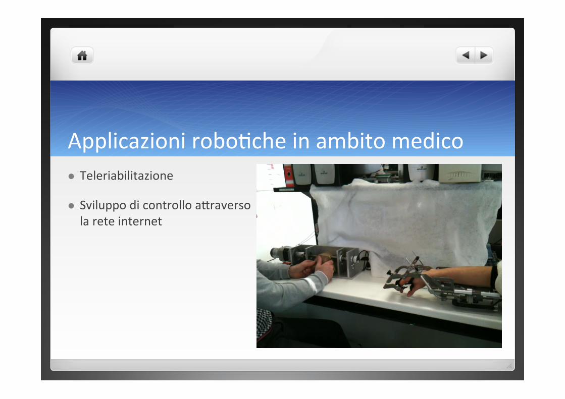
Applicazioni roboHche in ambito medico Teleriabilitazione
Sviluppo di controllo aIraverso la rete internet
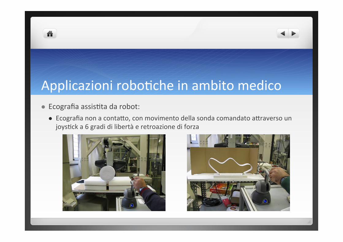
Applicazioni roboHche in ambito medico Ecografia assisHta da robot:
Ecografia non a contaIo, con movimento della sonda comandato aIraverso un joysHck a 6 gradi di libertà e retroazione di forza


![Proposte di TesiVer04-1.ppt [modalità compatibilità] di Tesi... · 2015. 6. 23. · Microsoft PowerPoint - Proposte di TesiVer04-1.ppt [modalità compatibilità] Author: Mauri Created](https://static.fdocuments.net/doc/165x107/5fc45e042b9d8b481414c0c4/proposte-di-tesiver04-1ppt-modalit-compatibilit-di-tesi-2015-6-23.jpg)
![Proposte di TesiVer04-1.ppt [modalità compatibilità]robotics.ing.unibs.it/pagine/Docs/Proposte di Tesi MECC APPL.pdf · Università degli Studi di Brescia Dipartimento di Ingegneria](https://static.fdocuments.net/doc/165x107/5b5e9e337f8b9a553d8ce5eb/proposte-di-tesiver04-1ppt-modalita-compatibilita-di-tesi-mecc-applpdf.jpg)


