Proposing feasible borehole spacing in non-vibrational ...€¦ · Proposing feasible borehole...
16
Proposing feasible borehole spacing in non-vibrational rock splitting method using discrete element modeling *Turab H. Jafri 1) and Han-Kyu Yoo 2) 1), 2) Department of Civil and Environmental Engineering, Hanyang University, Ansan 426-791, Korea 1) [email protected] 2) [email protected] ABSTRACT Drill-and-blast method is widely used for tunnelling and trench at the cost of noise and dust production alongside because of the excessive vibration used for excavation in urban areas. These problems demand utilization of a non-vibrational rock splitting method that involves the breaking of rock blocks by inserting a split-wedge system mounted on an excavator into already drilled boreholes and splitting of rock segments with their subsequent excavation. Particle mechanics approach using PFC 2D code was selected for this numerical analysis based study due to its inherent function of crack formation and coalescence that could be related to the fracture propagation in rocks. The spacing between the drilled boreholes is usually kept to be 0.6 m in soft rocks. This study can prove useful considering the deficiency of research work in this area. In this study, various values of spacing between 1.4 m deep boreholes were investigated for geotechnical properties of different rocks by adjusting the micro parameters of particles using bonded particle model (BPM). Fracture propagation was achieved by inserting the full length (1 m) of the split-wedge system in the borehole and the results were obtained according to two different splitting widths of the system at the head of borehole. The numerical analysis results show that when the splitting action is performed in soft rock, a breakout zone is formed vertically from the rock surface to the tip of fractured plane approaching the free space. Based on the numerical analysis results, it is suggested that the borehole spacing values greater than those in practice can be used in soft, normal, and hard rocks if the splitting width of 20 mm and 25 mm is utilized, respectively. The application of the results suggested in this study can help undergo an economical and efficient excavation process as they shall not only reduce the noise production during borehole drilling as well as the time and power usually consumed for the excavation. 1) Graduate Student 2) Professor, Corresponding Author
Transcript of Proposing feasible borehole spacing in non-vibrational ...€¦ · Proposing feasible borehole...
Proposing feasible borehole spacing in non-vibrational rock splitting method using discrete element modeling
*Turab H. Jafri1) and Han-Kyu Yoo 2)
1), 2) Department of Civil and Environmental Engineering, Hanyang University, Ansan
426-791, Korea 1)
ABSTRACT
Drill-and-blast method is widely used for tunnelling and trench at the cost of noise and dust production alongside because of the excessive vibration used for excavation in urban areas. These problems demand utilization of a non-vibrational rock splitting method that involves the breaking of rock blocks by inserting a split-wedge system mounted on an excavator into already drilled boreholes and splitting of rock segments with their subsequent excavation. Particle mechanics approach using PFC2D code was selected for this numerical analysis based study due to its inherent function of crack formation and coalescence that could be related to the fracture propagation in rocks. The spacing between the drilled boreholes is usually kept to be 0.6 m in soft rocks. This study can prove useful considering the deficiency of research work in this area. In this study, various values of spacing between 1.4 m deep boreholes were investigated for geotechnical properties of different rocks by adjusting the micro parameters of particles using bonded particle model (BPM). Fracture propagation was achieved by inserting the full length (1 m) of the split-wedge system in the borehole and the results were obtained according to two different splitting widths of the system at the head of borehole. The numerical analysis results show that when the splitting action is performed in soft rock, a breakout zone is formed vertically from the rock surface to the tip of fractured plane approaching the free space. Based on the numerical analysis results, it is suggested that the borehole spacing values greater than those in practice can be used in soft, normal, and hard rocks if the splitting width of 20 mm and 25 mm is utilized, respectively. The application of the results suggested in this study can help undergo an economical and efficient excavation process as they shall not only reduce the noise production during borehole drilling as well as the time and power usually consumed for the excavation.
1)
Graduate Student 2)
Professor, Corresponding Author

1. INTRODUCTION With the improvements in construction technologies, the living standards of the people specially those living in urban areas are getting better continuously. The increasing demand for space and the disturbances caused by the construction activities require the future construction projects to be executed underground. The provision of public facilities, such as roadways, railways, sewage facilities, and transmission of electrical lines, using underground spaces is not only environmentally feasible but cost-effective too in the long run. Tunnelling is considered an important way to provide and manage transportation facilities as well as other utilities to the population residing in urban areas. The use of Tunnel Boring Machine (TBM) and open cut excavation are the common methods used currently for the construction of tunnels in urban areas. These methods require the production of noise and vibration that, in most of the cases, is unbearable for the local residents and the society. As, tunnels are considered to be a vital part of the construction and development activities in urban areas specially big metropolitans, the environmental impacts of tunnelling such as vibration, noise, and dust production are necessary to be considered in the management of such projects. These considerations require the utilization of a non-vibrational tunnel construction method in which the noise produced due to all the activities in a tunnel excavation project is as little as possible. One of such methods involves the use of a split-wedge system which is inserted into the boreholes already drilled in the rock and the subsequent splitting of rock segments that is collected and transported out of the site easily. The production of noise level in the whole excavation process is less than 80 dBA, as recorded in a testing project (Won 2006), which is less than the Sound Exposure Level (SEL) of 82 dBA for a single transit car traveling at 50 mph at a distance of 50 feet from the receptor (FTA Guidance Manual). The introductory details of this non-vibrational rock splitting method have been overviewed by (Noma 2003) and this excavation technique is used all over the world for roadways construction in downtowns, building basement dig out, vertical shaft construction, trench excavation, and tunnel construction. The characteristic features of this method will be explained in the next section. An important part of this excavation process is the drilling of boreholes that not only takes much time but also produces most of the noise too. The spacing between boreholes depend on the quality of the rock to be excavated. If the borehole spacing can be increased without compromising the rock splitting process, it will not only produce less noise but will also involve minimum time and power consumption which can result in an economical and efficient excavation process to be conducted. In this study, numerical analysis was performed for the rock-splitting process of open-cut excavation in soft, normal, and hard rock. PFC2D, a commercial code based on particle mechanics approach, was used for the numerical analysis so that the formation and coalescence of micro cracks and the fracture propagation due to split-wedge action could be investigated. The main purpose of this study is to investigate the feasible borehole spacing to be used for excavation process in different types of rocks.

2. CHARACTERISTIC FEATURES OF SPLIT-WEDGE SYSTEM The split-wedge system consists of a combination of a steel wedge and two counter-wedges, designed for rock splitting by inserting it in the already drilled boreholes in the rock. This system can be easily mounted on an excavator that does not take more than 10 minutes and it can be operated by one person that saves the use of manpower required by the other types of excavation methods. Continuous excavation process can be carried out using this mechanized method in the form of borehole drilling, rock splitting, and hauling procedures conducted simultaneously. This makes it very easy to break and excavate the rock material without causing the vibration, noise and dust problems as compared to other mechanized as well as blasting methods. The boreholes are drilled in a formation, at first, in the rock using jumbo drill so that the rock splitting process could be initiated, as shown in Fig. 1 (a) and (b). The spacing between the individual boreholes depends on the strength properties of the rock. The harder the rock material is, the smaller the borehole spacing it will require for the rock splitting process. The non-vibrational rock splitting method also requires a free surface to be artificially formed at the working face, just like the other mechanized and blasting methods used for excavation. In order to create free surface for the excavation process, various methods have been proposed by (Hagimori 1991) and (Murata 1997) but these methods have some limitations such as the requirement of a special forming device, accuracy and efficiency of the forming in continuity. Considering these limitations, the jumbo drill is generally used not only to create the free surface but also the borehole drilled for rock splitting process. In this study, the rock material has been divided in to three types based on their unconfined compressive strengths and the typical values of borehole spacing in practice by different construction companies in South Korea are mentioned in Table 1.
(a) Boreholes drilled for splitting process (b) Split-wedge inserted in borehole
Fig.1 Borehole formation and fracturing process of rock by split-wedge

Table 1 Typical pattern used for drilling boreholes
Rock Type UCS (MPa) Borehole Spacing (mm)
Soft rock 50 700
Normal Rock 100 600
Hard Rock 150 500
After the completion of borehole drilling, the split-wedge system is mounted on the excavator and is then inserted in the borehole adjacent to the free surface. The main cylinder of the excavator exerts pressure on the central wedge which, as a consequence, starts moving in between the counter-wedges. The movement of the wedge between the counter-wedges forces them to move apart up to 20 mm of splitting width at the face of borehole and as a result of this process, the counter-wedges start exerting pressure on the walls of the borehole. Some of the characteristic features of the split-wedge system are mentioned in Table 2 and the rock splitting process using this excavation method is illustrated in Fig. 2. The exertion of pressure on the walls of the borehole starts creating fractures in the rock and ultimately, a breakout zone is formed that breaks out of the surface along the fractured rock and can be hauled away without any additional effort. These broken rock segments can then be transported out of the construction site for crushing or any other purposes. The splitting width of the counter-wedges at the face of borehole is usually 20 mm but this splitting width can also be designed to increase if the power consumption is increased. In this study, numerical analysis was performed by using the splitting widths of 20 mm and 25 mm. The borehole depth was kept to be 1.4 m and the full length (1 m) of split-wedge system was used for the rock splitting process in order to analyze the feasible borehole spacings for different types of rocks using bonded particle model (BPM).
Fig. 2 Illustration of rock splitting process

Table 2 General features of the split wedge system
Power of maximum rock splitting (kg)
2.18×10⁶
Rock Splitting Width (mm)
15~20
Depth of drilled borehole (mm)
1000~1400
Borehole diameter (mm)
76
3. BONDED PARTICLE MODEL Rock can be considered to behave like a cemented granular material of complex-shaped grains in which both the grains and cement are deformable (Potyondy 2004). In this study, the bonded particle model (BPM) is implemented in PFC2D code (Itasca Consulting Group 2008) using the distinct-element method (DEM) which was introduced by (Cundall 1971) for the analysis of problems related to rock mechanics. In the numerical simulations, BPM can represent the behavior of the rock material with the help of an assembly of circular-shaped rigid disks which are bonded together at their contacts. The mechanical behavior of the assembly of these particles (disks), whose shape and size may vary, can easily be simulated using BPM. Each particle, having a finite size, can be displaced independently through the space and can also interact with the neighboring particles through its contact point. In this way, the forces existing at the particle contacts can be transferred to each other due to the displacement of the individual particles. The translational as well as rotational displacement of the particles is independent of each other and they are allowed to overlap each other over a small region at their contacts. The particles simulated in a PFC2D model can be bonded together at their contacts using two types of bonds; contact bond and parallel bond. The parallel bond is basically an elastic interaction of a finite size between the particles that acts as an elastic spring between the circular cross-sections of the particles centered at their contact points. The main difference between contact bond and parallel bond is that the former can only resist the forces but the later can resist both forces as well as moments acting at the particle contacts. The parallel bond is controlled by its five characteristic parameters in
PFC2D, namely; normal and shear stiffnesses ( and ), normal and shear strengths
( and ), and bond radius ( ), whereas bond stiffnesses and bond radius do not need to be assigned to the specifications of contact bond. Either of these bonds are broken if the applied stresses exceed the bond strength. The stiffness of the model may not be significantly affected if the particles are bonded by using contact bond only and the particle contact is maintained because the inter-particle contact stiffness may not get reduced. However, if parallel bond is used to connect the particles, both the inter-particle contact stiffness as well as the bond stiffness contribute to the reduction in

overall stiffness of the model. Therefore, parallel bond was used for the BPM modeling in this study because the particles bonded by using parallel bond can behave more realistically in the modeling of rock material (Cho 2007).
Fig. 3 Illustration of the parallel bond model, (Zhang 2012); modified from (Cho 2007) The characteristics of the parallel bond model are shown in Fig. 3. The length of a parallel bond is equal to the average value of the diameters of two adjacent particles. When a parallel bond is broken, a crack is formed whose centroid lies along the line between the centers of two parent particles (Diederichs 2000). A tensile or compressive crack is formed when the normal strength of the parallel bond is exceeded, whereas, a shear crack is formed when the shear strength of the parallel bond is exceeded. The parallel bond can also break if the rotation between two particles occurs up to a certain limit and the normal strength of the bond is exceeded. After a bond is broken in a BPM model, the forces existing between the particles are redistributed and this can also cause the adjacent bonds to break. In this way, not only the stiffness of the adjacent particles gets reduced but the stiffness of the whole particle assembly is affected. 4. NUMERICAL ANALYSIS USING PFC2D 4.1 Calibration of microscopic parameters In order to simulate the mechanical behavior of the rock material, a typical PFC2D model requires some microscopic parameters to be determined such as; particle radius, particle and parallel bond stiffness ratios, particle friction coefficient, and parallel bond normal and shear strengths. Since these microscopic parameters cannot be measured

directly through the laboratory experiments, back calculation needs to be performed by a numerical calibration process. The microscopic parameters used in the unconfined compressive strength tests in PFC2D are calibrated so that the required intact rock properties, such as Young’s modulus, Poisson’s ratio and UCS are obtained. The rock materials to be used for numerical analysis in this study were classified into three types; soft rock, normal rock, and hard rock, and the unconfined compressive strength of these rocks was selected as 50, 100, and 150 MPa, respectively. The Young’s modulus and Poisson’s ratio of these rock materials were selected according to the index properties for intact rock (Deere 1966) and the average modulus ratio (Zhang 2004). In PFC2D, the unconfined compressive strength tests were performed by using the bonded particle models of the three rock samples (of about 30 cm×60 cm size), as shown in Fig. 4 (a), (b), and (c).
(a) Soft rock sample (b) Normal Rock sample
(c) Hard rock sample
Fig. 4 Cracked samples after UCS test performed in PFC2D
During the calibration of the microscopic parameters, equal values of the Young’s modulus of particle contacts as well as parallel bonds were used. The stiffness ratios of

particles and parallel bonds were also equal to each other. A lot of careful iterations performed for the calibrations of the microscopic parameters so that the calibration results could match with the index properties of the rock materials used in this study. The microscopic parameters related to all three types of rocks and the calibration results are given in Table 3 and Table 4, respectively.
Table 3 Microscopic parameters used in this study
Microscopic parameters Soft rock Normal
rock
Hard
rock
Particle density (kg/cm3) 2630 2630 2630
Minimum particle radius, Rmin (mm) 3 3 3
Particle size ratio, Rmax/Rmin 1.66 1.66 1.66
Sample height (mm) 600 600 600
Sample width (mm) 300 300 300
Particle-particle contact Young’s
modulus, Ec (GPa) 11 19 31
Particle stiffness ratio, ( ) 2 2 2
Young’s modulus of parallel bond, Ēc
(GPa) 11 19 31
Parallel bond stiffness ratio, λ 2 2 2
Particle friction coefficient, µ 0.5 0.5 0.5
Parallel bond normal strength, mean,
(MPa) 39 74.5 104.5
Parallel bond normal strength, std. dev,
(MPa) 5 10 10
Parallel bond shear strength, mean,
(MPa) 39 74.5 104.5
Parallel bond shear strength, std. dev,
(MPa) 5 10 10
Table 4 Calibration Results
Macroscopic parameters Soft rock Normal
rock
Hard
rock
Unconfined compressive strength, qu
(MPa) 55.6 100.8 150
Young’s modulus, E (GPa) 12.98 22.65 37.09
Poisson’s ratio, 0.24 0.24 0.24

4.2 AC/DC Approach The provision of AC/DC (Adaptive Continuum/DisContinuum) in PFC2D enables us to prepare the bonded assembly of particles in which the far-field regions can be treated as elastic. As the numerical analysis in rock mechanics usually requires the models of large size, FEM codes based on constitutive models are commonly used for this purpose. The preparation of large sized models with realistic particle size is not so easy in PFC2D due to the computational limitations of the software and the computing facilities. AC/DC approach provides an opportunity to use realistic particle size in preparation of large sized models for numerical analysis. This approach basically uses the pbrick which is a compacted bonded assembly that may be replicated many times to construct a large model (Itasca Consulting Group 2008). The pbrick is a combination of particles that can be joined together to create a periodic space with a fixed outer boundary, as shown in Fig. 5. The pbrick boundary comprises of a series of particles meant to join with the boundary particles of the adjacent pbrick. A large number of pbricks can be joined together to form a large sized model without consuming a large amount of time. The particles in a pbrick are bonded together using the parallel bonds that can be assigned the same stiffness properties as required by the model to exhibit the mechanical properties of the rock material. The time required to construct a model increases with the size of the model as the unbalanced forces in the model have to be balanced in order for the model to achieve equilibrium.
Fig. 5 Assembly of particles forming a pbrick
4.3 Formation of model for rock splitting Using the pbrick approach, the bonded particle model of size 6 m×6 m was prepared, as shown in Fig. 6 (a), in order to simulate the rock splitting process. This model consists of thousands of pbricks connected together at their outer boundaries. Initial stresses were not installed in the model because of the simulation of open cut excavation process was intended in this study. The pbricks at the model boundaries were fixed to control the displacements at the boundary. In order to prepare a free surface, the particles at the top of the model as well as adjacent to the proposed borehole were removed up to 2 m, as shown in Fig. 6 (b). This free surface was created

so that the appropriate and realistic conditions for open cut excavation could be fulfilled. Subsequently, a borehole of 76 mm diameter was excavated by removing the particles starting from the upper free surface of the model up to a depth of 1.4 m, as shown in Fig. 6 (c). Finally, two walls were installed at both sides of the excavated borehole up to 1 m depth for simulating the counter-wedges, as shown in Fig. 6 (d). The stiffness of both walls was kept as 200 GPa in order to match the stiffness of structural steel (Standard ASTM 2008) used in fabricating the counter-wedges of the split-wedge system.
(a) Bonded particle model (b) Formation of free surfaces
(c) Borehole excavation (d) Installation of counter-wedges
Fig. 6 Steps involved in the formation of rock splitting model 4.4 Numerical analysis results Borehole spacing can be defined as the horizontal distance from the center of the borehole to the free space created adjacent to it. The rock splitting analyses was performed by increasing the borehole spacing values in soft, normal and hard rocks. A

series of rock splitting experiments were performed by using the splitting widths of 20 mm and 25 mm, respectively.
(a) Soft Rock (Spacing = 0.5 m) (b) Soft Rock (Spacing = 1.2 m)
(c) Normal Rock (Spacing = 0.5 m) (d) Normal Rock (Spacing = 0.9 m)
(e) Hard Rock (Spacing = 0.5 m) (f) Hard Rock (Spacing = 0.7 m)
Fig. 7 Cracks coalescence due to rock splitting using the splitting width of 20 mm

(a) Soft Rock (Spacing = 1.2 m) (b) Soft Rock (Spacing = 1.5 m)
(c) Normal Rock (Spacing = 0.9 m) (d) Normal Rock (Spacing = 1.2 m)
(e) Hard Rock (Spacing = 0.7 m) (f) Hard Rock (Spacing = 1.2 m) Fig. 8 Cracks coalescence due to rock splitting using the splitting width of 25 mm

For the sake of simplicity, rock splitting results for the initial and final values of borehole spacing are shown in Fig. 7 and Fig. 8. In order to analyze rock splitting in all cases, the initial value of borehole spacing was kept as 0.5 m that was gradually increased until the crack propagation due to split-wedge action could not reach the adjacent free space. Splitting width is the horizontal distance between the two sides of the borehole after the counter-wedges finish their splitting function. The splitting width of 20 mm is commonly used in practice and using a splitting width of larger value will require a split-wedge system that could consume more power. In this study, numerical analysis was performed by using the splitting width of 20 mm and 25 mm. In order to achieve these splitting widths in the rock splitting model, the two walls installed at both sides of the excavated borehole were moved apart and their displacements were monitored in both cases so that the distance between both walls reached 20 mm and 25 mm, respectively. A microcracking or breakout zone, consisting of micro-tensile and micro-shear cracks, was formed between the side of the borehole and its adjacent free space due to rock splitting process. In Fig. 7 and Fig. 8, the micro-tensile and micro-shear cracks generated due to rock splitting can be seen in black and red colors respectively. The grey color in the breakout zone represents the displacement vectors in the model. When the split-wedge system started splitting the sides of the borehole, micro-shear cracks were formed around the periphery of the borehole. These micro-shear cracks did not propagate further than a few centimeters from the wall of borehole. Afterwards, the micro-tensile cracks started propagating horizontally from the tip of the counter-wedge towards the adjacent free space. This horizontal propagation of micro-tensile cracks can be viewed as a result of the thrust from the counter-wedge. The maximum values of borehole spacing for which the fracture surface reached the adjacent free surface in soft, normal, and hard rock was found out to be 1.1 m, 0.8 m, and 0.6 m (using splitting width of 20 mm), and 1.4 m, 1.1 m, and 1.1 m (using splitting width of 25 mm), respectively, as shown in Fig. 9.
Fig. 9 Maximum borehole spacing

In most of the cases, the propagation of the micro-tensile cracks created a primary fracture surface that separated the breakout zone from the rock material. In some cases, however, one or more secondary fracture surfaces were also observed to either emanate from the primary fracture or being developed individually due to the rock splitting action. The depth of breakout zone did not seem to vary with the borehole spacing and ranged between 1 m and 1.4 m. The relative time required for rock splitting observed in all cases, in terms of time steps used in PFC2D normalized with respect to the time required for rock splitting in soft rock using splitting width of 20 mm, is shown in Fig. 10. Irrespective of the splitting width used for the split-wedge action, the results show that the time required for the formation of breakout zone increases with the increase in intact rock strength.
Fig. 10 Relative time required for rock splitting
Furthermore, the breakout zones formed in all of the three in-situ rock strengths were also investigated by decreasing the depth of drilled boreholes. As shown in Fig. 11 (a), (b), and (c) respectively, the borehole depths of 1.4 m, 1.3 m, and 1.2 m were simulated in order to observe the maximum borehole spacing in soft, normal, and hard rock using the splitting width of 20 mm. The results, presented in Fig. 12, show that the decrease of 0.1 m in borehole depth does not affect the maximum borehole spacing in soft and normal rock, at all. The decrease of 0.2 m in borehole depth increases the maximum borehole spacing up to 0.2 m in both the soft and normal rock. On the other hand, the decrease in borehole depth influences the maximum spacing in hard rock more than the other two types of rock. The use of 1.3 m and 1.2 m as borehole depth in hard rock increased the maximum borehole spacing up to 0.2 m and 0.4 m respectively, as compared to the use of 1.4 m as borehole depth.
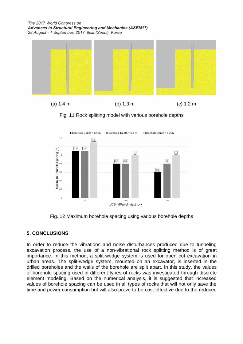
(a) 1.4 m (b) 1.3 m (c) 1.2 m
Fig. 11 Rock splitting model with various borehole depths
Fig. 12 Maximum borehole spacing using various borehole depths
5. CONCLUSIONS In order to reduce the vibrations and noise disturbances produced due to tunneling excavation process, the use of a non-vibrational rock splitting method is of great importance. In this method, a split-wedge system is used for open cut excavation in urban areas. The split-wedge system, mounted on an excavator, is inserted in the drilled boreholes and the walls of the borehole are split apart. In this study, the values of borehole spacing used in different types of rocks was investigated through discrete element modeling. Based on the numerical analysis, it is suggested that increased values of borehole spacing can be used in all types of rocks that will not only save the time and power consumption but will also prove to be cost-effective due to the reduced

number of boreholes. It was also observed that a decrease in borehole depth in all types of rocks results in increased values of maximum borehole spacing. ACKNOWLEDGEMENT This research was supported by Development of Design and Construction Technology for Double Deck Tunnel in Great Depth Underground Space(14SCIP-B088624-01) from Construction Technology Research Program funded by Ministry of Land, Infrastructure and Transport of Korean government. REFERENCES Cho, N. A., Martin, C. D., & Sego, D. C. (2007). A clumped particle model for
rock. International Journal of Rock Mechanics and Mining Sciences, 44(7), 997-1010. Cundall, P. (1971). A computer model for simulating progressive, large-scale
movements in blocky rock systems. In Proc. Int. Symp. on Rock Fracture (pp. 11-8). Deere, D. U., & Miller, R. P. (1966). Engineering classification and index properties for
intact rock. ILLINOIS UNIV AT URBANA DEPT OF CIVIL ENGINEERING. Diederichs MS (2000) Instability of hard rock masses: the role of tensile damage and
relaxation. University of Waterloo, Waterloo. FTA, U. (1995). Guidance Manual for Transit Noise and Vibration Impact Assessment.
DOT. Hagimori, K., Furukawa, K., Nakagawa, K., & Yokozeki, Y. (1991, January). Study of
non- blasting tunnelling by slot drilling method. In 7th ISRM Congress. International Society for Rock Mechanics.
Itasca Consulting Group (2008) PFC 2D (particle flow code, 2 dimension), version 4.0 user manual. Itasca Consulting Group, Mineapolis.
Murata, M., & Yokozawa, K. (1997). Mechanical excavation of hard rock tunnels without environmental disturbance: Effectiveness of TBM-driven pilot tunnels in non-blasting rock breaking method. In Proceedings 1st ARMS International Congress on Rock Mechanics, Seoul (pp. 107-112).
Noma, T., & Tsuchiya, T. (2003). Development of low noise and vibration tunneling methods using slots by single hole continuous drilling. Tunnelling and underground space technology, 18(2), 263-270.
Potyondy, D. O., & Cundall, P. A. (2004). A bonded-particle model for rock. International journal of rock mechanics and mining sciences, 41(8), 1329-1364.
Standard, A. S. T. M. (2008). Standard Specification for Carbon Structural Steel. Won, Y. H., Kang, C. W., & Ryu, C. H. (2006). The Study of noise and vibration on
application of the method breaking & excavating rock (Super wedge). In Proceedings of the KSEE Conference. Korean Society of Explosives and Blasting Engineering.
Zhang, L. (2004). Drilled shafts in rock: analysis and design. CRC Press. Zhang, X. P., & Wong, L. N. Y. (2012). Cracking processes in rock-like material
containing a single flaw under uniaxial compression: a numerical study based on parallel bonded-particle model approach. Rock Mechanics and Rock Engineering, 45(5), 711-737.