Proposed Revisions to Seismic Design Standards of...
27
Proposed Revisions to Seismic Design Standards of 2016 MOTEMS Prevention First 2014 Rakesh K. Goel, PhD, PE, F.ASCE, F.SEI Cal Poly, San Luis Obispo [email protected] 10/20/2014 © R.K. Goel 1
Transcript of Proposed Revisions to Seismic Design Standards of...

Proposed Revisions to Seismic Design Standards of
2016 MOTEMS
Prevention First 2014 Rakesh K. Goel, PhD, PE, F.ASCE, F.SEI
Cal Poly, San Luis Obispo [email protected]
10/20/2014 © R.K. Goel 1

Division 3 • Section 3103F.4.2 – Design earthquake
motion parameters – Replace second paragraph and three numbered
sub-paragraphs with: “For site classes A to E, peak ground and design spectral accelerations may be evaluated using USGS Published Data (updated link and procedure) as discussed in Section 3103F4.2.2 or Site-Specific PSHA as discussed in Section 3103F4.2.2. However, site-specific PSHA is required for site class F.”
– Delete PSHA results from POLA, POLB, and Port Hueneme
10/20/2014 © R.K. Goel 2

Division 3 • Section 3103F.4.2.2 – Earthquake motions
from USGS maps – http://earthquake.usgs.gov/designmaps/us/applic
ation.php – Select 2013 ASCE 41, Custom Earthquake
Hazard Option, Required Probability of Exceedance, and Site Soil condition
– Provides site corrected design spectrum • No need for manual adjustment for probability of
exceedance • No need to site class adjustment • Delete section 3103F.4.2.4 which provides details of
site class adjustment and construction of spectra
10/20/2014 © R.K. Goel 3

USGS Data
10/20/2014 © R.K. Goel 4

10/20/2014 © R.K. Goel 5

10/20/2014 © R.K. Goel 6

Division 3 • Section 3103F.4.2.3 – Earthquake motions from site specific
PSHA – “For site-specific PSHA, DPGA and DSA shall use appropriate
attenuation relationships, probability of exceedance, and site soil conditions. Site-specific PSHA shall be conducted by qualified California registered civil engineer with a California authorization as a geotechnical engineer per Section 3102F.3.4.8. If site-specific PSHA is used for site class other than site class F, results from site-specific PSHA shall be compared to those based on USGS published data in Section 3103F.4.2.2. If the two sets of values are significantly different, a justification for using the characterization chosen shall be provided. If DPGA or DSA from site-specific PSHA are less than 80% of the values from USGS data, a peer review may be required.”
– Delete all other details – No need for Sections 3103F.4.2.4 and 3103F.4.2.5
• Site amplification effects should already be part of site-specific PSHA
10/20/2014 © R.K. Goel 7

Division 3 • Section 3103F.4.2.6 – Directivity effects
– “1. Directivity effects may be reflected in the spectral acceleration values in deterministic manner by using [for example, the equation on page 213 (and Tables 6 and 7) of Somerville, et al. [3.9]] well established procedures with Division’s approval.”
– Remove explicit reference to Somerville
10/20/2014 © R.K. Goel 8
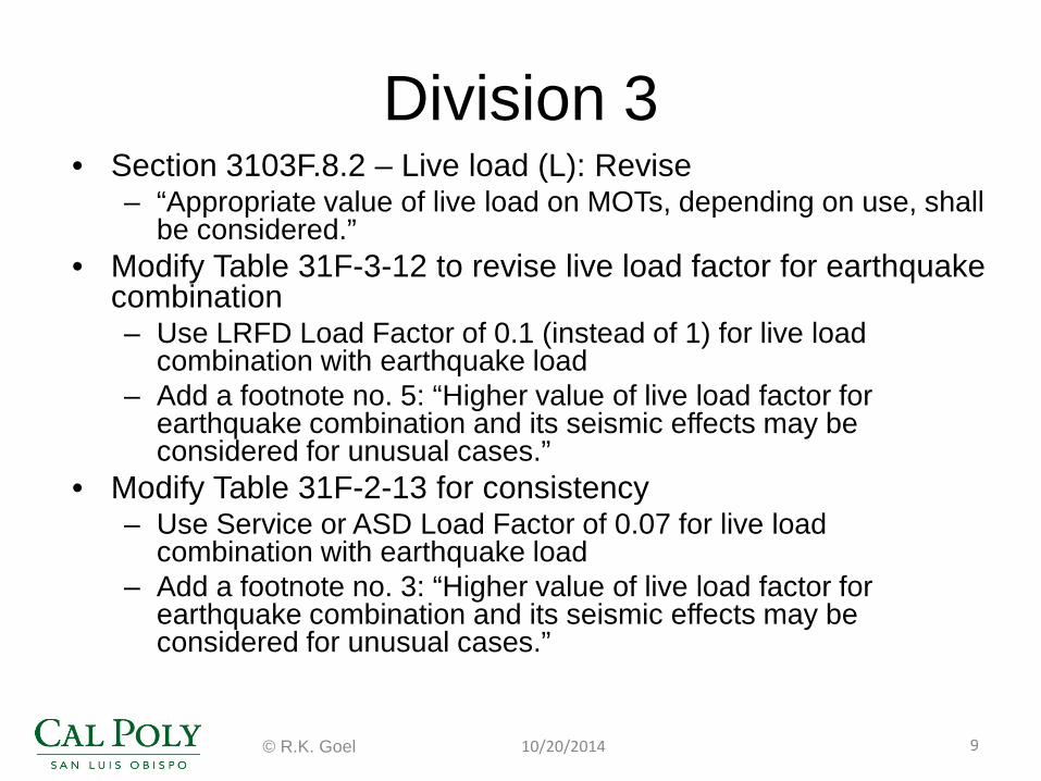
Division 3 • Section 3103F.8.2 – Live load (L): Revise
– “Appropriate value of live load on MOTs, depending on use, shall be considered.”
• Modify Table 31F-3-12 to revise live load factor for earthquake combination – Use LRFD Load Factor of 0.1 (instead of 1) for live load
combination with earthquake load – Add a footnote no. 5: “Higher value of live load factor for
earthquake combination and its seismic effects may be considered for unusual cases.”
• Modify Table 31F-2-13 for consistency – Use Service or ASD Load Factor of 0.07 for live load
combination with earthquake load – Add a footnote no. 3: “Higher value of live load factor for
earthquake combination and its seismic effects may be considered for unusual cases.”
10/20/2014 © R.K. Goel 9

Division 4
• Section 3104F.1.4 – Configuration classification – Current classification based only on plan – “Regular” plan-based configuration may
exhibit torsional behavior depending on pile configuration/length
– Configuration is needed to select displacement demand procedure in Table 31F-4-3
10/20/2014 © R.K. Goel 10

Division 4
• Section 3104F.1.4 – Configuration classification – revise as follows – Revise “Each MOT shall be designated as
regular or irregular based upon criteria in this section.”
– Add criteria based on ASCE 7-10 section 12.3.2.1 for horizontal irregularity classification
– Delete Figure 31F-4-1, its reference, and second paragraph
10/20/2014 © R.K. Goel 11

Division 4
• ASCE 7-10 section 12.3.2.1 based irregularity classification
• Irregular if
10/20/2014 © R.K. Goel 12
∆1
∆2
∆m > 1.2 ∆average
∆average=(∆1+∆2)/2 ∆m = max (∆1,∆2)

Division 4
• Table 31F-4-3: Add a footnote for displacement demand procedure for high/medium risk level, regular configuration, and concrete/steel materials – “Linear modal demand procedure may be
required for unusual cases where more than one mode is expected to contribute to the displacement demand.”
10/20/2014 © R.K. Goel 13

Division 4 • Section 3104F.2.3 – Analytical procedure
– Add after first sentence “For this purpose, displacement capacity for each element of the structure shall be checked against its displacement demand including orthogonal effects of section 3104F.4.2.”
– Add “For nonlinear static (pushover) procedure, the pushover load shall be applied at center of mass of the MOT structure.”
– Add after last sentence in second paragraph “Mass to be included in displacement demand calculation shall include mass from self weight of the structure, weight of permanent equipment, and portion of live load that may contribute to inertial mass during earthquake.”
– Remove the word “target” from sections 3104F.2.3.1 and 3104F.2.3.2.3 to avoid confusion
• Engineers may use this to check demand-capacity-ratio (DCR) instead of element DCR
10/20/2014 © R.K. Goel 14
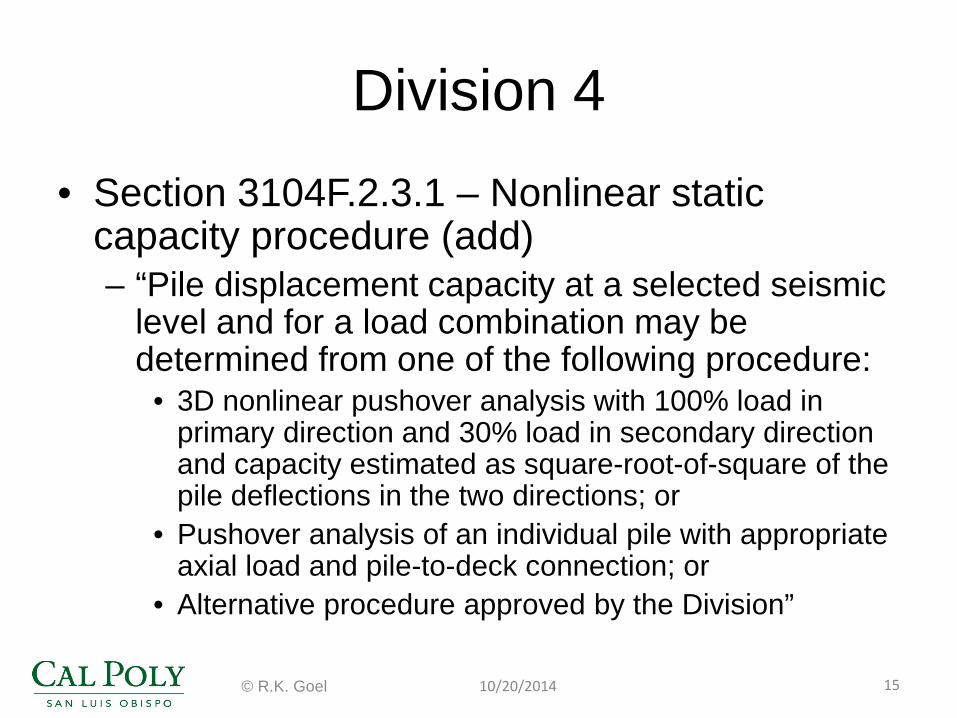
Division 4 • Section 3104F.2.3.1 – Nonlinear static
capacity procedure (add) – “Pile displacement capacity at a selected seismic
level and for a load combination may be determined from one of the following procedure:
• 3D nonlinear pushover analysis with 100% load in primary direction and 30% load in secondary direction and capacity estimated as square-root-of-square of the pile deflections in the two directions; or
• Pushover analysis of an individual pile with appropriate axial load and pile-to-deck connection; or
• Alternative procedure approved by the Division”
10/20/2014 © R.K. Goel 15

Division 4
• Section 3104F.2.3.1.1 Modeling (add) – “The effects of
connection flexibility shall be considered in pile-to-deck connection modeling. A procedure described in ASCE/COPRI 61-14 section C6.6.5 may be used for this purpose.”
10/20/2014 © R.K. Goel 16

Division 4
• Section 3104F.2.3.1.3 – Soil-structure interaction (SSI) – Delete section because SSI is described in
Division 6
10/20/2014 © R.K. Goel 17

Division 4 • Section 3104F.2.3.2 – Nonlinear static
demand procedures – Add “coefficient method” in ASCE 41-13 based on
FEMA 440: ASCE/SEI 41-13 Section 7.4.3.3.1 – Leave current “refined” MOTEMS procedure but
rename it as “substitute structure method” • This method is referred to as “substitute structure
method” in ASCE/COPRI 61-14 document • Remove restriction for substitute structure method to be
used only when T < To
– Add “Other methods approved by the Division may also be used.”
10/20/2014 © R.K. Goel 18

Division 4
• Section 3104F.2.3.2 – Nonlinear static demand procedures – “Coefficient method” in ASCE 41-13 based on
FEMA 440 – ∆d = C1C2SA(T2/4π2) – Coefficients C1 and C2 are defined based on
• Period • Soil type • Ratio of linear elastic demand and available
strength
10/20/2014 © R.K. Goel 19

Division 4 • Section 3104F.2.3.3 – Linear modal demand
procedures – Revise amplification of demand from linear modal
demand procedure when T < T0 • “… the displacement demand shall be amplified by the
ratio of Sd from Equation 4-4 and ∆d of Equation 4-2 or by C1C2 .”
– Current provision states • “ … the displacement demand shall be amplified as
specified in Section 3104F.2.3.2.5.” – Section 3104F2.3.2.5 only describes the refined analysis
procedure and does not discuss amplification of demand
10/20/2014 © R.K. Goel 20
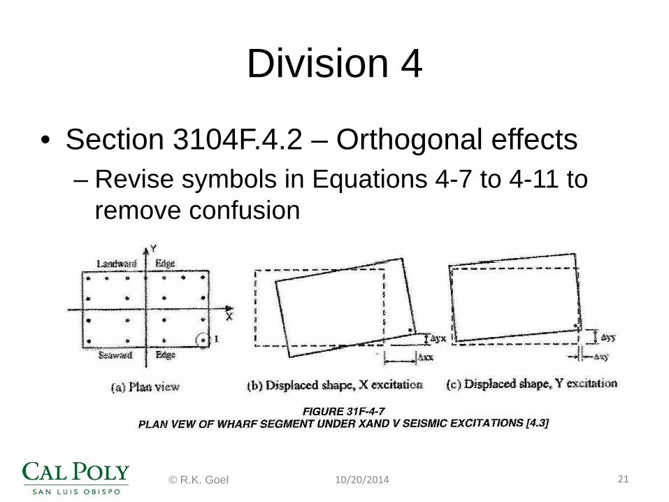
Division 4
• Section 3104F.4.2 – Orthogonal effects – Revise symbols in Equations 4-7 to 4-11 to
remove confusion
10/20/2014 © R.K. Goel 21

Division 4
• Section 3104F.4.2 – Orthogonal effects – Delete Equations 4-12 for marginal wharf type
MOTs because it is subject to misuse
10/20/2014 © R.K. Goel 22
21 0.3 1 20 /yd le L
∆ =∆ + +

Division 4
• Develop and add flowcharts for MOTEMS analysis procedures
10/20/2014 © R.K. Goel 23

Division 7 • Section 3107F.2.5.3 – Plastic hinge length
– Lp = 2D for in-ground hinge formation • Consistent with ASCE/COPRI 61-14
recommendations – Delete Figure 31F-7-4 and Table 31F-7-4
• These are no longer needed because in-ground plastic hinge length of ASCE/COPRI 61-14 does not depend on soil properties
10/20/2014 © R.K. Goel 24

Division 7 • Section 3107F.2.5.3 – Plastic hinge length
for pile-deck hinge – Keep current specification for concrete piles – Add Table 6-1 from ASCE/COPRI 61-14 for pile-deck
connection in pre-stressed concrete piles
10/20/2014 © R.K. Goel 25
Connection Type Lp at deck (in.) Pile buildup 0.15fyedb ≤ Lp ≤ 0.30fyedb
Extended Strand 0.20fpyedst
Embeded pile 0.5D Dowelled 0.25fyedb
Hollow dowelled 0.20fyedb External confinement 0.30fyedb
Isolated interface 0.25fyedb

Division 7
• Section 3107F.2.5.4 – Plastic rotation – Add ASCE/COPRI 61-14 Figure 6.5 as
additional way to idealize moment-curvature relationship
10/20/2014 © R.K. Goel 26

Division 7 • Section 3107F.2.6.3 – Plastic hinge length
for steel piles – Adopt ASCE/COPRI 61-14 recommendations – Lp = 2D for in-ground hinge formation – ASCE/COPRI 61-14 Table 6-1 for pile-deck
hinge
10/20/2014 © R.K. Goel 27
Connection Type Lp at deck (in.) Embeded pile 0.5D Concrete plug 0.30fyedb
Isolated shell 0.30fyedb + g Welded embed 0.5D