Proposal of a Diamond-based Beam Halo Monitor for an...
22
The 50th ICFA Advanced Beam Dynamics Workshop on Energy Recovery Linacs ERL2011, KEK, Tsukuba, Ibaraki, Japan 1 Proposal of a Diamond-based Beam Halo Monitor for an Energy Recovery Linac Hideki Aoyagi, T. Bizen , T. Itoga, N. Nariyama JASRI / SPring-8 Y. Asano, T. Tanaka, H. Kitamura RIKEN/ SPring-8 October 17, 2011 WG5OO1 OUTLINES 1. Introduction Purpose of the halo monitor, Required detection limit Principle verification tests of diamond detector 2. Feasibility tests using a prototype of the halo monitor 3. Adoption of RF fingers to the halo monitor 4. Operational Experience at SACLA 5. Summary
Transcript of Proposal of a Diamond-based Beam Halo Monitor for an...

The 50th ICFA Advanced Beam Dynamics Workshop on Energy Recovery Linacs
ERL2011, KEK, Tsukuba, Ibaraki, Japan 1
Proposal of a Diamond-based Beam Halo Monitor for an Energy Recovery Linac
Hideki Aoyagi, T. Bizen , T. Itoga, N. Nariyama JASRI / SPring-8
Y. Asano, T. Tanaka, H. Kitamura RIKEN/ SPring-8
October 17, 2011 WG5OO1
OUTLINES
1. Introduction Purpose of the halo monitor, Required detection limit Principle verification tests of diamond detector
2. Feasibility tests using a prototype of the halo monitor
3. Adoption of RF fingers to the halo monitor
4. Operational Experience at SACLA
5. Summary

SACLA SPring-8 Angstrom Compact Free Electron Laser 2
H. Tanaka, IPAC2011 Invited talk, MOYCA01

Purpose of the Halo Monitor 3
X-ray Laser Low Emittance Electron Gun
In-vacuum Undulators (5 m x 18)
8GeV C-band Accelerator
(400m)
Beam will be stopped, when beam halo exceed the threshold
In order to protect the undulator permanent magnets against radiation damage, Beam Halo Monitor has been installed in front of the in-vacuum undulators.
Schematic layout of SACLA
to users
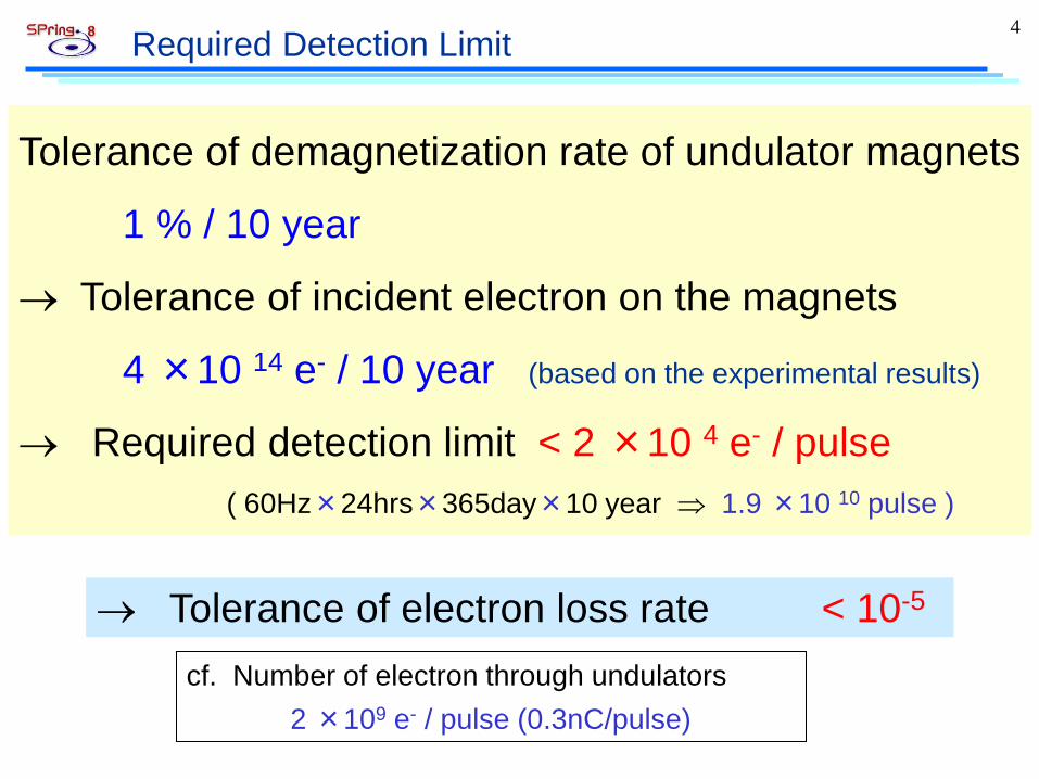
Required Detection Limit 4
Tolerance of demagnetization rate of undulator magnets
1 % / 10 year
→ Tolerance of incident electron on the magnets
4 ×10 14 e- / 10 year (based on the experimental results)
→ Required detection limit < 2 ×10 4 e- / pulse ( 60Hz×24hrs×365day×10 year ⇒ 1.9 ×10 10 pulse )
cf. Number of electron through undulators 2 ×10⁹ e- / pulse (0.3nC/pulse)
→ Tolerance of electron loss rate < 10-5

How to measure? 5
Direct measurement in the beam duct
Measure a differential of charge between before and after undulators.
Undulators Core monitor
e-
Ideally
Realistically
Sensors
Required resolution must be less than 10-6.
We adopted this type.
Core monitor
Measure a beam halo in front of undulator permanent magnets.

6 Configuration of sensors ?
Side edge of magnet array
Bulk diamond crystal
A single large detector with a hole in center.
A pair of detectors with separate actuators
Small active area Variable aperture Short time constant Easy to fabricate (small crystal)
Min.Gap ~ 4 mm
Φ30-50
~ 10 mm
Active area
We adopted the this type.
Wide active area Fixed aperture
Longer time constant, τ = RC

Diamond detector as semi-conductor detector 7
Clamp area
5 mm2
Manufactured by Kobelco
Advantages of diamond:
- High radiation hardness (durable)
- Good heat resistance (bakable)
- High insulation resistance (low dark current)
Active area Seen from on the axis
Beam core passes through between diamond detectors.
e-h pairs are generated in the bulk of diamond crystal.
EPAC2008, THPC146

Principle verification tests of diamond detector 8
Bias voltage = +100V
Practical detection limit is 2×10³ e- /pulse. Definition : 10σ of noise signal level
Carried out at 8GeV booster synchrotron
Unipolar pulse Wide dynamic range
One shot measurement
(incident electron)
Diamond detector
8GeV electron beam From booster
(beam size 0.4 x 0.1)
Si PIN photodiode (for calibration of incidence)
Check of pulse shape Linearity check
Required detection limit
EPAC2008, THPC146

9 2. Photographs of the Prototype
Beam
bellows 100mm bellows
100mm
chamber 100mm
ICF54 ICF70
Installed at 250MeV SCSS Test Accelerator
Kapton coaxial cable
ICF 70
SMA connectors
Seen from on the axis
DIPAC2009, TUPB24

10 Effect of Wake Field and their suppression
Charge of core part :0.02nC
The strong beam core passes through near the edge of diamond detectors.
Low Pass Filter
The active area of the diamond detector was irradiated directly with weak beam core (3×10⁴ e).
The effect of induction current can be smeared by using Low Pass Filters, so the net signal from e-h pairs that is created by the halo part of the electron beam can be measured.
The unipolar pulse shape can be observed clearly.
1 mm from the axis
Net signal from diamond
Measured at SCSS Test Accelerator
DIPAC2009, TUPB24

Profile measurement of the beam halo 11
X
Y
Spatial slit after 50 MeV Injector
Slit width = 10mm 4mm 2mm
Scanning in the vertical direction
Images of OTR screen just after beam halo monitor
1 m
m
beam
cor
e
DIPAC2009, TUPB24
Measured at SCSS Test Accelerator

Stability Tests of the Halo Monitor at the SCSS 12
Signal from upper blade
Signal from lower blade
(a) The output signal from the diamond detector
(b) The output signal from the pre-amplifier.
(C) The waveform stored at data base.
Time ( 210nsec/div) C
urre
nt s
igna
l (V
/50Ω
)
IPAC2010, WEPEB068
H. Maesaka et al. M. Yamaga et al.

13 Result of stability tests
during user operation during machine study
← Signal from upper blade
← Signal from lower blade
Power of FEL →
Pow
er of FEL (arb.)
Hal
o M
onito
r out
put (
nC)
Intensity of electron beam →
← Signal from upper blade
← Signal from lower blade Hal
o M
onito
r out
put (
nC)
Intensity of electron beam (nC
) in one day IPAC2010, WEPEB068
Measured at SCSS Test Accelerator
9am 7pm 9am 7pm

3. Adoption of RF Fingers 14
Finger type 0 (no fingers)
Finger type 1 (not covered)
Finger type 2 (fully covered)
Diamond detector RF fingers
Beam
In the configuration of type 1, the active areas of the diamond detectors project from between RF fingers.
In the configuration of type 2, the RF fingers are connected without bumps.
RF fingers
Type 1 Type 2
→ We need to know, if the fingers can reduce induced current, and if the signal blows up by radiation from the finger material.
FEL2010, THOC4 DIPAC2011, MOOB03

Reduction of induced current 15
Finger type 0 (no fingers)
Finger type 1 (not covered)
Finger type 2 (fully covered)
Type 0
Type 2
Type 0 Type 1
Type 2
Duration has also shortened.
Type 1
One shot
One shot
100 folds average
Pow
er s
pect
rum
den
sity
Reduced by 1/10
The high frequency component is drastically decreased.
at SCSS Test Accelerator FEL2010, THOC4
DIPAC2011, MOOB03

Radiation from RF fingers: experimental setup 16
Diamond detector
8GeV electron beam (beam size 0.4 x 0.1)
Si PIN photodiode (for calibration of incidence)
RF finger slope ≈ 1 / 3
Al window or BeCu plate
Si PIN
Diamond detector
Finger type Material Thickness Pass length
no finger none 0 mm 0 mm
Al window Al 0.1mm 0.3mm
BeCu x 1 BeCu 0.2mm 0.6mm
BeCu x 3 BeCu 0.6mm 1.8mm
Purpose of this measurement is to evaluate a variation of the detective efficiency caused by secondary electrons and bremsstrahlung that are generated in the finger material.
Carried out at 8GeV booster synchrotron Experimental conditions
DIPAC2011, MOOB03

experimental results and simulation results 17
The experimental results and the simulation results are in good agreement within the measurement errors.
Monte Carlo simulation code:
EGS5
Ene
rgy
depo
sitio
n (M
eV/e
) in
dia
mon
d cr
ysta
l (t=
0.3)
Measurement data were normalized as the measurement value with no fingers is corresponding to the energy deposition of 0.16MeV/e, which is the simulation result at thickness = 0.
Increment of a few %
RF finger with Al window can be used for our purpose.
DIPAC2011, MOOB03
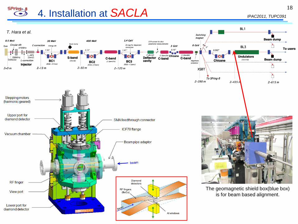
4. Installation at SACLA 18
The geomagnetic shield box(blue box) is for beam based alignment.
T. Hara et al.
IPAC2011, TUPC091
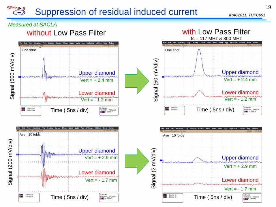
Suppression of residual induced current 19
Upper diamond
with Low Pass Filter
Vert = + 2.9 mm
Lower diamond
Time ( 5ns / div) Time ( 5ns / div)
Sig
nal (
200
mV
/div
)
Sig
nal (
2 m
V/d
iv)
fc = 117 MHz & 300 MHz
Time ( 5ns / div) Time ( 5ns / div)
Sig
nal (
500
mV
/div
)
Sig
nal (
50 m
V/d
iv)
One shot One shot
Ave _10 folds Ave _10 folds
Upper diamond
Lower diamond
Upper diamond
Lower diamond
Upper diamond
Lower diamond
Vert = - 1.7 mm
Vert = + 2.9 mm
Vert = - 1.7 mm
Vert = + 2.4 mm
Vert = - 1.2 mm
Vert = + 2.4 mm
Vert = - 1.2 mm
without Low Pass Filter
IPAC2011, TUPC091
Measured at SACLA

Trend graph of laser power while RF fingers are closed 20
The laser power did not received a significant change even at the minimum gap.
We conclude that this is an effect of reducing the wake field by the RF fingers.
Measured at SACLA
IPAC2011, TUPC091

Profile measurement of the beam halo 21
We succeeded in achieving the required detection limit at SACLA.
Required detection limit
Notice: When the edge of the RF finger is near the beam core, the output signals of diamond detectors blow up because of scattering.
IPAC2011, TUPC091
Estim
ated
inte
nsity
of b
eam
hal
o (p
C)
Measured at SACLA

5. Summary 22
1. Purpose of this work - to protect undulator magnets against radiation damage - using the beam halo monitor equipped with the diamond detectors - adopting pulse measurement for enhancing S/N ratio
2. Performances of the Halo Monitor - Practical detection limit is about 2×10³ e/pulse. (1ppm of 0.3nC) - Dynamic range is 4 orders. ( 2 × 10³ to 107 e/pulse) - Feasibility had been demonstrated. - RF fingers with Al windows were adopted. - Commissioning of the Halo Monitor at SACLA has been successfully
carried out.
3. Things to do toward a versatile equipment, - Improvement of lower/upper detection limit. - Refinement of RF finger structure (reduce gap between a finger and a detector)
- Equipment with a cooling mechanism.