Property Services Design Standards Brief - RMIT Universitymams.rmit.edu.au/uwyyvdlbnpbu.pdf ·...
27
Section 8 – Fire Services Design Standards Brief Section 8 Page 1 Issue No. 6, 2009 ©Copyright | RMIT University, Melbourne, Australia 1997 | ALL RIGHTS RESERVED Property Services Design Standards Brief Section 8 – Fire Services Issue 6 2009
-
Upload
hoangkhanh -
Category
Documents
-
view
215 -
download
0
Transcript of Property Services Design Standards Brief - RMIT Universitymams.rmit.edu.au/uwyyvdlbnpbu.pdf ·...

Section 8 – Fire Services
Design Standards Brief Section 8 Page 1 Issue No. 6, 2009 ©Copyright | RMIT University, Melbourne, Australia 1997 | ALL RIGHTS RESERVED
Property Services
Design Standards Brief Section 8 – Fire Services
Issue 6 2009

Section 8 – Fire Services
Design Standards Brief Section 8 Page 2 Issue No. 6, 2009 ©Copyright | RMIT University, Melbourne, Australia 1997 | ALL RIGHTS RESERVED
8. CONTENTS
8.1. GENERAL...........................................................................................................................................4 8.2. FIRE SAFETY OBJECTIVES .............................................................................................................5
8.2.1. Regulatory Requirements ....................................................................................................5 8.2.2. Asset Protection and Continuity of Services........................................................................5
8.3. DELIVERY PROCESS........................................................................................................................5 8.3.1. BCA Deemed-to-Satisfy and Fire Safety Engineered Solutions..........................................5 8.3.2. Engineering Design Specification and Drawings.................................................................6 8.3.3. Engineering Design Brief .....................................................................................................6 8.3.4. Preferred Contractors ..........................................................................................................6
8.4. ACTIVE SYSTEMS.............................................................................................................................7 8.4.1. Automatic Fire Suppression Systems..................................................................................7 8.4.2. Automatic Fire Detection Systems.......................................................................................7 8.4.3. Emergency Warning and Intercommunication System........................................................8 8.4.4. FIP & EWIS Panel Requirements ........................................................................................9 8.4.5. VESDA...............................................................................................................................10
8.4.5.1. General.............................................................................................................................................. 10 8.4.5.2. Approvals .......................................................................................................................................... 10 8.4.5.3. Codes, Standards or Regulations. .................................................................................................... 10 8.4.5.4. System Description ........................................................................................................................... 10 8.4.5.5. Submittals.......................................................................................................................................... 10 8.4.5.6. Manufacturer ..................................................................................................................................... 11 8.4.5.7. Detector Assembly. ........................................................................................................................... 11 8.4.5.8. Displays and Programmers. .............................................................................................................. 11 8.4.5.9. Device networking requirements ....................................................................................................... 11 8.4.5.10. Digital Communication ...................................................................................................................... 11 8.4.5.11. Equipment ......................................................................................................................................... 11 8.4.5.12. Sampling Pipework Design. . ............................................................................................................ 12 8.4.5.13. The Detection system........................................................................................................................ 13 8.4.5.14. Sampling Pipe Network ..................................................................................................................... 13 8.4.5.15. The Sampling Point Network............................................................................................................. 13 8.4.5.16. The Capillary Sampling Network. ...................................................................................................... 13 8.4.5.17. Air Sampling Network Calculations. .................................................................................................. 13 8.4.5.18. Commissioning Tests. ....................................................................................................................... 14 8.4.5.19. System Checks. ................................................................................................................................ 14 8.4.5.20. Tests.................................................................................................................................................. 14
8.5. INFORMATION FOR HEARING IMPAIRED PERSONS .................................................................15 8.5.1. System Installation.............................................................................................................15
8.6. SPRINKLER SYSTEMS / FIRE PUMPS ..........................................................................................15 8.6.1. Hydrant/Hose Reel Systems..............................................................................................16
8.7. FIRE HYDRANTS: - LOCATION SIGNAGE ....................................................................................16 8.7.1. Portable Fire Extinguishers................................................................................................17 8.7.2. Independent Certification...................................................................................................17 8.7.3. Pipe Identification...............................................................................................................17 8.7.4. Inspections.........................................................................................................................18 8.7.5. Requirements.....................................................................................................................19 8.7.6. The use of Fire Pillows is not permitted by RMIT ..............................................................19
8.7.6.1. Installation ......................................................................................................................................... 19 8.7.6.2. Materials............................................................................................................................................ 20 8.7.6.3. Preparation........................................................................................................................................ 20 8.7.6.4. Fire Doors / Smoke Doors................................................................................................................. 22
8.7.7. Door Sequence Device......................................................................................................22 8.7.8. Egress Provisions ..............................................................................................................23 8.7.9. Drawings ............................................................................................................................23
8.8. Operating/ Maintenance Manuals ..................................................................................................24 8.8.1. Maintenance ......................................................................................................................24
8.8.1.1. General.............................................................................................................................................. 24 8.8.1.2. Maintenance Field Logbooks ............................................................................................................ 24
8.8.2. Housekeeping ....................................................................................................................24 8.8.3. Operation and Maintenance Manuals................................................................................24

Section 8 – Fire Services
Design Standards Brief Section 8 Page 3 Issue No. 6, 2009 ©Copyright | RMIT University, Melbourne, Australia 1997 | ALL RIGHTS RESERVED
8.8.4. Installation Drawings..........................................................................................................25 8.9. CERTIFICATE OF OCCUPANCY / CERTIFICATES OF FINAL INSPECTION..............................25
8.9.1. Defects List ........................................................................................................................25 8.9.2. Practical Completion..........................................................................................................26 8.9.3. Defects Liability Period (DLP)............................................................................................26 8.9.4. Radio Interference/Lightning..............................................................................................26
8.10. PORTABLE FIRE EXTINGUISHERS...............................................................................................27 8.10.1. Factors affecting selection .................................................................................................27 8.10.2. Location of Portable Fire Extinguishes ..............................................................................27 8.10.3. Distribution of Portable Fire Extinguishes..........................................................................27

Section 8 – Fire Services
Design Standards Brief Section 8 Page 4 Issue No. 6, 2009 ©Copyright | RMIT University, Melbourne, Australia 1997 | ALL RIGHTS RESERVED
8.1. GENERAL The Project Architect shall in conjunction with the Project Manager and Project Manager, Services, establish the Fire Services Strategy to be adapted for the project. The methodology is to be discussed and confirmed with the Facilities Services, Manager Fire Engineering and Relevant Building Surveyor and the RMIT Fire Safety Engineer prior to commencement of the documentation.
The process shall consider:
BCA Deemed-to-Satisfy Provisions and Performance Based Fire Safety Engineered Alternate Solutions
Traditional Specification and Drawings for calling of Tenders for Installation Works
Engineering Design Brief for Design & Construct Tender for Installation Works
Fire Safety Services shall include and not be limited to the following:
Active Systems
Automatic fire suppression systems including sprinklers and gaseous flooding
Automatic fire detection systems including smoke and heat detection
Active smoke management systems including purge systems, zone pressurisation and stair pressurisation systems
Occupant warning and intercommunication systems
Fire hydrants and fire hose reels
Portable fire extinguishers
Visible fire alarm indication shall be considered and be provided as required
Any other active fire safety systems adopted in the design
Passive Systems
Fire and smoke separation/compartmentation including fire and smoke doors;
Structural fire resistant elements;
Egress provisions
Any other passive fire safety feature adopted in the design.
Fire Safety Management
Emergency evacuation procedures and occupant training
Emergency evacuation plans and fire orders
Contractor management
Essential services maintenance
Housekeeping
Signage associated with the above systems
The Project Architect shall consult with the Project Manager and Relevant Building Surveyor at the earliest possible stage in the design process so that the University's requirements are met and delays will not be experienced at the Building Occupation stage. Outcomes of the

Section 8 – Fire Services
Design Standards Brief Section 8 Page 5 Issue No. 6, 2009 ©Copyright | RMIT University, Melbourne, Australia 1997 | ALL RIGHTS RESERVED
consultative process shall be documented and the RMIT Fire Manager Engineering advised accordingly.
8.2. FIRE SAFETY OBJECTIVES The aim of the fire safety strategy is to install fire addressable protection systems within the building to provide life safety and a level of property protection. The Fire system shall be connected to the existing fire graphics and the fire graphics shall be installed accordingly.
The building is required to have a very flexible end use and therefore the fire strategy must take into account all realistic types of fire hazard and occupancy levels. Areas of uses not considered or deemed to be beyond the scope of the fire protection are to be listed within the “Limitations”.
The design shall utilize the performance provisions of the Building Code of Australia (BCA) 2008 to achieve the most suitable fire safety engineered solution for each project.
8.2.1. Regulatory Requirements The Building Code of Australia 2008 (BCA) is primarily concerned with and addresses the following:
The life safety of the building occupants.
Protection of adjacent property.
The BCA provides for fire safety engineering assessment against specified performance requirements to meet the Building Regulations. Fire safety engineered design is to be adopted where appropriate to optimize and effectively integrate the University’s accommodation requirements within both new and existing buildings and within site constraints associated with the variety of CBD and suburban properties.
8.2.2. Asset Protection and Continuity of Services Specific issues of asset protection and continuity of service will be identified by the University for each project, where applicable.
8.3. DELIVERY PROCESS
8.3.1. BCA Deemed-to-Satisfy and Fire Safety Engineered Solutions The BCA deemed-to-satisfy prescriptive approach in meeting the requirements of the Building Regulations is often not practical to apply to existing buildings or new buildings with limiting site constraints.
The BCA is a performance based Code that includes deemed-to-satisfy provisions that are deemed to comply with the performance requirements. The performance basis of the BCA provides flexibility for the University to construct new and refurbish existing building stock and optimize the fire safety for each particular project.
The Project Architect shall in conjunction with the Relevant Building Surveyor and Fire Safety Engineer establish at the schematic design phase where appropriate and for each project develop a fire engineering design brief.
The Relevant Building Surveyor shall be registered by the Building Commission to assess performance based submissions. The appointed Fire Safety Engineer shall be an Engineer registered by the Building Commission under the category of Engineer, Class of Fire Safety Engineer and be suitably experienced in carrying out fire safety engineering performance assessments.

Section 8 – Fire Services
Design Standards Brief Section 8 Page 6 Issue No. 6, 2009 ©Copyright | RMIT University, Melbourne, Australia 1997 | ALL RIGHTS RESERVED
The Fire Safety Engineering Performance Assessment report shall include sufficiently detailed schematic design information to allow appropriately qualified and experienced Services Engineers to prepare Engineering Design Specifications and Drawings or an Engineering Design Brief suitable for obtaining competitive tenders from installation contacting organizations.
All systems must comply with the relevant Australian Standards except where specifically varied by a performance based fire engineering alternate solution.
The performance based fire safety engineering assessment should consider the classification of the building at design stage and possible changes in the use that are possible in the future. RMIT have a continual movement of discipline throughout the whole of their premises and as such – flexibility erring on the selection of a higher classification due to possible future costs should be considered rather than minimum requirements to meet a budget.
The Project Architect shall in conjunction with the design team, RMIT Senior Projects Manager, Services - Projects and Building Surveyor and RMIT Manager Fire Engineering provide detailed performance based criteria that establish the Project requirements. On receipt of tenders, a comprehensive report and recommendation shall be issued to RMIT for approval. The Building Surveyors endorsement for the regulatory aspects is to be included. Consultants are to liaise with RMIT Fire Engineering Services.
Inspections shall be carried out for both new and altered systems by an RMIT listed independent Certifier (refer clause 8.7.2 Independent Certification) and the services consultants to ensure that the whole of the system complies with all appropriate Australian Standards. Any variation from a relevant Australian Standard in a system which is added to or altered should be highlighted in a written report by the Certifier.
8.3.2. Engineering Design Specification and Drawings Traditional documentation shall address the principles detailed in clauses 1.5.3 & 1.5.4 and the following minimum criteria to form the basis for the selected design options.
Preparation of Engineering Design Specifications and Drawings for Fire Safety Services is the traditional method adopted for obtaining competitive tenders from installation contacting organizations.
8.3.3. Engineering Design Brief The preparation of an Engineering Design Brief for Fire Safety Services, suitable for obtaining competitive tenders from installation contracting organizations is an alternative method.
8.3.4. Preferred Contractors To ensure the correct operation of the fire detection/suppression systems throughout RMIT please be aware that the University has preferred contractors who are familiar with all RMIT’s requirements and the minimum standards and conditions that are expected when working on any of the systems throughout RMIT. By having these preferred contractors the University can ensure that newly installed and altered systems have been completed to RMIT’s high standard; thus reducing faults, system malfunctions and false alarms and therefore standardizing the quality of work.
For a current list of preferred contractors please contact the Manager Fire Engineering Services.
If a Contractor or consultant wishes to use another fire services contractor they will be provide a detailed company history, references for similar work that they expect to complete for RMIT and details of employee qualifications and details of membership to the FPR, to the RMIT Project Manager for approval.

Section 8 – Fire Services
Design Standards Brief Section 8 Page 7 Issue No. 6, 2009 ©Copyright | RMIT University, Melbourne, Australia 1997 | ALL RIGHTS RESERVED
8.4. ACTIVE SYSTEMS
8.4.1. Automatic Fire Suppression Systems Automatic fire suppression systems may include sprinkler systems, gaseous flooding systems or other specific systems that may be provided to meet regulatory requirements or particular asset protection requirements of the University.
Sprinkler systems shall be in accordance with AS-2118 and other relevant Standards and Codes. The installing contractor shall allow for certification of the sprinkler design and installation by an independent certifier.
8.4.2. Automatic Fire Detection Systems Automatic fire detection systems will be fully addressable and networked back to the RMIT Security control room and connected up to the existing fire graphic system. These systems may include smoke and heat detection systems, air sampling systems or other specific systems and will be provided to meet regulatory requirements or particular asset protection requirements of the University.
Smoke and heat detection systems shall be provided in accordance with AS1670, AS1868 and other relevant Standards and Codes. The Project Architect and consultants are in association with the Project Manager and Projects Manager, Services, to discuss the scope of works and specific detailed requirement with RMIT Facilities Services, Manager Fire Engineering.
All systems to be in accordance with Australian Standard AS1670.1 and all equipment Fire Panels/Detectors, etc Laboratory approved.
Fire Alarm panels are to be fully addressable and conform to (AS4428-1 1999) and be CSIRO approved and compatible with the RMIT standard colour graphics and loop system.
The Fire Alarm System shall also incorporate an emergency warning and Communication system to AS2202-2; including warden inter communications points and public address facilities, or a single zone two tone fire warning system to AS2220 tones along with auto position and PA facility with microphone.
The type of EWIS system selected shall be Quintrix QE-90 or equivalent as approved by the RMIT Fire Engineer.
Clearance - a newly installed fire panel must comply with AS1670.1 and also be mounted a minimum of 50 mm above a floor.
Adequate storage facilities - shall be provided within the FIP for storage of lamps, detectors logbooks and As-constructed drawings and manuals. (Logbooks and As-constructed drawings shall not be permitted to be stored external to the fire panel).
Comprehensive tests shall be carried out for both new and altered systems by the contractor prior to a qualified independent certifier and services consultants testing the system to ensure that the whole of the system complies with all appropriate Australian Standards. Any deficiency in a system which is added to or altered should be highlighted.
Where smoke doors are automatically operated to close in the event of a Fire Alarm they shall have an inbuilt delay and appropriate warning system to alert occupants that doors are about to close (e.g. speakers and not an electronic sounder).
Automatic closing of door will only occur in the zone of the alarm, except where the integrity of an area is required, e.g. a stair well that needs to be pressurized.
All detectors shall indicate a continuous steady light in an alarm condition. This includes situations where the existing detectors are to be connected to a new fire indicator panel. All concealed detectors shall be installed in conjunction with a remote indicator which shall indicate a continuous steady light in an alarm condition.

Section 8 – Fire Services
Design Standards Brief Section 8 Page 8 Issue No. 6, 2009 ©Copyright | RMIT University, Melbourne, Australia 1997 | ALL RIGHTS RESERVED
Furthermore, the Project Architect is requested to take all steps necessary to ensure that the installation of manual call points be kept to an absolute minimum in order to reduce the incidence of malicious calls.
The required RMIT fire alarm panel is a WORMALD MX 4000 or similar as installations will need to interface with the existing system.
A provisional sum for the supply of the Fire Indicator Panels like systems or new extensions to existing boards will be included in the Tender Documents. The Projects Manager, Services, in association with the Facilities Services, RMIT Fire Engineer/ Emergency Services Coordinator, will provide to the Project Architect quotations from approved supplier/suppliers for the supply, connection, and commissioning of the Fire Panels for acceptance by the successful contractor
Consultation with the RMIT Manager Fire Engineering is required on the placement of manual call points. All break glass manual call point shall be key re-settable (as supplied by Ampac)
Any interface between the Fire Alarm System and Air Conditioning – shutdown/smoke fans, etc, shall be completely documented and in particular the responsibilities to run wires/terminate/provide equipment, etc. clearly defined.
Location Diagram - shall be laminated, framed and placed adjacent to the FIP, it shall indicate all fire zones, exits, isolation valves and fire equipment locations. Prior to mounting the proposed location diagram must be presented to the RMIT Fire Engineer for approval before installation.
The Location Diagram shall be drawn so that when it is mounted on the wall it is correctly oriented with respect to the building. The plans to have a “you are here” symbol, the date of installation and the installers name placed upon the plan
A CAUSE AND EFFECT MATRIX shall be completed showing the sequence operation of these systems and be provided with the system installation manuals.
8.4.3. Emergency Warning and Intercommunication System Not withstanding the following requirements the whole of the EWIS system must meet the appropriate Australian Standard and regulatory requirements.
The system shall be installed throughout all buildings of the University Campuses.
Where a EWIS system is not installed, a warning system to AS-1670.1 must be provided. The warning system must be a monitored system with ceiling or wall mounts, speakers. Where existing systems are extended, new equipment added shall be compatible. Additions shall be identical and shall be of the same manufacturer. Sound pressure level in any area served by the whole system at any point less that 2 meters above floor level shall not be less than 10db (A) above the maximum ambient noise level and shall be in the range of 75db (A) to 95db (A).
The preferred panel shall be manufactured by:
Quintrix/Vigilant Model QE90 and the system shall have 30% spare capacity.
The EWIS system shall be interfaced to the FIP and shall activate on receipt of an alarm from the FIP or a BGA.
The EWIS shall be installed to act as a standard PA system. Early discussion is required for this application to establish zones etc.
The EWIS shall be positioned adjacent to, or directly in the line of sight of the Building Fire Panel in accordance with Australian Standards.
All lock cylinders shall be keyed to CL 003 locks.
Warden Intercommunication Phones shall be installed at approved locations on each building level, and shall be enclosed as required in a RMIT standard box (sample available). All attempts should be made to have WIP phones placed within hose reel cabinets adjacent to exits within

Section 8 – Fire Services
Design Standards Brief Section 8 Page 9 Issue No. 6, 2009 ©Copyright | RMIT University, Melbourne, Australia 1997 | ALL RIGHTS RESERVED
buildings. When WIP‘s are located in these area’s signage must be provided to identify there location.
Speakers shall be positioned on site after consultation with the Architect. Speakers shall be selected with a frequency range to allow the Alert, Action and Speech signal to be clearly propagated.
Strobe lights shall operate simultaneously with the speakers in that zone. Where necessary, other areas such as laboratories and the like surface mounted cone speakers compatible to the QE 90 EWIS shall be installed, subject to the approval of the RMIT Manager Fire Engineering, and the Deputy Director Facilities Services and/or his appointee.
Strobe lights shall be located so that pipe work, ducts and the like will not obscure the lamps from view.
It is expected that in a typical floor area, a number of speakers are strategically located to provide the required sound pressure levels as described above.
Recessed type shall be 200 mm diameter and fitted with plug and socket connection, with a maximum 2000 mm cable for future relocation during fit out or renovation. All wiring shall be secured to the rear of the speaker with nylon zip ties to prevent accidental disconnection.
Horn speakers shall have 500 mm of cable and only be installed within plant rooms and large open spaces; other suggested locations must have the approval of RMIT Fire Engineer/Emergency Services Coordinator.
The speakers and WIP locations must allow the warden to communicate using the intercommunication system while either warning signal is sounding.
While complying with the current edition of all Australian Standard, special attention is to be paid to sound proof rooms where the sound pressure level generated by audible warning signals is less than 10db (a) above maximum normal ambient sound, or where the normal occupants may be expected to have hearing difficulties.
Note - Where practical, visual warning devices should be installed for the hearing impaired
Amplifier capacity and loadings shall be checked for correct operating parameters.
Batteries shall not be wired in multiple banks unless a separate charger and monitoring circuitry is provided for each bank. Batteries shall be of the same make and model and of the same vintage where more that one battery is installed.
8.4.4. FIP & EWIS Panel Requirements Panel Equipment - Allowance should be made for surface mounted or semi-recessed panels especially refurbishment jobs. Panels shall comply with AS-4428.1 in addition to AS-1670.
Clearance - A newly installed EWIS panel must comply with AS-1670.1 and also be mounted a minimum of 50 mm above a floor.
Adequate storage facilities - shall be provided within the EWIS for storage of lamps, detectors logbooks etc and As-constructed drawings and manuals.
All sub fire alarm panels - shall be totally enclosed suitable for recessed wall mounting in the position approved by the RMIT Manager, Fire Engineering. The Fire Indicator & EWIS Panel will be mounted in a dustproof sheet metal case suitable for surface mounting. Battery location within the FIP & EWIS Panel should be treated to render corrosion proof.
A break glass manual call point - key re-setable (as supplied by Ampac) will be installed in the lower section of the FIP door or in the near vicinity of the indicator panel.
A Red Strobe light - shall be installed adjacent to the FIP to indicate FIP location to the Fire Brigade.
Section 8 – Fire Services
Design Standards Brief Section 8 Page 10 Issue No. 6, 2009 ©Copyright | RMIT University, Melbourne, Australia 1997 | ALL RIGHTS RESERVED
8.4.5. VESDA
8.4.5.1. General
A Very Early Smoke Detection System known as a VESDA Laser PLUS shall be installed throughout the areas nominated within RMIT. The system shall consist of highly sensitive LASER-based Smoke Detectors with aspirators connected to a network of pipe work. Display and Programmers will be provided at locations nominated on the drawings.
8.4.5.2. Approvals
The Very Early Smoke Detection System must be of a type tested, approved and/ or listed by:
SSL (Scientific Services Laboratories);
UL (Underwriters Laboratories Inc.);
FM (Factory Mutual Insurance Approval Guide), AS1603 part 8;
shall conform to the requirements of EMC standards.
EN 50081-1: Emissions, EN 55022/CISPR22: 1993 Class B, EN 50082-1: Immunity, IEC 801-2: 1984 Level 3, IEC 801-3: 1984 Level 3, IEC 801-4: 1988 Level 3
8.4.5.3. Codes, Standards or Regulations.
The entire installation shall be installed to comply with:
AS1670, AS1603 Part 4, AS3000, and other appropriate Australian Standards.
8.4.5.4. System Description
Design Requirements The systems shall consist of a highly sensitive LASER-based smoke detector, aspirating fan, and filter. It shall be modular, with Display’s and Programmer that can be integral or remote. The system shall allow programming of the four smoke threshold alarm levels, time delays, faults including airflow, detector, power, and filter, and configurable relay outputs. It shall consist of an air sampling pipe network to transport air to the detection system.
Performance Requirements The system shall be tested and approved to cover up to 2000 sq. m. It shall provide four output levels corresponding to Pre Alarm, Action, and Fire. These shall be able to be set at sensitivities ranging from 0.005–20% obsc/metre.
8.4.5.5. Submittals
Quality Assurance
The manufacturer shall be certified as meeting ISO 9002 for manufacturing.
Both Light Scattering and Particle Counting shall be utilised in this device as follows: The LASER detection Chamber shall be of the Light Scattering type.
A particle counting method shall be employed for monitoring contamination of the filter.

Section 8 – Fire Services
Design Standards Brief Section 8 Page 11 Issue No. 6, 2009 ©Copyright | RMIT University, Melbourne, Australia 1997 | ALL RIGHTS RESERVED
NOTE: Particle counting circuitry shall ONLY be used for the purpose of monitoring contamination in the filter and not for the purpose of smoke detection. Similar systems utilising particle counting techniques for the purpose of smoke detection shall be deemed as unacceptable.
PART 2 PRODUCTS
8.4.5.6. Manufacturer
Xtralis.
8.4.5.7. Detector Assembly.
The Detector, Filter and Aspirating Fan shall be housed in a mounting box and shall be arranged in such a way that air is drawn from the fire risk area through the Filter and Detector by the Aspirator.
The Detector shall also incorporate facilities to transmit detector fault and air flow fault conditions. The filter must be a two stage disposable filter unit. The aspirator motor shall be a rotary vane air pump utilising a Brushless DC Motor.
The Assembly must contain software programmable relays for alarm and fault conditions. The Assembly shall be able to be surface or recessed mounted. The assembly shall have built-in data logging, with up to 12000 event storage per detector.
8.4.5.8. Displays and Programmers.
When required, a Display and/or Programmer shall be supplied that is able to be located within the detector mounting box or a mounting box or rack remote from the detector. The Displays could alternatively be mounted in a cabinet specifically designed for this purpose and located as nominated in the Drawings. The system Programmer could alternatively be provided as a portable hand-held unit.
8.4.5.9. Device networking requirements
The devices in the smoke detection System shall be capable of communicating with each other via shielded twisted pair RS485 cable. This shall be a daisy chain loop network. Multi-drop networks are not acceptable.
8.4.5.10. Digital Communication
Shall comply with EIA RS485 Protocol and be able to communicate with up to 250 other nodes.
8.4.5.11. Equipment
Detection Alarm Levels
The Laser based aspirating detection system shall have four independently programmable alarm levels; they shall be used as follows:
NOTE: The alarm level functions as listed are possible scenarios. Consideration should be given to the best utilisation of these facilities for each application and the requirements of the local authorities.
Section 8 – Fire Services
Design Standards Brief Section 8 Page 12 Issue No. 6, 2009 ©Copyright | RMIT University, Melbourne, Australia 1997 | ALL RIGHTS RESERVED
Initial Detection Alarm Settings
The laser based aspirating detection system shall have four (4) independently programmable alarm thresholds. The four alarm levels may be used as follows:
Alarm Level 1 (Alert) Activate a visual and audible alarm in the fire risk area.
Alarm Level 2 (Action) Activate the electrical/electronic equipment shutdown relay and activate visual and audible alarms in the Security Office or other appropriate location.
Alarm Level 3 (Fire 1) Activate an alarm condition in the Fire Alarm Control Panel to call the Fire Brigade and activate all warning systems.
Alarm Level 4 (Fire 2) Activate a suppression system and/or other suitable countermeasures (e.g. evacuation action or shut down of systems).
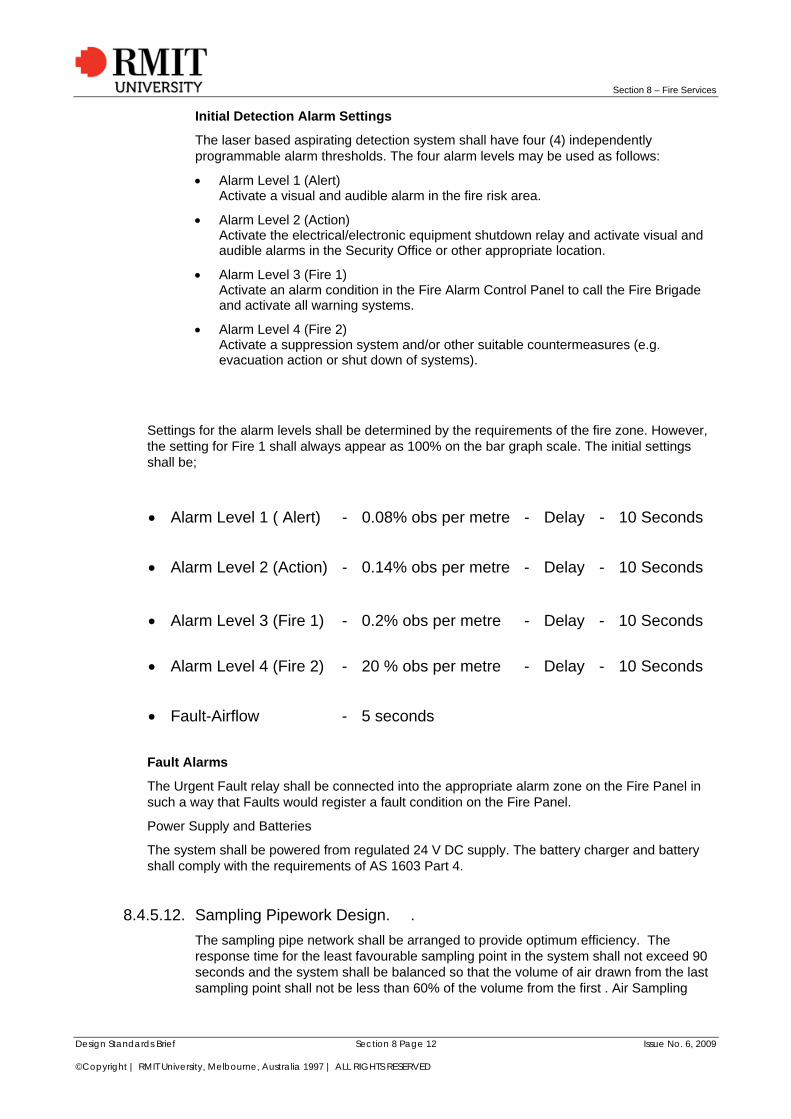
Settings for the alarm levels shall be determined by the requirements of the fire zone. However, the setting for Fire 1 shall always appear as 100% on the bar graph scale. The initial settings shall be;
Alarm Level 1 ( Alert) - 0.08% obs per metre - Delay - 10 Seconds
Alarm Level 2 (Action) - 0.14% obs per metre - Delay - 10 Seconds
Alarm Level 3 (Fire 1) - 0.2% obs per metre - Delay - 10 Seconds
Alarm Level 4 (Fire 2) - 20 % obs per metre - Delay - 10 Seconds
Fault-Airflow - 5 seconds
Fault Alarms
The Urgent Fault relay shall be connected into the appropriate alarm zone on the Fire Panel in such a way that Faults would register a fault condition on the Fire Panel.
Power Supply and Batteries
The system shall be powered from regulated 24 V DC supply. The battery charger and battery shall comply with the requirements of AS 1603 Part 4.
8.4.5.12. Sampling Pipework Design. .
The sampling pipe network shall be arranged to provide optimum efficiency. The response time for the least favourable sampling point in the system shall not exceed 90 seconds and the system shall be balanced so that the volume of air drawn from the last sampling point shall not be less than 60% of the volume from the first . Air Sampling

Section 8 – Fire Services
Design Standards Brief Section 8 Page 13 Issue No. 6, 2009 ©Copyright | RMIT University, Melbourne, Australia 1997 | ALL RIGHTS RESERVED
Network Calculations shall be provided from the ASPIRE (v1.9 or later) modelling software.
PART 3 INSTALLATIONS
8.4.5.13. The Detection system
The contractor shall install the system in accordance with the manufacturer's installation and instruction manual and local codes (AS1670). The Contractor must also be able to provide documentation that indicates individuals performing site works have attended and passed a factory sanctioned VESDA training course, this documentation must include course certification. Note: For certification to be current course must have been completed within two previous years.
8.4.5.14. Sampling Pipe Network
1. All piping shall be supplied and installed in accordance with AS3000; 2. The main sampling pipes shall be grey/white of the PVC electrical conduit type and
comply with AS 2053, be of 25 mm nominal diameter and shall comply with AS1670 (Clause 6.2.3);
3. All changes of direction shall be made with long radius bends; 4. The far end of each trunk pipe shall be fitted with an end cap and drilled with a hole
or holes normally of 2 mm diameter, or otherwise appropriately sized to achieve the performance as specified and as calculated by the system design;
5. All joints shall be air tight and made by using solvent cement, except at entry to detector mounting box;
6. All pipework shall be supported at not less than 1500 mm centres. NOTE: Should the pipe be supplied by parties other than Vision Systems, documentation
will need to be supplied ensuring that said pipe has had an (Anti Static treatment applied to its inner bore surface area)
8.4.5.15. The Sampling Point Network.
Sampling holes of 2 mm diameter shall be separated by intervals not more than as specified in AS1670 and typically in the range of 2 to 8 metre intervals along the length of the pipework.
1. Each Sampling Point shall be identified in accordance with AS1670. 2. Due regard shall be given to AS 1670 and local regulations and the manufacturers'
recommendations in relation to the number of Sampling Points and the distance of the Sampling Points from the ceiling or roof structure and forced ventilation systems.
8.4.5.16. The Capillary Sampling Network.
1. Where false ceilings are installed, Capillary Sampling Points shall be installed. 2. The Capillary tube diameter shall be 5.2 mm ld, the maximum length shall be 1000
mm unless specified otherwise. 3. The performance characteristics of the Sampling Points shall be taken into account
during the system design. 4. Connection fittings shall be made into special sampling pipe couplings.
8.4.5.17. Air Sampling Network Calculations.

Section 8 – Fire Services
Design Standards Brief Section 8 Page 14 Issue No. 6, 2009 ©Copyright | RMIT University, Melbourne, Australia 1997 | ALL RIGHTS RESERVED
Air Sampling Pipe Network Calculations shall be provided by a sampling pipe aspiration modelling program such as ASPIRE™ (latest Version) Pipework calculations shall be supplied with the proposed pipe layout design to indicate the following performance criteria:
Transport Time Local codes or end users standards may also apply. For example:
AS1670, Part 1 Australia 90 Seconds NFPA72 US 120 Seconds BFPSA Code of Practice UK 120 Seconds The maximum transport time must never exceed the local codes. Balance % The sample point balance for the pipe shall not be less than 70% as indicated by ASPIRE. That is, the volume of air drawn from the last sampling point shall not be less than 70% of the average volume of air through the other holes. Share %. The sample hole share for the pipe shall not be less that 70% as indicated by ASPIRE. That is, the sum volume of air drawn through the sampling holes must always be greater than 70% of the total volume of air entering the pipe (i.e. the End Vent must not exceed 30% of the total flow).
8.4.5.18. Commissioning Tests.
1. The contractor shall allow for the manufacturer or their representative to attend the commissioning.
2. All necessary instrumentation, equipment, materials and labour shall be provided by the Contractor.
3. The Contractor shall record all tests and system calibrations and a copy of these results shall be retained on site in the System Log Book and supplied to the end user.
8.4.5.19. System Checks.
1. Visually check all pipework to ensure that all joints, fixing, bends, sampling points, etc., comply with the Specification.
2. Check the system to ensure the following features are operational and programmed in accordance with the specification. o Alarm levels and Indicators, for both day and night; o Set clock function to local time; o Time delays; o Bar graph display; o Air flow fault indicators; o Isolate/Reset buttons;
3. Check to ensure that all ancillary warning devices operate as specified. 4. Check interconnection with Fire Indicator Panel to ensure correct operation.
8.4.5.20. Tests.
1. Introduce Smoke into the Detector Assembly to provide a Go/No-Go Test. 2. Introduce smoke to the least favourable Sampling Point in each Sampling Pipe. Response time is not to exceed ninety (90) seconds and is to be within 15% at the ASPIRE calculation. 3. Activate the appropriate Fire Panel zones and advise all concerned that the system
is fully operational. Fill out the log book accordingly.

Section 8 – Fire Services
Design Standards Brief Section 8 Page 15 Issue No. 6, 2009 ©Copyright | RMIT University, Melbourne, Australia 1997 | ALL RIGHTS RESERVED
8.5. INFORMATION FOR HEARING IMPAIRED PERSONS Refer AS-1428.4 for application, for tactile information.
Emergency warning Strobe Lights shall be installed within all teaching spaces and lecture theatres throughout RMIT. The approved strobe light unit is Redback Dual Strobe model S5424 supplied by Inertia or Altronics, or similar.
When activated the strobe light shall indicate the Alert and Evacuation modes of the alarm warning system.
8.5.1. System Installation The Master Emergency Control Point (MECP) containing all necessary alert and alarm controls and indicators, together with intercommunication facilities shall be located in the main entry foyer. If concealed within a cabinet appropriate signage will be provided to clearly identify the FIP location.
The battery reserve shall be suitable for 72 hours in quiescent conditions and two (2) hours for continuous alarm conditions.
The MECP shall be recessed into a lockable cupboard and shall be appropriately labeled. Door shall be provided with clear Perspex covered window, so that the MECP shall be visible.
Labeling and colour coding of MECP operating panel shall be subject to RMIT approval. The MECP must be compatible to the RMIT addressable existing system.
In a fire alarm situation, this system shall automatically be operated.
The interface between the MECP and the fire alarm system transponders shall be installed.
It shall be the responsibility of the Contractor to ensure the location of the transponder for final termination.
Provide voltage free contacts, relays for connection to the monitoring system (including batteries monitoring).
In area where MECP is located and considered remote, an emergency telephone shall be located besides the MECP and shall be secured.
The systems shall provide the option for cascade operation in all direction. Times for cascading for both alert and evacuation shall be adjustable from 0.5 to 300 sec in .5 intervals.
Alert tone shall incorporate this message: “ALERT, ALERT, and PREPARE TO EVACUATE THE BUILDING”. After every 3 tones or other message as requested by RMIT.
Evacuation tone shall incorporate this message: “ATTENTION, PLEASE EVACUATE the BUILDING. USE THE FIRE STAIRS. DO NOT USE LIFTS” as appropriate, after every 3 tones or other message as requested by RMIT.
During the course of work, when the existing system is made inoperative, temporary measures shall be provided in the form of portable equipment, to all levels.
8.6. SPRINKLER SYSTEMS / FIRE PUMPS All sprinkler systems shall conform to AS 2118-1999, and AS2941-1995.
Diesel hydrant batteries shall be cradled and harnessed in an approved manner.
An Auto test facility shall be installed to the pump set to allow the accurate testing and reporting of cut in pressures.

Section 8 – Fire Services
Design Standards Brief Section 8 Page 16 Issue No. 6, 2009 ©Copyright | RMIT University, Melbourne, Australia 1997 | ALL RIGHTS RESERVED
A Closed Loop Flow Switch Test Circuit similar to a TYCO Zone-check re-circulation system shall be installed on each valve set to ensure that water wastage is minimized.
All drains shall be fitted to pump systems and the test facility and shall run to an appropriate waste.
All flow switches will be fully addressable and networked back to the RMIT Security control room and connected up to the existing fire graphic system.
A pressure relief for the pump as well as system pipe work shall be installed.
A throttle valve is to be installed to allow for accurate flow readings.
All pumps shall be installed with Mechanical Seals only.
All Gauges shall be installed with a ball valve to enable the service or replacement of the gauge.
Doors to pump rooms will be signed appropriately with details of the building that the fire pump services.
8.6.1. Hydrant/Hose Reel Systems Hydrant systems shall be designed in accordance with AS1221& AS2419 and where a building is less than 25m high and the required fire hose reels are also installed then the requirement for hydrants to be equipped with lay flat hose may be deleted. Dispensation should be sought from Building Referees Board. Where buildings are being refurbished or services upgraded the Relevant Building Surveyor shall include within the Building Permit for the removal of existing internal fire hydrant canvas hoses. The Building Surveyor shall make application under Regulation 2.2 for the consent of the Chief Fire Officer for the removal of the existing canvas hoses.
All Fire Reels are to be 36 Metres in length. Only Fire Master (Tyco) or equivalent will be used, Fast- Fit or Quick- fit Hose Reels will not be installed within RMIT. All Hose reels are to be installed with a Gate Valve fitted to allow the removal of the fire hose reel for servicing and or replacement.
At ground level provide external fire hydrants in preference to equipped internal hydrants.
All hydrants are to be fitted with storz couplings suitable for use by the MFB.
Valves are to be packed stuffing box type in preference to o-ring type of similar manufacture. Valves below ground to be sluice type. After installation provide RMIT with at least one key. Locate below ground valves in “Gatic” type Hinged valve boxes.
Exposed fire service pipe work, Cabinets, valve box covers, etc are to be painted fire safety red.
Provide pressure gauges at the supply point and at highest point on the fire hydrant riser.
8.7. FIRE HYDRANTS: - LOCATION SIGNAGE Centre Road Type
A Blue reflective luminous indicator.
A red arrow painted on yellow reflective background with blue reflective indicator.
Footpath Type
A Blue reflective luminous indicator.
A black HR on white reflective background fixed to a 500mm high upright post of 100 x 75 steel RHS and painted red.
Door Signs
A door sign strip 600 mm long with the words - “Fire Hydrant”

Section 8 – Fire Services
Design Standards Brief Section 8 Page 17 Issue No. 6, 2009 ©Copyright | RMIT University, Melbourne, Australia 1997 | ALL RIGHTS RESERVED
Fire Booster cabinets
All Fire Booster cabinets will be installed in accordance with AS2419.1. Each Fire Booster cabinet will have an installed detailed Block Plan, which shall be laminated, framed and installed within the Fire Booster cabinet.
All cabinets shall be fitted with lock cylinders which shall be keyed to CL 003 locks
A sign shall be placed on the front of the cabinet not less than 150 mm high in a contrasting colour, it will state “Fire Booster Cabinet “and the name of the building
E.g. - FIRE BOOSTER “Building 101”
8.7.1. Portable Fire Extinguishers Locations of portable fire extinguishers are to be in accordance with the BCA.
Refer to AS2444 for the provision of fire extinguishers as a minimum requirement.
8.7.2. Independent Certification A written report shall be provided from an independent approved Certifier at the completion of installation of each active system or refurbishment works. Independent approved Certifiers shall be registered with the Australian Fire Safety Practitioners’ Accreditation Board.
Where defects are noted by the Certifier these shall be rectified prior to practical completion unless otherwise approved by the University. The written report from the independent Certifier, shall confirm that no defects were noted in the inspection and a copy of the report included in the Operation and Maintenance Manual.
Test at completion of the works shall include:
Test reports on db (A) levels in all areas, or as directed by the RMIT Fire Safety Engineer / his appointee. Ambient and tested db (A) levels shall be recorded and tabulated.
The Contractor and Specialist Contractors shall provide the services of competent personnel to instruct the appropriate University personnel in the operation and maintenance of the installed systems. Detailed instruction in the operation of the system and all microprocessor-based control functions shall be provided.
The RMIT Fire Manager Engineer or delegate is to witness all tests.
Formal certification by the Qualified Independent Certifier shall be provided to the Project Manager, RMIT Manager Fire Engineering confirming the adequacy and compliance of the installation, prior to the issue of the Certificate of Practical Completion.
Provide literature and operating instructions in terminology understandable to non technical personnel. (Refer also to Clause 1.8.16 Operating and Maintenance Manuals).
8.7.3. Pipe Identification All internal exposed pipe work is to be painted to match the colour of the adjacent surfaces and in external areas pipes are to be painted “Fire Red” and identified.
Fire stopping of wall / floor penetrations.
To prevent the spread of flame and smoke spread in the event of fire, all penetrations through fire rated walls and floors must be sealed with an approved fire barrier. The RMIT approved product for use within RMIT buildings is KBS Mortar Seal or similar. No other product may be used without the written approval of the RMIT Fire Engineer Applicable Codes and Standards.
All work to be completed in accordance to AS- 4072. 1 1992 and these guidelines.

Section 8 – Fire Services
Design Standards Brief Section 8 Page 18 Issue No. 6, 2009 ©Copyright | RMIT University, Melbourne, Australia 1997 | ALL RIGHTS RESERVED
Control joint fire stopping in accordance with AS-4072.1 1992.
Service penetration fire stopping systems, to BCA Section C3.15 and specification C3.15.
Fire Resistance tests of building elements AS- 1530 Part 4.
Ensure that all penetrations to the Works and perimeters to fire walls are stopped to the required FRL. The work shall include but not be limited to the following:
Floor control joints: Provide fire stopping to control joints to FRL -/120/120.
Wall control joints: Provide fire stopping to joints to the FRL on the drawings.
Penetrations to Floor Slabs: fire stopping to all concrete slabs, excluding slab on grade. Fires stop new penetrations to FRL -/120/120. Fires stop the floors on any non fire rated ducts at each and every floor level. The floors of any fire rated fire rated ducts are not required to be fire stopped, excepting the bottom and top level of the duct. The walls of the fire rated duct shall be fire stopped throughout the length of the duct.
Penetrations to fire rated walls: Fire stop all penetrations to the required FRL indicated on the drawings.
+/- 5mm should be allowed for vertical movement at the isolation joint (10mm in total)
+/- 10mm should be allowed for horizontal movement at the joints, however about 70% of this movement is likely to occur in the first 9 months after installation (20mm in total).
8.7.4. Inspections Contractors are to conduct inspections and carry out remedial works and certify fire stopping systems using these guidelines.
The inspector must be from a licensed company registered with the BSA in the appropriate Category for this type of work. i.e. Passive Fire Equipment / Wall and Ceiling Linings. Details and proof of licensing must be provided to RMIT before the Contractor is able to commence works.
The Company conducting Inspections and certifying works must also provide details and proof of their current Public Indemnity Insurance Policy.
The nominated persons carrying out the inspections must provide details of their experience in the field of fire stopping installation and must be a competent person as defined in the Standard Building Regulations and Building Act.
Documentation required by RMIT on completion of the inspections is to be completed in the following manner and be in the format as suggested by AS4072.1 (see fig 1.).
On completion of each area of work submit to RMIT, a penetration schedule in the form appended identifying each penetration according to the Space Designation Number from the contract drawings (see fig 1).
Floor plans indicating fire compartments and fire wall locations;
Record drawings (as constructed plans) showing each area referred to in the Penetration Schedule The penetration schedule is to be completed and returned and will become part of the Operation and Maintenance manuals. REFER AS4072.1;
Proforma drawing and schedule available from RMIT;
Format 2 sets of drawings in auto cad format and 1 set of hard copy drawings, for archiving in the Fire Services operations and Maintenance Manuals.
Details of the information required under the headings on these forms are as follows:
Floor/Level

Section 8 – Fire Services
Design Standards Brief Section 8 Page 19 Issue No. 6, 2009 ©Copyright | RMIT University, Melbourne, Australia 1997 | ALL RIGHTS RESERVED
The actual floor or level the penetration is on. E.g. Basement, Ground etc. Floor plans are required to accurately indicate the location of all fire walls & compartments.
Penetration No.
The exact location of the penetration in conjunction with the corresponding number on a floor plan. (see fig 1). Also see attached sample of identification label. (fig 3)
Penetration Type
The penetration size and element of construction through which the penetrant is passing. E.g. 300 x 300 penetrations through concrete.
Wall, Floor, Ceiling
All penetrations will be listed according to the side appropriate to the type, location and size appropriate to the Fire Rated barrier. i.e. if the barrier is sealed with a mortar system in the slab it will be a floor penetration, if it is sealed by a product being mounted to the underside of slab it will be a ceiling penetration, if sealed at the wall it obviously will be listed as a wall penetration. To show the placement of the penetration. W, F, C to be used.
FRL: Structural Adequacy, Integrity, Insulation.
Details of the actual fire rating the barrier shall give once completed with regards to the element of construction. E.g. -/ 120/ 120 or -/120/ -.
Service description: size x no. of - .
The actual number of, size and type of services in the penetration. E.g. 2 x 150mm copper pipes, 6 x 10mm electric cables, 65mm PVC pipe or similar description.
Treatment Code: - this is to show the actual products or system that has been or will be used to protect the penetration. E.g. fire collars or mortar system. If a product or system cannot correctly protect a penetration or system (with the evidence of compliance) RMIT must be informed immediately.
8.7.5. Requirements Installation Method
Give a brief description of how the product is to be installed.
Test Report Ref.
The actual test report or assessment number given to the product or system by the appropriate testing or assessing authority. Eg NI. 1189 or C 91624.
8.7.6. The use of Fire Pillows is not permitted by RMIT
8.7.6.1. Installation
The installer must hold a license registered with the BSA in the appropriate Category for this type of work. i.e. Passive Fire Equipment / Wall and Ceiling Linings. Details and proof of licensing must be provided to RMIT before the Contractor is able to commence works.
The standards to which the products are to be tested are AS1530.4 & AS4072. 1. Or assessed to these Standards. Standards from other countries can also be used as long as there is proof of evidence of compliance given by the appropriate authorities, e.g. CSIRO, SSL or an appropriately qualified fire engineer.

Section 8 – Fire Services
Design Standards Brief Section 8 Page 20 Issue No. 6, 2009 ©Copyright | RMIT University, Melbourne, Australia 1997 | ALL RIGHTS RESERVED
A competent person as defined in the Building Act and Standard Building Regulations must carry out installation of the products and systems. Evidence of the installers’ experience in installing Passive Fire Systems must be provided to RMIT before commencement of installation of works on site.
Installation of the barriers must be carried out strictly in accordance with the documentation provided by the product manufacturers and or the approval documentation showing drawings of the tested prototype.
On completion of each fire system there will be a label fixed to the substrate close to the penetration (not located on the floor). It is labelling to identify each penetration from the contract documents. In relation to floor, ceiling and wall penetrations where there are adjoining rooms this label will be fixed to both sides of the substrate (see fig 3 for sample label).
THE USE OF FIRE PILLOWS IN PENETRATIONS IS NOT PERMITTED BY RMIT REQUIREMENTS.
A competent person as defined in the Building Act and Standard Building Regulations must carry out installation of the products and systems. Evidence of the installers’ experience in installing Passive Fire Systems must be provided to RMIT before commencement of installation of works on site.
8.7.6.2. Materials
Material Safety Data sheets on all materials to be used in the installation are to be supplied to RMIT.
Ensure materials have not exceeded their shelf life when used.
Only asbestos free materials are to be used.
In fire conditions materials are to be Non Toxic.
Non corrosive materials.
Supply ventilation for nonaqueous solvent cured materials.
Install materials at a uniform density.
Maintain cable separation.
Fire stopping materials exposed to view must be finished to a uniform condition.
Only currently tested and approved products to be used.
Provide Fire Stopping capable of supporting the same loads as the surrounding element or provide structural support around the opening.
8.7.6.3. Preparation
Loose or damaged barriers must be removed and replaced.
Protection of adjacent surfaces from damage arising from installation of new barriers. New barriers must be protected from damage arising from other works.
Remove all materials that do not satisfy the required FRL and prepare for new installation.

Section 8 – Fire Services
Design Standards Brief Section 8 Page 21 Issue No. 6, 2009 ©Copyright | RMIT University, Melbourne, Australia 1997 | ALL RIGHTS RESERVED
Figure 1
Floor Level
Grid Ref. No. Penetration Type
Wall (W) Floor (F)
Ceiling (C)
FRL: Structural adequacy/ integrity/ insulation min./min./min.
Service description dia (size) x No. off or
Group opening mm x mm
Treatment code No.(s)
Installation method (data sheet ref. No.)
Test report ref.
3 1 20mm core hole in
concrete wall W ,-/ 120/120 1 phone cable thru wall Fyreflex Sealant
Fyreflex Sealant applied to a depth of 30mm in slab thickness plus a fillet around exit areas
NI. 1189
3 2 350 x 350
penetration thru concrete slab
F ,-/ 120/120 150mm Copper pipe Surface mounted Mortar System
80mm thick layer of Fyreset Lightweight Mortar surrounded by "Z" section lapping opening in
slab NI. 3089
3 3 350 x 350
penetration thru concrete slab
F ,-/ 120/120 150mm Copper pipe Surface mounted Mortar System
80mm thick layer of Fyreset Lightweight Mortar surrounded by "Z" section lapping opening in
slab NI. 3089
3 4 600 x 300
penetration thru concrete slab
F ,-/ 120/120 Multiple cable penetration Fyreflex Sealant Bead of Fyreflex Sealant around cable sheaths
3 5 1000 x 200
penetration thru concrete slab
F ,-/ 120/120 Multiple cable penetration thru
concrete slab Vermiculux Board and
Fyreflex Sealant
60MM Vermiculux fixed to masonry floor or wall at min. 300 ctrs with masonry anchors. All
penetrations sealed with Fyreflex DAS 4.03
Assessment No. FCO-
1720
3 6 350 x 350
penetration thru concrete slab
F 120/120/- 150mm Copper pipe Surface mounted Mortar System
80mm thick layer of Fyreset Lightweight Mortar surrounded by "Z" section lapping opening in
slab NI. 3089
3 7 30mm Core hole thru concrete wall
W 120/120/- 20mm Flexi conduit Fyreflex Sealant Fyreflex Sealant applied to a depth of 30mm in
slab thickness plus a fillet around exit areas NI. 1189
3 8 65mm penetration thru concrete wall
W 120/120/- 65mm core hole with bunch of
cables thru Fyreflex Sealant
Fyreflex Sealant applied to a depth of 30mm in slab thickness plus a fillet around exit areas
NI. 1189
3 9 150 x 100
penetration thru concrete slab
F 120/120/- Multiple Data cables thru floor
penetration Vermiculux Board and
Fyreflex Sealant
60MM Vermiculux fixed to masonry floor or wall at min. 300 ctrs with masonry anchors. All
penetrations sealed with Fyreflex DAS 4.03
Assessment No. FCO-
1720

Section 8 – Fire Services
Figure 2
THIS PENETRATION HAS BEEN INSPECTED BY:
CAUTION: FIRE RATED BARRIER DO NOT DISTURB. BEFORE MODIFICATION CONTACT: PROPERTY SERVICES 9925 1070
TO AS4072.1
F.R.L. THIS BARRIER IS MAINTAINED BY
/ /
BUILDING PENETRATION NO
COMPLIANT TO AS4072.1 200
INSTALLATION BY. JAN FEB
DATE MAR APR
CERTIFICATION BY MAY JUN
BSA NO JUL AUG
SEP OCT
NOV DEC
8.7.6.4. Fire Doors / Smoke Doors
Signage: - "FIRE EXIT - DO NOT OBSTRUCT" in letters not less than 50mm high and in a colour contrasting with that of the door, must be fixed to the following:
1. A required fire door providing direct access to a fire isolated exit, except a door providing direct access from a sole-occupancy unit in a Class 2 or 3 building or Class 4 part of a required smoke door, on the side of the door that faces a person seeking egress; and
2. A fire door forming part of a horizontal exit and a smoke door that swings in both directions, on both sides of the door; and
3. A door leading from a fire isolated exit to an open space, on both sides of the door. Upon the completion of any fire door installation, a certificate of compliance and the correct tagging of the door must be completed and issued to RMIT in accordance with AS1905.1:1997.
All Fire doors located externally to a building shall be sheathed in colour bond steel of a colour approved by RMIT.
All Rails and Stills on Fire Doors shall be sealed with paint prior to installation.
Fire Door Signage will be supplied to the installer by RMIT.
Where Magnetic Hold open devices for doors are required, wall or floor mounted magnets shall be used incorporating a release button, with standard door closers fitted separately.
Combination door closers and magnetic hold open units will not be allowed to be installed without built in remote release buttons.
A Lockwood door closer Model No 7766SSS
A Lockwood Primary Lock Model No 3572SC
For alternate equipment seek approval from RMIT.
8.7.7. Door Sequence Device The RMIT preferred Door Sequence Device is the COR Series Coordinators as supplied by Glynn Johnson. For alternate equipment seek approval from RMIT.
Design Standards Brief Section 8 Page 22 Issue No. 6, 2009 ©Copyright | RMIT University, Melbourne, Australia 1997 | ALL RIGHTS RESERVED
Section 8 – Fire Services
Design Standards Brief Section 8 Page 23 Issue No. 6, 2009 ©Copyright | RMIT University, Melbourne, Australia 1997 | ALL RIGHTS RESERVED
8.7.8. Egress Provisions * Refer to the Victorian Building Fire Safety Regulations and the Victorian Fire Authority Act.
Provide sign with a 1:200 plan (or as agreed) of each floor of the building including the following information:-
The name of the Building / Floor number or area description.
A brief statement of evacuation procedures:-
Alert Fire Brigade and other assistance required (push button alarm or telephone number (ext. 53333 Emergency all hours at RMIT security).
Warn Personnel in the vicinity
Evacuate the building, if necessary
Follow directions of building warden
Proceed to nominated assembly area
“If safe, confine the fire or other source of danger”
A floor or area plan showing the location of:-
fire exits and escape routes
manual alarm points
fire extinguishers and fire hose reels
WIP Locations
The names (and telephone numbers) of the:-
Building Warden (and deputy)
Floor or Area Warden (and deputy)
Note: There may be some variation in the detail for the sign depending on the site and building (e.g. the location or otherwise of manual alarm points and the relevant emergency number for the building). The names and telephone numbers of building and floor wardens are dealt with separately by RMIT).
Floor Plan Features: The floor plan must clearly show corridors rooms and exits. Symbols for the plan to be based on ASHB20 Graphical symbols for fire protection drawings. Symbols for the fire extinguishers and hose reels to be coloured red and the symbols for egress paths and exits coloured green. The plan to be drawn so that when it is mounted on the wall it is correctly oriented, with respect to the building.
The plans will have a “you are here” symbol. Liaise with RMIT as to the number and locations on floors and in Lecture Theatres.
Plans to be provided to RMIT in AutoCAD format with the profile plan X referenced in and all Evacuation information on Evac layers. A prototype drawing is available from RMIT.
8.7.9. Drawings Note: - A copy of the appropriate as-installed drawings to be located in the fire panel.

Section 8 – Fire Services
Design Standards Brief Section 8 Page 24 Issue No. 6, 2009 ©Copyright | RMIT University, Melbourne, Australia 1997 | ALL RIGHTS RESERVED
8.8. OPERATING/ MAINTENANCE MANUALS
8.8.1. Maintenance
8.8.1.1. General
The sprinkler system shall be tested in accordance with AS1851 Section 3 – 2005
Portable Fire Extinguishers shall be tested in accordance with AS1851 Section 1 – 2005
Fire Hose Reels shall be tested in accordance with AS1851 Section 2 – 2005
Fire Hydrant Installation shall be tested in accordance with AS1851 Section 4 – 2005
Automatic smoke/heat venting systems shall be tested in accordance with AS1851 Section 5– 2005
Maintenance of smoke control/air handling systems shall be tested in accordance with AS1851 Section 6 – 2005
Fire resistant door sets shall be tested in accordance with AS1851 Section 7 – 2005
Fire detection / alarm systems shall be tested in accordance with AS1851 Section 8 – 2005
EWIS Systems shall be tested in accordance with AS1851 Section 10 – 2005
Gaseous Fire systems shall be tested in accordance with AS1851 Section 12– 2005
Pump set systems shall be tested in accordance with AS1851 Section 14 – 2005
During the defects liability period, the fire service contractor shall attend to any emergencies within 2 hours of being notified, and promptly rectify any faults.
8.8.1.2. Maintenance Field Logbooks
The consultant shall initiate the preparation of field logbooks by the installing contractor prior to Practical Completion and monitor their use throughout the Defects Liability Period to record actual maintenance carried out.
Field log books shall be provided for essential and non essential services.
Each of these field logbooks shall be located within the facility, or as directed by the Maintenance Operations Manager.
8.8.2. Housekeeping RMIT shall be issued with an OH&S work safety plan and a Safe Work Method Statements (SWMS) prior to any work commencing.
8.8.3. Operation and Maintenance Manuals Detailed instructions shall be included in the Tender Specification for the preparation and supply of Operation and Maintenance Manuals. (Refer Section 1 Clause 1.10.11 – 1.10.15).
Initiation of the services contractor’s preparation of the draft Operations and Maintenance Manual is the responsibility of the Principle Consultant at the point of time when the detailed engineering of the systems is completed and approval has been given for all equipment and materials. The expected timing of the submission of the draft Manual is half way through the construction period.
The Consultant shall require the Main Contractor to first check the draft Manual for its compliance with the set format before its submission, to the RMIT Manager Fire Engineering and Project Manager, for acceptance and the final Manual is to be signed as approved by
Section 8 – Fire Services
Design Standards Brief Section 8 Page 25 Issue No. 6, 2009 ©Copyright | RMIT University, Melbourne, Australia 1997 | ALL RIGHTS RESERVED
the Consultant after approval of content by RMIT’s Manager Fire Engineering and Project Manager.
The minimum configuration of an Operation and Maintenance Manual shall comprise:-
The title and description of the works
A list of designers, contractors and sub-contractors
A description of the plant
Plant operation and operation instructions, fault diagnostic & remediation
A schedule of all items of equipment and suppliers
Installation details
A fully detailed description of the automatic control systems
Commissioning, Testing and Balancing Reports
A copy of the FIP Program.
A copy of the EWIS program
Maintenance schedule and manufacture’s literature on maintenance and service of each item of plan
Detailed drawings and Wiring Diagrams (As Installed) showing equipment addresses and DB levels throughout all area’s.
Certification of Compliance
Installers statements
Cause and Effect Matrix
Warranty Certificates
Other information relevant to the betterment of the plant maintenance requirements.
8.8.4. Installation Drawings All installation “As-Built” drawings shall also be produced on the latest version of the Auto Cad software program with the version identification clearly marked on double sided density diskettes or CD/DVD. Details of the software program including version number and printer data shall be included on the label.
As-built drawings shall accurately reflect the installation and all essential services. Each component shall be allotted an asset tag. Refer also to Section 1, Clause 1.8.14 for a detailed treatment of the requirements for these drawings.
The signature of the contractor, the main contractor and the services consultant shall be clearly displayed on each drawing.
8.9. CERTIFICATE OF OCCUPANCY / CERTIFICATES OF FINAL INSPECTION
8.9.1. Defects List The defects list shall make provision for the contractor to sign and date each as completed, and the consultant to sign and date each defect to verify acceptance of the work. Crossing out each item that is rectified is not permitted.
Rectification of all defects is to be monitored by the consultant during the Defects Liability Period.

Section 8 – Fire Services
Design Standards Brief Section 8 Page 26 Issue No. 6, 2009 ©Copyright | RMIT University, Melbourne, Australia 1997 | ALL RIGHTS RESERVED
8.9.2. Practical Completion The Building Services Consultant shall oversee the preparation by the contractor all project defect lists, ensuring attendance of the RMIT Fire Safety Engineer a detailed inspection of the facility. All defects relevant to essential services must be rectified before Occupation and the Certificate of Practical Completion is issued.
The Consultant shall sign as final (1) copy of the Operation & Maintenance Manual, and a full set of as-built drawings, as approved, before either of these are offered to RMIT University for acceptance (refer to Presentation of as-installed drawings”, Clause 1.8.14 Section 1 of this Brief). This is to include a set of Essential Services plans that show asset tag references for each component utilizing designations that are compatible with the RMIT system. He shall also ensure the trade sub-contractor has set up field logbooks, utilizing the essential services maintenance schedules and preventative maintenance schedule (Refer Appendix 1.E, 1.E.1 & 1.K.1 of this Brief), and that the contractor uses these during the Defects Liability Period to record maintenance carried out.
Prior to the issue of the Certificate of Practical Completion the Consultant shall via the Principal Consultant provide to the University certification by the contractor that the equipment, plant and services comply with the documentation and are in a condition that it is fit for purpose in accordance with industry practice and warranties.
The Consultant shall initiate the training of nominated RMIT Fire Engineering and Plant technician personnel in the operation and maintenance of the installed systems - all as detailed in Clause 1.8.10, Section 1 of this Brief. He shall vet the agenda for training prepared by the contractor, and shall be in attendance at both the classroom and field training sessions to verify the design intent. As stated elsewhere in this Brief, the approved 0 & M Manual and approved as-installed drawings are to be used in this training.
Only at the conclusion to this training, and provided the contractor has fulfilled all other obligations, will the Certificate of Practical Completion be issued.
8.9.3. Defects Liability Period (DLP) The Building Services Consultant shall receive from the installing contractor a copy of all completed maintenance schedules from the field logbooks. He shall monitor this activity throughout the DLP, as well as study the schedules to ensure maintenance is being carried out to the standards and requirements that reflect best practice. Refer to Clauses 1.1.14 & 1.1.15.
One month before the expiration of the DLP a joint inspection between the installation contractors, the Consultant and RMIT’s Manager Fire Engineering shall be conducted. This inspection shall include a check that all defects allocated have been rectified. It shall include an inspection of the general condition of all plant and systems for its cleanliness and correct operation. RMIT’s intent is that the plant and systems are as close to being in “as new” condition as can reasonably be achieved for the formal hand-over.
Only at the successful conclusion of the above will a Final completion be issued by the University releasing the consultants and the constructor from his contractual obligations.
8.9.4. Radio Interference/Lightning In the event of such interference being detected in the system installation, rectification shall be provided without cost to RMIT.
Section 8 – Fire Services
Design Standards Brief Section 8 Page 27 Issue No. 6, 2009 ©Copyright | RMIT University, Melbourne, Australia 1997 | ALL RIGHTS RESERVED
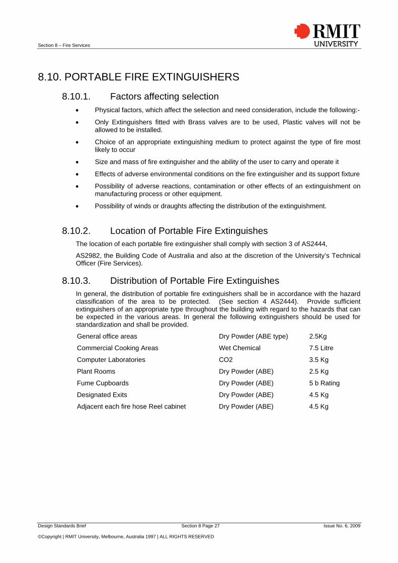
8.10. PORTABLE FIRE EXTINGUISHERS
8.10.1. Factors affecting selection Physical factors, which affect the selection and need consideration, include the following:-
Only Extinguishers fitted with Brass valves are to be used, Plastic valves will not be allowed to be installed.
Choice of an appropriate extinguishing medium to protect against the type of fire most likely to occur
Size and mass of fire extinguisher and the ability of the user to carry and operate it
Effects of adverse environmental conditions on the fire extinguisher and its support fixture
Possibility of adverse reactions, contamination or other effects of an extinguishment on manufacturing process or other equipment.
Possibility of winds or draughts affecting the distribution of the extinguishment.
8.10.2. Location of Portable Fire Extinguishes The location of each portable fire extinguisher shall comply with section 3 of AS2444,
AS2982, the Building Code of Australia and also at the discretion of the University’s Technical Officer (Fire Services).
8.10.3. Distribution of Portable Fire Extinguishes In general, the distribution of portable fire extinguishers shall be in accordance with the hazard classification of the area to be protected. (See section 4 AS2444). Provide sufficient extinguishers of an appropriate type throughout the building with regard to the hazards that can be expected in the various areas. In general the following extinguishers should be used for standardization and shall be provided.
General office areas Dry Powder (ABE type) 2.5Kg
Commercial Cooking Areas Wet Chemical 7.5 Litre
Computer Laboratories CO2 3.5 Kg
Plant Rooms Dry Powder (ABE) 2.5 Kg
Fume Cupboards Dry Powder (ABE) 5 b Rating
Designated Exits Dry Powder (ABE) 4.5 Kg
Adjacent each fire hose Reel cabinet Dry Powder (ABE) 4.5 Kg