proof-of-concept prototyping for observis platform - Theseus
110
Ekimov Victor PROOF-OF-CONCEPT PROTOTYPING FOR OBSERVIS PLATFORM Bachelor’s Thesis Information Technology March 2012
Transcript of proof-of-concept prototyping for observis platform - Theseus

Ekimov Victor
PROOF-OF-CONCEPT
PROTOTYPING FOR OBSERVIS PLATFORM
Bachelor’s Thesis Information Technology
March 2012

DESCRIPTION
Date of the bachelor's thesis
05.03.2012
Author(s)
Ekimov Victor
Degree programme and option
Information Technology
Name of the bachelor's thesis
Proof-of-Concept Prototyping for Observis Platform Abstract Observis Oy is a start-up company first appeared in January 2011. The company is building up a measurement platform that is open and easy to connect. It helps measurement device suppliers, system and service providers, and analyzing services to found and combine each other’s products to create more value to the end customers. Observis Oy intends to develop a plat-form for integration with other services in order to provide management functionality in environmental field of business. Platform is expected to provide user-friendly way of presenting the data as well as comprehensive administration functionality. Service must be accessible directly from the cloud, implementing the idea of Software As a Service (SaaS) in its pure manner. Scalabil-ity must be considered as a key aspect, since integration of new devices and services must be done within limited time period. The problem domain lays in the software development concept. Development team has been never experienced the technology before, resulting to a number of risks in that area. Because of the innovation nature of the platform, requirement became un-clear; software design became more complex and unpredictable. Number of questions remains unanswered, such as interpre-tation of the existing spatial database scheme coming from 52°North company and decision on the most suitable programming language framework. The goal of the project was a proof-of-concept prototyping for GEO informatics platform development. From the requirement specification and analysis of the future system and its expected functionality the general understanding was archived and con-verted into system design. Gained knowledge was immediately applied for implementing the most important parts of functional-ity in order to learn more about problem domain. Throughout the constant implementation, testing and changes of the require-ments prototype was able to highlight the solution domain. Moreover, prototype has been used as on the presentation of the Observis Oy as a possible predecessor of Observis Platform. Usage of the throw-away prototype methodology proved the ability to develop such a platform, defining boundaries, limitations and in-depth understanding of the solution domain. On the last development stage prototype reached the point, where it be-came suitable for promotion of the Observis Oy and discovered new exiting possibilities to study and research. Combination of the professional experience from Observis Oy development team and the knowledge of the newly released technology from MUAS’s practical trainee lead to the new dawn of the future leading Finnish company.
Subject headings, (keywords)
Java EE, JPA, EJB, JSF, JDBC, Hibernate, Wicket Framework, AJAX, jQuery, XML, XSL, JSON, SOAP, RESTful, OpenFlashChart, SOS, PostgreSQL, PostGIS, Apache Tomcat, Jetty, OpenLayers Pages Language URN
95
English URN:NBN:fi:amk-201203052838
Remarks, notes on appendices
Tutor
Matti Koivisto
Employer of the bachelor's thesis
Observis Oy

CONTENTS
1 INTRODUCTION ...................................................................................................... 1
1.1 Observis Oy ......................................................................................................... 2
1.2 52°North .............................................................................................................. 3
2 ENTERPRISE TECHNOLOGY ARCHITECTURE ................................................. 3
2.1 Cloud Computing ................................................................................................ 4
2.1.1 Software as a Service ................................................................................. 5
2.2 Geographic Information System ......................................................................... 7
2.2.1 Mercator Projection .................................................................................... 7
2.2.2 OpenLayers Structure................................................................................. 9
2.3 SensorML — Cleveland Volcano ..................................................................... 11
3 SOFTWARE DESIGN ............................................................................................. 12
3.1 Architectural Styles ........................................................................................... 12
3.1.1 Layered Style ........................................................................................... 13
3.1.2 Multi-Tier Architecture ............................................................................ 15
3.1.3 Model-View-Controller ............................................................................ 33
3.1.4 Service-Oriented Architecture ................................................................. 34
3.2 Software Patterns ............................................................................................... 39
3.2.1 Adapter ..................................................................................................... 41
3.2.2 Facade ...................................................................................................... 43
3.2.3 Proxy ........................................................................................................ 45
3.2.4 Singleton .................................................................................................. 47
3.2.5 Observer ................................................................................................... 48
4 SOFTWARE DEVELOPMENT PROCESS ............................................................ 51
4.1 Software Development Methodology ............................................................... 52
4.1.1 Throw-Away Prototype ............................................................................ 53
4.2 Requirement Analysis and Specification .......................................................... 55
4.2.1 52°North Sensor Observation Service ..................................................... 58
4.2.2 Functional Requirements ......................................................................... 61
4.2.3 Non-Functional Requirements ................................................................. 63
4.2.4 Scenarios and Use Cases .......................................................................... 65
4.3 Software Architecture and Design .................................................................... 73
4.3.1 Yahoo Fetcher .......................................................................................... 74

4.3.2 Data Browser ............................................................................................ 76
4.4 Software Implementation and Testing .............................................................. 78
4.4.1 Yahoo Fetcher .......................................................................................... 78
4.4.2 Data Browser ............................................................................................ 80
4.5 Software Deployment and Maintenance ........................................................... 86
4.5.1 User Interface of the Prototype ................................................................ 87
5 CONCLUSION ........................................................................................................ 93
REFERENCES ............................................................................................................. 95
APPENDICES .............................................................................................................. 96
Appendix 1 OpenLayers JavaScript with map and marker layout .......................... 96
Appendix 2 Cleveland Volcano SensorML description .......................................... 98
Appendix 3 Prevent the jsessionid key in URL for displaying the GMaps .......... 100
Appendix 4 YahooFetcher main logic .................................................................. 101
Appendix 5 YahooFetcher fetch the weather data from YahooWeather API ....... 102
Appendix 6 YahooFetcher save the fetched data into XML ................................. 102
Appendix 7 YahooFetcher transform the saved XML using XSLT rules ............. 103
Appendix 8 YahooFetcher additional data replacing in saved XML .................... 103
Appendix 9 YahooFetcher check whether sensor exists or not ............................ 104
Appendix 10 YahooFetcher populate the XML via SOS ...................................... 105

1
1 INTRODUCTION
For the past decades internet has experienced significant growth and impact of it to the society
became more valuable than other social media. Openness, ease of use and accessibility of
internet lead many people to be involved into developing and advertising goods as well as
communicating with each other. As time went on, internet became a tool not only for personal
discussions, but for making real deal as well. It all started at 6 August 1991, when the first
web site was build at CERN (European Organization for Nuclear Research) becoming the
oldest web site on the world.
Naturally, large business came to an idea of getting advantage from newly emerged area by
presenting new types of business solutions. Those solutions required comprehensive devel-
opment strategy and full understanding of problem domain as a combination of economical
and technical skills. Key advantage over common product was the ability to provide service
on demand, without wasting resources on something, which will not give back.
Meanwhile, society started to pay more attention to environmental impacts of power plants
and ecology-related detection devices. Geographical structure moved towards information
technology, resulting in number of consortium and development techniques creation. Spatial
database schemes were introduced in form of stack-build on top of the regular database. Large
influence was made in web area, such as SensorML and Sensor Web. GEO informatics be-
came more popular, especially in countries with significant environmental presence.
In this thesis I will take a look at Software Engineering impact on environmental business
idea development. Throughout the thesis I will introduce the theoretical foundation of enter-
prise development architecture, new influence of GEO-informatics, software engineering
techniques and particular example of software development process, which was done in form
of proof-of-concept prototyping serving as predecessor for Observis Platform.
The Observis Platform will consist of components, which will be responsible for gathering the
measurement data, storing it in GIS database and providing a user friendly interface with
maps and graphics, accessible via internet. Thus the aim of my study is to prove the feasibility
of such system by developing a prototype.

2
1.1 Observis Oy
Observis Oy is a start-up Eastern Finnish company, located in Mikkeli. It started at the begin-
ning of the 2011 year with solid experienced team members, who wanted to take a step into
unknown field of environmental-oriented data retrieving and information processing. Com-
pany idea was to provide automatisation of customers business throughout all stages of opera-
tions as well as administrative functionality.
Target group of customers are environmental companies, needed a flexible, scalable, reliable
and on demand accessible solution to manage and monitor their hardware equipment. Con-
verting faceless data into presentable information flow was a key concept. Nevertheless, the
system should keep itself up-to-date because new technologies and devices are popping out
rapidly.
Problem domain of the customers consists of following things:
Ability to add new measurement devices quickly
Viewing and exporting statistic information
Monitor the state of the measurement device
Explore geographical locations and supporting information on the map
Presenting information in user-friendly format (charts and tables)
Process the information for analysis purpose
Manage the existing devices
Business needs a tool to solve those issues. For that purpose Observis Platform has been de-
fined as a possible solution. Developing such a platform from scratch could become a com-
plex task, may be even impossible. Because of that, company decided to decompose problem
into smaller pieces and start building a prototype, showing the solution for the most important
parts. As time goes on, prototype will growth and cover more and more of the problem do-
main till it covers it all, turning itself into solution domain. After that exploration, company
will be able to develop Observis Platform, based on the knowledge and requirements, gath-
ered at the prototyping stages.
Success of the Observis Oy depends on that platform, since that it covers the target market of
the company and remains the major innovative product compare to other companies.
3
1.2 52°North
52°North is a German R&D company form relatively small city of Münster, which happened
to intersect the 52° degree latitude. That is really creative; every company should be named
like that. The main area of operations is GEO informatics produced under open source licence
and available to everyone.
Major development has been done in managing real-time sensor data, integrating GEO proc-
essing technologies into Satellite Digital Imaging System (SDIS) utilizing new macro trends,
such as the Internet of Things and Semantic Web. Company is focusing on implementing the
idea of Sensor Web, which is suitable for environmental monitoring.
Current products, developed by 52°North are as following:
SOS (Sensor Observation Service) — provides access to sensor information (Sen-
sorML) and measured sensor observations
SAS (Sensor Alert Service) — enables real-time alerting using a pub/sub paradigm
SES (Sensor Event Service) — an enhancement and further development of the SAS
SPS (Sensor Planning Service) — tasks sensors or sensor systems
WNS (Web Notification Service) — supports asynchronous notification of sensor
events
Also, they have developed a number of tools, supporting and making use of their products,
such as OX-Framework and SWE Client (Sensor Web Enablement). Speaking about OX-
Framework, it proved to be not suitable for Observis Platform; therefore I eliminated that tool
and decided to have direct access to the core products.
2 ENTERPRISE TECHNOLOGY ARCHITECTURE
Enterprise technology architecture applies to high-scalable and heavy-load applications, oper-
ating with large amount of data. It’s mainly focus to fill the gap between pure IT and business
needs providing more effective solution. In theory it can be distinguished by data-flow ori-
ented, event-flow oriented or service-oriented. Taking companies needs into account, com-
mon cloud computing will be combined with some distinct aspect of the companies field of
4
operation. For example, in my case such field will be a GIS which allows company to take the
advantage of the geographical data manipulation within the internet. Enterprise applications
usually are complex and consist of several subsystems, supporting the data interaction be-
tween them via interfaces and connectors.
2.1 Cloud Computing
Cloud computing brings a totally different way of delivering the software systems. It focuses
more on the service rather than on actual piece of software, in other words it does not provide
an access to the “physical” implementation of the product, but allows the usage of it. Cloud
computing is also known as lightweight way of using old software via Internet. [4]
Cloud computing provides the same features as electricity, connecting together two unrelated
fields. Both can be accessed from almost anywhere, both needs just to be plug in for operat-
ing, both does not require owing the product or generator station, instead they allow an access
with monthly payment for usage. [4]
But what is inside of the cloud? It consists of several layers:
Client
Application
Platform
Infrastructure
Server
Client is any device or application which gains the access to the cloud. Basically, client can be
a web-browser supplied with variety of devices from mobile phones to laptops. [2]
Application refers to SaaS (Service as a Software) which delivers the service over the Internet
on demand avoiding “physical” downloading and installing processes of application. [2] The
application can be developed in form of a web-site on .NET or Java EE platforms, but empha-
sising on service rather than on web-content. Usually such tasks include either storing data in
the database and its display or high speed computing over large amount of data. Among of all
layers, SaaS or application layer is the most valuable in terms of software engineering, and
therefore I will cover it in more details later.

5
Next step is a PaaS (Platform as a Service) which provides a solution stack for the upper lay-
ers. The world of PaaS divides between Windows-oriented and Linux-oriented solutions.
Most commonly used are Linux-based systems, such as LAMP (Linux, Apache, MySQL,
PHP), least popular alternatives are WINS (Windows, Internet Information Server, .NET,
SQL Server). [2] Due to the higher prices, less flexibility and higher security risks WINS is
used significantly less frequently than LAMP. However, it is possible and highly recom-
mended to mix the parts of PaaS in order to archive specific business solutions. Developers
are not forced to use only LAMP, PaaS can consist of any combinations, for example Linux
as an operating system, Java EE as application framework, PostgreSQL as database and
Apache or Jetty as application server. [2] It is possible due to the high level abstraction in
server environment. There are much more abbreviations for the solution stack, but all of them
service the same purpose — provide a platform for running services.
IaaS (Infrastructure as a Service) usually refers to virtualization of an operational environment
instead of having real devices. [4] Sometimes, IaaS is called Hardware as a Service, which
makes more sense. Business can use IaaS to outsource required equipment for installing PaaS
and deploying SaaS on the top.
Server is literally a cloud-oriented hardware for supporting all the upper layers and providing
accessibility from the client to the actual services. Server is not a virtualization, like IaaS, but
a physical hardware with multi-core processors, while IaaS just imitates the operation of real
devices. [4]
2.1.1 Software as a Service
SaaS has significant impact on the developing of new concepts for software engineering field.
Previously, most of the applications were standalone and not able to communicate with each
other. As the time goes on, communication protocols were developed to tight applications
together, such as RPC (Remote Procedure Call) or SOAP (Simple Object Access Protocol),
which despise of its name is not simple at all and lately was replaced by REST (Representa-
tional state transfer) which uses HTTP headers over the plaint XML files. Language-
dependent libraries also emerged on the horizon, such as RMI (Remote Method Invocation)
for Java allowing remote invoking of the function via the network. [2] Nowadays, services
which are explicitly deployed on the server eliminate the need for build-in solutions inside of

6
the standalone application so as the use of XML files either for mapping or declaration pur-
poses. Because everything already lies in the network, it is more convenient to utilize com-
munication methods, which are native to it, such as HTTP headers. Standalone applications
can also benefit from this providing only the interface to the user, while all the computation
processes will be called from the service. Such solution improves maintainability due to the
fact, that application most likely does not have to be recompiled, therefore avoiding fre-
quently updates. [4] Only the service has to be changed. On the other hand, if the client looses
the internet connection, developed program becomes useless. Those are the prices for having
centralized services with high maintainability and supportability, but also high dependency on
the vendor. In reality, distributed systems are not that distributed if something goes wrong.
Typically, most of the companies offer SaaS for their customers and rely on outsourcing of
PaaS and IaaS. However in case of gaining more independency and higher control all over the
projects, company may purchase real server environment (or couple of servers, depending on
the service load parameters), create virtualized environment on top of the servers, set up there
their favourite operating system, application server for running the services and a number of
framework or SDK’s to support it. [2] Once it has been done, final step is to install suitable
database (that is optional, but most likely it is essential to store some data rather than just
compute mathematical equations). Client part it lays in the responsibility of the client himself,
but the developed services which client access has to be developed by the company. SaaS part
is probably the most flexible of all, because developers are free to choose almost any combi-
nation they need. [4] For example, .NET supports CLI (Command Line Interface) to allow
usage of different high-level programming languages at the same time, meaning that company
does not have to spent time and money to re-educate employees, instead it can have one de-
partment writing C# code, one for VB.NET and one for J#. [2] On the other hand, Java EE
platform is less powerful in multi-language support, but still allows sending native calls to the
functions inside of the foreign code using JNI (Java Native Interface), although it is cryptic
and not recommended for common use. [2]
From the developers prospective, SaaS allows to archive [4]:
High scalability, supportability, maintainability
High control over the clients, especially on the payment options
High risks of not providing the service due to high centralization
Commonly provides an open interface for third-parties usage

7
SaaS is praised for having so called thin-client infrastructure, where service provider is con-
sidered to be fat. That brings the clients to following conclusions [4]:
High dependency on the vendor and the network provider
Data security cannot be guarantee by the company (privacy issue)
Some services require access to services provided by another company (Amazon.com
wants to be paid by Nordea Bank using credit card number and expiration date)
Plug-N-Play capabilities of accessing the service
2.2 Geographic Information System
GEO informatics takes knowledge of geography and supplies it with informatics, resulting in
the new engineering branch for managing the geographical data. Similarly, geospatial applies
statistical analysis to the geographical data. OGC (Open Geospatial Consortium) is an interna-
tional voluntary organisation, started in 1994 defines the GIS data processing and geospatial
standards. [18]
GIS operates with four entities: feature of interest, procedure, observation and phenomena.
None of them has precise meaning and they serve as a highly abstract definition for particular
cases. For example, if the process defined as non-physical element, let say mathematical op-
eration, then phenomena will become an input and output variable, while observation will
serve as intermediate calculation result. [18] On the other hand, if user considers a process as
physical element, let say space, then phenomena can be deformation of the space for input
variables and density of the space as output variable, while observation will serve as snapshot
of the space density phenomena, taken every minute. [18] As described above, all four entities
may fulfill any developer needs.
2.2.1 Mercator Projection
GIS is highly dependent on the used projection for laying the spatial positions retrieved from
the database. Coordinates for spatial systems can be represented in different projections. It is
important to choose right one because otherwise all the markers and referred locations on the
map will become offset from the expected position.

8
Commonly, maps are represented as rectangles with x-axis and y-axis for referencing to a
specific square or a point on the map. When it comes to the map of the world, there is a prob-
lem — Earth is not flat. It might seem simple, but how does coordinates gets converted the
ellipse-shaped Earth into the rectangle map. The same coordinates will be pointing at different
squares on both of them, if units were not converted. Without falling in too many details, I
will explain the major concepts related to such problem.
Theoretical foundation defines Mercator projection as a cylindrical map projection, which
was developed by Belgian geographer and cartographer Gerardus Mercator in 1569. Google is
using similar variation of such projection to as layout for GMaps. By default, GMaps is using
Spherical Mercator, meaning that world is treated as a sphere rather than ellipsoid. The world
known today is usually represented in Mercator projection between 82°S and 82°N, as it is
shown on Figure 1.
Figure 1: Mercator projection of the world between 82°S and 82°N. (US Government
USGS)
Even thoughgh the Earth have cylindrical shape, parallels and meridians are associated in
form of perpendicular to each other. Let’s agree EPSG:4326 WGS 84 description as a stan-
dard in our case. Information from the spatial reference defines it as following [18]:
WGS84 Bounds: -180.0000, -90.0000, 180.0000, 90.0000
Projected Bounds: -180.0000, -90.0000, 180.0000, 90.0000
Scope: Horizontal component of 3D system. Used by the GPS satellite navigation sys-
tem and for NATO military geodetic surveying.
Area: World

9
In case of using Pro4J library for converting from one projection to another usage of the fol-
lowing clause is required [18]:
+proj=longlat +ellps=WGS84 +datum=WGS84 +no_defs
OpenLayers, which is another JavaScript-based library, defines also world-as-a-sphere projec-
tion EPSG:900913 as a base by ellipsoidal coordinates. EPSG:900913 is used by web map-
ping and map visualization applications. [18] While EPSG:4326 describes coordinates in
form of latitude and longitude, EPSG:900913 represents them as x and y. Those two projects
are the most important and switching between them (recalculating latitude and longitude with
x and y) is essential. Figure 2 shows the computing the Mercator projection from cylindrical.
Figure 2: Computing the Mercator projection from cylindrical projection. (US Govern-
ment USGS)
The point here is, most likely developers need to convert in between spherical representation
of the world (also can be used traversal Mercator) and flat representation.
This is the most challenging things in software engineering, because developers are no-
experts in every single field of science. Engineers deal with realistic problems, but they are
not aware of “under the hood” concepts of projection, for example. Learning about new things
is the part of our work, leading us to better understanding the world.
2.2.2 OpenLayers Structure
Like it was mentioned before, two important libraries to deal with spatial data are:
Pro4J — supports large number of projections and converts values between of them
10
OpenLayers — provide high-level abstraction for layout of the map, whether it is
taken from Google, Yahoo, WMS or OpenStreetMaps. With OpenLayers it is even
possible to attach your own maps supplied with boundary values so that coordinates of
the real world will be applied to your particular map. Also, OpenLayers provide dif-
ferent kinds of operations with maps, such as laying Markers with Pop-up dialogs,
drawing shapes on the map and determine whether marker is inside of the shape or
outside.
Usually, Pro4J is used as an external add-on for OpenLayers. Let’s examine the basic struc-
ture of OpenLayers and discover how it communicates with third-parties frameworks and
API’s.
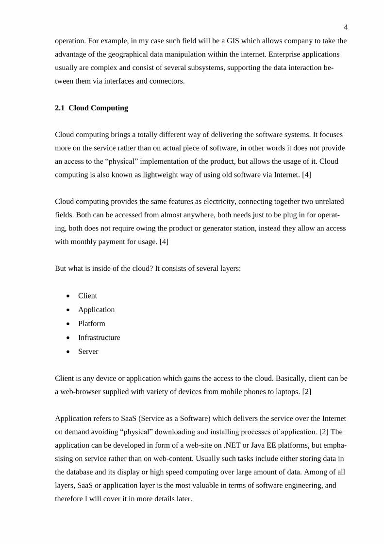
Because OpenLayers is a pure JavaScript library, installing is fairly easy and comes down to
including it inside of your HTML file:
<script type="text/javascript" src="./OpenLayers.js"></script>
Inside of the HTML file you need to specify the container for map. Important: it has to be a
“<div>” clause, not “<span>”, otherwise GMaps will not display in certain browsers and
OpenLayers also could experience problems:
<div id="map"></div>
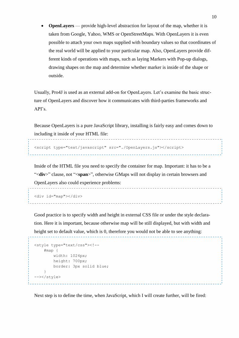
Good practice is to specify width and height in external CSS file or under the style declara-
tion. Here it is important, because otherwise map will be still displayed, but with width and
height set to default value, which is 0, therefore you would not be able to see anything:
<style type="text/css"><!--
#map {
width: 1024px;
height: 700px;
border: 3px solid blue;
}
--></style>
Next step is to define the time, when JavaScript, which I will create further, will be fired:
11
<body onload="init()">
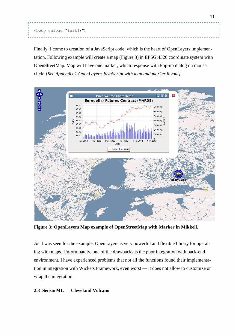
Finally, I come to creation of a JavaScript code, which is the heart of OpenLayers implemen-
tation. Following example will create a map (Figure 3) in EPSG:4326 coordinate system with
OpenStreetMap. Map will have one marker, which response with Pop-up dialog on mouse
click: [See Appendix 1 OpenLayers JavaScript with map and marker layout].
Figure 3: OpenLayers Map example of OpenStreetMap with Marker in Mikkeli.
As it was seen for the example, OpenLayers is very powerful and flexible library for operat-
ing with maps. Unfortunately, one of the drawbacks is the poor integration with back-end
environment. I have experienced problems that not all the functions found their implementa-
tion in integration with Wickets Framework, even worst — it does not allow to customize or
wrap the integration.
2.3 SensorML — Cleveland Volcano
12
The most important standard in our case is SensorML (Sensor Model Language). It provides
an access to the process information (stationary and movable sensors, altitude, latitude and
much more) in form of XML file. The process definition is very abstract and can be applied to
many different things either physical or non-physical. In my prototype I will describe sensors
via SensorML file and all the spatial manipulations with the database, markers, maps and
logic will be dependent on it.
Major purpose of SensorML is to:
provide sensor description, including its status and mobility
provide sensor information for observation discovery
provide sensor discovery
perform on-demand processing
specify input and output phenomenon
For example following SensorML file describes Cleveland Volcano located at fake easting 45,
nothing 45, which is 1000 meters tall based on EPSG::4326 standard with operational status
set to true having input parameters for time and output for ash and lava of numerical type:
[See Appendix 2 Cleveland Volcano SensorML description].
3 SOFTWARE DESIGN
Software engineering relies on design to provide the clear understanding of where component
will be located and how they will communicate with each other. [4] The components them-
selves were taken from the requirement activity, but before they will be implemented, devel-
opers need to put some effort into design to archive the reusability, reliability, appropriate
language-dependent patterns usage and maintainability of the future software product. [4]
3.1 Architectural Styles
In the design activity of software development process the decision on architectural style is
critical. The way application behaves will set the rules for maintenance, extendibility, sup-
portability and integration with other software components. The architectural style describes
the basic intent of the inner structure of the software, revealing the main focus of such soft-
ware. [4]

13
Choosing an appropriate architectural style is essential and when done wrongly it results in
“Architectural Fault”, which is the most expensive and time consuming to repair. [4] Most of
the time, architectural style is mistaken with software architectural — those are different
terms related to the same field. Architectural style is a pattern for subsystem decomposition,
while software architecture is an instance of architectural style. [4] Architectural style is not
the same as software pattern either. The difference is same as with strategy and tactics, while
style applies to application orientation, pattern defines a particular component structure, help-
ing to archive the chosen style.
Architectural style relies on components and defines the best use of them. Components have
to have loose coupling and high coherence in between each other to provide adequate realiza-
tion for styles. [6]
There are many architectural styles in use, but I will concentrate only on the once, which are
relative to the problem domain. Software engineers deal with complexity through modeling.
[4] Following diagrams throughout this chapter assume the previous knowledge of UML dia-
grams. [7]
Architectural Styles can be split into three categories based on their intent [4]:
Communication — Service-Oriented Architecture, Message Bus and Peer-to-Peer
Deployment — 3-Tier (popular in Java EE Beans) and Client/Server
Structure — Object-Oriented, Component-Based and Layered
In complex enterprise level systems it is common to see the usage of Hybrid Architecture,
which combines different styles together. [6]
I believe Object-Oriented and Client/Server architectural styles needs no introduction; there-
fore let’s continue with less discovered techniques.
3.1.1 Layered Style
The system is split into several layers, communicating with each other via interfaces and
sockets. Hierarchy of the layers is important, because a single layer is only aware of the lower
layers (dependence on them), but has no knowledge of the higher layers. [4] Most commonly

14
layers are represented in vertical top-down style. However, layers may consist of several par-
titions, located horizontally on the same level.
Because layers represent linear structure, there are only two types of relationship between
them [4]:
Uses — layer 1 has layer 2 (compile time dependency, represented in UML as associa-
tion with solid line)
Calls — layer 1 invokes functions of layer 2 (run time dependency, represented in
UML as association with dashed line)
Partitions always call each other. Best practice is to have no more than one level relationship
in both directions (top and down). Each layer can use or call only the lower layer. Figure 4
shows the layered architectural style.
Figure 4: Layered Architectural Style.
Advantages of the layered architectural style [6]:
Information hiding
Reduce overall coupling, complexity, dependency, decompose system
Easy to expand and replace one layer without modifying the other layers
Layers can be reused in another systems
Disadvantages of the layered architectural style [6]:
Degrade of performance due to the multiple passing of responsibilities

15
Debugging the layers can be time consuming
Layer Style Architecture is the core concept and can be found in many other styles with dif-
ferent prospective. In the next part of this section I will concentrate more on the particular
application of layer style architecture.
3.1.2 Multi-Tier Architecture
Multi-tier architecture relies on Layered architectural style, where single tier is an instance of
a layer. [4] Reduced or minimal version of multi-tier is two-tier client/server style. There are
two tiers, one for the client and another for the server, which may have following correlations:
Thin-client — only the presentation layer is implemented on the client side, while all
business logic and computations are passed to the server [4]
Fat-client — all the business logic is implemented on the client side, so as presenta-
tion layer. Only database information is accessed from the server [4]
Best practice shows the benefit of the thin-client, because only the presentation of the model
(reference to the MVC style) depends on the client archiving high level of control over client
software/device. [6] For each type of client, whether it is mobile phone or browser, thin-client
provides separate abstraction level. In perfect case, client must be limited only to the presenta-
tion, since that is the major dependency. None of the computation or logic, such as authentica-
tion or data retrieving should be presented on the client side. It allows having single service
accessed by one or more clients. Major disadvantage, though, is that thin-client places heavy
load on the network constantly passing data back and forth. [6]
Fat-client refers to heavy dependency on the client side, which is never a good thing. Imagine
that service, existing on the core server environment of the company should be accessed in
different applications. [4] Fat-client approach will lead to manual distribution of the compo-
nents across all presentation levels. Fat-client puts fewer loads to the network, since all the
computations are done on the client side, but also provides errors and inconsistency to the
maintenance activity. [6] Delegating of the processes must be carefully planned before im-
plementation.

16
Major advantage of thin-client over fat-client is absence of frequently updates to the client. [4]
Multi-tier architecture extends from two layers to four at maximum. It is essential to keep the
high of the tree around four or five, because higher number of layers will reduce the time ac-
cessibility, debugging and supportability due to the high passing iterations between the layers.
However, multi-tier architecture is highly scalable and distributed in responsibility sense. [4]
For the past years the most commonly seen architecture was 3-tier, including presentation
layer, business logic layer and database layer. In recent years architecture increased to 4-tier,
separating application layer into data access layer (related to the database layer) and applica-
tion layer (related to business logic and rules). [6] Usually, on the one end of the system there
is a client, on the other end — database, and everything in the middle server as rule-based
logic and data passing processing. The more complex system is the more layers it has to use.
Model-View-Controller (MVC) architectural style is usually confused with Multi-tier, there-
fore let’s clarify the differences. MVC is non-hierarchical structure, which does not follow the
pure layer rule of unawareness of the upper layers. [4] Instead, Model component can send
notification to the view in order to update it. Multi-tire is hierarchical structure, which follows
the rules of layer style, meaning that presentation layer never communicates directly to the
database; instead all communication is done only between the one-order layers. [4] The lower
decomposition goes (in direction to the database) the more similarities arise across the pro-
jects because data access is the same for most of the entities, the business logic is different
and the presentation level may vary even within the same project. [6] I will discuss MVC in
more details later.
3.1.2.1 Java Enterprise Edition
Multi-tier architecture became standard in Java EE framework in form of EJB (Enterprise
Java Beans). There, Oracle is using 3-tier structure, where each layer is a file:
Entity — is a class, which has explicit mapping to the database table, which is nothing
more than class definition, no complex operations are required. Mapping can be done
either via external xml or, most likely, via JPA (Java Persistence API) with @ annota-
tions [10]
EJB — serves as a wrapper for Entity, supplying it with basic CRUD (Create, Read,
Update, Delete) operations dealing with database [2]
17
ManageBean — only here the business logic makes its appearance, communicating
with EJB object. Even though this layer is considered to be an end-point in Java EE
structure, it’s clearly not [2]
JSF (Java Server Faces) — is a presentation layer for displaying controls and firing
events to the ManageBean, which is usually explicitly annotated with particular JSF
file. Also, instead of JSF file there could be a RESTful service allowing third-parties
to utilize the system functionality. Actually, JSF relies on the request-driven MVC ar-
chitecture [2]
To make things more clear, let’s have quick example of minimal Java EE 3-tier architecture.
All imports, getters and setters are omitted to save the space, also annotations are used as a
best practice. Of course, in reality tables in the database are connected to each other, but here
I want to emphasize on the tier structure, anyway such complexity can be held by annotations.
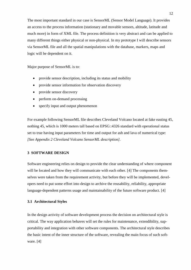
Development starts from the creation of a database (in our case it was MySQL, but it does not
make any differences). Typically once developers get familiar with database structure, they
create an entity, EJB and manage beans for them following the top-down approach from the
database to the presentation layer. [2] Figure 4 shows the table schema for employee.
Figure 5: Employee Table.
Here I create a single table with id for primary key and name as a string attribute.
Table Employee
CREATE TABLE `employee` (
`id` INT NOT NULL ,
`name` VARCHAR(45) NULL ,
PRIMARY KEY (`id`)
);

18
Now table has to be mapped with the entity using JPA annotations. Also, there are two pre-
pared SQL statements for querying the data. Entity must always implement serializable inter-
face in order to be passed via the network. [2]
Entity:
@Entity
@Table(name = "employee")
@NamedQueries({
@NamedQuery(name = "Employee.findAll",
query = "SELECT e FROM employee e"),
@NamedQuery(name = "Employee.findById",
query = "SELECT e FROM employee e WHERE e.id = :id")})
public class Employee implements Serializable {
private static final long serialVersionUID = 1L;
@Id
@GeneratedValue(strategy = GenerationType.IDENTITY)
@Column(name = "id")
private Integer id;
@Column(name = "name")
private String name;
}
Next step is to provide a CRUD operation to our newly created entity using the entity man-
ager, which is a part of Java EE platform. EJB’s can be stateful, stateless or singleton, which
literally describes its intent. [2] Stateful retain the state across multiple pages, Stateless dies as
soon as user lives the page, Singleton implies a Singleton Pattern, ensuring that the only one
instance of it exists across all the pages. [2] I have to mention that not all the frameworks sup-
port EJB annotations, for example Adobe Flex ignores the states and uses any EJB in stateless
form. [13] Only add-on for Spring Framework can solve the issue, but this is outside of the
EJB scope. [12] Also, EJB can use persistence context for accessing the database using a unit
name, given in persistence.xml file. [2]
EJB:
@Stateful
public class EmployeeEJB {
@PersistenceContext(unitName = "EmployeeEJB")
private EntityManager em;

19
public List<Employee> getEmployees() {
TypedQuery<Employee> query =
em.createNamedQuery("Employee.findAll",
Employee.class);
return query.getResultList();
}
public void updateEmployee(Employee employee) {
em.merge(employee);
}
public void addEmployee(Employee employee) {
em.persist(employee);
}
public void deleteEmployee(Integer employee) {
TypedQuery<Employee> query =
em.createNamedQuery("Employee.findById",
Employee.class);
query.setParameter("id", employee);
em.remove(query.getSingleResult());
}
}
After creating an EJB for managing the Entity class, developers can either create a manage
bean and map it to the JSF, or create any controller class, which will take care of business
logic. To simplify things, I will create a simple controller here.
Controller:
public class EmployeeController {
private EmployeeEJB EmployeeEJB;
private Employee Employee = new Employee();
private List<Employee> EmployeeList = new ArrayList<Employee>();
public void SetEJB() {
try {
EmployeeEJB = (EmployeeEJB) new InitialContext().
lookup("java:global/EmployeeEJB");
} catch (NamingException e) {
e.printStackTrace();
}
}
public List<Employee> getEmployees() {
this.SetEJB();

20
setEmployeeList(EmployeeEJB.getEmployees());
return getEmployeeList();
}
public void updateEmployee(Employee employee) {
this.SetEJB();
EmployeeEJB.updateEmployee(employee);
}
public Integer addEmployee(Employee employee) {
this.SetEJB();
return EmployeeEJB.addEmployee(employee);
}
public void deleteEmployee(Integer employee) {
this.SetEJB();
EmployeeEJB.deleteEmployee(employee);
}
}
This way it was possible to create 3-tier structure with Entity, EJB and Controller layers.
Consider the example, where the system has two presentation layers for Adobe Flex and JSF
files. System uses MySQL database and works on the Java EE technology for application
layer, the particular framework is standard binding Entity/EJB/ManageBean, but for data ac-
cess layer developers decided to use Hibernate. Apache Tomcat is used as an application
server. For illustrating such case, let’s examine the following deployment diagram (Figure 6).
Figure 6: Deployment Diagram of Multi-tier Architecture.
21
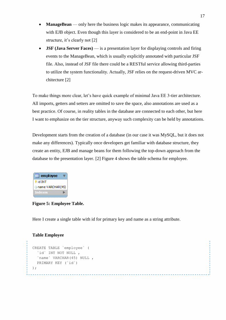
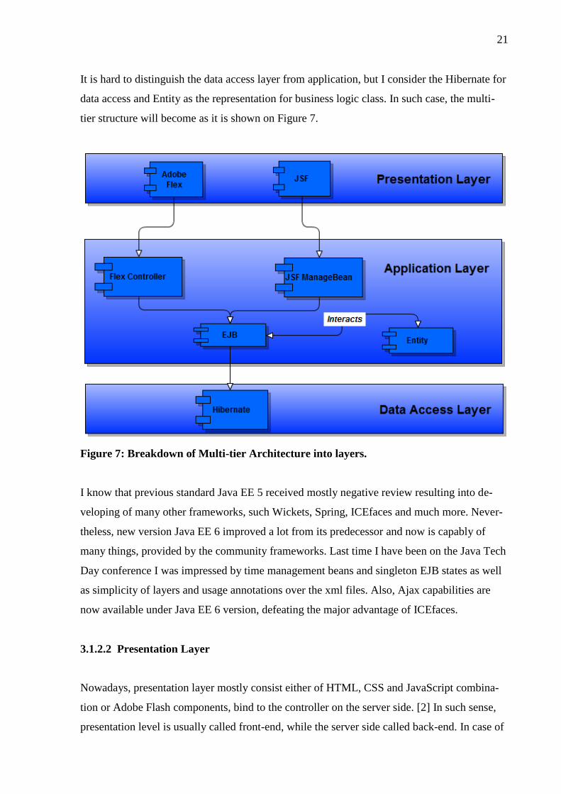
It is hard to distinguish the data access layer from application, but I consider the Hibernate for
data access and Entity as the representation for business logic class. In such case, the multi-
tier structure will become as it is shown on Figure 7.
Figure 7: Breakdown of Multi-tier Architecture into layers.
I know that previous standard Java EE 5 received mostly negative review resulting into de-
veloping of many other frameworks, such Wickets, Spring, ICEfaces and much more. Never-
theless, new version Java EE 6 improved a lot from its predecessor and now is capably of
many things, provided by the community frameworks. Last time I have been on the Java Tech
Day conference I was impressed by time management beans and singleton EJB states as well
as simplicity of layers and usage annotations over the xml files. Also, Ajax capabilities are
now available under Java EE 6 version, defeating the major advantage of ICEfaces.
3.1.2.2 Presentation Layer
Nowadays, presentation layer mostly consist either of HTML, CSS and JavaScript combina-
tion or Adobe Flash components, bind to the controller on the server side. [2] In such sense,
presentation level is usually called front-end, while the server side called back-end. In case of

22
having HTML file for presentation, most likely developers will be using frameworks to create
the GUI on the back-end side rather than code everything themselves. [4] It works in a way,
that when application is compiled, components from back-end java are converted into their
presentation with “id” attribute for referencing.
There are many approaches, for example GWT (GoogleWebToolkit) and its GXT (Sencha
JavaScript project) extension compiles all java code into obfuscated version of JavaScript
avoiding writing a single line of html. [14] [15] On the other hand, GWT also provides similar
implementation of ManageBean and JSF if needed. The communication is done via RPC
(Remote Procedure Call) form presentation layer to the back-end servlet. Even though appli-
cation, developed with GWT, is highly functional (implements most of the windows-feel GUI
by default, rather than emulating the HTML components) it is not flexible to configure and
limited in custom design. [14]
Other frameworks (which are more common to find) are similar to JSF MVC structure, forc-
ing developers to deal with not only HTML code, but also the specific extension to the html,
such as for loops and if statements. The syntax and rules vary from framework to framework
introducing high dependency and relations to the chosen framework, because programmers do
not want to rewrite the entire presentation level (which is the largest among of all layers) due
to the changes in architecture or deprecation of the framework.
Most likely, HTML pages will not be only supplied with nice graphics and CSS styles, but
also with JavaScript, providing the distinctive user experience and increasing responsiveness
of the application. Even further, for communication with back-end java, Ajax (Asynchronous
JavaScript and XML) can be used, since pure JavaScript interacts only with the user. [1] Java
EE 5 received most of the negative reviews due to the lack of Ajax integration, but wince Java
EE 6 that issue has been completely solved. [2] Ajax is capable to send asynchronous signals
to the back-end java, meaning that application can remain working while the request is proc-
essing. [1] Once it has been processed, Ajax receives response from the server and reflects to
the user. Notice that that no page refreshing or page change required during those operations,
decreasing the waiting time and increasing the productivity. Usually, Java-based frameworks
comes with build-in Ajax library, but for those, who is still programming with PHP there are
number of open-source Ajax libraries, such as Prototype JS and jQuery, for manual handling
the requests. [1] However, in case of using both Wickets, which has build-in Ajax library and
jQuery, which is an open source, jQuery turns out to be unable to send the request. [16] The

23
problem is a security issue, because Wickets has secure URL paths by default and jQuery
cannot predict the URL where it should send the request. [16] It might be different with other
frameworks, but remember that integration has been always an issue with complex systems.
Some application requires the usage of advanced graphics. Providing the diagrams, flow
charts and histograms impresses the user more, than pure data in table format. There are two
alternatives: using flash-based charts (OpenFlashChart), static generated images (jFreeCharts)
or dynamic interactive diagrams (jQuery based solutions). Obviously, user experience will be
higher in case of interactive diagrams, but flash could also be considered as an option, espe-
cially in case of Adobe Flex, which has its own library for graphics. Users of GWT can bene-
fit from external library GXT, which pre-renders the flash with supplied values from
JavaScript. [13] [14] [15]
3.1.2.3 Application Logic Layer
Application layer provides the core implementation of the business requirements. This is the
most variable layer among the projects, considering the constancy of presentation level.
Unlike other layers, application mostly consists of POJOs (Plaint Old Java Object) and con-
trollers to them, for example in Java EE 3-tier architecture it would have been a Controller,
EJB and Entity classes. [2] EJB is an interface to an Entity, Even though Entity has database
mapping. It depends, because if EJB is using Entity Manager, then it is talking to the data-
base, but if the system uses Hibernate, then EJB is just a wrapper to an Entity. [2]
The form of application layer structure highly depends on the project and cannot be predict
beforehand. It is necessary to distinguish the application layer from its relatives, such as data
access and presentation. Application layer receives the notification from presentation layer,
mainly caused by user actions (or triggered event from other services), process the data inside
of itself, retrieving or storing some data to the data access layer if required. [4]
Application layer may also provide a service for other applications, for example in SOAP or
RESTful formats. It also handles authentication and authorisation processes. Generally, this
layer is non-language dependent, because logic can be created no matter what developer uses,
either .NET or Java EE technologies. Besides the application layer, there could be other mid-
dle layers to handle the communication with different clients. [4]

24
Imagine that the system has two clients, one wish to use Adobe Flex application, another JSF,
both exists as presentation layers. In order to handle the communication via BlazeDS channel
developers create a controller (as it was done in the example), but this controller cannot be
mapped with JSF page, because it requires a ManageBean. Therefore developer may enhance
the application layers by middle-interaction for passing values back and forth.
3.1.2.4 Data Access Layer
Data Access layer only serves as an intermediate between application layer and the database
and is very similar in its behaviour to EJB and Entity. [4] Usually that communication is done
via mappings of the entity to the tables, but it does not have to be true for every system. [10]
Wicket does not maintain any particular ORM (Object Relational Mapping) or entity objects;
therefore developers are forced to use third-party libraries, such as Hibernate, JPA and EJB
for their POJOs. [17] On the other hand, Wicket provides a platform for simply web applica-
tion development, eliminating the tight binding to the additional features, reducing overheat
of the service and increasing flexibility of the application. [17]
Hibernate is in many ways similar to JPA, in fact JPA benefit from the last Hibernate release.
It also provides two ways of mapping an entity to the tables: by xml-file and by annotations.
However, it is recommended to use JPA annotations over Hibernate every time when it is
possible, because JPA is a part of Java EE standard, while Hibernate is an open-source pro-
ject, which may collapse in future. [10] [11]
Not often, but possible that some applications does not use database in common way. Consid-
ering the non-trivial databases, such as medical or spatial — there is now need to map the
entity explicitly because the database provides an external service, which takes and sends xml
files.
The reason for mapping at all is to wrap the object into tables for better use. The problem here
is that Object-Oriented paradigm is a data-centric and event-driven, while database remains in
the structural paradigm, which has been used one decade before. Structural approach was fo-
cusing on two techniques [9]:
DFD (Data Flow Diagram) — for process modelling

25
ERD (Entity Relationship Diagram) — for data modelling
Nowadays, DFD is not used any more in software production, but ERD is still used and Even
though there was an intent to move towards object-oriented databases (which failed misera-
bly), the ERD is used as a common structure for most of the databases. [4]
ERD structure is fairly simple:
Entity — also known as a table
Relationship — association between the tables
Attribute — literally an attributes in the table
Meanwhile, programming technologies were developing and came to the object-oriented,
where everything is represented as an object. But databases are still speaking structures. This
is the time, when there is a need for an Adapter pattern, which the ORM is. It takes the object,
annotate it with its inner variables providing loose-coupling and link them (each member
variable) to the table (including all the associations between the tables). [11] Pure Adapter
require no changes to the new or legacy system, however this does not apply to ORM. [4]
XML-mapping files proved to be painful to maintain, therefore development moved to anno-
tation, violating the rules of non-changes to the new system. [4] In such case, adapter merged
with the developing system.
In software engineering field the biggest issue is to maintain the existing system. Database
can be considered as an example of large scale problem. It is unclear what to do with it, be-
cause relation operations on the tables performs better with structural approach, which is not
true at all in case of objects and programming languages. [9]
3.1.2.5 Wicket Framework
In the application I have developed Wicket Framework was used, which is a lightweight com-
ponent-based web application framework, coming from Apache Software Foundation. [17]
This framework and emphasize on simplicity of web-application, oriented only for data repre-
sentation, assuming that all complexity will be delivered to the logic layer rather than web-site
pages. [17]

26
As it was discovered above, it is possible to send the asynchronous requests to the server and
receive the response on the client side. The types of data can be anything: JSON string, XML
file as a string or object itself, implementing serialized interface (which also converts the ob-
ject into string, but there is a need to de-serialize the object on the other side). Wickets has
model based communication, which can associate a form, table, list view or any other GUI
component with specific POJO and serialize it while processing back and forth. [16] [17] Eve-
rything in Wickets is a model, which comes handy while dealing with complex objects, their
relations and constraints, although I do regret flexibility. Sometimes when you need to pass a
single value, a string, it becomes impossible to do unless the wrapping a string into a model.
Each page in Wickets represented pair of .java and .html pages, explicitly bind by the name.
[16] Such approach defines the manage class for HTML and adds the GUI components to the
view. Let’s consider simple example of minimal Wicket application:
Wicket.html:
<!DOCTYPE HTML PUBLIC "-//W3C//DTD XHTML 1.0 Transitional//EN"
"http://www.w3.org/TR/xhtml1/DTD/xhtml1-transitional.dtd">
<html xmlns="http://www.w3.org/1999/xhtml"
xmlns:wicket="http://wicket.apache.org/dtds.data/
wicket-xhtml1.5-strict.dtd" xml:lang="en" lang="en">
<body><div wicket:id="print"></div></body>
</html>
Wicket.java:
public class Wicket extends WebPage {
public Wicket() {
add(new Label("print", "Wicket to the rescue!"));
}
}
WicketApplication.java:
public class WicketApplication extends WebApplication {
public Class getHomePage() {
return Wicket.class;
}
}

27
The key thing here is an “wicket:id” attribute in HTML file. At the running time it simply gets
replaced with the Label from components package with the same id as in the html. Of course
Wicket supports many other features, such as html-inheritance, for loops, panels and compo-
nents benefiting from Ajax technology, but I would like to give brief introduction here, and
discuss the more specific examples in practical section.
Wicket supports many patterns, but one in particular is Observer. Wicket contains the list
view component, which allows attaching or detaching the model and once the model has been
changes — view changes as well.
The version, I was using, Wicket 1.5 did not have integration with jQuery library, and there-
fore I used a hybrid coding the JavaScript inside of the HTML file while providing the con-
tainer id for the HTML blocks on the java side. Even though, newly released Wicket 1.6 do
support jQuery in-core, the binding between both is the same, because JavaScript code has to
be defined explicitly.
3.1.2.6 Relational Database Management System
Database is an organized collection of data, stored in digital format. [9] Most popular and
effective way to store the data is to use relational database over object-oriented, simply be-
cause relational operations has less execution time. Also, it is more natural to represent data in
relational format rather than object, because data retrieving is done over the large amount of
data.
DBMS (Database Management System) defines the tables, their relationship, such as one-to-
many, one-to-one and many-to-many (which is done via linkage table, both of which are one-
to-many) and relational operations over them. [9] Operations are described in SQL (Struc-
tured Query Language) which is not fully compatible with relational algebra, but still widely
used.
SQL is human-like programming language, which is fairly simple and obvious to use. Differ-
ent databases tried to take advantage over standard SQL by enhancing it with their stored pro-
cedures and syntaxes, like PL/SQL for Oracle Database. [9] Relational database is highly
coupled with SQL, but has different terminology for elements. [9] For example, relation is
called a table, tuple is a row, and attribute is a column.

28
Main importance of tables is to be able to reference to the other tables. In relational databases
it is done via primary key and foreign key. The primary key is only one for each table, but can
be in compound form, so that it consists of more than one attribute. Primary key ensures the
absence of duplicates in the relation, while foreign key in other table references to the primary
key in first table, creating a link in between of them. [9] Link may have different behaviour,
for example specifying “CASCADE” clause on certain operations (basically, delete or update)
it may drop or update the child table, if parent has changed, introducing the consistency into
database structure. [9] Tables are exist inside of the schema, but they still can reference to
tables from different schemas, although SQL does not support it, therefore referencing is
manual.
To reduce redundancy and avoid update anomalies normalization is taking place on the tables.
First normal form is archived when table becomes a relation, meaning that there is no dupli-
cate tuples. [9] Second normal form enhances the first one by moving partial dependencies to
the external table. [9] Third normal form goes further in table decomposition to eliminate any
functional dependency between candidate key and non-candidate key attributes. [9] The idea
is so that in single relation will be no attribute which can identify the tuple, except the primary
key. Best practice in database design defines that every table should be at least in third normal
form. There are much more to decompose, Boyce-Codd normal form and up to fifth normal
forms, but developers must keep in mind, that the more they decompose the tables, the longer
retrieving operation will take due to the table joining. [9] Sometimes it is better to find opti-
mal balance between the number of tables and redundancy elimination.
DBMS supports many other features, such as transactions for atomic operations, views, which
are basically a view to the one or more tables, triggers and more.
To illustrate the table relations, let’s consider the university database with students, courses
and university. All students belong to one university only, but the can be assigned for many
courses, so as the course may have zero or more students. In such case, student will have one
foreign key to reference to the university table, while assignment table will become a linkage
to maintain the many-to-many relationship between student and courses, where primary key is
compound and is the collection of its foreign keys. Relations are cascade in sense that if stu-
dent or course gets deleted or updated, the assignment will reflect the changes and also gets
either deleted or updated (updating means changing the primary key value).

29
Notice the normalisation, students and courses are not in the same table, because it will pro-
vide redundancy (each student will repeat the same course in its tuple) and inconsistency (up-
dating one of the tuple with course name I will end up with the same course having different
attribute values across the table). [9] Figure 8 demonstrates the database schema.
Figure 8: Database Schema for University Example.
SQL statements for creating such schema are as follows:
Database Schema:
CREATE SCHEMA IF NOT EXISTS `mydb` DEFAULT CHARACTER SET latin1 COLLATE
latin1_swedish_ci
University Table:
CREATE TABLE IF NOT EXISTS `mydb`.`university` (
`id` INT NOT NULL ,
`name` VARCHAR(45) NULL ,
PRIMARY KEY (`id`)
) ENGINE = InnoDB
Student Table:

30
CREATE TABLE IF NOT EXISTS `mydb`.`student` (
`id` INT NOT NULL ,
`name` VARCHAR(45) NULL ,
`universityID` INT NULL ,
PRIMARY KEY (`id`) ,
INDEX `universityID` (`universityID` ASC) ,
CONSTRAINT `universityID`
FOREIGN KEY (`universityID` )
REFERENCES `mydb`.`university` (`id` )
ON DELETE CASCADE
ON UPDATE CASCADE
) ENGINE = InnoDB
Course Table:
CREATE TABLE IF NOT EXISTS `mydb`.`course` (
`id` INT NOT NULL ,
`name` VARCHAR(45) NULL ,
PRIMARY KEY (`id`)
) ENGINE = InnoDB
Teached Table:
CREATE TABLE IF NOT EXISTS `mydb`.`teached` (
`courseID` INT NOT NULL ,
`universityID` INT NOT NULL ,
PRIMARY KEY (`courseID`, `universityID`) ,
INDEX `courseID` (`courseID` ASC) ,
INDEX `universityID` (`universityID` ASC) ,
CONSTRAINT `courseID`
FOREIGN KEY (`courseID` )
REFERENCES `mydb`.`course` (`id` )
ON DELETE CASCADE
ON UPDATE CASCADE,
CONSTRAINT `universityID`
FOREIGN KEY (`universityID` )
REFERENCES `mydb`.`university` (`id` )
ON DELETE CASCADE
ON UPDATE CASCADE)
ENGINE = InnoDB
Assignment Table:
CREATE TABLE IF NOT EXISTS `mydb`.`assignment` (
`studentID` INT NOT NULL ,
`courseID` INT NOT NULL ,
PRIMARY KEY (`studentID`, `courseID`) ,

31
INDEX `studentID` (`studentID` ASC) ,
INDEX `courseID` (`courseID` ASC) ,
CONSTRAINT `studentID`
FOREIGN KEY (`studentID` )
REFERENCES `mydb`.`student` (`id` )
ON DELETE CASCADE
ON UPDATE CASCADE,
CONSTRAINT `courseID`
FOREIGN KEY (`courseID` )
REFERENCES `mydb`.`course` (`id` )
ON DELETE CASCADE
ON UPDATE CASCADE
) ENGINE = InnoDB
SQL for operation over the schema are as follows:
Register tens student to the MAMK university, which has id = 1:
INSERT INTO `student` VALUES (10, "Victor Ekimov", 1);
Retrieve the names of all the students from UWO university, which are taking the
course named “DBMS”:
SELECT `student`.`name`
FROM `student`, `university`, `course`, `assignment`, `teached`
WHERE
`course`.`name` == "DBMS" AND
`university`.`name` == "UWO" AND
`student`.`universityID` == `university`.`id` AND
`student`.`id` == `assignment`.`studentID` AND
`teached`.`universityID` == `university`.`id` AND
`teached`.`courseID` == `course`.`id` AND
`course`.`id` == `assignment`.`courseID`;
Remove the course, from “LGU” university:
DELETE FROM `course`, `university`, `teached`
WHERE
`university`.`name` == "LGU" AND
`teached`.`universityID` == `university`.`id` AND
`teached`.`courseID` == `course`.`id`;
Change the name of all the students at “MAMK” university to “Matti”:

32
UPDATE `student`
SET `student`.`name` = "Matti"
WHERE
`student`.`universityID` == `university`.`id` AND
`university`.`name` == "MAMK";
3.1.2.7 Spatial Database Management System
Geometrical data are natural for spatial database. Besides the SQL queries, spatial databases
can perform a wide range of spatial operations: [9]
Functions — modifies the geometry with new one but of the same type
Measurements — determine the distance in between two geometry objects
Predicates — determine whether two geometry intersects, overlap or cross each other
Many databases, such as MySQL has add-ons to provide spatial operations. PostgreSQL da-
tabase can be supplied with enhancing functionality to provide spatial capabilities. By using
the stack builder, coming with the database, developers can install PostGIS stack, which ena-
bles the geographical data manipulations. For example, here is the list of documented func-
tions, PostGIS can calculate:
Distance(geometry, geometry) : number
Equals(geometry, geometry) : boolean
Disjoint(geometry, geometry) : boolean
Intersects(geometry, geometry) : boolean
Touches(geometry, geometry) : boolean
Crosses(geometry, geometry) : boolean
Overlaps(geometry, geometry) : boolean
Contains(geometry, geometry) : boolean
Length(geometry) : number
Area(geometry) : number
Centroid(geometry) : geometry
Here, geometry may be assumed as a point, line or a polygon. Therefore such operations as
intersection of polygons, crossing lines, distance between two point are every-day operations
for PostGIS and can be archived by enhanced SQL rather than calculating the data using the

33
back-end programming language. Simplicity and task delegation serves for distribution of
responsibilities among layers.
3.1.3 Model-View-Controller
MVC (Model-View-Component) style was developed to fulfil the needs of interaction with
the user via GUI (Graphical User Interface). [4] The idea is to decompose the complexity of
the system into three parts:
Model — represents row objects for domain-specific information
View — displays the model into user friendly interface (GUI), also view is bind to the
model, in a way that if model has changed, the view gets updated as well (model sends
notification and fires the update on the view side).
Controller — handles the events, fired from the user or other external client in order
to change the model
Figure 9 demonstrates the communication between components via calls and events.
Figure 9: Model-View-Controller Architectural Style. (Designing Enterprise Applica-
tions with the J2EE Platform)
MVC is one of the most popular architectural styles and it has been applied in large number of
frameworks, such as Swing in Java, Adobe Flex, Wickets and Qt. [6]

34
Advantages of MVC [6]:
Separates Data Access (Model), Data Presentation (View) and Data Transmission
(Controller)
One Model can be dynamically attached or detached to/from multiple Views and Con-
trollers providing data centralization and reusability
Disadvantages of MVC [6]:
Usually View and Controller are bind together and highly depend on each other
Introduce complexity in debugging
Reduce performance of GUI in case of frequent updates
In many ways, MVC relies on Observer Pattern, which will be discussed below, but MVC is
not exactly an Observer, because it adds the presence of Controller. [4]
3.1.4 Service-Oriented Architecture
Service-oriented architecture provides well-understood communication interface for the third-
party services or directly connected client (presentation layer). Such approach simplifies the
web-development process and orient on the service usage, rather than language-oriented ar-
chitectures. SOA (Service-Oriented Architecture) belongs to the set of event-driven struc-
tures, where the main motivation of it is to trigger the events and react on the changes, in con-
trast with structural set of orients, such as object-oriented architecture. [4]
Services are the end-points across the network and the way they communicate to each other
has to be specified by the certain protocol. [4] Service-provider initiates the communication
by serializing an object or to be more abstract — encoding the data, send it through the net-
work till the service-consumer will de-serializing or decoded data, just like in the telecommu-
nication transmission. [4]
Communication itself is done via network and is concern of network engineers, but what the
developers are responsible for, is for defining the encoding/decoding format, obviously, if the
sending format was JSON string and the receiver service expects XML, they would not be
able to understand each other Even though the data were passed perfectly. [6]

35
Services implies the loose coupling in sense that services has very little dependency on each
other, instead they use middle-layer (compare to Mediator Pattern) for data passing. [4] On
service fires the event on the other service without direct binding in between. Previous im-
plementations of standalone applications communicate via RMI in java, which was excep-
tional at that time, but with services the communication takes the major focus, and the objects
are now used only as business logic representation. [4]
SOA holds on the principals of reusing the services in different projects (in matrix structure
rather than linear), modularity, interoperability (ability of different services to work together)
and granularity (system breakdown to smaller parts). [4] Service discovery is essential key,
allowing the communication between services developed by different companies. For exam-
ple, company may decide to provide RESTful interface for group of users to query the data,
excluding the modification of it.
Two common formats, besides the manual serialization of the object are:
XML (Extensible Markup Language) — markup language (with text annotations)
identifies itself as comprehensive encoding document format, which is both human-
and machine-readable. Example of xml was introduced earlier in the section “Cleve-
land Volcano”. XML are heavy weight documents, being way too precise than neces-
sary they create overheat to the network and overcomplicate the development in case
of requiring a simple data to be send. Also, XML files are used as configuration files
because of its loose coupling nature, sometimes being wrapped with GUI
JSON (JavaScript Object Notation) — lightweight pure text-based formats, which is
also human- and machine-readable. Historically, it was derived from JavaScript lan-
guage, as the name says, but other languages also may understand such format in case
of having interpreter. [1] JSON structure is fairly simple and holds on Composite Pat-
tern, which is has tree-hierarchy, where each child has itself (recursively) and/or leaf
nodes. [4] Applying that, JSON either have a data (object, boolean, string or number)
or an array, containing data or another array:
{
"folder":
[
{
"id": 1,
"title": "first favorite file"
36
},
{
"id": 2,
"title": "second favorite file"
}
]
}
Both JSON and XML may found its use in different parts of project, while XML is fully-
functional suits the needs of complex systems; JSON is used in fast and simple data transmis-
sion.
Even though SOA can operate independently of communication technology, most of the pro-
jects come down to usage of following:
SOAP (Simple Object Access Protocol) — highly depends on XML and basically en-
hance it with additional clauses for passing through the network [2]
RESTful (Representational state transfer) — uses Uniform Resource Identifiers
(URIs) for referencing to the resources in HTTP (Hypertext Transfer Protocol) meth-
ods, such as GET, PUT, POST, or DELETE. [2] Each method finds its literal imple-
mentation under certain object, which becomes really easy to implement using Java
EE notations
SOAP consists of Envelope section, which includes Header and Body sections. Communica-
tion is done in a way that one service sends the SOAP-request to invoke the functions on the
other service and waits for SOAP-response. However, Header section is usually omitted in
simple non- authenticated communication. Consider the example of querying the name of the
student by the student id number.
SOAP-Request: Student.xml:
POST /Student HTTP/1.1
Host: www.mamk.fi
Content-Type: application/soap+xml; charset=utf-8
Content-Length: XXX
SOAPAction: "http://www.w3.org/2003/05/soap-envelope"
<?xml version="1.0"?>
<soap:Envelope xmlns:soap="http://www.w3.org/2003/05/soap-envelope">

37
<soap:Body xmlns:s="http://www.mamk.fi/students">
<s:GetStudentRequest>
<s:Id>250655695</s:Id>
</s:GetStudentRequest>
</soap:Body>
</soap:Envelope>
SOAP-Response: Student.xml:
HTTP/1.1 200 OK
Content-Type: application/soap+xml; charset=utf-8
Content-Length: XXX
<?xml version="1.0"?>
<soap:Envelope xmlns:soap="http://www.w3.org/2003/05/soap-envelope">
<soap:Body xmlns:s="http://www.mamk.fi/students">
<s:GetStudentResponse>
<s:Name>Victor Ekimov</s:Name>
</s:GetStudentResponse>
</soap:Body>
</soap:Envelope>
SOAP is flexible and multipurpose standard, which can be used outside of the SOA, or can be
passed through the firewall or proxy without any modifications. On the other hand, non-
standardized RESTful technology overcomes the SOAP by simplicity, transfer speed and
network-oriented structure.
In RESTful web service link is considered to be an object, while HTTP methods applied to it
becomes an actions. Considering the link http://www.mamk.fi/students/victor.ekimov,
methods can be assumed as following operations:
GET — retrieve the information of the student
PUT — update the student information, if student does not exist — create it
POST — create a new student
DELETE — delete an old student
Java EE technology has significant support of RESTful message passing, including the JAX-
RS, which supports automatic creation of XML/JSON strings. [2] It is done via JAXB (Java

38
Architecture for XML Binding), which basically annotates the class with one or more xml
clauses (for example, @XmlRootElement). [10]
To clarify the usage of RESTful technology and prove its easiness, let’s examine the small
Java system, which has JAXB for class with student id and student name, operating under
JAX-RS. [10] Our assumption is that there is a Singleton StudenList, taking care of database-
related operation at data access layer. The student class will be processed as XML having id
and name fields as is:
RESTful: Student.java:
@XmlRootElement
public class Student {
private int id;
private String name;
public Student(int id, String name) {
this.id = id;
this.name = name;
}
public String getId() {
return id;
}
public void setId(int id) {
this.id = id;
}
public String getName() {
return name;
}
public void setName(String name) {
this.name = name;
}
}
RESTful: StudentRS.java:
@Path("/students")
public class StudentRS {
StudentList studentList = new StudentList.getInstance();
@GET
@Path("{id}")

39
@Produces("application/xml")
public Student getStudent(@PathParm("id") int id) {
return studentList().getStudent(id);
}
@UPDATE
@Path("{id}")
@Consumes("application/x-www-form-urlencoded")
public void updateStudent(@PathParm("id") int id,
@FormParam("name") String name) {
Sturent student = studentList().getStudent(id);
if (student)
student.setName(name);
studentList.updateStudent(student);
else
studentList.insertStudent(new Student(id, name));
}
@POST
@Consumes("application/x-www-form-urlencoded")
public void postStudent(@FormParam("id") int id,
@FormParam("name") String name) {
studentList.insertStudent(new Student(id, name));
}
@DELETE
@Path("{id}")
public void deleteStudent(@PathParam("id") int id) {
studentList().deleteStudent(id);
}
}
In contrast with universal approaches, consider the BlazeDS channel for communicating be-
tween front-end Adobe Flex and back-end Java EE, where the message passing is binary by
its nature therefore happens much faster, eliminating the need of encoding and decoding. [13]
Mainstream is currently moving towards the RESTful due to its simplicity and nativity to the
networks, while SOAP remains an ugly shape monster resembling the old days of XML
communication between standalone applications. For example, Google introduced RESTful
API for its search engine in April 2008, discarding the SOAP API, which was introduced in
December 2006. [14]
3.2 Software Patterns

40
The intent of patterns is to fill the gap between the System Design and the Object Design. At
this point, developers realized the architectural style and classes they need to implement. Pat-
terns will tight those two entities together via interfaces and sockets. [4]
While architectural style deals with components, software patterns describe the communica-
tion between classes using object-oriented paradigm. [4] Off-the-shelf components need to be
connected with refined classes, realized as a business model. It is done through the Object-
Oriented techniques, such as association, inheritance and implementation. [4]
Outsourcing of the commercial existing patters can result into 0% coding, but be less flexible
and more expensive, especially considering the fact that all patterns can be developed by the
company itself. [6] Usually, that is the case due to the specific requirement, not covered by
the commercial patterns. This is not the case with STL (Standard Template Library) for ex-
ample where it is strongly suggested to use their data structure and algorithms rather than de-
veloping your own. STL is multi-purpose and perfectly performs its intent, while the patterns
have problem-oriented approach.
Software Patterns idea cannot be described better, than Christopher Alexander said in his
book: "Each pattern describes a problem which occurs over and over again in our environ-
ment, and then describes the core of the solution to that problem, in such a way that you can
use this solution a million times over, without ever doing it the same way twice”. [19]
Alexander was talking about patterns in buildings, but software engineering has lot of simi-
larities to the architecture, Even thoughgh it is done in the world of “virtual reality”. A perfect
example of reuse the ideas across two engineering field was taken very serious into considera-
tion by software engineers. Indeed, most of the problems arise at the design activity repeats
from project to project making developers think about creating a ready-made component to
handle such problems.
To understand the patterns communication it is necessary to differentiate association from
inheritance and implementation. Association uses the instantiated class inside of itself, while
inheritance literally inherits all the functionality from the parent class. The dependency of
inherited object is higher, than of associated, because if the parent object changes its function-
ality, it will also change the behaviour of all the children. A perfect example will be discussed
in the first and most commonly used pattern — Adapter.
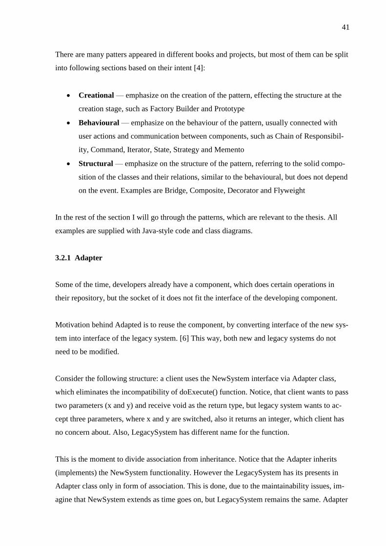
41
There are many patters appeared in different books and projects, but most of them can be split
into following sections based on their intent [4]:
Creational — emphasize on the creation of the pattern, effecting the structure at the
creation stage, such as Factory Builder and Prototype
Behavioural — emphasize on the behaviour of the pattern, usually connected with
user actions and communication between components, such as Chain of Responsibil-
ity, Command, Iterator, State, Strategy and Memento
Structural — emphasize on the structure of the pattern, referring to the solid compo-
sition of the classes and their relations, similar to the behavioural, but does not depend
on the event. Examples are Bridge, Composite, Decorator and Flyweight
In the rest of the section I will go through the patterns, which are relevant to the thesis. All
examples are supplied with Java-style code and class diagrams.
3.2.1 Adapter
Some of the time, developers already have a component, which does certain operations in
their repository, but the socket of it does not fit the interface of the developing component.
Motivation behind Adapted is to reuse the component, by converting interface of the new sys-
tem into interface of the legacy system. [6] This way, both new and legacy systems do not
need to be modified.
Consider the following structure: a client uses the NewSystem interface via Adapter class,
which eliminates the incompatibility of doExecute() function. Notice, that client wants to pass
two parameters (x and y) and receive void as the return type, but legacy system wants to ac-
cept three parameters, where x and y are switched, also it returns an integer, which client has
no concern about. Also, LegacySystem has different name for the function.
This is the moment to divide association from inheritance. Notice that the Adapter inherits
(implements) the NewSystem functionality. However the LegacySystem has its presents in
Adapter class only in form of association. This is done, due to the maintainability issues, im-
agine that NewSystem extends as time goes on, but LegacySystem remains the same. Adapter
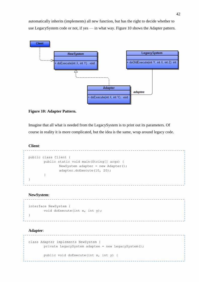
42
automatically inherits (implements) all new function, but has the right to decide whether to
use LegacySystem code or not, if yes — in what way. Figure 10 shows the Adapter pattern.
Figure 10: Adapter Pattern.
Imagine that all what is needed from the LegacySystem is to print out its parameters. Of
course in reality it is more complicated, but the idea is the same, wrap around legacy code.
Client:
public class Client {
public static void main(String[] args) {
NewSystem adapter = new Adapter();
adapter.doExecute(10, 20);
}
}
NewSystem:
interface NewSystem {
void doExecute(int x, int y);
}
Adapter:
class Adapter implements NewSystem {
private LegacySystem adaptee = new LegacySystem();
public void doExecute(int x, int y) {

43
adaptee.doOldExecute(y, x, x + y);
}
}
LegacySystem:
class LegacySystem {
public int doOldExecute(int y, int x, int z) {
System.out.println("doOldExecute(int " + y +
", int " + x + ", int " + z + ")");
return y * x * z;
}
}
3.2.2 Facade
Facade serves similar purpose as Adapter, but rather than connecting two systems together,
Facade provides a unified interface to the multiple subsystems. [6] That interface can even be
separated based on the client type. In some sense, Facade brings new layers into the system
allowing authorization and decision control all over it. Also, it shields the client from access-
ing inner classes, archiving information hiding and high level of security. At the same time,
Facade does not prevent the client from usage of the hidden classes because all communica-
tion is done via aggregation. [6]
Consider the following example: clients A, B and C want to assemble the car. Calling each
function from three different classes every time leads to inconsistency and errors in future
development. Therefore, I create a Facade which has a single function to call, which will ex-
plicitly call all the required functions from the other classes. It also may act as a firewall, pre-
venting the client C from accessing certain functions. Figure 11 shows the Facade pattern.

44
Figure 11: Facade Pattern.
Let’s consider following code for Facade class. Inner classes’ code is omitted due to its sim-
plicity, here it would have been writing the parameters, but in reality it can perform whatever
action it should. Our assumption is that client C did not pay for the car at all, while client B
paid only for wheels. Also, clients have inner function, which check whether he paid or not
for certain parts. It could be archived either of checking the instance of the object, or some
values of the attributes.
Client:
public class Client {
public static void main(String[] args) {
ClientA clientA = new ClientA();
ClientB clientb = new ClientB();
ClientC clientC = new ClientC();
Facade façade = new Facade();
facade.assembleTheCar(clientA);
facade.assembleTheCar(clientB);
facade.assembleTheCar(clientC);
}
}
Facade:

45
class Facade {
private Wheels wheels = new Wheels();
private Bumper bumper = new Bumper();
private Door door = new Door();
private Car car;
public Car assembleTheCar(Client client) {
car = new Car();
if (client.paid(wheels)) {
car.attach(wheels.attachWheel());
} else return Null;
if (client.paid(bumper)) {
car.attach(bumper.assembleBumper());
} else return Null;
if (client.paid(door)) {
car.attach(door.assembleDoor());
car.attach(door.assembleDoorWindow());
} else return Null;
return car;
}
}
3.2.3 Proxy
Proxy pattern is represented as additional layer between the system and object it wants to use.
Sometimes it is necessary to provide security, filter options or sample view of an object,
which is expensive in terms of performance (large image, video stream, large amount of data
from database). [6] Avoiding the creation of the object at the start-up time archives the on-
demand effect. [6] Although, object can be instantiated directly, not taking Proxy into ac-
count, it is a good practice to use two layer structure.
Notice that both of the classes inherits (implements) the Video interface. Essentially, both of
them has the same purpose, but with slight difference. Figure 12 shows the Proxy pattern.

46
Figure 12: Proxy Pattern.
Consider an example, where client requests a video, without knowing of its content. At this
point, it is unclear whether client likes it and wants to watch in higher quality or dislike it and
simply close the video stream. In the second case it would be foolish to create an expensive
object just to destroy it couple of seconds later. But if he likes it, Proxy provides a control to
improve the quality, while ProxyVideo class will contain low quality (typical for YouTube).
Client:
public class Client {
public static void main(String[] args) {
Video lowQualityVideo = new ProxyVideo();
Video highQualityVideo = new HighResolutionVideo();
lowQualityVideo.playVideo();
highQualityVideo.playVideo();
}
}
Video:
interface Video {
void playVideo();
}
ProxyVideo:

47
public class VideoProxy implements Video {
@Override
public void playVideo() {
video = new HighResolutionVideo();
video.playVideo();
}
}
HighResolutionVideo:
public class HighResolutionVideo implements Video {
@Override
public void playVideo() {
// Rendering the video
}
}
3.2.4 Singleton
Singleton is a creational patterns, unlike those, which were discussed previously (they were
structural). [6] It is created in a way that ensures the existence of only one instance at a time
across the application. [6] For such purpose, constructor defines as a private function, so that
it cannot be called from the outside of the class. Instead, common suggestion name for the
function is getInstance() which checks whether objects has been instantiated, and if not it cre-
ates the object and returns it. If the object has been created previously, function just returns it.
Singleton pattern can be modified depending on the case, to store an array of singletons or
gaining an access for the specific group of clients. General structure is the object, which has a
reference to itself. Implementation can be lazy, when object is created on-demand inside of
the getInstance() function, or early, when object exists as soon as application starts. In case of
multithreading application, getInstance() function must be supplied with “synchronized”
clause, because of the if statements inside. [6] Usually, singleton is used as a part of Fly-
weight Pattern, but may exist on its own.
Main purpose of Singleton is to represent authentication instance of user, or share common
objects among all the clients. [6] Also, it may be used as real world modelling, for example in
one country only one president could exist at a time. Consider the following lazy instantiation
example for multithreading system (Figure 13).
48
Figure 13: Singleton Pattern.
Singleton:
public class Singleton {
private static Singleton instance;
private Singleton() {}
public static synchronized Singleton getInstance() {
if (instance)
return instance;
else
instance = new Singleton();
}
}
3.2.5 Observer
Observer is a behavioural pattern, responsible for handling the evens at run time. One of the
biggest challenges in GUI development is to maintain the consistence between the compo-
nents, but retaining the loose coupling between them at the same time. [6] The model has one-
to-many relations to the diagrams, histograms, tables and lists. Such GUI components are
called the observers of the model, which can be attached or detached at the run time. Even
more, model may have no observers at all, remaining silence until the correct time. When
model changes its state (updates inner attributes), observers get notification and changes the
corresponding representation as well. [6] All attached observers become synchronized without
tight binding to the model.
Observer pattern is used in MVC architectural style, but it is not the same due to the lack of
Controller presence.
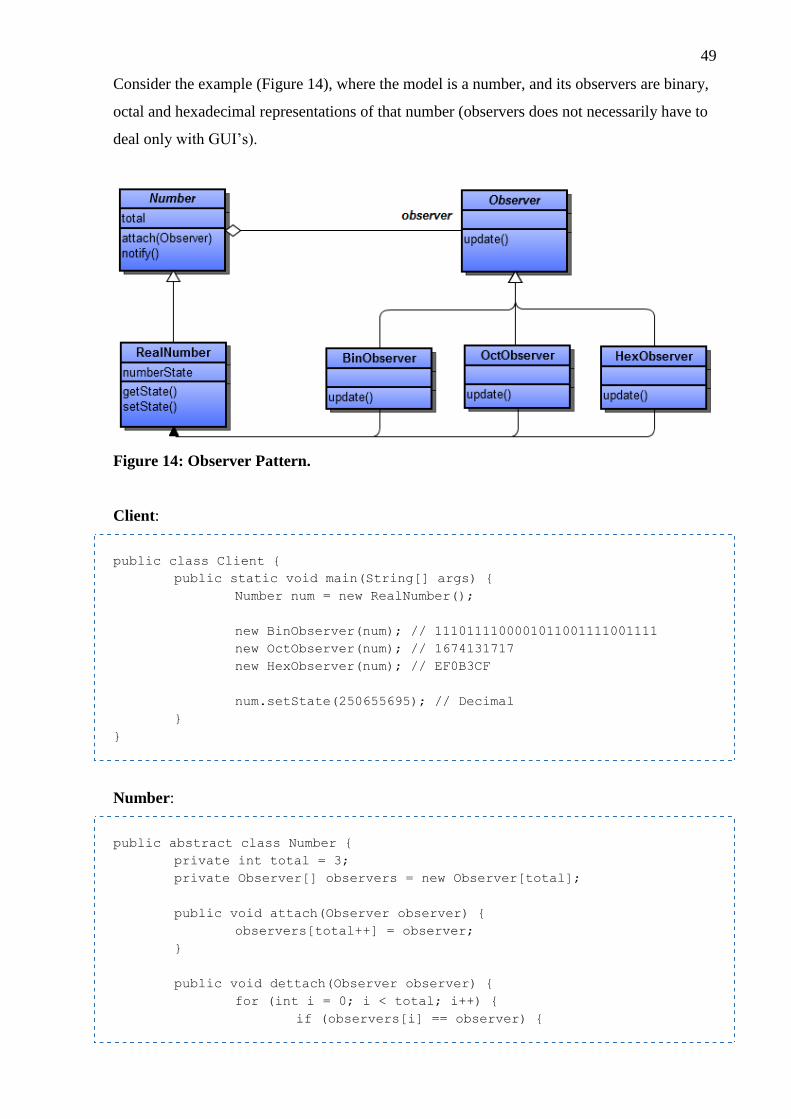
49
Consider the example (Figure 14), where the model is a number, and its observers are binary,
octal and hexadecimal representations of that number (observers does not necessarily have to
deal only with GUI’s).
Figure 14: Observer Pattern.
Client:
public class Client {
public static void main(String[] args) {
Number num = new RealNumber();
new BinObserver(num); // 1110111100001011001111001111
new OctObserver(num); // 1674131717
new HexObserver(num); // EF0B3CF
num.setState(250655695); // Decimal
}
}
Number:
public abstract class Number {
private int total = 3;
private Observer[] observers = new Observer[total];
public void attach(Observer observer) {
observers[total++] = observer;
}
public void dettach(Observer observer) {
for (int i = 0; i < total; i++) {
if (observers[i] == observer) {

50
observers[i] = null;
total--;
}
}
}
public void Notify() {
for (int i = 0; i < total; i++) {
observers[i].update();
}
}
public int getState() {return 0;}
public void setState(int in) {}
}
RealNumber:
public class RealNumber extends Number {
private int numberState;
public int getState() {
return numberState;
}
public void setState(int numberState) {
this.numberState = numberState;
notify();
}
}
Observer:
public abstract class Observer {
protected Number number;
public abstract void update();
}
BinObserver / OctObserver / HexObserver:
public class BinObserver extends Observer {
public BinObserver(Number number) {
this.number = number;
this.number.attach(this);
}
public void update() {
System.out.print(Integer.toBinaryString(number.getState()));

51
}
}
4 SOFTWARE DEVELOPMENT PROCESS
After gathering enough theoretical knowledge I am ready to turn them into practical imple-
mentation, finally helping the business to make some money. The SaaS system requires the
usage of third-party products, coming from 52°North company, implying the knowledge of
geospatial data, SensorML xml file description, and architectural styles, software patterns,
which are mostly concentrating on service-oriented and multi-tier architectures, and working
with spatial database management system.
The goal of the prototype is to develop a system, which includes the data integration compo-
nent, fetching the data from real measurement device, and web-site, which will allow man-
agement and monitoring features to the clients. Such system will prove the ability to transfer
data from the device, catch it on the server side, convert the data into meaningful information
which will be stored in the spatial database, waiting to be fetched by client and represented on
the web-site in different formats, including map view with markers, list view and graphics
with exporting features.
Software development process is a software life cycle, which has the following steps [4]:
Requirement Analysis
Requirement Specification
Software Architecture
Software Design
Software Implementation
Software Testing
Software Deployment
Software Maintenance
Due to the use of throw-away prototype methodology, all the steps will be done in cycle [4]:
Requirement Elicitation

52
Design Prototype
Build Prototype
Test Prototype
Throw-away prototype gathers the requirements, increases the familiarity with the technology
and shows the limitations and functionality of the future system. [6] Once the prototype is
done, all the documentation remains on the developers’ side as well as the knowledge of spe-
cific technology tricks — prototype is not fully taken into final product development, only
partially. [4] The design will be done again, from the scratch, once the developers had enough
time to explore the system. [6] After the outcome of prototyping cycle has been successfully
accepted, next steps are [4]:
Requirement Documentation
System/Object Design
Software Implementation
Software Testing
Software Deployment
Software Maintenance
The project involves the understanding the requirements of the Observis Platform, gathering
familiarity with Wicket Framework, discovering its suitability for the system, learning the
SaaS and PaaS structures in practical implementation, defining the use for 52°North products
inside of Observis Platform, gaining experience with spatial DBMS, essentially, PostGIS.
4.1 Software Development Methodology
Methodology specifies the rules for the development process, describing the activities to be
executed from the requirements elicitation up to software deployment and maintenance.
Many companies adopted their own software development methodology, but most of them
represent a variation of one existing and well-known concept. All methodologies can be di-
vided into following groups [6]:
Structural — Waterfall, V-Model
53
Rapid Application Development — Phased Model, System/Throw-Away Prototype,
Spiral Model
Agile — Extreme Programming Model
Structural models follow the clear path from the beginning to an end, without a possibility to
go back. It is suitable for simple, small-size tasks with clear requirements. However, that does
not apply to time-limited schedule or projects with unfamiliar technology.
In order to deal with risk management and complex projects, software development activities
should be repeated over and over again until the desired functionality is archived [6]. For that
purpose Rapid Application Development (RAD) was created, where all of the instances iterate
on some activity, it is emphasized in. For example, Phased Model iterates on the testing activ-
ity, meaning that all the systems developed with such methodology will be highly reliable [6].
Spiral model iterates in the Descartes system, providing risk management, because after each
quarter developers decide whether to go further or fix the problems. [6] RAD methodology is
usually seen in systems with unclear requirements, unfamiliar technologies and short time
schedule.
Agile methodology focuses on rapid development no matter whether the result archived or
not. [6] Functionality must be developed quickly, each task has time-boxes and when the time
runs out developer moves to the next task even if the previous was solved only partly. Also,
Agile comes handy when developers are dealing with unclear requirements because such
quick development allows investigating and discovering certain aspects of the system, which
were not seen before at the design activity. [6] However, Agile is not reliable due to the lack
of design; therefore complex projects may experience poor quality.
4.1.1 Throw-Away Prototype
Here I will concentrate on the most important methodology related to the thesis. As it was
mentioned before, Observis Oy is a start-up company, revealing the fact that it is unclear what
the system is supposed to do. Stepping into new technology field is also an issue. Of course,
previous knowledge of Java EE platform balances the risks, but there are much more frame-
work to discover. Will the chosen framework fulfil the system needs? Answer to such ques-
tion can be archived only by trial and error method, which is exactly the purpose of prototyp-
ing. Prototyping helps to answer the most frightening question: is the system feasible? Before

54
starting a business and having a real customer, company need to have some kind of presenta-
tion. Prove-of-concept requires the usage of prototyping not just for client demonstration pur-
pose, but also for the company itself, helping to understand, whether such thing can even be
implemented, and if yes — what are the limitations and possibilities?
Prototype intent is to be built, tested and reengineered until the acceptable requirements are
archived, serving as a fundament for the system build. [6] Requirements elicitation is done
first, followed by quick design, discovering only the major concepts. After first iteration, pro-
totype is evaluated by the customers or developers to refine the rest of the functionality. Ob-
vious drawback of prototyping is that customer treats the prototype as the final product, com-
plaining on the lack of functionality and possible inconsistency in GUI. Developers have bet-
ter opportunity of “playing around” with system, trying to explore new edges of the require-
ments.
Common use of prototyping is not to create the whole system at once, but to create different
functionality in several iterations. [6] After that, prototype is considered to be done and may
or may not appear as the reference for a real system development. The idea is so, that proto-
type is never a final product. Increasing the user involvement makes possible to reduce the
time and cost of the development. Profit of early prototyping is an ability to test implemented
functional, without waiting for the whole system to be done.
Two major streams of prototyping exits in the world of software development. Both of them
go through elicitation, design, build and test prototyping cycle; the only one single difference,
which clearly distinguishes one from another, is the System/Object Design activity. To begin
with, prototyping can be split into two types [4] [6]:
System Prototype — targets the need of product delivery, mainly concentrates on
well-understood concepts so that first version will contain the expected functionality,
requested by the user. After prototyping is finished, system prototype is retained and
used as the reference for developing the final product. The name System clearly de-
fines that the design is done during prototyping. Once the prototype is accepted, go
straight to the implementation activity; do not need to redesign the system.
Throw-Away Prototype — in contrast with System Prototype, it targets the require-
ment elicitation, and discarded (thrown away) once this activity is completed. Because
of that, developers might experience attachment to the all the hard work they put into
55
prototype even if it does not satisfy user. Throw-Away Prototype helps eliminate that
problem, since from the very beginning developers understand that their work will be
thrown away. Typically the development is concentrating on the least understood con-
cepts, in comparison with system prototype.
Bottom line, throw-away prototyping literally means [4] [6]:
develop a prototype
gather requirements, get familiar with technology, understand the complexity
throw away the prototype
start again from the requirement documentation followed by System/Object Design
Developing a prototype, especially throw-away prototype, requires significant investments,
because during this stage, client does not get any product, therefore company does not receive
any money [4]. Nevertheless, company will benefit from the prototyping on the long run.
4.2 Requirement Analysis and Specification
Software Requirement Specification (SRS) defines the system from the customers’ point of
view, while analysis model defines the system from developers’ prospective. [6] Requirement
elicitation was done based on the previous developers’ group experience with spatial systems
and current trends of ecological companies, which were observed via the media and personal
contacts.
The current situation of the clients is so, that companies need to host their spatial data into a
service, which will provide content management features over it, including map visualization,
historical data records, different form of graphics and also the component, which will convert
data into information in a meaningful way to the client. The scope statement of SRS defines
the system, as platform rather than product, meaning that there will be no delivery to the user,
instead it will provide an access to its capabilities. The system must be developed from the
scratch with unclear requirements, using unfamiliar technology and having long-term sched-
ule. That is the reason, why prototyping will be used for such system, even further, because
company wants to have more control over the system and be flexible to arising changes,
throw-away prototype will be used over system prototype.

56
It was decided to outsource the part of the system, responsible for translating the spatial data
from the application layer to database (data access layer). However, some of the operation
will be done directly, therefore I will split data access layer into two parts. Everything else
will be developed as a part of the future system, where presentation layer will be oriented for
browsers only as the first effort.
Deployment environment will not be outsources, and will remain in companies server under
Linux operating system, implementing the Platform level in cloud computing. Application
server, which is Apache Tomcat, will provide the connection to PostGIS spatial database,
which is an extension of PostgreSQL. Java EE technology will be used for Software level, in
form of Wicket Framework plus number of other third-party libraries to support the develop-
ment.
Prototyping will be divided into following components:
Yahoo Fetcher — first of all, weather data must be collected via an open XML API,
providing future dummy object for feeding the spatial database
SOS integration — secondly, system need an integration component, which will util-
ize the Sensor Observation Service (SOS) capabilities from 52°North on data access
layer and allow to fire events for it from the application logic layer on the Wicket side
Data Browser — now that system gained the data and can manage them on the data-
base side, system can display them to the end client and finally make something use-
ful. However, the data browser itself holds a number of items:
o Map Page — displays the OpenLayer maps, such as custom made, GMaps and
OpenStreetMaps with markers and pop-ups
o List Page — displays the data in list format with exportable features
o Graph Page — displays the data in form of line and pie charts with saveable
feature
o Administrator Page — allows to manage the database via SOS integration
Delivery timeline for decomposed system includes following stages:
Familiarity with Wicket Framework and system structure — 1 week
Integration of Wicket and SOS — 2 weeks
Developing dummy data supplier (Yahoo Fetcher) — 1 week

57
Developing Data Browser:
o Map Page — 3 weeks
o List Page — 3 weeks
o Graph Page — 3 weeks
o Administration features — 3 weeks
Meanwhile after each step, dependencies should be modified, for example when creating new
features for administration purpose, it may require modifying and re-engineering the integra-
tion with SOS. Constant development of every part of the system will be defined in story
cards, representing very small, but precise changes, bug fixes or improvements.
Acceptance criteria testing will include following considerations:
System must benefit from Wicket Framework best practice
Integration with SOS must be able to manage (read, write, modify, delete) the follow-
ing entities
Yahoo Fetcher must be able to take the weather data from yahoo XML service and
feed it into the PostGIS via integration component
Data Browser’s users must have the same experience in Safari, Opera, IE, Chrome and
Firefox using Mac OS X, Win X, Linux operating systems. Multiple users fetching the
data at the same time should be supported as well as reasonable response time. Design
and GUI should be nice to look and easy to use:
o Map Page must display the third-parties maps and be able to put markers all
over it with pop-up dialogs
o List Page must be able to present data in list form with basic management fea-
tures, such as searching, dividing large amount of data by pages, export to
CSV and PDF
o Graph Page must be able to display the data as pie-chart and line-chart allow-
ing to put markers with pop-up information and filtering options
o Administrator Page must be able to provide management features for SOS enti-
ties for integration and authentication and authorization for Wickets Frame-
work annotations
Observis Platform is a common name for measurement information gathering, storing, analyz-
ing and publishing platform that is operated by Observis Oy. The services are offered from a
58
cloud in a SaaS (Software as a Service) and PaaS (Platform as a Service) manner. Essentially
this means that Observis operates and maintains the platform components in hosted servers
and allows customers access to the user interfaces and capabilities of the platform following
the pay-as-you-go principle.
From abstract point of view, Observis Platform is expected to offer following functionalities:
Gathering data from any type of remote or local measurement device
Gathering data from any type of measurement information publishers
Storage of gathered data
Analysis of measured data
Storing analysis data
Flexible visualisation of stored data
Customized user interfaces for different clients
Customized user interfaces for data provider partners
3rd party analysis service and software integrations
In-built GIS features
Ability to integrate with common map services such as Google Maps
Ability to use proprietary map services as source of UI GIS information
4.2.1 52°North Sensor Observation Service
Observis Platform is taking advantage out of Germany 52°North products. SOS (Service Ob-
servation Service) demands to read live, in-situ and remote sensors. The service allows the
data to be passed and retrieved to and from the spatial database for the benefit of other third-
party services.
Because this database was built in PostGIS, it follows the spatial database convention, where
geometry types could be a polygon, a line or a point, making possible to execute the opera-
tions, such as polygon overlapping and distance between two points. However, to store the
geometry data it is essential to provide an appropriate SensorXML for it. For example to store
the textType “<swe:Text>” section must be used, for numericType — “<swe:Quantity>”,
for spatialType — “<swe:Position>”.

59
Consider the SOS database schema on Figure 15 (notice, that there is an error, in table “phe-
nomena”, attribute “value_type” does not exist, and instead it is just “valuetype”):
Figure 15: 52°North SOS Database Structure. (52°North Documentation)

60
SOS provides an interface in XML format for data manipulation on the high level of abstrac-
tion. Also, it provides testing interface out of the box on your downloaded version or for the
public audience from the net: http://v-swe.uni-muenster.de:8080/WeatherSOS/. On Figure 16,
client wants to see the details of the “ifgi-sensor-1.
Figure 16: 52°North SOS Describe Sensor Request.
If I feed that XML into SOS, the response will be a SensorML file (in case if the sensor was
previously registered). Figure 17 shows the response from SOS.
Figure 17: 52°North SOS Describe Sensor Response.
Besides that, SOS has a wide range of other useful operations from common xml format to
SOAP and mobile sensor. However, there are limitations, which can be avoided only in case
of direct JDBC (Java Database Connector) usage.
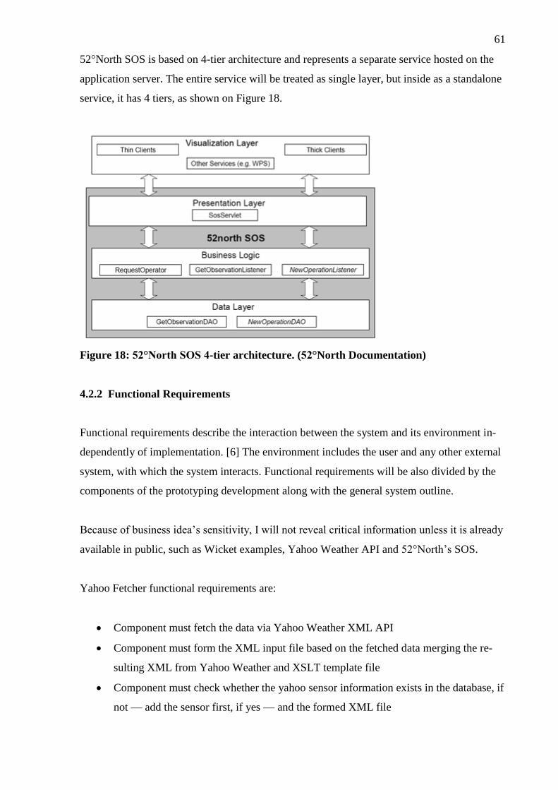
61
52°North SOS is based on 4-tier architecture and represents a separate service hosted on the
application server. The entire service will be treated as single layer, but inside as a standalone
service, it has 4 tiers, as shown on Figure 18.
Figure 18: 52°North SOS 4-tier architecture. (52°North Documentation)
4.2.2 Functional Requirements
Functional requirements describe the interaction between the system and its environment in-
dependently of implementation. [6] The environment includes the user and any other external
system, with which the system interacts. Functional requirements will be also divided by the
components of the prototyping development along with the general system outline.
Because of business idea’s sensitivity, I will not reveal critical information unless it is already
available in public, such as Wicket examples, Yahoo Weather API and 52°North’s SOS.
Yahoo Fetcher functional requirements are:
Component must fetch the data via Yahoo Weather XML API
Component must form the XML input file based on the fetched data merging the re-
sulting XML from Yahoo Weather and XSLT template file
Component must check whether the yahoo sensor information exists in the database, if
not — add the sensor first, if yes — and the formed XML file
62
Component must be loosely coupled for configuration with different SOS services and
different parameters
Component must supply the database with any 10 towns in North America and
Europe, where the information will be fetched every hour and saved in the database
based on the timestamp of the Yahoo Weather XML (if the timestamp is the same as
previous — do not insert new record)
SOS Integration functional requirements are:
Component must be loosely coupled for configuration with different SOS services and
different parameters
SOS must retrieve the model of the system at the start-up
SOS must be stored in the Wicket session across the pages
SOS handles the model manipulation for administrator page functionality as well as
supplied functions
Data Browser functional requirements are:
Data Browser has 4 pages for user purpose: Map Page, List Page, Graph Page, 360
Page (this one is omitted due to its simplicity); and 1 page for administration of the da-
tabase — Administration Page
Data Browser has 3 scrollable panels with items. Each panel’s behaviour must depend
on the selected page.
Map Page functional requirements are:
Map Page must be display the multiple maps and allow to switch from one to another
Map Page must represent the information in form of the markers and pop-ups
Map Page must be able to zoom and move view
Map Page should allow the marker filtering via mouse operations
Map Page must display markers in circle when multiple markers has the same lat/lon
Map Page pop-up details must be redirected to List and Graph Page is desired
Data Browser panels must filter the markers based on its selection

63
List Page functional requirements are:
List Page must display the data in table format by timestamp and value
List Page allows to filter the rows by timestamp or value
List Page allows to export the filtered/non-filtered data into different formats
List Page displays the entire data array by portions in form of pages
List Page allows sorting feature based on value or timestamps
Data Browser panels must select the viewed items based on its selection
Graph Page functional requirements are:
Graph Page display the graph in two formats: pie chart and line chart
Graph Page allow to save the current image of the graph
Graph Page allow to expand itself to a bigger window
All the lines of the items must have distinguished colour
Graph Page shows relations between timestamps and selected items
Line Chart allow to filer the items inside of the graph
Each edge point must be supplied with pop-up, in case of having more than one points
on the same position — pop-up must show all of them
Data Browser panels must select the viewed items based on its selection
4.2.3 Non-Functional Requirements
Non-functional requirement describe non-direct actions, related to the functional behaviour of
the system. [6] For example, is could be quality requirement, such as usability, reliability,
supportability or performance desires. Other example is the constraints: legal, interface or
operational requirements. Best practice is to eliminate any constraints from the requirement,
defining the methodology, programming language or use of specific IDE (Integrated Devel-
opment Environment) because it may slow the project or even make is ambitious. [6]
Observis Platform SRS does not specify any implementation or legal constraints, even further
it is open for usage of new technologies, rather than staying in the one field with one prospec-
tive.
Quality non-functional requirements are:

64
Data Browser must be accessible via following browsers: Safari, Opera, Chrome, Fire-
fox, Internet Explorer; running under one of the following operating systems: Linux,
Win X and Mac OS X. In any case, the user experience must remain the same
Development of prototype up to acceptance criteria must take no longer than 4 month
Performance non-functional requirements are:
System must allow access for the multiple users at the same time
Integration component for gathering the model of spatial database must take no longer
than 30 seconds to retrieve the data
Reliability non-functional requirements are:
Administrator Page should be secured with authentication and authorization
Non- authenticated user must not have the ability to create, update or delete informa-
tion from the database
Authenticated user must perform all changes in atomic way to ensure consistency of
the database
Errors on the Administration Page should be displayed in user-friendly format, in case
of faults, all operations must be rolled back
System should be available 24/7/365 under normal circumstances
Supportability non-functional requirements are:
System shutdown must not take longer than 4 hours to upgrade the service
System must be able retain portability across multiple application servers
System should follow component-based style to wrap and reuse the components
Usability non-functional requirements are:
GUI must be user friendly and does not require study any manuals before the usage
Use of GUI must look aesthetically correct and be fluent in interaction, eliminating the
unnecessary usage of keyboard, utilizing mouse scroll wheel for listing the data
65
Interface non-functional constraints:
System has to utilize the 52°North SOS as data access layer
Yahoo Fetcher must use XML and XSLT merging
The system also has a number of dependencies, excluding every-time required:
Wickets Framework libraries: wicket-extensions, wicket-auth-roles, wicket-datetime
JSON Simple for JSON string creation on Graph Page
OpenLayers integration for Map Page
jQuery for GUI interaction and data manipulation on List Page
XStream for loosely coupled configuration
DOM4J libraries to support XML-file operations
JAXEN for XPath for XML-file operations
OpenFlashChart 2 libraries for data visualization
4.2.4 Scenarios and Use Cases
Use cases helps to define the user functionality in graphical form. Being supplied with actors
and use case scenarios, they explain the particular situation, which may happen at the running
time. [6] I will provide only one example of the scenario, followed by the first effort use case
description and refined use case description, otherwise the amount of work for each single use
case will exceed any feasible boundaries. Also, I will draw a simplified use case diagram of
the system.
Use case has actors, which represent roles of the users, which interact directly to the system.
System actors (external entities that interact with the system) are:
Client — end-user who wish to view the information
Administrator — customer who wish to manage the information
Scenario is “a narrative description of what people do and experience as they try to make use
of computer systems and applications”. [4] In other words, scenario is an instance of the use
case, describing the concrete situation, without any paths or decisions. [4] [6] For example,

66
consider company wants to investigate what is happening when user wants to see and export
the details of the temperature from the system:
Scenario name viewTemperatureDetails
Participating actor Homer:Client
Flow of events 1. Homer opens the browser, types the address of the system
web site and hits Enter. New session is started by fetching
the model from the database. The home page redirects him
to the Map Page of the system.
2. Homer scrolls through the items in the panels using the
mouse wheel and selects his home town and temperature
items. By default all items were selected.
3. Homer sees the marker on the map over his town, zooms in
using the map controls.
4. It turns out that only one marker exists on the desired place,
therefore Homer simply clicks the temperature icon using
left mouse button and the pop-up appears on the left-bottom
side from the icon with the detains of the place, position and
current temperature
5. Homer wants more, and he presses the “View in List for-
mat” icon, which redirects him to the List Page with pre-
served selections
6. Being interested in the days, where temperature was exactly
15 degree, Homer type number 15 into search form and the
list automatically filters the rows, where value is equal to
the requested.
7. Homer is exited with the results and wants to share it with
his friends, in order to do so; he clicks the button, saying
“PDF” and chooses the location to save the table in PDF
format.
8. Once the document has been saved, Homer closes the
browser, terminating the session.

67
It may seem that scenario is the same as use case, but it’s not due to the decisions and abstract
nature of the use case. Now that I identified the flow of events for the particular Homer actor,
let’s move further and create an abstract of that scenario defining the use case description:
Use case name viewMapPageAndListPage
Participating actor Initiated by Client
Entry condition Client opens the browser, types the address of the system
web site and hits Enter.
New session is started by fetching the model from the data-
base.
The home page redirects him to the Map Page of the system.
Flow of events 1. Client selects the desired combination of place and item to
view.
a. System filters the markers on the map.
2. Client navigates to the place of his interest using map con-
trols.
a. Single marker is located in the position, OR
b. Multiple markers are located around the position in
circle form; the position itself has unclickable de-
fault marker.
3. Client clicks the marker.
a. System displays the information about place, posi-
tion and current item value in pop-up.
4. Client clicks the icon, leading to the ListPage.
a. System loads the ListPage with preserved selections.
5. Client enters the desired value into search field.
a. System filters the rows by the desired value.
6. Client hits the format button.
a. System opens the save dialog to chose the location
for saving the filtered results in chosen format.
Exit condition Client closes the browser, terminating the session, OR
Wait time exceed the 30 minutes limit.
Quality requirements Data Browser must be accessible via following browsers:
Safari, Opera, Chrome, Firefox, Internet Explorer; running

68
under one of the following operating systems: Linux, Win X
and Mac OS X. In any case, the user experience must re-
main the same
System must allow access for the multiple users at the same
time
Integration component for gathering the model of spatial da-
tabase must take no longer than 30 seconds to retrieve the
data
Refining the use cases description is important part of the software elicitation. As you can see
from the scenario, Homer actually performed two actions during the same session: view the
details of the temperature on the Map Page and export the filtered data on the List Page. The
first attempt of our use case just represented an abstract of such scenario. But now that I ex-
amined those two different actions, I can move further and split the List Page part into view-
ing data in table format from filtering and exporting them. It is perfectly fine to copy paste the
use case descriptions, split them into parts and redo the same part all over again, because the
system design will benefit from clear requirements on the long run.
After the refining process, instead of having viewMapPageAndListPage use case I will ar-
chive the distribution of responsibilities, resulting into use cases:
applicationSession
viewMapPage
viewMapPageMarker
viewListPage
viewListPageFilter
viewListPageFormat
connectionDown
Application Session will be a major use case, handling all quality requirements and includes
the Map and List Pages use cases. Purpose of it is to fetch the model and remain calm until
the user actions or termination conditions:
Use case name applicationSession

69
Participating actor Initiated by Client
Entry condition Client opens the browser, types the address of the system
web site and hits Enter.
Flow of events 1. System fetches the model from the database.
2. System remains in idle state, waiting for user actions.
a. Client may fire the MapPage or ListPage.
Exit condition Client closes the browser, terminating the session, OR
Wait time exceed the 30 minutes limit.
Quality requirements At any point during the flow of events, this use case can in-
clude the viewMapPage and viewListPage use cases.
Data Browser must be accessible via following browsers:
Safari, Opera, Chrome, Firefox, Internet Explorer; running
under one of the following operating systems: Linux, Win X
and Mac OS X. In any case, the user experience must re-
main the same
System must allow access for the multiple users at the same
time
Integration component for gathering the model of spatial da-
tabase must take no longer than 30 seconds to retrieve the
data
viewMapPage occurs after session initialization and may include the viewMapPageMarker:
Use case name viewMapPage
Participating actor Initiated by Client
Entry condition Application session has been started
Map Page has been opened.
Flow of events 1. System displays the map with all items selected by default
and presented in form of the markers.
2. Client selects the desired combination of place and item to
view.
a. System filters the markers on the map.
Exit condition Client leaves the MapPage.
Quality requirements At any point during the flow of events, this use case can in-

70
clude the viewMapPageMarker use case.
GUI must be user friendly and does not require study any
manuals before the usage.
Use of GUI must look aesthetically correct and be fluent in
interaction, eliminating the unnecessary usage of keyboard,
utilizing mouse scroll wheel for listing the data.
Client can execute the viewMapPageMarker use case, which may include the viewListPage:
Use case name viewMapPageMarker
Participating actor Initiated by Client
Entry condition Map Page has been viewed
Flow of events 1. Client navigates to the place of his interest using map con-
trols.
a. Single marker is located in the position, OR
b. Multiple markers are located around the position in
circle form; the position itself has unclickable de-
fault marker.
2. Client clicks the marker.
a. System displays the information about place, posi-
tion and current item value in pop-up.
3. Client may click the icon, leading to the ListPage.
a. The viewListPage use case is included here.
Exit condition Client leaves the MapPage.
Quality requirements none
Following use case may appear either after the application start or from viewMapPageMarker:
Use case name viewListPage
Participating actor Initiated by Client
Entry condition Application session has been started
List Page has been opened.
Flow of events 1. System displays the ListPage with
a. All items selected by default and empty table, OR

71
b. Selection was passed as a parameters and table con-
tains the pair of location and item value without fil-
tering
Exit condition Client leaves the ListPage.
Quality requirements At any point during the flow of events, this use case can in-
clude the viewListPageFilter and viewListPageExport use
cases.
GUI must be user friendly and does not require study any
manuals before the usage.
Use of GUI must look aesthetically correct and be fluent in
interaction, eliminating the unnecessary usage of keyboard,
utilizing mouse scroll wheel for listing the data.
ListPage use case enhanced by the filter and export options:
Use case name viewListPageFilter
Participating actor Initiated by Client
Entry condition Application session has been started
List Page has been viewed.
Flow of events 1. Client enters the desired value into search field.
a. System filters the rows by the desired value.
Exit condition Client leaves the ListPage.
Quality requirements none
Use case name viewListPageFormat
Participating actor Initiated by Client
Entry condition Application session has been started
List Page has been viewed.
Flow of events 1. Client hits the format button.
a. System opens the save dialog to chose the location
for saving the filtered results in chosen format.
Exit condition Client leaves the ListPage.
Quality requirements none

72
One more important use case has the exceptional behaviour, which is unlikely to happen:
Use case name connectionDown
Participating actor Client communicates with the system
Entry condition This use case extends the applicationSession use case. It is
initiated by the system whenever the network connection
between the database and presentation layer is lost.
Flow of events 1. System displays the error message.
2. System rolls back the model to preserve the atomic state.
Exit condition Client closes the browser, OR
Connection is successfully re-established.
Quality requirements none
Use case diagram (Figure 19) combines the actor and all use cases with their relationships:
Figure 19: Use Case Diagram for MapPage and ListPage.
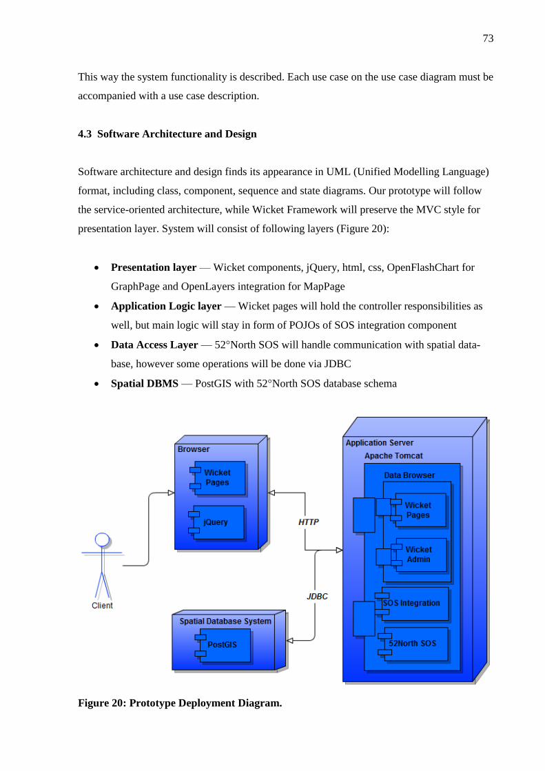
73
This way the system functionality is described. Each use case on the use case diagram must be
accompanied with a use case description.
4.3 Software Architecture and Design
Software architecture and design finds its appearance in UML (Unified Modelling Language)
format, including class, component, sequence and state diagrams. Our prototype will follow
the service-oriented architecture, while Wicket Framework will preserve the MVC style for
presentation layer. System will consist of following layers (Figure 20):
Presentation layer — Wicket components, jQuery, html, css, OpenFlashChart for
GraphPage and OpenLayers integration for MapPage
Application Logic layer — Wicket pages will hold the controller responsibilities as
well, but main logic will stay in form of POJOs of SOS integration component
Data Access Layer — 52°North SOS will handle communication with spatial data-
base, however some operations will be done via JDBC
Spatial DBMS — PostGIS with 52°North SOS database schema
Figure 20: Prototype Deployment Diagram.
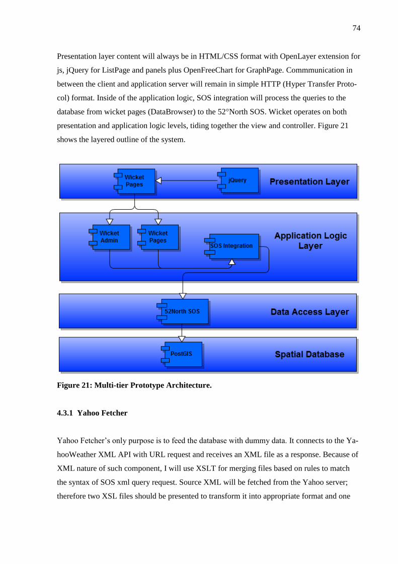
74
Presentation layer content will always be in HTML/CSS format with OpenLayer extension for
js, jQuery for ListPage and panels plus OpenFreeChart for GraphPage. Commmunication in
between the client and application server will remain in simple HTTP (Hyper Transfer Proto-
col) format. Inside of the application logic, SOS integration will process the queries to the
database from wicket pages (DataBrowser) to the 52°North SOS. Wicket operates on both
presentation and application logic levels, tiding together the view and controller. Figure 21
shows the layered outline of the system.
Figure 21: Multi-tier Prototype Architecture.
4.3.1 Yahoo Fetcher
Yahoo Fetcher’s only purpose is to feed the database with dummy data. It connects to the Ya-
hooWeather XML API with URL request and receives an XML file as a response. Because of
XML nature of such component, I will use XSLT for merging files based on rules to match
the syntax of SOS xml query request. Source XML will be fetched from the Yahoo server;
therefore two XSL files should be presented to transform it into appropriate format and one

75
XML for checking the presence of the sensor. Figure 22 shows the data flow diagram of the
component.
The intent is as following:
Fetch the XML based on the city zip ID
Save results as XML file
Check whether the sensor exists in the SOS database
o If Yes — feed the data
o If No — register the sensor and then feed the data
Figure 22: Yahoo Fetcher Control Flow.
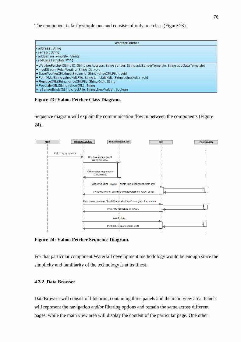
76
The component is fairly simple one and consists of only one class (Figure 23).
Figure 23: Yahoo Fetcher Class Diagram.
Sequence diagram will explain the communication flow in between the components (Figure
24).
Figure 24: Yahoo Fetcher Sequence Diagram.
For that particular component Waterfall development methodology would be enough since the
simplicity and familiarity of the technology is at its finest.
4.3.2 Data Browser
DataBrowser will consist of blueprint, containing three panels and the main view area. Panels
will represent the navigation and/or filtering options and remain the same across different
pages, while the main view area will display the content of the particular page. One other

77
panel in DataBrowser will be preserved for navigation in between the pages, which is simple
and does not count as content display operation. There also should be a way to administrate
the panels, meaning to change the name, image of the item, delete or add new one. Essential
feature is to add integration from existing devices so that new items will be populated auto-
matically within less than 24 hours. Adapter and Facade patterns will be used to deal with
third-party components and sometimes to reduce the complexity within the application itself.
DataBrowser must follow basic Wicket style of inheriting the pages and communication with
end-user via model-based programming paradigm. Everything, representing the logic and not
directly related to GUI graphical user interface must be moved to a separate component and
referenced via maven dependency. Essentially, DataBrowser should be nothing more compli-
cated, than using SOS Integration, OpenLayers Integration and storing the model and user
credentials in the session. The transition between the pages should be mounted to separate
classes, while the panels should communicate via AJAX depending on the selected page. Fig-
ure 25 layouts the schematic design for DataBrowser.
Figure 25: DataBrowser Schematic Design.

78
4.4 Software Implementation and Testing
Implementation will obviously take place in the world of Java EE using Wicket Framework,
jQuery (which did not have integration by that time) manual insertion into html, XML, SOS
and JDBC tricks.
Testing will be handled in Jetty application server environment, which has been chosen by
Wicket’s developers on the first place. Logs from there will be displayed right in the IDE, but
logs from the PostGIS database operations will be displayed in the log files of the Apache
Tomcat application server and mainly will be produced by 52°North SOS.
Wicket Framework, build from maven, comes with lightweight embedded Jetty application
server for testing. [16] It allows starting the server and deploying the application by simple
launching the Start.java file. [17] Also, Wicket does have its own testing class which relies on
JUnit.
Because the requirement elicitation is never clear on the first place for such complex systems
and also requirement functionality is never detailed enough to match the all the interfaces and
technologies, system testing must be taken into account:
Black-box testing — based on the requirements and answers the question “are we
building the right product?” Does not reveal the system implementation. [5]
White-box testing — based on implementation and answers the question “are we
building the product right?” Potentially contains the un-documented functionality. [5]
4.4.1 Yahoo Fetcher
Following section explains the implementation of Yahoo Fetcher component, which is grab-
bing the data via Yahoo Weather XML API and puts them into PostGIS. This part consists of
practical examples and pure code, therefore more information could be found in appendixes.
Constructor class implements the main logic of data flow diagram, presented earlier in archi-
tecture of the component. [See Appendix 4 YahooFetcher main logic].
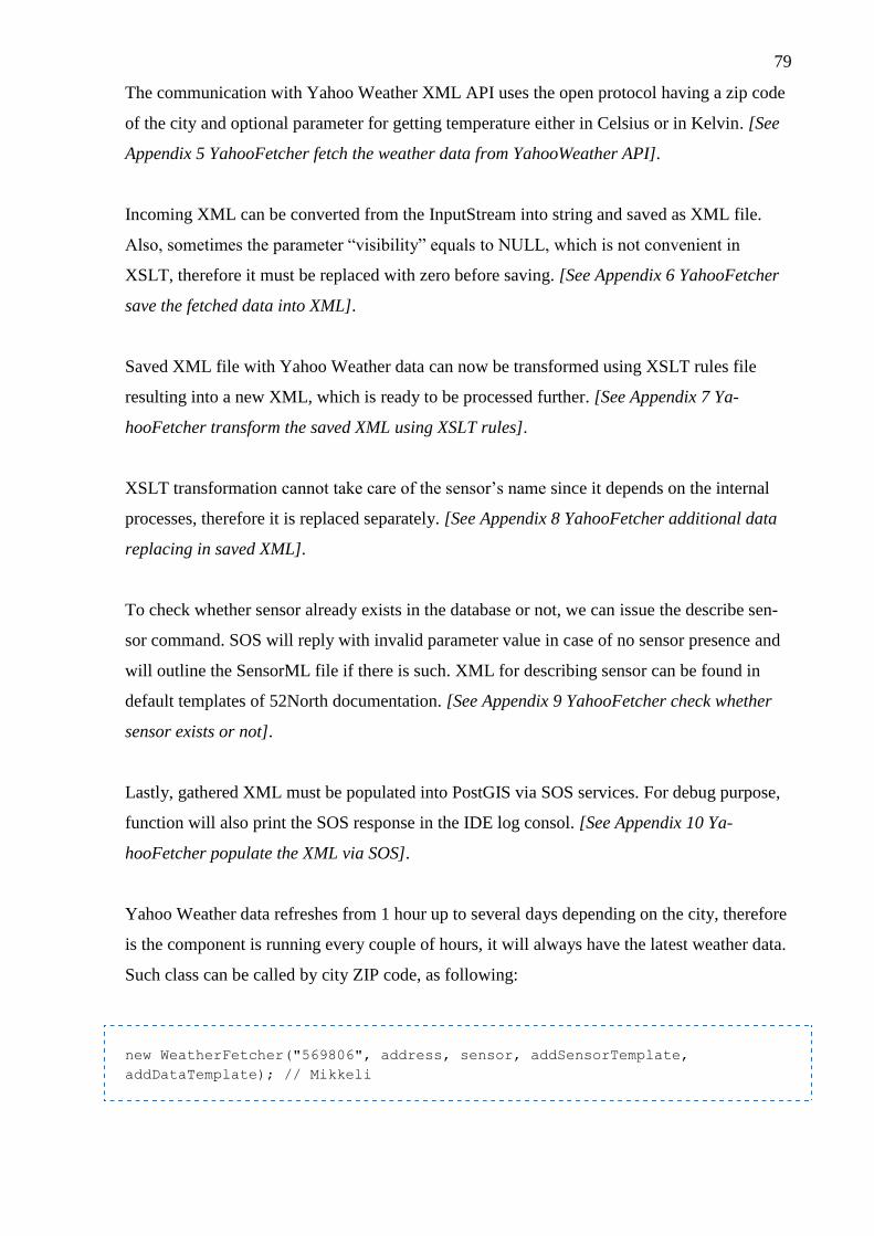
79
The communication with Yahoo Weather XML API uses the open protocol having a zip code
of the city and optional parameter for getting temperature either in Celsius or in Kelvin. [See
Appendix 5 YahooFetcher fetch the weather data from YahooWeather API].
Incoming XML can be converted from the InputStream into string and saved as XML file.
Also, sometimes the parameter “visibility” equals to NULL, which is not convenient in
XSLT, therefore it must be replaced with zero before saving. [See Appendix 6 YahooFetcher
save the fetched data into XML].
Saved XML file with Yahoo Weather data can now be transformed using XSLT rules file
resulting into a new XML, which is ready to be processed further. [See Appendix 7 Ya-
hooFetcher transform the saved XML using XSLT rules].
XSLT transformation cannot take care of the sensor’s name since it depends on the internal
processes, therefore it is replaced separately. [See Appendix 8 YahooFetcher additional data
replacing in saved XML].
To check whether sensor already exists in the database or not, we can issue the describe sen-
sor command. SOS will reply with invalid parameter value in case of no sensor presence and
will outline the SensorML file if there is such. XML for describing sensor can be found in
default templates of 52North documentation. [See Appendix 9 YahooFetcher check whether
sensor exists or not].
Lastly, gathered XML must be populated into PostGIS via SOS services. For debug purpose,
function will also print the SOS response in the IDE log consol. [See Appendix 10 Ya-
hooFetcher populate the XML via SOS].
Yahoo Weather data refreshes from 1 hour up to several days depending on the city, therefore
is the component is running every couple of hours, it will always have the latest weather data.
Such class can be called by city ZIP code, as following:
new WeatherFetcher("569806", address, sensor, addSensorTemplate,
addDataTemplate); // Mikkeli

80
4.4.2 Data Browser
In Wickets every AJAX behaviour component must be explicitly set into the updatable state
by following member function [16]:
whatever.setOutputMarkupId(true);
To create an updatable via AJAX HTML container and specify the child component for
Wicket page issue the following code [16]:
<span wicket:id="updatableAjax">
<wicket:child />
</span>
This code defines the current HTML file as parent and hides the child implementation to the
extended classes. The java class using such HTML must extend the Wicket’s WebPage and be
abstract. Meanwhile, the child HTML file will gain to clause: extend and head. Head is used
for whatever linkage files the HTML file was supposed to reference in the head section, while
extend will be replaced with child clause at the rendering time on the upper level. Java class
of child page is derived from the parent class. It is done in a way, that parent abstract class has
AJAX containers and adds components to the page itself, but the derived classes add compo-
nents to the containers, getting the reference from the parent class. Consider following exam-
ple:
<wicket:head>
<link rel="stylesheet" href="style.css" type="text/css" />
</wicket:head>
<wicket:extend>
A child has been born!
</wicket:extend>
Another option to extend and simplify the document structure is to use panels instead of child-
parent pair. With panels, they can be anything, which is better to keep outside of the docu-
ment scope, while child always have parent and parent has to have some child. Java class ex-

81
tends the panel, or the implementation of the panel in case of using OpenLayers. HTML for
the panel is fairly simple:
<wicket:panel>
Any single word here.
</wicket:panel>
Panels must be created in Wicket inherited style for HTML pages. Also, AJAX must be used
in the panels to prevent the server from constant refreshing the same exact data and keep the
user selections on the same place. Because Wicket does not have good integration with
jQuery (the one I found was simply overcomplicated due to fact that you not only have to
create a jQuery code on your own, but also the java code as well. There is not any purpose or
advantage of doing that, instead it is much simpler to just write direct jQuery inside of HTML
and it will still hold the Wicket style of not putting HTML inside of java) I decided to bind the
HTML containers with hidden ID inputs inside of the panel and pass it to the jQuery.
The trick is so, that each item in the panel is essentially an HTML form. At the time of render-
ing each item is supplied with hidden input field with id. Such id will be used as a reference to
the SOS integration. Panel will populate the appropriate image (if does not exists — use de-
fault image) and name to the item, but mostly important — the AJAX link which must per-
form an actions, dependent on what page the user is viewing. For example, for the MapPage
the user should be able to filter the markers when clicking on the items, meanwhile on the
ListPage the click action on the item must result into change of the table view. On GraphPage,
clicking the item essentially reloads the page in contrast with other pages, where communica-
tion is done via AJAX. Sometimes, panels must be dependent not only based on the viewed
page, but also on each other, for example selections on one panel will filter the items on the
other. Also, panel may allow multiple selections (checkbox) or only single one selection (ra-
dio button). It is important to keep track on which items were selected and which were not.
Wicket does not have any embedded function for that, so I decided to use jQuery class here.
Basically, each item has the state true or false inside of the Wicket, and at the time of render-
ing I can add different classes to the HTML containers based on such states. jQuery will take
the class, which is “active” or “passive” and toggle the style for each of them. Because the
states are held on Wicket side it is possible to preserve the states and the view for the end user
in correct form.

82
The distinguish behaviour for each panel based on the page can be archived by the fact, that
each page is a different object, derived from the same class. Therefore, decision path for the
panel’s actions and selection as well as link selection cuts to:
if (page instanceof MapPage)
…
if (page instanceof ListPage)
…
if (page instanceof GraphPage)
…
One issue with panels is that they are scrollable. That means that in case of travelling from
one page to another the state of the items is easy to keep, but how keeping the position of the
last clicked item? There could be more than 10 of them and user does not want to search for
the common place all the time. The answer lays in the jQuery jCaroUsel component options.
There is an option to start at any random item, but the referencing to such item must be done
via separate Wicket component. The problem there is that Wicket always works with HTML
containers if not specified otherwise. To pass the pure string into JavaScript code developer
need to explicitly disable the escape modelling of such string:
new Label("jsContainer", jsContainer).setEscapeModelStrings(false);
All the panels and also the table in ListPage are using Observer pattern, which is called List-
View in Wicket. Such pattern implements the idea of changing the model on the fly, resulting
into changing the view. Dynamic nature of Observer is important, since panels are updatable
via AJAX. Mediator pattern will take care of communication in between the panels to reduce
the dependency. Consider the following implementation of loadable model:
IModel<Vector<String>> repeatingList =
new LoadableDetachableModel<Vector<String>>() {
private static final long serialVersionUID = 1L;
@Override
protected Vector<String> load() {
return new Vector<String>();
}
};

83
Such code creates a Wicket model with model, consuming the vector of strings. It overrides
the load function to create the object from any source developers might have. Next piece of
code takes the model; bind it to the HTML container and overrides the populate function
which feeds the single object of the model:
ListView<String> repeatingView =
new ListView<String>("repeatingViewTable", repeatingList) {
private static final long serialVersionUID = 1L;
@Override
protected void populateItem(ListItem<String> item) {
String s = (String) item.getModelObject();
item.add(new Label("title", s));
}
};
The idea is so, that LoadableDetachedModel is a complex model, fetching itself based on
some business logic, while the ListView is pure html-oriented component, taking every single
object from the vector of the model and populating it to the document.
Pages themselves must be nearly identical; therefore I will create a MainPage which will be
an abstract constructor for every other page. It will create the structure for panels in Wicket
HTML style as well as reference to css/JavaScript files, change the title of the page and pro-
vide a reference to the session resources.
Another important issue is to store the session across the web application. In case of simple
servlet query, I will end up fetching the entire database every time I change the page, which
could possible take up to several minutes. Instead, I can fetch it for the first time and keep it
internally, modifying if needed. Fortunately, Wicket does have a session class, which in com-
bine with main application may contain any data structure. Such data structure can be refer-
enced from any page because of the inheritance. Session is using the expensive operation to
the SOS integration model — let it utilize the Proxy pattern to reduce the cost of fetching the
items, which are outside of the scope of interest.
AdministrationPage will allow database manipulation in CRUD style. It is important to know,
that in Wickets the main application as well as the session itself are derived from the base

84
class. In case of using authentication and authorisation base classes become different as well.
Those new classes will provide new functions to override, which will be responsible for sing-
ing up and out, getting roles and starting new session. Administration feature is very sensitive
and require only one instance of admin user across the application. Let the Singleton pattern
deal with it.
The authentication session can be checked from the session class in overridden function:
@Override
public boolean authenticate(final String username,
final String password) {
return new Admin(username, password).isAuthenticated();
}
Session also provides the array of roles, available for authenticated admin:
@Override
public Roles getRoles() {
return admin.getRoles();
}
Such roles can be used as annotation on the class or panel. Checking can also be done manu-
ally, since the usage of annotations is not available for functions and member variables. Con-
sider the example, where class can be accessed by the users with any of two roles:
@AuthorizeInstantiation({"developer", "manager"})
public class CompanyPage {}
Other option is not only allowing access, but specifies the actions. Here, the page will be
loaded for any role, bet component rendering will succeed only for the role “developer”:
@AuthorizeAction(action = "RENDER", roles = "developer")
public class CompanyPage {}

85
Administrator page will take advantage of JDBC; therefore I should provide an XML configu-
ration file with connection options for the database. On the long run it will be used to re-link
to the production server.
Wicket folder consist of java files, webapp, which holds the client code (html/css/JavaScript
and images) and resources, which are used to reference from the java files, because java can-
not link to the standard webapp folder.
One distinguished example is the BigGraphPage which essentially is expanded to the full
screen GraphPage. It is interesting, that Even though BigGraphPage is not derived from the
IndexPage nad does not inherit anything but standard BasePage, it still has access to all capa-
bilities of the application.
Another issue with both GraphPage and BigGraphPage is that they are using OpenFlashChart,
which obviously based on flash, meaning that page has to be refreshed since not build-in
AJAX capabilities are exist. Also, OFC has to use resource folder and be bind to the URL
explicitly. It can be done in the main application file, along with the ListPage requirement,
concerning the parameter passing. The page refreshing, however, can be done via AJAX as
well, but it is a little bit tricky and still does the common refreshing page behaviour [16]:
new AjaxFallbackLink<Object>("refresh") {
@Override
public void onClick(AjaxRequestTarget target) {
target.appendJavascript("window.location.reload()");
}
}
The mounting of a page to the particular name can be done in the main application class [16]:
@Override
protected void init() {
super.init();
mountBookmarkablePage("graph", GraphPage.class);
}
ListPage was the tricky one, because Wicket possesses the table component, but it failed to
impress due to its complexity and lack of flexibility. Instead, I re-implemented it in pure
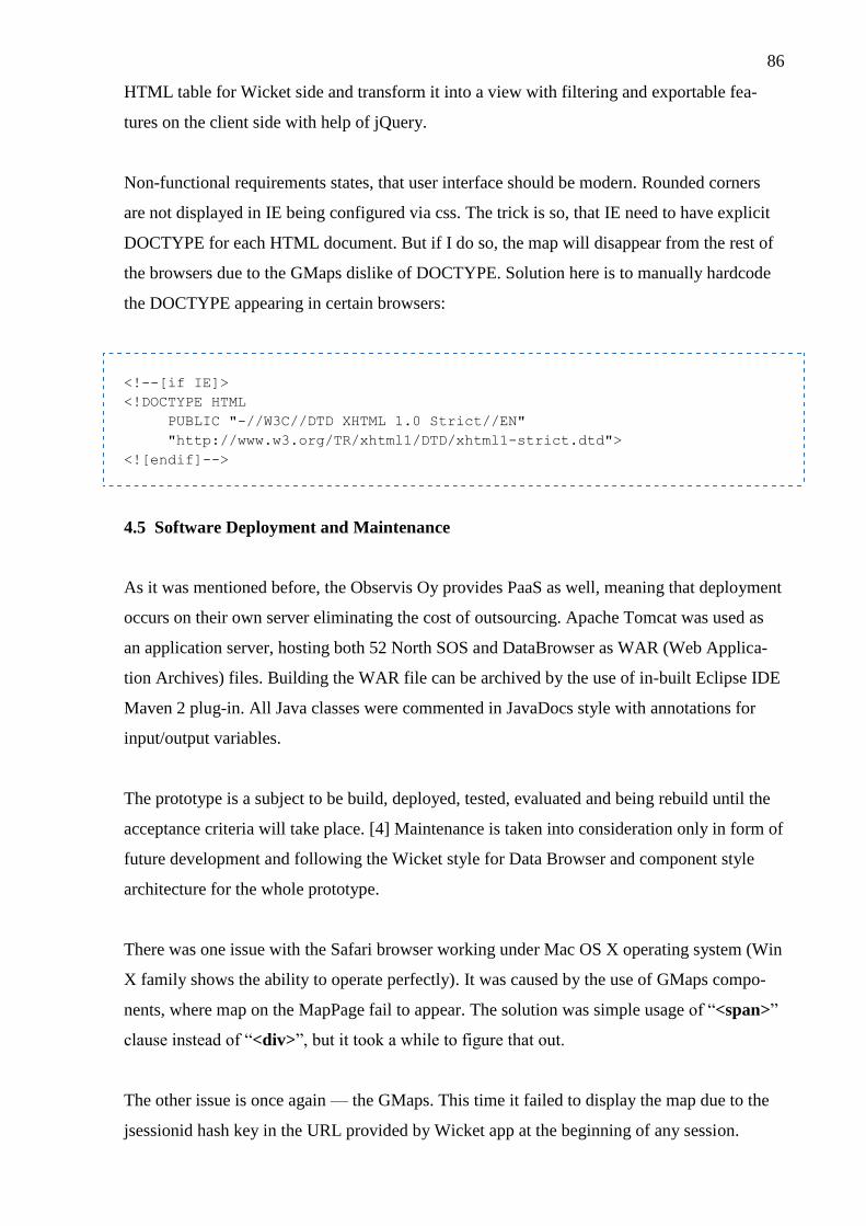
86
HTML table for Wicket side and transform it into a view with filtering and exportable fea-
tures on the client side with help of jQuery.
Non-functional requirements states, that user interface should be modern. Rounded corners
are not displayed in IE being configured via css. The trick is so, that IE need to have explicit
DOCTYPE for each HTML document. But if I do so, the map will disappear from the rest of
the browsers due to the GMaps dislike of DOCTYPE. Solution here is to manually hardcode
the DOCTYPE appearing in certain browsers:
<!--[if IE]>
<!DOCTYPE HTML
PUBLIC "-//W3C//DTD XHTML 1.0 Strict//EN"
"http://www.w3.org/TR/xhtml1/DTD/xhtml1-strict.dtd">
<![endif]-->
4.5 Software Deployment and Maintenance
As it was mentioned before, the Observis Oy provides PaaS as well, meaning that deployment
occurs on their own server eliminating the cost of outsourcing. Apache Tomcat was used as
an application server, hosting both 52 North SOS and DataBrowser as WAR (Web Applica-
tion Archives) files. Building the WAR file can be archived by the use of in-built Eclipse IDE
Maven 2 plug-in. All Java classes were commented in JavaDocs style with annotations for
input/output variables.
The prototype is a subject to be build, deployed, tested, evaluated and being rebuild until the
acceptance criteria will take place. [4] Maintenance is taken into consideration only in form of
future development and following the Wicket style for Data Browser and component style
architecture for the whole prototype.
There was one issue with the Safari browser working under Mac OS X operating system (Win
X family shows the ability to operate perfectly). It was caused by the use of GMaps compo-
nents, where map on the MapPage fail to appear. The solution was simple usage of “<span>”
clause instead of “<div>”, but it took a while to figure that out.
The other issue is once again — the GMaps. This time it failed to display the map due to the
jsessionid hash key in the URL provided by Wicket app at the beginning of any session.
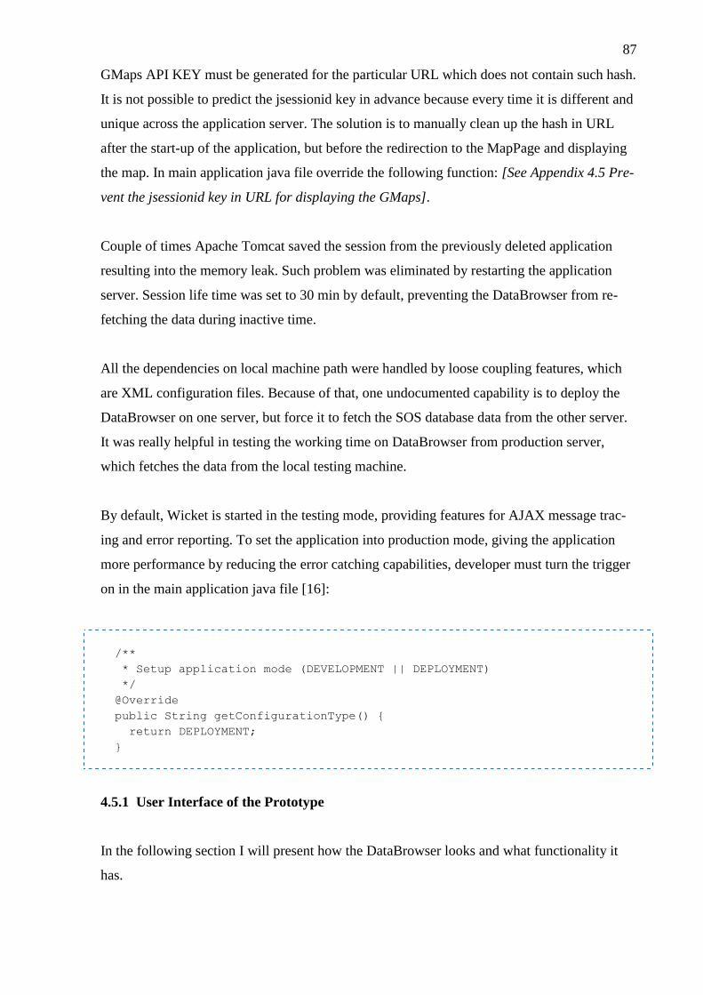
87
GMaps API KEY must be generated for the particular URL which does not contain such hash.
It is not possible to predict the jsessionid key in advance because every time it is different and
unique across the application server. The solution is to manually clean up the hash in URL
after the start-up of the application, but before the redirection to the MapPage and displaying
the map. In main application java file override the following function: [See Appendix 4.5 Pre-
vent the jsessionid key in URL for displaying the GMaps].
Couple of times Apache Tomcat saved the session from the previously deleted application
resulting into the memory leak. Such problem was eliminated by restarting the application
server. Session life time was set to 30 min by default, preventing the DataBrowser from re-
fetching the data during inactive time.
All the dependencies on local machine path were handled by loose coupling features, which
are XML configuration files. Because of that, one undocumented capability is to deploy the
DataBrowser on one server, but force it to fetch the SOS database data from the other server.
It was really helpful in testing the working time on DataBrowser from production server,
which fetches the data from the local testing machine.
By default, Wicket is started in the testing mode, providing features for AJAX message trac-
ing and error reporting. To set the application into production mode, giving the application
more performance by reducing the error catching capabilities, developer must turn the trigger
on in the main application java file [16]:
/**
* Setup application mode (DEVELOPMENT || DEPLOYMENT)
*/
@Override
public String getConfigurationType() {
return DEPLOYMENT;
}
4.5.1 User Interface of the Prototype
In the following section I will present how the DataBrowser looks and what functionality it
has.

88
GraphPage lays out data in flash format. Default and the most common is a line chart, which
can take multiple entries for the lines and differentiate them by given aspect (Figure 26).
Figure 26: DataBrower / GraphPage / Line chart.
The graphic consist of unit for y-axis and time for x-axis. Each time YahooFetcher component
fetches the weather data; it gets registered in the system and attached to the certain condition
and time. The graph populates by inserting the points and connecting them by lines. In case of
missing time-points lines will assume the value by calculating an average in between of two
nearest points. This usually happens because different cities have value for different time-
stamp but each timestamp has to be on the graph. In case of having the values for the same
timestamp for more than one city, the OFC has nice feature to popup the dialog for both of
them with additional information. The last type of the chart is a pie chart, which represents
values not based on one, but based on all selected cities (Figure 27). The flash also allows to
save the view screen in PNG format or to expand the view into new window making it bigger.

89
Figure 27: DataBrower / GraphPage / Pie chart.
Unlike GraphPage, ListPage will provide an ability to view data in table format with handy
features, such as column sorting, searching for string presence in both of the columns, listing
up to 15 records per page (Figure 28). Besides that, third-party framework based on jQuery
power the list with exporting features in CSV (Comma Separated Value), Excel or PDF for-
mats. It is even possible to save the data to clipboard by using “Copy” button. This view al-
lows only one-to-one selection between city and weather aspect, for example “Detroit” and
“temperature”. Firstly, the content view was done via default table component coming from
Wicket, but because of its complexity and reduced flexibility for a release I decided to switch
to the pure jQuery style table with outsourced exporting features. Such solution even escaped
from violating the golden rule of Wicket architectural style — split HTML and java imple-
mentation. The problem with Wicket table also was so, that every time it lists the pages back
and forth it fetches the data from back end java, which is a waste of resources. JavaScript im-
plementation simply fetches all the data once and populates them into simple HTML table
with no hard coding involved and the page listing features are handled by script in a way of
updating the table.

90
Figure 28: DataBrower / ListPage.
MapPage was one of the key points in data layout (Figure 29). Currently, it supports the
GMaps and OpenStreetMaps, but much more integrations are coming in latest release. Also,
the MapPage causes the most amounts of errors during the deployment and implementation
phases. Two possibilities exists while displaying the point — there could be only one weather
aspect or more than one with the same latitude and longitude on the map. One aspect repre-
sents itself with icon, but more than one were hard coded in a way that top icon is always the
icon provided in GIF format from yahoo weather API and shows the expected weather fore-
cast as picture. Because OpenLayers allows only one layer for each icon it is essential not to
put them over each other. Spreading icons into separate layers is possible, but requires more
complicated code and practically creates a mess in business logic. The weather icon from Ya-
hoo Weather must always stay on top. The problem was so, that every time the user selects
the city or weather aspect, map view gets filtered out, which is perfectly fine, but once the
user filters them back on the map, new icons overlay the previous one. The solution was so,
that each time user filters the markers, map view redraws every single one in a way that it
follows the “weather icon on the top” rule. Such solution is resource consuming, but at the
same time it is the only feasible one.

91
Figure 29: DataBrower / MapPage / Europe.
When the user zooms into such location, he can see all the icons around the real position
(Figure 30). Cities on the map can be filtered on the panel side as well as weather aspects
from yahoo weather. Because the YahooFetcher was put into use to fetch the data every day,
it was an interesting experience to see the clouds and fog moving across the Europe while
North America stood in “night” transition. User can get more information from the weather if
he clicks on the corresponding icon, resulting into pop-up appearance. Such pop-up contains
the current situation of the chosen weather aspect as well as the links to ListPage and Graph-
Page (Figure 31).
Each panel is scrollable under jCaroUsel framework coming from jQuery. Each panel is also
has different functionality depending on the selected page, for example on GraphPage it al-
lows multiple selection for cities, but only one for weather aspect, while for ListPage it is al-
ways one-to-one. MapPage also filters content by sensors, meaning that it not only filters the
view area, but also the panels. Website itself has the administration page which is not shown
here for security purpose, but can be only accessed by typing the URL in address bar. Login
page checks the authorization of the person and based on that shows the managing features.

92
Figure 30: DataBrower / MapPage / Mikkeli.
Figure 31: DataBrower / MapPage / Mikkeli Pop-up.

93
5 CONCLUSION
By using throw-away prototype methodology I proved the concept of Observis Platform, in-
vestigated functional possibilities, limitations of programming language framework and dis-
covered the third-party software implementation. Understanding of our own problem domain
was supplied with more clear view of spatial database scheme.
At first I discussed general enterprise architecture, its applications, patterns and different
models. I concentrated mostly on problem-related topics, such as Service-Oriented and Multi-
Tier Architectures, which are the most popular among web-based development process. Fi-
nally, I concluded the theory part with introducing the concepts of software engineering com-
ponents, which differentiate simple programming from software architecture development.
Second part of thesis covers practical implementation of our project. In this case example I
went throw whole software development process, applying knowledge, gathered in the theory
part. I started from the information gathering and deciding on functional/non-functional re-
quirements and its analysis. That knowledge was used for creating use case diagrams and use
case descriptions, defining the scope of our project. Having clear use cases I was able to do
the system design and further more understand the event-flow and control-flow activities of
our application. Once I had enough of design, implementation and testing of the system took
its place. Each cutting edge version of software was published on the internal company struc-
ture and presented for visualization of the results.
Prototype has been divided into three components: Yahoo Fetcher is relatively small and its
only purpose is to fulfil the spatial database with data coming from the Yahoo Weather API in
XML format; Data Browser is the largest of all since it serves as presentation and administra-
tion tool, operating with database information, gathered by Yahoo Weather component; SOS
Model takes care of core data-retrieving functionality and lays in between the Data Browser
and spatial database management system.
Because I was using rapid application development methodology, I was constantly iterating in
cycle of gathering requirements, design, implementation and testing of the prototype. Each
time I thought that I implemented very last thing and exhaust every last possibility on the test-
ing stage, I came across to the presentation and discovered that there is plenty more things to

94
do, therefore it’s back to the requirement elicitation. This way turned out to be the best
method, because problem domain was unknown and requirements were unclear. At the end of
the project I learned more about our own system and prototype became a predecessor for fu-
ture Observis Platform, which will eliminate lots of previous mistakes and start new line of
the development from the scratch having better understanding of the solution domain.
With that, my Final Thesis concludes the modern software development process at its best
manner combining theoretical knowledge and converting them into practical-oriented solu-
tion. Having such a prototype, Observis Oy will be able to further more develop the system
and implement Observis Platform, which will make our life easier.

95
REFERENCES
[1] jQuery Community Experts, jQuery Cookbook, Sebastopol, O’Reilly, 2010
[2] Goncalves Antonio, Beginning Java EE 6 with GlassFish 3, New York, Apress, 2010
[3] McConnell Steve, Code Complete, Washington, Microsoft Press, 2005
[4] Bass Len, Clements Paul and Rick Kazman, Software Architecture in Practice, Boston,
Addison-Wesley Professional, 2003
[5] Mathur Aditya, Foundations of Software Testing, Boston, Addison-Wesley Professional,
2008
[6] Bernd Bruegge and Allen Dutoit, Object-Oriented Software Engineering: Using UML,
Patterns and Java, New Jersey, Prentice Hall, 2009
[7] Alhir Sinan, Learning UML, Sebastopol, O’Reilly, 2003
[8] Liang Daniel, Introduction to Java Programming, New Jersey, Prentice Hall, 2010
[9] Christopher Date, Introduction to Database Systems, Boston, Addison-Wesley Profes-
sional, 2000
[10] Keith Mike and Schincariol Merrick, Pro JPA 2 Mastering the Java, New York, Apress,
2009
[11] Linwood Jeff and Minter Dave, Beginning Hibernate, New York, Apress, 2010
[12] Fisher Paul Tepper and Murphy Brian D., Spring Persistence with Hibernate, New York,
Apress, 2010
[13] Pisa Filippo, Beginning Java and Flex, New York, Apress, 2009
[14] Guermeur Daniel and Unruh Amy, Google App Engine Java and GWT Application De-
velopment, Birmingham, Packt Publishing Ltd., 2010
[15] Vaughan Daniel, Ext GWT 2.0, Birmingham, Packt Publishing Ltd., 2010
[16] Vaynberg Igor, Apache Wicket Cookbook, Birmingham, Packt Publishing Ltd., 2011
[17] Dashorst Martijin and Hillenius Eelco, Wicket in Action, Greenwich, Manning Publica-
tions Co., 2009
[18] Hazzard Erik, OpenLayers 2.10 Beginner’s Guide, Birmingham, Packt Publishing Ltd.,
2011
[19] Alexander Christopher, A Pattern Language: Towns, Buildings, Construction, Oxford
University Press, 1977
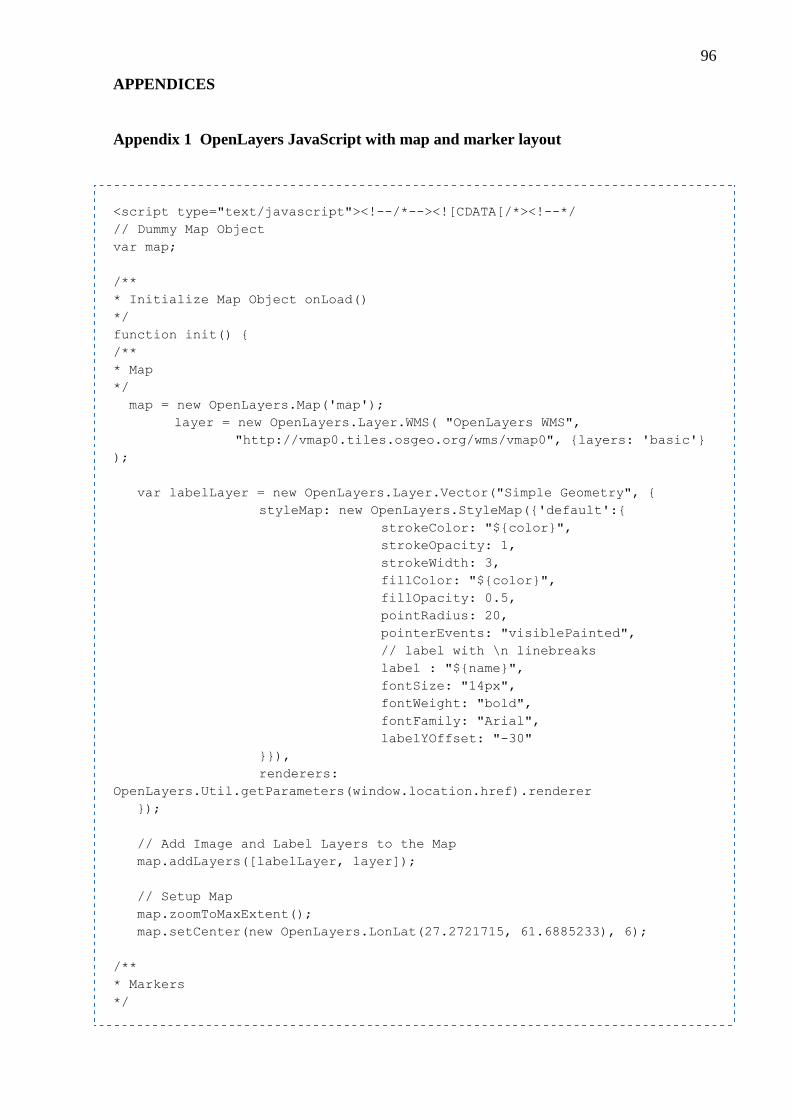
96
APPENDICES
Appendix 1 OpenLayers JavaScript with map and marker layout
<script type="text/javascript"><!--/*--><![CDATA[/*><!--*/
// Dummy Map Object
var map;
/**
* Initialize Map Object onLoad()
*/
function init() {
/**
* Map
*/
map = new OpenLayers.Map('map');
layer = new OpenLayers.Layer.WMS( "OpenLayers WMS",
"http://vmap0.tiles.osgeo.org/wms/vmap0", {layers: 'basic'}
);
var labelLayer = new OpenLayers.Layer.Vector("Simple Geometry", {
styleMap: new OpenLayers.StyleMap({'default':{
strokeColor: "${color}",
strokeOpacity: 1,
strokeWidth: 3,
fillColor: "${color}",
fillOpacity: 0.5,
pointRadius: 20,
pointerEvents: "visiblePainted",
// label with \n linebreaks
label : "${name}",
fontSize: "14px",
fontWeight: "bold",
fontFamily: "Arial",
labelYOffset: "-30"
}}),
renderers:
OpenLayers.Util.getParameters(window.location.href).renderer
});
// Add Image and Label Layers to the Map
map.addLayers([labelLayer, layer]);
// Setup Map
map.zoomToMaxExtent();
map.setCenter(new OpenLayers.LonLat(27.2721715, 61.6885233), 6);
/**
* Markers
*/

97
var markers = new OpenLayers.Layer.Markers("Markers");
map.addLayer(markers);
var markerClick = function (evt) {
if (this.popup == null) {
this.popup =
this.createPopup(this.closeBox);
map.addPopup(this.popup);
this.popup.show();
} else {
this.popup.toggle();
}
currentPopup = this.popup;
OpenLayers.Event.stop(evt);
};
/**
* Marker 1 Begin
*/
var feature = new OpenLayers.Feature(markers, new
OpenLayers.LonLat(27.2721715, 61.6885233));
feature.closeBox = true;
feature.data.popupContentHTML = '<img
src="http://www.jfree.org/jfreechart/images/PriceVolumeDemo1.png" />';
feature.data.icon = new
OpenLayers.Icon('http://icons.iconarchive.com/icons/arrioch/halloween/64/ra
dioactive-icon.png',
new OpenLayers.Size(32, 32),
new OpenLayers.Pixel(-16, -16)
);
feature.data.overflow = "auto";
feature.popupClass = OpenLayers.Class(OpenLayers.Popup.FramedCloud, {
'autoSize': true
});
var marker = feature.createMarker();
marker.events.register("mousedown", feature, markerClick);
var labelFeature = new OpenLayers.Feature.Vector(new
OpenLayers.Geometry.Point(27.2721715, 61.6885233));
labelFeature.attributes = {
name: "Scary Face",
color: "blue"
};
/**
* Marker 1 Finish
*/
markers.addMarker(marker);
// Add Labels and glowing sphere around the Marker
labelLayer.addFeatures([labelFeature]);
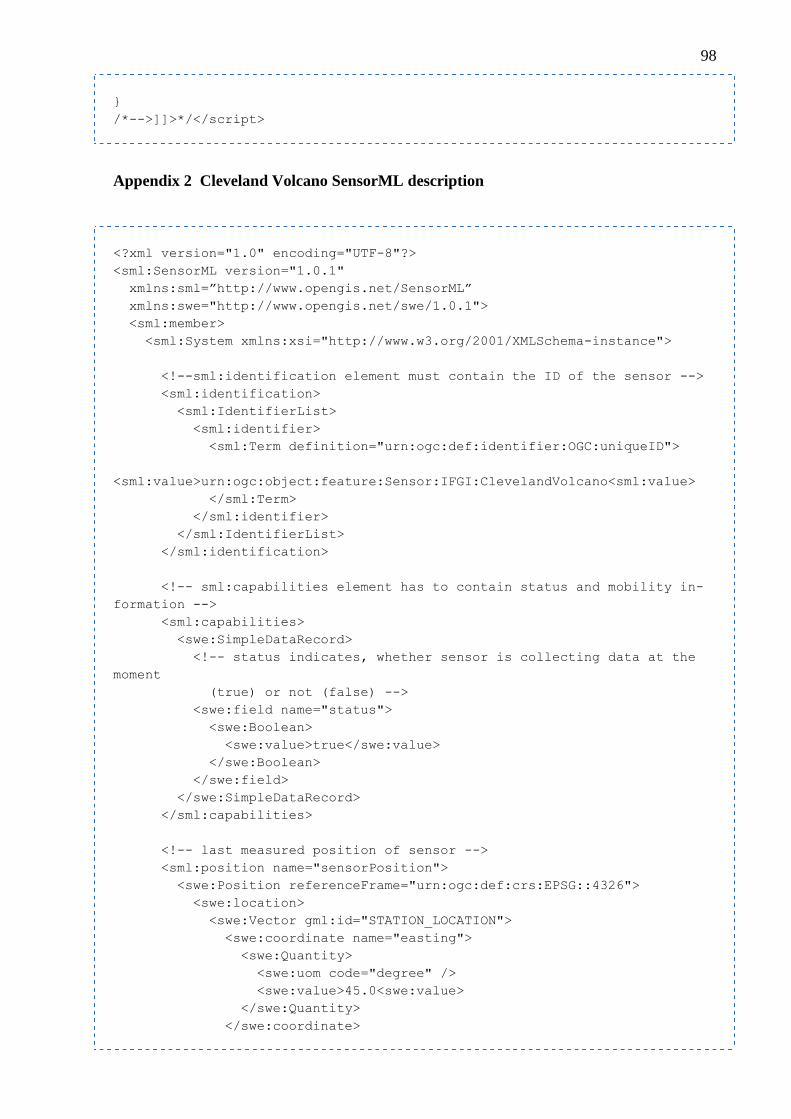
98
}
/*-->]]>*/</script>
Appendix 2 Cleveland Volcano SensorML description
<?xml version="1.0" encoding="UTF-8"?>
<sml:SensorML version="1.0.1"
xmlns:sml=”http://www.opengis.net/SensorML”
xmlns:swe="http://www.opengis.net/swe/1.0.1">
<sml:member>
<sml:System xmlns:xsi="http://www.w3.org/2001/XMLSchema-instance">
<!--sml:identification element must contain the ID of the sensor -->
<sml:identification>
<sml:IdentifierList>
<sml:identifier>
<sml:Term definition="urn:ogc:def:identifier:OGC:uniqueID">
<sml:value>urn:ogc:object:feature:Sensor:IFGI:ClevelandVolcano<sml:value>
</sml:Term>
</sml:identifier>
</sml:IdentifierList>
</sml:identification>
<!-- sml:capabilities element has to contain status and mobility in-
formation -->
<sml:capabilities>
<swe:SimpleDataRecord>
<!-- status indicates, whether sensor is collecting data at the
moment
(true) or not (false) -->
<swe:field name="status">
<swe:Boolean>
<swe:value>true</swe:value>
</swe:Boolean>
</swe:field>
</swe:SimpleDataRecord>
</sml:capabilities>
<!-- last measured position of sensor -->
<sml:position name="sensorPosition">
<swe:Position referenceFrame="urn:ogc:def:crs:EPSG::4326">
<swe:location>
<swe:Vector gml:id="STATION_LOCATION">
<swe:coordinate name="easting">
<swe:Quantity>
<swe:uom code="degree" />
<swe:value>45.0<swe:value>
</swe:Quantity>
</swe:coordinate>
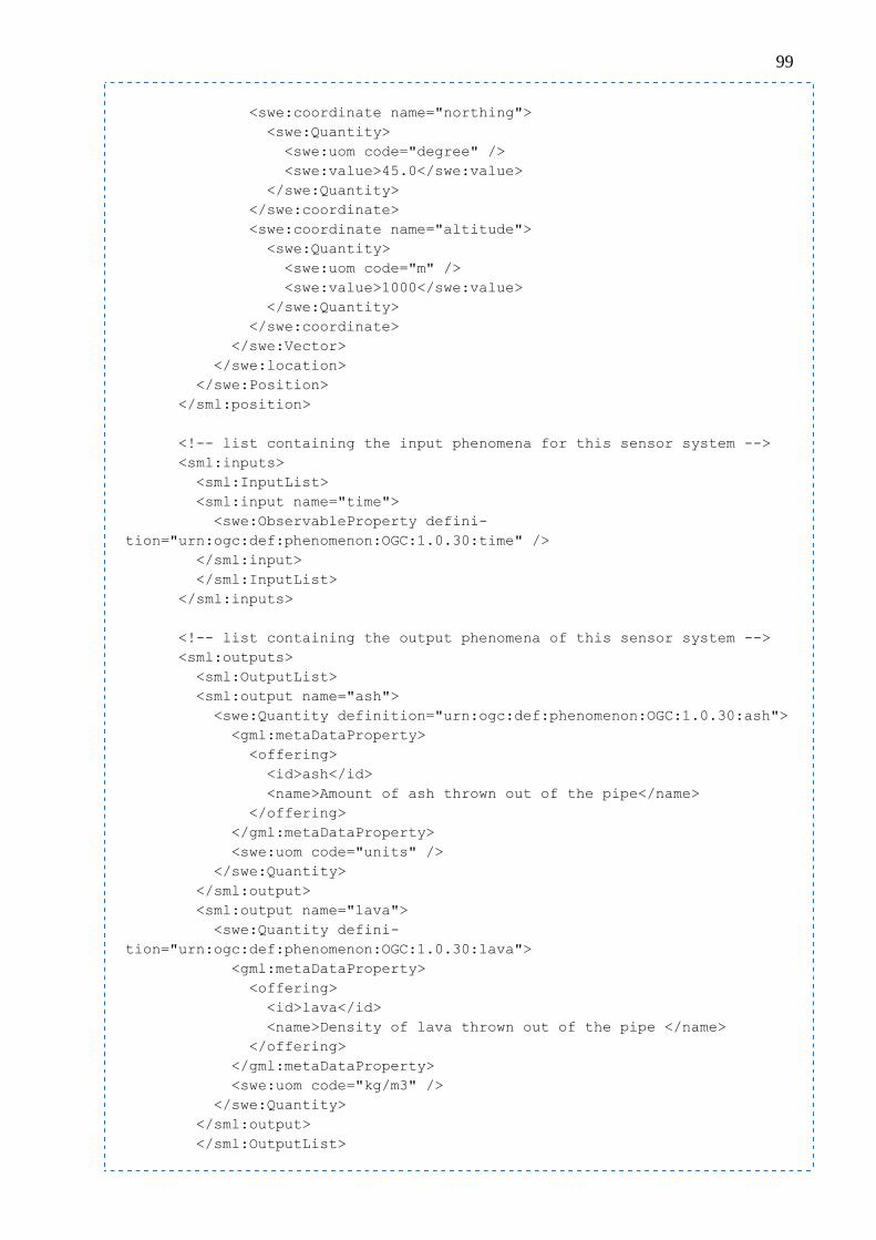
99
<swe:coordinate name="northing">
<swe:Quantity>
<swe:uom code="degree" />
<swe:value>45.0</swe:value>
</swe:Quantity>
</swe:coordinate>
<swe:coordinate name="altitude">
<swe:Quantity>
<swe:uom code="m" />
<swe:value>1000</swe:value>
</swe:Quantity>
</swe:coordinate>
</swe:Vector>
</swe:location>
</swe:Position>
</sml:position>
<!-- list containing the input phenomena for this sensor system -->
<sml:inputs>
<sml:InputList>
<sml:input name="time">
<swe:ObservableProperty defini-
tion="urn:ogc:def:phenomenon:OGC:1.0.30:time" />
</sml:input>
</sml:InputList>
</sml:inputs>
<!-- list containing the output phenomena of this sensor system -->
<sml:outputs>
<sml:OutputList>
<sml:output name="ash">
<swe:Quantity definition="urn:ogc:def:phenomenon:OGC:1.0.30:ash">
<gml:metaDataProperty>
<offering>
<id>ash</id>
<name>Amount of ash thrown out of the pipe</name>
</offering>
</gml:metaDataProperty>
<swe:uom code="units" />
</swe:Quantity>
</sml:output>
<sml:output name="lava">
<swe:Quantity defini-
tion="urn:ogc:def:phenomenon:OGC:1.0.30:lava">
<gml:metaDataProperty>
<offering>
<id>lava</id>
<name>Density of lava thrown out of the pipe </name>
</offering>
</gml:metaDataProperty>
<swe:uom code="kg/m3" />
</swe:Quantity>
</sml:output>
</sml:OutputList>

100
</sml:outputs>
</sml:System>
</sml:member>
</sml:SensorML>
Appendix 3 Prevent the jsessionid key in URL for displaying the GMaps
/**
* Prevent jsessionid for GMaps API Key display
*/
@Override
protected WebResponse newWebResponse(HttpServletResponse servletResponse)
{
return new BufferedWebResponse(servletResponse) {
@Override
public CharSequence encodeURL(final CharSequence url) {
final CharSequence encodeURL = super.encodeURL(url);
String s = encodeURL.toString();
int i = 0;
if (s.indexOf("jsessionid=") >= 0) {
i = s.indexOf("?");
if (i >= 0) {
return encodeURL.subSequence(i, encodeURL.length());
} else {
return encodeURL;
}
} else {
return encodeURL;
}
}
@Override
public void sendRedirect(String url) throws IOException {
CharSequence encodeURL = super.encodeURL(url);
String s = encodeURL.toString();
int i = 0;
if (s.indexOf("jsessionid=") >= 0) {
i = s.indexOf("?");
if (i >= 0) {
encodeURL = encodeURL.subSequence(i, encodeURL.length());
}
}
getHttpServletResponse().sendRedirect((String) encodeURL);
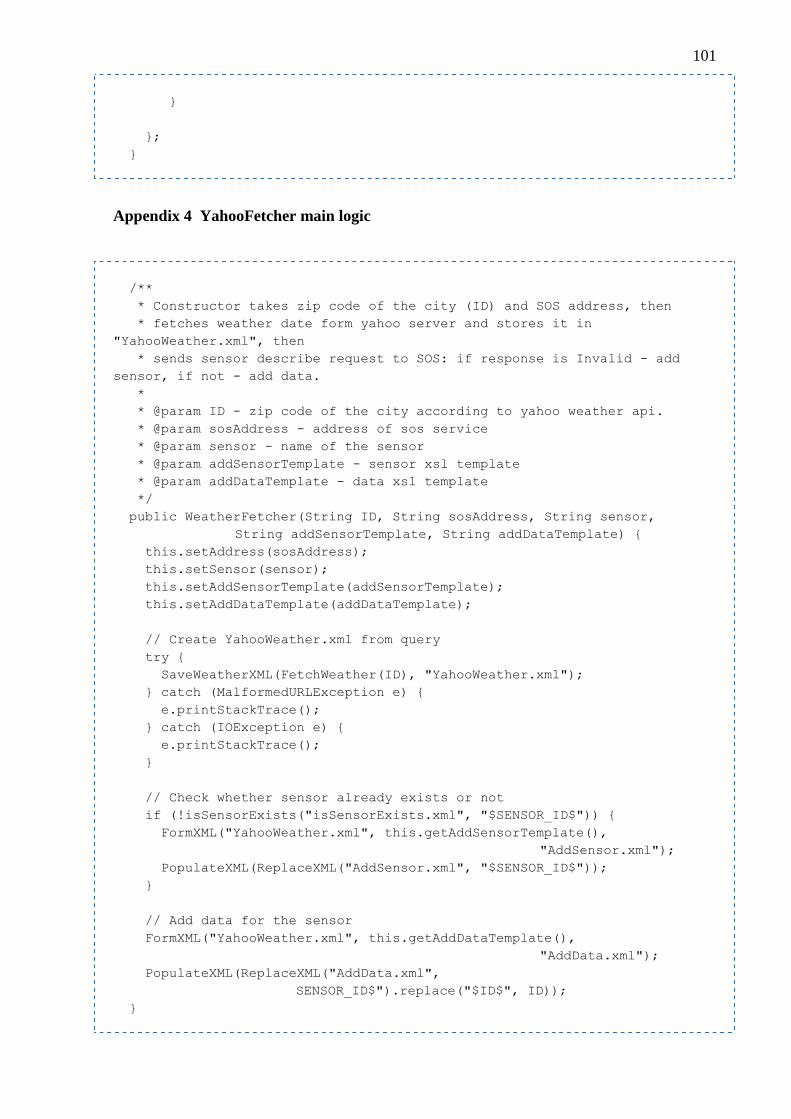
101
}
};
}
Appendix 4 YahooFetcher main logic
/**
* Constructor takes zip code of the city (ID) and SOS address, then
* fetches weather date form yahoo server and stores it in
"YahooWeather.xml", then
* sends sensor describe request to SOS: if response is Invalid - add
sensor, if not - add data.
*
* @param ID - zip code of the city according to yahoo weather api.
* @param sosAddress - address of sos service
* @param sensor - name of the sensor
* @param addSensorTemplate - sensor xsl template
* @param addDataTemplate - data xsl template
*/
public WeatherFetcher(String ID, String sosAddress, String sensor,
String addSensorTemplate, String addDataTemplate) {
this.setAddress(sosAddress);
this.setSensor(sensor);
this.setAddSensorTemplate(addSensorTemplate);
this.setAddDataTemplate(addDataTemplate);
// Create YahooWeather.xml from query
try {
SaveWeatherXML(FetchWeather(ID), "YahooWeather.xml");
} catch (MalformedURLException e) {
e.printStackTrace();
} catch (IOException e) {
e.printStackTrace();
}
// Check whether sensor already exists or not
if (!isSensorExists("isSensorExists.xml", "$SENSOR_ID$")) {
FormXML("YahooWeather.xml", this.getAddSensorTemplate(),
"AddSensor.xml");
PopulateXML(ReplaceXML("AddSensor.xml", "$SENSOR_ID$"));
}
// Add data for the sensor
FormXML("YahooWeather.xml", this.getAddDataTemplate(),
"AddData.xml");
PopulateXML(ReplaceXML("AddData.xml",
SENSOR_ID$").replace("$ID$", ID));
}

102
Appendix 5 YahooFetcher fetch the weather data from YahooWeather API
/**
* Connects to the Yahoo Weather service and fetches the xml data based
on ID
*
* @param ID - zip code of the city according to yahoo weather api.
* @return InputStream - retrieved data from Yahoo Weather service
* @throws MalformedURLException
* @throws IOException
*/
public InputStream FetchWeather(String ID)
throws MalformedURLException, IOException {
return new URL(
"http://weather.yahooapis.com/forecastrss?w=" + ID + "&u=c"
).openConnection().getInputStream();
}
Appendix 6 YahooFetcher save the fetched data into XML
/**
* Saves fetched data into yahooXMLFile param
*
* @param is - InputStream from Yahoo Weather service
* @param yahooXMLFile - name of the destination file
*/
public void SaveWeatherXML(InputStream is, String yahooXMLFile) {
Writer writer = new StringWriter();
char[] buffer = new char[1024];
try {
Reader reader = new BufferedReader(
new InputStreamReader(is, "UTF-8"));
int n;
while ((n = reader.read(buffer)) != -1) {
writer.write(buffer, 0, n);
}
is.close();
} catch (Exception e) {
e.printStackTrace();
}
File f = new File(yahooXMLFile);
FileWriter fw = null;

103
// YahooWeather sometimes contains null value for visibility field
// Inserting null into SOS fails the query to execute
try {
fw = new FileWriter(f);
fw.write(writer.toString().replace("visibility=\"\"",
"visibility=\"0\""));
fw.close();
} catch (IOException e1) {
e1.printStackTrace();
}
}
Appendix 7 YahooFetcher transform the saved XML using XSLT rules
/**
* Transforms yahooXMLFile based on the templateXML rules and stores re-
sult in outputXML
*
* @param yahooXMLFile - source xml for data retrieving
* @param templateXML - template xsl for rule generation
* @param outputXML - stores resulting xml
*/
public void FormXML(String yahooXMLFile,
String templateXML, String outputXML) {
String xmlFile = yahooXMLFile;
String xsltFile = templateXML;
Source xmlSource = new StreamSource(xmlFile);
Source xsltSource = new StreamSource(xsltFile);
Result result = new StreamResult(outputXML);
TransformerFactory transFact = TransformerFactory.newInstance();
Transformer trans;
try {
trans = transFact.newTransformer(xsltSource);
trans.transform(xmlSource, result);
} catch (TransformerConfigurationException e) {
e.printStackTrace();
} catch (TransformerException e) {
e.printStackTrace();
}
}
Appendix 8 YahooFetcher additional data replacing in saved XML

104
/**
* Replaces Old value by New value in yahooXMLFile file and returns re-
sulting String
*
* @param yahooXMLFile - victim file
* @param Old - old string
* @return String consist of replaced values of yahooXMLFile file
*/
public String ReplaceXML(String yahooXMLFile, String Old) {
FileReader fr;
String fileToReplace = "";
try {
fr = new FileReader(yahooXMLFile);
BufferedReader br = new BufferedReader(fr);
String s = "";
while ((s = br.readLine()) != null) {
fileToReplace = fileToReplace + s;
}
fr.close();
} catch (FileNotFoundException e) {
e.printStackTrace();
} catch (IOException e) {
e.printStackTrace();
}
return fileToReplace.replace(Old, this.getSensor());
}
Appendix 9 YahooFetcher check whether sensor exists or not
/**
* Checks whether sensor exists in the database or not
* Checking is done based on "InvalidParameterValue" parameter which oc-
curs on non-existing element
*
* @param checkFile - xml file with description for SOS
* @param checkValue - value, which is replaced by sensor param
* @return boolean true is exists, false is not
*/
public boolean isSensorExists(String checkFile, String checkValue) {
FileReader fr;
String isSensorExists = "";
try {
fr = new FileReader(checkFile);
BufferedReader br = new BufferedReader(fr);

105
String s = "";
while ((s = br.readLine()) != null) {
isSensorExists = isSensorExists + s;
}
fr.close();
} catch (FileNotFoundException e) {
e.printStackTrace();
} catch (IOException e) {
e.printStackTrace();
}
return !PopulateXML(isSensorExists.replace(checkValue,
this.getSensor())).contains("InvalidParameterValue");
}
Appendix 10 YahooFetcher populate the XML via SOS
/**
* Populate yahooXML string into database via SOS service address and re-
turns response
*
* @param yahooXML - xml string for population into database
* @return response from the SOS service
*/
public String PopulateXML(String yahooXML) {
String response = "";
HttpClient httpClient = new HttpClient();
PostMethod method = new PostMethod(this.getAddress());
try {
method.setRequestEntity(new StringRequestEntity(yahooXML,
"text/xml", "UTF-8"));
HostConfiguration hostConfig = new HostConfiguration();
// apply proxy settings:
String host = System.getProperty("http.proxyHost");
String port = System.getProperty("http.proxyPort");
String nonProxyHosts = System.getProperty("http.nonProxyHosts");
// check if service url is among the non-proxy-hosts:
boolean serviceIsNonProxyHost = false;
if (nonProxyHosts != null && nonProxyHosts.length() > 0) {
String[] nonProxyHostsArray = nonProxyHosts.split("\\|");
String serviceHost = new URL(this.getAddress()).getHost();
for (String nonProxyHost : nonProxyHostsArray) {
if (nonProxyHost.equals(serviceHost)) {

106
serviceIsNonProxyHost = true;
break;
}
}
}
// set proxy:
if (serviceIsNonProxyHost == false
&& host != null && host.length() > 0
&& port != null && port.length() > 0) {
int portNumber = Integer.parseInt(port);
hostConfig.setProxy(host, portNumber);
}
httpClient.setHostConfiguration(hostConfig);
httpClient.executeMethod(method);
response = method.getResponseBodyAsString();
} catch (UnsupportedEncodingException e) {
e.printStackTrace();
} catch (HttpException e) {
e.printStackTrace();
} catch (IOException e) {
e.printStackTrace();
}
// Debug feature, prints response from the SOS
System.out.println("---START---"+response+"---END---");
return response;
}