ProNest 8 Manual
274
1 Chapter 1: Introduction to ProNest 8.0 .................................................................................................... 1 Introduction ................................................................................................................................................... 1 ProNest Features and Options ..................................................................................................................... 1 ProNest Standard Features .................................................................................................................................... 1 ProNest Optional Features...................................................................................................................................... 2 Installing ProNest .......................................................................................................................................... 3 Installation Procedure ............................................................................................................................................. 3 Starting ProNest...................................................................................................................................................... 4 Chapter 2: Quick Start Procedures .......................................................................................................... 5 Install, Start and Authorize ProNest 8 ........................................................................................................... 5 Settings ......................................................................................................................................................... 6 Chapter 3: Preferences ............................................................................................................................ 14 General........................................................................................................................................................ 14 Miscellaneous ............................................................................................................................................. 15 Regional ...................................................................................................................................................... 16 Settings ....................................................................................................................................................... 17 Bevel ........................................................................................................................................................... 18 Chapter 4: ProNest Basics ...................................................................................................................... 19 Starting a New Job ...................................................................................................................................... 19 Add Parts..................................................................................................................................................... 19 Explorer View........................................................................................................................................................ 20 Adding to Your Parts List ...................................................................................................................................... 20 Preview ................................................................................................................................................................. 21 Add VSP (Variable Shape Part) Part to Part List ........................................................................................ 22 Add VSP Part to Current Nest............................................................................................................................... 22 Add Pipe Part to Part List ............................................................................................................................ 26 Add Pipe Part to Current Nest............................................................................................................................... 27 Add Tee....................................................................................................................................................... 29 Saving/Loading Pipe Part............................................................................................................................ 29 Add Plates ................................................................................................................................................... 30 User Defined ......................................................................................................................................................... 30 Inventory ............................................................................................................................................................... 30 Interactive Nesting ...................................................................................................................................... 30 Starting a New Nest .............................................................................................................................................. 30 Adding Parts to the Nest ....................................................................................................................................... 31 Matching Material .................................................................................................................................................. 31 Zooming In and Out .............................................................................................................................................. 33 Working With Selected Parts ...................................................................................................................... 34 Multiple Torches .......................................................................................................................................... 36 Move Lead In/Out Locations ....................................................................................................................... 37 Cut Sequence ............................................................................................................................................. 37 Cut Simulation ............................................................................................................................................. 39 Cropping the Plate ...................................................................................................................................... 40 Measure Mode ............................................................................................................................................ 40 Advance to a New Plate .............................................................................................................................. 41 CNC Output ................................................................................................................................................. 41
-
Upload
diego-de-souza -
Category
Documents
-
view
1.039 -
download
118
Transcript of ProNest 8 Manual
1
Chapter 1: Introduction to ProNest 8.0 ....................................................................................................1
Introduction ...................................................................................................................................................1 ProNest Features and Options .....................................................................................................................1
ProNest Standard Features ....................................................................................................................................1 ProNest Optional Features......................................................................................................................................2
Installing ProNest ..........................................................................................................................................3 Installation Procedure .............................................................................................................................................3 Starting ProNest......................................................................................................................................................4
Chapter 2: Quick Start Procedures ..........................................................................................................5
Install, Start and Authorize ProNest 8...........................................................................................................5 Settings .........................................................................................................................................................6
Chapter 3: Preferences............................................................................................................................14
General........................................................................................................................................................14 Miscellaneous .............................................................................................................................................15 Regional ......................................................................................................................................................16 Settings .......................................................................................................................................................17 Bevel ...........................................................................................................................................................18
Chapter 4: ProNest Basics......................................................................................................................19
Starting a New Job......................................................................................................................................19 Add Parts.....................................................................................................................................................19
Explorer View........................................................................................................................................................20 Adding to Your Parts List ......................................................................................................................................20 Preview .................................................................................................................................................................21
Add VSP (Variable Shape Part) Part to Part List ........................................................................................22 Add VSP Part to Current Nest...............................................................................................................................22
Add Pipe Part to Part List............................................................................................................................26 Add Pipe Part to Current Nest...............................................................................................................................27
Add Tee.......................................................................................................................................................29 Saving/Loading Pipe Part............................................................................................................................29 Add Plates...................................................................................................................................................30
User Defined .........................................................................................................................................................30 Inventory ...............................................................................................................................................................30
Interactive Nesting ......................................................................................................................................30 Starting a New Nest ..............................................................................................................................................30 Adding Parts to the Nest .......................................................................................................................................31 Matching Material..................................................................................................................................................31 Zooming In and Out ..............................................................................................................................................33
Working With Selected Parts ......................................................................................................................34 Multiple Torches..........................................................................................................................................36 Move Lead In/Out Locations .......................................................................................................................37 Cut Sequence .............................................................................................................................................37 Cut Simulation.............................................................................................................................................39 Cropping the Plate ......................................................................................................................................40 Measure Mode ............................................................................................................................................40 Advance to a New Plate..............................................................................................................................41 CNC Output.................................................................................................................................................41
Saving A Job/Opening A Job ......................................................................................................................42 Reports........................................................................................................................................................43 Automatic Nesting (Optional Feature).........................................................................................................44
Rectangular vs True Shape Automatic Nesting ....................................................................................................44 Multiple Torches....................................................................................................................................................45 Using Both Automatic and Interactive Nesting ......................................................................................................45
Material Database .......................................................................................................................................45 Customer Database ....................................................................................................................................46 Advanced Edit .............................................................................................................................................46 Additional Utilities of Advanced Edit ...........................................................................................................48 Saving Changes..........................................................................................................................................50 Properties....................................................................................................................................................50
Chapter 5: ProNest Options.....................................................................................................................53
Plate Inventory Database............................................................................................................................53 To open the Plate Inventory Database..................................................................................................................53
Part Inventory Database .............................................................................................................................55 Custom Remnants ......................................................................................................................................57 Assembly Database ....................................................................................................................................58 Chain and Bridge Cutting............................................................................................................................59
Chain Cutting Settings ..........................................................................................................................................60 Bridge Cutting Settings .........................................................................................................................................60 Using Chain Cutting ..............................................................................................................................................61 Using Bridge Cutting .............................................................................................................................................62
Common Line Cutting .................................................................................................................................63 Common Line Cut Settings ...................................................................................................................................64 Using Common Line Cutting .................................................................................................................................65 Quad CLC (Common Line Cut).............................................................................................................................65
Common Line Cut Array..............................................................................................................................67 Creating a CLC Array............................................................................................................................................67
Multi Part Common Line Cut .......................................................................................................................69 Working CLC Clusters ..........................................................................................................................................71 Multi-Part CLC Parts .............................................................................................................................................72 Safety Cuts ...........................................................................................................................................................73 Torch path editing .................................................................................................................................................76 Plate Edge Common Line Cut...............................................................................................................................78
Collision Avoidance.....................................................................................................................................79 Skeleton Cut Up ..........................................................................................................................................79 Pattern Array ...............................................................................................................................................80 Part Cut Up .................................................................................................................................................81
Chapter 6: Menu and Toolbar Reference...............................................................................................83
Menu Reference..........................................................................................................................................83 File Menu ..............................................................................................................................................................83 Edit Menu..............................................................................................................................................................83 View Menu ............................................................................................................................................................84 Job Menu ..............................................................................................................................................................84 Nest Menu.............................................................................................................................................................85 Part Menu .............................................................................................................................................................86
Help Menu.............................................................................................................................................................87 Toolbars Reference.....................................................................................................................................87 Customizing ProNest Desktop ....................................................................................................................91
Chapter 7: ProNest Settings References...............................................................................................94
What are ProNest Settings?........................................................................................................................94 How are settings saved?.............................................................................................................................94 What is a ProNest machine?.......................................................................................................................95 Using the settings dialog.............................................................................................................................96 Creating a new machine .............................................................................................................................98 Editing a machine's settings........................................................................................................................98 Settings tables (Spreadsheets)...................................................................................................................99 Saving your machine settings .....................................................................................................................99 Machine.....................................................................................................................................................100 Add or Remove Processes .......................................................................................................................101 Select a Post Processor (CFF) .................................................................................................................102 Reuse Existing Settings ............................................................................................................................103 Importing Parts..........................................................................................................................................104 Importing Parts (Advanced) ......................................................................................................................111 Bevel .........................................................................................................................................................113 Bevel - Pass Profiles .................................................................................................................................115 Standard Plate Sizes.................................................................................................................................117 Torches .....................................................................................................................................................119 Work Zones...............................................................................................................................................121 Nesting ......................................................................................................................................................125 AutoNest....................................................................................................................................................127 Pattern Array Strategies............................................................................................................................130 AutoNest Strategies ..................................................................................................................................132 AutoNest Strategies - Rectangular Optimization ......................................................................................133 AutoNest Strategies - True Shape ............................................................................................................135 Optimization ..............................................................................................................................................138 Cut Sequence ...........................................................................................................................................141 Cut Sequence - Interior Profile..................................................................................................................144 Cut Sequence Rules .................................................................................................................................147 Editing a cut sequence rule.......................................................................................................................148 Collision Avoidance...................................................................................................................................152 Collision Avoidance (Advanced) ...............................................................................................................155 Edge Pierce...............................................................................................................................................156 Skeleton Cut-Up........................................................................................................................................157 Skeleton Cut-Up - Skeleton Grid...............................................................................................................161 Skeleton Cut-Up - Cut Sequence..............................................................................................................162 Crop...........................................................................................................................................................163 Costing ......................................................................................................................................................166 CNC Output...............................................................................................................................................168 CNC Output - Pre-Pierces.........................................................................................................................176 CNC Output - Auto Height Control............................................................................................................177 CNC Output - Step and Repeat ................................................................................................................179 CNC Output - Output Axis.........................................................................................................................179 CNC Output - Subroutines ........................................................................................................................180 CNC Output - Microjoint / Plate Handler ...................................................................................................182 CNC Output - DXF Output ........................................................................................................................184 Editing process settings ............................................................................................................................185 Process Parameters..................................................................................................................................186 Interior/Exterior Leads...............................................................................................................................187 Cutting Techniques ...................................................................................................................................189 Common Line Cut .....................................................................................................................................190 Common Line Cut - Plate Edge ................................................................................................................194 Common Line Cut - Array .........................................................................................................................195 Common Line Cut - Safety Cuts ...............................................................................................................197 Chaining ....................................................................................................................................................199
Bridging .....................................................................................................................................................200 AutoTab.....................................................................................................................................................201
Chapter 8: AutoNesting.........................................................................................................................206
Start AutoNest... (Yellow Icon)..................................................................................................................206 AutoNest Settings .....................................................................................................................................206
How should ProNest create new nests? .............................................................................................................206 Use a custom plate ...................................................................................................................................207 Torch settings............................................................................................................................................207 Start AutoNest (Green Icon)......................................................................................................................208 Part Properties (for all selected parts) ......................................................................................................208 Part Properties (for one selected part)......................................................................................................209 Part Properties (for one part in the Part List) ............................................................................................209
Chapter 9: Process Parameters............................................................................................................211
Default Process Parameters .....................................................................................................................211 Process Parameters XLS Table..........................................................................................................................211
Using Part, Plate and Pierce Separations with Multiple Processes..........................................................213 Using a Process Parameters XLS Table vs. Using Default Process Parameters ....................................214 Troubleshooting ........................................................................................................................................215
Chapter 10: XLS Table Overview..........................................................................................................216
XLS Table Types.......................................................................................................................................216 Using XLS Tables ...............................................................................................................................................216 General XLS Table Format .................................................................................................................................217 Using Wildcards ..................................................................................................................................................219 The Advantages and Disadvantages of Using XLS Tables.................................................................................220
Chapter 11: Pipe Settings and Fitting Descriptions ...........................................................................221
Pipe Settings .............................................................................................................................................221 Fitting Descriptions....................................................................................................................................223
Offset Cone.........................................................................................................................................................223 Reducing Elbow..................................................................................................................................................225 ID_OD Ellipse .....................................................................................................................................................227 Ellipse in Rectangle ............................................................................................................................................228 Flange.................................................................................................................................................................229 Angled Pipe.........................................................................................................................................................230 Straight Pipe .......................................................................................................................................................231 Offset Pipe ..........................................................................................................................................................232 Rectangle to Round ............................................................................................................................................234 Segmented Elbow...............................................................................................................................................236 Tee Into Partial Pipe ...........................................................................................................................................238 Y-Joint.................................................................................................................................................................239 Trapezoid to Round ............................................................................................................................................241
Chapter 12: Costing ...............................................................................................................................244
Costing Settings ........................................................................................................................................244
Advanced Costing...............................................................................................................................................245 Required column headers in the costing XLS table ............................................................................................246
Chapter 13: Cutting Techniques...........................................................................................................247
General Description ..................................................................................................................................247 Available Types of Cutting Techniques...............................................................................................................247
Record Matching .......................................................................................................................................249 The Base Condition ............................................................................................................................................249
Interaction with Process Parameters ........................................................................................................251 Interaction with CFF ..................................................................................................................................251 Putting It All Together................................................................................................................................252 Profile Area ...............................................................................................................................................254 Profile Type ...............................................................................................................................................255 Multiple Materials ......................................................................................................................................255 Troubleshooting ........................................................................................................................................255
Chapter 14: Lead Style Settings ...........................................................................................................258
Default Lead Style Settings.................................................................................................................................258 Record Matching .......................................................................................................................................260 Units Conversion.......................................................................................................................................261
The Default Lead Style Settings Record .............................................................................................................262 Multiple Process Considerations.........................................................................................................................262 Material/Thickness ..............................................................................................................................................263 Settings saved with a job ....................................................................................................................................263
Troubleshooting: .......................................................................................................................................264
Chapter 15: Database Filtering .............................................................................................................265
Chapter 16: Summary of Key Strokes..................................................................................................266
Chapter 17: Technical Support.............................................................................................................267

1
Chapter 1: Introduction to ProNest 8.0
Introduction The ProNest system has been specifically designed to meet the most demanding requirements of 2-axis profile cutting applications including Laser, Plasma, Oxy-fuel, Waterjet Routers and Combination Plasma-Punch/Laser-Punch. ProNest fully automates the import of part geometry from popular CAD systems as well as from existing CNC files. The combination of best-of-class material utilization, powerful, easy to use editing and productivity tools, and uniquely flexible control over cutting techniques, cutting parameters and CNC output make ProNest the ideal solution for any manufacturer or fabricator.
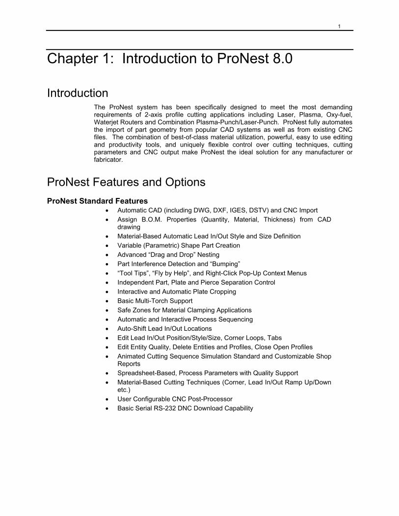
ProNest Features and Options ProNest Standard Features
• Automatic CAD (including DWG, DXF, IGES, DSTV) and CNC Import • Assign B.O.M. Properties (Quantity, Material, Thickness) from CAD
drawing • Material-Based Automatic Lead In/Out Style and Size Definition • Variable (Parametric) Shape Part Creation • Advanced “Drag and Drop” Nesting • Part Interference Detection and “Bumping” • “Tool Tips”, “Fly by Help”, and Right-Click Pop-Up Context Menus • Independent Part, Plate and Pierce Separation Control • Interactive and Automatic Plate Cropping • Basic Multi-Torch Support • Safe Zones for Material Clamping Applications • Automatic and Interactive Process Sequencing • Auto-Shift Lead In/Out Locations • Edit Lead In/Out Position/Style/Size, Corner Loops, Tabs • Edit Entity Quality, Delete Entities and Profiles, Close Open Profiles • Animated Cutting Sequence Simulation Standard and Customizable Shop
Reports • Spreadsheet-Based, Process Parameters with Quality Support • Material-Based Cutting Techniques (Corner, Lead In/Out Ramp Up/Down
etc.) • User Configurable CNC Post-Processor • Basic Serial RS-232 DNC Download Capability
2
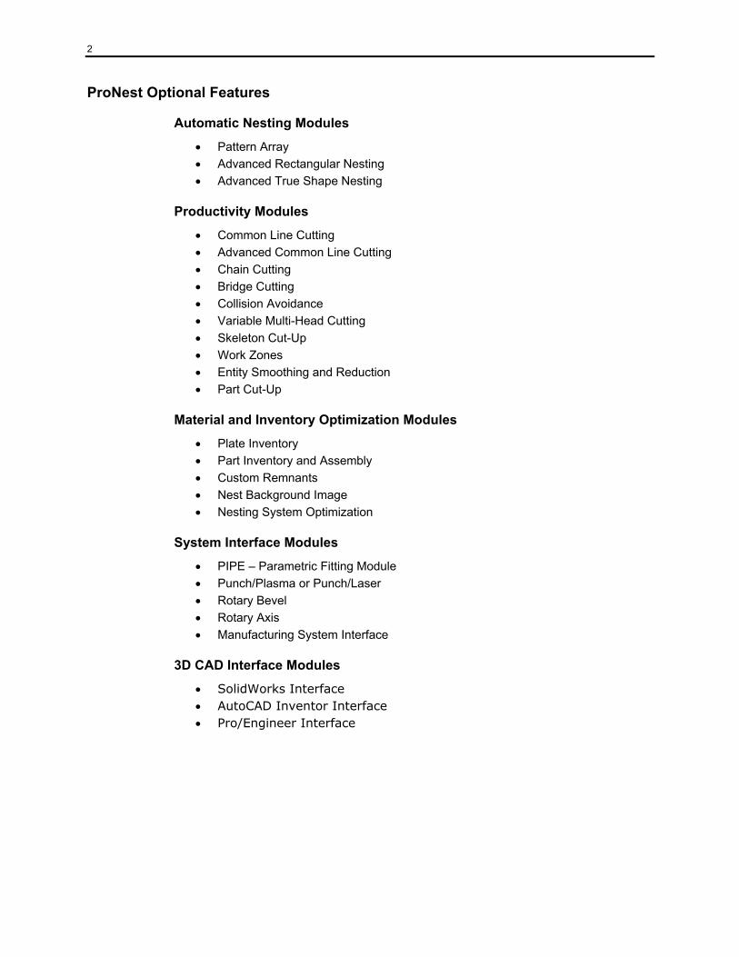
ProNest Optional Features
Automatic Nesting Modules
• Pattern Array • Advanced Rectangular Nesting • Advanced True Shape Nesting
Productivity Modules
• Common Line Cutting • Advanced Common Line Cutting • Chain Cutting • Bridge Cutting • Collision Avoidance • Variable Multi-Head Cutting • Skeleton Cut-Up • Work Zones • Entity Smoothing and Reduction • Part Cut-Up
Material and Inventory Optimization Modules
• Plate Inventory • Part Inventory and Assembly • Custom Remnants • Nest Background Image • Nesting System Optimization
System Interface Modules
• PIPE – Parametric Fitting Module • Punch/Plasma or Punch/Laser • Rotary Bevel • Rotary Axis • Manufacturing System Interface
3D CAD Interface Modules
• SolidWorks Interface • AutoCAD Inventor Interface • Pro/Engineer Interface

3
Installing ProNest Recommended System Requirements
For successful installation of ProNest, your computer should meet the following minimum system requirements:
• Microsoft® Windows® XP (recommended) or Windows 2000 (recommended) with Service Pack 4. • Intel Pentium® based computers
• Internet Explorer 5.5 or later
• Administrative privileges on the system
• 512 megabytes of RAM or greater
• Super VGA monitor (with the screen set to at least 800 x 600 and 256 colors)
Installation Procedure 1. Close all programs. 2. Insert the CD labeled ProNest into the CD-ROM drive. 3. The Setup program should start automatically, if it does proceed to step 5. 4. From the Taskbar Start menu, choose Run. 5. Type D:\setup (substitute the appropriate letter of your CD drive for D). 6. Follow the on-screen instructions. By default, ProNest is installed in the following location:
C:\Program Files\MTC\ProNest 8
4
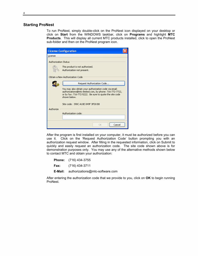
Starting ProNest To run ProNest, simply double-click on the ProNest icon displayed on your desktop or click on Start from the WINDOWS taskbar, click on Programs and highlight MTC Products. This will display all current MTC products installed, click to open the ProNest sub-folder and then on the ProNest program icon.
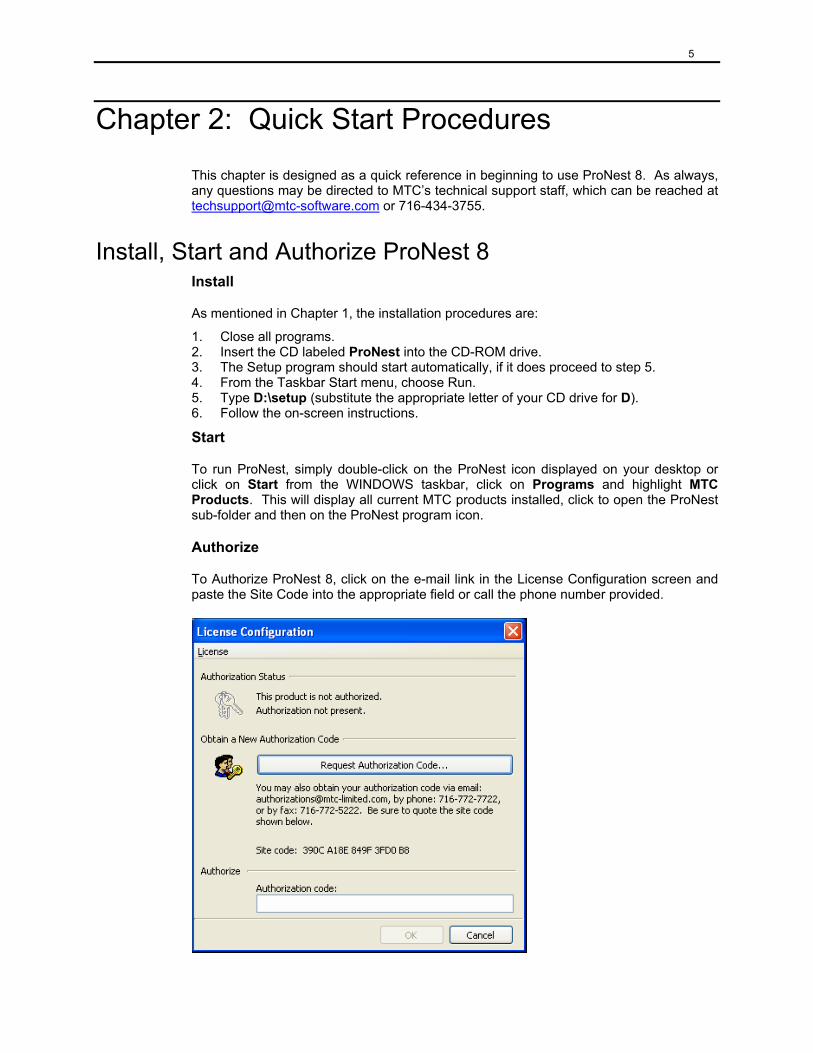
After the program is first installed on your computer, it must be authorized before you can use it. Click on the ‘Request Authorization Code’ button prompting you with an authorization request window. After filling in the requested information, click on Submit to quickly and easily request an authorization code. The site code shown above is for demonstration purposes only. You may use any of the alternative methods shown below to contact MTC and obtain your authorization:
Phone: (716) 434-3755
Fax: (716) 434-3711
E-Mail: [email protected]
After entering the authorization code that we provide to you, click on OK to begin running ProNest.
5
Chapter 2: Quick Start Procedures
This chapter is designed as a quick reference in beginning to use ProNest 8. As always, any questions may be directed to MTC’s technical support staff, which can be reached at [email protected] or 716-434-3755.
Install, Start and Authorize ProNest 8 Install
As mentioned in Chapter 1, the installation procedures are:
1. Close all programs. 2. Insert the CD labeled ProNest into the CD-ROM drive. 3. The Setup program should start automatically, if it does proceed to step 5. 4. From the Taskbar Start menu, choose Run. 5. Type D:\setup (substitute the appropriate letter of your CD drive for D). 6. Follow the on-screen instructions.
Start
To run ProNest, simply double-click on the ProNest icon displayed on your desktop or click on Start from the WINDOWS taskbar, click on Programs and highlight MTC Products. This will display all current MTC products installed, click to open the ProNest sub-folder and then on the ProNest program icon.
Authorize
To Authorize ProNest 8, click on the e-mail link in the License Configuration screen and paste the Site Code into the appropriate field or call the phone number provided.
6
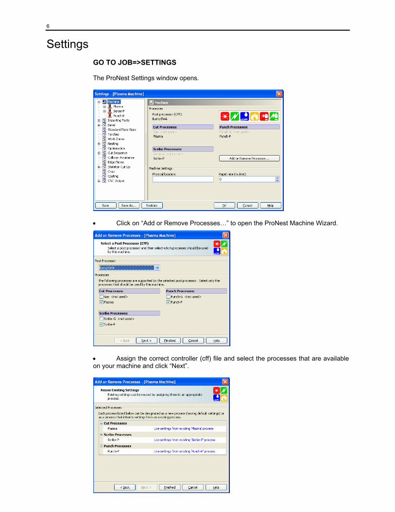
Settings GO TO JOB=>SETTINGS
The ProNest Settings window opens.
• Click on “Add or Remove Processes…” to open the ProNest Machine Wizard.
• Assign the correct controller (cff) file and select the processes that are available on your machine and click “Next”.
7
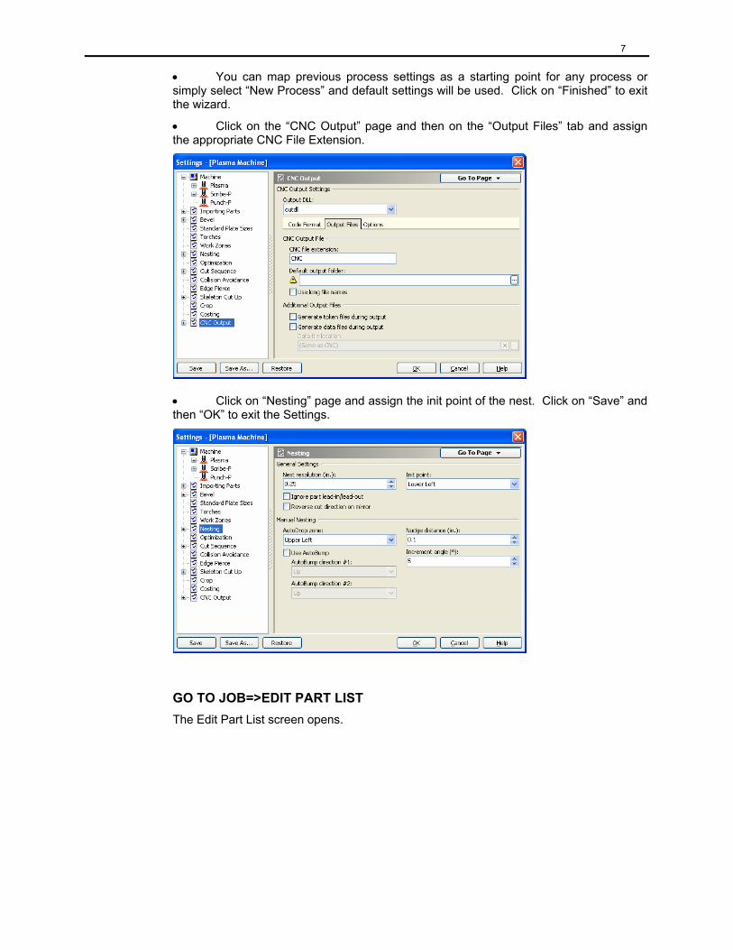
• You can map previous process settings as a starting point for any process or simply select “New Process” and default settings will be used. Click on “Finished” to exit the wizard.
• Click on the “CNC Output” page and then on the “Output Files” tab and assign the appropriate CNC File Extension.
• Click on “Nesting” page and assign the init point of the nest. Click on “Save” and then “OK” to exit the Settings.
GO TO JOB=>EDIT PART LIST The Edit Part List screen opens.
8
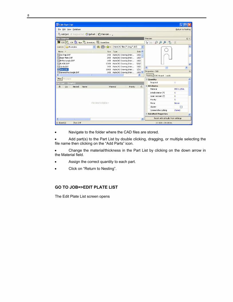
• Navigate to the folder where the CAD files are stored.
• Add part(s) to the Part List by double clicking, dragging, or multiple selecting the file name then clicking on the “Add Parts” icon.
• Change the material/thickness in the Part List by clicking on the down arrow in the Material field.
• Assign the correct quantity to each part.
• Click on “Return to Nesting”.
GO TO JOB=>EDIT PLATE LIST
The Edit Plate List screen opens
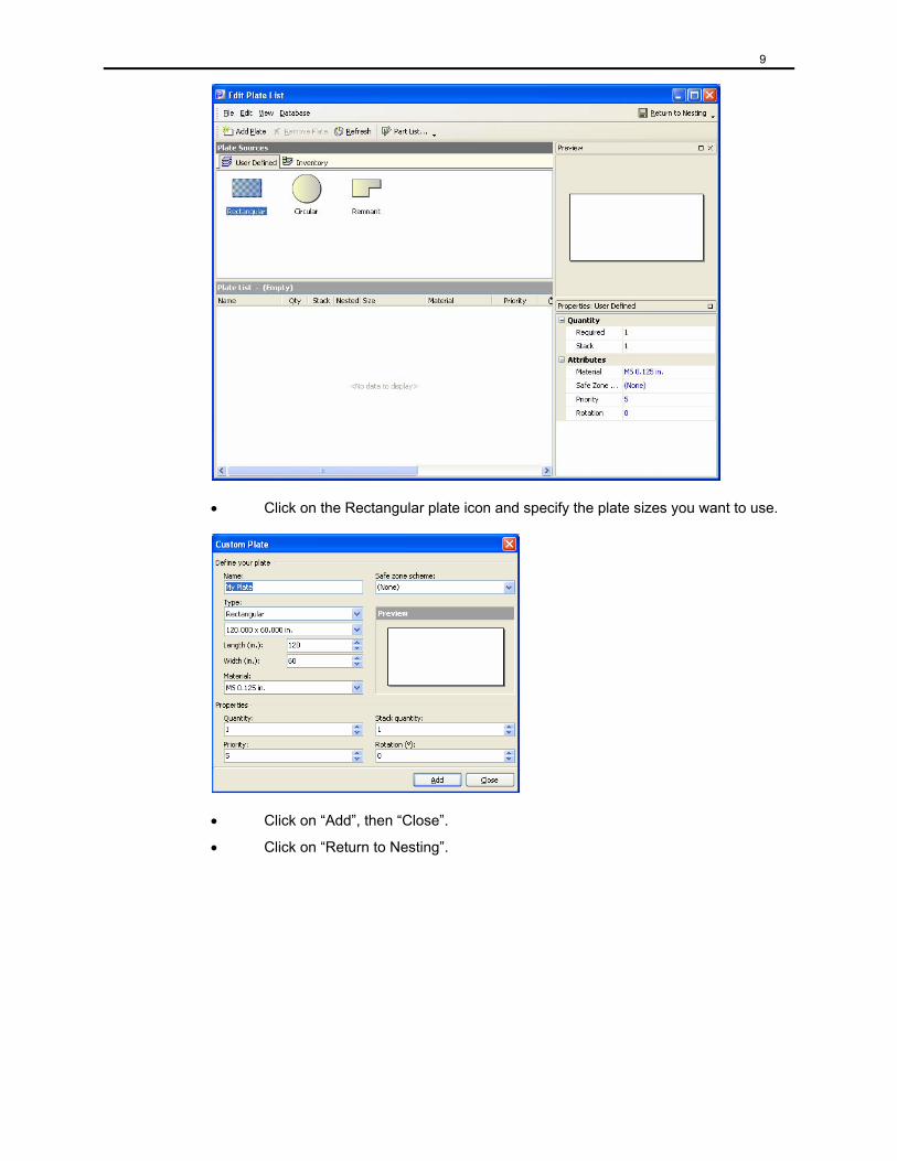
9
• Click on the Rectangular plate icon and specify the plate sizes you want to use.
• Click on “Add”, then “Close”.
• Click on “Return to Nesting”.
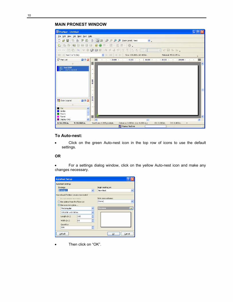
10
MAIN PRONEST WINDOW
To Auto-nest: • Click on the green Auto-nest icon in the top row of icons to use the default
settings.
OR
• For a settings dialog window, click on the yellow Auto-nest icon and make any changes necessary.
• Then click on “OK”.
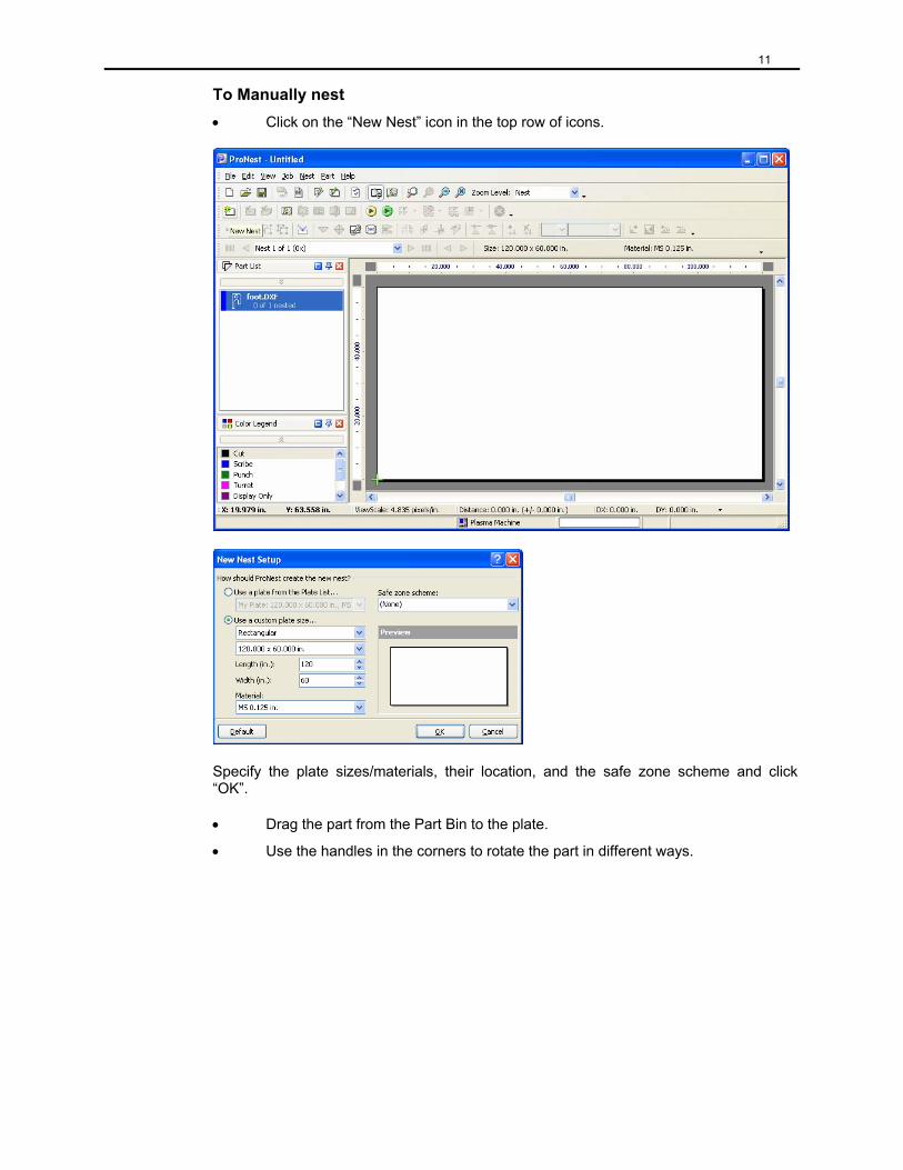
11
To Manually nest • Click on the “New Nest” icon in the top row of icons.
Specify the plate sizes/materials, their location, and the safe zone scheme and click “OK”.
• Drag the part from the Part Bin to the plate.
• Use the handles in the corners to rotate the part in different ways.
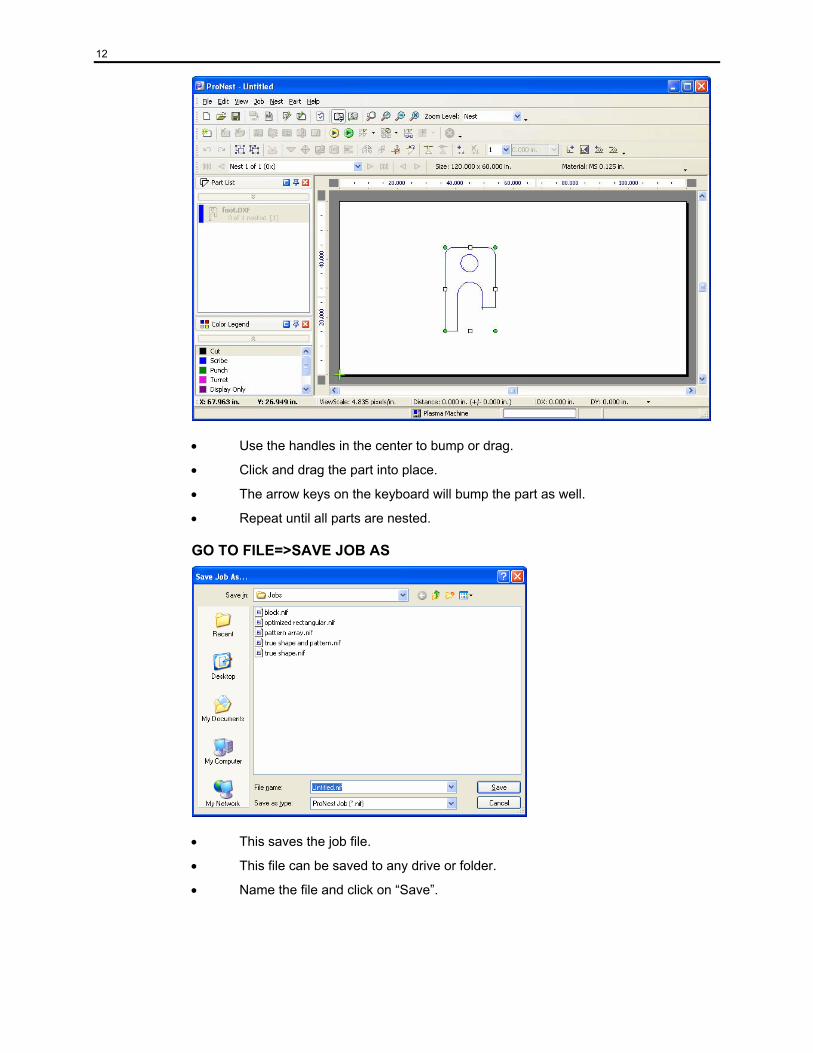
12
• Use the handles in the center to bump or drag.
• Click and drag the part into place.
• The arrow keys on the keyboard will bump the part as well.
• Repeat until all parts are nested.
GO TO FILE=>SAVE JOB AS
• This saves the job file.
• This file can be saved to any drive or folder.
• Name the file and click on “Save”.
13
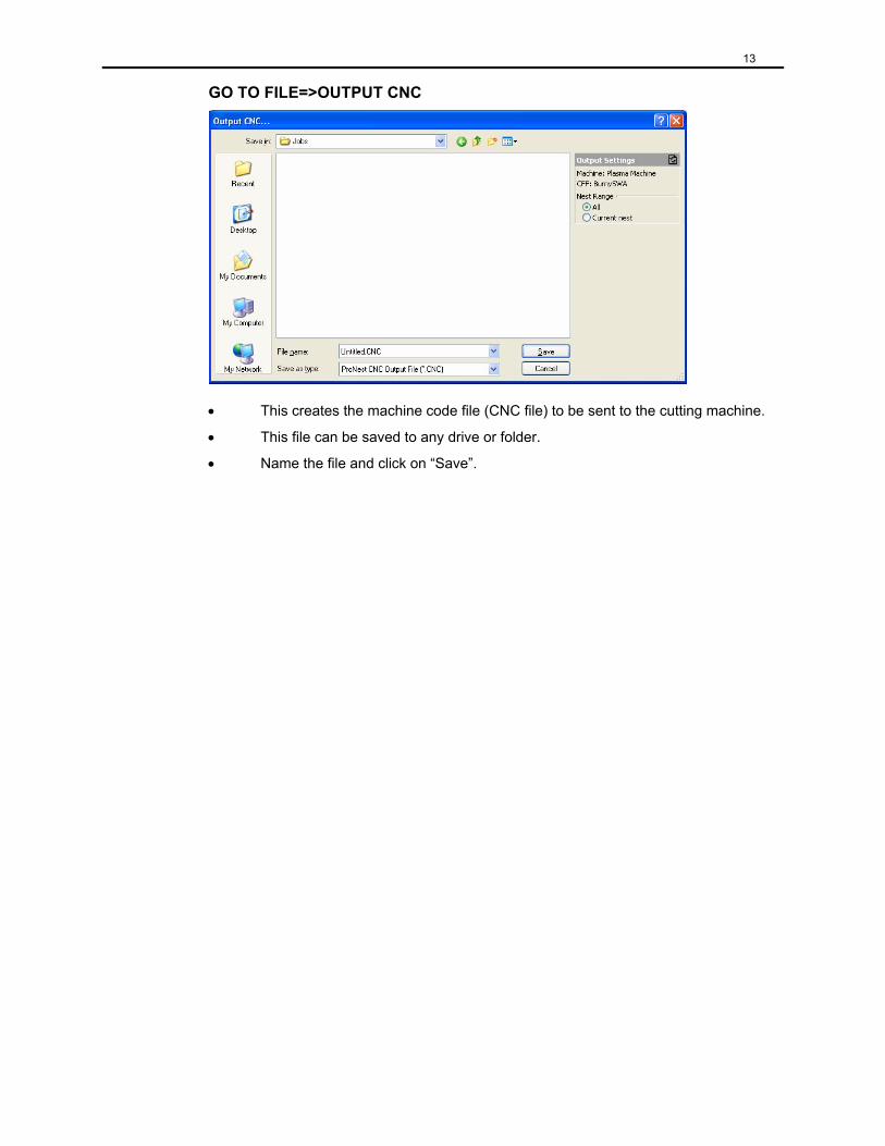
GO TO FILE=>OUTPUT CNC
• This creates the machine code file (CNC file) to be sent to the cutting machine.
• This file can be saved to any drive or folder.
• Name the file and click on “Save”.
14
Chapter 3: Preferences
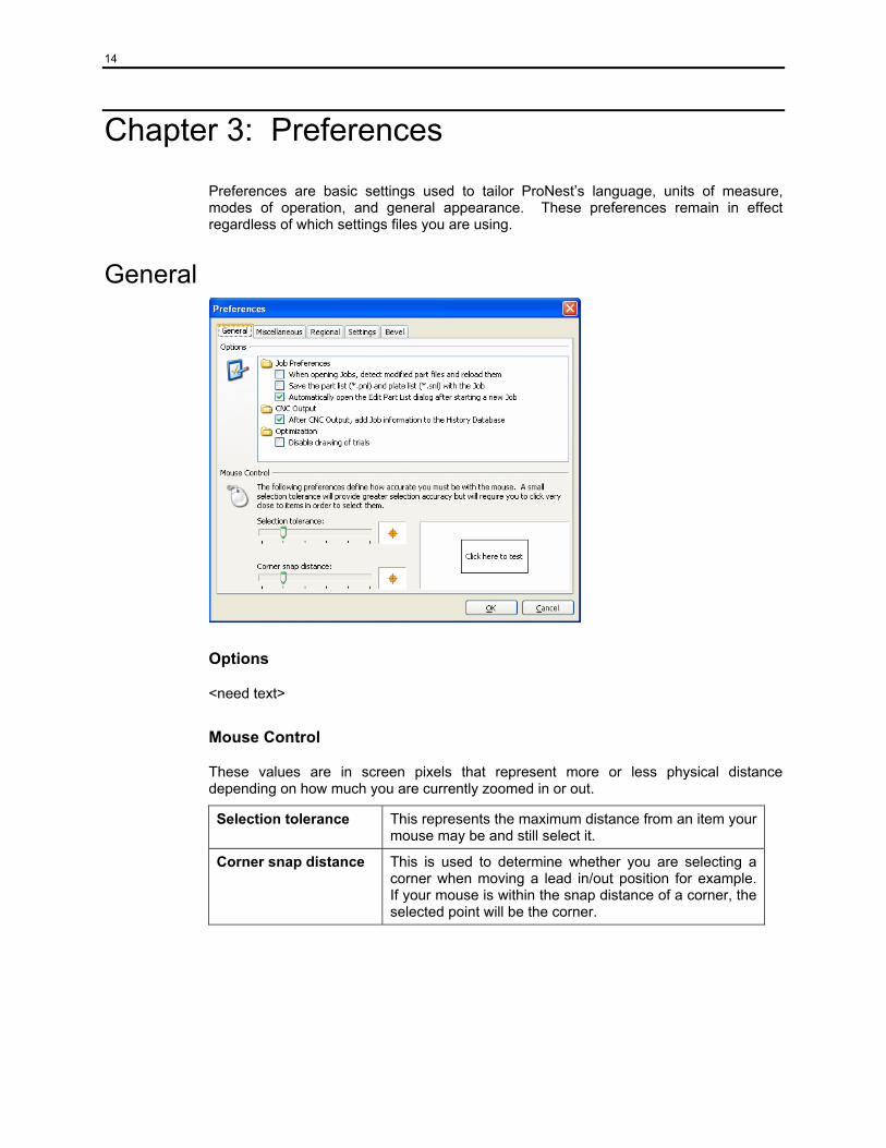
Preferences are basic settings used to tailor ProNest’s language, units of measure, modes of operation, and general appearance. These preferences remain in effect regardless of which settings files you are using.
General
Options
<need text>
Mouse Control
These values are in screen pixels that represent more or less physical distance depending on how much you are currently zoomed in or out.
Selection tolerance This represents the maximum distance from an item your mouse may be and still select it.
Corner snap distance This is used to determine whether you are selecting a corner when moving a lead in/out position for example. If your mouse is within the snap distance of a corner, the selected point will be the corner.
15
Miscellaneous
Options
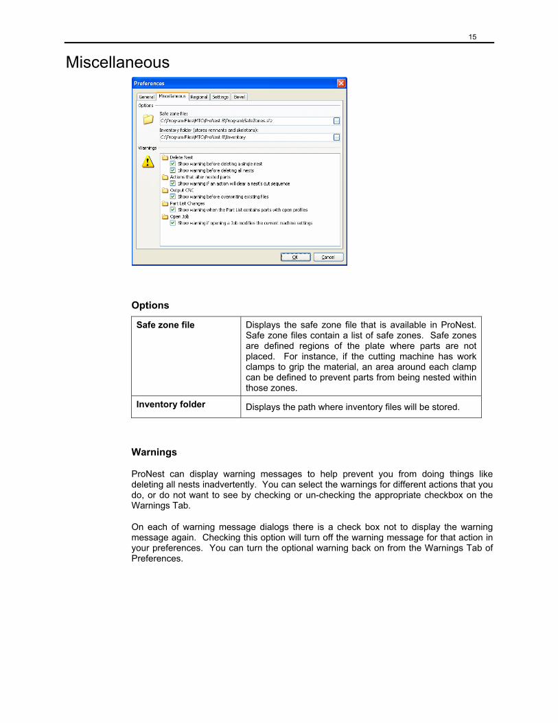
Safe zone file Displays the safe zone file that is available in ProNest. Safe zone files contain a list of safe zones. Safe zones are defined regions of the plate where parts are not placed. For instance, if the cutting machine has work clamps to grip the material, an area around each clamp can be defined to prevent parts from being nested within those zones.
Inventory folder Displays the path where inventory files will be stored.
Warnings
ProNest can display warning messages to help prevent you from doing things like deleting all nests inadvertently. You can select the warnings for different actions that you do, or do not want to see by checking or un-checking the appropriate checkbox on the Warnings Tab.
On each of warning message dialogs there is a check box not to display the warning message again. Checking this option will turn off the warning message for that action in your preferences. You can turn the optional warning back on from the Warnings Tab of Preferences.
16
Regional
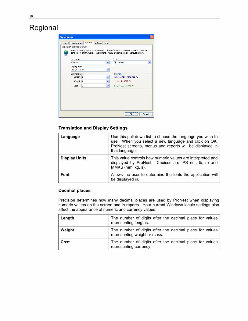
Translation and Display Settings
Language Use this pull-down list to choose the language you wish to use. When you select a new language and click on OK, ProNest screens, menus and reports will be displayed in that language.
Display Units This value controls how numeric values are interpreted and displayed by ProNest. Choices are IPS (in., lb, s) and MMKS (mm, kg, s).
Font Allows the user to determine the fonts the application will be displayed in.
Decimal places
Precision determines how many decimal places are used by ProNest when displaying numeric values on the screen and in reports. Your current Windows locale settings also affect the appearance of numeric and currency values.
Length The number of digits after the decimal place for values representing lengths.
Weight The number of digits after the decimal place for values representing weight or mass.
Cost The number of digits after the decimal place for values representing currency.
17
Settings
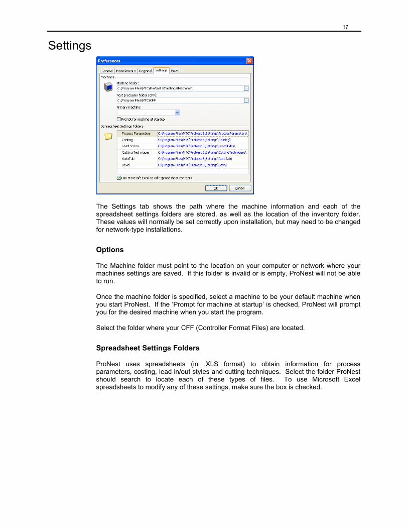
The Settings tab shows the path where the machine information and each of the spreadsheet settings folders are stored, as well as the location of the inventory folder. These values will normally be set correctly upon installation, but may need to be changed for network-type installations.
Options
The Machine folder must point to the location on your computer or network where your machines settings are saved. If this folder is invalid or is empty, ProNest will not be able to run.
Once the machine folder is specified, select a machine to be your default machine when you start ProNest. If the ‘Prompt for machine at startup’ is checked, ProNest will prompt you for the desired machine when you start the program.
Select the folder where your CFF (Controller Format Files) are located.
Spreadsheet Settings Folders
ProNest uses spreadsheets (in .XLS format) to obtain information for process parameters, costing, lead in/out styles and cutting techniques. Select the folder ProNest should search to locate each of these types of files. To use Microsoft Excel spreadsheets to modify any of these settings, make sure the box is checked.
18
Bevel
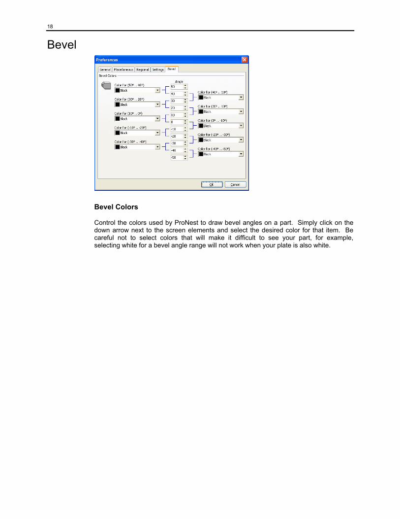
Bevel Colors
Control the colors used by ProNest to draw bevel angles on a part. Simply click on the down arrow next to the screen elements and select the desired color for that item. Be careful not to select colors that will make it difficult to see your part, for example, selecting white for a bevel angle range will not work when your plate is also white.

19
Chapter 4: ProNest Basics
ProNest provides several ways to accomplish most tasks like starting a new job, deleting the selected parts, or using the array function. Most functions are available through the menus and toolbars, and in some cases by using a right-click pop-up menu.
Hints, or “fly-by-help” are displayed when you position the mouse cursor over a toolbar icon for a short period of time to help you understand and learn its meaning. ProNest also uses special mouse cursors when the pointer is over the nesting handles of a selected part or group of parts.
Starting a New Job To start a new job, click on New Job in the File menu, or click on the New Job icon on your toolbar. The new job dialog screen will appear.
Enter a descriptive name for this job and select the appropriate machine by clicking on the down arrow of the combo box and clicking on the desired name. For the purposes of learning ProNest, select the same machine you did while reviewing settings in the Quick Start guide.
Click on OK to close the New Job dialog and the Add Parts window will appear.
Add Parts We’ve provided sample CAD DXF files in both English and Metric in your ProNest 8\Examples folder. You can use these files while you learn ProNest, and they can serve as an example of how to properly layer your DXF or DWG drawing files.
These CAD files were drawn using specific layer names for different attributes such as profiles that are to be cut, scribe and punch marks, dimension information etc. By matching the layer name with the correct process, ProNest can distinguish the different aspects of the drawing and display (and output) the part properly.
20
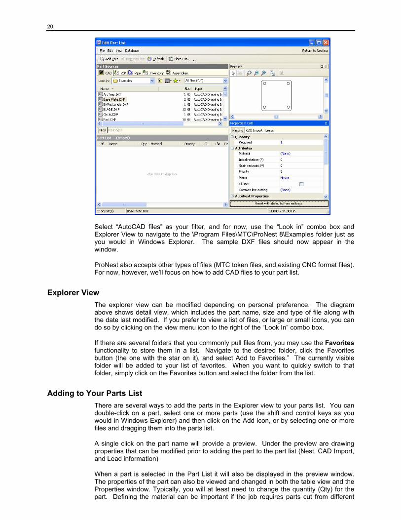
Select “AutoCAD files” as your filter, and for now, use the “Look in” combo box and Explorer View to navigate to the \Program Files\MTC\ProNest 8\Examples folder just as you would in Windows Explorer. The sample DXF files should now appear in the window.
ProNest also accepts other types of files (MTC token files, and existing CNC format files). For now, however, we’ll focus on how to add CAD files to your part list.
Explorer View The explorer view can be modified depending on personal preference. The diagram above shows detail view, which includes the part name, size and type of file along with the date last modified. If you prefer to view a list of files, or large or small icons, you can do so by clicking on the view menu icon to the right of the “Look In” combo box.
If there are several folders that you commonly pull files from, you may use the Favorites functionality to store them in a list. Navigate to the desired folder, click the Favorites button (the one with the star on it), and select Add to Favorites.” The currently visible folder will be added to your list of favorites. When you want to quickly switch to that folder, simply click on the Favorites button and select the folder from the list.
Adding to Your Parts List There are several ways to add the parts in the Explorer view to your parts list. You can double-click on a part, select one or more parts (use the shift and control keys as you would in Windows Explorer) and then click on the Add icon, or by selecting one or more files and dragging them into the parts list.
A single click on the part name will provide a preview. Under the preview are drawing properties that can be modified prior to adding the part to the part list (Nest, CAD Import, and Lead information)
When a part is selected in the Part List it will also be displayed in the preview window. The properties of the part can also be viewed and changed in both the table view and the Properties window. Typically, you will at least need to change the quantity (Qty) for the part. Defining the material can be important if the job requires parts cut from different
21
materials or process parameters (feed rates, kerf values, etc.) need to be output. Select the appropriate material (click in the material field, then click on the arrow) from the material database. This ensures that parts will only be nested on plates sharing the same material record.
Preview
Messages
When a part is drawn incorrectly, the Messages tab at the bottom of the Explorer view window becomes active. Clicking on this tab provides a descriptive text of the problem. The two most common error messages are open profiles (gaps, overlaps, or untrimmed intersections) in the drawing and empty drawing file (the layers used on the CAD drawing do not match the layers ProNest expects to see, as defined in the CAD Import settings). Open profiles can be located in the preview window if the open profiles box is checked under the view menu.
An empty drawing file message will not display a preview of the part.
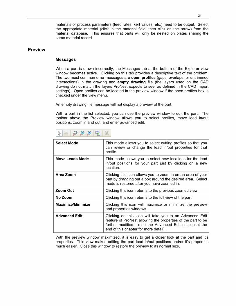
With a part in the list selected, you can use the preview window to edit the part. The toolbar above the Preview window allows you to select profiles, move lead in/out positions, zoom in and out, and enter advanced edit.
Select Mode This mode allows you to select cutting profiles so that you can review or change the lead in/out properties for that profile.
Move Leads Mode This mode allows you to select new locations for the lead in/out positions for your part just by clicking on a new location.
Area Zoom Clicking this icon allows you to zoom in on an area of your part by dragging out a box around the desired area. Select mode is restored after you have zoomed in.
Zoom Out Clicking this icon returns to the previous zoomed view.
No Zoom Clicking this icon returns to the full view of the part.
Maximize/Minimize Clicking this icon will maximize or minimize the preview and properties windows.
Advanced Edit Clicking on this icon will take you to an Advanced Edit feature of ProNest allowing the properties of the part to be further modified. (see the Advanced Edit section at the end of this chapter for more detail).
With the preview window maximized, it is easy to get a closer look at the part and it’s properties. This view makes editing the part lead in/out positions and/or it’s properties much easier. Close this window to restore the preview to its normal size.
22
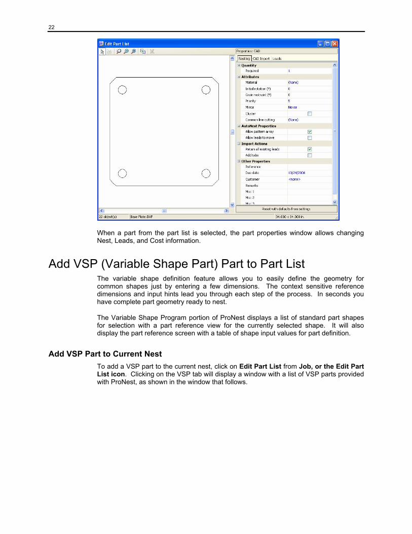
When a part from the part list is selected, the part properties window allows changing Nest, Leads, and Cost information.
Add VSP (Variable Shape Part) Part to Part List The variable shape definition feature allows you to easily define the geometry for common shapes just by entering a few dimensions. The context sensitive reference dimensions and input hints lead you through each step of the process. In seconds you have complete part geometry ready to nest.
The Variable Shape Program portion of ProNest displays a list of standard part shapes for selection with a part reference view for the currently selected shape. It will also display the part reference screen with a table of shape input values for part definition.
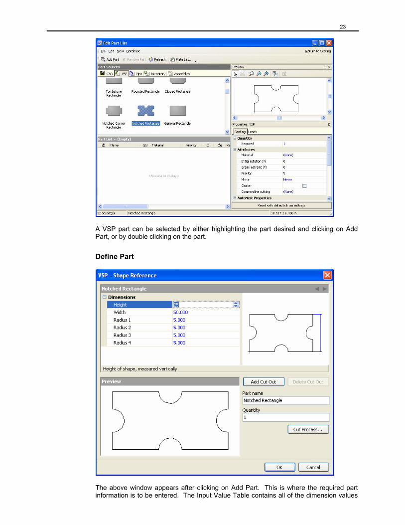
Add VSP Part to Current Nest To add a VSP part to the current nest, click on Edit Part List from Job, or the Edit Part List icon. Clicking on the VSP tab will display a window with a list of VSP parts provided with ProNest, as shown in the window that follows.
23
A VSP part can be selected by either highlighting the part desired and clicking on Add Part, or by double clicking on the part.
Define Part
The above window appears after clicking on Add Part. This is where the required part information is to be entered. The Input Value Table contains all of the dimension values
24
being defined in the left side column, with the input value editable fields in the column on the right side of the table. The values displayed have been edited to differ from the default values. As each value is selected, the reference window at the top right of the screen shows the dimension that is currently being defined and a descriptive prompt appears on the bottom of the screen. As the part is edited the preview window is updated. Any errors will be displayed and the preview will vanish.
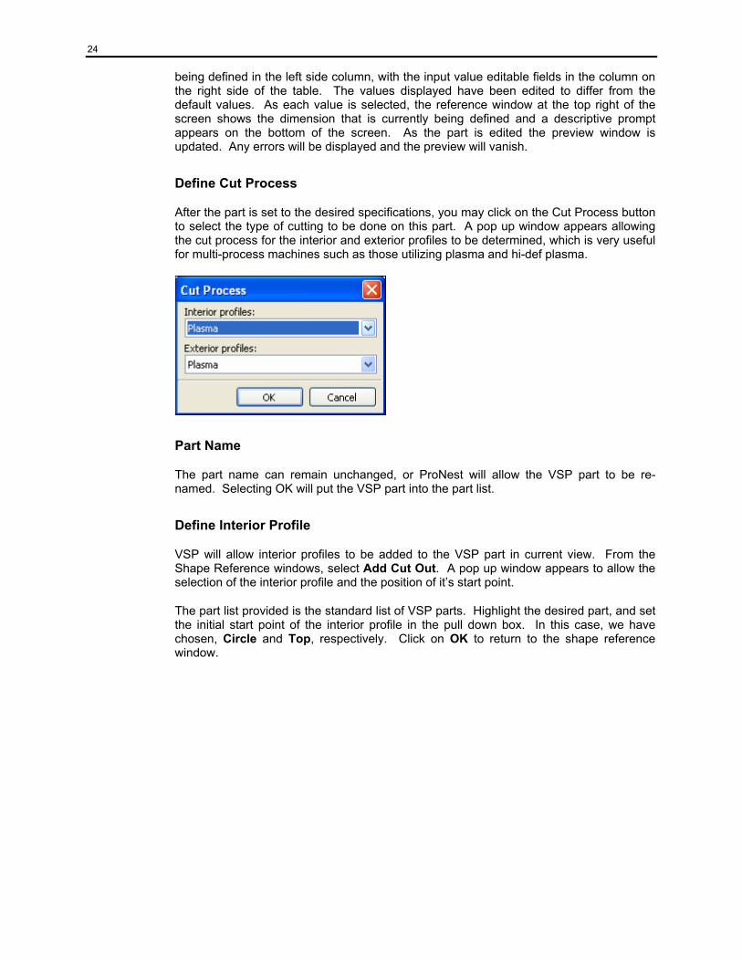
Define Cut Process
After the part is set to the desired specifications, you may click on the Cut Process button to select the type of cutting to be done on this part. A pop up window appears allowing the cut process for the interior and exterior profiles to be determined, which is very useful for multi-process machines such as those utilizing plasma and hi-def plasma.
Part Name
The part name can remain unchanged, or ProNest will allow the VSP part to be re-named. Selecting OK will put the VSP part into the part list.
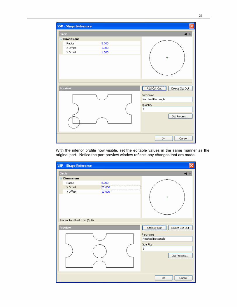
Define Interior Profile
VSP will allow interior profiles to be added to the VSP part in current view. From the Shape Reference windows, select Add Cut Out. A pop up window appears to allow the selection of the interior profile and the position of it’s start point.
The part list provided is the standard list of VSP parts. Highlight the desired part, and set the initial start point of the interior profile in the pull down box. In this case, we have chosen, Circle and Top, respectively. Click on OK to return to the shape reference window.
25
With the interior profile now visible, set the editable values in the same manner as the original part. Notice the part preview window reflects any changes that are made.
26
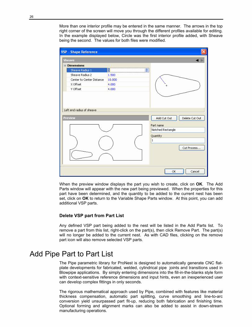
More than one interior profile may be entered in the same manner. The arrows in the top right corner of the screen will move you through the different profiles available for editing. In the example displayed below, Circle was the first interior profile added, with Sheave being the second. The values for both files were modified.
When the preview window displays the part you wish to create, click on OK. The Add Parts window will appear with the new part being previewed. When the properties for this part have been determined, and the quantity to be added to the current nest has been set, click on OK to return to the Variable Shape Parts window. At this point, you can add additional VSP parts.
Delete VSP part from Part List
Any defined VSP part being added to the nest will be listed in the Add Parts list. To remove a part from this list, right-click on the part(s), then click Remove Part. The part(s) will no longer be added to the current nest. As with CAD files, clicking on the remove part icon will also remove selected VSP parts.
Add Pipe Part to Part List The Pipe parametric library for ProNest is designed to automatically generate CNC flat-plate developments for fabricated, welded, cylindrical pipe joints and transitions used in Blowpipe applications. By simply entering dimensions into the fill-in-the-blanks style form with context-sensitive reference dimensions and input hints, even an inexperienced user can develop complex fittings in only seconds.
The rigorous mathematical approach used by Pipe, combined with features like material thickness compensation, automatic part splitting, curve smoothing and line-to-arc conversion yield unsurpassed part fit-up, reducing both fabrication and finishing time. Optional forming and alignment marks can also be added to assist in down-stream manufacturing operations.
27
Each fitting is designed with flexibility in mind and includes powerful features like offsets, tilts, extensions and laps. Cylindrical, conical, rectangular and boot (take-off) tees can be added to Pipes, Cones, and the Angled Pipe.
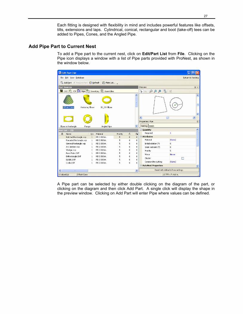
Add Pipe Part to Current Nest To add a Pipe part to the current nest, click on Edit/Part List from File. Clicking on the Pipe icon displays a window with a list of Pipe parts provided with ProNest, as shown in the window below.
A Pipe part can be selected by either double clicking on the diagram of the part, or clicking on the diagram and then click Add Part. A single click will display the shape in the preview window. Clicking on Add Part will enter Pipe where values can be defined.
28
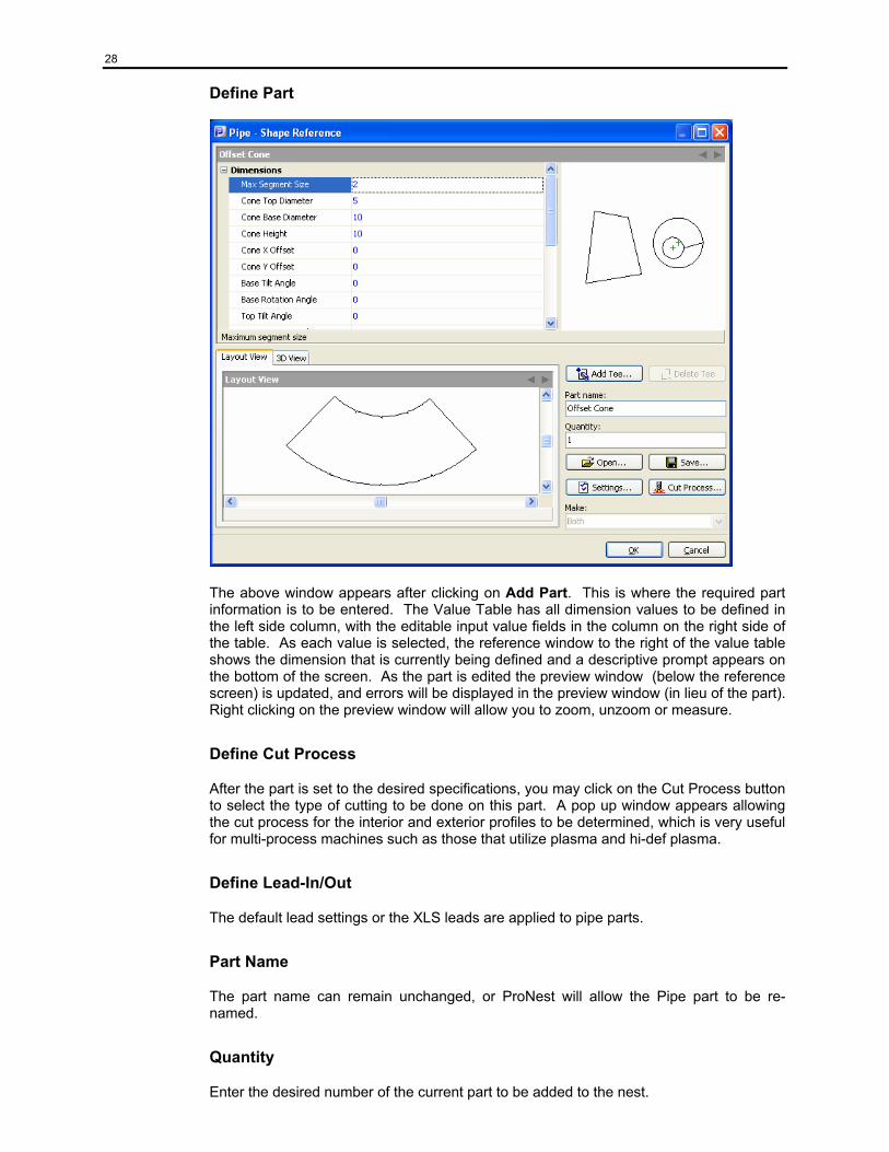
Define Part
The above window appears after clicking on Add Part. This is where the required part information is to be entered. The Value Table has all dimension values to be defined in the left side column, with the editable input value fields in the column on the right side of the table. As each value is selected, the reference window to the right of the value table shows the dimension that is currently being defined and a descriptive prompt appears on the bottom of the screen. As the part is edited the preview window (below the reference screen) is updated, and errors will be displayed in the preview window (in lieu of the part). Right clicking on the preview window will allow you to zoom, unzoom or measure.
Define Cut Process
After the part is set to the desired specifications, you may click on the Cut Process button to select the type of cutting to be done on this part. A pop up window appears allowing the cut process for the interior and exterior profiles to be determined, which is very useful for multi-process machines such as those that utilize plasma and hi-def plasma.
Define Lead-In/Out
The default lead settings or the XLS leads are applied to pipe parts.
Part Name
The part name can remain unchanged, or ProNest will allow the Pipe part to be re-named.
Quantity
Enter the desired number of the current part to be added to the nest.
29
Settings
Clicking on Settings will allow you to view or modify the current Pipe settings. Refer to the Pipe Settings and Fitting Descriptions for complete descriptions of these settings.
View
By clicking on the 3D View tab above the layout view, Pipe will allow you to zoom in and/or out by right clicking the mouse and selecting ‘Zoom’. In addition to Zoom, you can choose to view the shape as either a solid or wire frame. Pipe will also allow you to rotate the part up, down, left or right to view the part from a different perspective by simply clicking on the appropriate arrow button.
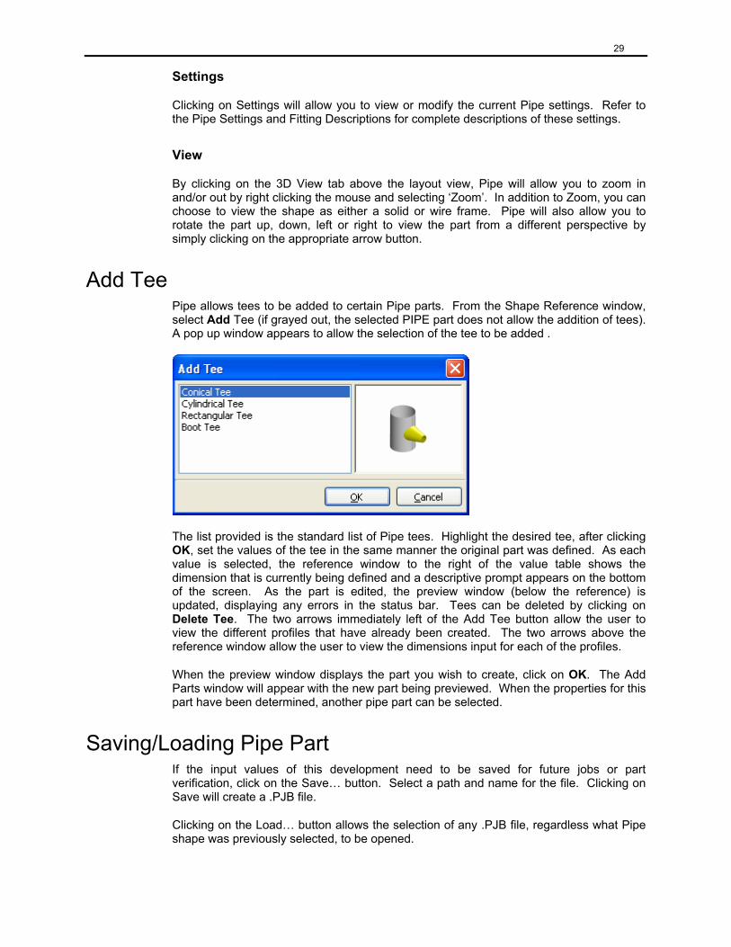
Add Tee Pipe allows tees to be added to certain Pipe parts. From the Shape Reference window, select Add Tee (if grayed out, the selected PIPE part does not allow the addition of tees). A pop up window appears to allow the selection of the tee to be added .
The list provided is the standard list of Pipe tees. Highlight the desired tee, after clicking OK, set the values of the tee in the same manner the original part was defined. As each value is selected, the reference window to the right of the value table shows the dimension that is currently being defined and a descriptive prompt appears on the bottom of the screen. As the part is edited, the preview window (below the reference) is updated, displaying any errors in the status bar. Tees can be deleted by clicking on Delete Tee. The two arrows immediately left of the Add Tee button allow the user to view the different profiles that have already been created. The two arrows above the reference window allow the user to view the dimensions input for each of the profiles.
When the preview window displays the part you wish to create, click on OK. The Add Parts window will appear with the new part being previewed. When the properties for this part have been determined, another pipe part can be selected.
Saving/Loading Pipe Part If the input values of this development need to be saved for future jobs or part verification, click on the Save… button. Select a path and name for the file. Clicking on Save will create a .PJB file.
Clicking on the Load… button allows the selection of any .PJB file, regardless what Pipe shape was previously selected, to be opened.
30
Delete Pipe part from Part List
Any defined Pipe parts to be added to the nest will be listed in the Part List. To remove a part from this list, highlight the part, then click on the Remove Part Icon. The part will no longer be added to the current nest.
Accepting the Part List
When all parts have been added to the part list with correct quantities, material and properties, close out of the Add Parts screen by clicking on the return to nesting button or the “x” in the upper right corner. This returns the user to the main nesting screen with the selected parts in the part bin to the left of the plate.
Add Plates User Defined
Selecting Edit Plate List from File or clicking on the Edit Plate List icon brings up the Add Plate screen. The user can now define the material, size, and thickness of the plate(s) needed for the job, similar to the way the part list was created. The plate can be named and defined as either rectangular or circular (plate type). Custom remnants may also be defined and added. A quantity can be assigned, length and width can be defined and rotation angles can be determined (useful for remnants). Once defined, the plate can be added to the plate list on the bottom by clicking the Add Plate icon.
Inventory If the part and plate inventory option is active, plates can be added from a list previously defined in the plate inventory database. These can include rectangular and circular plates, along with remnants (crops) and skeletons created in ProNest. Select 1 or multiple plates (using the shift or CTRL keys) then click on the Add Plate icon (or double click on the record) to add to the plate list. Single clicking on a record displays the plate in the preview window.
Deleting a Plate Record from the Plate List
A record can be removed from the plate list by selecting the record(s) then clicking on the remove plate icon.
Accepting the Plate List
When all plates have been added to the list, select close from the file menu, click on “X”, or click on Return to Nesting.
Interactive Nesting Interactive Nesting allows you to place parts on the screen and position them where desired. You can interactively nest all of your parts, or it can be done before or after automatic nesting if you have that option.
Starting a New Nest To start a new nest, click on the New Nest icon, or select New Nest… from the Nest Menu. Use New Nest to select a different plate size, or to continue nesting on a new plate when the current plate is full. When the New Nest dialog window appears, you can select from one of the plates you defined in your plate list, select a size defined in your
31
preferences, or enter the dimensions. When you click on OK, an empty plate will be displayed on your ProNest desktop.
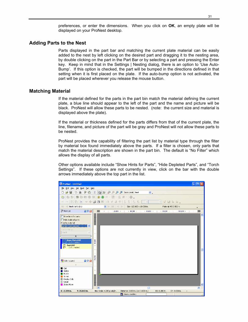
Adding Parts to the Nest Parts displayed in the part bar and matching the current plate material can be easily added to the nest by left clicking on the desired part and dragging it to the nesting area, by double clicking on the part in the Part Bar or by selecting a part and pressing the Enter key. Keep in mind that in the Settings | Nesting dialog, there is an option to ‘Use Auto-Bump’. If this option is checked, the part will be bumped in the directions defined in that setting when it is first placed on the plate. If the auto-bump option is not activated, the part will be placed wherever you release the mouse button.
Matching Material If the material defined for the parts in the part bin match the material defining the current plate, a blue line should appear to the left of the part and the name and picture will be black. ProNest will allow these parts to be nested. (note: the current size and material is displayed above the plate).
If the material or thickness defined for the parts differs from that of the current plate, the line, filename, and picture of the part will be gray and ProNest will not allow these parts to be nested.
ProNest provides the capability of filtering the part list by material type through the filter by material box found immediately above the parts. If a filter is chosen, only parts that match the material description are shown in the part bin. The default is “No Filter” which allows the display of all parts.
Other options available include “Show Hints for Parts”, “Hide Depleted Parts”, and “Torch Settings”. If these options are not currently in view, click on the bar with the double arrows immediately above the top part in the list.
32
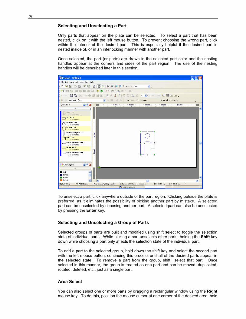
Selecting and Unselecting a Part
Only parts that appear on the plate can be selected. To select a part that has been nested, click on it with the left mouse button. To prevent choosing the wrong part, click within the interior of the desired part. This is especially helpful if the desired part is nested inside of, or in an interlocking manner with another part.
Once selected, the part (or parts) are drawn in the selected part color and the nesting handles appear at the corners and sides of the part region. The use of the nesting handles will be described later in this section.
To unselect a part, click anywhere outside of the part region. Clicking outside the plate is preferred, as it eliminates the possibility of picking another part by mistake. A selected part can be unselected by choosing another part. A selected part can also be unselected by pressing the Enter key.
Selecting and Unselecting a Group of Parts
Selected groups of parts are built and modified using shift select to toggle the selection state of individual parts. While picking a part unselects other parts, holding the Shift key down while choosing a part only affects the selection state of the individual part.
To add a part to the selected group, hold down the shift key and select the second part with the left mouse button, continuing this process until all of the desired parts appear in the selected state. To remove a part from the group, shift select that part. Once selected in this manner, the group is treated as one part and can be moved, duplicated, rotated, deleted, etc., just as a single part.
Area Select
You can also select one or more parts by dragging a rectangular window using the Right mouse key. To do this, position the mouse cursor at one corner of the desired area, hold
33
the right mouse button down and move the mouse to the opposite corner of the area and release the mouse button.
If you select the area by moving from the left to the right, all parts entirely contained in the selection area will become selected. If you select from right to left, all parts contained or whose region intersects the selection area will become selected.
If you hold the shift key down while using area select, the parts in the selection area will be added to the selected group.
Selecting or Unselecting all Parts
To select all parts on the current nest, choose the Select All menu item from the Edit menu. To unselect all parts, choose Unselect All.
Zooming In and Out Zooming in allows you to examine smaller areas of your nest by magnifying them to fill the desktop area of ProNest. Zooming out means to return to a previous level of magnification.
Area Zoom
To zoom in on a selected (rectangular) area of the plate, click on the Area Zoom icon on your toolbar, or select the Area Zoom item from the View menu.
Zoom to Selected
To zoom in on a selected part or group of parts, click on the Zoom Selected icon on your toolbar, or select the Zoom Selected item from the View menu.
Dynamic Zoom
Dynamic zooming allows you to easily zoom in and out at any desired location on your nest. Just position the mouse cursor at the center of the area and press the Page Up or Page Down keys. Each time you press the page up or down keys you will zoom in or out more. Dynamic zooming is very useful when you are in a mode like Move Leads.
You may also dynamically zoom by using the mouse wheel, if your mouse is so equipped. Position the mouse pointer at the center of the zoom region. Rolling the mouse wheel up (away from you) will zoom in and rolling it down (towards you) will zoom out.
Zoom Out
To zoom out (return to the previous magnification level), click on the Zoom Out icon on your toolbar, or select the Zoom Out item from the View menu.
No Zoom
To return to a view of the entire plate, click on the No Zoom icon on your toolbar, or select the No Zoom item from the View menu.
34
Working With Selected Parts During interactive nesting, all operations effect the selected parts. These parts are referred to as the selected group. The group is surrounded by eight “handles”, one at each corner and the center of each side. A part must be selected before most operations can be performed on it.
Moving (Dragging)
To move the selected group or part, click inside a part in the selected group and hold down the left mouse button. The selected parts are redrawn in the specified moving color. Only exterior profiles of these parts are visible while they are being moved, and the bump and rotation handles disappear. This is a dragging state. Still holding down the left mouse button, drag the group with the mouse until it is in the desired location.
Releasing the left mouse button returns the selected group to a normal selected state in the new location.
Moving (Using Slide)
If you click and hold the mouse button down on one of the middle bump handles you can slide it horizontally or vertically without changing its position in the other direction. For example, if you slide the part using the left middle bump handle, the part can only be moved horizontally, not vertically.
Moving (Using Nudge)
The selected group can also be moved a pre-defined distance by using the shift key with arrow keys or the bump handles. To move up by the nudge distance, hold down the shift key and press the UP ARROW key (or click on the top-center bump handle), to move left, press the LEFT ARROW key, and so on. The selected group will move the amount given by the Nudge Distance setting in the Nesting tab of the Settings screen.
Bumping
In ProNest, bumping means to move a part in a desired direction until it is the specified separation from other parts or the plate edge.
To bump, click on the desired middle handle of the selected part or group. For example, to bump left, select the middle handle on the left side of the selected group. You can also bump by using the arrow keys, or selecting the desired bump direction under part. The selected group will move left until it is a specified separation away from another part or the plate edge. Parts that are completely off the plate will not bump. If the leading edge of a part (i.e., the left edge if bumping left) is already in conflict, it will not bump. The part, plate edge, and pierce separations used can be found in the process parameter settings for the chosen cut process (see chapter 7 settings overview).
Delete
To delete the selected group or part, press the Delete key or choose Delete from the edit menu.
Delete Nest
To delete the current nest, select Delete Nest from Nest, or select the Delete Nest Icon.
35
Delete All Nests
To delete all nests, select Delete All Nests from Nest, or select the Delete All Nests Icon. When this is done, all parts are free to be nested again.
Note: If a part or parts are selected when either delete nest function is used, they will remain selected on the plate, even though all other part are removed.
Duplicating
To duplicate the selected group or part, select Duplicate from the Parts pull down menu, or select the Duplicate Parts Icon. The selected group will be unselected, and a copy of it will be placed slightly offset from the original. If the selected group requires more of any of its parts than remain to be nested, the selected group will not be duplicated and the original part will remain selected.
Clustering
A cluster may be created by grouping multiple parts in the selected state, then clicking on Cluster from the Parts menu, or clicking on the Cluster icon. These can be the same part or different parts. Once a cluster is created, it can be treated as an individual part. It can be bumped, rotated, arrayed, duplicated, etc. Unselecting any individual part in the cluster unselects the entire cluster.
Clusters are also added to the part list and can then be used in automatic nesting, or can be added interactively to the nest.
Unclustering
When a cluster of parts is selected and the Uncluster Icon is clicked (or Uncluster is selected from the Parts menu), the parts in that cluster are no longer permanently grouped together. After Unclustering, the individual parts can again be unselected or selected individually, though the cluster still exists in the part bar and can be added to the plate at any time.
Mirroring
To mirror the selected group or part, select Mirror from Parts or select the Mirror Icon. The selected group is mirrored on a vertical axis, which runs through the center of the selected group’s region.
Reverse Cut Direction
The reverse cut direction feature is used to change the direction the selected part will be cut. Generally, ProNest will process parts so that the interior cuts are done in a counter-clockwise direction and exterior profiles in a clockwise direction. Cutter kerf compensation left is also used as standard practice.
Sometimes it may be desirable to reverse the cutting direction; for example, in order to keep a part attached to the bulk of the plate as long as possible.
When the cut direction is reversed, interior profiles are cut clockwise and exterior profiles counter-clockwise, and kerf compensation right is used.
The direction of cut can be displayed on the plate if Cut Direction is checked under the View menu.
36
Arraying
To array, place the selected part or group in the desired start location and select Array from Nest, or select the Array Icon. The number of parts to place in the X and Y directions, and the part offset (X & Y spacing) are calculated. The number in the Y direction is maximized to cover the plate height. The part offset is calculated to place parts as close together as possible based on the part separation in your settings.
Pattern Array (Optional Feature)
To Pattern Array, place the selected part or group in the desired start location and select Pattern Array from Nest, or select the Pattern Array icon. ProNest will then calculate an optimal arrangement of that part or group to maximize the number of copies that can be nested.
Pattern Array will be discussed in detail in Chapter 5.
Rotating Parts or Part Groups
All rotations occur in relation to the center point of the selected part or group.
Rotating by Increment - To rotate the selected part or group by a set increment, click on either the Incremental Rotation Icon, or the upper left handle. The selected group will rotate by the specified increment. The Incremental Rotate Angle setting in the Preferences screen under Manual Nesting is used for the icon, keyboard, and upper left handle rotations. If the “+” Incremental Rotation Icon or the upper left handle are used, the selected group rotates counter-clockwise. If the “-“ Incremental Rotation Icon is used, the selected group rotates clockwise.
Rotating to Next 90 - To rotate the selected part/group to the next 90 degree increment greater than its current angle, starting from its initial angle, select the Rotate To Next 90 Icon, Press “Q” on the keyboard, or select the lower left handle. The current angle of the selected part/group is the total rotation from its initial angle. If the selected part/group consists of one part, the initial angle of that part is used. If the part/group consists of multiple parts, the initial angle is set to zero each time a part is added or removed from the group.
Longest Straight Side – Clicking the Long Side Rotate Icon, pressing “S” on the keyboard, or clicking the lower right “handle” will determine the selected part’s longest straight side and proceed to rotate that side to the next closest counter-clockwise horizontal or vertical position. For example, the hypotenuse of a right triangle will rotate to 90°, 180°, 270° or 360°.
Free Rotate - To “free” rotate the selected group, select the upper right handle and hold down the left mouse button. The selected parts are redrawn in the moving color. Only exterior profiles of the parts are visible and the bump and rotate handles disappear. This is a dragging state. Still holding down the left mouse button, move the mouse. The part rotates with the mouse. To rotate quickly, stay closer to the center of the part or group. To rotate slowly, move farther away from the center. Releasing the left mouse button returns the selected group to a normal selected state.
Multiple Torches If the cutting machine has multiple torches of one process, the torch settings feature allows ProNest to take advantage of this. In Torches, under Settings, set “Number of Torches” to match what the machine has.
Open the Torch Settings combo box under the part list and select 2 for number of torches to be used on this plate. Set the torch spacing field to 0, then click on OK. Drag a part
37
over to the plate. There should be two parts on the plate now, the master being the darker color and the slave being the lighter. The spacing between corresponding locations on the 2 parts is determined by the width of the plate divided by the number of torches. This can be modified by assigning a value for torch spacing.
As an option, MTC provides a variable multi-torch feature which can adjust both the number of torches and the spacing used automatically based on the size of the part being nested.
Even without the variable torch option, ProNest allows the user to manually modify the torch spacing and number of torches as different parts are nested. When the nest is output to the machine, a stop code and comments are included that tell the operator what torch settings to use, allowing him to set up the machine properly.
Move Lead In/Out Locations In addition to being able to move lead in/out locations in the Preview window while you are building your parts list, you can also move them in the main nesting window.
To enter move leads mode, click on the Move Leads Mode icon in your toolbar or select the Move Leads Mode from the Edit menu.
To move the lead in/out for an interior or exterior profile of a part, simply click on the desired new location and the lead in/out will be automatically moved there. ProNest will change the style (according to your settings) when you move from a side location to a corner or from a corner to a side.
If you need to zoom in on a profile to select the location properly, it is usually best to use dynamic zooming. Just move the mouse cursor over the desired area and use the page up and down keys. Dynamic zooming will not cancel Move Leads Mode.
To return to normal Select Mode, you can click the Right mouse button, or click on the Select Mode icon in your toolbar.
Note: Since moving leads will cause ProNest to generate a new cut sequence, it is best to move leads prior to setting a cut sequence.
Cut Sequence When you nest parts in ProNest, either manually or automatically, the program generates a cutting sequence for those parts based on your current settings. After your nesting is complete, you can interactively change the cut sequence if desired. Click on the Cut Sequence Icon in your toolbar, or select the Cut Sequence item from the Nest Menu; ProNest will display the Cut Sequence Toolbar. This tool bar has special tools to help you change the cut sequence. Normally it appears as a floating toolbar on your workspace area, but like all other toolbars, it can be “docked”. The current cut sequence for each part on your nest will be displayed. You can now use the mouse to select parts and toggle them between sequenced and unsequenced mode by simply clicking on them. When a part is unsequenced, it will not have a sequence number displayed near the start point of the exterior profile and it will be drawn in the “unsequenced” color.
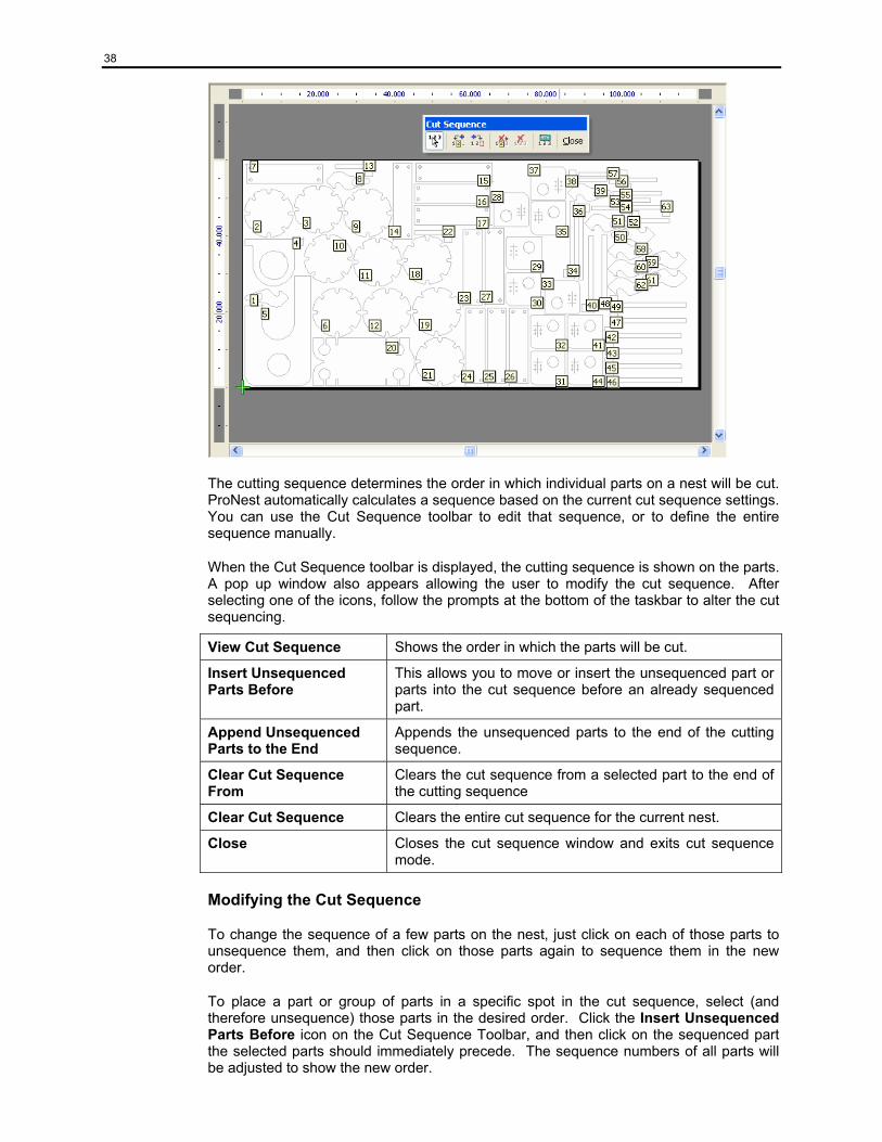
38
The cutting sequence determines the order in which individual parts on a nest will be cut. ProNest automatically calculates a sequence based on the current cut sequence settings. You can use the Cut Sequence toolbar to edit that sequence, or to define the entire sequence manually.
When the Cut Sequence toolbar is displayed, the cutting sequence is shown on the parts. A pop up window also appears allowing the user to modify the cut sequence. After selecting one of the icons, follow the prompts at the bottom of the taskbar to alter the cut sequencing.
View Cut Sequence Shows the order in which the parts will be cut.
Insert Unsequenced Parts Before
This allows you to move or insert the unsequenced part or parts into the cut sequence before an already sequenced part.
Append Unsequenced Parts to the End
Appends the unsequenced parts to the end of the cutting sequence.
Clear Cut Sequence From
Clears the cut sequence from a selected part to the end of the cutting sequence
Clear Cut Sequence Clears the entire cut sequence for the current nest.
Close Closes the cut sequence window and exits cut sequence mode.
Modifying the Cut Sequence
To change the sequence of a few parts on the nest, just click on each of those parts to unsequence them, and then click on those parts again to sequence them in the new order.
To place a part or group of parts in a specific spot in the cut sequence, select (and therefore unsequence) those parts in the desired order. Click the Insert Unsequenced Parts Before icon on the Cut Sequence Toolbar, and then click on the sequenced part the selected parts should immediately precede. The sequence numbers of all parts will be adjusted to show the new order.
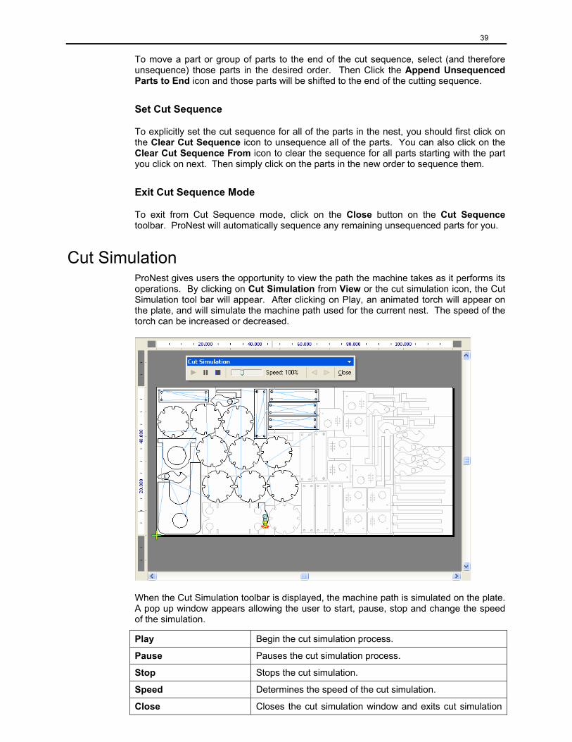
39
To move a part or group of parts to the end of the cut sequence, select (and therefore unsequence) those parts in the desired order. Then Click the Append Unsequenced Parts to End icon and those parts will be shifted to the end of the cutting sequence.
Set Cut Sequence
To explicitly set the cut sequence for all of the parts in the nest, you should first click on the Clear Cut Sequence icon to unsequence all of the parts. You can also click on the Clear Cut Sequence From icon to clear the sequence for all parts starting with the part you click on next. Then simply click on the parts in the new order to sequence them.
Exit Cut Sequence Mode
To exit from Cut Sequence mode, click on the Close button on the Cut Sequence toolbar. ProNest will automatically sequence any remaining unsequenced parts for you.
Cut Simulation ProNest gives users the opportunity to view the path the machine takes as it performs its operations. By clicking on Cut Simulation from View or the cut simulation icon, the Cut Simulation tool bar will appear. After clicking on Play, an animated torch will appear on the plate, and will simulate the machine path used for the current nest. The speed of the torch can be increased or decreased.
When the Cut Simulation toolbar is displayed, the machine path is simulated on the plate. A pop up window appears allowing the user to start, pause, stop and change the speed of the simulation.
Play Begin the cut simulation process.
Pause Pauses the cut simulation process.
Stop Stops the cut simulation.
Speed Determines the speed of the cut simulation.
Close Closes the cut simulation window and exits cut simulation
40
mode.
Cropping the Plate In ProNest, cropping is used to cut a usable portion of the plate away from the skeleton created by cutting out the parts. When a crop is defined for a nest, the default sequence would place the crop at the end of the CNC file. This may be overridden by modifying your cut sequence rules.
AutoCrop
The Autocrop option (under the nest menu) will add a cropping cut beyond the nested parts. ProNest uses the settings on the Settings | Crop page to determine the best remnant that may be generated from the current nest.
Checking the Crop settings box for “Step 1: Find the best vertical crop” will result in a straight crop cut from the top to the bottom of the plate. The remnant plate created can then be easily used in ProNest by entering it as a custom plate size.
Interactive Cropping
Interactive cropping allows you to create the path for the cropping cut by defining a series of linear motions.
To interactively crop a nest, click on the Crop Mode icon on your toolbar, or select the Crop item from the Nest menu.
Once in crop mode, a cross-hair cursor will be drawn across the plate. Start your crop by clicking below (or above) the plate edge. ProNest will automatically start the cut at the plate edge for you. You can then simply click on a series of points to define the cut path. Finish the crop by clicking above (or below) the opposite plate edge for the last crop motion. You can complete a crop at the right or left edge of the plate if desired.
An alternative to the single click method for defining the crop is to click down with the mouse button, drag out a line and then release the mouse button. This method allows you to see where each section of the crop cut will be before you release the mouse button. You can also hold the shift key down while using this method; this causes the resulting crop line to "snap to" the nearest horizontal, vertical or 45 degree line.
While in the process of defining a crop, you may delete the most recently added crop point by pressing the Backspace key. Repeatedly pressing the Backspace key will erase all of the crop points in the active crop so that you may choose a new starting location for the crop.
To exit crop mode, click the right mouse button. ProNest will automatically trim or extend the last crop line to the plate edge.
Delete Crop
To delete an existing crop for a nest, select the Delete Crop item from the Nest menu.
Measure Mode Measure mode is used to measure distances on your nest using the mouse cursor. For example, you could use this to check part separation or a dimension on a part. The accuracy of the measurement is limited by the distance represented by one pixel on the screen, and by how accurately you select the measurement points.
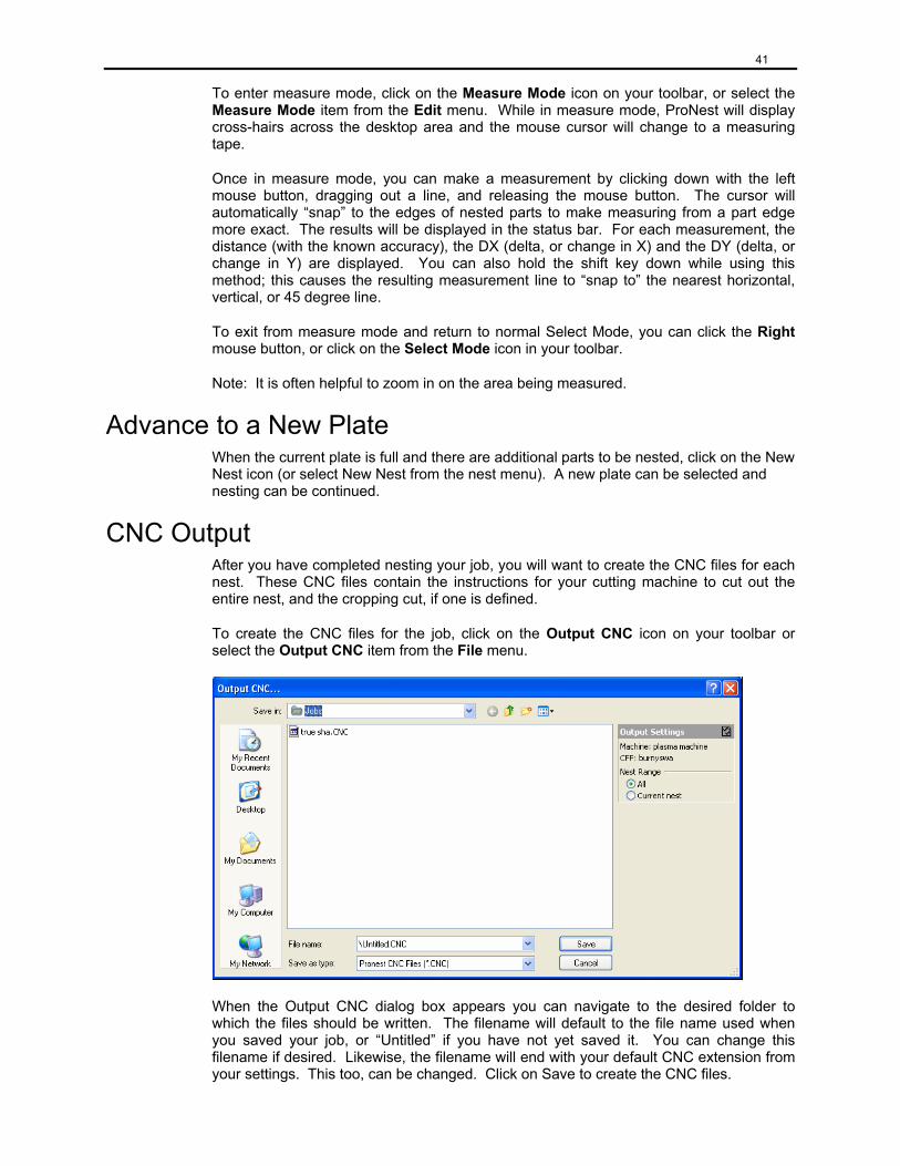
41
To enter measure mode, click on the Measure Mode icon on your toolbar, or select the Measure Mode item from the Edit menu. While in measure mode, ProNest will display cross-hairs across the desktop area and the mouse cursor will change to a measuring tape.
Once in measure mode, you can make a measurement by clicking down with the left mouse button, dragging out a line, and releasing the mouse button. The cursor will automatically “snap” to the edges of nested parts to make measuring from a part edge more exact. The results will be displayed in the status bar. For each measurement, the distance (with the known accuracy), the DX (delta, or change in X) and the DY (delta, or change in Y) are displayed. You can also hold the shift key down while using this method; this causes the resulting measurement line to “snap to” the nearest horizontal, vertical, or 45 degree line.
To exit from measure mode and return to normal Select Mode, you can click the Right mouse button, or click on the Select Mode icon in your toolbar.
Note: It is often helpful to zoom in on the area being measured.
Advance to a New Plate When the current plate is full and there are additional parts to be nested, click on the New Nest icon (or select New Nest from the nest menu). A new plate can be selected and nesting can be continued.
CNC Output After you have completed nesting your job, you will want to create the CNC files for each nest. These CNC files contain the instructions for your cutting machine to cut out the entire nest, and the cropping cut, if one is defined.
To create the CNC files for the job, click on the Output CNC icon on your toolbar or select the Output CNC item from the File menu.
When the Output CNC dialog box appears you can navigate to the desired folder to which the files should be written. The filename will default to the file name used when you saved your job, or “Untitled” if you have not yet saved it. You can change this filename if desired. Likewise, the filename will end with your default CNC extension from your settings. This too, can be changed. Click on Save to create the CNC files.
42
If you have more than one nest, and are using a default CNC extension, ProNest will append a number to the filename. For example, if you have two nests and you entered TEST.CNC as the filename, ProNest would create two nests named TEST01.CNC and TEST02.CNC.
If the option to “Use Long Filenames” is not checked in the CNC output section of your settings, ProNest will first truncate the filename so that the resulting name is not longer than eight characters.
If existing files will be overwritten and you have asked to be warned about overwriting CNC files in your Preferences (Miscellaneous), ProNest will display a warning dialog box. Click on OK to replace the existing files, or Cancel to exit without writing any CNC files.
Saving A Job/Opening A Job When the nesting is done, the entire job can be saved by either clicking on the Save Job icon or selecting Save Job under the File menu. When the Save Job As… dialog appears, the desired folder to which the .NIF file is written can be selected. All aspects of the nest including part geometry, plate information, and settings are saved. This file can be opened at any time by clicking on the Open Job icon or selecting Open Job from the File menu. This restores the job as it was saved, should it need to be changed. At this time, the nest(s) can be modified in any way or the entire job can be unnested and renested in a different manner.
Creating Plate Inventory (optional feature)
With this option, you can save remnants and/or skeletons from nest material to a database for use in ProNest at a later time.
Creating a Remnant or Skeleton
A skeleton is the full plate minus the nested parts. Note that the plate does not need to be cropped in order to create the skeleton. After cropping the plate, the remnant (drop) may be saved to the plate inventory database by selecting Remnants and Skeletons… under Job. A list of all available remnants and skeletons that have been or may be created will appear in a list. You may right click on a particular nest to create remnants and skeletons just for that nest or you may create remnants and skeletons for all selected nests by clicking on the Save Remnants and Save Skeletons buttons on the bottom of the dialog.
Remnants and skeletons for any nest may be discarded in a similar fashion, either by right clicking on a nest in the list and choosing one of the Discard options or by clicking on the Discard Remnants and Discard Skeletons buttons on the bottom of the dialog.
During the CNC output process, if any remnants and skeletons have been created, you will be given the option of updating them in your plate inventory database.
Custom Remnants
A custom remnant is a partial plate of material available in inventory. Custom remnants can be created in both the New Nest and Autonest setup screens. In each of these screens you have the Remnant option when selecting the custom plate drop-down menu.
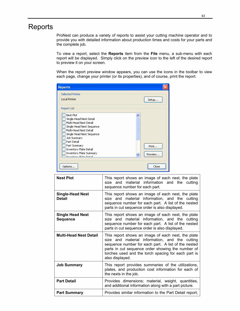
43
Reports ProNest can produce a variety of reports to assist your cutting machine operator and to provide you with detailed information about production times and costs for your parts and the complete job.
To view a report, select the Reports item from the File menu, a sub-menu with each report will be displayed. Simply click on the preview icon to the left of the desired report to preview it on your screen.
When the report preview window appears, you can use the icons in the toolbar to view each page, change your printer (or its properties), and of course, print the report.
Nest Plot This report shows an image of each nest, the plate size and material information and the cutting sequence number for each part.
Single-Head Nest Detail
This report shows an image of each nest, the plate size and material information, and the cutting sequence number for each part. A list of the nested parts in cut sequence order is also displayed.
Single Head Nest Sequence
This report shows an image of each nest, the plate size and material information, and the cutting sequence number for each part. A list of the nested parts in cut sequence order is also displayed.
Multi-Head Nest Detail This report shows an image of each nest, the plate size and material information, and the cutting sequence number for each part. A list of the nested parts in cut sequence order showing the number of torches used and the torch spacing for each part is also displayed.
Job Summary This report provides summaries of the utilizations, plates, and production cost information for each of the nexts in the job.
Part Detail Provides dimensions; material, weight, quantities, and additional information along with a part picture.
Part Summary Provides similar information to the Part Detail report,
44
but without the part picture.
Inventory Summary Accounts for inventory plates used in the job
Inventory Detail Provides dimensional information on the inventory plates used.
Optimization Displays the utilization and production information for each nest in the job, along with the optimization strategy (if any) that was used to create it.
Part List by Customer The Part List report contains the filenames (including path), quantity required, quantity nested, priority, restriction angle, initial rotation and reference value for each part in the job, and will sort the parts by customer.
Part Label(Avery 5264) Will print the part information on standard Avery 5264 labels.
HVAC Label(A5164) Will print labels for HVAC on Avery 5164 labels.
Automatic Nesting (Optional Feature) Rectangular vs True Shape Automatic Nesting
Automatic nesting can be performed in two different styles, depending on the options chosen when ProNest was purchased. Rectangular nesting (often called Block nesting) places an imaginary rectangular border around each part. The parts are then placed on the plate in such a way that no part infringes inside the rectangular border of another. True Shape nesting allows parts to be placed on the plate based on their actual shape, not a rectangular border. This allows parts to be interlocked or placed inside profiles of other parts. Since, in general, both styles follow the same procedures and rules, we will concentrate on True Shape nesting.
Factors Which Influence Nesting
After developing a list of parts and plates (as discussed earlier in this chapter), rather than manually placing parts, click on the Start Autonest icon. If the parts are defined to match the plate material, they will automatically be placed on the plate, starting from the corner specified as the Init Point (defined in the General Settings).
Autonest, under Settings, is a Strategy combo box- the strategy chosen will dictate the way ProNest places the parts on the plate. Each strategy may give different results and take varying amounts of time, based on its complexity. Once the parts are nested, the plate(s) can be unnested and another strategy can be selected, if desired.
An important aspect of autonesting (as mentioned earlier) is the separations between other parts, the edge of the plate, and the pierces (blow-through points). These can be set as defaults (Settings => Machine => Plasma, Gas, Laser, etc- (Choose the appropriate process) => Process Parameters) or based on individual material records in conjunction with the appropriate Process Parameter database record (discussed elsewhere in this manual).
Clicking on the ‘+’ by the Importing Parts section under Settings, then Nesting reveals parameters which affect the rotation angles ProNest tries before placing the parts on the plate and the order (Priority) they are added. These are discussed in Chapter 3.
It is important to know that ProNest normally will nest the largest part first, until either the quantity is exhausted or no more can be fit on the plate. Then it will try the next largest part and so on. The priority allows the user to dictate which part should be nested first. The lower the number, the sooner it will be nested. These values are applied to all parts
45
but ProNest allows the user to modify individual parts by changing the part record field on the Add Parts screen under the Part List bar. The part bin is ordered by size (largest part on top). If the priority is changed, the order the parts appear in the part bin changes also.
Multiple Torches As in interactive nesting, multiple torches can be used. Set the Number of Torches in the Torches section in Settings to the maximum number of torches (of the same process) used by the cutting machine. If the optional variable multi-torching features are used, ProNest will not only vary the spacing between parts but also change the number of torches used, based on the space available.
If fixed number of torches and spacing is used and the parts are too large to fit on the plate, a “Not all parts were nested” message will be displayed. Change the number of torches and try again. This message also occurs if there are parts remaining and all plates are full. Click on OK, then the New Nest icon and select a new plate or add another plate from the Add Plates icon.
Using Both Automatic and Interactive Nesting A very useful feature of ProNest is the ability to utilize both automatic and interactive nesting on the same job. Place a few parts on the plate manually in the manner desired then click on the Start Autonest icon to complete the plate. Likewise, autonesting can be used first followed by manual rearranging of parts to enhance the utilization of the plate. The autonest function can be stopped at any time by clicking on the Stop Autonest icon.
Once the parts are nested, the features discussed earlier in the Interactive Nesting section are all available to the user. Parts can be moved, rotated, duplicated, or mirrored. The cut direction can be changed on individual parts. The plate can be cropped and the cutting sequence, which is automatically developed by ProNest, can be modified. When all modifications have been made, the nest can be saved and/or output as a CNC file.
Material Database The Material Database stores a list of all the different material types and thicknesses that you might want to eventually nest on. Once this list is created, it will be available within ProNest and you will be able to assign a material type and thickness for each part and plate. By providing this information, ProNest will be able to calculate costs and weights for every part and plate.
To open the Material Database
• To open the Material Database from within the Add Parts window, click on the Database menu, select Material….
• To open the Material Database from the Windows Start menu, click Start, click All Programs, click MTC Products, click ProNest 8 Nesting System, and then click Material Database.
To add a material to your Material Database 1. On the Material Database toolbar, click New. 2. Under the General tab, type at least the material name and thickness of the material. 3. To save the material, click OK.
Notes:
• The density and thickness are used to calculate part and plate weight.
• The unit price is used to calculate the part and plate material cost.
46
• The scrap value is used to calculate the nest’s scrap value.
To delete a material from your Material Database
• In the list of materials, click the one you want to delete, and then click Delete on the toolbar.
To change material information in your Material Database
• In the list of materials, locate and double-click the material you want, and then change the information as needed.
Customer Database The Customer Database stores a list of all your company’s clients. Once this list is created, it will be available within ProNest and you will be able to assign a customer for each part. By providing this information, ProNest will be able to provide reports itemized by customer.
To open the Customer Database
• To open the Customer Database from within the Add Parts window, click on the Database menu, select Customer….
• To open the Customer Database from the Windows Start menu, click Start, click All Programs, click MTC Products, click ProNest 8 Nesting System, and then click Customer Database.
To add a customer to your Customer Database 1. On the Customer Database toolbar, click New. 2. Under the General tab, type at least the customer name. 3. On the other tab, add any information you would like to include. 4. To save the customer, click OK.
To delete a customer from your Customer Database
• In the list of customers, click the one you want to delete, and then click Delete on the toolbar.
To change customer information in your Customer Database
• In the list of customers, locate and double-click the customer you want, and then change the information as needed.
Advanced Edit When a part in the Part List is highlighted in the Add Parts window, the Advanced Edit icon becomes visible on the Preview screen. This program allows the user to make significant changes to the selected part. Advanced Edit allows the selection of points, entities, or profiles. If the entire profile highlights when selected with the left mouse key, Advanced Edit is in profile mode. If editing entities or points is desired, click on Select Profiles under the Edit menu to disable profile mode. Likewise, if only individual entities are being highlighted, click on Select Profiles to activate profile mode. The current mode is displayed on the bottom of the screen.
47
Point Mode
Point or Entity selection mode is determined by which is selected first. If you left click on a part entity within the selection tolerance of an intersection point, you will enter Point mode and the intersection point will become selected. If you click on a part entity outside of the selection tolerance of an intersection point, you will enter Entity mode and the entity you left clicked on will become selected.
When in Point mode, left click on a point (one of the dots on the profile). To the right of the part display, an Intersection Point Properties box appears giving the Coordinates (X and Y distance from the origin, signified by the + on the part display) and Properties, which allow the addition of loops. Looping is a method to ensure a sharp corner on a part. The torch passes straight through and beyond the corner, then loops around to enter the corner again at a zero degree angle relative to the next line to be cut. This prevents rounding of the corner but, since it adds to the profile, also takes up more material when nested. The scale controls the size of the loop and the remaining parameters refer to CNC output and may or may not be applicable to the cutting machine.
Right clicking on a point allows the user to make it a Start Point or choose Quick Loop, using whatever loop values were previously used in this session of Advanced Edit. When Make Start Point is selected, the default leads from ProNest are used in conjunction with the style already used for the part. In other words, if moving the leads from corner to corner, the style and dimension will not change. If the leads are moved from corner to side (or vice versa), the leads will be set to the ProNest default values.
Right clicking on an existing lead allows it to be deleted by clicking on Delete LILO or flipped (either from outside the profile to inside or vice versa) by clicking on Flip LILO. However, if the leads appear on the wrong side of the profile, there are most likely problems with the drawing that should be explored. MTC Technical Support will be happy to explain some possible reasons and solutions should this occur.
Entity Mode
Selecting an entity (line or arc) with the left mouse key opens the Entity Properties box to the right of the part display. This provides pertinent information about the entity such as start, end, and center point (if applicable) coordinates, length or radius, and output parameters.
Right clicking on an entity allows the user to Delete the entity, make the point where he clicked the start point (Make Start Point), or split the entity at the point he clicked (Split Entity). Tabs can also be added at the point of the mouse click. Selecting Add Tab opens the Tab Properties box on the right of the part display screen. A tab is a bridge or stitch cut that leaves the part still connected to the plate. At the spot of the tab, the torch will shut off, move to the end of the tab or the leadin to the tab, then begin cutting again. The properties allow definition of the leadin (if desired), the length of the tab, and CNC output values. After adding the tab, left click to select another entity, then right click to select Quick Tab. This will create a duplicate tab at the new location.
Profile Mode
If the user has been modifying points and entities and now wants to change features of a profile, he would need to choose Select Profiles from the Edit Menu. A left click on a profile opens the Profile Properties box, allowing the user to change the cut process, the kerf offset direction, the cut direction, and the cut sequence number location.
Right clicking on a profile allows the user to Delete it.
48
Additional Utilities of Advanced Edit File Menu
When all changes are made to the part, the following options may be useful:
Output generates the CNC code that operates the cutting machine. Normally, this would not be used since ProNest outputs the code for the entire nest. Sometimes however, the output of only a single part is needed and this is a quick way to do it.
Update saves and carries over the part changes into ProNest upon exiting Advanced Edit. The changes can also be saved when the “x” in the upper right corner is clicked.
Reload restores the part to the last saved condition (either the way the part was originally brought in or the way it was after Updating), eliminating any changes made.
Print allows the part and it’s properties to be printed
Edit Menu
In addition to those discussed earlier, the Edit menu allows other helpful routines:
Select All allows mass editing of multiple points, entities, or profiles. For example, if a lead was selected anywhere on the part and Select All was clicked, all the leads would be highlighted and could be modified by changing the properties as we did with a single lead. When applied, all the leads should change.
Unselect All will unselect everything, as will clicking off the part.
Delete will remove the selected entity or profile.
Select Mode allows you to select points or entities to be modified.
Select Profiles allows whole profiles to be selected, allowing them to be edited.
Measure the distance between two points by clicking on the measure icon or menu item. Move the crosshairs to one spot, click and hold the left key, dragging the mouse to the next spot. Release the mouse key and the information will be displayed on the status bar at the bottom of the screen.
Default Tab Settings allows the user to set up the tab properties that will be used in Quick Tab mode.
Default Loops Settings allows the user to set up the loop properties that will be used in Quick Loop mode.
Additional Selection Techniques
In addition to the selection method we used to pick points, entities, and profiles, Advanced Edit provides a couple other tools.
Area Select (not listed in the Edit menu) fine tunes the Select All function by allowing the user to open a window around the items he wants to select. This works in an identical manner to ProNest- right click then drag the mouse from left to right, opening a window around a given area. If a point is selected, all points falling within this window will also become selected. Likewise, if an entity is selected prior to opening a window, all entities completely inside the area will be selected. The same holds true for profiles. When the
49
Area Select window is opened from right to left, the entity or profile only needs to be partially in the box to be selected.
Using the Ctrl Key Multiple (but similar) items can also be selected by holding the Ctrl key while selecting. All the items that are clicked will be selected.
Using the Shift Key Multiple (but similar) items can also be selected by holding the Shift key while selecting. If an item is selected and an item on the other side of the part is clicked with the Shift key, not only the two items will be highlighted but all similar items in between.
View Menu
Toolbars may be selected for display and customized.
Properties Toolbar will either display the various properties toolbars to the right of the part display or not.
The following are some useful features found in the View menu that aid in verifying whether or not the part is ready to nest.
Zoom features are identical to those found in ProNest and were discussed earlier in this chapter.
Index traces the path of the torch as it rapid travels (torch off motions) from profile to profile.
Cut Sequence assigns a number for each profile in the order the part will be cut.
Cut Direction displays arrows pointing the direction the torch will travel around each profile.
Intersection Points show the start and end points of each entity.
Start Points displays the start point of each profile.
Open Profiles, when selected, displays diamonds at points where ProNest finds problems in the cad drawing.
Display Only shows any information that is on a cad drawing layer that matches the ProNest Plot layer name. Part names, heat #’s, dimensions, and other items of interest can be displayed if selected.
Bevel Properties, when selected, displays bevel angle information for selected entities in the Entity Properties dialog.
View All Profiles displays all currently visible profiles in the current part.
View One Profile changes the display mode so that only one visible profile at a time is displayed. The user may then cycle through each of the visible profiles, displaying one at a time.
Part Menu
Cut Sequence allows the user to change the order that profiles are cut simply by clicking on the profiles in the order he wants.
50
Close Open Profiles allows the user to close a gap in the profile (Note- This is not designed to correct other types of open profiles like overlapping entities or improperly trimmed intersections). Open profiles are indicated between two diamonds.
Part Cut Up is an option where ProNest will allow the user to cut parts into smaller pieces and place them at different locations on the same plate or even a different plate.
Cut Simulation allows the user to view a simulation of the geometry of the current part as it would be cut at the cutting machine.
Edit Cut Paths allows the user to resequence motions in the current CLC part into one or more new profiles. This is an advanced feature which must be authorized.
Scale, when selected will change the dimensions of the entire part by a factor defined by the user. After clicking on Scale, a crosshair appears. Click and drag the mouse (where or how far the mouse is moved makes no difference) and a Scale window appears. Enter a percentage value for the scale (200 will double the size, 50 will cut it in half), then click on OK. The display will not appear different but measuring (Measure from the Tools menu) will indicate the difference.
Scribe Text will write text onto the part for information purposes. This information will be etched or scribed onto the part at the cutting machine.
Move Init Pt allows the user to select a new init (0,0) point for the part. The spot at which the mouse is clicked can become the new init point or X, Y coordinate values can be entered. The + sign representing the init point will be moved to that location.
Recalc Init Pt locates the (0,0) point to a specified location in reference to the part.
Entity Menu
Split Entity allows the user to split the selected entity, which creates a new point.
Split Profile removes the selected entities from the profiles they are currently in and creates 2 or more open profiles.
Flip Leads will move the LI/LO from the interior portion of the profile to the exterior portion, and vice versa, while maintaining the properties previously assigned.
Modify Leads allows the user to change the starting point of the part’s lead-in and lead-out; the new start point will assume the original start point properties if the start point is moved into a similar situation, i.e. corner to corner or side to side. Otherwise, the appropriate leads will be applied from settings.
Modify Loops will allow the user to quickly enter loops using the default settings.
Modify Tabs allows the user to add tabs to selected entities using the default settings.
Saving Changes When finished with Advanced Edit, Click on the X to close or select File – Exit. A screen appears which allows the user to either save the changes for this part or to update those parts already nested.
Properties The following properties can be modified at the properties window (under Preview) depending on whether a part is selected in the explorer view or the part list. See Chapter
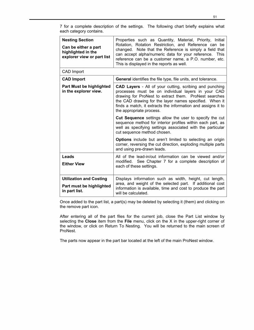
51
7 for a complete description of the settings. The following chart briefly explains what each category contains.
Nesting Section
Can be either a part highlighted in the explorer view or part list
Properties such as Quantity, Material, Priority, Initial Rotation, Rotation Restriction, and Reference can be changed. Note that the Reference is simply a field that can accept alpha/numeric data for your reference. This reference can be a customer name, a P.O. number, etc. This is displayed in the reports as well.
CAD Import
General identifies the file type, file units, and tolerance. CAD Import
Part Must be highlighted in the explorer view.
CAD Layers - All of your cutting, scribing and punching processes must be on individual layers in your CAD drawing for ProNest to extract them. ProNest searches the CAD drawing for the layer names specified. When it finds a match, it extracts the information and assigns it to the appropriate process.
Cut Sequence settings allow the user to specify the cut sequence method for interior profiles within each part, as well as specifying settings associated with the particular cut sequence method chosen.
Options include but aren’t limited to selecting an origin corner, reversing the cut direction, exploding multiple parts and using pre-drawn leads.
Leads
Either View
All of the lead-in/out information can be viewed and/or modified. See Chapter 7 for a complete description of each of these settings.
Utilization and Costing
Part must be highlighted in part list.
Displays information such as width, height, cut length, area, and weight of the selected part. If additional cost information is available, time and cost to produce the part will be calculated.
Once added to the part list, a part(s) may be deleted by selecting it (them) and clicking on the remove part icon.
After entering all of the part files for the current job, close the Part List window by selecting the Close item from the File menu, click on the X in the upper-right corner of the window, or click on Return To Nesting. You will be returned to the main screen of ProNest.
The parts now appear in the part bar located at the left of the main ProNest window.
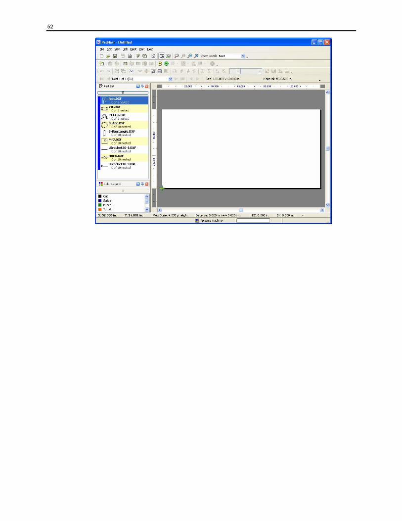
52
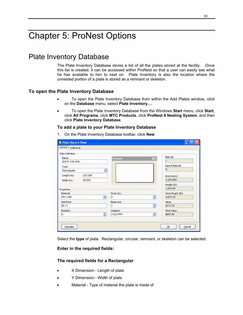
53
Chapter 5: ProNest Options
Plate Inventory Database The Plate Inventory Database stores a list of all the plates stored at the facility. Once this list is created, it can be accessed within ProNest so that a user can easily see what he has available to him to nest on. Plate Inventory is also the location where the unnested portion of a plate is stored as a remnant or skeleton.
To open the Plate Inventory Database • To open the Plate Inventory Database from within the Add Plates window, click
on the Database menu, select Plate Inventory….
• To open the Plate Inventory Database from the Windows Start menu, click Start, click All Programs, click MTC Products, click ProNest 8 Nesting System, and then click Plate Inventory Database.
To add a plate to your Plate Inventory Database 1. On the Plate Inventory Database toolbar, click New.
Select the type of plate. Rectangular, circular, remnant, or skeleton can be selected.
Enter in the required fields:
The required fields for a Rectangular
• X Dimension - Length of plate
• Y Dimension - Width of plate
• Material - Type of material the plate is made of

54
The required fields for Remnants and Skeletons
• Filename - If manually entered, this field needs to be filled in
• Material - Type of material the plate is made of
The required fields for a Circle
• Diameter
• Material
The important fields for each type of plate:
• Material
• Date
• Rotation Angle of the plate
• Quantity Available for plate
• Reorder Quantity for plate
• Reorder Limit - number of times order can be duplicated
Click Calculate. This will automatically calculate the area, weight, total weight, value, and total value. If the plate type is remnant or skeleton the length and width will also be calculated.
To save the plate, click OK.
Notes:
• The plate’s unit price will be initialized to the material’s unit price.
• The unit price is used to calculate the plate’s value.
To delete a plate from your Plate Inventory Database
• In the list of plates, click the one you want to delete, and then click Delete on the toolbar.
To change plate information in your Plate Inventory Database
• In the list of plates, locate and double-click the plate you want, and then change the information as needed.
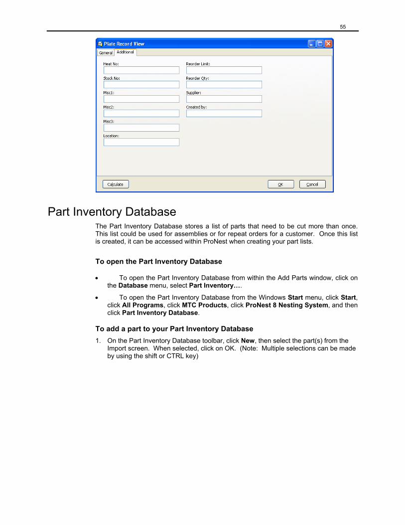
55
Part Inventory Database The Part Inventory Database stores a list of parts that need to be cut more than once. This list could be used for assemblies or for repeat orders for a customer. Once this list is created, it can be accessed within ProNest when creating your part lists.
To open the Part Inventory Database
• To open the Part Inventory Database from within the Add Parts window, click on the Database menu, select Part Inventory….
• To open the Part Inventory Database from the Windows Start menu, click Start, click All Programs, click MTC Products, click ProNest 8 Nesting System, and then click Part Inventory Database.
To add a part to your Part Inventory Database 1. On the Part Inventory Database toolbar, click New, then select the part(s) from the
Import screen. When selected, click on OK. (Note: Multiple selections can be made by using the shift or CTRL key)
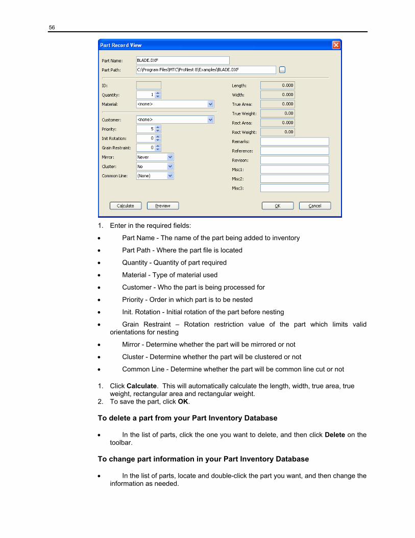
56
1. Enter in the required fields:
• Part Name - The name of the part being added to inventory
• Part Path - Where the part file is located
• Quantity - Quantity of part required
• Material - Type of material used
• Customer - Who the part is being processed for
• Priority - Order in which part is to be nested
• Init. Rotation - Initial rotation of the part before nesting
• Grain Restraint – Rotation restriction value of the part which limits valid orientations for nesting
• Mirror - Determine whether the part will be mirrored or not
• Cluster - Determine whether the part will be clustered or not
• Common Line - Determine whether the part will be common line cut or not
1. Click Calculate. This will automatically calculate the length, width, true area, true weight, rectangular area and rectangular weight.
2. To save the part, click OK.
To delete a part from your Part Inventory Database
• In the list of parts, click the one you want to delete, and then click Delete on the toolbar.
To change part information in your Part Inventory Database
• In the list of parts, locate and double-click the part you want, and then change the information as needed.
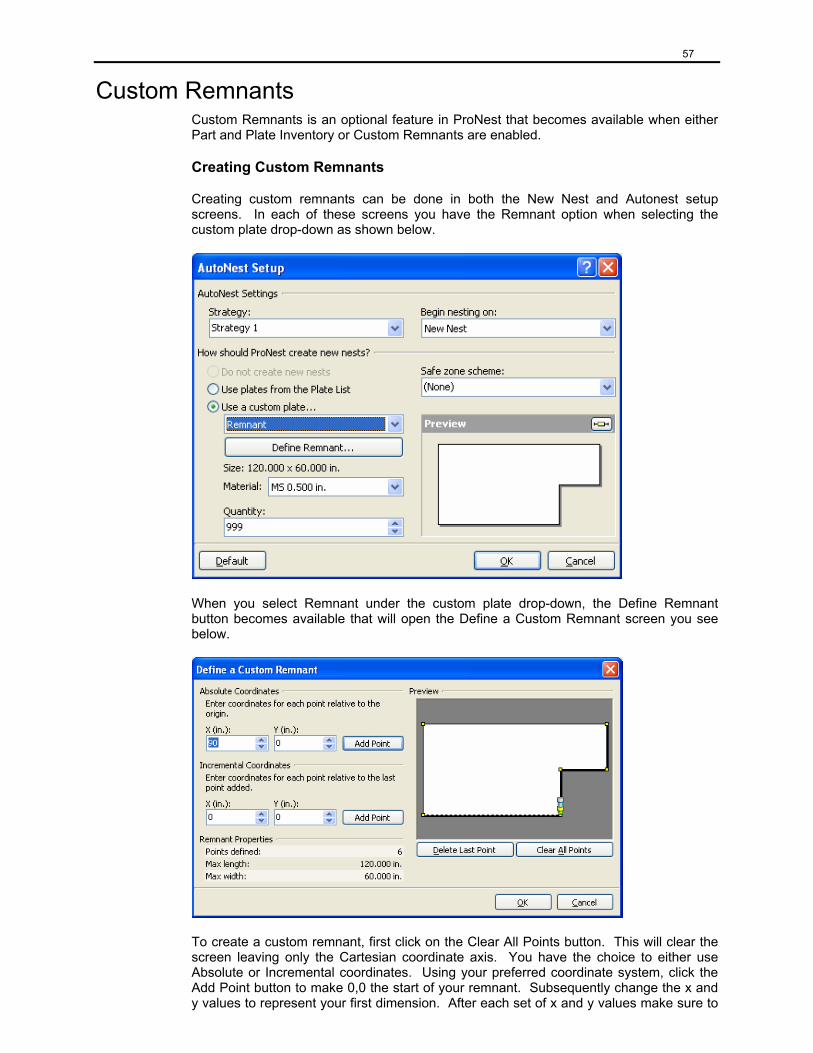
57
Custom Remnants Custom Remnants is an optional feature in ProNest that becomes available when either Part and Plate Inventory or Custom Remnants are enabled.
Creating Custom Remnants
Creating custom remnants can be done in both the New Nest and Autonest setup screens. In each of these screens you have the Remnant option when selecting the custom plate drop-down as shown below.
When you select Remnant under the custom plate drop-down, the Define Remnant button becomes available that will open the Define a Custom Remnant screen you see below.
To create a custom remnant, first click on the Clear All Points button. This will clear the screen leaving only the Cartesian coordinate axis. You have the choice to either use Absolute or Incremental coordinates. Using your preferred coordinate system, click the Add Point button to make 0,0 the start of your remnant. Subsequently change the x and y values to represent your first dimension. After each set of x and y values make sure to
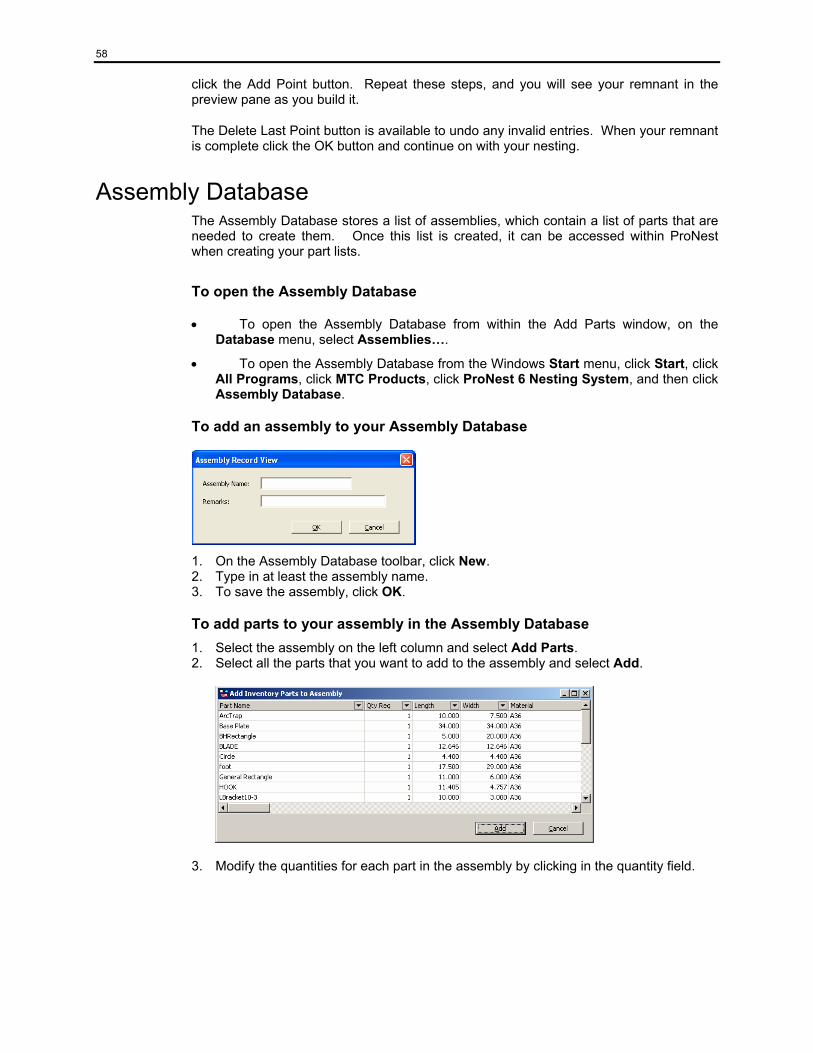
58
click the Add Point button. Repeat these steps, and you will see your remnant in the preview pane as you build it.
The Delete Last Point button is available to undo any invalid entries. When your remnant is complete click the OK button and continue on with your nesting.
Assembly Database The Assembly Database stores a list of assemblies, which contain a list of parts that are needed to create them. Once this list is created, it can be accessed within ProNest when creating your part lists.
To open the Assembly Database
• To open the Assembly Database from within the Add Parts window, on the Database menu, select Assemblies….
• To open the Assembly Database from the Windows Start menu, click Start, click All Programs, click MTC Products, click ProNest 6 Nesting System, and then click Assembly Database.
To add an assembly to your Assembly Database
1. On the Assembly Database toolbar, click New. 2. Type in at least the assembly name. 3. To save the assembly, click OK.
To add parts to your assembly in the Assembly Database 1. Select the assembly on the left column and select Add Parts. 2. Select all the parts that you want to add to the assembly and select Add.
3. Modify the quantities for each part in the assembly by clicking in the quantity field.
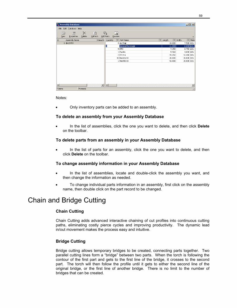
59
Notes:
• Only inventory parts can be added to an assembly.
To delete an assembly from your Assembly Database
• In the list of assemblies, click the one you want to delete, and then click Delete on the toolbar.
To delete parts from an assembly in your Assembly Database
• In the list of parts for an assembly, click the one you want to delete, and then click Delete on the toolbar.
To change assembly information in your Assembly Database
• In the list of assemblies, locate and double-click the assembly you want, and then change the information as needed.
• To change individual parts information in an assembly, first click on the assembly name, then double click on the part record to be changed.
Chain and Bridge Cutting Chain Cutting
Chain Cutting adds advanced interactive chaining of cut profiles into continuous cutting paths, eliminating costly pierce cycles and improving productivity. The dynamic lead in/out movement makes the process easy and intuitive.
Bridge Cutting
Bridge cutting allows temporary bridges to be created, connecting parts together. Two parallel cutting lines form a “bridge” between two parts. When the torch is following the contour of the first part and gets to the first line of the bridge, it crosses to the second part. The torch will then follow the profile until it gets to either the second line of the original bridge, or the first line of another bridge. There is no limit to the number of bridges that can be created.
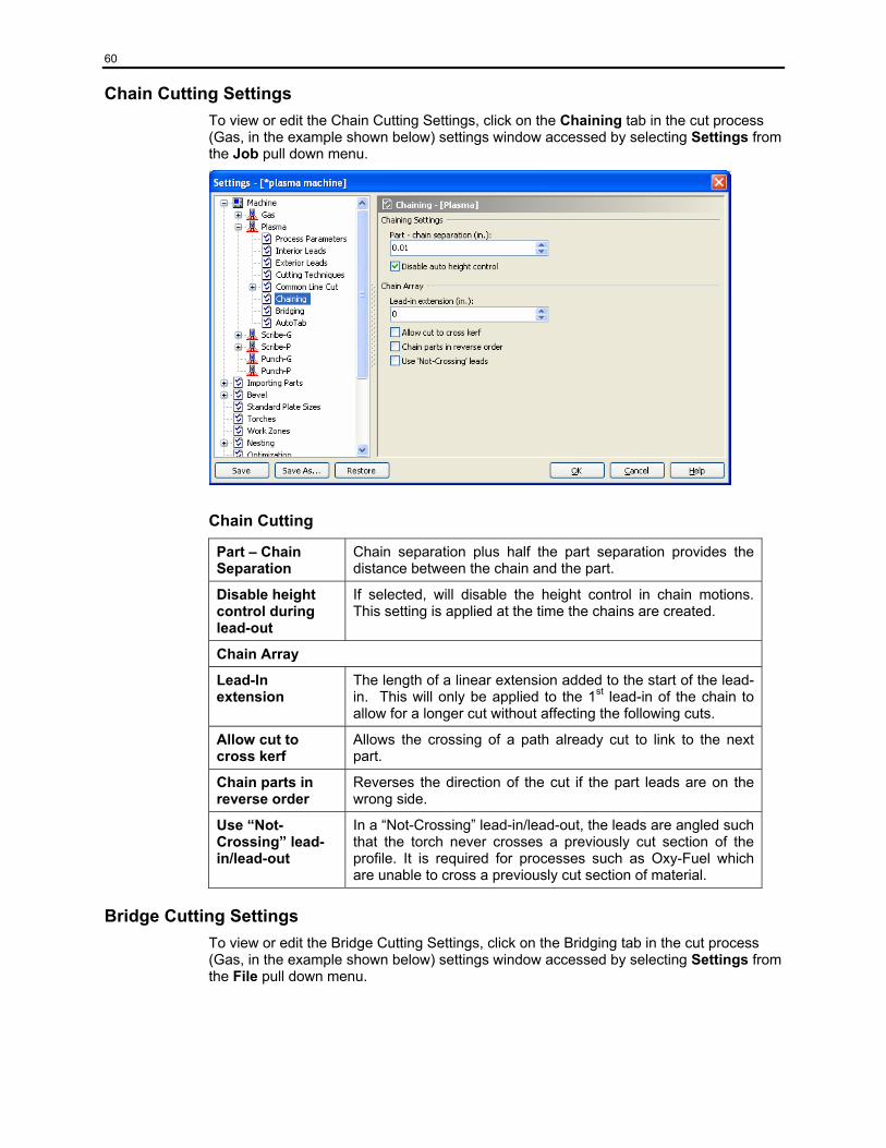
60
Chain Cutting Settings To view or edit the Chain Cutting Settings, click on the Chaining tab in the cut process (Gas, in the example shown below) settings window accessed by selecting Settings from the Job pull down menu.
Chain Cutting
Part – Chain Separation
Chain separation plus half the part separation provides the distance between the chain and the part.
Disable height control during lead-out
If selected, will disable the height control in chain motions. This setting is applied at the time the chains are created.
Chain Array
Lead-In extension
The length of a linear extension added to the start of the lead-in. This will only be applied to the 1st lead-in of the chain to allow for a longer cut without affecting the following cuts.
Allow cut to cross kerf
Allows the crossing of a path already cut to link to the next part.
Chain parts in reverse order
Reverses the direction of the cut if the part leads are on the wrong side.
Use “Not-Crossing” lead-in/lead-out
In a “Not-Crossing” lead-in/lead-out, the leads are angled such that the torch never crosses a previously cut section of the profile. It is required for processes such as Oxy-Fuel which are unable to cross a previously cut section of material.
Bridge Cutting Settings To view or edit the Bridge Cutting Settings, click on the Bridging tab in the cut process (Gas, in the example shown below) settings window accessed by selecting Settings from the File pull down menu.
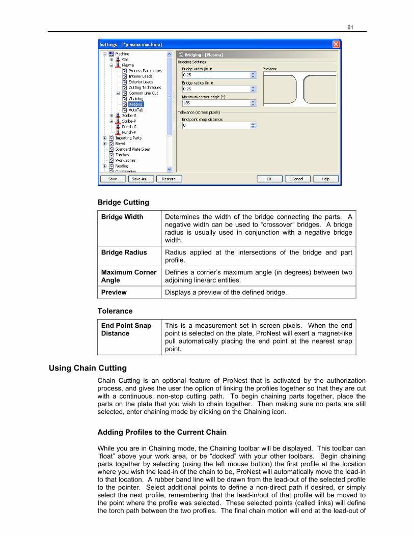
61
Bridge Cutting
Bridge Width Determines the width of the bridge connecting the parts. A negative width can be used to “crossover” bridges. A bridge radius is usually used in conjunction with a negative bridge width.
Bridge Radius Radius applied at the intersections of the bridge and part profile.
Maximum Corner Angle
Defines a corner’s maximum angle (in degrees) between two adjoining line/arc entities.
Preview Displays a preview of the defined bridge.
Tolerance
End Point Snap Distance
This is a measurement set in screen pixels. When the end point is selected on the plate, ProNest will exert a magnet-like pull automatically placing the end point at the nearest snap point.
Using Chain Cutting Chain Cutting is an optional feature of ProNest that is activated by the authorization process, and gives the user the option of linking the profiles together so that they are cut with a continuous, non-stop cutting path. To begin chaining parts together, place the parts on the plate that you wish to chain together. Then making sure no parts are still selected, enter chaining mode by clicking on the Chaining icon.
Adding Profiles to the Current Chain
While you are in Chaining mode, the Chaining toolbar will be displayed. This toolbar can “float” above your work area, or be “docked” with your other toolbars. Begin chaining parts together by selecting (using the left mouse button) the first profile at the location where you wish the lead-in of the chain to be, ProNest will automatically move the lead-in to that location. A rubber band line will be drawn from the lead-out of the selected profile to the pointer. Select additional points to define a non-direct path if desired, or simply select the next profile, remembering that the lead-in/out of that profile will be moved to the point where the profile was selected. These selected points (called links) will define the torch path between the two profiles. The final chain motion will end at the lead-out of
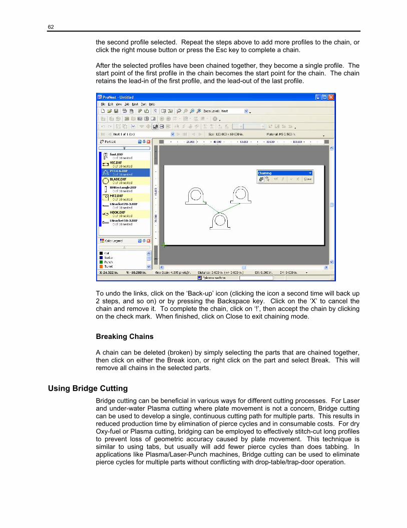
62
the second profile selected. Repeat the steps above to add more profiles to the chain, or click the right mouse button or press the Esc key to complete a chain.
After the selected profiles have been chained together, they become a single profile. The start point of the first profile in the chain becomes the start point for the chain. The chain retains the lead-in of the first profile, and the lead-out of the last profile.
To undo the links, click on the ‘Back-up’ icon (clicking the icon a second time will back up 2 steps, and so on) or by pressing the Backspace key. Click on the ‘X’ to cancel the chain and remove it. To complete the chain, click on ‘!’, then accept the chain by clicking on the check mark. When finished, click on Close to exit chaining mode.
Breaking Chains
A chain can be deleted (broken) by simply selecting the parts that are chained together, then click on either the Break icon, or right click on the part and select Break. This will remove all chains in the selected parts.
Using Bridge Cutting Bridge cutting can be beneficial in various ways for different cutting processes. For Laser and under-water Plasma cutting where plate movement is not a concern, Bridge cutting can be used to develop a single, continuous cutting path for multiple parts. This results in reduced production time by elimination of pierce cycles and in consumable costs. For dry Oxy-fuel or Plasma cutting, bridging can be employed to effectively stitch-cut long profiles to prevent loss of geometric accuracy caused by plate movement. This technique is similar to using tabs, but usually will add fewer pierce cycles than does tabbing. In applications like Plasma/Laser-Punch machines, Bridge cutting can be used to eliminate pierce cycles for multiple parts without conflicting with drop-table/trap-door operation.
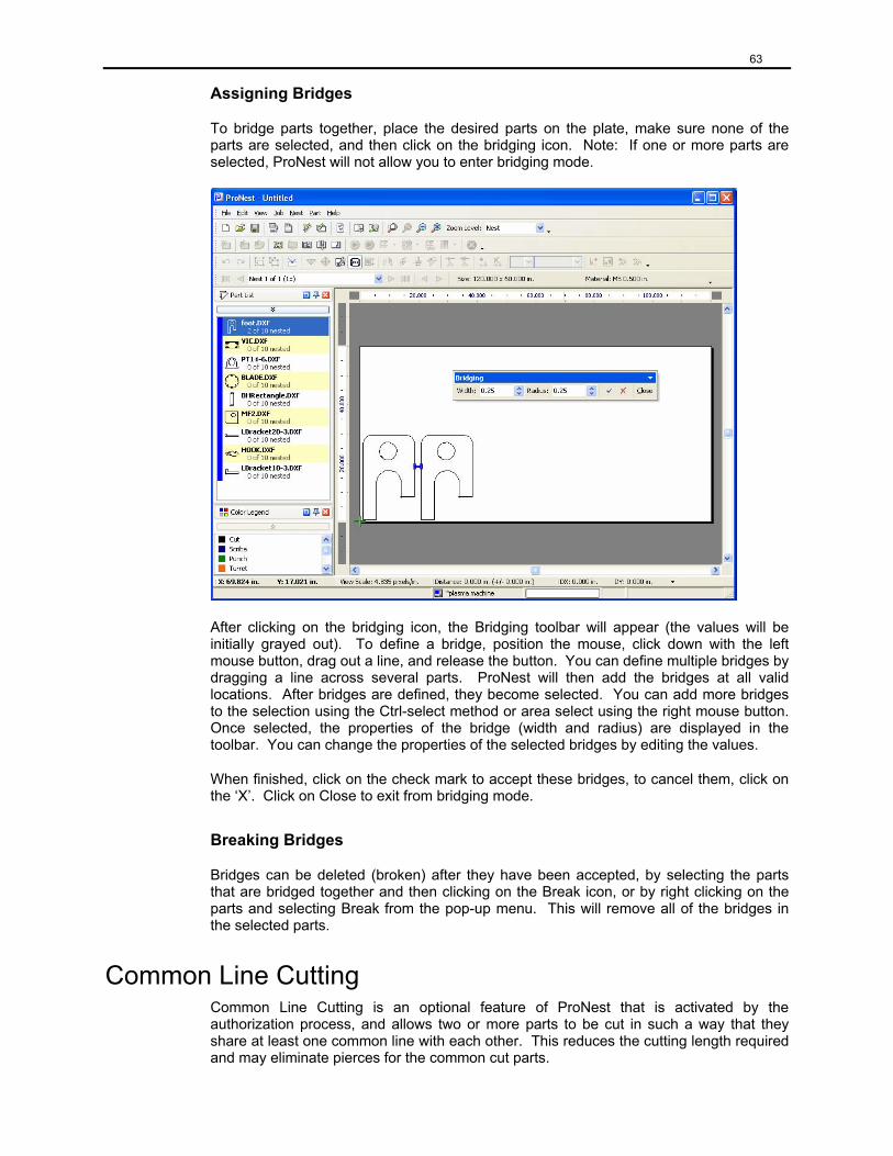
63
Assigning Bridges
To bridge parts together, place the desired parts on the plate, make sure none of the parts are selected, and then click on the bridging icon. Note: If one or more parts are selected, ProNest will not allow you to enter bridging mode.
After clicking on the bridging icon, the Bridging toolbar will appear (the values will be initially grayed out). To define a bridge, position the mouse, click down with the left mouse button, drag out a line, and release the button. You can define multiple bridges by dragging a line across several parts. ProNest will then add the bridges at all valid locations. After bridges are defined, they become selected. You can add more bridges to the selection using the Ctrl-select method or area select using the right mouse button. Once selected, the properties of the bridge (width and radius) are displayed in the toolbar. You can change the properties of the selected bridges by editing the values.
When finished, click on the check mark to accept these bridges, to cancel them, click on the ‘X’. Click on Close to exit from bridging mode.
Breaking Bridges
Bridges can be deleted (broken) after they have been accepted, by selecting the parts that are bridged together and then clicking on the Break icon, or by right clicking on the parts and selecting Break from the pop-up menu. This will remove all of the bridges in the selected parts.
Common Line Cutting Common Line Cutting is an optional feature of ProNest that is activated by the authorization process, and allows two or more parts to be cut in such a way that they share at least one common line with each other. This reduces the cutting length required and may eliminate pierces for the common cut parts.
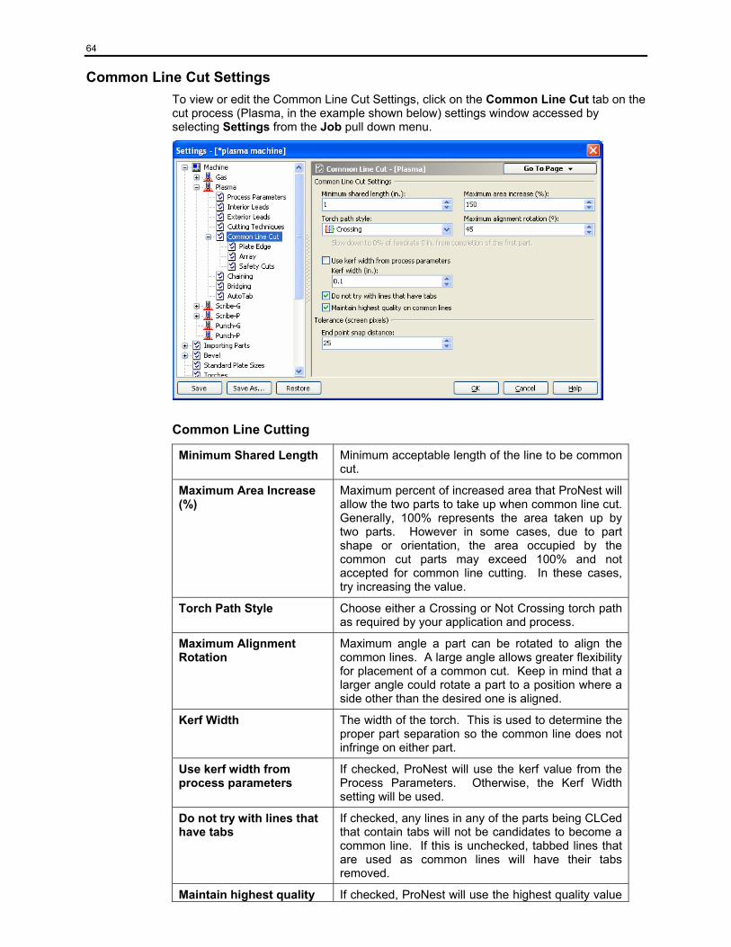
64
Common Line Cut Settings To view or edit the Common Line Cut Settings, click on the Common Line Cut tab on the cut process (Plasma, in the example shown below) settings window accessed by selecting Settings from the Job pull down menu.
Common Line Cutting
Minimum Shared Length Minimum acceptable length of the line to be common cut.
Maximum Area Increase (%)
Maximum percent of increased area that ProNest will allow the two parts to take up when common line cut. Generally, 100% represents the area taken up by two parts. However in some cases, due to part shape or orientation, the area occupied by the common cut parts may exceed 100% and not accepted for common line cutting. In these cases, try increasing the value.
Torch Path Style Choose either a Crossing or Not Crossing torch path as required by your application and process.
Maximum Alignment Rotation
Maximum angle a part can be rotated to align the common lines. A large angle allows greater flexibility for placement of a common cut. Keep in mind that a larger angle could rotate a part to a position where a side other than the desired one is aligned.
Kerf Width The width of the torch. This is used to determine the proper part separation so the common line does not infringe on either part.
Use kerf width from process parameters
If checked, ProNest will use the kerf value from the Process Parameters. Otherwise, the Kerf Width setting will be used.
Do not try with lines that have tabs
If checked, any lines in any of the parts being CLCed that contain tabs will not be candidates to become a common line. If this is unchecked, tabbed lines that are used as common lines will have their tabs removed.
Maintain highest quality If checked, ProNest will use the highest quality value
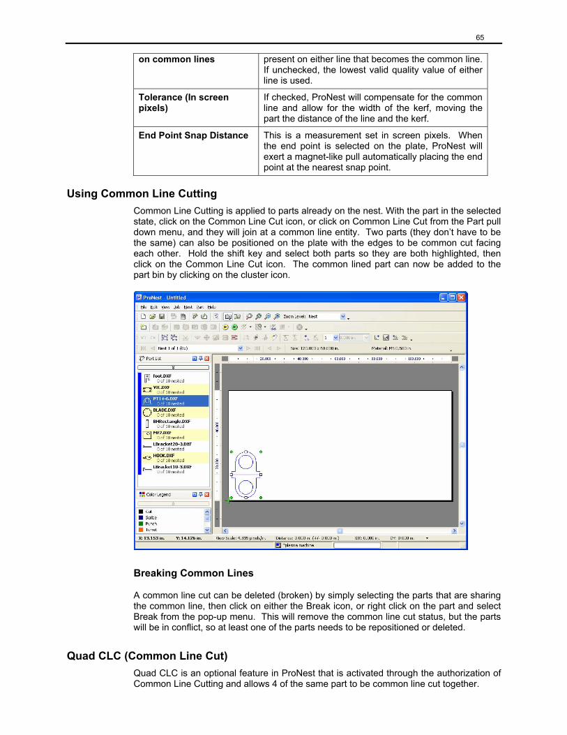
65
on common lines present on either line that becomes the common line. If unchecked, the lowest valid quality value of either line is used.
Tolerance (In screen pixels)
If checked, ProNest will compensate for the common line and allow for the width of the kerf, moving the part the distance of the line and the kerf.
End Point Snap Distance This is a measurement set in screen pixels. When the end point is selected on the plate, ProNest will exert a magnet-like pull automatically placing the end point at the nearest snap point.
Using Common Line Cutting Common Line Cutting is applied to parts already on the nest. With the part in the selected state, click on the Common Line Cut icon, or click on Common Line Cut from the Part pull down menu, and they will join at a common line entity. Two parts (they don’t have to be the same) can also be positioned on the plate with the edges to be common cut facing each other. Hold the shift key and select both parts so they are both highlighted, then click on the Common Line Cut icon. The common lined part can now be added to the part bin by clicking on the cluster icon.
Breaking Common Lines
A common line cut can be deleted (broken) by simply selecting the parts that are sharing the common line, then click on either the Break icon, or right click on the part and select Break from the pop-up menu. This will remove the common line cut status, but the parts will be in conflict, so at least one of the parts needs to be repositioned or deleted.
Quad CLC (Common Line Cut) Quad CLC is an optional feature in ProNest that is activated through the authorization of Common Line Cutting and allows 4 of the same part to be common line cut together.
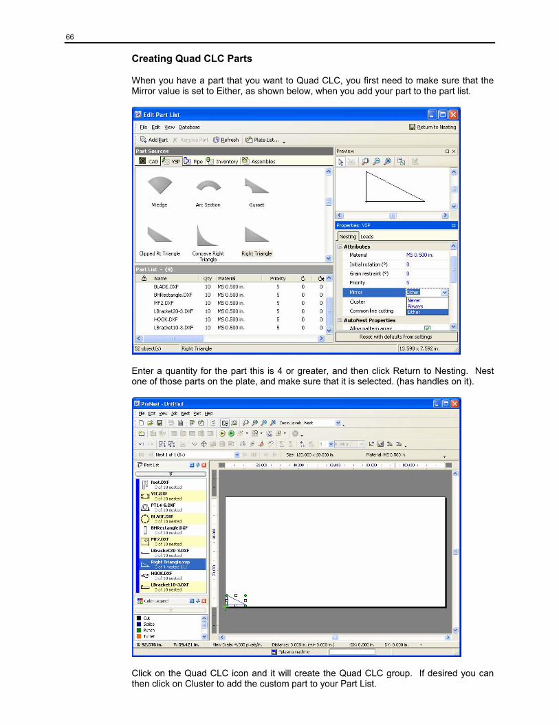
66
Creating Quad CLC Parts
When you have a part that you want to Quad CLC, you first need to make sure that the Mirror value is set to Either, as shown below, when you add your part to the part list.
Enter a quantity for the part this is 4 or greater, and then click Return to Nesting. Nest one of those parts on the plate, and make sure that it is selected. (has handles on it).
Click on the Quad CLC icon and it will create the Quad CLC group. If desired you can then click on Cluster to add the custom part to your Part List.
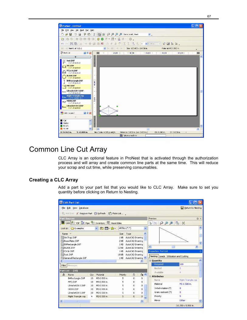
67
Common Line Cut Array CLC Array is an optional feature in ProNest that is activated through the authorization process and will array and create common line parts at the same time. This will reduce your scrap and cut time, while preserving consumables.
Creating a CLC Array Add a part to your part list that you would like to CLC Array. Make sure to set you quantity before clicking on Return to Nesting.
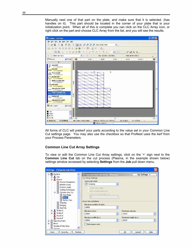
68
Manually nest one of that part on the plate, and make sure that it is selected. (has handles on it). This part should be located in the corner of your plate that is your initialization point. When all of this is complete you can click on the CLC Array icon, or right click on the part and choose CLC Array from the list, and you will see the results.
All forms of CLC will prekerf your parts according to the value set in your Common Line Cut settings page. You may also use the checkbox so that ProNest uses the kerf from your Process Parameters.
Common Line Cut Array Settings
To view or edit the Common Line Cut Array settings, click on the ‘+’ sign next to the Common Line Cut tab on the cut process (Plasma, in the example shown below) settings window accessed by selecting Settings from the Job pull down menu.
69
CLC Array Settings
Torch path style
Choose either a Crossing or Not Crossing torch path as required by your application and process.
Insert Stop Codes
If using a Not Crossing torch path, select this option to output a stop code at the end of each part in the array.
Kerf crossing lead-outs
If using a Not Crossing torch path, select this option to allow leadouts on the CLC array to cross previously cut motions. Unselecting this will limit the number of leadouts that will be applied to the array.
Array Size Limitations
Maximum number of units
The largest number of base units that will be used to create a CLC array. A base unit is the smallest grouping of parts that may easily be combined into a symmetrical CLCed group. For example, the base unit of a right triangle contains 2 parts CLCed along the hypotenuse, but the base unit for a rectangle contains only one part.
Maximum rows
The largest number of rows of base units that will be used in the completed array.
Maximum columns
The largest number of columns of base units that will be used in the completed array.
Maximum width
The maximum width, in linear units, of the completed array.
Maximum height
The maximum height, in linear units, of the completed array.
Full columns only
Check this box to force the completed CLC array to use full columns. Unchecking this box allows the last column in the CLC array to have fewer parts than the rest of the columns in the array.
Multi Part Common Line Cut Multi-part Common Line Cut is an optional feature which enables common line cutting with any number of parts or with the plate edge. It introduces many new features into ProNest, including geometric drag, geometric bump, safety cuts, and torch path edit in Advanced Edit.
Geometric drag and geometric bump are used to position parts with other parts or with the plate edge. In addition if CLC is not available, geometric bump can place parts a single kerf width from other parts or directly at the plate edge.
Safety cuts are used to avoid piercing too close to a previously cut part. Safety cuts can be applied to all intersection points between CLC profiles and to the profile start or end.
Torch path edit in Advanced Edit will allow torch paths to be defined for any CLC parts in the part list or the nest.
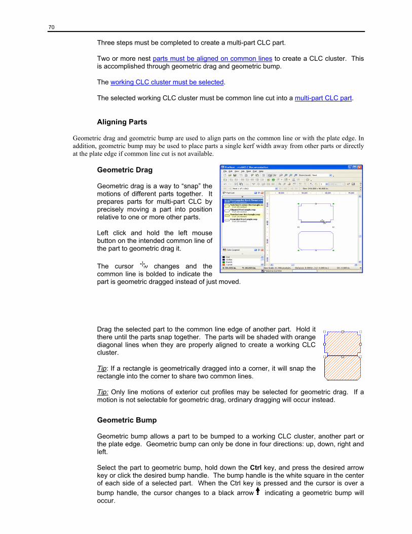
70
Three steps must be completed to create a multi-part CLC part.
Two or more nest parts must be aligned on common lines to create a CLC cluster. This is accomplished through geometric drag and geometric bump.
The working CLC cluster must be selected.
The selected working CLC cluster must be common line cut into a multi-part CLC part.
Aligning Parts
Geometric drag and geometric bump are used to align parts on the common line or with the plate edge. In addition, geometric bump may be used to place parts a single kerf width away from other parts or directly at the plate edge if common line cut is not available.
Geometric Drag
Geometric drag is a way to “snap” the motions of different parts together. It prepares parts for multi-part CLC by precisely moving a part into position relative to one or more other parts.
Left click and hold the left mouse button on the intended common line of the part to geometric drag it.
The cursor changes and the common line is bolded to indicate the part is geometric dragged instead of just moved.
Drag the selected part to the common line edge of another part. Hold it there until the parts snap together. The parts will be shaded with orange diagonal lines when they are properly aligned to create a working CLC cluster.
Tip: If a rectangle is geometrically dragged into a corner, it will snap the rectangle into the corner to share two common lines.
Tip: Only line motions of exterior cut profiles may be selected for geometric drag. If a motion is not selectable for geometric drag, ordinary dragging will occur instead.
Geometric Bump
Geometric bump allows a part to be bumped to a working CLC cluster, another part or the plate edge. Geometric bump can only be done in four directions: up, down, right and left.
Select the part to geometric bump, hold down the Ctrl key, and press the desired arrow key or click the desired bump handle. The bump handle is the white square in the center of each side of a selected part. When the Ctrl key is pressed and the cursor is over a bump handle, the cursor changes to a black arrow indicating a geometric bump will occur.
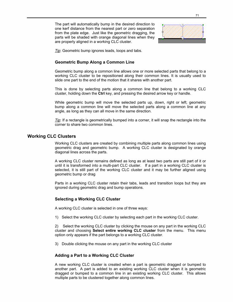
71
The part will automatically bump in the desired direction to one kerf distance from the nearest part or zero separation from the plate edge. Just like the geometric dragging, the parts will be shaded with orange diagonal lines when they are properly aligned in a working CLC cluster.
Tip: Geometric bump ignores leads, loops and tabs.
Geometric Bump Along a Common Line
Geometric bump along a common line allows one or more selected parts that belong to a working CLC cluster to be repositioned along their common lines. It is usually used to slide one part to the end of the motion that it shares with another part.
This is done by selecting parts along a common line that belong to a working CLC cluster, holding down the Ctrl key, and pressing the desired arrow key or handle.
While geometric bump will move the selected parts up, down, right or left; geometric bump along a common line will move the selected parts along a common line at any angle, as long as they can all move in the same direction.
Tip: If a rectangle is geometrically bumped into a corner, it will snap the rectangle into the corner to share two common lines.
Working CLC Clusters Working CLC clusters are created by combining multiple parts along common lines using geometric drag and geometric bump. A working CLC cluster is designated by orange diagonal lines across the parts.
A working CLC cluster remains defined as long as at least two parts are still part of it or until it is transformed into a multi-part CLC cluster. If a part in a working CLC cluster is selected, it is still part of the working CLC cluster and it may be further aligned using geometric bump or drag
Parts in a working CLC cluster retain their tabs, leads and transition loops but they are ignored during geometric drag and bump operations.
Selecting a Working CLC Cluster
A working CLC cluster is selected in one of three ways:
1) Select the working CLC cluster by selecting each part in the working CLC cluster.
2) Select the working CLC cluster by clicking the mouse on any part in the working CLC cluster and choosing Select entire working CLC cluster from the menu. This menu option only appears if the part belongs to a working CLC cluster.
3) Double clicking the mouse on any part in the working CLC cluster
Adding a Part to a Working CLC Cluster
A new working CLC cluster is created when a part is geometric dragged or bumped to another part. A part is added to an existing working CLC cluster when it is geometric dragged or bumped to a common line in an existing working CLC cluster. This allows multiple parts to be clustered together along common lines.
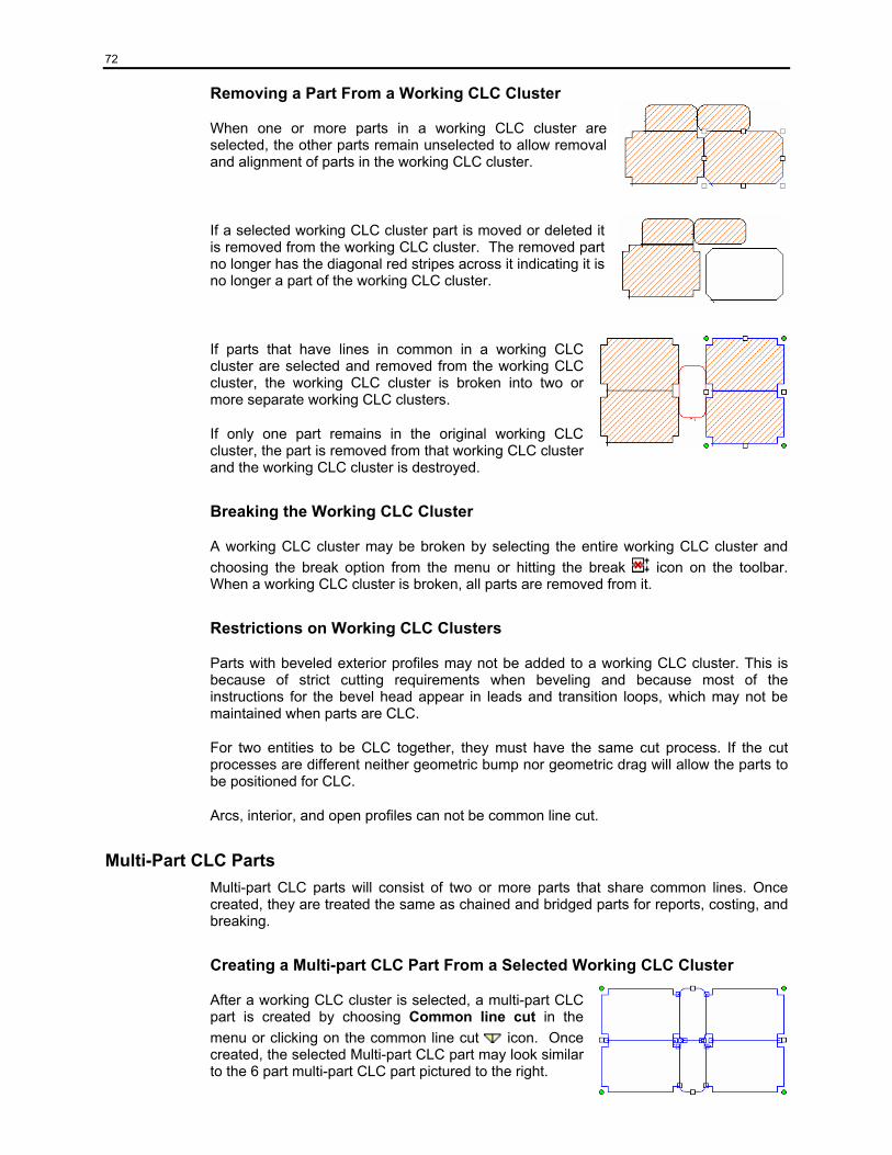
72
Removing a Part From a Working CLC Cluster
When one or more parts in a working CLC cluster are selected, the other parts remain unselected to allow removal and alignment of parts in the working CLC cluster.
If a selected working CLC cluster part is moved or deleted it is removed from the working CLC cluster. The removed part no longer has the diagonal red stripes across it indicating it is no longer a part of the working CLC cluster.
If parts that have lines in common in a working CLC cluster are selected and removed from the working CLC cluster, the working CLC cluster is broken into two or more separate working CLC clusters.
If only one part remains in the original working CLC cluster, the part is removed from that working CLC cluster and the working CLC cluster is destroyed.
Breaking the Working CLC Cluster
A working CLC cluster may be broken by selecting the entire working CLC cluster and choosing the break option from the menu or hitting the break icon on the toolbar. When a working CLC cluster is broken, all parts are removed from it.
Restrictions on Working CLC Clusters
Parts with beveled exterior profiles may not be added to a working CLC cluster. This is because of strict cutting requirements when beveling and because most of the instructions for the bevel head appear in leads and transition loops, which may not be maintained when parts are CLC.
For two entities to be CLC together, they must have the same cut process. If the cut processes are different neither geometric bump nor geometric drag will allow the parts to be positioned for CLC.
Arcs, interior, and open profiles can not be common line cut.
Multi-Part CLC Parts Multi-part CLC parts will consist of two or more parts that share common lines. Once created, they are treated the same as chained and bridged parts for reports, costing, and breaking.
Creating a Multi-part CLC Part From a Selected Working CLC Cluster
After a working CLC cluster is selected, a multi-part CLC part is created by choosing Common line cut in the menu or clicking on the common line cut icon. Once created, the selected Multi-part CLC part may look similar to the 6 part multi-part CLC part pictured to the right.
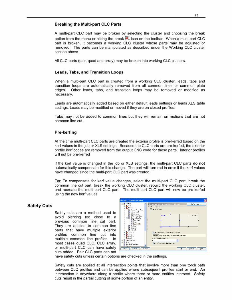
73
Breaking the Multi-part CLC Parts
A multi-part CLC part may be broken by selecting the cluster and choosing the break option from the menu or hitting the break icon on the toolbar. When a multi-part CLC part is broken, it becomes a working CLC cluster whose parts may be adjusted or removed. The parts can be manipulated as described under the Working CLC cluster section above.
All CLC parts (pair, quad and array) may be broken into working CLC clusters.
Leads, Tabs, and Transition Loops
When a multi-part CLC part is created from a working CLC cluster, leads, tabs and transition loops are automatically removed from all common lines or common plate edges. Other leads, tabs, and transition loops may be removed or modified as necessary.
Leads are automatically added based on either default leads settings or leads XLS table settings. Leads may be modified or moved if they are on closed profiles.
Tabs may not be added to common lines but they will remain on motions that are not common line cut.
Pre-kerfing
At the time multi-part CLC parts are created the exterior profile is pre-kerfed based on the kerf values in the job or XLS settings. Because the CLC parts are pre-kerfed, the exterior profile kerf codes are removed from the output CNC code for these parts. Interior profiles will not be pre-kerfed
If the kerf value is changed in the job or XLS settings, the multi-part CLC parts do not automatically compensate for this change. The part will turn red in error if the kerf values have changed since the multi-part CLC part was created.
Tip: To compensate for kerf value changes, select the multi-part CLC part, break the common line cut part, break the working CLC cluster, rebuild the working CLC cluster, and recreate the multi-part CLC part. The multi-part CLC part will now be pre-kerfed using the new kerf values
Safety Cuts Safety cuts are a method used to avoid piercing too close to a previous common line cut part. They are applied to common line parts that have multiple exterior profiles common line cut into multiple common line profiles. In most cases quad CLC, CLC array, or multi-part CLC can have safety cuts added. Pair CLC parts can not have safety cuts unless certain options are checked in the settings.
Safety cuts are applied at all intersection points that involve more than one torch path between CLC profiles and can be applied where subsequent profiles start or end. An intersection is anywhere along a profile where three or more entities intersect. Safety cuts result in the partial cutting of some portion of an entity.
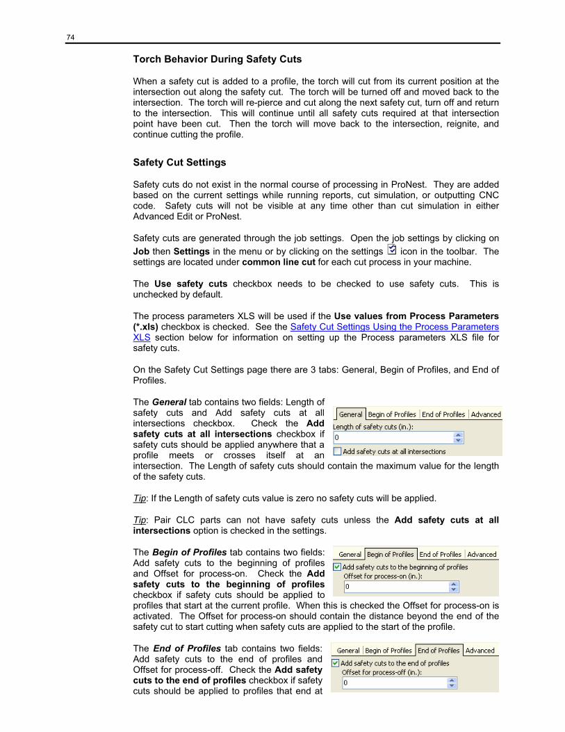
74
Torch Behavior During Safety Cuts
When a safety cut is added to a profile, the torch will cut from its current position at the intersection out along the safety cut. The torch will be turned off and moved back to the intersection. The torch will re-pierce and cut along the next safety cut, turn off and return to the intersection. This will continue until all safety cuts required at that intersection point have been cut. Then the torch will move back to the intersection, reignite, and continue cutting the profile.
Safety Cut Settings
Safety cuts do not exist in the normal course of processing in ProNest. They are added based on the current settings while running reports, cut simulation, or outputting CNC code. Safety cuts will not be visible at any time other than cut simulation in either Advanced Edit or ProNest.
Safety cuts are generated through the job settings. Open the job settings by clicking on Job then Settings in the menu or by clicking on the settings icon in the toolbar. The settings are located under common line cut for each cut process in your machine.
The Use safety cuts checkbox needs to be checked to use safety cuts. This is unchecked by default.
The process parameters XLS will be used if the Use values from Process Parameters (*.xls) checkbox is checked. See the Safety Cut Settings Using the Process Parameters XLS section below for information on setting up the Process parameters XLS file for safety cuts.
On the Safety Cut Settings page there are 3 tabs: General, Begin of Profiles, and End of Profiles.
The General tab contains two fields: Length of safety cuts and Add safety cuts at all intersections checkbox. Check the Add safety cuts at all intersections checkbox if safety cuts should be applied anywhere that a profile meets or crosses itself at an intersection. The Length of safety cuts should contain the maximum value for the length of the safety cuts.
Tip: If the Length of safety cuts value is zero no safety cuts will be applied.
Tip: Pair CLC parts can not have safety cuts unless the Add safety cuts at all intersections option is checked in the settings.
The Begin of Profiles tab contains two fields: Add safety cuts to the beginning of profiles and Offset for process-on. Check the Add safety cuts to the beginning of profiles checkbox if safety cuts should be applied to profiles that start at the current profile. When this is checked the Offset for process-on is activated. The Offset for process-on should contain the distance beyond the end of the safety cut to start cutting when safety cuts are applied to the start of the profile.
The End of Profiles tab contains two fields: Add safety cuts to the end of profiles and Offset for process-off. Check the Add safety cuts to the end of profiles checkbox if safety cuts should be applied to profiles that end at
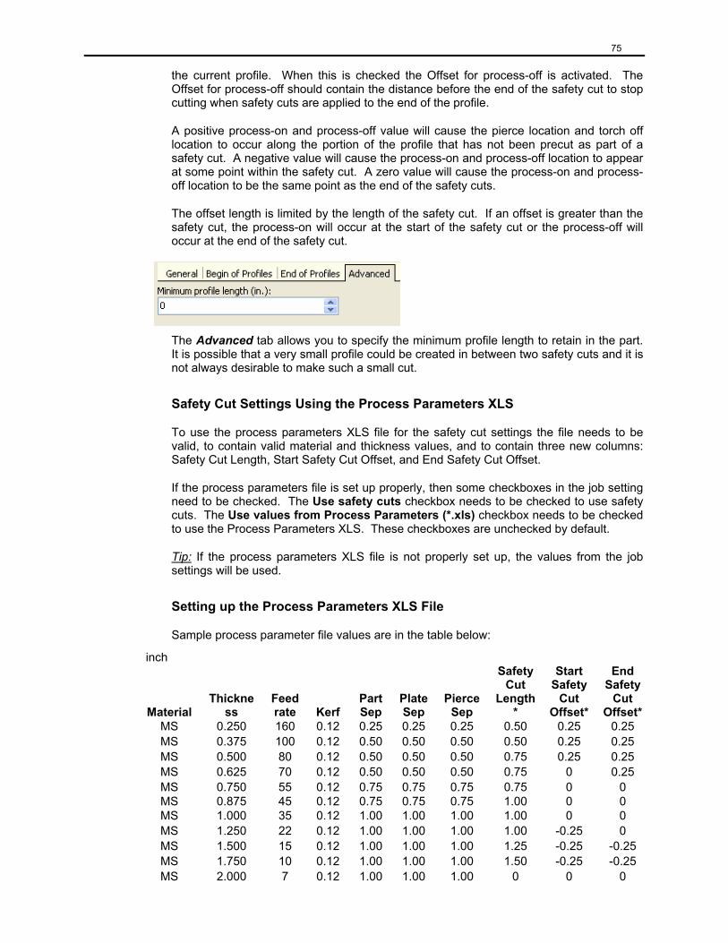
75
the current profile. When this is checked the Offset for process-off is activated. The Offset for process-off should contain the distance before the end of the safety cut to stop cutting when safety cuts are applied to the end of the profile.
A positive process-on and process-off value will cause the pierce location and torch off location to occur along the portion of the profile that has not been precut as part of a safety cut. A negative value will cause the process-on and process-off location to appear at some point within the safety cut. A zero value will cause the process-on and process-off location to be the same point as the end of the safety cuts.
The offset length is limited by the length of the safety cut. If an offset is greater than the safety cut, the process-on will occur at the start of the safety cut or the process-off will occur at the end of the safety cut.
The Advanced tab allows you to specify the minimum profile length to retain in the part. It is possible that a very small profile could be created in between two safety cuts and it is not always desirable to make such a small cut.
Safety Cut Settings Using the Process Parameters XLS
To use the process parameters XLS file for the safety cut settings the file needs to be valid, to contain valid material and thickness values, and to contain three new columns: Safety Cut Length, Start Safety Cut Offset, and End Safety Cut Offset.
If the process parameters file is set up properly, then some checkboxes in the job setting need to be checked. The Use safety cuts checkbox needs to be checked to use safety cuts. The Use values from Process Parameters (*.xls) checkbox needs to be checked to use the Process Parameters XLS. These checkboxes are unchecked by default.
Tip: If the process parameters XLS file is not properly set up, the values from the job settings will be used.
Setting up the Process Parameters XLS File
Sample process parameter file values are in the table below:
inch
Material Thickne
ss Feed rate Kerf
Part Sep
Plate Sep
Pierce Sep
Safety Cut
Length*
Start Safety
Cut Offset*
End Safety
Cut Offset*
MS 0.250 160 0.12 0.25 0.25 0.25 0.50 0.25 0.25 MS 0.375 100 0.12 0.50 0.50 0.50 0.50 0.25 0.25 MS 0.500 80 0.12 0.50 0.50 0.50 0.75 0.25 0.25 MS 0.625 70 0.12 0.50 0.50 0.50 0.75 0 0.25 MS 0.750 55 0.12 0.75 0.75 0.75 0.75 0 0 MS 0.875 45 0.12 0.75 0.75 0.75 1.00 0 0 MS 1.000 35 0.12 1.00 1.00 1.00 1.00 0 0 MS 1.250 22 0.12 1.00 1.00 1.00 1.00 -0.25 0 MS 1.500 15 0.12 1.00 1.00 1.00 1.25 -0.25 -0.25 MS 1.750 10 0.12 1.00 1.00 1.00 1.50 -0.25 -0.25 MS 2.000 7 0.12 1.00 1.00 1.00 0 0 0
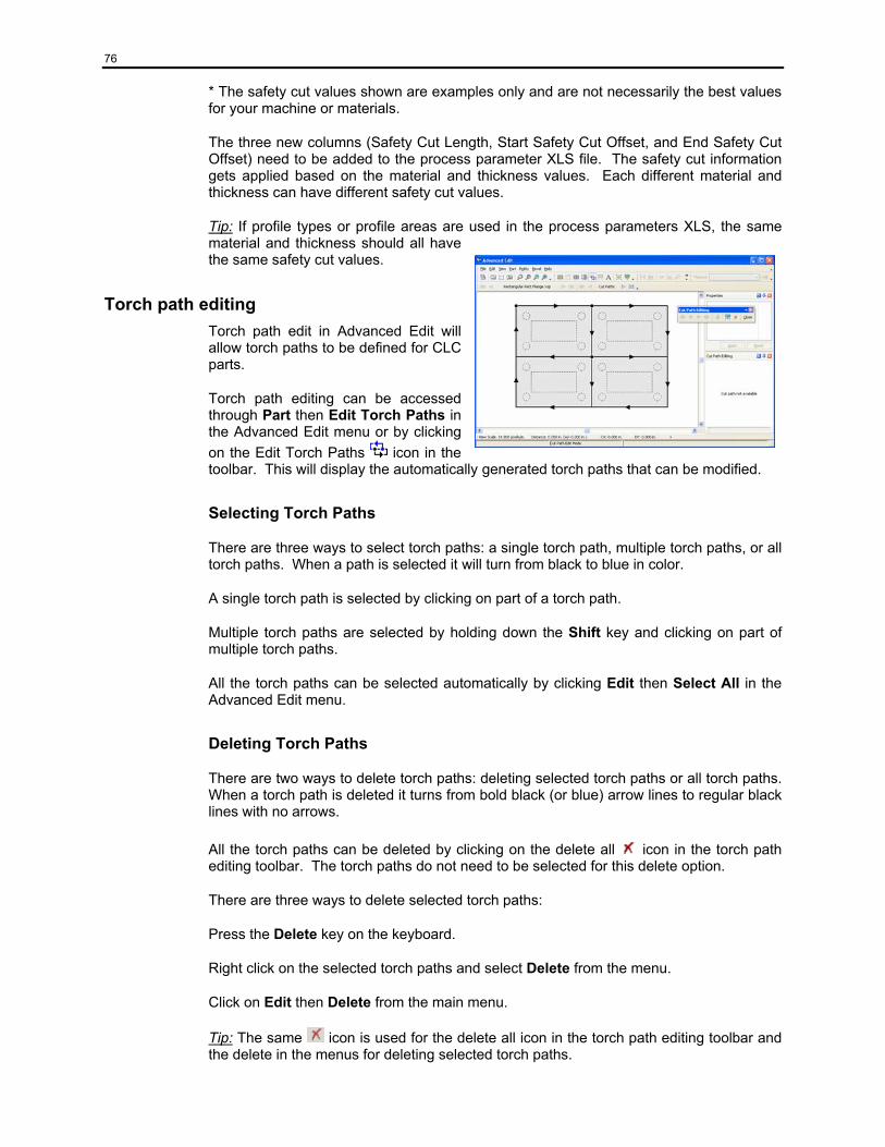
76
* The safety cut values shown are examples only and are not necessarily the best values for your machine or materials.
The three new columns (Safety Cut Length, Start Safety Cut Offset, and End Safety Cut Offset) need to be added to the process parameter XLS file. The safety cut information gets applied based on the material and thickness values. Each different material and thickness can have different safety cut values.
Tip: If profile types or profile areas are used in the process parameters XLS, the same material and thickness should all have the same safety cut values.
Torch path editing Torch path edit in Advanced Edit will allow torch paths to be defined for CLC parts.
Torch path editing can be accessed through Part then Edit Torch Paths in the Advanced Edit menu or by clicking on the Edit Torch Paths icon in the toolbar. This will display the automatically generated torch paths that can be modified.
Selecting Torch Paths
There are three ways to select torch paths: a single torch path, multiple torch paths, or all torch paths. When a path is selected it will turn from black to blue in color.
A single torch path is selected by clicking on part of a torch path.
Multiple torch paths are selected by holding down the Shift key and clicking on part of multiple torch paths.
All the torch paths can be selected automatically by clicking Edit then Select All in the Advanced Edit menu.
Deleting Torch Paths
There are two ways to delete torch paths: deleting selected torch paths or all torch paths. When a torch path is deleted it turns from bold black (or blue) arrow lines to regular black lines with no arrows.
All the torch paths can be deleted by clicking on the delete all icon in the torch path editing toolbar. The torch paths do not need to be selected for this delete option.
There are three ways to delete selected torch paths:
Press the Delete key on the keyboard.
Right click on the selected torch paths and select Delete from the menu.
Click on Edit then Delete from the main menu.
Tip: The same icon is used for the delete all icon in the torch path editing toolbar and the delete in the menus for deleting selected torch paths.
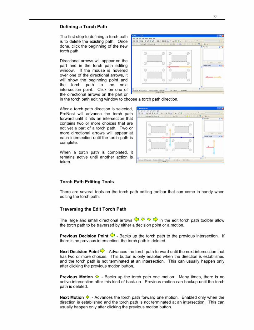
77
Defining a Torch Path
The first step to defining a torch path is to delete the existing path. Once done, click the beginning of the new torch path.
Directional arrows will appear on the part and in the torch path editing window. If the mouse is hovered over one of the directional arrows, it will show the beginning point and the torch path to the next intersection point. Click on one of the directional arrows on the part or in the torch path editing window to choose a torch path direction.
After a torch path direction is selected, ProNest will advance the torch path forward until it hits an intersection that contains two or more choices that are not yet a part of a torch path. Two or more directional arrows will appear at each intersection until the torch path is complete.
When a torch path is completed, it remains active until another action is taken.
Torch Path Editing Tools
There are several tools on the torch path editing toolbar that can come in handy when editing the torch path.
Traversing the Edit Torch Path
The large and small directional arrows in the edit torch path toolbar allow the torch path to be traversed by either a decision point or a motion.
Previous Decision Point - Backs up the torch path to the previous intersection. If there is no previous intersection, the torch path is deleted.
Next Decision Point - Advances the torch path forward until the next intersection that has two or more choices. This button is only enabled when the direction is established and the torch path is not terminated at an intersection. This can usually happen only after clicking the previous motion button.
Previous Motion - Backs up the torch path one motion. Many times, there is no active intersection after this kind of back up. Previous motion can backup until the torch path is deleted.
Next Motion - Advances the torch path forward one motion. Enabled only when the direction is established and the torch path is not terminated at an intersection. This can usually happen only after clicking the previous motion button.
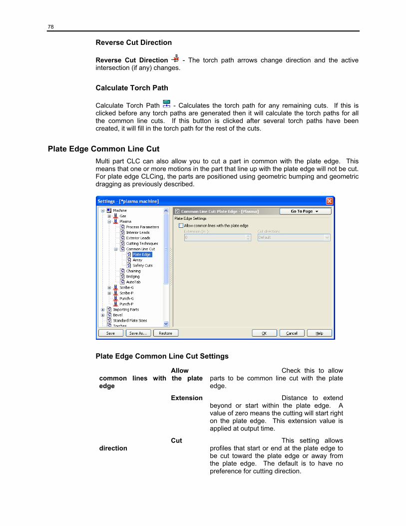
78
Reverse Cut Direction
Reverse Cut Direction - The torch path arrows change direction and the active intersection (if any) changes.
Calculate Torch Path
Calculate Torch Path - Calculates the torch path for any remaining cuts. If this is clicked before any torch paths are generated then it will calculate the torch paths for all the common line cuts. If this button is clicked after several torch paths have been created, it will fill in the torch path for the rest of the cuts.
Plate Edge Common Line Cut Multi part CLC can also allow you to cut a part in common with the plate edge. This means that one or more motions in the part that line up with the plate edge will not be cut. For plate edge CLCing, the parts are positioned using geometric bumping and geometric dragging as previously described.
Plate Edge Common Line Cut Settings
Allow common lines with the plate edge
Check this to allow parts to be common line cut with the plate edge.
Extension Distance to extend beyond or start within the plate edge. A value of zero means the cutting will start right on the plate edge. This extension value is applied at output time.
Cut direction
This setting allows profiles that start or end at the plate edge to be cut toward the plate edge or away from the plate edge. The default is to have no preference for cutting direction.

79
Collision Avoidance Collision Avoidance is an optional feature that helps eliminate the chance of torch - part collisions and can significantly reduce production time. This is accomplished through a combination of moving lead in/out positions, resequencing interior profiles, developing avoidance paths around possible tip-up situations, and by using partial or full torch raises. User defined settings allow ProNest to automatically apply this technology to your nests, and of course, you have full interactive editing capability.
To view or edit collision avoidance settings, click on the Collision Avoidance tab under Settings from Job. Place a check in the top box to “enable collision avoidance”. Click ok then create a nest as shown in the following screen.
To display the torch path with Collision Avoidance activated, click on the Collision Avoidance Mode icon. The blue line represents the torch path; a solid line indicates a full torch raise, and a dotted line indicates a partial torch raise.
Each torch path can be modified by clicking on the path line, and dragging it to the desired position. At this point, the user can determine whether he wants the torch to travel the selected path fully or partially raised, or travel a direct path – all by choosing the appropriate icon. This will activate the collision avoidance settings for that particular torch path. To reconfigure the torch path altogether, click on the ‘Calculate New Paths’ icon. Refer to Chapter 7 for a complete description of these settings.
Note: Additional modification to the nest will most likely cause ProNest to recalculate the cut sequence and collision avoidance paths. Collision avoidance should be one of the last operations performed prior to saving the job and creating the CNC output.
Skeleton Cut Up Skeleton Cut Up is an optional feature that will cut the left over plate into smaller pieces, making it easier to remove the scrap material from the shop floor. Click on Settings from the Job pull down menu, then choose Skeleton Cut Up to display the settings on the right of the screen. Place a check in the box to activate Skeleton Cut Up.
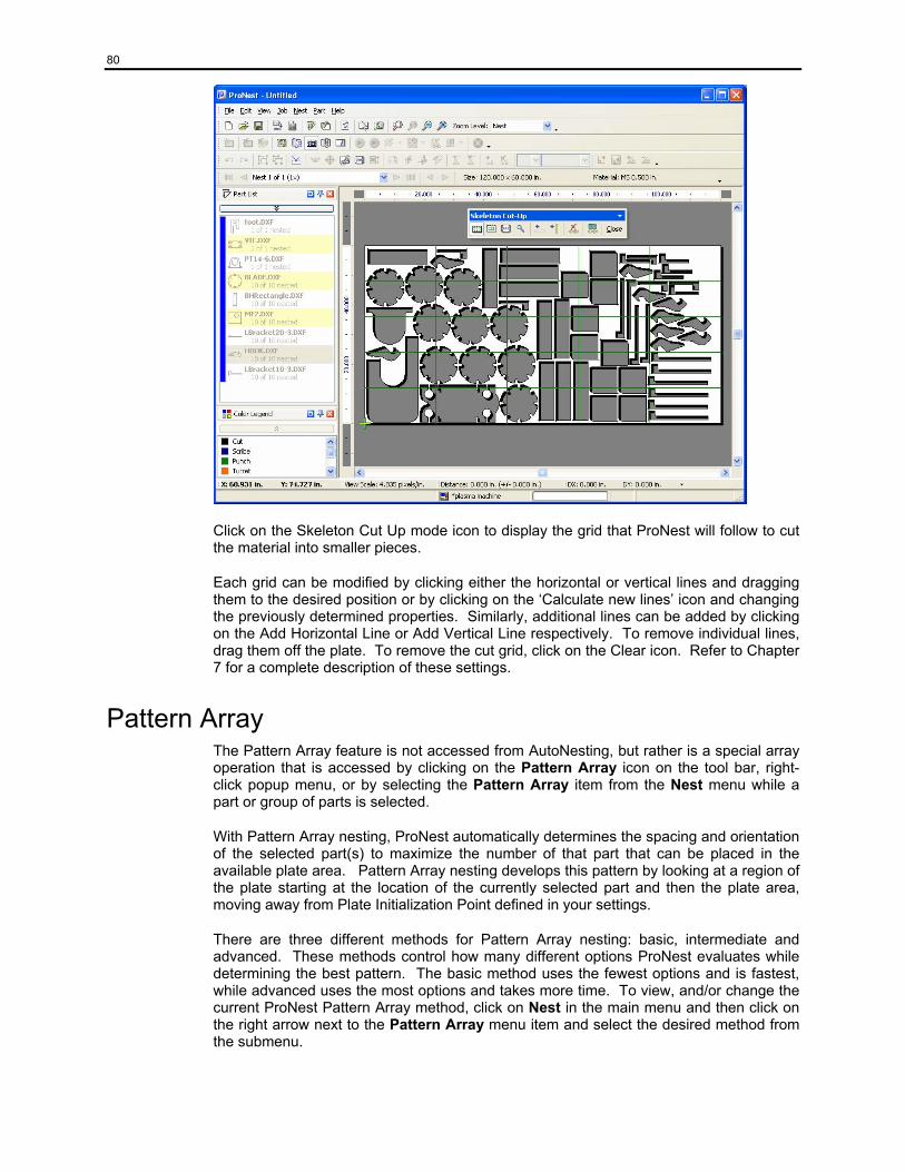
80
Click on the Skeleton Cut Up mode icon to display the grid that ProNest will follow to cut the material into smaller pieces.
Each grid can be modified by clicking either the horizontal or vertical lines and dragging them to the desired position or by clicking on the ‘Calculate new lines’ icon and changing the previously determined properties. Similarly, additional lines can be added by clicking on the Add Horizontal Line or Add Vertical Line respectively. To remove individual lines, drag them off the plate. To remove the cut grid, click on the Clear icon. Refer to Chapter 7 for a complete description of these settings.
Pattern Array The Pattern Array feature is not accessed from AutoNesting, but rather is a special array operation that is accessed by clicking on the Pattern Array icon on the tool bar, right-click popup menu, or by selecting the Pattern Array item from the Nest menu while a part or group of parts is selected.
With Pattern Array nesting, ProNest automatically determines the spacing and orientation of the selected part(s) to maximize the number of that part that can be placed in the available plate area. Pattern Array nesting develops this pattern by looking at a region of the plate starting at the location of the currently selected part and then the plate area, moving away from Plate Initialization Point defined in your settings.
There are three different methods for Pattern Array nesting: basic, intermediate and advanced. These methods control how many different options ProNest evaluates while determining the best pattern. The basic method uses the fewest options and is fastest, while advanced uses the most options and takes more time. To view, and/or change the current ProNest Pattern Array method, click on Nest in the main menu and then click on the right arrow next to the Pattern Array menu item and select the desired method from the submenu.
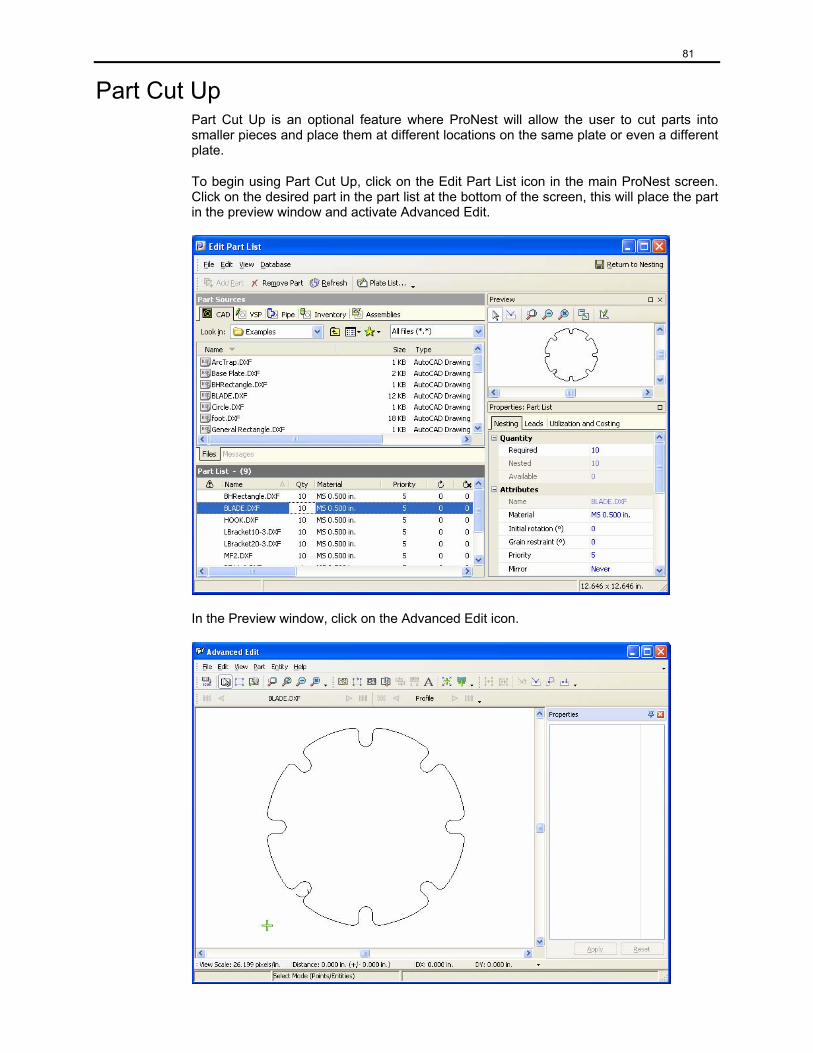
81
Part Cut Up Part Cut Up is an optional feature where ProNest will allow the user to cut parts into smaller pieces and place them at different locations on the same plate or even a different plate.
To begin using Part Cut Up, click on the Edit Part List icon in the main ProNest screen. Click on the desired part in the part list at the bottom of the screen, this will place the part in the preview window and activate Advanced Edit.
In the Preview window, click on the Advanced Edit icon.
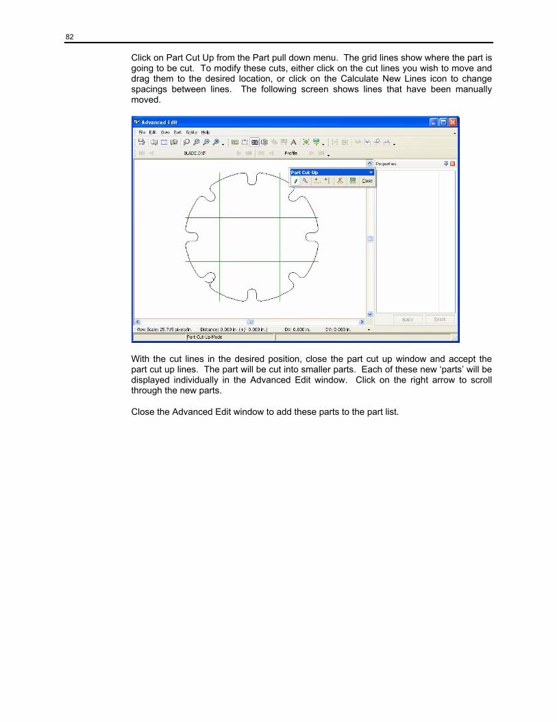
82
Click on Part Cut Up from the Part pull down menu. The grid lines show where the part is going to be cut. To modify these cuts, either click on the cut lines you wish to move and drag them to the desired location, or click on the Calculate New Lines icon to change spacings between lines. The following screen shows lines that have been manually moved.
With the cut lines in the desired position, close the part cut up window and accept the part cut up lines. The part will be cut into smaller parts. Each of these new ‘parts’ will be displayed individually in the Advanced Edit window. Click on the right arrow to scroll through the new parts.
Close the Advanced Edit window to add these parts to the part list.
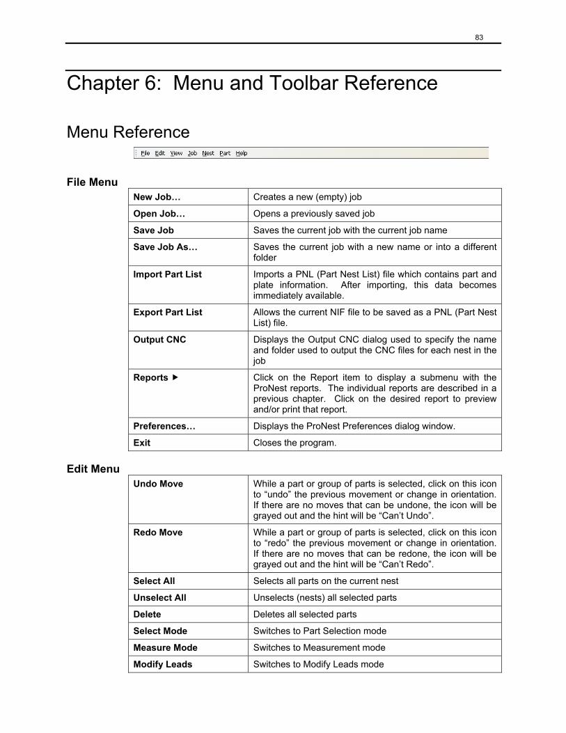
83
Chapter 6: Menu and Toolbar Reference
Menu Reference
File Menu New Job… Creates a new (empty) job
Open Job… Opens a previously saved job
Save Job Saves the current job with the current job name
Save Job As… Saves the current job with a new name or into a different folder
Import Part List Imports a PNL (Part Nest List) file which contains part and plate information. After importing, this data becomes immediately available.
Export Part List Allows the current NIF file to be saved as a PNL (Part Nest List) file.
Output CNC Displays the Output CNC dialog used to specify the name and folder used to output the CNC files for each nest in the job
Reports Click on the Report item to display a submenu with the ProNest reports. The individual reports are described in a previous chapter. Click on the desired report to preview and/or print that report.
Preferences… Displays the ProNest Preferences dialog window.
Exit Closes the program.
Edit Menu Undo Move While a part or group of parts is selected, click on this icon
to “undo” the previous movement or change in orientation. If there are no moves that can be undone, the icon will be grayed out and the hint will be “Can’t Undo”.
Redo Move While a part or group of parts is selected, click on this icon to “redo” the previous movement or change in orientation. If there are no moves that can be redone, the icon will be grayed out and the hint will be “Can’t Redo”.
Select All Selects all parts on the current nest
Unselect All Unselects (nests) all selected parts
Delete Deletes all selected parts
Select Mode Switches to Part Selection mode
Measure Mode Switches to Measurement mode
Modify Leads Switches to Modify Leads mode
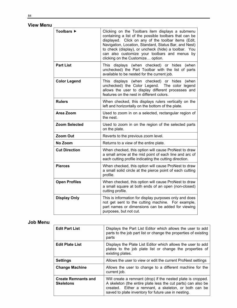
84
View Menu Toolbars Clicking on the Toolbars item displays a submenu
containing a list of the possible toolbars that can be displayed. Click on any of the toolbar items (Edit, Navigation, Location, Standard, Status Bar, and Nest) to check (display), or uncheck (hide) a toolbar. You can also customize your toolbars and menus by clicking on the Customize… option.
Part List This displays (when checked) or hides (when unchecked) the Part Toolbar with the list of parts available to be nested for the current job.
Color Legend This displays (when checked) or hides (when unchecked) the Color Legend. The color legend allows the user to display different processes and features on the nest in different colors.
Rulers When checked, this displays rulers vertically on the left and horizontally on the bottom of the plate.
Area Zoom Used to zoom in on a selected, rectangular region of the nest.
Zoom Selected Used to zoom in on the region of the selected parts on the plate.
Zoom Out Reverts to the previous zoom level.
No Zoom Returns to a view of the entire plate.
Cut Direction When checked, this option will cause ProNest to draw a small arrow at the mid point of each line and arc of each cutting profile indicating the cutting direction.
Pierces When checked, this option will cause ProNest to draw a small solid circle at the pierce point of each cutting profile.
Open Profiles When checked, this option will cause ProNest to draw a small square at both ends of an open (non-closed) cutting profile.
Display Only This is information for display purposes only and does not get sent to the cutting machine. For example, part names or dimensions can be added for viewing purposes, but not cut.
Job Menu Edit Part List Displays the Part List Editor which allows the user to add
parts to the job part list or change the properties of existing parts
Edit Plate List Displays the Plate List Editor which allows the user to add plates to the job plate list or change the properties of existing plates.
Settings Allows the user to view or edit the current ProNest settings
Change Machine Allows the user to change to a different machine for the current job.
Create Remnants and Skeletons
Will create a remnant (drop) if the nested plate is cropped. A skeleton (the entire plate less the cut parts) can also be created. Either a remnant, a skeleton, or both can be saved to plate inventory for future use in nesting.
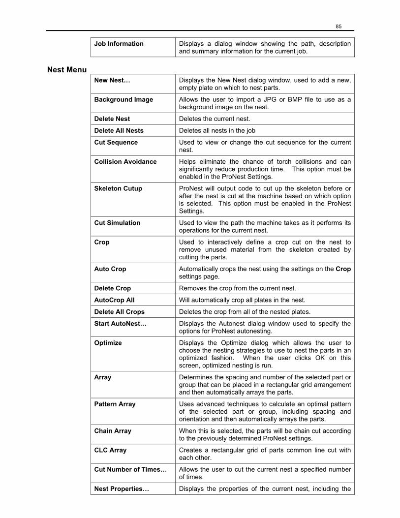
85
Job Information Displays a dialog window showing the path, description and summary information for the current job.
Nest Menu New Nest… Displays the New Nest dialog window, used to add a new,
empty plate on which to nest parts.
Background Image Allows the user to import a JPG or BMP file to use as a background image on the nest.
Delete Nest Deletes the current nest.
Delete All Nests Deletes all nests in the job
Cut Sequence Used to view or change the cut sequence for the current nest.
Collision Avoidance Helps eliminate the chance of torch collisions and can significantly reduce production time. This option must be enabled in the ProNest Settings.
Skeleton Cutup ProNest will output code to cut up the skeleton before or after the nest is cut at the machine based on which option is selected. This option must be enabled in the ProNest Settings.
Cut Simulation Used to view the path the machine takes as it performs its operations for the current nest.
Crop Used to interactively define a crop cut on the nest to remove unused material from the skeleton created by cutting the parts.
Auto Crop Automatically crops the nest using the settings on the Crop settings page.
Delete Crop Removes the crop from the current nest.
AutoCrop All Will automatically crop all plates in the nest.
Delete All Crops Deletes the crop from all of the nested plates.
Start AutoNest… Displays the Autonest dialog window used to specify the options for ProNest autonesting.
Optimize Displays the Optimize dialog which allows the user to choose the nesting strategies to use to nest the parts in an optimized fashion. When the user clicks OK on this screen, optimized nesting is run.
Array Determines the spacing and number of the selected part or group that can be placed in a rectangular grid arrangement and then automatically arrays the parts.
Pattern Array Uses advanced techniques to calculate an optimal pattern of the selected part or group, including spacing and orientation and then automatically arrays the parts.
Chain Array When this is selected, the parts will be chain cut according to the previously determined ProNest settings.
CLC Array Creates a rectangular grid of parts common line cut with each other.
Cut Number of Times… Allows the user to cut the current nest a specified number of times.
Nest Properties… Displays the properties of the current nest, including the
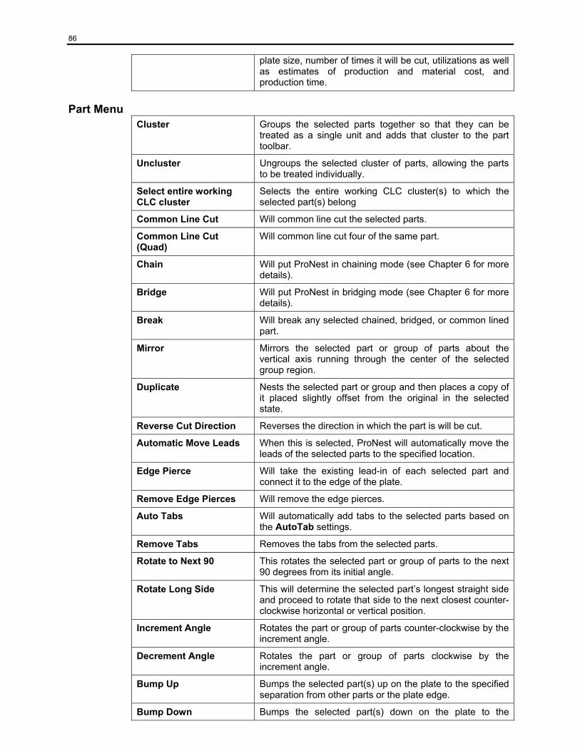
86
plate size, number of times it will be cut, utilizations as well as estimates of production and material cost, and production time.
Part Menu Cluster Groups the selected parts together so that they can be
treated as a single unit and adds that cluster to the part toolbar.
Uncluster Ungroups the selected cluster of parts, allowing the parts to be treated individually.
Select entire working CLC cluster
Selects the entire working CLC cluster(s) to which the selected part(s) belong
Common Line Cut Will common line cut the selected parts.
Common Line Cut (Quad)
Will common line cut four of the same part.
Chain Will put ProNest in chaining mode (see Chapter 6 for more details).
Bridge Will put ProNest in bridging mode (see Chapter 6 for more details).
Break Will break any selected chained, bridged, or common lined part.
Mirror Mirrors the selected part or group of parts about the vertical axis running through the center of the selected group region.
Duplicate Nests the selected part or group and then places a copy of it placed slightly offset from the original in the selected state.
Reverse Cut Direction Reverses the direction in which the part is will be cut.
Automatic Move Leads When this is selected, ProNest will automatically move the leads of the selected parts to the specified location.
Edge Pierce Will take the existing lead-in of each selected part and connect it to the edge of the plate.
Remove Edge Pierces Will remove the edge pierces.
Auto Tabs Will automatically add tabs to the selected parts based on the AutoTab settings.
Remove Tabs Removes the tabs from the selected parts.
Rotate to Next 90 This rotates the selected part or group of parts to the next 90 degrees from its initial angle.
Rotate Long Side This will determine the selected part’s longest straight side and proceed to rotate that side to the next closest counter-clockwise horizontal or vertical position.
Increment Angle Rotates the part or group of parts counter-clockwise by the increment angle.
Decrement Angle Rotates the part or group of parts clockwise by the increment angle.
Bump Up Bumps the selected part(s) up on the plate to the specified separation from other parts or the plate edge.
Bump Down Bumps the selected part(s) down on the plate to the
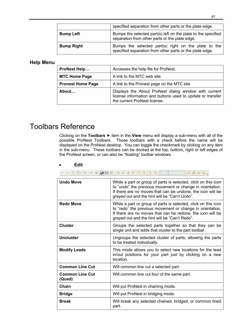
87
specified separation from other parts or the plate edge.
Bump Left Bumps the selected part(s) left on the plate to the specified separation from other parts or the plate edge.
Bump Right Bumps the selected part(s) right on the plate to the specified separation from other parts or the plate edge.
Help Menu ProNest Help… Accesses the help file for ProNest.
MTC Home Page A link to the MTC web site
Pronest Home Page A link to the Pronest page on the MTC site
About… Displays the About ProNest dialog window with current license information and buttons used to update or transfer the current ProNest license.
Toolbars Reference Clicking on the Toolbars item in the View menu will display a sub-menu with all of the possible ProNest Toolbars. Those toolbars with a check before the name will be displayed on the ProNest desktop. You can toggle the checkmark by clicking on any item in the sub-menu. These toolbars can be docked at the top, bottom, right or left edges of the ProNest screen, or can also be “floating” toolbar windows.
• Edit
Undo Move While a part or group of parts is selected, click on this icon to “undo” the previous movement or change in orientation. If there are no moves that can be undone, the icon will be grayed out and the hint will be “Can’t Undo”.
Redo Move While a part or group of parts is selected, click on this icon to “redo” the previous movement or change in orientation. If there are no moves that can be redone, the icon will be grayed out and the hint will be “Can’t Redo”.
Cluster Groups the selected parts together so that they can be single unit and adds that cluster to the part toolbar.
Uncluster Ungroups the selected cluster of parts, allowing the parts to be treated individually.
Modify Leads This mode allows you to select new locations for the lead in/out positions for your part just by clicking on a new location.
Common Line Cut Will common line cut a selected part.
Common Line Cut (Quad)
Will common line cut four of the same part.
Chain Will put ProNest in chaining mode.
Bridge Will put ProNest in bridging mode.
Break Will break any selected chained, bridged, or common lined part.
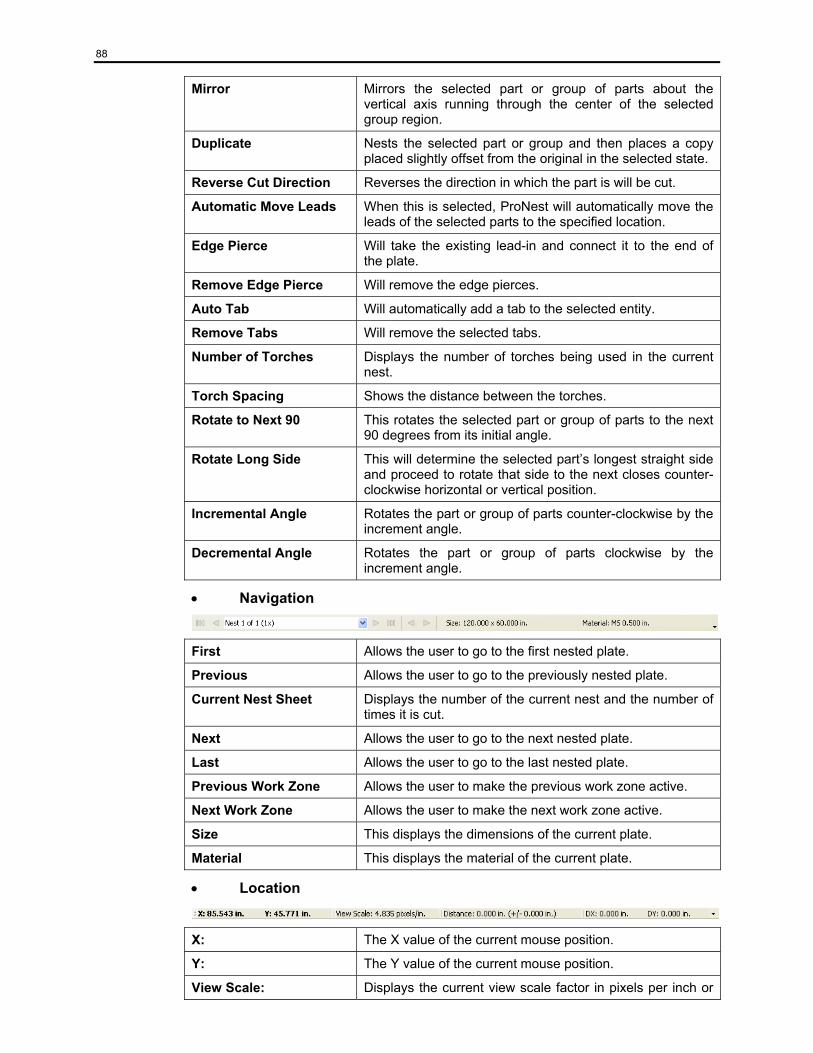
88
Mirror Mirrors the selected part or group of parts about the vertical axis running through the center of the selected group region.
Duplicate Nests the selected part or group and then places a copy placed slightly offset from the original in the selected state.
Reverse Cut Direction Reverses the direction in which the part is will be cut.
Automatic Move Leads When this is selected, ProNest will automatically move the leads of the selected parts to the specified location.
Edge Pierce Will take the existing lead-in and connect it to the end of the plate.
Remove Edge Pierce Will remove the edge pierces.
Auto Tab Will automatically add a tab to the selected entity.
Remove Tabs Will remove the selected tabs.
Number of Torches Displays the number of torches being used in the current nest.
Torch Spacing Shows the distance between the torches.
Rotate to Next 90 This rotates the selected part or group of parts to the next 90 degrees from its initial angle.
Rotate Long Side This will determine the selected part’s longest straight side and proceed to rotate that side to the next closes counter-clockwise horizontal or vertical position.
Incremental Angle Rotates the part or group of parts counter-clockwise by the increment angle.
Decremental Angle Rotates the part or group of parts clockwise by the increment angle.
• Navigation
First Allows the user to go to the first nested plate.
Previous Allows the user to go to the previously nested plate.
Current Nest Sheet Displays the number of the current nest and the number of times it is cut.
Next Allows the user to go to the next nested plate.
Last Allows the user to go to the last nested plate.
Previous Work Zone Allows the user to make the previous work zone active.
Next Work Zone Allows the user to make the next work zone active.
Size This displays the dimensions of the current plate.
Material This displays the material of the current plate.
• Location
X: The X value of the current mouse position.
Y: The Y value of the current mouse position.
View Scale: Displays the current view scale factor in pixels per inch or

89
pixels per mm.
Distance: This field is used to display the distance represented by the line drawn while in measurement mode.
DX: This field is used to display the delta X (change in X position) represented by the line drawn while in measurement mode.
DY: This field is used to display the delta Y (change in Y position) represented by the line drawn while in measurement mode.
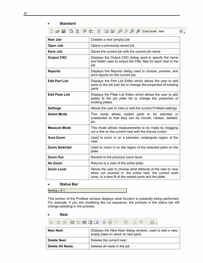
90
• Standard
New Job Creates a new (empty) job
Open Job Opens a previously saved job
Save Job Saves the current job with the current job name
Output CNC Displays the Output CNC dialog used to specify the name and folder used to output the CNC files for each nest in the job
Reports Displays the Reports dialog used to choose, preview, and print reports for the current job.
Edit Part List Displays the Part List Editor which allows the user to add parts to the job part list or change the properties of existing parts
Edit Plate List Displays the Plate List Editor which allows the user to add plates to the job plate list or change the properties of existing plates.
Settings Allows the user to view or edit the current ProNest settings
Select Mode This mode allows nested parts to be selected or unselected so that they can be moved, rotated, deleted, etc.
Measure Mode This mode allows measurements to be made by dragging out a line on the current nest with the mouse cursor.
Area Zoom Used to zoom in on a selected, rectangular region of the nest.
Zoom Selected Used to zoom in on the region of the selected parts on the plate.
Zoom Out Reverts to the previous zoom level.
No Zoom Returns to a view of the entire plate.
Zoom Level Allows the user to choose what attribute of the nest to view when not zoomed in: the entire nest, the current work zone, or a best fit of the nested parts and the plate.
• Status Bar
This portion of the ProNest window displays what function is presently being performed. For example, if you are modifying the cut sequence, the prompts in the status bar will change assisting in the process.
• Nest
New Nest Displays the New Nest dialog window, used to add a new, empty plate on which to nest parts.
Delete Nest Deletes the current nest.
Delete All Nests Deletes all nests in the job
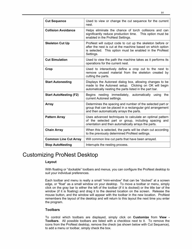
91
Cut Sequence Used to view or change the cut sequence for the current nest.
Collision Avoidance Helps eliminate the chance of torch collisions and can significantly reduce production time. This option must be enabled in the ProNest Settings.
Skeleton Cut Up ProNest will output code to cut up the skeleton before or after the nest is cut at the machine based on which option is selected. This option must be enabled in the ProNest Settings.
Cut Simulation Used to view the path the machine takes as it performs its operations for the current nest.
Crop Used to interactively define a crop cut to the nest to remove unused material from the skeleton created by cutting the parts.
Start Autonesting Displays the Autonest dialog box, allowing changes to be made to the Autonest setup. Clicking on OK will begin automatically nesting the parts listed in the part bar.
Start AutoNesting (F2) Begins nesting immediately, automatically using the current Autonest settings.
Array Determines the spacing and number of the selected part or group that can be placed in a rectangular grid arrangement and then automatically arrays the parts.
Pattern Array Uses advanced techniques to calculate an optimal pattern of the selected part or group, including spacing and orientation and then automatically arrays the parts.
Chain Array When this is selected, the parts will be chain cut according to the previously determined ProNest settings.
Common Line Cut Array Will common line cut parts that have been arrayed.
Stop AutoNesting Interrupts the nesting process.
Customizing ProNest Desktop Layout
With floating or “dockable” toolbars and menus, you can configure the ProNest desktop to suit your individual preferences.
Each toolbar and menu is really a small “mini-window” that can be “docked” at a screen edge, or “float” as a small window on your desktop. To move a toolbar or menu, simply click on the gray bar to either the left of the toolbar (if it is docked) or the title bar of the window (if it is floating) and drag it to the desired location on the screen. Release the mouse button, and the window will appear with the toolbar in the new location. ProNest remembers the layout of the desktop and will return to this layout the next time you enter the program.
Toolbars
To control which toolbars are displayed, simply click on Customize from View - Toolbars. All possible toolbars are listed with a checkbox next to it. To remove the icons from the ProNest desktop, remove the check (as shown below with Cut Sequence), to add a menu or toolbar, simply check the box.
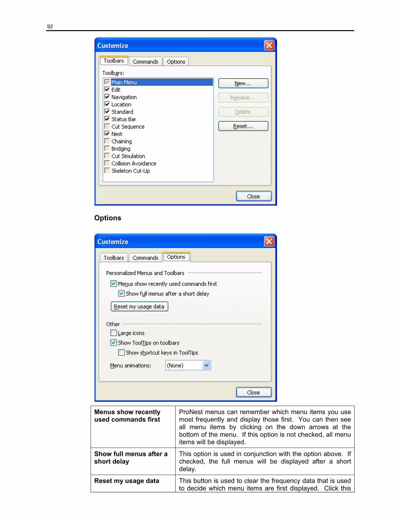
92
Options
Menus show recently used commands first
ProNest menus can remember which menu items you use most frequently and display those first. You can then see all menu items by clicking on the down arrows at the bottom of the menu. If this option is not checked, all menu items will be displayed.
Show full menus after a short delay
This option is used in conjunction with the option above. If checked, the full menus will be displayed after a short delay.
Reset my usage data This button is used to clear the frequency data that is used to decide which menu items are first displayed. Click this
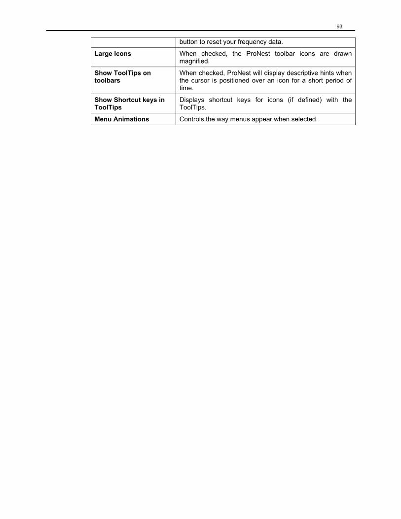
93
button to reset your frequency data.
Large Icons When checked, the ProNest toolbar icons are drawn magnified.
Show ToolTips on toolbars
When checked, ProNest will display descriptive hints when the cursor is positioned over an icon for a short period of time.
Show Shortcut keys in ToolTips
Displays shortcut keys for icons (if defined) with the ToolTips.
Menu Animations Controls the way menus appear when selected.
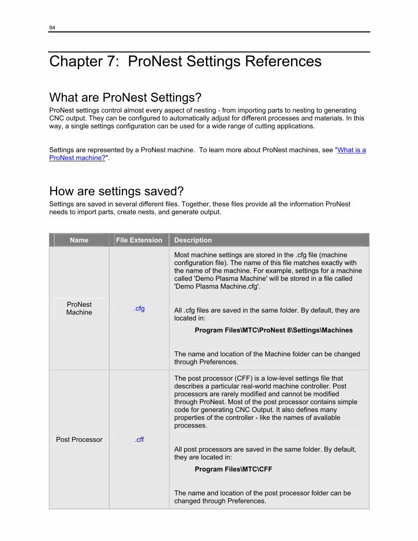
94
Chapter 7: ProNest Settings References
What are ProNest Settings? ProNest settings control almost every aspect of nesting - from importing parts to nesting to generating CNC output. They can be configured to automatically adjust for different processes and materials. In this way, a single settings configuration can be used for a wide range of cutting applications.
Settings are represented by a ProNest machine. To learn more about ProNest machines, see "What is a ProNest machine?".
How are settings saved? Settings are saved in several different files. Together, these files provide all the information ProNest needs to import parts, create nests, and generate output.
Name File Extension Description
ProNest Machine .cfg
Most machine settings are stored in the .cfg file (machine configuration file). The name of this file matches exactly with the name of the machine. For example, settings for a machine called 'Demo Plasma Machine' will be stored in a file called 'Demo Plasma Machine.cfg'.
All .cfg files are saved in the same folder. By default, they are located in:
Program Files\MTC\ProNest 8\Settings\Machines
The name and location of the Machine folder can be changed through Preferences.
Post Processor .cff
The post processor (CFF) is a low-level settings file that describes a particular real-world machine controller. Post processors are rarely modified and cannot be modified through ProNest. Most of the post processor contains simple code for generating CNC Output. It also defines many properties of the controller - like the names of available processes.
All post processors are saved in the same folder. By default, they are located in:
Program Files\MTC\CFF
The name and location of the post processor folder can be changed through Preferences.
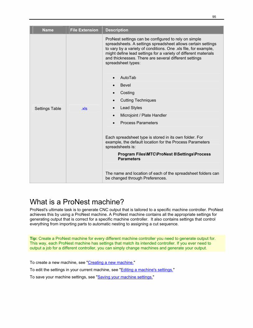
95
Name File Extension Description
Settings Table .xls
ProNest settings can be configured to rely on simple spreadsheets. A settings spreadsheet allows certain settings to vary by a variety of conditions. One .xls file, for example, might define lead settings for a variety of different materials and thicknesses. There are several different settings spreadsheet types:
• AutoTab
• Bevel
• Costing
• Cutting Techniques
• Lead Styles
• Microjoint / Plate Handler
• Process Parameters
Each spreadsheet type is stored in its own folder. For example, the default location for the Process Parameters spreadsheets is:
Program Files\MTC\ProNest 8\Settings\Process Parameters
The name and location of each of the spreadsheet folders can be changed through Preferences.
What is a ProNest machine? ProNest's ultimate task is to generate CNC output that is tailored to a specific machine controller. ProNest achieves this by using a ProNest machine. A ProNest machine contains all the appropriate settings for generating output that is correct for a specific machine controller. It also contains settings that control everything from importing parts to automatic nesting to assigning a cut sequence.
Tip: Create a ProNest machine for every different machine controller you need to generate output for. This way, each ProNest machine has settings that match its intended controller. If you ever need to output a job for a different controller, you can simply change machines and generate your output.
To create a new machine, see "Creating a new machine."
To edit the settings in your current machine, see "Editing a machine's settings."
To save your machine settings, see "Saving your machine settings."
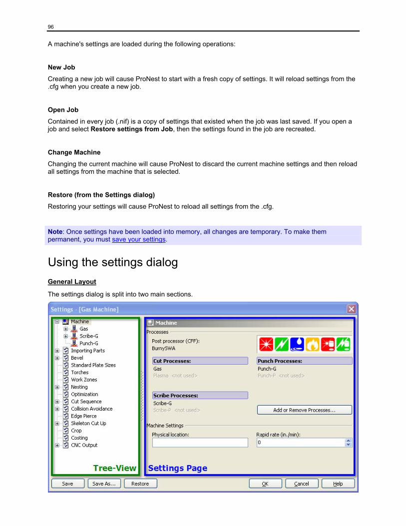
96
A machine's settings are loaded during the following operations:
New Job
Creating a new job will cause ProNest to start with a fresh copy of settings. It will reload settings from the .cfg when you create a new job.
Open Job
Contained in every job (.nif) is a copy of settings that existed when the job was last saved. If you open a job and select Restore settings from Job, then the settings found in the job are recreated.
Change Machine
Changing the current machine will cause ProNest to discard the current machine settings and then reload all settings from the machine that is selected.
Restore (from the Settings dialog)
Restoring your settings will cause ProNest to reload all settings from the .cfg.
Note: Once settings have been loaded into memory, all changes are temporary. To make them permanent, you must save your settings.
Using the settings dialog General Layout
The settings dialog is split into two main sections.
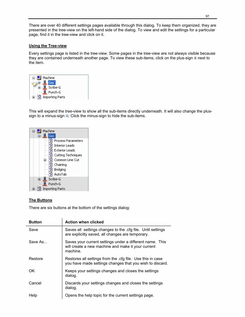
97
There are over 40 different settings pages available through this dialog. To keep them organized, they are presented in the tree-view on the left-hand side of the dialog. To view and edit the settings for a particular page, find it in the tree-view and click on it.
Using the Tree-view
Every settings page is listed in the tree-view. Some pages in the tree-view are not always visible because they are contained underneath another page. To view these sub-items, click on the plus-sign next to the item.
This will expand the tree-view to show all the sub-items directly underneath. It will also change the plus-sign to a minus-sign . Click the minus-sign to hide the sub-items.
The Buttons
There are six buttons at the bottom of the settings dialog:
Button Action when clicked
Save Saves all settings changes to the .cfg file. Until settings are explicitly saved, all changes are temporary.
Save As... Saves your current settings under a different name. This will create a new machine and make it your current machine.
Restore Restores all settings from the .cfg file. Use this in case you have made settings changes that you wish to discard.
OK Keeps your settings changes and closes the settings dialog.
Cancel Discards your settings changes and closes the settings dialog.
Help Opens the help topic for the current settings page.
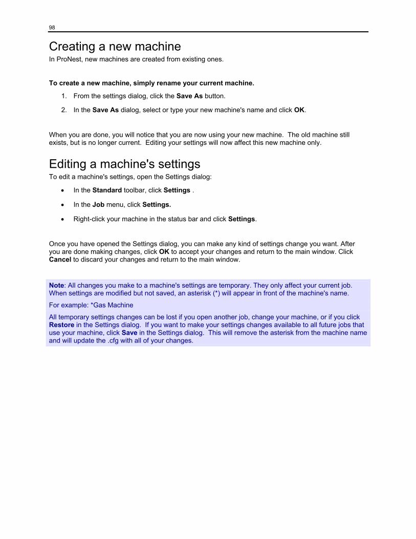
98
Creating a new machine In ProNest, new machines are created from existing ones.
To create a new machine, simply rename your current machine.
1. From the settings dialog, click the Save As button.
2. In the Save As dialog, select or type your new machine's name and click OK.
When you are done, you will notice that you are now using your new machine. The old machine still exists, but is no longer current. Editing your settings will now affect this new machine only.
Editing a machine's settings To edit a machine's settings, open the Settings dialog:
• In the Standard toolbar, click Settings .
• In the Job menu, click Settings.
• Right-click your machine in the status bar and click Settings.
Once you have opened the Settings dialog, you can make any kind of settings change you want. After you are done making changes, click OK to accept your changes and return to the main window. Click Cancel to discard your changes and return to the main window.
Note: All changes you make to a machine's settings are temporary. They only affect your current job. When settings are modified but not saved, an asterisk (*) will appear in front of the machine's name.
For example: *Gas Machine
All temporary settings changes can be lost if you open another job, change your machine, or if you click Restore in the Settings dialog. If you want to make your settings changes available to all future jobs that use your machine, click Save in the Settings dialog. This will remove the asterisk from the machine name and will update the .cfg with all of your changes.
99
Settings tables (Spreadsheets) For certain settings, users will find that the default settings are not able to provide a desired result. For these kinds of settings, ProNest uses spreadsheets. In these spreadsheets, users can differentiate settings based on material type and thickness, as well as profile type and profile area. Each row in the spreadsheet thus defines a unique setting based on these parameters. This allows for more comprehensive control over the cutting and nesting parameters. Some cutting parameters, such as cutting conditions for lasers, are not offered in the default settings and may only be accessed via these spreadsheets.
There are nine different types of spreadsheets:
• Process Parameters
• Costing
• Interior Leads
• Exterior Leads
• AutoTab
• Cutting Techniques
• Bevel
• Microjoint*
• Plate Handler*
* Note: The post processor (CFF) must be properly configured to make use of the Microjoint and Plate Handler spreadsheets. If you need to use microjoints and/or a plate handler, please contact MTC Software.
Saving your machine settings Settings are saved in two different ways:
• With the ProNest machine (.cfg)
• With the job (.nif)
Saving with the ProNest machine
To save your temporary settings changes:
In the Settings dialog, click Save. This will update the current machine's .cfg with your changes.
To save your temporary settings changes as a new machine:
1. In the Settings dialog, click Save As.
2. Type or select a machine name in the box and click OK. This will create a new .cfg with the name you specify. If you entered the name of a machine that already exists, a warning message will appear before it is overwritten. Your current machine will also change to this new machine.
Saving with the Job
Every time a job is saved, the current state of your settings are also saved in the job. This has no effect on the current machine's .cfg.
100
Machine This is the main settings page. While there are only two editable settings on this page, it serves as a description of the machine's basic configuration. It also provides a controlled means of editing this configuration.
Processes
The most important information on this page is in the Processes section at the top. In this section, you can see the name of the post processor (CFF file) and the processes that this machine is using.
The post processor is the core of any ProNest machine. This file is usually tailored to match a specific real-world machine controller and will generally be named accordingly. While most of the contents of a post processor is specific to output, there is some information that helps to configure the settings for any ProNest machine that makes use of it.
One set of information in the post processor is a list of available processes. The processes that a ProNest machine can have is limited to the list of processes described in the post processor. The machine page shows the names of all processes listed in the post processor organized by process class (cut, scribe, and punch). Processes that are used by the ProNest machine will appear as normal text. These processes will also appear in the Settings window's tree-view as children of the Machine settings page. Processes that are not used will appear disabled and will have the phrase '<not used>' next to them.
Advanced: The settings in the Processes section are not directly editable on this page. To change the post processor or to modify which processes are used, click Add or Remove Processes.
Machine Settings
Physical location
It is often advisable to create one ProNest machine for every physical machine you have. This setting is informational only and simply provides an indication of where the real-world machine is located.
Rapid rate
This setting describes the machine's maximum traverse speed while the torch/head is off.
Units: Length per minute
Range: 0 to 10,000 in./min
Recommended Value: 600 in./min
101
Add or Remove Processes The Add or Remove Processes wizard provides a controlled way to change the fundamental configuration of a ProNest machine.
To access this wizard:
On the Machine settings page, click Add or Remove Processes.
Wizard Pages
The first page of this wizard is called "Select a Post Processor (CFF)." The purpose of this page is to allow changes to the post processor and/or to the processes that should be used by the current ProNest machine. For more information about this page, see "Select a Post Processor (CFF)."
The second page of this wizard is called "Reuse Existing Settings." The purpose of this page is to ensure that existing process settings aren't lost simply because changes were made on the previous page: "Select a Post Processor (CFF)." For more information about this page, see "Reuse Existing Settings."
Navigation Buttons
Along the bottom of the Add or Remove Processes wizard are the following buttons:
Button Action when clicked
Back Go to the previous wizard page.
Next Go to the next wizard page.
Finished Accept your changes and exit the wizard.
Cancel Discard your changes and exit the wizard.
Help Opens help for the current wizard page.
102
Select a Post Processor (CFF) This is the first page in the Add or Remove Processes wizard. The purpose of this page is to allow changes to the post processor and/or to the processes that should be used by the current ProNest machine.
Post Processor
The post processor is the core of any ProNest machine. This file is usually tailored to match a specific real-world machine controller and will generally be named accordingly. While most of the contents of a post processor is specific to output, there is some information that helps to configure the settings for any ProNest machine that makes use of it.
This section contains a combo box of available post processors found on your computer.
To change your post processor:
Type of select the post processor name in the box.
Every process supported by the selected post processor is listed in this section. As the post processor changes, the processes listed will update.
To add a process to the machine:
Select the process' associated check box.
To remove a process from the machine:
Clear the process' associated check box.
Important: Adding and removing processes from a ProNest machine is considered an advanced type of change. Changes of this nature are usually done once while setting up a machine for the first time. This is because a ProNest machine is intended to mirror a real-world machine and the abilities of a specific real-world machine do not change often. Adding a new process will introduce a new set of process settings that must be edited before any meaningful output can be expected. Likewise, removing a process will destroy its existing settings. Exercise caution when making any changes to the settings on this page and be sure to visit the next page in the wizard: "Reuse existing settings."
Note: You must select at least one cut process or the Next and Finished buttons will become disabled.
103
Reuse Existing Settings This is the second page in the Add or Remove Processes wizard. The purpose of this page is to ensure that existing process settings aren't lost simply because changes were made on the previous page: "Select a Post Processor (CFF)."
Selected Processes
All processes that have been selected on the previous wizard page will appear in a box in this section.
For each process, the following options are available:
New process
If this is chosen when Finished is clicked, then the process will be given new default settings. These default settings should then be edited to better suit the needs of the new process.
Use settings from existing '<process name>' process
If this is chosen when Finished is clicked, then the process will inherit all the settings from the existing process.
Example:
Let's say that the settings for a given ProNest machine are perfect, but you need to switch the post processor to something else. Currently, the only cut process defined is called 'Laser'. On the Machine page, you click Add or Remove Processes. Then, on the first page of this wizard you select the new post processor.
At this point, the list of processes changes and you notice that the new post processor doesn't have a 'Laser' process. Instead, it has a cut process called 'SuperLaser'. So on the first page of the wizard, you select the 'SuperLaser' process and click Finished.
What happens:
When you click Finished, ProNest re-configures your machine. The old 'Laser' process is removed - along with all its settings - and a new 'SuperLaser' process is added with default settings. This may be a valid result for some cases, but let's say that your intention was to use your old 'Laser' settings with the new 'SuperLaser' process. How would you transfer these settings?
Transferring settings from one process to another:
Instead of clicking Finished on the "Select a Post Processor (CFF)" page, click Next to advance to the "Reuse Existing Settings" page. On this page you can now see what is happening. The 'SuperLaser' process is defined as a 'New process'. Also, there is a warning below the process box telling you that the settings for the 'Laser' process will be deleted.
To use the old 'Laser' settings for your new 'SuperLaser' process do the following:
1. For 'SuperLaser', click where it says 'New process' and a down arrow will appear.
2. Click the down arrow and select Use settings from existing 'Laser' process.
What happens:
Now when you click Finished, ProNest copies the 'Laser' settings into your new 'SuperLaser' process before it removes the 'Laser' process.
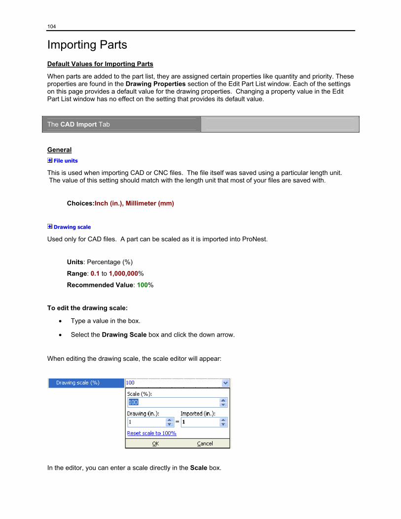
104
Importing Parts Default Values for Importing Parts
When parts are added to the part list, they are assigned certain properties like quantity and priority. These properties are found in the Drawing Properties section of the Edit Part List window. Each of the settings on this page provides a default value for the drawing properties. Changing a property value in the Edit Part List window has no effect on the setting that provides its default value.
The CAD Import Tab
General File units
This is used when importing CAD or CNC files. The file itself was saved using a particular length unit. The value of this setting should match with the length unit that most of your files are saved with.
Choices:Inch (in.), Millimeter (mm)
Drawing scale
Used only for CAD files. A part can be scaled as it is imported into ProNest.
Units: Percentage (%)
Range: 0.1 to 1,000,000%
Recommended Value: 100%
To edit the drawing scale:
• Type a value in the box.
• Select the Drawing Scale box and click the down arrow.
When editing the drawing scale, the scale editor will appear:
In the editor, you can enter a scale directly in the Scale box.
105
You can also specify a scale by defining the ratio between a length in the drawing and the corresponding imported length.
Example:
In this example, most CAD files in our CAD folder must be scaled as they are imported into ProNest. For whatever reason, a length of 2.5 mm in each drawing should be imported as 10 mm.
In the scale editor:
1. Type 2.5 in the Drawing box.
2. Type 10 in the Imported box.
As values are typed in each box, the value in the Scale box will update to match the ratio implied by the Drawing and Imported values. When complete, the Scale box will contain the value: 400%. Click OK and the Drawing scale field will contain 400%. Now when CAD parts are imported, they will be scaled to 400% of their actual size in the drawing.
Open profile tolerance
This setting specifies the maximum distance allowed for joining line and arc entities. In other words, if Open profile tolerance is set to 0.005 in., gaps that are 0.005 in. or smaller will be closed - helping to prevent open profiles.
Units: Distance
Range: 0.001 to 1.0 in.
Recommended Value: 0.005 in.
CAD Layers
The following settings apply only to CAD files: Cut all layers with [Cut Process]
This setting is automatically named according to the first cut process used by this machine. For example, if the first cut process was called "Laser", then this setting would appear as "Cut all layers with [Laser]". Select this check box if all layers found in a CAD file should be cut by the process shown. Most applications will require that this checkbox be cleared.
Cut - [Cut Process]
Defines the CAD layers that should be mapped to a particular cut process. Each cut process supported by the machine will have its own setting.
Example:
If a machine supported both a Gas and a Plasma process, then there would be two rows here:
Cut - [Gas]
Cut - [Plasma]
106
Scribe - [Scribe Process]
Defines the CAD layers that should be mapped to a particular scribe process. Each scribe process supported by the machine will have its own setting.
Example:
If a machine supported a single scribe process called "Scribe-G", then there would be one row here:
Scribe - [Scribe-G]
Punch - [Punch Process]
Defines the CAD layers that should be mapped to a particular punch process. Each punch process supported by the machine will have its own setting.
Example:
If a machine supported a single punch process called "MyPunch", then there would be one row here:
Punch - [MyPunch]
Turret
Defines the CAD layers that should be mapped to the machine's turret process.
Display Only
Defines the CAD layers that should be displayed in ProNest, but should not be cut.
BOM
Defines the CAD layers that contain BOM information.
Map to CAD color numbers
Select this setting to allow importing parts by CAD color number instead of by layer name.
Example:
A part file defines a part in one layer: "CUT". The part is a simple rectangle with a hole in it. The exterior profile of the part has a color number of 1, but the interior hole has a color number of 2.
If Map to CAD color numbers is cleared, then a cut process must be mapped to "CUT" in order to import the part properly. Importing the part in this way will cause the same cut process to cut both the interior and exterior profiles.
If Map to CAD color numbers is selected, then one cut process must be mapped to "1" and another (or the same) cut process must also be mapped to "2". Importing the part in this way can result in one process handling the exterior profile while another process handles the interior profile.
107
Options Leads origin
This determines where the origin of the lead-in/out of the part is, in relation to the drawing being processed.
Choices:Lower-Left, Upper-Left, Upper-Right, Lower-Right, Left, Top, Right, Bottom
Punch/Scribe first
If selected, will Punch and Scribe ALL parts before cutting. If you are cutting with underwater plasma,you should select this option. Normally very light metal should not have the punching and/or scribing done first to avoid problems with metal movement.
Reverse direction and kerf
Select this to import parts with a reversed cut direction. Interior profiles will be cut clockwise and exterior profiles will be cut counter-clockwise. Right-handed kerf compensation is also used.
Delete overlapped entities
When this setting is selected, duplicate or coincident entities (lines or arcs) are automatically deleted as the part is imported.
Contains multiple parts
If there is more than one part on your drawing, select this setting.
Explode multiple parts
Select this setting if there is more than one part on your drawing and you want to separate them as they are imported.
Note: This setting is active only when Contains multiple parts is selected.
User drawn leads
Having this setting selected means that a part can be pattern arrayed during AutoNest.
108
Quality
Attaches a quality value to every entity.
Choices:(None), Use CAD Colors, 0..255
(None) - Quality values will not be attached to any entity in the part.
Use CAD Colors - Each entity's color number (from the CAD drawing) will be used as the entity's quality number.
0..255 - All entities will be assigned the same quality value.
Advanced: The quality number can be used as a key into the process parameter table or as a way of outputting specific M-codes based on the quality number.
Smooth entities
Select this setting to convert curves made from line segments (approximated curves) into true arcs whenever possible.
Smooth tolerance
When converting a set of line segments into a curve, it is important to define how accurate the curve must be. The Smooth tolerance value specifies a maximum distance from the approximated curve in which an arc can be formed. A large tolerance will likely cause more smoothing to occur at the expense of a less accurate curve.
This tolerance value is opposite, but similar, to Arc radius tolerance found on the Importing Part (Advanced) settings page.
The Nesting Tab
Quantity Required
This setting defines the default quantity used when importing parts.
Range: 1 to 10,000
Recommended Value: 1
109
Attributes Initial rotation
A part can be rotated (counter-clockwise) when it is added to the part list by defining an initial rotation angle. This rotation will become the part's "natural" orientation.
Units: Degrees (°)
Range: 0 to 360°
Recommended Value: 0°
Grain restraint
When editing your part list, you can specify a rotation restriction that will be used when importing parts.
Units: Degrees (°)
Range: 0 to 360°
Recommended Value: 0°
This setting is commonly used with parts that have grain restrictions (they must run parallel with the grain of the material). The grain restraint angle defines a set of valid part orientations. For example, a value of 180° will limit valid part orientations to 0° and 180°. A value of 360° will restrict rotation completely - allowing only the part's natural orientation. A value of 0° will allow any rotation.
Note: The grain restraint angle will not restrict parts that are rotated manually. If a part is rotated manually to an angle that violates the part's rotation restriction, ProNest will show the part in conflict.
Priority
Priority is used to sort parts for automatic nesting. All things being equal, parts with a priority of 1 will nest before parts with a priority of 99.
Range: 1 to 99
Recommended Value: 5
Tip: A priority value of 99 is reserved for filler parts. Filler parts are nested on a plate during automatic nesting only when:
• At least one non-filler part has already been nested on the plate. • Automatic nesting has already tried to place all other parts with a priority less than 99 on the
plate.
110
Mirror
A part's mirror value will affect how ProNest will nest the part during automatic nesting, CLC Quad, and CLC Array. When editing your part list, you can specify a mirror value that will be used when importing parts.
Choices: No Mirror, Mirror Only, Either
No Mirror - Pronest will never mirror the part.
Mirror Only - ProNest will always mirror the part.
Either - ProNest will decide which part orientation is best: natural or mirrored.
Important: For CLC Quad to work with certain parts (triangles, parts with only one square corner) the mirror value must be set to Either.
Cluster
ProNest will automatically build clusters of parts that have this property selected.
Fit ratio
This ratio defines the cutoff for desirable clusters created automatically for parts with their Cluster property selected. The main reason to create a cluster is because it uses less space than two of that part placed next to each other. The space used by two parts placed next to each other is used as the 'benchmark'. An improvement is defined as follows:
Improvement = Space used by the cluster / Space used by two parts
If the improvement is better (less) than the fit ratio, then the cluster is added to the Part List as a custom part.
Units: Percentage
Range: 50 to 100%
Recommended Value: 90%
Common line cutting
ProNest will automatically build CLC clusters of parts that have this property set to anything other than (None).
Choices: (None), Pair, Quad, Both
(None) - CLC clusters will not be built for the part.
Pair - If possible, a pair CLC cluster (2 parts) will be built for the part.
Quad - If possible, a quad CLC cluster (4 parts) will be built for the part.
Both - If possible, will build a pair and a quad CLC cluster.
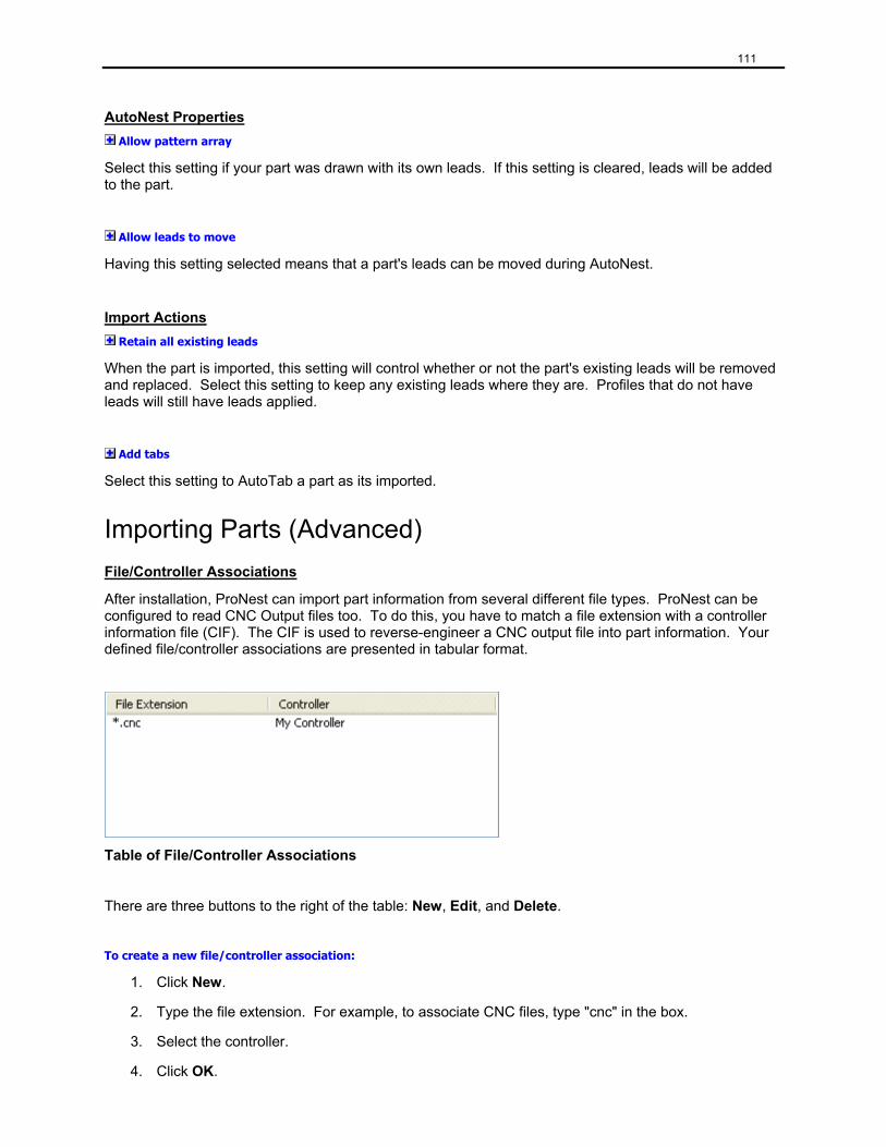
111
AutoNest Properties Allow pattern array
Select this setting if your part was drawn with its own leads. If this setting is cleared, leads will be added to the part.
Allow leads to move
Having this setting selected means that a part's leads can be moved during AutoNest.
Import Actions Retain all existing leads
When the part is imported, this setting will control whether or not the part's existing leads will be removed and replaced. Select this setting to keep any existing leads where they are. Profiles that do not have leads will still have leads applied.
Add tabs
Select this setting to AutoTab a part as its imported.
Importing Parts (Advanced) File/Controller Associations
After installation, ProNest can import part information from several different file types. ProNest can be configured to read CNC Output files too. To do this, you have to match a file extension with a controller information file (CIF). The CIF is used to reverse-engineer a CNC output file into part information. Your defined file/controller associations are presented in tabular format.
Table of File/Controller Associations
There are three buttons to the right of the table: New, Edit, and Delete.
To create a new file/controller association:
1. Click New.
2. Type the file extension. For example, to associate CNC files, type "cnc" in the box.
3. Select the controller.
4. Click OK.
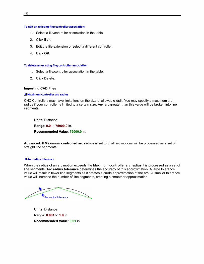
112
To edit an existing file/controller association:
1. Select a file/controller association in the table.
2. Click Edit.
3. Edit the file extension or select a different controller.
4. Click OK.
To delete an existing file/controller association:
1. Select a file/controller association in the table.
2. Click Delete.
Importing CAD Files
Maximum controller arc radius
CNC Controllers may have limitations on the size of allowable radii. You may specify a maximum arc radius if your controller is limited to a certain size. Any arc greater than this value will be broken into line segments.
Units: Distance
Range: 0.0 to 75000.0 in.
Recommended Value: 75000.0 in.
Advanced: If Maximum controlled arc radius is set to 0, all arc motions will be processed as a set of straight line segments.
Arc radius tolerance
When the radius of an arc motion exceeds the Maximum controller arc radius it is processed as a set of line segments. Arc radius tolerance determines the accuracy of this approximation. A large tolerance value will result in fewer line segments as it creates a crude approximation of the arc. A smaller tolerance value will increase the number of line segments, creating a smoother approximation.
Units: Distance
Range: 0.001 to 1.0 in.
Recommended Value: 0.01 in.
113
Save part file tokens
Each time a CAD file is imported, it is processed as if the file had never been imported before. This processing takes time. To improve the speed of importing CAD files you can select the Save part file tokens check box.
When Save part file tokens is selected, ProNest will create an MTC token file (.tok) as each CAD file is processed. This token file represents a "processed" version of the CAD file and will have the same name (except with a .tok extension). Next time the CAD file is imported, ProNest will search for its matching token file. If the CAD file hasn't been modified since the token file was created, ProNest will import from the token file - saving on processing time. Otherwise, the CAD file will be processed and a new token file will be saved.
Note: The trade-off with this speed improvement is the extra storage space needed for the token files.
Save Advanced Edit tokens
If selected, all part changes made in Advanced Edit will be saved to the part's token file. The next time the CAD file is imported, the part's token file will be loaded because Save part file tokens is already selected. The end result is that the part will load with all of the changes made in Advanced Edit.
Note: This setting is active only when Save part file tokens is selected.
Use text marker
If your cutting machine controller has a special text-marking device you may have to check this option. Contact MTC to determine if you need to use this feature.
Importing CNC Files
Tab auto-recognition size
This value is used only when computer numerically controlled (CNC) files are added to ProNest's part list. CNC files are reverse-engineered (decoded) from controller instructions to part geometry. During this process, ProNest uses tab auto-recognition size to determine if gaps in a cutting profile are tabs. If a gap is smaller than this value, it will be converted to a tab. Otherwise, it will be interpreted as a break in the profile.
Units: Distance
Range: -0.01 to 5.0 in.
Recommended Value: 0.01 in.
Bevel Bevel Settings
Settings table
Most beveling applications require modification of process parameters such as voltage, kerf, current, and feed rate at particular locations in the CNC code. The process parameters used for beveled profiles are stored in the bevel settings table.
114
To select a settings table:
Type or select the name of the settings table in the box.
You can make changes to the selected settings table by clicking the button. For more information on this and other settings tables, see "Settings Tables (Spreadsheets)."
Macro folder
Macros are often required for beveling applications. They are used to represent the required geometry and process parameter changes for beveling a profile or for changing bevel angles within a profile. All bevel macros exist in a single folder.
To specify this folder you can:
Type the full path in the box.
-or-
Browse for the macro folder.
To browse for the macro folder:
1. Click the button to open the Browse for Folder dialog.
2. Browse to the folder containing bevel macros.
3. Click OK.
Advanced: A set of standard bevel macros are installed with ProNest. Due to the specific needs of your particular beveling application it is possible that these macros are not adequate. Please contact MTC Software if custom macros are needed.
Top angle orientation
This setting defines how top angles are specified. Some beveling machines use positive angles to define a top angle, but some use negative angles.
Choices:Negative (-), Positive (+)
Negative (-)
Top angles will be referred to as negative angles. Positive angles will be used to represent bottom bevels.
Positive (+)
Top angles will be referred to as positive angles. Negative angles will be used to represent bottom bevels.
This setting is primarily used for output purposes and for pulling the correct information from the bevel settings table.
115
AutoBevel Settings
When adding CAD parts to your part list, ProNest can automatically bevel parts that contain bevel information. This information is embedded in CAD layer names.
Use AutoBevel
Select this setting if you have CAD files with bevel information contained in the CAD layer names.
Bevel angle - prefix
CAD layer names that begin with this prefix will be interpreted as layer names that contain AutoBevel information. By default, the prefix is "BVL".
Note: This setting is active only if Use AutoBevel is selected.
Bevel - Pass Profiles Pass profiles are created when using multiple pass beveling. Multiple pass beveling allows more than one contour on entities in the part - this may include using two different bevels angles on the same entity or using a bevel angle such that the beveled portion of the entity does not account for the full material thickness.
Pass Profile Sequence
Sequence order for pass levels
When making pass profiles, up to three types may be created: Top, Bottom, and Land. This setting allows you to choose the order in which they are cut.
To modify the cut order:
1. Select the pass type that you want to move
2. Click on the Up or Down button.
Before making pass profiles
Remove existing leads
Select this check box to remove and replace leads on beveled profiles with the correct leads from the Bevel settings table. This action will occur during pass profile creation.
Remove existing loops
Select this check box to remove and replace loops on beveled profiles with the correct loops from the Bevel settings table. This action will occur during pass profile creation.
While making pass profiles
Add leads and loops
Select this check box to have loops and leads applied during pass profile creation. Their exact properties will come from the Bevel setting table.
Add loops to non-beveled corners

116
Select this check box if you wish transition loops to be added to corners of the beveled profiles where the entities to either side are not beveled. Otherwise, transition loops will only be added to beveled corners.
Note: This setting is active only if Add leads and loops is selected.
AutoLoop threshold
Threshold angle used to determine which corners in a profile are candidates for automatically adding transition loops. Corners with an included angle less than this setting's value may have transition loops automatically added to them during pass profile creation.
Units: Degrees
Range:0 to 360°
Recommended Value:135°
Note: This setting is active only if Add leads and loops is selected.
Compensate geometry
Some beveling machines achieve the correct torch location through varying the kerf and other parameters based on the bevel angle. Others require that the geometry of the profiles themselves be changed.
Select this check box if your bevel machine requires that the profile geometry itself be compensated when beveling. Clear this check box if your bevel machine uses kerf and other process parameters to offset to the correct position when cutting the beveled profiles.
Torch height
Height of the torch above the plate. This value is used when compensating the geometry of beveled profiles.
Units: Distance
Range:0.0 to 100.0 in.
Note: This setting is active only if Compensate geometry is selected.

117
Pass profile strategy
When X, Y, and K cuts are defined for a profile, that profile must be broken into multiple profiles. The Pass profile strategy specifies how the motions derived from the original profile are re-combined into profiles that will be cut.
Choices:Pass Levels, Mixed Levels
Pass Levels
When this strategy is used, each of the resulting profiles will be composed entirely of motions of the same type (top, bottom, or land passes).
Mixed Levels
When this strategy is used, the resulting profiles can contain motions of all types (top, bottom, and land passes).. If the original profile was closed, the Mixed Levels strategy will also produce a closed profile that is made up of the last remaining type for each motion in the original profile - as specified in Sequence order for pass levels.
Standard Plate Sizes Defined Plate Sizes
Every machine has its own list of standard plates sizes defined on this settings page. A machine can have any number of standard plates sizes: there is no upper limit. However, a machine must always have at least one standard plate size.
All standard plate sizes are rectangular and are listed in "Length x Width" format. For example:
120.000 x 60.000 in.
3000.0 x 1500.0 mm
To add a new plate size:
1. Click Add. The "Add Standard Plate Size" dialog will appear.
2. Fill in the values for Length and Width.
3. Click OK.
To edit a plate size:
1. Select a plate size in the Defined Plate Sizes box.
2. Click Edit. The "Add Standard Plate Size" dialog will appear.
3. Change the values for Length and/or Width.
4. Click OK.
To delete a plate size:
1. Select a plate size in the Defined Plate Sizes box.
2. Click Remove.
118
Notes:
• The Remove button will be inactive when there is only one defined plate size.
• If you delete a plate size that is marked as the default plate, one of the remaining plates will become the new default plate.
The Default Plate
Each machine must have a "default plate". It is this plate that is immediately available for nesting whenever you create a new job. Also, it is the default choice for new nests created either through the New Nest Setup dialog (manual nesting) or the AutoNest Setup dialog (automatic nesting). In the Defined Plate Sizes box, the default plate appears with a checkmark next to it.
To set a plate size as the default plate:
1. Select a plate size in the Defined Plate Sizes box.
2. Click Set as Default Plate.
Safe Zones (Default Plate Only)
Scheme
In the Scheme list, select the safe zone scheme that should be assigned to the default plate size. You can also create new schemes or edit existing ones in the list.
Safe zones define areas on the nest that ProNest will consider as "unusable". Perhaps these areas are used for clamping, or maybe they define an area that should be left alone. Naturally, these kinds of areas shouldn't have parts nested on them. During any kind of automatic nesting, ProNest will avoid all safe zones. Also, during manual nesting ProNest will show conflicts between parts and safe zones.
Sometimes, a particular group of safe zones can be used on several different plate sizes. This group is called a safe zone scheme. In ProNest, you can define safe zone schemes and then use (and re-use) them on any custom or inventory plate.
Important: The safe zone scheme selected here will be automatically applied to the default plate only. Whenever ProNest creates a nest from the default plate, it will use the safe zone scheme selected here.
119
Torches Torch Settings
Number of torches
This setting defines the maximum number of torches/heads that are possible. Usually this setting will match the physical limitation of the machine.
Range: 1 to 100
Recommended Value: 1
Important: The remaining torch settings are active only if Number of torches is greater than 1.
Master torch number
For multi-torch operations, this setting identifies the master torch.
Range: 1 to Number of torches
Recommended Value: 1
Torch selection
The AutoNest Setup dialog will use this value as its default for "Torch selection".
Choices: Fixed, "Fixed, Then One", Variable
When AutoNest is run, ProNest uses Torch selection to select how many torches are used.
Fixed - ProNest with try to nest all parts using the maximum number of torches allowed (specified by Number of torches). Unless each part quantity divides evenly into the number of torches, a small remainder of parts will not be nested.
Fixed, Then One - Similar to Fixed. Whenever a part cannot be nested using the number of torches, it will try to nest the part with only one torch.
Variable: ProNest will first try to nest all parts using the maximum number of torches allowed. If it cannot place the part, it will reduce the number of torches by one and try again. This process is repeated until it has tried with only one torch.
120
Minimum torch spacing
If parts are automatically nested using multiple torches, the torch spacing will be no less than this value.
Units: Distance
Range: 0.0 to 10,000.0 in.
Recommended Value: 0.0 in.
Tip: Specify a value of 0 to allow any spacing.
Torch spacing type
The AutoNest Setup dialog will use this value as its default for 'Torch spacing type'. The Part List toolbar also uses this value to define its own torch settings.
Choices: Equal, Fixed, Variable
When AutoNest is run, ProNest uses Torch spacing type to select the torch spacing. The spacing used by ProNest is always limited by the Minimum torch spacing.
Equal: The torch spacing is based on the nest width and the maximum number of torches being used. It is calculated by dividing the nest's width (ProNest y-axis) by the Number of torches.
Fixed: The torch spacing is always the same value (defined by Torch spacing) - regardless of the number of torches used.
Variable: ProNest will first try to nest all parts using the maximum number of torches allowed. If it cannot place the part, it will reduce the number of torches by one and try again. This process is repeated until it has tried with only one torch.
Torch spacing
The AutoNest Setup dialog will use this value as its default for 'Torch spacing'. The Part List toolbar also uses this value to define its own torch settings.
Units: Distance
Range: Minimum torch spacing to 10,000.0 in.
Recommended Value: 20.0 in.
Whenever Torch spacing type is set to Fixed,this value defines the torch spacing used.
Note: This setting is activated only if Torch spacing type is set to Fixed.
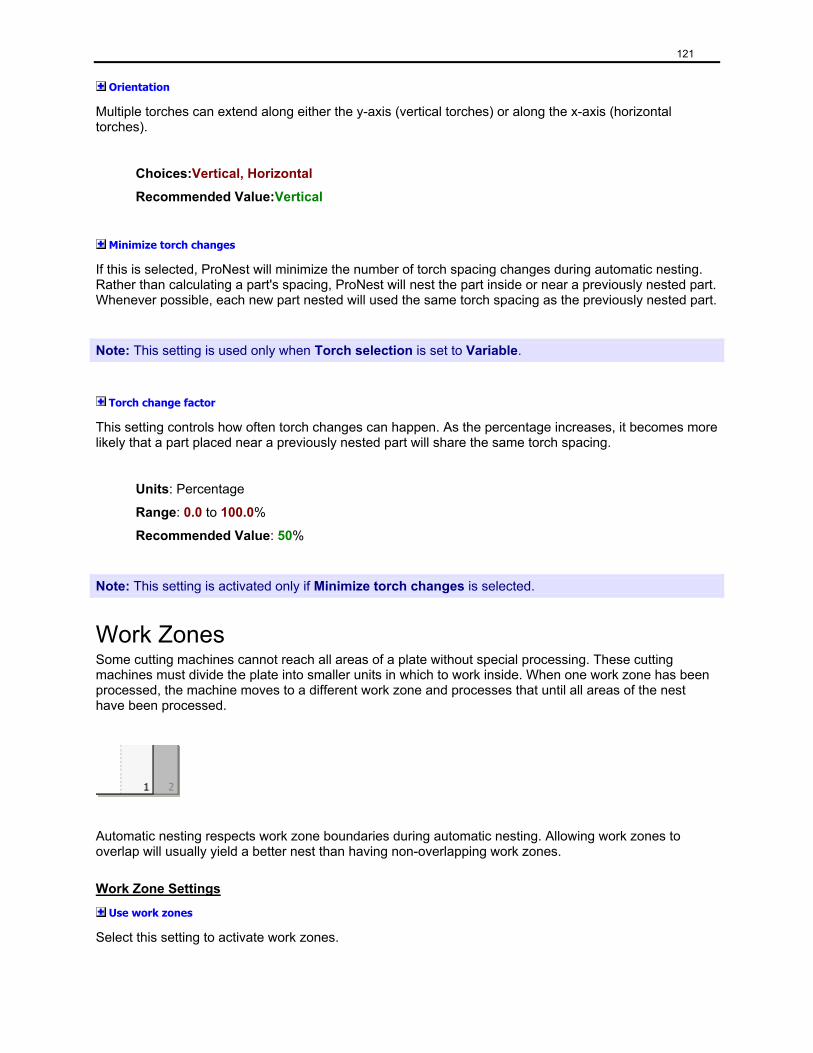
121
Orientation
Multiple torches can extend along either the y-axis (vertical torches) or along the x-axis (horizontal torches).
Choices:Vertical, Horizontal
Recommended Value:Vertical
Minimize torch changes
If this is selected, ProNest will minimize the number of torch spacing changes during automatic nesting. Rather than calculating a part's spacing, ProNest will nest the part inside or near a previously nested part. Whenever possible, each new part nested will used the same torch spacing as the previously nested part.
Note: This setting is used only when Torch selection is set to Variable.
Torch change factor
This setting controls how often torch changes can happen. As the percentage increases, it becomes more likely that a part placed near a previously nested part will share the same torch spacing.
Units: Percentage
Range: 0.0 to 100.0%
Recommended Value: 50%
Note: This setting is activated only if Minimize torch changes is selected.
Work Zones Some cutting machines cannot reach all areas of a plate without special processing. These cutting machines must divide the plate into smaller units in which to work inside. When one work zone has been processed, the machine moves to a different work zone and processes that until all areas of the nest have been processed.
Automatic nesting respects work zone boundaries during automatic nesting. Allowing work zones to overlap will usually yield a better nest than having non-overlapping work zones.
Work Zone Settings
Use work zones
Select this setting to activate work zones.
122
Layout
This setting defines the type of work zones that this machine supports.
Choices:Horizontal repositions, Vertical repositions, Reposition in both directions
Horizontal repositions (along x-axis)
Select this setting to use work zones that subdivide the length of the plate into multiple work zones.
Vertical repositions (along y-axis) [Not available]
Select this setting to use work zones that subdivide the width of the plate into multiple work zones.
Reposition in both directions [Not available]
Select this setting to use work zones that subdivide both the length and width of the plate into work zones.
Work zone length
Length (along the x-axis) of each work zone. This represents the size of the working area available to the controller at any given time.
Units: Distance
Range:0.1 to 10000.0 in.
Work zone width
Width (along the y-axis) of each work zone.
Units: Distance
Range:0.1 to 10000.0 in.
Note: This setting is intended to work with the Vertical reposition layout - which is not available.
123
Horizontal reposition distance
Represents the horizontal distance a machine needs to shift to move from one work zone to the next.
Units: Distance
Range:0.1 to 10000.0 in.
Examples:
• If this setting has the same value as Work zone length, then the work zones will not overlap.
• If this setting has a value less than Work zone length, the work zones will overlap.
• If this setting has a value greater than Work zone length, unreachable gaps will be created between consecutive work zones.
Vertical reposition distance
Represents the vertical distance a machine needs to shift to move from one work zone to the next.
Units: Distance
Range:0.1 to 10000.0 in.
Examples:
• If this setting has the same value as Work zone width, then the work zones will not overlap.
• If this setting has a value less than Work zone width, the work zones will overlap.
• If this setting has a value greater than Work zone width, unreachable gaps will be created between consecutive work zones.
Note: This setting is intended to work with the Vertical reposition layout - which is not available.
124
Maximum repositions
This setting limits the number of work zones for any given nest.
Range:0 to 10000
Tip: Set Maximum repositions to 0 to allow an unlimited number of repositions.
Allow forward and backward repositions
Select this setting if your cutting machine can reposition both forward and backwards along the same axis. Clear this setting if your machine can only reposition in one direction.
Effect of "Allow forward and backward repositions" on the active cut sequence rule:
When this setting is selected, the active cut sequence rule will be completed such that:
1. All tasks in Step 1 will be completed as the machine repositions from the first work zone to the last (repositioning in the "positive" direction).
2. Any tasks in Step 2 would then be completed as the machine repositions from the last work zone to the first (repositioning in the "negative" direction).
3. Any tasks in Step 3 would then be completed in the "positive" direction - like Step 1.
4. etc..
When this setting is cleared, each step in the active cut sequence rule will be completed such that:
1. All tasks in Step 1 will be completed as the machine repositions from the first work zone to the last (repositioning in the "positive" direction).
2. When all tasks in Step 1 is complete, the machine will reposition to the first work zone.
3. Any tasks in Step 2 would then be completed in the "positive" direction.
4. etc...
For more information about cut sequence steps and tasks, see "Cut Sequence Rules."
125
Nesting General Settings
Nest resolution
This setting controls many aspects of nesting (positioning parts, conflict checking, ...) because it specifies how accurate you want ProNest to be. There is a trade-off between accuracy and speed. Smaller nest resolutions can result in tighter nests and better conflict checking but will cause most operations to run slower.
Units: Distance
Range:0.01 to 1.0 in.
Recommended Value:0.1 in.
Init point
This setting represents the desired point of origin or home position. The location specified can be interpreted as coordinate (0, 0) and will be displayed in the nesting area with a plus symbol.
Choices:Lower Left, Upper Left, Upper Right, Lower Right
Ignore part lead-in/lead-out
If this is selected, ProNest will ignore leads when determining part separation. This allows ProNest to create a tighter nest but will most likely require movement of the leads to new locations where they avoid neighboring profiles.
Reverse cut direction on mirror
When a part is mirrored on the nest (either manually or by automatic nesting) one of two things can happen to the cut direction:
1. The cut direction can remain the same. This means that clockwise cuts will remain clockwise. Clear this check box to maintain the same cut direction during mirror operations.
2. The cut direction will reverse. This means that clockwise cuts will change to counter-clockwise cuts. Kerf is adjusted accordingly. Select this check box to reverse the cut direction during mirror operations.
Interactive (Manual) Nesting
Parts can be manually nested in two different ways:
1. Parts can be dragged from the Part List toolbar onto the nest.
2. Using AutoDrop, parts in the Part List toolbar can be added to the nest in the same relative spot. This type of manual nesting is most useful when used together with AutoBump.
To AutoDrop a part onto the nest:
• Double-click a part in the Part List toolbar
• Select a part in the Part List toolbar and press ENTER.
126
AutoDrop zone
Defines the area of the nest where AutoDrop will place parts.
Choices:Upper Left, Upper Right, Center, Lower Left, Lower Right
AutoBump is a manual nesting feature that is performed when a part is manually added to a nest. It happens after a part is dragged onto the nest from the Part List toolbar or after an AutoDrop. The AutoBump settings define up to two bump directions that are applied in order. The result is exactly the same as nesting a part manually and then using the bump handles to 'simulate' an AutoBump.
Use AutoBump
Select this check box to use AutoBump during manual nesting.
AutoBump direction #1
This is the first direction a part is bumped during AutoBump.
Choices:Up, Down, Left, Right, (None)
AutoBump direction #2
This is the second direction a part is bumped during AutoBump.
Choices:Up, Down, Left, Right, (None)
Example:
To manually nest parts along the bottom of the nest:
• In the AutoDrop zone box select Upper Right.
• Select the Use AutoBump check box.
• In the AutoBump direction #1 box, select Down.
• In the AutoBump direction #2 box, select Left.
The effect of these setting is that parts added manually to a nest will be bumped towards the lower-left corner. When a part is dragged onto the nest, the AutoBump settings will bump the part down and then left from the location where the part was dropped. After an AutoDrop (like when a part in the Part List toolbar is double-clicked) the part will first be placed in the AutoDrop zone. Then, the part will be bumped down and left.
127
Nudge distance
This setting defines the distance a part moves when it is nudged.
Units: Distance
Range:0.0 to 10,000.0 in.
Recommended Value:0.1 in.
To nudge a selected part:
• Hold the SHIFT key and click one of the bump handles ( ).
OR
• Hold the SHIFT key and press one of the arrow keys.
Increment angle
This setting defines the amount of rotation applied to a part selection when either the Increment Angle or Decrement Angle buttons are clicked.
Units: Degrees
Range:0 to 360°
Recommended Value:180°
To rotate a part selection by the "Increment angle":
• Click Increment Angle . This will rotate the part counter-clockwise.
• Click Decrement Angle . This will rotate the part clockwise.
• Click the upper-left rotate handle . This will rotate the part counter-clockwise.
AutoNest Pattern Array Settings
Default pattern array strategy
When ProNest is started, Pattern Array will use this strategy until a different strategy is selected. All strategies use several techniques to calculate an optimal pattern of the selected part or group (including spacing and orientation). Once the optimal pattern is calculated, ProNest arrays the parts using that pattern.
Choices: Basic, Intermediate, Advanced
The difference between these three choices is speed and utilization. The Basic strategy will be much faster than the Advanced strategy, but it will not attempt nearly as many part orientations. In many cases, the Advanced strategy will find a tighter pattern than the Basic strategy.
128
Advanced: Each of these strategies is defined by a group of settings. To edit these strategies, open the Pattern Array Strategies dialog by clicking on the Edit Strategies button in the "Pattern Array Settings" section.
AutoNest Settings
Straight edge ratio
This is used in estimating the area needed on the last plate of a nest, which tries to create a straight edge of parts for cropping. The higher the estimated utilization, the higher the number. (i.e., Rectangles nest easily and neatly, therefore the straight edge factor would be higher than a nest of odd shaped parts.
Units: Percentage (%)
Range: 50 to 100%
Recommended Value: 100%
Begin nesting on
When ProNest is first started, this value will be used when AutoNest is run. The AutoNest Setup dialog will use this value as its default for 'Begin nesting on'.
Choices: First Nest, Current Nest, New Nest
When AutoNest is run, ProNest can start in three places:
First Nest means that ProNest will try to fill on all existing nests (starting with Nest 1) before it creates new nests.
Current Nest means that ProNest will try to fill on all existing nest (starting with the current/visible) nest before it creates new nests.
New Nest means that ProNest will not fill on any existing nests before it starts to create new nests.
129
Strategy
When ProNest is first started, this value will be used when AutoNest is run. The AutoNest Setup dialog will use this value as its default for 'Strategy'.
Choices: The choices presented depend on your authorized options
Strategies available: Rectangular
Rectangular nesting is a nesting strategy where ProNest places an imaginary rectangular border around each part. The parts are then nested in such a way that no part overlaps into the rectangular border of another part.
To create a nest, ProNest simply nests the parts one at a time, in the order they appear in the Part List toolbar.
Note: This choice is available only if you have the Rectangular Nesting option.
Rectangular Optimization
Rectangular optimization uses the same rules as Block nesting for placing parts. The strategy, however, is more complicated and time consuming.
To create a nest, this strategy tries to determine which parts fit together best. Parts that fit together into efficient units (kits) are remembered and used several times. During this strategy, ProNest also looks ahead a few steps for each nested part - to determine if each placement is truly optimal.
Note: This choice is available only if you have the Optimized Rectangular Nesting option.
Strategy 1-10
Strategy 1-10 are all very similar. They are different from Block nesting in that they use the part's true shape when determining where to place it - instead of using the part's rectangular region. This means that parts can be nested closer together, interlocked with other parts, or be placed inside other parts.
Each of these strategies employs different rules when nesting parts. Some will try fewer part orientations and others will attempt some of the arraying algorithms (pattern array, CLC array). As a strategy tries more possibilities the time needed to create a nest increases.
Note: This choice is available only if you have the True Shape Nesting option.
Advanced: Each of these strategies (except Rectangular) is defined by a group of settings. To edit these strategies, open the AutoNest Strategies dialog by clicking on the Edit Strategies button in the "AutoNest Settings" section.
130
Cut each nest the maximum number of times
If this is checked, ProNest will generate a nest and then calculate how many times that nest can be cut with the parts that remain.
Moving Leads (AutoNest and Pattern Array)
Strategy
While parts are nested during automatic nesting or during pattern array, leads will be moved on each nested part to the location specified by this setting.
Choices: Upper Left, Upper Right, Lower Right, Lower Left, Top, Right, Bottom, Left
Note: This setting only applies to parts that have their Allow leads to move property selected.
Automatically move leads
If this is selected, ProNest will move each part’s leads to the relative location specified by the Moving Leads Strategy setting.
Note: This setting only applies to parts that have their Allow leads to move property selected.
Move interior leads
If this is checked, ProNest will move interior leads according to the same rules it uses for exterior leads. Otherwise, interior leads are left alone.
Pattern Array Strategies The Pattern Array Strategies dialog allows you to modify each of the three available strategies: Basic, Intermediate, and Advanced.
To open the Pattern Array Strategies dialog:
1. Go to the AutoNest settings page.
2. Click the Edit Strategies button in the Pattern Array Settings section.
At the top of the dialog is a combo box that displays the current pattern array strategy.
To edit the settings for a particular pattern array strategy:
• In the Strategy box, select either Basic, Intermediate, or Advanced.
<Strategy> Settings
Note: The section name will change to match the current pattern array strategy. If Intermediate is selected, then the section would read "Intermediate Settings".
131
Cluster building technique
This setting allows you to choose how good of a pattern you want created. The Basic technique builds a pattern in the least amount of time. Advanced often takes longer, but usually produces a tighter pattern.
Choices:Basic, Intermediate, Advanced
Basic
A good technique for simple parts like rectangles.
Intermediate
This technique does everything Basic does, plus it will try to optimize the size of the pattern. It will also try to build a "three part" cluster.
Advanced
This technique works best for complicated parts. It does everything Intermediate does, but uses more attempts to create a tighter cluster.
Pattern rotation increment
This is the angle by which to rotate the part before attempting to create the pattern. With a smaller angle, more patterns are attempted, which increases the time needed to find a good pattern.
Units: Degrees
Range:0 to 90°
Tip: For circular and rectangular parts, a value of 90° usually suffices, although 45° can help depending on lead placement. For other parts, 45° is a generally a good value. Sometimes a value of 15° or even 5° can result in significantly better patterns.
Cluster resolution (% of nest resolution)
This setting represents the percentage of the nest resolution to use when creating the pattern. Smaller values will create tighter patterns, but will take longer to create. Values over 100% represent resolutions greater than the nest resolution.
Units: Percentage
Range:20 to 500%
Try extra row
If this check box is selected, an attempt will be made to squeeze an extra row in the pattern. This will increase the time required to generate the pattern.
132
Try extra column
If this check box is selected, an attempt will be made to squeeze an extra column in the pattern. This will increase the time required to generate the pattern.
Fill unused regions with new pattern
If this check box is selected, ProNest will try to create the optimal combination of two patterns, either side by side or one above the other.
AutoNest Strategies When the Edit Strategies button in the AutoNest Settings section of the AutoNest page is clicked, the AutoNest Strategies dialog will appear. This dialog allows you to edit the settings that define the behavior of each strategy.
On the left-hand side of the AutoNest Strategies dialog is the list of available strategies. If you have purchased the Rectangular Optimization module, it will appear at the top of this list. If you have purchased the True Shape module, then there will be ten strategies called "Strategy 1" through "Strategy 10".
To edit the settings for a strategy:
• Select the strategy on the left that you want to edit.
On the right, the settings for that strategy will appear.
For more information about editing Rectangular Optimization settings, see "AutoNest Strategies - Rectangular Optimization".
For more information about editing all other strategies, see "AutoNest Strategies - True Shape".
Renaming strategies
All of the strategies (with the exception of Rectangular Optimization) can be named to whatever you want.
To rename a strategy:
1. In the list on the left-hand side, select a strategy to rename.
2. After the strategy is selected, click on its name.
The name of the strategy will become surrounded by an edit box - indicating that you can change it.
3. Type the new name for the strategy and press ENTER.
Tip: You can also right-click a strategy name to rename it. When you do, select Rename and then provide the new name for the strategy.
133
Saving and discarding changes
All changes made to settings in the AutoNest Strategies dialog are temporary. This includes changing strategy names.
To accept your changes:
• Exit the dialog by clicking OK.
To discard your changes:
• Exit the dialog by clicking Cancel.
AutoNest Strategies - Rectangular Optimization Rectangular optimization is best used with parts that are rectangular in shape.
General
Cutoff nest utilization
The percentage of the plate that must be used before rectangular optimization is done. The first time a configuration of parts meets or exceeds this value, the nest is considered done. Having a high value leads to nests with high utilization, but they can take longer to produce. Having a low value finishes each nest quickly, but the nests tend to have lower utilizations.
Units: Percentage
Range:0 to 100%
Recommended Value:95%
Stack cutoff utilization
The percentage of the region of each individual horizontal or vertical stack of rectangularly optimized clusters that must be occupied by parts before that stack will be chosen.
Units: Percentage
Range:0 to 100%
Recommended Value:90%
Cutoff time
This is the amount of time spent trying to nest multiple part combinations. Once this time limit is reached, multiple part combinations are "deactivated" and only single part combinations (i.e. the parts in the part bin) are considered. The larger the value, the longer each nest will take but it will result in better nests in some cases.
Units: Time (seconds)
Range:0 to 60s
Recommended Value:2s
134
Look ahead
Number of recursive levels in which to try rectangular optimization within the original available region. The larger this number, the more trials are attempted and the tighter the resulting nest.
Range:0 to 99
Recommended Value:99
Part fit ratio
The minimum percentage of a part’s bounding rectangle that must be filled by the exterior profile of the part for the part to be considered rectangular. The higher this number, the fewer parts will qualify as rectangular, but the nests will have much higher utilizations. Low values for this setting will cause more parts to be used for rectangular optimization, but the resulting nests will have much lower utilizations.
Units: Percentage
Range:50 to 100%
Recommended Value:90%
Build vertical stacks
If this check box is selected when a rectangular cluster is placed, ProNest will try to rectangularly optimize in the region directly above it.
Build horizontal stacks
If this check box is selected when a rectangular cluster is placed, ProNest will try to rectangularly optimize in the region directly to the side of it.
Combinations
Maximum parts per combination
The maximum number of parts that ProNest will include in each combination it builds for rectangular optimization.
Range:0 to 99
Recommended Value:6 - 10
Maximum combinations
This setting is the maximum number of combinations that will be created when creating candidate rectangular clusters for rectangular optimization.
Range:0 to 1000
Recommended Value:500
135
Maximum combination utilization
This setting is the minimum percentage that a rectangular cluster must occupy of its bounding rectangle for it to be kept as a viable candidate for rectangular optimization.
Units: Percentage
Range:0 to 100%
Recommended Value:90%
AutoNest Strategies - True Shape Nesting direction
This section contains two options: Vertical or Horizontal.
Vertical
Nesting will give preference to filling the plate from top to bottom before extending the nest horizontally. In general, this nesting direction will work towards completing the nest in such a way that it can be finished with a vertical crop.
Horizontal
Nesting will give preference to filling the plate from side to side first before extending the nest vertically. In general, this nesting direction will work towards completing the nest in such a way that it can be finished with a horizontal crop.
Nesting approaches
Rectangular Optimization
Select this check box if rectangular optimization should be attempted during automatic nesting.
Pattern Array
Select this check box if pattern array should be used during automatic nesting.
Pattern Array strategy
The name of the pattern array strategy used during automatic nesting will appear to the right of the Pattern Array check box.
Choices:Basic, Intermediate, Advanced
To edit the strategy used:
1. Click on the name of the strategy (its a hyperlink).
2. Select the strategy you want from the list.
Note: This setting is active only if Pattern Array is selected.
136
Fill using Pattern Array
Select this check box if ProNest should attempt to fill unused regions of the plate with pattern arrays during automatic nesting.
Note: This setting is active only if Pattern Array is selected.
CLC Array
Select this check box if CLC array should be used during automatic nesting.
Fill using CLC Array
Select this check box if ProNest should attempt to fill unused regions of the plate with CLC arrays during automatic nesting.
Note: This setting is active only if CLC Array is selected.
Profile Nesting Options
Maximum part orientations to try
This slider controls the maximum number of rotations to try when placing each part. Some parts, like rectangles, don't require many orientations to try and find a good fit on the nest. They can be nested well using Level 1 - with only 90° rotations. Some other parts may need more orientations tried before a good fit can be found. As the levels increase (by moving the slider down), more orientations are tried for each part before moving on. While this can improve the utilization on the nest, it will increase the time needed to place each part.
Choices:Level 1 - 7
Note: As each level is selected, the description to the right of the slider will change.
Try orientations in groups of <value>
The number of orientations to try when placing a part during automatic nesting for each attempted rotation angle.
Choices:Two, Four
Two
Two orientations for each rotation angle will be tried (the chosen orientation and the chosen orientation + 180 degrees).
Four
Four orientations for each rotation angle will be tried (the chosen orientation, plus the chosen orientation rotated 90, 180, and 270 degrees).

137
Rotate to minimize part area
Select this setting if the parts should be rotated to minimize their bounding rectangles before they are nested.
Tight fit
Select this check box if ProNest should try to "wiggle" parts after they've been nested to get them to fit tighter. This often results in a better nest, but it does take more time.
Advanced Common Line Cut
Select this check box if common line cut parts should be built as the parts are nested.
Important: This setting is independent of the CLC Array setting.
The following settings are in a group called Fit Evaluation:
Part interlock
Every newly nested part interlocks with existing parts on the nest. Sometimes, the amount of interlock is zero - meaning that the new part doesn't really interlock with existing parts. Select this check box to use the amount part interlock as a measure of how good the fit is.
Nest interlock
Every newly nested part interlocks with the region of the nest that already contains nested parts. Sometimes, the amount of interlock is zero - meaning that the new part doesn't really interlock with existing region of nested parts. Select this check box to use the amount nest interlock as a measure of how good the fit is.
Plate usage
Nesting a part will sometimes extend the region of already nested parts by some distance along the X axis. The region of nested parts will "grow". Select this check box to use this distance as a measure of how good the fit is.
138
Optimization Optimized nesting tries one or more nesting strategies with one or more plate sizes to find the best plate and strategy for the parts remaining in the part list at any given time. The user has full control over the sheet selection methodology and the nesting strategies to use, as well as whether or not costing factors are included when determining the best nesting result.
Optimization Settings
Plate selection criteria
Algorithm to use when selecting plates to use for each nesting trial.
Choices:(None), Select One Plate Size, Select Best Plate For Each Nest
(None) - Plates will be nested in order. The first plate in the plate list will be optimized first, then the second plate, and so on.
Select One Plate Size - All nests created during optimization will be created from a single plate size.
Select Best Plate For Each Nest - All nesting trials will be performed on all plates in the plate list. The best result will be chosen, then nesting trials with the remaining parts will be performed on the remaining plates and the best result chosen, etc.
Cut-off utilization
When a nesting trial produces a nested utilization equal to or greater than this value, that result is automatically chosen. If no nesting trials exceed this value, then the best overall utilization is chosen.
Units: Percentage (%)
Range: 0 to 100%
Recommended Value: 95%
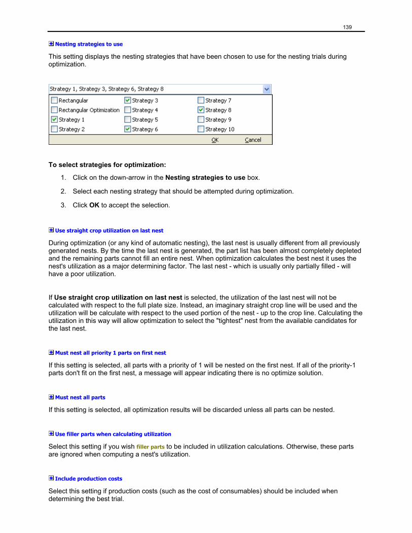
139
Nesting strategies to use
This setting displays the nesting strategies that have been chosen to use for the nesting trials during optimization.
To select strategies for optimization:
1. Click on the down-arrow in the Nesting strategies to use box.
2. Select each nesting strategy that should be attempted during optimization.
3. Click OK to accept the selection.
Use straight crop utilization on last nest
During optimization (or any kind of automatic nesting), the last nest is usually different from all previously generated nests. By the time the last nest is generated, the part list has been almost completely depleted and the remaining parts cannot fill an entire nest. When optimization calculates the best nest it uses the nest's utilization as a major determining factor. The last nest - which is usually only partially filled - will have a poor utilization.
If Use straight crop utilization on last nest is selected, the utilization of the last nest will not be calculated with respect to the full plate size. Instead, an imaginary straight crop line will be used and the utilization will be calculate with respect to the used portion of the nest - up to the crop line. Calculating the utilization in this way will allow optimization to select the "tightest" nest from the available candidates for the last nest.
Must nest all priority 1 parts on first nest
If this setting is selected, all parts with a priority of 1 will be nested on the first nest. If all of the priority-1 parts don't fit on the first nest, a message will appear indicating there is no optimize solution.
Must nest all parts
If this setting is selected, all optimization results will be discarded unless all parts can be nested.
Use filler parts when calculating utilization
Select this setting if you wish filler parts to be included in utilization calculations. Otherwise, these parts are ignored when computing a nest's utilization.
Include production costs
Select this setting if production costs (such as the cost of consumables) should be included when determining the best trial.
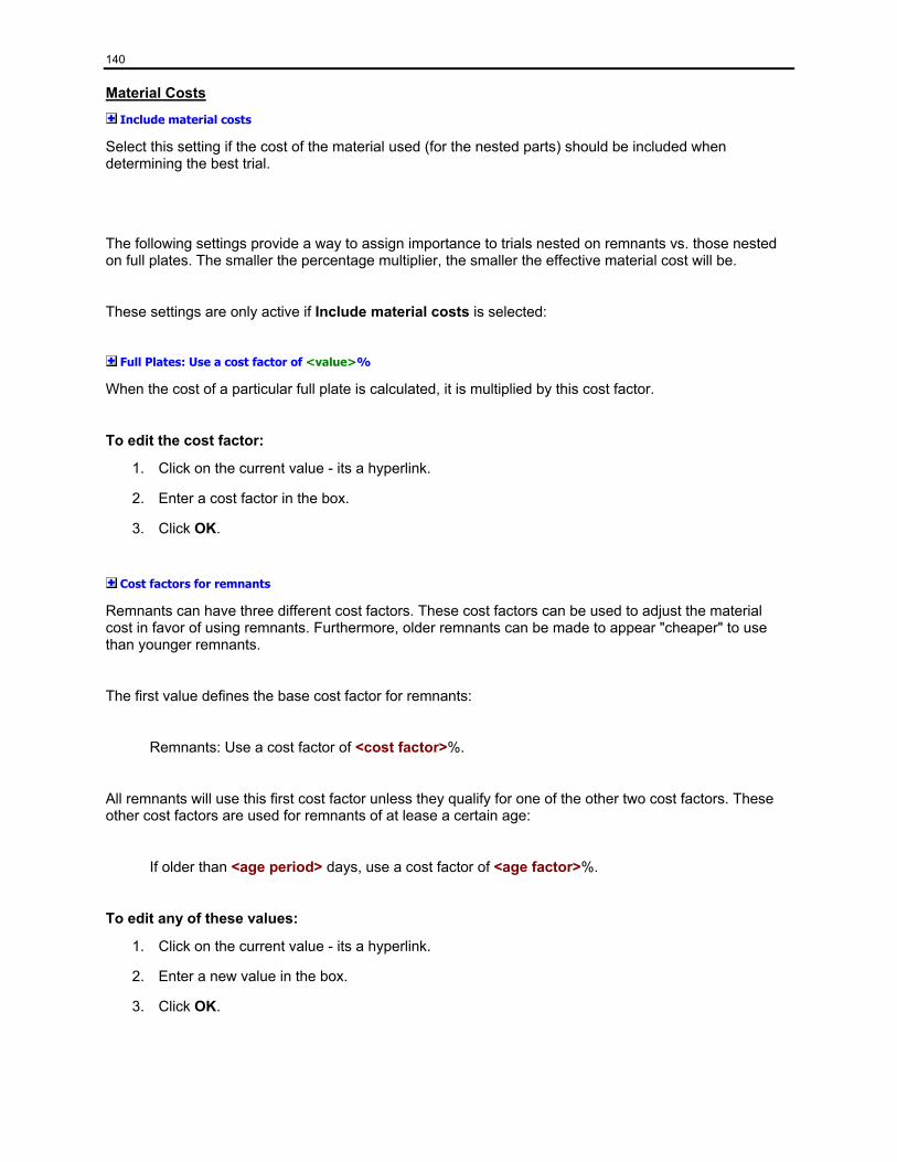
140
Material Costs
Include material costs
Select this setting if the cost of the material used (for the nested parts) should be included when determining the best trial.
The following settings provide a way to assign importance to trials nested on remnants vs. those nested on full plates. The smaller the percentage multiplier, the smaller the effective material cost will be.
These settings are only active if Include material costs is selected:
Full Plates: Use a cost factor of <value>%
When the cost of a particular full plate is calculated, it is multiplied by this cost factor.
To edit the cost factor:
1. Click on the current value - its a hyperlink.
2. Enter a cost factor in the box.
3. Click OK.
Cost factors for remnants
Remnants can have three different cost factors. These cost factors can be used to adjust the material cost in favor of using remnants. Furthermore, older remnants can be made to appear "cheaper" to use than younger remnants.
The first value defines the base cost factor for remnants:
Remnants: Use a cost factor of <cost factor>%.
All remnants will use this first cost factor unless they qualify for one of the other two cost factors. These other cost factors are used for remnants of at lease a certain age:
If older than <age period> days, use a cost factor of <age factor>%.
To edit any of these values:
1. Click on the current value - its a hyperlink.
2. Enter a new value in the box.
3. Click OK.
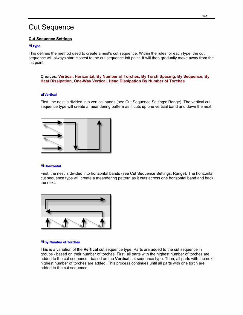
141
Cut Sequence Cut Sequence Settings
Type
This defines the method used to create a nest's cut sequence. Within the rules for each type, the cut sequence will always start closest to the cut sequence init point. It will then gradually move away from the init point.
Choices: Vertical, Horizontal, By Number of Torches, By Torch Spacing, By Sequence, By Heat Dissipation, One-Way Vertical, Head Dissipation By Number of Torches
Vertical
First, the nest is divided into vertical bands (see Cut Sequence Settings: Range). The vertical cut sequence type will create a meandering pattern as it cuts up one vertical band and down the next.
Horizontal
First, the nest is divided into horizontal bands (see Cut Sequence Settings: Range). The horizontal cut sequence type will create a meandering pattern as it cuts across one horizontal band and back the next.
By Number of Torches
This is a variation of the Vertical cut sequence type. Parts are added to the cut sequence in groups - based on their number of torches. First, all parts with the highest number of torches are added to the cut sequence - based on the Vertical cut sequence type. Then, all parts with the next highest number of torches are added. This process continues until all parts with one torch are added to the cut sequence.
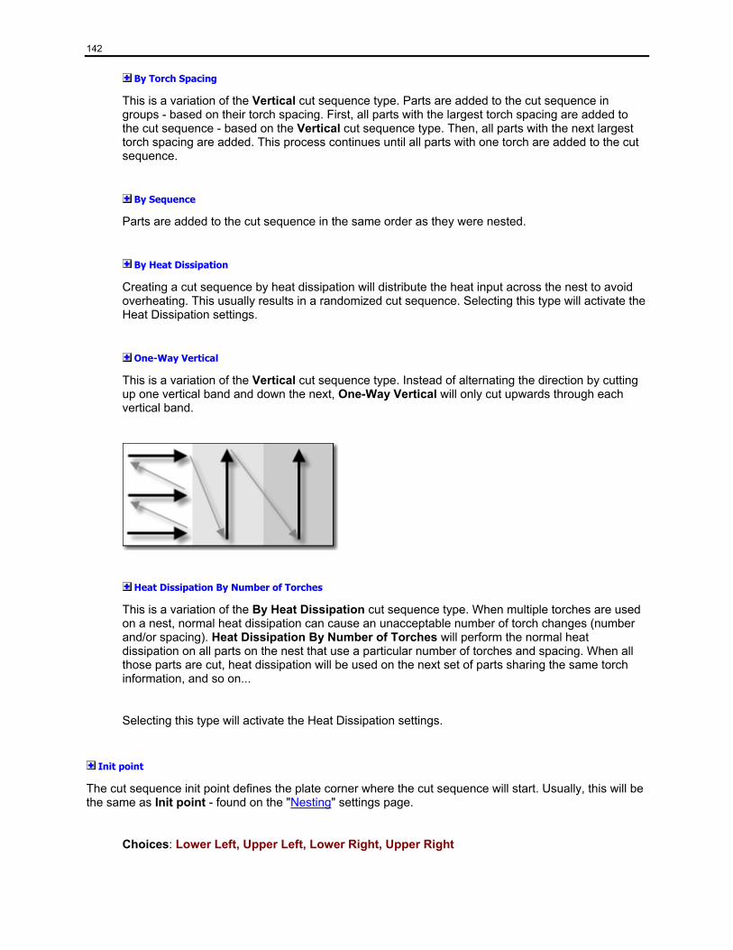
142
By Torch Spacing
This is a variation of the Vertical cut sequence type. Parts are added to the cut sequence in groups - based on their torch spacing. First, all parts with the largest torch spacing are added to the cut sequence - based on the Vertical cut sequence type. Then, all parts with the next largest torch spacing are added. This process continues until all parts with one torch are added to the cut sequence.
By Sequence
Parts are added to the cut sequence in the same order as they were nested.
By Heat Dissipation
Creating a cut sequence by heat dissipation will distribute the heat input across the nest to avoid overheating. This usually results in a randomized cut sequence. Selecting this type will activate the Heat Dissipation settings.
One-Way Vertical
This is a variation of the Vertical cut sequence type. Instead of alternating the direction by cutting up one vertical band and down the next, One-Way Vertical will only cut upwards through each vertical band.
Heat Dissipation By Number of Torches
This is a variation of the By Heat Dissipation cut sequence type. When multiple torches are used on a nest, normal heat dissipation can cause an unacceptable number of torch changes (number and/or spacing). Heat Dissipation By Number of Torches will perform the normal heat dissipation on all parts on the nest that use a particular number of torches and spacing. When all those parts are cut, heat dissipation will be used on the next set of parts sharing the same torch information, and so on...
Selecting this type will activate the Heat Dissipation settings.
Init point
The cut sequence init point defines the plate corner where the cut sequence will start. Usually, this will be the same as Init point - found on the "Nesting" settings page.
Choices: Lower Left, Upper Left, Lower Right, Upper Right
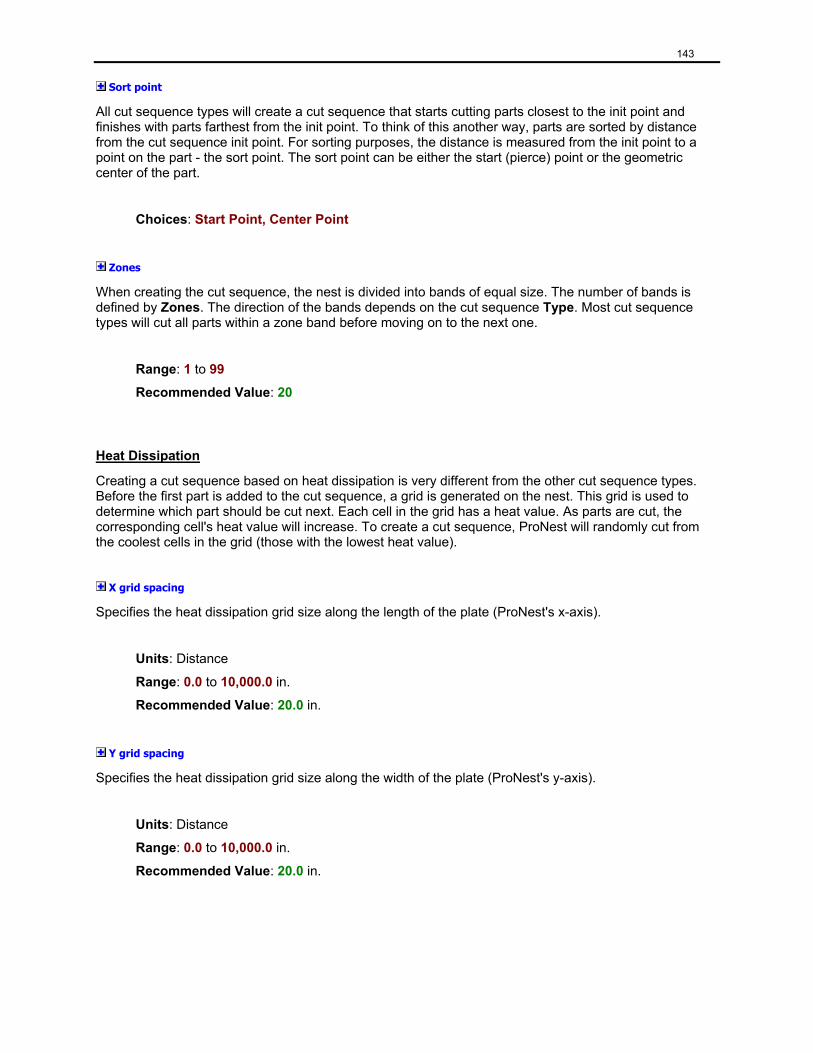
143
Sort point
All cut sequence types will create a cut sequence that starts cutting parts closest to the init point and finishes with parts farthest from the init point. To think of this another way, parts are sorted by distance from the cut sequence init point. For sorting purposes, the distance is measured from the init point to a point on the part - the sort point. The sort point can be either the start (pierce) point or the geometric center of the part.
Choices: Start Point, Center Point
Zones
When creating the cut sequence, the nest is divided into bands of equal size. The number of bands is defined by Zones. The direction of the bands depends on the cut sequence Type. Most cut sequence types will cut all parts within a zone band before moving on to the next one.
Range: 1 to 99
Recommended Value: 20
Heat Dissipation
Creating a cut sequence based on heat dissipation is very different from the other cut sequence types. Before the first part is added to the cut sequence, a grid is generated on the nest. This grid is used to determine which part should be cut next. Each cell in the grid has a heat value. As parts are cut, the corresponding cell's heat value will increase. To create a cut sequence, ProNest will randomly cut from the coolest cells in the grid (those with the lowest heat value).
X grid spacing
Specifies the heat dissipation grid size along the length of the plate (ProNest's x-axis).
Units: Distance
Range: 0.0 to 10,000.0 in.
Recommended Value: 20.0 in.
Y grid spacing
Specifies the heat dissipation grid size along the width of the plate (ProNest's y-axis).
Units: Distance
Range: 0.0 to 10,000.0 in.
Recommended Value: 20.0 in.
144
Minimum distance
Whenever possible, the next part added to the cut sequence will be at least this distance away from the current part.
Units: Distance
Range: 0.0 to 10,000.0 in.
Recommended Value: 0.0 in.
Note: Heat Dissipation settings are usually inactive. To activate them, you must set Type to one of the heat dissipation choices.
Cut Sequence - Interior Profile Interior Profile Sequencing
Interior profile sequencing sequences interior profiles, including scribes, punches, cuts, and text marking.
The sequence of interior profiles is calculated when:
• a CAD file is loaded.
• parts are bridged or chained together.
• parts are common line cut with one another.
• profiles are reordered for collision avoidance.
Important: Once the interior profiles of a part are sequenced, they are never re-sequenced unless one of the above events occurs. This means that changes to the Interior Profile settings will not have any immediate effect on any nests in the job.
145
Type
This defines the method used to create a part's interior cut sequence.
Choices:(None), Vertical, Horizontal, Closest to Init Point, Closest to Center, Closest to Sort Point, By Heat Dissipation
Recommended Value:Vertical
(None) - The existing sequence for interior profiles is not recalculated.
Vertical - Interior profiles will be sequenced in a generally upward (or downward) direction.
Horizontal - Interior profiles will be sequenced in a generally left to right (or right to left) direction.
Closest to Init Point - Profiles are sequenced in the order of their distance from the chosen cut sequence Init point (found on the "Cut Sequence" settings page). They are ordered from closest to farthest.
Closest to Center - The next profile to be sequenced will be the one whose center point is closest to the center point of the current profile.
Closest to Sort Point - The next profile to be sequenced will be the one whose start point is closest to the end point of the current profile.
By Heat Dissipation - An algorithm which seeks to limit the amount of heat generated in any particular zone will be used to sequence the profiles.
Origin
The origin setting allows the user to specify the location on the part's bounding rectangle from which to start sequencing. The first profile sequenced will typically be the one closest to this origin point using the appropriate measure for the particular type of sequencing chosen.
Choices: Lower Left, Upper Left, Lower Right, Upper Right, Left, Top, Right, Bottom
Recommended Value:Same as Init Point from the Cut Sequence page
Note: This setting is active only when Type is set to something other than "(None)".
146
Zones
The number of zones represents the number of horizontal or vertical bands that will be used to sequence the interior profiles. In general, sequencing starts in the first zone and profiles are sequenced as they get generally farther away from the applicable edge containing the origin point. Once all profiles in that zone have been sequenced, the profiles in the next zone are sequenced in the other direction (so that they are getting closer to the edge containing the origin point). Sequencing continues, alternating sequence direction in subsequent zones until all zones have been sequenced.
Range: 1 to 99
Recommended Value: 10
Note: This setting is active only when Type is set to "Vertical" or "Horizontal".
Heat Dissipation
Creating a cut sequence based on heat dissipation is very different from the other cut sequence types. Before the first interior profile is added to the cut sequence, a grid is generated on the part. This grid is used to determine which interior profile should be cut next. Each cell in the grid has a heat value. As interior profiles are cut, the corresponding cell's heat value will increase. To create a cut sequence, ProNest will randomly cut from the coolest cells in the grid (those with the lowest heat value).
Note: The Heat Dissipation settings are active only when Type is set to "By Heat Dissipation".
X grid spacing
Specifies the heat dissipation grid size along the length of the part (ProNest's x-axis).
Units: Distance
Range: 0.0 to 10,000.0 in.
Recommended Value: 24.0 in.
Y grid spacing
Specifies the heat dissipation grid size along the width of the part (ProNest's y-axis).
Units: Distance
Range: 0.0 to 10,000.0 in.
Recommended Value: 12.0 in.
Minimum distance
Whenever possible, the next interior profile added to the cut sequence will be at least this distance away from the current interior profile.
Units: Distance
Range: 0.0 to 10,000.0 in.
Recommended Value: 0.0 in.
147
Cut Sequence Rules This settings page displays all the cut sequence rule that are available for the current machine.
Available Rules
The list of available rules is at the top of this page. The first rule is always called "Use settings instead of rules". By default, this is the only rule in the list.
Use settings instead of rules By default, this is the Active Rule. The active rule is marked with a . When this rule is selected, the bottom-half of the settings page displays a section called Cut Sequence Settings. This section contains all the normal settings that help control the cut sequence when a true cut sequence rule is not in use. They are displayed here as "repeated" settings, as each of them already exists on another settings page.
The following settings are displayed in the Cut Sequence Settings section:
From the CNC Output page: Punch/Scribe first
Order punches by process
Order scribes by process
Order cuts by process
Ignore for output
From the CNC Output - Pre-pierces page: Pre-pierce by part
From the Skeleton Cut Up - Cut Sequence page: Skeleton Cut Up - Cut sequence order
While you can edit these repeated setting on this page, you can also jump to the settings page that they belong to.
To jump to a settings page that contains a particular setting:
• Click on the Settings button to the right of the setting in question.
Creating and using true cut sequence rules True cut sequence rule are far more flexible than using the regular settings. For a full explanation of how a cut sequence rule is built and how it works, see "Editing a cut sequence rule".
There are two ways to create a new rule.
Method 1:
1. While Use settings instead of rules is selected, click Convert this to a Rule. This button is found in the section header titled: "Cut Sequence Settings".
2. Type a name for your rule in the box and click OK.
148
Method 2:
1. Click Add.
This will open the New Rule dialog.
2. Edit your rule and click OK.
Method 1 is the easiest way to create a rule if you are creating your first cut sequence rule. This method will use your existing settings to create a rule that will work the same as if you keep Use settings instead of rules as your Active Rule.
To make any rule the Active Rule:
1. In the list, select the rule you want to be active.
2. Click Set as Active Rule.
Note: When a true cut sequence rule is selected, the bottom-half of the settings page shows a view of the rule. This view matches exactly with the view you see when editing the rule. For a full explanation of how to read and understand a cut sequence rule, see "Editing a cut sequence rule".
Editing a cut sequence rule As you edit a cut sequence rule, you will be using the New Rule / Edit Rule dialog.
At the top of the dialog is a view of the rule. This view is the same as in the Cut Sequence Rules setting page, only this one is editable. At the bottom of this dialog are two lists of actions. On the left is Unsequenced actions. On the right is a list of actions that are assigned to the selected task in the view above.
The anatomy of a cut sequence rule
Cut sequence rules are built on actions. These actions are grouped into tasks. And finally, if you are using Work Zones, tasks are grouped into steps. Most of the time, a machine will not support cut sequence steps.
Actions For the purposes of cut sequencing, an action refers to a specific profile type that can be completed by a single machine process.
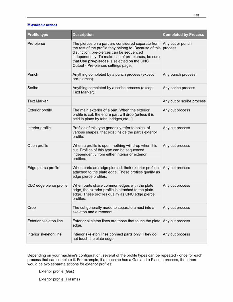
149
Available actions
Profile type Description Completed by Process
Pre-pierce The pierces on a part are considered separate from the rest of the profile they belong to. Because of this distinction, pre-pierces can be sequenced independently. To make use of pre-pierces, be sure that Use pre-pierces is selected on the CNC Output - Pre-pierces settings page.
Any cut or punch process
Punch Anything completed by a punch process (except pre-pierces).
Any punch process
Scribe Anything completed by a scribe process (except Text Marker).
Any scribe process
Text Marker Any cut or scribe process
Exterior profile The main exterior of a part. When the exterior profile is cut, the entire part will drop (unless it is held in place by tabs, bridges,etc...).
Any cut process
Interior profile Profiles of this type generally refer to holes, of various shapes, that exist inside the part's exterior profile.
Any cut process
Open profile When a profile is open, nothing will drop when it is cut. Profiles of this type can be sequenced independently from either interior or exterior profiles.
Any cut process
Edge pierce profile When parts are edge pierced, their exterior profile is attached to the plate edge. These profiles qualify as edge pierce profiles.
Any cut process
CLC edge pierce profile When parts share common edges with the plate edge, the exterior profile is attached to the plate edge. These profiles qualify as CNC edge pierce profiles.
Any cut process
Crop The cut generally made to separate a nest into a skeleton and a remnant.
Any cut process
Exterior skeleton line Exterior skeleton lines are those that touch the plate edge.
Any cut process
Interior skeleton line Interior skeleton lines connect parts only. They do not touch the plate edge.
Any cut process
Depending on your machine's configuration, several of the profile types can be repeated - once for each process that can complete it. For example, if a machine has a Gas and a Plasma process, then there would be two separate actions for exterior profiles:
Exterior profile (Gas)
Exterior profile (Plasma)
150
In the above example, you would be able to sequence exteriors cut with gas independent from exteriors cut with plasma.
Tasks For the purposes of cut sequencing, a task refers to a collection of actions. Actions within a task are not ordered in any specific way by the cut sequence rule. Tasks, however, are ordered within the cut sequence rule. If there were three tasks in a rule, for example, then there would be a Task 1, a Task 2, and a Task 3. They would be handled in order until all actions in all the tasks were complete.
For machines that do not use work zones, a cut sequence rule is truly defined by its tasks. If you need an action (or set of actions) to be cut before or after other actions, put them in a task. Then, you can sequence the task however you want. For example, to be sure that interior profiles are cut before exteriors, create a task and assign the interior profile action to that task. Once that is done, the task can be ordered before the task that contains the exterior profile action.
Steps Lastly, we have the steps. Steps are only needed when using work zones. Otherwise, it is sufficient to define a rule only using tasks and actions. A step refers to a collection of tasks. Tasks within a step are processed in a specific order. Also, steps are ordered within the cut sequence rule.
Why steps?
When work zones are used, a nest is generally split into more than one work zone. The machine can then be instructed to reposition from work zone to work zone until everything is cut. Without steps, a machine would have to fully complete the current work zone before repositioning to the next work zone. Sometimes it is useful to complete only certain actions in a work zone, then reposition to the next work zone, and then complete those same actions on the new work zone. After the actions have been completed across the entire nest, the machine can be instructed to make another pass across the nest - only this time, different actions will be processed. Steps allow a nest with repositions to be processed in several passes. For example, the first step in a rule may cut all pre-pierces. Regardless of the actions present in the next step, the machine would be instructed to reposition to all work zones until all pre-pierces are cut. Only then would it move on to any actions in the next step.
Editing the rule (Simple view: Actions and Tasks only)
When you create a new rule, be sure to give it a name.
To name your rule:
• Type a name in the Name box.
When a new rule is started, it will be given one empty task: Task 1. At the bottom-left of the New Rule dialog, you will see a list of unsequenced actions.
At the top, select Task 1. Notice that the name of the list at the bottom-right will change to "Task 1 actions". This list will always show the actions that have been assigned to the task selected above.
151
Adding and removing tasks An important aspect of editing a cut sequence rule is adding, arranging, and removing tasks.
To add new tasks:
• Click Add Task.
A new empty task will be inserted after the selected task.
To arrange tasks:
1. Select a task to move.
2. Click Move Up and the task will move up one place.
OR
2. Click Move Down and the task will move down one place.
To remove a task:
1. Select a task to remove.
2. Click Remove.
Assigning and removing actions The most important aspect of a task is the list of actions it contains.
To assign actions to the selected task:
• Double-click an unsequenced action.
OR
• Select any number of unsequenced actions and click .
To assign all actions to the selected task:
• Click .
Tip: Regardless of the selected task, you can drag any action from either of the bottom lists into the desired task in the rule view at the top. Using this feature, you can select a task that contains an action you want to move. Once selected, you can then drag an action from the list at the bottom-right into the desired task at the top.
152
To remove actions from the selected task:
• Double-click a task action.
OR
• Select any number of task actions and click .
To remove all actions from the selected task:
• Click .
When you are done editing your rule, click OK to save your changes and close the Edit Rule dialog.
Collision Avoidance Optional Feature: This settings page is available as part of the Collision Avoidance option.
Collision Avoidance is intended to eliminate the chance of collisions with existing material which can significantly reduce production time. Avoidance paths are generated by a combination of:
• moving leads
• routing rapid traverses around potential tip-ups
• raising the torch - with a full raise
Note: Not all cutting machines differentiate between a partial raise and a full raise.
The settings on this page allow avoidance paths to be generated automatically before CNC output is generated. You can also edit the avoidance paths directly on the nest.
Collision Avoidance Settings
Enable collision avoidance
Select this setting to enable collision avoidance.
Note: The remaining settings on this page are active only when Enable collision avoidance is selected.
Ignore tabbed profiles
Select this setting if you want to treat tabbed profiles as if they cannot tip up and therefore do not need to be avoided.
Automatically move exterior leads for avoidance
Select this setting if generating avoidance paths should automatically move leads on exterior profiles. By moving leads, it is possible that straight-line paths can be found that do not pass over potential tip-up situations.
153
Automatically move interior leads for avoidance
Select this setting if generating avoidance paths should automatically move leads on interior profiles.
Sequence the interior profiles for an optimal path
Select this setting if generating avoidance paths should re-sequence the interior profiles of each part. Re-sequencing interior profiles may avoid potential collision situations.
Note: The sequencing method used by collision avoidance is specified by the sequencing settings found on the "Cut Sequence - Interior Profile" settings page.
Select this setting if you want collision avoidance to try resequencing the interior profiles of each part. Resequencing profiles may allow for potential torch head collision situations to be avoided. Note that the sequencing method used by collision avoidance is specified by the Profile Sequencing settings on the Cut Sequence page.
Clear this setting if you do not want to resequence profiles during collision avoidance.
Place leads on corners whenever possible
Select this setting if leads should be placed on profile corners rather than on the side. The "zone of acceptability" for placing leads on the corners rather than on the sides is related to the smallest dimension of the profile.
Trim leads if they are placed in conflict
While avoidance paths are generated, leads are moved. Sometimes they can be moved into conflict. Select this setting if ProNest should try shortening the leads to resolve the conflict.
Maximum profile size to avoid
This setting determines the largest profile size that collision avoidance will try to avoid. Collision avoidance will try to avoid any profiles with a length or width smaller than this threshold value. Profiles with lengths and widths greater than this threshold value will not be avoided.
Units: Distance
Range:0.001 to 10000.0 in.
Maximum torch down distance to avoid
This setting represents the maximum length allowable for a torch-down avoidance path. The primary factor in determining a good value for this setting is the average amount of plate warpage present and the relative importance of avoiding tip-ups compared with the speed of cutting. Also keep in mind that an avoidance path may take much longer than a direct full raise path.
Units: Distance
Range:0.001 to 10000.0 in.
154
Maximum number to avoid
This setting determines the maximum number of profiles that should be avoided when traversing between profiles.
Range:0 to 10
Recommended Value:3
Advanced: This setting has a major impact on the time needed to calculate avoidance paths. Smaller values will cause collision avoidance to run much faster than larger values.
Avoidance ratio
This setting is used when determining which type of path is more desirable in a given situation: an avoidance path or a direct full-raise path. A larger avoidance ratio will tend to select a direct full-raise more often than the avoidance path.
Units: Percentage (%)
Range:0 to 100%
Full raise/lower time
This setting represents the average amount of time required to fully retract the cutting head on a full raise and then fully lower the cutting head when it is turned back on.
Units: Time
Range:0.0 to 100.0 s
Partial raise/lower time
This setting represents the average amount of time required to partially retract the torch for a partial raise and then fully lower the torch when it is turned back on.
Units: Time
Range:0.0 to 100.0 s
Torch diameter
This setting represents the diameter of the torch head and is used as a safety margin around profiles when creating avoidance paths. It should be treated as the maximum diameter of the torch head that could collide with a tip-up.
Units: Distance
Range:0.001 to 10.0 in.
155
Snap tolerance
When moving leads for collision avoidance, this setting is used to determine how close to a corner a selected start point has to be before the leads are adjusted to be exactly at that corner. Making this value large makes it more likely that only corner lead locations will be chosen. Making this value small makes it less likely that a corner lead location will be chosen when moving the leads on any particular profile.
Units: Distance
Range:0.0 to 10000.0 in.
Collision Avoidance (Advanced) Optional Feature: This settings page is available as part of the Collision Avoidance option. Your post processor (CFF) must also be configured to handle subroutines.
Advanced Collision Avoidance Settings
Enable collision avoidance
Select this setting to enable collision avoidance. This setting is repeated from the Collision Avoidance settings page.
Note: The remaining settings on this page are active only when Enable collision avoidance is selected.
Automatically move interior leads for avoidance
Select this setting if generating avoidance paths should automatically move leads on interior profiles. This setting is repeated from the Collision Avoidance settings page.
Don’t move leads for the last interior profile (in each part)
Select this setting if generating avoidance paths should not move leads for the last interior profile in each part.
Notes:
• This setting is active only when Automatically move interior leads for avoidance is selected.
• This setting is important when outputting CNC code for lasers which use subroutines. By keeping the leads in place for the last interior profile of each part, it becomes more likely that several instances of the same part will have identical geometry on the nest. Having many parts on the nest with identical geometry greatly improves the effectiveness of subroutines.
Sequence the interior profiles for an optimal path
Select this setting if generating avoidance paths should re-sequence the interior profiles of each part. Re-sequencing interior profiles may avoid potential collision situations. This setting is repeated from the Collision Avoidance settings page.
156
Note: The sequencing method used by collision avoidance is specified by the sequencing settings found on the "Cut Sequence - Interior Profile" settings page.
Build similar optimized paths inside similar parts
Select this setting if all copies of the same nested part should have the same interior cut sequence.
Warning: This functionality has not been implemented yet.
Do not create avoidance paths away from exterior profiles
Select this setting if a direct full-raise path should be created from every exterior profile to the next profile in the cut sequence. When this is selected, avoidance paths are generated only for traverse motions from interior profiles.
Tip: Select this setting if you are concerned about too many subroutines being created for CNC output meant to run on a laser machine.
Edge Pierce Edge Piercing is a method of extending a part’s lead-in to the edge of the plate (including a hole in a skeleton). This allows for faster pierce times, especially on thick material. Edge piercing will not generate edge pierce extensions that are in conflict with other parts, including other edge pierce extensions.
Edge Pierce Settings
Maximum length
An edge pierce acts as an extension to a part's existing lead-in. This setting defines the upper limited for the length of an edge pierce extension. Only parts that lie within this distance of a plate edge (or skeleton profile) will be considered for edge piercing.
Units: Distance
Range:0.0 to 10000.0 in.
Move leads (if necessary)
Select this setting if you wish ProNest to try moving leads during edge piercing. Leads may move to a location from which edge piercing is possible, based on the value of Maximum length. The leads will not be moved into conflict with any other parts or the edge of the plate. If no favorable position is found, the leads will remain in their original location and the part will most likely not be edge pierced.
Note: The Plate Edge Threshold settings will be active only when the value of Maximum length is greater than 0.
157
Plate Edge Threshold
Only one of the following settings may be selected at any given time: Extend past the plate edge
Select this setting if you need the edge pierce extensions to extend beyond the edge of the plate or into a skeleton profile.
Stop before the plate edge
Select this setting if you need the edge pierce extensions to stop short of the edge of the plate or a skeleton profile.
Distance
The distance by which the edge pierce extension will be lengthened (or shortened).
Units: Distance
Range:0 to Maximum length
Skeleton Cut-Up Skeleton cut-up allows the user to slice the skeleton into smaller pieces. This is typically done to aid in the movement, storage, or disposal of the skeleton.
Skeleton Cut Up Settings
Enable skeleton cut-up
Select this setting if you would like to activate skeleton cut-up.
Note: The following settings are active only if Enable skeleton cut-up is selected.
The General Tab
Plate edge tolerance
The closest distance to which a skeleton cut-up line may approach the plate edge if no extension values are used. Non-zero extension values take precedence over this setting.
Units: Distance
Range:0.0 to 10.0 in.
Recommended Value: 0.1 in.

158
Safe zone tolerance
This defines the closest distance to which a skeleton cut-up line may approach a safe zone. For example, if you wanted a skeleton cut-up line to start or stop no closer than 1 inch from a safe zone, set this value to 1.0 in.
Units: distance
Range:0.0 to 10.0 in.
Recommended Value:0.1 in.
Part tolerance
This defines the closest distance to which a skeleton cut-up line may approach a part. For example, if you wanted the skeleton cut-up line to start or stop no closer than 1 inch from a part on the nest, set this value to 1.0 in.
Units: Distance
Range:0.0 to 10.0 in.
Recommended Value:0.1 in.
Minimum cut length
Minimum acceptable length of a skeleton cut-up line. All skeleton cut-up lines below this threshold value will be deleted during processing.
Units: distance
Range:0.0 to 100.0 in.
Recommended Value:0.5 in.
Ignore part lead-in / lead-out
Select this setting if it is acceptable for skeleton cut-up lines to cut through part leads.
159
The Cut Direction Tab
Horizontal lines
Direction which horizontal skeleton cut-up lines will be cut.
Choices: Left to Right, Right to Left, Serpentine
Left to Right
All horizontal skeleton cuts will be cut from the left edge of the plate to the right edge of the plate.
Right to Left
All horizontal skeleton cuts will be cut from the right edge of the plate to the left edge of the plate.
Serpentine
The cut direction of horizontal skeleton cuts will alternate between Left to Right and Right to Left.
Vertical lines
Direction which vertical skeleton cut-up lines will be cut.
Choices:Top to Bottom, Bottom to Top, Serpentine
Top to Bottom
All vertical skeleton cuts will be cut from the top edge of the plate to the bottom edge of the plate.
Bottom to Top
All vertical skeleton cuts will be cut from the bottom edge of the plate to the top edge of the plate.
Serpentine
The cut direction of vertical skeleton cuts will alternate between Top to Bottom and Bottom to Top.
160
Lines at the plate edge
Defines the behavior of skeleton cut lines that touch the plate edge.
Choices:Cut towards the plate edge, Cut away from the plate edge, Default
Cut towards the plate edge
The portion of the skeleton cut line that touches the plate edge will be cut so that it starts at a part (if possible) and is cut towards the plate edge.
Cut away from the plate edge
The portion of the skeleton cut line that touches the plate edge will be cut so that it starts at the plate edge and is cut towards a part (if possible).
Default
No special cut direction will be applied to the segments of skeleton cut lines that touch the plate edge. The normal cut direction used by the rest of the skeleton cut line will be used.
The Extensions Tab
Top edge
Distance to extend the skeleton cut line beyond the top edge of the plate.
Units: Distance
Range:0.0 to 1000.0 in.
Recommended Value:0.0 in.
Bottom edge
Distance to extend the skeleton cut line beyond the bottom edge of the plate.
Units: Distance
Range:0.0 to 1000.0 in.
Recommended Value:0.0 in.
Left edge
Distance to extend the skeleton cut line beyond the left edge of the plate.
Units: Distance
Range:0.0 to 1000.0 in.
Recommended Value:0.0 in.

161
Right edge
Distance to extend the skeleton cut line beyond the right edge of the plate.
Units: Distance
Range:0.0 to 1000.0 in.
Recommended Value:0.0 in.
Skeleton Cut-Up - Skeleton Grid Skeleton cuts are defined by a grid that is laid on top of the nest. Grid lines are evenly spaced along the nest’s length and width, so any grid spacing values specified by the user are target length and width values only.
Grid Settings
Enable skeleton cut-up
Select this setting if you would like to activate skeleton cut-up. This setting is repeated from the Skeleton Cut-Up page.
Note: The following settings are active only if Enable skeleton cut up is selected.
Use separate grids for exterior and interior skeleton cuts
Select this setting if you want to use different grid spacing for interior skeleton cuts and exterior skeleton cuts.
If Use separate grids... is cleared, a single skeleton grid will be used to determine where the skeleton is cut. In this case, the following settings are available:
Vertical grid spacing
This setting specifies the desired spacing between vertical grid lines. In effect, this determines the maximum length of skeleton pieces.
Units: Distance
Range:0.0 to 10000.0 in.
162
Horizontal grid spacing
This setting specifies the desired spacing between horizontal grid lines. In effect, this determines the maximum width of skeleton pieces.
Units: Distance
Range:0.0 to 10000.0 in.
Advanced: If Use separate grids... is selected, then two separate skeleton grids will be used to determine where the skeleton is cut. The exterior grid will have is own settings to define horizontal and vertical grid spacing - as will the interior grid.
Skeleton Cut-Up - Cut Sequence Advanced Skeleton Cut-Up Settings
Enable skeleton cut-up
Select this setting if you would like to activate skeleton cut-up. This setting is repeated from the Skeleton Cut-Up page.
Note: The following settings are active only if Enable skeleton cut-up is selected.
Cut sequence order
Using this list, you can define when skeleton lines are cut in relation to parts.
If you are using a single skeleton grid, you can simply order the cut sequence for parts and skeleton lines. If you are using interior and exterior skeleton grids, you can select the relative order between parts, interior skeleton cuts, and exterior skeleton cuts. For more information about setting up single or double skeleton grids, see "Skeleton Cut-Up - Skeleton Grid".
To edit the sequence:
1. Select an item in the list that you want to move.
2. Do one of the following:
• Press the up button to move the selected item up in the sequence order.
• Press the down button to move the selected item down in the sequence order.
Advanced: Cut sequence rules can provide greater flexibility over when skeleton lines are cut. For more information, see "Cut Sequence Rules".
Note: The following two settings are active only if Use separate grids for exterior and interior skeleton cuts setting is selected. This setting can be found on the Skeleton Grid page.
163
Exterior cut order
Defines the order in which exterior skeleton cuts are made.
Choices:(None), Circle the plate (clockwise), Cut vertical lines first, Cut horizontal lines first
(None)
Exterior skeleton cuts are made in the order in which they were created.
Circle the plate (clockwise)
Exterior skeleton cuts are made in a clockwise direction around the plate, starting at the init point.
Cut vertical lines first
All vertical exterior skeleton cuts are made first, followed by all horizontal exterior skeleton cuts.
Cut horizontal lines first
All horizontal exterior skeleton cuts are made first, followed by all vertical exterior skeleton cuts.
Traverse along the plate edge between exterior cuts
Select this setting if you would like the torch head to follow along the plate edge between exterior skeleton cuts, or to track back down the just cut exterior skeleton cut if cutting the other end of it which touches the plate edge.
Tip: This setting is useful if you are worried about the pieces of the skeleton created by skeleton cut up tipping up as the exterior skeleton lines are cut. If the torch head were to run into one of these tipped up pieces of plate, a lot of damage could be done to the cutting head or the cutting machine itself.
Crop Crop Settings
Extension
A crop line is always defined with respect to the plate edge. A crop extension allows the pierce point to move off the plate (a positive extension) or onto the plate (a negative extension).
Units: Distance
Range: -10.0 to 10.0 in.
Recommended Value: 0.0 in.
164
Allow one crop for each nest
This setting is available only if you have the Work Zones module. Normally, only one crop is allowed per nest and Nest will be selected in the box. To allow one crop for each work zone, select Work Zone.
Choices:Nest, Work Zone
Allow nesting outside the crop
If this setting is selected, parts that are nested outside the crop (in the remnant) will not be shown in conflict.
AutoCrop Settings
Minimum remnant area
All calculated crop lines will be rejected unless they produce a remnant with at least this much surface area.
Units: Area
Range: 0.0 to 100,000,000.0 in.²
Recommended Value: 500.0 in.²
Step 1: Find the best vertical crop
When finding a crop line, ProNest will first find the best vertical (straight) crop line. This step is always checked.
Step 2: Find the best L-shape crop
If this step is checked, ProNest will try to improve on Step 1. An L-shaped crop has one (or two) 90-degree turns resulting in an L-shaped remnant.
You can force ProNest to accept the L-shaped crop line only if it beats Step 1 with a better (larger) remnant. The setting reads: Use only if the remnant area improves by at least x%. This means that the vertical crop from Step 1 will be used unless the remnant calculated in step 2 is at least x% larger.
To edit the L-shape crop improvement:
1. Click the % value (its a hyperlink).
2. Type a value for L-shape crop improvement in the box.
3. Click OK.
165
Step 3: Find the best profile crop
If this step is checked, ProNest will try to improve on the previous steps. A profile crop is built by trying to stay as close to the parts as possible. This method generally creates a remnant with the most area. The tradeoff, however, is that the crop line usually has significantly more motions.
You can force ProNest to accept the profile crop line only if it beats the previous steps with a better (larger) remnant. The setting reads: Use only if the remnant area improves by at least x%. This means that the best crop line from the previous steps will be used unless the remnant calculated in step 3 is at least x% larger.
To edit the profile crop improvement:
1. Click the % value (its a hyperlink).
2. Type a value for profile crop improvement in the box.
3. Click OK.
Remnant Webs
When ProNest creates a crop line (especially when Step 3 is checked) it can create remnants that have useless, thin spokes of material. Use the following settings to have ProNest adjust the crop line to remove these webs from the remnant.
Minimum usable web width
ProNest will remove any webs that are thinner than this value. This does not include webs that share the plate edge.
Units: Distance
Range: 0.0 to 10,000.0 in.
Recommended Value: 6.0 in.
Minimum width - along plate edge
Webs that share the plate edge are considered separately. Any such web thinner than this value will be removed.
Units: Distance
Range: 0.0 to 10,000.0 in.
Recommended Value: 12.0 in.
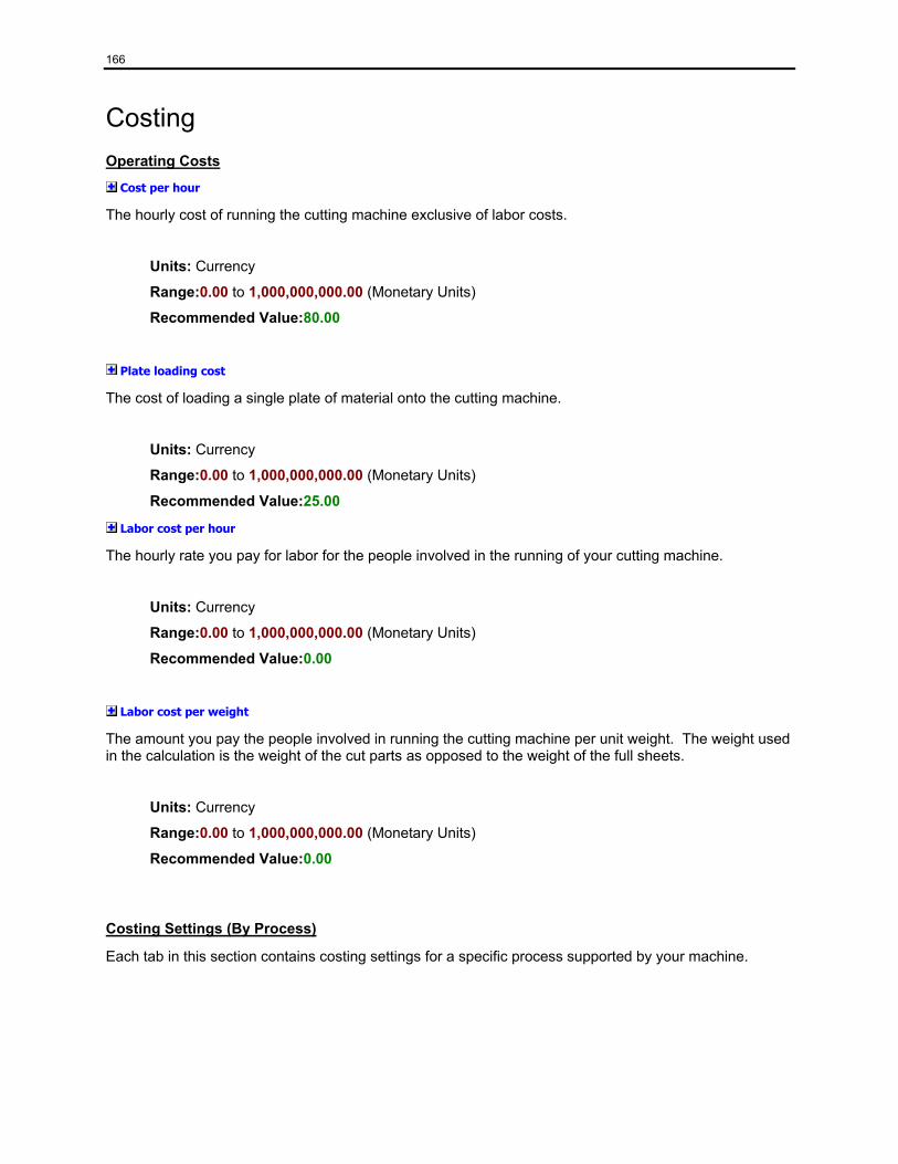
166
Costing Operating Costs
Cost per hour
The hourly cost of running the cutting machine exclusive of labor costs.
Units: Currency
Range:0.00 to 1,000,000,000.00 (Monetary Units)
Recommended Value:80.00
Plate loading cost
The cost of loading a single plate of material onto the cutting machine.
Units: Currency
Range:0.00 to 1,000,000,000.00 (Monetary Units)
Recommended Value:25.00
Labor cost per hour
The hourly rate you pay for labor for the people involved in the running of your cutting machine.
Units: Currency
Range:0.00 to 1,000,000,000.00 (Monetary Units)
Recommended Value:0.00
Labor cost per weight
The amount you pay the people involved in running the cutting machine per unit weight. The weight used in the calculation is the weight of the cut parts as opposed to the weight of the full sheets.
Units: Currency
Range:0.00 to 1,000,000,000.00 (Monetary Units)
Recommended Value:0.00
Costing Settings (By Process)
Each tab in this section contains costing settings for a specific process supported by your machine.
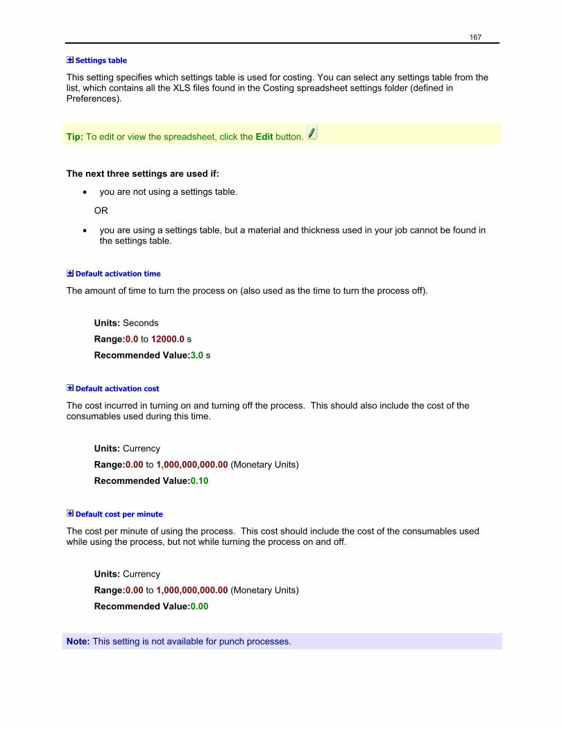
167
Settings table
This setting specifies which settings table is used for costing. You can select any settings table from the list, which contains all the XLS files found in the Costing spreadsheet settings folder (defined in Preferences).
Tip: To edit or view the spreadsheet, click the Edit button.
The next three settings are used if:
• you are not using a settings table.
OR
• you are using a settings table, but a material and thickness used in your job cannot be found in the settings table.
Default activation time
The amount of time to turn the process on (also used as the time to turn the process off).
Units: Seconds
Range:0.0 to 12000.0 s
Recommended Value:3.0 s
Default activation cost
The cost incurred in turning on and turning off the process. This should also include the cost of the consumables used during this time.
Units: Currency
Range:0.00 to 1,000,000,000.00 (Monetary Units)
Recommended Value:0.10
Default cost per minute
The cost per minute of using the process. This cost should include the cost of the consumables used while using the process, but not while turning the process on and off.
Units: Currency
Range:0.00 to 1,000,000,000.00 (Monetary Units)
Recommended Value:0.00
Note: This setting is not available for punch processes.
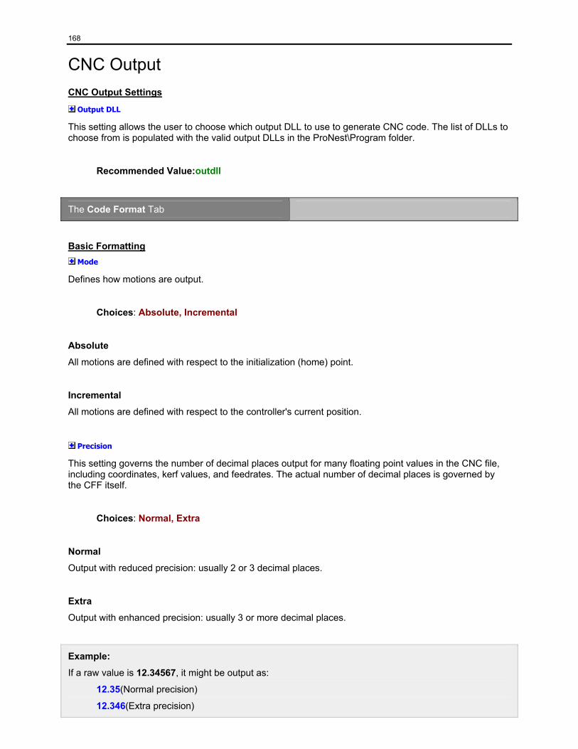
168
CNC Output CNC Output Settings
Output DLL
This setting allows the user to choose which output DLL to use to generate CNC code. The list of DLLs to choose from is populated with the valid output DLLs in the ProNest\Program folder.
Recommended Value:outdll
The Code Format Tab
Basic Formatting Mode
Defines how motions are output.
Choices: Absolute, Incremental
Absolute
All motions are defined with respect to the initialization (home) point.
Incremental
All motions are defined with respect to the controller's current position.
Precision
This setting governs the number of decimal places output for many floating point values in the CNC file, including coordinates, kerf values, and feedrates. The actual number of decimal places is governed by the CFF itself.
Choices: Normal, Extra
Normal
Output with reduced precision: usually 2 or 3 decimal places.
Extra
Output with enhanced precision: usually 3 or more decimal places.
Example:
If a raw value is 12.34567, it might be output as:
12.35(Normal precision)
12.346(Extra precision)
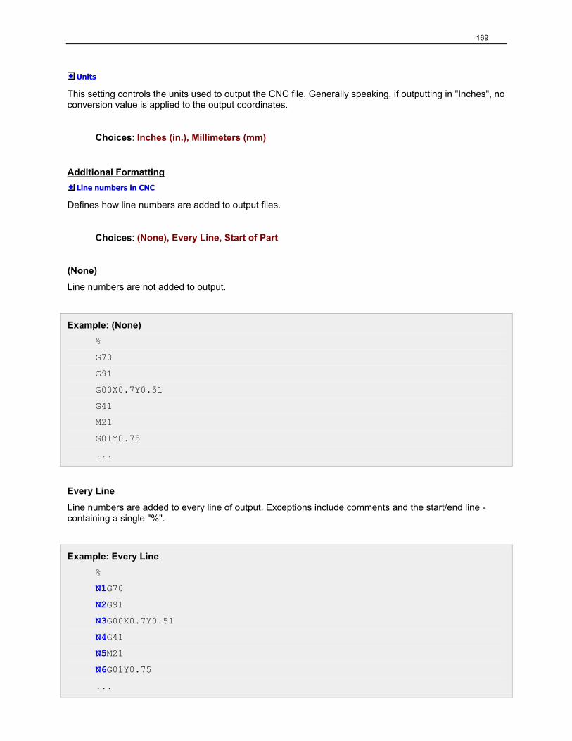
169
Units
This setting controls the units used to output the CNC file. Generally speaking, if outputting in "Inches", no conversion value is applied to the output coordinates.
Choices: Inches (in.), Millimeters (mm)
Additional Formatting Line numbers in CNC
Defines how line numbers are added to output files.
Choices: (None), Every Line, Start of Part
(None)
Line numbers are not added to output.
Example: (None) %
G70
G91
G00X0.7Y0.51
G41
M21
G01Y0.75
...
Every Line
Line numbers are added to every line of output. Exceptions include comments and the start/end line - containing a single "%".
Example: Every Line %
N1G70
N2G91
N3G00X0.7Y0.51
N4G41
N5M21
N6G01Y0.75
...
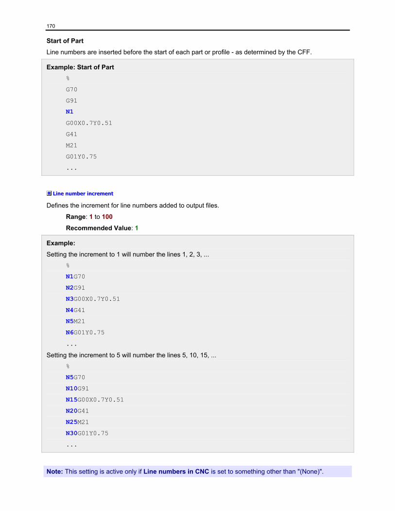
170
Start of Part
Line numbers are inserted before the start of each part or profile - as determined by the CFF.
Example: Start of Part %
G70
G91
N1
G00X0.7Y0.51
G41
M21
G01Y0.75
...
Line number increment
Defines the increment for line numbers added to output files.
Range: 1 to 100
Recommended Value: 1
Example:
Setting the increment to 1 will number the lines 1, 2, 3, ...
%
N1G70
N2G91
N3G00X0.7Y0.51
N4G41
N5M21
N6G01Y0.75
...
Setting the increment to 5 will number the lines 5, 10, 15, ...
%
N5G70
N10G91
N15G00X0.7Y0.51
N20G41
N25M21
N30G01Y0.75
...
Note: This setting is active only if Line numbers in CNC is set to something other than "(None)".
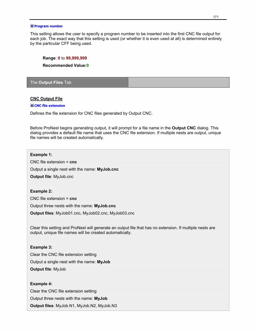
171
Program number
This setting allows the user to specify a program number to be inserted into the first CNC file output for each job. The exact way that this setting is used (or whether it is even used at all) is determined entirely by the particular CFF being used.
Range: 0 to 99,999,999
Recommended Value:0
The Output Files Tab
CNC Output File CNC file extension
Defines the file extension for CNC files generated by Output CNC.
Before ProNest begins generating output, it will prompt for a file name in the Output CNC dialog. This dialog provides a default file name that uses the CNC file extension. If multiple nests are output, unique file names will be created automatically.
Example 1:
CNC file extension = cnc
Output a single nest with the name: MyJob.cnc
Output file: MyJob.cnc
Example 2:
CNC file extension = cnc
Output three nests with the name: MyJob.cnc
Output files: MyJob01.cnc, MyJob02.cnc, MyJob03.cnc
Clear this setting and ProNest will generate an output file that has no extension. If multiple nests are output, unique file names will be created automatically.
Example 3:
Clear the CNC file extension setting
Output a single nest with the name: MyJob
Output file: MyJob
Example 4:
Clear the CNC file extension setting
Output three nests with the name: MyJob
Output files: MyJob.N1, MyJob.N2, MyJob.N3
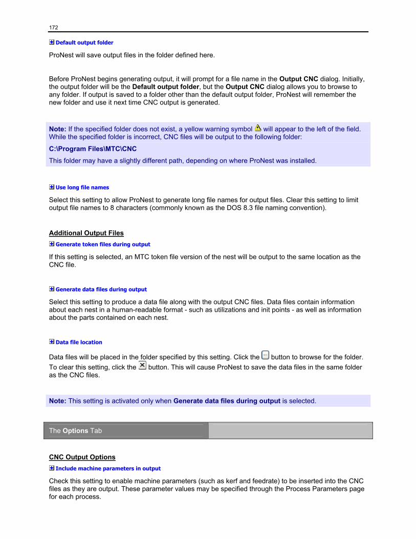
172
Default output folder
ProNest will save output files in the folder defined here.
Before ProNest begins generating output, it will prompt for a file name in the Output CNC dialog. Initially, the output folder will be the Default output folder, but the Output CNC dialog allows you to browse to any folder. If output is saved to a folder other than the default output folder, ProNest will remember the new folder and use it next time CNC output is generated.
Note: If the specified folder does not exist, a yellow warning symbol will appear to the left of the field. While the specified folder is incorrect, CNC files will be output to the following folder:
C:\Program Files\MTC\CNC
This folder may have a slightly different path, depending on where ProNest was installed.
Use long file names
Select this setting to allow ProNest to generate long file names for output files. Clear this setting to limit output file names to 8 characters (commonly known as the DOS 8.3 file naming convention).
Additional Output Files Generate token files during output
If this setting is selected, an MTC token file version of the nest will be output to the same location as the CNC file.
Generate data files during output
Select this setting to produce a data file along with the output CNC files. Data files contain information about each nest in a human-readable format - such as utilizations and init points - as well as information about the parts contained on each nest.
Data file location
Data files will be placed in the folder specified by this setting. Click the button to browse for the folder. To clear this setting, click the button. This will cause ProNest to save the data files in the same folder as the CNC files.
Note: This setting is activated only when Generate data files during output is selected.
The Options Tab
CNC Output Options Include machine parameters in output
Check this setting to enable machine parameters (such as kerf and feedrate) to be inserted into the CNC files as they are output. These parameter values may be specified through the Process Parameters page for each process.
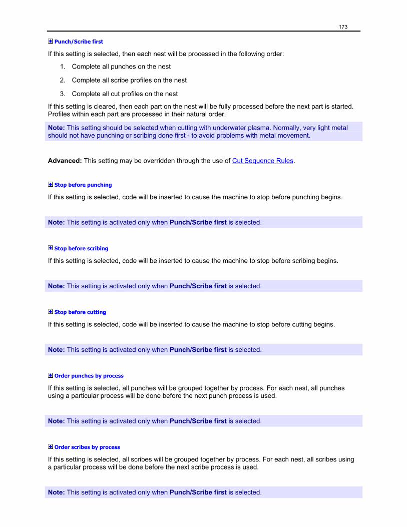
173
Punch/Scribe first
If this setting is selected, then each nest will be processed in the following order:
1. Complete all punches on the nest
2. Complete all scribe profiles on the nest
3. Complete all cut profiles on the nest
If this setting is cleared, then each part on the nest will be fully processed before the next part is started. Profiles within each part are processed in their natural order.
Note: This setting should be selected when cutting with underwater plasma. Normally, very light metal should not have punching or scribing done first - to avoid problems with metal movement.
Advanced: This setting may be overridden through the use of Cut Sequence Rules.
Stop before punching
If this setting is selected, code will be inserted to cause the machine to stop before punching begins.
Note: This setting is activated only when Punch/Scribe first is selected.
Stop before scribing
If this setting is selected, code will be inserted to cause the machine to stop before scribing begins.
Note: This setting is activated only when Punch/Scribe first is selected.
Stop before cutting
If this setting is selected, code will be inserted to cause the machine to stop before cutting begins.
Note: This setting is activated only when Punch/Scribe first is selected.
Order punches by process
If this setting is selected, all punches will be grouped together by process. For each nest, all punches using a particular process will be done before the next punch process is used.
Note: This setting is activated only when Punch/Scribe first is selected.
Order scribes by process
If this setting is selected, all scribes will be grouped together by process. For each nest, all scribes using a particular process will be done before the next scribe process is used.
Note: This setting is activated only when Punch/Scribe first is selected.
174
Order cuts by process
If this setting is selected, all cuts will be grouped together by process. For each nest, all cuts using a particular process will be done before the next cut process is used.
Note: This setting is activated only when Punch/Scribe first is selected.
Return to initialization point
When this setting is selected, ProNest will return the torch to the initialization (home) point at the end of each nest. If this setting is cleared, the torch will remain in its position at the end of each nest.
Insert part name as comment
Select this setting if a comment should be output in the CNC file before the first profile of each part. This comment typically gives the sequence number of the part and the part name.
Validate plate size
When this setting is selected, the plate size is validated. The procedure for this typically consists of the following actions:
1. Start with the torch head at the initialization point
2. Traverse to the opposite corner of the plate
3. Traverse back to the initialization point
4. Begin normal processing of the nest
Enable automatic CNC torch spacing
If this setting is selected, ProNest will insert code to automatically change the torch spacing at the cutting machine. Otherwise, ProNest will insert a stop code to allow an operator to manually adjust the torches (quantity and/or spacing) whenever they need to be changed.
Important: Select this setting only if the machine is capable of arranging torches automatically. To facilitate this, a special post processor (CFF) may be required. Please contact MTC Software, Inc. if you require this ability.
Pre-kerf
Selecting this setting will remove all kerf left, kerf right, and kerf off commands from the CNC code. ProNest will alter the part geometry to compensate for this change.
Note: If the cutting machine is slow at kerfing the CNC code, you may want to select this setting.
Strip stop codes from CNC part files
When CNC files are added to the Part List, they may contain stop codes. If this setting is selected, these stop codes will be removed when output files are created.
175
Ignore for output
Processes listed here will not appear in the CNC file. The list of ignored processes will be highlighted and underlined - like a hyperlink.
To edit the list:
1. Click the process list hyperlink.
2. Select the processes you want to ignore during output and click OK.
Note: This setting is ignored if Cut Sequence Rules are used.
Important: CNC Output settings and the Post Processor (CFF)
Certain CNC Output Settings require specific capabilities to be present in the CFF in order to function properly. While many CFFs are already set up for this functionality, it is possible that you may require changes to your CFF before it will work correctly. Please contact MTC for further assistance if you feel you have one of these CFFs.
The settings which activate functionality resident in the CFF are:
• Include machine parameters in output
• Line number in CNC
• Program number
• Return to initialization point
• Insert part name as comment
• Validate plate size
• Enable automatic CNC torch spacing
CFFs may override the values of Mode, Precision, and Units. In addition, the CFF may override the settings in the above list. For example, a CFF may be configured to always output in incremental mode or without the ability to output machine parameters in the CNC file.
176
CNC Output - Pre-Pierces Before each profile is cut, the machine can be instructed to create a pierce hole that will serve as the starting point when the profile is cut. The settings on this page help to define exactly how these pre-pierces should be made. Pre-pierces are represented by an action that can be sequenced through Cut Sequence Rules - so it is possible to control exactly when profiles are pre-pierced.
Pre-Pierce Settings
Use Pre-pierces
To enable pre-piercing of profiles, select this check box.
Note: The following settings are enabled only when the Use Pre-pierces check box is selected:
Style
This setting defines the method used to pierce holes.
Choices:Pre-pierce as Circles, Pre-pierce as Punch, Torch Blow Through
Pre-pierce as Circles
All pierce holes are created by piercing and cutting a small circle.
Pre-pierce as Punch
If the machine has a punch, all pierce holes are punched.
Torch Blow Through
All pierce holes are created simply by piercing each start point.
Enable only for materials thicker than <value> in.
Pre-piercing can be limited to materials that are thicker than a specific value. The value is highlighted and underlined - like a hyperlink.
Units: Distance
Range: 0.0 to 100 in.
Recommended Value: 0.0 in.
To edit this setting:
1. Click the value (its a hyperlink).
2. Type a value in the Pre-pierce threshold box.
Process

177
This setting defines the process that will be used to create pierce holes. When Style is set to Pre-Pierce as Circles or Torch Blow Through, the choices are limited to valid cut processes. When Style is set to Pre-Pierce as Punch, the choices are limited to valid punch processes.
Radius
This setting defines the radius for circle pierce holes.
Units: Distance
Range: 0.01 to 10.0 in.
Recommended Value: 0.5 in.
This setting is activated only when Style is set to Pre-Pierce as Circles.
Pre-pierce by part
If this setting is selected, then pre-pierces are done on a part-by-part basis. This means that the profiles for a single part will be pre-pierced and cut before moving on to cut the next part. When this setting is cleared, pre-pierces are done for the entire nest before any profiles are cut.
Important: This setting is used only if the active Cut Sequence Rule is 'Use settings instead of rules'. A true cut sequence rule would dictate exactly when pre-pierces are to be cut and this setting would be effectively ignored.
CNC Output - Auto Height Control Auto Height Control Settings
Disable for interior profiles smaller than <value> in.2
Disabling of auto height control can be limited to interior profiles that are smaller in area than a specific value. Auto height control is disabled for the entire profile (from the end of the lead-in to the end of the lead-out). The value, Auto height control threshold, is highlighted and underlined - like a hyperlink.
Units: Area
Range:0.0 to 10,000 in.2
Recommended Value:0.0 in.2
To edit the value:
1. Click the value (it’s a hyperlink).
2. Specify the Auto height control threshold.
Note: This setting is useful for machines where the cutting head tends to follow the surface of the material being cut. When an interior profile drops out, the cutting head on these machines may dive into the hole - risking damage.
178
Disable for all lead-outs
Select this setting to disable auto height control at the beginning of the lead-out.
Note: This setting applies to interior, exterior, and open profiles. However, this setting does not apply to interior profiles that already fit the criterion defined by the Disable for interior profiles smaller than… setting. That setting takes precedence for interior profiles.
Disable no further than <value> in. before the lead-out
Disables auto height control the specified distance before the beginning of a lead-out. The value is highlighted and underlined – like a hyperlink.
Units: Distance
Range: 0.0 to 10.0 in.
Recommended Value: 1.0in.
This setting is active only if Disable for all lead-outs is selected.
To edit the value:
1. Click the value (it’s a hyperlink).
2. Specify the Disable no further than... value.
Disable for crop lines
Select this setting to disable auto height control for crop lines.
Re-enable before the torch turns off
Select this setting to re-enable auto height control immediately before the cutting head turns off at the end of the lead-out. If this setting is not selected, the auto height control will be re-enabled immediately after the cutting head turns off at the end of the lead-out.
This setting is active if...
• The value for Disable for interior profiles smaller than… is set to a non-zero value
-or-
• The Disable for all lead-outs check box is selected
-or-
• The Disable for crop lines check box is selected.
Disable for skeleton lines
Select this setting to disable auto height control for skeleton cut up lines.
Important: The value of this setting is used only at the moment when a nest's skeleton is created.
179
CNC Output - Step and Repeat Step and Repeat allows the CNC file to be repeated along the length or width of the plate. This has the same effect as arraying a row or column of parts, except that the CNC file is much smaller.
Step and Repeat Settings
Use step and repeat
Select this setting if you wish to use step and repeat mode during output.
Offset
Each repeated row or column will be offset this distance from the previous row or column.
Units: Distance
Range:0.0 to 10,000.0 in.
Direction
Repeated rows (or columns) will be offset in the direction selected here.
Choices:Left, Up, Right, Down
When repeating horizontally nested parts (rows), this setting should be set to either Up or Down. Likewise, when repeating vertically nested parts (columns), this setting should be set to Left or Right.
Advanced: Since some details of step and repeat are machine specific, please refer to your machine’s programming manual and contact MTC Software, Inc. in the event that changes are required to your post processor (CFF).
CNC Output - Output Axis The Output Axis settings page allows you to modify your nesting init point and to define the output axis that will be used to generate CNC files.
This screen shows a simplified view of a rectangular plate. One corner of the plate will be highlighted and will have two arrows coming out of it - representing the output axis. In the center of the plate are 3 buttons which allow you to modify the output axis.
Changing the Init Point
To change your init point:
1. Hover the mouse over one of the corners of the plate. This will cause the corner to become temporarily highlighted.
2. Click the left mouse button to select the new init point.
As you change the init point, the output axis will remain the same.
180
Example:
With an init point in the lower-left corner, the arrow pointing up is labeled as the +Y axis and the arrow pointing right is labeled as the +X axis. If the init point were then changed to the upper-left corner, there would be a down arrow labeled as the -Y axis. Notice that the output axis hasn't changed: up is still +Y and right is still +X.
Changing the Output Axis
Some machines have the plate loaded with the long side on the bottom, but as far as the machine is concerned this is the right-hand side of the plate. These machines assume a lower-right init point. Presenting this vertical plate correctly in ProNest would result in a much smaller view of the nest (because most monitors are wider than they are tall). To provide the best view of the nest and to also allow for correct output you would select a lower left init point, but rotate the axes 90 degrees clockwise. During output, this has the effect of changing the nest to one with a lower-right init point and with its long side on the right, rather than the bottom.
Note: Changes to the output axis will only affect CNC output.
To change your output axis, use the three buttons in the middle of the plate...
The first button will rotate the output axis clockwise by 90°.
The middle button will flip the output axis vertically.
The last button will flip the output axis horizontally.
Click Default to restore the default output axis with +Y in the up direction and +X in the right direction.
Example:
With an init point in the lower-left corner, the arrow pointing up is labeled as the +Y axis and the arrow pointing right is labeled as the +X axis. Click the rotate button once and the up-arrow will become -X while the right-arrow changes to +Y. Click the flip axis vertically button and the up-arrow will become +X while the right-arrow remains the same as +Y.
CNC Output - Subroutines A subroutine is a basic program unit, usually representing a profile or collection of profiles. Certain types of machines, primarily lasers, allow the use of subroutines to reduce CNC file size. For example, on a nest of 500 identical circles, rather than specifying the geometry for the circle 500 times, a single subroutine could be created, which would then be called 500 times.
Important: A specialized section in the post processor governs whether this settings page is available. Usually this section is not used. This section also controls the available choices for Type and Mode, and whether or not Use rotation angle is active. If you need subroutine support, contact MTC Software Inc.
181
Subroutine Settings
Type
Defines the type of subroutines that will be generated.
Choices:(None), Profile, Part, Profile Cluster, Part Cluster, Optimized
(None)
No subroutines will be created.
Profile
Each subroutine will represent a single profile.
Part
Each subroutine will represent a collection of profiles (a part).
Profile Cluster
Explanation.
Part Cluster
Explanation.
Optimized
Explanation.
Note: The rest of the settings on this page are activated only if Type is set to something other than (None).
Mode
This setting defines the mode that will be used for generating the CNC code for the subroutines.
Choices:Always Absolute, Always Incremental, Same as Main Program
Always Absolute
Subroutines will be generated in absolute mode, irrespective of the mode of the main program.
Always Incremental
Subroutines will be generated in incremental mode, irrespective of the mode of the main program.
Same As Main Program
Subroutines will be generated using the same mode as the main program.
182
Use rotation angle
Select this setting to allow ProNest to use the same subroutine for similar geometry being output at different rotation angles. Otherwise, a different subroutine will be used for each unique rotation of the same geometry.
Allow nested subroutines
Check this setting to allow one subroutine to call another subroutine. For example, this would allow a part subroutine to be composed of calls to profile subroutines.
Important: This functionality is not currently implemented.
Allow subroutined nests
Select this setting to generate subroutines for each nest in the job. These nest subroutines may be output into a single master CNC file. This setting is intended for machines with automatic plate handling systems.
Important: This functionality is not currently implemented.
Allow subroutines that contain only collision avoidance motions
Select this setting if you are using collision avoidance and want separate profile subroutines generated that contain only the rapid traverses between profiles. Otherwise, the collision avoidance motions will be contained within their respective part or profile subroutines.
Note: This setting is intended to reduce the number of subroutines required. A unique subroutine will be generated based on the total geometry of the part or profile - including the avoidance motions. If the avoidance motions are removed from consideration, it becomes more likely that subroutines can be reused.
CNC Output - Microjoint / Plate Handler Important: A specialized section in the post processor governs whether this settings page is available. Usually this section is not used. If you need microjoint and/or plate handler support, contact MTC Software Inc.
Microjoint Settings
Microjoints are machine-applied tabs. A place holder is inserted into the CNC code which the cutting machine translates into a tab when the CNC code is run. Settings in the settings table determine the size of the tab and the length of the tab lead-in. Not all machines have this capability.
Settings Table
This setting specifies which settings table is used for microjoints. You can select any settings table from the list, which contains all the XLS files found in the Microjoint spreadsheet settings folder (defined in Preferences).
Tip: To edit or view the spreadsheet, click the Edit button.
183
Use programmed microjoints
Select this setting if you want to be able to manually add microjoint tabs to profile geometry. When adding tabs manually in Advanced Edit, you will be given the option of adding the tab as a microjoint instead of a normal tab.
Note: The following two settings are active only if Use programmed microjoints is selected.
Replace every lead-out with a microjoint
Select this setting if you want to replace all profile lead-outs with microjoint tabs at output time.
Use microjoints during AutoTab
Select this setting to have ProNest insert microjoint tab placeholders during the AutoTab process (instead of normal tabs). Otherwise, normal tabs will be added.
Important: The value of this setting is used only when tabs are added. Changing the value of this setting does not affect parts that already have tabs (or don't have tabs).
Use automatic microjoints
Select this setting if you want the machine to automatically insert microjoints where the machine deems appropriate. Settings from the Microjoint settings table may be used by the machine to make this determination.
Plate Handler Settings
An automatic plate handler is a mechanism provided by some machine manufacturers that enables the cutting machine to load its own plates as specified in the CNC code. Not all machines have this capability.
Use plate handler
Select this setting if your machine is capable of using an automatic plate handler and you wish to make use of this feature.
Note: The Settings table setting is active only if Use plate handler is selected.
Settings table
This setting specifies which settings table is used for the plate handler. You can select any settings table from the list, which contains all the XLS files found in the Plate Handler spreadsheet settings folder (defined in Preferences).
Tip: To edit or view the spreadsheet, click the Edit button.
184
CNC Output - DXF Output For DXF output, layer and color information is normally stored in the post processor or may be retrieved from Process Parameters (if process parameters are being used). Some of the settings on this page allow this behavior to be overridden. The DXF files produced during output should be readable by ProNest or any CAD system that understands DXF files.
Important: A specialized section in the post processor governs whether this settings page is available. It also controls which DXF Output settings are available. Usually this section is not used. If you need DXF Output support, contact MTC Software Inc.
DXF Output Settings
Output polylines
Select this setting to output DXF files using polylines. Each profile would be generated as a single polyline entity. Clear this setting to output DXF files as individual DXF entities (arcs and lines).
Output sheets
Select this setting to output the sheet geometry into the DXF file.
Output safe zones
Select this setting to output the safezone geometry into the DXF file.
Output leads
Select this setting to output existing lead-ins and lead-outs on profiles when outputting DXF files. Otherwise, leads are removed.
Use quality to output CAD colors
Select this setting to interpret the QUALITY attribute of arcs and lines as CAD colors. If this setting is cleared, the default CAD color will be used (this comes from either the post processor or the Process Parameters settings table).
Layer Names
Output original layer names whenever possible
Select this setting to output the original CAD layer names as the entity layer names in the DXF file. If the profile being output was not originally a CAD file, then the default layer information will be used (this comes from either the post processor or the Process Parameters settings table).
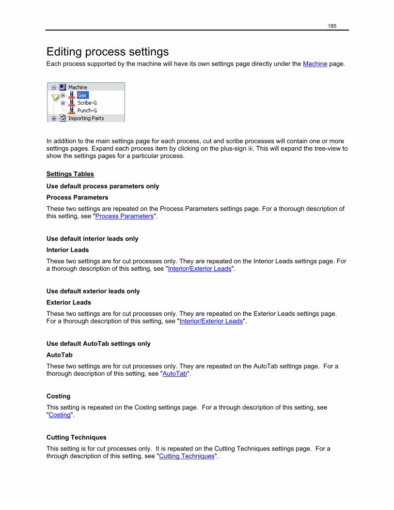
185
Editing process settings Each process supported by the machine will have its own settings page directly under the Machine page.
In addition to the main settings page for each process, cut and scribe processes will contain one or more settings pages. Expand each process item by clicking on the plus-sign . This will expand the tree-view to show the settings pages for a particular process.
Settings Tables
Use default process parameters only
Process Parameters
These two settings are repeated on the Process Parameters settings page. For a thorough description of this setting, see "Process Parameters".
Use default interior leads only
Interior Leads
These two settings are for cut processes only. They are repeated on the Interior Leads settings page. For a thorough description of this setting, see "Interior/Exterior Leads".
Use default exterior leads only
Exterior Leads
These two settings are for cut processes only. They are repeated on the Exterior Leads settings page. For a thorough description of this setting, see "Interior/Exterior Leads".
Use default AutoTab settings only
AutoTab
These two settings are for cut processes only. They are repeated on the AutoTab settings page. For a thorough description of this setting, see "AutoTab".
Costing
This setting is repeated on the Costing settings page. For a through description of this setting, see "Costing".
Cutting Techniques
This setting is for cut processes only. It is repeated on the Cutting Techniques settings page. For a through description of this setting, see "Cutting Techniques".
186
Process Parameters Process Parameter Settings
Use default process parameters only
If this is selected, then Process Parameters will not be active, because all process parameter settings will come from the Default Settings section. If this is cleared, then the entire Default Settings section will be inactive, because all process parameter settings will come from the spreadsheet specified by Process Parameters.
Process Parameters
This setting specifies which settings table is used for process parameters. You can select any settings table from the list, which contains all the XLS files found in the Process Parameters spreadsheet settings folder (defined in Preferences).
Tip: To edit or view the spreadsheet, click the Edit button.
Default Settings
Kerf width
This defines the width of the torch. This can be useful for parts that share a common line. With a proper kerf value, ProNest can adjust a common line so that it doesn't infringe on either part.
Units: Distance
Range: -10,000.0 to 10,000.0 in.
Recommended Value: 0.1 in.
Feedrate
Feed rate to use in CNC output and costing.
Units: Speed
Range: 0.0 to 10,000.0 in./min
Recommended Value: 100.0 in./min
Part - part separation
The minimum separation allowed between two nested parts. Nested parts that are closer together will be shown in conflict.
Units: Distance
Range: 0.0 to 100.0 in.
Recommended Value: 0.5 in.
187
Part - plate edge separation
The minimum separation allowed between a nested part and a plate edge. Nested parts that are closer to the plate edge will be shown in conflict.
Units: Distance
Range: 0.0 to 100.0 in.
Recommended Value: 0.5 in.
Part - pierce separation
The minimum separation allowed between a nested part and the pierce point of another nested part. Nested parts that are closer to a pierce point will be shown in conflict.
Units: Distance
Range: 0.0 to 100.0 in.
Recommended Value: 0.5 in.
The following values are calculated and appear for information purposes only:
Pierce - pierce separation
value = (2 * Part - pierce separation) – Part - part separation
Pierce - plate edge separation
value = Part - pierce separation + Part - plate separation – Part to part separation
Interior/Exterior Leads Each cut process has one settings page for interior leads and another for exterior leads.
Interior/Exterior Leads Settings
Use default interior/exterior leads only
If this is selected, then Interior/Exterior leads will not be active, because all lead settings will come from the Default Settings section. If this is cleared, then the entire Default Settings section will be inactive, because all lead settings will come from the spreadsheet specified by Interior/Exterior leads.
Interior/Exterior Leads
This setting specifies which settings table is used for interior/exterior. You can select any settings table from the list, which contains all the XLS files found in the Interior/Exterior Leads spreadsheet settings folder (defined in Preferences).
Tip: To edit or view the spreadsheet, click the Edit button.
188
Default Settings
Default lead settings can be specified for both corner and side leads. A lead is defined by its style, size, angle, and extension. Lead-outs also have an overtravel setting. These five aspects of a lead are defined here.
Style
The style of a lead defines its basic shape.
Choices for Lead In:(None), Arc, Linear, Spiral, Lock-9, Lock-7, Step, Diagonal Step, T-Lock
Choices for Lead Out:(None), Arc, Linear
To change a lead style:
1. Click the right-hand side of the Style row (where it shows the actual style used).
2. Click the down arrow and select a new style from the list.
3. Click OK.
Size
For the linear style, Size specifies the length of the lead. For the arc style, Size specifies the radius of the arc. For all other lead styles, Size controls the scale of the lead.
Units: Distance
Range: 0.0 to 100.0 in.
Recommended Value: 0.5 in. for a lead-in, 0.25 in. for a lead-out
Angle
The angle of a lead-in is defined with respect to the first motion after the lead. A 0° lead-in will lead straight into the first cut. Positive lead-in angles are defined clockwise from the 0° position, so a 90° lead-in will cause a sharp left-turn into the first cut. Lead-out angles are defined in a similar fashion with a 0° lead-out extending straight out of the last cut. Positive lead-out angles are defined counter-clockwise from the 0° position, so a 90° lead-out will cause a sharp left-turn out of the last cut.
Units: Degrees
Range:0.0 to 360.0°
Recommended Value:0.0° for corner leads, 180.0° for a side lead-in, 90.0° for a side lead-out
189
Extension
The tip of the lead-in (or lead-out) will be extended by this distance.
Units: Distance
Range: 0.0 to 100.0 in.
Recommended Value: 0.0 in.
Overtravel
This value applies only to the lead-out. If this value is positive (overtravel), then the torch/head will travel past the start point before cutting the lead-out. If this value is negative (undertravel), then the torch/head will begin cutting the lead-out before reaching the start point.
Units: Distance
Range: -100.0 to 100.0 in.
Recommended Value: 0.0 in.
Cutting Techniques Cutting Techniques Settings
Disable auto height control for slots smaller than <value> in.
Auto height control will be disabled for slots that are smaller in width than the value (referred to as Slot tolerance).
Units: Distance
Range:0.0 to 10.0 in.
Recommended Value:0.0 in.
To edit the slot tolerance:
1. Click the value (it’s a hyperlink).
2. Type the slot tolerance in the box.
3. Click OK.
Cutting techniques (table)
This setting specifies which settings table is used for cutting techniques. You can select any settings table from the list, which contains all the XLS files found in the Cutting Techniques spreadsheet settings folder (defined in Preferences).
Tip: To edit or view the spreadsheet, click the Edit button.
190
Common Line Cut Common line cutting is a way of reducing the number of pierces and total cut length while maximizing the number of parts being cut. ProNest handles five different methods of common line cutting:
Important: The following methods of common line cutting use only pre-kerfed parts when creating the finished common line cut part. Consequently, no kerf codes are present in the finished CLC profile.
Pair
Two parts are common line cut together.
Quad
A part is common line cut with itself into a 2 x 2 grid.
CLC Array
Two or more of the same parts are cut in a series of rows and columns such that they fill a region up to the size of the plate the parts are being nested on or a smaller, user-defined region.
Advanced CLC
Two or more parts are common line cut together. An unlimited number of dissimilar parts can be used. The plate edge may also be used as one of the common lines.
Old Pair*
Two parts are common line cut together, maintaining proper kerf direction and original part geometry. Kerf codes are present in the finished CLC profile.
* The Old Pair method of common line cutting is in the process of being phased out. It is available only through the use of a special command line parameter that causes ProNest to use this method over the regular Pair method. In the rare case that this would be required, please contact MTC Software Inc. for assistance.
Unless otherwise denoted, the following settings are labeled according to which type of common line cutting they are used with. The labels are: O = old pair CLC, P = pair CLC, Q = quad CLC, A = CLC array, M = multi-part CLC.
Common Line Cut Settings
Minimum shared length
The minimum length of a line that must overlap a line in another part for them to be considered "in common." At least one such line must exist between two parts for those parts to be eligible for becoming a common line part.
Units: Distance
Range: 0.0 to 10000.0 in.
Recommended Value: 1.0 in.
Used For: All methods of common line cut
191
Torch path style
There are two torch path styles available for common line cutting.
Choices:Crossing, Not Crossing
Used For: All methods of common line cut
Crossing
Select this choice when it is possible for the machine to cut over a previously cut kerf width: such as with laser or plasma cutting.
Not Crossing
Select this choice when it is not possible for the machine to cut over a previously cut kerf width: such as with oxyfuel cutting.
Slow down to <value1>% of feedrate <value2> in. from completion of the first part
<value1> represents a percentage of the normal cutting feed rate and <value2> represents a distance from the end of the common line at which to slow down to this percentage. Additionally, the lead-in will be shifted one kerf width "down" (toward the second part in the CLC pair).
Value 1 = Slowdown (% of feedrate)
Units: Percentage
Range: 0.0 to 100.0%
Used For: Old Pair only
Value 2 = Slowdown distance
Units: Distance
Range: 0.0 to 10000.0 in.
Used For: Old Pair only
To change either of these values:
1. Click on the underlined value (its a hyperlink)
2. Edit the value and click OK.
Note: This setting is active only if Torch path style is set to Not Crossing.
192
Maximum area increase
This setting is used only when a part is automatically common line cut with itself (like when a single nested part is selected and then the CLC button is clicked). The value defines the percentage by which it is allowable for the region of the finished pair CLC part to be bigger than the region of the original part.
Units: Percentage
Range:0 to 1000%
Recommended Value:150%
Used For: Pair and Old Pair
Maximum alignment rotation
This setting is used only when a part is automatically common line cut with itself (like when a single nested part is selected and then the CLC button is clicked). The value defines the maximum angle by which to rotate one part of a selected pair to line up common line cuttable entities. If no entities may be lined up by rotating one of the selected pair of parts by up to this angle, no pair CLC part is created.
Units: Degrees
Range:0 to 360°
Recommended Value:45°
Used For: Pair and Old Pair
Use kerf width from process parameters
Select this check box to use kerf values specified in your Process Parameters settings. If this check box is cleared, then the kerf width defined below is used.
Kerf width
Amount by which to pre-kerf each part when creating the finished CLC part for every CLC method except old pair CLC. For old pair CLC, this value represents how far the geometry from the second part will be from the geometry of the first part in the finished common line part.
Units: Distance
Range:0.0 to 10000.0 in.
Used For: All methods of common line cut

193
Do not try with lines that have tabs
Depending on is use, this setting has a slightly different purpose.
Used For: Pair, Advanced CLC, and Old Pair
When used for Pair (or Old Pair):
Select this check box to disallow lines with tabs from being considered for the common line. If this check box is cleared, lines with tabs will be considered for the common line. In this case, if a tabbed line is chosen as the common line, any tabs on that line are removed.
When used for Advanced CLC:
Select this check box to remove all tabs from the finished CLC part. If this checkbox is cleared, then tabs will be maintained on all entities in the finished part except for the common line(s).
Maintain highest quality on common lines
Sometimes, two lines that are common line cut together will have different quality values. Select this check box to maintain the highest quality value belonging to either entity. Clear this check box to maintain the lowest quality value.
Used For: Pair, CLC Array, Advanced CLC, and Old Pair
Tolerance (screen pixels)
End point snap distance
When creating a pair CLC part from two parts selected on the screen, if the end points of the common line in each part are closer together than this tolerance, those end points are lined up before creating the common line part.
Units: Screen pixels
Range:0 to 100
Recommended Value:25
Used For: Pair and Old Pair
Note: This tolerance is in screen pixels to allow you to control its accuracy by using an appropriate zoom level on the nest. When you are zoomed far out, a distance measured on your monitor will represent a larger real-world distance on your nest than if you were zoomed in. As a result, the tolerance is also greater when you are zoomed out.
194
Common Line Cut - Plate Edge Plate Edge Settings
Allow common lines with the plate edge
Select this check box if you wish to be able to place parts right on the plate edge and have the plate edge count as one or more sides of the part. Any part sides in common with the plate edge will not be cut.
Extension
Profiles cut in common with the plate edge can start outside (or inside) the plate. A negative extension will shorten the start of the profile and the pierce will occur on the plate. A zero-length extension will case the pierce to occur on the plate edge. A positive extension will extend the start of the profile and the pierce will occur off the plate.
Units: Distance
Range:-100.0 to 100.0 in.
Recommended Value:0.0 in.
Cut Direction
This dictates the cut direction of profiles that are in common with the plate edge and, when no extension is specified, would start right on the plate edge.
Choices:Default, Cut towards the plate edge, Cut away from the plate edge
Default
No modification to cut direction is made. Whatever the torch path direction is when first created is what gets used in the part.
Cut towards the plate edge
Any profile that starts at the plate edge will have its cut direction modified so that it will end at the plate edge.
Cut away from the plate edge
Any profile that ends at the plate edge will have its cut direction modified so that it will start cutting at the plate edge.
Note: In any case where a profile both starts and ends at a plate edge, no modification to torch path direction will be made. In these cases, the torch path direction already satisfies any of the cut direction choices.
195
Common Line Cut - Array CLC Array Settings
Torch path style
There are two torch path styles available for common line cutting.
Choices:Crossing, Not Crossing
Used For: All methods of common line cut
Crossing
Select this choice when it is possible for the machine to cut over a previously cut kerf width: such as with laser, plasma, or waterjet cutting.
Not Crossing
Select this choice when it is not possible for the machine to cut over a previously cut kerf width: such as with oxyfuel cutting.
This setting is repeated from the Common Line Cut page.
Note: Most automatically generated CLC arrays will use Not Crossing as their torch path style. Certain specific cases of parts (rectangles, triangles, trapezoids, and parallelograms) may use either style.
Insert stop codes
Select this check box to insert a stop code at the end of each part so that is may be removed before cutting continues.
Note: This setting is active only if Torch path style is set to Not Crossing.
Kerf crossing lead-outs
Select this setting to allow lead-outs to cross a previously cut kerf.
Note: This setting is active only if Torch path style is set to Not Crossing.
Lead-out percentage
If lead-outs are allowed to cross a previously cut kerf, then this setting defines the length of that lead-out. The length is defined as a percentage of the kerf width.
Units: Percentage
Range:0 to 100%
Recommended Value:50%
Note: This setting is active only if Kerf crossing lead-outs is selected.
196
Array Size Limitations
When a CLC array is created, the end result is a grid of parts with a certain number of rows and columns. Each cell in this grid is made from one base unit. For some parts, such as rectangles, the base unit consists of one part; for parallelograms a base unit requires two parts, and for triangles a four part base unit is created.
Tip: To preview the base unit before creating a CLC array, use interactive CLC array.
Maximum number of units
This setting limits the overall size of CLC arrays. They will not be built with more base units than this maximum.
Units: Base units
Range:0 to 10000
Maximum rows
Defines the maximum number of rows that a single CLC array part can have.
Range:0 to 10000
Maximum columns
Defines the maximum number of columns that a single CLC array part can have.
Range:0 to 10000
Maximum width
Defines the maximum allowable width of the finished CLC array (excluding lead-ins and lead-outs).
Units: Distance
Range:0.0 to 10000.0 in.
Maximum height
Defines the maximum allowable height of the finished CLC array (excluding lead-ins and lead-outs).
Units: Distance
Range:0.0 to 10000.0 in.
Full columns only
If this check box is selected, CLC arrays will be created only with completely filled columns. Often, the array could continue in a new column except that there aren't enough parts left to complete that column. If this check box is cleared, CLC arrays will partially fill this last column.
197
Common Line Cut - Safety Cuts Safety cuts are added to common line cut parts to help avoid potential tip up situations as parts are cut out. They also provide a way of piercing a user-specified distance away from a previously cut portion of the CLC part. Safety cuts may be used with all types of common line cutting except for parts paired with the "Old Pair" method. For more information about common line cut methods, see "Common Line Cut".
Safety Cut Settings
Use safety cuts
Select this check box to allow safety cuts to be added to common line cut parts.
Important: Safety cuts will be added only during post processing so they will only be visible during cut simulation. They may not be selected or edited.
Note: The following settings are active only if Use safety cuts is selected.
Use values from Process Parameters (*.xls)
Select this check box to retrieve the values for Length of safety cuts, Offset for process-on, and Offset for process-off from the Process Parameters XLS file. If this check box is cleared, then these values will come from settings on this page.
Note: If a Process Parameters XLS is specified and a material match cannot be found, the values specified on this page will be used.
The General Tab
Length of safety cuts
Maximum length to use for safety cuts. Safety cuts may not cross entity boundaries, so it is possible to have shorter safety cuts created.
Units: Distance
Range:0.0 to 100.0 in.
Recommended Value:0.0 in.
Add safety cuts at all intersections
Select this check box to add safety cuts at intersection points within the profile being processed, as well as with subsequent profiles. If this check box is cleared, then safety cuts will be added only at intersection points with subsequent profiles.
198
The Begin of Profiles Tab
Add safety cuts to the beginning of profiles
Select this setting to add safety cuts at the beginning of subsequent profiles. This has the effect of moving the initial pierce point of the subsequent profile by a length at least equal to the length of the safety cut.
Offset for process-on
Specifies the distance beyond the end of the safety cut at which to pierce. A negative value will cause the pierce point to be within the safety cut. A zero value will pierce exactly at the end of the safety cut. A positive value will cause the pierce to occur beyond the end of the safety cut.
Units: Distance
Range:-100.0 to 100.0 in.
Recommended Value:0.0 in.
Note: This setting is active only if Add safety cuts to the beginning of profiles is selected.
The End of Profiles Tab
Add safety cuts to the end of profiles
Select this setting to add safety cuts at the end of subsequent profiles. This has the effect of moving the final torch off of the subsequent profile by a length at least equal to the length of the safety cut.
Offset for process-off
When cutting a profile, the torch may advance towards an existing safety cut. This setting specifies a distance to stop cutting before the safety cut is reached.
Units: Distance
Range:-100.0 to 100.0 in.
Recommended Value:0.0 in.
Note: This setting is active only if Add safety cuts to the end of profiles is selected
199
The Advanced Tab
Minimum profile length
When applying safety cuts it is possible to end up with very short profiles. This setting allows you to specify how long these short profiles have to be for them to be cut. In effect, any profiles shorter than this value will be ignored.
Units: Distance
Range:0.0 to 10.0 in.
Recommended Value:0.0 in.
Chaining Chaining parts together allows multiple exterior profiles to be cut with a single pierce. The torch will remain on as it moves from the lead-out of one part to the lead-in of the next part. While this reduces the number of pierces needed to cut the parts, it does result in a longer cut length.
Chaining Settings
Part-chain separation
The minimum separation allowed between a nested part and a nested chain. Parts closer than this distance to a chain will be shown in conflict.
Units: Distance
Range:0.0 to 10000.0 in.
Recommended Value:0.01 in.
Disable auto height control
Select this check box to turn off automatic height control when cutting a chain between parts. Automatic height control will be re-enabled before cutting the next part in the chain.
Important: The way any chain controls auto height control is governed by this setting at the time the chain is created. If this setting is modified, existing chains are not modified to match.
Chain Array
Chain array creates a nested array of parts chained together either vertically or horizontally. This yields a uniform array of parts, not packed together as closely as with array or pattern array, but with only one pierce per row or column (for the exterior profiles).
Lead-in extension
When a chained array of parts is created, each row or column will have its lead-in extended by this value.
Units: Distance
Range:0.0 to 10000.0 in.
Recommended Value:0.0 in.
200
Allow cut to cross kerf
Select this check box to allow chain arrays to be generated such that the chain coming from the lead-out of one part may cross the chain going toward the lead-in of another part. Clear this check box if the chain should not be allowed to cross itself.
Chain parts in reverse order
Select this check box to allow chain arrays to be built from the end of each row or column back toward the beginning.
Use ‘Not-Crossing’ lead-in/lead-out
Select this check box to force chain array to modify the leads such that the kerf is not crossed within the part at the start point. Otherwise, chain array will use the part's existing leads.
Bridging Bridging parts together allows multiple exterior profiles to be cut with a minimal number of pierces. When bridged parts are cut, they remain connected by thin webs of material (bridges). Cutting parts together in this way can reduce the number of pierces needed to cut the parts, but it does result in a longer cut length.
Bridging Settings
Bridge width
Specifies the width of the bridge between adjacent parts. A positive value will leave a thin web of material connecting the parts. A zero value means that the torch will travel over the exact same bridge geometry twice: once going to the next part and once returning from it. A negative value will invert the sides of the bridge, effectively cutting the bridge.
Units: Distance
Range:-5.0 to 5.0 in.
Recommended Value:0.125 in.
Bridge radius
Bridges can have a radius where they enter and leave each part. This radius allows for a smoother transition from the part to the bridge. A value of 0.0 indicates that no radius should be used.
Units: Distance
Range:0.0 to 1.0 in.
Recommended Value:0.125 in.
201
Maximum corner angle
Since bridges will "snap" to corners, this setting helps define exactly what a corner is. For the purposes of "snapping" to corners, angled cuts greater than this value will not be considered corners.
Units: Degrees
Range:0 to 360°
Recommended Value:135°
Tolerance (screen pixels)
End point snap distance
Maximum distance from a corner (see Maximum corner angle above) that a bridge start point can be which would cause it to snap to that corner. Allowing the bridge to snap to a corner can create smoother transitions from the part geometry to the bridge.
Units: Screen pixels
Range:0 to 100
Recommended Value:8
Note: This tolerance is in screen pixels to allow you to control its accuracy by using an appropriate zoom level on the nest. When you are zoomed far out, a distance measured on your monitor will represent a larger real-world distance on your nest than if you were zoomed in. As a result, the tolerance is also greater when you are zoomed out.
AutoTab AutoTab Settings
Use default AutoTab settings only
If this is selected, then AutoTab will not be active, because all process parameter settings will come from the Default AutoTab Settings section. If this is cleared, then the entire Default AutoTab Settings section will be inactive, because all process parameter settings will come from the spreadsheet specified by AutoTab.
AutoTab
This setting specifies which settings table is used for AutoTab. You can select any settings table from the list, which contains all the XLS files found in the AutoTab spreadsheet settings folder (defined in Preferences).
Tip: To edit or view the spreadsheet, click the Edit button.
202
Snap tolerance
If the location chosen as the start point of the tab is within this distance from the start point of the chosen entity, the tab start point will be shifted to the beginning of the entity. Similarly, if the tab would end within this distance from the end of the entity, the tab will be shifted so that its end point coincides with the entity end point.
Units: Distance
Range:0.0 to 5.0 in.
Recommended Value:1.0 in.
Tip: Giving this setting a non-zero value will help prevent tiny motions from being created. This can be beneficial on some machines where tiny motions can be problematic.
Apply only to straight lines
Select this setting to restrict AutoTab placement to linear motions only (no arcs).
Note: This setting is overridden if the default AutoTab strategy is set to Center of Line (see below).
Default AutoTab Settings
Tab length
Length of each tab that will be added during AutoTab. This length represents the distance along the original part geometry that will remain uncut for each tab.
Units: Distance
Range:0.0 to 10.0 in.
Recommended Value:0.5 in.
Minimum spacing
Defines the minimum amount of profile perimeter that should be cut between tabs. No two tabs will be placed closer than this value along any profile perimeter. Tabs will also not be placed closer than this distance to the start or end point of the profile (the exception to this is the At Corners strategy).
Units: Distance
Range:0.1 to 10000.0 in.
203
Strategy
Determines which AutoTab strategy will be employed.
Choices:(None), Center of Line, Number of Tabs, At Intervals, At Corners
(None)
No tabs will be added during AutoTab.
Center of Line
AutoTab will attempt to place tabs only at the center point of lines greater than a specified length.
Do not consider lines smaller than <value> in.
During AutoTab, lines shorter than distance will be ignored.
Units: Distance
Range:0.0 to 10000.0 in.
Recommended Value:5.0 in.
To edit the Minimum line size value:
1. Click the value (it’s a hyperlink).
2. Specify the Minimum line size and click OK.
Number of Tabs
AutoTab will attempt to add a user specified number of tabs to each profile.
Number per profile
Maximum number of tabs to add to each profile during AutoTab. Due to profile perimeter length and other factors, the number of tabs added may be smaller than the amount specified with this setting.
Range:0 to 100
At Intervals
AutoTab will attempt to add tabs at a user specified interval around the perimeter of each profile.
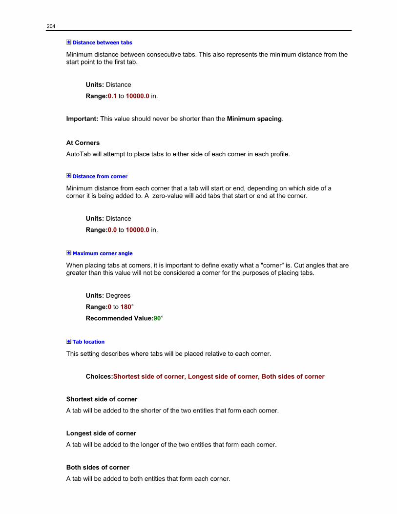
204
Distance between tabs
Minimum distance between consecutive tabs. This also represents the minimum distance from the start point to the first tab.
Units: Distance
Range:0.1 to 10000.0 in.
Important: This value should never be shorter than the Minimum spacing.
At Corners
AutoTab will attempt to place tabs to either side of each corner in each profile.
Distance from corner
Minimum distance from each corner that a tab will start or end, depending on which side of a corner it is being added to. A zero-value will add tabs that start or end at the corner.
Units: Distance
Range:0.0 to 10000.0 in.
Maximum corner angle
When placing tabs at corners, it is important to define exatly what a "corner" is. Cut angles that are greater than this value will not be considered a corner for the purposes of placing tabs.
Units: Degrees
Range:0 to 180°
Recommended Value:90°
Tab location
This setting describes where tabs will be placed relative to each corner.
Choices:Shortest side of corner, Longest side of corner, Both sides of corner
Shortest side of corner
A tab will be added to the shorter of the two entities that form each corner.
Longest side of corner
A tab will be added to the longer of the two entities that form each corner.
Both sides of corner
A tab will be added to both entities that form each corner.

205
Immediately after start point
Select this check box to add a tab immediately after the start point of each profile. Otherwise, tabs will be added only at true corners.
Immediately before end point
Select this check box to add a tab immediately before the end point of each profile. Otherwise, tabs will be added only at true corners.
206
Chapter 8: AutoNesting
Start AutoNest... (Yellow Icon) By default, this command exists only under the Nest menu item. Start AutoNest... will open the AutoNest Setup dialog. From there, you can edit your AutoNest Setup values and start or cancel AutoNesting.
AutoNest Setup
This dialog provides access to the AutoNest Setup values. These values are used whenever AutoNesting is performed. Whenever a Machine’s settings are loaded (either by selecting a new machine, or opening a Job), the AutoNest Setup values are reset to match the Machine’s settings.
AutoNest Settings Strategy
The strategies available in this drop-down list are limited to those that are authorized. They may include the following: Rectangular, Rectangular Optimization, and Strategy 1-10. Strategies 1-10 may be given more descriptive names as part of the process of editing your strategy settings.
Begin nesting on
There are 3 choices available in this drop-down list: First Nest, Current Nest, New Nest. If the ‘Do not create new nest’ radio button is checked, the New Nest selection will be removed.
How should ProNest create new nests? During AutoNesting, ProNest can create new nests as needed. The following selections define how new nests are created:
• Do not create new nests - nest only on existing nests.
• Use plates from the plate list – all new nests will be created from available plates in the Plate List.
• Use a custom plate – all new nests have the attributes of the defined custom plate.
Use plates from the plate list
When ‘Use plates from the plate list’ is checked, the Plate List appears. This contains an image of the current plate from the list, plus the following information: Name, Size, Material. Using the navigator, all plates in the list can be viewed.
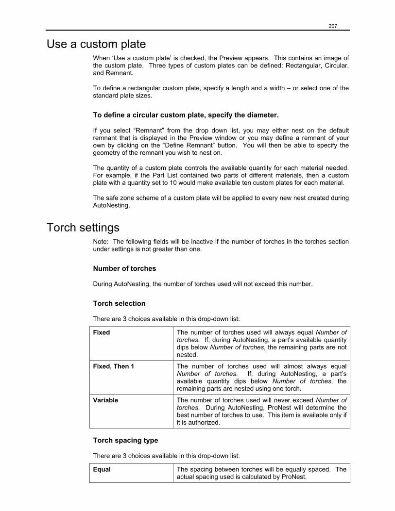
207
Use a custom plate When ‘Use a custom plate’ is checked, the Preview appears. This contains an image of the custom plate. Three types of custom plates can be defined: Rectangular, Circular, and Remnant.
To define a rectangular custom plate, specify a length and a width – or select one of the standard plate sizes.
To define a circular custom plate, specify the diameter.
If you select “Remnant” from the drop down list, you may either nest on the default remnant that is displayed in the Preview window or you may define a remnant of your own by clicking on the “Define Remnant” button. You will then be able to specify the geometry of the remnant you wish to nest on.
The quantity of a custom plate controls the available quantity for each material needed. For example, if the Part List contained two parts of different materials, then a custom plate with a quantity set to 10 would make available ten custom plates for each material.
The safe zone scheme of a custom plate will be applied to every new nest created during AutoNesting.
Torch settings Note: The following fields will be inactive if the number of torches in the torches section under settings is not greater than one.
Number of torches
During AutoNesting, the number of torches used will not exceed this number.
Torch selection
There are 3 choices available in this drop-down list:
Fixed The number of torches used will always equal Number of torches. If, during AutoNesting, a part’s available quantity dips below Number of torches, the remaining parts are not nested.
Fixed, Then 1 The number of torches used will almost always equal Number of torches. If, during AutoNesting, a part’s available quantity dips below Number of torches, the remaining parts are nested using one torch.
Variable The number of torches used will never exceed Number of torches. During AutoNesting, ProNest will determine the best number of torches to use. This item is available only if it is authorized.
Torch spacing type
There are 3 choices available in this drop-down list:
Equal The spacing between torches will be equally spaced. The actual spacing used is calculated by ProNest.
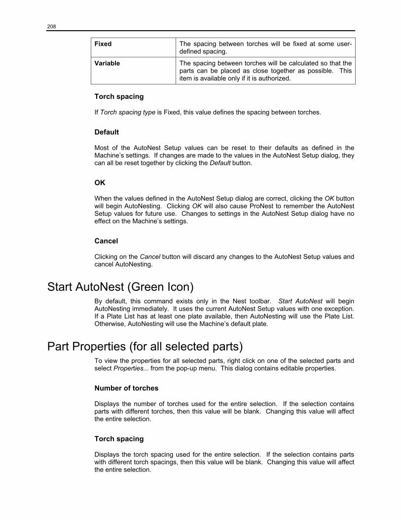
208
Fixed The spacing between torches will be fixed at some user-defined spacing.
Variable The spacing between torches will be calculated so that the parts can be placed as close together as possible. This item is available only if it is authorized.
Torch spacing
If Torch spacing type is Fixed, this value defines the spacing between torches.
Default
Most of the AutoNest Setup values can be reset to their defaults as defined in the Machine’s settings. If changes are made to the values in the AutoNest Setup dialog, they can all be reset together by clicking the Default button.
OK
When the values defined in the AutoNest Setup dialog are correct, clicking the OK button will begin AutoNesting. Clicking OK will also cause ProNest to remember the AutoNest Setup values for future use. Changes to settings in the AutoNest Setup dialog have no effect on the Machine’s settings.
Cancel
Clicking on the Cancel button will discard any changes to the AutoNest Setup values and cancel AutoNesting.
Start AutoNest (Green Icon) By default, this command exists only in the Nest toolbar. Start AutoNest will begin AutoNesting immediately. It uses the current AutoNest Setup values with one exception. If a Plate List has at least one plate available, then AutoNesting will use the Plate List. Otherwise, AutoNesting will use the Machine’s default plate.
Part Properties (for all selected parts) To view the properties for all selected parts, right click on one of the selected parts and select Properties... from the pop-up menu. This dialog contains editable properties.
Number of torches
Displays the number of torches used for the entire selection. If the selection contains parts with different torches, then this value will be blank. Changing this value will affect the entire selection.
Torch spacing
Displays the torch spacing used for the entire selection. If the selection contains parts with different torch spacings, then this value will be blank. Changing this value will affect the entire selection.
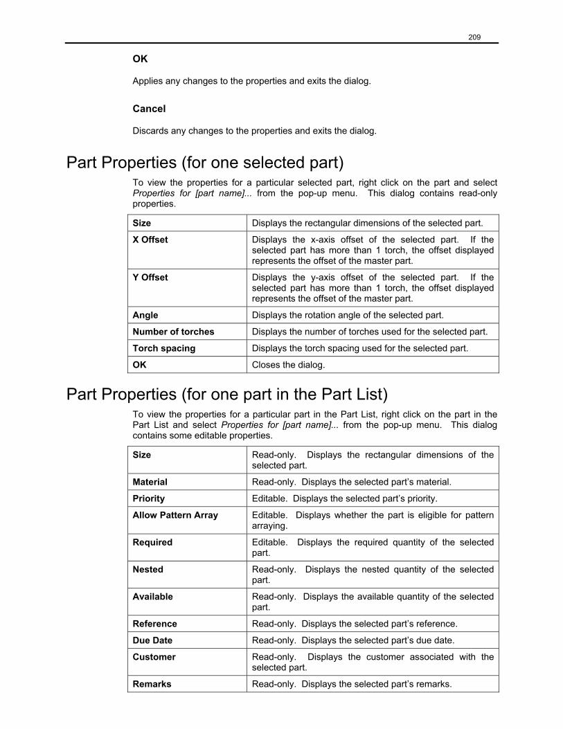
209
OK
Applies any changes to the properties and exits the dialog.
Cancel
Discards any changes to the properties and exits the dialog.
Part Properties (for one selected part) To view the properties for a particular selected part, right click on the part and select Properties for [part name]... from the pop-up menu. This dialog contains read-only properties.
Size Displays the rectangular dimensions of the selected part.
X Offset
Displays the x-axis offset of the selected part. If the selected part has more than 1 torch, the offset displayed represents the offset of the master part.
Y Offset
Displays the y-axis offset of the selected part. If the selected part has more than 1 torch, the offset displayed represents the offset of the master part.
Angle Displays the rotation angle of the selected part.
Number of torches Displays the number of torches used for the selected part.
Torch spacing Displays the torch spacing used for the selected part.
OK Closes the dialog.
Part Properties (for one part in the Part List) To view the properties for a particular part in the Part List, right click on the part in the Part List and select Properties for [part name]... from the pop-up menu. This dialog contains some editable properties.
Size Read-only. Displays the rectangular dimensions of the selected part.
Material Read-only. Displays the selected part’s material.
Priority Editable. Displays the selected part’s priority.
Allow Pattern Array Editable. Displays whether the part is eligible for pattern arraying.
Required Editable. Displays the required quantity of the selected part.
Nested Read-only. Displays the nested quantity of the selected part.
Available Read-only. Displays the available quantity of the selected part.
Reference Read-only. Displays the selected part’s reference.
Due Date Read-only. Displays the selected part’s due date.
Customer Read-only. Displays the customer associated with the selected part.
Remarks Read-only. Displays the selected part’s remarks.

210
Misc 1-3 Read-only. Displays miscellaneous information for the selected part.
OK Applies any changes to the properties and exits the dialog.
Cancel Discards any changes to the properties and exits the dialog.
Note: Most of the categories in the left column above (material, priority, etc.) can be entered in the part record under part list in the Add Parts screen.
211
Chapter 9: Process Parameters
Process parameters are process and material specific settings used in CNC output, costing and nesting. Process parameters can be specified in two ways - by using process parameters XLS tables or by using default process parameter settings. Process parameters XLS tables are spreadsheets containing settings for different materials, thickness ranges, profile types, profile areas, cut qualities and cut conditions. For a general discussion of XLS tables, see the XLS Tables Overview section. Default process parameter settings for each process reside on that process’ Process Parameters settings screen.
Default Process Parameters Default process parameters reside on the Process Parameters settings screen for a given process, which can be reached by going to File | Settings | Machine, selecting a process, then selecting Process Parameters from the processes’ tree view. To use default parameters check the Use default process parameters only checkbox. Default settings can be set for Kerf width, Feedrate, Part-part separation, Part-plate edge separation, and Part-pierce separation. Note that Pierce-pierce separation and Pierce-plate edge separation are calculated from the other separation values and may not be set.
Process Parameters XLS Table Using settings from a process parameters XLS table requires three steps. First, go to File | Settings | Processes and Layers, select a process, and select Process Parameters from the processes’ tree view. Next, uncheck the Use default process parameters only checkbox. Finally, choose a process parameters XLS table from the Process Parameters drop down box. Edit the XLS table by clicking on the icon to the right of the Process Parameters drop down box. XLS tables can be edited using the XLS Editor or using a spreadsheet editor such as Microsoft Excel. The File | Preferences | Settings | Use Microsoft Excel to edit spreadsheet contents checkbox determines which editor is used.
Like all XLS tables, the process parameters XLS table has a units cell located at A1, a column header row number cell located at B1, a column header located in the row specified by the column header row number and rows of data below the column header. For further information about XLS table formats see the discussion of the General XLS Table Format in the XLS Table Overview section.
The standard column-headings in a process parameters XLS table are Material, Thickness, Profile Area, Profile Type, Quality, Condition, Kerf, Feedrate, Dynamic Pierce, Part Sep, Plate Sep and Pierce Sep. User defined process parameters may be added to the XLS table as defined in a later section.
Material is a required key denoting the name of the material used. Any name can be used for this key. Examples of valid Material data include A36 and Mild Steel. An exact match of this key is required to select a record. This name must exactly match the name of the material selected when a part or plate is loaded.
Thickness is a required key denoting the thickness of the material used. An exact match is not required to match this key. A material thickness range is used as follows. A match is found if a record contains a thickness less than or equal to the required material thickness. If more than one record match is found, the record with the closest material thickness less than or equal to the required material thickness is selected. For instance, if the material thickness required is 0.5”, and a record exists with 0.5” material thickness, it is selected. If an exact match is not found and a record exists with a 0.25” material
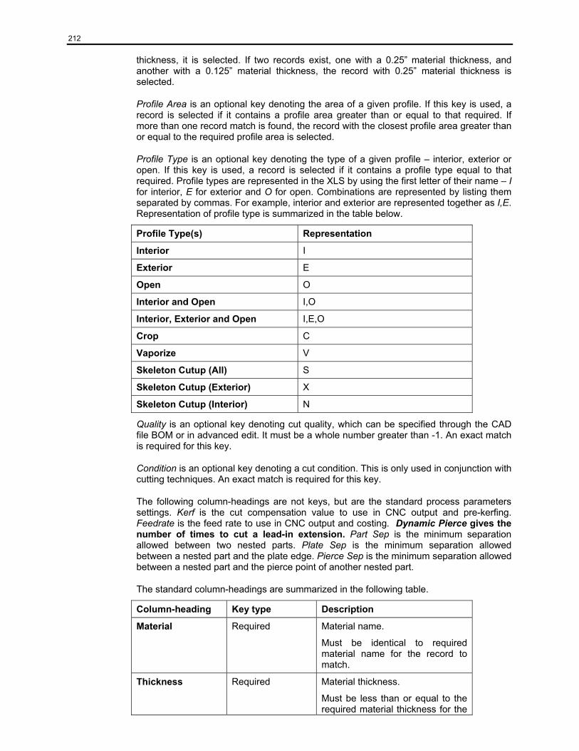
212
thickness, it is selected. If two records exist, one with a 0.25” material thickness, and another with a 0.125” material thickness, the record with 0.25” material thickness is selected.
Profile Area is an optional key denoting the area of a given profile. If this key is used, a record is selected if it contains a profile area greater than or equal to that required. If more than one record match is found, the record with the closest profile area greater than or equal to the required profile area is selected.
Profile Type is an optional key denoting the type of a given profile – interior, exterior or open. If this key is used, a record is selected if it contains a profile type equal to that required. Profile types are represented in the XLS by using the first letter of their name – I for interior, E for exterior and O for open. Combinations are represented by listing them separated by commas. For example, interior and exterior are represented together as I,E. Representation of profile type is summarized in the table below.
Profile Type(s) Representation
Interior I
Exterior E
Open O
Interior and Open I,O
Interior, Exterior and Open I,E,O
Crop C
Vaporize V
Skeleton Cutup (All) S
Skeleton Cutup (Exterior) X
Skeleton Cutup (Interior) N
Quality is an optional key denoting cut quality, which can be specified through the CAD file BOM or in advanced edit. It must be a whole number greater than -1. An exact match is required for this key.
Condition is an optional key denoting a cut condition. This is only used in conjunction with cutting techniques. An exact match is required for this key.
The following column-headings are not keys, but are the standard process parameters settings. Kerf is the cut compensation value to use in CNC output and pre-kerfing. Feedrate is the feed rate to use in CNC output and costing. Dynamic Pierce gives the number of times to cut a lead-in extension. Part Sep is the minimum separation allowed between two nested parts. Plate Sep is the minimum separation allowed between a nested part and the plate edge. Pierce Sep is the minimum separation allowed between a nested part and the pierce point of another nested part.
The standard column-headings are summarized in the following table.
Column-heading Key type Description
Material Required Material name.
Must be identical to required material name for the record to match.
Thickness Required Material thickness.
Must be less than or equal to the required material thickness for the
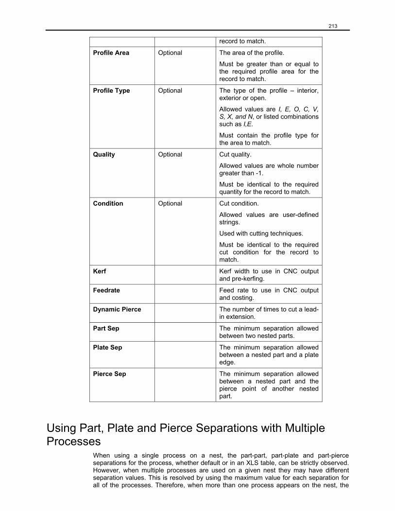
213
record to match.
Profile Area Optional The area of the profile.
Must be greater than or equal to the required profile area for the record to match.
Profile Type Optional The type of the profile – interior, exterior or open.
Allowed values are I, E, O, C, V, S, X, and N, or listed combinations such as I,E.
Must contain the profile type for the area to match.
Quality Optional Cut quality.
Allowed values are whole number greater than -1.
Must be identical to the required quantity for the record to match.
Condition Optional Cut condition.
Allowed values are user-defined strings.
Used with cutting techniques.
Must be identical to the required cut condition for the record to match.
Kerf Kerf width to use in CNC output and pre-kerfing.
Feedrate Feed rate to use in CNC output and costing.
Dynamic Pierce The number of times to cut a lead-in extension.
Part Sep The minimum separation allowed between two nested parts.
Plate Sep The minimum separation allowed between a nested part and a plate edge.
Pierce Sep The minimum separation allowed between a nested part and the pierce point of another nested part.
Using Part, Plate and Pierce Separations with Multiple Processes
When using a single process on a nest, the part-part, part-plate and part-pierce separations for the process, whether default or in an XLS table, can be strictly observed. However, when multiple processes are used on a given nest they may have different separation values. This is resolved by using the maximum value for each separation for all of the processes. Therefore, when more than one process appears on the nest, the
214
separations used will be those that lead to the greatest distance between parts, pierces and plate edge and that preserve the minimum separation requirements of all processes. Note that this comes at the expense of efficient material usage. Care should be taken to balance the needs of mixed process cutting and plate utilization.
Record Matching
Each row, or record, in a process parameters XLS table contains a complete set of process parameters settings values. Therefore, for a given instance of use, a single row or record must be selected by matching the combination of required and optional keys. Wildcards can also be used to prevent a proliferation of records caused by the use of many optional keys. If no record is found, the default process parameters settings are used. For a more detailed discussion of record matching see Record Matching in the XLS Table Overview section.
User Defined Process Parameters
In addition to the standard process parameters described above, process parameters can be added to the process parameter XLS table and used for CNC output. To add a user defined process parameter, edit the XLS table using the XLS Editor or Microsoft Excel and add a new column. Enter a name in the column header row, and enter data into the process parameters records. To use this parameter in CNC output, add the name, data type and default value to the [USER DEFINED VARIABLES] section of the CFF used by the desired machine. This parameter can then be used in any format section of the CFF and can be output to the CNC file or used in calculations or evaluations. Contact MTC technical support for more information. Note that user defined process parameters are only used for CNC output and not for nesting or costing. Units conversion is not done on user defined process parameters.
Units Conversion
Units conversion is done on the following columns: Thickness, Feedrate, Part Sep, Plate Sep, Pierce Sep, Kerf. Conversion is not done on user defined process parameters.
Saving Information in the Job
Process parameters XLS table information is not saved to or restored from jobs. Default process parameter information for each process is saved to and restored from jobs.
Using a Process Parameters XLS Table vs. Using Default Process Parameters
Process parameters XLS tables offer a powerful and flexible way to use settings specific to a given material and process, including part, plate and pierce separations. In addition, factors such as Profile Type, Profile Area, Quality, and Condition may be used to further specify a group of settings to use. This allows different feed rates and kerfs to be used in CNC output and costing for profiles of varying areas, quality and types such as interior vs. exterior. These factors can be combined to provide for very specific parameters to use in each of a wide array of cutting conditions. Settings can be defined for ranges of material thickness, avoiding the need to have a record for each material thickness. User defined process parameters can be added to the tables to meet CNC file output requirements. XLS tables provide the flexibility needed to handle process specific settings required to work with multiple process nests. Combined with cutting conditions, process parameters XLS tables allow tremendous control over the parameters used to nest, cut and cost parts.
215
Troubleshooting 1. What if I don’t get process parameters in CNC output?
• Go to File | Settings | CNC Settings and make sure Use machine parameters in output is checked.
• If using default process parameters, make sure the default feed rate and kerf values are not zero.
• Check the CFF to make sure it is set up to output process parameters.
2. What if I’m getting the wrong process parameters in output?
• Process parameters for the wrong process may be in use. Check CAD import layers to make sure the layers are mapping to the correct process. Another way to do this is to advanced edit the part and check the cut process for the profile in question.
• Make sure the correct XLS table record is being matched by checking the keys used (Material, Thickness, Profile Type, Profile Area and Quality.)
3. What if I’m not getting user defined process parameters in output?
• Make sure the proper XLS table is being used.
• Make sure the name in the XLS table column header matches that in the CFF.
• Make sure the CFF is properly set up to output the user defined process parameters.
• What if my process parameters are coming out in the wrong place in output?
• Check the CFF for proper formatting of CNC output.
• What if one of my keys is ignored? • Make sure the column-heading of the key is spelled correctly.
• If the ignored key is quality, go into advanced edit and check the quality value for the profile in question.
6. What if I always get default process parameters, even if I don’t have it checked?
• No matching record is found.
7. What if I’m getting incorrect separations?
• Check column header spellings.
• Check record match.
• If multiple processes are used for the same material, check the separations for all the processes. The largest separations are used.
216
Chapter 10: XLS Table Overview
XLS tables allow the use of process and material specific settings. There are four types of XLS tables - process parameters, lead style settings, costing settings and cutting techniques. These tables are spreadsheets and can be created and edited with the XLS Editor or with a spreadsheet application such as Microsoft Excel. Each XLS table can be used with one or more processes, and represents settings for the different material types and thickness ranges to be used with that process. An individual row of an XLS table contains settings for a given range of material thicknesses. In certain XLS table types, the process parameters table for example, it is possible to define settings dependent on additional factors such as cut quality, profile type and profile area.
XLS files reside in user defined locations that are set by going to File | Preferences | Settings. Note that each type of XLS table resides in a different folder. This makes it easier to manage multiple tables of a given type and to select the correct type of XLS table for a given process and usage.
XLS Table Types There are four XLS table types: process parameters, lead style settings, costing settings and cutting techniques. Process parameters tables contain information such as feed rate and kerf width used in CNC file output and costing. Lead style settings tables contain descriptions of lead styles to be applied to parts when they are loaded. Costing settings tables contain information used to calculate production time and cost. Cutting techniques tables contain specifications for things like radius and corner ramp downs. Autotab tables contain descriptions of automatic tabbing strategies to be applied to parts when they are loaded or when they are manually autotabbed. When an XLS table is assigned to a process, it must be the correct type for the desired usage.
Using XLS Tables To use XLS file settings, go to File | Settings | Machine and select a process. Choose XLS tables from the drop down boxes. If default settings are currently in use, this box will be inactive. Edit an XLS table by clicking on the edit icon to the right of its drop down box. Since each XLS table is designed to contain settings for all materials to be used with a given process, an XLS table of each type – process parameters, interior and exterior lead styles, costing and cutting techniques – should be assigned to each process. However, XLS tables can be shared between processes when it makes sense to do so.
Sharing XLS Tables
Each XLS table represents the settings for different material types and thickness ranges for a single process. However, the same XLS table may be used for multiple processes within a given machine, or for multiple processes across different machines. This reduces the need to maintain duplicate copies of a table if the same settings are to be used for different processes.
Editing XLS Tables
XLS tables can be edited using the XLS Editor or using a spreadsheet editor such as Microsoft Excel. The File | Preferences | Settings | Use Microsoft Excel to edit spreadsheet contents checkbox determines which editor is used. Rows can be added or removed, and data can be modified in the individual cells. New columns may also be added to certain table types. See the individual table type sections for further information.
217
Table cells are not required to be formatted in any particular way. Column header names such as Material and Thickness should not be modified because the application looks for specific column header names when matching records and loading data. If using the Save As feature, be sure to save the table in Microsoft Excel Workbook format.
General XLS Table Format XLS tables have a required format consisting of four components: a units cell, a column header row cell, a column header, and rows of data.
The units cell is located in the upper left hand corner of the table in cell A1 and specifies the units used in the table. Allowed values for this cell are inch and mm. If this cell is blank, inch is assumed. Note that only certain table values will be converted between different units if required (for instance, if the table is in mm but the CNC output is required in inch.) See the Units Conversion section below for further information.
The row number of the required column header is located in cell B1, just to the right of the units cell, and specifies the row number of the required column header, which contains column-heading names such as Material and Thickness. If this cell is blank, a value of 2 is assumed. This can be modified if rows of information must be added above the required column header, for things such as translated column-headings.
The column header resides in the row specified by the column header row number in cell B1. Each cell of this row contains the name of the data stored in that column. For instance, the column-heading name Material specifies a column containing the names of different materials. In general, the column header should not be modified because the application expects this data to exist in a specific format and context. Modifying the information in this row may lead to the inability to use information from an XLS table. However, columns may be moved to improve readability of the table. Also, for certain XLS table types columns may be added or removed. See individual table type sections for further information.
The rows of settings data begin immediately below the column header. Rows may be added or removed and the data may be modified. The proper type of data must be entered into each cell. For instance, numeric data should be entered in the Thickness column, and alphanumeric data should be entered into the Material column.
The XLS table required format is summarized in the table below.
Format Item Description
Units cell Value in cell A1 that specifies the table’s units. Allowed values are inch and mm.
Column header row cell Value in cell B1 that specifies the row of the required column header. Allowed values are whole numbers greater than or equal to 2.
Column header The required row of column-headings. These values should not be changed.
Data row(s) One or more rows of settings data, immediately below the column header. Allowed values vary between columns.
Record Matching
Each row, or record, in an XLS table contains a complete set of settings values. Therefore, for a given instance of use, a single row or record must be selected by using
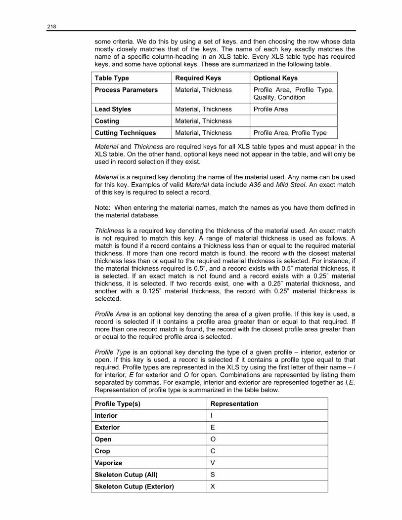
218
some criteria. We do this by using a set of keys, and then choosing the row whose data mostly closely matches that of the keys. The name of each key exactly matches the name of a specific column-heading in an XLS table. Every XLS table type has required keys, and some have optional keys. These are summarized in the following table.
Table Type Required Keys Optional Keys
Process Parameters Material, Thickness Profile Area, Profile Type, Quality, Condition
Lead Styles Material, Thickness Profile Area
Costing Material, Thickness
Cutting Techniques Material, Thickness Profile Area, Profile Type
Material and Thickness are required keys for all XLS table types and must appear in the XLS table. On the other hand, optional keys need not appear in the table, and will only be used in record selection if they exist.
Material is a required key denoting the name of the material used. Any name can be used for this key. Examples of valid Material data include A36 and Mild Steel. An exact match of this key is required to select a record.
Note: When entering the material names, match the names as you have them defined in the material database.
Thickness is a required key denoting the thickness of the material used. An exact match is not required to match this key. A range of material thickness is used as follows. A match is found if a record contains a thickness less than or equal to the required material thickness. If more than one record match is found, the record with the closest material thickness less than or equal to the required material thickness is selected. For instance, if the material thickness required is 0.5”, and a record exists with 0.5” material thickness, it is selected. If an exact match is not found and a record exists with a 0.25” material thickness, it is selected. If two records exist, one with a 0.25” material thickness, and another with a 0.125” material thickness, the record with 0.25” material thickness is selected.
Profile Area is an optional key denoting the area of a given profile. If this key is used, a record is selected if it contains a profile area greater than or equal to that required. If more than one record match is found, the record with the closest profile area greater than or equal to the required profile area is selected.
Profile Type is an optional key denoting the type of a given profile – interior, exterior or open. If this key is used, a record is selected if it contains a profile type equal to that required. Profile types are represented in the XLS by using the first letter of their name – I for interior, E for exterior and O for open. Combinations are represented by listing them separated by commas. For example, interior and exterior are represented together as I,E. Representation of profile type is summarized in the table below.
Profile Type(s) Representation
Interior I
Exterior E
Open O
Crop C
Vaporize V
Skeleton Cutup (All) S
Skeleton Cutup (Exterior) X
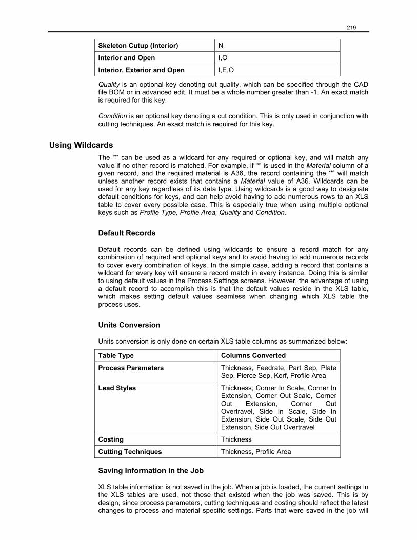
219
Skeleton Cutup (Interior) N
Interior and Open I,O
Interior, Exterior and Open I,E,O
Quality is an optional key denoting cut quality, which can be specified through the CAD file BOM or in advanced edit. It must be a whole number greater than -1. An exact match is required for this key.
Condition is an optional key denoting a cut condition. This is only used in conjunction with cutting techniques. An exact match is required for this key.
Using Wildcards The ‘*’ can be used as a wildcard for any required or optional key, and will match any value if no other record is matched. For example, if ‘*’ is used in the Material column of a given record, and the required material is A36, the record containing the ‘*’ will match unless another record exists that contains a Material value of A36. Wildcards can be used for any key regardless of its data type. Using wildcards is a good way to designate default conditions for keys, and can help avoid having to add numerous rows to an XLS table to cover every possible case. This is especially true when using multiple optional keys such as Profile Type, Profile Area, Quality and Condition.
Default Records
Default records can be defined using wildcards to ensure a record match for any combination of required and optional keys and to avoid having to add numerous records to cover every combination of keys. In the simple case, adding a record that contains a wildcard for every key will ensure a record match in every instance. Doing this is similar to using default values in the Process Settings screens. However, the advantage of using a default record to accomplish this is that the default values reside in the XLS table, which makes setting default values seamless when changing which XLS table the process uses.
Units Conversion
Units conversion is only done on certain XLS table columns as summarized below:
Table Type Columns Converted
Process Parameters Thickness, Feedrate, Part Sep, Plate Sep, Pierce Sep, Kerf, Profile Area
Lead Styles Thickness, Corner In Scale, Corner In Extension, Corner Out Scale, Corner Out Extension, Corner Out Overtravel, Side In Scale, Side In Extension, Side Out Scale, Side Out Extension, Side Out Overtravel
Costing Thickness
Cutting Techniques Thickness, Profile Area
Saving Information in the Job
XLS table information is not saved in the job. When a job is loaded, the current settings in the XLS tables are used, not those that existed when the job was saved. This is by design, since process parameters, cutting techniques and costing should reflect the latest changes to process and material specific settings. Parts that were saved in the job will

220
retain their original lead styles, but new parts loaded will reflect the current lead style settings.
The Advantages and Disadvantages of Using XLS Tables XLS tables provide a powerful and flexible way to use settings specific to a given material and process. In addition, factors such as Profile Type, Profile Area, Quality, and Condition may be used to further specify a group of settings to use. In a single job, different lead styles can be applied to parts as they are loaded based on material, thickness, and process; different kerfs and feed rates can be output in the CNC file based on profile area, profile type, or cut quality; and different cutting techniques can be applied to interior and exterior profiles. In addition, settings can be defined for ranges of material thickness, avoiding the need to have a record for each material thickness.
There are disadvantages to using XLS tables. First, each key used dramatically increases the number of records required. This can be calculated as follows:
(Number of possible values of Key1) * (Number of possible values of Key2) *… * (Number of possible values of Keyn)
For example, if three keys are used - Material, Thickness, and Profile Type – and there are two material types, five thickness ranges for each and all three profile types are used, the total number of records required if a unique set of settings is desired for each case is 2 * 5 * 3 = 30 records. It is easy to see how an explosion of records can occur when optional keys are used. Using wildcards helps to mitigate this, however.
Another difficult issue is record matching. Care must be taken to ensure that each XLS table contains records that cover all combinations of keys that are required by the application, or that appropriate default records are defined. If a record match is not found in an XLS table, default values from the Process Settings will be used for table types that have them, or an error will be generated.
Finally, the material name of an XLS table record must exactly match that of the ProNest Database material table record that was used when a given part or plate was loaded. Although case and white space are not considered, the spelling and punctuation of each name must be identical between the records of the XLS table and the Database material, or no record will be matched in the XLS table.
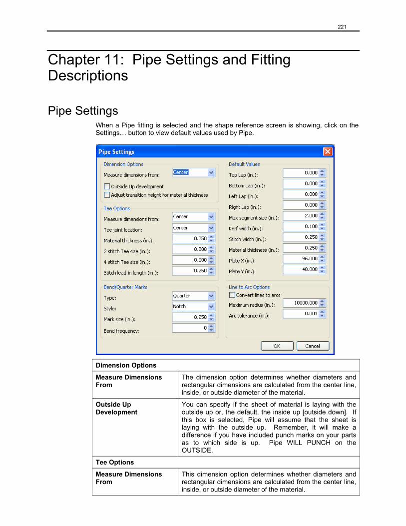
221
Chapter 11: Pipe Settings and Fitting Descriptions
Pipe Settings When a Pipe fitting is selected and the shape reference screen is showing, click on the Settings… button to view default values used by Pipe.
Dimension Options
Measure Dimensions From
The dimension option determines whether diameters and rectangular dimensions are calculated from the center line, inside, or outside diameter of the material.
Outside Up Development
You can specify if the sheet of material is laying with the outside up or, the default, the inside up [outside down]. If this box is selected, Pipe will assume that the sheet is laying with the outside up. Remember, it will make a difference if you have included punch marks on your parts as to which side is up. Pipe WILL PUNCH on the OUTSIDE.
Tee Options
Measure Dimensions From
This dimension option determines whether diameters and rectangular dimensions are calculated from the center line, inside, or outside diameter of the material.
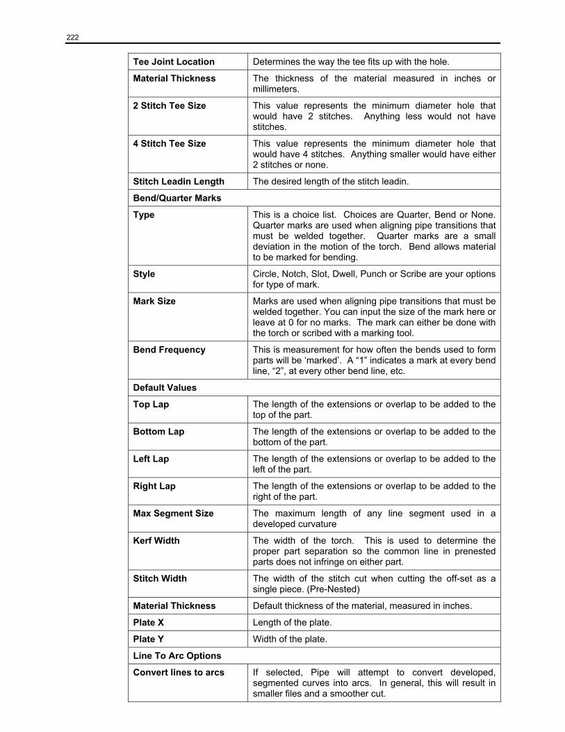
222
Tee Joint Location Determines the way the tee fits up with the hole.
Material Thickness The thickness of the material measured in inches or millimeters.
2 Stitch Tee Size This value represents the minimum diameter hole that would have 2 stitches. Anything less would not have stitches.
4 Stitch Tee Size This value represents the minimum diameter hole that would have 4 stitches. Anything smaller would have either 2 stitches or none.
Stitch Leadin Length The desired length of the stitch leadin.
Bend/Quarter Marks
Type This is a choice list. Choices are Quarter, Bend or None. Quarter marks are used when aligning pipe transitions that must be welded together. Quarter marks are a small deviation in the motion of the torch. Bend allows material to be marked for bending.
Style Circle, Notch, Slot, Dwell, Punch or Scribe are your options for type of mark.
Mark Size Marks are used when aligning pipe transitions that must be welded together. You can input the size of the mark here or leave at 0 for no marks. The mark can either be done with the torch or scribed with a marking tool.
Bend Frequency This is measurement for how often the bends used to form parts will be ‘marked’. A “1” indicates a mark at every bend line, “2”, at every other bend line, etc.
Default Values
Top Lap The length of the extensions or overlap to be added to the top of the part.
Bottom Lap The length of the extensions or overlap to be added to the bottom of the part.
Left Lap The length of the extensions or overlap to be added to the left of the part.
Right Lap The length of the extensions or overlap to be added to the right of the part.
Max Segment Size The maximum length of any line segment used in a developed curvature
Kerf Width The width of the torch. This is used to determine the proper part separation so the common line in prenested parts does not infringe on either part.
Stitch Width The width of the stitch cut when cutting the off-set as a single piece. (Pre-Nested)
Material Thickness Default thickness of the material, measured in inches.
Plate X Length of the plate.
Plate Y Width of the plate.
Line To Arc Options
Convert lines to arcs If selected, Pipe will attempt to convert developed, segmented curves into arcs. In general, this will result in smaller files and a smoother cut.
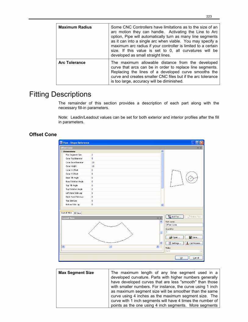
223
Maximum Radius Some CNC Controllers have limitations as to the size of an arc motion they can handle. Activating the Line to Arc option, Pipe will automatically turn as many line segments as it can into a single arc when viable. You may specify a maximum arc radius if your controller is limited to a certain size. If this value is set to 0, all curvatures will be developed as small straight lines.
Arc Tolerance The maximum allowable distance from the developed curve that arcs can be in order to replace line segments. Replacing the lines of a developed curve smooths the curve and creates smaller CNC files but if the arc tolerance is too large, accuracy will be diminished.
Fitting Descriptions The remainder of this section provides a description of each part along with the necessary fill-in parameters.
Note: Leadin/Leadout values can be set for both exterior and interior profiles after the fill in parameters.
Offset Cone
Max Segment Size The maximum length of any line segment used in a
developed curvature. Parts with higher numbers generally have developed curves that are less "smooth" than those with smaller numbers. For instance, the curve using 1 inch as maximum segment size will be smoother than the same curve using 4 inches as the maximum segment size. The curve with 1 inch segments will have 4 times the number of points as the one using 4 inch segments. More segments
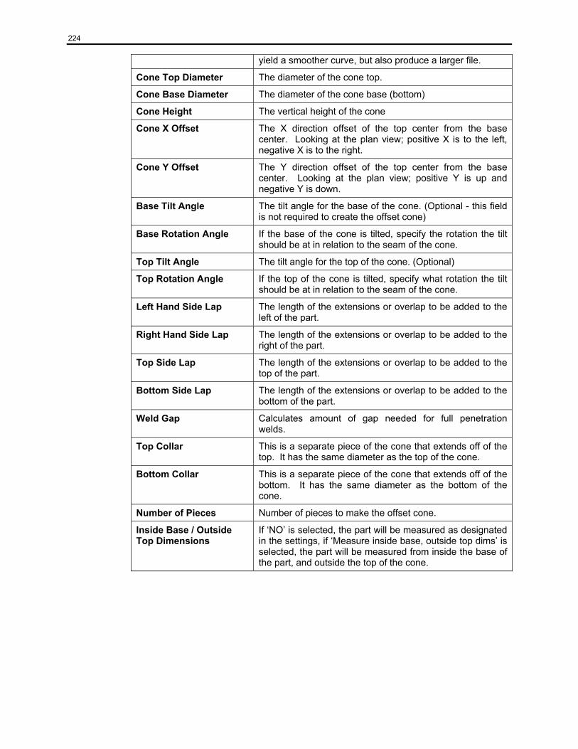
224
yield a smoother curve, but also produce a larger file.
Cone Top Diameter The diameter of the cone top.
Cone Base Diameter The diameter of the cone base (bottom)
Cone Height The vertical height of the cone
Cone X Offset The X direction offset of the top center from the base center. Looking at the plan view; positive X is to the left, negative X is to the right.
Cone Y Offset The Y direction offset of the top center from the base center. Looking at the plan view; positive Y is up and negative Y is down.
Base Tilt Angle The tilt angle for the base of the cone. (Optional - this field is not required to create the offset cone)
Base Rotation Angle If the base of the cone is tilted, specify the rotation the tilt should be at in relation to the seam of the cone.
Top Tilt Angle The tilt angle for the top of the cone. (Optional)
Top Rotation Angle If the top of the cone is tilted, specify what rotation the tilt should be at in relation to the seam of the cone.
Left Hand Side Lap The length of the extensions or overlap to be added to the left of the part.
Right Hand Side Lap The length of the extensions or overlap to be added to the right of the part.
Top Side Lap The length of the extensions or overlap to be added to the top of the part.
Bottom Side Lap The length of the extensions or overlap to be added to the bottom of the part.
Weld Gap Calculates amount of gap needed for full penetration welds.
Top Collar This is a separate piece of the cone that extends off of the top. It has the same diameter as the top of the cone.
Bottom Collar This is a separate piece of the cone that extends off of the bottom. It has the same diameter as the bottom of the cone.
Number of Pieces Number of pieces to make the offset cone.
Inside Base / Outside Top Dimensions
If ‘NO’ is selected, the part will be measured as designated in the settings, if ‘Measure inside base, outside top dims’ is selected, the part will be measured from inside the base of the part, and outside the top of the cone.
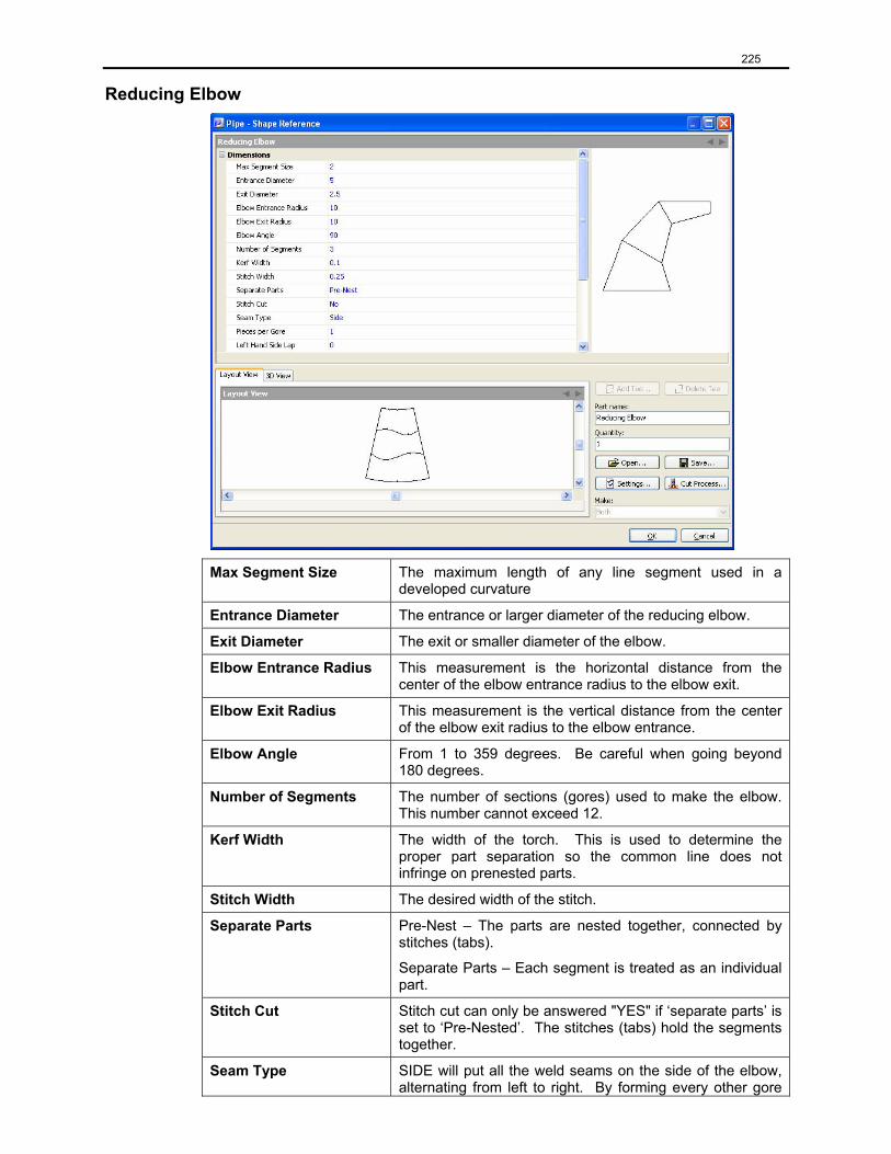
225
Reducing Elbow
Max Segment Size The maximum length of any line segment used in a developed curvature
Entrance Diameter The entrance or larger diameter of the reducing elbow.
Exit Diameter The exit or smaller diameter of the elbow.
Elbow Entrance Radius This measurement is the horizontal distance from the center of the elbow entrance radius to the elbow exit.
Elbow Exit Radius This measurement is the vertical distance from the center of the elbow exit radius to the elbow entrance.
Elbow Angle From 1 to 359 degrees. Be careful when going beyond 180 degrees.
Number of Segments The number of sections (gores) used to make the elbow. This number cannot exceed 12.
Kerf Width The width of the torch. This is used to determine the proper part separation so the common line does not infringe on prenested parts.
Stitch Width The desired width of the stitch.
Separate Parts Pre-Nest – The parts are nested together, connected by stitches (tabs).
Separate Parts – Each segment is treated as an individual part.
Stitch Cut Stitch cut can only be answered "YES" if ‘separate parts’ is set to ‘Pre-Nested’. The stitches (tabs) hold the segments together.
Seam Type SIDE will put all the weld seams on the side of the elbow, alternating from left to right. By forming every other gore
226
inside out, all seams will end up on the right or left.
Heel/Throat locates the seam on the short side of the elbow.
Pieces per Gore The number of individual pieces used to make a single section (gore). (1,2,4,8)
Left Hand Side Lap The length of the extensions or overlap to be added to the left of the part.
Right Hand Side Lap The length of the extensions or overlap to be added to the right of the part.
Top Side Lap The length of the extensions or overlap to be added to the top of the part.
Bottom Side Lap The length of the extensions or overlap to be added to the bottom of the part.
Weld Gap Calculates amount of gap needed for full penetration welds.
Top Collar This is a separate piece of the cone that extends off of the top. It has the same diameter as the top of the cone.
Bottom Collar This is a separate piece of the cone that extends off of the bottom. It has the same diameter as the bottom of the cone.
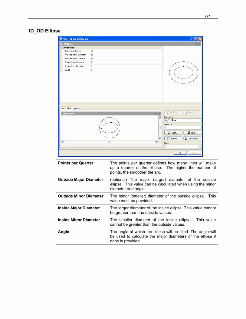
227
ID_OD Ellipse
Points per Quarter The points per quarter defines how many lines will make up a quarter of the ellipse. The higher the number of points, the smoother the arc.
Outside Major Diameter (optional) The major (larger) diameter of the outside ellipse. This value can be calculated when using the minor diameter and angle.
Outside Minor Diameter The minor (smaller) diameter of the outside ellipse. This value must be provided.
Inside Major Diameter The larger diameter of the inside ellipse. This value cannot be greater than the outside values.
Inside Minor Diameter The smaller diameter of the inside ellipse. This value cannot be greater than the outside values.
Angle The angle at which the ellipse will be tilted. The angle will be used to calculate the major diameters of the ellipse if none is provided.
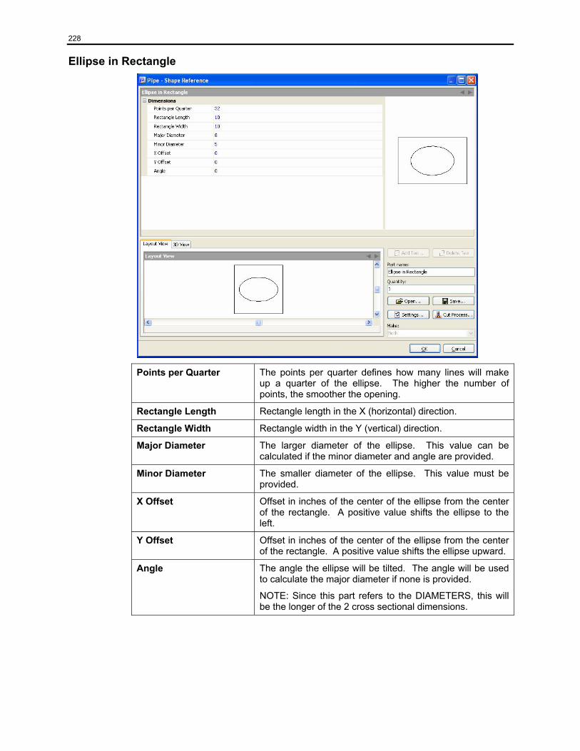
228
Ellipse in Rectangle
Points per Quarter The points per quarter defines how many lines will make up a quarter of the ellipse. The higher the number of points, the smoother the opening.
Rectangle Length Rectangle length in the X (horizontal) direction.
Rectangle Width Rectangle width in the Y (vertical) direction.
Major Diameter The larger diameter of the ellipse. This value can be calculated if the minor diameter and angle are provided.
Minor Diameter The smaller diameter of the ellipse. This value must be provided.
X Offset Offset in inches of the center of the ellipse from the center of the rectangle. A positive value shifts the ellipse to the left.
Y Offset Offset in inches of the center of the ellipse from the center of the rectangle. A positive value shifts the ellipse upward.
Angle The angle the ellipse will be tilted. The angle will be used to calculate the major diameter if none is provided.
NOTE: Since this part refers to the DIAMETERS, this will be the longer of the 2 cross sectional dimensions.
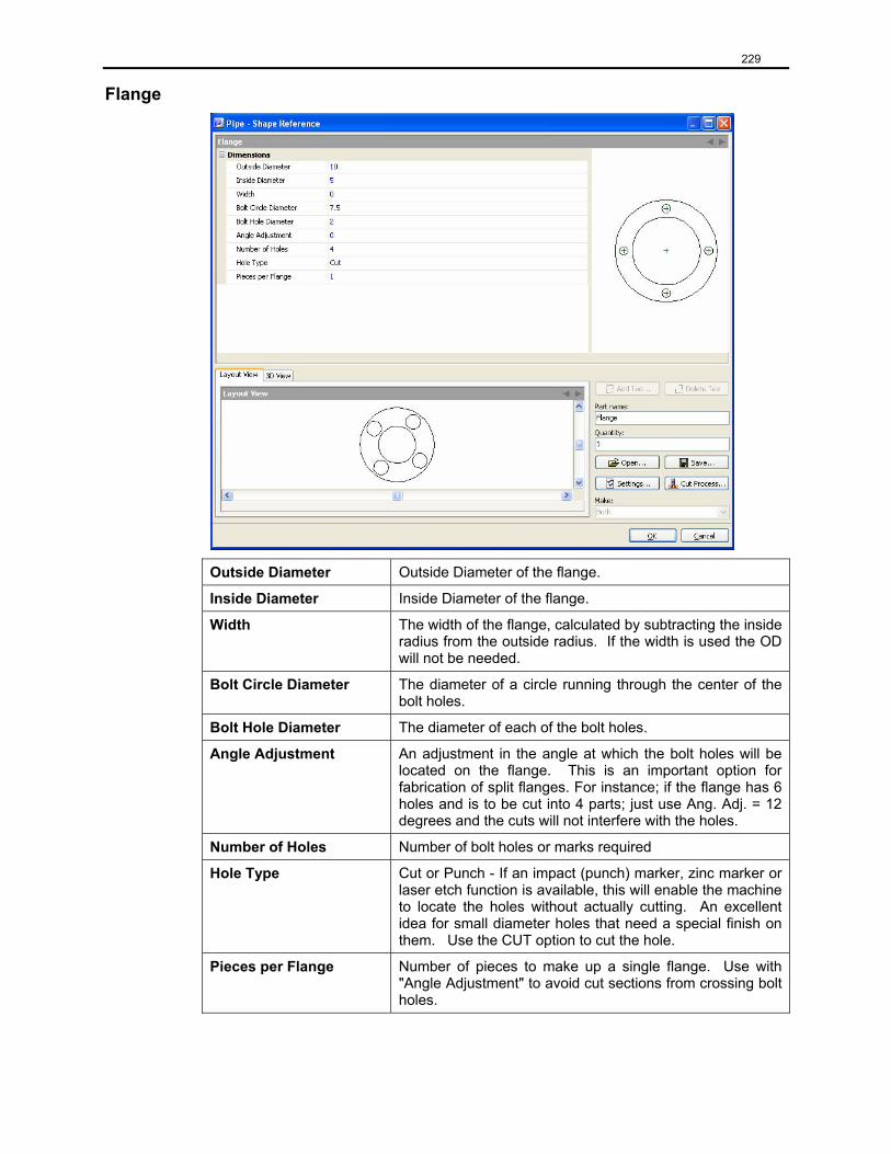
229
Flange
Outside Diameter Outside Diameter of the flange.
Inside Diameter Inside Diameter of the flange.
Width The width of the flange, calculated by subtracting the inside radius from the outside radius. If the width is used the OD will not be needed.
Bolt Circle Diameter The diameter of a circle running through the center of the bolt holes.
Bolt Hole Diameter The diameter of each of the bolt holes.
Angle Adjustment An adjustment in the angle at which the bolt holes will be located on the flange. This is an important option for fabrication of split flanges. For instance; if the flange has 6 holes and is to be cut into 4 parts; just use Ang. Adj. = 12 degrees and the cuts will not interfere with the holes.
Number of Holes Number of bolt holes or marks required
Hole Type Cut or Punch - If an impact (punch) marker, zinc marker or laser etch function is available, this will enable the machine to locate the holes without actually cutting. An excellent idea for small diameter holes that need a special finish on them. Use the CUT option to cut the hole.
Pieces per Flange Number of pieces to make up a single flange. Use with "Angle Adjustment" to avoid cut sections from crossing bolt holes.
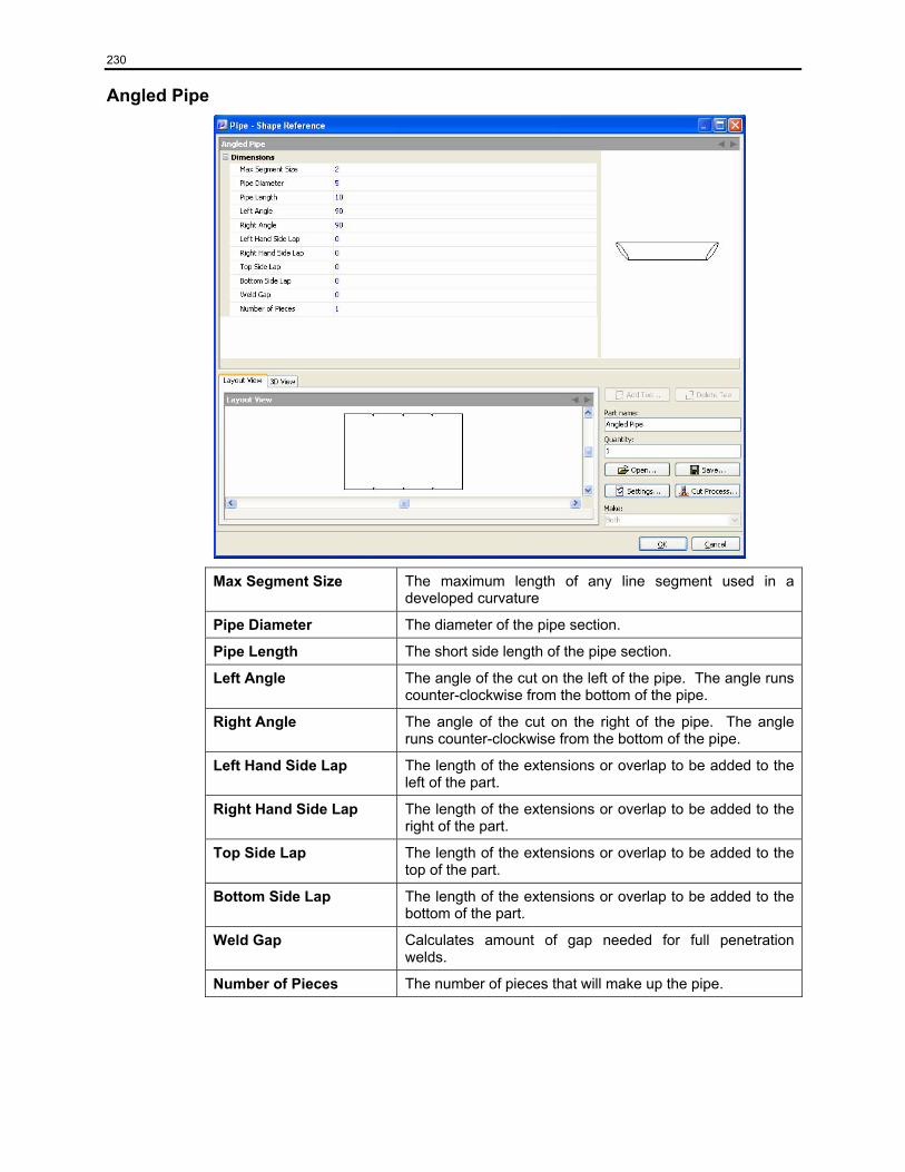
230
Angled Pipe
Max Segment Size The maximum length of any line segment used in a developed curvature
Pipe Diameter The diameter of the pipe section.
Pipe Length The short side length of the pipe section.
Left Angle The angle of the cut on the left of the pipe. The angle runs counter-clockwise from the bottom of the pipe.
Right Angle The angle of the cut on the right of the pipe. The angle runs counter-clockwise from the bottom of the pipe.
Left Hand Side Lap The length of the extensions or overlap to be added to the left of the part.
Right Hand Side Lap The length of the extensions or overlap to be added to the right of the part.
Top Side Lap The length of the extensions or overlap to be added to the top of the part.
Bottom Side Lap The length of the extensions or overlap to be added to the bottom of the part.
Weld Gap Calculates amount of gap needed for full penetration welds.
Number of Pieces The number of pieces that will make up the pipe.
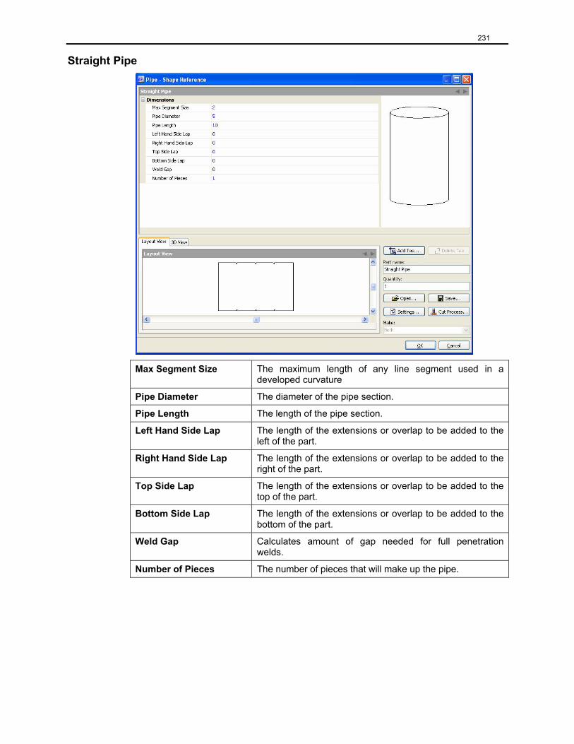
231
Straight Pipe
Max Segment Size The maximum length of any line segment used in a developed curvature
Pipe Diameter The diameter of the pipe section.
Pipe Length The length of the pipe section.
Left Hand Side Lap The length of the extensions or overlap to be added to the left of the part.
Right Hand Side Lap The length of the extensions or overlap to be added to the right of the part.
Top Side Lap The length of the extensions or overlap to be added to the top of the part.
Bottom Side Lap The length of the extensions or overlap to be added to the bottom of the part.
Weld Gap Calculates amount of gap needed for full penetration welds.
Number of Pieces The number of pieces that will make up the pipe.
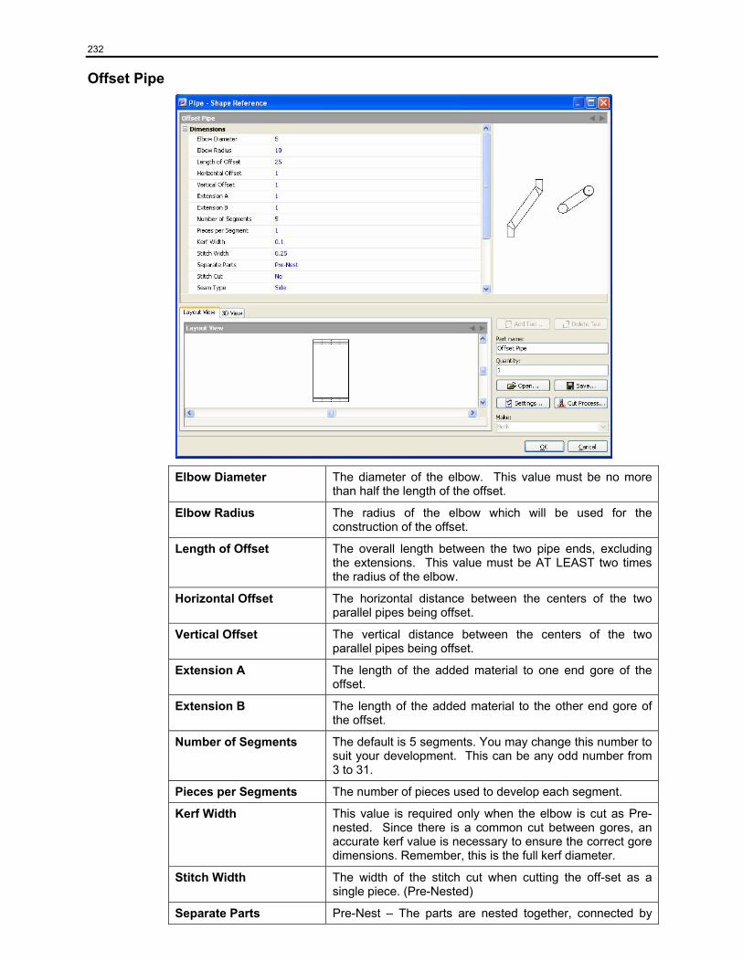
232
Offset Pipe
Elbow Diameter The diameter of the elbow. This value must be no more than half the length of the offset.
Elbow Radius The radius of the elbow which will be used for the construction of the offset.
Length of Offset The overall length between the two pipe ends, excluding the extensions. This value must be AT LEAST two times the radius of the elbow.
Horizontal Offset The horizontal distance between the centers of the two parallel pipes being offset.
Vertical Offset The vertical distance between the centers of the two parallel pipes being offset.
Extension A The length of the added material to one end gore of the offset.
Extension B The length of the added material to the other end gore of the offset.
Number of Segments The default is 5 segments. You may change this number to suit your development. This can be any odd number from 3 to 31.
Pieces per Segments The number of pieces used to develop each segment.
Kerf Width This value is required only when the elbow is cut as Pre-nested. Since there is a common cut between gores, an accurate kerf value is necessary to ensure the correct gore dimensions. Remember, this is the full kerf diameter.
Stitch Width The width of the stitch cut when cutting the off-set as a single piece. (Pre-Nested)
Separate Parts Pre-Nest – The parts are nested together, connected by
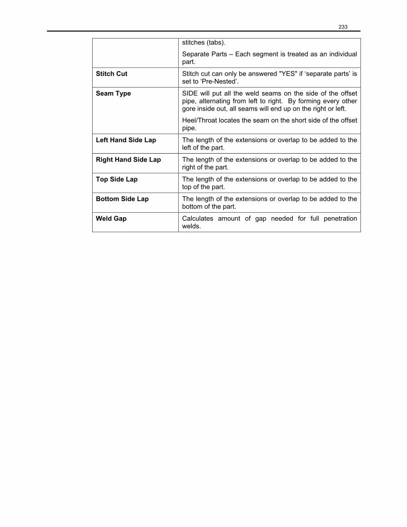
233
stitches (tabs).
Separate Parts – Each segment is treated as an individual part.
Stitch Cut Stitch cut can only be answered "YES" if ‘separate parts’ is set to ‘Pre-Nested’.
Seam Type SIDE will put all the weld seams on the side of the offset pipe, alternating from left to right. By forming every other gore inside out, all seams will end up on the right or left.
Heel/Throat locates the seam on the short side of the offset pipe.
Left Hand Side Lap The length of the extensions or overlap to be added to the left of the part.
Right Hand Side Lap The length of the extensions or overlap to be added to the right of the part.
Top Side Lap The length of the extensions or overlap to be added to the top of the part.
Bottom Side Lap The length of the extensions or overlap to be added to the bottom of the part.
Weld Gap Calculates amount of gap needed for full penetration welds.
234
Rectangle to Round
Max Segment Size The maximum length of any line segment used in a developed curvature
Rectangle Length The length of the rectangular base.
Rectangle Width The width of the rectangular base.
Transition Height The vertical height of the transition. This height is derived from a plane that passes horizontally through the center of the circular end (no matter what the tilt), to a parallel plane that passes horizontally through the center of the rectangular end (no matter what tilt).
Exit Diameter The diameter of the exit. This shape will always be maintained as a circle no matter what the tilt.
Exit Center X Offset The offset of the center of the exit in relation to the center of the rectangle. A positive value moves the center to the left, a negative, to the right.
Exit Center Y Offset The offset of the circular center from the center of the rectangle in the positive (up) or negative (down) Y direction.
Exit Tilt Angle The tilt of the exit from the horizontal plane. When looking at the transition in elevation, with the diameter on top, if the diameter is horizontal then this is zero (0). The right side MUST rotate down (clock-wise). This will establish the tilt "Angle". To adjust the position of the angle use the next input field.
Exit Rotation Angle The rotation of the low point of the exit tilt, as viewed from the plan view. A zero value locates the low point at the 3 o'clock position. A positive angle rotates this low point in a counter-clockwise direction. (i.e.: 60° rotates the low point
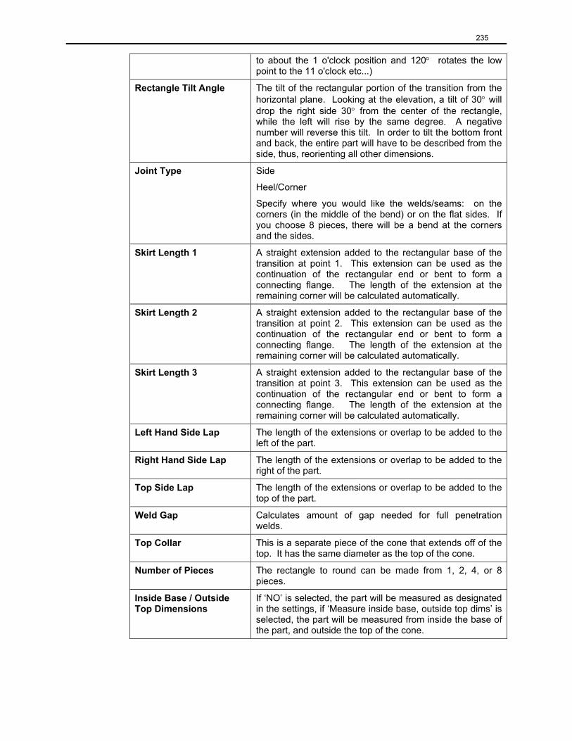
235
to about the 1 o'clock position and 120° rotates the low point to the 11 o'clock etc...)
Rectangle Tilt Angle The tilt of the rectangular portion of the transition from the horizontal plane. Looking at the elevation, a tilt of 30° will drop the right side 30° from the center of the rectangle, while the left will rise by the same degree. A negative number will reverse this tilt. In order to tilt the bottom front and back, the entire part will have to be described from the side, thus, reorienting all other dimensions.
Joint Type Side
Heel/Corner
Specify where you would like the welds/seams: on the corners (in the middle of the bend) or on the flat sides. If you choose 8 pieces, there will be a bend at the corners and the sides.
Skirt Length 1 A straight extension added to the rectangular base of the transition at point 1. This extension can be used as the continuation of the rectangular end or bent to form a connecting flange. The length of the extension at the remaining corner will be calculated automatically.
Skirt Length 2 A straight extension added to the rectangular base of the transition at point 2. This extension can be used as the continuation of the rectangular end or bent to form a connecting flange. The length of the extension at the remaining corner will be calculated automatically.
Skirt Length 3 A straight extension added to the rectangular base of the transition at point 3. This extension can be used as the continuation of the rectangular end or bent to form a connecting flange. The length of the extension at the remaining corner will be calculated automatically.
Left Hand Side Lap The length of the extensions or overlap to be added to the left of the part.
Right Hand Side Lap The length of the extensions or overlap to be added to the right of the part.
Top Side Lap The length of the extensions or overlap to be added to the top of the part.
Weld Gap Calculates amount of gap needed for full penetration welds.
Top Collar This is a separate piece of the cone that extends off of the top. It has the same diameter as the top of the cone.
Number of Pieces The rectangle to round can be made from 1, 2, 4, or 8 pieces.
Inside Base / Outside Top Dimensions
If ‘NO’ is selected, the part will be measured as designated in the settings, if ‘Measure inside base, outside top dims’ is selected, the part will be measured from inside the base of the part, and outside the top of the cone.
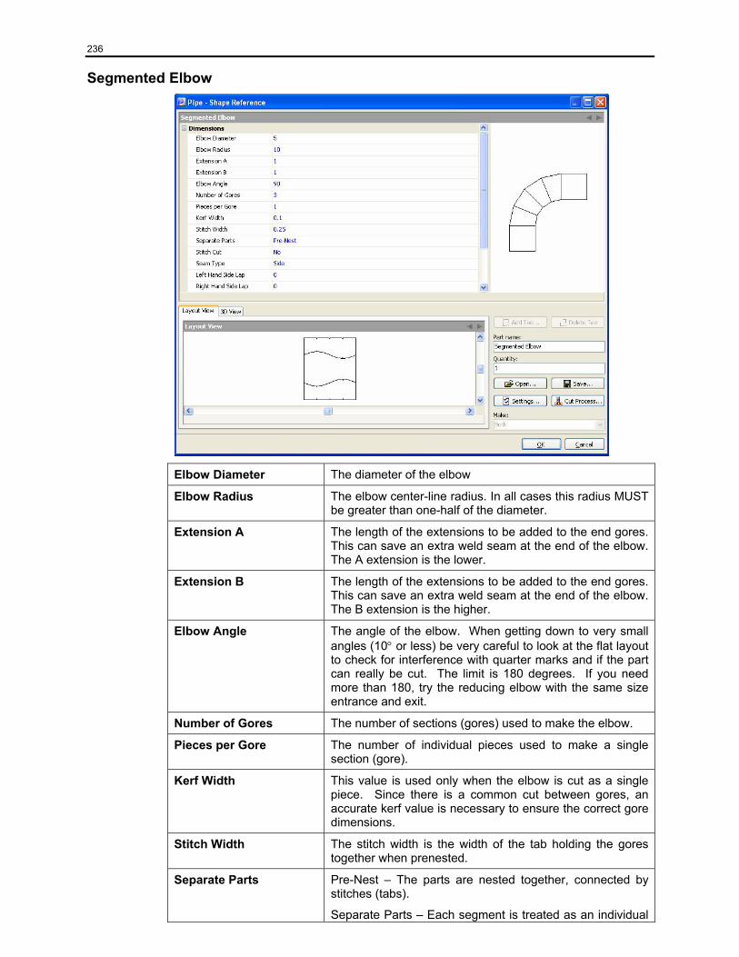
236
Segmented Elbow
Elbow Diameter The diameter of the elbow
Elbow Radius The elbow center-line radius. In all cases this radius MUST be greater than one-half of the diameter.
Extension A The length of the extensions to be added to the end gores. This can save an extra weld seam at the end of the elbow. The A extension is the lower.
Extension B The length of the extensions to be added to the end gores. This can save an extra weld seam at the end of the elbow. The B extension is the higher.
Elbow Angle The angle of the elbow. When getting down to very small angles (10° or less) be very careful to look at the flat layout to check for interference with quarter marks and if the part can really be cut. The limit is 180 degrees. If you need more than 180, try the reducing elbow with the same size entrance and exit.
Number of Gores The number of sections (gores) used to make the elbow.
Pieces per Gore The number of individual pieces used to make a single section (gore).
Kerf Width This value is used only when the elbow is cut as a single piece. Since there is a common cut between gores, an accurate kerf value is necessary to ensure the correct gore dimensions.
Stitch Width The stitch width is the width of the tab holding the gores together when prenested.
Separate Parts Pre-Nest – The parts are nested together, connected by stitches (tabs).
Separate Parts – Each segment is treated as an individual
237
part.
Stitch Cut Stitch cut can only be answered "YES" if ‘separate parts’ is set to ‘Pre-Nested’.
Seam Type SIDE will put all the weld seams on the side of the elbow, alternating from left to right. By forming every other gore inside out, all seams will end up on the right or left.
HEEL/THROAT will develop the seams alternating from the heel to the throat. To get all the seams on the heel (or throat) takes a little more creativity. Call us and we'll be happy to explain.
Left hand Side Lap The length of the extensions or overlap to be added to the left of the part.
Right Hand Side Lap The length of the extensions or overlap to be added to the right of the part.
Top Side Lap The length of the extensions or overlap to be added to the top of the part.
Bottom Side Lap The length of the extensions or overlap to be added to the bottom of the part.
Weld Gap Calculates amount of gap needed for full penetration welds.
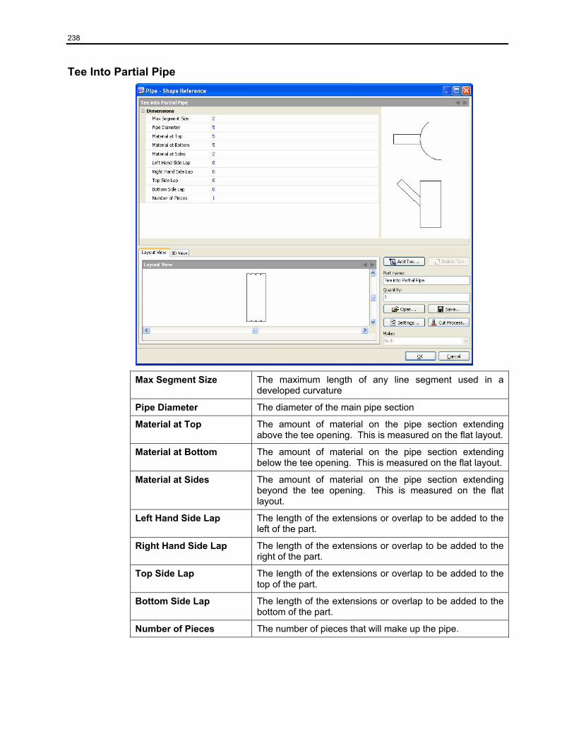
238
Tee Into Partial Pipe
Max Segment Size The maximum length of any line segment used in a developed curvature
Pipe Diameter The diameter of the main pipe section
Material at Top The amount of material on the pipe section extending above the tee opening. This is measured on the flat layout.
Material at Bottom The amount of material on the pipe section extending below the tee opening. This is measured on the flat layout.
Material at Sides The amount of material on the pipe section extending beyond the tee opening. This is measured on the flat layout.
Left Hand Side Lap The length of the extensions or overlap to be added to the left of the part.
Right Hand Side Lap The length of the extensions or overlap to be added to the right of the part.
Top Side Lap The length of the extensions or overlap to be added to the top of the part.
Bottom Side Lap The length of the extensions or overlap to be added to the bottom of the part.
Number of Pieces The number of pieces that will make up the pipe.
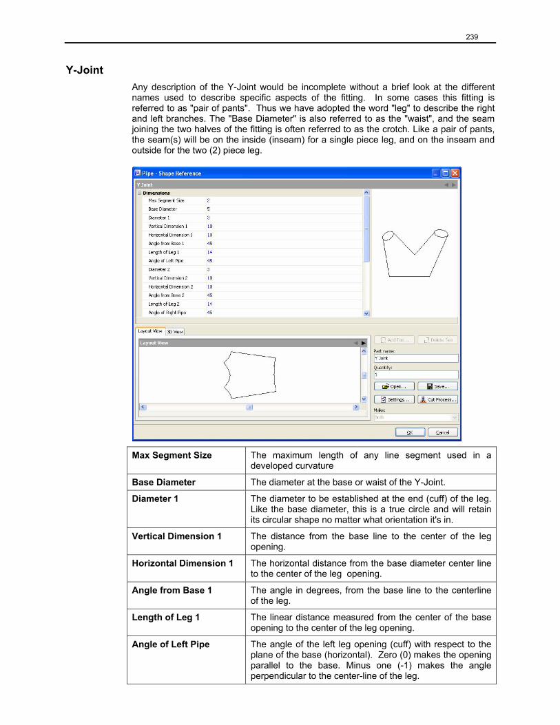
239
Y-Joint Any description of the Y-Joint would be incomplete without a brief look at the different names used to describe specific aspects of the fitting. In some cases this fitting is referred to as "pair of pants". Thus we have adopted the word "leg" to describe the right and left branches. The "Base Diameter" is also referred to as the "waist", and the seam joining the two halves of the fitting is often referred to as the crotch. Like a pair of pants, the seam(s) will be on the inside (inseam) for a single piece leg, and on the inseam and outside for the two (2) piece leg.
Max Segment Size The maximum length of any line segment used in a developed curvature
Base Diameter The diameter at the base or waist of the Y-Joint.
Diameter 1 The diameter to be established at the end (cuff) of the leg. Like the base diameter, this is a true circle and will retain its circular shape no matter what orientation it's in.
Vertical Dimension 1 The distance from the base line to the center of the leg opening.
Horizontal Dimension 1 The horizontal distance from the base diameter center line to the center of the leg opening.
Angle from Base 1 The angle in degrees, from the base line to the centerline of the leg.
Length of Leg 1 The linear distance measured from the center of the base opening to the center of the leg opening.
Angle of Left Pipe The angle of the left leg opening (cuff) with respect to the plane of the base (horizontal). Zero (0) makes the opening parallel to the base. Minus one (-1) makes the angle perpendicular to the center-line of the leg.
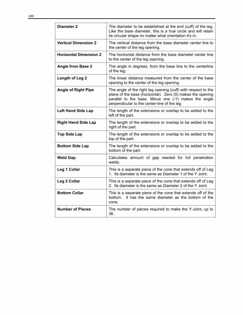
240
Diameter 2 The diameter to be established at the end (cuff) of the leg. Like the base diameter, this is a true circle and will retain its circular shape no matter what orientation it's in.
Vertical Dimension 2 The vertical distance from the base diameter center line to the center of the leg opening.
Horizontal Dimension 2 The horizontal distance from the base diameter center line to the center of the leg opening.
Angle from Base 2 The angle in degrees, from the base line to the centerline of the leg.
Length of Leg 2 The linear distance measured from the center of the base opening to the center of the leg opening.
Angle of Right Pipe The angle of the right leg opening (cuff) with respect to the plane of the base (horizontal). Zero (0) makes the opening parallel to the base. Minus one (-1) makes the angle perpendicular to the center-line of the leg.
Left Hand Side Lap The length of the extensions or overlap to be added to the left of the part.
Right Hand Side Lap The length of the extensions or overlap to be added to the right of the part.
Top Side Lap The length of the extensions or overlap to be added to the top of the part.
Bottom Side Lap The length of the extensions or overlap to be added to the bottom of the part.
Weld Gap Calculates amount of gap needed for full penetration welds.
Leg 1 Collar This is a separate piece of the cone that extends off of Leg 1. Its diameter is the same as Diameter 1 of the Y Joint.
Leg 2 Collar This is a separate piece of the cone that extends off of Leg 2. Its diameter is the same as Diameter 2 of the Y Joint.
Bottom Collar This is a separate piece of the cone that extends off of the bottom. It has the same diameter as the bottom of the cone.
Number of Pieces The number of pieces required to make the Y-Joint, up to 36.
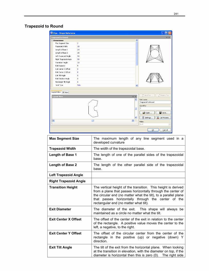
241
Trapezoid to Round
Max Segment Size The maximum length of any line segment used in a developed curvature
Trapezoid Width The width of the trapezoidal base.
Length of Base 1 The length of one of the parallel sides of the trapezoidal base.
Length of Base 2 The length of the other parallel side of the trapezoidal base.
Left Trapezoid Angle
Right Trapezoid Angle
Transition Height The vertical height of the transition. This height is derived from a plane that passes horizontally through the center of the circular end (no matter what the tilt), to a parallel plane that passes horizontally through the center of the rectangular end (no matter what tilt).
Exit Diameter The diameter of the exit. This shape will always be maintained as a circle no matter what the tilt.
Exit Center X Offset The offset of the center of the exit in relation to the center of the rectangle. A positive value moves the center to the left, a negative, to the right.
Exit Center Y Offset The offset of the circular center from the center of the rectangle in the positive (up) or negative (down) Y direction.
Exit Tilt Angle The tilt of the exit from the horizontal plane. When looking at the transition in elevation, with the diameter on top, if the diameter is horizontal then this is zero (0). The right side
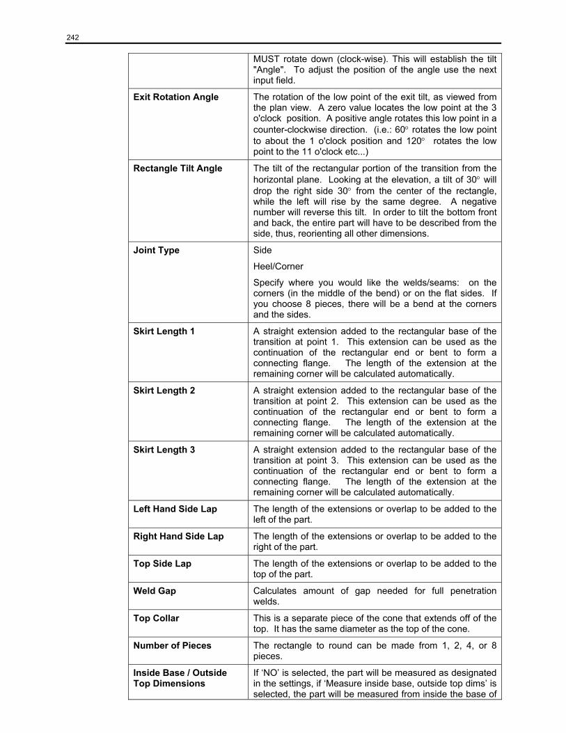
242
MUST rotate down (clock-wise). This will establish the tilt "Angle". To adjust the position of the angle use the next input field.
Exit Rotation Angle The rotation of the low point of the exit tilt, as viewed from the plan view. A zero value locates the low point at the 3 o'clock position. A positive angle rotates this low point in a counter-clockwise direction. (i.e.: 60° rotates the low point to about the 1 o'clock position and 120° rotates the low point to the 11 o'clock etc...)
Rectangle Tilt Angle The tilt of the rectangular portion of the transition from the horizontal plane. Looking at the elevation, a tilt of 30° will drop the right side 30° from the center of the rectangle, while the left will rise by the same degree. A negative number will reverse this tilt. In order to tilt the bottom front and back, the entire part will have to be described from the side, thus, reorienting all other dimensions.
Joint Type Side
Heel/Corner
Specify where you would like the welds/seams: on the corners (in the middle of the bend) or on the flat sides. If you choose 8 pieces, there will be a bend at the corners and the sides.
Skirt Length 1 A straight extension added to the rectangular base of the transition at point 1. This extension can be used as the continuation of the rectangular end or bent to form a connecting flange. The length of the extension at the remaining corner will be calculated automatically.
Skirt Length 2 A straight extension added to the rectangular base of the transition at point 2. This extension can be used as the continuation of the rectangular end or bent to form a connecting flange. The length of the extension at the remaining corner will be calculated automatically.
Skirt Length 3 A straight extension added to the rectangular base of the transition at point 3. This extension can be used as the continuation of the rectangular end or bent to form a connecting flange. The length of the extension at the remaining corner will be calculated automatically.
Left Hand Side Lap The length of the extensions or overlap to be added to the left of the part.
Right Hand Side Lap The length of the extensions or overlap to be added to the right of the part.
Top Side Lap The length of the extensions or overlap to be added to the top of the part.
Weld Gap Calculates amount of gap needed for full penetration welds.
Top Collar This is a separate piece of the cone that extends off of the top. It has the same diameter as the top of the cone.
Number of Pieces The rectangle to round can be made from 1, 2, 4, or 8 pieces.
Inside Base / Outside Top Dimensions
If ‘NO’ is selected, the part will be measured as designated in the settings, if ‘Measure inside base, outside top dims’ is selected, the part will be measured from inside the base of

243
the part, and outside the top of the cone.
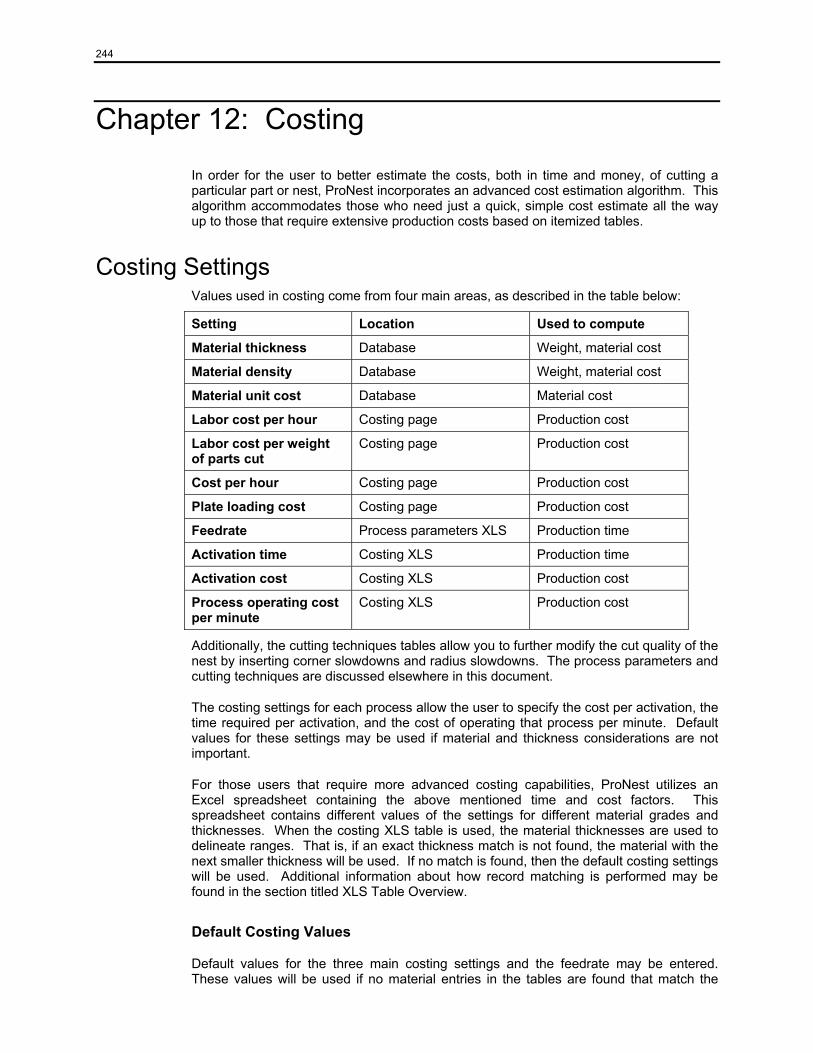
244
Chapter 12: Costing
In order for the user to better estimate the costs, both in time and money, of cutting a particular part or nest, ProNest incorporates an advanced cost estimation algorithm. This algorithm accommodates those who need just a quick, simple cost estimate all the way up to those that require extensive production costs based on itemized tables.
Costing Settings Values used in costing come from four main areas, as described in the table below:
Setting Location Used to compute
Material thickness Database Weight, material cost
Material density Database Weight, material cost
Material unit cost Database Material cost
Labor cost per hour Costing page Production cost
Labor cost per weight of parts cut
Costing page Production cost
Cost per hour Costing page Production cost
Plate loading cost Costing page Production cost
Feedrate Process parameters XLS Production time
Activation time Costing XLS Production time
Activation cost Costing XLS Production cost
Process operating cost per minute
Costing XLS Production cost
Additionally, the cutting techniques tables allow you to further modify the cut quality of the nest by inserting corner slowdowns and radius slowdowns. The process parameters and cutting techniques are discussed elsewhere in this document.
The costing settings for each process allow the user to specify the cost per activation, the time required per activation, and the cost of operating that process per minute. Default values for these settings may be used if material and thickness considerations are not important.
For those users that require more advanced costing capabilities, ProNest utilizes an Excel spreadsheet containing the above mentioned time and cost factors. This spreadsheet contains different values of the settings for different material grades and thicknesses. When the costing XLS table is used, the material thicknesses are used to delineate ranges. That is, if an exact thickness match is not found, the material with the next smaller thickness will be used. If no match is found, then the default costing settings will be used. Additional information about how record matching is performed may be found in the section titled XLS Table Overview.
Default Costing Values
Default values for the three main costing settings and the feedrate may be entered. These values will be used if no material entries in the tables are found that match the
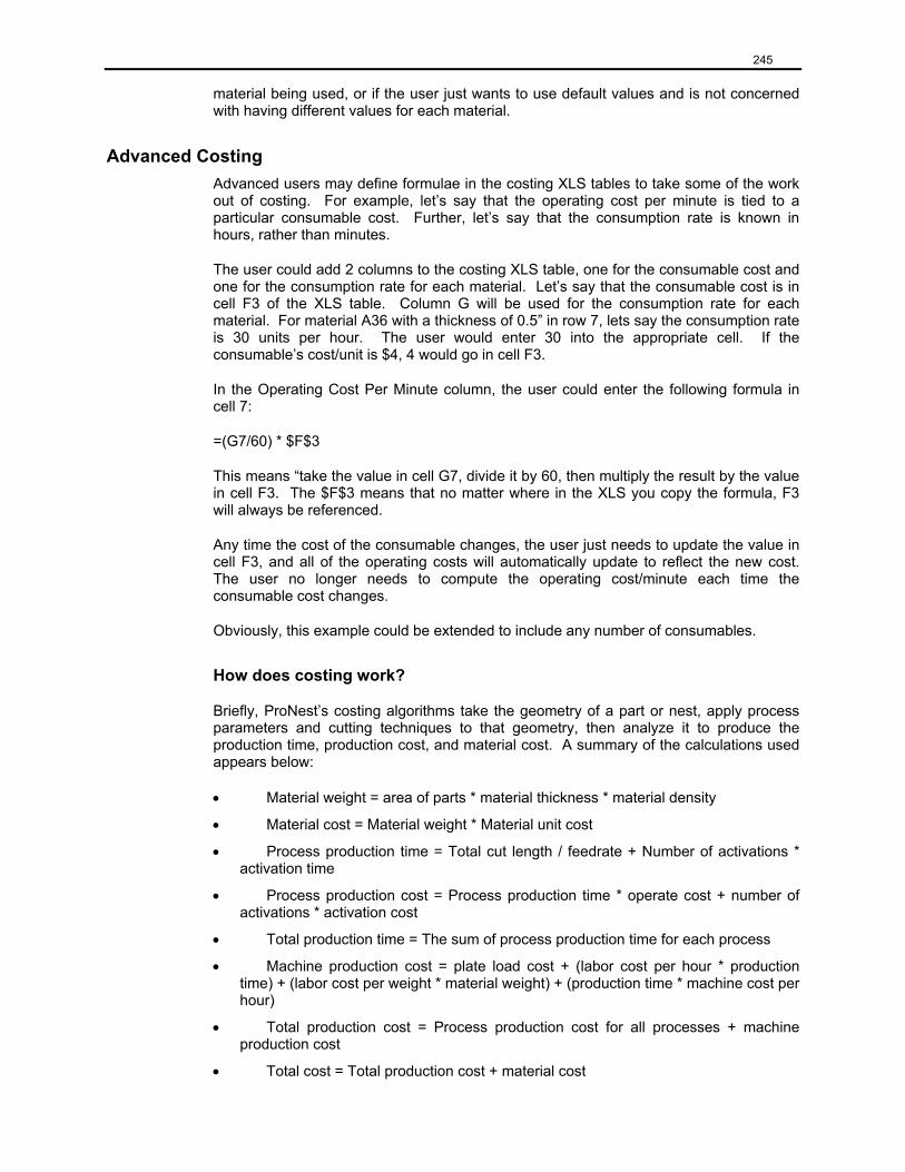
245
material being used, or if the user just wants to use default values and is not concerned with having different values for each material.
Advanced Costing Advanced users may define formulae in the costing XLS tables to take some of the work out of costing. For example, let’s say that the operating cost per minute is tied to a particular consumable cost. Further, let’s say that the consumption rate is known in hours, rather than minutes.
The user could add 2 columns to the costing XLS table, one for the consumable cost and one for the consumption rate for each material. Let’s say that the consumable cost is in cell F3 of the XLS table. Column G will be used for the consumption rate for each material. For material A36 with a thickness of 0.5” in row 7, lets say the consumption rate is 30 units per hour. The user would enter 30 into the appropriate cell. If the consumable’s cost/unit is $4, 4 would go in cell F3.
In the Operating Cost Per Minute column, the user could enter the following formula in cell 7:
=(G7/60) * $F$3
This means “take the value in cell G7, divide it by 60, then multiply the result by the value in cell F3. The $F$3 means that no matter where in the XLS you copy the formula, F3 will always be referenced.
Any time the cost of the consumable changes, the user just needs to update the value in cell F3, and all of the operating costs will automatically update to reflect the new cost. The user no longer needs to compute the operating cost/minute each time the consumable cost changes.
Obviously, this example could be extended to include any number of consumables.
How does costing work?
Briefly, ProNest’s costing algorithms take the geometry of a part or nest, apply process parameters and cutting techniques to that geometry, then analyze it to produce the production time, production cost, and material cost. A summary of the calculations used appears below:
• Material weight = area of parts * material thickness * material density
• Material cost = Material weight * Material unit cost
• Process production time = Total cut length / feedrate + Number of activations * activation time
• Process production cost = Process production time * operate cost + number of activations * activation cost
• Total production time = The sum of process production time for each process
• Machine production cost = plate load cost + (labor cost per hour * production time) + (labor cost per weight * material weight) + (production time * machine cost per hour)
• Total production cost = Process production cost for all processes + machine production cost
• Total cost = Total production cost + material cost

246
Where is Costing Info Displayed in ProNest?
Costing information appears on the Cost Info area of the Add Part List screen, the bottom portion of the Nest Properties screen, and on some reports. The costing information displayed on the Add Parts screen is the cost and time to cut that part by itself, as is. It does not reflect the cost or time to cut this part once it has been nested. The cost and time displayed on the Nest Properties screen represent the cost and time to cut that nest. The costs and times displayed on the different reports depend on which report they appear on.
Required column headers in the costing XLS table The following column headings are required and should not be modified in any way. That would cause invalid results to be produced by the costing algorithm.
Material The name of the material
Thickness The thickness of the material (matched as a range)
Activation Time Process activation time in seconds
Cost Per Activation Cost of each activation
Operating Cost Per Minute
The cost incurred for running that process for 60 seconds
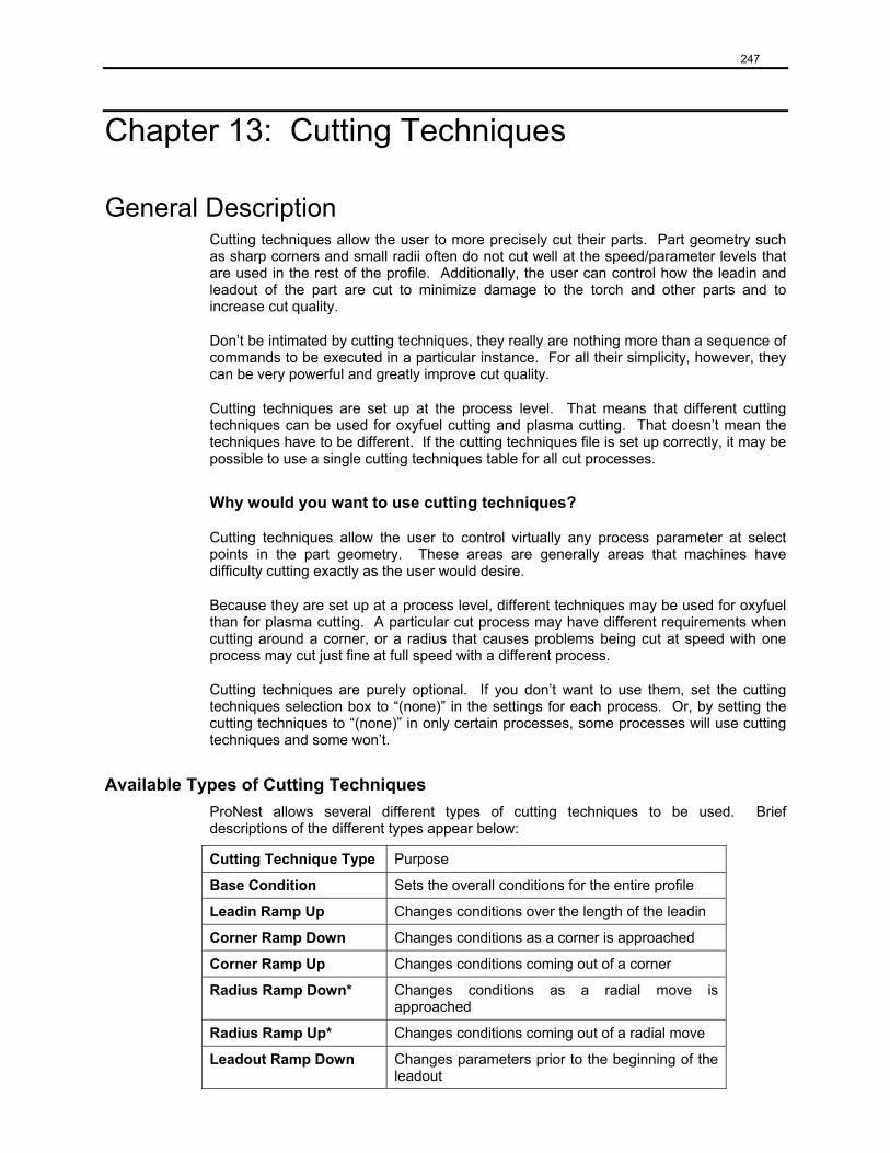
247
Chapter 13: Cutting Techniques
General Description Cutting techniques allow the user to more precisely cut their parts. Part geometry such as sharp corners and small radii often do not cut well at the speed/parameter levels that are used in the rest of the profile. Additionally, the user can control how the leadin and leadout of the part are cut to minimize damage to the torch and other parts and to increase cut quality.
Don’t be intimated by cutting techniques, they really are nothing more than a sequence of commands to be executed in a particular instance. For all their simplicity, however, they can be very powerful and greatly improve cut quality.
Cutting techniques are set up at the process level. That means that different cutting techniques can be used for oxyfuel cutting and plasma cutting. That doesn’t mean the techniques have to be different. If the cutting techniques file is set up correctly, it may be possible to use a single cutting techniques table for all cut processes.
Why would you want to use cutting techniques?
Cutting techniques allow the user to control virtually any process parameter at select points in the part geometry. These areas are generally areas that machines have difficulty cutting exactly as the user would desire.
Because they are set up at a process level, different techniques may be used for oxyfuel than for plasma cutting. A particular cut process may have different requirements when cutting around a corner, or a radius that causes problems being cut at speed with one process may cut just fine at full speed with a different process.
Cutting techniques are purely optional. If you don’t want to use them, set the cutting techniques selection box to “(none)” in the settings for each process. Or, by setting the cutting techniques to “(none)” in only certain processes, some processes will use cutting techniques and some won’t.
Available Types of Cutting Techniques ProNest allows several different types of cutting techniques to be used. Brief descriptions of the different types appear below:
Cutting Technique Type Purpose
Base Condition Sets the overall conditions for the entire profile
Leadin Ramp Up Changes conditions over the length of the leadin
Corner Ramp Down Changes conditions as a corner is approached
Corner Ramp Up Changes conditions coming out of a corner
Radius Ramp Down* Changes conditions as a radial move is approached
Radius Ramp Up* Changes conditions coming out of a radial move
Leadout Ramp Down Changes parameters prior to the beginning of the leadout
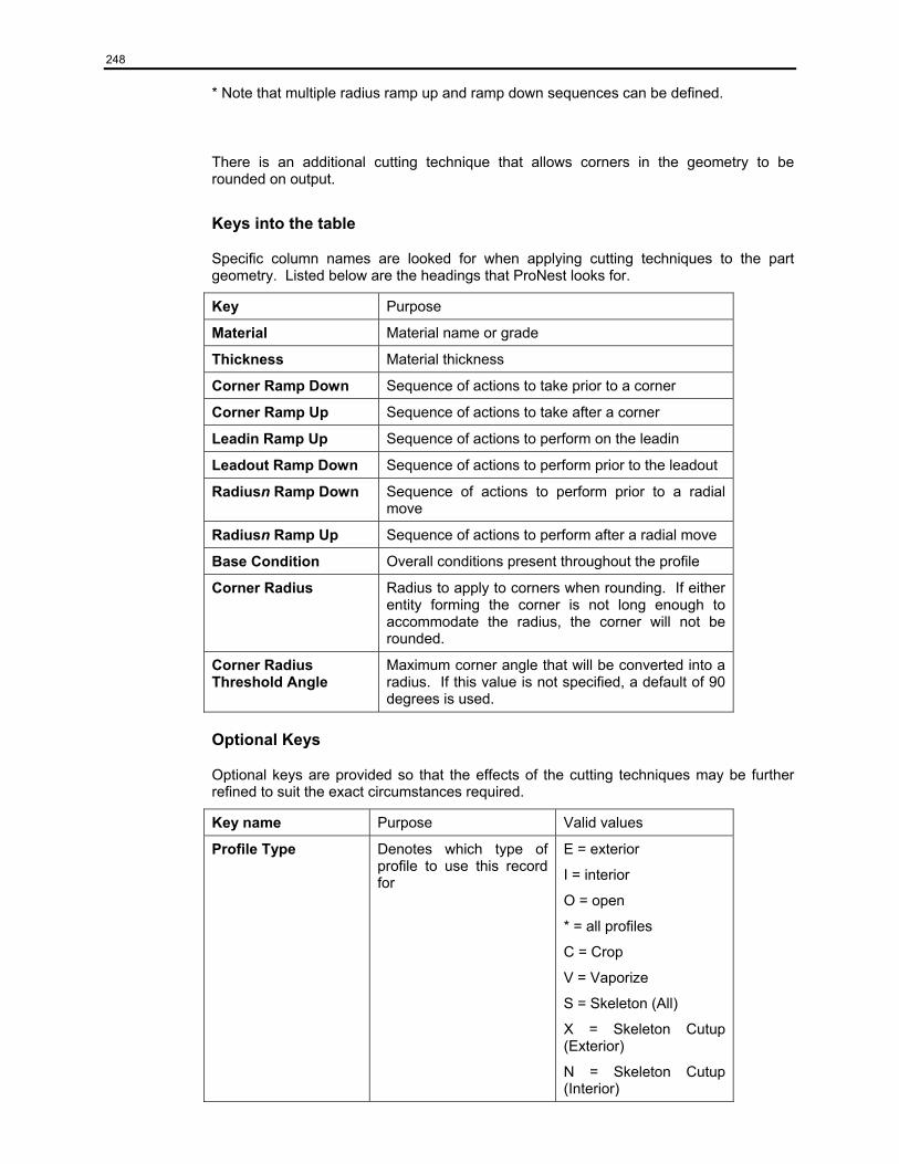
248
* Note that multiple radius ramp up and ramp down sequences can be defined.
There is an additional cutting technique that allows corners in the geometry to be rounded on output.
Keys into the table
Specific column names are looked for when applying cutting techniques to the part geometry. Listed below are the headings that ProNest looks for.
Key Purpose
Material Material name or grade
Thickness Material thickness
Corner Ramp Down Sequence of actions to take prior to a corner
Corner Ramp Up Sequence of actions to take after a corner
Leadin Ramp Up Sequence of actions to perform on the leadin
Leadout Ramp Down Sequence of actions to perform prior to the leadout
Radiusn Ramp Down Sequence of actions to perform prior to a radial move
Radiusn Ramp Up Sequence of actions to perform after a radial move
Base Condition Overall conditions present throughout the profile
Corner Radius Radius to apply to corners when rounding. If either entity forming the corner is not long enough to accommodate the radius, the corner will not be rounded.
Corner Radius Threshold Angle
Maximum corner angle that will be converted into a radius. If this value is not specified, a default of 90 degrees is used.
Optional Keys
Optional keys are provided so that the effects of the cutting techniques may be further refined to suit the exact circumstances required.
Key name Purpose Valid values
Profile Type Denotes which type of profile to use this record for
E = exterior
I = interior
O = open
* = all profiles
C = Crop
V = Vaporize
S = Skeleton (All)
X = Skeleton Cutup (Exterior)
N = Skeleton Cutup (Interior)
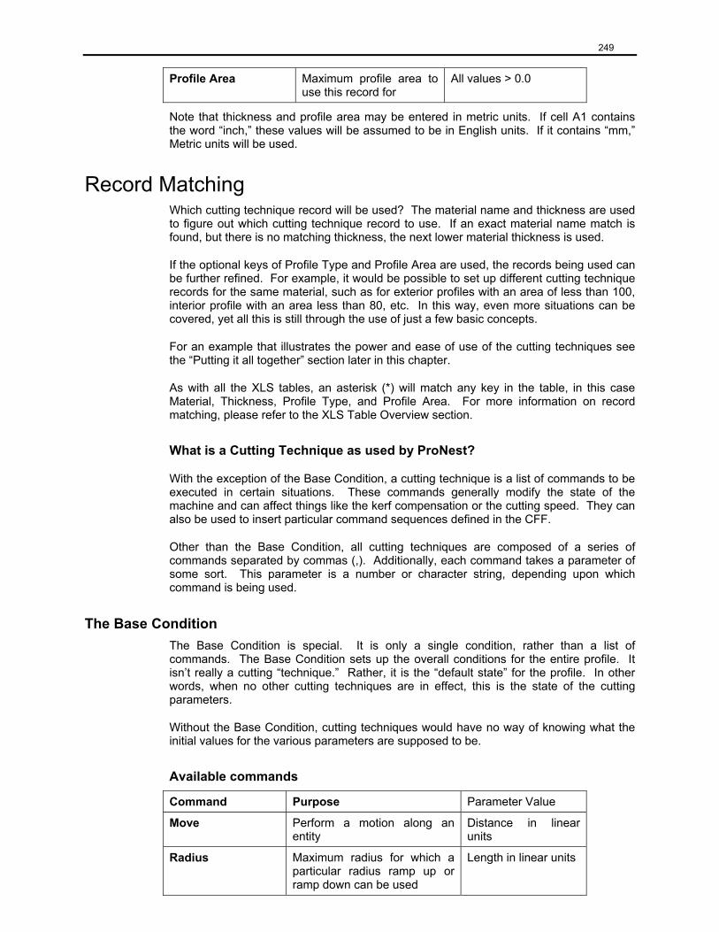
249
Profile Area Maximum profile area to use this record for
All values > 0.0
Note that thickness and profile area may be entered in metric units. If cell A1 contains the word “inch,” these values will be assumed to be in English units. If it contains “mm,” Metric units will be used.
Record Matching Which cutting technique record will be used? The material name and thickness are used to figure out which cutting technique record to use. If an exact material name match is found, but there is no matching thickness, the next lower material thickness is used.
If the optional keys of Profile Type and Profile Area are used, the records being used can be further refined. For example, it would be possible to set up different cutting technique records for the same material, such as for exterior profiles with an area of less than 100, interior profile with an area less than 80, etc. In this way, even more situations can be covered, yet all this is still through the use of just a few basic concepts.
For an example that illustrates the power and ease of use of the cutting techniques see the “Putting it all together” section later in this chapter.
As with all the XLS tables, an asterisk (*) will match any key in the table, in this case Material, Thickness, Profile Type, and Profile Area. For more information on record matching, please refer to the XLS Table Overview section.
What is a Cutting Technique as used by ProNest?
With the exception of the Base Condition, a cutting technique is a list of commands to be executed in certain situations. These commands generally modify the state of the machine and can affect things like the kerf compensation or the cutting speed. They can also be used to insert particular command sequences defined in the CFF.
Other than the Base Condition, all cutting techniques are composed of a series of commands separated by commas (,). Additionally, each command takes a parameter of some sort. This parameter is a number or character string, depending upon which command is being used.
The Base Condition The Base Condition is special. It is only a single condition, rather than a list of commands. The Base Condition sets up the overall conditions for the entire profile. It isn’t really a cutting “technique.” Rather, it is the “default state” for the profile. In other words, when no other cutting techniques are in effect, this is the state of the cutting parameters.
Without the Base Condition, cutting techniques would have no way of knowing what the initial values for the various parameters are supposed to be.
Available commands
Command Purpose Parameter Value
Move Perform a motion along an entity
Distance in linear units
Radius Maximum radius for which a particular radius ramp up or ramp down can be used
Length in linear units
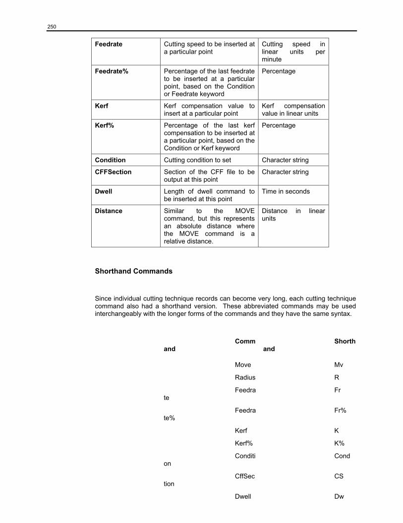
250
Feedrate Cutting speed to be inserted at a particular point
Cutting speed in linear units per minute
Feedrate% Percentage of the last feedrate to be inserted at a particular point, based on the Condition or Feedrate keyword
Percentage
Kerf Kerf compensation value to insert at a particular point
Kerf compensation value in linear units
Kerf% Percentage of the last kerf compensation to be inserted at a particular point, based on the Condition or Kerf keyword
Percentage
Condition Cutting condition to set Character string
CFFSection Section of the CFF file to be output at this point
Character string
Dwell Length of dwell command to be inserted at this point
Time in seconds
Distance Similar to the MOVE command, but this represents an absolute distance where the MOVE command is a relative distance.
Distance in linear units
Shorthand Commands
Since individual cutting technique records can become very long, each cutting technique command also had a shorthand version. These abbreviated commands may be used interchangeably with the longer forms of the commands and they have the same syntax.
Command
Shorthand
Move Mv
Radius R
Feedrate
Fr
Feedrate%
Fr%
Kerf K
Kerf% K%
Condition
Cond
CffSection
CS
Dwell Dw
251
Distance
Dist
Interaction with Process Parameters By using the “Feedrate” keyword, the user may insert a specific feedrate value into the CNC file. Alternatively, the “Feedrate%” keyword may be used to output a percentage of the most recently output main federate, (not including those generated by previous cutting techniques, such as slowdowns). Note that this percentage will be based off of the base value for feedrate, the most recent Condition encountered, or the most recent Feedrate command, whichever was encountered more recently.
By using the “Kerf” keyword, the user may insert a specific kerf compensation value into the CNC file. Alternatively, the “Kerf%” keyword may be used to output a percentage of the most recently output kerf value. Note that this percentage will be based off of the base value for kerf, the most recent Condition encountered, or the most recent Kerf command, whichever was encountered more recently.
Cutting techniques use the “Condition” command to insert process parameters into the geometry of the part. This allows the user to not only change feedrate and kerf to the values associated with that condition without having to specify them individually in the cutting technique sequence, but it also allows the user to use any sort of parameters that are required for their particular situation. Such parameters may include, but are by no means limited to, things like voltage, current, and duty percent.
If no match for the individual conditions is found, the closest matching parameter record will be used for the base condition, but none of the other conditions will be used.
Interaction with CFF Cutting techniques use the “CFFSection” command to cause a section in the CFF file to be output at a particular time. This section in the CFF can produce simple output like inserting a comment into the CNC file, or more complex output like outputting a sequence of commands to set kerf and feedrate and turn off the auto height control.
If no matching section name in the CFF file is found, nothing happens when the CFFSection command is encountered.
Similarly, if a feedrate or kerf value is specified in the cutting techniques, but the CFF is incapable of outputting a feedrate or kerf value, no feedrates or kerfs will be output.
The Radius Keyword
The “Radius” keyword is used to specify the largest radius for which a particular radius ramp up or ramp down will be used. This allows the user to set up different sequences of events for different radius sizes. Also, the user doesn’t need to specify a cutting technique sequence for each and every radius that may be used.
For instance, if all radii between 3” and 10” will use a particular slowdown sequence, there is no need to define radius ramp down sequences for 3”, 3.5”, 4” and so on. Simply setting up a radius ramp down sequence for 2.99” and one for 10” will suffice. All radii greater than 2.99” and less than or equal to 10” will then use this sequence. Examples are included in a later section that will try to make these concepts clear.
252
What is a Corner
For purposes of cutting techniques, a corner is defined as being an intersection of two lines, two arcs, or one arc and one line such that they form a 90 degree or smaller angle. In the case of an arc, the tangent to the arc at the intersection point is used to determine the angle.
How is the Move Command Used
The “Move” command is used to advance along a particular entity. The total distance specified by all the Move commands in a cutting technique sequence is the total amount of space required to apply that sequence. In certain cases, such as where there isn’t enough room to apply a cutting technique as specified, the total distance may be scaled so that all of the required actions will still be performed, albeit over a shorter distance.
Safeguards
Leadin ramp up always inserts the base condition at the end of the ramp up sequence, just in case. If no base condition exists, the default feedrate and kerf will be inserted instead.
Cutting conditions are always scaled to fit in the space available. If leadin ramp up is supposed to cover 0.5”, but only 0.25” is available, the leadin ramp up will be scaled down. The same is true if there is less space available between corners or radii than is needed. The available space will be used to scale the cutting techniques so that both will fit. With the exception of leadin ramp up, no cutting techniques will be scaled to be larger than the desired length.
Putting It All Together Now that we’ve covered all the basics, let’s see how to set up a few different cutting techniques. For the moment, we will only consider a single material. Keep in mind that this discussion is applicable to any number of material records. Also, bear in mind that this discussion is meant as an example only, and is not meant to represent actual cutting techniques to use in production.
Call the material we will be using in this example “Test Material” and give it a thickness of 0.25”.
Base Condition
The Base Condition is simply the condition to use when no cutting techniques are in effect. Think of it as the conditions you would want to use if you weren’t using cutting techniques at all.
For purposes of this example, we will say that the Base Condition is “Base.”
Leadin Ramp Up
Leadin ramp up allows parameters to be varied over the length of the leadin.
Let’s assume for this example that we want to start out at 50% of the base feedrate and 110% of the base kerf, move 0.25” along the leadin, then change to 75% of the base feedrate and 105% of the base kerf. After another move of 0.25”, we want to set both feedrate and kerf to 100% of their base values.
Below is how the leadin ramp up would need to look:
253
Feedrate%(50), Kerf%(110), Move(0.25), Feedrate%(75), Kerf%(105), Move(0.25), Feedrate%(100), Kerf%(100)
Note that the final Feedrate%(100) and Kerf%(100) are not necessary, as the base conditions are automatically inserted at the end of the leadin.
Radius Ramp Down
Radius ramp down allows the user to specify parameter changes and special output conditions just prior to an arc motion.
For this example, let’s consider 2 ranges of radii, up to 5” and between 5” and 10”.
For radii less than or equal to 5”, we want to drop the feedrate to 85%, output the contents of the CFF section “SMALL RADIUS”, move 0.5”, drop the feedrate to 75%, then move 0.25”.
Note: The CFF section entry is not necessary in most applications. It is used to output specific commands required by certain controls in a variety of situations. The use of it in this example is meant to show the power and flexibility of ProNest.
In the Radius1 Ramp Down column, we would enter the following:
Radius(5), Feedrate%(85), CFFSection(SMALL RADIUS), Move(0.5), Feedrate%(75), Move(0.25)
For radii larger than 5” and up to 10”, let’s output the contents of the CFFSection “LARGE RADIUS”, move 0.1”, drop the feedrate to 90%, then move 0.25”.
In the Radius2 Ramp Down column, we would enter the following:
Radius(10), CFFSection(LARGE RADIUS), Move(0.1), Feedrate%(90), Move(0.25)
Always keep in mind that you must use the “Radius” keyword to indicate the maximum radius to apply the cutting technique to when doing radius ramp up or radius ramp down. Otherwise, the technique will be applied to all radii.
Radius Ramp Up
Radius ramp up is used to restore the cutting parameters to their base conditions after cutting an arc motion.
For radius ramp up, let’s assume that we always want to come out of a radius the same way, no matter what the size. We’ll move 0.25” then return to the BASE condition. For this, we’ll need a column called Radius1 Ramp Up. Move(0.25), Condition(BASE)
Corner Ramp Down
The following example makes use of conditions commands, and addition to the process parameter table that allows many different values to be inserted to the code. When a specific condition is encountered, the base values can be changed to reflect chain cutting requirements.
Corner ramp down allows cutting parameters to be changed when approaching a corner.
254
For this example of corner ramp down, we will exclusively use the Move and Condition commands and assume that our CFF is capable of outputting the correct parameters for us. Let’s perform 3 0.25” motions, setting conditions CRD1, CRD2, and CRD3. There will be a dwell of 2 seconds at the corner.
In the Corner Ramp Down column we would type:
Condition(CRD1), Move(0.25), Condition(CRD2), Move(0.25), Condition(CRD3), Move(0.25), Dwell(2)
Because we have used the conditions CRD1, CRD2, and CRD3 in this cutting technique, we must make sure that there are records in the process parameters XLS table that use those conditions.
Corner Ramp Up
Corner ramp up is used to restore cutting conditions to their base values when coming out of a corner.
Let’s assume that we will need to return to the base condition after we output the CFF section CORNER and move 0.5”. As noted earlier, the base condition is simply BASE.
In the Corner Ramp Up column we would type:
CFFSection(CORNER), Move(0.5), Condition(BASE)
Leadout Ramp Down
Leadout ramp down is used to alter process parameters just prior to leading out from the profile.
For this example, we’ll do a simple one. We’ll slow down to 50% of cutting speed 0.25” before the start of the leadout.
In the Leadout Ramp Down column, we would enter the following:
Feedrate%(50), Move(0.25)
Extended Example
To continue with this example, there are several other things we can consider: profile area, profile type, multiple materials.
Profile Area First, let’s consider profile area. If there isn’t a Profile Area column in the cutting techniques XLS, we’ll need to add one. For this example, we’ll consider 3 different ranges: up to 10 square inches, up to 100 square inches, and beyond 100 square inches.
Highlight the record we just added in the example. Add two copies of it to the cutting techniques XLS table. In the profile area column of the first record, enter 10. Enter 100 for the next one, and * for the last one. The * will match any area. Without using the *, we may encounter profiles that wouldn’t get cutting techniques applied to them.
At this point, no matter the profile size, the cutting techniques being applied are always the same. To make them do slightly different things, we can change BASE everywhere it
255
appears in the record for area of 100 to be BASE100. We will need a record with that condition in the process parameters table. Double the feedrate and kerf for this process parameter record. This means that the cutting techniques will apply a significantly larger kerf and feedrate value to the profiles.
For profile area *, change BASE to BASE999 and add an appropriate record to the process parameters table. This time, triple the feedrate and kerf from the original BASE record.
It might also be a good idea to change CRD1, CRD2, and CRD3 for each of the different profile areas. Otherwise, the corner ramp down will always produce the same results, no matter what size profile we are outputting. Remember to add the appropriate records to the process parameter table.
Profile Type Now we have three cutting technique records, all set up the same way, but they will produce different results on output. To bring profile types into this example, highlight the three cutting technique records and insert two copies into the cutting techniques table, for a total of nine records.
Add a Profile Type column if there isn’t one already. For each of the different profile areas, mark one of the Profile Types as E, one as I, and one as O. This means that you should have an E, I, and O for area 10, an E, I, and O for area 100, and an E, I, and O for area *.
For this example, we don’t want to change the kerf for interior profiles. So, for each of the records with a profile type of I, remove any mention of Kerf or Kerf%.
For open profiles, we want all of the moves we make to be 0.1”. Change all of the move commands to Move(0.1) if the profile type for that record is an O.
Now we have nine cutting technique records, covering three different areas and three profile types for each of the areas. To do all of this, we’ve also had to add or modify 12 records in the process parameters table. But after all this work, we’ve got one material completely set up for just about any situation. Of course, there is no practical limit to the number of radius ramp down and radius ramp up cutting techniques that could be used.
Multiple Materials To set up a second material, copy the 9 cutting technique records that we’ve just set up and change the thickness to 0.5”. Also copy the 12 process parameter records and change the material thickness there to 0.5”. Also in the process parameter table, change the kerf and feedrate values for the 12 records.
That’s it. We now have two materials set up for cutting techniques. Of course, before this will actually work on output, you would need to add the “Test Material” for thicknesses of 0.25” and 0.5” to the material database, then import and nest parts for these materials.
Troubleshooting Below is a list of common problems encountered while using cutting techniques and possible ways to resolve them.
256
1. Cutting techniques are not being applied at all
• Make sure the “Insert machine parameters into output” checkbox on the CNC settings screen is checked
• Check each of the processes being used to see that a cutting techniques XLS table and process parameters XLS table have been assigned.
• Check that the materials that you are using for your parts match one or more records in your XLS tables
2. Only some cutting techniques are being applied
• Check that the column headers in the cutting techniques table are correct
• Make sure that the materials you are using for all of your parts are represented in the cutting techniques XLS tables you are using
• Make sure all processes you are using have a cutting techniques table specified
• Make sure any radii specified in the cutting techniques are large enough to match any radial moves that require slowdowns in the parts
• Check for any Feedrate, Feedrate%, Kerf, or Kerf% commands with 0 or negative values as the parameter
• Make sure that the profile areas and types, if used, are correct
3. Only the base process parameters are being used
• Make sure the process parameters XLS table contains records with the conditions being used in the cutting techniques XLS table
4. Not getting any CFF section output, even though the CFFSection command is used
• Make sure the CFF section named in the cutting technique exists in the CFF file being used
5. Cutting techniques are being applied, but no parameters are being output
• Verify that each process used has a valid process parameter table assigned
• Make sure the process parameters XLS table contains records with the conditions being used in the cutting techniques XLS table
• Make sure the CFF is capable of outputting the parameters you are expecting. If the CFF cannot output a kerf value once the torch is on, there won’t be any kerf values in the code
• Make sure that the cutting techniques being used cause the parameters to be modified
• Check for any Feedrate, Feedrate%, Kerf, or Kerf% commands with 0 or negative values as the parameter
6. I’m using profile area and large profiles don’t get any cutting techniques
• Specify a cutting technique record with a very large area or ‘*’ for the area

257
7. I can’t get a profile type of “EI”, “IO”, “EO”, or “EIO” to work correctly
• Currently, exterior, interior, and open profile types must be specified in separate cutting technique records, or the ‘*’ (for all profile types) must be used
8. I’m getting radius ramp up/down where I don’t want it, or I’m not getting it where it should be
• Check the Radiusn Ramp Up and Radiusn Ramp Down columns to make sure that the Radius keyword is used to specify the maximum radius to use for the slowdown/speedup. Omit the Radius keyword if you want the technique to apply to all radii.
9. The wrong feedrates and kerfs are being output.
• Set the correct condition before issuing a Feedrate% or Kerf% command. These commands work on the most recently encountered Condition, Feedrate, or Kerf command. If the most recent condition was CRD1 and then a Feedrate%(50) was encountered, the resulting feedrate would be 50% of the CRD1 feedrate.
10. Only default parameter values are being output, even though my cutting techniques and process parameter tables are set up correctly
• Make sure the checkbox to “Use default process parameters only” is not checked for each of the processes.
258
Chapter 14: Lead Style Settings
Using Lead Style Settings
ProNest allows the user to set up XLS tables containing leadin and leadout definitions for different materials. Each cutting process used may have a leads table assigned to it, though it is possible that the same table may be used for multiple processes. These tables are assigned in the settings for each process.
Additionally, the user may set up different lead styles for interior and exterior profiles.
Default Lead Style Settings Each process has default lead styles for both interior and exterior profiles. These settings are configurable by the user and would be used if no matching records are found in the XLS tables, or if the user desires that only default leads be used.
When Lead Style Settings Are Applied
Initially, lead style settings are not applied to CAD files until they have been added to the part list. This is done on the Add Parts screen. The part preview area of the Add Parts screen will not show the leads on the part until the part has been added.
By default, the lead settings associated with the cut process and material of the part are used. If desired, the user may change the lead settings for a particular part after it has been added, or change the leads to be used for all parts subsequently added. More information about this may be found elsewhere in this document.
Lead styles may also be applied if the user changes the material for the part once it has already been added to the part list. A dialog will be displayed allowing the user to change the lead styles or not.
Lead Style Settings XLS Tables
Each cut process can have two lead settings tables associated with it, one for interior leads and one for exterior leads. These tables contain the necessary information for leading into and out of the side of a profile and leading into and out of the corner of a profile.
Table Organization
The lead settings XLS tables are set up as follows:
Cell A1 contains the units designation for the file, inch or mm.
Cell B1 contains the row number of the English language column headers, n.
Row n – English language column headers
Anywhere between row 2 and row n may be any number of things, such as the column headers translated into a different language. These are purely informational and are ignored by ProNest.
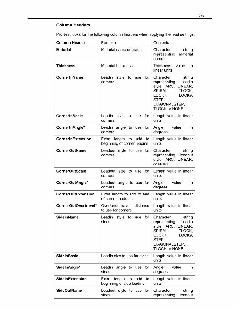
259
Column Headers
ProNest looks for the following column headers when applying the lead settings:
Column Header Purpose Contents
Material Material name or grade Character string representing material name
Thickness Material thickness Thickness value in linear units
CornerInName Leadin style to use for corners
Character string representing leadin style: ARC, LINEAR, SPIRAL, TLOCK, LOCK7, LOCK9, STEP, DIAGONALSTEP, TLOCK or NONE
CornerInScale Leadin size to use for corners
Length value in linear units
CornerInAngle* Leadin angle to use for corners
Angle value in degrees
CornerInExtension Extra length to add to beginning of corner leadins
Length value in linear units
CornerOutName Leadout style to use for corners
Character string representing leadout style: ARC, LINEAR, or NONE
CornerOutScale Leadout size to use for corners
Length value in linear units
CornerOutAngle* Leadout angle to use for corners
Angle value in degrees
CornerOutExtension Extra length to add to end of corner leadouts
Length value in linear units
CornerOutOvertravel┼ Over/undertravel distance to use for corners
Length value in linear units
SideInName Leadin style to use for sides
Character string representing leadin style: ARC, LINEAR, SPIRAL, TLOCK, LOCK7, LOCK9, STEP, DIAGONALSTEP, TLOCK or NONE
SideInScale Leadin size to use for sides Length value in linear units
SideInAngle* Leadin angle to use for sides
Angle value in degrees
SideInExtension Extra length to add to beginning of side leadins
Length value in linear units
SideOutName Leadout style to use for sides
Character string representing leadout
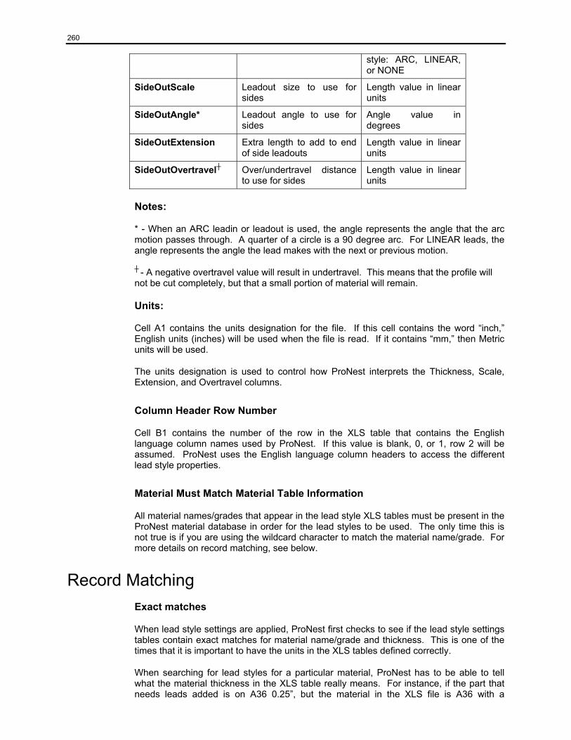
260
style: ARC, LINEAR, or NONE
SideOutScale Leadout size to use for sides
Length value in linear units
SideOutAngle* Leadout angle to use for sides
Angle value in degrees
SideOutExtension Extra length to add to end of side leadouts
Length value in linear units
SideOutOvertravel┼ Over/undertravel distance to use for sides
Length value in linear units
Notes:
* - When an ARC leadin or leadout is used, the angle represents the angle that the arc motion passes through. A quarter of a circle is a 90 degree arc. For LINEAR leads, the angle represents the angle the lead makes with the next or previous motion.
┼ - A negative overtravel value will result in undertravel. This means that the profile will not be cut completely, but that a small portion of material will remain.
Units:
Cell A1 contains the units designation for the file. If this cell contains the word “inch,” English units (inches) will be used when the file is read. If it contains “mm,” then Metric units will be used.
The units designation is used to control how ProNest interprets the Thickness, Scale, Extension, and Overtravel columns.
Column Header Row Number
Cell B1 contains the number of the row in the XLS table that contains the English language column names used by ProNest. If this value is blank, 0, or 1, row 2 will be assumed. ProNest uses the English language column headers to access the different lead style properties.
Material Must Match Material Table Information
All material names/grades that appear in the lead style XLS tables must be present in the ProNest material database in order for the lead styles to be used. The only time this is not true is if you are using the wildcard character to match the material name/grade. For more details on record matching, see below.
Record Matching Exact matches
When lead style settings are applied, ProNest first checks to see if the lead style settings tables contain exact matches for material name/grade and thickness. This is one of the times that it is important to have the units in the XLS tables defined correctly.
When searching for lead styles for a particular material, ProNest has to be able to tell what the material thickness in the XLS table really means. For instance, if the part that needs leads added is on A36 0.25”, but the material in the XLS file is A36 with a
261
thickness of 6.35, the XLS has to be in Metric units for a match to be found. (0.25” = 6.35mm)
Material Thickness Ranges
It is not always practical to expect there to be exact matches. Perhaps the material you are using has a slightly different thickness than the ones in your XLS tables, or maybe different thicknesses of material can all use the same lead settings.
For this case, ProNest is capable of matching records based on thickness ranges. For example, if you have records in your lead settings XLS for 0.125”, 0.25”, and 1” and load a part on 0.5” material, you will still get leads applied, even though an exact match on material thickness was not made. What ProNest does is look for the largest thickness smaller than the thickness being searched for. In this case, ProNest could not find a match for 0.5” material, so it would use the lead settings for 0.25” material instead.
Because of this material matching feature, you do not need to have records in your XLS tables for every material you have in your material database.
Using the wildcard character
There is still another way to match records. This is by using the wildcard character, rather than an actual material name or thickness value. The wildcard character is an asterisk (*).
The wildcard character matches any valid material or thickness value. If, for example, the type of the material doesn’t matter, you can set up lead settings that will look only at material thickness when matching records.
For instance, assume that you cut three different thicknesses, 0.125”, 0.25”, and 0.5”, of three different materials, normally a total of nine records in each lead settings XLS table. However, if each material uses the same lead settings for 0.125”, you would need only one record for material thickness 0.125”. You could replace the material name with the wildcard character (*). Now, you would need only seven records. Further extending this example, if all materials that are 0.25” thick use the same lead settings, you would need only one record for 0.25”, with ‘*’ as the material name.
The same holds true for thickness values. Let’s say that you normally cut parts on two different materials, “Material1” and “Material2.” In this case, the lead settings will be the same for all the thicknesses of each material. You would need only two records in each of your leads XLS tables, one for Material1 and one for Material2. The thickness in each of these records would be *.
Units Conversion ProNest will convert the following columns based on the contents of the units designation cell, cell A1:
Thickness, CornerInScale, CornerInExtension, SideInScale, SideInExtension, CornerOutScale, CornerOutExtension, CornerOutOvertravel, SideOutScale, SideOutExtension, SideOutOvertravel.
When converting from inch to Metric, the values are multiplied by 25.4. When converting from Metric to inch, the values are divided by 25.4.
262
The Default Lead Style Settings Record Each process has a default lead style settings record for interior and exterior profiles. These records are set up on the Interior Leads and Exterior Leads pages for each of the cut processes.
These default records are used when a match cannot be found in the XLS table for that process, when no XLS table is associated with that process, or when the user has checked the “use default interior/exterior leads only” checkbox.
An alternate way to set up default settings would be to have a record in each of the lead style settings XLS tables with material name of * and thickness of *.
Multiple Process Considerations When importing multiple process parts, the leads on each profile may differ from the leads on the other profiles. This is because each process can use its own lead style settings table. Optionally, these tables may be ignored for each process and have default values used instead.
Moving leads
ProNest provides several different ways of moving the leads on a particular profile. The leads may be moved in the Add Parts screen’s preview window, they may be moved in Advanced Edit, or they may be moved on the nested parts themselves.
Editing leads in the Add Parts screen
Once you have added a part to the part list in the Add Parts screen, you can change the style of the leads, change their location, or both.
Simply left click on one of the profiles in the preview window to see the leads style settings that are currently being used for that profile. Changing any of the values in the Lead Info area will change the leads on the selected profile.
Click on the Move Leads Mode button and you will be able to move the leads simply by clicking somewhere on the profile. If moving from one corner of the profile to another or one side of the profile to another, the same lead styles will be used. However, if moving from side to corner or corner to side, the appropriate settings will be used.
Editing leads in Advanced Edit
In Advanced Edit you can also modify and move leads. Selecting the start point of the profile will display the properties for the current leadin and leadout that are on that profile. You may change the size, style, extension, etc. of the leadin and leadout. Click the “Apply” button to have these changes take effect. Clicking the “Reset” button, instead, will cancel any changes that you have made.
While in entity or point mode, you can right click on a profile and select the Make Start Point option from the menu that appears. This will move the leadin and leadout to the point you right clicked on. You may then change the properties of the leadin and leadout.
Another option is to go into “Quick Move Start Point” mode. While in this mode, moving the leads works like moving the leads in the Add Parts preview area in Move Leads Mode. When moving from side to side or from corner to corner the existing lead properties are used. When moving from corner to side or side to corner the appropriate lead style settings from the XLS table or the default lead style settings will be used.
263
Editing leads on nested parts
Once a part has been placed on the nest and unselected, you may enter Move Leads mode. Changes made in this mode will apply only to the particular instance of the nested part that is being changed, not to the master copy of the part in the Part List.
While in Move Leads mode, left clicking anywhere on a profile will move the leadin and leadout to that point. When moving from side to side or from corner to corner the existing lead properties are used. When moving from corner to side or side to corner the appropriate lead style settings from the XLS table or the default lead style settings will be used.
You may also right click on any point on the perimeter of a profile. The leads will be moved there and you will be given the opportunity to modify the lead settings that will be applied. Note that you may right click on the existing start point to modify the current lead styles without moving the leads.
What is saved in the job?
The lead style settings used for each profile are stored with that profile. This allows the user to go into the Add Parts window or Advanced Edit at any time and examine the leadin and leadout properties, and also to change them.
The default lead styles for each process are also saved in the job. The XLS tables, however, are not stored with the job.
Using default leads vs. using an XLS file
ProNest has a lot of built in flexibility when it comes to applying lead settings. However, there may be times when the issue of using the default settings versus what is in the XLS tables becomes confusing.
Material/Thickness When using default lead style settings the material and thickness do not matter. The default settings will be used regardless of the material and thickness. Unfortunately, this means that the same lead styles will be applied to all of your parts, which may not be what you want.
If using material and thickness, however, you can have exactly the lead settings you want applied to each of the different materials you are using. One of the drawbacks of this approach is that you need to worry about having the correct records set up in both your material database and the lead settings XLS tables. If some of these records are missing, you will wind up with the defaults leads anyway.
Settings saved with a job As mentioned before, the leadin and leadout settings for each profile are stored in that profile. These only represent what was used for that profile.
The default lead style settings are stored with the job. However, the XLS table information is not. Therefore, when a job is read back in, the default lead settings used with that job will be restored, but the original XLS tables will not be. Any lead styles used from the lead styles XLS tables, such as when new parts are added to the job, will come from the current XLS tables. The XLS tables are not stored in the job because of the potential size of these tables.

264
What happens if you don’t match a record
If no matching record is found in the XLS tables for the particular material and thickness that you’re using, the default lead style will be used. This ensures, as long as the defaults are set up, that leads of some sort will always be applied to your parts.
Troubleshooting: 1. What if I get the incorrect leads?
• Check the lead settings for the process that you are using
• Check the CAD layering you are using. The CAD layers used determine the processes used
• Check to see that the “Use default interior/exterior leads only” checkbox is not checked if you want to use the XLS tables
• Check to see that the “Use default interior/exterior leads only” checkbox is checked if you do not want to use the XLS tables
• Check the spelling of the column headers in the lead settings XLS tables
• Make sure the column header row number (cell B2) contains the correct row number
• Check the spelling of the leadin and leadout names in the leads XLS tables
2. What if I change my material?
• If you change the material for one of your parts, you will be given the option of keeping the existing leads or using the appropriate leads for the new material
3. What if I always get default leads, even if I don’t have the “Use default interior/exterior leads” checkbox checked?
• Check your process settings to make sure lead XLS tables are assigned
• Check the individual lead XLS tables to make sure there is a record that matches the material you are using.
• Check the spelling of the column headers in the lead settings XLS tables
• Make sure the column header row number (cell B2) contains the correct row number
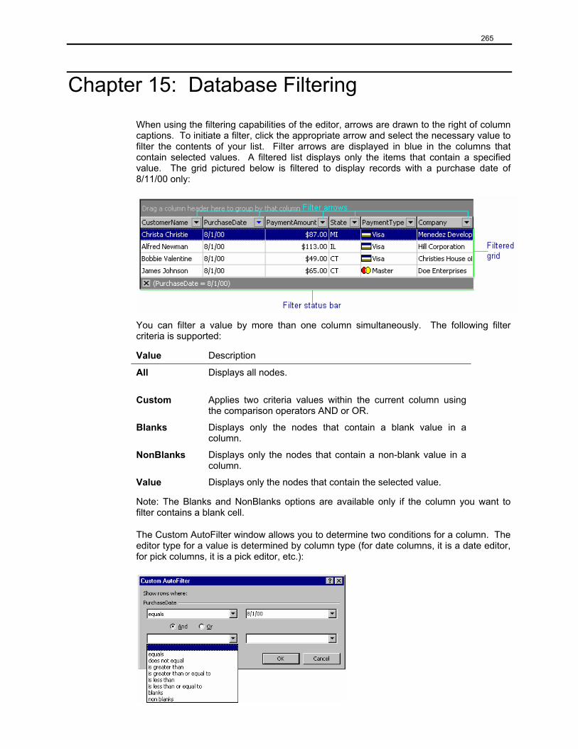
265
Chapter 15: Database Filtering
When using the filtering capabilities of the editor, arrows are drawn to the right of column captions. To initiate a filter, click the appropriate arrow and select the necessary value to filter the contents of your list. Filter arrows are displayed in blue in the columns that contain selected values. A filtered list displays only the items that contain a specified value. The grid pictured below is filtered to display records with a purchase date of 8/11/00 only:
You can filter a value by more than one column simultaneously. The following filter criteria is supported:
Value Description
All
Displays all nodes.
Custom Applies two criteria values within the current column using the comparison operators AND or OR.
Blanks Displays only the nodes that contain a blank value in a column.
NonBlanks Displays only the nodes that contain a non-blank value in a column.
Value Displays only the nodes that contain the selected value.
Note: The Blanks and NonBlanks options are available only if the column you want to filter contains a blank cell.
The Custom AutoFilter window allows you to determine two conditions for a column. The editor type for a value is determined by column type (for date columns, it is a date editor, for pick columns, it is a pick editor, etc.):
266
Chapter 16: Summary of Key Strokes
Select/unselect a part
To select a part, click on the part with the left mouse button. To prevent choosing the wrong part, click as close as possible to the center of the desired part. This is especially helpful if the desired part is nested inside of, or in an interlocking manner with another part.
To unselect a part, click anywhere outside of the part region. Clicking outside the plate is preferred, as it eliminates the possibility of picking another part by mistake. A selected part can be unselected by choosing another part. A selected part can also be unselected by pressing the ESCAPE key.
The selection state of a part can be toggled by holding down the Shift key and clicking with the left mouse button inside the part region. For example, if a part is unselected, shift select will select the part. If the part is selected, shift select will unselect the part.
Bump
To bump a part, select the center handle on the desired side of the selected group. For example, to bump left, select the center handle on the left side of the selected group. The selected group will move left until it is a part separation away from another part or the plate edge. Parts that are completely off the plate will not bump. If the leading edge of a part (i.e., the left edge if bumping left) is already in conflict, it will not bump.
To bump a part without using the mouse, press the corresponding keyboard arrow key pointing in the direction that you wish the part to be bumped.
Geometric Bump
To geometrically bump a part so that it ends up a kerf separation from another part or the plate edge, hold down the CTRL key when bumping, using either the bump handles or the arrow keys.
Rotate
Rotating by Increment - To rotate the selected group by a set increment, click on either the “+” Incremental Rotation Icon, the “-“ Incremental Rotation Icon, or the upper left handle. The selected group will rotate by the given increment. The Incremental Rotate Angle setting in the Preferences screen is used. If the “+” Incremental Rotation Icon or the upper left handle are used, the selected group rotates counter clockwise. If the “-“ Incremental Rotation Icon is used, the selected group rotates clockwise.
Move
With the part or group of parts in the selected state, click and hold the left mouse button on the part(s) dragging them to the desired position on the plate. Release the mouse button. Using the keypad, SHIFT plus an arrow key moves the part by the amount specified in Settings | Nesting – Nudge distance.

267
Chapter 17: Technical Support
We, at MTC hope that this document has provided you with all information necessary to get you started using ProNest for Windows with a minimum amount of difficulty.
MTC offers free training at our offices in Lockport, New York, and are available to conduct on-sight training. Please call for pricing.
If you wish to contact us, our office hours are 8:00 AM – 5:00 PM EST Monday through Friday. Don’t hesitate to contact us should you have any questions:
MTC
22 West Main Street
Lockport, NY 14094
Technical Support
716-434-3755
Main Office 716-434-3755
Fax 716-434-3711
E-mail [email protected]
Web Site http://www.mtc-software.com/
MTC is driven to achieve TOTAL CUSTOMER SATISFACTION with quality, world class software solutions. We accomplish this by maintaining a high standard of work life, listening to customer needs, adapting to industry trends, and keeping our commitments.

268