Promag 3000
112
Product manual LS.27.V2.02 SITRANS F M MAGFLO Electromagnetic flowmeters Sensor types MAG 1100, MAG 2100, MAG 3100 Signal converter types MAG 2500, MAG 3000 [ ] s *083R9120*
-
Upload
oliverio-teixeira -
Category
Documents
-
view
135 -
download
0
Transcript of Promag 3000

Product manual
LS.27.V2.02
SITRANS F M MAGFLO
Electromagnetic flowmetersSensor types MAG 1100, MAG 2100, MAG 3100Signal converter types MAG 2500, MAG 3000
[ ]
s
*083R9120*

LS.27.V2.02
MAGFLO
Siemens range of electro-magnetic flowmeters
MAG 1100 MAG 1100 MAG 2100 MAG 3100 MAG 3100 WFOOD
Size [mm] DN 6-100 DN 10-100 DN 25-80 DN 15-2000 DN 25-1200
Connection Flangeless Direct welding, Hygienic ISO 2852 Flange Flange(Sandwich design) clamp adapter, clamp, DIN 11851
thread adapter screwed fitting
Pressure [bar] Max. 40 Max. 40 Max. 20 Max. 425 Max. 40
Temperature [ °°°°°C] −20 to 200 −20 to 150 −30 to 100 −20 to180 −10 to 95
Liner Al2 O3 Al2 O3 FEP Neoprene, EPDM, Neoprene andTeflon (PTFE), EPDMPolyurethane,
Natural rubber, Ebonite,Linatex
Electrodes Platinum Platinum Platinum AISI 316 Ti, AISI 316 TiHastelloy C,
Platinum/Iridium,Monel, Titanium,
Tantalum
Enclosure IP 67 IP 67 IP 67 / 68 IP 67 / 68 IP 67 / 68
Ex-version EEx ia/ib IIB T4-T6 EEx ia/ib IIB T4-T6EEx e/ia IIC T3-T6
MAG 2500 MAG 2500 MAG 3000 MAG 3000Blind version Ex d
Outputs 1 current output 1 current output 1 current output 1 current output1 frequency / 1 frequency / 1 frequency / 1 frequency /pulse output pulse output pulse output pulse output
1 relay output 1 relay output 1 relay output 1 relay outputOption:
MAG 3000 withProfibus output
Flow direction Unidirectional Unidirectional Uni/bidirectional Uni/bidirectional
Display Actual flow settings MAG 2500 Blind Actual flow settings Actual flow settingsfault indications is supplied without fault indications fault indications
alarm display alarm alarm1 internal counter 2 internal counters 2 internal counters
Meter uncertainty ±0,5% ±0,5% ±0,25% ±0,25%of actual flow of actual flow of actual flow of actual flow
±0,5% of actual flowwith MAG 3100 W
Enclosure IP 67, IP 20 IP 67, IP 20 IP 67, IP 20 IP 67
Custody transfer 6.221 93.16 PTBapproval DANAK OIML R75
DANAK OIML R117
Ex-version [EEx ia/ib] IIB EEx de [ia/ib] IIB T6
2
3LS.27.V2.02
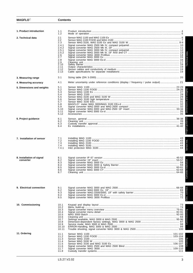
MAGFLO Contents
1.1 Product introduction .................................................................................................................................. 41.2 Mode of operation ........................................................................................................... .......................... 5
2.1 Sensor MAG 1100 and MAG 1100 Ex ........................................................................................................ 62.2 Sensor MAG 1100 FOOD and MAG 2100 .................................................................................................. 72.3 Sensor MAG 3100, MAG 3100 Ex and MAG 3100 W ......................................................................... 8-92.4.1 Signal converter MAG 2500 Mk IV, compact polyamid ......................................................................... 102.4.2 Signal converter MAG 2500 Mk III, 19" ................................................................................................. 112.5.1 Signal converter MAG 3000 Mk IV, compact polyamid ......................................................................... 122.5.2 Signal converter MAG 3000 Mk III, 19" AISI and CT ........................................................................... 132.6 Signal converter MAG 3000 Profibus .................................................................................................... 142.7 Signal converter MAG 3000 Ex .............................................................................................................. 152.8 Signal converter MAG 3000 Ex-d ........................................................................................................... 162.9 Cleaning unit ............................................................................................................... ............................. 172.10 Safety barrier ............................................................................................................................................ 182.11 Output characteristics .............................................................................................................................. 192.12 Sensor cables and conductivity of medium ........................................................................................... 192.13 Cable specifications for separate installations ...................................................................................... 19
3.1 Sizing table (DN 3-2000) ......................................................................................................................... 20
4.1 Meter uncertainty under reference conditions (display / frequency / pulse output) ........................... 21
5.1 Sensor MAG 1100 .............................................................................................................................. 22-235.2 Sensor MAG 1100 FOOD .................................................................................................................. 24-265.3 Sensor MAG 1100 Ex ............................................................................................................................. 275.4 Sensor MAG 2100 ................................................................................................................................... 285.5 Sensor MAG 3100 and MAG 3100 W .................................................................................................... 295.6 Sensor MAG 3100 high temperature ..................................................................................................... 305.7 Sensor MAG 3100 EEx ......................................................................................................... .................. 315.8 MAGFLO meter MAG 3000/MAG 3100 EEx-d .................................................................................... 325.9 Signal converter MAG 3000 and MAG 2500 compact ......................................................................... 325.10 Signal converter MAG 3000 and MAG 2500 19" insert .................................................................. 33-345.11 Signal converter MAG 3000 Ex-d ........................................................................................................... 355.12 Accessories .............................................................................................................................................. 35
6.1 Sensor, general .................................................................................................................................. 36-386.2 Cleaning unit ............................................................................................................................................ 396.3 Custody transfer approval ....................................................................................................................... 406.4 Ex installations ............................................................................................................ ........................ 41-42
7.1 Installing MAG 1100 ................................................................................................................................ 437.2 Installing MAG 1100 FOOD .................................................................................................................... 437.3 Installing MAG 2100 ......................................................................................................... ....................... 437.4 Installing MAG 3100 ......................................................................................................... ....................... 447.4.1 Inlet protection MAG 3100 ...................................................................................................................... 44
8.1 Signal converter IP 67 version .......................................................................................................... 45-528.2 Signal converter 19" insert ................................................................................................................. 53-578.3 Signal converter MAG 3000 Ex .............................................................................................................. 588.4 Signal converter MAG 3000 & Safety Barrier ........................................................................................ 598.5 Signal converter MAG 3000 Ex-d ...................................................................................................... 60-618.6 Signal converter MAG 3000 CT ......................................................................................................... 62-648.7 Cleaning unit ....................................................................................................................................... 64-65
9.1 Signal converter MAG 3000 and MAG 2500 .................................................................................... 66-689.2 Signal converter MAG 3000 Ex, 19" ...................................................................................................... 699.3 Signal converter MAG /2500/3000, 19" with safety barrier .................................................................. 709.4 Signal converter MAG 3000 Ex-d ........................................................................................................... 719.5 Signal converter MAG 3000 Profibus .................................................................................................... 72
10.1 Keypad and display layout ..................................................................................................................... 7310.2 Menu build-up .......................................................................................................................................... 7410.3 Signal converter menu overview ........................................................................................................ 75-8110.4 Signal converter menu detail .............................................................................................................. 82-9110.5 MAG 3000 Batch ................................................................................................................................ 92-9310.6 Cleaning unit ............................................................................................................................................ 9410.7 Settings available, MAG 3000 & MAG 2500 ..................................................................................... 95-9610.8 Dimension-dependent factory settings, MAG 3000 & MAG 2500 ....................................................... 9710.9 Service mode, MAG 3000 & MAG 2500 ................................................................................................ 9810.10 ERROR-Handling, MAG 3000 & MAG 2500 .......................................................................................... 9910.11 Trouble shooting, signal converter MAG 3000 & MAG 2500 ............................................................. 100
11.1 Sensor MAG 1100 ......................................................................................................................... 101-10211.2 Sensor MAG 1100 FOOD ............................................................................................................. 103-10411.3 Sensor MAG 2100 ................................................................................................................................. 10511.4 Sensor MAG 3100 W ............................................................................................................................ 10511.5 Sensor MAG 3100 and MAG 3100 Ex ......................................................................................... 106-10711.6 Signal converter MAG 2500 and MAG 2500 Blind ............................................................................. 10811.7 Signal converter MAG 3000 ......................................................................................................... 109-11011.8 Custody transfer systems ...................................................................................................................... 111
Tec
hnic
al d
ata
Sen
sor i
nst.
Com
mis
sion
ing
Ord
erin
gD
imen
sion
s an
d w
eigh
tsC
onve
rter i
nsta
llatio
nE
lec.
con
nect
.
2. Technical data
1. Product introduction
3. Measuring range
4. Measuring accuracy
5. Dimensions and weights
6. Project guidance
Pro
ject
gui
danc
e
7. Installation of sensor
8. Installation of signalconverter
9. Electrical connection
10. Commissioning
11. Ordering

4 LS.27.V2.02
MAGFLO
1.1 Product introduction
1. Product introduction
MAGFLO electromagnetic flowmeters offer reliable, precise and inexpensive flow measure-ment on all electrically conductive liquids. Typical applications are found in all industries. E.g.:
• Water sector: Drinking water, treatment chemicals, waste water, sludge.• Food sector: Dairy products, beer, wine, soft-drinks, fruit juices and pulps.• Chemical sector: Detergents, pharmaceuticals, acids, alkalies.• Other sectors: District heating, paper pulp, mining slurries.
MAGFLO electromagnetic flowmeters are characterised by simplicity:
⇒ Simple to install⇒ Simple to commission⇒ Simple to operate⇒ Simple to maintain
MAGFLO electromagnetic flowmeters are manufactured by Siemens Flow Instruments - one of theworlds leading makers of flowmeters.
All MAGFLO electromagnetic flowmeter feature a unique SENSORPROM® memory unit whichstores sensor calibration data and signal converter settings for the lifetime of the product.At commissioning the flowmeter commerces measurement without any initial programming.The factory settings matching the sensor are stored in the SENSORPROM® unit. Also customerspecified settings are downloaded to the SENSORPROM® unit. Should the signal converter bereplaced, the new converter will upload all previous settings and resume measurement without anyneed for reprogramming.

5LS.27.V2.02
MAGFLO
The flowmeter is built up of a number of function blocks
COIL CURRENT MODULE generates a pulsating magnetising current that drives the coils in thesensor. The current is permanently monitored and corrected. Errors, open circuits or cable faultsare registered by the self-monitoring circuit.
INPUT CIRCUIT amplifies the flow proportional signal from the electrodes. The input impedanceis extremely high: >1x10¹⁴Ω, which allows flow measurements on fluids with conductivities as lowas 1µS/cm. Measuring errors due to cable capacitance are eliminated due to active cablescreening.
DIGITAL SIGNAL PROCESSOR converts the analog flow signal to a digital signal andsuppresses electrode noise through a digital filter. Inaccuracies in the signal converter as a resultof long-term drift and temperature drift are monitored and continously compensated for via theself-monitoring circuit. The analog to digital conversion takes place in an ultra low noise ASIC with23 bit signal resolution. This has eliminated the need for range switching. The dynamic range ofthe signal converter is thus unsurpassed, with a turn down ratio of min. 3000:1.
OUTPUT CONDITIONER generates the signals for the output module and communicates with theuser interface and the SENSORPROM® unit. A built-in error handler evaluates any detected errorconditions and controls the status of the output module. Errors are registered and stored for up to180 days.
USER INTERFACE MODULE consists of a keypad, a display and a microprocessor for com-munication between the user and the signal converter.
OUTPUT MODULE converts flow data to current, frequency/pulse signals and an error relayindicates errors, if any. The outputs are galvanically isolated and continously monitored. Anycurrent loop break is detected as an error.
SENSORPROM® unit contains sensor data and signal converter settings. The SENSORPROM®
unit is located on the connection board for the signal converter. Immediately on starting, the signalconverter uploads the calibration data and factory settings matching the sensor and commencemeasurement. All customer specified settings are retained in the SENSORPROM® unit. In casethe signal converter is replaced, the new converter will upload all previous settings and resumemeasurement without any need for reprogramming.
1.2 Mode of operation
1. Product introduction

6 LS.27.V2.02
MAGFLO
Tec
hnic
al d
ata
Type Flangeless sensor (Sandwich design) Flangeless sensor (Sandwich design)
Nominal size DN 6, 10, 15, 25, 40, 65, 80, 100 mm DN 6, 10, 15, 25, 40, 65, 80, 100 mm
Operating pressure PN 40. Vacuum: 1 × 10⁻⁶ bar PN 40. Vacuum: 1 × 10⁻⁶ bar
Temperature of medium −20°C to +150°C (standard) −20°C to +120°C
−20°C to +200°C (option)
Temperature shock By gradual change of temperature (duration > 1 min.): By gradual change of temperature (duration > 1 min.):
DN 6, 10, 15, 25 Max. ∆T ≤ 15°C/min. DN 6, 10, 15, 25 Max. ∆T ≤ 15°C/min.
DN 40, 50, 65 Max. ∆T ≤ 10°C/min. DN 40, 50, 65 Max. ∆T ≤ 10°C/min.
DN 80, 100 Max. ∆T ≤ 5°C/min. DN 80, 100 Max. ∆T ≤ 5°C/min.
By sudden change of temperature By sudden change of temperature
(duration ≤ 1 min., followed by 10 min. rest): (duration ≤ 1 min., followed by 10 min. rest):
DN 6, 10, 15, 25 Max. ∆T ≤ 80°C DN 6, 10, 15, 25 Max. ∆T ≤ 80°CDN 40, 50, 65 Max. ∆T ≤ 70°C DN 40, 50, 65 Max. ∆T ≤ 70°CDN 80, 100 Max. ∆T ≤ 60°C DN 80, 100 Max. ∆T ≤ 60°C
Ambient temperature Remote signal converter: −40°C to +100°C Remote signal converter: −40°C to +40°C
Compact signal converter: −20°C to +50°C Compact signal converter:−20°C to +40°C
Liner Aluminium oxide Al2O3 (ceramics) Aluminium oxide Al2O3 (ceramics)
Electrodes Platinum/gold/titanium Platinum/gold/titanium
Enclosure Stainless steel AISI 316 (1.4436) Stainless steel AISI 316 (1.4436)
Terminal box Fibreglass reinforced polyamide (Standard) Stainless steel AISI 316 (1.4436)
Stainless steel AISI 316 (1.4436) (Option)
Fixing studs Stainless steel AISI 304 (1.4301) Stainless steel AISI 304 (1.4301)
Number and size to DIN 2501 Number and size to DIN 2501
Mating flanges To DIN 2501 (PN 10-PN 40), ANSI B16.5 To DIN 2501 (PN 10-PN 40), ANSI B16.5
class 150 and 300 or equivalent class 150 and 300 or equivalent
Option DN 6/10: ½" pipe connection adapters thread:½" tappered ISO 7-1
Gaskets Standard EPDM (max. 150°C, PN 40) EPDM (max. 150°C, PN 40)
Option Graphite (max. 200°C, PN 40) Graphite (max. 200°C, PN 40)
Option PTFE (max.130°C, PN 25) PTFE (max.130°C, PN 25)
Cable entries 2-off Pg 13.5 - 2 others available 2-off Pg 13.5
Enclosure rating Standard: IP 67 to IEC 529 and DIN 40050 IP 67 (1 m w.g. for 30 min.) to IEC 529(tested to 3 m w.g. for 72 h)and DIN 40050
Option: IP 68 to 10 m w.g. when used withsubmersible kit Code no. 085U0220
Mechanical load (vibration) 18-1000 Hz random, 3.17G rms, in all directions, 18-1000 Hz random in all directions,to IEC 68-2-36 to IEC 68-2-36
Sensor: 3.17 G Compact Ex-d.: 1.14 G
Test pressure 80 bar (2 × PN) 80 bar (2 × PN)
Ex approval EEx ia/ib IIB T4-T6/DEMKO, No. 97D.121909XRemote, MAG 3000 EEx 19" or MAG 3000 EEx-d
EEx de (ia/ib) IIB T4-T6/DEMKO 94C.115327XCompact, MAG 3000 EEx-d
Exitation frequency DN 6-15: 25 Hz DN 6-65: 12.5 HzDN 25-65: 12.5 Hz DN 80-100: 6.25 HzDN 80-100: 6.25 Hz
2.1 Sensor MAG 1100 and MAG 1100 Ex
2. Technical data MAG 1100 & MAG 1100 Ex
MAG 1100 MAG 1100 EEx & EEx-d

7LS.27.V2.02
MAGFLO
Tec
hnic
al d
ata
Adapter Stainless steel AISI 316Pipe connection/ Adapter for direct welding into dairy pipe:Operating ISO 2037, DIN 11850, SMS 3008, BS 4825-1pressure DN 10, 15, 25, 40, 50, 65, 80 PN 40
DN 100 PN 25Clamp adapter:ISO 2852, DIN 32676, SMS 3016, BS 4825-3
DN 10, 15, 25, 40, 50 PN 16DN 65, 80, 100 PN 10
Thread adapter:DIN 11851: DN 10, 15, 25, 40 PN 40
DN 50, 65, 80, 100 PN 25ISO 2853, SS 3351, BS 4825-4: DN 10, 15, 25, 40, 50, 65, 80 PN 16SMS 1145: DN 25, 40, 50, 65, 80 PN 6
Gasket Standard EPDM (−20 °C to 130 °C)Option NBR (−20 °C to 100 °C)
Clamp Stainless steel AISI 304
Type Hygienic sensor Hygienic sensorNominal size DN 10, 15, 25, 40, 50, 65, 80, 100 mm DN 25, 40, 50, 65, 80 mm
Sensor connection: Clamp ISO 2852 Di to ISO 2037 or DIN 11850 depending on connectionProcess connection Hygienic adapters available for: Integred hygienic fittings:
♦ Direct welding into dairy pipe ♦ Clamp fitting ♦ Clamp fitting: ISO 2852♦ Threaded fitting ♦ Threaded fitting: DIN 11851
Operating pressure Depending on type of adapters, see accessories Max. 20 bar at medium temperature ≤ 80°CVacuum: 1 × 10⁻⁶ bar Max. 10 bar at medium temperature ≤ 100°C
Vacuum: 1 × 10⁻⁶ barTemperature of medium −20°C to +150°C −30°C to +100°C
Suitable for steam sterilization Not suitable for steam sterilizationTemperature shock By gradual change of temperature (duration > 1 min.): Max. ±75°C/s
DN 6, 10, 15, 25 Max. ∆T ≤ 15°C/min.DN 40, 50, 65 Max. ∆T ≤ 10°C/min.DN 80, 100 Max. ∆T ≤ 5°C/min.By sudden change of temperature(duration ≤ 1 min., followed by 10 min. rest):
DN 6, 10, 15, 25 Max. ∆T ≤ 80°CDN 40, 50, 65 Max. ∆T ≤ 70°CDN 80, 100 Max. ∆T ≤ 60°C
Ambient temperature Remote signal converter: −40°C to +100°C Remote signal converter: −30°C to +100°CCompact signal converter: −20°C to +50°C Compact signal converter: −20°C to +50°C
Liner Aluminium oxide Al2O3 (ceramic) FEP (Perflouroethylenepropylene)Electrodes Platinum/gold/titanium PlatinumEnclosure Stainless steel AISI 316 (1.4436) Stainless steel AISI 316 (1.4436)Terminal box Standard Fibreglass reinforced polyamide Fibreglass reinforced polyamide
Option Stainless steel AISI 316 (1.4436) Stainless steel AISI 316 (1.4436)Cable entries 2-off Pg 13.5 - 2 others available 2-off Pg 13.5 - 2 others availableEnclosure rating Standard: IP 67 to IEC 529 and DIN 40050 IP 67 (1 m w.g. for 30 min.) to IEC 529
(tested to 3 m w.g. for 72 h) and DIN 40050Option: IP 68 to 10 m w.g. when used withsubmersible kit Code no. 085U0220
Mechanical load (vibration) 18-1000 Hz random, 3.17G rms, in all directions, 18-1000 Hz random, 3.17G rms, in all directions,to IEC 68-2-36 to IEC 68-2-36
Test pressure 80 bar (2 × PN) 20 barApprovals 3A, EHEDG 3AExitation frequency DN 10-15: 25 Hz, DN 25-65: 12.5 Hz DN 25-65: 12.5 Hz, DN 80: 6.25 Hz
DN 80-100: 6.25 Hz
2.2 Sensor MAG 1100 FOOD and MAG 2100
MAG 1100 FOOD MAG 2100
2. Technical data MAG 1100 FOOD & MAG 2100
AccessoriesMAG 1100 FOOD

8 LS.27.V2.02
MAGFLO
Tec
hnic
al d
ata
Type Sensor with flanges Sensor with flanges Sensor with flangesNominal size DN 15-2000 mm DN 15-2000 mm / 15-300 mm DN 25-1200 mmLiner selection guide Neoprene: General purpose, waste water, drinking water
EDPM: General purpose, waste water, drinking water (WRC approved)Linatex: Abrasive media, mineral slurriesEbonite: General purpose, waste water, drinking water (WRC approved), high pressurePolyurethane: Abrasive media, high pressurePTFE teflon: Aggressive chemicals, food & beverage, paper & pulp
Liner Standard Neoprene Neoprene, EPDM 1)Option Ebonite, EPDM 1), Teflon (PTFE), polyurethane (PU), natural rubber,
Linatex
Temperature of medium Temperature classificationLiner: T3 + T4 T5 T6Neoprene 0 - 95°C 0-95°C 0-90°C 0-75°C 0 - 95°CEPDM −10 - 95°C −10-95°C −10-90°C −10-75°C −10 - 95°CLinatex rubber −40 - 70°C −20-70°C −20-70°C −20-70°CEbonite 0 - 95°C 0-95°C 0-90°C 0-75°CPolyurethane 0 - 50°C 0-50°C 0-50°C 0-50°CPTFE teflon: −20 - 180°C −20-120°C −20-90°C −20-75°C
The temperature ranges statedassume a maximum ambienttemperature of +40°C
Ambient temperatureRemote signal converter −40°C - 100°C −20°C - 40°C −40°C - 100°CCompact signal converter −20°C - 50°C −20°C - 40°C −20°C - 50°C
Operating pressure [[[[[abs.bar ]]]]]Liner:Neoprene 0.01 to 100 bar 0.01 to 100 bar 0.01 to 40 barEPDM 0.01 to 40 bar 0.01 to 40 bar 0.01 to 40 barNatural rubber & Linatex 0.01 to 40 bar 0.01 to 40 barEbonite 0.01 to 425 bar 0.01 to 425 barPolyurethane 0.4 to 425 bar 0.4 to 425 barPTFE teflon:
DN 15 to 600 Max. 100°C: 0.3 to 40 bar 0.3 to 40 barDN 15 to 600 Max. 120°C: 0.5 to 40 barDN 15 to 300 Max. 180°C: 0.6 to 40 bar
Operating pressure is limited by flange rating. Maximum operating pressure decreases with increasingoperating temperature (above 100°F or 38°C) and with stainless steel flanges
Pipe connection StandardBS 4504 DN 15-50: PN 40 DN 15-50: PN 40(∼DIN 2501) DN 65-150: PN 16 DN 65-150: PN 16
DN 200-1000: PN 10 DN 200-1200: PN 10DN 1100-2000: PN 6
Option DN 65-1000: PN 6 DN 200-600: PN 16DN 1200-2000: PN 10DN 200-2000: PN 16DN 200-600: PN 25DN 65-600: PN 40DN 50-400 PN 64DN 50-350 PN 100
2. Technical data MAG 3100 & MAG 3100 Ex & MAG 3100 W
2.3 Sensor MAG 3100, MAG 3100 Ex and MAG 3100 W
MAG 3100 MAG 3100 EEx / EEx-d MAG 3100 W
1) With WRC (Water Research Council, UK) approval

9LS.27.V2.02
MAGFLO
Tec
hnic
al d
ata
Pipe connectionANSI B 16.5 3/4"-24": Class 150 (20 bar) 2"-24": Class 900 (150 bar)(∼BS 1560) 3/4"-24": Class 300 (50 bar) 2"-24": Class 1500 (250 bar)
2"-24": Class 600 (100 bar) 2"-12": Class 2500 (425 bar)BS 10 3/4"-60": Table D/EAS 2129 3/4"-48": Table D/EAS 4087 DN 50-1200 (14 bar)JIS B 2220 DN 50-1000: K10 (10 bar)
DN 50-1200: K16 (16 bar)AWWA C-207 28"-78": Class D
Electrodes Standard AISI 316 Ti (1.4571) AISI 316 Ti (1.4571)Option Hastelloy C-276, Platinum / Iridium, Titanium, Monel (Alloy 400),
AISI 316 Ti Coated, Tantalum
Earthing electrodes AISI 316 Ti (1.4571), Hastelloy C276. Available as option with all liner Standard: AISI 316 Ti (1.4571)materials except PTFE
Measuring pipe AISI 304 (1.4301)Flange 2) and Standard St. 37.2 flanges and housing. Corrosion-resistant two-component St. 37.2 flanges and housing.housing material coating (min. 150 µm) Corrosion-resistant two-compo-
nent coating (min. 150 µm)Option AISI 304 (1.4301) flanges and St. 37.2 housing. Coating as aboveOption AISI 316/L (1.4436/1.4401) flanges and housing.
Enclosure rating Standard IP 67 to IEC 529 and DIN 40050 (tested to 3 m w.g. for 72 h)Option IP 68 to 10 m w.g. when used with submersible kit Code no. 085U0220
Cable entries 2-off Pg 13.5 - 2 others availableMechanical load 18-1000 Hz random, 3.17G rms, in all directions, to IEC 68-2-36Design pressure 1.5 × PNEx-approval Remote DN 15 to DN 100 EEx ia/ib m IIB T4-T6/DEMKO 94C.116403X
MAG 3000 EEx 19" or MAG 3000 EEx-dRemote DN 125 to DN 300 EEx ia/ib e IIB T4-T6/DEMKO 94C.115326X
MAG 3000 EEx 19" or MAG 3000 EEx-dRemote DN 350 to DN 2000 EEx e ia IIC T3-T6/Sira Ex 92C3107X
MAG 3000 19" standard with Safety BarriesCompact DN 15 to DN 300 EEx de [ia/ib] IIB T4-T6/DEMKO 94C.115327X
MAG 3000 EEx-dExitation frequency DN ≤ 65: 12 1/2 Hz DN ≤ 65: 12 1/2 Hz All sizes: 3 1/8 Hz
65 < DN ≤ 300: 6 1/4 Hz DN 80/100: 6 1/4 Hz300 < DN ≤ 1200: 3 1/8 Hz DN ≥ 125: 3 1/8 HzDN > 1200: 1 9/16 Hz
2.3 Sensor MAG 3100, MAG 3100 Ex and MAG 3100 W (continued)
2. Technical data MAG 3100 & MAG 3100 Ex & MAG 3100 W
2) With stainless steel flanges the maximum pressure is derated. Please refer to appropriate standards
MAG 3100 MAG 3100 EEx & EEx-d MAG 3100 W

10 LS.27.V2.02
MAGFLO
Tec
hnic
al d
ata
Terminalconnection
Current output 31 and 32Current 0-20 mA or 4-20 mALoad < 800 ohmTime constant 0.2-41.1 s adjustable
Frequency/pulse output Short-circuit-protected 56, 57 and 58Frequency 0-10 kHz. 50% duty cyclePulse width 50 µs, 500 µs, 5 ms, 50 ms, 100 ms, 500 ms, 1 s, 5 s, 250 msTime constant 0.2-41.1 s adjustableActive 24 V d.c., 30 mA, 1 KΩ ≤ Rload ≤ 10 KΩPassive 3-30 V d.c., max. 110 mA, 1 KΩ ≤ Rload ≤ 10 KΩ
Relay Changeover relay for fault or flowdirection 44, 45 and 46Load Max. 42 V / 2 ATime constant Flowdirection: 5 s, Fault: 1 s
Galvanic isolation All inputs and outputs are galvanically isolatedCut-off Low-flow 0-9.9% of maximum flowCounter One internal eight-digit counter to integrate volumeDisplay Background illumination with alphanumerical text, 2 × 16 characters to indicate flow,
volume, settings and faults. Option: MAG 2500 Blind supplied without display 1)Time constant 0.2-41.1 s adjustable (Time constant as current output)
Zero point adjustment AutomaticElectrode input impedance > 1 × 10¹⁴ ΩExitation frequency Pulsating d.c. current (125 mA) with a frequency of 3 1/8 HzAmbient temperature During operation: −20 to +50°C
During storage: −40 to +70°CSupply voltage and a.c. 115-230 V a.c. +10% to −15%, 50-60 Hz, 9 VA l, N and Lpower consumption d.c. 11-30 V d.c. or 11-24 V a.c. 9 W − and +IP 67 Enclosure material Fibre glass-reinforced polyamide
Enclosure rating IP 67 to IEC 529 and DIN 40050 (1 m w.g. for 30 min.)Mechanical load 18-1000 Hz random, 3.17G rms, in all directions, to IEC 68-2-36
EMC performance Emission EN 50081-1 (Light industry)
Immunity EN 50082-1 (Light industry)
2.4.1 Signal converter MAG 2500 Mk IV, compact polyamid (DN 6 to DN 1200)
1) The MAG 2500 Blind is delivered with the following output settings: Current OffFrequency/pulse output OnFrequency/pulse output Pulse output selectedPulse width 50 msLow flow cut-off 1.5%
The settings of Qmax., totalizer unit and volume per pulse are depending on the sensor size selected. Due to the SENSORPROM techniqueit is possible to change the settings (both IP 67 and 19" insert version) by using a standard MAG 2500 or MAG 3000.
Accuracy 0.5%
2. Technical data MAG 2500

11LS.27.V2.02
MAGFLO
Tec
hnic
al d
ata
Terminalconnection
Current output 31 and 32Current 0-20 mA or 4-20 mALoad < 800 ohmTime constant 0.8-30 s adjustable
Frequency/pulse output Short-circuit-protected 50, 51 and 52Frequency 0-10 kHz. 50% duty cyclePulse width 50 µs, 500 µs, 5 ms, 50 ms, 100 ms, 500 ms, 1 s, 5 sTime constant 0.3-30 s adjustableActive 24 V d.c.
≤ ≤ ≤ ≤ ≤ 1 Hz ≤ ≤ ≤ ≤ ≤ 10 kHzMin. Rload ≥ 150 Ω ≥ 1 KΩMax. Rload ≤ 10 KΩ ≤ 10 KΩ
Passive 3-30 V d.c.U = 3 V U = 30 V
Min. Rload 10 Ω 225 ΩMax. Rload ≤ 10 KΩ ≤ 10 KΩ
Relay Changeover relay for fault indication 44, 45 and 46Load Max. 42 V / 2 ATime constant 1 s
Galvanic isolation All inputs and outputs are galvanically isolatedCut-off Low-flow 0-9.9% of maximum flowCounter One internal eight-digit counter to integrate volumeDisplay Background illumination with alphanumerical text, 2 × 16 characters to indicate flow,
volume, settings and faults. Option: MAG 2500 Blind supplied without display 1)Time constant 0.3-30 s adjustable (Time constant as current output)
Zero point adjustment AutomaticElectrode input impedance > 1 × 10¹⁴ ΩExitation frequency Pulsating d.c. current (125 mA) with a frequency of 3 1/8 HzAmbient temperature During operation: −20 to +50°C
During storage: −40 to +70°CSupply voltage and a.c. 115/230 V a.c. +10% - −15%, 50-60 Hz, 9 VA l, N and Lpower consumption d.c. 11-30 V d.c. or 11-24 V a.c. 9 W − and +19" insert Enclosure material Standard 19" insert in aluminium/steel (DIN 41494)
Width: 28 TE (142 mm)Height: 3 HE (128 mm)Module depth: 160 mm
Enclosure rating IP 20 to IEC 529 and DIN 40050Mechanical load 115/230 V a.c. version: 1 G, 1-800 Hz sinusoidal in all directions, to IEC 68-2-6
11-30 V d.c./11-24 V a.c. version: 18-1000 Hz random, 3.17G rms, in all directions,to IEC 68-2-36
EMC performance Emission EN 50081-1 (Light industry)
Immunity EN 50082-1 (Light industry)
2. Technical data MAG 2500
2.4.2 Signal converter MAG 2500 Mk III, 19" (DN 6 to DN 1200)
1) The MAG 2500 Blind is delivered with the following output settings: Current OffFrequency/pulse output OnFrequency/pulse output Pulse output selectedPulse width 50 msLow flow cut-off 1.5%
The settings of Qmax., totalizer unit and volume per pulse are depending on the sensor size selected. Due to the SENSORPROM techniqueit is possible to change the settings (both IP 67 and 19" insert version) by using a standard MAG 2500 or MAG 3000.
Accuracy 0.5%

12 LS.27.V2.02
MAGFLO
Tec
hnic
al d
ata
Terminalconnection
Current output 31 and 32Current 0-20 mA or 4-20 mALoad < 800 ohmTime constant 0.2-41.1 s adjustable
Frequency/pulse output Short-circuit-protected 56, 57 and 58Frequency 0-10 kHz, 50% duty cyclePulse width 50 µs, 500 µs, 5 ms, 50 ms, 100 ms, 500 ms, 1 s, 5 s, 250 msTime constant 0.2-41.1 s adjustableActive 24 V d.c., 30 mA, 1 KΩ ≤ Rload ≤ 10 KΩPassive 3-30 V d.c., max. 110 mA, 1 KΩ ≤ Rload ≤ 10 KΩ
Relay Changeover relay to indicate flow direction, fault or batch output 44, 45 and 46Load Max.: 42 V / 2 ATime constant Flow direction: 5 s; Fault : 1 s
Batch Type Single stageBatch quantity 0.000001-100 of selectet unitsBatch compensation Yes, –1.0-1.0 of selected unit 0 by defaultBatch counter Up or down Up by defaultOutput Relay or open collector Relay by defaultInput Start, hold/continue, stop Stop by defaultBatch cycles Display with reset option
Galvanic isolation All inputs and outputs are galvanically isolatedCut-off Low-flow 0-9.9% of maximum flow
Empty pipe Detection of empty sensor. Can be deselected on low conductivity fluids.Use a special electrode cable.
Counter Two internal eight-digit counters for forward flow and reverse flow respectivelyElectrode cleaning For use on measurement of liquids which can give rise to the building of insulating
deposits on the sensor’s electrodes, or conductive deposits on the inside of thesensor. Electrode cleaning requires a special unit, available as an insert for 19" rack.
Display Background illumination with alphanumerical text, 2 × 16 characters to indicate flow,volume, settings and faults.Reverse flow indicated by negative sign.
Time constant 0.2-41.1 s adjustable (Time constant as current output)Zero point adjustment AutomaticElectrode input impedance > 1 x 10¹⁴ ΩExitation frequency Pulsating d.c. current (125 mA) with one of the following frequencies:
1 9/16, 3 1/8 Hz, 6 1/4 Hz, 12 1/2 Hz or 25 HzAmbient temperature During operation −20 to +50°C
During storage −40 to +70°CSupply voltage and a.c. 115-230 V a.c. +10% - −15%, 50-60 Hz, 9 VA l, N and Lpower consumption d.c. 11-30 V d.c. or 11-24 V a.c. 9 W L− and L+Compact Enclosure material Fibre glass-reinforced polyamide or stainless steel AISI 316 L (1.4401)
Enclosure rating IP 67 to IEC 529 and DIN 40050 (1 m w.g. for 30 min.)Mecanical load 18-1000 Hz random, 3.17G rms, in all directions, to IEC 68-2-36
EMC performance Emission EN 50081-1 (Light industry)Immunity EN 50082-1 (Light industry)
2. Technical data MAG 3000 & MAG 3000 CT
2.5.1 Signal converter MAG 3000 Mk IV, compact polyamid
Accuracy 0.25%

13LS.27.V2.02
MAGFLO
Tec
hnic
al d
ata
Terminalconnection
Current output 31 and 32Current 0-20 mA or 4-20 mALoad < 800 ohmTime constant 0.8-30 s adjustable
Frequency/pulse output Short-circuit-protected 50, 51 and 52Frequency 0-10 kHz, 50% duty cyclePulse width 50 µs, 500 µs, 5 ms, 50 ms, 100 ms, 500 ms, 1 s, 5 sTime constant 0.3-30 s adjustableActive 24 V d.c.
≤ ≤ ≤ ≤ ≤ 1 Hz ≤ ≤ ≤ ≤ ≤ 10 kHzMin. Rload ≥ 150 Ω ≥ 1 KΩMax. Rload ≤ 10 KΩ ≤ 10 KΩ
Passive 3-30 V d.c.U = 3 V U = 30 V
Min. Rload 10 Ω 225 ΩMax. Rload ≤ 10 KΩ ≤ 10 KΩ
Relay Changeover relay to indicate flow direction or fault 44, 45 and 46Load Max.: 42 V / 2 ATime constant Flow direction: 5 s; Fault : 1 s
Galvanic isolation All inputs and outputs are galvanically isolatedCut-off Low-flow 0-9.9% of maximum flow
Empty pipe Detection of empty sensor. Can be deselected on low conductivity fluids.Use a special electrode cable.
Counter Two internal eight-digit counters for forward flow and reverse flow respectivelyElectrode cleaning For use on measurement of liquids which can give rise to the building of insulating
deposits on the sensor’s electrodes, or conductive deposits on the inside of thesensor. Electrode cleaning requires a special unit, available as an insert for 19" rack.
Display Background illumination with alphanumerical text, 2 × 16 characters to indicate flow,volume, settings and faults.Reverse flow indicated by negative sign.
Time constant 0.3-30 s adjustable (Time constant as current output)Zero point adjustment AutomaticElectrode input impedance > 1 x 10¹⁴ ΩExitation frequency Pulsating d.c. current (125 mA) with one of the following frequencies:
1 9/16, 3 1/8 Hz, 6 1/4 Hz, 12 1/2 Hz or 25 HzCustody transfer approval PTB DANAK OIML R75 DANAK OIML R117MAG 3000 CT only (cold water) (hot water) (milk, beer etc.)Ambient temperature During operation −20 to +50°C
During storage −40 to +70°CSupply voltage and a.c. 115/230 V a.c. +10% to −15%, 50-60 Hz, 9 VA l, N and Lpower consumption d.c. 11-30 V d.c. or 11-24 V a.c. 9 W L− and L+Compact Enclosure material Fibre glass-reinforced polyamide or stainless steel AISI 316 L (1.4401)
Enclosure rating IP 67 to IEC 529 and DIN 40050 (1 m w.g. for 30 min.)Mechanical load 18-1000 Hz random, 3.17G rms, in all directions, to IEC 68-2-36
19" insert Enclosure material Standard 19" insert of aluminium/steel (DIN 41494)Width: 28 TE (142 mm)Height: 3 HE (128 mm)Module depth: 160 mm
Enclosure rating IP 20 to IEC 529 and DIN 40050Mechanical load 115/230 V a.c. version: 1 G, 1-800 Hz sinusoidal in all directions, to IEC 68-2-6
24 V d.c. version: 18-1000 Hz random, 3.17G rms, in all directions, to IEC 68-2-36EMC performance Emission EN 50081-1 (Light industry)
Immunity EN 50082-1 (Light industry)
2. Technical data MAG 3000 & MAG 3000 CT
6.22193.16
2.5.2 Signal converter MAG 3000 Mk III, 19" AISI and CT
Accuracy 0.25%

14 LS.27.V2.02
MAGFLO
Tec
hnic
al d
ata
2. Technical data MAG 3000 Profibus
2.6 Signal converter MAG 3000 Profibus
Terminalconnection
FMS communication protocol Follows the frame sheet of the sensor/actor profile (class 4.) 50, 51 and 52Standards DIN 19245 T1+T2, EN 50170Types of communication Master/Slave asynchronous, Master/Slave asynchronous with initiative and
Master/Salve cycleBaudrate 9.6, 19.2, 93.75, 187.5 or 500 Kbaud with automatic selectionVolume flow function block Follows the data sheet of the sensor/actor profile function for analogue input,
class 4. Enables:Arbitrary display of measuring value in 16 bit integer or floating point format.Parametering of measuring range.Parametering with limit values, monitoring and handling of Event.Setting of time constant 0.2 - 51 seconds.
Interval of up-datings 200 msec.Volume counter function block Reading of measuring value in 16 bit integer format.
Setting of volume per counter unit over the bus.Parametering with limit values, monitoring and handling of Event.Control of totalizer function with start/stop and reset.
Interval of up-datings 20 msec. (Flow input up-dating 200 msec.)Status Status for the sensor is indicated by standard states: Operable, partly
operable, not operable and need commissioning.DP communication protocol Profibus DP (500 Kbaud)
Standards DIN 19245 T1+T3, EN 50170Baudrate 9.6, 19.2, 93.75, 187.5 or 500 Kbaud with automatic selectionInput data DP-Volume set point 1: 16 bit integer
DP-Volume set point 2: 16 bit integerCounter control Start/stop and resetVolume flow Reading as 16 bit integerVolume counter Reading as 16 bit integerProcess status Monitoring of limit values, empty sensor and 2 DP volume set pointsDiagnosis data Like "Status" under FMS communication
Display Background illumination with alphanumerical text, 2 × 16 characters toindicate flow, volume, settings and faults.Reverse flow indicated by negative sign.
Zero point adjustment AutomaticElectrode input impedance > 1 × 10¹⁴ ΩExitation frequency Pulsating d.c. current (125 mA) with one of the following frequencies:
3 1/8 Hz, 6 1/4 Hz, 12 1/2 Hz (DN 6-1200)Ambient temperature During operation: −20 to +50°C
During storage: −40 to +70°CSupply voltage and powerconsumption a.c. 115/230 V a.c. +10% to −15%, 50-60 Hz, 10 VA l, N and LCompact
Enclosure material Fibre glass reinforced polyamideEnclosure rating IP 67 to IEC 529 and DIN 40050 (1 m w.g. for 30 min.)Mechanical load 18-1000 Hz random, 3.17G rms, in all directions, to IEC 68-2-36
EMC performanceEmission EN 50081-1 (Light industry)Immunity EN 50082-1 (Light industry)
Accuracy 0.25%

15LS.27.V2.02
MAGFLO
Tec
hnic
al d
ata
Terminalconnection
Application For use together with MAG 1100 Ex and MAG 3100 Ex in the size range DN 6 - 300Current output 31 and 32
Current 0-20 mA or 4-20 mALoad < 800 ohmTime constant 0.3 - 30 s adjustable
Frequency/pulse output Short-circuit-protected 50, 51 and 52Frequency 0-10 kHz, 50% duty cyclePulse width 50 µs, 500 µs, 5 ms, 50 ms, 100 ms, 500 ms, 1 s, 5 sTime constant 0.3 - 30 s adjustableActive 24 V d.c.
≤ ≤ ≤ ≤ ≤ 1 Hz ≤ ≤ ≤ ≤ ≤ 10 kHzMin. Rload ≥ 150 Ω ≥ 1 KΩMax. Rload ≤ 10 KΩ ≤ 10 KΩ
Passive 3-30 V d.c.U = 3 V U = 30 V
Min. Rload 10 Ω 225 ΩMax. Rload ≤ 10 KΩ ≤ 10 KΩ
Relay Changeover relay to indicate flow direction or fault 44, 45 and 46Load Max.: 42 V / 2 ATime constant Flow direction: 5 s; Fault : 1 s
Galvanic isolation All inputs and outputs are galvanically isolatedCut-off Low-flow 0 - 9.9% of maximum flowCounter Two internal eight-digit counters for forward flow and reverse flow respectivelyDisplay Background illumination with alphanumerical text, 2 × 16 characters to indicate flow,
volume, settings and faults.Reverse flow indicated by negative sign.
Time constant 0.3-30 s adjustable (Time constant as current output)Zero point adjustment AutomaticElectrode input impedance > 1 × 10¹⁴ ΩExitation frequency Pulsating d.c. current (90 mA) with one of the following frequencies:
3 1/8 Hz, 6 1/4 Hz, 12 1/2 Hz (max. DN 300)Ambient temperature During operation: −20 to +40°C
During storage: −20 to +70°CSupply voltage and a.c. 115/230 V a.c. +10% to −15%, 50-60 Hz, 9 VA l, N and Lpower consumption d.c. 11-30 V d.c. or 11-24 V a.c., 9 W L- and L+Ex approval [EEx ia/ib]IIB Sira Certification Service SCS No. Ex 92C2106XCable parameter Group Capacity in µF Inductance in mH
Electrode cable IIB ≤ 31 ≤ 90 82Ex, 0 and 83ExIIA ≤ 345 ≤ 180
Coil cable IIB ≤ 1.3 ≤ 13 85Ex and 86ExIIA ≤ 5.5 ≤ 23
19" insert Enclosure material Standard 19" insert in aluminium/steel (DIN 41494)Width: 42 TE (213 mm)Height: 3 HE (128 mm)Module depth: 160 mm
Enclosure rating IP 20 to IEC 529 and DIN 40050Mechanical load 115/230 V a.c. version: 1 G, 1-800 Hz sinusoidal in all directions, to IEC 68-2-6
11-30 V d.c./11-24 V a.c. version: 18-1000 Hz random, 3.17G rms, in all directions,to IEC 68-2-36
EMC performanceEmission EN 50081-1 (Light industry)Immunity EN 50082-1 (Light industry)
2. Technical data MAG 3000 Ex
2.7 Signal converter MAG 3000 Ex
Accuracy 0.25%

16 LS.27.V2.02
MAGFLO
Tec
hnic
al d
ata
Terminalconnection
Application For use together with MAG 1100 Ex and MAG 3100 Ex in the size range DN 6 - 300Current output 31 and 32
Current 0-20 mA or 4-20 mALoad < 370 ohmTime constant 0.8-30 s adjustable
Frequency/pulse output Short-circuit-protected 50, 51 and 52Frequency 0-10 kHz, 50% duty cyclePulse width 50 µs, 500 µs, 5 ms, 50 ms, 100 ms, 500 ms, 1 s, 5 sTime constant 0.3-30 s adjustableActive 24 V d.c.
≤ ≤ ≤ ≤ ≤ 1 Hz ≤ ≤ ≤ ≤ ≤ 10 kHzMin. Rload ≥ 150 Ω ≥ 1 KΩMax. Rload ≤ 10 KΩ ≤ 10 KΩ
Passive 3-30 V d.c.U = 3 V U = 30 V
Min. Rload 10 Ω 225 ΩMax. Rload ≤ 10 KΩ ≤ 10 KΩ
Relay Changeover relay to indicate direction of flow or faults 44, 45 and 46Load Max. 30 V d.c. (EEx ia)Time constant Flow direction: 5 s; Fault: 1 s
Galvanic isolation All inputs and outputs are galvanically isolated.Short-circuit proof (EEx ia)
Cut-off Low-flow 0-9.9% of maximum flowCounter Two internal eight-digit counters for forward flow and reverse flow respectivelyAutorange Automatic adjustment of sensitivity to match flow velocities.
Can be deselected.Display Background illumination with alphanumerical text, 2 × 16 characters to indicate flow,
volume, settings and faults.Reverse flow indicated by negative sign.
Time constant 0.3-30 s adjustable (Time constant as current output)Zero point adjustment AutomaticElectrode input impedance > 1 × 10¹⁴ ΩExitation frequency Pulsating d.c. current (90 mA) with one of the following frequencies:
3 1/8 Hz, 6 1/4 Hz, or 12 1/2 Hz (DN 15-300)Ambient temperature During operation: −20 to +40°C
During storage: −20 to +70°CSupply voltage and a.c. 24 V a.c. ±15%, 10 VA L− and L+power consumption d.c. 24 V d.c. +25% -15%, 10 WEx approval EEx de [ia/ib] IIB T6, DEMKO no. 94C.114985XCable parameter See certificateCompact Enclosure material Stainless steel AISI 304 (1.4301)
Enclosure rating Compact mounted: IP 67 to IEC 529 and DIN 40050Remote mounted: IP 65 to IEC 529 and DIN 40050
Mechanical load 18-1000 Hz random, 1.14 G rms, in all directions, to IEC 68-2-36EMC performance Emission Immunity
CENELEC Light industry EN 50081-1 EN 50082-1Industry EN 50081-2 EN 50082-2
NAMUR Within the value limits according to "allgemeine Anforderung"with error criteria A1) in accordance with NE 21.
2. Technical data MAG 3000 Ex-d
2.8 Signal converter MAG 3000 Ex-d
1) Criterium A:Under operation max. variation on current output ± 0.25% FSO, other outputs as normally specified.After stress as normally specified.
Accuracy 0.25%

17LS.27.V2.02
MAGFLO
Tec
hnic
al d
ata
2. Technical data Cleaning unit and safety barrier
2.9 Cleaning unit
Terminalconnection
Application For use together with MAG 3000 19" insert to clean the electrodes on MAG 1100,MAG 2100 or MAG 3100.NB May not be used with intrinsically safe systems
Cleaning voltage (unloaded) 82, 0 and 83a.c. cleaning 90 V a.c.d.c. cleaning 40 V d.c.
Cleaning period Approx. 60 sRelay Switch relay indicating when cleaning is in progress 41, 42 and 43
Load 250 V a.c. / 220 V d.c. 1 AManual cleaning Option of external control of cleaning process 91 and 92
Control signal External switch, relay or transistor (12 V d.c. 1 mA)Indicator lamps LEDs: "ON" and "CLEANING"Supply voltage and a.c. 115/230 V a.c. +10% to −15%, 50-60 Hz, 7 VA cleaning, 5 VA stand bypower consumption d.c. 18-30 V d.c., 17 W cleaning, 3 W stand byAmbient temperature During operation: −20 to +50°C
During storage: −20 to +70°C19" insert Enclosure material Standard 19" insert in aluminium/steel (DIN 41494)
Width: 14 TE (71 mm)Height: 3 HE (128 mm)Module depth: 160 mm
Enclosure rating IP 20 to IEC 529 and DIN 40050Mechanical load 1 G, 1-800 Hz sinusoidal in all directions, to IEC 68-2-6

18 LS.27.V2.02
MAGFLO
Tec
hnic
al d
ata
Terminalconnection
Application For use with MAG 2500/3000 19" insert andMAG 3100 Ex in the size range DN 350-2000
Ex approval [EEx ia]IIC Sira Certification Service SCS No. Ex 92C2108Cable parameter Group Capacity in µF Inductance in µH L/R in µH/ohm 82Ex, 0 and 83Ex
IIC ≤ 5 ≤ 23 ≤ 372IIB ≤ 45 ≤ 87 ≤ 1116IIA ≤ 45 ≤ 87 ≤ 1116
Ambient temperature During operation: −20 to +40°CDuring storage: −20 to +70°C
19" insert Enclosure material Standard 19" insert in aluminium/steel (DIN 41494)Width: 14 TE (71 mm)Height: 3 HE (128 mm)Module depth: 187 mm
Enclosure rating IP 20 to IEC 529 and DIN 40050Mechanical load 1 G, 1-800 Hz sinusoidal in all directions, to IEC 68-2-6
EMC performance Emission EN 50081-1 (Light industry)
Immunity EN 50082-1 (Light industry)
2.10 Safety barrier
2. Technical data

19LS.27.V2.02
MAGFLO
Tec
hnic
al d
ata
2. Technical data
2.11Output characteristics
Output characteristics MAG 3000 MAG 2500Bidirectional mode Unidirectional mode
Relay indicates flow direction Relay indicates error
Relay Direction relay Error relay
Power down Power down
Forward flow Error
Reverse flow No Error
Max. load: 42 V 2 A. (Relay shown in de-energized condition)Current output
0/4-20 mA galvanically isolated. Load: < 800 ohmLow flow cut-off Adjustable from 0%-9.9% of Full Scale
2.12Sensor cables andconductivity of medium
Conductivity of Compact installation: (incl. MAG 3100 EEx-d)medium Liquids with an electrically conductivity ≥ 1 µS/cm.
By a conductivity between 1 and 5 µS/cm and a flow velocity ≥ 0.5 m/s therepeatability may increase to ±0.5% of actual flow.Remote installation:
Standard cable Special cable
2.13Cable specifications forseparate installations
Coil cable 2 x min. 0.5 mm2 cable with common screenMax. cable loop resistance: Temp. of medium: Max. 100 °C ⇒ max. 40 ΩTemp. of medium: Max. 200 °C ⇒ max. 6 Ω
Standard electrode 3 x min. 0.2 mm2 cable with common screencable Max. capacitance: Core/screen ≤ 350 pF/mSpecial electrode 3 x min. 0.2 mm2 cable with common overall screen and individually screenedcable cores. Max. capacitance: Individual screen/overall screen: ≤ 350 pF/m
NB By detection of empty sensor the min. conditivity must always be ≥ 5 µS/cm and the max. lengthof electrode cable when remote mounted is 50 metres.By remote mounting in EEx applications special cable cannot be used, empty sensor cannotbe detected and the electrically conductivity must be ≥ 30 µS/cm.

20 LS.27.V2.02
MAGFLO
Tec
hnic
al d
ata
3.1 Sizing table(DN 3-2000)
3. Measuring range
The table shows the relationship between flow velocity V, flow quantity Q, and sensor dimensionDN.
Guidelines for selection of sensorMin. measuring range: 0-0.25 m/sMax. measuring range: 0-10 m/sNormally the sensor is selected so that V lies within the measuring range 1-2 m/s.
Flow velocity calculation formula:
V = 1273.24 x Q [l/s] [m/s]
Di2 [mm]or V = [m/s]
Di2 [mm]353.64 x Q [m3/h]

21LS.27.V1.02
MAGFLO
Tec
hnic
al d
ata
MAG 30004.1 Meter uncertaintyunder referenceconditions (display/frequency/pulseoutput)
V: Actual flow velocity [m/s]E: Meter uncertainty as a percentage of actual flow
MAG 2500
V: Actual flow velocity [m/s]E: Meter uncertainty as a percentage of actual flow
Reference conditions (ISO 9104 and DIN/EN 29104)
Temperature of medium 20°C ±2 KAmbient temperature 20°C ±2 KSupply voltage Un ±1%Warming-up time 30 min.Incorporation in pipe section Inlet section 10×DN (DN ≤ 1200), 5×DN (DN > 1200)in accordance with reference Outlet section 5×DN (DN ≤ 1200), 3×DN (DN > 1200)conditions (ISO and DIN) Sensor optimally earthed and centred
For further information contact SiemensFlow conditions Fully developed flow profile
Additions in the event of deviations from reference conditionsCurrent output As pulse output ±(0.1% of actual flow +0.05% FSO)Effect of ambient temperature Display/frequency/pulse output: < ±0.003% / K act.
Current output: < ±0.005% / K act.Effect of supply voltage < 0.005% of measuring value on 1% changeRepeatability ±0.1% of actual flow for V ≥ 0.5 m/s
For the sizes DN 1400 to DN 2000 the measuring accuracy is +/− 0.5% as standard and MAG 3000only must be used. (+/− 0.25% as option)
For all MAG 3100 W sizes the measuring accuracy is ±0.5%.
Internal and external totalizersMax. deviation between the internal totalizer and puls/frequency output: 0.2%.
4. Measuring accuracy
22
MAGFLO
Dim
ensi
ons
and
wei
ghts
LS.27.V2.02
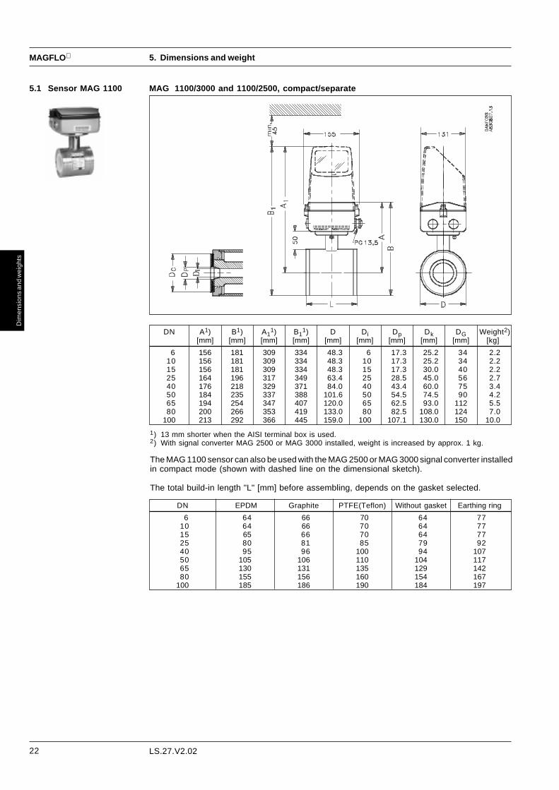
MAG 1100/3000 and 1100/2500, compact/separate5.1 Sensor MAG 1100
5. Dimensions and weight
DN A1) B1) A11) B1
1) D Di Dp Dk DG Weight2)[mm] [mm] [mm] [mm] [mm] [mm] [mm] [mm] [mm] [kg]
6 156 181 309 334 48.3 6 17.3 25.2 34 2.210 156 181 309 334 48.3 10 17.3 25.2 34 2.215 156 181 309 334 48.3 15 17.3 30.0 40 2.225 164 196 317 349 63.4 25 28.5 45.0 56 2.740 176 218 329 371 84.0 40 43.4 60.0 75 3.450 184 235 337 388 101.6 50 54.5 74.5 90 4.265 194 254 347 407 120.0 65 62.5 93.0 112 5.580 200 266 353 419 133.0 80 82.5 108.0 124 7.0
100 213 292 366 445 159.0 100 107.1 130.0 150 10.0
1) 13 mm shorter when the AISI terminal box is used.2) With signal converter MAG 2500 or MAG 3000 installed, weight is increased by approx. 1 kg.
The MAG 1100 sensor can also be used with the MAG 2500 or MAG 3000 signal converter installedin compact mode (shown with dashed line on the dimensional sketch).
The total build-in length "L" [mm] before assembling, depends on the gasket selected.
DN EPDM Graphite PTFE(Teflon) Without gasket Earthing ring
6 64 66 70 64 7710 64 66 70 64 7715 65 66 70 64 7725 80 81 85 79 9240 95 96 100 94 10750 105 106 110 104 11765 130 131 135 129 14280 155 156 160 154 167
100 185 186 190 184 197

23
MAGFLO
Dim
ensi
ons
and
wei
ghts
LS.27.V2.02
5. Dimensions and weight
5.1 Sensor MAG 1100(continued)
The MAG 1100 DN 6 and DN 10 are prepared for assembly with the 1/2" pipe connection (ISO).
The length "L" varies dependent on the gasket choice:
Without gasket EPDM Graphite Teflon
L [mm] 150 150 152 156

24
MAGFLO
Dim
ensi
ons
and
wei
ghts
LS.27.V2.02
5.2 SensorMAG 1100 FOOD
MAG 1100 FOOD/3000 and MAG 1100 FOOD/2500, compact and separate
5. Dimensions and weight
DN L A B A1 B1 D Weight 1)[mm] [mm] [mm] [mm] [mm] [mm] [kg]
10 64 156 181 309 334 64 2.215 64 156 181 309 334 64 2.225 79 164 196 317 349 77.5 2.740 94 176 218 329 371 91 3.450 104 184 235 337 388 119 4.265 131 194 254 347 407 130 5.580 156 200 266 353 419 155 7.0
100 186 213 292 366 445 183 10.01) With signal converter MAG 2500 or MAG 3000 installed weight is increased by approx. 1 kg.
The MAG 1100 FOOD sensor can also be used with the MAG 2500 or MAG 3000 signal converterinstalled in compact mode (shown with dashed line on the dimensional sketch)
Built-in length DN A L 1)[mm] [mm]
10 99 14615 99 14625 113 16140 126 17650 154 18665 165 22380 200 258100 225 288
1) The total built-in length "L" is independent of theadapter type selected.

25
MAGFLO
Dim
ensi
ons
and
wei
ghts
LS.27.V2.02
AccessoriesMAG 1100 FOOD
5. Dimensions and weight
Weld-in typeDIN 11850 DS/ISO 2037 SMS 3008 BS4825-1 Tri-Clover®
Di Do Di Do Di Do Di Do Di Do[mm] [mm] [mm] [mm] [mm] [mm] [mm] [mm] [mm] [mm] [mm] [mm] [mm]
10 10 40 10.0 13.0 10.0 13.0 10.0 13.0 10.0 13.0 - -15 15 40 16.0 19.0 16.0 19.0 16.0 19.0 16.0 19.0 - -15.9 15 40 - - - - - - - - 13.5 15.920 15 40 20.0 23.0 20.0 23.0 20.0 23.0 20.0 23.0 - -25 25 40 - - 22.6 25.6 22.6 25.6 22.6 25.6 - -25 25 40 26.0 29.0 - - - - - - - -28 25 40 - - 25.6 28.6 - - - - - -32 25 40 - - - - 29.6 32.0 - - - -32 25 40 32.0 35.0 - - - - - - - -33.7 25 40 - - 31.3 34.3 31.3 34.3 - - - -38 40 40 - - 35.6 38.6 35.6 38.6 35.6 38.6 35.6 38.640 40 40 - - 37.6 40.6 - - - - - -40 40 40 38.0 40.0 - - - - - - - -50 50 40 - - 48.6 51.6 48.6 51.6 48.6 51.6 48.6 51.650 50 40 50.0 53.0 - - - - - - - -63.5 65 45 - - 60.3 64.1 60.3 64.1 60.3 64.1 60.3 64.165 65 45 66.0 70.0 - - - - - - - -70 65 45 - - 66.8 70.6 - - - - - -76 65 45 - - - - 72.0 76.0 - - - -76.1 80 50 - - 72.9 76.7 72.9 76.7 72.9 76.7 72.9 76.780 80 50 81.0 85.0 - - - - - - - -88.9 80 50 - - 84.9 89.8 84.9 89.8 - - - -100 100 50 100 104 - - - - - - - -101.6 100 50 - - 97.6 102.5 97.6 102.5 97.6 102.6 97.6 102.6114.3 100 50 - - 110.3 115.6 110.3 115.6 110.3 115.6 - -
AdapterDN
SensorDN
Tri-Clover is a registered trademark for Ladish Co.
Clamp typeDIN 32676 ISO 2852 SMS 3016 BS4825-3 Tri-Clamp®
Di Do Di Do Di Do Di Do Di Do[mm] [mm] [mm] [mm] [mm] [mm] [mm] [mm] [mm] [mm] [mm] [mm] [mm]
10 10 40 10.0 34.0 10.0 34.0 10.0 34.0 - - - -15 15 40 16.0 34.0 16.0 34.0 16.0 34.0 - - - -20 15 40 20.0 34.0 20.0 34.0 - - - - - -25 25 40 - - 22.6 50.5 22.6 50.5 22.6 50.5 22.6 50.525 25 40 26.0 50.5 26.0 50.5 - - - - - -33.7 25 40 31.3 50.5 31.3 50.5 31.3 50.5 - - - -38 40 40 - - 35.6 50.5 35.6 50.5 35.6 50.5 35.6 50.540 40 40 38.0 50.5 38.0 50.5 - - - - - -50 50 40 50.0 64.0 - - - - - - - -51 50 40 48.6 64.0 48.6 64.0 48.6 64.0 48.6 64.063.5 65 45 - - 60.3 77.5 60.3 77.5 60.3 77.5 60.3 77.565 65 45 66.0 91.0 - - - - - - - -76.1 80 50 - - 72.9 91.0 72.9 91.0 72.9 91.0 72.9 91.080 80 50 81.0 106.0 - - - - - - - -100 100 50 100 119.9 - - - - - - - -101.6 100 50 - - 97.6 119.0 97.6 119.0 97.6 119.0 97.6 119.0
AdapterDN
SensorDN
L
L

26
MAGFLO
Dim
ensi
ons
and
wei
ghts
LS.27.V2.02
5. Dimensions and weight
AccessoriesMAG 1100 FOOD
Threaded type
DIN 11851Di Do
[mm] [mm] [mm] [mm] [mm]
10 10 40 10.0 28.015 15 40 16.0 34.020 15 40 20.0 44.025 25 40 26.0 52.032 25 40 32.0 58.040 40 40 38.0 65.050 50 40 50.0 78.065 65 45 66.0 95.080 80 50 81.0 110.0100 100 50 100.0 130.0
AdapterDN
SensorDN
Tri-Clamp is a registered trademark for Ladish Co.
Threaded typeISO 2853 SS 3351 BS 4825-4 (IDF)
Di Do Di Do Di Do[mm] [mm] [mm] [mm] [mm] [mm] [mm] [mm] [mm]
25 25 40 22.6 37.0 22.6 37.0 22.6 37.038 40 40 35.6 51.0 35.6 51.0 35.6 51.051 50 40 48.6 64.0 48.6 64.0 48.6 64.0
63.5 65 45 60.3 78.0 60.3 78.0 60.3 78.076.1 80 50 72.9 91.0 72.9 91.0 72.9 91.0
101.6 100 50 - - - - 97.6 126.0101.6 100 50 97.6 118.0 97.6 118.0 - -
AdapterDN
Threaded type
SMS 1145Di Do
[mm] [mm] [mm] [mm] [mm]
25 25 40 22.6 40.032 25 40 29.6 48.038 40 40 35.6 60.051 50 40 48.6 70.0
63.5 65 45 60.3 85.076 65 45 72.0 98.0
AdapterDN
SensorDN
L
L
SensorDN
L

27
MAGFLO
Dim
ensi
ons
and
wei
ghts
LS.27.V2.02
MAG 1100 Ex5.3 Sensor MAG 1100 Ex
Remotemounting
5. Dimensions and weight
MAG 1100 / 3000
Compactmounting
DN A B C D DiWeight
remote compact[mm] [mm] [mm] [mm] [kg] [kg]
6 156 181 270 48.3 6 2.2 11 10 156 181 270 48.3 10 2.2 11
15 156 181 270 48.3 15 2.2 1125 164 196 278 63.5 25 2.7 1240 176 218 287 84.0 40 3.4 1250 184 235 297 101.6 50 4.2 1365 194 254 305 120.0 65 5.5 1580 200 266 312 133.0 80 7.0 16
100 213 292 326 159.0 100 10.0 19
The total built-in length L [mm] depends on the gasket selected.
DN EPDM Graphite PTFE (Teflon) Without gasket Earthing ring
6 64 66 70 64 7710 64 66 70 64 7715 65 66 70 64 7725 80 81 85 79 9240 95 96 100 94 10750 105 106 110 104 11765 130 131 135 129 14280 155 156 160 154 167
100 185 186 190 184 197

28
MAGFLO
Dim
ensi
ons
and
wei
ghts
LS.27.V2.02
5. Dimensions and weight
MAG 2100/3000 and 2100/2500, compact/separate5.4 Sensor MAG 2100
DN Di L Di L A B A1 B1 D Weight 1)[mm] [mm] [mm] [mm] [mm] [mm] [mm] [mm] [mm] [kg]
25 26 130.4 22.6 108.4 172 210 325 352 76 3.040 38 150.6 35.6 131.3 176 218 329 360 84 3.050 50 162.9 48.6 145.7 185 236 338 378 102 3.565 66 191.7 60.3 175.3 194 254 347 396 120 5.080 81 225.7 76.1 196.3 201 267 354 409 133 6.0
ISO 2852DIN 11851
1) With signal converter MAG 2500 or MAG 3000 installed weight is increased by approx. 1 kg.
Standard ISO/DIN gaskets are used.
ISO 2852mating part
DIN 11851Nipple

29
MAGFLO
Dim
ensi
ons
and
wei
ghts
LS.27.V2.02
DN A A1 B D1 L1) TC 2) TE
2) Weight3)
DIN 2501/BS 4504 BS 1560/ BS 10 JIS B 2220 AWWAANSI 16.5 AS 2129 C-207
PN PN PN PN PN Class Class Class D & E 10K 16K Class6, 25 40 64 100 150 300 600 AS 4087 D10, Class 1416
[mm] [mm] [mm] [mm] [mm] [mm] [mm] [mm] [mm] [mm] [mm] [mm] [mm] [mm] [mm] [mm] [mm] [mm] [mm] [kg]
15 187 338 59 104 200 200 200 - - 200 200 - 200 200 200 1.2 6 5
25 187 338 59 104 200 200 200 - 260 200 200 - 200 200 200 1.2 6 6
40 197 348 82 124 200 200 200 - 280 200 - 200 200 200 200 1.2 6 8
50 205 356 72 139 200 200 200 276 300 200 200 - 200 200 200 1.2 6 13
65 212 363 72 154 200 200 200 320 350 200 272 - 200 200 200 1.2 6 14
80 222 373 72 174 200 272 272 323 340 272 272 - 200 200 272 1.2 6 15
100 242 393 85 214 250 280 280 380 400 280 310 - 250 250 280 1.2 6 20
125 255 406 85 239 275 300 300 420 450 300 335 - 275 275 300 1.2 6 25
150 276 427 85 282 300 325 325 415 450 325 370 500 300 300 325 1.2 6 30
200 304 455 137 338 350 350 350 480 530 350 410 580 350 350 350 1.2 8 50
250 332 483 137 393 450 450 450 550 620 450 500 640 450 450 450 1.2 8 70
300 357 508 137 444 500 500 500 600 680 500 550 680 500 500 500 1.6 8 80
350 362 513 270 451 500 500 550 - - 550 590 725 500 500 550 - 1.6 8 110
400 387 538 270 502 500 500 550 - - 550 590 750 500 500 550 - 1.6 10 125
450 418 569 310 563 560 560 600 - - 600 640 810 560 560 600 - 1.6 10 175
500 443 594 350 614 625 625 680 - - 680 730 860 625 625 680 - 1.6 10 200
600 494 645 390 715 750 750 750 - - 820 860 910 750 750 820 - 1.6 10 300
700 586 737 500 900 875 - - - - - - - 875 875 875 875 2.0 - 350
750 571 722 556 869 - - - - - - - - 937 937 937 937 2.0 -
800 637 788 560 1002 1000 - - - - - - - 1000 1000 1000 1000 2.0 - 475
900 687 838 630 1101 1125 - - - - - - - 1125 1125 1125 1125 2.0 - 560
1000 738 889 670 1204 1250 - - - - - - - 1250 1250 1250 1250 2.0 - 700
1100 755 906 770 1238 1375 - - - - - - - - - - - 2.0 -
1200 839 990 770 1406 1500 - - - - - - - 1500 - - 1500 2.0 - 1250
1400 925 1076 1000 1675 1750 - - - - - - - - - - - 3.0 - 1753
1500 972 1123 1020 1672 - - - - - - - - 1875 - - 1875 3.0 -
1600 1025 1176 1130 1915 2000 - - - - - - - - - - 3.0 - 2341
1800 1123 1274 1250 1974 2250 - - - - - - - - - - 3.0 - 3253
2000 1223 1374 1375 2174 2500 - - - - - - - - - - 3.0 - 4060
5. Dimensions and weight
5.5 Sensor MAG 3100and MAG 3100 W
MAG 3100 & MAG 3100 W/3000 and MAG 3100 & MAG 3100 W/2500, compact/separate
1) When earthing flanges are used the thickness of the earthing flange and gasket must be added to the built-in length2) TC = Type C grounding ring, TE = Type E grounding ring3) Weights are approx and for PN 16 without signal converter.D = Outside diameter of flange, see flange tables

30
MAGFLO
Dim
ensi
ons
and
wei
ghts
LS.27.V2.02
5. Dimensions and weight
5.6 Sensor MAG 3100high temperature
MAG 3100, remote
1) When earthing flanges are used the thickness of the earthing flange and gasket must be added to the built-in length2) TE = Type E grounding ring3) Weights are approx and for PN 16 without signal converter.D = Outside diameter of flange, see flange tables
DN A B D1 L1) TE 2) Weight 3)
DIN 2501/BS 4504 BS 1560/ BS 10 JIS B 2220ANSI 16.5 AS 2129
PN 6, PN 25 PN 40 PN 64 PN 100 Class Class Class D & E 10K 16K10, 16 150 300 600 AS 4087
Class 14
[mm] [mm] [mm] [mm] [mm] [mm] [mm] [mm] [mm] [mm] [mm] [mm] [mm] [mm] [mm] [mm] [kg]
15 162 59 104 200 200 200 200 200 200 200 200 6 5
25 162 59 104 200 200 200 260 200 200 200 200 200 6 6
40 172 82 124 200 200 200 280 200 200 200 200 200 6 8
50 172 72 139 200 200 200 276 300 200 200 200 200 200 6 13
65 180 72 154 200 200 200 320 350 200 272 200 200 200 6 14
80 187 72 174 200 272 272 323 340 272 272 200 200 272 6 15
100 202 85 214 250 280 280 380 400 280 310 250 250 280 6 20
125 222 85 239 275 300 300 420 450 300 335 275 275 300 6 25
150 237 85 282 300 325 325 415 450 325 370 500 300 300 325 6 30
200 265 137 338 350 350 350 480 530 350 410 580 350 350 350 8 50
250 295 137 393 450 450 450 550 620 450 500 640 450 450 450 8 70
300 319 137 444 500 500 500 600 680 500 550 680 500 500 500 8 80
Eathing/protection flange
DNt1
t2
[mm] [mm]25-250 1.2 15300-600 1.6 20700-1200 2.0 251400-2000 3 40
DNt1
[mm]15 6
25-150 6200-350 8400-600 10

31
MAGFLO
Dim
ensi
ons
and
wei
ghts
LS.27.V2.02
L
BS 4504 BS 1560/ BS 10 JIS B 2220ANSI 16.5 AS 2129
DN A B D1PN 6, PN 25 PN 40 PN 64 PN 100 Class Class Class
D & E10K 16K
TC 1) TE
1) Weight 2)
10, 16 150 300 600AS 4087Class 14
[mm] [mm] [mm] [mm] [mm] [mm] [mm] [mm] [mm] [mm] [mm] [mm] [mm] [mm] [mm] [mm] [mm] [kg]
15 182 59 104 200 200 200 200 200 200 200 200 1.2 6 14
25 182 59 104 200 200 200 260 200 200 200 200 200 1.2 6 15
40 192 82 124 200 200 200 280 200 200 200 200 200 1.2 6 17
50 192 82 124 200 200 200 276 300 200 200 200 200 200 1.2 6 22
65 200 88 139 200 200 200 320 350 200 272 200 200 200 1.2 6 23
80 207 106 153 200 272 272 323 340 272 272 200 200 272 1.2 6 24
100 222 128 183 250 280 280 380 400 280 310 250 250 280 1.2 6 29
125 244 136 222 275 300 300 42 450 300 335 275 275 300 1.2 6 34
150 259 136 252 300 325 325 415 450 325 370 500 300 300 325 1.2 6 39
200 287 162 308 350 350 350 480 530 350 410 580 350 350 350 1.2 8 59
250 316 180 367 450 450 450 550 620 450 500 640 450 450 450 1.2 8 79
300 341 224 416 500 500 500 600 680 500 550 680 500 500 500 1.6 8 89
5.7 Sensor MAG 3100EEx
5. Dimensions and weight
DN 15 to DN 100
DN 125 to DN 300
1) TC = Type C grounding ring, TE = Type E grounding ring2) Weights are approx and for PN 16 without signal converter.D = Outside diameter of flange, see flange tables

32
MAGFLO
Dim
ensi
ons
and
wei
ghts
LS.27.V2.02
5.8 Signal converterMAG 3000/MAG 3100 EEx-d
[mm] [mm] [mm] [mm] [mm] [mm] [mm] [mm] [mm] [mm] [mm] [mm] [mm] [mm] [mm] [mm] [mm] [mm] [mm] [mm] [mm] [mm] [kg]
15 300.5 67 104 - 200 - - 200 200 - 200 200 200 - - 95 89 95 - 95 95 20
25 300.5 67 104 - 200 - - 200 200 - 200 200 200 - - 115 108 124 114.3 125 125 22
40 310.5 90 124 - 200 - - 200 200 - 200 200 200 - - 150 127 156 133.5 140 140 23
50 310.5 90 124 - 200 276 300 200 200 - 200 200 200 - - 165 152 165 152.4 155 155 23
65 318.0 96 139 200 200 320 350 200 272 - 200 200 200 33.0 185 185 178 190 161.5 175 175 24
80 325.0 109 153 200 272 323 340 272 272 - 272 200 200 23.5 200 200 190 210 184.1 185 200 25
100 340.0 135 183 250 280 380 400 280 310 - 250 250 280 31.0 220 235 229 254 215.9 210 225 30
[mm] [mm] [mm] [mm] [mm] [mm] [mm] [mm] [mm] [mm] [mm] [mm] [mm] [mm] [mm] [mm] [mm] [mm] [mm] [mm] [mm] [mm] [mm] [mm] [mm] [kg]
125 362.5 140 224 275 - 300 420 450 300 335 275 275 300 240 - 250 - 270 254 279 254.0 250 270 35
150 377.5 140 254 300 - 325 415 450 325 370 500 300 300 325 265 - 285 - 300 279 318 279.4 280 305 40
200 405.5 175 304 350 350 350 480 530 350 410 580 350 350 350 320 340 340 360 375 343 381 336.5 330 350 60
250 434.5 226 373 450 450 450 550 620 450 500 640 450 450 450 375 395 405 425 450 406 444 406.4 400 430 80
300 459.5 251 406 500 500 500 600 680 500 550 680 500 500 500 440 445 460 485 515 483 521 457.2 445 480 90
5.9 Signal converterMAG 3000 andMAG 2500 compact
Signal converter installed incompact mode
Weight: MAG 3000 and MAG 2500 approx. 1.0 kg Weight: Wall bracket approx. 1.0 kg
Signal converter installed remote
5. Dimensions and weight
A B D1
PN
6,
10,
16
L D
DN
PN
40
PN
64
Cla
ss 1
50
Cla
ss 3
00
PN
100
BS
T D
& E
JIS
10
K
JIS
16
K
PN
6
PN
40
Cla
ss 1
50
Cla
ss 3
00
BS
T D
& E
JIS
10
K
JIS
16
K
PN
16
We
igh
t
Cla
ss 6
00
DN A B D1
PN
6,
10,
16
PN
40
Cla
ss 1
50
Cla
ss 3
00
BS
T D
& E
JIS
10
K
JIS
16
K
PN
6
PN
40
Cla
ss 1
50
Cla
ss 3
00
BS
T D
& E
JIS
10
K
JIS
16
K
PN
16
We
igh
t
D
PN
25
PN
10
PN
25
PN
64
PN
100
Cla
ss 6
00
L
DN TC 1) TE
1)
[mm] [mm]
15-250 1.2 6
300-300 1.6 8
1) TC = Type C grounding ring,TE = Type E grounding ringD = Outside diameter of flange, see flange tables

33
MAGFLO
Dim
ensi
ons
and
wei
ghts
LS.27.V2.02
5. Dimensions and weight
5.10 Signal converterMAG 3000 andMAG 2500 19" insert
Signal converter as 19" insert
Weight: MAG 3000 and MAG 2500 approx. 1.4 kg
19" insert shown with IP 65 wall mounting enclosure
Weight: IP 65 wall mounting enclosure approx. 1.5/3.0 kg
IP 65 panel mounting kit for 19" insert
Weight: Panel mounting kit approx. 1.5/2.9 kg. Cut-out dimension: 185 × 139 mm
Back of panel mounting kit for 19" insert (28TE)
Weight: Back of panel mounting kit approx. 1 kg

34
MAGFLO
Dim
ensi
ons
and
wei
ghts
LS.27.V2.02
5. Dimensions and weight
Signal converter 3000 Ex as 19" insert
Weight: MAG 3000 Ex approx. 3 kg
IP 65 wall mounting enclosure for 19" insert (42TE)
Weight: 19" insert with IP 65 wall mounting enclosure approx. 2.3/5.3 kg
IP 65 panel mounting kit for 19" insert (42TE)
Back of panel mounting kit for 19" insert (42TE)
Weight: Back of panel mounting kit approx. 1 kg
Weight: Panel mounting kit approx. 2.1/5 kg. Cut-out dimension: 282 × 139 mm
5.10 Signal converterMAG 3000 andMAG 2500 19" insert(continued)

35
MAGFLO
Dim
ensi
ons
and
wei
ghts
LS.27.V2.02
5. Dimensions and weight
Signal converter MAG 3000 Ex-d for wall mounting
Weight: MAG 3000 Ex-d for wall mounting, approx. 9.6 kg
5.12 Accessories Electrode cleaning unit
Weight: Electrode cleaning unit approx. 1 kg
Safety Barrier
Weight: Safety Barrier approx. 1 kg
5.11 Signal converterMAG 3000 Ex-d

36
MAGFLO
Pro
ject
gui
danc
e
6. Project guidance
LS.27.W1.02 - 521H0723
6.1 Sensor, general Reading and operating the flowmeter is possi-ble under almost any installation conditionsbecause the display can be oriented in relation tothe sensor. To ensure optimum flow mea-surement attention should be paid to the follow-ing:
The sensor must always be completely full withliquid.
Therefore avoid:• Installation at the highest point in the pipe
system• Installation in vertical pipes with free outlet
For partially filled pipes or pipes with downwardflow and free outlet the flowmeter should belocated in a U-tube.
Installation in vertical pipesRecommended flow direction: upwards. Thisminimizes the effect on the measurement of anygas/air bubbles in the liquid.

37
MAGFLO
Pro
ject
gui
danc
e
6. Project guidance
LS.27.W1.02 - 521H0723
Installation in horizontal pipesThe sensor must be mounted as shown in theupper figure. Do not mount the sensor asshown in the lower figure. This will positionthe electrodes at the top where there ispossibility for air bubbles and at the bottomwhere there is possibility for mud, sludge,sand etc.If using empty pipe detection (MAG 3000) thesensor can be tilted 45°, as shown in theupper figure.
Measuring abrasive liquids and liquidscontaining particlesRecommended installation is in a vertical/inclined pipe to minimize the wear anddeposits in the sensor.
Inlet and outlet conditionsTo achieve accurate flow measurement it isessential to have straight lengths of inlet andoutlet pipes and a certain distance betweenpumps and valves.It is also important to centre the flowmeter inrelation to pipe flanges and gaskets.
Potential equalizationThe liquid’s electrical potential must alwaysbe equal to the electrical potential of thesensor. This can be achieved in different waysdepending on the application:A. Wire jumper between sensor and adjacent
flanges. (MAG 1100 and MAG 3100).B. Direct metallic contact between sensor and
fittings. (MAG 1100 FOOD and MAG 2100).C. Built in earthing electrodes. (MAG 3100
and MAG 3100 W).D. Optional earthing/protection flanges/rings.
(MAG 1100 and MAG 3100).
6.1 Sensor, general(continued)

38
MAGFLO
Pro
ject
gui
danc
e
6. Project guidance
LS.27.W1.02 - 521H0723
VacuumAvoid a vacuum in the measuring pipe, sincethis can damage certain liners.See "Technical data", Section 2.
Installation in large pipesThe flowmeter can be installed between tworeducers (e.g. DIN 28545). Assuming that at8° the following pressure drop curve applies.The curves are applicable to water.
Example:A flow velocity of 3 m/s (V) in a sensor with adiameter reduction from DN 100 to DN 80(d1/d2 = 0.8) gives a pressure drop of 2.9mbar.
Compact/remote installationThe sensor and signal converter can beinstalled either compact or remote.
With compact installation the temperature ofmedium must be according to the graph.
With remote installation, the cable length andtype described under "Technical data",Section 2 must be used.
6.1 Sensor, general(continued)

39
MAGFLO
Pro
ject
gui
danc
e
6. Project guidance
LS.27.W1.02 - 521H0723
The Siemens cleaning unit can be used with MAG 3000 in 19" insert version.The cleaning unit can be used in applications where the liner material and subsequently theelectrodes may be coated by deposits. If the coating is electrically insulating, the electrode signalwill be reduced. If the coating is electrically conductive the electrode signal will be partly shortcircuited and in both cases the accuracy of the meter will decrease (dependent on the type andthickness of the coating.
Note! The cleaning unit cannot be used for inflammable or explosive media!
The cleaning unit cleans the electrodes electrochemically by applying a voltage to the electrodesfor approx. 30 sec. While cleaning, MAG 3000 stores and holds the last measured flow readingon the display and also the signal outputs. After an additional pausing period of 30 sec. theflowmeter resumes normal measurement and the cleaning is now completed.
The relay in the MAG 3000 activates the cleaning cycle. Under the menu “Cleaning interval”(under special functions) the cleaning interval can be set between 1 hour and 24 hours.
Cleaning should only take place with liquid in the pipe. This can be detected by MAG 3000 viathe empty pipe function. It is therefore recommended to select “empty pipe detection” ON whenusing the cleaning unit.
The cleaning sequence can also be controlled manually by short circuiting two terminals. Beforethis is done, ensure the measuring pipe is full.
Mode of operation
6.2 Cleaning unit
AC-cleaning
DC-cleaning
AC-cleaning is used to remove fatty deposits on the electrodes. These fatty deposits are seen inwaste water applications in abbatoirs and water applications with oil residuals and sometimes insewage treatment applications. During the cleaning process, the surface of the electrodes getwarmer, which tends to soften grease particles and the gas bubbles generated mechanically liftdeposits away from the surface of the electrodes.
DC-cleaning is used to eliminate electrically conductive deposits in the measuring pipeinfluencing the measuring accuracy.Particularly in district heating applications an electrically conductive deposit (magnetite) mayoccur and short circuit the electrode signal. In this case the accuracy of the meter decreasesand the signal/noise conditions of the meter become inferior. The problem may also arise if theconductivity of the water is less than approx. 250 µS/cm.
During DC-cleaning, electrolysis takes place where the flow of electrons removes the particledeposits from the electrode area.

40
MAGFLO
Pro
ject
gui
danc
e
6. Project guidance
LS.27.W1.02 - 521H0723
The MAG 3000 signal converter can besupplied in a version tested and approvedby PTB (Physikalisch-TechnischeBundesanstalt) for e.g. potable waterapplications and by DANAK (DanishAccreditation) for e.g. district heatingapplications. The internal counter of MAG3000 can accordingly be used for charging.This requires verification, sealing and settingof the signal converter together with thesensor for a specific flow range. After sealingthe data on the signal converter may not bechanged.
6.3 Custody transferapproval

41
MAGFLO
Pro
ject
gui
danc
e
6. Project guidance
LS.27.W1.02 - 521H0723
6.4 Ex installations Siemens MAGFLO ® electromagnetic flowmeters for hazardous areas are standard products with anextensive range of applications. The measuring system consists of a sensor and a signal converter.
Empty pipe detectionEmpty pipe cannot be detected with remote mounted Ex signal converters as special electrodecable cannot be connected to MAG 3000 Ex-d, MAG 3000 Ex and the safety barrier. If empty pipemust be detected in Ex installations, only MAG 3000 Ex-d compact mounted can be used.
Signal convertersThe signal converter MAG 3000 Ex has an intrinsic safe “ia” connection for the electrode circuit andan “ib” connection for the coil circuit.
The signal converter can be one of the following type:
MAG 3000 Ex-d for wall mounting in Ex areasApproval EEX de [ia/ib] llC T6, DEMKO No. 94C.114985X.The signal converter can be used with sensors type MAG 1100 Ex and MAG 3100 Ex, DN 15 - 300.
MAG 3000 Ex, 19” for separate mounting in safe areaApproval EEx [ia/ib] llB, SIRA No. Ex 92C2106X.The signal converter can be used with sensor type MAG 1100 Ex and MAG 3100 Ex, DN 15 - 300.
MAG 2500/3000 19” with safety barrier for separate mounting in safe areaApproval EEx [ia] llC. SIRA No. Ex 92C2108.The safety barrier is to be used with sensors MAG 3100 Ex, DN 350 - 2000. It can however be usedwith all dimension of MAG 1100 Ex and MAG 3100 Ex. When the safety barrier is used. The coil circuitis increased safety “e” and the electrode circuit is intrinsic safety “ia”.
SensorsThe sensors can be one of the following type.
MAG 1100 Ex for mounting in Ex areasApproval EEx [ia/ib] llB T4..T6. DEMKO No. 97D.121909X.DN 6 - 100.
MAG 3100 EX for mounting in EX areasThe sensor carries the approval:DN 15 - 100 EEx [ia/ib] m llB T4..T6, DEMKO No. 94C116403X.DN 125 - 300 EEx [ia/ib] e llB T4..T6, DEMKO No. 94C115326X.DN 125 - 2000 EEx e [ia] llC T3 - T6, SIRA No. Ex 92C3107X.
The electrode circuit in the sensors is manufactured to an intrinsically safe category “ia” and the coilcircuit to an intrinsically safe category “ib”, achieved by an integrated and patented protection circuit.For DN 350 - 2000 the coil circuit is increased safety “e”.
SystemsMAG 3000 Ex-d systemMAG 3000 Ex-d compact mounted on a MAG 1100 Ex or MAG 3100 Ex DN 15 - 300 comprises asystem for mounting in Ex areas.Approval Ex de [ia/ib] llB T4..T6 approval. DEMKO No. 94C115327X.

42
MAGFLO
Pro
ject
gui
danc
e
6. Project guidance
LS.27.W1.02 - 521H0723
MarkingThe marking has the following meaning according to European Norm EN 50014.
E: Certified to CENELEC standard.
Ex: Designates explosion proof material and indicates that the apparatus has beenapproved in accordance with a certificate issued.
i: “Intrinsic safety” is a protection ensuring that the energy in the electric circuit is too smallto ignite the explosive atmosphere. There are two categories of intrinsic safety: “ia” and“ib”.
ia: In intrinsic safety category “ia”, the circuit must remain safe, even in the event of twosimultaneous errors occurring that are independent of one another.
ib: In intrinsic safety category “ib” the circuit must remain safe if one error occurs.
d: The enclosure of the of the signal converter is so strong that it can resist an explosion inside the enclosure. The enclosure is dimensioned in a way so that an explosion will noteffect the surroundings.
e: “Increased safety” is a constructional safeguard which ensures the apparatus does notcontain normally arcing or sparking devices, or hot surfaces that will cause ignition.
ll: Designates that the apparatus may be used in all areas (Except mining).
B: Indicates the gas group in which the unit may be used.
T4..T6 The temperature class describes the maximum temperature which any exposedsurface of the equipment may reach. The sensor can have temperature class T4, T5 orT6 depending on the temperature of the media. Please see technical data for the sensor.
T4: Max. surface temperature 135 °C. => (Max. media temperature 120 °C).T5: Max. surface temperature 100 °C. => (Max. media temperature 90 °C).T6: Max. surface temperature 85 °C. => (Max. media temperature 75 °C).
6.4 Ex installations(continued)

43LS.27.V2.02
MAGFLO
Sen
sor
inst
.
Potential equalizationTo obtain optimum results from the measuring system the sensor’s chassis point/housing musthave the same electrical potential as the liquid being measured.Depending on the type of gasket selected (graphite or PTFE) and application, this can be achievedas follows:
7.1 InstallingMAG 1100
Graphite gaskets EPDM or PTFE gaskets
Electricallyconductivepiping
A: Potential equalization with electri-cally conductive graphite gaskets
B: Potential equalization using earthstrap supplied.
C: Potential equalization with electri-cally conductive graphite gaskets
D: Potential equalization using sepa-rate potential equalization ring
Electricallynon-conductivepiping
NOTE:Special attention must be paid to piping systems with cathodic protection.By compact mounting:The terminal "PE" must not be connected. If this is not acceptable the signal converter mustbe supplied through an isolation transformer.By remote mounting:The screen must not be connected at the signal converter end.
7.2 InstallingMAG 1100 FOOD
Potential equalizationThe sensor must be installed between twoadapters. Potential equalization with the liquidoccurs automatically via these adapters andthrough the adjacent pipe.
Potential equalizationThe sensor must be installed between twofittings/clamps. Potential equalization with theliquid takes place automatically via theseconnections and through the adjacent pipe.
7.3 InstallingMAG 2100
7. Installing of sensor

44 LS.27.V2.02
MAGFLO
Sen
sor
inst
.
7. Installing of sensor
7.4 InstallingMAG 3100
Earthing and potential equalizationTo obtain optimum results from the measuringsystem the sensor’s chassis point/housingmust have the same electrical potential as theliquid being measured. The method dependson the individual application:
1. Electrically conductive pipingUse an earth straps on one side.
Potential equalization, electricallyconductive pipe
2. Non-conductive pipingHere an earthing flange is used, placedbetween flowmeter and the adjacent pipeflange. Selection of earthing flange dependson the medium, liner material and application,see figure.
3. Cathodic protected pipingSpecial attention must be given to systemswith cathodic protection.By compact mounting:The terminal "PE" must not be connected.If this is not acceptable the signal convertermust be supplied through an isolation trans-former.By remote mounting:The screen must not be connected at thesignal converter end.
Liner Suitablematerial earthing flange
All except Type CPTFEPTFE Type E
Type of earthing flange depending onliner material
Inlet protection MAG 3100With abrasive liquids flowmeter inlet protectionmay be necessary. Here type C and E earthingflanges are used.Type C (for all liners except PTFE) is clampedbetween the flanges.Type E (for PTFE liner only) is fitted to theflange.When using an earthing flange, gaskets mustalways be used between the adjacent pipeflange and the earthing flange.
7.4.1Inlet protection MAG 3100

45LS.27.V2.02
MAGFLO
Con
verte
r ins
talla
tion
8. Installation of signal converter
8.1Signal converterIP 67 versionGeneral
The IP 67 version signal converter can beinstalled indoors or outdoors.The ambient temperature must lie between–20 and 50 °C. The signal converter must notbe exposed to direct sunlight. Use a shield ifnecessary.
With compact installation the temperature ofthe medium must be according to „ProjectGuidance“, compact installation section 6.
With remote installation the distance betweensensor and signal converter must not exceedthe length specified under “Technical Data”,signal converter, section 2.12.
Screened cable must be used as a minimumbetween sensor and transmitter for electrodeas well as for coil cable.If the empty pipe function is used, theelectrodecable must be special double screened cable.
Voltage selector switchA mains voltage selector switch is located inthe base of the MAG 3000 CT, AISI andProfibus. Switch mode power supply on othertypes.
SENSORPROM® memory unitA SENSORPROM® memory unit is suppliedwith the flowsensor.The sensor program must be connected tothe connection plate supplied with the signalconverter.
Tighten the cable entry union to give optimumtightness. The rubber sealing bush mustextrude through the clamping nut as show.
Installation, cable

46 LS.27.V2.02
MAGFLO
Con
verte
r ins
talla
tion
8. Installation of signal converter
1
2
4
3
5
1. Remove the outer frame using a finger-nailor a screwdriver.
2. Loosen the 4 screws retaining the controlpad.
3. Withdraw the control pad and turn it to therequired orientation.
4. Tighten the 4 screws until a mechanicalstop is felt in order to obtain IP 67 enclo-sure rating.
5. Snap-lock the outer frame onto the control pad (click).
1. The signal converter can be mounted ineither direction as the arrow indicates with-out turning the terminal box.
2. The terminal box can be rotated ±90° inorder to optimize the viewing angle of thesignal converter display/keypad:Unscrew the four screws in the bottom ofthe terminal box. Turn the terminal box tothe required position and retighten thescrews firmly.
Turning the control pad
Turning the signalconverter

47LS.27.V2.02
MAGFLO
Con
verte
r ins
talla
tion
8. Installation of signal converter
8.1.1.Compact installationMAG 2500, 3000Compact polyamid
Remove and discard the terminal box lid of thesensor.
Fit the PG 13.5 cable glands for the supply andoutput cables.
Take the SENSORPROM® memory unit fromthe antistatic bag. Remove the connectormounted to the SENSORPROM® unit.The connector and 2 fixing screws are for oldtype of transmitters only and shall not be usedwith this type of transmitter.Mount the SENSORPROM® unit directly onthe back of the connection plate supplied withthe transmitter.
As from February 1998 and onwards theSENSORPROM® unit will be delivered fixedmounted in the terminal box.The SENSORPROM® unit connections willthen be established automatically when the
connection plate is mounted in the terminalbox.
Remove the two black plug assemblies forcoil and electrode cables in the terminal boxand connect them to their correspondingterminal numbers on the connection plate.
Mount the connection plate in the terminalbox. Tighten the earthing screw in the centreof the connection box properly.If you have an old terminal box withoutcentre thread, then fix the connection platewith the two diagonal opposite screws.
Fit the supply and output cables respectivelyand tighten the cable glands to obtainoptimum sealing.Please see the wiring diagram in section 9for the electrical connections.
Mount the signal converter on the terminalbox.
1
2a
eitheror
2b
3 4

48 LS.27.V2.02
MAGFLO
Con
verte
r ins
talla
tion
8. Installation of signal converter
8.1.1.Compact installationMAG 3000 ProfibusMAG 3000 AISIMAG 3000 CT
Remove and discard the terminal box lid ofthe sensor.
Fit the PG 13.5 cable glands for the supplyand output cables.
Take the SENSORPROM® memory unit fromthe terminal box.Mount the SENSORPROM® unit on theconnection plate supplied with the transmitter.
Remove the two black plug assemblies for coiland electrode cables in the terminal box andconnect them to their corresponding terminalnumbers on the connection plate.
Snap lock the connection plate into place inthe terminal box.
Fit the supply and output cables respectivelyand tighten the cable glands to obtainoptimum sealing. Please see the wiringdiagram in section 9 for the electrical connec-tions.
Mount the signal converter on the terminalbox.

49LS.27.V2.02
MAGFLO
Con
verte
r ins
talla
tion
Remove and keep the sensor terminal boxlid.
Remove the SENSORPROM® unit and keep itfor later use.
The SENSORPROM® unit will be mounted onthe connection plate to the signal converter.
The sensorprogram is either supplied in anantistatic bag or mounted in the terminal boxof the sensor.
8. Installation of signal converter
8.1.2.Remote InstallationAt the sensor
Fit and connect the electrode and coilcables as shown.The unscreened cable ends must be kept asshort as possible.The electrode cable and the coil cable must bekept separate to prevent interference.Tighten the cable glands well to obtain opti-mum sealing.
IP 68 Applications only If the sensor is buried or permanentlysubmerged, the terminal box must beencapsulated with silicon dielectric gel(submersible kit, code no. 085U0220).
Mix the two components well and pour thecontents into the terminal box.The material is a non-toxic, transparentselfhealing gel which cures in approx. 24hours.The gel can be penetrated with testinstruments or be removed in case of cablereplacement.
Horizontal installation
Vertical installation

50 LS.27.V2.02
MAGFLO
Con
verte
r ins
talla
tion
8. Installation of signal converter
8.1.2.Remote Installation
Mount wall bracket on a wall or in the back ofa panel.
Wall mounting
Mount wall bracket on a vertical or horizontalpipe using an ordinary hose clip or a ductstrap.
Vertical pipe mounting
Horizontal pipe mounting
Fit the sensor cables, supply cable andoutput cable through the cable glands at thebottom of the wall bracket.

51LS.27.V2.02
MAGFLO
Con
verte
r ins
talla
tion
8. Installation of signal converter
8.1.2.Remote installationMAG 2500, 3000Compact polyamid
either or
New wall mouting units Old wall mouting units
Take the SENSORPROM® memory unit fromthe sensor. Remove any connector mountedto the SENSORPROM® unit.The connector and 2 fixing screws are for oldtype of transmitters only and shall not be usedwith this type of transmitter. Mount theSENSORPROM® unit directly on the back ofthe connection plate supplied with the trans-mitter.
Mount the connection plate in the terminalbox. Tighten the earthing screw in the centreof the connection box properly.If you have an old wall mounting unit withoutcentre thread, then fix the connection platewith the two diagonal opposite screws.
Fit the coil, electrode, supply and outputcables respectively and tighten the cableglands to obtain optimum sealing. Please seethe wiring diagram in section 9 for the electri-cal connections.
Mount the signal converter on the terminalbox.

52 LS.27.V2.02
MAGFLO
Con
verte
r ins
talla
tion
8. Installation of signal converter
8.1.2.Remote installationMAG 2500, 3000CT, AISI, Profibus
Take the SENSORPROM® memory unit fromthe sensor.Mount the SENSORPROM® unit on theconnection plate supplied with the transmitter.
Snap lock the connection plate into place inthe terminal box.
Fit the supply and output cables respectivelyand tighten the cable glands to obtainoptimum sealing.Please see the wiring diagram in section 9 forthe electrical connections.
Mount the signal converter on the terminalbox.

53LS.27.V2.02
MAGFLO
Con
verte
r ins
talla
tion
8. Installation of signal converter
8.2.1Signal converter in 19"insert
1. Fit the SENSORPROM® memory unit on theconnection board supplied with the signalconverter. The SENSORPROM® unit issupplied with the sensor in a bag in theterminal box.
2. Mount the connection board and the guiderails in the rack system as shown.
3. Connect the cables as shown under"Electrical connection", section 9.
4. Plug the signal converter into the racksystem.

54 LS.27.V2.02
MAGFLO
Con
verte
r ins
talla
tion
8. Installation of signal converter
8.2.2Installation in IP 65 wallmounting enclosure
1. Mount the IP 65 enclosure to the wall withfour screws.
2. Mount the SENSORPROM® memory uniton the connection board located in theback of the enclosure. TheSENSORPROM® unit is supplied with thesensor in a bag in the terminal box. Theconnection board supplied with the signalconverter is not used.
3. Connect the cables to the terminals, see"Electrical connection", section 9.
4. Plug in the signal converter and close thecover.
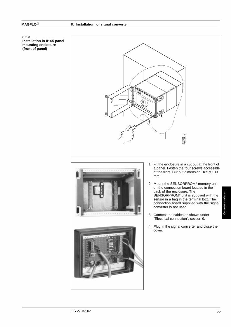
55LS.27.V2.02
MAGFLO
Con
verte
r ins
talla
tion
8.2.3Installation in IP 65 panelmounting enclosure(front of panel)
1. Fit the enclosure in a cut out at the front ofa panel. Fasten the four screws accessibleat the front. Cut out dimension: 185 x 139mm.
2. Mount the SENSORPROM® memory uniton the connection board located in theback of the enclosure. TheSENSORPROM® unit is supplied with thesensor in a bag in the terminal box. Theconnection board supplied with the signalconverter is not used.
3. Connect the cables as shown under"Electrical connection", section 9.
4. Plug in the signal converter and close thecover.
8. Installation of signal converter

56 LS.27.V2.02
MAGFLO
Con
verte
r ins
talla
tion
8.2.4Installation in the back ofa panel
1. Fit the SENSORPROM® memory unit onthe connection board supplied with thesignal converter. The SENSORPROM® unitis supplied with the sensor in a bag in theterminal box.
2. Mount the connection board in the back ofthe enclosure.
3. Connect the cables as shown under"Electrical connection", section 9.
4. Mount the enclosure in the back of a panelwith four screws.
5. Plug in the signal converter.
8. Installation of signal converter
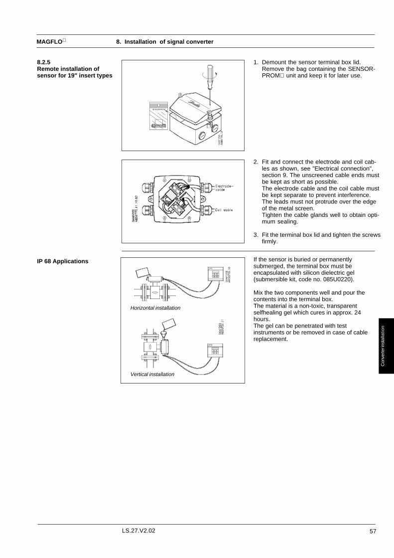
57LS.27.V2.02
MAGFLO
Con
verte
r ins
talla
tion
1. Demount the sensor terminal box lid.Remove the bag containing the SENSOR-PROM unit and keep it for later use.
8.2.5Remote installation ofsensor for 19" insert types
2. Fit and connect the electrode and coil cab-les as shown, see "Electrical connection",section 9. The unscreened cable ends mustbe kept as short as possible.The electrode cable and the coil cable mustbe kept separate to prevent interference.The leads must not protrude over the edgeof the metal screen.Tighten the cable glands well to obtain opti-mum sealing.
3. Fit the terminal box lid and tighten the screwsfirmly.
IP 68 Applications If the sensor is buried or permanentlysubmerged, the terminal box must beencapsulated with silicon dielectric gel(submersible kit, code no. 085U0220).
Mix the two components well and pour thecontents into the terminal box.The material is a non-toxic, transparentselfhealing gel which cures in approx. 24hours.The gel can be penetrated with testinstruments or be removed in case of cablereplacement.
Horizontal installation
Vertical installation
8. Installation of signal converter

58 LS.27.V2.02
MAGFLO
Con
verte
r ins
talla
tion
8. Installation of signal converter
8.3Signal converterMAG 3000 Ex
The MAG 3000 Ex has been designed as a IP 00 insert for installation in a wall mounting box orin a 19" rack, mounted on a wall or in a panel. MAG 3000 Ex has a width of 42 TE (213 mm), aheight of 3U (128 mm) and a module depth of 160 mm.
1. Remove the SENSORPROM® unit, forwarded with the sensor in a bag and fit it on the connectionboard for MAG 3000 Ex.
2. Mount MAG 3000 Ex and guide rails, if any, in the rack system, as shown.
3. Connect the cables as shown above.

59LS.27.V2.02
MAGFLO
Con
verte
r ins
talla
tion
8. Installation of signal converter
8.4Signal converterMAG 3000 &Safety Barrier
The Safety Barrier has been designed as a IP 00 insert for installation adjacent to a MAG 3000in a 19" rack, appropriate wall mounting box or in a panel. The Safety Barrier has a width of 14TE (71 mm), a height of 3U (128 mm) and a module depth of 160 mm.
1. Remove the SENSORPROM® unit, located in the terminal box of the sensor in a bag and fitit on the connection board for MAG 3000.
2. Mount the connection boards for MAG 3000, the Safety Barrier and the guide rails, in therack system as shown.
3. Connect the cables as shown above.
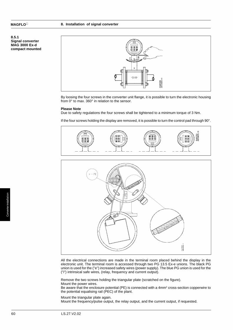
60 LS.27.V2.02
MAGFLO
Con
verte
r ins
talla
tion
8. Installation of signal converter
By loosing the four screws in the converter unit flange, it is possible to turn the electronic housingfrom 0° to max. 360° in relation to the sensor.
Please NoteDue to safety regulations the four screws shall be tightened to a minimum torque of 3 Nm.
If the four screws holding the display are removed, it is possible to turn the control pad through 90°.
8.5.1Signal converterMAG 3000 Ex-dcompact mounted
All the electrical connections are made in the terminal room placed behind the display in theelectronic unit. The terminal room is accessed through two PG 13.5 Ex-e unions. The black PGunion is used for the ("e") increased safety wires (power supply). The blue PG union is used for the("i") intrinsical safe wires, (relay, frequency and current output).
Remove the two screws holding the triangular plate (scratched on the figure).Mount the power wires.Be aware that the enclosure potential (PE) is connected with a 4mm2 cross-section copperwire tothe potential equalising rail (PEC) of the plant.
Mount the triangular plate again.Mount the frequency/pulse output, the relay output, and the current output, if requested.

61LS.27.V2.02
MAGFLO
Con
verte
r ins
talla
tion
8. Installation of signal converter
8.5.2Signal converterMAG 3000 Ex-dseparate mounted
The electronic housing has to be mounted e.g. on a wall. This is done with three screws.
It is possible to turn the electronic housing and the key-pad as in the compact mounted version.
Placing the SENSOR-PROM memory unitSeparate mounted
The SENSORPROM® unit is forwarded with the sensor in an antistatic bag.
Remove the electronic assembly.1. Loosen the back cover by putting i.e. a screwdriver in one of the two holes.
2. Remove the two screws holding the electronic assembly.
3. Remove the electronic assembly by pulling the handle.
Place the SENSORPROM® unit.1. Take the SENSORPROM® unit from the antistatic bag and remove the 6-pole screw
terminal mounted on the SENSORPROM® unit.
2. Now mount the 6-pole screw terminal delivered with the electronic housing, placed in thebottom of the housing.
3. Place the SENSORPROM® unit (with the new screw terminal) in the bottom of the housing.
4. Replace the electronic assembly and make sure that the two screws are fully screwed on.
5. Now place the back cover again and make sure that the cover is fully screwed on with aminimum torque of 5 Nm.

62 LS.27.V2.02
MAGFLO
Con
verte
r ins
talla
tion
When the meter is mounted separately the connection between signal converter and sensor mustbe made as shown in the manual under "Electrical connection".
Remote installation
Sealing After set-up (setting of Qmax, cut-off etc.) and calibration of the unit, the plug in the bottom ofthe unit is removed. When the plug is removed the menu structure and the settings entered arelocked.
Location of the plug to be removed
8.6Signal converterMAG 3000 CT
Siemens MAGFLO electromagnetic flowmeter is approved by PTB for cold-water custodytransfer (no. 6.221, 93.16) and by DANAK for hot-water custody transfer(OIML 75 approval no. 1994-4163-530).
If the meter is installed for cold-water custody transfer (PTB approved) the plate to the left mustbe placed on the side of the meter. If the meter is installed for hot-water custody transfer theplate to the right must be used.
When the meter is used for custody transfer the installation and sealing must be madeaccording to this instruction.
The calibration has been made on the frequency output of the meter.Calibration
Depending on the use, one of the two plates must be mounted on the side of the meter
8. Installation of signal converter
Compact 19”
When using a compact unit the suppliedbar is mounted over the SENSORPROM®
unit and the two adhesive labels (P) canbe attached by the authorities.
Sealing of compact unitsLocation of the plug to be removed

63LS.27.V2.02
MAGFLO
Con
verte
r ins
talla
tion
8. Installation of signal converter
Sealing For MAG 3000 in the 19" insert version the boxis mounted and the screws in the front plate aresealed.
The final sealing is carried out as shown:
Sealing of the 19" box

64 LS.27.V2.02
MAGFLO
Con
verte
r ins
talla
tion
8.7. Cleaning unit The cleaning unit is designed as a standard IP 00 insert for installation adjacent to a MAG 3000in a 19" rack, on a wall or in a panel. The insert has a width of 14 TE (71 mm) , a height of 3 U(128 mm) and a module depth of 187 mm.
1. Remove the SENSORPROM® unit located in the sensor terminal box and place it on theconnection board supplied.
2. Mount the connection board and guide rails in the rack system as shown.
Guide rails Connection board
3. Connect the cables as shown under “Electrical connection”.
4. Under normal conditions the cleaning unit must be controlled by MAG 3000 (AutomaticCleaning). If the cleaning unit is controlled manually, the two “jumpers” must be cut and aswitch must be mounted in 91-92 (short circuited ⇒ cleaning).
8. Installation of signal converter

65LS.27.V2.02
MAGFLO
Con
verte
r ins
talla
tion
5. SensorPlace the cables in the screening duct as shown. To prevent noise problems, cables must notprotrude over the edge of the duct.Unscreened cable ends must be as short as possible.When special cable is used, the inner screens must remain unconnected at the sensor end.
6. Signal converterUnscreened cable ends must be as short as possible and the two cables must be kept separate.Cables must be in one length and must not be taken to a distribution box or similar terminalarrangement.The outer screen of the electrode cable must be connected to the terminal marked “Shield”.If special cable is used, connect the inner screens to terminals 81 and 84 at the signal converterend only.
7. Select the supply voltage to 115 or 230 Volt a.c. The switch is located on the base of the cleaningunit.
115 V / 230 V 24 V d.c.
8. Select AC-cleaning or DC-cleaning mode at the switch located on the base of the cleaning unit.
9. Insert the cleaning unit and the signal converter in the rack system.
8. Installation of signal converter

66 LS.27.V2.02
MAGFLO
Ele
ctr.
con
n.
9. Electrical connection
9.1.1. MAG 3000 and MAG 2500, Mk IV, Compact Polyamid, IP 67
1. Normally the external shield is not connected to the signal converter. In environments with strong electrical noise theexternal screen can be earthed. In applications with cathotic protection, where there is a difference in voltage betweenground and earth the screen must only be connected via a 1.5 µF capacitor (code no. 612B2710).Electrical data is further specified in “Technical data”, section 2.
2. U = 3-30 V d.c.
3. If RLOAD exceeds 10kΩ it is recommended to connect an external 10kΩ load resistor, in, parallel to RLOAD.
4. It is possible to select between positive and negative pulse in the output setup of the converter setup menu.
Connection of power supply, analog output and batch input Connection of pulse or frequency output
Connection of electrode cable when remote installed Connection of coil cable when remote installed

67LS.27.V2.02
MAGFLO
Ele
ctr.
con
n.
9. Electrical connection
9.1.2 MAG 3000 and MAG 2500 Mk III, 19“, CT and AISIConnection of electromechanical counter (active output)
Cable cross-section: Max. 1.5 mm2
Connection of PLC or electronic counter (passive output)

68 LS.27.V2.02
MAGFLO
Ele
ctr.
con
n.
Installation in separate mode (other connections as shown on previous page)
9. Electrical connection
Compact installed with standard electrode cable 19" insert installed with standard electrode cable
Compact installed with special electrode cable 19" insert installed with special electrode cable
1. Normally the external shield is not connected to the signal converter. In environments with strong electrical noise the externalscreen can be earthed. In applications with cathotic protection, where there is a difference in voltage between ground and earththe screen must be connected via a 1.5 µF capacitor (code no. 612B2710).Electrical data is further specified in “Technical data”, section 2.

69LS.27.V2.02
MAGFLO
Ele
ctr.
con
n.
9. Electrical connection
9.2 Signal converterMAG 3000 Ex, 19”
All cables and installations in hazardous areas must conform to the national code of practise.
The sensor and signal converter must be connected to a potential equalising rail with an insulatingcubber wire according to national regulations. A min. cross section of 4 mm2 must be used if notspecified otherwise in national regulations.
The screen of the cables between sensor and signal converter must be connected at the sensorend. The screen must never be connected at both signal converter and sensor end.
Cables must be in one length and must be kept as short as possible.

70 LS.27.V2.02
MAGFLO
Ele
ctr.
con
n.
All cables and installations in hazardous areas must conform to the national code of practise.
The sensor and safety barrier must be connected to a potential equalising rail with an insulatingcubber wire according to national regulations. A min. cross section of 4 mm2 must be used if notspecified otherwise in national regulations.
The screen of the cables between sensor and signal converter/safety barrier must be connectedat the sensor end. The screen must never be connected at both signal converter and sensor end.
Cables must be in one length and must be kept as short as possible.
9. Electrical connection
9.3 Signal converterMAG 2500/3000 19”with safety barrier

71LS.27.V2.02
MAGFLO
Ele
ctr.
con
n.
9. Electrical connection
9.4 Signal converter MAG 3000 Ex-d
All cables and installations in hazardous areas must conform to the national code of practise.
The sensor and safety barrier must be connected to a potential equalising rail with an insulatingcubber wire according to national regulations. A min. cross section of 4 mm2 must be used if notspecified otherwise in national regulations.
The screen of the cables between sensor and signal converter/safety barrier must be connectedat the sensor end. The screen must never be connected at both signal converter and sensor end.
Cables must be in one length and must be kept as short as possible.
Power supplied to digital outputs from external sources must be intrinsic ia/ib safety.

72 LS.27.V2.02
MAGFLO
Ele
ctr.
con
n.
twisted pairs
9. Electrical connection
9.5 Signal converterMAG 3000 Profibus
1. Normally the external shield is not connected to the signal converter. In environments withstrong electrical noise the external screen can be earthed. In applications with cathoticprotection, where there is a difference in voltage between ground and earth the screen mustonly be connected via a 1.5 µF capacitor (code no. 612B2710).Electrical data is further specified in “Technical data”, section 2.
Remote installedwith specialelectrode cable
Remote installedwith standardelectrode cable
Cable cross-section:Max. 1.5 mm²
Compact installed

73LS.27.V2.02
MAGFLO
Com
mis
sion
ing
10.1Keypad anddisplay layout
Keypad
Display The display is alphanumerical and indicates flow values and flowmeter settings.The three fields F, M and L are reserved for the following symbols - see keypad layout:
F: If a fault develops, two flashing triangles appear .
M: Symbols indicate the following:
RESET MENU
SERVICE MODE
LANGUAGE SETUP
OPERATOR MENU SETUP
CONVERTER SETUP
L: Indicates the function of the lock key by the following symbols:
Ready for change
Value locked
Access to submenu
RESET MODE: Zero setting of totalizers and initialization of setting.
The keypad is used to set the flowmeter. The function of the keys are as follows:
TOP UP KEY This key always returns the display to the operator menushowing flow
PAGE FORWARD KEY This key is used to step forward through the menus. It is theonly key normally used by the operator
PAGE BACKWARD KEY This key is used to step backward through the menus.
CHANGE KEY This key changes the settings or numerical values.
SELECT KEY This key selects the figures to be changed.
LOCK/UNLOCK KEY This key allows the operator to change settings and givesaccess to submenus.
Settings are stored automatically in signal converter and SENSORPROM unit. Thesettings remain stored in the event of power failure and when a signal converter is replaced.
10. Commissioning

74 LS.27.V2.02
MAGFLO
Com
mis
sion
ing
The menu structure of the signal converter is shown in an overview map see previous page and in detailby the build-up of each submenu on the following pages.
The menu is built up in two parts. An OPERATOR MENU and a SETUP MENU. Access to the SETUPMENU is, by pressing the TOP UP key for 2 seconds. The SETUP MENU will operate in twomodes: VIEW and CHANGE mode. VIEW is a read only mode and CHANGE is both a read and writemode. The preselected flowmeter settings can only be scanned via VIEW MODE. The access toCHANGE MODE is protected with a USER CODE. The user code is factory-set at 1000.
The signal converter always starts in the basic OPERATOR MENU showing flow rate.The PAGE FORWARD and PAGE BACKWARD key are used to step through theOPERATOR MENU.
The SETUP MENU contains the following menus:
• Converter set-up mode• Reset mode• Service mode• Language set-up• Operator menu set-up• User code set-up
The PAGE FORWARD key is used to step through the main menu. Pressing the LOCK keyopens the submenu below. There is no access from the submenu back to the main menu. To leavethe submenu press the TOP UP key , which returns the program to the OPERATOR MENU.To perform further changes in other main menus, press the TOP UP key for 2 seconds, thenpress the PAGE FORWARD key to select the CHANGE mode. Enter the USER CODE, pressthe LOCK key and page through the main menu using by the PAGE FORWARD key untilthe required menu is reached. Access the submenu by pressing the LOCK key .
CONVERTER SETUP MODE contains 3 submenus:
• BASIC SETTINGS• OUTPUT SETUP• SENSOR CHARACTERISTICS• SPECIAL FUNCTIONS (MAG 3000 only)
In BASIC SETTINGS selection of flow direction, measuring range, measuring units, totalizer unitsand low flow cut off can be made.
In OUTPUT SETUP the required output signals can be selected.
SENSOR CHARACTERISTICS gives sensor information. This information is uploaded automaticallyfrom the SENSORPROM unit.
Totalizers are reset under RESET MODE and menus can be reset on factory settings.When setting up using a 9 V battery, totalizers are not reset.
NOTE!USER CODE, CORRECTION FACTOR and LANGUAGE do not return to the factory setting viaRESET MODE.
SERVICE MODE provides the facility to set the outputs to fixed values (forced outputs).On leaving SERVICE MODE, all settings, made in SERVICE MODE, are cancelled.
The menu language can be selected.
The information accessible to the operator can be selected in this menu.
The user code can be changed in this menu.The code is factory set at 1000. If the user code is lost, the factory setting can be reestablished asfollows:Switch off supply voltage, press the TOP UP key and switch on the supply voltage. Releasethe key after ROM and RAM tests are completed. The user code is now reset to 1000.
10.2Menu build-up
OPERATOR MENU
CONVERTER SETUP MODE
BASIC SETTINGS
RESET MODE
OUTPUT SETUP
SENSORCHARACTERISTICS
SETUP MENU
LANGUAGE SET-UP
USER CODE SET-UP
SERVICE MODE
OPERATOR MENU SET-UP
If the signal converter is left in CONVERTER SETUP for more than 10 minutes, the converterautomatically changes back to OPERATOR MENU.
10. Commissioning

75LS.27.V2.02
MAGFLO
Com
mis
sion
ing
10.3.1 MAG 2500 Mk IV, Compact Polyamid
10. Commissioning Menu overview

76 LS.27.V2.02
MAGFLO
Com
mis
sion
ing
10.3.2 MAG 2500 Mk III, 19“
Menu overview10. Commissioning
2 se
c.
Con
vert
erse
tup
mod
e
Flo
wra
teV
iew
Cha
nge
0000
Res
etm
ode
Ser
vice
mod
eLa
ngua
gem
ode
Ope
rato
rm
enu
setu
pU
ser
code
setu
p
Tot
aliz
erre
set
Flo
wra
te %
Eng
lish
Flo
wra
teS
et n
ew c
ode
Low
flow
Cut
-off
Cur
rent
out
put
forc
ed %
Exc
itatio
non
/off
Cur
rent
out
put
norm
al/fo
rced
Frq
. out
put
norm
al/fo
rced
Sen
sor
type Sen
sor
seria
l no.
Qm
ax u
nit
Qm
ax
Low
flow
cut-
off
Tot
aliz
erun
it
Flo
w d
irect
ion
defin
ition
Tim
e co
nsta
nt
Frq
. out
put
Fm
ax
Vol
ume/
puls
e
Pul
se w
idth
Pul
se o
utpu
tun
it
Bas
icse
tting
sO
utpu
tse
tup
Sen
sor
char
acte
ristic
s
Ger
man
Fre
nch
Ope
rato
rm
enu
Con
vert
erse
tup
Pip
e si
ze
Cal
. fa
ctor
Cor
rect
ion
fact
or
Exc
itatio
nfr
eque
ncy
SE
NS
OR
PR
OM
(Not
inst
alle
d)
Qm
ax
Flo
wra
te %
Cur
rent
out
put
on/o
ff
Cur
rent
out
put
0/4
- 20
mA
Cur
rent
out
put
time
cons
tant
Frq
./pul
seon
/off
Frq
./pul
seou
tput
Set
def
ault
setti
ng
Err
or lo
g
Ope
ratio
n tim
e
Sof
twar
eve
rsio
n
Con
figur
atio
nve
rsio
n
Err
or p
endi
ng
Tot
aliz
er f
wd.
Tot
aliz
erre
set
Pip
e si
ze Err
or lo
g
Err
or p
endi
ng
Sen
sor
type
DTP

77LS.27.V2.02
MAGFLO
Com
mis
sion
ing
10.3.3 MAG 3000 Mk IV, Compact Polyamid
Menu overview10. Commissioning

78 LS.27.V2.02
MAGFLO
Com
mis
sion
ing
10.3.4 MAG 3000 Mk III, AISI, 19“, EEx
Menu overview10. Commissioning
2 se
c.
Con
vert
erse
tup
mod
e
Flo
wra
teV
iew
Cha
nge
0000
Res
etm
ode
Ser
vice
mod
eLa
ngua
gem
ode
Ope
rato
rm
enu
setu
pU
ser
code
setu
p
Tot
aliz
erfw
d. r
eset
Flo
wra
te %
Eng
lish
Flo
wra
teS
et n
ew c
ode
Set
def
ault
setti
ng
Tot
aliz
errv
. res
etLo
w fl
owC
ut-o
ff
Cur
rent
out
put
forc
ed %
Exc
itatio
non
/off
Cur
rent
out
put
norm
al/fo
rced
Frq
. out
put
norm
al/fo
rced
Err
or lo
g
Ope
ratio
n tim
e
Sof
twar
eve
rsio
n
Con
figur
atio
nve
rsio
n
Err
or p
endi
ng
Rel
ayon
/off
Rel
ayno
rmal
/forc
ed
Sen
sor
type Sen
sor
seria
l no.
Em
pty
pipe
cut-
off o
n/of
f
Ele
ctro
decl
eani
ng o
n/of
f
Cle
anin
gin
terv
al
Cur
rent
out
put
on/o
ff
Cur
rent
out
put
0/4
- 20
mA
Cur
rent
out
put
time
cons
tant
Frq
./pul
seon
/off
Frq
./pul
seou
tput
Flo
w d
irect
ion
uni-/
bidi
rect
iona
l
Qm
ax u
nit
Qm
ax
Low
flow
cut-
off
Tot
aliz
erun
it
Flo
w d
irect
ion
defin
ition
Tim
e co
nsta
nt
Frq
. out
put
Fm
ax
Vol
ume/
puls
e
Pul
se w
idth
Pul
se o
utpu
tun
it
Bas
icse
tting
sO
utpu
tse
tup
Sen
sor
char
acte
ristic
sS
peci
alfu
nctio
ns
DTP
Ger
man
Fre
nch
Ope
rato
rm
enu
Con
vert
erse
tup
Pip
e si
ze
Cal
. fac
tor
Cor
rect
ion
fact
or
Exc
itatio
nfr
eque
ncy
SE
NS
OR
PR
OM
(Not
inst
alle
d)
Qm
ax
Tot
aliz
er fw
d.
Flo
wra
te %
Pip
e si
ze Err
or lo
g
Err
or p
endi
ng
Sen
sor
type
Tot
aliz
erfw
d. r
eset
Tot
aliz
errv
. res
et
Tot
aliz
erre
vers
e

79LS.27.V2.02
MAGFLO
Com
mis
sion
ing
10.3.5 MAG 3000 CT, Compact, 19“
Menu overview
1 ) N
o ac
cess
to
shad
ed w
indo
w w
hen
the
sign
al c
onve
rter
is s
eale
d
10. Commissioning
Flo
w d
irect
ion
defin
ition
2 se
c.
Con
vert
erse
tup
mod
e
Flo
wra
teV
iew
Cha
nge
0000
Res
etm
ode
Ser
vice
mod
eLa
ngua
gem
ode
Ope
rato
rm
enu
setu
pU
ser
code
setu
p
Tot
aliz
erfw
d. r
eset
Flo
wra
te %
Eng
lish
Flo
wra
teS
et n
ew c
ode
Tot
aliz
errv
. res
etLo
w fl
owC
ut-o
ff
Cur
rent
out
put
forc
ed %
Exc
itatio
non
/off
Cur
rent
out
put
norm
al/fo
rced
Frq
. out
put
norm
al/fo
rced
Err
or lo
g
Ope
ratio
n tim
e
Sof
twar
eve
rsio
n
Con
figur
atio
nve
rsio
n
Err
or p
endi
ng
Rel
ayon
/off
Rel
ayno
rmal
/forc
ed
Sen
sor
type Sen
sor
seria
l no.
Em
pty
pipe
cut-
off o
n/of
f
Ele
ctro
decl
eani
ng o
n/of
f
Cle
anin
gin
terv
al
Cur
rent
out
put
on/o
ff
Cur
rent
out
put
0/4
- 20
mA
Cur
rent
out
put
time
cons
tant
Frq
./pul
seon
/off
Frq
./pul
seou
tput
Flo
w d
irect
ion
uni-/
bidi
rect
iona
l
Qm
ax u
nit
Qm
ax
Low
flow
cut-
off
Tot
aliz
erun
it
Tim
e co
nsta
nt
Frq
. out
put
Fm
ax
Vol
ume/
puls
e
Pul
se w
idth
Pul
se o
utpu
tun
it
Bas
icse
tting
sO
utpu
tse
tup
Sen
sor
char
acte
ristic
sS
peci
alfu
nctio
ns
DTP
Ger
man
Fre
nch
Ope
rato
rm
enu
Con
vert
erse
tup
Pip
e si
ze
SE
NS
OR
PR
OM
(Not
inst
alle
d)
Qm
ax
Tot
aliz
er fw
d.
Tot
aliz
erre
vers
e
Pip
e si
ze Err
or lo
g
Err
or p
endi
ng
Sen
sor
type
Tot
aliz
erfw
d. r
eset
Tot
aliz
errv
. res
et
Flo
wra
te %
Cor
rect
ion
fact
or
Tot
aliz
erm
ode
Dis
play
test

80 LS.27.V2.02
MAGFLO
Com
mis
sion
ing
10.3.6 MAG 3000 Profibus
Menu overview
2 se
c.
Con
vert
erse
tup
mod
e
Flo
wra
teV
iew
Cha
nge
0000
Res
etm
ode
Ser
vice
mod
eLa
ngua
gem
ode
Ope
rato
rm
enu
setu
pU
ser
code
setu
p
Tot
aliz
erfw
d. r
eset
Flo
wra
te %
Eng
lish
Flo
wra
te %
Set
new
cod
e
Set
def
ault
setti
ng
Tot
aliz
errv
. res
etLo
w fl
owC
ut-o
ff
Exc
itatio
non
/off
Qm
ax
Tot
aliz
er fw
d.
Tot
aliz
erre
vers
e
Pip
e si
ze Err
or lo
g
Err
or p
endi
ng
Sen
sor
type
Tot
aliz
erfw
d. r
eset
Tot
aliz
errv
. res
et
Sen
sor
type Sen
sor
seria
l no.
Pip
e si
ze
Cal
. fac
tor
Cor
rect
ion
fact
or
Exc
itatio
nfr
eque
ncy
Not
pos
sibl
e
Qm
ax u
nit
Qm
ax
Low
flow
cut-
off
Tot
aliz
erun
it
Flo
w d
irect
ion
defin
ition
Bas
icse
tting
sO
utpu
tse
tup
Sen
sor
char
acte
ristic
sP
RO
FIB
US
setu
p
DTP
Ger
man
Fre
nch
Ope
rato
rm
enu
Con
vert
erse
tup
Com
mun
icat
ion
type
Em
pty
pipe
cut-
off o
n/of
f
Aut
oran
geon
/off
Spe
cial
func
tions
Err
or lo
g
Ope
ratio
n tim
e
Sof
twar
eve
rsio
n
Con
figur
atio
nve
rsio
n
Err
or p
endi
ng
Sta
tion
No V
olum
e flo
wtim
e co
nst.
Vol
ume
unit V
olum
e/P
uls
10. Commissioning

81LS.27.V2.02
MAGFLO
Com
mis
sion
ing
10.3.7 MAG 3000 Ex-d
Menu overview
2 se
c.
Con
vert
erse
tup
mod
e
Flo
wra
teV
iew
Cha
nge
0000
Res
etm
ode
Ser
vice
mod
eLa
ngua
gem
ode
Ope
rato
rm
enu
setu
pU
ser
code
setu
p
Tot
aliz
erfw
d. r
eset
Flo
wra
te %
Eng
lish
Flo
wra
te %
Set
new
cod
e
Set
def
ault
setti
ng
Tot
aliz
errv
. re
set
Low
flow
Cut
-off
Cur
rent
out
put
forc
ed %
Exc
itatio
non
/off
Cur
rent
out
put
norm
al/fo
rced
Frq
. out
put
norm
al/fo
rced
Err
or lo
g
Ope
ratio
n tim
e
Sof
twar
eve
rsio
n
Con
figur
atio
nve
rsio
n
Err
or p
endi
ng
Rel
ayon
/off
Rel
ayno
rmal
/forc
ed
Qm
ax
Tot
aliz
er f
wd.
Tot
aliz
erre
vers
e
Pip
e si
ze Err
or lo
g
Err
or p
endi
ng
Sen
sor
type
Tot
aliz
erfw
d. r
eset
Tot
aliz
errv
. re
set
Sen
sor
type Sen
sor
seria
l no.
Pip
e si
ze
Cal
. fa
ctor
Cor
rect
ion
fact
or
Exc
itatio
nfr
eque
ncy
Em
pty
pipe
cut-
off
on/o
ff
Aut
oran
geon
/off
Ele
ctro
decl
eani
ng o
n/of
f
Cle
anin
gin
terv
al
Cur
rent
out
put
on/o
ff
Cur
rent
out
put
0/4
- 20
mA
Cur
rent
out
put
time
cons
tant
Frq
./pul
seon
/off
Frq
./pul
seou
tput
Flo
w d
irect
ion
uni-/
bidi
rect
iona
l
Qm
ax u
nit
Qm
ax
Low
flow
cut-
off
Tot
aliz
erun
it
Flo
w d
irect
ion
defin
ition
Tim
e co
nsta
nt
Frq
. out
put
Fm
ax
Vol
ume/
puls
e
Pul
se w
idth
Pul
se o
utpu
tun
it
Bas
icse
tting
sO
utpu
tse
tup
Sen
sor
char
acte
ristic
sS
peci
alfu
nctio
ns
DTP
Ger
man
Fre
nch
Ope
rato
rm
enu
Con
vert
erse
tup
10. Commissioning

82 LS.27.V2.02
MAGFLO
Com
mis
sion
ing
Menu detail
10.4.1 MAG 2500 Mk IV, Compact Polyamid
10. Commissioning

83LS.27.V2.02
MAGFLO
Com
mis
sion
ing
Menu detail
10.4.1 MAG 2500 Mk IV, Compact Polyamid (continuid)
10. Commissioning

84 LS.27.V2.02
MAGFLO
Com
mis
sion
ing
Menu detail
10.4.1 MAG 2500 Mk IV, Compact Polyamid (continuid)
10. Commissioning
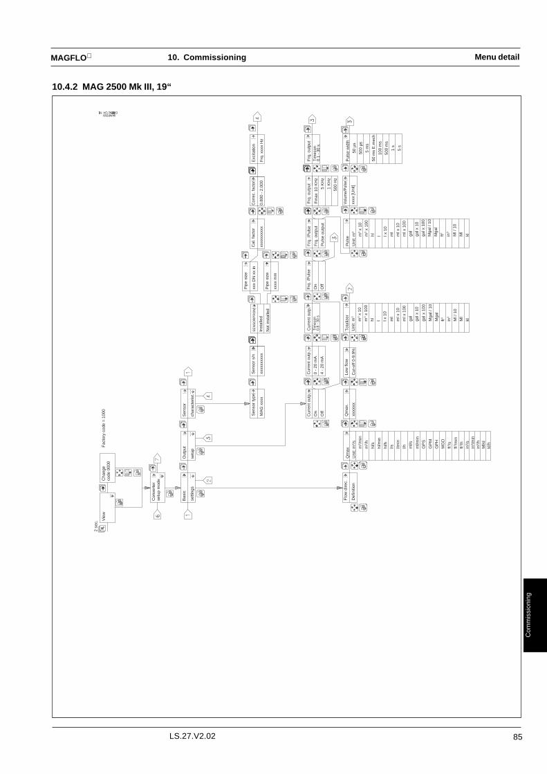
85LS.27.V2.02
MAGFLO
Com
mis
sion
ing
Menu detail
10.4.2 MAG 2500 Mk III, 19“2
sec.
DTP
Vie
wC
hang
eF
acto
ry c
ode
= 1
000
code
000
0
Con
vert
erse
tup
mod
e
Bas
ic
setti
ngs
Out
put
setu
p
Sen
sor
char
acte
rist.
Sen
sor
type
MA
G x
xxx
Sen
sor
s/n
xxxx
xxxx
xx
Exc
itatio
n
Frq
. xxx
x H
z
Cor
rec.
fact
or
0.80
0 -
2.00
0
Cal
. fac
tor
xxxx
xxxx
xx
Pip
e si
ze
xxx
DN
xx
in
Pip
e si
ze
xxxx
mm
SE
NS
OR
PR
OM
Inst
alle
d
Not
inst
alle
d
Cur
rent
out
p.
0 -
20 m
A
4 -
20 m
A
Frq
. /P
ulse
On
Off
Cur
rent
out
p.T
imec
on0.
8 -
30 s
Cur
rent
out
p.
On
Off
Frq
. /P
ulse
Frq
. out
put
Pul
se o
utpu
t
Frq
. out
put
Fm
ax10
KH
z
5 K
Hz
1 K
Hz
500
Hz
Frq
. out
put
Tim
econ
0.1
- 30
s
Vol
ume/
Pul
se
xxxx
[Uni
t]P
ulse
wid
th
50 µ
s
500
µs
5 m
s
50 m
s E
.mec
h
100
ms
500
ms
1 s
5 s
Pul
se
Uni
t:m
3
m3
x 10
m3
x 10
0
hl l l x 1
0
ml
ml x
10
ml x
100
gal
gal x
10
gal x
100
Mga
l / 1
0
Mga
l
ft3 in3
Ml /
10
Ml
kl
Tot
aliz
er
Uni
t:m
3
m3
x 10
m3
x 10
0
hl l l x 1
0
ml
ml x
10
ml x
100
gal
gal x
10
gal x
100
Mga
l / 1
0
Mga
l
ft3 in3
Ml /
10
Ml
kl
Low
flow
Cut
-off
0-9.
9%
Qm
ax.
xxxx
xxQ
max
Uni
t:m
3 /s
m3 /
min
m3 /
h
hl/s
hl/m
in
hl/h
l/s l/min
l/h ml/s
ml/m
in
GP
S
GP
M
GP
H
MG
D
ft3 /s
ft3 /m
inft3 /
hin
3 /s
in3 /
min
in3 /
hM
l/dkl
/h
Flo
w d
irec.
Def
initi
on
10. Commissioning

86 LS.27.V2.02
MAGFLO
Com
mis
sion
ing
Menu detail
10.4.2 MAG 2500 Mk III, 19“ (continuid)
Pip
e si
ze
xxx
m x
x in
Con
figur
atio
nV
ersi
on x
x.xx
Ope
ratio
nTi
me
xxxx
Day
s
Lang
uage
setu
p
Use
r co
de
xxxx
Flo
w r
ate
xxxx
xxx
Flo
w r
ate
xxx.
x %
Qm
ax.
xxxx
Ser
vice
mod
eO
pera
tor
men
use
tup
Use
r co
dese
tup
Res
etm
ode
Sen
sor
type
MA
G x
xxx
Err
or lo
gE
rr. p
endi
ng
Tot
aliz
er
xxxx
xxx
Fre
q. o
utp.
Nor
mal
For
ced
1 H
zC
urre
nt o
utp.
For
ced
0-10
0%
Cur
rent
out
p.
Nor
mal
For
ced
Exc
itatio
n
On
Off
Flo
w r
ate
xx.x
%
Low
flow
cut-
off 0
-9.9
%
Tot
aliz
er
Res
et
0000
000
Set
def
ault
Set
ting
Des
troy
own
setti
ng?
Des
troy
0000
000
Err
. pen
dlin
g
1.E
rror
+ ti
me
2.E
rror
+ ti
me
3.E
rror
+ ti
me
4.E
rror
+ ti
me
5.E
rror
+ ti
me
Err
or lo
g
1.E
rror
+ ti
me
2.E
rror
+ ti
me
......
......
......
.
9.E
rror
+ ti
me
10.E
rror
+ ti
me
Sof
twar
eV
ersi
on x
x.xx
DTP
Lang
uage
Eng
lish
Ger
man
Fre
nch
Tot
aliz
er
Res
et
10. Commissioning

87LS.27.V2.02
MAGFLO
Com
mis
sion
ing
10.4.3 MAG 3000 Mk IV, Compact Polyamid
Menu detail10. Commissioning

88 LS.27.V2.02
MAGFLO
Com
mis
sion
ing
10.4.3 MAG 3000 Mk IV, Compact Polyamid (continuid)
Menu detail10. Commissioning

89LS.27.V2.02
MAGFLO
Com
mis
sion
ing
10.4.3 MAG 3000 Mk IV, Compact Polyamid (continuid)
Menu detail10. Commissioning

90 LS.27.V2.02
MAGFLO
Com
mis
sion
ing
10.4.4 MAG 3000 Mk III, AISI, 19“, EEx
Menu detail2
sec.
Vie
wC
hang
eF
acto
ry c
ode
= 1
000
code
000
0
Con
vert
erse
tup
mod
e
Bas
ic
setti
ngs
Out
put
setu
p
Sen
sor
char
acte
rist.
Spe
cial
func
tions
Cle
anin
g
Inte
rval
xxx
h
0.80
0 -
2.00
0
Em
pty
pipe
Cut
-off
on
Cut
-off
off
Ele
ctro
de
Cle
anin
g on
Cle
anin
g of
f
Sen
sor
type
MA
G x
xxx
Sen
sor
s/n
xxxx
xxxx
xx
Exc
itatio
n
Frq
. xxx
x H
z
Cor
rec.
fact
or
0.80
0 -
2.00
0
Cal
. fac
tor
xxxx
xxxx
xx
Pip
e si
ze
xxx
DN
xx
in
Pip
e si
ze
xxxx
mm
SE
NS
OR
PR
OM
Inst
alle
d
Not
inst
alle
d
Cur
rent
out
p.
0 -
20 m
A
4 -
20 m
A
Frq
. /P
ulse
On
Off
Cur
rent
out
p.T
imec
on0.
8 -
30 s
Cur
rent
out
p.
On
Off
Flo
w
Uni
dire
ctio
nal
Bid
irect
iona
l
Frq
. /P
ulse
Frq
. out
put
Pul
se o
utpu
t
Frq
. out
put
Fm
ax10
KH
z
5 K
Hz
1 K
Hz
500
Hz
Frq
. out
put
Tim
econ
0.1
- 30
s
Vol
ume/
Pul
se
xxxx
[Uni
t]P
ulse
wid
th
50 µ
s
500
µs
5 m
s
50 m
s E
.mec
h
100
ms
500
ms
1 s
5 s
Pul
se
Uni
t:m
3
m3
x 10
m3
x 10
0
hl l l x 1
0
ml
ml x
10
ml x
100
gal
gal x
10
gal x
100
Mga
l / 1
0
Mga
l
ft3 in3
Ml /
10
Ml
kl
Tot
aliz
er
Uni
t:m
3
m3
x 10
m3
x 10
0
hl l l x 1
0
ml
ml x
10
ml x
100
gal
gal x
10
gal x
100
Mga
l / 1
0
Mga
l
ft3 in3
Ml /
10
Ml
kl
Low
flow
Cut
-off
0-9.
9%
Qm
ax.
xxxx
xxQ
max
Uni
t:m
3 /s
m3 /
min
m3 /
h
hl/s
hl/m
in
hl/h
l/s l/min
l/h ml/s
ml/m
in
GP
S
GP
M
GP
H
MG
D
ft3 /s
ft3 /m
inft3 /
hin
3 /s
in3 /
min
in3 /
hM
l/dkl
/h
Flo
w d
irec.
Def
initi
on
DTP
10. Commissioning

91LS.27.V2.02
MAGFLO
Com
mis
sion
ing
10.4.4 MAG 3000 Mk III, AISI, 19“, EEx (continuid)
Menu detail
Tot
aliz
er R
V
xxxx
xxx
Pip
e si
ze
xxx
m x
x in
Con
figur
atio
nV
ersi
on x
x.xx
Ope
ratio
nTi
me
xxxx
Day
sR
elay
Nor
mal
For
ced
Rel
ay
On
Off
Lang
uage
setu
p
Use
r co
de
xxxx
Flo
w r
ate
xxxx
xxx
Flo
w r
ate
xxx.
x %
Qm
ax.
xxxx
Ser
vice
mod
eO
pera
tor
men
use
tup
Use
r co
dese
tup
Res
etm
ode
Sen
sor
type
MA
G x
xxx
Err
or lo
gE
rr. p
endi
ng
Tot
aliz
er F
W
xxxx
xxx
Tot
aliz
er F
W
Res
et
Tot
aliz
er R
V
Res
et
Fre
q. o
utp.
Nor
mal
For
ced
1 H
zC
urre
nt o
utp.
For
ced
0-10
0%
Cur
rent
out
p.
Nor
mal
For
ced
Exc
itatio
n
On
Off
Flo
w r
ate
xx.x
%
Low
flow
cut-
off 0
-9.9
%
Tot
aliz
er F
W
Res
et
0000
000
Tot
aliz
er R
V
Res
et
0000
000
Set
def
ault
Set
ting
Des
troy
own
setti
ng?
Des
troy
0000
000
Err
. pen
dlin
g
1.E
rror
+ ti
me
2.E
rror
+ ti
me
3.E
rror
+ ti
me
4.E
rror
+ ti
me
5.E
rror
+ ti
me
Err
or lo
g
1.E
rror
+ ti
me
2.E
rror
+ ti
me
......
......
......
.
9.E
rror
+ ti
me
10.E
rror
+ ti
me
Sof
twar
eV
ersi
on x
x.xx
DTP
Lang
uage
Eng
lish
Ger
man
Fre
nch
10. Commissioning

92 LS.27.V2.02
MAGFLO
Com
mis
sion
ing
10. Commissioning
10.5 BatchMAG 3000 Mk lV
Select operator menu windows necessary for the application.• Batch counter• Batch start/hold• Batch stop• Batch cycles• Batch cycles reset
The “Operator menusetup” menu
The “Special functions”menu
Select Batch on
Select type of electrically input: Start, Hold/Continue or Stop. Stop batch is selected by default.
Select batch output channel between the digital output and the relay output.
Select batch units. Units identical to the pulse output units are available, but can be selectedindividually for batch and pulse output respectively. Default value is stored in theSENSORPROM and given by the sensor.
Tip in a batch quantity between 0.000001 and 100 of the unit selected above.
Tip in any compensation quantity to the batch quantity if necessary.This is to be used for fine adjustment of the batch process and will normally be used duringcommissioning only.Default value is 0.
Select direction for the display counter
Upwards 0,1,2,3, …………XXDownwards XX……..……3,2,1,0
The “Output setup” menu: In case digital output has been selected as batch output, it could be necessary to select theright pulse output polarity in the output setup. Positive pulses are set as default.
Operation The batch process runs normally automatically controlled through the 11 - 30 V input signal.The output will be used to control the flow via a valve or a pump.
Input in start mode The batch output is off before the batch process is initiated.
The batch output turns on when the batch is started by a signal on the input terminals.
The batch output turns off when the batch value has been reached.
If the input turns on again before the batch is completed the batch controller will dismiss theinput and nothing will happen. If the input turns on after the batch has been completed a newbatch will be initiated.
The batch can alternatively be started by the operator by pressing the lock key when theoperator menu is in the batch start/hold window. If the lock key is pressed during a batch, thebatch will be hold until the lock key is pressed again for continue.
The batch process is stopped with the lock key, while the operator menu is in the batch stopwindow.
Commissioning

93LS.27.V2.02
MAGFLO
Com
mis
sion
ing
The total no. of batch cycles are counted and can be read and reset in the operator menu.
The cycles can also be counted by an external counter connected to the digital output, providedthat the relay output is used as batch output and the following procedure are followed.
1. Digital output is set on.
2. Puls width as per external counter.
3. Set “batch on” in the special functions menu and follow the standard procedure for settingthe batch function up with the relay output as batch output.
10. Commissioning
10.5 Batch (continuid)MAG 3000 MklV
Batch cycles
Input in hold/continuemode
The batch will work accordingly to the above except:
The batch process has to be started through the operator menu by pressing the lock key while inthe batch start/hold window.
The input signal will bring the batch process to a halt => The output to go off.An additional input will bring the batch to continue => The output to go on.
A new batch can only be initiated by the operator.
Input in stop mode As above, but the batch is stopped completely when the input signal goes on

94 LS.27.V2.02
MAGFLO
Com
mis
sion
ing
Cleaning / normal relayThe cleaning unit is fitted with a change-over relay giving a signal on terminals 41, 42 and 43during cleaning. At the same time the front plate LED marked “Cleaning” lights up.
Automatic cleaning The connection board is factory fitted with two wire jumpers which make the connection of therelay output of the signal converter. In this way the cleaning intervals can be automatically set inthe MAG 3000 menu. The relay output of the signal converter is therefore not available as flowdirection relay or error relay in automatic cleaning mode.
Please noteIf the measuring pipe can run dry, it is recommended to select “Empty pipe cut-off” in the MAG3000 menu. In this mode cleaning does not operate when the sensor is empty.
The cleaning process is controlled manually via the terminals 91 and 92. Cleaning takes placewhen the terminals 91-92 are short circuited by means of a switch or PLC etc.To avoid damage to the electrodes by excessive cleaning, the cleaning unit has a built-in timerlimiting the cleaning period to approx. 60 sec.Manual cleaning allows the MAG 3000 relay output to be used as a direction or error relay.When manual cleaning is used, a 30 s interval between cleaning and measuring must beensured in order to have the electrode signal stabilized.
Manual cleaning
Attention During cleaning there are high voltages on the electrode cables:1. Do not touch electrodes and open electrode cables.2. Do not use cleaning unit in hazardous areas.3. Do not use cleaning unit with simulator etc.
Commissioning MAG 3000 is set for automatic cleaning in the “Special functions” menu:
1. Electrode cleaning ON : Automatic cleaning.
Electrode cleaning OFF: None or manual cleaning.Make sure the jumpers at the connection board are opencircuited when manual cleaning is set, otherwise cleaning willtake place for a period of 60 sec. every time MAG 3000 isswitched on.
2. Cleaning interval: Available setting: 1 - 24 hrs.A cleaning interval of 24 hrs. is adequate in most cases. Ifcleaning is insufficient, the interval should be decreased.
With automatic cleaning, MAG 3000 will initiate a cleaning period immediately after settingMAG 3000 on and will repeat cleaning after the set interval. The timer is reset when MAG 3000is switched off.When MAG 3000 is switched on, cleaning takes place and repeats as above.
10. Commissioning
10.6 Cleaning Unit

95LS.27.V2.02
MAGFLO
Com
mis
sion
ing
10. Commissioning
10.7.1Settings availableMAG 2500/3000 Mk IV,Compact Polyamid
1) Dimension dependent, please see section 10.82) Not available on MAG 2500
GPS, GPM, GPH, MGD, gal and Mgal are U.S. units
The signal converter is delivered pre-set with standard settings, ready to measure the actual flow.
It may be necessary to customise these settings, in order to achieve maximum benefit of theinstallation.
Please note that the signal converters are delivered with the analog 0/4 -20 mA outputset off.
Factory-setting Settings available
BASIC SETTINGS(Flow direction definition)Flow direction definition Positive Positive, negativeQmax. unit1) m3/s, m3/min, m3/h, hl/s, hl/min, hl/h, l/s, l/min,
l/h, ml/s, ml/min, GPS, GPM, GPH, MGD, ft3/s,ft3/min, ft3/h, in3/s, in3/min, in3/h, Ml/d, kl/h
Qmax.1)
Low flow cut-off 1.5% 0-9.9%Totalizer units1) m3, m3 × 10, m3 × 100, hl, l, l × 10, ml, ml × 10,
ml × 100, gal, gal × 10, gal × 100, Mgal/10,Mgal, ft3, in3, Ml/10, Ml, kl
OUTPUT SETUPFlow direction Unidirectional Unidirectional or bidirectionalCurrent output (on/off) Off On or offCurrent output (0-20/4-20 mA) 4-20 mA 0-20 mA, 4-20 mACurrent output, time constant 6.9 s 0.2-41.1 sDigital output on/off On On or offDigital output Pulse Frequency, pulse or batch2)
Fmax. 10 kHz 500 Hz, 1 kHz, 5 kHz, 10 kHzFrq. output time constant 6.9 s 0.2-41.1 sPulse unit1) m3, m3 × 10, m3 × 100, hl, l, l × 10, ml, ml × 10,
ml × 100, gal, gal × 10, gal × 100, Mgal/10,Mgal, ft3, in3, Ml/10, Ml, kl
Volume/Pulse1) 1 ml-100 MlPulse width 50 ms 50 µs, 500 µs, 5 ms, 50 ms, 100 ms, 250 ms,
500 ms, 1s, 5 s
SENSOR CHARACTERISTICCorrection factor 1.000 0.850-2.000
SPECIAL FUNCTIONS 2)
Empty pipe cut-off, on/off Off On or offElectrode cleaning on/off Off On or offBatch Off Quantity, compensation value, input, output,
units
OPERATOR MENU SETUP Flowrate (Permanent - cannot be deselected)
Totalizer Flowrate %Error pending Qmax.
Totalizer-FWTotalizer-RVTotalizer-FW ResetTotalizer-RV ResetBatch counter2)
Batch start/hold2)
Batch stop2)
Batch cycles2)
Batch cycles reset2)
Pipe sizeSensor typeError pendingError log
USER CODE SETUP 1000 1000-9999

96 LS.27.V2.02
MAGFLO
Com
mis
sion
ing
10. Commissioning
BASIC SETTINGS(Flow direction definition)Flow direction definition Positive Positive, negativeQmax. unit1) m3/s, m3/min, m3/h, hl/s, hl/min, hl/h, l/s, l/min,
l/h, ml/s, ml/min, GPS, GPM, GPH, MGD, ft3/s,ft3/min, ft3/h, in3/s, in3/min, in3/h, Ml/d, kl/h
Qmax.1)
Low flow cut-off 1.5% 0-9.9%Totalizer units1) m3, m3 × 10, m3 × 100, hl, l, l × 10, ml, ml × 10,
ml × 100, gal, gal × 10, gal × 100, Mgal/10,Mgal, ft3, in3, Ml/10, Ml, kl
OUTPUT SETUPUni-, bidirectional2) Unidirectional Unidirectional or bidirectionalCurrent output (on/off) Off On or offCurrent output (0-20/4-20 mA) 4-20 mA 0-20 mA, 4-20 mACurrent output, time constant 5 s 0.3-30 s(Current output and display,time constant)Frq./pulse on/off On On or offFrq./pulse output Pulse Frequency or pulseFmax. 10 kHz 500 Hz, 1 kHz, 5 kHz, 10 kHzFrq. output time constant 5 s 0.3-30 sPulse unit1) m3, m3 × 10, m3 × 100, hl, l, l × 10, ml, ml × 10,
ml × 100, gal, gal × 10, gal × 100, Mgal/10,Mgal, ft3, in3, Ml/10, Ml, kl
Volume/Pulse1) 1 ml-100 MlPulse width 50 ms e. mech. 50 µs, 500 µs, 5 ms, 50 ms e. mech., 100 ms,
500 ms, 1s, 5 s
SENSOR CHARACTERISTICCorrection factor 1.000 0,85-2.000
SPECIAL FUNCTIONS 2)
Empty pipe cut-off, on/off Off On or offElectrode cleaning on/off Off On or offCleaning interval 24 H 1-24 hours
OPERATOR MENU SETUP Flowrate (Permanent - cannot be deselected)
Totalizer Flowrate %Error pending Qmax.
Totalizer-FWTotalizer-RVTotalizer-FW ResetTotalizer-RV ResetPipe sizeSensor typeError pendingError log
USER CODE SETUP 1000 1000-9999
Factory-setting Settings available
1) Dimension dependent, please see section 10.82) Not available on MAG 2500
GPS, GPM, GPH, MGD, gal and Mgal are U.S. units
Please note that the signal converters are delivered with the analog 0/4 -20 mA outputset off.
10.7.2Settings availableMAG 2500/3000 Mk III,19“, AISI, EEx and Ex-d

97LS.27.V2.02
MAGFLO
Com
mis
sion
ing
DN Qmax. Volume/ Pulse Totalizer
mm [inches] fac.set. min. max. unit pulse unit unit
6 5/16 300 25.4 1018 l/h 1 l l
10 3/8 900 70.6 2827 l/h 1 l l
15 1/2 2000 159.0 6362 l/h 1 l l
25 1 5000 442.0 17671 l/h 10 l l
40 11/2 12 1.1 45 m3/h 10 l l
50 2 20 1.8 71 m3/h 10 l l
65 21/2 30 3.0 119 m3/h 100 l l
80 3 50 4.5 181 m3/h 100 l l
100 4 120 7.1 283 m3/h 100 l l
125 5 180 11.0 442 m3/h 100 l m3
150 6 250 15.9 636 m3/h 100 l m3
200 8 400 28.3 1131 m3/h 1 m3 m3
250 10 700 44.2 1767 m3/h 1 m3 m3
300 12 1000 63.6 2545 m3/h 1 m3 m3
350 14 1200 86.6 3464 m3/h 1 m3 m3
400 16 1800 113.1 4524 m3/h 1 m3 m3
450 18 2000 143.1 5726 m3/h 1 m3 m3
500 20 3000 176.7 7069 m3/h 1 m3 m3
600 24 4000 254.0 10179 m3/h 10 m3 m3
700 28 5000 346.0 13854 m3/h 10 m3 m3
750 30 6000 397.6 15904 m3/h 10 m3 m3
800 32 7000 452.0 18096 m3/h 10 m3 m3
900 36 9000 573.0 22902 m3/h 10 m3 m3
1000 40 12000 707.0 28274 m3/h 10 m3 m3 ×10
1100 44 14000 855.3 34211 m3/h 10 m3 m3 ×10
1200 48 15000 1018.0 40715 m3/h 10 m3 m3 ×10
1400 56 25000 1385.4 55417 m3/h 10 m3 m3 ×10
1500 60 30000 1590.4 63617 m3/h 10 m3 m3 ×10
1600 64 35000 1809.6 72382 m3/h 10 m3 m3 ×10
1800 72 40000 2290.2 91608 m3/h 10 m3 m3 ×10
2000 80 45000 2827.4 113097 m3/h 10 m3 m3 ×10
10. Commissioning
10.8Dimension-dependentfactory settingsMAG 3000 & MAG 2500

98 LS.27.V2.02
MAGFLO
Com
mis
sion
ing
10. Commissioning
10.9 Service modeMAG 3000 & MAG 2500
SERVICE MODE can be used when commissioning and trouble shooting.
FLOWRATE indicates flowrate in %, whilst tests are being conducted in SERVICE MODE.
Used when commissioning, to experiment with LOW FLOW CUT-OFF.This function is useful when measurements are to be taken on noisy media.
EXCITATION ON/OFF can be used when locating faults. When EXCITATION OFF is selected(coil current off) the flowmeter must show FLOWRATE 0% in SERVICE MODE.Possible fault sources: incorrect electrical connections, electrical interference, noisy media,empty measuring pipe.
CURRENT OUTPUT FORCED simulates a given flow signal when commissioning. This en-ables checking and calibration of connected equipment before the system is operated.
FRQ OUTPUT FORCED 1 Hz is used when commissioning to test connected counters, datacollection, etc.
RELAY FORCED is used when commissioning to test indicators, contactors, etc.
OPERATION TIME gives the total number of days the signal converter has been in operation.
CONFIGURATION VERSION gives the software configuration version.
SOFTWARE VERSION gives the software version.
See Chapter 10.11, Trouble shooting
See Chapter 10.11, Trouble shooting
OPERATOR MENU can be returned to with the TOP UP key .Irrespective of the settings made in SERVICE MODE, operation will continue with the settingsmade before SERVICE MODE was selected.
FLOWRATEXX.X%
LOW FLOWCUT-OFF X.X%
EXCITATIONON/OFF
CURRENT OUTPUTFORCED
FRQ OUTPUTFORCED 1HZ
RELAY FORCED
OPERATION TIME:xxx days
CONFIGURATIONVERSION xx.xx
SOFTWAREVERSION xx.xx
ERROR PENDING
ERROR LOG

99LS.27.V2.02
MAGFLO
Com
mis
sion
ing
Fault
ERROR PENDING ERROR LOG
1 Error no.+ time 1 Error no. + time2 23 34 45 5
6789
10The last ten faults registered within180 days are stored here
The first five presentfaults are stored here
10. Commissioning
10.10 The signal converter is self-monitoring and registers the following faults:ERROR-HandlingMAG 3000 and 2500 1. Cable fault on coil circuit, electrode circuit and current output loop.
2. Operation and setting faults.
3. Internal faults in signal converter.
These operational disturbances are displayed immediately in the form of two flashingtriangles .
The individual faults are stored in two memories. Present faults are stored in ERRORPENDING, while present and past faults are stored in ERROR LOG. The faults are stored inthe form of an error code, with indication of time elapsed since error registration.
Errors can also be registered via the relay, but conditional on the signal converter being setUNIDIRECTIONAL under the menu OUTPUT SETUP.While the apparatus is being set (user code keyed in), error indication via relay is automaticallyblocked.

100 LS.27.V2.02
MAGFLO
Com
mis
sion
ing
Symptom Output Error Cause Remedysignals code
Empty display Minimum 1. Supply voltage 1. Check supply voltage,voltage selector
2. MAG 3000/2500 defective 2. Replace MAG 3000/2500No flow signal Minimum 1. Current output deselected Run through output setup
menu2. Frequency/pulse output Run through output setup
deselected menuMinimum Reverse flow direction Select direction definition.
(Basic settings)Minimum 14 Incorrect or no coil current Check cables and connectionsUndefined 60 1. No load on current output 1. Check cables and
connections2. MAG 3000/2500 defective 2. Replace MAG 3000/2500
Undefined 41 Initializing error Switch off MAG 3000/2500,wait 5 s and switch on again
Minimum 161) Measuring pipe empty Ensure that the measuringEmpty pipe cut-off is ON pipe is full
Minimum 12 Analog/digital conversion Replace MAG 3000/2500incorrect
Indicates flow Undefined Measuring pipe empty Select empty pipe cut-offwith no flow Empty pipe cut-off is OFF1) Ensure that the measuringin pipe pipe is full
(Special functions)Electrode cable Ensure that electrode cableinsufficiently screened is sufficiently screened and
connected as described inSection 9 “Electricalconnection”
Unstable Pulsating flow Increase time constantflow signal (Output setup)
Unstable Conductivity of medium Use special electrode cable.too low Contact Siemens
Flow Instruments.Electrical noise potential Ensure sufficient potentialbetween medium and sensor equalization. See the sensor
instruction sheetAir bubbles in medium Ensure medium does not
contain air bubblesHigh concentration of par- Increase time constantticles or fibres (Output setup)
Measuring error Incorrect installation See section 6 "Projectguidance"
Maximum 15 Flow exceeds 120% of Qmax. Ensure sensor is correctlysized and check Qmax.(Basic Settings)
Maximum 72 Pulse error: Run through output setup.1. Volume/pulse too small2. Pulse width too large
Undefined 33 Loss of internal data Replace MAG 3000/250034
Undefined 30 SENSORPROM unit fault. 1. Remove SENSORPROM
unit and key Cal-factormanually in sensorcharacteristics
31 Defective or deficient 2. Replace SENSORPROM
40 SENSORPROM unit unit (Contact Siemens 422) Flow Instruments)
OK OK 50 Loss of totalizer data Replace MAG 3000/2500OK 1002) "Power on" indication.
Signal converter self-testswhen switched on.This condition is notconsidered a fault.
1) Not available on MAG 25002) These "errors" are not registered in the display or relay output, but only in ERROR LOG.
10.11Trouble shootingMAG 3000 and 2500
10. Commissioning

101LS.27.V2.02
MAGFLO
Ord
erin
g
Description Size Code no. Symbol
Sensor MAG 1100 DN 6 083G4044Temperature of medium max. 150°C DN 10 083G4046Enclosure IP 67 DN 15 083G4047PN 40 DN 25 083G4049Included: DN 40 083G40512 EPDM gaskets, studs and nuts DN 50 083G4052
DN 65 083G4053DN 80 083G4054DN 100 1) 083G4055
Sensor MAG 1100 DN 15 083G4057Temperature of medium max. 200°C DN 25 083G4059Enclosure IP 67 DN 40 083G4061PN 40 DN 50 083G4062Included: DN 80 083G40642 graphite gaskets, studs and nuts DN 100 1) 083G4065
Sensor MAG 1100 Ex DN 6 083G4024Temperature of medium max. 120°C DN 10 083G4026Enclosure IP 67 DN 15 083G4027PN 40 DN 25 083G4029Included: DN 40 083G40312 EPDM gaskets, studs and nuts DN 50 083G4032
DN 65 083G4033DN 80 083G4034DN 100 1) 083G4035
MAG 1100/3000 Ex-d DN 6 083G3054Temperature of medium max. 120°C DN 10 083G3056Enclosure IP 67 DN 15 083G3057PN 40 DN 25 083G3059Included: DN 40 083G30612 EPDM gaskets, studs and nuts DN 50 083G3062
DN 65 083G3063DN 80 083G3064DN 100 1) 083G3065
1) The studs supplied for DN 100 are for PN 10/16 only. For use with PN25/40, see "Accessories".
11.1 Sensor MAG 1100
11. Ordering

102 LS.27.V2.02
MAGFLO
Ord
erin
g
Description Material DN Code no. Symbol
Pipe connection 1/2” external thread AISI 316 6, 10 083G00802 pipe connections (1.4436)2 gaskets EPDM12 M4 screws (12 mm)
EPDM gaskets EPDM 6, 10 083G31162 gaskets 15 083G31172 earth straps 25 083G31193 M6 screws 40 083G3121
50 083G312265 083G312380 083G3124100 083G3125
PTFE gaskets PTFE 6, 10 083G01562 PTFE gaskets 15 083G01572 earth straps 25 083G01593 M6 screws 40 083G0161
50 083G016265 083G016380 083G0164100 083G0165
Graphite gaskets Graphite 6, 10 083G01162 gaskets 15 083G0117
25 083G011940 083G012150 083G012265 083G012380 083G0124100 083G0125
Grounding ring AISI 316 6, 10 083G06861 potential equalizing ring (1.4436) 15 083G06873 teflon gaskets 25 083G06891 earth strap 40 083G06911 M6 screw 50 083G0692
65 083G069380 083G0694100 083G0695
Grounding ring Hastelloy C 6, 10 083G06961 potential equalizing ring 15 083G06973 teflon gaskets 25 083G06991 earth strap 40 083G07011 M6 screw 50 083G0702
65 083G070380 083G0704100 083G0705
Studs and Nuts for DN 100 PN 25/40 AISI 304 100 083G02268 M20 studs (1.4305)16 M20 nuts
11. Ordering
Accessories forMAG 1100

103LS.27.V2.02
MAGFLO
Ord
erin
g
Adapter Do Di Sensor Clamp type: Matching standardDN DN DIN 32676 DS/ISO 2852 SMS 3016 BS 4825-2 Tri-Clamp
[mm] [mm] [mm] [mm] Code no. Code no. Code no. Code no. Code no.10 34.0 10.0 10 083G2186 083G2186 083G2186 - -15 34.0 16.0 15 083G2187 083G2187 083G2187 - -20 34.0 20.0 15 083G2188 083G2188 - - -
25 50.5 22.6 25 - 083G2189 083G2189 083G2189 083G218925 50.5 26.0 25 083G2179 083G2179 - - -
33.7 50.5 31.3 25 083G2190 083G2190 083G2190 - -
38 50.5 35.6 40 - 083G2191 083G2191 083G2191 083G219140 50.5 38.0 40 083G2181 083G2181 - - -50 64.0 50.0 50 083G2182 - - - -
51 64.0 48.6 50 083G2192 083G2192 083G2192 083G219263.5 77.5 60.3 65 - 083G2193 083G2193 083G2193 083G219365 91.0 66.0 65 083G2183 - - - -
76.1 91.0 72.9 80 - 083G2194 083G2194 083G2194 083G219480 106.0 81.0 80 083G2184 - - - -
100 119.0 100.0 100 083G2185 - - - -101.6 119.0 97.6 100 - 083G2195 - - -
Description Size Code no. Symbol
Sensor MAG 1100 FOOD DN 10 083G2016Temperature of medium max. 150°C DN 15 083G2017Enclosure IP 67 DN 25 083G2019PN 40 DN 40 083G2021
DN 50 083G2022DN 65 083G2023DN 80 083G2024
DN 100 083G2025
11. Ordering
11.2 SensorMAG 1100 FOOD
Mouting parts not included, see below
Adapter Do Di Sensor Weld-in type : Matching standardDN DN DIN 11850 DS/ISO 2037 SMS 3008 BS 4825-1 Tri-Clover
[mm] [mm] [mm] [mm] Code no. Code no. Code no. Code no. Code no.10 13.0 10.0 10 083G2116 083G2116 083G2116 083G2116 -15 19.0 16.0 15 083G2117 083G2117 083G2117 083G2117 -
15.9 15.9 13.5 15 - - - - 083G2107
20 23.0 20.0 15 083G2118 083G2118 083G2118 083G2118 -25 25.6 22.6 25 - 083G2109 083G2109 083G2109 -25 29.0 26.0 25 083G2119 - - - -
28 28.6 25.6 25 - 083G2100 - - -32 32.0 29.6 25 - - 083G2102 - -32 35.0 32.0 25 083G2120 - - - -
33.7 34.3 31.3 25 - 083G2110 083G2110 - -38 38.6 35.6 40 - 083G2111 083G2111 083G2111 083G211140 40.6 37.6 40 - 083G2101 - - -
40 41.0 38.0 40 083G2121 - - - -50 53.0 50.0 50 083G2122 - - - -51 51.6 48.6 50 - 083G2112 083G2112 083G2112 083G2112
63.5 64.1 60.3 65 - 083G2113 083G2113 083G2113 083G211365 70.0 66.0 65 083G2123 - - - -70 70.6 66.8 65 - 083G2103 - - -
76 76.0 72.0 65 - - 083G2106 - -76.1 76.7 72.9 80 - 083G2114 083G2114 083G2114 083G211480 85.0 81.0 80 083G2124 - - - -
88.9 88.9 84.9 80 - 083G2104 083G2104 - -
100 104.0 100.0 100 083G2125 - - - -101.6 102.5 97.6 100 - 083G2115 - - -114.3 115.6 110.3 100 - 083G2105 - - -
Accessories MAG 1100 FOOD (contains 2 adaptors, 2 clamp rings and 2 gaskets)
Symbol
Symbol
Tri-Clover and Tri-Clamp are registered trademarks for Ladish Co.
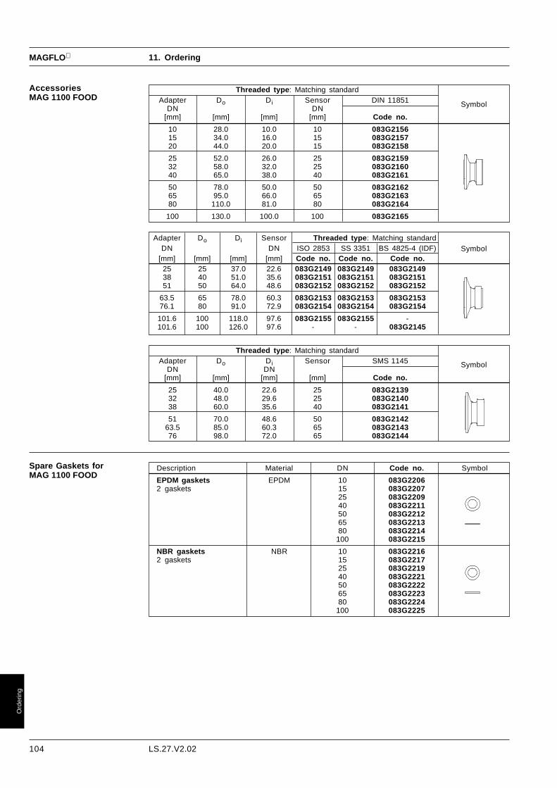
104 LS.27.V2.02
MAGFLO
Ord
erin
g
Adapter Do Di Sensor Threaded type : Matching standardDN DN ISO 2853 SS 3351 BS 4825-4 (IDF)
[mm] [mm] [mm] [mm] Code no. Code no. Code no.25 25 37.0 22.6 083G2149 083G2149 083G214938 40 51.0 35.6 083G2151 083G2151 083G215151 50 64.0 48.6 083G2152 083G2152 083G2152
63.5 65 78.0 60.3 083G2153 083G2153 083G215376.1 80 91.0 72.9 083G2154 083G2154 083G2154
101.6 100 118.0 97.6 083G2155 083G2155 -101.6 100 126.0 97.6 - - 083G2145
11. Ordering
Threaded type : Matching standardAdapter Do Di Sensor DIN 11851
DN DN[mm] [mm] [mm] [mm] Code no.
10 28.0 10.0 10 083G215615 34.0 16.0 15 083G215720 44.0 20.0 15 083G2158
25 52.0 26.0 25 083G215932 58.0 32.0 25 083G216040 65.0 38.0 40 083G2161
50 78.0 50.0 50 083G216265 95.0 66.0 65 083G216380 110.0 81.0 80 083G2164
100 130.0 100.0 100 083G2165
Symbol
AccessoriesMAG 1100 FOOD
Symbol
Symbol
Threaded type : Matching standardAdapter Do Di Sensor SMS 1145
DN DN[mm] [mm] [mm] [mm] Code no.
25 40.0 22.6 25 083G213932 48.0 29.6 25 083G214038 60.0 35.6 40 083G2141
51 70.0 48.6 50 083G214263.5 85.0 60.3 65 083G214376 98.0 72.0 65 083G2144
Description Material DN Code no. Symbol
EPDM gaskets EPDM 10 083G22062 gaskets 15 083G2207
25 083G220940 083G221150 083G221265 083G221380 083G2214
100 083G2215
NBR gaskets NBR 10 083G22162 gaskets 15 083G2217
25 083G221940 083G222150 083G222265 083G222380 083G2224
100 083G2225
Spare Gaskets forMAG 1100 FOOD

105LS.27.V2.02
MAGFLO
Ord
erin
g
Description DN PN Code no.Neoprene EPDM
liner liner
Sensor MAG 3100 W 25 40 083Z8000 083Z8100Liner: Neoprene or EPDM 40 40 083Z8001 083Z8101Flanges: Mild steel, DIN 2501 50 40 083Z8002 083Z8102Electrodes: AISI 316 Ti 65 16 083Z8003 083Z8103Grounding Electrodes: AISI 316 Ti 80 16 083Z8004 083Z8104Enclosure: IP 67 100 16 083Z8005 083Z8105
125 16 083Z8006 083Z8106150 16 083Z8007 083Z8107200 10 083Z8008 083Z8108200 16 083Z8208 083Z8308250 10 083Z8009 083Z8109250 16 083Z8209 083Z8309300 10 083Z8010 083Z8110300 16 083Z8210 083Z8310350 10 083Z8011 083Z8111350 16 083Z8211 083Z8311400 10 083Z8012 083Z8112400 16 083Z8212 083Z8312450 10 083Z8013 083Z8113450 16 083Z8213 083Z8313500 10 083Z8014 083Z8114500 16 083Z8214 083Z8314600 10 083Z8015 083Z8115600 16 083Z8215 083Z8315700 10 083Z8016 083Z8116800 10 083Z8017 083Z8117900 10 083Z8018 083Z8118
1000 10 083Z8019 083Z81191200 10 083Z8021 083Z8121
Description Size Code no. Symbol
Sensor MAG 2100 DN 25 083G1039Connection: DN 40 083G1041Hygienic fitting DIN 11851 DN 50 083G1042Enclosure : IP 67 DN 65 083G1043PN 10 DN 80 083G1044Sensor MAG 2100 DN 25 083G1019Connection: DN 40 083G1021Clamp ISO 2852 DN 50 083G1022Enclosure : IP 67 DN 65 083G1023PN 10 DN 80 083G1024
11. Ordering
11.3 Sensor MAG 2100
Description Material DN Code no. Symbol
1 Mounting set DIN 11851 Stainless steel 25 085U10192 unions AISI 316 40 085U10212 mating parts (for welding to pipe end) EPDM 50 085U10222 gaskets 65 085U1023
80 085U10241 Mounting set ISO 2852 Stainless steel 25 085U10292 clamps AISI 316 40 085U10312 mating parts (for welding to pipe end) EPDM 50 085U10322 gaskets 65 085U1033
80 085U1034EPDM gaskets with collar EPDM 25 085U100910 gaskets for mounting set DIN 11851 40 085U1011
50 085U101265 085U101380 085U1014
Accesories
11.4 SensorMAG 3100 W

106 LS.27.V2.02
MAGFLO
Ord
erin
g
Type No.: MAG 3100 −−−−−
1. Nominal size DN15 (with PTFE and PN 40 only) ............................ 0425 ......................................................................... 0640 ......................................................................... 0850 ......................................................................... 0965 ......................................................................... 1080 ......................................................................... 11
100 ......................................................................... 12125 ......................................................................... 13150 ......................................................................... 14200 ......................................................................... 15250 ......................................................................... 16300 ......................................................................... 17350 ......................................................................... 18400 ......................................................................... 19450 ......................................................................... 30500 ......................................................................... 20600 ......................................................................... 21700 ......................................................................... 22750 ......................................................................... 34800 ......................................................................... 23900 ......................................................................... 24
1000 ......................................................................... 251100 ......................................................................... 261200 ......................................................................... 271400 ......................................................................... 281500 ......................................................................... 291600 ......................................................................... 311800 ......................................................................... 322000 ......................................................................... 33
2. Liner materialNeoprene, standard .............................................................. 1EPDM with WRC approval 1) ................................................ 2PTFE (DN ≤ 600 mm) ............................................................ 3Polyurethane ......................................................................... 4Ebonite ................................................................................. 6Natural rubber (Linatex) .......................................................... 7
3. Pressure stageDIN, PN 6 (standard on DN 1200 - 2000) ....................................... ADIN, PN 10 (standard on DN 200 - 1000) ....................................... BDIN, PN 16 (standard on DN 65 - 150) ........................................... CDIN, PN 25 (option on DN 200 - 600) ............................................. DDIN, PN 40 (standard on DN 15 - 50, option on DN 65 - 600) .......... EDIN, PN 64 (DN25 - 400) ................................................................. QDIN, PN 100 (DN 25 - 350) not with PTFE ...................................... RANSI class 150 (DN 15-600) ........................................................... FANSI class 300 (DN 15-600) ........................................................... GBS10, Table D .................................................................................. HBS10, Table E .................................................................................. IJIS, K10 (DN 50 - 1000) ................................................................. KJIS, K16 (DN 50 - 1200) ................................................................. LAS 2129, Table D ............................................................................ MAS 2129, Table E ............................................................................ NAWWA C-207, class D (DN 700 - 2000) .......................................... OAS 4087 Class 14 (DN 50 - 1200) .................................................. P
4. Electrode material/Earthing electrodes 2)AISI 316 Ti, ceramic coated ....................................................................... 1AISI 316 Ti, standard .................................................................................. 2Hastelloy C-276 ........................................................................................... 4Platinum/iridium (80/20) ............................................................................... 5Titanium ....................................................................................................... 6Monel ........................................................................................................... 7Tantalum ...................................................................................................... 8AISI 316 Ti, ceramic coated + earthing electrodes .................................... AAISI 316 Ti + earthing electrodes standard .............................................. BHastelloy C-276 + earthing electrodes ........................................................ D
5. Flange and housing materialSt. 37.2 flanges and housing (grey coating) .......................................................... 1AISI 304 flanges/st. 37.2 housing (grey coating) .................................................. 2AISI 316/L flanges/housing (polished) .................................................................... 3
6. Enclosure/Temperature/Ex-versionIP 67 (3 m w.g. for 72 h) Tmax. < = 120°C) ......................................................................................... 1000IP 67 (3 m w.g. for 72 h) 120°C < Tmax. < = 180°C 3) ........................................................................ 2100IP 67 (3 m w.g. for 72 h) Tmax. < = 120°C, DN 350 - 2000 EEx e ia IIC T4-T6 .................................. 4000IP 67 (3 m w.g. for 72 h) Tmax. < = 120°C, DN 15 - 300 EEx ia ib IIB T4-T6 ..................................... 4100IP 67 (3 m w.g. for 72 h) T ≤ 120°C, DN 15 - 300 Compact EEx de ................................................... 5000
11. Ordering
11.5 SensorMAG 3100 andMAG 3100 Ex
1) Water Research Council, UK.
2) Earthing electrode material andmeasuring electrode material isidentical.Earthing electrodes are notceramic coated.Earthing electrodes are not yetavailable with PTFE liner.
3) Including protection flangestype E.

107LS.27.V2.02
MAGFLO
Ord
erin
g
Accessories
Earthing/protection flange type C (AISI 304) for all liners except PTFE
BS 10ANSI B 16.5DIN 2501/BS 4504 JIS B 2220
Pressurestage
Flange
PN 6 PN 10 PN 16 PN 25 PN 40 150 lb 300 lb Table D/E K 10 K 16
DN 083N... 083N... 083N... 083N... 083N... 083N... 083N... 083N... 083N... 083N...25 8361 8361 8361 836140 8362 8362 8362 836250 8344 8344 8344 8344 8344 834465 8345 8345 8345 8345 8345 8346 8345 834580 8347 8347 8347 8347 8347 8347 8347 8347100 8070 8025 8025 8025 8025 8025 8070 8025125 8071 8071 8071 8071 8071 8071 8071 8071150 8072 8008 8008 8008 8073 8008 8008 8325200 8074 8011 8011 8011 8075 8011 8076 8011 8322 8011250 8078 8013 8013 8013 8079 8013 8079 8013 8013 8324300 8080 8012 8012 8081 8082 8012 8082 8012 8323 8081350 8083 8039 8039 8084 8085 8039 8085 8039 8326 8327400 8099 8100 8100 8101 8102 8100 8102 8100 8330 8331450 8103 8103 8104 8104 8105 8104 8106 8104 8103 8333500 8107 8107 8108 8108 8109 8107 8110 8108 8107 8335600 8111 8111 8112 8112 8113 8114 8113 8337 8112700 8300 8294 8294 8294 8339800 8303 8304 8304 8304 8341900 8306 8307 8307 8307 83421000 8309 8310 8310 8310 83431200 8312 8313 83131400 8349 8353 83571600 8350 8354 83581800 8351 8355 83592000 8352 8356 8360
Earthing/protection flange type E (AISI 316) for PTFE liner only
Flange
PN 6 PN 10 PN 16 PN 25 PN 40 150 lb 300 lb Table D Table Estage
DN 083N... 083N... 083N... 083N... 083N... 083N... 083N... 083N... 083N...15 8365 8365 8365 8365 836525 8271 8272 8272 8272 827240 8278 8275 8275 8276 827650 8282 8283 8283 8281 828165 8284 8285 8286 8287 8287 8284 828480 8288 8289 8290 8291 8292 8293 8293100 8116 8117 8118 8118 8119 8117 8117125 8120 8121 8122 8122 8123 8121 8121150 8124 8125 8126 8126 8127 8128 8128200 8129 8130 8130 8131 8132 8370 8133 8134 8134250 8135 8136 8137 8138 8139 8140 8141 8142 8143300 8144 8144 8145 8146 8147 8148 8149 8150 8151350 8152 8153 8154 8155 8156 8157 8158 8159 8153400 8160 8161 8162 8163 8164 8165 8166 8167 8161450 8168 8169 8170 8171 8172 8173 8174 8175 8176500 8177 8178 8179 8180 8181 8182 8183 8184 8185600 8186 8187 8188 8189 8190 8191 8192 8193
BS 10/AS 2129ANSI B 16.5DIN 2501/BS 4504
Pressure
JIS B 2220
Description Code no. Symbol
Submersible kit (IP 68, 10 m w.g.)For use with standard MAG 3100, when sensor is buried 085U0220or permanently submerged.
11. Ordering

108 LS.27.V2.02
MAGFLO
Ord
erin
g
DN t1 t2[mm] [mm]
25 - 250 1.2 15300 - 600 1.6 20
700 - 2000 2.0 25
DN t1[mm]
15 - 150 6200 - 350 8400 - 600 10
NBRemember to add t1 and the gasket thickness to the overall length of the flowmeter when earthingflanges are used.
11. Ordering
Signal converterMAG 2500 Blind
Description Version Enclosure Code no. Symbol
Signal converter MAG 2500 Blind for 115/230 V a.c. IP 67, fibre-compact and wall mounting 50/60 Hz glass reinforced 083F4081
polyamide
11-30 V d.c./ IP 67, fibre-11-24 V a.c. glass reinforced 083F4083
polyamide
Signal converter MAG 2500 Blind for 115/230 V a.c. IP 20 083F4042rack and panel mounting 50/60 Hz 19" insert
11-30 V d.c./ IP 20 083F404311-24 V a.c. 19" insert
Description Version Enclosure Code no. Symbol
Signal converter MAG 2500 for 115/230 V a.c. IP 67, fibre-compact and wall mounting 50/60 Hz glass reinforced 083F4080
polyamide
11-30 V d.c./ IP 67, fibre-11-24 V a.c. glass reinforced 083F4082
polyamide
Signal converter MAG 2500 for rack 115/230 V a.c. IP 20 083F4040and panel mounting 50/60 Hz 19" insert
11-30 V d.c./ IP 20 083F404111-24 V a.c. 19" insert
11.6 Signal converterMAG 2500

109LS.27.V2.02
MAGFLO
Ord
erin
g
Description Version Enclosure Code no. Symbol
Signal converter 115/230 V a.c. IP 67, fibreMAG 3000 for compact and 50/60 Hz glass-reinforced 083F4051wall mounting polyamide
IP 67AISI 316 L 083F4002W. no. 1.4401
11-30 V d.c. IP 67, fibre11-24 V a.c. glass-reinforced 083F4053
polyamide
IP 67AISI 316 L 083F4004W.no. 1.4401
Signal converter 115/230 V a.c. IP 20MAG 3000 for 19" rack and 50/60 Hz 19" insert (28 TE) 083F4016panel mounting
11-30 V d.c. IP 2011-24 V a.c. 19" insert (28 TE) 083F4017
Signal converter 115/230 V a.c. IP 65MAG 3000 19" insert and 50/60 Hz ABS plastic 083F4044cleaning unitcomplete mounted inIP 65 wall mounting enclosure
Signal converter 115/230 V a.c. IP 67, fibreMAG 3000CT for compact 50/60 Hz glass-reinforced 083F4009and wall mounting, polyamidecustody transfer approval:PTB, cold water 11-30 V d.c. IP 67, fibreDANAK/OIML R75, hot water 11-24 V a.c. glass-reinforced 083F4008
polyamide
Signal converter 115/230 V a.c. IP 65MAG 3000CT 19" insert 50/60 Hz ABS plastic 083F4019complete mounted in IP 65wall mounting enclosure, 11-30 V d.c. IP 65custody transfer approval 11-24 V a.c. ABS plastic 083F4020PTB, cold waterDANAK/OIML R75, hot waterDANAK/OIML R117, milk, beer, etc.
Signal converter 115/230 V a.c. IP 20MAG 3000 Ex for 19" rack and 50/60 Hz 19" insert (42TE) 083F3038panel mounting,[EEx ia ib]IIB 11-30 V d.c. IP 20
11-24 V a.c. 19" insert (42TE) 083F3039Signal converter 115/230 V a.c. IP 65MAG 3000 Ex 19" insert 50/60 Hz ABS plastic 083F3042complete mounted in IP 65wall mounting enclosure,[EEx ia ib]IIB 11-30 V d.c. IP 65
11-24 V a.c. ABS plastic 083F3043Signal converter 115/230 V a.c. IP 65MAG 3000 19" insert 50/60 Hz ABS plastic 083F3044and safety barriercomplete mounted in IP 65wall mounting enclosure, 11-30 V d.c. IP 65[EEx e ia]IIC 11-24 V a.c. ABS plastic 083F3045
Signal converter 115/230 V a.c. IP 67, fibreMAG 3000 Profibus 50-60 Hz glass-reinforced 083F4011for compact and separate mounting polyamide
Signal converter 24 V a.c./d.c. IP 67MAG 3000 Ex-d, stainless steel 083F3080with wall mounting bracket. AISI 304
Signal converter 24 V a.c./d.c. IP 67MAG 3000 Ex-d, stainless steel 083X9027with wall mounting bracket. AISI 316
11.7 Signal converterMAG 3000
11. Ordering
6.22193.16
6.22193.16

110 LS.27.V2.02
MAGFLO
Ord
erin
g
Description Code no. Symbol
Wall mounting kit for IP 67 versionWall bracket, 4 Pg 13.5 cable glands 085U1001(cables not included)Panel mounting kit for 19" insert (28TE)IP 65 enclosure in ABS plastic for panel-front mounting 083F3087
Panel mounting kit for 19" insert (42TE)IP 65 enclosure in ABS plastic for panel-front mounting 083F3082
Back of panel mounting kit for 19" insert (28TE)IP 20 enclosure in aluminium 083F3084
Back of panel mounting kit for 19" insert (42TE)IP 20 enclosure in aluminium 083F3083
IP 65 wall mounting enclosure for IP 20 19" inserts(28 TE) 083F4099
LengthCable 10 m 083F0121Standard electrode and coil cable, 20 m 083F02103 x 1,5 mm2 PVC 40 m 083F0211
60 m 083F0212100 m 083F0213150 m 083F3052200 m 083F3053500 m 083F3054
Cable 20 m 083F3095Special electrode cable, 40 m 083F3094double screened, PVC 60 m 083F3093
100 m 083F3092150 m 083F3056200 m 083F3057500 m 083F3058
Standard Pg 13.5 screwed cable entriesfor above cables (nickel-plated brass) 2-off 083G0227
Standard Pg 13.5 screwed cable entriesfor above cables in black polyamide (100°C) 2-off 083G0228
Sealing screws for sensor/signal converter 2-off 085U0221
Stainless steel (AISI 316) terminal box with lid 085U1000
AccessoriesMAG 2500 and MAG 3000
11. Ordering
AccessoriesMAG 3000
Description Version Code no. SymbolCleaning Unit for electrode cleaning 115-230 V a.c.19" insert (14TE) 50/60 Hz 083F3086
Cleaning Unit for electrode cleaning 18-30 V d.c.19" insert (14TE) 083F3081
Safety Barrier [EEx ia]IIC for MAG 3100 Ex DN 350-200019" insert (14TE) 083F3085

LS.27.V2.02
MAGFLO
111
11. Ordering
11.8 Custody transfersystems
MAGFLO electromagnetic flowmeters are available for custody transfer applications with signalconverter type MAG 3000 CT.A custody transfer system consist of a MAG 3000 CT and a sensor type MAG 1100, MAG 1100FOOD, MAG 2100 or MAG 3100.The internal totalizer in MAG 3000 CT is approved for custody transfer according to the followingtype approvals:
PTB, (Physikalisch - Technische Bundesanstalt):
Potable water applications, Class B.
DANAK, (Danish Accreditation):OIML R75, Class 4, Hot water in district heating applicationsOIML R117, Class I, Liquids other than water (milk, beer, etc.)
Each system must be verified on an accredited test rig, set and sealed by an authorized person.The system is available from Siemens as individual items for on-site verification or as a completesystem which is verified by a matched calibration at an accredited test rig at Siemens. After sealingthe settings of the signal converter may not be changed.
For ordering and calibration details, please contact Siemens.
6.22193.16
Ord
erin
g

We have checked the contents of this manual for agreement with the hardware andsoftware described. Since deviations cannot be precluded entirely, we cannot guaranteefull agreement. However, the data in this manual are reviewed regularly and anynecessary corrections included in subsequent editions. Suggestions for improvementare always welcomed.
Technical data subject to change without prior notice.
The reproduction, transmission or use of this document or its contents is not permitted withoutexpress written authority.Offenders will be liable for damages. All rights, including rights created by patent grant orregistration of a utility model or design, are reserved.
Copyright © Siemens AG 1997 All Rights Reserved
SIEMENSFlow Instruments A/SNordborgvej 81DK-6430 Nordborg
Order no.:Printed in: Denmark