
Proline Promass O 100 - Endress+Hauser
80
The robust high-pressure flowmeter with an ultra-compact transmitter Application • Measuring principle operates independently of physical fluid properties such as viscosity or density • Premium accuracy at highest process pressures, fully suitable for onshore/offshore conditions Device properties • Measuring tube in 25Cr Duplex, 1.4410 (UNS S32750) • Process pressure up to PN 250 (Class 1500) • Nominal diameter: DN 80 to 150 (3 to 6") • Robust, ultra-compact transmitter housing • Highest degree of protection: IP69K • Local display available Your benefits • Maximum safety – highest resistance to stress corrosion cracking • Fewer process measuring points – multivariable measurement (flow, density, temperature) • Space‐saving installation – no inlet/outlet run needs • Space‐saving transmitter – full functionality on smallest footprint • Time‐saving local operation without additional software and hardware – integrated web server • Integrated verification – Heartbeat Technology™ Products Solutions Services Technical Information Proline Promass O 100 Coriolis flowmeter TI01107D/06/EN/02.15 71302416
Transcript of Proline Promass O 100 - Endress+Hauser

The robust high-pressure flowmeter with an ultra-compact transmitter
Application
• Measuring principle operates independently of physical fluidproperties such as viscosity or density
• Premium accuracy at highest process pressures, fullysuitable for onshore/offshore conditions
Device properties• Measuring tube in 25Cr Duplex, 1.4410 (UNS S32750)• Process pressure up to PN 250 (Class 1500)• Nominal diameter: DN 80 to 150 (3 to 6")• Robust, ultra-compact transmitter housing• Highest degree of protection: IP69K• Local display available
Your benefits
• Maximum safety – highest resistance to stress corrosioncracking
• Fewer process measuring points – multivariablemeasurement (flow, density, temperature)
• Space‐saving installation – no inlet/outlet run needs• Space‐saving transmitter – full functionality on smallest
footprint• Time‐saving local operation without additional software and
hardware – integrated web server• Integrated verification – Heartbeat Technology™
Products Solutions Services
Technical InformationProline Promass O 100Coriolis flowmeter
TI01107D/06/EN/02.1571302416
Proline Promass O 100
2 Endress+Hauser
Table of contents
Document information . . . . . . . . . . . . . . . . . . . . . . . 4Symbols used . . . . . . . . . . . . . . . . . . . . . . . . . . . . . . . . 4
Function and system design . . . . . . . . . . . . . . . . . . . 5Measuring principle . . . . . . . . . . . . . . . . . . . . . . . . . . . . 5Measuring system . . . . . . . . . . . . . . . . . . . . . . . . . . . . . 5Equipment architecture . . . . . . . . . . . . . . . . . . . . . . . . . 7Safety . . . . . . . . . . . . . . . . . . . . . . . . . . . . . . . . . . . . . 7
Input . . . . . . . . . . . . . . . . . . . . . . . . . . . . . . . . . . . . . 8Measured variable . . . . . . . . . . . . . . . . . . . . . . . . . . . . . 8Measuring range . . . . . . . . . . . . . . . . . . . . . . . . . . . . . . 8Operable flow range . . . . . . . . . . . . . . . . . . . . . . . . . . . 8Input signal . . . . . . . . . . . . . . . . . . . . . . . . . . . . . . . . . 9
Output . . . . . . . . . . . . . . . . . . . . . . . . . . . . . . . . . . . 9Output signal . . . . . . . . . . . . . . . . . . . . . . . . . . . . . . . . 9Signal on alarm . . . . . . . . . . . . . . . . . . . . . . . . . . . . . . 11Ex connection data . . . . . . . . . . . . . . . . . . . . . . . . . . . 12Low flow cut off . . . . . . . . . . . . . . . . . . . . . . . . . . . . . 13Galvanic isolation . . . . . . . . . . . . . . . . . . . . . . . . . . . . 13Protocol-specific data . . . . . . . . . . . . . . . . . . . . . . . . . . 13
Power supply . . . . . . . . . . . . . . . . . . . . . . . . . . . . . 23Terminal assignment . . . . . . . . . . . . . . . . . . . . . . . . . . 23Pin assignment, device plug . . . . . . . . . . . . . . . . . . . . . . 30Supply voltage . . . . . . . . . . . . . . . . . . . . . . . . . . . . . . 32Power consumption . . . . . . . . . . . . . . . . . . . . . . . . . . . 33Current consumption . . . . . . . . . . . . . . . . . . . . . . . . . . 33Power supply failure . . . . . . . . . . . . . . . . . . . . . . . . . . 33Electrical connection . . . . . . . . . . . . . . . . . . . . . . . . . . 34Potential equalization . . . . . . . . . . . . . . . . . . . . . . . . . 39Terminals . . . . . . . . . . . . . . . . . . . . . . . . . . . . . . . . . 39Cable entries . . . . . . . . . . . . . . . . . . . . . . . . . . . . . . . 39Cable specification . . . . . . . . . . . . . . . . . . . . . . . . . . . . 39
Performance characteristics . . . . . . . . . . . . . . . . . . 41Reference operating conditions . . . . . . . . . . . . . . . . . . . 41Maximum measured error . . . . . . . . . . . . . . . . . . . . . . . 41Repeatability . . . . . . . . . . . . . . . . . . . . . . . . . . . . . . . 42Response time . . . . . . . . . . . . . . . . . . . . . . . . . . . . . . 43Influence of ambient temperature . . . . . . . . . . . . . . . . . 43Influence of medium temperature . . . . . . . . . . . . . . . . . . 43Influence of medium pressure . . . . . . . . . . . . . . . . . . . . 43Design fundamentals . . . . . . . . . . . . . . . . . . . . . . . . . . 44
Installation . . . . . . . . . . . . . . . . . . . . . . . . . . . . . . . 44Mounting location . . . . . . . . . . . . . . . . . . . . . . . . . . . . 45Orientation . . . . . . . . . . . . . . . . . . . . . . . . . . . . . . . . 45Inlet and outlet runs . . . . . . . . . . . . . . . . . . . . . . . . . . 46Special mounting instructions . . . . . . . . . . . . . . . . . . . . 46Mounting Safety Barrier Promass 100 . . . . . . . . . . . . . . . 47
Environment . . . . . . . . . . . . . . . . . . . . . . . . . . . . . . 48Ambient temperature range . . . . . . . . . . . . . . . . . . . . . 48Storage temperature . . . . . . . . . . . . . . . . . . . . . . . . . . 50Climate class . . . . . . . . . . . . . . . . . . . . . . . . . . . . . . . 50
Degree of protection . . . . . . . . . . . . . . . . . . . . . . . . . . 50Vibration resistance . . . . . . . . . . . . . . . . . . . . . . . . . . . 50Shock resistance . . . . . . . . . . . . . . . . . . . . . . . . . . . . . 50Shock resistance . . . . . . . . . . . . . . . . . . . . . . . . . . . . . 50Electromagnetic compatibility (EMC) . . . . . . . . . . . . . . . 50
Process . . . . . . . . . . . . . . . . . . . . . . . . . . . . . . . . . . 50Medium temperature range . . . . . . . . . . . . . . . . . . . . . . 50Density . . . . . . . . . . . . . . . . . . . . . . . . . . . . . . . . . . . 51Pressure-temperature ratings . . . . . . . . . . . . . . . . . . . . 51Secondary containment pressure rating . . . . . . . . . . . . . . 51Rupture disk . . . . . . . . . . . . . . . . . . . . . . . . . . . . . . . . 52Flow limit . . . . . . . . . . . . . . . . . . . . . . . . . . . . . . . . . 52Pressure loss . . . . . . . . . . . . . . . . . . . . . . . . . . . . . . . 52System pressure . . . . . . . . . . . . . . . . . . . . . . . . . . . . . 52Thermal insulation . . . . . . . . . . . . . . . . . . . . . . . . . . . 53Heating . . . . . . . . . . . . . . . . . . . . . . . . . . . . . . . . . . . 54Vibrations . . . . . . . . . . . . . . . . . . . . . . . . . . . . . . . . . 54
Mechanical construction . . . . . . . . . . . . . . . . . . . . 55Dimensions in SI units . . . . . . . . . . . . . . . . . . . . . . . . . 55Dimensions in US units . . . . . . . . . . . . . . . . . . . . . . . . . 59Weight . . . . . . . . . . . . . . . . . . . . . . . . . . . . . . . . . . . 64Materials . . . . . . . . . . . . . . . . . . . . . . . . . . . . . . . . . . 64Process connections . . . . . . . . . . . . . . . . . . . . . . . . . . . 66Surface roughness . . . . . . . . . . . . . . . . . . . . . . . . . . . 66
Operability . . . . . . . . . . . . . . . . . . . . . . . . . . . . . . . 66Operating concept . . . . . . . . . . . . . . . . . . . . . . . . . . . . 66Local display . . . . . . . . . . . . . . . . . . . . . . . . . . . . . . . . 66Remote operation . . . . . . . . . . . . . . . . . . . . . . . . . . . . 66Service interface . . . . . . . . . . . . . . . . . . . . . . . . . . . . . 68
Certificates and approvals . . . . . . . . . . . . . . . . . . . 71CE mark . . . . . . . . . . . . . . . . . . . . . . . . . . . . . . . . . . . 71C-Tick symbol . . . . . . . . . . . . . . . . . . . . . . . . . . . . . . . 71Ex approval . . . . . . . . . . . . . . . . . . . . . . . . . . . . . . . . 71HART certification . . . . . . . . . . . . . . . . . . . . . . . . . . . . 72Certification PROFIBUS . . . . . . . . . . . . . . . . . . . . . . . . . 72Certification PROFINET . . . . . . . . . . . . . . . . . . . . . . . . 72EtherNet/IP certification . . . . . . . . . . . . . . . . . . . . . . . . 72Modbus RS485 certification . . . . . . . . . . . . . . . . . . . . . 72Pressure Equipment Directive . . . . . . . . . . . . . . . . . . . . 72Other standards and guidelines . . . . . . . . . . . . . . . . . . . 73
Ordering information . . . . . . . . . . . . . . . . . . . . . . . 73
Application packages . . . . . . . . . . . . . . . . . . . . . . . 73Heartbeat Technology . . . . . . . . . . . . . . . . . . . . . . . . . 74Concentration . . . . . . . . . . . . . . . . . . . . . . . . . . . . . . . 74
Accessories . . . . . . . . . . . . . . . . . . . . . . . . . . . . . . . 74Communication-specific accessories . . . . . . . . . . . . . . . . 74Service-specific accessories . . . . . . . . . . . . . . . . . . . . . . 75System components . . . . . . . . . . . . . . . . . . . . . . . . . . . 76

Proline Promass O 100
Endress+Hauser 3
Supplementary documentation . . . . . . . . . . . . . . . 76Standard documentation . . . . . . . . . . . . . . . . . . . . . . . . 76Supplementary device-dependent documentation . . . . . . . 76
Registered trademarks . . . . . . . . . . . . . . . . . . . . . . 77
Proline Promass O 100
4 Endress+Hauser
Document information
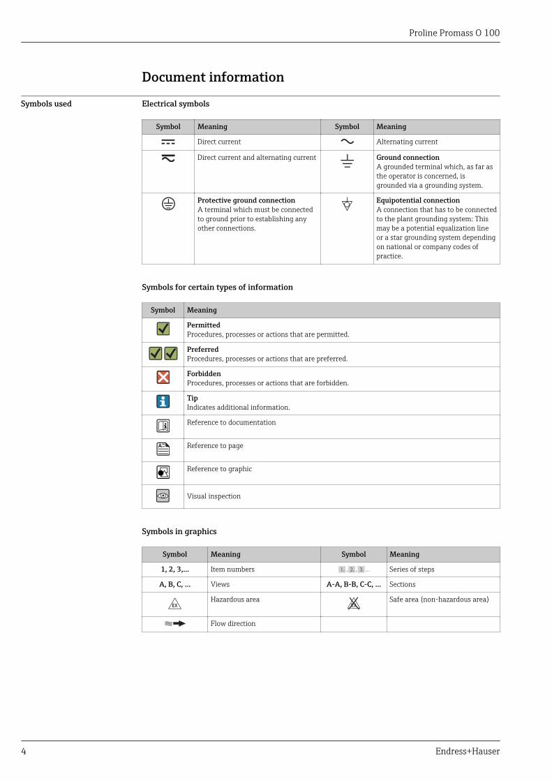
Symbols used Electrical symbols
Symbol Meaning Symbol Meaning
Direct current Alternating current
Direct current and alternating current Ground connectionA grounded terminal which, as far asthe operator is concerned, isgrounded via a grounding system.
Protective ground connectionA terminal which must be connectedto ground prior to establishing anyother connections.
Equipotential connectionA connection that has to be connectedto the plant grounding system: Thismay be a potential equalization lineor a star grounding system dependingon national or company codes ofpractice.
Symbols for certain types of information
Symbol Meaning
PermittedProcedures, processes or actions that are permitted.
PreferredProcedures, processes or actions that are preferred.
ForbiddenProcedures, processes or actions that are forbidden.
TipIndicates additional information.
Reference to documentation
Reference to page
Reference to graphic
Visual inspection
Symbols in graphics
Symbol Meaning Symbol Meaning
1, 2, 3,... Item numbers , …, Series of steps
A, B, C, ... Views A-A, B-B, C-C, ... Sections
-Hazardous area . Safe area (non-hazardous area)
Flow direction
Proline Promass O 100
Endress+Hauser 5
Function and system design
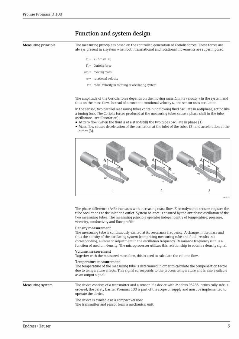
Measuring principle The measuring principle is based on the controlled generation of Coriolis forces. These forces arealways present in a system when both translational and rotational movements are superimposed.
Fc = 2 · ∆m (ν · ω)
Fc = Coriolis force
∆m = moving mass
ω = rotational velocity
ν = radial velocity in rotating or oscillating system
The amplitude of the Coriolis force depends on the moving mass ∆m, its velocity ν in the system andthus on the mass flow. Instead of a constant rotational velocity ω, the sensor uses oscillation.
In the sensor, two parallel measuring tubes containing flowing fluid oscillate in antiphase, acting likea tuning fork. The Coriolis forces produced at the measuring tubes cause a phase shift in the tubeoscillations (see illustration):• At zero flow (when the fluid is at a standstill) the two tubes oscillate in phase (1).• Mass flow causes deceleration of the oscillation at the inlet of the tubes (2) and acceleration at the
outlet (3).
1 2 3
A0016771
The phase difference (A-B) increases with increasing mass flow. Electrodynamic sensors register thetube oscillations at the inlet and outlet. System balance is ensured by the antiphase oscillation of thetwo measuring tubes. The measuring principle operates independently of temperature, pressure,viscosity, conductivity and flow profile.
Density measurementThe measuring tube is continuously excited at its resonance frequency. A change in the mass andthus the density of the oscillating system (comprising measuring tube and fluid) results in acorresponding, automatic adjustment in the oscillation frequency. Resonance frequency is thus afunction of medium density. The microprocessor utilizes this relationship to obtain a density signal.Volume measurementTogether with the measured mass flow, this is used to calculate the volume flow.Temperature measurementThe temperature of the measuring tube is determined in order to calculate the compensation factordue to temperature effects. This signal corresponds to the process temperature and is also availableas an output signal.
Measuring system The device consists of a transmitter and a sensor. If a device with Modbus RS485 intrinsically safe isordered, the Safety Barrier Promass 100 is part of the scope of supply and must be implemented tooperate the device.
The device is available as a compact version:The transmitter and sensor form a mechanical unit.
Proline Promass O 100
6 Endress+Hauser
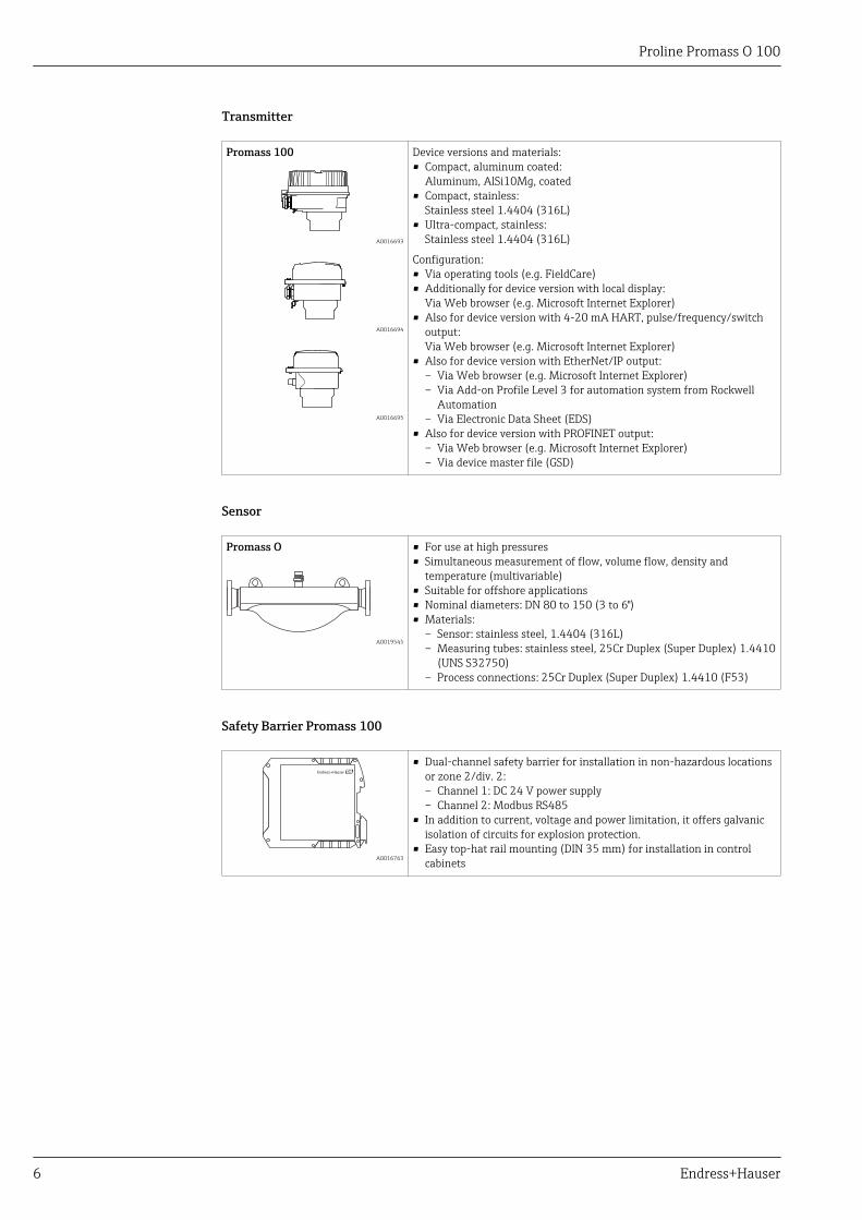
Transmitter
Promass 100 Device versions and materials:• Compact, aluminum coated:
Aluminum, AlSi10Mg, coated• Compact, stainless:
Stainless steel 1.4404 (316L)• Ultra-compact, stainless:
Stainless steel 1.4404 (316L)
Configuration:• Via operating tools (e.g. FieldCare)• Additionally for device version with local display:
Via Web browser (e.g. Microsoft Internet Explorer)• Also for device version with 4-20 mA HART, pulse/frequency/switch
output:Via Web browser (e.g. Microsoft Internet Explorer)
• Also for device version with EtherNet/IP output:– Via Web browser (e.g. Microsoft Internet Explorer)– Via Add-on Profile Level 3 for automation system from Rockwell
Automation– Via Electronic Data Sheet (EDS)
• Also for device version with PROFINET output:– Via Web browser (e.g. Microsoft Internet Explorer)– Via device master file (GSD)
A0016693
A0016694
A0016695
Sensor
Promass O
A0019545
• For use at high pressures• Simultaneous measurement of flow, volume flow, density and
temperature (multivariable)• Suitable for offshore applications• Nominal diameters: DN 80 to 150 (3 to 6")• Materials:
– Sensor: stainless steel, 1.4404 (316L)– Measuring tubes: stainless steel, 25Cr Duplex (Super Duplex) 1.4410
(UNS S32750)– Process connections: 25Cr Duplex (Super Duplex) 1.4410 (F53)
Safety Barrier Promass 100
A0016763
• Dual-channel safety barrier for installation in non-hazardous locationsor zone 2/div. 2:– Channel 1: DC 24 V power supply– Channel 2: Modbus RS485
• In addition to current, voltage and power limitation, it offers galvanicisolation of circuits for explosion protection.
• Easy top-hat rail mounting (DIN 35 mm) for installation in controlcabinets
Proline Promass O 100
Endress+Hauser 7
Equipment architecture
2 3
7 86
9
10
11
4
1
5
A0016779
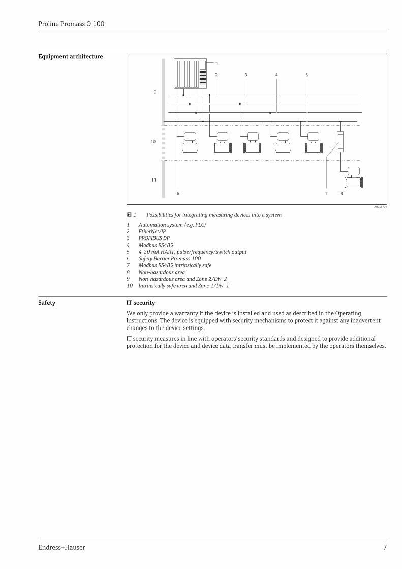
1 Possibilities for integrating measuring devices into a system
1 Automation system (e.g. PLC)2 EtherNet/IP3 PROFIBUS DP4 Modbus RS4855 4-20 mA HART, pulse/frequency/switch output6 Safety Barrier Promass 1007 Modbus RS485 intrinsically safe8 Non-hazardous area9 Non-hazardous area and Zone 2/Div. 210 Intrinsically safe area and Zone 1/Div. 1
Safety IT security
We only provide a warranty if the device is installed and used as described in the OperatingInstructions. The device is equipped with security mechanisms to protect it against any inadvertentchanges to the device settings.
IT security measures in line with operators' security standards and designed to provide additionalprotection for the device and device data transfer must be implemented by the operators themselves.
Proline Promass O 100
8 Endress+Hauser
Input
Measured variable Direct measured variables
• Mass flow• Density• Temperature
Calculated measured variables
• Volume flow• Corrected volume flow• Reference density
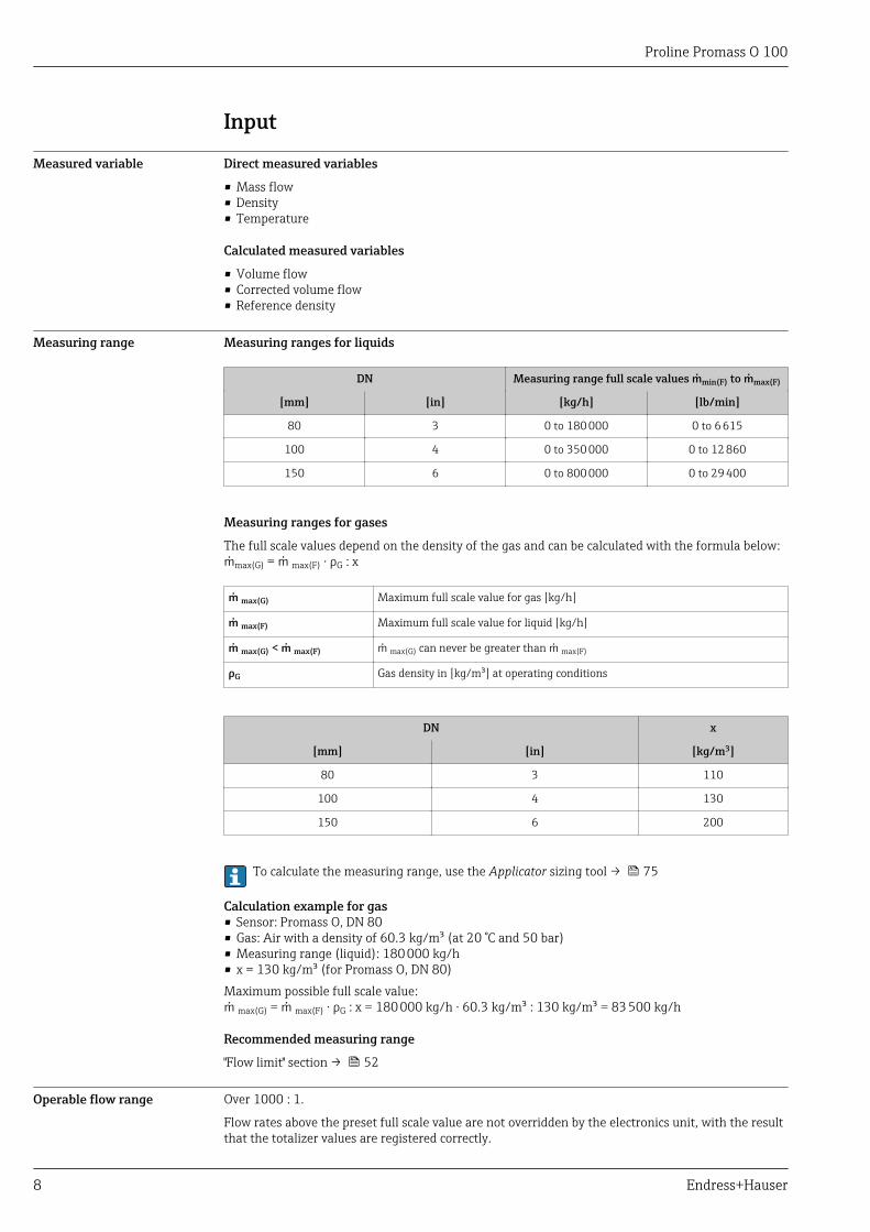
Measuring range Measuring ranges for liquids
DN Measuring range full scale values min(F) to max(F)
[mm] [in] [kg/h] [lb/min]
80 3 0 to 180 000 0 to 6 615
100 4 0 to 350 000 0 to 12 860
150 6 0 to 800 000 0 to 29 400
Measuring ranges for gases
The full scale values depend on the density of the gas and can be calculated with the formula below:max(G) = max(F) · ρG : x
max(G) Maximum full scale value for gas [kg/h]
max(F) Maximum full scale value for liquid [kg/h]
max(G) < max(F) max(G) can never be greater than max(F)
ρG Gas density in [kg/m³] at operating conditions
DN x
[mm] [in] [kg/m3]
80 3 110
100 4 130
150 6 200
To calculate the measuring range, use the Applicator sizing tool → 75
Calculation example for gas• Sensor: Promass O, DN 80• Gas: Air with a density of 60.3 kg/m³ (at 20 °C and 50 bar)• Measuring range (liquid): 180 000 kg/h• x = 130 kg/m³ (for Promass O, DN 80)Maximum possible full scale value: max(G) = max(F) · ρG : x = 180 000 kg/h · 60.3 kg/m³ : 130 kg/m³ = 83 500 kg/h
Recommended measuring range
"Flow limit" section → 52
Operable flow range Over 1000 : 1.
Flow rates above the preset full scale value are not overridden by the electronics unit, with the resultthat the totalizer values are registered correctly.

Proline Promass O 100
Endress+Hauser 9
Input signal External measured values
To increase the accuracy of certain measured variables or to calculate the corrected volume flow forgases, the automation system can continuously write different measured values to the measuringdevice:• Operating pressure to increase accuracy (Endress+Hauser recommends the use of a pressure
measuring device for absolute pressure, e.g. Cerabar M or Cerabar S)• Medium temperature to increase accuracy (e.g. iTEMP)• Reference density for calculating the corrected volume flow for gases
Various pressure transmitters and temperature measuring devices can be ordered from Endress+Hauser: see "Accessories" section → 76
It is recommended to read in external measured values to calculate the following measured variables:• Mass flow• Corrected volume flow
HART protocol
The measured values are written from the automation system to the measuring device via the HARTprotocol. The pressure transmitter must support the following protocol-specific functions:• HART protocol• Burst mode
Digital communication
The measured values can be written from the automation system to the measuring via:• PROFIBUS DP• Modbus RS485• EtherNet/IP• PROFINET
Output
Output signal Current output
Current output 4-20 mA HART (active)
Maximum output values • DC 24 V (no flow)• 22.5 mA
Load 0 to 700 Ω
Resolution 0.38 µA
Damping Adjustable: 0.07 to 999 s
Assignable measuredvariables
• Mass flow• Volume flow• Corrected volume flow• Density• Reference density• Temperature
The range of options increases if the measuring device has one or moreapplication packages.
Pulse/frequency/switch output
Function Can be set to pulse, frequency or switch output
Version Passive, open collector
Maximum input values • DC 30 V• 25 mA
Voltage drop For 25 mA: ≤ DC 2 V
Pulse output
Proline Promass O 100
10 Endress+Hauser
Pulse width Adjustable: 0.05 to 2 000 ms
Maximum pulse rate 10 000 Impulse/s
Pulse value Adjustable
Assignable measuredvariables
• Mass flow• Volume flow• Corrected volume flow
Frequency output
Output frequency Adjustable: 0 to 10 000 Hz
Damping Adjustable: 0 to 999 s
Pulse/pause ratio 1:1
Assignable measuredvariables
• Mass flow• Volume flow• Corrected volume flow• Density• Reference density• Temperature
The range of options increases if the measuring device has one or moreapplication packages.
Switch output
Switching behavior Binary, conductive or non-conductive
Switching delay Adjustable: 0 to 100 s
Number of switchingcycles
Unlimited
Assignable functions • Off• On• Diagnostic behavior• Limit value
– Mass flow– Volume flow– Corrected volume flow– Density– Reference density– Temperature– Totalizer 1-3
• Flow direction monitoring• Status
– Partially filled pipe detection– Low flow cut off
The range of options increases if the measuring device has one or moreapplication packages.
PROFIBUS DP
Signal encoding NRZ code
Data transfer 9.6 kBaud…12 MBaud
Modbus RS485
Physical interface In accordance with EIA/TIA-485-A standard
Terminating resistor • For device version used in non-hazardous areas or Zone 2/Div. 2: integratedand can be activated via DIP switches on the transmitter electronics module
• For device version used in intrinsically safe areas: integrated and can beactivated via DIP switches on the Safety Barrier Promass 100
Proline Promass O 100
Endress+Hauser 11
EtherNet/IP
Standards In accordance with IEEE 802.3
PROFINET
Standards In accordance with IEEE 802.3
Signal on alarm Depending on the interface, failure information is displayed as follows:
Current output
4-20 mA
Failure mode Choose from:• 4 to 20 mA in accordance with NAMUR recommendation NE 43• 4 to 20 mA in accordance with US• Min. value: 3.59 mA• Max. value: 22.5 mA• Freely definable value between: 3.59 to 22.5 mA• Actual value• Last valid value
HART
Device diagnostics Device condition can be read out via HART Command 48
Pulse/frequency/switch output
Pulse output
Failure mode Choose from:• Actual value• No pulses
Frequency output
Failure mode Choose from:• Actual value• 0 Hz• Defined value: 0 to 12 500 Hz
Switch output
Failure mode Choose from:• Current status• Open• Closed
PROFIBUS DP
Status and alarmmessages
Diagnostics in accordance with PROFIBUS PA Profile 3.02
Modbus RS485
Failure mode Choose from:• NaN value instead of current value• Last valid value
Proline Promass O 100
12 Endress+Hauser
EtherNet/IP
Device diagnostics Device condition can be read out in Input Assembly
PROFINET
Device diagnostics In accordance with "Application Layer protocol for decentral device periphery anddistributed automation", version 2.3
Local display
Plain text display With information on cause and remedial measures
Backlight Red backlighting indicates a device error.
Status signal as per NAMUR recommendation NE 107
Operating tool
• Via digital communication:– HART protocol– PROFIBUS DP– Modbus RS485– EtherNet/IP– PROFINET
• Via service interface• Via Web server
Plain text display With information on cause and remedial measures
Additional information on remote operation → 66
Web browser
Plain text display With information on cause and remedial measures
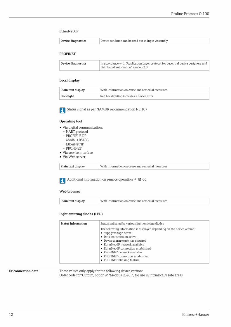
Light emitting diodes (LED)
Status information Status indicated by various light emitting diodes
The following information is displayed depending on the device version:• Supply voltage active• Data transmission active• Device alarm/error has occurred• EtherNet/IP network available• EtherNet/IP connection established• PROFINET network available• PROFINET connection established• PROFINET blinking feature
Ex connection data These values only apply for the following device version:Order code for "Output", option M "Modbus RS485", for use in intrinsically safe areas
Proline Promass O 100
Endress+Hauser 13
Safety Barrier Promass 100
Safety-related values
Terminal numbers
Supply voltage Signal transmission
2 (L-) 1 (L+) 26 (A) 27 (B)
Unom = DC 24 VUmax = AC 260 V
Unom = DC 5 VUmax = AC 260 V
Intrinsically safe values
Terminal numbers
Supply voltage Signal transmission
20 (L-) 10 (L+) 62 (A) 72 (B)
Uo = 16.24 VIo = 623 mAPo = 2.45 W
With IIC 1): Lo = 92.8 µH, Co = 0.433 μF, Lo/Ro = 14.6 μH/ΩWith IIB 1): Lo= 372 µH, Co = 2.57 μF, Lo/Ro = 58.3 μH/Ω
For an overview and for information on the interdependencies between the gas group - sensor - nominaldiameter, see the "Safety Instructions" (XA) document for the measuring device
1) The gas group depends on the sensor and nominal diameter.
Transmitter
Intrinsically safe values
Order code for"Approval"
Terminal numbers
Supply voltage Signal transmission
20 (L-) 10 (L+) 62 (A) 72 (B)
• Option BM: ATEX II2G + IECEx Z1 Ex ia, II2D Ex tb• Option BO: ATEX II1/2G + IECEx Z0/Z1 Ex ia, II2D• Option BQ: ATEX II1/2G + IECEx Z0/Z1 Ex ia• Option BU: ATEX II2G + IECEx Z1 Ex ia• Option C2: CSA C/US IS Cl. I, II, III Div. 1• Option 85: ATEX II2G + IECEx Z1 Ex ia + CSA C/US
IS Cl. I, II, III Div. 1
Ui = 16.24 VIi = 623 mAPi = 2.45 W
Li = 0 µHCi = 6 nF
For an overview and for information on the interdependencies between the gas group - sensor - nominaldiameter, see the "Safety Instructions" (XA) document for the measuring device
Low flow cut off The switch points for low flow cut off are user-selectable.
Galvanic isolation The following connections are galvanically isolated from each other:• Outputs• Power supply
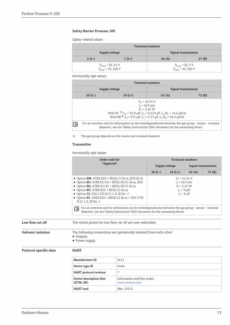
Protocol-specific data HART
Manufacturer ID 0x11
Device type ID 0x4A
HART protocol revision 7
Device description files(DTM, DD)
Information and files under:www.endress.com
HART load Min. 250 Ω
Proline Promass O 100
14 Endress+Hauser
Dynamic variables Read out the dynamic variables: HART command 3The measured variables can be freely assigned to the dynamic variables.
Measured variables for PV (primary dynamic variable)• Mass flow• Volume flow• Corrected volume flow• Density• Reference density• Temperature
Measured variables for SV, TV, QV (secondary, tertiary and quaternarydynamic variable)• Mass flow• Volume flow• Corrected volume flow• Density• Reference density• Temperature• Totalizer 1• Totalizer 2• Totalizer 3
The range of options increases if the measuring device has one or moreapplication packages.
Heartbeat Technology Application PackageAdditional measured variables are available with the Heartbeat Technologyapplication package:• Carrier pipe temperature• Oscillation amplitude 0
Device variables Read out the device variables: HART command 9The device variables are permanently assigned.
A maximum of 8 device variables can be transmitted:• 0 = mass flow• 1 = volume flow• 2 = corrected volume flow• 3 = density• 4 = reference density• 5 = temperature• 6 = totalizer 1• 7 = totalizer 2• 8 = totalizer 3• 13 = target mass flow• 14 = carrier mass flow• 15 = concentration
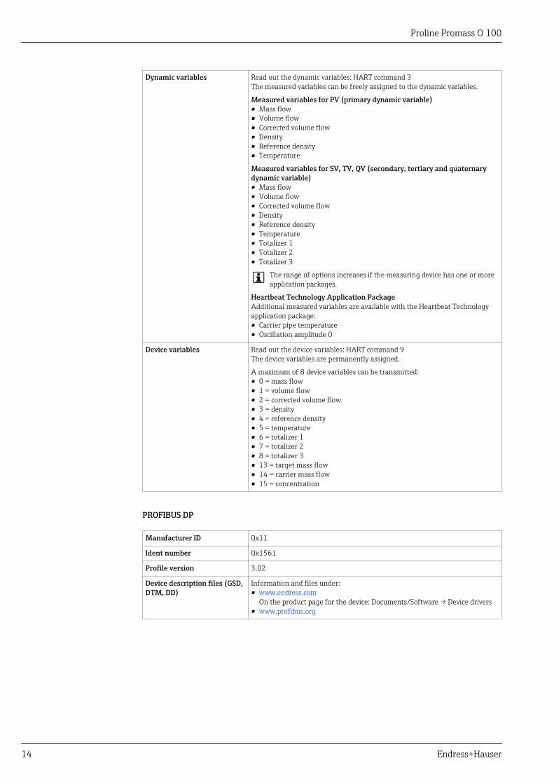
PROFIBUS DP
Manufacturer ID 0x11
Ident number 0x1561
Profile version 3.02
Device description files (GSD,DTM, DD)
Information and files under:• www.endress.com
On the product page for the device: Documents/Software → Device drivers• www.profibus.org
Proline Promass O 100
Endress+Hauser 15
Output values(from measuring device toautomation system)
Analog input 1 to 8• Mass flow• Volume flow• Corrected volume flow• Target mass flow• Carrier mass flow• Density• Reference density• Concentration• Temperature• Carrier pipe temperature• Electronic temperature• Oscillation frequency• Oscillation amplitude• Frequency fluctuation• Oscillation damping• Tube damping fluctuation• Signal asymmetry• Exciter current
Digital input 1 to 2• Partially filled pipe detection• Low flow cut off
Totalizer 1 to 3• Mass flow• Volume flow• Corrected volume flow
Input values(from automation system tomeasuring device)
Analog output 1 to 3 (fixed assignment)• Pressure• Temperature• Reference density
Digital output 1 to 3 (fixed assignment)• Digital output 1: switch positive zero return on/off• Digital output 2: perform zero point adjustment• Digital output 3: switch switch output on/off
Totalizer 1 to 3• Totalize• Reset and hold• Preset and hold• Stop• Operating mode configuration:
– Net flow total– Forward flow total– Reverse flow total
Supported functions • Identification & MaintenanceSimplest device identification on the part of the control system andnameplate
• PROFIBUS upload/downloadReading and writing parameters is up to ten times faster with PROFIBUSupload/download
• Condensed statusSimplest and self-explanatory diagnostic information by categorizingdiagnostic messages that occur
Configuration of the deviceaddress
• DIP switches on the I/O electronics module• Via operating tools (e.g. FieldCare)
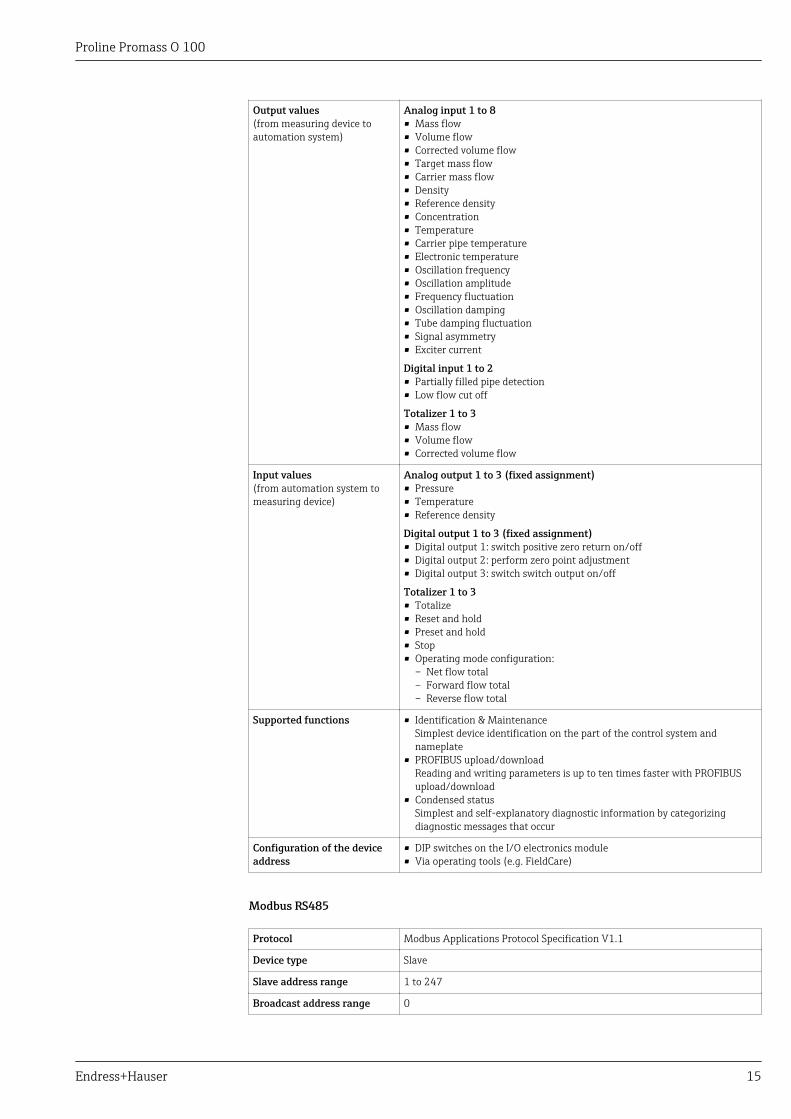
Modbus RS485
Protocol Modbus Applications Protocol Specification V1.1
Device type Slave
Slave address range 1 to 247
Broadcast address range 0
Proline Promass O 100
16 Endress+Hauser
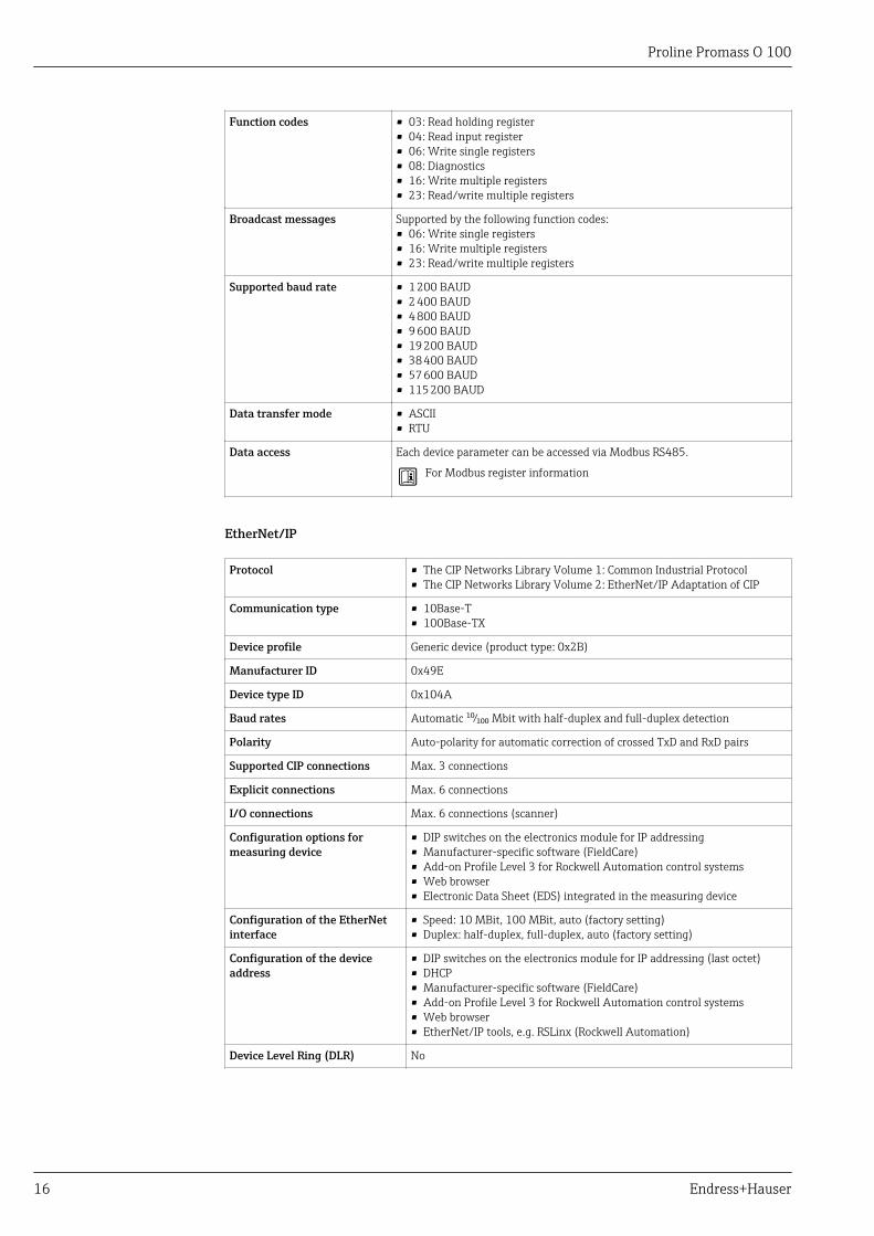
Function codes • 03: Read holding register• 04: Read input register• 06: Write single registers• 08: Diagnostics• 16: Write multiple registers• 23: Read/write multiple registers
Broadcast messages Supported by the following function codes:• 06: Write single registers• 16: Write multiple registers• 23: Read/write multiple registers
Supported baud rate • 1 200 BAUD• 2 400 BAUD• 4 800 BAUD• 9 600 BAUD• 19 200 BAUD• 38 400 BAUD• 57 600 BAUD• 115 200 BAUD
Data transfer mode • ASCII• RTU
Data access Each device parameter can be accessed via Modbus RS485.
For Modbus register information
EtherNet/IP
Protocol • The CIP Networks Library Volume 1: Common Industrial Protocol• The CIP Networks Library Volume 2: EtherNet/IP Adaptation of CIP
Communication type • 10Base-T• 100Base-TX
Device profile Generic device (product type: 0x2B)
Manufacturer ID 0x49E
Device type ID 0x104A
Baud rates Automatic ¹⁰⁄₁₀₀ Mbit with half-duplex and full-duplex detection
Polarity Auto-polarity for automatic correction of crossed TxD and RxD pairs
Supported CIP connections Max. 3 connections
Explicit connections Max. 6 connections
I/O connections Max. 6 connections (scanner)
Configuration options formeasuring device
• DIP switches on the electronics module for IP addressing• Manufacturer-specific software (FieldCare)• Add-on Profile Level 3 for Rockwell Automation control systems• Web browser• Electronic Data Sheet (EDS) integrated in the measuring device
Configuration of the EtherNetinterface
• Speed: 10 MBit, 100 MBit, auto (factory setting)• Duplex: half-duplex, full-duplex, auto (factory setting)
Configuration of the deviceaddress
• DIP switches on the electronics module for IP addressing (last octet)• DHCP• Manufacturer-specific software (FieldCare)• Add-on Profile Level 3 for Rockwell Automation control systems• Web browser• EtherNet/IP tools, e.g. RSLinx (Rockwell Automation)
Device Level Ring (DLR) No
Proline Promass O 100
Endress+Hauser 17
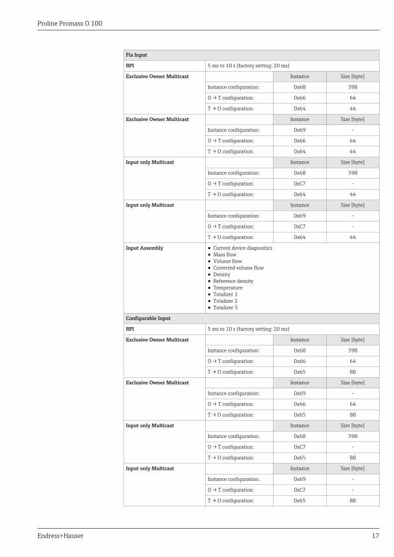
Fix Input
RPI 5 ms to 10 s (factory setting: 20 ms)
Exclusive Owner Multicast Instance Size [byte]
Instance configuration: 0x68 398
O → T configuration: 0x66 64
T → O configuration: 0x64 44
Exclusive Owner Multicast Instance Size [byte]
Instance configuration: 0x69 -
O → T configuration: 0x66 64
T → O configuration: 0x64 44
Input only Multicast Instance Size [byte]
Instance configuration: 0x68 398
O → T configuration: 0xC7 -
T → O configuration: 0x64 44
Input only Multicast Instance Size [byte]
Instance configuration: 0x69 -
O → T configuration: 0xC7 -
T → O configuration: 0x64 44
Input Assembly • Current device diagnostics• Mass flow• Volume flow• Corrected volume flow• Density• Reference density• Temperature• Totalizer 1• Totalizer 2• Totalizer 3
Configurable Input
RPI 5 ms to 10 s (factory setting: 20 ms)
Exclusive Owner Multicast Instance Size [byte]
Instance configuration: 0x68 398
O → T configuration: 0x66 64
T → O configuration: 0x65 88
Exclusive Owner Multicast Instance Size [byte]
Instance configuration: 0x69 -
O → T configuration: 0x66 64
T → O configuration: 0x65 88
Input only Multicast Instance Size [byte]
Instance configuration: 0x68 398
O → T configuration: 0xC7 -
T → O configuration: 0x65 88
Input only Multicast Instance Size [byte]
Instance configuration: 0x69 -
O → T configuration: 0xC7 -
T → O configuration: 0x65 88
Proline Promass O 100
18 Endress+Hauser
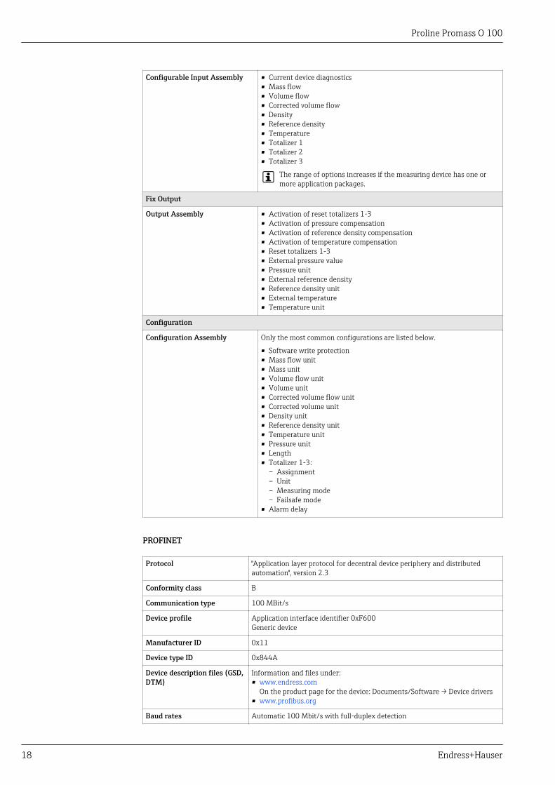
Configurable Input Assembly • Current device diagnostics• Mass flow• Volume flow• Corrected volume flow• Density• Reference density• Temperature• Totalizer 1• Totalizer 2• Totalizer 3
The range of options increases if the measuring device has one ormore application packages.
Fix Output
Output Assembly • Activation of reset totalizers 1-3• Activation of pressure compensation• Activation of reference density compensation• Activation of temperature compensation• Reset totalizers 1-3• External pressure value• Pressure unit• External reference density• Reference density unit• External temperature• Temperature unit
Configuration
Configuration Assembly Only the most common configurations are listed below.
• Software write protection• Mass flow unit• Mass unit• Volume flow unit• Volume unit• Corrected volume flow unit• Corrected volume unit• Density unit• Reference density unit• Temperature unit• Pressure unit• Length• Totalizer 1-3:
– Assignment– Unit– Measuring mode– Failsafe mode
• Alarm delay
PROFINET
Protocol "Application layer protocol for decentral device periphery and distributedautomation", version 2.3
Conformity class B
Communication type 100 MBit/s
Device profile Application interface identifier 0xF600Generic device
Manufacturer ID 0x11
Device type ID 0x844A
Device description files (GSD,DTM)
Information and files under:• www.endress.com
On the product page for the device: Documents/Software → Device drivers• www.profibus.org
Baud rates Automatic 100 Mbit/s with full-duplex detection
Proline Promass O 100
Endress+Hauser 19
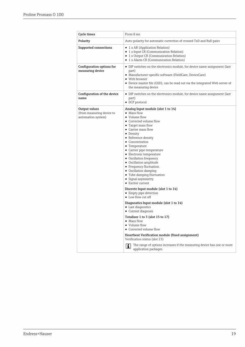
Cycle times From 8 ms
Polarity Auto-polarity for automatic correction of crossed TxD and RxD pairs
Supported connections • 1 x AR (Application Relation)• 1 x Input CR (Communication Relation)• 1 x Output CR (Communication Relation)• 1 x Alarm CR (Communication Relation)
Configuration options formeasuring device
• DIP switches on the electronics module, for device name assignment (lastpart)
• Manufacturer-specific software (FieldCare, DeviceCare)• Web browser• Device master file (GSD), can be read out via the integrated Web server of
the measuring device
Configuration of the devicename
• DIP switches on the electronics module, for device name assignment (lastpart)
• DCP protocol
Output values(from measuring device toautomation system)
Analog Input module (slot 1 to 14)• Mass flow• Volume flow• Corrected volume flow• Target mass flow• Carrier mass flow• Density• Reference density• Concentration• Temperature• Carrier pipe temperature• Electronic temperature• Oscillation frequency• Oscillation amplitude• Frequency fluctuation• Oscillation damping• Tube damping fluctuation• Signal asymmetry• Exciter current
Discrete Input module (slot 1 to 14)• Empty pipe detection• Low flow cut off
Diagnostics Input module (slot 1 to 14)• Last diagnostics• Current diagnosis
Totalizer 1 to 3 (slot 15 to 17)• Mass flow• Volume flow• Corrected volume flow
Heartbeat Verification module (fixed assignment)Verification status (slot 23)
The range of options increases if the measuring device has one or moreapplication packages.
Proline Promass O 100
20 Endress+Hauser
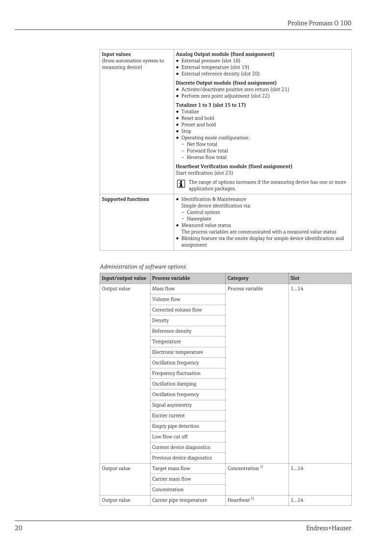
Input values(from automation system tomeasuring device)
Analog Output module (fixed assignment)• External pressure (slot 18)• External temperature (slot 19)• External reference density (slot 20)
Discrete Output module (fixed assignment)• Activate/deactivate positive zero return (slot 21)• Perform zero point adjustment (slot 22)
Totalizer 1 to 3 (slot 15 to 17)• Totalize• Reset and hold• Preset and hold• Stop• Operating mode configuration:
– Net flow total– Forward flow total– Reverse flow total
Heartbeat Verification module (fixed assignment)Start verification (slot 23)
The range of options increases if the measuring device has one or moreapplication packages.
Supported functions • Identification & MaintenanceSimple device identification via:– Control system– Nameplate
• Measured value statusThe process variables are communicated with a measured value status
• Blinking feature via the onsite display for simple device identification andassignment
Administration of software options
Input/output value Process variable Category Slot
Output value Mass flow Process variable 1…14
Volume flow
Corrected volume flow
Density
Reference density
Temperature
Electronic temperature
Oscillation frequency
Frequency fluctuation
Oscillation damping
Oscillation frequency
Signal asymmetry
Exciter current
Empty pipe detection
Low flow cut off
Current device diagnostics
Previous device diagnostics
Output value Target mass flow Concentration 1) 1…14
Carrier mass flow
Concentration
Output value Carrier pipe temperature Heartbeat 2) 1…14
Proline Promass O 100
Endress+Hauser 21
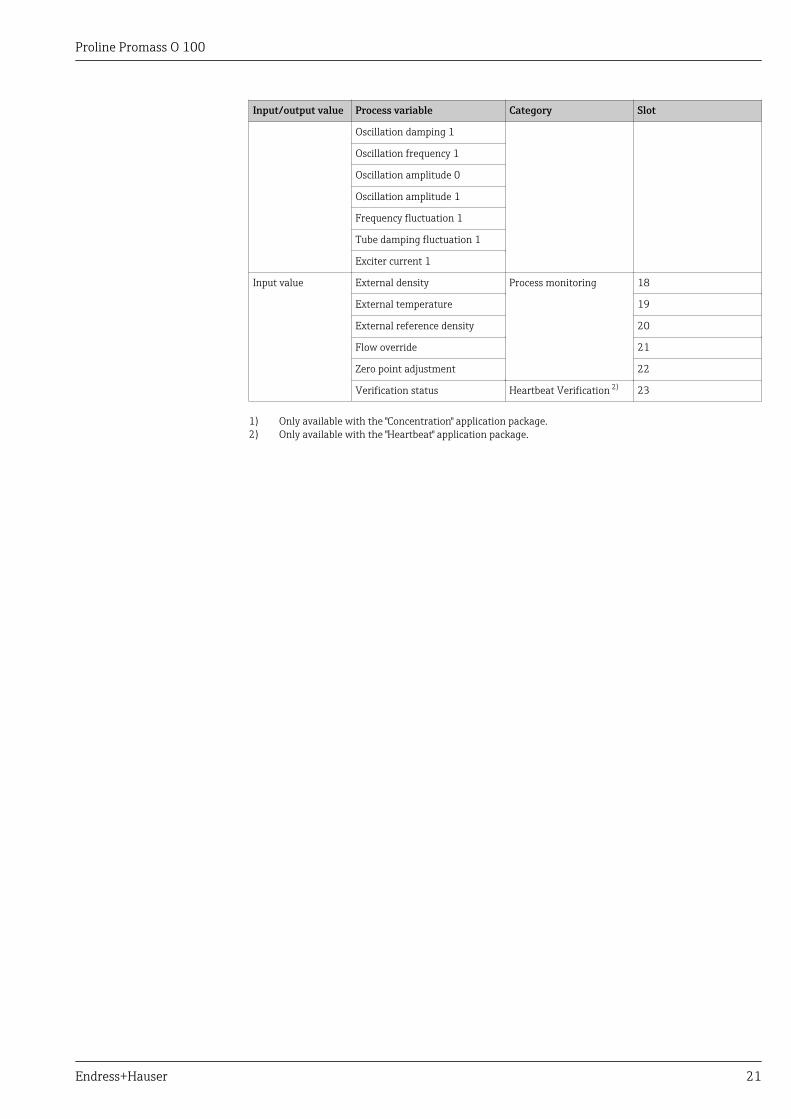
Input/output value Process variable Category Slot
Oscillation damping 1
Oscillation frequency 1
Oscillation amplitude 0
Oscillation amplitude 1
Frequency fluctuation 1
Tube damping fluctuation 1
Exciter current 1
Input value External density Process monitoring 18
External temperature 19
External reference density 20
Flow override 21
Zero point adjustment 22
Verification status Heartbeat Verification 2) 23
1) Only available with the "Concentration" application package.2) Only available with the "Heartbeat" application package.
Proline Promass O 100
22 Endress+Hauser
Startup configuration
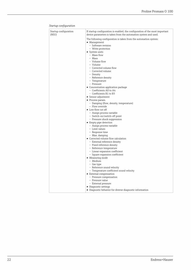
Startup configuration(NSU)
If startup configuration is enabled, the configuration of the most importantdevice parameters is taken from the automation system and used.
The following configuration is taken from the automation system:• Management
– Software revision– Write protection
• System units– Mass flow– Mass– Volume flow– Volume– Corrected volume flow– Corrected volume– Density– Reference density– Temperature– Pressure
• Concentration application package– Coefficients A0 to A4– Coefficients B1 to B3
• Sensor adjustment• Process param.
– Damping (flow, density, temperature)– Flow override
• Low flow cut off– Assign process variable– Switch-on/switch-off point– Pressure shock suppression
• Empty pipe detection– Assign process variable– Limit values– Response time– Max. damping
• Corrected volume flow calculation– External reference density– Fixed reference density– Reference temperature– Linear expansion coefficient– Square expansion coefficient
• Measuring mode– Medium– Gas type– Reference sound velocity– Temperature coefficient sound velocity
• External compensation– Pressure compensation– Pressure value– External pressure
• Diagnostic settings• Diagnostic behavior for diverse diagnostic information
Proline Promass O 100
Endress+Hauser 23
Power supply
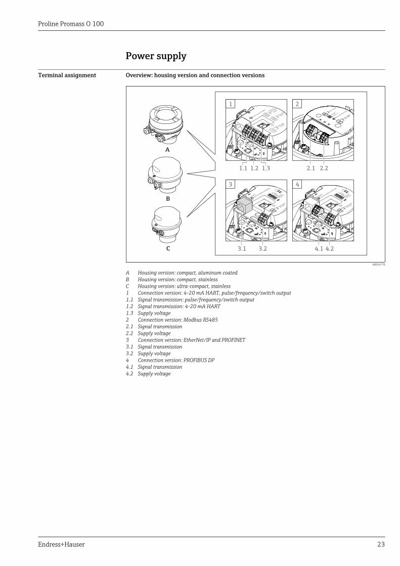
Terminal assignment Overview: housing version and connection versions
A
B
C
2
2.1 2.2
3
3.1 3.2
1
1.1 1.2 1.3
4
4.24.1
A0016770
A Housing version: compact, aluminum coatedB Housing version: compact, stainlessC Housing version: ultra-compact, stainless1 Connection version: 4-20 mA HART, pulse/frequency/switch output1.1 Signal transmission: pulse/frequency/switch output1.2 Signal transmission: 4-20 mA HART1.3 Supply voltage2 Connection version: Modbus RS4852.1 Signal transmission2.2 Supply voltage3 Connection version: EtherNet/IP and PROFINET3.1 Signal transmission3.2 Supply voltage4 Connection version: PROFIBUS DP4.1 Signal transmission4.2 Supply voltage
Proline Promass O 100
24 Endress+Hauser
Transmitter
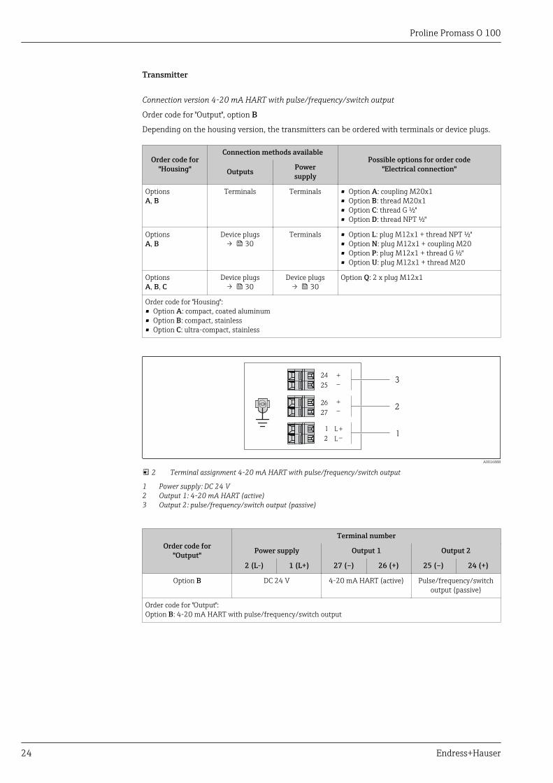
Connection version 4-20 mA HART with pulse/frequency/switch output
Order code for "Output", option B
Depending on the housing version, the transmitters can be ordered with terminals or device plugs.
Order code for"Housing"
Connection methods availablePossible options for order code
"Electrical connection"Outputs Powersupply
OptionsA, B
Terminals Terminals • Option A: coupling M20x1• Option B: thread M20x1• Option C: thread G ½"• Option D: thread NPT ½"
OptionsA, B
Device plugs→ 30
Terminals • Option L: plug M12x1 + thread NPT ½"• Option N: plug M12x1 + coupling M20• Option P: plug M12x1 + thread G ½"• Option U: plug M12x1 + thread M20
OptionsA, B, C
Device plugs→ 30
Device plugs→ 30
Option Q: 2 x plug M12x1
Order code for "Housing":• Option A: compact, coated aluminum• Option B: compact, stainless• Option C: ultra-compact, stainless
L
L
26
27
+_
24
25
1
2
+_
+_ 1
2
3
A0016888
2 Terminal assignment 4-20 mA HART with pulse/frequency/switch output
1 Power supply: DC 24 V2 Output 1: 4-20 mA HART (active)3 Output 2: pulse/frequency/switch output (passive)
Order code for"Output"
Terminal number
Power supply Output 1 Output 2
2 (L-) 1 (L+) 27 (–) 26 (+) 25 (–) 24 (+)
Option B DC 24 V 4-20 mA HART (active) Pulse/frequency/switchoutput (passive)
Order code for "Output":Option B: 4-20 mA HART with pulse/frequency/switch output
Proline Promass O 100
Endress+Hauser 25
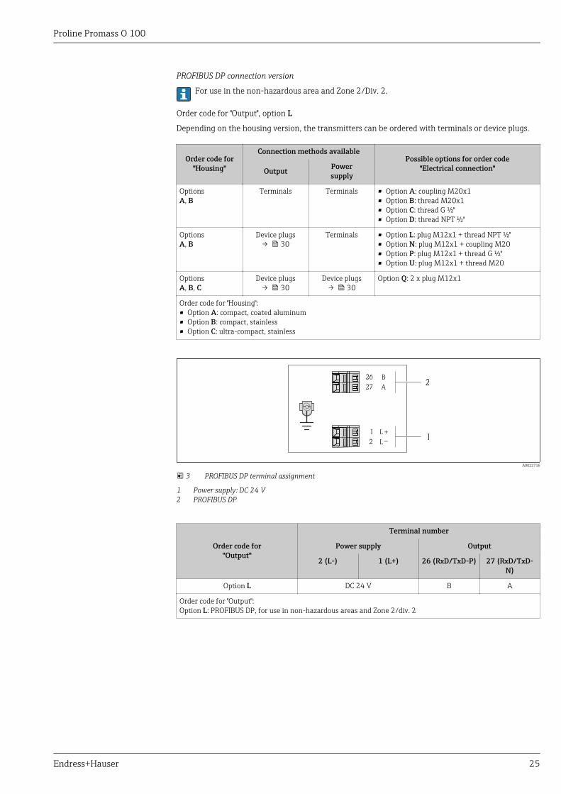
PROFIBUS DP connection version
For use in the non-hazardous area and Zone 2/Div. 2.
Order code for "Output", option L
Depending on the housing version, the transmitters can be ordered with terminals or device plugs.
Order code for"Housing"
Connection methods availablePossible options for order code
"Electrical connection"Output Powersupply
OptionsA, B
Terminals Terminals • Option A: coupling M20x1• Option B: thread M20x1• Option C: thread G ½"• Option D: thread NPT ½"
OptionsA, B
Device plugs→ 30
Terminals • Option L: plug M12x1 + thread NPT ½"• Option N: plug M12x1 + coupling M20• Option P: plug M12x1 + thread G ½"• Option U: plug M12x1 + thread M20
OptionsA, B, C
Device plugs→ 30
Device plugs→ 30
Option Q: 2 x plug M12x1
Order code for "Housing":• Option A: compact, coated aluminum• Option B: compact, stainless• Option C: ultra-compact, stainless
L
L
26
27
B
A
1
2
+_ 1
2
A0022716
3 PROFIBUS DP terminal assignment
1 Power supply: DC 24 V2 PROFIBUS DP
Order code for"Output"
Terminal number
Power supply Output
2 (L-) 1 (L+) 26 (RxD/TxD-P) 27 (RxD/TxD-N)
Option L DC 24 V B A
Order code for "Output":Option L: PROFIBUS DP, for use in non-hazardous areas and Zone 2/div. 2
Proline Promass O 100
26 Endress+Hauser
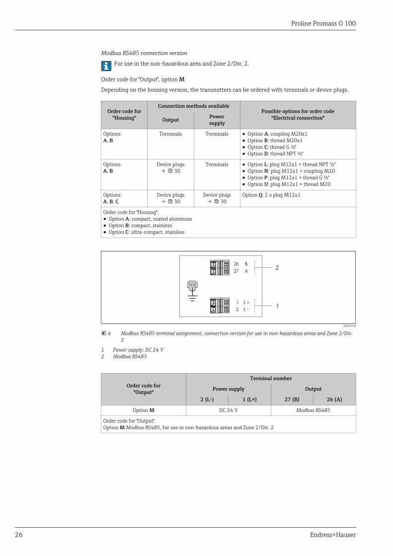
Modbus RS485 connection version
For use in the non-hazardous area and Zone 2/Div. 2.
Order code for "Output", option M
Depending on the housing version, the transmitters can be ordered with terminals or device plugs.
Order code for"Housing"
Connection methods availablePossible options for order code
"Electrical connection"Output Powersupply
OptionsA, B
Terminals Terminals • Option A: coupling M20x1• Option B: thread M20x1• Option C: thread G ½"• Option D: thread NPT ½"
OptionsA, B
Device plugs→ 30
Terminals • Option L: plug M12x1 + thread NPT ½"• Option N: plug M12x1 + coupling M20• Option P: plug M12x1 + thread G ½"• Option U: plug M12x1 + thread M20
OptionsA, B, C
Device plugs→ 30
Device plugs→ 30
Option Q: 2 x plug M12x1
Order code for "Housing":• Option A: compact, coated aluminum• Option B: compact, stainless• Option C: ultra-compact, stainless
L
L
26
27 A
B
1
2
+_ 1
2
A0019528
4 Modbus RS485 terminal assignment, connection version for use in non-hazardous areas and Zone 2/Div.2
1 Power supply: DC 24 V2 Modbus RS485
Order code for"Output"
Terminal number
Power supply Output
2 (L-) 1 (L+) 27 (B) 26 (A)
Option M DC 24 V Modbus RS485
Order code for "Output":Option M Modbus RS485, for use in non-hazardous areas and Zone 2/Div. 2
Proline Promass O 100
Endress+Hauser 27
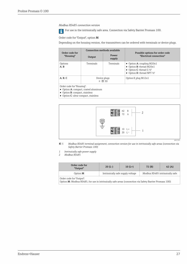
Modbus RS485 connection version
For use in the intrinsically safe area. Connection via Safety Barrier Promass 100.
Order code for "Output", option M
Depending on the housing version, the transmitters can be ordered with terminals or device plugs.
Order code for"Housing"
Connection methods availablePossible options for order code
"Electrical connection"Output Powersupply
OptionsA, B
Terminals Terminals • Option A: coupling M20x1• Option B: thread M20x1• Option C: thread G ½"• Option D: thread NPT ½"
A, B, C Device plugs→ 30
Option I: plug M12x1
Order code for "Housing":• Option A: compact, coated aluminum• Option B: compact, stainless• Option C: ultra-compact, stainless
L
L
62
72 A
B
10
20
+_ 1
2
A0017053
5 Modbus RS485 terminal assignment, connection version for use in intrinsically safe areas (connection viaSafety Barrier Promass 100)
1 Intrinsically safe power supply2 Modbus RS485
Order code for"Output" 20 (L-) 10 (L+) 72 (B) 62 (A)
Option M Intrinsically safe supply voltage Modbus RS485 intrinsically safe
Order code for "Output":Option M: Modbus RS485, for use in intrinsically safe areas (connection via Safety Barrier Promass 100)
Proline Promass O 100
28 Endress+Hauser
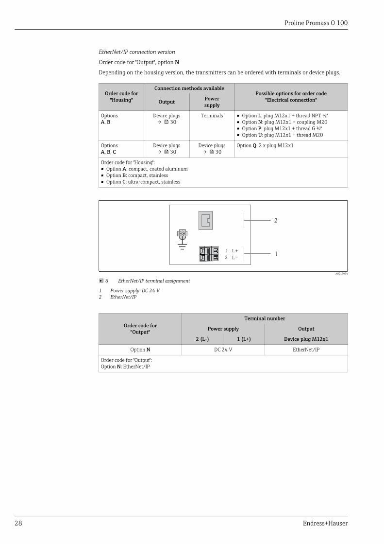
EtherNet/IP connection version
Order code for "Output", option N
Depending on the housing version, the transmitters can be ordered with terminals or device plugs.
Order code for"Housing"
Connection methods availablePossible options for order code
"Electrical connection"Output Powersupply
OptionsA, B
Device plugs→ 30
Terminals • Option L: plug M12x1 + thread NPT ½"• Option N: plug M12x1 + coupling M20• Option P: plug M12x1 + thread G ½"• Option U: plug M12x1 + thread M20
OptionsA, B, C
Device plugs→ 30
Device plugs→ 30
Option Q: 2 x plug M12x1
Order code for "Housing":• Option A: compact, coated aluminum• Option B: compact, stainless• Option C: ultra-compact, stainless
L
L
1
2
+_ 1
2
A0017054
6 EtherNet/IP terminal assignment
1 Power supply: DC 24 V2 EtherNet/IP
Order code for"Output"
Terminal number
Power supply Output
2 (L-) 1 (L+) Device plug M12x1
Option N DC 24 V EtherNet/IP
Order code for "Output":Option N: EtherNet/IP
Proline Promass O 100
Endress+Hauser 29
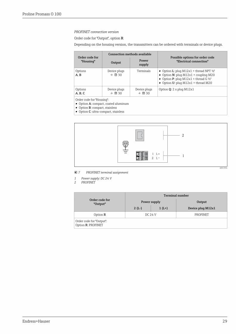
PROFINET connection version
Order code for "Output", option R
Depending on the housing version, the transmitters can be ordered with terminals or device plugs.
Order code for"Housing"
Connection methods availablePossible options for order code
"Electrical connection"Output Powersupply
OptionsA, B
Device plugs→ 30
Terminals • Option L: plug M12x1 + thread NPT ½"• Option N: plug M12x1 + coupling M20• Option P: plug M12x1 + thread G ½"• Option U: plug M12x1 + thread M20
OptionsA, B, C
Device plugs→ 30
Device plugs→ 30
Option Q: 2 x plug M12x1
Order code for "Housing":• Option A: compact, coated aluminum• Option B: compact, stainless• Option C: ultra-compact, stainless
L
L
1
2
+_ 1
2
A0017054
7 PROFINET terminal assignment
1 Power supply: DC 24 V2 PROFINET
Order code for"Output"
Terminal number
Power supply Output
2 (L-) 1 (L+) Device plug M12x1
Option R DC 24 V PROFINET
Order code for "Output":Option R: PROFINET
Proline Promass O 100
30 Endress+Hauser
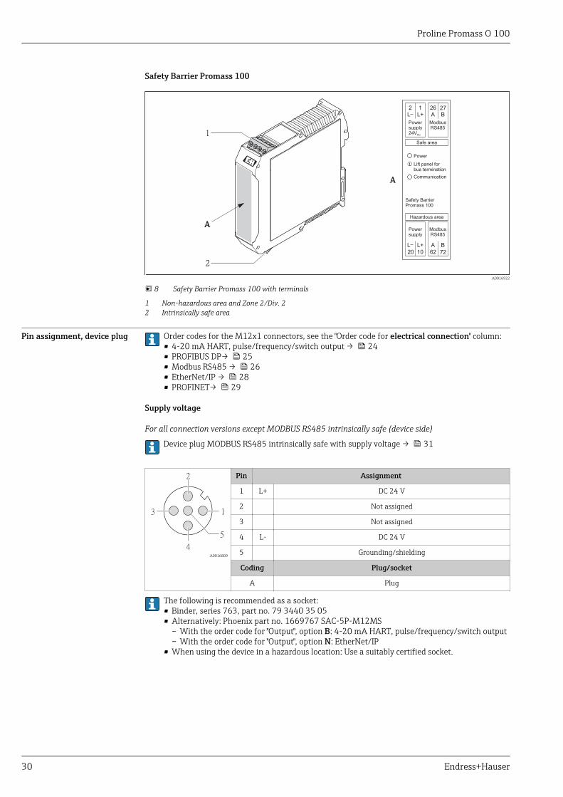
Safety Barrier Promass 100
A
Safe area
1L+
2L
2726A B
Powersupply24VDC
ModbusRS485
1020 7262
L+L A B
Powersupply
ModbusRS485
Hazardous area
Safety BarrierPromass 100
Power
Communication
Lift panel forbus termination
1
2
A
A0016922
8 Safety Barrier Promass 100 with terminals
1 Non-hazardous area and Zone 2/Div. 22 Intrinsically safe area
Pin assignment, device plug Order codes for the M12x1 connectors, see the "Order code for electrical connection" column:• 4-20 mA HART, pulse/frequency/switch output → 24• PROFIBUS DP→ 25• Modbus RS485 → 26• EtherNet/IP → 28• PROFINET→ 29
Supply voltage
For all connection versions except MODBUS RS485 intrinsically safe (device side)
Device plug MODBUS RS485 intrinsically safe with supply voltage → 31
1
2
4
3
5
A0016809
Pin Assignment
1 L+ DC 24 V
2 Not assigned
3 Not assigned
4 L- DC 24 V
5 Grounding/shielding
Coding Plug/socket
A Plug
The following is recommended as a socket:• Binder, series 763, part no. 79 3440 35 05• Alternatively: Phoenix part no. 1669767 SAC-5P-M12MS
– With the order code for "Output", option B: 4-20 mA HART, pulse/frequency/switch output– With the order code for "Output", option N: EtherNet/IP
• When using the device in a hazardous location: Use a suitably certified socket.
Proline Promass O 100
Endress+Hauser 31
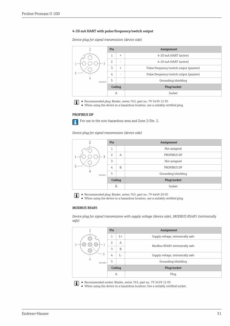
4-20 mA HART with pulse/frequency/switch output
Device plug for signal transmission (device side)
3
2
4
1
5
A0016810
Pin Assignment
1 + 4-20 mA HART (active)
2 - 4-20 mA HART (active)
3 + Pulse/frequency/switch output (passive)
4 - Pulse/frequency/switch output (passive)
5 Grounding/shielding
Coding Plug/socket
A Socket
• Recommended plug: Binder, series 763, part no. 79 3439 12 05• When using the device in a hazardous location, use a suitably certified plug.
PROFIBUS DP
For use in the non-hazardous area and Zone 2/Div. 2.
Device plug for signal transmission (device side)
3
2
4
1
5
A0016811
Pin Assignment
1 Not assigned
2 A PROFIBUS DP
3 Not assigned
4 B PROFIBUS DP
5 Grounding/shielding
Coding Plug/socket
B Socket
• Recommended plug: Binder, series 763, part no. 79 4449 20 05• When using the device in a hazardous location, use a suitably certified plug.
MODBUS RS485
Device plug for signal transmission with supply voltage (device side), MODBUS RS485 (intrinsicallysafe)
1
2
4
3
5
A0016809
Pin Assignment
1 L+ Supply voltage, intrinsically safe
2 AModbus RS485 intrinsically safe
3 B
4 L- Supply voltage, intrinsically safe
5 Grounding/shielding
Coding Plug/socket
A Plug
• Recommended socket: Binder, series 763, part no. 79 3439 12 05• When using the device in a hazardous location: Use a suitably certified socket.
Proline Promass O 100
32 Endress+Hauser
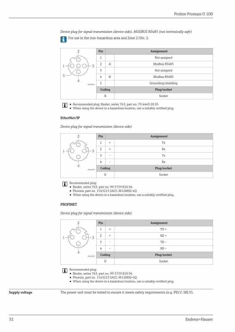
Device plug for signal transmission (device side), MODBUS RS485 (not intrinsically safe)
For use in the non-hazardous area and Zone 2/Div. 2.
3
2
4
1
5
A0016811
Pin Assignment
1 Not assigned
2 A Modbus RS485
3 Not assigned
4 B Modbus RS485
5 Grounding/shielding
Coding Plug/socket
B Socket
• Recommended plug: Binder, series 763, part no. 79 4449 20 05• When using the device in a hazardous location, use a suitably certified plug.
EtherNet/IP
Device plug for signal transmission (device side)
3
2
4
1
A0016812
Pin Assignment
1 + Tx
2 + Rx
3 - Tx
4 - Rx
Coding Plug/socket
D Socket
Recommended plug:• Binder, series 763, part no. 99 3729 810 04• Phoenix, part no. 1543223 SACC-M12MSD-4Q• When using the device in a hazardous location, use a suitably certified plug.
PROFINET
Device plug for signal transmission (device side)
3
2
4
1
A0016812
Pin Assignment
1 + TD +
2 + RD +
3 - TD –
4 - RD –
Coding Plug/socket
D Socket
Recommended plug:• Binder, series 763, part no. 99 3729 810 04• Phoenix, part no. 1543223 SACC-M12MSD-4Q• When using the device in a hazardous location, use a suitably certified plug.
Supply voltage The power unit must be tested to ensure it meets safety requirements (e.g. PELV, SELV).
Proline Promass O 100
Endress+Hauser 33
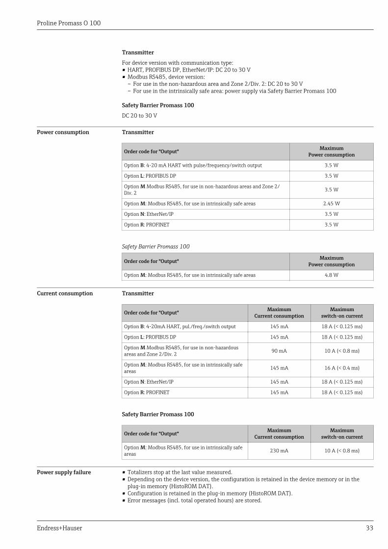
Transmitter
For device version with communication type:• HART, PROFIBUS DP, EtherNet/IP: DC 20 to 30 V• Modbus RS485, device version:
– For use in the non-hazardous area and Zone 2/Div. 2: DC 20 to 30 V– For use in the intrinsically safe area: power supply via Safety Barrier Promass 100
Safety Barrier Promass 100
DC 20 to 30 V
Power consumption Transmitter
Order code for "Output" MaximumPower consumption
Option B: 4-20 mA HART with pulse/frequency/switch output 3.5 W
Option L: PROFIBUS DP 3.5 W
Option M Modbus RS485, for use in non-hazardous areas and Zone 2/Div. 2 3.5 W
Option M: Modbus RS485, for use in intrinsically safe areas 2.45 W
Option N: EtherNet/IP 3.5 W
Option R: PROFINET 3.5 W
Safety Barrier Promass 100
Order code for "Output" MaximumPower consumption
Option M: Modbus RS485, for use in intrinsically safe areas 4.8 W
Current consumption Transmitter
Order code for "Output" MaximumCurrent consumption
Maximumswitch-on current
Option B: 4-20mA HART, pul./freq./switch output 145 mA 18 A (< 0.125 ms)
Option L: PROFIBUS DP 145 mA 18 A (< 0.125 ms)
Option M Modbus RS485, for use in non-hazardousareas and Zone 2/Div. 2 90 mA 10 A (< 0.8 ms)
Option M: Modbus RS485, for use in intrinsically safeareas 145 mA 16 A (< 0.4 ms)
Option N: EtherNet/IP 145 mA 18 A (< 0.125 ms)
Option R: PROFINET 145 mA 18 A (< 0.125 ms)
Safety Barrier Promass 100
Order code for "Output" MaximumCurrent consumption
Maximumswitch-on current
Option M: Modbus RS485, for use in intrinsically safeareas 230 mA 10 A (< 0.8 ms)
Power supply failure • Totalizers stop at the last value measured.• Depending on the device version, the configuration is retained in the device memory or in the
plug-in memory (HistoROM DAT).• Configuration is retained in the plug-in memory (HistoROM DAT).• Error messages (incl. total operated hours) are stored.
Proline Promass O 100
34 Endress+Hauser
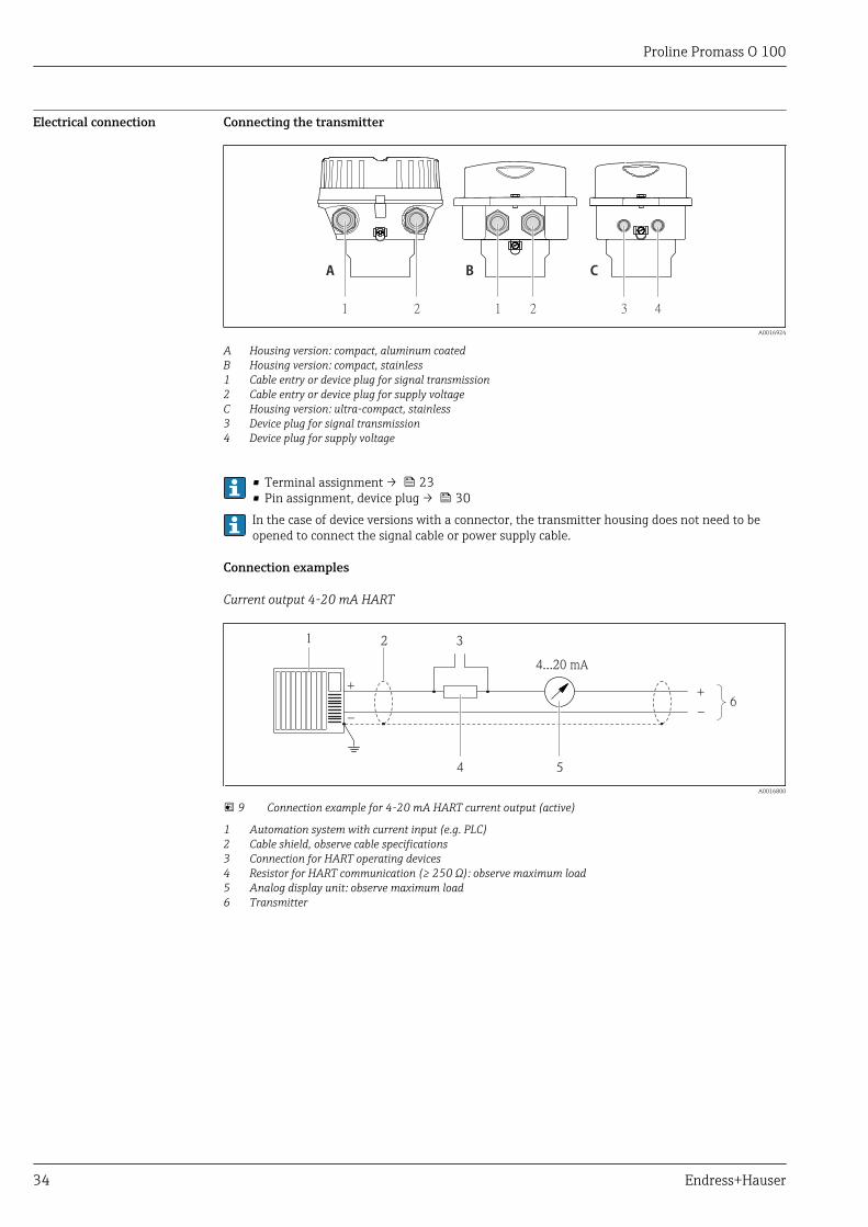
Electrical connection Connecting the transmitter
1 2 1 2 3 4
A B C
A0016924
A Housing version: compact, aluminum coatedB Housing version: compact, stainless1 Cable entry or device plug for signal transmission2 Cable entry or device plug for supply voltageC Housing version: ultra-compact, stainless3 Device plug for signal transmission4 Device plug for supply voltage
• Terminal assignment → 23• Pin assignment, device plug → 30In the case of device versions with a connector, the transmitter housing does not need to beopened to connect the signal cable or power supply cable.
Connection examples
Current output 4-20 mA HART
4
4...20 mA
+
–
5
21 3
6
+
_
A0016800
9 Connection example for 4-20 mA HART current output (active)
1 Automation system with current input (e.g. PLC)2 Cable shield, observe cable specifications3 Connection for HART operating devices4 Resistor for HART communication (≥ 250 Ω): observe maximum load5 Analog display unit: observe maximum load6 Transmitter
Proline Promass O 100
Endress+Hauser 35
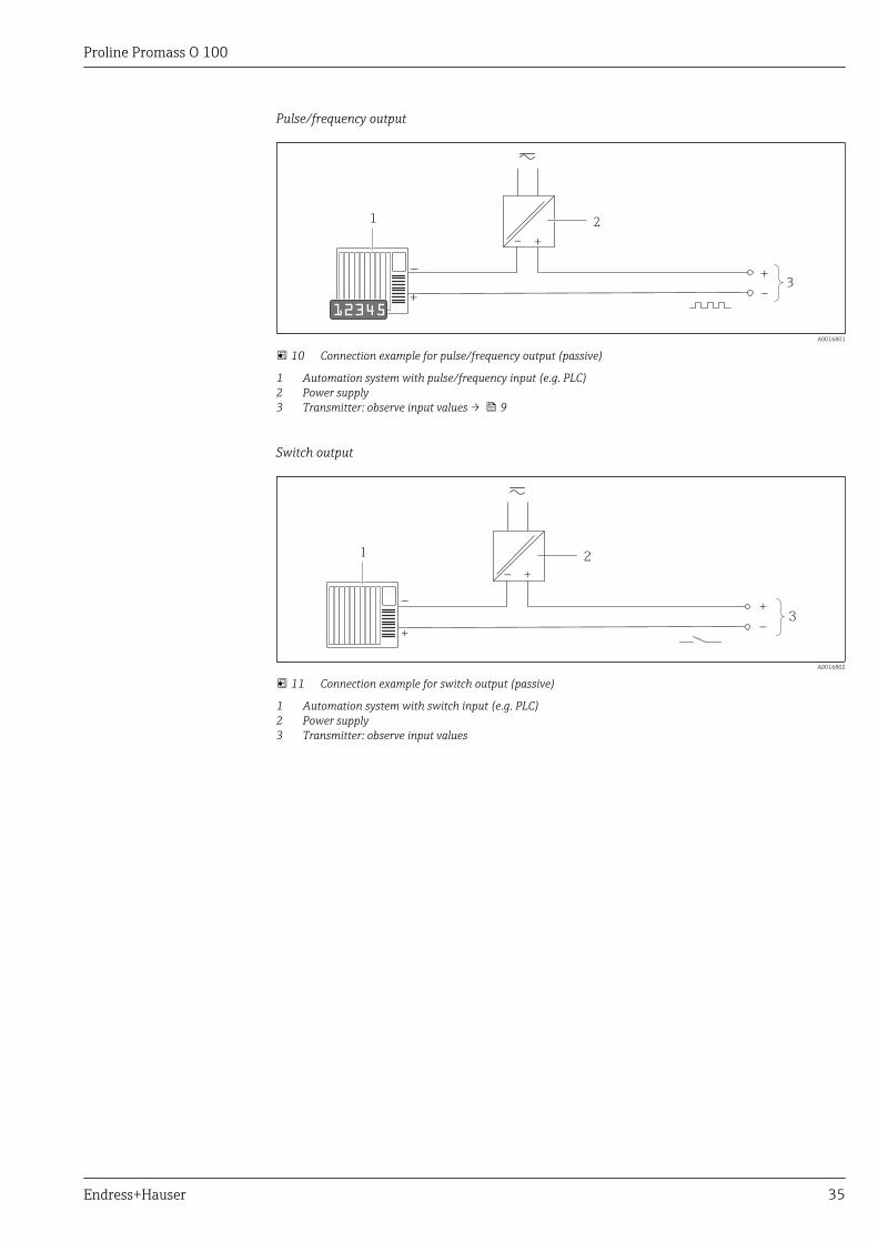
Pulse/frequency output
1
+
_
12345
2
+
–
+–
3
A0016801
10 Connection example for pulse/frequency output (passive)
1 Automation system with pulse/frequency input (e.g. PLC)2 Power supply3 Transmitter: observe input values → 9
Switch output
1
+_
+
_
2
+
_ 3
A0016802
11 Connection example for switch output (passive)
1 Automation system with switch input (e.g. PLC)2 Power supply3 Transmitter: observe input values
Proline Promass O 100
36 Endress+Hauser
PROFIBUS DP
21
A
B
A
B
A
B
3
3
A0021429
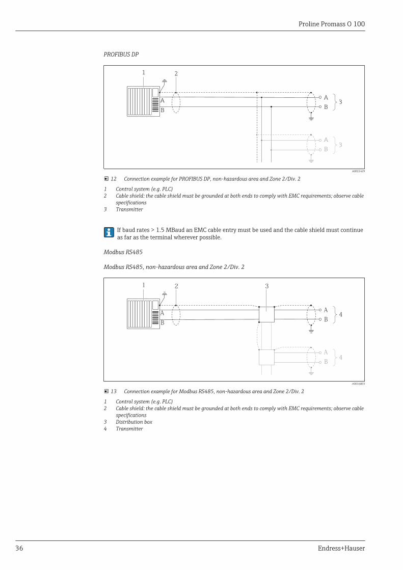
12 Connection example for PROFIBUS DP, non-hazardous area and Zone 2/Div. 2
1 Control system (e.g. PLC)2 Cable shield: the cable shield must be grounded at both ends to comply with EMC requirements; observe cable
specifications3 Transmitter
If baud rates > 1.5 MBaud an EMC cable entry must be used and the cable shield must continueas far as the terminal wherever possible.
Modbus RS485
Modbus RS485, non-hazardous area and Zone 2/Div. 2
21
A
B
A
B
A
B
3
4
4
A0016803
13 Connection example for Modbus RS485, non-hazardous area and Zone 2/Div. 2
1 Control system (e.g. PLC)2 Cable shield: the cable shield must be grounded at both ends to comply with EMC requirements; observe cable
specifications3 Distribution box4 Transmitter
Proline Promass O 100
Endress+Hauser 37
Modbus RS485 intrinsically safe
21
A
BA
B
3
L+
L-
A
BL+
L-L- L+
A
B
5 6 7
8
4
A0016804
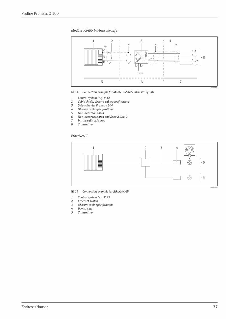
14 Connection example for Modbus RS485 intrinsically safe
1 Control system (e.g. PLC)2 Cable shield, observe cable specifications3 Safety Barrier Promass 1004 Observe cable specifications5 Non-hazardous area6 Non-hazardous area and Zone 2/Div. 27 Intrinsically safe area8 Transmitter
EtherNet/IP
1 2 4
5
5
3
A0016805
15 Connection example for EtherNet/IP
1 Control system (e.g. PLC)2 Ethernet switch3 Observe cable specifications4 Device plug5 Transmitter
Proline Promass O 100
38 Endress+Hauser
PROFINET
1 2 4
5
5
3
A0016805
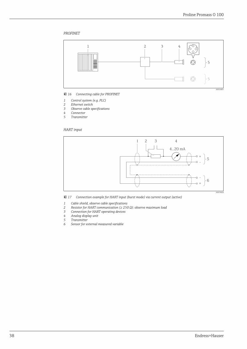
16 Connecting cable for PROFINET
1 Control system (e.g. PLC)2 Ethernet switch3 Observe cable specifications4 Connector5 Transmitter
HART input
2
4...20 mA
3 41
+
-5
+
-
6
A0019828
17 Connection example for HART input (burst mode) via current output (active)
1 Cable shield, observe cable specifications2 Resistor for HART communication (≥ 250 Ω): observe maximum load3 Connection for HART operating devices4 Analog display unit5 Transmitter6 Sensor for external measured variable
Proline Promass O 100
Endress+Hauser 39
3
4...20 mA
4 521
+
-6
4...20 mA
+
-7
3 4 52
+
--+
A0019830
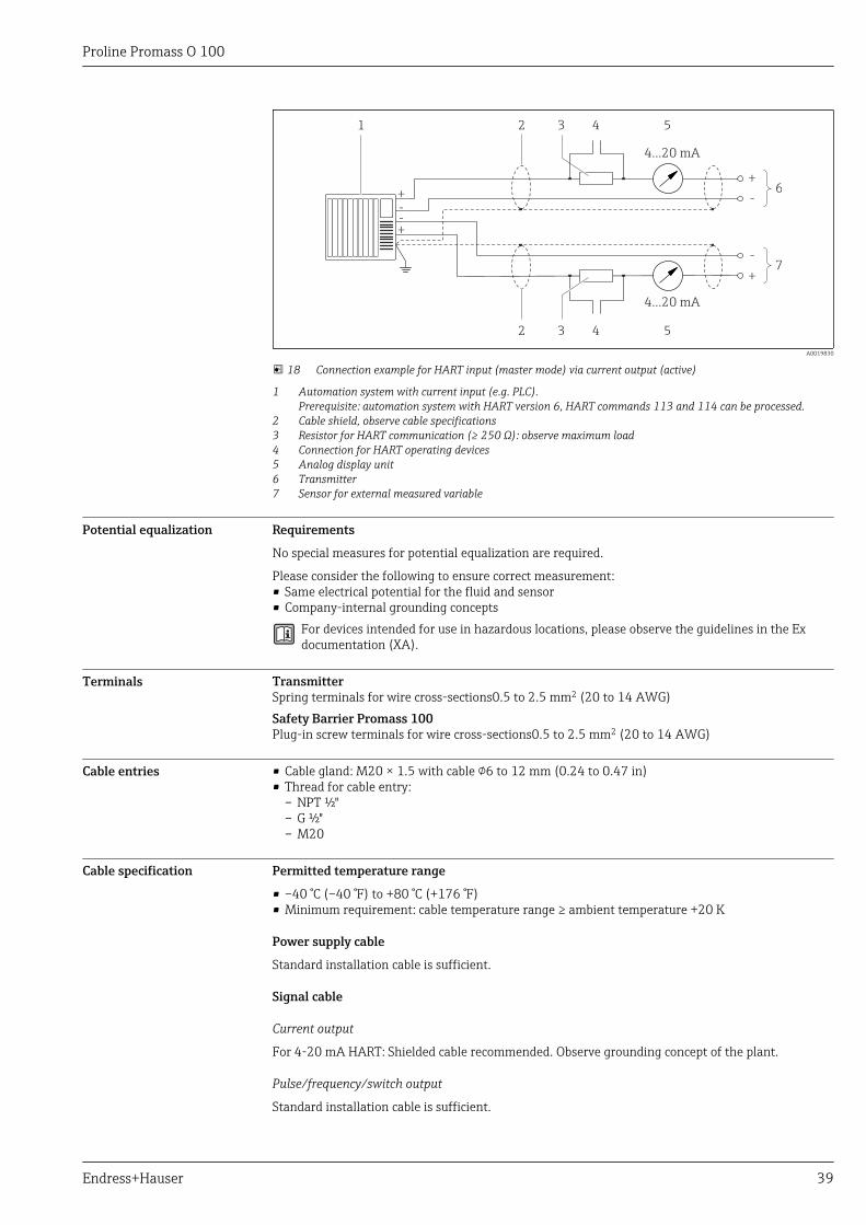
18 Connection example for HART input (master mode) via current output (active)
1 Automation system with current input (e.g. PLC).Prerequisite: automation system with HART version 6, HART commands 113 and 114 can be processed.
2 Cable shield, observe cable specifications3 Resistor for HART communication (≥ 250 Ω): observe maximum load4 Connection for HART operating devices5 Analog display unit6 Transmitter7 Sensor for external measured variable
Potential equalization Requirements
No special measures for potential equalization are required.
Please consider the following to ensure correct measurement:• Same electrical potential for the fluid and sensor• Company-internal grounding concepts
For devices intended for use in hazardous locations, please observe the guidelines in the Exdocumentation (XA).
Terminals TransmitterSpring terminals for wire cross-sections0.5 to 2.5 mm2 (20 to 14 AWG)Safety Barrier Promass 100Plug-in screw terminals for wire cross-sections0.5 to 2.5 mm2 (20 to 14 AWG)
Cable entries • Cable gland: M20 × 1.5 with cable 6 to 12 mm (0.24 to 0.47 in)• Thread for cable entry:
– NPT ½"– G ½"– M20
Cable specification Permitted temperature range
• –40 °C (–40 °F) to +80 °C (+176 °F)• Minimum requirement: cable temperature range ≥ ambient temperature +20 K
Power supply cable
Standard installation cable is sufficient.
Signal cable
Current output
For 4-20 mA HART: Shielded cable recommended. Observe grounding concept of the plant.
Pulse/frequency/switch output
Standard installation cable is sufficient.
Proline Promass O 100
40 Endress+Hauser
PROFIBUS DP
The IEC 61158 standard specifies two types of cable (A and B) for the bus line which can be used forevery transmission rate. Cable type A is recommended.
Cable type A
Characteristic impedance 135 to 165 Ω at a measuring frequency of 3 to 20 MHz
Cable capacitance <30 pF/m
Wire cross-section >0.34 mm2 (22 AWG)
Cable type Twisted pairs
Loop resistance ≤110 Ω/km
Signal damping Max. 9 dB over the entire length of the cable cross-section
Shield Copper braided shielding or braided shielding with foil shield. When groundingthe cable shield, observe the grounding concept of the plant.
Modbus RS485
The EIA/TIA-485 standard specifies two types of cable (A and B) for the bus line which can be usedfor every transmission rate. Cable type A is recommended.
Cable type A
Characteristic impedance 135 to 165 Ω at a measuring frequency of 3 to 20 MHz
Cable capacitance <30 pF/m
Wire cross-section >0.34 mm2 (22 AWG)
Cable type Twisted pairs
Loop resistance ≤110 Ω/km
Signal damping Max. 9 dB over the entire length of the cable cross-section
Shield Copper braided shielding or braided shielding with foil shield. When groundingthe cable shield, observe the grounding concept of the plant.
EtherNet/IP
The standard ANSI/TIA/EIA-568-B.2 Annex specifies CAT 5 as the minimum category for a cableused for EtherNet/IP. CAT 5e and CAT 6 are recommended.
For more information on planning and installing EtherNet/IP networks, please refer to the"Media Planning and Installation Manual. EtherNet/IP" of ODVA Organization
PROFINET
Standard IEC 61156-6 specifies CAT 5 as the minimum category for a cable used for PROFINET. CAT5e and CAT 6 are recommended.
For more information on planning and installing PROFINET networks, see: "PROFINET Cablingand Interconnection Technology", Guideline for PROFINET
Connecting cable between Safety Barrier Promass 100 and measuring device
Cable type Shielded twisted-pair cable with 2x2 wires. When grounding the cable shield,observe the grounding concept of the plant.
Maximum cable resistance 2.5 Ω, one side
Comply with the maximum cable resistance specifications to ensure the operational reliabilityof the measuring device.
Proline Promass O 100
Endress+Hauser 41
The maximum cable length for individual wire cross-sections is specified in the table below. Observethe maximum capacitance and inductance per unit length of the cable and connection values forhazardous areas .
Wire cross-section Maximum cable length
[mm2] [AWG] [m] [ft]
0.5 20 70 230
0.75 18 100 328
1.0 17 100 328
1.5 16 200 656
2.5 14 300 984
Performance characteristics
Reference operatingconditions
• Error limits based on ISO 11631• Water with +15 to +45 °C (+59 to +113 °F) at 2 to 6 bar (29 to 87 psi)• Specifications as per calibration protocol• Accuracy based on accredited calibration rigs that are traced to ISO 17025.
To obtain measured errors, use the Applicator sizing tool → 75
Maximum measured error o.r. = of reading; 1 g/cm³ = 1 kg/l; T = medium temperature
Base accuracy
Design fundamentals → 44
Mass flow and volume flow (liquids)
±0.05 % o.r. (PremiumCal, for mass flow)±0.10 %
Mass flow (gases)
±0.35 % o.r.
Density (liquids)
Underreference operating conditions
Standard densitycalibration 1)
Wide-rangedensity specification 2) 3)
[g/cm³] [lbs/in³] [g/cm³] [lbs/in³] [g/cm³] [lbs/in³]
±0.0005 ±0.00097 ±0.01 ±0.019 ±0.001 ±0.0019
1) Valid over the entire temperature and density range2) Valid range for special density calibration: 0 to 2 g/cm³, +5 to +80 °C (+41 to +176 °F)3) Order code for "Application package", option EF "Special density and concentration "
Temperature
±0.5 °C ± 0.005 · T °C (±0.9 °F ± 0.003 · (T – 32) °F)
Proline Promass O 100
42 Endress+Hauser
Zero point stability
DN Zero point stability
[mm] [in] [kg/h] [lb/min]
80 3 9.0 0.330
100 4 14.0 0.514
150 6 32.0 1.17
Flow values
Flow values as turndown parameter depending on nominal diameter.
SI units
DN 1:1 1:10 1:20 1:50 1:100 1:500
[mm] [kg/h] [kg/h] [kg/h] [kg/h] [kg/h] [kg/h]
80 180 000 18 000 9 000 3 600 1 800 360
100 350 000 35 000 17 500 7 000 3 500 700
150 800 000 80 000 40 000 16 000 8 000 1 600
US units
DN 1:1 1:10 1:20 1:50 1:100 1:500
[inch] [lb/min] [lb/min] [lb/min] [lb/min] [lb/min] [lb/min]
3 6 615 661.5 330.8 132.3 66.15 13.23
4 12 860 1 286 643.0 257.2 128.6 25.72
6 29 400 2 940 1 470 588 294 58.80
Accuracy of outputs
In the case of analog outputs, the output accuracy must also be considered for the measurederror; in contrast, this need not be considered in the case of fieldbus outputs (e.g. ModbusRS485, EtherNet/IP).
The outputs have the following base accuracy specifications.
Current output
Accuracy Max. ±5 µA
Pulse/frequency output
o.r. = of reading
Accuracy Max. ±50 ppm o.r. (across the entire ambient temperature range)
Repeatability o.r. = of reading; 1 g/cm3 = 1 kg/l; T = medium temperature
Base repeatability
Mass flow and volume flow (liquids)±0.025 % o.r. (PremiumCal, for mass flow)±0.05 % o.r.
Proline Promass O 100
Endress+Hauser 43
Mass flow (gases)±0.25 % o.r.
Design fundamentals → 44
Density (liquids)±0.00025 g/cm3
Temperature±0.25 °C ± 0.0025 · T °C (±0.45 °F ± 0.0015 · (T–32) °F)
Response time The response time depends on the configuration (damping).
Influence of ambienttemperature
Current output
o.r. = of reading
Temperature coefficient Max. ±0.005% o.r./°C
Pulse/frequency output
Temperature coefficient No additional effect. Included in accuracy.
Influence of mediumtemperature
Mass flow and volume flowWhen there is a difference between the temperature for zero point adjustment and the processtemperature, the typical measured error of the sensor is ±0.0002 % of the full scale value/°C(±0.0001 % of the full scale value/°F).
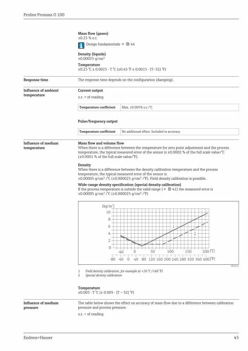
DensityWhen there is a difference between the density calibration temperature and the processtemperature, the typical measured error of the sensor is±0.00005 g/cm3 /°C (±0.000025 g/cm3 /°F). Field density calibration is possible.Wide-range density specification (special density calibration)If the process temperature is outside the valid range (→ 41) the measured error is±0.00005 g/cm3 /°C (±0.000025 g/cm3 /°F)
[kg/m ]3
[°C]
-40 0-80 40 80 120 160 200 240 280 320 360 400[°F]
-40 0 50 100 150 2000
2
4
6
8
10
2
1
A0016612
1 Field density calibration, for example at +20 °C (+68 °F)2 Special density calibration
Temperature±0.005 · T °C (± 0.005 · (T – 32) °F)
Influence of mediumpressure
The table below shows the effect on accuracy of mass flow due to a difference between calibrationpressure and process pressure.
o.r. = of reading
Proline Promass O 100
44 Endress+Hauser
DN [% o.r./bar] [% o.r./psi]
[mm] [in]
80 3 –0.0055 –0.0004
100 4 –0.0035 –0.0002
150 6 –0.002 –0.0001
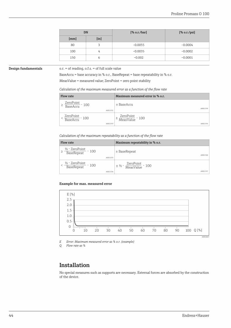
Design fundamentals o.r. = of reading, o.f.s. = of full scale value
BaseAccu = base accuracy in % o.r., BaseRepeat = base repeatability in % o.r.
MeasValue = measured value; ZeroPoint = zero point stability
Calculation of the maximum measured error as a function of the flow rate
Flow rate Maximum measured error in % o.r.
ZeroPoint
BaseAccu⋅ 100³
A0021332
± BaseAccu
A0021339
ZeroPoint
BaseAccu⋅ 100<
A0021333
ZeroPoint
MeasValue⋅ 100±
A0021334
Calculation of the maximum repeatability as a function of the flow rate
Flow rate Maximum repeatability in % o.r.
½ ⋅ ZeroPointBaseRepeat ⋅ 100³
A0021335 A0021340
½ ⋅ ZeroPointBaseRepeat ⋅ 100<
A0021336
ZeroPoint
MeasValue⋅ 100½ ⋅±
A0021337
Example for max. measured error
E [%]
0 10 20 30 40 50 600
0.5
1.0
1.5
2.0
2.5
70 80 90 100 Q [%]
A0024063
E Error: Maximum measured error as % o.r. (example)Q Flow rate as %
InstallationNo special measures such as supports are necessary. External forces are absorbed by the constructionof the device.
Proline Promass O 100
Endress+Hauser 45
Mounting location
A0023344
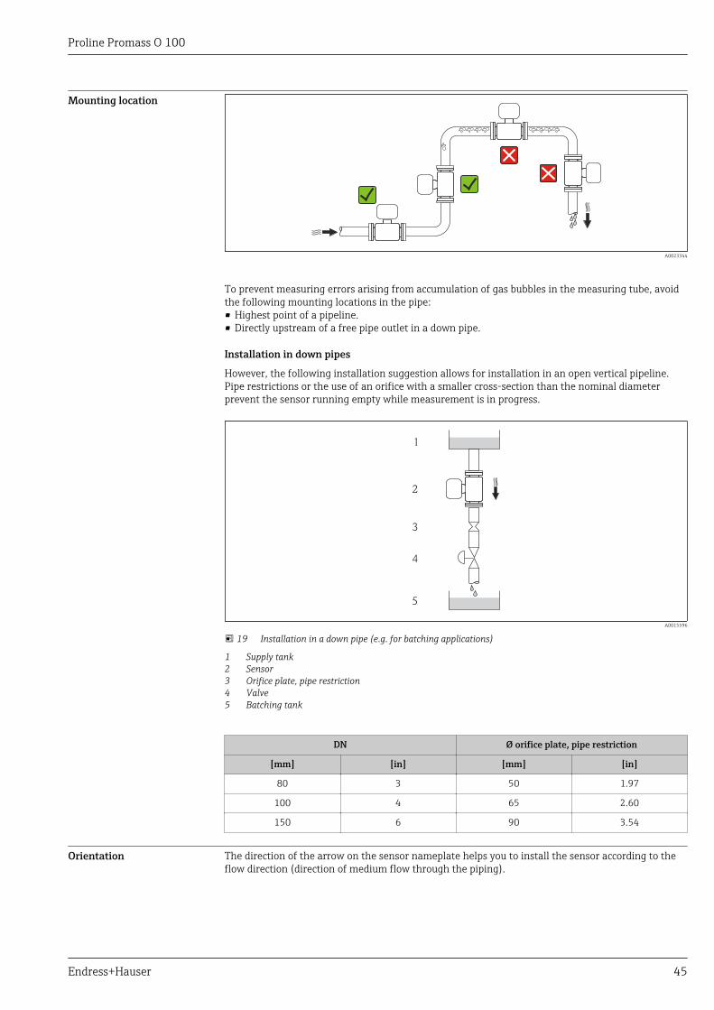
To prevent measuring errors arising from accumulation of gas bubbles in the measuring tube, avoidthe following mounting locations in the pipe:• Highest point of a pipeline.• Directly upstream of a free pipe outlet in a down pipe.
Installation in down pipes
However, the following installation suggestion allows for installation in an open vertical pipeline.Pipe restrictions or the use of an orifice with a smaller cross-section than the nominal diameterprevent the sensor running empty while measurement is in progress.
1
2
3
4
5
A0015596
19 Installation in a down pipe (e.g. for batching applications)
1 Supply tank2 Sensor3 Orifice plate, pipe restriction4 Valve5 Batching tank
DN Ø orifice plate, pipe restriction
[mm] [in] [mm] [in]
80 3 50 1.97
100 4 65 2.60
150 6 90 3.54
Orientation The direction of the arrow on the sensor nameplate helps you to install the sensor according to theflow direction (direction of medium flow through the piping).
Proline Promass O 100
46 Endress+Hauser
Orientation Recommendation
A Vertical orientation
A0015591
B Horizontal orientation, transmitterhead up
A0015589
1)
Exceptions:→ 20, 46
C Horizontal orientation, transmitterhead down
A0015590
2)
Exceptions:→ 20, 46
D Horizontal orientation, transmitterhead at side
A0015592
1) Applications with low process temperatures may decrease the ambient temperature. To maintain theminimum ambient temperature for the transmitter, this orientation is recommended.
2) Applications with high process temperatures may increase the ambient temperature. To maintain themaximum ambient temperature for the transmitter, this orientation is recommended.
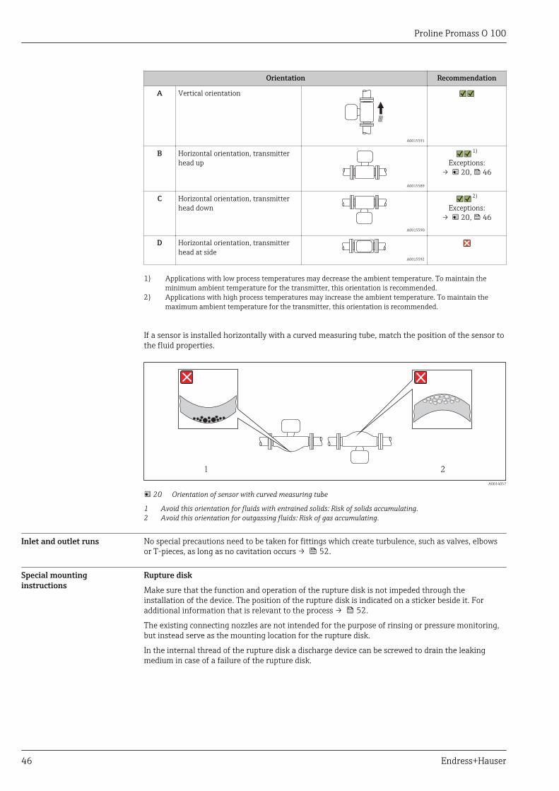
If a sensor is installed horizontally with a curved measuring tube, match the position of the sensor tothe fluid properties.
1 2
A0014057
20 Orientation of sensor with curved measuring tube
1 Avoid this orientation for fluids with entrained solids: Risk of solids accumulating.2 Avoid this orientation for outgassing fluids: Risk of gas accumulating.
Inlet and outlet runs No special precautions need to be taken for fittings which create turbulence, such as valves, elbowsor T-pieces, as long as no cavitation occurs → 52.
Special mountinginstructions
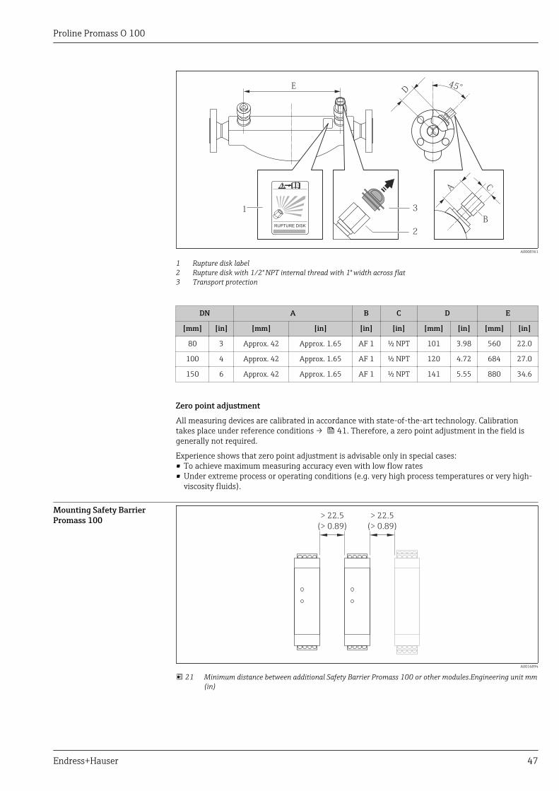
Rupture disk
Make sure that the function and operation of the rupture disk is not impeded through theinstallation of the device. The position of the rupture disk is indicated on a sticker beside it. Foradditional information that is relevant to the process → 52.
The existing connecting nozzles are not intended for the purpose of rinsing or pressure monitoring,but instead serve as the mounting location for the rupture disk.
In the internal thread of the rupture disk a discharge device can be screwed to drain the leakingmedium in case of a failure of the rupture disk.
Proline Promass O 100
Endress+Hauser 47
ED
45°
RUPTURE DISK
i
2
31
B
CA
A0008361
1 Rupture disk label2 Rupture disk with 1/2" NPT internal thread with 1" width across flat3 Transport protection
DN A B C D E
[mm] [in] [mm] [in] [in] [in] [mm] [in] [mm] [in]
80 3 Approx. 42 Approx. 1.65 AF 1 ½ NPT 101 3.98 560 22.0
100 4 Approx. 42 Approx. 1.65 AF 1 ½ NPT 120 4.72 684 27.0
150 6 Approx. 42 Approx. 1.65 AF 1 ½ NPT 141 5.55 880 34.6
Zero point adjustment
All measuring devices are calibrated in accordance with state-of-the-art technology. Calibrationtakes place under reference conditions → 41. Therefore, a zero point adjustment in the field isgenerally not required.
Experience shows that zero point adjustment is advisable only in special cases:• To achieve maximum measuring accuracy even with low flow rates• Under extreme process or operating conditions (e.g. very high process temperatures or very high-
viscosity fluids).
Mounting Safety BarrierPromass 100 > 22.5
(> 0.89)
> 22.5
(> 0.89)
A0016894
21 Minimum distance between additional Safety Barrier Promass 100 or other modules.Engineering unit mm(in)
Proline Promass O 100
48 Endress+Hauser
Environment
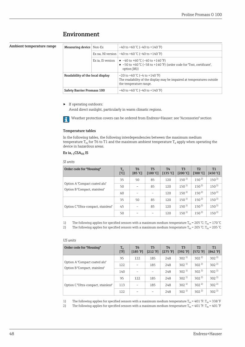
Ambient temperature range Measuring device Non-Ex –40 to +60 °C (–40 to +140 °F)
Ex na, NI version –40 to +60 °C (–40 to +140 °F)
Ex ia, IS version • –40 to +60 °C (–40 to +140 °F)• –50 to +60 °C (–58 to +140 °F) (order code for "Test, certificate",
option JM))
Readability of the local display –20 to +60 °C (–4 to +140 °F)The readability of the display may be impaired at temperatures outsidethe temperature range.
Safety Barrier Promass 100 –40 to +60 °C (–40 to +140 °F)
‣ If operating outdoors:Avoid direct sunlight, particularly in warm climatic regions.
Weather protection covers can be ordered from Endress+Hauser: see "Accessories" section
Temperature tables
In the following tables, the following interdependencies between the maximum mediumtemperature Tm for T6 to T1 and the maximum ambient temperature Ta apply when operating thedevice in hazardous areas.
Ex ia, CCSAUS IS
SI units
Order code for "Housing" Ta[°C]
T6[85 °C]
T5[100 °C]
T4[135 °C]
T3[200 °C]
T2[300 °C]
T1[450 °C]
Option A "Compact coated alu"
Option B "Compact, stainless"
35 50 85 120 150 1) 150 2) 150 2)
50 – 85 120 150 1) 150 2) 150 2)
60 – – 120 150 1) 150 2) 150 2)
Option C "Ultra-compact, stainless"
35 50 85 120 150 1) 150 2) 150 2)
45 – 85 120 150 1) 150 2) 150 2)
50 – – 120 150 1) 150 2) 150 2)
1) The following applies for specified sensors with a maximum medium temperature Tm = 205 °C: Tm = 170 °C2) The following applies for specified sensors with a maximum medium temperature Tm = 205 °C: Tm = 205 °C
US units
Order code for "Housing" Ta[°F]
T6[185 °F]
T5[212 °F]
T4[275 °F]
T3[392 °F]
T2[572 °F]
T1[842 °F]
Option A "Compact coated alu"
Option B "Compact, stainless"
95 122 185 248 302 1) 302 2) 302 2)
122 – 185 248 302 1) 302 2) 302 2)
140 – – 248 302 1) 302 2) 302 2)
Option C "Ultra-compact, stainless"
95 122 185 248 302 1) 302 2) 302 2)
113 – 185 248 302 1) 302 2) 302 2)
122 – – 248 302 1) 302 2) 302 2)
1) The following applies for specified sensors with a maximum medium temperature Tm = 401 °F: Tm = 338 °F2) The following applies for specified sensors with a maximum medium temperature Tm = 401 °F: Tm = 401 °F
Proline Promass O 100
Endress+Hauser 49
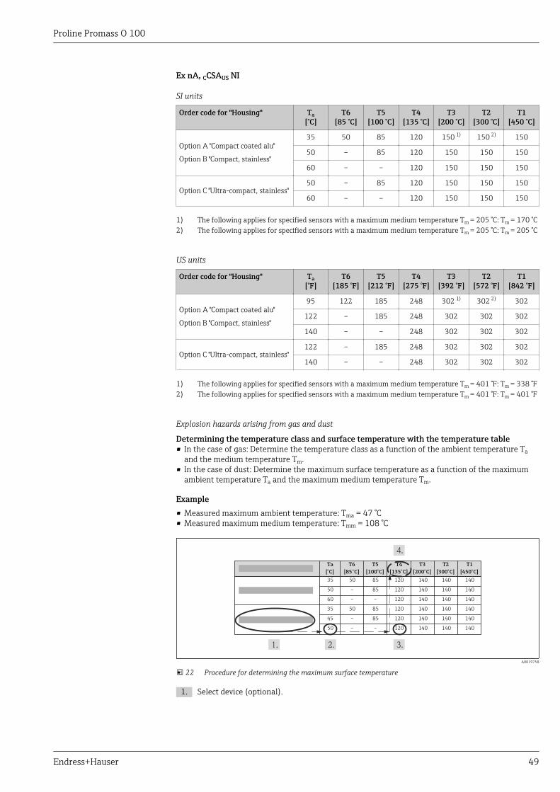
Ex nA, CCSAUS NI
SI units
Order code for "Housing" Ta[°C]
T6[85 °C]
T5[100 °C]
T4[135 °C]
T3[200 °C]
T2[300 °C]
T1[450 °C]
Option A "Compact coated alu"
Option B "Compact, stainless"
35 50 85 120 150 1) 150 2) 150
50 – 85 120 150 150 150
60 – – 120 150 150 150
Option C "Ultra-compact, stainless"50 – 85 120 150 150 150
60 – – 120 150 150 150
1) The following applies for specified sensors with a maximum medium temperature Tm = 205 °C: Tm = 170 °C2) The following applies for specified sensors with a maximum medium temperature Tm = 205 °C: Tm = 205 °C
US units
Order code for "Housing" Ta[°F]
T6[185 °F]
T5[212 °F]
T4[275 °F]
T3[392 °F]
T2[572 °F]
T1[842 °F]
Option A "Compact coated alu"
Option B "Compact, stainless"
95 122 185 248 302 1) 302 2) 302
122 – 185 248 302 302 302
140 – – 248 302 302 302
Option C "Ultra-compact, stainless"122 – 185 248 302 302 302
140 – – 248 302 302 302
1) The following applies for specified sensors with a maximum medium temperature Tm = 401 °F: Tm = 338 °F2) The following applies for specified sensors with a maximum medium temperature Tm = 401 °F: Tm = 401 °F
Explosion hazards arising from gas and dust
Determining the temperature class and surface temperature with the temperature table• In the case of gas: Determine the temperature class as a function of the ambient temperature Ta
and the medium temperature Tm.• In the case of dust: Determine the maximum surface temperature as a function of the maximum
ambient temperature Ta and the maximum medium temperature Tm.
Example• Measured maximum ambient temperature: Tma = 47 °C• Measured maximum medium temperature: Tmm = 108 °C
Ta
[°C]
T1
[450°C]
35 140
50 140
60 140
35 140
45 140
50 140
50 85 120 140 140
– 85 120 140 140
– – 120 140 140
50 85 120 140 140
– 85 120 140 140
– – 120 140 140
T6
[85°C]
T5
[100°C]
T4
[135°C]
T3
[200°C]
T2
[300°C]
A0019758
22 Procedure for determining the maximum surface temperature
1. Select device (optional).
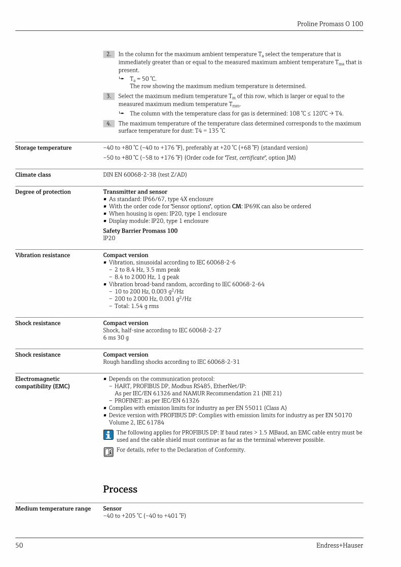
Proline Promass O 100
50 Endress+Hauser
2. In the column for the maximum ambient temperature Ta select the temperature that isimmediately greater than or equal to the measured maximum ambient temperature Tma that ispresent. Ta = 50 °C.
The row showing the maximum medium temperature is determined.3. Select the maximum medium temperature Tm of this row, which is larger or equal to the
measured maximum medium temperature Tmm. The column with the temperature class for gas is determined: 108 °C ≤ 120°C → T4.
4. The maximum temperature of the temperature class determined corresponds to the maximumsurface temperature for dust: T4 = 135 °C
Storage temperature –40 to +80 °C (–40 to +176 °F), preferably at +20 °C (+68 °F) (standard version)–50 to +80 °C (–58 to +176 °F) (Order code for "Test, certificate", option JM)
Climate class DIN EN 60068-2-38 (test Z/AD)
Degree of protection Transmitter and sensor• As standard: IP66/67, type 4X enclosure• With the order code for "Sensor options", option CM: IP69K can also be ordered• When housing is open: IP20, type 1 enclosure• Display module: IP20, type 1 enclosureSafety Barrier Promass 100IP20
Vibration resistance Compact version• Vibration, sinusoidal according to IEC 60068-2-6
– 2 to 8.4 Hz, 3.5 mm peak– 8.4 to 2 000 Hz, 1 g peak
• Vibration broad-band random, according to IEC 60068-2-64– 10 to 200 Hz, 0.003 g2/Hz– 200 to 2 000 Hz, 0.001 g2/Hz– Total: 1.54 g rms
Shock resistance Compact versionShock, half-sine according to IEC 60068-2-276 ms 30 g
Shock resistance Compact versionRough handling shocks according to IEC 60068-2-31
Electromagneticcompatibility (EMC)
• Depends on the communication protocol:– HART, PROFIBUS DP, Modbus RS485, EtherNet/IP:
As per IEC/EN 61326 and NAMUR Recommendation 21 (NE 21)– PROFINET: as per IEC/EN 61326
• Complies with emission limits for industry as per EN 55011 (Class A)• Device version with PROFIBUS DP: Complies with emission limits for industry as per EN 50170
Volume 2, IEC 61784The following applies for PROFIBUS DP: If baud rates > 1.5 MBaud, an EMC cable entry must beused and the cable shield must continue as far as the terminal wherever possible.For details, refer to the Declaration of Conformity.
Process
Medium temperature range Sensor–40 to +205 °C (–40 to +401 °F)
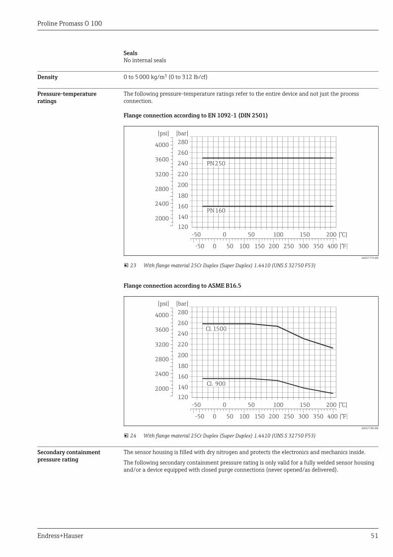
Proline Promass O 100
Endress+Hauser 51
SealsNo internal seals
Density 0 to 5 000 kg/m3 (0 to 312 lb/cf)
Pressure-temperatureratings
The following pressure-temperature ratings refer to the entire device and not just the processconnection.
Flange connection according to EN 1092-1 (DIN 2501)
300 [°F]350250200150100500-50
[°C]200150100500-50
400
120
140
160
180
200
220
260
240
280
[bar][psi]
2000
2400
2800
3200
3600
4000
PN160
PN250
A0027779-EN
23 With flange material 25Cr Duplex (Super Duplex) 1.4410 (UNS S 32750 F53)
Flange connection according to ASME B16.5
300 [°F]350250200150100500-50
[°C]200150100500-50
400
120
140
160
180
200
220
260
240
280
[bar][psi]
2000
2400
2800
3200
3600
4000
Cl. 900
Cl.1500
A0027780-EN
24 With flange material 25Cr Duplex (Super Duplex) 1.4410 (UNS S 32750 F53)
Secondary containmentpressure rating
The sensor housing is filled with dry nitrogen and protects the electronics and mechanics inside.
The following secondary containment pressure rating is only valid for a fully welded sensor housingand/or a device equipped with closed purge connections (never opened/as delivered).
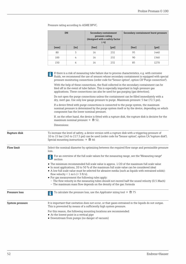
Proline Promass O 100
52 Endress+Hauser
Pressure rating according to ASME BPVC.
DN Secondary containmentpressure rating
(designed with a safety factor≥ 4)
Secondary containment burst pressure
[mm] [in] [bar] [psi] [bar] [psi]
80 3 16 232 95 1440
100 4 16 232 90 1360
150 6 16 232 85 1270
If there is a risk of measuring tube failure due to process characteristics, e.g. with corrosivefluids, we recommend the use of sensors whose secondary containment is equipped with specialpressure monitoring connections (order code for "Sensor option", option CH "Purge connection").
With the help of these connections, the fluid collected in the secondary containment can bebled off in the event of tube failure. This is especially important in high-pressure gasapplications. These connections can also be used for gas purging (gas detection).
Do not open the purge connections unless the containment can be filled immediately with adry, inert gas. Use only low gauge pressure to purge. Maximum pressure: 5 bar (72.5 psi).
If a device fitted with purge connections is connected to the purge system, the maximumnominal pressure is determined by the purge system itself or by the device, depending on whichcomponent has the lower nominal pressure.
If, on the other hand, the device is fitted with a rupture disk, the rupture disk is decisive for themaximum nominal pressure → 52.
Dimensions:
Rupture disk To increase the level of safety, a device version with a rupture disk with a triggering pressure of10 to 15 bar (145 to 217.5 psi) can be used (order code for "Sensor option", option CA "rupture disk").Special mounting instructions: → 46
Flow limit Select the nominal diameter by optimizing between the required flow range and permissible pressureloss.
For an overview of the full scale values for the measuring range, see the "Measuring range"section
• The minimum recommended full scale value is approx. 1/20 of the maximum full scale value• In most applications, 20 to 50 % of the maximum full scale value can be considered ideal• A low full scale value must be selected for abrasive media (such as liquids with entrained solids):
flow velocity < 1 m/s (< 3 ft/s).• For gas measurement the following rules apply:
– The flow velocity in the measuring tubes should not exceed half the sound velocity (0.5 Mach)– The maximum mass flow depends on the density of the gas: formula
Pressure loss To calculate the pressure loss, use the Applicator sizing tool → 75
System pressure It is important that cavitation does not occur, or that gases entrained in the liquids do not outgas.This is prevented by means of a sufficiently high system pressure.
For this reason, the following mounting locations are recommended:• At the lowest point in a vertical pipe• Downstream from pumps (no danger of vacuum)
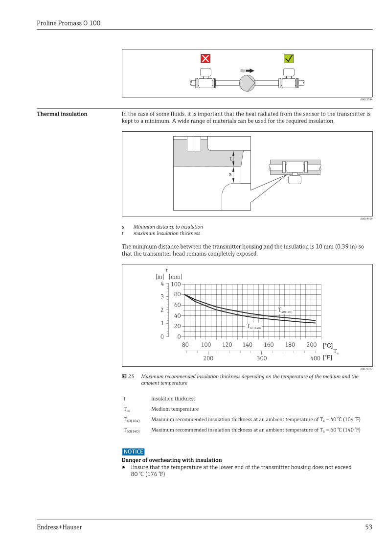
Proline Promass O 100
Endress+Hauser 53
A0015594
Thermal insulation In the case of some fluids, it is important that the heat radiated from the sensor to the transmitter iskept to a minimum. A wide range of materials can be used for the required insulation.
t
a
A0019919
a Minimum distance to insulationt maximum Insulation thickness
The minimum distance between the transmitter housing and the insulation is 10 mm (0.39 in) sothat the transmitter head remains completely exposed.
0
20
60
40
80
[in]
1
2
3
0
t
1004
[mm]
T40 (104)
T60 (140)
80 100 120 140
200 300 400
160 180 200
[°F]Tm
[°C]
A0023177
25 Maximum recommended insulation thickness depending on the temperature of the medium and theambient temperature
t Insulation thickness
Tm Medium temperature
T40(104) Maximum recommended insulation thickness at an ambient temperature of Ta = 40 °C (104 °F)
T60(140) Maximum recommended insulation thickness at an ambient temperature of Ta = 60 °C (140 °F)
NOTICEDanger of overheating with insulation‣ Ensure that the temperature at the lower end of the transmitter housing does not exceed
80 °C (176 °F)
Proline Promass O 100
54 Endress+Hauser
NOTICEThe insulation can also be thicker than the maximum recommended insulation thickness.Prerequisite:‣ Ensure that convection takes place on a sufficiently large scale at the transmitter neck.‣ Ensure that a sufficiently large area of the housing support remains exposed. The uncovered part
serves as a radiator and protects the electronics from overheating and excessive cooling.
Heating Some fluids require suitable measures to avoid loss of heat at the sensor.
Heating options• Electrical heating, e.g. with electric band heaters• Via pipes carrying hot water or steam• Via heating jackets
NOTICEDanger of overheating when heating‣ Ensure that the temperature at the lower end of the transmitter housing does not exceed
80 °C (176 °F).‣ Ensure that convection takes place on a sufficiently large scale at the transmitter neck.‣ Ensure that a sufficiently large area of the housing support remains exposed. The uncovered part
serves as a radiator and protects the electronics from overheating and excessive cooling.
Vibrations The high oscillation frequency of the measuring tubes ensures that the correct operation of themeasuring system is not influenced by plant vibrations.
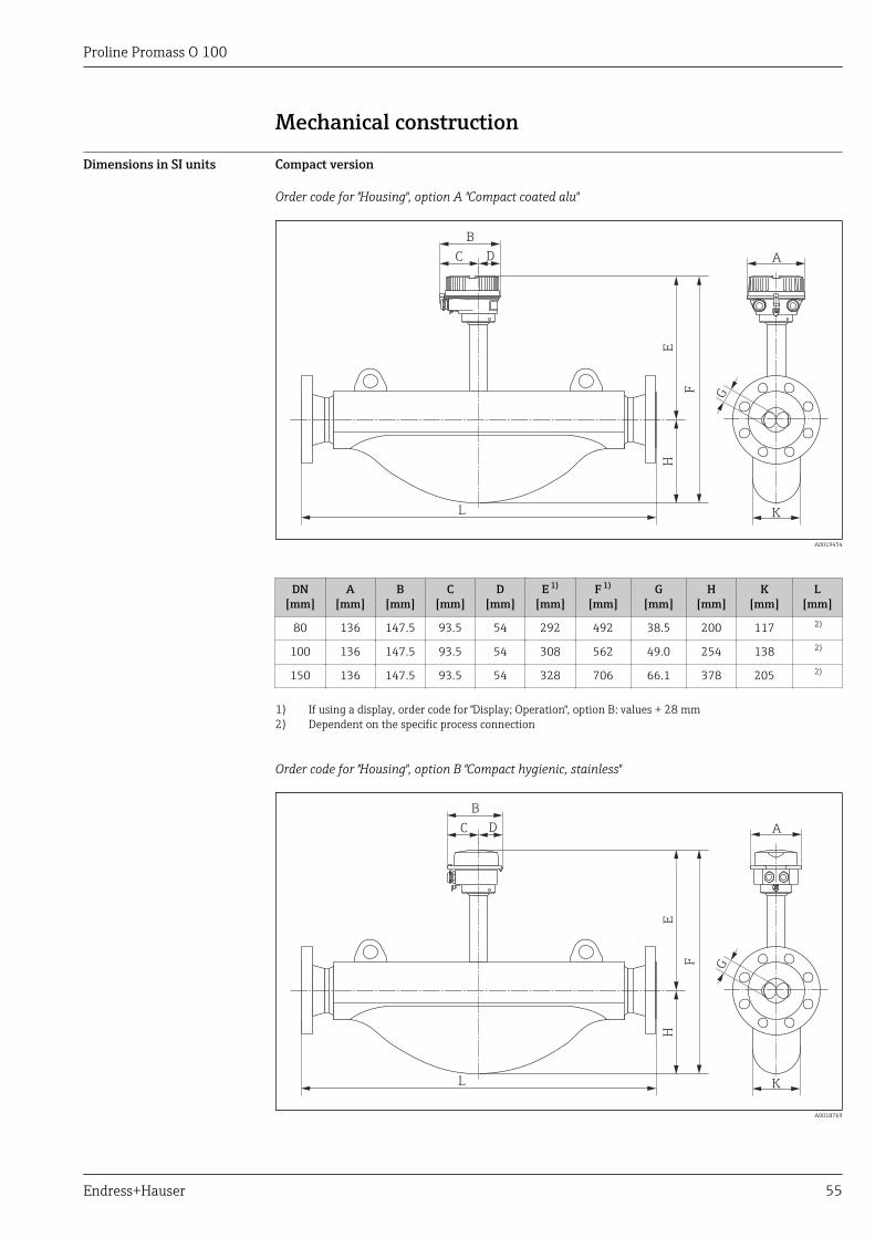
Proline Promass O 100
Endress+Hauser 55
Mechanical construction
Dimensions in SI units Compact version
Order code for "Housing", option A "Compact coated alu"
K
ADC
B
EH
F
L
G
A0019454
DN[mm]
A[mm]
B[mm]
C[mm]
D[mm]
E 1)
[mm]F 1)
[mm]G
[mm]H
[mm]K
[mm]L
[mm]
80 136 147.5 93.5 54 292 492 38.5 200 117 2)
100 136 147.5 93.5 54 308 562 49.0 254 138 2)
150 136 147.5 93.5 54 328 706 66.1 378 205 2)
1) If using a display, order code for "Display; Operation", option B: values + 28 mm2) Dependent on the specific process connection
Order code for "Housing", option B "Compact hygienic, stainless"
ADC
B
EH
F
L K
G
A0018769
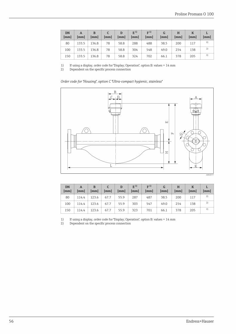
Proline Promass O 100
56 Endress+Hauser
DN[mm]
A[mm]
B[mm]
C[mm]
D[mm]
E 1)
[mm]F 1)
[mm]G
[mm]H
[mm]K
[mm]L
[mm]
80 133.5 136.8 78 58.8 288 488 38.5 200 117 2)
100 133.5 136.8 78 58.8 304 548 49.0 254 138 2)
150 133.5 136.8 78 58.8 324 702 66.1 378 205 2)
1) If using a display, order code for "Display; Operation", option B: values + 14 mm2) Dependent on the specific process connection
Order code for "Housing", option C "Ultra-compact hygienic, stainless"
ADC
B
EH
F
L K
G
A0018777
DN[mm]
A[mm]
B[mm]
C[mm]
D[mm]
E 1)
[mm]F 1)
[mm]G
[mm]H
[mm]K
[mm]L
[mm]
80 114.4 123.6 67.7 55.9 287 487 38.5 200 117 2)
100 114.4 123.6 67.7 55.9 303 547 49.0 254 138 2)
150 114.4 123.6 67.7 55.9 323 701 66.1 378 205 2)
1) If using a display, order code for "Display; Operation", option B: values + 14 mm2) Dependent on the specific process connection

Proline Promass O 100
Endress+Hauser 57
Flange connections
Fixed flange EN 1092-1, ASME B16.5
L+1,5 (+0.06)*
-2,0 (-0.08)*
C
D
A B E
* DN 150: ±3.5 (6": ±0.14)
A0023178
26 Engineering unit mm (in)
Flange according to EN 1092-1 Form B2 (DIN 2501): PN16025Cr Duplex (Super Duplex), 1.4410 (F53)Order code for "Process connection", option DAD
Flange with groove according to EN 1092-1 Form D (DIN 2512N): PN16025Cr Duplex (Super Duplex), 1.4410 (F53)Order code for "Process connection", option DCD
DN[mm]
A[mm]
B[mm]
C[mm]
D[mm]
E[mm]
L[mm]
80 230 180 8 × Ø26 36 80.9 916
100 265 210 8 × Ø30 40 104.3 1 208
150 355 290 12 × Ø33 50 155.7 1 476
Flange according to EN 1092-1 Form B2 (DIN 2501): PN25025Cr Duplex (Super Duplex), 1.4410 (F53)Order code for "Process connection", option DBD
Flange with groove according to EN 1092-1 Form D (DIN 2512N): PN25025Cr Duplex (Super Duplex), 1.4410 (F53)Order code for "Process connection", option DDD
DN[mm]
A[mm]
B[mm]
C[mm]
D[mm]
E[mm]
L[mm]
80 255 200 8 × Ø30 46 77.7 948
100 300 235 8 × Ø33 54 100.3 1 248
150 390 320 12 × Ø36 68 148.3 1 540
Flange according to ASME B16.5: Class 900 Sched 4025Cr Duplex (Super Duplex), 1.4410 (F53)Order code for "Process connection", option ADD
DN[mm]
A[mm]
B[mm]
C[mm]
D[mm]
E[mm]
L[mm]
80 240 190.5 8 × Ø25.4 45.1 78.0 962
100 290 235 8 × Ø31.8 51.4 102.4 1 251
150 380 317.5 12 × Ø31.8 62.6 154.1 1 513
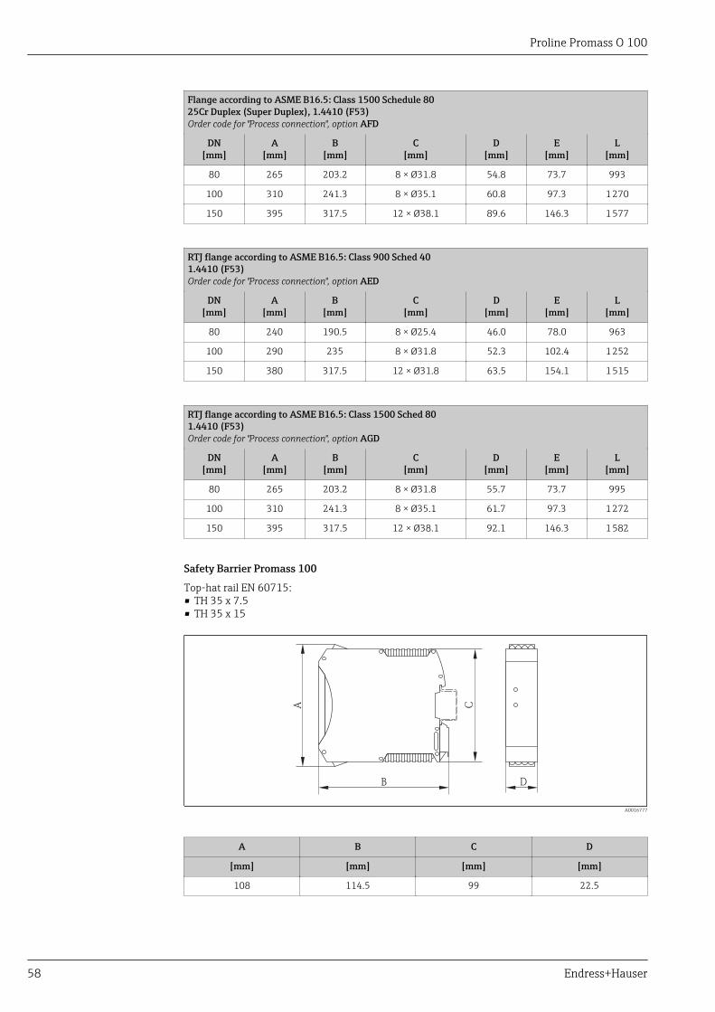
Proline Promass O 100
58 Endress+Hauser
Flange according to ASME B16.5: Class 1500 Schedule 8025Cr Duplex (Super Duplex), 1.4410 (F53)Order code for "Process connection", option AFD
DN[mm]
A[mm]
B[mm]
C[mm]
D[mm]
E[mm]
L[mm]
80 265 203.2 8 × Ø31.8 54.8 73.7 993
100 310 241.3 8 × Ø35.1 60.8 97.3 1 270
150 395 317.5 12 × Ø38.1 89.6 146.3 1 577
RTJ flange according to ASME B16.5: Class 900 Sched 401.4410 (F53)Order code for "Process connection", option AED
DN[mm]
A[mm]
B[mm]
C[mm]
D[mm]
E[mm]
L[mm]
80 240 190.5 8 × Ø25.4 46.0 78.0 963
100 290 235 8 × Ø31.8 52.3 102.4 1 252
150 380 317.5 12 × Ø31.8 63.5 154.1 1 515
RTJ flange according to ASME B16.5: Class 1500 Sched 801.4410 (F53)Order code for "Process connection", option AGD
DN[mm]
A[mm]
B[mm]
C[mm]
D[mm]
E[mm]
L[mm]
80 265 203.2 8 × Ø31.8 55.7 73.7 995
100 310 241.3 8 × Ø35.1 61.7 97.3 1 272
150 395 317.5 12 × Ø38.1 92.1 146.3 1 582
Safety Barrier Promass 100
Top-hat rail EN 60715:• TH 35 x 7.5• TH 35 x 15
B D
A C
A0016777
A B C D
[mm] [mm] [mm] [mm]
108 114.5 99 22.5
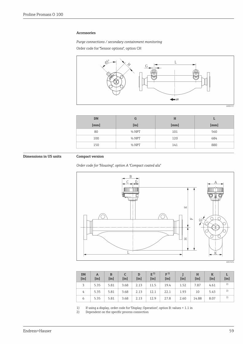
Proline Promass O 100
Endress+Hauser 59
Accessories
Purge connections / secondary containment monitoring
Order code for "Sensor options", option CH
LH45°
G
A0002537
DN G H L
[mm] [in] [mm] [mm]
80 ½ NPT 101 560
100 ½ NPT 120 684
150 ½ NPT 141 880
Dimensions in US units Compact version
Order code for "Housing", option A "Compact coated alu"
K
ADC
B
EH
F
L
G
A0019454
DN[in]
A[in]
B[in]
C[in]
D[in]
E 1)
[in]F 1)
[in]J
[in]H
[in]K
[in]L
[in]
3 5.35 5.81 3.68 2.13 11.5 19.4 1.52 7.87 4.61 2)
4 5.35 5.81 3.68 2.13 12.1 22.1 1.93 10 5.43 2)
6 5.35 5.81 3.68 2.13 12.9 27.8 2.60 14.88 8.07 2)
1) If using a display, order code for "Display; Operation", option B: values + 1.1 in2) Dependent on the specific process connection
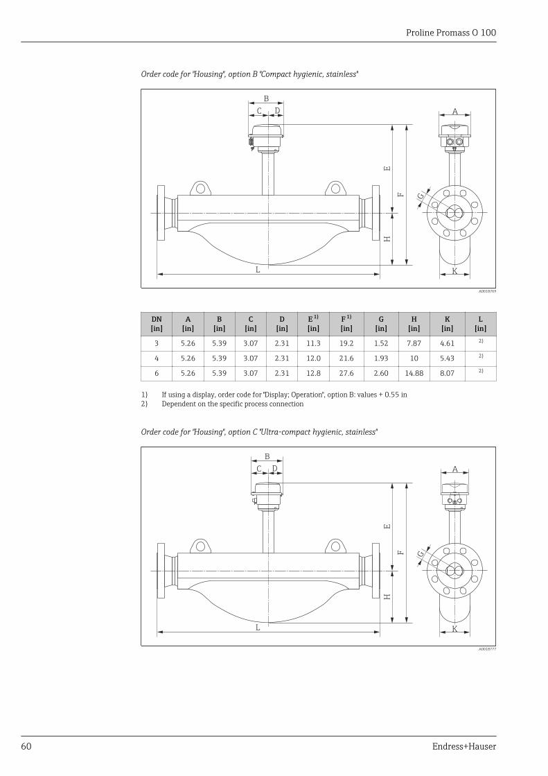
Proline Promass O 100
60 Endress+Hauser
Order code for "Housing", option B "Compact hygienic, stainless"
ADC
B
EH
F
L K
G
A0018769
DN[in]
A[in]
B[in]
C[in]
D[in]
E 1)
[in]F 1)
[in]G
[in]H
[in]K
[in]L
[in]
3 5.26 5.39 3.07 2.31 11.3 19.2 1.52 7.87 4.61 2)
4 5.26 5.39 3.07 2.31 12.0 21.6 1.93 10 5.43 2)
6 5.26 5.39 3.07 2.31 12.8 27.6 2.60 14.88 8.07 2)
1) If using a display, order code for "Display; Operation", option B: values + 0.55 in2) Dependent on the specific process connection
Order code for "Housing", option C "Ultra-compact hygienic, stainless"
ADC
B
EH
F
L K
G
A0018777

Proline Promass O 100
Endress+Hauser 61
DN[in]
A[in]
B[in]
C[in]
D[in]
E 1)
[in]F 1)
[in]G
[in]H
[in]K
[in]L
[in]
3 4.39 4.87 2.67 2.2 11.3 19.2 1.52 7.87 4.61 2)
4 4.39 4.87 2.67 2.2 11.9 21.5 1.93 10 5.43 2)
6 4.39 4.87 2.67 2.2 12.7 27.6 2.60 14.88 8.07 2)
1) If using a display, order code for "Display; Operation", option B: values + 0.55 in2) Dependent on the specific process connection
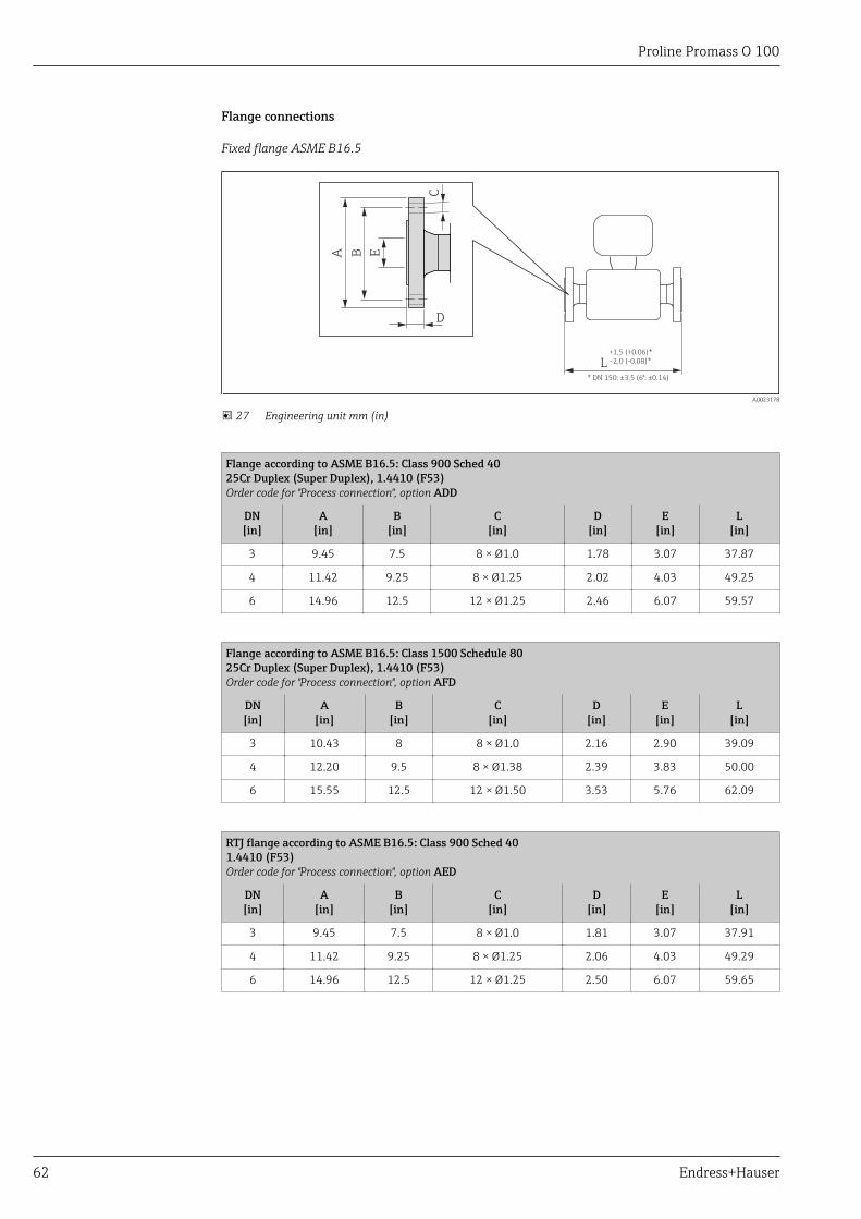
Proline Promass O 100
62 Endress+Hauser
Flange connections
Fixed flange ASME B16.5
L+1,5 (+0.06)*
-2,0 (-0.08)*
C
D
A B E* DN 150: ±3.5 (6": ±0.14)
A0023178
27 Engineering unit mm (in)
Flange according to ASME B16.5: Class 900 Sched 4025Cr Duplex (Super Duplex), 1.4410 (F53)Order code for "Process connection", option ADD
DN[in]
A[in]
B[in]
C[in]
D[in]
E[in]
L[in]
3 9.45 7.5 8 × Ø1.0 1.78 3.07 37.87
4 11.42 9.25 8 × Ø1.25 2.02 4.03 49.25
6 14.96 12.5 12 × Ø1.25 2.46 6.07 59.57
Flange according to ASME B16.5: Class 1500 Schedule 8025Cr Duplex (Super Duplex), 1.4410 (F53)Order code for "Process connection", option AFD
DN[in]
A[in]
B[in]
C[in]
D[in]
E[in]
L[in]
3 10.43 8 8 × Ø1.0 2.16 2.90 39.09
4 12.20 9.5 8 × Ø1.38 2.39 3.83 50.00
6 15.55 12.5 12 × Ø1.50 3.53 5.76 62.09
RTJ flange according to ASME B16.5: Class 900 Sched 401.4410 (F53)Order code for "Process connection", option AED
DN[in]
A[in]
B[in]
C[in]
D[in]
E[in]
L[in]
3 9.45 7.5 8 × Ø1.0 1.81 3.07 37.91
4 11.42 9.25 8 × Ø1.25 2.06 4.03 49.29
6 14.96 12.5 12 × Ø1.25 2.50 6.07 59.65
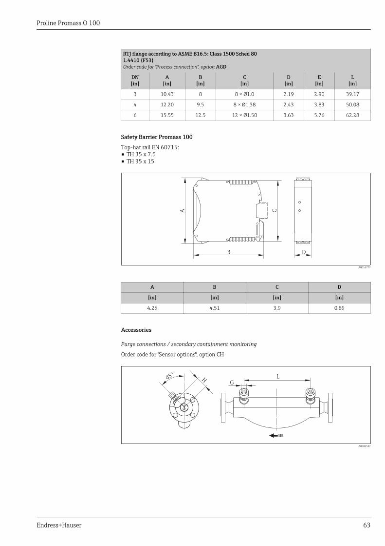
Proline Promass O 100
Endress+Hauser 63
RTJ flange according to ASME B16.5: Class 1500 Sched 801.4410 (F53)Order code for "Process connection", option AGD
DN[in]
A[in]
B[in]
C[in]
D[in]
E[in]
L[in]
3 10.43 8 8 × Ø1.0 2.19 2.90 39.17
4 12.20 9.5 8 × Ø1.38 2.43 3.83 50.08
6 15.55 12.5 12 × Ø1.50 3.63 5.76 62.28
Safety Barrier Promass 100
Top-hat rail EN 60715:• TH 35 x 7.5• TH 35 x 15
B D
A C
A0016777
A B C D
[in] [in] [in] [in]
4.25 4.51 3.9 0.89
Accessories
Purge connections / secondary containment monitoring
Order code for "Sensor options", option CH
LH45°
G
A0002537
Proline Promass O 100
64 Endress+Hauser
DN G H L
[in] [in] [in] [in]
3 ½ NPT 3.98 22.0
4 ½ NPT 4.72 27.0
6 ½ NPT 5.55 34.6
Weight Compact version
Weight in SI units
All values (weight) refer to devices with Class 900 flanges. Weight information in [kg].
DN[mm]
Weight [kg]
80 73
100 139
150 244
Weight in US units
All values (weight) refer to devices with Class 900 flanges. Weight information in [lbs].
DN[in]
Weight [lbs]
3 161
4 306
6 538
Safety Barrier Promass 100
49 g (1.73 ounce)
Materials Transmitter housing
• Order code for "Housing", option A "Compact, aluminum coated":Aluminum, AlSi10Mg, coated
• Order code for "Housing", option B "Compact, stainless":Stainless steel 1.4404 (316L)
• Order code for "Housing", option C "Ultra-compact, stainless":Stainless steel 1.4404 (316L)
• Window material for optional local display (→ 66):– For order code for "Housing", option A: glass– For order code for "Housing", option B and C: plastic
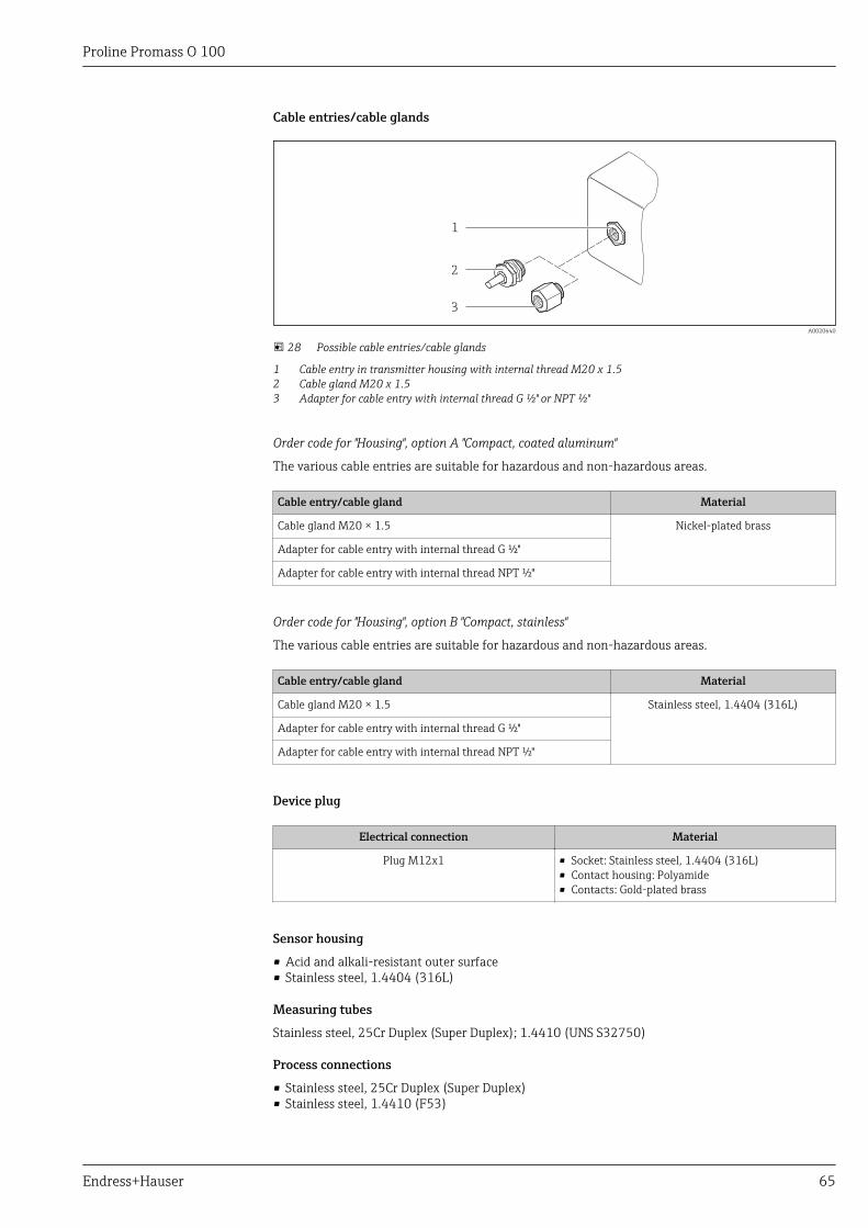
Proline Promass O 100
Endress+Hauser 65
Cable entries/cable glands
1
2
3
A0020640
28 Possible cable entries/cable glands
1 Cable entry in transmitter housing with internal thread M20 x 1.52 Cable gland M20 x 1.53 Adapter for cable entry with internal thread G ½" or NPT ½"
Order code for "Housing", option A "Compact, coated aluminum"
The various cable entries are suitable for hazardous and non-hazardous areas.
Cable entry/cable gland Material
Cable gland M20 × 1.5 Nickel-plated brass
Adapter for cable entry with internal thread G ½"
Adapter for cable entry with internal thread NPT ½"
Order code for "Housing", option B "Compact, stainless"
The various cable entries are suitable for hazardous and non-hazardous areas.
Cable entry/cable gland Material
Cable gland M20 × 1.5 Stainless steel, 1.4404 (316L)
Adapter for cable entry with internal thread G ½"
Adapter for cable entry with internal thread NPT ½"
Device plug
Electrical connection Material
Plug M12x1 • Socket: Stainless steel, 1.4404 (316L)• Contact housing: Polyamide• Contacts: Gold-plated brass
Sensor housing
• Acid and alkali-resistant outer surface• Stainless steel, 1.4404 (316L)
Measuring tubes
Stainless steel, 25Cr Duplex (Super Duplex); 1.4410 (UNS S32750)
Process connections
• Stainless steel, 25Cr Duplex (Super Duplex)• Stainless steel, 1.4410 (F53)
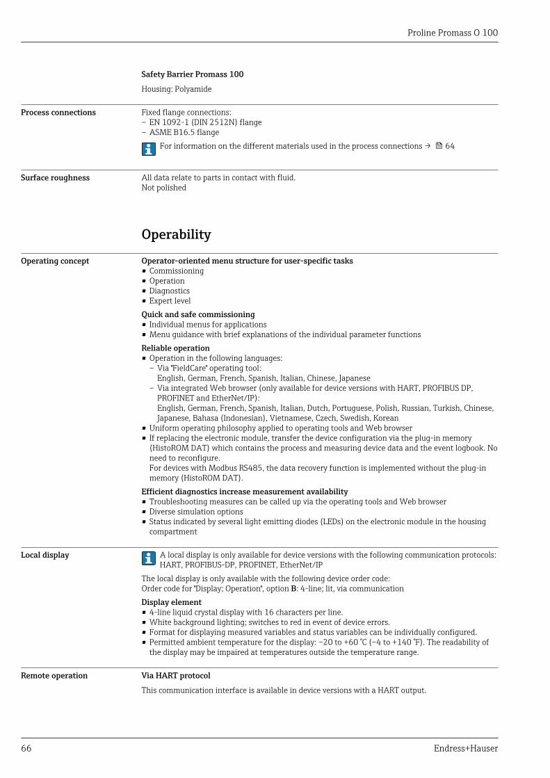
Proline Promass O 100
66 Endress+Hauser
Safety Barrier Promass 100
Housing: Polyamide
Process connections Fixed flange connections:– EN 1092-1 (DIN 2512N) flange– ASME B16.5 flange
For information on the different materials used in the process connections → 64
Surface roughness All data relate to parts in contact with fluid.Not polished
Operability
Operating concept Operator-oriented menu structure for user-specific tasks• Commissioning• Operation• Diagnostics• Expert levelQuick and safe commissioning• Individual menus for applications• Menu guidance with brief explanations of the individual parameter functionsReliable operation• Operation in the following languages:
– Via "FieldCare" operating tool:English, German, French, Spanish, Italian, Chinese, Japanese
– Via integrated Web browser (only available for device versions with HART, PROFIBUS DP,PROFINET and EtherNet/IP):English, German, French, Spanish, Italian, Dutch, Portuguese, Polish, Russian, Turkish, Chinese,Japanese, Bahasa (Indonesian), Vietnamese, Czech, Swedish, Korean
• Uniform operating philosophy applied to operating tools and Web browser• If replacing the electronic module, transfer the device configuration via the plug-in memory
(HistoROM DAT) which contains the process and measuring device data and the event logbook. Noneed to reconfigure.For devices with Modbus RS485, the data recovery function is implemented without the plug-inmemory (HistoROM DAT).
Efficient diagnostics increase measurement availability• Troubleshooting measures can be called up via the operating tools and Web browser• Diverse simulation options• Status indicated by several light emitting diodes (LEDs) on the electronic module in the housing
compartment
Local display A local display is only available for device versions with the following communication protocols:HART, PROFIBUS-DP, PROFINET, EtherNet/IP
The local display is only available with the following device order code:Order code for "Display; Operation", option B: 4-line; lit, via communicationDisplay element• 4-line liquid crystal display with 16 characters per line.• White background lighting; switches to red in event of device errors.• Format for displaying measured variables and status variables can be individually configured.• Permitted ambient temperature for the display: –20 to +60 °C (–4 to +140 °F). The readability of
the display may be impaired at temperatures outside the temperature range.
Remote operation Via HART protocol
This communication interface is available in device versions with a HART output.
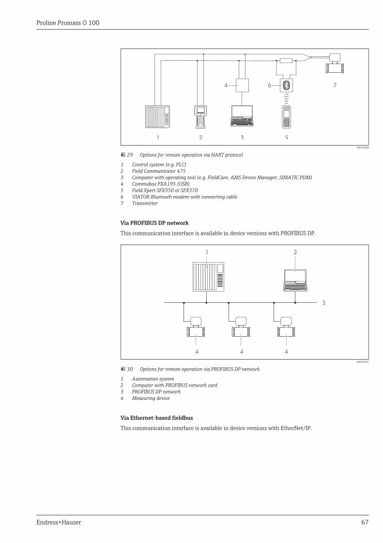
Proline Promass O 100
Endress+Hauser 67
1 2 3 5
74 6
A0016948
29 Options for remote operation via HART protocol
1 Control system (e.g. PLC)2 Field Communicator 4753 Computer with operating tool (e.g. FieldCare, AMS Device Manager, SIMATIC PDM)4 Commubox FXA195 (USB)5 Field Xpert SFX350 or SFX3706 VIATOR Bluetooth modem with connecting cable7 Transmitter
Via PROFIBUS DP network
This communication interface is available in device versions with PROFIBUS DP.
1 2
3
444
A0020903
30 Options for remote operation via PROFIBUS DP network
1 Automation system2 Computer with PROFIBUS network card3 PROFIBUS DP network4 Measuring device
Via Ethernet-based fieldbus
This communication interface is available in device versions with EtherNet/IP.
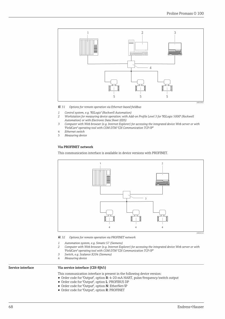
Proline Promass O 100
68 Endress+Hauser
4
21 3
5 5 5
A0016961
31 Options for remote operation via Ethernet-based fieldbus
1 Control system, e.g. "RSLogix" (Rockwell Automation)2 Workstation for measuring device operation: with Add-on Profile Level 3 for "RSLogix 5000" (Rockwell
Automation) or with Electronic Data Sheet (EDS)3 Computer with Web browser (e.g. Internet Explorer) for accessing the integrated device Web server or with
"FieldCare" operating tool with COM DTM "CDI Communication TCP/IP"4 Ethernet switch5 Measuring device
Via PROFINET network
This communication interface is available in device versions with PROFINET.
3
1 2
4 4 4
A0026545
32 Options for remote operation via PROFINET network
1 Automation system, e.g. Simatic S7 (Siemens)2 Computer with Web browser (e.g. Internet Explorer) for accessing the integrated device Web server or with
"FieldCare" operating tool with COM DTM "CDI Communication TCP/IP"3 Switch, e.g. Scalance X204 (Siemens)4 Measuring device
Service interface Via service interface (CDI-RJ45)
This communication interface is present in the following device version:• Order code for "Output", option B: 4-20 mA HART, pulse/frequency/switch output• Order code for "Output", option L: PROFIBUS DP• Order code for "Output", option N: EtherNet/IP• Order code for "Output", option R: PROFINET
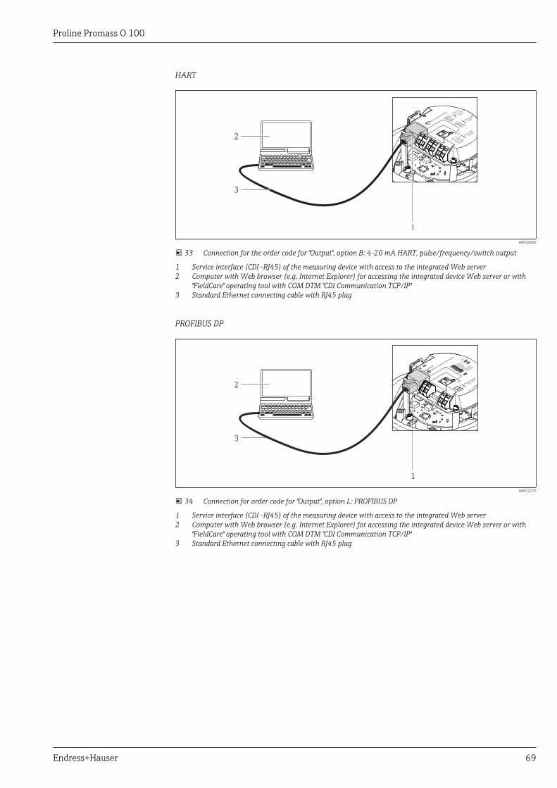
Proline Promass O 100
Endress+Hauser 69
HART
1
2
3
A0016926
33 Connection for the order code for "Output", option B: 4-20 mA HART, pulse/frequency/switch output
1 Service interface (CDI -RJ45) of the measuring device with access to the integrated Web server2 Computer with Web browser (e.g. Internet Explorer) for accessing the integrated device Web server or with
"FieldCare" operating tool with COM DTM "CDI Communication TCP/IP"3 Standard Ethernet connecting cable with RJ45 plug
PROFIBUS DP
1
2
3
A0021270
34 Connection for order code for "Output", option L: PROFIBUS DP
1 Service interface (CDI -RJ45) of the measuring device with access to the integrated Web server2 Computer with Web browser (e.g. Internet Explorer) for accessing the integrated device Web server or with
"FieldCare" operating tool with COM DTM "CDI Communication TCP/IP"3 Standard Ethernet connecting cable with RJ45 plug
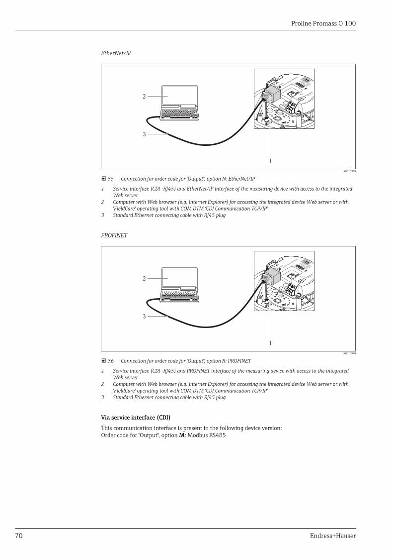
Proline Promass O 100
70 Endress+Hauser
EtherNet/IP
1
2
3
A0016940
35 Connection for order code for "Output", option N: EtherNet/IP
1 Service interface (CDI -RJ45) and EtherNet/IP interface of the measuring device with access to the integratedWeb server
2 Computer with Web browser (e.g. Internet Explorer) for accessing the integrated device Web server or with"FieldCare" operating tool with COM DTM "CDI Communication TCP/IP"
3 Standard Ethernet connecting cable with RJ45 plug
PROFINET
1
2
3
A0016940
36 Connection for order code for "Output", option R: PROFINET
1 Service interface (CDI -RJ45) and PROFINET interface of the measuring device with access to the integratedWeb server
2 Computer with Web browser (e.g. Internet Explorer) for accessing the integrated device Web server or with"FieldCare" operating tool with COM DTM "CDI Communication TCP/IP"
3 Standard Ethernet connecting cable with RJ45 plug
Via service interface (CDI)
This communication interface is present in the following device version:Order code for "Output", option M: Modbus RS485
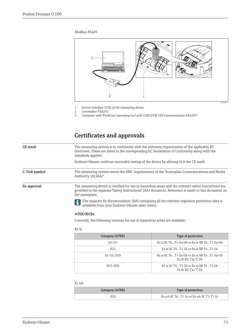
Proline Promass O 100
Endress+Hauser 71
Modbus RS485
12
3
A0016925
1 Service interface (CDI) of the measuring device2 Commubox FXA2913 Computer with "FieldCare" operating tool with COM DTM "CDI Communication FXA291"
Certificates and approvals
CE mark The measuring system is in conformity with the statutory requirements of the applicable ECDirectives. These are listed in the corresponding EC Declaration of Conformity along with thestandards applied.
Endress+Hauser confirms successful testing of the device by affixing to it the CE mark.
C-Tick symbol The measuring system meets the EMC requirements of the "Australian Communications and MediaAuthority (ACMA)".
Ex approval The measuring device is certified for use in hazardous areas and the relevant safety instructions areprovided in the separate "Safety Instructions" (XA) document. Reference is made to this document onthe nameplate.
The separate Ex documentation (XA) containing all the relevant explosion protection data isavailable from your Endress+Hauser sales center.
ATEX/IECEx
Currently, the following versions for use in hazardous areas are available:
Ex ia
Category (ATEX) Type of protection
II1/2G Ex ia IIC T6…T1 Ga/Gb or Ex ia IIB T6…T1 Ga/Gb
II2G Ex ia IIC T6…T1 Gb or Ex ia IIB T6…T1 Gb
II1/2G, II2D Ex ia IIC T6…T1 Ga/Gb or Ex ia IIB T6…T1 Ga/GbEx tb IIIC Txx °C Db
II2G, II2D Ex ia IIC T6…T1 Gb or Ex ia IIB T6…T1 GbEx tb IIIC Txx °C Db
Ex nA
Category (ATEX) Type of protection
II3G Ex nA IIC T6…T1 Gc or Ex nA IIC T5-T1 Gc
Proline Promass O 100
72 Endress+Hauser
CCSAUS
Currently, the following versions for use in hazardous areas are available:
IS (Ex i)• Class I Division 1 Groups ABCD• Class II Division 1 Groups EFG and Class IIINI (Ex nA)Class I Division 2 Groups ABCD
HART certification HART interface
The measuring device is certified and registered by the FieldComm Group. The measuring systemmeets all the requirements of the following specifications:• Certified according to HART 7• The device can also be operated with certified devices of other manufacturers (interoperability)
Certification PROFIBUS PROFIBUS interface
The measuring device is certified and registered by the PROFIBUS User Organization (PNO). Themeasuring system meets all the requirements of the following specifications:• Certified in accordance with PROFIBUS PA Profile 3.02• The device can also be operated with certified devices of other manufacturers (interoperability)
Certification PROFINET PROFINET interface
The measuring device is certified and registered by the PNO (PROFIBUS User Organization ). Themeasuring system meets all the requirements of the following specifications:• Certified according to:
– Test specification for PROFINET devices– PROFINET Security Level 1 – Net load test
• The device can also be operated with certified devices of other manufacturers (interoperability)
EtherNet/IP certification The measuring device is certified and registered by the ODVA (Open Device Vendor Association).The measuring system meets all the requirements of the following specifications:• Certified in accordance with the ODVA Conformance Test• EtherNet/IP Performance Test• EtherNet/IP PlugFest compliance• The device can also be operated with certified devices of other manufacturers (interoperability)
Modbus RS485 certification The measuring device meets all the requirements of the MODBUS/TCP conformity test and has the"MODBUS/TCP Conformance Test Policy, Version 2.0". The measuring device has successfully passedall the test procedures carried out and is certified by the “MODBUS/TCP Conformance TestLaboratory” of the University of Michigan.
Pressure EquipmentDirective
The devices can be ordered with or without a PED approval. If a device with a PED approval isrequired, this must be explicitly stated in the order.
• With the PED/G1/x (x = category) marking on the sensor nameplate, Endress+Hauser confirmscompliance with the "Essential Safety Requirements" specified in Annex I of the PressureEquipment Directive 97/23/EC.
• Devices bearing this marking (PED) are suitable for the following types of medium:– Media in Group 1 and 2 with a vapor pressure greater than, or smaller and equal to0.5 bar
(7.3 psi)– Unstable gases
• Devices not bearing this marking (PED) are designed and manufactured according to goodengineering practice. They meet the requirements of Art.3 Section 3 of the Pressure EquipmentDirective 97/23/EC. The range of application is indicated in tables 6 to 9 in Annex II of thePressure Equipment Directive.

Proline Promass O 100
Endress+Hauser 73
Other standards andguidelines
• EN 60529Degrees of protection provided by enclosures (IP code)
• IEC/EN 60068-2-6Environmental influences: Test procedure - Test Fc: vibrate (sinusoidal).
• IEC/EN 60068-2-31Environmental influences: Test procedure - Test Ec: shocks due to rough handling, primarily fordevices.
• EN 61010-1Safety requirements for electrical equipment for measurement, control and laboratory use -general requirements
• IEC/EN 61326Emission in accordance with Class A requirements. Electromagnetic compatibility (EMCrequirements).
• NAMUR NE 21Electromagnetic compatibility (EMC) of industrial process and laboratory control equipment
• NAMUR NE 32Data retention in the event of a power failure in field and control instruments withmicroprocessors
• NAMUR NE 43Standardization of the signal level for the breakdown information of digital transmitters withanalog output signal.
• NAMUR NE 53Software of field devices and signal-processing devices with digital electronics
• NAMUR NE 80The application of the pressure equipment directive to process control devices
• NAMUR NE 105Specifications for integrating fieldbus devices in engineering tools for field devices
• NAMUR NE 107Self-monitoring and diagnosis of field devices
• NAMUR NE 131Requirements for field devices for standard applications
• NAMUR NE 132Coriolis mass meter
• NACE MR0103Materials resistant to sulfide stress cracking in corrosive petroleum refining environments.
• NACE MR0175/ISO 15156-1Materials for use in H2S-containing Environments in Oil and Gas Production.
Ordering informationDetailed ordering information is available from the following sources:• In the Product Configurator on the Endress+Hauser website: www.endress.com → Select your
country → Products → Select measuring technology, software or components → Select the product(picklists: measurement method, product family etc.) → Device support (right-hand column):Configure the selected product → The Product Configurator for the selected product opens.
• From your Endress+Hauser Sales Center: www.addresses.endress.comProduct Configurator - the tool for individual product configuration• Up-to-the-minute configuration data• Depending on the device: Direct input of measuring point-specific information such as
measuring range or operating language• Automatic verification of exclusion criteria• Automatic creation of the order code and its breakdown in PDF or Excel output format• Ability to order directly in the Endress+Hauser Online Shop
Application packagesMany different application packages are available to enhance the functionality of the device. Suchpackages might be needed to address safety aspects or specific application requirements.
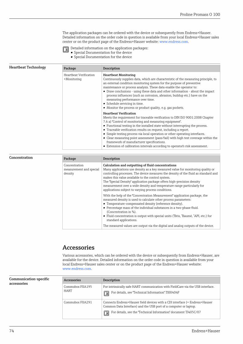
Proline Promass O 100
74 Endress+Hauser
The application packages can be ordered with the device or subsequently from Endress+Hauser.Detailed information on the order code in question is available from your local Endress+Hauser salescenter or on the product page of the Endress+Hauser website: www.endress.com.
Detailed information on the application packages:• Special Documentation for the device• Special Documentation for the device
Heartbeat Technology Package Description
Heartbeat Verification+Monitoring
Heartbeat MonitoringContinuously supplies data, which are characteristic of the measuring principle, toan external condition monitoring system for the purpose of preventivemaintenance or process analysis. These data enable the operator to:• Draw conclusions - using these data and other information - about the impact
process influences (such as corrosion, abrasion, buildup etc.) have on themeasuring performance over time.
• Schedule servicing in time.• Monitor the process or product quality, e.g. gas pockets.
Heartbeat VerificationMeets the requirement for traceable verification to DIN ISO 9001:2008 Chapter7.6 a) "Control of monitoring and measuring equipment".• Functional testing in the installed state without interrupting the process.• Traceable verification results on request, including a report.• Simple testing process via local operation or other operating interfaces.• Clear measuring point assessment (pass/fail) with high test coverage within the
framework of manufacturer specifications.• Extension of calibration intervals according to operator's risk assessment.
Concentration Package Description
Concentrationmeasurement and specialdensity
Calculation and outputting of fluid concentrationsMany applications use density as a key measured value for monitoring quality orcontrolling processes. The device measures the density of the fluid as standard andmakes this value available to the control system.The "Special Density" application package offers high-precision densitymeasurement over a wide density and temperature range particularly forapplications subject to varying process conditions.
With the help of the "Concentration Measurement" application package, themeasured density is used to calculate other process parameters:• Temperature-compensated density (reference density).• Percentage mass of the individual substances in a two-phase fluid.
(Concentration in %).• Fluid concentration is output with special units (°Brix, °Baumé, °API, etc.) for
standard applications.
The measured values are output via the digital and analog outputs of the device.
AccessoriesVarious accessories, which can be ordered with the device or subsequently from Endress+Hauser, areavailable for the device. Detailed information on the order code in question is available from yourlocal Endress+Hauser sales center or on the product page of the Endress+Hauser website:www.endress.com.
Communication-specificaccessories
Accessories Description
Commubox FXA195HART
For intrinsically safe HART communication with FieldCare via the USB interface.
For details, see "Technical Information" TI00404F
Commubox FXA291 Connects Endress+Hauser field devices with a CDI interface (= Endress+HauserCommon Data Interface) and the USB port of a computer or laptop.
For details, see the "Technical Information" document TI405C/07
Proline Promass O 100
Endress+Hauser 75
HART Loop ConverterHMX50
Is used to evaluate and convert dynamic HART process variables to analog currentsignals or limit values.
For details, see "Technical Information" TI00429F and Operating InstructionsBA00371F
Wireless HART adapterSWA70
Is used for the wireless connection of field devices.The WirelessHART adapter can be easily integrated into field devices and existinginfrastructures, offers data protection and transmission safety and can be operatedin parallel with other wireless networks with minimum cabling complexity.
For details, see Operating Instructions BA00061S
Fieldgate FXA320 Gateway for the remote monitoring of connected 4-20 mA measuring devices via aWeb browser.
For details, see "Technical Information" TI00025S and Operating InstructionsBA00053S
Fieldgate FXA520 Gateway for the remote diagnostics and remote configuration of connected HARTmeasuring devices via a Web browser.
For details, see "Technical Information" TI00025S and Operating InstructionsBA00051S
Field Xpert SFX350 Field Xpert SFX350 is a mobile computer for commissioning and maintenance. Itenables efficient device configuration and diagnostics for HART and FOUNDATIONFieldbus devices in the non-Ex area.
For details, see Operating Instructions BA01202S
Field Xpert SFX370 Field Xpert SFX370 is a mobile computer for commissioning and maintenance. Itenables efficient device configuration and diagnostics for HART and FOUNDATIONFieldbus devices in the non-Ex area and the Ex area.
For details, see Operating Instructions BA01202S
Service-specific accessories Accessories Description
Applicator Software for selecting and sizing Endress+Hauser measuring devices:• Calculation of all the necessary data for identifying the optimum flowmeter: e.g.
nominal diameter, pressure loss, accuracy or process connections.• Graphic illustration of the calculation results
Administration, documentation and access to all project-related data andparameters throughout the entire life cycle of a project.
Applicator is available:• Via the Internet: https://wapps.endress.com/applicator• On CD-ROM for local PC installation.
W@M Life cycle management for your plantW@M supports you with a wide range of software applications over the entireprocess: from planning and procurement, to the installation, commissioning andoperation of the measuring devices. All the relevant device information, such asthe device status, spare parts and device-specific documentation, is available forevery device over the entire life cycle.The application already contains the data of your Endress+Hauser device. Endress+Hauser also takes care of maintaining and updating the data records.
W@M is available:• Via the Internet: www.endress.com/lifecyclemanagement• On CD-ROM for local PC installation.
FieldCare FDT-based plant asset management tool from Endress+Hauser.It can configure all smart field units in your system and helps you manage them. Byusing the status information, it is also a simple but effective way of checking theirstatus and condition.
For details, see Operating Instructions BA00027S and BA00059S
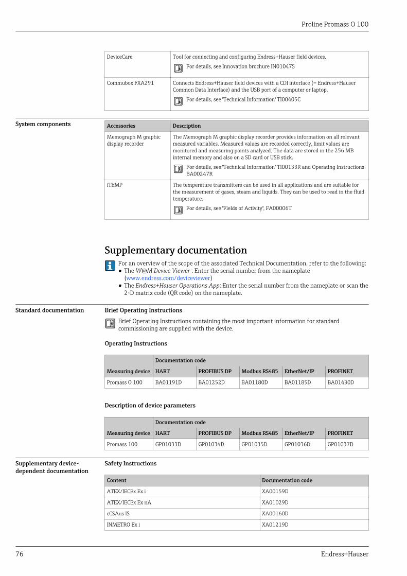
Proline Promass O 100
76 Endress+Hauser
DeviceCare Tool for connecting and configuring Endress+Hauser field devices.
For details, see Innovation brochure IN01047S
Commubox FXA291 Connects Endress+Hauser field devices with a CDI interface (= Endress+HauserCommon Data Interface) and the USB port of a computer or laptop.
For details, see "Technical Information" TI00405C
System components Accessories Description
Memograph M graphicdisplay recorder
The Memograph M graphic display recorder provides information on all relevantmeasured variables. Measured values are recorded correctly, limit values aremonitored and measuring points analyzed. The data are stored in the 256 MBinternal memory and also on a SD card or USB stick.
For details, see "Technical Information" TI00133R and Operating InstructionsBA00247R
iTEMP The temperature transmitters can be used in all applications and are suitable forthe measurement of gases, steam and liquids. They can be used to read in the fluidtemperature.
For details, see "Fields of Activity", FA00006T
Supplementary documentationFor an overview of the scope of the associated Technical Documentation, refer to the following:• The W@M Device Viewer : Enter the serial number from the nameplate
(www.endress.com/deviceviewer)• The Endress+Hauser Operations App: Enter the serial number from the nameplate or scan the
2-D matrix code (QR code) on the nameplate.
Standard documentation Brief Operating Instructions
Brief Operating Instructions containing the most important information for standardcommissioning are supplied with the device.
Operating Instructions
Measuring device
Documentation code
HART PROFIBUS DP Modbus RS485 EtherNet/IP PROFINET
Promass O 100 BA01191D BA01252D BA01180D BA01185D BA01430D
Description of device parameters
Measuring device
Documentation code
HART PROFIBUS DP Modbus RS485 EtherNet/IP PROFINET
Promass 100 GP01033D GP01034D GP01035D GP01036D GP01037D
Supplementary device-dependent documentation
Safety Instructions
Content Documentation code
ATEX/IECEx Ex i XA00159D
ATEX/IECEx Ex nA XA01029D
cCSAus IS XA00160D
INMETRO Ex i XA01219D
Proline Promass O 100
Endress+Hauser 77
Content Documentation code
INMETRO Ex nA XA01220D
NEPSI Ex i XA01249D
NEPSI Ex nA XA01262D
Special Documentation
Content Documentation code
Information on the Pressure Equipment Directive SD00142D
Modbus RS485 Register Information SD00154D
Concentration Measurement SD01152D
Heartbeat Technology SD01153D
Installation Instructions
Contents Documentation code
Installation Instructions for spare part sets Specified for each individual accessory
Registered trademarksHART®
Registered trademark of the HART Communication Foundation, Austin, USA
PROFIBUS®
Registered trademark of the PROFIBUS User Organization, Karlsruhe, Germany
Modbus®
Registered trademark of SCHNEIDER AUTOMATION, INC.
EtherNet/IPTM
Trademark of ODVA, Inc.
PROFINET®
Registered trademark of the PROFIBUS User Organization, Karlsruhe, Germany
Microsoft®
Registered trademark of the Microsoft Corporation, Redmond, Washington, USA
TRI-CLAMP®
Registered trademark of Ladish & Co., Inc., Kenosha, USA
Applicator®, FieldCare®, DeviceCare ®, Field XpertTM, HistoROM®, Heartbeat TechnologyTM
Registered or registration-pending trademarks of the Endress+Hauser Group


www.addresses.endress.com