Projects book - Cloud Object Storage | Store & Retrieve …with... · Web viewThis signal can be...
23
Stage 1 Blinking LED with Scratch for pcDuino Setup: When we connect the LED to the base shield, please connect to the slot marked as D1. This is important, as Scratch for pcDuino controls different slot. If we use slot other than D1, we will need to change the number later in the scratch for pcDuino script. Script: 1 / 23
Transcript of Projects book - Cloud Object Storage | Store & Retrieve …with... · Web viewThis signal can be...
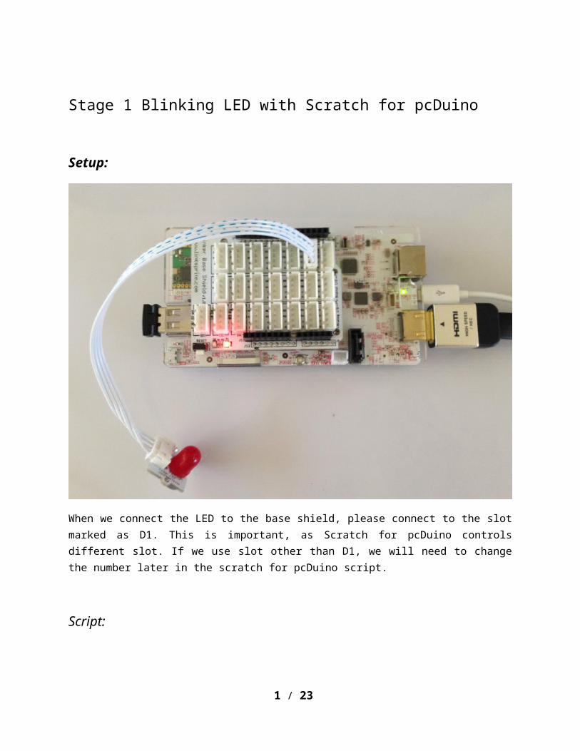
Stage 1 Blinking LED with Scratch for pcDuino
Setup:
When we connect the LED to the base shield, please connect to the slot marked as D1. This is important, as Scratch for pcDuino controls different slot. If we use slot other than D1, we will need to change the number later in the scratch for pcDuino script.
Script:
The scratch for pcDuino has the following areas: command blocks, Scripts area, stage, and sprite list.
1 / 21
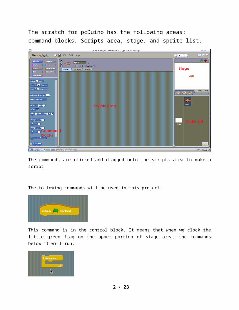
The commands are clicked and dragged onto the scripts area to make a script.
The following commands will be used in this project:
This command is in the control block. It means that when we clock the little green flag on the upper portion of stage area, the commands below it will run.
This command is in the control block. The commands nested in it will be running forever.
2 / 21
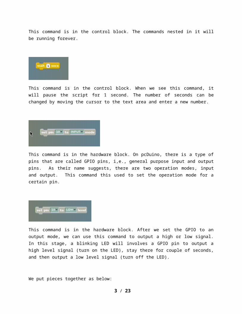
This command is in the control block. When we see this command, it will pause the script for 1 second. The number of seconds can be changed by moving the cursor to the text area and enter a new number.
This command is in the hardware block. On pcDuino, there is a type of pins that are called GPIO pins, i,e., general purpose input and output pins. As their name suggests, there are two operation modes, input and output. This command this used to set the operation mode for a certain pin.
This command is in the hardware block. After we set the GPIO to an output mode, we can use this command to output a high or low signal. In this stage, a blinking LED will involves a GPIO pin to output a high level signal (turn on the LED), stay there for couple of seconds, and then output a low level signal (turn off the LED).
We put pieces together as below:
3 / 21
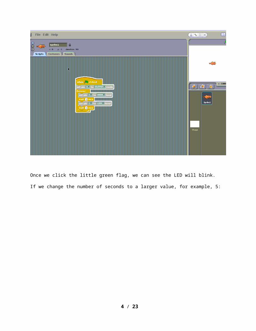
Once we click the little green flag, we can see the LED will blink.
If we change the number of seconds to a larger value, for example, 5:
4 / 21
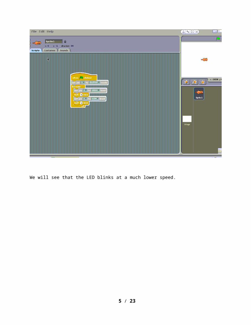
We will see that the LED blinks at a much lower speed.
5 / 21

Stage 2 Control LED with a Button
Setup:
We need a LED and a button and hook them to the base shield. Please connect the LED to the slot marked as D1, and the button to the slot marked at D2. This is important, as Scratch for pcDuino senses and controls different slots. If we use slot other than what we specified above D1, we will need to change the number later in the scratch for pcDuino script.
Script:
The following new commands will be used in this project:
6 / 21
This command is in the control block. Basically, it will check if the thing is true or not in the hexagon. If the hexagon is ture, it will pick the commands in the upper space. Otherwise, it will go with the commands in the lower space. We do need to click and drop another command which will produce true/false into the hexagon.
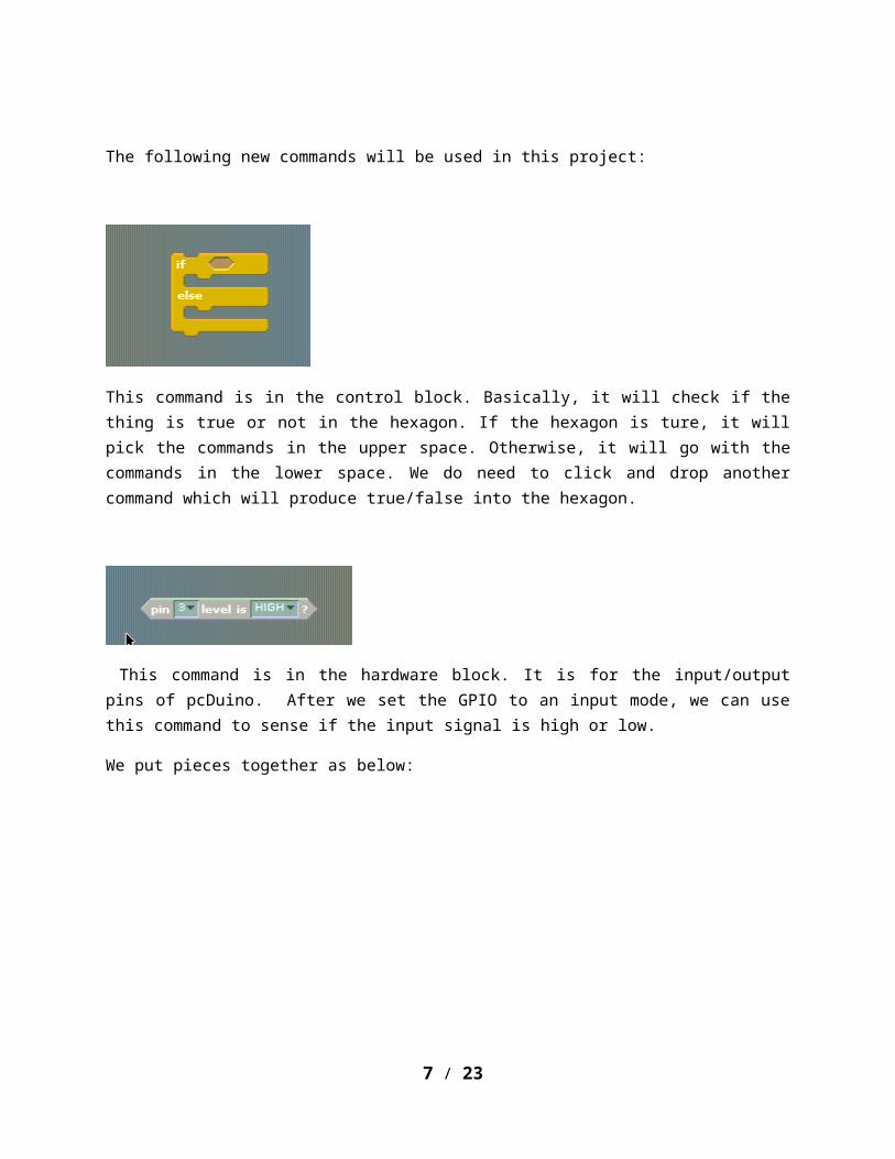
This command is in the hardware block. It is for the input/output pins of pcDuino. After we set the GPIO to an input mode, we can use this command to sense if the input signal is high or low.
We put pieces together as below:
7 / 21
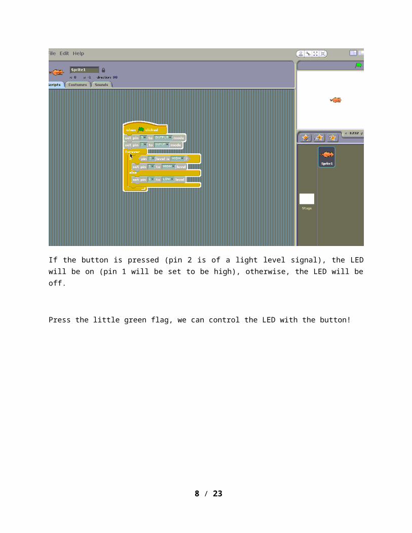
If the button is pressed (pin 2 is of a light level signal), the LED will be on (pin 1 will be set to be high), otherwise, the LED will be off.
Press the little green flag, we can control the LED with the button!
8 / 21
Stage 3 A Cat Races to the Finish Line
In this stage, there will be a cat racing to the finish line. When it hits the finish line, the LED will start to blink to indicate the moment.
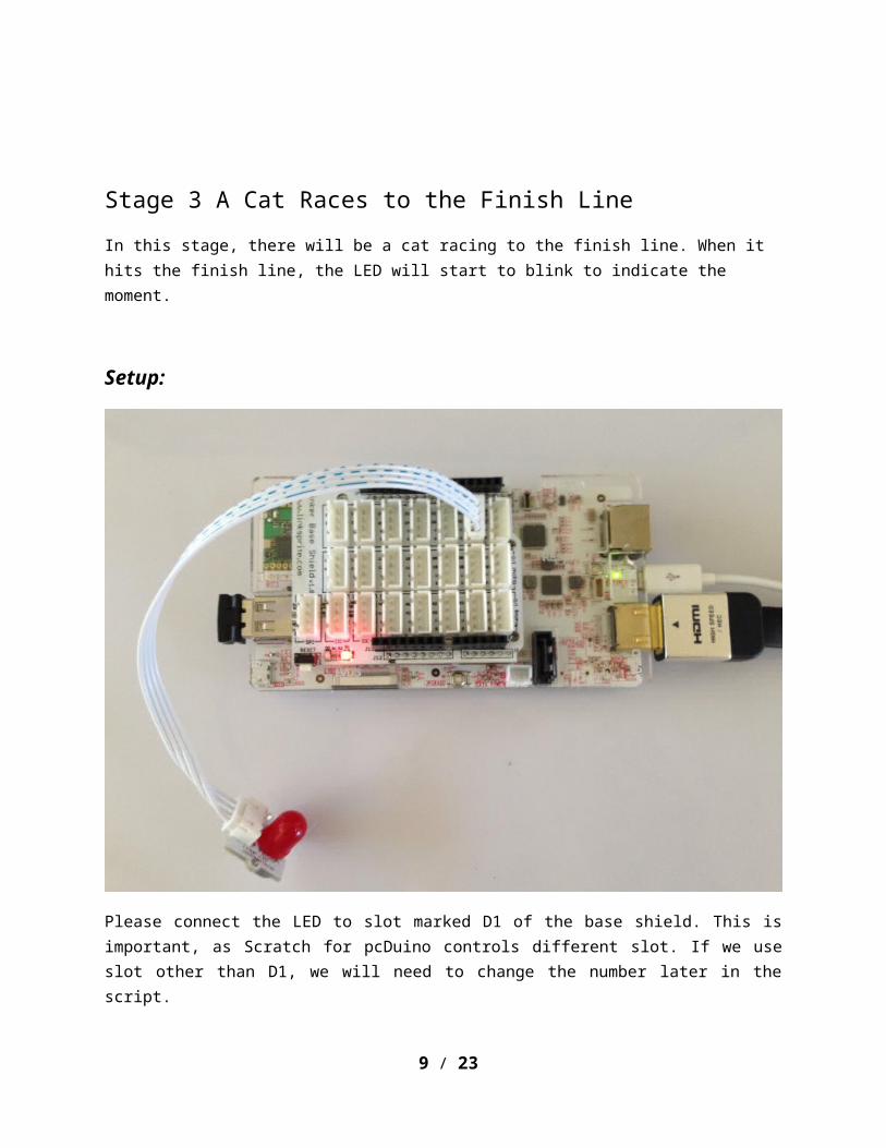
Setup:
Please connect the LED to slot marked D1 of the base shield. This is important, as Scratch for pcDuino controls different slot. If we use slot other than D1, we will need to change the number later in the script.
Script:
There will be two sprites in this stage, the cat, which is already there titled sprite1, and a finish line.
9 / 21
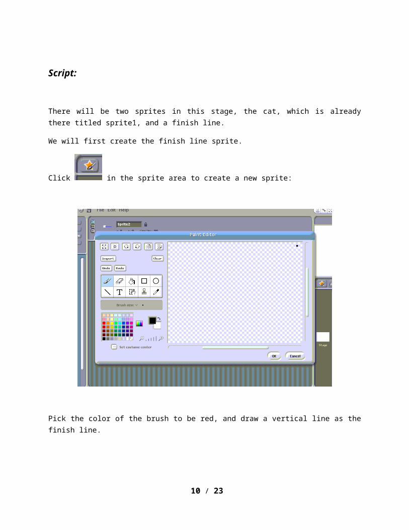
We will first create the finish line sprite.
Click in the sprite area to create a new sprite:
Pick the color of the brush to be red, and draw a vertical line as the finish line.
10 / 21
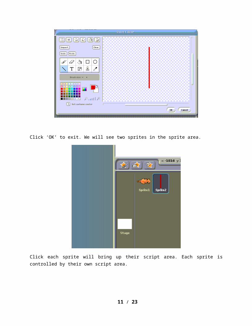
Click ‘OK’ to exit. We will see two sprites in the sprite area.
Click each sprite will bring up their script area. Each sprite is controlled by their own script area.
Let’s work on the finish line sprite first. When we click the green flag, we would want the finish line to jump to the rightmost side. That’s all we want for the finish line.
To achieve what we want, we will need a new command block:
This command is in the motion block. It will set the sprite to the coordinate specified.
11 / 21

(230, 0) is the rightmost in the stage.
Now let’s work on the sprite1, the cat.
The cat will move to the left most, and will move 4 steps toward the right until it touches sprite2, the finish line. After this, the LED will blink.
The full script is as below:
12 / 21

When we click the green flag, the cat will race to the finish line, and when it touches it, the LED will start to blink.
Stage 4 Sensing the distance with an Infrared Sensor
13 / 21
The infrared sensor can be used to measure the distance. It has a transmitter and a receiver. Just like the bat, the transmitted infrared signal will be reflected back when it bumps into an obstacle. The closer the obstacle is to the infrared sensor, the stronger is the strength of the reflected signal. This signal can be measured by pcDuino with a special circuit to give a reading which corresponds to the strength of the signal.
Setup:
We connect the infrared sensor to a slot marked as A0 of the base shield. Please use A0 in the script. A0 is a special port on pcDuino. It’s different from GPIO, where only a high or low level can be sensed. A0 can be used to measure the strength of the input signal.
Script:
14 / 21
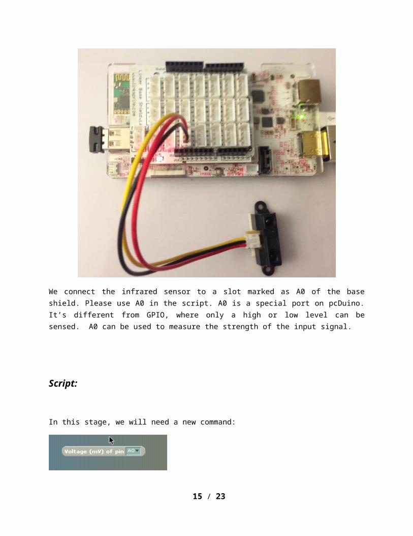
In this stage, we will need a new command:
This command is in the hardware block. It can read the signal strength of the input signal.
We will use the command: to print the number.
The whole script is as following:
Once we click the green flag to run the script, the cat will tell us the reading. The closer we wave our hand toward the sensor, the larger the reading would be.
15 / 21

16 / 21

Stage 5 Play Pong
We have seen that infrared sensor can be used to measure the distance in stage 4. In this stage, we go further to use hand to control the board to catch the ball, and play the pong game.
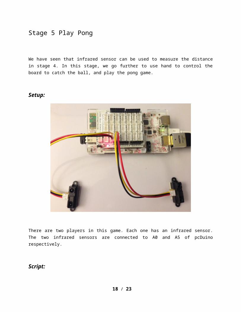
Setup:
There are two players in this game. Each one has an infrared sensor. The two infrared sensors are connected to A0 and A5 of pcDuino respectively.
Script:
There are 5 sprites in total, the ball, the red board, the black board, the red goal, and the black goal.
The game works as following:
17 / 21
The ball will start with a randomly picked direction to move. If it is caught by a board, it will be reflected to the other side. If it is caught by the other board, it will be reflected back again. However, if it is missed, it will hit the goal, and the player will get credit.
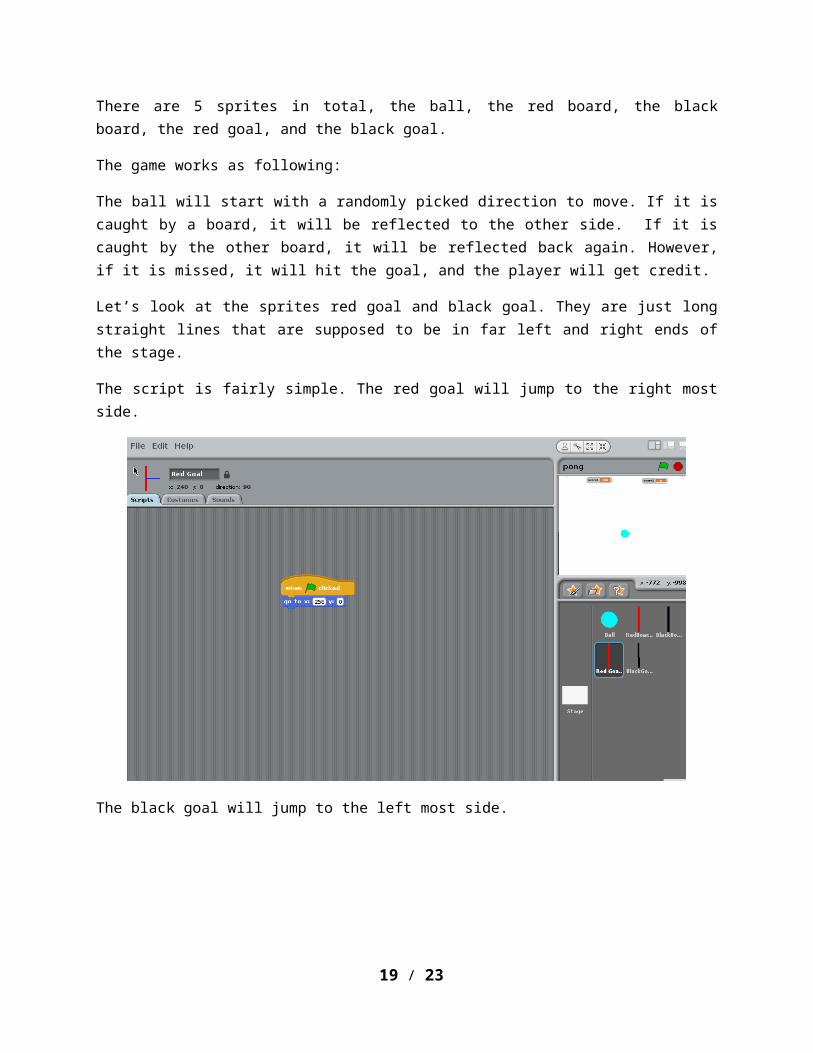
Let’s look at the sprites red goal and black goal. They are just long straight lines that are supposed to be in far left and right ends of the stage.
The script is fairly simple. The red goal will jump to the right most side.
The black goal will jump to the left most side.
18 / 21
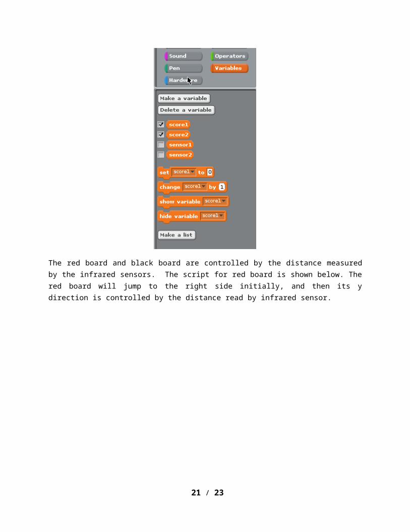
We need to create two variables: score1 and score2 to hold the score, sensor1 and sensor2 to hold the reading of the infrared sensors. If the checkbox before the variable is checked, it will show up on the stage. The position can be adjusted by dragging.
19 / 21

The red board and black board are controlled by the distance measured by the infrared sensors. The script for red board is shown below. The red board will jump to the right side initially, and then its y direction is controlled by the distance read by infrared sensor.
The script for the black board is shown below. Its same as the one for red board except that it will jump to the left side when it starts.
20 / 21
The script for the ball, which is the most important, is shown below:
The score1 and score2 are initiated in the beginning. Then the ball will pick a random direction to move. If it touches either board, it will reverse its direction. If it hits the goal, the score will be added.
21 / 21