
ProjectPro 117 Airless Sprayer - Wagner Australia :: … 117 Airless Sprayer 0418B Betriebsanleitung...
19
® ProjectPro 117 Airless Sprayer 0418B Betriebsanleitung • Owner’s Manual • Manuel d’utilisation • Manuale dell’utente • Manual de usuario • Gebruikshandleiding • Ejermanual • Användarmanual • Manual do Proprietário D GB F . . . . . . . . . . 2 . . . . . . . . . . 12 . . . . . . . . . . 22 I ES NL . . . . . . . . . . 32 . . . . . . . . . . 42 . . . . . . . . . . 52 DK S P . . . . . . . . . . 62 . . . . . . . . . . 72 . . . . . . . . . . 82 D GB F I ES NL DK S P Originalbetriebsanleitung
Transcript of ProjectPro 117 Airless Sprayer - Wagner Australia :: … 117 Airless Sprayer 0418B Betriebsanleitung...

®
ProjectPro 117Airless Sprayer
0418BBetriebsanleitung • Owner’s Manual • Manuel d’utilisation •
Manuale dell’utente • Manual de usuario • Gebruikshandleiding • Ejermanual • Användarmanual • Manual do Proprietário
DGBF
. . . . . . . . . . 2
. . . . . . . . . . 12
. . . . . . . . . . 22
IESNL
. . . . . . . . . . 32
. . . . . . . . . . 42
. . . . . . . . . . 52
DKSP
. . . . . . . . . . 62
. . . . . . . . . . 72
. . . . . . . . . . 82
D GB F I ES NL DK S P
Originalbetriebsanleitung

WAGNER Project Pro 117 - 0418BWAGNER Project Pro 117 - 0418B
D
F
E
G
H
J
BC
A
I
1
2)1)
2
1) 2)(a)
3
4
SPRAY PRIM
E
1) 3)
2)
O
5
1) 2)
6

WAGNER Project Pro 117 - 0418BWAGNER Project Pro 117 - 0418B
1)
(a)(b)
+
2)
SPRAY PRIM
E
4)
3)
5)
l
7
SPR
AY PR
IME
1)2)
SPRAY
PRIME
3)
l
8
(a) (b)
9
10
25 - 30 cm
A) B)
C) 25 - 35 cm
25 - 30 cm25 - 30 cm
D)

WAGNER Project Pro 117 - 0418BWAGNER Project Pro 117 - 0418B
A)
B)
11 12
A)
2)
3)1)
B)
13
(a) (c)
(b)
14
(g)
(a) (c) (b)
(f)
(d)
(e)
15

WAGNER Project Pro 117 - 0418BWAGNER Project Pro 117 - 0418B
(a) (b)
16
(a)
18
1) 2)
17
19
3
2
4
120
7
8
5
9
11
6
3
4
12
10
21

12
WAGNER Project Pro 117 - 0418B- Safety Information
Warning!
Never put your fingers, hands or any other parts of the body into thespray jet!Never point the spray gun at yourself, other persons or animals.Never use the spray gun without safety guard.
Do not treat a spraying injury as a harmless cut. In case of injury tothe skin through coating materials or solvents, consult a doctorimmediately for quick and expert treatment. Inform the doctorabout the coating material or solvent used.
The operating instructions state that the following points mustalways be observed before starting up:1. Faulty units must not be used.2. Secure WAGNER spray gun using the safety catch on the
trigger.3. Ensure that the unit is properly earthed. The connection
must take place through a correctly earthed two-pole and earthsocket outlet.
4. Check allowable operating pressure of high-pressure hose and spray gun.
5. Check all connections for leaks.
The instructions regarding regular cleaning and maintenance of theunit must be strictly observed.Before any work is done on the unit or for every break in work thefollowing rules must be observed:1. Release the pressure from spray gun and hose.2. Secure the WAGNER spray gun using the safety catch
on the trigger.
3. Switch off unit.
Be safety-conscious!
Attention: Danger of injury by injection!Airless units develop extremely high spraying pressures.
Danger
1
2
3
Translation of the original operating instructions

13
WAGNER Project Pro 117 - 0418B- Safety Information
General Safety InstructionsRead all the instructions. Non-observance of the instructions below can cause electric shock, fire and or serious personal injuries. The term „power tool“ used below covers both mains-operated power tools (with mains lead) and accumulator-operated power tools (without mains lead).All local regulations in force must be observed.
Explanation of symbols used
Danger
Indicates an immediate danger. Unless avoided, death or serious injuries will result.
iIndicates tips for use and other particularly useful information.
Explosion hazard.
Attention: Danger of injury by injection!
1. Workplace
a) Keep your workplace clean and tidy. Untidiness and unlit working areas can lead to accidents.
b) Never use the tool in hazardous areas that contain flammable liquids, gases or dusts. Power tools generate sparks that can ignite the dust or vapors.
c) Keep children and other persons away when using the power tool. You can lose control of the tool if you are distracted.
2. Electrical Safety
a) The tool plug must fit into the socket. The plug may not be modified in any form. Do not use adaptor plugs together with protective-earthed tools. Unmodified plugs and suitable sockets reduce the risk of an electric shock.
b) Avoid physical contact with earthed surfaces such as pipes, heating elements, stoves and refrigerators. The risk through electric shock increases if your body is earthed.
c) Keep the equipment away from rain and moisture. The risk of an electric shock increases if water penetrates electrical equipment.
d) Do not misuse the mains lead by carrying the tool by the lead, hanging it from the lead or by pulling on the lead to remove the plug. Keep the lead away from heat, oil, sharp edges or moving tool parts. Damaged or twisted leads increase the risk of an electric shock.
e) If you work outdoors, use only extension leads that are approved for outdoor use. The use of an extension lead that is suitable for outdoors reduces the risk of an electric shock.
3. Safety of Persons
a) Be attentive. Pay attention to what you are doing and work sensibly with a power tool. Do not use the tool if you are tired or under the influence of drugs, alcohol or medication. Just a moment of inattentiveness while using the tool can lead to serious injuries.
b) Wear personal safety equipment and always wear safety goggles. Wearing personal protective equipment, such as dust mask, non-slip safety shoes, safety helm or ear protection, depending on the type of power tools, reduces the risk of injury.
c) Avoid accidental starting-up. Ensure that the switch is in the "OFF" position before inserting the plug into the socket. Accidents can occur if you carry the power tool while your finger is on the switch or if you connect the power tool to the power supply which it is on.
d) Remove setting tools or wrenches before switching on the power tool. A tool or wrench that is in a rotating tool part can lead to injuries.
e) Do not overestimate your abilities. Ensure that you are standing securely and have your balance at all times. This ensures that you can control the tool better in unexpected situations.
f) Wear suitable clothing. Do not wear wide clothing or jewelry. Keep your hair, clothes and gloves away from moving parts. Loose clothing, jewelry or long hair can be caught in moving parts.
g) This appliance is not intended for use by persons (including children) with reduced physical, sensory or mental capabilities, or lack of experience and knowledge, unless they have been given supervision or instruction concerning use of the appliance by a person responsible for their safety. Children should be supervised to ensure that they do not play with the appliance.
4. Careful Handling and Use of Power Tools
a) Do not overload the tool. Use the power tool designed for the work that you are doing. You work better and safer in the specified performance range if you use the suitable power tool.
b) Do not use power tools whose switch is defective. A power tool that cannot be switched on or off is dangerous and has to be repaired.
c) Remove the plug from the socket before carrying out tool settings, changing accessories or putting the tool away. This precautionary measure prevents unintentional starting of the tool.
d) Store unused power tools so that they are inaccessible to children. Do not let persons use the tool who are not familiar with it or who have not read these instructions. Power tools are dangerous when they are used by inexperienced persons.
e) Take proper care of your tools. Check whether the moving parts function trouble-free and do not jam, whether parts are broken or damaged so that the tool function is impaired. Have damaged parts repaired before using the tool. Many accidents have their origin in power tools that have been
14
WAGNER Project Pro 117 - 0418B- Safety Information
maintained badly.
f) Use the power tool, accessories, insert tools, etc. in accordance with these instructions and in a fashion specified for this special tool type. Take the working conditions and the activity to be carried out into consideration. The use of power tools for purposes other than the intended ones can lead to dangerous situations.
5. Service
a) Have your tool repaired only by qualified specialist personnel and only with original spare parts. This ensures that the tool safety is maintained.
b) If the supply cord is damaged, it must be replaced by the manufacturer or it’s service agent or a similarly qualified person in order to avoid a safety hazard.
For secure handling of Airless high-pressure spraying units the following safety regulations are to be observed:
U Health protection
Danger
Caution! Wear breathing equipment: Paint mist and solvent vapors are damaging to health. Always wear breathing equipment and only work in well ventilated rooms or using supplementary ventilating equipment. It is advisable to wear working clothing, safty glasses, ear protection and gloves
U Flammable materials
Danger
Do not use the spray guns to spray flammable substances.
U Explosion protection
Danger
Do not use the unit in work places which are covered to the explosion protection regulations.
U Danger of explosion and fire through sources of flame during spraying work
Danger
There may be no sources of flame such as, for example, open fires, smoking of cigarettes, cigars or tobacco pipes, sparks, glowing wires, hot surfaces, etc. in the vicinity.
U Electrostatic charging (formation of sparks or flame)
Danger
Under certain circumstances, electrostatic charging can occur on the unit due to the rate of flow of the coating material when spraying. On discharging this can result in the emergence of sparks or fire. It is
therefore necessary that the unit is always earthed through the electrical installation. The connection must take place through a correctly earthed two-pole-and-earth socket outlet.
U VentilationGood natural or artificial ventilation must be ensured in order to avoid the risk of explosion or fire and damage to health during spray work.
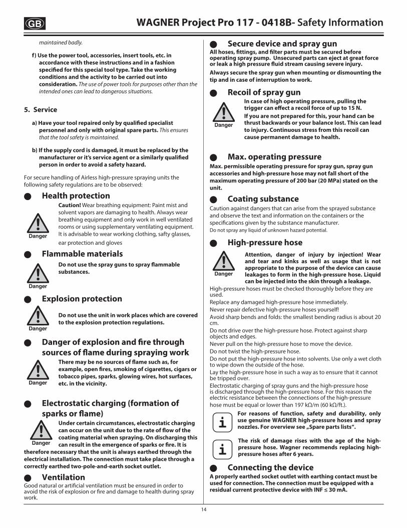
U Secure device and spray gunAll hoses, fittings, and filter parts must be secured before operating spray pump. Unsecured parts can eject at great force or leak a high pressure fluid stream causing severe injury.Always secure the spray gun when mounting or dismounting the tip and in case of interruption to work.
U Recoil of spray gun
Danger
In case of high operating pressure, pulling the trigger can effect a recoil force of up to 15 N.If you are not prepared for this, your hand can be thrust backwards or your balance lost. This can lead to injury. Continuous stress from this recoil can cause permanent damage to health.
U Max. operating pressureMax. permissible operating pressure for spray gun, spray gun accessories and high-pressure hose may not fall short of the maximum operating pressure of 200 bar (20 MPa) stated on the unit.
U Coating substanceCaution against dangers that can arise from the sprayed substance and observe the text and information on the containers or the specifications given by the substance manufacturer. Do not spray any liquid of unknown hazard potential.
U High-pressure hose
Danger
Attention, danger of injury by injection! Wear and tear and kinks as well as usage that is not appropriate to the purpose of the device can cause leakages to form in the high-pressure hose. Liquid can be injected into the skin through a leakage.
High-pressure hoses must be checked thoroughly before they are used.Replace any damaged high-pressure hose immediately.Never repair defective high-pressure hoses yourself!Avoid sharp bends and folds: the smallest bending radius is about 20 cm.Do not drive over the high-pressure hose. Protect against sharp objects and edges.Never pull on the high-pressure hose to move the device.Do not twist the high-pressure hose.Do not put the high-pressure hose into solvents. Use only a wet cloth to wipe down the outside of the hose.Lay the high-pressure hose in such a way as to ensure that it cannot be tripped over.Electrostatic charging of spray guns and the high-pressure hose is discharged through the high-pressure hose. For this reason the electric resistance between the connections of the high-pressure hose must be equal or lower than 197 kΩ/m (60 kΩ/ft.).
iFor reasons of function, safety and durability, only use genuine WAGNER high-pressure hoses and spray nozzles. For overview see „Spare parts lists“.
iThe risk of damage rises with the age of the high-pressure hose. Wagner recommends replacing high-pressure hoses after 6 years.
U Connecting the deviceA properly earthed socket outlet with earthing contact must be used for connection. The connection must be equipped with a residual current protective device with INF ≤ 30 mA.

15
WAGNER Project Pro 117 - 0418B
Components and DescriptionThe shipping carton for your painting system contains the following:
• Suction tube and return tube (including inlet filter and 3 clips) • Spray tip assembly• Basic unit • 10 m, 6.35mm internal diameter pressure hose• Spray gun with two filters (L-XXL; one in gun, one separate) • Oil flask• Instruction manual
Figure 1 - Controls and Functions(further, detailed descriptions of the individual items can be found in the relevant section of the operating instructions) Item Component Description
A) ON / OFF Switch ............................The ON/OFF switch turns the power to the sprayer on and off (O=OFF, l=ON).B) PRIME / SPRAY Knob ....................The PRIME/SPRAY knob directs fluid to the spray hose when set to SPRAY or the return tube when set
to PRIME. The arrows on the PRIME/SPRAY knob shows the rotation directions for PRIME and SPRAY. The PRIME/SPRAY knob is also used to relieve pressure built up in the spray hose (see Pressure Relief Procedure).
C) Quickflo™ Valve .............................The Quickflo™ valve is designed to keep the inlet valve open and from sticking to dried materials. The Quickflo™ valve is activated manually by the user.
D) PressureTrac™ ................................The PressureTrac™ regulates the amount of force the pump uses to push the fluid.E) Pump Section .................................A piston in the pump section moves up and down to create the suction that draws fluid through the
suction tube. F) Suction Tube ..................................Fluid is drawn through the suction tube into the pump.G) Return Tube ....................................Fluid is sent back out through the return tube to the original container when PRIME/SPRAY knob is in
PRIME position.H) Inlet filter ..........................................The inlet filter strains the spray material to prevent the system from becoming clogged.I) Spray Gun ........................................For application of the coating material and regulation of the pump capacity. J) Spray Hose ......................................The spray hose connects the gun to the pump.
U Setting up the unitWhen working indoors:
Danger
Vapors containing solvents may not be allowed to build up in the area of the device.Setting up the unit on the side a way from the sprayed object. A minimum distance of 5 m between the unit and spray gun is to be maintained.
When working outdoors:
Danger
Vapors containing solvents may not be allowed to blow toward the unit. Note the direction of the wind. Set the unit up in such a way that vapors containing solvents do not reach the unit and build up there. A minimum distance of 5 m between the unit and spray
gun is to be maintained.
U Cleaning the unit
Danger
Danger of short circuit through penetrating water!Never spray down the unit with high-pressure or high-pressure steam cleaners.
U Cleaning units with solvents
Danger
When cleaning the unit with solvents, the solvent should never be sprayed or pumped back into a container with a small opening (bunghole). An explosive gas/air mixture can be produced. The container must be earthed. Do not use flammable materials for cleaning purposes.
U Earthing of the objectThe object to be coated must be earthed.
Technical DataPump type Piston pumpPower source 230 V ~ 50 Hz / 240 V ~ 50 HzPower consumption 670 W /Fusing Only connect to sockets protected
with an FI fuse (16 A)Protection class IMax. spray pressure 200 barMax. delivery rate 1,0 l/minSound pressure level 71,4 dB (A)Oscillation level < 2,5 m/s²Max. temperature of coating substance 40°CMax. nozzle size L (0,017")Hose length 10 mWeight 7,8 kg
Coating Materials Suitable for UseWater-based and solvent-containing lacquers and glazes. Paints, oils, release agents, synthetic enamels, PVC lacquers, undercoats, base coats, fillers and anti-rust paints. Dispersion and latex paints for interior use.
Coating Materials Not Suitable for UseMaterials that contain highly abrasive components, facade paint, caustic solutions and acidic coating substances. Flammable materials
iIn order to ensure compatibility of the coating substance with the materials used to manufacture the device, please contact Wagner Service in cases of doubt.
16
WAGNER Project Pro 117 - 0418B
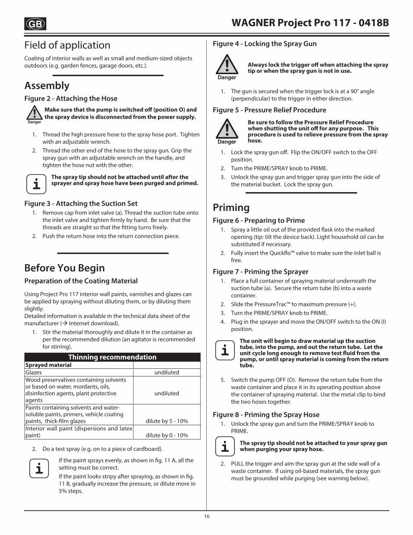
AssemblyFigure 2 - Attaching the Hose
Danger
Make sure that the pump is switched off (position O) and the spray device is disconnected from the power supply.
1. Thread the high pressure hose to the spray hose port. Tighten with an adjustable wrench.
2. Thread the other end of the hose to the spray gun. Grip the spray gun with an adjustable wrench on the handle, and tighten the hose nut with the other.
i The spray tip should not be attached until after the sprayer and spray hose have been purged and primed.
Figure 3 - Attaching the Suction Set 1. Remove cap from inlet valve (a). Thread the suction tube onto
the inlet valve and tighten firmly by hand. Be sure that the threads are straight so that the fitting turns freely.
2. Push the return hose into the return connection piece.
Before You BeginPreparation of the Coating Material
Using Project Pro 117 interior wall paints, varnishes and glazes can be applied by spraying without diluting them, or by diluting them slightly. Detailed information is available in the technical data sheet of the manufacturer ( Internet download). 1. Stir the material thoroughly and dilute it in the container as
per the recommended dilution (an agitator is recommended for stirring).
Thinning recommendationSprayed materialGlazes undilutedWood preservatives containing solvents or based on water, mordants, oils, disinfection agents, plant protective agents
undiluted
Paints containing solvents and water-soluble paints, primers, vehicle coating paints, thick-film glazes
dilute by 5 - 10%Interior wall paint (dispersions and latex paint)
dilute by 0 - 10%
2. Do a test spray (e.g. on to a piece of cardboard).
iIf the paint sprays evenly, as shown in fig. 11 A, all the setting must be correct.If the paint looks stripy after spraying, as shown in fig. 11 B, gradually increase the pressure, or dilute more in 5% steps.
Figure 4 - Locking the Spray Gun
Danger
Always lock the trigger off when attaching the spray tip or when the spray gun is not in use.
1. The gun is secured when the trigger lock is at a 90° angle
(perpendicular) to the trigger in either direction.
Figure 5 - Pressure Relief Procedure
Danger
Be sure to follow the Pressure Relief Procedure when shutting the unit off for any purpose. This procedure is used to relieve pressure from the spray hose.
1. Lock the spray gun off. Flip the ON/OFF switch to the OFF position.
2. Turn the PRIME/SPRAY knob to PRIME. 3. Unlock the spray gun and trigger spray gun into the side of
the material bucket. Lock the spray gun.
PrimingFigure 6 - Preparing to Prime 1. Spray a little oil out of the provided flask into the marked
opening (tip: tilt the device back). Light household oil can be substituted if necessary.
2. Fully insert the Quickflo™ valve to make sure the inlet ball is free.
Figure 7 - Priming the Sprayer 1. Place a full container of spraying material underneath the
suction tube (a). Secure the return tube (b) into a waste container.
2. Slide the PressureTrac™ to maximum pressure (+). 3. Turn the PRIME/SPRAY knob to PRIME. 4. Plug in the sprayer and move the ON/OFF switch to the ON (l)
position.
iThe unit will begin to draw material up the suction tube, into the pump, and out the return tube. Let the unit cycle long enough to remove test fluid from the pump, or until spray material is coming from the return tube.
5. Switch the pump OFF (O). Remove the return tube from the waste container and place it in its operating position above the container of spraying material. Use the metal clip to bind the two hoses together.
Figure 8 - Priming the Spray Hose 1. Unlock the spray gun and turn the PRIME/SPRAY knob to
PRIME.
i The spray tip should not be attached to your spray gun when purging your spray hose.
2. PULL the trigger and aim the spray gun at the side wall of a waste container. If using oil-based materials, the spray gun must be grounded while purging (see warning below).
Field of applicationCoating of interior walls as well as small and medium-sized objects outdoors (e.g. garden fences, garage doors, etc.).

17
WAGNER Project Pro 117 - 0418B
Danger
Keep hands clear from fluid stream. Ground the gun by holding it against the edge of a metal container while flushing. Failure to do so may lead to a static electric discharge which may cause a fire.
3. While pulling the trigger, switch the pump ON (l), and turn the PRIME/SPRAY knob to Spray. Hold the trigger until all air, water, or solvent is purged from the spray hose and material is flowing freely.
Danger
If the PRIME/SPRAY knob is still on SPRAY, there will be high pressure in the hose and spray gun until the PRIME/SPRAY knob is turned to PRIME.
4. Release trigger. Turn the prime/spray knob to PRIME. Turn the pump OFF (O). Trigger the gun into the waste container to be sure that no pressure is left in the hose.
Figure 9 - Attaching the Spray Tip
Danger
POSSIBLE INJECTION HAZARD. Do not spray without the tip guard in place. Never trigger the gun unless the tip is in either the spray or the unclog position. Always engage the gun trigger lock before removing, replacing or cleaning tip.
1. Lock the spray gun off. 2. Thread the tip guard onto the gun.
i When attaching the tip guard to the gun, align the tip guard as shown in figure 9 (a), then tighten by hand (b).
SprayingFigure 10 - Spraying Technique A) The key to a good paint job is an even coating over the entire
surface. Keep your arm moving at a constant speed and keep the spray gun at a constant distance from the surface. The best spraying distance is 25 to 30 cm between the spray tip and the surface.
B) Keep the spray gun at right angles to the surface. This means moving your entire arm back and forth rather than just flexing your wrist.
C) Keep the spray gun perpendicular to the surface, otherwise one end of the pattern will be thicker than the other.
D) Trigger gun after starting the stroke. Release the trigger before ending the stroke. The spray gun should be moving when the trigger is pulled and released. Overlap each stroke by about 30%. This will ensure an even coating.
i When finished spraying, perform Pressure Relief Procedure.
iIf you expect to be away from your spray project for more than 1 hour, follow the Short Term Cleanup procedure described in the Cleanup section of this manual.
Figure 11 - Practice 1. Be sure that the paint hose is free of kinks and clear of objects
with sharp cutting edges. 2. Slide the PressureTrac™ to its to its lowest setting. 3. Turn the PRIME/SPRAY valve to SPRAY. 4. Slide the PressureTrac™ to its highest setting. The paint hose
should stiffen as material begins to flow through it. 5. Unlock the spray gun. 6. Trigger the spray gun to bleed air out of the hose. 7. When material reaches the spray tip, spray a test area to check
the spray pattern. 8. Use the lowest pressure setting necessary to get a good spray
pattern (A). If the pressure is set too high, the spray pattern will be too light. If the pressure is set too low, tailing will appear or the paint will spatter out in blobs rather than in a fine spray (B).
Figure 12 - Unclogging the Spray Tip
i If the spray pattern becomes distorted or stops completely while the gun is triggered, follow these steps.
Danger
Do not attempt to unclog or clean the tip with your finger. High pressure fluid can cause injection injury.
1. Release the trigger and lock the gun off. Rotate the reversible tip arrow 180º so that the point of the arrow is toward the rear of the gun (see figure 12).
iUnder pressure, the spray tip may be very difficult to turn. Turn the PRIME/SPRAY knob to PRIME and trigger the gun. This will relieve pressure and the tip will turn more easily.
2. Turn the PRIME/SPRAY knob to SPRAY. 3. Unlock the gun and squeeze the trigger, pointing the gun at
a scrap piece of wood or cardboard. This allows pressure in the spray hose to blow out the obstruction. When the nozzle is clean, material will come out in a straight, high pressure stream.
4. Release the trigger and lock the gun off. Reverse the tip so the arrow points forward again. Unlock the gun and resume spraying.

18
WAGNER Project Pro 117 - 0418B
Cleanup
Danger
Do not use flammable materials for cleaning purposes.
i If you are using water-soluble materials, use warm suds to clean the spray device. If you are using solvent-based spray, use a suitable solvent for cleaning.
i Do not use solvents for water-soluble materials, as the mixture will turn into a gel-type substance which is difficult to remove.
Figure 13 - Short Term Cleanup
i Only follow these instructions when using water-soluble materials. If you are using solvent-based spray, follow the Cleanup and Long-Term Storage steps.
A) Shutdown 1. Perform the Pressure Relief Procedure (see figure 5) and
unplug the sprayer. 2. Pour 1/2 cup water slowly on the top of the paint to prevent
the paint from drying. 3. Wrap the spray gun assembly in a damp cloth and place it in
a plastic bag. Seal the bag shut. Place the sprayer in a safe place out of the sun for short-term storage.
B) Startup 1. Remove the gun from the plastic bag. Stir the water into the
paint. 2. Turn the PRIME/SPRAY knob to PRIME. 3. Plug sprayer in. 4. Turn the switch to ON (I). 5. Turn the PRIME/SPRAY knob to SPRAY. Test the sprayer on a
practice piece and begin spraying.
Figure 14 - Flushing the System
Danger
Do not use flammable materials for cleaning purposes.
1. Lock the gun and remove spray tip assembly. Submerge suction set into a bucket with appropriate cleaning solution (a).
2. Place a waste container (b) next to the original material container (c). The containers should be touching. Aim the spray gun into the side of the original material container (c) and hold the trigger.
3. While pulling the gun trigger, turn the pump ON (l), and turn the PRIME/ SPRAY knob to SPRAY to purge material from the hose back into the original container. Keep holding trigger through next steps.
4. When cleaning solution flows from the spray gun, keep holding the trigger and aim the spray gun into the side of the waste container (ground gun with a metal container if flushing with flammable solvent).
5. Trigger the gun until the fluid flowing out of the gun is clear. You may need to dispose and obtain new cleaning solution.
6. Turn the PRIME/SPRAY knob to PRIME and trigger gun to relieve pressure.
Figure 15 - Cleaning the Spray Gun 1. Make sure the pump is switched OFF (O). Make sure
the PRIME/SPRAY knob is turned to PRIME. Unplug the sprayer.
2. Remove spray gun from the paint hose using adjustable wrenches.
3. Unclip the trigger guard (a) from the filter housing (b) by pulling outward from the filter housing. Unscrew the filter housing.
4. Remove the filter (c) from the spray gun housing and clean with the appropriate cleaning solution (e.g. warm suds for water-soluble materials).
5. Remove spray tip (d) from spray guard assembly. Clean spray tip with a soft-bristled brush and the appropriate cleaning solution. Be sure to remove and clean the washer (e) and saddle seat (f) located in the rear of the spray tip assembly.
6. Replace the cleaned filter, tapered end first, into the gun housing. The tapered end (g) of the filter must be loaded properly into the gun. Improper assembly will result in a plugged tip or no flow from the gun.
7. Install spray tip (d), saddle seat (f) and washer (e), and replace spray guard assembly.
8. Thread the spray gun back onto the paint hose. Tighten with a wrench.
Figure 16 - Cleaning the Suction Set 1. Lock the gun and turn the pump OFF (O). Turn the PRIME/
SPRAY knob to PRIME. 2. Remove the suction hose from the inlet valve. Remove the
return hose, by pushing the blue circlip ring up and pulling the hose down simultaneously. Coarsely clean the outside of both hoses with a suitable cleaning solution.
3. Clean the thread of the inlet valve (a) with a cloth. 4. Carefully remove the filter disc (b) from the suction filter using
pliers, and clean both. 5. After cleaning the suction unit screw the suction hose back onto
the inlet valve and replace the return hose in the return connection piece.
6. Submerge the suction hose and return tube into a bucket of new cleaning solution.
7. Turn the PRIME/SPRAY knob to PRIME. Turn the pump ON (l), and trigger the gun into a waste container to relieve pressure.
8. Let the pump circlulate cleaning solution through the suction set for 2-3 minutes. Turn the pump OFF.
Figure 17 - Long-Term Storage 1. Fill a cup or another container with a little separating oil or
a light, common household oil. Hold the cup under the inlet valve. The valve opening must be completely in the oil bath.
2. Place a rag over the spray hose port, and turn the switch ON (l). When the oil has been pumped from the cup, turn the pump OFF (O).
3. Fully insert the Quickflo™ valve. 4. Wipe the entire unit, hose and gun with a damp cloth to
remove accumulated paint. Replace the high pressure hose to the paint hose port.

19
WAGNER Project Pro 117 - 0418B
Figure 18 - Cleaning the Inlet Valve
iCleaning or servicing the inlet valve may be required if the unit has priming problems. Priming problems may be prevented by properly cleaning the sprayer and following the long-term storage steps.
1. Remove the suction hose and return tube. 2. Remove the inlet valve unit (a) from the basic unit with an
adjustable wrench. Visually inspect the inside and outside of the inlet valve assembly. Clean any paint residue with the appropriate cleaning solution.
3. Replace inlet valve assembly by screwing it into the sprayer.
Parts ListsFigure 19 - Suction Set Part # Description Quantity 2306606 Suction set assembly ........................................... 1
Figure 20 - Spray Gun/Spray Hose Item Part # Description Quantity 1 0418717 Gun assembly (without nozzle) ....................... 1 2 0418708 Tip, L ........................................................................... 1 3 0418713 Filter, L - XXL+ (white) ......................................... 2 4 2351007 Spray hose, 10m, yellow ..................................... 1
Accessories Part # Description 0418705 Spray tip, XS .....................Water-soluble and solvent
based enamels and paints, oils and release agents
0418706 Spray tip, S .......................Synthetic resin-based paints, PVC paints
0418707 Spray tip, M ......................Enamel paints, undercoats, primers, fillers, indoor latex paints and indoor emulsions
0418708 Spray tip, L .......................Enamel paints, undercoats, primers, fillers, indoor latex paints and indoor emulsions, anti-corrosive paints
0418711 Filter, XS - S (red, 2 pack) 0418712 Filter, M (yellow, 2 pack) 0418713 Filter, L - XXL+ (white, 2 pack) 0418715 Pump section refurbishing kit (No. 5,6,7,8,9,10,11)
All spare parts listed above are wear parts, and are not covered by warranty.

20
WAGNER Project Pro 117 - 0418B
Figure 21 - Pump section replacement instructionsKit Part Number 0418715
Danger
Always wear protective eye wear while servicing the pump. Be sure to follow the Pressure Relief Procedure when shutting the unit down for any purpose, including servicing or adjusting. After performing the Pressure Relief Procedure, be sure to unplug the unit before servicing or adjusting. Area must be free of solvents and paint fumes.
Disassembly of the Pump Section 1. Remove the suction set. 2. Remove the front cover and the three screws that secure it
using a T20 Torx head driver. 3. Remove the yoke screw (1) and washer (2) that secures the
dowel pin (3). The dowel pin connects the yoke (4) to the piston (5).
4. Using a pliers, pull the dowel pin out. 5. Rotate the pump shaft so the piston is in the top dead center
position. This can be done by pushing on the yoke. This is required to disassemble all the parts.
6. Unscrew the inlet valve unit (6) from the basic unit. 7. Remove the piston assembly by pushing down on the piston
near the yoke. 8. Unscrew and remove the top nut (7) using and adjustable
wrench. 9. Remove the worn seals using a flat head screwdriver or punch.
Remove the top seal (8) from the top and the bottom seal (9) from the bottom by pressing against the side of the seal and popping it out. Be sure not to scratch the housing where the seals are located.
10. Clean the area where the new seals are to be installed.
Assembly of the Pump Section 1. Lubricate the new top seal (8) with Separating Oil or light
household oil and by hand place the seal (cup side of seal down) into the top port of the housing.
2. Place a small amount of bearing grease on the threads of the top nut (7). Place the top nut into the top of the housing and tighten with an adjustable wrench. This will drive the top seal into the correct position.
3. Turn the pump upside down. Lubricate the seal on the piston/seal assembly (5, 9) similar to the top seal. Place the piston/seal assembly into the bottom of the housing.
i DO NOT attempt to remove the bottom seals from the new piston.
4. Insert the insertion tool (10) and thread into position to properly seat the piston/seal. Thread fully until tight. Remove the insertion tool.
5. Align the piston (5) with the yoke (4). Be careful not to damage the piston.
6. Apply a bearing grease to the holes in the yoke where the dowel (3) is inserted.
7. Install the dowel pin (3) to connect the yoke to the piston. The piston may have to be moved up or down to do this.
8. Install the yoke screw (1) and washer (2) to secure the dowel pin.
9. Install the new O-ring (11) on the inlet valve assembly, lubricate with Separating Oil or light household oil, thread into the bottom (inlet) of the housing, and tighten with an adjustable wrench. This will drive the bottom seal into the correct position.
10. Turn pump right side up and apply a few drops of Separating Oil or light household oil between the top nut (7) and piston (5). This will prolong the seal life.
11. Install front cover and three (3) screws. 12. Install the suction set.
Warning!
Danger
If the supply cord of this appliance is damaged, it must only be replaced by a repair shop appointed by the manufacturer, because special purpose tools are required.
The wires in this mains lead are coloured in accordance with the following code:
green/yellow = earth blue = neutral brown = live
As the colours of the wires in the mains lead of this appliance may not correspond with the coloured markings identifiying the terminals in your plug, proceed as follows:• The wire which is coloured green and yellow must be connected to
the terminal in the plug which is marked with the letter E or by the earth symbol or coloured green or green and yellow.
• The wire which is coloured blue must be connected to the terminal which is marked with the letter N or coloured black.
• The wire which is coloured brown must be connected to the terminal which is marked with the letter L or coloured brown.
• Should the moulded plug have to be replaced, never re-use the defective plug or attempt to plug it into a different 13 A socket. This could result in an electric shock.
• Should it be necessary to exchange the fuse in the plug only use fuses approved by ASTA in accordance with BS 1362. Only 13 Amp fuses may be used.
• To ensure that the fuse and fuse carrier are correctly mounted please observe the provided markings or colour coding in the plug.
• After changing the fuse, always make sure that the fuse carrier is correctly inserted. With out the fuse carrier, it is not permissible to use the plug.
• The correct fuses and fuse carriers are available from your local electrical supplies stockist.

21
WAGNER Project Pro 117 - 0418B - Troubleshooting / Maintenance
ProblemA. The sprayer does not start.
B. The sprayer starts but does not draw in paint when the PRIME/SPRAY knob is set to PRIME.
C. The sprayer draws up paint but the pressure drops when the gun is triggered.
D. The PRIME/SPRAY valve is on SPRAY and there is flow through the return tube.
E. The spray gun leaks.
F. The tip assembly leaks.
G. The spray gun will not spray.
H. The paint pattern is tailing.
Cause1. The sprayer is not plugged in.2. The ON/OFF switch is set to OFF.3. The sprayer was turned off while still under
pressure.
4. No voltage is coming from the wall plug.5. The extension cord is damaged or has too low
a capacity.6. A fuse is blown in the sprayer.7. There is a problem with the motor.
1. The unit will not prime properly or has lost prime.
2. The paint bucket is empty or the suction tube is not totally immersed in the paint.
3. The suction set is clogged.4. The suction tube is loose at the inlet valve.5. The inlet valve is stuck.
6. The inlet valve is worn or damaged.7. The PRIME/SPRAY valve is plugged.
1. The spray tip is worn.2. The inlet filter is clogged.3. The gun filter is plugged.
4. The paint is too heavy or coarse.5. The inlet valve assembly is damaged or worn.
1. The PRIME/SPRAY valve is dirty or worn.
1. Internal parts of the gun are worn or dirty.
1. The tip was assembled incorrectly.2. A seal is dirty.
1. The spray tip or the gun filter is plugged.2. The spray tip is in the reverse position.
1. The pressure is set too low.2. The gun filter, the tip, or the suction filter is
plugged.3. The suction tube is loose at the inlet valve.4. The tip is worn.5. The paint is too thick.6. Pressure loss.
Solution1. Plug the sprayer in.2. Turn the ON/OFF switch to ON.3. Slide the PressureTrac™ to maximum pressure (+), or
relieve pressure by turning the PRIME/SPRAY valve to PRIME.
4. Properly test the power supply voltage.5. Replace the extension cord.
6. Contact your sales point/ dealer.7. Contact your sales point/ dealer.
1. Try to prime the unit again.
2. Refill the bucket or immerse the suction tube in paint.
3. Clean the suction set.4. Clean the tube connection and tighten it securely.5. Clean the inlet valve. Inlet may be stuck from old paint.
Operate Quickflo™ valve to release.6. Install pump section refurbishing kit*.7. Contact your sales point/ dealer.
1. Replace the spray tip with a new tip.*2. Clean the inlet filter..3. Clean or replace the proper filter. Always keep extra
filters on hand.4. Thin or strain the paint.5. Install pump section refurbishing kit*.
1. Contact your sales point/ dealer.
1. Contact your sales point/ dealer.
1. Check the tip assembly and assemble properly.2. Clean the seal.
1. Clean the spray tip or gun filter.2. Put the tip in the forward position.
1. Increase the pressure.2. Clean..
3. Tighten the suction tube fitting.4. Replace the spray tip.5. Thin the paint.6. Refer to Causes and Solutions for problem C.
* Special repair kits with instructions are available for these procedures. Refer to the Accessories section of this manual for a list of the kits and their part numbers.
Daily MaintenanceThe only daily maintenance necessary is thorough cleaning and lubricating after usage. Follow the cleaning and lubricating procedures in this manual.
Extended MaintenanceSome pump parts eventually wear out from use and must be replaced. However, pump performance is the only reliable indicator of when to replace wear parts. Refer to the Troubleshooting section for more information on when to use these kits.

97
Entsorgungshinweis:Gemäß der europäischen Richtlinie 2002/96/EG zur Entsorgung von Elektro-Altgeräten, und deren Umsetzung in nationales Recht, ist dieses Produkt nicht über den Hausmüll zu entsorgen, sondern muss der umweltgerechten Wiederverwertung zugeführt werden!Ihr Wagner-Altgerät wird von uns, bzw. unseren Handelsvertretungen zurückgenommen und für Sie umweltgerecht entsorgt. Wenden Sie sich in diesem Fall an einen unserer Service-Stützpunkte, bzw. Handelsvetretungen oder direkt an uns.
Consignes d’élimination:Selon la directive européenne 2002/96/CE sur l’élimination des vieux appareils électriques et sa conversion en droit national, ce produit ne peut pas être jeté dans les ordures ménagères, mais est à amener à un point de recyclage en vue d’une élimination dans le respect de l’environnement!Wagner, resp. nos représentations commerciales reprennent votre vieil appareil Wagner pour l’éliminer dans le respect de l’environnement. Adressez-vous donc directement à nos points de service resp. représentations commerciales ou directement à nous.
Note on disposal:In observance of the European Directive 2002/96/EC on waste electrical and electronic equipment and implementation in accordance with national law, this product is not to be disposed of together with household waste material but must be recycled in an environmentally friendly way!Wagner or one of our dealers will take back your used Wagner waste electrical or electronic equipment and will dispose of it for you in an environmentally friendly way. Please ask your local Wagner service centre or dealer for details or contact us direct.
Aanwijzing voor afvalverwerking:Conform de Europese Richtlijn 2002/96/EG voor afvalverwerking van oude elektrische apparatuur en diens uitvoer volgens nationaal recht, mag dit product niet in het huisval worden gedeponeerd, en dient het milieuvriendelijk te worden gerecycled!Uw oude Wagner-apparaat wordt door ons resp. onze handelsvertegenwoordigingen teruggenomen en op de betreffende inzamelpunten gedeponeerd. Wendt u zich in dit geval aan één van onze service-contactpunten, resp. handelsvertegenwoordigingen of direct aan ons.
Indicazione per lo smaltimento:Secondo la direttiva europea 2002/96/CE per lo smaltimento di vecchi apparecchi elettrici e la sua conversione nel diritto nazionale, questo prodotto non va smaltito attraverso i rifiuti domestici, bensì va smaltito portandolo al riutilizzo in conformità della tutela ambiente!Il Vs. apparecchio vecchio Wagner verrà preso indietro da noi risp. dalle nostre rappresentanze commerciali e smaltito per Voi in conformità della tutela ambiente. In questo caso rivolgetevi ad uno dei nostri punti di servizio per l’assistenza clienti, risp. ad una delle nostre rappresentanze commerciali oppure direttamente a noi.
Bortskaffelse:Elektrisk og elektronisk udstyr er mærket med nedenstående overkrydsede skraldespand. Den symboliserer, at elektrisk og elektronisk udstyr ikke må bortskaffes sammen med usorteret husholdningsaffald, men skal indsamles særskilt. Alle kommuner har etableret indsamlingsordninger, hvor elektrisk og elektronisk udstyr gratis kan afleveres af borgerne på genbrugsstationer og andre indsamlingssteder eller bliver afhentet direkte fra husholdningerne. Nærmere information kan fås hos kommunens tekniske forvaltning.
Observación sobre la eliminación de residuos:De acuerdo con la directriz europea 2002/96/CE referente a la eliminación de aparatos eléctricos usados y su puesta en la práctica en el derecho nacional, este producto no se deberá eliminar en la basura doméstica, ¡sino que se deberá llevar a una planta de reciclaje ecológico!Su aparato usado de Wagner nos lo puede entregar a nosotros o a una de nuestras agencias comerciales, del resto nos ocupamos nosotros, es decir, de la eliminación ecológica de los residuos. Diríjase en este caso a uno de nuestros centros de asistencia técnica o a una de nuestras agencias comerciales o bien directamente a nosotros.
Information om avfallshantering:Enligt det europeiska direktivet 2002/96/EG om avfall som utgörs av eller innehåller elektriska eller elektroniska produkter och tillämpningen av detta inom nationell rättspraxis, skall denna produkt inte kastas i hushållssoporna, utan måste återvinnas på ett miljövänligt sätt!Din färdiganvända utrustning från Wagner återtas av oss eller våra agenturer och avfallshanteringen sköts sedan på ett miljövänligt sätt. Vänd dig till något av våra serviceställen, agenturer eller direkt till oss.

98
D
Konformitätserklärung
Hiermit erklären wir, dass die Bauart vonWAGNER Project Pro 117 - 0418Bfolgenden einschlägigen Bestimmungen entspricht:2006/42/EG, 2004/108/EG, 2002/95/EG, 2002/96/EG.Angewendete harmonisierte Normen, insbesondere:EN 60335-1:2002+A11:2004+A1:2004+A12:2006+A13:2008 +A14:2010, EN ISO 12100:2010, EN 1953:1998+A1:2009, EN 55014-1:2006+A1:2009, EN 55014-2:1997+A1:2001+A2:2008, EN 61000-3-2:2006+A1:2009+A2:2009, EN 61000-3-3:2008
F
Déclaration de conformité
Par la présente, nous déclarons, que le type de WAGNER Project Pro 117 - 0418BCorrespond aux dispositions pertinentes suivantes:2006/42/EG, 2004/108/EG, 2002/95/EG, 2002/96/EG.Normes harmonisée utilisées, notamment:EN 60335-1:2002+A11:2004+A1:2004+A12:2006+A13:2008 +A14:2010, EN ISO 12100:2010, EN 1953:1998+A1:2009, EN 55014-1:2006+A1:2009, EN 55014-2:1997+A1:2001+A2:2008, EN 61000-3-2:2006+A1:2009+A2:2009, EN 61000-3-3:2008
GB
Declaration of conformity
Herewith we declare that the supplied version ofWAGNER Project Pro 117 - 0418BComplies with the following provisons applying to it:2006/42/EG, 2004/108/EG, 2002/95/EG, 2002/96/EG.Applied harmonized standards, in particular:EN 60335-1:2002+A11:2004+A1:2004+A12:2006+A13:2008 +A14:2010, EN ISO 12100:2010, EN 1953:1998+A1:2009, EN 55014-1:2006+A1:2009, EN 55014-2:1997+A1:2001+A2:2008, EN 61000-3-2:2006+A1:2009+A2:2009, EN 61000-3-3:2008
NL
Verklaring van overeenstemming
Hiermede verklaren wij, dat de in de handel gebrachte machineWAGNER Project Pro 117 - 0418Bvoldoet aan de eisen van de in het vervolg genoemde bepalingen:2006/42/EG, 2004/108/EG, 2002/95/EG, 2002/96/EG.Gebruikte geharmoniseerde normen, in het bijzondere:EN 60335-1:2002+A11:2004+A1:2004+A12:2006+A13:2008 +A14:2010, EN ISO 12100:2010, EN 1953:1998+A1:2009, EN 55014-1:2006+A1:2009, EN 55014-2:1997+A1:2001+A2:2008, EN 61000-3-2:2006+A1:2009+A2:2009, EN 61000-3-3:2008
I
Dichiarazione di conformità
Si dichiare che il modello dellaWAGNER Project Pro 117 - 0418Bè conforme alle sequenti disposizioni pertinenti:2006/42/EG, 2004/108/EG, 2002/95/EG, 2002/96/EG.Norme armonizzate applicate, in particolare:EN 60335-1:2002+A11:2004+A1:2004+A12:2006+A13:2008 +A14:2010, EN ISO 12100:2010, EN 1953:1998+A1:2009, EN 55014-1:2006+A1:2009, EN 55014-2:1997+A1:2001+A2:2008, EN 61000-3-2:2006+A1:2009+A2:2009, EN 61000-3-3:2008
i.V. T. Jeltsch i. V. J. UlbrichVice President Development Manager Product Strategy & Planning
Dokumentationsverantwortlicher Responsible person for documents Responsable de la documentation DocumentatieverantwoordelijkeResponsabile della documentazione
J. Wagner GmbH Otto-Lilienthal-Str. 18 D-88677 Markdorf
99
S
konformitetsdeklaration
Härmed intygar vi attWAGNER Project Pro 117 - 0418Bär konstruerad enligt följande gällande bestämmelser:2006/42/EG, 2004/108/EG, 2002/95/EG, 2002/96/EG. Tillämpade harmoniserade standarder, i synnerhet:EN 60335-1:2002+A11:2004+A1:2004+A12:2006+A13:2008 +A14:2010, EN ISO 12100:2010, EN 1953:1998+A1:2009, EN 55014-1:2006+A1:2009, EN 55014-2:1997+A1:2001+A2:2008, EN 61000-3-2:2006+A1:2009+A2:2009, EN 61000-3-3:2008
DK
Overensstemmelseserklæring
Hermed erklæres at produkttypen WAGNER Project Pro 117 - 0418Ber i overensstemmelse med følgende bestemmelser: 73/23 EØF,2006/42/EG, 2004/108/EG, 2002/95/EG, 2002/96/EG. Harmoniserede standarder, der blev anvendt, isærdeleshed:EN 60335-1:2002+A11:2004+A1:2004+A12:2006+A13:2008 +A14:2010, EN ISO 12100:2010, EN 1953:1998+A1:2009, EN 55014-1:2006+A1:2009, EN 55014-2:1997+A1:2001+A2:2008, EN 61000-3-2:2006+A1:2009+A2:2009, EN 61000-3-3:2008
P
Declaração de conformidade
Declaramos com a presente que a versão fornecida deWAGNER Project Pro 117 - 0418BEstá em conformidade com as seguintes normas:2006/42/EG, 2004/108/EG, 2002/95/EG, 2002/96/EG.Normas harmonizadas aplicadas, em particular:EN 60335-1:2002+A11:2004+A1:2004+A12:2006+A13:2008 +A14:2010, EN ISO 12100:2010, EN 1953:1998+A1:2009, EN 55014-1:2006+A1:2009, EN 55014-2:1997+A1:2001+A2:2008, EN 61000-3-2:2006+A1:2009+A2:2009, EN 61000-3-3:2008
E
Declaración de conformidad
Por la presente, declaramos que laWAGNER Project Pro 117 - 0418Bsatisface las disposiciones pertinentes siguientes:2006/42/EG, 2004/108/EG, 2002/95/EG, 2002/96/EG.Normas armonizadas utilizadas particularmente:EN 60335-1:2002+A11:2004+A1:2004+A12:2006+A13:2008 +A14:2010, EN ISO 12100:2010, EN 1953:1998+A1:2009, EN 55014-1:2006+A1:2009, EN 55014-2:1997+A1:2001+A2:2008, EN 61000-3-2:2006+A1:2009+A2:2009, EN 61000-3-3:2008
i.V. T. Jeltsch i. V. J. UlbrichVice President Development Manager Product Strategy & Planning Dokumentationsansvarlig Dokumentationsansvarig Responsable de la documentación Responsável pela documentação
J. Wagner GmbH Otto-Lilienthal-Str. 18 D-88677 Markdorf

WAGNER Project Pro 117 - 0418BWAGNER Project Pro 117 - 0418B
100
www.wagner-group.com Irrtümer und Änderungen vorbehalten.Not responsible for errors and changes.
Sous réserves d’erreurs et de modifications.Fouten en wijzigingen voorbehouden.
Non responsabili per errori o modificheNous déclinons toute responsabilité en cas d’erreur ou de modification
Ikke ansvarlig for fejl og ændringer Med reservation för feltryck och ändringar
Sem responsabilidade por erros e alteraçõesPart. No. 041 8843 10/2014_RS © Copyright by J.Wagner GmbH
NL WSB Finishing Equipment BVDe Heldinnenlaan 200
3543 MB Utrecht
+31/30/2 41 41 55 +31/30/2 41 17 87
AUS Wagner Spraytech Australia Pty. Ltd.,14-16 Kevlar Close,Braeside, VIC 3195/Australia
+61/3/95 87 20 00 +61/3/95 80 91 20
HR Adresa servisa: EL-ME-HO
Horvatinčićev put 2 10436 Rakov Potok/Kroatien/ +385(-1)65 86 - 028
SK E-Coreco SK s.r.o.Kráľovská ulica 8/7133927 01 Šaľa
Slovenská republika +421948882850 +421313700077
PL PUT Wagner Serviceul. E. Imieli 27
41-605 Swietochlowice
+48/32/2 45 06 19 +48/32/2 41 42 51
CH J. Wagner AGIndustriestraße 22
9450 Altstätten
+41/71/7 57 22 11 +41/71/7 57 23 23
H Magyarországi szerviz Hondimpex KFT.
Kossuth L. u. 48-50 8060 Mór +36(-22)/407 321 +36(-22)/407 852
DK/S Wagner Spraytech Scandinavia A/SHelgeshøj Allé 28
DK-2630 Tåstrup +45/43 27 18 18 +45/43 43 05 28
E Makimport Herramientas, S.L.C/ Méjico nº 6 Pol. El Descubrimiento28806 Alcalá de Henares (Madrid)
902 199 021/ 91 879 72 00 91 883 19 59
B WSB Finishing EquipmentVeilinglaan 56-58
1861 Meise-Wolvertem
+32/2/2 69 46 75 +32/2/2 69 78 45
SLO Adresa servisa: GMA Elektromehanika d.o.o.
Cesta Andreja Bitenca 115, Ljubljana 1000/Slovenija +386(1)/583 83 04 +386(1)/518 38 03
GB Wagner Spraytech (UK) Ltd.The Coach House2 Main Road
Middleton Cheney OX17 2ND
01295 714200 01295 710100
D J. Wagner GmbHOtto-Lilienthal-Str. 18
D-88677 Markdorf Hotline 0180 5 59 24 637
+49/ (0) 75 44/ 505-1169
CZ E-Coreco s.r.o.Na Roudné 102
301 00 Plzeň
+420 734 792 823 +420 227 077 364
F Wagner France S.a.r.l.12 Avenue des TropiquesZ.A. de Courtaboeuf
91978 Les Ulis Cedex 0 825 011 111 +33 (0) 1 69 81 72 57
Fhc SrlVia Stazione 94,26013 Crema (CR)
0373 204839 0373 204845
I