PROJECT SUBMITTAL Power-StudTM Wedge …lr-clients.com/effluent/productpdfs/Stainless Wedge Anchor...
17
Anchoring into Solid Concrete and Masonry Base Materials Anchor Diameter is the Same as the Hole Diameter Interlocking Clip Wedges Prevent Anchor Spinning During Installation Available in Zinc Plated Carbon Steel, Mechanically Galvanized, Type 304 and Type 316 Stainless Steels — Rod Hanger and Tie-Wire Version also Available Typical Size Range: 1/4" diameter x 1-3/4" to 1-1/4" diameter x 12" PROJECT SUBMITTAL CONTENTS General Information Installation Specifications Material Specifications Performance Data Design Criteria Ordering Information APPROVALS AND LISTINGS International Code Council, Evaluation Service (ICC-ES) ESR-1532 (formerly listed in ICBO ES ER-5225) Southern Building Code Conference International (SBCCI) #9943A City of Los Angeles (COLA) Research Report LARR – 24960 Florida Building Code Approval – FL2209.6 Miami-Dade County Notice of Acceptance (NOA) 03-0311.08 Factory Mutual Research Corporation (FM Approvals) – File No. J.I. OK3A9.AH Underwriters Laboratory (UL Listed) – File No. EX1289 Federal GSA Specification – Meets the proof load requirements of FF-S-325C, Group II, Type 4, Class 1 (superseded) and CID A-A-1923A, Type 4 Various North American Departments of Transportation (DOT) – See www.powers.com, including CALTRANS listing for “Stud Mechanical Expansion Anchors” Tested to ASTM E488 and AC01 Criteria for Mechanical Anchors Qualified for Seismic and Wind Applications Threaded Power-Stud Rod Hanger Power-Stud Tie-Wire Power-Stud Power-Stud TM Wedge Expansion Anchor PROJECT SUBMITTAL
Transcript of PROJECT SUBMITTAL Power-StudTM Wedge …lr-clients.com/effluent/productpdfs/Stainless Wedge Anchor...

Anchoring into Solid Concrete and Masonry Base Materials
Anchor Diameter is the Same as the Hole Diameter Interlocking Clip Wedges Prevent Anchor Spinning During Installation
Available in Zinc Plated Carbon Steel, Mechanically Galvanized, Type 304 and Type 316 Stainless Steels — Rod Hanger and Tie-Wire Version also Available
Typical Size Range: 1/4" diameter x 1-3/4" to 1-1/4" diameter x 12"
PROJECT SUBMITTAL CONTENTS
General Information
Installation Specifications
Material Specifications
Performance Data
Design Criteria
Ordering Information
APPROVALS AND LISTINGS
q International Code Council, Evaluation Service (ICC-ES) ESR-1532(formerly listed in ICBO ES ER-5225)
q Southern Building Code Conference International (SBCCI) #9943A
q City of Los Angeles (COLA) Research Report LARR – 24960
q Florida Building Code Approval – FL2209.6
q Miami-Dade County Notice of Acceptance (NOA) 03-0311.08
Factory Mutual Research Corporation (FM Approvals) – File No. J.I. OK3A9.AH
Underwriters Laboratory (UL Listed) – File No. EX1289
Federal GSA Specification – Meets the proof load requirements of FF-S-325C, Group II,
Type 4, Class 1 (superseded) and CID A-A-1923A, Type 4
Various North American Departments of Transportation (DOT) – See www.powers.com, including CALTRANS listing for “Stud Mechanical Expansion Anchors”
Tested to ASTM E488 and AC01 Criteria for Mechanical Anchors
Qualified for Seismic and Wind Applications
Threaded Power-Stud
Rod Hanger Power-Stud
Tie-Wire Power-Stud
Power-StudTM
Wedge Expansion Anchor
P R O J E C T S U B M I T T A L
Keith
Polygon
PRODUCT SUBMITTAL / SUBSTITUTION REQUESTTO:
PROJECT:
SPECIFIED ITEM:
Section Page Paragraph Description
P R O D U C T S U B M I T TA L / S U B S T I T U T I O N R E Q U E S T E D :
The attached submittal package includes the product description, specifications, drawings, and performance data for use in the evaluation
of the request.
S U B M I T T E D B Y:
Name: Signature:
Company:
Address:
Date: Telephone: Fax:
F O R U S E B Y T H E A R C H I T E C T A N D / O R E N G I N E E R
■■ Approved ■■ Approved as Noted ■■ Not Approved
(If not approved, please briefly explain why the product was not accepted.)
By: Date:
Remarks:
SECTION CONTENTS Page No.
General Information .................. 40
Installation Specifications ......... 41
Material Specifications.............. 43
Performance Data...................... 44
Design Criteria........................... 48
Ordering Information ................ 52
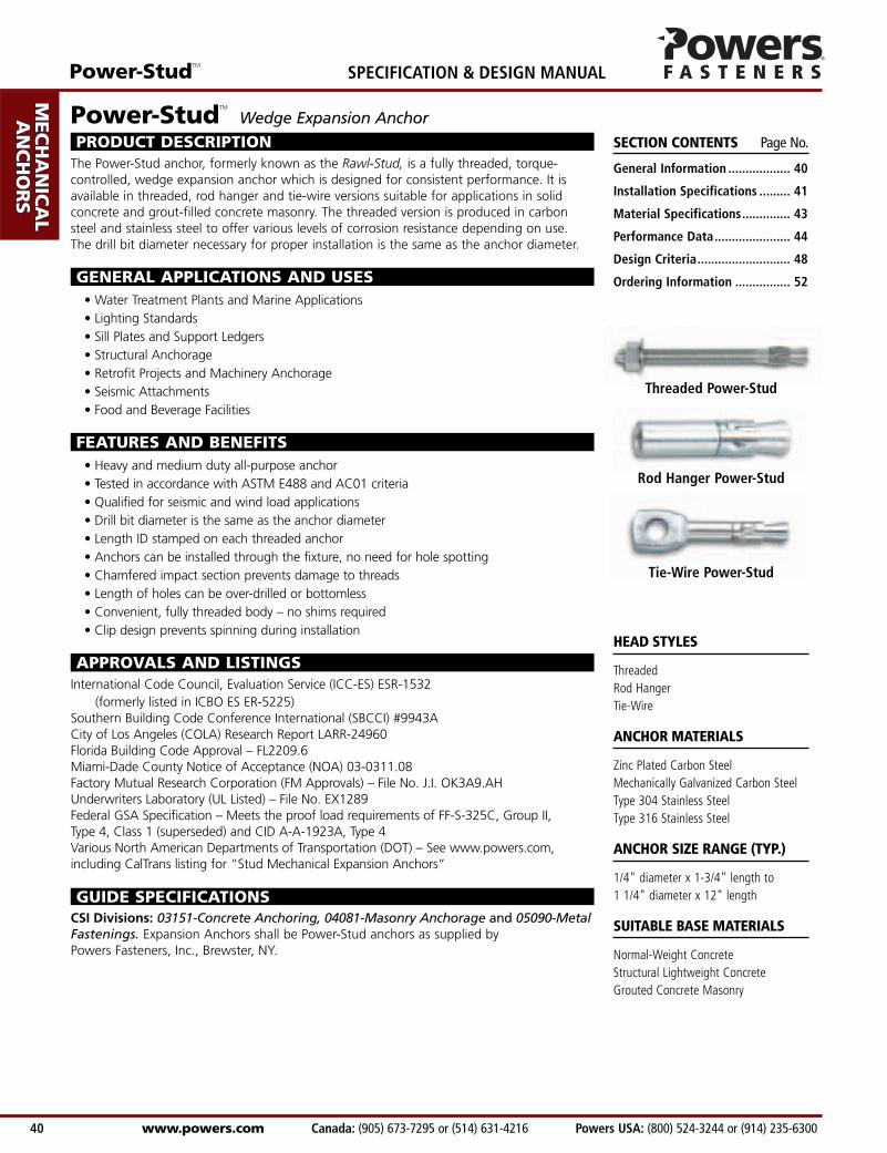
Threaded Power-Stud
Rod Hanger Power-Stud
Tie-Wire Power-Stud
HEAD STYLES
ThreadedRod HangerTie-Wire
ANCHOR MATERIALS
Zinc Plated Carbon SteelMechanically Galvanized Carbon SteelType 304 Stainless SteelType 316 Stainless Steel
ANCHOR SIZE RANGE (TYP.)
1/4" diameter x 1-3/4" length to 1 1/4" diameter x 12" length
SUITABLE BASE MATERIALS
Normal-Weight ConcreteStructural Lightweight ConcreteGrouted Concrete Masonry
Power-StudTM
Wedge Expansion Anchor
PRODUCT DESCRIPTIONThe Power-Stud anchor, formerly known as the Rawl-Stud, is a fully threaded, torque-controlled, wedge expansion anchor which is designed for consistent performance. It isavailable in threaded, rod hanger and tie-wire versions suitable for applications in solidconcrete and grout-filled concrete masonry. The threaded version is produced in carbonsteel and stainless steel to offer various levels of corrosion resistance depending on use.The drill bit diameter necessary for proper installation is the same as the anchor diameter.
GENERAL APPLICATIONS AND USES• Water Treatment Plants and Marine Applications• Lighting Standards• Sill Plates and Support Ledgers• Structural Anchorage• Retrofit Projects and Machinery Anchorage• Seismic Attachments• Food and Beverage Facilities
FEATURES AND BENEFITS• Heavy and medium duty all-purpose anchor• Tested in accordance with ASTM E488 and AC01 criteria• Qualified for seismic and wind load applications• Drill bit diameter is the same as the anchor diameter• Length ID stamped on each threaded anchor• Anchors can be installed through the fixture, no need for hole spotting• Chamfered impact section prevents damage to threads• Length of holes can be over-drilled or bottomless• Convenient, fully threaded body – no shims required• Clip design prevents spinning during installation
APPROVALS AND LISTINGSInternational Code Council, Evaluation Service (ICC-ES) ESR-1532
(formerly listed in ICBO ES ER-5225)Southern Building Code Conference International (SBCCI) #9943ACity of Los Angeles (COLA) Research Report LARR-24960Florida Building Code Approval – FL2209.6Miami-Dade County Notice of Acceptance (NOA) 03-0311.08Factory Mutual Research Corporation (FM Approvals) – File No. J.I. OK3A9.AHUnderwriters Laboratory (UL Listed) – File No. EX1289Federal GSA Specification – Meets the proof load requirements of FF-S-325C, Group II,Type 4, Class 1 (superseded) and CID A-A-1923A, Type 4Various North American Departments of Transportation (DOT) – See www.powers.com,including CalTrans listing for “Stud Mechanical Expansion Anchors”
GUIDE SPECIFICATIONSCSI Divisions: 03151-Concrete Anchoring, 04081-Masonry Anchorage and 05090-MetalFastenings. Expansion Anchors shall be Power-Stud anchors as supplied by Powers Fasteners, Inc., Brewster, NY.
AD
HESIV
ES
MEC
HAN
ICA
LAN
CH
OR
S
WA
LL AN
CH
OR
S
POW
DER
AC
TUA
TED
GA
S FA
STENIN
G
RO
OFIN
G
FASTEN
ERS
CA
RB
IDE
DR
ILL BITS
SPECIFICATION & DESIGN MANUAL Power-StudTM
www.powers.com Canada: (905) 673-7295 or (514) 631-4216 Powers USA: (800) 524-3244 or (914) 235-6300 40
Keith
Polygon
Dimension 1/4" 3/8" 1/2" 5/8" 3/4" 7/8" 1"
ANSI Drill Bit Size, dbit (in.) 1/4 3/8 1/2 5/8 3/4 7/8 1Fixture Clearance Hole, dh (in.) 5/16 7/16 9/16 11/16 13/16 15/16 1-1/8Thread Size (UNC) 1/4-20 3/8-16 1/2-13 5/8-11 3/4-10 7/8-9 1-8Nut Height (in.) 7/32 21/64 7/16 35/64 41/64 3/4 55/64Washer O.D (304 SS)., dw (in.) 5/8 13/16 1 1/16 1 3/4 2 2 1/4 2 1/2Washer O.D (316 SS)., dw (in.) 5/8 7/8 1 1/4 1 1/2 1 3/4 2 2Wrench Size (in.) 7/16 9/16 3/4 15/16 1 1/8 1 5/16 1 1/2Max. Tightening Torque, Tmax (ft-lbs) 8 28 60 90 175 250 300
Anchor Diameter, d
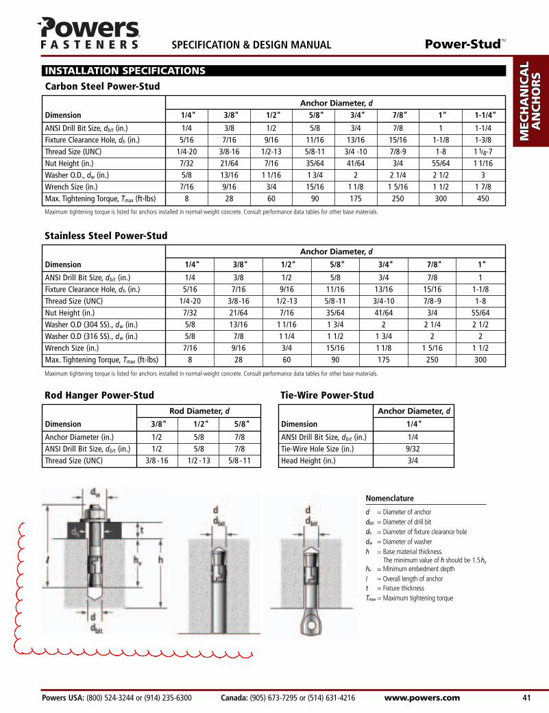
INSTALLATION SPECIFICATIONS
Carbon Steel Power-Stud
Rod Hanger Power-Stud
Stainless Steel Power-Stud
Dimension 3/8" 1/2" 5/8"
Anchor Diameter (in.) 1/2 5/8 7/8ANSI Drill Bit Size, dbit (in.) 1/2 5/8 7/8Thread Size (UNC) 3/8 -16 1/2 -13 5/8 -11
Rod Diameter, d
Tie-Wire Power-Stud
Dimension 1/4"
ANSI Drill Bit Size, dbit (in.) 1/4Tie-Wire Hole Size (in.) 9/32Head Height (in.) 3/4
Anchor Diameter, d
Dimension 1/4" 3/8" 1/2" 5/8" 3/4" 7/8" 1" 1-1/4"
ANSI Drill Bit Size, dbit (in.) 1/4 3/8 1/2 5/8 3/4 7/8 1 1-1/4Fixture Clearance Hole, dh (in.) 5/16 7/16 9/16 11/16 13/16 15/16 1-1/8 1-3/8Thread Size (UNC) 1/4-20 3/8-16 1/2-13 5/8-11 3/4 -10 7/8-9 1-8 1 1/4-7Nut Height (in.) 7/32 21/64 7/16 35/64 41/64 3/4 55/64 1 1/16Washer O.D., dw (in.) 5/8 13/16 1 1/16 1 3/4 2 2 1/4 2 1/2 3Wrench Size (in.) 7/16 9/16 3/4 15/16 1 1/8 1 5/16 1 1/2 1 7/8Max. Tightening Torque, Tmax (ft-lbs) 8 28 60 90 175 250 300 450
Anchor Diameter, d
Nomenclature
d = Diameter of anchordbit = Diameter of drill bitdh = Diameter of fixture clearance holedw = Diameter of washerh = Base material thickness.
The minimum value of h should be 1.5hv
hv = Minimum embedment depthl = Overall length of anchort = Fixture thicknessTmax = Maximum tightening torque
Maximum tightening torque is listed for anchors installed in normal-weight concrete. Consult performance data tables for other base materials.
Maximum tightening torque is listed for anchors installed in normal-weight concrete. Consult performance data tables for other base materials.
Power-StudTM
Powers USA: (800) 524-3244 or (914) 235-6300 Canada: (905) 673-7295 or (514) 631-4216 www.powers.com 41
AD
HES
IVES
MEC
HAN
ICA
LAN
CH
OR
S
WA
LL
AN
CH
OR
S
POW
DER
AC
TUA
TED
GA
S FA
STEN
ING
RO
OFIN
G
FAST
ENER
S
CA
RB
IDE
DR
ILL
BIT
S
SPECIFICATION & DESIGN MANUAL
Keith
Polygon
Keith
Polygon
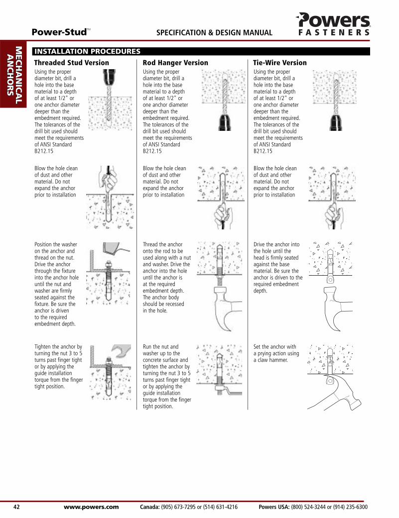
Using the properdiameter bit, drill ahole into the basematerial to a depth of at least 1/2" orone anchor diameterdeeper than theembedment required.The tolerances of thedrill bit used shouldmeet the requirementsof ANSI StandardB212.15
Blow the hole clean of dust and othermaterial. Do notexpand the anchorprior to installation
Position the washeron the anchor andthread on the nut.Drive the anchorthrough the fixtureinto the anchor holeuntil the nut andwasher are firmlyseated against thefixture. Be sure theanchor is driven to the requiredembedment depth.
Tighten the anchor byturning the nut 3 to 5turns past finger tightor by applying theguide installationtorque from the fingertight position.
Using the properdiameter bit, drill ahole into the basematerial to a depth of at least 1/2" orone anchor diameterdeeper than theembedment required.The tolerances of thedrill bit used shouldmeet the requirementsof ANSI StandardB212.15
Blow the hole clean of dust and othermaterial. Do notexpand the anchorprior to installation
Drive the anchor intothe hole until thehead is firmly seatedagainst the basematerial. Be sure theanchor is driven to therequired embedmentdepth.
Set the anchor with a prying action usinga claw hammer.
Using the properdiameter bit, drill ahole into the basematerial to a depth of at least 1/2" orone anchor diameterdeeper than theembedment required.The tolerances of thedrill bit used shouldmeet the requirementsof ANSI StandardB212.15
Blow the hole clean of dust and othermaterial. Do notexpand the anchorprior to installation
Thread the anchoronto the rod to beused along with a nutand washer. Drive theanchor into the holeuntil the anchor is at the requiredembedment depth.The anchor bodyshould be recessed in the hole.
Run the nut andwasher up to theconcrete surface andtighten the anchor byturning the nut 3 to 5turns past finger tightor by applying theguide installationtorque from the fingertight position.
INSTALLATION PROCEDURES
Threaded Stud Version Rod Hanger Version Tie-Wire Version
AD
HESIV
ES
MEC
HAN
ICA
LAN
CH
OR
S
WA
LL AN
CH
OR
S
POW
DER
AC
TUA
TED
GA
S FA
STENIN
G
RO
OFIN
G
FASTEN
ERS
CA
RB
IDE
DR
ILL BITS
SPECIFICATION & DESIGN MANUAL Power-StudTM
www.powers.com Canada: (905) 673-7295 or (514) 631-4216 Powers USA: (800) 524-3244 or (914) 235-6300 42
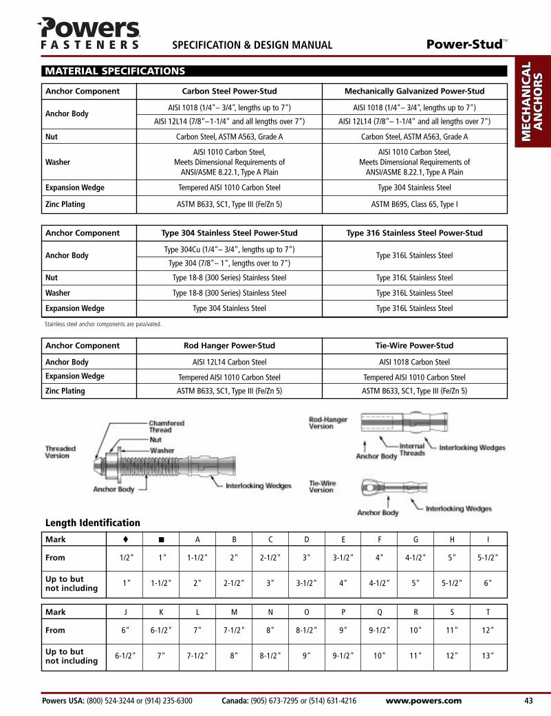
MATERIAL SPECIFICATIONS
Mark � � A B C D E F G H I
From 1/2" 1" 1-1/2" 2" 2-1/2" 3" 3-1/2" 4" 4-1/2" 5" 5-1/2"
Up to but 1" 1-1/2" 2" 2-1/2" 3" 3-1/2" 4" 4-1/2" 5" 5-1/2" 6"not including
Length Identification
Mark J K L M N O P Q R S T
From 6" 6-1/2" 7" 7-1/2" 8" 8-1/2" 9" 9-1/2" 10" 11" 12"
Up to but 6-1/2" 7" 7-1/2" 8" 8-1/2" 9" 9-1/2" 10" 11" 12" 13"not including
Anchor Component Carbon Steel Power-Stud Mechanically Galvanized Power-Stud
Anchor BodyAISI 1018 (1/4"– 3/4", lengths up to 7") AISI 1018 (1/4"– 3/4", lengths up to 7")
AISI 12L14 (7/8"–1-1/4" and all lengths over 7") AISI 12L14 (7/8"– 1-1/4" and all lengths over 7")
Nut Carbon Steel, ASTM A563, Grade A Carbon Steel, ASTM A563, Grade A
AISI 1010 Carbon Steel, AISI 1010 Carbon Steel,Washer Meets Dimensional Requirements of Meets Dimensional Requirements of
ANSI/ASME 8.22.1, Type A Plain ANSI/ASME 8.22.1, Type A Plain
Expansion Wedge Tempered AISI 1010 Carbon Steel Type 304 Stainless Steel
Zinc Plating ASTM B633, SC1, Type III (Fe/Zn 5) ASTM B695, Class 65, Type I
Anchor Component Type 304 Stainless Steel Power-Stud Type 316 Stainless Steel Power-Stud
Anchor BodyType 304Cu (1/4"– 3/4", lengths up to 7")
Type 316L Stainless SteelType 304 (7/8"– 1", lengths over to 7")
Nut Type 18-8 (300 Series) Stainless Steel Type 316L Stainless Steel
Washer Type 18-8 (300 Series) Stainless Steel Type 316L Stainless Steel
Expansion Wedge Type 304 Stainless Steel Type 316L Stainless Steel
Anchor Component Rod Hanger Power-Stud Tie-Wire Power-Stud
Anchor Body AISI 12L14 Carbon Steel AISI 1018 Carbon Steel
Expansion Wedge Tempered AISI 1010 Carbon Steel Tempered AISI 1010 Carbon Steel
Zinc Plating ASTM B633, SC1, Type III (Fe/Zn 5) ASTM B633, SC1, Type III (Fe/Zn 5)
Stainless steel anchor components are passivated.
Power-StudTM
Powers USA: (800) 524-3244 or (914) 235-6300 Canada: (905) 673-7295 or (514) 631-4216 www.powers.com 43
AD
HES
IVES
MEC
HAN
ICA
LAN
CH
OR
S
WA
LL
AN
CH
OR
S
POW
DER
AC
TUA
TED
GA
S FA
STEN
ING
RO
OFIN
G
FAST
ENER
S
CA
RB
IDE
DR
ILL
BIT
S
SPECIFICATION & DESIGN MANUAL
1/4(6.4)
3/8(9.5)
1/2(12.7)
5/8(15.9)
3/4(19.1)
7/8(22.2)
1(25.4)
1 1/4(31.8)
1 1/8 1,240 1,580 1,440 1,620 1,740 1,620(28.6) (5.6) (7.1) (6.5) (7.3) (7.8) (7.3)1 1/2 1,635 1,580 2,080 1,620 2,100 1,620(38.1) (7.4) (7.1) (9.4) (7.3) (9.5) (7.3)
2 1,900 1,580 2,080 1,620 2,100 1,620(50.8) (8.6) (7.1) (9.4) (7.3) (9.5) (7.3)2 3/4 2,340 1,655 2,360 2,070 2,535 2,080(69.9) (10.5) (7.4) (10.6) (9.3) (11.4) (9.4)1 5/8 1,920 3,560 3,040 3,760 3,040 3,760(41.3) (8.6) (16.0) (13.7) (16.9) (13.7) (16.9)
2 2,800 3,560 3,850 3,760 4,075 3,760(50.8) (12.6) (16.0) (17.3) (16.9) (18.3) (16.9)
3 4,100 3,560 6,020 3,760 6,025 3,760(76.2) (18.5) (16.0) (27.1) (16.9) (27.1) (16.9)4 1/4 5,045 3,840 6,020 5,185 6,025 5,185
(108.0) (22.7) (17.3) (27.1) (23.3) (27.1) (23.3)2 1/4 3,440 6,540 5,560 6,800 6,540 6,800(57.2) (15.5) (29.4) (25.0) (30.6) (29.4) (30.6)
3 5,100 6,540 8,160 6,800 9,200 6,800(76.2) (23.0) (29.4) (36.7) (30.6) (41.4) (30.6)
4 5,700 6,540 8,160 6,800 9,200 6,800(101.6) (25.7) (29.4) (36.7) (30.6) (41.4) (30.6)
6 7,910 7,025 9,550 7,190 10,730 7,190(152.4) (35.6) (31.6) (43.0) (32.4) (48.3) (32.4)2 3/4 6,240 9,280 8,300 11,900 9,860 11,900(69.9) (27.8) (41.8) (37.4) (53.6) (44.4) (53.6)
4 9,600 9,280 10,825 11,900 13,495 11,900(101.6) (43.2) (41.8) (48.7) (53.6) (60.7) (53.6)
5 10,640 9,280 12,510 11,900 16,410 11,900(127.0) (47.3) (41.8) (56.3) (53.6) (73.8) (53.6)
7 12,500 9,760 15,880 12,170 16,410 12,170(177.8) (55.6) (43.9) (71.5) (54.8) (73.8) (54.8)3 3/8 7,420 12,380 10,000 15,060 12,540 15,060(85.7) (33.0) (55.7) (45.0) (67.8) (56.4) (67.8)
5 10,640 12,380 14,630 15,060 17,265 15,060(127.0) (47.3) (55.7) (65.8) (67.8) (77.7) (67.8)
6 10,640 12,380 17,080 15,060 20,180 15,060(152.4) (47.3) (55.7) (76.9) (67.8) (90.8) (67.8)
8 14,000 13,600 22,000 17,110 24,905 17,110(203.2) (62.3) (61.2) (99.0) (77.0) (112.1) (77.0)3 7/8 7,600 17,960 12,300 24,160 17,300 24,160(98.4) (34.2) (80.8) (55.4) (108.7) (77.9) (108.7)4 1/2 9,600 17,960 15,620 24,160 20,075 24,160
(114.3) (43.2) (80.8) (70.3) (108.7) (90.3) (108.7)5 3/4 10,640 17,960 19,880 24,160 25,625 24,160
(146.1) (47.3) (80.8) (89.5) (108.7) (115.3) (108.7)7 12,680 17,960 20,440 24,160 31,180 24,160
(177.8) (56.4) (80.8) (92.0) (108.7) (140.3) (108.7)8 15,160 18,630 22,840 25,710 31,180 25,710
(203.2) (67.4) (83.8) (101.6) (115.7) (140.3) (115.7)4 1/2 8,740 26,420 13,820 31,100 21,220 31,100
(114.3) (39.3) (118.9) (62.2) (140.0) (94.4) (140.0)5 1/2 12,770 26,420 20,280 31,100 27,800 31,100
(139.7) (57.5) (118.9) (91.3) (140.0) (123.7) (140.0)6 1/2 16,605 26,420 25,485 31,100 34,360 31,100
(165.1) (74.7) (118.9) (114.7) (140.0) (152.8) (140.0)8 22,360 26,420 27,040 31,100 44,220 31,100
(203.2) (100.6) (118.9) (121.7) (140.0) (199.0) (140.0)9 26,195 27,020 34,205 32,370 44,220 32,370
(228.6) (117.9) (121.6) (153.9) (145.7) (199.0) (145.7)5 1/2 16,800 40,820 26,980 40,820 36,925 40,820
(139.7) (75.6) (183.7) (121.4) (183.7) (166.2) (183.7)7 25,360 40,820 35,410 40,820 44,845 40,820
(177.8) (114.1) (183.7) (159.3) (183.7) (201.8) (183.7)10 28,800 40,820 52,280 40,820 60,690 40,820
(254.0) (129.6) (183.7) (235.3) (183.7) (273.1) (183.7)
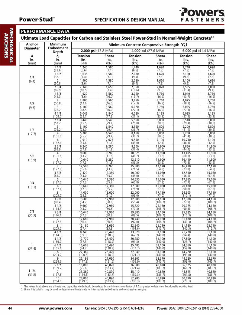
Minimum Concrete Compressive Strength (f c )MinimumEmbedment
Depthhvin.
(mm)
AnchorDiameter
din.
(mm)
Tension Shear Tension Shear Tension Shearlbs. lbs. lbs. lbs. lbs. lbs.(kN) (kN) (kN) (kN) (kN) (kN)
2,000 psi (13.8 MPa) 4,000 psi (27.6 MPa) 6,000 psi (41.4 MPa)
PERFORMANCE DATA
Ultimate Load Capacities for Carbon and Stainless Steel Power-Stud in Normal-Weight Concrete1,2
1. The values listed above are ultimate load capacities which should be reduced by a minimum safety factor of 4.0 or greater to determine the allowable working load.2. Linear interpolation may be used to determine ultimate loads for intermediate embedments and compressive strengths.
AD
HESIV
ES
MEC
HAN
ICA
LAN
CH
OR
S
WA
LL AN
CH
OR
S
POW
DER
AC
TUA
TED
GA
S FA
STENIN
G
RO
OFIN
G
FASTEN
ERS
CA
RB
IDE
DR
ILL BITS
SPECIFICATION & DESIGN MANUAL Power-StudTM
www.powers.com Canada: (905) 673-7295 or (514) 631-4216 Powers USA: (800) 524-3244 or (914) 235-6300 44
1/4(6.4)
3/8(9.5)
1/2(12.7)
5/8(15.9)
3/4(19.1)
7/8(22.2)
1(25.4)
1 1/4(31.8)
1 1/8 310 395 360 405 435 405(28.6) (1.4) (1.8) (1.6) (1.8) (2.0) (1.8)1 1/2 410 395 520 405 525 405(38.1) (1.8) (1.8) (2.3) (1.8) (2.4) (1.8)
2 475 395 520 405 525 405(50.8) (2.1) (1.8) (2.3) (1.8) (2.4) (1.8)2 3/4 585 415 590 520 635 520(69.9) (2.6) (1.9) (2.7) (2.3) (2.9) (2.3)1 5/8 480 890 760 940 760 940(41.3) (2.2) (4.0) (3.4) (4.2) (3.4) (4.2)
2 700 890 965 940 1,020 940(50.8) (3.2) (4.0) (4.3) (4.2) (4.6) (4.2)
3 1,025 890 1,505 940 1,505 940(76.2) (4.6) (4.0) (6.8) (4.2) (6.8) (4.2)4 1/4 1,260 960 1,505 1,295 1,505 1,295
(108.0) (5.7) (4.3) (6.8) (5.8) (6.8) (5.8)2 1/4 860 1,635 1,390 1,700 1,635 1,700(57.2) (3.9) (7.4) (6.3) (7.7) (7.4) (7.7)
3 1,275 1,635 2,040 1,700 2,300 1,700(76.2) (5.7) (7.4) (9.2) (7.7) (10.4) (7.7)
4 1,425 1,635 2,040 1,700 2,300 1,700(101.6) (6.4) (7.4) (9.2) (7.7) (10.4) (7.7)
6 1,980 1,755 2,390 1,800 2,685 1,800(152.4) (8.9) (7.9) (10.8) (8.1) (12.1) (8.1)2 3/4 1,560 2,320 2,075 2,975 2,465 2,975(69.9) (6.9) (10.4) (9.3) (13.4) (11.1) (13.4)
4 2,400 2,320 2,705 2,975 3,375 2,975(101.6) (10.8) (10.4) (12.2) (13.4) (15.2) (13.4)
5 2,660 2,320 3,130 2,975 4,105 2,975(127.0) (11.8) (10.4) (14.1) (13.4) (18.5) (13.4)
7 3,125 2,440 3,970 3,045 4,105 3,045(177.8) (13.9) (11.0) (17.9) (13.7) (18.5) (13.7)3 3/8 1,855 3,095 2,500 3,765 3,135 3,765(85.7) (8.3) (13.9) (11.3) (16.9) (14.1) (16.9)
5 2,660 3,095 3,660 3,765 4,315 3,765(127.0) (11.8) (13.9) (16.5) (16.9) (19.4) (16.9)
6 2,660 3,095 4,270 3,765 5,045 3,765(152.4) (11.8) (13.9) (19.2) (16.9) (22.7) (16.9)
8 3,500 3,400 5,710 4,280 6,225 4,280(203.2) (15.6) (15.3) (25.4) (19.3) (28.0) (19.3)3 7/8 1,900 4,490 3,075 6,040 4,325 6,040(98.4) (8.6) (20.2) (13.8) (27.2) (19.5) (27.2)4 1/2 2,400 4,490 3,905 6,040 5,305 6,040
(114.3) (10.8) (20.2) (17.6) (27.2) (23.6) (27.2)5 3/4 2,660 4,490 4,970 6,040 6,950 6,040
(146.1) (11.8) (20.2) (22.4) (27.2) (30.9) (27.2)7 3,170 4,490 5,110 6,040 8,590 6,040
(177.8) (14.1) (20.2) (23.0) (27.2) (38.2 ) (27.2)8 3,790 4,660 5,710 6,430 7,795 6,430
(203.2) (16.9) (21.0) (25.4) (28.9) (35.1) (28.9)4 1/2 2,185 6,605 3,455 7,775 5,305 7,775
(114.3) (9.8) (29.7) (15.5) (35.0) (23.6) (35.0)5 1/2 3,195 6,605 5,070 7,775 6,950 7,775
(139.7) (14.4) (29.7) (22.8) (35.0) (30.9) (35.0)6 1/2 4,150 6,605 6,370 7,775 8,590 7,775
(165.1) (18.7) (29.7) (28.7) (35.0) (38.2) (35.0)8 5,590 6,605 6,760 7,775 11,055 7,775
(203.2) (25.2) (29.7) (30.4) (35.0) (49.7) (35.0)9 6,550 6,755 8,550 8,095 11,055 8,095
(228.6) (29.5) (30.4) (38.5) (36.4) (49.7) (36.4)5 1/2 4,200 10,205 6,745 10,205 9,230 10,205
(139.7) (18.9) (45.9) (30.4) (45.9) (41.5) (45.9)7 6,340 10,205 8,855 10,205 11,210 10,205
(177.8) (28.5) (45.9) (39.8) (45.9) (50.4) (45.9)10 7,200 10,205 13,070 10,205 15,175 10,205
(254.0) (32.4) (45.9) (58.8) (45.9) (68.3) (45.9)
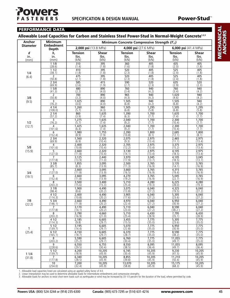
Minimum Concrete Compressive Strength (f c )MinimumEmbedment
Depthhvin.
(mm)
AnchorDiameter
din.
(mm)
Tension Shear Tension Shear Tension Shearlbs. lbs. lbs. lbs. lbs. lbs.(kN) (kN) (kN) (kN) (kN) (kN)
2,000 psi (13.8 MPa) 4,000 psi (27.6 MPa) 6,000 psi (41.4 MPa)
PERFORMANCE DATA
Allowable Load Capacities for Carbon and Stainless Steel Power-Stud in Normal-Weight Concrete1,2,3
1. Allowable load capacities listed are calculated using an applied safety factor of 4.0.2. Linear interpolation may be used to determine allowable loads for intermediate embedments and compressive strengths.3. Allowable loads for anchors to resist short-term loads such as earthquake or wind may be increased by 33-1/3 percent for the duration of the load, where permitted by code.
Power-StudTM
Powers USA: (800) 524-3244 or (914) 235-6300 Canada: (905) 673-7295 or (514) 631-4216 www.powers.com 45
AD
HES
IVES
MEC
HAN
ICA
LAN
CH
OR
S
WA
LL
AN
CH
OR
S
POW
DER
AC
TUA
TED
GA
S FA
STEN
ING
RO
OFIN
G
FAST
ENER
S
CA
RB
IDE
DR
ILL
BIT
S
SPECIFICATION & DESIGN MANUAL

1 1/8 720 180 960 240 1,200 300 720 180(28.6) (3.2) (0.8) (4.3) (1.1) (5.4) (1.4) (3.2) (0.8)
1 5/8 1,600 400 1,940 485 2,300 575 1,840 460(41.3) (7.2) (1.8) (8.7) (2.2) (10.4) (2.6) (8.3) (2.1)
3 – – 2,860 715 – – 1,840 460(76.2) (12.9) (3.2) (8.3) (2.1)
2 1/4 2,820 705 3,180 795 3,560 890 5,040 1,260(57.2) (12.7) (3.2) (14.3) (3.6) (16.0) (4.0) (22.7) (5.7)
3 – – 4,020 1,005 – – 5,040 1,260(76.2) (18.1) (4.5) (22.7) (5.7)
5 – – 4,200 1,050 – – 5,040 1,260(127.0) (18.9) (4.7) (22.7) (5.7)
2 3/4 4,380 1,095 4,980 1,245 5,580 1,395 6,940 1,735(69.9) (19.7) (4.9) (22.4) (5.6) (25.1) (6.3) (31.2) (7.8)
3 1/2 – – 4,840 1,210 – – 6,940 1,735(88.9) (21.8) (5.4) (31.2) (7.8)
5 – – 6,920 1,730 – – 6,940 1,735(127.0) (31.1) (7.8) (31.2) (7.8)
3 3/8 5,060 1,265 5,600 1,400 6,140 1,535 9,880 2,470(85.7) (22.8) (5.7) (25.2) (6.3) (27.6) (6.9) (44.5) (11.1)
4 – – 8,240 2,060 – – 9,880 2,470(101.6) (37.1) (9.3) (44.5) (11.1)
5 – – 9,300 2,325 – – 9,880 2,470(127.0) (41.9) (10.5) (44.5) (11.1)
Shear, lbs (kN)
1/4(6.4)
3/8(9.5)
1/2(12.7)
5/8(15.9)
3/4(19.1)
Minimum Concrete Compressive Strength (f c )
Tension, lbs (kN)
1. The values listed above are ultimate and allowable load capacities for anchors installed in sand-lightweight concrete.2. Allowable load capacities are calculated using an applied safety factor of 4.0.3. Linear interpolation may be used to determine loads for intermediate embedments and compressive strengths.
4
20
30
65
90
Min.Embed.Depth
hvin.
(mm)
AnchorDiameter
din.
(mm)
Max.GuideTorque
Tmaxft.-lbs. Ultimate Allowable Ultimate Allowable Ultimate Allowable Ultimate Allowable
Load Load Load Load Load Load Load Load
3,000 psi (20.7 MPa) 4,000 psi (27.6 MPa) 5,000 psi (34.5 MPa) fc ≥ 3,000 psi (20.7 MPa)
PERFORMANCE DATA
Ultimate and Allowable Load Capacities for Carbon and Stainless Steel Power-Stud in Structural Lightweight Concrete1,2,3
AD
HESIV
ES
MEC
HAN
ICA
LAN
CH
OR
S
WA
LL AN
CH
OR
S
POW
DER
AC
TUA
TED
GA
S FA
STENIN
G
RO
OFIN
G
FASTEN
ERS
CA
RB
IDE
DR
ILL BITS
SPECIFICATION & DESIGN MANUAL Power-StudTM
www.powers.com Canada: (905) 673-7295 or (514) 631-4216 Powers USA: (800) 524-3244 or (914) 235-6300 46
1/4(6.4)
3/8(9.5)
1/2(12.7)
5/8(15.9)
3/4(19.1)
Power-StudTM
Powers USA: (800) 524-3244 or (914) 235-6300 Canada: (905) 673-7295 or (514) 631-4216 www.powers.com 47
AD
HES
IVES
MEC
HAN
ICA
LAN
CH
OR
S
WA
LL
AN
CH
OR
S
POW
DER
AC
TUA
TED
GA
S FA
STEN
ING
RO
OFIN
G
FAST
ENER
S
CA
RB
IDE
DR
ILL
BIT
S
SPECIFICATION & DESIGN MANUAL
PERFORMANCE DATA
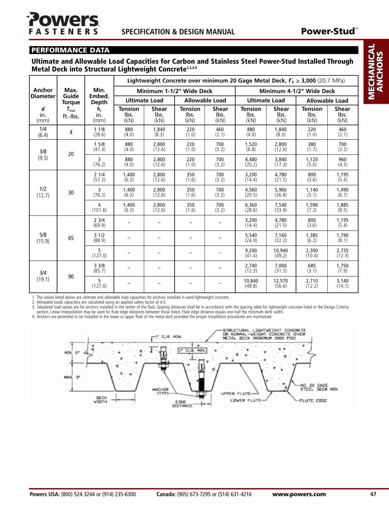
Ultimate and Allowable Load Capacities for Carbon and Stainless Steel Power-Stud Installed Through Metal Deck into Structural Lightweight Concrete1,2,3,4
1 1/8 880 1,840 220 460 880 1,840 220 460(28.6) (4.0) (8.3) (1.0) (2.1) (4.0) (8.3) (1.0) (2.1)
1 5/8 880 2,800 220 700 1,520 2,800 380 700(41.3) (4.0) (12.6) (1.0) (3.2) (6.8) (12.6) (1.7) (3.2)
3 880 2,800 220 700 4,480 3,840 1,120 960(76.2) (4.0) (12.6) (1.0) (3.2) (20.2) (17.3) (5.0) (4.3)
2 1/4 1,400 2,800 350 700 3,200 4,780 800 1,195(57.2) (6.3) (12.6) (1.6) (3.2) (14.4) (21.5) (3.6) (5.4)
3 1,400 2,800 350 700 4,560 5,960 1,140 1,490(76.2) (6.3) (12.6) (1.6) (3.2) (20.5) (26.8) (5.1) (6.7)
4 1,400 2,800 350 700 6,360 7,540 1,590 1,885(101.6) (6.3) (12.6) (1.6) (3.2) (28.6) (33.9) (7.2) (8.5)
2 3/4 – – – – 3,200 4,780 800 1,195(69.9) (14.4) (21.5) (3.6) (5.4)
3 1/2 – – – – 5,540 7,160 1,385 1,790(88.9) (24.9) (32.2) (6.2) (8.1)
5 – – – – 9,200 10,940 2,300 2,735(127.0) (41.4) (49.2) (10.4) (12.3)
3 3/8 – – – – 2,740 7,000 685 1,750(85.7) (12.3) (31.5) (3.1) (7.9)
5 – – – – 10,840 12,570 2,710 3,140(127.0) (48.8) (56.6) (12.2) (14.1)
Lightweight Concrete over minimum 20 Gage Metal Deck, f c ≥ 3,000 (20.7 MPa)
Minimum 1-1/2" Wide Deck Minimum 4-1/2" Wide Deck
4
20
30
65
90
Min.Embed.Depth
hvin.
(mm)
AnchorDiameter
din.
(mm)
Max.GuideTorque
Tmax
ft.-lbs.Tension Shear Tension Shear Tension Shear Tension Shear
lbs. lbs. lbs. lbs. lbs. lbs. lbs. lbs.(kN) (kN) (kN) (kN) (kN) (kN) (kN) (kN)
Ultimate Load Allowable Load Ultimate Load Allowable Load
1. The values listed above are ultimate and allowable load capacities for anchors installed in sand-lightweight concrete.2. Allowable loads capacities are calculated using an applied safety factor of 4.0.3. Tabulated load values are for anchors installed in the center of the flute. Spacing distances shall be in accordance with the spacing table for lightweight concrete listed in the Design Criteria
section. Linear interpolation may be used for flute edge distances between those listed. Flute edge distance equals one-half the minimum deck width.4. Anchors are permitted to be installed in the lower or upper flute of the metal deck provided the proper installation procedures are maintained.
1 1/8 3 3/4 3 3/4 1,230 1,230 245 245(28.6) (95.3) (95.3) (5.5) (5.5) (1.1) (1.1)
2 5 1/4 3 3/4 1,670 1,230 335 245(50.8) (133.4) (95.3) (7.5) (5.5) (1.5) (1.1)1 5/8 5 5/8 5 5/8 1,990 3,240 400 650(41.3) (142.9) (142.9) (9.0) (14.6) (1.8) (2.9)
3 7 7/8 5 5/8 2,200 3,240 440 650(76.2) (200.0) (142.9) (9.9) (14.6) (2.0) (2.9)2 1/4 7 1/2 7 1/2 2,260 6,230 450 1,245(57.2) (190.5) (190.5) (10.2) (28.0) (2.0) (5.6)
4 10 1/2 7 1/2 2,620 6,230 525 1,245(101.6) (266.7) (190.5) (11.8) (28.0) (2.4) (5.6)2 3/4 9 3/8 9 3/8 3,170 7,830 635 1,565(69.9) (238.1) (238.1) (14.3) (35.2) (2.9) (7.0)
5 13 1/8 9 3/8 3,780 7,830 755 1,565(127.0) (333.4) (238.1) (17.0) (35.2) (3.4) (7.0)3 3/8 11 1/4 11 1/4 4,085 9,760 815 1,950(85.7) (285.8) (285.8) (18.4) (43.9) (3.7) (8.8)
5 15 3/4 11 1/4 4,420 9,760 885 1,950(127.0) (400.1) (285.8) (19.9) (43.9) (4.0) (8.8)
DESIGN CRITERIA
NuNn( ) Vu
Vn( )+53
53
≤ 1 NuNn( ) Vu
Vn( )+ ≤ 1
Combined Loading
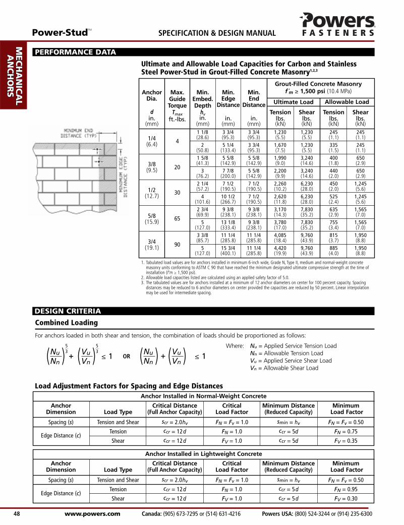
For anchors loaded in both shear and tension, the combination of loads should be proportioned as follows:
Where: Nu = Applied Service Tension LoadNn = Allowable Tension LoadVu = Applied Service Shear LoadVn = Allowable Shear Load
OR
Load Adjustment Factors for Spacing and Edge DistancesAnchor Installed in Normal-Weight Concrete
Anchor Critical Distance Critical Minimum Distance MinimumDimension Load Type (Full Anchor Capacity) Load Factor (Reduced Capacity) Load Factor
Spacing (s) Tension and Shear scr = 2.0hv FN = Fv = 1.0 smin = hv FN = Fv = 0.50
Edge Distance (c)Tension ccr = 12d FN = 1.0 ccr = 5d FN = 0.75
Shear ccr = 12d FV = 1.0 ccr = 5d FV = 0.35
Anchor Installed in Lightweight Concrete
Anchor Critical Distance Critical Minimum Distance MinimumDimension Load Type (Full Anchor Capacity) Load Factor (Reduced Capacity) Load Factor
Spacing (s) Tension and Shear scr = 2.0hv FN = Fv = 1.0 smin = hv FN = Fv = 0.50
Edge Distance (c)Tension ccr = 12d FN = 1.0 ccr = 5d FN = 0.95
Shear ccr = 12d FV = 1.0 ccr = 5d FV = 0.30
1. Tabulated load values are for anchors installed in minimum 6-inch wide, Grade N, Type II, medium and normal-weight concrete masonry units conforming to ASTM C 90 that have reached the minimum designated ultimate compressive strength at the time of installation (f'm ≥ 1,500 psi).
2. Allowable load capacities listed are calculated using an applied safety factor of 5.0.3. The tabulated values are for anchors installed at a minimum of 12 anchor diameters on center for 100 percent capacity. Spacing
distances may be reduced to 6 anchor diameters on center provided the capacities are reduced by 50 percent. Linear interpolation may be used for intermediate spacing.
1/4(6.4)
3/8(9.5)
1/2(12.7)
5/8(15.9)
3/4(19.1)
4
20
30
65
90
Max.GuideTorque
Tmaxft.-lbs.
AnchorDia.
din.
(mm)
Min.End
Distance
in.(mm)
Min.Embed.Depth
hvin.
(mm)
Min.Edge
Distance
in.(mm)
Tension Shear Tension Shearlbs. lbs. lbs. lbs.(kN) (kN) (kN) (kN)
Ultimate Load Allowable Load
Grout-Filled Concrete Masonryf m ≥ 1,500 psi (10.4 MPa)
Ultimate and Allowable Load Capacities for Carbon and Stainless Steel Power-Stud in Grout-Filled Concrete Masonry1,2,3
PERFORMANCE DATA
AD
HESIV
ES
MEC
HAN
ICA
LAN
CH
OR
S
WA
LL AN
CH
OR
S
POW
DER
AC
TUA
TED
GA
S FA
STENIN
G
RO
OFIN
G
FASTEN
ERS
CA
RB
IDE
DR
ILL BITS
SPECIFICATION & DESIGN MANUAL Power-StudTM
www.powers.com Canada: (905) 673-7295 or (514) 631-4216 Powers USA: (800) 524-3244 or (914) 235-6300 48
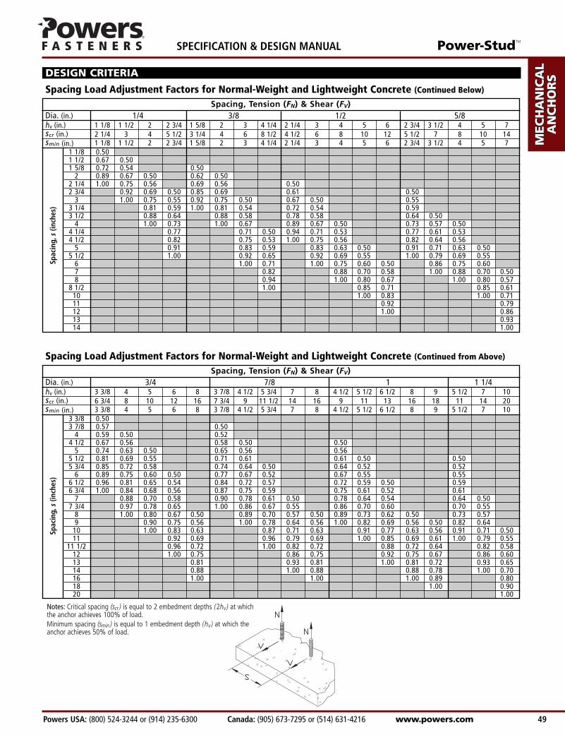
Dia. (in.) 1/4 3/8 1/2 5/8hv (in.) 1 1/8 1 1/2 2 2 3/4 1 5/8 2 3 4 1/4 2 1/4 3 4 5 6 2 3/4 3 1/2 4 5 7scr (in.) 2 1/4 3 4 5 1/2 3 1/4 4 6 8 1/2 4 1/2 6 8 10 12 5 1/2 7 8 10 14smin (in.) 1 1/8 1 1/2 2 2 3/4 1 5/8 2 3 4 1/4 2 1/4 3 4 5 6 2 3/4 3 1/2 4 5 7
1 1/8 0.501 1/2 0.67 0.501 5/8 0.72 0.54 0.50
2 0.89 0.67 0.50 0.62 0.502 1/4 1.00 0.75 0.56 0.69 0.56 0.502 3/4 0.92 0.69 0.50 0.85 0.69 0.61 0.50
3 1.00 0.75 0.55 0.92 0.75 0.50 0.67 0.50 0.553 1/4 0.81 0.59 1.00 0.81 0.54 0.72 0.54 0.593 1/2 0.88 0.64 0.88 0.58 0.78 0.58 0.64 0.50
4 1.00 0.73 1.00 0.67 0.89 0.67 0.50 0.73 0.57 0.504 1/4 0.77 0.71 0.50 0.94 0.71 0.53 0.77 0.61 0.534 1/2 0.82 0.75 0.53 1.00 0.75 0.56 0.82 0.64 0.56
5 0.91 0.83 0.59 0.83 0.63 0.50 0.91 0.71 0.63 0.505 1/2 1.00 0.92 0.65 0.92 0.69 0.55 1.00 0.79 0.69 0.55
6 1.00 0.71 1.00 0.75 0.60 0.50 0.86 0.75 0.607 0.82 0.88 0.70 0.58 1.00 0.88 0.70 0.508 0.94 1.00 0.80 0.67 1.00 0.80 0.57
8 1/2 1.00 0.85 0.71 0.85 0.6110 1.00 0.83 1.00 0.7111 0.92 0.7912 1.00 0.8613 0.9314 1.00
Spacing Load Adjustment Factors for Normal-Weight and Lightweight Concrete (Continued Below)
Spacing, Tension (FN) & Shear (FV)
Spac
ing,
s(in
ches
)
DESIGN CRITERIA
Power-StudTM
Powers USA: (800) 524-3244 or (914) 235-6300 Canada: (905) 673-7295 or (514) 631-4216 www.powers.com 49
AD
HES
IVES
MEC
HAN
ICA
LAN
CH
OR
S
WA
LL
AN
CH
OR
S
POW
DER
AC
TUA
TED
GA
S FA
STEN
ING
RO
OFIN
G
FAST
ENER
S
CA
RB
IDE
DR
ILL
BIT
S
SPECIFICATION & DESIGN MANUAL
Spacing Load Adjustment Factors for Normal-Weight and Lightweight Concrete (Continued from Above)
3 3/8 0.503 7/8 0.57 0.50
4 0.59 0.50 0.524 1/2 0.67 0.56 0.58 0.50 0.50
5 0.74 0.63 0.50 0.65 0.56 0.565 1/2 0.81 0.69 0.55 0.71 0.61 0.61 0.50 0.505 3/4 0.85 0.72 0.58 0.74 0.64 0.50 0.64 0.52 0.52
6 0.89 0.75 0.60 0.50 0.77 0.67 0.52 0.67 0.55 0.556 1/2 0.96 0.81 0.65 0.54 0.84 0.72 0.57 0.72 0.59 0.50 0.596 3/4 1.00 0.84 0.68 0.56 0.87 0.75 0.59 0.75 0.61 0.52 0.61
7 0.88 0.70 0.58 0.90 0.78 0.61 0.50 0.78 0.64 0.54 0.64 0.507 3/4 0.97 0.78 0.65 1.00 0.86 0.67 0.55 0.86 0.70 0.60 0.70 0.55
8 1.00 0.80 0.67 0.50 0.89 0.70 0.57 0.50 0.89 0.73 0.62 0.50 0.73 0.579 0.90 0.75 0.56 1.00 0.78 0.64 0.56 1.00 0.82 0.69 0.56 0.50 0.82 0.64
10 1.00 0.83 0.63 0.87 0.71 0.63 0.91 0.77 0.63 0.56 0.91 0.71 0.5011 0.92 0.69 0.96 0.79 0.69 1.00 0.85 0.69 0.61 1.00 0.79 0.55
11 1/2 0.96 0.72 1.00 0.82 0.72 0.88 0.72 0.64 0.82 0.5812 1.00 0.75 0.86 0.75 0.92 0.75 0.67 0.86 0.6013 0.81 0.93 0.81 1.00 0.81 0.72 0.93 0.6514 0.88 1.00 0.88 0.88 0.78 1.00 0.7016 1.00 1.00 1.00 0.89 0.8018 1.00 0.9020 1.00
Dia. (in.) 3/4 7/8 1 1 1/4hv (in.) 3 3/8 4 5 6 8 3 7/8 4 1/2 5 3/4 7 8 4 1/2 5 1/2 6 1/2 8 9 5 1/2 7 10scr (in.) 6 3/4 8 10 12 16 7 3/4 9 11 1/2 14 16 9 11 13 16 18 11 14 20smin (in.) 3 3/8 4 5 6 8 3 7/8 4 1/2 5 3/4 7 8 4 1/2 5 1/2 6 1/2 8 9 5 1/2 7 10
Spacing, Tension (FN) & Shear (FV)
Spac
ing,
s(in
ches
)
Notes: Critical spacing (scr ) is equal to 2 embedment depths (2hv) at whichthe anchor achieves 100% of load.Minimum spacing (smin ) is equal to 1 embedment depth (hv ) at which theanchor achieves 50% of load.
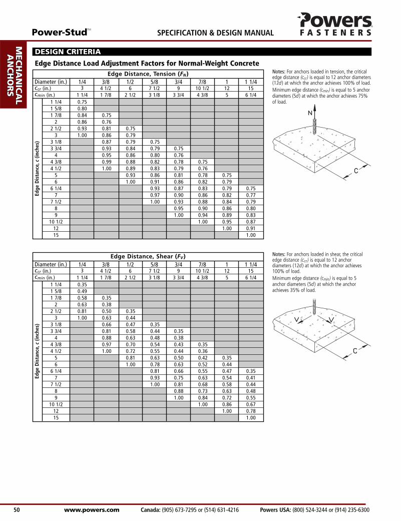
Diameter (in.) 1/4 3/8 1/2 5/8 3/4 7/8 1 1 1/4ccr (in.) 3 4 1/2 6 7 1/2 9 10 1/2 12 15 cmin (in.) 1 1/4 1 7/8 2 1/2 3 1/8 3 3/4 4 3/8 5 6 1/4
Diameter (in.) 1/4 3/8 1/2 5/8 3/4 7/8 1 1 1/4ccr (in.) 3 4 1/2 6 7 1/2 9 10 1/2 12 15 cmin (in.) 1 1/4 1 7/8 2 1/2 3 1/8 3 3/4 4 3/8 5 6 1/4
Edge Distance Load Adjustment Factors for Normal-Weight Concrete
DESIGN CRITERIA
Notes: For anchors loaded in tension, the criticaledge distance (ccr) is equal to 12 anchor diameters(12d ) at which the anchor achieves 100% of load.Minimum edge distance (cmin) is equal to 5 anchordiameters (5d ) at which the anchor achieves 75%of load.
Notes: For anchors loaded in shear, the criticaledge distance (ccr ) is equal to 12 anchordiameters (12d ) at which the anchor achieves100% of load.Minimum edge distance (cmin) is equal to 5anchor diameters (5d ) at which the anchorachieves 35% of load.
Edge Distance, Tension (FN)
1 1/4 0.751 5/8 0.801 7/8 0.84 0.75
2 0.86 0.762 1/2 0.93 0.81 0.75
3 1.00 0.86 0.793 1/8 0.87 0.79 0.753 3/4 0.93 0.84 0.79 0.75
4 0.95 0.86 0.80 0.764 3/8 0.99 0.88 0.82 0.78 0.754 1/2 1.00 0.89 0.83 0.79 0.76
5 0.93 0.86 0.81 0.78 0.756 1.00 0.91 0.86 0.82 0.79
6 1/4 0.93 0.87 0.83 0.79 0.757 0.97 0.90 0.86 0.82 0.77
7 1/2 1.00 0.93 0.88 0.84 0.798 0.95 0.90 0.86 0.809 1.00 0.94 0.89 0.83
10 1/2 1.00 0.95 0.8712 1.00 0.9115 1.00
Edge
Dis
tanc
e,c
(inch
es)
Edge Distance, Shear (FV)
1 1/4 0.351 5/8 0.491 7/8 0.58 0.35
2 0.63 0.382 1/2 0.81 0.50 0.35
3 1.00 0.63 0.443 1/8 0.66 0.47 0.353 3/4 0.81 0.58 0.44 0.35
4 0.88 0.63 0.48 0.384 3/8 0.97 0.70 0.54 0.43 0.354 1/2 1.00 0.72 0.55 0.44 0.36
5 0.81 0.63 0.50 0.42 0.356 1.00 0.78 0.63 0.52 0.44
6 1/4 0.81 0.66 0.55 0.47 0.357 0.93 0.75 0.63 0.54 0.41
7 1/2 1.00 0.81 0.68 0.58 0.448 0.88 0.73 0.63 0.489 1.00 0.84 0.72 0.55
10 1/2 1.00 0.86 0.6712 1.00 0.7815 1.00
Edge
Dis
tanc
e,c
(inch
es)
AD
HESIV
ES
MEC
HAN
ICA
LAN
CH
OR
S
WA
LL AN
CH
OR
S
POW
DER
AC
TUA
TED
GA
S FA
STENIN
G
RO
OFIN
G
FASTEN
ERS
CA
RB
IDE
DR
ILL BITS
SPECIFICATION & DESIGN MANUAL Power-StudTM
www.powers.com Canada: (905) 673-7295 or (514) 631-4216 Powers USA: (800) 524-3244 or (914) 235-6300 50
Power-StudTM
Powers USA: (800) 524-3244 or (914) 235-6300 Canada: (905) 673-7295 or (514) 631-4216 www.powers.com 51
AD
HES
IVES
MEC
HAN
ICA
LAN
CH
OR
S
WA
LL
AN
CH
OR
S
POW
DER
AC
TUA
TED
GA
S FA
STEN
ING
RO
OFIN
G
FAST
ENER
S
CA
RB
IDE
DR
ILL
BIT
S
SPECIFICATION & DESIGN MANUAL
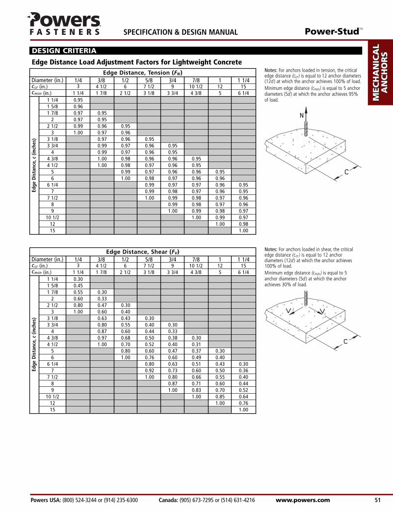
Diameter (in.) 1/4 3/8 1/2 5/8 3/4 7/8 1 1 1/4ccr (in.) 3 4 1/2 6 7 1/2 9 10 1/2 12 15 cmin (in.) 1 1/4 1 7/8 2 1/2 3 1/8 3 3/4 4 3/8 5 6 1/4
Diameter (in.) 1/4 3/8 1/2 5/8 3/4 7/8 1 1 1/4ccr (in.) 3 4 1/2 6 7 1/2 9 10 1/2 12 15 cmin (in.) 1 1/4 1 7/8 2 1/2 3 1/8 3 3/4 4 3/8 5 6 1/4
Edge Distance Load Adjustment Factors for Lightweight Concrete
DESIGN CRITERIA
Notes: For anchors loaded in tension, the criticaledge distance (ccr) is equal to 12 anchor diameters(12d ) at which the anchor achieves 100% of load.Minimum edge distance (cmin) is equal to 5 anchordiameters (5d ) at which the anchor achieves 95%of load.
Notes: For anchors loaded in shear, the criticaledge distance (ccr ) is equal to 12 anchordiameters (12d ) at which the anchor achieves100% of load.Minimum edge distance (cmin) is equal to 5anchor diameters (5d ) at which the anchorachieves 30% of load.
Edge Distance, Shear (FV)
1 1/4 0.301 5/8 0.451 7/8 0.55 0.30
2 0.60 0.332 1/2 0.80 0.47 0.30
3 1.00 0.60 0.403 1/8 0.63 0.43 0.303 3/4 0.80 0.55 0.40 0.30
4 0.87 0.60 0.44 0.334 3/8 0.97 0.68 0.50 0.38 0.304 1/2 1.00 0.70 0.52 0.40 0.31
5 0.80 0.60 0.47 0.37 0.306 1.00 0.76 0.60 0.49 0.40
6 1/4 0.80 0.63 0.51 0.43 0.307 0.92 0.73 0.60 0.50 0.36
7 1/2 1.00 0.80 0.66 0.55 0.408 0.87 0.71 0.60 0.449 1.00 0.83 0.70 0.52
10 1/2 1.00 0.85 0.6412 1.00 0.7615 1.00
Edge
Dis
tanc
e,c
(inch
es)
Edge Distance, Tension (FN)
1 1/4 0.951 5/8 0.961 7/8 0.97 0.95
2 0.97 0.952 1/2 0.99 0.96 0.95
3 1.00 0.97 0.963 1/8 0.97 0.96 0.953 3/4 0.99 0.97 0.96 0.95
4 0.99 0.97 0.96 0.954 3/8 1.00 0.98 0.96 0.96 0.954 1/2 1.00 0.98 0.97 0.96 0.95
5 0.99 0.97 0.96 0.96 0.956 1.00 0.98 0.97 0.96 0.96
6 1/4 0.99 0.97 0.97 0.96 0.957 0.99 0.98 0.97 0.96 0.95
7 1/2 1.00 0.99 0.98 0.97 0.968 0.99 0.98 0.97 0.969 1.00 0.99 0.98 0.97
10 1/2 1.00 0.99 0.9712 1.00 0.9815 1.00
Edge
Dis
tanc
e,c
(inch
es)
AD
HESIV
ES
MEC
HAN
ICA
LAN
CH
OR
S
WA
LL AN
CH
OR
S
POW
DER
AC
TUA
TED
GA
S FA
STENIN
G
RO
OFIN
G
FASTEN
ERS
CA
RB
IDE
DR
ILL BITS
SPECIFICATION & DESIGN MANUAL Power-StudTM
www.powers.com Canada: (905) 673-7295 or (514) 631-4216 Powers USA: (800) 524-3244 or (914) 235-6300 52
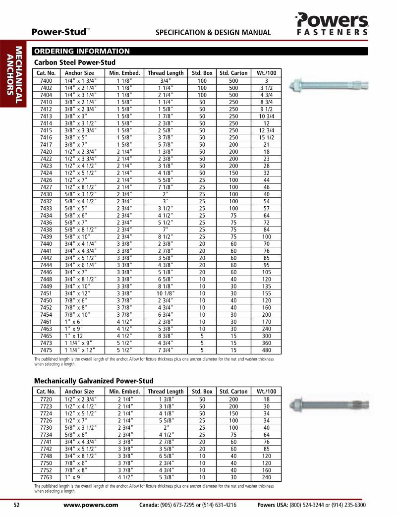
Cat. No. Anchor Size Min. Embed. Thread Length Std. Box Std. Carton Wt./1007720 1/2" x 2 3/4" 2 1/4" 1 3/8" 50 200 187723 1/2" x 4 1/2" 2 1/4" 3 1/8" 50 200 307724 1/2" x 5 1/2" 2 1/4" 4 1/8" 50 150 347726 1/2" x 7" 2 1/4" 5 5/8" 25 100 347730 5/8" x 3 1/2" 2 3/4" 2" 25 100 407734 5/8" x 6" 2 3/4" 4 1/2" 25 75 647741 3/4" x 4 3/4" 3 3/8" 2 7/8" 20 60 767742 3/4" x 5 1/2" 3 3/8" 3 5/8" 20 60 857748 3/4" x 8 1/2" 3 3/8" 6 5/8" 10 40 1207750 7/8" x 6" 3 7/8" 2 3/4" 10 40 1207752 7/8" x 8" 3 7/8" 4 3/4" 10 40 1607763 1" x 9" 4 1/2" 5 3/8" 10 30 240
Cat. No. Anchor Size Min. Embed. Thread Length Std. Box Std. Carton Wt./1007400 1/4" x 1 3/4" 1 1/8" 3/4" 100 500 37402 1/4" x 2 1/4" 1 1/8" 1 1/4" 100 500 3 1/27404 1/4" x 3 1/4" 1 1/8" 2 1/4" 100 500 4 3/47410 3/8" x 2 1/4" 1 5/8" 1 1/4" 50 250 8 3/47412 3/8" x 2 3/4" 1 5/8" 1 5/8" 50 250 9 1/27413 3/8" x 3" 1 5/8" 1 7/8" 50 250 10 3/47414 3/8" x 3 1/2" 1 5/8" 2 3/8" 50 250 127415 3/8" x 3 3/4" 1 5/8" 2 5/8" 50 250 12 3/47416 3/8" x 5" 1 5/8" 3 7/8" 50 250 15 1/27417 3/8" x 7" 1 5/8" 5 7/8" 50 200 217420 1/2" x 2 3/4" 2 1/4" 1 3/8" 50 200 187422 1/2" x 3 3/4" 2 1/4" 2 3/8" 50 200 237423 1/2" x 4 1/2" 2 1/4" 3 1/8" 50 200 287424 1/2" x 5 1/2" 2 1/4" 4 1/8" 50 150 327426 1/2" x 7" 2 1/4" 5 5/8" 25 100 447427 1/2" x 8 1/2" 2 1/4" 7 1/8" 25 100 467430 5/8" x 3 1/2" 2 3/4" 2" 25 100 407432 5/8" x 4 1/2" 2 3/4" 3" 25 100 547433 5/8" x 5" 2 3/4" 3 1/2" 25 100 577434 5/8" x 6" 2 3/4" 4 1/2" 25 75 647436 5/8" x 7" 2 3/4" 5 1/2" 25 75 727438 5/8" x 8 1/2" 2 3/4" 7" 25 75 847439 5/8" x 10" 2 3/4" 8 1/2" 25 75 1007440 3/4" x 4 1/4" 3 3/8" 2 3/8" 20 60 707441 3/4" x 4 3/4" 3 3/8" 2 7/8" 20 60 767442 3/4" x 5 1/2" 3 3/8" 3 5/8" 20 60 857444 3/4" x 6 1/4" 3 3/8" 4 3/8" 20 60 957446 3/4" x 7" 3 3/8" 5 1/8" 20 60 1057448 3/4" x 8 1/2" 3 3/8" 6 5/8" 10 40 1207449 3/4" x 10" 3 3/8" 8 1/8" 10 30 1357451 3/4" x 12" 3 3/8" 10 1/8" 10 30 1557450 7/8" x 6" 3 7/8" 2 3/4" 10 40 1207452 7/8" x 8" 3 7/8" 4 3/4" 10 40 1607454 7/8" x 10" 3 7/8" 6 3/4" 10 30 2007461 1" x 6" 4 1/2" 2 3/8" 10 30 1707463 1" x 9" 4 1/2" 5 3/8" 10 30 2407465 1" x 12" 4 1/2" 8 3/8" 5 15 3007473 1 1/4" x 9" 5 1/2" 4 3/4" 5 15 3607475 1 1/4" x 12" 5 1/2" 7 3/4" 5 15 480
The published length is the overall length of the anchor. Allow for fixture thickness plus one anchor diameter for the nut and washer thicknesswhen selecting a length.
ORDERING INFORMATION
Carbon Steel Power-Stud
The published length is the overall length of the anchor. Allow for fixture thickness plus one anchor diameter for the nut and washer thicknesswhen selecting a length.
Mechanically Galvanized Power-Stud
Power-StudTM
Powers USA: (800) 524-3244 or (914) 235-6300 Canada: (905) 673-7295 or (514) 631-4216 www.powers.com 53
AD
HES
IVES
MEC
HAN
ICA
LAN
CH
OR
S
WA
LL
AN
CH
OR
S
POW
DER
AC
TUA
TED
GA
S FA
STEN
ING
RO
OFIN
G
FAST
ENER
S
CA
RB
IDE
DR
ILL
BIT
S
SPECIFICATION & DESIGN MANUAL
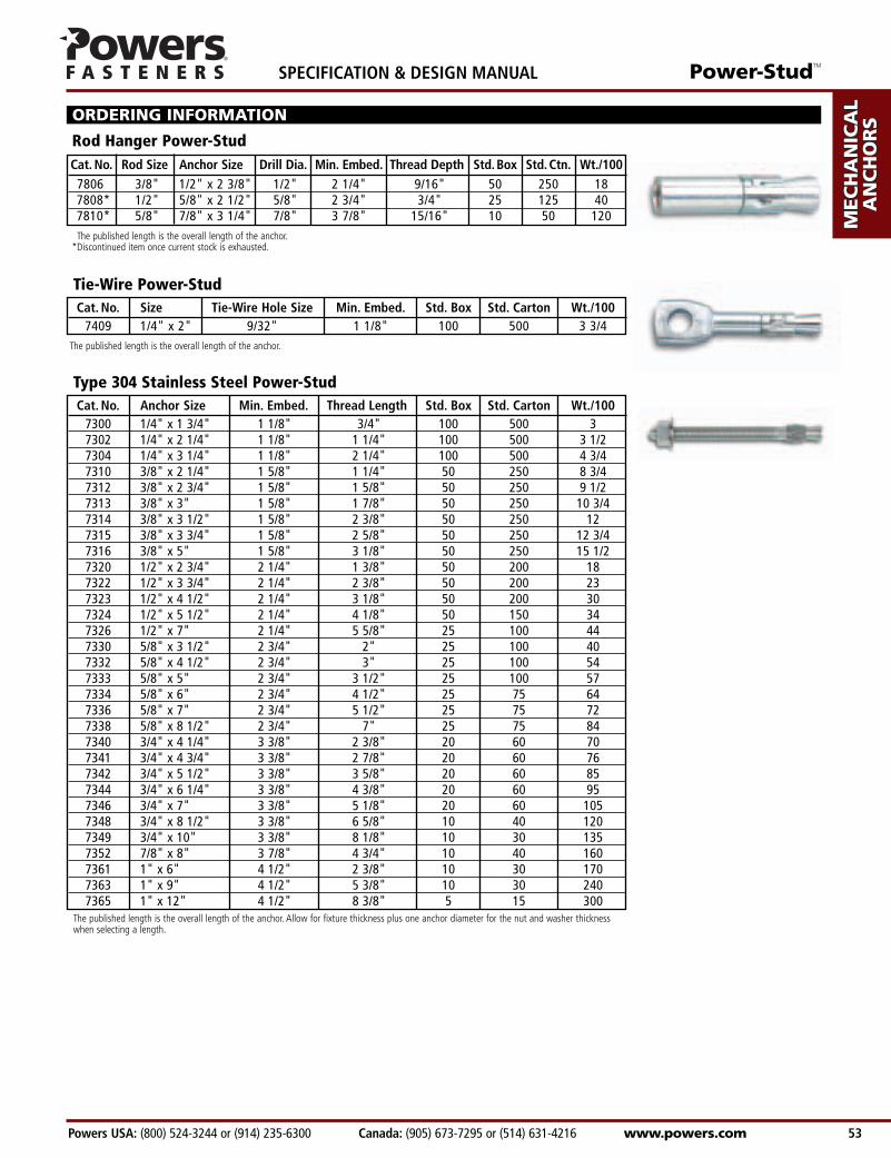
Cat. No. Rod Size Anchor Size Drill Dia. Min. Embed. Thread Depth Std.Box Std.Ctn. Wt./1007806 3/8" 1/2" x 2 3/8" 1/2" 2 1/4" 9/16" 50 250 187808* 1/2" 5/8" x 2 1/2" 5/8" 2 3/4" 3/4" 25 125 407810* 5/8" 7/8" x 3 1/4" 7/8" 3 7/8" 15/16" 10 50 120The published length is the overall length of the anchor.
*Discontinued item once current stock is exhausted.
Rod Hanger Power-Stud
ORDERING INFORMATION
Cat. No. Size Tie-Wire Hole Size Min. Embed. Std. Box Std. Carton Wt./1007409 1/4" x 2" 9/32" 1 1/8" 100 500 3 3/4
Tie-Wire Power-Stud
Cat. No. Anchor Size Min. Embed. Thread Length Std. Box Std. Carton Wt./1007300 1/4" x 1 3/4" 1 1/8" 3/4" 100 500 37302 1/4" x 2 1/4" 1 1/8" 1 1/4" 100 500 3 1/27304 1/4" x 3 1/4" 1 1/8" 2 1/4" 100 500 4 3/47310 3/8" x 2 1/4" 1 5/8" 1 1/4" 50 250 8 3/47312 3/8" x 2 3/4" 1 5/8" 1 5/8" 50 250 9 1/27313 3/8" x 3" 1 5/8" 1 7/8" 50 250 10 3/47314 3/8" x 3 1/2" 1 5/8" 2 3/8" 50 250 127315 3/8" x 3 3/4" 1 5/8" 2 5/8" 50 250 12 3/47316 3/8" x 5" 1 5/8" 3 1/8" 50 250 15 1/27320 1/2" x 2 3/4" 2 1/4" 1 3/8" 50 200 187322 1/2" x 3 3/4" 2 1/4" 2 3/8" 50 200 237323 1/2" x 4 1/2" 2 1/4" 3 1/8" 50 200 307324 1/2" x 5 1/2" 2 1/4" 4 1/8" 50 150 347326 1/2" x 7" 2 1/4" 5 5/8" 25 100 447330 5/8" x 3 1/2" 2 3/4" 2" 25 100 407332 5/8" x 4 1/2" 2 3/4" 3" 25 100 547333 5/8" x 5" 2 3/4" 3 1/2" 25 100 577334 5/8" x 6" 2 3/4" 4 1/2" 25 75 647336 5/8" x 7" 2 3/4" 5 1/2" 25 75 727338 5/8" x 8 1/2" 2 3/4" 7" 25 75 847340 3/4" x 4 1/4" 3 3/8" 2 3/8" 20 60 707341 3/4" x 4 3/4" 3 3/8" 2 7/8" 20 60 767342 3/4" x 5 1/2" 3 3/8" 3 5/8" 20 60 857344 3/4" x 6 1/4" 3 3/8" 4 3/8" 20 60 957346 3/4" x 7" 3 3/8" 5 1/8" 20 60 1057348 3/4" x 8 1/2" 3 3/8" 6 5/8" 10 40 1207349 3/4" x 10" 3 3/8" 8 1/8" 10 30 1357352 7/8" x 8" 3 7/8" 4 3/4" 10 40 1607361 1" x 6" 4 1/2" 2 3/8" 10 30 1707363 1" x 9" 4 1/2" 5 3/8" 10 30 2407365 1" x 12" 4 1/2" 8 3/8" 5 15 300
The published length is the overall length of the anchor. Allow for fixture thickness plus one anchor diameter for the nut and washer thicknesswhen selecting a length.
Type 304 Stainless Steel Power-Stud
The published length is the overall length of the anchor.
AD
HESIV
ES
MEC
HAN
ICA
LAN
CH
OR
S
WA
LL AN
CH
OR
S
POW
DER
AC
TUA
TED
GA
S FA
STENIN
G
RO
OFIN
G
FASTEN
ERS
CA
RB
IDE
DR
ILL BITS
SPECIFICATION & DESIGN MANUAL Power-StudTM
www.powers.com Canada: (905) 673-7295 or (514) 631-4216 Powers USA: (800) 524-3244 or (914) 235-6300 54
Cat. No. Anchor Size Min. Embed. Thread Length Std. Box Std. Carton Wt./1007600 1/4" x 1 3/4" 1 1/8" 3/4" 100 500 3 1/47602 1/4" x 2 1/4" 1 1/8" 1 1/4" 100 500 3 3/47604 1/4" x 3 1/4" 1 1/8" 2 1/4" 100 500 5 1/47610 3/8" x 2 1/4" 1 5/8" 1 1/4" 50 250 8 3/47612 3/8" x 2 3/4" 1 5/8" 1 5/8" 50 250 10 1/27613 3/8" x 3" 1 5/8" 1 7/8" 50 250 117614 3/8" x 3 1/2" 1 5/8" 2 3/8" 50 250 127615 3/8" x 3 3/4" 1 5/8" 2 5/8" 50 250 137616 3/8" x 5" 1 5/8" 3 1/8" 50 250 17 1/47620 1/2" x 2 3/4" 2 1/4" 1 3/8" 50 200 187622 1/2" x 3 3/4" 2 1/4" 2 3/8" 50 200 247623 1/2" x 4 1/2" 2 1/4" 3 1/8" 50 200 307624 1/2" x 5 1/2" 2 1/4" 4 1/8" 50 150 347626 1/2" x 7" 2 1/4" 5 5/8" 25 100 447630 5/8" x 3 1/2" 2 3/4" 2" 25 100 407632 5/8" x 4 1/2" 2 3/4" 3" 25 100 547633 5/8" x 5" 2 3/4" 3 1/2" 25 100 577634 5/8" x 6" 2 3/4" 4 1/2" 25 75 647636 5/8" x 7" 2 3/4" 5 1/2" 25 75 727638 5/8" x 8 1/2" 2 3/4" 7" 25 75 847640 3/4" x 4 1/4" 3 3/8" 2 3/8" 20 60 707641 3/4" x 4 3/4" 3 3/8" 2 7/8" 20 60 767642 3/4" x 5 1/2" 3 3/8" 3 5/8" 20 60 857644 3/4" x 6 1/4" 3 3/8" 4 3/8" 20 60 957646 3/4" x 7" 3 3/8" 5 1/8" 20 60 1057648 3/4" x 8 1/2" 3 3/8" 6 5/8" 10 40 120
The published length is the overall length of the anchor. Allow for fixture thickness plus one anchor diameter for the nut and washer thicknesswhen selecting a length.
ORDERING INFORMATION
Type 316 Stainless Steel Power-Stud
© 2006 Powers Fasteners, Inc. All Rights Reserved. Power-Stud is a trademark of Powers Fasteners, Inc.
Keith
Polygon