PROJECT - South Dakotaapps.sd.gov/HC65C2C/EBS/lettings/electronicplans/X03T_SectionB.pdf · project...
16
SECTION B STORM WATER AND GRADING PLANS CITY of RAPID CITY PUBLIC WORKS DEPARTMENT ENGINEERING DIVISION C A K P A I D S O R T H U D 1882 I T A T Y O Plan Set Number : INDEX OF SHEETS B1 COVER SHEET B2-B3 ESTIMATE OF QUANTITIES AND GENERAL NOTES B4 HORIZONTAL ALIGNMENT DATA B5 11th STREET DEMOLITION PLAN B6 11th STREET SIDEWALK PLAN B7 BIKE PATH DETOUR B8-B10 11th STREET CROSS SECTIONS B11 36" STORM SEWER PLAN B12 36" STORM SEWER PROFILE B13-B14 36" RCP HEADWALL B15-B16 STANDARD DETAILS (605) 342-4105 FAX (605) 342-4222 Rapid City, SD 57702-0317 3700 Sturgis Road Consulting Civil Engineers www.fmgengineering.com SILVER STREET INTERCHANGE UTILITY RECONSTRUCTION PROJECT CITY OF RAPID CITY PROJECT NO. 12-2053 PROJECT LOCATION PROJECT LOCATION MAP NOT TO SCALE I:\Civil 3D Working Folder\130234 Silver Street Interchange\2053TITLE.dwg, Sec B-Storm, 6/15/2015 3:05:04 PM, 1:2 FOR BIDDING PURPOSES ONLY
Transcript of PROJECT - South Dakotaapps.sd.gov/HC65C2C/EBS/lettings/electronicplans/X03T_SectionB.pdf · project...

SECTION B
STORM WATER AND GRADING PLANS
CIT
Y o
f R
AP
ID
C
IT
Y
PU
BLI
C W
OR
KS
DE
PA
RTM
EN
TE
NG
INE
ER
ING
DIV
ISIO
N
C AK
PAID
SOR TH
U
D
1882
IT
ATY O
Pla
n S
et N
umbe
r :
INDEX OF SHEETS
B1 COVER SHEETB2-B3 ESTIMATE OF QUANTITIES AND GENERAL NOTESB4 HORIZONTAL ALIGNMENT DATAB5 11th STREET DEMOLITION PLANB6 11th STREET SIDEWALK PLANB7 BIKE PATH DETOURB8-B10 11th STREET CROSS SECTIONSB11 36" STORM SEWER PLANB12 36" STORM SEWER PROFILEB13-B14 36" RCP HEADWALLB15-B16 STANDARD DETAILS
(605) 342-4105 FAX (605) 342-4222Rapid City, SD 57702-03173700 Sturgis RoadConsulting Civil Engineers
www.fmgengineering.com
SIL
VE
R S
TR
EE
T IN
TE
RC
HA
NG
E
UT
IL
IT
Y R
EC
ON
ST
RU
CT
IO
N P
RO
JE
CT
CIT
Y O
F R
AP
ID
C
IT
Y P
RO
JE
CT
N
O. 12-2053
PROJECT
LOCATION
PROJECT LOCATION MAP NOT TO SCALE
I:\C
ivil
3D W
orki
ng F
olde
r\13
0234
Silv
er S
tree
t Int
erch
ange
\205
3TIT
LE.d
wg,
Sec
B-S
torm
, 6/1
5/20
15 3
:05:
04 P
M, 1
:2
FOR BIDDING PURPOSES ONLY
Sheet:
B2
of
B51
SILVER STREET INTERCHANGE UTILITYRECONSTRUCTION PROJECT
12-2053 / CIP 50940 / PCN X03T
Scale:
Design By:RAS
Drawn By:RS/KS/JK
Internal Job No. 130234
Surveyed By:DOT / FMG
Survey Date:SURVEY BY DOT
Sheet Title:
SECTION BESTIMATED
QUANTITES AND
GENERAL NOTES
Prepared By: Prepared For:
Public Works Department
Engineering Services
Design Date:JUNE 2015
Print Date:JUNE 2015
SECTION B ESTIMATE OF QUANTITIES
BID ITEMNUMBER ITEM QUANTITY UNIT
110E1140 Remove Concrete Sidewalk 229.0 SqYd230E0020 Placing Contractor Furnished Topsoil 42 CuYd250E0020 Incidental Work, Grading Lump Sum LS260E2010 Gravel Cushion 2.8 Ton420E0400 Structure Excavation, Miscellaneous 4 CuYd450E0183 36” RCP Class 3, Furnish 138 Ft450E0190 36” RCP, Install 138 Ft450E0428 36” RCP Bend, Furnish 1 Each450E0429 36” RCP Bend, Install 1 Each462E0100 Class M6 Concrete 2.4 CuYd480E0200 Epoxy Coated Reinforcing Steel 162 Lb632E3520 Remove, Salvage, Relocate, and Reset Traffic Sign 1 Each634E0120 Traffic Control, Miscellaneous Lump Sum LS651E0040 4” Concrete Sidewalk 52 SqFt651E0050 5” Concrete Sidewalk 2998 SqFt651E7000 Type 1 Detectable Warning Panel 12 SqFt
GENERAL NOTES
See Section A for GENERAL NOTES common to all sections.
WORK LIMITS / DO NOT DISTURB
All work in Section B occurs within the ROW or on City owned property. Work limits are indicated on the plans. The Contractor shall limit disturbance outside of the identified project limits. Any disturbance that does occur outside of the project limits will be restored by the Contractor at no cost to the City.
WATER POLLUTION CONTROL
Permanent stabilization measures are shown in Section D. The Contractor shall provide temporary erosion and sediment control measures in accordance with Section D. The Contractor shall coordinate Erosion and Sediment Control practices with the SD DOT Combination Project.
PLACING CONTRACTOR FURNISHED TOPSOIL
The ability to salvage topsoil along the 36” RCP is limited. The Contractor shall furnish and place topsoil to a depth of 6" in all disturbed areas within 36” RCP alignment.
Payment for furnishing and placingcontractor furnished topsoil within 36” RCP alignment will be at the contract unit price per cubic yard for "Placing Contractor Furnished Topsoil” and will bemeasured and paid for at the contract unit price per cubic yard for "Placing Contractor Furnished Topsoil."
GRADING
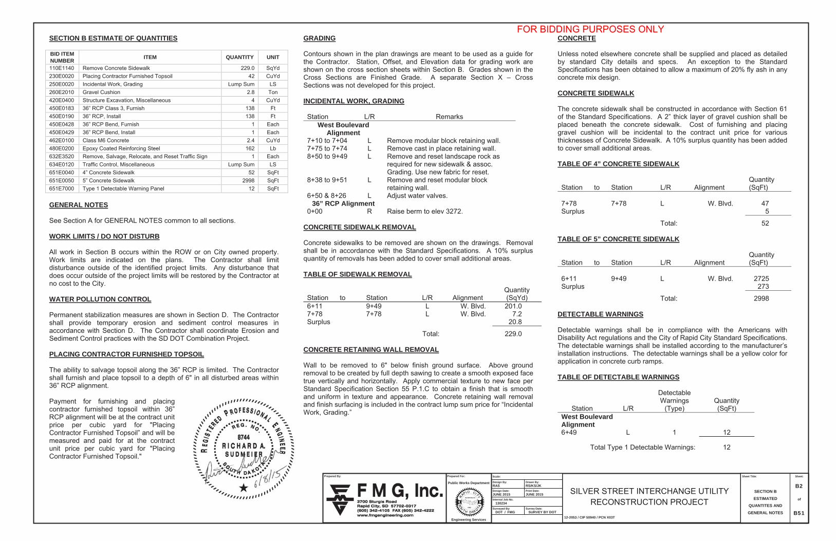
Contours shown in the plan drawings are meant to be used as a guide for the Contractor. Station, Offset, and Elevation data for grading work are shown on the cross section sheets within Section B. Grades shown in the Cross Sections are Finished Grade. A separate Section X – Cross Sections was not developed for this project.
INCIDENTAL WORK, GRADING
Station L/R RemarksWest Boulevard
Alignment7+10 to 7+04 L Remove modular block retaining wall.7+75 to 7+74 L Remove cast in place retaining wall.8+50 to 9+49 L Remove and reset landscape rock as
required for new sidewalk & assoc. Grading. Use new fabric for reset.
8+38 to 9+51 L Remove and reset modular block retaining wall.
6+50 & 8+26 L Adjust water valves.36” RCP Alignment
0+00 R Raise berm to elev 3272.
CONCRETE SIDEWALK REMOVAL
Concrete sidewalks to be removed are shown on the drawings. Removal shall be in accordance with the Standard Specifications. A 10% surplus quantity of removals has been added to cover small additional areas.
TABLE OF SIDEWALK REMOVAL
Station to Station L/R AlignmentQuantity(SqYd)
6+11 9+49 L W. Blvd. 201.07+78 7+78 L W. Blvd. 7.2Surplus 20.8
Total: 229.0
CONCRETE RETAINING WALL REMOVAL
Wall to be removed to 6" below finish ground surface. Above ground removal to be created by full depth sawing to create a smooth exposed face true vertically and horizontally. Apply commercial texture to new face per Standard Specification Section 55 P.1.C to obtain a finish that is smooth and uniform in texture and appearance. Concrete retaining wall removal and finish surfacing is included in the contract lump sum price for “IncidentalWork, Grading.”
CONCRETE
Unless noted elsewhere concrete shall be supplied and placed as detailed by standard City details and specs. An exception to the Standard Specifications has been obtained to allow a maximum of 20% fly ash in any concrete mix design.
CONCRETE SIDEWALK
The concrete sidewalk shall be constructed in accordance with Section 61 of the Standard Specifications. A 2” thick layer of gravel cushion shall be placed beneath the concrete sidewalk. Cost of furnishing and placing gravel cushion will be incidental to the contract unit price for various thicknesses of Concrete Sidewalk. A 10% surplus quantity has been added to cover small additional areas.
TABLE OF 4” CONCRETE SIDEWALK
Station to Station L/R AlignmentQuantity(SqFt)
7+78 7+78 L W. Blvd. 47Surplus 5
Total: 52
TABLE OF 5” CONCRETE SIDEWALK
Station to Station L/R AlignmentQuantity(SqFt)
6+11 9+49 L W. Blvd. 2725Surplus 273
Total: 2998
DETECTABLE WARNINGS
Detectable warnings shall be in compliance with the Americans with Disability Act regulations and the City of Rapid City Standard Specifications. The detectable warnings shall be installed according to the manufacturer’s installation instructions. The detectable warnings shall be a yellow color for application in concrete curb ramps.
TABLE OF DETECTABLE WARNINGS
Station L/R
DetectableWarnings
(Type)Quantity(SqFt)
West Boulevard Alignment6+49 L 1 12
Total Type 1 Detectable Warnings: 12
FOR BIDDING PURPOSES ONLY

Sheet:
B3
of
B51
SILVER STREET INTERCHANGE UTILITY RECONSTRUCTION PROJECT
12-2053 / CIP 50940 / PCN X03T
Scale:
Design By: RAS
Drawn By: RS/KS/JK
Internal Job No. 130234 Surveyed By: DOT / FMG
Survey Date: SURVEY BY DOT
Sheet Title:
SECTION B ESTIMATED
QUANTITES AND
GENERAL NOTES
Prepared By:
Prepared For: Public Works Department
Engineering Services
Design Date: JUNE 2015
Print Date: JUNE 2015
STORM SEWER Reinforced concrete pipe may be either bell and spigot or tongue and groove. The pipe sections shall be adjoined such that the ends are fully entered and the inner surfaces are reasonably flush and even. Lift holes in the reinforced concrete pipe shall be plugged with grout. Watertight joints are required for reinforced concrete pipe, drop inlets, manholes, and junction boxes where storm sewers run parallel to and within 10 feet horizontally from existing or proposed water mains. Locations for these are shown on the plans. Watertight joints are required where reinforced concrete pipes, drop inlets, manholes, or junction boxes cross water mains and are separated a distance of 18 inches or less, above or below, the water main. If watertight joints are required then the watertight joints shall extend for a distance of 10 feet beyond the water main. This measurement shall be from the sealed concrete joint to the outer most surface of the water main. Watertight joint seals shall conform to the following requirements: 1. Reinforced Concrete Pipe (Circular): Gasketed pipe shall conform to
the requirements of ASTM C443. Non-gasketed concrete pipe shall be sealed with a mastic joint seal conforming to the requirements of ASTM C990 and encased with a minimum 2’ wide by 6” thick M6 concrete collar reinforced with 6x6 W2.9 x W2.9 wire mesh.
2. Reinforced Concrete Pipe (Arch): Joints shall be sealed with a waterstop seal meeting the requirements of ASTM C990. Waterstop seals shall consist of hydrophilic compounds such as Waterstop-RX or ConSeal CS-231.
3. Drop Inlets, Manholes, and Junction Boxes: Joints shall be sealed with a waterstop seal or seal wrap meeting the requirements of ASTM C990 or encased with a minimum 2’ wide by 6” thick M6 concrete collar reinforced with 6x6 W2.9 x W2.9 wire mesh. Waterstop seal shall contain hydrophilic compounds such as Waterstop-RX or ConSeal CS-231. Seal wrap shall be a self adhesive external joint wrap such as ConWrap CS-217 or Mar Mac Seal Wrap.
Gaskets and seals (mastic, waterstop, and seal wraps) shall be installed in accordance with the manufacturer’s recommendations. The cost for furnishing and installing all gaskets, mastic joint seal, waterstop seal, seal wrap, concrete collars, and for plugging the lift holes shall be incidental to the contract unit price per foot for the corresponding pipe bid item.
REMOVE, SALVAGE, RELOCATE & RESET TRAFFIC SIGN The Contractor shall remove signs, posts, and bases for reset as shown in the plans. All bolts, nuts, and washers shall be placed in individual 5-gallon pails. Backing materials shall be separated from the signs and may be reused at the contractor’s discretion. Non-threaded connections (rivets) shall be cut when necessary to reduce sign section to a 4’x6’ maximum size. Wooden posts shall be carefully removed to avoid damage and cleaned of excess dirt and neatly stockpiled separate from the steel posts. The resultant holes in the ground from removal of posts shall be backfilled to the satisfaction of the Engineer. Any post assembly including sign, post, or bases that call for being removed, relocated or reset in the remarks column in the Table of Permanent Signing shall be included in the contract unit price per each for “Remove, Salvage, Relocate & Reset Traffic Sign”. Payment shall include all cost of labor and equipment necessary to remove, dismantle, backfill holes (wooden posts only) and reset signs at new locations indicated in the plans. TABLE OF REMOVE, SALVAGE, RELOCATE & RESET TRAFFIC SIGN Existing Station
New Station
L/R
Number
Description
West Boulevard Alignment 6+36 6+36 L W1-6r Large Arrow-One Direction
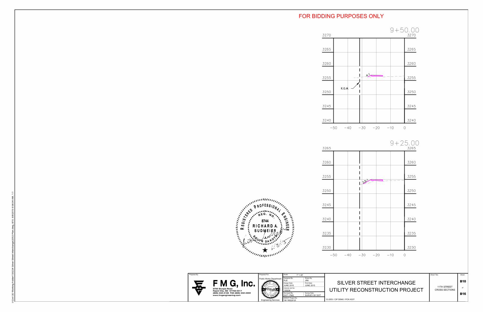
11TH STREET BIKE PATH WORK TRAFFIC CONTROL The road and pedestrian detours associated with the 11th Street Bike Path construction will require the Contractor to establish traffic control. The extent of the traffic control plan and placement of devices will depend on the construction operations and traffic control in place due to the combination project IM 1902(61)0, PCN 1162. All costs for coordination with the combination project; preparation of the traffic control plan; placement, maintenance, and removal of all traffic control devices shall be paid at the contract lump sum price for “Traffic Control, Miscellaneous.”
FOR BIDDING PURPOSES ONLY
JPettyjohn
STAMP RAS 6-8-15

Sheet:
B4
of
B16
SILVER STREET INTERCHANGE UTILITYRECONSTRUCTION PROJECT
12-2053 / CIP X03T
Scale:
Design By:JAP
Drawn By:JRK
Internal Job No. 130234
Surveyed By:DOT / FMG
Survey Date:SURVEY BY DOT
Sheet Title:
HORIZONTAL
ALIGNMENT DATA
Prepared By: Prepared For:
Public Works Department
Engineering Services
Design Date:MARCH 2015
Print Date:MARCH 2015
36” STORM SEWER ALIGNMENT
Tangent DataDescription PT Station Northing EastingStart: 0+00.000 654608.794 1206737.724End: 0+31.627 654608.965 1206769.351Length: 31.627 Course:N 89° 41' 28.6523" E
Tangent DataDescription PT Station Northing EastingStart: 0+31.627 654608.965 1206769.351End: 1+89.998 654547.391 1206915.262Length: 158.371 Course:S 67° 07' 14.0314" E
CONTROL ESTABLISHED FROM SDDOT REFER TO COMPANION PROJECT IM 1902(61)0, PCN 1162.
SURVEY DATA SHOWN IS BASED ON SDDOT SURVEY ON THE SOUTH DAKOTA STATE PLANE COORDINATE SYSTEM, SOUTH ZONE (NAD83/96, NAVD 88) SF = 0.99978357.
FOR BIDDING PURPOSES ONLY

Sheet Title:
Internal Job No:
Designed By:
Design Date:
Surveyed By: Survey Date:
Drawn By:
Print Date:
Scale:Prepared By:
Public Works Department
Engineering Services
1882
Prepared For: Sheet:
SDDOT Project No.
SILVER STREET INTERCHANGEUTILITY RECONSTRUCTION PROJECT
12-2053 / CIP 50940 / PCN X03T
1" = 40'
RJS JRK
JUNE 2015 JUNE 2015
130234
DOT / FMG SURVEY BY DOT
1M 1902(61)0
of
I:\C
ivil
3D W
orki
ng F
olde
r\13
0234
Silv
er S
tree
t Int
erch
ange
\205
3 D
emo.
dwg,
B5,
6/8
/201
5 9:
39:2
9 A
M, 1
:1
FOR BIDDING PURPOSES ONLY

Sheet Title:
Internal Job No:
Designed By:
Design Date:
Surveyed By: Survey Date:
Drawn By:
Print Date:
Scale:Prepared By:
Public Works Department
Engineering Services
1882
Prepared For: Sheet:
SDDOT Project No.
SILVER STREET INTERCHANGEUTILITY RECONSTRUCTION PROJECT
12-2053 / CIP 50940 / PCN X03T
1" = 40'
RJS JRK
JUNE 2015 JUNE 2015
130234
DOT / FMG SURVEY BY DOT
1M 1902(61)0
of
I:\C
ivil
3D W
orki
ng F
olde
r\13
0234
Silv
er S
tree
t Int
erch
ange
\205
3 P
lan.
dwg,
B6,
6/8
/201
5 9:
52:5
6 A
M, 1
:1
FOR BIDDING PURPOSES ONLY

WORK AREA
THE CONTRACTOR SHALL ESTABLISHROAD AND PEDESTRIAN DETOURS ASNECESSARY BASED ON ADJACENTCONSTRUCTION OPERATIONSPERFORMED BY THE COMPANIONPROJECT IM 1902(61)0, PCN 1162.
Sheet Title:
Internal Job No:
Designed By:
Design Date:
Surveyed By: Survey Date:
Drawn By:
Print Date:
Scale:Prepared By:
Public Works Department
Engineering Services
1882
Prepared For: Sheet:
SDDOT Project No.
SILVER STREET INTERCHANGEUTILITY RECONSTRUCTION PROJECT
12-2053 / CIP 50940 / PCN X03T
1" = 40'
RJS JRK
JUNE 2015 JUNE 2015
130234
DOT / FMG SURVEY BY DOT
1M 1902(61)0
of
REFERENCE SDDOT STANDARDPLATE 634.03 FOR TRAFFICCONTROL DEVICES WHEN WORKINGON SHOULDER
I:\C
ivil
3D W
orki
ng F
olde
r\13
0234
Silv
er S
tree
t Int
erch
ange
\205
3Aer
ial.d
wg,
B7,
6/8
/201
5 9:
42:4
7 A
M, 1
:1
FOR BIDDING PURPOSES ONLY

Sheet Title:
Internal Job No:
Designed By:
Design Date:
Surveyed By: Survey Date:
Drawn By:
Print Date:
Scale:Prepared By:
Public Works Department
Engineering Services
1882
Prepared For: Sheet:
SDDOT Project No.
SILVER STREET INTERCHANGEUTILITY RECONSTRUCTION PROJECT
12-2053 / CIP 50940 / PCN X03T
1" = 40'
RJS JRK
JUNE 2015 JUNE 2015
130234
DOT / FMG SURVEY BY DOT
1M 1902(61)0
of
I:\C
ivil
3D W
orki
ng F
olde
r\13
0234
Silv
er S
tree
t Int
erch
ange
\205
3 P
lan.
dwg,
B8,
6/8
/201
5 9:
53:2
3 A
M, 1
:1
FOR BIDDING PURPOSES ONLY

Sheet Title:
Internal Job No:
Designed By:
Design Date:
Surveyed By: Survey Date:
Drawn By:
Print Date:
Scale:Prepared By:
Public Works Department
Engineering Services
1882
Prepared For: Sheet:
SDDOT Project No.
SILVER STREET INTERCHANGEUTILITY RECONSTRUCTION PROJECT
12-2053 / CIP 50940 / PCN X03T
1" = 40'
RJS JRK
JUNE 2015 JUNE 2015
130234
DOT / FMG SURVEY BY DOT
1M 1902(61)0
of
I:\C
ivil
3D W
orki
ng F
olde
r\13
0234
Silv
er S
tree
t Int
erch
ange
\205
3 P
lan.
dwg,
B9,
6/8
/201
5 9:
55:3
6 A
M, 1
:1
FOR BIDDING PURPOSES ONLY
Sheet Title:
Internal Job No:
Designed By:
Design Date:
Surveyed By: Survey Date:
Drawn By:
Print Date:
Scale:Prepared By:
Public Works Department
Engineering Services
1882
Prepared For: Sheet:
SDDOT Project No.
SILVER STREET INTERCHANGEUTILITY RECONSTRUCTION PROJECT
12-2053 / CIP 50940 / PCN X03T
1" = 40'
RJS JRK
JUNE 2015 JUNE 2015
130234
DOT / FMG SURVEY BY DOT
1M 1902(61)0
of
I:\C
ivil
3D W
orki
ng F
olde
r\13
0234
Silv
er S
tree
t Int
erch
ange
\205
3 P
lan.
dwg,
B10
, 6/8
/201
5 9:
58:0
4 A
M, 1
:1
FOR BIDDING PURPOSES ONLY

Sheet Title:
Internal Job No:
Designed By:
Design Date:
Surveyed By: Survey Date:
Drawn By:
Print Date:
Scale:Prepared By:
Public Works Department
Engineering Services
1882
Prepared For: Sheet:
SDDOT Project No.
SILVER STREET INTERCHANGEUTILITY RECONSTRUCTION PROJECT
12-2053 / CIP 50940 / PCN X03T
1" = 40'
RJS JRK
JUNE 2015 JUNE 2015
130234
DOT / FMG SURVEY BY DOT
1M 1902(61)0
of
I:\C
ivil
3D W
orki
ng F
olde
r\13
0234
Silv
er S
tree
t Int
erch
ange
\205
3 P
lan.
dwg,
B11
, 6/8
/201
5 9:
59:0
4 A
M, 1
:1
FOR BIDDING PURPOSES ONLY

Sheet Title:
Internal Job No:
Designed By:
Design Date:
Surveyed By: Survey Date:
Drawn By:
Print Date:
Scale:Prepared By:
Public Works Department
Engineering Services
1882
Prepared For: Sheet:
SDDOT Project No.
SILVER STREET INTERCHANGEUTILITY RECONSTRUCTION PROJECT
12-2053 / CIP 50940 / PCN X03T
1" = 40'
RJS JRK
JUNE 2015 JUNE 2015
130234
DOT / FMG SURVEY BY DOT
1M 1902(61)0
of
I:\C
ivil
3D W
orki
ng F
olde
r\13
0234
Silv
er S
tree
t Int
erch
ange
\205
3 P
lan.
dwg,
B12
, 6/8
/201
5 9:
59:3
4 A
M, 1
:1
FOR BIDDING PURPOSES ONLY

Mk. No. LengthSize Type
a4 1 4 4'-4'' 17A
a6 1 4 5'-1'' 17A
Bending Details
a5 1 4 4'-9'' 17A
a3 2 4 5'-2'' 17A
a1 2 4 13'-8'' Str.
a2 5 4 13'-10'' 19B
REINFORCING SCHEDULE
TYPE 17A
a4
Cut
3-a
4
4'-1''3'-4''
3'-8 1/2'' 3'-8 1/2''
3'-4
''
12''
a53'
-8''
Notes:-All Dimensions are out to out of bars-All bar ends shall have a min. Clear Cover of 2''
a7 1 4 4'-3'' 17A
a8 1 4 4'-7'' 17A
a9 1 4 4'-10'' 17A
b1 10 4 8'-2'' 19
b2 2 4 7'-8'' Str.
b3 3 4 1'-7'' Str.
b4 3 4 2'-1'' Str.
a64'
-1''
a73'
-3''
a83'
-7''
a93'
-10'
'
TYPE 17B
a44'
-2''
12''
TYPE 19B
11'-10''
126
a2
4'-6''
2'-0''
126
b1 129
1'-8''
TYPE 19
12'' (
Typ.
)
TYPE 17
General Notes:
All concrete shall be Class M6 and conform to the Standard Specifications.
All reinforcing steel shall be epoxy coated and shall conform to ASTM A615,Grade 60. The epoxy coating shall conform to AASHTO M284.
A 3 4 inch chamfer shall be provided on all exposed edges.
Structure excavation quantity is estimated from the flow line of the headwall slabto the bottom of the gravel cushion layer. Plans quantity shall be the basis ofpayment unless a change is ordered by the engineer.
Class M6 concrete shall be paid for by the nearest tenth of a cubic yard. Plansquantity shall be the basis of payment unless a change is ordered by theEngineer.
Epoxy coated reinforcing steel shall be paid for by the nearest lb. Plans quantityshall be the basis of payment unless a change is ordered by the Engineer.
Sheet Title:
Internal Job No:
Designed By:
Design Date:
Surveyed By: Survey Date:
Drawn By:
Print Date:
Scale:Prepared By:
OS
TA
Public Works Department
Engineering Services
DA
U
T H1882
OK
R
AP DI
Prepared For:
YTIC
Sheet:
SDDOT Project No.
SILVER STREET INTERCHANGEUTILITY RECONSTRUCTION PROJECT
12-2053 / CIP 50940 / PCN X03T
1" = 40'
RJS JRK
JUNE 2015 JUNE 2015
130234
DOT / FMG SURVEY BY DOT
1M 1902(61)0
of
2'-0''
I:\C
ivil
3D W
orki
ng F
olde
r\13
0234
Silv
er S
tree
t Int
erch
ange
\205
3 S
TR
M-D
ET
AIL
S.d
wg,
B13
, 6/8
/201
5 10
:08:
44 A
M, 1
:2
FOR BIDDING PURPOSES ONLY

Sheet Title:
Internal Job No:
Designed By:
Design Date:
Surveyed By: Survey Date:
Drawn By:
Print Date:
Scale:Prepared By:
OS
TA
Public Works Department
Engineering Services
DA
U
T H1882
OK
R
AP DI
Prepared For:
YTIC
Sheet:
SDDOT Project No.
SILVER STREET INTERCHANGEUTILITY RECONSTRUCTION PROJECT
12-2053 / CIP 50940 / PCN X03T
1" = 40'
RJS JRK
JUNE 2015 JUNE 2015
130234
DOT / FMG SURVEY BY DOT
1M 1902(61)0
of
I:\C
ivil
3D W
orki
ng F
olde
r\13
0234
Silv
er S
tree
t Int
erch
ange
\205
3 S
TR
M-D
ET
AIL
S.d
wg,
B14
, 6/8
/201
5 10
:08:
57 A
M, 1
:2
FOR BIDDING PURPOSES ONLY

Sheet Title:
Internal Job No:
Designed By:
Design Date:
Surveyed By: Survey Date:
Drawn By:
Print Date:
Scale:Prepared By:
OS
TA
Public Works Department
Engineering Services
DA
U
T H1882
OK
R
AP DI
Prepared For:
YTIC
Sheet:
SDDOT Project No.
SILVER STREET INTERCHANGEUTILITY RECONSTRUCTION PROJECT
12-2053 / CIP 50940 / PCN X03T
1" = 40'
RJS JRK
JUNE 2015 JUNE 2015
130234
DOT / FMG SURVEY BY DOT
1M 1902(61)0
of
I:\C
ivil
3D W
orki
ng F
olde
r\13
0234
Silv
er S
tree
t Int
erch
ange
\205
3 S
TR
M-D
ET
AIL
S.d
wg,
B15
, 6/8
/201
5 10
:15:
17 A
M, 1
:2
FOR BIDDING PURPOSES ONLY
Sheet Title:
Internal Job No:
Designed By:
Design Date:
Surveyed By: Survey Date:
Drawn By:
Print Date:
Scale:Prepared By:
OS
TA
Public Works Department
Engineering Services
DA
U
T H1882
OK
R
AP DI
Prepared For:
YTIC
Sheet:
SDDOT Project No.
SILVER STREET INTERCHANGEUTILITY RECONSTRUCTION PROJECT
12-2053 / CIP 50940 / PCN X03T
1" = 40'
RJS JRK
JUNE 2015 JUNE 2015
130234
DOT / FMG SURVEY BY DOT
1M 1902(61)0
of
I:\C
ivil
3D W
orki
ng F
olde
r\13
0234
Silv
er S
tree
t Int
erch
ange
\205
3 S
TR
M-D
ET
AIL
S.d
wg,
B16
, 6/8
/201
5 10
:16:
44 A
M, 1
:2
FOR BIDDING PURPOSES ONLY