Project Proposal & Feasibility Study - Calvin College Proposal & Feasibility Study Team 11 ... the...
41
Project Proposal & Feasibility Study Team 11 – Lazer-Ops Matthew Block Eric Bouwkamp Kristen Herder Mark Willard Calvin College Engineering 339/340 Senior Design Project December 9, 2013
Transcript of Project Proposal & Feasibility Study - Calvin College Proposal & Feasibility Study Team 11 ... the...

Project Proposal & Feasibility Study Team 11 – Lazer-Ops
Matthew Block Eric Bouwkamp Kristen Herder Mark Willard
Calvin College
Engineering 339/340 Senior Design Project December 9, 2013

©2013, Matthew Block, Eric Bouwkamp, Kristen Herder, Mark Willard and Calvin College

Executive Summary Team Lazer Ops examined the feasibility of designing and prototyping a home laser tag system.
Current laser tag systems involve time, monetary cost, and game limitations. Lazer Ops wants to bring a refreshing twist to traditional laser tag allowing for a differentiated product focused on convenience, game flexibility, and user awareness. The system targets a wide market of competitors, gamers, and fun-lovers ranging from elementary aged children to young adults. The system will operate wirelessly through a Wi-Fi network. The vests and laser gun relay data to the game’s central hub that performs of all the data processing and analysis. From there, it is transmitted to a mobile phone application that relays game statistics in real-time to each player and presents them with alternative gameplay options. The major risks to the project include sub-system cohesion and communication. Through preliminary research and rudimentary system design, Team Lazer Ops has estimated that it will cost $340 to build a preliminary system consisting of two laser guns, two vests, a central hub, and mobile application. These deliverables will be completed by May 2014. In the event that the system goes into production, cost estimates and market research have led to a potential retail value of $70 for a home laser tag starter kit consisting of 2 laser guns and 2 vests in addition to the hub and mobile application. Expansion packs of 2 additional guns and vests will be sold for $40.

i
Table of Contents 1. Project Overview .................................................................................................................................... 1
Calvin Senior Design .................................................................................................................... 1
Problem Statement ........................................................................................................................ 1
Project Overview .......................................................................................................................... 2
1.3.1. Project Functions ................................................................................................................ 2
1.3.2. Differentiation ..................................................................................................................... 2
1.3.3. Target Customers ................................................................................................................ 4
1.3.4. Project Goal ........................................................................................................................ 5
Team Organization ....................................................................................................................... 5
1.4.1. Team Member Biographies................................................................................................. 5
1.4.1.1. Matthew Block .......................................................................................................... 5 1.4.1.2. Eric Bouwkamp ......................................................................................................... 6 1.4.1.3. Kristen Herder ........................................................................................................... 6 1.4.1.4. Mark Willard ............................................................................................................. 6
1.4.2. Team Member Responsibilities .......................................................................................... 7
1.4.2.1. Matthew Block .......................................................................................................... 7 1.4.2.2. Eric Bouwkamp ......................................................................................................... 7 1.4.2.3. Kristen Herder ........................................................................................................... 7 1.4.2.4. Mark Willard ............................................................................................................. 7
Work Breakdown Schedule .......................................................................................................... 8
1.5.1. Schedule Management ........................................................................................................ 8
Design Norms ............................................................................................................................... 8
Document Description .................................................................................................................. 9
2. Requirements ........................................................................................................................................ 10
Technical Description ................................................................................................................. 10
2.1.1. Central Hub ....................................................................................................................... 10
2.1.2. Laser Gun .......................................................................................................................... 10
2.1.3. Sensor Vest ....................................................................................................................... 10
2.1.4. Android Application ......................................................................................................... 10
System Features .......................................................................................................................... 11
Customer / Market Requirements ............................................................................................... 11
2.3.1. Functional Requirement .................................................................................................... 11
2.3.2. Weight Limit ..................................................................................................................... 11
2.3.3. Type of Environment / Use ............................................................................................... 11
Mechanical Requirements .......................................................................................................... 11
2.4.1. Central Hub Casing ........................................................................................................... 12

ii
2.4.2. Sensor Vest Casing ........................................................................................................... 12
2.4.3. Laser Gun Casing .............................................................................................................. 12
User Interface Requirements ...................................................................................................... 12
2.5.1. Basic Inputs ....................................................................................................................... 12
2.5.2. Basic Outputs .................................................................................................................... 12
2.5.3. Heads-Up Display / Android Application ......................................................................... 13
Communication Requirements ................................................................................................... 13
Power Requirements ................................................................................................................... 13
Environmental Requirements ..................................................................................................... 13
2.8.1. Power Efficiency ............................................................................................................... 13
2.8.2. RoHS Compliance ............................................................................................................ 14
Deliverables ................................................................................................................................ 14
2.9.1. PPFS ................................................................................................................................. 14
2.9.2. In-class Presentations ........................................................................................................ 14
2.9.3. Project Posters ................................................................................................................... 14
2.9.4. Final Report ...................................................................................................................... 14
2.9.5. Final Presentation ............................................................................................................. 14
2.9.6. Working Prototype ............................................................................................................ 14
2.9.7. Design Notebooks ............................................................................................................. 15
2.9.8. Team Website ................................................................................................................... 15
2.9.9. System Control Software .................................................................................................. 15
2.9.10. Drawings & Schematics .................................................................................................... 15
3. System Architecture ............................................................................................................................. 15
Overview .................................................................................................................................... 15
Components ................................................................................................................................ 16
3.2.1. Central Control Hub .......................................................................................................... 16
3.2.2. Laser Gun .......................................................................................................................... 16
3.2.3. Sensor Vest ....................................................................................................................... 16
3.2.4. Android Application ......................................................................................................... 17
System Power Consumption ....................................................................................................... 17
Communication Overview .......................................................................................................... 17
3.4.1. Central Hub to Gun/Vest Communication ........................................................................ 17
3.4.2. Central Hub to Android Application Communication ...................................................... 18
3.4.3. Laser Gun to Vest Communication ................................................................................... 18
4. Central Control Hub ............................................................................................................................. 18

iii
Requirements .............................................................................................................................. 19
Electrical Design ......................................................................................................................... 19
Hardware Design ........................................................................................................................ 20
4.3.1. Central Processor .............................................................................................................. 20
4.3.2. Wireless Router ................................................................................................................. 20
4.3.3. Power Supply .................................................................................................................... 21
4.3.4. Display & Buttons ............................................................................................................ 21
4.3.5. Physical Enclosure ............................................................................................................ 21
Software Design ......................................................................................................................... 21
4.4.1. Programming Language Choice ....................................................................................... 21
4.4.2. Graphical User Interface ................................................................................................... 21
4.4.3. Receiving and Transmitting Information .......................................................................... 22
5. Laser Gun ............................................................................................................................................. 22
Electrical Hardware Design ........................................................................................................ 22
5.1.1. Power Delivery ................................................................................................................. 22
5.1.2. Processing ......................................................................................................................... 22
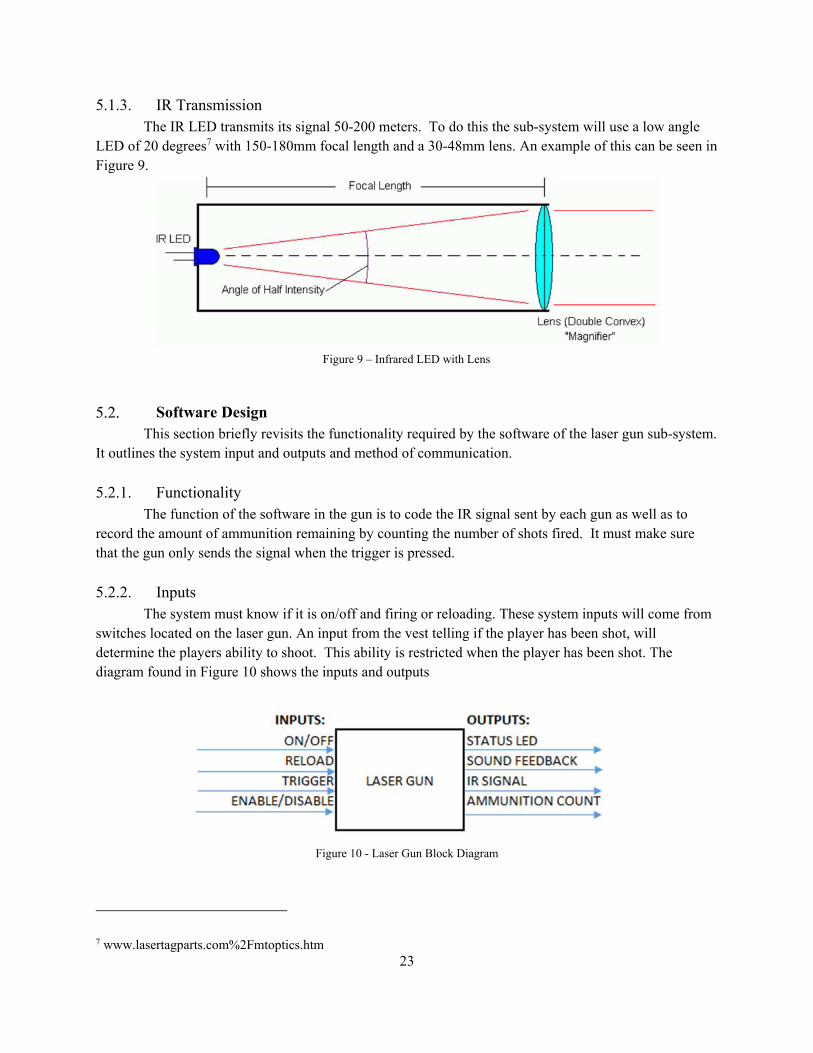
5.1.3. IR Transmission ................................................................................................................ 23
Software Design ......................................................................................................................... 23
5.2.1. Functionality ..................................................................................................................... 23
5.2.2. Inputs ................................................................................................................................ 23
5.2.3. Outputs .............................................................................................................................. 24
5.2.4. Data Transmission ............................................................................................................ 24
Mechanical Design ..................................................................................................................... 24
6. Sensor Vest ........................................................................................................................................... 24
Hardware Design ........................................................................................................................ 24
6.1.1. Sensors .............................................................................................................................. 24
6.1.2. Processor ........................................................................................................................... 25
6.1.3. Wi-Fi Transceiver ............................................................................................................. 26
6.1.4. Power System. .................................................................................................................. 26
Software Design ......................................................................................................................... 27
7. Android Application ............................................................................................................................. 28
Software Design ......................................................................................................................... 28
7.1.1. Overview ........................................................................................................................... 28
7.1.2. Functionality ..................................................................................................................... 29
7.1.3. Inputs ................................................................................................................................ 29
iv
7.1.4. Outputs .............................................................................................................................. 30
7.1.5. Software Updates .............................................................................................................. 30
8. System Prototype: Lazer-Ops 1.0 ......................................................................................................... 30
Purpose ....................................................................................................................................... 30
System ........................................................................................................................................ 30
Hardware .................................................................................................................................... 31
Software ...................................................................................................................................... 31
Mechanical .................................................................................................................................. 31
9. Production Model ................................................................................................................................. 31
System ........................................................................................................................................ 31
Central Hub ................................................................................................................................. 31
Gun/Vest ..................................................................................................................................... 32
Mobile Application ..................................................................................................................... 32
10. Conclusion ............................................................................................................................................ 32
Feasibility ................................................................................................................................... 32
Potential Project Obstacles ......................................................................................................... 32
11. Acknowledgements .............................................................................................................................. 32
12. References ............................................................................................................................................ 33

v
Table of Figures Figure 1 - A Possible solution ....................................................................................................................... 1 Figure 2 - System Mockup ............................................................................................................................ 2 Figure 3 - Typical Laser Tag Arena .............................................................................................................. 3 Figure 4 - A Group of Friends enjoying Laser Tag ...................................................................................... 4 Figure 5 - System Block Diagram ............................................................................................................... 15 Figure 6 - Infrared Sensor Placement ......................................................................................................... 16 Figure 7- Central Hub Block Diagram ........................................................................................................ 19 Figure 8 - Schematic for Testing IR Transmission (Aaron Ward) .............................................................. 22 Figure 9 – Infrared LED with Lens ............................................................................................................. 23 Figure 10 - Laser Gun Block Diagram ........................................................................................................ 23 Figure 11 - Infrared Sensor Placement ....................................................................................................... 25 Figure 12 - Power-state diagram ................................................................................................................. 26 Figure 13 - ATMEGA328 Pin out Diagram ............................................................................................... 27 Figure 14 - ATMEGA UML Diagram ........................................................................................................ 27 Figure 15 - Android Application Flow Diagram......................................................................................... 29
Table of Tables Table 1 - Team Hours ................................................................................................................................... 8 Table 2 - Sensor Vest and Laser Gun Power Consumption ........................................................................ 17 Table 3 - Communication Comparison Table ............................................................................................. 18 Table 4 - Central Processor Comparison Chart .......................................................................................... 20

1
1. Project Overview Team Lazer Ops consists of four senior members of Calvin College’s engineering program.
Team member biographies and responsibilities are outlined in the following sections. The home-laser tag system fulfills the senior design project requirement of the college. The following section will discuss the proposed project including an overview, differentiation, goals, and target customers of the project.
Calvin Senior Design During senior year, engineering students at Calvin College participate in a one year long (two
semester) Senior Design Project – termed ENGR 339 and 340. Students from all four concentrations are obligated to take part in a senior design project as a requirement for graduation. This allows students to form their own groups and choose a project that they will take from conception to design to implementation in the form of a prototype.
Problem Statement Since 19841, laser tag has been provided as a fun and interactive alternative to contemporary
video games. It demands similar team-based strategy but gets kids off the couch and moving around. However, for 29 years it has not changed much in concept. Teams of players are equipped with laser guns and vests. The players fire at members of the opposing team. Successful hits gain points for that team and prevent the hit player from firing for a given amount of time. The game ends after a set amount of time, victory going to the team with the highest accumulation of points. At the conclusion of the game, players receive their individual scores.
Instead of having to go to play laser tag, we aim to bring the laser tag experience to the consumer in the convenience of their own home or any other area with a secure Wi-Fi connection. This will give users the freedom to alter their game and environment as they please. This will differentiate the experience from that of traditional laser tag and add an additional benefit of convenience. There are several home-based systems currently available on the market. These systems do not include a mobile application, central hub, and sensor vests making our system the single most immersive and complete laser tag system available. Figure 1 is an example of a competing design which lacks a central hub and sensor vests
1 http://en.wikipedia.org/wiki/Laser_tag
Figure 1 - A Possible solution

2
Project Overview This section overviews various components essential for project completion including team organization, individual responsibilities, and the work breakdown schedule (WBS). It also states the project goal, product differentiation, and the targeted consumer market.
1.3.1. Project Functions The system will utilize four separate sub-systems to create an enjoyable and thrilling game
experience. This system will contain a central hub, sensor vests, laser-guns, and an Android application. This system in its entirety can be seen in Figure 2.
The central hub will visually display each team’s score, a game timer, as well as three status LEDs. The mobile application will deliver real-time game statistics to individual players. These statistics include each player’s shooting percentage, remaining ammunition and times the user has been hit. The user will be able to view their own personal statistics, any other player’s statistics, or an overview of the current game’s statistics. Additionally, the laser gun will provide sound feedback to the user upon each fire.
1.3.2. Differentiation A standard laser tag experience involves locating a nearby laser tag arena, travel to said arena,
and a cost of about 5-10 dollars per game2. Often laser tag facilities will offer group rates or special deals on certain days of the week. Games last from 10-30 minutes, with a time for briefing and vesting. Some laser tag arenas are able to handle up to 30 players, 15 per team. Depending on the system, players are
2 Sport Laser Tag Prices, Laser Sport
Figure 2 - System Mockup
3
given a printout revealing their team and individuals’ scores at the conclusion of the game. Our system aims to differentiate itself in three key areas: user awareness, convenience, and game flexibility which will be explained in further detail below.
Firstly, our system is designed to provide the users with more awareness throughout the game.
The proposed system would establish a more transparent form of gameplay where players can see game statistics in real time as they play. Current systems, as described above, either do not inform players of their scores and team scores until the game’s conclusion or they provide users with their personal score alone. Without the ability to know how their team is doing or how they are playing in reference to other players, it is hard to develop a meaningful game strategy. By providing the players with player scores, team scores, and other game statistics, the system will convey our design norm of care which is explained further in section 1.6. Our product aims to promote problem solving and logic building, both of which are enhanced by having more knowledge on the current situation in the game. This knowledge and self- awareness will supply a solid basis for game strategy, critical thinking, and add a new level of complexity to gameplay. For example, if players know that the game is near its end and their team is down by a few hits, they could quickly plan a strategic attack on a weaker member of the opposing team in order to pull ahead. Conversely, if their team is winning by a small margin near the game’s conclusion, they would know the opposing team’s lead scorer and could avoid an encounter. Mid-game, a better strategy may be to try to ambush the opposing team’s lead scorer and plan a secondary strike while their lead scorer’s laser gun is temporarily inoperable.
Secondly, convenience is a large benefit to the Lazer Ops system. The mobility of the system differentiates it from standard laser tag systems. It takes time and planning to gather a group of people together and to the laser tag arena. It is dependent upon the arenas’ availability and hours of operation. Having a home-system allows the users to play laser tag without having to coordinate transportation, depend on the facility, deal with crowds, waiting time, and cost per game. With the Lazer-Ops system, a game of laser tag can be played at the users’ convenience.
Traditional laser tag has been enjoyed by
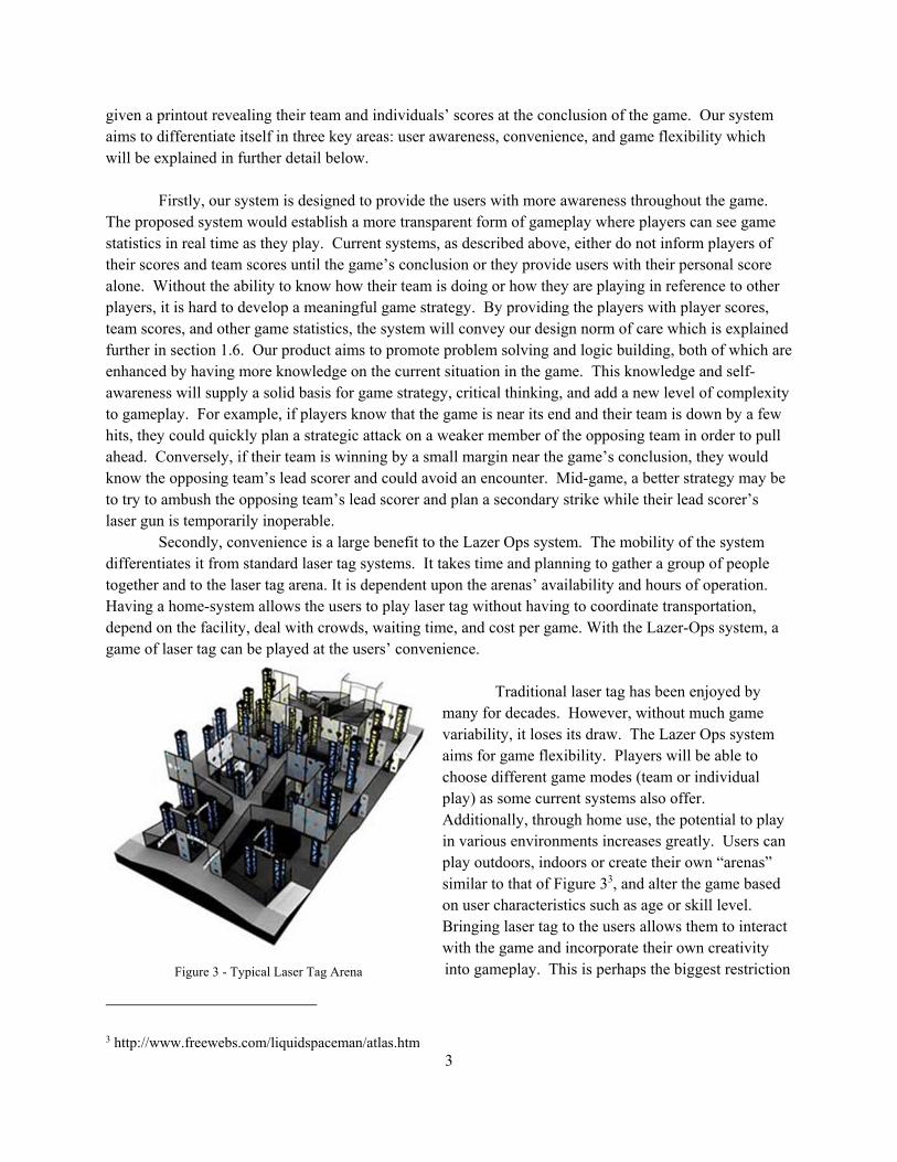
many for decades. However, without much game variability, it loses its draw. The Lazer Ops system aims for game flexibility. Players will be able to choose different game modes (team or individual play) as some current systems also offer. Additionally, through home use, the potential to play in various environments increases greatly. Users can play outdoors, indoors or create their own “arenas” similar to that of Figure 33, and alter the game based on user characteristics such as age or skill level. Bringing laser tag to the users allows them to interact with the game and incorporate their own creativity into gameplay. This is perhaps the biggest restriction
3 http://www.freewebs.com/liquidspaceman/atlas.htm
Figure 3 - Typical Laser Tag Arena

4
of existing laser tag systems. In contrast to current “one-size-fits-all” laser tag systems, Lazer Ops desires to create a dynamic system where the user experience is the central focus and where the user has control over when, where, and how the game is conducted.
1.3.3. Target Customers The focus of the Lazer-Ops project is to develop a system which essentially targets the same
market as traditional laser tag. One website advertises that laser tag is for anyone ages 6 to 964. Three targeted consumer groups in particular are existing laser tag arenas, young adult gamers, and families. Laser tag arena, which still use old systems, could benefit from technology that is reliable and much more profitable. Customers will be attracted by new game features and technology. Real-time data eliminates downtime and increases customer throughput, thus increasing profitability. Young adult gamers, such as those seen in Figure 45, will be intrigued by the new system; it will appeal to technology-lovers who desire a new twist on a classic game. Also, the convenience factor makes it easy
to start impromptu games whenever they desire. Children could benefit physically and socially from an at-home laser tag system. Laser tag systems encourage active participation, quick thinking, teamwork, and communication. Laser tag provides the perfect opportunity for children to play together, but in a controlled situation within the home. It also eliminates the stress on parents of having to deal with
4 Ultrazone 5 http://www.xplasersport.com/general-info/prices.htm
Figure 4 - A Group of Friends enjoying Laser Tag
5
recurring costs and transportation, while providing their children with a “birthday party” type activity, able to easily accommodate various amount of players.
1.3.4. Project Goal The ultimate goal of the Lazer-Ops team is to have a fully-functional product by the conclusion of
the spring 2014 semester (May 10). The Requirements chapter, found in section 2.0, specifies what ‘fully-functional’ is defined as, but a brief overview can be found below:
2 Operational Gun/Vest Systems
1 Operational Central hub for processing the wireless signals and data in real time
1 Operating Android application that will relay live game statistics
Interface for assigning player identities to a gun/vest system In addition, an objective of our final product is to research and present the feasibility of the project, specifically in areas of cost, consumer demand, and an overall business strategy.
Team Organization This section outlines the team organization by giving a short biography of each team member,
and their respective responsibilities.
1.4.1. Team Member Biographies Short biographies of each team member including their origins, education, and their experience in
the engineering field are detailed below. 1.4.1.1. Matthew Block
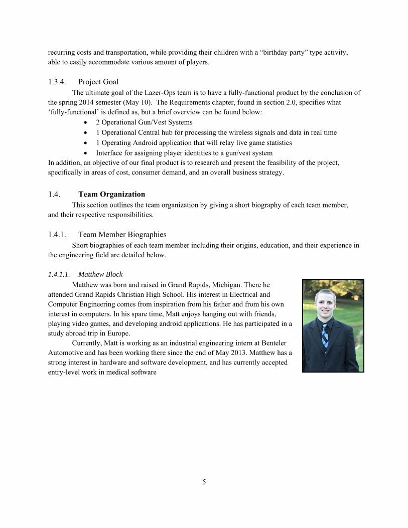
Matthew was born and raised in Grand Rapids, Michigan. There he attended Grand Rapids Christian High School. His interest in Electrical and Computer Engineering comes from inspiration from his father and from his own interest in computers. In his spare time, Matt enjoys hanging out with friends, playing video games, and developing android applications. He has participated in a study abroad trip in Europe.
Currently, Matt is working as an industrial engineering intern at Benteler Automotive and has been working there since the end of May 2013. Matthew has a strong interest in hardware and software development, and has currently accepted entry-level work in medical software

6
1.4.1.2. Eric Bouwkamp
Eric was born and raised in Grand Rapids, MI where he graduated from Grand Rapids Christian High School in 2010. Post-graduation, Eric started the Engineering program at Calvin College where he will graduate in May 2014 with a Bachelor of Science in Engineering with a concentration in Electrical and Computer Engineering. Eric is currently an active member of the Calvin College IEEE chapter. During the past summer, Eric gained significant software experience working as an engineering intern at L-3 Avionics systems where he developed and verified test software. 1.4.1.3. Kristen Herder
Kristen's roots lie in Portage, Michigan where she grew up and graduated from Kalamazoo Christian High School. Her interest in Electrical Engineering comes from her curiosity and love for creative problem solving. In her spare time, she enjoys leading Calvin's Soccer Club, studying other languages, and serving as a senior representative for the honors student council. She has participated in two study abroad programs in Europe.
Kristen has worked as an intern for two years in the Automotive Electronics Business Unit at Johnson Controls Incorporated, three years as a peer tutor, and two years as the SWE student leader for the engineering department. She has a strong interest in the application of electrical engineering in the automotive and medical industries where she is seeking full time work.
1.4.1.4. Mark Willard
Mark is from the small town of Yale, located in the thumb of Michigan. Following high school, he enrolled at Calvin College where he will graduate with a Bachelor of Science in Engineering with a concentration in Electrical and Computer Engineering. Mark played one year of basketball for Calvin College during his sophomore year, and he continues to play recreationally. His other interests include leading Calvin’s Chess Club, as well as making other people laugh. Innotec is Mark’s current employer. He is a Product Design Intern, where he utilizes his training in Computed Tomography to perform X-ray and CT scans on particular lighting and illumination products in order to discover failure modes. His previous work experience includes an industrial engineering internship at Benteler Automotive and a conveyor assembly technician job at Dematic, both companies located in Grand Rapids, MI. Upon graduation, Mark would like to work in robotics programming, hardware design, or controls engineering.

7
1.4.2. Team Member Responsibilities This section outlines individual team responsibilities within the project as a whole. It also
describes what each responsibility entails. 1.4.2.1. Matthew Block
Matt’s main job for the design project is to develop and create the android application. The android application will serve as a graphical user interface for each player. The basic function of this application is to allow players to access their real-time statistics while playing the game. This will mostly involve software programming, and UDP communication protocols.
1.4.2.2. Eric Bouwkamp
Eric’s focus during the project is primarily on the central hub and its integration with the other system components. The central hub sub-system consists of a significant amount of programming, Wi-Fi data communications, and some physical hardware integration. The hub will have the ability to send and receive data between the system components accurately and efficiently, and display some essential data on the unit itself.
1.4.2.3. Kristen Herder
Kristen’s primary focus is on the laser gun design. The main task is to produce a laser gun that sends an infrared signal unique to that gun so that it can be received and recognized by other players’ vest and processed correctly. The laser gun will keep track of the number of shots fired and ammunition remaining. This information is sent to the sensor vest through a wire connection between the two sub-systems. It will have an on/off switch, and will also give the user sound feedback upon each fire. Due to the reliance on the infrared receiver in the vest, Kristen will be working closely with Mark to develop these subsystems simultaneously and incrementally for testing purposes.
Kristen has experiencing working with micro-controllers as well writing software in assembly and C/C++ code. Though a previous project, she was able to gain experiencing with designing and implementing a custom PCB which provides a good foundation for working on creating a custom PCB for the laser gun. She also has industrial contacts who will provide feedback on optimizing the laser gun design, improving safety, and aesthetics.
1.4.2.4. Mark Willard
The focus of Mark’s work was on the sensor vest. The complexity of this subsystem primarily comes from the several operations by the microcontroller. The operations were:
Read in IR signal
Add header to IR signal--write new signal to Wi-Fi input
Write low voltage to gun (disable gun)
Write low voltage to LEDs (enable) In addition to these functions, the vest has to appropriately respond to the infrared signals from
the laser gun. Thus, there was consistent communication between both members, especially regarding processing particular coded signals. Mark had some experience in signal processing from previous projects, including an RFID-reader project which implemented an ATMEGA 328. He was very interested in signal processing, as well as

8
serial communication with Wi-Fi transmission. Additionally, the PCB design of our vest and gun intrigued him.
Work Breakdown Schedule Deadlines are being met with the help of a work breakdown schedule (WBS). The WBS was
implemented using Microsoft Project, which is easily accessible via the team’s workstation computer. The file is continuously updated, which provides consistent monitoring of progress and focus points. The most recent version of the WBS can be found on the team’s website (http://www.calvin.edu/ academic/engineering/2013-14-team11/documentation.html). Based on the hours put into the project thus far, the team estimates that the total time spent on the project by the end of the spring semester will be approximately 650 hours. Currently about 300 hours have been logged already (most of which has been design, purchasing, and documentation). The team expects at least that much time into prototyping, component integration, alterations, and design finalization. The current hours recorded by each team member can be found in Table 1 below.
Table 1 - Team Hours
Team Member Hours Matthew Block 67 Eric Bouwkamp 80 Kristen Herder 72 Mark Willard 68 Total Hours 287
1.5.1. Schedule Management The team’s WBS was largely overseen by Matt, but was consistently accessed by all members of the team. Frequently, there was live collaboration when updating the WBS. This allowed the team to re-cap on our accomplishments and establish new goals during the week, in addition to the weekly status updates.
Design Norms Lazer-Ops seeks to provide a fun, new way to engage people of all ages in the classic recreational
activity of laser tag. We seek to do this by producing affordable equipment and software that is user-friendly. Lazer-Ops will also provide a strong support structure for customers via cutting-edge technology and satisfaction guarantees. The company is focused on being a strong competitor in the field of home laser-tag systems in the near future. There is also great potential for breaking into commercial laser tag locations.
In order to deliver the goals discussed, the principles that guide our mission are the following: 1. Transparency: Lazer-Ops will produce a system that has easily defined purposes and parts
that is, the system will be exceptionally user-friendly. Easy-to-follow documentation will be included in the product.
2. Care: Lazer-Ops will take into account the effect on individuals physically, socially, and psychologically. From a physical standpoint, the game will promote physical activity and

9
fitness. Socially, the product gathers people together. Psychologically, Lazer-Ops intends to promote a message of team-work and competiveness, rather than violence that some products convey.
3. Stewardship: Lazer-Ops will be efficient in its allocation of time and resources. Cash flow management will be consistently effective such that the highest rate of return on assets may be maintained. Additionally, manufacturing principles will secure environmental friendliness.
4. Trust: Lazer-Ops will produce cost-effective and structurally sound equipment. The product will be dependable and reliable, and it will avoid any conflicts of interest regarding business practices.
Document Description In the chapters that follow, the design team describes the requirements and specifications of the
proposed laser tag system, gives a general overview of the laser tag system as a whole, and provides detailed descriptions of each subsystem. The final chapters are composed of descriptions of the prototypes that have been created thus far and an assessment of the feasibility of the proposed system. This document will conclude with a statement about the feasibility of the proposed system as well as a description of the risks that threaten the success of the design project. The design team will acknowledge all people that provided support and insight into the design of the system. Finally, the design team will report all sources that were used as reference material in the design of this project. The requirements chapter will detail the features of the system. This section will also explain the physical, customer and market, mechanical, user interface, communication, power, and environmental requirements of the system. This section will conclude with a description of the deliverables that the design team will provide at the end of the design process. The next five chapters provide a description of the whole system and its individual subsystems. The first chapter focuses on an overview of the laser tag system as a whole. In this chapter the design team will describe the components that comprise the system and the communication that will be necessary between each subsystems. The next chapter describes the central control hub. This chapter covers the design decisions that were made for the hardware and software components of this subsystem. The following chapter presents the design specifications, in terms of hardware and software, for the laser gun sub system. This chapter also communicates the decisions that were made regarding the mechanical design of the laser guns. The subsequent chapter specifies the design of the sensor vest. This chapter is divided into two sections. The first section details the software design, while the second section focuses on the hardware design. The final chapter in this group details the decisions made in the design of the Android application. The final four chapters of this report detail the prototypes that have been created or are currently being tested, the feasibility assessment and concluding remarks of the design team, acknowledgements to anyone who have given advice to the design team, and a list of any references that were used in the creation of this project. The prototype chapter provides the specifications of all prototypes that have been created or are being created. The following chapter will include any final remarks that the design team has. This chapter will also have a statement on the feasibility of this project. The final two chapters will give acknowledgements to any outside contributors, and will provide any references used in the design process or in the writing of this report.

10
2. Requirements This section breaks down the project requirements based on category and subsystem. The
categories covered include technical, customer, user interface, communication, and environmental requirements. It concludes by establishing the project deliverables.
Technical Description This section gives an in-depth description of the technical requirements set in place for each sub-
system. These requirements will be met by the completion of this project in the form of the May deliverables of the basic system.
2.1.1. Central Hub The central hub will oversee the game and the game’s events by receiving information from the
sensor vest and android application. Using the decoded information from the sensor vest, the central hub will then keep track of the game statistics and events throughout the duration of the game. The central hub will also have a simple, yet elegant, graphical user interface to setup, initialize, and end games. Game statistics, such as score and time remaining, will also be able to be seen on the front of the central hub.
2.1.2. Laser Gun The laser gun will send coded IR signals when the trigger is pulled. With each trigger pull, a
noise will sound to give feedback to the user that the system is operating properly. Each IR signal is unique to a given laser gun. When decoded by the vest this will enable it to distinguish which particular user the signal is coming from. An LED will also light when the system is activated. The laser gun will keep track of the amount of ammunition left. It will send this information via a tether to the sensor vest. The laser gun will incorporate an on/off switchand reload buttons. All the circuitry will be enclosed in a plastic housing. A lens used to focus the IR LED and extend its range of accuracy. The laser gun is powered by the power supply in the vest. The laser gun will provide an adjustable holster to hold a mobile device displaying the system’s application as a head’s up display (HUD).
2.1.3. Sensor Vest The vest will house the sensor circuit, which will have front, back, and two-shoulder sensors and
LED strings. The microcontroller will be placed in the front encasement with both front and shoulder sensor systems feeding to it and the LED control flowing from it. The controller will also oversee the function of the gun via a separate controller output. Thus, the vest and gun will be tethered (temporarily, via a physical connection), as will the power source that is located in the vest.
2.1.4. Android Application The Android application will be responsible for accessing and displaying player statistics. This
function will only be usable when a game has been started. When accessed during the game, it will display key statistics that would be important to the player during gameplay. The statistics that will be recorded or calculated include shots fired, hits, shots per minute, hit percentage, times hit, player with most hits, player hit most, player score, team score and opposing team score. When a game is not in play and the score screen is accessed, the app will display an error message telling the user that they must first start a game of laser tag in order to view current statistics.

11
System Features A complete laser tag system package would include 2 guns, 2 vests, and 1 central hub. In order to
utilize the Android application during gameplay, the application will have to be downloaded from the Google Play Store. This application will be free and provide additional information including download instructions. This laser tag system will feature infrared communication between laser guns and sensor vests, and Wi-Fi communication between sensor vests, Android application, and the central hub. This system will feature in-game statistic-tracking, allowing players to see current scores during the game on their mobile devices.
Customer / Market Requirements This section outlines various requirements for everyday use by an average consumer. In order for
our system to be reliable, these requirements must be implemented.
2.3.1. Functional Requirement For the system to function properly, the laser guns must be able to turn on and off and fire upon
trigger press. The system must also record ammunition usage and when the vests get hit. The hub must be able to take this data and process all the game information into useful statistics. Once the data has been processed, the hub must relay the information to the application which displays it to the users. The hub must allow the users to sign into the game, record which players are on which teams, and begin the game. The hub will also be able to keep track of the game’s elapsed time, and time left in each game.
2.3.2. Weight Limit The maximum weight desired for the vest as a whole was 1.8 kg. This is the approximate weight of a winter jacket, as found by the team. A single-layer PCB is less than 20 grams, which is the most contributing factor to the weight of the vest (aside from the material). This asserts the feasibility of meeting the weight limitation of the system. The gun’s weight should imitate the weight of a common NERF© gun — approximately 1.8 kg. The user should be able to hold the gun comfortably for 4 or more hours at a time, without exhibiting noticeable fatigue due to the weight of the gun.
2.3.3. Type of Environment / Use Meeting the established system requirements poses several potential system limitations. While
this system will be versatile and durable, it will not be able to stand harsh outdoor elements such as rain, mud, or snow. Because of this, the home laser tag system shall be intended for either home use, or use in a commercial setting. The system will withstand temperatures from 0 to 32 degrees Celsius, as well as a relative humidity of up to 95%.
Mechanical Requirements This section outlines several of the mechanical requirements that the subsystems have to ensure
product operation and integrity. All subsystems will implement safety measures to protect them from the rough use that they might receive during gameplay.

12
2.4.1. Central Hub Casing In order to protect the central hub’s components, a casing will be provided. As this is not
involved in rough gameplay, the casing will consist of a simple plastic enclosure which allows port access for input and output purposes.
2.4.2. Sensor Vest Casing The primary requirement for the encasements is to protect the IR sensors and the LEDs.
Additionally, the material must be constructed of a transparent plastic, so as to limit any infrared signal blocking and to maximize visual feedback via the LEDs. As far as the limiting force that the encasements are required to handle, it should withstand up to 1.14 kN, which is the weight of a 250-pound person.
The vest should support some sort of latching function (vel-cro, adjustable straps) for different-sized players to fit comfortably within the vests. The vest material should also maintain the weight of the components in the vest (estimated at 3 pounds).
2.4.3. Laser Gun Casing A plastic housing will be used to contain and secure the laser gun’s circuitry. The case must be
durable enough for rough gameplay, yet light enough so that it does not burden the user. Typical wall thickness of 3-4mm6 will be used. A tensile strength of 34-48MPa will be ideal to provide the casing enough strength to withstand game roughness. The ideal total weight for the gun circuitry and casing will be 1.8kg and it should be no longer than 40cm. The casing will incorporate a trigger and as many as three buttons, for on/off, and reload functions. Ideally, this design would be able to incorporate a “Heads up Display” in order to allow players to attach their phone directly to their gun to display the game information hands-free and in a convenient location as they play. This structure should be adjustable to adapt to differing mobile phone devices. This structure will be 4-6mm6 in thickness for extra stability.
User Interface Requirements This section outlines the basic requirements needed for the system to operate as far as inputs and
outputs are concerned. In order to control the system and the game experience, these requirements must be in place.
2.5.1. Basic Inputs The laser-tag system will consist of only two sources of input. The first and primary source is
through the graphical user interface of the central control hub. This will allow a user to initialize the game, change settings, and even view the previous game’s statistics. In addition to the graphical user interface, the Android application will also allow a user to change game settings and start a new game remotely.
2.5.2. Basic Outputs The Android application will relay gameplay statistics to the players via a digital display on an
Android device. These statistics will include the number of times the laser gun was fired, the number of
6 http://www.envplastics.com/about/articles/series-how-build-custom-plastic-enclosure-using-nmr-technology

13
shots that hit another player, the percentage of shots that hit another player, the average number of shots fired per minute, the score for an individual player or for a team, the number of times the player has been hit, who the player has shot most, and who was shot by the player the most. These statistics will be recorded or calculated by the central hub using data collected from the vests and guns of all the players in the current game. There will be additional outputs for user feedback. LEDs will blink on a player’s vest when they get hit. Also, whenever a player pulls the trigger on their laser gun, LEDs will flash. Additionally, when a game is finished, the lights on both the gun and the vest will blink for a few seconds.
2.5.3. Heads-Up Display / Android Application By using the touch capabilities that current smartphones are equipped with, the Android
application will function as a type of HUD. To incorporate this functionality, buttons and drop down lists will need to be mapped onto the display of the application. To ensure that these buttons work properly, the touch sensitivity and accuracy of the phone and application will need to be tested. To ensure that the design norm of transparency is met, the application will need to be intuitive and aesthetically pleasing. If these requirements are not met, the user may not be inclined to use the application at all.
Communication Requirements In order for the system to operate to its full potential, there needs to be constant communication
between all of the system components. This will be accomplished by establishing a Wi-Fi server. All wireless data will be transmitted using this server and the UDP protocol. This will allow data to be transferred to and from the central hub. While the central hub will be communicating wirelessly, the laser gun will be communicating with the sensor vest through a wired connection.
Power Requirements In order to provide a fun, enjoyable experience for the consumer, the team’s goal is to provide a
sensor and laser gun with a 40 hour use time per charge. This will be accomplished primarily by using low power components.
The central control hub unit will be plugged into a standard wall receptacle (115V). This signal will then be transformed, rectified, and regulated to provide clean power for the Raspberry Pi, wireless router, and the hub’s circuit boards. The supply must provide at least 3-4 Amps of current at 12V for all of the components in the central hub.
Environmental Requirements This section outlines environmental requirements including power efficiency of the sensor vest
and laser gun, and RoHS compliance.
2.8.1. Power Efficiency In order to create a sustainable and environmentally friendly system, the power used by all
systems must be minimized. By creating a system that can operate at a lower voltage, power consumption will be lowered. The team believes that this is an important design aspect that must be taken into account

14
as godly stewards of the planet Earth. In order to do this, it is the hope of the team that all components, during operation, will use less than 55 Watts of power at any given time.
2.8.2. RoHS Compliance In order to comply with the Restriction of Hazardous Substances Directive, lead-free solder will be used to construct the PCB’s, and was also used for hand-soldered components by the team. All other banned substances will also be nonexistent in our system. For a detailed list of these banned substances, see http://www.bis.gov.uk/nmo/enforcement/rohs-home.
Deliverables This section describes the deliverables that will be presented as a result of the project in its entirety. These will be delivered in May 2014.
2.9.1. PPFS Team Lazer-Ops will submit a complete project proposal and feasibility study, which will
encompass a proposed solution to a presented problem. The document (this document, itself) will also detail the hurdles involved in reaching the proposed solution.
2.9.2. In-class Presentations Team Lazer-Ops shall give four presentations to the senior design class regarding the progress of
the project, as well as what will be done on the project following the presentations. These presentations will be distributed throughout the year.
2.9.3. Project Posters The team will complete a poster describing the team and project that will be displayed at the
team’s project station in the engineering building. The poster will be updated throughout the year to include updated block diagrams, drawings, and details.
2.9.4. Final Report The team will submit a final report detailing the solution to the problem outlined, the research
behind the solution, the obstacles presented, the construction and testing of a prototype. Also, the document will cover the conclusions gathered from prototype testing, including the changes implemented into the final construction.
2.9.5. Final Presentation The team will be present on Senior Design Night, Saturday, May 10, 2014. Team Lazer-Ops will demonstrate the final project and its functionality, in addition to answering any questions from interested persons.
2.9.6. Working Prototype Team Lazer-Ops will demonstrate a complete, functional prototype, the requirements of which are discussed in sections 8.1.

15
2.9.7. Design Notebooks Each member of Team Lazer-Ops shall submit all of his/her relevant documents and folders to
the faculty advisor, including individual contributions to the project.
2.9.8. Team Website Team Lazer-Ops will publish a website available to any person interested in the project at
http://www.calvin.edu/academic/engineering/2013-14-team11/.
2.9.9. System Control Software All control software will be submitted with the final report.
2.9.10. Drawings & Schematics All CAD drawings, circuit schematics, and PCB designs shall be submitted with the final report
3. System Architecture This section outlines the system’s structure as a whole. This is done by first examining the
overview of the system, and then each subsystem in more detail.
Overview The Laser Tag system will consist of four main components. The first component, the central
control hub, will establish and maintain communication between all the separate components of the system, as well as manage the game environment. The hub will consist of a Raspberry Pi computer which will store and interpret data from the other components of the system. The second component is the
mobile application. This, initially using the android development framework, will provide a user interface that will be used to update game settings, view statistics, or create a new game. The next two components consist of the sensor vest, and the laser gun. The sensor vest will be used to sense incoming IR signals from other players, while the laser gun will send these modulated infrared signals. When game events occur, the sensor vest will communicate with the central hub in order to update the score, and enable additional features based on game performance. The system block diagram can be viewed in Figure 5.
Figure 5 - System Block Diagram

16
Components This subsection describes the individual components of the laser tag system individually. These
components are all essential to the operation and performance of the system as a whole.
3.2.1. Central Control Hub The central control hub will consist of a small Linux computer and a wireless router in order to
control the game data. This computer will be running a simple server in order to update game information, store game information, and provide the backbones for the general communication between the other components. This hub will also include basic status information displayed on the front of the unit. This status information will include the scores of either teams, the time remaining in the current game, and status LEDs for the system’s status.
3.2.2. Laser Gun Two laser guns are to be a part of the May deliverable. The laser gun is the apparatus for
transmitting the IR signal when the trigger is pulled. The device is to be held by each player and pointed in the direction of other users. When the IR beam is received by the vests of a player on the opposing team, it is considered a hit. In the beginning design phase, each player’s gun will be connected to their vest. A key objective of the laser gun sub-system is to ensure that each gun transmits an infrared signal specific to each laser gun upon trigger press. Upon game initiation, the central hub stores which players are members of each team. The overall system can process statistics on a team and individual basis. Another essential objective of the laser gun is enable the IR signal to be transmitted long-range and not be affected by ambient light.
3.2.3. Sensor Vest The sensor vest will consist of a vest and four housings for the sensing circuit. Additionally, it
will provide hardwired connections to the gun, including power, and trigger. The encasements will house the LEDs and microcontroller, as well as the spatially placed IR sensors. The LEDs and sensors will be controlled by the microcontroller, and thus be wired to the microcontroller. Figure 6 below shows a mockup (with component placements) of the vest.
Figure 6 - Infrared Sensor Placement

17
From the mock-up, note that the yellow circles represent LEDs, the purple blocks indicate IR sensors, and the three entities inside the front encasement on the vest are the microcontroller, the Wi-Fi transmitter, and the battery pack (power supply). The cords between the shoulder and back encasements will contain one wire for each of the following signals: 5V, GND, digital output from the ATMEGA, and an input wire (on one side) to the ATMEGA from the gun’s microcontroller.
The placement of the sensors will allow for complete coverage of the individual, and the LED locations provide the users feedback that a player was shot. The cable to the gun outputs from a median sagittal position. This placement lets right- and left- handed people have the same gun-extension distance, and the cable will be less likely to get in the way.
3.2.4. Android Application The mobile application will be responsible for showing players their in-game statistics. This
application will be written using the programming language Java. The application will be written for the Android operating using the Android Development Kit. The application will communicate with the central hub system over Wi-Fi. This communication will involve the use of UDP protocols.
System Power Consumption Table 2 below represents an estimate of the maximum power consumption of a gun/vest system.
Since these components were battery powered, their power consumption directly influences battery life.
The team assumed about 100% overhead, allowing for a maximum power consumption of about 2.5W. The team does not expect to approach this limit, as each of these components are absolute maximums consumptions (they assume continuous operation).
Communication Overview This section outlines the communication methods that will be in place between the subsystems. These protocols must be in place for the system to operate as a whole.
3.4.1. Central Hub to Gun/Vest Communication The central control hub will be communicating with the sensor vest and gun using 802.11n Wi-Fi.
This network will be implemented using a router, and range extenders as needed per application. The data
Table 2 - Sensor Vest and Laser Gun Power Consumption

18
will be transmitted using the UDP protocol, which encapsulates the data into packets when are then transmitted. This will make it very easy for data to be transferred between all of the components.
3.4.2. Central Hub to Android Application Communication The communication between the central hub and Android application will be done using Wi-Fi
communication. All the data will be transferred using UDP protocols. Bluetooth was considered as an alternative to Wi-Fi communication, but was ultimately decided against because of the limitations in Bluetooth communication range capabilities. Range was the deciding factor for choosing between Wi-Fi and Bluetooth. The design team wanted players to be able to use large areas while playing laser tag and using our system. Table 3, below shows the specifications for both Wi-Fi and Bluetooth that were taken into consideration while making this decision.
As shown in the table Wi-Fi has a potential maximum communication range of 45.72 m in
optimal conditions while Bluetooth only has a maximum range of 9.144 m. Two other specifications that the design team considered were power drain and power efficiency. Although the power drain for Bluetooth was significantly lower than Wi-Fi 802.11n, the power efficiency of Wi-Fi, on a per bit level, was 10 times lower than that of Bluetooth. Zigbee was considered as a potential alternative to Wi-Fi communication. Zigbee was ultimately not chosen, however, because it does not come as a standard form of wireless communication on mobile devices. This reason was a major factor in choosing Wi-Fi over other forms of wireless communication.
3.4.3. Laser Gun to Vest Communication Initially the laser gun will be wired to the vest. As the project evolves, we may change this to a wireless connection, through either Bluetooth or local Wi-Fi network. This will largely be influenced by time constraints, however an additional power supply will also be required for the gun if they are separated
4. Central Control Hub This section outlines specifications, requirements, and design choices that will be implemented
within the central control hub. This includes electrical, hardware, and software design, and many aspects of each subsystem.
Table 3 - Communication Comparison Table

19
Requirements The control hub has many requirements for the successful operation of the laser tag system. The
largest of these requirements is to effectively receive, interpret, and manage data sent to it from the sensor vest. This will be essential for the game experience that will be provided to the consumer. In addition, the central hub will also have two means of visual communication.
The first is a simple graphical user interface in order to modify gameplay and view game results on a monitor. The second is through the use of several 7-segment displays on the unit, and status LED’s. The 7-segments will be used to convey both teams’ current score, and the remaining game time. The status LED’s will be used to convey the power, hub, and game status. The system block diagram can be seen in Figure 7.
Electrical Design Since the central control hub will be confined to a single enclosure, it will be powered from a
standard wall outlet (120VAC). This signal will then be transformed and rectified using a wall-mount adaptor to 12 Volts DC. It will be rated to provide between 36 and 48 Watts. This supply will be used to provide power to the raspberry pi, Wi-Fi router, and the control hub displays.
The Raspberry Pi will be utilized as a server that is in charge of receiving, interpreting, and managing game data throughout the game. In addition to sending game data to the android application, the central hub will also display data through the graphical user interface, and through the use of three 7-segment displays, each of which have four digits. Two of these displays will be used to show each team’s current score, while the third will be used to display the remaining game time.
In addition to these three displays, three status LED’s will be used to show the status of the central control hub. Some possible statuses that might be shown with the LED’s might include power, current hub status, and current game status.
Figure 7- Central Hub Block Diagram

20
Hardware Design In order to create the entity of the central control hub, four main components will be used. These
four components, the central processor, the wireless router, and power supply, will be used to establish communication, manage game data, and create the game environment.
4.3.1. Central Processor In order to meet the requirements of the system, a central computer must be chosen. The team
examined two different systems for use within the central hub, the BeagleBone Black, and the Raspberry Pi. These alternatives and some specifications can be examined in Table 4.
Table 4 - Central Processor Comparison Chart
This Raspberry Pi was chosen for many reasons. The first and greatest reason, is the fact that the Raspberry Pi is readily available to use at Calvin. In addition to this, the Raspberry Pi includes 2 USB hosts, for use with the keyboard and mouse, where the BeagleBone Black only has 1. The Raspberry Pi also has a lower average power consumption. These specifications make it an ideal computer processor for use within our system. The Raspberry Pi will act as the central hub for the entire system. This is completed by initializing a server on the Raspberry Pi that will manage, interpret, and store game data. By establishing a UDP server on the device, the Android Application and sensor vest will be able to send and receive data. Because the central hub will consist of a single enclosure, a wired between the wireless router and Raspberry Pi is ideal.
4.3.2. Wireless Router The wireless router will also be enclosed within the central hubs enclosure. This device is capable
of establishing an 802.11n connection between the Raspberry Pi and the other system components.

21
To accomplish the requirements for this subsystem, a Linksys E1200 has been chosen. This router allows for a fast, reliable connection with data transfer rates up to 300 Mbps using the wireless-N protocol. The 802.11n protocol was chosen for a variety of reasons, the biggest of these reasons being the range of Wi-Fi signal. This protocol is able to penetrate barriers obstacles easier, making it a perfect choice for a laser tag system.
4.3.3. Power Supply The central hub will be powered using a single wall adaptor. In order to provide enough power
for every component, the wall adaptor will be rated for at least 12V at 3 Amps (36 Watts). This fused supply will power the wireless router directly, and provide a regulated 5V signal to the raspberry pi. This 5 volt signal will be regulated and filtered internally.
4.3.4. Display & Buttons The central hub will also be equipped with three 7-segment displays, each with four digits, in
order to display several game characteristics. These will consist of each team’s current score, and the game time remaining. In addition to this, the hub will also have three status LEDs for the power status, central hub status, and game status. The hub will also have an on/off switch that will cut power to the entire hub. This will only be used when initially plugged in, or when shutting the unit down after the pi has been shut down. There are several more aspects of the central hub that will be controlled via the graphical user interface.
4.3.5. Physical Enclosure The physical enclosure will encapsulate the entire central hub and all of its components. The
wireless router and the raspberry pi will be mounted internally, along with a custom printed circuit board to control the 7-segment displays and LEDs.
Software Design This section outlines several aspects of the central hub’s software, its design, and the
corresponding decisions.
4.4.1. Programming Language Choice In order for the central hub’s server to communicate and manage data, some software must be
written. While different languages have different advantages, these options were eliminated into python or C/C++. These languages are the two most native to the Raspberry Pi platform. While both applications would work to our specifications, C/C++ was chosen because it is a precompiled languages while python is interpreted at runtime. This will allow the software to run faster within the Raspberry Pi.
4.4.2. Graphical User Interface In order to provide an easy to use experience, the program will also use an external library in
order to provide a graphical user interface. This will allow for a easy to use experience for the end user when configuring and starting laser tag games.
22
4.4.3. Receiving and Transmitting Information All information, whether transferred from the sensor vest or to the android application will be
sent over a Wi-Fi connection using the UDP protocol. This information, which will be configured by the sensor vest’s processor, will then be decoded and the appropriate action will be taken within the Raspberry Pi’s data structure.
5. Laser Gun The laser gun design can be broken down into three main categories: Hardware, software and
mechanical design. This section briefly discusses the power consumption, processing, and IR transmission of the hardware as well as the inputs, outputs, and data transmission of the system software.
Electrical Hardware Design The hardware of the laser gun sub-system has three main components in order to meet the design
requirements and product functionality. It requires a power source, infrared transmitter, and microprocessor.
5.1.1. Power Delivery The laser gun will receive its power from its tether to the sensor vest.
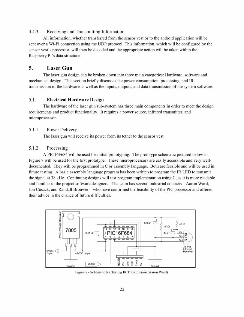
5.1.2. Processing A PIC16F684 will be used for initial prototyping. The prototype schematic pictured below in
Figure 8 will be used for the first prototype. These microprocessors are easily accessible and very well-documented. They will be programmed in C or assembly language. Both are feasible and will be used in future testing. A basic assembly language program has been written to program the IR LED to transmit the signal at 38 kHz. Continuing designs will test program implementation using C, as it is more readable and familiar to the project software designers. The team has several industrial contacts—Aaron Ward, Jon Cusack, and Randall Brouwer—who have confirmed the feasibility of the PIC processor and offered their advice in the chance of future difficulties.
Figure 8 - Schematic for Testing IR Transmission (Aaron Ward)
23
5.1.3. IR Transmission The IR LED transmits its signal 50-200 meters. To do this the sub-system will use a low angle
LED of 20 degrees7 with 150-180mm focal length and a 30-48mm lens. An example of this can be seen in Figure 9.
Software Design This section briefly revisits the functionality required by the software of the laser gun sub-system.
It outlines the system input and outputs and method of communication.
5.2.1. Functionality The function of the software in the gun is to code the IR signal sent by each gun as well as to
record the amount of ammunition remaining by counting the number of shots fired. It must make sure that the gun only sends the signal when the trigger is pressed.
5.2.2. Inputs The system must know if it is on/off and firing or reloading. These system inputs will come from
switches located on the laser gun. An input from the vest telling if the player has been shot, will determine the players ability to shoot. This ability is restricted when the player has been shot. The diagram found in Figure 10 shows the inputs and outputs
7 www.lasertagparts.com%2Fmtoptics.htm
Figure 9 – Infrared LED with Lens
Figure 10 - Laser Gun Block Diagram

24
5.2.3. Outputs Within the initial system and expansion packs, the laser gun will sound and flash an LED upon
each trigger press as well as a status LED when the laser gun is activated. An IR signal unique to the specific device will be transmitted. These signals are pulse modulated off from a 38 kHz signal. The gun will also relay the details on the ammunition supply to the vest and ultimately to the hub.
5.2.4. Data Transmission The wire connection between the vest and gun will be the initial means of data transmission
between the two sub systems. As the design process progresses, the team will look to implement wireless communication between the sensor vest and the laser gun.
Mechanical Design The choice was made to put an emphasis on the aesthetics of the final laser gun. There are three
possibilities for this: Purchasing and modifying an existing electrical housing, 3D-printing a housing unit, or using industry contacts to produce a housing unit. The specific mechanical details of the plastic casing can be found in section 2.4
6. Sensor Vest The following sections describe the sensor vests, the embedded hardware and software, and their
use within the entire system.
Hardware Design These subsections describe the hardware design for the sensor vest, and a description of their
purpose.
6.1.1. Sensors Although the exact sensor has not yet been chosen, enough has been done to verify that the
parameters that will influence the team’s decision are:
Filtration Tolerance (minimum of 800 nm wavelength)
Range (angle of reception) The maximum wavelengths of visible light generally reaches a maximum of 750 nm (red), which
signals the start of infrared light. Therefore, most photodiodes filter anything below 800 nm, but some poorer-quality components (or design-specific components) only filter below 700 or 750 nm wavelengths. Since the team desires full operability even in lighted areas, which contain some high-frequency infrared light, there was a strict filtration limit placed on this component. Additionally, the photodiode should be exposed enough that the vest can be targeted from an angle that is not directly “above” the photodiode. If the IR receiver is too concealed within its case, the angle of reception will be greatly reduced.
The number of sensors was also considered for adequate “tagging” in the game. Figure 11 below indicates by red arrows the infrared detectors.

25
Front, back, and shoulder locations were determined to be sufficient for full-functionality, with
the possibility of additional locations based on time constraints. These four sensors will manage a full-circle rotation of a player, given the IR sensor intended for purchase. This sensor (BP104) has a receiving angle of +/- 60 degrees without a lens8. Since the shoulder sensors will be directed to the sides of the player, there will be significant overlap of sensing (120 degree angle of reception per sensor).
6.1.2. Processor The processor implemented in the vest was chosen to be an ATMEGA328. Although the gun
utilizes a PIC processor, there was no obvious reason that the vest processor should contain the same architecture. The only signal communicated between the gun processor and the vest processor is an output from the PIC to the ATMEGA. As long as the ATMEGA can handle data in (when a shot is taken), the processor used in the vest has no other influence from the PIC.
A Raspberry Pi was not considered for the vest, primarily to the fact that every operation intended for the processor could be completed by a far less costly processor—in size, weight, and money. Additionally, any additional operations that the team desired of the vest processor are still possibilities with a smaller, 32-bit microprocessor. The ATMEGA was chosen because it has a vast open-source support platform (Arduino). Additionally, Mark already has significant experience programming on an Arduino Uno, which is the same development board implemented for prototyping. The Wi-Fi transceiver purchased also operates well with Atmel chips. In fact, an ATMEGA328 is directly installed with the MRF24WB0MA in a design by Seed Studio.9
8 Erix, Dan. "How to build IR remote controls." Resistance. N.p., n.d. Web. 2 Dec. 2013. <http://privat.bahnhof.se/wb907234/remote.htm>. 9 http://www.seeedstudio.com/depot/wifi-bee-p-823.html
Figure 11 - Infrared Sensor Placement

26
6.1.3. Wi-Fi Transceiver The team decided to purchase a MRF24WB0MA module for Wi-Fi transmission. This
transmitter is 802.11.n compatible, which is the chosen protocol for the team’s system. Aside from networking protocol compatibility, this transceiver was chosen because it works well with an Atmel processor (the ATMEGA), and it contains a TCP/IP driver10. This transceiver also has great documentation on its functionality. Below in Figure 12 is a state machine of the module, which supports lower power consumption due to its built-in sleep mode.
6.1.4. Power System. Both the vest and gun vessels will be powered by only one battery-pack (4 1.5 volt batteries) in
series with a 5V voltage regulator. The regulator will also be smoothed with a smoothing capacitor, but this is an area of little research thus far. In addition to the limited work on power regulation, there is also testing needed on how many milliamp-hours the vest and gun will be drawing when a final product is complete. With this knowledge, the team will determine the exact voltage necessary for consistent use.
10 http://ww1.microchip.com/downloads/en/DeviceDoc/70632C.pdf
Figure 12 - Power-state diagram

27
Software Design Because the sensor circuit implemented an ATMEGA chip, Arduino code was implemented via an Arduino Uno. Arduino code is C-based, which is a language the team has significant coursework experience in. The code for the processor reads and writes to various pins. A pin out of the ATMEGA chip is shown below in Figure 1311.
Although the specific design is not complete (pin mapping, e.g.) the primary functions of the code are thoroughly understood by the team. Figure 14, below is a state UML diagram of the ATMEGA code. Essentially, the code will be written to have conditional writing to 3 low-voltage pins. Another pin will
11 http://pikirsa.wordpress.com/2011/11/20/pinmapping-pin-layout-arduino/
Figure 13 - ATMEGA328 Pin out Diagram
Figure 14 - ATMEGA UML Diagram

28
be activated and deactivated in a sequence resembling light flashing for the LED circuit, as discuss. This flashing should last about 4 seconds (“dead” time), and the pin should return to 0 volts. The second low-voltage pin will control the functionality of the gun. The low-voltage (normally on) will influence the trigger circuit of the gun, such that, when the pin is high, the trigger circuit can function normally—otherwise pulling the trigger will do nothing. As for the digital pin, it will be used for writing to the Wi-Fi transmitter whenever the buffer is not empty. The buffer will only have something in it if there has been a shot fired or an enemy IR signal has been received.
Lastly, one pin must be used for IR detection. This pin will read in an analog IR signal, and convert it to digital using the using analogRead() function. This one pin will be connected to each sensor on the vest, such that if any sensor receives a signal, the pin will be high. At this point, all of the pins implemented for writing will depend on the incoming IR signal. The code will add a header signal to the received IR signal so as to include the vest identity in the Wi-Fi digital signal. The process of adding a header to a digital signal is possible with an ATMEGA, but the team has not accomplished it yet. Once the IR signal has been decoded, though, it must be combined with this digital header before being sent to the buffer (pictured in Figure 14)
There is opportunity in this area to allocate one pin for each sensor, but this is only necessary if the team wishes to track where (on the body) an individual was shot. This is not a requirement, but it is definitely a possibility for future improvements.
7. Android Application This section describes the Android application, its use within the system. It is described by
analyzing the software components, as well as communication used to make this happen.
Software Design This section describes the Android applications software design components, how they operate,
and their importance within the system.
7.1.1. Overview The design team decided that an application that anyone could use while playing laser tag on our
system would make this system more modern and immersive than many of the laser tag products currently available. The main function of the application, with regards to the laser tag system, is to provide in-game statistics to players. The design team decided to develop the mobile application for the Android operating system as this platform has the largest share of the world smartphone market.12 Another reason for developing for the Android platform is because Google provides a free software development kit, SDK, for all platforms. Apple also provides a free SDK for their IOS, but it is limited to Mac users. Another reason the design team chose Android instead of Apple was because of licensing costs. There is a $100 per year cost to become a licensed Apple developer13, however, it is significantly
12 Koetsier, John. "VentureBeat | News About Tech, Money and Innovation." VentureBeat. N.p., 31 Oct. 2013. Web. 10 Nov. 2013. 13 "Apple Developer." IOS Developer Program. Apple Inc., n.d. Web. 07 Dec. 2013.

29
less expensive both in the short run and long run to develop for Android. To become a licensed developer for Android, there is a one-time fee of $25.14
7.1.2. Functionality The main function of the application will be to display game statistics for all players. These
statistics will be viewable in two ways. The main way statistics will be viewable will be on a single player basis. The user will be able to choose which player’s statistics they wish to view and he/she will be shown the statistics of that player alone. The other way a user will be able to view statistics will be on a game wide spreadsheet view. This spreadsheet will show statistics for all players in the current game.
The statistics will be received by communicating with the central hub over Wi-Fi. In order to distinguish between multiple hubs and devices, the application user will need to know which central hub that he/she wish to connect to. The user will determine which central hub to connect to by connecting to the central hub that has the same identification as the router that is connected to the Raspberry Pi. The application will send a request signal to the central hub through the Wi-Fi connection between the two systems. The central hub will process this request and report the relevant player data to the application.
7.1.3. Inputs The inputs to this system include both user touch-based inputs and digital inputs from the central
hub system over Wi-Fi. The user touch-based inputs will be in response to prompts from the application and also used to navigate the menu system of the application. The inputs from the Wi-Fi server will be in the form of data packets sent from the central hub. These data packets will follow the UDP standards for network communication. Player statistics will be contained in these data packets. Once the packets are decoded, the statistics on the player will be displayed in table format on the screen of the smart device. Figure 15 below is a diagram that describes the basic flow of the application. The first view that will appear when the application is launched is the home screen view. This view will have a welcome message and a button that leads to the score menu screen view. The score menu screen will have a description of how to operate the score menu. In terms of input, the user will have options. The first input option will be a back button. The back button will return the user to the home screen. The second input will be to access a drop down list structure. This drop down list will contain all the players in the current game as well as the game itself.
14 "Get Started with Publishing." Android Developers. Google, n.d. Web. 08 Dec. 2013.
Figure 15 - Android Application Flow Diagram

30
Each player’s score screen will display the statistics for the selected player. The overall game statistics screen will show statistics for all players in the game. The statistics will be displayed in a table format. The application will store the player identifications for the current game in an array of players. A player will be a custom defined data structure that will be able to store all of the statistics necessary in individual instance variables. The application will receive this data from the central hub in the form of data packets. These data packets will follow the UDP standard for data transmission.
7.1.4. Outputs The application will produce only digital outputs. These outputs will be in the form of either the
player’s mobile display or data packets being sent to the central hub. The display output will be used to prompt the user for inputs or to provide the user with information. The other digital output of the system will be data packets sent from the application to the central hub system. These data packets will follow the UDP standards for data transmission. The data in these packets will be requests to the hub for player statistics.
7.1.5. Software Updates Software updates will be handled using the Google Play Store’s update system. When new
software patches or updates are created and released, they will be published to the Google Play Store. After these patches are published, it will be up to the user to connect to a Wi-Fi network and update their instance of the application.
8. System Prototype: Lazer-Ops 1.0 The system prototype section describes the goals, purpose, and a description of the hardware and
software components of this system. This prototype will be delivered in May of 2014.
Purpose The basic system will include two vests and two guns, a central hub, and an android application.
The players will initiate play using the central hub or the android application to begin a game of designated length. The hub will output the team’s scores and remaining game time, while the Android application will display game statistics and status to users during play. Two extra gun processors will be swapped out of each of the guns in order to transmit a different signal to the other team’s gun. This will allow for testing of friendly fire and proper identification of player tagging.
System The hub will utilize an 802.11n Wi-Fi network to receive data from the vest, process it, and store
it within the central hub. The mobile application can then request information from the central hub which will be sent in response. All data within the system will be communicated using the UDP protocol.
Two Infrared sensors must be incorporated into the prototype’s sensor vest to receive information from the laser guns. This information will then be decoded and transferred to the central hub.

31
Hardware The laser gun and vest will each have their own microprocessor. The gun will make use of long-
range LEDs in order to send signals to other sensor vests. In order to keep track of all the game events and scores, a central hub is needed. This consists of a small computer capable of establishing communication with all components of the system using Wi-Fi and the 802.11n protocol. The central hub will directly communicate with both the sensor vest and the android application.
Software This system contains several aspects of software. The central hub will have a server program
running constantly in order to maintain, update, and configure the gameplay throughout the life of the game. There will also be software in the sensor vest and gun which will be used to encode or decode the IR signal between the sensor and vest. In addition to this system, there will also be an android application in order to see game statistics, update game settings, and to initialize or end the game. This software will be directly communicating with the central hub.
Mechanical The prototype will include a basic housing for the initial system that will protect the electrical
components from natural conditions and basic wear due to use. This housing will be created by an outside source to the specifications given by the team.
9. Production Model The purpose of this section is to describe the actual production model and differentiate the course
deliverables if it were to go full-scale.
System The production model of our system will be sold in two ways. Firstly, our production model will
be distributed in the form of a starter pack. The starter pack will contain two laser guns, two sensor vests, and a central communication hub. Secondly, our product will be sold in the form of an expansion pack. This expansion pack will include two laser guns and two sensor vests. This will allow for great modularity with our product. This means that our customers will be able to increase their team size by one player per team with each additional purchased expansion pack. The android application will still be available for free.
Central Hub The central hub would be a custom designed printed circuit board. This circuit board would have
a built in Wi-Fi transceiver instead of using a separate Wi-Fi router. This will allow for a more integrated central hub system. The design team would also design their own microprocessor to be used in the integrated circuit board. All of these changes would increase the performance of the subsystem by eliminating off-chip communication.

32
Gun/Vest The gun and vest subsystems will maintain the same physical structure as discussed for the final
product. Some differences would include a sleek design (custom plastic molds) for the gun encasement and sensor casings, as well as a display on the gun for ammunition readings. The microcontrollers in the systems would only support the minimum functionalities of the gun and vest and there would be wireless communication between the two components.
Mobile Application The production model of the mobile application would be developed using the Unity engine. This will allow the mobile application to be developed for Android, IOS and Windows systems simultaneously, allowing almost all smartphone users to use the application.
10. Conclusion This section ties up the feasibility of the project and some obstacles that the team may face in order to deliver the prototype in May 2014.
Feasibility After much research and analysis, team Lazer-Ops believes that this system is feasible. Through
discussion with industry consultants and determination of the functionality and requirements of the essential subsystems, preliminary system designs were made and project costs were estimated. In reference to the given time, resource, and cost restraints, the project has been scaled to an appropriate level in which the May deliverables are plausible.
Potential Project Obstacles Some potential project obstacles that may be encountered by the design team are accurate
communication between the central hub and the sensor vest or application. Errors in communication between these devices could lead to incorrect statistics. This could potentially lead to incorrect data and inconsistencies within the results.
11. Acknowledgements Sang Mark Chung – Senior Designer from JCI for Design Advice on Poster
JCI – Product Development at for Hub casing/Gun Casing
Aaron Ward – Engineer from Calgon Carbon for IR and microprocessor Ideas
Steve VanderLeest – Electrical Engineering Professor at Calvin College
Randall Brouwer – Electrical Engineering Professor at Calvin College
Jon Cusack – Electrical Engineering professor from Hope College

33
12. References "Android 4.4 KitKat!" Android Developers. Android, n.d. Web. 09 Dec. 2013.
"Apple Developer." IOS Developer Program -. Apple Computers, n.d. Web. 07 Dec. 2013.
"AppTag - Laser Tag for Your IPhone or Samsung Galaxy Phone | HEX3." HEX3. Hex3, n.d. Web. 09 Dec. 2013.
"Calculation of Printed Circuits Weight for Standard Boards, Multilayer and Aluminum PCBs." Calculation of
Printed Circuits Weight for Standard Boards, Multilayer and Aluminum PCBs. Leiton, n.d. Web. 09 Dec.
2013.
"Compare with Other Technologies." Bluetooth Development Portal. Bluetooth Special Interest Group, n.d. Web.
08 Dec. 2013. <https://developer.bluetooth.org/TechnologyOverview/Pages/Compare.aspx>.
"Envision Plastics & Design." Series: How to Build a Custom Plastic Enclosure Using NMR Technology.
Envision Plastics and Design, n.d. Web. 09 Dec. 2013.
Erix, Dan. "IR Remote Control for Use by the Resistance." IR Remote Control for Use by the Resistance. N.p.,
n.d. Web. 09 Dec. 2013.
"FAQ." Untitled Document. Lalasertag.com, n.d. Web. 09 Dec. 2013.
Koetsier, John. "VentureBeat | News About Tech, Money and Innovation." VentureBeat. N.p., 31 Oct. 2013.
Web. 10 Nov. 2013.
"Laser Flash - LT-11.5 Laser Tag Gear." Laser Flash - LT-11.5 Laser Tag Gear. Laser Flash, n.d. Web. 09 Dec.
2013.
"Laser Tag." Qcfec.com. Family Entertainment, n.d. Web. 09 Dec. 2013.
"MilesTag - DIY Laser Tag System." MilesTag - DIY Laser Tag System. Laser Tag Parts, n.d. Web. 09 Dec.
2013.
"MRF24WB0MA/MRF24WB0MB Data Sheet." MRF24WB0MA/MRF24WB0MB Data Sheet. Microchip
Corporation, n.d. Web. 9 Dec. 2013.
"Prices." Prices. Ultrazone Laser Tag, n.d. Web. 09 Dec. 2013.
Schurek, Kenn. "2 Dirty Little Secrets That Some Laser Tag Manufacturers Don't Want You to Know." LaZer
Runner Laser Tag Systems, n.d. Web.
"Sport Laser Tag Prices." Pricing. Laser Sport, n.d. Web. 09 Dec. 2013.
"Terluran® GP-22." Terluran® GP-22. BASF Corporation, n.d. Web. 7 Dec. 2013.
"Time Line." Time Line. Laser Tag Museum, n.d. Web. 09 Dec. 2013.
"Wifi Bee." RSS Specials. Seeed Studio, n.d. Web. 09 Dec. 2013.
"Xappr Laser Tag Accessory for Iphone!" YouSayToo. N.p., n.d. Web. 09 Dec. 2013.