PROJECT NAME Chickamauga Lock Replacement –...
8
Lock Review - version 2 (May 06)PIANC - WG29 by Robert Bittner & Sam Yao – 100% DRAFT p.1 PROJECT NAME: Chickamauga Lock Replacement – Landward Lift-In Segmental Cofferdam Project Status: The Chickamauga Lock and Dam are existing structures. Design of a new lock addition is underway. A construction contract has been awarded for a combined cofferdam located downstream of the existing dam. The new cofferdam includes 794 feet of an innovative lift-in cofferdam system that will be incorporated into the new landward lock wall. Project Owner: The Tennessee Valley Authority (TVA) Organization in charge of operation: U.S. Army Corps of Engineers Nashville District Construction Company(s): C.J. Mahan, LLC, Grove City, Ohio Design Company(s): Bergmann Associates / Ben C. Gerwick Joint Venture Period of Construction: Mid 2006 thru Early 2009 (32 months total anticipated) Year Placed in Operation: Estimated 2012 Estimate Cost of Entire Project: $82,991,785 (US) (Segmental Cofferdam only) Entire Project: $325M (US) estimated Location: Country: United States City/Region: Near Chattanooga, Tennessee Relevant river: mile 471 on the Tennessee River Contact Address(es) (organization(s) that can provide additional information – if different from project Owner): Name: Wayne Huddleston with the U.S. Army Corps of Engineers, Nashville District Address, tel, fax: P.O.Box 1070, Nashville, Tennessee 37202-1070 Tel: (615)736-7842 Email, URL(web): [email protected] References: 1. “Chickamauga Lock Replacement Innovative Design – Phase I Feasibility Study,” prepared by Bergmann/Gerwick Joint Venture, Final Submittal, January 2003. 2. “Chickamauga Lock Replacement Innovative Landward Cofferdam and Lock Wall Concept Design Study,” prepared by Bergmann Associates and Ben C. Gerwick, December 2005. 3. “Design of New Gated Dam for Innovative In-the-Wet Construction, Braddock Locks and Dam, Monongahela River,” prepared by Bergmann Associates, Ben C. Gerwick, D’Appolonia, GeoSci, et al., November 1998. 4. “Engineering Report on the Downstream Cofferdam in the Kentucky Lock Addition Project,” prepared by Bergmann Associates and Ben C. Gerwick, JV for the USACE Nashville District, 2003. 5. “Upper Mississippi River - Illinois Waterway System Navigation Study: Innovative Lock Concept Review,” prepared by Ben C. Gerwick, Inc. for the USACE, 1995
Transcript of PROJECT NAME Chickamauga Lock Replacement –...
Lock Review - version 2 (May 06)PIANC - WG29 by Robert Bittner & Sam Yao – 100% DRAFT p.1
PROJECT NAME: Chickamauga Lock Replacement – Landward Lift-In Segmental Cofferdam Project Status: The Chickamauga Lock and Dam are existing structures. Design of a new lock addition is underway. A construction contract has been awarded for a combined cofferdam located downstream of the existing dam. The new cofferdam includes 794 feet of an innovative lift-in cofferdam system that will be incorporated into the new landward lock wall. Project Owner: The Tennessee Valley Authority (TVA) Organization in charge of operation: U.S. Army Corps of Engineers Nashville District Construction Company(s): C.J. Mahan, LLC, Grove City, Ohio Design Company(s): Bergmann Associates / Ben C. Gerwick Joint Venture Period of Construction: Mid 2006 thru Early 2009 (32 months total anticipated) Year Placed in Operation: Estimated 2012 Estimate Cost of Entire Project: $82,991,785 (US) (Segmental Cofferdam only) Entire Project: $325M (US) estimated Location:
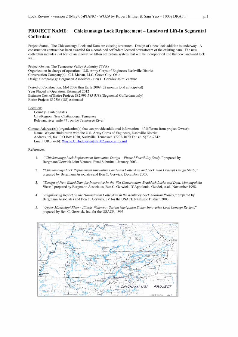
Country: United States City/Region: Near Chattanooga, Tennessee Relevant river: mile 471 on the Tennessee River
Contact Address(es) (organization(s) that can provide additional information – if different from project Owner): Name: Wayne Huddleston with the U.S. Army Corps of Engineers, Nashville District Address, tel, fax: P.O.Box 1070, Nashville, Tennessee 37202-1070 Tel: (615)736-7842 Email, URL(web): [email protected]
References:
1. “Chickamauga Lock Replacement Innovative Design – Phase I Feasibility Study,” prepared by Bergmann/Gerwick Joint Venture, Final Submittal, January 2003.
2. “Chickamauga Lock Replacement Innovative Landward Cofferdam and Lock Wall Concept Design Study,”
prepared by Bergmann Associates and Ben C. Gerwick, December 2005.
3. “Design of New Gated Dam for Innovative In-the-Wet Construction, Braddock Locks and Dam, Monongahela River,” prepared by Bergmann Associates, Ben C. Gerwick, D’Appolonia, GeoSci, et al., November 1998.
4. “Engineering Report on the Downstream Cofferdam in the Kentucky Lock Addition Project,” prepared by
Bergmann Associates and Ben C. Gerwick, JV for the USACE Nashville District, 2003.
5. “Upper Mississippi River - Illinois Waterway System Navigation Study: Innovative Lock Concept Review,” prepared by Ben C. Gerwick, Inc. for the USACE, 1995
Lock Review - version 2 (May 06)PIANC - WG29 by Robert Bittner & Sam Yao – 100% DRAFT p.2
2- PROJECT DESCRIPTION AND OVERVIEW (1 page)
- The Chickamauga Lock on the Tennessee River was constructed in the 1930s. The existing lock is a single chamber measuring 60 feet wide and 360 feet long. Since 1930, the structure has been plagued with a concrete volume expansion problem due to alkali-aggregate reaction. This problem has resulted in significant volume growth and cracking in the concrete, requiring high maintenance costs and frequent lock outages. The Corps of Engineers completed a Feasibility Study in April 2002, which demonstrated that replacement of the existing lock is feasible and economically justified. The Federal Government in 2003 authorized construction of a 110-foot x 600-foot replacement lock riverward of the existing lock. Feasibility studies were completed in 2004 for construction of a new lock using both the “conventional” cofferdam construction method and the innovative in-the-wet construction method.
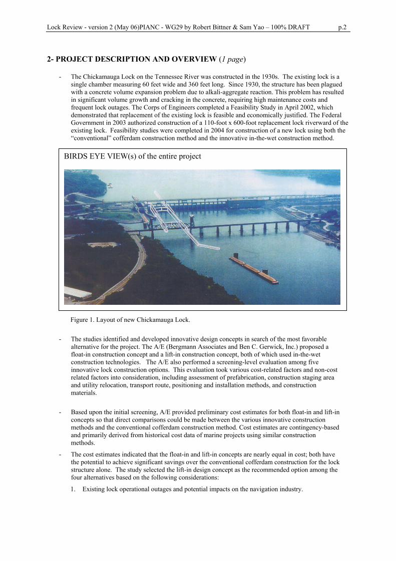
BIRDS EYE VIEW(s) of the entire project
Figure 1. Layout of new Chickamauga Lock. - The studies identified and developed innovative design concepts in search of the most favorable
alternative for the project. The A/E (Bergmann Associates and Ben C. Gerwick, Inc.) proposed a float-in construction concept and a lift-in construction concept, both of which used in-the-wet construction technologies. The A/E also performed a screening-level evaluation among five innovative lock construction options. This evaluation took various cost-related factors and non-cost related factors into consideration, including assessment of prefabrication, construction staging area and utility relocation, transport route, positioning and installation methods, and construction materials.
- Based upon the initial screening, A/E provided preliminary cost estimates for both float-in and lift-in
concepts so that direct comparisons could be made between the various innovative construction methods and the conventional cofferdam construction method. Cost estimates are contingency-based and primarily derived from historical cost data of marine projects using similar construction methods.
- The cost estimates indicated that the float-in and lift-in concepts are nearly equal in cost; both have the potential to achieve significant savings over the conventional cofferdam construction for the lock structure alone. The study selected the lift-in design concept as the recommended option among the four alternatives based on the following considerations:
1. Existing lock operational outages and potential impacts on the navigation industry.
Lock Review - version 2 (May 06)PIANC - WG29 by Robert Bittner & Sam Yao – 100% DRAFT p.3
2. Inherent risk in the method of transport and erection of precast lock elements, including the potential effect of this risk on both the navigation industry and efficient execution of the lock construction work.
3. Constructability issues associated with alignment, contraction joints, underwater foundation preparation, logistics, and sequence.
4. Economies of scale, whereby the proposed construction methods could be effectively applied to other portions of the project (e.g., the guide walls) as cost saving measures.
- However, the Corps of Engineers decided to proceed with a conventional cellular cofferdam concept for
the new Chickamauga Lock designed by their consultant Black & Veatch. This design was pursued until Black and Veatch’s initial Cofferdam Study identified design difficulties associated with the landward arm of the conventional cellular cofferdam. These difficulties included the lateral stability of the landward cellular structure founded on a complex geologic formation, its location adjacent to the deep excavation needed for lock wall construction, and the limitations on the width available for construction of the landward cofferdam and lock wall to maintain navigation during construction. As a result of these potential difficulties, the Corps of Engineers undertook further study for the landward portion of the cofferdam and the landward lock wall. This study, termed the Innovative Landward Cofferdam and Lock Wall Concept Design Study, was performed by the Corps of Engineers and their consultant Bergmann-Gerwick JV.
- This study provided information on both innovative cofferdam/lock wall concepts and a landward lock
wall concept supported wholly or partially on drilled shaft foundations. From the information generated by this study, in conjunction with information developed by both the Corps of Engineers and other consultants, a direct comparison was made between each of the conventional and innovative cofferdam, lock, and foundation options being considered.
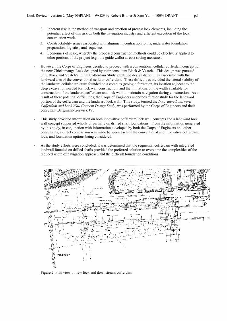
- As the study efforts were concluded, it was determined that the segmental cofferdam with integrated landwall founded on drilled shafts provided the preferred solution to overcome the complexities of the reduced width of navigation approach and the difficult foundation conditions.
Figure 2. Plan view of new lock and downstream cofferdam
Lock Review - version 2 (May 06)PIANC - WG29 by Robert Bittner & Sam Yao – 100% DRAFT p.4
Segmental Cofferdam
- The segmental cofferdam design was developed to address a number of key issues in the design of the landside cofferdam and lock wall, including:
A. Reduction of the risk exposure in rock excavation: Drilled shafts for the segmental cofferdam
provides high safety margin for the stability of the rock excavation adjacent to the cofferdam, especially where multiple or thick bentonite seams are exposed to rock excavation.
B. Increasing the vertical load bearing capacity of the foundation: Drilled shafts carry vertical loads
directly down to deep and sound rock, thereby bridging through bentonite seams and solution cavities near the top rock surface. Thus, the drilled shaft foundation reduces the adverse influence and uncertainties associated with the presence of bentonite seams and solution cavities, especially in highly jointed rock mass.
C. Reduction of adverse construction impact to the navigation traffic: The segmental cofferdam
concept imposes minimal impact on the navigation traffic during construction. In general, installation of a lift-in concrete segment will require at most a one-day shut-down of navigation traffic through the existing Chickamauga Lock. The follow-up construction for that segment will not affect the navigation traffic. In comparison with the conventional cellular cofferdam construction, the segmental cofferdam solution represents a significant reduction of construction impact on the navigation traffic.
D. Accommodating the limited width for cofferdam at the upstream end of the landward lock wall.
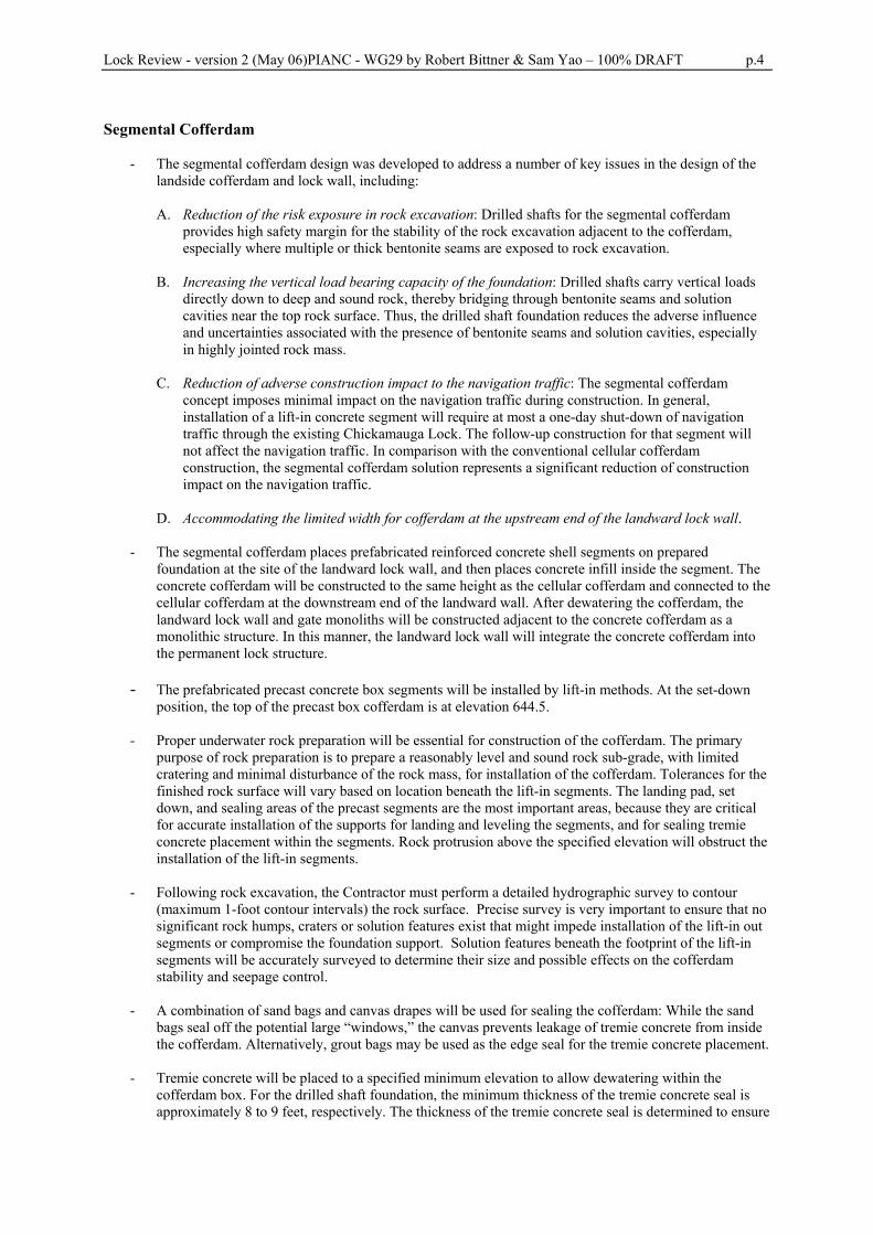
- The segmental cofferdam places prefabricated reinforced concrete shell segments on prepared
foundation at the site of the landward lock wall, and then places concrete infill inside the segment. The concrete cofferdam will be constructed to the same height as the cellular cofferdam and connected to the cellular cofferdam at the downstream end of the landward wall. After dewatering the cofferdam, the landward lock wall and gate monoliths will be constructed adjacent to the concrete cofferdam as a monolithic structure. In this manner, the landward lock wall will integrate the concrete cofferdam into the permanent lock structure.
- The prefabricated precast concrete box segments will be installed by lift-in methods. At the set-down
position, the top of the precast box cofferdam is at elevation 644.5. - Proper underwater rock preparation will be essential for construction of the cofferdam. The primary
purpose of rock preparation is to prepare a reasonably level and sound rock sub-grade, with limited cratering and minimal disturbance of the rock mass, for installation of the cofferdam. Tolerances for the finished rock surface will vary based on location beneath the lift-in segments. The landing pad, set down, and sealing areas of the precast segments are the most important areas, because they are critical for accurate installation of the supports for landing and leveling the segments, and for sealing tremie concrete placement within the segments. Rock protrusion above the specified elevation will obstruct the installation of the lift-in segments.
- Following rock excavation, the Contractor must perform a detailed hydrographic survey to contour (maximum 1-foot contour intervals) the rock surface. Precise survey is very important to ensure that no significant rock humps, craters or solution features exist that might impede installation of the lift-in out segments or compromise the foundation support. Solution features beneath the footprint of the lift-in segments will be accurately surveyed to determine their size and possible effects on the cofferdam stability and seepage control.
- A combination of sand bags and canvas drapes will be used for sealing the cofferdam: While the sand
bags seal off the potential large “windows,” the canvas prevents leakage of tremie concrete from inside the cofferdam. Alternatively, grout bags may be used as the edge seal for the tremie concrete placement.
- Tremie concrete will be placed to a specified minimum elevation to allow dewatering within the
cofferdam box. For the drilled shaft foundation, the minimum thickness of the tremie concrete seal is approximately 8 to 9 feet, respectively. The thickness of the tremie concrete seal is determined to ensure
Lock Review - version 2 (May 06)PIANC - WG29 by Robert Bittner & Sam Yao – 100% DRAFT p.5
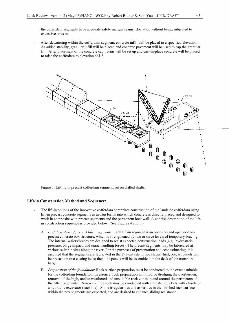
the cofferdam segments have adequate safety margin against floatation without being subjected to excessive stresses.
- After dewatering within the cofferdam segment, concrete infill will be placed to a specified elevation.
As added stability, granular infill will be placed and concrete pavement will be used to cap the granular fill. After placement of the concrete cap, forms will be set up and cast-in-place concrete will be placed to raise the cofferdam to elevation 661.8.
Figure 3. Lifting in precast cofferdam segment, set on drilled shafts.
Lift-in Construction Method and Sequence:
- The lift-in options of the innovative cofferdam comprises construction of the landside cofferdam using
lift-in precast concrete segments as in-situ forms into which concrete is directly placed and designed to work in composite with precast segments and the permanent lock wall. A concise description of the lift-in construction sequence is provided below: (See Figures 4 and 5.)
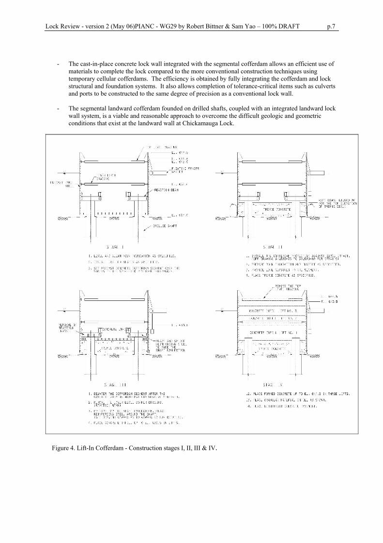
A. Prefabrication of precast lift-in segments: Each lift-in segment is an open-top and open-bottom
precast concrete box structure, which is strengthened by two or three levels of temporary bracing. The internal walers/braces are designed to resist expected construction loads (e.g., hydrostatic pressure, barge impact, and crane handling forces). The precast segments may be fabricated at various suitable sites along the river. For the purposes of presentation and cost estimating, it is assumed that the segments are fabricated in the DuPont site in two stages: first, precast panels will be precast on two casting beds; then, the panels will be assembled on the deck of the transport barge.
B. Preparation of the foundation: Rock surface preparation must be conducted to the extent suitable for the cofferdam foundation. In essence, rock preparation will involve dredging the overburden, removal of the high, and/or weathered and unsuitable rock zones in and around the perimeters of the lift-in segments. Removal of the rock may be conducted with clamshell buckets with chisels or a hydraulic excavator (backhoe). Some irregularities and asperities in the finished rock surface within the box segments are expected, and are desired to enhance sliding resistance.
Lock Review - version 2 (May 06)PIANC - WG29 by Robert Bittner & Sam Yao – 100% DRAFT p.6
C. Preparation of set-down foundation: Each lift-in segment will be set upon a leveled surface. The lift-in segment will be set down onto the top of the steel channels in the shafts and then be adjusted to level using flat-jacks or similar measures.
D. Transporting the lift-in segments: Each lift-in segment will be transported on barge to the lock site. The depth and width of the navigation channel on site appear to be adequate for the delivery of the segments on barge, although some minor excavation of rock crop at the lock site might be necessary. Due to the site access restrictions, the delivery barge will be pushed to pass through the railway bridge before the floating crane picks up the segment.
E. Installation of the lift-in segments: A typical lift-in segment will weigh approximately 260 to 320 tons. The segments will be lifted off the transport barge by a floating crane. (See Fig. 3.) Four tag lines and winches will be attached to the segment to prevent excessive swing during the lift-off. The crane barge will be moved into position near the set-down area and be stabilized with moorings lines or spud piles. The lift-in segment will be controlled by the tag line and winches during the set-down process. At a few feet above the set-down position, the lift-in segment will engage a pre-installed horn guide attached to the previously set segment. At this time, winches will be used to pull the segment laterally to mate with the adjacent segment and to compress pre-installed compressible seals to seal off edges of the mating surface. Survey control for positioning the lift-in segments will be performed using conventional land based survey techniques. The vertical alignment of the segment will be adjusted with flat jacks.
F. Tremie seal: Tremie concrete will be placed within the lift-in segment as a bottom seal for dewatering of the segment. (See Fig. 4 – Stage II) Prior to placing the tremie concrete seal, it will be critical to clean the rock surface to ensure good bond between concrete and rock, and to develop a water seal with a grout curtain, as remnant debris or soil on the rock surface might provide a channel for seepage and/or compromise sliding resistance. It is proposed that airlifting and/or suction dredging be used to clean the rock sub-grade. Close inspection with divers after settling out suspended solids with flocculants is also recommended. Sealing the gap between the bottom of lift-in segments and the river bed may be accomplished in several ways. A technique successfully used in the past is to attach pleated curtains of canvas around precast concrete segments. Steel chains are sewn onto one side of the curtains as counterweights. The curtains are initially held up by fiber lines. Once the precast segments are installed, sand bags are laid around the perimeters of the segment, the lines holding the pleated canvas are cut loose, and the curtains drop to seal the gaps. Divers are then used to inspect and reset the curtains as required. Alternatively, inflatable fabric grout bags may be used to seal the gap.
G. Placement of concrete infill: The cofferdam box will be dewatered. Then, concrete will be placed in lifts within the cofferdam segments. (See Fig. 4 – Stages III and IV.) The precast box is generally braced at two levels. The landward cofferdam will be protected with floating camels from direct barge impact throughout the construction. The floating camels are intended to spread a concentrated barge impact load and absorb a portion of the impact energy.
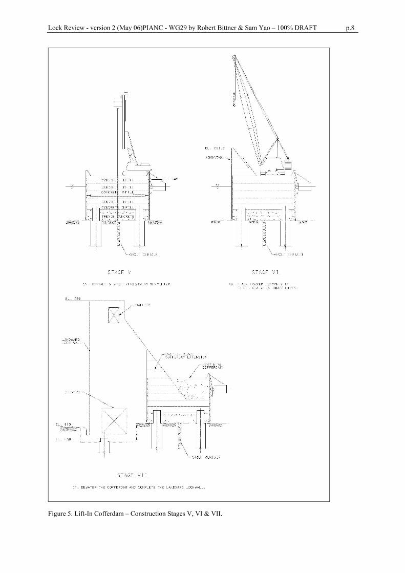
H. Placement of formed concrete: Above EL 644.5, formed concrete will be placed to complete the upper portion of the cofferdam up to EL 661.8. (See Fig. 5 – Stage VI.)
Innovative Lock Wall Configuration:
- The landward lock wall will be constructed in-the-dry and made integral with the segmental landward cofferdam structure. This will be done by excavating rock adjacent to the previously installed segmental cofferdam structure, with subsequent provision of foundations, foundation preparation, and placement of concrete. (See Fig. 5 – Stage VII.)
- The depth of the rock excavation would vary and is dependent on the type of lock wall being installed. Essentially the depth is dependent on the elevation of the proposed lock chamber filling and emptying culvert.
- The proposed lock wall will be integrated and physically attached to the innovative cofferdam during the concrete placement for the lock wall. Drilled and grouted reinforcing bars can be used, or attachment could be made through the use of threaded reinforcing couplers installed during the cofferdam construction. If necessary by design, it appears feasible to provide formed shear keys or roughened surface to better provide integrated structural behavior of the cofferdam and lock wall. See Figure 5 (Stage VII).
Lock Review - version 2 (May 06)PIANC - WG29 by Robert Bittner & Sam Yao – 100% DRAFT p.7
- The cast-in-place concrete lock wall integrated with the segmental cofferdam allows an efficient use of
materials to complete the lock compared to the more conventional construction techniques using temporary cellular cofferdams. The efficiency is obtained by fully integrating the cofferdam and lock structural and foundation systems. It also allows completion of tolerance-critical items such as culverts and ports to be constructed to the same degree of precision as a conventional lock wall.
- The segmental landward cofferdam founded on drilled shafts, coupled with an integrated landward lock wall system, is a viable and reasonable approach to overcome the difficult geologic and geometric conditions that exist at the landward wall at Chickamauga Lock.
Figure 4. Lift-In Cofferdam - Construction stages I, II, III & IV.
Lock Review - version 2 (May 06)PIANC - WG29 by Robert Bittner & Sam Yao – 100% DRAFT p.8
Figure 5. Lift-In Cofferdam – Construction Stages V, VI & VII.