Project Key Arena Redevelopment Feasibility Study ...€¦ · 2017 Key Arena Structural ......
20
2017 Key Arena Structural Narrative March 10 ,2017 | W17001.00 Project Key Arena Redevelopment Feasibility Study Structural Narrative Report Prepared For Populous Prepared By Steve Hofmeister, PE, SE, LEED AP Managing Principal Greg Briggs, PE, SE, LEED AP Principal Mark Johnson, PE Senior Associate Thornton Tomasetti Inc. 1500 4 th Avenue, Suite 450 Seattle, WA 98101 United States of America Phone: +1.206.336.4100 Fax: +1.206.336.7701 March 10, 2017
Transcript of Project Key Arena Redevelopment Feasibility Study ...€¦ · 2017 Key Arena Structural ......
2017 Key Arena Structural Narrative March 10 ,2017 | W17001.00
Project
Key Arena Redevelopment Feasibility Study Structural Narrative Report Prepared For
Populous
Prepared By
Steve Hofmeister, PE, SE, LEED AP Managing Principal Greg Briggs, PE, SE, LEED AP Principal Mark Johnson, PE Senior Associate Thornton Tomasetti Inc. 1500 4th Avenue, Suite 450 Seattle, WA 98101 United States of America Phone: +1.206.336.4100 Fax: +1.206.336.7701 March 10, 2017
2017 Key Arena Structural Narrative March 10 ,2017 | W17001.00
TABLE OF CONTENTS
1.00 Introduction .............................................................................................................................. 1
2.00 Description of Structural System........................................................................................... 1
2.01 Foundations and Grade Slab .................................................................................................................... 1
2.02 Bowl and Gravity Framing ...................................................................................................................... 10
3.00 Preliminary Quantities and Costs ........................................................................................ 14
3.01 Preliminary Reinforcing Steel Quantities ................................................................................................ 14
3.02 Preliminary Structural Steel Quantities ................................................................................................... 15 3.03 Specialty Contractor Preliminary Costs .................................................................................................. 16
Page 1 of 18
2017 Key Arena Structural Narrative March 10 ,2017 | W17001.00
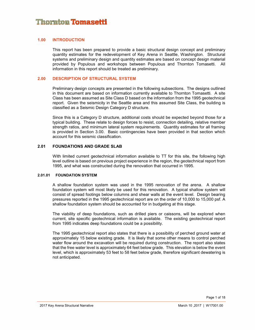
1.00 INTRODUCTION
This report has been prepared to provide a basic structural design concept and preliminary quantity estimates for the redevelopment of Key Arena in Seattle, Washington. Structural systems and preliminary design and quantity estimates are based on concept design material provided by Populous and workshops between Populous and Thornton Tomasetti. All information in this report should be treated as preliminary.
2.00 DESCRIPTION OF STRUCTURAL SYSTEM
Preliminary design concepts are presented in the following subsections. The designs outlined in this document are based on information currently available to Thornton Tomasetti. A site Class has been assumed as Site Class D based on the information from the 1995 geotechnical report. Given the seismicity in the Seattle area and this assumed Site Class, the building is classified as a Seismic Design Category D structure.
Since this is a Category D structure, additional costs should be expected beyond those for a typical building. These relate to design forces to resist, connection detailing, relative member strength ratios, and minimum lateral system requirements. Quantity estimates for all framing is provided in Section 3.00. Basic contingencies have been provided in that section which account for this seismic classification.
2.01 FOUNDATIONS AND GRADE SLAB
With limited current geotechnical information available to TT for this site, the following high level outline is based on previous project experience in the region, the geotechnical report from 1995, and what was constructed during the renovation that occurred in 1995.
2.01.01 FOUNDATION SYSTEM
A shallow foundation system was used in the 1995 renovation of the arena. A shallow foundation system will most likely be used for this renovation. A typical shallow system will consist of spread footings below columns and shear walls at the event level. Design bearing pressures reported in the 1995 geotechnical report are on the order of 10,000 to 15,000 psf. A shallow foundation system should be accounted for in budgeting at this stage.
The viability of deep foundations, such as drilled piers or caissons, will be explored when current, site specific geotechnical information is available. The existing geotechnical report from 1995 indicates deep foundations could be a possibility.
The 1995 geotechnical report also states that there is a possibility of perched ground water at approximately 15 below existing grade. It is likely that some other means to control perched water flow around the excavation will be required during construction. The report also states that the free water level is approximately 64 feet below grade. This elevation is below the event level, which is approximately 53 feet to 58 feet below grade, therefore significant dewatering is not anticipated.
Page 2 of 18
2017 Key Arena Structural Narrative March 10 ,2017 | W17001.00
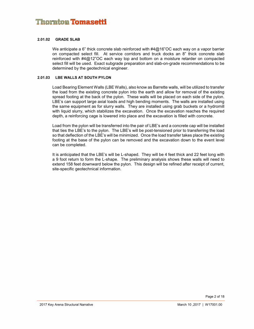
2.01.02 GRADE SLAB
We anticipate a 6” thick concrete slab reinforced with #4@16”OC each way on a vapor barrier on compacted select fill. At service corridors and truck docks an 8” thick concrete slab reinforced with #4@12”OC each way top and bottom on a moisture retarder on compacted select fill will be used. Exact subgrade preparation and slab-on-grade recommendations to be determined by the geotechnical engineer.
2.01.03 LBE WALLS AT SOUTH PYLON
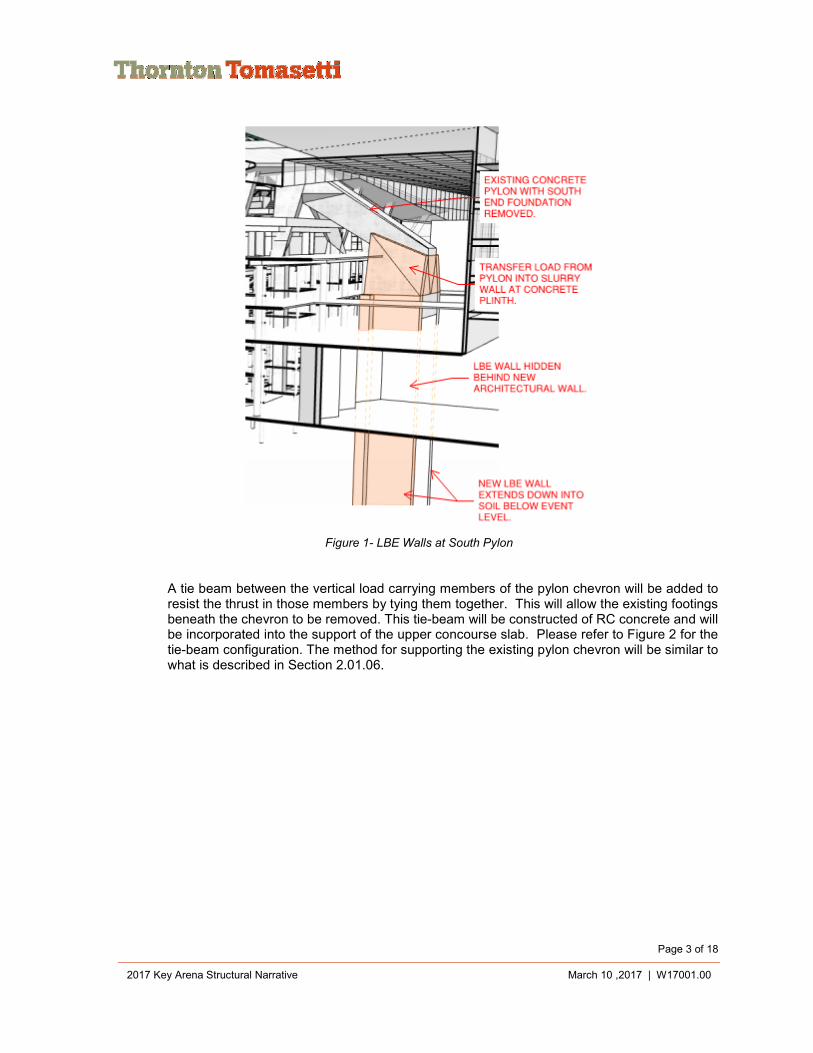
Load Bearing Element Walls (LBE Walls), also know as Barrette walls, will be utilized to transfer the load from the existing concrete pylon into the earth and allow for removal of the existing spread footing at the back of the pylon. These walls will be placed on each side of the pylon. LBE’s can support large axial loads and high bending moments. The walls are installed using the same equipment as for slurry walls. They are installed using grab buckets or a hydromill with liquid slurry, which stabilizes the excavation. Once the excavation reaches the required depth, a reinforcing cage is lowered into place and the excavation is filled with concrete.
Load from the pylon will be transferred into the pair of LBE’s and a concrete cap will be installed that ties the LBE’s to the pylon. The LBE’s will be post-tensioned prior to transferring the load so that deflection of the LBE’s will be minimized. Once the load transfer takes place the existing footing at the base of the pylon can be removed and the excavation down to the event level can be completed.
It is anticipated that the LBE’s will be L-shaped. They will be 4 feet thick and 22 feet long with a 9 foot return to form the L-shape. The preliminary analysis shows these walls will need to extend 158 feet downward below the pylon. This design will be refined after receipt of current, site-specific geotechnical information.
Page 3 of 18
2017 Key Arena Structural Narrative March 10 ,2017 | W17001.00
Figure 1- LBE Walls at South Pylon
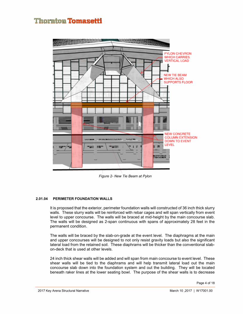
A tie beam between the vertical load carrying members of the pylon chevron will be added to resist the thrust in those members by tying them together. This will allow the existing footings beneath the chevron to be removed. This tie-beam will be constructed of RC concrete and will be incorporated into the support of the upper concourse slab. Please refer to Figure 2 for the tie-beam configuration. The method for supporting the existing pylon chevron will be similar to what is described in Section 2.01.06.
Page 4 of 18
2017 Key Arena Structural Narrative March 10 ,2017 | W17001.00
Figure 2- New Tie Beam at Pylon
2.01.04 PERIMETER FOUNDATION WALLS
It is proposed that the exterior, perimeter foundation walls will constructed of 36 inch thick slurry walls. These slurry walls will be reinforced with rebar cages and will span vertically from event level to upper concourse. The walls will be braced at mid-height by the main concourse slab. The walls will be designed as 2-span continuous with spans of approximately 28 feet in the permanent condition.
The walls will be braced by the slab-on-grade at the event level. The diaphragms at the main and upper concourses will be designed to not only resist gravity loads but also the significant lateral load from the retained soil. These diaphrams will be thicker than the conventional slab-on-deck that is used at other levels.
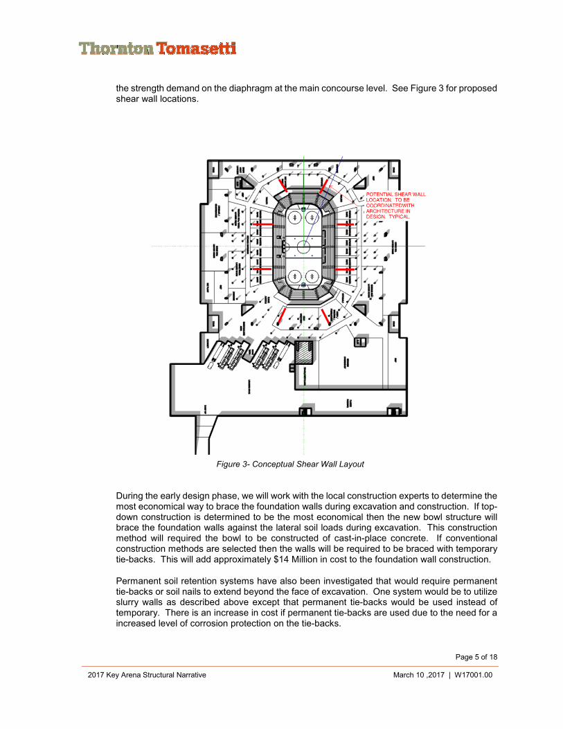
24 inch thick shear walls will be added and will span from main concourse to event level. These shear walls will be tied to the diaphrams and will help transmit lateral load out the main concourse slab down into the foundation system and out the building. They will be located beneath raker lines at the lower seating bowl. The purpose of the shear walls is to decrease
Page 5 of 18
2017 Key Arena Structural Narrative March 10 ,2017 | W17001.00
the strength demand on the diaphragm at the main concourse level. See Figure 3 for proposed shear wall locations.
Figure 3- Conceptual Shear Wall Layout
During the early design phase, we will work with the local construction experts to determine the most economical way to brace the foundation walls during excavation and construction. If top-down construction is determined to be the most economical then the new bowl structure will brace the foundation walls against the lateral soil loads during excavation. This construction method will required the bowl to be constructed of cast-in-place concrete. If conventional construction methods are selected then the walls will be required to be braced with temporary tie-backs. This will add approximately $14 Million in cost to the foundation wall construction.
Permanent soil retention systems have also been investigated that would require permanent tie-backs or soil nails to extend beyond the face of excavation. One system would be to utilize slurry walls as described above except that permanent tie-backs would be used instead of temporary. There is an increase in cost if permanent tie-backs are used due to the need for a increased level of corrosion protection on the tie-backs.
Page 6 of 18
2017 Key Arena Structural Narrative March 10 ,2017 | W17001.00
A second system would be to use a permanent soil nail wall. This wall would be have a 1:5 (horizontal to vertical) slope. Permanent soil nails would be drilled into the soil and a shotcrete wall would be applied to the slope and would engage the soil nails. A wall drainage system would be required between the face of soil and face of shotcrete. This drainage system would relieve any potential hydrostatic pressure build-up behind the wall.
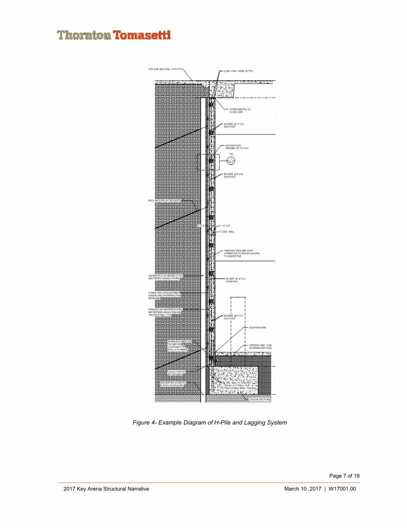
A third system that could be considered is to install an H-pile and lagging system with permanent tie-backs and a permanent concrete facing wall. This system requires H-piles to be installed inside of drilled shafts. Lagging between the H-Piles and permanent tie-backs are then installed as the excavation progresses downward. After excavation is complete a permanent concrete wall is cast against the lagging and tied to the H-piles. This permanent wall is designed to span between H-Piles and resist the lateral soil pressure. A wall drainage system would be required between the face of lagging and face of concrete facing wall. This drainage system would relieve any potential hydrostatic pressure build-up behind the wall.
Any of the permanent soil retention systems outlined above, will reduce the shearwalls outlined in Figure 3 as well as the diaphragm reinforcing as indicated on in the structural quantities.
Page 7 of 18
2017 Key Arena Structural Narrative March 10 ,2017 | W17001.00
Figure 4- Example Diagram of H-Pile and Lagging System
Page 8 of 18
2017 Key Arena Structural Narrative March 10 ,2017 | W17001.00
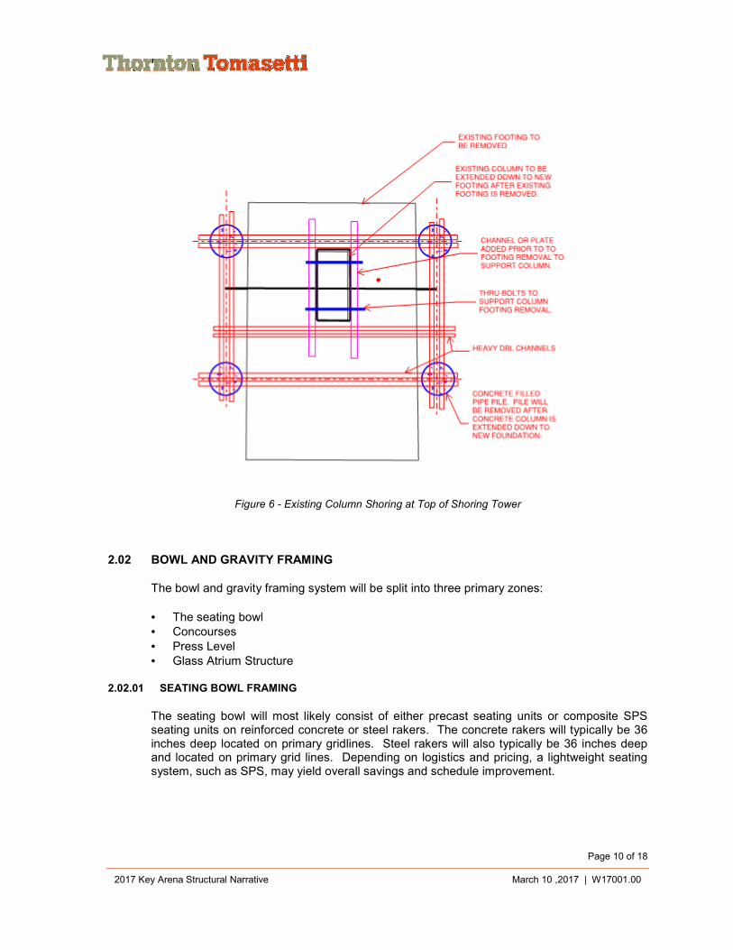
2.01.05 EXISTING COLUMN EXTENSION
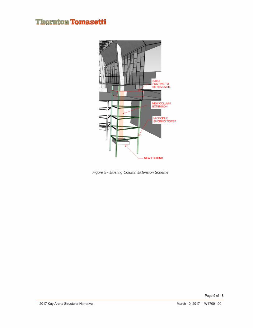
The existing concrete columns around the perimeter of the building have a very iconic shape and will be preserved during the renovation of the arena. The basement of the building is going to be extended below these columns. Therefore, these columns must be extended downward and the existing footing demolished. In addition, a new footing must be placed below the event level.
In order to accomplish this the columns will have to be supported during excavation. Micropiles will be driven around the perimeter of the existing footings and the column loads will be transferred to those micropiles through beams that span between the piles. As excavation occurs, the existing footing will be removed and the micropiles will be tied together with horizontal struts to form a shoring tower. Horizontal struts between micropiles will be added as the excavation gets deeper. Once the excavation reaches the event level, a new spread footing will be poured. After the footing is poured, a new column will be constructed of reinforced concrete and will extend up to the existing column.
After the column is in place, the micropile shoring tower will be cut off at the top of the new footing and removed.
Two of these micropile shoring towers will be required beneath each pylon (8 towers required). They will also be required beneath each concrete “Y-Column” (20 towers required). The micropile shoring towers will also be required beneath 4 columns that support roof trusses added in 1995. A grand total of 32 micropile shoring towers will be required.
Please refer to Figure 5 and Figure 6 for an illustration of the column extension scheme and the column load transfer concept detail.
Page 9 of 18
2017 Key Arena Structural Narrative March 10 ,2017 | W17001.00
Figure 5 - Existing Column Extension Scheme
Page 10 of 18
2017 Key Arena Structural Narrative March 10 ,2017 | W17001.00
Figure 6 - Existing Column Shoring at Top of Shoring Tower
2.02 BOWL AND GRAVITY FRAMING
The bowl and gravity framing system will be split into three primary zones:
• The seating bowl • Concourses • Press Level • Glass Atrium Structure
2.02.01 SEATING BOWL FRAMING
The seating bowl will most likely consist of either precast seating units or composite SPS seating units on reinforced concrete or steel rakers. The concrete rakers will typically be 36 inches deep located on primary gridlines. Steel rakers will also typically be 36 inches deep and located on primary grid lines. Depending on logistics and pricing, a lightweight seating system, such as SPS, may yield overall savings and schedule improvement.
Page 11 of 18
2017 Key Arena Structural Narrative March 10 ,2017 | W17001.00
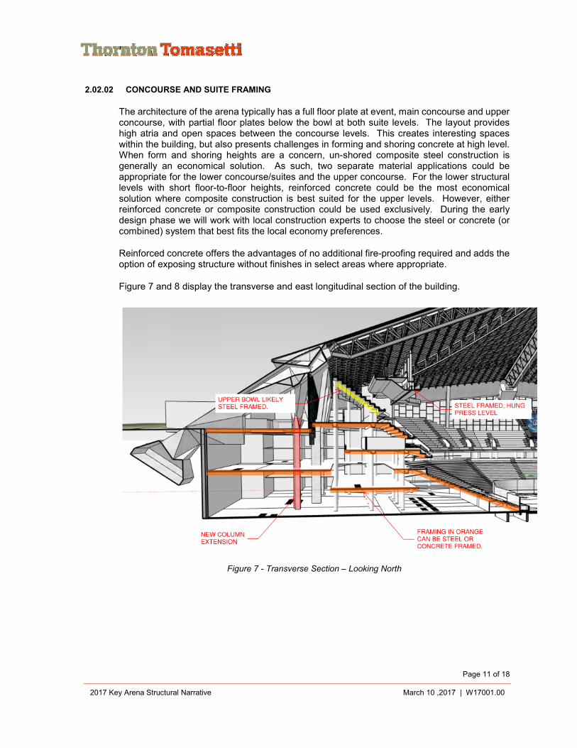
2.02.02 CONCOURSE AND SUITE FRAMING
The architecture of the arena typically has a full floor plate at event, main concourse and upper concourse, with partial floor plates below the bowl at both suite levels. The layout provides high atria and open spaces between the concourse levels. This creates interesting spaces within the building, but also presents challenges in forming and shoring concrete at high level. When form and shoring heights are a concern, un-shored composite steel construction is generally an economical solution. As such, two separate material applications could be appropriate for the lower concourse/suites and the upper concourse. For the lower structural levels with short floor-to-floor heights, reinforced concrete could be the most economical solution where composite construction is best suited for the upper levels. However, either reinforced concrete or composite construction could be used exclusively. During the early design phase we will work with local construction experts to choose the steel or concrete (or combined) system that best fits the local economy preferences.
Reinforced concrete offers the advantages of no additional fire-proofing required and adds the option of exposing structure without finishes in select areas where appropriate.
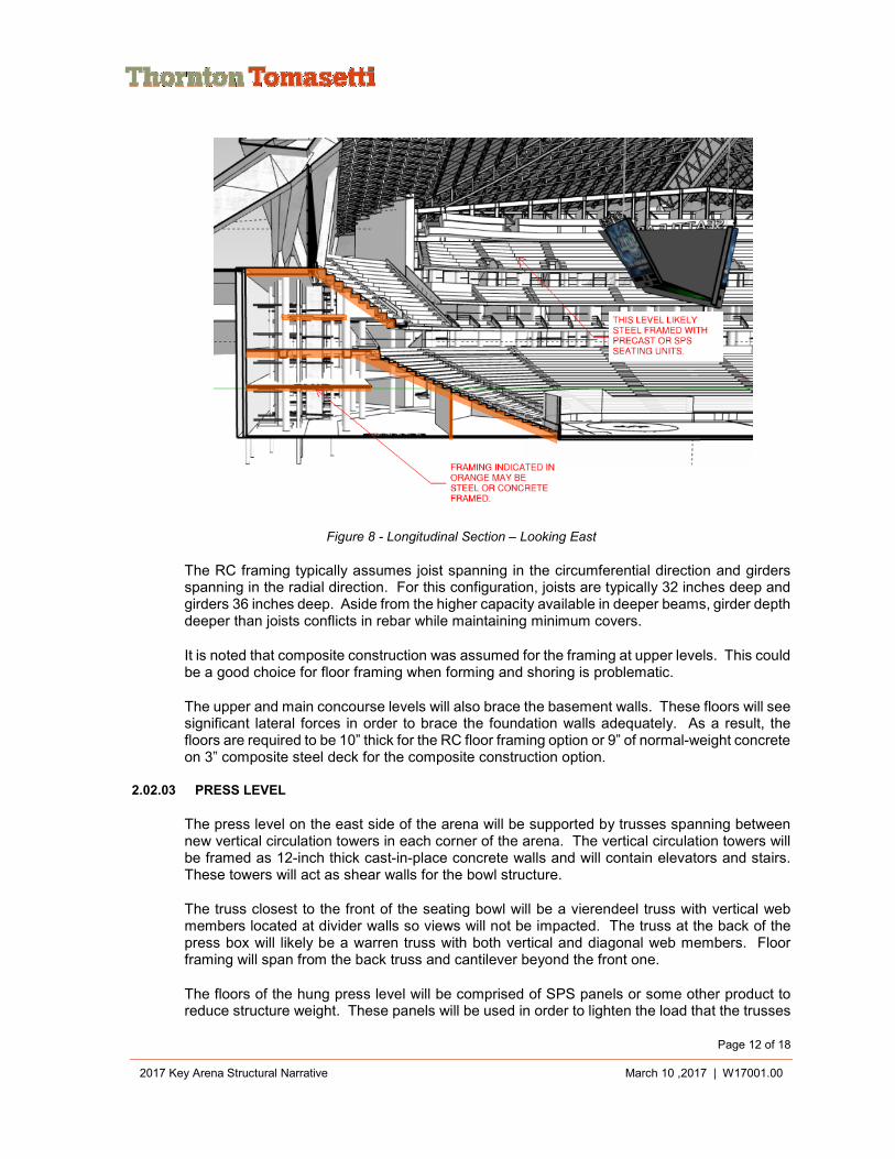
Figure 7 and 8 display the transverse and east longitudinal section of the building.
Figure 7 - Transverse Section – Looking North
Page 12 of 18
2017 Key Arena Structural Narrative March 10 ,2017 | W17001.00
Figure 8 - Longitudinal Section – Looking East
The RC framing typically assumes joist spanning in the circumferential direction and girders spanning in the radial direction. For this configuration, joists are typically 32 inches deep and girders 36 inches deep. Aside from the higher capacity available in deeper beams, girder depth deeper than joists conflicts in rebar while maintaining minimum covers.
It is noted that composite construction was assumed for the framing at upper levels. This could be a good choice for floor framing when forming and shoring is problematic.
The upper and main concourse levels will also brace the basement walls. These floors will see significant lateral forces in order to brace the foundation walls adequately. As a result, the floors are required to be 10” thick for the RC floor framing option or 9” of normal-weight concrete on 3” composite steel deck for the composite construction option.
2.02.03 PRESS LEVEL
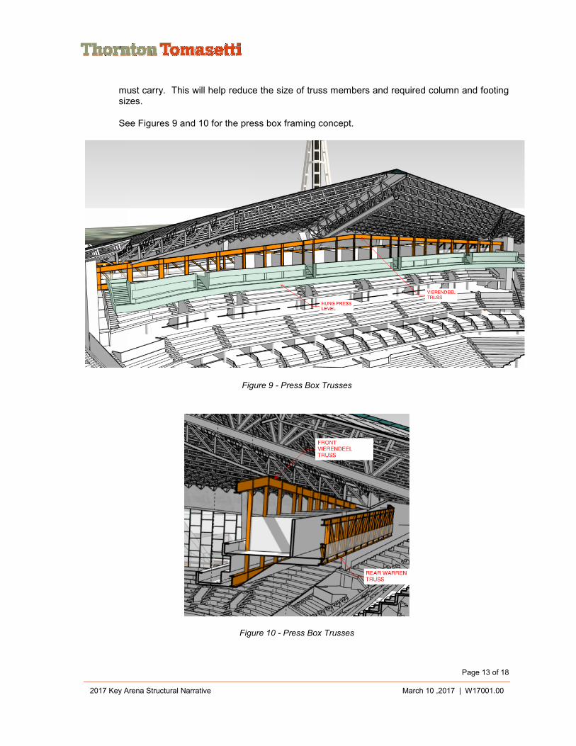
The press level on the east side of the arena will be supported by trusses spanning between new vertical circulation towers in each corner of the arena. The vertical circulation towers will be framed as 12-inch thick cast-in-place concrete walls and will contain elevators and stairs. These towers will act as shear walls for the bowl structure.
The truss closest to the front of the seating bowl will be a vierendeel truss with vertical web members located at divider walls so views will not be impacted. The truss at the back of the press box will likely be a warren truss with both vertical and diagonal web members. Floor framing will span from the back truss and cantilever beyond the front one.
The floors of the hung press level will be comprised of SPS panels or some other product to reduce structure weight. These panels will be used in order to lighten the load that the trusses
Page 13 of 18
2017 Key Arena Structural Narrative March 10 ,2017 | W17001.00
must carry. This will help reduce the size of truss members and required column and footing sizes.
See Figures 9 and 10 for the press box framing concept.
Figure 9 - Press Box Trusses
Figure 10 - Press Box Trusses
Page 14 of 18
2017 Key Arena Structural Narrative March 10 ,2017 | W17001.00
The hung press level is located on the east side of the arena. There is a hung seating level on the west side. Framing for the west hung seating will be similar to what is shown for the hung press level.
2.02.04 GLASS ATRIUM STRUCTURE
In order for south side of the existing arena to be viewed from the street, an atrium with glass walls will be added south of the arena between the arena and parking structure and will function as the front door to the arena. This atrium structure will be approximately 400 feet long, 60 feet wide and 40 feet tall. It will lean on the parking structure for lateral stability.
The roof structure could be framed three different ways. The first option is to frame it with conventional steel deck supported by steel beams. The second option is to provide glass panels that would function as a skylight. Steel beams or a lightweight steel trusses with cable bottom chord members would support the glass. The third option is to provide an ETFE roof system that would also function as a skylight. The ETFE pillows would be supported with beams or trusses as described for the glass panels. Steel columns that would be sized to be as small as possible will support the roof framing.
The walls of the atrium will need to be transparent. The amount of steel structure in these walls will be minimized. This will require the glass wall to span vertically from grade to roof. The glass wall panels could be stiffened with glass ribs that are oriented perpendicular to the wall panels or with deep window mullions to achieve the 40’ vertical span. Horizontal steel girts could also be added to reduce the curtain wall panel span but their size will need to be minimized.
3.00 PRELIMINARY QUANTITIES AND COSTS
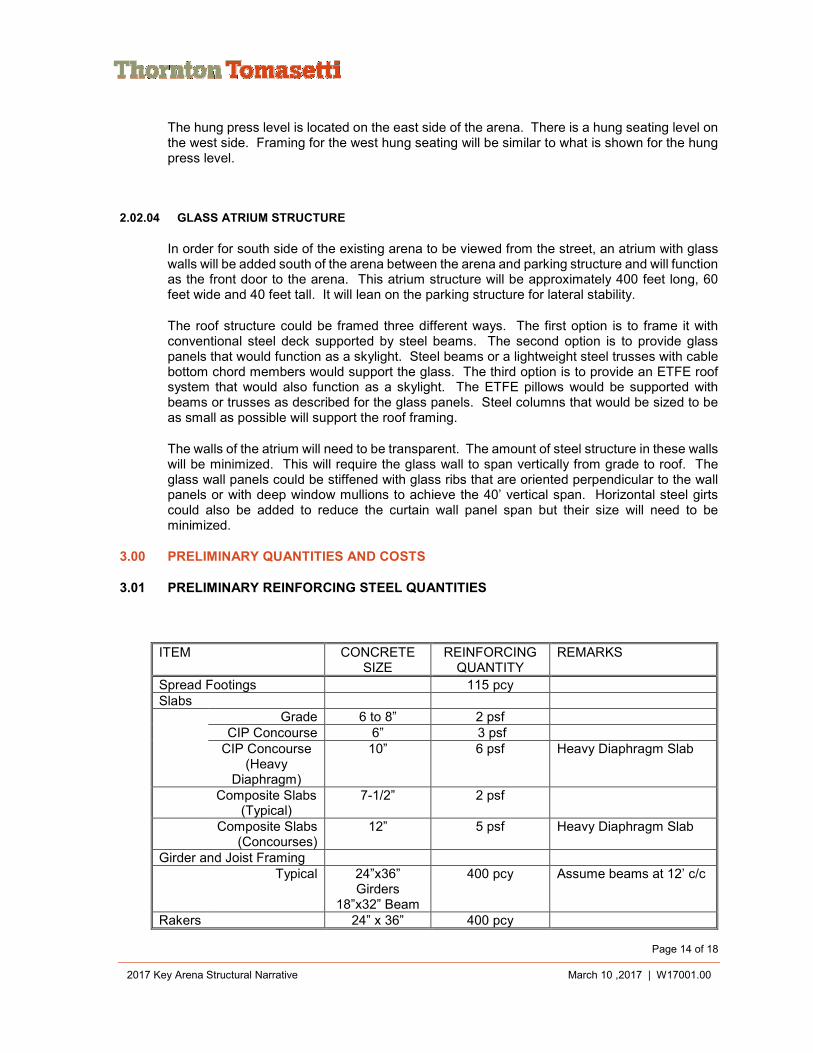
3.01 PRELIMINARY REINFORCING STEEL QUANTITIES
ITEM CONCRETE SIZE
REINFORCING QUANTITY
REMARKS
Spread Footings 115 pcy Slabs
Grade 6 to 8” 2 psf CIP Concourse 6” 3 psf CIP Concourse
(Heavy Diaphragm)
10” 6 psf Heavy Diaphragm Slab
Composite Slabs (Typical)
7-1/2” 2 psf
Composite Slabs (Concourses)
12” 5 psf Heavy Diaphragm Slab
Girder and Joist Framing Typical 24”x36”
Girders 18”x32” Beam
400 pcy Assume beams at 12’ c/c
Rakers 24” x 36” 400 pcy
Page 15 of 18
2017 Key Arena Structural Narrative March 10 ,2017 | W17001.00
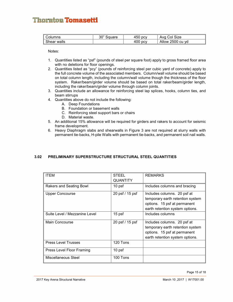
Columns 30” Square 450 pcy Avg Col Size Shear walls 400 pcy Allow 2500 cu yd
Notes:
1. Quantities listed as “psf” (pounds of steel per square foot) apply to gross framed floor area with no deletions for floor openings.
2. Quantities listed as “pcy” (pounds of reinforcing steel per cubic yard of concrete) apply to the full concrete volume of the associated members. Column/wall volume should be based on total column length, including the column/wall volume though the thickness of the floor system. Raker/beam/girder volume should be based on total raker/beam/girder length, including the raker/beam/girder volume through column joints.
3. Quantities include an allowance for reinforcing steel lap splices, hooks, column ties, and beam stirrups
4. Quantities above do not include the following: A. Deep Foundations B. Foundation or basement walls C. Reinforcing steel support bars or chairs D. Material waste.
5. An additional 15% allowance will be required for girders and rakers to account for seismic frame development.
6. Heavy Diaphragm slabs and shearwalls in Figure 3 are not required at slurry walls with permanent tie-backs, H-pile Walls with permanent tie-backs, and permanent soil nail walls.
3.02 PRELIMINARY SUPERSTRUCTURE STRUCTURAL STEEL QUANTITIES
ITEM STEEL
QUANTITY
REMARKS
Rakers and Seating Bowl 10 psf Includes columns and bracing
Upper Concourse 20 psf / 15 psf Includes columns. 20 psf at
temporary earth retention system
options. 15 psf at permanent
earth retention system options.
Suite Level / Mezzanine Level 15 psf Includes columns
Main Concourse 20 psf / 15 psf Includes columns. 20 psf at
temporary earth retention system
options. 15 psf at permanent
earth retention system options.
Press Level Trusses 120 Tons
Press Level Floor Framing 10 psf
Miscellaneous Steel 100 Tons
Page 16 of 18
2017 Key Arena Structural Narrative March 10 ,2017 | W17001.00
Notes:
1. Quantities listed as “psf” (pounds of steel per square foot) apply to gross framed floor area with no deletions for floor openings.
2. Quantities above do not include the following: A. Steel Floor and Roof Deck B. Material waste C. Facade system support steel D. Steel Stairs/ladders E. Handrails and other miscellaneous metals F. Window washing support system and associated steel support framing G. Temporary shoring/bracing H. Scoreboard framing, sign supports, etc. I. Field Lighting support steel, Trusses, catwalks, etc. J. Entrance Canopy Framing and other miscellaneous canopies. K. Elevator divider beams, machine beams, Guiderail support framing, etc. L. Mechanical equipment supports, piping supports, etc. M. Other miscellaneous skin/cladding requirements N. Embedded items.
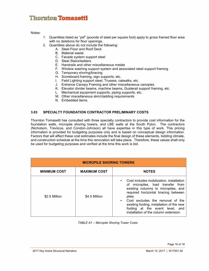
3.03 SPECIALTY FOUNDATION CONTRACTOR PRELIMINARY COSTS
Thornton Tomasetti has consulted with three specialty contractors to provide cost information for the foundation walls, micropile shoring towers, and LBE walls at the South Pylon. The contractors (Nicholson, Treviicos, and Condon-Johnson) all have expertise in this type of work. This pricing information is provided for budgeting purposes only and is based on conceptual design information. Factors that will affect these cost estimates include the final design of these elements, bidding climate, and construction schedule at the time this renovation will take place. Therefore, these values shall only be used for budgeting purposes and verified at the time this work is bid.
MICROPILE SHORING TOWERS
MINIMUM COST MAXIMUM COST NOTES
$2.5 Million $4.5 Million
• Cost includes mobilization, installation of micropiles, load transfer from existing columns to micropiles, and required horizontal bracing between piles.
• Cost excludes the removal of the existing footing, installation of the new footing at the event level, and installation of the column extension.
TABLE A1 – Micropile Shoring Tower Costs
Page 17 of 18
2017 Key Arena Structural Narrative March 10 ,2017 | W17001.00
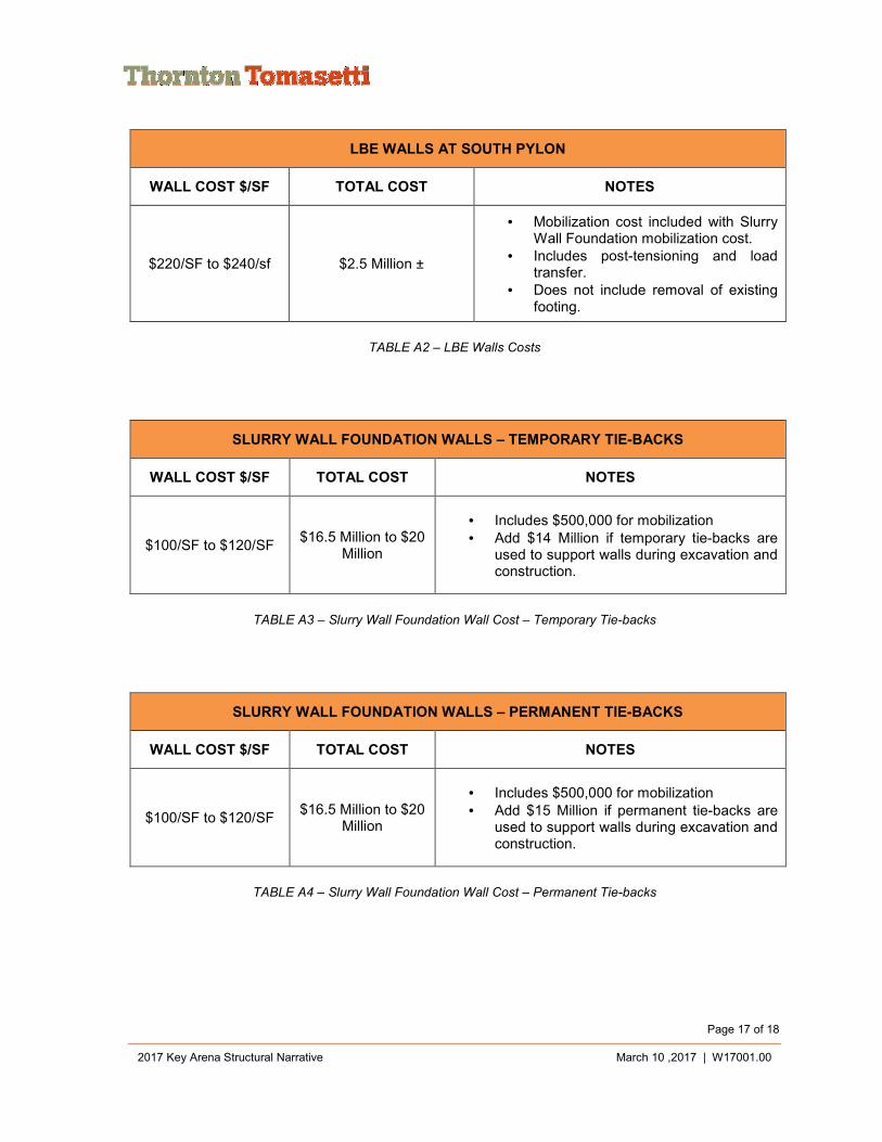
LBE WALLS AT SOUTH PYLON
WALL COST $/SF TOTAL COST NOTES
$220/SF to $240/sf $2.5 Million ±
• Mobilization cost included with Slurry Wall Foundation mobilization cost.
• Includes post-tensioning and load transfer.
• Does not include removal of existing footing.
TABLE A2 – LBE Walls Costs
SLURRY WALL FOUNDATION WALLS – TEMPORARY TIE-BACKS
WALL COST $/SF TOTAL COST NOTES
$100/SF to $120/SF $16.5 Million to $20
Million
• Includes $500,000 for mobilization • Add $14 Million if temporary tie-backs are
used to support walls during excavation and construction.
TABLE A3 – Slurry Wall Foundation Wall Cost – Temporary Tie-backs
SLURRY WALL FOUNDATION WALLS – PERMANENT TIE-BACKS
WALL COST $/SF TOTAL COST NOTES
$100/SF to $120/SF $16.5 Million to $20
Million
• Includes $500,000 for mobilization • Add $15 Million if permanent tie-backs are
used to support walls during excavation and construction.
TABLE A4 – Slurry Wall Foundation Wall Cost – Permanent Tie-backs
Page 18 of 18
2017 Key Arena Structural Narrative March 10 ,2017 | W17001.00
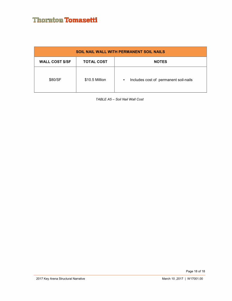
SOIL NAIL WALL WITH PERMANENT SOIL NAILS
WALL COST $/SF TOTAL COST NOTES
$80/SF $10.5 Million • Includes cost of permanent soil-nails
TABLE A5 – Soil Nail Wall Cost