
PROJECT: Florida Power and Light – Golden Gate Service Center · Addendum No. 1 Page 1 Golden...
578
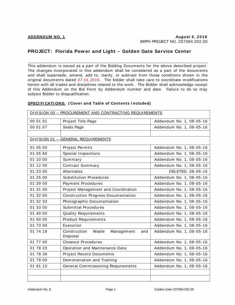
Addendum No. 1 Page 1 Golden Gate C07084.002.00 ADDENDUM NO. 1 August 5, 2016 BRPH PROJECT NO. C07084.002.00 PROJECT: Florida Power and Light – Golden Gate Service Center This addendum is issued as a part of the Bidding Documents for the above described project. The changes incorporated in this addendum shall be considered as a part of the documents and shall supersede, amend, add to, clarify, or subtract from those conditions shown in the original documents dated 07.01.2016. The bidder shall take care to coordinate modifications herein with all trades and disciplines related to the work. The Bidder shall acknowledge receipt of this Addendum on the Bid Form by Addendum number and date. Failure to do so may subject Bidder to disqualification. SPECIFICATIONS: (Cover and Table of Contents Included) DIVISION 00 – PROCUREMENT AND CONTRACTING REQUIREMENTS 00 01 01 Project Title Page Addendum No. 1, 08-05-16 00 01 07 Seals Page Addendum No. 1, 08-05-16 DIVISION 01 – GENERAL REQUIREMENTS 01 05 50 Project Permits Addendum No. 1, 08-05-16 01 05 60 Special Inspections Addendum No. 1, 08-05-16 01 10 00 Summary Addendum No. 1, 08-05-16 01 12 00 Contract Summary Addendum No. 1, 08-05-16 01 23 00 Alternates DELETED, 08-05-16 01 25 00 Substitution Procedures Addendum No. 1, 08-05-16 01 29 00 Payment Procedures Addendum No. 1, 08-05-16 01 31 00 Project Management and Coordination Addendum No. 1, 08-05-16 01 32 00 Construction Progress Documentation Addendum No. 1, 08-05-16 01 32 33 Photographic Documentation Addendum No. 1, 08-05-16 01 33 00 Submittal Procedures Addendum No. 1, 08-05-16 01 40 00 Quality Requirements Addendum No. 1, 08-05-16 01 60 00 Product Requirements Addendum No. 1, 08-05-16 01 73 00 Execution Addendum No. 1, 08-05-16 01 74 19 Construction Waste Management and Disposal Addendum No. 1, 08-05-16 01 77 00 Closeout Procedures Addendum No. 1, 08-05-16 01 78 23 Operation and Maintenance Data Addendum No. 1, 08-05-16 01 78 39 Project Record Documents Addendum No. 1, 08-05-16 01 79 00 Demonstration and Training Addendum No. 1, 08-05-16 01 91 13 General Commissioning Requirements Addendum No. 1, 08-05-16
Transcript of PROJECT: Florida Power and Light – Golden Gate Service Center · Addendum No. 1 Page 1 Golden...
Addendum No. 1 Page 1 Golden Gate C07084.002.00
ADDENDUM NO. 1 August 5, 2016 BRPH PROJECT NO. C07084.002.00 PROJECT: Florida Power and Light – Golden Gate Service Center This addendum is issued as a part of the Bidding Documents for the above described project. The changes incorporated in this addendum shall be considered as a part of the documents and shall supersede, amend, add to, clarify, or subtract from those conditions shown in the original documents dated 07.01.2016. The bidder shall take care to coordinate modifications herein with all trades and disciplines related to the work. The Bidder shall acknowledge receipt of this Addendum on the Bid Form by Addendum number and date. Failure to do so may subject Bidder to disqualification. SPECIFICATIONS: (Cover and Table of Contents Included) DIVISION 00 – PROCUREMENT AND CONTRACTING REQUIREMENTS
00 01 01 Project Title Page Addendum No. 1, 08-05-16 00 01 07 Seals Page Addendum No. 1, 08-05-16 DIVISION 01 – GENERAL REQUIREMENTS
01 05 50 Project Permits Addendum No. 1, 08-05-16 01 05 60 Special Inspections Addendum No. 1, 08-05-16 01 10 00 Summary Addendum No. 1, 08-05-16 01 12 00 Contract Summary Addendum No. 1, 08-05-16 01 23 00 Alternates DELETED, 08-05-16 01 25 00 Substitution Procedures Addendum No. 1, 08-05-16 01 29 00 Payment Procedures Addendum No. 1, 08-05-16 01 31 00 Project Management and Coordination Addendum No. 1, 08-05-16 01 32 00 Construction Progress Documentation Addendum No. 1, 08-05-16 01 32 33 Photographic Documentation Addendum No. 1, 08-05-16 01 33 00 Submittal Procedures Addendum No. 1, 08-05-16 01 40 00 Quality Requirements Addendum No. 1, 08-05-16 01 60 00 Product Requirements Addendum No. 1, 08-05-16 01 73 00 Execution Addendum No. 1, 08-05-16 01 74 19 Construction Waste Management and
Disposal Addendum No. 1, 08-05-16
01 77 00 Closeout Procedures Addendum No. 1, 08-05-16 01 78 23 Operation and Maintenance Data Addendum No. 1, 08-05-16 01 78 39 Project Record Documents Addendum No. 1, 08-05-16 01 79 00 Demonstration and Training Addendum No. 1, 08-05-16 01 91 13 General Commissioning Requirements Addendum No. 1, 08-05-16

Addendum No. 1 Page 2 Golden Gate C07084.002.00
DIVISION 03 - CONCRETE
03 47 13 Site-Cast Precast Concrete (Tilt-Up) Wall System
Addendum No. 1, 08-05-16
DIVISION 05 - METALS
05 12 00 Structural Steel Addendum No. 1, 08-05-16 05 21 00 Steel Joists Addendum No. 1, 08-05-16 05 31 00 Steel Deck Addendum No. 1, 08-05-16 05 51 13 Metal Pan Stairs Addendum No. 1, 08-05-16 DIVISION 07 – THERMAL AND MOISTURE PROTECTION
07 41 13.16 Standing-Seam Metal Roof Panels Addendum No. 1, 08-05-16 07 54 23 Thermoplastic Polyolefin (TPO) Roofing Addendum No. 1, 08-05-16 07 71 00 Roof Specialties Addendum No. 1, 08-05-16 07 72 00 Roof Accessories Addendum No. 1, 08-05-16 07 92 00 Joint Sealants Addendum No. 1, 08-05-16 DIVISION 08 - OPENINGS
08 33 23 Overhead Coiling Doors Addendum No. 1, 08-05-16 08 71 00 Door Hardware Addendum No. 1, 08-05-16 08 80 00 Glazing Addendum No. 1, 08-05-16 DIVISION 09 - FINISHES
09 22 16 Non-Structural Metal Framing Addendum No. 1, 08-05-16 09 29 00 Gypsum Board Addendum No. 1, 08-05-16 09 30 00 Wall and Floor Tiling Addendum No. 1, 08-05-16 09 30 00.13 Metal Edge Transition Strip for Floors and
Walls Addendum No. 1, 08-05-16
09 65 19 Resilient Floor Tile Addendum No. 1, 08-05-16 09 68 13 Tile Carpeting Addendum No. 1, 08-05-16 DIVISION 10 - SPECIALTIES
10 21 13 Toilet Compartments Addendum No. 1, 08-05-16 10 28 00 Toilet Accessories Addendum No. 1, 08-05-16 10 41 16 Emergency Key Cabinets Addendum No. 1, 08-05-16 10 44 16 Fire Extinguishers Addendum No. 1, 08-05-16 10 71 13.19 Rolling Exterior Shutters Addendum No. 1, 08-05-16 DIVISION 11 - EQUIPMENT
11 24 29.13 Fall Protection Safety Hook Addendum No. 1, 08-05-16

Addendum No. 1 Page 3 Golden Gate C07084.002.00
DIVISION 14 – CONVEYING EQUIPMENT
14 24 00 Hydraulic Elevators Addendum No. 1, 08-05-16 DIVISION 22 – PLUMBING
22 13 16 Sanitary Waste and Vent Piping Addendum No. 1, 08-05-16 DIVISION 26 – ELECTRICAL
26 05 33 Raceways and Boxes for Electrical Systems Addendum No. 1, 08-05-16 26 27 26 Wiring Devices Addendum No. 1, 08-05-16 DIVISION 27 – COMMUNICATIONS
27 05 26 Grounding and Bonding for Communication Systems
Addendum No. 1, 08-05-16
27 05 28 Pathways for Communication Systems Addendum No. 1, 08-05-16 27 05 36 Cable Trays for Communications Systems Addendum No. 1, 08-05-16 27 05 44 Sleeves and Sleeve Seals for
Communications Pathways and Cabling Addendum No. 1, 08-05-16
DRAWINGS Architectural AL-101 Revised generator yard. A-101 Revised generator yard. A-102 Revised generator yard. A-103 Revised generator yard. A-104 Revised generator yard. A-105 Revised generator yard. A-106 Revised generator yard. A-121 Revised colonnade soffit. A-122 Revised colonnade soffit. A-141 Revised generator yard. A-310 Revised wall section to indicated bearing heights and remove light
weight concrete note.
A-311 Revised wall section to indicated bearing heights and remove light weight concrete note. Added insulation to wall section and clarified soffit on section 4/A-311
A-401 Revised toilet accessories schedule. A-404 Revised enlarged plan 2/ A-404 to add fall protection note. A-431 Revised enlarged stair plans to add gyp. bd. wall type. Revised Stair
sections to add gyp. bd. wall type.

Addendum No. 1 Page 4 Golden Gate C07084.002.00
Civil
Electrical
Mechanical M-401 1. Raised refrigerant piping from floor to avoid tripping hazard.
2. Changed supply duct in 2nd floor mechanical room from flex to hard duct to diffuser.
Plumbing P-502 Shut-off valve removed from sump pump discharge on detail - Detail
5 added Structural S-000 Removed light weight concrete note from concrete on steel deck
added note TU-7 to conceal exposed connections in tilt panel walls
S-121 1. Added clarification note for hip framing to be designed by delegated engineer
2. Added clarification note to joist schedule that reactions are un-factored
END ADDENDUM NO. 1
A-502 Revised Details 5, 6, 10 & 11/A-502. A-504 Revised Sections 2 & 5/A-504 A-601 Indicated the door ratings for doors 219C & 133. Added window
shades to window A A-602 Revised Window details WH1 &2, WJ1 & 2, WS1 &2, to indicated
flashing. A-640 Added ptd. Gyp bd. ceiling to the stairs. On Room Finish Schedule. A-641 Added SC-1 and WS-1 to Finish Legend A-700 Added notes 10 & 11 to general notes.
B-1 Added double row of silt fence adjacent to wetland preservation area per SFWMD comment.
B-5 Added double row silt fence to Section 2, added note to Section 2 per SFWMD comment. Added wetland preserve signage per SFWMD comment. Revised CS-01 detail for clarification, per RFI comment.
EP-101 Added power for front entry door. EP-601 Changed generator ground size. E-701 Added circuit P1A-44 for door. E-702 Changed breaker and wire size for circuit H2A-33 & 35.

Board of Architecture License No. AAC000149 Certificate of Authorization – Engineering 1439
Prepared for: Florida Power & Light 700 Universal Boulevard Juno Beach, FL 33408 Prepared by: BRPH Architects-Engineers, Inc. 5700 North Harbor City Boulevard, Suite 400 Melbourne, FL 32940
BRPH NO. C07084.003.00 July 1, 2016
Addendum No. 1, August 5, 2016
Florida Power & Light Golden Gate Service Center
4105 15th Ave. SW City of Naples
Collier County, Florida 34116
100% Issue for Bid

THIS PAGE INTENTIONALLY LEFT BLANK

FLORIDA POWER & LIGHT GOLDEN GATE SERVICE CENTER TABLE OF CONTENTS BRPH ARCHITECTS-ENGINEERS, INC.
C07084.003.00 TOC - i
DIVISION 00 – PROCUREMENT AND CONTRACTING REQUIREMENTS
00 01 01 Project Title Page Addendum No. 1, 08-05-1600 01 07 Seals Page Addendum No. 1, 08-05-1600 26 00 Procurement Substitution Procedures 07-01-1600 31 32 Geotechnical Data 07-01-1600 31 43 Permit Application 07-01-16 DIVISION 01 – GENERAL REQUIREMENTS
01 05 50 Project Permits Addendum No. 1, 08-05-1601 05 60 Special Inspections Addendum No. 1, 08-05-1601 10 00 Summary Addendum No. 1, 08-05-1601 12 00 Contract Summary Addendum No. 1, 08-05-1601 23 00 Alternates DELETED, 08-05-1601 25 00 Substitution Procedures Addendum No. 1, 08-05-1601 26 00 Contract Modification Procedures 07-01-1601 29 00 Payment Procedures Addendum No. 1, 08-05-1601 31 00 Project Management and Coordination Addendum No. 1, 08-05-1601 32 00 Construction Progress Documentation Addendum No. 1, 08-05-1601 32 33 Photographic Documentation Addendum No. 1, 08-05-1601 33 00 Submittal Procedures Addendum No. 1, 08-05-1601 39 00 Electronic Deliverables Release 07-01-1601 40 00 Quality Requirements Addendum No. 1, 08-05-1601 42 00 References 07-01-1601 60 00 Product Requirements Addendum No. 1, 08-05-1601 73 00 Execution Addendum No. 1, 08-05-1601 74 19 Construction Waste Management and
Disposal Addendum No. 1, 08-05-16
01 77 00 Closeout Procedures Addendum No. 1, 08-05-1601 78 23 Operation and Maintenance Data Addendum No. 1, 08-05-1601 78 39 Project Record Documents Addendum No. 1, 08-05-1601 79 00 Demonstration and Training Addendum No. 1, 08-05-1601 91 13 General Commissioning Requirements Addendum No. 1, 08-05-16 DIVISION 02 – EXISTING CONDITIONS
SITE-RELATED SPECIFICATIONS CAN BE FOUND ON THE KHA DRAWINGS.
DIVISION 03 - CONCRETE
03 10 00 Concrete Formwork 07-01-1603 20 00 Concrete Reinforcement and Embedded Assemblies 07-01-1603 30 00 Cast-In-Place Concrete 07-01-1603 47 13 Site-Cast Precast Concrete (Tilt-Up) Wall
System Addendum No. 1, 08-05-16

FLORIDA POWER & LIGHT GOLDEN GATE SERVICE CENTER TABLE OF CONTENTS BRPH ARCHITECTS-ENGINEERS, INC.
C07084.003.00 TOC - ii
DIVISION 05 - METALS
05 12 00 Structural Steel Addendum No. 1, 08-05-1605 21 00 Steel Joists Addendum No. 1, 08-05-1605 31 00 Steel Deck Addendum No. 1, 08-05-1605 51 13 Metal Pan Stairs Addendum No. 1, 08-05-16 DIVISION 06 – WOOD, PLASTICS, AND COMPOSITES
06 10 00 Rough Carpentry 07-01-1606 40 23 Interior Architectural Woodwork 07-01-16 DIVISION 07 – THERMAL AND MOISTURE PROTECTION
07 13 26 Self-Adhering Sheet Waterproofing 07-01-1607 21 00 Thermal Insulation 07-01-1607 24 19.13 Exterior Insulation and Finish System (EIFS) 07-01-1607 41 13.16 Standing-Seam Metal Roof Panels Addendum No. 1, 08-05-1607 54 23 Thermoplastic Polyolefin (TPO) Roofing Addendum No. 1, 08-05-1607 71 00 Roof Specialties Addendum No. 1, 08-05-1607 72 00 Roof Accessories Addendum No. 1, 08-05-1607 81 00 Applied Fireproofing 07-01-1607 84 13 Penetration Firestopping 07-01-1607 84 43 Joint Firestopping 07-01-1607 92 00 Joint Sealants Addendum No. 1, 08-05-16 DIVISION 08 - OPENINGS
08 11 13 Hollow Metal Doors and Frames 07-01-1608 14 16 Flush Wood Doors 07-01-1608 31 13 Access Doors and Frames 07-01-1608 33 23 Overhead Coiling Doors Addendum No. 1, 08-05-1608 41 13.19 Interior Aluminum-Framed Entrances and Storefronts 07-01-1608 44 13 Glazed Aluminum Curtain Walls 07-01-1608 51 13.19 Interior Aluminum Horizontal Sliding Service Windows 07-01-1608 71 00 Door Hardware Addendum No. 1, 08-05-1608 80 00 Glazing Addendum No. 1, 08-05-1608 91 19 Fixed Louvers 07-01-16 DIVISION 09 - FINISHES
09 22 16 Non-Structural Metal Framing Addendum No. 1, 08-05-1609 29 00 Gypsum Board Addendum No. 1, 08-05-1609 30 00 Wall and Floor Tiling Addendum No. 1, 08-05-1609 30 00.13 Metal Edge Transition Strip for Floors and
Walls Addendum No. 1, 08-05-16
09 51 13 Acoustical Panel Ceilings 07-01-16

FLORIDA POWER & LIGHT GOLDEN GATE SERVICE CENTER TABLE OF CONTENTS BRPH ARCHITECTS-ENGINEERS, INC.
C07084.003.00 TOC - iii
DIVISION 09 – FINISHES (cont.)
09 65 13 Resilient Base and Accessories 07-01-1609 65 19 Resilient Floor Tile Addendum No. 1, 08-05-1609 65 36 Static-Control Resilient Flooring 07-01-1609 68 13 Tile Carpeting Addendum No. 1, 08-05-1609 91 23 Interior Painting and Exterior Painting 07-01-16 DIVISION 10 - SPECIALTIES
10 14 23 Panel Signage 07-01-1610 21 13 Toilet Compartments Addendum No. 1, 08-05-1610 28 00 Toilet Accessories Addendum No. 1, 08-05-1610 41 16 Emergency Key Cabinets Addendum No. 1, 08-05-1610 44 13 Fire Protection Cabinets 07-01-1610 44 16 Fire Extinguishers Addendum No. 1, 08-05-1610 51 13 Metal Lockers 07-01-1610 71 13.19 Rolling Exterior Shutters Addendum No. 1, 08-05-1610 75 16 Ground-Set Flagpoles 07-01-16 DIVISION 11 - EQUIPMENT
11 24 29.13 Fall Protection Safety Hook Addendum No. 1, 08-05-16 DIVISION 14 – CONVEYING EQUIPMENT
14 24 00 Hydraulic Elevators Addendum No. 1, 08-05-16 DIVISION 21 – FIRE PROTECTION/FIRE SUPPRESSION
FIRE PROTECTION/SUPPRESSION SPECIFICATIONS CAN BE FOUND ON THE JENSEN-HUGHES DRAWINGS.
DIVISION 22 – PLUMBING
22 05 17 Sleeves and Sleeve Seals for Plumbing Piping 07-01-1622 05 18 Escutcheons for Plumbing Piping 07-01-1622 05 19 Meters and Gages for Plumbing Piping 07-01-1622 05 23.12 Ball Valves for Plumbing Piping 07-01-1622 05 23.14 Check Valves for Plumbing Piping 07-01-1622 05 23.15 Gate Valves for Plumbing Piping 07-01-1622 05 29 Hangers and Supports for Plumbing Piping and Equipment 07-01-1622 05 53 Identification for Plumbing Piping and Equipment 07-01-1622 07 19 Plumbing Piping Insulation 07-01-1622 11 16 Domestic Water Piping 07-01-16

FLORIDA POWER & LIGHT GOLDEN GATE SERVICE CENTER TABLE OF CONTENTS BRPH ARCHITECTS-ENGINEERS, INC.
C07084.003.00 TOC - iv
DIVISION 22 – PLUMBING (cont.)
22 11 19 Domestic Water Piping Specialties 07-01-1622 11 23 Domestic Water Pumps 07-01-1622 13 16 Sanitary Waste and Vent Piping Addendum No. 1, 08-05-1622 13 19 Sanitary Waste Piping Specialties 07-01-1622 13 19.13 Sanitary Drains 07-01-1622 33 00 Electric, Domestic-Water Heaters 07-01-1622 42 13.13 Commercial Water Closets 07-01-1622 42 13.16 Commercial Urinals 07-01-1622 42 16.13 Commercial Lavatories 07-01-1622 42 16.16 Commercial Sinks 07-01-1622 42 23 Commercial Showers 07-01-16 DIVISION 23 – HEATING, VENTILATING, AND AIR CONDITIONING
23 05 00 Basic Mechanical Requirements 07-01-1623 05 13 Common Motor Requirements for HVAC Equipment 07-01-1623 05 17 Sleeves and Sleeve Seals for HVAC Piping 07-01-1623 05 19 Meters and Gages for HVAC Piping 07-01-1623 05 29 Hangers and Supports for HVAC Piping and Equipment 07-01-1623 05 48 Vibration and Seismic Controls for HVAC Piping and
Equipment 07-01-16
23 05 53 Identification for HVAC Piping and Equipment 07-01-1623 05 93 Testing, Adjusting, and Balancing for HVAC 07-01-1623 07 13 Duct Insulation 07-01-1623 09 00 Instrumentation and Control for HVAC 07-01-1623 31 13 Metal Ducts 07-01-1623 33 00 Air Duct Accessories 07-01-1623 34 23 HVAC Power Ventilators 07-01-1623 72 13 Air Handling Units with Coils 07-01-1623 72 13.13 Air Cooled Condensing Units 07-01-1623 72 14 Dedicated Outside Air System 07-01-16 DIVISION 26 – ELECTRICAL
26 01 00 Common Work Results for Electrical 07-01-1626 05 19 Low-Voltage Electrical Power Conductors and Cables 07-01-1626 05 26 Grounding and Bonding for Electrical Systems 07-01-1626 05 29 Hangers and Supports for Electrical Systems 07-01-1626 05 33 Raceways and Boxes for Electrical
Systems Addendum No. 1, 08-05-16
26 05 43 Underground Ducts and Utility Structures 07-01-1626 05 44 Sleeves and Sleeve Seals for Electrical Raceways and Cabling 07-01-1626 05 53 Identification for Electrical Systems 07-01-1626 05 73.13 Overcurrent Protective Device Short-Circuit Study 07-01-16

FLORIDA POWER & LIGHT GOLDEN GATE SERVICE CENTER TABLE OF CONTENTS BRPH ARCHITECTS-ENGINEERS, INC.
C07084.003.00 TOC - v
DIVISION 26 – ELECTRICAL (cont.)
26 05 73.16 Overcurrent Protective Device Coordination Study 07-01-1626 05 73.19 Overcurrent Protective Device Arc-Flash Study 07-01-1626 09 23 Lighting Control Devices 07-01-1626 22 00 Low-Voltage Transformers 07-01-1626 24 16 Panelboards 07-01-1626 27 26 Wiring Devices Addendum No. 1, 08-05-1626 28 13 Fuses 07-01-1626 28 16 Enclosed Switches and Circuit Breakers 07-01-1626 29 23 Variable-Frequency Motor Controllers 07-01-1626 32 13 Engine Generators 07-01-1626 36 00 Transfer Switches 07-01-1626 41 13 Lightning Protection for Structures 07-01-1626 43 13 Surge Protection for Low-Voltage Electrical Power Circuits 07-01-1626 51 19 LED Interior Lighting 07-01-1626 52 19 Exit Lighting 07-01-1626 56 13 Lighting Poles and Standards 07-01-1626 56 19 LED Exterior Lighting 07-01-16 DIVISION 27 – COMMUNICATIONS
27 05 26 Grounding and Bonding for Communication Systems
Addendum No. 1, 08-05-16
27 05 28 Pathways for Communication Systems Addendum No. 1, 08-05-1627 05 36 Cable Trays for Communications Systems Addendum No. 1, 08-05-1627 05 44 Sleeves and Sleeve Seals for
Communications Pathways and Cabling Addendum No. 1, 08-05-16
DIVISION 28 – ELECTRONIC SAFETY AND SECURITY
FIRE ALARM SPECIFICATIONS CAN BE FOUND ON THE JENSEN-HUGHES DRAWINGS.
DIVISION 31 – EARTHWORK
SITE-RELATED SPECIFICATIONS CAN BE FOUND ON THE KHA DRAWINGS.
DIVISION 32 – EXTERIOR IMPROVEMENTS
SITE-RELATED SPECIFICATIONS CAN BE FOUND ON THE KHA DRAWINGS.
32 31 13.13 Interior Chain Link Fences and Gates 07-01-16 DIVISION 33 – UTILITIES
SITE-RELATED SPECIFICATIONS CAN BE FOUND ON THE KHA DRAWINGS.

FLORIDA POWER & LIGHT GOLDEN GATE SERVICE CENTER TABLE OF CONTENTS BRPH ARCHITECTS-ENGINEERS, INC.
C07084.003.00 TOC - vi
APPENDICES
Appendix A Environmental Site Assessment Report Appendix B Project Specific Requirements / Supplemental Conditions Appendix C Asbestos Report
END OF TABLE OF CONTENTS

FLORIDA POWER & LIGHT GOLDEN GATE SERVICE CENTER PROJECT TITLE PAGE BRPH ARCHITECTS-ENGINEERS, INC.
C07084.003.00 00 01 01 - 1 07-01-16 Addendum No. 1, 08-05-16
DOCUMENT 00 01 01 - PROJECT TITLE PAGE
1.1 PROJECT MANUAL VOLUME 1 – Addendum No. 1
A. FP&L Golden Gate Service Center.
B. Florida Power & Light.
C. Collier County, FL 34116.
D. Owner Project No. 2000168727.
E. Architect Project No. C07084.003.00.
F. BRPH Architects-Engineers, Inc.
G. 5700 N. Harbor City Blvd., Suite 400.
H. Melbourne, FL 32940.
I. Phone: 321-254-7666.
J. Fax: 321-259-4703.
K. Web Site: www.brph.com.
L. Issued: 07-01-16, revised 08-05-16.
M. Copyright 2015 BRPH Architects-Engineers, Inc. All rights reserved.
END OF DOCUMENT 00 01 01

THIS PAGE INTENTIONALLY LEFT BLANK

FLORIDA POWER & LIGHT GOLDEN GATE SERVICE CENTER SEALS PAGE BRPH ARCHITECTS-ENGINEERS, INC.
C07084.003.00 00 01 07 - 1 07-01-16 Addendum No. 1, 08-05-16
DOCUMENT 00 01 07 - SEALS PAGE
1.1 DESIGN PROFESSIONALS OF RECORD
A. Architect:
1. Michael Blanchard, AIA. 2. State of Florida, License No. AR0093144. 3. Responsible for Divisions 01-49 Sections except where indicated as prepared
by other design professionals of record.
B. Civil Engineer:
1. Kimley-Horn and Associates, Inc.; Michael F. Schwartz, P.E. 2. State of Florida, License No. 56200. 3. Responsible for Specifications on Drawings.
C. Landscape Architect:
1. Gentile, Glas, Holloway, O’Mahoney & Associates, Inc.; Emily O’Mahoney, P.E. 2. State of Florida, License No. LA0000684 3. Responsible for Specifications on Drawings.
D. Structural Engineer:
1. Jezerinac Group; Ronald Michael Jezerinac Jr., P.E. 2. State of Florida, License No. 53859. 3. Responsible for Division 03 and Division 05 - Sections 05 12 00, 05 21 00,
and 05 31 00.
E. Fire-Protection Engineer:
1. Jensen Hughes; Hamid Bahadori, P.E. 2. State of Florida, License No. 45138. 3. Responsible for Specifications on Drawings.
F. Plumbing Engineer:
1. Keith J. Couch, P.E. 2. State of Florida, License No. 45074. 3. Responsible for Division 22.
G. HVAC Engineer:
1. Keith J. Couch, P.E. 2. State of Florida, License No. 45074. 3. Responsible for Division 23.

FLORIDA POWER & LIGHT GOLDEN GATE SERVICE CENTER SEALS PAGE BRPH ARCHITECTS-ENGINEERS, INC.
C07084.003.00 00 01 07 - 2 07-01-16 Addendum No. 1, 08-05-16
H. Electrical Engineer:
1. Mohammad B. El Habbal, P.E. 2. State of Florida, License No. 78943. 3. Responsible for Division 26 and 27.
END OF DOCUMENT 00 01 07


THIS PAGE INTENTIONALLY LEFT BLANK


THIS PAGE INTENTIONALLY LEFT BLANK


THIS PAGE INTENTIONALLY LEFT BLANK


THIS PAGE INTENTIONALLY LEFT BLANK
FLORIDA POWER & LIGHT GOLDEN GATE SERVICE CENTER PROJECT PERMITS BRPH ARCHITECTS-ENGINEERS, INC.
C07084.003.00 01 05 50 - 1 07-01-16 Addendum No. 1, 08-05-16
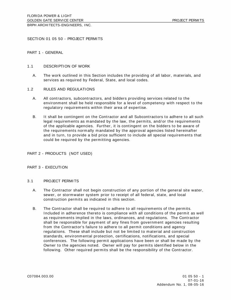
SECTION 01 05 50 - PROJECT PERMITS
PART 1 - GENERAL
1.1 DESCRIPTION OF WORK A. The work outlined in this Section includes the providing of all labor, materials, and
services as required by Federal, State, and local codes. 1.2 RULES AND REGULATIONS
A. All contractors, subcontractors, and bidders providing services related to the
environment shall be held responsible for a level of competency with respect to the regulatory requirements within their area of expertise.
B. It shall be contingent on the Contractor and all Subcontractors to adhere to all such
legal requirements as mandated by the law, the permits, and/or the requirements of the applicable agencies. Further, it is contingent on the bidders to be aware of the requirements normally mandated by the approval agencies listed hereinafter and in turn, to provide a bid price sufficient to include all special requirements that could be required by the permitting agencies.
PART 2 - PRODUCTS (NOT USED) PART 3 - EXECUTION
3.1 PROJECT PERMITS A. The Contractor shall not begin construction of any portion of the general site water,
sewer, or stormwater system prior to receipt of all federal, state, and local construction permits as indicated in this section.
B. The Contractor shall be required to adhere to all requirements of the permits.
Included in adherence thereto is compliance with all conditions of the permit as well as requirements implied in the laws, ordinances, and regulations. The Contractor shall be responsible for payment of any fines from government agencies resulting from the Contractor's failure to adhere to all permit conditions and agency regulations. These shall include but not be limited to material and construction standards, environmental protection, certifications, notifications, and special conferences. The following permit applications have been or shall be made by the Owner to the agencies noted. Owner will pay for permits identified below in the following. Other required permits shall be the responsibility of the Contractor.

FLORIDA POWER & LIGHT GOLDEN GATE SERVICE CENTER PROJECT PERMITS BRPH ARCHITECTS-ENGINEERS, INC.
C07084.003.00 01 05 50 - 2 07-01-16 Addendum No. 1, 08-05-16
AGENCY PERMIT Florida Department of Environmental Protection (FDEP)
Notice of Intent (NOI) to use Generic Permit for Stormwater Discharge from Large and Small Construction Activities (CGP)
FDEP FDEP FDEP
Notice of Intent to use the General Permit for Construction of Water Main Extensions for PWSs Notification/Application for constructing a Domestic Wastewater Collection/Transmission System National Pollutant Discharge Elimination System (NPDES) Stormwater Notice of Termination (NOT)
St. Johns River Water Management District (SJRWMD)
Standard General Environmental Resource Permit
Local City and/or County Local City and/or County
Site Plan Review Building Plan Review
3.2 PERMIT POSTING
A. The Owner shall make available to the Contractor upon issuance of the Notice to
Proceed copies of all permits with conditions related thereto. The Contractor shall post on a weatherproof display board all actual permits and keep, suitably accessible for use by the Owner, the Architect/Engineer, and representatives of the approval agencies, the actual permits and related materials such as drawings.
3.3 CONTRACTOR FURNISHED SYSTEMS A. Certain systems in the project, such as water and wastewater systems, are to be
furnished in compliance with the designs indicated. The designs indicated are not intended to be proprietary. It is contingent on the bidders marketing such systems in the State of Florida and the Contractors installing such systems to provide systems that are acceptable to the local utility authority as well as to the governmental agencies who approve the design shop drawings and accept the "As-Built" condition of the systems such as FDEP. If anytime during the construction process some portions of the systems prove to be unacceptable to the governmental agencies or the local utility authority, the systems shall be modified, corrected, or replaced until they are made acceptable. It shall be contingent on the contractor to propose only on systems that are acceptable to the local utility authority and the applicable governmental agencies. Further, it is contingent on the contractor and suppliers to be cognizant of pending regulatory changes that may affect this individual project and the systems to be furnished. The Contractor's responsibility on these systems will extend to that point when the

FLORIDA POWER & LIGHT GOLDEN GATE SERVICE CENTER PROJECT PERMITS BRPH ARCHITECTS-ENGINEERS, INC.
C07084.003.00 01 05 50 - 3 07-01-16 Addendum No. 1, 08-05-16
actual systems are deemed acceptable to the applicable authority or agency. All submittals shall be made in the format required by the applicable authority or agency. Any changes or upgrades required shall be made at no expense to the Owner.
B. The water, sewer, and stormwater systems shall not be put into operation for
purposes other than testing for leaks and system functions prior to receipt of all required federal, state, and local agency clearance and operating permits.
3.4 CERTIFICATIONS/OPERATING PERMITS A. The following minimum certifications/operating permits are required prior to placing
the water, wastewater, and stormwater facilities into operation: 1. Potable Water System: FDEP "Certification of Construction Completion and
Request for Clearance to Place Permitted PWS Components into Operation.” 2. Stormwater System: Specific Water Management District approval of
"Statement of Completion As-Built Certification and Request to Transfer to Operation Entity."
3. Sanitary Sewer System: FDEP “Certification of Construction Completion and Request to Place Permitted SS Components into Operation”.
3.5 ENGINEER OF RECORD ATTENDANCES AT TESTING
A. The Engineer of Record (EOR) is required to certify to certain permitting agencies that the improvements have been constructed in substantial accordance with the permitted construction documents. The EOR must be satisfied that the improvements will function as intended and will not pose a threat to the health and welfare of the public. The EOR, or his/her designer, must be present to witness all facility water and sewer line leakage testing and lift station start-up testing. Contractor is responsible for all costs associated with the monitoring, testing, inspecting, and start up of facilities and or equipment installed by Contractor. This is inclusive of the fees to have the Engineer of Record witness and monitor the completion of the identified Work. The Contractor shall notify the EOR a minimum of 48 hours prior to scheduled testing. If the testing is performed without notifying the EOR, a testing will be required with the EOR present at the Contractor’s expense.
3.6 FINAL CERTIFICATION
A. The Contractor shall provide to the Architect/Engineer "As-Built/Record" drawings, prepared by a surveyor licensed in the State of Florida, on all systems covered by the permits a minimum of sixty (60) days prior to building occupancy to allow for the Architect/Engineer to obtain the required final "As-Built/Record" acceptance, certification, and/or operating permits. In most cases including the water, wastewater and stormwater facilities, said agency acceptance will be required prior to occupancy of the facility or use of any part of the systems. The Contractor shall be advised that the use of unaccepted systems such as potable water systems, sanitary sewer systems, and those systems that would affect the health and safety

FLORIDA POWER & LIGHT GOLDEN GATE SERVICE CENTER PROJECT PERMITS BRPH ARCHITECTS-ENGINEERS, INC.
C07084.003.00 01 05 50 - 4 07-01-16 Addendum No. 1, 08-05-16
of the employees of the Contractor, the Owner, or the public at large shall be at the risk of the Contractor. The Contractor shall use care in controlling and regulating the use of such systems. Any fines levied by the permitting agencies as the result of operating systems prior to agency acceptance shall be paid by the Contractor at no additional cost to the Owner.
B. The Contractor shall submit the following information to the Engineer:
1. Potable Water System:
a. As-built/record drawings of the water distribution system, prepared and
signed and sealed by a surveyor licensed in the State of Florida. b. Satisfactory bacteriological results on the water distribution system
along with a plan indicating the location of the sampling. c. Letter certifying acceptable water main pressure testing.
2. Wastewater Collection/Transmission System:
a. As-Built/Record drawings of the wastewater collection/transmission
system, prepared and signed and sealed by a surveyor licensed in the State of Florida.
b. Letter certifying acceptable gravity sanitary sewer leakage testing. c. Letter certifying acceptable force main pressure / leakage testing. d. Lift station start-up reports. e. Lift station O&M manuals.
3. Stormwater System:
a. As-built/record drawings of stormwater facilities, prepared and signed
and sealed by a surveyor licensed in the State of Florida. C. The Contractor's project responsibility shall extend to the final acceptance and
issuance of operating permits by the approval agencies or authorities and in some cases could extend the time frame beyond that for final project acceptance.
3.7 SYSTEM SUBSTITUTIONS SUBSEQUENT TO PERMITTING A. If the Contractor proposes to substitute a system for use other than that detailed
and permitted by the Architect/Engineer, he shall provide the Owner’s Representative with all necessary supportive data required to file for a modification to the approved permit. In turn, the Contractor shall reimburse the Owner for all expenses incurred in the refiling of the applicable permit including, but not limited to, labor cost, reproduction cost, delivery charges, and filing fees. The Contractor should realize that this includes all items of a "substantial deviation" from the permitted project.

FLORIDA POWER & LIGHT GOLDEN GATE SERVICE CENTER PROJECT PERMITS BRPH ARCHITECTS-ENGINEERS, INC.
C07084.003.00 01 05 50 - 5 07-01-16 Addendum No. 1, 08-05-16
3.8 SCHEDULE IMPACT A. The Contractor shall provide all certifications and required material in such a time
frame as to not affect the completion date of the project. A minimum of sixty (60) days should be allowed from submission to the Architect/Engineer until acceptance of the systems by agencies such as FDEP and the applicable Water Management District. The Contractor's schedule shall reflect the "As-Builts/Record" conditions and certifications of all such systems and the Contractor shall perform all corrective measures mandated by the approval agencies.
B. It shall be the Contractor's responsibility to flag the water system as "NON-
POTABLE WATER" until written notice of FDEP clearance is issued; and/or to protect the system from contamination upon receipt of FDEP clearance. The Contractor's responsibility in this regard shall continue until the Owner provides written acceptance of the system.
C. Permits shall be listed on the regularly scheduled project meeting agenda for
update and discussion.
3.9 CONFERENCES A. The Contractor shall be aware of the requirements of the various agencies in the
State of Florida and all applicable government regulatory agencies that could require their attendance at a special agency or authority pre-construction conference. The Contractor shall set up all such meetings as required with attendance by a representative of the Owner or the Architect/Engineer. Further, the Contractor, who is deemed to be cognizant of the requirements of said agencies and authorities, shall provide at no additional expense any special requirements relating to labor, materials, or construction procedures.
3.10 MAINTENANCE OF TRAFFIC A. The Contractor shall be responsible for all around-the-clock maintenance of traffic
both on the site, as well as the adjoining roadways, as he affects such activities. This shall conform to all the applicable requirements of the City, County, and the State of Florida Department of Transportation (FDOT). The Contractor shall submit a maintenance of traffic (MOT) plan to the Owner's Representative a minimum of forty-eight (48) hours in advance of work. The Contractor shall make all arrangements for inspection, layout, and safety review of the MOT in accordance with City, County and FDOT requirements as applicable.
3.11 SUBMITTALS AND TESTING A. The Contractor shall provide all necessary submittals such as shop drawings and
test reports as may be required by the utility authorities or permitting agencies.

FLORIDA POWER & LIGHT GOLDEN GATE SERVICE CENTER PROJECT PERMITS BRPH ARCHITECTS-ENGINEERS, INC.
C07084.003.00 01 05 50 - 6 07-01-16 Addendum No. 1, 08-05-16
3.12 "AS-BUILT/RECORD" DRAWINGS A. The Contractor shall provide upon completion of the work or portions thereof, "As-
Built/Record" drawings prepared by a surveyor licensed in the State of Florida, as required by and acceptable to all permitting agencies. Agencies require submittal from the Architect/Engineer of certified "As-Built/Record" drawings prior to placement of systems into service.
B. It shall be the Contractor's responsibility to provide drawings in a timely manner
and/or to accept responsibility for all agency monetary fines resulting from his failure to submit "As-Built/Record" drawings to the Architect/Engineer in a timely manner, or for his premature operation of a system prior to receipt of the system construction approval from the applicable agencies.
C. Following construction, a surveyor licensed in the State of Florida shall survey the
final construction as part of the site wide final as-built survey. The Contractor shall check this final as-built, make all necessary field changes, resurvey the affected areas, and submit the survey to the Architect/Engineer in separate submittals as required for the final certification to the applicable governmental agencies.
D. Utility “As-Built/Record” drawings (water, sewer, and stormwater) shall comply with
all requirements of the City Engineering Department.
3.13 GOPHER TORTOISES
A. If any gopher tortoises or active gopher tortoise borrows are found located on the site prior to or during construction, construction shall cease immediately and the Contractor shall notify the Owner immediately.
B. The Owner shall make arrangements to have the gopher tortoises relocated.
3.14 SURFACE WATER QUALITY
A. Beside full adherence to the requirements of the Water Management District, the Contractor shall not discharge any stormwater runoff from the construction process off the project site. In the event that stormwater runoff from construction activities discharges off site, the Contractor shall be responsible for obtaining any permits required from EPA and paying any fines associated with non-compliance.
END OF SECTION 01 05 50

FLORIDA POWER & LIGHT GOLDEN GATE SERVICE CENTER SPECIAL INSPECTIONS BRPH ARCHITECTS-ENGINEERS, INC.
C07084.003.00 01 05 60 - 1 07-01-16 Addendum No. 1, 08-05-16
SECTION 01 05 60 – SPECIAL INSPECTIONS
PART 1 - GENERAL
1.1 RELATED DOCUMENTS
A. Drawings and general provisions of the Contract, including General and Supplementary Conditions and Division 1 Specification Sections, apply to this Section.
B. DELETED
1.2 THE SPECIAL INSPECTOR
A. The Owner shall hire the Special Inspector to inspect the construction of structural work and report that such work has been done in substantial compliance with the requirements of the official contract documents accepted by the Enforcing Agency, except variations permitted in writing by the Structural Engineer of Record.
1.3 THE OFFICIAL CONTRACT DOCUMENTS
A. Are defined as the plans, recorded addenda, project specifications including all referenced codes and standards, and this special inspection plan.
1.4 THE SPECIAL INSPECTOR IS NOT AUTHORIZED
A. To make design decisions, to alter contract requirements, direct Contractor’s work, or be responsible for construction safety or Contractor’s means and methods.
1.5 QUALIFICATIONS OF THE SPECIAL INSPECTOR
A. The Special Inspector shall be a Professional Engineer, currently registered in the State of Florida who has met the requirements of the Qualification Program for Special Inspectors. The Special Inspector shall have a minimum of ten (10) years of experience in the design and inspection of similar structures.
B. The Special Inspector may assign a qualified full-time employee to the project as his authorized technical representative. The authorized technical representative shall be a licensed architect, a licensed professional engineer, a graduate from an engineering education program in civil or structural engineering, a graduate from an architectural education program, an individual that has successfully completed an NCEES examination, a registered building inspector or a registered general contractor. The authorized technical representative shall be qualified for structural inspection by training and a minimum of one (1) year of experience in the inspection of similar structures, shall be acceptable to the Enforcing Agency, and

FLORIDA POWER & LIGHT GOLDEN GATE SERVICE CENTER SPECIAL INSPECTIONS BRPH ARCHITECTS-ENGINEERS, INC.
C07084.003.00 01 05 60 - 2 07-01-16 Addendum No. 1, 08-05-16
shall exhibit knowledge in the structural materials and systems used in the project. Documentation of such training and experience shall be submitted to the Enforcing Agency for approval prior to commencement of inspection work.
1.6 RESPONSIBILITIES OF THE SPECIAL INSPECTOR
A. Thorough understanding of the official Contract Documents, including all amendments, knowledge of appropriate portions of governing building codes, and the exercise of common sense and good engineering judgment.
B. The Special Inspector shall provide a certified affidavit to the Owner and Structural Engineer of Record attesting that he has reviewed the Contract Documents and understands their content and the concept conveyed therein. Also, attesting that he has read the Threshold Building Inspection Plan, understands its content, and intends to comply with its requirements.
C. Timely and thorough inspection of all structural components.
D. Preparing reports and the preparation of field inspection reports for each inspection.
1.7 LIMITATIONS OF RESPONSIBILITIES OF THE SPECIAL INSPECTOR
A. The Special Inspector shall not function as a replacement for the Enforcing Agency nor shall he assume the responsibilities of the Structural Engineer of Record.
B. The presence of the Special Inspector does not alter or relieve the Contractor from his contractual and statutory obligation to comply with all requirements of the official Contract Documents and local building and safety codes. Deviations and unauthorized changes from the official Contract Documents remain the sole responsibility of the Contractor. The Special Inspector shall cooperate with the Contractor but shall not direct the Contractor’s work nor be responsible for construction means and methods.
C. The duties and responsibilities of the Special Inspector are limited to inspection and reporting on construction of structural components and all items included in this inspection plan.
D. Reports shall be limited to acknowledgment that structural components have been constructed in substantial conformance with the requirements of official Contract Documents or, if not in conformance, the location and description of variations. The Special Inspector is not to make design decisions or interpretations of the contract documents.
E. Special inspection does not include inspection, reporting, nor responsibility for glass components or frames; permanent or temporary metal or wood handrails; fire protection or fireproofing, roofing, architectural components, mechanical/plumbing/ electrical components, systems, or supports, architectural components, including architectural concrete, stone work, brick work, and other elements not contributing to the performance or capacity of the structural building frame.

FLORIDA POWER & LIGHT GOLDEN GATE SERVICE CENTER SPECIAL INSPECTIONS BRPH ARCHITECTS-ENGINEERS, INC.
C07084.003.00 01 05 60 - 3 07-01-16 Addendum No. 1, 08-05-16
1.8 REPORTS
A. Shall be in electronic form and shall be completed at the end of the inspection or the period covered. Reports shall be maintained at all times on the jobsite in electronic form in chronological order.
B. Reports shall be submitted within seven (7) days of inspection provided the construction component inspected meets the Construction Documents, Specifications and construction means and methods.
C. If inspection finds the construction does not meet the Construction Documents, Specifications and/ or construction means and methods, the Special Inspection Report needs to be submitted with twenty-four (24) hours of inspection.
D. Reports shall be kept by the Special Inspector for a minimum of 7 years after the completion of the project.
1.9 VERBAL REPORTING
A. It is the duty of the Special Inspector to immediately notify the Contractor in person, and the Structural Engineer of Record by telephone, of the following: 1. The use of materials, tests, equipment, workmanship or construction not
conforming to the official contract documents. 2. Construction performed without inspection and not capable of being inspected
or tested in place. These exceptions shall then be issued electronically to those listed above and attached to the daily field reports.
B. The Special Inspector shall keep an exception file for follow-up. This file shall be reviewed on a daily basis and updated as exceptions are rectified. Any uncorrected exceptions shall be reported at an appropriate time, using a non-compliance notice, to the Contractor, Owner, Enforcing Agency, and Structural Engineer of Record.
1.10 SUBMITTALS
A. Inspection and daily reports shall be electronically submitted by the Special Inspector to the Owner, Enforcing Agency, Contractor, and Structural Engineer of Record, on a weekly basis.
B. If the special inspections are conducted by a duly authorized employee of the Special Inspector, the inspection reports, and daily reports shall be submitted to the Owner, Enforcing Agency, Structural Engineer of Record, and Contractor, signed by authorized representative and signed by the Special Inspector.

FLORIDA POWER & LIGHT GOLDEN GATE SERVICE CENTER SPECIAL INSPECTIONS BRPH ARCHITECTS-ENGINEERS, INC.
C07084.003.00 01 05 60 - 4 07-01-16 Addendum No. 1, 08-05-16
1.11 ITEMS AND CONTENTS OF REPORTS
A. Report number, date, time, weather including temperature, Contractor's representative present, description of type and location of work inspected, observations and remarks concerning compliance with contract documents.
B. Report of each as-built deviation or change from the requirements of the Contract Documents and/or approved shop drawings, including a report on corrective work required or performed.
C. Photographs as required for information and clarification.
1.12 INTENT OF REPORTS
A. Reports are intended to notify the Owner, Enforcing Agency, Contractor, and Structural Engineer of Record of the following: 1. Work which is not being performed according to official Contract Documents. 2. Use of materials, equipment, or workmanship which does not conform to
requirements of official Contract Documents or which may result in improper and unacceptable work.
3. Recommend removal of nonconforming work or recommend corrective construction.
4. Recommendations for acceptance or rejection of work which is not capable of being inspected or tested.
5. Work performed and completed without being inspected or tested. 6. Requests for clarification.
1.13 FINAL REPORT
A. Final report shall be signed and sealed by the Special Inspector attesting as follows:
"To the best of my knowledge and belief, the reported construction of all structural
load bearing components complies with the requirements of the official Contract Documents and the shoring conforms with the shoring plans submitted to the Enforcing Agency.”
B. Final project report shall be prepared, signed and sealed by the Special Inspector and shall be submitted to the Owner, Enforcing Agency, Structural Engineer of Record, and Contractor.
1.14 CONTRACTOR REQUIREMENTS
A. The Contractor shall cooperate with and assist the Special Inspector in performing his inspection duties as specified herein. The Special Inspector shall have free access to the project at all times.
FLORIDA POWER & LIGHT GOLDEN GATE SERVICE CENTER SPECIAL INSPECTIONS BRPH ARCHITECTS-ENGINEERS, INC.
C07084.003.00 01 05 60 - 5 07-01-16 Addendum No. 1, 08-05-16
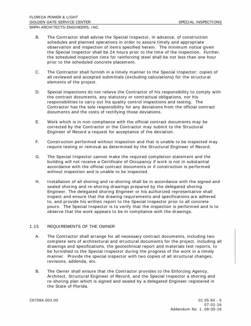
B. The Contractor shall advise the Special Inspector, in advance, of construction schedules and planned operations in order to assure timely and appropriate observation and inspection of items specified herein. The minimum notice given the Special Inspector shall be 24 hours prior to the time of the inspection. Further, the scheduled inspection time for reinforcing steel shall be not less than one hour prior to the scheduled concrete placement.
C. The Contractor shall furnish in a timely manner to the Special Inspector; copies of all reviewed and accepted submittals (excluding calculations) for the structural elements of the project.
D. Special inspections do not relieve the Contractor of his responsibility to comply with the contract documents, any statutory or contractual obligations, nor his responsibilities to carry out his quality control inspections and testing. The Contractor has the sole responsibility for any deviations from the official contract documents and the costs of rectifying those deviations.
E. Work which is in non-compliance with the official contract documents may be corrected by the Contractor or the Contractor may submit to the Structural Engineer of Record a request for acceptance of the deviation.
F. Construction performed without inspection and that is unable to be inspected may require testing or removal as determined by the Structural Engineer of Record.
G. The Special Inspector cannot make the required completion statement and the building will not receive a Certificate of Occupancy if work is not in substantial accordance with the official contract documents or if construction is performed without inspection and is unable to be inspected.
H. Installation of all shoring and re-shoring shall be in accordance with the signed and sealed shoring and re-shoring drawings prepared by the delegated shoring Engineer. The delegated shoring Engineer or his authorized representative shall inspect and ensure that the drawing requirements and specifications are adhered to, and provide his written report to the Special Inspector prior to all concrete pours. The Special Inspector is to verify that the inspection is performed and is to observe that the work appears to be in compliance with the drawings.
1.15 REQUIREMENTS OF THE OWNER
A. The Contractor shall arrange for all necessary contract documents, including two complete sets of architectural and structural documents for the project, including all drawings and specifications, the geotechnical report and materials test reports, to be furnished to the Special Inspector during the progress of the work in a timely manner. Provide the special inspector with two copies of all structural changes, revisions, addenda, etc.
B. The Owner shall ensure that the Contractor provides to the Enforcing Agency, Architect, Structural Engineer of Record, and the Special Inspector a shoring and re-shoring plan which is signed and sealed by a delegated Engineer registered in the State of Florida.

FLORIDA POWER & LIGHT GOLDEN GATE SERVICE CENTER SPECIAL INSPECTIONS BRPH ARCHITECTS-ENGINEERS, INC.
C07084.003.00 01 05 60 - 6 07-01-16 Addendum No. 1, 08-05-16
C. The Owner shall ensure that a qualified testing agency is retained. See contract documents for requirements.
D. The Owner shall ensure that a qualified engineer or testing/inspecting consultant is retained to confirm that the specified foundation preparation is performed.
PART 2 - PRODUCTS
2.1 CONTRACT DOCUMENTS
A. Structural Drawings and Specifications prepared by BRPH Architects • Jezerinac Group, latest revision.
2.2 STRUCTURAL SYSTEM DESCRIPTION
A. Shallow Foundation: Shallow spread continuous and isolated footings and reinforcement.
B. Walls: The walls are composed of Site Cast Concrete Tilt-up wall panels.
C. Floors: Floor structures reinforced slab-on-ground and Composite steel framing and concrete reinforced slabs.
D. Roof: Roof framing consists of steel deck on joists and beams and conventionally reinforced concrete slabs.
PART 3 - EXECUTION
3.1 GENERAL
A. The following is a general inspection plan describing work to be performed by the Special Inspector. The intent is to describe minimum levels necessary to confirm that work complies with the design documents. The following are not inspector check lists but point out some critical areas requiring specific attention by the Special Inspector.
3.2 REINFORCED CONCRETE
A. The Contractor is to notify the Special Inspector a minimum of 24 hours prior to the placement of any structural concrete.
B. Reinforcing Steel: 1. Using the structural drawings, inspect grade, size, quantity, configuration and
spacing of reinforcing for compliance with the structural drawings supplemented with shop drawings. Prior to concrete placement report any

FLORIDA POWER & LIGHT GOLDEN GATE SERVICE CENTER SPECIAL INSPECTIONS BRPH ARCHITECTS-ENGINEERS, INC.
C07084.003.00 01 05 60 - 7 07-01-16 Addendum No. 1, 08-05-16
noted conflict and confirm that corrections are made before concrete is poured.
2. Check minimum clearance requirements from concrete surfaces. 3. Check that reinforcing is adequately supported and tied to resist displacement
or shifting during pour. 4. Check that rebar surfaces are free of excess rust or other coatings that may
adversely affect bonding capacity. If oiling of forms is required, check that it is applied before reinforcing is placed.
5. Check splice locations and required length of lap. Report any deviations from the contract documents before concrete is cast and confirm that corrections are made.
6. Check installation of hooked bars for compliance with the contract documents.
C. Check that expansion joint material, anchors, lifting inserts, and other embedded items are in compliance with the contract documents and approved shop drawings and have been positioned and secured in place so that displacement is not possible. 1. Check that conduits placed in the slab are reasonably spaced to ensure
integrity of the slab. 2. Confirm that load carrying embedded items are placed in compliance with the
contract documents. Relocation of embedded items in conflict with reinforcing will not be permitted without prior approval of the Structural Engineer of Record.
D. Check that construction joints, including dowels, keys and bulkheads, are in conformance with the contract documents. Review the location of construction joints in beams and slabs for compliance with the construction joint location plan submitted by the Contractor to the Structural Engineer of Record.
E. Openings: 1. Report all slab and wall openings larger than 12” and not shown on the
contract documents to the Architect/Engineer. Check placement of additional reinforcement around openings. No sleeves or openings will be permitted in beams without prior approval of the Structural Engineer of Record.
F. Check that all foreign material has been removed from spaces which concrete is to occupy.
G. The Special Inspector shall be on site when concrete is being placed as necessary to ascertain that proper concreting practices, as required by ACI 301, ASTM C94 and other recognized industry standards are followed. Observations by the Special Inspector shall include, but not be limited to, verification of the following: 1. Testing agency is on site and that mixing time, temperature, slump, and air
content are as specified. Check that addition of water to the concrete mix in the field is based on the guidelines set forth in the contract documents.
2. The concrete as delivered to the project site is as specified for that portion in which placement is to occur.
3. Concrete is being conveyed from mixer to place of final deposit by recognized industry standards. Concrete is being deposited continuously, or in layers of such thickness that no concrete will be deposited on concrete which has

FLORIDA POWER & LIGHT GOLDEN GATE SERVICE CENTER SPECIAL INSPECTIONS BRPH ARCHITECTS-ENGINEERS, INC.
C07084.003.00 01 05 60 - 8 07-01-16 Addendum No. 1, 08-05-16
hardened sufficiently to cause the formation of seams or planes of weakness within the area of placement.
4. Concrete is being consolidated and thoroughly worked around reinforcement, embedded items and into corners of forms, eliminating air or stone pockets which may cause honeycombing, pitting or planes of weakness.
5. Curing procedures are as per contract documents, ACI 308, “Standard Practice for Curing Concrete” and other recognized industry standards.
H. After the formwork has been removed, inspect concrete surfaces for honeycombing and voids.
3.3 STRUCTURAL STEEL
A. Inspect structural steel framing prior to concealment to verify grade, sizes, connections, straightness and finish. Check with contract documents and shop drawings.
B. Inspect setting of anchor bolts, embeds and other miscellaneous structural items prior to concreting. Verify size, quantity and finish.
C. Inspect Connections for the following: 1. Bolted connections: Type, size and number of bolts. Check that bolts are
clean and lubricated and have proper washers and that they conform to the specifications. Check that bolt holes are the specified type and size. Verify that bolts are properly tightened. For slip-critical bolts with load indicator washers, check all bolts visually and 10 percent with a feeler gauge.
2. Welded Connections: Verify that welders are AWS certified for the type of welds being made. Visually examine all welds for type, size and length for compliance with the structural drawings. Verify that required non-destructive testing is performed by the testing agency. Verify that welds are clean, free from slag, and that rust protection has been applied as per specifications.
D. Headed Stud Anchors: Check for size, length, spacing and welding.
E. Steel Decks: Check for type, size and gage. Check connection to supports.
F. Open Web Steel Joists:
1. Inspect steel joists to verify type, size, spacing, connections, straightness and finish. Inspect from construction documents and shop drawings.
2. Check that bearing conditions conform to requirements of S.J.I. and contract documents.
3. Verify that the temporary bracing and permanent cross-bridging are being implemented per requirements of the construction documents and erection drawings.
4. Inspect setting of shelf angles, bearing plates and miscellaneous structural items to verify size, quantity, location and finish.
5. Visually examine all field welds. Verify that welders are AWS certified.

FLORIDA POWER & LIGHT GOLDEN GATE SERVICE CENTER SPECIAL INSPECTIONS BRPH ARCHITECTS-ENGINEERS, INC.
C07084.003.00 01 05 60 - 9 07-01-16 Addendum No. 1, 08-05-16
3.4 MATERIALS TESTING
A. All testing requirements as defined in the contract documents shall be adhered to, with copies of results forwarded to the Special Inspector. Prior to each inspection, the Special Inspector shall review all material tests and report on their results. The Special Inspector may request the Owner’s Representative to authorize additional tests if required by unforeseeable events or conditions. All materials testing must be executed by qualified laboratories and testing firms.
END OF SECTION 01 05 60

THIS PAGE INTENTIONALLY LEFT BLANK

FLORIDA POWER & LIGHT GOLDEN GATE SERVICE CENTER SUMMARY BRPH ARCHITECTS-ENGINEERS, INC.
C07084.003.00 01 10 00 - 1 07-01-16 Addendum No. 1, 08-05-16
SECTION 01 10 00 - SUMMARY
PART 1 - GENERAL
1.1 RELATED DOCUMENTS
A. Drawings and general provisions of the Contract, including General and Supplementary Conditions and other Division 01 Specification Sections, apply to this Section.
1.2 SUMMARY
A. Section Includes:
1. Project information. 2. Work covered by Contract Documents. 3. Phased construction. 4. Work by Owner. 5. Work under separate contracts. 6. Future work. 7. Purchase contracts. 8. Owner-furnished products. 9. Contractor-furnished, Owner-installed products. 10. Access to site. 11. Coordination with occupants. 12. Work restrictions. 13. Specification and drawing conventions. 14. Miscellaneous provisions.
B. Related Requirements:
1. DELETED 2. See Appendix B for Project Specific Requirements / Supplemental Conditions. 3. Section 01 12 00 “Contract Summary” for additional description of work
covered by Contract Documents and temporary facilities and controls.
1.3 PROJECT INFORMATION
A. Project Identification:
1. Florida Power & Light Company (Florida Power & Light) Golden Gate Service Center 4105 15th Avenue SW, Naples, Florida 34116 BRPH Project No. C07084.003.00

FLORIDA POWER & LIGHT GOLDEN GATE SERVICE CENTER SUMMARY BRPH ARCHITECTS-ENGINEERS, INC.
C07084.003.00 01 10 00 - 2 07-01-16 Addendum No. 1, 08-05-16
B. Owner: Florida Power & Light Company, 700 Universe Boulevard, Juno, Florida 33408-2657.
1. Owner's Representative: Jon Rosenthal, Manager - Construction or as designated by Owner per Project Florida Power and Light 561.694.4274 Office 561.310.1165 Mobile
C. Architect: 1. BRPH Architects-Engineers, Inc. 5700 N. U.S. Highway 1 Suite 400 Melbourne, Florida 32940 321.254.7666
D. Architect's Consultants: The Architect has retained the following design professionals who have prepared designated portions of the Contract Documents:
1. Jezerinac Group – Structural Engineers
4400 PGA Boulevard Suite 306 Palm Beach Gardens, Florida 33410 561.622.8585
2. Jensen-Hughes – Fire Alarm/Fire Protection Engineers 725 Primera Boulevard Suite 215 Lake Mary, Florida 32746 407.647.3737
3. Kimley-Horn Associates, Inc. – Civil Engineers 1690 S. Congress Avenue Suite 100 Delray Beach, Florida 33445 561.404.7247
E. Contractor: To Be Determined through RFP.
1.4 WORK COVERED BY CONTRACT DOCUMENTS
A. The Work of Project is defined by the Contract Documents and consists of the following:
1. The Project consists of a 2-story hardened concrete office building containing square footage as shown on the Architectural Drawings and certain site improvements associated with supporting the building's operation and use of the property day to day as well as during events that impact the electrical power system in the area affiliated with the property.
2. The Project Site consists of an existing FP&L property as shown on Civil Drawings, with several existing structures, one of which is to be demolished. The site is to be redesigned to serve the new Service Center Office Building.

FLORIDA POWER & LIGHT GOLDEN GATE SERVICE CENTER SUMMARY BRPH ARCHITECTS-ENGINEERS, INC.
C07084.003.00 01 10 00 - 3 07-01-16 Addendum No. 1, 08-05-16
B. Type of Contract:
1. See Owner’s Procurement and Construction Contract.
1.5 PHASED CONSTRUCTION
A. The Work shall be conducted in one phase as the new service center office building is being constructed in the same location as the existing service center office building currently resides. In order for the Work to commence in the new office building area, staff and equipment are being relocated off site during the construction of the new building. Furthermore, the modular Telecommunications building being constructed by another contractor along the west property line needs to be operational prior to the demolition of the existing service center office building commences.
1. Contractor shall proceed with other site improvement work including but not limited completing the various site improvements along the west, north and eastern portions of the property, including the site work associated with establishing the paved area just south of the substation and east of the existing building to remain.
2. Owner is working with the other contractor to commence the construction of the modular Telecommunications building prior to Contractors commencement of work on site. Furthermore, Contractor and the other contractor can perform work on site simultaneously as needed with the exception of the demolition of the existing service center office building.
B. Before commencing Work, Contractor shall submit an updated copy of Contractor's construction schedule showing the sequence, commencement and completion dates for the various areas of Work can be established.
1.6 WORK BY OWNER
A. General: Cooperate fully with Owner so work may be carried out smoothly, without interfering with or delaying work under this Contract or work by Owner. Coordinate the Work of this Contract with work performed by Owner.
B. Preceding Work: Owner will perform the following construction operations at Project site. Those operations are scheduled to be provisionally accepted before work under this Contract begins.
1. Owner is proceeding with obtaining Water and Sewer, Power, and Communication (telephone and data) from the applicable providers in the area. Contracts are being negotiated and fees associated with providing the applicable service should be in place prior to the construction start.

FLORIDA POWER & LIGHT GOLDEN GATE SERVICE CENTER SUMMARY BRPH ARCHITECTS-ENGINEERS, INC.
C07084.003.00 01 10 00 - 4 07-01-16 Addendum No. 1, 08-05-16
1.7 WORK UNDER SEPARATE CONTRACTS
A. General: Cooperate fully with separate contractors so work on those contracts may be carried out smoothly, without interfering with or delaying work under this Contract or other contracts. Coordinate the Work of this Contract with work performed under separate contracts.
B. Concurrent Work: Owner will perform the following construction operations at the Project Site. Those operations will be conducted simultaneously with work under this Contract.
1. Owner will be hiring separately, contractors to provide and install low voltage, audio visual equipment, security, furniture and communication (communication, telephone, radio, and data) system for use in the new building. This work will be done in cooperation and simultaneously with the Contractors work. Furthermore, Owner will have a separate contractor relocate the Test Shed to an area located in the Phase 2 area of the Project. The completion of this work will need to be coordinated with the Contractors work.
2. Additionally, it should be noted that the site is and will remain an active FPL Service Center with staff, deliveries, operations, etc. occurring around the clock. The facility and its operations will need to remain operational throughout the project.
C. Subsequent Work: Owner will perform the following additional work at site after the completion of Phase 2. Completion of this work will depend on successful completion and preparatory work under this Contract.
1. Owner will be adjusting wooden utility poles and other equipment in the Green Space identified on Sheet C-06 in coordination with the construction of Phase 1. The utility poles and equipment to be located in this Green Space are to be used for training and the reconfiguration of the Training Area for the staff located at the Site.
1.8 PURCHASE CONTRACTS
A. General: Owner has negotiated purchase contracts with suppliers of material and equipment to be incorporated into the Work. Owner will assign these purchase contracts to Contractor. Include receiving, handling, storage if required, and installation of material and equipment in the Contract Sum, unless otherwise indicated.
1. Contractor's responsibilities are same as if Contractor had negotiated purchase contracts, including responsibility to renegotiate purchase and to execute final purchasing agreements.
B. Purchase Contracts Information:
1. Owner will be purchasing the proposed stand-by Emergency Generator, Fuel Tank, Automatic Transfer Switch (ATS), and metal protective housing surrounding the Emergency Generator. Owner will purchase and provide the

FLORIDA POWER & LIGHT GOLDEN GATE SERVICE CENTER SUMMARY BRPH ARCHITECTS-ENGINEERS, INC.
C07084.003.00 01 10 00 - 5 07-01-16 Addendum No. 1, 08-05-16
equipment including the load bank test and warranty on the equipment provided for the Contractor to install. Contractor shall be responsible for coordinating the receipt, handling, storage if required, complete installation and start up including one initial supply of fuel for the fuel tank. The Contractor shall be responsible for providing the applicable fuel to fill the emergency generator fuel tank one time in connection with the installation and start-up of the equipment. Owner shall be responsible for refueling the tank after the initial fuel supplied is exhausted and the load bank test is complete.
1.9 OWNER-FURNISHED PRODUCTS
A. Owner will furnish products indicated. The Work includes receiving, unloading, handling, storing, protecting, and installing Owner-furnished products.
B. Owner-Furnished Products:
1. Low voltage cabling, Audio Visual, Furniture, Security, Appliances, etc. 2. Appliances are Owner-furnished and Contractor installed. 3. Furniture is Owner-furnished and installed. Contractor to install electrical
connections and communication/data raceways.
1.10 ACCESS TO SITE
A. Use of Site: Limit use of Project site to areas within the Contract limits indicated. Do not disturb portions of Project site beyond areas in which the Work is indicated.
1. Limits: Confine construction operations to areas defined in the Phasing Plan. 2. Driveways, Walkways and Entrances: Keep driveways, loading areas and
entrances serving premises clear and available to Owner, Owner's employees, and emergency vehicles at all times. Do not use these areas for parking or storage of materials.
a. Schedule deliveries to minimize use of driveways and entrances by construction operations.
b. Schedule deliveries to minimize space and time requirements for storage of materials and equipment on-site.
1.11 COORDINATION WITH OCCUPANTS
A. Partial Owner Occupancy: Owner will occupy the premises during entire construction period, with the exception of areas under construction. Cooperate with Owner during construction operations to minimize conflicts and facilitate Owner usage. Perform the Work so as not to interfere with Owner's operations. Maintain existing exits unless otherwise indicated.

FLORIDA POWER & LIGHT GOLDEN GATE SERVICE CENTER SUMMARY BRPH ARCHITECTS-ENGINEERS, INC.
C07084.003.00 01 10 00 - 6 07-01-16 Addendum No. 1, 08-05-16
1. Maintain access to existing walkways, corridors, and other adjacent occupied or used facilities. Do not close or obstruct walkways, corridors, or other occupied or used facilities without written permission from Owner and authorities having jurisdiction.
2. Provide not less than 72 hours' notice to Owner of activities that will affect Owner's operations.
3. Upon identification or announcement of severe weather events, Contractor will be directed to secure, tie down, remove, and possibly demobilize certain materials and equipment from the site in preparation of severe weather conditions impacting the Project area.
B. Owner Limited Occupancy of Completed Areas of Construction: Owner reserves the right to occupy and to place and install equipment in completed portions of the Work, prior to Provisional Acceptance (per the Owner’s Contract) of the Work, provided such occupancy does not interfere with completion of the Work. Such placement of equipment and limited occupancy shall not constitute acceptance of the total Work.
1. Architect will prepare a Certificate of Provisional Acceptance (per the Owner’s Contract) for each specific portion of the Work to be occupied prior to Owner acceptance of the completed Work.
2. Obtain a Certificate of Occupancy from authorities having jurisdiction before limited Owner occupancy.
3. Before limited Owner occupancy, mechanical and electrical systems shall be fully operational, and required tests and inspections shall be successfully completed. On occupancy, Owner will operate and maintain mechanical and electrical systems serving occupied portions of Work.
4. On occupancy, Owner will assume responsibility for maintenance and custodial service for occupied portions of Work.
1.12 WORK RESTRICTIONS
A. Work Restrictions, General: Comply with restrictions on construction operations.
1. Comply with limitations on use of public streets and with other requirements of authorities having jurisdiction.
B. On-Site Work Hours: Limit work in the existing building to normal business working hours of 7:00 a.m. to 5:00 p.m., Monday through Friday, unless otherwise indicated.
1. Weekend Hours: Hours to be coordinated with Owner. 2. Early Morning Hours: Hours to be coordinated with Owner. 3. Hours for Utility Shutdowns: Hours to be coordinated with Owner. 4. Hours for Core Drilling: Hours to be coordinated with Owner.
C. Existing Utility Interruptions: Do not interrupt utilities serving facilities occupied by Owner or others unless permitted under the following conditions and then only after providing temporary utility services according to requirements indicated:

FLORIDA POWER & LIGHT GOLDEN GATE SERVICE CENTER SUMMARY BRPH ARCHITECTS-ENGINEERS, INC.
C07084.003.00 01 10 00 - 7 07-01-16 Addendum No. 1, 08-05-16
1. Notify Architect and Owner not less than 48 hours in advance of proposed utility interruptions.
D. Noise, Vibration, and Odors: Coordinate operations that may result in high levels of noise and vibration, odors, or other disruption to Owner occupancy with Owner.
1. Notify Architect and Owner not less than 48 hours in advance of proposed disruptive operations.
E. Controlled Substances: Use of tobacco products and other controlled substances on Project site is not permitted.
F. Employee Identification: Provide identification tags for Contractor personnel working on Project site. Require personnel to use identification tags at all times.
G. Employee Screening: Comply with Owner's requirements for drug and background screening of Contractor personnel working on Project site.
1. Maintain list of approved screened personnel with Owner's representative.
1.13 SPECIFICATION AND DRAWING CONVENTIONS
A. Specification Content: The Specifications use certain conventions for the style of language and the intended meaning of certain terms, words, and phrases when used in particular situations. These conventions are as follows:
1. Imperative mood and streamlined language are generally used in the Specifications. The words "shall," "shall be," or "shall comply with," depending on the context, are implied where a colon (:) is used within a sentence or phrase.
2. Specification requirements are to be performed by Contractor unless specifically stated otherwise.
B. Division 01 General Requirements: Requirements of Sections in Division 01 apply to the Work of all Sections in the Specifications.
C. Drawing Coordination: Requirements for materials and products identified on Drawings are described in detail in the Specifications. One or more of the following are used on Drawings to identify materials and products:
1. Terminology: Materials and products are identified by the typical generic terms used in the individual Specifications Sections.
2. Abbreviations: Materials and products are identified by abbreviations scheduled on Drawings.
3. Keynoting: Materials and products are identified by reference keynotes referencing Specification Section numbers found in this Project Manual.

FLORIDA POWER & LIGHT GOLDEN GATE SERVICE CENTER SUMMARY BRPH ARCHITECTS-ENGINEERS, INC.
C07084.003.00 01 10 00 - 8 07-01-16 Addendum No. 1, 08-05-16
PART 2 - PRODUCTS (Not Used)
PART 3 - EXECUTION (Not Used)
END OF SECTION 01 10 00

FLORIDA POWER & LIGHT GOLDEN GATE SERVICE CENTER CONTRACT SUMMARY BRPH ARCHITECTS-ENGINEERS, INC.
C07084.003.00 01 12 00 - 1 07-01-16 Addendum No. 1, 08-05-16
SECTION 01 12 00 - CONTRACT SUMMARY
PART 1 - GENERAL
1.1 RELATED DOCUMENTS
A. Drawings and general provisions of the Contract, including General and Supplementary Conditions and other Division 01 Specification Sections, apply to this Section.
1.2 SUMMARY
A. Section includes a summary of contract, including responsibilities for coordination and temporary facilities and controls.
B. Specific requirements for Work of contract are also indicated in individual Specification Sections and on Drawings.
C. Related Requirements:
1. Section 01 10 00 "Summary" for the Work covered by the Contract Documents, restrictions on use of Project site, phased construction, coordination with occupants, and work restrictions.
2. Section 01 31 00 "Project Management and Coordination" for general coordination requirements.
1.3 DEFINITIONS
A. Permanent Enclosure: As determined by Architect, the condition at which roofing is insulated and weathertight; exterior walls are insulated and weathertight; and all openings are closed with permanent construction or substantial temporary closures equivalent in weather protection to permanent construction.
1.4 COORDINATION ACTIVITIES
A. Coordination activities of Owner’s Representative include, but are not limited to, the following:
1. Provide overall coordination of the Work. 2. Coordinate shared access to work areas. 3. Coordinate product selections for compatibility. 4. Provide overall coordination of temporary facilities and controls. 5. Coordinate, schedule, and approve interruptions of permanent and temporary
utilities, including those necessary to make connections for temporary services.

FLORIDA POWER & LIGHT GOLDEN GATE SERVICE CENTER CONTRACT SUMMARY BRPH ARCHITECTS-ENGINEERS, INC.
C07084.003.00 01 12 00 - 2 07-01-16 Addendum No. 1, 08-05-16
6. Coordinate construction and operations of the Work with work performed by each Contract, Owner's construction forces and any separate contracts.
7. Prepare Coordination Drawings in collaboration with each subcontractor to coordinate work by more than one contract.
8. Coordinate sequencing and scheduling of the Work. Include the following:
a. Initial Coordination Meeting: At earliest possible date, arrange and conduct a meeting with subcontractors for sequencing and coordinating the Work; negotiate reasonable adjustments to schedules.
b. Prepare a combined subcontractors' construction schedule for entire Project. Base schedule on preliminary construction schedule. Secure time commitments for performing critical construction activities from subcontractors. Show activities of each subcontract on a separate sheet. Prepare a simplified summary sheet indicating combined construction activities of subcontracts.
1) Submit schedules for approval. 2) Distribute copies of approved schedules to subcontractors.
9. Provide weekly photographic documentation. 10. Provide quality-assurance and quality-control services specified in
Section 01 40 00 "Quality Requirements." 11. Coordinate sequence of activities to accommodate tests and inspections, and
coordinate schedule of tests and inspections. 12. Provide information necessary to adjust, move or relocate existing utility
structures affected by construction. 13. Locate existing permanent benchmarks, control points and similar reference
points, and establish permanent benchmarks on Project site. 14. Provide field surveys of in-progress construction and site work and final
property survey. 15. Provide progress cleaning of common areas and coordinate progress cleaning
of areas or pieces of equipment where more than one subcontractor has worked.
16. Coordinate cutting and patching. 17. Coordinate protection of the Work. 18. Coordinate firestopping. 19. Coordinate completion of interrelated punch list items. 20. Coordinate preparation of Project Record Documents if information from more
than one subcontractor is to be integrated with information from other subcontractors to form one combined record.
21. Print and submit Record Documents if installations by more than one subcontractor are indicated on the same contract drawing or shop drawing.
22. Collect record Specification Sections from subcontractors, collate Sections into numeric order, and submit complete set.
B. DELETED

FLORIDA POWER & LIGHT GOLDEN GATE SERVICE CENTER CONTRACT SUMMARY BRPH ARCHITECTS-ENGINEERS, INC.
C07084.003.00 01 12 00 - 3 07-01-16 Addendum No. 1, 08-05-16
1.5 GENERAL REQUIREMENTS OF CONTRACTS
A. Extent of Contract: Unless the Agreement contains a more specific description of the Work of each Subcontract, requirements indicated on Drawings and in Specification Sections determine which contract includes a specific element of Project.
1. Unless otherwise indicated, the work described in this Section for each subcontract shall be complete systems and assemblies, including products, components, accessories, and installation required by the Contract Documents.
2. Trenches and other excavation for the work of each contract shall be the work of the General Construction Contract.
3. Blocking, backing panels, sleeves, and metal fabrication supports for the work of each contract shall be the work of the General Construction Contract.
4. Furnishing of access panels for the work of each contract shall be the work of each contract for its own work. Installation of access panels shall be the work of the General Construction Contract.
5. Equipment pads for the work of each contract shall be the work of the General Construction Contract.
6. Roof-mounted equipment curbs for the work of each contract shall be the work of the General Construction Contract.
7. Painting for the work of each contract shall be the work of the General Construction Contract.
8. Cutting and Patching: Provided by the General Construction Contract. 9. Through-penetration firestopping for the work of each contract shall be
provided by the General Construction Contract. 10. Contractors' Startup Construction Schedule: Within five (05) working days
after startup horizontal bar-chart-type construction submittal has been received from Owner’s Representative, submit a matching startup horizontal bar-chart schedule showing construction operations sequenced and coordinated with overall construction.
B. Substitutions: Each subcontractor shall cooperate with other subcontractors involved to coordinate approved substitutions with remainder of the work.
1. The General Construction Contractor shall coordinate substitutions.
C. Temporary Facilities and Controls: In addition to specific responsibilities for temporary facilities and controls indicated in this Section, each subcontractor is responsible for the following:
1. Installation, operation, maintenance, and removal of each temporary facility necessary for its own normal construction activity, and costs and use charges associated with each facility, except as otherwise provided for in this Section.
2. Plug-in electric power cords and extension cords, supplementary plug-in task lighting, and special lighting necessary exclusively for its own activities.
3. Its own field office, complete with necessary furniture, utilities, and telephone service.
4. Its own storage and fabrication sheds. 5. Temporary enclosures for its own construction activities. 6. Staging and scaffolding for its own construction activities.

FLORIDA POWER & LIGHT GOLDEN GATE SERVICE CENTER CONTRACT SUMMARY BRPH ARCHITECTS-ENGINEERS, INC.
C07084.003.00 01 12 00 - 4 07-01-16 Addendum No. 1, 08-05-16
7. General hoisting facilities for its own construction activities, up to 2 tons. 8. Waste disposal facilities, including collection and legal disposal of its own
hazardous, dangerous, unsanitary, or other harmful waste materials. 9. Progress cleaning of work areas affected by its operations on a daily basis. 10. Secure lockup of its own tools, materials, and equipment. 11. Construction aids and miscellaneous services and facilities necessary
exclusively for its own construction activities.
D. Temporary Heating, Cooling, and Ventilation: The General Construction Contractor is responsible for temporary heating, cooling, and ventilation before weathertight enclosure of building is complete. The General Construction Contractor is also responsible for temporary heating, cooling, and ventilation after permanent enclosure of building is complete.
E. Use Charges: Comply with the following:
1. Sewer Service: Include the cost for sewer service use by all parties engaged in construction activities at Project site in the General Construction Contract.
2. Water Service: Include the cost for water service, whether metered or otherwise, for water used by all entities engaged in construction activities at Project site in the General Construction Contract.
3. Electric Power Service: Include the cost for electric power service, whether metered or otherwise, for electricity used by all entities engaged in construction activities at Project site in the General Construction Contract.
1.6 GENERAL CONSTRUCTION CONTRACT
A. Work in the General Construction Contract includes, but is not limited to, the following:
1. Remaining work not identified as work under other contracts. 2. Site preparation, including clearing, building demolition and relocations, and
earthwork. 3. Site improvements, including roadways, parking lots, pedestrian paving, site
development furnishings and equipment, and landscaping. 4. DELETED 5. Selective demolition. 6. Foundations, including footings and foundation walls. 7. Slabs-on-grade, including earthwork, sub-drainage systems, and insulation. 8. Below-grade building construction, including excavation, backfill, and thermal
and moisture protection. 9. Superstructure, including floor and roof construction, and any sprayed fire-
resistive materials and/or board fire protection. 10. Exterior closure, including walls, parapets, doors, windows and louvers. 11. Roofing, including coverings, flashings and roof specialties. 12. Interior construction, including partitions, doors, interior glazed openings and
fittings. 13. Fire-protection specialties. 14. Stairs, including railings and finishes. 15. Interior finishes, finish carpentry, architectural woodwork and built-in
casework.

FLORIDA POWER & LIGHT GOLDEN GATE SERVICE CENTER CONTRACT SUMMARY BRPH ARCHITECTS-ENGINEERS, INC.
C07084.003.00 01 12 00 - 5 07-01-16 Addendum No. 1, 08-05-16
16. Miscellaneous items, including concrete equipment bases and painting of mechanical and electrical work.
17. Conveying systems, including elevators. 18. Equipment, including the following:
a. Restroom accessories b. Toilet partitions c. DELETED d. DELETED
19. Fixed/built-in casework and window treatments. 20. Complete Plumbing, HVAC, and Electrical systems.
B. Temporary facilities and controls in the General Construction Contract include, but are not limited to, the following:
1. Temporary facilities and controls including those for HVAC, Electrical and/or Plumbing systems.
2. Sediment and erosion control. 3. Unpiped sewers and drainage, including drainage ditches, dry wells,
stabilization ponds, and containers. 4. Stormwater control. 5. Unpiped temporary toilet fixtures, wash facilities, and drinking water facilities,
including disposable supplies. 6. Temporary enclosure for building exterior, except as indicated. 7. Temporary roads and paved areas. 8. Dewatering facilities and drains. 9. Excavation support and protection, unless required solely for the Work of
another contract. 10. Special or unusual hoisting requirements for construction activities, including
hoisting loads in excess of 2 tons, hoisting material or equipment into spaces below grade, and hoisting requirements outside building enclosure.
11. Project identification and temporary signs. 12. General waste disposal facilities. 13. Pest control. 14. Temporary stairs. 15. Temporary fire-protection facilities. 16. Barricades, warning signs, and lights. 17. Site enclosure fence. 18. Covered walkways. 19. Security enclosure and lockup. 20. Environmental protection. 21. Restoration of Owner's existing facilities used as temporary facilities.

FLORIDA POWER & LIGHT GOLDEN GATE SERVICE CENTER CONTRACT SUMMARY BRPH ARCHITECTS-ENGINEERS, INC.
C07084.003.00 01 12 00 - 6 07-01-16 Addendum No. 1, 08-05-16
1.7 DELETED
1.8 DELETED
1.9 DELETED
PART 2 - PRODUCTS (Not Used)
PART 3 - EXECUTION (Not Used)
END OF SECTION 01 12 00

FLORIDA POWER & LIGHT GOLDEN GATE SERVICE CENTER SUBSTITUTION PROCEDURES BRPH ARCHITECTS-ENGINEERS, INC.
C07084.003.00 01 25 00 - 1 07-01-16 Addendum No. 1, 08-05-16
SECTION 01 25 00 - SUBSTITUTION PROCEDURES
PART 1 - GENERAL
1.1 RELATED DOCUMENTS
A. Drawings and general provisions of the Contract, including General and Supplementary Conditions and other Division 01 Specification Sections, apply to this Section.
1.2 SUMMARY
A. Section includes administrative and procedural requirements for substitutions.
B. Related Requirements:
1. DELETED 2. DELETED 3. Section 01 60 00 "Product Requirements" for requirements for submitting
comparable product submittals for products by listed manufacturers.
1.3 DEFINITIONS
A. Substitutions: Changes in products, materials, equipment, and methods of construction from those required by the Contract Documents and proposed by Contractor.
1. Substitutions for Cause: Changes proposed by Contractor that are required due to changed Project conditions, such as unavailability of product, regulatory changes, or unavailability of required warranty terms.
2. Substitutions for Convenience: Changes proposed by Contractor or Owner that are not required in order to meet other Project requirements but may offer time- and/or cost-saving advantages to Owner.
1.4 ACTION SUBMITTALS
A. Substitution Requests: Submit three copies of each request for consideration. Identify product or fabrication or installation method to be replaced. Include Specification Section number and title and Drawing numbers and titles.
1. Substitution Request Form: Use CSI Form 13.1A, a copy of which follows this section.
2. Documentation: Show compliance with requirements for substitutions and the following, as applicable:
a. Statement indicating why specified product or fabrication or installation cannot be provided, if applicable.

FLORIDA POWER & LIGHT GOLDEN GATE SERVICE CENTER SUBSTITUTION PROCEDURES BRPH ARCHITECTS-ENGINEERS, INC.
C07084.003.00 01 25 00 - 2 07-01-16 Addendum No. 1, 08-05-16
b. Coordination information, including a list of changes or revisions needed to other parts of the Work and to construction performed by Owner and separate subcontractors that will be necessary to accommodate proposed substitution.
c. Detailed comparison of significant qualities of proposed substitution with those of the Work specified. Include annotated copy of applicable Specification Section. Significant qualities may include attributes such as performance, weight, size, durability, visual effect, sustainable design characteristics, warranties, and specific features and requirements indicated. Indicate deviations, if any, from the Work specified.
d. Product Data, including drawings and descriptions of products and fabrication and installation procedures.
e. Samples, where applicable or requested. f. Certificates and qualification data, where applicable or requested. g. List of similar installations for completed projects with project names
and addresses and names and addresses of architects and owners. h. Material test reports from a qualified testing agency indicating and
interpreting test results for compliance with requirements indicated. i. Research reports evidencing compliance with building code in effect for
Project, from 2014 Florida Building Code, 5th Edition. j. Detailed comparison of Contractor's construction schedule using
proposed substitution with products specified for the Work, including effect on the overall Contract Time. If specified product or method of construction cannot be provided within the Contract Time, include letter from manufacturer, on manufacturer's letterhead, stating date of receipt of purchase order, lack of availability, or delays in delivery.
k. Cost information, including a proposal of change, if any, in the Contract Sum.
l. Contractor's certification that proposed substitution complies with requirements in the Contract Documents except as indicated in substitution request, is compatible with related materials, and is appropriate for applications indicated.
m. Contractor's waiver of rights to additional payment or time that may subsequently become necessary because of failure of proposed substitution to produce indicated results.
3. Architect's Action: If necessary, Architect will request additional information or documentation for evaluation within seven (07) calendar days of receipt of a request for substitution. Architect will notify Contractor of acceptance or rejection of proposed substitution within 15 calendar days of receipt of request, or seven (07) calendar days of receipt of additional information or documentation, whichever is later.
a. Forms of Acceptance: Change Order, Construction Change Directive (CCD), or Architect's Supplemental Instructions (ASI) for minor changes in the Work.
b. Use product specified if Architect does not issue a decision on use of a proposed substitution within time allocated.
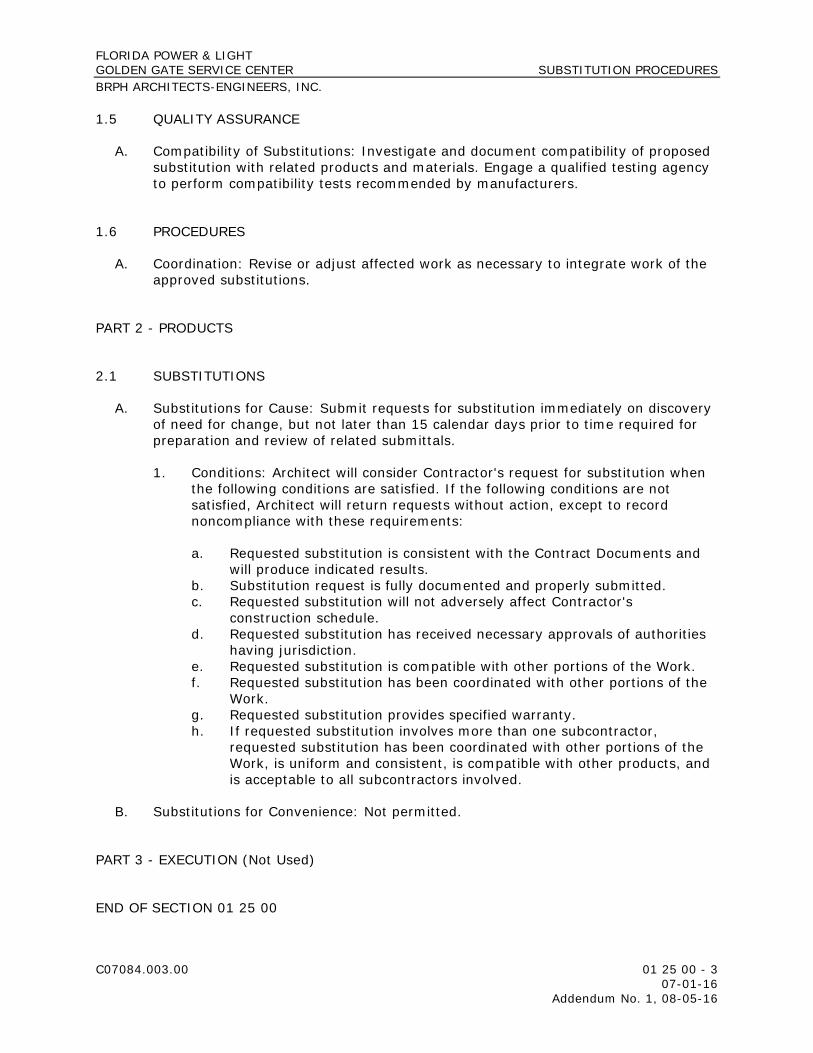
FLORIDA POWER & LIGHT GOLDEN GATE SERVICE CENTER SUBSTITUTION PROCEDURES BRPH ARCHITECTS-ENGINEERS, INC.
C07084.003.00 01 25 00 - 3 07-01-16 Addendum No. 1, 08-05-16
1.5 QUALITY ASSURANCE
A. Compatibility of Substitutions: Investigate and document compatibility of proposed substitution with related products and materials. Engage a qualified testing agency to perform compatibility tests recommended by manufacturers.
1.6 PROCEDURES
A. Coordination: Revise or adjust affected work as necessary to integrate work of the approved substitutions.
PART 2 - PRODUCTS
2.1 SUBSTITUTIONS
A. Substitutions for Cause: Submit requests for substitution immediately on discovery of need for change, but not later than 15 calendar days prior to time required for preparation and review of related submittals.
1. Conditions: Architect will consider Contractor's request for substitution when the following conditions are satisfied. If the following conditions are not satisfied, Architect will return requests without action, except to record noncompliance with these requirements:
a. Requested substitution is consistent with the Contract Documents and will produce indicated results.
b. Substitution request is fully documented and properly submitted. c. Requested substitution will not adversely affect Contractor's
construction schedule. d. Requested substitution has received necessary approvals of authorities
having jurisdiction. e. Requested substitution is compatible with other portions of the Work. f. Requested substitution has been coordinated with other portions of the
Work. g. Requested substitution provides specified warranty. h. If requested substitution involves more than one subcontractor,
requested substitution has been coordinated with other portions of the Work, is uniform and consistent, is compatible with other products, and is acceptable to all subcontractors involved.
B. Substitutions for Convenience: Not permitted.
PART 3 - EXECUTION (Not Used)
END OF SECTION 01 25 00

THIS PAGE INTENTIONALLY LEFT BLANK

FLORIDA POWER & LIGHT GOLDEN GATE SERVICE CENTER PAYMENT PROCEDURES BRPH ARCHITECTS-ENGINEERS, INC.
C07084.003.00 01 29 00 - 1 07-01-16 Addendum No. 1, 08-05-16
SECTION 01 29 00 - PAYMENT PROCEDURES
PART 1 - GENERAL
1.1 RELATED DOCUMENTS
A. Drawings and general provisions of the Contract, including General and Supplementary Conditions and other Division 01 Specification Sections, apply to this Section.
1.2 SUMMARY
A. Section includes administrative and procedural requirements necessary to prepare and process Applications for Payment.
B. Related Requirements:
1. DELETED 2. DELETED 3. Section 01 26 00 "Contract Modification Procedures" for administrative
procedures for handling changes to the Contract. 4. Section 01 32 00 "Construction Progress Documentation" for administrative
requirements governing the preparation and submittal of the Contractor's construction schedule.
1.3 DEFINITIONS
A. Schedule of Values: A statement furnished by Contractor allocating portions of the Contract Sum to various portions of the Work and used as the basis for reviewing Contractor's Applications for Payment.
1.4 SCHEDULE OF VALUES
A. Coordination: Coordinate preparation of the schedule of values with preparation of Contractor's construction schedule.
1. Coordinate line items in the schedule of values with other required administrative forms and schedules, including the following:
a. Application for Payment forms with continuation sheets. b. Submittal schedule. c. Items required to be indicated as separate activities in Contractor's
construction schedule.

FLORIDA POWER & LIGHT GOLDEN GATE SERVICE CENTER PAYMENT PROCEDURES BRPH ARCHITECTS-ENGINEERS, INC.
C07084.003.00 01 29 00 - 2 07-01-16 Addendum No. 1, 08-05-16
2. Submit the schedule of values to Owner at earliest possible date, but no later than seven (07) days before the date scheduled for submittal of initial Applications for Payment.
3. Subschedules for Phased Work: Where the Work is separated into phases requiring separately phased payments, provide subschedules showing values coordinated with each phase of payment.
4. Subschedules for Separate Elements of Work: Where the Contractor's construction schedule defines separate elements of the Work, provide subschedules showing values coordinated with each element.
B. Format and Content: Use Project Manual table of contents as a guide to establish line items for the schedule of values. Provide at least one line item for each Specification Section.
1. Identification: Include the following Project identification on the schedule of values:
a. Project name and location. b. Name of Architect. c. Architect's project number. d. Contractor's name and address. e. Date of submittal.
2. Arrange schedule of values consistent with format of AIA Document G703. 3. Arrange the schedule of values in tabular form with separate columns to
indicate the following for each item listed:
a. Related Specification Section or Division. b. Description of the Work. c. Name of subcontractor. d. Name of manufacturer or fabricator. e. Name of supplier. f. Change Orders (numbers) that affect value. g. Dollar value of the following, as a percentage of the Contract Sum to
nearest one-hundredth percent, adjusted to total 100 percent.
1) Labor. 2) Materials. 3) Equipment.
4. Provide a breakdown of the Contract Sum in enough detail to facilitate continued evaluation of Applications for Payment and progress reports. Coordinate with Project Manual table of contents. Provide multiple line items for principal subcontract amounts in excess of five percent (05%) of the Contract Sum.
a. Include separate line items under Contractor and principal subcontractors for Project closeout requirements in an amount totaling five percent (05%) percent of the Contract Sum and subcontract amount.
5. Round amounts to nearest whole dollar; total shall equal the Contract Sum.

FLORIDA POWER & LIGHT GOLDEN GATE SERVICE CENTER PAYMENT PROCEDURES BRPH ARCHITECTS-ENGINEERS, INC.
C07084.003.00 01 29 00 - 3 07-01-16 Addendum No. 1, 08-05-16
6. Provide a separate line item in the schedule of values for each part of the Work where Applications for Payment may include materials or equipment purchased or fabricated and stored, but not yet installed.
a. Differentiate between items stored on-site and items stored off-site. If required, include evidence of insurance.
7. Provide separate line items in the schedule of values for initial cost of materials, for each subsequent stage of completion, and for total installed value of that part of the Work.
8. DELETED 9. Purchase Contracts: Provide a separate line item in the schedule of values for
each purchase contract. Show line-item value of purchase contract. Indicate owner payments or deposits, if any, and balance to be paid by Contractor.
10. Each item in the schedule of values and Applications for Payment shall be complete. Include total cost and proportionate share of general overhead and profit for each item.
a. Temporary facilities and other major cost items that are not direct cost of actual work-in-place may be shown either as separate line items in the schedule of values or distributed as general overhead expense, at Contractor's option.
11. Schedule Updating: Update and resubmit the schedule of values before the next Applications for Payment when Change Orders or Construction Change Directives result in a change in the Contract Sum.
1.5 APPLICATIONS FOR PAYMENT
A. Each Application for Payment following the initial Application for Payment shall be consistent with previous applications and payments as certified by Architect and paid for by Owner.
1. Initial Application for Payment, Application for Payment at time of Provisional Acceptance (per the Owner’s Contract), and final Application for Payment involve additional requirements.
B. Payment Application Times: The date for each progress payment is indicated in the Agreement between Owner and Contractor. The period of construction work covered by each Application for Payment is the period indicated in the Agreement.
C. Payment Application Times: Submit Application for Payment to Architect by the first day of the month. The period covered by each Application for Payment is one month, ending on the last day of the month.
1. Submit draft copy of Application for Payment seven (07) days prior to due date for review by Architect.
D. Application for Payment Forms: Use AIA Document G702 and AIA Document G703 as form for Applications for Payment.

FLORIDA POWER & LIGHT GOLDEN GATE SERVICE CENTER PAYMENT PROCEDURES BRPH ARCHITECTS-ENGINEERS, INC.
C07084.003.00 01 29 00 - 4 07-01-16 Addendum No. 1, 08-05-16
E. Application for Payment Forms: Use forms provided by Owner for Applications for Payment. Sample copies are included in Project Manual.
F. Application for Payment Forms: Use forms acceptable to Architect and Owner for Applications for Payment. Submit forms for approval with initial submittal of schedule of values.
G. Application Preparation: Complete every entry on form. Notarize and execute by a person authorized to sign legal documents on behalf of Contractor. Architect will return incomplete applications without action.
1. Entries shall match data on the schedule of values and Contractor's construction schedule. Use updated schedules if revisions were made.
2. Include amounts for work completed following previous Application for Payment, whether or not payment has been received. Include only amounts for work completed at time of Application for Payment.
3. Include amounts of Change Orders and Construction Change Directives issued before last day of construction period covered by application.
4. Indicate separate amounts for work being carried out under Owner-requested project acceleration.
H. Stored Materials: Include in Application for Payment amounts applied for materials or equipment purchased or fabricated and stored, but not yet installed. Differentiate between items stored on-site and items stored off-site.
1. Provide certificate of insurance, evidence of transfer of title to Owner, and consent of surety to payment, for stored materials.
2. Provide supporting documentation that verifies amount requested, such as paid invoices. Match amount requested with amounts indicated on documentation; do not include overhead and profit on stored materials.
3. Provide summary documentation for stored materials indicating the following:
a. Value of materials previously stored and remaining stored as of date of previous Applications for Payment.
b. Value of previously stored materials put in place after date of previous Application for Payment and on or before date of current Application for Payment.
c. Value of materials stored since date of previous Application for Payment and remaining stored as of date of current Application for Payment.
I. Transmittal: Submit three (03) signed and notarized original copies of each Application for Payment to Architect by a method ensuring receipt within 24 hours. One copy shall include waivers of lien and similar attachments if required.
1. Transmit each copy with a transmittal form listing attachments and recording appropriate information about application.
J. Waivers of Mechanic's Lien: With each Application for Payment, submit waivers of mechanic's liens from subcontractors, sub-subcontractors, and suppliers for construction period covered by the previous application.

FLORIDA POWER & LIGHT GOLDEN GATE SERVICE CENTER PAYMENT PROCEDURES BRPH ARCHITECTS-ENGINEERS, INC.
C07084.003.00 01 29 00 - 5 07-01-16 Addendum No. 1, 08-05-16
1. Submit partial waivers on each item for amount requested in previous application, after deduction for retainage, on each item.
2. When an application shows completion of an item, submit conditional final or full waivers.
3. Owner reserves the right to designate which entities involved in the Work must submit waivers.
4. Submit final Application for Payment with or preceded by conditional final waivers from every entity involved with performance of the Work covered by the application who is lawfully entitled to a lien.
5. Waiver Forms: Submit executed waivers of lien on forms, acceptable to Owner.
K. Initial Application for Payment: Administrative actions and submittals that must precede or coincide with submittal of first Application for Payment include the following:
1. List of subcontractors. 2. Schedule of values. 3. Sustainable design submittal for project materials cost data. 4. Contractor's construction schedule (preliminary if not final). 5. Combined Contractor's construction schedule (preliminary if not final)
incorporating Work of multiple contracts, with indication of acceptance of schedule by each Contractor.
6. Products list (preliminary if not final). 7. Sustainable design action plans. 8. DELETED 9. Submittal schedule (preliminary if not final). 10. List of Contractor's staff assignments. 11. List of Contractor's principal consultants. 12. Copies of building permits. 13. Copies of authorizations and licenses from authorities having jurisdiction for
performance of the Work. 14. Initial progress report. 15. Report of preconstruction conference. 16. Certificates of insurance and insurance policies. 17. Performance and payment bonds. 18. Data needed to acquire Owner's insurance.
L. Monthly Progress Payments: The Owner shall make partial payments for the completed work as the construction progresses, subject to retention. In accordance with the Project Specific Requirements/Supplemental Conditions, documents included therein shall be provided with each progress payment request. This will include but not limited to the Cost Management Reports and the Monthly Management Report.

FLORIDA POWER & LIGHT GOLDEN GATE SERVICE CENTER PAYMENT PROCEDURES BRPH ARCHITECTS-ENGINEERS, INC.
C07084.003.00 01 29 00 - 6 07-01-16 Addendum No. 1, 08-05-16
M. Application for Payment at Provisional Acceptance (per the Owner’s Contract): After Architect issues the Certificate of Provisional Acceptance (per the Owner’s Contract), submit an Application for Payment showing 100 percent completion for portion of the Work claimed as substantially complete.
1. Include documentation supporting claim that the Work is substantially complete and a statement showing an accounting of changes to the Contract Sum.
2. This application shall reflect Certificate(s) of Provisional Acceptance (per the Owner’s Contract) issued previously for Owner occupancy of designated portions of the Work.
N. Final Payment Application: After completing Project closeout requirements, submit final Application for Payment with releases and supporting documentation not previously submitted and accepted, including, but not limited, to the following:
1. Evidence of completion of Project closeout requirements. 2. Insurance certificates for products and completed operations where required
and proof that taxes, fees, and similar obligations were paid. 3. Updated final statement, accounting for final changes to the Contract Sum. 4. AIA Document G706, "Contractor's Affidavit of Payment of Debts and Claims." 5. AIA Document G706A, "Contractor's Affidavit of Release of Liens." 6. AIA Document G707, "Consent of Surety to Final Payment." 7. Evidence that claims have been settled. 8. Final meter readings for utilities, a measured record of stored fuel, and similar
data as of date of Provisional Acceptance (per the Owner’s Contract) or when Owner took possession of and assumed responsibility for corresponding elements of the Work.
9. Final liquidated damages settlement statement.
PART 2 - PRODUCTS (Not Used)
PART 3 - EXECUTION (Not Used)
END OF SECTION 01 29 00
FLORIDA POWER & LIGHT GOLDEN GATE SERVICE CENTER PROJECT MANAGEMENT AND COORDINATION BRPH ARCHITECTS-ENGINEERS, INC.
C07084.003.00 01 31 00 - 1 07-01-16 Addendum No. 1, 08-05-16
SECTION 01 31 00 - PROJECT MANAGEMENT AND COORDINATION
PART 1 - GENERAL
1.1 RELATED DOCUMENTS
A. Drawings and general provisions of the Contract, including General and Supplementary Conditions and other Division 01 Specification Sections, apply to this Section.
1.2 SUMMARY
A. Section includes administrative provisions for coordinating construction operations on Project including, but not limited to, the following:
1. General coordination procedures. 2. Coordination Drawings. 3. Requests for Information (RFIs). 4. Project Web site. 5. Project meetings. 6. Cost Management Report.
B. Each contractor shall participate in coordination requirements. Certain areas of responsibility are assigned to a specific contractor.
C. Related Requirements:
1. Section 01 10 00 “Summary” and Section 01 12 00 "Contract Summary" for a description of the division of work among separate contracts and responsibility for coordination activities not in this Section.
2. Section 01 32 00 "Construction Progress Documentation" for preparing and submitting Contractor's construction schedule.
3. Section 01 73 00 "Execution" for procedures for coordinating general installation and field-engineering services, including establishment of benchmarks and control points.
4. Section 01 77 00 "Closeout Procedures" for coordinating closeout of the Contract.
5. Section 01 91 13 "General Commissioning Requirements" for coordinating the Work with Owner's Commissioning Authority.
1.3 DEFINITIONS
A. RFI: Request from Owner, Architect, or Contractor seeking information required by or clarifications of the Contract Documents.

FLORIDA POWER & LIGHT GOLDEN GATE SERVICE CENTER PROJECT MANAGEMENT AND COORDINATION BRPH ARCHITECTS-ENGINEERS, INC.
C07084.003.00 01 31 00 - 2 07-01-16 Addendum No. 1, 08-05-16
1.4 INFORMATIONAL SUBMITTALS
A. Subcontract List: Prepare a written summary identifying individuals or firms proposed for each portion of the Work, including those who are to furnish products or equipment fabricated to a special design. Use CSI Form 1.5A. Include the following information in tabular form:
1. Name, address, and telephone number of entity performing subcontract or supplying products.
2. Number and title of related Specification Section(s) covered by subcontract. 3. Drawing number and detail references, as appropriate, covered by
subcontract.
B. Key Personnel Names: Within 15 days of starting construction operations, submit a list of key personnel assignments, including superintendent and other personnel in attendance at Project site. Identify individuals and their duties and responsibilities; list addresses and telephone numbers, including home, office, and cellular telephone numbers and e-mail addresses. Provide names, addresses, and telephone numbers of individuals assigned as alternates in the absence of individuals assigned to Project.
1. Post copies of list in project meeting room, in temporary field office, on Project Web site, and by each temporary telephone. Keep list current at all times.
1.5 GENERAL COORDINATION PROCEDURES
A. Coordination: Coordinate construction operations included in different Sections of the Specifications to ensure efficient and orderly installation of each part of the Work. Coordinate construction operations, included in different Sections, that depend on each other for proper installation, connection, and operation.
1. Schedule construction operations in sequence required to obtain the best results where installation of one part of the Work depends on installation of other components, before or after its own installation.
2. Coordinate installation of different components to ensure maximum performance and accessibility for required maintenance, service, and repair.
3. Make adequate provisions to accommodate items scheduled for later installation.
B. Coordination: Each contractor shall coordinate its construction operations with those of other contractors and entities to ensure efficient and orderly installation of each part of the Work. Each contractor shall coordinate its operations with operations, included in different Sections, that depend on each other for proper installation, connection, and operation.
1. Schedule construction operations in sequence required to obtain the best results where installation of one part of the Work depends on installation of other components, before or after its own installation.

FLORIDA POWER & LIGHT GOLDEN GATE SERVICE CENTER PROJECT MANAGEMENT AND COORDINATION BRPH ARCHITECTS-ENGINEERS, INC.
C07084.003.00 01 31 00 - 3 07-01-16 Addendum No. 1, 08-05-16
2. Coordinate installation of different components with other contractors to ensure maximum performance and accessibility for required maintenance, service, and repair.
3. Make adequate provisions to accommodate items scheduled for later installation.
C. Prepare memoranda for distribution to each party involved, outlining special procedures required for coordination. Include such items as required notices, reports, and list of attendees at meetings.
1. Prepare similar memoranda for Owner and separate contractors if coordination of their Work is required.
D. Administrative Procedures: Coordinate scheduling and timing of required administrative procedures with other construction activities and activities of other subcontractors to avoid conflicts and to ensure orderly progress of the Work. Such administrative activities include, but are not limited to, the following:
1. Preparation of Contractor's construction schedule. 2. Preparation of the schedule of values. 3. Installation and removal of temporary facilities and controls. 4. Delivery and processing of submittals. 5. Progress meetings. 6. Preinstallation conferences. 7. Project closeout activities. 8. Startup and adjustment of systems.
E. Conservation: Coordinate construction activities to ensure that operations are carried out with consideration given to conservation of energy, water, and materials. Coordinate use of temporary utilities to minimize waste.
1. Salvage materials and equipment involved in performance of, but not actually incorporated into, the Work. See other Sections for disposition of salvaged materials that are designated as Owner's property.
1.6 COORDINATION DRAWINGS
A. Coordination Drawings, General: Prepare coordination drawings according to requirements in individual Sections, and additionally where installation is not completely shown on Shop Drawings, where limited space availability necessitates coordination, or if coordination is required to facilitate integration of products and materials fabricated or installed by more than one entity.
1. Content: Project-specific information, drawn accurately to a scale large enough to indicate and resolve conflicts. Do not base coordination drawings on standard printed data. Include the following information, as applicable:
a. Use applicable Drawings as a basis for preparation of coordination drawings. Prepare sections, elevations, and details as needed to describe relationship of various systems and components.

FLORIDA POWER & LIGHT GOLDEN GATE SERVICE CENTER PROJECT MANAGEMENT AND COORDINATION BRPH ARCHITECTS-ENGINEERS, INC.
C07084.003.00 01 31 00 - 4 07-01-16 Addendum No. 1, 08-05-16
b. Coordinate the addition of trade-specific information to the coordination drawings by multiple contractors in a sequence that best provides for coordination of the information and resolution of conflicts between installed components before submitting for review.
c. Indicate functional and spatial relationships of components of architectural, structural, civil, mechanical, and electrical systems.
d. Indicate space requirements for routine maintenance and for anticipated replacement of components during the life of the installation.
e. Show location and size of access doors required for access to concealed dampers, valves, and other controls.
f. Indicate required installation sequences. g. Indicate dimensions shown on the Drawings. Specifically note
dimensions that appear to be in conflict with submitted equipment and minimum clearance requirements. Provide alternate sketches to Architect indicating proposed resolution of such conflicts. Minor dimension changes and difficult installations will not be considered changes to the Contract.
B. Coordination Drawing Organization: Organize coordination drawings as follows:
1. Floor Plans and Reflected Ceiling Plans: Show architectural and structural elements, and mechanical, plumbing, fire-protection, fire-alarm, and electrical Work. Show locations of visible ceiling-mounted devices relative to acoustical ceiling grid. Supplement plan drawings with section drawings where required to adequately represent the Work.
2. Plenum Space: Indicate subframing for support of ceiling and wall systems, mechanical and electrical equipment, and related Work. Locate components within ceiling plenum to accommodate layout of light fixtures indicated on Drawings. Indicate areas of conflict between light fixtures and other components.
3. Mechanical Rooms: Provide coordination drawings for mechanical rooms showing plans and elevations of mechanical, plumbing, fire-protection, fire-alarm, and electrical equipment.
4. Structural Penetrations: Indicate penetrations and openings required for all disciplines.
5. Slab Edge and Embedded Items: Indicate slab edge locations and sizes and locations of embedded items for metal fabrications, sleeves, anchor bolts, bearing plates, angles, door floor closers, slab depressions for floor finishes, curbs and housekeeping pads, and similar items.
6. Mechanical and Plumbing Work: Show the following:
a. Sizes and bottom elevations of ductwork, piping, and conduit runs, including insulation, bracing, flanges, and support systems.
b. Dimensions of major components, such as dampers, valves, diffusers, access doors, cleanouts and electrical distribution equipment.
c. Fire-rated enclosures around ductwork.
7. Electrical Work: Show the following:
a. Runs of vertical and horizontal conduit 1-1/4 inches in diameter and larger.

FLORIDA POWER & LIGHT GOLDEN GATE SERVICE CENTER PROJECT MANAGEMENT AND COORDINATION BRPH ARCHITECTS-ENGINEERS, INC.
C07084.003.00 01 31 00 - 5 07-01-16 Addendum No. 1, 08-05-16
b. Light fixture, exit light, emergency battery pack, smoke detector, and other fire-alarm locations.
c. Panel board, switch board, switchgear, transformer, busway, generator, and motor control center locations.
d. Location of pull boxes and junction boxes, dimensioned from column center lines.
8. Fire-Protection System: Show the following:
a. Locations of standpipes, mains piping, branch lines, pipe drops, and sprinkler heads.
9. Review: Architect will review coordination drawings to confirm that the Work is being coordinated, but not for the details of the coordination, which are Contractor's responsibility. If Architect determines that coordination drawings are not being prepared in sufficient scope or detail, or are otherwise deficient, Architect will so inform Contractor, who shall make changes as directed and resubmit.
10. Coordination Drawing Prints: Prepare coordination drawing prints according to requirements in Section 01 33 00 "Submittal Procedures."
C. Coordination Digital Data Files: Prepare coordination digital data files according to the following requirements:
1. File Preparation Format: Same digital data software program, version, and operating system as original Drawings.
2. File Preparation Format: DWG, Version 2015, operating in Microsoft Windows operating system.
3. File Submittal Format: Submit or post coordination drawing files using Portable Data File (PDF) format.
4. BIM File Incorporation: Develop and incorporate Contractor's and subcontractors’ coordination drawing files into Building Information Model established for Project.
a. Perform three-dimensional component conflict analysis as part of preparation of coordination drawings. Resolve component conflicts prior to submittal. Indicate where conflict resolution requires modification of design requirements by Architect.
5. Architect will furnish Contractor one set of digital data files of Drawings for use in preparing coordination digital data files.
a. Architect makes no representations as to the accuracy or completeness of digital data files as they relate to Drawings.
b. Digital Data Software Program: Drawings are available in AutoCAD 2015 and Revit 2015 for Microsoft Windows.
c. Contractor shall execute a data licensing agreement in the form of Section 01 39 00 “Electronic Deliverables Release”.

FLORIDA POWER & LIGHT GOLDEN GATE SERVICE CENTER PROJECT MANAGEMENT AND COORDINATION BRPH ARCHITECTS-ENGINEERS, INC.
C07084.003.00 01 31 00 - 6 07-01-16 Addendum No. 1, 08-05-16
1.7 REQUESTS FOR INFORMATION (RFIs)
A. General: Immediately on discovery of the need for additional information or interpretation of the Contract Documents, Contractor shall prepare and submit an RFI in the form specified.
1. Architect will return RFIs submitted to Architect by other entities controlled by Contractor with no response.
2. Coordinate and submit RFIs in a prompt manner so as to avoid delays in Contractor's work or work of subcontractors.
B. Content of the RFI: Include a detailed, legible description of item needing information or interpretation and the following:
1. Project name. 2. Project number. 3. Date. 4. Name of Contractor. 5. Name of Architect. 6. RFI number, numbered sequentially. 7. RFI subject. 8. Specification Section number and title and related paragraphs, as appropriate. 9. Drawing number and detail references, as appropriate. 10. Field dimensions and conditions, as appropriate. 11. Contractor's suggested resolution. If Contractor's suggested resolution
impacts the Contract Time or the Contract Sum, Contractor shall state impact in the RFI.
12. Contractor's signature. 13. Attachments: Include sketches, descriptions, measurements, photos, Product
Data, Shop Drawings, coordination drawings, and other information necessary to fully describe items needing interpretation.
a. Include dimensions, thicknesses, structural grid references, and details of affected materials, assemblies, and attachments on attached sketches.
C. RFI Forms: AIA Document G716 or software-generated form with substantially the same content as indicated above, acceptable to Architect.
1. Attachments shall be electronic files in Adobe Acrobat PDF format.
D. Architect's Action: Architect will review each RFI, determine action required, and respond. Allow seven (07) working days for Architect's response for each RFI. RFIs received by Architect after 1:00 p.m. will be considered as received the following working day.
1. The following Contractor-generated RFIs will be returned without action:
a. Requests for approval of submittals. b. Requests for approval of substitutions. c. Requests for approval of Contractor's means and methods.

FLORIDA POWER & LIGHT GOLDEN GATE SERVICE CENTER PROJECT MANAGEMENT AND COORDINATION BRPH ARCHITECTS-ENGINEERS, INC.
C07084.003.00 01 31 00 - 7 07-01-16 Addendum No. 1, 08-05-16
d. Requests for coordination information already indicated in the Contract Documents.
e. Requests for adjustments in the Contract Time or the Contract Sum. f. Requests for interpretation of Architect's actions on submittals. g. Incomplete RFIs or inaccurately prepared RFIs.
2. Architect's action may include a request for additional information, in which case Architect's time for response will date from time of receipt of additional information.
3. Architect's action on RFIs that may result in a change to the Contract Time or the Contract Sum may be eligible for Contractor to submit Change Proposal according to Section 01 26 00 "Contract Modification Procedures."
a. If Contractor believes the RFI response warrants change in the Contract Time or the Contract Sum, notify Architect in writing within 10 working days of receipt of the RFI response.
E. RFI Log: Prepare, maintain, and submit a tabular log of RFIs organized by the RFI number. Submit log weekly. Use CSI Log Form 13.2B. Include the following:
1. Project name. 2. Name and address of Contractor. 3. Name and address of Architect. 4. RFI number including RFIs that were returned without action or withdrawn. 5. RFI description. 6. Date the RFI was submitted. 7. Date Architect's response was received.
F. On receipt of Architect's action, update the RFI log and immediately distribute the RFI response to affected parties. Review response and notify Architect seven (07) days if Contractor disagrees with response.
1. Identification of related Minor Change in the Work, Construction Change Directive, and Proposal Request, as appropriate.
2. Identification of related Field Order, Work Change Directive, and Proposal Request, as appropriate.
1.8 PROJECT WEB SITE
A. Provide, administer, and use Project Web site for purposes of hosting and managing project communication and documentation until Final Completion. Project Web site shall include the following functions:
1. Project directory. 2. Project correspondence. 3. Meeting minutes. 4. Contract modifications forms and logs. 5. RFI forms and logs. 6. Task and issue management. 7. Photo documentation. 8. Schedule and calendar management.

FLORIDA POWER & LIGHT GOLDEN GATE SERVICE CENTER PROJECT MANAGEMENT AND COORDINATION BRPH ARCHITECTS-ENGINEERS, INC.
C07084.003.00 01 31 00 - 8 07-01-16 Addendum No. 1, 08-05-16
9. Submittals forms and logs. 10. Payment application forms. 11. Drawing and specification document hosting, viewing, and updating. 12. Online document collaboration. 13. Reminder and tracking functions. 14. Archiving functions.
B. Provide up to seven (07) Project Web site user licenses for use of the Owner, Architect, and Architect's consultants. Provide eight (08) hours of software training at Architect's office for Project Web site users.
C. On completion of Project, provide one (01) complete archive copy of Project Web site files to Owner and to Architect in a digital storage format acceptable to Architect.
D. Provide one of the following Project Web site software packages under their current published licensing agreements:
1. Newforma, Inc.
E. Contractor, subcontractors, and other parties granted access by Contractor to Project Web site shall execute a data licensing agreement in the form of 01 39 00 “Electronic Deliverables Release”.
1.9 PROJECT MEETINGS
A. General: Schedule and conduct meetings and conferences at Project site unless otherwise indicated.
1. Attendees: Inform participants and others involved, and individuals whose presence is required, of date and time of each meeting. Notify Owner and Architect of scheduled meeting dates and times.
2. Agenda: Prepare the meeting agenda. Distribute the agenda to all invited attendees.
3. Minutes: Entity responsible for conducting meeting will record significant discussions and agreements achieved. Distribute the meeting minutes to everyone concerned, including Owner and Architect, within three (03) working days of the meeting.
B. Preconstruction Conference: Owner will schedule and conduct a preconstruction conference before starting construction, at a time convenient to Owner and Architect, but no later than 15 working days after execution of the Agreement.
1. Conduct the conference to review responsibilities and personnel assignments. 2. Attendees: Authorized representatives of Owner, Architect, and their
consultants; Contractor and its superintendent; major subcontractors; suppliers; and other concerned parties shall attend the conference. Participants at the conference shall be familiar with Project and authorized to conclude matters relating to the Work.

FLORIDA POWER & LIGHT GOLDEN GATE SERVICE CENTER PROJECT MANAGEMENT AND COORDINATION BRPH ARCHITECTS-ENGINEERS, INC.
C07084.003.00 01 31 00 - 9 07-01-16 Addendum No. 1, 08-05-16
3. Agenda: Discuss items of significance that could affect progress, including the following:
a. Tentative construction schedule. b. Phasing. c. Critical work sequencing and long-lead items. d. Designation of key personnel and their duties. e. Lines of communications. f. Procedures for processing field decisions and Change Orders. g. Procedures for RFIs. h. Procedures for testing and inspecting. i. Procedures for processing Applications for Payment. j. Distribution of the Contract Documents. k. Submittal procedures. l. Sustainable design requirements. m. Preparation of record documents. n. Use of the premises and existing buildings. o. Work restrictions. p. Working hours. q. Owner's occupancy requirements. r. Responsibility for temporary facilities and controls. s. Procedures for moisture and mold control. t. Procedures for disruptions and shutdowns. u. Construction waste management and recycling. v. Parking availability. w. Office, work, and storage areas. x. Equipment deliveries and priorities. y. First aid. z. Security. aa. Progress cleaning.
4. Minutes: Entity responsible for conducting meeting will record and distribute meeting minutes.
C. Project Closeout Conference: Schedule and conduct a project closeout conference, at a time convenient to Owner and Architect, but no later than 90 days prior to the scheduled date of Provisional Acceptance (per the Owner’s Contract).
1. Conduct the conference to review requirements and responsibilities related to Project closeout.
2. Attendees: Authorized representatives of Owner, Architect and their consultants; Contractor and its superintendent; major subcontractors; suppliers; and other concerned parties shall attend the meeting. Participants at the meeting shall be familiar with Project and authorized to conclude matters relating to the Work.
3. Agenda: Discuss items of significance that could affect or delay Project closeout, including the following:
a. Preparation of record documents. b. Procedures required prior to inspection for Provisional Acceptance (per
the Owner’s Contract) and for final inspection for acceptance. c. Submittal of written warranties.

FLORIDA POWER & LIGHT GOLDEN GATE SERVICE CENTER PROJECT MANAGEMENT AND COORDINATION BRPH ARCHITECTS-ENGINEERS, INC.
C07084.003.00 01 31 00 - 10 07-01-16 Addendum No. 1, 08-05-16
d. Requirements for completing sustainable design documentation. e. Requirements for preparing operations and maintenance data. f. Requirements for delivery of material samples, attic stock, and spare
parts. g. Requirements for demonstration and training. h. Preparation of Contractor's punch list. i. Procedures for processing Applications for Payment at Provisional
Acceptance (per the Owner’s Contract) and for final payment. j. Submittal procedures. k. Coordination of separate contracts. l. Owner's partial occupancy requirements. m. Installation of Owner's furniture, fixtures, and equipment. n. Responsibility for removing temporary facilities and controls.
4. Minutes: Entity conducting meeting will record and distribute meeting minutes.
D. Progress Meetings: Conduct progress meetings at biweekly intervals.
1. Coordinate dates of meetings with preparation of payment requests. 2. Attendees: In addition to representatives of Owner and Architect, each
contractor, subcontractor, supplier, and other entity concerned with current progress or involved in planning, coordination, or performance of future activities shall be represented at these meetings. All participants at the meeting shall be familiar with Project and authorized to conclude matters relating to the Work.
3. Agenda: Review and correct or approve minutes of previous progress meeting. Review other items of significance that could affect progress. Include topics for discussion as appropriate to status of Project.
a. Contractor's Construction Schedule: Review progress since the last meeting. Determine whether each activity is on time, ahead of schedule, or behind schedule, in relation to Contractor's construction schedule. Determine how construction behind schedule will be expedited; secure commitments from parties involved to do so. Discuss whether schedule revisions are required to ensure that current and subsequent activities will be completed within the Contract Time.
1) Review schedule for next period.
b. Review present and future needs of each entity present, including the following:
1) Interface requirements. 2) Sequence of operations. 3) Resolution of BIM component conflicts. 4) Status of submittals. 5) Status of sustainable design documentation. 6) Deliveries. 7) Off-site fabrication. 8) Access. 9) Site utilization.

FLORIDA POWER & LIGHT GOLDEN GATE SERVICE CENTER PROJECT MANAGEMENT AND COORDINATION BRPH ARCHITECTS-ENGINEERS, INC.
C07084.003.00 01 31 00 - 11 07-01-16 Addendum No. 1, 08-05-16
10) Temporary facilities and controls. 11) Progress cleaning. 12) Quality and work standards. 13) Status of correction of deficient items. 14) Field observations. 15) Status of RFIs. 16) Status of proposal requests. 17) Pending changes. 18) Status of Change Orders. 19) Pending claims and disputes. 20) Documentation of information for payment requests.
4. Minutes: Entity responsible for conducting the meeting will record and distribute the meeting minutes to each party present and to parties requiring information.
a. Schedule Updating: Revise Contractor's construction schedule after each progress meeting where revisions to the schedule have been made or recognized. Issue revised schedule concurrently with the report of each meeting.
E. Coordination Meetings: Conduct Project Coordination meetings at biweekly intervals. Project coordination meetings are in addition to specific meetings held for other purposes, such as progress meetings and preinstallation conferences.
1. Attendees: In addition to representatives of Owner and Architect, each contractor, subcontractor, supplier, and other entity concerned with current progress or involved in planning, coordination, or performance of future activities shall be represented at these meetings. All participants at the meetings shall be familiar with Project and authorized to conclude matters relating to the Work.
2. Agenda: Review and correct or approve minutes of the previous coordination meeting. Review other items of significance that could affect progress. Include topics for discussion as appropriate to status of Project.
a. Combined Contractor's Construction Schedule: Review progress since the last coordination meeting. Determine whether each contract is on time, ahead of schedule, or behind schedule, in relation to combined Contractor's construction schedule. Determine how construction behind schedule will be expedited; secure commitments from parties involved to do so. Discuss whether schedule revisions are required to ensure that current and subsequent activities will be completed within the Contract Time.
b. Schedule Updating: Revise combined Contractor's construction schedule after each coordination meeting where revisions to the schedule have been made or recognized. Issue revised schedule concurrently with report of each meeting.

FLORIDA POWER & LIGHT GOLDEN GATE SERVICE CENTER PROJECT MANAGEMENT AND COORDINATION BRPH ARCHITECTS-ENGINEERS, INC.
C07084.003.00 01 31 00 - 12 07-01-16 Addendum No. 1, 08-05-16
c. Review present and future needs of each contractor present, including the following:
1) Interface requirements. 2) Sequence of operations. 3) Resolution of BIM component conflicts. 4) Status of submittals. 5) Deliveries. 6) Off-site fabrication. 7) Access. 8) Site utilization. 9) Temporary facilities and controls. 10) Work hours. 11) Hazards and risks. 12) Progress cleaning. 13) Quality and work standards. 14) Change Orders.
3. Reporting: Record meeting results and distribute copies to everyone in attendance and to others affected by decisions or actions resulting from each meeting.
4. Cost Management Report: Supplier shall provide a “Cost Management Report” on a bi-weekly basis which includes at a minimum the Claims, Changes or extra work, delays or accelerations, interferences or impacts known to Supplier that have occurred or may be claimed to have occurred since project onset. This information is required to be provided in Microsoft Excel. This Cost Management Report will be cumulative and include current status of aforementioned items, initiated dates, dollar exposure amounts (incremental to the executed contract amount), drawing references, subcontractor documentation, etc. as required to establish an understanding of the issues. If there are no known Claims, Changes, etc. the Cost Management Report shall still be issued bi-weekly stating NONE. The most recent Cost Management Report shall be attached to each Supplier invoice.
PART 2 - PRODUCTS (Not Used)
PART 3 - EXECUTION (Not Used)
END OF SECTION 01 31 00

FLORIDA POWER & LIGHT GOLDEN GATE SERVICE CENTER CONSTRUCTION PROGRESS DOCUMENTATION BRPH ARCHITECTS-ENGINEERS, INC.
C07084.003.00 01 32 00 - 1 07-01-16 Addendum No. 1, 08-05-16
SECTION 01 32 00 - CONSTRUCTION PROGRESS DOCUMENTATION
PART 1 - GENERAL
1.1 RELATED DOCUMENTS
A. Drawings and general provisions of the Contract, including General and Supplementary Conditions and other Division 01 Specification Sections, apply to this Section.
1.2 SUMMARY
A. Section includes administrative and procedural requirements for documenting the progress of construction during performance of the Work, including the following:
1. Startup construction schedule. 2. Contractor's construction schedule. 3. Construction schedule updating reports. 4. Daily construction reports. 5. Material location reports. 6. Site condition reports. 7. Special reports.
B. Related Requirements:
1. DELETED 2. Section 01 33 00 "Submittal Procedures" for submitting schedules and
reports. 3. Section 01 40 00 "Quality Requirements" for submitting a schedule of tests
and inspections.
1.3 DEFINITIONS
A. Activity: A discrete part of a project that can be identified for planning, scheduling, monitoring, and controlling the construction project. Activities included in a construction schedule consume time and resources.
1. Critical Activity: An activity on the critical path that must start and finish on the planned early start and finish times.
2. Predecessor Activity: An activity that precedes another activity in the network.
3. Successor Activity: An activity that follows another activity in the network.
B. Cost Loading: The allocation of the schedule of values for the completion of an activity as scheduled. The sum of costs for all activities must equal the total Contract Sum unless otherwise approved by Owner.

FLORIDA POWER & LIGHT GOLDEN GATE SERVICE CENTER CONSTRUCTION PROGRESS DOCUMENTATION BRPH ARCHITECTS-ENGINEERS, INC.
C07084.003.00 01 32 00 - 2 07-01-16 Addendum No. 1, 08-05-16
C. CPM: Critical path method, which is a method of planning and scheduling a construction project where activities are arranged based on activity relationships. Network calculations determine when activities can be performed and the critical path of Project.
D. Critical Path: The longest connected chain of interdependent activities through the network schedule that establishes the minimum overall Project duration and contains no float.
E. Event: The starting or ending point of an activity.
F. Float: The measure of leeway in starting and completing an activity.
1. Float time is not for the exclusive use or benefit of either Owner or Contractor, but is a jointly owned, expiring Project resource available to both parties as needed to meet schedule milestones and Contract completion date.
2. Free float is the amount of time an activity can be delayed without adversely affecting the early start of the successor activity.
3. Total float is the measure of leeway in starting or completing an activity without adversely affecting the planned Project completion date.
1.4 INFORMATIONAL SUBMITTALS
A. Format for Submittals: Submit required submittals in the following format:
1. Working electronic copy of schedule file, where indicated. 2. PDF electronic file.
B. Startup construction schedule.
1. Approval of cost-loaded, startup construction schedule will not constitute approval of schedule of values for cost-loaded activities.
C. Startup Network Diagram: Of size required to display entire network for entire construction period. Show logic ties for activities.
D. Contractor's Construction Schedule: Initial schedule, of size required to display entire schedule for entire construction period.
1. Submit a working electronic copy of schedule, using software indicated, and labeled to comply with requirements for submittals. Include type of schedule (initial or updated) and date on label.
E. CPM Reports: Concurrent with CPM schedule, submit each of the following reports. Format for each activity in reports shall contain activity number, activity description, cost and resource loading, original duration, remaining duration, early start date, early finish date, late start date, late finish date, and total float in calendar days.
1. Activity Report: List of all activities sorted by activity number and then early start date, or actual start date if known.

FLORIDA POWER & LIGHT GOLDEN GATE SERVICE CENTER CONSTRUCTION PROGRESS DOCUMENTATION BRPH ARCHITECTS-ENGINEERS, INC.
C07084.003.00 01 32 00 - 3 07-01-16 Addendum No. 1, 08-05-16
2. Logic Report: List of preceding and succeeding activities for all activities, sorted in ascending order by activity number and then early start date, or actual start date if known.
3. Total Float Report: List of all activities sorted in ascending order of total float. 4. Earnings Report: Compilation of Contractor's total earnings from the Notice to
Proceed until most recent Application for Payment.
F. Construction Schedule Updating Reports: Submit with Applications for Payment.
G. Daily Construction Reports: Submit at weekly intervals.
H. Material Location Reports: Submit at weekly intervals.
I. Site Condition Reports: Submit at time of discovery of differing conditions.
J. Special Reports: Submit at time of unusual event.
K. Qualification Data: For scheduling consultant.
1.5 QUALITY ASSURANCE
A. Scheduling Consultant Qualifications: An experienced specialist in CPM scheduling and reporting, with capability of producing CPM reports and diagrams within 24 hours of Architect's request.
B. Prescheduling Conference: Conduct conference at Project site to comply with requirements in Section 01 31 00 "Project Management and Coordination." Review methods and procedures related to the preliminary construction schedule and Contractor's construction schedule, including, but not limited to, the following:
1. Review software limitations and content and format for reports. 2. Verify availability of qualified personnel needed to develop and update
schedule. 3. Discuss constraints, including phasing, work stages, area separations, interim
milestones and partial Owner occupancy. 4. Review delivery dates for Owner-furnished products. 5. Review schedule for work of Owner's separate contracts. 6. Review submittal requirements and procedures. 7. Review time required for review of submittals and resubmittals. 8. Review requirements for tests and inspections by independent testing and
inspecting agencies. 9. Review time required for Project closeout and Owner startup procedures,
including commissioning activities. 10. Review and finalize list of construction activities to be included in schedule. 11. Review procedures for updating schedule.

FLORIDA POWER & LIGHT GOLDEN GATE SERVICE CENTER CONSTRUCTION PROGRESS DOCUMENTATION BRPH ARCHITECTS-ENGINEERS, INC.
C07084.003.00 01 32 00 - 4 07-01-16 Addendum No. 1, 08-05-16
1.6 COORDINATION
A. Coordinate Contractor's construction schedule with the schedule of values, list of subcontractors, submittal schedule, progress reports, payment requests, and other required schedules and reports.
1. Secure time commitments for performing critical elements of the Work from entities involved.
2. Coordinate each construction activity in the network with other activities and schedule them in proper sequence.
PART 2 - PRODUCTS
2.1 CONTRACTOR'S CONSTRUCTION SCHEDULE, GENERAL
A. Time Frame: Extend schedule from date established for the Notice of Award to date of final completion.
1. Contract completion date shall not be changed by submission of a schedule that shows an early completion date, unless specifically authorized by Change Order.
B. Activities: Treat each story or separate area as a separate numbered activity for each main element of the Work. Comply with the following:
1. Activity Duration: Define activities so no activity is longer than 20 calendar days, unless specifically allowed by Architect.
2. Procurement Activities: Include procurement process activities for the following long lead items and major items, requiring a cycle of more than 60 days, as separate activities in schedule. Procurement cycle activities include, but are not limited to, submittals, approvals, purchasing, fabrication, and delivery. a. HVAC equipment. b. Stand-by Generator. c. Water Heaters.
3. Submittal Review Time: Include review and resubmittal times indicated in Section 01 33 00 "Submittal Procedures" in schedule. Coordinate submittal review times in Contractor's construction schedule with submittal schedule.
4. Startup and Testing Time: Include no fewer than 15 calendar days for startup and testing.
5. Provisional Acceptance (per the Owner’s Contract): Indicate completion in advance of date established for Provisional Acceptance (per the Owner’s Contract), and allow time for Architect's administrative procedures necessary for certification of Provisional Acceptance (per the Owner’s Contract).
6. Punch List and Final Completion: Include not more than 30 calendar days for completion of punch list items and final completion.

FLORIDA POWER & LIGHT GOLDEN GATE SERVICE CENTER CONSTRUCTION PROGRESS DOCUMENTATION BRPH ARCHITECTS-ENGINEERS, INC.
C07084.003.00 01 32 00 - 5 07-01-16 Addendum No. 1, 08-05-16
C. Constraints: Include constraints and work restrictions indicated in the Contract Documents and as follows in schedule, and show how the sequence of the Work is affected.
1. Phasing: Arrange list of activities on schedule by phase. 2. Work under More Than One Contract: Include a separate activity for each
contract. 3. Work by Owner: Include a separate activity for each portion of the Work
performed by Owner. 4. Products Ordered in Advance: Include a separate activity for each product.
Include delivery date indicated in Section 01 10 00 "Summary." Delivery dates indicated stipulate the earliest possible delivery date.
5. Owner-Furnished Products: Include a separate activity for each product. Include delivery date indicated in Section 01 10 00 "Summary." Delivery dates indicated stipulate the earliest possible delivery date.
6. Work Restrictions: Show the effect of the following items on the schedule:
a. Coordination with existing construction. b. Limitations of continued occupancies. c. Uninterruptible services. d. Partial occupancy before Provisional Acceptance (per the Owner’s
Contract). e. Use of premises restrictions. f. Provisions for future construction. g. Seasonal variations. h. Environmental control.
7. Work Stages: Indicate important stages of construction for each major portion of the Work, including, but not limited to, the following:
a. Subcontract awards. b. Submittals. c. Purchases. d. Mockups. e. Fabrication. f. Sample testing. g. Deliveries. h. Installation. i. Tests and inspections. j. Adjusting. k. Curing. l. Building flush-out. m. Startup and placement into final use and operation.
8. Construction Areas: Identify each major area of construction for each major portion of the Work. Indicate where each construction activity within a major area must be sequenced or integrated with other construction activities to provide for the following:
a. Structural completion. b. Temporary enclosure and space conditioning. c. Permanent space enclosure.

FLORIDA POWER & LIGHT GOLDEN GATE SERVICE CENTER CONSTRUCTION PROGRESS DOCUMENTATION BRPH ARCHITECTS-ENGINEERS, INC.
C07084.003.00 01 32 00 - 6 07-01-16 Addendum No. 1, 08-05-16
d. Completion of mechanical installation. e. Completion of electrical installation. f. Provisional Acceptance (per the Owner’s Contract).
D. Milestones: Include milestones indicated in the Contract Documents in schedule, including, but not limited to, the Notice to Proceed, Provisional Acceptance (per the Owner’s Contract), and final completion, and the following interim milestones:
1. Casting of concrete tilt-wall panels. 2. Erection of concrete tilt-wall panels. 3. Temporary enclosure and space conditioning.
E. Cost Correlation: Superimpose a cost correlation timeline, indicating planned and actual costs. On the line, show planned and actual dollar volume of the Work performed as of planned and actual dates used for preparation of payment requests.
1. See Section 01 29 00 "Payment Procedures" for cost reporting and payment procedures.
F. Upcoming Work Summary: Prepare summary report indicating activities scheduled to occur or commence prior to submittal of next schedule update. Summarize the following issues:
1. Unresolved issues. 2. Unanswered Requests for Information. 3. Rejected or unreturned submittals. 4. Notations on returned submittals. 5. Pending modifications affecting the Work and Contract Time.
G. Recovery Schedule: When periodic update indicates the Work is 14 or more calendar days behind the current approved schedule, submit a separate recovery schedule indicating means by which Contractor intends to regain compliance with the schedule. Indicate changes to working hours, working days, crew sizes, and equipment required to achieve compliance, and date by which recovery will be accomplished.
H. Computer Scheduling Software: Prepare schedules using current version of a program that has been developed specifically to manage construction schedules.
1. Use Microsoft Project.
2.2 STARTUP CONSTRUCTION SCHEDULE
A. Bar-Chart Schedule: Submit startup, horizontal, bar-chart-type construction schedule within seven (07) days of date established for the Notice of Award.
B. Preparation: Indicate each significant construction activity separately. Identify first workday of each week with a continuous vertical line. Outline significant construction activities for first 90 days of construction. Include skeleton diagram for the remainder of the Work and a cash requirement prediction based on indicated activities.

FLORIDA POWER & LIGHT GOLDEN GATE SERVICE CENTER CONSTRUCTION PROGRESS DOCUMENTATION BRPH ARCHITECTS-ENGINEERS, INC.
C07084.003.00 01 32 00 - 7 07-01-16 Addendum No. 1, 08-05-16
2.3 CONTRACTOR'S CONSTRUCTION SCHEDULE (GANTT CHART)
A. Gantt-Chart Schedule: Submit a comprehensive, fully developed, horizontal, Gantt-chart-type, Contractor's construction schedule within 30 calendar days of date established for the Notice of Award. Base schedule on the startup construction schedule and additional information received since the start of Project.
B. Preparation: Indicate each significant construction activity separately. Identify first workday of each week with a continuous vertical line.
1. For construction activities that require three months or longer to complete, indicate an estimated completion percentage in 10 percent increments within time bar.
2.4 CONTRACTOR'S CONSTRUCTION SCHEDULE (CPM SCHEDULE)
A. General: Prepare network diagrams using AON (activity-on-node) format.
B. Startup Network Diagram: Submit diagram within 14 calendar days of date established for the Notice of Award. Outline significant construction activities for the first 90 calendar days of construction. Include skeleton diagram for the remainder of the Work and a cash requirement prediction based on indicated activities.
C. CPM Schedule: Prepare Contractor's construction schedule using a time-scaled CPM network analysis diagram for the Work.
1. Develop network diagram in sufficient time to submit CPM schedule so it can be accepted for use no later than 60 calendar days after date established for the Notice of Award.
a. Failure to include any work item required for performance of this Contract shall not excuse Contractor from completing all work within applicable completion dates, regardless of Architect's approval of the schedule.
2. Conduct educational workshops to train and inform key Project personnel, including subcontractors' personnel, in proper methods of providing data and using CPM schedule information.
3. Establish procedures for monitoring and updating CPM schedule and for reporting progress. Coordinate procedures with progress meeting and payment request dates.
4. Use "one workday" as the unit of time for individual activities. Indicate nonworking days and holidays incorporated into the schedule in order to coordinate with the Contract Time.
D. CPM Schedule Preparation: Prepare a list of all activities required to complete the Work. Using the startup network diagram, prepare a skeleton network to identify probable critical paths.

FLORIDA POWER & LIGHT GOLDEN GATE SERVICE CENTER CONSTRUCTION PROGRESS DOCUMENTATION BRPH ARCHITECTS-ENGINEERS, INC.
C07084.003.00 01 32 00 - 8 07-01-16 Addendum No. 1, 08-05-16
1. Activities: Indicate the estimated time duration, sequence requirements, and relationship of each activity in relation to other activities. Include estimated time frames for the following activities:
a. Preparation and processing of submittals. b. Mobilization and demobilization. c. Purchase of materials. d. Delivery. e. Fabrication. f. Utility interruptions. g. Installation. h. Work by Owner that may affect or be affected by Contractor's activities. i. Testing and commissioning. j. Punch list and final completion. k. Activities occurring following final completion.
2. Critical Path Activities: Identify critical path activities, including those for interim completion dates. Scheduled start and completion dates shall be consistent with Contract milestone dates.
3. Processing: Process data to produce output data on a computer-drawn, time-scaled network. Revise data, reorganize activity sequences, and reproduce as often as necessary to produce the CPM schedule within the limitations of the Contract Time.
4. Format: Mark the critical path. Locate the critical path near center of network; locate paths with most float near the edges.
a. Subnetworks on separate sheets are permissible for activities clearly off the critical path.
5. Cost- and Resource-Loading of CPM Schedule: Assign cost to construction activities on the CPM schedule. Do not assign costs to submittal activities. Obtain Architect's approval prior to assigning costs to fabrication and delivery activities. Assign costs under main subcontracts for testing and commissioning activities, operation and maintenance manuals, punch list activities, Project record documents, and demonstration and training (if applicable), in the amount of five percent (05%) of the Contract Sum.
a. Each activity cost shall reflect an appropriate value subject to approval by Architect.
b. Total cost assigned to activities shall equal the total Contract Sum.
E. Contract Modifications: For each proposed contract modification and concurrent with its submission, prepare a time-impact analysis using a network fragment to demonstrate the effect of the proposed change on the overall project schedule.
F. Initial Issue of Schedule: Prepare initial network diagram from a sorted activity list indicating straight "early start-total float." Identify critical activities. Prepare tabulated reports showing the following:
1. Contractor or subcontractor and the Work or activity. 2. Description of activity. 3. Main events of activity.

FLORIDA POWER & LIGHT GOLDEN GATE SERVICE CENTER CONSTRUCTION PROGRESS DOCUMENTATION BRPH ARCHITECTS-ENGINEERS, INC.
C07084.003.00 01 32 00 - 9 07-01-16 Addendum No. 1, 08-05-16
4. Immediate preceding and succeeding activities. 5. Early and late start dates. 6. Early and late finish dates. 7. Activity duration in workdays. 8. Total float or slack time. 9. Average size of workforce. 10. Dollar value of activity (coordinated with the schedule of values).
G. Schedule Updating: Concurrent with making revisions to schedule, prepare tabulated reports showing the following:
1. Identification of activities that have changed. 2. Changes in early and late start dates. 3. Changes in early and late finish dates. 4. Changes in activity durations in workdays. 5. Changes in the critical path. 6. Changes in total float or slack time. 7. Changes in the Contract Time.
H. Value Summaries: Prepare two cumulative value lists, sorted by finish dates.
1. In first list, tabulate activity number, early finish date, dollar value, and cumulative dollar value.
2. In second list, tabulate activity number, late finish date, dollar value, and cumulative dollar value.
3. In subsequent issues of both lists, substitute actual finish dates for activities completed as of list date.
4. Prepare list for ease of comparison with payment requests; coordinate timing with progress meetings.
a. In both value summary lists, tabulate "actual percent complete" and "cumulative value completed" with total at bottom.
b. Submit value summary printouts one (01) week before each regularly scheduled progress meeting.
2.5 REPORTS
A. Daily Construction Reports: Prepare a daily construction report recording the following information concerning events at Project site:
1. List of subcontractors at Project site. 2. List of separate contractors at Project site. 3. Approximate count of personnel at Project site. 4. Equipment at Project site. 5. Material deliveries. 6. High and low temperatures and general weather conditions, including
presence of rain or snow. 7. Accidents. 8. Meetings and significant decisions. 9. Unusual events (see special reports). 10. Stoppages, delays, shortages, and losses.
FLORIDA POWER & LIGHT GOLDEN GATE SERVICE CENTER CONSTRUCTION PROGRESS DOCUMENTATION BRPH ARCHITECTS-ENGINEERS, INC.
C07084.003.00 01 32 00 - 10 07-01-16 Addendum No. 1, 08-05-16
11. Meter readings and similar recordings. 12. Emergency procedures. 13. Orders and requests of authorities having jurisdiction. 14. Change Orders received and implemented. 15. Construction Change Directives (CCDs) received and implemented. 16. Services connected and disconnected. 17. Equipment or system tests and startups. 18. Partial completions and occupancies. 19. Provisional Acceptance (per the Owner’s Contract) authorized.
B. Material Location Reports: At monthly intervals, prepare and submit a comprehensive list of materials delivered to and stored at Project site. List shall be cumulative, showing materials previously reported plus items recently delivered. Include with list a statement of progress on and delivery dates for materials or items of equipment fabricated or stored away from Project site. Indicate the following categories for stored materials:
1. Material stored prior to previous report and remaining in storage. 2. Material stored prior to previous report and since removed from storage and
installed. 3. Material stored following previous report and remaining in storage.
C. Site Condition Reports: Immediately on discovery of a difference between site conditions and the Contract Documents, prepare and submit a detailed report. Submit with a Request for Information. Include a detailed description of the differing conditions, together with recommendations for changing the Contract Documents.
2.6 SPECIAL REPORTS
A. General: Submit special reports directly to Owner within one (01) day of an occurrence. Distribute copies of report to parties affected by the occurrence.
B. Reporting Unusual Events: When an event of an unusual and significant nature occurs at Project site, whether or not related directly to the Work, prepare and submit a special report. List chain of events, persons participating, response by Contractor's personnel, evaluation of results or effects, and similar pertinent information. Advise Owner in advance when these events are known or predictable.
PART 3 - EXECUTION
3.1 CONTRACTOR'S CONSTRUCTION SCHEDULE
A. Scheduling Consultant: Engage a consultant to provide planning, evaluation, and reporting using CPM scheduling.
1. In-House Option: Owner may waive the requirement to retain a consultant if Contractor employs skilled personnel with experience in CPM scheduling and reporting techniques. Submit qualifications.

FLORIDA POWER & LIGHT GOLDEN GATE SERVICE CENTER CONSTRUCTION PROGRESS DOCUMENTATION BRPH ARCHITECTS-ENGINEERS, INC.
C07084.003.00 01 32 00 - 11 07-01-16 Addendum No. 1, 08-05-16
2. Meetings: Scheduling consultant shall attend all meetings related to Project progress, alleged delays, and time impact.
B. Contractor's Construction Schedule Updating: At monthly intervals, update schedule to reflect actual construction progress and activities. Issue schedule one (01) week before each regularly scheduled progress meeting.
1. Revise schedule immediately after each meeting or other activity where revisions have been recognized or made. Issue updated schedule concurrently with the report of each such meeting.
2. Include a report with updated schedule that indicates every change, including, but not limited to, changes in logic, durations, actual starts and finishes, and activity durations.
3. As the Work progresses, indicate final completion percentage for each activity.
C. Distribution: Distribute copies of approved schedule to Architect, Owner, separate subcontractors, testing and inspecting agencies, and other parties identified by Contractor with a need-to-know schedule responsibility.
1. Post copies in Project meeting rooms and temporary field offices. 2. When revisions are made, distribute updated schedules to the same parties
and post in the same locations. Delete parties from distribution when they have completed their assigned portion of the Work and are no longer involved in performance of construction activities.
END OF SECTION 01 32 00

THIS PAGE INTENTIONALLY LEFT BLANK

FLORIDA POWER & LIGHT GOLDEN GATE SERVICE CENTER PHOTOGRAPHIC DOCUMENTATION BRPH ARCHITECTS-ENGINEERS, INC.
C07084.003.00 01 32 33 - 1 07-01-16 Addendum No. 1, 08-05-16
SECTION 01 32 33 - PHOTOGRAPHIC DOCUMENTATION
PART 1 - GENERAL
1.1 RELATED DOCUMENTS
A. Drawings and general provisions of the Contract, including General and Supplementary Conditions and other Division 01 Specification Sections, apply to this Section.
1.2 SUMMARY
A. Section includes administrative and procedural requirements for the following:
1. Preconstruction photographs. 2. Periodic construction photographs. 3. Final completion construction photographs. 4. Preconstruction video recordings. 5. Periodic construction video recordings. 6. Web-based construction photographic documentation.
B. Related Requirements:
1. DELETED 2. Section 01 33 00 "Submittal Procedures" for submitting photographic
documentation. 3. Section 01 77 00 "Closeout Procedures" for submitting photographic
documentation as project record documents at Project closeout. 4. Section 01 79 00 "Demonstration and Training" for submitting video
recordings of demonstration of equipment and training of Owner's personnel. 5. DELETED 6. DELETED 7. DELETED
1.3 DELETED
1.4 DELETED
1.5 INFORMATIONAL SUBMITTALS
A. Qualification Data: For photographer(s).

FLORIDA POWER & LIGHT GOLDEN GATE SERVICE CENTER PHOTOGRAPHIC DOCUMENTATION BRPH ARCHITECTS-ENGINEERS, INC.
C07084.003.00 01 32 33 - 2 07-01-16 Addendum No. 1, 08-05-16
B. Key Plan: Submit key plan of Project site and building with notation of vantage points marked for location and direction of each photograph and/or video recording. Indicate elevation or story of construction. Include same information as corresponding photographic documentation.
C. Digital Photographs: Submit image files within three (03) days of taking photographs.
1. Digital Camera: Minimum sensor resolution of 16 megapixels. 2. Format: Minimum 3200 by 2400 pixels, in unaltered original files, with same
aspect ratio as the sensor, uncropped, date and time stamped, in folder named by date of photograph, accompanied by key plan file.
3. Identification: Provide the following information with each image description in file metadata tag:
a. Name of Project. b. Name and contact information for photographer. c. Name of Architect. d. Name of Contractor. e. Date photograph was taken. f. Description of vantage point, indicating location, direction (by compass
point), and elevation or story of construction. g. Unique sequential identifier keyed to accompanying key plan.
1.6 QUALITY ASSURANCE
A. Photographer Qualifications: An individual who has been regularly engaged as a professional photographer of construction projects for not less than three years.
1.7 USAGE RIGHTS
A. Obtain and transfer copyright usage rights from photographer to Owner for unlimited reproduction of photographic documentation.
PART 2 - PRODUCTS
2.1 PHOTOGRAPHIC MEDIA
A. Digital Images: Provide images in JPG format, produced by a digital camera with minimum sensor size of 16 megapixels, and at an image resolution of not less than 3200 by 2400 pixels.
B. Digital Video Recordings: Provide high-resolution, digital video in format acceptable to Architect.

FLORIDA POWER & LIGHT GOLDEN GATE SERVICE CENTER PHOTOGRAPHIC DOCUMENTATION BRPH ARCHITECTS-ENGINEERS, INC.
C07084.003.00 01 32 33 - 3 07-01-16 Addendum No. 1, 08-05-16
PART 3 - EXECUTION
3.1 CONSTRUCTION PHOTOGRAPHS
A. Photographer: Engage a qualified photographer to take construction photographs.
B. General: Take photographs using the maximum range of depth of field, and that are in focus, to clearly show the Work. Photographs with blurry or out-of-focus areas will not be accepted.
1. Maintain key plan with each set of construction photographs that identifies each photographic location.
C. Digital Images: Submit digital images exactly as originally recorded in the digital camera, without alteration, manipulation, editing, or modifications using image-editing software.
1. Date and Time: Include date and time in file name for each image. 2. Field Office Images: Maintain one set of images accessible in the field office at
Project site, available at all times for reference. Identify images in the same manner as those submitted to Architect.
D. Preconstruction Photographs: Before commencement of excavation, commencement of demolition and/or commencing construction, take photographs of Project site and surrounding properties, including existing items to remain during construction, from different vantage points, as directed by Architect.
1. Flag excavation areas and construction limits before taking construction photographs.
2. Take 20 photographs to show existing conditions adjacent to property before starting the Work.
3. Take 20 photographs of existing buildings either on or adjoining property to accurately record physical conditions at start of construction.
4. Take additional photographs as required to record settlement or cracking of adjacent structures, pavements, and improvements.
E. Periodic Construction Photographs: Take 20 photographs weekly, with timing each month adjusted to coincide with the cutoff date associated with each Application for Payment. Select vantage points to show status of construction and progress since last photographs were taken.
F. Time-Lapse Sequence Construction Photographs: Take 20 photographs as indicated, to show status of construction and progress since last photographs were taken.
1. Frequency: Take photographs weekly, with timing each month adjusted to coincide with the cutoff date associated with each Application for Payment.
FLORIDA POWER & LIGHT GOLDEN GATE SERVICE CENTER PHOTOGRAPHIC DOCUMENTATION BRPH ARCHITECTS-ENGINEERS, INC.
C07084.003.00 01 32 33 - 4 07-01-16 Addendum No. 1, 08-05-16
2. Vantage Points: Following suggestions by Architect and Contractor, photographer to select vantage points. During each of the following construction phases, take not less than two (02) of the required shots from same vantage point each time to create a time-lapse sequence as follows:
a. Commencement of the Work, through completion of subgrade construction.
b. Above-grade structural framing. c. Exterior building enclosure. d. Interior Work, through date of Provisional Acceptance (per the Owner’s
Contract).
G. Final Completion Construction Photographs: Take 20 color photographs after date of Provisional Acceptance (per the Owner’s Contract) for submission as project record documents. Architect will inform photographer of desired vantage points.
1. Do not include date stamp.
H. Additional Photographs: Architect may request photographs in addition to periodic photographs specified. Additional photographs will be paid for by Change Order and are not included in the Contract Sum.
1. Three days' notice will be given, where feasible. 2. In emergency situations, take additional photographs within 24 hours of
request. 3. Circumstances that could require additional photographs include, but are not
limited to, the following:
a. Special events planned at Project site. b. Immediate follow-up when on-site events result in construction damage
or losses. c. Photographs to be taken at fabrication locations away from Project site.
These photographs are not subject to unit prices or unit-cost allowances.
d. Provisional Acceptance (per the Owner’s Contract) of a major phase or component of the Work.
e. Extra record photographs at time of final acceptance. f. Owner's request for special publicity photographs.
END OF SECTION 01 32 33
FLORIDA POWER & LIGHT GOLDEN GATE SERVICE CENTER SUBMITTAL PROCEDURES BRPH ARCHITECTS-ENGINEERS, INC.
C07084.003.00 01 33 00 - 1 07-01-16 Addendum No. 1, 08-05-16
SECTION 01 33 00 - SUBMITTAL PROCEDURES
PART 1 - GENERAL
1.1 RELATED DOCUMENTS
A. Drawings and general provisions of the Contract, including General and Supplementary Conditions and other Division 01 Specification Sections, apply to this Section.
1.2 SUMMARY
A. Section includes requirements for the submittal schedule and administrative and procedural requirements for submitting Shop Drawings, Product Data, Samples, and other submittals.
B. Related Requirements:
1. Section 01 29 00 "Payment Procedures" for submitting Applications for Payment and the schedule of values.
2. Section 01 32 00 "Construction Progress Documentation" for submitting schedules and reports, including Contractor's construction schedule.
3. Section 01 78 23 "Operation and Maintenance Data" for submitting operation and maintenance manuals.
4. Section 01 78 39 "Project Record Documents" for submitting record Drawings, record Specifications, and record Product Data.
5. Section 01 79 00 "Demonstration and Training" for submitting video recordings of demonstration of equipment and training of Owner's personnel.
1.3 DEFINITIONS
A. Action Submittals: Written and graphic information and physical samples that require Architect's and Owner’s Representative responsive action. Action submittals are those submittals indicated in individual Specification Sections as "action submittals."
B. Informational Submittals: Written and graphic information and physical samples that do not require Architect's and Owner’s Representative responsive action. Submittals may be rejected for not complying with requirements. Informational submittals are those submittals indicated in individual Specification Sections as "informational submittals."
C. File Transfer Protocol (FTP): Communications protocol that enables transfer of files to and from another computer over a network and that serves as the basis for standard Internet protocols. An FTP site is a portion of a network located outside of network firewalls within which internal and external users are able to access files.

FLORIDA POWER & LIGHT GOLDEN GATE SERVICE CENTER SUBMITTAL PROCEDURES BRPH ARCHITECTS-ENGINEERS, INC.
C07084.003.00 01 33 00 - 2 07-01-16 Addendum No. 1, 08-05-16
D. Portable Document Format (PDF): An open standard file format licensed by Adobe Systems used for representing documents in a device-independent and display resolution-independent fixed-layout document format.
1.4 ACTION SUBMITTALS
A. Submittal Schedule: Submit a schedule of submittals, arranged in chronological order by dates required by construction schedule. Include time required for review, ordering, manufacturing, fabrication, and delivery when establishing dates. Include additional time required for making corrections or revisions to submittals noted by Architect and Owner’s Representative and additional time for handling and reviewing submittals required by those corrections.
1. Coordinate submittal schedule with list of subcontracts, the schedule of values, and Contractor's construction schedule.
2. Initial Submittal: Submit concurrently with startup construction schedule. Include submittals required during the first 60 days of construction. List those submittals required to maintain orderly progress of the Work and those required early because of long lead time for manufacture or fabrication.
3. Final Submittal: Submit concurrently with the first complete submittal of Contractor's construction schedule.
a. Submit revised submittal schedule to reflect changes in current status and timing for submittals.
4. Format: Arrange the following information in a tabular format:
a. Scheduled date for first submittal. b. Specification Section number and title. c. Submittal category: Action; informational. d. Name of subcontractor. e. Description of the Work covered. f. Scheduled date for Architect's and Owner’s Representative final release
or approval. g. Scheduled date of fabrication. h. Scheduled dates for purchasing. i. Scheduled dates for installation. j. Activity or event number.
1.5 SUBMITTAL ADMINISTRATIVE REQUIREMENTS
A. Coordination: Coordinate preparation and processing of submittals with performance of construction activities.
1. Coordinate each submittal with fabrication, purchasing, testing, delivery, other submittals, and related activities that require sequential activity.
2. Submit all submittal items required for each Specification Section concurrently unless partial submittals for portions of the Work are indicated on approved submittal schedule.
FLORIDA POWER & LIGHT GOLDEN GATE SERVICE CENTER SUBMITTAL PROCEDURES BRPH ARCHITECTS-ENGINEERS, INC.
C07084.003.00 01 33 00 - 3 07-01-16 Addendum No. 1, 08-05-16
3. Submit action submittals and informational submittals required by the same Specification Section as separate packages under separate transmittals.
4. Coordinate transmittal of different types of submittals for related parts of the Work so processing will not be delayed because of need to review submittals concurrently for coordination.
a. Owner’s Representative reserves the right to withhold action on a submittal requiring coordination with other submittals until related submittals are received.
B. Processing Time: Allow time for submittal review, including time for resubmittals, as follows. Time for review shall commence on Owner’s Representative’s receipt of submittal. No extension of the Contract Time will be authorized because of failure to transmit submittals enough in advance of the Work to permit processing, including resubmittals.
1. Initial Review: Allow 15 days for initial review of each submittal. Allow additional time if coordination with subsequent submittals is required. Owner’s Representative will advise Contractor when a submittal being processed must be delayed for coordination.
2. Intermediate Review: If intermediate submittal is necessary, process it in same manner as initial submittal.
3. Resubmittal Review: Allow 15 days for review of each resubmittal. 4. Sequential Review: Where sequential review of submittals by Architect's
consultants, Owner, or other parties is indicated, allow 15 days for initial review of each submittal.
C. DELETED
D. Electronic Submittals: Identify and incorporate information in each electronic submittal file as follows:
1. Assemble complete submittal package into a single indexed file incorporating submittal requirements of a single Specification Section and transmittal form with links enabling navigation to each item.
2. Name file with submittal number or other unique identifier, including revision identifier.
a. File name shall use project identifier and Specification Section number followed by a decimal point and then a sequential number (e.g., LNHS-061000.01). Resubmittals shall include an alphabetic suffix after another decimal point (e.g., LNHS-061000.01.A).
3. Provide means for insertion to permanently record Contractor's review and approval markings and action taken by Architect and Owner’s Representative.
4. Transmittal Form for Electronic Submittals: Use electronic form acceptable to Owner, containing the following information:
a. Project name. b. Date. c. Name and address of Architect. d. Name of Owner’s Representative.

FLORIDA POWER & LIGHT GOLDEN GATE SERVICE CENTER SUBMITTAL PROCEDURES BRPH ARCHITECTS-ENGINEERS, INC.
C07084.003.00 01 33 00 - 4 07-01-16 Addendum No. 1, 08-05-16
e. Name of Contractor. f. Name of firm or entity that prepared submittal. g. Names of subcontractor, manufacturer, and supplier. h. Category and type of submittal. i. Submittal purpose and description. j. Specification Section number and title. k. Specification paragraph number or drawing designation and generic
name for each of multiple items. l. Drawing number and detail references, as appropriate. m. Location(s) where product is to be installed, as appropriate. n. Related physical samples submitted directly. o. Indication of full or partial submittal. p. Transmittal number, numbered consecutively. q. Submittal and transmittal distribution record. r. Other necessary identification. s. Remarks.
5. Metadata: Include the following information as keywords in the electronic submittal file metadata:
a. Project name. b. Number and title of appropriate Specification Section. c. Manufacturer name. d. Product name.
E. Options: Identify options requiring selection by Architect.
F. Deviations and Additional Information: On an attached separate sheet, prepared on Contractor's letterhead, record relevant information, requests for data, revisions other than those requested by Architect and Owner’s Representative on previous submittals, and deviations from requirements in the Contract Documents, including minor variations and limitations. Include same identification information as related submittal.
G. Resubmittals: Make resubmittals in same form and number of copies as initial submittal.
1. Note date and content of previous submittal. 2. Note date and content of revision in label or title block and clearly indicate
extent of revision. 3. Resubmit submittals until they are marked with approval notation from
Architect's and Owner's Representative action stamp.
H. Distribution: Furnish copies of final submittals to manufacturers, subcontractors, suppliers, fabricators, installers, authorities having jurisdiction, and others as necessary for performance of construction activities. Show distribution on transmittal forms.
I. Use for Construction: Retain complete copies of submittals on Project site. Use only final action submittals that are marked with approval notation from Architect's and Owner’s Representative's action stamp.

FLORIDA POWER & LIGHT GOLDEN GATE SERVICE CENTER SUBMITTAL PROCEDURES BRPH ARCHITECTS-ENGINEERS, INC.
C07084.003.00 01 33 00 - 5 07-01-16 Addendum No. 1, 08-05-16
PART 2 - PRODUCTS
2.1 SUBMITTAL PROCEDURES
A. General Submittal Procedure Requirements: Prepare and submit submittals required by individual Specification Sections. Types of submittals are indicated in individual Specification Sections.
1. Post electronic submittals as PDF electronic files directly to Project Web site specifically established for Project.
a. Architect, through Owner’s Representative, will return annotated file. Annotate and retain one copy of file as an electronic Project record document file.
2. Submit electronic submittals via email as PDF electronic files.
a. Architect, through Owner’s Representative, will return annotated file. Annotate and retain one copy of file as an electronic Project record document file.
3. Action Submittals: Submit electronic submittal unless otherwise indicated. Architect, through Owner’s Representative, will return as electronic.
4. Informational Submittals: Submit electronic submittal unless otherwise indicated. Architect and Owner’s Representative will not return anything.
5. Certificates and Certifications Submittals: Provide a statement that includes signature of entity responsible for preparing certification. Certificates and certifications shall be signed by an officer or other individual authorized to sign documents on behalf of that entity.
a. Provide a digital signature with digital certificate on electronically submitted certificates and certifications where indicated.
b. Provide a notarized statement on original paper copy certificates and certifications where indicated.
B. Product Data: Collect information into a single submittal for each element of construction and type of product or equipment.
1. If information must be specially prepared for submittal because standard published data are not suitable for use, submit as Shop Drawings, not as Product Data.
2. Mark each copy of each submittal to show which products and options are applicable.
3. Include the following information, as applicable:
a. Manufacturer's catalog cuts. b. Manufacturer's product specifications. c. Standard color charts. d. Statement of compliance with specified referenced standards. e. Testing by recognized testing agency. f. Application of testing agency labels and seals.

FLORIDA POWER & LIGHT GOLDEN GATE SERVICE CENTER SUBMITTAL PROCEDURES BRPH ARCHITECTS-ENGINEERS, INC.
C07084.003.00 01 33 00 - 6 07-01-16 Addendum No. 1, 08-05-16
g. Notation of coordination requirements. h. Availability and delivery time information.
4. For equipment, include the following in addition to the above, as applicable:
a. Wiring diagrams showing factory-installed wiring. b. Printed performance curves. c. Operational range diagrams. d. Clearances required to other construction, if not indicated on
accompanying Shop Drawings.
5. Submit Product Data before or concurrent with Samples. 6. Submit Product Data in the following format:
a. PDF electronic file. b. DELETED
C. Shop Drawings: Prepare Project-specific information, drawn accurately to scale. Do not base Shop Drawings on reproductions of the Contract Documents or standard printed data.
1. Preparation: Fully illustrate requirements in the Contract Documents. Include the following information, as applicable:
a. Identification of products. b. Schedules. c. Compliance with specified standards. d. Notation of coordination requirements. e. Notation of dimensions established by field measurement. f. Relationship and attachment to adjoining construction clearly indicated. g. Seal and signature of professional engineer if specified.
2. Sheet Size: Except for templates, patterns, and similar full-size drawings, submit Shop Drawings on sheets at least 8-1/2 by 11 inches, but no larger than 30 by 42 inches.
3. Submit Shop Drawings in the following format:
a. PDF electronic file. b. DELETED c. DELETED
D. Samples: Submit Samples for review of kind, color, pattern, and texture for a check of these characteristics with other elements and for a comparison of these characteristics between submittal and actual component as delivered and installed.
1. Transmit Samples that contain multiple, related components such as accessories together in one submittal package.
2. Identification: Attach label on unexposed side of Samples that includes the following:
a. Generic description of Sample. b. Product name and name of manufacturer.

FLORIDA POWER & LIGHT GOLDEN GATE SERVICE CENTER SUBMITTAL PROCEDURES BRPH ARCHITECTS-ENGINEERS, INC.
C07084.003.00 01 33 00 - 7 07-01-16 Addendum No. 1, 08-05-16
c. Sample source. d. Number and title of applicable Specification Section. e. Specification paragraph number and generic name of each item.
3. For projects where electronic submittals are required, provide corresponding electronic submittal of Sample transmittal, digital image file illustrating Sample characteristics, and identification information for record.
4. Disposition: Maintain sets of approved Samples at Project site, available for quality-control comparisons throughout the course of construction activity. Sample sets may be used to determine final acceptance of construction associated with each set.
a. Samples that may be incorporated into the Work are indicated in individual Specification Sections. Such Samples must be in an undamaged condition at time of use.
b. Samples not incorporated into the Work, or otherwise designated as Owner's property, are the property of Contractor.
5. Samples for Initial Selection: Submit manufacturer's color charts consisting of units or sections of units showing the full range of colors, textures, and patterns available.
a. Number of Samples: Submit two full sets of available choices where color, pattern, texture, or similar characteristics are required to be selected from manufacturer's product line. Architect, through Owner’s Representative, will return submittal with options selected.
6. Samples for Verification: Submit full-size units or Samples of size indicated, prepared from same material to be used for the Work, cured and finished in manner specified, and physically identical with material or product proposed for use, and that show full range of color and texture variations expected. Samples include, but are not limited to, the following: partial sections of manufactured or fabricated components; small cuts or containers of materials; complete units of repetitively used materials; swatches showing color, texture, and pattern; color range sets; and components used for independent testing and inspection.
a. Number of Samples: Submit three sets of Samples. Architect and Owner’s Representative will retain two Sample sets; remainder will be returned. Mark up and retain one returned Sample set as a project record sample.
1) Submit a single Sample where assembly details, workmanship, fabrication techniques, connections, operation, and other similar characteristics are to be demonstrated.
2) If variation in color, pattern, texture, or other characteristic is inherent in material or product represented by a Sample, submit at least three sets of paired units that show approximate limits of variations.

FLORIDA POWER & LIGHT GOLDEN GATE SERVICE CENTER SUBMITTAL PROCEDURES BRPH ARCHITECTS-ENGINEERS, INC.
C07084.003.00 01 33 00 - 8 07-01-16 Addendum No. 1, 08-05-16
E. Product Schedule: As required in individual Specification Sections, prepare a written summary indicating types of products required for the Work and their intended location. Include the following information in tabular form:
1. Type of product. Include unique identifier for each product indicated in the Contract Documents or assigned by Contractor if none is indicated.
2. Manufacturer and product name, and model number if applicable. 3. Number and name of room or space. 4. Location within room or space. 5. Submit product schedule in the following format:
a. PDF electronic file. b. Three paper copies of product schedule or list unless otherwise
indicated. Architect, through Owner’s Representative, will return two copies.
F. Coordination Drawing Submittals: Comply with requirements specified in Section 01 31 00 "Project Management and Coordination."
G. Contractor's Construction Schedule: Comply with requirements specified in Section 01 32 00 "Construction Progress Documentation."
H. Application for Payment and Schedule of Values: Comply with requirements specified in Section 01 29 00 "Payment Procedures."
I. Test and Inspection Reports and Schedule of Tests and Inspections Submittals: Comply with requirements specified in Section 01 40 00 "Quality Requirements."
J. Closeout Submittals and Maintenance Material Submittals: Comply with requirements specified in Section 01 77 00 "Closeout Procedures."
K. Maintenance Data: Comply with requirements specified in Section 01 78 23 "Operation and Maintenance Data."
L. Qualification Data: Prepare written information that demonstrates capabilities and experience of firm or person. Include lists of completed projects with project names and addresses, contact information of architects and owners, and other information specified.
M. Welding Certificates: Prepare written certification that welding procedures and personnel comply with requirements in the Contract Documents. Submit record of Welding Procedure Specification and Procedure Qualification Record on AWS forms. Include names of firms and personnel certified.
N. Installer Certificates: Submit written statements on manufacturer's letterhead certifying that Installer complies with requirements in the Contract Documents and, where required, is authorized by manufacturer for this specific Project.
O. Manufacturer Certificates: Submit written statements on manufacturer's letterhead certifying that manufacturer complies with requirements in the Contract Documents. Include evidence of manufacturing experience where required.

FLORIDA POWER & LIGHT GOLDEN GATE SERVICE CENTER SUBMITTAL PROCEDURES BRPH ARCHITECTS-ENGINEERS, INC.
C07084.003.00 01 33 00 - 9 07-01-16 Addendum No. 1, 08-05-16
P. Product Certificates: Submit written statements on manufacturer's letterhead certifying that product complies with requirements in the Contract Documents.
Q. Material Certificates: Submit written statements on manufacturer's letterhead certifying that material complies with requirements in the Contract Documents.
R. Material Test Reports: Submit reports written by a qualified testing agency, on testing agency's standard form, indicating and interpreting test results of material for compliance with requirements in the Contract Documents.
S. Product Test Reports: Submit written reports indicating that current product produced by manufacturer complies with requirements in the Contract Documents. Base reports on evaluation of tests performed by manufacturer and witnessed by a qualified testing agency, or on comprehensive tests performed by a qualified testing agency.
T. Research Reports: Submit written evidence, from a model code organization acceptable to authorities having jurisdiction, that product complies with building code in effect for Project. Include the following information:
1. Name of evaluation organization. 2. Date of evaluation. 3. Time period when report is in effect. 4. Product and manufacturers' names. 5. Description of product. 6. Test procedures and results. 7. Limitations of use.
U. Preconstruction Test Reports: Submit reports written by a qualified testing agency, on testing agency's standard form, indicating and interpreting results of tests performed before installation of product, for compliance with performance requirements in the Contract Documents.
V. Compatibility Test Reports: Submit reports written by a qualified testing agency, on testing agency's standard form, indicating and interpreting results of compatibility tests performed before installation of product. Include written recommendations for primers and substrate preparation needed for adhesion.
W. Field Test Reports: Submit written reports indicating and interpreting results of field tests performed either during installation of product or after product is installed in its final location, for compliance with requirements in the Contract Documents.
X. Design Data: Prepare and submit written and graphic information, including, but not limited to, performance and design criteria, list of applicable codes and regulations, and calculations. Include list of assumptions and other performance and design criteria and a summary of loads. Include load diagrams if applicable. Provide name and version of software, if any, used for calculations. Include page numbers.

FLORIDA POWER & LIGHT GOLDEN GATE SERVICE CENTER SUBMITTAL PROCEDURES BRPH ARCHITECTS-ENGINEERS, INC.
C07084.003.00 01 33 00 - 10 07-01-16 Addendum No. 1, 08-05-16
2.2 DELEGATED-DESIGN SERVICES
A. Performance and Design Criteria: Where professional design services or certifications by a design professional are specifically required of Contractor by the Contract Documents, provide products and systems complying with specific performance and design criteria indicated.
1. If criteria indicated are not sufficient to perform services or certification required, submit a written request for additional information to Architect.
B. Delegated-Design Services Certification: In addition to Shop Drawings, Product Data, and other required submittals, submit digitally signed PDF electronic file and three paper copies of certificate, signed and sealed by the responsible design professional, for each product and system specifically assigned to Contractor to be designed or certified by a design professional.
1. Indicate that products and systems comply with performance and design criteria in the Contract Documents. Include list of codes, loads, and other factors used in performing these services.
PART 3 - EXECUTION
3.1 CONTRACTOR'S REVIEW
A. Action and Informational Submittals: Review each submittal and check for coordination with other Work of the Contract and for compliance with the Contract Documents. Note corrections and field dimensions. Mark with approval stamp before submitting to Architect and Owner’s Representative.
B. Project Closeout and Maintenance Material Submittals: See requirements in Section 01 77 00 "Closeout Procedures."
C. Approval Stamp: Stamp each submittal with a uniform, approval stamp. Include Project name and location, submittal number, Specification Section title and number, name of reviewer, date of Contractor's approval, and statement certifying that submittal has been reviewed, checked, and approved for compliance with the Contract Documents.
3.2 ARCHITECT'S AND OWNER'S REPRESENTATIVE’S ACTION
A. Action Submittals: Architect will review each submittal, make marks to indicate corrections or revisions required, and return it. Architect and Owner’s Representative will stamp each submittal with an action stamp and will mark stamp appropriately to indicate action.
B. Informational Submittals: Architect and Owner’s Representative will review each submittal and will not return it, or will return it if it does not comply with requirements. Architect and Owner’s Representative will forward each submittal to appropriate party.

FLORIDA POWER & LIGHT GOLDEN GATE SERVICE CENTER SUBMITTAL PROCEDURES BRPH ARCHITECTS-ENGINEERS, INC.
C07084.003.00 01 33 00 - 11 07-01-16 Addendum No. 1, 08-05-16
C. Partial submittals prepared for a portion of the Work will be reviewed when use of partial submittals has received prior approval from Architect and Owner’s Representative.
D. Incomplete submittals are unacceptable, will be considered nonresponsive, and will be returned for resubmittal without review.
E. Submittals not required by the Contract Documents may be returned by the Architect without action.
END OF SECTION 01 33 00

THIS PAGE INTENTIONALLY LEFT BLANK

FLORIDA POWER & LIGHTGOLDEN GATE SERVICE CENTER
Section Number Section Name Product
Data Samples Shop Dwgs Schedules
Delegated Design Calcs Coord
DwgsWiring
DiagramsCertifications Qualifications Test Reports Warranties Attic stock O&M
Manual
As-Built/ Record Dwgs
Product Data
03 10 00 Concrete Formwork x
03 20 00 Concrete Reinforcement and Embedded Assemblies x x x x
03 30 00 Cast-In-Place Concrete x x x x
03 47 13 Site-Cast Precast Concrete (Tilt-Up) Wall System x x x x x
05 12 00 Structural Steel x x x x x
05 21 00 Steel Joists x x x x
05 31 00 Steel Deck x x x x
05 51 13 Metal Pan Stairs x x
06 40 23 Interior Architectural Woodwork x x x
07 13 26 Self-Adhering Sheet Waterproofing x x x x x x
07 21 00 Thermal Insulation x x
07 24 19.13 Exterior Insulation and Finish System (EIFS) x x x x x x
07 41 13.16 Standing-Seam Metal Roof Panels x x x x x x x x x
07 54 23 Thermoplastic Polyolefin (TPO) Roofing x x x x x x x x
07 71 00 Roof Specialties x x x x x x x x x
07 72 00 Roof Accessories x x x x x x x
07 81 00 Applied Fireproofing x x x x x x
07 84 13 Penetration Firestopping x x x x
07 84 43 Joint Firestopping x x x x
SUBMITTAL REQUIREMENTSACTION INFORMATION
C07084.003.00

FLORIDA POWER & LIGHTGOLDEN GATE SERVICE CENTER
Section Number Section Name Product
Data Samples Shop Dwgs Schedules
Delegated Design Calcs Coord
DwgsWiring
DiagramsCertifications Qualifications Test Reports Warranties Attic stock O&M
Manual
As-Built/ Record Dwgs
Product Data
07 92 00 Joint Sealants x x x x x x
08 11 13 Hollow Metal Doors and Frames x x x x x x
08 14 16 Flush Wood Doors x x x x x x
08 31 13 Access Doors and Frames x x x x
08 33 23 Overhead Coiling Doors x x x x x x x x
08 41 13.19 Interior Aluminum-Framed Entrances and Storefronts x x x x x x x x
08 44 13 Glazed Aluminum Curtain Walls x x x x x x x x
08 51 13.19 Interior Aluminum Horizontal Sliding Service Windows x x x x x
08 71 00 Door Hardware x x x x x x x
08 80 00 Glazing x x x x x x x
08 91 19 Fixed Louvers x x x x x x x
09 22 16 Non-Structural Metal Framing x x
09 29 00 Gypsum Board x
09 30 00 Wall and Floor Tiling x x x x x x
09 30 00.13 Metal Edge Transition Strip for Floors and Walls x x x
09 51 13 Acoustical Panel Ceilings x x x x x
09 65 13 Resilient Base and Accessories x x x x x
09 65 19 Resilient Floor Tile x x x x x x x
09 65 36 Static-Control Resilient Flooring x x x x x x
09 68 13 Tile Carpeting x x x x x x x x
09 91 23 Interior Painting and Exterior Painting x x x
10 14 23 Panel Signage x x x x
C07084.003.00
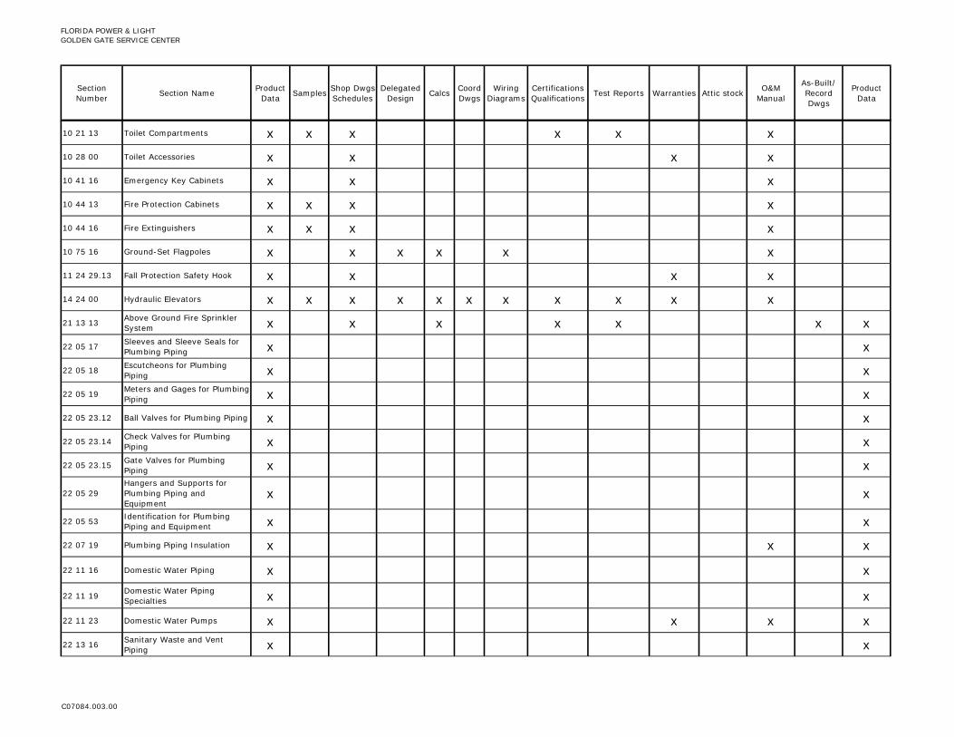
FLORIDA POWER & LIGHTGOLDEN GATE SERVICE CENTER
Section Number Section Name Product
Data Samples Shop Dwgs Schedules
Delegated Design Calcs Coord
DwgsWiring
DiagramsCertifications Qualifications Test Reports Warranties Attic stock O&M
Manual
As-Built/ Record Dwgs
Product Data
10 21 13 Toilet Compartments x x x x x x
10 28 00 Toilet Accessories x x x x
10 41 16 Emergency Key Cabinets x x x
10 44 13 Fire Protection Cabinets x x x x
10 44 16 Fire Extinguishers x x x x
10 75 16 Ground-Set Flagpoles x x x x x x
11 24 29.13 Fall Protection Safety Hook x x x x
14 24 00 Hydraulic Elevators x x x x x x x x x x x
21 13 13 Above Ground Fire Sprinkler System x x x x x x x
22 05 17 Sleeves and Sleeve Seals for Plumbing Piping x x
22 05 18 Escutcheons for Plumbing Piping x x
22 05 19 Meters and Gages for Plumbing Piping x x
22 05 23.12 Ball Valves for Plumbing Piping x x
22 05 23.14 Check Valves for Plumbing Piping x x
22 05 23.15 Gate Valves for Plumbing Piping x x
22 05 29Hangers and Supports for Plumbing Piping and Equipment
x x
22 05 53 Identification for Plumbing Piping and Equipment x x
22 07 19 Plumbing Piping Insulation x x x
22 11 16 Domestic Water Piping x x
22 11 19 Domestic Water Piping Specialties x x
22 11 23 Domestic Water Pumps x x x x
22 13 16 Sanitary Waste and Vent Piping x x
C07084.003.00

FLORIDA POWER & LIGHTGOLDEN GATE SERVICE CENTER
Section Number Section Name Product
Data Samples Shop Dwgs Schedules
Delegated Design Calcs Coord
DwgsWiring
DiagramsCertifications Qualifications Test Reports Warranties Attic stock O&M
Manual
As-Built/ Record Dwgs
Product Data
22 13 19 Sanitary Waste Piping Specialties x x
22 13 19.13 Sanitary Drains x x
22 33 00 Electric, Domestic-Water Heaters x x x x
22 42 13.13 Commercial Water Closets x x x x
22 42 13.16 Commercial Urinals x x x x
22 42 16.13 Commercial Lavatories x x x x
22 42 16.16 Commercial Sinks x x x x
22 42 23 Commercial Showers x x x x
23 05 00 Basic Mechanical Requirements x
23 05 13 Common Motor Requirements for HVAC Equipment x x x
23 05 17 Sleeves and Sleeve Seals for HVAC Piping x x x
23 05 19 Meters and Gages for HVAC Piping x x x x x
23 05 29 Hangers and Supports for HVAC Piping and Equipment x x
23 05 48Vibration and Seismic Controls for HVAC Piping and Equipment
x x
23 05 53 Identification for HVAC Piping and Equipment x x
23 05 93 Testing, Adjusting, and Balancing for HVAC x x x
23 07 13 Duct Insulation x x x
23 09 00 Instrumentation and Control for HVAC x x x x x
23 31 13 Metal Ducts x x
23 33 00 Air Duct Accessories x x x
23 34 23 HVAC Power Ventilators x x x x x
23 72 13 Air Handling Units with Coils x x x x x
C07084.003.00

FLORIDA POWER & LIGHTGOLDEN GATE SERVICE CENTER
Section Number Section Name Product
Data Samples Shop Dwgs Schedules
Delegated Design Calcs Coord
DwgsWiring
DiagramsCertifications Qualifications Test Reports Warranties Attic stock O&M
Manual
As-Built/ Record Dwgs
Product Data
23 72 13.13 Air Cooled Condensing Units x x x x x
23 72 14 Dedicated Outside Air System x x x x x
26 05 19 Low-Voltage Electrical Power Conductors and Cables x
26 05 26 Grounding and Bonding for Electrical Systems x x x x x x x
26 05 29 Hangers and Supports for Electrical Systems x
26 05 33 Raceways and Boxes for Electrical Systems x
26 05 43 Underground Ducts and Utility Structures x x x x
26 05 44Sleeves and Sleeve Seals for Electrical Raceways and Cabling
x x
26 05 53 Identification for Electrical Systems x x
26 05 73.13 Overcurrent Protective Device Short-Circuit Study x x x x
26 05 73.16 Overcurrent Protective Device Coordination Study x x x x
26 05 73.19 Overcurrent Protective Device Arc-Flash Study x x x x
26 09 23 Lighting Control Devices x x x x
26 22 00 Low-Voltage Transformers x x x x
26 24 16 Panelboards x x x x x
26 27 26 Wiring Devices x
26 28 13 Fuses x x
26 28 16 Enclosed Switches and Circuit Breakers x x x
26 29 23 Variable-Frequency Motor Controllers x x x x
26 32 13 Engine Generators x x x x x x
26 36 00 Transfer Switches x x x x x x
26 41 13 Lightning Protection for Structures x x x x x x
C07084.003.00

FLORIDA POWER & LIGHTGOLDEN GATE SERVICE CENTER
Section Number Section Name Product
Data Samples Shop Dwgs Schedules
Delegated Design Calcs Coord
DwgsWiring
DiagramsCertifications Qualifications Test Reports Warranties Attic stock O&M
Manual
As-Built/ Record Dwgs
Product Data
26 43 13Surge Protection for Low-Voltage Electrical Power Circuits
x x x x
26 51 19 LED Interior Lighting x x x x
26 52 19 Exit Lighting x x x x
26 56 13 Lighting Poles and Standards x x x x x x x
26 56 19 LED Exterior Lighting x x x x x x
27 05 26 Grounding and Bonding for Communication Systems x x x x x x
27 05 28 Pathways for Communication Systems x
27 05 36 Cable Trays for Communications Systems x x x x x x
27 05 44Sleeves and Sleeve Seals for Communications Pathways and Cabling
x x
28 31 11 Fire Alarm System x x x x x x x x x x
32 31 13.13 Interior Chain Link Fences and Gates x x x
**Note: Refer to Civil & Landscape Drawings for any submittal required for this portion of Work.**
C07084.003.00

FLORIDA POWER & LIGHT GOLDEN GATE SERVICE CENTER QUALITY REQUIREMENTS BRPH ARCHITECTS-ENGINEERS, INC.
C07084.003.00 01 40 00 - 1 07-01-16 Addendum No. 1, 08-05-16
SECTION 01 40 00 - QUALITY REQUIREMENTS
PART 1 - GENERAL
1.1 RELATED DOCUMENTS
A. Drawings and general provisions of the Contract, including General and Supplementary Conditions and other Division 01 Specification Sections, apply to this Section.
1.2 SUMMARY
A. Section includes administrative and procedural requirements for quality assurance and quality control.
B. Testing and inspecting services are required to verify compliance with requirements specified or indicated. These services do not relieve Contractor of responsibility for compliance with the Contract Document requirements.
1. Specific quality-assurance and quality-control requirements for individual construction activities are specified in the Sections that specify those activities. Requirements in those Sections may also cover production of standard products.
2. Specified tests, inspections, and related actions do not limit Contractor's other quality-assurance and quality-control procedures that facilitate compliance with the Contract Document requirements.
3. Requirements for Contractor to provide quality-assurance and -control services required by Architect, Owner or authorities having jurisdiction are not limited by provisions of this Section.
4. Specific test and inspection requirements are not specified in this Section.
C. DELETED
1.3 DEFINITIONS
A. Quality-Assurance Services: Activities, actions, and procedures performed before and during execution of the Work to guard against defects and deficiencies, and substantiate that proposed construction will comply with requirements.
B. Quality-Control Services: Tests, inspections, procedures and related actions during and after execution of the Work to evaluate that actual products incorporated into the Work and completed construction comply with requirements. Services do not include contract enforcement activities performed by Architect.
C. Mockups: Full-size physical assemblies that are constructed on-site. Mockups are constructed to verify selections made under Sample submittals; to demonstrate aesthetic effects and, where indicated, qualities of materials and execution; to
FLORIDA POWER & LIGHT GOLDEN GATE SERVICE CENTER QUALITY REQUIREMENTS BRPH ARCHITECTS-ENGINEERS, INC.
C07084.003.00 01 40 00 - 2 07-01-16 Addendum No. 1, 08-05-16
review coordination, testing, or operation; to show interface between dissimilar materials; and to demonstrate compliance with specified installation tolerances. Mockups are not Samples. Unless otherwise indicated, approved mockups establish the standard by which the Work will be judged.
1. Integrated Exterior Mockups: Mockups of the exterior envelope erected separately from the building but on Project site, consisting of multiple products, assemblies, and subassemblies.
D. Preconstruction Testing: Tests and inspections performed specifically for Project before products and materials are incorporated into the Work, to verify performance or compliance with specified criteria.
E. Product Testing: Tests and inspections that are performed by an NRTL, an NVLAP, or a testing agency qualified to conduct product testing and acceptable to authorities having jurisdiction, to establish product performance and compliance with specified requirements.
F. Source Quality-Control Testing: Tests and inspections that are performed at the source, e.g., plant, mill, factory, or shop.
G. Field Quality-Control Testing: Tests and inspections that are performed on-site for installation of the Work and for completed Work.
H. Testing Agency: An entity engaged to perform specific tests, inspections, or both. Testing laboratory shall mean the same as testing agency.
I. Installer/Applicator/Erector: Contractor or another entity engaged by Contractor as an employee, Subcontractor, or Sub-subcontractor, to perform a particular construction operation, including installation, erection, application, and similar operations.
1. Use of trade-specific terminology in referring to a trade or entity does not require that certain construction activities be performed by accredited or unionized individuals, or that requirements specified apply exclusively to specific trade(s).
J. Experienced: When used with an entity or individual, "experienced" means having successfully completed a minimum of five previous projects similar in nature, size and extent to this Project; being familiar with special requirements indicated; and having complied with requirements of authorities having jurisdiction.

FLORIDA POWER & LIGHT GOLDEN GATE SERVICE CENTER QUALITY REQUIREMENTS BRPH ARCHITECTS-ENGINEERS, INC.
C07084.003.00 01 40 00 - 3 07-01-16 Addendum No. 1, 08-05-16
1.4 CONFLICTING REQUIREMENTS
A. Referenced Standards: If compliance with two or more standards is specified and the standards establish different or conflicting requirements for minimum quantities or quality levels, comply with the most stringent requirement. Refer conflicting requirements that are different, but apparently equal, to Architect for a decision before proceeding.
B. Minimum Quantity or Quality Levels: The quantity or quality level shown or specified shall be the minimum provided or performed. The actual installation may comply exactly with the minimum quantity or quality specified, or it may exceed the minimum within reasonable limits. To comply with these requirements, indicated numeric values are minimum or maximum, as appropriate, for the context of requirements. Refer uncertainties to Architect for a decision before proceeding.
1.5 ACTION SUBMITTALS
A. Shop Drawings: For integrated exterior and laboratory mockups, provide plans, sections and elevations, indicating materials and size of mockup construction.
1. Indicate manufacturer and model number of individual components. 2. Provide axonometric drawings for conditions difficult to illustrate in two
dimensions.
1.6 INFORMATIONAL SUBMITTALS
A. Contractor's Quality-Control Plan: For quality-assurance and quality-control activities and responsibilities.
B. Qualification Data: For Contractor's quality-control personnel.
C. Contractor's Statement of Responsibility: When required by authorities having jurisdiction, submit copy of written statement of responsibility sent to authorities having jurisdiction before starting work on the following systems:
1. Main wind-force-resisting system or a wind-resisting component.
D. Testing Agency Qualifications: For testing agencies specified in "Quality Assurance" Article to demonstrate their capabilities and experience. Include proof of qualifications in the form of a recent report on the inspection of the testing agency by a recognized authority.
E. Schedule of Tests and Inspections: Prepare in tabular form and include the following:
1. Specification Section number and title. 2. Entity responsible for performing tests and inspections. 3. Description of test and inspection. 4. Identification of applicable standards. 5. Identification of test and inspection methods.
FLORIDA POWER & LIGHT GOLDEN GATE SERVICE CENTER QUALITY REQUIREMENTS BRPH ARCHITECTS-ENGINEERS, INC.
C07084.003.00 01 40 00 - 4 07-01-16 Addendum No. 1, 08-05-16
6. Number of tests and inspections required. 7. Time schedule or time span for tests and inspections. 8. Requirements for obtaining samples. 9. Unique characteristics of each quality-control service.
1.7 CONTRACTOR'S QUALITY-CONTROL PLAN
A. Quality-Control Plan, General: Submit quality-control plan within 10 days of Notice to Proceed, and not less than five days prior to preconstruction conference. Submit in format acceptable to Architect. Identify personnel, procedures, controls, instructions, tests, records, and forms to be used to carry out Contractor's quality-assurance and quality-control responsibilities. Coordinate with Contractor's construction schedule.
B. Quality-Control Personnel Qualifications: Engage qualified full-time personnel trained and experienced in managing and executing quality-assurance and quality-control procedures similar in nature and extent to those required for Project.
1. Project quality-control manager may also serve as Project superintendent.
C. Procedure: Describe procedures for ensuring compliance with requirements through review and management of submittal process. Indicate qualifications of personnel responsible for submittal review.
D. Testing and Inspection: In quality-control plan, include a comprehensive schedule of Work requiring testing or inspection, including the following:
1. Contractor-performed tests and inspections including subcontractor-performed tests and inspections. Include required tests and inspections and Contractor-elected tests and inspections.
2. Special inspections required by authorities having jurisdiction and indicated on the "Statement of Special Inspections."
3. Owner-performed tests and inspections indicated in the Contract Documents, including any tests and/or inspections indicated to be performed by a Commissioning Authority.
E. Continuous Inspection of Workmanship: Describe process for continuous inspection during construction to identify and correct deficiencies in workmanship in addition to testing and inspection specified. Indicate types of corrective actions to be required to bring work into compliance with standards of workmanship established by Contract requirements and approved mockups.
F. Monitoring and Documentation: Maintain testing and inspection reports including log of approved and rejected results. Include work Architect has indicated as nonconforming or defective. Indicate corrective actions taken to bring nonconforming work into compliance with requirements. Comply with requirements of authorities having jurisdiction.

FLORIDA POWER & LIGHT GOLDEN GATE SERVICE CENTER QUALITY REQUIREMENTS BRPH ARCHITECTS-ENGINEERS, INC.
C07084.003.00 01 40 00 - 5 07-01-16 Addendum No. 1, 08-05-16
1.8 REPORTS AND DOCUMENTS
A. Test and Inspection Reports: Prepare and submit certified written reports specified in other Sections. Include the following:
1. Date of issue. 2. Project title and number. 3. Name, address, and telephone number of testing agency. 4. Dates and locations of samples and tests or inspections. 5. Names of individuals making tests and inspections. 6. Description of the Work and test and inspection method. 7. Identification of product and Specification Section. 8. Complete test or inspection data. 9. Test and inspection results and an interpretation of test results. 10. Record of temperature and weather conditions at time of sample taking and
testing and inspecting. 11. Comments or professional opinion on whether tested or inspected Work
complies with the Contract Document requirements. 12. Name and signature of laboratory inspector. 13. Recommendations on retesting and re-inspecting.
B. Manufacturer's Technical Representative's Field Reports: Prepare written information documenting manufacturer's technical representative's tests and inspections specified in other Sections. Include the following:
1. Name, address, and telephone number of technical representative making report.
2. Statement on condition of substrates and their acceptability for installation of product.
3. Statement that products at Project site comply with requirements. 4. Summary of installation procedures being followed, whether they comply with
requirements and, if not, what corrective action was taken. 5. Results of operational and other tests and a statement of whether observed
performance complies with requirements. 6. Statement whether conditions, products, and installation will affect warranty. 7. Other required items indicated in individual Specification Sections.
C. Factory-Authorized Service Representative's Reports: Prepare written information documenting manufacturer's factory-authorized service representative's tests and inspections specified in other Sections. Include the following:
1. Name, address, and telephone number of factory-authorized service representative making report.
2. Statement that equipment complies with requirements. 3. Results of operational and other tests and a statement of whether observed
performance complies with requirements. 4. Statement whether conditions, products, and installation will affect warranty. 5. Other required items indicated in individual Specification Sections.
FLORIDA POWER & LIGHT GOLDEN GATE SERVICE CENTER QUALITY REQUIREMENTS BRPH ARCHITECTS-ENGINEERS, INC.
C07084.003.00 01 40 00 - 6 07-01-16 Addendum No. 1, 08-05-16
D. Permits, Licenses, and Certificates: For Owner's records, submit copies of permits, licenses, certifications, inspection reports, releases, jurisdictional settlements, notices, receipts for fee payments, judgments, correspondence, records and similar documents, established for compliance with standards and regulations bearing on performance of the Work.
1.9 QUALITY ASSURANCE
A. General: Qualifications paragraphs in this article establish the minimum qualification levels required; individual Specification Sections specify additional requirements.
B. Manufacturer Qualifications: A firm experienced in manufacturing products or systems similar to those indicated for this Project and with a record of successful in-service performance, as well as sufficient production capacity to produce required units.
C. Fabricator Qualifications: A firm experienced in producing products similar to those indicated for this Project and with a record of successful in-service performance, as well as sufficient production capacity to produce required units.
D. Installer Qualifications: A firm or individual experienced in installing, erecting, or assembling work similar in material, design, and extent to that indicated for this Project, whose work has resulted in construction with a record of successful in-service performance.
E. Professional Engineer Qualifications: A professional engineer who is legally qualified to practice in jurisdiction where Project is located and who is experienced in providing engineering services of the kind indicated. Engineering services are defined as those performed for installations of the system, assembly, or products that are similar in material, design, and extent to those indicated for this Project.
F. Specialists: Certain Specification Sections require that specific construction activities shall be performed by entities who are recognized experts in those operations. Specialists shall satisfy qualification requirements indicated and shall be engaged for the activities indicated.
1. Requirements of authorities having jurisdiction shall supersede requirements for specialists.
G. Testing Agency Qualifications: An NRTL, an NVLAP, or an independent agency with the experience and capability to conduct testing and inspecting indicated, as documented according to ASTM E 329; and with additional qualifications specified in individual Sections; and, where required by authorities having jurisdiction, that is acceptable to authorities.
1. NRTL: A nationally recognized testing laboratory according to 29 CFR 1910.7. 2. NVLAP: A testing agency accredited according to NIST's National Voluntary
Laboratory Accreditation Program.

FLORIDA POWER & LIGHT GOLDEN GATE SERVICE CENTER QUALITY REQUIREMENTS BRPH ARCHITECTS-ENGINEERS, INC.
C07084.003.00 01 40 00 - 7 07-01-16 Addendum No. 1, 08-05-16
H. Manufacturer's Technical Representative Qualifications: An authorized representative of manufacturer who is trained and approved by manufacturer to observe and inspect installation of manufacturer's products that are similar in material, design, and extent to those indicated for this Project.
I. Factory-Authorized Service Representative Qualifications: An authorized representative of manufacturer who is trained and approved by manufacturer to inspect installation of manufacturer's products that are similar in material, design, and extent to those indicated for this Project.
J. Preconstruction Testing: Where testing agency is indicated to perform preconstruction testing for compliance with specified requirements for performance and test methods, comply with the following:
1. Contractor responsibilities include the following:
a. Provide test specimens representative of proposed products and construction.
b. Submit specimens in a timely manner with sufficient time for testing and analyzing results to prevent delaying the Work.
c. Provide sizes and configurations of test assemblies, mockups, and laboratory mockups to adequately demonstrate capability of products to comply with performance requirements.
d. Build site-assembled test assemblies and mockups using installers who will perform same tasks for Project.
e. Build laboratory mockups at testing facility using personnel, products, and methods of construction indicated for the completed Work.
f. When testing is complete, remove test specimens, assemblies, and mockups; do not reuse products on Project.
2. Testing Agency Responsibilities: Submit a certified written report of each test, inspection, and similar quality-assurance service to Architect, with copy to Contractor. Interpret tests and inspections and state in each report whether tested and inspected work complies with or deviates from the Contract Documents.
K. Mockups: Before installing portions of the Work requiring mockups, build mockups for each form of construction and finish required to comply with the following requirements, using materials indicated for the completed Work:
1. Build mockups in location and of size indicated or, if not indicated, as directed by Architect.
2. Notify Architect seven days in advance of dates and times when mockups will be constructed.
3. Employ supervisory personnel who will oversee mockup construction. Employ workers that will be employed during the construction at Project.
4. Demonstrate the proposed range of aesthetic effects and workmanship. 5. Obtain Architect's approval of mockups before starting work, fabrication, or
construction.
a. Allow seven days for initial review and each re-review of each mockup.

FLORIDA POWER & LIGHT GOLDEN GATE SERVICE CENTER QUALITY REQUIREMENTS BRPH ARCHITECTS-ENGINEERS, INC.
C07084.003.00 01 40 00 - 8 07-01-16 Addendum No. 1, 08-05-16
6. Maintain mockups during construction in an undisturbed condition as a standard for judging the completed Work.
7. Demolish and remove mockups when directed unless otherwise indicated.
L. Integrated Exterior Mockups: Construct integrated exterior mockup according to approved Shop Drawings. Coordinate installation of exterior envelope materials and products for which mockups are required in individual Specification Sections, along with supporting materials.
1.10 QUALITY CONTROL
A. Owner Responsibilities: Where quality-control services are indicated as Owner's responsibility, Owner will engage a qualified testing agency to perform these services.
1. Contractor is responsible for engaging the testing agency and shall include costs in their proposal to perform all applicable testing.
B. Contractor Responsibilities: Tests and inspections are Contractor's responsibility. Perform additional quality-control activities required to verify that the Work complies with requirements, whether specified or not.
1. Unless otherwise indicated, provide quality-control services specified and those required by authorities having jurisdiction. Perform quality-control services required of Contractor by authorities having jurisdiction, whether specified or not.
2. Where services are indicated as Contractor's responsibility, engage a qualified testing agency to perform these quality-control services.
3. Notify testing agencies at least 24 hours in advance of time when Work that requires testing or inspecting will be performed.
4. Where quality-control services are indicated as Contractor's responsibility, submit a certified written report, in duplicate, of each quality-control service.
5. Testing and inspecting requested by Contractor and not required by the Contract Documents are Contractor's responsibility.
6. Submit additional copies of each written report directly to authorities having jurisdiction, when they so direct.
C. Manufacturer's Field Services: Where indicated, engage a factory-authorized service representative to inspect field-assembled components and equipment installation, including service connections. Report results in writing as specified in Section 01 33 00 "Submittal Procedures."
D. Manufacturer's Technical Services: Where indicated, engage a manufacturer's technical representative to observe and inspect the Work. Manufacturer's technical representative's services include participation in pre-installation conferences, examination of substrates and conditions, verification of materials, observation of Installer activities, inspection of completed portions of the Work, and submittal of written reports.

FLORIDA POWER & LIGHT GOLDEN GATE SERVICE CENTER QUALITY REQUIREMENTS BRPH ARCHITECTS-ENGINEERS, INC.
C07084.003.00 01 40 00 - 9 07-01-16 Addendum No. 1, 08-05-16
E. Retesting/Re-inspecting: Regardless of whether original tests or inspections were Contractor's responsibility, provide quality-control services, including retesting and re-inspecting, for construction that replaced Work that failed to comply with the Contract Documents.
F. Testing Agency Responsibilities: Cooperate with Architect and Contractor in performance of duties. Provide qualified personnel to perform required tests and inspections.
1. Notify Architect and Contractor promptly of irregularities or deficiencies observed in the Work during performance of its services.
2. Determine the location from which test samples will be taken and in which in-situ tests are conducted.
3. Conduct and interpret tests and inspections and state in each report whether tested and inspected work complies with or deviates from requirements.
4. Submit a certified written report, in duplicate, of each test, inspection, and similar quality-control service through Contractor.
5. Do not release, revoke, alter or increase the Contract Document requirements or approve or accept any portion of the Work.
6. Do not perform any duties of Contractor.
G. Associated Services: Cooperate with agencies performing required tests, inspections, and similar quality-control services, and provide reasonable auxiliary services as requested. Notify agency sufficiently in advance of operations to permit assignment of personnel. Provide the following:
1. Access to the Work. 2. Incidental labor and facilities necessary to facilitate tests and inspections. 3. Adequate quantities of representative samples of materials that require
testing and inspecting. Assist agency in obtaining samples. 4. Facilities for storage and field curing of test samples. 5. Delivery of samples to testing agencies. 6. Preliminary design mix proposed for use for material mixes that require
control by testing agency. 7. Security and protection for samples and for testing and inspecting equipment
at Project site.
H. Coordination: Coordinate sequence of activities to accommodate required quality-assurance and -control services with a minimum of delay and to avoid necessity of removing and replacing construction to accommodate testing and inspecting.
1. Schedule times for tests, inspections, obtaining samples, and similar activities.
I. Schedule of Tests and Inspections: Prepare a schedule of tests, inspections, and similar quality-control services required by the Contract Documents as a component of Contractor's quality-control plan. Coordinate and submit concurrently with Contractor's construction schedule. Update as the Work progresses.
1. Distribution: Distribute schedule to Owner, Architect, testing agencies, and each party involved in performance of portions of the Work where tests and inspections are required.

FLORIDA POWER & LIGHT GOLDEN GATE SERVICE CENTER QUALITY REQUIREMENTS BRPH ARCHITECTS-ENGINEERS, INC.
C07084.003.00 01 40 00 - 10 07-01-16 Addendum No. 1, 08-05-16
1.11 SPECIAL INSPECTIONS
A. Refer to Section 01 05 60 “Special Inspections” for requirements.
1.12 SPECIAL TESTS AND INSPECTIONS
A. Special Tests and Inspections: Owner will engage a qualified testing agency and/or special inspector to conduct special tests and inspections required by authorities having jurisdiction as the responsibility of Owner, and as follows:
1. Verifying that manufacturer maintains detailed fabrication and quality-control procedures and reviews the completeness and adequacy of those procedures to perform the Work.
2. Notifying Architect and Contractor promptly of irregularities and deficiencies observed in the Work during performance of its services.
3. Submitting a certified written report of each test, inspection, and similar quality-control service to Architect with copy to Contractor and to authorities having jurisdiction.
4. Submitting a final report of special tests and inspections at Provisional Acceptance (per the Owner’s Contract), which includes a list of unresolved deficiencies.
5. Interpreting tests and inspections and stating in each report whether tested and inspected work complies with or deviates from the Contract Documents.
6. Retesting and re-inspecting corrected work.
PART 2 - PRODUCTS (Not Used)
PART 3 - EXECUTION
3.1 ACCEPTABLE TESTING AGENCIES
A. To be submitted by Contractor for review and approval by Owner’s Representative and Architect.
3.2 TEST AND INSPECTION LOG
A. Test and Inspection Log: Prepare a record of tests and inspections. Include the following:
1. Date test or inspection was conducted. 2. Description of the Work tested or inspected. 3. Date test or inspection results were transmitted to Architect. 4. Identification of testing agency or special inspector conducting test or
inspection.

FLORIDA POWER & LIGHT GOLDEN GATE SERVICE CENTER QUALITY REQUIREMENTS BRPH ARCHITECTS-ENGINEERS, INC.
C07084.003.00 01 40 00 - 11 07-01-16 Addendum No. 1, 08-05-16
B. Maintain log at Project site. Post changes and revisions as they occur. Provide access to test and inspection log for Architect's reference during normal working hours.
3.3 REPAIR AND PROTECTION
A. General: On completion of testing, inspecting, sample taking, and similar services, repair damaged construction and restore substrates and finishes.
1. Provide materials and comply with installation requirements specified in other Specification Sections or matching existing substrates and finishes. Restore patched areas and extend restoration into adjoining areas with durable seams that are as invisible as possible. Comply with the Contract Document requirements for cutting and patching in Section 01 73 00 "Execution."
B. Protect construction exposed by or for quality-control service activities.
C. Repair and protection are Contractor's responsibility, regardless of the assignment of responsibility for quality-control services.
END OF SECTION 01 40 00

THIS PAGE INTENTIONALLY LEFT BLANK
FLORIDA POWER & LIGHT GOLDEN GATE SERVICE CENTER PRODUCT REQUIREMENTS BRPH ARCHITECTS-ENGINEERS, INC.
C07084.003.00 01 60 00 - 1 07-01-16 Addendum No. 1, 08-05-16
SECTION 01 60 00 - PRODUCT REQUIREMENTS
PART 1 - GENERAL
1.1 RELATED DOCUMENTS
A. Drawings and general provisions of the Contract, including General and Supplementary Conditions and other Division 01 Specification Sections, apply to this Section.
1.2 SUMMARY
A. Section includes administrative and procedural requirements for selection of products for use in Project; product delivery, storage, and handling; manufacturers' standard warranties on products; special warranties; and comparable products.
B. Related Requirements:
1. DELETED 2. DELETED 3. Section 01 25 00 "Substitution Procedures" for requests for substitutions. 4. Section 01 42 00 "References" for applicable industry standards for products
specified.
1.3 DEFINITIONS
A. Products: Items obtained for incorporating into the Work, whether purchased for Project or taken from previously purchased stock. The term "product" includes the terms "material," "equipment," "system," and terms of similar intent.
1. Named Products: Items identified by manufacturer's product name, including make or model number or other designation shown or listed in manufacturer's published product literature, that is current as of date of the Contract Documents.
2. New Products: Items that have not previously been incorporated into another project or facility. Products salvaged or recycled from other projects are not considered new products.
3. Comparable Product: Product that is demonstrated and approved through submittal process to have the indicated qualities related to type, function, dimension, in-service performance, physical properties, appearance, and other characteristics that equal or exceed those of specified product.
B. Basis-of-Design Product Specification: A specification in which a specific manufacturer's product is named and accompanied by the words "basis-of-design product," including make or model number or other designation, to establish the significant qualities related to type, function, dimension, in-service performance, physical properties, appearance, and other characteristics for purposes of evaluating comparable products of additional manufacturers named in the specification.

FLORIDA POWER & LIGHT GOLDEN GATE SERVICE CENTER PRODUCT REQUIREMENTS BRPH ARCHITECTS-ENGINEERS, INC.
C07084.003.00 01 60 00 - 2 07-01-16 Addendum No. 1, 08-05-16
1.4 ACTION SUBMITTALS
A. Comparable Product Requests: Submit request for consideration of each comparable product. Identify product or fabrication or installation method to be replaced. Include Specification Section number and title and Drawing numbers and titles.
1. Include data to indicate compliance with the requirements specified in "Comparable Products" Article.
2. Architect's Action: If necessary, Architect will request additional information or documentation for evaluation within one week of receipt of a comparable product request. Architect will notify Owner’s Representative of approval or rejection of proposed comparable product request within 15 days of receipt of request, or seven days of receipt of additional information or documentation, whichever is later.
a. Form of Approval: As specified in Section 01 33 00 "Submittal Procedures."
b. Use product specified if Architect does not issue a decision on use of a comparable product request within time allocated.
B. Basis-of-Design Product Specification Submittal: Comply with requirements in Section 01 33 00 "Submittal Procedures." Show compliance with requirements.
1.5 QUALITY ASSURANCE
A. Compatibility of Options: If Contractor is given option of selecting between two or more products for use on Project, select product compatible with products previously selected, even if previously selected products were also options.
1. Each contractor is responsible for providing products and construction methods compatible with products and construction methods of other contractors.
2. If a dispute arises between contractors over concurrently selectable but incompatible products, Architect will determine which products shall be used.
1.6 PRODUCT DELIVERY, STORAGE, AND HANDLING
A. Deliver, store, and handle products using means and methods that will prevent damage, deterioration, and loss, including theft and vandalism. Comply with manufacturer's written instructions.
B. Delivery and Handling:
1. Schedule delivery to minimize long-term storage at Project site and to prevent overcrowding of construction spaces.
2. Coordinate delivery with installation time to ensure minimum holding time for items that are flammable, hazardous, easily damaged, or sensitive to deterioration, theft, and other losses.

FLORIDA POWER & LIGHT GOLDEN GATE SERVICE CENTER PRODUCT REQUIREMENTS BRPH ARCHITECTS-ENGINEERS, INC.
C07084.003.00 01 60 00 - 3 07-01-16 Addendum No. 1, 08-05-16
3. Deliver products to Project site in an undamaged condition in manufacturer's original sealed container or other packaging system, complete with labels and instructions for handling, storing, unpacking, protecting, and installing.
4. Inspect products on delivery to determine compliance with the Contract Documents and to determine that products are undamaged and properly protected.
C. Storage:
1. Store products to allow for inspection and measurement of quantity or counting of units.
2. Store materials in a manner that will not endanger Project structure. 3. Store products that are subject to damage by the elements, under cover in a
weathertight enclosure above ground, with ventilation adequate to prevent condensation.
4. Protect foam plastic from exposure to sunlight, except to extent necessary for period of installation and concealment.
5. Comply with product manufacturer's written instructions for temperature, humidity, ventilation, and weather-protection requirements for storage.
6. Protect stored products from damage and liquids from freezing. 7. Provide a secure location and enclosure at Project site for storage of materials
and equipment by Owner's construction forces. Coordinate location with Owner.
1.7 PRODUCT WARRANTIES
A. Warranties specified in other Sections shall be in addition to, and run concurrent with, other warranties required by the Contract Documents. Manufacturer's disclaimers and limitations on product warranties do not relieve Contractor of obligations under requirements of the Contract Documents.
1. Manufacturer's Warranty: Written warranty furnished by individual manufacturer for a particular product and specifically endorsed by manufacturer to Owner.
2. Special Warranty: Written warranty required by the Contract Documents to provide specific rights for Owner.
B. Special Warranties: Prepare a written document that contains appropriate terms and identification, ready for execution.
1. Manufacturer's Standard Form: Modified to include Project-specific information and properly executed.
2. Specified Form: When specified forms are included with the Specifications, prepare a written document using indicated form properly executed.
3. See other Sections for specific content requirements and particular requirements for submitting special warranties.
C. Submittal Time: Comply with requirements in Section 01 77 00 "Closeout Procedures."

FLORIDA POWER & LIGHT GOLDEN GATE SERVICE CENTER PRODUCT REQUIREMENTS BRPH ARCHITECTS-ENGINEERS, INC.
C07084.003.00 01 60 00 - 4 07-01-16 Addendum No. 1, 08-05-16
PART 2 - PRODUCTS
2.1 PRODUCT SELECTION PROCEDURES
A. General Product Requirements: Provide products that comply with the Contract Documents, are undamaged and, unless otherwise indicated, are new at time of installation.
1. Provide products complete with accessories, trim, finish, fasteners, and other items needed for a complete installation and indicated use and effect.
2. Standard Products: If available, and unless custom products or nonstandard options are specified, provide standard products of types that have been produced and used successfully in similar situations on other projects.
3. Owner reserves the right to limit selection to products with warranties not in conflict with requirements of the Contract Documents.
4. Where products are accompanied by the term "as selected," Architect will make selection.
5. Descriptive, performance, and reference standard requirements in the Specifications establish salient characteristics of products.
6. Or Equal: For products specified by name and accompanied by the term "or equal," or "or approved equal," or "or approved," comply with requirements in "Comparable Products" Article to obtain approval for use of an unnamed product.
B. Product Selection Procedures:
1. Product: Where Specifications name a single manufacturer and product, provide the named product that complies with requirements. Comparable products or substitutions for Contractor's convenience will not be considered.
2. Manufacturer/Source: Where Specifications name a single manufacturer or source, provide a product by the named manufacturer or source that complies with requirements. Comparable products or substitutions for Contractor's convenience will not be considered.
3. Products:
a. Restricted List: Where Specifications include a list of names of both manufacturers and products, provide one of the products listed that complies with requirements. Comparable products or substitutions for Contractor's convenience will not be considered.
b. Nonrestricted List: Where Specifications include a list of names of both available manufacturers and products, provide one of the products listed, or an unnamed product, that complies with requirements. Comply with requirements in "Comparable Products" Article for consideration of an unnamed product.
4. Manufacturers:
a. Restricted List: Where Specifications include a list of manufacturers' names, provide a product by one of the manufacturers listed that complies with requirements. Comparable products or substitutions for Contractor's convenience will not be considered.

FLORIDA POWER & LIGHT GOLDEN GATE SERVICE CENTER PRODUCT REQUIREMENTS BRPH ARCHITECTS-ENGINEERS, INC.
C07084.003.00 01 60 00 - 5 07-01-16 Addendum No. 1, 08-05-16
b. Nonrestricted List: Where Specifications include a list of available manufacturers, provide a product by one of the manufacturers listed, or a product by an unnamed manufacturer, that complies with requirements. Comply with requirements in "Comparable Products" Article for consideration of an unnamed manufacturer's product.
5. Basis-of-Design Product: Where Specifications name a product, or refer to a product indicated on Drawings, and include a list of manufacturers, provide the specified or indicated product or a comparable product by one of the other named manufacturers. Drawings and Specifications indicate sizes, profiles, dimensions, and other characteristics that are based on the product named. Comply with requirements in "Comparable Products" Article for consideration of an unnamed product by one of the other named manufacturers.
C. Visual Matching Specification: Where Specifications require "match Architect's sample", provide a product that complies with requirements and matches Architect's sample. Architect's decision will be final on whether a proposed product matches.
1. If no product available within specified category matches and complies with other specified requirements, comply with requirements in Section 01 25 00 "Substitution Procedures" for proposal of product.
D. Visual Selection Specification: Where Specifications include the phrase "as selected by Architect from manufacturer's full range" or similar phrase, select a product that complies with requirements. Architect will select color, gloss, pattern, density, or texture from manufacturer's product line that includes both standard and premium items.
2.2 COMPARABLE PRODUCTS
A. Conditions for Consideration: Architect will consider Contractor's request for comparable product when the following conditions are satisfied. If the following conditions are not satisfied, Architect may return requests without action, except to record noncompliance with these requirements:
1. Evidence that the proposed product does not require revisions to the Contract Documents, that it is consistent with the Contract Documents and will produce the indicated results, and that it is compatible with other portions of the Work.
2. Detailed comparison of significant qualities of proposed product with those named in the Specifications. Significant qualities include attributes such as performance, weight, size, durability, visual effect, and specific features and requirements indicated.
3. Evidence that proposed product provides specified warranty. 4. List of similar installations for completed projects with project names and
addresses and names and addresses of architects and owners, if requested. 5. Samples, if requested.

FLORIDA POWER & LIGHT GOLDEN GATE SERVICE CENTER PRODUCT REQUIREMENTS BRPH ARCHITECTS-ENGINEERS, INC.
C07084.003.00 01 60 00 - 6 07-01-16 Addendum No. 1, 08-05-16
PART 3 - EXECUTION (Not Used)
END OF SECTION 01 60 00

FLORIDA POWER & LIGHT GOLDEN GATE SERVICE CENTER EXECUTION BRPH ARCHITECTS-ENGINEERS, INC.
C07084.003.00 01 73 00 - 1 07-01-16 Addendum No. 1, 08-05-16
SECTION 01 73 00 - EXECUTION
PART 1 - GENERAL
1.1 RELATED DOCUMENTS
A. Drawings and general provisions of the Contract, including General and Supplementary Conditions and other Division 01 Specification Sections, apply to this Section.
1.2 SUMMARY
A. Section includes general administrative and procedural requirements governing execution of the Work including, but not limited to, the following:
1. Construction layout. 2. Field engineering and surveying. 3. Installation of the Work. 4. Cutting and patching. 5. Coordination of Owner-installed products. 6. Progress cleaning. 7. Starting and adjusting. 8. Protection of installed construction.
B. Related Requirements:
1. Section 01 10 00 "Summary" for limits on use of Project site. 2. Section 01 33 00 "Submittal Procedures" for submitting surveys. 3. Section 01 77 00 "Closeout Procedures" for submitting final property survey
with Project Record Documents, recording of Owner-accepted deviations from indicated lines and levels, and final cleaning.
4. DELETED 5. Section 07 84 13 "Penetration Firestopping" for patching penetrations in fire-
rated construction.
1.3 DEFINITIONS
A. Cutting: Removal of in-place construction necessary to permit installation or performance of other work.
B. Patching: Fitting and repair work required to restore construction to original conditions after installation of other work.
1.4 INFORMATIONAL SUBMITTALS
A. Qualification Data: For land surveyor and/or professional engineer.

FLORIDA POWER & LIGHT GOLDEN GATE SERVICE CENTER EXECUTION BRPH ARCHITECTS-ENGINEERS, INC.
C07084.003.00 01 73 00 - 2 07-01-16 Addendum No. 1, 08-05-16
B. Certificates: Submit certificate signed by land surveyor and/or professional engineer certifying that location and elevation of improvements comply with requirements.
C. Cutting and Patching Plan: Submit plan describing procedures at least 10 days prior to the time cutting and patching will be performed. Include the following information:
1. Extent: Describe reason for and extent of each occurrence of cutting and patching.
2. Changes to In-Place Construction: Describe anticipated results. Include changes to structural elements and operating components as well as changes in building appearance and other significant visual elements.
3. Products: List products to be used for patching and firms or entities that will perform patching work.
4. Dates: Indicate when cutting and patching will be performed. 5. Utilities and Mechanical and Electrical Systems: List services and systems that
cutting and patching procedures will disturb or affect. List services and systems that will be relocated and those that will be temporarily out of service. Indicate length of time permanent services and systems will be disrupted.
a. Include description of provisions for temporary services and systems during interruption of permanent services and systems.
D. Landfill Receipts: Submit copy of receipts issued by a landfill facility, licensed to accept hazardous materials, for hazardous waste disposal.
E. Certified Surveys: Submit two copies signed by land surveyor and/or professional engineer.
F. Final Property Survey: Submit 10 copies showing the Work performed and record survey data.
1.5 QUALITY ASSURANCE
A. Land Surveyor Qualifications: A professional land surveyor who is legally qualified to practice in jurisdiction where Project is located and who is experienced in providing land-surveying services of the kind indicated.
B. Cutting and Patching: Comply with requirements for and limitations on cutting and patching of construction elements.
1. Structural Elements: When cutting and patching structural elements, notify Architect of locations and details of cutting and await directions from Architect before proceeding. Shore, brace, and support structural elements during cutting and patching. Do not cut and patch structural elements in a manner that could change their load-carrying capacity or increase deflection

FLORIDA POWER & LIGHT GOLDEN GATE SERVICE CENTER EXECUTION BRPH ARCHITECTS-ENGINEERS, INC.
C07084.003.00 01 73 00 - 3 07-01-16 Addendum No. 1, 08-05-16
2. Operational Elements: Do not cut and patch operating elements and related components in a manner that results in reducing their capacity to perform as intended or that results in increased maintenance or decreased operational life or safety. Operational elements include the following:
a. Primary operational systems and equipment. b. Fire separation assemblies. c. Air or smoke barriers. d. Fire-suppression systems. e. Mechanical systems piping and ducts. f. Control systems. g. Communication systems. h. Fire-detection and -alarm systems. i. Conveying systems. j. Electrical wiring systems. k. Operating systems of special construction.
3. Other Construction Elements: Do not cut and patch other construction elements or components in a manner that could change their load-carrying capacity, that results in reducing their capacity to perform as intended, or that results in increased maintenance or decreased operational life or safety. Other construction elements include but are not limited to the following:
a. Water, moisture, or vapor barriers. b. Membranes and flashings. c. Exterior curtain-wall construction. d. Sprayed fire-resistive material. e. Equipment supports. f. Piping, ductwork, vessels, and equipment. g. Noise- and vibration-control elements and systems.
4. Visual Elements: Do not cut and patch construction in a manner that results in visual evidence of cutting and patching. Do not cut and patch exposed construction in a manner that would, in Architect's opinion, reduce the building's aesthetic qualities. Remove and replace construction that has been cut and patched in a visually unsatisfactory manner.
C. Cutting and Patching Conference: Before proceeding, meet at Project site with parties involved in cutting and patching, including mechanical and electrical trades. Review areas of potential interference and conflict. Coordinate procedures and resolve potential conflicts before proceeding.
D. Manufacturer's Installation Instructions: Obtain and maintain on-site manufacturer's written recommendations and instructions for installation of products and equipment.

FLORIDA POWER & LIGHT GOLDEN GATE SERVICE CENTER EXECUTION BRPH ARCHITECTS-ENGINEERS, INC.
C07084.003.00 01 73 00 - 4 07-01-16 Addendum No. 1, 08-05-16
PART 2 - PRODUCTS
2.1 MATERIALS
A. General: Comply with requirements specified in other Sections.
1. For projects requiring compliance with sustainable design and construction practices and procedures, use products for patching that comply with sustainable design requirements.
B. In-Place Materials: Use materials for patching identical to in-place materials. For exposed surfaces, use materials that visually match in-place adjacent surfaces to the fullest extent possible.
1. If identical materials are unavailable or cannot be used, use materials that, when installed, will provide a match acceptable to Architect for the visual and functional performance of in-place materials.
PART 3 - EXECUTION
3.1 EXAMINATION
A. Existing Conditions: The existence and location of underground and other utilities and construction indicated as existing are not guaranteed. Before beginning sitework, investigate and verify the existence and location of underground utilities, mechanical and electrical systems, and other construction affecting the Work.
1. Before construction, verify the location and invert elevation at points of connection of sanitary sewer, storm sewer, and water-service piping; underground electrical services, and other utilities.
2. Furnish location data for work related to Project that must be performed by public utilities serving Project site.
B. Examination and Acceptance of Conditions: Before proceeding with each component of the Work, examine substrates, areas, and conditions, with Installer or Applicator present where indicated, for compliance with requirements for installation tolerances and other conditions affecting performance. Record observations.
1. Examine roughing-in for mechanical and electrical systems to verify actual locations of connections before equipment and fixture installation.
2. Examine walls, floors, and roofs for suitable conditions where products and systems are to be installed.
3. Verify compatibility with and suitability of substrates, including compatibility with existing finishes or primers.

FLORIDA POWER & LIGHT GOLDEN GATE SERVICE CENTER EXECUTION BRPH ARCHITECTS-ENGINEERS, INC.
C07084.003.00 01 73 00 - 5 07-01-16 Addendum No. 1, 08-05-16
C. Written Report: Where a written report listing conditions detrimental to performance of the Work is required by other Sections, include the following:
1. Description of the Work. 2. List of detrimental conditions, including substrates. 3. List of unacceptable installation tolerances. 4. Recommended corrections.
D. Proceed with installation only after unsatisfactory conditions have been corrected. Proceeding with the Work indicates acceptance of surfaces and conditions.
3.2 PREPARATION
A. Existing Utility Information: Furnish information to local utility and Owner that is necessary to adjust, move, or relocate existing utility structures, utility poles, lines, services, or other utility appurtenances located in or affected by construction. Coordinate with authorities having jurisdiction.
B. Field Measurements: Take field measurements as required to fit the Work properly. Recheck measurements before installing each product. Where portions of the Work are indicated to fit to other construction, verify dimensions of other construction by field measurements before fabrication. Coordinate fabrication schedule with construction progress to avoid delaying the Work.
C. Space Requirements: Verify space requirements and dimensions of items shown diagrammatically on Drawings.
D. Review of Contract Documents and Field Conditions: Immediately on discovery of the need for clarification of the Contract Documents caused by differing field conditions outside the control of Contractor, submit a request for information to Architect according to requirements in Section 01 31 00 "Project Management and Coordination."
3.3 CONSTRUCTION LAYOUT
A. Verification: Before proceeding to lay out the Work, verify layout information shown on Drawings, in relation to the property survey and existing benchmarks. If discrepancies are discovered, notify Architect and Owner’s Representative promptly.
B. General: Engage a land surveyor and/or professional engineer to lay out the Work using accepted surveying practices.
1. Establish benchmarks and control points to set lines and levels at each story of construction and elsewhere as needed to locate each element of Project.
2. Establish limits on use of Project site. 3. Establish dimensions within tolerances indicated. Do not scale Drawings to
obtain required dimensions. 4. Inform installers of lines and levels to which they must comply.

FLORIDA POWER & LIGHT GOLDEN GATE SERVICE CENTER EXECUTION BRPH ARCHITECTS-ENGINEERS, INC.
C07084.003.00 01 73 00 - 6 07-01-16 Addendum No. 1, 08-05-16
5. Check the location, level and plumb, of every major element as the Work progresses.
6. Notify Architect and Owner’s Representative when deviations from required lines and levels exceed allowable tolerances.
7. Close site surveys with an error of closure equal to or less than the standard established by authorities having jurisdiction.
C. Site Improvements: Locate and lay out site improvements, including pavements, grading, fill and topsoil placement, utility slopes, and rim and invert elevations.
D. Building Lines and Levels: Locate and lay out control lines and levels for structures, building foundations, column grids, and floor levels, including those required for mechanical and electrical work. Transfer survey markings and elevations for use with control lines and levels. Level foundations and piers from two or more locations.
E. Record Log: Maintain a log of layout control work. Record deviations from required lines and levels. Include beginning and ending dates and times of surveys, weather conditions, name and duty of each survey party member, and types of instruments and tapes used. Make the log available for reference by Architect and Owner’s Representative.
3.4 FIELD ENGINEERING
A. Identification: Owner will identify existing benchmarks, control points, and property corners.
B. Reference Points: Locate existing permanent benchmarks, control points, and similar reference points before beginning the Work. Preserve and protect permanent benchmarks and control points during construction operations.
1. Do not change or relocate existing benchmarks or control points without prior written approval of Architect or Owner’s Representative. Report lost or destroyed permanent benchmarks or control points promptly. Report the need to relocate permanent benchmarks or control points to Architect and Owner’s Representative before proceeding.
2. Replace lost or destroyed permanent benchmarks and control points promptly. Base replacements on the original survey control points.
C. Benchmarks: Establish and maintain a minimum of two permanent benchmarks on Project site, referenced to data established by survey control points. Comply with authorities having jurisdiction for type and size of benchmark.
1. Record benchmark locations, with horizontal and vertical data, on Project Record Documents.
2. Where the actual location or elevation of layout points cannot be marked, provide temporary reference points sufficient to locate the Work.
3. Remove temporary reference points when no longer needed. Restore marked construction to its original condition.
FLORIDA POWER & LIGHT GOLDEN GATE SERVICE CENTER EXECUTION BRPH ARCHITECTS-ENGINEERS, INC.
C07084.003.00 01 73 00 - 7 07-01-16 Addendum No. 1, 08-05-16
D. Certified Survey: On completion of foundation walls, major site improvements, and other work requiring field-engineering services, prepare a certified survey showing dimensions, locations, angles, and elevations of construction and sitework.
E. Final Property Survey: Engage a land surveyor and/or professional engineer to prepare a final property survey showing significant features (real property) for Project. Include on the survey a certification, signed by land surveyor and/or professional engineer, that principal metes, bounds, lines, and levels of Project are accurately positioned as shown on the survey.
1. Show boundary lines, monuments, streets, site improvements and utilities, existing improvements and significant vegetation, adjoining properties, acreage, grade contours, and the distance and bearing from a site corner to a legal point.
2. Recording: At Provisional Acceptance (per the Owner’s Contract), have the final property survey recorded by or with authorities having jurisdiction as the official "property survey."
3.5 INSTALLATION
A. General: Locate the Work and components of the Work accurately, in correct alignment and elevation, as indicated.
1. Make vertical work plumb and make horizontal work level. 2. Where space is limited, install components to maximize space available for
maintenance and ease of removal for replacement. 3. Conceal pipes, ducts, and wiring in finished areas unless otherwise indicated. 4. Maintain minimum headroom clearance of 96 inches in occupied spaces and
90 inches in unoccupied spaces.
B. Comply with manufacturer's written instructions and recommendations for installing products in applications indicated.
C. Install products at the time and under conditions that will ensure the best possible results. Maintain conditions required for product performance until Provisional Acceptance (per the Owner’s Contract).
D. Conduct construction operations so no part of the Work is subjected to damaging operations or loading in excess of that expected during normal conditions of occupancy.
E. Sequence the Work and allow adequate clearances to accommodate movement of construction items on site and placement in permanent locations.
F. Tools and Equipment: Do not use tools or equipment that produce harmful noise levels.
G. Templates: Obtain and distribute to the parties involved templates for work specified to be factory prepared and field installed. Check Shop Drawings of other work to confirm that adequate provisions are made for locating and installing products to comply with indicated requirements.

FLORIDA POWER & LIGHT GOLDEN GATE SERVICE CENTER EXECUTION BRPH ARCHITECTS-ENGINEERS, INC.
C07084.003.00 01 73 00 - 8 07-01-16 Addendum No. 1, 08-05-16
H. Attachment: Provide blocking and attachment plates and anchors and fasteners of adequate size and number to securely anchor each component in place, accurately located and aligned with other portions of the Work. Where size and type of attachments are not indicated, verify size and type required for load conditions.
1. Mounting Heights: Where mounting heights are not indicated, mount components at heights directed by Architect.
2. Allow for building movement, including thermal expansion and contraction. 3. Coordinate installation of anchorages. Furnish setting drawings, templates,
and directions for installing anchorages, including sleeves, concrete inserts, anchor bolts, and items with integral anchors, that are to be embedded in concrete or masonry. Deliver such items to Project site in time for installation.
I. Joints: Make joints of uniform width. Where joint locations in exposed work are not indicated, arrange joints for the best visual effect. Fit exposed connections together to form hairline joints.
J. Hazardous Materials: Use products, cleaners, and installation materials that are not considered hazardous.
3.6 CUTTING AND PATCHING
A. Cutting and Patching, General: Employ skilled workers to perform cutting and patching. Proceed with cutting and patching at the earliest feasible time, and complete without delay.
1. Cut in-place construction to provide for installation of other components or performance of other construction, and subsequently patch as required to restore surfaces to their original condition.
B. Existing Warranties: Remove, replace, patch, and repair materials and surfaces cut or damaged during installation or cutting and patching operations, by methods and with materials so as not to void existing warranties.
C. Temporary Support: Provide temporary support of work to be cut.
D. Protection: Protect in-place construction during cutting and patching to prevent damage. Provide protection from adverse weather conditions for portions of Project that might be exposed during cutting and patching operations.
E. Adjacent Occupied Areas: Where interference with use of adjoining areas or interruption of free passage to adjoining areas is unavoidable, coordinate cutting and patching according to requirements in Section 01 10 00 "Summary."
F. Existing Utility Services and Mechanical/Electrical Systems: Where existing services/systems are required to be removed, relocated, or abandoned, bypass such services/systems before cutting to prevent interruption to occupied areas.

FLORIDA POWER & LIGHT GOLDEN GATE SERVICE CENTER EXECUTION BRPH ARCHITECTS-ENGINEERS, INC.
C07084.003.00 01 73 00 - 9 07-01-16 Addendum No. 1, 08-05-16
G. Cutting: Cut in-place construction by sawing, drilling, breaking, chipping, grinding, and similar operations, including excavation, using methods least likely to damage elements retained or adjoining construction. If possible, review proposed procedures with original Installer; comply with original Installer's written recommendations.
1. In general, use hand or small power tools designed for sawing and grinding, not hammering and chopping. Cut holes and slots neatly to minimum size required, and with minimum disturbance of adjacent surfaces. Temporarily cover openings when not in use.
2. Finished Surfaces: Cut or drill from the exposed or finished side into concealed surfaces.
3. Concrete and Masonry: Cut using a cutting machine, such as an abrasive saw or a diamond-core drill.
4. Excavating and Backfilling: Comply with requirements in applicable Sections where required by cutting and patching operations.
5. Mechanical and Electrical Services: Cut off pipe or conduit in walls or partitions to be removed. Cap, valve, or plug and seal remaining portion of pipe or conduit to prevent entrance of moisture or other foreign matter after cutting.
6. Proceed with patching after construction operations requiring cutting are complete.
H. Patching: Patch construction by filling, repairing, refinishing, closing up, and similar operations following performance of other work. Patch with durable seams that are as invisible as practicable. Provide materials and comply with installation requirements specified in other Sections, where applicable.
1. Inspection: Where feasible, test and inspect patched areas after completion to demonstrate physical integrity of installation.
2. Exposed Finishes: Restore exposed finishes of patched areas and extend finish restoration into retained adjoining construction in a manner that will minimize evidence of patching and refinishing.
a. Clean piping, conduit, and similar features before applying paint or other finishing materials.
b. Restore damaged pipe covering to its original condition.
3. Floors and Walls: Where walls or partitions that are removed extend one finished area into another, patch and repair floor and wall surfaces in the new space. Provide an even surface of uniform finish, color, texture, and appearance. Remove in-place floor and wall coverings and replace with new materials, if necessary, to achieve uniform color and appearance.
a. Where patching occurs in a painted surface, prepare substrate and apply primer and intermediate paint coats appropriate for substrate over the patch, and apply final paint coat over entire unbroken surface containing the patch. Provide additional coats until patch blends with adjacent surfaces.
4. Ceilings: Patch, repair, or rehang in-place ceilings as necessary to provide an even-plane surface of uniform appearance.
FLORIDA POWER & LIGHT GOLDEN GATE SERVICE CENTER EXECUTION BRPH ARCHITECTS-ENGINEERS, INC.
C07084.003.00 01 73 00 - 10 07-01-16 Addendum No. 1, 08-05-16
5. Exterior Building Enclosure: Patch components in a manner that restores enclosure to a weathertight condition and ensures thermal and moisture integrity of building enclosure.
I. Cleaning: Clean areas and spaces where cutting and patching are performed. Remove paint, mortar, oils, putty, and similar materials from adjacent finished surfaces.
3.7 OWNER-INSTALLED PRODUCTS
A. Site Access: Provide access to Project site for Owner's construction personnel.
B. Coordination: Coordinate construction and operations of the Work with work performed by Owner's construction personnel.
1. Construction Schedule: Inform Owner of Contractor's preferred construction schedule for Owner's portion of the Work. Adjust construction schedule based on a mutually agreeable timetable. Notify Owner if changes to schedule are required due to differences in actual construction progress.
2. Preinstallation Conferences: Include Owner's construction personnel at preinstallation conferences covering portions of the Work that are to receive Owner's work. Attend preinstallation conferences conducted by Owner's construction personnel if portions of the Work depend on Owner's construction.
3.8 PROGRESS CLEANING
A. General: Clean Project site and work areas daily, including common areas. Enforce requirements strictly. Dispose of materials lawfully.
1. Comply with requirements in NFPA 241 for removal of combustible waste materials and debris.
2. Do not hold waste materials more than seven days during normal weather or three days if the temperature is expected to rise above 80 deg F.
3. Containerize hazardous and unsanitary waste materials separately from other waste. Mark containers appropriately and dispose of legally, according to regulations.
a. Use containers intended for holding waste materials of type to be stored.
4. Coordinate progress cleaning for joint-use areas where Contractor and other contractors are working concurrently.
B. Site: Maintain Project site free of waste materials and debris.
C. Work Areas: Clean areas where work is in progress to the level of cleanliness necessary for proper execution of the Work.
1. Remove liquid spills promptly.

FLORIDA POWER & LIGHT GOLDEN GATE SERVICE CENTER EXECUTION BRPH ARCHITECTS-ENGINEERS, INC.
C07084.003.00 01 73 00 - 11 07-01-16 Addendum No. 1, 08-05-16
2. Where dust would impair proper execution of the Work, broom-clean or vacuum the entire work area, as appropriate.
D. Installed Work: Keep installed work clean. Clean installed surfaces according to written instructions of manufacturer or fabricator of product installed, using only cleaning materials specifically recommended. If specific cleaning materials are not recommended, use cleaning materials that are not hazardous to health or property and that will not damage exposed surfaces.
E. Concealed Spaces: Remove debris from concealed spaces before enclosing the space.
F. Exposed Surfaces in Finished Areas: Clean exposed surfaces and protect as necessary to ensure freedom from damage and deterioration at time of Provisional Acceptance (per the Owner’s Contract).
G. Waste Disposal: Do not bury or burn waste materials on-site. Do not wash waste materials down sewers or into waterways. Comply with waste disposal requirements in Section 01 74 19 "Construction Waste Management and Disposal."
H. During handling and installation, clean and protect construction in progress and adjoining materials already in place. Apply protective covering where required to ensure protection from damage or deterioration at Provisional Acceptance (per the Owner’s Contract).
I. Clean and provide maintenance on completed construction as frequently as necessary through the remainder of the construction period. Adjust and lubricate operable components to ensure operability without damaging effects.
J. Limiting Exposures: Supervise construction operations to assure that no part of the construction, completed or in progress, is subject to harmful, dangerous, damaging, or otherwise deleterious exposure during the construction period.
3.9 STARTING AND ADJUSTING
A. Coordinate startup and adjusting of equipment and operating components with requirements in Section 01 91 13 "General Commissioning Requirements."
B. Start equipment and operating components to confirm proper operation. Remove malfunctioning units, replace with new units, and retest.
C. Adjust equipment for proper operation. Adjust operating components for proper operation without binding.
D. Test each piece of equipment to verify proper operation. Test and adjust controls and safeties. Replace damaged and malfunctioning controls and equipment.
E. Manufacturer's Field Service: Comply with qualification requirements in Section 01 40 00 "Quality Requirements."

FLORIDA POWER & LIGHT GOLDEN GATE SERVICE CENTER EXECUTION BRPH ARCHITECTS-ENGINEERS, INC.
C07084.003.00 01 73 00 - 12 07-01-16 Addendum No. 1, 08-05-16
3.10 PROTECTION OF INSTALLED CONSTRUCTION
A. Provide final protection and maintain conditions that ensure installed Work is without damage or deterioration at time of Provisional Acceptance (per the Owner’s Contract).
B. Comply with manufacturer's written instructions for temperature and relative humidity.
END OF SECTION 01 73 00

FLORIDA POWER & LIGHT CONSTRUCTION WASTE GOLDEN GATE SERVICE CENTER MANAGEMENT AND DISPOSAL BRPH ARCHITECTS-ENGINEERS, INC.
C07084.003.00 01 74 19 - 1 07-01-16 Addendum No. 1, 08-05-16
SECTION 01 74 19 - CONSTRUCTION WASTE MANAGEMENT AND DISPOSAL
PART 1 - GENERAL
1.1 RELATED DOCUMENTS
A. Drawings and general provisions of the Contract, including General and Supplementary Conditions and other Division 01 Specification Sections, apply to this Section.
1.2 SUMMARY
A. Section includes administrative and procedural requirements for the following:
1. Salvaging nonhazardous demolition and construction waste. 2. Recycling nonhazardous demolition and construction waste. 3. Disposing of nonhazardous demolition and construction waste.
B. DELETED
1.3 DEFINITIONS
A. Construction Waste: Building and site improvement materials and other solid waste resulting from construction, remodeling, renovation, or repair operations. Construction waste includes packaging.
B. Demolition Waste: Building and site improvement materials resulting from demolition or selective demolition operations.
C. Disposal: Removal off-site of demolition and construction waste and subsequent sale, recycling, reuse, or deposit in landfill or incinerator acceptable to authorities having jurisdiction.
PART 2 - PRODUCTS (Not Used)
PART 3 - EXECUTION
3.1 DISPOSAL OF WASTE
A. General: Except for items or materials to be salvaged, recycled, or otherwise reused, remove waste materials from Project site and legally dispose of them in a landfill or incinerator acceptable to authorities having jurisdiction.

FLORIDA POWER & LIGHT CONSTRUCTION WASTE GOLDEN GATE SERVICE CENTER MANAGEMENT AND DISPOSAL BRPH ARCHITECTS-ENGINEERS, INC.
C07084.003.00 01 74 19 - 2 07-01-16 Addendum No. 1, 08-05-16
1. Except as otherwise specified, do not allow waste materials that are to be disposed of accumulate on-site.
2. Remove and transport debris in a manner that will prevent spillage on adjacent surfaces and areas.
B. Burning: Do not burn waste materials.
C. Burning: Burning of waste materials is permitted only at designated areas on Owner's property, provided required permits are obtained. Provide full-time monitoring for burning materials until fires are extinguished.
D. Disposal: Remove waste materials and dispose of at designated spoil areas on Owner's property.
E. Disposal: Remove waste materials from Owner's property and legally dispose of them.
END OF SECTION 01 74 19

FLORIDA POWER & LIGHT GOLDEN GATE SERVICE CENTER CLOSEOUT PROCEDURES BRPH ARCHITECTS-ENGINEERS, INC.
C07084.003.00 01 77 00 - 1 07-01-16 Addendum No. 1, 08-05-16
SECTION 01 77 00 - CLOSEOUT PROCEDURES
PART 1 - GENERAL
1.1 RELATED DOCUMENTS
A. Drawings and general provisions of the Contract, including General and Supplementary Conditions and other Division 01 Specification Sections, apply to this Section. In addition, Contractor shall refer to Owner’s Contract and Project Specific Requirements/Supplemental Conditions for further clarification on what needs to be submitted in connection with Project Closeout.
1.2 SUMMARY
A. Section includes administrative and procedural requirements for contract closeout, including, but not limited to, the following:
1. Provisional Acceptance (per the Owner’s Contract) procedures. 2. Final completion procedures. 3. Warranties. 4. Final cleaning. 5. Repair of the Work.
B. Related Requirements:
1. Section 01 32 33 "Photographic Documentation" for submitting final completion construction photographic documentation.
2. Section 01 73 00 "Execution" for progress cleaning of Project site. 3. Section 01 78 23 "Operation and Maintenance Data" for operation and
maintenance manual requirements. 4. Section 01 78 39 "Project Record Documents" for submitting record Drawings,
record Specifications, and record Product Data. 5. Section 01 79 00 "Demonstration and Training" for requirements for
instructing Owner's personnel.
1.3 ACTION SUBMITTALS
A. Product Data: For cleaning agents.
B. Contractor's List of Incomplete Items: Initial submittal at Provisional Acceptance.
C. Certified List of Incomplete Items: Final submittal at Final Provisional Acceptance.
1.4 CLOSEOUT SUBMITTALS
A. Certificates of Release: From authorities having jurisdiction.

FLORIDA POWER & LIGHT GOLDEN GATE SERVICE CENTER CLOSEOUT PROCEDURES BRPH ARCHITECTS-ENGINEERS, INC.
C07084.003.00 01 77 00 - 2 07-01-16 Addendum No. 1, 08-05-16
B. Certificate of Insurance: For continuing coverage.
C. Field Report: For pest control inspection.
1.5 MAINTENANCE MATERIAL SUBMITTALS
A. Schedule of Maintenance Material Items: For maintenance material submittal items specified in other Sections.
1.6 PROVISIONAL ACCEPTANCE PROCEDURES
A. Contractor's List of Incomplete Items: Prepare and submit a list of items to be completed and corrected (Contractor's punch list), indicating the value of each item on the list and reasons why the Work is incomplete.
B. Submittals Prior to Provisional Acceptance (per the Owner’s Contract): Complete the following a minimum of 10 days prior to requesting inspection for determining date of Provisional Acceptance (per the Owner’s Contract). List items below that are incomplete at time of request.
1. Certificates of Release: Obtain and submit releases from authorities having jurisdiction permitting Owner unrestricted use of the Work and access to services and utilities. Include occupancy permits, operating certificates, and similar releases.
2. Submit closeout submittals specified in other Division 01 Sections, including project record documents, operation and maintenance manuals, final completion construction photographic documentation, damage or settlement surveys, property surveys, and similar final record information.
3. Submit closeout submittals specified in individual Sections, including specific warranties, workmanship bonds, maintenance service agreements, final certifications, and similar documents.
4. Submit maintenance material submittals specified in individual Sections, including tools, spare parts, extra materials, and similar items, and deliver to location designated by Architect and Owner’s Representative. Label with manufacturer's name and model number where applicable.
a. Schedule of Maintenance Material Items: Prepare and submit schedule of maintenance material submittal items, including name and quantity of each item and name and number of related Specification Section. Obtain Architect's and Owner’s Representative's signature for receipt of submittals.
5. Submit test/adjust/balance records. 6. Submit sustainable design submittals not previously submitted. 7. Submit changeover information related to Owner's occupancy, use, operation,
and maintenance.

FLORIDA POWER & LIGHT GOLDEN GATE SERVICE CENTER CLOSEOUT PROCEDURES BRPH ARCHITECTS-ENGINEERS, INC.
C07084.003.00 01 77 00 - 3 07-01-16 Addendum No. 1, 08-05-16
C. Procedures Prior to Provisional Acceptance (per the Owner’s Contract): Complete the following a minimum of 10 days prior to requesting inspection for determining date of Provisional Acceptance (per the Owner’s Contract). List items below that are incomplete at time of request.
1. Advise Owner of pending insurance changeover requirements. 2. Make final changeover of permanent locks and deliver keys to Owner. Advise
Owner's personnel of changeover in security provisions. 3. Complete startup and testing of systems and equipment. 4. Perform preventive maintenance on equipment used prior to Provisional
Acceptance (per the Owner’s Contract). 5. Instruct Owner's personnel in operation, adjustment, and maintenance of
products, equipment, and systems. Submit demonstration and training video recordings specified in Section 01 79 00 "Demonstration and Training."
6. Advise Owner of changeover in heat and other utilities. 7. Participate with Owner in conducting inspection and walkthrough with local
emergency responders. 8. Terminate and remove temporary facilities from Project site, along with
mockups, construction tools, and similar elements. 9. Complete final cleaning requirements, including touchup painting. 10. Touch up and otherwise repair and restore marred exposed finishes to
eliminate visual defects.
D. Inspection: Submit a written request for inspection to determine Provisional Acceptance (per the Owner’s Contract) a minimum of 10 days prior to date the work will be completed and ready for final inspection and tests. On receipt of request, Architect and Owner’s Representative will either proceed with inspection or notify Contractor of unfulfilled requirements. Architect will prepare the Certificate of Provisional Acceptance (per the Owner’s Contract) after inspection or will notify Contractor of items, either on Contractor's list or additional items identified by Architect, that must be completed or corrected before certificate will be issued.
1. Reinspection: Request reinspection when the Work identified in previous inspections as incomplete is completed or corrected.
2. Results of completed inspection will form the basis of requirements for final completion.
1.7 FINAL COMPLETION PROCEDURES
A. Submittals Prior to Final Completion: Before requesting final inspection for determining final completion, complete the following:
1. Submit a final Application for Payment according to Section 01 29 00 "Payment Procedures."
2. Certified List of Incomplete Items: Submit certified copy of Architect's Provisional Acceptance (per the Owner’s Contract) inspection list of items to be completed or corrected (punch list), endorsed and dated by Architect. Certified copy of the list shall state that each item has been completed or otherwise resolved for acceptance.
3. Certificate of Insurance: Submit evidence of final, continuing insurance coverage complying with insurance requirements.
FLORIDA POWER & LIGHT GOLDEN GATE SERVICE CENTER CLOSEOUT PROCEDURES BRPH ARCHITECTS-ENGINEERS, INC.
C07084.003.00 01 77 00 - 4 07-01-16 Addendum No. 1, 08-05-16
4. Submit pest-control final inspection report.
B. Inspection: Submit a written request for final inspection to determine acceptance a minimum of 10 days prior to date the work will be completed and ready for final inspection and tests. On receipt of request, Architect and Owner’s Representative will either proceed with inspection or notify Contractor of unfulfilled requirements. Architect will prepare a final Certificate for Payment after inspection or will notify Contractor of construction that must be completed or corrected before certificate will be issued.
1. Reinspection: Request reinspection when the Work identified in previous inspections as incomplete is completed or corrected.
1.8 LIST OF INCOMPLETE ITEMS (PUNCH LIST)
A. Organization of List: Include name and identification of each space and area affected by construction operations for incomplete items and items needing correction including, if necessary, areas disturbed by Contractor that are outside the limits of construction. Use CSI Form 14.1A.
1. Organize list of spaces in sequential order, starting with exterior areas first and proceeding from lowest floor to highest floor.
2. Organize items applying to each space by major element, including categories for ceiling, individual walls, floors, equipment, and building systems.
3. Include the following information at the top of each page:
a. Project name. b. Date. c. Name of Architect and Owner’s Representative. d. Name of Contractor. e. Page number.
4. Submit list of incomplete items in the following format:
a. MS Excel electronic file. Architect, through Owner’s Representative, will return annotated file.
b. PDF electronic file. Architect, through Owner’s Representative, will return annotated file.
c. Three paper copies. Architect, through Owner’s Representative, will return two copies.
1.9 SUBMITTAL OF PROJECT WARRANTIES
A. Time of Submittal: Submit written warranties on request of Architect for designated portions of the Work where commencement of warranties other than date of Provisional Acceptance (per the Owner’s Contract) is indicated, or when delay in submittal of warranties might limit Owner's rights under warranty.

FLORIDA POWER & LIGHT GOLDEN GATE SERVICE CENTER CLOSEOUT PROCEDURES BRPH ARCHITECTS-ENGINEERS, INC.
C07084.003.00 01 77 00 - 5 07-01-16 Addendum No. 1, 08-05-16
B. Partial Occupancy: Submit properly executed warranties within 15 days of completion of designated portions of the Work that are completed and occupied or used by Owner during construction period by separate agreement with Contractor.
C. Organize warranty documents into an orderly sequence based on the table of contents of Project Manual.
1. Bind warranties and bonds in heavy-duty, three-ring, vinyl-covered, loose-leaf binders, thickness as necessary to accommodate contents, and sized to receive 8-1/2-by-11-inch paper.
2. Provide heavy paper dividers with plastic-covered tabs for each separate warranty. Mark tab to identify the product or installation. Provide a typed description of the product or installation, including the name of the product and the name, address, and telephone number of Installer.
3. Identify each binder on the front and spine with the typed or printed title "WARRANTIES," Project name, and name of Contractor.
4. Warranty Electronic File: Scan warranties and bonds and assemble complete warranty and bond submittal package into a single indexed electronic PDF file with links enabling navigation to each item. Provide bookmarked table of contents at beginning of document.
D. Provide additional copies of each warranty to include in operation and maintenance manuals.
PART 2 - PRODUCTS (NOT USED)
PART 3 - EXECUTION
3.1 FINAL CLEANING
A. General: Perform final cleaning. Conduct cleaning and waste-removal operations to comply with local laws and ordinances and Federal and local environmental and antipollution regulations.
B. Cleaning: Employ experienced workers or professional cleaners for final cleaning. Clean each surface or unit to condition expected in an average commercial building cleaning and maintenance program. Comply with manufacturer's written instructions.
1. Complete the following cleaning operations before requesting inspection for certification of Provisional Acceptance (per the Owner’s Contract) for entire Project or for a designated portion of Project:
a. Clean Project site, yard, and grounds, in areas disturbed by construction activities, including landscape development areas, of rubbish, waste material, litter, and other foreign substances.
b. Sweep paved areas broom clean. Remove petrochemical spills, stains, and other foreign deposits.

FLORIDA POWER & LIGHT GOLDEN GATE SERVICE CENTER CLOSEOUT PROCEDURES BRPH ARCHITECTS-ENGINEERS, INC.
C07084.003.00 01 77 00 - 6 07-01-16 Addendum No. 1, 08-05-16
c. Rake grounds that are neither planted nor paved to a smooth, even-textured surface.
d. Remove tools, construction equipment, machinery, and surplus material from Project site.
e. Remove snow and ice to provide safe access to building. f. Clean exposed exterior and interior hard-surfaced finishes to a dirt-free
condition, free of stains, films, and similar foreign substances. Avoid disturbing natural weathering of exterior surfaces. Restore reflective surfaces to their original condition.
g. Remove debris and surface dust from limited access spaces, including roofs, plenums, shafts, trenches, equipment vaults, manholes, attics, and similar spaces.
h. Sweep concrete floors broom clean in unoccupied spaces. i. Vacuum carpet and similar soft surfaces, removing debris and excess
nap; clean according to manufacturer's recommendations if visible soil or stains remain.
j. Clean transparent materials, including mirrors and glass in doors and windows. Remove glazing compounds and other noticeable, vision-obscuring materials. Polish mirrors and glass, taking care not to scratch surfaces.
k. Remove labels that are not permanent. l. Wipe surfaces of mechanical and electrical equipment, elevator
equipment, and similar equipment. Remove excess lubrication, paint and mortar droppings, and other foreign substances.
m. Clean plumbing fixtures to a sanitary condition, free of stains, including stains resulting from water exposure.
n. Replace disposable air filters and clean permanent air filters. Clean exposed surfaces of diffusers, registers, and grills.
o. Clean ducts, blowers, and coils if units were operated without filters during construction or that display contamination with particulate matter on inspection.
1) Clean HVAC system in compliance with NADCA Standard 1992-01. Provide written report on completion of cleaning.
p. Clean light fixtures, lamps, globes, and reflectors to function with full efficiency.
q. Leave Project clean and ready for occupancy.
C. Pest Control: Comply with pest control requirements. Prepare written report.
D. Construction Waste Disposal: Comply with waste disposal requirements in Section 01 74 19 "Construction Waste Management and Disposal."
3.2 REPAIR OF THE WORK
A. Complete repair and restoration operations before requesting inspection for determination of Provisional Acceptance (per the Owner’s Contract).

FLORIDA POWER & LIGHT GOLDEN GATE SERVICE CENTER CLOSEOUT PROCEDURES BRPH ARCHITECTS-ENGINEERS, INC.
C07084.003.00 01 77 00 - 7 07-01-16 Addendum No. 1, 08-05-16
B. Repair or remove and replace defective construction. Repairing includes replacing defective parts, refinishing damaged surfaces, touching up with matching materials, and properly adjusting operating equipment. Where damaged or worn items cannot be repaired or restored, provide replacements. Remove and replace operating components that cannot be repaired. Restore damaged construction and permanent facilities used during construction to specified condition.
1. Remove and replace chipped, scratched, and broken glass, reflective surfaces, and other damaged transparent materials.
2. Touch up and otherwise repair and restore marred or exposed finishes and surfaces. Replace finishes and surfaces that that already show evidence of repair or restoration.
a. Do not paint over "UL" and other required labels and identification, including mechanical and electrical nameplates. Remove paint applied to required labels and identification.
3. Replace parts subject to operating conditions during construction that may impede operation or reduce longevity.
4. Replace burned-out bulbs, bulbs noticeably dimmed by hours of use, and defective and noisy starters in fluorescent and mercury vapor fixtures to comply with requirements for new fixtures.
END OF SECTION 01 77 00

THIS PAGE INTENTIONALLY LEFT BLANK

WATER AND SEWER IMPROVEMENTS CLOSE OUT CHECKLIST
Project Number:
Project Name:
Item Received
Item Required Description
/ / YES 3 ORIGINAL "AS-BUILT" PLANS SIGNED & SEALED BY SURVEYOR TO INCLUDE PUMP STATION IF APPLICABLE
/ / YES 1 COPY OF FINAL PLAT CAD DISK (auto CAD, 2000 or Later Version) (ENG)
/ / YES 1 CAD DISK OF "AS-BUILT" PLANS TO INCLUDE PUMP STATION IF APPLICABLE (Auto CAD, 2000 or Later Version) (ENG)
/ / YES EASEMENT (S) DEDICATED TO CITY (PLATS FOR SUBDIVISIONS) (DEV / OWNER)
/ / YES CONTRACTOR'S LETTER OF WARRANTY (SIGNED AND SEALED OR NOTORIZED)
/ / YES CONTRACTOR'S WAIVER AND RELEASE OF LIEN.
/ / YES ENGINEER'S LETTER OF CERTIFICATION (SIGNED & SEALED)
/ / YES FINAL INSPECTION REPORT (CITY UTILITY DEPARTMENT)
/ / YES MANDREL, LOW PRESSURE AIR, TVing, LAMPING (GRAVITY): PRESSURE TEST (FM) (CONTRACTOR)
/ / YES LIFT STATION START UP REPORT AND OPERATION & MAINTENANCE MANUAL (CONTRACTOR)
/ / YES LIFT STATION CALCULATION WITH SHOP DRAWINGS (CONTRACTOR)
/ / YES FDEP REQUEST FOR CERTIFICATION FOR WATER SYSTEM APPLICATION (ENG)
/ / YES FDEP CERTIFICATION OF COMPLETION FOR WASTEWATER SYSTEM APPLICATION (ENG)
/ / YES BACTERIOLOGICAL TESTS (WATER MAIN) (CONTRACTOR)
/ / YES PRESSURE TESTS (PROVIDED BY CITY INSPECTOR)
/ / YES BILL OF SALE – WATER (DEV / OWNER)
/ / YES BILL OF SALE – SEWER (DEV / OWNER)
/ / YES LOCATE WIRE TEST REPORT
/ / YES WARRANTY DEED (PUMP STATION) / AS-BUILT BOUNDARY SURVEY REQUIRED
* All documents must be submitted in one package and approved prior to meter installation
Comments:

THIS PAGE INTENTIONALLY LEFT BLANK

FLORIDA POWER & LIGHT GOLDEN GATE SERVICE CENTER OPERATION AND MAINTENANCE DATA BRPH ARCHITECTS-ENGINEERS, INC.
C07084.003.00 01 78 23 - 1 07-01-16 Addendum No. 1, 08-05-16
SECTION 01 78 23 - OPERATION AND MAINTENANCE DATA
PART 1 - GENERAL
1.1 RELATED DOCUMENTS
A. Drawings and general provisions of the Contract, including General and Supplementary Conditions and other Division 01 Specification Sections, apply to this Section.
1.2 SUMMARY
A. Section includes administrative and procedural requirements for preparing operation and maintenance manuals, including the following:
1. Operation and maintenance documentation directory. 2. Emergency manuals. 3. Operation manuals for systems, subsystems, and equipment. 4. Product maintenance manuals. 5. Systems and equipment maintenance manuals.
B. Related Requirements:
1. DELETED 2. Section 01 33 00 "Submittal Procedures" for submitting copies of submittals
for operation and maintenance manuals. 3. Section 01 91 13 "General Commissioning Requirements" for verification and
compilation of data into operation and maintenance manuals.
1.3 DEFINITIONS
A. System: An organized collection of parts, equipment, or subsystems united by regular interaction.
B. Subsystem: A portion of a system with characteristics similar to a system.
1.4 CLOSEOUT SUBMITTALS
A. Manual Content: Operations and maintenance manual content is specified in individual Specification Sections to be reviewed at the time of Section submittals. Submit reviewed manual content formatted and organized as required by this Section.
1. Architect and Commissioning Authority will comment on whether content of operations and maintenance submittals are acceptable.
FLORIDA POWER & LIGHT GOLDEN GATE SERVICE CENTER OPERATION AND MAINTENANCE DATA BRPH ARCHITECTS-ENGINEERS, INC.
C07084.003.00 01 78 23 - 2 07-01-16 Addendum No. 1, 08-05-16
2. Where applicable, clarify and update reviewed manual content to correspond to revisions and field conditions.
B. Format: Submit operations and maintenance manuals in the following format:
1. PDF electronic file. Assemble each manual into a composite electronically indexed file. Submit on digital media acceptable to Architect.
a. Name each indexed document file in composite electronic index with applicable item name. Include a complete electronically linked operation and maintenance directory.
b. Enable inserted reviewer comments on draft submittals.
2. Three paper copies. Include a complete operation and maintenance directory. Enclose title pages and directories in clear plastic sleeves. Architect, through Owner’s Representative, will return two copies.
C. Initial Manual Submittal: Submit draft copy of each manual at least 30 days before commencing demonstration and training. Architect and Commissioning Authority will comment on whether general scope and content of manual are acceptable.
D. Final Manual Submittal: Submit each manual in final form prior to requesting inspection for Provisional Acceptance (per the Owner’s Contract) and at least 15 days before commencing demonstration and training. Architect and Commissioning Authority will return copy with comments.
1. Correct or revise each manual to comply with Architect's and Commissioning Authority's comments. Submit copies of each corrected manual within 15 days of receipt of Architect's and Commissioning Authority's comments and prior to commencing demonstration and training.
PART 2 - PRODUCTS
2.1 OPERATION AND MAINTENANCE DOCUMENTATION DIRECTORY
A. Directory: Prepare a single, comprehensive directory of emergency, operation, and maintenance data and materials, listing items and their location to facilitate ready access to desired information. Include a section in the directory for each of the following:
1. List of documents. 2. List of systems. 3. List of equipment. 4. Table of contents.
B. List of Systems and Subsystems: List systems alphabetically. Include references to operation and maintenance manuals that contain information about each system.

FLORIDA POWER & LIGHT GOLDEN GATE SERVICE CENTER OPERATION AND MAINTENANCE DATA BRPH ARCHITECTS-ENGINEERS, INC.
C07084.003.00 01 78 23 - 3 07-01-16 Addendum No. 1, 08-05-16
C. List of Equipment: List equipment for each system, organized alphabetically by system. For pieces of equipment not part of system, list alphabetically in separate list.
D. Tables of Contents: Include a table of contents for each emergency, operation, and maintenance manual.
E. Identification: In the documentation directory and in each operation and maintenance manual, identify each system, subsystem, and piece of equipment with same designation used in the Contract Documents. If no designation exists, assign a designation according to ASHRAE Guideline 4, "Preparation of Operating and Maintenance Documentation for Building Systems."
2.2 REQUIREMENTS FOR EMERGENCY, OPERATION, AND MAINTENANCE MANUALS
A. Organization: Unless otherwise indicated, organize each manual into a separate section for each system and subsystem, and a separate section for each piece of equipment not part of a system. Each manual shall contain the following materials, in the order listed:
1. Title page. 2. Table of contents. 3. Manual contents.
B. Title Page: Include the following information:
1. Subject matter included in manual. 2. Name and address of Project. 3. Name and address of Owner. 4. Date of submittal. 5. Name and contact information for Contractor. 6. Name and contact information for Owner’s Representative. 7. Name and contact information for Architect. 8. Name and contact information for Commissioning Authority. 9. Names and contact information for major consultants to the Architect that
designed the systems contained in the manuals. 10. Cross-reference to related systems in other operation and maintenance
manuals.
C. Table of Contents: List each product included in manual, identified by product name, indexed to the content of the volume, and cross-referenced to Specification Section number in Project Manual.
1. If operation or maintenance documentation requires more than one volume to accommodate data, include comprehensive table of contents for all volumes in each volume of the set.
D. Manual Contents: Organize into sets of manageable size. Arrange contents alphabetically by system, subsystem, and equipment. If possible, assemble instructions for subsystems, equipment, and components of one system into a single binder.

FLORIDA POWER & LIGHT GOLDEN GATE SERVICE CENTER OPERATION AND MAINTENANCE DATA BRPH ARCHITECTS-ENGINEERS, INC.
C07084.003.00 01 78 23 - 4 07-01-16 Addendum No. 1, 08-05-16
E. Manuals, Electronic Files: Submit manuals in the form of a multiple file composite electronic PDF file for each manual type required.
1. Electronic Files: Use electronic files prepared by manufacturer where available. Where scanning of paper documents is required, configure scanned file for minimum readable file size.
2. File Names and Bookmarks: Enable bookmarking of individual documents based on file names. Name document files to correspond to system, subsystem, and equipment names used in manual directory and table of contents. Group documents for each system and subsystem into individual composite bookmarked files, then create composite manual, so that resulting bookmarks reflect the system, subsystem, and equipment names in a readily navigated file tree. Configure electronic manual to display bookmark panel on opening file.
F. Manuals, Paper Copy: Submit manuals in the form of hard copy, bound and labeled volumes.
1. Binders: Heavy-duty, three-ring, vinyl-covered, loose-leaf binders, in thickness necessary to accommodate contents, sized to hold 8-1/2-by-11-inch paper; with clear plastic sleeve on spine to hold label describing contents and with pockets inside covers to hold folded oversize sheets.
a. If two or more binders are necessary to accommodate data of a system, organize data in each binder into groupings by subsystem and related components. Cross-reference other binders if necessary to provide essential information for proper operation or maintenance of equipment or system.
b. Identify each binder on front and spine, with printed title "OPERATION AND MAINTENANCE MANUAL," Project title or name, and subject matter of contents, and indicate Specification Section number on bottom of spine. Indicate volume number for multiple-volume sets.
2. Dividers: Heavy-paper dividers with plastic-covered tabs for each section of the manual. Mark each tab to indicate contents. Include typed list of products and major components of equipment included in the section on each divider, cross-referenced to Specification Section number and title of Project Manual.
3. Protective Plastic Sleeves: Transparent plastic sleeves designed to enclose diagnostic software storage media for computerized electronic equipment.
4. Supplementary Text: Prepared on 8-1/2-by-11-inch white bond paper. 5. Drawings: Attach reinforced, punched binder tabs on drawings and bind with
text.
a. If oversize drawings are necessary, fold drawings to same size as text pages and use as foldouts.
b. If drawings are too large to be used as foldouts, fold and place drawings in labeled envelopes and bind envelopes in rear of manual. At appropriate locations in manual, insert typewritten pages indicating drawing titles, descriptions of contents, and drawing locations.

FLORIDA POWER & LIGHT GOLDEN GATE SERVICE CENTER OPERATION AND MAINTENANCE DATA BRPH ARCHITECTS-ENGINEERS, INC.
C07084.003.00 01 78 23 - 5 07-01-16 Addendum No. 1, 08-05-16
2.3 EMERGENCY MANUALS
A. Content: Organize manual into a separate section for each of the following:
1. Type of emergency. 2. Emergency instructions. 3. Emergency procedures.
B. Type of Emergency: Where applicable for each type of emergency indicated below, include instructions and procedures for each system, subsystem, piece of equipment, and component:
1. Fire. 2. Flood. 3. Gas leak. 4. Water leak. 5. Power failure. 6. Water outage. 7. System, subsystem, or equipment failure. 8. Chemical release or spill.
C. Emergency Instructions: Describe and explain warnings, trouble indications, error messages, and similar codes and signals. Include responsibilities of Owner's operating personnel for notification of Installer, supplier, and manufacturer to maintain warranties.
D. Emergency Procedures: Include the following, as applicable:
1. Instructions on stopping. 2. Shutdown instructions for each type of emergency. 3. Operating instructions for conditions outside normal operating limits. 4. Required sequences for electric or electronic systems. 5. Special operating instructions and procedures.
2.4 OPERATION MANUALS
A. Content: In addition to requirements in this Section, include operation data required in individual Specification Sections and the following information:
1. System, subsystem, and equipment descriptions. Use designations for systems and equipment indicated on Contract Documents.
2. Performance and design criteria if Contractor has delegated design responsibility.
3. Operating standards. 4. Operating procedures. 5. Operating logs. 6. Wiring diagrams. 7. Control diagrams. 8. Piped system diagrams. 9. Precautions against improper use. 10. License requirements including inspection and renewal dates.

FLORIDA POWER & LIGHT GOLDEN GATE SERVICE CENTER OPERATION AND MAINTENANCE DATA BRPH ARCHITECTS-ENGINEERS, INC.
C07084.003.00 01 78 23 - 6 07-01-16 Addendum No. 1, 08-05-16
B. Descriptions: Include the following:
1. Product name and model number. Use designations for products indicated on Contract Documents.
2. Manufacturer's name. 3. Equipment identification with serial number of each component. 4. Equipment function. 5. Operating characteristics. 6. Limiting conditions. 7. Performance curves. 8. Engineering data and tests. 9. Complete nomenclature and number of replacement parts.
C. Operating Procedures: Include the following, as applicable:
1. Startup procedures. 2. Equipment or system break-in procedures. 3. Routine and normal operating instructions. 4. Regulation and control procedures. 5. Instructions on stopping. 6. Normal shutdown instructions. 7. Seasonal and weekend operating instructions. 8. Required sequences for electric or electronic systems. 9. Special operating instructions and procedures.
D. Systems and Equipment Controls: Describe the sequence of operation, and diagram controls as installed.
E. Piped Systems: Diagram piping as installed, and identify color-coding where required for identification.
2.5 PRODUCT MAINTENANCE MANUALS
A. Content: Organize manual into a separate section for each product, material, and finish. Include source information, product information, maintenance procedures, repair materials and sources, and warranties and bonds, as described below.
B. Source Information: List each product included in manual, identified by product name and arranged to match manual's table of contents. For each product, list name, address, and telephone number of Installer or supplier and maintenance service agent, and cross-reference Specification Section number and title in Project Manual and drawing or schedule designation or identifier where applicable.
C. Product Information: Include the following, as applicable:
1. Product name and model number. 2. Manufacturer's name. 3. Color, pattern, and texture. 4. Material and chemical composition. 5. Reordering information for specially manufactured products.

FLORIDA POWER & LIGHT GOLDEN GATE SERVICE CENTER OPERATION AND MAINTENANCE DATA BRPH ARCHITECTS-ENGINEERS, INC.
C07084.003.00 01 78 23 - 7 07-01-16 Addendum No. 1, 08-05-16
D. Maintenance Procedures: Include manufacturer's written recommendations and the following:
1. Inspection procedures. 2. Types of cleaning agents to be used and methods of cleaning. 3. List of cleaning agents and methods of cleaning detrimental to product. 4. Schedule for routine cleaning and maintenance. 5. Repair instructions.
E. Repair Materials and Sources: Include lists of materials and local sources of materials and related services.
F. Warranties and Bonds: Include copies of warranties and bonds and lists of circumstances and conditions that would affect validity of warranties or bonds.
1. Include procedures to follow and required notifications for warranty claims.
2.6 SYSTEMS AND EQUIPMENT MAINTENANCE MANUALS
A. Content: For each system, subsystem, and piece of equipment not part of a system, include source information, manufacturers' maintenance documentation, maintenance procedures, maintenance and service schedules, spare parts list and source information, maintenance service contracts, and warranty and bond information, as described below.
B. Source Information: List each system, subsystem, and piece of equipment included in manual, identified by product name and arranged to match manual's table of contents. For each product, list name, address, and telephone number of Installer or supplier and maintenance service agent, and cross-reference Specification Section number and title in Project Manual and drawing or schedule designation or identifier where applicable.
C. Manufacturers' Maintenance Documentation: Manufacturers' maintenance documentation including the following information for each component part or piece of equipment:
1. Standard maintenance instructions and bulletins. 2. Drawings, diagrams, and instructions required for maintenance, including
disassembly and component removal, replacement, and assembly. 3. Identification and nomenclature of parts and components. 4. List of items recommended to be stocked as spare parts.
D. Maintenance Procedures: Include the following information and items that detail essential maintenance procedures:
1. Test and inspection instructions. 2. Troubleshooting guide. 3. Precautions against improper maintenance. 4. Disassembly; component removal, repair, and replacement; and reassembly
instructions. 5. Aligning, adjusting, and checking instructions.

FLORIDA POWER & LIGHT GOLDEN GATE SERVICE CENTER OPERATION AND MAINTENANCE DATA BRPH ARCHITECTS-ENGINEERS, INC.
C07084.003.00 01 78 23 - 8 07-01-16 Addendum No. 1, 08-05-16
6. Demonstration and training video recording, if available.
E. Maintenance and Service Schedules: Include service and lubrication requirements, list of required lubricants for equipment, and separate schedules for preventive and routine maintenance and service with standard time allotment.
1. Scheduled Maintenance and Service: Tabulate actions for daily, weekly, monthly, quarterly, semiannual, and annual frequencies.
2. Maintenance and Service Record: Include manufacturers' forms for recording maintenance.
F. Spare Parts List and Source Information: Include lists of replacement and repair parts, with parts identified and cross-referenced to manufacturers' maintenance documentation and local sources of maintenance materials and related services.
G. Maintenance Service Contracts: Include copies of maintenance agreements with name and telephone number of service agent.
H. Warranties and Bonds: Include copies of warranties and bonds and lists of circumstances and conditions that would affect validity of warranties or bonds.
1. Include procedures to follow and required notifications for warranty claims.
PART 3 - EXECUTION
3.1 MANUAL PREPARATION
A. Operation and Maintenance Documentation Directory: Prepare a separate manual that provides an organized reference to emergency, operation, and maintenance manuals.
B. Emergency Manual: Assemble a complete set of emergency information indicating procedures for use by emergency personnel and by Owner's operating personnel for types of emergencies indicated.
C. Product Maintenance Manual: Assemble a complete set of maintenance data indicating care and maintenance of each product, material, and finish incorporated into the Work.
D. Operation and Maintenance Manuals: Assemble a complete set of operation and maintenance data indicating operation and maintenance of each system, subsystem, and piece of equipment not part of a system.
1. Engage a factory-authorized service representative to assemble and prepare information for each system, subsystem, and piece of equipment not part of a system.
2. Prepare a separate manual for each system and subsystem, in the form of an instructional manual for use by Owner's operating personnel.

FLORIDA POWER & LIGHT GOLDEN GATE SERVICE CENTER OPERATION AND MAINTENANCE DATA BRPH ARCHITECTS-ENGINEERS, INC.
C07084.003.00 01 78 23 - 9 07-01-16 Addendum No. 1, 08-05-16
E. Manufacturers' Data: Where manuals contain manufacturers' standard printed data, include only sheets pertinent to product or component installed. Mark each sheet to identify each product or component incorporated into the Work. If data include more than one item in a tabular format, identify each item using appropriate references from the Contract Documents. Identify data applicable to the Work and delete references to information not applicable.
1. Prepare supplementary text if manufacturers' standard printed data are not available and where the information is necessary for proper operation and maintenance of equipment or systems.
F. Drawings: Prepare drawings supplementing manufacturers' printed data to illustrate the relationship of component parts of equipment and systems and to illustrate control sequence and flow diagrams. Coordinate these drawings with information contained in record Drawings to ensure correct illustration of completed installation.
1. Do not use original project record documents as part of operation and maintenance manuals.
2. Comply with requirements of newly prepared record Drawings in Section 01 78 39 "Project Record Documents."
G. Comply with Section 01 77 00 "Closeout Procedures" for schedule for submitting operation and maintenance documentation.
END OF SECTION 01 78 23

THIS PAGE INTENTIONALLY LEFT BLANK

FLORIDA POWER & LIGHT GOLDEN GATE SERVICE CENTER PROJECT RECORD DOCUMENTS BRPH ARCHITECTS-ENGINEERS, INC.
C07084.003.00 01 78 39 - 1 07-01-16 Addendum No. 1, 08-05-16
SECTION 01 78 39 - PROJECT RECORD DOCUMENTS
PART 1 - GENERAL
1.1 RELATED DOCUMENTS
A. Drawings and general provisions of the Contract, including General and Supplementary Conditions and other Division 01 Specification Sections, apply to this Section.
1.2 SUMMARY
A. Section includes administrative and procedural requirements for project record documents, including the following:
1. Record Drawings. 2. Record Specifications. 3. Record Product Data. 4. Miscellaneous record submittals.
B. Related Requirements:
1. DELETED 2. Section 01 73 00 "Execution" for final property survey. 3. Section 01 77 00 "Closeout Procedures" for general closeout procedures. 4. Section 01 78 23 "Operation and Maintenance Data" for operation and
maintenance manual requirements.
1.3 CLOSEOUT SUBMITTALS
A. Record Drawings: Comply with the following:
1. DELETED 2. Number of Copies: Submit copies of record Drawings as follows:
a. Initial Submittal:
1) Submit one paper-copy set of marked-up record prints. 2) Submit PDF electronic files of scanned record prints and one of file
prints. 3) Submit record digital data files and one set of plots. 4) Architect will indicate whether general scope of changes,
additional information recorded, and quality of drafting are acceptable.
FLORIDA POWER & LIGHT GOLDEN GATE SERVICE CENTER PROJECT RECORD DOCUMENTS BRPH ARCHITECTS-ENGINEERS, INC.
C07084.003.00 01 78 39 - 2 07-01-16 Addendum No. 1, 08-05-16
b. DELETED c. Final Submittal:
1) Submit two paper-copy sets of marked-up record prints. 2) Submit record digital data files and one set of record digital data
file plots. 3) Plot each drawing file, whether or not changes and additional
information were recorded.
B. Record Specifications: Submit one electronic copy in PDF of Project's Specifications, including addenda and contract modifications.
C. Record Product Data: Submit one electronic copy in PDF of each submittal.
1. Where record Product Data are required as part of operation and maintenance manuals, submit duplicate marked-up Product Data as a component of manual.
D. Miscellaneous Record Submittals: See other Specification Sections for miscellaneous record-keeping requirements and submittals in connection with various construction activities. Submit one copy of each submittal.
E. Reports: See Project Specific Requirements / Supplemental Conditions located in Appendix B of this Project Manual.
PART 2 - PRODUCTS
2.1 RECORD DRAWINGS
A. Record Prints: Maintain one set of marked-up paper copies of the Contract Drawings and Shop Drawings, incorporating new and revised drawings as modifications are issued.
1. Preparation: Mark record prints to show the actual installation where installation varies from that shown originally. Require individual or entity who obtained record data, whether individual or entity is Installer, subcontractor, or similar entity, to provide information for preparation of corresponding marked-up record prints.
a. Give particular attention to information on concealed elements that would be difficult to identify or measure and record later.
b. Accurately record information in an acceptable drawing technique. c. Record data as soon as possible after obtaining it. d. Record and check the markup before enclosing concealed installations. e. Cross-reference record prints to corresponding archive photographic
documentation.

FLORIDA POWER & LIGHT GOLDEN GATE SERVICE CENTER PROJECT RECORD DOCUMENTS BRPH ARCHITECTS-ENGINEERS, INC.
C07084.003.00 01 78 39 - 3 07-01-16 Addendum No. 1, 08-05-16
2. Content: Types of items requiring marking include, but are not limited to, the following:
a. Dimensional changes to Drawings. b. Revisions to details shown on Drawings. c. Depths of foundations below first floor. d. Locations and depths of underground utilities. e. Revisions to routing of piping and conduits. f. Revisions to electrical circuitry. g. Actual equipment locations. h. Duct size and routing. i. Locations of concealed internal utilities. j. Changes made by Change Order or Construction Change Directive. k. Changes made following Architect's written orders. l. Details not on the original Contract Drawings. m. Field records for variable and concealed conditions. n. Record information on the Work that is shown only schematically.
3. Mark the Contract Drawings and Shop Drawings completely and accurately. Use personnel proficient at recording graphic information in production of marked-up record prints.
4. Mark record sets with erasable, red-colored pencil. Use other colors to distinguish between changes for different categories of the Work at same location.
5. Mark important additional information that was either shown schematically or omitted from original Drawings.
6. Note Construction Change Directive numbers, alternate numbers, Change Order numbers, and similar identification, where applicable.
B. Record Digital Data Files: Immediately before inspection for Certificate of Provisional Acceptance (per the Owner’s Contract), review marked-up record prints with Architect and Owner’s Representative. When authorized, prepare a full set of corrected digital data files of the Contract Drawings, as follows:
1. Format: Same digital data software program, version, and operating system as the original Contract Drawings.
2. Format: DWG, Version 10, Microsoft Windows operating system. 3. Format: Annotated PDF electronic file with comment function enabled. 4. Incorporate changes and additional information previously marked on record
prints. Delete, redraw, and add details and notations where applicable. 5. Refer instances of uncertainty to Architect through Owner’s Representative for
resolution. 6. Architect will furnish Contractor one set of digital data files of the Contract
Drawings for use in recording information.
a. See Section 01 33 00 "Submittal Procedures" for requirements related to use of Architect's digital data files.
b. Architect will provide data file layer information. Record markups in separate layers.

FLORIDA POWER & LIGHT GOLDEN GATE SERVICE CENTER PROJECT RECORD DOCUMENTS BRPH ARCHITECTS-ENGINEERS, INC.
C07084.003.00 01 78 39 - 4 07-01-16 Addendum No. 1, 08-05-16
C. Newly Prepared Record Drawings: Prepare new Drawings instead of preparing record Drawings where Architect determines that neither the original Contract Drawings nor Shop Drawings are suitable to show actual installation.
1. New Drawings may be required when a Change Order is issued as a result of accepting an alternate, substitution, or other modification.
2. Consult Architect and Owner’s Representative for proper scale and scope of detailing and notations required to record the actual physical installation and its relation to other construction. Integrate newly prepared record Drawings into record Drawing sets; comply with procedures for formatting, organizing, copying, binding, and submitting.
D. Format: Identify and date each record Drawing; include the designation "PROJECT RECORD DRAWING" in a prominent location.
1. Record Prints: Organize record prints and newly prepared record Drawings into manageable sets. Bind each set with durable paper cover sheets. Include identification on cover sheets.
2. Format: Annotated PDF electronic file with comment function enabled. 3. Record Digital Data Files: Organize digital data information into separate
electronic files that correspond to each sheet of the Contract Drawings. Name each file with the sheet identification. Include identification in each digital data file.
4. Identification: As follows:
a. Project name. b. Date. c. Designation "PROJECT RECORD DRAWINGS." d. Name of Architect and Owner’s Representative. e. Name of Contractor.
2.2 RECORD SPECIFICATIONS
A. Preparation: Mark Specifications to indicate the actual product installation where installation varies from that indicated in Specifications, addenda, and contract modifications.
1. Give particular attention to information on concealed products and installations that cannot be readily identified and recorded later.
2. Mark copy with the proprietary name and model number of products, materials, and equipment furnished, including substitutions and product options selected.
3. Record the name of manufacturer, supplier, Installer, and other information necessary to provide a record of selections made.
4. For each principal product, indicate whether record Product Data has been submitted in operation and maintenance manuals instead of submitted as record Product Data.
5. Note related Change Orders, record Product Data, and record Drawings where applicable.

FLORIDA POWER & LIGHT GOLDEN GATE SERVICE CENTER PROJECT RECORD DOCUMENTS BRPH ARCHITECTS-ENGINEERS, INC.
C07084.003.00 01 78 39 - 5 07-01-16 Addendum No. 1, 08-05-16
B. Format: Submit record Specifications as annotated PDF electronic file, scanned PDF electronic file(s) of marked-up paper copy of Specifications.
2.3 RECORD PRODUCT DATA
A. Preparation: Mark Product Data to indicate the actual product installation where installation varies substantially from that indicated in Product Data submittal.
1. Give particular attention to information on concealed products and installations that cannot be readily identified and recorded later.
2. Include significant changes in the product delivered to Project site and changes in manufacturer's written instructions for installation.
3. Note related Change Orders, record Specifications, and record Drawings where applicable.
B. Format: Submit record Product Data as annotated PDF electronic file, scanned PDF electronic file(s) of marked-up paper copy of Product Data.
1. Include record Product Data directory organized by Specification Section number and title, electronically linked to each item of record Product Data.
2.4 MISCELLANEOUS RECORD SUBMITTALS
A. Assemble miscellaneous records required by other Specification Sections for miscellaneous record keeping and submittal in connection with actual performance of the Work. Bind or file miscellaneous records and identify each, ready for continued use and reference.
B. Format: Submit miscellaneous record submittals as PDF electronic file, scanned PDF electronic file(s) of marked-up miscellaneous record submittals.
1. Include miscellaneous record submittals directory organized by Specification Section number and title, electronically linked to each item of miscellaneous record submittals.
PART 3 - EXECUTION
3.1 RECORDING AND MAINTENANCE
A. Recording: Maintain one copy of each submittal during the construction period for project record document purposes. Post changes and revisions to project record documents as they occur; do not wait until end of Project.

FLORIDA POWER & LIGHT GOLDEN GATE SERVICE CENTER PROJECT RECORD DOCUMENTS BRPH ARCHITECTS-ENGINEERS, INC.
C07084.003.00 01 78 39 - 6 07-01-16 Addendum No. 1, 08-05-16
B. Maintenance of Record Documents and Samples: Store record documents and Samples in the field office apart from the Contract Documents used for construction. Do not use project record documents for construction purposes. Maintain record documents in good order and in a clean, dry, legible condition, protected from deterioration and loss. Provide access to project record documents for Architect's and Owner’s Representative’s reference during normal working hours.
END OF SECTION 01 78 39

FLORIDA POWER & LIGHT GOLDEN GATE SERVICE CENTER DEMONSTRATION AND TRAINING BRPH ARCHITECTS-ENGINEERS, INC.
C07084.003.00 01 79 00 - 1 07-01-16 Addendum No. 1, 08-05-16
SECTION 01 79 00 - DEMONSTRATION AND TRAINING
PART 1 - GENERAL
1.1 RELATED DOCUMENTS
A. Drawings and general provisions of the Contract, including General and Supplementary Conditions and other Division 01 Specification Sections, apply to this Section.
1.2 SUMMARY
A. Section includes administrative and procedural requirements for instructing Owner's personnel, including the following:
1. Demonstration of operation of systems, subsystems, and equipment. 2. Training in operation and maintenance of systems, subsystems, and
equipment. 3. Demonstration and training video recordings.
B. DELETED
C. DELETED
1.3 INFORMATIONAL SUBMITTALS
A. Instruction Program: Submit outline of instructional program for demonstration and training, including a list of training modules and a schedule of proposed dates, times, length of instruction time, and instructors' names for each training module. Include learning objective and outline for each training module.
1. Indicate proposed training modules using manufacturer-produced demonstration and training video recordings for systems, equipment, and products in lieu of video recording of live instructional module.
B. Qualification Data: For instructor.
C. Attendance Record: For each training module, submit list of participants and length of instruction time.
D. Evaluations: For each participant and for each training module, submit results and documentation of performance-based test.

FLORIDA POWER & LIGHT GOLDEN GATE SERVICE CENTER DEMONSTRATION AND TRAINING BRPH ARCHITECTS-ENGINEERS, INC.
C07084.003.00 01 79 00 - 2 07-01-16 Addendum No. 1, 08-05-16
1.4 CLOSEOUT SUBMITTALS
A. Demonstration and Training Video Recordings: Submit two copies within seven days of end of each training module.
1. Identification: On each copy, provide an applied label with the following information:
a. Name of Project. b. Name and address of videographer. c. Name of Architect. d. Name of Owner’s Representative. e. Name of Contractor. f. Date of video recording.
2. Transcript: Prepared and bound in format matching operation and maintenance manuals. Mark appropriate identification on front and spine of each binder. Include a cover sheet with same label information as the corresponding video recording. Include name of Project and date of video recording on each page.
3. Transcript: Prepared in PDF electronic format. Include a cover sheet with same label information as the corresponding video recording and a table of contents with links to corresponding training components. Include name of Project and date of video recording on each page.
4. At completion of training, submit complete training manual(s) for Owner's use prepared and bound in format matching operation and maintenance manuals in PDF electronic file format on compact disc.
1.5 QUALITY ASSURANCE
A. Facilitator Qualifications: A firm or individual experienced in training or educating maintenance personnel in a training program similar in content and extent to that indicated for this Project, and whose work has resulted in training or education with a record of successful learning performance.
B. Instructor Qualifications: A factory-authorized service representative, complying with requirements in Section 01 40 00 "Quality Requirements," experienced in operation and maintenance procedures and training.
C. Videographer Qualifications: A professional videographer who is experienced photographing demonstration and training events similar to those required.
D. Preinstruction Conference: Conduct conference at Project site to comply with requirements in Section 01 31 00 "Project Management and Coordination." Review methods and procedures related to demonstration and training including, but not limited to, the following:
1. Inspect and discuss locations and other facilities required for instruction. 2. Review and finalize instruction schedule and verify availability of educational
materials, instructors' personnel, audiovisual equipment, and facilities needed to avoid delays.

FLORIDA POWER & LIGHT GOLDEN GATE SERVICE CENTER DEMONSTRATION AND TRAINING BRPH ARCHITECTS-ENGINEERS, INC.
C07084.003.00 01 79 00 - 3 07-01-16 Addendum No. 1, 08-05-16
3. Review required content of instruction. 4. For instruction that must occur outside, review weather and forecasted
weather conditions and procedures to follow if conditions are unfavorable.
1.6 COORDINATION
A. Coordinate instruction schedule with Owner's operations. Adjust schedule as required to minimize disrupting Owner's operations and to ensure availability of Owner's personnel.
B. Coordinate instructors, including providing notification of dates, times, length of instruction time, and course content.
C. Coordinate content of training modules with content of approved emergency, operation, and maintenance manuals. Do not submit instruction program until operation and maintenance data has been reviewed and approved by Architect.
PART 2 - PRODUCTS
2.1 INSTRUCTION PROGRAM
A. Program Structure: Develop an instruction program that includes individual training modules for each system and for equipment not part of a system, as required by individual Specification Sections.
B. Training Modules: Develop a learning objective and teaching outline for each module. Include a description of specific skills and knowledge that participant is expected to master. For each module, include instruction for the following as applicable to the system, equipment, or component:
1. Basis of System Design, Operational Requirements, and Criteria: Include the following:
a. System, subsystem, and equipment descriptions. b. Performance and design criteria if Contractor is delegated design
responsibility. c. Operating standards. d. Regulatory requirements. e. Equipment function. f. Operating characteristics. g. Limiting conditions. h. Performance curves.
2. Documentation: Review the following items in detail:
a. Emergency manuals. b. Operations manuals. c. Maintenance manuals. d. Project record documents.
FLORIDA POWER & LIGHT GOLDEN GATE SERVICE CENTER DEMONSTRATION AND TRAINING BRPH ARCHITECTS-ENGINEERS, INC.
C07084.003.00 01 79 00 - 4 07-01-16 Addendum No. 1, 08-05-16
e. Identification systems. f. Warranties and bonds. g. Maintenance service agreements and similar continuing commitments.
3. Emergencies: Include the following, as applicable:
a. Instructions on meaning of warnings, trouble indications, and error messages.
b. Instructions on stopping. c. Shutdown instructions for each type of emergency. d. Operating instructions for conditions outside of normal operating limits. e. Sequences for electric or electronic systems. f. Special operating instructions and procedures.
4. Operations: Include the following, as applicable:
a. Startup procedures. b. Equipment or system break-in procedures. c. Routine and normal operating instructions. d. Regulation and control procedures. e. Control sequences. f. Safety procedures. g. Instructions on stopping. h. Normal shutdown instructions. i. Operating procedures for emergencies. j. Operating procedures for system, subsystem, or equipment failure. k. Seasonal and weekend operating instructions. l. Required sequences for electric or electronic systems. m. Special operating instructions and procedures.
5. Adjustments: Include the following:
a. Alignments. b. Checking adjustments. c. Noise and vibration adjustments. d. Economy and efficiency adjustments.
6. Troubleshooting: Include the following:
a. Diagnostic instructions. b. Test and inspection procedures.
7. Maintenance: Include the following:
a. Inspection procedures. b. Types of cleaning agents to be used and methods of cleaning. c. List of cleaning agents and methods of cleaning detrimental to product. d. Procedures for routine cleaning e. Procedures for preventive maintenance. f. Procedures for routine maintenance. g. Instruction on use of special tools.

FLORIDA POWER & LIGHT GOLDEN GATE SERVICE CENTER DEMONSTRATION AND TRAINING BRPH ARCHITECTS-ENGINEERS, INC.
C07084.003.00 01 79 00 - 5 07-01-16 Addendum No. 1, 08-05-16
8. Repairs: Include the following:
a. Diagnosis instructions. b. Repair instructions. c. Disassembly; component removal, repair, and replacement; and
reassembly instructions. d. Instructions for identifying parts and components. e. Review of spare parts needed for operation and maintenance.
PART 3 - EXECUTION
3.1 PREPARATION
A. Assemble educational materials necessary for instruction, including documentation and training module. Assemble training modules into a training manual organized in coordination with requirements in Section 01 78 23 "Operation and Maintenance Data."
B. Set up instructional equipment at instruction location.
3.2 INSTRUCTION
A. Facilitator: Engage a qualified facilitator to prepare instruction program and training modules, to coordinate instructors, and to coordinate between Contractor and Owner for number of participants, instruction times, and location.
B. Engage qualified instructors to instruct Owner's personnel to adjust, operate, and maintain systems, subsystems, and equipment not part of a system.
1. Architect will furnish an instructor to describe basis of system design, operational requirements, criteria, and regulatory requirements.
2. Owner will furnish an instructor to describe Owner's operational philosophy. 3. Owner will furnish Contractor with names and positions of participants.
C. Scheduling: Provide instruction at mutually agreed on times. For equipment that requires seasonal operation, provide similar instruction at start of each season.
1. Schedule training with Owner, through Architect and through Owner’s Representative, with at least seven days' advance notice.
D. Training Location and Reference Material: Conduct training on-site in the completed and fully operational facility using the actual equipment in-place. Conduct training using final operation and maintenance data submittals.
E. Evaluation: At conclusion of each training module, assess and document each participant's mastery of module by use of a demonstration performance-based test.

FLORIDA POWER & LIGHT GOLDEN GATE SERVICE CENTER DEMONSTRATION AND TRAINING BRPH ARCHITECTS-ENGINEERS, INC.
C07084.003.00 01 79 00 - 6 07-01-16 Addendum No. 1, 08-05-16
F. Cleanup: Collect used and leftover educational materials and give to Owner. Remove instructional equipment. Restore systems and equipment to condition existing before initial training use.
3.3 DEMONSTRATION AND TRAINING VIDEO RECORDINGS
A. General: Engage a qualified commercial videographer to record demonstration and training video recordings. Record each training module separately. Include classroom instructions and demonstrations, board diagrams, and other visual aids, but not student practice.
1. At beginning of each training module, record each chart containing learning objective and lesson outline.
B. Video: Provide minimum 640 x 480 video resolution converted to format file type acceptable to Owner, on electronic media.
1. Electronic Media: Read-only format compact disc acceptable to Owner, with commercial-grade graphic label.
2. File Hierarchy: Organize folder structure and file locations according to project manual table of contents. Provide complete screen-based menu.
3. File Names: Utilize file names based upon name of equipment generally described in video segment, as identified in Project specifications.
4. Contractor and Installer Contact File: Using appropriate software, create a file for inclusion on the Equipment Demonstration and Training DVD that describes the following for each Contractor involved on the Project, arranged according to Project table of contents:
a. Name of Contractor/Installer. b. Business address. c. Business phone number. d. Point of contact. e. E-mail address.
C. Recording: Mount camera on tripod before starting recording, unless otherwise necessary to adequately cover area of demonstration and training. Display continuous running time.
1. Film training session(s) in segments not to exceed 15 minutes.
a. Produce segments to present a single significant piece of equipment per segment.
b. Organize segments with multiple pieces of equipment to follow order of Project Manual table of contents.
c. Where a training session on a particular piece of equipment exceeds 15 minutes, stop filming and pause training session. Begin training session again upon commencement of new filming segment.
D. Light Levels: Verify light levels are adequate to properly light equipment. Verify equipment markings are clearly visible prior to recording.

FLORIDA POWER & LIGHT GOLDEN GATE SERVICE CENTER DEMONSTRATION AND TRAINING BRPH ARCHITECTS-ENGINEERS, INC.
C07084.003.00 01 79 00 - 7 07-01-16 Addendum No. 1, 08-05-16
1. Furnish additional portable lighting as required.
E. Narration: Describe scenes on video recording by dubbing audio narration off-site after video recording is recorded. Include description of items being viewed.
F. Transcript: Provide a transcript of the narration. Display images and running time captured from videotape opposite the corresponding narration segment.
G. Preproduced Video Recordings: Provide video recordings used as a component of training modules in same format as recordings of live training.
END OF SECTION 01 79 00

THIS PAGE INTENTIONALLY LEFT BLANK
FLORIDA POWER & LIGHT GOLDEN GATE SERVICE CENTER GENERAL COMMISSIONING REQUIREMENTS BRPH ARCHITECTS-ENGINEERS, INC.
C07084.003.00 01 91 13 - 1 07-01-16 Addendum No. 1, 08-05-16
SECTION 01 91 13 - GENERAL COMMISSIONING REQUIREMENTS
PART 1 - GENERAL
1.1 RELATED DOCUMENTS
A. Drawings and general provisions of the Contract, including General and Supplementary Conditions and other Division 01 Specification Sections, apply to this Section.
B. Owner's Project Requirements and Basis-of-Design Document are included by reference for information only.
1.2 SUMMARY
A. Section Includes:
1. General requirements for coordinating and scheduling commissioning activities.
2. Commissioning meetings. 3. Commissioning reports. 4. Use of commissioning process test equipment, instrumentation, and tools. 5. Construction checklists, including, but not limited to, installation checks,
startup, performance tests, and performance test demonstration. 6. Commissioning tests and commissioning test demonstration. 7. Adjusting, verifying, and documenting identified systems and assemblies.
B. Related Requirements:
1. DELETED 2. DELETED 3. Section 01 33 00 "Submittal Procedures" for submittal procedure
requirements for commissioning process. 4. Section 01 77 00 "Closeout Procedures" for Certificate of Construction-Phase
Commissioning Process Completion submittal requirements. 5. Section 01 78 23 "Operation and Maintenance Data" for preliminary operation
and maintenance data submittal requirements. 6. DELETED

FLORIDA POWER & LIGHT GOLDEN GATE SERVICE CENTER GENERAL COMMISSIONING REQUIREMENTS BRPH ARCHITECTS-ENGINEERS, INC.
C07084.003.00 01 91 13 - 2 07-01-16 Addendum No. 1, 08-05-16
1.3 DELETED
1.4 DELETED
1.5 DEFINITIONS
A. Acceptance Criteria: Threshold of acceptable work quality or performance specified for a commissioning activity, including, but not limited to, construction checklists, performance tests, performance test demonstrations, commissioning tests, and commissioning test demonstrations.
B. Basis-of-Design Document: A document prepared by Architect that records concepts, calculations, decisions, and product selections used to comply with Owner's Project Requirements and to suit applicable regulatory requirements, standards, and guidelines.
C. Commissioning Authority: An entity engaged by Owner, and identified in Section 01 10 00 "Summary," to evaluate Commissioning-Process Work.
D. Commissioning Plan: A document, prepared by Commissioning Authority, that outlines the organization, schedule, allocation of resources, and documentation of commissioning requirements.
E. Commissioning: A quality-focused process for verifying and documenting that the facility and all of its systems and assemblies are planned, designed, installed, and tested to comply with Owner's Project Requirements. The requirements specified here are limited to the construction phase commissioning activities. The scope of the commissioning process is defined in Section 01 10 00 "Summary." Construction-Phase Commissioning-Process Completion: The stage of completion and acceptance of commissioning process when resolution of deficient conditions and issues discovered during commissioning process and retesting until acceptable results are obtained has been accomplished. Owner will establish in writing the date construction-phase commissioning-process completion is achieved. See Section 01 77 00 "Closeout Procedures" for Certificate of Construction-Phase Commissioning Process Completion submittal requirements.
1. Commissioning process is complete when the Work specified of this Section and related Sections has been completed and accepted, including, but not limited to, the following:
a. Completion of tests and acceptance of test results. b. Resolution of issues, as verified by retests performed and documented
with acceptance of retest results. c. Comply with requirements in Section 01 79 00 "Demonstration and
Training." d. Completion and acceptance of submittals and reports.

FLORIDA POWER & LIGHT GOLDEN GATE SERVICE CENTER GENERAL COMMISSIONING REQUIREMENTS BRPH ARCHITECTS-ENGINEERS, INC.
C07084.003.00 01 91 13 - 3 07-01-16 Addendum No. 1, 08-05-16
F. Owner's Project Requirements: A document that details the functional requirements of a project and the expectations of how it will be used and operated, including Project goals, measurable performance criteria, cost considerations, benchmarks, success criteria, and supporting information. This document is prepared either by the Owner or for the Owner by the Architect or Commissioning Authority.
G. Owner's Witness: Commissioning Authority, Owner's Project Manager, or Architect-designated witness authorized to authenticate test demonstration data and to sign completed test data forms.
H. "Systems," "Assemblies," "Subsystems," "Equipment," and "Components": Where these terms are used together or separately, they shall mean "as-built" systems, assemblies, subsystems, equipment, and components.
I. Test: Performance tests, performance test demonstrations, commissioning tests, and commissioning test demonstrations.
J. Sampling Procedures and Tables for Inspection by Attributes: As defined in ASQ Z1.4.
1.6 COMPENSATION
A. If Architect, Commissioning Authority, other Owner's witness, or Owner's staff perform additional services or incur additional expenses due to actions of Contractor listed below, compensate Owner for such additional services and expenses.
1. Failure to provide timely notice of commissioning activities schedule changes. 2. Failure to meet acceptance criteria for test demonstrations.
1.7 COMMISSIONING TEAM
A. Members Appointed by Contractor(s):
1. Commissioning Coordinator: A person or entity employed by Contractor to manage, schedule, and coordinate commissioning process.
2. Project superintendent and other employees that Contractor may deem appropriate for a particular portion of the commissioning process.
3. Subcontractors, installers, suppliers, and specialists that Contractor may deem appropriate for a particular portion of the commissioning process.
4. Appointed team members shall have the authority to act on behalf of the entity they represent.
B. Members Appointed by Owner:
1. Commissioning Authority, plus consultants that Commissioning Authority may deem appropriate for a particular portion of the commissioning process.
2. Owner representative(s), facility operations and maintenance personnel, plus other employees, separate contractors, and consultants that Owner may deem appropriate for a particular portion of the commissioning process.

FLORIDA POWER & LIGHT GOLDEN GATE SERVICE CENTER GENERAL COMMISSIONING REQUIREMENTS BRPH ARCHITECTS-ENGINEERS, INC.
C07084.003.00 01 91 13 - 4 07-01-16 Addendum No. 1, 08-05-16
3. Architect, plus employees and consultants that Architect may deem appropriate for a particular portion of the commissioning process.
1.8 INFORMATIONAL SUBMITTALS
A. Comply with requirements in Section 01 33 00 "Submittal Procedures" for submittal procedure general requirements for commissioning process.
B. Commissioning Plan Information:
1. List of Contractor-appointed commissioning team members to include specific personnel and subcontractors performing the various commissioning requirements.
2. Schedule of commissioning activities, integrated with the Construction Schedule. Comply with requirements in Section 01 32 00 "Construction Progress Documentation" for the Construction Schedule general requirements for commissioning process.
3. Contractor personnel and subcontractors participating in each test. 4. List of instrumentation required for each test to include identification of
parties that will provide instrumentation for each test.
C. Commissioning schedule.
D. Two-week look-ahead schedules.
E. Commissioning Coordinator Letter of Authority:
1. Within 10 days after approval of Commissioning Coordinator qualifications, submit a letter of authority for Commissioning Coordinator, signed by a principal of Contractor's firm. Letter shall authorize Commissioning Coordinator to do the following:
a. Make inspections required for commissioning process. b. Coordinate, schedule, and manage commissioning process of
Contractor, subcontractors, and suppliers. c. Obtain documentation required for commissioning process from
Contractor, subcontractors, and suppliers. d. Report issues, delayed resolution of issues, schedule conflicts, and lack
of cooperation or expertise on the part of members of the commissioning team.
F. Commissioning Coordinator Qualification Data: For entity coordinating Contractor's commissioning activities to demonstrate their capabilities and experience.
1. Experienced: When used with an entity or individual, "experienced" means having successfully completed a minimum of five previous projects similar in nature, size, and extent to this Project; being familiar with special requirements indicated; and having complied with requirements of authorities having jurisdiction.

FLORIDA POWER & LIGHT GOLDEN GATE SERVICE CENTER GENERAL COMMISSIONING REQUIREMENTS BRPH ARCHITECTS-ENGINEERS, INC.
C07084.003.00 01 91 13 - 5 07-01-16 Addendum No. 1, 08-05-16
G. List test instrumentation, equipment, and monitoring devices. Include the following information:
1. Make, model, serial number, and application for each instrument, equipment, and monitoring device.
2. Brief description of intended use. 3. Calibration record showing the following:
a. Calibration agency, including name and contact information. b. Last date of calibration. c. Range of values for which calibration is valid. d. Certification of accuracy. e. Certification for calibration equipment traceable to NIST. f. Due date of the next calibration.
H. Test Reports:
1. Pre-Startup Report: Prior to startup of equipment or a system, submit signed, completed construction checklists.
2. Test Data Reports: At the end of each day in which tests are conducted, submit test data for tests performed.
3. Commissioning Issue Reports: Daily, at the end of each day in which tests are conducted, submit commissioning issue reports for tests for which acceptable results were not achieved.
4. Weekly Progress Report: Weekly, at the end of each week in which tests are conducted, submit a progress report.
5. Data Trend Logs: Submit data trend logs at the end of the trend log period. 6. System Alarm Logs: Daily, at the start of days following a day in which tests
were performed, submit printout of log of alarms that occurred since the last log was printed.
I. Construction Checklists:
1. Material checks. 2. Installation checks. 3. Startup procedures, where required.
1.9 CLOSEOUT SUBMITTALS
A. Commissioning Report:
1. At Construction-Phase Commissioning Completion, include the following:
a. Pre-startup reports. b. Approved test procedures c. Test data forms, completed and signed. d. Progress reports. e. Commissioning issue report log. f. Commissioning issue reports showing resolution of issues. g. Correspondence or other documents related to resolution of issues. h. Other reports required by commissioning process.

FLORIDA POWER & LIGHT GOLDEN GATE SERVICE CENTER GENERAL COMMISSIONING REQUIREMENTS BRPH ARCHITECTS-ENGINEERS, INC.
C07084.003.00 01 91 13 - 6 07-01-16 Addendum No. 1, 08-05-16
i. List unresolved issues and reasons they remain unresolved and should be exempted from the requirements for Construction-Phase Commissioning Completion.
j. Report shall include commissioning work of Contractor.
B. Request for Certificate of Construction-Phase Commissioning Process Completion.
C. Operation and Maintenance Data: For proprietary test equipment, instrumentation, and tools to include in operation and maintenance manuals.
1.10 QUALITY ASSURANCE
A. Commissioning Coordinator Qualifications:
1. Documented experience commissioning systems of similar complexity to those contained in these documents on at least three projects of similar scope and complexity.
2. Certification of commissioning-process expertise. The following certifications are acceptable. Owner reserves the right to accept or reject certifications as evidence of qualification.
a. Certified Commissioning Professional, by Building Commissioning Association.
b. Commissioning-Process Management Professional, by American Society of Heating, Refrigerating and Air-Conditioning Engineers.
c. Accredited Commissioning-Process Authority Professional, by University of Wisconsin.
d. Accredited Commissioning-Process Manager, by University of Wisconsin. e. Accredited Green Commissioning-Process Provider, by University of
Wisconsin.
B. Calibration Agency Qualifications: Certified by The American Association for Laboratory Accreditation that the calibration agency complies with minimum requirements of ISO/IEC 17025.
PART 2 - PRODUCTS
2.1 TEST EQUIPMENT, INSTRUMENTATION, AND TOOLS
A. Test equipment and instrumentation required to perform the commissioning process shall remain the property of Contractor unless otherwise indicated.
B. Test equipment and instrumentation required to perform commissioning process shall comply with the following criteria:
1. Be manufactured for the purpose of testing and measuring tests for which they are being used and have an accuracy to test and measure system performance within the tolerances required to determine acceptable performance.

FLORIDA POWER & LIGHT GOLDEN GATE SERVICE CENTER GENERAL COMMISSIONING REQUIREMENTS BRPH ARCHITECTS-ENGINEERS, INC.
C07084.003.00 01 91 13 - 7 07-01-16 Addendum No. 1, 08-05-16
2. Calibrated and certified.
a. Calibration performed and documented by a qualified calibration agency according to national standards applicable to the tools and instrumentation being calibrated. Calibration shall be current according to national standards or within test equipment and instrumentation manufacturer's recommended intervals, whichever is more frequent, but not less than within six months of initial use on Project. Calibration tags shall be permanently affixed.
b. Repair and recalibrate test equipment and instrumentation if dismantled, dropped, or damaged since last calibrated.
3. Maintain test equipment and instrumentation. 4. Use test equipment and instrumentation only for testing or monitoring Work
for which they are designed.
2.2 PROPRIETARY TEST EQUIPMENT, INSTRUMENTATION, AND TOOLS
A. Proprietary test equipment, instrumentation, and tools are those manufactured or prescribed by tested equipment manufacturer and required for work on its equipment as a condition of equipment warranty, or as otherwise required to service, repair, adjust, calibrate, or perform work on its equipment.
1. Identify proprietary test equipment, instrumentation, and tools required in the test equipment identification list submittal.
2. Proprietary test equipment, instrumentation, and tools shall become the property of Owner at Provisional Acceptance (per the Owner’s Contract).
2.3 REPORT FORMAT AND ORGANIZATION
A. General Format and Organization:
1. Bind report in three-ring binders. 2. Label the front cover and spine of each binder with the report title, volume
number, project name, Contractor's name, and date of report. 3. Record report on compact disk. 4. Electronic Data: Portable document format (PDF); a single file with outline-
organized bookmarks for major and minor tabs and tab contents itemized for specific reports.
B. Commissioning Report:
1. Include a table of contents and an index to each test. 2. Include major tabs for each Specification Section. 3. Include minor tabs for each test. 4. Within each minor tab, include the following:
a. Test specification. b. Pre-startup reports. c. Approved test procedures.

FLORIDA POWER & LIGHT GOLDEN GATE SERVICE CENTER GENERAL COMMISSIONING REQUIREMENTS BRPH ARCHITECTS-ENGINEERS, INC.
C07084.003.00 01 91 13 - 8 07-01-16 Addendum No. 1, 08-05-16
d. Test data forms, completed and signed. e. Commissioning issue reports, showing resolution of issues, and
documentation related to resolution of issues pertaining to a single test. Group data forms, commissioning issue reports showing resolution of issues, and documentation related to resolution of issues for each test repetition together within the minor tab, in reverse chronological order (most recent on top).
PART 3 - EXECUTION
3.1 PREPARATION
A. Review preliminary construction checklists and preliminary test procedures and data forms.
3.2 CONSTRUCTION CHECKLISTS
A. Construction checklists cannot modify or conflict with the Contract Documents.
B. Create construction checklists based on actual systems and equipment to be included in Project.
C. Material Checks: Compare specified characteristics and approved submittals with materials as received. Include factory tests and other evaluations, adjustments, and tests performed prior to shipment if applicable.
1. Service connection requirements, including configuration, size, location, and other pertinent characteristics.
2. Included optional features. 3. Delivery Receipt Check: Inspect and record physical condition of materials
and equipment on delivery to Project site, including agreement with approved submittals, cleanliness, and lack of damage.
4. Installation Checks:
a. Location according to Drawings and approved Shop Drawings. b. Configuration. c. Compliance with manufacturers' written installation instructions. d. Attachment to structure. e. Access clearance to allow for maintenance, service, repair, removal, and
replacement without the need to disassemble or remove other equipment or building elements. Access coordinated with other building elements and equipment, including, but not limited to, ceiling and wall access panels, in a manner consistent with OSHA fall-protection regulations and safe work practices.
f. Utility connections are of the correct characteristics, as applicable. g. Correct labeling and identification. h. Startup Checks: Verify readiness of equipment to be energized. Include
manufacturer's standard startup procedures and forms.
FLORIDA POWER & LIGHT GOLDEN GATE SERVICE CENTER GENERAL COMMISSIONING REQUIREMENTS BRPH ARCHITECTS-ENGINEERS, INC.
C07084.003.00 01 91 13 - 9 07-01-16 Addendum No. 1, 08-05-16
D. Startup: Perform and document initial operation of equipment to prove that it is installed properly and operates as intended according to manufacturer's standard startup procedures, at minimum.
E. Performance Tests:
1. Static Tests: As specified elsewhere, including, but not limited to, duct and pipe leakage tests, insulation-resistance tests, and water-penetration tests.
2. Component Performance Tests: Tests evaluate the performance of an input or output of components under a full range of operating conditions.
3. Equipment and Assembly Performance Tests: Test and evaluate performance of equipment and assemblies under a full range of operating conditions and loads.
4. System Performance Tests: Test and evaluate performance of systems under a full range of operating conditions and loads.
5. Intersystem Performance Tests: Test and evaluate the interface of different systems under a full range of operating conditions and loads.
F. Deferred Construction Checklists: Obtain Owner approval of proposed deferral of construction checklists, including proposed schedule of completion of each deferred construction checklist, before submitting request for Certificate of Construction-Phase Commissioning Process Completion. When approved, deferred construction checklists may be completed after date of Construction-Phase Commissioning Completion. Include the following in a request for Certificate of Construction-Phase Commissioning Process Completion:
1. Identify deferred construction checklists by number and title. 2. Provide a target schedule for completion of deferred construction checklists. 3. Written approval of proposed deferred construction checklists, including
approved schedule of completion of each deferred construction checklist.
G. Delayed Construction Checklists: Obtain Owner approval of proposed delayed construction checklists, including proposed schedule of completion of each delayed construction checklist, before submitting request for Certificate of Construction-Phase Commissioning Process Completion. When approved, delayed construction checklists may be completed after date of Construction-Phase Commissioning Completion. Include the following in a request for Certificate of Construction-Phase Commissioning Process Completion:
1. Identify delayed construction checklist by construction checklist number and title.
2. Provide a target schedule for completion of delayed construction checklists. 3. Written approval of proposed delayed construction checklists, including
approved schedule of completion of each delayed construction checklist.
3.3 GENERAL EXECUTION REQUIREMENTS
A. Schedule and coordinate commissioning process with the Construction Schedule.
B. Perform activities identified in construction checklists, including tests, and document results of actions as construction proceeds.

FLORIDA POWER & LIGHT GOLDEN GATE SERVICE CENTER GENERAL COMMISSIONING REQUIREMENTS BRPH ARCHITECTS-ENGINEERS, INC.
C07084.003.00 01 91 13 - 10 07-01-16 Addendum No. 1, 08-05-16
C. Perform test demonstrations for Owner's witness. Unless otherwise indicated, demonstrate tests for 100 percent of work to which the test applies. In some instances, demonstration of a random sample of other than 100 percent of the results of a test is specified.
1. Where sampling is specified, the sampling plan and procedure for the test demonstration shall be determined using ASQ Z1.4.
a. General Inspection: Level I. b. Special Inspection: Level S-1. c. Acceptance Quality Limit (AQL) of 1.5.
2. The "lot size" in ASQ Z1.4 is the sum of the number of items to which the test demonstration applies, as described in the scope subparagraph of each test.
3. On determination of the sample size, the samples shall be selected randomly by Owner's witness at the time of the test demonstration.
4. Include in the Commissioning Plan a detailed list of the test demonstrations with lot and sample quantities for each test.
D. Report test data and commissioning issue resolutions.
E. Schedule personnel to participate in and perform Commissioning-Process Work.
F. Installing contractors' commissioning responsibilities include, but are not limited to, the following:
1. Operating the equipment and systems they install during tests. 2. In addition, installing contractors may be required to assist in tests of
equipment and systems with which their work interfaces.
3.4 COMMISSIONING COORDINATOR RESPONSIBILITIES
A. Management and Coordination: Manage, schedule, and coordinate commissioning process, including, but not limited to, the following:
1. Coordinate with subcontractors on their commissioning responsibilities and activities.
2. Obtain, assemble, and submit commissioning documentation. 3. Attend periodic on-site commissioning meetings. Comply with requirements in
Section 01 31 00 "Project Management and Coordination." 4. Develop and maintain the commissioning schedule. Integrate commissioning
schedule into the Construction Schedule. Update Construction Schedule at specified intervals.
5. Review and comment on preliminary test procedures and data forms. 6. Report inconsistencies and issues in system operations. 7. Verify that tests have been completed and results comply with acceptance
criteria, and that equipment and systems are ready before scheduling test demonstrations.
8. Direct and coordinate test demonstrations. 9. Coordinate witnessing of test demonstrations by Owner's witness.

FLORIDA POWER & LIGHT GOLDEN GATE SERVICE CENTER GENERAL COMMISSIONING REQUIREMENTS BRPH ARCHITECTS-ENGINEERS, INC.
C07084.003.00 01 91 13 - 11 07-01-16 Addendum No. 1, 08-05-16
10. Coordinate and manage training. Be present during training sessions to direct video recording, present training, and direct the training presentations of others. Comply with requirements in Section 01 79 00 "Demonstration and Training."
11. Prepare and submit specified commissioning reports. 12. Track commissioning issues until resolution and retesting is successfully
completed. 13. Retain original records of Commissioning-Process Work, organized as required
for the commissioning report. Provide Owner's representative access to these records on request.
14. Assemble and submit commissioning report.
3.5 COMMISSIONING TESTING
A. Quality Control: Construction checklists, including tests, are quality-control tools designed to improve the functional quality of Project. Test demonstrations evaluate the effectiveness of Contractor's quality-control process.
B. Owner's witness will be present to witness commissioning work requiring the signature of an owner's witness, including, but not limited to, test demonstrations. Owner's project manager will coordinate attendance by Owner's witness with Contractor's published Commissioning Schedule. Owner's witness will provide no labor or materials in the commissioning work. The only function of Owner's witness will be to observe and comment on the progress and results of commissioning process.
C. Construction Checklists:
1. Complete construction checklists as Work is completed. 2. Distribute construction checklists to installing contractors before they start
work. 3. Installers:
a. Verify installation using approved construction checklists as Work proceeds.
b. Complete and sign construction checklists weekly for work performed during the preceding week.
4. Provide Commissioning Authority access to construction checklists.
D. Installation Compliance Issues: Record as an installation compliance issue Work found to be incomplete, inaccessible, at variance with the Contract Documents, nonfunctional, or that does not comply with construction checklists. Record installation compliance issues on the construction checklist at the time they are identified. Record corrective action and how future Work should be modified before signing off the construction checklist.

FLORIDA POWER & LIGHT GOLDEN GATE SERVICE CENTER GENERAL COMMISSIONING REQUIREMENTS BRPH ARCHITECTS-ENGINEERS, INC.
C07084.003.00 01 91 13 - 12 07-01-16 Addendum No. 1, 08-05-16
E. Pre-Startup Audit: Prior to executing startup procedures, review completed installation checks to determine readiness for startup and operation. Report conditions, which, if left uncorrected, adversely impact the ability of systems or equipment to operate satisfactorily or to comply with acceptance criteria. Prepare pre-startup report for each system.
F. Test Procedures and Test Data Forms:
1. Test procedures shall define the step-by-step procedures to be used to execute tests and test demonstrations.
2. Test procedures shall be specific to the make, model, and application of the equipment and systems being tested.
3. Completed test data forms are the official records of the test results. 4. Commissioning Authority will provide to Contractor preliminary test
procedures and test data forms for performance tests and commissioning tests after approval of Product Data, Shop Drawings, and preliminary operation and maintenance manual.
5. Review preliminary test procedures and test data forms, and provide comments within 14 days of receipt from Commissioning Authority. Review shall address the following:
a. Equipment protection and warranty issues, including, but not limited to, manufacturers' installation and startup recommendations, and operation and maintenance instructions.
b. Applicability of the procedure to the specific software, equipment, and systems approved for installation.
6. After Contractor has reviewed and commented on the preliminary test procedures and test data forms, Commissioning Authority will revise and reissue the approved revised test procedures and test data forms marked "Approved for Testing."
7. Use only approved test procedures and test data forms marked "Approved for Testing" to perform and document tests and test demonstrations.
G. Performance of Tests:
1. The sampling rate for tests is 100 percent. The sampling rate for test demonstrations is 100 percent unless otherwise indicated.
2. Perform and complete each step of the approved test procedures in the order listed.
3. Record data observed during performance of tests on approved data forms at the time of test performance and when the results are observed.
4. Record test results that are not within the range of acceptable results on commissioning issue report forms in addition to recording the results on approved test procedures and data forms according to the "Commissioning Compliance Issues" Paragraph in this Article.
5. On completion of a test, sign the completed test procedure and data form. Tests for which test procedures and data forms are incomplete, not signed, or which indicate performance that does not comply with acceptance criteria will be rejected. Tests for which test procedures and data forms are rejected shall be repeated and results resubmitted.

FLORIDA POWER & LIGHT GOLDEN GATE SERVICE CENTER GENERAL COMMISSIONING REQUIREMENTS BRPH ARCHITECTS-ENGINEERS, INC.
C07084.003.00 01 91 13 - 13 07-01-16 Addendum No. 1, 08-05-16
H. Performance of Test Demonstration:
1. Perform test demonstrations on a sample of tests after test data submittals are approved. The sampling rate for test demonstrations shall be 100 percent unless otherwise indicated in the individual test specification.
2. Notify Owner's witness at least three days in advance of each test demonstration.
3. Perform and complete each step of the approved test procedures in the order listed.
4. Record data observed during performance of test demonstrations on approved data forms at the time of demonstration and when the results are observed.
5. Provide full access to Owner's witness to directly observe the performance of all aspects of system response during the test demonstration. On completion of a test demonstration, sign the completed data form and obtain signature of Owner's witness at the time of the test to authenticate the reported results.
6. Test demonstration data forms not signed by Contractor and Owner's witness at the time of the completion of the procedure will be rejected. Test demonstrations for which data forms are rejected shall be repeated and results shall be resubmitted.
a. Exception for Failure of Owner's Witness to Attend: Failure of Owner's witness to be present for agreed-on schedule of test demonstration shall not delay Contractor. If Owner's witness fails to attend a scheduled test, Contractor shall proceed with the scheduled test. On completion, Contractor shall sign the data form for Contractor and for Owner's witness, and shall note the absence of Owner's witness at the scheduled time and place.
7. False load test requirements are specified in related sections.
a. Where false load testing is specified, provide temporary equipment, power, controls, wiring, piping, valves, and other necessary equipment and connections required to apply the specified load to the system. False load system shall be capable of steady-state operation and modulation at the level of load specified. Equipment and systems permanently installed in this work shall not be used to create the false load without Architect's written approval.
I. Deferred Tests:
1. Deferred Test List: Identify, in the request for Certificate of Construction-Phase Commissioning Process Completion, proposed deferred tests or other tests approved for deferral until specified seasonal or other conditions are available. When approved, deferred tests may be completed after the date of Construction-Phase Commissioning Completion. Identify proposed deferred tests in the request for Certificate of Construction-Phase Commissioning Process Completion as follows:
a. Identify deferred tests by number and title. b. Provide a target schedule for completion of deferred tests.

FLORIDA POWER & LIGHT GOLDEN GATE SERVICE CENTER GENERAL COMMISSIONING REQUIREMENTS BRPH ARCHITECTS-ENGINEERS, INC.
C07084.003.00 01 91 13 - 14 07-01-16 Addendum No. 1, 08-05-16
2. Schedule and coordinate deferred tests. Schedule deferred tests when specified conditions are available. Notify Architect and Commissioning Authority at least three working days (minimum) in advance of tests.
3. Where deferred tests are specified, coordinate participation of necessary personnel and of Architect, Commissioning Authority, and Owner's witness. Schedule deferred tests to minimize occupant and facility impact. Obtain Architect's approval of the proposed schedule.
J. Delayed Tests:
1. Delayed Test List: Identify, in the request for Certificate of Construction-Phase Commissioning Process Completion, proposed delayed tests. Obtain Owner approval of proposed delayed tests, including proposed schedule of completion of each delayed test, before submitting request for Certificate of Construction-Phase Commissioning Process Completion. Include the following in the request for Certificate of Construction-Phase Commissioning Process Completion:
a. Identify delayed tests by test number and title. b. Written approval of proposed delayed tests, including approved
schedule of completion of delayed tests.
2. Schedule and coordinate delayed tests. Schedule delayed tests when conditions that caused the delay have been rectified. Notify Architect and Commissioning Authority at least three working days (minimum) in advance of tests.
3. Where delayed tests are approved, coordinate participation of necessary personnel and of Architect, Commissioning Authority, and Owner's witness. Schedule delayed tests to minimize occupant and facility impact. Obtain Architect's approval of the proposed schedule.
K. Commissioning Compliance Issues:
1. Test results that are not within the range of acceptable results are commissioning compliance issues.
2. Track and report commissioning compliance issues until resolution and retesting are successfully completed.
3. If a test demonstration fails, determine the cause of failure. Direct timely resolution of issue and then repeat the demonstration. If a test demonstration must be repeated due to failure caused by Contractor work or materials, reimburse Owner for billed costs for the participation in the repeated demonstration.
4. Test Results: If a test demonstration fails to meet the acceptance criteria, perform the following:
a. Complete a commissioning compliance issue report form promptly on discovery of test results that do not comply with acceptance criteria.
b. Submit commissioning compliance issue report form within 24 hours of the test.
c. Determine the cause of the failure. d. Establish responsibility for corrective action if the failure is due to
conditions found to be Contractor's responsibility.

FLORIDA POWER & LIGHT GOLDEN GATE SERVICE CENTER GENERAL COMMISSIONING REQUIREMENTS BRPH ARCHITECTS-ENGINEERS, INC.
C07084.003.00 01 91 13 - 15 07-01-16 Addendum No. 1, 08-05-16
5. Commissioning Compliance Issue Report: Provide a commissioning compliance issue report for each issue. Do not report multiple issues on the same commissioning compliance issue report.
a. Exception: If an entire class of devices is determined to exhibit the identical issue, they may be reported on a single commissioning compliance issue report. (For example, if all return-air damper actuators that are specified to fail to the open position are found to fail to the closed position, they may be reported on a single commissioning issue report. If a single commissioning issue report is used for multiple commissioning compliance issues, each device shall be identified in the report, and the total number of devices at issue shall be identified.
b. Complete and submit Part 1 of the commissioning compliance issue report immediately when the condition is observed.
c. Record the commissioning compliance issue report number and describe the deficient condition on the data form.
d. Resolve commissioning compliance issues promptly. Complete and submit Part 2 of the commissioning compliance issue report when issues are resolved.
6. Diagnose and correct failed test demonstrations as follows:
a. Perform diagnostic tests and activities required to determine the fundamental cause of issues observed.
b. Record each step of the diagnostic procedure prior to performing the procedure. Update written procedure as changes become necessary.
c. Record the results of each step of the diagnostic procedure. d. Record the conclusion of the diagnostic procedure on the fundamental
cause of the issue. e. Determine and record corrective measures. f. Include diagnosis of fundamental cause of issues in commissioning
compliance issue report.
7. Retest:
a. Schedule and repeat the complete test procedure for each test demonstration for which acceptable results are not achieved. Obtain signature of Owner's witness on retest data forms. Repeat test demonstration until acceptable results are achieved. Except for issues that are determined to result from design errors or omissions, or other conditions beyond Contractor's responsibility, compensate Owner for direct costs incurred as the result of repeated test demonstrations to achieve acceptable results.
b. For each repeated test demonstration, submit a new test data form, marked "Retest."
8. Do not correct commissioning compliance issues during test demonstrations.

FLORIDA POWER & LIGHT GOLDEN GATE SERVICE CENTER GENERAL COMMISSIONING REQUIREMENTS BRPH ARCHITECTS-ENGINEERS, INC.
C07084.003.00 01 91 13 - 16 07-01-16 Addendum No. 1, 08-05-16
a. Exceptions will be allowed if the cause of the issue is obvious and resolution can be completed in less than five minutes. If corrections are made under this exception, note the deficient conditions on the test data form and issue a commissioning compliance issue report. A new test data form, marked "Retest," shall be initiated after the resolution has been completed.
3.6 COMMISSIONING MEETINGS
A. Commissioning Authority will schedule and conduct commissioning meetings. Comply with requirements in Section 01 31 00 "Project Management and Coordination."
3.7 SEQUENCING
A. Sequencing of Commissioning Verification Activities: For a particular material, item of equipment, assembly, or system, perform the following in the order listed unless otherwise indicated:
1. Construction Checklists:
a. Material checks. b. Installation checks. c. Startup, as appropriate. Some startup may depend on component
performance. Such startup may follow component performance tests on which the startup depends.
d. Performance Tests:
1) Static tests, as appropriate. 2) Component performance tests. Some component performance
tests may depend on completion of startup. Such component performance tests may follow startup.
3) Equipment and assembly performance tests. 4) System performance tests. 5) Intersystem performance tests.
2. Commissioning tests.
B. Before performing commissioning tests, verify that materials, equipment, assemblies, and systems are delivered, installed, started, and adjusted to perform according to construction checklists.
C. Verify readiness of materials, equipment, assemblies, and systems by performing tests prior to performing test demonstrations. Notify Architect if acceptable results cannot be achieved due to conditions beyond Contractor's control or responsibility.
D. Commence tests as soon as installation checks for materials, equipment, assemblies, or systems are satisfactorily completed. Tests of a particular system may proceed prior to completion of other systems, provided the incomplete work does not interfere with successful execution of test.

FLORIDA POWER & LIGHT GOLDEN GATE SERVICE CENTER GENERAL COMMISSIONING REQUIREMENTS BRPH ARCHITECTS-ENGINEERS, INC.
C07084.003.00 01 91 13 - 17 07-01-16 Addendum No. 1, 08-05-16
3.8 SCHEDULING
A. Commence commissioning process as early in the construction period as possible.
B. Commissioning Schedule: Integrate commissioning activities into Construction Schedule. See Section 01 32 00 "Construction Progress Documentation."
1. Include detailed commissioning activities in monthly updated Construction Schedule and short-interval schedule submittals.
2. Schedule the start date and duration for the following commissioning activities:
a. Submittals. b. Preliminary operation and maintenance manual submittals. c. Installation checks. d. Startup, where required. e. Performance tests. f. Performance test demonstrations. g. Commissioning tests. h. Commissioning test demonstrations.
3. Schedule shall include a line item for each installation check, startup, and test activity specific to the equipment or systems involved.
4. Determine milestones and prerequisites for commissioning process. Show commissioning milestones, prerequisites, and dependencies in monthly updated critical-path-method construction schedule and short-interval schedule submittals.
C. Two-Week Look-Ahead Commissioning Schedule:
1. Two weeks prior to the beginning of tests, submit a detailed two-week look-ahead schedule. Thereafter, submit updated two-week look-ahead schedules weekly for the duration of commissioning process.
2. Two-week look-ahead schedules shall identify the date, time, beginning location, Contractor personnel required, and anticipated duration for each startup or test activity.
3. Use two-week look-ahead schedules to notify and coordinate participation of Owner's witnesses.
D. Owner's Witness Coordination:
1. Coordinate Owner's witness participation via Architect. 2. Notify Architect of commissioning schedule changes at least two work days in
advance for activities requiring the participation of Owner's witness.

FLORIDA POWER & LIGHT GOLDEN GATE SERVICE CENTER GENERAL COMMISSIONING REQUIREMENTS BRPH ARCHITECTS-ENGINEERS, INC.
C07084.003.00 01 91 13 - 18 07-01-16 Addendum No. 1, 08-05-16
3.9 COMMISSIONING REPORTS
A. Test Reports:
1. Pre-startup reports include observations of the conditions of installation, organized into the following sections:
a. Equipment Model Verification: Compare contract requirements, approved submittals, and provided equipment. Note inconsistencies.
b. Preinstallation Physical Condition Checks: Observe physical condition of equipment prior to installation. Note conditions including, but not limited to, physical damage, corrosion, water damage, or other contamination or dirt.
c. Preinstallation Component Verification Checks: Verify components supplied with the equipment, preinstalled or field installed, are correctly installed and functional. Verify external components required for proper operation of equipment correctly installed and functional. Note missing, improperly configured, improperly installed, or nonfunctional components.
d. Summary of Installation Compliance Issues and Corrective Actions: Identify installation compliance issues and the corrective actions for each. Verify that issues noted have been corrected.
e. Evaluation of System Readiness for Startup: For each item of equipment for each system for which startup is anticipated, document in summary form acceptable to Owner completion of equipment model verification, preinstallation physical condition checks, preinstallation component verification checks, and completion of corrective actions for installation compliance issues.
2. Test data reports include the following:
a. "As-tested" system configuration. Complete record of conditions under which the test was performed, including, but not limited to, the status of equipment, systems, and assemblies; temporary adjustments and settings; and ambient conditions.
b. Data and observations, including, but not limited to, data trend logs, recorded during the tests.
c. Signatures of individuals performing and witnessing tests. d. Data trend logs accumulated overnight from the previous day of testing.
3. Commissioning Compliance Issue Reports: Report as commissioning compliance issues results of tests and test demonstrations that do not comply with acceptance criteria. Report only one issue per commissioning compliance issue report. Use sequentially numbered facsimiles of commissioning compliance issue report form included in this Section, or other form approved by Owner. Distribute commissioning compliance issue reports to parties responsible for taking corrective action. Identify the following:
a. Commissioning compliance issue report number. Assign unique, sequential numbers to individual commissioning compliance issue reports when they are created, to be used for tracking.
b. Action distribution list.

FLORIDA POWER & LIGHT GOLDEN GATE SERVICE CENTER GENERAL COMMISSIONING REQUIREMENTS BRPH ARCHITECTS-ENGINEERS, INC.
C07084.003.00 01 91 13 - 19 07-01-16 Addendum No. 1, 08-05-16
c. Report date. d. Test number and description. e. Equipment identification and location. f. Briefly describe observations about the performance associated with
failure to achieve acceptable results. Identify the cause of failure if apparent.
g. Diagnostic procedure or plan to determine the cause (include in initial submittal)
h. Diagnosis of fundamental cause of issues as specified below (include in resubmittal).
i. Fundamental cause of unacceptable performance as determined by diagnostic tests and activities.
j. When issues have been resolved, update and resubmit the commissioning issue report forms by completing Part 2. Identify resolution taken and the dates and initials of the persons making the entries.
k. Schedule for retesting.
4. Weekly progress reports include information for tests conducted since the preceding report and the following:
a. Completed data forms. b. Equipment or system tested, including test number, system or
equipment tag number and location, and notation about the apparent acceptability of results.
c. Activities scheduled but not conducted per schedule. d. Commissioning compliance issue report log. e. Schedule changes for remaining Commissioning-Process Work, if any.
5. Data trend logs shall be initiated and running prior to the time scheduled for the test demonstration.
a. Trend log data format shall be multiple data series graphs. Where multiple data series are trend logged concurrently, present the data on a common horizontal time axis. Individual data series may be presented on a segmented vertical axis to avoid interference of one data series with another, and to accommodate different axis scale values. Graphs shall be sufficiently clear to interpret data within the accuracy required by the acceptance criteria.
b. Attach to the data form printed trend log data collected during the test or test demonstration.
c. Record, print out, and attach to the data form operator activity during the time the trend log is running. During the time the trend log is running, operator intervention not directed by the test procedure invalidates the test results.
6. System Alarm Logs: Record and print out a log of alarms that occurred since the last log was printed. Evaluate alarms to determine if the previous day's work resulted in any conditions that are not considered "normal operation."

FLORIDA POWER & LIGHT GOLDEN GATE SERVICE CENTER GENERAL COMMISSIONING REQUIREMENTS BRPH ARCHITECTS-ENGINEERS, INC.
C07084.003.00 01 91 13 - 20 07-01-16 Addendum No. 1, 08-05-16
a. Conditions that are not considered "normal operation" shall be reported on a commissioning issue report attached to the alarm log. Resolve as necessary. The intent of this requirement is to discover control system points or sequences left in manual or disabled conditions, equipment left disconnected, set points left with abnormal values, or similar conditions that may have resulted from failure to fully restore systems to normal, automatic control after test completion.
3.10 CERTIFICATE OF CONSTRUCTION-PHASE COMMISSIONING PROCESS COMPLETION
A. When Contractor considers that construction-phase commissioning process, or a portion thereof which Owner agrees to accept separately, is complete, Contractor shall prepare and submit to Owner and Commissioning Authority through Architect a comprehensive list of items to be completed or corrected. Failure to include an item on such list does not alter Contractor's responsibility to compete commissioning process.
B. On receipt of Contractor's list, Commissioning Authority will make an inspection to determine whether the construction-phase commissioning process or designated portion thereof is complete. If Commissioning Authority's inspection discloses items, whether included on Contractor's list, which is not sufficiently complete as defined in "Construction-Phase Commissioning Process Completion" Paragraph in the "Definitions" Article, Contractor shall, before issuance of the Certificate of Construction-Phase Commissioning Process Completion, complete or correct such items on notification by Commissioning Authority. In such case, Contractor shall then submit a request for another inspection by Commissioning Authority to determine construction-phase commissioning process completion.
C. Contractor shall promptly correct deficient conditions and issues discovered during commissioning process. Costs of correcting such deficient conditions and issues, including additional testing and inspections, the cost of uncovering and replacement, and compensation for Architect's and Commissioning Authority's services and expenses made necessary thereby, shall be at Contractor's expense.
D. When construction-phase commissioning process or designated portion is complete, Commissioning Authority will prepare a Certificate of Construction-Phase Commissioning Process Completion that shall establish the date of completion of construction-phase commissioning process. Certificate of Construction-Phase Commissioning Process Completion shall be submitted prior to requesting inspection for determining date of Provisional Acceptance (per the Owner’s Contract).
END OF SECTION 01 91 13

FLORIDA POWER & LIGHT SITE-CAST PRECAST GOLDEN GATE SERVICE CENTER CONCRETE (TILT-UP) WALL SYSTEM BRPH ARCHITECTS-ENGINEERS, INC.
C07084.003.00 03 47 13 - 1 07-01-16 Addendum No. 1, 08-05-16
SECTION 03 47 13 - SITE-CAST PRECAST CONCRETE (TILT-UP) WALL SYSTEM
PART 1 - GENERAL
1.1 RELATED DOCUMENTS
A. Drawings and general provisions of the Contract, including General and Supplementary Conditions and Division 01 Specification Sections, apply to this Section.
1.2 SUMMARY
A. This Section specifies load-bearing, tilt-up concrete, including the following:
1. Monolithic panels.
B. Related Sections include the following:
1. Division 03 Section "Cast-in-Place Concrete" for slab-on-grade closure strip and general concrete construction.
2. DELETED 3. DELETED 4. DELETED 5. Division 07 Section "Joint Sealants" for elastomeric joint sealants and sealant
backings between tilt-up panels.
1.3 DEFINITIONS
A. Face-down Surface: Concealed surface of as-cast, tilt-up panel formed against the casting slab.
B. Face-up Surface: Exposed upper surface of as-cast, tilt-up panel.
C. Reveal: Projection of the coarse aggregate from the matrix after exposure.
1.4 SUBMITTALS
A. Product Data: For each type of product indicated.
B. Design Mixtures: For each concrete mixture. Submit alternate design mixtures when characteristics of materials, Project conditions, weather, test results, or other circumstances warrant adjustments.
C. Shop Drawings: Detail fabrication and installation of tilt-up concrete units. Indicate panel locations, plans, elevations, dimensions, shapes, cross sections, and details of steel embedments.

FLORIDA POWER & LIGHT SITE-CAST PRECAST GOLDEN GATE SERVICE CENTER CONCRETE (TILT-UP) WALL SYSTEM BRPH ARCHITECTS-ENGINEERS, INC.
C07084.003.00 03 47 13 - 2 07-01-16 Addendum No. 1, 08-05-16
1. Include steel reinforcement, detailing fabrication, bending, and placing. Include material, grade, bar schedules, stirrup spacing, bent-bar diagrams, arrangement, and supports of concrete reinforcement.
2. Include additional steel reinforcement to resist hoisting and erection stresses. 3. Include locations and details of hoisting points and lifting devices for handling
and erection. 4. Include engineering analysis data of additional steel reinforcement and
hoisting and erection details, signed and sealed by the qualified professional engineer responsible for their preparation.
5. Indicate welded connections by AWS standard symbols. Detail cast-in inserts, connections, and joints, including accessories.
6. Include layout of wythe connectors for sandwich panels.
D. Samples: 20-lb Sample of exposed aggregate.
E. Welding certificates.
F. Material Test Reports: For the following, from a qualified testing agency, indicating compliance with requirements:
1. Aggregates: Include service record data indicating absence of deleterious expansion of concrete due to alkali aggregate reactivity.
G. Material Certificates: For each of the following, signed by manufacturers:
1. Cementitious materials. 2. Admixtures. 3. Steel reinforcement and accessories. 4. Bondbreakers. 5. Curing compounds. 6. Inserts and embedments. 7. Sandwich-panel insulation and wythe connectors.
H. Field quality-control test and inspection reports.
I. Minutes of preinstallation conference.
1.5 QUALITY ASSURANCE
A. Installer Qualifications: A qualified installer who employs a supervisor on Project who is an ACI-certified Tilt-up Supervisor.
B. Manufacturer Qualifications: A firm experienced in manufacturing ready-mixed concrete products and that complies with ASTM C 94/C 94M requirements for production facilities and equipment.
1. Manufacturer certified according to NRMCA's "Certification of Ready Mixed Concrete Production Facilities."

FLORIDA POWER & LIGHT SITE-CAST PRECAST GOLDEN GATE SERVICE CENTER CONCRETE (TILT-UP) WALL SYSTEM BRPH ARCHITECTS-ENGINEERS, INC.
C07084.003.00 03 47 13 - 3 07-01-16 Addendum No. 1, 08-05-16
C. Testing Agency Qualifications: An independent agency, acceptable to authorities having jurisdiction, qualified according to ASTM C 1077 and ASTM E 329 for testing indicated, as documented according to ASTM E 548.
1. Personnel conducting field tests shall be qualified as ACI Concrete Field Testing Technician, Grade I, according to ACI CP-01 or an equivalent certification program.
2. Personnel performing laboratory tests shall be an ACI-certified Concrete Strength Testing Technician and Concrete Laboratory Testing Technician - Grade I. Testing agency laboratory supervisor shall be an ACI-certified Concrete Laboratory Testing Technician - Grade II.
D. Source Limitations: Obtain each type or class of cementitious material of the same brand from the same manufacturer's plant, obtain aggregate from one source, and obtain admixtures through one source from a single manufacturer.
E. Welding: Qualify procedures and personnel according to the following:
1. AWS D1.1, "Structural Welding Code--Steel." 2. AWS D1.4, "Structural Welding Code--Reinforcing Steel."
F. ACI Publications: Comply with ACI 301, "Specification for Structural Concrete," Sections 1 through 5, unless modified by requirements in the Contract Documents.
G. Concrete Testing Service: Engage a qualified independent testing agency to perform material evaluation tests and to design concrete mixtures.
H. Mockups: Cast and erect tilt-up concrete panel mockups to demonstrate typical reveals, surface finishes, texture, color, and standard of workmanship.
1. Build mockup panels in the location and of the size indicated or, if not indicated, as directed by Architect.
2. In presence of Architect, damage part of an exposed surface for each finish, color, and texture required, and demonstrate materials and techniques proposed for repairs to match adjacent undamaged surfaces.
3. Approved mockups may become part of the completed Work if undisturbed at time of Provisional Acceptance (per the Owner’s Contract).
I. Preinstallation Conference: Conduct conference at Project site to comply with requirements in Division 01 Section "Project Management and Coordination."
1. Before submitting design mixtures, review concrete design mixture and examine procedures for ensuring quality of concrete materials. Require representatives of each entity directly concerned with tilt-up concrete to attend, including the following:
a. Contractor's superintendent. b. Independent testing agency responsible for concrete design mixtures. c. Ready-mix concrete manufacturer. d. Tilt-up concrete subcontractor.

FLORIDA POWER & LIGHT SITE-CAST PRECAST GOLDEN GATE SERVICE CENTER CONCRETE (TILT-UP) WALL SYSTEM BRPH ARCHITECTS-ENGINEERS, INC.
C07084.003.00 03 47 13 - 4 07-01-16 Addendum No. 1, 08-05-16
2. Review special inspection procedures; testing and inspecting agency procedures for field quality control; tilt-up concrete finishes and finishing; hot-weather concreting procedures; curing procedures; casting-slab construction, flatness and levelness, finish, and joint requirements; steel reinforcement installation; hoisting and erection plans; measurement of fabrication and erection tolerances; tilt-up concrete repair procedures; and tilt-up concrete protection.
PART 2 - PRODUCTS
2.1 FORMS AND ACCESSORIES
A. Forms: Metal, dressed lumber, or other approved materials that are nonreactive with concrete and that will provide continuous, true, and smooth concrete surfaces.
B. Chamfer Strips: Wood, metal, PVC, or rubber strips, 3/4 by 3/4 inch.
C. Form Liners: Units of face design, texture, arrangement, and configuration indicated. Furnish with manufacturer's recommended liquid-release agent that will not bond with, stain, or adversely affect concrete surfaces and will not impair subsequent surface treatments of concrete.
D. Reveal Strips: Metal, PVC, rubber, straight dressed wood, or plywood; with sides kerfed.
E. Sealer: Penetrating, clear, polyurethane wood form sealer formulated to reduce absorption of bleedwater and prevent migration of set-retarding chemicals from wood or plywood.
2.2 STEEL REINFORCEMENT
A. Reinforcing Bars: ASTM A 615/A 615M, Grade 60, deformed.
B. Low-Alloy-Steel Reinforcing Bars: ASTM A 706/A 706M, deformed.
C. Plain-Steel Wire: ASTM A 82, galvanized.
D. Plain-Steel Welded Wire Reinforcement: ASTM A 185, fabricated from as-drawn steel wire into flat sheets.
E. Deformed-Steel Welded Wire Reinforcement: ASTM A 497, flat sheet.
F. Bar Supports: Manufactured according to CRSI's "Manual of Standard Practice" of plastic or CRSI Class 1 plastic-protected steel wire or Class 2 stainless-steel wire.

FLORIDA POWER & LIGHT SITE-CAST PRECAST GOLDEN GATE SERVICE CENTER CONCRETE (TILT-UP) WALL SYSTEM BRPH ARCHITECTS-ENGINEERS, INC.
C07084.003.00 03 47 13 - 5 07-01-16 Addendum No. 1, 08-05-16
2.3 CONCRETE MATERIALS
A. Cementitious Material: Use the following cementitious materials, of the same type, brand, and source, throughout the Project:
1. Portland Cement: ASTM C 150, Type I/II white. Supplement with the following:
a. Fly Ash: ASTM C 618, Class C. b. Ground Granulated Blast-Furnace Slag: ASTM C 989, Grade 100 or 120.
B. Coarse Aggregate: ASTM C 33, Class 4S coarse aggregate or better, graded. Provide aggregates from a single source with documented service record data of at least 5 years' satisfactory service in similar applications and service conditions using similar aggregates and cementitious materials.
1. Maximum Coarse-Aggregate Size: 1 inch nominal.
C. Fine Aggregate: ASTM C 33, manufactured or natural sand, from same source for Project, free of materials with deleterious reactivity to alkali in cement.
D. Exposed Coarse Aggregate: Hard and durable; washed; free of material that reacts with cementitious material or causes staining; from a single source, as follows:
1. Aggregate Sizes: 3/4 to 1 inch nominal. 2. Gradation: Uniformly graded.
E. Water: ASTM C 94/C potable.
2.4 ADMIXTURES
A. Air-Entraining Admixture: ASTM C 260.
B. Chemical Admixtures: Provide admixtures certified by manufacturer to be compatible with other admixtures and that will not contribute water-soluble chloride ions exceeding those permitted in hardened concrete. Do not use calcium chloride or admixtures containing calcium chloride.
1. Water-Reducing Admixture: ASTM C 494/C 494M, Type A. 2. Retarding Admixture: ASTM C 494/C 494M, Type B. 3. Water-Reducing and Retarding Admixture: ASTM C 494/C 494M, Type D. 4. High-Range, Water-Reducing Admixture: ASTM C 494/C 494M, Type F. 5. High-Range, Water-Reducing and Retarding Admixture: ASTM C 494/C 494M,
Type G. 6. Plasticizing and Retarding Admixture: ASTM C 1017/C 1017M, Type II.

FLORIDA POWER & LIGHT SITE-CAST PRECAST GOLDEN GATE SERVICE CENTER CONCRETE (TILT-UP) WALL SYSTEM BRPH ARCHITECTS-ENGINEERS, INC.
C07084.003.00 03 47 13 - 6 07-01-16 Addendum No. 1, 08-05-16
2.5 BONDBREAKERS
A. Available Products: Subject to compliance with requirements, products that may be incorporated into the Work include, but are not limited to, products listed in this Article.
B. Products: Subject to compliance with requirements, provide one of the following products listed in this Article.
C. Solvent-Borne, Chemically Reactive Bondbreaker: Penetrating polymerized solution containing no oils, waxes, paraffins, or silicones, and compatible with casting-slab curing compound.
1. Burke by Edoco; Clean Lift 90 V.O.C. 2. Conspec Marketing and Manufacturing Co., Inc., a Dayton Superior Company;
Conspec CST VOC. 3. Dayton/Richmond Concrete Accessories; Maxi Tilt. 4. Dayton Superior Coporation; Sure Lift (J-6).
D. Solvent-Borne, Membrane-Forming Bondbreaker: Dissipating polymerized solution containing no oils, waxes, paraffins, or silicones, and compatible with casting-slab curing compound.
1. Burke by Edoco; Super Bondbreaker V.O.C. 2. Conspec Marketing and Manufacturing Co., Inc., a Dayton Superior Company;
Tilt-Eez VOC.
E. Waterborne, Chemically Reactive Bondbreaker: Penetrating polymerized emulsion containing no oils, waxes, paraffins, or silicones, and compatible with casting-slab curing compound.
1. Burke by Edoco; Super Tilt Bondbreaker W.B. 2. Conspec Marketing and Manufacturing Co., Inc., a Dayton Superior Company;
Conspec CST/WB. 3. Dayton/Richmond Concrete Accessories; Maxi Tilt E. 4. Dayton Superior Corporation; Sure-Lift WB (J-5). 5. Nox-Crete Products Group, Kinsman Corporation; Silcoseal 2000F.
F. Waterborne, Membrane-Forming Bondbreaker: Dissipating polymerized emulsion containing no oils, waxes, paraffins, or silicones, and compatible with casting-slab curing compound.
1. Burke by Edoco; Super Bondbreaker W.B. 2. Conspec Marketing and Manufacturing Co., Inc., a Dayton Superior Company;
Tilt-Eez WB. 3. Dayton/Richmond Concrete Accessories; Rich Tilt E.
2.6 CURING MATERIALS
A. Evaporation Retarder: Waterborne, monomolecular film forming; manufactured for application to fresh concrete.

FLORIDA POWER & LIGHT SITE-CAST PRECAST GOLDEN GATE SERVICE CENTER CONCRETE (TILT-UP) WALL SYSTEM BRPH ARCHITECTS-ENGINEERS, INC.
C07084.003.00 03 47 13 - 7 07-01-16 Addendum No. 1, 08-05-16
B. Absorptive Cover: AASHTO M 182, Class 2, burlap cloth made from jute or kenaf, weighing approximately 9 oz./sq. yd. when dry.
C. Moisture-Retaining Cover: ASTM C 171, polyethylene film or white burlap-polyethylene sheet.
D. Clear, Waterborne, Membrane-Forming Curing Compound: ASTM C 309, Type 1, Class B.
2.7 CONNECTION MATERIALS
A. Embedded Metal Items and Loose Hardware: Materials for securing tilt-up concrete panels together and to supporting and adjacent construction are specified in Division 05.
B. Loose Hardware: Materials for securing tilt-up concrete panels together and to supporting and adjacent construction are specified in Division 05 Section "Metal Fabrications."
C. Carbon-Steel Shapes and Plates: ASTM A 36/A 36M.
D. Carbon-Steel Bolts and Studs: ASTM A 307, Grade A; carbon-steel, hex-head bolts and studs; carbon-steel nuts; and flat, unhardened steel washers.
E. Unheaded Carbon-Steel Rods and Nuts: ASTM A 36/A 36M, threaded rods with ASTM A 563, nuts.
F. Welded Headed Studs: AWS D1.1, Type B headed studs, and cold-finished, carbon-steel bars.
G. Low-Alloy-Steel Reinforcing Bars: ASTM A 706/A 706M, deformed.
H. Chord Bar Sleeves: Tubular sheathing, plastic or moisture-resistance-treated cardboard.
I. Welding Electrodes: Comply with AWS standards.
J. Hot-Dip Galvanized Finish: Apply zinc coating to steel connections by hot-dip process, complying with ASTM A 123/A 123M or ASTM A 153/A 153M as applicable.
1. Zinc Repair Paint: SSPC-Paint 20.
K. Shop-Primed Finish: Prepare surfaces of steel connections, except those surfaces to be embedded in concrete, according to requirements in SSPC-SP 3, and shop-apply primer according to SSPC-PA 1.
1. Primer: MPI#79, "Alkyd Anti-Corrosive Metal Primer"

FLORIDA POWER & LIGHT SITE-CAST PRECAST GOLDEN GATE SERVICE CENTER CONCRETE (TILT-UP) WALL SYSTEM BRPH ARCHITECTS-ENGINEERS, INC.
C07084.003.00 03 47 13 - 8 07-01-16 Addendum No. 1, 08-05-16
2.8 LIFTING INSERTS AND ACCESSORIES
A. Furnish inserts, dowels, bolts, nuts, washers, and other items to be cast in panels for tilting and lifting.
1. Manufacture inserts with feet of plastic, galvanized steel wire, plastic-tipped steel wire, or stainless-steel-tipped steel wire.
B. Furnish brace anchors and other accessories to be cast in panels and in casting slab for attaching bracing.
1. Manufacture wall brace anchors and accessories with feet of galvanized steel wire, plastic-tipped steel wire, or stainless-steel-tipped steel wire.
2. Manufacture floor brace anchors that will not penetrate vapor retarder under slab-on-grade.
2.9 BEARING PADS
A. Elastomeric Pads: AASHTO M 251, plain, vulcanized, 100 percent polychloroprene (neoprene) elastomer, molded to size or cut from a molded sheet; Type A Shore durometer hardness of 50 to 70, ASTM D 2240; and minimum tensile strength 2250 psi, ASTM D 412.
B. Random, Fiber-Reinforced Elastomeric Pads: Preformed, randomly oriented synthetic fibers set in elastomer with a Type A Shore durometer hardness of 70 to 90, ASTM D 2240.
C. Cotton-Duck-Fabric-Reinforced Elastomeric Pads: Preformed, horizontally layered cotton-duck fabric bonded in elastomer with a Type A Shore durometer hardness of 80 to 100, ASTM D 2240.
D. High-Density Plastic Strips: Multimonomer, nonleaching plastic.
2.10 GROUT
A. Cement Grout: Portland cement, ASTM C 150, Type I; and clean, natural sand, ASTM C 404. Mix at ratio of 1 part cement to 2-1/2 parts sand, by volume, with minimum water required for placement and hydration.
B. Nonmetallic, Nonshrink Grout: Premixed, nonmetallic, noncorrosive, nonstaining grout containing selected silica sands, portland cement, shrinkage-compensating agents, and plasticizing and water-reducing agents; complying with ASTM C 1107, of consistency suitable for application.
2.11 MISCELLANEOUS MATERIALS
A. Chemical Surface Retarder: Water-soluble, liquid set retarder with color dye, for horizontal concrete surface application, capable of temporarily delaying final hardening of concrete to depth of reveal or etch required of specified finish.

FLORIDA POWER & LIGHT SITE-CAST PRECAST GOLDEN GATE SERVICE CENTER CONCRETE (TILT-UP) WALL SYSTEM BRPH ARCHITECTS-ENGINEERS, INC.
C07084.003.00 03 47 13 - 9 07-01-16 Addendum No. 1, 08-05-16
B. Form Retarder: Chemical liquid set retarder, for application on hardened horizontal concrete and capable of temporarily delaying final hardening of newly placed concrete to depth of reveal specified.
1. Mold Release: Solution specially formulated by manufacturer for use under form retarder.
C. Flashing Reglets: Open type having continuous groove not less than 1-1/8 inches deep by 3/16 inch wide at opening and sloped upward to 45 degrees. Temporarily fill or cover face openings of reglets to prevent intrusion of concrete or debris.
1. Stainless Steel: ASTM A 240/A 240M, Type 304, soft annealed, not less than 0.0187 inch thick.
2. Copper Strip: ASTM B 370, Temper H00 or O60, not less than 16 oz./sq. ft.. 3. Hot-Dip Galvanized Steel Sheet: ASTM A 653/A 653M, G90 coating, not less
than 0.0217 inch thick.
D. Dovetail Anchor Slots: Hot-dip galvanized steel sheet, not less than 0.0336 inch thick, with bent tab anchors. Temporarily fill or cover face opening of slots to prevent intrusion of concrete or debris.
2.12 REPAIR MATERIALS
A. Bonding Agent: ASTM C 1059, Type II, nonredispersible, acrylic emulsion or styrene butadiene.
B. Patching Mortar: Dry-pack mix consisting of 1 part portland cement to 2-1/2 parts fine aggregate passing No. 16 sieve, using only enough water for handling and placing.
2.13 CONCRETE MIXTURES
A. Prepare design mixtures for each type and strength of concrete, proportioned on basis of laboratory trial mixture or field test data, or both, according to ACI 301.
1. Use a qualified independent testing agency for preparing and reporting proposed concrete design mixtures based on laboratory trial mixtures.
B. Proportion concrete mixture as follows:
1. Minimum Compressive Strength: 4000 psi at 28 days. 2. Maximum Water-Cementitious Materials Ratio: 0.45. 3. Slump Limit: 4 inches8 inches for concrete with verified slump of 2 to 4
inches before adding high-range, water-reducing admixture or plasticizing admixture, plus or minus 1 inch.
4. Air Content: 6 percent plus or minus 1.5 percent for 1-inchnominal maximum aggregate size at point of delivery.
5. Cementitious Materials: Limit percentage, by weight, of cementitious materials other than portland cement in concrete according to ACI 301 requirements.

FLORIDA POWER & LIGHT SITE-CAST PRECAST GOLDEN GATE SERVICE CENTER CONCRETE (TILT-UP) WALL SYSTEM BRPH ARCHITECTS-ENGINEERS, INC.
C07084.003.00 03 47 13 - 10 07-01-16 Addendum No. 1, 08-05-16
C. Limit water-soluble chloride-ion content in hardened concrete to 0.05 percent by weight of cement.
D. Admixtures: Use admixtures according to manufacturer's written instructions.
1. Use water-reducing high-range, water-reducing or plasticizing admixture in concrete, as required, for placement and workability.
2. Use water-reducing and retarding admixture when required by high temperatures, low humidity, or other adverse placement conditions.
2.14 CONCRETE MIXING
A. Ready-Mixed Concrete: Measure, batch, mix, and deliver concrete according to ASTM C 94/C 94M, and furnish batch ticket information.
1. When air temperature is above 90 deg F, reduce mixing and delivery time to 60 minutes.
B. Project-Site-Produced Concrete: Measure, batch, and mix concrete according to ASTM C 94/C 94M. Mix concrete materials in appropriate drum-type batch machine mixer.
1. Provide a batch ticket for each batch discharged and used in the Work, indicating Project identification name and number, date, mix type, mix time, quantity, and amount of water added. Record panel locations where concrete is deposited.
PART 3 - EXECUTION
3.1 FORMS
A. Construct and brace formwork so tilt-up concrete panels are of size, shape, alignment, elevation, and position indicated.
1. Construct forms on slab-on-grade or on temporary casting slab, at Contractor's option.
2. Provide for openings, offsets, recesses, reveals, rustications, reglets, and blockouts.
3. Place form liners accurately to provide finished surface texture indicated. Provide solid backing and supports to maintain stability of liners during concreting. Coat form liner with form-release agent.
B. Fabricate forms for easy removal without hammering or prying against concrete surfaces. Use kerfed inserts, such as those forming reglets, rustications, and recesses, for easy removal.
C. Set edge forms for panels to achieve required panel thickness.

FLORIDA POWER & LIGHT SITE-CAST PRECAST GOLDEN GATE SERVICE CENTER CONCRETE (TILT-UP) WALL SYSTEM BRPH ARCHITECTS-ENGINEERS, INC.
C07084.003.00 03 47 13 - 11 07-01-16 Addendum No. 1, 08-05-16
D. Chamfer exposed corners and edges, unless otherwise indicated, using chamfer strips fabricated to produce uniform, smooth lines and tight edge joints.
E. Coat contact surfaces of wood forms and chamfers with sealer before placing reinforcement.
3.2 BONDBREAKERS
A. Uniformly and continuously apply two coats of bondbreaker to casting-slab surfaces by power spray or roller according to manufacturer's written instructions, before placing steel reinforcement. Recoat areas subjected to moisture before drying. Maintain continuity of coating until concrete placement.
B. After placing steel reinforcement, touch up or recoat worn or damaged areas with bondbreaker. Do not splash or coat steel reinforcement and inserts.
3.3 FORM RETARDER
A. Uniformly and continuously apply form retarder to slab surfaces by power spray, roller, or brush according to manufacturer's written instructions, before placing steel reinforcement. Recoat areas subjected to moisture before drying. Maintain continuity of coating until concrete placement.
1. Uniformly apply mold release according to manufacturer's written instructions and allow to dry before applying form retarder.
B. After placing steel reinforcement, touch up or recoat worn or damaged areas with form retarder. Do not splash or coat steel reinforcement and inserts.
3.4 REINFORCEMENT AND INSERTS
A. General: Comply with CRSI's "Manual of Standard Practice" for fabricating and placing reinforcement.
B. Accurately position, support, and secure reinforcement against displacement. Locate and support reinforcement with bar supports to maintain minimum concrete cover.
1. Field weld reinforcement according to AWS D1.4, where indicated. 2. Do not tack-weld crossing reinforcing bars. 3. Set wire ties so ends are directed into concrete, not toward exposed concrete
surfaces.
C. Install welded wire reinforcement in longest practicable lengths on bar supports spaced to minimize sagging. Lap edges and ends of adjoining sheets at least one mesh spacing. Offset laps of adjoining sheet widths to prevent continuous laps in either direction. Lace overlaps with wire.

FLORIDA POWER & LIGHT SITE-CAST PRECAST GOLDEN GATE SERVICE CENTER CONCRETE (TILT-UP) WALL SYSTEM BRPH ARCHITECTS-ENGINEERS, INC.
C07084.003.00 03 47 13 - 12 07-01-16 Addendum No. 1, 08-05-16
D. Accurately place and securely support embedded items, anchorages, inserts, cramps, retainers, bar chords and sleeves, and other items to be built into panels. Coordinate with other trades for installing cast-in items.
E. Wythe Connectors: Accurately place and securely support stainless-steel anchors and connecting pins for sandwich panels.
3.5 PANEL CASTING, GENERAL
A. Comply with ACI 301 for handling, placing, and consolidating concrete.
B. Maintain position of steel reinforcement, inserts, and anchors during concrete placement, consolidation, and finishing.
C. Screed panel surfaces to correct level with a straightedge and strike off.
1. Begin initial floating before excess moisture or bleedwater appears on the surface. Use bull floats or darbies to form a uniform and open-textured surface plane free of humps or hollows. Do not disturb panel surfaces before beginning finishing operations.
D. Form chamfers at top edges of panel perimeters, openings, and similar locations not formed by chamfer strips, unless otherwise indicated.
E. Surface Defects: Limit visible surface defects to those permitted by TCA's "Tilt-up Concrete Association's Guideline Specifications" for Grade A, Architectural panel surfaces.
3.6 CASTING TOLERANCES
A. Cast tilt-up concrete panels without exceeding the following tolerances:
1. Height and Width of Panels:
a. For Panels up to 20 Feet Tall: 1/4 inch wide. b. For Panels 20 to 30 Feet Tall: 3/8 inch wide. c. Each Additional 10 Feet in Excess of 30 Feet Tall: 1/8 inch wide.
2. Thickness: 3/16 inch. 3. Skew of Panel or Opening: Difference in length of diagonals of 1/8 inch per
72 inches with a maximum difference of 1/2 inch. 4. Openings Cast into Panel:
a. Size of Opening: 1/4 inch. b. Location of Centerline of Opening: 1/4 inch.
5. Location and Placement of Embedded Items:
a. Inserts, Bolts, and Pipe Sleeves: 3/8 inch. b. Lifting and Bracing Inserts: As required by manufacturer.

FLORIDA POWER & LIGHT SITE-CAST PRECAST GOLDEN GATE SERVICE CENTER CONCRETE (TILT-UP) WALL SYSTEM BRPH ARCHITECTS-ENGINEERS, INC.
C07084.003.00 03 47 13 - 13 07-01-16 Addendum No. 1, 08-05-16
c. Lateral Placement of Weld Plate Embedments: 1 inch. d. Tipping and Flushness of Weld Plate Embedments: 1/4 inch.
6. Deviation of Steel Reinforcement Cover: Maintain minimum cover required by ACI 301.
3.7 FACE-UP FINISHES
A. Float Finish: Consolidate surface of plastic concrete with power-driven floats or by hand floating. Restraighten and cut down high spots and fill low spots. Repeat float passes and restraighten until surface is left with a uniform, smooth, granular texture.
B. Trowel Finish: After applying float finish, apply first trowel finish and consolidate plastic concrete by hand trowel or power-driven trowel. Continue troweling passes and restraighten until surface is free of trowel marks and is uniform in texture and appearance.
C. Trowel and Fine-Broom Finish: After applying float finish, apply a partial trowel finish to plastic concrete, stopping after second troweling. Immediately after second troweling, and when concrete is still plastic, slightly scarify the surface with a fine broom.
1. Broom surface in a top-to-bottom direction.
3.8 FACE-DOWN FINISHES
A. Smooth, As-Cast Finish: Cast panel to produce a surface free of pockets, sand streaks, and honeycombs. Produce a surface appearance of uniform color and texture.
B. Form-Liner Finish: Cast panel over form liners placed, secured, and sealed over casting slab to produce a textured surface free of pockets, streaks, and honeycombs. Produce a surface appearance of uniform color and texture.
C. Abrasive-Blast, Exposed-Aggregate Finish: Produce exposed-aggregate finish to exterior surface of concrete by abrasive-blasting after panel erection.
1. Apply abrasive-blast finish using abrasive grit, equipment, application techniques, and cleaning procedures to expose aggregate and surrounding matrix surfaces as follows:
a. Light Exposure: Expose fine aggregate with occasional exposure of coarse aggregate and uniform color; maximum reveal of 1/16 inch.
b. Medium Exposure: Generally expose coarse aggregate with slight reveal; maximum reveal of 1/4 inch.
c. Heavy Exposure: Expose and reveal coarse aggregate to a maximum projection of 1/3 of its diameter; reveal of 1/4 to 1/2 inch.
FLORIDA POWER & LIGHT SITE-CAST PRECAST GOLDEN GATE SERVICE CENTER CONCRETE (TILT-UP) WALL SYSTEM BRPH ARCHITECTS-ENGINEERS, INC.
C07084.003.00 03 47 13 - 14 07-01-16 Addendum No. 1, 08-05-16
D. Brushed Exposed-Aggregate Finish: Produce exposed-aggregate finish to exterior surface of concrete by washing and brushing after panel erection, as follows:
1. After panel erection and without dislodging aggregate, remove excess mortar by lightly brushing surface with stiff nylon-bristle broom.
2. Fine spray surface with water, and brush. Repeat water flushing and brushing cycle until cement film is removed from aggregate surfaces to depth required.
E. Bushhammer Exposed-Aggregate Finish: Allow concrete to cure at least 14 days before starting bushhammer surface finish operations.
1. Surface Continuity: Perform bushhammer finishing in as continuous an operation as possible, maintaining continuity of finish on each surface or area of Work. Maintain required patterns or variances of cut as shown on Drawings or to match mockup.
2. Surface Cut: Maintain required depth of cut and general aggregate exposure. Use power tool with bushhammer attachments for large, flat surfaces, and use hand hammers for small areas, at corners and edges, and for restricted locations where power tools cannot reach.
F. Sand-Bed, Exposed-Aggregate Finish: Place selected exposed aggregate on a sand bed over casting slab before placing reinforcement, embedments, and concrete. After erecting panel, remove sand to expose aggregate.
3.9 CONCRETE PROTECTING AND CURING
A. Protect freshly placed concrete from premature drying and excessive cold or hot temperatures according to ACI 301.
1. Apply evaporation retarder in hot, dry, or windy weather to protect concrete from rapid moisture loss before and during finishing operations. Apply according to manufacturer's written instructions after screeding and bull floating concrete, but before float finishing.
B. Begin curing immediately after finishing concrete. Cure by one or a combination of the following methods according to ACI 308.1:
1. Moisture Curing: Keep surfaces continuously moist for not less than seven days with the following materials:
a. Water. b. Continuous water-fog spray. c. Absorptive cover, water saturated and kept continuously wet. Cover
concrete surfaces and edges with 12-inch lap over adjacent absorptive covers.
2. Moisture-Retaining-Cover Curing: Cover concrete surfaces with moisture-retaining cover for curing concrete, placed in widest practicable width, with sides and ends lapped at least 12 inches, and sealed by waterproof tape or adhesive. Cure for not less than seven days. Immediately repair any holes or tears during curing period, using cover material and waterproof tape.

FLORIDA POWER & LIGHT SITE-CAST PRECAST GOLDEN GATE SERVICE CENTER CONCRETE (TILT-UP) WALL SYSTEM BRPH ARCHITECTS-ENGINEERS, INC.
C07084.003.00 03 47 13 - 15 07-01-16 Addendum No. 1, 08-05-16
3. Curing Compound: Apply uniformly in continuous operation by power spray or roller according to manufacturer's written instructions. Recoat areas subjected to heavy rainfall within three hours after initial application. Maintain continuity of coating and repair damage during curing period.
3.10 ERECTION
A. Use erection equipment with care to prevent damage to floor slabs and panels.
B. Lift, support, and erect panels only at designated lifting or supporting points indicated on Shop Drawings.
C. Do not erect panels until 75 percent of 28-day compressive strength of concrete has been verified.
D. Install tilt-up concrete panels level, plumb, square, and true. Place panels on leveled grout-setting pads or shims in correct position. Maintain joint width of 3/4 inch between panels.
1. Install tilt-up concrete panels with face-down surfaces exposed to exterior of building.
E. Temporarily brace and support panels securely in position against loads comparable in intensity to those for which structure was designed. Maintain braces and supports in place, undisturbed, until entire integrated supporting structure has been completed and permanent connections to panels are secured.
F. Anchor panels in place and, if indicated, to one another.
1. Weld steel connectors to steel supports and embedments indicated, complying with AWS D1.1.
G. Solidly grout-fill gaps between foundation system and bottom of panels.
3.11 FIELD QUALITY CONTROL
A. Testing and Inspecting: Owner will engage a special inspector and qualified testing and inspecting agency to perform tests and inspections and to submit reports.
B. Testing and Inspecting: Engage a qualified testing and inspecting agency to perform tests and inspections and to submit reports.
C. Inspections:
1. Steel reinforcement placement. 2. Steel reinforcement welding. 3. Headed bolts and studs. 4. Verification of use of required design mixture. 5. Concrete placement, including conveying and depositing. 6. Curing procedures and maintenance of curing temperature.
FLORIDA POWER & LIGHT SITE-CAST PRECAST GOLDEN GATE SERVICE CENTER CONCRETE (TILT-UP) WALL SYSTEM BRPH ARCHITECTS-ENGINEERS, INC.
C07084.003.00 03 47 13 - 16 07-01-16 Addendum No. 1, 08-05-16
7. Verification of concrete strength before erection of tilt-up panels.
D. Testing Services: Tests shall be performed according to ACI 301.
3.12 ERECTION TOLERANCES
A. Install tilt-up concrete panels without exceeding the following erection tolerances:
1. Joint Width Variation (Exterior Face): Without decreasing or increasing more than 50 percent from specified joint width, maintain joint width as follows:
a. For Panels up to 20 Feet Tall: 1/4 inch. b. Each Additional 10 Feet in Excess of 20 Feet Tall: 1/8 inch.
2. Joint Taper: Maximum 3/8 inch over length, but not greater than the following:
a. For Panels up to 20 Feet Tall: 1/4 inch. b. Each Additional 10 Feet in Excess of 20 Feet Tall: 1/8 inch
3. Panel Alignment:
a. Alignment of Horizontal and Vertical Joints: 1/4 inch. b. Offset in Exterior Face of Adjacent Panels: 1/4 inch.
3.13 FILLING AND REPAIRS
A. Patch holes and voids left by erecting and bracing inserts on tilt-up panels and slabs-on-grade. Cut or chip edges of voids perpendicular to concrete surface. Fill blockouts where indicated.
1. Clean, dampen with water, and brush-coat holes, voids, and blockouts with bonding agent. Fill and compact with patching mortar of a stiff consistency before bonding agent has dried.
2. Finish surfaces of fills and repairs to Architect's approval, with materials of same colors and textures as finishes on surrounding surfaces.
B. Repair damaged galvanized steel surfaces of connectors by cleaning and applying a coat of zinc repair paint.
C. Repair damage to tilt-up panels and slabs-on-grade resulting from tilt-up work, as directed by Architect.
D. Remove and replace tilt-up panels that do not comply with requirements in this Section.
E. Demolish and remove temporary concrete casting slabs.
END OF SECTION 03 47 13

FLORIDA POWER & LIGHT GOLDEN GATE SERVICE CENTER STRUCTURAL STEEL BRPH ARCHITECTS-ENGINEERS, INC.
C07084.003.00 05 12 00 - 1 07-01-16 Addendum No. 1, 08-05-16
SECTION 05 12 00 - STRUCTURAL STEEL
PART 1 - GENERAL
1.1 GENERAL
A. Work of this Section shall conform to requirements of Drawings and general provisions of the Contract, including General and Supplementary Conditions and Division 1 Specification sections.
1.2 SCOPE
A. The work covered by this Section shall include all labor, material, equipment, permits, engineering and other services necessary for the fabrication and installation of structural steel and related work, complete, in accordance with the drawings and as specified herein.
1.3 RELATED WORK SPECIFIED IN OTHER SECTIONS
A. Section 01 33 00 Submittal Procedures
B. Section 01 40 00 Quality Control
C. Section 03 30 00 Cast-In-Place Concrete
D. Section 05 21 00 Steel Joists
E. Section 05 31 00 Steel Deck
F. Section 07 81 00 Applied Fireproofing
G. Section 09 91 23 Interior Painting and Exterior Painting
1.4 CODES AND STANDARDS
A. Building Code: Structural steel work shall conform to the requirements of the Building Code identified on the Structural General Notes, and OSHA requirements, except where more stringent conditions or criteria occur in the standards referenced below and on the drawings.
B. Standards:
1. American Institute of Steel Construction (ANSI/AISC 360) "Specification for Structural Steel Buildings" per Structural General Notes.
2. American Institute of Steel Construction (AISC 303-05), "Code of Standard Practice", March 18, 2005, shall apply except:

FLORIDA POWER & LIGHT GOLDEN GATE SERVICE CENTER STRUCTURAL STEEL BRPH ARCHITECTS-ENGINEERS, INC.
C07084.003.00 05 12 00 - 2 07-01-16 Addendum No. 1, 08-05-16
a. The last sentence of the last paragraph of item 3.1.2 shall be revised from “…for approval.” to read “…for review; the Contractor’s Engineer shall be professionally responsible for connections they design.”
b. Item 3.6 shall be deleted. c. Item 4.4 shall be deleted, and replaced with the requirements of the
project specification. d. The second paragraph of 7.10.3 shall be revised from “… Owner’s
Designated Representative for Design and Construction” to “Owner’s Designated Representative for Construction or as indicated in the Contract Documents”
e. The last sentence of items 8.5.2 and 8.5.4 shall be deleted. f. Item 8.5.3 shall be deleted. Where a conflict exists between the Code of
Standard Practice and the Contract Documents, the Contract Documents shall govern.
3. American Welding Society, AWS D1.1-06, "Structural Welding Code". 4. Research Council on Structural Connections (RCSC) - "Specification for
Structural Joints Using ASTM A325 or A490 Bolts", (June 30, 2004). 5. American Society for Testing and Materials "ASTM Standards in Building
Codes", various standards as referenced herein, latest edition. 6. The Society for Protective Coatings (formerly Steel Structures Painting
Council, “SSPC”) "Steel Structures Painting Manual", (2005).
C. Definitions:
1. The term “Contract Documents” in this specification is defined as the design drawings and the specifications.
2. The term “SER” in this specification is defined as the Structural Engineer of Record for the structure in its final condition.
3. The term “Design Professionals” in this specification is defined as the Owner’s Architect and SER.
4. The term “Contractor” in this specification is defined to include any of the following: Owner’s Representative and their sub-contractors, Owner’s Representative, Structural Steel Fabricator or Structural Steel Erector.
5. The term “Testing Agency” in this specification is defined as an independent testing and inspection service engaged by the Owner for quality assurance observation and testing of steel construction in accordance with applicable building code provisions and any additional activities listed in the Contract Documents.
6. The terms “for record” and “submit for record” in this specification are defined as Contractor submittals that do not require a response from the Design Professionals.
7. Working Days: Monday through Friday, except for federal or state holidays.
1.5 STRUCTURAL STEEL CONTRACTOR QUALIFICATIONS
A. The term Structural Steel Contractor refers to any or all of the following parties, regardless of their contractual relationships: Structural Steel Fabricator, Structural Steel Detailer, Structural Steel Erector and Contractor’s Engineer.
FLORIDA POWER & LIGHT GOLDEN GATE SERVICE CENTER STRUCTURAL STEEL BRPH ARCHITECTS-ENGINEERS, INC.
C07084.003.00 05 12 00 - 3 07-01-16 Addendum No. 1, 08-05-16
B. Qualification Data: Submit qualification data (personnel and firm resumes, and project lists with references) for the Structural Steel Fabricator (“Fabricator”), Structural Steel Detailer (“Detailer”), Contractor’s Engineer(s) and Structural Steel Erector (“Erector”).
C. The Fabricator shall have 10 years of comparable experience in installations of this type and shall employ labor and supervisory personnel familiar with the type of installation, experienced in fabrication and erection of structural steel for projects of similar size and complexity. At the time of bid the Fabricator shall be AISC certified to the Standard for Steel Building Structures (STD) and must submit proof of these qualifications. The Fabricator’s qualifications shall be subject to review by the Design Professionals and Owner.
D. The Detailer shall have 10 years’ experience preparing detailed steel shop drawings and CNC downloads for structures of this type and complexity. The detailer’s qualifications shall be subject to review by the Design Professionals and Owner. All detailing shall be performed with 3D modeling software, such as TEKLA STRUCTURES, SDS-II or equivalent. Model shall be maintained to be current throughout the construction and in a form useable by the Design Professionals.
E. The Contractor’s Engineer(s) shall be qualified to perform the type of work required by the project. The Engineer(s) shall be a Licensed Professional Engineer(s) in the State of Florida. The Contractor’s Engineer(s) shall have 10 years of experience being in responsible charge of work of this nature. The proposed Engineer(s) shall be subject to approval of Design Professionals and Owner.
F. The Erector shall have 10 years of successful experience erecting structural steel for structures of this type and complexity in the region of the project. At the time of bid the Erector shall be an AISC Certified Steel Erector (CSE) and must submit documentation of this qualification.
G. Welding: Qualify the welding procedures, shop welders, field welders, welding operators and tackers in accordance with AWS D1.1 and for the following periods of effectiveness of certification:
1. Certification of welding personnel shall be less than six months old at commencement of welding on this project. Certification shall remain in effect for duration of work provided welders are continuously engaged in performing the type of welding for which they are certified, unless welders fail to perform acceptable welding, as determined by the Owner’s Testing Agency. Certification and re-certification of welding personnel is subject to verification by the Testing Agency. Re-testing for re-certification will be the Contractor's responsibility.
1.6 SUBMITTALS
A. Required Submittals - Where the SUBMITTALS section of this specification is in conflict with Division 1 Submittals, the more stringent requirements for the Contractor apply. Required submittal items are listed here; see below for detailed requirements. Do not submit items not requested.

FLORIDA POWER & LIGHT GOLDEN GATE SERVICE CENTER STRUCTURAL STEEL BRPH ARCHITECTS-ENGINEERS, INC.
C07084.003.00 05 12 00 - 4 07-01-16 Addendum No. 1, 08-05-16
1. Submittal Schedule 2. Calculations, Shop Drawings and Erection Drawings 3. Submittal Letters 4. Pre-construction Survey 5. Quality Control Program 6. Product Data 7. Samples 8. Welding Procedures Specification (WPS) 9. Welder Certifications 10. Mill Reports 11. As-built surveys
B. Submittal Schedule: The contractor shall submit for approval a typical connection design calculation and shop drawing submission schedule at least twenty (20) working days prior to commencing submission of connection design calculations and shop drawings.
1. This schedule shall include a list, in order of date to be submitted, of all drawings and other required submittal items scheduled to be submitted. The schedule shall list the proposed submittals for each week, including but not limited to the number of calculation sheets, erection drawings, and piece drawings, as well as their formats. Once shop drawing submissions have commenced any modification or addition to this schedule must be submitted for approval at least twenty (20) working days before the modification or addition is proposed to take place.
2. If at any time the total number of connection design calculations, erection drawings and shop drawings received in any one week period exceeds the amount in the approved schedule by more than 10% for that week, the Design Professionals have the right to add two days to the average turnaround time for each 20% increment in excess of the scheduled quantity for that week’s submissions. For example if the weekly total exceeds the schedule by 10% to 20%, two days may be added; if it is exceeded by 21% to 40%, four days may be added. The return dates for subsequent submittals may be extended based on the additional review time stated above.
C. Calculations, Shop Drawings and Erection Drawings (including Field Work drawings): Submit required connection calculations, shop drawings and erection drawings for all structural steel indicated on the Contract Documents.
1. Material shall not be fabricated or delivered before the shop and erection drawings have been approved or approved as noted by the Design Professionals and returned to the Contractor.
2. Connection design calculations: Calculations are required for all details that are not indicated on the drawings as “Completely Designed.” Each calculation package shall be signed and sealed by the Contractor’s Engineer.
3. Structural Steel Shop Drawings: Submitted shop drawings shall include layouts and details for each member showing the steel type and grade, size, connections, cuts, copes, holes, bolts, welds, surface treatments (cleaning, shop paint, etc.) and provisions for the connection of other work. Steel type, grade and size for all attached elements shall also be shown.

FLORIDA POWER & LIGHT GOLDEN GATE SERVICE CENTER STRUCTURAL STEEL BRPH ARCHITECTS-ENGINEERS, INC.
C07084.003.00 05 12 00 - 5 07-01-16 Addendum No. 1, 08-05-16
4. Shop and erection drawings shall contain complete dimensional and geometric information, based on established dimensions shown on contract documents, and shall not be scaled from contract documents. The shop drawings shall clearly distinguish between shop and field welds and bolts, identify pre-tensioned high strength bolts and identify surface preparation requirements at slip critical connections.
5. Welds: All welds shall be indicated by standard welding symbols in the "Standard Code for Arc and Gas Welding in Building Construction" or as accepted by the SER. Shop and erection drawings shall show the size, length, and type of each weld, including the electrode type to be used.
6. Bolts: Details for bolt assemblies shall indicate bolt size, length, type and the presence, type and location of washers where required as part of the assembly; distinguish between N and X bolts, distinguish between slip-critical and bearing bolts; and distinguish between shop and field bolts. Also, indicate bolt orientation where required by the Contract Documents.
7. Erection Drawings: The erection drawings shall include plans showing exact locations of base and bearing plates, and/or anchor rods and other embedded items. All field connections not specifically shown on shop drawings shall be shown on erection drawings, including field bolt size, type, number, location and any special installation requirements, and field weld size, type, length and location.
D. Submittal Letters: The Contractor shall submit for record letters from the Contractor's Engineer supervising the preparation of connection designs on shop and erection drawings.
1. A letter shall be submitted along with the first submission of Connection design calculations. It shall be signed and sealed by the Contractor's Engineer, and shall include the following:
2. "All Connection design calculations for this project have been developed, and all details and connections for this project will be designed, by me, or by qualified personnel under my direct supervision, to resist the loads and reactions indicated on the Contract Documents, except for those connections which are designated as completely designed on the Contract Drawings."
3. A second letter shall be submitted upon the satisfactory submission, review and/or approval of all shop and erection drawings. It shall be signed and sealed by the Contractor's Engineer and include the following:
4. "All details and connections as shown on the final shop and erection drawings for this project have been designed by me, or by qualified personnel under my direct supervision, to resist the loads and reactions indicated on the Contract Documents, except for those connections which are designated as completely designed on the Contract Drawings."
E. Quality Control Program: Submit for record complete details of the Contractor's quality control program including the names of the personnel responsible for this work.
F. Product Data: Submit manufacturers' specifications, test reports and applicable standards for all products listed under Part 2: Products. Standard literature shall be edited to suit job conditions.

FLORIDA POWER & LIGHT GOLDEN GATE SERVICE CENTER STRUCTURAL STEEL BRPH ARCHITECTS-ENGINEERS, INC.
C07084.003.00 05 12 00 - 6 07-01-16 Addendum No. 1, 08-05-16
G. Samples: Submit (2) samples each, (2) of shop painted products and (2) of field touch-up painted products.
H. Welding Procedures: Submit for record written welding procedures for all AWS D1.1 prequalified joints, and qualification procedures for all joints not prequalified by Section 3 of AWS D1.1. Submit written welding procedures developed by Contractor’s welding consultant for heavy shapes and High Restraint Welds described in this specification. Use the forms in AWS D1.1, Annex E. Submit all welding and qualification procedures to the Owner's Testing Agency for approval before submitting to the Design Professionals.
I. Welder Certification: Submit for record certification that the welders have passed qualification tests acceptable to the governing authority using AWS procedures.
1. A certification shall be submitted in standard AWS format. 2. Each certification shall state that the welder has been doing satisfactory
welding of the required type within the six-month period prior to the subject work.
3. For any welder whose period of certification effectiveness has lapsed or whose workmanship is subject to question in the opinion of the Design Professionals or Testing Agency, immediate testing for recertification will be required. Tests, when required, shall be conducted at the sole expense of the Contractor
J. Mill Reports: Submit for record certified copies of all mill reports, two (2) to the Design Professionals and one (1) to the Testing Agency, covering the chemical and physical properties of all structural steel and accessories (as defined in this specification) for the project. Where required on the Contract Documents or by the AISC Code, reports shall include results of Charpy V-notch tests.
1. Such certificates shall be obtained from the mills producing the steel and shall certify in a cover letter submitted with the certificates, that the steel meets the minimum requirements as to physical properties, inspection, marking and tests for structural steel as defined by the current edition of the relevant ASTM Standard Specifications. Any steel that does not meet the ASTM requirements must be clearly identified in a cover letter submitted with the certificates.
2. Prior to commencing steel erection, the contractor shall deliver certificates to the Owner in number and form as may be required by the local Building Department or other local and State agencies having jurisdiction.
K. Submittal Process
1. Submittal of shop and erection drawings and other submittals by the Contractor shall constitute Contractor's representation that the Contractor has verified all quantities, dimensions, specified performance criteria, installation requirements, materials, catalog numbers and similar data with respect thereto and reviewed or coordinated each drawing with other drawings and other trades. The Contractor shall place their shop drawing stamp on all submittals confirming the above.
FLORIDA POWER & LIGHT GOLDEN GATE SERVICE CENTER STRUCTURAL STEEL BRPH ARCHITECTS-ENGINEERS, INC.
C07084.003.00 05 12 00 - 7 07-01-16 Addendum No. 1, 08-05-16
2. Connection design calculations: Calculations are required for all details that are not indicated on the drawings as “Completely Designed.” The Contractor shall submit connection design calculations prior to submitting shop drawings related to those calculations. The shop drawings shall incorporate all comments provided on the calculations.
3. Shop and erection drawings: Submit in complete packages so that individual parts and the assembled unit may be reviewed together. This Specification Section and the applicable drawings used in the development of the shop and erection drawings shall be referenced on each shop and erection drawing to facilitate checking. Unless the piece marks are self-indexing, furnish index sheets with the shop drawings, relating piece marks for all beam, girder and column details to the sheet numbers on which they are located.
4. The Contractor shall submit to the Design Professionals two (2) black line prints and one (1) electronic copy for shop drawing review. If the Contractor and Design Team agree to process shop drawings electronically, Contractor shall submit one hardcopy and one electronic copy to the SER. The naming convention of each drawing must follow the submittal numbering system and include the submittal #, specification #, revision # and drawing # in the prefix of the drawing name.
5. The Contractor shall allow at least ten (10) working days between receipt and release by the SER for the review of shop and erection drawings and submittals other than connection design calculations. The Contractor shall allow at least fifteen (15) working days between receipt and release by the SER for the review of connection design calculations.
6. All modifications or revisions to submittals, shop drawings, connection design calculations and erection drawings must be clouded, with an appropriate revision number clearly indicated. The following shall automatically be considered cause for rejection of the modification or revision whether or not the drawing has been approved by the Design Professionals:
a. Failure to specifically cloud modifications b. Failure to submit calculations for the modifications c. Unapproved revisions to previous submittals d. Unapproved departure from Contract Documents
7. The Contractor shall deliver to the Design Professionals at the completion of the job two (2) electronic versions of the final as-built shop drawings on a CD-ROM or other media acceptable to the Design Professionals.
8. Resubmittals: Completely address previous comments prior to resubmitting a drawing. Resubmit only those drawings that require resubmittal.
9. Resubmittals Compensation: The Contractor shall compensate the Design Professionals for submittals that must be reviewed more than twice due to contractors’ errors. The Contractor shall compensate the Design Professionals at the standard billing rates plus out-of-pocket expenses incurred at cost + 10%.

FLORIDA POWER & LIGHT GOLDEN GATE SERVICE CENTER STRUCTURAL STEEL BRPH ARCHITECTS-ENGINEERS, INC.
C07084.003.00 05 12 00 - 8 07-01-16 Addendum No. 1, 08-05-16
L. SER Submittal Review
1. The review of connection design and the review and approval of shop and erection drawings and other submittals by the Design Professionals shall be for general conformance with the design intent of the work and with the information given in the Contract Documents only and will not in any way relieve the Contractor or the Contractor's Engineer from:
a. Responsibility for the adequacy of the design of the connections designed by the Contractor's Engineer.
b. Responsibility for all required detailing. c. Responsibility for the proper fitting of construction work in strict
conformance with the contract requirements. d. The necessity of furnishing material and workmanship required by
contract drawings and specifications which may not be indicated on the shop and erection drawings.
e. Conforming to the Contract Documents. f. Coordination with other trades. g. Control or charge of construction means, methods, techniques,
sequences or procedures, for safety precautions and programs in connection with the work.
M. Substitution Request
1. Requests for any departure from Contract Documents must be submitted in writing by the Contractor and accepted in writing by the Design Professionals, prior to receipt of submittals.
2. All substitutions must be requested using the structural substitution request form included at the end of this section. Acceptance using the structural substitution request form indicates acceptability of the structural concept only. Contractor must submit shop drawings reflecting accepted substitutions for review in accordance with this Specification. The structural substitution request form, even if accepted, does not constitute a change order.
3. Such substitutions or modifications, if acceptable to the Design Professionals shall be coordinated and incorporated in the work at the sole expense of the Contractor.
4. The acceptance by the Design Professionals of a specific and isolated request by the contractor to deviate from these requirements does not constitute a waiving of that requirement for other elements of, or locations in the project, unless specifically addressed as such and permitted by the Design Professionals in writing.
5. Compensation for Additional Services: Should additional work by Design Professionals such as design, drafting, meetings and/or visits be required which are necessitated for the review and/or incorporation of the Contractor-requested substitution, including indirect effects on other portions of the work, the Contractor is responsible for paying for additional work performed by the Design Professionals at the standard billing rates plus out-of-pocket expenses incurred at cost + 10%. Additional costs for testing and inspection by the Owner shall also be compensated by the Contractor.
6. Contractor is responsible for means and methods and any impacts on other portions of the work that may arise from this substitution.

FLORIDA POWER & LIGHT GOLDEN GATE SERVICE CENTER STRUCTURAL STEEL BRPH ARCHITECTS-ENGINEERS, INC.
C07084.003.00 05 12 00 - 9 07-01-16 Addendum No. 1, 08-05-16
N. Request for Information (RFI)
1. RFI shall originate with the Contractor. RFI submitted by entities other than that Contractor will be returned with no response.
2. Limit RFI to one subject. 3. Submit RFI immediately upon discovery of the need for interpretation or
clarification of the Contract Documents. Submit RFI within timeframe so as not to delay the Construction Schedule while allowing the full response time described below.
4. The response time for answering an RFI depends on the category in which it is assigned.
a. Upon receipt by the SER, each RFI will be assigned to one of the following categories:
1) No cost clarification 2) Shown in Contract Documents 3) Change to be issued in future bulletin 4) Previously answered 5) Information needs to be provided by others. 6) Request for corrective field work 7) Request for substitution
b. RFIs in categories 1, 2, 3, 4 and 5 will be turned around by the SER on average of five (5) working days.
c. RFIs in categories 6 and 7 will be rejected and must be submitted as submittals or requests for substitution.
1.7 TEMPORARY SUPPORT OF STRUCTURAL STEEL FRAME
A. The structure as shown on the Contract Documents is designed to withstand the design loads only when all structural elements are installed and fully connected. The contractor shall be responsible for the analysis of all components and assemblies for stresses and displacements that may be imposed by fabrication, shipping, handling, erection, temporary conditions, construction loads, etc. The analysis of such shall be performed by the Contractor’s Engineer.
1.8 STORAGE AND DELIVERY
A. Delivery: Unload all structural steel promptly upon arrival and store in an area designated and approved by the Owner at the site of the work. The Contractor shall be responsible for any charges from failure to unload material promptly.
B. Storage: Store structural steel to drain properly. Provide weep holes and clean out as required to keep steel free from water. Provide adequate protection and shoring to prevent distortion and other damage. Store structural steel on timber; do not lay on mud, directly on ground or cinders, or otherwise handle in a manner that damages finishes. Stored sections shall be readily accessible for inspection.
C. Store fasteners in a protected place.

FLORIDA POWER & LIGHT GOLDEN GATE SERVICE CENTER STRUCTURAL STEEL BRPH ARCHITECTS-ENGINEERS, INC.
C07084.003.00 05 12 00 - 10 07-01-16 Addendum No. 1, 08-05-16
D. Welding materials to be in moisture resistant, undamaged package. Maintain packages effectively sealed until electrode is required for use. Storage and handling shall be per AWS D1.1.
1.9 CONNECTION DESIGN AND DETAILING MEETING
A. At least 20 working days prior to starting connection design and detailing, the Fabricator shall hold a meeting to verify all connection design assumptions and procedures and shop drawing preparation and submittal procedures.
B. The Contractor shall prepare an agenda and require responsible representatives of every party who is concerned with the connection design and detailing to attend this meeting, including but not limited to:
1. Owner’s Representative 2. Fabricator 3. Detailer 4. Connection Engineer 5. Design Professionals 6. Erector
C. The Fabricator shall prepare an agenda prior to the meeting, and shall distribute meeting minutes to all parties within 5 working days of the meeting.
1.10 DESIGN OF CONNECTIONS
A. The contractor is responsible to design all connections not completely designed on the Contract Documents. A Completely Designed connection is only one that is specifically designated as such by the statement “COMPLETELY DESIGNED” on the Contract Documents. All connections not indicated as “COMPLETELY DESIGNED” shall be designed for the forces and/or connection design criteria called for in the Contract Documents.
B. Connection concepts shown on the drawings that are not “COMPLETELY DESIGNED” show only the minimum requirements to convey design intent.
C. All connections and details shown on shop and erection drawings shall be prepared under the supervision of the Contractor's Engineer, in accordance with AISC "Load and Resistance Factor Design Specification for Structural Steel Buildings."
D. The contractor shall design and provide any stiffener plates, doubler plates, reinforcing plates, etc. and their connections that may be required to develop and/or transfer the forces and/or connection design criteria called for in the Contract Documents.
E. Design connections to withstand the combined effects of shears, axial forces, moments and torques and as required by applicable code(s) and the contract documents.

FLORIDA POWER & LIGHT GOLDEN GATE SERVICE CENTER STRUCTURAL STEEL BRPH ARCHITECTS-ENGINEERS, INC.
C07084.003.00 05 12 00 - 11 07-01-16 Addendum No. 1, 08-05-16
F. All forces shown on the drawings are to be assumed reversible unless noted otherwise and must be checked for both directions. If no transfer/pass-through forces are shown on the Contract Documents, the most critical combinations of member forces and directions shall be assumed for the connection design.
G. Use types of shop and field connections shown on Contract Documents or, in absence of such indication, propose appropriate type for Design Professionals review.
H. Welding of High Restraint Welds: Use double bevels in lieu of single bevels where practical. Detail joints to allow for weld shrinkage. In cases of plates in more than one plane, show welding operation sequence on the drawings. In general, start welding at the most restrained part of the weldment and proceed to the least restrained.
I. All welded connection must utilize pre-qualified joints or joints that have been qualified by AWS D1.1, section 2.
J. Comply with all connection notes on drawings in conjunction with these specifications.
K. The connection design calculation submittals shall meet the following criteria:
1. Number each calculation in a logical and orderly system. Once submitted for review, calculations shall not be renumbered. Resubmitted calculations shall be indicated by using the same number with an “R” suffix. All changes must be clouded.
2. Provide sketches for results of each calculation, with all pertinent dimensions relating to the calculations (including pitch, gage, edge distance, unbraced lengths, Whitmore lengths, etc.) clearly shown. Geometry must be shown accurately and to scale. Provide enough sketches to clearly document the full range of geometric conditions applicable to each connection design calculation proposed.
3. For repetitive connections provide a spreadsheet or computer program summary table for each specific location, and a standard calculation which shows how the spreadsheet or program calculation applies.
4. Provide drawings showing the overall locations of the connections that are keyed/referenced to each connection calculation.
5. Calculations shall be typed, or performed by spreadsheet, or by computer program, or by other method approved by the SER. All spreadsheet calculations shall show the input and results for every calculation step and include appropriate text and sketches explaining all calculation assumptions.
6. Provide calculation checks for all forces shown on the drawings. All AISC code requirements apply. Provide calculations for each check. “OK by inspection” is not permitted.
1.11 STRUCTURAL STEEL PRE-ERECTION CONFERENCE:
A. At least twenty (20) working days prior to the commencing of steel erection the Contractor shall hold a meeting to review the detailed requirements of the steel erection.

FLORIDA POWER & LIGHT GOLDEN GATE SERVICE CENTER STRUCTURAL STEEL BRPH ARCHITECTS-ENGINEERS, INC.
C07084.003.00 05 12 00 - 12 07-01-16 Addendum No. 1, 08-05-16
B. The Contractor shall prepare an agenda and require responsible representatives of every party who is concerned with the steel erection to attend the conference, including but not limited to the following:
1. Owner’s Representative 2. Steel Erector / Steel Fabricator 3. Erector’s Surveyor 4. Roof Deck Contractor 5. All Testing and Inspection Agencies 6. Design Professionals 7. Owner 8. Precast or Cladding Contractor as appropriate.
C. Minutes of the meeting shall be recorded, typed and distributed by the Contractor to all parties listed above within 5 working days of the meeting.
D. The minutes shall include a detailed outline of the erection procedure including a schedule of milestone dates for surveys and sign-offs on erection stages which represents an agreement reached by all parties involved. It shall also include the surveying program and submission schedule for approval.
E. Notwithstanding any provision of the Specification, the SER shall not be responsible for and not have charge over any safety programs or precautions at the site of the Project.
1.12 QUALITY ASSURANCE BY OWNER’S TESTING AGENCY
A. Quality assurance is testing and inspection to assist the Owner in evaluating the Contractor's performance in the fabrication shop and field. It is not a substitute for the testing and inspection which is required as part of the Contractor's quality control program (see the following section on quality control).
B. Cost: Except as specifically noted otherwise, the testing agencies for quality assurance shall be engaged and paid by the Owner.
C. The Owner has negotiated inspection services based upon the assumption that all fabrication work shall be performed at one single fabrication shop. Costs associated with work being performed in additional shops will require reimbursement to the Owner.
D. Coordination with Owner’s Testing Agency: The Contractor shall have sole responsibility for coordinating their work with the testing agency to assure that all test and inspection procedures required by the Contract Documents and Public Agencies are provided. The Contractor shall cooperate fully with the Owners testing agencies in the performance of their work and shall provide the following:
1. Information as to time and place of starting shop fabrication and a field construction and erection schedule, one week prior to the beginning of the work

FLORIDA POWER & LIGHT GOLDEN GATE SERVICE CENTER STRUCTURAL STEEL BRPH ARCHITECTS-ENGINEERS, INC.
C07084.003.00 05 12 00 - 13 07-01-16 Addendum No. 1, 08-05-16
2. Site File: At least one copy of each approved shop drawing shall be kept available in the contractor’s field office and the drawings not bearing evidence of approval and release for construction by the Design Professionals shall not be kept on the job. Provide drawings for the work to be performed in the shop or field one week prior to the start of work.
3. Representative sample pieces requested by the inspection agency for testing, if necessary
4. Full and ample means of assistance for testing and inspection of material 5. Proper facilities, including scaffolding, temporary work platforms, safety
equipment etc., for inspection of the work in shop and field
E. Duties of the Owner’s Testing Agencies:
1. Reports: The Testing Agency shall prepare daily reports of the structural steel work including progress and description/area of work, tests made and results. Reports of inspection of welding shall include deficiencies noted and corrections made, and other items pertinent to acceptance or rejection of the work. The reports shall state whether specimens comply with or deviate from contract requirements. The daily reports shall be collected and delivered to the Design Professionals and Owner weekly.
2. Rejection: The Owner’s Testing Agency has the right to reject any material, at any time, when it is determined that the material or workmanship does not conform to the Contract Documents. The Testing Agency shall report deficiencies to Owner, Design Professionals, and Contractor immediately.
3. Structural steel work and general testing requirements: The Testing Agency shall perform the following shop and field inspections in addition to any other inspections enumerated above or specified on the Contract Documents:
a. Shop inspection of steel shall include alignment and straightness of members, camber, preparation for connections, dimensional checks, testing of shop bolts, witnessing of welding procedures, testing of cuts, weld access holes and copes of heavy shapes as defined in this specification, examination and testing of completed welds, headed studs and deformed bar anchors, cutting of heavy shapes, finishing of column ends, cleaning, painting and storage of material. All shop fabrication shall be inspected in the shop.
b. Field inspection of steel shall include connections, proper tensioning of bolts, levelness, plumbness and alignment of the frame, conformance to AWS welding methods, examination of surface before welding, examination and testing of completed welds, headed studs and deformed bar anchors and field painting, including touch-up.
c. Check qualifications of the following:
1) Shop welding procedures and personnel
d. Shop stud welding setup and operators e. Shop bolting procedure and crew
4. Where testing is required for less than 100% of locations, select test locations at random and throughout the project.

FLORIDA POWER & LIGHT GOLDEN GATE SERVICE CENTER STRUCTURAL STEEL BRPH ARCHITECTS-ENGINEERS, INC.
C07084.003.00 05 12 00 - 14 07-01-16 Addendum No. 1, 08-05-16
a. Review mill certifications for compliance with the Contract Documents. b. High Strength Bolting: The Testing Agency inspector shall inspect high
strength bolted construction in accordance with RCSC "Specification for Structural Joints using ASTM A 325 or A 490 Bolts," including but not limited to:
c. Surface preparation and bolt type conforms to plans and specifications prior to start of bolting operations.
d. Proper bolt storage and handling procedures are being followed. e. Visually inspect all bolted connections. f. For all bolted connections that are indicated as snug tight, connections
are properly compacted and brought to the snug tight condition progressing outward from the most rigid part.
g. For all bolted connections that are indicated as pre-tensioned or slip critical, pre-installation verification testing is performed by the inspector in cooperation with the contractor in accordance with RCSC section 9.2 and section 7.
h. For all bolted connections that are indicated as pre-tensioned or slip critical, through routine observation, as defined in RCSC 9.2.1, 9.2.3 or 9.2.4, that the pre-tensioning methods of RCSC 8.2.1, 8.2.3, or 8.2.4, as appropriate, are performed.
1) "Routine observation" is defined as observation of 10 bolts for every 100 bolts with a minimum of 2 bolts per connection.
i. Retest bolted connections that fail initial inspection after correction by the Fabricator or Erector.
5. Welding:
a. Review of submittals: Welding procedures including prequalification, qualifications test and, for heavy shapes and high restraint welds, the welding procedure prepared by the Contractor's Engineer or Welding Consultant.
b. Full penetration welds: Test all full penetration welds for soundness by means of either radiographic or ultrasonic testing in accordance with AWS D1.1 and ASTM E164 procedures. All flaws in plate or flange material revealed during such tests shall be repaired by the Contractor at the Contractor's expense.
c. Partial penetration welds: Test all partial penetration welds for soundness by means of visual and magnetic particle inspection, unless other methods are specified in the Contract Documents. All flaws in plate or flange material revealed during such tests shall be repaired by the Contractor at the Contractor's expense.
d. Testing of welds at heavy shapes and high restraint welds shall be performed not less than 48 hours after the weld has been completed.
e. Fillet welds: Visually inspect all fillet welds. In addition test ten percent (10%) of all fillet welds per connection using a non-destructive method, such as dye penetrant or magnetic particle. Select test locations randomly throughout the structure. If, in the opinion of the SER and Testing Agency this testing discloses a large ratio (10% or more) of unacceptable welds, the required percentage of tested welds may be increased by the SER to 100%, all at the Contractor's expense.

FLORIDA POWER & LIGHT GOLDEN GATE SERVICE CENTER STRUCTURAL STEEL BRPH ARCHITECTS-ENGINEERS, INC.
C07084.003.00 05 12 00 - 15 07-01-16 Addendum No. 1, 08-05-16
f. Inspection and Testing by the Testing Agency of high restraint welds and where Heavy Shapes are to be joined by partial or full penetration welds in tension:
1) Joint Preparation: Monitor fit up and joint preparation (bevel angle, etc.) for conformance to the submitted welding procedures including preheat and interpass temperature. Monitor base metal temperature during welding operations.
g. At heavy shapes and high restraint welds: provide pre-production sample testing of heat treatment, observe fabrication, welding and heat treatment of the samples for conformance with submitted welding procedures. Establish locations of testing coupons following AWS procedures. Test coupons following AWS procedures to verify satisfactory results using the welding procedure and heat treatment.
6. Headed Studs and Deformed Bar Anchors: Visually inspect all headed studs and deformed bar anchors for complete fusion and full 360-degree weld flash (or fillet).
a. Check all studs with incomplete fusion, and at random five studs at each of six beams per floor, by bending to an angle of 15 degrees from its original axis (away from any missing flash). If more than twenty percent of studs fail on one member, check all studs on member. In addition for each member with any defective studs, test an additional member.
b. Contractor to replace any studs that crack or break. Contractor to only straighten studs that would foul other work or have less than 1 inch cover in bent position.
7. Cleaning & Painting:
a. Prior to shop painting, examine all fabricated pieces to verify proper cleaning in accordance with this specification.
b. Examine all shop painting to verify conformance with this specification. c. Examine loading and unloading of steel to verify damage does not occur
during shipping and handling.
8. Remedial Work: The Testing Agency shall indicate to the Contractor where remedial work must be performed and will maintain a current list of work not in compliance with the Contract Documents. This list shall be submitted to the Design Professionals and Owner on a weekly basis.
9. Certification: When all work has been approved by the Testing Agency, the Testing Agency shall certify in a letter to the Design Professionals and Owner that the installation is in accordance with the design and specification requirements (including applicable codes).
1.13 QUALITY CONTROL BY CONTRACTOR
A. The Contractor shall provide a program of quality control to ensure that the minimum standards specified herein are attained.

FLORIDA POWER & LIGHT GOLDEN GATE SERVICE CENTER STRUCTURAL STEEL BRPH ARCHITECTS-ENGINEERS, INC.
C07084.003.00 05 12 00 - 16 07-01-16 Addendum No. 1, 08-05-16
B. The Contractor shall bring to the attention of the Design Professionals any defects in the work which are departures from the Contract Documents which may occur during construction. The Contractor shall propose corrective actions and their recommendations in writing and submit them for review by the Design Professionals.
C. The Owner's general review during construction and activities of the Owner’ Testing Agency are undertaken to inform the Owner of performance by the Contractor but shall in no way replace or augment the Contractor's quality control program or relieve the Contractor of total responsibility for quality control.
1.14 OBSERVATIONS AND CORRECTIONS BY DESIGN PROFESSIONALS
A. Review: The Design Professionals will observe the construction for general compliance with the provisions of the Contract Documents during various phases of construction.
B. Compensation for Additional Services: Should additional work by Design Professionals such as design, drafting, meetings and/or visits be required which are necessitated by failure of the Contractor to perform the work in accordance with the Contract Documents, the Contractor is responsible for paying for additional work performed by the Design Professionals at their standard firm-wide billing rates plus out-of-pocket expenses incurred at cost + 10%. Additional costs for testing and inspection by the Owner shall also be compensated by the Contractor.
1.15 PERMITS AND WARRANTY:
A. Permits: The Contractor shall apply for, procure, renew, maintain, and pay for all permits required by City, State, or other governing authorities, necessary to execute work under this Contract. Contractor shall furnish copies of all permits to the Owner and Design Professionals.
B. Warranty: Upon completion of all work to be performed under this Contract, the Contractor shall execute and deliver in a satisfactory form a warranty that all workmanship and materials used in the performance of this Contract shall remain free from defects for a period of one (1) year from the date of execution of the Warranty.
PART 2 - PRODUCTS
2.1 STRUCTURAL STEEL
A. Structural steel shall conform to the requirements listed on the Structural General Notes.
B. “Heavy Shapes” as defined in this specification require minimum Charpy impact values per the Structural General Notes, in addition to any other members stated in the Notes.
FLORIDA POWER & LIGHT GOLDEN GATE SERVICE CENTER STRUCTURAL STEEL BRPH ARCHITECTS-ENGINEERS, INC.
C07084.003.00 05 12 00 - 17 07-01-16 Addendum No. 1, 08-05-16
2.2 SHOP COATINGS
A. Standard Primer: SSPC – Paint 25 or Paint 25 BCS, Type II zinc oxide raw linseed oil and alkyd primer. Color to be determined by Architect. Primer shall be compatible with, and from the same manufacturer as, top coats specified in Division 9 specification.
B. Zinc Rich Primer: SSPC-Paint 20, Type I or Type II, Zinc rich primer utilizing either an organic or inorganic binder with a minimum zinc content of 80 percent by weight in the dry film. The primer shall provide a surface meeting AISC Slip Critical Class B (slip coefficient =0.50 min) requirements. Color to be determined by Architect. Primer shall be compatible with, and from the same manufacturer as, top coats specified in Division 9 specification.
C. Hot Dip Galvanizing: ASTM A123, weight of coating shall average not less than 2.3 oz per square foot, with no individual thickness less than 2.0 oz per square foot.
D. Galvanizing Repair Paint: ZRC Cold Galvanizing Compound, or other complying with SSPC-Paint 20.
2.3 ACCESSORIES
A. High Strength Bolts: Conform to the provisions of the Research Council on Structural Connections (RCSC) "Specifications for Structural Joints using ASTM A325 or A490 Bolts" except that nuts shall be ASTM A563 Grades DH or DH3 (hardened) for both A325 and A490 bolts. Twist off type bolts (Tension Control bolts) shall additionally conform to ASTM F1852 or ASTM F2280.
B. All bolts shall be new, and not re-used.
C. Where A325 galvanized bolts nuts and washers are required, they shall be in accordance with ASTM A153, Class C. Where A588 steel is used, bolts, nuts and washers shall be Type 3.
D. Direct Tension Indicators: Meet requirements of ASTM F959.
E. Anchor Rods: Per structural General Notes.
F. Washers:
1. Round washers shall conform to American Standard B 27.2 type b 2. Washers in contact with high-strength bolt heads and nuts shall be hardened
in accordance with ASTM Standard F436. 3. Beveled washers shall be square, smooth and sloped so that contact surfaces
of the bolt head and nut are parallel. 4. The diameter of the hole of square beveled washers shall be 1/16 inch greater
than the bolt size for bolts smaller than one inch, and shall be 1/8 inch greater than the bolt size for bolts larger than one inch.
5. Comply with requirements of RCSC for all washers including thickness, size and hardness, depending on connection details.
FLORIDA POWER & LIGHT GOLDEN GATE SERVICE CENTER STRUCTURAL STEEL BRPH ARCHITECTS-ENGINEERS, INC.
C07084.003.00 05 12 00 - 18 07-01-16 Addendum No. 1, 08-05-16
G. Welding Electrodes: Electrodes shall be low hydrogen and shall be selected from Table 4.1.1 of AWS D1.1. Comply with CVN requirements of the Structural General Notes.
1. Shielded Metal-Arc Welding: Welding electrodes for manual shielded metal-arc welding shall conform to the specification for Mild Steel Covered Arc-Welding Electrodes, AWS A5.1 E70 or 80, or the specification for Low-Alloy Steel Covered Arc-Welding Electrode, AWS A5.5.
2. Submerged-Arc Welding: Bare electrodes and granular flux used in submerged-arc welding shall conform to F70 or F80 AWS flux classifications of the specification for Gare Mild Steel Electrodes and Fluxes for submerged-arc Welding, AWS A5.17.
3. Where Charpy V-Notch values are required on the base metal, an electrode meeting the Charpy V-Notch requirements listed in the Structural General Notes shall be provided.
H. Headed Studs (shear connectors) shall be per Structural General Notes.
I. Deformed Bar Anchors shall be as specified in Structural General Notes.
J. Steel Castings shall conform to ASTM A27, Grade 65-35, medium strength carbon steel.
K. Grout: Refer to General Notes.
L. Post-installed Anchors shall be per Structural General Notes.
M. Slide bearing assemblies: Self-lubricating bearing elements comprised of 100% virgin polytetrafluoroethylene (PTFE) bearing pads bonded to steel plates. Assembly shall have allowable bearing stress of 2000 psi (14MPa), a coefficient of friction of 4% or less at 500 psi (3.5 MPa) bearing, a minimum 60 durometer hardness in conformance with ASTM D 2240. Assembly shall be Fabreeka Slide Bearings as manufactured by Fabreeka Products Company, or equal.
N. Elastomeric bearing pads: Pre-formed bearing pads consisting of Neoprene or synthetic rubber molded with internal steel shims. ASTM D 2240 Shore A hardness of 60 durometer.
1. American Bearing Co., Inc. "Neoprene Bearing Pads." 2. Balco, Inc. "Neoprene Bearing Pads." 3. Fluorocarbon/Oil States Bearing Pad Division. "Elastomeric Bearing Pads.” 4. Tobi Engineering, Inc. "Dura-Slide Elastomeric Pads."

FLORIDA POWER & LIGHT GOLDEN GATE SERVICE CENTER STRUCTURAL STEEL BRPH ARCHITECTS-ENGINEERS, INC.
C07084.003.00 05 12 00 - 19 07-01-16 Addendum No. 1, 08-05-16
PART 3 - EXECUTION
3.1 PREPARATION
A. Work by Others: Examine all work prepared by others to receive work of this Section and report any defects affecting installation to Design Professionals. Commencement of work will be construed as complete acceptance of preparatory work by others. The Contractor alone shall be responsible for checking the dimensions and coordination of the structural steel work with other trades.
B. Anchor Rods: At least 20 working days prior to the start of the structural steel erection, the Contractor shall ascertain by accurate survey the existing location, alignment, and elevation of the anchor rods embedded in the concrete by others. The Contractor shall immediately bring to the attention of the Design Professionals any discrepancies observed between the Contract Documents and the as-built conditions. Steel erection shall not start until corrective measures, if required, have been performed.
3.2 FABRICATION
A. Fabricate and assemble structural steel in the shop to the greatest extent possible.
B. Tolerances:
1. Conform to the tolerances of the AISC "Code of Standard Practice," compensate for the difference between the temperature at time of fabrication and the mean temperature in service.
2. Elevator shafts used for temporary hoists shall conform to the detailed requirements of the hoist manufacturer.
3. Conform to the tolerances of the AISC "Code of Standard Practice", Section 10 (AESS) for architecturally exposed structural steel as indicated as “AESS” on the drawings.
C. Holes: Holes shall be provided in members to permit connections to the work of other trades or contracts, and for passage through the member of work of other trades. All holes shall be accurately drilled or punched at right angles to the surface of the metal in accordance with AISC Specifications. Holes shall not be made or enlarged by burning. Burning or drifting unfair holes will not be permitted. Holes that must be enlarged shall be reamed. Drift pins will be allowed only to bring together the several parts for connection. Holes in base plates shall be drilled. Holes shall be clean-cut without torn or ragged edges. Outside burrs resulting from drilling operations shall be removed with a suitable tool.
D. Camber: Provide camber as indicated on the Contract Documents. Where no camber is indicated, provide natural camber up.

FLORIDA POWER & LIGHT GOLDEN GATE SERVICE CENTER STRUCTURAL STEEL BRPH ARCHITECTS-ENGINEERS, INC.
C07084.003.00 05 12 00 - 20 07-01-16 Addendum No. 1, 08-05-16
E. Cutting: Manual gas-cutting in the shop may be used only if automatic or semi-automatic methods are not possible. If manual shop cutting is required, it shall be done only with a mechanically guided torch, except that an unguided torch may be used where the cut is more than 1/2 inch from the finished dimension and final removal is completed by means such as chipping or grinding to produce a gouge-free surface of quality equal to that of the base metal. At restrained joints and as indicated elsewhere, weld access holes shall be ground smooth.
F. Cutting of Heavy Shapes: Where “Heavy Shapes” as defined in this specification are to be joined by partial or full penetration welds in tension, preheating shall be required for all thermal cutting operations. Preheat shall be sufficient to prevent cracking but in no case less than 150 degrees F. Weld access holes and copes shall be ground to a smooth radius after cutting and tested for cracks by the magnetic particle method. All cut edges shall be free of sharp notches and gouges.
G. Anchor Rods: Rigid steel templates and anchor rods shall be furnished, labeled and shipped in sets indicating sizes and locations of columns, together with instructions for setting of anchor rods. Plate washers per Typical Details shall be provided.
H. Bolting: Bolts shall be driven accurately into the holes without damaging the threads. Bolt heads shall be protected from damage during driving. Bolt heads and nuts shall rest squarely against the metal. Where bolts are to be used on beveled surfaces having slopes greater than 1 in 20 with a plane normal to the bolt axis, beveled washers shall be provided to give full bearing under the head or nut.
I. Bolts indicated as “finger tight” on the Contract Documents shall be prevented from backing off by using lock nuts, thread compound or deformed threads.
J. Installation of High Strength Bolts:
1. Except where "snug tight" installation is specifically permitted on design drawings, all high strength bolts shall be installed with full pretension using Turn-of-Nut Pretensioning, Twist-Off Type Tension Control Bolt Pretensioning or Direct-Tension-Indicator (DTI) Pretensioning in accordance with the "Specification for Structural Joints Using ASTM A325 or A490 Bolts". Calibrated Wrench Pretensioning shall only be used where specifically approved by the SER.
2. Comply with special washer requirements of the RCSC, such as those related to slotted and oversize holes, and tapered flanges. DTI "washers" shall not be substituted for such required washers.
3. All high strength bolt assemblies (including Tension Control bolts and DTI’s) used in pretensioned connections shall be verified in accordance with the Pre-Installation Verification section of the RCSC.
4. Clean and re-lubricate bolts and nuts that become dry or rusty before use, except Tension Control bolts must be re-lubricated by manufacturer.
K. Welding of Structural Steel:
1. Pre-Weld Inspection: The surface to be welded and the filler material to be used shall be subject to inspection before welding is performed.

FLORIDA POWER & LIGHT GOLDEN GATE SERVICE CENTER STRUCTURAL STEEL BRPH ARCHITECTS-ENGINEERS, INC.
C07084.003.00 05 12 00 - 21 07-01-16 Addendum No. 1, 08-05-16
2. Welds indicated on the Contract Documents or the approved shop or erection drawings shall be created by electric arc welding processes that comply in all respects with the codes and specifications herein noted covering the design, fabrication, and inspection of welded structures and the qualifications of welders and supervisors. Control the heat input, weld length, weld sequence and cooling process to prevent distortion of the completed assembly.
3. Each welder’s work shall be traceable. 4. Special Requirements: For high restraint welds and welds at heavy shapes,
follow approved welding procedures for weld process, sequence, pre-heating and cooling. Use stress relieving techniques where shown in the approved procedure developed by the Contractor’s Welding Consultant.
a. Special Procedures: Prior to the start of production welding, the contractor shall demonstrate to the Testing Agency that preheat can be maintained without relying on heat from the arc. For field welding, the contractor shall provide a shelter to protect each joint from inclement weather (rain, snow, etc.), from start until completion of the joint.
b. Preheat and Postheat: Preheat shall be sufficient to prevent cracking, but in no case less than required by AWS D1.1. For high-restraint welds, minimum preheat shall be 225 degrees F. The preheat shall be maintained throughout the thickness of the material for a distance equal to twice the material thickness on both sides of the joint at a minimum. Where different thicknesses of steel are being joined, the greater thickness shall govern. Preheat shall be measured on the face opposite the side of the heat application. Preheat shall be applied uniformly in a manner that does not harm the surface of the material nor cause surface temperatures to exceed 1100 degrees F. Should stress relief heat treatment be required, the contractor shall submit a written procedure.
c. Prior to heat treatment on a production weld, prepare and treat a test sample per the contractor's written procedure for tensile and Charpy V-notch tests in accordance with ASTM requirements.
5. Deficient Welds: Welds found deficient in dimensions but not in quality may be enlarged by additional welding. Any weld found deficient in quality shall be removed by grinding or melting and the weld shall be remade.
L. Bearing:
1. Bearing ends of columns shall be milled or sawn square perpendicular to axis of the column.
2. Finish bearing areas of base plates per AISC M2.8.
M. Stiffeners: Fitted stiffeners shall be ground to fit closely against flanges.

FLORIDA POWER & LIGHT GOLDEN GATE SERVICE CENTER STRUCTURAL STEEL BRPH ARCHITECTS-ENGINEERS, INC.
C07084.003.00 05 12 00 - 22 07-01-16 Addendum No. 1, 08-05-16
N. Cleaning and Preparation of Steel Surfaces:
1. Clean all steel work in accordance with the Steel Structures Painting Council (SSPC). Method specified herein that corresponds to its location and exposure. Steel work to be painted shall be painted within the same day that it is cleaned.
a. Interior, Not Exposed to View (above suspended ceilings, under sprayed-on fireproofing, steel to be encased in concrete): SSPC-SP-2, Hand Tool Cleaning.
b. Interior, Exposed in the Finished Building: SSPC-SP-6, Commercial Blast Cleaning, unless noted otherwise on the drawings.
c. Exterior (exposed to weather or in unconditioned space): SSPC-SP-6, Commercial Blast Cleaning, unless noted otherwise on the drawings.
d. Architecturally Exposed Structural Steel where indicated on the Contract Documents as “AESS”: SSPC-SP-10, Near White Blast. All mill marks and other marks such as pitting, rust and scale, seam marks, roller marks, and rolled trade names shall be removed by grinding, or welding and grinding, prior to blast cleaning.
e. Members to be Hot Dipped Galvanized: SSPC-SP3, Power Tool Cleaning, before galvanizing.
O. Shop Coating:
1. Where painting is specified, paint all steel work in accordance with the Steel Structures Painting Council (SSPC) Method specified herein that corresponds to its location and exposure and in accordance with manufacturer's written instructions. Paint steel work the same day that it is cleaned.
a. Interior, Not Exposed to View (above suspended ceilings, under sprayed-on fireproofing, steel to be encased in concrete): No Paint.
b. Interior, Exposed in the Finished Building: SSPC – Paint 25 c. Exterior (exposed to weather or in unconditioned space): SSPC – Paint
20
2. Protect finished bearing surfaces with a rust-inhibiting coating which is to be removed immediately prior to erection.
3. Do not paint:
a. Surfaces within six (6) inches of field welds b. Surfaces to be encased in concrete or to receive cementitious
fireproofing c. Contact surfaces of high-strength bolted Slip Critical connections (unless
surface prep and paint has been specifically prequalified by the contractor or approved for use in this location by the SER)
d. Surfaces required for testing and preheat, until all testing and preheat has been performed
e. Finished bearing surfaces (use removable rust-inhibiting coating) f. Top flange of the beam where steel deck or headed studs are to be
attached
FLORIDA POWER & LIGHT GOLDEN GATE SERVICE CENTER STRUCTURAL STEEL BRPH ARCHITECTS-ENGINEERS, INC.
C07084.003.00 05 12 00 - 23 07-01-16 Addendum No. 1, 08-05-16
4. Paint shall be applied thoroughly and evenly to dry surfaces only when surface temperatures are above dew-point, in strict accordance with manufacturer's instructions.
5. Surfaces of exterior members which are inaccessible after assembly or erection shall receive their second coat of the approved paint, in a different shade, in the shop.
6. Hot-dip galvanize the following steel members:
a. All angles, steel plates and shims supporting exterior masonry or exposed to the weather, including shelf, arch and relieving angles
b. All connections between the above angles and steel plates and the supporting structural member, including clip angles and hardware
c. Any other steel members indicated as “Galvanized” on the Contract Documents.
d. All miscellaneous metal, angles, clips, etc. on exterior masonry walls.
3.3 ERECTION
A. Tolerances: Erect all work plumb, square and true to lines and levels in strict accordance with the structural requirements of the building within tolerances of the AISC Code of Standard Practice, unless otherwise indicated on the Contract Documents. Compensate for the difference between the temperature at time of erection and the mean temperature in service.
B. Bracing: Brace the frame during erection in accordance with the Contractor’s erection procedure.
C. Errors: Immediately report to the Design Professionals any errors in shop fabrication, deformations resulting from handling and transportation, and improper erection that affects the assembly and fitting of parts. Prepare details for corrective work and obtain approval of the method of correction. Approved corrections shall be made expeditiously at the sole expense of the Contractor.
D. Column Base Plates: Support and align on steel shims or setting bolts. After the supported members have been plumbed and properly positioned, tighten anchor rod nuts in preparation for grouting. Cut off wedges and shims flush with edges of plates and leave in place. The use of leveling plates will not be permitted.
E. Grouting: Refer to General Notes. Grout base plates immediately after the first tier of columns are plumbed. Do not proceed with steel erection above the first tier until base plates are grouted.
F. Bolting and Welding of Structural Steel: See Section on "Fabrication".
G. Bearing Surface: Clean bearing surfaces and surfaces that will be in permanent contact before the members are assembled.

FLORIDA POWER & LIGHT GOLDEN GATE SERVICE CENTER STRUCTURAL STEEL BRPH ARCHITECTS-ENGINEERS, INC.
C07084.003.00 05 12 00 - 24 07-01-16 Addendum No. 1, 08-05-16
H. Splices: Splices will be permitted only where indicated on the contract drawings or the reviewed shop drawings. Fasten splices of compression members only after surfaces are cleaned and abutting surfaces have been brought completely into contact. Fill any remaining gaps with steel shims driven into place and cut flush. Tack weld shims to each other and to members. Use runoff tabs at bevel weld splices. Cut off runoff tabs and ground smooth after weld completion.
I. Driftpins: Driftpins may be used only to bring together the several parts, and shall not be used in such a manner as to distort or damage the metal. Correct poor matching of holes by drilling to the next larger size and using a larger size bolt. Plug welding and redrilling will not be permitted, unless a specific instance arises and is approved by the SER.
J. Erection bolts: On exposed welded construction, remove erection bolts, fill holes with plug welds and grind smooth at exposed surfaces. On non-exposed welded construction, remove erection bolts.
K. Hammering: Hammering which may damage or distort the members will not be permitted.
L. Do not use cutting torches in the field without the specific approval of the SER for each application. Where cutting torch use is permitted, all the requirements of the Section on "Fabrication" shall apply.
M. Additional Material and Labor: If the Contractor furnishes additional material and labor for the purpose of erection or if the erection method requires that material be added to certain members, the required modifications shall be at the sole expense of the Contractor.
N. Alignment: Following erection, accurately align, level, and adjust all members prior to final fastening. Conform to AISC standard tolerances unless otherwise noted in the Contract Documents.
O. Touch-Up and Field Applied Paint: After erection, clean all damaged areas in the shop coat, exposed surfaces of bolts, bolt heads, nuts and washers and all field welds and unpainted areas adjacent to field welds according to manufacturer’s recommendations and paint with the same paint used for the shop coat. Match the touch up and field applied paint color to the as-built paint color. After touch up, at exterior (exposed to the weather or in unconditioned space) steel members apply a full coat of the specified paint in a different shade than the shop applied coat.
P. After erection, clean all damaged galvanized areas, welds and areas adjacent to welds and paint with the specified galvanizing repair paint.
Q. Clean all steel members of mud and debris and construction residue prior to erection.
R. Headed Studs and Deformed Bar Anchors
1. End weld headed studs and deformed bar anchors with an automatic process in accordance with section 7 of AWS D1.1.

FLORIDA POWER & LIGHT GOLDEN GATE SERVICE CENTER STRUCTURAL STEEL BRPH ARCHITECTS-ENGINEERS, INC.
C07084.003.00 05 12 00 - 25 07-01-16 Addendum No. 1, 08-05-16
S. Areas to which studs are to be attached must be free of foreign material, such as rust, oil, grease, paint etc. When mill scale is sufficiently thick to cause difficulty in obtaining proper welds, remove by grinding or sand blasting.
T. Remove ceramic ferrules from studs and work after welding.
U. Slide Bearings: Slide bearing plates shall be permanently affixed to member and support, respectively, by welding or bolting, as indicated. Member faces shall be aligned and leveled so as to maintain full and level contact between surfaces before completing installation. Use tapered shims where required for leveling.
END OF SECTION 05 12 00

THIS PAGE INTENTIONALLY LEFT BLANK
FLORIDA POWER & LIGHT GOLDEN GATE SERVICE CENTER STEEL JOISTS BRPH ARCHITECTS-ENGINEERS, INC.
C07084.003.00 05 21 00 - 1 07-01-16 Addendum No. 1, 08-05-16
SECTION 05 21 00 - STEEL JOISTS
PART 1 - GENERAL
1.1 GENERAL
A. Related Documents: Drawings and General Provisions of the Contracts, including the Division 1 Specification Section, apply to this section
1.2 SCOPE
A. The work under this section includes design, fabrication and erection of open web steel joists and joist girders as indicated on the drawings, complete with bridging, attached seats and anchors, joist substitutes compatible with joist seat depths at short spans, labor, accessories and services necessary for the installation of joists and related work.
B. Include supplementary parts and members necessary to complete joist and joist girder work, regardless of whether such parts and members are indicated on the Drawings.
1.3 RELATED WORK
A. Division 1 Submittals
B. Division 1 Quality Control
C. Section 03 30 00 Concrete
D. Division 4 Concrete Unit Masonry
E. Section 05 12 00 Structural Steel
F. Section 05 31 00 Metal Decking
G. Division 5 Miscellaneous Metals
H. Division 7 Fireproofing
I. Division 9 Painting

FLORIDA POWER & LIGHT GOLDEN GATE SERVICE CENTER STEEL JOISTS BRPH ARCHITECTS-ENGINEERS, INC.
C07084.003.00 05 21 00 - 2 07-01-16 Addendum No. 1, 08-05-16
1.4 CODES AND STANDARDS
A. Building Code: Work shall conform to the requirements of the Building Code identified on the Structural General Notes, and OSHA requirements, except where more stringent conditions or criteria occur in the standards referenced below and on the drawings.
B. Standards and Definitions:
1. Reference Section 05 12 00 and Structural General Notes for applicable Standards and Definitions.
2. Steel Joist Institute (SJI) - Standard Specifications for Open Web Steel Joists. SJI-K-1.0
3. SJI – Standard Specifications for Joist Girders. SJI-JG-1.0 4. Recommended Code of Standard Practice for Steel Joists and Joists Girders.
1.5 CONTRACTOR QUALIFICATIONS
A. Reference Section 05 12 00 and Structural General Notes for Contractor Qualifications.
B. Steel Joist manufacturer: Shall be a member of the Steel Joist Institute.
1.6 SUBMITTALS
A. Required Submittals - Where the SUBMITTALS section of this specification is in conflict with Division 1 Submittals, the more stringent requirements for the Contractor apply. Required submittal items are listed here; see below for detailed requirements.
1. Submittal Schedule 2. Shop Drawings and Erection Drawings 3. Submittal Letter 4. Certificate of Compliance 5. Submittal Schedule: See requirements of Specification Section 05 12 00,
Structural Steel 6. Shop Drawings and Erection Drawings: Submit
a. Design calculations showing loads and other design criteria used for design of the joists and joist girders, bridging details for conditions not addressed by SJI standard bridging details, and connection details for field splices, for joist headers and for connections not addressed by SJI standard connection details. Calculations shall be signed and sealed by a P.E. licensed in the State of Florida for joists to meet the design load requirements indicated on the plans.

FLORIDA POWER & LIGHT GOLDEN GATE SERVICE CENTER STEEL JOISTS BRPH ARCHITECTS-ENGINEERS, INC.
C07084.003.00 05 21 00 - 3 07-01-16 Addendum No. 1, 08-05-16
b. A complete set of Shop Drawings using standard designations and showing sizes, configurations, profiles, coding, camber, provision for, bridging, connections and attachments, surface preparation and finishes including primer product description and manufacturer. Show design loads and calculation references.
c. A complete set of Erection (Joist Placement) Drawings using standard designations, showing joist, joist girder and joist header design loads, sizes, cambers, spacing, locations, connections and supports; coding; bridging sizes, locations, connections and attachments; field splices: and surface preparation and finishes, including primer product description and manufacturer. For all non-SJI standard joists, also show custom configurations, profiles and deflection criteria for live and total loads,
d. The steel joist shop and erection drawings shall be prepared under the seal of a professional structural engineer registered in State of Florida.
7. Submittal Letter: Joist manufacturer shall submit for record a letter accompanying the design calculations signed by their Engineer stating that they have received all structural steel specification sections and have prepared their work in accordance with these specifications.
8. Certificate of Compliance: Upon completion of fabrication, the steel joist manufacturer shall submit for record a signed certificate of compliance stating that the work was performed in accordance with approved construction documents and with SJI standard specifications and that all material meets the specified requirements.
B. Submittal Process: See Specification 05 12 00 Structural Steel for submittal requirements
C. Submittal Review: See Specification 05 1200 Structural Steel for actions following review.
D. Substitution Request: See Specification 05 12 00 Structural Steel for requirements
E. Request for Information (RFI): See Specification 05 12 00 Structural Steel for requirements
1.7 PERMITS AND WARRANTY
A. Refer to Section 05 12 00
1.8 QUALITY ASSURANCE BY OWNER’S TESTING AGENCY
A. Owner’s Testing Agency shall provide qualified representatives at site during erection of steel joists responsible for following
1. Mill test report reviews to determine compliance to Specifications 2. Welders' qualification reviews to determine compliance to Specifications. 3. Welding procedure reviews to determine compliance to Specifications. 4. Visual inspection of weld quality, size and length; visual inspection of paint.

FLORIDA POWER & LIGHT GOLDEN GATE SERVICE CENTER STEEL JOISTS BRPH ARCHITECTS-ENGINEERS, INC.
C07084.003.00 05 21 00 - 4 07-01-16 Addendum No. 1, 08-05-16
5. Verify inspections required of manufacturer have been performed, and any corrections required as a result of inspections have been completed.
6. Field inspection of erected joists for damage. 7. Visual inspection of placement of erected steel joists including:
a. proper seat bearing b. welding from seat to support c. bolted and welded field connections d. bridging installation e. spacing
B. Owner’s Testing Agency shall submit inspection reports and shall state in each report whether or not erection conform to requirements of Specification and Drawings and shall specifically note deviations from them.
C. Owner reserves the right to engage Owner’s Testing Agency to perform shop inspections at any time during fabrication.
D. Joist manufacturer shall notify Contractor and Owner’s Testing Agency seven (7) days in advance of start of shop fabrication and three (3) days in advance of initial field delivery.
E. Joist manufacturer shall comply with instructions of Owner’s Testing Agency to correct deficiencies in materials and welding work as provided in Contract Documents.
F. Joist manufacturer shall make available to Owner’s Testing Agency lists showing identification marks, number of each different type of joist required, overall length, components size, ASTM designation of materials, camber and shop paint.
1.9 QUALITY CONTROL BY CONTRACTOR
A. Manufacturer shall maintain a quality control manual containing manufacturing tolerances (sweep, camber, depth, length, components locations, standard welding requirement, other fabrication requirements, etc.). Quality control manual shall be made available to the Owner’s Testing Agency for review and use.
B. Manufacturer shall inspect joists to extent he deems necessary to assure fabrication is in accordance with Drawings, Specifications and manufacturer’s design calculations, including the following:
1. Visually inspect welds to assure that size, length, and location of welds are in accordance with submitted shop drawings and details of welded connections.
2. Visually inspect ALL welds to assure weld quality is in accordance with Specifications.
3. Observe joint preparation assembly practices, welding techniques and performance of welding to assure that welding work is being performed in accordance with written welding procedures.

FLORIDA POWER & LIGHT GOLDEN GATE SERVICE CENTER STEEL JOISTS BRPH ARCHITECTS-ENGINEERS, INC.
C07084.003.00 05 21 00 - 5 07-01-16 Addendum No. 1, 08-05-16
4. Test weld performance at random intervals. Pull test welds at light joists; if any fail, reinforce all welds made in that lot. Bend test welds at larger chords, at least 5% of welds and at every size change; if any fail, reinforce or repair all welds in that lot.
5. Check joists for over-all length, depth, camber, sweep, components size, locations and materials etc. to assure dimensions conform to tolerances specified herein and manufacturer's quality control manual.
6. Visually inspect painting of joists to assure appearance is in accordance with Contract Documents.
7. Randomly test paint thickness of joists to assure paint meets dry film thickness requirements.
C. Issue reports of inspections to Owner’s Testing Agency prior to shipping joists.
PART 2 - PRODUCTS
2.1 STRUCTURAL STEEL JOISTS:
A. Acceptable Manufacturers:
1. Vulcraft Div., Nucor Corp. 2. The New Columbia Joist Company, SMI. 3. Canam United States, Canam Group
B. All joists shall be designed:
1. In accordance with the SJI Specifications except as noted herein 2. In the configurations shown on the contract documents. 3. To resist the loads and forces listed on the contract documents. 4. For deflection limits as listed on the contract documents, using effective
moment of inertia 5. To consist of rolled shapes (or bent angle chords up to ¼ inch thick), not bent
plate ‘hat sections.’ 6. With all joist components in accordance with the requirements of the SJI
Standard specifications, except as defined in this specification. 7. Using k>=1.0 for all joist compression elements.
C. Materials:
1. All material shall be structural steel meeting the requirements of the joist design. Mill Test Reports shall be available for and traceable to all materials used.
2. Open Web Joist Members: SJI Type K.
D. Standard Primer: Unless specifically defined otherwise, Use manufacturers Standard Primer in dipped application of 2.0 mils minimum dry film thickness, conforming to SSPC-Paint 15, Type I, red oxide steel primer; or manufacturer's standard shop primer meeting the performance requirements of this primer. Use multiple dips as necessary to develop specified dry film thickness.

FLORIDA POWER & LIGHT GOLDEN GATE SERVICE CENTER STEEL JOISTS BRPH ARCHITECTS-ENGINEERS, INC.
C07084.003.00 05 21 00 - 6 07-01-16 Addendum No. 1, 08-05-16
E. Surface preparation – SSPC-SP2 or SSPC-SP3 minimum, unless higher surface preparation standard is required by coating manufacturer’s minimum recommendation.
F. Fabrication:
1. Design and fabricate steel joists including headers and other supplementary framing; follow SJI Standard Specifications, except as noted in this specification.
2. Fabricate joist with SJI standard camber, except where the design drawings call for specific camber or for un-cambered geometry.
3. Provide bottom and top joist chord extensions as required. 4. Provide sloping shoes or beveled ends where required to provide full bearing
of sloping joists or on sloping bearing surfaces. 5. To support point loads where shown on the Contract Documents, if a custom
web pattern is specified, lay out joist panel points to occur at locations coinciding with the point loads.
6. To support point loads where shown on the Contract Documents, if a standard web pattern is permitted, provide web stiffeners/struts to deliver point loads to panel points.
7. Prepare and shop prime joists. Do not prime surfaces to be field welded or in contact with concrete or cementitious fireproofing materials.
8. Bridging: As a minimum, provide horizontal and/or diagonal type bridging for joists, complying with SJI Specifications, including bridging designed and located to satisfy uplift loads indicated on the drawings.
9. Connect bridging to joists by welding or mechanical means, with connections capable of resisting a minimum horizontal force in accordance with SJI. Do not tack weld bridging to joists or supports. Use fillet welds with a length of four (4) times weld throat thickness, or use length of weld divided by four (4) to determine usable throat thickness.
10. Bolt rigid x-bracing at intersection of two angles between joists. 11. Anchor ends of bridging lines at top and bottom chords where terminating at
walls or beams as indicated on Drawings and in SJI specifications. 12. See drawings for additional bridging requirements that may affect bridging
locations and/or configurations.
PART 3 - EXECUTION
3.1 HANDLING AND STORING MATERIALS
A. Protect steel joists and accessories in transit, in storage, while handling and during erection.
B. When stored at site, store steel joists above ground on platforms, pallets, skids, trailers, or other supports. Keep joists free of dirt and other foreign matter.
C. Support steel joists in such a manner as to prevent distortion of members and injury to shop paint.

FLORIDA POWER & LIGHT GOLDEN GATE SERVICE CENTER STEEL JOISTS BRPH ARCHITECTS-ENGINEERS, INC.
C07084.003.00 05 21 00 - 7 07-01-16 Addendum No. 1, 08-05-16
3.2 ERECTION
A. Joist Installation:
1. Coordinate placement of anchors in concrete and masonry construction for securing bearing plates. Coordinate attachment holes in structural steel members.
2. Do not install joists until supporting work is in place and secured 3. Erect steel joists following SJI Standard Specifications 4. Bear joists on supports following SJI Standard Specifications 5. Space joists as indicated on Contract Documents 6. Laterally brace joists adequately during erection following SJI
recommendations 7. After placing steel joists on supporting work, but before permanently
fastening, adjust and align in accurate location and spacing, shimming as required to keep top chords at proper elevation,
8. Where the design requires bottom chord extensions to be connected, do not attach joist bottom chord extensions until all dead load is in place.
9. Permanently fasten joists to supporting work, install permanent bridging and inspect erected framework before any construction or dead loads are applied.
10. During erection period, provide means for adequate distribution of concentrated loads so that load carrying capacity of any joist is not exceeded
11. Do not field cut or alter joists without engineering direction of the joist manufacturer, and written approval of Design Professional.
B. Bridging Installation:
1. Install bridging immediately after erection and before construction loads are applied.
2. Bridging shall support top chords against lateral movement during construction period and hold joists in locations indicated on Drawings.
3.3 FIELD TOUCH-UP PAINTING
A. After erection, inspection and acceptance of erected joists, touch up damaged shop paint, repaired welds, rust spots and field connections.
B. Field touch-up paint shall be the same as that used in shop painting of joists.
END OF SECTION 05 21 00

THIS PAGE INTENTIONALLY LEFT BLANK

FLORIDA POWER & LIGHT GOLDEN GATE SERVICE CENTER STEEL DECK BRPH ARCHITECTS-ENGINEERS, INC.
C07084.003.00 05 31 00 - 1 07-01-16 Addendum No. 1, 08-05-16
SECTION 05 31 00 - STEEL DECK
PART 1 - GENERAL
1.1 GENERAL
A. Work of this Section shall conform to the requirements of Drawings and general provisions of the Contract, including General Conditions, Supplementary General Conditions and Division 1 Specification sections.
1.2 SCOPE
A. The work covered by this Section shall include all labor, material, equipment, permits, engineering and other services necessary for the installation of composite and non-composite structural steel floor deck systems, steel roof deck systems and related work with all attachments, flashings, metal closures, concrete stops, accessories and fittings as required for a complete installation in accordance with the drawings and as specified herein.
1.3 RELATED WORK SPECIFIED IN OTHER SECTIONS:
A. Section 01 33 00 Submittal Procedures
B. Section 01 40 00 Quality Requirements
C. Section 03 30 00 Cast-In-Place Concrete
D. Section 05 12 00 Structural Steel
E. Section 05 21 00 Steel Joists
F. Section 07 81 00 Applied Fireproofing
G. Section 09 91 23 Interior Painting and Exterior Painting
1.4 CODES AND STANDARDS
A. Building Code: Steel deck work shall conform to the requirements of the Building Code identified on the Structural General Notes, and OSHA requirements, except where more stringent conditions or criteria occur in the standards referenced below and on the drawings.

FLORIDA POWER & LIGHT GOLDEN GATE SERVICE CENTER STEEL DECK BRPH ARCHITECTS-ENGINEERS, INC.
C07084.003.00 05 31 00 - 2 07-01-16 Addendum No. 1, 08-05-16
B. Standards and Definitions:
1. All steel floor and roof deck manufacturers shall be listed in the Underwriter's Laboratories "Fire Resistance Index of Companies".
2. American Iron and Steel Institute (AISI) “Specification for the Design of Cold-Formed Steel Structural Members”, latest edition.
3. American Welding Society AWS D1.3, “Structural Welding Code – Sheet Steel.”
4. American Society for Testing and Materials "ASTM Standards in Building Codes", various standards as referenced herein, latest edition.
5. Steel Deck Institute (SDI) “Design Manual for Composite Decks, Form Decks and Roof Decks”, latest edition.
6. For definitions see Steel Specification, 051000.
1.5 STEEL DECK MANUFACTURER AND CONTRACTOR QUALIFICATIONS
A. The Manufacturer and the Steel Deck Erector (“Erector”) shall each demonstrate a minimum of ten (10) years of experience with the specified steel deck systems.
B. The Erector shall use prequalified welding processes in accordance with the AWS Structural Welding Code and shall provide certification that those welders to be employed in the Work are currently qualified for those processes and have satisfactorily passed the applicable AWS qualification tests.
C. Contractor’s Engineer shall be qualified to perform the type of work required by the project. The Engineer shall be a Licensed Professional Engineer in Florida. The Contractor’s Engineer shall have 10 years of experience in responsible charge of work of this nature, on steel deck installations similar to this Project in material, design, and extent, with a record of successful in-service performance. Proposed Contractor’s Engineer shall be subject to approval of Design Professionals and Owner.
D. FM Listing: Provide steel roof deck evaluated by Factory Mutual (FM) and listed in Factory Mutual’s “Approval Guide” for Class 1 fire rating and Class 1-90 windstorm ratings.
1.6 SUBMITTALS
A. Submittals shall be in compliance with requirements of Section 01 30 00, Section 05 10 00 and as stated below. Where the SUBMITTALS section of this specification is in conflict with Division 1 Submittals, the more stringent requirements for the Contractor apply. Required submittal items are listed here; see below for detailed requirements.
1. Submittal Schedule 2. Calculations, Shop Drawings and Erection Drawings 3. Manufacturer’s Certification 4. Manufacturer’s Installation Instructions 5. Welder Certifications 6. Research Reports or Evaluation Reports
FLORIDA POWER & LIGHT GOLDEN GATE SERVICE CENTER STEEL DECK BRPH ARCHITECTS-ENGINEERS, INC.
C07084.003.00 05 31 00 - 3 07-01-16 Addendum No. 1, 08-05-16
B. Submittal Schedule: The Steel Deck Contractor shall submit a schedule of drawing and calculation submissions at least twenty (20) working days prior to commencing submission of drawings and calculations. The schedule will indicate the number of drawings and calculations proposed to be submitted each week. Any modifications to the schedule shall be submitted for approval at least twenty (20) working days prior to modification is proposed to take place.
C. Shop Drawings and Erection Drawings (including Field Work Drawings): Submit manufacturers standard load tables and calculations for items designed by the Contractor’s Engineer. Submit shop drawings and erection drawings for all steel deck indicated on the contract documents.
1. Materials shall not be fabricated or delivered to the site before the shop drawings have been approved or approved as noted by the Design Professionals and returned to the Contractor.
2. Shop Drawings shall clearly indicate:
a. Deck types (profiles), steel gauges, and deck finishes. b. Deck layout, including panel locations, number of deck spans per panel,
structural support locations and joint locations. c. Deck dimensions and sections keyed to layout plans, including side and
end details and bearing requirements. d. Deck fastener types (welds, screws, pins, proprietary systems) and
layout patterns at panel sides, ends and interior supports. e. Deck manufacturer, profiles, properties, vertical load capacity and in-
plane diaphragm shear capacity for all as-detailed conditions. f. Details and locations of accessories including hardware, framing
reinforcement anchorage, sump pans, cant strips, ridge plates, valley plates and closure plates.
g. Fabrication necessary to incorporate steel deck into the job. h. Correlation with other requirements, openings and flashings. i. Fully dimensioned layout of field-installed headed studs (shear
connectors). j. Contractor-coordinated openings for mechanical, electrical, plumbing,
fire protection and other trades.
3. A letter shall be submitted along with the shop drawings It shall bear the registration number seal, signature and address of the Professional Engineer who prepared or supervised the calculation and reviewed the shop drawing submittal and shall include the following: “The steel deck calculations have been developed, for this project and are designed by me, or by qualified personnel under my direct supervision, to resist the loads and reactions indicated on the contract Documents. I have reviewed the steel deck layout drawings and they comply with assumptions used to develop the steel deck calculation.”
4. The Contractor shall have reviewed and approved the shop drawings prior to submission to the Design Professionals for their review, representing that the Contractor has verified all quantities, dimensions, specified performance criteria, installation requirements, materials, catalog number and similar data with respect thereto and reviewed or coordinated each drawing and sample with the work of other trades and with the requirements of the project and the Contract Documents.

FLORIDA POWER & LIGHT GOLDEN GATE SERVICE CENTER STEEL DECK BRPH ARCHITECTS-ENGINEERS, INC.
C07084.003.00 05 31 00 - 4 07-01-16 Addendum No. 1, 08-05-16
D. Manufacturer’s Certification: Submit for record a letter of certification from the deck manufacturer stating that the design, the detailing and fabrication of the steel deck to be installed under this Section are in accordance with the SDI Design Manual for Composite Decks, Form Decks and Roof Decks.
E. Manufacturer’s Installation Instructions: Submit for record Manufacturer’s literature providing recommended installation instructions.
F. Welder Certifications: Submit for record welder certificates signed by the Contractor certifying that welders comply with requirements specified under the "Quality Assurance" Article.
1. Submittal Process: See Section 05 12 00 2. SER Submittal Review: See Section 05 12 00 3. Substitution Request: See Section 05 12 00 4. Request for Information (RFI): See Section 05 12 00
1.7 COORDINATION AND TEMPORARY SUPPORT
A. Consult and cooperate with Contractors for other trades whose work affects or is affected by work under this Section in order that all phases of the work are properly coordinated to avoid delays, errors, omissions, or damage to any part of the work.
B. Steel Deck Contractor shall inform Owner’s Representative of any special support requirements such as shoring of deck for wet concrete loads.
C. Owner’s Representative shall coordinate with Steel Deck Contractor regarding any construction loads on deck before concreting, and on completed deck in excess of the design loads shown. Such conditions may include both gravity and lateral loads.
1.8 STORAGE AND DELIVERY
A. Do not bend or mar decking.
B. Store off ground with one end elevated for drainage.
C. Cover decking with waterproof material, ventilated to avoid condensation.
D. Do not store deck bundles on framing unless material is securely tied down and the framing has been analyzed to ensure that such storage will not cause an overload.
1.9 STRUCTURAL STEEL PRE-ERECTION CONFERENCE
A. See Section 05 12 00

FLORIDA POWER & LIGHT GOLDEN GATE SERVICE CENTER STEEL DECK BRPH ARCHITECTS-ENGINEERS, INC.
C07084.003.00 05 31 00 - 5 07-01-16 Addendum No. 1, 08-05-16
1.10 QUALITY ASSURANCE BY OWNER’S TESTING AGENCY
A. Owner’s Testing & Inspection Agency (“Testing Agency”):
1. Reports: The Testing Agency shall include in the daily reports of the structural steel, steel deck progress and description/area of work, tests made and results.
2. Coordination: The Contractor shall have sole responsibility for coordinating his work with the Testing Agency to assure that all test and inspection procedures required by the Contract Documents and/or Public Agencies, are properly provided. The Contractor shall cooperate fully with the Testing Agency in the performance of their work.
3. Cost: Except as specifically noted otherwise, the Testing Agency shall be engaged and paid by the Owner.
4. Decking is subject to inspection and testing once connected in place:
a. Expense of removing and replacing any portion of decking for testing purposes will be borne by the Owner if connections are found to be satisfactory.
b. Contractor shall remove work found to be defective and provide acceptable work at no additional cost to the Owner.
B. Field Inspection:
1. All steel deck shall be inspected after erection to ascertain the following relative to approved shop drawings:
a. Deck profile, type (acoustic, cellular, vented), gage and finish b. Deck orientation, alignment, bearing and laps (if applicable) c. Supplementary items including secondary supports, closures, pour
stops, sumps and their connections to deck and to other members d. Damage of members during transportation, storage and erection e. Installation for proper erection f. Connections (for quantity, size and spacing, and quality of welds)
including continuous inspection of deck welding
2. Headed studs (shear connectors):
a. At the start of each day's operations for attaching headed studs, the Contractor shall first weld a minimum of two studs to demonstrate proper welding set up for that day’s typical deck and support conditions. Testing Agency to observe Contractor hammer-bending the studs to an angle 15 degrees from the vertical without weld failure.
b. Should failure occur in the weld zone of either stud, Contractor shall adjust welding set up and repeat the test until two consecutive studs are, tested and found satisfactory before any production welding of studs may begin.
c. Perform demonstration tests at each significant change in conditions including deck thickness, deck coating (painted to galvanized) or number of deck layers.
d. Do not weld studs through more than one layer of steel deck, except where cellular deck is specified.

FLORIDA POWER & LIGHT GOLDEN GATE SERVICE CENTER STEEL DECK BRPH ARCHITECTS-ENGINEERS, INC.
C07084.003.00 05 31 00 - 6 07-01-16 Addendum No. 1, 08-05-16
e. Failed test studs shall be removed and replaced by production studs. f. During production installation, bend testing of headed studs is required
where incomplete weld flash is observed, and at random locations on each floor. For production testing requirements see Section 05 12 00.
C. Testing Agency Reports & Certifications:
1. Indicate to the Contractor where remedial work must be performed. Track and retest all locations of remedial work.
2. Upon completion of work and resolution of remedial items, certify in a letter to the Design Professionals and Owner that the installation is in accordance with the design and specification requirements (including applicable codes).
1.11 QUALITY CONTROL BY CONTRACTOR
A. The Contractor shall provide a program of quality control to ensure that the minimum standards specified herein are attained.
B. The Contractor shall bring to the attention of the Design Professionals any defects in the work which are departures from the Contract Documents which may occur during construction. The Contractor shall submit proposed corrective actions and recommendations in writing for review by the Design Professionals.
C. The Owner's general review during construction and activities of the Testing Agency is undertaken to inform the Owner of performance by the Contractor but shall in no way replace or augment the Contractor's quality control program or relieve the Contractor of total responsibility for quality control.
1.12 OBSERVATIONS AND CORRECTIONS BY DESIGN PROFESSIONALS
A. Should additional work and/or visits be required which are necessitated by failure of the Contractor to perform his work in accordance with the Contract Documents the Contractor shall bear the cost of such in accordance with the Division 1 Specifications and specification section 05 12 00.
1.13 WARRANTIES
A. Warranty: Upon completion of all work to be performed under this Contract, the Contractor shall execute and deliver in a satisfactory form a warranty that all workmanship and materials used in the performance of this Contract shall remain free from defects for a period of one (1) year from the date of execution of the Warranty.
FLORIDA POWER & LIGHT GOLDEN GATE SERVICE CENTER STEEL DECK BRPH ARCHITECTS-ENGINEERS, INC.
C07084.003.00 05 31 00 - 7 07-01-16 Addendum No. 1, 08-05-16
PART 2 - PRODUCTS
2.1 GENERAL
A. The work specified herein is based on the products of Vulcraft, in order to establish design quality and function in the installed work. Products of other manufacturers shall be subject to the approval of the Design Professionals. All steel deck units shall be of the same depth and profile as shown on the drawings and the product of one manufacturer.
2.2 DESIGN
A. Section properties of the steel deck units shall be calculated in accordance with the AISI “Specification for the Design of Cold-Formed Steel Structural Members”, latest edition. The minimum positive and negative section moduli so obtained shall be used in calculations involving positive and negative moments, respectively, in determining the required gauges of steel deck units.
2.3 MATERIALS
A. Prime Painted Cold Rolled Steel Sheet: ASTM A1008 SS Grade 33 (minimum) with minimum yield strength of 38 ksi. Surface in contact with concrete (typically top) to be phosphatized. Exposed surface (typically bottom) to have oven cured gray or white lead- and chromate-free rust-inhibitive primer to 0.3 mil nominal dry film thickness.
B. Galvanized Steel: roof steel deck, floor galvanized steel deck and all closures and flashings shall be formed from steel sheets conforming to ASTM A653, Structural Quality Grade 33 (minimum) with minimum yield strength of 33 ksi. Before forming, the steel sheet shall be coated with a zinc coating conforming to ASTM A653 Zinc coated per ASTM A653 G90.
C. Floor decking shall be formed with integral locking lugs or embossments to provide a mechanical lock between the steel floor and the concrete slab sufficient to resist at least twice the design shear force. Minimum depth of embossments or locking lugs shall be .050".
D. All steel decking shall be roll formed for uniformity in dimension and strength.
E. Floor and roof decking shall be classified by Underwriters’ Laboratories, Inc. Each unit or bundle shall be labeled and marked as required by UL, indicating manufacturer, testing, and inspection.
2.4 ACCESSORIES
A. General: Provide accessory materials for steel deck that comply with requirements indicated and recommendations of the steel deck manufacturer.

FLORIDA POWER & LIGHT GOLDEN GATE SERVICE CENTER STEEL DECK BRPH ARCHITECTS-ENGINEERS, INC.
C07084.003.00 05 31 00 - 8 07-01-16 Addendum No. 1, 08-05-16
B. Side Lap Fasteners: Manufacturer's standard, corrosion-resistant, hexagonal washer head; self-drilling, carbon steel screws, No. 10 minimum diameter. Where Factory Mutal is indicated in the contract documents, fasteners must be approved by Factory Mutual as a method for securing steel roof deck for Class indicated.
C. Pour Stops and Girder Fillers: Steel sheet, of same material as deck panels, and of thickness and profile indicated, but not less than the deck gauge.
D. Column Closures, End Closures, Z-Closures, and Cover Plates: Steel sheet, of same material and thickness as deck panels, unless otherwise indicated.
E. Hanger Tabs: Manufacturer's standard UL rated piercing steel sheet hanger attachment devices for floor deck panels.
F. Recessed Sump Pans: Manufacturer's standard size, single piece steel sheet 0.071-inch thick minimum, of same material as deck panels, with 1-1/2-inch minimum deep level recessed pans and 3-inch wide flanges. Cut holes for drains in the field.
G. Flat Receiver Pan: Manufacturer's standard size, single-piece steel sheet, 0.071” thick minimum units, of same material as deck panels.
H. Miscellaneous Roof Deck Accessories: Steel sheet ridge and valley plates, finish strips, and reinforcing channels, of same material and thickness as roof deck unless otherwise indicated.
I. Headed Studs (shear connectors) shall be per Structural General Notes.
J. Steel Sheet Accessories: ASTM A 653, galvanized to G 90 coating class.
K. Galvanizing Repair Paint: SSPC Paint 20 or MIL-P-21035, with dry film containing a minimum of 94% zinc dust by weight.
L. Flexible Rib Closure Strips: Manufacturer's standard vulcanized, closed-cell, synthetic rubber.
M. Weld Washers: Where required by the manufacturer, provide manufacturer's standard uncoated-steel sheet weld washers, shaped to fit deck rib, 0.0598” thick with 3/8” minimum diameter prepunched hole.
N. Sound-Absorbing Insulation: As required by the contract documents, provide manufacturer's standard premolded roll or strip glass fiber or mineral fiber.
2.5 SIDE JOINT HANGER SYSTEM
A. Provide hanger tabs along the side joints of units at 1'-0" centers.
B. Side joint hanger tabs shall have a minimum allowable static load capacity of at least 100 lbs. and shall accommodate a flat bar hanger (no rod hangars).
C. All hangers, their installation, and tab activation shall be by trades requiring the tabs.

FLORIDA POWER & LIGHT GOLDEN GATE SERVICE CENTER STEEL DECK BRPH ARCHITECTS-ENGINEERS, INC.
C07084.003.00 05 31 00 - 9 07-01-16 Addendum No. 1, 08-05-16
D. No plastered ceilings shall be hung from side joint hanger tabs.
E. No mechanical, electrical, plumbing or fire protection loads shall be hung from deck side joint hanger tabs.
2.6 MISCELLANEOUS MATERIALS
A. Arc-Welding Electrodes: AWS A5.1 E60XX or E70XX Series, as required for the conditions of use.
B. Touch Up Paint: use galvanized repair paint specified above.
C. Closure Tape as required to maintain cells clear of concrete at abutting panel ends.
PART 3 - EXECUTION
3.1 PREPARATION
A. Work by Others: Examine all work prepared by others to receive work of this Section, especially plan and elevation locations of supporting frames and walls. Report any defects affecting installation to Design Professionals. The Contractor alone shall be responsible for checking the dimensions and coordination of the steel deck work with other trades.
B. Do not place deck units on supports with debris or unapproved coatings that could affect full, level bearing and proper connections.
C. Do not place deck units on concrete supporting structures until concrete has cured and is dry.
D. Coordinate the location of decking bundles with a structural steel erector to prevent overloading of structural members.
3.2 ERECTION – PLACEMENT
A. Erect steel deck in accordance with the decking manufacturer’s recommendations and the requirements of the drawings and these specifications.
B. Place steel deck on the supporting framework and adjust to final position with ends accurately aligned and bearing on supporting members before making permanent connections. Do not stretch or contract sidelap interlocks.
C. Place deck units flat, square, without warping or excessive deflections, in straight alignment for entire length of run of cells and with close alignment between the cells at ends of abutting units.
D. Abutting ends of deck panels shall occur over supports. End bearing shall be a minimum of 2 inches, or greater if required by deck manufacturer.

FLORIDA POWER & LIGHT GOLDEN GATE SERVICE CENTER STEEL DECK BRPH ARCHITECTS-ENGINEERS, INC.
C07084.003.00 05 31 00 - 10 07-01-16 Addendum No. 1, 08-05-16
E. Where deck panels nest, laps shall be a minimum of 2" and shall occur over supports. Nesting is permitted only where profiles are designed to nest and are fabricated with offset ends.
F. Install slab edge closures and pour stops at the theoretical position with maximum tolerance of + 3/8". Closures and pour stops shall have adequate adjustments to maintain this tolerance while accommodating the structural steel frame tolerances.
3.3 ERECTION - CONNECTIONS
A. Connect steel deck to the steel framework at ends of units and at intermediate supports as shown on the Contract Documents and approved shop drawings.
B. Deck to support welds shall be puddle welds of diameter and spacing shown on Contract Documents and/or approved shop drawings.
C. Use welding washers for puddle welding at deck thinner than 22 gauge and where recommended by the manufacturer
D. Where headed studs occur, if fused to deck for full weld perimeter each headed stud may be considered to replace one puddle weld
E. Fasten side laps and perimeter edges of panels between supports by button punching, side seam welding or screws, or as noted on construction drawings.
3.4 ERECTION – OPENINGS AND CLOSURES
A. Contractor to coordinate location of all openings with other trades (see Submittals).
B. Cut and install sleeves and holes through decking for openings indicated on the Architectural, Structural, and/or Mechanical-Electrical-Plumbing-Fire Protection Drawings. Cost shall be paid by the trade requiring such sleeves and holes. Sleeves will be furnished by the various trades requiring them. Provide and install reinforcement as required around sleeves. Where possible, leave deck intact and use block outs to hold back concrete at openings. Cut deck after concrete cures.
C. Provide miscellaneous headers and other steel reinforcing and supports welded to decking and structural steel as required at penetrations, around columns, etc. per typical details and manufacturer’s recommendations.
D. Field cutting parallel to flutes shall be done in the low flutes, taking care to leave sufficient horizontal material to permit satisfactory welding of deck to supporting steel.
E. Openings required for work of other trades and not indicated on Architectural, Structural, Mechanical / Electrical / Plumbing / Fire Protection / Telecom Drawings shall be permitted only upon approval of the Design Professionals as to size and location.

FLORIDA POWER & LIGHT GOLDEN GATE SERVICE CENTER STEEL DECK BRPH ARCHITECTS-ENGINEERS, INC.
C07084.003.00 05 31 00 - 11 07-01-16 Addendum No. 1, 08-05-16
F. Furnish and install tight-fitting closures at locations including but not limited to:
1. Open ends of flutes and sides of decking (neoprene or sheet steel) 2. Open ends of all flutes at columns, walls and openings shown on Contract
Drawings 3. Panel ends where panels change direction or abut (sheet steel or closure
tape) 4. Between deck units and columns (sheet steel) 5. Between columns and exterior cladding (sheet steel) 6. Welding hole cover, with friction fastening, to close excess holes when
required (sheet steel).
3.5 WELDING
A. Welding of steel deck shall follow the technique outlined by the steel deck manufacturer. Use welding washers where recommended by deck manufacturer.
B. Welding of headed studs shall conform to all AWS requirements, including workmanship, quality control, and inspection, which shall be performed by the Contractor and observed by the Owner’s testing agency.
3.6 ROOF SUMP PANS
A. Place over openings provided in roof decking and weld to top decking surface. Space welds not more than 12 inches o.c. with at least one weld at each corner. Cut opening in roof sump bottom to accommodate drain size shown, coordinate with Plumbing drawings.
3.7 CONCRETE PLACEMENT
A. Concrete with admixtures containing chloride salts or other deleterious materials shall not be used with steel deck.
B. Steel deck used to support concrete buggy runways shall be adequately protected against wheel damage. Decking and any runways or shoring shall be evaluated and designed by Contractor’s Engineer.
3.8 TOUCH-UP
A. After installation touch-up welds on galvanized decking with specified galvanized repair paint to a dry film thickness of 2 mils, at all locations that will not receive concrete fill.
B. Touch-Up Painting: Where exposed to view, wire brush, clean, and paint scarred areas, welds, and rust spots on both surfaces of installed deck panels.
1. Touch up painted surfaces with same type of shop paint used on adjacent surfaces.

FLORIDA POWER & LIGHT GOLDEN GATE SERVICE CENTER STEEL DECK BRPH ARCHITECTS-ENGINEERS, INC.
C07084.003.00 05 31 00 - 12 07-01-16 Addendum No. 1, 08-05-16
2. Where shop-painted surfaces are exposed in-service, apply touch-up paint to blend into adjacent surfaces.
END OF SECTION 05 31 00

FLORIDA POWER & LIGHT GOLDEN GATE SERVICE CENTER METAL PAN STAIRS BRPH ARCHITECTS-ENGINEERS, INC.
C07084.003.00 05 51 13 - 1 07-01-16 Addendum No. 1, 08-05-16
SECTION 05 51 13 - METAL PAN STAIRS
PART 1 - GENERAL
1.1 RELATED DOCUMENTS
A. Drawings and general provisions of the Contract, including General and Supplementary Conditions and Division 01 Specification Sections, apply to this Section.
1.2 SUMMARY
A. Section Includes:
1. Preassembled steel stairs with concrete-filled treads. 2. Steel tube railings attached to metal stairs. 3. Steel tube handrails attached to walls adjacent to metal stairs. 4. Railing gates at the level of exit discharge.
B. Related Requirements:
1. Section 03 30 00 "Cast-in-Place Concrete" for concrete fill for stair treads and platforms.
1.3 COORDINATION
A. Coordinate selection of shop primers with topcoats to be applied over them. Comply with paint and coating manufacturers' written recommendations to ensure that shop primers and topcoats are compatible with one another.
B. Coordinate installation of anchorages for metal stairs. Furnish setting drawings, templates, and directions for installing anchorages, including sleeves, concrete inserts, anchor bolts, and items with integral anchors, that are to be embedded in concrete or masonry. Deliver such items to Project site in time for installation.
C. Coordinate locations of hanger rods and struts with other work so that they do not encroach on required stair width and are within the fire-resistance-rated stair enclosure.
1.4 ACTION SUBMITTALS
A. Product Data: For metal pan stairs and the following:
1. Prefilled metal-pan-stair treads. 2. Paint products.

FLORIDA POWER & LIGHT GOLDEN GATE SERVICE CENTER METAL PAN STAIRS BRPH ARCHITECTS-ENGINEERS, INC.
C07084.003.00 05 51 13 - 2 07-01-16 Addendum No. 1, 08-05-16
B. Shop Drawings: Include plans, elevations, sections, details, and attachments to other work.
C. Delegated-Design Submittal: For stairs and railings, including analysis data signed and sealed by the qualified professional engineer responsible for their preparation.
1.5 INFORMATIONAL SUBMITTALS
A. Welding certificates.
B. Paint Compatibility Certificates: From manufacturers of topcoats applied over shop primers certifying that shop primers are compatible with topcoats.
1.6 QUALITY ASSURANCE
A. Installer Qualifications: Fabricator of products.
B. Welding Qualifications: Qualify procedures and personnel according to the following:
1. AWS D1.1/D1.1M, "Structural Welding Code - Steel." 2. AWS D1.3/D1.3M, "Structural Welding Code - Sheet Steel."
PART 2 - PRODUCTS
2.1 PERFORMANCE REQUIREMENTS
A. Delegated Design: Engage a qualified professional engineer, as defined in Section 01 40 00 "Quality Requirements," to design stairs and railings.
B. Structural Performance of Stairs: Metal stairs shall withstand the effects of gravity loads and the following loads and stresses within limits and under conditions indicated:
1. Uniform Load: 100 lbf/sq. ft. 2. Concentrated Load: 300 lbf applied on an area of 4 sq. in.. 3. Uniform and concentrated loads need not be assumed to act concurrently. 4. Stair Framing: Capable of withstanding stresses resulting from railing loads in
addition to loads specified above. 5. Limit deflection of treads, platforms, and framing members to L/360 or 1/4
inch, whichever is less.
C. Structural Performance of Railings: Railings shall withstand the effects of gravity loads and the following loads and stresses within limits and under conditions indicated:
1. Handrails and Top Rails of Guards:
a. Uniform load of 50 lbf/ft. applied in any direction.

FLORIDA POWER & LIGHT GOLDEN GATE SERVICE CENTER METAL PAN STAIRS BRPH ARCHITECTS-ENGINEERS, INC.
C07084.003.00 05 51 13 - 3 07-01-16 Addendum No. 1, 08-05-16
b. Concentrated load of 200 lbf applied in any direction. c. Uniform and concentrated loads need not be assumed to act
concurrently.
2. Infill of Guards:
a. Concentrated load of 50 lbf applied horizontally on an area of 1 sq. ft. b. Infill load and other loads need not be assumed to act concurrently.
2.2 METALS
A. Metal Surfaces, General: Provide materials with smooth, flat surfaces unless otherwise indicated. For components exposed to view in the completed Work, provide materials without seam marks, roller marks, rolled trade names, or blemishes.
B. Steel Plates, Shapes, and Bars: ASTM A 36/A 36M.
C. Steel Tubing: ASTM A 500 (cold formed) or ASTM A 513.
D. Uncoated, Cold-Rolled Steel Sheet: ASTM A 1008/A 1008M, structural steel, Grade 25, unless another grade is required by design loads; exposed.
E. Uncoated, Hot-Rolled Steel Sheet: ASTM A 1011/A 1011M, structural steel, Grade 30, unless another grade is required by design loads.
F. Galvanized-Steel Sheet: ASTM A 653/A 653M, G90 coating, structural steel, Grade 33, unless another grade is required by design loads.
2.3 FASTENERS
A. General: Provide zinc-plated fasteners with coating complying with ASTM B 633 or ASTM F 1941, Class Fe/Zn 12 for exterior use, and Class Fe/Zn 5 where built into exterior walls. Select fasteners for type, grade, and class required.
B. Bolts and Nuts: Regular hexagon-head bolts, ASTM A 307, Grade A; with hex nuts, ASTM A 563; and, where indicated, flat washers.
C. Anchor Bolts: ASTM F 1554, Grade 36, of dimensions indicated; with nuts, ASTM A 563; and, where indicated, flat washers.
1. Provide mechanically deposited or hot-dip, zinc-coated anchor bolts for stairs indicated to be galvanized.
D. Post-Installed Anchors: Torque-controlled expansion anchors or chemical anchors capable of sustaining, without failure, a load equal to six times the load imposed when installed in unit masonry and four times the load imposed when installed in concrete, as determined by testing according to ASTM E 488/E 488M, conducted by a qualified independent testing agency.

FLORIDA POWER & LIGHT GOLDEN GATE SERVICE CENTER METAL PAN STAIRS BRPH ARCHITECTS-ENGINEERS, INC.
C07084.003.00 05 51 13 - 4 07-01-16 Addendum No. 1, 08-05-16
1. Material for Interior Locations: Carbon-steel components zinc plated to comply with ASTM B 633 or ASTM F 1941, Class Fe/Zn 5, unless otherwise indicated.
2.4 MISCELLANEOUS MATERIALS
A. Shop Primers: Provide primers that comply with Section 09 91 23 "Interior Painting and Exterior Painting."
B. Galvanizing Repair Paint: High-zinc-dust-content paint complying with SSPC-Paint 20 and compatible with paints specified to be used over it.
C. Concrete Materials and Properties: Comply with requirements in Section 03 30 00 "Cast-in-Place Concrete" for normal-weight, air-entrained, ready-mix concrete with a minimum 28-day compressive strength of 3000 psi unless otherwise indicated.
2.5 FABRICATION, GENERAL
A. Provide complete stair assemblies, including metal framing, hangers, struts, railings, clips, brackets, bearing plates, and other components necessary to support and anchor stairs and platforms on supporting structure.
1. Join components by welding unless otherwise indicated. 2. Use connections that maintain structural value of joined pieces.
B. Preassembled Stairs: Assemble stairs in shop to greatest extent possible. Disassemble units only as necessary for shipping and handling limitations. Clearly mark units for reassembly and coordinated installation.
C. Cut, drill, and punch metals cleanly and accurately. Remove burrs and ease edges to a radius of approximately 1/32 inch unless otherwise indicated. Remove sharp or rough areas on exposed surfaces.
D. Form bent-metal corners to smallest radius possible without causing grain separation or otherwise impairing work.
E. Form exposed work with accurate angles and surfaces and straight edges.
F. Weld connections to comply with the following:
1. Use materials and methods that minimize distortion and develop strength and corrosion resistance of base metals.
2. Obtain fusion without undercut or overlap. 3. Remove welding flux immediately. 4. Weld exposed corners and seams continuously unless otherwise indicated. 5. At exposed connections, finish exposed welds to comply with NOMMA's
"Voluntary Joint Finish Standards" for Type 3 welds: partially dressed weld with spatter removed.

FLORIDA POWER & LIGHT GOLDEN GATE SERVICE CENTER METAL PAN STAIRS BRPH ARCHITECTS-ENGINEERS, INC.
C07084.003.00 05 51 13 - 5 07-01-16 Addendum No. 1, 08-05-16
G. Form exposed connections with hairline joints, flush and smooth, using concealed fasteners where possible. Where exposed fasteners are required, use Phillips flat-head (countersunk) screws or bolts unless otherwise indicated. Locate joints where least conspicuous.
2.6 STEEL-FRAMED STAIRS
A. NAAMM Stair Standard: Comply with "Recommended Voluntary Minimum Standards for Fixed Metal Stairs" in NAAMM AMP 510, "Metal Stairs Manual," Class, unless more stringent requirements are indicated.
B. Stair Framing:
1. Fabricate stringers of steel channels.
a. Provide closures for exposed ends of channel stringers.
2. Construct platforms of steel channel headers and miscellaneous framing members as needed to comply with performance requirements.
3. Weld or bolt stringers to headers; weld or bolt framing members to stringers and headers. If using bolts, fabricate and join so bolts are not exposed on finished surfaces.
4. Where masonry walls support metal stairs, provide temporary supporting struts designed for erecting steel stair components before installing masonry.
C. Metal Pan Stairs: Form risers, subtread pans, and subplatforms to configurations shown from steel sheet of thickness needed to comply with performance requirements, but not less than 0.067 inch.
1. Steel Sheet: Uncoated cold-rolled steel sheet. 2. Directly weld metal pans to stringers; locate welds on top of subtreads where
they are concealed by concrete fill. Do not weld risers to stringers. 3. Attach risers and subtreads to stringers with brackets made of steel angles or
bars. Weld brackets to stringers and attach metal pans to brackets by welding, riveting, or bolting.
4. Shape metal pans to include nosing integral with riser. 5. At Contractor's option, provide stair assemblies with metal pan subtreads
filled with reinforced concrete during fabrication. 6. Provide subplatforms of configuration indicated or, if not indicated, the same
as subtreads. Weld subplatforms to platform framing.
a. Smooth Soffit Construction: Construct subplatforms with flat metal under surfaces to produce smooth soffits.
2.7 STAIR RAILINGS
A. Comply with applicable requirements.
1. Rails may be bent at corners, rail returns, and wall returns, instead of using prefabricated fittings.

FLORIDA POWER & LIGHT GOLDEN GATE SERVICE CENTER METAL PAN STAIRS BRPH ARCHITECTS-ENGINEERS, INC.
C07084.003.00 05 51 13 - 6 07-01-16 Addendum No. 1, 08-05-16
2. Connect posts to stair framing by direct welding unless otherwise indicated.
B. Steel Tube Railings: Fabricate railings to comply with requirements indicated for design, dimensions, details, finish, and member sizes, including wall thickness of tube, post spacings, and anchorage, but not less than that needed to withstand indicated loads.
1. Rails and Posts: 1-5/8-inch-diameter top and bottom rails and 1-1/2-inch-square posts.
2. Picket Infill: 1/2-inch-round pickets spaced less than 4 inches clear. 3. Intermediate Rails Infill: 1-5/8-inch-diameter intermediate rails spaced less
than 12 inches clear.
C. Welded Connections: Fabricate railings with welded connections. Cope components at connections to provide close fit, or use fittings designed for this purpose. Weld all around at connections, including at fittings.
D. Form changes in direction of railings as follows:
1. As detailed. 2. By radius bends of radius indicated or by inserting prefabricated elbow fittings
of radius indicated.
E. For changes in direction made by bending, use jigs to produce uniform curvature for each repetitive configuration required. Maintain cross section of member throughout entire bend without buckling, twisting, cracking, or otherwise deforming exposed surfaces of components.
F. Close exposed ends of railing members with prefabricated end fittings.
G. Provide wall returns at ends of wall-mounted handrails unless otherwise indicated. Close ends of returns unless clearance between end of rail and wall is 1/4 inch or less.
H. Connect posts to stair framing by direct welding unless otherwise indicated.
I. Brackets, Flanges, Fittings, and Anchors: Provide wall brackets, end closures, flanges, miscellaneous fittings, and anchors for interconnecting components and for attaching to other work. Furnish inserts and other anchorage devices for connecting to concrete or masonry work.
1. For galvanized railings, provide galvanized fittings, brackets, fasteners, sleeves, and other ferrous-metal components.
2. For nongalvanized railings, provide nongalvanized ferrous-metal fittings, brackets, fasteners, and sleeves, except galvanize anchors embedded in exterior masonry and concrete construction.
J. Fillers: Provide fillers made from steel plate, or other suitably crush-resistant material, where needed to transfer wall bracket loads through wall finishes to structural supports. Size fillers to suit wall finish thicknesses and to produce adequate bearing area to prevent bracket rotation and overstressing of substrate.
FLORIDA POWER & LIGHT GOLDEN GATE SERVICE CENTER METAL PAN STAIRS BRPH ARCHITECTS-ENGINEERS, INC.
C07084.003.00 05 51 13 - 7 07-01-16 Addendum No. 1, 08-05-16
2.8 FINISHES
A. Finish metal stairs after assembly.
B. Galvanizing: Hot-dip galvanize items as indicated to comply with ASTM A 153/A 153M for steel and iron hardware and with ASTM A 123/A 123M for other steel and iron products.
1. Do not quench or apply post galvanizing treatments that might interfere with paint adhesion.
2. Fill vent and drain holes that are exposed in the finished Work, unless indicated to remain as weep holes, by plugging with zinc solder and filing off smooth.
C. Preparation for Shop Priming: Prepare uncoated ferrous-metal surfaces to comply with SSPC-SP 3, "Power Tool Cleaning."
D. Apply shop primer to uncoated surfaces of metal stair components, except those with galvanized finishes and those to be embedded in concrete or masonry unless otherwise indicated. Comply with SSPC-PA 1, "Paint Application Specification No. 1: Shop, Field, and Maintenance Painting of Steel," for shop painting.
PART 3 - EXECUTION
3.1 INSTALLING METAL PAN STAIRS
A. Fastening to In-Place Construction: Provide anchorage devices and fasteners where necessary for securing metal stairs to in-place construction. Include threaded fasteners for concrete and masonry inserts, through-bolts, lag bolts, and other connectors.
B. Cutting, Fitting, and Placement: Perform cutting, drilling, and fitting required for installing metal stairs. Set units accurately in location, alignment, and elevation, measured from established lines and levels and free of rack.
C. Install metal stairs by welding stair framing to steel structure or to weld plates cast into concrete unless otherwise indicated.
D. Provide temporary bracing or anchors in formwork for items that are to be built into concrete, masonry, or similar construction.
E. Fit exposed connections accurately together to form hairline joints. Weld connections that are not to be left as exposed joints but cannot be shop welded because of shipping size limitations. Do not weld, cut, or abrade surfaces of exterior units that have been hot-dip galvanized after fabrication and are for bolted or screwed field connections.
F. Field Welding: Comply with requirements for welding in "Fabrication, General" Article.

FLORIDA POWER & LIGHT GOLDEN GATE SERVICE CENTER METAL PAN STAIRS BRPH ARCHITECTS-ENGINEERS, INC.
C07084.003.00 05 51 13 - 8 07-01-16 Addendum No. 1, 08-05-16
G. Place and finish concrete fill for treads and platforms to comply with Section 03 30 00 "Cast-in-Place Concrete."
1. Install abrasive nosings with anchors fully embedded in concrete. Center nosings on tread width.
H. Install precast concrete treads with adhesive supplied by manufacturer.
3.2 INSTALLING RAILINGS
A. Adjust railing systems before anchoring to ensure matching alignment at abutting joints. Space posts at spacing indicated or, if not indicated, as required by design loads. Plumb posts in each direction. Secure posts and rail ends to building construction as follows:
1. Anchor posts to steel by welding to steel supporting members. 2. Anchor handrail ends to concrete and masonry with steel round flanges
welded to rail ends and anchored with postinstalled anchors and bolts.
B. Attach handrails to wall with wall brackets. Locate brackets as indicated or, if not indicated, at spacing required to support structural loads. Secure wall brackets to building construction as required to comply with performance requirements.
1. For concrete and solid masonry anchorage, use drilled-in expansion shields and hanger or lag bolts.
2. For hollow masonry anchorage, use toggle bolts. 3. For steel-framed partitions, use hanger or lag bolts set into fire-retardant-
treated wood backing between studs. Coordinate with stud installation to locate backing members.
4. For steel-framed partitions, use self-tapping screws fastened to steel framing or to concealed steel reinforcements.
5. For steel-framed partitions, use toggle bolts installed through flanges of steel framing or through concealed steel reinforcements.
3.3 ADJUSTING AND CLEANING
A. Touchup Painting: Immediately after erection, clean field welds, bolted connections, and abraded areas of shop paint, and paint exposed areas with same material as used for shop painting to comply with SSPC-PA 1 for touching up shop-painted surfaces.
1. Apply by brush or spray to provide a minimum 2.0-mil dry film thickness.
B. Touchup Painting: Cleaning and touchup painting of field welds, bolted connections, and abraded areas of shop paint are specified in Division 9 painting sections.
C. Galvanized Surfaces: Clean field welds, bolted connections, and abraded areas and repair galvanizing to comply with ASTM A 780/A 780M.
END OF SECTION 05 51 13

FLORIDA POWER & LIGHT GOLDEN GATE SERVICE CENTER STANDING-SEAM METAL ROOF PANELS BRPH ARCHITECTS-ENGINEERS, INC.
C07084.003.00 07 41 13.16 - 1 07-01-16 Addendum No. 1, 08-05-16
SECTION 07 41 13.16 - STANDING-SEAM METAL ROOF PANELS
PART 1 - GENERAL
1.1 RELATED DOCUMENTS
A. Drawings and general provisions of the Contract, including General and Supplementary Conditions and Division 01 Specification Sections, apply to this Section.
1.2 SUMMARY
A. Section includes standing-seam metal roof panels.
B. Related Sections:
1. Section 05 12 00 "Structural Steel Framing". 2. Concealed fastener metal soffit.
1.3 PREINSTALLATION MEETINGS
A. Preinstallation Conference: Conduct conference at Project site.
1. Meet with Owner, Architect, Owner's insurer if applicable, metal panel Installer, metal panel manufacturer's representative, structural-support Installer, and installers whose work interfaces with or affects metal panels, including installers of roof accessories and roof-mounted equipment.
2. Review and finalize construction schedule and verify availability of materials, Installer's personnel, equipment, and facilities needed to make progress and avoid delays.
3. Review methods and procedures related to metal panel installation, including manufacturer's written instructions.
4. Examine support conditions for compliance with requirements, including alignment between and attachment to structural members.
5. Review structural loading limitations of purlins and rafters during and after roofing.
6. Review flashings, special details, drainage, penetrations, equipment curbs, and condition of other construction that affect metal panels.
7. Review governing regulations and requirements for insurance, certificates, and tests and inspections if applicable.
8. Review temporary protection requirements for metal panel systems during and after installation.
9. Review procedures for repair of metal panels damaged after installation. 10. Document proceedings, including corrective measures and actions required,
and furnish copy of record to each participant.

FLORIDA POWER & LIGHT GOLDEN GATE SERVICE CENTER STANDING-SEAM METAL ROOF PANELS BRPH ARCHITECTS-ENGINEERS, INC.
C07084.003.00 07 41 13.16 - 2 07-01-16 Addendum No. 1, 08-05-16
1.4 ACTION SUBMITTALS
A. Product Data: For each type of product.
1. Include construction details, material descriptions, dimensions of individual components and profiles, and finishes for each type of panel and accessory.
B. Shop Drawings:
1. Include fabrication and installation layouts of metal panels, metal soffits; details of edge conditions, joints, panel profiles, corners, anchorages, attachment system, trim, flashings, closures, and accessories; and special details.
2. Accessories: Include details of the flashing, trim, and anchorage systems, at a scale of not less than 1-1/2 inches per 12 inches.
C. Samples for Verification: For each type of exposed finish required, prepared on Samples of size indicated below.
1. Metal Panels and metal soffits: 12 inches long by actual panel width. Include clips, fasteners, closures, and other metal panel accessories.
1.5 INFORMATIONAL SUBMITTALS
A. Qualification Data: For Installer.
B. Product Test Reports: For each product, for tests performed by a qualified testing agency.
C. Field quality-control reports.
D. Florida Product Approval: Provide applicable product approval number and evaluation report.
E. Provide Miami-Dade NOA Approval: Provide applicable product approval number and evaluation report.
F. Research/Evaluation Reports: For components of roofing system, from ICC-ES.
G. Delegated-Design Submittal: For standing-seam metal roof panels and metal soffits indicated to comply with performance requirements and design criteria, including analysis data signed and sealed by the qualified professional engineer responsible for their preparation.
H. Sample Warranties: For special warranties.
1.6 CLOSEOUT SUBMITTALS
A. Maintenance Data: For metal panels to include in maintenance manuals.

FLORIDA POWER & LIGHT GOLDEN GATE SERVICE CENTER STANDING-SEAM METAL ROOF PANELS BRPH ARCHITECTS-ENGINEERS, INC.
C07084.003.00 07 41 13.16 - 3 07-01-16 Addendum No. 1, 08-05-16
1.7 QUALITY ASSURANCE
A. Installer Qualifications: An entity that employs installers and supervisors who are trained and approved by manufacturer.
B. Mockups: Build mockups to verify selections made under Sample submittals and to demonstrate aesthetic effects and set quality standards for fabrication and installation.
1. Build mockup of typical roof area, metal soffit and eave as shown on Drawings; approximately 48 inches square by full thickness, including attachments and accessories.
2. Build mockups for typical roof area only, including accessories.
a. Size: 12 feet long by 6 feet.
3. Approval of mockups does not constitute approval of deviations from the Contract Documents contained in mockups unless Architect specifically approves such deviations in writing.
4. Approved mockups may become part of the completed Work if undisturbed at time of Substantial Completion.
1.8 DELIVERY, STORAGE, AND HANDLING
A. Deliver components, metal panels, and other manufactured items so as not to be damaged or deformed. Package metal panels for protection during transportation and handling.
B. Unload, store, and erect metal panels in a manner to prevent bending, warping, twisting, and surface damage.
C. Stack metal panels horizontally on platforms or pallets, covered with suitable weathertight and ventilated covering. Store metal panels to ensure dryness, with positive slope for drainage of water. Do not store metal panels in contact with other materials that might cause staining, denting, or other surface damage.
D. Retain strippable protective covering on metal panels during installation.
1.9 FIELD CONDITIONS
A. Weather Limitations: Proceed with installation only when existing and forecasted weather conditions permit assembly of metal panels to be performed according to manufacturers' written instructions and warranty requirements.
1.10 COORDINATION
A. Coordinate sizes and locations of roof curbs, equipment supports, and roof penetrations with actual equipment provided.

FLORIDA POWER & LIGHT GOLDEN GATE SERVICE CENTER STANDING-SEAM METAL ROOF PANELS BRPH ARCHITECTS-ENGINEERS, INC.
C07084.003.00 07 41 13.16 - 4 07-01-16 Addendum No. 1, 08-05-16
B. Coordinate metal panel installation with rain drainage work, flashing, trim, construction of soffits, and other adjoining work to provide a leakproof, secure, and noncorrosive installation.
1.11 WARRANTY
A. Special Warranty: Manufacturer's standard form in which manufacturer agrees to repair or replace components of metal panel systems that fail in materials or workmanship within specified warranty period.
1. Failures include, but are not limited to, the following:
a. Structural failures including rupturing, cracking, or puncturing. b. Deterioration of metals and other materials beyond normal weathering.
2. Warranty Period: Two years from date of Substantial Completion.
B. Special Warranty on Panel Finishes: Manufacturer's standard form in which manufacturer agrees to repair finish or replace metal panels that show evidence of deterioration of factory-applied finishes within specified warranty period.
1. Exposed Panel Finish: Deterioration includes, but is not limited to, the following:
a. Color fading more than 5 Hunter units when tested according to ASTM D 2244.
b. Chalking in excess of a No. 8 rating when tested according to ASTM D 4214.
c. Cracking, checking, peeling, or failure of paint to adhere to bare metal.
2. Finish Warranty Period: 20 years from date of Substantial Completion.
C. Special Weathertightness Warranty: Manufacturer's standard form in which manufacturer agrees to repair or replace standing-seam metal roof panel assemblies that fail to remain weathertight, including leaks, within specified warranty period.
1. Warranty Period: 20 years from date of Substantial Completion.
PART 2 - PRODUCTS
2.1 PERFORMANCE REQUIREMENTS
A. Energy Performance: Provide roof panels that are listed on the EPA/DOE's ENERGY STAR "Roof Product List" for steep-slope roof products.
B. Energy Performance: Provide roof panels according to one of the following when tested according to CRRC-1:

FLORIDA POWER & LIGHT GOLDEN GATE SERVICE CENTER STANDING-SEAM METAL ROOF PANELS BRPH ARCHITECTS-ENGINEERS, INC.
C07084.003.00 07 41 13.16 - 5 07-01-16 Addendum No. 1, 08-05-16
C. Structural Performance: Provide metal panel systems capable of withstanding the effects of the following loads, based on testing according to ASTM E 1592:
1. Wind Loads: As indicated on Structural Drawings. 2. Other Design Loads: As indicated on Drawings. 3. Deflection Limits: For wind loads, no greater than 1/240 of the span.
D. Air Infiltration: Air leakage of not more than 0.06 cfm/sq. ft. when tested according to ASTM E 1680 at the following test-pressure difference:
1. Test-Pressure Difference: 6.24 lbf/sq. ft.
E. Water Penetration under Static Pressure: No water penetration when tested according to ASTM E 1646 at the following test-pressure difference:
1. Test-Pressure Difference: 6.24 lbf/sq. ft.
F. Hydrostatic-Head Resistance: No water penetration when tested according to ASTM E 2140.
G. Wind-Uplift Resistance: Provide metal roof panel assemblies that comply with UL 580 for wind-uplift-resistance class indicated.
1. Uplift Rating: UL 90.
H. FM Global Listing: Provide metal roof panels and component materials that comply with requirements in FM Global 4471 as part of a panel roofing system and that are listed in FM Global's "Approval Guide" for Class 1 or noncombustible construction, as applicable. Identify materials with FM Global markings.
1. Fire/Windstorm Classification: Class 1A- 90. 2. Hail Resistance: SH.
I. Thermal Movements: Allow for thermal movements from ambient and surface temperature changes by preventing buckling, opening of joints, overstressing of components, failure of joint sealants, failure of connections, and other detrimental effects. Base calculations on surface temperatures of materials due to both solar heat gain and nighttime-sky heat loss.
1. Temperature Change (Range): 120 deg F, ambient; 180 deg F, material surfaces.
2.2 STANDING-SEAM METAL ROOF PANELS
A. General: Provide factory-formed metal roof panels designed to be installed by lapping and interconnecting raised side edges of adjacent panels with joint type indicated and mechanically attaching panels to supports using concealed clips in side laps. Include clips, cleats, pressure plates, and accessories required for weathertight installation.

FLORIDA POWER & LIGHT GOLDEN GATE SERVICE CENTER STANDING-SEAM METAL ROOF PANELS BRPH ARCHITECTS-ENGINEERS, INC.
C07084.003.00 07 41 13.16 - 6 07-01-16 Addendum No. 1, 08-05-16
1. Aluminum Panel Systems: Unless more stringent requirements are indicated, comply with ASTM E 1637.
B. Vertical-Rib, Seamed-Joint, Standing-Seam Metal Roof Panels: Formed with vertical ribs at panel edges and a flat pan between ribs; designed for sequential installation by mechanically attaching panels to supports using concealed clips located under one side of panels, engaging opposite edge of adjacent panels, and mechanically seaming panels together.
1. Basis-of-Design Product: Subject to compliance with requirements, provide Firestone Building Products; UC-6 HD or comparable product by one of the following:
a. ATAS International, Inc. b. CENTRIA Architectural Systems. c. Morin - A Kingspan Group Company. d. Petersen Aluminum Corporation.
2. Aluminum Sheet: Coil-coated sheet, ASTM B 209, alloy as standard with manufacturer, with temper as required to suit forming operations and structural performance required.
a. Thickness: 0.032 inch. b. Surface: Smooth, flat finish. c. Exterior Finish: Two-coat fluoropolymer. d. Color: As selected by Architect from manufacturer's full range.
3. Clips: Two-piece floating to accommodate thermal movement.
a. Material: 20 ga. (0.035 inch min. coated) top and 16 ga. (0.0575 inch min. base.
4. Joint Type: Double-Lock. 5. Panel Coverage: 16 inches. 6. Panel Height: 2.0 inches. 7. Comply with approved NOA system.
2.3 METAL SOFFIT PANELS
A. General: Provide metal soffit panels designed to be installed by lapping and interconnecting side edges of adjacent panels and mechanically attaching through panel to supports using concealed fasteners in side laps. Include accessories required for weathertight installation.
B. Metal Soffit Panels: Match profile and material of metal roof panels.
1. Finish: Match finish and color of standing-seam metal roof panels, unless otherwise noted.
2. Sealant: Factory applied within interlocking joint.
FLORIDA POWER & LIGHT GOLDEN GATE SERVICE CENTER STANDING-SEAM METAL ROOF PANELS BRPH ARCHITECTS-ENGINEERS, INC.
C07084.003.00 07 41 13.16 - 7 07-01-16 Addendum No. 1, 08-05-16
2.4 CONCEALED FASTENER SOFFIT PANELS
A. General: Provide factory-formed metal wall panels designed to be field assembled by engaging interlocking side edges of adjacent panels and mechanically attaching panels to supports using concealed fasteners in side laps. Include accessories required for weathertight installation.
1. Basis-of-Design Product: Subject to compliance with requirements, provide Firestone Building Products; UC-500 Soffit Panels or comparable product by one of the following:
a. ATAS International, Inc. b. CENTRIA Architectural Systems. c. Morin - A Kingspan Group Company. d. Petersen Aluminum Corporation.
2.5 FABRICATION
A. Form panels in longest practical lengths, true to shape, accurate in size, square, and free from distribution or manufacturing defects.
1. Panel Type: Flush. 2. Panel Depth: 1 inch. 3. Panel Width: 12 inches maximum. 4. Thickness: 0.040 inch minimum. 5. Fabricate panels with an interlocking leg (male/female interlocking joint
design).
B. Tolerances
1. Form panels in longest practical lengths, true to shape, accurate in size, square, and free from distribution or manufacturing defects.
2. Bend lines, breaks, and angles shall be sharp and true, and surfaces shall be free from warp or buckle.
C. Material surfaces shall be free of scratches or marks caused during fabrication.
D. Ensure that entire project is manufactured from single color coil paint run to ensure color uniformity.
E. Provide factory applied strippable plastic film for protection during fabrication and installation.
2.6 ACCESSORIES
A. All fasteners shall be non-corrosive type, as recommended by the panel manufacturer. Provide self-tapping screws at mounting flange and side lap joints designed to withstand building design loads.

FLORIDA POWER & LIGHT GOLDEN GATE SERVICE CENTER STANDING-SEAM METAL ROOF PANELS BRPH ARCHITECTS-ENGINEERS, INC.
C07084.003.00 07 41 13.16 - 8 07-01-16 Addendum No. 1, 08-05-16
B. Flashing: Unless noted otherwise, shall be same material and gauge as for panel where exposed.
C. Panel Sealants:
1. Perimeter Joint Sealant: ASTM C90; elastomeric polyurethane, polysulfide, or silicone sealant; of type, grade, class, and use classifications required to seal joints in metal wall panels and remain weathertight; and as recommended in writing by metal wall panel manufacture.
2. Panel Joint Sealant Non-Skinning Butyl Sealant: ASTM C734 Nonhardening, non-drying, non-oxidizing butyl rubber-based sealant.
D. Subgrits: Provide G90 galvanized steel of gauge and spacing required for panel structural requirements, as recommended by the panel manufacturer and in accordance with approved shop drawings. To avoid galvanic reaction, separate dissimilar metals.
E. Backing Plates: Provide metal backing plates at end splices, fabricated from material recommended by manufacture.
F. Closure Strips: Closed-cell, expanded, cellular, rubber or cross-linked, polyolefin-foam or closed-cell laminated polyethylene; minimum 1 inch thick, flexible closure strips; provide closure strips where indicated or necessary to ensure weathertight construction.
2.7 MISCELLANEOUS MATERIALS
A. Miscellaneous Metal Subframing and Furring: ASTM C 645; cold-formed, metallic-coated steel sheet, ASTM A 653/A 653M, G90 coating designation or ASTM A 792/A 792M, Class AZ50 coating designation unless otherwise indicated. Provide manufacturer's standard sections as required for support and alignment of metal panel system.
B. Panel Accessories: Provide components required for a complete, weathertight panel system including trim, copings, fasciae, mullions, sills, corner units, clips, flashings, sealants, gaskets, fillers, closure strips, and similar items. Match material and finish of metal panels unless otherwise indicated.
1. Closures: Provide closures at eaves and ridges, fabricated of same metal as metal panels.
2. Backing Plates: Provide metal backing plates at panel end splices, fabricated from material recommended by manufacturer.
3. Closure Strips: Closed-cell, expanded, cellular, rubber or crosslinked, polyolefin-foam or closed-cell laminated polyethylene; minimum 1-inch-thick, flexible closure strips; cut or premolded to match metal panel profile. Provide closure strips where indicated or necessary to ensure weathertight construction.
FLORIDA POWER & LIGHT GOLDEN GATE SERVICE CENTER STANDING-SEAM METAL ROOF PANELS BRPH ARCHITECTS-ENGINEERS, INC.
C07084.003.00 07 41 13.16 - 9 07-01-16 Addendum No. 1, 08-05-16
C. Flashing and Trim: Provide flashing and trim formed from same material as metal panels as required to seal against weather and to provide finished appearance. Locations include, but are not limited to, eaves, rakes, corners, bases, framed openings, ridges, fasciae, and fillers. Finish flashing and trim with same finish system as adjacent metal panels.
D. Gutters: Formed from same material as roof panels, complete with end pieces, outlet tubes, and other special pieces as required. Fabricate in minimum 96-inch-long sections, of size and metal thickness according to SMACNA's "Architectural Sheet Metal Manual." Furnish gutter supports spaced a maximum of 36 inches o.c., fabricated from same metal as gutters. Provide wire ball strainers of compatible metal at outlets. Finish gutters to match metal roof panels.
E. Downspouts: Formed from same material as roof panels. Fabricate in 10-foot-long sections, complete with formed elbows and offsets, of size and metal thickness according to SMACNA's "Architectural Sheet Metal Manual." Finish downspouts to match gutters.
F. Panel Fasteners: Self-tapping screws designed to withstand design loads.
G. Panel Sealants: Provide sealant type recommended by manufacturer that are compatible with panel materials, are nonstaining, and do not damage panel finish.
1. Sealant Tape: Pressure-sensitive, 100 percent solids, gray polyisobutylene compound sealant tape with release-paper backing. Provide permanently elastic, nonsag, nontoxic, nonstaining tape 1/2 inch wide and 1/8 inch thick.
2. Joint Sealant: ASTM C 920; elastomeric polyurethane or silicone sealant; of type, grade, class, and use classifications required to seal joints in metal panels and remain weathertight; and as recommended in writing by metal panel manufacturer.
3. Butyl-Rubber-Based, Solvent-Release Sealant: ASTM C 1311.
2.8 FABRICATION
A. General: Fabricate and finish metal panels and accessories at the factory, by manufacturer's standard procedures and processes, as necessary to fulfill indicated performance requirements demonstrated by laboratory testing. Comply with indicated profiles and with dimensional and structural requirements.
B. On-Site Fabrication: Subject to compliance with requirements of this Section, metal panels may be fabricated on-site using UL-certified, portable roll-forming equipment if panels are of same profile and warranted by manufacturer to be equal to factory-formed panels. Fabricate according to equipment manufacturer's written instructions and to comply with details shown.
C. Provide panel profile, including major ribs and intermediate stiffening ribs, if any, for full length of panel.
D. Fabricate metal panel joints with factory-installed captive gaskets or separator strips that provide a weathertight seal and prevent metal-to-metal contact, and that minimize noise from movements.

FLORIDA POWER & LIGHT GOLDEN GATE SERVICE CENTER STANDING-SEAM METAL ROOF PANELS BRPH ARCHITECTS-ENGINEERS, INC.
C07084.003.00 07 41 13.16 - 10 07-01-16 Addendum No. 1, 08-05-16
E. Sheet Metal Flashing and Trim: Fabricate flashing and trim to comply with manufacturer's recommendations and recommendations in SMACNA's "Architectural Sheet Metal Manual" that apply to design, dimensions, metal, and other characteristics of item indicated.
1. Seams for Aluminum: Fabricate nonmoving seams with flat-lock seams. Form seams and seal with epoxy seam sealer. Rivet joints for additional strength.
2. Sealed Joints: Form nonexpansion, but movable, joints in metal to accommodate sealant and to comply with SMACNA standards.
3. Conceal fasteners and expansion provisions where possible. Exposed fasteners are not allowed on faces of accessories exposed to view.
4. Fabricate cleats and attachment devices from same material as accessory being anchored or from compatible, noncorrosive metal recommended in writing by metal panel manufacturer.
a. Size: As recommended by SMACNA's "Architectural Sheet Metal Manual" or metal panel manufacturer for application, but not less than thickness of metal being secured.
2.9 FINISHES
A. Protect mechanical and painted finishes on exposed surfaces from damage by applying a strippable, temporary protective covering before shipping.
B. Appearance of Finished Work: Variations in appearance of abutting or adjacent pieces are acceptable if they are within one-half of the range of approved Samples. Noticeable variations in same piece are unacceptable. Variations in appearance of other components are acceptable if they are within the range of approved Samples and are assembled or installed to minimize contrast.
C. Aluminum Panels and Accessories:
1. Two-Coat Fluoropolymer: AAMA 2605. Fluoropolymer finish containing not less than 70 percent PVDF resin by weight in color coat. Prepare, pretreat, and apply coating to exposed metal surfaces to comply with coating and resin manufacturers' written instructions.
PART 3 - EXECUTION
3.1 EXAMINATION
A. Examine substrates, areas, and conditions, with Installer present, for compliance with requirements for installation tolerances, metal panel supports, and other conditions affecting performance of the Work.
1. Examine primary and secondary roof framing to verify that rafters, purlins, angles, channels, and other structural panel support members and anchorages have been installed within alignment tolerances required by metal roof panel manufacturer.
FLORIDA POWER & LIGHT GOLDEN GATE SERVICE CENTER STANDING-SEAM METAL ROOF PANELS BRPH ARCHITECTS-ENGINEERS, INC.
C07084.003.00 07 41 13.16 - 11 07-01-16 Addendum No. 1, 08-05-16
2. Examine solid roof sheathing to verify that sheathing joints are supported by framing or blocking and that installation is within flatness tolerances required by metal roof panel manufacturer.
a. Verify that air- or water-resistive barriers have been installed over sheathing or backing substrate to prevent air infiltration or water penetration.
B. Examine roughing-in for components and systems penetrating metal panels to verify actual locations of penetrations relative to seam locations of metal panels before installation.
C. Proceed with installation only after unsatisfactory conditions have been corrected.
3.2 PREPARATION
A. Miscellaneous Supports: Install subframing, furring, and other miscellaneous panel support members and anchorages according to ASTM C 754 and metal panel manufacturer's written recommendations.
3.3 METAL PANEL INSTALLATION
A. Comply with approved NOA system.
B. General: Install metal panels according to manufacturer's written instructions in orientation, sizes, and locations indicated. Install panels perpendicular to supports unless otherwise indicated. Anchor metal panels and other components of the Work securely in place, with provisions for thermal and structural movement.
1. Shim or otherwise plumb substrates receiving metal panels. 2. Flash and seal metal panels at perimeter of all openings. Fasten with self-
tapping screws. Do not begin installation until air- or water-resistive barriers and flashings that will be concealed by metal panels are installed.
3. Install screw fasteners in predrilled holes. 4. Locate and space fastenings in uniform vertical and horizontal alignment. 5. Install flashing and trim as metal panel work proceeds. 6. Locate panel splices over, but not attached to, structural supports. Stagger
panel splices and end laps to avoid a four-panel lap splice condition. 7. Align bottoms of metal panels and fasten with blind rivets, bolts, or self-
tapping screws. Fasten flashings and trim around openings and similar elements with self-tapping screws.
8. Provide weathertight escutcheons for pipe- and conduit-penetrating panels.
C. Fasteners:
1. Aluminum Panels: Use aluminum or stainless-steel fasteners for surfaces exposed to the exterior; use aluminum or galvanized-steel fasteners for surfaces exposed to the interior.

FLORIDA POWER & LIGHT GOLDEN GATE SERVICE CENTER STANDING-SEAM METAL ROOF PANELS BRPH ARCHITECTS-ENGINEERS, INC.
C07084.003.00 07 41 13.16 - 12 07-01-16 Addendum No. 1, 08-05-16
D. Anchor Clips: Anchor metal roof panels and other components of the Work securely in place, using manufacturer's approved fasteners according to manufacturers' written instructions.
E. Metal Protection: Where dissimilar metals contact each other or corrosive substrates, protect against galvanic action as recommended in writing by metal panel manufacturer.
F. Standing-Seam Metal Roof Panel Installation: Fasten metal roof panels to supports with concealed clips at each standing-seam joint at location, spacing, and with fasteners recommended in writing by manufacturer.
1. Install clips to supports with self-tapping fasteners. 2. Install pressure plates at locations indicated in manufacturer's written
installation instructions. 3. Watertight Installation:
a. Apply a continuous ribbon of sealant or tape to seal joints of metal panels, using sealant or tape as recommend in writing by manufacturer as needed to make panels watertight.
b. Provide sealant or tape between panels and protruding equipment, vents, and accessories.
c. At panel splices, nest panels with minimum 6-inch end lap, sealed with sealant and fastened together by interlocking clamping plates.
G. Accessory Installation: Install accessories with positive anchorage to building and weathertight mounting, and provide for thermal expansion. Coordinate installation with flashings and other components.
1. Install components required for a complete metal panel system including trim, copings, corners, seam covers, flashings, sealants, gaskets, fillers, closure strips, and similar items. Provide types indicated by metal roof panel manufacturers; or, if not indicated, types recommended by metal roof panel manufacturer.
H. Flashing and Trim: Comply with performance requirements, manufacturer's written installation instructions, and SMACNA's "Architectural Sheet Metal Manual." Provide concealed fasteners where possible, and set units true to line and level as indicated. Install work with laps, joints, and seams that will be permanently watertight and weather resistant.
1. Install exposed flashing and trim that is without buckling and tool marks, and that is true to line and levels indicated, with exposed edges folded back to form hems. Install sheet metal flashing and trim to fit substrates and achieve waterproof and weather-resistant performance.
2. Expansion Provisions: Provide for thermal expansion of exposed flashing and trim. Space movement joints at a maximum of 10 feet with no joints allowed within 24 inches of corner or intersection. Where lapped expansion provisions cannot be used or would not be sufficiently weather resistant and waterproof, form expansion joints of intermeshing hooked flanges, not less than 1 inch deep, filled with mastic sealant (concealed within joints).

FLORIDA POWER & LIGHT GOLDEN GATE SERVICE CENTER STANDING-SEAM METAL ROOF PANELS BRPH ARCHITECTS-ENGINEERS, INC.
C07084.003.00 07 41 13.16 - 13 07-01-16 Addendum No. 1, 08-05-16
I. Gutters: Join sections with riveted and soldered or lapped and sealed joints. Attach gutters to eave with gutter hangers spaced not more than 36 inches o.c. using manufacturer's standard fasteners. Provide end closures and seal watertight with sealant. Provide for thermal expansion.
J. Downspouts: Join sections with telescoping joints. Provide fasteners designed to hold downspouts securely 1 inch away from walls; locate fasteners at top and bottom and at approximately 60 inches o.c. in between.
1. Provide elbows at base of downspouts to direct water away from building. 2. Connect downspouts to underground drainage system indicated.
K. Pipe Flashing: Form flashing around pipe penetration and metal roof panels. Fasten and seal to metal roof panels as recommended by manufacturer.
3.4 ERECTION TOLERANCES
A. Installation Tolerances: Shim and align metal panel units within installed tolerance of 1/4 inch in 20 feet on slope and location lines as indicated and within 1/8-inch offset of adjoining faces and of alignment of matching profiles.
3.5 FIELD QUALITY CONTROL
A. Manufacturer's Field Service: Engage a factory-authorized service representative to test and inspect metal roof panel installation, including accessories. Report results in writing.
B. Remove and replace applications of metal roof panels where tests and inspections indicate that they do not comply with specified requirements.
C. Additional tests and inspections, at Contractor's expense, are performed to determine compliance of replaced or additional work with specified requirements.
D. Prepare test and inspection reports.
3.6 CLEANING AND PROTECTION
A. Remove temporary protective coverings and strippable films, if any, as metal panels are installed, unless otherwise indicated in manufacturer's written installation instructions. On completion of metal panel installation, clean finished surfaces as recommended by metal panel manufacturer. Maintain in a clean condition during construction.
B. Replace metal panels that have been damaged or have deteriorated beyond successful repair by finish touchup or similar minor repair procedures.
END OF SECTION 07 41 13.16

THIS PAGE INTENTIONALLY LEFT BLANK
FLORIDA POWER & LIGHT GOLDEN GATE SERVICE CENTER THERMOPLASTIC POLYOLEFIN (TPO) ROOFING BRPH ARCHITECTS-ENGINEERS, INC.
C07084.003.00 07 54 23 - 1 07-01-16 Addendum No. 1, 08-05-16
SECTION 07 54 23 - THERMOPLASTIC POLYOLEFIN (TPO) ROOFING
PART 1 - GENERAL
1.1 RELATED DOCUMENTS
A. Drawings and general provisions of the Contract, including General and Supplementary Conditions and Division 01 Specification Sections, apply to this Section.
1.2 SUMMARY
A. Section Includes:
1. Adhered thermoplastic polyolefin (TPO) roofing system. 2. Roof insulation. 3. Walkpads.
B. Section includes the installation of insulation strips in ribs of roof deck. Insulation strips are furnished under Section 05 31 00 "Steel Decking."
C. Related Requirements:
1. Section 06 10 00 "Rough Carpentry" for wood nailers, curbs, and blocking; and for wood-based, structural-use roof deck panels.
2. Section 07 21 00 "Thermal Insulation" for insulation beneath the roof deck. 3. DELETED 4. Section 07 92 00 "Joint Sealants" for joint sealants, joint fillers, and joint
preparation.
1.3 DEFINITIONS
A. Roofing Terminology: Definitions in ASTM D 1079 and glossary in NRCA's "The NRCA Roofing and Waterproofing Manual" apply to work of this Section.
1.4 ACTION SUBMITTALS
A. Product Data: For each type of product.
B. Shop Drawings: For roofing system. Include plans, elevations, sections, details, and attachments to other work, including:
1. Base flashings and membrane terminations. 2. Tapered insulation, including slopes. 3. Roof plan showing orientation of steel roof deck and orientation of roofing.

FLORIDA POWER & LIGHT GOLDEN GATE SERVICE CENTER THERMOPLASTIC POLYOLEFIN (TPO) ROOFING BRPH ARCHITECTS-ENGINEERS, INC.
C07084.003.00 07 54 23 - 2 07-01-16 Addendum No. 1, 08-05-16
1.5 INFORMATIONAL SUBMITTALS
A. Qualification Data: For Installer and manufacturer.
B. Manufacturer Certificates: Signed by roofing manufacturer certifying that roofing system complies with requirements specified in "Performance Requirements" Article.
1. Submit evidence of compliance with performance requirements.
C. Product Test Reports: For components of roofing system, tests performed by manufacturer and witnessed by a qualified testing agency.
1. Fastener/Pullout Adhesive Tests: Provide on-site tests conducted by an independent testing laboratory.
a. TAS-103 (Underlayment). b. TAS-114 Appendix “D” (Adhered Uplift Test). c. TAS-114 Appendix “J” (12’x24’ Uplift Test).
D. Research/Evaluation Reports: For components of roofing system, from ICC-ES.
E. Provide Florida Product Approval: Provide applicable product approval number and evaluation report.
F. Field quality-control reports.
G. Sample Warranties: For manufacturer's special warranties.
1.6 CLOSEOUT SUBMITTALS
A. Maintenance Data: For roofing system to include in maintenance manuals.
1.7 QUALITY ASSURANCE
A. Manufacturer Qualifications: A qualified manufacturer that is UL listed for roofing system identical to that used for this Project.
B. Installer Qualifications: A qualified firm that is approved, authorized, or licensed by roofing system manufacturer to install manufacturer's product and that is eligible to receive manufacturer's special warranty.
1.8 DELIVERY, STORAGE, AND HANDLING
A. Deliver roofing materials to Project site in original containers with seals unbroken and labeled with manufacturer's name, product brand name and type, date of manufacture, approval or listing agency markings, and directions for storing and mixing with other components.

FLORIDA POWER & LIGHT GOLDEN GATE SERVICE CENTER THERMOPLASTIC POLYOLEFIN (TPO) ROOFING BRPH ARCHITECTS-ENGINEERS, INC.
C07084.003.00 07 54 23 - 3 07-01-16 Addendum No. 1, 08-05-16
B. Store liquid materials in their original undamaged containers in a clean, dry, protected location and within the temperature range required by roofing system manufacturer. Protect stored liquid material from direct sunlight.
1. Discard and legally dispose of liquid material that cannot be applied within its stated shelf life.
C. Protect roof insulation materials from physical damage and from deterioration by sunlight, moisture, soiling, and other sources. Store in a dry location. Comply with insulation manufacturer's written instructions for handling, storing, and protecting during installation.
D. Handle and store roofing materials, and place equipment in a manner to avoid permanent deflection of deck.
1.9 FIELD CONDITIONS
A. Weather Limitations: Proceed with installation only when existing and forecasted weather conditions permit roofing system to be installed according to manufacturer's written instructions and warranty requirements.
1.10 WARRANTY
A. Special Warranty: Manufacturer agrees to repair or replace components of roofing system that fail in materials or workmanship within specified warranty period.
1. Special warranty includes roofing, base flashings, roof insulation, fasteners, roofing accessories, and other components of roofing system.
2. Warranty Period: 20 years from date of Provisional Acceptance (per the Owner’s Contract).
B. Special Project Warranty: Submit roofing Installer's warranty, on warranty form at end of this Section, signed by Installer, covering the Work of this Section, including all components of roofing system such as roofing, base flashing, roof insulation, fasteners, and walkway products, for the following warranty period:
1. Warranty Period: Two years from date of Provisional Acceptance (per the Owner’s Contract) inclusive of labor and material.
PART 2 - PRODUCTS
2.1 MANUFACTURERS
A. Basis-of-Design Product: Subject to compliance with requirements, provide Johns Manville; a Berkshire Hathaway company or a comparable product by one of the following:
1. Carlisle SynTec Incorporated.
FLORIDA POWER & LIGHT GOLDEN GATE SERVICE CENTER THERMOPLASTIC POLYOLEFIN (TPO) ROOFING BRPH ARCHITECTS-ENGINEERS, INC.
C07084.003.00 07 54 23 - 4 07-01-16 Addendum No. 1, 08-05-16
2. Firestone Building Products. 3. GAF Materials Corporation. 4. GenFlex Roofing Systems.
B. Source Limitations: Obtain components including roof insulation and fasteners for roofing system from same manufacturer as membrane roofing or manufacturer approved by membrane roofing manufacturer.
2.2 PERFORMANCE REQUIREMENTS
A. General Performance: Installed roofing and base flashings shall withstand specified uplift pressures, thermally induced movement, and exposure to weather without failure due to defective manufacture, fabrication, installation, or other defects in construction. Roofing and base flashings shall remain watertight.
1. Accelerated Weathering: Roofing system shall withstand 2000 hours of exposure when tested according to ASTM G 152, ASTM G 154, or ASTM G 155.
2. Impact Resistance: Roofing system shall resist impact damage when tested according to ASTM D 3746 or ASTM D 4272.
B. Material Compatibility: Roofing materials shall be compatible with one another and adjacent materials under conditions of service and application required, as demonstrated by roofing manufacturer based on testing and field experience.
C. Roofing System Design: Tested by a qualified testing agency to resist the following uplift pressures:
1. As indicated on Structural Drawings. 2. Design wind speed as indicated on Structural Drawings.
D. FM Global Listing: Roofing, base flashings, and component materials shall comply with requirements in FM Global 4450 or FM Global 4470 as part of a built-up roofing system, and shall be listed in FM Global's "RoofNav" for Class 1 or noncombustible construction, as applicable. Identify materials with FM Global markings.
1. Fire/Windstorm Classification: As indicated on Structural Drawings. 2. Hail-Resistance Rating: SH.
E. Energy Star Listing: Roofing system shall be listed on the DOE's ENERGY STAR "Roof Products Qualified Product List" for low-slope roof products.
F. Energy Performance: Roofing system shall have an initial solar reflectance of not less than 0.70 and an emissivity of not less than 0.75 when tested according to CRRC-1.
G. Exterior Fire-Test Exposure: ASTM E 108 or UL 790, Class A; for application and roof slopes indicated; testing by a qualified testing agency. Identify products with appropriate markings of applicable testing agency.

FLORIDA POWER & LIGHT GOLDEN GATE SERVICE CENTER THERMOPLASTIC POLYOLEFIN (TPO) ROOFING BRPH ARCHITECTS-ENGINEERS, INC.
C07084.003.00 07 54 23 - 5 07-01-16 Addendum No. 1, 08-05-16
2.3 TPO ROOFING
A. Basis of Design Product: Johns Manville; JM TPO-60 Mil.
B. Fabric-Reinforced TPO Sheet: ASTM D 6878, internally fabric- or scrim-reinforced, uniform, flexible TPO sheet.
1. Thickness: 60 mils, nominal. 2. Exposed Face Color: White.
2.4 AUXILIARY ROOFING MATERIALS
A. General: Auxiliary materials recommended by roofing system manufacturer for intended use and compatible with roofing.
1. Liquid-type auxiliary materials shall comply with VOC limits of authorities having jurisdiction.
B. Sheet Flashing: Manufacturer's standard unreinforced TPO sheet flashing, 55 mils thick, minimum, of same color as TPO sheet.
C. Bonding Adhesive: Manufacturer's standard.
1. Refer to Florida Product Approval.
D. Metal Termination Bars: Manufacturer's standard, predrilled stainless-steel or aluminum bars, approximately 1 by 1/8 inch thick; with anchors.
E. Metal Battens: Manufacturer's standard, aluminum-zinc-alloy-coated or zinc-coated steel sheet, approximately 1 inch wide by 0.05 inch thick, prepunched.
F. Fasteners: Factory-coated steel fasteners and metal or plastic plates complying with corrosion-resistance provisions in FM Global 4470, designed for fastening roofing to substrate, and acceptable to roofing system manufacturer.
G. Miscellaneous Accessories: Provide pourable sealers, preformed cone and vent sheet flashings, preformed inside and outside corner sheet flashings, T-joint covers, lap sealants, termination reglets, and other accessories.
2.5 ROOF INSULATION
A. General: Preformed roof insulation boards manufactured or approved by TPO roofing manufacturer, selected from manufacturer's standard sizes suitable for application, of thicknesses indicated and that produce FM Global-approved roof insulation.
B. Polyisocyanurate Board Insulation: ASTM C 1289, Type II, Class 1, Grade 2, felt or glass-fiber mat facer on both major surfaces.
FLORIDA POWER & LIGHT GOLDEN GATE SERVICE CENTER THERMOPLASTIC POLYOLEFIN (TPO) ROOFING BRPH ARCHITECTS-ENGINEERS, INC.
C07084.003.00 07 54 23 - 6 07-01-16 Addendum No. 1, 08-05-16
C. Basis-of-Design Product: Subject to compliance with requirements, provide Johns Manville; a Berkshire Hathaway company; Flat & Tapered Enrgy 3 or a comparable product by one of the following:
a. Atlas Roofing Corporation. b. Carlisle SynTec Incorporated. c. Firestone Building Products. d. GAF Materials Corporation. e. Insulfoam LLC; a Carlisle company.
1. Refer to Florida Product Approval.
D. Tapered Insulation: Provide factory-tapered insulation boards fabricated to slope of 1/4 inch per 12 inches unless otherwise indicated.
E. Provide preformed saddles, crickets, tapered edge strips, and other insulation shapes where indicated for sloping to drain. Fabricate to slopes indicated.
2.6 INSULATION ACCESSORIES
A. General: Roof insulation accessories recommended by insulation manufacturer for intended use and compatibility with roofing.
B. Fasteners: Factory-coated steel fasteners and metal or plastic plates complying with corrosion-resistance provisions in FM Global 4470, designed for fastening roof insulation to substrate, and acceptable to roofing system manufacturer.
C. Insulation Adhesive: Insulation manufacturer's recommended adhesive formulated to attach roof insulation to substrate or to another insulation layer as follows:
1. Bead-applied, low-rise, one-component or multicomponent urethane adhesive.
2. Refer to Florida Product Approval.
2.7 WALKWAYS
A. Flexible Walkways: Factory-formed, nonporous, heavy-duty, slip-resisting, surface-textured walkway pads, approximately 3/16 inch thick and acceptable to roofing system manufacturer.
B. Basis of Design Product: Johns Manville; JM TPO Walkpad – 150 mil.
PART 3 - EXECUTION
3.1 EXAMINATION
A. Examine substrates, areas, and conditions, with Installer present, for compliance with requirements and other conditions affecting performance of the Work:

FLORIDA POWER & LIGHT GOLDEN GATE SERVICE CENTER THERMOPLASTIC POLYOLEFIN (TPO) ROOFING BRPH ARCHITECTS-ENGINEERS, INC.
C07084.003.00 07 54 23 - 7 07-01-16 Addendum No. 1, 08-05-16
1. Verify that roof openings and penetrations are in place, curbs are set and braced, and roof-drain bodies are securely clamped in place.
2. Verify that wood blocking, curbs, and nailers are securely anchored to roof deck at penetrations and terminations and that nailers match thicknesses of insulation.
3. Verify that minimum concrete drying period recommended by roofing system manufacturer has passed.
4. Verify that concrete substrate is visibly dry and free of moisture. Test for capillary moisture by plastic sheet method according to ASTM D 4263.
5. Verify that concrete-curing compounds that will impair adhesion of roofing components to roof deck have been removed.
B. Proceed with installation only after unsatisfactory conditions have been corrected.
3.2 PREPARATION
A. Clean substrate of dust, debris, moisture, and other substances detrimental to roofing installation according to roofing system manufacturer's written instructions. Remove sharp projections.
B. Prevent materials from entering and clogging roof drains and conductors and from spilling or migrating onto surfaces of other construction. Remove roof-drain plugs when no work is taking place or when rain is forecast.
C. Install insulation strips according to acoustical roof deck manufacturer's written instructions.
3.3 ROOFING INSTALLATION, GENERAL
A. Install roofing system according to roofing system manufacturer's written instructions.
B. Complete terminations and base flashings and provide temporary seals to prevent water from entering completed sections of roofing system at the end of the workday or when rain is forecast. Remove and discard temporary seals before beginning work on adjoining roofing.
3.4 INSULATION INSTALLATION
A. Coordinate installing roofing system components so insulation is not exposed to precipitation or left exposed at the end of the workday.
B. Comply with roofing system and insulation manufacturer's written instructions for installing roof insulation.
C. Install tapered insulation under area of roofing to conform to slopes indicated.

FLORIDA POWER & LIGHT GOLDEN GATE SERVICE CENTER THERMOPLASTIC POLYOLEFIN (TPO) ROOFING BRPH ARCHITECTS-ENGINEERS, INC.
C07084.003.00 07 54 23 - 8 07-01-16 Addendum No. 1, 08-05-16
D. Install insulation under area of roofing to achieve required thickness. Where overall insulation thickness is 2.7 inches or greater, install two or more layers with joints of each succeeding layer staggered from joints of previous layer a minimum of 6 inches in each direction.
1. Where installing composite and noncomposite insulation in two or more layers, install noncomposite board insulation for bottom layer and intermediate layers, if applicable, and install composite board insulation for top layer.
E. Trim surface of insulation where necessary at roof drains so completed surface is flush and does not restrict flow of water.
F. Install insulation with long joints of insulation in a continuous straight line with end joints staggered between rows, abutting edges and ends between boards. Fill gaps exceeding 1/4 inch with insulation.
1. Cut and fit insulation within 1/4 inch of nailers, projections, and penetrations.
G. Adhered Insulation: Install each layer of insulation and adhere to substrate as follows:
1. Prime surface of concrete deck with asphalt primer at rate of ¾ gal./100 sq. ft., and allow primer to dry.
2. Set each layer of insulation in ribbons of bead-applied insulation adhesive, firmly pressing and maintaining insulation in place.
3. Refer to Florida Product Approval.
3.5 ADHERED ROOFING INSTALLATION
A. Adhere roofing over area to receive roofing according to roofing system manufacturer’s written instructions. Unroll roofing and allow to relax before retaining.
B. Start installation of roofing in presence of roofing system manufacturer’s technical personnel.
C. Accurately align roofing, and maintain uniform side and end laps of minimum dimensions required by manufacturer. Stagger end laps.
D. Bonding Adhesive: Apply to substrate and underside of roofing at rate required by manufacturer, and allow to partially dry before installing roofing. Do not apply to splice area of roofing.
E. In addition to adhering, mechanically fasten roofing securely at terminations, penetrations, and perimeter of roofing.
F. Apply roofing with side laps shingled with slope of roof deck where possible.

FLORIDA POWER & LIGHT GOLDEN GATE SERVICE CENTER THERMOPLASTIC POLYOLEFIN (TPO) ROOFING BRPH ARCHITECTS-ENGINEERS, INC.
C07084.003.00 07 54 23 - 9 07-01-16 Addendum No. 1, 08-05-16
G. Seams: Clean seam areas, overlap roofing, and hot-air weld side and end laps of roofing and sheet flashings according to manufacturer’s written instructions, to ensure a watertight seam installation.
1. Test lap edges with probe to verify seam weld continuity. Apply lap sealant to seal cut edges of sheet.
2. Verify field strength of seams a minimum of twice daily, and repair seam sample areas.
3. Repair tears, voids, and lapped seams in roofing that do not comply with requirements.
H. Spread sealant bed over deck-drain flange at roof drains, and securely seal roofing in place with clamping ring.
3.6 BASE FLASHING INSTALLATION
A. Install sheet flashings and preformed flashing accessories, and adhere to substrates according to roofing system manufacturer's written instructions.
B. Apply bonding adhesive to substrate and underside of sheet flashing at required rate, and allow to partially dry. Do not apply to seam area of flashing.
C. Flash penetrations and field-formed inside and outside corners with cured or uncured sheet flashing.
D. Clean seam areas, overlap, and firmly roll sheet flashings into the adhesive. Hot-air weld side and end laps to ensure a watertight seam installation.
E. Terminate and seal top of sheet flashings and mechanically anchor to substrate through termination bars.
3.7 WALKWAY INSTALLATION
A. Flexible Walkways: Install walkway products in locations indicated. Heat weld to substrate or adhere walkway products to substrate with compatible adhesive according to roofing system manufacturer's written instructions.
3.8 FIELD QUALITY CONTROL
A. Testing Agency: Owner will engage a qualified testing agency to inspect substrate conditions, surface preparation, membrane application, flashings, protection, and drainage components, and to furnish reports to Architect.
B. Flood Testing: Flood test each roofing area for leaks, according to recommendations in ASTM D 5957, after completing roofing and flashing but before overlying construction is placed. Install temporary containment assemblies, plug or dam drains, and flood with potable water.

FLORIDA POWER & LIGHT GOLDEN GATE SERVICE CENTER THERMOPLASTIC POLYOLEFIN (TPO) ROOFING BRPH ARCHITECTS-ENGINEERS, INC.
C07084.003.00 07 54 23 - 10 07-01-16 Addendum No. 1, 08-05-16
1. Flood to an average depth of 2-1/2 inches with a minimum depth of 1 inch and not exceeding a depth of 4 inches. Maintain 2 inches of clearance from top of base flashing.
2. Flood each area for 24 hours. 3. After flood testing, repair leaks, repeat flood tests, and make further repairs
until roofing and flashing installations are watertight.
C. Final Roof Inspection: Arrange for roofing system manufacturer's technical personnel to inspect roofing installation on completion.
D. Repair or remove and replace components of roofing system where inspections indicate that they do not comply with specified requirements.
E. Additional testing and inspecting, at Contractor's expense, will be performed to determine if replaced or additional work complies with specified requirements.
3.9 PROTECTING AND CLEANING
A. Protect roofing system from damage and wear during remainder of construction period. When remaining construction does not affect or endanger roofing, inspect roofing for deterioration and damage, describing its nature and extent in a written report, with copies to Architect and Owner.
B. Correct deficiencies in or remove roofing system that does not comply with requirements, repair substrates, and repair or reinstall roofing system to a condition free of damage and deterioration at time of Provisional Acceptance (per the Owner’s Contract) and according to warranty requirements.
C. Clean overspray and spillage from adjacent construction using cleaning agents and procedures recommended by manufacturer of affected construction.
3.10 ROOFING INSTALLER'S WARRANTY
A. WHEREAS _______________________________ of ___________________________, herein called the "Roofing Installer," has performed roofing and associated work ("work") on the following project:
1. Owner: _________________. 2. Address: _________________. 3. Building Name/Type: _________________. 4. Address: _________________. 5. Area of Work: _________________. 6. Acceptance Date: _________________. 7. Warranty Period: _________________. 8. Expiration Date: __________________.
B. AND WHEREAS Roofing Installer has contracted (either directly with Owner or indirectly as a subcontractor) to warrant said work against leaks and faulty or defective materials and workmanship for designated Warranty Period,

FLORIDA POWER & LIGHT GOLDEN GATE SERVICE CENTER THERMOPLASTIC POLYOLEFIN (TPO) ROOFING BRPH ARCHITECTS-ENGINEERS, INC.
C07084.003.00 07 54 23 - 11 07-01-16 Addendum No. 1, 08-05-16
C. NOW THEREFORE Roofing Installer hereby warrants, subject to terms and conditions herein set forth, that during Warranty Period he will, at his own cost and expense, make or cause to be made such repairs to or replacements of said work as are necessary to correct faulty and defective work and as are necessary to maintain said work in a watertight condition.
D. This Warranty is made subject to the following terms and conditions:
1. Specifically excluded from this Warranty are damages to work and other parts of the building, and to building contents, caused by:
a. lightning; b. peak gust wind speed exceeding 226 mph; c. fire; d. failure of roofing system substrate, including cracking, settlement,
excessive deflection, deterioration, and decomposition; e. faulty construction of parapet walls, copings, chimneys, skylights, vents,
equipment supports, and other edge conditions and penetrations of the work;
f. vapor condensation on bottom of roofing; and g. activity on roofing by others, including construction contractors,
maintenance personnel, other persons, and animals, whether authorized or unauthorized by Owner.
2. When work has been damaged by any of foregoing causes, Warranty shall be null and void until such damage has been repaired by Roofing Installer and until cost and expense thereof have been paid by Owner or by another responsible party so designated.
3. Roofing Installer is responsible for damage to work covered by this Warranty but is not liable for consequential damages to building or building contents resulting from leaks or faults or defects of work.
4. During Warranty Period, if Owner allows alteration of work by anyone other than Roofing Installer, including cutting, patching, and maintenance in connection with penetrations, attachment of other work, and positioning of anything on roof, this Warranty shall become null and void on date of said alterations, but only to the extent said alterations affect work covered by this Warranty. If Owner engages Roofing Installer to perform said alterations, Warranty shall not become null and void unless Roofing Installer, before starting said work, shall have notified Owner in writing, showing reasonable cause for claim, that said alterations would likely damage or deteriorate work, thereby reasonably justifying a limitation or termination of this Warranty.
5. During Warranty Period, if original use of roof is changed and it becomes used for, but was not originally specified for, a promenade, work deck, spray-cooled surface, flooded basin, or other use or service more severe than originally specified, this Warranty shall become null and void on date of said change, but only to the extent said change affects work covered by this Warranty.
6. Owner shall promptly notify Roofing Installer of observed, known, or suspected leaks, defects, or deterioration and shall afford reasonable opportunity for Roofing Installer to inspect work and to examine evidence of such leaks, defects, or deterioration.

FLORIDA POWER & LIGHT GOLDEN GATE SERVICE CENTER THERMOPLASTIC POLYOLEFIN (TPO) ROOFING BRPH ARCHITECTS-ENGINEERS, INC.
C07084.003.00 07 54 23 - 12 07-01-16 Addendum No. 1, 08-05-16
7. This Warranty is recognized to be the only warranty of Roofing Installer on said work and shall not operate to restrict or cut off Owner from other remedies and resources lawfully available to Owner in cases of roofing failure. Specifically, this Warranty shall not operate to relieve Roofing Installer of responsibility for performance of original work according to requirements of the Contract Documents, regardless of whether Contract was a contract directly with Owner or a subcontract with Owner’s Representative.
E. IN WITNESS THEREOF, this instrument has been duly executed this ___________ day of ___________________, ________________.
1. Authorized Signature: _______________________________________. 2. Name: ______________________________________. 3. Title: _______________________________________.
END OF SECTION 07 54 23

FLORIDA POWER & LIGHT GOLDEN GATE SERVICE CENTER ROOF SPECIALTIES BRPH ARCHITECTS-ENGINEERS, INC.
C07084.003.00 07 71 00 - 1 07-01-16 Addendum No. 1, 08-05-16
SECTION 07 71 00 - ROOF SPECIALTIES
PART 1 - GENERAL
1.1 RELATED DOCUMENTS
A. Drawings and general provisions of the Contract, including General and Supplementary Conditions and Division 01 Specification Sections, apply to this Section.
1.2 SUMMARY
A. Section Includes:
1. Copings. 2. Roof-edge specialties. 3. Roof-edge drainage systems. 4. Reglets and counter flashings. 5. The following shall be 22 gauge stainless steel:
a. Downspouts, Collector boxes/conductor heads, scupper flashing.
B. Related Requirements:
1. Section 03 30 00 “Cast In-Place Concrete”. 2. Section 06 10 00 "Rough Carpentry" for wood nailers, curbs, and blocking. 3. DELETED 4. Section 07 72 00 "Roof Accessories" for set-on-type curbs, equipment
supports, vents, and other manufactured roof accessory units. 5. Section 07 92 00 "Joint Sealants" for field-applied sealants between roof
specialties and adjacent materials.
C. Preinstallation Conference: Conduct conference at Project site.
1. Meet with Owner, Architect, Owner's insurer if applicable, roofing-system testing and inspecting agency representative, roofing Installer, roofing-system manufacturer's representative, Installer, structural-support Installer, and installers whose work interfaces with or affects roof specialties, including installers of roofing materials and accessories.
2. Examine substrate conditions for compliance with requirements, including flatness and attachment to structural members.
3. Review special roof details, roof drainage, and condition of other construction that will affect roof specialties.

FLORIDA POWER & LIGHT GOLDEN GATE SERVICE CENTER ROOF SPECIALTIES BRPH ARCHITECTS-ENGINEERS, INC.
C07084.003.00 07 71 00 - 2 07-01-16 Addendum No. 1, 08-05-16
1.3 ACTION SUBMITTALS
A. Product Data: For each type of product.
1. Include construction details, material descriptions, dimensions of individual components and profiles, and finishes.
B. Shop Drawings: For roof specialties.
1. Include plans, elevations, expansion-joint locations, keyed details, and attachments to other work. Distinguish between plant- and field-assembled work.
2. Include details for expansion and contraction; locations of expansion joints, including direction of expansion and contraction.
3. Indicate profile and pattern of seams and layout of fasteners, cleats, clips, and other attachments.
4. Detail termination points and assemblies, including fixed points. 5. Include details of special conditions.
C. Samples for Verification:
1. Include Samples of each type of roof specialty to verify finish and color selection, in manufacturer's standard sizes.
2. Include copings, roof-edge specialties, roof-edge drainage systems, reglets and counterflashings made from 12-inch lengths of full-size components in specified material, and including fasteners, cover joints, accessories, and attachments.
1.4 INFORMATIONAL SUBMITTALS
A. Qualification Data: For manufacturer.
B. Product Certificates: For each type of roof specialty.
C. Product Test Reports: For copings and roof-edge flashings, for tests performed by a qualified testing agency.
1. Fastener/Pullout Tests: Provide on-site tests conducted by an independent testing laboratory.
2. Submit evidence of meeting performance requirements. Include test reports signed and sealed by the qualified professional engineer witnessing the test and preparing the report.
D. Sample Warranty: For manufacturer's special warranty.
E. Florida Product Approval: Provide applicable product approval number and evaluation report.
F. Miami-Dade Product Approval, NOA: Provide applicable product approval number and evaluation report.

FLORIDA POWER & LIGHT GOLDEN GATE SERVICE CENTER ROOF SPECIALTIES BRPH ARCHITECTS-ENGINEERS, INC.
C07084.003.00 07 71 00 - 3 07-01-16 Addendum No. 1, 08-05-16
1.5 CLOSEOUT SUBMITTALS
A. Maintenance Data: For roofing specialties to include in maintenance manuals.
1.6 QUALITY ASSURANCE
A. Manufacturer Qualifications: A qualified manufacturer offering products meeting requirements that are SPRI ES-1 tested to specified design pressure.
B. Source Limitations: Obtain roof specialties approved by manufacturer providing roofing-system warranty.
C. Mockups: Build mockups to verify selections made under Sample submittals, to demonstrate aesthetic effects, and set quality standards for fabrication and installation.
1. Build mockup of typical roof edge, including fascia, and downspout, approximately 10 feet long, including supporting construction, seams, attachments, underlayment, and accessories.
2. Approval of mockups does not constitute approval of deviations from the Contract Documents contained in mockups unless Architect specifically approves such deviations in writing.
3. Subject to compliance with requirements, approved mockups may become part of the completed Work if undisturbed at time of Provisional Acceptance (per the Owner’s Contract).
1.7 DELIVERY, STORAGE, AND HANDLING
A. Do not store roof specialties in contact with other materials that might cause staining, denting, or other surface damage. Store roof specialties away from uncured concrete and masonry.
B. Protect strippable protective covering on roof specialties from exposure to sunlight and high humidity, except to extent necessary for the period of roof-specialty installation.
1.8 FIELD CONDITIONS
A. Field Measurements: Verify profiles and tolerances of roof-specialty substrates by field measurements before fabrication, and indicate measurements on Shop Drawings.
B. Coordination: Coordinate roof specialties with flashing, trim, and construction of parapets, roof deck, roof and wall panels, and other adjoining work to provide a leak-proof, secure, and noncorrosive installation.

FLORIDA POWER & LIGHT GOLDEN GATE SERVICE CENTER ROOF SPECIALTIES BRPH ARCHITECTS-ENGINEERS, INC.
C07084.003.00 07 71 00 - 4 07-01-16 Addendum No. 1, 08-05-16
1.9 WARRANTY
A. Special Warranty on Painted Finishes: Manufacturer agrees to repair finish or replace roof specialties that show evidence of deterioration of factory-applied finishes within specified warranty period.
1. Fluoropolymer Finish: Deterioration includes, but is not limited to, the following:
a. Color fading more than 5 Hunter units when tested according to ASTM D 2244.
b. Chalking in excess of a No. 8 rating when tested according to ASTM D 4214.
c. Cracking, checking, peeling, or failure of paint to adhere to bare metal.
2. Finish Warranty Period: 20 years from date of Provisional Acceptance (per the Owner’s Contract).
PART 2 - PRODUCTS
2.1 PERFORMANCE REQUIREMENTS
A. General Performance: Roof specialties shall withstand exposure to weather and resist thermally induced movement without failure, rattling, leaking, or fastener disengagement due to defective manufacture, fabrication, installation, or other defects in construction.
B. The coping shall have a Notice of Approval for use in Miami-Dade County and have been designed and manufactured to comply with Florida Building Code, including the High Velocity Hurricane Zone.
C. SPRI Wind Design Standard: Manufacture and install copings and roof-edge specialties tested according to SPRI ES-1 and capable of resisting the following design pressures:
1. Design Pressure: As indicated on Structural Drawings.
D. Thermal Movements: Allow for thermal movements from ambient and surface temperature changes to prevent buckling, opening of joints, hole elongation, overstressing of components, failure of joint sealants, failure of connections, and other detrimental effects. Provide clips that resist rotation and avoid shear stress as a result of thermal movements. Base calculations on surface temperatures of materials due to both solar heat gain and nighttime-sky heat loss.
1. Temperature Change (Range): 120 deg F, ambient; 180 deg F material surfaces.

FLORIDA POWER & LIGHT GOLDEN GATE SERVICE CENTER ROOF SPECIALTIES BRPH ARCHITECTS-ENGINEERS, INC.
C07084.003.00 07 71 00 - 5 07-01-16 Addendum No. 1, 08-05-16
2.2 COPINGS
A. Metal Copings: Manufactured coping system consisting of metal coping cap in section lengths not exceeding 10 feet, concealed anchorage; with corner units, end cap units, and concealed splice plates with finish matching coping caps.
1. Basis-of-Design Product: Subject to compliance with requirements, provide Hickman Company, W. P; Permasnap Plus Continuous Cleat or a comparable product by one of the following:
a. ATAS International, Inc. b. Castle Metal Products. c. Cheney Flashing Company. d. Metal-Era, Inc. e. Petersen Aluminum Corporation.
2. Formed Aluminum Sheet Coping Caps: Aluminum sheet, 0.063 inch thick or thickness as required to meet performance requirements.
a. Surface: Smooth, flat finish. b. Finish: Three-coat fluoropolymer. c. Color: As selected by Architect from manufacturer's full range.
3. Corners: Factory mitered and continuously welded. 4. Coping-Cap Attachment Method: Snap-on, fabricated from coping-cap
material.
a. Snap-on Coping Anchor Plates: Concealed, galvanized-steel sheet, 12 inches wide, with integral cleats.
b. Face-Leg Cleats: Concealed, continuous galvanized-steel sheet.
2.3 ROOF-EDGE SPECIALTIES
A. Canted Roof-Edge Fascia: Manufactured, two-piece, roof-edge fascia consisting of snap-on metal fascia cover in section lengths not exceeding 12 feet and a continuous formed galvanized-steel sheet cant, 0.028 inch thick, minimum, with extended vertical leg terminating in a drip-edge cleat. Provide matching corner units.
1. Extruded-Aluminum Fascia Covers: Extruded aluminum, thickness as required to meet performance requirements.
a. Finish: Three-coat fluoropolymer. b. Color: As selected by Architect from manufacturer's full range.
2. Corners: Factory mitered and continuously welded. 3. Splice Plates: Concealed, of same material, finish, and shape as fascia cover. 4. Fascia Accessories: Fascia extenders with continuous hold-down cleats, wall
cap, soffit trim, and downspout scuppers with integral conductor head and downspout adapters and perforated screens.

FLORIDA POWER & LIGHT GOLDEN GATE SERVICE CENTER ROOF SPECIALTIES BRPH ARCHITECTS-ENGINEERS, INC.
C07084.003.00 07 71 00 - 6 07-01-16 Addendum No. 1, 08-05-16
2.4 ROOF-EDGE DRAINAGE SYSTEMS
A. Manufacturers: Subject to compliance with requirements, provide products by one of the following:
1. ATAS International, Inc. 2. Berger Building Products, Inc. 3. Castle Metal Products. 4. Cheney Flashing Company. 5. Hickman Company, W. P. 6. Merchant & Evans Inc. 7. Metal-Era, Inc.
B. Downspouts: Plain rectangular complete with mitered elbows, manufactured from the following exposed metal. Furnish with metal hangers, from same material as downspouts, and anchors.
1. Stainless Steel: 22 gauge thick. 2. Connect downspouts to storm drain systems. Refer to Civil Drawings.
C. Parapet Scuppers: Manufactured with closure flange trim to exterior, 4-inch-wide wall flanges to interior, and base extending 4 inches beyond cant or tapered strip into field of roof.
1. Stainless Steel: 22 gauge thick.
D. Conductor Heads: Manufactured conductor heads, each with flanged back and stiffened top edge, and of dimensions and shape indicated, complete with outlet tube that nests into upper end of downspout, exterior flange trim, and built-in overflow.
1. Stainless Steel: 22 gauge thick.
2.5 REGLETS AND COUNTERFLASHINGS
A. Reglets: Manufactured units formed to provide secure interlocking of separate reglet and counterflashing pieces, from the following exposed metal:
1. Stainless Steel: 22 gauge thick. 2. Corners: Factory mitered and continuously welded. 3. Surface-Mounted Type: Provide reglets with slotted holes for fastening to
substrate, with neoprene or other suitable weatherproofing washers, and with channel for sealant at top edge.
4. Concrete Type, Embedded: Provide temporary closure tape to keep reglet free of concrete materials, special fasteners for attaching reglet to concrete forms, and guides to ensure alignment of reglet section ends.
B. Counterflashings: Manufactured units of heights to overlap top edges of base flashings by 4 inches and in lengths not exceeding 12 feet designed to snap into reglets and compress against base flashings with joints lapped, from the following exposed metal:

FLORIDA POWER & LIGHT GOLDEN GATE SERVICE CENTER ROOF SPECIALTIES BRPH ARCHITECTS-ENGINEERS, INC.
C07084.003.00 07 71 00 - 7 07-01-16 Addendum No. 1, 08-05-16
1. Stainless Steel: 22 gauge thick.
C. Accessories:
1. Flexible-Flashing Retainer: Provide resilient plastic or rubber accessory to secure flexible flashing in reglet where clearance does not permit use of standard metal counterflashing or where reglet is provided separate from metal counterflashing.
2. Counterflashing Wind-Restraint Clips: Provide clips to be installed before counterflashing to prevent wind uplift of counterflashing lower edge.
D. Aluminum Finish: Three-coat fluoropolymer.
1. Color: As selected by Architect from manufacturer's full range.
E. Stainless-Steel Finish: No. 2B (bright, cold rolled, unpolished).
2.6 MATERIALS
A. Aluminum Sheet: ASTM B 209, alloy as standard with manufacturer for finish required, with temper to suit forming operations and performance required.
B. Aluminum Extrusions: ASTM B 221, alloy and temper recommended by manufacturer for type of use and finish indicated, finished as follows:
C. Stainless-Steel Sheet: ASTM A 240/A 240M or ASTM A 666, Type 304.
2.7 UNDERLAYMENT MATERIALS
A. Self-Adhering, High-Temperature Sheet: Minimum 30 to 40 mils thick, consisting of slip-resisting polyethylene-film top surface laminated to layer of butyl or SBS-modified asphalt adhesive, with release-paper backing; cold applied. Provide primer when recommended by underlayment manufacturer.
1. Thermal Stability: ASTM D 1970/D 1970M; stable after testing at 240 deg F. 2. Low-Temperature Flexibility: ASTM D 1970/D 1970M; passes after testing at
minus 20 deg F.
2.8 MISCELLANEOUS MATERIALS
A. Fasteners: Manufacturer's recommended fasteners, suitable for application and designed to meet performance requirements. Furnish the following unless otherwise indicated:
1. Exposed Penetrating Fasteners: Gasketed screws with hex washer heads matching color of sheet metal.
2. Fasteners for Aluminum: Aluminum or Series 300 stainless steel. 3. Fasteners for Stainless-Steel Sheet: Series 300 stainless steel.

FLORIDA POWER & LIGHT GOLDEN GATE SERVICE CENTER ROOF SPECIALTIES BRPH ARCHITECTS-ENGINEERS, INC.
C07084.003.00 07 71 00 - 8 07-01-16 Addendum No. 1, 08-05-16
B. Elastomeric Sealant: ASTM C 920, elastomeric polyurethane polymer sealant of type, grade, class, and use classifications required by roofing-specialty manufacturer for each application.
2.9 FINISHES
A. Comply with NAAMM's "Metal Finishes Manual for Architectural and Metal Products" for recommendations for applying and designating finishes.
B. Protect mechanical and painted finishes on exposed surfaces from damage by applying a strippable, temporary protective covering before shipping.
C. Appearance of Finished Work: Noticeable variations in same piece are unacceptable. Variations in appearance of adjoining components are acceptable if they are within the range of approved Samples and are assembled or installed to minimize contrast.
D. Aluminum Extrusion Finishes:
1. High-Performance Organic Finish: Prepare, pretreat, and apply coating to exposed metal surfaces to comply with coating and resin manufacturers' written instructions.
a. Three-Coat Fluoropolymer: Fluoropolymer finish containing not less than 70 percent PVDF resin by weight in both color coat and clear topcoat. Prepare, pretreat, and apply coating to exposed metal surfaces to comply with coating and resin manufacturers' written instructions.
b. Basis of Design Product: KYNAR 500 PVDF or HYLAR 5000 PVDF finish.
PART 3 - EXECUTION
3.1 EXAMINATION
A. Examine substrates, areas, and conditions, with Installer present, to verify actual locations, dimensions, and other conditions affecting performance of the Work.
B. Examine walls, roof edges, and parapets for suitable conditions for roof specialties.
C. Verify that substrate is sound, dry, smooth, clean, sloped for drainage where applicable, and securely anchored.
D. Proceed with installation only after unsatisfactory conditions have been corrected.
FLORIDA POWER & LIGHT GOLDEN GATE SERVICE CENTER ROOF SPECIALTIES BRPH ARCHITECTS-ENGINEERS, INC.
C07084.003.00 07 71 00 - 9 07-01-16 Addendum No. 1, 08-05-16
3.2 UNDERLAYMENT INSTALLATION
A. Self-Adhering Sheet Underlayment: Apply primer if required by manufacturer. Comply with temperature restrictions of underlayment manufacturer for installation. Apply wrinkle free, in shingle fashion to shed water, and with end laps of not less than 6 inches staggered 24 inches between courses. Overlap side edges not less than 3-1/2 inches. Roll laps with roller. Cover underlayment within 14 days.
1. Apply continuously under copings, roof-edge specialties and reglets, and counterflashings.
2. Coordinate application of self-adhering sheet underlayment under roof specialties with requirements for continuity with adjacent air barrier materials.
3.3 INSTALLATION, GENERAL
A. General: Install roof specialties according to manufacturer's written instructions. Anchor roof specialties securely in place, with provisions for thermal and structural movement. Use fasteners, solder, protective coatings, separators, underlayments, sealants, and other miscellaneous items as required to complete roof-specialty systems.
1. Install roof specialties level, plumb, true to line and elevation; with limited oil-canning and without warping, jogs in alignment, buckling, or tool marks.
2. Provide uniform, neat seams with minimum exposure of solder and sealant. 3. Install roof specialties to fit substrates and to result in weathertight
performance. Verify shapes and dimensions of surfaces to be covered before manufacture.
4. Torch cutting of roof specialties is not permitted. 5. Do not use graphite pencils to mark metal surfaces.
B. Metal Protection: Protect metals against galvanic action by separating dissimilar metals from contact with each other or with corrosive substrates by painting contact surfaces with bituminous coating or by other permanent separation as recommended by manufacturer.
1. Coat concealed side of uncoated aluminum and stainless-steel roof specialties with bituminous coating where in contact with wood, ferrous metal, or cementitious construction.
2. Bed flanges in thick coat of asphalt roofing cement where required by manufacturers of roof specialties for waterproof performance.
C. Expansion Provisions: Allow for thermal expansion of exposed roof specialties.
1. Space movement joints at a maximum of 12 feet with no joints within 18 inches of corners or intersections unless otherwise indicated on Drawings.
2. When ambient temperature at time of installation is between 40 and 70 deg F, set joint members for 50 percent movement each way. Adjust setting proportionately for installation at higher ambient temperatures.

FLORIDA POWER & LIGHT GOLDEN GATE SERVICE CENTER ROOF SPECIALTIES BRPH ARCHITECTS-ENGINEERS, INC.
C07084.003.00 07 71 00 - 10 07-01-16 Addendum No. 1, 08-05-16
D. Fastener Sizes: Use fasteners of sizes that penetrate wood blocking or sheathing not less than 1-1/4 inches for nails and not less than 3/4 inch for wood screws.
E. Seal concealed joints with butyl sealant as required by roofing-specialty manufacturer.
F. Seal joints as required for weathertight construction. Place sealant to be completely concealed in joint. Do not install sealants at temperatures below 40 deg F.
G. Soldered Joints: Clean surfaces to be soldered, removing oils and foreign matter. Pre-tin edges of sheets to be soldered to a width of 1-1/2 inches; however, reduce pre-tinning where pre-tinned surface would show in completed Work. Tin edges of uncoated copper sheets using solder for copper. Do not use torches for soldering. Heat surfaces to receive solder and flow solder into joint. Fill joint completely. Completely remove flux and spatter from exposed surfaces.
3.4 COPING INSTALLATION
A. Install cleats, anchor plates, and other anchoring and attachment accessories and devices with concealed fasteners.
B. Anchor copings with manufacturer's required devices, fasteners, and fastener spacing to meet performance requirements.
1. Interlock face-leg drip edge into continuous cleat anchored to substrate at manufacturer's required spacing that meets performance requirements.
2. Install gage thickness an anchorage per Miami-Dade County approved roof edge termination systems.
3.5 ROOF-EDGE SPECIALITIES INSTALLATION
A. General: Install components to produce a complete roof-edge drainage system according to manufacturer's written instructions. Coordinate installation of roof perimeter flashing with installation of roof-edge drainage system.
B. General: Install components to produce a complete roof-edge drainage system according to manufacturer's written instructions. Coordinate installation of roof perimeter flashing with installation of roof-edge drainage system.
C. Downspouts: Join sections with manufacturer's standard telescoping joints. Provide hangers with fasteners designed to hold downspouts securely to walls and 1 inch away from walls; locate fasteners at top and bottom and at approximately 60 inches o.c.
1. Connect downspouts to underground drainage system indicated.
D. Parapet Scuppers: Install scuppers through parapet where indicated. Continuously support scupper, set to correct elevation, and seal flanges to interior wall face, over cants or tapered edge strips, and under roofing membrane.

FLORIDA POWER & LIGHT GOLDEN GATE SERVICE CENTER ROOF SPECIALTIES BRPH ARCHITECTS-ENGINEERS, INC.
C07084.003.00 07 71 00 - 11 07-01-16 Addendum No. 1, 08-05-16
1. Anchor scupper closure trim flange to exterior wall and seal or solder to scupper.
2. Loosely lock front edge of scupper with conductor head. 3. Seal or solder exterior wall scupper flanges into back of conductor head.
E. Conductor Heads: Anchor securely to wall with elevation of conductor top edge 1 inch below scupper discharge.
3.6 REGLET AND COUNTERFLASHING INSTALLATION
A. General: Coordinate installation of reglets and counterflashings with installation of base flashings.
B. Embedded Reglets: See Section 03 30 00 "Cast-in-Place Concrete" for installation of reglets.
C. Surface-Mounted Reglets: Install reglets to receive flashings where flashing without embedded reglets is indicated on Drawings. Install at height so that inserted counterflashings overlap 4 inches over top edge of base flashings.
D. Counterflashings: Insert counterflashings into reglets or other indicated receivers; ensure that counterflashings overlap 4 inches over top edge of base flashings. Lap counterflashing joints a minimum of 4 inches and bed with butyl sealant. Fit counterflashings tightly to base flashings.
3.7 CLEANING AND PROTECTION
A. Clean exposed metal surfaces of substances that interfere with uniform oxidation and weathering.
B. Clean and neutralize flux materials. Clean off excess solder and sealants.
C. Remove temporary protective coverings and strippable films as roof specialties are installed. On completion of installation, clean finished surfaces, including removing unused fasteners, metal filings, pop rivet stems, and pieces of flashing. Maintain roof specialties in a clean condition during construction.
D. Replace roof specialties that have been damaged or that cannot be successfully repaired by finish touchup or similar minor repair procedures.
END OF SECTION 07 71 00

THIS PAGE INTENTIONALLY LEFT BLANK

FLORIDA POWER & LIGHT GOLDEN GATE SERVICE CENTER ROOF ACCESSORIES BRPH ARCHITECTS-ENGINEERS, INC.
C07084.003.00 07 72 00 - 1 07-01-16 Addendum No. 1, 08-05-16
SECTION 07 72 00 - ROOF ACCESSORIES
PART 1 - GENERAL
1.1 RELATED DOCUMENTS
A. Drawings and general provisions of the Contract, including General and Supplementary Conditions and Division 01 Specification Sections, apply to this Section.
1.2 SUMMARY
A. Section Includes:
1. Roof hatches. 2. Safety Railing System. 3. Ladder-Assist Post.
B. DELETED
1.3 COORDINATION
A. Coordinate layout and installation of roof accessories with roofing membrane and base flashing and interfacing and adjoining construction to provide a leakproof, weathertight, secure, and noncorrosive installation.
B. Coordinate dimensions with rough-in information or Shop Drawings of equipment to be supported.
1.4 ACTION SUBMITTALS
A. Product Data: For each type of roof accessory.
1. Include construction details, material descriptions, dimensions of individual components and profiles, and finishes.
B. Shop Drawings: For roof accessories.
1. Include plans, elevations, keyed details, and attachments to other work. Indicate dimensions, loadings, and special conditions. Distinguish between plant- and field-assembled work.

FLORIDA POWER & LIGHT GOLDEN GATE SERVICE CENTER ROOF ACCESSORIES BRPH ARCHITECTS-ENGINEERS, INC.
C07084.003.00 07 72 00 - 2 07-01-16 Addendum No. 1, 08-05-16
1.5 INFORMATIONAL SUBMITTALS
A. Coordination Drawings: Roof plans, drawn to scale, and coordinating penetrations and roof-mounted items. Show the following:
1. Size and location of roof accessories specified in this Section. 2. Method of attaching roof accessories to roof or building structure. 3. Required clearances.
B. Provide Florida Product Approval: Provide applicable product approval number and evaluation report.
C. Sample Warranties: For manufacturer's special warranties.
1.6 CLOSEOUT SUBMITTALS
A. Operation and Maintenance Data: For roof accessories to include in operation and maintenance manuals.
1.7 WARRANTY
A. Special Warranty on Painted Finishes: Manufacturer's standard form in which manufacturer agrees to repair finishes or replace roof accessories that show evidence of deterioration of factory-applied finishes within specified warranty period.
1. Fluoropolymer Finish: Deterioration includes, but is not limited to, the following:
a. Color fading more than 5 Hunter units when tested according to ASTM D 2244.
b. Chalking in excess of a No. 8 rating when tested according to ASTM D 4214.
c. Cracking, checking, peeling, or failure of paint to adhere to bare metal.
2. Finish Warranty Period: 10 years from date of Provisional Acceptance (per the Owner’s Contract).
PART 2 - PRODUCTS
2.1 PERFORMANCE REQUIREMENTS
A. General Performance: Roof accessories shall withstand exposure to weather and resist thermally induced movement without failure, rattling, leaking, or fastener disengagement due to defective manufacture, fabrication, installation, or other defects in construction.
B. Wind-Restraint Performance: As indicated on Structural Drawings.

FLORIDA POWER & LIGHT GOLDEN GATE SERVICE CENTER ROOF ACCESSORIES BRPH ARCHITECTS-ENGINEERS, INC.
C07084.003.00 07 72 00 - 3 07-01-16 Addendum No. 1, 08-05-16
2.2 ROOF HATCH
A. Roof Hatches: Metal roof-hatch units with lids and insulated double-walled curbs, welded or mechanically fastened and sealed corner joints, continuous lid-to-curb counterflashing and weathertight perimeter gasketing, and integrally formed deck-mounting flange at perimeter bottom.
1. Basis-of-Design Product: Subject to compliance with requirements, provide Bilco Company (The); Type S-20 steel cover/steel frame or a comparable product by one of the following:
a. Acudor Products, Inc. b. JL Industries, Inc.; a division of the Activar Construction Products
Group. c. Milcor; Commercial Products Group of Hart & Cooley, Inc. d. Williams Bros. Corporation of America (The).
B. Type and Size: Single-leaf lid, 30 by 36 inches.
C. Loads:
1. Refer to wind loads as indicated on Structural Drawings. 2. Refer to Florida Product Approval.
D. Hatch Material: Zinc-coated (galvanized) steel sheet.
1. Thickness: Manufacturer's standard thickness for hatch size indicated. 2. Finish: Mill phosphatized.
E. Construction:
1. Insulation: Glass-fiber board.
a. R-Value: 12.0 according to ASTM C 1363.
2. Nailer: Factory-installed wood nailer continuous around hatch perimeter. 3. Hatch Lid: Opaque, insulated, and double walled, with manufacturer's
standard metal liner of same material and finish as outer metal lid. 4. Curb Liner: Manufacturer's standard, of same material and finish as metal
curb. 5. Fabricate curbs to minimum height of 12 inches above roofing surface unless
otherwise indicated. 6. Sloping Roofs: Where slope or roof deck exceeds 1:48, fabricate curb with
perimeter curb height that is constant or tapered to accommodate roof slope so that top surfaces of perimeter curb are level. Equip hatch with water diverter or cricket on side that obstructs water flow.
F. Hardware: Spring operators, hold-open arm, stainless-steel spring latch with turn handles, stainless-steel butt- or pintle-type hinge system, and padlock hasps inside and outside.

FLORIDA POWER & LIGHT GOLDEN GATE SERVICE CENTER ROOF ACCESSORIES BRPH ARCHITECTS-ENGINEERS, INC.
C07084.003.00 07 72 00 - 4 07-01-16 Addendum No. 1, 08-05-16
G. Safety Railing System: Roof-hatch manufacturer's standard system including rails, clamps, fasteners, safety barrier at railing opening, and accessories required for a complete installation; attached to roof hatch and complying with 29 CFR 1910.23 requirements and authorities having jurisdiction.
H. Basis of Design Product: Type Bil-Guard Roof Hatch Railing System by The Bilco Company; Model RL-S.
1. Height: 42 inches above finished roof deck. 2. Posts and Rails: Galvanized-steel pipe, 1-1/4 inches in diameter or
galvanized-steel tube, 1-5/8 inches in diameter. 3. Flat Bar: Galvanized steel, 2 inches high by 3/8 inch thick. 4. Maximum Opening Size: System constructed to prevent passage of a sphere
21 inches in diameter. 5. Self-Latching Gate: Fabricated of same materials and rail spacing as safety
railing system. Provide manufacturer's standard hinges and self-latching mechanism.
6. Post and Rail Tops and Ends: Weather resistant, closed or plugged with prefabricated end fittings.
7. Provide weep holes or another means to drain entrapped water in hollow sections of handrail and railing members.
8. Fabricate joints exposed to weather to be watertight. 9. Fasteners: Manufacturer's standard, finished to match railing system. 10. Finish: Manufacturer's standard.
a. Color: As selected by Architect from manufacturer's full range.
I. Ladder-Assist Post: Roof-hatch manufacturer's standard device for attachment to roof-access ladder.
J. Basis of Design Product: Type LU Ladder Safety Post by The Bilco Company; Model LU-1.
1. Operation: Post locks in place on full extension; release mechanism returns post to closed position.
2. Height: 42 inches above finished roof deck. 3. Material: Steel tube. 4. Post: 1-5/8-inch-diameter pipe. 5. Finish: Manufacturer's standard baked enamel or powder coat.
a. Color: As selected by Architect from manufacturer's full range.
2.3 GENERAL FINISH REQUIREMENTS
A. Comply with NAAMM's "Metal Finishes Manual for Architectural and Metal Products" for recommendations for applying and designating finishes.
B. Appearance of Finished Work: Noticeable variations in same piece are not acceptable. Variations in appearance of adjoining components are acceptable if they are within the range of approved Samples and are assembled or installed to minimize contrast.
FLORIDA POWER & LIGHT GOLDEN GATE SERVICE CENTER ROOF ACCESSORIES BRPH ARCHITECTS-ENGINEERS, INC.
C07084.003.00 07 72 00 - 5 07-01-16 Addendum No. 1, 08-05-16
PART 3 - EXECUTION
3.1 EXAMINATION
A. Examine substrates, areas, and conditions, with Installer present, to verify actual locations, dimensions, and other conditions affecting performance of the Work.
B. Verify that substrate is sound, dry, smooth, clean, sloped for drainage, and securely anchored.
C. Verify dimensions of roof openings for roof accessories.
D. Proceed with installation only after unsatisfactory conditions have been corrected.
3.2 INSTALLATION
A. General: Install roof accessories according to manufacturer's written instructions.
1. Install roof accessories level; plumb; true to line and elevation; and without warping, jogs in alignment, buckling, or tool marks.
2. Anchor roof accessories securely in place so they are capable of resisting indicated loads.
3. Use fasteners, separators, sealants, and other miscellaneous items as required to complete installation of roof accessories and fit them to substrates.
4. Install roof accessories to resist exposure to weather without failing, rattling, leaking, or loosening of fasteners and seals.
B. Metal Protection: Protect metals against galvanic action by separating dissimilar metals from contact with each other or with corrosive substrates by painting contact surfaces with bituminous coating or by other permanent separation as recommended by manufacturer.
1. Coat concealed side of uncoated aluminum or stainless-steel roof accessories with bituminous coating where in contact with wood, ferrous metal, or cementitious construction.
2. Underlayment: Where installing roof accessories directly on cementitious or wood substrates, install a course of underlayment and cover with manufacturer's recommended slip sheet.
3. Bed flanges in thick coat of asphalt roofing cement where required by manufacturers of roof accessories for waterproof performance.
C. Roof-Hatch Installation:
1. Verify that roof hatch operates properly. Clean, lubricate, and adjust operating mechanism and hardware.
2. Attach safety railing system to roof-hatch curb. 3. Attach ladder-assist post according to manufacturer's written instructions.

FLORIDA POWER & LIGHT GOLDEN GATE SERVICE CENTER ROOF ACCESSORIES BRPH ARCHITECTS-ENGINEERS, INC.
C07084.003.00 07 72 00 - 6 07-01-16 Addendum No. 1, 08-05-16
D. Pipe Support Installation: Comply with MSS SP-58 and MSS SP-89. Install supports and attachments as required to properly support piping. Arrange for grouping of parallel runs of horizontal piping, and support together.
1. Pipes of Various Sizes: Space supports for smallest pipe size or install intermediate supports for smaller diameter pipes as specified for individual pipe hangers.
E. Preformed Flashing-Sleeve Installation: Secure flashing sleeve to roof membrane according to flashing-sleeve manufacturer's written instructions; flash sleeve flange to surrounding roof membrane according to roof membrane manufacturer's instructions.
F. Seal joints with elastomeric or butyl sealant as required by roof accessory manufacturer.
3.3 REPAIR AND CLEANING
A. Galvanized Surfaces: Clean field welds, bolted connections, and abraded areas and repair galvanizing according to ASTM A 780/A 780M.
B. Touch up factory-primed surfaces with compatible primer ready for field painting according to Section 09 91 23 "Interior Painting and Exterior Painting."
C. Clean exposed surfaces according to manufacturer's written instructions.
D. Clean off excess sealants.
E. Replace roof accessories that have been damaged or that cannot be successfully repaired by finish touchup or similar minor repair procedures.
END OF SECTION 07 72 00

FLORIDA POWER & LIGHT GOLDEN GATE SERVICE CENTER JOINT SEALANTS BRPH ARCHITECTS-ENGINEERS, INC.
C07084.003.00 07 92 00 - 1 07-01-16 Addendum No. 1, 08-05-16
SECTION 07 92 00 - JOINT SEALANTS
PART 1 - GENERAL
1.1 RELATED DOCUMENTS
A. Drawings and general provisions of the Contract, including General and Supplementary Conditions and Division 01 Specification Sections, apply to this Section.
1.2 SUMMARY
A. Section Includes:
1. Silicone joint sealants. 2. Urethane joint sealants. 3. Latex joint sealants. 4. Preformed joint sealants. 5. Acoustical joint sealants.
B. Related Sections:
1. Section 07 84 43 "Joint Firestopping" for sealing joints in fire-resistance-rated construction.
2. Section 08 80 00 "Glazing" for glazing sealants. 3. Section 09 29 00 "Gypsum Board" for sealing perimeter joints. 4. Section 09 30 00 "Wall and Floor Tiling" for sealing tile joints. 5. Section 09 51 13 "Acoustical Panel Ceilings" for sealing edge moldings at
perimeters with acoustical sealant.
1.3 ACTION SUBMITTALS
A. Product Data: For each joint-sealant product indicated.
B. Samples for Verification: For each kind and color of joint sealant required, provide Samples with joint sealants in 1/2-inch-wide joints formed between two 6-inch-long strips of material matching the appearance of exposed surfaces adjacent to joint sealants.
C. Joint-Sealant Schedule: Include the following information:
1. Joint-sealant application, joint location, and designation. 2. Joint-sealant manufacturer and product name. 3. Joint-sealant formulation. 4. Joint-sealant color.

FLORIDA POWER & LIGHT GOLDEN GATE SERVICE CENTER JOINT SEALANTS BRPH ARCHITECTS-ENGINEERS, INC.
C07084.003.00 07 92 00 - 2 07-01-16 Addendum No. 1, 08-05-16
1.4 INFORMATIONAL SUBMITTALS
A. Qualification Data: For qualified Installer and testing agency.
B. Product Certificates: For each kind of joint sealant and accessory, from manufacturer.
C. Sealant, Waterproofing, and Restoration Institute (SWRI) Validation Certificate: For each sealant specified to be validated by SWRI's Sealant Validation Program.
D. Product Test Reports: Based on evaluation of comprehensive tests performed by a qualified testing agency, indicating that sealants comply with requirements.
E. Preconstruction Field-Adhesion Test Reports: Indicate which sealants and joint preparation methods resulted in optimum adhesion to joint substrates based on testing specified in "Preconstruction Testing" Article.
F. Field-Adhesion Test Reports: For each sealant application tested.
G. Warranties: Sample of special warranties.
1.5 QUALITY ASSURANCE
A. Installer Qualifications: Manufacturer's authorized representative who is trained and approved for installation of units required for this Project.
B. Source Limitations: Obtain each kind of joint sealant from single source from single manufacturer.
C. Product Testing: Test joint sealants using a qualified testing agency.
1. Testing Agency Qualifications: An independent testing agency qualified according to ASTM C 1021 to conduct the testing indicated.
2. Test according to SWRI's Sealant Validation Program for compliance with requirements specified by reference to ASTM C 920 for adhesion and cohesion under cyclic movement, adhesion-in-peel, and indentation hardness.
D. Mockups: Install sealant in mockups of assemblies specified in other Sections that are indicated to receive joint sealants specified in this Section. Use materials and installation methods specified in this Section.
E. Preinstallation Conference: Conduct conference at Project site.
1.6 PROJECT CONDITIONS
A. Do not proceed with installation of joint sealants under the following conditions:
1. When ambient and substrate temperature conditions are outside limits permitted by joint-sealant manufacturer or are below 40 deg F.
2. When joint substrates are wet.

FLORIDA POWER & LIGHT GOLDEN GATE SERVICE CENTER JOINT SEALANTS BRPH ARCHITECTS-ENGINEERS, INC.
C07084.003.00 07 92 00 - 3 07-01-16 Addendum No. 1, 08-05-16
3. Where joint widths are less than those allowed by joint-sealant manufacturer for applications indicated.
4. Where contaminants capable of interfering with adhesion have not yet been removed from joint substrates.
1.7 WARRANTY
A. Special Installer's Warranty: Manufacturer's standard form in which Installer agrees to repair or replace joint sealants that do not comply with performance and other requirements specified in this Section within specified warranty period.
1. Warranty Period: Two years from date of Provisional Acceptance (per the Owner’s Contract).
B. Special Manufacturer's Warranty: Manufacturer's standard form in which joint-sealant manufacturer agrees to furnish joint sealants to repair or replace those that do not comply with performance and other requirements specified in this Section within specified warranty period.
1. Warranty Period: Ten years from date of Provisional Acceptance (per the Owner’s Contract).
C. Special warranties specified in this article exclude deterioration or failure of joint sealants from the following:
1. Movement of the structure caused by structural settlement or errors attributable to design or construction resulting in stresses on the sealant exceeding sealant manufacturer's written specifications for sealant elongation and compression.
2. Disintegration of joint substrates from natural causes exceeding design specifications.
3. Mechanical damage caused by individuals, tools, or other outside agents. 4. Changes in sealant appearance caused by accumulation of dirt or other
atmospheric contaminants.
PART 2 - PRODUCTS
2.1 MATERIALS, GENERAL
A. Compatibility: Provide joint sealants, backings, and other related materials that are compatible with one another and with joint substrates under conditions of service and application, as demonstrated by joint-sealant manufacturer, based on testing and field experience.
B. Liquid-Applied Joint Sealants: Comply with ASTM C 920 and other requirements indicated for each liquid-applied joint sealant specified, including those referencing ASTM C 920 classifications for type, grade, class, and uses related to exposure and joint substrates.

FLORIDA POWER & LIGHT GOLDEN GATE SERVICE CENTER JOINT SEALANTS BRPH ARCHITECTS-ENGINEERS, INC.
C07084.003.00 07 92 00 - 4 07-01-16 Addendum No. 1, 08-05-16
1. Suitability for Immersion in Liquids. Where sealants are indicated for Use I for joints that will be continuously immersed in liquids, provide products that have undergone testing according to ASTM C 1247. Liquid used for testing sealants is deionized water, unless otherwise indicated.
C. Stain-Test-Response Characteristics: Where sealants are specified to be nonstaining to porous substrates, provide products that have undergone testing according to ASTM C 1248 and have not stained porous joint substrates indicated for Project.
D. Suitability for Contact with Food: Where sealants are indicated for joints that will come in repeated contact with food, provide products that comply with 21 CFR 177.2600.
E. Colors of Exposed Joint Sealants: As selected by Architect from manufacturer's full range.
2.2 SILICONE JOINT SEALANTS
A. Single-Component, Nonsag, Neutral-Curing Silicone Joint Sealant: ASTM C 920, Type S, Grade NS, Class 100/50, for Use NT.
1. Products: Subject to compliance with requirements, available products that may be incorporated into the Work include, but are not limited to, the following:
a. Dow Corning Corporation; 790 NS Parking Structure Sealant. b. GE Advanced Materials - Silicones; SilPruf LM SCS2700. c. May National Associates, Inc.; Bondaflex Sil 290; Bondaflex Sil 728 NS. d. Pecora Corporation; 301 NS; 311 NS; 890; 890FTS. e. Sika Corporation, Construction Products Division; SikaSil-C990. f. Tremco Incorporated; Spectrem 1; Spectrem 800.
B. Single-Component, Nonsag, Neutral-Curing Silicone Joint Sealant: ASTM C 920, Type S, Grade NS, Class 50, for Use NT.
1. Products: Subject to compliance with requirements, available products that may be incorporated into the Work include, but are not limited to, the following:
a. BASF Building Systems; Omniseal 50. b. Dow Corning Corporation; 756 SMS; 791; 795; 995. c. GE Advanced Materials - Silicones; SilGlaze II SCS2800;
SilPruf NB SCS9000; SilPruf SCS2000; UltraPruf II SCS2900. d. May National Associates, Inc.; Bondaflex Sil 295. e. Pecora Corporation; 864; 895; 898. f. Polymeric Systems, Inc.; PSI-641. g. Sika Corporation, Construction Products Division; SikaSil-C995. h. Tremco Incorporated; Spectrem 2; Spectrem 3.

FLORIDA POWER & LIGHT GOLDEN GATE SERVICE CENTER JOINT SEALANTS BRPH ARCHITECTS-ENGINEERS, INC.
C07084.003.00 07 92 00 - 5 07-01-16 Addendum No. 1, 08-05-16
C. Single-Component, Nonsag, Neutral-Curing Silicone Joint Sealant: ASTM C 920, Type S, Grade NS, Class 25, for Use NT.
1. Products: Subject to compliance with requirements, available products that may be incorporated into the Work include, but are not limited to, the following:
a. Dow Corning Corporation; 799. b. GE Advanced Materials - Silicones; UltraGlaze SSG4000;
UltraGlaze SSG4000AC. c. May National Associates, Inc.; Bondaflex Sil 200 GPN; Bondaflex
Sil 201 FC. d. Polymeric Systems, Inc.; PSI-631. e. Schnee-Morehead, Inc.; SM5731 Poly-Glaze Plus. f. Tremco Incorporated; Proglaze SSG; Tremsil 600.
D. Single-Component, Nonsag, Traffic-Grade, Neutral-Curing Silicone Joint Sealant: ASTM C 920, Type S, Grade NS, Class 100/50, for Use T.
1. Products: Subject to compliance with requirements, available products that may be incorporated into the Work include, but are not limited to, the following:
a. Dow Corning Corporation; 790 NS Parking Structure Sealant. b. May National Associates, Inc.; Bondaflex Sil 728 NS. c. Pecora Corporation; 301 NS; 311 NS. d. Tremco Incorporated; Spectrem 800.
E. Single-Component, Pourable, Traffic-Grade, Neutral-Curing Silicone Joint Sealant: ASTM C 920, Type S, Grade P, Class 100/50, for Use T.
1. Products: Subject to compliance with requirements, available products that may be incorporated into the Work include, but are not limited to, the following:
a. Dow Corning Corporation; 890-SL; SL Parking Structure Sealant. b. May National Associates, Inc.; Bondaflex Sil 728 SG; Sil 728 SL. c. Pecora Corporation; 300 SL; 310 SL. d. Tremco Incorporated; Spectrem 900 SL.
F. Multicomponent, Nonsag, Neutral-Curing Silicone Joint Sealant: ASTM C 920, Type M, Grade NS, Class 50, for Use NT.
1. Products: Subject to compliance with requirements, available products that may be incorporated into the Work include, but are not limited to, the following:
a. Tremco Incorporated; Spectrem 4TS.
G. Multicomponent, Pourable, Traffic-Grade, Neutral-Curing Silicone Joint Sealant: ASTM C 920, Type M, Grade P, Class 100/50, for Use T.

FLORIDA POWER & LIGHT GOLDEN GATE SERVICE CENTER JOINT SEALANTS BRPH ARCHITECTS-ENGINEERS, INC.
C07084.003.00 07 92 00 - 6 07-01-16 Addendum No. 1, 08-05-16
1. Products: Subject to compliance with requirements, available products that may be incorporated into the Work include, but are not limited to, the following:
a. Dow Corning Corporation; FC Parking Structure Sealant. b. May National Associates, Inc.; Bondaflex Sil 728 RCS.
H. Mildew-Resistant, Single-Component, Nonsag, Neutral-Curing Silicone Joint Sealant: ASTM C 920, Type S, Grade NS, Class 25, for Use NT.
1. Products: Subject to compliance with requirements, available products that may be incorporated into the Work include, but are not limited to, the following:
a. Pecora Corporation; 898.
2.3 URETHANE JOINT SEALANTS
A. Single-Component, Nonsag, Urethane Joint Sealant: ASTM C 920, Type S, Grade NS, Class 100/50, for Use NT.
1. Products: Subject to compliance with requirements, available products that may be incorporated into the Work include, but are not limited to, the following:
a. Sika Corporation, Construction Products Division; Sikaflex - 15LM. b. Tremco Incorporated; Vulkem 921; Dymonic FC.
B. Single-Component, Nonsag, Urethane Joint Sealant: ASTM C 920, Type S, Grade NS, Class 50, for Use NT.
1. Products: Subject to compliance with requirements, available products that may be incorporated into the Work include, but are not limited to, the following:
a. Pacific Polymers International, Inc.; Elasto-Thane 230 LM Type II. b. Polymeric Systems, Inc.; PSI-901.
C. Single-Component, Nonsag, Urethane Joint Sealant: ASTM C 920, Type S, Grade NS, Class 25, for Use NT.
1. Products: Subject to compliance with requirements, available products that may be incorporated into the Work include, but are not limited to, the following:
a. BASF Building Systems; Sonolastic NP1; Sonalastic TX1; Sonolastic Ultra.
b. Bostik, Inc.; Chem-Calk 900; 915; 916 Textured. c. May National Associates, Inc.; Bondaflex PUR 25; Bondaflex
PUR 25 Textured; Bondaflex PUR 40 FC. d. Pacific Polymers International, Inc.; Elasto-Thane 230 Type II.

FLORIDA POWER & LIGHT GOLDEN GATE SERVICE CENTER JOINT SEALANTS BRPH ARCHITECTS-ENGINEERS, INC.
C07084.003.00 07 92 00 - 7 07-01-16 Addendum No. 1, 08-05-16
e. Pecora Corporation; Dynatrol I-XL. f. Polymeric Systems, Inc.; Flexiprene 1000. g. Schnee-Morehead, Inc.; Permathane SM7100; Permathane SM7108;
Permathane SM7110. h. Sika Corporation, Construction Products Division; Sikaflex - 1a. i. Tremco Incorporated; Dymonic; Vulkem 116.
D. Single-Component, Nonsag, Traffic-Grade, Urethane Joint Sealant: ASTM C 920. Type S, Grade NS, Class 25, for Use T.
1. Products: Subject to compliance with requirements, available products that may be incorporated into the Work include, but are not limited to, the following:
a. BASF Building Systems; Sonolastic NP1; Sonolastic Ultra. b. May National Associates, Inc.; Bondaflex PUR 40 FC. c. Pacific Polymers International, Inc.; Elasto-Thane 230 Type II. d. Sika Corporation, Construction Products Division; Sikaflex - 1a. e. Tremco Incorporated; Vulkem 116.
E. Single-Component, Pourable, Traffic-Grade, Urethane Joint Sealant: ASTM C 920, Type S, Grade P, Class 25, for Use T.
1. Products: Subject to compliance with requirements, available products that may be incorporated into the Work include, but are not limited to, the following:
a. BASF Building Systems; Sonolastic SL 1. b. Bostik, Inc.; Chem-Calk 950. c. May National Associates, Inc.; Bondaflex PUR 35 SL. d. Pecora Corporation; Urexpan NR-201. e. Polymeric Systems, Inc.; Flexiprene 952. f. Schnee-Morehead, Inc.; Permathane SM7101. g. Sika Corporation. Construction Products Division; Sikaflex - 1CSL. h. Tremco Incorporated; Vulkem 45.
F. Multicomponent, Nonsag, Urethane Joint Sealant: ASTM C 920, Type M, Grade NS, Class 50, for Use NT.
1. Products: Subject to compliance with requirements, available products that may be incorporated into the Work include, but are not limited to, the following:
a. Pecora Corporation; Dynatrol II. b. Polymeric Systems, Inc.; PSI-270. c. Tremco Incorporated; Dymeric 240; Dymeric 240 FC.
G. Multicomponent, Nonsag, Urethane Joint Sealant: ASTM C 920, Type M, Grade NS, Class 25, for Use NT.

FLORIDA POWER & LIGHT GOLDEN GATE SERVICE CENTER JOINT SEALANTS BRPH ARCHITECTS-ENGINEERS, INC.
C07084.003.00 07 92 00 - 8 07-01-16 Addendum No. 1, 08-05-16
1. Products: Subject to compliance with requirements, available products that may be incorporated into the Work include, but are not limited to, the following:
a. BASF Building Systems; Sonolastic NP 2. b. Bostik, Inc.; Chem-Calk 500. c. May National Associates, Inc.; Bondaflex PUR 2 NS. d. Pacific Polymers International, Inc.; Elasto-Thane 227 High Shore
Type II; Elasto-Thane 227 R Type II; Elasto-Thane 227 Type II. e. Pecora Corporation; Dynatred. f. Sika Corporation, Construction Products Division; Sikaflex - 2c NS;
Sikaflex - 2c EZ Mix. g. Tremco Incorporated; Vulkem 227.
H. Multicomponent, Nonsag, Traffic-Grade, Urethane Joint Sealant: ASTM C 920, Type M, Grade NS, Class 50, for Use T.
1. Products: Subject to compliance with requirements, available products that may be incorporated into the Work include, but are not limited to, the following:
a. Polymeric Systems, Inc.; PSI-270. b. Tremco Incorporated; Dymeric 240 FC.
I. Multicomponent, Nonsag, Traffic-Grade, Urethane Joint Sealant: ASTM C 920, Type M, Grade NS, Class 25, for Use T.
1. Products: Subject to compliance with requirements, available products that may be incorporated into the Work include, but are not limited to, the following:
a. BASF Building Systems; Sonolastic NP 2. b. LymTal International, Inc.; Iso-Flex 885 SG. c. May National Associates, Inc.; Bondaflex PUR 2 NS. d. Pacific Polymers International, Inc.; Elasto-Thane 227 High Shore
Type II; Elasto-Thane 227 Type II. e. Pecora Corporation; Dynatred. f. Sika Corporation, Construction Products Division; Sikaflex - 2c NS;
Sikaflex - 2c EZ Mix. g. Tremco Incorporated; Vulkem 227.
2.4 LATEX JOINT SEALANTS
A. Latex Joint Sealant: Acrylic latex or siliconized acrylic latex, ASTM C 834, Type OP, Grade NF.
1. Products: Subject to compliance with requirements, available products that may be incorporated into the Work include, but are not limited to, the following:
a. BASF Building Systems; Sonolac.

FLORIDA POWER & LIGHT GOLDEN GATE SERVICE CENTER JOINT SEALANTS BRPH ARCHITECTS-ENGINEERS, INC.
C07084.003.00 07 92 00 - 9 07-01-16 Addendum No. 1, 08-05-16
b. Bostik, Inc.; Chem-Calk 600. c. May National Associates, Inc.; Bondaflex 600; Bondaflex Sil-A 700. d. Pecora Corporation; AC-20+. e. Schnee-Morehead, Inc.; SM 8200. f. Tremco Incorporated; Tremflex 834.
2.5 PREFORMED JOINT SEALANTS
A. Preformed Silicone Joint Sealants: Manufacturer's standard sealant consisting of precured low-modulus silicone extrusion, in sizes to fit joint widths indicated, combined with a neutral-curing silicone sealant for bonding extrusions to substrates.
1. Products: Subject to compliance with requirements, available products that may be incorporated into the Work include, but are not limited to, the following:
a. Dow Corning Corporation; 123 Silicone Seal. b. GE Advanced Materials - Silicones; UltraSpan US1100. c. May National Associates, Inc.; Bondaflex Silbridge 300. d. Pecora Corporation; Sil-Span. e. Sealex, Inc.; ImmerSeal.
B. Preformed Foam Joint Sealant: Manufacturer's standard preformed, precompressed, open-cell foam sealant manufactured from urethane foam with minimum density of 10 lb/cu. ft. and impregnated with a nondrying, water-repellent agent. Factory produce in precompressed sizes in roll or stick form to fit joint widths indicated; coated on one side with a pressure-sensitive adhesive and covered with protective wrapping.
1. Products: Subject to compliance with requirements, available products that may be incorporated into the Work include, but are not limited to, the following:
a. Dayton Superior Specialty Chemicals; Polytite Standard. b. EMSEAL Joint Systems, Ltd.; Emseal 25V. c. Sandell Manufacturing Co., Inc.; Polyseal. d. Schul International, Inc.; Sealtite; Sealtite 50N. e. Willseal USA, LLC; Willseal 150; Willseal 250.
2.6 ACOUSTICAL JOINT SEALANTS
A. Acoustical Joint Sealant: Manufacturer's standard nonsag, paintable, nonstaining latex sealant complying with ASTM C 834. Product effectively reduces airborne sound transmission through perimeter joints and openings in building construction as demonstrated by testing representative assemblies according to ASTM E 90.

FLORIDA POWER & LIGHT GOLDEN GATE SERVICE CENTER JOINT SEALANTS BRPH ARCHITECTS-ENGINEERS, INC.
C07084.003.00 07 92 00 - 10 07-01-16 Addendum No. 1, 08-05-16
1. Products: Subject to compliance with requirements, available products that may be incorporated into the Work include, but are not limited to, the following:
a. Pecora Corporation; AC-20 FTR; AIS-919. b. USG Corporation; SHEETROCK Acoustical Sealant.
2.7 JOINT SEALANT BACKING
A. General: Provide sealant backings of material that are nonstaining; are compatible with joint substrates, sealants, primers, and other joint fillers; and are approved for applications indicated by sealant manufacturer based on field experience and laboratory testing.
B. Cylindrical Sealant Backings: ASTM C 1330, Type C (closed-cell material with a surface skin), and of size and density to control sealant depth and otherwise contribute to producing optimum sealant performance.
C. Bond-Breaker Tape: Polyethylene tape or other plastic tape recommended by sealant manufacturer for preventing sealant from adhering to rigid, inflexible joint-filler materials or joint surfaces at back of joint. Provide self-adhesive tape where applicable.
2.8 MISCELLANEOUS MATERIALS
A. Primer: Material recommended by joint-sealant manufacturer where required for adhesion of sealant to joint substrates indicated, as determined from preconstruction joint-sealant-substrate tests and field tests.
B. Cleaners for Nonporous Surfaces: Chemical cleaners acceptable to manufacturers of sealants and sealant backing materials, free of oily residues or other substances capable of staining or harming joint substrates and adjacent nonporous surfaces in any way, and formulated to promote optimum adhesion of sealants to joint substrates.
C. Masking Tape: Nonstaining, nonabsorbent material compatible with joint sealants and surfaces adjacent to joints.
PART 3 - EXECUTION
3.1 EXAMINATION
A. Examine joints indicated to receive joint sealants, with Installer present, for compliance with requirements for joint configuration, installation tolerances, and other conditions affecting joint-sealant performance.
B. Proceed with installation only after unsatisfactory conditions have been corrected.

FLORIDA POWER & LIGHT GOLDEN GATE SERVICE CENTER JOINT SEALANTS BRPH ARCHITECTS-ENGINEERS, INC.
C07084.003.00 07 92 00 - 11 07-01-16 Addendum No. 1, 08-05-16
3.2 PREPARATION
A. Surface Cleaning of Joints: Clean out joints immediately before installing joint sealants to comply with joint-sealant manufacturer's written instructions and the following requirements:
1. Remove all foreign material from joint substrates that could interfere with adhesion of joint sealant, including dust, paints (except for permanent, protective coatings tested and approved for sealant adhesion and compatibility by sealant manufacturer), old joint sealants, oil, grease, waterproofing, water repellents, water, surface dirt, and frost.
2. Clean porous joint substrate surfaces by brushing, grinding, mechanical abrading, or a combination of these methods to produce a clean, sound substrate capable of developing optimum bond with joint sealants. Remove loose particles remaining after cleaning operations above by vacuuming or blowing out joints with oil-free compressed air. Porous joint substrates include the following:
a. Concrete. b. Masonry. c. Unglazed surfaces of ceramic tile. d. Exterior insulation and finish systems.
3. Remove laitance and form-release agents from concrete. 4. Clean nonporous joint substrate surfaces with chemical cleaners or other
means that do not stain, harm substrates, or leave residues capable of interfering with adhesion of joint sealants. Nonporous joint substrates include the following:
a. Metal. b. Glass. c. Porcelain enamel. d. Glazed surfaces of ceramic tile.
B. Joint Priming: Prime joint substrates where recommended by joint-sealant manufacturer or as indicated by preconstruction joint-sealant-substrate tests or prior experience. Apply primer to comply with joint-sealant manufacturer's written instructions. Confine primers to areas of joint-sealant bond; do not allow spillage or migration onto adjoining surfaces.
C. Masking Tape: Use masking tape where required to prevent contact of sealant or primer with adjoining surfaces that otherwise would be permanently stained or damaged by such contact or by cleaning methods required to remove sealant smears. Remove tape immediately after tooling without disturbing joint seal.
3.3 INSTALLATION OF JOINT SEALANTS
A. General: Comply with joint-sealant manufacturer's written installation instructions for products and applications indicated, unless more stringent requirements apply.
FLORIDA POWER & LIGHT GOLDEN GATE SERVICE CENTER JOINT SEALANTS BRPH ARCHITECTS-ENGINEERS, INC.
C07084.003.00 07 92 00 - 12 07-01-16 Addendum No. 1, 08-05-16
B. Sealant Installation Standard: Comply with recommendations in ASTM C 1193 for use of joint sealants as applicable to materials, applications, and conditions indicated.
C. Install sealant backings of kind indicated to support sealants during application and at position required to produce cross-sectional shapes and depths of installed sealants relative to joint widths that allow optimum sealant movement capability.
1. Do not leave gaps between ends of sealant backings. 2. Do not stretch, twist, puncture, or tear sealant backings. 3. Remove absorbent sealant backings that have become wet before sealant
application and replace them with dry materials.
D. Install bond-breaker tape behind sealants where sealant backings are not used between sealants and backs of joints.
E. Install sealants using proven techniques that comply with the following and at the same time backings are installed:
1. Place sealants so they directly contact and fully wet joint substrates. 2. Completely fill recesses in each joint configuration. 3. Produce uniform, cross-sectional shapes and depths relative to joint widths
that allow optimum sealant movement capability.
F. Tooling of Nonsag Sealants: Immediately after sealant application and before skinning or curing begins, tool sealants according to requirements specified in subparagraphs below to form smooth, uniform beads of configuration indicated; to eliminate air pockets; and to ensure contact and adhesion of sealant with sides of joint.
1. Remove excess sealant from surfaces adjacent to joints. 2. Use tooling agents that are approved in writing by sealant manufacturer and
that do not discolor sealants or adjacent surfaces. 3. Provide concave joint profile per Figure 8A in ASTM C 1193, unless otherwise
indicated. 4. Provide flush joint profile where indicated per Figure 8B in ASTM C 1193. 5. Provide recessed joint configuration of recess depth and at locations indicated
per Figure 8C in ASTM C 1193.
a. Use masking tape to protect surfaces adjacent to recessed tooled joints.
G. Installation of Preformed Silicone-Sealant System: Comply with the following requirements:
1. Apply masking tape to each side of joint, outside of area to be covered by sealant system.
2. Apply silicone sealant to each side of joint to produce a bead of size complying with preformed silicone-sealant system manufacturer's written instructions and covering a bonding area of not less than 3/8 inch. Hold edge of sealant bead 1/4 inch inside masking tape.

FLORIDA POWER & LIGHT GOLDEN GATE SERVICE CENTER JOINT SEALANTS BRPH ARCHITECTS-ENGINEERS, INC.
C07084.003.00 07 92 00 - 13 07-01-16 Addendum No. 1, 08-05-16
3. Within 10 minutes of sealant application, press silicone extrusion into sealant to wet extrusion and substrate. Use a roller to apply consistent pressure and ensure uniform contact between sealant and both extrusion and substrate.
4. Complete installation of sealant system in horizontal joints before installing in vertical joints. Lap vertical joints over horizontal joints. At ends of joints, cut silicone extrusion with a razor knife.
H. Installation of Preformed Foam Sealants: Install each length of sealant immediately after removing protective wrapping. Do not pull or stretch material. Produce seal continuity at ends, turns, and intersections of joints. For applications at low ambient temperatures, apply heat to sealant in compliance with sealant manufacturer's written instructions.
I. Acoustical Sealant Installation: At sound-rated assemblies and elsewhere as indicated, seal construction at perimeters, behind control joints, and at openings and penetrations with a continuous bead of acoustical sealant. Install acoustical sealant at both faces of partitions at perimeters and through penetrations. Comply with ASTM C 919 and with manufacturer's written recommendations.
3.4 FIELD QUALITY CONTROL
A. Field-Adhesion Testing: Field test joint-sealant adhesion to joint substrates as follows:
1. Extent of Testing: Test completed and cured sealant joints as follows:
a. Perform 10 tests for the first 1000 feet of joint length for each kind of sealant and joint substrate.
b. Perform 1 test for each 1000 feet of joint length thereafter or 1 test per each floor per elevation.
2. Test Method: Test joint sealants according to Method A, Field-Applied Sealant Joint Hand Pull Tab, in Appendix X1 in ASTM C 1193 or Method A, Tail Procedure, in ASTM C 1521.
a. For joints with dissimilar substrates, verify adhesion to each substrate separately; extend cut along one side, verifying adhesion to opposite side. Repeat procedure for opposite side.
3. Inspect tested joints and report on the following:
a. Whether sealants filled joint cavities and are free of voids. b. Whether sealant dimensions and configurations comply with specified
requirements. c. Whether sealants in joints connected to pulled-out portion failed to
adhere to joint substrates or tore cohesively. Include data on pull distance used to test each kind of product and joint substrate. Compare these results to determine if adhesion passes sealant manufacturer's field-adhesion hand-pull test criteria.

FLORIDA POWER & LIGHT GOLDEN GATE SERVICE CENTER JOINT SEALANTS BRPH ARCHITECTS-ENGINEERS, INC.
C07084.003.00 07 92 00 - 14 07-01-16 Addendum No. 1, 08-05-16
4. Record test results in a field-adhesion-test log. Include dates when sealants were installed, names of persons who installed sealants, test dates, test locations, whether joints were primed, adhesion results and percent elongations, sealant fill, sealant configuration, and sealant dimensions.
5. Repair sealants pulled from test area by applying new sealants following same procedures used originally to seal joints. Ensure that original sealant surfaces are clean and that new sealant contacts original sealant.
B. Evaluation of Field-Adhesion Test Results: Sealants not evidencing adhesive failure from testing or noncompliance with other indicated requirements will be considered satisfactory. Remove sealants that fail to adhere to joint substrates during testing or to comply with other requirements. Retest failed applications until test results prove sealants comply with indicated requirements.
3.5 CLEANING
A. Clean off excess sealant or sealant smears adjacent to joints as the Work progresses by methods and with cleaning materials approved in writing by manufacturers of joint sealants and of products in which joints occur.
3.6 PROTECTION
A. Protect joint sealants during and after curing period from contact with contaminating substances and from damage resulting from construction operations or other causes so sealants are without deterioration or damage at time of Provisional Acceptance (per the Owner’s Contract). If, despite such protection, damage or deterioration occurs, cut out and remove damaged or deteriorated joint sealants immediately so installations with repaired areas are indistinguishable from original work.
3.7 JOINT-SEALANT SCHEDULE
A. Joint-Sealant Application: Exterior joints in horizontal traffic surfaces JS-1.
1. Joint Locations:
a. Isolation and contraction joints in cast-in-place concrete slabs. b. Tile control and expansion joints. c. Joints between different materials listed above. d. Other joints as indicated.
2. Silicone Joint Sealant: Single component, nonsag, traffic grade, neutral curing Single component, pourable, traffic grade, neutral curing Multicomponent, pourable, traffic grade, neutral curing.
3. Urethane Joint Sealant: Single component, nonsag, traffic grade Single component, pourable, traffic grade Multicomponent, nonsag, traffic grade, Class 50 Multicomponent, nonsag, traffic grade, Class 25.
4. Polysulfide Joint Sealant: Multicomponent, nonsag, traffic grade Multicomponent, pourable, traffic grade.

FLORIDA POWER & LIGHT GOLDEN GATE SERVICE CENTER JOINT SEALANTS BRPH ARCHITECTS-ENGINEERS, INC.
C07084.003.00 07 92 00 - 15 07-01-16 Addendum No. 1, 08-05-16
5. Preformed Joint Sealant: Preformed foam sealant. 6. Joint-Sealant Color: As selected by Architect from manufacturer's full range
of colors.
B. Joint-Sealant Application: Exterior joints in vertical surfaces and horizontal nontraffic surfaces JS-2.
1. Joint Locations:
a. Construction joints in cast-in-place concrete. b. Joints between plant-precast architectural concrete units. c. Control and expansion joints in unit masonry. d. Joints in dimension stone cladding. e. Joints in glass unit masonry assemblies. f. Joints in exterior insulation and finish systems. g. Joints between metal panels. h. Joints between different materials listed above. i. Perimeter joints between materials listed above and frames of doors,
windows, and louvers. j. Control and expansion joints in ceilings and other overhead surfaces. k. Other joints as indicated.
2. Silicone Joint Sealant: Single component, nonsag, neutral curing, Class 100/50, Single component, nonsag, neutral curing, Class 50, Single component, nonsag, neutral curing, Class 25, Single component, nonsag, acid curing, Multicomponent, nonsag, neutral curing.
3. Urethane Joint Sealant: Single component, nonsag, Class 100/50, Single component, nonsag, Class 50, Single component, nonsag, Class 25, Multicomponent, nonsag, Class 50, Multicomponent, nonsag, Class 25.
4. Polysulfide Joint Sealant: Single component, nonsag, Multicomponent, nonsag.
5. Preformed Joint Sealant: Preformed silicone, Preformed foam. 6. Joint-Sealant Color: As selected by Architect from manufacturer’s full range of
colors.
C. Joint-Sealant Application: Interior joints in horizontal traffic surfaces JS-3.
1. Joint Locations:
a. Isolation joints in cast-in-place concrete slabs. b. Control and expansion joints in tile flooring. c. Other joints as indicated.
2. Silicone Joint Sealant: Single component, nonsag, traffic grade, neutral curing, Single component, pourable, traffic grade, neutral curing, Multicomponent, pourable, traffic grade, neutral curing.
3. Urethane Joint Sealant: Single component, nonsag, traffic grade, Single component, pourable, traffic grade, Multicomponent, nonsag, traffic grade, Class 50, Multicomponent, nonsag, traffic grade, Class 25.
4. Polysulfide Joint Sealant: Multicomponent, nonsag, traffic grade, Multicomponent, pourable, traffic grade.
5. Preformed Joint Sealant: Preformed foam.

FLORIDA POWER & LIGHT GOLDEN GATE SERVICE CENTER JOINT SEALANTS BRPH ARCHITECTS-ENGINEERS, INC.
C07084.003.00 07 92 00 - 16 07-01-16 Addendum No. 1, 08-05-16
6. Joint-Sealant Color: As selected by Architect from manufacturer's full range of colors.
D. Joint-Sealant Application: Interior joints in vertical surfaces and horizontal nontraffic surfaces JS-4.
1. Joint Locations:
a. Control and expansion joints on exposed interior surfaces of exterior walls.
b. Perimeter joints of exterior openings where indicated. c. Tile control and expansion joints. d. Vertical joints on exposed surfaces of interior unit masonry, concrete
walls and partitions. e. Perimeter joints between interior wall surfaces and frames of interior
doors, windows, and elevator entrances. f. Other joints as indicated.
2. Joint Sealant: Latex, Acrylic based, Butyl rubber based. 3. Joint-Sealant Color: As selected by Architect from manufacturer's full range
of colors.
E. Joint-Sealant Application: Mildew-resistant interior joints in vertical surfaces and horizontal nontraffic surfaces JS-5.
1. Joint Sealant Location:
a. Joints between plumbing fixtures and adjoining walls, floors, and counters.
b. Tile control and expansion joints where indicated. c. Other joints as indicated.
2. Joint Sealant: Mildew resistant, single component, nonsag, neutral curing, Silicone, Single component, nonsag, mildew resistant, acid curing.
3. Joint-Sealant Color: As selected by Architect from manufacturer's full range of colors.
F. Joint-Sealant Application: Interior acoustical joints in vertical surfaces and horizontal nontraffic surfaces JS-6.
1. Joint Location:
a. Acoustical joints where indicated. b. Other joints as indicated.
2. Joint Sealant: Acoustical. 3. Joint-Sealant Color: As selected by Architect from manufacturer's full range.
END OF SECTION 07 92 00

FLORIDA POWER & LIGHT GOLDEN GATE SERVICE CENTER OVERHEAD COILING DOORS BRPH ARCHITECTS-ENGINEERS, INC.
C07084.003.00 08 33 23 - 1 07-01-16 Addendum No. 1, 08-05-16
SECTION 08 33 23 - OVERHEAD COILING DOORS
PART 1 - GENERAL
1.1 RELATED DOCUMENTS
A. Drawings and general provisions of the Contract, including General and Supplementary Conditions and Division 01 Specification Sections, apply to this Section.
1.2 SUMMARY
A. Section Includes:
1. Insulated service doors with electric door operator.
B. Related Requirements:
1. Section 05 12 00 "Structural Steel" for miscellaneous steel supports. 2. Section 09 91 23 "Interior and Exterior Painting" for finish painting of factory-
primed doors. 3. Division 26 – Electrical.
C. Design Requirements:
1. Design exterior overhead coiling doors to conform to the Florida Building Code and meet the design pressures shown on Structural Drawings.
1.3 ACTION SUBMITTALS
A. Product Data: For each type and size of overhead coiling door and accessory.
1. Include construction details, material descriptions, dimensions of individual components, profiles for slats, and finishes.
2. Include rated capacities, operating characteristics, electrical characteristics, and furnished accessories.
B. Shop Drawings: For each installation and for special components not dimensioned or detailed in manufacturer's product data.
1. Include plans, elevations, sections, and mounting details. 2. Include details of equipment assemblies, and indicate dimensions, required
clearances, method of field assembly, components, and location and size of each field connection.
3. Include points of attachment and their corresponding static and dynamic loads imposed on structure.

FLORIDA POWER & LIGHT GOLDEN GATE SERVICE CENTER OVERHEAD COILING DOORS BRPH ARCHITECTS-ENGINEERS, INC.
C07084.003.00 08 33 23 - 2 07-01-16 Addendum No. 1, 08-05-16
4. For exterior components, include details of provisions for assembly expansion and contraction and for excluding and draining moisture to the exterior.
5. Include diagrams for power, signal, and control wiring.
1.4 INFORMATIONAL SUBMITTALS
A. Qualification Data: For Installer.
B. Provide Florida Product Approval: Provide applicable product approval number and evaluation report.
C. Delegated-Design Submittal: For overhead coiling doors indicated to comply with performance requirements and design criteria, including analysis data signed and sealed by the qualified professional engineer responsible for their preparation.
1. Summary of forces and loads on walls and jambs.
1.5 CLOSEOUT SUBMITTALS
A. Maintenance Data: For overhead coiling doors to include in maintenance manuals.
1.6 QUALITY ASSURANCE
A. Installer Qualifications: An entity that employs installers and supervisors who are trained and approved by manufacturer for both installation and maintenance of units required for this Project.
1. Maintenance Proximity: Not more than two hours' normal travel time from Installer's place of business to Project site.
PART 2 - PRODUCTS
2.1 MANUFACTURERS, GENERAL
A. Source Limitations: Obtain overhead coiling doors from single source from single manufacturer.
1. Obtain operators and controls from overhead coiling door manufacturer.
2.2 PERFORMANCE REQUIREMENTS
A. Structural Performance, Exterior Doors: Capable of withstanding the design wind loads.
1. Design Wind Load: As indicated on Structural Drawings. 2. Testing: According to ASTM E 330.

FLORIDA POWER & LIGHT GOLDEN GATE SERVICE CENTER OVERHEAD COILING DOORS BRPH ARCHITECTS-ENGINEERS, INC.
C07084.003.00 08 33 23 - 3 07-01-16 Addendum No. 1, 08-05-16
3. Deflection Limits: Design overhead coiling doors to withstand design wind load without evidencing permanent deformation or disengagement of door components.
4. Operability under Wind Load: Design overhead coiling doors to remain operable under design wind load, acting inward and outward.
B. Windborne-Debris Impact Resistance: Provide overhead coiling doors that pass missile-impact and cyclic-pressure tests according to ASTM E 1886 and ASTM E 1996.
1. Large-Missile Test: For overhead coiling doors located within 30 feet of grade. 2. Refer to Structural Drawings for wind loads and performance criteria.
C. Delegated Design: Design overhead coiling doors, including comprehensive engineering analysis by a qualified professional engineer, using performance requirements and design criteria indicated.
1. Structural Performance, Exterior Doors: Refer to Structural Drawings.
2.3 DOOR ASSEMBLY
A. Insulated Service Door: Overhead coiling door formed with curtain of interlocking metal slats.
1. Basis-of-Design Product: Subject to compliance with requirements, provide Cornell Iron Works, Inc; Thermiser Insulated Rolling Door Model ESD20 or a comparable product by one of the following:
a. Cookson Company. b. Overhead Door Corporation. c. Wayne-Dalton Corp.
B. Operation Cycles: Door components and operators capable of operating for not less than 20,000. One operation cycle is complete when a door is opened from the closed position to the fully open position and returned to the closed position.
1. Include tamperproof cycle counter.
C. Air Infiltration: Maximum rate of 1.0 cfm/sq. ft. at 15 and 25 mph when tested according to ASTM E 283.
D. Curtain R-Value: 8 (U-value of 0.125) as calculated using the ASHRAE Handbook of Fundamentals.
E. Insulation: 7/8 inch foamed-in-place, closed cell urethane.
F. Total Slat Thickness: 15/16 inch.
G. STC Rating: Up to 30 for the curtain and up to 22 for the entire assembly, as tested per ASTM E90 and based on testing a complete, operable assembly.

FLORIDA POWER & LIGHT GOLDEN GATE SERVICE CENTER OVERHEAD COILING DOORS BRPH ARCHITECTS-ENGINEERS, INC.
C07084.003.00 08 33 23 - 4 07-01-16 Addendum No. 1, 08-05-16
H. Door Curtain Material: Galvanized steel.
I. Exterior skin thickness: 18 ga.
J. Interior skin thickness: 22 ga.
K. Door Curtain Slats: Flat profile slats of 3-1/4-inch center-to-center height.
1. Insulated-Slat Interior Facing: Metal. 2. Gasket Seal. Manufacturer's standard continuous gaskets between slats.
L. Bottom Bar: Two angles, each not less than 2 by 2 by 1/8 inch thick; fabricated from hot-dip galvanized steel and finished to match door.
M. Curtain Jamb Guides: Galvanized steel with exposed finish matching curtain slats.
N. Hood: Galvanized steel.
1. Shape: Round. 2. Mounting: Face of wall.
O. Locking Devices: Equip door with slide bolt for padlock and chain lock keeper.
1. Locking Device Assembly: Single-jamb side locking bars, operable from.
P. Electric Door Operator:
1. Usage Classification: Standard duty, up to 25 cycles per hour and up to 90 cycles per day.
2. Operator Location: Front of hood or as shown on Drawings. 3. Safety: Listed according to UL 325 by a qualified testing agency for
commercial or industrial use; moving parts of operator enclosed or guarded if exposed and mounted at 8 feet or lower.
4. Motor Exposure: Interior. 5. Emergency Manual Operation: Chain type. 6. Obstruction-Detection Device: Automatic electric sensor edge on bottom bar.
a. Sensor Edge Bulb Color: As selected by Architect from manufacturer's full range.
7. Control Station(s): Interior mounted or where shown on Drawings. 8. Other Equipment: Audible and visual signals, verify with drawings.
Q. Curtain Accessories: Equip door with weatherseals and push/pull handles.
R. Door Finish:
1. Powder-Coated Finish: Color as selected by Architect from manufacturer's full range.
2. Interior Curtain-Slat Facing: Match finish of exterior curtain-slat face.

FLORIDA POWER & LIGHT GOLDEN GATE SERVICE CENTER OVERHEAD COILING DOORS BRPH ARCHITECTS-ENGINEERS, INC.
C07084.003.00 08 33 23 - 5 07-01-16 Addendum No. 1, 08-05-16
2.4 MATERIALS, GENERAL
A. Electrical Components, Devices, and Accessories: Listed and labeled as defined in NFPA 70, by a qualified testing agency, and marked for intended location and application.
2.5 DOOR CURTAIN MATERIALS AND CONSTRUCTION
A. Door Curtains: Fabricate overhead coiling-door curtain of interlocking metal slats, designed to withstand wind loading indicated, in a continuous length for width of door without splices. Unless otherwise indicated, provide slats of thickness and mechanical properties recommended by door manufacturer for performance, size, and type of door indicated, and as follows:
1. Steel Door Curtain Slats: Zinc-coated (galvanized), cold-rolled structural steel sheet; complying with ASTM A 653/A 653M, with G90 zinc coating; nominal sheet thickness (coated) of 0.028 inch; and as required.
2. Insulation: Fill slats for insulated doors with manufacturer's standard thermal insulation complying with maximum flame-spread and smoke-developed indexes of 75 and 450, respectively, according to ASTM E 84 or UL 723. Enclose insulation completely within slat faces.
3. Metal Interior Curtain-Slat Facing: Match metal of exterior curtain-slat face, with minimum steel thickness of 22 ga.
B. Curtain Jamb Guides: Manufacturer's standard angles or channels and angles of same material and finish as curtain slats unless otherwise indicated, with sufficient depth and strength to retain curtain, to allow curtain to operate smoothly, and to withstand loading. Slot bolt holes for guide adjustment. Provide removable stops on guides to prevent overtravel of curtain.
2.6 HOODS
A. General: Form sheet metal hood to entirely enclose coiled curtain and operating mechanism at opening head. Contour to fit end brackets to which hood is attached. Roll and reinforce top and bottom edges for stiffness. Form closed ends for surface-mounted hoods and fascia for any portion of between-jamb mounting that projects beyond wall face. Equip hood with intermediate support brackets as required to prevent sagging.
1. Galvanized Steel: 24 ga. thick, hot-dip galvanized steel sheet with G90 zinc coating, complying with ASTM A 653/A 653M.
2.7 LOCKING DEVICES
A. Slide Bolt: Fabricate with side-locking bolts to engage through slots in tracks for locking by padlock, located on both left and right jamb sides, operable from coil side.
B. Chain Lock Keeper: Suitable for padlock.

FLORIDA POWER & LIGHT GOLDEN GATE SERVICE CENTER OVERHEAD COILING DOORS BRPH ARCHITECTS-ENGINEERS, INC.
C07084.003.00 08 33 23 - 6 07-01-16 Addendum No. 1, 08-05-16
C. Safety Interlock Switch: Equip power-operated doors with safety interlock switch to disengage power supply when door is locked.
2.8 CURTAIN ACCESSORIES
A. Weatherseals for Exterior Doors: Equip each exterior door with weather-stripping gaskets fitted to entire exterior perimeter of door for a weather-resistant installation unless otherwise indicated.
1. At door head, use 1/8-inch-thick, replaceable, continuous-sheet baffle secured to inside of hood or field- installed on the header.
2. At door jambs, use replaceable, adjustable, continuous, flexible, 1/8-inch-thick seals of flexible vinyl, rubber, or neoprene.
B. Push/Pull Handles: Equip each push-up-operated or emergency-operated door with lifting handles on each side of door, finished to match door.
2.9 COUNTERBALANCING MECHANISM
A. General: Counterbalance doors by means of manufacturer's standard mechanism with an adjustable-tension, steel helical torsion spring mounted around a steel shaft and contained in a spring barrel connected to top of curtain with barrel rings. Use grease-sealed bearings or self-lubricating graphite bearings for rotating members.
B. Counterbalance Barrel: Fabricate spring barrel of manufacturer's standard hot-formed, structural-quality, seamless or welded carbon-steel pipe, of sufficient diameter and wall thickness to support rolled-up curtain without distortion of slats and to limit barrel deflection to not more than 0.03 in./ft. of span under full load.
C. Counterbalance Spring: One or more oil-tempered, heat-treated steel helical torsion springs. Size springs to counterbalance weight of curtain, with uniform adjustment accessible from outside barrel. Secure ends of springs to barrel and shaft with cast-steel barrel plugs.
D. Torsion Rod for Counterbalance Shaft: Fabricate of manufacturer's standard cold-rolled steel, sized to hold fixed spring ends and carry torsional load.
E. Brackets: Manufacturer's standard mounting brackets of either cast iron or cold-rolled steel plate.
2.10 ELECTRIC DOOR OPERATORS
A. General: Electric door operator assembly of size and capacity recommended and provided by door manufacturer for door and operation-cycles requirement specified, with electric motor and factory-prewired motor controls, starter, gear-reduction unit, solenoid-operated brake, clutch, control stations, control devices, integral gearing for locking door, and accessories required for proper operation.

FLORIDA POWER & LIGHT GOLDEN GATE SERVICE CENTER OVERHEAD COILING DOORS BRPH ARCHITECTS-ENGINEERS, INC.
C07084.003.00 08 33 23 - 7 07-01-16 Addendum No. 1, 08-05-16
1. Comply with NFPA 70. 2. Control equipment complying with NEMA ICS 1, NEMA ICS 2, and
NEMA ICS 6, with NFPA 70 Class 2 control circuit, maximum 24-V ac or dc. 3. Basis of Design Product: Cornell Model MG or a comparable product.
a. Motor – Standard Use – Cornell Model MG (Industrial Duty Gear Head) b. Operator: The operator must not extend above or below the door coil
when mounted front-of-coil. Rated for a maximum of 20 cycles per hour (not to be used for consecutive hours) cULus listed (to comply with UL requirements in The United States and Canada), Totally Enclosed Non Ventilated gear head operator(s) rated (1/3) (1/2) or (3/4) hp as recommended by door manufacture for size and type of door.
c. Motor shall be high starting torque, industrial type, protected against overload with an auto-reset thermal sensing device. Primary speed reduction shall be heavy-duty, lubricated gears with mechanical braking to hold the door in any position.
d. Operator shall be capable of driving the door at a speed of 8 to 9 inches per second (20 to 23 cm/sec). Fully adjustable, driven linear screw type cam limit switch mechanism shall synchronize the operator with the door.
e. The electrical contractor shall mount the control station(s) and supply the appropriate disconnect switch, all conduit and wiring per the overhead door wiring instructions.
B. Usage Classification: Electric operator and components capable of operating for not less than number of cycles per hour indicated for each door.
C. Door Operator Location(s): Operator location indicated for each door.
1. Wall Mounted: Operator is mounted to the inside front wall on the left or right side of door and connected to door drive shaft with drive chain and sprockets. Side room is required for this type of mounting. Wall mounted operator can also be mounted above or below shaft; if above shaft, headroom is required.
D. Motors: Reversible-type motor with controller (disconnect switch) for motor exposure indicated.
1. Electrical Characteristics:
a. Phase: Single phase. b. Volts: 115/230 V. c. Hertz: 60. d. Verify motor performance and availability with door manufacturer and
coordinate electrical characteristics with Electrical Drawings.
2. Motor Size: Minimum size as indicated. If not indicated, large enough to start, accelerate, and operate door in either direction from any position, at a speed not less than 8 in./sec. and not more than 12 in./sec., without exceeding nameplate ratings or service factor.
3. Operating Controls, Controllers, Disconnect Switches, Wiring Devices, and Wiring: Manufacturer's standard unless otherwise indicated.
FLORIDA POWER & LIGHT GOLDEN GATE SERVICE CENTER OVERHEAD COILING DOORS BRPH ARCHITECTS-ENGINEERS, INC.
C07084.003.00 08 33 23 - 8 07-01-16 Addendum No. 1, 08-05-16
4. Coordinate wiring requirements and electrical characteristics of motors and other electrical devices with building electrical system and each location where installed.
E. Limit Switches: Equip each motorized door with adjustable switches interlocked with motor controls and set to automatically stop door at fully opened and fully closed positions.
1. Electric Sensor Edge: Automatic safety sensor edge, located within astragal or weather stripping mounted to bottom bar. Contact with sensor activates device. Connect to control circuit using manufacturer's standard take-up reel or self-coiling cable.
a. Self-Monitoring Type: Four-wire configured device designed to interface with door operator control circuit to detect damage to or disconnection of sensor edge.
F. Control Station: Three-button control station in fixed location with momentary-contact push-button controls labeled "Open" and "Stop" and sustained- or constant-pressure push-button control labeled "Close."
1. Interior-Mounted Units: Full-guarded, surface-mounted, heavy-duty type, with general-purpose NEMA ICS 6, Type 1 enclosure.
G. Emergency Manual Operation: Equip each electrically powered door with capability for emergency manual operation. Design manual mechanism so required force for door operation does not exceed 25 lbf.
H. Emergency Operation Disconnect Device: Equip operator with hand-operated disconnect mechanism for automatically engaging manual operator and releasing brake for emergency manual operation while disconnecting motor without affecting timing of limit switch. Mount mechanism so it is accessible from floor level. Include interlock device to automatically prevent motor from operating when emergency operator is engaged.
I. Motor Removal: Design operator so motor may be removed without disturbing limit-switch adjustment and without affecting emergency manual operation.
J. Audible and Visual Signals: Audible alarm and visual indicator lights in compliance with regulatory requirements for accessibility.
2.11 GENERAL FINISH REQUIREMENTS
A. Comply with NAAMM/NOMMA's "Metal Finishes Manual for Architectural and Metal Products (AMP 500-06)" for recommendations for applying and designating finishes.
B. Appearance of Finished Work: Noticeable variations in same piece are not acceptable. Variations in appearance of adjoining components are acceptable if they are within the range of approved Samples and are assembled or installed to minimize contrast.

FLORIDA POWER & LIGHT GOLDEN GATE SERVICE CENTER OVERHEAD COILING DOORS BRPH ARCHITECTS-ENGINEERS, INC.
C07084.003.00 08 33 23 - 9 07-01-16 Addendum No. 1, 08-05-16
2.12 STEEL AND GALVANIZED-STEEL FINISHES
A. Powder-Coat Finish: Manufacturer's standard baked-on finish consisting of prime coat and thermosetting topcoat. Comply with coating manufacturer's written instructions for cleaning, pretreatment, application, and minimum dry film thickness.
1. Basis-of-Design Product: Subject to compliance with requirements, provide Cornell Iron Works, Inc:
a. SpectraShield Coating System (Color Selected by Architect): Phosphate treatment followed by baked-on polyester powder coat, minimum 2.5 mils cured film thickness; ASTM D-3363 pencil hardness: H or better.
PART 3 - EXECUTION
3.1 EXAMINATION
A. Examine substrates areas and conditions, with Installer present, for compliance with requirements for substrate construction and other conditions affecting performance of the Work.
B. Examine locations of electrical connections.
C. Proceed with installation only after unsatisfactory conditions have been corrected.
3.2 INSTALLATION
A. Install overhead coiling doors and operating equipment complete with necessary hardware, anchors, inserts, hangers, and equipment supports; according to manufacturer's written instructions and as specified.
B. Install overhead coiling doors, hoods, controls, and operators at the mounting locations indicated for each door.
C. Accessibility: Install overhead coiling doors, switches, and controls along accessible routes in compliance with regulatory requirements for accessibility.
D. Power-Operated Doors: Install according to UL 325.
3.3 STARTUP SERVICE
A. Engage a factory-authorized service representative to perform startup service.
1. Perform installation and startup checks according to manufacturer's written instructions.
2. Test and adjust controls and safety devices. Replace damaged and malfunctioning controls and equipment.

FLORIDA POWER & LIGHT GOLDEN GATE SERVICE CENTER OVERHEAD COILING DOORS BRPH ARCHITECTS-ENGINEERS, INC.
C07084.003.00 08 33 23 - 10 07-01-16 Addendum No. 1, 08-05-16
3.4 ADJUSTING
A. Adjust hardware and moving parts to function smoothly so that doors operate easily, free of warp, twist, or distortion.
1. Adjust exterior doors and components to be weather-resistant.
B. Lubricate bearings and sliding parts as recommended by manufacturer.
C. Adjust seals to provide tight fit around entire perimeter.
3.5 MAINTENANCE SERVICE
A. Initial Maintenance Service: Beginning at Provisional Acceptance (per the Owner’s Contract), maintenance service shall include 12 months' full maintenance by skilled employees of coiling-door Installer. Include quarterly preventive maintenance, repair or replacement of worn or defective components, lubrication, cleaning, and adjusting as required for door operation. Parts and supplies shall be manufacturer's authorized replacement parts and supplies.
1. Perform maintenance, including emergency callback service, during normal working hours.
2. Include 24-hour-per-day, seven-day-per-week, emergency callback service.
3.6 DEMONSTRATION
A. Engage a factory-authorized service representative to train Owner's maintenance personnel to adjust, operate, and maintain overhead coiling doors.
END OF SECTION 08 33 23

FLORIDA POWER & LIGHT GOLDEN GATE SERVICE CENTER DOOR HARDWARE BRPH ARCHITECTS-ENGINEERS, INC.
C07084.003.00 08 71 00 - 1 07-01-16 Addendum No. 1, 08-05-16
SECTION 08 71 00 - DOOR HARDWARE
PART 1 - GENERAL
1.1 RELATED DOCUMENTS
A. Drawings and general provisions of the Contract, including General and Supplementary Conditions and Division 01 Specification Sections, apply to this Section.
1.2 SUMMARY
A. Section Includes:
1. Mechanical door hardware for the following:
a. Swinging doors.
2. Cylinders for door hardware specified in other Sections. 3. Electrified door hardware.
B. Related Requirements:
1. Section 08 11 13 "Hollow Metal Doors and Frames" for astragals provided as part of labeled fire-rated assemblies and for door silencers provided as part of hollow-metal frames.
2. Section 08 41 13.19 "Interior Aluminum-Framed Entrances and Storefronts" for entrance door hardware, including cylinders.
3. DELETED
1.3 COORDINATION
A. Floor-Recessed Door Hardware: Coordinate layout and installation with floor construction.
1. Cast anchoring inserts into concrete.
B. Installation Templates: Distribute for doors, frames, and other work specified to be factory prepared. Check Shop Drawings of other work to confirm that adequate provisions are made for locating and installing door hardware to comply with indicated requirements.
C. Security: Coordinate installation of door hardware, keying, and access control with Owner's security consultant.
FLORIDA POWER & LIGHT GOLDEN GATE SERVICE CENTER DOOR HARDWARE BRPH ARCHITECTS-ENGINEERS, INC.
C07084.003.00 08 71 00 - 2 07-01-16 Addendum No. 1, 08-05-16
D. Electrical System Roughing-In: Coordinate layout and installation of electrified door hardware with connections to power supplies and building safety and security systems.
1.4 PREINSTALLATION MEETINGS
A. Preinstallation Conference: Conduct conference at Project site.
1. Conference participants shall include Installer's Architectural Hardware Consultant and Owner's security consultant.
B. Keying Conference: Conduct conference at Project site.
1. Conference participants shall include Installer's Architectural Hardware Consultant and Owner's security consultant.
2. Incorporate conference decisions into keying schedule after reviewing door hardware keying system including, but not limited to, the following:
a. Flow of traffic and degree of security required. b. Preliminary key system schematic diagram. c. Requirements for key control system. d. Requirements for access control. e. Address for delivery of keys.
1.5 ACTION SUBMITTALS
A. Product Data: For each type of product.
1. Include construction details, material descriptions, dimensions of individual components and profiles, and finishes.
B. Shop Drawings: For electrified door hardware.
1. Include diagrams for power, signal, and control wiring. 2. Include details of interface of electrified door hardware and building safety
and security systems.
C. Samples: For each exposed product in each finish specified, in manufacturer's standard size.
1. Tag Samples with full product description to coordinate Samples with door hardware schedule.
D. Samples for Initial Selection: For each type of exposed finish.
E. Samples for Verification: For each type of exposed product, in each finish specified.
1. Sample Size: Full-size units or minimum 2-by-4-inch Samples for sheet and 4-inch long Samples for other products.
FLORIDA POWER & LIGHT GOLDEN GATE SERVICE CENTER DOOR HARDWARE BRPH ARCHITECTS-ENGINEERS, INC.
C07084.003.00 08 71 00 - 3 07-01-16 Addendum No. 1, 08-05-16
a. Full-size Samples will be returned to Contractor. Units that are acceptable and remain undamaged through submittal, review, and field comparison process may, after final check of operation, be incorporated into the Work, within limitations of keying requirements.
2. Tag Samples with full product description to coordinate Samples with door hardware schedule.
F. Door Hardware Schedule: Prepared by or under the supervision of Installer's Architectural Hardware Consultant. Coordinate door hardware schedule with doors, frames, and related work to ensure proper size, thickness, hand, function, and finish of door hardware.
1. Submittal Sequence: Submit door hardware schedule concurrent with submissions of Product Data, Samples, and Shop Drawings. Coordinate submission of door hardware schedule with scheduling requirements of other work to facilitate the fabrication of other work that is critical in Project construction schedule.
2. Format: Use same scheduling sequence and format and use same door numbers as in door hardware schedule in the Contract Documents.
3. Content: Include the following information:
a. Identification number, location, hand, fire rating, size, and material of each door and frame.
b. Locations of each door hardware set, cross-referenced to Drawings on floor plans and to door and frame schedule.
c. Complete designations, including name and manufacturer, type, style, function, size, quantity, function, and finish of each door hardware product.
d. Description of electrified door hardware sequences of operation and interfaces with other building control systems.
e. Fastenings and other installation information. f. Explanation of abbreviations, symbols, and designations contained in
door hardware schedule. g. Mounting locations for door hardware. h. List of related door devices specified in other Sections for each door and
frame.
G. Keying Schedule: Prepared by or under the supervision of Installer's Architectural Hardware Consultant, detailing Owner's final keying instructions for locks. Include schematic keying diagram and index each key set to unique door designations that are coordinated with the Contract Documents.
1.6 INFORMATIONAL SUBMITTALS
A. Qualification Data: For Architectural Hardware Consultant.
B. Product Certificates: For each type of electrified door hardware.
1. Certify that door hardware for use on each type and size of labeled fire-rated doors complies with listed fire-rated door assemblies.

FLORIDA POWER & LIGHT GOLDEN GATE SERVICE CENTER DOOR HARDWARE BRPH ARCHITECTS-ENGINEERS, INC.
C07084.003.00 08 71 00 - 4 07-01-16 Addendum No. 1, 08-05-16
C. Product Test Reports: For compliance with accessibility requirements, for tests performed by manufacturer and witnessed by a qualified testing agency, for door hardware on doors located in accessible routes.
D. Provide Florida Product Approval: Provide applicable product approval number and evaluation report.
E. Field quality-control reports.
F. Sample Warranty: For special warranty.
1.7 CLOSEOUT SUBMITTALS
A. Maintenance Data: For each type of door hardware to include in maintenance manuals.
B. Schedules: Final door hardware and keying schedule.
1.8 QUALITY ASSURANCE
A. Installer Qualifications: Supplier of products and an employer of workers trained and approved by product manufacturers and of an Architectural Hardware Consultant who is available during the course of the Work to consult Contractor, Architect, and Owner about door hardware and keying.
1. Warehousing Facilities: In Project's vicinity. 2. Scheduling Responsibility: Preparation of door hardware and keying schedule. 3. Engineering Responsibility: Preparation of data for electrified door hardware,
including Shop Drawings, based on testing and engineering analysis of manufacturer's standard units in assemblies similar to those indicated for this Project.
B. Architectural Hardware Consultant Qualifications: A person who is experienced in providing consulting services for door hardware installations that are comparable in material, design, and extent to that indicated for this Project and who is currently certified by DHI as an Architectural Hardware Consultant (AHC).
1.9 DELIVERY, STORAGE, AND HANDLING
A. Inventory door hardware on receipt and provide secure lock-up for door hardware delivered to Project site.
B. Tag each item or package separately with identification coordinated with the final door hardware schedule, and include installation instructions, templates, and necessary fasteners with each item or package.
C. Deliver keys to manufacturer of key control system for subsequent delivery to Owner.

FLORIDA POWER & LIGHT GOLDEN GATE SERVICE CENTER DOOR HARDWARE BRPH ARCHITECTS-ENGINEERS, INC.
C07084.003.00 08 71 00 - 5 07-01-16 Addendum No. 1, 08-05-16
D. Deliver keys and permanent cores to Owner by registered mail or overnight package service.
1.10 WARRANTY
A. Special Warranty: Manufacturer agrees to repair or replace components of door hardware that fail in materials or workmanship within specified warranty period.
1. Failures include, but are not limited to, the following:
a. Structural failures including excessive deflection, cracking, or breakage. b. Faulty operation of doors and door hardware. c. Deterioration of metals, metal finishes, and other materials beyond
normal weathering and use.
2. Warranty Period: Three years from date of Provisional Acceptance (per the Owner’s Contract) unless otherwise indicated below:
a. Electromagnetic and Delayed-Egress Locks: Five years from date of Provisional Acceptance (per the Owner’s Contract).
b. Exit Devices: Two years from date of Provisional Acceptance (per the Owner’s Contract).
c. Manual Closers: 10 years from date of Provisional Acceptance (per the Owner’s Contract).
PART 2 - PRODUCTS
2.1 MANUFACTURERS
A. Source Limitations: Obtain each type of door hardware from single manufacturer.
1. Provide electrified door hardware from same manufacturer as mechanical door hardware unless otherwise indicated. Manufacturers that perform electrical modifications and that are listed by a testing and inspecting agency acceptable to authorities having jurisdiction are acceptable.
2.2 PERFORMANCE REQUIREMENTS
A. Fire-Rated Door Assemblies: Where fire-rated doors are indicated, provide door hardware complying with NFPA 80 that is listed and labeled by a qualified testing agency, for fire-protection ratings indicated, based on testing at positive pressure according to NFPA 252 or UL 10C.
B. Electrified Door Hardware: Listed and labeled as defined in NFPA 70, by a qualified testing agency, and marked for intended location and application.
C. Means of Egress Doors: Latches do not require more than 15 lbf to release the latch. Locks do not require use of a key, tool, or special knowledge for operation.
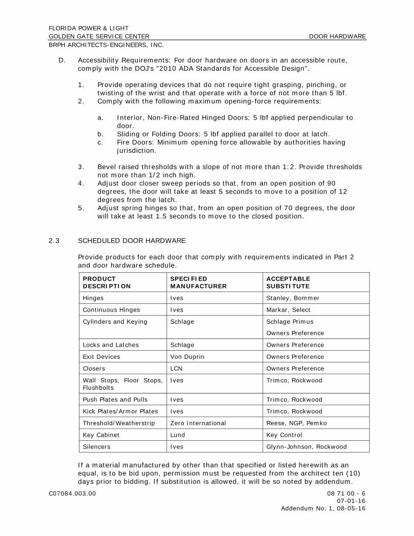
FLORIDA POWER & LIGHT GOLDEN GATE SERVICE CENTER DOOR HARDWARE BRPH ARCHITECTS-ENGINEERS, INC.
C07084.003.00 08 71 00 - 6 07-01-16 Addendum No. 1, 08-05-16
D. Accessibility Requirements: For door hardware on doors in an accessible route, comply with the DOJ's "2010 ADA Standards for Accessible Design".
1. Provide operating devices that do not require tight grasping, pinching, or twisting of the wrist and that operate with a force of not more than 5 lbf.
2. Comply with the following maximum opening-force requirements:
a. Interior, Non-Fire-Rated Hinged Doors: 5 lbf applied perpendicular to door.
b. Sliding or Folding Doors: 5 lbf applied parallel to door at latch. c. Fire Doors: Minimum opening force allowable by authorities having
jurisdiction.
3. Bevel raised thresholds with a slope of not more than 1:2. Provide thresholds not more than 1/2 inch high.
4. Adjust door closer sweep periods so that, from an open position of 90 degrees, the door will take at least 5 seconds to move to a position of 12 degrees from the latch.
5. Adjust spring hinges so that, from an open position of 70 degrees, the door will take at least 1.5 seconds to move to the closed position.
2.3 SCHEDULED DOOR HARDWARE
Provide products for each door that comply with requirements indicated in Part 2 and door hardware schedule.
PRODUCT DESCRIPTION
SPECIFIED MANUFACTURER
ACCEPTABLE SUBSTITUTE
Hinges Ives Stanley, Bommer
Continuous Hinges Ives Markar, Select
Cylinders and Keying Schlage Schlage Primus
Owners Preference
Locks and Latches Schlage Owners Preference
Exit Devices Von Duprin Owners Preference
Closers LCN Owners Preference
Wall Stops, Floor Stops, Flushbolts
Ives Trimco, Rockwood
Push Plates and Pulls Ives Trimco, Rockwood
Kick Plates/Armor Plates Ives Trimco, Rockwood
Threshold/Weatherstrip Zero International Reese, NGP, Pemko
Key Cabinet Lund Key Control
Silencers Ives Glynn-Johnson, Rockwood
If a material manufactured by other than that specified or listed herewith as an equal, is to be bid upon, permission must be requested from the architect ten (10) days prior to bidding. If substitution is allowed, it will be so noted by addendum.

FLORIDA POWER & LIGHT GOLDEN GATE SERVICE CENTER DOOR HARDWARE BRPH ARCHITECTS-ENGINEERS, INC.
C07084.003.00 08 71 00 - 7 07-01-16 Addendum No. 1, 08-05-16
2.4 LOCK CYLINDERS
A. Lock Cylinders: Tumbler type, constructed from brass or bronze, stainless steel, or nickel silver. Provide Schlage Primus cylinders.
1. Manufacturers: Subject to compliance with requirements, available manufacturers offering products that may be incorporated into the Work include, but are not limited to the following:
a. Allegion plc-Schlage Lock Company.
B. Standard Lock Cylinders: BHMA A156.5; Grade 1 permanent cores; face finished to match lockset.
1. Core Type: Interchangeable.
C. Construction Cores: Provide construction cores that are replaceable by permanent cores. Provide 10 construction master keys.
2.5 KEYING
A. Keying System: Factory registered, complying with guidelines in BHMA A156.28, appendix. Provide one extra key blank for each lock. Incorporate decisions made in keying conference.
1. Grand Master Key System: Change keys, a master key, and a grand master key operate cylinders.
a. Provide three cylinder change keys and five each of master and grand master keys.
b. Provide three cylinder change keys and five each of master and grand master keys.
2. Existing System:
a. Master key or grand master key locks to Owner's existing system. b. Re-key Owner's existing master key system into new keying system.
B. Keys: Nickel silver.
1. Stamping: Permanently inscribe each key with a visual key control number and include the following notation:
a. Notation: "DO NOT DUPLICATE."
FLORIDA POWER & LIGHT GOLDEN GATE SERVICE CENTER DOOR HARDWARE BRPH ARCHITECTS-ENGINEERS, INC.
C07084.003.00 08 71 00 - 8 07-01-16 Addendum No. 1, 08-05-16
2.6 KEY CONTROL SYSTEM
A. Key Control Cabinet: BHMA A156.28; metal cabinet with baked-enamel finish; containing key-holding hooks, labels, two sets of key tags with self-locking key holders, key-gathering envelopes, and temporary and permanent markers; with key capacity of 150 percent of the number of locks.
1. Manufacturers: Subject to compliance with requirements, available manufacturers offering products that may be incorporated into the Work include, but are not limited to the following:
a. Lund Equipment Co., Inc. b. MMF Industries. c. TelKee; Oasis International.
2.7 FABRICATION
A. Manufacturer's Nameplate: Do not provide products that have manufacturer's name or trade name displayed in a visible location except in conjunction with required fire-rating labels and as otherwise approved by Architect.
1. Manufacturer's identification is permitted on rim of lock cylinders only.
B. Base Metals: Produce door hardware units of base metal indicated, fabricated by forming method indicated, using manufacturer's standard metal alloy, composition, temper, and hardness. Furnish metals of a quality equal to or greater than that of specified door hardware units and BHMA A156.18.
C. Fasteners: Provide door hardware manufactured to comply with published templates prepared for machine, wood, and sheet metal screws. Provide screws that comply with commercially recognized industry standards for application intended, except aluminum fasteners are not permitted. Provide Phillips flat-head screws with finished heads to match surface of door hardware unless otherwise indicated.
1. Concealed Fasteners: For door hardware units that are exposed when door is closed, except for units already specified with concealed fasteners. Do not use through bolts for installation where bolt head or nut on opposite face is exposed unless it is the only means of securely attaching the door hardware. Where through bolts are used on hollow door and frame construction, provide sleeves for each through bolt.
2. Fire-Rated Applications:
a. Wood or Machine Screws: For the following:
1) Hinges mortised to doors or frames; use threaded-to-the-head wood screws for wood doors and frames.
2) Strike plates to frames. 3) Closers to doors and frames.

FLORIDA POWER & LIGHT GOLDEN GATE SERVICE CENTER DOOR HARDWARE BRPH ARCHITECTS-ENGINEERS, INC.
C07084.003.00 08 71 00 - 9 07-01-16 Addendum No. 1, 08-05-16
b. Steel Through Bolts: For the following unless door blocking is provided:
1) Surface hinges to doors. 2) Closers to doors and frames. 3) Surface-mounted exit devices.
3. Spacers or Sex Bolts: For through bolting of hollow-metal doors. 4. Gasketing Fasteners: Provide noncorrosive fasteners for exterior applications
and elsewhere as indicated.
2.8 FINISHES
A. Provide finishes complying with BHMA A156.18 as indicated in door hardware schedule.
B. Protect mechanical finishes on exposed surfaces from damage by applying a strippable, temporary protective covering before shipping.
C. Appearance of Finished Work: Variations in appearance of abutting or adjacent pieces are acceptable if they are within one-half of the range of approved Samples. Noticeable variations in the same piece are not acceptable. Variations in appearance of other components are acceptable if they are within the range of approved Samples and are assembled or installed to minimize contrast.
PART 3 - EXECUTION
3.1 EXAMINATION
A. Examine doors and frames, with Installer present, for compliance with requirements for installation tolerances, labeled fire-rated door assembly construction, wall and floor construction, and other conditions affecting performance of the Work.
B. Examine roughing-in for electrical power systems to verify actual locations of wiring connections before electrified door hardware installation.
C. Proceed with installation only after unsatisfactory conditions have been corrected.
3.2 PREPARATION
A. Steel Doors and Frames: For surface-applied door hardware, drill and tap doors and frames according to ANSI/SDI A250.6.
B. Wood Doors: Comply with door and hardware manufacturers' written instructions.

FLORIDA POWER & LIGHT GOLDEN GATE SERVICE CENTER DOOR HARDWARE BRPH ARCHITECTS-ENGINEERS, INC.
C07084.003.00 08 71 00 - 10 07-01-16 Addendum No. 1, 08-05-16
3.3 INSTALLATION
A. Mounting Heights: Mount door hardware units at heights to comply with the following unless otherwise indicated or required to comply with governing regulations.
1. Standard Steel Doors and Frames: ANSI/SDI A250.8. 2. Custom Steel Doors and Frames: HMMA 831. 3. Wood Doors: DHI's "Recommended Locations for Architectural Hardware for
Wood Flush Doors."
B. Install each door hardware item to comply with manufacturer's written instructions. Where cutting and fitting are required to install door hardware onto or into surfaces that are later to be painted or finished in another way, coordinate removal, storage, and reinstallation of surface protective trim units with finishing work. Do not install surface-mounted items until finishes have been completed on substrates involved.
1. Set units level, plumb, and true to line and location. Adjust and reinforce attachment substrates as necessary for proper installation and operation.
2. Drill and countersink units that are not factory prepared for anchorage fasteners. Space fasteners and anchors according to industry standards.
C. Hinges: Install types and in quantities indicated in door hardware schedule, but not fewer than the number recommended by manufacturer for application indicated or one hinge for every 30 inches of door height, whichever is more stringent, unless other equivalent means of support for door, such as spring hinges or pivots, are provided.
D. Intermediate Offset Pivots: Where offset pivots are indicated, provide intermediate offset pivots in quantities indicated in door hardware schedule, but not fewer than one intermediate offset pivot per door and one additional intermediate offset pivot for every 30 inches of door height greater than 90 inches.
E. Lock Cylinders: Install construction cores to secure building and areas during construction period.
1. Replace construction cores with permanent cores as directed by Owner. 2. Furnish permanent cores to Owner for installation.
F. Key Control System:
1. Key Control Cabinet: Tag keys and place them on markers and hooks in key control system cabinet, as determined by final keying schedule.
2. Key Lock Boxes: Install where indicated or approved by Architect to provide controlled access for fire and medical emergency personnel.
3. Key Control System Software: Set up multiple-index system based on final keying schedule.
G. Boxed Power Supplies: Locate power supplies as indicated or, if not indicated, above accessible ceilings. Verify location with Architect.

FLORIDA POWER & LIGHT GOLDEN GATE SERVICE CENTER DOOR HARDWARE BRPH ARCHITECTS-ENGINEERS, INC.
C07084.003.00 08 71 00 - 11 07-01-16 Addendum No. 1, 08-05-16
1. Configuration: Provide one power supply for each door opening with electrified door hardware.
H. Thresholds: Set thresholds for exterior doors and other doors indicated in full bed of sealant complying with requirements specified in Section 07 92 00 "Joint Sealants."
I. Stops: Provide floor stops for doors unless wall or other type stops are indicated in door hardware schedule. Do not mount floor stops where they will impede traffic.
J. Perimeter Gasketing: Apply to head and jamb, forming seal between door and frame.
1. Do not notch perimeter gasketing to install other surface-applied hardware.
K. Meeting Stile Gasketing: Fasten to meeting stiles, forming seal when doors are closed.
L. Door Bottoms: Apply to bottom of door, forming seal with threshold when door is closed.
3.4 FIELD QUALITY CONTROL
A. Independent Architectural Hardware Consultant: Owner will engage a qualified independent Architectural Hardware Consultant to perform inspections and to prepare inspection reports.
1. Independent Architectural Hardware Consultant will inspect door hardware and state in each report whether installed work complies with or deviates from requirements, including whether door hardware is properly installed and adjusted.
3.5 ADJUSTING
A. Initial Adjustment: Adjust and check each operating item of door hardware and each door to ensure proper operation or function of every unit. Replace units that cannot be adjusted to operate as intended. Adjust door control devices to compensate for final operation of heating and ventilating equipment and to comply with referenced accessibility requirements.
1. Door Closers: Adjust sweep period to comply with accessibility requirements and requirements of authorities having jurisdiction.
2. Spring Hinges: Adjust to achieve positive latching when door is allowed to close freely from an open position of 70 degrees and so that closing time complies with accessibility requirements of authorities having jurisdiction.
3. Electric Strikes: Adjust horizontal and vertical alignment of keeper to properly engage lock bolt.

FLORIDA POWER & LIGHT GOLDEN GATE SERVICE CENTER DOOR HARDWARE BRPH ARCHITECTS-ENGINEERS, INC.
C07084.003.00 08 71 00 - 12 07-01-16 Addendum No. 1, 08-05-16
B. Occupancy Adjustment: Approximately six months after date of Provisional Acceptance (per the Owner’s Contract), Installer's Architectural Hardware Consultant shall examine and readjust each item of door hardware, including adjusting operating forces, as necessary to ensure function of doors, door hardware, and electrified door hardware.
3.6 CLEANING AND PROTECTION
A. Clean adjacent surfaces soiled by door hardware installation.
B. Clean operating items as necessary to restore proper function and finish.
C. Provide final protection and maintain conditions that ensure that door hardware is without damage or deterioration at time of Provisional Acceptance (per the Owner’s Contract).
3.7 MAINTENANCE SERVICE
A. Maintenance Tools and Instructions: Furnish a complete set of specialized tools and maintenance instructions for Owner's continued adjustment, maintenance, and removal and replacement of door hardware.
B. Maintenance Service: Beginning at Provisional Acceptance (per the Owner’s Contract), maintenance service shall include 12 months' full maintenance by skilled employees of door hardware Installer. Include quarterly preventive maintenance, repair or replacement of worn or defective components, lubrication, cleaning, and adjusting as required for proper door and door hardware operation. Parts and supplies shall be manufacturer's authorized replacement parts and supplies.
3.8 DEMONSTRATION
A. Train Owner's maintenance personnel to adjust, operate, and maintain door hardware.
3.9 DOOR HARDWARE SETS
Hardware Group No. 01
Provide each PR door(s) with the following: Qty Description Catalog Number Finish Mfr
2 EA CONT. HINGE 224HD EPT 628 IVE 2 EA POWER TRANSFER EPT10 689 VON 1 EA ELEC PANIC
HARDWARE RX-QEL+-9847-EO 626 VON
1 EA ELEC PANIC HARDWARE
RX-QEL+-9847-NL-OP-110MD 626 VON
1 EA RIM CYLINDER 20-057-ICX 626 SCH 1 EA PRIMUS CORE 20-740-XP 626 SCH 2 EA 90 DEG OFFSET PULL 8190HD 10" O 630 IVE

FLORIDA POWER & LIGHT GOLDEN GATE SERVICE CENTER DOOR HARDWARE BRPH ARCHITECTS-ENGINEERS, INC.
C07084.003.00 08 71 00 - 13 07-01-16 Addendum No. 1, 08-05-16
2 EA OH STOP 100S 630 GLY 2 EA SURFACE CLOSER 4111 EDA 689 LCN 1 EA THRESHOLD 65A-MSLA-10 A ZER 2 EA DOOR CONTACT 679-05HM BLK SCE 1 EA POWER SUPPLY PS902 900-2RS LGR VON 1 EA CARD READER BY OTHERS 1 EA INTERCOM BY OTHERS 2 EA WIRE HARNESS CON-192 VON 2 EA WIRE HARNESS CON-192P VON 2 EA WIRE HARNESS CON-26 VON 2 EA WIRE HARNESS CON-6W VON
OPERATIONAL DESCRIPTION: DOOR NORMALLY CLOSED AND LOCKED. ACCESS CONTROL SYSTEM WILL RETRACT EXIT DEVICE LATCHBOLT AND ALLOW INGRESS. REQUEST TO EXIT AND DOOR CONTACT CONNECTED TO BUILDING'S SECURITY SYSTEM. FREE EGRESS AT ALL TIMES. Balance of Door Hardware to be supplied by Aluminum Door Supplier 084100
Hardware Group No. 02
Provide each SGL door(s) with the following: Qty Description Catalog Number Finish Mfr
3 EA HINGE 5BB1 4.5 X 4.5 NRP 630 IVE 1 EA POWER TRANSFER EPT10 CON 689 VON 1 EA ELEC PANIC
HARDWARE RX-CD-98-L-NL-06-CON 626 VON
1 EA RIM CYLINDER 20-057-ICX 626 SCH 1 EA MORTISE CYLINDER 20-061-ICX 626 SCH 2 EA PRIMUS CORE 20-740-XP 626 SCH 1 EA SURFACE CLOSER 4111 SCUSH 689 LCN 1 EA KICK PLATE 8400 10" X 2" LDW 630 IVE 1 EA RAIN DRIP 142A AL ZER 1 EA GASKETING 188S-BK S-Bk ZER 1 EA DOOR SWEEP 8198AA AL ZER 1 EA THRESHOLD 65A-MSLA-10 A ZER 1 EA DOOR CONTACT 679-05HM BLK SCE 1 EA POWER SUPPLY PS902 LGR VON 1 EA PEZO BY OTHERS
OPERATIONAL DESCRIPTION: DOOR NORMALLY CLOSED AND LOCKED. REQUEST TO EXIT AND DOOR CONTACT CONNECTED TO BUILDING'S SECURITY SYSTEM. PEZO TO SOUND WHEN DOOR IS OPENED. FREE EGRESS AT ALL TIMES.
Hardware Group No. 03
Provide each SGL door(s) with the following: Qty Description Catalog Number Finish Mfr
3 EA HINGE 5BB1 4.5 X 4.5 NRP 630 IVE 1 EA PANIC HARDWARE HH-LD-98-EO-SNB 626 VON 1 EA SURFACE CLOSER 4111 SCUSH 689 LCN 1 EA KICK PLATE 8400 10" X 2" LDW 630 IVE

FLORIDA POWER & LIGHT GOLDEN GATE SERVICE CENTER DOOR HARDWARE BRPH ARCHITECTS-ENGINEERS, INC.
C07084.003.00 08 71 00 - 14 07-01-16 Addendum No. 1, 08-05-16
1 EA RAIN DRIP 142A AL ZER 1 EA GASKETING 188S-BK S-Bk ZER 1 EA THRESHOLD 65A-MSLA-10 A ZER 1 EA DOOR CONTACT 679-05HM BLK SCE
Hardware Group No. 04
Provide each SGL door(s) with the following: Qty Description Catalog Number Finish Mfr
1 EA CONT. HINGE 224HD EPT 628 IVE 1 EA POWER TRANSFER EPT10 CON 689 VON 1 EA ELEC PANIC
HARDWARE RX-QEL+-98-NL-OP-110MD-CON 626 VON
1 EA RIM CYLINDER 20-057-ICX 626 SCH 1 EA PRIMUS CORE 20-740-XP 626 SCH 1 EA 90 DEG OFFSET PULL 8190HD 10" O 630 IVE 1 EA SURFACE CLOSER 4111 SCUSH 689 LCN 1 EA MOUNTING PLATE 4110-18 689 LCN 1 EA CUSH SHOE SUPPORT 4110-30 689 LCN 1 EA BLADE STOP SPACER 4110-61 689 LCN 1 SET SEALS BY ALUMINUM DOOR SUPPLIER 1 EA DOOR SWEEP BY ALUMINUM DOOR SUPPLIER 1 EA THRESHOLD BY ALUMINUM DOOR SUPPLIER 1 EA DOOR CONTACT 679-05HM BLK SCE 1 EA POWER SUPPLY PS914 900-2RS LGR VON 1 EA CARD READER BY OTHERS 1 EA WIRE HARNESS CON-192 VON 1 EA WIRE HARNESS CON-26 VON 1 EA WIRE HARNESS CON-6W VON
OPERATIONAL DESCRIPTION: DOOR NORMALLY CLOSED AND LOCKED. ACCESS CONTROL SYSTEM WILL RETRACT EXIT DEVICE LATCHBOLT AND ALLOW INGRESS. REQUEST TO EXIT AND DOOR CONTACT CONNECTED TO BUILDING'S SECURITY SYSTEM. FREE EGRESS AT ALL TIMES.
Hardware Group No. 05
Provide each SGL door(s) with the following: Qty Description Catalog Number Finish Mfr
3 EA HINGE 5BB1 4.5 X 4.5 NRP 630 IVE 1 EA POWER TRANSFER EPT10 CON 689 VON 1 EA ELEC PANIC
HARDWARE HH-LD-98-L-E996-06-FSE-CON 626 VON
1 EA RIM CYLINDER 20-057-ICX 626 SCH 1 EA PRIMUS CORE 20-740-XP 626 SCH 1 EA SURFACE CLOSER 4111 SCUSH 689 LCN 1 EA GASKETING 188S-BK S-Bk ZER 1 EA DOOR SWEEP 8198AA AL ZER 1 EA THRESHOLD 65A-MSLA-10 A ZER
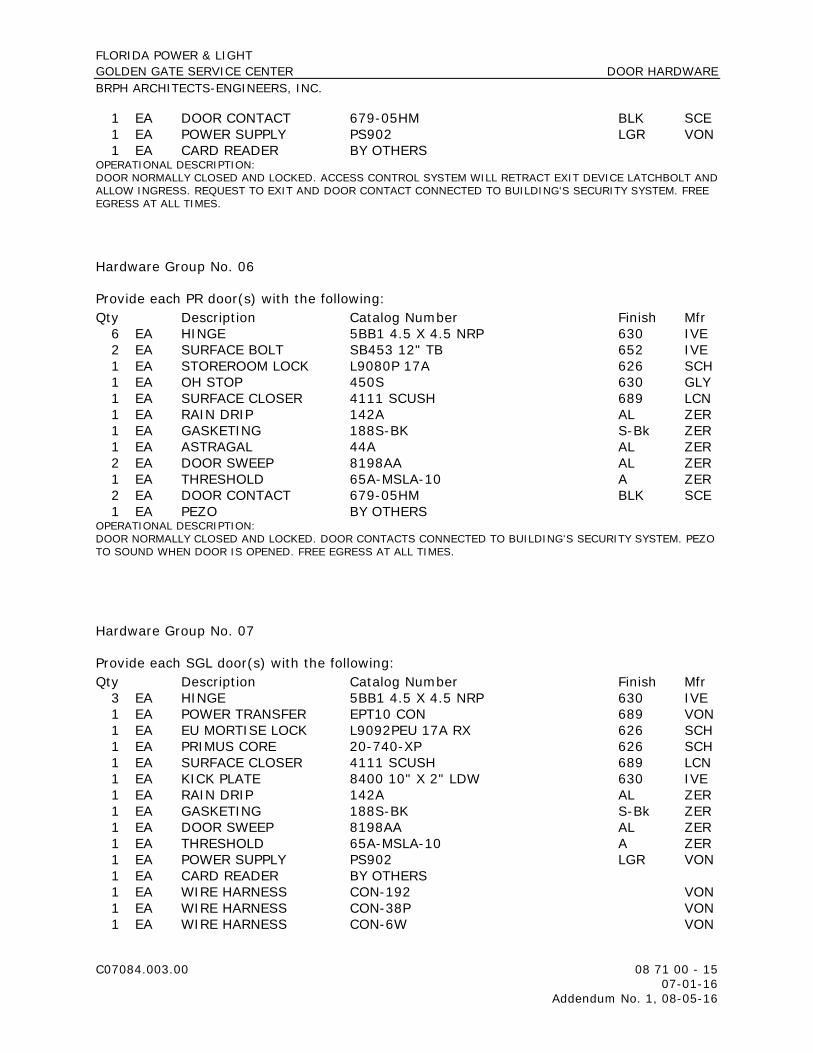
FLORIDA POWER & LIGHT GOLDEN GATE SERVICE CENTER DOOR HARDWARE BRPH ARCHITECTS-ENGINEERS, INC.
C07084.003.00 08 71 00 - 15 07-01-16 Addendum No. 1, 08-05-16
1 EA DOOR CONTACT 679-05HM BLK SCE 1 EA POWER SUPPLY PS902 LGR VON 1 EA CARD READER BY OTHERS
OPERATIONAL DESCRIPTION: DOOR NORMALLY CLOSED AND LOCKED. ACCESS CONTROL SYSTEM WILL RETRACT EXIT DEVICE LATCHBOLT AND ALLOW INGRESS. REQUEST TO EXIT AND DOOR CONTACT CONNECTED TO BUILDING'S SECURITY SYSTEM. FREE EGRESS AT ALL TIMES.
Hardware Group No. 06
Provide each PR door(s) with the following: Qty Description Catalog Number Finish Mfr
6 EA HINGE 5BB1 4.5 X 4.5 NRP 630 IVE 2 EA SURFACE BOLT SB453 12" TB 652 IVE 1 EA STOREROOM LOCK L9080P 17A 626 SCH 1 EA OH STOP 450S 630 GLY 1 EA SURFACE CLOSER 4111 SCUSH 689 LCN 1 EA RAIN DRIP 142A AL ZER 1 EA GASKETING 188S-BK S-Bk ZER 1 EA ASTRAGAL 44A AL ZER 2 EA DOOR SWEEP 8198AA AL ZER 1 EA THRESHOLD 65A-MSLA-10 A ZER 2 EA DOOR CONTACT 679-05HM BLK SCE 1 EA PEZO BY OTHERS
OPERATIONAL DESCRIPTION: DOOR NORMALLY CLOSED AND LOCKED. DOOR CONTACTS CONNECTED TO BUILDING'S SECURITY SYSTEM. PEZO TO SOUND WHEN DOOR IS OPENED. FREE EGRESS AT ALL TIMES.
Hardware Group No. 07
Provide each SGL door(s) with the following: Qty Description Catalog Number Finish Mfr
3 EA HINGE 5BB1 4.5 X 4.5 NRP 630 IVE 1 EA POWER TRANSFER EPT10 CON 689 VON 1 EA EU MORTISE LOCK L9092PEU 17A RX 626 SCH 1 EA PRIMUS CORE 20-740-XP 626 SCH 1 EA SURFACE CLOSER 4111 SCUSH 689 LCN 1 EA KICK PLATE 8400 10" X 2" LDW 630 IVE 1 EA RAIN DRIP 142A AL ZER 1 EA GASKETING 188S-BK S-Bk ZER 1 EA DOOR SWEEP 8198AA AL ZER 1 EA THRESHOLD 65A-MSLA-10 A ZER 1 EA POWER SUPPLY PS902 LGR VON 1 EA CARD READER BY OTHERS 1 EA WIRE HARNESS CON-192 VON 1 EA WIRE HARNESS CON-38P VON 1 EA WIRE HARNESS CON-6W VON

FLORIDA POWER & LIGHT GOLDEN GATE SERVICE CENTER DOOR HARDWARE BRPH ARCHITECTS-ENGINEERS, INC.
C07084.003.00 08 71 00 - 16 07-01-16 Addendum No. 1, 08-05-16
OPERATIONAL DESCRIPTION: DOOR NORMALLY CLOSED AND LOCKED. ACCESS CONTROL SYSTEM WILL UNLOCK LATCHBOLT AND ALLOW INGRESS. REQUEST TO EXIT AND DOOR CONTACT CONNECTED TO BUILDING'S SECURITY SYSTEM. FREE EGRESS AT ALL TIMES.
Hardware Group No. 08
Provide each SGL door(s) with the following: Qty Description Catalog Number Finish Mfr
3 EA HINGE 5BB1 4.5 X 4.5 NRP 652 IVE 1 EA PANIC HARDWARE CD-98-L-17 626 VON 1 EA RIM CYLINDER 20-057-ICX 626 SCH 1 EA MORTISE CYLINDER 20-061-ICX 626 SCH 2 EA FSIC CORE 23-030 626 SCH 1 EA SURFACE CLOSER 4111 SCUSH 689 LCN 1 EA KICK PLATE 8400 10" X 2" LDW 630 IVE 3 EA SILENCER SR64 GRY IVE
TEMPLATE CLOSER FOR 90 DEGREE STOP.
Hardware Group No. 09
Provide each SGL door(s) with the following: Qty Description Catalog Number Finish Mfr
3 EA HINGE 5BB1 4.5 X 4.5 NRP 652 IVE 1 EA PANIC HARDWARE CD-98-L-17 626 VON 1 EA RIM CYLINDER 20-057-ICX 626 SCH 1 EA MORTISE CYLINDER 20-061-ICX 626 SCH 2 EA FSIC CORE 23-030 626 SCH 1 EA SURFACE CLOSER 4111 EDA 689 LCN 1 EA KICK PLATE 8400 10" X 2" LDW 630 IVE 1 EA WALL STOP WS406/407CVX 630 IVE 3 EA SILENCER SR64 GRY IVE
Hardware Group No. 10
Provide each SGL door(s) with the following: Qty Description Catalog Number Finish Mfr
3 EA HINGE 5BB1 4.5 X 4.5 NRP 652 IVE 1 EA POWER TRANSFER EPT10 CON 689 VON 1 EA ELEC FIRE EXIT
HARDWARE RX-98-L-F-E996-17-FSE-SNB-CON 626 VON
1 EA RIM CYLINDER 20-057-ICX 626 SCH 1 EA FSIC CORE 23-030 626 SCH 1 EA SURFACE CLOSER 4011 689 LCN 1 EA KICK PLATE 8400 10" X 2" LDW 630 IVE 1 EA WALL STOP WS406/407CVX 630 IVE 1 SET SEALS 488S BLK ZER

FLORIDA POWER & LIGHT GOLDEN GATE SERVICE CENTER DOOR HARDWARE BRPH ARCHITECTS-ENGINEERS, INC.
C07084.003.00 08 71 00 - 17 07-01-16 Addendum No. 1, 08-05-16
1 EA DOOR CONTACT 679-05HM BLK SCE 1 EA POWER SUPPLY PS902 LGR VON 1 EA CARD READER BY OTHERS 1 EA WIRE HARNESS CON-192 VON 1 EA WIRE HARNESS CON-26 VON 1 EA WIRE HARNESS CON-6W VON
OPERATIONAL DESCRIPTION: DOOR NORMALLY CLOSED AND LOCKED. ACCESS CONTROL SYSTEM WILL RETRACT EXIT DEVICE LATCHBOLT AND ALLOW INGRESS. REQUEST TO EXIT AND DOOR CONTACT CONNECTED TO BUILDING'S SECURITY SYSTEM. FREE EGRESS AT ALL TIMES.
Hardware Group No. 11
Provide each SGL door(s) with the following: Qty Description Catalog Number Finish Mfr
3 EA HINGE 5BB1 4.5 X 4.5 652 IVE 1 EA POWER TRANSFER EPT10 CON 689 VON 1 EA EU MORTISE LOCK L9092PEU 17A RX 626 SCH 1 EA SURFACE CLOSER 4011 689 LCN 1 EA KICK PLATE 8400 10" X 2" LDW 630 IVE 1 EA WALL STOP WS406/407CVX 630 IVE 3 EA SILENCER SR64 GRY IVE 1 EA POWER SUPPLY PS902 LGR VON 1 EA CARD READER BY OTHERS 1 EA WIRE HARNESS CON-192 VON 1 EA WIRE HARNESS CON-38P VON 1 EA WIRE HARNESS CON-6W VON
OPERATIONAL DESCRIPTION: DOOR NORMALLY CLOSED AND LOCKED. ACCESS CONTROL SYSTEM WILL UNLOCK LATCHBOLT AND ALLOW INGRESS. REQUEST TO EXIT AND DOOR CONTACT CONNECTED TO BUILDING'S SECURITY SYSTEM. FREE EGRESS AT ALL TIMES.
Hardware Group No. 12
Provide each SGL door(s) with the following: Qty Description Catalog Number Finish Mfr
3 EA HINGE 5BB1 4.5 X 4.5 NRP 652 IVE 1 EA FIRE EXIT HARDWARE 98-L-F-17 626 VON 1 EA RIM CYLINDER 20-057-ICX 626 SCH 1 EA FSIC CORE 23-030 626 SCH 1 EA SURFACE CLOSER 4111 EDA 689 LCN 1 EA KICK PLATE 8400 10" X 2" LDW 630 IVE 1 EA WALL STOP WS406/407CVX 630 IVE 1 SET SEALS 488S BLK ZER

FLORIDA POWER & LIGHT GOLDEN GATE SERVICE CENTER DOOR HARDWARE BRPH ARCHITECTS-ENGINEERS, INC.
C07084.003.00 08 71 00 - 18 07-01-16 Addendum No. 1, 08-05-16
Hardware Group No. 13
Provide each SGL door(s) with the following: Qty Description Catalog Number Finish Mfr
3 EA HINGE 5BB1 4.5 X 4.5 652 IVE 1 EA FIRE EXIT HARDWARE 98-L-BE-F-17 626 VON 1 EA SURFACE CLOSER 4111 EDA 689 LCN 1 EA KICK PLATE 8400 10" X 2" LDW 630 IVE 1 EA WALL STOP WS406/407CVX 630 IVE 1 SET SEALS 488S-BK S-BK ZER
Hardware Group No. 13A
Provide each SGL door(s) with the following: Qty Description Catalog Number Finish Mfr
3 EA HINGE 5BB1 4.5 X 4.5 652 IVE 1 EA PANIC HARDWAR 98-L-BE-17 626 VON 1 EA SURFACE CLOSER 4111 EDA 689 LCN 1 EA KICK PLATE 8400 10” X 2” LDW 630 IVE 1 EA WALL STOP WS406/407CVX 630 IVE 1 EA GASKETING 488S-BK S-BK ZER
Hardware Group No. 14
Provide each SGL door(s) with the following: Qty Description Catalog Number Finish Mfr
3 EA HINGE 5BB1 4.5 X 4.5 652 IVE 1 EA OFFICE/ENTRY LOCK L9050P 17A 626 SCH 1 EA SURFACE CLOSER 4011 689 LCN 1 EA KICK PLATE 8400 10" X 2" LDW 630 IVE 1 EA WALL STOP WS406/407CVX 630 IVE 1 SET SEALS 488S-BK S-BK ZER
Hardware Group No. 15
Provide each SGL door(s) with the following: Qty Description Catalog Number Finish Mfr
3 EA HW HINGE 5BB1HW 5 X 4.5 652 IVE 1 EA STOREROOM LOCK L9080P 17A 626 SCH 1 EA SURFACE CLOSER 4111 EDA 689 LCN 1 EA WALL STOP WS406/407CVX 630 IVE 3 EA SILENCER SR64 GRY IVE
Hardware Group No. 16

FLORIDA POWER & LIGHT GOLDEN GATE SERVICE CENTER DOOR HARDWARE BRPH ARCHITECTS-ENGINEERS, INC.
C07084.003.00 08 71 00 - 19 07-01-16 Addendum No. 1, 08-05-16
Provide each SGL door(s) with the following: Qty Description Catalog Number Finish Mfr
3 EA HINGE 5BB1 4.5 X 4.5 652 IVE 1 EA STOREROOM LOCK L9080P 17A 626 SCH 1 EA SURFACE CLOSER 4011 689 LCN 1 EA KICK PLATE 8400 10" X 2" LDW 630 IVE 1 EA WALL STOP WS406/407CVX 630 IVE 3 EA SILENCER SR64 GRY IVE
Hardware Group No. 17
Provide each SGL door(s) with the following: Qty Description Catalog Number Finish Mfr
3 EA HINGE 5BB1 4.5 X 4.5 652 IVE 1 EA PRIVACY LOCK L9040 17A L583-363 626 SCH 1 EA SURFACE CLOSER 4011 689 LCN 1 EA KICK PLATE 8400 10" X 2" LDW 630 IVE 1 EA WALL STOP WS406/407CCV 630 IVE 3 EA SILENCER SR64 GRY IVE
Hardware Group No. 18
Provide each SGL door(s) with the following: Qty Description Catalog Number Finish Mfr
3 EA HINGE 5BB1 4.5 X 4.5 652 IVE 1 EA PASSAGE SET L9010 17A 626 SCH 1 EA SURFACE CLOSER 4011 689 LCN 1 EA KICK PLATE 8400 10" X 2" LDW 630 IVE 1 EA WALL STOP WS406/407CVX 630 IVE 1 SET SEALS 488S-BK S-BK ZER
Hardware Group No. 19
Provide each SGL door(s) with the following: Qty Description Catalog Number Finish Mfr
3 EA HINGE 5BB1 4.5 X 4.5 652 IVE 1 EA PUSH PLATE 8200 8" X 16" 630 IVE 1 EA PULL PLATE 8303 10" 6" X 16" 630 IVE 1 EA SURFACE CLOSER 4011 689 LCN 1 EA KICK PLATE 8400 10" X 2" LDW 630 IVE 1 EA WALL STOP WS406/407CVX 630 IVE 3 EA SILENCER SR64 GRY IVE
Hardware Group No. 20

FLORIDA POWER & LIGHT GOLDEN GATE SERVICE CENTER DOOR HARDWARE BRPH ARCHITECTS-ENGINEERS, INC.
C07084.003.00 08 71 00 - 20 07-01-16 Addendum No. 1, 08-05-16
Provide each PR door(s) with the following: Qty Description Catalog Number Finish Mfr
6 EA HINGE 5BB1 4.5 X 4.5 NRP 652 IVE 2 EA MANUAL FLUSH BOLT FB458 626 IVE 1 EA CLASSROOM LOCK L9070P 17A 626 SCH 2 EA OH STOP 450S 630 GLY 2 EA SILENCER SR64 GRY IVE
Hardware Group No. 21
Provide each SGL door(s) with the following: Qty Description Catalog Number Finish Mfr
3 EA HINGE 5PB1 4.5 X 4.5 652 IVE 1 EA OFFICE/ENTRY LOCK L9050P 17A 626 SCH 1 EA WALL STOP WS406/407CVX 630 IVE 3 EA SILENCER SR64 GRY IVE
Hardware Group No. 22
Provide each SGL door(s) with the following: Qty Description Catalog Number Finish Mfr
3 EA HINGE 5PB1 4.5 X 4.5 652 IVE 1 EA STOREROOM LOCK L9080P 17A 626 SCH 1 EA WALL STOP WS406/407CVX 630 IVE 3 EA SILENCER SR64 GRY IVE
Hardware Group No. 23
Provide each SGL door(s) with the following: Qty Description Catalog Number Finish Mfr
3 EA HINGE 5PB1 4.5 X 4.5 652 IVE 1 EA CLASSROOM LOCK L9070P 17A 626 SCH 1 EA WALL STOP WS406/407CVX 630 IVE 1 EA GASKETING 188S-BK S-BK ZER
Hardware Group No. 23A Provide each SGL door(s) with the following: Qty Description Catalog Number Finish Mfr
3 EA HINGE 5BB1 4.5 X 4.5 652 IVE 1 EA CLASSROOM LOCK L9070P 17A 626 SCH 1 EA SURFACE CLOSER 4111 EDA 689 LCN 1 EA WALL STOP WS406/407CVX 630 IVE 1 EA GASKETING 188S-BK S-BK ZER

FLORIDA POWER & LIGHT GOLDEN GATE SERVICE CENTER DOOR HARDWARE BRPH ARCHITECTS-ENGINEERS, INC.
C07084.003.00 08 71 00 - 21 07-01-16 Addendum No. 1, 08-05-16
Hardware Group No. 24
Provide each RU door(s) with the following: Qty Description Catalog Number Finish Mfr
HARDWARE BY DOOR MANUFACTURER
Hardware Group No. 25
Provide each SGL door(s) with the following: Qty Description Catalog Number Finish Mfr
1 EA CONT. HINGE 224HD 628 IVE 2 EA 90 DEG OFFSET PULL 8190HD 10” O 630 IVE 1 EA SURFACE CLOSER 4011 689 LCN 1 EA MOUNTING PLATE 4110-18 689 LCN 1 EA CUSH SHOE SUPPORT 4110-30 689 LCN 1 EA BLADE STOP SPACER 4110-61 689 LCN 1 EA SEALS BY ALUMINUM DOOR SUPPLIER
Hardware Group No. 26
Provide each SGL door(s) with the following: Qty Description Catalog Number Finish Mfr
3 EA HINGE 5BB1 4.5 X 4.5 NRP 630 IVE 1 EA STOREROOM LOCK L9080P 17A 626 SCH 1 EA SURFACE CLOSER 4111 SCUSH TBSRT 689 LCN 1 EA RAIN DRIP 142A AL ZER 1 EA GASKETING 31AA AA ZER 1 EA DOOR SWEEP 39A A ZER 1 EA THRESHOLD 65A-V3-MSLA-10 A ZER
Hardware Group No. 27
Provide each PR door(s) with the following: Qty Description Catalog Number Finish Mfr
1 EA PADLOCK L/CYL-FSIC KS43F3200 606 SCH 1 EA PRIMUS CORE 20-740 606 SCH 1 HARDWARE BY GATE MANUFACTURER

FLORIDA POWER & LIGHT GOLDEN GATE SERVICE CENTER DOOR HARDWARE BRPH ARCHITECTS-ENGINEERS, INC.
C07084.003.00 08 71 00 - 22 07-01-16 Addendum No. 1, 08-05-16
Hardware Group No. 28
Provide each SGL door(s) with the following: Qty Description Catalog Number Finish Mfr
1 EA PADLOCK L/CYL-FSIC KS43F3200 606 SCH 1 EA PRIMUS CORE 20-740 606 SCH 1 HARDWARE BY GATE MANUFACTURER

FLORIDA POWER & LIGHT GOLDEN GATE SERVICE CENTER DOOR HARDWARE BRPH ARCHITECTS-ENGINEERS, INC.
C07084.003.00 08 71 00 - 23 07-01-16 Addendum No. 1, 08-05-16
3.10 DOOR INDEX
Mark # HW Set # DELETED 100A 01 100B 08 101A 03 101B 18 101C 10 103 15 104 07 106 17 107A 06 107B 16 108 21 109 11 110A 02 110B 16 111A 05 111B 24 112 23 113A 21 113B 21 114A 11 114B 16 115 21 116 21 117 21 118 21 119 09 120A 09 120B 09 121 19 122 19 123 16 124A 04 124B 04 125B 13 125A 13 126 11 127A 04 127B 13 128 14 129 23 130 22 131 22
Mark # HW Set # 132 09 133 14 134 02 134A 21 134B 21 135 21 136 21 137 21 138 21 139A 23 139B 23 142A 27 142B 27 142C 28 142D 27 142E 27 201 21 202 16 203 22 204 11 205 22 207 21 208 21 209 21 210 21 211 21 212A 23 212B 23 213A 12 213B 13A 214 20 215 19 216 19 217 16 218 22 219A 09 219B 09 219C 23A 220 21 221 21 222 13 225 25 226 20

FLORIDA POWER & LIGHT GOLDEN GATE SERVICE CENTER DOOR HARDWARE BRPH ARCHITECTS-ENGINEERS, INC.
C07084.003.00 08 71 00 - 24 07-01-16 Addendum No. 1, 08-05-16
Mark # HW Set # 229 21
Mark # HW Set # 230 21
END OF SECTION 08 71 00

FLORIDA POWER & LIGHT GOLDEN GATE SERVICE CENTER GLAZING BRPH ARCHITECTS-ENGINEERS, INC.
C07084.003.00 08 80 00 - 1 07-01-16 Addendum No. 1, 08-05-16
SECTION 08 80 00 - GLAZING
PART 1 - GENERAL
1.1 RELATED DOCUMENTS
A. Drawings and general provisions of the Contract, including General and Supplementary Conditions and Division 01 Specification Sections, apply to this Section.
1.2 SUMMARY
A. Section includes:
1. Glass for windows, doors, storefront framing. 2. Glazing sealants and accessories. 3. Sound Transmission; Secondary Glass framing.
B. Related Requirements:
1. Section 08 11 13 "Hollow Metal Doors And Frames." 2. Section 08 41 13.19 "Interior Aluminum-Framed Entrances and Storefronts." 3. Section 08 44 13 “Glazed Aluminum Curtain Walls.”
1.3 DEFINITIONS
A. Glass Manufacturers: Firms that produce primary glass, fabricated glass, or both, as defined in referenced glazing publications.
B. Glass Thicknesses: Indicated by thickness designations in millimeters according to ASTM C 1036.
C. IBC: International Building Code.
D. FBC: Florida Building Code.
E. Interspace: Space between lites of an insulating-glass unit.
1.4 COORDINATION
A. Coordinate glazing channel dimensions to provide necessary bite on glass, minimum edge and face clearances, and adequate sealant thicknesses, with reasonable tolerances.

FLORIDA POWER & LIGHT GOLDEN GATE SERVICE CENTER GLAZING BRPH ARCHITECTS-ENGINEERS, INC.
C07084.003.00 08 80 00 - 2 07-01-16 Addendum No. 1, 08-05-16
1.5 PREINSTALLATION MEETINGS
A. Preinstallation Conference: Conduct conference at Project site.
1. Review and finalize construction schedule and verify availability of materials, Installer's personnel, equipment, and facilities needed to make progress and avoid delays.
2. Review temporary protection requirements for glazing during and after installation.
3. Review STC Ratomg requirements for windows and required details.
1.6 ACTION SUBMITTALS
A. Product Data: For each type of product.
B. Glass Samples: For each type of glass product other than clear monolithic vision glass; 12 inches square.
C. Glazing Accessory Samples: For sealants, in 12-inch lengths. Install sealant Samples between two strips of material representative in color of the adjoining framing system.
D. Glazing Schedule: List glass types and thicknesses for each size opening and location. Use same designations indicated on Drawings.
E. Delegated-Design Submittal: For glass indicated to comply with performance requirements and design criteria, including analysis data signed and sealed by the qualified professional engineer responsible for their preparation.
1.7 INFORMATIONAL SUBMITTALS
A. Qualification Data: For Installer, manufacturers of insulating-glass units with sputter-coated, low-E coatings, glass testing agency, and sealant testing agency.
B. Product Certificates: For glass.
C. Product Test Reports: For tinted glass and coated glass, insulating glass, and glazing sealants, for tests performed by a qualified testing agency.
1. For glazing sealants, provide test reports based on testing current sealant formulations within previous 36-month period.
D. Sample Warranties: For special warranties.
E. Florida Product Approval Number for assembly.

FLORIDA POWER & LIGHT GOLDEN GATE SERVICE CENTER GLAZING BRPH ARCHITECTS-ENGINEERS, INC.
C07084.003.00 08 80 00 - 3 07-01-16 Addendum No. 1, 08-05-16
1.8 QUALITY ASSURANCE
A. Manufacturer Qualifications for Insulating-Glass Units with Sputter-Coated, Low-E Coatings: A qualified insulating-glass manufacturer who is approved and certified by coated-glass manufacturer.
B. Installer Qualifications: A qualified installer who employs glass installers for this Project who are certified under the National Glass Association's Certified Glass Installer Program.
C. Glass Testing Agency Qualifications: A qualified independent testing agency accredited according to the NFRC CAP 1 Certification Agency Program.
D. Sealant Testing Agency Qualifications: An independent testing agency qualified according to ASTM C 1021 to conduct the testing indicated.
E. Mockups: Build mockups to demonstrate aesthetic effects and to set quality standards for materials and execution.
1. Install glazing in mockups specified in Section 08 41 13.19 "Interior Aluminum-Framed Entrances and Storefronts," to match glazing systems required for Project, including glazing methods.
2. Subject to compliance with requirements, approved mockups may become part of the completed Work if undisturbed at time of Provisional Acceptance (per the Owner’s Contract).
1.9 DELIVERY, STORAGE, AND HANDLING
A. Protect glazing materials according to manufacturer's written instructions. Prevent damage to glass and glazing materials from condensation, temperature changes, direct exposure to sun, or other causes.
B. Comply with insulating-glass manufacturer's written instructions for venting and sealing units to avoid hermetic seal ruptures due to altitude change.
1.10 FIELD CONDITIONS
A. Environmental Limitations: Do not proceed with glazing when ambient and substrate temperature conditions are outside limits permitted by glazing material manufacturers and when glazing channel substrates are wet from rain, frost, condensation, or other causes.
1. Do not install glazing sealants when ambient and substrate temperature conditions are outside limits permitted by sealant manufacturer or are below 40 deg F.

FLORIDA POWER & LIGHT GOLDEN GATE SERVICE CENTER GLAZING BRPH ARCHITECTS-ENGINEERS, INC.
C07084.003.00 08 80 00 - 4 07-01-16 Addendum No. 1, 08-05-16
1.11 WARRANTY
A. Manufacturer's Special Warranty for Coated-Glass Products: Manufacturer agrees to replace coated-glass units that deteriorate within specified warranty period. Deterioration of coated glass is defined as defects developed from normal use that are not attributed to glass breakage or to maintaining and cleaning coated glass contrary to manufacturer's written instructions. Defects include peeling, cracking, and other indications of deterioration in coating.
1. Warranty Period: 10 years from date of Provisional Acceptance (per the Owner’s Contract).
B. Manufacturer's Special Warranty for Laminated Glass: Manufacturer agrees to replace laminated-glass units that deteriorate within specified warranty period. Deterioration of laminated glass is defined as defects developed from normal use that are not attributed to glass breakage or to maintaining and cleaning laminated glass contrary to manufacturer's written instructions. Defects include edge separation, delamination materially obstructing vision through glass, and blemishes exceeding those allowed by referenced laminated-glass standard.
1. Warranty Period: 10 years from date of Provisional Acceptance (per the Owner’s Contract).
C. Manufacturer's Special Warranty for Insulating Glass: Manufacturer agrees to replace insulating-glass units that deteriorate within specified warranty period. Deterioration of insulating glass is defined as failure of hermetic seal under normal use that is not attributed to glass breakage or to maintaining and cleaning insulating glass contrary to manufacturer's written instructions. Evidence of failure is the obstruction of vision by dust, moisture, or film on interior surfaces of glass.
1. Warranty Period: 10 years from date of Provisional Acceptance (per the Owner’s Contract).
PART 2 - PRODUCTS
2.1 MANUFACTURERS
A. Basis-of-Design Product: Subject to compliance with requirements, provide glazing product by Viracon, Inc. PPG Industries, Inc.; or a comparable product by one of the following:
1. AGC Glass Company North America. 2. Cardinal Glass Industries. 3. Guardian Industries Corp. 4. Oldcastle Building Envelope. 5. PPG Industries, Inc.
B. Source Limitations for Glass: Obtain from single source from single manufacturer for each glass type.
1. Obtain tinted glass from single source from single manufacturer.

FLORIDA POWER & LIGHT GOLDEN GATE SERVICE CENTER GLAZING BRPH ARCHITECTS-ENGINEERS, INC.
C07084.003.00 08 80 00 - 5 07-01-16 Addendum No. 1, 08-05-16
C. Source Limitations for Glazing Accessories: Obtain from single source from single manufacturer for each product and installation method.
2.2 PERFORMANCE REQUIREMENTS
A. General: Installed glazing systems shall withstand normal thermal movement and wind and impact loads (where applicable) without failure, including loss or glass breakage attributable to the following: defective manufacture, fabrication, or installation; failure of sealants or gaskets to remain watertight and airtight; deterioration of glazing materials; or other defects in construction.
B. Delegated Design: Engage a qualified professional engineer, as defined in Section 01 40 00 "Quality Requirements," to design glazing.
C. Structural Performance: Glazing shall withstand the following design loads within limits and under conditions indicated determined according to the IBC and ASTM E 1300.
1. Design Wind Pressures: As indicated on Structural Drawings. 2. Design Wind Pressures: Determine design wind pressures applicable to
Project according to ASCE/SEI 7, based on heights above grade indicated on Drawings.
a. Wind Design Data: As indicated on Structural Drawings. b. Basic Wind Speed: As indicated on Drawings. c. Importance Factor: As indicated on Drawings. d. Exposure Category: As indicated on Drawings.
3. Maximum Lateral Deflection: For glass supported on all four edges, limit center-of-glass deflection at design wind pressure to not more than 1/50 times the short-side length or 1 inch, whichever is less.
4. Differential Shading: Design glass to resist thermal stresses induced by differential shading within individual glass lites.
5. Differential Shading: Design glass to resist thermal stresses induced by differential shading within individual glass lites.
D. Windborne-Debris-Impact Resistance: Exterior glazing shall comply with enhanced-protection testing requirements in ASTM E 1996 when tested according to ASTM E 1886. Test specimens shall be no smaller in width and length than glazing indicated for use on Project and shall be installed in same manner as glazing indicated for use on Project.
1. Large-Missile Test: For glazing located within 30 feet of grade. 2. Small-Missile Test: For glazing located more than 30 feet above grade. 3. Miami-Dade TAS 201, 202, 203, and AAMA 506.
E. Safety Glazing: Where safety glazing is indicated, provide glazing that complies with 16 CFR 1201, Category II.

FLORIDA POWER & LIGHT GOLDEN GATE SERVICE CENTER GLAZING BRPH ARCHITECTS-ENGINEERS, INC.
C07084.003.00 08 80 00 - 6 07-01-16 Addendum No. 1, 08-05-16
F. Thermal and Optical Performance Properties: Provide glass with performance properties specified, as indicated in manufacturer's published test data, based on procedures indicated below:
1. For monolithic-glass lites, properties are based on units with lites 6 mm thick. 2. For laminated-glass lites, properties are based on products of construction
indicated. 3. For insulating-glass units, properties are based on units of thickness indicated
for overall unit and for each lite. 4. U-Factors: Center-of-glazing values, according to NFRC 100 and based on
LBL's WINDOW 5.2 computer program, expressed as Btu/sq. ft. x h x deg F. 5. Solar Heat-Gain Coefficient and Visible Transmittance: Center-of-glazing
values, according to NFRC 200 and based on LBL's WINDOW 5.2 computer program.
6. Visible Reflectance: Center-of-glazing values, according to NFRC 300.
2.3 GLASS PRODUCTS, GENERAL
A. Glazing Publications: Comply with published recommendations of glass product manufacturers and organizations below unless more stringent requirements are indicated. See these publications for glazing terms not otherwise defined in this Section or in referenced standards.
1. GANA Publications: "Laminated Glazing Reference Manual" and "Glazing Manual."
2. IGMA Publication for Insulating Glass: SIGMA TM-3000, "North American Glazing Guidelines for Sealed Insulating Glass Units for Commercial and Residential Use."
B. Safety Glazing Labeling: Where safety glazing is indicated, permanently mark glazing with certification label of the SGCC or another certification agency acceptable to authorities having jurisdiction. Label shall indicate manufacturer's name, type of glass, thickness, and safety glazing standard with which glass complies.
1. Certification label per Chapter 24 of 2010 Florida Building Code.
C. Insulating-Glass Certification Program: Permanently marked either on spacers or on at least one component lite of units with appropriate certification label of IGCC.
1. Chapter 24 of 2014 Florida Building Code.
D. Thickness: Where glass thickness is indicated, it is a minimum. Provide glass that complies with performance requirements and is not less than the thickness indicated.
1. Minimum Glass Thickness for Exterior Lites: 6 mm. 2. Thickness of Tinted Glass: Provide same thickness for each tint color
indicated throughout Project.
FLORIDA POWER & LIGHT GOLDEN GATE SERVICE CENTER GLAZING BRPH ARCHITECTS-ENGINEERS, INC.
C07084.003.00 08 80 00 - 7 07-01-16 Addendum No. 1, 08-05-16
E. Strength: Where annealed float glass is indicated, provide annealed float glass, heat-strengthened float glass, or fully tempered float glass as needed to comply with "Performance Requirements" Article. Where heat-strengthened float glass is indicated, provide heat-strengthened float glass or fully tempered float glass as needed to comply with "Performance Requirements" Article. Where fully tempered float glass is indicated, provide fully tempered float glass.
2.4 GLASS PRODUCTS
A. Clear Annealed Float Glass: ASTM C 1036, Type I, Class 1 (clear), Quality-Q3.
B. Tinted Annealed Float Glass: ASTM C 1036, Type I, Class 2 (tinted), Quality-Q3.
C. Fully Tempered Float Glass: ASTM C 1048, Kind FT (fully tempered), Condition A (uncoated) unless otherwise indicated, Type I, Class 1 (clear) or Class 2 (tinted) as indicated, Quality-Q3.
1. Fabrication Process: By horizontal (roller-hearth) process with roll-wave distortion parallel to bottom edge of glass as installed unless otherwise indicated.
D. Heat-Strengthened Float Glass: ASTM C 1048, Kind HS (heat strengthened), Type I, Condition A (uncoated) unless otherwise indicated, Type I, Class 1 (clear) or Class 2 (tinted) as indicated, Quality-Q3.
1. Fabrication Process: By horizontal (roller-hearth) process with roll-wave distortion parallel to bottom edge of glass as installed unless otherwise indicated.
2.5 LAMINATED GLASS
A. Laminated Glass: ASTM C 1172. Use materials that have a proven record of no tendency to bubble, discolor, or lose physical and mechanical properties after fabrication and installation.
1. Construction: Laminate glass with polyvinyl butyral interlayer to comply with interlayer manufacturer's written instructions.
2. Interlayer Thickness: Provide thickness not less than that indicated and as needed to comply with requirements.
3. Interlayer Color: Clear unless otherwise indicated.
B. Windborne-Debris-Impact-Resistant Laminated Glass: Comply with requirements specified above for laminated glass except laminate glass with the following to comply with interlayer manufacturer's written instructions:
1. Polyvinyl butyral interlayer.

FLORIDA POWER & LIGHT GOLDEN GATE SERVICE CENTER GLAZING BRPH ARCHITECTS-ENGINEERS, INC.
C07084.003.00 08 80 00 - 8 07-01-16 Addendum No. 1, 08-05-16
2.6 INSULATING GLASS
A. Insulating-Glass Units: Factory-assembled units consisting of sealed lites of glass separated by a dehydrated interspace, qualified according to ASTM E 2190.
1. Sealing System: Dual seal, with manufacturer's standard primary and secondary sealants.
2. Spacer: Manufacturer's standard spacer material and construction Aluminum with mill or clear anodic finish.
3. Desiccant: Molecular sieve or silica gel, or a blend of both.
2.7 GLAZING SEALANTS
A. General:
1. Compatibility: Compatible with one another and with other materials they contact, including glass products, seals of insulating-glass units, and glazing channel substrates, under conditions of service and application, as demonstrated by sealant manufacturer based on testing and field experience.
2. Suitability: Comply with sealant and glass manufacturers' written instructions for selecting glazing sealants suitable for applications indicated and for conditions existing at time of installation.
3. Field-applied sealants shall have a VOC content of not more than 250 g/L. 4. Colors of Exposed Glazing Sealants: As indicated by manufacturer's
designations as selected by Architect from manufacturer's full range.
B. Glazing Sealant: Neutral-curing silicone glazing sealant complying with ASTM C 920, Type S, Grade NS, Class 50, Use NT.
1. Basis-of-Design Product: Subject to compliance with requirements, provide Dow Corning Corporation; 795 or a comparable product by one of the following:
a. GE Construction Sealants; Momentive Performance Materials Inc. b. May National Associates, Inc.; a subsidiary of Sika Corporation. c. Pecora Corporation. d. Sika Corporation. e. Tremco Incorporated.
2. Applications: Non-Structural Glazing.
2.8 GLAZING TAPES
A. Back-Bedding Mastic Glazing Tapes: Preformed, butyl-based, 100 percent solids elastomeric tape; nonstaining and nonmigrating in contact with nonporous surfaces; with or without spacer rod as recommended in writing by tape and glass manufacturers for application indicated; and complying with ASTM C 1281 and AAMA 800 for products indicated below:

FLORIDA POWER & LIGHT GOLDEN GATE SERVICE CENTER GLAZING BRPH ARCHITECTS-ENGINEERS, INC.
C07084.003.00 08 80 00 - 9 07-01-16 Addendum No. 1, 08-05-16
1. AAMA 806.3 tape, for glazing applications in which tape is subject to continuous pressure.
2. AAMA 807.3 tape, for glazing applications in which tape is not subject to continuous pressure.
B. Expanded Cellular Glazing Tapes: Closed-cell, PVC foam tapes; factory coated with adhesive on both surfaces; and complying with AAMA 800 for the following types:
1. AAMA 810.1, Type 1, for glazing applications in which tape acts as the primary sealant.
2. AAMA 810.1, Type 2, for glazing applications in which tape is used in combination with a full bead of liquid sealant.
2.9 MISCELLANEOUS GLAZING MATERIALS
A. General: Provide products of material, size, and shape complying with referenced glazing standard, with requirements of manufacturers of glass and other glazing materials for application indicated, and with a proven record of compatibility with surfaces contacted in installation.
B. Cleaners, Primers, and Sealers: Types recommended by sealant or gasket manufacturer.
C. Setting Blocks: Elastomeric material with a Shore, Type A durometer hardness of 85, plus or minus 5.
D. Spacers: Elastomeric blocks or continuous extrusions of hardness required by glass manufacturer to maintain glass lites in place for installation indicated.
E. Edge Blocks: Elastomeric material of hardness needed to limit glass lateral movement (side walking).
F. Cylindrical Glazing Sealant Backing: ASTM C 1330, Type O (open-cell material), of size and density to control glazing sealant depth and otherwise produce optimum glazing sealant performance.
2.10 FABRICATION OF GLAZING UNITS
A. Fabricate glazing units in sizes required to fit openings indicated for Project, with edge and face clearances, edge and surface conditions, and bite complying with written instructions of product manufacturer and referenced glazing publications, to comply with system performance requirements.
1. Allow for thermal movements from ambient and surface temperature changes acting on glass framing members and glazing components.
a. Temperature Change: 120 deg F, ambient; 180 deg F, material surfaces.
B. Grind smooth and polish exposed glass edges and corners.

FLORIDA POWER & LIGHT GOLDEN GATE SERVICE CENTER GLAZING BRPH ARCHITECTS-ENGINEERS, INC.
C07084.003.00 08 80 00 - 10 07-01-16 Addendum No. 1, 08-05-16
PART 3 - EXECUTION
3.1 EXAMINATION
A. Examine framing, glazing channels, and stops, with Installer present, for compliance with the following:
1. Manufacturing and installation tolerances, including those for size, squareness, and offsets at corners.
2. Presence and functioning of weep systems. 3. Minimum required face and edge clearances. 4. Effective sealing between joints of glass-framing members.
B. Proceed with installation only after unsatisfactory conditions have been corrected.
3.2 PREPARATION
A. Clean glazing channels and other framing members receiving glass immediately before glazing. Remove coatings not firmly bonded to substrates.
B. Examine glazing units to locate exterior and interior surfaces. Label or mark units as needed so that exterior and interior surfaces are readily identifiable. Do not use materials that leave visible marks in the completed Work.
3.3 GLAZING, GENERAL
A. Comply with combined written instructions of manufacturers of glass, sealants, gaskets, and other glazing materials, unless more stringent requirements are indicated, including those in referenced glazing publications.
B. Protect glass edges from damage during handling and installation. Remove damaged glass from Project site and legally dispose of off Project site. Damaged glass includes glass with edge damage or other imperfections that, when installed, could weaken glass, impair performance, or impair appearance.
C. Apply primers to joint surfaces where required for adhesion of sealants, as determined by preconstruction testing.
D. Install setting blocks in sill rabbets, sized and located to comply with referenced glazing publications, unless otherwise required by glass manufacturer. Set blocks in thin course of compatible sealant suitable for heel bead.
E. Do not exceed edge pressures stipulated by glass manufacturers for installing glass lites.
F. Provide spacers for glass lites where length plus width is larger than 50 inches.

FLORIDA POWER & LIGHT GOLDEN GATE SERVICE CENTER GLAZING BRPH ARCHITECTS-ENGINEERS, INC.
C07084.003.00 08 80 00 - 11 07-01-16 Addendum No. 1, 08-05-16
1. Locate spacers directly opposite each other on both inside and outside faces of glass. Install correct size and spacing to preserve required face clearances, unless gaskets and glazing tapes are used that have demonstrated ability to maintain required face clearances and to comply with system performance requirements.
2. Provide 1/8-inch minimum bite of spacers on glass and use thickness equal to sealant width. With glazing tape, use thickness slightly less than final compressed thickness of tape.
G. Provide edge blocking where indicated or needed to prevent glass lites from moving sideways in glazing channel, as recommended in writing by glass manufacturer and according to requirements in referenced glazing publications.
H. Set glass lites in each series with uniform pattern, draw, bow, and similar characteristics.
I. Set glass lites with proper orientation so that coatings face exterior or interior as specified.
J. Where wedge-shaped gaskets are driven into one side of channel to pressurize sealant or gasket on opposite side, provide adequate anchorage so gasket cannot walk out when installation is subjected to movement.
K. Square cut wedge-shaped gaskets at corners and install gaskets in a manner recommended by gasket manufacturer to prevent corners from pulling away; seal corner joints and butt joints with sealant recommended by gasket manufacturer.
3.4 TAPE GLAZING
A. Position tapes on fixed stops so that, when compressed by glass, their exposed edges are flush with or protrude slightly above sightline of stops.
B. Install tapes continuously, but not necessarily in one continuous length. Do not stretch tapes to make them fit opening.
C. Cover vertical framing joints by applying tapes to heads and sills first, then to jambs. Cover horizontal framing joints by applying tapes to jambs, then to heads and sills.
D. Place joints in tapes at corners of opening with adjoining lengths butted together, not lapped. Seal joints in tapes with compatible sealant approved by tape manufacturer.
E. Do not remove release paper from tape until right before each glazing unit is installed.
F. Apply heel bead of elastomeric sealant.

FLORIDA POWER & LIGHT GOLDEN GATE SERVICE CENTER GLAZING BRPH ARCHITECTS-ENGINEERS, INC.
C07084.003.00 08 80 00 - 12 07-01-16 Addendum No. 1, 08-05-16
G. Center glass lites in openings on setting blocks, and press firmly against tape by inserting dense compression gaskets formed and installed to lock in place against faces of removable stops. Start gasket applications at corners and work toward centers of openings.
H. Apply cap bead of elastomeric sealant over exposed edge of tape.
3.5 GASKET GLAZING (DRY)
A. Cut compression gaskets to lengths recommended by gasket manufacturer to fit openings exactly, with allowance for stretch during installation.
B. Insert soft compression gasket between glass and frame or fixed stop so it is securely in place with joints miter cut and bonded together at corners.
C. Installation with Drive-in Wedge Gaskets: Center glass lites in openings on setting blocks, and press firmly against soft compression gasket by inserting dense compression gaskets formed and installed to lock in place against faces of removable stops. Start gasket applications at corners and work toward centers of openings. Compress gaskets to produce a weathertight seal without developing bending stresses in glass. Seal gasket joints with sealant recommended by gasket manufacturer.
D. Installation with Pressure-Glazing Stops: Center glass lites in openings on setting blocks, and press firmly against soft compression gasket. Install dense compression gaskets and pressure-glazing stops, applying pressure uniformly to compression gaskets. Compress gaskets to produce a weathertight seal without developing bending stresses in glass. Seal gasket joints with sealant recommended by gasket manufacturer.
E. Install gaskets so they protrude past face of glazing stops.
3.6 SEALANT GLAZING (WET)
A. Install continuous spacers, or spacers combined with cylindrical sealant backing, between glass lites and glazing stops to maintain glass face clearances and to prevent sealant from extruding into glass channel and blocking weep systems until sealants cure. Secure spacers or spacers and backings in place and in position to control depth of installed sealant relative to edge clearance for optimum sealant performance.
B. Force sealants into glazing channels to eliminate voids and to ensure complete wetting or bond of sealant to glass and channel surfaces.
C. Tool exposed surfaces of sealants to provide a substantial wash away from glass.
3.7 CLEANING AND PROTECTION
A. Immediately after installation remove nonpermanent labels and clean surfaces.

FLORIDA POWER & LIGHT GOLDEN GATE SERVICE CENTER GLAZING BRPH ARCHITECTS-ENGINEERS, INC.
C07084.003.00 08 80 00 - 13 07-01-16 Addendum No. 1, 08-05-16
B. Protect glass from contact with contaminating substances resulting from construction operations. Examine glass surfaces adjacent to or below exterior concrete and other masonry surfaces at frequent intervals during construction, but not less than once a month, for buildup of dirt, scum, alkaline deposits, or stains.
1. If, despite such protection, contaminating substances do come into contact with glass, remove substances immediately as recommended in writing by glass manufacturer. Remove and replace glass that cannot be cleaned without damage to coatings.
C. Remove and replace glass that is damaged during construction period.
D. Wash glass on both exposed surfaces not more than four days before date scheduled for inspections that establish date of Provisional Acceptance (per the Owner’s Contract). Wash glass as recommended in writing by glass manufacturer.
3.8 GLAZING SCHEDULE
A. Exterior Glazing Schedule (Basis of Design Product: Viracon)
VUE – Viracon VUE Low-E
B. VISION GLASS
Exterior Storefronts
Glass Type GL-01: Low-e-coated, tinted, insulating laminated glass. Large Missile Impact.
Basis of Design Product: 1/4” BlueGreen HS Viracon VUE 1-50 #2 + 1/2” Air Black + Lami – 1/4” Clear HS + Clear .150 PVB + 1/4” Clear HS.
1. Overall Unit Thickness: 1-5/16 inch. 2. Thickness of Outdoor Lite: 6.0 mm. 3. Outdoor Lite: Tinted heat-strengthened float glass. 4. Interspace Content: Air/Black. 5. Indoor Lite: Clear laminated glass with two plies of heat-strengthened float
glass.
a. Thickness of Each Glass Ply: 6.0 mm. b. Interlayer Thickness: 0.150 inch.
6. Low-E Coating: Sputtered on second surface. 7. Visible Light Transmittance (VLT): 46 percent minimum. 8. Reflectance Out: 11%. 9. Winter Nighttime U-Factor: 0.29 maximum. 10. Summer Daytime U-Factor: 0.25 maximum. 11. Shading Coefficient (SC): 0.29. 12. Solar Heat Gain Coefficient (SHGC): 0.25 maximum. 13. LSG (Light to Solar Gain Ratio): 1.84. 14. Provide safety glazing labeling.

FLORIDA POWER & LIGHT GOLDEN GATE SERVICE CENTER GLAZING BRPH ARCHITECTS-ENGINEERS, INC.
C07084.003.00 08 80 00 - 14 07-01-16 Addendum No. 1, 08-05-16
C. EXTERIOR SWINGING DOORS Glass Type GL-02: Laminated glass with two plies of heat-strengthened glass.
Basis of Design Product: 1/4” HS Viracon VLE 1-70 #2 + .060 PVB Clear + 1/4” Clear HS.
1. Overall Unit Thickness: 9/16" Laminated Glass. 2. 1/4" Clear Heat Strengthened Glass. 3. .060 PVB Interlayer. 4. 1/4" Clear Heat Strengthened Glass. 5. Low-E Coating: Sputtered on second surface. 6. Visible Light Transmittance (VLT): 68 percent minimum. 7. Winter Nighttime U-Factor: 0.95 maximum. 8. Summer Daytime U-Factor: 0.87 maximum. 9. Shading Coefficient (SC): 0.50. 10. Solar Heat Gain Coefficient (SHGC): 0.43 maximum. 11. LSG (Light to Solar Gain Ratio): 1.58. 12. Provide safety glazing labeling.
D. INTERIOR STOREFRONTS Glass Type GL-03: Laminated glass with two plies of heat-strengthened glass. 1. Overall Unit Thickness: 3/8" Laminated Glass. 2. 3/16" Clear Heat Strengthened Glass. 3. .030 PVB Interlayer. 4. 3/16" Clear Heat Strengthened Glass. 5. Provide safety glazing labeling.
A. INTERIOR SWINGING DOORS Glass Type GL-04: Laminated glass with two plies of heat-strengthened glass. 1. Overall Unit Thickness: 3/8" Laminated Glass. 2. 3/16" Clear Heat Strengthened Glass. 3. .030 PVB Interlayer. 4. 3/16" Clear Heat Strengthened Glass. 5. Provide safety glazing labeling.
B. FIRE RATED GLAZING Glass Type GL-05: Fire-rated and impact safety-rated glazing.
At fire rated narrow vision doors. Basis of Design Product: TGP; FireLite NT. 1. Fire Rating: 60 minute. 2. Overall Unit Thickness: 3/16”.

FLORIDA POWER & LIGHT GOLDEN GATE SERVICE CENTER GLAZING BRPH ARCHITECTS-ENGINEERS, INC.
C07084.003.00 08 80 00 - 15 07-01-16 Addendum No. 1, 08-05-16
3. Impact Safety Rating: Meets ANSI Z97.1 and CPSC 16CFR1201 (Cat. I and II).
4. Provide safety glazing labeling.
END OF SECTION 08 80 00

THIS PAGE INTENTIONALLY LEFT BLANK

FLORIDA POWER & LIGHT GOLDEN GATE SERVICE CENTER NON-STRUCTURAL METAL FRAMING BRPH ARCHITECTS-ENGINEERS, INC.
C07084.003.00 09 22 16 - 1 07-01-16 Addendum No. 1, 08-05-16
SECTION 09 22 16 - NON-STRUCTURAL METAL FRAMING
PART 1 - GENERAL
1.1 RELATED DOCUMENTS
A. Drawings and general provisions of the Contract, including General and Supplementary Conditions and Division 01 Specification Sections, apply to this Section.
1.2 SUMMARY
A. Section Includes:
1. Non-load-bearing steel framing systems for interior partitions. 2. Suspension systems for interior ceilings and soffits. 3. Grid suspension systems for gypsum board ceilings.
B. DELETED
1.3 ACTION SUBMITTALS
A. Product Data: For each type of product.
1. Studs and Runners: Provide documentation that framing members' certification is according to SIFA's "Code Compliance Certification Program for Cold-Formed Steel Structural and Non-Structural Framing Members."
1.4 INFORMATIONAL SUBMITTALS
A. Evaluation Reports: For firestop tracks, from ICC-ES or other qualified testing agency acceptable to authorities having jurisdiction.
PART 2 - PRODUCTS
2.1 PERFORMANCE REQUIREMENTS
A. Fire-Test-Response Characteristics: For fire-resistance-rated assemblies that incorporate non-load-bearing steel framing, provide materials and construction identical to those tested in assembly indicated, according to ASTM E 119 by an independent testing agency.

FLORIDA POWER & LIGHT GOLDEN GATE SERVICE CENTER NON-STRUCTURAL METAL FRAMING BRPH ARCHITECTS-ENGINEERS, INC.
C07084.003.00 09 22 16 - 2 07-01-16 Addendum No. 1, 08-05-16
B. STC-Rated Assemblies: For STC-rated assemblies, provide materials and construction identical to those tested in assembly indicated, according to ASTM E 90 and classified according to ASTM E 413 by an independent testing agency.
C. Horizontal Deflection: For wall assemblies, limited to 1/240 of the wall height based on horizontal loading of 10 lbf/sq. ft.
2.2 FRAMING SYSTEMS
A. Framing Members, General: Comply with ASTM C 754 for conditions indicated.
1. Steel Sheet Components: Comply with ASTM C 645 requirements for metal unless otherwise indicated.
2. Protective Coating: ASTM A 653/A 653M, G40, hot-dip galvanized unless otherwise indicated.
B. Studs and Runners: ASTM C 645.
1. Steel Studs and Runners:
a. Manufacturers: Subject to compliance with requirements, provide products by one of the following:
1) CEMCO; California Expanded Metal Products Co. 2) MBA Building Supplies. 3) MRI Steel Framing, LLC. 4) Phillips Manufacturing Co. 5) Steel Network, Inc. (The). 6) Telling Industries.
b. Minimum Base-Metal Thickness: As indicated on Drawings. c. Depth: As indicated on Drawings.
C. Slip-Type Head Joints: Where indicated, provide one of the following:
1. Clip System: Clips designed for use in head-of-wall deflection conditions that provide a positive attachment of studs to runners while allowing 2-inch minimum vertical movement.
a. Manufacturers: Subject to compliance with requirements, provide products by one of the following:
1) CEMCO; California Expanded Metal Products Co. 2) ClarkDietrich Building Systems. 3) Fire Trak Corp. 4) Steel Network, Inc. (The). 5) Super Stud Building Products Inc.

FLORIDA POWER & LIGHT GOLDEN GATE SERVICE CENTER NON-STRUCTURAL METAL FRAMING BRPH ARCHITECTS-ENGINEERS, INC.
C07084.003.00 09 22 16 - 3 07-01-16 Addendum No. 1, 08-05-16
2. Single Long-Leg Runner System: ASTM C 645 top runner with 2-inch-deep flanges in thickness not less than indicated for studs, installed with studs friction fit into top runner and with continuous bridging located within 12 inches of the top of studs to provide lateral bracing.
3. Double-Runner System: ASTM C 645 top runners, inside runner with 2-inch-deep flanges in thickness not less than indicated for studs and fastened to studs, and outer runner sized to friction fit inside runner.
4. Deflection Track: Steel sheet top runner manufactured to prevent cracking of finishes applied to interior partition framing resulting from deflection of structure above; in thickness not less than indicated for studs and in width to accommodate depth of studs.
a. Manufacturers: Subject to compliance with requirements, provide products by one of the following:
1) Blazeframe Industries. 2) CEMCO; California Expanded Metal Products Co. 3) ClarkDietrich Building Systems. 4) MBA Building Supplies. 5) Metal-Lite. 6) Perfect Wall, Inc. 7) Steel Network, Inc. (The). 8) Telling Industries.
D. Firestop Tracks: Top runner manufactured to allow partition heads to expand and contract with movement of structure while maintaining continuity of fire-resistance-rated assembly indicated; in thickness not less than indicated for studs and in width to accommodate depth of studs.
1. Manufacturers: Subject to compliance with requirements, provide products by one of the following:
a. Blazeframe Industries. b. CEMCO; California Expanded Metal Products Co. c. ClarkDietrich Building Systems. d. Fire Trak Corp. e. Metal-Lite. f. Perfect Wall, Inc. g. Steel Network, Inc. (The).
E. Flat Strap and Backing Plate: Steel sheet for blocking and bracing in length and width indicated.
1. Manufacturers: Subject to compliance with requirements, provide products by one of the following:
a. ClarkDietrich Building Systems. b. MRI Steel Framing, LLC.
2. Minimum Base-Metal Thickness: As indicated on Drawings.

FLORIDA POWER & LIGHT GOLDEN GATE SERVICE CENTER NON-STRUCTURAL METAL FRAMING BRPH ARCHITECTS-ENGINEERS, INC.
C07084.003.00 09 22 16 - 4 07-01-16 Addendum No. 1, 08-05-16
F. Cold-Rolled Channel Bridging: Steel, 0.0538-inch minimum base-metal thickness, with minimum 1/2-inch-wide flanges.
1. Manufacturers: Subject to compliance with requirements, provide products by one of the following:
a. ClarkDietrich Building Systems. b. MRI Steel Framing, LLC.
2. Depth: As indicated on Drawings. 3. Clip Angle: Not less than 1-1/2 by 1-1/2 inches, 0.068-inch-thick, galvanized
steel.
G. Hat-Shaped, Rigid Furring Channels: ASTM C 645.
1. Manufacturers: Subject to compliance with requirements, provide products by one of the following:
a. ClarkDietrich Building Systems. b. MRI Steel Framing, LLC.
2. Minimum Base-Metal Thickness: As indicated on Drawings. 3. Depth: As indicated on Drawings.
H. Resilient Furring Channels: 1/2-inch-deep, steel sheet members designed to reduce sound transmission.
1. Manufacturers: Subject to compliance with requirements, provide products by one of the following:
a. ClarkDietrich Building Systems. b. MRI Steel Framing, LLC.
2. Configuration: Asymmetrical or hat shaped.
I. Cold-Rolled Furring Channels: 0.053-inch uncoated-steel thickness, with minimum 1/2-inch-wide flanges.
1. Depth: As indicated on Drawings. 2. Furring Brackets: Adjustable, corrugated-edge-type steel sheet with minimum
uncoated-steel thickness of 0.0329 inch. 3. Tie Wire: ASTM A 641/A 641M, Class 1 zinc coating, soft temper, 0.062-inch-
diameter wire, or double strand of 0.048-inch-diameter wire.
J. Z-Shaped Furring: With slotted or nonslotted web, face flange of 1-1/4 inches, wall attachment flange of 7/8 inch, minimum uncoated-metal thickness of 0.0179 inch, and depth required to fit insulation thickness indicated.
1. Manufacturers: Subject to compliance with requirements, provide products by one of the following:
a. ClarkDietrich Building Systems.

FLORIDA POWER & LIGHT GOLDEN GATE SERVICE CENTER NON-STRUCTURAL METAL FRAMING BRPH ARCHITECTS-ENGINEERS, INC.
C07084.003.00 09 22 16 - 5 07-01-16 Addendum No. 1, 08-05-16
b. MRI Steel Framing, LLC.
2.3 SUSPENSION SYSTEMS
A. Tie Wire: ASTM A 641/A 641M, Class 1 zinc coating, soft temper, 0.062-inch-diameter wire, or double strand of 0.048-inch-diameter wire.
B. Hanger Attachments to Concrete:
1. Expansion Anchors: Fabricated from corrosion-resistant materials, with allowable load or strength design capacities calculated according to ICC-ES AC193 and ACI 318 greater than or equal to the design load, as determined by testing per ASTM E 488/E 488M conducted by a qualified testing agency.
2. Power-Actuated Anchors: Fastener system of type suitable for application indicated, fabricated from corrosion-resistant materials, with allowable load capacities calculated according to ICC-ES AC70, greater than or equal to the design load, as determined by testing per ASTM E 1190 conducted by a qualified testing agency.
C. Wire Hangers: ASTM A 641/A 641M, Class 1 zinc coating, soft temper, 0.16 inch in diameter.
D. Flat Hangers: Steel sheet, in size indicated on Drawings.
E. Carrying Channels: Cold-rolled, commercial-steel sheet with a base-metal thickness of 0.0538 inch and minimum 1/2-inch-wide flanges.
1. Depth: As indicated on Drawings.
F. Furring Channels (Furring Members):
1. Cold-Rolled Channels: 0.0538-inch uncoated-steel thickness, with minimum 1/2-inch-wide flanges, 3/4 inch deep.
2. Steel Studs and Runners: ASTM C 645.
a. Minimum Base-Metal Thickness: As indicated on Drawings. b. Depth: As indicated on Drawings.
3. Hat-Shaped, Rigid Furring Channels: ASTM C 645, 7/8 inch deep.
a. Minimum Base-Metal Thickness: As indicated on Drawings.
4. Resilient Furring Channels: 1/2-inch-deep members designed to reduce sound transmission.
a. Configuration: Asymmetrical or hat shaped.
G. Grid Suspension System for Gypsum Board Ceilings: ASTM C 645, direct-hung system composed of main beams and cross-furring members that interlock.

FLORIDA POWER & LIGHT GOLDEN GATE SERVICE CENTER NON-STRUCTURAL METAL FRAMING BRPH ARCHITECTS-ENGINEERS, INC.
C07084.003.00 09 22 16 - 6 07-01-16 Addendum No. 1, 08-05-16
1. Manufacturers: Subject to compliance with requirements, provide products by one of the following:
a. Armstrong World Industries, Inc. b. Chicago Metallic Corporation. c. United States Gypsum Company.
2.4 AUXILIARY MATERIALS
A. General: Provide auxiliary materials that comply with referenced installation standards.
1. Fasteners for Metal Framing: Of type, material, size, corrosion resistance, holding power, and other properties required to fasten steel members to substrates.
PART 3 - EXECUTION
3.1 EXAMINATION
A. Examine areas and substrates, with Installer present, and including welded hollow-metal frames, cast-in anchors, and structural framing, for compliance with requirements and other conditions affecting performance of the Work.
B. Proceed with installation only after unsatisfactory conditions have been corrected.
3.2 PREPARATION
A. Suspended Assemblies: Coordinate installation of suspension systems with installation of overhead structure to ensure that inserts and other provisions for anchorages to building structure have been installed to receive hangers at spacing required to support the Work and that hangers will develop their full strength.
1. Furnish concrete inserts and other devices indicated to other trades for installation in advance of time needed for coordination and construction.
B. Coordination with Sprayed Fire-Resistive Materials:
1. Before sprayed fire-resistive materials are applied, attach offset anchor plates or ceiling runners (tracks) to surfaces indicated to receive sprayed fire-resistive materials. Where offset anchor plates are required, provide continuous plates fastened to building structure not more than 24 inches o.c.
2. After sprayed fire-resistive materials are applied, remove them only to extent necessary for installation of non-load-bearing steel framing. Do not reduce thickness of fire-resistive materials below that are required for fire-resistance ratings indicated. Protect adjacent fire-resistive materials from damage.

FLORIDA POWER & LIGHT GOLDEN GATE SERVICE CENTER NON-STRUCTURAL METAL FRAMING BRPH ARCHITECTS-ENGINEERS, INC.
C07084.003.00 09 22 16 - 7 07-01-16 Addendum No. 1, 08-05-16
3.3 INSTALLATION, GENERAL
A. Installation Standard: ASTM C 754.
1. Portland Cement Plaster Assemblies: Also comply with requirements in ASTM C 1063 that apply to framing installation.
2. Gypsum Board Assemblies: Also comply with requirements in ASTM C 840 that apply to framing installation.
B. Install framing and accessories plumb, square, and true to line, with connections securely fastened.
C. Install supplementary framing, and blocking to support fixtures, equipment services, heavy trim, grab bars, toilet accessories, furnishings, or similar construction.
D. Install bracing at terminations in assemblies.
E. Do not bridge building control and expansion joints with non-load-bearing steel framing members. Frame both sides of joints independently.
3.4 INSTALLING FRAMED ASSEMBLIES
A. Install framing system components according to spacings indicated, but not greater than spacings required by referenced installation standards for assembly types.
1. Single-Layer Application: As required by horizontal deflection performance requirements unless otherwise indicated.
2. Multilayer Application: As required by horizontal deflection performance requirements unless otherwise indicated.
3. Tile Backing Panels: As required by horizontal deflection performance requirements unless otherwise indicated.
B. Where studs are installed directly against exterior masonry walls or dissimilar metals at exterior walls, install isolation strip between studs and exterior wall.
C. Install studs so flanges within framing system point in same direction.
D. Install tracks (runners) at floors and overhead supports. Extend framing full height to structural supports or substrates above suspended ceilings except where partitions are indicated to terminate at suspended ceilings. Continue framing around ducts that penetrate partitions above ceiling.
1. Slip-Type Head Joints: Where framing extends to overhead structural supports, install to produce joints at tops of framing systems that prevent axial loading of finished assemblies.
2. Door Openings: Screw vertical studs at jambs to jamb anchor clips on door frames; install runner track section (for cripple studs) at head and secure to jamb studs.
a. Install two studs at each jamb unless otherwise indicated.

FLORIDA POWER & LIGHT GOLDEN GATE SERVICE CENTER NON-STRUCTURAL METAL FRAMING BRPH ARCHITECTS-ENGINEERS, INC.
C07084.003.00 09 22 16 - 8 07-01-16 Addendum No. 1, 08-05-16
b. Install cripple studs at head adjacent to each jamb stud, with a minimum 1/2-inch clearance from jamb stud to allow for installation of control joint in finished assembly.
c. Extend jamb studs through suspended ceilings and attach to underside of overhead structure.
3. Other Framed Openings: Frame openings other than door openings the same as required for door openings unless otherwise indicated. Install framing below sills of openings to match framing required above door heads.
4. Fire-Resistance-Rated Partitions: Install framing to comply with fire-resistance-rated assembly indicated and support closures and to make partitions continuous from floor to underside of solid structure.
a. Firestop Track: Where indicated, install to maintain continuity of fire-resistance-rated assembly indicated.
5. Sound-Rated Partitions: Install framing to comply with sound-rated assembly indicated.
6. Curved Partitions:
a. Bend track to uniform curve and locate straight lengths so they are tangent to arcs.
b. Begin and end each arc with a stud, and space intermediate studs equally along arcs. On straight lengths of no fewer than two studs at ends of arcs, place studs 6 inches o.c.
E. Direct Furring:
1. Attach to concrete or masonry with stub nails, screws designed for masonry attachment, or powder-driven fasteners spaced 24 inches o.c.
F. Z-Shaped Furring Members:
1. Erect insulation, specified in Section 07 21 00 "Thermal Insulation," vertically and hold in place with Z-shaped furring members spaced 24 inches o.c.
2. Except at exterior corners, securely attach narrow flanges of furring members to wall with concrete stub nails, screws designed for masonry attachment, or powder-driven fasteners spaced 24 inches o.c.
3. At exterior corners, attach wide flange of furring members to wall with short flange extending beyond corner; on adjacent wall surface, screw-attach short flange of furring channel to web of attached channel. At interior corners, space second member no more than 12 inches from corner and cut insulation to fit.
G. Installation Tolerance: Install each framing member so fastening surfaces vary not more than 1/8 inch from the plane formed by faces of adjacent framing.

FLORIDA POWER & LIGHT GOLDEN GATE SERVICE CENTER NON-STRUCTURAL METAL FRAMING BRPH ARCHITECTS-ENGINEERS, INC.
C07084.003.00 09 22 16 - 9 07-01-16 Addendum No. 1, 08-05-16
3.5 INSTALLING SUSPENSION SYSTEMS
A. Install suspension system components according to spacings indicated, but not greater than spacings required by referenced installation standards for assembly types.
B. Isolate suspension systems from building structure where they abut or are penetrated by building structure to prevent transfer of loading imposed by structural movement.
C. Suspend hangers from building structure as follows:
1. Install hangers plumb and free from contact with insulation or other objects within ceiling plenum that are not part of supporting structural or suspension system.
a. Splay hangers only where required to miss obstructions and offset resulting horizontal forces by bracing, countersplaying, or other equally effective means.
2. Where width of ducts and other construction within ceiling plenum produces hanger spacings that interfere with locations of hangers required to support standard suspension system members, install supplemental suspension members and hangers in the form of trapezes or equivalent devices.
a. Size supplemental suspension members and hangers to support ceiling loads within performance limits established by referenced installation standards.
3. Wire Hangers: Secure by looping and wire tying, either directly to structures or to inserts, eye screws, or other devices and fasteners that are secure and appropriate for substrate, and in a manner that will not cause hangers to deteriorate or otherwise fail.
4. Flat Hangers: Secure to structure, including intermediate framing members, by attaching to inserts, eye screws, or other devices and fasteners that are secure and appropriate for structure and hanger, and in a manner that will not cause hangers to deteriorate or otherwise fail.
5. Do not attach hangers to steel roof deck. 6. Do not attach hangers to permanent metal forms. Furnish cast-in-place
hanger inserts that extend through forms. 7. Do not attach hangers to rolled-in hanger tabs of composite steel floor deck. 8. Do not connect or suspend steel framing from ducts, pipes, or conduit.
D. Fire-Resistance-Rated Assemblies: Wire tie furring channels to supports.
E. Grid Suspension Systems: Attach perimeter wall track or angle where grid suspension systems meet vertical surfaces. Mechanically join main beam and cross-furring members to each other and butt-cut to fit into wall track.

FLORIDA POWER & LIGHT GOLDEN GATE SERVICE CENTER NON-STRUCTURAL METAL FRAMING BRPH ARCHITECTS-ENGINEERS, INC.
C07084.003.00 09 22 16 - 10 07-01-16 Addendum No. 1, 08-05-16
F. Installation Tolerances: Install suspension systems that are level to within 1/8 inch in 12 feet measured lengthwise on each member that will receive finishes and transversely between parallel members that will receive finishes.
END OF SECTION 09 22 16

FLORIDA POWER & LIGHT GOLDEN GATE SERVICE CENTER GYPSUM BOARD BRPH ARCHITECTS-ENGINEERS, INC.
C07084.003.00 09 29 00 - 1 07-01-16 Addendum No. 1, 08-05-16
SECTION 09 29 00 - GYPSUM BOARD
PART 1 - GENERAL
1.1 RELATED DOCUMENTS
A. Drawings and general provisions of the Contract, including General and Supplementary Conditions and Division 01 Specification Sections, apply to this Section.
1.2 SUMMARY
A. Section Includes:
1. Interior gypsum board. 2. Exterior gypsum board for ceilings and soffits. 3. Tile backing panels.
B. Related Requirements:
1. DELETED 2. DELETED 3. Section 09 22 16 "Non-Structural Metal Framing" for non-structural steel
framing and suspension systems that support gypsum board panels. 4. Section 09 30 00 "Wall and Floor Tiling" for cementitious backer units
installed as substrates for ceramic tile.
1.3 ACTION SUBMITTALS
A. Product Data: For each type of product.
1.4 QUALITY ASSURANCE
A. Mockups: Build mockups of at least 100 sq. ft. in surface area to demonstrate aesthetic effects and to set quality standards for materials and execution.
1. Build mockups for the following:
a. Each level of gypsum board finish indicated for use in exposed locations. b. Each texture finish indicated.
2. Apply or install final decoration indicated, including painting and wallcoverings, on exposed surfaces for review of mockups.
3. Simulate finished lighting conditions for review of mockups.

FLORIDA POWER & LIGHT GOLDEN GATE SERVICE CENTER GYPSUM BOARD BRPH ARCHITECTS-ENGINEERS, INC.
C07084.003.00 09 29 00 - 2 07-01-16 Addendum No. 1, 08-05-16
4. Subject to compliance with requirements, approved mockups may become part of the completed Work if undisturbed at time of Provisional Acceptance (per the Owner’s Contract).
1.5 DELIVERY, STORAGE AND HANDLING
A. Store materials inside under cover and keep them dry and protected against weather, condensation, direct sunlight, construction traffic, and other potential causes of damage. Stack panels flat and supported on risers on a flat platform to prevent sagging.
1.6 FIELD CONDITIONS
A. Environmental Limitations: Comply with ASTM C 840 requirements or gypsum board manufacturer's written instructions, whichever are more stringent.
B. Do not install paper-faced gypsum panels until installation areas are enclosed and conditioned.
C. Do not install panels that are wet, moisture damaged, and mold damaged.
1. Indications that panels are wet or moisture damaged include, but are not limited to, discoloration, sagging, or irregular shape.
2. Indications that panels are mold damaged include, but are not limited to, fuzzy or splotchy surface contamination and discoloration.
PART 2 - PRODUCTS
2.1 PERFORMANCE REQUIREMENTS
A. Fire-Resistance-Rated Assemblies: For fire-resistance-rated assemblies, provide materials and construction identical to those tested in assembly indicated according to ASTM E 119 by an independent testing agency.
2.2 GYPSUM BOARD, GENERAL
A. Size: Provide maximum lengths and widths available that will minimize joints in each area and that correspond with support system indicated.
2.3 INTERIOR GYPSUM BOARD
A. Manufacturers: Subject to compliance with requirements, available manufacturers offering products that may be incorporated into the Work include, but are not limited to the following:
1. American Gypsum.

FLORIDA POWER & LIGHT GOLDEN GATE SERVICE CENTER GYPSUM BOARD BRPH ARCHITECTS-ENGINEERS, INC.
C07084.003.00 09 29 00 - 3 07-01-16 Addendum No. 1, 08-05-16
2. CertainTeed Corporation. 3. Georgia-Pacific Building Products. 4. Lafarge North America, Inc. 5. National Gypsum Company. 6. United States Gypsum Company.
B. Gypsum Wallboard: ASTM C 1396/C 1396M.
1. Thickness: 5/8 inch. 2. Long Edges: Tapered.
C. Gypsum Board, Type X: ASTM C 1396/C 1396M.
1. Thickness: 5/8 inch. 2. Long Edges: Tapered.
D. Gypsum Ceiling Board: ASTM C 1396/C 1396M.
1. Thickness: 1/2 inch. 2. Long Edges: Tapered.
E. Mold-Resistant Gypsum Board: ASTM C 1396/C 1396M. With moisture- and mold-resistant core and paper surfaces.
1. Core: As indicated. 2. Long Edges: Tapered. 3. Mold Resistance: ASTM D 3273, score of 10 as rated according to
ASTM D 3274.
2.4 EXTERIOR GYPSUM BOARD FOR CEILINGS AND SOFFITS
A. Glass-Mat Gypsum Sheathing Board: ASTM C 1177/C 1177M, with fiberglass mat laminated to both sides and with manufacturer's standard edges.
1. Manufacturers: Subject to compliance with requirements, available manufacturers offering products that may be incorporated into the Work include, but are not limited to the following:
a. CertainTeed Corporation. b. Continental Building Products, LLC. c. Georgia-Pacific Building Products. d. National Gypsum Company. e. Temple-Inland Building Products by Georgia-Pacific. f. United States Gypsum Company.
2. Core: As indicated.

FLORIDA POWER & LIGHT GOLDEN GATE SERVICE CENTER GYPSUM BOARD BRPH ARCHITECTS-ENGINEERS, INC.
C07084.003.00 09 29 00 - 4 07-01-16 Addendum No. 1, 08-05-16
2.5 TILE BACKING PANELS
A. Water-Resistant Gypsum Backing Board: ASTM C 1396/C 1396M, with manufacturer's standard edges.
1. Manufacturers: Subject to compliance with requirements, available manufacturers offering products that may be incorporated into the Work include, but are not limited to the following:
a. American Gypsum. b. CertainTeed Corporation. c. Continental Building Products, LLC. d. Georgia-Pacific Building Products. e. PABCO Gypsum. f. Temple-Inland Building Products by Georgia-Pacific. g. United States Gypsum Company.
2. Core: As indicated on Drawings.
2.6 TRIM ACCESSORIES
A. Interior Trim: ASTM C 1047.
1. Material: Galvanized or aluminum-coated steel sheet or rolled zinc. 2. Shapes:
a. Cornerbead. b. Bullnose bead. c. LC-Bead: J-shaped; exposed long flange receives joint compound. d. L-Bead: L-shaped; exposed long flange receives joint compound. e. U-Bead: J-shaped; exposed short flange does not receive joint
compound. f. Expansion (control) joint.
2.7 JOINT TREATMENT MATERIALS
A. General: Comply with ASTM C 475/C 475M.
B. Joint Tape:
1. Interior Gypsum Board: Paper. 2. Glass-Mat Gypsum Sheathing Board: 10-by-10 glass mesh. 3. Tile Backing Panels: As recommended by panel manufacturer.
C. Joint Compound for Interior Gypsum Board: For each coat, use formulation that is compatible with other compounds applied on previous or for successive coats.
1. Prefilling: At open joints and damaged surface areas, use setting-type taping compound.

FLORIDA POWER & LIGHT GOLDEN GATE SERVICE CENTER GYPSUM BOARD BRPH ARCHITECTS-ENGINEERS, INC.
C07084.003.00 09 29 00 - 5 07-01-16 Addendum No. 1, 08-05-16
2. Embedding and First Coat: For embedding tape and first coat on joints, fasteners, and trim flanges, use setting-type taping compound.
a. Use setting-type compound for installing paper-faced metal trim accessories.
3. Fill Coat: For second coat, use setting-type, sandable topping or drying-type, all-purpose compound.
4. Finish Coat: For third coat, use drying-type, all-purpose compound. 5. Skim Coat: For final coat of Level 5 finish, use setting-type, sandable topping
compound.
D. Joint Compound for Exterior Applications:
1. Exterior Gypsum Soffit Board: Use setting-type taping compound and setting-type, sandable topping compound.
2. Glass-Mat Gypsum Sheathing Board: As recommended by sheathing board manufacturer.
E. Joint Compound for Tile Backing Panels:
1. Glass-Mat, Water-Resistant Backing Panel: As recommended by backing panel manufacturer.
2. Cementitious Backer Units: As recommended by backer unit manufacturer. 3. Water-Resistant Gypsum Backing Board: Use setting-type taping compound
and setting-type, sandable topping compound.
2.8 AUXILIARY MATERIALS
A. General: Provide auxiliary materials that comply with referenced installation standards and manufacturer's written instructions.
B. Laminating Adhesive: Adhesive or joint compound recommended for directly adhering gypsum panels to continuous substrate.
C. Steel Drill Screws: ASTM C 1002 unless otherwise indicated.
1. Use screws complying with ASTM C 954 for fastening panels to steel members from 0.033 to 0.112 inch thick.
2. For fastening cementitious backer units, use screws of type and size recommended by panel manufacturer.
D. Sound-Attenuation Blankets: ASTM C 665, Type I (blankets without membrane facing) produced by combining thermosetting resins with mineral fibers manufactured from glass, slag wool, or rock wool.
1. Fire-Resistance-Rated Assemblies: Comply with mineral-fiber requirements of assembly.

FLORIDA POWER & LIGHT GOLDEN GATE SERVICE CENTER GYPSUM BOARD BRPH ARCHITECTS-ENGINEERS, INC.
C07084.003.00 09 29 00 - 6 07-01-16 Addendum No. 1, 08-05-16
E. Acoustical Sealant: Manufacturer's standard nonsag, paintable, nonstaining latex sealant complying with ASTM C 834. Product effectively reduces airborne sound transmission through perimeter joints and openings in building construction as demonstrated by testing representative assemblies according to ASTM E 90.
1. Manufacturers: Subject to compliance with requirements, available manufacturers offering products that may be incorporated into the Work include, but are not limited to the following:
a. Accumetric LLC. b. Franklin International. c. Grabber Construction Products. d. Hilti, Inc. e. Pecora Corporation. f. Specified Technologies, Inc. g. United States Gypsum Company.
F. Thermal Insulation: As specified in Section 07 21 00 "Thermal Insulation."
G. DELETED
PART 3 - EXECUTION
3.1 EXAMINATION
A. Examine areas and substrates including welded hollow-metal frames and support framing, with Installer present, for compliance with requirements and other conditions affecting performance of the Work.
B. Examine panels before installation. Reject panels that are wet, moisture damaged, and mold damaged.
C. Proceed with installation only after unsatisfactory conditions have been corrected.
3.2 APPLYING AND FINISHING PANELS, GENERAL
A. Comply with ASTM C 840.
B. Install ceiling panels across framing to minimize the number of abutting end joints and to avoid abutting end joints in central area of each ceiling. Stagger abutting end joints of adjacent panels not less than one framing member.
C. Install panels with face side out. Butt panels together for a light contact at edges and ends with not more than 1/16 inch of open space between panels. Do not force into place.

FLORIDA POWER & LIGHT GOLDEN GATE SERVICE CENTER GYPSUM BOARD BRPH ARCHITECTS-ENGINEERS, INC.
C07084.003.00 09 29 00 - 7 07-01-16 Addendum No. 1, 08-05-16
D. Locate edge and end joints over supports, except in ceiling applications where intermediate supports or gypsum board back-blocking is provided behind end joints. Do not place tapered edges against cut edges or ends. Stagger vertical joints on opposite sides of partitions. Do not make joints other than control joints at corners of framed openings.
E. Form control and expansion joints with space between edges of adjoining gypsum panels.
F. Cover both faces of support framing with gypsum panels in concealed spaces (above ceilings, etc.), except in chases braced internally.
1. Unless concealed application is indicated or required for sound, fire, air, or smoke ratings, coverage may be accomplished with scraps of not less than 8 sq. ft. in area.
2. Fit gypsum panels around ducts, pipes, and conduits. 3. Where partitions intersect structural members projecting below underside of
floor/roof slabs and decks, cut gypsum panels to fit profile formed by structural members; allow 1/4- to 3/8-inch-wide joints to install sealant.
G. Isolate perimeter of gypsum board applied to non-load-bearing partitions at structural abutments. Provide 1/4- to 1/2-inch-wide spaces at these locations and trim edges with edge trim where edges of panels are exposed. Seal joints between edges and abutting structural surfaces with acoustical sealant.
H. Attachment to Steel Framing: Attach panels so leading edge or end of each panel is attached to open (unsupported) edges of stud flanges first.
I. Install sound attenuation blankets before installing gypsum panels unless blankets are readily installed after panels have been installed on one side.
3.3 APPLYING INTERIOR GYPSUM BOARD
A. Install interior gypsum board in the following locations:
1. Wallboard Type: As indicated on Drawings. 2. Type X: As indicated on Drawings. 3. Ceiling Type: As indicated on Drawings. 4. Mold-Resistant Type: As indicated on Drawings. 5. Glass-Mat Interior Type: As indicated on Drawings.
B. Single-Layer Application:
1. On ceilings, apply gypsum panels before wall/partition board application to greatest extent possible and at right angles to framing unless otherwise indicated.
2. On partitions/walls, apply gypsum panels vertically (parallel to framing) unless otherwise indicated or required by fire-resistance-rated assembly, and minimize end joints.

FLORIDA POWER & LIGHT GOLDEN GATE SERVICE CENTER GYPSUM BOARD BRPH ARCHITECTS-ENGINEERS, INC.
C07084.003.00 09 29 00 - 8 07-01-16 Addendum No. 1, 08-05-16
a. Stagger abutting end joints not less than one framing member in alternate courses of panels.
b. At stairwells and other high walls, install panels horizontally unless otherwise indicated or required by fire-resistance-rated assembly.
3. On Z-shaped furring members, apply gypsum panels vertically (parallel to framing) with no end joints. Locate edge joints over furring members.
4. Fastening Methods: Apply gypsum panels to supports with steel drill screws.
C. Multilayer Application:
1. On ceilings, apply gypsum board indicated for base layers before applying base layers on walls/partitions; apply face layers in same sequence. Apply base layers at right angles to framing members and offset face-layer joints one framing member, 16 inches minimum, from parallel base-layer joints, unless otherwise indicated or required by fire-resistance-rated assembly.
2. On partitions/walls, apply gypsum board indicated for base layers and face layers vertically (parallel to framing) with joints of base layers located over stud or furring member and face-layer joints offset at least one stud or furring member with base-layer joints unless otherwise indicated or required by fire-resistance-rated assembly. Stagger joints on opposite sides of partitions.
3. On Z-shaped furring members, apply base layer vertically (parallel to framing) and face layer either vertically (parallel to framing) or horizontally (perpendicular to framing) with vertical joints offset at least one furring member. Locate edge joints of base layer over furring members.
4. Fastening Methods: Fasten base layers and face layers separately to supports with screws.
D. Laminating to Substrate: Where gypsum panels are indicated as directly adhered to a substrate (other than studs, joists, furring members, or base layer of gypsum board), comply with gypsum board manufacturer's written instructions and temporarily brace or fasten gypsum panels until fastening adhesive has set.
3.4 APPLYING EXTERIOR GYPSUM PANELS FOR CEILINGS AND SOFFITS
A. Apply panels perpendicular to supports, with end joints staggered and located over supports.
1. Install with 1/4-inch open space where panels abut other construction or structural penetrations.
2. Fasten with corrosion-resistant screws.
3.5 APPLYING TILE BACKING PANELS
A. Glass-Mat, Water-Resistant Backing Panels: Comply with manufacturer's written installation instructions and install at locations indicated to receive tile. Install with 1/4-inch gap where panels abut other construction or penetrations.
B. Water-Resistant Backing Board: Install where indicated with 1/4-inch gap where panels abut other construction or penetrations.

FLORIDA POWER & LIGHT GOLDEN GATE SERVICE CENTER GYPSUM BOARD BRPH ARCHITECTS-ENGINEERS, INC.
C07084.003.00 09 29 00 - 9 07-01-16 Addendum No. 1, 08-05-16
C. Where tile backing panels abut other types of panels in same plane, shim surfaces to produce a uniform plane across panel surfaces.
3.6 INSTALLING TRIM ACCESSORIES
A. General: For trim with back flanges intended for fasteners, attach to framing with same fasteners used for panels. Otherwise, attach trim according to manufacturer's written instructions.
B. Control Joints: Install control joints at locations indicated on Drawings.
C. Interior Trim: Install in the following locations:
1. Cornerbead: Use at outside corners. 2. LC-Bead: Use at exposed panel edges. 3. L-Bead: Use where indicated. 4. U-Bead: Use at exposed panel edges.
D. Exterior Trim: Install in the following locations:
1. Cornerbead: Use at outside corners. 2. LC-Bead: Use at exposed panel edges.
E. Aluminum Trim: Install in locations indicated on Drawings.
3.7 FINISHING GYPSUM BOARD
A. General: Treat gypsum board joints, interior angles, edge trim, control joints, penetrations, fastener heads, surface defects, and elsewhere as required to prepare gypsum board surfaces for decoration. Promptly remove residual joint compound from adjacent surfaces.
B. Prefill open joints and damaged surface areas.
C. Apply joint tape over gypsum board joints, except for trim products specifically indicated as not intended to receive tape.
D. Gypsum Board Finish Levels: Finish panels to levels indicated below and according to ASTM C 840:
1. Level 1: Ceiling plenum areas, concealed areas, and where indicated. 2. Level 2: Panels that are substrate for tile. 3. Level 4: At panel surfaces that will be exposed to view unless otherwise
indicated.
a. Primer and its application to surfaces are specified in Section 09 91 23 "Interior Painting and Exterior Painting."
E. Glass-Mat Gypsum Sheathing Board: Finish according to manufacturer's written instructions for use as exposed soffit board.

FLORIDA POWER & LIGHT GOLDEN GATE SERVICE CENTER GYPSUM BOARD BRPH ARCHITECTS-ENGINEERS, INC.
C07084.003.00 09 29 00 - 10 07-01-16 Addendum No. 1, 08-05-16
F. Glass-Mat Faced Panels: Finish according to manufacturer's written instructions.
G. Cementitious Backer Units: Finish according to manufacturer's written instructions.
3.8 PROTECTION
A. Protect adjacent surfaces from drywall compound and promptly remove from floors and other non-drywall surfaces. Repair surfaces stained, marred, or otherwise damaged during drywall application.
B. Protect installed products from damage from weather, condensation, direct sunlight, construction, and other causes during remainder of the construction period.
C. Remove and replace panels that are wet, moisture damaged, and mold damaged.
1. Indications that panels are wet or moisture damaged include, but are not limited to, discoloration, sagging, or irregular shape.
2. Indications that panels are mold damaged include, but are not limited to, fuzzy or splotchy surface contamination and discoloration.
END OF SECTION 09 29 00

FLORIDA POWER & LIGHT GOLDEN GATE SERVICE CENTER WALL AND FLOOR TILING BRPH ARCHITECTS-ENGINEERS, INC.
C07084.003.00 09 30 00 - 1 07-01-16 Addendum No. 1, 08-05-16
SECTION 09 30 00 – WALL AND FLOOR TILING
PART 1 - GENERAL
1.1 SUMMARY
A. Section Includes:
1. Glazed wall tile. 2. Porcelain wall base. 3. Grout. 4. Porcelain tile flooring. 5. Crack isolation membrane. 6. Waterproofing Membrane. 7. Metal edge strips. 8. Sound and crack isolation mat.
B. Related Sections:
1. Division 07 Section “Joint Sealants” for sealing of expansion, contraction, control, and isolation joints in tile surfaces.
2. Section 09 68 13 “Tile Carpeting.” 3. DELETED 4. Division 09, Section 09 30 00.13 “Metal Edge Transition Strip for Floors and
Walls.” 5. Division 26, Electrical. 6. Division 26, Lighting.
1.2 SUBMITTALS
A. Product Data: For each type of product indicated.
B. Shop Drawings: Show locations of each type of tile and tile pattern. Show widths, details and locations of expansion, contraction, control, and isolation joints in tile substrates and finished tile surfaces.
C. Samples for Verification:
1. Each type and composition of tile and for each color and finish as selected by Interior Designer.
2. Actual grout samples. 3. Metal edge strips.
D. Qualification Data: For qualified Installer.
E. Master Grade Certificates: For each shipment, type, and composition of tile, signed by tile manufacturer and Installer.

FLORIDA POWER & LIGHT GOLDEN GATE SERVICE CENTER WALL AND FLOOR TILING BRPH ARCHITECTS-ENGINEERS, INC.
C07084.003.00 09 30 00 - 2 07-01-16 Addendum No. 1, 08-05-16
F. Product Certificates: For each type of product, signed by product manufacturer.
G. Material Test Reports: For each tile-setting and grouting product and special purpose tile.
1.3 QUALITY ASSURANCE
A. Source Limitations for Tile: Obtain tile of each type and color or finish from sources as specified on drawings.
1. Obtain tile of each type and color or finish from same production run and of consistent quality in appearance and physical properties for each contiguous area.
B. Source Limitations for Setting and Grouting Materials: Obtain ingredients of a uniform quality for each mortar, adhesive, and grout component from one manufacturer and each aggregate from one source or producer.
C. Source Limitations for Other Products: Obtain each of the following products specified in this Section from a single manufacturer for each product:
1. Crack isolation membrane. 2. Joint sealants. 3. Cementitious backer units. 4. Metal edge strips, see Finish Legend, Schluter.
D. Preinstallation Conference: Conduct conference at Project site including Interior Designer, Owner’s Representative, Contractor and floor transition representative.
E. Review requirements in ANSI A108.01 for substrates and for preparation by other trades. See Section 3.2, B, and follow for project in entirety.
1. Floor transition representative to be on site before installation to guide Installer and Owner’s Representative on proper installation materials and methods, and profiles.
2. See Section 3.3., B, and follow for project in entirety.
F. Mockups: Build mockups to verify selections made under Sample submittals and to demonstrate aesthetic effects and set quality standards for materials and execution.
1. Build mockup of each type of floor tile installation. 2. Build mockup of each type of wall tile installation. 3. Subject to compliance with requirements, approved mockups may become
part of the completed Work if undisturbed at time of Provisional Acceptance (per the Owner’s contract).

FLORIDA POWER & LIGHT GOLDEN GATE SERVICE CENTER WALL AND FLOOR TILING BRPH ARCHITECTS-ENGINEERS, INC.
C07084.003.00 09 30 00 - 3 07-01-16 Addendum No. 1, 08-05-16
1.4 DELIVERY, STORAGE, AND HANDLING
A. Deliver and store packaged materials in original containers with seals unbroken and labels intact until time of use. Comply with requirements in ANSI A137.1 for labeling tile packages.
B. Store tile and cementitious materials on elevated platforms, under cover, and in a dry location.
C. Store aggregates where grading and other required characteristics can be maintained and contamination can be avoided.
D. Store liquid materials in unopened containers and protected from freezing.
E. Handle tile that has temporary protective coating on exposed surfaces to prevent coated surfaces from contacting backs or edges of other units. If coating does contact bonding surfaces of tile, remove coating from bonding surfaces before setting tile.
1.5 PROJECT CONDITIONS
A. Environmental Limitations: Do not install tile until construction in spaces is complete and ambient temperature and humidity conditions are maintained at the levels indicated in referenced standards and manufacturer's written instructions.
1.6 EXTRA MATERIALS
A. Furnish extra materials that match and are from same production runs as products installed and that are packaged with protective covering and identified with labels describing contents.
1. Tile and Trim Units: Furnish quantity of full-size units equal to 3 percent of amount installed for each type, composition, color, pattern, and size indicated.
1.7 WARRANTY
A. The Contractor warrants the work of this Section to be in accordance with the Contract Documents and free from faults and defects in materials and workmanship for a period of 25 years. The manufacturer of adhesives, mortars, grouts and other installation materials shall provide a written twenty five (25) year warranty, which covers materials and labor – reference LATICRETE Warranty Data Sheet 025.0 for complete details and requirements.

FLORIDA POWER & LIGHT GOLDEN GATE SERVICE CENTER WALL AND FLOOR TILING BRPH ARCHITECTS-ENGINEERS, INC.
C07084.003.00 09 30 00 - 4 07-01-16 Addendum No. 1, 08-05-16
PART 2 - PRODUCTS
2.1 TILE PRODUCTS
A. Provide products as listed below and in drawings. No Alternates.
1. Wall Tile. 2. Floor Tile. 3. Base. 4. Transitions.
2.2 FLOOR & WALL TRANSITIONS
A. Floors: Fabricate to sizes and profiles indicated or required to provide transition between adjacent floor finishes using Schluter transition strips as selected by Architect according to field conditions.
1. Bevel edges at 1:2 slope, with lower edge of bevel aligned with or up to 1/16 inch above adjacent floor surface. Finish bevel to match top surface of threshold. Limit height of threshold to 1/2 inch or less above adjacent floor surface.
2.3 CRACK ISOLATION MEMBRANE
A. General: Manufacturer's standard product that complies with ANSI A118.12 for high performance and is recommended by the manufacturer for the application indicated.
2.4 WATERPROOFING MEMBRANE
A. Fluid-Applied Membrane: Liquid rubber polymer.
1. Products at Restrooms: Subject to compliance with requirements, provide the following:
a. Laticrete International, Inc.; Laticrete HydroBan.
B. Sound and crack isolation mat.
1. Products at elevated floor slab areas scheduled to receive epoxy terrazzo and tile.
a. Laticrete 170 Sound and Crack Isolation Mat.
2.5 SETTING MATERIALS
A. Latex-Set Portland Cement Mortar Medium Bed (Thin Set): ANSI A118.4.

FLORIDA POWER & LIGHT GOLDEN GATE SERVICE CENTER WALL AND FLOOR TILING BRPH ARCHITECTS-ENGINEERS, INC.
C07084.003.00 09 30 00 - 5 07-01-16 Addendum No. 1, 08-05-16
1. Manufacturers: Provide products as selected by Interior Designer. 2. For wall applications, provide hollow ceramic microspheres, non-
sagging/slumping mortar. See Section 3.4, A. 3. For floor applications, provide hollow ceramic microspheres, non-
sagging/slumping mortar. See Section 3.4, B.
B. Water-Cleanable, Tile-Setting Epoxy: ANSI A118.3, with a VOC content of 65 g/L or less when calculated according to 40 CFR 59, Subpart D (EPA Method 24).
1. Manufacturers: Laticrete.
C. Use proper color and type for glass tiles.
2.6 GROUT MATERIALS
A. Epoxy Grout at Walls: ANSI A108.10.
1. Manufacturers:
a. Laticrete, SpectraLock, no substitutions.
B. Epoxy Grout at Floors: ANSI A118.3.
1. Manufacturers:
a. Laticrete, SpectraLock, no substitutions.
2.7 CEMENTITIOUS BACKER UNITS
A. Provide cementitious backer units complying with ANSI A118.9 in maximum lengths available to minimize end-to-end butt joints.
1. Thickness: As indicated. 2. Width: Manufacturer's standard width, but not less than 32 inches.
B. Products:
1. C-Cure; C-Cure Board 990. 2. Custom Building Products; Wonderboard. 3. FinPan, Inc.; Util-A-Crete Concrete Backer Board. 4. USG Corporation; DUROCK Cement Board.
2.8 MISCELLANEOUS MATERIALS
A. Trowelable Underlayments and Patching Compounds: Latex-modified, portland cement-based formulation provided or approved by manufacturer of tile-setting materials for installations indicated.

FLORIDA POWER & LIGHT GOLDEN GATE SERVICE CENTER WALL AND FLOOR TILING BRPH ARCHITECTS-ENGINEERS, INC.
C07084.003.00 09 30 00 - 6 07-01-16 Addendum No. 1, 08-05-16
B. Metal Edge Strips: Schluter Angle or L-shape, stainless steel, ASTM A 666, exposed-edge strips as indicated on Drawings and/or as selected by Interior Designer.
2.9 SEALANT
A. Laticrete: Latasil.
PART 3 - EXECUTION
3.1 EXAMINATION
A. Examine substrates, areas, and conditions where tile will be installed, with Installer present, for compliance with requirements for installation tolerances and other conditions affecting performance of installed tile.
1. Verify that substrates for setting tile are firm, dry, clean, free of coatings that are incompatible with tile-setting materials including curing compounds and other substances that contain soap, wax, oil, or silicone; and comply with flatness tolerances required by ANSI A108.01 for installations indicated.
3.2 PREPARATION
A. Fill cracks, holes, and depressions in concrete substrates for tile floors installed with adhesives or thin-set mortar with trowelable leveling and patching compound specifically recommended by tile-setting material manufacturer.
B. To avoid lippage or misalignment of tiles (especially large format) provide a flat substrate for tile, 1/8” or less, maximum deviation from planarity every 10 feet.
C. Owner’s Representative to provide floor and wall surfaces that are installed flat, flush and even. Add sufficient amounts of floor prep material to accommodate all unlevel conditions and transitions in concrete floor slab. All adjacent floor areas are to have smooth level transition surfaces. All doors and sills transitions must be taken into account prior to installation. Floor Contractor to adjust all tile layouts per actual build-out conditions.
D. Use stainless steel transition strips as called out.
E. Owner’s Representative and Subcontractors to review and direct proper installation sequencing of all applied finish materials prior to installation.
F. Where indicated, prepare substrates to receive waterproofing by applying a reinforced mortar bed that complies with ANSI A108.1A and is sloped 1/4 inch per foot toward drains.
G. Blending: For tile exhibiting color variations, use factory blended tile or blend tiles at Project site before installing.

FLORIDA POWER & LIGHT GOLDEN GATE SERVICE CENTER WALL AND FLOOR TILING BRPH ARCHITECTS-ENGINEERS, INC.
C07084.003.00 09 30 00 - 7 07-01-16 Addendum No. 1, 08-05-16
H. Field-Applied Temporary Protective Coating: If indicated under tile type or needed to prevent grout from staining or adhering to exposed tile surfaces, precoat them with continuous film of temporary protective coating, taking care not to coat unexposed tile surfaces.
3.3 INSTALLATION
A. Comply with TCA's "Handbook for Ceramic Tile Installation" for TCA installation methods specified in tile installation schedules. Comply with parts of the ANSI A108 Series "Specifications for Installation of Ceramic Tile" that are referenced in TCA installation methods, specified in tile installation schedules, and apply to types of setting and grouting materials used.
1. For the following installations, follow procedures in the ANSI A108 Series of tile installation standards for providing 95 percent mortar coverage:
a. Tile walls and floors in wet areas. b. Tile floors composed of tiles 8 by 8 inches or larger. c. Tile floors composed of rib-backed tiles.
B. Allow tile installers extra time to install tiles to achieve a flat installation when tiles are placed closely together. Only use experienced tile installers.
C. Extend tile work into recesses and under or behind equipment and fixtures to form complete covering without interruptions unless otherwise indicated. Terminate work neatly at obstructions, edges, and corners without disrupting pattern or joint alignments. Use proper trim pieces to form edges and corners. Use mitered tile pieces at outside corner conditions, including base. Mitered pieces are called out in drawings and legends.
D. Accurately form intersections and returns. Use pieces as required, leaving no visible cut or unfinished edges. Perform cutting and drilling of tile without marring visible surfaces. Carefully grind cut edges of tile abutting trim, finish, or built-in items for straight aligned joints. Fit tile closely to electrical outlets, piping, fixtures, and other penetrations so plates, collars, or covers overlap tile.
E. Jointing Pattern: Lay tile patterns as indicated on Drawings. Lay out tile work and center tile fields in both directions in each space or on each wall area, unless otherwise noted. Use full tiles wherever possible, and as indicated on Drawings. Minimize the use of pieces that are less than one half of a full tile.
F. Use mitered trim pieces to form finished edges and corners. Provide uniform joint widths unless otherwise indicated. Order factory cut mitered wall tiles and trims (for all outside corners). See Finish Legend. Consult with the interior designer before materials are purchased if any questions arise.
G. Joint Widths: Unless otherwise indicated, install tile with the following joint widths:
1. Glazed Wall Tile: 1/16 inch. Unless otherwise noted in Drawings. 2. Porcelain Floor Tile: Maximum 1/8 inch. Unless otherwise noted in Drawings. 3. Porcelain Wall Tile: Maximum 1/8 inch. Unless otherwise noted in Drawings.

FLORIDA POWER & LIGHT GOLDEN GATE SERVICE CENTER WALL AND FLOOR TILING BRPH ARCHITECTS-ENGINEERS, INC.
C07084.003.00 09 30 00 - 8 07-01-16 Addendum No. 1, 08-05-16
4. Glass Tile: Per manufacturer standard.
H. Expansion Joints: Provide expansion joints and other sealant-filled joints, including control, contraction, and isolation joints, where indicated. Form joints during installation of setting materials, mortar beds, and tile. Do not saw-cut joints after installing tiles.
1. Where joints occur in concrete substrates, locate joints in tile surfaces directly above them.
2. Prepare joints and apply sealants to comply with requirements in Division 07 Section "Joint Sealants."
I. Metal Edge Strips: Install where exposed edge of tile flooring meets carpet, wood, or other flooring that finishes flush with or below top of tile. See drawings for transition details and specifications.
J. Install crack isolation membrane to comply with ANSI A108.17 and manufacturer's written instructions to produce membrane of uniform thickness and bonded securely to substrate.
3.4 INTERIOR TILE INSTALLATION SCHEDULE
A. Interior Wall Installations:
1. Tile Installation: Modified thin-set mortar bonded to cementitious backer units; TCA W244.
a. Tile Type: As indicated in other sections of this specification and on Drawings.
b. Use adhesive mortar Laticrete, 4-XLT for thin bed and medium bed applications. No substitutions.
c. Grout: Laticrete SpectraLock Pro (no substitutions). See colors on drawings.
d. No visible raw edges are permitted on base, floor, or wall tile. e. Rough and uneven surfaces should be made smooth with Laticrete
Latex-fortified underlayment or leveling mortar to provide a proper finish.
B. Interior Floor Installations, Concrete Subfloor:
1. Tile Installation F115: Modified thin-set mortar; epoxy grout; TCA F115.
a. Tile Type: As indicated in other sections of this specification and on Drawings.
b. Use adhesive mortar Laticrete, 4-XLT for thin and medium bed applications. No substitutions.
c. Grout: Laticrete SpectraLock Pro (no substitutions). See colors on drawings.
d. No visible raw edges are permitted on base, floor, or wall tile.

FLORIDA POWER & LIGHT GOLDEN GATE SERVICE CENTER WALL AND FLOOR TILING BRPH ARCHITECTS-ENGINEERS, INC.
C07084.003.00 09 30 00 - 9 07-01-16 Addendum No. 1, 08-05-16
e. Rough and uneven surfaces should be made smooth with Laticrete Latex-fortified underlayment or leveling mortar to provide a proper finish.
C. Interior Floor Installation, Revise Floor
1. Tile Type: As indicated in other sections of this specification and on Drawings.
2. Use adhesive mortar Laticrete, 4-XLT for thin bed and medium bed applications. No substitutions.
3. Grout: Laticrete SpectraLock Pro (no substitutions). See colors on drawings. 4. No visible raw edges are permitted on base, floor, or wall tile. 5. Rough and uneven surfaces should be made smooth with Laticrete Latex-
fortified underlayment or leveling mortar to provide a proper finish.
3.5 CLEANING AND PROTECTING
A. Cleaning: On completion of placement and grouting, clean all ceramic tile surfaces so they are free of foreign matter.
1. Remove grout residue from tile as soon as possible. 2. Clean grout smears and haze from tile according to tile and grout
manufacturer's written instructions, but no sooner than 10 days after installation. Use only cleaners recommended by tile and grout manufacturers and only after determining that cleaners are safe to use by testing on samples of tile and other surfaces to be cleaned. Protect metal surfaces and plumbing fixtures from effects of cleaning. Flush surfaces with clean water before and after cleaning.
3. Remove temporary protective coating by method recommended by coating manufacturer that is acceptable to tile and grout manufacturer. Trap and remove coating to prevent it from clogging drains.
B. When recommended by tile manufacturer, apply coat of neutral protective cleaner to completed tile walls and floors. Protect installed tile work with kraft paper or other heavy covering during construction period to prevent staining, damage, and wear.
C. Prohibit foot and wheel traffic from tiled floors for at least seven days after grouting is completed.
D. Before final inspection, remove protective coverings and rinse neutral cleaner from tile surfaces.
END OF SECTION 09 30 00

THIS PAGE INTENTIONALLY LEFT BLANK

FLORIDA POWER & LIGHT METAL EDGE TRANSITION GOLDEN GATE SERVICE CENTER STRIP FOR FLOORS AND WALLS BRPH ARCHITECTS-ENGINEERS, INC.
C07084.003.00 09 30 00.13 - 1 07-01-16 Addendum No. 1, 08-05-16
SECTION 09 30 00.13 – METAL EDGE TRANSITION STRIP FOR FLOORS AND WALLS
PART 1 - GENERAL
1.1 RELATED DOCUMENTS
A. Drawings and general provisions of the Contract, including General and Supplementary Conditions and Division 01 Specification Sections, apply to this Section.
1.2 SUMMARY
A. Section Includes:
1. Edge-protection and transition profiles for floors and walls. 2. Metal edge strip ‘Schedule’ for floors and walls.
B. Related Sections:
1. Section 07 92 00 "Joint Sealants" for sealing of expansion, contraction, control, and isolation joints in tile surfaces.
2. Section 09 30 00 "Wall and Floor Tiling" for metal edge strips installed as part of tile installations.
3. Section 09 68 13 “Tile Carpeting” for metal edge strips installed as part of tile installations.
4. See Finish Legend for material finishes.
1.3 REFERENCES
A. General: Definitions in the ANSI A108 series of tile installation standards and in ANSI A137.1 apply to Work of this Section unless otherwise specified.
B. Tile Council of North America (TCNA) Handbook for Ceramic Tile Installation
C. American National Standard Specifications for the installation of ceramic tile A108 / A118 / A136.1
1.4 ACTION SUBMITTALS
A. Product Data: For each type of product indicated.
B. Shop Drawings: Show locations of each type of metal edge strip and pattern. Show widths, details, and locations of expansion, contraction, control, and isolation joints in tile substrates and finished tile surfaces.

FLORIDA POWER & LIGHT METAL EDGE TRANSITION GOLDEN GATE SERVICE CENTER STRIP FOR FLOORS AND WALLS BRPH ARCHITECTS-ENGINEERS, INC.
C07084.003.00 09 30 00.13 - 2 07-01-16 Addendum No. 1, 08-05-16
1.5 INFORMATIONAL SUBMITTALS
A. Qualification Data: For qualified Installer.
B. Product Certificates: For each type of product, signed by product manufacturer.
1.6 QUALITY ASSURANCE
A. Qualifications: An entity that employs installers and supervisors who are trained and approved by the manufacturer.
B. Source Limitations for Other Products: Obtain metal edge strips specified in this Section from a single manufacturer for each product:
C. Pre-installation Conference: Conduct conference at Project site.
D. A Schluter manufacturer’s representative shall be required to attend the pre-installation meeting as well as other subcontractors whose work may impact the installation.
1.7 DELIVERY, STORAGE, AND HANDLING
A. Deliver and store packaged materials in original containers with seals unbroken and labels intact until time of use. Store metal edge strips on elevated platforms, under cover, and in a dry location.
1.8 PROJECT CONDITIONS
A. Environmental Limitations: Do not install tile until construction in spaces is complete and ambient temperature and humidity conditions are maintained at the levels indicated in referenced standards and manufacturer's written instructions.
PART 2 - PRODUCTS
2.1 METAL EDGE STRIPS
A. Basis-of-Design Product: Subject to compliance with requirements, provide Schluter Systems, LP, or comparable product by one of the following:
1. Schluter (Local) Tech Rep, Steve Brasington, 803-429-2950. All product data sheet can be found at www.Schluter.Com.
2. Metal Edge Strips: Angle or L-shape, height to match tile and setting-bed thickness, metallic or combination of metal and PVC or neoprene base, designed specifically for flooring and wall applications; see ‘Metal Edge Strips Schedule’, in Part 3 of this section and the Drawings.

FLORIDA POWER & LIGHT METAL EDGE TRANSITION GOLDEN GATE SERVICE CENTER STRIP FOR FLOORS AND WALLS BRPH ARCHITECTS-ENGINEERS, INC.
C07084.003.00 09 30 00.13 - 3 07-01-16 Addendum No. 1, 08-05-16
B. Setting Materials: Consult manufacturer for installation instructions, Schluter Systems: www.schluter.com. Representative: Steve Brasington, 803-429-2950.
PART 3 - EXECUTION
3.1 EXISTING CONDITIONS
A. Prior to starting work, carefully inspect installed work of other trades and verify that such work is complete to the point where work of this Section may properly commence. Notify the Architect in writing of conditions detrimental to the proper and timely completion of the work.
B. Do not begin installation until unsatisfactory conditions are resolved. Beginning work constitutes acceptance of site conditions and responsibility for defective installation caused by prior observable conditions.
C. Construction must be sensitive to avoid damage to existing areas.
3.2 EXAMINATION
A. Examine substrates, areas, and conditions where tile will be installed, with Installer present, for compliance with requirements for installation tolerances and other conditions affecting performance of installed tile.
1. Verify that substrates for setting tile are firm, dry, clean, free of coatings that are incompatible with tile-setting materials including curing compounds and other substances that contain soap, wax, oil, or silicone; and comply with flatness tolerances required by ANSI A108.01 for installations indicated.
2. Verify that concrete substrates for tile floors installed with adhesives, bonded mortar bed or thin-set mortar comply with surface finish requirements in ANSI A108.01 for installations indicated.
a. Verify that surfaces that received a steel trowel finish have been mechanically scarified.
b. Verify that protrusions, bumps, and ridges have been removed by sanding or grinding.
3. Verify that installation of grounds, anchors, recessed frames, electrical and mechanical units of work, and similar items located in or behind tile has been completed.
4. Verify that joints and cracks in tile substrates are coordinated with tile joint locations; if not coordinated, adjust joint locations in consultation with the Interior Designer.
B. Consult Schluter Systems current technical literature for proper design and installation instructions.
C. Proceed with installation only after unsatisfactory conditions have been corrected.

FLORIDA POWER & LIGHT METAL EDGE TRANSITION GOLDEN GATE SERVICE CENTER STRIP FOR FLOORS AND WALLS BRPH ARCHITECTS-ENGINEERS, INC.
C07084.003.00 09 30 00.13 - 4 07-01-16 Addendum No. 1, 08-05-16
3.3 PREPARATION
A. Fill cracks, holes, and depressions in concrete substrates for tile floors installed with adhesives or thin-set mortar with trowelable leveling and patching compound specifically recommended by tile-setting material manufacturer.
3.4 METAL EDGE STRIPS INSTALLATION
A. Comply with TCA "Handbook for Ceramic Tile Installation" for TCA installation methods specified in tile installation schedules. Comply with parts of the ANSI A108 Series "Specifications for Installation of Ceramic Tile" that are referenced in TCA installation methods, specified in tile installation schedules, and apply to types of setting and grouting materials used.
B. Metal Edge Strips: Install at locations indicated where exposed edge of tile meets carpet, wood, or other flooring that finishes flush with top of tile and as noted on the drawings.
3.5 CLEANING AND PROTECTING
A. Cleaning: On completion of placement and grouting, clean all ceramic tile surfaces and any material adjacent to the work (doors, door jambs, etc.) so they are free of foreign matter.
1. Remove epoxy and latex-Portland cement grout residue from metal edge strips as soon as possible.
2. Clean grout smears and haze from tile according to tile and grout manufacturer's written instructions but no sooner than ten days after installation. Use only cleaners recommended by tile and grout manufacturers and only after determining that cleaners are safe to use by testing on samples of tile and other surfaces to be cleaned. Protect metal surfaces and plumbing fixtures from effects of cleaning. Flush surfaces with clean water before and after cleaning.
B. Protect installed metal edge strips work with Kraft paper or other heavy covering during construction period to prevent staining, damage, and wear. If recommended by tile manufacturer, apply coat of neutral protective cleaner to completed tile walls and floors.
C. Prohibit foot and wheel traffic from tiled floors for at least seven days after grouting is completed.
D. Before final inspection, remove protective coverings and rinse neutral protective cleaner from tile surfaces.

FLORIDA POWER & LIGHT METAL EDGE TRANSITION GOLDEN GATE SERVICE CENTER STRIP FOR FLOORS AND WALLS BRPH ARCHITECTS-ENGINEERS, INC.
C07084.003.00 09 30 00.13 - 5 07-01-16 Addendum No. 1, 08-05-16
3.6 METAL EDGE STRIP SCHEDULE
A. Floor Transition Trim:
1. Schluter Systems, floor transitions, brushed stainless steel on all profiles. Flooring contractor to adjust size and heights per actual field flooring conditions. Follow manufacturers’ instructions for installation of each profile, as they will vary.
2. TS-1-Metal flooring transition
a. Item: profile: carpet to porcelain tile- (even height condition) reno t or schiene
b. Item: profile: carpet to vct, porcelain tile- (uneven height condition) reno u or tk
c. Color: brushed stainless steel d. All actual field conditions to be examined with gc, sub-contractor and
designer to verify the appropriate floor transition profiles are ordered.
3. TS-3-Metal wall transition
a. Schluter, quadec square shaped profile b. Item: select profile per tile thickness c. Color: brushed stainless steel d. Use at all ceramic tile walls, where tile creates an outside corner
condition. The metal profile is secured with the tile assembly for a clean corner edge for flush tile abutment.
e. All actual field conditions to be examined with gc, sub-contractor and designer to verify the appropriate wall transition profiles are ordered.
4. Contractor to provide full-size mock-up prior to installation. Mock-up to be per actual field conditions.
END OF SECTION 09 30 00.13

THIS PAGE INTENTIONALLY LEFT BLANK

FLORIDA POWER & LIGHT GOLDEN GATE SERVICE CENTER RESILIENT FLOOR TILE BRPH ARCHITECTS-ENGINEERS, INC.
C07084.003.00 09 65 19 - 1 07-01-16 Addendum No. 1, 08-05-16
SECTION 09 65 19 - RESILIENT FLOOR TILE
PART 1 - GENERAL
1.1 SUMMARY
A. This Section includes the following:
1. Vinyl Composition floor tile, (VCT).
B. Related requirements:
1. Section 03 30 00 “Cast-In-Place Concrete”. 2. DELETED
1.2 SUBMITTALS
A. Product Data: For each type of product indicated.
B. Samples for Verification: Full-size units of each color and pattern of resilient floor tile required.
C. Product Schedule: For floor tile. Use same designations indicated on Drawings.
D. Qualification Data: Installer certification from bio-based tile manufacturer.
E. Maintenance Data: For resilient products to include in maintenance manuals.
1.3 QUALITY ASSURANCE
A. American Society for Testing and Materials:
1. ASTM E 84: Standard Test Method for Surface Burning Characteristics of Building Materials.
2. ASTM E 648: Standard Test Method for Critical Radiant Flux of Floor-Covering Systems Using a Radiant Heat Energy Source.
3. ASTM E 662: Standard Test Method for Specified Optical Density of Smoke Generated by Solid Materials.
4. ASTM F 1344: Rubber Floor Tile. 5. ASTM D 3389: Abrasion Resistance. 6. ASTM D 2240: Hardness. 7. ASTM D 2047: Static Coefficient of Friction. 8. ASTM F 970: Static Load. 9. ASTM D 297: Density. 10. ASTM D 412: Tensile. 11. ASTM F 925: Chemical Resistance.

FLORIDA POWER & LIGHT GOLDEN GATE SERVICE CENTER RESILIENT FLOOR TILE BRPH ARCHITECTS-ENGINEERS, INC.
C07084.003.00 09 65 19 - 2 07-01-16 Addendum No. 1, 08-05-16
B. National Fire Protection Association:
1. NFPA 253: Standard Method of Test for Critical Radiant Flux for Floor Covering Systems Using a Radiant Heat Energy Source.
C. Contractor Qualifications:
1. Employ only experienced Contractors (Installers) skilled in the successful installation of the specified materials and accessories on similar projects for a minimum of five years.
2. Installers shall be state-certified or licensed Sub-Contractors, or locally registered Sub-Contractors, approved by the manufacturers.
3. Installing company shall employ a minimum of three qualified installers with a minimum of two years experience (each) installing the specified flooring.
D. Manufacturer(s) Qualifications: Employ only manufacturers making the specified materials as a current and regular production item.
E. Preparation/Field Verification:
1. Verify that Shop Drawings have been successfully submitted, reviewed and returned.
2. Verify concrete floors have been properly prepared in accordance with ASTM F 710 “Practice for Preparing Concrete Floors to Receive Resilient Flooring.”
3. Test concrete slabs in accordance with ASTM F 1869 “Test Method for Measuring Moisture Vapor Emission Rate of Concrete Subfloor” to ensure substrate does not exceed maximum moisture content as recommended by manufacturer. Proceed with installation of items only after unsatisfactory conditions have been corrected.
4. Beginning of installation means acceptance of surface and conditions.
F. Source Limitations: Unless specifically noted otherwise, provide products of the same manufacturer for each product type.
G. Mockups: Build mockups to verify selections made under Sample submittals, to demonstrate aesthetic effects, and to set quality standards for materials and execution.
1. Coordinate mockups in this Section with mockups specified in other Sections.
a. Size: Minimum 100 sq. ft. for each type, color, and pattern in locations directed by Architect.
2. Approval of mockups does not constitute approval of deviations from the Contract Documents contained in mockups unless Architect specifically approves such deviations in writing.
3. Subject to compliance with requirements, approved mockups may become part of the completed Work if undisturbed at time of Provisional Acceptance (per the Owner’s contract).

FLORIDA POWER & LIGHT GOLDEN GATE SERVICE CENTER RESILIENT FLOOR TILE BRPH ARCHITECTS-ENGINEERS, INC.
C07084.003.00 09 65 19 - 3 07-01-16 Addendum No. 1, 08-05-16
1.4 DELIVERY, STORAGE, AND HANDLING
A. Store resilient and rubber products and installation materials in dry spaces protected from the weather, with ambient temperatures maintained within range recommended by manufacturer, but not less than 50-deg F or more than 90-deg F. Store tiles on flat surfaces.
1.5 PROJECT CONDITIONS
A. Installation Environmental Conditions: Specified items shall not be delivered or installed until building is enclosed, wet work completed and HVAC system is operating and maintaining temperature and humidity at occupancy level during remainder of construction period.
B. Maintain temperatures within range recommended by manufacturer, but not less than 70-deg F or more than 95-deg F, in spaces to receive floor tile during the following time periods:
1. 48 hours before installation.
C. After installation, maintain temperatures within range recommended by manufacturer, but not less than 55-deg F or more than 95-deg F.
D. Close spaces to traffic during floor covering installation.
E. Close spaces to traffic for 48 hours after floor covering installation.
F. Install resilient and rubber products after other finishing operations, including painting, have been completed.
1.6 EXTRA MATERIALS
A. Furnish extra materials described below that match products installed and that are packaged with protective covering for storage and identified with labels describing contents.
1. Floor Tile: Furnish one box for each type, color, and pattern of floor tile installed.
1.7 WARRANTY
A. Project Warranty shall be as stated in Division 1 of the Specifications.
B. Manufacturer’s Warranty on “Armstrong Standard Excelon” tile covering manufacturing defects and installation integrity shall be for five years. Installation integrity is defined as products installed in accordance with the manufacturer’s installation manual.

FLORIDA POWER & LIGHT GOLDEN GATE SERVICE CENTER RESILIENT FLOOR TILE BRPH ARCHITECTS-ENGINEERS, INC.
C07084.003.00 09 65 19 - 4 07-01-16 Addendum No. 1, 08-05-16
C. Manufacturer’s Warranty on “Mohawk Group LVT” covering manufacturing defects and installation integrity shall be for ten years. Installation integrity is defined as products installed in accordance with the manufacturer’s installation manual.
D. Installer’s Warranty: The Contractor (Installer) shall fully guarantee installation of bio-based tile, rubber tile and wall base against defects in installation, workmanship and loss of adhesion for a period of one year.
E. Unless otherwise stated, duration of all warranties shall begin on the date of Provisional Acceptance (per the Owner’s Contract).
PART 2 - PRODUCTS
2.1 FLOOR TILE, VCT-1
A. Basis of Design Products: Subject to compliance with requirements, provide Armstrong World Industries, Inc. “Standard Excelon” Tile Flooring or equivalent product that meets or exceeds the minimum design requirements of the Basis of Design.
B. Alternates/Substitutes: Where a selected manufacturer or product has been specified, an equal or superior product or change in manufacturer may be accepted only upon review and written acceptance by the Interior Designer. It is mandatory that such review and approval be obtained ten days prior to bidding, or the substitution or change will not be considered. All such proposed changes or substitutions shall be submitted to the Interior Designer with appropriate manufacturer’s specifications and literature, environmental compliance assurance and independent laboratory testing data. The Interior Designer’s decision whether a product or manufacturer is equal or superior to the one specified shall be final.
C. Tile Standard: Floor tile composed of polyester resin binder, fillers and pigments with colors and texture dispersed uniformly throughout its thickness, and conforming to the size, squareness, thickness, indentation, impact, deflection, resistance to chemicals and resistance to heat requirements of ASTM F 1066, Class 2 through pattern.
D. Wearing Surface: Smooth.
E. Thickness: 1/8”.
F. Size: 12" x 12".
G. Colors and Patterns: As indicated on Drawings.
H. ASTM E648 Critical Radiant Flux - 0.45 watts/sq. cm. Class 1 ASTM E662, Smoke - 450 or less.

FLORIDA POWER & LIGHT GOLDEN GATE SERVICE CENTER RESILIENT FLOOR TILE BRPH ARCHITECTS-ENGINEERS, INC.
C07084.003.00 09 65 19 - 5 07-01-16 Addendum No. 1, 08-05-16
2.2 INSTALLATION MATERIALS
A. Trowelable Leveling and Patching Compounds: Latex-modified, Portland cement based or blended hydraulic-cement-based formulation provided or approved by manufacturer for applications indicated.
B. For VCT tile use, full spread, adhesive S-515, S-525, S-700, ORS-750.
C. For vinyl tile use Mapei 550, Tremco SF105, SF108.
D. Use trowel and roller specified in the installation and maintenance instructions as required per specific use.
E. Floor Polish: Provide protective liquid floor polish products if recommended by manufacturer.
F. Metal Edge Strips: Extruded aluminum with mill finish of width shown, of height required to protect exposed edges of tiles, and in maximum available lengths to minimize running joints. See drawings for metal edge transition details and specifications.
G. Vapor Mitigation Treatment (if required): Colorless, inorganic roller or spray-applied treatment that penetrates and chemically reacts with concrete to block water, vapor or contaminant movement within the concrete matrix.
1. Acceptable Products:
a. Protect VM-CS by Protective Industrial Polymers, Inc. b. Moxie 1500 Concrete Sealer by Moxie. c. Approved equal.
PART 3 - EXECUTION
3.1 EXAMINATION
A. Examine substrates, with Installer present, for compliance with requirements for installation tolerances, moisture content, and other conditions affecting performance.
1. Verify that finishes of substrates comply with tolerances and other requirements specified in other Sections and that substrates are free of cracks, ridges, depressions, scale, and foreign deposits that might interfere with adhesion of resilient products.
2. Proceed with installation only after unsatisfactory conditions have been corrected.

FLORIDA POWER & LIGHT GOLDEN GATE SERVICE CENTER RESILIENT FLOOR TILE BRPH ARCHITECTS-ENGINEERS, INC.
C07084.003.00 09 65 19 - 6 07-01-16 Addendum No. 1, 08-05-16
3.2 PREPARATION
A. Prepare substrates according to manufacturer's written recommendations to ensure adhesion of resilient and rubber products.
B. Concrete Substrates: Prepare according to ASTM F 710.
1. Verify that substrates are dry and free of curing compounds, sealers, and hardeners.
2. Verify concrete floors are dry to maximum moisture content as recommended by manufacturer, and exhibit negative alkalinity, carbonization, and dusting. Conduct calcium chloride moisture test in accordance with ASTM F 1869-98.
a. If concrete fails to meet flooring manufacturer’s permissible limits, apply Vapor Mitigation Treatment product as described in Part 2 Specifications according to manufacturer’s application instructions.
b. Retest substrate to verify acceptable results. Reapply treatment if required.
C. Provide appropriate quantity of floor preparation to achieve smooth surfaces and flush transitions, to be verified and approved by the project architect or interior designer at a field visit meeting prior to the installation of flooring material.
D. Remove substrate coatings and other substances that are incompatible with adhesives and that contain soap, wax, oil, or silicone, using mechanical methods recommended by manufacturer. Do not use solvents.
E. Use trowelable leveling and patching compound to fill cracks, holes, and depressions in substrates, to achieve smooth surfaces and flush transitions.
F. Prohibit traffic until filler is cured.
G. Move resilient products and installation materials into spaces where they will be installed at least 48 hours in advance of installation.
1. Do not install resilient or rubber products until they are same temperature as space where they are to be installed.
H. Sweep and vacuum clean substrates to be covered by resilient products immediately before installation. After cleaning, examine substrates for moisture, alkaline salts, carbonation, and dust. Proceed with installation only after unsatisfactory conditions have been corrected.
I. Apply primer as required to prevent “bleed-thru” or interference with adhesion by substances which cannot be removed.
3.3 TILE INSTALLATION
A. Lay out tiles from center marks established with principal walls, discounting minor offsets, so tiles at opposite edges of room are of equal width. Adjust as necessary to avoid using cut widths that equal less than one-half tile at perimeter.

FLORIDA POWER & LIGHT GOLDEN GATE SERVICE CENTER RESILIENT FLOOR TILE BRPH ARCHITECTS-ENGINEERS, INC.
C07084.003.00 09 65 19 - 7 07-01-16 Addendum No. 1, 08-05-16
1. Lay flooring with joints and seams parallel or at 45-degrees to building lines to produce symmetrical tile patterns. (See drawings for specifications.)
B. Match tiles for color and pattern by selecting tiles from cartons in the same sequence as manufactured and packaged, if so numbered. Discard broken, cracked, chipped, or deformed tiles.
1. Lay tiles with grain running in one direction and in pattern of colors and sizes, unless otherwise noted in drawings.
C. Scribe, cut, and fit tiles to butt neatly and tightly to vertical surfaces and permanent fixtures including built-in furniture, cabinets, pipes, outlets, edgings, door frames, thresholds, and nosings.
D. Extend tiles into toe spaces, door reveals, closets, and similar openings.
E. Maintain reference markers, holes, and openings that are in place or marked for future cutting by repeating on floor tiles as marked on substrates. Use chalk or other nonpermanent, nonstaining marking device.
F. Install tiles on covers for telephone and electrical ducts and similar items in finished floor areas. Maintain overall continuity of color and pattern with pieces of tile installed on covers. Tightly adhere tile edges to substrates that abut covers and to cover perimeters.
G. Adhere tiles to flooring substrates using a full spread of adhesive applied to substrate to produce a completed installation without open cracks, voids, raising and puckering at joints, telegraphing of adhesive spreader marks, and other surface imperfections.
H. Where floor finishes are different on opposite sides of door, terminate flooring under centerline of doors.
I. Install edge strips at unprotected or exposed edges where flooring terminates, and where indicated.
J. At movable partitions, install flooring under partitions without interrupting floor pattern.
K. Install feature strips and floor markings where indicated. Fit joints tightly.
3.4 CLEANING AND PROTECTION
A. Post-Installation:
1. Allow adhesive to dry for 48 hours after installation. 2. Remove adhesive and other blemishes from exposed surfaces.

FLORIDA POWER & LIGHT GOLDEN GATE SERVICE CENTER RESILIENT FLOOR TILE BRPH ARCHITECTS-ENGINEERS, INC.
C07084.003.00 09 65 19 - 8 07-01-16 Addendum No. 1, 08-05-16
3. Sweep and clean surfaces thoroughly. 4. Damp-mop surfaces with neutral detergent solution while machine scrubbing
to remove soil marks. 5. Apply two coats of an Owner approved high-quality commercial floor finish or
as may be recommended by floor manufacturer.
B. Preparation for Provisional Acceptance (per the Owner’s Contract):
1. Contact Owner for current standard for protective floor finishes and subsequent cleaning and finishing procedure.
2. No more than four days prior to Provisional Acceptance (per the Owner’s Contract), complete final cleaning in method recommended by flooring manufacturer. Depending upon manufacturer and job conditions, this may require stripping or scrubbing floor.
3. Tape off areas where stripper may harm adjacent flooring (doorways, other corridors, etc.).
4. Provide five coats of current Owner approved protective floor finish. 5. Work in sections. 6. Use the “S” stroke when applying finish. Always keep the leading edge the
same. 7. Do not apply finish to rubber wall base. 8. Allow at least one hour between coats.
3.5 PROTECTION DURING CONSTRUCTION
A. Protect resilient products from mars, marks, indentations and other damage from time of installation to remainder of construction using methods recommended in writing by the product manufacturer.
END OF SECTION 09 65 19

FLORIDA POWER & LIGHT GOLDEN GATE SERVICE CENTER TILE CARPETING BRPH ARCHITECTS-ENGINEERS, INC.
C07084.003.00 09 68 13 - 1 07-01-16 Addendum No. 1, 08-05-16
SECTION 09 68 13 - TILE CARPETING
PART 1 - GENERAL
1.1 SUMMARY
A. Section includes modular, carpet tile.
B. Related Requirements:
1. Division 06 Section “Interior Finish Carpentry” for wood wall bases. 2. Division 09 Section "Resilient Base and Accessories" for resilient wall base and
accessories installed with carpet tile. 3. Division 09 Section “Metal Edge Transition Strip for Flooring.” 4. Division 09 Section “Access Flooring”
1.2 PRE-INSTALLATION MEETINGS
A. Preinstallation Conference: Conduct conference at Project site including Interior Designer, Owner’s Representative, Contractor, and Carpet Representative.
1. Review methods and procedures related to carpet tile installation including, but not limited to, the following:
a. Layout floor patterns in key areas and make adjustment per field conditions.
b. Review delivery, storage, and handling procedures. c. Review ambient conditions and ventilation procedures. d. Review subfloor preparation procedures. e. Review areas that will require extra leveling materials to achieve sloping
or other conditions.
1.3 ACTION SUBMITTALS
A. Product Data: For each type of product.
1. Include manufacturer's written data on physical characteristics, durability, and fade resistance.
2. Include installation recommendations for each type of substrate.
B. Product Data:
1. For carpet tile, documentation indicating compliance with testing and product requirements of CRI’s “Green Label Plus” program.
2. For installation adhesive, documentation including printed statement of VOC content.

FLORIDA POWER & LIGHT GOLDEN GATE SERVICE CENTER TILE CARPETING BRPH ARCHITECTS-ENGINEERS, INC.
C07084.003.00 09 68 13 - 2 07-01-16 Addendum No. 1, 08-05-16
C. For carpet and installation adhesives, documentation indicating that products comply with the testing and product requirements of the California Department of Health Services’ “Standard Practice for the Testing of Volatile Organic Emissions from Various Sources Using Small-Scale Environmental Chambers.
D. Samples: For each of the following products and for each color and texture required. Label each Sample with manufacturer's name, material description, color, pattern, and designation indicated on Drawings and in schedules.
1. Carpet Tile: Full-size Sample – 6 pieces of each type. 2. Exposed Edge, Transition, and Other Accessory Stripping: 12-inch-long
Samples. See Finish Legend.
E. Product Schedule: For carpet tile. Use same designations indicated on Drawings.
F. Finish Schedule:
1. CPT-1
1.4 INFORMATIONAL SUBMITTALS
A. Qualification Data: For Installer.
B. Product Test Reports: For carpet tile, for tests performed by a qualified testing agency.
C. Sample Warranty: For special warranty.
1.5 CLOSEOUT SUBMITTALS
A. Maintenance Data: For carpet tiles to include in maintenance manuals. Include the following:
1. Methods for maintaining carpet tile, including cleaning and stain-removal products and procedures and manufacturer's recommended maintenance schedule.
2. Precautions for cleaning materials and methods that could be detrimental to carpet tile.
1.6 MAINTENANCE MATERIAL SUBMITTALS
A. Furnish extra materials, from the same product run, that match products installed and that are packaged with protective covering for storage and identified with labels describing contents.
1. Carpet Tile: Full-size units equal to 5 percent of amount installed for each type indicated, but not less than 10 sq. yd. for each color and style installed, unless otherwise directed by end-user.

FLORIDA POWER & LIGHT GOLDEN GATE SERVICE CENTER TILE CARPETING BRPH ARCHITECTS-ENGINEERS, INC.
C07084.003.00 09 68 13 - 3 07-01-16 Addendum No. 1, 08-05-16
1.7 QUALITY ASSURANCE
A. Installer Qualifications: An experienced installer who is certified by the International Certified Floorcovering Installers Association at the Commercial II certification level.
B. Fire-Test-Response Ratings: Where indicated, provide carpet tile identical to those of assemblies tested for fire response according to NFPA 253 by a qualified testing agency.
C. Mockups: Build mockups to verify selections made under Sample submittals, to demonstrate aesthetic effects, and to set quality standards for fabrication and installation.
1. Build mockups at locations and in sizes shown on Drawings or as directed by Architect.
2. Subject to compliance with requirements, approved mockups may become part of the completed Work if undisturbed at time of Provisional Acceptance (per the Owner’s contract).
1.8 DELIVERY, STORAGE, AND HANDLING
A. Comply with CRI 104.
1.9 FIELD CONDITIONS
A. Comply with CRI 104 for temperature, humidity, and ventilation limitations.
B. Environmental Limitations: Do not deliver or install carpet tiles until spaces are enclosed and weathertight, wet work in spaces is complete and dry, and ambient temperature and humidity conditions are maintained at occupancy levels during the remainder of the construction period.
C. Do not install carpet tiles over concrete slabs until slabs have cured and are sufficiently dry to bond with adhesive and concrete slabs have pH range recommended by carpet tile manufacturer.
D. Where demountable partitions or other items are indicated for installation on top of carpet tiles, install carpet tiles before installing these items.
PART 2 - PRODUCTS
2.1 CARPET TILE
A. Product: Subject to compliance with requirements, provide products as scheduled below and as indicated on Architect’s Interior Design Drawings, Finish Legend Sheet: No Alternates.

FLORIDA POWER & LIGHT GOLDEN GATE SERVICE CENTER TILE CARPETING BRPH ARCHITECTS-ENGINEERS, INC.
C07084.003.00 09 68 13 - 4 07-01-16 Addendum No. 1, 08-05-16
1. Primary: CPT-1 Interface Representative: Pamela Ortman (813) 503-4920
B. Manufacturer shall have no less than fifteen years of production experience with modular carpet. Manufacturer must provide verification of its registration to the ISO 9001 Quality Management System and the ISO 14001 Environmental Management System Standards. Manufacturer must demonstrate environmental responsibility and a commitment to sustainability through programs of source reduction, recycling, reuse and conservation.
C. Installation Material: Reference manufacturer standards.
D. Carpet Tile:
1. All carpet shall be tufted and of first quality. 2. If applicable, carpet tile styles shall have guaranteed mergeable dye lots
(same color manufactured at different times blending with no distinguishable variation).
3. Installation Directional Method: Carpet tile must be installed as specified under each product as identified on Architect’s/Interior Design Drawings, and manufacturer must state amount of anticipated trim/installation waste with bid.
4. Specified carpet must have Climate Neutral certification, (Please provide documentation including the carbon footprint inn CO2e, description of the emission reduction credits used and name of 3rd party verifying these claims) ensuring that all greenhouse gas emissions associated with the entire life cycle of the product, from raw material extraction through end-of-life, have been offset.
5. Carpet tile should contain a minimum of 40% total recycled content. 6. All products must have an Environmental Product Declaration, as defined
under ISO 14025. The declaration must be independently verified in accordance with ISO 14025. The life cycle assessment must be independently verified in accordance with ISO 14044 and the reference Product Category Rules.
7. All products must be certified to a minimum of Sustainable Carpet Assessment Standard – NSF/ANSI 140-2007 Gold.
8. All products must pass Carpet & Rug Institute's Green Label Plus indoor air quality test.
E. All Carpet and Alternates Shall Meet the Following Performance Standards:
1. Carpet Flammability. 2. Pill Test (ASTM D2859 or CPSC FF-1-70) Passes. 3. Radiant Panel Test (ASTM E648) > 0.45 watts/cm2, Class 1. 4. Smoke Density (ASTM E662) < 450 Flaming Mode. 5. Dimensional Stability (AachenMethod Din 54318) < 0.10% change. 6. Static Generation at 70º F (AATCC 134 w/ neolite) < 3.0 kV at 20% R.H. 7. Lightfastness (AATCC 16E) 4.0 after 60 hours. 8. Crocking (AATCC 165) 4.0 wet, dry. 9. Nitrogen Dioxide (AATCC 164) 4.0. 10. Ozone Fade (AATCC 109) 4.0. 11. Antimicrobial (AATCC 174, Part II) > 95.0% reduction.

FLORIDA POWER & LIGHT GOLDEN GATE SERVICE CENTER TILE CARPETING BRPH ARCHITECTS-ENGINEERS, INC.
C07084.003.00 09 68 13 - 5 07-01-16 Addendum No. 1, 08-05-16
12. Fungicidal (AATCC 174, Part III) No growth. 13. Soil/Stain Protection (AATCC 175-1991) > 8.0 on the Red 40 Stain Scale. 14. Appearance Retention (CRI TM101) Severe Use.
F. Product Specification: CPT-1 Interface:
1. Product Number: 1380102500 2. Construction: Tufted Textured Loop 3. Yarn System: 100% Recycled Content Type 6 Nylon. 4. Yarn Manufacturer: Aquafil. 5. Dye Method: 100% Solution Dyed. 6. Dye Lots: Mergeable. 7. Soil/Stain Protection: Protekt2® 8. Preservative Protection: Intersept® 9. Tufted Yarn Weight: 18 oz/yd2 10. Machine Gauge: 1/12 in. 11. Pile Height: 0.14 in. 12. Pile Thickness: 0.093 in. 13. Stitches: 8.2/in. 14. Pile Density: 6,968 oz/yd3 15. Total Thickness: 0.28 in. 16. Size: 19.69 in x 19.69 in.
G. Performance Specifications:
1. Flooring Radiant Panel: ASTM E 648, Class 1. 2. Smoke Density: ASTM E 662, ≤ 450. 3. Lightfastness: AATCC 16 - E, ≥ 4.0 @ 60 AFU’s. 4. Static: AATCC - 134 < 3.0 KV 5. Dimensional Stability: AACHEN Din 54318 < .10% 6. Traffic Classification: Severe. 7. Fiber Modification Ratio: 1.9 to 2.2. 8. Preservative Efficacy: AATCC 174 Parts 2 & 3, 99% Reduction/No Mold 7
days, ASTM E 2471 Complete Inhibition.
H. Minimum Construction Standards in Addition to Product Specifications:
1. Nylon Specification–Premium Branded Type 6 with modification ratio of less than 2.0. (Alternate Products/Yarn systems will need to be submitted to Architect 21 days prior to Bid date) Architect will determine if proposed Product/Yarn System will meet standards and be accepted.
2. Antimicrobial Preservative (Required):
a. The preservative must be registered with the EPA and have a stamped EPA Technical Bulletin stating it is approved for use in carpets.
b. The preservative should be incorporated into the primary backing of the product during the manufacturing process not topically applied to the carpet fibers or the backing.
c. The preservative must not be metallic or halogen based (No zinc, copper, tin, chlorine, bromine, etc.) and have low water solubility (30 ppm or less) for good durability.
FLORIDA POWER & LIGHT GOLDEN GATE SERVICE CENTER TILE CARPETING BRPH ARCHITECTS-ENGINEERS, INC.
C07084.003.00 09 68 13 - 6 07-01-16 Addendum No. 1, 08-05-16
d. The preservative should be low in toxicity (not less than an oral LD50 of 2.4 g/Kg), show no mold or bacterial growth when tested per the ASTM E2471 Standard Test Method, and meet the AATCC method 174 parts II and III.
e. The antimicrobial treated carpet must maintain, for the warranted life of the carpet, a minimum of 90% reduction of the microorganisms and be environmentally responsible, i.e., biodegradable and not toxic to non-target species.
I. Warranty
1. Wear–Surface fiber wear shall not be more than 10% by weight in 15 years. (Note: Wear warranty shall not require use of chair pads).
2. Static–Static generation at less than 3.0 kV at 70º F, and 20% R.H. for not less than 15 years.
3. No delamination for a period not less than 15 years. 4. No edge-ravel for a period not less than 15 years. 5. No dimensional instability (i.e., shrinkage, curling and doming) which
adversely affect the ability of the tile to lay flat for a period not less than 15 years.
6. Mold warranty. 7. Carpet must not cause any damage to slab when removed.
J. Carpet Recycling: Modular carpet tile manufacturer must meet the following criteria:
1. Must have an operational closed loop “takeback/recycling” facility that specifically allows for reclamation of each of the product types produced in manufacturing history, nylon face and backing.
2. Manufacturer shall recycle the existing carpet at a cost not to exceed the cost of the local land fill “tipping” rate per sq yard.
2.2 INSTALLATION ACCESSORIES
A. Trowelable Leveling and Patching Compounds: Latex-modified, hydraulic-cement-based formulation provided or recommended by carpet tile manufacturer.
1. Basis of Design Product: Reference manufacturer’s installation standards.
B. Metal Edge/Transition Strips: Brushed stainless steel, width and height required to protect exposed edge of carpet, terrazzo, rubber, tile, etc. and of maximum lengths to minimize running joints. See drawings for specifications.
C. MVR Primer: Moisture vapor resistant primer as recommended by carpet manufacturer and as required to meet manufacturer’s criteria for adhesion and dryness characteristics of slab substrate.

FLORIDA POWER & LIGHT GOLDEN GATE SERVICE CENTER TILE CARPETING BRPH ARCHITECTS-ENGINEERS, INC.
C07084.003.00 09 68 13 - 7 07-01-16 Addendum No. 1, 08-05-16
PART 3 - EXECUTION
3.1 EXAMINATION
A. Examine substrates, areas, and conditions, with Installer present, for compliance with requirements for maximum moisture content, alkalinity range, installation tolerances, and other conditions affecting carpet tile performance. Examine carpet tile for type, color, pattern, and potential defects.
B. Concrete Subfloors: Verify that concrete slabs comply with ASTM F 710 and the following:
1. Slab substrates are dry and free of curing compounds, sealers, hardeners, and other materials that may interfere with adhesive bond. Determine adhesion and dryness characteristics by performing bond and moisture tests recommended by carpet tile manufacturer.
2. Subfloor finishes comply with requirements specified in Division 03 Section "Cast-in-Place Concrete" for slabs receiving carpet tile.
3. Subfloors are free of cracks, ridges, depressions, scale, and foreign deposits.
C. Proceed with installation only after unsatisfactory conditions have been corrected including application of moisture vapor resistant primer as required.
3.2 PREPARATION
A. General: Comply with CRI 104, Section 6.2, "Site Conditions; Floor Preparation," and with carpet tile manufacturer's written installation instructions for preparing substrates indicated to receive carpet tile installation.
B. Use trowelable leveling and patching compounds, according to manufacturer's written instructions, to fill cracks, holes, depressions, and protrusions in substrates. Fill or level cracks, holes and depressions 1/8 inch wide or wider and protrusions more than 1/32 inch unless more stringent requirements are required by manufacturer's written instructions. See drawings for specialty areas that may require a sloping condition. See Section 1.2 A.
C. Provide appropriate quantity of floor preparation to achieve smooth surfaces and flush transitions.
D. Remove coatings, including curing compounds, and other substances that are incompatible with adhesives and that contain soap, wax, oil, or silicone, without using solvents. Use mechanical methods recommended in writing by carpet tile manufacturer.
E. Clean metal substrates of grease, oil, soil and rust, and prime if directed by adhesive manufacturer. Rough sand painted metal surfaces and remove loose paint. Sand aluminum surfaces, to remove metal oxides, immediately before applying adhesive.

FLORIDA POWER & LIGHT GOLDEN GATE SERVICE CENTER TILE CARPETING BRPH ARCHITECTS-ENGINEERS, INC.
C07084.003.00 09 68 13 - 8 07-01-16 Addendum No. 1, 08-05-16
F. Broom and vacuum clean substrates to be covered immediately before installing carpet tile.
3.3 INSTALLATION
A. General: Comply with CRI 104, Section 14, "Carpet Modules," and with carpet tile manufacturer's written installation instructions.
B. Installation Method: Reference manufacturer’s installation standards.
C. Maintain dye lot integrity. Do not mix dye lots in same area.
D. Cut and fit carpet tile to butt tightly to vertical surfaces, permanent fixtures, and built-in furniture including cabinets, pipes, outlets, edgings, thresholds, and nosings. Bind or seal cut edges as recommended by carpet tile manufacturer.
E. Use full size carpet tiles at transition areas such as elevator doors, doorways, change in materials. Minimize small cuts wherever possible.
F. Extend carpet tile into toe spaces, door reveals, closets, open-bottomed obstructions, removable flanges, alcoves, and similar openings.
G. Maintain reference markers, holes, and openings that are in place or marked for future cutting by repeating on finish flooring as marked on subfloor. Use nonpermanent, nonstaining marking device.
H. Project must be installed using a glue free installation method that does not adhere carpet to the subfloor in any fashion.
3.4 CLEANING AND PROTECTION
A. Perform the following operations immediately after installing carpet tile:
1. Remove excess adhesive, seam sealer, and other surface blemishes using cleaner recommended by carpet tile manufacturer.
2. Remove yarns that protrude from carpet tile surface. 3. Vacuum carpet tile using commercial machine with face-beater element.
B. Protect installed carpet tile to comply with CRI 104, Section 16, "Protecting Indoor Installations."
C. Protect carpet tile against damage from construction operations and placement of equipment and fixtures during the remainder of construction period. Use protection methods indicated or recommended in writing by carpet tile manufacturer.
END OF SECTION 09 68 13

FLORIDA POWER & LIGHT GOLDEN GATE SERVICE CENTER TOILET COMPARTMENTS BRPH ARCHITECTS-ENGINEERS, INC.
C07084.003.00 10 21 13 - 1 07-01-16 Addendum No. 1, 08-05-16
SECTION 10 21 13 - TOILET COMPARTMENTS
PART 1 - GENERAL
1.1 RELATED DOCUMENTS
A. Drawings and general provisions of the Contract, including General and Supplementary Conditions and Division 01 Specification Sections, apply to this Section.
1.2 SUMMARY
A. Section Includes:
1. Solid-plastic toilet compartments configured as toilet enclosures and urinal screens.
B. Related Sections:
1. Section 10 28 00 "Toilet Accessories" for toilet tissue dispensers, grab bars, purse shelves, and similar accessories.
1.3 ACTION SUBMITTALS
A. Product Data: For each type of product indicated. Include construction details, material descriptions, dimensions of individual components and profiles, and finishes.
B. Shop Drawings: For toilet compartments. Include plans, elevations, sections, details, and attachments to other work.
1. Show locations of cutouts for compartment-mounted toilet accessories. 2. Show locations of reinforcements for compartment-mounted grab bars. 3. Show locations of centerlines of toilet fixtures. 4. Show overhead support or bracing locations.
C. Samples for Initial Selection: For each type of unit indicated. Include Samples of hardware and accessories involving material and color selection.
D. Samples for Verification: For the following products, in manufacturer's standard sizes unless otherwise indicated:
1. Each type of material, color, and finish required for units, prepared on 6-inch- square Samples of same thickness and material indicated for Work.
2. Each type of hardware and accessory.

FLORIDA POWER & LIGHT GOLDEN GATE SERVICE CENTER TOILET COMPARTMENTS BRPH ARCHITECTS-ENGINEERS, INC.
C07084.003.00 10 21 13 - 2 07-01-16 Addendum No. 1, 08-05-16
1.4 INFORMATIONAL SUBMITTALS
A. Product Certificates: For each type of toilet compartment, from manufacturer.
1.5 CLOSEOUT SUBMITTALS
A. Maintenance Data: For toilet compartments to include in maintenance manuals.
1.6 QUALITY ASSURANCE
A. Comply with requirements in GSA's CID-A-A-60003, "Partitions, Toilets, Complete."
B. Surface-Burning Characteristics: As determined by testing identical products according to ASTM E 84, or another standard acceptable to authorities having jurisdiction, by a qualified testing agency. Identify products with appropriate markings of applicable testing agency.
1. Flame-Spread Index: 200 or less. 2. Smoke-Developed Index: 450 or less.
C. Regulatory Requirements: Comply with applicable provisions in the U.S. Architectural & Transportation Barriers Compliance Board's "Americans with Disabilities Act (ADA) and Architectural Barriers Act (ABA) Accessibility Guidelines for Buildings and Facilities" and ICC/ANSI A117.1 for toilet compartments designated as accessible.
1.7 PROJECT CONDITIONS
A. Field Measurements: Verify actual locations of toilet fixtures, walls, columns, ceilings, and other construction contiguous with toilet compartments by field measurements before fabrication.
PART 2 - PRODUCTS
2.1 MATERIALS
A. Aluminum Castings: ASTM B 26/B 26M.
B. Aluminum Extrusions: ASTM B 221.
C. Stainless-Steel Sheet: ASTM A 666, Type 304, stretcher-leveled standard of flatness.
D. Stainless-Steel Castings: ASTM A 743/A 743M.
FLORIDA POWER & LIGHT GOLDEN GATE SERVICE CENTER TOILET COMPARTMENTS BRPH ARCHITECTS-ENGINEERS, INC.
C07084.003.00 10 21 13 - 3 07-01-16 Addendum No. 1, 08-05-16
2.2 SOLID-POLYMER UNITS
A. Basis-of-Design Product: Contract Documents are based on products by Scranton Products (www.scrantonproducts.com), or comparable product by one of the following:
1. Ampco, Inc. 2. Bradley Corporation; Mills Partitions. 3. Global Steel Products Corp. 4. Santana Products, Inc.
B. Toilet-Enclosure Style: Ceiling hung, braced.
C. Urinal-Screen Style: Wall hung Floor anchored.
D. Door, Panel, and Pilaster Construction: Solid, high-density polyethylene (HDPE) panel material, not less than 1 inch thick, seamless, with eased edges, and with homogenous color and pattern throughout thickness of material.
1. Heat-Sink Strip: Manufacturer's standard continuous, extruded-aluminum or stainless-steel strip fastened to exposed bottom edges of solid-polymer components to prevent burning.
2. Color and Pattern: As selected by Architect from manufacturer's full range.
a. See Finish Legend on Drawings.
E. Pilaster Shoes and Sleeves (Caps): Manufacturer's standard design; stainless steel.
F. Brackets (Fittings):
1. Stirrup Type: Ear or U-brackets, stainless steel.
2.3 ACCESSORIES
A. Hardware and Accessories: Manufacturer's standard design, heavy-duty operating hardware and accessories.
1. Material: Stainless steel. 2. Hinges: Manufacturer's standard paired, self-closing type that can be
adjusted to hold doors open at any angle up to 90 degrees. 3. Latch and Keeper: Manufacturer's standard surface-mounted latch unit
designed for emergency access and with combination rubber-faced door strike and keeper. Provide units that comply with regulatory requirements for accessibility at compartments designated as accessible.
4. Coat Hook: Manufacturer's standard combination hook and rubber-tipped bumper, sized to prevent in-swinging door from hitting compartment-mounted accessories.
5. Door Bumper: Manufacturer's standard rubber-tipped bumper at out-swinging doors.

FLORIDA POWER & LIGHT GOLDEN GATE SERVICE CENTER TOILET COMPARTMENTS BRPH ARCHITECTS-ENGINEERS, INC.
C07084.003.00 10 21 13 - 4 07-01-16 Addendum No. 1, 08-05-16
6. Door Pull: Manufacturer's standard unit at out-swinging doors that complies with regulatory requirements for accessibility. Provide units on both sides of doors at compartments designated as accessible.
B. Anchorages and Fasteners: Manufacturer's standard exposed fasteners of stainless steel or chrome-plated steel or brass, finished to match the items they are securing, with theft-resistant-type heads. Provide sex-type bolts for through-bolt applications. For concealed anchors, use stainless steel, hot-dip galvanized steel, or other rust-resistant, protective-coated steel.
2.4 FABRICATION
A. Doors and Dividing Panels: 55 inches high, mounted 14 inches above finished floor.
B. Pilasters: Mounted 14 inches above floor, secured to ceiling supports with manufacturer’s standard hardware, fastened to pilaster sleeves with stainless steel tamper resistant Torx head sex bolt, with stainless steel angle attachment to floor and ceiling.
C. Pilaster Sleeves: 4 inches high, 20 gage stainless steel, secured to pilaster with stainless steel tamper resistant Torx head sex bolt.
D. Wall Brackets: 54 and 68 inches long, heavy-duty aluminum, bright dip anodized finish, fastened to pilasters and panels with stainless steel tamper resistant Torx head sex bolts. Provide manufacturer's standard corrosion-resistant supports, leveling mechanism, and anchors at pilasters to suit floor conditions. Provide shoes at pilasters to conceal supports and leveling mechanism.
E. Door Size and Swings: Unless otherwise indicated, provide 24-inch- wide, in-swinging doors for standard toilet compartments and 36-inch- wide, out-swinging doors with a minimum 32-inch- wide, clear opening for compartments designated as accessible.
PART 3 - EXECUTION
3.1 INSTALLATION
A. Install compartments in accordance with manufacturer’s instructions and approved Shop Drawings.
B. Install rigid, straight, plumb, and level.
C. Locate bottom edge of doors and panels 14 inches above finished floor.
D. Provide uniform, maximum 3/8 inch vertical clearance at doors.
E. Not Acceptable: Evidence of cutting, drilling, or patching.

FLORIDA POWER & LIGHT GOLDEN GATE SERVICE CENTER TOILET COMPARTMENTS BRPH ARCHITECTS-ENGINEERS, INC.
C07084.003.00 10 21 13 - 5 07-01-16 Addendum No. 1, 08-05-16
F. Urinal Screens: Attach with anchoring devices to suit supporting structure. Set units level and plumb, rigid, and secured to resist lateral impact.
3.2 ADJUSTING
A. Hardware Adjustment: Adjust and lubricate hardware according to hardware manufacturer's written instructions for proper operation. Set hinges on in-swinging doors to hold doors open approximately 30 degrees from closed position when unlatched. Set hinges on out-swinging doors to return doors to fully closed position.
END OF SECTION 10 21 13

THIS PAGE INTENTIONALLY LEFT BLANK

FLORIDA POWER & LIGHT GOLDEN GATE SERVICE CENTER TOILET ACCESSORIES BRPH ARCHITECTS-ENGINEERS, INC.
C07084.003.00 10 28 00 - 1 07-01-16 Addendum No. 1, 08-05-16
SECTION 10 28 00 - TOILET ACCESSORIES
PART 1 - GENERAL
1.1 RELATED DOCUMENTS
A. Drawings and general provisions of the Contract, including General and Supplementary Conditions and Division 01 Specification Sections, apply to this Section.
1.2 SUMMARY
A. Section Includes:
1. Public-use washroom accessories. 2. Public-use shower room accessories. 3. Warm-air dryers. 4. Custodial accessories.
B. Related Sections:
1. See Drawings for ‘Toilet Accessories Schedule’. 2. Section 06 10 00 “Rough Carpentry”. 3. Division 26 Sections: Electrical distribution circuits and grounding. 4. Division 09 30 00 “Wall and Floor Tiling”.
1.3 ACTION SUBMITTALS
A. Product Data: For each type of product indicated. Include the following:
1. Construction details and dimensions. 2. Anchoring and mounting requirements, including requirements for cutouts in
other work and substrate preparation. 3. Material and finish descriptions. 4. Features that will be included for Project. 5. Manufacturer's warranty.
B. Product schedule:
1. Identify locations using room designations indicated on Drawings. 2. Identify products using designations indicated on Drawings.
1.4 INFORMATIONAL SUBMITTALS
A. Warranty: Sample of special warranty.

FLORIDA POWER & LIGHT GOLDEN GATE SERVICE CENTER TOILET ACCESSORIES BRPH ARCHITECTS-ENGINEERS, INC.
C07084.003.00 10 28 00 - 2 07-01-16 Addendum No. 1, 08-05-16
1.5 CLOSEOUT SUBMITTALS
A. Maintenance Data: For toilet and bath accessories to include in maintenance manuals.
1.6 QUALITY ASSURANCE
A. Source Limitations: For products listed together in the same Part 2 articles, obtain products from single source from single manufacturer.
B. Electrical Components, Devices, and Accessories: Listed and labeled as defined in NFPA 70, by a qualified testing agency, and marked for intended location and application.
1.7 COORDINATION
A. Coordinate accessory locations with other work to prevent interference with clearances required for access by people with disabilities, and for proper installation, adjustment, operation, cleaning, and servicing of accessories.
B. Deliver inserts and anchoring devices set into concrete or masonry as required to prevent delaying the Work.
1.8 WARRANTY
A. Special Mirror Warranty: Manufacturer's standard form in which manufacturer agrees to replace mirrors that develop visible silver spoilage defects and that fail in materials or workmanship within specified warranty period.
1. Warranty Period: 15 years from date of Provisional Acceptance (per the Owner’s Contract).
PART 2 - PRODUCTS
2.1 MATERIALS
A. Stainless Steel: ASTM A 666, Type 304, 0.031-inch minimum nominal thickness unless otherwise indicated.
B. Brass: ASTM B 19, flat products; ASTM B 16/B 16M, rods, shapes, forgings, and flat products with finished edges; or ASTM B 30, castings.
C. Steel Sheet: ASTM A 1008/A 1008M, Designation CS (cold rolled, commercial steel), 0.036-inch minimum nominal thickness.
D. Galvanized-Steel Sheet: ASTM A 653/A 653M, with G60 hot-dip zinc coating.

FLORIDA POWER & LIGHT GOLDEN GATE SERVICE CENTER TOILET ACCESSORIES BRPH ARCHITECTS-ENGINEERS, INC.
C07084.003.00 10 28 00 - 3 07-01-16 Addendum No. 1, 08-05-16
E. Galvanized-Steel Mounting Devices: ASTM A 153/A 153M, hot-dip galvanized after fabrication.
F. Fasteners: Screws, bolts, and other devices of same material as accessory unit and tamper-and-theft resistant where exposed, and of galvanized steel where concealed.
G. Chrome Plating: ASTM B 456, Service Condition Number SC 2 (moderate service).
H. Mirrors: ASTM C 1503, Mirror Glazing Quality, clear-glass mirrors, nominal 6.0 mm thick.
I. ABS Plastic: Acrylonitrile-butadiene-styrene resin formulation.
2.2 FABRICATION
A. General: Fabricate units with tight seams and joints, and exposed edges rolled. Hang doors and access panels with full-length, continuous hinges. Equip units for concealed anchorage and with corrosion-resistant backing plates.
B. Keys: Provide universal keys for internal access to accessories for servicing and resupplying. Provide minimum of six keys to Owner's representative.
PART 3 - EXECUTION
3.1 INSTALLATION
A. Install accessories according to manufacturers' written instructions, using fasteners appropriate to substrate indicated and recommended by unit manufacturer. Install units level, plumb, and firmly anchored in locations and at heights indicated.
B. Grab Bars: Install to withstand a downward load of at least 250 lbf, when tested according to ASTM F 446.
3.2 ADJUSTING AND CLEANING
A. Adjust accessories for unencumbered, smooth operation. Replace damaged or defective items.
B. Remove temporary labels and protective coatings.
C. Clean and polish exposed surfaces according to manufacturer's written recommendations.

FLORIDA POWER & LIGHT GOLDEN GATE SERVICE CENTER TOILET ACCESSORIES BRPH ARCHITECTS-ENGINEERS, INC.
C07084.003.00 10 28 00 - 4 07-01-16 Addendum No. 1, 08-05-16
3.3 SCHEDULE
A. See Drawings for schedule and location of required toilet and custodial accessory items.
END OF SECTION 10 28 00
FLORIDA POWER & LIGHT GOLDEN GATE SERVICE CENTER EMERGENCY KEY CABINETS BRPH ARCHITECTS-ENGINEERS, INC.
C07084.003.00 10 41 16 - 1 07-01-16 Addendum No. 1, 08-05-16
SECTION 10 41 16 - EMERGENCY KEY CABINETS
PART 1 - GENERAL
1.1 RELATED DOCUMENTS
A. Drawings and general provisions of the Contract, including General and Supplementary Conditions and Division 01 Specification Sections, apply to this Section.
1.2 SUMMARY
A. Section Includes:
1. Key protection cabinets for the following:
a. Hinged door surface mount; at entry concrete tilt wall. b. Pedestal recessed mount; at vehicular security access gate.
B. Related Requirements:
1. Civil Drawings. 2. Locate box as indicated on drawings.
1.3 REFERENCES
A. NFPA 1 Fire Code.
B. Florida Building Code.
C. Florida Fire Prevention Code.
D. Underwriters Laboratories (UL).
1.4 PREINSTALLATION CONFERENCE
A. Preinstallation Conference: Conduct conference at Project site.
1. DELETED
1.5 ACTION SUBMITTALS
A. Product Data: For each type of product indicated. Include construction details, material descriptions, dimensions of individual components and profiles, and finishes for emergency key cabinets.

FLORIDA POWER & LIGHT GOLDEN GATE SERVICE CENTER EMERGENCY KEY CABINETS BRPH ARCHITECTS-ENGINEERS, INC.
C07084.003.00 10 41 16 - 2 07-01-16 Addendum No. 1, 08-05-16
B. Shop Drawings: For emergency key cabinets. Include plans, elevations, sections, details, and attachments to other work.
1. Emergency Key Cabinets: Include roughing-in dimensions, details showing mounting methods, relationships of box to surrounding construction, door hardware, and cabinet type.
1.6 CLOSEOUT SUBMITTALS
A. Maintenance Data: For fire-protection cabinets to include in maintenance manuals.
1.7 COORDINATION
A. Coordinate locking and keying requirements with the Fire Department and Owner.
B. Locate as indicated on Drawings.
1.8 QUALITY ASSURANCE
A. Source Limitations: Obtain Emergency Key Cabinets through one source from a single manufacturer.
1.9 WARRANTY
A. In addition to the specific warranty requirements of the Contract, provide in the Owner's name the standard written manufacturer's warranty of all products furnished and installed under this Section where such warranties are offered in the manufacturer's published product data. All these warranties shall be in addition to, and not in lieu of, other liabilities which the Contractor may have by law or other provisions of the Contract Documents.
1. Warranty period shall commence from the date of Provisional Acceptance (per the Owner’s Contract).
PART 2 - PRODUCTS
2.1 EXTERIOR EMERGENCY KEY CABINETS AT CONCRETE TILT WALL
A. Basis-of-Design Product: Subject to compliance with requirements, provide Knox Company www.knoxbox.com: Series 3200 surface Mounted or a comparable product by one of the following:
1. Barska. 2. FireKing. 3. Steelmaster.

FLORIDA POWER & LIGHT GOLDEN GATE SERVICE CENTER EMERGENCY KEY CABINETS BRPH ARCHITECTS-ENGINEERS, INC.
C07084.003.00 10 41 16 - 3 07-01-16 Addendum No. 1, 08-05-16
B. Performance
1. Furnish and install surface mounted exterior emergency key cabinets on exterior walls adjacent to the front entrances as directed by local Fire Department.
2. Exterior emergency key cabinets fabricated of heavy duty drill-resistant 1/4" solid steel housing 100% welded construction.
3. High security UL listed double-action rotating tumblers and hardened steel pins accessed by a biased cut key. Lock shall have 1/8" thick stainless steel dust cover with tamper seal mounting capability. Provide 4 keys to each cabinet master-keyed to the local Fire Department keying system.
4. Dead bar protected stainless steel hinge. 5. 1/2" thick steel door with three-bolt latch and weather resistant door gasket.
Hinged door shall allow single hand operation.
C. Door Type: Hinged door; 4 inches high by 5 inches wide by 3 -3/4 inches deep.
D. Mount Type: Surface.
E. Weight: Approximately 10 lbs.
F. Finish: Knox-Coat.
G. Color: Black.
H. Key Capacity: Holds up to 10 keys and access cards in interior compartment.
2.2 EXTERIOR EMERGENCY KEY CABINETS AT PEDESTAL
A. Basis-of-Design Product: Subject to compliance with requirements, provide Knox Company www.knoxbox.com: Series 3200 Recessed Mounted or comparable product.
B. Coordinate with pedestal depth requirements.
C. Provide recessed mounting kit as recommended by manufacturer.
PART 3 - EXECUTION
3.1 EXAMINATION
A. Inspect all surfaces and verify that they are in proper condition to receive the work of this Section. Verify that field measurements are as indicated on reviewed and approved shop drawings.
B. Coordinate device mounting locations with authorities having jurisdiction and obtain approval in writing prior to installation.

FLORIDA POWER & LIGHT GOLDEN GATE SERVICE CENTER EMERGENCY KEY CABINETS BRPH ARCHITECTS-ENGINEERS, INC.
C07084.003.00 10 41 16 - 4 07-01-16 Addendum No. 1, 08-05-16
1. Exterior emergency key cabinets mounting locations shall be as directed and approved by the local Fire Department.
C. Beginning of installation means acceptance of substrate.
3.2 INSTALLATION
A. All items under this Section which are specified to be installed as work of this Section shall be installed in strict accordance with the approved shop drawings and the manufacturer's printed instructions and recommendations, required to be submitted as specified hereinabove.
B. Fasten key vault to structure, square and plumb.
3.3 ADJUSTING AND CLEANING
A. Remove temporary protective coverings and strippable films on finished surfaces.
B. Adjust emergency key cabinet doors to operate easily without binding and so that integral locking devices operate properly.
C. Touch up marred finishes; replace emergency key cabinets that cannot be restored to factory-finished appearance.
D. Replace emergency key cabinets that have been damaged or have deteriorated beyond successful repair by finish touchup or similar minor repair procedures.
END OF SECTION 10 41 16

FLORIDA POWER & LIGHT GOLDEN GATE SERVICE CENTER FIRE EXTINGUISHERS BRPH ARCHITECTS-ENGINEERS, INC.
C07084.003.00 10 44 16 - 1 07-01-16 Addendum No. 1, 08-05-16
SECTION 10 44 16 - FIRE EXTINGUISHERS
PART 1 - GENERAL
1.1 RELATED DOCUMENTS
A. Drawings and general provisions of the Contract, including General and Supplementary Conditions and Division 01 Specification Sections, apply to this Section.
1.2 SUMMARY
A. Section includes portable, hand-carried fire extinguishers and mounting brackets for fire extinguishers.
B. DELETED
C. Related Requirements:
1. Section 10 44 13 "Fire Protection Cabinets."
1.3 ACTION SUBMITTALS
A. Product Data: For each type of product. Include rating and classification, material descriptions, dimensions of individual components and profiles, and finishes for fire extinguisher and mounting brackets.
1.4 INFORMATIONAL SUBMITTALS
A. Warranty: Sample of special warranty.
1.5 CLOSEOUT SUBMITTALS
A. Operation and Maintenance Data: For fire extinguishers to include in maintenance manuals.
1.6 COORDINATION
A. Coordinate type and capacity of fire extinguishers with fire-protection cabinets to ensure fit and function.

FLORIDA POWER & LIGHT GOLDEN GATE SERVICE CENTER FIRE EXTINGUISHERS BRPH ARCHITECTS-ENGINEERS, INC.
C07084.003.00 10 44 16 - 2 07-01-16 Addendum No. 1, 08-05-16
1.7 WARRANTY
A. Special Warranty: Manufacturer's standard form in which manufacturer agrees to repair or replace fire extinguishers that fail in materials or workmanship within specified warranty period.
1. Failures include, but are not limited to, the following:
a. Failure of hydrostatic test according to NFPA 10. b. Faulty operation of valves or release levers.
2. Warranty Period: Six years from date of Provisional Acceptance (per the Owner’s Contract).
PART 2 - PRODUCTS
2.1 PERFORMANCE REQUIREMENTS
A. NFPA Compliance: Fabricate and label fire extinguishers to comply with NFPA 10, "Portable Fire Extinguishers."
B. Fire Extinguishers: Listed and labeled for type, rating, and classification by an independent testing agency acceptable to authorities having jurisdiction.
1. Provide fire extinguishers approved, listed, and labeled by FM Global.
2.2 PORTABLE, HAND-CARRIED FIRE EXTINGUISHERS
A. Fire Extinguishers: Type, size, and capacity for each fire-protection cabinet and mounting bracket indicated.
1. Manufacturers: Subject to compliance with requirements, available manufacturers offering products that may be incorporated into the Work include, but are not limited to, the following:
a. Amerex Corporation. b. Ansul Incorporated; Tyco International. c. Guardian Fire Equipment, Inc. d. JL Industries, Inc.; a division of the Activar Construction Products
Group. e. Larsens Manufacturing Company. f. Nystrom, Inc.
2. Valves: Manufacturer's standard. 3. Handles and Levers: Manufacturer's standard. 4. Instruction Labels: Include pictorial marking system complying with NFPA 10,
Appendix B, and bar coding for documenting fire-extinguisher location, inspections, maintenance, and recharging.
FLORIDA POWER & LIGHT GOLDEN GATE SERVICE CENTER FIRE EXTINGUISHERS BRPH ARCHITECTS-ENGINEERS, INC.
C07084.003.00 10 44 16 - 3 07-01-16 Addendum No. 1, 08-05-16
B. Multipurpose Dry-Chemical Type: UL-rated A, B, C 5 lb. nominal capacity, with monoammonium phosphate-based dry chemical in manufacturer's standard enameled container.
2.3 MOUNTING BRACKETS
A. Mounting Brackets: Manufacturer's standard galvanized steel, designed to secure fire extinguisher to wall or structure, of sizes required for types and capacities of fire extinguishers indicated, with plated or red baked-enamel finish.
1. Manufacturers: Subject to compliance with requirements, available manufacturers offering products that may be incorporated into the Work include, but are not limited to, the following:
a. Amerex Corporation. b. Ansul Incorporated; Tyco International. c. Guardian Fire Equipment, Inc. d. JL Industries, Inc.; a division of the Activar Construction Products
Group. e. Larsens Manufacturing Company. f. Nystrom, Inc.
B. Identification: Lettering complying with authorities having jurisdiction for letter style, size, spacing, and location. Locate as indicated by Architect.
1. Identify bracket-mounted fire extinguishers with the words "FIRE EXTINGUISHER" in red letter decals applied to mounting surface.
a. Orientation: Vertical.
PART 3 - EXECUTION
3.1 EXAMINATION
A. Examine fire extinguishers for proper charging and tagging.
1. Remove and replace damaged, defective, or undercharged fire extinguishers.
B. Proceed with installation only after unsatisfactory conditions have been corrected.
3.2 INSTALLATION
A. General: Install fire extinguishers and mounting brackets in locations indicated and in compliance with requirements of authorities having jurisdiction.
1. Mounting Brackets: 54 inches above finished floor to top of fire extinguisher.

FLORIDA POWER & LIGHT GOLDEN GATE SERVICE CENTER FIRE EXTINGUISHERS BRPH ARCHITECTS-ENGINEERS, INC.
C07084.003.00 10 44 16 - 4 07-01-16 Addendum No. 1, 08-05-16
B. Mounting Brackets: Fasten mounting brackets to surfaces, square and plumb, at locations indicated.
END OF SECTION 10 44 16

FLORIDA POWER & LIGHT GOLDEN GATE SERVICE CENTER ROLLING EXTERIOR SHUTTERS BRPH ARCHITECTS-ENGINEERS, INC.
C07084.003.00 10 71 13.19 - 1 07-01-16 Addendum No. 1, 08-05-16
SECTION 10 71 13.19 - ROLLING EXTERIOR SHUTTERS
PART 1 - GENERAL
1.1 RELATED DOCUMENTS
A. Drawings and general provisions of the Contract, including General and Supplementary Conditions and Division 01 Specification Sections, apply to this Section.
1.2 SUMMARY
A. Section Includes:
1. Rolling exterior shutters with motor.
B. Related Requirements:
1. Section 05 12 00 "Structural Steel" for miscellaneous steel supports. 2. Section 09 91 23 "Interior Painting and Exterior Painting". 3. Division 26 – Electrical.
1.3 PREINSTALLATION MEETINGS
A. Preinstallation Conference: Conduct conference at Project site.
1.4 ACTION SUBMITTALS
A. Product Data: For each type and size of rolling exterior shutters and accessory.
1. Include construction details, material descriptions, dimensions of individual components, profiles for slats, and finishes.
2. Include rated capacities, operating characteristics, electrical characteristics, and furnished accessories.
B. Shop Drawings: For each installation and for special components not dimensioned or detailed in manufacturer's product data.
1. Include plans, elevations, sections, and mounting details. 2. Include details of equipment assemblies, and indicate dimensions, required
clearances, method of field assembly, components, and location and size of each field connection.
3. Include points of attachment and their corresponding static and dynamic loads imposed on structure.
4. Include diagrams for power, signal, and control wiring.

FLORIDA POWER & LIGHT GOLDEN GATE SERVICE CENTER ROLLING EXTERIOR SHUTTERS BRPH ARCHITECTS-ENGINEERS, INC.
C07084.003.00 10 71 13.19 - 2 07-01-16 Addendum No. 1, 08-05-16
C. Samples for Verification: For each type of exposed finish on the following components, in manufacturer's standard sizes:
1. Shutter slats.
1.5 INFORMATIONAL SUBMITTALS
A. Qualification Data: For Installer.
B. Florida Product Approval: Provide applicable product approval number and evaluation report.
C. Miami-Dade Product Approval (NOA): Provide applicable product approval number and evaluation report.
D. Delegated-Design Submittal: For rolling exterior shutters indicated to comply with performance requirements and design criteria, including analysis data signed and sealed by the qualified professional engineer responsible for their preparation.
1. Summary of forces and loads on walls and jambs. 2. Comply with the High Velocity Hurricane Zone.
E. Sample Warranties: For special warranties.
1.6 CLOSEOUT SUBMITTALS
A. Maintenance Data: For rolling exterior shutters to include in maintenance manuals.
1.7 QUALITY ASSURANCE
A. Installer Qualifications: An entity that employs installers and supervisors who are trained and approved by manufacturer for both installation and maintenance of units required for this Project.
1.8 WARRANTY
A. Special Assembly Warranty: Manufacturer agrees to repair or replace components of glazed aluminum shutter wall that do not comply with requirements or that fail in materials or workmanship within specified warranty period.
1. Failures include, but are not limited to, the following:
a. Structural failures including, but not limited to, excessive deflection. b. Noise or vibration created by wind and thermal and structural
movements. c. Deterioration of metals, metal finishes, and other materials beyond
normal weathering. d. Water penetration through framing areas.

FLORIDA POWER & LIGHT GOLDEN GATE SERVICE CENTER ROLLING EXTERIOR SHUTTERS BRPH ARCHITECTS-ENGINEERS, INC.
C07084.003.00 10 71 13.19 - 3 07-01-16 Addendum No. 1, 08-05-16
e. Failure of operating components.
2. Warranty Period: Two years from date of Provisional Acceptance (per the Owner’s Contract).
B. Special Finish Warranty: Standard form in which manufacturer agrees to repair finishes or replace aluminum that shows evidence of deterioration of factory-applied finishes within specified warranty period.
1. Deterioration includes, but is not limited to, the following:
a. Color fading more than 5 Hunter units when tested according to ASTM D 2244.
b. Chalking in excess of a No. 8 rating when tested according to ASTM D 4214.
c. Cracking, checking, peeling, or failure of paint to adhere to bare metal.
2. Warranty Period: 10 years from date of Provisional Acceptance (per the Owner’s Contract).
1.9 DELIVERY, STORAGE, AND HANDLING
A. Deliver products to the project site in undamaged condition. Store products out of contact with the ground, under weathertight covering, and protect against damage.
PART 2 - PRODUCTS
2.1 MANUFACTURERS, GENERAL
A. Source Limitations: Obtain rolling exterior shutters from single source from single manufacturer.
2.1 PERFORMANCE REQUIREMENTS
A. Structural Performance, Rolling Exterior Shutters: Capable of withstanding the design wind loads.
1. Design Wind Load: As indicated on Structural Drawings. 2. Testing: According to ASTM E 330. 3. Deflection Limits: Design rolling exterior shutters withstand design wind load
without evidencing permanent deformation or disengagement of door components.
4. Operability under Wind Load: Design rolling exterior shutters to remain operable under design pressures as indicated on Structural Drawings.
B. Windborne-Debris Impact Resistance: Provide rolling exterior shutters that pass missile-impact and cyclic-pressure tests according to ASTM E 1886 and ASTM E 1996.

FLORIDA POWER & LIGHT GOLDEN GATE SERVICE CENTER ROLLING EXTERIOR SHUTTERS BRPH ARCHITECTS-ENGINEERS, INC.
C07084.003.00 10 71 13.19 - 4 07-01-16 Addendum No. 1, 08-05-16
1. Large-Missile Test: For rolling exterior shutters located within 30 feet of grade.
2. Small-Missile Test: For rolling exterior shutters located more than 30 feet above grade.
C. Delegated Design: Design rolling exterior shutters, including comprehensive engineering analysis by a qualified professional engineer, using performance requirements and design criteria indicated.
1. Structural Performance, rolling exterior shutters: Refer to Structural Drawings.
2.2 ROLLING EXTERIOR SHUTTERS
A. Basis-of-Design Product: Subject to compliance with requirements, provide Shutter-Tech, Inc.; Roll-Up Shutter or a comparable product by one of the following:
1. Eastern Metal Supply. 2. SEI Manufacturing, Inc. 3. Shutter Outlet; Roller Guard Shutters.
B. Operation Cycles: Door components and operators capable of operating for not less than 10,000. One operation cycle is complete when a door is opened from the closed position to the fully open position and returned to the closed position.
1. Include tamperproof cycle counter.
C. Door Shutter Material: Aluminum.
D. Door Shutter Slats: Curved profile slats of 2-1/2-inch center-to-center height.
1. Gasket Seal. Manufacturer's standard continuous gaskets between slats.
E. Bottom Bar: Manufacturer's standard continuous channel or tubular shape, fabricated aluminum extrusion and finished to match door.
F. Shutter Jamb Guides: Aluminum with exposed finish matching shutter slats.
G. Hood: Aluminum.
1. Shape: Square. 2. Mounting: As shown on Drawings.
H. Locking Devices: Equip door with slide bolt for padlock.
I. DELETED

FLORIDA POWER & LIGHT GOLDEN GATE SERVICE CENTER ROLLING EXTERIOR SHUTTERS BRPH ARCHITECTS-ENGINEERS, INC.
C07084.003.00 10 71 13.19 - 5 07-01-16 Addendum No. 1, 08-05-16
J. Door Finish:
1. Aluminum Finish: Color as selected by Architect from full range of industry colors and color densities.
2.3 DOOR SHUTTER MATERIALS AND CONSTRUCTION
A. Door Shutters: Fabricate rolling exterior shutters of interlocking metal slats in a continuous length for width of door without splices. Unless otherwise indicated, provide slats of thickness and mechanical properties recommended by door manufacturer for performance, size, and type of door indicated, and as follows:
1. Aluminum Shutter Slats: ASTM B 209 sheet or ASTM B 221 extrusions, alloy and temper standard with manufacturer for type of use and finish indicated; a minimum thickness of 0.050 inch; and as required by Miami-Dade NOA.
B. Shutter Jamb Guides: Manufacturer's standard angles or channels and angles of same material and finish as shutter slats unless otherwise indicated, with sufficient depth and strength to retain shutter, to allow shutter to operate smoothly, and to withstand loading. Slot bolt holes for guide adjustment. Provide removable stops on guides to prevent overtravel of shutter.
2.4 HOODS
A. General: Form sheet metal hood to entirely enclose rolling exterior shutters and operating mechanism at opening head. Contour to fit end brackets to which hood is attached. Roll and reinforce top and bottom edges for stiffness. Form closed ends for surface-mounted hoods and fascia for any portion of between-jamb mounting that projects beyond wall face. Equip hood with intermediate support brackets as required to prevent sagging.
1. Aluminum: 0.040-inch-thick aluminum sheet complying with ASTM B 209, of alloy and temper recommended by manufacturer and finisher for type of use and finish indicated.
2.5 LOCKING DEVICES
A. Slide Bolt: Fabricate with side-locking bolts to engage through slots in tracks for locking by padlock, located on both left and right jamb sides, operable from coil side.
2.6 SHUTTER ACCESSORIES
A. Weatherseals: Equip door with weather-stripping gaskets fitted to entire perimeter of door for air-resistant installation unless otherwise indicated.
1. At door head, use 1/8-inch-thick, replaceable, continuous-sheet baffle secured to inside of hood or field- installed on the header.

FLORIDA POWER & LIGHT GOLDEN GATE SERVICE CENTER ROLLING EXTERIOR SHUTTERS BRPH ARCHITECTS-ENGINEERS, INC.
C07084.003.00 10 71 13.19 - 6 07-01-16 Addendum No. 1, 08-05-16
2. At door jambs, use replaceable, adjustable, continuous, flexible, 1/8-inch-thick seals of flexible vinyl, rubber, or neoprene.
B. Astragal: Equip each door bottom bar with a replaceable, adjustable, continuous, compressible gasket of flexible vinyl, rubber, or neoprene as a cushion bumper.
C. Push/Pull Handles: Equip each push-up-operated or emergency-operated door with lifting handles on each side of door, finished to match door.
2.7 COUNTERBALANCING MECHANISM
A. General: Counterbalance doors by means of manufacturer's standard mechanism with an adjustable-tension, steel helical torsion spring mounted around a steel shaft and contained in a spring barrel connected to top of shutter with barrel rings. Use grease-sealed bearings or self-lubricating graphite bearings for rotating members.
B. Counterbalance Barrel: Fabricate spring barrel of manufacturer's standard hot-formed, structural-quality, seamless or welded carbon-steel pipe, of sufficient diameter and wall thickness to support rolled-up shutter without distortion of slats and to limit barrel deflection to not more than 0.03 in./ft. of span under full load.
C. Counterbalance Spring: One or more oil-tempered, heat-treated steel helical torsion springs. Size springs to counterbalance weight of shutter, with uniform adjustment accessible from outside barrel. Secure ends of springs to barrel and shaft with cast-steel barrel plugs.
D. Torsion Rod for Counterbalance Shaft: Fabricate of manufacturer's standard cold-rolled steel, sized to hold fixed spring ends and carry torsional load.
E. Brackets: Manufacturer's standard mounting brackets of either cast iron or cold-rolled steel plate.
2.8 DELETED
2.9 ELECTRIC DOOR OPERATORS
A. General: Electric door operator assembly of size and capacity recommended and provided by door manufacturer for door and operation-cycles requirement specified, with electric motor and factory-prewired motor controls, starter, control devices, integral gearing for locking door, and accessories required for proper operation.
B. Basis of Design Product: Elero tubular motor.
C. Coordinate with Electrical Engineer; switch location, motor capacity, amps, emergency cut off switch.

FLORIDA POWER & LIGHT GOLDEN GATE SERVICE CENTER ROLLING EXTERIOR SHUTTERS BRPH ARCHITECTS-ENGINEERS, INC.
C07084.003.00 10 71 13.19 - 7 07-01-16 Addendum No. 1, 08-05-16
2.10 GENERAL FINISH REQUIREMENTS
A. Comply with NAAMM/NOMMA's "Metal Finishes Manual for Architectural and Metal Products (AMP 500-06)" for recommendations for applying and designating finishes.
B. Appearance of Finished Work: Noticeable variations in same piece are not acceptable. Variations in appearance of adjoining components are acceptable if they are within the range of approved Samples and are assembled or installed to minimize contrast.
2.11 ALUMINUM FINISHES
A. Baked-Enamel or Powder-Coat Finish: AAMA 2603. Comply with coating manufacturer’s written instructions for cleaning, conversion coating, application, and baking.
PART 3 - EXECUTION
3.1 EXAMINATION
A. Examine substrates areas and conditions, with Installer present, for compliance with requirements for substrate construction and other conditions affecting performance of the Work.
B. Proceed with installation only after unsatisfactory conditions have been corrected.
3.2 INSTALLATION
A. Install rolling exterior shutters and operating equipment complete with necessary hardware, anchors, inserts, hangers, and equipment supports; according to manufacturer's written instructions and as specified.
B. Install rolling exterior shutters, hoods at the mounting locations indicated for each door.
3.3 ADJUSTING
A. Adjust hardware and moving parts to function smoothly so that doors operate easily, free of warp, twist, or distortion.
B. Lubricate bearings and sliding parts as recommended by manufacturer.
3.4 MAINTENANCE SERVICE
A. Refer to Section 01 78 23 - Operation And Maintenance.

FLORIDA POWER & LIGHT GOLDEN GATE SERVICE CENTER ROLLING EXTERIOR SHUTTERS BRPH ARCHITECTS-ENGINEERS, INC.
C07084.003.00 10 71 13.19 - 8 07-01-16 Addendum No. 1, 08-05-16
3.5 DEMONSTRATION
A. Engage a factory-authorized service representative to train Owner's maintenance personnel to adjust, operate, and maintain rolling exterior shutters.
END OF SECTION 10 71 13.19

FLORIDA POWER & LIGHT GOLDEN GATE SERVICE CENTER FALL PROTECTION SAFETY HOOK BRPH ARCHITECTS-ENGINEERS, INC.
C07084.003.00 11 24 29.13 - 1 07-01-16 Addendum No. 1, 08-05-16
SECTION 11 24 29.13 - FALL PROTECTION SAFETY HOOK
PART 1 - GENERAL
1.1 RELATED DOCUMENTS
A. Drawings and general provisions of the Contract, including General and Supplementary Conditions and Division 01 Specification Sections, apply to this Section.
1.2 SUMMARY
A. Section Includes:
1. Fall protection.
a. The Concrete Bolt Anchorage Connector is designed for use as an attachment of a personal fall arrest, restraint, work positioning, personnel riding, or rescue system to an anchorage.
2. Safety hook at interior concrete wall; at Mezzanine 111B. 3. Refer to Drawings for layout and additional information.
B. Related Sections:
1. Section 03 30 00 "Cast-In-Place Concrete".
1.3 REFERENCES
A. American Society for Testing and Materials (ASTM)
B. American National Standard Institute (ANSI)
a. ANSI Z359.1-2007 – Safety Requirements for Personal Fall Arrest Systems, Subsystems and Components
b. ANSI Z359.6-2009 – Specifications and Design Requirements for Active Fall Protection Systems
C. Occupational Health And Safety Administration (OSHA)
a. OSHA 1926.502 – Fall Prevention Systems Criteria and Practices

FLORIDA POWER & LIGHT GOLDEN GATE SERVICE CENTER FALL PROTECTION SAFETY HOOK BRPH ARCHITECTS-ENGINEERS, INC.
C07084.003.00 11 24 29.13 - 2 07-01-16 Addendum No. 1, 08-05-16
1.4 ACTION SUBMITTALS
A. Product Data: For each type of accessory indicated. Include construction details, material descriptions, dimensions of individual components and profiles, and finishes.
B. Shop Drawings: Include plans, elevations, keyed details, and attachments to other work. Indicate dimensions, loadings, and special conditions.
1. Fall Protection
a. Provide field verification of existing conditions. b. Provide proposed anchor testing on systems, and provide corresponding
report showing anchor meets requirements for fall restraint. c. Drawings shall be to scale and clearly show dimensioned layout of
system components. d. Include notes to indicate proper use of system. e. Shall bear the seal of the supervising registered professional engineer.
1.5 INFORMATIONAL SUBMITTALS
A. Warranty: Sample of special warranty.
1.6 CLOSEOUT SUBMITTALS
A. Operation and Maintenance Data: For accessories and to include operation and maintenance manuals.
1.7 WARRANTY
A. Limited Lifetime Warranty: DB Industries, Inc., dba Capital Safety Usa (“Capital Safety”) warrants to the original end user (“End User”) that its products are free from defects in materials and workmanship under normal use and service. This warranty extends for the lifetime of the product from the date the product is purchased by the End User, in new and unused condition, from a Capital Safety authorized distributor.
PART 2 - PRODUCTS
2.1 FALL PROTECTION
A. General
1. Fall Protection Anchorage Systems: To comply with current OSHA, ANSI, and applicable state regulatory requirements.

FLORIDA POWER & LIGHT GOLDEN GATE SERVICE CENTER FALL PROTECTION SAFETY HOOK BRPH ARCHITECTS-ENGINEERS, INC.
C07084.003.00 11 24 29.13 - 3 07-01-16 Addendum No. 1, 08-05-16
2.2 MATERIALS
1. D-ring Bracket Material: Stainless Steel. 2. D-ring Material: Forged Alloy Steel. 3. Anchor Bolt Material: Alloy Steel.
2.3 LIMITATIONS
A. Capacity: The Concrete Bolt Anchorage Connector is designed for use by persons with a combined weight (clothing, tools, etc.) of no more than 310 lbs. No more than one personal protective system may be connected at one time. Note: For emergency rescues it may be acceptable to connect more than one system if the anchorage will support the anticipated loads.
B. Free Fall: Personal fall arrest systems used with this equipment must be rigged to limit the free fall to 6 feet (ANSI Z359.1). See the personal fall arrest system manufacturer’s instructions for more information. Restraint systems must be rigged so that no vertical free fall is possible. Work positioning systems must be rigged so that free fall is limited to 2 feet or less. Personnel riding systems must be rigged so that no vertical free fall is possible. Rescue systems must be rigged so that no vertical free fall is possible.
C. Fall Clearance: There must be sufficient clearance below the user to arrest a fall before the user strikes the ground or other obstruction. The clearance required is dependent on the following factors:
1. Deceleration distance. 2. Movement of harness attachment element. 3. Free fall distance. 4. Elevation of D-ring Anchorage Connector. 5. Worker height. 6. Connecting subsystem length. 7. See the personal fall arrest system manufacturer’s instructions for more
information.
D. Anchorage Connector
1. Basis of Design Product: DB Industries, Inc., Capital Safety USA Capital Safety, www.capitalsafety.com.
a. Concrete D-Ring Anchor 2104560.
E. Training
1. This equipment must be installed and used by persons trained in its correct application and use.

FLORIDA POWER & LIGHT GOLDEN GATE SERVICE CENTER FALL PROTECTION SAFETY HOOK BRPH ARCHITECTS-ENGINEERS, INC.
C07084.003.00 11 24 29.13 - 4 07-01-16 Addendum No. 1, 08-05-16
2.4 SYSTEM REQUIREMENTS
A. Compatibility Of Components:
1. DBI-SALA equipment is designed for use with DBI-SALA approved components and subsystems only. Substitutions or replacements made with non-approved components or subsystems may jeopardize compatibility of equipment and may effect the safety and reliability of the complete system.
B. Compatibility Of Connectors:
1. Connectors are considered to be compatible with connecting elements when they have been designed to work together in such a way that their sizes and shapes do not cause their gate mechanisms to inadvertently open regardless of how they become oriented. Contact DBI-SALA if you have any questions about compatibility.
2. Connectors (hooks, carabiners, and D-rings) must be capable of supporting at least 5,000 lbs. (22.2 kN). Connectors must be compatible with the anchorage or other system components. Do not use equipment that is not compatible. Non-compatible connectors may unintentionally disengage. Connectors must be compatible in size, shape, and strength. Self-locking snap hooks and carabiners are required by ANSI Z359.1 and OSHA.
C. Making Connections:
1. Use only self-locking snap hooks and carabiners with this equipment. Use only connectors that are suitable to each application. Ensure all connections are compatible in size, shape and strength. Do not use equipment that is not compatible. Ensure all connectors are fully closed and locked.
2. DBI-SALA connectors (snap hooks and carabiners) are designed to be used only as specified in each product’s user instructions. DBI-SALA snap hooks and carabiners should not be connected:
a. To a D-ring to which another connector is attached. b. In a manner that would result in a load on the gate. c. In a false engagement, where features that protrude from the snap
hook or carabiner catch on the anchor, and without visual confirmation seems to be fully engaged to the anchor point.
d. To each other. e. Directly to webbing or rope lanyard or tie-back (unless the
manufacturer’s instructions for both the lanyard and connector specifically allows such a connection).
f. To any object which is shaped or dimensioned such that the snap hook or carabiner will not close and lock, or that roll-out could occur.
g. In a manner that does not allow the connector to align properly while under load.

FLORIDA POWER & LIGHT GOLDEN GATE SERVICE CENTER FALL PROTECTION SAFETY HOOK BRPH ARCHITECTS-ENGINEERS, INC.
C07084.003.00 11 24 29.13 - 5 07-01-16 Addendum No. 1, 08-05-16
2.5 PERSONAL FALL ARREST SYSTEM
A. Personal fall arrest systems used with this equipment must meet applicable state, federal, OSHA, and ANSI requirements. A full body harness must be worn when this equipment is used as a component of a personal fall arrest system. As required by OSHA, the personal fall arrest system must be capable of arresting the user’s fall with a maximum arresting force of 1,800 lbs., and limit the free fall to 6 feet or less. If the maximum free fall distance must be exceeded, the employer must document, based on test data, that the maximum arresting force will not be exceeded, and the personal fall arrest system will function properly.
B. When a free fall greater than 6 feet, and up to a maximum of 12 feet is possible, DBI-SALA recommends using a personal fall arrest system incorporating a DBI-SALA Force2 Energy Absorbing Lanyard. DBI-SALA has performed testing using the Force2 Energy Absorbing Lanyard in free falls up to 12 feet to ensure the maximum arresting force does not exceed 1,800 lbs., and the system functions properly. The results of these tests are listed in the user instruction manual provided with Force2 Energy Absorbing Lanyards.
2.6 RESTRAINT SYSTEM
A. Restraint systems used with this equipment must meet state, federal, OSHA, and ANSI requirements.
2.7 ANCHORAGE STRENGTH
A. The anchorage strength required is dependent on the application. Following are anchorage strength requirements for specific applications:
B. Fall Arrest: The structure to which the Concrete Bolt Anchorage Connector (CBAC) is attached must sustain static loads applied in the directions permitted by the fall arrest system of at least: 3,600 lbs. with certification of a qualified person, or 5,000 lbs. without certification. See ANSI Z359.1 for certification definition. When more than one personal fall arrest system is attached to an anchorage, the strengths stated above must be multiplied by the number of personal fall arrest systems attached to the anchorage.
C. From OSHA 1926.500 and 1910.66: Anchorages used for attachment of a personal fall arrest system shall be independent of any anchorage being used to support or suspend platforms, and must support at least 5,000 lbs. per user attached; or be designed, installed, and used as part of a complete personal fall arrest system which maintains a safety factor of at least two, and is supervised by a qualified person.
D. Restraint: The structure to which the CBAC is attached must sustain static loads applied in the directions permitted by the restraint system of at least 3,000 lbs. When more than one restraint system is attached to an anchorage, the strengths stated above must be multiplied by the number of restraint systems attached to the anchorage.
FLORIDA POWER & LIGHT GOLDEN GATE SERVICE CENTER FALL PROTECTION SAFETY HOOK BRPH ARCHITECTS-ENGINEERS, INC.
C07084.003.00 11 24 29.13 - 6 07-01-16 Addendum No. 1, 08-05-16
E. Work Positioning: The structure to which the CBAC is attached must sustain static loads applied in the directions permitted by the work positioning system of at least 3,000 lbs., or twice the potential impact load, whichever is greater. When more than one work positioning system is attached to an anchorage, the strengths stated above must be multiplied by the number of work positioning systems attached to the anchorage.
F. Personnel Riding: The structure to which the CBAC is attached must sustain static loads applied in the directions permitted by the personnel riding system of at least 2,500 lbs. When more than one personnel riding system is attached to an anchorage, the strengths stated above must be multiplied by the number of personnel riding systems attached to the anchorage.
G. Rescue: The structure to which the CBAC is attached must sustain static loads applied in the directions permitted by the rescue system of at least 2,500 lbs. When more than one rescue system is attached to an anchorage, the strengths stated above must be multiplied by the number of rescue systems attached to the anchorage.
PART 3 - EXECUTION
3.1 EXAMINATION
A. Examine substrates, areas, and conditions, with Installer present, to verify actual locations, dimensions, and other conditions affecting performance of the Work.
B. Proceed with installation only after unsatisfactory conditions have been corrected.
3.2 INSTALLATION REQUIREMENTS
A. Concrete Bolt Anchorage Connector (Cbac) Location
1. Select a location on a suitable strength anchorage that will provide overall safety and proper loading as shown in Figure 6. The concrete must have a minimum compressive strength of 3000 psi. The CBAC is not intended for use in lightweight concrete, hollow block, brick, grout, or stone. The concrete base material must be at least 6 1/4-inches thick.
2. The mounting hole for the CBAC must be located at least 15 inches from any free edge and far enough away from any obstruction or feature that will keep the D-ring from rotating freely when a personal fall arrest system is attached to it. When mounting more than one CBAC is mounted on an anchorage, they must be separated by at least 10 inches. Drill bits used to create the mounting holes must conform to ANSI B212.15.
3.3 INSTALLATION
1. Use a rotary hammer and 11/16-in., 3/4-in., or 18-mm bit to drill a hole to a depth of 4 1/8 in.

FLORIDA POWER & LIGHT GOLDEN GATE SERVICE CENTER FALL PROTECTION SAFETY HOOK BRPH ARCHITECTS-ENGINEERS, INC.
C07084.003.00 11 24 29.13 - 7 07-01-16 Addendum No. 1, 08-05-16
2. Clean the hole using a blow-out bulb or compressed air. The hole must be free of debris for the CBAC to develop full strength.
3. Use a hammer to drive the CBAC into the hole. The CBAC must be seated firmly against the D-ring flange. Do not expand the anchor bolt by hand before installation.
4. Tighten the bolt using a 15/16-in. wrench. The red cap will shear off at the appropriate torque and the green seal on the bolt head indicates that the anchor has tightened properly. A torque wrench is not required for installation. When the red cap has sheared off the anchor, no further adjustment is necessary.
B. Making Connections
1. When using a hook to connect to the Concrete Bolt Anchorage Connector (CBAC), ensure rollout cannot occur. Roll-out occurs when interference between the hook and mating connector causes the hook gate to unintentionally open and release. Self-locking snap hooks and carabiners should be used to reduce the possibility of roll-out. Do not use hooks or connectors that will not completely close over the attachment object. See subsystem manufacturer’s instructions for information on connecting to the CBAC.
3.4 LABELING
A. All labels must be present and fully legible.
3.5 ADJUSTMENT AND INSPECTION
A. Ensure all manufactured anchors have been installed in accordance with fall protection manufacturer’s engineering documentation and specifications.
B. Provide plan drawings with any deviations in anchor locations as installed.
3.6 TRAINING
A. It is the responsibility of the user and the purchaser of this equipment to assure that they are familiar with these instructions, trained in the correct care and use of, and are aware of the operating characteristics, application limits, and the consequences of improper use of this equipment.
3.7 REPAIR AND CLEANING
A. Clean exposed surfaces according to manufacturer's written instructions.
END OF SECTION 11 24 29.13

THIS PAGE INTENTIONALLY LEFT BLANK

FLORIDA POWER & LIGHT GOLDEN GATE SERVICE CENTER HYDRAULIC ELEVATORS BRPH ARCHITECTS-ENGINEERS, INC.
C07084.003.00 14 24 00 - 1 07-01-16 Addendum No. 1, 08-05-16
SECTION 14 24 00 - HYDRAULIC ELEVATORS
PART 1 - GENERAL
1.1 RELATED DOCUMENTS
A. Drawings and general provisions of the Contract, including General and Supplementary Conditions and Division 01 Specification Sections, apply to this Section.
1.2 SUMMARY
A. Section includes hydraulic passenger elevators with remote machine room.
B. Related Requirements:
1. Section 03 30 00 “Cast-in-Place Concrete”. 2. Section 05 12 00 “Structural Steel” for the following:
a. Attachment plates and angle brackets for supporting guide-rail brackets. b. Hoist beams. c. Structural-steel shapes for subsills. d. Pit ladders.
3. Division 09 – Finish Legend for floor and base finish. 4. Division 22 – Plumbing for sump pumps and sump covers in elevator pits. 5. Division 26 – Electrical. 6. DELETED 7. Stand-by Generator.
1.3 DEFINITIONS
A. Definitions in ASME A17.1/CSA B44 apply to work of this Section.
1.4 ACTION SUBMITTALS
A. Product Data: Include capacities, sizes, performances, operations, safety features, finishes, and similar information. Include product data for car enclosures; hoistway entrances; and operation, control, and signal systems.
B. Shop Drawings:
1. Include plans, elevations, sections, and large-scale details indicating service at each landing; machine room layout; coordination with building structure; relationships with other construction; and locations of equipment.

FLORIDA POWER & LIGHT GOLDEN GATE SERVICE CENTER HYDRAULIC ELEVATORS BRPH ARCHITECTS-ENGINEERS, INC.
C07084.003.00 14 24 00 - 2 07-01-16 Addendum No. 1, 08-05-16
2. Include large-scale layout of car-control station and standby-power operation control panel.
3. Indicate maximum dynamic and static loads imposed on building structure at points of support as well as maximum and average power demands.
C. Samples for Verification: 3-inch-square Samples of sheet materials and 4-inch lengths of running trim members.
1. Provide manufacture’s standard samples.
1.5 INFORMATIONAL SUBMITTALS
A. Qualification Data: For Installer.
B. Manufacturer Certificates: Signed by elevator manufacturer, certifying that hoistway, pit, and machine room layout and dimensions, as shown on Drawings, and electrical service including standby-power generator, as shown and specified, are adequate for elevator system being provided.
C. Sample Warranty: For special warranty.
1.6 CLOSEOUT SUBMITTALS
A. Operation and Maintenance Data: For elevators to include in emergency, operation, and maintenance manuals.
1. In addition to items specified in Section 01 78 23 “Operation and Maintenance Data” include diagnostic and repair information available to manufacturer's and Installer's maintenance personnel.
B. Inspection and Acceptance Certificates and Operating Permits: As required by authorities having jurisdiction for normal, unrestricted elevator use.
C. Continuing Maintenance Proposal: Submit a continuing maintenance proposal from Installer to Owner, in the form of a standard two-year maintenance agreement, starting on date initial maintenance service is concluded. State services, obligations, conditions, and terms for agreement period and for future renewal options.
1.7 QUALITY ASSURANCE
A. Installer Qualifications: Elevator manufacturer or an authorized representative who is trained and approved by manufacturer.

FLORIDA POWER & LIGHT GOLDEN GATE SERVICE CENTER HYDRAULIC ELEVATORS BRPH ARCHITECTS-ENGINEERS, INC.
C07084.003.00 14 24 00 - 3 07-01-16 Addendum No. 1, 08-05-16
1.8 DELIVERY, STORAGE, AND HANDLING
A. Deliver, store, and handle materials, components and equipment in manufacturer's protective packaging. Store materials, components, and equipment off of ground, under cover, and in a dry location.
1. Should site conditions not be ready upon arrival of the elevator equipment as previously agreed, the Owner’s Representative will provide means of storage.
1.9 COORDINATION
A. Coordinate installation of sleeves, block outs, elevator equipment with integral anchors, and other items that are embedded in concrete or masonry for elevator equipment. Furnish templates, sleeves, elevator equipment with integral anchors, and installation instructions and deliver to Project site in time for installation.
B. Coordinate locations and dimensions of other work specified in other Sections that relates to hydraulic elevators, including pit ladders; sumps and floor drains in pits; entrance subsills; electrical service; and electrical outlets, lights, and switches in hoistways, pits, and machine rooms.
1.10 WARRANTY
A. Manufacturer's Special Warranty: Manufacturer agrees to repair, restore, or replace elevator work that fails in materials or workmanship within specified warranty period.
1. Failures include, but are not limited to, operation or control system failure, including excessive malfunctions; performances below specified ratings; excessive wear; unusual deterioration or aging of materials or finishes; unsafe conditions; need for excessive maintenance; abnormal noise or vibration; and similar unusual, unexpected, and unsatisfactory conditions.
2. Warranty Period: 1 year from date of Provisional Acceptance (per the Owner’s Contract).
PART 2 - PRODUCTS
2.1 MANUFACTURERS
A. Basis-of-Design Product: Subject to compliance with requirements, provide Otis Elevator Co; HydroFit with Machine Room or a comparable product by one of the following:
1. Schindler Elevator Corp. 2. ThyssenKrupp Elevator.
B. Source Limitations: Obtain elevators from single manufacturer.

FLORIDA POWER & LIGHT GOLDEN GATE SERVICE CENTER HYDRAULIC ELEVATORS BRPH ARCHITECTS-ENGINEERS, INC.
C07084.003.00 14 24 00 - 4 07-01-16 Addendum No. 1, 08-05-16
1. Major elevator components, including pump-and-tank units, plunger-cylinder assemblies, controllers, signal fixtures, door operators, car frames, cars, and entrances, shall be manufactured by single manufacturer.
2.2 PERFORMANCE REQUIREMENTS
A. Regulatory Requirements: Comply with ASME A17.1/CSA B44.
B. Accessibility Requirements: Comply with Section 407 in the United States Access Board's ADA-ABA Accessibility Guidelines and with ICC A117.1.
2.3 ELEVATORS
A. Elevator System, General: Manufacturer's standard elevator systems. Unless otherwise indicated, manufacturers' standard components shall be used, as included in standard elevator systems and as required for complete system.
B. Elevator Description:
1. Type: Holeless, beside-the-car, single-acting, dual cylinder. 2. Rated Load: 3000 lb. 3. Rated Speed: 125 fpm. 4. Operation System: Single automatic operation. 5. Auxiliary Operations:
a. Standby-power operation. b. Automatic dispatching of loaded car. c. Nuisance call cancel. d. Loaded-car bypass.
6. Security Features: Card reader provisions; include a block-out in the COP to accommodate the card reader.
7. Car Enclosures:
a. Inside Width: 6’-5 9/16” from side wall to side wall. b. Inside Depth: 5’-0 3/16” from back wall to front wall (return panels). c. Inside Height: Not less than 7’-9” to underside of ceiling. d. Front Walls (Return Panels): Satin stainless steel, No. 4 finish with
integral car door frames. e. Car Fixtures: Satin stainless steel, No. 4 finish. f. Door Sills: Aluminum.
8. Hoistway Entrances:
a. Width: 42 inches. b. Height: 84 inches. c. Type: Single-speed side sliding. d. Frames: Satin stainless steel, No. 4 finish. e. Doors: Satin stainless steel, No. 4 finish. f. Sills: Aluminum.

FLORIDA POWER & LIGHT GOLDEN GATE SERVICE CENTER HYDRAULIC ELEVATORS BRPH ARCHITECTS-ENGINEERS, INC.
C07084.003.00 14 24 00 - 5 07-01-16 Addendum No. 1, 08-05-16
9. Hall Fixtures: Recessed type with no exposed-metal surfaces. 10. Additional Requirements:
a. Provide inspection certificate in each car, mounted under acrylic cover with frame made from satin stainless steel, No. 4 finish.
b. Provide hooks for protective pads in all cars and one complete set of full-height protective pads.
2.4 SYSTEMS AND COMPONENTS
A. Pump Units: Positive-displacement type with a maximum of 10 percent variation between no load and full load and with minimum pulsations.
1. Pump shall be submersible type with submersible squirrel-cage induction motor, and shall be suspended inside oil tank from vibration isolation mounts or shall be tank-top-mounted type with fan-cooled, squirrel-cage induction motor, and shall be mounted on oil tank with vibration isolation mounts and enclosed in prime-painted steel enclosure lined with 1-inch-thick, glass-fiber insulation board.
2. Motor shall have wye-delta or solid-state starting. 3. Motor shall have variable-voltage, variable-frequency control.
B. Hydraulic Silencers: System shall have hydraulic silencer containing pulsation-absorbing material in blowout-proof housing at pump unit.
C. Piping: Size, type, and weight of piping as recommended by elevator manufacturer, with flexible connectors to minimize sound and vibration transmissions from power unit.
1. Cylinder units shall be connected with dielectric couplings. 2. Casing for Underground Piping: Schedule 40 PVC pipe complying with
ASTM D 1785, joined with PVC fittings complying with ASTM D 2466 and solvent cement complying with ASTM D 2564.
D. Hydraulic Fluid: Elevator manufacturer's standard fire-resistant fluid with additives as needed to prevent oxidation of fluid, corrosion of cylinder and other components, and other adverse effects.
E. Inserts: Furnish required concrete and masonry inserts and similar anchorage devices for installing guide rails, machinery, and other components of elevator work. Device installation is specified in another Section.
F. Car Frame and Platform: Welded steel units.
G. Guides: Roller guides; Polymer-coated, non-lubricated sliding guides or sliding guides with guide-rail lubricators. Provide guides at top and bottom of car frame.

FLORIDA POWER & LIGHT GOLDEN GATE SERVICE CENTER HYDRAULIC ELEVATORS BRPH ARCHITECTS-ENGINEERS, INC.
C07084.003.00 14 24 00 - 6 07-01-16 Addendum No. 1, 08-05-16
2.5 OPERATION SYSTEMS
A. General: Provide manufacturer's standard microprocessor operation system as required to provide type of operation indicated.
B. Auxiliary Operations:
1. Single-Car Standby-Powered Lowering: On activation of Stand-by Generator, car is lowered to the lowest floor, opens its doors, and shuts down.
2. When the elevator is on generator power:
a. Provide a jewel that will be illuminated alerting the building engineer and riders that the unit is running on emergency power.
3. Automatic Dispatching of Loaded Car: When car load exceeds 80 percent of rated capacity, doors start closing.
4. Nuisance Call Cancel: When car calls exceed a preset number while car load is less than a predetermined weight, all car calls are canceled. Preset number of calls and predetermined weight can be adjusted.
C. Security Features: Security features shall not affect emergency firefighters' service.
1. Card-Reader Operation: System uses card readers at car-control stations to authorize calls. Security system determines which landings and at which times calls require authorization by card reader. Provide required conductors in traveling cable and panel in machine room for interconnecting card readers, other security access system equipment, and elevator controllers. Allow space for card reader in car. Provide stripe-swipe card reader integral with each car-control station. Coordinate stripe-swipe card reader with Security Drawings and verify the number of closed contacts required.
a. DELETED
2. Car-to-Lobby Feature: Feature, activated by keyswitch at main lobby, that causes car to return immediately to lobby and open doors for inspection. On deactivation by keyswitch, calls registered before keyswitch activation are completed and normal operation is resumed.
2.6 DOOR-REOPENING DEVICES
A. Infrared Array: Provide door-reopening device with uniform array of 36 or more microprocessor-controlled, infrared light beams projecting across car entrance. Interruption of one or more light beams shall cause doors to stop and reopen.
2.7 CAR ENCLOSURES
A. General: Provide steel-framed car enclosures with nonremovable wall panels, with car roof, access doors, power door operators, and ventilation.

FLORIDA POWER & LIGHT GOLDEN GATE SERVICE CENTER HYDRAULIC ELEVATORS BRPH ARCHITECTS-ENGINEERS, INC.
C07084.003.00 14 24 00 - 7 07-01-16 Addendum No. 1, 08-05-16
1. Provide standard railings complying with ASME A17.1/CSA B44 on car tops where required by ASME A17.1/CSA B44.
B. Cab Enclosure Only
1. Basis-of-Design Product: Subject to compliance with requirements, provide Retro Elevator Cab Company, 3241 118th Ave. N, St. Petersburg, Florida 33716, [email protected] or a comparable product.
a. Ceiling: Aluminum framed ceiling (4 panels) with Lexan Thermoclear lenses and LED light fixtures. Continuous at perimeter.
b. Front Elevation: By Manufacturer; Satin stainless steel, No. 4 finish. c. Applied Upper Panels: Seven (7) vertical raised panels faced with
Standard Grade plastic laminate and edge-banded with black PVC. Wilsonart Wild Cherry, 7054. All panels are installed with z-clips to allow future removal.
d. Applied Lower Panels: Three (3) horizontal raised panels faced and edge-wrapped with Rigidized textured stainless steel: 20 gauge, 5WL pattern. All panels are installed with z-clips to allow future removal.
e. Reveals: 1 1/4 inch wide black laminate between panels and 6 inch wide. (6 inch wide reveal separating the upper and the lower panels at handrail height).
f. Handrails: 3/8 inch by 2 inch satin stainless steel with returned ends and solid satin stainless steel stand-offs. Stand-offs include concealed set-screw to permit future removal. (For Flat bar type handrails the standoffs are Aluminum and for Tubular type handrails the standoffs are stainless steel, both will match the stainless steel handrails).
g. Base: To match handrail. (Base is typically 6” tall satin Stainless steel with code required punched ventilation incorporated into base) This will match handrail finish.
h. Floor: Refer to Finish Legend.
C. Materials and Finishes: Manufacturer's standards, but not less than the following:
1. Subfloor: Exterior, underlayment grade plywood, not less than 5/8-inch nominal thickness.
2. Fabricate car with recesses and cutouts for signal equipment. 3. Fabricate car door frame integrally with front wall of car. 4. Stainless-Steel Doors: Flush, hollow-metal construction; fabricated from
stainless-steel sheet. 5. Sight Guards: Provide sight guards on car doors. 6. Sills: Extruded or machined metal, with grooved surface, 1/4 inch thick.
7. Light Fixture Efficiency: Not less than 35 lumens/W. 8. Ventilation Fan Efficiency: Not less than 3.0 cfm/W.
2.8 HOISTWAY ENTRANCES
A. Hoistway Entrance Assemblies: Manufacturer's standard horizontal-sliding, door-and-frame hoistway entrances complete with track systems, hardware, sills, and accessories. Frame size and profile shall accommodate hoistway wall construction.

FLORIDA POWER & LIGHT GOLDEN GATE SERVICE CENTER HYDRAULIC ELEVATORS BRPH ARCHITECTS-ENGINEERS, INC.
C07084.003.00 14 24 00 - 8 07-01-16 Addendum No. 1, 08-05-16
1. Where gypsum board wall construction is indicated, frames shall be self-supporting with reinforced head sections.
B. Fire-Rated Hoistway Entrance Assemblies: Door-and-frame assemblies shall comply with NFPA 80 and be listed and labeled by a testing and inspecting agency acceptable to authorities having jurisdiction based on testing at as close-to-neutral pressure as possible according to NFPA 252 or UL 10B.
1. Fire-Protection Rating: 2 hours. 2. Refer to Life Safety Drawings.
C. Materials and Fabrication: Manufacturer's standards, but not less than the following:
1. Stainless-Steel Doors and Transoms: Flush, hollow-metal construction; fabricated from stainless-steel sheet.
2. Sight Guards: Provide sight guards on doors matching door edges. 3. Sills: Extruded or machined metal, with grooved surface, 1/4 inch thick. 4. Nonshrink, Nonmetallic Grout: Factory-packaged, nonstaining, noncorrosive,
nongaseous grout complying with ASTM C 1107/C 1107M.
2.9 SIGNAL EQUIPMENT
A. General: Provide hall-call and car-call buttons that light when activated and remain lit until call has been fulfilled. Provide buttons and lighted elements illuminated with LEDs.
B. Car-Control Stations: Provide manufacturer's standard car-control stations. Mount in return panel adjacent to car door unless otherwise indicated.
1. Mark buttons and switches for required use or function. Use both tactile symbols and Braille.
2. Provide "No Smoking" sign matching car-control station, either integral with car-control station or mounted adjacent to it, with text and graphics as required by authorities having jurisdiction.
C. Emergency Communication System: Two-way voice communication system, with visible signal, which dials preprogrammed number of monitoring station and does not require handset use. System is contained in flush-mounted cabinet, with identification, instructions for use, and battery backup power supply.
D. Firefighters' Two-Way Telephone Communication Service: Provide telephone jack in each car and required conductors in traveling cable for firefighters' two-way telephone communication service specified on Fire Protection Drawings.
E. Hall Push-Button Stations: Provide one hall push-button station at each landing.
1. Provide units with flat faceplate for mounting with body of unit recessed in wall.
2. Equip units with buttons for calling elevator and for indicating applicable direction of travel.
FLORIDA POWER & LIGHT GOLDEN GATE SERVICE CENTER HYDRAULIC ELEVATORS BRPH ARCHITECTS-ENGINEERS, INC.
C07084.003.00 14 24 00 - 9 07-01-16 Addendum No. 1, 08-05-16
3. Provide telephone jack in each unit for firefighters' two-way telephone communication service specified on Fire Alarm Drawings.
F. Hall Lanterns: Units with illuminated arrows; however, provide single arrow at terminal landings. Provide one of the following:
1. Manufacturer's standard wall-mounted units, for mounting above entrance frames.
2. Units with flat faceplate for mounting with body of unit recessed in wall and with illuminated elements projecting from faceplate for ease of angular viewing.
G. Hall Annunciator: With each hall lantern, provide audible signals indicating car arrival and direction of travel. Signals sound once for up and twice for down.
1. At manufacturer's option, audible signals may be placed on cars.
H. Hall Position Indicators: Provide illuminated, digital-display-type position indicators, located above each hoistway entrance at ground floor.
1. Integrate ground-floor hall lanterns with hall position indicators.
I. Stand-by Generator: Coordinate with Electrical Drawings.
J. Emergency Pictorial Signs: Fabricate from materials matching hall push-button stations, with text and graphics as required by authorities having jurisdiction, indicating that in case of fire, elevators are out of service and exits should be used instead. Provide one sign at each hall push-button station unless otherwise indicated.
2.10 FINISH MATERIALS
A. Cold-Rolled Steel Sheet: ASTM A 1008/A 1008M, commercial steel, Type B, exposed, matte finish.
B. Hot-Rolled Steel Sheet: ASTM A 1011/A 1011M, commercial steel, Type B, pickled.
C. Stainless-Steel Sheet: ASTM A 240/A 240M, Type 304.
D. Textured Stainless-Steel Sheet: ASTM A 240/A 240M, Type 304, with embossed texture rolled into exposed surface.
E. Stainless-Steel Bars: ASTM A 276, Type 304.
F. Aluminum Extrusions: ASTM B 221, Alloy 6063.
G. Nickel Silver Extrusions: ASTM B 151/B 151M, Alloy UNS No. C74500 or No. C77600.
H. Plastic Laminate: High-pressure type complying with NEMA LD 3, Type HGS for flat applications.

FLORIDA POWER & LIGHT GOLDEN GATE SERVICE CENTER HYDRAULIC ELEVATORS BRPH ARCHITECTS-ENGINEERS, INC.
C07084.003.00 14 24 00 - 10 07-01-16 Addendum No. 1, 08-05-16
1. Panels have a flame-spread index of 25 or less, when tested according to ASTM E 84.
PART 3 - EXECUTION
3.1 EXAMINATION
A. Examine elevator areas, with Installer present, for compliance with requirements for installation tolerances and other conditions affecting performance of the Work. Verify critical dimensions and examine supporting structure and other conditions under which elevator work is to be installed.
B. Prepare written report, endorsed by Installer, listing conditions detrimental to performance of the Work.
C. Proceed with installation only after unsatisfactory conditions have been corrected.
3.2 INSTALLATION
A. Install cylinder plumb and accurately centered for elevator car position and travel. Anchor securely in place, supported at pit floor and braced at intervals as needed to maintain alignment. Anchor cylinder guides at spacing needed to maintain alignment and avoid overstressing guides.
B. Welded Construction: Provide welded connections for installing elevator work where bolted connections are not required for subsequent removal or for normal operation, adjustment, inspection, maintenance, and replacement of worn parts. Comply with AWS workmanship and welding operator qualification standards.
C. Sound Isolation: Mount rotating and vibrating equipment on vibration-isolating mounts to minimize vibration transmission to structure and structure-borne noise due to elevator system.
D. Install piping above the floor, where possible. Install underground piping in casing.
1. Excavate for piping and backfill encased piping according to applicable requirements on Civil Drawings.
E. Lubricate operating parts of systems as recommended by manufacturers.
F. Alignment: Coordinate installation of hoistway entrances with installation of elevator guide rails for accurate alignment of entrances with car. Where possible, delay installation of sills and frames until car is operable in shaft. Reduce clearances to minimum, safe, workable dimension at each landing.
G. Leveling Tolerance: 1/4 inch, up or down, regardless of load and travel direction.
H. Set sills flush with finished floor surface at landing. Fill space under sill solidly with nonshrink, nonmetallic grout.

FLORIDA POWER & LIGHT GOLDEN GATE SERVICE CENTER HYDRAULIC ELEVATORS BRPH ARCHITECTS-ENGINEERS, INC.
C07084.003.00 14 24 00 - 11 07-01-16 Addendum No. 1, 08-05-16
I. Locate hall signal equipment for elevators as follows unless otherwise indicated:
1. Place hall lanterns either above or beside each hoistway entrance. 2. Mount hall lanterns at a minimum of 72 inches above finished floor.
3.3 FIELD QUALITY CONTROL
A. Acceptance Testing: On completion of elevator installation and before permitting elevator use (either temporary or permanent), perform acceptance tests as required and recommended by ASME A17.1/CSA B44 and by governing regulations and agencies.
B. Advise Owner, Architect, and authorities having jurisdiction in advance of dates and times that tests are to be performed on elevators.
3.4 PROTECTION
A. Temporary Use: Limit temporary use for construction purposes to one elevator. Comply with the following requirements for elevator used for construction purposes:
1. Provide car with temporary enclosure, either within finished car or in place of finished car, to protect finishes from damage.
2. Provide strippable protective film on entrance and car doors and frames. 3. Provide padded wood bumpers on entrance door frames covering jambs and
frame faces. 4. Provide other protective coverings, barriers, devices, signs, and procedures as
needed to protect elevator and elevator equipment. 5. Do not load elevators beyond their rated weight capacity. 6. Engage elevator Installer to provide full maintenance service. Include
preventive maintenance, repair or replacement of worn or defective components, lubrication, cleanup, and adjustment as necessary for proper elevator operation at rated speed and capacity. Provide parts and supplies same as those used in the manufacture and installation of original equipment.
7. Engage elevator Installer to restore damaged work, if any, so no evidence remains of correction. Return items that cannot be refinished in the field to the shop, make required repairs and refinish entire unit, or provide new units as required.
3.5 DEMONSTRATION
A. Engage a factory-authorized service representative to train Owner's maintenance personnel to operate, adjust, and maintain elevator(s).

FLORIDA POWER & LIGHT GOLDEN GATE SERVICE CENTER HYDRAULIC ELEVATORS BRPH ARCHITECTS-ENGINEERS, INC.
C07084.003.00 14 24 00 - 12 07-01-16 Addendum No. 1, 08-05-16
B. Check operation of elevator with Owner's personnel present before date of Provisional Acceptance (per the Owner’s Contract) and again not more than one month before end of warranty period. Determine that operation systems and devices are functioning properly.
3.6 MAINTENANCE
A. Initial Maintenance Service: Beginning at Provisional Acceptance (per the Owner’s Contract), maintenance service shall include twenty-four months' full maintenance by skilled employees of elevator Installer. Include monthly preventive maintenance, repair or replacement of worn or defective components, lubrication, cleaning, and adjusting as required for proper elevator operation. Parts and supplies shall be manufacturer's authorized replacement parts and supplies.
1. Perform maintenance during normal working hours. 2. Perform emergency callback service during normal working hours with
response time of two hours or less. 3. Include 24-hour-per-day, 7-day-per-week emergency callback service with
response time of two hours or less.
3.7 ELEVATOR SCHEDULE
A. Elevator Qty. 1
1. Equipment Description: Holeless Hydraulic elevator with remote machine room up to 100 ft.
2. Equipment Control: Elevonic Control System. 3. Quantity of Elevators: 1. 4. Stops: 2. 5. Openings: Front. 6. Travel (maximum): 14’-0”. 7. Rated Capacity: 3000 lb. 8. Rated Speed: 125 fpm. 9. Platform Size: Front 6’-6 3/4” W x 5’-7 3/4” D. 10. Clear Inside Dimensions: 3000 front 6’-5 9/16” W x 5’-0 3/16” D. 11. Clear Cab Height: 7’-9” with 5/16” floor recess and 4 LED ceiling. 12. Entrance Type and Width: Single Speed Doors at 42”. 13. Entrance Height: 7’-0”. 14. Side Elevations:
a. Lower Panel: Horizontal raised panels faced and edge-wrapped with Rigidized textured stainless steel. One (1) panel per elevation.
b. Upper Panel: Vertical raised panels faced with Standard Grade plastic laminate. Two (2) panels per elevation.
15. Rear Elevation:
a. Lower Panel: Horizontal raised panels faced and edge-wrapped with Rigidized textured stainless steel. One (1) panel per elevation.

FLORIDA POWER & LIGHT GOLDEN GATE SERVICE CENTER HYDRAULIC ELEVATORS BRPH ARCHITECTS-ENGINEERS, INC.
C07084.003.00 14 24 00 - 13 07-01-16 Addendum No. 1, 08-05-16
b. Upper Panel: Vertical raised panels faced with Standard Grade plastic laminate. Three (3) panels per elevation.
16. Front Elevation: Satin stainless steel, No. 4 finish. 17. Ceiling: Aluminum framed ceiling with Lexan Thermoclear lenses and LED
light fixtures. 18. Security Features: Card-reader operation. 19. Main Power Supply: 208 or 480 Volts, 3-Phase, 60Hz + or – 5% of normal,
three-Phase, with a separate equipment grounding conductor.
a. Refer to Electrical Drawings.
20. Floor prepared to receive finish as specified in Division 09 Section. 21. Floor Thickness, Including Setting Materials: Coordinate with Division 09
Section for thickness above plywood subfloor, for elevator to receive rubber tile flooring.
END OF SECTION 14 24 00

THIS PAGE INTENTIONALLY LEFT BLANK

FLORIDA POWER & LIGHT GOLDEN GATE SERVICE CENTER SANITARY WASTE AND VENT PIPING BRPH ARCHITECTS-ENGINEERS, INC.
C07084.003.00 22 13 16 - 1 07-01-16 Addendum No. 1, 08-05-16
SECTION 22 13 16 - SANITARY WASTE AND VENT PIPING
PART 1 - GENERAL
1.1 RELATED DOCUMENTS
A. Drawings and general provisions of the Contract, including General and Supplementary Conditions and Division 01 Specification Sections, apply to this Section.
1.2 SUMMARY
A. Section Includes:
1. Pipe, tube, and fittings. 2. Specialty pipe fittings.
1.3 ACTION SUBMITTALS
A. Product Data: For each type of product.
B. Shop Drawings: For hubless, single-stack drainage system. Include plans, elevations, sections, and details.
1.4 INFORMATIONAL SUBMITTALS
A. Seismic Qualification Certificates: For waste and vent piping, accessories, and components, from manufacturer.
1. Basis for Certification: Indicate whether withstand certification is based on actual test of assembled components or on calculation.
2. Detailed description of piping anchorage devices on which the certification is based and their installation requirements.
B. Field quality-control reports.
PART 2 - PRODUCTS
2.1 PERFORMANCE REQUIREMENTS
A. Components and installation shall be capable of withstanding the following minimum working pressure unless otherwise indicated:
1. Soil, Waste, and Vent Piping: 10-foot head of water.

FLORIDA POWER & LIGHT GOLDEN GATE SERVICE CENTER SANITARY WASTE AND VENT PIPING BRPH ARCHITECTS-ENGINEERS, INC.
C07084.003.00 22 13 16 - 2 07-01-16 Addendum No. 1, 08-05-16
2. Waste, Force-Main Piping: 100 psig.
2.2 PIPING MATERIALS
A. Piping materials shall bear label, stamp, or other markings of specified testing agency.
B. Comply with requirements in "Piping Schedule" Article for applications of pipe, tube, fitting materials, and joining methods for specific services, service locations, and pipe sizes.
2.3 HUBLESS, CAST-IRON SOIL PIPE AND FITTINGS
A. Pipe and Fittings: ASTM A 888 or CISPI 301.
B. Single-Stack Aerator Fittings: ASME B16.45, hubless, cast-iron aerator and deaerator drainage fittings.
1. Manufacturers: Subject to compliance with requirements, provide products by the following:
a. Conine Manufacturing Co., Inc.
C. CISPI, Hubless-Piping Couplings:
1. Manufacturers: Subject to compliance with requirements, provide products by one of the following:
a. ANACO-Husky. b. Charlotte Pipe and Foundry Company. c. Dallas Specialty & Mfg. Co. d. Fernco Inc. e. Matco-Norca. f. MIFAB, Inc. g. Mission Rubber Company, LLC; a division of MCP Industries. h. NewAge Casting. i. Stant.
2. Standards: ASTM C 1277 and CISPI 310. 3. Description: Stainless-steel corrugated shield with stainless-steel bands and
tightening devices; and ASTM C 564, rubber sleeve with integral, center pipe stop.
2.4 PVC PIPE AND FITTINGS
A. Solid-Wall PVC Pipe: ASTM D 2665, drain, waste, and vent.
B. PVC Socket Fittings: ASTM D 2665, made to ASTM D 3311, drain, waste, and vent patterns and to fit Schedule 40 pipe.

FLORIDA POWER & LIGHT GOLDEN GATE SERVICE CENTER SANITARY WASTE AND VENT PIPING BRPH ARCHITECTS-ENGINEERS, INC.
C07084.003.00 22 13 16 - 3 07-01-16 Addendum No. 1, 08-05-16
C. Adhesive Primer: ASTM F 656.
1. Adhesive primer shall have a VOC content of 550 g/L or less when calculated according to 40 CFR 59, Subpart D (EPA Method 24).
D. Solvent Cement: ASTM D 2564.
1. PVC solvent cement shall have a VOC content of 510 g/L or less when calculated according to 40 CFR 59, Subpart D (EPA Method 24).
2.5 COPPER TUBE AND FITTINGS
A. Copper Type DWV Tube: ASTM B 306, drainage tube, drawn temper.
B. Copper Drainage Fittings: ASME B16.23, cast copper or ASME B16.29, wrought copper, solder-joint fittings.
C. Hard Copper Tube: ASTM B 88, Type L and Type M, water tube, drawn temper.
D. Copper Pressure Fittings:
1. Copper Fittings: ASME B16.18, cast-copper-alloy or ASME B16.22, wrought-copper, solder-joint fittings. Furnish wrought-copper fittings if indicated.
2. Copper Unions: MSS SP-123, copper-alloy, hexagonal-stock body with ball-and-socket, metal-to-metal seating surfaces, and solder-joint or threaded ends.
E. Solder: ASTM B 32, lead free with ASTM B 813, water-flushable flux.
F. Dielectric Fittings:
1. Dielectric Unions:
a. Manufacturers: Subject to compliance with requirements, provide products by one of the following:
1) A.Y. McDonald Mfg. Co. 2) Capitol Manufacturing Company. 3) Central Plastics Company. 4) HART Industrial Unions, LLC. 5) Jomar Valve. 6) Matco-Norca. 7) Watts; a Watts Water Technologies company. 8) Wilkins.
b. Description:
1) Standard: ASSE 1079. 2) Pressure Rating: 125 psig minimum at 180 deg F. 3) End Connections: Solder-joint copper alloy and threaded ferrous.

FLORIDA POWER & LIGHT GOLDEN GATE SERVICE CENTER SANITARY WASTE AND VENT PIPING BRPH ARCHITECTS-ENGINEERS, INC.
C07084.003.00 22 13 16 - 4 07-01-16 Addendum No. 1, 08-05-16
PART 3 - EXECUTION
3.1 EARTH MOVING
A. Comply with requirements for excavating, trenching, and backfilling specified in Section 31 20 00 "Earth Moving."
3.2 PIPING INSTALLATION
A. Drawing plans, schematics, and diagrams indicate general location and arrangement of piping systems.
1. Indicated locations and arrangements were used to size pipe and calculate friction loss, expansion, pump sizing, and other design considerations.
2. Install piping as indicated unless deviations to layout are approved on coordination drawings.
B. Install piping in concealed locations unless otherwise indicated and except in equipment rooms and service areas.
C. Install piping indicated to be exposed and piping in equipment rooms and service areas at right angles or parallel to building walls. Diagonal runs are prohibited unless specifically indicated otherwise.
D. Install piping above accessible ceilings to allow sufficient space for ceiling panel removal.
E. Install piping to permit valve servicing.
F. Install piping at indicated slopes.
G. Install piping free of sags and bends.
H. Install fittings for changes in direction and branch connections.
I. Install piping to allow application of insulation.
J. Make changes in direction for soil and waste drainage and vent piping using appropriate branches, bends, and long-sweep bends.
1. Sanitary tees and short-sweep 1/4 bends may be used on vertical stacks if change in direction of flow is from horizontal to vertical.
2. Use long-turn, double Y-branch and 1/8-bend fittings if two fixtures are installed back to back or side by side with common drain pipe.
a. Straight tees, elbows, and crosses may be used on vent lines.
3. Do not change direction of flow more than 90 degrees. 4. Use proper size of standard increasers and reducers if pipes of different sizes
are connected.
FLORIDA POWER & LIGHT GOLDEN GATE SERVICE CENTER SANITARY WASTE AND VENT PIPING BRPH ARCHITECTS-ENGINEERS, INC.
C07084.003.00 22 13 16 - 5 07-01-16 Addendum No. 1, 08-05-16
a. Reducing size of waste piping in direction of flow is prohibited.
K. Lay buried building waste piping beginning at low point of each system.
1. Install true to grades and alignment indicated, with unbroken continuity of invert. Place hub ends of piping upstream.
2. Install required gaskets according to manufacturer's written instructions for use of lubricants, cements, and other installation requirements.
3. Maintain swab in piping and pull past each joint as completed.
L. Install soil and waste and vent piping at the following minimum slopes unless otherwise indicated:
1. Building Sanitary Waste: 2 percent downward in direction of flow for piping NPS 2 and smaller; 1 percent downward in direction of flow for piping NPS 3 and larger.
2. Horizontal Sanitary Waste Piping: 2 percent downward in direction of flow. 3. Vent Piping: 1 percent down toward vertical fixture vent or toward vent stack.
M. Install cast-iron soil piping according to CISPI's "Cast Iron Soil Pipe and Fittings Handbook," Chapter IV, "Installation of Cast Iron Soil Pipe and Fittings."
1. Install encasement on underground piping according to ASTM A 674 or AWWA C105/A 21.5.
N. Install underground PVC piping according to ASTM D 2321.
1. Install encasement on underground piping according to ASTM A 674 or AWWA C105/A 21.5.
O. Install steel piping according to applicable plumbing code.
P. Install engineered soil and waste and vent piping systems as follows:
1. Combination Waste and Vent: Comply with standards of authorities having jurisdiction.
2. Hubless, Single-Stack Drainage System: Comply with ASME B16.45 and hubless, single-stack aerator fitting manufacturer's written installation instructions.
3. Reduced-Size Venting: Comply with standards of authorities having jurisdiction.
Q. Plumbing Specialties:
1. Install backwater valves in sanitary waster gravity-flow piping.
a. Comply with requirements for backwater valves specified in Section 22 13 19 "Sanitary Waste Piping Specialties."
2. Install cleanouts at grade and extend to where building sanitary drains connect to building sanitary sewers in sanitary waste gravity-flow piping.
FLORIDA POWER & LIGHT GOLDEN GATE SERVICE CENTER SANITARY WASTE AND VENT PIPING BRPH ARCHITECTS-ENGINEERS, INC.
C07084.003.00 22 13 16 - 6 07-01-16 Addendum No. 1, 08-05-16
a. Install cleanout fitting with closure plug inside the building in sanitary drainage force-main piping.
b. Comply with requirements for cleanouts specified in Section 22 13 19 "Sanitary Waste Piping Specialties."
3. Install drains in sanitary waste gravity-flow piping.
a. Comply with requirements for drains specified in Section 22 13 19 "Sanitary Waste Piping Specialties."
R. Do not enclose, cover, or put piping into operation until it is inspected and approved by authorities having jurisdiction.
S. Install sleeves for piping penetrations of walls, ceilings, and floors.
1. Comply with requirements for sleeves specified in Section 22 05 17 "Sleeves and Sleeve Seals for Plumbing Piping."
T. Install sleeve seals for piping penetrations of concrete walls and slabs.
1. Comply with requirements for sleeve seals specified in Section 22 05 17 "Sleeves and Sleeve Seals for Plumbing Piping."
U. Install escutcheons for piping penetrations of walls, ceilings, and floors.
1. Comply with requirements for escutcheons specified in Section 22 05 18 "Escutcheons for Plumbing Piping."
3.3 JOINT CONSTRUCTION
A. Join hubless, cast-iron soil piping according to CISPI 310 and CISPI's "Cast Iron Soil Pipe and Fittings Handbook" for hubless-piping coupling joints.
B. Join copper tube and fittings with soldered joints according to ASTM B 828. Use ASTM B 813, water-flushable, lead-free flux and ASTM B 32, lead-free-alloy solder.
C. Plastic, Nonpressure-Piping, Solvent-Cement Joints: Clean and dry joining surfaces. Join pipe and fittings according to the following:
1. Comply with ASTM F 402 for safe-handling practice of cleaners, primers, and solvent cements.
2. ABS Piping: Join according to ASTM D 2235 and ASTM D 2661 appendices. 3. PVC Piping: Join according to ASTM D 2855 and ASTM D 2665 appendices.
D. Dielectric Fittings:
1. Install dielectric fittings in piping at connections of dissimilar metal piping and tubing.

FLORIDA POWER & LIGHT GOLDEN GATE SERVICE CENTER SANITARY WASTE AND VENT PIPING BRPH ARCHITECTS-ENGINEERS, INC.
C07084.003.00 22 13 16 - 7 07-01-16 Addendum No. 1, 08-05-16
3.4 VALVE INSTALLATION
A. Comply with requirements in Section 22 05 23.12 "Ball Valves for Plumbing Piping,"" Section 22 05 23.14 "Check Valves for Plumbing Piping," and Section 22 05 23.15 "Gate Valves for Plumbing Piping" for general-duty valve installation requirements.
B. Shutoff Valves:
1. Install shutoff valve on each sewage pump discharge. 2. Install gate or full-port ball valve for piping NPS 2 and smaller. 3. Install gate valve for piping NPS 2-1/2 and larger.
C. Check Valves: Install swing check valve, between pump and shutoff valve, on each sewage pump discharge.
D. Backwater Valves: Install backwater valves in piping subject to backflow.
1. Horizontal Piping: Horizontal backwater valves. 2. Floor Drains: Drain outlet backwater valves unless drain has integral
backwater valve. 3. Install backwater valves in accessible locations. 4. Comply with requirements for backwater valve specified in Section 22 13 19
"Sanitary Waste Piping Specialties."
3.5 HANGER AND SUPPORT INSTALLATION
A. DELETED
B. Comply with requirements for pipe hanger and support devices and installation specified in Section 22 05 29 "Hangers and Supports for Plumbing Piping and Equipment."
1. Install carbon-steel pipe hangers for horizontal piping in noncorrosive environments.
2. Install stainless-steel pipe hangers for horizontal piping in corrosive environments.
3. Install carbon-steel pipe support clamps for vertical piping in noncorrosive environments.
4. Install stainless-steel pipe support clamps for vertical piping in corrosive environments.
5. Vertical Piping: MSS Type 8 or Type 42, clamps. 6. Install individual, straight, horizontal piping runs:
a. 100 Feet and Less: MSS Type 1, adjustable, steel clevis hangers. b. Longer Than 100 Feet: MSS Type 43, adjustable roller hangers. c. Longer Than 100 Feet if Indicated: MSS Type 49, spring cushion rolls.
7. Multiple, Straight, Horizontal Piping Runs 100 Feet or Longer: MSS Type 44, pipe rolls. Support pipe rolls on trapeze.
8. Base of Vertical Piping: MSS Type 52, spring hangers.

FLORIDA POWER & LIGHT GOLDEN GATE SERVICE CENTER SANITARY WASTE AND VENT PIPING BRPH ARCHITECTS-ENGINEERS, INC.
C07084.003.00 22 13 16 - 8 07-01-16 Addendum No. 1, 08-05-16
C. Support horizontal piping and tubing within 12 inches of each fitting and coupling.
D. Support vertical piping and tubing at base and at each floor.
E. Rod diameter may be reduced one size for double-rod hangers, with 3/8-inch minimum rods.
F. Install hangers for cast-iron soil piping with the following maximum horizontal spacing and minimum rod diameters:
1. NPS 1-1/2 and NPS 2: 60 inches with 3/8-inch rod. 2. NPS 3: 60 inches with 1/2-inch rod. 3. NPS 4 and NPS 5: 60 inches with 5/8-inch rod.
G. Install supports for vertical cast-iron soil piping every 15 feet.
H. Install hangers for copper tubing with the following maximum horizontal spacing and minimum rod diameters:
1. NPS 1-1/4: 72 inches with 3/8-inch rod. 2. NPS 1-1/2 and NPS 2: 96 inches with 3/8-inch rod. 3. NPS 2-1/2: 108 inches with 1/2-inch rod. 4. NPS 3 and NPS 5: 10 feet with 1/2-inch rod.
I. Install supports for vertical copper tubing every 10 feet.
J. Install hangers for PVC piping with the following maximum horizontal spacing and minimum rod diameters:
1. NPS 1-1/2 and NPS 2: 48 inches with 3/8-inch rod. 2. NPS 3: 48 inches with 1/2-inch rod. 3. NPS 4 and NPS 5: 48 inches with 5/8-inch rod.
K. Install supports for vertical PVC piping every 48 inches.
L. Support piping and tubing not listed above according to MSS SP-58 and manufacturer's written instructions.
3.6 CONNECTIONS
A. Drawings indicate general arrangement of piping, fittings, and specialties.
B. Connect soil and waste piping to exterior sanitary sewerage piping. Use transition fitting to join dissimilar piping materials.
C. Connect waste and vent piping to the following:
1. Plumbing Fixtures: Connect waste piping in sizes indicated, but not smaller than required by plumbing code.
2. Plumbing Fixtures and Equipment: Connect atmospheric vent piping in sizes indicated, but not smaller than required by authorities having jurisdiction.

FLORIDA POWER & LIGHT GOLDEN GATE SERVICE CENTER SANITARY WASTE AND VENT PIPING BRPH ARCHITECTS-ENGINEERS, INC.
C07084.003.00 22 13 16 - 9 07-01-16 Addendum No. 1, 08-05-16
3. Plumbing Specialties: Connect waste and vent piping in sizes indicated, but not smaller than required by plumbing code.
4. Install test tees (wall cleanouts) in conductors near floor and floor cleanouts with cover flush with floor.
5. Install horizontal backwater valves with cleanout cover flush with floor or in pit with pit cover flush with floor
6. Comply with requirements for backwater valves, cleanouts and drains specified in Section 22 13 19 "Sanitary Waste Piping Specialties."
7. Equipment: Connect waste piping as indicated.
a. Provide shutoff valve if indicated and union for each connection. b. Use flanges instead of unions for connections NPS 2-1/2 and larger.
D. Where installing piping adjacent to equipment, allow space for service and maintenance of equipment.
E. Make connections according to the following unless otherwise indicated:
1. Install unions, in piping NPS 2 and smaller, adjacent to each valve and at final connection to each piece of equipment.
2. Install flanges, in piping NPS 2-1/2 and larger, adjacent to flanged valves and at final connection to each piece of equipment.
3.7 IDENTIFICATION
A. Identify exposed sanitary waste and vent piping.
B. Comply with requirements for identification specified in Section 22 05 53 "Identification for Plumbing Piping and Equipment."
3.8 FIELD QUALITY CONTROL
A. During installation, notify authorities having jurisdiction at least 24 hours before inspection must be made. Perform tests specified below in presence of authorities having jurisdiction.
1. Roughing-in Inspection: Arrange for inspection of piping before concealing or closing-in after roughing-in and before setting fixtures.
2. Final Inspection: Arrange for final inspection by authorities having jurisdiction to observe tests specified below and to ensure compliance with requirements.
B. Reinspection: If authorities having jurisdiction find that piping will not pass test or inspection, make required corrections and arrange for reinspection.
C. Reports: Prepare inspection reports and have them signed by authorities having jurisdiction.
D. Test sanitary waste and vent piping according to procedures of authorities having jurisdiction or, in absence of published procedures, as follows:
FLORIDA POWER & LIGHT GOLDEN GATE SERVICE CENTER SANITARY WASTE AND VENT PIPING BRPH ARCHITECTS-ENGINEERS, INC.
C07084.003.00 22 13 16 - 10 07-01-16 Addendum No. 1, 08-05-16
1. Test for leaks and defects in new piping and parts of existing piping that have been altered, extended, or repaired.
a. If testing is performed in segments, submit separate report for each test, complete with diagram of portion of piping tested.
2. Leave uncovered and unconcealed new, altered, extended, or replaced waste and vent piping until it has been tested and approved.
a. Expose work that was covered or concealed before it was tested.
3. Roughing-in Plumbing Test Procedure: Test waste and vent piping except outside leaders on completion of roughing-in.
a. Close openings in piping system and fill with water to point of overflow, but not less than 10-foot head of water.
b. From 15 minutes before inspection starts to completion of inspection, water level must not drop.
c. Inspect joints for leaks.
4. Finished Plumbing Test Procedure: After plumbing fixtures have been set and traps filled with water, test connections and prove they are gastight and watertight.
a. Plug vent-stack openings on roof and building drains where they leave building. Introduce air into piping system equal to pressure of 1-inch wg.
b. Use U-tube or manometer inserted in trap of water closet to measure this pressure.
c. Air pressure must remain constant without introducing additional air throughout period of inspection.
d. Inspect plumbing fixture connections for gas and water leaks.
5. Repair leaks and defects with new materials and retest piping, or portion thereof, until satisfactory results are obtained.
6. Prepare reports for tests and required corrective action.
E. Test force-main piping according to procedures of authorities having jurisdiction or, in absence of published procedures, as follows:
1. Leave uncovered and unconcealed new, altered, extended, or replaced force-main piping until it has been tested and approved.
a. Expose work that was covered or concealed before it was tested.
2. Cap and subject piping to static-water pressure of 50 psig above operating pressure, without exceeding pressure rating of piping system materials.
a. Isolate test source and allow to stand for four hours. b. Leaks and loss in test pressure constitute defects that must be repaired.

FLORIDA POWER & LIGHT GOLDEN GATE SERVICE CENTER SANITARY WASTE AND VENT PIPING BRPH ARCHITECTS-ENGINEERS, INC.
C07084.003.00 22 13 16 - 11 07-01-16 Addendum No. 1, 08-05-16
3. Repair leaks and defects with new materials and retest piping, or portion thereof, until satisfactory results are obtained.
4. Prepare reports for tests and required corrective action.
3.9 CLEANING AND PROTECTION
A. Clean interior of piping. Remove dirt and debris as work progresses.
B. Protect sanitary waste and vent piping during remainder of construction period to avoid clogging with dirt and debris and to prevent damage from traffic and construction work.
C. Place plugs in ends of uncompleted piping at end of day and when work stops.
D. Repair damage to adjacent materials caused by waste and vent piping installation.
3.10 PIPING SCHEDULE
A. Flanges and unions may be used on aboveground pressure piping unless otherwise indicated.
B. Aboveground, soil and waste piping NPS 4 and smaller shall be the following:
1. Hubless, cast-iron soil pipe and fittings; CISPI hubless-piping couplings; and coupled joints.
C. Aboveground, vent piping NPS 4 and smaller shall be the following:
1. Hubless, cast-iron soil pipe and fittings; CISPI hubless-piping couplings; and coupled joints.
D. Underground, soil, waste, and vent piping NPS 4 and smaller shall be the following:
1. Hubless, cast-iron soil pipe and fittings; CISPI hubless-piping couplings; and coupled joints.
2. Solid wall PVC pipe, PVC socket fittings, and solvent-cemented joints.
E. Aboveground sanitary-sewage force mains NPS 1-1/2 and NPS 2 shall be the following:
1. Hard copper tube, Type L; copper pressure fittings; and soldered joints.
END OF SECTION 22 13 16

THIS PAGE INTENTIONALLY LEFT BLANK

FLORIDA POWER & LIGHT RACEWAYS AND BOXES GOLDEN GATE SERVICE CENTER FOR ELECTRICAL SYSTEMS BRPH ARCHITECTS-ENGINEERS, INC.
C07084.003.00 26 05 33 - 1 07-01-16 Addendum No. 1, 08-05-16
SECTION 26 05 33 - RACEWAYS AND BOXES FOR ELECTRICAL SYSTEMS
PART 1 - GENERAL
1.1 RELATED DOCUMENTS
A. Drawings and general provisions of the Contract, including General and Supplementary Conditions and Division 01 Specification Sections, apply to this Section.
1.2 SUMMARY
A. Section Includes:
1. Metal conduits, tubing, and fittings. 2. Nonmetal conduits and fittings. 3. Metal wireways and auxiliary gutters. 4. Surface raceways. 5. Boxes, enclosures, and cabinets.
1.3 DEFINITIONS
A. GRC: Galvanized rigid steel conduit.
B. IMC: Intermediate metal conduit.
C. EMT: Electrical metallic tubing.
D. FMC: Flexible metallic conduit.
E. LFMC: Liquid tight flexible metallic conduit.
F. RNC: Rigid non-metallic conduit.
G. MC Cable: Metal clad cable.
1.4 ACTION SUBMITTALS
A. Product Data: For surface raceways, wireways and fittings, floor boxes, hinged-cover enclosures, and cabinets.

FLORIDA POWER & LIGHT RACEWAYS AND BOXES GOLDEN GATE SERVICE CENTER FOR ELECTRICAL SYSTEMS BRPH ARCHITECTS-ENGINEERS, INC.
C07084.003.00 26 05 33 - 2 07-01-16 Addendum No. 1, 08-05-16
1.5 INFORMATIONAL SUBMITTALS
A. Coordination Drawings: Conduit routing plans, drawn to scale, on which the following items are shown and coordinated with each other, using input from installers of items involved:
1. Structural members in paths of conduit groups with common supports. 2. HVAC and plumbing items and architectural features in paths of conduit
groups with common supports.
B. Seismic Qualification Certificates: For enclosures, cabinets, and conduit racks and their mounting provisions including those for internal components, from manufacturer.
1. Basis for Certification: Indicate whether withstand certification is based on actual test of assembled components or on calculation.
2. Dimensioned Outline Drawings of Equipment Unit: Identify center of gravity and locate and describe mounting and anchorage provisions.
3. Detailed description of equipment anchorage devices on which the certification is based and their installation requirements.
4. Detailed description of conduit support devices and interconnections on which the certification is based and their installation requirements.
C. Source quality-control reports.
PART 2 - PRODUCTS
2.1 METAL CONDUITS, TUBING, AND FITTINGS
A. Manufacturers: Subject to compliance with requirements, available manufacturers offering products that may be incorporated into the Work include, but are not limited to, the following:
1. AFC Cable Systems, Inc. 2. Allied Tube & Conduit; a Tyco International Ltd. Co. 3. Anamet Electrical, Inc. 4. Electri-Flex Company. 5. O-Z/Gedney; a brand of EGS Electrical Group. 6. Picoma Industries, a subsidiary of Mueller Water Products, Inc. 7. Republic Conduit. 8. Robroy Industries. 9. Southwire Company. 10. Thomas & Betts Corporation. 11. Western Tube and Conduit Corporation. 12. Wheatland Tube Company; a division of John Maneely Company.
B. Listing and Labeling: Metal conduits, tubing, and fittings shall be listed and labeled as defined in NFPA 70, by a qualified testing agency, and marked for intended location and application.
FLORIDA POWER & LIGHT RACEWAYS AND BOXES GOLDEN GATE SERVICE CENTER FOR ELECTRICAL SYSTEMS BRPH ARCHITECTS-ENGINEERS, INC.
C07084.003.00 26 05 33 - 3 07-01-16 Addendum No. 1, 08-05-16
C. GRC: Comply with ANSI C80.1 and UL 6.
D. IMC: Comply with ANSI C80.6 and UL 1242.
E. PVC-Coated Steel Conduit: PVC-coated rigid steel conduit.
1. Comply with NEMA RN 1. 2. Coating Thickness: 0.040 inch, minimum.
F. DELETED
G. FMC: Comply with UL 1; zinc-coated steel.
H. LFMC: Flexible steel conduit with PVC jacket and complying with UL 360.
I. Fittings for Metal Conduit: Comply with NEMA FB 1 and UL 514B.
J. MC Cable: UL listed. Comply with all applicable NEMA guidelines.
1. Conduit Fittings for Hazardous (Classified) Locations: Comply with UL 886 and NFPA 70.
2. Fittings for EMT:
a. Material: Steel or die cast. b. Type: Compression.
3. Expansion Fittings: PVC or steel to match conduit type, complying with UL 651, rated for environmental conditions where installed, and including flexible external bonding jumper.
4. Coating for Fittings for PVC-Coated Conduit: Minimum thickness of 0.040 inch, with overlapping sleeves protecting threaded joints.
K. Joint Compound for IMC or GRC: Approved, as defined in NFPA 70, by authorities having jurisdiction for use in conduit assemblies, and compounded for use to lubricate and protect threaded conduit joints from corrosion and to enhance their conductivity.
2.2 NONMETALLIC CONDUITS, TUBING, AND FITTINGS
A. Manufacturers: Subject to compliance with requirements, available manufacturers offering products that may be incorporated into the Work include, but are not limited to, the following:
1. AFC Cable Systems, Inc. 2. Anamet Electrical, Inc. 3. Arnco Corporation. 4. CANTEX Inc. 5. CertainTeed Corp. 6. Condux International, Inc. 7. Electri-Flex Company. 8. Kraloy.

FLORIDA POWER & LIGHT RACEWAYS AND BOXES GOLDEN GATE SERVICE CENTER FOR ELECTRICAL SYSTEMS BRPH ARCHITECTS-ENGINEERS, INC.
C07084.003.00 26 05 33 - 4 07-01-16 Addendum No. 1, 08-05-16
9. Lamson & Sessions; Carlon Electrical Products. 10. Niedax-Kleinhuis USA, Inc. 11. RACO; a Hubbell company. 12. Thomas & Betts Corporation.
B. Listing and Labeling: Nonmetallic conduits and fittings shall be listed and labeled as defined in NFPA 70, by a qualified testing agency, and marked for intended location and application.
C. DELETED
D. RNC: Type EPC-40-PVC, complying with NEMA TC 2 and UL 651 unless otherwise indicated.
E. Fittings for RNC: Comply with NEMA TC 3; match to conduit type and material.
F. Solvent cements and adhesive primers shall have a VOC content of 510 and 550 g/L or less, respectively, when calculated according to 40 CFR 59, Subpart D (EPA Method 24).
G. Solvent cements and adhesive primers shall comply with the testing and product requirements of the California Department of Health Services' "Standard Practice for the Testing of Volatile Organic Emissions from Various Sources Using Small-Scale Environmental Chambers."
2.3 METAL WIREWAYS AND AUXILIARY GUTTERS
A. Manufacturers: Subject to compliance with requirements, available manufacturers offering products that may be incorporated into the Work include, but are not limited to, the following:
1. Cooper B-Line, Inc. 2. Hoffman; a Pentair company. 3. Mono-Systems, Inc. 4. Square D; a brand of Schneider Electric.
B. Description: Sheet metal, complying with UL 870 and NEMA 250, Type 1 or Type 3R as indicated, and sized according to NFPA 70.
1. Metal wireways installed outdoors shall be listed and labeled as defined in NFPA 70, by a qualified testing agency, and marked for intended location and application.
C. Fittings and Accessories: Include covers, couplings, offsets, elbows, expansion joints, adapters, hold-down straps, end caps, and other fittings to match and mate with wireways as required for complete system.
D. Wireway Covers: Hinged type unless otherwise indicated.
E. Finish: Manufacturer's standard enamel finish.
FLORIDA POWER & LIGHT RACEWAYS AND BOXES GOLDEN GATE SERVICE CENTER FOR ELECTRICAL SYSTEMS BRPH ARCHITECTS-ENGINEERS, INC.
C07084.003.00 26 05 33 - 5 07-01-16 Addendum No. 1, 08-05-16
2.4 SURFACE RACEWAYS
A. Listing and Labeling: Surface raceways shall be listed and labeled as defined in NFPA 70, by a qualified testing agency, and marked for intended location and application.
B. Surface Metal Raceways: Galvanized steel with snap-on covers complying with UL 5. Manufacturer's standard enamel finish in color selected by Architect.
1. Manufacturers: Subject to compliance with requirements, provide products by the available manufacturers offering products that may be incorporated into the Work include, but are not limited to, the following:
a. Wiremold / Legrand. b. Mono-Systems, Inc. c. Panduit Corp.
2.5 BOXES, ENCLOSURES, AND CABINETS
A. Manufacturers: Subject to compliance with requirements, available manufacturers offering products that may be incorporated into the Work include, but are not limited to, the following:
1. Adalet. 2. Cooper Technologies Company; Cooper Crouse-Hinds. 3. EGS/Appleton Electric. 4. Erickson Electrical Equipment Company. 5. FSR Inc. 6. Hoffman; a Pentair company. 7. Hubbell Incorporated; Killark Division. 8. Kraloy. 9. Milbank Manufacturing Co. 10. Mono-Systems, Inc. 11. O-Z/Gedney; a brand of EGS Electrical Group. 12. RACO; a Hubbell Company. 13. Robroy Industries. 14. Spring City Electrical Manufacturing Company. 15. Stahlin Non-Metallic Enclosures; a division of Robroy Industries. 16. Thomas & Betts Corporation. 17. Wiremold / Legrand.
B. General Requirements for Boxes, Enclosures, and Cabinets: Boxes, enclosures, and cabinets installed in wet locations shall be listed for use in wet locations.
C. Sheet Metal Outlet and Device Boxes: Comply with NEMA OS 1 and UL 514A.
D. Cast-Metal Outlet and Device Boxes: Comply with NEMA FB 1, ferrous alloy, Type FD, with gasketed cover.

FLORIDA POWER & LIGHT RACEWAYS AND BOXES GOLDEN GATE SERVICE CENTER FOR ELECTRICAL SYSTEMS BRPH ARCHITECTS-ENGINEERS, INC.
C07084.003.00 26 05 33 - 6 07-01-16 Addendum No. 1, 08-05-16
E. Metal Floor Boxes:
1. Material: Cast metal. 2. Type: Fully adjustable. 3. Shape: Rectangular for cast in floor type, round for poke-thru type. 4. Listing and Labeling: Metal floor boxes shall be listed and labeled as defined
in NFPA 70, by a qualified testing agency, and marked for intended location and application.
F. Luminaire Outlet Boxes: Nonadjustable, designed for attachment of luminaire weighing 50 lb. Outlet boxes designed for attachment of luminaires weighing more than 50 lb shall be listed and marked for the maximum allowable weight.
G. Small Sheet Metal Pull and Junction Boxes: NEMA OS 1.
H. Cast-Metal Access, Pull, and Junction Boxes: Comply with NEMA FB 1 and UL 1773, galvanized, cast iron with gasketed cover.
I. Box extensions used to accommodate new building finishes shall be of same material as recessed box.
J. Device Box Dimensions: 4 inches square by 2-1/8 inches deep.
K. Gangable boxes are prohibited.
L. Hinged-Cover Enclosures: Comply with UL 50 and NEMA 250, Type 1 or Type 3R as indicated.
1. Metal Enclosures: Steel, finished inside and out with manufacturer's standard enamel.
2. Nonmetallic Enclosures: Fiberglass. 3. Interior Panels: Steel; all sides finished with manufacturer's standard
enamel.
M. Cabinets:
1. NEMA 250, Type 1 or Type 3R galvanized-steel box with removable interior panel and removable front, finished inside and out with manufacturer's standard enamel.
2. Hinged door in front cover with flush latch and concealed hinge. 3. Key latch to match panelboards. 4. Metal barriers to separate wiring of different systems and voltage. 5. Accessory feet where required for freestanding equipment.
PART 3 - EXECUTION
3.1 RACEWAY APPLICATION
A. Outdoors: Apply raceway products as specified below unless otherwise indicated:

FLORIDA POWER & LIGHT RACEWAYS AND BOXES GOLDEN GATE SERVICE CENTER FOR ELECTRICAL SYSTEMS BRPH ARCHITECTS-ENGINEERS, INC.
C07084.003.00 26 05 33 - 7 07-01-16 Addendum No. 1, 08-05-16
1. Exposed Conduit: GRC or IMC. 2. Concealed Conduit, Aboveground: GRC, IMC, or EMT. 3. Underground Conduit: RNC, Type EPC-80-PVC, direct buried. 4. Connection to Vibrating Equipment (Including Transformers and Hydraulic,
Pneumatic, Electric Solenoid, or Motor-Driven Equipment): LFMC. 5. Boxes and Enclosures, Aboveground: NEMA 250, Type 3R.
B. Indoors: Apply raceway products as specified below unless otherwise indicated:
1. Exposed, Not Subject to Physical Damage: EMT. 2. Exposed, Not Subject to Severe Physical Damage: EMT. 3. Exposed and Subject to Severe Physical Damage: GRC. 4. Concealed in Ceilings and Interior Walls and Partitions: EMT. MC Cable is
also allowed in concealed locations for final connections to outlets and fixtures but shall not be allowed for circuit home runs.
5. Connection to Vibrating Equipment (Including Transformers and Hydraulic, Pneumatic, Electric Solenoid, or Motor-Driven Equipment): FMC, except use LFMC in damp or wet locations.
6. Damp or Wet Locations: GRC. 7. Boxes and Enclosures: NEMA 250, Type 1, except use NEMA 250, Type 4
stainless steel in commercial kitchens and damp or wet locations.
C. Minimum Raceway Size: 3/4-inch trade size, 1” where installed below grade.
D. Raceway Fittings: Compatible with raceways and suitable for use and location.
1. Rigid and Intermediate Steel Conduit: Use threaded rigid steel conduit fittings unless otherwise indicated. Comply with NEMA FB 2.10.
2. PVC Externally Coated, Rigid Steel Conduits: Use only fittings listed for use with this type of conduit. Patch and seal all joints, nicks, and scrapes in PVC coating after installing conduits and fittings. Use sealant recommended by fitting manufacturer and apply in thickness and number of coats recommended by manufacturer.
3. EMT: Use compression type steel or cast-metal fittings. Comply with NEMA FB 2.10.
4. Flexible Conduit: Use only fittings listed for use with flexible conduit. Comply with NEMA FB 2.20.
E. Install surface raceways only where indicated on Drawings.
F. Do not install nonmetallic conduit where ambient temperature exceeds 120 deg F.
3.2 INSTALLATION
A. Comply with NECA 1 and NECA 101 for installation requirements except where requirements on Drawings or in this article are stricter. Comply with NFPA 70 limitations for types of raceways allowed in specific occupancies and number of floors.
B. Keep raceways at least 6 inches away from parallel runs of hot-water pipes. Install horizontal raceway runs above water and steam piping.
FLORIDA POWER & LIGHT RACEWAYS AND BOXES GOLDEN GATE SERVICE CENTER FOR ELECTRICAL SYSTEMS BRPH ARCHITECTS-ENGINEERS, INC.
C07084.003.00 26 05 33 - 8 07-01-16 Addendum No. 1, 08-05-16
C. Complete raceway installation before starting conductor installation.
D. Comply with requirements in Section 26 05 29 "Hangers and Supports for Electrical Systems" for hangers and supports.
E. Arrange stub-ups so curved portions of bends are not visible above finished slab.
F. Install no more than the equivalent of three 90-degree bends in any conduit run except for control wiring conduits and communications conduits installed below grade, for which fewer bends are allowed. Support within 12 inches of changes in direction.
G. Conceal conduit, EMT, and MC Cable within finished walls and ceilings unless otherwise indicated. Install conduits parallel or perpendicular to building lines.
H. Support conduit within 12 inches of enclosures to which attached.
I. Stub-ups to Above Recessed Ceilings:
1. Use EMT, IMC, or RMC for raceways. 2. Use a conduit bushing or insulated fitting to terminate stub-ups not
terminated in hubs.
J. Threaded Conduit Joints, Exposed to Wet, Damp, Corrosive, or Outdoor Conditions: Apply listed compound to threads of raceway and fittings before making up joints. Follow compound manufacturer's written instructions.
K. Coat field-cut threads on PVC-coated raceway with a corrosion-preventing conductive compound prior to assembly.
L. Raceway Terminations at Locations Subject to Moisture or Vibration: Use insulating bushings to protect conductors including conductors smaller than No. 4 AWG.
M. Terminate threaded conduits into threaded hubs or with locknuts on inside and outside of boxes or cabinets. Install bushings on conduits up to 1-1/4-inch trade size and insulated throat metal bushings on 1-1/2-inch trade size and larger conduits terminated with locknuts. Install insulated throat metal grounding bushings on service conduits.
N. Install raceways square to the enclosure and terminate at enclosures with locknuts. Install locknuts hand tight plus 1/4 turn more.
O. Do not rely on locknuts to penetrate nonconductive coatings on enclosures. Remove coatings in the locknut area prior to assembling conduit to enclosure to assure a continuous ground path.
P. Cut conduit perpendicular to the length. For conduits 2-inch trade size and larger, use roll cutter or a guide to make cut straight and perpendicular to the length.

FLORIDA POWER & LIGHT RACEWAYS AND BOXES GOLDEN GATE SERVICE CENTER FOR ELECTRICAL SYSTEMS BRPH ARCHITECTS-ENGINEERS, INC.
C07084.003.00 26 05 33 - 9 07-01-16 Addendum No. 1, 08-05-16
Q. Install pull wires in empty raceways. Use polypropylene or monofilament plastic line with not less than 200-lb tensile strength. Leave at least 12 inches of slack at each end of pull wire. Cap underground raceways designated as spare above grade alongside raceways in use.
R. Surface Raceways:
1. Install surface raceway with a minimum 2-inch radius control at bend points. 2. Secure surface raceway with screws or other anchor-type devices at intervals
not exceeding 48 inches and with no less than two supports per straight raceway section. Support surface raceway according to manufacturer's written instructions. Tape and glue are not acceptable support methods.
S. Install raceway sealing fittings at accessible locations according to NFPA 70 and fill them with listed sealing compound. For concealed raceways, install each fitting in a flush steel box with a blank cover plate having a finish similar to that of adjacent plates or surfaces. Install raceway sealing fittings according to NFPA 70.
T. Install devices to seal raceway interiors at accessible locations. Locate seals so no fittings or boxes are between the seal and the following changes of environments. Seal the interior of all raceways at the following points:
1. Where conduits pass from warm to cold locations, such as boundaries of refrigerated spaces.
2. Where an underground service raceway enters a building or structure. 3. Where otherwise required by NFPA 70.
U. Comply with manufacturer's written instructions for solvent welding RNC and fittings.
V. Expansion-Joint Fittings:
1. Install in each run of aboveground RNC that is located where environmental temperature change may exceed 30 deg F and that has straight-run length that exceeds 25 feet. Install in each run of aboveground GRC conduit that is located where environmental temperature change may exceed 100 deg F and that has straight-run length that exceeds 100 feet.
2. Install type and quantity of fittings that accommodate temperature change listed for each of the following locations:
a. Outdoor Locations Not Exposed to Direct Sunlight: 125 deg F temperature change.
b. Outdoor Locations Exposed to Direct Sunlight: 155 deg F temperature change.
c. Indoor Spaces Connected with Outdoors without Physical Separation: 125 deg F temperature change.
3. Install fitting(s) that provide expansion and contraction for at least 0.00041 inch per foot of length of straight run per deg F of temperature change for PVC conduits. Install fitting(s) that provide expansion and contraction for at least 0.000078 inch per foot of length of straight run per deg F of temperature change for metal conduits.

FLORIDA POWER & LIGHT RACEWAYS AND BOXES GOLDEN GATE SERVICE CENTER FOR ELECTRICAL SYSTEMS BRPH ARCHITECTS-ENGINEERS, INC.
C07084.003.00 26 05 33 - 10 07-01-16 Addendum No. 1, 08-05-16
4. Install expansion fittings at all locations where conduits cross building or structure expansion joints.
5. Install each expansion-joint fitting with position, mounting, and piston setting selected according to manufacturer's written instructions for conditions at specific location at time of installation. Install conduit supports to allow for expansion movement.
W. Flexible Conduit Connections: Comply with NEMA RV 3. Use a maximum of 72 inches of flexible conduit for recessed and semirecessed luminaires, equipment subject to vibration, noise transmission, or movement; and for transformers and motors.
1. Use LFMC in damp or wet locations.
X. Mount boxes at heights indicated on Drawings. If mounting heights of boxes are not individually indicated, give priority to ADA requirements. Install boxes with height measured to center of box unless otherwise indicated.
Y. Recessed Boxes in Masonry Walls: Saw-cut opening for box in center of cell of masonry block, and install box flush with surface of wall. Prepare block surfaces to provide a flat surface for a raintight connection between box and cover plate or supported equipment and box.
Z. Horizontally separate boxes mounted on opposite sides of walls so they are not in the same vertical channel.
AA. Locate boxes so that cover or plate will not span different building finishes.
BB. Support boxes with three devices or more from more than one side by spanning two framing members or mounting on brackets specifically designed for the purpose.
CC. Fasten junction and pull boxes to or support from building structure. Do not support boxes by conduits.
DD. Set metal floor boxes level and flush with finished floor surface.
3.3 SLEEVE AND SLEEVE-SEAL INSTALLATION FOR ELECTRICAL PENETRATIONS
A. Install sleeves and sleeve seals at penetrations of exterior floor and wall assemblies. Comply with requirements in Section 26 05 44 "Sleeves and Sleeve Seals for Electrical Raceways and Cabling."
3.4 FIRESTOPPING
A. Install firestopping at penetrations of fire-rated floor and wall assemblies. Comply with requirements in Section 07 84 13 "Penetration Firestopping."

FLORIDA POWER & LIGHT RACEWAYS AND BOXES GOLDEN GATE SERVICE CENTER FOR ELECTRICAL SYSTEMS BRPH ARCHITECTS-ENGINEERS, INC.
C07084.003.00 26 05 33 - 11 07-01-16 Addendum No. 1, 08-05-16
3.5 PROTECTION
A. Protect coatings, finishes, and cabinets from damage and deterioration.
1. Repair damage to galvanized finishes with zinc-rich paint recommended by manufacturer.
2. Repair damage to PVC coatings or paint finishes with matching touchup coating recommended by manufacturer.
END OF SECTION 26 05 33

THIS PAGE INTENTIONALLY LEFT BLANK
FLORIDA POWER & LIGHT GOLDEN GATE SERVICE CENTER WIRING DEVICES BRPH ARCHITECTS-ENGINEERS, INC.
C07084.003.00 26 27 26 - 1 07-01-16 Addendum No. 1, 08-05-16
SECTION 26 27 26 – WIRING DEVICES
PART 1 - GENERAL
1.1 RELATED DOCUMENTS
A. Drawings and general provisions of the Contract, including General and Supplementary Conditions and Division 01 Specification Sections, apply to this Section.
1.2 SUMMARY
A. This Section includes the following:
1. Receptacles, receptacles with integral GFCI, and associated device plates. 2. Twist-locking receptacles. 3. Cord and plug sets. 4. Snap switches. 5. Occupancy sensors (non-networked).
1.3 DEFINITIONS
A. EMI: Electromagnetic interference.
B. GFCI: Ground-fault circuit interrupter.
C. Pigtail: Short lead used to connect a device to a branch-circuit conductor.
D. RFI: Radio-frequency interference.
1.4 SUBMITTALS
A. Product Data: For each type of product indicated.
B. Samples: One for each type of device and wall plate specified, in each color specified.
C. Field quality-control test reports.
D. Operation and Maintenance Data: For wiring devices to include in all manufacturers' packing label warnings and instruction manuals that include labeling conditions.

FLORIDA POWER & LIGHT GOLDEN GATE SERVICE CENTER WIRING DEVICES BRPH ARCHITECTS-ENGINEERS, INC.
C07084.003.00 26 27 26 - 2 07-01-16 Addendum No. 1, 08-05-16
1.5 QUALITY ASSURANCE
A. Source Limitations: Obtain each type of wiring device and associated wall plate through one source from a single manufacturer. Insofar as they are available, obtain all wiring devices and associated wall plates from a single manufacturer and one source.
B. Electrical Components, Devices, and Accessories: Listed and labeled as defined in NFPA 70, Article 100, by a testing agency acceptable to authorities having jurisdiction, and marked for intended use.
C. Comply with NFPA 70.
1.6 COORDINATION
A. Receptacles for Owner-Furnished Equipment: Match plug configurations.
1. Cord and Plug Sets: Match equipment requirements.
PART 2 - PRODUCTS
2.1 MANUFACTURERS
A. Manufacturers' Names: Shortened versions (shown in parentheses) of the following manufacturers' names are used in other Part 2 articles:
1. Cooper Wiring Devices; a division of Cooper Industries, Inc. (Cooper). 2. Hubbell Incorporated; Wiring Device-Kellems (Hubbell). 3. Leviton Mfg. Company Inc. (Leviton). 4. Pass & Seymour/Legrand; Wiring Devices & Accessories (Pass & Seymour).
2.2 STRAIGHT BLADE RECEPTACLES
A. Convenience Receptacles, 125 V, 20 A: Comply with NEMA WD 1, NEMA WD 6 configuration 5-20R, and UL 498.
1. Products: Subject to compliance with requirements, provide one of the following:
a. Cooper; 5361 (single), 5362 (duplex). b. Hubbell; 5361 (single), 5362 (duplex). c. Leviton; 5801 (single), 5800 (duplex). d. Pass & Seymour; 5351 (single), CR20 (duplex).
FLORIDA POWER & LIGHT GOLDEN GATE SERVICE CENTER WIRING DEVICES BRPH ARCHITECTS-ENGINEERS, INC.
C07084.003.00 26 27 26 - 3 07-01-16 Addendum No. 1, 08-05-16
2.3 GFCI RECEPTACLES
A. General Description: Straight blade, non-feed-through type. Comply with NEMA WD 1, NEMA WD 6, UL 498, and UL 943, Class A, and include indicator light that is lighted when device is tripped.
B. Duplex GFCI Convenience Receptacles, 125 V, 20 A:
1. Products: Subject to compliance with requirements, provide one of the following:
a. Cooper; VGF20. b. Pass & Seymour; 2095.
2.4 CORD AND PLUG SETS
A. Description: Match voltage and current ratings and number of conductors to requirements of equipment being connected.
1. Cord: Rubber-insulated, stranded-copper conductors, with Type SOW-A jacket; with green-insulated grounding conductor and equipment-rating ampacity plus a minimum of 30 percent.
2. Plug: Nylon body and integral cable-clamping jaws. Match cord and receptacle type for connection.
2.5 SNAP SWITCHES
A. Comply with NEMA WD 1 and UL 20.
B. Switches, 120/277 V, 20 A:
1. Products: Subject to compliance with requirements, provide one of the following:
a. Cooper; 2221 (single pole), 2223 (three way), 2224 (four way). b. Hubbell; CS120 (single pole), CS320 (three way), CSB420 (four way). c. Leviton; 54522 (single pole), 54523 (three way), 54524 (four way). d. Pass & Seymour; PS20AC1 (single pole), PS20AC3 (three way),
PS20AC4 (four way).
2.6 WALL PLATES
A. Single and combination types to match corresponding wiring devices.
1. Plate-Securing Screws: Metal with head color to match plate finish. 2. Material for Finished Spaces: Nylon, white. 3. Material for Unfinished Spaces: Galvanized steel. 4. Material for Damp Locations: Cast aluminum with spring-loaded lift cover,
and listed and labeled for use in "wet locations."
FLORIDA POWER & LIGHT GOLDEN GATE SERVICE CENTER WIRING DEVICES BRPH ARCHITECTS-ENGINEERS, INC.
C07084.003.00 26 27 26 - 4 07-01-16 Addendum No. 1, 08-05-16
2.7 FINISHES
A. Color: Wiring device catalog numbers in Section Text do not designate device color.
1. Wiring Devices Connected to Normal Power System: White, unless otherwise indicated.
2.8 OCCUPANCY SENSORS (non-networked)
A. Basis-of-Design Product: Subject to compliance with requirements, Wattstopper or comparable product by one of the following:
1. Bryant Electric. 2. Cooper Industries, Inc. 3. Hubbell Building Automation, Inc. 4. Leviton Manufacturing Co., Inc. 5. Lightolier Controls. 6. Lithonia Lighting; Acuity Brands Lighting, Inc. 7. Lutron Electronics Co., Inc. 8. Sensor Switch, Inc.
B. General Requirements for Sensors: Wall-or ceiling-mounted, solid-state indoor vacancy type sensors with a separate power pack.
1. Listed and labeled as defined in NFPA 70, by a qualified testing agency, and marked for intended location and application.
2. Operation: Unless otherwise indicated, lights are manual on and maintained on when coverage area is occupied, and turn them off when unoccupied; with a time delay for turning lights off, adjustable over a minimum range of 1 to 15 minutes.
3. Sensor Output: Contacts rated to operate the connected relay, complying with UL 773A. Sensor is powered from the power pack.
4. Power Pack: Dry contacts rated for 20-A ballast load at 120- and 277-V ac, for 13-A tungsten at 120-V ac, and for 1 hp at 120-V ac. Sensor has 24-V dc, 150-mA, Class 2 power source, as defined by NFPA 70.
5. Mounting:
a. Sensor: Suitable for mounting in any position on a standard outlet box. b. Relay: Externally mounted through a 1/2-inch knockout in a standard
electrical enclosure. c. Time-Delay and Sensitivity Adjustments: Recessed and concealed
behind hinged door.
6. Indicator: Digital display, to show when motion is detected during testing and normal operation of sensor.
7. Bypass Switch: Override the "on" function in case of sensor failure. 8. Automatic Light-Level Sensor: Adjustable from 2 to 200 fc; turn lights off
when selected lighting level is present.

FLORIDA POWER & LIGHT GOLDEN GATE SERVICE CENTER WIRING DEVICES BRPH ARCHITECTS-ENGINEERS, INC.
C07084.003.00 26 27 26 - 5 07-01-16 Addendum No. 1, 08-05-16
C. Dual-Technology Type: Ceiling mounted; detect occupants in coverage area using PIR and ultrasonic detection methods. The particular technology or combination of technologies that control on-off functions is selectable in the field by operating controls on unit.
1. Sensitivity Adjustment: Separate for each sensing technology. 2. Detector Sensitivity: Detect occurrences of 6-inch-minimum movement of any
portion of a human body that presents a target of not less than 36 sq. in and detect a person of average size and weight moving not less than 12 inches in either a horizontal or a vertical manner at an approximate speed of 12 inches/s.
3. Detection Coverage (Standard Room): Detect occupancy anywhere within a circular area of 1000 sq. ft. when mounted on a 96-inch- high ceiling.
2.9 SWITCHBOX-MOUNTED OCCUPANCY SENSORS
A. Basis-of-Design Product: Subject to compliance with requirements, Wattstopper or comparable product by one of the following:
1. Bryant Electric. 2. Cooper Industries, Inc. 3. Hubbell Building Automation, Inc. 4. Leviton Manufacturing Co., Inc. 5. Lightolier Controls. 6. Lithonia Lighting; Acuity Brands Lighting, Inc. 7. Lutron Electronics Co., Inc. 8. Sensor Switch, Inc.
B. General Requirements for Sensors: Automatic-wall-switch occupancy sensor, suitable for mounting in a single gang switchbox.
1. Listed and labeled as defined in NFPA 70, by a qualified testing agency, and marked for intended location and application.
2. Operating Ambient Conditions: Dry interior conditions, 32 to 120 deg F. 3. Switch Rating: Not less than 800-VA fluorescent at 120 V, 1200-VA
fluorescent at 277 V, and 800-W incandescent. 4. Concealed, field-adjustable, "off" time-delay selector at up to 30 minutes. 5. Adaptive Technology: Self-adjusting circuitry detects and memorizes usage
patterns of the space and helps eliminate false "off" switching.
PART 3 - EXECUTION
3.1 INSTALLATION
A. Comply with NECA 1, including the mounting heights listed in that standard, unless otherwise noted.

FLORIDA POWER & LIGHT GOLDEN GATE SERVICE CENTER WIRING DEVICES BRPH ARCHITECTS-ENGINEERS, INC.
C07084.003.00 26 27 26 - 6 07-01-16 Addendum No. 1, 08-05-16
B. Coordination with Other Trades:
1. Take steps to insure that devices and their boxes are protected. Do not place wall finish materials over device boxes and do not cut holes for boxes with routers that are guided by riding against outside of the boxes.
2. Keep outlet boxes free of plaster, drywall joint compound, mortar, cement, concrete, dust, paint, and other material that may contaminate the raceway system, conductors, and cables.
3. Install device boxes in brick or block walls so that the cover plate does not cross a joint unless the joint is troweled flush with the face of the wall.
4. Install wiring devices after all wall preparation, including painting, is complete.
C. Conductors:
1. Do not strip insulation from conductors until just before they are spliced or terminated on devices.
2. Strip insulation evenly around the conductor using tools designed for the purpose. Avoid scoring or nicking of solid wire or cutting strands from stranded wire.
3. The length of free conductors at outlets for devices shall meet provisions of NFPA 70, Article 300, without pigtails.
D. Device Installation:
1. Replace all devices that have been in temporary use during construction or that show signs that they were installed before building finishing operations were complete.
2. Keep each wiring device in its package or otherwise protected until it is time to connect conductors.
3. Do not remove surface protection, such as plastic film and smudge covers, until the last possible moment.
4. Connect devices to branch circuits using pigtails that are not less than 6 inches in length.
5. When there is a choice, use side wiring with binding-head screw terminals. Wrap solid conductor tightly clockwise, 2/3 to 3/4 of the way around terminal screw.
6. Use a torque screwdriver when a torque is recommended or required by the manufacturer.
7. When conductors larger than No. 10 AWG are installed on 20-A circuits splice No. 12 AWG pigtails for device connections.
8. Tighten unused terminal screws on the device. 9. When mounting into metal boxes, remove the fiber or plastic washers used to
hold device mounting screws in yokes, allowing metal-to-metal contact.
E. Receptacle Orientation:
1. Install ground pin of vertically mounted receptacles up, and on horizontally mounted receptacles to the right.

FLORIDA POWER & LIGHT GOLDEN GATE SERVICE CENTER WIRING DEVICES BRPH ARCHITECTS-ENGINEERS, INC.
C07084.003.00 26 27 26 - 7 07-01-16 Addendum No. 1, 08-05-16
F. Device Plates: Do not use oversized or extra-deep plates. Repair wall finishes and remount outlet boxes when standard device plates do not fit flush or do not cover rough wall opening.
G. Arrangement of Devices: Unless otherwise indicated, mount flush, with long dimension vertical and with grounding terminal of receptacles on top. Group adjacent switches under single, multigang wall plates.
3.2 FIELD QUALITY CONTROL
A. Perform tests and inspections and prepare test reports.
1. Test Instruments: Use instruments that comply with UL 1436.
B. Tests for Convenience Receptacles:
1. Line Voltage: Acceptable range is 105 to 132 V. 2. Ground Impedance: Values of up to 5 ohms are acceptable. 3. GFCI Trip: Test for tripping values specified in UL 1436 and UL 943. 4. Using the test plug, verify that the device and its outlet box are securely
mounted. 5. Polarity: Test for proper polarity of ungrounded and neutral conductors.
END OF SECTION 26 27 26

THIS PAGE INTENTIONALLY LEFT BLANK

FLORIDA POWER & LIGHT GROUNDING AND BONDING GOLDEN GATE SERVICE CENTER FOR COMMUNICATIONS SYSTEMS BRPH ARCHITECTS-ENGINEERS, INC.
C07084.003.00 27 05 26 - 1 Addendum No. 1, 08-05-16
SECTION 27 05 26 - GROUNDING AND BONDING FOR COMMUNICATIONS SYSTEMS
PART 1 - GENERAL
1.1 RELATED DOCUMENTS
A. Drawings and general provisions of the Contract, including General and Supplementary Conditions and Division 01 Specification Sections, apply to this Section.
B. Refer to specifications section 26 05 26 “Grounding and Bonding for Electrical Systems” for basis of design products and additional requirements.
1.2 SUMMARY
A. Section Includes:
1. Grounding conductors. 2. Grounding connectors. 3. Grounding busbars. 4. Grounding rods. 5. Grounding labeling.
1.3 DEFINITIONS
A. BCT: Bonding conductor for telecommunications.
B. EMT: Electrical metallic tubing.
C. TGB: Telecommunications grounding busbar.
D. TMGB: Telecommunications main grounding busbar.
1.4 ACTION SUBMITTALS
A. Product Data: For each type of product.
1.5 INFORMATIONAL SUBMITTALS
A. As-Built Data: Plans showing as-built locations of grounding and bonding infrastructure, including the following:
1. BCT, TMGB, TGBs, and routing of their bonding conductors.
B. Field quality-control reports.

FLORIDA POWER & LIGHT GROUNDING AND BONDING GOLDEN GATE SERVICE CENTER FOR COMMUNICATIONS SYSTEMS BRPH ARCHITECTS-ENGINEERS, INC.
C07084.003.00 27 05 26 - 2 Addendum No. 1, 08-05-16
1.6 CLOSEOUT SUBMITTALS
A. Operation and Maintenance Data: For grounding to include in emergency, operation, and maintenance manuals.
1. In addition to items specified in Section 01 78 23 "Operation and Maintenance Data," include the following:
a. Result of the ground-resistance test, measured at the point of BCT connection.
b. Result of the bonding-resistance test at each TGB and its nearest grounding electrode.
PART 2 - PRODUCTS
2.1 SYSTEM COMPONENTS
A. Comply with J-STD-607-A.
2.2 CONDUCTORS
A. Comply with UL 486A-486B.
B. Insulated Conductors: Stranded copper wire, green or green with yellow stripe insulation, insulated for 600 V, and complying with UL 83.
1. Ground wire for custom-length equipment ground jumpers shall be No. 6 AWG, 19-strand, UL-listed, Type THHN wire.
2. Cable Tray Equipment Grounding Wire: No. 6 AWG.
C. Cable Tray Grounding Jumper:
1. Not smaller than No. 6 AWG and not longer than 12 inches. If jumper is a wire, it shall have a crimped grounding lug with two holes and long barrel for two crimps. If jumper is a flexible braid, it shall have a one-hole ferrule. Attach with grounding screw or connector provided by cable tray manufacturer.
D. Bare Copper Conductors:
1. Stranded Conductors: ASTM B 8. 2. Tinned Conductors: ASTM B 33. 3. Bonding Conductor: No. 4 or No. 6 AWG, stranded conductor.

FLORIDA POWER & LIGHT GROUNDING AND BONDING GOLDEN GATE SERVICE CENTER FOR COMMUNICATIONS SYSTEMS BRPH ARCHITECTS-ENGINEERS, INC.
C07084.003.00 27 05 26 - 3 Addendum No. 1, 08-05-16
2.3 CONNECTORS
A. Irreversible connectors listed for the purpose. Listed by an NRTL as complying with NFPA 70 for specific types, sizes, and combinations of conductors and other items connected. Comply with UL 486A-486B.
B. Compression Wire Connectors: Crimp-and-compress connectors that bond to the conductor when the connector is compressed around the conductor. Comply with UL 467.
1. Electroplated tinned copper, C and H shaped.
C. Busbar Connectors: Cast silicon bronze, solderless compression or exothermic-type, mechanical connector; with a long barrel and two holes spaced on 5/8- or 1-inch centers for a two-bolt connection to the busbar.
D. Welded Connectors: Exothermic-welding kits of types recommended by kit manufacturer for materials being joined and installation conditions.
2.4 GROUNDING BUSBARS
A. TMGB: Predrilled, wall-mounted, rectangular bars of hard-drawn solid copper, 1/4 by 4 inches in cross section, length as indicated on Drawings. The busbar shall be NRTL listed for use as TMGB and shall comply with J-STD-607-A.
1. Predrilling shall be with holes for use with lugs specified in this Section. 2. Mounting Hardware: Stand-off brackets that provide a 4-inch clearance to
access the rear of the busbar. Brackets and bolts shall be stainless steel. 3. Stand-off insulators for mounting shall be Lexan or PVC. Comply with UL 891
for use in 600-V switchboards, impulse tested at 5000 V.
B. TGB: Predrilled rectangular bars of hard-drawn solid copper, 1/4 by 4 inches in cross section, length as indicated on Drawings. The busbar shall be for wall mounting, shall be NRTL listed as complying with UL 467, and shall comply with J-STD-607-A.
1. Predrilling shall be with holes for use with lugs specified in this Section. 2. Mounting Hardware: Stand-off brackets that provide at least a 4-inch
clearance to access the rear of the busbar. Brackets and bolts shall be stainless steel.
3. Stand-off insulators for mounting shall be Lexan or PVC. Comply with UL 891 for use in 600-V switchboards, impulse tested at 5000 V.
2.5 GROUND RODS
A. Ground Rods: Copper-clad steel, sectional type; 3/4 inch diameter by 20 feet in total length, minimum.

FLORIDA POWER & LIGHT GROUNDING AND BONDING GOLDEN GATE SERVICE CENTER FOR COMMUNICATIONS SYSTEMS BRPH ARCHITECTS-ENGINEERS, INC.
C07084.003.00 27 05 26 - 4 Addendum No. 1, 08-05-16
2.6 LABELING
A. Comply with TIA/EIA-606-A and UL 969 for a system of labeling materials, including label stocks, laminating adhesives, and inks used by label printers.
B. Adhesive Film Label with Clear Protective Overlay: Machine printed, in black, by thermal transfer or equivalent process. Minimum letter height shall be 3/8 inch. Overlay shall provide a weatherproof and UV-resistant seal for label.
PART 3 - EXECUTION
3.1 EXAMINATION
A. Examine the ac grounding electrode system and equipment grounding for compliance with requirements for maximum ground-resistance level and other conditions affecting performance of grounding and bonding of the electrical system.
B. Inspect the test results of the ac grounding system measured at the point of BCT connection.
C. Prepare written report, endorsed by Installer, listing conditions detrimental to performance of the Work.
D. Proceed with connection of the BCT only after unsatisfactory conditions have been corrected.
3.2 INSTALLATION
A. Bonding shall include the ac utility power service entrance, the communications cable entrance, and the grounding electrode system. The bonding of these elements shall form a loop so that each element is connected to at least two others.
B. Comply with NECA 1.
C. Comply with J-STD-607-A.
3.3 APPLICATION
A. Conductors: Install solid conductor for No. 8 AWG and smaller and stranded conductors for No. 6 AWG and larger unless otherwise indicated.
1. The bonding conductors between the TGB and structural steel of steel-frame buildings shall not be smaller than No. 6 AWG.
2. The bonding conductors between the TMGB and structural steel of steel-frame buildings shall not be smaller than No. 6 AWG.

FLORIDA POWER & LIGHT GROUNDING AND BONDING GOLDEN GATE SERVICE CENTER FOR COMMUNICATIONS SYSTEMS BRPH ARCHITECTS-ENGINEERS, INC.
C07084.003.00 27 05 26 - 5 Addendum No. 1, 08-05-16
B. Conductor Terminations and Connections:
1. Pipe and Equipment Grounding Conductor Terminations: Bolted connectors. 2. Underground Connections: Welded connectors except at test wells and as
otherwise indicated. 3. Connections to Ground Rods at Test Wells: Bolted connectors. 4. Connections to Structural Steel: Welded connectors.
C. Conductor Support:
1. Secure grounding and bonding conductors at intervals of not less than 36 inches.
D. Grounding and Bonding Conductors:
1. Install in the straightest and shortest route between the origination and termination point, and no longer than required. The bend radius shall not be smaller than eight times the diameter of the conductor. No one bend may exceed 90 degrees.
2. Install without splices. 3. Support at not more than 36-inch intervals. 4. Install grounding and bonding conductors in 3/4-inch conduit until conduit
enters a telecommunications room. The grounding and bonding conductor pathway through a plenum shall be in EMT. Conductors shall not be installed in EMT unless otherwise indicated.
a. If a grounding and bonding conductor is installed in ferrous metallic conduit, bond the conductor to the conduit using a grounding bushing that complies with requirements in Section 27 05 28 "Pathways for Communications Systems," and bond both ends of the conduit to a TGB.
3.4 GROUNDING ELECTRODE SYSTEM
A. The BCT between the TMGB and the ac service equipment ground shall not be smaller than No. 3/0 AWG.
3.5 GROUNDING BUSBARS
A. Indicate locations of grounding busbars on Drawings. Install busbars horizontally, on insulated spacers 4 inches minimum from wall, 12 inches above finished floor unless otherwise indicated.
B. Where indicated on both sides of doorways, route bus up to top of door frame, across top of doorway, and down; connect to horizontal bus.

FLORIDA POWER & LIGHT GROUNDING AND BONDING GOLDEN GATE SERVICE CENTER FOR COMMUNICATIONS SYSTEMS BRPH ARCHITECTS-ENGINEERS, INC.
C07084.003.00 27 05 26 - 6 Addendum No. 1, 08-05-16
3.6 CONNECTIONS
A. Bond metallic equipment in a telecommunications equipment room to the grounding busbar in that room, using equipment grounding conductors not smaller than No. 6 AWG.
B. Stacking of conductors under a single bolt is not permitted when connecting to busbars.
C. Assemble the wire connector to the conductor, complying with manufacturer's written instructions and as follows:
1. Use crimping tool and the die specific to the connector. 2. Pretwist the conductor. 3. Apply an antioxidant compound to all bolted and compression connections.
D. Primary Protector: Bond to the TMGB with insulated bonding conductor.
E. Interconnections: Interconnect all TGBs with the TMGB with the telecommunications backbone conductor. If more than one TMGB is installed, interconnect TMGBs using the grounding equalizer conductor. The telecommunications backbone conductor and grounding equalizer conductor size shall not be less than 2 kcmils/linear foot of conductor length, up to a maximum size of No. 3/0 AWG unless otherwise indicated.
F. Telecommunications Enclosures and Equipment Racks: Bond metallic components of enclosures to the telecommunications bonding and grounding system. Bond the equipment grounding busbar to the TGB using No. 2 AWG bonding conductors.
G. Structural Steel: Where the structural steel of a steel frame building is readily accessible within the room or space, bond each TGB and TMGB to the vertical steel of the building frame.
H. Power connection shall comply with NFPA 70; the equipment grounding conductor in the power cord of cord- and plug-connected equipment shall be considered as a supplement to bonding requirements in this Section.
I. Towers and Antennas:
1. Ground Ring: Buried at least 30 inches below grade and at least 24 inches from the base of the tower or mounting.
2. Bond each tower base and metallic frame of a dish to the ground ring, buried at least 18 inches below grade.
3. Bond the ground ring and antenna grounds to the equipment room TMGB or TGB, buried at least 30 inches below grade.
4. Bond metallic fences within 6 feet of towers and antennas to the ground ring, buried at least 18 inches below grade.
FLORIDA POWER & LIGHT GROUNDING AND BONDING GOLDEN GATE SERVICE CENTER FOR COMMUNICATIONS SYSTEMS BRPH ARCHITECTS-ENGINEERS, INC.
C07084.003.00 27 05 26 - 7 Addendum No. 1, 08-05-16
5. Special Requirements for Roof-Mounted Towers:
a. Roof Ring: Meet requirements for the ground ring except the conductors shall comply with requirements in Section 26 41 13 "Lightning Protection for Structures."
b. Bond tower base footings steel, the TGB in the equipment room, and antenna support guys to the roof ring.
c. Connect roof ring to the perimeter conductors of the lightning protection system.
6. Waveguides and Coaxial Cable:
a. Bond cable shields at the point of entry into the building to the TGB and to the cable entrance plate, using No. 2 AWG bonding conductors.
b. Bond coaxial cable surge arrester to the ground or roof ring using bonding conductor size recommended by surge-arrester manufacturer.
3.7 IDENTIFICATION
A. Labels shall be preprinted or computer-printed type.
1. Label TMGB(s) with "fs-TMGB," where "fs" is the telecommunications space identifier for the space containing the TMGB.
2. Label TGB(s) with "fs-TGB," where "fs" is the telecommunications space identifier for the space containing the TGB.
3. Label the BCT and each telecommunications backbone conductor at its attachment point: "WARNING! TELECOMMUNICATIONS BONDING CONDUCTOR. DO NOT REMOVE OR DISCONNECT!"
3.8 FIELD QUALITY CONTROL
A. Perform tests and inspections.
B. Tests and Inspections:
1. Inspect physical and mechanical condition. Verify tightness of accessible, bolted, electrical connections with a calibrated torque wrench according to manufacturer's written instructions.
2. Test the bonding connections of the system using an ac earth ground-resistance tester, taking two-point bonding measurements in each telecommunications equipment room containing a TMGB and a TGB and using the process recommended by BICSI TDMM. Conduct tests with the facility in operation.
a. Measure the resistance between the busbar and the nearest available grounding electrode. The maximum acceptable value of this bonding resistance is 100 milliohms.

FLORIDA POWER & LIGHT GROUNDING AND BONDING GOLDEN GATE SERVICE CENTER FOR COMMUNICATIONS SYSTEMS BRPH ARCHITECTS-ENGINEERS, INC.
C07084.003.00 27 05 26 - 8 Addendum No. 1, 08-05-16
3. Test for ground loop currents using a digital clamp-on ammeter, with a full-scale of not more than 10 A, displaying current in increments of 0.01 A at an accuracy of plus/minus 2.0 percent.
a. With the grounding infrastructure completed and the communications system electronics operating, measure the current in every conductor connected to the TMGB and in each TGB. Maximum acceptable ac current level is 1 A.
C. Excessive Ground Resistance: If resistance to ground at the BCT exceeds 5 ohms, notify Architect promptly and include recommendations to reduce ground resistance.
D. Grounding system will be considered defective if it does not pass tests and inspections.
E. Prepare test and inspection reports.
END OF SECTION 27 05 26

FLORIDA POWER & LIGHT GOLDEN GATE SERVICE CENTER PATHWAYS FOR COMMUNICATIONS SYSTEMS BRPH ARCHITECTS-ENGINEERS, INC.
C07084.003.00 27 05 28 - 1 Addendum No. 1, 08-05-16
SECTION 27 05 28 - PATHWAYS FOR COMMUNICATIONS SYSTEMS
PART 1 - GENERAL
1.1 RELATED DOCUMENTS
A. Drawings and general provisions of the Contract, including General and Supplementary Conditions and Division 01 Specification Sections, apply to this Section.
B. Refer to specification section 26 05 33 “Raceways and Boxes for Electrical Systems” for basis of design products and additional requirements.
1.2 SUMMARY
A. Section Includes:
1. Metal conduits and fittings. 2. Nonmetallic conduits and fittings. 3. Optical-fiber-cable pathways and fittings. 4. Metal wireways and auxiliary gutters. 5. Nonmetallic wireways and auxiliary gutters. 6. Metallic surface pathways. 7. Nonmetallic surface pathways. 8. Hooks. 9. Boxes, enclosures, and cabinets. 10. Polymer-concrete handholes and boxes for exterior underground cabling. 11. Fiberglass handholes and boxes for exterior underground cabling.
1.3 DEFINITIONS
A. GRC: Galvanized rigid conduit.
B. IMC: Intermediate metal conduit.
C. RTRC: Reinforced thermosetting resin conduit.
1.4 ACTION SUBMITTALS
A. Product data for the following:
1. Surface pathways 2. Wireways and fittings. 3. Boxes, enclosures, and cabinets. 4. Underground handholes and boxes.
FLORIDA POWER & LIGHT GOLDEN GATE SERVICE CENTER PATHWAYS FOR COMMUNICATIONS SYSTEMS BRPH ARCHITECTS-ENGINEERS, INC.
C07084.003.00 27 05 28 - 2 Addendum No. 1, 08-05-16
1.5 INFORMATIONAL SUBMITTALS
A. Coordination Drawings: Pathway routing plans, drawn to scale, on which the following items are shown and coordinated with each other, using input from installers of items involved:
1. Structural members in paths of pathway groups with common supports. 2. HVAC and plumbing items and architectural features in paths of conduit
groups with common supports. 3. Underground ducts, piping, and structures in location of underground
enclosures and handholes.
B. Source quality-control reports.
PART 2 - PRODUCTS
2.1 METAL CONDUITS AND FITTINGS
A. Description: Metal raceway of circular cross section with manufacturer-fabricated fittings.
B. General Requirements for Metal Conduits and Fittings:
1. Listed and labeled as defined in NFPA 70, by a nationally recognized testing laboratory, and marked for intended location and application.
2. Comply with TIA-569-D.
C. GRC: Comply with ANSI C80.1 and UL 6.
D. IMC: Comply with ANSI C80.6 and UL 1242.
E. EMT: Comply with ANSI C80.3 and UL 797.
F. Fittings for Metal Conduit: Comply with NEMA FB 1 and UL 514B.
1. Conduit Fittings for Hazardous (Classified) Locations: Comply with UL 1203 and NFPA 70.
2. Fittings for EMT:
a. Material: Steel or die cast. b. Type: Compression.
3. Expansion Fittings: PVC or steel to match conduit type, complying with UL-467, rated for environmental conditions where installed, and including flexible external bonding jumper.
G. Joint Compound for IMC, GRC, or ARC: Approved, as defined in NFPA 70, by authorities having jurisdiction for use in conduit assemblies, and compounded for use to lubricate and protect threaded conduit joints from corrosion and to enhance their conductivity.

FLORIDA POWER & LIGHT GOLDEN GATE SERVICE CENTER PATHWAYS FOR COMMUNICATIONS SYSTEMS BRPH ARCHITECTS-ENGINEERS, INC.
C07084.003.00 27 05 28 - 3 Addendum No. 1, 08-05-16
2.2 NONMETALLIC CONDUITS AND FITTINGS
A. Description: Nonmetallic raceway of circular section with manufacturer-fabricated fittings.
B. General Requirements for Nonmetallic Conduits and Fittings:
1. Listed and labeled as defined in NFPA 70, by an NRTL, and marked for intended location and application.
2. Comply with TIA-569-D.
C. RNC: Type EPC-40-PVC or Type EPC-80-PVC, complying with NEMA TC 2 and UL 651 unless otherwise indicated.
D. Rigid HDPE: Comply with UL 651A.
E. Continuous HDPE: Comply with UL 651A.
F. Fittings: Comply with NEMA TC 3; match to conduit or tubing type and material.
G. Solvents and Adhesives: As recommended by conduit manufacturer.
2.3 OPTICAL-FIBER-CABLE PATHWAYS AND FITTINGS
A. Description: Comply with UL 2024; flexible-type pathway with a circular cross section, approved for plenum riser or general-use, as applicable.
B. Listed and labeled as defined in NFPA 70, by an NRTL, and marked for intended location and application.
C. Comply with TIA-569-D.
2.4 METAL WIREWAYS AND AUXILIARY GUTTERS
A. Description: Sheet metal trough of rectangular cross section fabricated to required size and shape, without holes or knockouts, and with hinged or removable covers.
B. General Requirements for Metal Wireways and Auxiliary Gutters:
1. Comply with UL 870 and NEMA 250, Type 1 for indoors and Type 4X for outdoors unless otherwise indicated, and sized according to NFPA 70.
2. Metal wireways installed outdoors shall be listed and labeled as defined in NFPA 70, by an NRTL, and marked for intended location and application.
3. Comply with TIA-569-D.
C. Fittings and Accessories: Include covers, couplings, offsets, elbows, expansion joints, adapters, hold-down straps, end caps, and other fittings to match and mate with wireways as required for complete system.

FLORIDA POWER & LIGHT GOLDEN GATE SERVICE CENTER PATHWAYS FOR COMMUNICATIONS SYSTEMS BRPH ARCHITECTS-ENGINEERS, INC.
C07084.003.00 27 05 28 - 4 Addendum No. 1, 08-05-16
D. Wireway Covers: Screw-cover type for indoors and Flanged-and-gasketed type for outdoors unless otherwise indicated.
E. Finish: Manufacturer's standard enamel finish.
2.5 NONMETALLIC WIREWAYS AND AUXILIARY GUTTERS
A. Description: Fiberglass polyester, extruded and fabricated to required size and shape, without holes or knockouts. Cover shall be gasketed with oil-resistant gasket material and fastened with captive screws treated for corrosion resistance. Connections shall be flanged and have stainless-steel screws and oil-resistant gaskets.
B. General Requirements for Nonmetallic Wireways and Auxiliary Gutters:
1. Listed and labeled as defined in NFPA 70, by an NRTL, and marked for intended location and application.
2. Comply with TIA-569-D.
C. Fittings and Accessories: Couplings, offsets, elbows, expansion joints, adapters, hold-down straps, end caps, and other fittings shall match and mate with wireways as required for complete system.
D. Solvents and Adhesives: As recommended by conduit manufacturer.
2.6 HOOKS
A. Description: Prefabricated sheet metal cable supports for telecommunications cable.
B. Listed and labeled as defined in NFPA 70, by an NRTL, and marked for intended location and application.
C. Comply with TIA-569-D.
D. Galvanized steel.
E. J shape.
2.7 BOXES, ENCLOSURES, AND CABINETS
A. Description: Enclosures for communications.
B. General Requirements for Boxes, Enclosures, and Cabinets:
1. Comply with TIA-569-D. 2. Boxes, enclosures, and cabinets installed in wet locations shall be listed and
labeled as defined in NFPA 70, by an NRTL, and marked for use in wet locations.

FLORIDA POWER & LIGHT GOLDEN GATE SERVICE CENTER PATHWAYS FOR COMMUNICATIONS SYSTEMS BRPH ARCHITECTS-ENGINEERS, INC.
C07084.003.00 27 05 28 - 5 Addendum No. 1, 08-05-16
3. Box extensions used to accommodate new building finishes shall be of same material as recessed box.
4. Device Box Dimensions: 4 inches square by 2-1/8 inches deep. 5. Gangable boxes are prohibited.
C. Sheet Metal Outlet and Device Boxes: Comply with NEMA OS 1 and UL 514A.
D. Cast-Metal Outlet and Device Boxes: Comply with NEMA FB 1, ferrous alloy, Type FD, with gasketed cover.
E. Metal Floor Boxes:
1. Material: Cast metal. 2. Type: Fully adjustable. 3. Shape: Rectangular. 4. Metal floor boxes shall be listed and labeled as defined in NFPA 70, by a
qualified testing agency, and marked for intended location and application.
F. Small Sheet Metal Pull and Junction Boxes: NEMA OS 1.
G. Cast-Metal Access, Pull, and Junction Boxes: Comply with NEMA FB 1 and UL 1773, galvanized, cast iron with gasketed cover.
H. Nonmetallic Outlet and Device Boxes: Comply with NEMA OS 2 and UL 514C.
I. Cabinets:
1. NEMA 250, Type 1 for indoors and Type 4X for outdoors steel box with removable interior panel and removable front, finished inside and out with manufacturer's standard enamel.
2. Hinged door in front cover with flush latch and concealed hinge. 3. Key latch to match panelboards. 4. Metal barriers to separate wiring of different systems and voltage. 5. Accessory feet where required for freestanding equipment. 6. Nonmetallic cabinets shall be listed and labeled as defined in NFPA 70, by a
qualified testing agency, and marked for intended location and application.
2.8 POLYMER-CONCRETE HANDHOLES
A. Description: Molded of sand and aggregate; bound together with polymer resin; and reinforced with steel, fiberglass, or a combination of the two.
B. General Requirements for Polymer Concrete Handholes:
1. Boxes and handholes for use in underground systems shall be listed and labeled as defined in NFPA 70, by an NRTL, and marked for intended location and application.
2. Boxes installed in wet areas shall be listed and labeled as defined in NFPA 70, by an NRTL, and marked for intended location and application.
3. Comply with TIA-569-D and SCTE 77.

FLORIDA POWER & LIGHT GOLDEN GATE SERVICE CENTER PATHWAYS FOR COMMUNICATIONS SYSTEMS BRPH ARCHITECTS-ENGINEERS, INC.
C07084.003.00 27 05 28 - 6 Addendum No. 1, 08-05-16
C. Configuration: Designed for flush burial with open bottom unless otherwise indicated.
D. Cover: Weatherproof, secured by tamper-resistant locking devices and having structural load rating consistent with enclosure and handhole location.
1. Cover Finish: Nonskid finish shall have a minimum coefficient of friction of 0.50.
2. Cover Legend: Molded lettering, "COMMUNICATIONS".
E. Conduit Entrance Provisions: Conduit-terminating fittings shall mate with entering ducts for secure, fixed installation in enclosure wall.
2.9 FIBERGLASS HANDHOLES AND BOXES
A. Description: Molded of fiberglass-reinforced polyester resin, with frame and covers of fiberglass.
B. General Requirements for Fiberglass Handholes and Boxes:
1. Boxes and handholes for use in underground systems shall be listed and labeled as defined in NFPA 70, by an NRTL, and marked for intended location and application.
2. Boxes installed in wet areas shall be listed and labeled as defined in NFPA 70, by an NRTL, and marked for intended location and application.
3. Comply with TIA-569-D and SCTE 77.
C. Color of Frame and Cover: Gray.
D. Configuration: Designed for flush burial with open bottom unless otherwise indicated.
E. Cover: Weatherproof, secured by tamper-resistant locking devices and having structural load rating consistent with enclosure and handhole location.
F. Cover Finish: Nonskid finish shall have a minimum coefficient of friction of 0.50.
G. Cover Legend: Molded lettering, "COMMUNICATIONS".
H. Conduit Entrance Provisions: Conduit-terminating fittings shall mate with entering ducts for secure, fixed installation in enclosure wall.
2.10 SOURCE QUALITY CONTROL FOR UNDERGROUND ENCLOSURES
A. Handhole and Pull-Box Prototype Test: Test prototypes of handholes and boxes for compliance with SCTE 77. Strength tests shall be for specified tier ratings of products supplied.
1. Tests of materials shall be performed by an independent testing agency.

FLORIDA POWER & LIGHT GOLDEN GATE SERVICE CENTER PATHWAYS FOR COMMUNICATIONS SYSTEMS BRPH ARCHITECTS-ENGINEERS, INC.
C07084.003.00 27 05 28 - 7 Addendum No. 1, 08-05-16
2. Strength tests of complete boxes and covers shall be by either an independent testing agency or manufacturer. A qualified registered professional engineer shall certify tests by manufacturer.
3. Testing machine pressure gages shall have current calibration certification complying with ISO 9000 and ISO 10012, and traceable to NIST standards.
PART 3 - EXECUTION
3.1 PATHWAY APPLICATION
A. Outdoors: Apply pathway products as specified below unless otherwise indicated:
1. Exposed Conduit: GRC. 2. Concealed Conduit, Aboveground: GRC. 3. Underground Conduit: RNC, Type EPC-80-PVC, direct buried. 4. Boxes and Enclosures, Aboveground: NEMA 250, Type 4X.
B. Indoors: Apply pathway products as specified below unless otherwise indicated:
1. Exposed, Not Subject to Physical Damage: EMT. 2. Exposed, Not Subject to Severe Physical Damage: EMT. 3. Exposed and Subject to Severe Physical Damage: GRC. Pathway locations
include the following:
a. Mechanical rooms.
4. Concealed in Ceilings and Interior Walls and Partitions: EMT. 5. Damp or Wet Locations: GRC. 6. Pathways for Optical-Fiber or Communications Cable in Spaces Used for
Environmental Air: Plenum-type, optical-fiber-cable pathway. 7. Pathways for Optical-Fiber or Communications-Cable Risers in Vertical Shafts:
Riser-type, optical-fiber-cable pathway or EMT. 8. Pathways for Concealed General-Purpose Distribution of Optical-Fiber or
Communications Cable: General-use, optical-fiber-cable pathway. 9. Boxes and Enclosures: NEMA 250, Type 1, except use NEMA 250, Type 4X
stainless steel or nonmetallic units in damp or wet locations.
C. Minimum Pathway Size: 3/4-inch trade size for copper and aluminum cables, and 1 inch for optical-fiber cables.
D. Pathway Fittings: Compatible with pathways and suitable for use and location.
1. Rigid and Intermediate Steel Conduit: Use threaded rigid steel conduit fittings unless otherwise indicated. Comply with NEMA FB 2.10.
2. EMT: Use compression, steel fittings. Comply with NEMA FB 2.10.
E. Do not install nonmetallic conduit where ambient temperature exceeds 120 deg F.

FLORIDA POWER & LIGHT GOLDEN GATE SERVICE CENTER PATHWAYS FOR COMMUNICATIONS SYSTEMS BRPH ARCHITECTS-ENGINEERS, INC.
C07084.003.00 27 05 28 - 8 Addendum No. 1, 08-05-16
3.2 INSTALLATION
A. Comply with the following standards for installation requirements except where requirements on Drawings or in this Section are stricter:
1. NECA 1. 2. NECA/BICSI 568. 3. TIA-569-D. 4. NECA 101 5. NECA 102. 6. NECA 105. 7. NECA 111.
B. Comply with NFPA 70 limitations for types of pathways allowed in specific occupancies and number of floors.
C. Comply with requirements in Section 07 84 13 "Penetration Firestopping" for firestopping materials and installation for penetrations through fire-rated walls, ceilings, and assemblies.
D. Comply with requirements in Section 27 05 44 "Sleeves and Sleeve Seals for Communications Pathways and Cabling" for sleeves and sleeve seals for communications.
E. Keep pathways at least 6 inches away from parallel runs of flues and steam or hot-water pipes. Install horizontal pathway runs above water and steam piping.
F. Complete pathway installation before starting conductor installation.
G. Arrange stub-ups so curved portions of bends are not visible above finished slab.
H. Install no more than the equivalent of two 90-degree bends in any pathway run. Support within 12 inches of changes in direction. Utilize long radius ells for all optical-fiber cables.
I. Conceal conduit within finished walls, ceilings, and floors unless otherwise indicated. Install conduits parallel or perpendicular to building lines.
J. Support conduit within 12 inches of enclosures to which attached.
K. Pathways Embedded in Slabs:
1. Run conduit larger than 1-inch trade size, parallel or at right angles to main reinforcement. Where at right angles to reinforcement, place conduit close to slab support. Secure pathways to reinforcement at maximum 10-foot intervals.
2. Arrange pathways to cross building expansion joints at right angles with expansion fittings. Comply with requirements for expansion joints specified in this article.
3. Arrange pathways to keep a minimum of 2 inches of concrete cover in all directions.

FLORIDA POWER & LIGHT GOLDEN GATE SERVICE CENTER PATHWAYS FOR COMMUNICATIONS SYSTEMS BRPH ARCHITECTS-ENGINEERS, INC.
C07084.003.00 27 05 28 - 9 Addendum No. 1, 08-05-16
4. Do not embed threadless fittings in concrete unless specifically approved by Architect for each specific location.
5. Change from nonmetallic conduit and fittings to GRC and fittings before rising above floor.
L. Stub-ups to Above Recessed Ceilings:
1. Use EMT for pathways. 2. Use a conduit bushing or insulated fitting to terminate stub-ups not
terminated in hubs or in an enclosure.
M. Threaded Conduit Joints, Exposed to Wet, Damp, Corrosive, or Outdoor Conditions: Apply listed compound to threads of pathway and fittings before making up joints. Follow compound manufacturer's written instructions.
N. Terminate threaded conduits into threaded hubs or with locknuts on inside and outside of boxes or cabinets. Install insulated bushings on conduits terminated with locknuts.
O. Install pathways square to the enclosure and terminate at enclosures with locknuts. Install locknuts hand tight plus one additional quarter-turn.
P. Do not rely on locknuts to penetrate nonconductive coatings on enclosures. Remove coatings in the locknut area prior to assembling conduit to enclosure, to assure a continuous ground path.
Q. Cut conduit perpendicular to the length. For conduits of 2-inch trade size and larger, use roll cutter or a guide to ensure cut is straight and perpendicular to the length.
R. Install pull wires in empty pathways. Use polypropylene or monofilament plastic line with not less than 200-lb tensile strength. Leave at least 12 inches of slack at each end of pull wire. Secure pull wire, so it cannot fall into conduit. Cap pathways designated as spare alongside pathways in use.
S. Pathways for Optical-Fiber and Communications Cable: Install pathways, metal and nonmetallic, rigid and flexible, as follows:
1. 3/4-Inch Trade Size and Smaller: Install pathways in maximum lengths of 50 feet.
2. 1-Inch Trade Size and Larger: Install pathways in maximum lengths of 75 feet.
3. Install with a maximum of two 90-degree bends or equivalent for each length of pathway unless Drawings show stricter requirements. Separate lengths with pull or junction boxes or terminations at distribution frames or cabinets where necessary to comply with these requirements.

FLORIDA POWER & LIGHT GOLDEN GATE SERVICE CENTER PATHWAYS FOR COMMUNICATIONS SYSTEMS BRPH ARCHITECTS-ENGINEERS, INC.
C07084.003.00 27 05 28 - 10 Addendum No. 1, 08-05-16
T. Install devices to seal pathway interiors at accessible locations. Locate seals, so no fittings or boxes are between the seal and the following changes of environments. Seal the interior of all pathways at the following points:
1. Where conduits pass from warm to cold locations, such as boundaries of refrigerated spaces.
2. Where an underground service pathway enters a building or structure. 3. Where otherwise required by NFPA 70.
U. Comply with manufacturer's written instructions for solvent welding PVC conduit and fittings.
V. Expansion-Joint Fittings:
1. Install in each run of aboveground RNC that is located where environmental temperature change may exceed 30 deg F, and that has straight-run length that exceeds 25 feet. Install in each run of aboveground RMC and EMT that is located where environmental temperature change may exceed 100 deg F, and that has straight-run length that exceeds 100 feet.
2. Install type and quantity of fittings that accommodate temperature change listed for each of the following locations:
a. Outdoor Locations Not Exposed to Direct Sunlight: 125 deg F temperature change.
b. Outdoor Locations Exposed to Direct Sunlight: 155 deg F temperature change.
c. Indoor Spaces Connected with Outdoors without Physical Separation: 125 deg F temperature change.
d. Attics: 135 deg F temperature change.
3. Install fitting(s) that provide expansion and contraction for at least 0.00041 inch per foot of length of straight run per deg F of temperature change for PVC conduits. Install fitting(s) that provide expansion and contraction for at least 0.000078 inch per foot of length of straight run per deg F of temperature change for metal conduits.
4. Install expansion fittings at all locations where conduits cross building or structure expansion joints.
5. Install each expansion-joint fitting with position, mounting, and piston setting selected according to manufacturer's written instructions for conditions at specific location at time of installation. Install conduit supports to allow for expansion movement.
W. Hooks:
1. Size to allow a minimum of 25 percent future capacity without exceeding design capacity limits.
2. Shall be supported by dedicated support wires. Do not use ceiling grid support wire or support rods.

FLORIDA POWER & LIGHT GOLDEN GATE SERVICE CENTER PATHWAYS FOR COMMUNICATIONS SYSTEMS BRPH ARCHITECTS-ENGINEERS, INC.
C07084.003.00 27 05 28 - 11 Addendum No. 1, 08-05-16
3. Hook spacing shall allow no more than 6 inches of slack. The lowest point of the cables shall be no less than 6 inches adjacent to ceilings, mechanical ductwork and fittings, luminaires, power conduits, power and telecommunications outlets, and other electrical and communications equipment.
4. Space hooks no more than 5 feet o.c. 5. Provide a hook at each change in direction.
X. Mount boxes at heights indicated on Drawings. If mounting heights of boxes are not individually indicated, give priority to ADA requirements. Install boxes with height measured to center of box unless otherwise indicated.
Y. Recessed Boxes in Masonry Walls: Saw-cut opening for box in center of cell of masonry block, and install box flush with surface of wall. Prepare block surface to provide a flat surface for a raintight connection between box and cover plate or supported equipment and box.
Z. Horizontally separate boxes mounted on opposite sides of walls, so they are not in the same vertical channel.
AA. Fasten junction and pull boxes to or support from building structure. Do not support boxes by conduits.
BB. Set floor boxes level and flush with finished floor surface.
3.3 INSTALLATION OF UNDERGROUND CONDUIT
A. Direct-Buried Conduit:
1. Excavate trench bottom to provide firm and uniform support for conduit. Prepare trench bottom as specified in Section 31 20 00 "Earth Moving" for pipe of less than 6 inches in nominal diameter.
2. Install backfill as specified in Section 31 20 00 "Earth Moving." 3. After installing conduit, backfill and compact. Start at tie-in point, and work
toward end of conduit run, leaving conduit at end of run free to move with expansion and contraction as temperature changes during this process. Firmly hand tamp backfill around conduit to provide maximum supporting strength. After placing controlled backfill to within 12 inches of finished grade, make final conduit connection at end of run and complete backfilling with normal compaction as specified in Section 31 20 00 "Earth Moving."
4. Install manufactured rigid steel conduit elbows for stub-ups at poles and equipment and at building entrances through floor.
a. Couple steel conduits to ducts with adapters designed for this purpose, and wrap coupling and elbow with non-corrosive tape extending 12 inches beyond each coupling. Install insulated grounding bushings on terminations at equipment.
5. Underground Warning Tape: Comply with requirements in Section 26 05 53 "Identification for Electrical Systems."

FLORIDA POWER & LIGHT GOLDEN GATE SERVICE CENTER PATHWAYS FOR COMMUNICATIONS SYSTEMS BRPH ARCHITECTS-ENGINEERS, INC.
C07084.003.00 27 05 28 - 12 Addendum No. 1, 08-05-16
3.4 INSTALLATION OF UNDERGROUND HANDHOLES AND BOXES
A. Install handholes and boxes level and plumb and with orientation and depth coordinated with connecting conduits to minimize bends and deflections required for proper entrances.
B. Unless otherwise indicated, support units on a level bed of crushed stone or gravel, graded from 1/2-inch sieve to No. 4 sieve and compacted to same density as adjacent undisturbed earth.
C. Elevation: In paved areas, set so cover surface will be flush with finished grade. Set covers of other enclosures 1 inch above finished grade.
D. Install handholes with bottom below frost line.
E. Field cut openings for conduits according to enclosure manufacturer's written instructions. Cut wall of enclosure with a tool designed for material to be cut. Size holes for terminating fittings to be used, and seal around penetrations after fittings are installed.
3.5 SLEEVE AND SLEEVE-SEAL INSTALLATION FOR COMMUNICATIONS PENETRATIONS
A. Install sleeves and sleeve seals at penetrations of exterior floor and wall assemblies. Comply with requirements in Section 27 05 44 "Sleeves and Sleeve Seals for Communications Pathways and Cabling."
3.6 FIRESTOPPING
A. Install firestopping at penetrations of fire-rated floor and wall assemblies. Comply with requirements in Section 07 84 13 "Penetration Firestopping."
3.7 PROTECTION
A. Protect coatings, finishes, and cabinets from damage or deterioration.
1. Repair damage to galvanized finishes with zinc-rich paint recommended by manufacturer.
2. Repair damage to PVC coatings or paint finishes with matching touchup coating recommended by manufacturer.
END OF SECTION 27 05 28

FLORIDA POWER & LIGHT GOLDEN GATE SERVICE CENTER CABLE TRAYS FOR COMMUNICATIONS SYSTEMS BRPH ARCHITECTS-ENGINEERS, INC.
C07084.003.00 27 05 36 - 1 Addendum No. 1, 08-05-16
SECTION 27 05 36 - CABLE TRAYS FOR COMMUNICATIONS SYSTEMS
PART 1 - GENERAL
1.1 RELATED DOCUMENTS
A. Drawings and general provisions of the Contract, including General and Supplementary Conditions and Division 01 Specification Sections, apply to this Section.
1.2 SUMMARY
A. Section Includes:
1. Ladder cable tray. 2. Cable tray accessories. 3. Warning signs.
B. Related Requirements:
1. Section 26 05 36 "Cable Trays for Electrical Systems" for cable trays and accessories serving electrical systems.
1.3 ACTION SUBMITTALS
A. Product Data: For each type of cable tray.
1. Include data indicating dimensions and finishes.
B. Shop Drawings:
1. Show fabrication and installation details of cable trays, including plans, elevations, and sections of components and attachments to other construction elements. Designate components and accessories, including clamps, brackets, hanger rods, splice-plate connectors, expansion-joint assemblies, straight lengths, and fittings.
2. Cable tray layout, showing cable tray route to scale, with relationship between the tray and adjacent structural, electrical, and mechanical elements. Include the following:
a. Vertical and horizontal offsets and transitions. b. Clearances for access above and to sides of cable trays. c. Vertical elevation of cable trays above the floor or bottom of ceiling
structure.

FLORIDA POWER & LIGHT GOLDEN GATE SERVICE CENTER CABLE TRAYS FOR COMMUNICATIONS SYSTEMS BRPH ARCHITECTS-ENGINEERS, INC.
C07084.003.00 27 05 36 - 2 Addendum No. 1, 08-05-16
1.4 INFORMATIONAL SUBMITTALS
A. Coordination Drawings: Floor plans and sections, drawn to scale, on which the following items are shown and coordinated with each other, using input from installers of the items involved:
1. Scaled cable tray layout and relationships between components and adjacent structural, electrical, and mechanical elements.
2. Vertical and horizontal offsets and transitions. 3. Clearances for access above and to side of cable trays. 4. Vertical elevation of cable trays above the floor or below bottom of ceiling
structure.
B. Field quality-control reports.
PART 2 - PRODUCTS
2.1 GENERAL REQUIREMENTS FOR CABLE TRAYS
A. Cable Trays and Accessories: Identified as defined in NFPA 70 and marked for intended location, application, and grounding.
1. Source Limitations: Obtain cable trays and components from single manufacturer.
B. Sizes and Configurations: See the Cable Tray Schedule on Drawings for specific requirements for types, materials, sizes, and configurations.
C. Structural Performance: See articles for individual cable tray types for specific values for the following parameters:
1. Uniform Load Distribution: Capable of supporting a uniformly distributed load on the indicated support span when supported as a simple span and tested according to NEMA VE 1.
2. Concentrated Load: A load applied at midpoint of span and centerline of tray. 3. Load and Safety Factors: Applicable to both side rails and rung capacities.
2.2 LADDER CABLE TRAY
A. Subject to compliance with these specifications, ladder cable tray systems to be installed shall be manufactured by cooper B-line or an Engineer approved equivalent.
B. Description:
1. Configuration: Two longitudinal side rails with transverse rungs swaged or welded to side rails, complying with NEMA VE 1.
2. Width: 12 inches unless otherwise indicated on Drawings. 3. Minimum Usable Load Depth: 4 inches.
FLORIDA POWER & LIGHT GOLDEN GATE SERVICE CENTER CABLE TRAYS FOR COMMUNICATIONS SYSTEMS BRPH ARCHITECTS-ENGINEERS, INC.
C07084.003.00 27 05 36 - 3 Addendum No. 1, 08-05-16
4. Straight Section Lengths: 10 feet, except where shorter lengths are required to facilitate tray assembly.
5. Rung Spacing: 6 inches o.c. 6. Radius-Fitting Rung Spacing: 9 inches at center of tray's width. 7. Minimum Cable-Bearing Surface for Rungs: 7/8-inch width with radius edges. 8. No portion of the rungs shall protrude below the bottom plane of side rails. 9. Structural Performance of Each Rung: Capable of supporting a maximum
cable load, with a safety factor of 1.5, plus a 200-lb concentrated load, when tested according to NEMA VE 1.
10. Fitting Minimum Radius: 12 inches. 11. Class Designation: Comply with NEMA VE 1, Class 8C. 12. Splicing Assemblies: Bolted type using serrated flange locknuts. 13. Splice-Plate Capacity: Splices located within support span shall not diminish
rated loading capacity of cable tray. 14. Covers: Louvered type made of same materials and with same finishes as
cable tray.
C. Materials and Finishes:
1. Steel:
a. Straight Section and Fitting Side Rails and Rungs: Steel complies with the minimum mechanical properties of ASTM A 1008/A 1008M, Grade 33, Type 2.
b. Steel Tray Splice Plates: ASTM A 1011/A 1011M, HSLAS, Grade 50, Class 1.
c. Fasteners: Steel complies with the minimum mechanical properties of ASTM A 510/A 510M, Grade 1008.
d. Finish: Hot-dipped galvanized after fabrication, complying with ASTM A 653/A 653M, G90.
1) Hardware: Galvanized, ASTM B 633.
2.3 CABLE TRAY ACCESSORIES
A. Fittings: Tees, crosses, risers, elbows, and other fittings as indicated, of same materials and finishes as cable tray.
B. Barrier Strips: Same materials and finishes as for cable tray.
C. Cable tray supports and connectors, including bonding jumpers, as recommended by cable tray manufacturer.
2.4 WARNING SIGNS
A. Lettering: 1-1/2-inch-high, black letters on yellow background with legend "Warning! Not To Be Used as Walkway, Ladder, or Support for Ladders or Personnel."

FLORIDA POWER & LIGHT GOLDEN GATE SERVICE CENTER CABLE TRAYS FOR COMMUNICATIONS SYSTEMS BRPH ARCHITECTS-ENGINEERS, INC.
C07084.003.00 27 05 36 - 4 Addendum No. 1, 08-05-16
B. Comply with requirements for fasteners in Section 26 05 53 "Identification for Electrical Systems."
2.5 SOURCE QUALITY CONTROL
A. Testing: Test and inspect cable trays according to NEMA FG 1 or NEMA VE 1.
PART 3 - EXECUTION
3.1 CABLE TRAY INSTALLATION
A. Install cable trays according to NEMA FG 1 or NEMA VE 2.
B. Install cable trays as a complete system, including fasteners, hold-down clips, support systems, barrier strips, adjustable horizontal and vertical splice plates, elbows, reducers, tees, crosses, cable dropouts, adapters, covers, and bonding.
C. Install cable trays so that the tray is accessible for cable installation and all splices are accessible for inspection and adjustment.
D. Remove burrs and sharp edges from cable trays.
E. Fasten cable tray supports to building structure.
F. Design fasteners and supports to carry cable tray, the cables, and a concentrated load of 200 lb. Comply with requirements in Section 26 05 29 "Hangers and Supports for Electrical Systems."
G. Place supports so that spans do not exceed maximum spans as recommended by manufacturer. Install intermediate supports when cable weight exceeds the load-carrying capacity of the tray rungs.
H. Construct supports from channel members, threaded rods, and other appurtenances per the cable tray manufacturer. Arrange supports in trapeze or wall-bracket form as required by application.
I. Locate and install supports according to NEMA FG 1 or NEMA VE 2. Do not install more than one cable tray splice between supports.
J. Install expansion connectors where cable trays cross building expansion joints and in cable tray runs that exceed dimensions recommended in NEMA FG 1 or NEMA VE 2. Space connectors and set gaps according to applicable standard.
K. Make changes in direction and elevation using manufacturer's recommended fittings.
L. Make cable tray connections using manufacturer's recommended fittings.
FLORIDA POWER & LIGHT GOLDEN GATE SERVICE CENTER CABLE TRAYS FOR COMMUNICATIONS SYSTEMS BRPH ARCHITECTS-ENGINEERS, INC.
C07084.003.00 27 05 36 - 5 Addendum No. 1, 08-05-16
M. Seal penetrations through fire and smoke barriers. Comply with requirements in Section 07 84 13 "Penetration Firestopping."
N. Install capped metal sleeves for future cables through firestop-sealed cable tray penetrations of fire and smoke barriers.
O. Install cable trays with enough workspace to permit access for installing cables.
P. Install barriers to separate cables of different systems, such as power, communications, and data processing; or of different insulation levels.
Q. Install warning signs in visible locations on or near cable trays after cable tray installation.
3.2 CABLE TRAY GROUNDING
A. Ground cable trays according to NFPA 70 unless additional grounding is specified. Comply with requirements in Section 27 05 26 "Grounding and Bonding for Communications Systems."
B. Cable trays shall be bonded together with splice plates listed for grounding purposes or with listed bonding jumpers.
C. Cable trays with single-conductor power conductors shall be bonded together with a grounding conductor run in the tray along with the power conductors and bonded to the tray at 72-inch intervals. The grounding conductor shall be sized according to NFPA 70, Article 250.122, "Size of Equipment Grounding Conductors," and Article 392, "Cable Trays."
D. When using epoxy- or powder-coat painted cable trays as a grounding conductor, completely remove coating at all splice contact points or ground connector attachment. After completing splice-to-grounding bolt attachment, repair the coated surfaces with coating materials recommended by cable tray manufacturer.
E. Bond cable trays to power source for cables contained within with bonding conductors sized according to NFPA 70, Article 250.122, "Size of Equipment Grounding Conductors."
3.3 CABLE INSTALLATION
A. Install cables only when each cable tray run has been completed and inspected.
B. Fasten cables on horizontal runs with cable clamps or cable ties according to NEMA VE 2. Tighten clamps only enough to secure the cable, without indenting the cable jacket. Install cable ties with a tool that includes an automatic pressure-limiting device.
C. Fasten cables on vertical runs to cable trays every 18 inches.

FLORIDA POWER & LIGHT GOLDEN GATE SERVICE CENTER CABLE TRAYS FOR COMMUNICATIONS SYSTEMS BRPH ARCHITECTS-ENGINEERS, INC.
C07084.003.00 27 05 36 - 6 Addendum No. 1, 08-05-16
D. Fasten and support cables that pass from one cable tray to another or drop from cable trays to equipment enclosures. Fasten cables to the cable tray at the point of exit and support cables independent of the enclosure. The cable length between cable trays or between cable tray and enclosure shall be no more than 72 inches.
3.4 CONNECTIONS
A. Remove paint from all connection points before making connections. Repair paint after the connections are completed.
B. Connect pathways to cable trays according to requirements in NEMA VE 2 and NEMA FG 1.
3.5 FIELD QUALITY CONTROL
A. Perform the following tests and inspections:
1. After installing cable trays and after electrical circuitry has been energized, survey for compliance with requirements.
2. Visually inspect cable insulation for damage. Correct sharp corners, protuberances in cable trays, vibrations, and thermal expansion and contraction conditions, which may cause or have caused damage.
3. Verify that the number, size, and voltage of cables in cable trays do not exceed that permitted by NFPA 70. Verify that communications or data-processing circuits are separated from power circuits by barriers or are installed in separate cable trays.
4. Verify that there are no intruding items such as pipes, hangers, or other equipment in the cable tray.
5. Remove dust deposits, industrial process materials, trash of any description, and any blockage of tray ventilation.
6. Visually inspect each cable tray joint and each ground connection for mechanical continuity. Check bolted connections between sections for corrosion. Clean and retorque in suspect areas.
7. Check for improperly sized or installed bonding jumpers. 8. Check for missing, incorrect, or damaged bolts, bolt heads, or nuts. When
found, replace with specified hardware. 9. Perform visual and mechanical checks for adequacy of cable tray grounding;
verify that all takeoff raceways are bonded to cable trays. Test entire cable tray system for continuity. Maximum allowable resistance is 1 ohm.
B. Prepare test and inspection reports.

FLORIDA POWER & LIGHT GOLDEN GATE SERVICE CENTER CABLE TRAYS FOR COMMUNICATIONS SYSTEMS BRPH ARCHITECTS-ENGINEERS, INC.
C07084.003.00 27 05 36 - 7 Addendum No. 1, 08-05-16
3.6 PROTECTION
A. Protect installed cable trays and cables.
1. Install temporary protection for cables in open trays to safeguard exposed cables against falling objects or debris during construction. Temporary protection for cables and cable tray can be constructed of wood or metal materials and shall remain in place until the risk of damage is over.
2. Repair damage to galvanized finishes with zinc-rich paint recommended by cable tray manufacturer.
3. Repair damage to paint finishes with matching touchup coating recommended by cable tray manufacturer.
END OF SECTION 27 05 36

THIS PAGE INTENTIONALLY LEFT BLANK

FLORIDA POWER & LIGHT SLEEVES AND SLEEVE SEALS FOR GOLDEN GATE SERVICE CENTER COMMUNICATIONS PATHWAYS AND CABLING BRPH ARCHITECTS-ENGINEERS, INC.
C07084.003.00 27 05 44 - 1 Addendum No. 1, 08-05-16
SECTION 27 05 44 - SLEEVES AND SLEEVE SEALS FOR COMMUNICATIONS PATHWAYS AND CABLING
PART 1 - GENERAL
1.1 RELATED DOCUMENTS
A. Drawings and general provisions of the Contract, including General and Supplementary Conditions and Division 01 Specification Sections, apply to this Section.
B. Refer to specification section 26 05 44 “Sleeves and Sleeve Seals for Electrical Raceways and Cabling” for basis of design products and additional requirements.
1.2 SUMMARY
A. Section Includes:
1. Sleeves for pathway and cable penetration of non-fire-rated construction walls and floors.
2. Sleeve-seal systems. 3. Sleeve-seal fittings. 4. Grout. 5. Silicone sealants.
B. Related Requirements:
1. Section 07 84 13 "Penetration Firestopping" for penetration firestopping installed in fire-resistance-rated walls, horizontal assemblies, and smoke barriers, with and without penetrating items.
1.3 ACTION SUBMITTALS
A. Product Data: For each type of product.
PART 2 - PRODUCTS
2.1 SLEEVES
A. Wall Sleeves:
1. Steel Pipe Sleeves: ASTM A 53/A 53M, Type E, Grade B, Schedule 40, zinc coated, plain ends.
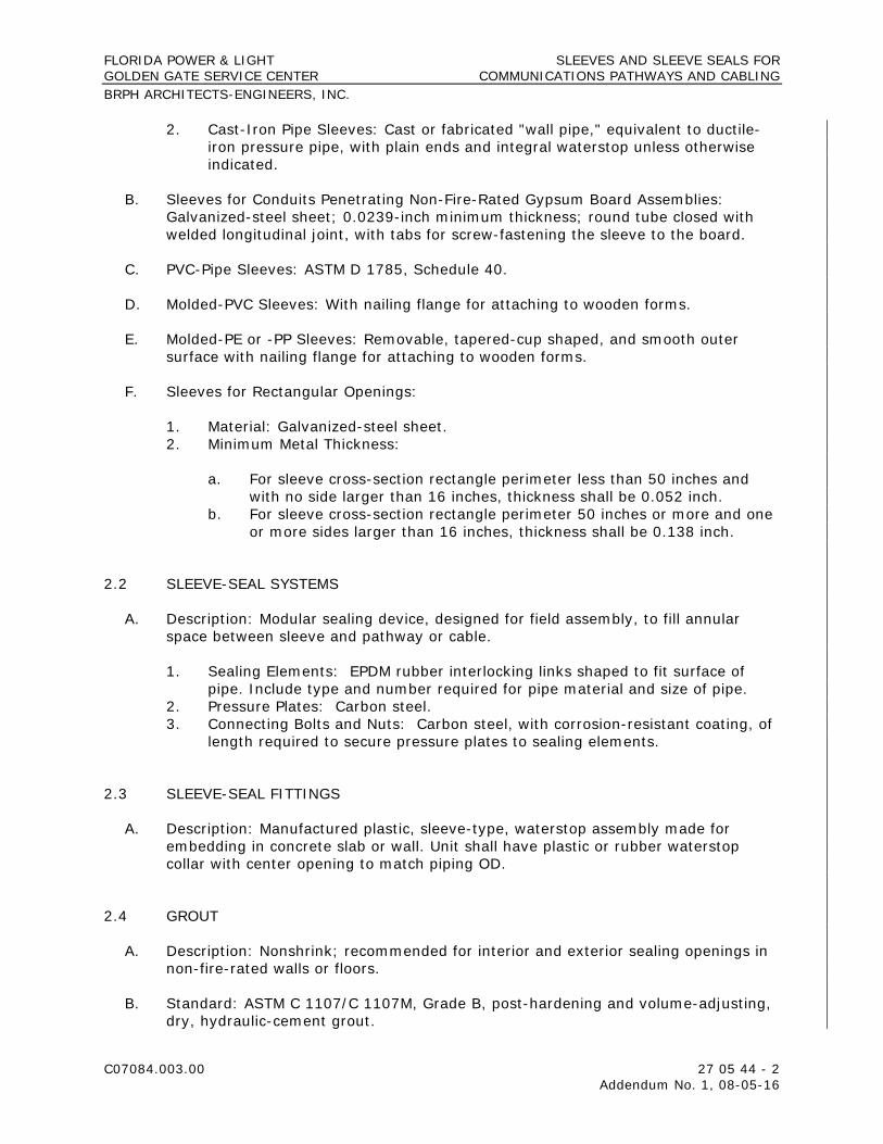
FLORIDA POWER & LIGHT SLEEVES AND SLEEVE SEALS FOR GOLDEN GATE SERVICE CENTER COMMUNICATIONS PATHWAYS AND CABLING BRPH ARCHITECTS-ENGINEERS, INC.
C07084.003.00 27 05 44 - 2 Addendum No. 1, 08-05-16
2. Cast-Iron Pipe Sleeves: Cast or fabricated "wall pipe," equivalent to ductile-iron pressure pipe, with plain ends and integral waterstop unless otherwise indicated.
B. Sleeves for Conduits Penetrating Non-Fire-Rated Gypsum Board Assemblies: Galvanized-steel sheet; 0.0239-inch minimum thickness; round tube closed with welded longitudinal joint, with tabs for screw-fastening the sleeve to the board.
C. PVC-Pipe Sleeves: ASTM D 1785, Schedule 40.
D. Molded-PVC Sleeves: With nailing flange for attaching to wooden forms.
E. Molded-PE or -PP Sleeves: Removable, tapered-cup shaped, and smooth outer surface with nailing flange for attaching to wooden forms.
F. Sleeves for Rectangular Openings:
1. Material: Galvanized-steel sheet. 2. Minimum Metal Thickness:
a. For sleeve cross-section rectangle perimeter less than 50 inches and with no side larger than 16 inches, thickness shall be 0.052 inch.
b. For sleeve cross-section rectangle perimeter 50 inches or more and one or more sides larger than 16 inches, thickness shall be 0.138 inch.
2.2 SLEEVE-SEAL SYSTEMS
A. Description: Modular sealing device, designed for field assembly, to fill annular space between sleeve and pathway or cable.
1. Sealing Elements: EPDM rubber interlocking links shaped to fit surface of pipe. Include type and number required for pipe material and size of pipe.
2. Pressure Plates: Carbon steel. 3. Connecting Bolts and Nuts: Carbon steel, with corrosion-resistant coating, of
length required to secure pressure plates to sealing elements.
2.3 SLEEVE-SEAL FITTINGS
A. Description: Manufactured plastic, sleeve-type, waterstop assembly made for embedding in concrete slab or wall. Unit shall have plastic or rubber waterstop collar with center opening to match piping OD.
2.4 GROUT
A. Description: Nonshrink; recommended for interior and exterior sealing openings in non-fire-rated walls or floors.
B. Standard: ASTM C 1107/C 1107M, Grade B, post-hardening and volume-adjusting, dry, hydraulic-cement grout.

FLORIDA POWER & LIGHT SLEEVES AND SLEEVE SEALS FOR GOLDEN GATE SERVICE CENTER COMMUNICATIONS PATHWAYS AND CABLING BRPH ARCHITECTS-ENGINEERS, INC.
C07084.003.00 27 05 44 - 3 Addendum No. 1, 08-05-16
C. Design Mix: 5000-psi, 28-day compressive strength.
D. Packaging: Premixed and factory packaged.
2.5 SILICONE SEALANTS
A. Silicone Sealants: Single-component, silicone-based, neutral-curing elastomeric sealants of grade indicated below.
1. Grade: Pourable (self-leveling) formulation for openings in floors and other horizontal surfaces that are not fire rated.
B. Silicone Foams: Multicomponent, silicone-based liquid elastomers that, when mixed, expand and cure in place to produce a flexible, nonshrinking foam.
PART 3 - EXECUTION
3.1 SLEEVE INSTALLATION FOR NON-FIRE-RATED ELECTRICAL PENETRATIONS
A. Comply with NECA 1.
B. Comply with NEMA VE 2 for cable tray and cable penetrations.
C. Sleeves for Conduits Penetrating Above-Grade Non-Fire-Rated Concrete and Masonry-Unit Floors and Walls:
1. Interior Penetrations of Non-Fire-Rated Walls and Floors:
a. Seal annular space between sleeve and pathway or cable, using joint sealant appropriate for size, depth, and location of joint. Comply with requirements in Section 07 92 00 "Joint Sealants."
b. Seal space outside of sleeves with mortar or grout. Pack sealing material solidly between sleeve and wall so no voids remain. Tool exposed surfaces smooth; protect material while curing.
2. Use pipe sleeves unless penetration arrangement requires rectangular sleeved opening.
3. Size pipe sleeves to provide 1/4-inch annular clear space between sleeve and pathway or cable unless sleeve seal is to be installed.
4. Install sleeves for wall penetrations unless core-drilled holes or formed openings are used. Install sleeves during erection of walls. Cut sleeves to length for mounting flush with both surfaces of walls. Deburr after cutting.
5. Install sleeves for floor penetrations. Extend sleeves installed in floors 2 inches above finished floor level. Install sleeves during erection of floors.
D. Sleeves for Conduits Penetrating Non-Fire-Rated Gypsum Board Assemblies:
1. Use circular metal sleeves unless penetration arrangement requires rectangular sleeved opening.

FLORIDA POWER & LIGHT SLEEVES AND SLEEVE SEALS FOR GOLDEN GATE SERVICE CENTER COMMUNICATIONS PATHWAYS AND CABLING BRPH ARCHITECTS-ENGINEERS, INC.
C07084.003.00 27 05 44 - 4 Addendum No. 1, 08-05-16
2. Seal space outside of sleeves with approved joint compound for gypsum board assemblies.
E. Roof-Penetration Sleeves: Seal penetration of individual pathways and cables with flexible boot-type flashing units applied in coordination with roofing work.
F. Aboveground, Exterior-Wall Penetrations: Seal penetrations using steel pipe sleeves and mechanical sleeve seals. Select sleeve size to allow for 1-inch annular clear space between pipe and sleeve for installing mechanical sleeve seals.
G. Underground, Exterior-Wall and Floor Penetrations: Install cast-iron pipe sleeves. Size sleeves to allow for 1-inch annular clear space between pathway or cable and sleeve for installing sleeve-seal system.
3.2 SLEEVE-SEAL-SYSTEM INSTALLATION
A. Install sleeve-seal systems in sleeves in exterior concrete walls and slabs-on-grade at pathway entries into building.
B. Install type and number of sealing elements recommended by manufacturer for pathway or cable material and size. Position pathway or cable in center of sleeve. Assemble mechanical sleeve seals and install in annular space between pathway or cable and sleeve. Tighten bolts against pressure plates that cause sealing elements to expand and make watertight seal.
3.3 SLEEVE-SEAL-FITTING INSTALLATION
A. Install sleeve-seal fittings in new walls and slabs as they are constructed.
B. Assemble fitting components of length to be flush with both surfaces of concrete slabs and walls. Position waterstop flange to be centered in concrete slab or wall.
C. Secure nailing flanges to concrete forms.
D. Using grout, seal the space around outside of sleeve-seal fittings.
END OF SECTION 27 05 44

Supplier Q&A8/9/2016
Ref # Date Created
RFP Section Title
QuestionStatus
(New, Open, Closed) FPL Response
1 18-Jul Spec Section 01 05 60, Threshold Inspection
This section references Design Build and elements not within this project:1. Is Threshold Inspection by Owner or Contractor?2. Special Inspector is by Onwer per this section as well, is this correct?
CLOSED - Modified 8/5/16 1. Owner will hire a consultant to perform Threshold Inspections.2. Yes. The Special Inspector, also known as the Threshold Inspector, will be hired by Owner. All other inspections, testing, etc. asscociated with the completion of Contractor's Work is the responsibilty of the Contractor. See updated Speficiations issued as Addendum No. 1, dated 08-05-16, Division 01 05 60.
2 18-Jul Spec Section 01 21 00, Allowances
Please provide Spec Section 01 21 00 for allowances as shown to be referenced as the following sections:01 32 33, Photographic Documentation01 40 00 1.2C Quality Requirements01 79 00 1.2B Demonstration & Training01 91 13 1.3 General Commissioning
CLOSED - Modified 8/5/16 There are NO Allowances. Contractor shall provide a fixed fee for the completion of all Work covered under the Contract Documents including but not limited to Photographic documentation, Quality Assurance Requirements, Demonstration and Training, Equipment and Building Commissioning, etc. See revised Specifications issued as Addendum No. 1, dated 08-05-16, Division 01 21 00.
3 25-Jul Construction Agreement Article 1.3 lists Exhibits I & O, not included in documents provided. Clarify or provide.
CLOSED Exhibits I and O are to be provided by successful bidder General Contractors after selection is made (not to included with bid). Exhibit I is to contain the list of Subcontractors the General Contractor is proposing to use on the Project. Exhibit O is an outline of the Project Team the General Contractor is proposing for the Project.
4 25-Jul Clarifications on Scope Of Work
Is project taxable? CLOSED Yes. The Project is taxable and the General Contractor shall pay all applicable taxes for the purchase of material included in their Scope of Work.
5 25-Jul Clarifications on Scope Of Work
Clarify Mill & Overlay. Sheet A-6 indicates 1422 SYS and Sheets A-7 & A-8 indicate 1,002 SYS.On A-7 & 8 the area east of the new building shows medium duty asphalt ILO Mill & Overlay.
CLOSED - Modified 8/5/16 Mill and overlay has been removed from Sheet A-6. It has been included as medium duty asphalt. Please refer to revsised Sheet A-7. The legend has been removed from Sheet A-8. See Owner's Addendum No. 4 issued on 08-02-16.
6 25-Jul 26 32 16 Provide information on the gen-set being purchased by FPL for install purposes and fuel tankl fill. Include fuel tank size.
CLOSED The generator is 400kW/500kVA Standby Generator; 72 hour run time ; approximately 2,000 gal fuel Tank;
7 25-Jul 01 05 50 Who is responsible for paying the Engineer Of Record to witness water, sewer leak tests and lift station startup?
CLOSED - Modified 8/5/16 Contractor is responsible for all costs associated with the monitoring, testing, inspecting, and start up of facilities and or equipment installed by Contractor. This is inclusive of the fees to have the Engineer of Record witness and monitor the completion of the identified Work. See updated Specificaitons issued as Addendum No. 1, dated 08-05-16, Division 01 05 50.
8 25-Jul 01 12 00 Can we connect to FPL water supply and electrical without being charged useage fees?
CLOSED - Modified 8/5/16 As stated in the Project Specific Requirements/Supplemental Conditions of the Project Specifications, General Contractor is responsible for all applicable temporary utilities (water, sewer, electricity, communication, etc.) and associated fees to establish said temporary utilities. Owner is not responsible for any temporary facilities, trailers, equipment, services, etc. needed by Contractor to perform the applicable work covered in the Project. See updated Specificions issued as Addendum No. 1, dated 08-05-16, Division 01 12 00.
9 25-Jul 01 32 33 This section refers to a cash allowance in section 01 21 00. Section 01 21 00 is not include in the documents received. Please clarify or provide allowance for photographic documention
CLOSED - Modified 8/5/16 There are NO Allowances. Contractor shall provide a fixed fee for the completion of all Work covered under the Contract Documents including but not limited to Photographic documentation, Quality Assurance Requirements, Demonstration and Training, Equipment, and Building Commissioning, etc. See updated Specification issued as Addendum No. 1, dated 08-05-16, Division 01 21 00.
10 25-Jul 01 91 13 This section refers to a cash allowance in section 01 21 00. Section 01 21 00 is not include in the documents received. Please clarify or provide allowance for commissioning. This section refers to unit prices in section 01 22 00, section 01 22 00 is not include in the documents received. Please clarify or provide unit prices for commissioning.
CLOSED - Modified 8/5/16 There are NO Allowances. Contractor shall provide a fixed fee for the completion of all Work covered under the Contract Documents including but not limited to Photographic documentation, Quality Assurance Requirements, Demonstration and Training, Equipment, and Building Commissioning, etc. See updated Specification issued as Addendum No. 1, dated 08-05-16, Division 01 21 00 and 01 22 00.
11 26-Jul Clarifications on Scope Of Work
Provide specification for exterior chainlink Fencing. CLOSED - Modified 8/5/16 See Civil Drawings (7/28/2016), Sheet B-6 detailing chain link fencing with single angle of 3-strand of barb wire. Issued as Owner's Addendum No. 4, dated 08-02-16.
FPL Input Columns
Supplier Q&A Submittal Form Golden Gate Service Center
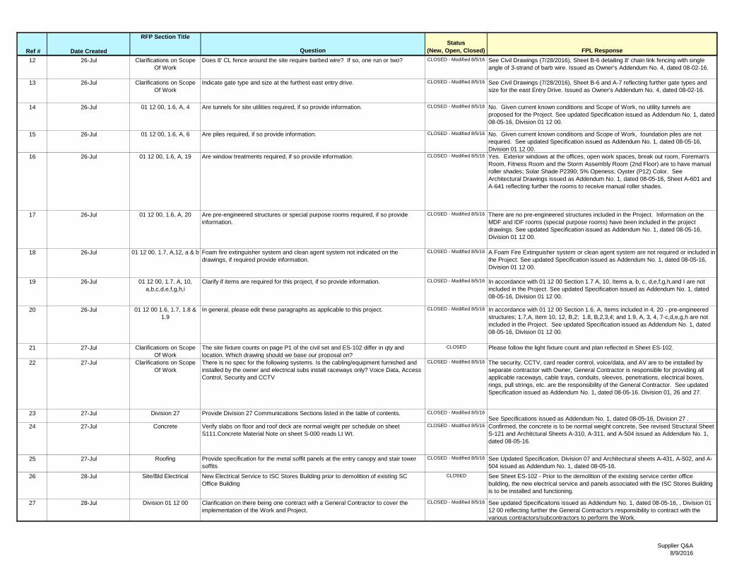
Supplier Q&A8/9/2016
Ref # Date Created
RFP Section Title
QuestionStatus
(New, Open, Closed) FPL Response
12 26-Jul Clarifications on Scope Of Work
Does 8' CL fence around the site require barbed wire? If so, one run or two? CLOSED - Modified 8/5/16 See Civil Drawings (7/28/2016), Sheet B-6 detailing 8' chain link fencing with single angle of 3-strand of barb wire. Issued as Owner's Addendum No. 4, dated 08-02-16.
13 26-Jul Clarifications on Scope Of Work
Indicate gate type and size at the furthest east entry drive. CLOSED - Modified 8/5/16 See Civil Drawings (7/28/2016), Sheet B-6 and A-7 reflecting further gate types and size for the east Entry Drive. Issued as Owner's Addendum No. 4, dated 08-02-16.
14 26-Jul 01 12 00, 1.6, A, 4 Are tunnels for site utilities required, if so provide information. CLOSED - Modified 8/5/16 No. Given current known conditions and Scope of Work, no utility tunnels are proposed for the Project. See updated Specification issued as Addendum No. 1, dated 08-05-16, Division 01 12 00.
15 26-Jul 01 12 00, 1.6, A, 6 Are piles required, if so provide information. CLOSED - Modified 8/5/16 No. Given current known conditions and Scope of Work, foundation piles are not required. See updated Specification issued as Addendum No. 1, dated 08-05-16, Division 01 12 00.
16 26-Jul 01 12 00, 1.6, A, 19 Are window treatments required, if so provide information. CLOSED - Modified 8/5/16 Yes. Exterior windows at the offices, open work spaces, break out room, Foreman's Room, Fitness Room and the Storm Assembly Room (2nd Floor) are to have manual roller shades; Solar Shade P2390; 5% Openess; Oyster (P12) Color. See Architectural Drawings issued as Addendum No. 1, dated 08-05-16, Sheet A-601 and A-641 reflecting further the rooms to receive manual roller shades.
17 26-Jul 01 12 00, 1.6, A, 20 Are pre-engineered structures or special purpose rooms required, if so provide information.
CLOSED - Modified 8/5/16 There are no pre-engineered structures included in the Project. Information on the MDF and IDF rooms (special purpose rooms) have been included in the project drawings. See updated Specification issued as Addendum No. 1, dated 08-05-16, Division 01 12 00.
18 26-Jul 01 12 00, 1.7, A,12, a & b Foam fire extinguisher system and clean agent system not indicated on the drawings, if required provide information.
CLOSED - Modified 8/5/16 A Foam Fire Extinguisher system or clean agent system are not required or included in the Project. See updated Specification issued as Addendum No. 1, dated 08-05-16, Division 01 12 00.
19 26-Jul 01 12 00, 1.7, A, 10, a,b,c,d,e,f,g,h,i
Clarify if items are required for this project, if so provide information. CLOSED - Modified 8/5/16 In accordance with 01 12 00 Section 1.7 A, 10, Items a, b, c, d,e,f,g,h,and I are not included in the Project. See updated Specification issued as Addendum No. 1, dated 08-05-16, Division 01 12 00.
20 26-Jul 01 12 00 1.6, 1.7, 1.8 & 1.9
In general, please edit these paragraphs as applicable to this project. CLOSED - Modified 8/5/16 In accordance with 01 12 00 Section 1.6, A, Items included in 4, 20 - pre-engineered structures; 1.7,A, Item 10, 12, B,2; 1.8, B,2,3,4; and 1.9, A, 3, 4, 7-c,d,e,g,h are not included in the Project. See updated Specification issued as Addendum No. 1, dated 08-05-16, Division 01 12 00.
21 27-Jul Clarifications on Scope Of Work
The site fixture counts on page P1 of the civil set and ES-102 differ in qty and location. Which drawing should we base our proposal on?
CLOSED Please follow the light fixture count and plan reflected in Sheet ES-102.
22 27-Jul Clarifications on Scope Of Work
There is no spec for the following systems. Is the cabling/equipment furnished and installed by the owner and electrical subs install raceways only? Voice Data, Access Control, Security and CCTV
CLOSED - Modified 8/5/16 The security, CCTV, card reader control, voice/data, and AV are to be installed by separate contractor with Owner, General Contractor is responsible for providing all applicable raceways, cable trays, conduits, sleeves, penetrations, electrical boxes, rings, pull strings, etc. are the responsibility of the General Contractor. See updated Specification issued as Addendum No. 1, dated 08-05-16. Division 01, 26 and 27.
23 27-Jul Division 27 Provide Division 27 Communications Sections listed in the table of contents. CLOSED - Modified 8/5/16See Specifications issued as Addendum No. 1, dated 08-05-16, Division 27 .
24 27-Jul Concrete Verify slabs on floor and roof deck are normal weight per schedule on sheet S111.Concrete Material Note on sheet S-000 reads Lt Wt.
CLOSED - Modified 8/5/16 Confirmed, the concrete is to be normal weight concrete, See revised Structural Sheet S-121 and Architctural Sheets A-310, A-311, and A-504 issued as Addendum No. 1, dated 08-05-16.
25 27-Jul Roofing Provide specification for the metal soffit panels at the entry canopy and stair tower soffits
CLOSED - Modified 8/5/16 See Updated Specification, Division 07 and Architectural sheets A-431, A-502, and A-504 issued as Addendum No. 1, dated 08-05-16.
26 28-Jul Site/Bld Electrical New Electrical Service to ISC Stores Building prior to demolition of existing SC Office Building
CLOSED See Sheet ES-102 - Prior to the demolition of the existing service center office building, the new electrical service and panels associated with the ISC Stores Building is to be installed and functioning.
27 28-Jul Division 01 12 00 Clarification on there being one contract with a General Contractor to cover the implementation of the Work and Project.
CLOSED - Modified 8/5/16 See updated Specificaitons issued as Addendum No. 1, dated 08-05-16, , Division 01 12 00 reflecting further the General Contractor's responsibility to contract with the various contractors/subcontractors to perform the Work.

Supplier Q&A8/9/2016
Ref # Date Created
RFP Section Title
QuestionStatus
(New, Open, Closed) FPL Response
28 28-Jul Civil Drawings A-6, A-8, B-1, and B-5
In response to comments received from permitting, Sheets A-8, B-1, and B-5 have been updated; areas impacted are clouded.
CLOSED - Modified 8/5/16 The Civil Engineering drawings (dated 07/20/16 and 7/28/2016); issued as part of Owner's RFP Addendum No. 4, dated 08-02-16 shall replace the previous provided sheets. Areas impacted include deletion of index, additional signage for preserve area, additional cross section detail, and FDOT Type H Drop structure.
29 2-Aug 10 14 23 Verify that the only room signage required is what is indicated on the doors schedule and main entrance sign. If not provide signage schedule or plan indicating location and sign type required.
CLOSED Contractor is responsible for the supplying and the installation of all code required signage and or labeling of spaces, rooms or devices, including those items included on sheet A-601 Door Schedule and sheet A-700 Interior Signage Details, made part of the Project. Furthermore, Contractor is responsible for the installation only of FPL Name Plate signage (room, name, or seat number - See file title ISC-Procument - Sign & Engraving ) for individual workstations, conference room, offices, miscellenaous rooms, etc. that are included in the space and made part of the Project. Owner will provide the FPL Name Plate signage for Contractor's installation. Please see updated Architetural drawings issued as Addendum No. 1, dated 08-05-16, Sheet A-601 and A-700.
30 29-Jul 10 14 23 Provide entry sign text and layout if required for GC to provide CLOSED The signage to be installed adjacent to main building entrance is under review by Owner and not included in Scope of Work at this time. Designation was integrated into plans as part of building entitlements and future interests for building signage.
31 29-Jul 11 24 29.13 Provide Part #'s for the D-Ring and any other equipment required as part of this section. Unable to get pricing without Part #'s. Are we to provide the carabiners, lanyard and harness as well?
CLOSED Part # 2104560, Concrete D-ring anchor. Contractor is not responsible for carabiners, lanyards and harnesses associated with using D-Ring or hooks positioned in the room. Contractor is responsible for the procurement and installation of D-Ring.
32 29-Jul 10 71 13.19 The manufactures listed for the shutter can not meet most of the specification. Such as, none can not provide a Kynar 500 finish, simply powder coated or painted. This size of shutter will require a motor, will need to add a power source on the electrical drawings.
CLOSED Confirmed, the finish to be powder coated and the shuuter to get a motor. See updated Specifications and Architectural and Electrical drawngs issued as Addendum No. 1, dated 08-05-16.
33 1-Aug 01 05 60, Threshold Inspections
Who is responsible for the completion of Special Inspections (a/k/a Threshold Inspections)
CLOSED The Owner shall have performed and be responsible for the costs of Special Inspections (a/k/a Threshold Inspections) in accordance with the work being performed and what is typically covered under Threshold Inspections. Revised Section 01 05 60 of the Specificaiton Book further reflects the work to be performed by Owner. All over inspections, testing, monitoring, etc. is the responsibilty of the General Contractor. See updated Specifications issued as Addendum No. 1, dated 08-05-16, Division 01 05 60.
34 1-Aug 09 68 13 Confirm Carpet is by Owner per section 09 68 13. CLOSED Carpet selection is by Owner in accordance with finish schedule on Sheet A-641 Contractor is responsible for procurement, delivery, and installation of carpeting, base trim and accessories associated with carpeting installation. See updated Specificaiton issued as Addendum No. 1, dated 08-05-16, Divsion 09-68.
35 1-Aug 10 44 16 Confirm FE are by Owner per section 10 44 16 CLOSED Fire Extinguishers are to be purchased and provided by General Contractor in accordance with specificaitons. See updated Specification issued as Addendum No. 1, dated 08-05-16, Division 10 44 16.
36 1-Aug Clarficaitons 1. The Q/A spreadsheet reads civil drawings B-6, A-7 dated 7/28/16, my drawings are dated 5/27/16.2. Fencing question 11-Sheet B-6 specifies gates only. Doesn’t indicate fence material gauge, fence post spacing, top and bottom rail sizing…etc.3. Fencing question 13- the other gate you indicate 25’ sliding gate, just asking for the size of the furthest east entry gate.4. Question 28 indicates new drawings, haven’t received these drawings yet.
CLOSED 1. See top right corner of sheets for Revision dates reflectng 7/28/16. 2. Sheet B-6 includes fencing detail but material to be used shall adhere to the following: galvanized chain link fencing 1" x 3" 8 guage galvanized wirewall; posts are to be 10' O.C., 3" Galvinzed piping, schedule 80, 3.5" OD, 10.25#/FT.; Top rail 1 1/2", 1.66 OD, 2.72#/FT. We do not want to use black vinyl fencing. 3. As identified on Sheet A-7, eastern most entry gate is 20' wide.4. Drawings included Owner's Addendum #4 (dated 8/2/16) addressed these questions.
37 2-Aug Glass Glazing Can you please clarify ULT 226 MPH or FBC ULT 180 mph? CLOSED The wind load design data-wind pressure diagrams can be found on the structural drawings S-000 and S-002.
38 2-Aug Glass Glazing Can you please clarify Level "E" large missile or Level "D large missile? CLOSED The Level of missile impact requirements will be determined by the structural drawings S-000 and S-002 and ASTM E 1996 testing.
39 2-Aug Toilet Partitions Section 1.6.B calls for Class B fire retardant material. Section 2.2.D.1 call for heat sink strips. Heat sinks are obsolete when Class B is used Only used on non-rate material. Are heat sinks to be included?
CLOSED Class C mateials are acceptable.

Supplier Q&A8/9/2016
Ref # Date Created
RFP Section Title
QuestionStatus
(New, Open, Closed) FPL Response
40 2-Aug Toilet Partitions Spec calls for Scranton as "basis of design", listing several other manufacturers. Finish Legend Sheet A-641 indicates TP-1 as toilet partitions by Scranton, Color: Concrete. Scranton color "Concrete" is not offered in Class B materials as required by the spec. Only in unrated. Please clarify, as this cannot be bid per plans and specs as written and drawn.
CLOSED Class C mateials are acceptable.
41 3-Aug Toilet Accessories The Bradley Soap dish is missing the model number, please provide. CLOSED Model number 6562. 42 28-Jul Plumbing Specification
section 22 13 16 3.10, DThe underground portion of the sanitary waste and vent piping according to the specifications section 22 13 16, 3.10, D calls for hubless cast iron pipe this is not standard practice. Please confirm if Pipe is tobe cast Iron or PVC
CLOSED Contractor may use PVC (solid wall sch 40 pipe, socket fittings and solvent-cement) for the underground sanitary system. See updated Specifications issued as part of Addendum No.1, dated 08-05-16, Division 22 for further reference.
43 2-Aug Clarification owner RFI Item 16
Will blinds be required in Rooms 126 Fitness. 128 Foreman, 139 Conference, 227 Storm Assenbly Area. Also will fascia be required at blinds
CLOSED Yes, See response to RFI 16 for further reference. Facia or valance not required.
44 2-Aug L-2 landscaping Trees Plant schedule Confirm 1. Size of (17) Bald Cypress. CLOSED Bald Cypress minimum size: 1.75" Caliper, 10 height min, 4' min. spread.45 2-Aug L-2 landscaping Shrubs Plant shrub schedule confirm Sizes of shrubs -- (604) Coco Plum (509) Dwarf fire
bush, (198) Indian hawthorn (11) Trinette are indicated as both 3 gal 24" and 30" shrubs. Note to get the 24" and 30" heights plants will need to be 7gal which have a substantially higher cost. Please confirm if shrubs are to be 3gal or 7 gal sizes.
CLOSED Note #3 on sheet L-1 states that all plant specifications are a minimum and the contractor shall upsize as needed to meet the specs. Therefore if 7 gal is required to achieve the minimum spec then bid them as 7 gal.
46 2-Aug L-2 landscaping Sod Confirm if 1050 sf of irrigated sod at new building tobe Floratam. Remainder of property to be Bahia.
CLOSED All sod shall be bahia per the owner, no floritam. Please bid accordingly.
47 2-Aug A-7 Site plan Curb Landscape islands
11 new Landscape islands are indicated to be cut into existng paved area. A-7 does not indicate D curb at these islands. Will d curb be required.
CLOSED A "D Curb" is not required for the landscape islands being cut into existing pavement.
48 2-Aug Rolling Exterior shutters 10 71 13.19 Drawing
A311
Please confirm that only Door 100A main entrance gets Rolling Exterior Shutter. CLOSED Yes. The Main entrance door (Door 100A) is the only entrnace to receive the rolling exterior shutter.
49 2-Aug Finish Floor Plan A015, A106, A640, A641
Please confirm if there is a specification section for SC-1 on concrete 1st and 2nd floors
CLOSED Sealed concrete to be H & C concrete and masonry waterproofing sealer (2 coats) to be revised to the finish legend. This finish is to be applied to the rooms with exposed concrete floors such as the mechanical room, electrical room, fire riser, elevator mechanical room., stair, mezzanine, janitors closet, large tool storage, etc.
50 3-Aug Electrical / General We read the notes but didn’t see any mention of MC cable. Are we allowed to use it on this job?
CLOSED MC cable is permitted in concealed spaces (walls & ceilings) but not for homeruns.
51 3-Aug Electrical / General The plans specify square D, can an equivalent be used in bid? CLOSED No. Please follow plans and specificaitons.52 3-Aug Electrical / General We see the T2C penel location but not the location of P2C panel, please advise. CLOSED Panel `P2C’ is located in room MDF Room 204. Refer to drawing E-401
53 3-Aug Sheet P1 & ES-102 The site fixture counts on page P1 of the civil set and ES-102 differ in qty and location. Which drawing should we base our proposal on?
CLOSED See response to RFI 21 and follow site lighting plan on Sheet ES-102
54 3-Aug Low Voltage There is no spec for the following systems. Access Control, Voice / Data, Security, CCTV, are these by Owner?
CLOSED See response to RFI 22 and Scope of Work. Owner through separate contractor hired by Owner will complete Access Control, Voice/Data, secuirty, CCTV. See updated Specificaitons issued as Addendum No. 1, dated 08-05-16, Division 01, 26, and 27.
55 3-Aug Low Voltage We assume Raceways are provided by GC for all above systems, are there wiring spec's available? Plentum rated Cat5 or 6?
CLOSED See Response to RFI 22. Cabling is plentum rated CAT 6 cable.
56 3-Aug Exterior Glass / A-602 Arch drawings are showing a dry glazed curtain wall system. Which is fine, however below is the listed glass type for the exterior system and it is not the FPA tested interlayer. In order for YHC 300 OG to be dry glazed it must be glazed with a .090 Dupont SentryGlas interlayer, please advise.
CLOSED The drawings for the curtain wall system are used to show flashing/ connections/ coordination with the wall system and performance criteria of the curtain wall system. The specifications sections are to be used by the bidder to to determine glazing system. The specification indicates a wet or dry system, the system can be dry or wet to meet the design requirements based on sections 08 44 13 and 08 80 00 and wind-loading as called out on the structural drawings.
57 3-Aug A-101 / Fire Spray The sections say steel with fire spray see A-101. A-101 shows all 0’s for any fire rating yet there is a detail of a fire rated beam UL D902 on A-103. What exactly receives fire spray?
CLOSED The Sections say to see AL-101. AL-101 is the Life Safety Sheet that shows the extents of fire rated strucure UL D902. See the hatched area on the First Floor Plan. The rating indicated on the table are for the general stucture building elements.
58 3-Aug Civil / Utilities What is the elevation for the Weir? CLOSED The control strucute is a Type H box modified with the following orifices and weirs. One, 3-inch orifice at elevation 9.30, one 5-inch wide notch at elevation 11.00. The top of the structure (grate elevation) is set at 11.88. The invert of the 18" pipes is elevation 9.30. The sump elevation in the box is set at elevation 7.40. Please refer to revised Sheet B-5 issued as part of Owner's Addendum #4, dated 08-02-16 for the detail.

Supplier Q&A8/9/2016
Ref # Date Created
RFP Section Title
QuestionStatus
(New, Open, Closed) FPL Response
59 3-Aug Civil / Utilities What is the elevation for the "H" Drop Structure? CLOSED The control strucute is a Type H box modified with the following orifices and weirs. One, 3-inch orifice at elevation 9.30, one 5-inch wide notch at elevation 11.00. The top of the structure (grate elevation) is set at 11.88. The invert of the 18" pipes is elevation 9.30. The sump elevation in the box is set at elevation 7.40. Please refer to revised Sheet B-5 issued as part of Owner's Addendum No. 1, dated 08-02-16, for the detail.
60 4-Aug Drawing L-2 RFI #1 - The following plants are specified as 3 gallon containers but the height does not coincide with the size of the container. Please clarify if these heights have to met at the time of planting.1)Cocoplum 3 gallon - typically 24" height is max, if 30" is required, it will be a 7 gallon. 2)Dwarf Firebush 3 gallon - typically 14-16' max, if 24" ht is required, it will be a 7 gallon. Indian Hawthorn 3 gallon - typically 12-14" ht, if 24" ht is required, it will be a 7 gallon. 3)Trinette Arboricola 3 gallon - typically 16-18" ht, if 24" ht is required, it will be a 7 gallon
CLOSED Heights provided must be met at time of planting. The gallon size provided is a minimum. If a larger gallon size is required to meet the minimum height or other specifications then it should be bid accordingly
61 4-Aug Drawing L-1 & L-2 Sod was not specified, bid Bahia throughout, please clarify if a different variety is to be used
CLOSED All sod shall be bahia per the owner, no floritam. Please bid accordingly.
62 4-Aug Drawing L-1 & L-2 Bald Cypress - size was not specified on plan, bid 25 gallon, please clarify CLOSED Bald Cypress minimum size: 1.75" Caliper, 10 height min, 4' min. spread.63 4-Aug 01 12 00, 1.4,B, 1&2 Indicates Owner is providing Office Trailer & Phone Service. Please Comfirm. CLOSED No. See updated Specificaitons issued as part of Addendum No. 1, dated 08-05-16,
Division 01 12. Owner is not responsible for providing Office trailer or phone service for Contractor's use.
64 5-Aug Addendum No. 1 In connection with responses to RFI's and clarificaitons of Scope of Work for Contractors to provide and perform, Specificaitons and Drawings issued as Addendum No. 1, dated 08-05-16 , have been issued and made part of Project.
CLOSED Documents included in Addendum No. 1 dated 08-05-16 include the following:1. Specificaiton Book Addendum No. 1 August 5, 2016 (includes revised table of contents and specificaiton Divisions updated.2. Addendum No. 1 Narrative dated August 5, 2016 by BRPH3. Architectural Drawings updated per Addendum No. 1, dated 08-05-16. 4. Civil Engineering Drawings B-1 and B-5, reflecting corrections to revision numbers ONLY. The Delta was changed to "5".5. Electrical Drawings updated per Addendum No. 1, dated 08-05-16.6. Mechanical Drawing updated per Addendum No. 1, dated 08-05-16.7. Plumbing Drawing updated per Addendum No. 1, dated 08-05-16.8. Structural Drawing updated per Addendum No. 1, dated 08-05-16.
656667686970717273747576777879808182838485868788899091929394


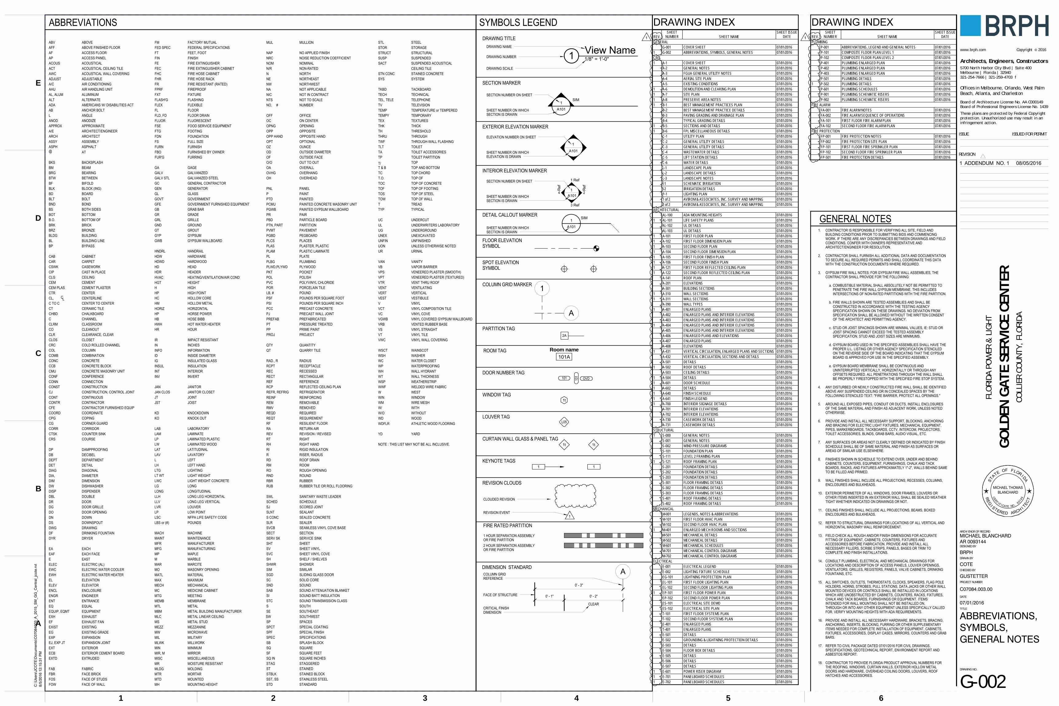
ABBREVIATIONS
VENTED RUBBER BASEVRB
STAINED CONCRETESTN CONC
RUBBER TILE OR ROLL FLOORINGRUB
SUSPENDED ACOUSTICALCEILING TILE
NOTE : THIS LIST MAY NOT BE ALL INCLUSIVE.
YD YARD
WINDOW
ATHLETIC WOOD FLOORING
WATERPROOFING
WAINSCOT
WIRE MESH
WALL HYDRANT
WELDED WIRE FABRIC
WALL THICKNESSWEATHERSTRIP
WASHER
WP
WSHWSCT
WWF
WTWSP
WDFLR
WM
WH
WIN
WATER CLOSET
WOODWD
WC
WITH
WEST
W/
W
VENEERED PLASTER (TEXTURED)
VINYL STRAIGHTVS
VPTVENEERED PLASTER (SMOOTH)VPS
VENTILATINGVENT
VANITY
VINYL COVEVC
VAN
UNFIN UNFINISHEDUNEXCAVATEDUNEXUNDERGROUNDUG
TWF THROUGH-WALL FLASHING
TOILET PARTITIONTP
TOP OF WALLTOW
TACKBOARD
TOILETTLT
TKBD
TEXTURES
THRESHOLDTHKTEX
TEMPORARYTEMPERATURE or TEMPEREDTEMP
TEMPY
TOILET ACCESSORIESTA
SHEET VINYLSHEET VINYL COVE
SEAMLESS VINYL COVE BASE
SANITARY WASTE LEADER
SOUTHWESTSW
SWL
SVCB
SVCSV
STAINEDSTAGGERED
STAINED BLOCK
SOUND TRANSMISSION CLASSSTC
STBLK
STAGST
SPECIAL FINISHSPF
SEALANT
SEALER
SOUND
SPACESSPECIAL COATINGSPCT
SP
SND
SLR
SLNTSCORED JOINTSJ
SOUND BATT INSULATIONSI
SHOWERSHWRSHELF / SHELVESSH
SLIDING GLASS DOORSGD
SERVICE SINKSERV SK
SOUTHEAST
SECTIONSECT
SE
SB SPLASH BLOCK
SOUND ATTENUATION BLANKETSAB
RF
RT RIGHT
ROUNDRND
RMV REMOVED
RESILIENT FLOOR
RIGHT HANDRIGID INSULATION
RHRI
REV REVISION / REVISED
REM REMOVABLE
RECTANGULARRECTREC RECESSED
REFLECTED CEILING PLANRCP
RBR RUBBER
RADIUSRAD., R
PKT POCKET
QUANTITYQTY
PAINTED
PAVEMENT
PTD
PVMT
POLISH
PORCELAIN TILE
PRIME PAINTPP
POR
POL
PANELPNL
PLUMBINGPLBG
PLAM PLASTIC LAMINATE
PARTICLE BOARD
PRECAST CONCRETE
PEGBOARDPGBD
PCC
PBD
P PAINT
OPT
OVHG OVERHANG
OPTIONAL
OH
OUTSIDE FACE
OVERHEAD
OFOUT TO OUTOVERALLOA
O/O
NWNE NORTHEAST
NORTHWEST
NRC NOISE REDUCTION COEFFICIENT
NON-RATED
NO APPLIED FINISHNAP
N/R
MICROWAVEMW
MUL MULLION
MORTARMTR
MEETINGMTG
METAL STUDMS
MAPLEMP
MILLWORKMLWK
MLDG MOLDING
METAL LINEAR CEILINGMLC
MOUNTING HEIGHTMH
MANUFACTURINGMFG
MEMBRANEMEMB
MEDICINE CABINETMC
MARCITE
MACHINE
MAR
MACH
MARBLEM
LW LAMINATED WOOD
LVR LOUVER
LTG LIGHTING
LSC NFPA LIFE SAFETY CODE
LAMINATED PLASTICLP
LONGITUDINAL
LEFT HAND
LONG
LH
POUNDSLBS or (#)
LATITUDINALLAT
L LEFT
KNOCKDOWNKD
JOISTJST
INSIDE DIAMETERINSULATED GLASS
INCHESINFORMATION
IMPACT RESISTANTIR
INFOIN
IGID
HOT WATER HEATERHWH
HP HORSE POWER
HNDRL HANDRAIL
HDWD HARDWOOD
HEADERHDRHEADHD
GT GROUT
GRILLEGRLGR GRADE
GC GENERAL CONTRACTOR
GRAB BARGB
FIRE EXTINGUISHER CABINET
FIXTUREFXT
FURRINGFUR'G
FOOD SERVICE EQUIPMENT
FULL SIZE
FSE
FS
FIREPROOFFPRF
FACE OF WALLFACE OF STUDS
FOWFOS
FLEXIBLEFLEX
FABRIC
FURNISHED BY OWNER
FACE BRICKFBR
FBO
FAB
EXTRUDEDEXTD
ELECTRIC WATER HEATEREWH
ENTRANCEEQUALEQ
ENT
ENCLOSUREENCL
EXISTING GRADEEG
EXTERIOR CEMENT BOARDECB
EACH FACEEAF
DW
DYR DRYER
DISHWASHER
DR DOOR
DP DAMPPROOFING
DISP DISPENSER
DF DRINKING FOUNTAIN
DECIBELDB
CTSK COUNTER SINK
CENTERCTR
CASEWORKCSWK
COPINGCPG
CORRIDORCORR
CONFERENCECONF
CLEANOUTCOCLASSROOMCLRM
CAST IN PLACECIP
CHALKBOARDCHBD
CORNER GUARDCG
BETWEENBTW
BS BOTH SIDES
BRK BRICK
BOT
BP BYPASS
BOTTOM
BONDBND
BUILDING LINEBL
BKS BACKSPLASH
BIFOLDBF
ACOUS
ADJUST
AHU
ALT
APACOUSTICAL
ADJUSTABLE
AIR HANDLING UNIT
ALTERNATE
ACCESS PANEL
AWC
ASSY ASSEMBLY
ACOUSTICAL WALL COVERING
ASPHALTASPH
AFF ABOVE FINISHED FLOOR
SQ
STORSTL
STDSST, SS
SQ INSF
TVTEL, TELETECH
SYS
SACTSUSPSTRUCT
HIGH
HOLLOW METAL
HIGH POINTHOLLOW CORE
HEIGHT
HARDWARE
INVERTINTERIORINSULATION
HOUR
HORIZONTAL
HOSE BIBB
HEATING/VENTILATION/AIR COND
TELEVISIONTELEPHONETECHNICAL
SYSTEM
SUSPENDEDSTRUCTURALSTORAGESTEEL
STANDARDSTAINLESS STEEL
SQUARE INCHESSQUARE FEETSQUARE
TOP
T.O.
TOFTOC
T & BTC
T/
T
THRU
URUON
ULUC
TYP
TOS
LABORATORY
KNOCK OUT
JANITOR CLOSETJANITOR
JOINT
LOW POINT
LONG LEG VERTICAL
LONG
LIGHT WEIGHT
LAVATORY
LAMINATE
LONG LEG HORIZONTAL
LIGHT WEIGHT CONCRETE
V
VT
VGWB
VCT
VESTVERT
VTR
VB
W/O
VWC
MEZZANINE
METAL
MECHANICALMAXIMUMMATERIALMASONRY OPENING
MANUFACTURERMAINTENANCE
NORTH
NOMINAL
MOUNTED
MISCELLANEOUSMIRRORMINIMUM
MILITARY
MOISTURE RESISTANT
METAL BUILDING MANUFACTURER
TOP OF
VINYL WALL COVERINGVINYL TILE
VINYL COVERED GYPSUM WALLBOARD
VINYL COMPOSITION TILE
VESTIBULEVERTICAL
VENT THRU ROOF
VAPOR BARRIER
VINYL
URINAL
UNDERWRITERS LABORATORY
UNLESS OTHERWISE NOTED
UNDERCUT
TYPICAL
TOP OF STEELTOP OF FOOTINGTOP OF CONCRETE
TOP AND BOTTOMTOP CHORD
TREAD
THROUGH
WITHOUT
THICKTH
HGTHVAC
HDW
H
HCHM
HP
HORIZ
HB
HR
INTINSUL
INV
BEAMBEARINGBRG
BM
JAN
JT
KO
LAB
LAV
LGLWC
LLVLLH
LP
LAM
BOLT
BUILDINGBRONZE
BOARD
BOTTOM OF
CARPETCABINET
BLDGBRZ
BLTBD
B.O.
CARCAB
CENTERLINE
CEMENTCEILING
CHANNEL
LCCL,
CEM PLASCEMCLG
C
CLR
CTC TO C
CCB
CLEARANCE, CLEAR
CERAMIC TILECENTER TO CENTER
CEMENT PLASTER
CONCRETE BLOCK
MFR
MATLMO
MECH
MEZZ
MTL
MAX
MIN
MTD
MISCMR
MBM
N
NOM
MIL
COMBINATIONCOLUMN
COURSE
CONNECTION
CONCRETECOMBCOLCRC
CRS
CONSTCONN
CMU
CONC
CONTRACTORCONTINUOUS
DETAILDEPARTMENT
COORDINATECFECONTRCONTCJ
DETDEPT
COORDCONTRACTOR FURNISHED EQUIP
CONSTRUCTION, CONTROL JOINTCONSTRUCTION
CONCRETE MASONRY UNIT
COLD ROLLED CHANNELCLOSETCLOS
BLOCK (ING)BLK
MIR, M
MAINT
LT WT
JAN CLOS
OPENINGON CENTEROFFICE
NUMBERNOT TO SCALENOT IN CONTRACTNOT APPLICABLE
PAIR
OUTSIDE DIAMETEROUNCE
OPPOSITE HANDOPPOSITE
PAINTED GYPSUM WALLBOARDPAINTED CONCRETE MASONRY UNIT
POUND
POLYVINYL CHLORIDE
PLYWOOD
PLATE
PLACESPLASTER, PLASTIC
RISER, RADIUS
RECEPTACLE
QUARRY TILE
PROJECT
PRESSURE TREATEDPREFABRICATED
POUNDS PER SQUARE INCHPOUNDS PER SQUARE FOOT
PARTITION
ROOMROOF DRAIN
RETURN AIR
REQUIREMENTREQUIRED
REINFORCINGREFRIGERATOR
REFERENCE
SPECIFICATIONS
SOLID CORE
SIMILAR
SHEET
SEALED CONCRETE
SCHEDULE
SOUTH
ROUGH OPENING
NICNA
#NO,NTS
OFF
OPNGOC
OPP
ODOZ
PCMU
PRPGWB
DOOR GRILLE
DOUBLE
DIMENSIONDIAMETER
DOWN
DRAWINGDOWNSPOUT
�
DG
DBL
DIMDIA,
DWGDSDNDO
EAST
EACH
ELECTRIC (AL)
ENGINEER
ELEVATORELEVATION
EELEC
EA
ENGR
ELEVEL
EWC ELECTRIC WATER COOLER
DOOR OPENING
PLAS
PL
PLCS
LB, #
PVC
PSIPSF
PT
PROJ
QT
R
RCPT
EXPANSION
EXISTINGEXHAUST FANEXHAUST
EXTERIOR
EXP
EXISTEFEXH
EXTEJ, EXP JT
FINISHFEET, FOOT
FEFINFTFED SPEC
FRFHRFHCFEC
FM
FIRE RESISTANT (RATED)FIRE HOSE RACKFIRE HOSE CABINET
FIRE EXTINGUISHER
FEDERAL SPECIFICATIONSFACTORY MUTUAL
EXPANSION JOINT
EQUIPMENTEQUIP, EQMT
REF
REQD
REINF
RA
RMRD
REQT
S
SIM
SHT
SPEC
SC
RO
FOOTING
FLUORESCENTFLOOR DRAINFLOOR
FURNISH
FOUNDATION
FLUOR
FTG
FLD, FDFL
FURN
FDN
GLASSGENERATOR
GALVANIZED
GYPSUM
GROUND
GOVERNMENTGLGEN
GALV STLGALV
GYP
GND
GFEGOVT
GAGEGA
GOVERNMENT FURNISHED EQUIPMENT
GALVANIZED STEEL
GYPSUM WALLBOARDGWB
FLASHINGFLASH'G
S CONC
SCHED
REFR, REFRIG
PREFAB
PLWD,PLYWD
PTN, PART
OPP HAND
DIAGONALDIAG
PJ PRECAST WALL JOINT
ADA AMERICANS W/ DISABILITIES ACT
ABOVE
ACOUSTICAL CEILING TILE
AIR CONDITIONING
ARCHITECT/ENGINEER
ACCESS FLOOR
@
ANODAPPROXA/EARCH
ANODIZEAPPROXIMATE
ARCHITECT
AT
A/C
AL, ALUM
ABL
ABV
ACT
AF
ALUMINUM
ANCHOR BOLTANGLE
101101
A101
1
A1011
1
L05
2A
1t
DRAWING TITLE
SECTION MARKER
EXTERIOR ELEVATION MARKER
INTERIOR ELEVATION MARKER
FLOOR ELEVATIONSYMBOL
SYMBOLS LEGEND
DETAIL CALLOUT MARKER
A
1t
SPOT ELEVATIONSYMBOL
COLUMN GRID MARKER
PARTITION TAG
DOOR NUMBER TAG
ROOM TAG Room name101A
DRAWING NUMBER
DRAWING SCALE
DRAWING NAME
SECTION NUMBER ON SHEET
SHEET NUMBER ON WHICHSECTION IS DRAWN
ELEVATION NUMBER ON SHEET
SHEET NUMBER ON WHICHELEVATION IS DRAWN
SECTION NUMBER ON SHEET
SHEET NUMBER ON WHICHSECTION IS DRAWN
WINDOW TAG
LOUVER TAG
CURTAIN WALL GLASS & PANEL TAG1t
KEYNOTE TAGS
REVISION CLOUDS
1
FIRE RATED PARTITION
1 HOUR SEPARATION ASSEMBLYOR FIRE PARTITION2 HOUR SEPARATION ASSEMBLYOR FIRE PARTITION
SHEET NUMBER ON WHICHSECTION IS DRAWN
DIMENSION STANDARDA
FACE OF STRUCTURE
CRITICAL FINISHDIMENSION
COLUMN GRIDREFERENCE
REVISION EVENT
CLOUDED REVISION
0' - 3"
0' - 1"
CLEAR
0' - 2"
1 View Name1/8" = 1'-0"
A101
1SIM
OVD
1
A101
SIM
1 Ref
1
Ref
1 Ref
1
Ref
1 1
2
3
4
GENERAL NOTES1. CONTRACTOR IS RESPONSIBLE FOR VERIFYING ALL SITE, FIELD AND
BUILDING CONDITIONS PRIOR TO SUBMITTING BIDS AND COMMENCING WORK. IF THERE ARE ANY DISCREPANCIES BETWEEN DRAWINGS AND FIELD CONDITIONS, CONFER WITH OWNER'S REPRESENTATIVE AND ARCHITECT/ENGINEER FOR RESOLUTION.
2. CONTRACTOR SHALL FURNISH ALL ADDITIONAL DATA AND DOCUMENTATION TO SECURE ALL REQUIRED PERMITS AND SHALL COORDINATE THIS DATA WITH THE CONSTRUCTION DOCUMENTS WHERE REQUIRED.
3. GYPSUM FIRE WALL NOTES; FOR GYPSUM FIRE WALL ASSEMBLIES, THE CONTRACTOR SHALL PROVIDE FOR THE FOLLOWING:
a. COMBUSTIBLE MATERIAL SHALL ABSOLUTELY NOT BE PERMITTED TO PENETRATE THE FIRE WALL GYPSUM MEMBRANE. THIS INCLUDES INTERSECTIONS OF NON-RATED PARTITIONS WITH THE FIRE PARTITION.
b. FIRE WALLS SHOWN ARE TESTED ASSEMBLIES AND SHALL BE CONSTRUCTED IN ACCORDANCE WITH THE TESTING AGENCY SPECIFICATION SHOWN ON THESE DRAWINGS. NO DEVIATION FROM SPECIFICATION SHALL BE ALLOWED WITHOUT THE WRITTEN CONSENT OF THE ARCHITECT AND PERMITTING AGENCY.
c. STUD OR JOIST SPACINGS SHOWN ARE MINIMAL VALUES, IE: STUD OR JOIST SPACING CANNOT EXCEED THE TESTED ASSEMBLY SPECIFICATION. STUD AND JOIST SIZES ARE MINIMUMS.
d. GYPSUM BOARD USED IN THE SPECIFIED ASSEMBLIES SHALL HAVE THE PROPER U.L. LISTING OR OTHER AGENCY SPECIFICATION STENCILED ON THE REVERSE SIDE OF THE BOARD INDICATING THAT THE GYPSUM BOARD IS APPROVED FOR USE IN THE SPECIFIED ASSEMBLY.
e. GYPSUM BOARD MEMBRANE SHALL BE CONTINUOUS AND UNINTERRUPTED VERTICALLY, HORIZONTALLY OR THROUGH ANY OFFSETS REQUIRED. ALL PENETRATIONS THROUGH THE WALL SHALL BE PROPERLY FIRESTOPPED WITH THE SPECIFIED FIRE STOP SYSTEM.
4. ANY DISTURBED OR NEWLY CONSTRUCTED FIRE WALL SHALL BE IDENTIFIED ABOVE ANY SUSPENDED CEILING OR IN CONCEALED SPACES BY THE FOLLOWING STENCILED TEXT: "FIRE BARRIER, PROTECT ALL OPENINGS."
5. AROUND ALL EXPOSED PIPES, CONDUIT OR DUCTS, INSTALL ENCLOSURES OF THE SAME MATERIAL AND FINISH AS ADJACENT WORK, UNLESS NOTED OTHERWISE.
6. PROVIDE AND INSTALL ALL NECESSARY SUPPORT, BLOCKING, ANCHORING AND BRACING FOR ELECTRIC LIGHT FIXTURES, MECHANICAL EQUIPMENT, PIPES, MARKERBOARDS, TACKBOARDS, CCTV, INTERCOM, PROJECTORS, TOILET ACCESSORIES, BLINDS, GRAB BARS, AUDIO VISUAL, ETC.
7. ANY SURFACES OR AREAS NOT CLEARLY DEFINED OR INDICATED BY FINISH SCHEDULE SHALL BE OF SAME MATERIAL AND FINISH AS SURFACES OR AREAS OF SIMILAR USE ELSEWHERE.
8. FINISHES SHOWN IN SCHEDULE TO EXTEND OVER, UNDER AND BEHIND CABINETS, COUNTERS, EQUIPMENT, FURNISHINGS, CHALK AND TACK BOARDS, RACKS, AND FIXTURES APPROXIMATELY 1"-2", WALLS BEHIND SAME TO BE FILLED AND PRIMED.
9. WALL FINISHES SHALL INCLUDE ALL PROJECTIONS, RECESSES, COLUMNS, ENCLOSURES AND BULKHEADS.
10. EXTERIOR PERIMETER OF ALL WINDOWS, DOOR FRAMES, LOUVERS OR OTHER ITEMS INSERTED IN AN EXTERIOR WALL SHALL BE SEALED WEATHER TIGHT WHETHER INDICATED ON DRAWINGS OR NOT.
11. CEILING FINISHES SHALL INCLUDE ALL PROJECTIONS, BEAMS, BOXED ENCLOSURES AND BULKHEADS.
12. REFER TO STRUCTURAL DRAWINGS FOR LOCATIONS OF ALL VERTICAL AND HORIZONTAL MASONRY WALL REINFORCEMENT.
13. FIELD CHECK ALL ROUGH AND/OR FINISH DIMENSIONS FOR ACCURATE FITTING OF EQUIPMENT, CABINETS, COUNTERS, FIXTURES AND ACCESSORIES BEFORE FABRICATION. PROVIDE AND INSTALL ALL NECESSARY FILLERS, SCRIBE STRIPS, PANELS, BASES OR TRIM TO COMPLETE AND FINISH INSTALLATIONS.
14. CONSULT PLUMBING, ELECTRICAL AND MECHANICAL DRAWINGS FOR LOCATIONS AND DESCRIPTION OF ACCESS PANELS, LOUVER OPENINGS, VENTILATORS, GRILLES, REGISTERS, PANELS, VALVE CABINETS, DRINKING FOUNTAINS, ETC.
15. ALL SWITCHES, OUTLETS, THERMOSTATS, CLOCKS, SPEAKERS, FLAG POLE HOLDERS, HORNS, STROBES, PULL STATIONS, DATA JACKS OR OTHER WALL MOUNTED DEVICES OR CONTROLS SHALL BE INSTALLED IN LOCATIONS WHICH ARE UNOBSTRUCTED BY CABINETS, COUNTERS, RACKS, FIXTURES, CHALK AND TACK BOARDS, FURNISHINGS OR EQUIPMENT. ITEMS INTENDED FOR WALL MOUNTING SHALL NOT BE INSTALLED ON, THROUGH OR INTO ANY OTHER EQUIPMENT UNLESS SPECIFICALLY CALLED FOR. VERIFY MOUNTING HEIGHTS WITH ADA REQUIREMENTS.
16. PROVIDE AND INSTALL ALL NECESSARY HARDWARE, BRACKETS, BRACING, ANCHORING, INSERTS, BLOCKING, FURRING OR OTHER SUPPLEMENTARY ITEMS NEEDED FOR COMPLETE INSTALLATION OF EQUIPMENT, CABINETS, FIXTURES, ACCESSORIES, DISPLAY CASES, MIRRORS, COUNTERS AND GRAB BARS.
17. REFER TO CIVIL PACKAGE DATED 07/01/2016 FOR CIVIL DRAWINGS, SPECIFICATIONS, GEOTECHNICAL REPORT, ENVIRONMENT REPORT AND ASBESTOS REPORT.
18. CONTRACTOR TO PROVIDE FLORIDA PRODUCT APPROVAL NUMBERS FOR THE ROOFING, WINDOWS, CURTAIN WALLS, EXTERIOR HOLLOW METAL DOORS AND HARDWARE, OVERHEAD COILING DOORS, LOUVERS, ROOF HATCHES AND ACCESSORIES.
Architects, Engineers, Constructors
These plans are protected by Federal Copyrightprotection. Unauthorized use may result in aninfringement action.
www.brph.com ©Copyright 2016
5700 North Harbor City Blvd | Suite 400Melbourne | Florida | 32940321-254-7666 | 321-259-4703 f
Board of Architecture License No. AA C000149Board of Professional Engineers License No. 1439
Offices in Melbourne, Orlando, West PalmBeach, Atlanta, and Charleston
REVISION
DRAWING NO.
TITLE
PROJECT NUMBER
CHECKED BY
DRAWN BY
DESIGNED BY
ARCH/ENGR OF RECORD
DATE
ISSUE ISSUED FOR PERMIT
54321 6
A
B
C
D
E
C:\
Use
rs\J
CO
TE\D
ocum
ents
\C07
0840
03_A
_201
5_S
M_G
G_C
entr
al_j
cote
.rvt
8/5/
2016
12:
15:3
1 P
M
FLO
RIDA
PO
WER
& L
IGH
T
BRPH
COTE
GO
LDEN
GAT
E SE
RVIC
E CE
NTE
RCO
LLIE
R CO
UNT
Y, F
LORI
DA
C07084.003.00
G-002
07/01/2016
ABBREVIATIONS,SYMBOLS,GENERAL NOTES
GUSTETTER
MICHAEL BLANCHARDAR 0093144
DRAWING INDEXREV.
SHEETNUMBER SHEET NAME
SHEET ISSUEDATE
PLUMBINGP-001 ABBREVIATIONS, LEGEND AND GENERAL NOTES 07/01/2016P-101 COMPOSITE FLOOR PLAN LEVEL 1 07/01/2016P-102 COMPOSITE FLOOR PLAN LEVEL 2 07/01/2016P-401 PLUMBING ENLARGED PLAN 07/01/2016P-402 PLUMBING ENLARGED PLAN 07/01/2016P-403 PLUMBING ENLARGED PLAN 07/01/2016P-501 PLUMBING DETAILS 07/01/2016
1 P-502 PLUMBING DETAILS 07/01/2016P-601 PLUMBING SCHEDULES 07/01/2016P-901 PLUMBING SCHEMATIC RISERS 07/01/2016P-902 PLUMBING SCHEMATIC RISERS 07/01/2016
FIRE ALARMFA-001 FIRE ALARM NOTES 07/01/2016FA-002 FIRE ALARM SEQUENCE OF OPERATIONS 07/01/2016FA-101 FIRST FLOOR FIRE ALARM PLAN 07/01/2016FA-102 SECOND FLOOR FIRE ALARM PLAN 07/01/2016
FIRE PROTECTIONFP-001 FIRE PROTECTION NOTES 07/01/2016FP-002 FIRE PROTECTION SITE PLAN 07/01/2016FP-101 FIRST FLOOR FIRE SPRINKLER PLAN 07/01/2016FP-102 SECOND FLOOR FIRE SPRINKLER PLAN 07/01/2016FP-501 FIRE PROTECTION DETAILS 07/01/2016
DRAWING INDEXREV.
SHEETNUMBER SHEET NAME
SHEET ISSUEDATE
GENERALG-001 COVER SHEET 07/01/2016
1 G-002 ABBREVIATIONS, SYMBOLS, GENERAL NOTES 07/01/2016CIVIL1 A-1 COVER SHEET 07/01/2016
A-2 GENERAL NOTES 07/01/2016A-3 FGUA GENERAL UTILITY NOTES 07/01/2016A-4 AERIAL SITE PLAN 07/01/2016A-5 EXISTING CONDITIONS 07/01/2016
1 A-6 DEMOLITION AND CLEARING PLAN 07/01/20161 A-7 SITE PLAN 07/01/20161 A-8 PRESERVE AREA NOTES 07/01/20161 B-1 BEST MANAGEMENT PRACTICES PLAN 07/01/2016
B-2 BEST MANAGEMENT PRACTICE DETAILS 07/01/2016B-3 PAVING GRADING AND DRAINAGE PLAN 07/01/2016B-4 TYPICAL GRADING DETAILS 07/01/2016
1 B-5 SECTIONS AND DETAILS 07/01/20161 B-6 FPL MISCELLANEOUS DETAILS 07/01/2016
C-1 UTILITY PLAN 07/01/2016C-2 GENERAL UTILITY DETAILS 07/01/2016C-3 GENERAL UTILITY DETAILS 07/01/2016C-4 WASTEWATER DETAILS 07/01/2016C-5 LIFT STATION DETAILS 07/01/2016C-6 WATER DETAILS 07/01/2016L-1 LANDSCAPE PLAN 07/01/2016L-2 LANDSCAPE DETAILS 07/01/2016L-3 LANDSCAPE NOTES 07/01/2016I-1 SCHEMATIC IRRIGATION 07/01/2016I-2 IRRIGATION DETAILS 07/01/2016P-1 LIGHTING PLAN 07/01/20161 of 2 AVIROM & ASSOCIATES, INC. SURVEY AND MAPPING 07/01/20162 of 2 AVIROM & ASSOCIATES, INC. SURVEY AND MAPPING 07/01/2016
ARCHITECTURALAL-100 ADA MOUNTING HEIGHTS 07/01/2016
1 AL-101 LIFE SAFETY PLANS 07/01/2016AL-102 UL DETAILS 07/01/2016AL-103 UL DETAILS 07/01/2016
1 A-101 FIRST FLOOR PLAN 07/01/20161 A-102 FIRST FLOOR DIMENSION PLAN 07/01/20161 A-103 SECOND FLOOR PLAN 07/01/20161 A-104 SECOND FLOOR DIMENSION PLAN 07/01/20161 A-105 FIRST FLOOR FINISH PLAN 07/01/20161 A-106 SECOND FLOOR FINISH PLAN 07/01/20161 A-121 FIRST FLOOR REFLECTED CEILING PLAN 07/01/20161 A-122 SECOND FLOOR REFLECTED CEILING PLAN 07/01/2016
A-141 ROOF PLAN 07/01/2016A-201 ELEVATIONS 07/01/2016A-301 BUILDING SECTIONS 07/01/2016
1 A-310 WALL SECTIONS 07/01/20161 A-311 WALL SECTIONS 07/01/2016
A-390 WALL TYPES 07/01/20161 A-401 ENLARGED PLANS 07/01/2016
A-402 ENLARGED PLANS AND INTERIOR ELEVATIONS 07/01/2016A-403 ENLARGED PLANS AND INTERIOR ELEVATIONS 07/01/2016
1 A-404 ENLARGED PLANS AND INTERIOR ELEVATIONS 07/01/2016A-405 ENLARGED PLANS AND INTERIOR ELEVATIONS 07/01/2016A-406 ENLARGED PLANS AND ELEVATIONS 07/01/2016A-407 ENLARGED PLANS 07/01/2016A-408 ELEVATIONS 07/01/2016
1 A-431 VERTICAL CIRCULATION, ENLARGED PLANS AND SECTIONS 07/01/2016A-432 VERTICAL CIRCULATION, SECTIONS AND DETAILS 07/01/2016A-501 DETAILS 07/01/2016
1 A-502 ROOF DETAILS 07/01/2016A-503 CEILING DETAILS 07/01/2016
1 A-504 DETAILS 07/01/20161 A-601 DOOR SCHEDULE 07/01/20161 A-602 DETAILS 07/01/20161 A-640 FINISH SCHEDULE 07/01/20161 A-641 FINISH LEGEND 07/01/20161 A-700 INTERIOR SIGNAGE DETAILS 07/01/2016
A-701 INTERIOR ELEVATIONS 07/01/2016A-702 INTERIOR ELEVATIONS 07/01/2016A-730 CASEWORK DETAILS 07/01/2016A-731 CASEWORK DETAILS 07/01/2016
STRUCTURAL1 S-000 GENERAL NOTES 07/01/2016
S-001 GENERAL NOTES 07/01/2016S-002 WIND PRESSURE DIAGRAMS 07/01/2016S-101 FOUNDATION PLAN 07/01/2016S-111 LEVEL 2 FRAMING PLAN 07/01/2016
1 S-121 ROOF FRAMING PLAN 07/01/2016S-201 FOUNDATION DETAILS 07/01/2016S-202 FOUNDATION DETAILS 07/01/2016S-203 FOUNDATION DETAILS 07/01/2016S-301 FLOOR FRAMING DETAILS 07/01/2016S-302 FLOOR FRAMING DETAILS 07/01/2016S-303 FLOOR FRAMING DETAILS 07/01/2016S-401 ROOF FRAMING DETAILS 07/01/2016S-402 ROOF FRAMING DETAILS 07/01/2016
M-001 LEGENDS, NOTES & ABBREVATIONS 07/01/2016M-101 FIRST FLOOR HVAC PLAN 07/01/2016M-102 SECOND FLOOR HVAC PLAN 07/01/2016
1 M-401 ENLARGED MECH ROOMS AND SECTIONS 07/01/2016M-501 MECHANICAL DETAILS 07/01/2016M-502 MECHANICAL DETAILS 07/01/2016M-601 MECHANICAL SCHEDULES 07/01/2016M-701 MECHANICAL CONTROL DIAGRAMS 07/01/2016M-702 MECHANICAL CONTROL DIAGRAMS 07/01/2016
ELECTRICALE-001 ELECTRICAL LEGEND 07/01/2016E-002 LIGHTING FIXTURE SCHEDULE 07/01/2016EG-101 LIGHTNING PROTECTION PLAN 07/01/2016EL-101 FIRST FLOOR LIGHTING PLAN 07/01/2016EL-102 SECOND FLOOR LIGHTING PLAN 07/01/2016
1 EP-101 FIRST FLOOR POWER PLAN 07/01/2016EP-102 SECOND FLOOR POWER PLAN 07/01/2016ES-101 ELECTRICAL SITE DEMO 07/01/2016ES-102 ELECTRICAL SITE PLAN 07/01/2016T-101 FIRST FLOOR SYSTEMS PLAN 07/01/2016T-102 SECOND FLOOR SYSTEMS PLAN 07/01/2016E-401 ENLARGED PLANS 07/01/2016T-401 ENLARGED PLANS 07/01/2016E-501 DETAILS 07/01/2016E-502 GROUNDING & LIGHTNING PROTECTION DETAILS 07/01/2016E-503 DETAILS 07/01/2016E-504 FLOOR BOX DETAILS 07/01/2016E-505 DETAILS 07/01/2016E-506 DETAILS 07/01/2016E-507 DETAILS 07/01/2016
1 E-601 POWER RISER DIAGRAM 07/01/20161 E-701 PANELBOARD SCHEDULES 07/01/20161 E-702 PANELBOARD SCHEDULES 07/01/2016
MECHANICAL
BLANCHARDMICHAEL THOMAS
ST
ATE OF FLORI DA
REG
I STERED ARCH I TECT
CERT I F I CATE NO. 93144
1 ADDENDUM NO. 1 08/05/2016
1 1

LIFE SAFETY ROOM TAG
LIFE SAFETY LEGEND
ROOM NUMBER
NUMBER OF OCCUPANTS
ROOM NAME
FIRE RATED PARTITION
1 HOUR SEPARATION ASSEMBLYOR FIRE PARTITION
ROOM AREAOCCUPANT LOAD FACTOR
ROOM NAME101
Area ?????
LIFE SAFETY EXIT TAG
EGRESS ROUTE
EGRESS PATH ORIGINEGRESS PATH EXIT
SEGMENT LENGTH 30'-0"
FIRE EXTINGUISHER, BRACKET-MOUNTEDMULTI-PURPOSEDRY-CHEMICAL 5LB FECFIRE EXTINGUISHER CABINET,SEMI-RECESSED
FE
45FIRE RESISTANT RATED OPENING (MINUTES)
FIRE PROTECTION
EXIT CAPACITY REQUIRED (PERSONS)EXIT WIDTH REQUIRED (INCHES)
EXIT WIDTH PROVIDED (INCHES)EXIT CAPACITY PROVIDED (PERSONS)
6.63334170
EXIT LIGHT
EXTERIOR WALL LIGHT (REFER TO ELECTRICAL DRAWINGS)
2 X 4 EMERGENCY LED LIGHT FIXTURE
1 X 4 EMERGENCY FLUORESCENT LIGHT FIXTURE
EMERGENCY LIGHT
4' STRIP FLUORESCENT LIGHTING FIXTURE
EYEWASH/SHOWER
FURNITURE OR EQUIPMENT NOT IN CONTRACT
EWS
FIRE ALARM HORN
FIRE ALARM HORN/STROBE
FIRE ALARM STROBE
EMERGENCY SYSTEMS
FIRE ALARM SMOKE DETECTOR
FIRE ALARM MANUAL FIRE ALARM PULL STATION M
THE HATCHED AREA INDICATES THEEXTENTS OF SECOND FLOOR DECKABOVE TO RECEIVE A SPRAYAPPLIED FIRE RESISTICE MATERIALTO ACHIEVE A 1-HOUR RATEDFLOOR-CEILING ASSEMBLY
UL# 419
UL# D902
CODE DATAApplicable Codes:A. Florida Building Code (FBC), Fifth edition (2014)B. National Electric Code (NEC), 2011C. Florida Fire Prevention Code (FFPC), Fifth edition (2014)D. NFPA 101 Life Safety Code (LSC), 2012 edition with Florida Amendments.E. NFPA 1 Uniform Fire Code (2012) with Florida AmendmentsF. Public Law 101-336 (Americans with Disabilities Act of 1993)
Building Data:Project consists of group B-business occupancy with ancillary group A-assembly occupancy and groupS-storage spaces.
The primary structural system will be constructed of load-bearing concrete tilt-wall panels with steel joistand deck floor and roof system. All roof areas will have Thermoplastic Polyolefin (TPO) single-ply roofingsystems over rigid insulation. The roof will utilize through-parapet scuppers to conductor heads anddownspouts.
Building Area (gross)First Floor 13,077 SF
Mezzanine 224 SFSecond Floor 13,092 SFTotal 26,393 SF
Building Use:Office Building
Occupancy Type:Mixed Occupancy - Separated Uses (as defined and regulated by FBC 508.2):1. Business: Business Occupancy (B) FBC 3042. Storage: Storage:Storage Occupancy, Low Hazard (S-2) FBC 311.33. Assembly: Lecture Hall (A-3) FBC 303.4
Allowable Building Height and Area: (FBC Table 503)(Using A3 as most restrictive building classification)
Construction Type II-B, sprinklered.Maximum height: 75’ (55’ per Table 503 + 20’ per 504.2)Maximum area: 28,500 SF per story per FBC 506.3 for sprinkler protection.
Allowable Building Separation, Wall Ratings and Percent of Opening: (FBC Table 601 and 602)Construction Type II-B
Fire Resistant Requirements for Building Elements (hours)Structural Frame (including columns, girders,trusses) 0
Bearing Walls: Exterior 0 Interior 0Nonbearing walls and partitionsExterior (based on fire separation distance from assumed property line) 0Interior 0Floor Construction (including supporting beams and joists) 0 Roof Construction (including supporting beams and joists) 0
Fire Resistance Separation by OccupancyFBC Table 508.4: Requires 1-hour separation between A and B occupancies.
Fire Detection and Suppression:Facility will be protected throughout by automatic fire suppression systems. All building spaces will beprovided with a automatic wet-pipe sprinkler system per NFPA.
Portable Fire Extinguishers and Special Requirements:FBC 906 - Portable fire extinguishers shall be installed as required by the Florida Fire Prevention Code:
FFPC 13.6.1.2 and NFPA 10:Assembly and Administrative Areas: Ordinary Hazard
Minimum 2-A rated single extinguisher, maximum 11,250 sf coverage per extinguisher, 75’ maximumtravel distance to extinguisher.
Fire Alarm systems:
Fire Alarm system is required per FBC 907.2.2
Means Of Egress:Occupant Load (FBC Table 1004.1.2 and LSC Table 7.3.1.2)
Business Occupancies (office/break/toilets) - 1 occupant per 100 square feet (gross)Storage Occupancies (storage) - 1 occupant per 300 sf (gross)Assembly Occupancies - 1 occupant per 15 sf (gross)Assembly Occupancies used for Instructional Space - 1 occupant per 20 sf (gross)First Floor: 269 Total occupantsSecond Floor: 315 Total occupants
Egress Requirements:Exit Capacity: (FBC Table 1005.1)0.2 inches per person for level and ramp travel.0.3 inches per person for stairwaysMinimum width of exit corridor: 44 inchesMinimum width of stairs: 36 inches (FBC 1009.1, etc. 1 - occupant load <50)
Travel Distance to an exit (FBC Table 1016.2 and LSC Table 38.2.5):Maximum 300’ - sprinklered
Common Path of Travel (FBC 1014.3 and LSC Table 38.2.5):Sprinklered B-Business Maximum - 100'
S-Storage - 100'Sprinklered A-Assembly - Maximum 75'
Dead Ends (FBC 1018.4 and LSC Table 38.2.5):Maximum 50' Fully Sprinklered (FBC 1018.4, Exception 2)
BUILDING DATA:PROJECT CONTAINS A TWO STORY CONCRETE TILT-UP BUILDING
OWNED PROPERTY.13,077 SF 1ST FLOOR
224 SF MEZZANINE13,092 SF 2ND FLOOR26,393 SF TOTAL
ALLOWABLE BUILDING HEIGHT AND AREA: [FBC TABLE 503]OCCUPANCY BUSINESS TYPE IIB CONSTRUCTIONALLOWABLE HEIGHT: LIMIT TO 75 FEET IN HEIGHTALLOWABLE AREA: 9,500 SF BASE AREA
AREA INCREASE CALCULATIONSTYPE IIB, BASE SQ. FTG IS 9,500 SF, 2 STORIESTOTAL ALLOWED SQUARE FOOTAGE / FLOOR = 28,500 SF
506.3 SPRINKLER INCREASEBUILDING IS FULLY SPRINKLED AND ACHIEVES AN EXTRA 300% AREA INCREASE.
WIND DESIGN CRITERIAWINDSPEED DESIGN SHALL BE BASED ON 226 MPH WITH AN IMPORTANCE FACTOROF 1.15. DESIGN SHALL BE IN ACCORDANCE WITH ASCE 7-02.
1 2 3 4 5 6
A
B
C
D
0OFFICE
115120 SF 2100
OFFICE116
120 SF 2100
OFFICE117
120 SF 2100
OFFICE118
121 SF 2100
WOMEN'SRESTROOM
121297 SF 3100
MEN'SRESTROOM
122567 SF 6100
FITNESS ROOM126
400 SF 850
FOREMANROOM
128756 SF 5115
SAFETY OFFICE129
136 SF 2100
SECURESTORAGE
13093 SF 1100
OFFICE135
120 SF 2100
OFFICE136
120 SF 2100
OFFICE137
120 SF 2100
OFFICE138
120 SF 2100CONFERENCE
ROOM139
411 SF 2815
OPEN OFFICE140
546 SF 6100
LOBBY100
318 SF 4100ELEV. MECH.103
57 SF 1100
FIRE RISER104
69 SF 1100
MECHANICALROOM
107430 SF 5100
RESTROOM106
65 SF 1100
RECEPTION105
102 SF 2100
OPERATIONS/SITUATION
ROOM108
302 SF 4100
ELECTRICALROOM
110293 SF 3100
IDF109
83 SF 1100
CONFERENCEROOM
112150 SF 1015
DISPATCH113
150 SF 2100
SUPPORT114
150 SF 2100
LARGE TOOLSTORAGE
111726 SF 3300
COPY/MAIL119
516 SF 6100
ASSEMBLYROOM
1201389 SF 7020
STORAGE131
176 SF 2100
BREAK ROOM133
302 SF 2115
10.854
17034
10.85470350
FEC
10.85434
170
26.413234
170
26.613334
170
GENERATORYARD
142
FEC
FEC
FEC
FEC
FEC
60
60
52'
87'114'
87'
83'
64'
104'
68'
41'
17'
FE
STAIR
EL
EV
AT
OR
STAIR
JANITOR'SCLOSET
EWS
60
60
60
45
31.615838
190
60 60
SAFETY OFFICE134A
120 SF 2100
OFFICE134B
120 SF 2100
FOREMAN AREA134C
135 SF 915
60
1 2 3 4 5 6
A
B
C
D
2.4 3.30OFFICE
207120 SF 2100
OFFICE208
120 SF 2100
OFFICE209
120 SF 2100
OFFICE210
120 SF 2100
OFFICE211
121 SF 2100
WOMEN'SRESTROOM
215300 SF 3100
MEN'SRESTROOM
216488 SF 5100
STORAGE218
97 SF 1100
STORMASSEMBLY
AREA227
1688 SF 11415
STORAGE226
468 SF 5100
OFFICE220
120 SF 2100
OFFICE221
120 SF 2100
OPEN OFFICE224
528 SF 20100
CONFERENCEROOM
225227 SF 1615
BREAK OUTROOM
201136 SF 2100
STORAGE202
101 SF 2100
MECHANICALROOM
203464 SF 5100
MDF204
169 SF 2100
CONFERENCEROOM
212456 SF 3115
BREAK ROOM223
200 SF 1415
STORAGE205
124 SF 2100
ASSEMBLYROOM
2191451 SF 7320
COPY/MAIL228
189 SF 2100
STAIR
STAIR
EL
EV
AT
OR
FEC
FEC
FEC
FEC
JANITOR'SCLOSET
CL
OS
ET
1942
93'
90'
84'
76'
135'
122'
31.615838190
31.415738
190
60
60
FEC
60
60
60
60
60
MEZZANINE111B
211 SF 1300
143'
OFFICE230
120 SF 2100
OFFICE229
120 SF 2100
BUILDING ENVELOPE THERMAL VALUESENVELOPE COMPONENT THERMAL VALUE
ROOF
WALLS
FLOORS
OPAQUE DOORS
FENESTRATION
U-FACTOR R-VALUE
ROOF TYPE:
WALL TYPE:
FLOOR TYPE:
FLOOR TYPE:
DOOR TYPE:
VERTICAL GLAZING TYPE:
U-FACTOR
U-FACTOR
U-FACTOR
R-VALUE
R-VALUE
R-VALUE
INSULATION ALL ABOVE DECK
CONCRETE TILT WALL
SLAB ON GADE, UNHEATED
STEEL COMPOSITE BEAM
SWINGING
INSULATED GLASS, LOW-E (IG-1)
20.5
.3125
NR
NR
0.95
MAX U-FACTOR(FIXED/OPER)
MAX SHGC (ALLORIENTATIONS)
.28/.29 .19
NOTES:1. ALL EXTERIOR JOINTS IN THE BUILDING ENVELOPE SHALL BE SEALED, CAULKED, GASKETED, OR
WEATHER STRIPPED TO MINIMIZE AIR LEAKAGE.
2. AIR LEAKAGE FOR EXTERIOR DOORS AND WINDOWS SHALL NOT EXCEED 1.0 CFM/SF FOR GLAZED SWINGING ENTRY DOORS AND 0.4 CFM/SF FOR ALL OTHER PRODUCTS. ALL PRODUCTS SHALL BE LABELED AND CERTIFIED BY THE MANUFACTURER.
NR
NR
WALL TYPE: METAL STUD WITH RIGID INSULATION 6
TRUE NORTH PLAN NORTH
Architects, Engineers, Constructors
These plans are protected by Federal Copyrightprotection. Unauthorized use may result in aninfringement action.
www.brph.com ©Copyright 2016
5700 North Harbor City Blvd | Suite 400Melbourne | Florida | 32940321-254-7666 | 321-259-4703 f
Board of Architecture License No. AA C000149Board of Professional Engineers License No. 1439
Offices in Melbourne, Orlando, West PalmBeach, Atlanta, and Charleston
REVISION
DRAWING NO.
TITLE
PROJECT NUMBER
CHECKED BY
DRAWN BY
DESIGNED BY
ARCH/ENGR OF RECORD
DATE
ISSUE ISSUED FOR PERMIT
54321 6
A
B
C
D
E
C:\
Use
rs\J
CO
TE\D
ocum
ents
\C07
0840
03_A
_201
5_S
M_G
G_C
entr
al_j
cote
.rvt
8/5/
2016
12:
17:1
2 P
M
FLO
RIDA
PO
WER
& L
IGH
T
BRPH
COTE
GO
LDEN
GAT
E SE
RVIC
E CE
NTE
RCO
LLIE
R CO
UNT
Y, F
LORI
DA
C07084.003.00
AL-101
07/01/2016
LIFE SAFETYPLANS
GUSTETTER
MICHAEL BLANCHARDAR 0093144
0 8' 16' 24' 32'
3/32" = 1'-0"
3/32" = 1'-0"1 LIFE SAFETY - FIRST FLOOR
3/32" = 1'-0"2 LIFE SAFETY - SECOND FLOOR
BLANCHARDMICHAEL THOMAS
ST
ATE OF FLORI DA
REG
I STERED ARCH I TECT
CERT I F I CATE NO. 93144
1
1
1 ADDENDUM NO. 1 08/05/2016

UP
UP
WD
2
A-201
5
A-201
4
A-201
1
A-201
1
A-301
1
A-301
3
A-301
3
A-301
1 2 3 4 5 6
A
B
C
D
LARGE TOOLSTORAGE
111
OFFICE115
OFFICE116
OFFICE117
OFFICE118
WOMEN'SRESTROOM
121
MEN'SRESTROOM
122
STAIR125
FITNESS ROOM126
FOREMANROOM
128
SAFETY OFFICE129
SECURESTORAGE
130
CORRIDOR127
STORAGE131
BREAK ROOM133
COMM.CORRIDOR
132
ASSEMBLYROOM
120
OFFICE135
OFFICE136
OFFICE137
OFFICE138
CONFERENCEROOM
139
LOBBY100
RESTROOM106
RE
CE
PT
ION
105
ELEVATOR102
ELEV. MECH.103
FIRE RISER104
MECHANICALROOM
107
ELECTRICALROOM
110
CONFERENCEROOM
112
IDF109
DIS
PA
TC
H11
3
SU
PP
OR
T11
4
OPERATIONS/SITUATION
ROOM
108
113B
114B 108
109
110B
107B
106
103
104
107A
110A
101A
100A
100B
134
132
120B120A
133
130
129
128
126
127B
124B
122
123
121
119
111A
131
115
116
117
118
114A
113A112
139A
139B 138
137
136
135
127A
124A
JANITOR'SCLOSET
123
STAIR101
A-431
1
A-431
3
A-401
1
A-401
5
A-402
1
A-403
1
A-403
10
A-405
1
A-405
6
A-404
1
125A
101B
2
A-301
2
A-301
1
A-310
2
A-310
3
A-310
4
A-310
2
A-311
1
A-311
3
A-311
COPY/MAIL119
CORRIDOR124
CORRIDOR134
OPEN OFFICE140
111B
GENERATORYARD
142
A A
A A A A
B
A A A AB
2.4 3.3
DJ3
TW7TW7 DJ3
DC4
DC4
DC4
DC4
DC4DC4
DC4 DB4
DC4DC4
DC4
DC4
TW7
DJ3
DC4
DC4
DC4DC4
DC4
DC4
DB4
DC6
DC4
DB4DB4
DC4
DB4 DC4DC4 DB4
DC4DC4
DB4
DC4DC4
DB4
DB4
DC4DC4
DC4
DC4
DC4
DC4DC4
DC4DC4
DC4DC4
DC4
DB4DB4
DB4
DC4
DC4DC4 DC4 TW7
DJ1
TW7
TW7
DJ1
DC4
DC4DC4
DC6
DC4
DC4DC4DJ3
DC4
DC4
DC4
DC4
DC4
DC4
DC4
DC4
DC4
DC4
DC4
DC4
DC4
DC4
DC4
DC4
DC4
DC4
DC4
TW9
DC4
TW9
DJ1
DC4
TW9
DJ3
TW9DJ3
DJ3
TW7
A-501
1
A-501
2
A-501
3
A-401
3
A-401
6
D D
SF2
SF1
E
A
A
A
DH4
DH4
DC4
0
A
DC4
CORRIDOR105A
DB4
SURFACE MOUNTED KNOX-BOX COORDINATE W/ FIREDEPARTMENT FOR HEIGHT
DJ1
DJ1
DJ1
DC4
DJ1
A-501
3SIM
TV1
TV2 TV2 TV2
TV1
TV3 TV3
TV3
TV1
TV1
TV2
TV2
TV1
TV0 TV0 TV0 TV0
DC4
TW7
A-501
6
142B
142A
142C
142D
142E
A-403
12
A-407
1
134A
134B
SAFETY OFFICE134A
OFFICE134B
DC4
DC4
DC4
DJ1
TW9DJ3
DC4
FOREMANAREA
134C
A A
TW9
REFER TO CIVIL ENGINEERINGDRAWINGS FOR CONTINUATIONOF SIDEWALK
3
A-201b
1
A-201b
2
A-201b
4
A-201b
OWNERPROVIDEDCASEWORK
COPIER (NIC)
TRUE NORTH PLAN NORTH
Architects, Engineers, Constructors
These plans are protected by Federal Copyrightprotection. Unauthorized use may result in aninfringement action.
www.brph.com ©Copyright 2016
5700 North Harbor City Blvd | Suite 400Melbourne | Florida | 32940321-254-7666 | 321-259-4703 f
Board of Architecture License No. AA C000149Board of Professional Engineers License No. 1439
Offices in Melbourne, Orlando, West PalmBeach, Atlanta, and Charleston
REVISION
DRAWING NO.
TITLE
PROJECT NUMBER
CHECKED BY
DRAWN BY
DESIGNED BY
ARCH/ENGR OF RECORD
DATE
ISSUE ISSUED FOR PERMIT
54321 6
A
B
C
D
E
C:\
Use
rs\J
CO
TE\D
ocum
ents
\C07
0840
03_A
_201
5_S
M_G
G_C
entr
al_j
cote
.rvt
8/5/
2016
12:
13:1
3 P
M
FLO
RIDA
PO
WER
& L
IGH
T
BRPH
COTE
GO
LDEN
GAT
E SE
RVIC
E CE
NTE
RCO
LLIE
R CO
UNT
Y, F
LORI
DA
C07084.003.00
A-101
07/01/2016
FIRST FLOORPLAN
GUSTETTER
MICHAEL BLANCHARDAR 0093144
1/8" = 1'-0"1 FIRST FLOOR PLAN
0 4' 8' 16' 24'
1/8" = 1'-0"
TV1
TV2
TV3
FLAT SCREEN TV LEGEND:
FUTURE TV
60" TV
70" TV
90" TV
50" TV
TV0
TV4
1. PROVIDE METAL BACKINGAND BLOCKING PER2/AL-100 FOR FUTURE TV.COORDINATE LOCATIONWITH OWNER.
2. SEE SHEET A-702 FOR TVMOUNTING HEIGHTS.
3. ALL DISPLAYS ARE TO BEPROVIDED AND INSTALLEDBY OWNER'S AV VENDOR
BLANCHARDMICHAEL THOMAS
ST
ATE OF FLORI DA
REG
I STERED ARCH I TECT
CERT I F I CATE NO. 93144
1
1 ADDENDUM NO. 1 08/05/2016

UP
UP
WD
2
A-201
5
A-201
4
A-201
1
A-2011 2 3 4 5 6
A
B
C
D
2.4 3.3
LARGE TOOLSTORAGE
111
OFFICE115
OFFICE116
OFFICE117
OFFICE118
WOMEN'SRESTROOM
121
MEN'SRESTROOM
122
STAIR125
FITNESS ROOM126
FOREMANROOM
128
SAFETY OFFICE129
SECURESTORAGE
130
CORRIDOR127
STORAGE131
BREAK ROOM133
COMM.CORRIDOR
132
ASSEMBLYROOM
120
OFFICE135
OFFICE136
OFFICE137
OFFICE138
CONFERENCEROOM
139
LOBBY100
RESTROOM106
RECEPTION105
EL
EV
AT
OR
102
ELEV. MECH.103
FIRE RISER104
MECHANICALROOM
107
ELECTRICALROOM
110
CONFERENCEROOM
112
IDF109
DISPATCH113
SUPPORT114
OPERATIONS/SITUATION
ROOM
108
JANITOR'SCLOSET
123
STAIR101
COPY/MAIL119
CORRIDOR124
CORRIDOR134
OPEN OFFICE140
GENERATORYARD
142
A-401
1
A-401
3
A-401
5
A-401
6
A-403
1
A-403
10
A-431
3
A-405
1
A-405
6
A-404
1
A-402
1
A-431
1
20' - 2 3/4"
10' - 3 1/8"
8' - 5"
8' - 1
0 5/
8"
18' -
11 1
/2"
13' -
4 1/
2"
6' - 5 1/4"
10' - 4 7/8" 10' - 4 7/8" 10' - 4 7/8" 10' - 8"
12' -
4 3/
8" 5' - 4 3/4"
15' -
4 3/
8"6'
- 7 3
/4"
10' - 8 3/8" 10' - 5" 10' - 5" 5' - 5" 36' - 5" 8' - 5" 12' - 9 1/2"
3' - 5"
15' -
8"
16' -
2 3/
4"
6' - 4 1/4"8'
- 10
7/8"
8' - 6 1/2" 7' - 9 5/8" 18' - 1 7/8" 39' - 0"
15' -
7"5'
- 9"
17' -
2"5'
- 5"
11' -
0 1/
8"
3' - 2"
2' - 7 5/8"
3' - 0
3/4
" 12' -
6 1/
4"22
' - 11
"
14' -
4"
5' - 5
"
6' - 0"
20' - 6"
5' - 3 1/8"
8' - 6
"6'
- 8"
10' - 8 1/4"
5' - 5 1/8"
5' - 4
1/2
"
4' - 0"
3' - 0
"
0' - 1
1 1/
4"9'
- 10
3/4"
4' - 9
"15
' - 9"
2' - 3
"1'
- 6 1
/2"
3' - 1
0"2'
- 6 1
/2"
2' - 0
"3'
- 4 1
/2"
16' -
0"6'
- 4 1
/2"
4' - 6
3/4
"3'
- 4 1
/2"
13' -
3 1/
2"
0' - 1
"
0' - 9
1/4
"
31' -
4"37
' - 11
"22
' - 1"
91' -
4"
0
27' - 9 3/4" 10' - 4 7/8" 10' - 4 7/8" 10' - 4 7/8" 10' - 4 7/8" 10' - 4 7/8" 10' - 4 3/8"
A-403
12
11 1/4"
1" 1' - 7 3/4"9' - 4"
2' - 1 1/4"9' - 4"
1' - 9 3/4"
1" 3' - 7"
1' - 6 1/2"
12' - 6"
3' - 8 1/2" 3"1' - 10 1/4"
9' - 4 3/4"1' - 3"
8' - 9 1/2" 4' - 0 1/2" 6' - 0" 11' - 0" 10' - 2 1/4" 4' - 0 1/2" 4' - 0 3/4"
2' - 0 1/2"3 1/8"
4' - 0 1/2" 6' - 4 3/8" 4' - 0 1/2" 6' - 4 3/8" 4' - 0 1/2" 6' - 4 3/8" 4' - 0 1/2" 6' - 4 3/8" 4' - 0 1/2" 6' - 4 3/8" 4' - 0 1/2"
3' - 2 1/2" 1" 9 1/4"3' - 3" 9 1/4"
25' - 4" 23' - 5 1/4" 9' - 4 3/4" 49' - 4 1/2" 62' - 5 1/4" 4' - 0 1/4"
174' - 0"
A-407
1
9 1/
4"1"
7' - 1
1"4'
- 0 1
/2"
9' - 6
1/4
"4'
- 10"
4' - 1
"4'
- 0 1
/2"
19' -
7"4'
- 0 1
/2"
3' - 7
"1"
6' - 2
"1"
19' -
6"1" 2'
- 0 3
/4"
1"
9 1/
4"
22' -
4"4'
- 10"
35' -
4"6'
- 4"
19' -
6"3'
- 0"
91' -
4"
8" 3' - 4 1/2"
9' - 0"
0' - 11 1/4"
0' - 1"
1' - 7 3/4"9' - 4" 2' - 1 1/4" 9' - 4"
1' - 9 3/4"0' - 1" 1' - 8 5/8"
3' - 4 1/2"1' - 8" 10' - 0" 4' - 6"
0' - 3 7/8"
5' - 3"3' - 10 3/4"
4' - 0 1/2" 6' - 4 3/8" 4' - 0 1/2" 6' - 4 3/8" 4' - 0 1/2" 6' - 4 3/8" 4' - 0 1/2"2' - 6 3/4"
15' - 8 3/8" 26' - 9" 4' - 10" 5' - 5"1' - 6 1/2"
13' - 8 1/8" 4' - 0 1/2" 8' - 1 7/8"
46' - 7 1/8" 5' - 6 7/8" 41' - 8 5/8" 42' - 5 3/8" 4' - 10" 32' - 10"
25' - 4" 21' - 7" 12' - 6" 18' - 10" 11' - 0" 20' - 4" 31' - 7" 32' - 10"
174' - 0"
12' -
8"5'
- 3 1
/2"
5' - 9
"
SAFETY OFFICE134A
OFFICE134B
1' - 6
"
FOREMANAREA
134C
3
A-201b
1
A-201b
2
A-201b
4
A-201b
CLEARANCE5' - 0" MIN.
4' - 1
"6'
- 11"
6' - 0
"
3' - 9"
TRUE NORTH PLAN NORTH
Architects, Engineers, Constructors
These plans are protected by Federal Copyrightprotection. Unauthorized use may result in aninfringement action.
www.brph.com ©Copyright 2016
5700 North Harbor City Blvd | Suite 400Melbourne | Florida | 32940321-254-7666 | 321-259-4703 f
Board of Architecture License No. AA C000149Board of Professional Engineers License No. 1439
Offices in Melbourne, Orlando, West PalmBeach, Atlanta, and Charleston
REVISION
DRAWING NO.
TITLE
PROJECT NUMBER
CHECKED BY
DRAWN BY
DESIGNED BY
ARCH/ENGR OF RECORD
DATE
ISSUE ISSUED FOR PERMIT
54321 6
A
B
C
D
E
C:\
Use
rs\J
CO
TE\D
ocum
ents
\C07
0840
03_A
_201
5_S
M_G
G_C
entr
al_j
cote
.rvt
8/5/
2016
12:
13:1
9 P
M
FLO
RIDA
PO
WER
& L
IGH
T
BRPH
COTE
GO
LDEN
GAT
E SE
RVIC
E CE
NTE
RCO
LLIE
R CO
UNT
Y, F
LORI
DA
C07084.003.00
A-102
07/01/2016
FIRST FLOORDIMENSION PLAN
GUSTETTER
MICHAEL BLANCHARDAR 0093144
1/8" = 1'-0"1 FIRST FLOOR DIMENSION PLAN
0 4' 8' 16' 24'
1/8" = 1'-0"
BLANCHARDMICHAEL THOMAS
ST
ATE OF FLORI DA
REG
I STERED ARCH I TECT
CERT I F I CATE NO. 93144
1
1 ADDENDUM NO. 1 08/05/2016

DN
DN
2
A-201
5
A-201
4
A-201
1
A-201
1
A-301
1
A-301
3
A-301
3
A-301
1 2 3 4 5 6
A
B
C
D
MECHANICALROOM
203
STORAGE202
BREAK OUTROOM
201
CONFERENCEROOM
225
OFFICE221
OFFICE220
ASSEMBLYROOM
219
BREAK ROOM223
CONFERENCEROOM
212
MDF204
OFFICE207
OFFICE208
OFFICE209
OFFICE210
OFFICE211
WOMEN'SRESTROOM
215
MEN'SRESTROOM
216
STORAGE218
STAIR125
STAIR101
JANITOR'SCLOSET
217
203
202
201
101C
225
221
220
219A
212B
212A
204
208
209
210
211
214
215
217
216
218
125B
219B
207
A-431
2
A-431
4
A-401
2
A-402
7
A-403
6
A-403
11
2
A-301
2
A-301
1
A-310
2
A-310
3
A-310
4
A-310
2
A-311
1
A-311
3
A-311
OPEN OFFICE224
DC4
CORRIDOR213
CLOSET214
CO
RR
IDO
R20
0CORRIDOR
222
205
STORAGE205
AA
AAA
A
B
A
A A A A AB
CORRIDOR206
2.4 3.3
DC4DC4
DC4
DJ1
TW7
DJ1
TW7
DJ1
DJ1
DC4DC4
DC4DC4
DC4DC4
DC4
DC4
DC4
DC4
DC4
DC4
DC4
DC4
DB4
DC4
TW7DJ3
TW7
DJ3
DC4
DC6
DB4
DB4
DC4
DB4
DC4
DC4DC4
DC4
DC4
DC4DC4 DC4DC4
DC4DC4
DC4DC4DC4
DC4
DC4
DB4DB4DB4
DB4 DC4
DC4
DC4
DB4
DC4
DC4
DC4
TW9
A-401
4
SF3
DC4
222
STORAGE226
DC4
L1
DB4
DB4DB4
DA4
DB4DB4
EL
EV
AT
OR
102
DB4DB4
0
A A
A
A
A
A
A
STORMASSEMBLY
AREA
227
C
C
L4
213A
A
COPY/MAIL228
DC4
DC4
TW9
DJ1
DC4DC4
TW9
TW9
DC4
DC4
230
229
219C
DJ1
DJ1
DJ1
DJ1
DJ3
15
A-501
DB4
DJ1
A-501
2SIM
A-501
2 SIM
A-403
3
A-404
2
DC4
LOUVER
ROOF HATCH
L5
A-501
5
TV1
TV4
TV3
TV3
TV3
TV3 TV3
TV0
EXHAUST FAN
A-407
2
OFFICE230
OFFICE229
DC4DC4
DC4
DC4DC4
226
DG4DG4
DG4DG4TW9
ABOVEDJ1
A-504
6
MEZZANINE111B
213BDC4
TV0 TV0 TV0 TV0
3
A-201b
1
A-201b
2
A-201b
4
A-201b
TRUE NORTH PLAN NORTH
Architects, Engineers, Constructors
These plans are protected by Federal Copyrightprotection. Unauthorized use may result in aninfringement action.
www.brph.com ©Copyright 2016
5700 North Harbor City Blvd | Suite 400Melbourne | Florida | 32940321-254-7666 | 321-259-4703 f
Board of Architecture License No. AA C000149Board of Professional Engineers License No. 1439
Offices in Melbourne, Orlando, West PalmBeach, Atlanta, and Charleston
REVISION
DRAWING NO.
TITLE
PROJECT NUMBER
CHECKED BY
DRAWN BY
DESIGNED BY
ARCH/ENGR OF RECORD
DATE
ISSUE ISSUED FOR PERMIT
54321 6
A
B
C
D
E
C:\
Use
rs\J
CO
TE\D
ocum
ents
\C07
0840
03_A
_201
5_S
M_G
G_C
entr
al_j
cote
.rvt
8/5/
2016
12:
13:3
4 P
M
FLO
RIDA
PO
WER
& L
IGH
T
BRPH
COTE
GO
LDEN
GAT
E SE
RVIC
E CE
NTE
RCO
LLIE
R CO
UNT
Y, F
LORI
DA
C07084.003.00
A-103
07/01/2016
SECOND FLOORPLAN
GUSTETTER
MICHAEL BLANCHARDAR 0093144
1/8" = 1'-0"1 SECOND FLOOR PLAN
0 4' 8' 16' 24'
1/8" = 1'-0"
TV1
TV2
TV3
FLAT SCREEN TV LEGEND:
FUTURE TV
60" TV
70" TV
90" TV
50" TV
TV0
TV4
1. PROVIDE METAL BACKINGAND BLOCKING PER2/AL-100 FOR FUTURE TV.COORDINATE LOCATIONWITH OWNER.
2. SEE SHEET A-702 FOR TVMOUNTING HEIGHTS.
3. ALL DISPLAYS ARE TO BEPROVIDED AND INSTALLEDBY OWNER'S AV VENDOR
BLANCHARDMICHAEL THOMAS
ST
ATE OF FLORI DA
REG
I STERED ARCH I TECT
CERT I F I CATE NO. 93144
1
1 ADDENDUM NO. 1 08/05/2016

DN
DN
2
A-201
5
A-201
4
A-201
1
A-2011 2 3 4 5 6
A
B
C
D
2.4 3.3
MECHANICALROOM
203
STORAGE202
BREAK OUTROOM
201
CONFERENCEROOM
225
OFFICE221
OFFICE220
ASSEMBLYROOM
219
BREAK ROOM223
CONFERENCEROOM
212
MDF204
STORAGE205
OFFICE207
OFFICE208
OFFICE209
OFFICE210
OFFICE211
WOMEN'SRESTROOM
215
MEN'SRESTROOM
216
STORAGE218
STAIR125
EL
EV
AT
OR
102
STAIR101
JANITOR'SCLOSET
217
OPEN OFFICE224
CORRIDOR213
CL
OS
ET
214
CO
RR
IDO
R20
0
CORRIDOR222
CORRIDOR206
OFFICE230
A-431
2
A-403
11
A-402
7
A-403
6
A-401
2
A-401
4A-431
4
14' - 9 1/2"
21' -
1 7/
8"10
' - 4"
9' - 8
3/4
"
10' - 6" 10' - 0"
5' - 8
"
9' - 3
1/4
"20
' - 11
"19
' - 0
1/8"
12' -
4 3/
8"
10' - 8" 10' - 4 7/8" 10' - 4 7/8" 10' - 4 7/8" 10' - 8"
8' - 3 7/8" 15' - 5 1/2" 32' - 4 7/8" 10' - 4 7/8" 10' - 4 7/8" 10' - 4 7/8" 10' - 4 7/8" 22' - 7 1/2"
4' - 4 7/8" 29' - 6 1/4" 12' - 7 7/8" 33' - 9" 5' - 6 1/8"
5' - 9
1/2
"35
' - 0
7/8"
2' - 1
1"5'
- 3 1
/2"
5' - 4 3/4" 4' - 6"
11' -
1 5/
8"
0
0' - 9
1/4
"
0' - 1
"
5' - 8
3/4
"8'
- 0 1
/2"
2' - 3
"8'
- 0 1
/2"
6' - 5
"11
' - 4"
2' - 6
1/2
"17
' - 5"
3' - 0
1/2
"3'
- 7"
3' - 2
1/4
"4'
- 0 1
/2"
14' -
0"
0' - 1
"
0' - 9
1/4
"
31' -
4"37
' - 11
"22
' - 1"
91' -
4"
COPY/MAIL228
STORMASSEMBLY
AREA
227
1' - 6
"
8' - 8 5/8"
A-404
2
3' - 7"
1' - 6 1/2"
16' - 5 1/2" 4' - 5" 4' - 0 1/2" 4' - 0 1/2" 18' - 10"
0' - 4 1/2"
4' - 0 1/2" 6' - 4 3/8" 4' - 0 1/2" 6' - 4 3/8" 4' - 0 1/2" 4' - 0 3/4"
2' - 0 1/2"0' - 3 1/8"
4' - 0 1/2" 6' - 4 3/8" 4' - 0 1/2" 6' - 4 3/8" 4' - 0 1/2" 6' - 4 3/8" 4' - 0 1/2" 24' - 0 1/4" 0' - 1"
0' - 9 1/4"
3' - 2" 0' - 1"
0' - 9 1/4"
82' - 2 1/2" 62' - 5 1/4" 4' - 0 1/4"
148' - 8"
0' - 9
1/4
"0'
- 1"
2' - 0
3/4
"
0' - 1
" 3' - 7
1/4
"
4' - 0
1/2
"11
' - 10
1/4
"0'
- 1"
1' - 0
3/4
"
4' - 0
1/2
"
1' - 0
3/4
"0'
- 1"
3' - 7
"4'
- 0 1
/2"
19' -
7"4'
- 0 1
/2"
18' -
5 1/
4"4'
- 0 1
/2"
7' - 1
1" 0' - 1
"
0' - 9
1/4
"
62' -
6"6'
- 4"
19' -
6"3'
- 0"
91' -
4"
9' - 9 3/4" 4' - 0 1/2" 7' - 4 7/8"0' - 3 7/8" 0' - 10 1/2"
4' - 0 1/2" 6' - 4 3/8" 4' - 0 1/2" 6' - 4 3/8" 4' - 0 1/2" 5' - 7 1/4"0' - 9 1/8"4' - 0 1/2" 6' - 2 3/8"
0' - 2"
4' - 0 1/2" 0' - 5 1/8" 15' - 8 3/8" 31' - 7" 5' - 5" 1' - 6 1/2" 13' - 8 1/8" 4' - 0 1/2" 8' - 1 7/8"
21' - 3 1/8" 47' - 3 1/2" 80' - 1 3/8"
25' - 4" 21' - 7" 12' - 6" 18' - 10" 11' - 0" 20' - 4" 31' - 7" 32' - 10"
148' - 8"
9' - 0"
A-407
2
OFFICE229
STORAGE226
11' - 9 1/4"
12' -
8"13
' - 5
1/8"
MEZZANINE111B
3' - 7 5/8"
3
A-201b
1
A-201b
2
A-201b
4
A-201b
TRUE NORTH PLAN NORTH
Architects, Engineers, Constructors
These plans are protected by Federal Copyrightprotection. Unauthorized use may result in aninfringement action.
www.brph.com ©Copyright 2016
5700 North Harbor City Blvd | Suite 400Melbourne | Florida | 32940321-254-7666 | 321-259-4703 f
Board of Architecture License No. AA C000149Board of Professional Engineers License No. 1439
Offices in Melbourne, Orlando, West PalmBeach, Atlanta, and Charleston
REVISION
DRAWING NO.
TITLE
PROJECT NUMBER
CHECKED BY
DRAWN BY
DESIGNED BY
ARCH/ENGR OF RECORD
DATE
ISSUE ISSUED FOR PERMIT
54321 6
A
B
C
D
E
C:\
Use
rs\J
CO
TE\D
ocum
ents
\C07
0840
03_A
_201
5_S
M_G
G_C
entr
al_j
cote
.rvt
8/5/
2016
12:
13:4
0 P
M
FLO
RIDA
PO
WER
& L
IGH
T
BRPH
COTE
GO
LDEN
GAT
E SE
RVIC
E CE
NTE
RCO
LLIE
R CO
UNT
Y, F
LORI
DA
C07084.003.00
A-104
07/01/2016
SECOND FLOORDIMENSION PLAN
GUSTETTER
MICHAEL BLANCHARDAR 0093144
0 4' 8' 16' 24'
1/8" = 1'-0"
1/8" = 1'-0"1 SECOND FLOOR DIMENSION PLAN
BLANCHARDMICHAEL THOMAS
ST
ATE OF FLORI DA
REG
I STERED ARCH I TECT
CERT I F I CATE NO. 93144
1
1 ADDENDUM NO. 1 08/05/2016

UP
UP
WD
2
A-201
5
A-201
4
A-201
1
A-201
1 2 3 4 5 6
A
B
C
D
2.4 3.30
OFFICE116
OFFICE115
OFFICE117
OFFICE118
WOMEN'SRESTROOM
121
MEN'SRESTROOM
122
JANITOR'SCLOSET
123
STAIR125
FITNESS ROOM126
CORRIDOR127
FOREMANROOM
128
STORAGE131
COMM.CORRIDOR
132
ASSEMBLYROOM
120
COPY/MAIL119
OPERATIONS/SITUATION
ROOM
108
DISPATCH113
SUPPORT114
CONFERENCEROOM
112
IDF109
OPEN OFFICE140
RESTROOM106
LOBBY100
CONFERENCEROOM
139
OFFICE138
OFFICE137
OFFICE136
FIRE RISER104
STAIR101
ELEV. MECH.103
EL
EV
AT
OR
102
MECHANICALROOM
107
ELECTRICALROOM
110
LARGE TOOLSTORAGE
111
GENERATORYARD
142
OFFICE135
CORRIDOR134
BREAK ROOM133
SAFETY OFFICE129
SECURESTORAGE
130
PT-3
PT-3
TS-2 TS-2TS-2TS-2
TS-1
TS-2
TS-2
TS-2
TS-2
TS-1
TS-2
TS-1 TS-1
TS-1
TS-1
TS-2
TS-1
TS-1
PT-3 0' - 3
1/2
"
FULL-HEIGHT/FULL-WIDTHMIRRORED WALL
PWT-1
PWT-1
PWT-1
PWT-1
PWT-1
PWT-1
PWT-1PWT-1
SAFETY OFFICE134A
OFFICE134B
FOREMANAREA
134C
TS-2
CORRIDOR124
3
A-201b
1
A-201b
2
A-201b
4
A-201b
CPT-1
SDT-1
PFT-1
SC-1
VCT-1
RF-1
TRUE NORTH PLAN NORTH
Architects, Engineers, Constructors
These plans are protected by Federal Copyrightprotection. Unauthorized use may result in aninfringement action.
www.brph.com ©Copyright 2016
5700 North Harbor City Blvd | Suite 400Melbourne | Florida | 32940321-254-7666 | 321-259-4703 f
Board of Architecture License No. AA C000149Board of Professional Engineers License No. 1439
Offices in Melbourne, Orlando, West PalmBeach, Atlanta, and Charleston
REVISION
DRAWING NO.
TITLE
PROJECT NUMBER
CHECKED BY
DRAWN BY
DESIGNED BY
ARCH/ENGR OF RECORD
DATE
ISSUE ISSUED FOR PERMIT
54321 6
A
B
C
D
E
C:\
Use
rs\J
CO
TE\D
ocum
ents
\C07
0840
03_A
_201
5_S
M_G
G_C
entr
al_j
cote
.rvt
8/5/
2016
12:
13:4
9 P
M
FLO
RIDA
PO
WER
& L
IGH
T
BRPH
LISTER
GO
LDEN
GAT
E SE
RVIC
E CE
NTE
RCO
LLIE
R CO
UNT
Y, F
LORI
DA
C07084.003.00
A-105
07/01/2016
FIRST FLOORFINISH PLAN
GUSTETTER
MICHAEL BLANCHARDAR 0093144
1/8" = 1'-0"1 FIRST FLOOR FINISH PLAN
FLOOR FINISH LEGEND:
0 4' 8' 16' 24'
1/8" = 1'-0"
FINISH NOTES:
1. ALL WALLS THAT ARE NOT CALLED OUT IN THE PLANTO BE PT-2 GENERAL PAINT. SEE FINISH SCHEDULE FORMORE INFORMATION.
2. REFERENCE FINISH SCHEDULE AND LEGEND ONSHEET A-641 FOR ADDITIONAL INFORMATION AND CALLOUT DESCRIPTIONS.
3. ALL WALLS IN ALL SHOWERS TO HAVE PWT-1
BLANCHARDMICHAEL THOMAS
ST
ATE OF FLORI DA
REG
I STERED ARCH I TECT
CERT I F I CATE NO. 93144
1
1 ADDENDUM NO. 1 08/05/2016

DN
DN
2
A-201
5
A-201
4
A-201
1
A-201
1 2 3 4 5 6
A
B
C
D
2.4 3.30
BREAK OUTROOM
201
MECHANICALROOM
203
STORAGE202
OFFICE207
OFFICE208
OFFICE209
OFFICE210
OFFICE211
WOMEN'SRESTROOM
215
STAIR125
STORAGE218
JANITOR'SCLOSET
217
ASSEMBLYROOM
219
OPEN OFFICE224
CONFERENCEROOM
212
BREAK ROOM223
OPEN OFFICE224
CONFERENCEROOM
225CORRIDOR
200
STORAGE226
STORMASSEMBLY
AREA
227
CLOSET214
COPY/MAIL228
CORRIDOR206
STAIR101
OFFICE220
OFFICE221
STORAGE205
MDF204
PT-3
TS-2
TS-2
TS-2
TS-1
TS-2
TS-2TS-2 TS-2
TS-1 TS-1
TS-2
TS-2
TS-1
TS-2
TS-1
1' - 1
"
32' - 0"
1' - 1
"
8' - 8 5/8"
9' - 3
1/4"
ALIGN
28' -
10 1
/2"
4' - 0" 18' - 10 1/2" 6' - 4 1/8" 4' - 0 1/2"
16' -
10 3/
4"5'
- 0 3/
8"
16' - 11 1/2"
MEN'SRESTROOM
216
PWT-1
PWT-1
PWT-1
PWT-1
PWT-1
PWT-1
PWT-1PWT-1
PWT-1
OFFICE230
OFFICE229
TS-2
MEZZANINE111B
CORRIDOR213
3
A-201b
1
A-201b
2
A-201b
4
A-201b
CPT-1
SDT-1
PFT-1
SC-1
VCT-1
RF-1
1/8" = 1'-0"1 SECOND FLOOR FINISH PLAN
FLOOR FINISH LEGEND:
0 4' 8' 16' 24'
1/8" = 1'-0"
FINISH NOTES:
1. ALL WALLS THAT ARE NOT CALLED OUT IN THE PLANTO BE PT-2 GENERAL PAINT. SEE FINISH SCHEDULE FORMORE INFORMATION.
2. REFERENCE FINISH SCHEDULE AND LEGEND ONSHEET A-641 FOR ADDITIONAL INFORMATION AND CALLOUT DESCRIPTIONS.
3. ALL WALLS IN ALL SHOWERS TO HAVE PWT-1
TRUE NORTH PLAN NORTH
Architects, Engineers, Constructors
These plans are protected by Federal Copyrightprotection. Unauthorized use may result in aninfringement action.
www.brph.com ©Copyright 2016
5700 North Harbor City Blvd | Suite 400Melbourne | Florida | 32940321-254-7666 | 321-259-4703 f
Board of Architecture License No. AA C000149Board of Professional Engineers License No. 1439
Offices in Melbourne, Orlando, West PalmBeach, Atlanta, and Charleston
REVISION
DRAWING NO.
TITLE
PROJECT NUMBER
CHECKED BY
DRAWN BY
DESIGNED BY
ARCH/ENGR OF RECORD
DATE
ISSUE ISSUED FOR PERMIT
54321 6
A
B
C
D
E
C:\
Use
rs\J
CO
TE\D
ocum
ents
\C07
0840
03_A
_201
5_S
M_G
G_C
entr
al_j
cote
.rvt
8/5/
2016
12:
13:5
5 P
M
FLO
RIDA
PO
WER
& L
IGH
T
BRPH
LISTER
GO
LDEN
GAT
E SE
RVIC
E CE
NTE
RCO
LLIE
R CO
UNT
Y, F
LORI
DA
C07084.003.00
A-106
07/01/2016
SECOND FLOORFINISH PLAN
GUSTETTER
MICHAEL BLANCHARDAR 0093144
BLANCHARDMICHAEL THOMAS
ST
ATE OF FLORI DA
REG
I STERED ARCH I TECT
CERT I F I CATE NO. 93144
1
1 ADDENDUM NO. 1 08/05/2016

OC
OC
OC
OC
OC
OC
OC
OC
OCOC
OC
OC
OC
OC
OC
OC OC
OC OC
OC OC
OC
OCOC
OC
OC
OC
OC
OC
OC
OC
OC
OC OC
1 2 3 4 5 6
A
B
C
D
9'-0"ACP-1
9'-0"ACP-1
9'-0"ACP-1
9'-0"ACP-1
9'-0"ACP-1
9'-0"ACP-1
9'-0"ACP-1
9'-0"ACP-1
9'-0"ACP-1
8'-0"ACP-1
9'-0"ACP-1
9'-0"ACP-1
9'-0"ACP-1
9'-0"ACP-1
9'-0"ACP-1
9'-0"ACP-1
9'-0"ACP-1
9'-0"GYP-1
9'-0"GYP-1
9'-0"ACP-1
9'-0"ACP-1
9'-0"ACP-1
EPS
EPS
EPS
EPS
EPS
9'-0"ACP-1
9'-0"ACP-1
9'-0"ACP-1
2.4 3.3
EPS
EPS
0
OFFICE115
OFFICE116
OFFICE117
OFFICE118
WOMEN'SRESTROOM
121
MEN'SRESTROOM
122
CORRIDOR124
JANITOR'SCLOSET
123
FITNESS ROOM126
CORRIDOR127
FOREMANROOM
128
SAFETY OFFICE129
SECURESTORAGE
130
CORRIDOR134
OFFICE135
OFFICE136
OFFICE137
OFFICE138
CONFERENCEROOM
139OPEN OFFICE
140LOBBY
100
FIRE RISER104
ELEV. MECH.103
MECHANICALROOM
107
RESTROOM106
RECEPTION105
ELECTRICALROOM
110
CORRIDOR105A
IDF109
LARGE TOOLSTORAGE
111
CONFERENCEROOM
112
DISPATCH113
SUPPORT114
OPERATIONS/SITUATION
ROOM
108
ASSEMBLYROOM
120COPY/MAIL
119
9'-0"ACP-1
BREAK ROOM133
STORAGE131
EL
EV
AT
OR
102
STAIR125
STAIR101
EPS
8'-0"ACP-1
9'-0"ACP-1
9'-0"ACP-1
9'-0"ACP-1 8'-0"
GYP-1
1
A-504
3' - 3
"
1' - 9
3/4
"
1
A-504
1
A-504
SAFETY OFFICE134A
OFFICE134B
9'-0"ACP-1
9'-0"ACP-1
3' - 3"
METAL SOFFIT PANEL
CONTINUOUS SOFFIT VENT
DOWNSPOUT LEADERS (TYP.)
PAINTED STUCCO
OVERHEADSHUTTER DOOR
6" x 6" S.S. GUTTER
GYP. BD. CEILING (PAINTED)
NO CEILING - EXPOSED PAINTEDSTRUCTURE (EPS)
2' x 2' ACOUSTICAL CEILING PANEL
RECESSED DOWNLIGHT
SUPPLY REGISTER
RETURN REGISTER
EXHAUST REGISTER
RECESSED DOWNLIGHT
2' x 2' LIGHTING FIXTURE
SINGLE SIDED EMERGENCY EXIT LIGHT
DOUBLE SIDED EMERGENCY EXIT LIGHT
2' x 4' LIGHTING FIXTURE(EMERGENCY)
1' x 4' LIGHTING FIXTURE (EMERGENCY)
2' x 2' LIGHTING FIXTURE (EMERGENCY)
2' x 4' LIGHTING FIXTURE
INDUSTRIAL STRIP LIGHT FIXTURE.
INDUSTRIAL STRIP LIGHT FIXTURE
CEILING LEGEND
1' x 4' LIGHTING FIXTURE
OC OCCUPANCY SENSOR
30" x 30" ACCESS PANEL
12" x 12" ACCESS PANEL
LIGHTING FIXTURE (CANOPY)
EMERGENCY LIGHTING FIXTURE(CANOPY)
FIRE ALARM SMOKE DETECTOR
FIRE ALARM STROBE
FIRE ALARM HORN/STROBE
TRUE NORTH PLAN NORTH
Architects, Engineers, Constructors
These plans are protected by Federal Copyrightprotection. Unauthorized use may result in aninfringement action.
www.brph.com ©Copyright 2016
5700 North Harbor City Blvd | Suite 400Melbourne | Florida | 32940321-254-7666 | 321-259-4703 f
Board of Architecture License No. AA C000149Board of Professional Engineers License No. 1439
Offices in Melbourne, Orlando, West PalmBeach, Atlanta, and Charleston
REVISION
DRAWING NO.
TITLE
PROJECT NUMBER
CHECKED BY
DRAWN BY
DESIGNED BY
ARCH/ENGR OF RECORD
DATE
ISSUE ISSUED FOR PERMIT
54321 6
A
B
C
D
E
C:\
Use
rs\J
CO
TE\D
ocum
ents
\C07
0840
03_A
_201
5_S
M_G
G_C
entr
al_j
cote
.rvt
8/5/
2016
12:
14:0
6 P
M
FLO
RIDA
PO
WER
& L
IGH
T
BRPH
COTE
GO
LDEN
GAT
E SE
RVIC
E CE
NTE
RCO
LLIE
R CO
UNT
Y, F
LORI
DA
C07084.003.00
A-121
07/01/2016
FIRST FLOORREFLECTEDCEILING PLAN
GUSTETTER
MICHAEL BLANCHARDAR 0093144
1/8" = 1'-0"1 FIRST FLOOR REFLECTED CEILING PLAN
0 4' 8' 16' 24'
1/8" = 1'-0"
BLANCHARDMICHAEL THOMAS
ST
ATE OF FLORI DA
REG
I STERED ARCH I TECT
CERT I F I CATE NO. 93144
1
1 ADDENDUM NO. 1 08/05/2016
1
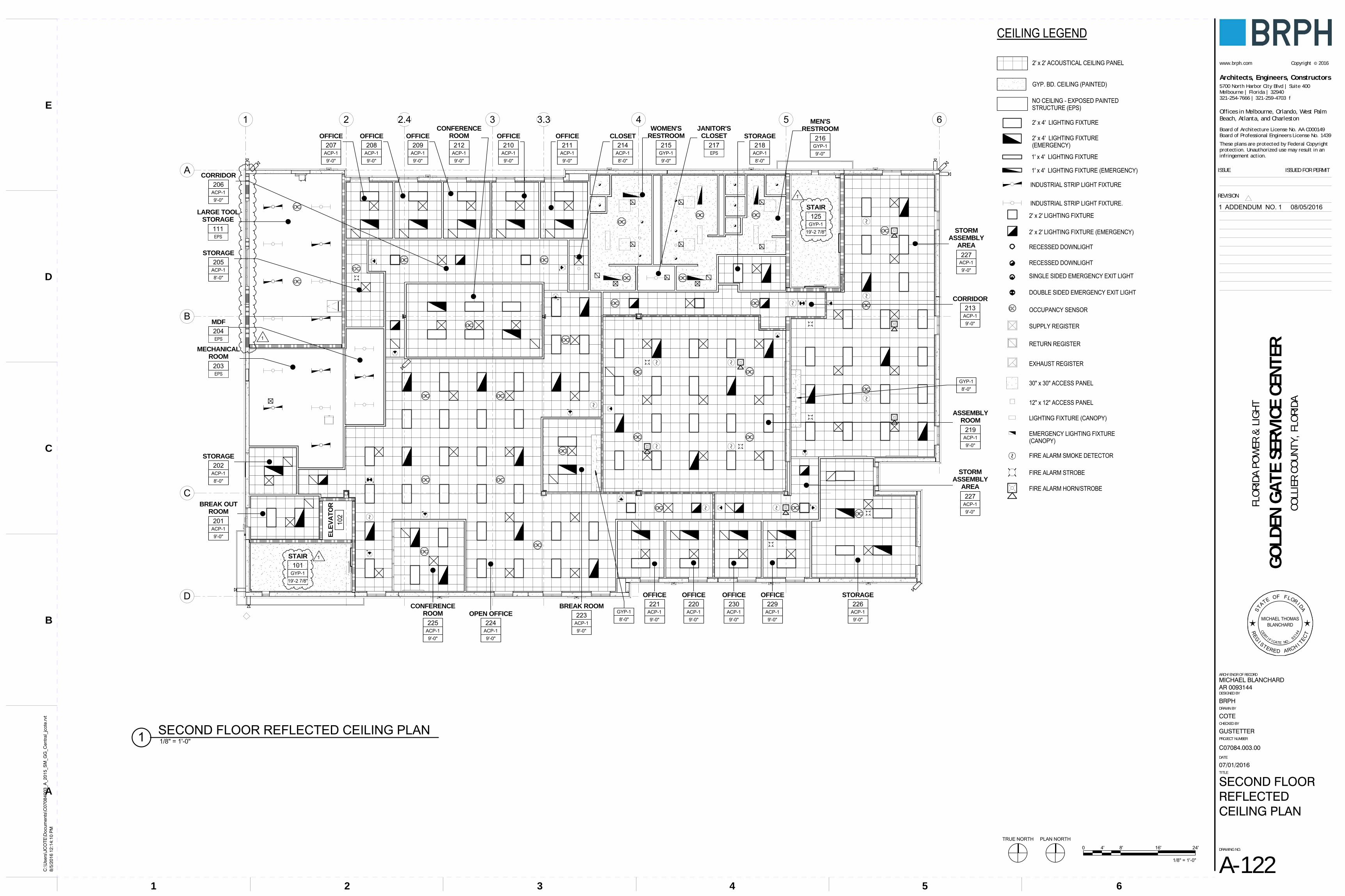
OC
OC OC
OC OC
OC
OC
OC
OC
OC
OC OC
OC OC
OCOCOC
OC
OC
OC
OC
OC
OC
OC
OC OC
OC
OC
OC
OC
OC
1 2 3 4 5 6
A
B
C
D
9'-0"ACP-1
9'-0"ACP-1
9'-0"ACP-1
9'-0"ACP-1
9'-0"ACP-1
9'-0"ACP-1
8'-0"ACP-1
9'-0"ACP-1
9'-0"ACP-1
9'-0"ACP-1
9'-0"ACP-1
9'-0"ACP-1
9'-0"ACP-1
8'-0"ACP-1
9'-0"GYP-1 9'-0"
GYP-1
9'-0"ACP-1
8'-0"ACP-1
EPS
2.4 3.3
8'-0"ACP-1
9'-0"ACP-1
9'-0"ACP-1
EPS
EPS
9'-0"ACP-1
MECHANICALROOM
203
STORAGE202
BREAK OUTROOM
201
CONFERENCEROOM
225OPEN OFFICE
224
OFFICE221
OFFICE220
OFFICE230
STORMASSEMBLY
AREA
227
ASSEMBLYROOM
219
BREAK ROOM223
CONFERENCEROOM
212
CORRIDOR206
CORRIDOR213
STORAGE218
MEN'SRESTROOM
216WOMEN'S
RESTROOM
215OFFICE
211OFFICE
210OFFICE
209OFFICE
208OFFICE
207
STORAGE205
MDF204
EL
EV
AT
OR
102
STAIR101
STAIR125
JANITOR'SCLOSET
217
9'-0"ACP-1
LARGE TOOLSTORAGE
111
CLOSET214
8'-0"GYP-1
8'-0"GYP-1
9'-0"ACP-1
9'-0"ACP-1
OFFICE229
STORAGE226
9'-0"ACP-1
STORMASSEMBLY
AREA
227
EPS19'-2 7/8"
GYP-1
19'-2 7/8"GYP-1
GYP. BD. CEILING (PAINTED)
NO CEILING - EXPOSED PAINTEDSTRUCTURE (EPS)
2' x 2' ACOUSTICAL CEILING PANEL
RECESSED DOWNLIGHT
SUPPLY REGISTER
RETURN REGISTER
EXHAUST REGISTER
RECESSED DOWNLIGHT
2' x 2' LIGHTING FIXTURE
SINGLE SIDED EMERGENCY EXIT LIGHT
DOUBLE SIDED EMERGENCY EXIT LIGHT
2' x 4' LIGHTING FIXTURE(EMERGENCY)
1' x 4' LIGHTING FIXTURE (EMERGENCY)
2' x 2' LIGHTING FIXTURE (EMERGENCY)
2' x 4' LIGHTING FIXTURE
INDUSTRIAL STRIP LIGHT FIXTURE.
INDUSTRIAL STRIP LIGHT FIXTURE
CEILING LEGEND
1' x 4' LIGHTING FIXTURE
OC OCCUPANCY SENSOR
30" x 30" ACCESS PANEL
12" x 12" ACCESS PANEL
LIGHTING FIXTURE (CANOPY)
EMERGENCY LIGHTING FIXTURE(CANOPY)
FIRE ALARM SMOKE DETECTOR
FIRE ALARM STROBE
FIRE ALARM HORN/STROBE
TRUE NORTH PLAN NORTH
Architects, Engineers, Constructors
These plans are protected by Federal Copyrightprotection. Unauthorized use may result in aninfringement action.
www.brph.com ©Copyright 2016
5700 North Harbor City Blvd | Suite 400Melbourne | Florida | 32940321-254-7666 | 321-259-4703 f
Board of Architecture License No. AA C000149Board of Professional Engineers License No. 1439
Offices in Melbourne, Orlando, West PalmBeach, Atlanta, and Charleston
REVISION
DRAWING NO.
TITLE
PROJECT NUMBER
CHECKED BY
DRAWN BY
DESIGNED BY
ARCH/ENGR OF RECORD
DATE
ISSUE ISSUED FOR PERMIT
54321 6
A
B
C
D
E
C:\
Use
rs\J
CO
TE\D
ocum
ents
\C07
0840
03_A
_201
5_S
M_G
G_C
entr
al_j
cote
.rvt
8/5/
2016
12:
14:1
0 P
M
FLO
RIDA
PO
WER
& L
IGH
T
BRPH
COTE
GO
LDEN
GAT
E SE
RVIC
E CE
NTE
RCO
LLIE
R CO
UNT
Y, F
LORI
DA
C07084.003.00
A-122
07/01/2016
SECOND FLOORREFLECTEDCEILING PLAN
GUSTETTER
MICHAEL BLANCHARDAR 0093144
1/8" = 1'-0"1 SECOND FLOOR REFLECTED CEILING PLAN
0 4' 8' 16' 24'
1/8" = 1'-0"
BLANCHARDMICHAEL THOMAS
ST
ATE OF FLORI DA
REG
I STERED ARCH I TECT
CERT I F I CATE NO. 93144
1
1 ADDENDUM NO. 1 08/05/2016
1
1

LEVEL 10' - 0"
LEVEL 214' - 0"
T.O. PANEL 233' - 6"
CEILING AS SCHEDULED
PREFINISHED METAL COPING
GALVANIZED METAL ROOF DECK
CONCRETE (REFER TO STRUCTURALDRAWINGS)
THERMOPLASTIC ROOF MEMBRANEON 4" POLYISO INSULATION ONSTRUCTURAL METAL DECK
1 1/2" RIGID INSULATION BOARD
METAL STUDS
CONCRETE TILT-UP WALLPANEL
5/8" GYP. BOARD
CONCRETE SLAB ON GRADE(REFER TO STRUCTURALDRAWINGS)
CONCRETE FOUNDATION(REFER TO STRUCTURAL DRAWINGS)
STORAGE226
CONCRETE SLAB
METAL DECK
CEILING AS SCHEDULED
XPS HALF ROUNDACCENT TRIM
STEEL ROOF JOIST(REFER TO STRUCTURAL DRAWINGS)
A-501
9TYP.
REFER TO DETAIL 6/A-501FOR REVEAL SPACING INEXTERIOR TILT-WALLPANELS
TPO MEMBRANE ROOFINGINSTALLED ON FACE OF WALL, UPAND OVER PARAPET NAILER
DJ3
DJ3 FLOOR FINISH ASSCHEDULED
A-501
10 TYP.
A-501
16 TYP.
BASE; REFER TO MATERIALFINISH SCHEDULE
FLOOR FINISH AS SCHEDULED
B.O. DECK27' - 0 1/2"
LEVEL 10' - 0"
LEVEL 214' - 0"
T.O. PANEL 130' - 6"
1
MECHANICALROOM
107
MECHANICALROOM
203
PREFINISHED METAL COPING
THERMOPLASTIC ROOF MEMBRANEON 4" POLYISO INSULATION ONSTRUCTURAL METAL DECK
CONCRETE (REFER TO STRUCTURALDRAWINGS)GALVANIZED METAL ROOF DECK
STEEL BEAM(REFER TO STRUCTURALDRAWINGS)
CONCRETE SLAB
METAL DECK
CONCRETE SLAB ON GRADE(REFER TO STRUCTURALDRAWINGS)
CONCRETE FOUNDATION(REFER TO STRUCTURAL DRAWINGS)
CONCRETE TILT-UP WALLPANEL
XPS HALF ROUNDACCENT TRIM
A-501
17
TPO MEMBRANE ROOFINGINSTALLED ON FACE OF WALL, UPAND OVER PARAPET NAILER
A-501
10TYP.
REFER TO DETAIL 6/A-501FOR REVEAL SPACING INEXTERIOR TILT-WALLPANELS
A-501
16 TYP.
A-501
9TYP.
FLOOR FINISHAS SCHEDULED
FLOOR FINISHAS SCHEDULED
B.O. DECKVARIES
LEVEL 10' - 0"
T.O. PANEL 233' - 6"
1
LARGE TOOLSTORAGE
111
4
A-404PREFINISHED METAL COPING
THERMOPLASTIC ROOF MEMBRANEON 4" POLYISO INSULATION ONSTRUCTURAL METAL DECK
CONCRETE (REFER TOSTRUCTURAL DRAWINGS)
GALVANIZED METAL ROOF DECK
CONCRETE TILT-UP WALLPANEL
CONCRETE SLAB ON GRADE(REFER TO STRUCTURALDRAWINGS)
CONCRETE FOOTING(REFER TO STRUCTURALDRAWINGS)
XPS HALF ROUNDACCENT TRIM
A-501
9 TYP.
LIGHTING FIXTURE
STEEL ROOF JOIST(REFER TO STRUCTURALDRAWINGS)
TPO MEMBRANE ROOFINGINSTALLED ON FACE OF WALL,UP AND OVER PARAPET NAILER
5/8" GYP. BOARD ON 6" METALSTUDS @ 16" O.C.
8" WIDE SOLID SURFACE SHELF
4' - 0
"
WASHER (NIC)
A-501
10 TYP.
GENERATORYARD
142
A-501
16 TYP.
ALUMINUM WINDOW
EMERGENCY SHOWERAND EYE WASH STATION
FLOOR FINISHAS SCHEDULED
REFER TO DETAIL 6/A-501FOR REVEAL SPACING INEXTERIOR TILT-WALLPANELS
B.O. DECKVARIES
LEVEL 10' - 0"
LEVEL 214' - 0"
2
LARGE TOOLSTORAGE
111
COPY/MAIL119
THERMOPLASTIC ROOFMEMBRANE ON 4" POLYISOINSULATION ONSTRUCTURAL METAL DECK
CONCRETE (REFER TOSTRUCTURAL DRAWINGS)
GALVANIZED METALROOF DECK
CEILING AS SCHEDULED
CONCRETE TILT-UP WALLPANEL
CEILING AS SCHEDULED
CONCRETE SLAB ONGRADE (REFER TOSTRUCTURALDRAWINGS)
CONCRETE FOOTING(REFER TO STRUCTURAL DRAWINGS)
DJ3
STORAGE205
FIRE CAULK RATEDWALL TO BOTTOM OFROOF DECK
STEEL ROOF JOIST(REFER TO STRUCTURAL DRAWINGS)
DJ3FLOOR FINISH AS SCHEDULED
BASE; REFER TO MATERIALFINISH SCHEDULE
FLOOR FINISH AS SCHEDULED
TOP OF TILT-WALL PANELTO FOLLOW SAME SLOPEAS ROOF STRUCTURE
B.O. DECKVARIES
Architects, Engineers, Constructors
These plans are protected by Federal Copyrightprotection. Unauthorized use may result in aninfringement action.
www.brph.com ©Copyright 2016
5700 North Harbor City Blvd | Suite 400Melbourne | Florida | 32940321-254-7666 | 321-259-4703 f
Board of Architecture License No. AA C000149Board of Professional Engineers License No. 1439
Offices in Melbourne, Orlando, West PalmBeach, Atlanta, and Charleston
REVISION
DRAWING NO.
TITLE
PROJECT NUMBER
CHECKED BY
DRAWN BY
DESIGNED BY
ARCH/ENGR OF RECORD
DATE
ISSUE ISSUED FOR PERMIT
54321 6
A
B
C
D
E
C:\
Use
rs\J
CO
TE\D
ocum
ents
\C07
0840
03_A
_201
5_S
M_G
G_C
entr
al_j
cote
.rvt
8/5/
2016
12:
14:1
5 P
M
FLO
RIDA
PO
WER
& L
IGH
T
BRPH
COTE
GO
LDEN
GAT
E SE
RVIC
E CE
NTE
RCO
LLIE
R CO
UNT
Y, F
LORI
DA
C07084.003.00
A-310
07/01/2016
WALL SECTIONS
GUSTETTER
MICHAEL BLANCHARDAR 0093144
0 1' 2' 3' 4'
3/4" = 1'-0" 3/4" = 1'-0"1 WALL SECTION 3/4" = 1'-0"2 WALL SECTION
3/4" = 1'-0"3 WALL SECTION 3/4" = 1'-0"4 WALL SECTION
BLANCHARDMICHAEL THOMAS
ST
ATE OF FLORI DA
REG
I STERED ARCH I TECT
CERT I F I CATE NO. 93144
1
1
1
1
1 ADDENDUM NO. 1 08/05/2016
1
1
1
1

LEVEL 10' - 0"
LEVEL 214' - 0"
T.O. PANEL 130' - 6"
6
SAFETY OFFICE129
PREFINISHED METAL COPING
THERMOPLASTIC ROOFMEMBRANE ON 4" POLYISOINSULATION ONSTRUCTURAL DECK
CONCRETE (REFER TOSTRUCTURAL DRAWINGS)
GALVANIZED METAL ROOF DECK
CEILING ASSCHEDULED
CONCRETE TILT-UP WALLPANEL
CONCRETE SLAB ON GRADE(REFER TO STRUCTURAL DRAWINGS)
CONCRETE FOUNDATION(REFER TO STRUCTURALDRAWINGS)
STORMASSEMBLY
AREA
227
CEILING ASSCHEDULED
XPS HALF ROUNDACCENT TRIM
A-501
16 TYP.
TPO MEMBRANE ROOFINGINSTALLED ON FACE OF WALL,UP AND OVER PARAPET NAILER
DJ3
DJ3
BASE; REFER TOMATERIAL FINISHSCHEDULE
BASE; REFER TOMATERIAL FINISHSCHEDULE
A-501
9 TYP.
REFER TO DETAIL 6/A-501FOR REVEAL SPACING INEXTERIOR TILT-WALLPANELS
A-501
10 TYP.
B.O. DECKVARIES
LEVEL 10' - 0"
LEVEL 214' - 0"
T.O. PANEL 130' - 6"
THERMOPLASTIC ROOFMEMBRANE ON 4" POLYISOON STRUCTURAL DECK
CONCRETE (REFER TOSTRUCTURAL DRAWINGS)
METAL ROOF DECK
PREFINISHED METAL COPING
CEILING AS SCHEDULED
CONCRETE TILT-UP WALLPANEL
CONCRETE SLAB ON GRADE(REFER TO STRUCTURAL DRAWINGS)
CONCRETE FOUNDATION(REFER TO STRUCTURAL DRAWINGS)
CONCRETE SLAB
METAL DECK
XPS HALF ROUNDACCENT TRIM
A-501
10TYP. TPO MEMBRANE ROOFING
INSTALLED ON FACE OF WALL,UP AND OVER PARAPET NAILER
DJ3
DJ3
A-501
16 TYP.
REFER TO DETAIL 6/A-501FOR REVEAL SPACING INEXTERIOR TILT-WALLPANELS
A-501
9TYP.
FLOOR FINISH AS SCHEDULED
BASE; REFER TO MATERIALFINISH SCHEDULE
FLOOR FINISH AS SCHEDULED
SAFETY OFFICE129
B.O. DECK27' - 7 1/2"
LEVEL 10' - 0"
LEVEL 214' - 0"
DCONCRETE TILT-UPWALL PANEL
A-602
DH4
A-602
DS4
A-311
5
B.O. SLAB10'-0"
10
A-502
A-502
11STEEL BEAM (REFER TOSTRUCTURAL DRAWINGS)
A-502
5
SLOPE 1/4" : 1'-0" MIN.
A-502
6
CONCRETE COLUMN,REFER TO STRUCTURALDRAWINGS
4" x 3" S.S. DOWNSPOUT
STANDING SEAMMETAL ROOF
2' - 4"
OVERHEAD SHUTTER DOOR(SEE A-102 FOR WIDTH)
EXTERIOR SURFACE-MOUNTEDLIGHT FIXTURE
DOWNSPOUT BRACKETSCENTERED ON REVEALS (TYP.)
LEVEL 10' - 0"
LEVEL 214' - 0"
5
FOREMANROOM
128
STORAGE131
ASSEMBLYROOM
219
THERMOPLASTIC ROOFMEMBRANE ON 4" POLYISOINSULATION ON STRUCTURALMETAL DECK
CONCRETE (REFER TOSTRUCTURAL DRAWINGS)
GALVANIZED METAL ROOF DECK
CEILING ASSCHEDULED
CONCRETE TILT-UPWALL PANEL
CEILING ASSCHEDULED
CONCRETE SLAB
METAL DECK
CEILING ASSCHEDULED
CONCRETE SLAB ONGRADE (REFER TOSTRUCTURALDRAWINGS)
CONCRETE FOUNDATION(REFER TO STRUCTURAL DRAWINGS)
DJ1
STORMASSEMBLY
AREA
227
DJ3
DJ1 DJ3
TV MONITOR ANDMOUNTING BRACKET (NIC)
CASEWORK
BASE; REFER TOMATERIAL FINISHSCHEDULE
METAL STUD ANDGYPSUM BOARD SOFFIT;REFER TO REFLECTEDCEILING PLANS
FLOOR FINISHAS SCHEDULED
CASEWORK
BASE; REFER TOMATERIAL FINISHSCHEDULE
FLOOR FINISHAS SCHEDULED
STRUCTURAL STEEL TORECEIVE SPRAYAPPLIED FIRERESISTANT MATERIAL.SEE AL-101 FOREXTENTS.STRUCTURAL STEEL TO
RECEIVE SPRAYAPPLIED FIRERESISTANT MATERIAL.SEE AL-101 FOREXTENTS.
B.O. DECKVARIES
D
B.O. PANEL9'-0"
CONCRETE TILT-UPWALL PANEL
INTERIOR
SUSPENDEDACOUSTICAL CEILING
EXTERIORALUMINUM CURTAIN WALLSYSTEM
CONCRETE TILT-UP PANEL
CONTINUOUS SEALANT ANDBACKER ROD BOTH SIDES.
OVERHEAD SHUTTER DOOR(COORDINATE WITH STRUCTURALDRAWINGS FOR HEIGHT OF DOOR)
DJ3
WITH DOOR MANUFACTURER4" TO BE COORDINATED
B.O. DOOR HOOD10'-0"
AND DOOR BOTTOM BAR
1/2" FIRE TREATED PLYWOODMAINTENANCE PLATFORM
3 5/8" (18 GA.) METAL STUDS@ 16" O.C.
DJ3
Architects, Engineers, Constructors
These plans are protected by Federal Copyrightprotection. Unauthorized use may result in aninfringement action.
www.brph.com ©Copyright 2016
5700 North Harbor City Blvd | Suite 400Melbourne | Florida | 32940321-254-7666 | 321-259-4703 f
Board of Architecture License No. AA C000149Board of Professional Engineers License No. 1439
Offices in Melbourne, Orlando, West PalmBeach, Atlanta, and Charleston
REVISION
DRAWING NO.
TITLE
PROJECT NUMBER
CHECKED BY
DRAWN BY
DESIGNED BY
ARCH/ENGR OF RECORD
DATE
ISSUE ISSUED FOR PERMIT
54321 6
A
B
C
D
E
C:\
Use
rs\J
CO
TE\D
ocum
ents
\C07
0840
03_A
_201
5_S
M_G
G_C
entr
al_j
cote
.rvt
8/5/
2016
12:
14:2
0 P
M
FLO
RIDA
PO
WER
& L
IGH
T
BRPH
COTE
GO
LDEN
GAT
E SE
RVIC
E CE
NTE
RCO
LLIE
R CO
UNT
Y, F
LORI
DA
C07084.003.00
A-311
07/01/2016
WALL SECTIONS
GUSTETTER
MICHAEL BLANCHARDAR 0093144
0 1' 2' 3' 4'
3/4" = 1'-0" 3/4" = 1'-0"2 WALL SECTION
3/4" = 1'-0"3 WALL SECTION 3/4" = 1'-0"4 MAIN ENTRANCE SECTION
3/4" = 1'-0"1 WALL SECTION
1 1/2" = 1'-0"5 MAIN ENTRANCE SOFFIT DETAIL
0 1/2' 1' 1 1/2' 2'
1 1/2" = 1'-0"
BLANCHARDMICHAEL THOMAS
ST
ATE OF FLORI DA
REG
I STERED ARCH I TECT
CERT I F I CATE NO. 93144
1
1 1
1 ADDENDUM NO. 1 08/05/2016
1
1
1
1
1
1

4
A
WOMEN'SRESTROOM
121
MEN'SRESTROOM
122
JANITOR'SCLOSET
1235' - 5
"11
' - 3
3/4"
3' - 7
3/8
"4'
- 6 3
/8"
0' - 0
"
4' - 1" 5' - 4" 5' - 3" 3' - 0 3/4" 4' - 4" 4' - 4 5/8" 14' - 1 1/4"
7' - 7
"
0' - 9
1/4
"
4' - 6
3/8
"4'
- 6 7
/8"
3' - 7
3/8
"
0' - 5
1/2
"
11' -
8 3/
8"
10' -
0"2'
- 10"
10' -
3 7/
8"2'
- 10"
4' - 9
"
1' - 9
3/4
"4'
- 6"
2' - 1
0"3'
- 1"
3' - 1
"2'
- 11"
2' - 7
1/2
"2'
- 8 3
/4"
2' - 6
"2'
- 6"
2' - 1"
4' - 10" 9' - 1" 1' - 0 1/8" 0' - 8 1/4" 12' - 3 1/4" 1' - 5 3/8" 4' - 6 7/8" 7' - 2"
5' - 0" 4' - 6"
2' - 1
0"4'
- 8"
3' - 8"
RESTROOM106
8' - 6 1/2"
8' - 4
7/8
"
A-70116
13
14
15
4 5
A
WOMEN'SRESTROOM
215
MEN'SRESTROOM
216
JANITOR'SCLOSET
217
STORAGE218
4' - 1" 6' - 0" 8' - 5" 4' - 6 3/4" 4' - 1" 14' - 10 1/2"
4' - 6
3/8
"3'
- 7 3
/8"
11' -
3 3/
4"5'
- 6 1
/2"
7' - 7
1/2
"4'
- 0 1
/8"
8' - 1
0"4'
- 6 3
/8" 0' - 9
1/4
"
3' - 0"2' - 1" 5' - 4"
10' -
0"2'
- 10"
10' -
3 7/
8"2'
- 10"
4' - 9
"
9' - 1
3/4
"3'
- 1"
3' - 1
"2'
- 10
1/8"
1' - 6
3/4
"2'
- 7"
2' - 8
3/4
"2'
- 6"
2' - 6
"
4' - 6
3/8
"4'
- 6 7
/8"
4' - 0
7/8
"
4' - 6 7/8" 5' - 10 3/8" 3' - 1 5/8" 1' - 9 3/8" 12' - 3 1/4" 1' - 4 3/8" 4' - 6 7/8" 4' - 1 3/8" 4' - 4 1/8"
1' - 6
"
4' - 6 7/8"
3' - 8"
EWC
4
A
WOMEN'SRESTROOM
121
MEN'SRESTROOM
122
JANITOR'SCLOSET
123
A-7014
A-7016
1
2
3
5
7
8A-701
12 10
9
11
A-70214
13
DA
D
A
JF
E
E
C
C
I
E
M
C
C
A
A
A
DE
J
CIA
E
D
E
D
EG
H
H
G
H
C
B
B
LOCKER BENCHES (8) LOCKERS LOCKER BENCHES
(50) LOCKERS
FK
K
FK
F
K
4 5
A
WOMEN'SRESTROOM
215
MEN'SRESTROOM
216
JANITOR'SCLOSET
217
STORAGE218
A-7024
A-7028
A-70212
1
2
3
5
6
7
9
10
11
A-702
13SIM
14
SIM
D
E
E
A
C
D
E
J
C
A I
C
C
C
A
A
A
E
E
E
DE
CJ
A I
D
H
H
H
GD
M
G
H
B
B
LOCKER BENCHES (8) LOCKERS
EWC
N
F
KF
K
FK
F
K
RESTROOM106
D
E
I
J
B
F
K
TRUE NORTH PLAN NORTH
Architects, Engineers, Constructors
These plans are protected by Federal Copyrightprotection. Unauthorized use may result in aninfringement action.
www.brph.com ©Copyright 2016
5700 North Harbor City Blvd | Suite 400Melbourne | Florida | 32940321-254-7666 | 321-259-4703 f
Board of Architecture License No. AA C000149Board of Professional Engineers License No. 1439
Offices in Melbourne, Orlando, West PalmBeach, Atlanta, and Charleston
REVISION
DRAWING NO.
TITLE
PROJECT NUMBER
CHECKED BY
DRAWN BY
DESIGNED BY
ARCH/ENGR OF RECORD
DATE
ISSUE ISSUED FOR PERMIT
54321 6
A
B
C
D
E
C:\
Use
rs\J
CO
TE\D
ocum
ents
\C07
0840
03_A
_201
5_S
M_G
G_C
entr
al_j
cote
.rvt
8/5/
2016
12:
14:2
9 P
M
FLO
RIDA
PO
WER
& L
IGH
T
BRPH
COTE
GO
LDEN
GAT
E SE
RVIC
E CE
NTE
RCO
LLIE
R CO
UNT
Y, F
LORI
DA
C07084.003.00
A-401
07/01/2016
ENLARGEDPLANS
GUSTETTER
MICHAEL BLANCHARDAR 0093144
1/4" = 1'-0"1 RESTROOMS 121/122 - DIMENSIONS
1/4" = 1'-0"5 RESTROOM 106 - DIMENSIONS
1/4" = 1'-0"2 RESTROOMS 215/216 - DIMENSIONS
0 2' 4' 8' 12'
1/4" = 1'-0"
1/4" = 1'-0"3 RESTROOMS 121/122 1/4" = 1'-0"4 RESTROOMS 215/216
1/4" = 1'-0"6 RESTROOM 106
RESTROOM ACCESSORIES SCHEDULETYPE MARK MANUFACTURER DESCRIPTION SUPPLIED/INSTALLED
A KC PROFESSIONAL CORELESS DOUBLE ROLL BATHROOM TISSUEDISPENSER CODE 09606
CS/CI
B BOBRICK WASHROOMEQUIPMENT, INC.
B-254 SURFACE MOUNTED SANITARY NAPKINDISPOSAL
CS/CI
C KC PROFESSIONAL TOILET SEAT COVER DISPENSER CODE 09512 CS/CID BRADLEY CORPORATION DISPENSER, SOAP, WALL MOUNTED 6562 CS/CIE BOBRICK WASHROOM
EQUIPMENT, INC.GLASS MIRROR WITH STAINLESS STEEL ANGLEFRAME
CS/CI
F KC PROFESSIONAL MANUAL HARD ROLL TOWEL DISPENSER 29734 CS/CIG BOBRICK WASHROOM
EQUIPMENT, INC.BOBRICK - 204-3 VINYL SHOWER CURTAIN CS/CI
H BOBRICK WASHROOMEQUIPMENT, INC.
BOBRICK - 204-3 VINYL SHOWER CURTAIN CS/CI
I BOBRICK WASHROOMEQUIPMENT, INC.
42" GRAB BAR CS/CI
J BOBRICK WASHROOMEQUIPMENT, INC.
36" GRAB BAR CS/CI
K TBD FREE STANDING TRASH CAN CS/CIM BRADLEY CORPORATION MOP-BROOM HOLDER W/3 HOLDERS 24" W CS/CIN BRADLEY CORPORATION LENOXCUBBY LOCKER CS/CI
OS - OWNER SUPPLIEDOI - OWNER INSTALLEDCS - CONTRACTOR SUPPLIEDCI - CONTRACTOR INSTALLED
GENERAL NOTES:
1. REFERENCE DATA MANUAL FOR ADDITIONAL EQUIPMENT SPECIFICATIONS AND REQUIRMENTS.
3. GREY, DASHED, UN-TAGGED FF&E TO BE OWNER PROVIDED. SHOWN FOR PLANNING PURPOSES ONLY.
4. SPECIALTY EQUIPMENT LISTED IN LEGEND IS BASIS OF DESIGN ONLY. EQUAL SUBSTITUTIONS MAY BE ACCEPTED.
5. PROVIDE MOP HOLDER M AT ALL JANITOR'S CLOSET.
BLANCHARDMICHAEL THOMAS
ST
ATE OF FLORI DA
REG
I STERED ARCH I TECT
CERT I F I CATE NO. 93144
1 ADDENDUM NO. 1 08/05/2016
1

WD
1 2
A
B
LARGE TOOLSTORAGE
111
3
A-310
4
A-310
4
A-404
A-404
3
6' - 0
7/8
"30
' - 6
3/4"
0' - 9
1/4
"
VEHICLE BY OWNER
FE EQUIPMENTBY OWNER
SHELVES BY OWNER
4" DIA. BOLLARDS(SEE DETAIL 5/A-406)
CHAINLINK FENCE
3'-0" x 6'-0"CHAINLINKFENCE GATE
6" DIA. CONCRETE-FILLEDSTEEL BOLLARD, PAINTEDSAFETY YELLOW (SEEDETAIL 5/A-406)
5/8" GYP. BOARD ON6" METAL STUDS @16" O.C. BELOW
SLO
PE1/
4 " /
12 "
7' - 0" 4' - 5"
5' - 0
"5'
- 7"
0' - 9 1/4"
19' - 10 5/8"
0' - 11 1/8"
EXHAUST FANWITH SHROUDOVER OHC DOOR
8" W. SOLIDSURFACE MATERIALTOP SHELF
EMERGENCY SHOWAND EYE WASHSTATION
STEEL COLUMN
11"
11"
1 2
A
B
3
A-310
4
A-310
4
A-404
FE
SAFETY HOOK (CONTRACTOR TO PROVIDE ANDINSTALL FALL PROTECTION SAFETY HOOK.CARABINERS, LANYARDS AND HARNESSESASSOCIATED WITH USING D-RING ARE BY OWNER)
A-404
7
4' - 2
3/4
"14
TRE
ADS
@ 1
1" =
12'-
10"
4' - 0
"7
TREA
DS @
11"
= 6
'-5"
8' - 2
7/8
"
ROOF ACCESSLADDER
0' - 9
1/4
"
30' -
6 3/
4"6'
- 0 7
/8"
EXTERIOR LIGHTINGFIXTURE BELOW (REFER TOELECTRICAL DRAWINGS)
0' - 9 1/4"
19' - 10 5/8"
0' - 11 1/8"
EXHAUST FAN WITHSHROUD AT LOUVER,OVER OHC DOOR
OHC DOORHOUSING BELOW
4' - 4" 15' - 6 5/8"
REMOVEABLE SECTIONOF GUARDRAIL
MEZZANINE111B
11"
11"
12"
12"
EQEQ 6' - 0"
11' -
2 7/
8"
LEVEL 10' - 0"
Mezz.13' - 5"
T.O. PANEL 130' - 6"
12 4
A-404
SAFETY HOOK
4" HIGH TOE BOARD
6' WIDE REMOVABLE SECTION,ALL RAILING TO BE PAINTEDBRIGHT CAUTION YELLOW
3'-0" x 6'-0" CHAINLINKFENCE GATE
CHAINLINKFENCE
ROOF ACCESSLADDER
SAFETY RAIL
ROOF HATCH
FIRE EXTINGUISHER
FENCING TO EXTEND TOBOTTOM OF MEZZANINE
4" DIA CONCRETE-FILLEDSTEEL BOLLARD, PAINTEDSAFETY YELLOW (SEEDETAIL 5/A-406)
LEVEL 10' - 0"
Mezz.13' - 5"
T.O. ROOF29' - 0"
AB
WASHER(NIC)DRYER(NIC)
LOAD RATING SIGNAGEON WALL
EYE WASHSHOWER
CHAINLINKFENCE
FIREEXTINGUISHER
LIGHTING FIXTURE(REFER TO ELECTRICALDRAWINGS)
XPS HALF-ROUNDBAND BEYOND
TPO ROOF MEMBRANESYSTEM
4' - 0
"
5/8" GYP. BOARD ON6" METAL STUDS @16" O.C.
CORE DRILL CHAINLINK POSTS INTO SLAB(DEPTH AS REQUIRED)
ALUMINUM WINDOWS
8" W. SOLID SURFACEMATERIAL TOP SHELF
SLOPE1/4" / 12"
5' - 1
9/1
6"9
RISE
RS @
6 2
15/2
56"
8' - 6
155
/256
"15
RIS
ERS
@ 6
215
/256
"
11"
12"
LEVEL 10' - 0"
Mezz.13' - 5"
T.O. PANEL 130' - 6"
12 4
A-404
SAFETY HOOK
4" HIGH TOE BOARD
6' WIDE REMOVABLESECTION
3'-0" x 6'-0" CHAINLINKFENCE GATE
CHAINLINKFENCE
FIRE EXTINGUISHER5
A-404
6
A-404
1'-9"
1'-9"
1'-5 1
/2"
CONCRETE SLAB ON STEELDECK, REF. STRUCTURALDRAWINGS
1 1/2"Ø STEEL TUBE RAIL
STEEL BEAM, REF.STRUCTURAL DRAWINGS
1 1/2"Ø STEEL TUBE RAIL
1 1/2"Ø STEEL TUBE POST
1/4" THICK STEEL PLATE
2"x1 1/2"x1/8" STEEL TUBE RAIL
4"x1/4" STEEL KICK PLATE
2"x2"x1/4" STEEL PLATE
3/16
3/163/16
3/16
3/16
E.O.S 5 1/2"
CL3' - 6
"
1'-9"
1'-9"
1'-5 1
/2"
CONCRETE SLAB ON STEELDECK, REF. STRUCTURALDRAWINGS
1 1/2"Ø STEEL TUBE RAIL
STEEL BEAM, REF.STRUCTURAL DRAWINGS
1 1/2"Ø STEEL TUBE RAIL
1 1/2"Ø STEEL TUBE POST
1/4" THICK STEEL PLATE
2"x1 1/2"x1/8" STEEL TUBE RAIL
4"x1/4" STEEL KICK PLATE
2"x2"x1/4" STEEL PLATE
3/16
3/163/16
(REMOVABLE RAIL SYSTEM)
2"x2"x1/4" STEEL TUBE SLEEVE
3/8" Ø QUICK RELEASE PIN W/LANYARD (TWO PER REMOVABLEHANDRAIL
3/16
3/16
E.O.S 5 1/2"
CL3' - 6
"
TRUE NORTH PLAN NORTH
Architects, Engineers, Constructors
These plans are protected by Federal Copyrightprotection. Unauthorized use may result in aninfringement action.
www.brph.com ©Copyright 2016
5700 North Harbor City Blvd | Suite 400Melbourne | Florida | 32940321-254-7666 | 321-259-4703 f
Board of Architecture License No. AA C000149Board of Professional Engineers License No. 1439
Offices in Melbourne, Orlando, West PalmBeach, Atlanta, and Charleston
REVISION
DRAWING NO.
TITLE
PROJECT NUMBER
CHECKED BY
DRAWN BY
DESIGNED BY
ARCH/ENGR OF RECORD
DATE
ISSUE ISSUED FOR PERMIT
54321 6
A
B
C
D
E
C:\
Use
rs\J
CO
TE\D
ocum
ents
\C07
0840
03_A
_201
5_S
M_G
G_C
entr
al_j
cote
.rvt
8/5/
2016
12:
14:3
6 P
M
FLO
RIDA
PO
WER
& L
IGH
T
BRPH
COTE
GO
LDEN
GAT
E SE
RVIC
E CE
NTE
RCO
LLIE
R CO
UNT
Y, F
LORI
DA
C07084.003.00
A-404
07/01/2016
ENLARGEDPLANS ANDINTERIORELEVATIONS
GUSTETTER
MICHAEL BLANCHARDAR 0093144
1/4" = 1'-0"1 LARGE TOOL STORAGE ROOM 111 1/4" = 1'-0"2 LARGE TOOL STORAGE ROOM MEZZANINE
0 2' 4' 8' 12'
1/4" = 1'-0"
1/4" = 1'-0"3 MEZZANINE SECTION
1/4" = 1'-0"4 MEZZANINE SECTION 1/4" = 1'-0"7 MEZZANINE SECTION
3/4" = 1'-0"5 RAILING TYPE - R1 3/4" = 1'-0"6 RAILING TYPE - R2
BLANCHARDMICHAEL THOMAS
ST
ATE OF FLORI DA
REG
I STERED ARCH I TECT
CERT I F I CATE NO. 93144
0 1' 2' 3' 4'
3/4" = 1'-0"
1 1
1 ADDENDUM NO. 1 08/05/2016
1
1
1

UP
DN
UP
DN
1 2
D
5
A-431
2
A-432
1
A-432
0' - 9 1/4"
22' - 8"
FIRE RISER104
ELEV. MECH.103
0' - 9 1/4" 8' - 5 5/8" 7' - 3 1/8" 5' - 1" 1' - 3"
STAIR101
PAINTED, GALVANIZED BREAK METAL COVER FULL-HEIGHT TO UNDERSIDE OF ROOF DECK TOCONCEAL REFRIGERANT AND CONDENSATE PIPING
1' - 0
3/8
"11
' - 0
7/8"
8' - 1
0 5/
8"
EL
EV
AT
OR
102
4' - 1
0 1/
2"
8' - 4
"
6' - 4" PROVIDE SIGNAGESEE 7/A-700
11"
11"
8
A-431
SUMP PIT BELOW
1 2
D
5
A-431
2
A-432
1
A-432
5' - 0" 11 TREADS @ 11" = 10' - 1" 6' - 8 5/8"
5' - 0" 11 TREADS @ 11" = 10' - 1"
STAIR101
8' - 4
"
6' - 4"
PAINTED, GALVANIZED BREAKMETAL COVER FULL-HEIGHT TOUNDERSIDE OF ROOF DECK TOCONCEAL REFRIGERANT ANDCONDENSATE PIPING
8' - 1
1 1/
4"11
' - 0
7/8"
1' - 0
3/8
"
22' - 4 7/8"
1' - 0 3/8" 15' - 5 5/8" 5' - 1" 1' - 10 1/4"
12"
11" 12"
4' - 1
0 1/
2"0'
- 4 5
/8"
4' - 1
0 1/
2"
12"
EL
EV
AT
OR
102
PROVIDE SIGNAGESEE 2/A-700
PROVIDE SIGNAGESEE 7/A-700
LEVEL 10' - 0"
LEVEL 214' - 0"
T.O. PANEL 233' - 6"
T.O. PANEL 130' - 6"
12
12 R
ISER
S @
7" =
7' -
0"12
RIS
ERS
@ 7
" = 7
' - 0"
11"
PAINTED, GALVANIZED BREAK METALCOVER FULL-HEIGHT TO UNDERSIDE OFROOD DECK TO CONCEAL REFRIGERANTAND CONDENSATE PIPING
8
A-431
A-431
7
A-431
9
CCTV SECURITY CAMERA
CONCRETE TILT-UP WALL (TYP.)
CONCRETE REVEAL (TYP.)ALUMINUM WINDOW (TYP.)
WALL MOUNTEDLIGHTING FIXTURE(REFER TO ELECTRICALDRAWINGS)
CONCRETE SLABON GRADE
CONCRETE SLABON METAL DECK
HOLLOW METAL DOOR
CONDENSER (REFER TOMECHANICAL DRAWINGS FORANY PIPING PENETRATIONS)
SOLID WOODCORE DOOR (TYP.)
EXIT SIGN (REFER TOELECTRICAL DRAWINGS)
STAIR GUARDRAIL/HANDRAIL (PAINTED)
XPS HALF ROUNDACCENT TRIM
CONCRETE TILT-UP WALL (TYP.)
11"
STANDING SEAMMETAL ROOF
DK2 DK2
J MOLD
12"
5
A
B
6
A-431
3' - 7
1/4
"8'
- 9 1
/8"
17' -
11 1
/4"
1' - 0
3/8
" 0' - 9 1/4" 11' - 7 1/4"
STAIR125
PAINTED, GALVANIZED BREAKMETAL COVER FULL-HEIGHT TOUNDERSIDE OF ROOD DECK TOCONCEAL REFRIGERANT ANDCONDENSATE PIPING
1' - 0
3/8
"
21' -
3 5/
8"
FEC
10' - 10"
ADA-COMPLIANTEWC
5' - 0"
8
A-431
11"
11"
5
A
B
6
A-431
5' - 0
"8
TREA
DS @
11"
= 7
' - 4"
5' - 0
"14
TRE
ADS
@ 1
1" =
12'
- 10"
6' - 4
3/8
"
0' - 9 1/4" 10' - 10"
STAIR125
PAINTED, GALVANIZED BREAKMETAL COVER FULL-HEIGHT TOUNDERSIDE OF ROOD DECK TOCONCEAL REFRIGERANT ANDCONDENSATE PIPING
1' - 0
3/8
"24
' - 2
3/8"
6' - 1
1/4
"
FEC
12" 11"
12"
5' - 0" 0' - 6" 5' - 0"
A-504
3
A-501
8
11"
PROVIDE SIGNAGESEE 2/A-700
7
A-431
8
A-431
12"
11"
LEVEL 10' - 0"
LEVEL 214' - 0"
T.O. ROOF29' - 0"
T.O. PANEL 233' - 6"
A B15
RIS
ERS
@ 7
" = 8
' - 9"
9 RI
SERS
@ 7
" = 5
' - 3"
PAINTED, GALVANIZED BREAK METALCOVER FULL-HEIGHT TO UNDERSIDE OFROOD DECK TO CONCEAL REFRIGERANTAND CONDENSATE PIPING
11"
8
A-431
A-431
7
A-431
9
WALL MOUNTEDLIGHTING FIXTURE(REFER TO ELECTRICALDRAWINGS)
CONCRETE TILT-UP WALL (TYP.)
CONCRETE REVEAL (TYP.)
XPS HALF ROUNDACCENT TRIM
CONDENSER (REFER TOMECHANICAL DRAWINGS FORANY PIPING PENETRATIONS)
CONCRETE SLABON GRADE
SOLID WOODCORE DOOR (TYP.)
CONCRETE SLABON METAL DECK
STAIR GUARDRAIL/HANDRAIL (PAINTED)
STAIR GUARDRAIL
STANDING SEAMMETAL ROOF
J MOLDDK2DK2
DK2
A-504
5
12"
11"
A.F.
F .3'
- 6"
1 1/2"Ø STD PIPE TOP RAIL
1 1/2"Ø TUBE RAILS @ 51/2" OC VERTICALLY
1 1/2"Ø STD PIPE PIPEPOST 48" OC MAX
1 1/2"Ø STD BOTTOM RAIL
2"
ABO V
E TR
EAD
FINI
SH3'
- 0"
ABO V
E TR
EAD
FINI
SH3'
- 6"
2"
1 1/2"Ø STD PIPE TOP RAIL
1 1/2"Ø STD PIPE HANDRAIL
1 1/2" TUBE RAILS @ 5 1/2"OC VERTICALLY
1 1/2"Ø STD PIPE PIPEPOST 48" OC MAX
1 1/2"Ø STD BOTTOM RAIL
STAIR STRINGER
STAIR TREADTREAD NOSE
1/2"Ø BAR @ EACH POST
2 1/
2"
2 1/2"
RUN11"
RUN11"
STEEL PAN, BY MANUFACTURER,(PRIMED AND PAINTED) TYP.
STEEL STRINGER BEYOND,(PRIMED AND PAINTED).
RISE
0' - 7
"CONCRETETREAD, TYP.
NOSING1"
TRUE NORTH PLAN NORTH
Architects, Engineers, Constructors
These plans are protected by Federal Copyrightprotection. Unauthorized use may result in aninfringement action.
www.brph.com ©Copyright 2016
5700 North Harbor City Blvd | Suite 400Melbourne | Florida | 32940321-254-7666 | 321-259-4703 f
Board of Architecture License No. AA C000149Board of Professional Engineers License No. 1439
Offices in Melbourne, Orlando, West PalmBeach, Atlanta, and Charleston
REVISION
DRAWING NO.
TITLE
PROJECT NUMBER
CHECKED BY
DRAWN BY
DESIGNED BY
ARCH/ENGR OF RECORD
DATE
ISSUE ISSUED FOR PERMIT
54321 6
A
B
C
D
E
C:\
Use
rs\J
CO
TE\D
ocum
ents
\C07
0840
03_A
_201
5_S
M_G
G_C
entr
al_j
cote
.rvt
8/5/
2016
12:
14:4
3 P
M
FLO
RIDA
PO
WER
& L
IGH
T
BRPH
COTE
GO
LDEN
GAT
E SE
RVIC
E CE
NTE
RCO
LLIE
R CO
UNT
Y, F
LORI
DA
C07084.003.00
A-431
07/01/2016
VERTICALCIRCULATION,ENLARGEDPLANS ANDSECTIONS
GUSTETTER
MICHAEL BLANCHARDAR 0093144
1/4" = 1'-0"1 STAIR 101 - FIRST FLOOR 1/4" = 1'-0"2 STAIR 101 - SECOND FLOOR
1/4" = 1'-0"5 STAIR 101 SECTION
1/4" = 1'-0"3 STAIR 125 - FIRST FLOOR 1/4" = 1'-0"4 STAIR 125 - SECOND FLOOR
1/4" = 1'-0"6 STAIR 125 SECTION0 2' 4' 8' 12'
1/4" = 1'-0"
1" = 1'-0"7 LANDING GUARDRAIL 1" = 1'-0"8
TYPICAL STAIRGUARDRAIL/HANDRAIL
1 1/2" = 1'-0"9 CONCRETE TREAD DETAIL 0 1' 2' 3'
1" = 1'-0"
0 1/2' 1' 1 1/2' 2'
1 1/2" = 1'-0"
BLANCHARDMICHAEL THOMAS
ST
ATE OF FLOR I DA
REG
I STERED ARCH I TECT
CERT I F I CATE NO. 93144
1 ADDENDUM NO. 1 08/05/2016
1
1
1
1
1
1
1
1
1
NOTE:HANDRAIL ENDS SHALLRETURN TO THE WALLOR NEWEL POST
1

TPO MEMBRANE ROOFINGTPO FLASHINGMEMBRANE BONDING ADHESIVE
CONT. SEALANT
PRE-FIN MTL SCUPPER SLEEVE
STAINLESS STEELCONDUCTOR HEADAND DOWNSPOUT
CONT SEALANT (TYP)
TPO FLASHINGMEMBRANE
TILT-UP CONCPANEL
PT BLOCKING
POLYISO INSUL
TPO FLASHINGMEMBRANE
4"POLYISO INSUL
BONDING ADHESIVE
TPO MEMBRANE ROOFING
CONT. SEALANT
PRE-FIN MTLSCUPPER SLEEVE
TPO FLASHINGMEMBRANE
CONT SEALANT (TYP)
TPO FLASHINGMEMBRANE
FASTENER AND PLATE
TILT-UP CONC PANEL
HEIGHT 2" - 4" ABOVEBASE OF PRIMARYDRAIN
T.O. PANEL 233' - 6"
METAL DECK
STEEL JOIST(REF. STRUCT.)
STEEL ANGLE(REF. STRUCT.)
POLYISO INSUL.
FASTENTER AND PLATE
P.T. 2X BLOCKING
STEEL ANGLE(REF. STRUCT.)
TILT-UP CONCRETE PANELTPO MEMBRANEBONDING ADHESIVEP.T. 2X BLOCKING
GASKETED FASTENER
PRE-FINISHED METALCOPING
CONT. METAL CLIP C
T.O. PANEL 429' - 4 3/4"
BONDING ADHESIVE
TPO MEMBRANE
POLYISO INSUL.
STEEL ANGLE(REF. STRUCT.)
P.T. 2X BLOCKING
FASTENER AND PLATE
METAL DECK
TILT-UP CONC PANEL
WD NAILERS.S. METAL FASCIA
WALL INSULATION
ROOF MEMBRANEEXTEND UP WALL ANDUNDER ROOF CLEAT
ROOF MEMBRANE
ROOF INSULATION
METAL ROOF DECKING
EPDM CLOSURE
PRE-MANUFACTURED METALROOF TRUSS SYSTEM
WATER PROOF MEMBRANE
METAL CLOSURE
STANDING SEAM METALROOF PANEL
CONTINUOUS SEALANT
PRE-FINISHED METALCOUNTER FLASHING
TERMINATION BAR
TPO FLASHING
BONDING ADHESIVE
FASTENER AND PLATE
CONCRETE ROOF PANEL(REFER TO STRUCTURALDRAWINGS)
CONTINUOUS SEALANT
5/8" DENS GLASS
7/8" HIGH HAT METAL FURRING@ 16" O.C.
STAINLESS STEEL FASCIA
CONTINUOUS STAINLESSSTEEL CLEAT
2x PT WOOD BLOCKING
DRIP
7/8" THREE-COAT STUCCO OVEREXPANDED METAL LATH (PAINTED)
7/8" HAT CHANNELS
METAL FASCIA FLASHING
METAL STUD FASCIA
S.S. GUTTER
S.S. GUTTER STRAP
EAVE FLASHING
METAL ROOF DECKING
WATER PROOF MEMBRANE
STANDING SEAM METAL ROOFSYSTEM
CAULKING BETWEEN WEB
2x PT WOOD NAILER
SEALANT
CONTINUOUS METAL SOFFIT (WIDTH TO MEET NOACRITERIA) PROXIDE PURLIN FRAMING ORSUBSTRATE TO ATTACH METAL SOFFIT PANELSSUPPORTED FROM ROOF METAL FRAMING.
PROXIDE FRAMING DESIGN PER FLORIDAPRODUCT APPROVAL EVALUATION REPORT.REFER TO STRUCTURAL FOR ADDITIONALINFORMATION AND PERFORMANCE CRITERIA.
PRE-MANUFACTURED METAL ROOF TRUSSSYSTEM. (SEE STRUCTURAL FORINFORMATION ON DELEGATED DESIGN)
CONCRETE ROOF PANEL (REFER TOSTRUCTURAL DRAWINGS)
CONTINUOUS SEALANT & BACKER RODCOMPRESSIBLE FILLER
CONCRETE COLUMN
STEEL EMBED PLATE (REFER TOSTRUCTURAL DRAWINGS)
STEEL ANGLE (REFER TOSTRUCTURAL DRAWINGS)
CONTINUOUS SEALANT5/8" DENS GLASS
7/8" HIGH HAT METAL FURRING@ 16" O.C.
STEEL EMBED PLATE (REFER TOSTRUCTURAL DRAWINGS)7/8" THREE-COAT STUCCOOVER EXPANDED METAL LATH
PRE-MANUFACTURED METAL ROOFTRUSS SYSTEM
2X PT. WOOD NAILER
0' - 10" 2' - 0" 0' - 10"
0' - 6
"0'
- 3"
1" 10" 1"
4"
3 1/
8"5
7/8"
1" 8" 1" 6" 1' - 0" 6" 1" 8" 1"
1"3
7/8"
1"
4 1/
2"1
3/8"
2" 2"
VENT THRU ROOF
POLYISOINSUL
PRE-MOLDED PIPEBOOT (PORTALS PLUSOR EQUAL.)
SEALANTSTAINLESS STEELCLAMPING RINGFASTENER AND PLATE
TPO MEMBRANE
METAL ROOF DECK
LIGHTWIEIGHT CONCRETE
CONCRETE ROOF PANEL(REFER TO STRUCTURALDRAWINGS)
STAINLESS STEEL FASCIA
A-502
11
B.O. SLAB10'-0"
STANDING SEAM METAL ROOFSYSTEM
6
A-502
2' - 4"
PRE-MANUFACTURED METAL TRUSSROOF SYSTEM (SEE STRUCTURAL FORINFO ON DELEGATED DESIGN)
Architects, Engineers, Constructors
These plans are protected by Federal Copyrightprotection. Unauthorized use may result in aninfringement action.
www.brph.com ©Copyright 2016
5700 North Harbor City Blvd | Suite 400Melbourne | Florida | 32940321-254-7666 | 321-259-4703 f
Board of Architecture License No. AA C000149Board of Professional Engineers License No. 1439
Offices in Melbourne, Orlando, West PalmBeach, Atlanta, and Charleston
REVISION
DRAWING NO.
TITLE
PROJECT NUMBER
CHECKED BY
DRAWN BY
DESIGNED BY
ARCH/ENGR OF RECORD
DATE
ISSUE ISSUED FOR PERMIT
54321 6
A
B
C
D
E
C:\
Use
rs\J
CO
TE\D
ocum
ents
\C07
0840
03_A
_201
5_S
M_G
G_C
entr
al_j
cote
.rvt
8/5/
2016
12:
14:4
5 P
M
FLO
RIDA
PO
WER
& L
IGH
T
BRPH
COTE
GO
LDEN
GAT
E SE
RVIC
E CE
NTE
RCO
LLIE
R CO
UNT
Y, F
LORI
DA
C07084.003.00
A-502
07/01/2016
ROOF DETAILS
GUSTETTER
MICHAEL BLANCHARDAR 0093144
3" = 1'-0"1 SCUPPER WITH CONDUCTOR 3" = 1'-0"2 OVERFLOW SCUPPER
1 1/2" = 1'-0"3 PARAPET, TYP.
0 3" 6" 9" 12"
3" = 1'-0"
0 1/2' 1' 1 1/2' 2'
1 1/2" = 1'-0"
0 1' 2' 4' 6'
1/2" = 1'-0"
1 1/2" = 1'-0"4 ELEVATOR SHAFT CAP
3" = 1'-0"5 DETAIL
3" = 1'-0"11 DETAIL
3" = 1'-0"6 DETAIL
1 1/2" = 1'-0"7
SCUPPER AND CONDUCTORHEAD ELEVATION
1 1/2" = 1'-0"8 PIPE PENETRATION
1" = 1'-0"10 ENTRY CANOPY SECTION
0 1' 2' 3'
1" = 1'-0"
BLANCHARDMICHAEL THOMAS
ST
ATE OF FLORI DA
REG
I STERED ARCH I TECT
CERT I F I CATE NO. 93144
1
1 ADDENDUM NO. 1 08/05/2016
1
1
1
11
1

LEVEL 214' - 0"
6"
CONCRETE TILT-UPWALL PANEL
B.O. PANEL7'-2"
SUSPENDEDACOUSTICAL CEILING
EXTERIOR
INTERIOR
SEE REFLECTED CEILING PLAN
HOLLOW METAL FRAME, PAINTED.GROUT SOLID.
DOOR PER SCHEDULE
CONTINUOUS SEALANT- EACHSIDE
5/8" GYP. BOARD
3 5/8" METAL STUDS
STEEL BEAM (REFER TOSTRUCTURAL DRAWINGS)
CONCRETE SLAB
METAL DECK
STUD DEFLECTION TRACK ANDRUNNER
T.O. PANEL 233' - 6"
CONCRETE ROOF PANEL(REFER TO STRUCTURALDRAWINGS)
PRE-MANUFACTURED METAL ROOFTRUSS SYSTEM (SEE STRUCTURAL FORINFORMATION ON DELEGATED DESIGN)
STANDING SEAM METAL ROOFSYSTEM
TILT-UP CONC. PANEL
2' - 0" 2' - 0"
A-504
5
A-504
4
GALVANIZED METAL ROOF DECK
LIGHTWEIGHT CONCRETE
THERMOPLASTIC ROOF MEMBRANEON 4" POLYISO INSULATION ONSTRUCTURAL METAL DECK
DK2DK2
J MOLD
CONCRETE ROOF PANEL(REFER TO STRUCTURALDRAWINGS)
METAL FASCIA FLASHING
METAL FASCIA FLASHING
METAL STUD FASCIA
EAVE FLASHING
METAL ROOF DECKING
WATER PROOF MEMBRANE
STANDING SEAM METAL ROOFSYSTEM
CAULKING BETWEEN WEB
TILT-UP CONC. PANEL
CONTINUOUS STAINLESSSTEEL CLEAT
CONTINUOUS SEALANT
CONTINUOUS PT WOODNAILER
10"
SEALANT
PRE-MANUFACTURED METAL ROOF TRUSSSYSTEM. (SEE STRUCTURAL FORINFORMATION ON DELEGATED DESIGN)
5/8" GYP. BD. OVER 2 1/2" GALV. METALSTUDS @ 16" O.C. WITH 2 1/2" RIGIDTHERMAL INSULATION BETWEEN STUDS
7/8" HAT CHANNELS
CONTINUOUS METAL SOFFIT (WIDTH TO MEET NOACRITERIA) PROXIDE PURLIN FRAMING ORSUBSTRATE TO ATTACH METAL SOFFIT PANELSSUPPORTED FROM ROOF METAL FRAMING.
PROXIDE FRAMING DESIGN PER FLORIDAPRODUCT APPROVAL EVALUATION REPORT.REFER TO STRUCTURAL FOR ADDITIONALINFORMATION AND PERFORMANCE CRITERIA.
CONTINUOUS SEALANT
PRE-FINISHED METALCOUNTER FLASHING
TERMINATION BAR
TPO FLASHING
BONDING ADHESIVE
FASTENER AND PLATE
TPO MEMBRANE ROOFING
POLYISO INSULATION
METAL DECK (REFER TOSTRUCTURAL DRAWINGS)
LIGHTWEIGHT CONCRETE
STEEL ANGLE (REFER TOSTRUCTURAL DRAWINGS)
CONCRETE TILT-UPWALL PANEL
7/8" Z FURRINGCHANNELS @ 16" O.C.
5/8" GYP. BOARD
7/8" Z FURRINGCHANNELS @ 16" O.C.
3 5/8" METAL STUDS@ 16" O.C.
5/8" GYP. BOARD
5
C
1 5/8" METALSTUD @ 16" O.C.
3 5/8" METALSTUD @ 16" O.C.
5/8" GYP. BOARD
STEEL COLUMN (REFER TOSTRUCTURAL DRAWINGS)
DC4
7/8" Z FURRINGCHANNELS @ 16" O. C.
CONCRETE TILT-UPWALL PANEL
1 5/8" METALSTUDS @ 16" O.C.
Architects, Engineers, Constructors
These plans are protected by Federal Copyrightprotection. Unauthorized use may result in aninfringement action.
www.brph.com ©Copyright 2016
5700 North Harbor City Blvd | Suite 400Melbourne | Florida | 32940321-254-7666 | 321-259-4703 f
Board of Architecture License No. AA C000149Board of Professional Engineers License No. 1439
Offices in Melbourne, Orlando, West PalmBeach, Atlanta, and Charleston
REVISION
DRAWING NO.
TITLE
PROJECT NUMBER
CHECKED BY
DRAWN BY
DESIGNED BY
ARCH/ENGR OF RECORD
DATE
ISSUE ISSUED FOR PERMIT
54321 6
A
B
C
D
E
C:\
Use
rs\J
CO
TE\D
ocum
ents
\C07
0840
03_A
_201
5_S
M_G
G_C
entr
al_j
cote
.rvt
8/5/
2016
12:
14:4
9 P
M
FLO
RIDA
PO
WER
& L
IGH
T
BRPH
COTE
GO
LDEN
GAT
E SE
RVIC
E CE
NTE
RCO
LLIE
R CO
UNT
Y, F
LORI
DA
C07084.003.00
A-504
07/01/2016
DETAILS
GUSTETTER
MICHAEL BLANCHARDAR 0093144
1" = 1'-0"1 ENTRANCE SOFFIT DETAIL
0 1' 2' 3'
1" = 1'-0"
0 1/2' 1' 1 1/2' 2'
1 1/2" = 1'-0"
3/4" = 1'-0"2 STAIR TOWER SECTION
3" = 1'-0"5 STAIR TOWER SOFFIT DETAIL 3" = 1'-0"4 TERMINATION BAR DETAIL
1 1/2" = 1'-0"3 DETAIL
0 3" 6" 9" 12"
3" = 1'-0"
0 1' 2' 3' 4'
3/4" = 1'-0"
1" = 1'-0"6 DETAIL
BLANCHARDMICHAEL THOMAS
ST
ATE OF FLORI DA
REG
I STERED ARCH I TECT
CERT I F I CATE NO. 93144
1 ADDENDUM NO. 1 08/05/2016
1
1
1
1
1

A B C D
AS SCHEDULED
AS S
CHED
ULED
AS S
CHED
ULED
AS SCHEDULED
AS S
CHED
ULED
AS SCHEDULED
AS S
CHED
ULED
AS SCHEDULED
AS S
CHED
ULED
AS SCHEDULED
E F G
2"4' - 5"
2"4' - 5"
2"
AS S
CHED
ULED
1"6"
3' - 8
"6"
2"4' - 5"
2"
01
02
03
04
05
06
6"3'
- 6"
6"1"
AS S
CHED
ULED
BASIS OF DESIGN FOR GATE SYSTEM:BASIS OF DESIGN PRODUCT: SUBJECT TO COMPLIANCE WITH REQUIREMENTS,PROVIDE SHADOW 100 BY AMETCO MANUFACTURING CORPORATION, 4326 HAMANNPARKWAY, P.O. BOX 1210, WILLOUGHBY, OHIO 44096; 800-362-1360GATE TO MEET REQUIRED WIND LOADING (SEE STRUCTURAL).
1. PAINTED STEEL LOUVER ON STEEL FRAMING.2. HEAVY DUTY GATE FRAME FABRICATED FROM STEEL TUBE SIZED TO MEET THE
WIND LOAD REQUIRMENTS3. PROVIDE PADLOCKABLE SLIDE BOLTS.4. PROVIDE HEAVY DUTY GATE HINGE AS REQUIRED TO MEET WIND LOADING.5. PADLOCKABLE HEAVY DUTY PIVOTING CANE BOLTS SIZED TO MEET WIND LOADING.6. PROVIDE SLEEVES IN CONCRETE FOR LATCHES7. ALL GATE PANELS TO BE COMPOSED OF HOT-DIP GALVANIZED STEEL
COMPONENTS, PRIMED AND PAINTED WITH CORROSION-INHIBITING MATERIALS
DOUBLE SWINGGATE
SINGLE SWINGGATE
TUBE FRAMEINFILL PANELS
13' -
4"
AS SCHEDULED AS SCHEDULED
13' -
2"
H
AS SCHEDULED
AS S
CHED
ULED
5' - 6
"3'
- 4"
8' - 0
"
1' - 6
"7'
- 4"
A B C
4' - 0"
1' - 6"
8' - 0"
WH1
WH2
WH2
WJ1
WJ2
WJ2
WS1
WS2
WS2
SFJ3
SFH2
SFS3
3' - 8
"3'
- 6"
5' - 0"
D E
WH4
WJ4
WS4
SLIDE OPERATION6' - 4"
3' - 0
"4'
- 0"
WINDOW SHADE(SEE A-641)
3' - 4
"5'
- 6"
L1
4' - 0 1/2"
LH1
LS1
LJ1
L2
LH1
LS1
LJ1
8' - 1
0"2'
- 6"
1' - 6 1/2"
LH1
LS1
LJ1
6' - 1
"2'
- 6"
2' - 6 1/2"
L3
LH1
LS1
LJ1
5' - 7
"3'
- 0"
2' - 6 1/2"
L4
LH1
LS1
LJ1
10' -
4"2'
- 0"
3' - 0 1/2"
L5
A B C
7' - 0
"0'
- 2"
7' - 2
"
0' - 2" 6' - 0" 0' - 2"
6' - 4"
7' - 0
"0'
- 2"
7' - 2
"
0' - 2" 3' - 0" 0' - 2"
3' - 4"
0' - 2" 3' - 0"0' - 2"
1' - 4" 0' - 2"
7' - 0
"0'
- 2"
4' - 10"
D
0' - 2" 3' - 0"0' - 2"
1' - 9" 0' - 2"
7' - 0
"0'
- 2"
5' - 3"
0' - 4
"
3' - 0
"
0' - 2
"3' - 6
"
0' - 2
"
7' - 2
"
7' - 2
"
5/A-311
SFS1
SFJ1
SFJ1DH4
DS4
0' - 2
1/2
"
0' - 2 1/2"
1' - 5
1/2
"0'
- 4"
4' - 1
0 1/
4"2'
- 4 1
/4"
9' - 0
"
9' - 4 3/4"
1' - 8 3/8"
6' - 0"
1' - 8 3/8"
14' - 9"
9' - 0
"
1' - 9
1/2
"4'
- 8 1
/2"
2' - 6
"
3' - 0 1/2" 2' - 10" 2' - 10" 2' - 10" 3' - 2 1/2"0' - 2 1/2"
0' - 2
1/2
"
SFH1
SFJ3
SFS2
9' - 0
"
15' - 0"
0' - 2
1/2
"
0' - 2 1/2"
SFJ3
SFH1
SFS2SF1 SF2 SF3
3' - 1 1/4" 2' - 10 3/4" 2' - 10 3/4" 2' - 10 3/4" 3' - 2 1/2"
2' - 6
"4'
- 8 1
/2"
1' - 9
1/2
"
SFJ4 SFJ3
DS5 DS5
SFJ2
SFJ2
GLAZING NOTES:GLASS MANUFACTURERS VISIBLE LIGHT REFLECTANCE: 15%VISIBLE LIGHT TRANSMITTANCE RATINGS: 33% MINIMUMLOW-E GLASS COATING
7' - 2
"1'
- 5"
SEE DIMENSION PLAN
PAINT COLOR VARIES(SEE A-201)
REVEALDECORATIVEPANEL JOINT
1/2" 3/4" 3/4"
3/4" 1/2"
3"
1 1/
4"
1/2
" 3
/4"
Architects, Engineers, Constructors
These plans are protected by Federal Copyrightprotection. Unauthorized use may result in aninfringement action.
www.brph.com ©Copyright 2016
5700 North Harbor City Blvd | Suite 400Melbourne | Florida | 32940321-254-7666 | 321-259-4703 f
Board of Architecture License No. AA C000149Board of Professional Engineers License No. 1439
Offices in Melbourne, Orlando, West PalmBeach, Atlanta, and Charleston
REVISION
DRAWING NO.
TITLE
PROJECT NUMBER
CHECKED BY
DRAWN BY
DESIGNED BY
ARCH/ENGR OF RECORD
DATE
ISSUE ISSUED FOR PERMIT
54321 6
A
B
C
D
E
C:\
Use
rs\J
CO
TE\D
ocum
ents
\C07
0840
03_A
_201
5_S
M_G
G_C
entr
al_j
cote
.rvt
8/5/
2016
12:
14:5
3 P
M
FLO
RIDA
PO
WER
& L
IGH
T
BRPH
COTE
GO
LDEN
GAT
E SE
RVIC
E CE
NTE
RCO
LLIE
R CO
UNT
Y, F
LORI
DA
C07084.003.00
A-601
07/01/2016
DOOR SCHEDULE
GUSTETTER
MICHAEL BLANCHARDAR 0093144
DOOR SCHEDULE
NUMBER
DOOR
FIRE RATING
FRAME
CARD READER COMMENTSTYPESIZE
MATL UNDER CUT TYPE MATLDETAIL
WIDTH HEIGHT THICK HEAD JAMB SILL
100A A 6' - 0" 7' - 0" 0' - 1 3/4" ALUM/GLS SF1 ALUM DH4 DS4 CR100B D 3' - 0" 7' - 0" 0' - 1 3/4" SCWD B HM DH1 DJ1 DS1 CR101A C 3' - 4" 7' - 0" 0' - 1 3/4" HM B HM DH2 DJ2 DS2101B D 3' - 0" 7' - 0" 0' - 1 3/4" SCWD 60MIN B HM DH2 DJ2 DS2 SEE NOTE #2 BELOW101C D 3' - 4" 7' - 0" 0' - 1 3/4" SCWD 60MIN B HM DH2 DJ2 DS2 CR SEE NOTE #2 BELOW103 C 4' - 0" 7' - 0" 0' - 1 3/4" SCWD 60MIN B HM DH1 DJ1 DS1104 C 3' - 0" 7' - 0" 0' - 1 3/4" HM B HM DH2 DJ2 DS2 CR106 C 3' - 0" 7' - 0" 0' - 1 3/4" SCWD B HM DH1 DJ1 DS1 SEE NOTE #1 BELOW107A H 6' - 0" 7' - 0" 0' - 1 3/4" HM A HM DH2 DJ2 DS2107B C 3' - 0" 7' - 0" 0' - 1 3/4" SCWD B HM DH1 DJ1 DS1108 B 3' - 0" 7' - 0" 0' - 1 3/4" ALUM/GLS SF2 ALUM SFH2 SFJ2 DS5109 C 3' - 0" 7' - 0" 0' - 1 3/4" SCWD B HM DH1 DJ1 DS1 CR110A C 3' - 0" 7' - 0" 0' - 1 3/4" HM B HM DH2 DJ2 DS2 CR110B C 3' - 0" 7' - 0" 0' - 1 3/4" SCWD B HM DH1 DJ1 DS1 SEE NOTE #3 BELOW111A C 3' - 0" 7' - 0" 0' - 1 3/4" HM B HM DH2 DJ2 DS2 CR111B E 10' - 0" 14' - 0" STL STL DH3 DJ3 DS3112 D 3' - 0" 7' - 0" 0' - 1 3/4" SCWD B HM DH1 DJ1 DS1113A D 3' - 0" 7' - 0" 0' - 1 3/4" SCWD B HM DH1 DJ1 DS1113B D 3' - 0" 7' - 0" 0' - 1 3/4" SCWD B HM DH1 DJ1 DS1114A D 3' - 0" 7' - 0" 0' - 1 3/4" SCWD B HM DH1 DJ1 DS1114B D 3' - 0" 7' - 0" 0' - 1 3/4" SCWD B HM DH1 DJ1 DS1115 D 3' - 0" 7' - 0" 0' - 1 3/4" SCWD B HM DH1 DJ1 DS1116 D 3' - 0" 7' - 0" 0' - 1 3/4" SCWD B HM DH1 DJ1 DS1117 D 3' - 0" 7' - 0" 0' - 1 3/4" SCWD B HM DH1 DJ1 DS1118 D 3' - 0" 7' - 0" 0' - 1 3/4" SCWD B HM DH1 DJ1 DS1119 D 3' - 0" 7' - 0" 0' - 1 3/4" SCWD B HM DH1 DJ1 DS1120A C 3' - 0" 7' - 0" 0' - 1 3/4" SCWD 60MIN B HM DH1 DJ1 DS1120B C 3' - 0" 7' - 0" 0' - 1 3/4" SCWD 60MIN B HM DH1 DJ1 DS1121 C 3' - 0" 7' - 0" 0' - 1 3/4" SCWD B HM DH1 DJ1 DS1 SEE NOTE #1 BELOW122 C 3' - 0" 7' - 0" 0' - 1 3/4" SCWD B HM DH1 DJ1 DS1 SEE NOTE #1 BELOW123 C 3' - 0" 7' - 0" 0' - 1 3/4" SCWD B HM DH1 DJ1 DS1124A D 3' - 0" 7' - 0" 0' - 1 3/4" HM D HM 1/A-504 DJ2 DS2 CR124B D 3' - 0" 7' - 0" 0' - 1 3/4" HM C HM 1/A-504 DJ2 DS2 CR125A D 3' - 4" 7' - 0" 0' - 1 3/4" SCWD 60MIN B HM DH1 DJ1 DS1 SEE NOTE #2 BELOW125B D 3' - 4" 7' - 0" 0' - 1 3/4" SCWD 60MIN B HM DH2 DJ2 DS2 SEE NOTE #2 BELOW126 D 3' - 0" 7' - 0" 0' - 1 3/4" SCWD 60MIN B HM DH1 DJ1 DS1 CR127A D 3' - 0" 7' - 0" 0' - 1 3/4" HM C HM 1/A-504 DJ2 DS2 CR127B D 3' - 0" 7' - 0" 0' - 1 3/4" SCWD 60MIN D HM DH2 DJ2 DS2128 D 3' - 0" 7' - 0" 0' - 1 3/4" SCWD 60MIN B HM DH1 DJ1 DS1129 D 3' - 0" 7' - 0" 0' - 1 3/4" SCWD B HM DH1 DJ1 DS1130 C 3' - 0" 7' - 0" 0' - 1 3/4" SCWD B HM DH1 DJ1 DS1131 C 3' - 0" 7' - 0" 0' - 1 3/4" SCWD B HM DH1 DJ1 DS1132 D 3' - 0" 7' - 0" 0' - 1 3/4" SCWD B HM DH1 DJ1 DS1133 C 3' - 0" 7' - 0" 0' - 1 3/4" SCWD 60MIN B HM DH2 DJ2 DS2134 C 3' - 0" 7' - 0" 0' - 1 3/4" HM B HM DH2 DJ2 DS2134A C 3' - 0" 7' - 0" 0' - 1 3/4" SCWD B HM DH1 DJ1 DS1134B C 3' - 0" 7' - 0" 0' - 1 3/4" SCWD B HM DH1 DJ1 DS1135 D 3' - 0" 7' - 0" 0' - 1 3/4" SCWD B HM DH1 DJ1 DS1136 D 3' - 0" 7' - 0" 0' - 1 3/4" SCWD B HM DH1 DJ1 DS1137 D 3' - 0" 7' - 0" 0' - 1 3/4" SCWD B HM DH1 DJ1 DS1138 D 3' - 0" 7' - 0" 0' - 1 3/4" SCWD B HM DH1 DJ1 DS1139A D 3' - 0" 7' - 0" 0' - 1 3/4" SCWD B HM DH1 DJ1 DS1139B D 3' - 0" 7' - 0" 0' - 1 3/4" SCWD B HM DH1 DJ1 DS1142A F 9' - 4" 8' - 7" 0' - 2" STEEL F STEEL SEE NOTE #4 SEE NOTE #4 SEE NOTE #4 EXT. LOUVERED GATE142B F 9' - 4" 8' - 7" 0' - 2" STEEL F STEEL SEE NOTE #4 SEE NOTE #4 SEE NOTE #4 EXT. LOUVERED GATE142C G 4' - 9" 8' - 7" 0' - 2" STEEL F STEEL SEE NOTE #4 SEE NOTE #4 SEE NOTE #4 EXT. LOUVERED GATE142D F 9' - 4" 8' - 7" 0' - 2" STEEL F STEEL SEE NOTE #4 SEE NOTE #4 SEE NOTE #4 EXT. LOUVERED GATE142E F 9' - 4" 8' - 7" 0' - 2" STEEL F STEEL SEE NOTE #4 SEE NOTE #4 SEE NOTE #4 EXT. LOUVERED GATE201 D 3' - 0" 7' - 0" 0' - 1 3/4" SCWD B HM DH1 DJ1 DS1202 C 3' - 0" 7' - 0" 0' - 1 3/4" SCWD B HM DH1 DJ1 DS1203 C 3' - 0" 7' - 0" 0' - 1 3/4" SCWD B HM DH1 DJ1 DS1204 C 3' - 0" 7' - 0" 0' - 1 3/4" SCWD B HM DH1 DJ1 DS1 CR205 C 3' - 0" 7' - 0" 0' - 1 3/4" SCWD B HM DH1 DJ1 DS1207 D 3' - 0" 7' - 0" 0' - 1 3/4" SCWD B HM DH1 DJ1 DS1208 D 3' - 0" 7' - 0" 0' - 1 3/4" SCWD B HM DH1 DJ1 DS1209 D 3' - 0" 7' - 0" 0' - 1 3/4" SCWD B HM DH1 DJ1 DS1210 D 3' - 0" 7' - 0" 0' - 1 3/4" SCWD B HM DH1 DJ1 DS1211 D 3' - 0" 7' - 0" 0' - 1 3/4" SCWD B HM DH1 DJ1 DS1212A D 3' - 0" 7' - 0" 0' - 1 3/4" SCWD B HM DH1 DJ1 DS1212B D 3' - 0" 7' - 0" 0' - 1 3/4" SCWD B HM DH1 DJ1 DS1213A C 3' - 0" 7' - 0" 0' - 1 3/4" SCWD 60MIN B HM DH1 DJ1 DS1 CR213B C 3' - 0" 7' - 0" 0' - 1 3/4" SCWD B HM DH1 DJ1 DS1 CR214 H 6' - 0" 7' - 0" 0' - 1 3/4" SCWD A HM DH1 DJ1 DS1215 C 3' - 0" 7' - 0" 0' - 1 3/4" SCWD B HM DH1 DJ1 DS1 SEE NOTE #1 BELOW216 C 3' - 0" 7' - 0" 0' - 1 3/4" SCWD B HM DH1 DJ1 DS1 SEE NOTE #1 BELOW217 C 3' - 0" 7' - 0" 0' - 1 3/4" SCWD B HM DH1 DJ1 DS1218 C 3' - 0" 7' - 0" 0' - 1 3/4" SCWD B HM DH1 DJ1 DS1219A C 3' - 0" 7' - 0" 0' - 1 3/4" SCWD 60MIN B HM DH1 DJ1 DS1 CR219B C 3' - 0" 7' - 0" 0' - 1 3/4" SCWD 60MIN B HM DH1 DJ1 DS1 CR219C C 3' - 0" 7' - 0" 0' - 1 3/4" SCWD 60MIN B HM DH1 DJ1 DS1 CR220 D 3' - 0" 7' - 0" 0' - 1 3/4" SCWD B HM DH1 DJ1 DS1221 D 3' - 0" 7' - 0" 0' - 1 3/4" SCWD B HM DH1 DJ1 DS1222 C 3' - 0" 7' - 0" 0' - 1 3/4" SCWD 60MIN B HM DH1 DJ1 DS1 CR225 B 3' - 0" 7' - 0" 0' - 1 3/4" ALUM/GLS SF3 ALUM SFH2 SFJ2 DS5226 H 6' - 0" 7' - 0" 0' - 1 3/4" SCWD A HM DH1 DJ1 DS1229 C 3' - 0" 7' - 0" 0' - 1 3/4" SCWD B HM DH1 DJ1 DS1230 C 3' - 0" 7' - 0" 0' - 1 3/4" SCWD B HM DH1 DJ1 DS1
0 2' 4' 8' 12'
1/4" = 1'-0"
1/4" = 1'-0"DOOR ELEVATIONS
1/4" = 1'-0"WINDOW ELEVATIONS
1/4" = 1'-0"LOUVER ELEVATIONS
1/4" = 1'-0"FRAME ELEVATIONS
1/4" = 1'-0"CURTAIN WALL/STOREFRONT ELEVATIONS
NOTES:1. PROVIDE SIGNAGE, SEE 1/A-700 FOR SIGNAGE PLACEMENT AND 3/A-700 FOR SIGNAGE TYPE.2. PROVIDE SIGNAGE, SEE 1/A-700 FOR SIGNAGE PLACEMENT AND 5/A-700 FOR SIGNAGE TYPE.3. PROVIDE SIGNAGE, SEE 1/A-700 FOR SIGNAGE PLACEMENT AND 6/A-700 FOR SIGNAGE TYPE.4. MANUFACTURERS STANDARD HEAD, JAMB AND SILL DETAILS
1/4" = 1'-0"TYPICAL ENTRANCE ALCOVE
BLANCHARDMICHAEL THOMAS
ST
ATE OF FLORI DA
REG
I STERED ARCH I TECT
CERT I F I CATE NO. 93144
1 ADDENDUM NO. 1 08/05/2016
1
1
1

METAL STUD WALL WITH 5/8"GYP BD EACH SIDE. SEEWALL TYPES.
WRAP AROUND METAL FRAME
DOOR PER SCHEDULE
DH1
DJ1
WRAP AROUND METAL FRAME
DOOR PER SCHEDULE
FLOOR FINISH (ASSCHEDULED).
DOOR PER SCHEDULE
DS1
DOUBLE METAL STUD JAMB
DOUBLE METAL STUD HEADER
HOLLOW METAL FRAME, PAINTED.GROUT SOLID. PRIMED AND PAINTEDEXTERIOR; MASTIC COATING INTERIORPRIOR TO GROUTING SOLID.
TILT-UP CONCRETE WALL PANEL,PAINTED.
CONTINUOUS SEALANT- EACHSIDE
DOOR PER SCHEDULE
REFER TO WALL TYPES FORLOCATION OF FINISHES
HOLLOW METAL FRAME, PAINTED.GROUT SOLID. PRIMED AND PAINTEDEXTERIOR; MASTIC COATING INTERIORPRIOR TO GROUTING SOLID.
CONTINUOUS SEALANT- EACHSIDE
DOOR PER SCHEDULE
JAMB ANCHOR EACH SIDE
DH2
DJ2
DS2
1/2" EXPANSION JOINTMATERIAL- CONTINUOUS
THRESHOLD SET IN SEALANT
EXTERIOR SLAB
CONCRETE SLAB,FINISH PERSCHEDULE
CONTINUOUS SEALANT
DOOR COIL
STEEL BRACKETPLATE
STEEL COIL HOOD
INSULATED SECTIONALDOOR
STEEL DOOR GUIDES
STEEL CURTAIN DOOR
TILT-UPCONCRETE WALL
STEEL DOOR BOTTOMAND SEAL.
CONCRETE SLAB
OPEN
ING
WID
TH:
AS S
CHED
ULED
MFR STEEL DOOR GUIDE TOBE MOUNTED AS PER MFR
TILT-UP CONCRETE WALL
DH3
DJ3
DS3
TILT-UP CONCRETE WALL
CONT. SEALANT BOTH SIDES
CURTAIN WALL HEADPROFILE
PER WALL TYPE. 5/8"GYP. BD. 1-5/8" FURRINGW/ 1-1/2" POLYISO. INSUL.
CORNER BEAD
CONT. SEALANT BOTH SIDES
CURTAIN WALL JAMBPROFILE
CURTAIN WALL SILLPROFILE
TILT-UP CONCRETE WALL
SS-1
WH1
WJ1
WS1
9 1/4"
9 1/4"
9 1/4"
1"
1"
1"
CONT. S.S. DRIP
WINDOW SHADE(SEE A-641)
CONT. SEALANT BOTH SIDES
CONT. S.S. FLASHING
FLASHING END DAM
FLASHINGBACK DAM
TILT-UP CONCRETE WALL
CONT. SEALANT BOTH SIDES
CURTAIN WALLHEAD PROFILE
WH2
9 1/4"
1"
CONT. S.S. DRIP
CONT. SEALANT BOTH SIDES
CURTAIN WALLJAMB PROFILE
WJ29 1/4"
1"
CURTAIN WALLSILL PROFILE
CONT. SEALANT BOTH SIDES
TILT-UP CONCRETE WALL
WS29 1/4"
1"
CONT. S.S. FLASHING
FLASHING END DAMFLASHING BACK DAM
TILT-UP CONCRETE WALL
CONT. SEALANT
PREFINISHED LOUVER(REF. MECH.)
CONT. SEALANT
CONT. SEALANT
TILT-UP CONCRETE WALL
ALUMINUMATTACHMENT ANGLEAROUND PERIMETER
PREFINISHED LOUVER(REF. MECH.)
LH1
LJ1
LS1
1"
9 1/4"
1"
9 1/4"
9 1/4"
1"
CONT. S.S. DRIP
CONT. S.S. FLASHING
ALUMINUM STOREFRONTSYSTEM, GLASS PERSCHEDULE
CONTINUOUS SEALANTAND BACKER ROD BOTHSIDES.
5/8" GYP BD ON METALSTUDS PER WALL TYPEDEFINITION
ALUMINUM STOREFRONTSYSTEM, GLASS PERSCHEDULECONTINUOUS SEALANTAND BACKER ROD BOTHSIDES.
FINISHED FLOOR PERSCHEDULE ON CONCRETESLAB
ALUMINUM STOREFRONTSYSTEM, GLASS PERSCHEDULE
CONTINUOUS SEALANTAND BACKER ROD BOTHSIDES.
5/8" GYP BD ON METALSTUDS PER WALL TYPEDEFINITION
SFH1
SFJ3
SFS2
ALUMINUM STOREFRONTSYSTEM
CONTINUOUS SEALANTAND BACKER ROD BOTHSIDES.
5/8" GYP BD ON METALSTUDS PER WALL TYPEDEFINITION
GLASS PER SCHEDULE
SFS3
ALUMINUM STOREFRONTSYSTEM, GLASS PERSCHEDULE
CONTINUOUS SEALANTAND BACKER ROD BOTHSIDES.
5/8" GYP BD ON METALSTUDS PER WALL TYPEDEFINITION
SFJ4
SFJ1
SFS1
ALUMINUM STOREFRONTSYSTEM, GLASS PERSCHEDULE
CONTINUOUS SEALANTAND BACKER ROD BOTHSIDES.
7 1/4" TILT-UP CONCRETEWALL
ALUMINUM STOREFRONTSYSTEM, GLASS PERSCHEDULE
CONTINUOUS SEALANTAND BACKER ROD BOTHSIDES.
FINISHED FLOOR PERSCHEDULE ON CONCRETESLAB
INTERIOR EXTERIOR
SFJ2
ALUMINUM STOREFRONTSYSTEM, GLASS PERSCHEDULE
CONTINUOUS SEALANTAND BACKER ROD BOTHSIDES.
7 1/4" TILT-UP CONCRETEWALL
INTERIOR EXTERIOR
INTERIOR EXTERIOR
ALUMINUM STOREFRONTDOOR, GLASS PERSCHEDULE
FINISHED FLOOR PERSCHEDULE ON CONCRETESLAB
DS4
EXTERIORINTERIOR
ADA-COMPLIANT ANDWATER-PROFF ALUMINUMTHRESHOLD SET IN FULLBED OF SEALANT WITHCOUNTERSUNK FASTENERS
ALUMINUM STOREFRONTDOOR, GLASS PERSCHEDULE
FINISHED FLOOR PERSCHEDULE ON CONCRETESLAB
DS5INTERIORINTERIOR
DH4
ALUMINUM STOREFRONTDOOR. GLASS PERSCHEDULE
CONTINUOUS SEALANTAND BACKER ROD BOTHSIDES.
CURTAIN WALL SILL PROFILE
HSS LINTEL(REFER TO STRUCTURAL DRAWINGS)
ALUMINUM BREAK METAL(BOTH SIDES)
EXTERIORINTERIOR
CONTINUOUS SEALANTBOTH SIDES.
5/8" GYP BD ON METALSTUDS PER WALL TYPEDEFINITION
CONTINUOUS SEALANTBOTH SIDES.
5/8" GYP BD ON METALSTUDS PER WALL TYPEDEFINITION
5/8" GYP BD ON METALSTUDS PER WALL TYPEDEFINITION
WH4
WJ4
WS4
2" 8" 1 1/
2"
SOLID SURFACETRIM
3/4" F.T. PLYWOOD
3/4" THICK SOLIDSURFACE SHELF
HORIZONTAL SLIDINGSERVICE WINDOW
CONTINUOUS SEALANTBOTH SIDES
HORIZONTAL SLIDINGSERVICE WINDOW
SOLID SURFACESHELF BELOW
HORIZONTAL SLIDINGSERVICE WINDOW
Architects, Engineers, Constructors
These plans are protected by Federal Copyrightprotection. Unauthorized use may result in aninfringement action.
www.brph.com ©Copyright 2016
5700 North Harbor City Blvd | Suite 400Melbourne | Florida | 32940321-254-7666 | 321-259-4703 f
Board of Architecture License No. AA C000149Board of Professional Engineers License No. 1439
Offices in Melbourne, Orlando, West PalmBeach, Atlanta, and Charleston
REVISION
DRAWING NO.
TITLE
PROJECT NUMBER
CHECKED BY
DRAWN BY
DESIGNED BY
ARCH/ENGR OF RECORD
DATE
ISSUE ISSUED FOR PERMIT
54321 6
A
B
C
D
E
C:\
Use
rs\J
CO
TE\D
ocum
ents
\C07
0840
03_A
_201
5_S
M_G
G_C
entr
al_j
cote
.rvt
8/5/
2016
12:
14:5
5 P
M
FLO
RIDA
PO
WER
& L
IGH
T
BRPH
COTE
GO
LDEN
GAT
E SE
RVIC
E CE
NTE
RCO
LLIE
R CO
UNT
Y, F
LORI
DA
C07084.003.00
A-602
07/01/2016
DETAILS
GUSTETTER
MICHAEL BLANCHARDAR 0093144
0 1/2' 1' 1 1/2' 2'
1 1/2" = 1'-0"
1 1/2" = 1'-0"DOOR DETAILS
1 1/2" = 1'-0"WINDOW DETAILS
1 1/2" = 1'-0"LOUVER DETAILS
1 1/2" = 1'-0"STOREFRONT DETAILS
1 1/2" = 1'-0"CURTAIN WALL DETAILS
DOOR DETAILS (CONTINUED) WINDOW DETAILS(CONTINUED)
BLANCHARDMICHAEL THOMAS
ST
ATE OF FLORI DA
REG
I STERED ARCH I TECT
CERT I F I CATE NO. 93144
1
1
1
1
1
1 ADDENDUM NO. 1 08/05/2016
1
1

Architects, Engineers, Constructors
These plans are protected by Federal Copyrightprotection. Unauthorized use may result in aninfringement action.
www.brph.com ©Copyright 2016
5700 North Harbor City Blvd | Suite 400Melbourne | Florida | 32940321-254-7666 | 321-259-4703 f
Board of Architecture License No. AA C000149Board of Professional Engineers License No. 1439
Offices in Melbourne, Orlando, West PalmBeach, Atlanta, and Charleston
REVISION
DRAWING NO.
TITLE
PROJECT NUMBER
CHECKED BY
DRAWN BY
DESIGNED BY
ARCH/ENGR OF RECORD
DATE
ISSUE ISSUED FOR PERMIT
54321 6
A
B
C
D
E
C:\
Use
rs\J
CO
TE\D
ocum
ents
\C07
0840
03_A
_201
5_S
M_G
G_C
entr
al_j
cote
.rvt
8/5/
2016
12:
15:0
1 P
M
FLO
RIDA
PO
WER
& L
IGH
T
BRPH
COTE
GO
LDEN
GAT
E SE
RVIC
E CE
NTE
RCO
LLIE
R CO
UNT
Y, F
LORI
DA
C07084.003.00
A-640
07/01/2016
FINISHSCHEDULE
GUSTETTER
MICHAEL BLANCHARDAR 0093144
FIRST FLOOR ROOM SCHEDULE
ROOM NUMBER ROOM NAME FLOOR FINISH BASE FINISH CEILING FINISH CEILING HEIGHTWALL FINISH
COMMENTSNORTH SOUTH EAST WEST
100 LOBBY VCT-1 PBT-1 ACP-1 9' - 0" PT-4 PT-2 PT-2 PT-2101 STAIR SC-1 RB-1 GYP-1 PT-2 PT-2 PT-2 PT-2102 ELEVATOR RF-1 PBT-1 EXP - - - -103 ELEV. MECH. SC-1 RB-1 EXP PT-2 PT-2 PT-2 PT-2104 FIRE RISER SC-1 RB-1 EXP PT-2 PT-2 PT-2 PT-2105 RECEPTION CPT-1 RB-1 ACP-1 9' - 0" PT-2 PT-2 PT-2 PT-2105A CORRIDOR CPT-1 RB-1 ACP-1 9' - 0" PT-2 PT-2 PT-2 PT-2106 RESTROOM PFT-1 PBT-1 ACP-1 9' - 0" PWT-1 PWT-1 PWT-1 PWT-1 SEE FINISH PLANS FOR LOCATIONS107 MECHANICAL ROOM SC-1 RB-1 EXP PT-2 PT-2 PT-2 PT-2 PAINT EXPOSED CEILING PT-9108 OPERATIONS/ SITUATION ROOM CPT-1 RB-1 ACP-1 9' - 0" PT-2 PT-2 PT-2 PT-2109 IDF SDT-1 RB-1 EXP PT-2 PT-2 PT-2 PT-2110 ELECTRICAL ROOM SC-1 RB-1 EXP PT-2 PT-2 PT-2 PT-2 PAINT EXPOSED CEILING PT-9111 LARGE TOOL STORAGE SC-1 RB-1 EXP PT-2 PT-2 PT-2 PT-2 PAINT EXPOSED CEILING PT-9111B MEZZANINE SC-1 RB-1 EXP PT-2 PT-2 PT-2 PT-2 PAINT EXPOSED CEILING PT-9112 CONFERENCE ROOM CPT-1 RB-1 ACP-1 9' - 0" PT-2 PT-2 PT-2 PT-2113 DISPATCH CPT-1 RB-1 ACP-1 9' - 0" PT-2 PT-2 PT-2 PT-2 SEE FINISH PLANS FOR LOCATIONS114 SUPPORT CPT-1 RB-1 ACP-1 9' - 0" PT-2 PT-2 PT-2 PT-2 SEE FINISH PLANS FOR LOCATIONS115 OFFICE CPT-1 RB-1 ACP-1 9' - 0" PT-3 PT-2 PT-2 PT-2 SEE FINISH PLANS FOR LOCATIONS116 OFFICE CPT-1 RB-1 ACP-1 9' - 0" PT-3 PT-2 PT-2 PT-2 SEE FINISH PLANS FOR LOCATIONS117 OFFICE CPT-1 RB-1 ACP-1 9' - 0" PT-3 PT-2 PT-2 PT-2 SEE FINISH PLANS FOR LOCATIONS118 OFFICE CPT-1 RB-1 ACP-1 9' - 0" PT-3 PT-2 PT-2 PT-2 SEE FINISH PLANS FOR LOCATIONS119 COPY/MAIL VCT-1 RB-1 ACP-1 9' - 0" PT-2 PT-2 PT-2 PT-2120 ASSEMBLY ROOM VCT-1 RB-1 ACP-1 9' - 0" PT-2 PT-2 PT-2 PT-2121 WOMEN'S RESTROOM PFT-1 PBT-1 GYP-1 9' - 0" PWT-1/PT-2 PWT-1/ PT-2 PWT-1/ PT-2 PWT-1/ PT-2 SEE FINISH PLANS FOR LOCATIONS122 MEN'S RESTROOM PFT-1 PBT-1 GYP-1 9' - 0" PWT-1/ PT-2 PWT-1/ PT-2 PWT-1/ PT-2 PWT-1/ PT-2 SEE FINISH PLANS FOR LOCATIONS123 JANITOR'S CLOSET SC-1 RB-1 EXP PT-2 PT-2 PT-2/ PWT-1 PT-2/ PWT-1 SEE FINISH PLANS FOR LOCATIONS124 CORRIDOR VCT-1 RB-1 ACP-1 9' - 0" PT-2 PT-2/ PT-5 PT-2 PT-2125 STAIR SC-1 RB-1 GYP-1 PT-2 PT-2 PT-2 PT-2126 FITNESS ROOM CPT-1 RB-1 EXP PT-2 PT-2 PT-3 PT-2 SEE FINISH PLANS FOR LOCATIONS/ PAINT EXPOSED
CEILING PT-9127 CORRIDOR VCT-1 RB-1 ACP-1 9' - 0" PT-2 PT-2 PT-2 PT-2 SEE FINISH PLANS FOR LOCATIONS128 FOREMAN ROOM VCT-1 RB-1 ACP-1 9' - 0" PT-2 PT-2 PT-2 PT-2 SEE FINISH PLANS FOR LOCATIONS129 SAFETY OFFICE VCT-1 RB-1 ACP-1 9' - 0" PT-2 PT-2 PT-2 PT-3 SEE FINISH PLANS FOR LOCATIONS130 SECURE STORAGE VCT-1 RB-1 ACP-1 8' - 0" PT-2 PT-2 PT-2 PT-2131 STORAGE VCT-1 RB-1 ACP-1 8' - 0" PT-2 PT-2 PT-2 PT-2132 COMM. CORRIDOR VCT-1 RB-1 ACP-1 9' - 0" PT-2 PT-2 PT-2 PT-2/ PT-5133 BREAK ROOM VCT-1 RB-1 ACP-1 9' - 0" PT-5 PT-2 PT-2 PT-2 SEE FINISH PLANS FOR LOCATIONS134 CORRIDOR VCT-1 RB-1 ACP-1 9' - 0" PT-2/PT-5 PT-2 PT-2/PT-5 PT-2134A SAFETY OFFICE CPT-1 RB-1 ACP-1 9' - 0" PT-2 PT-3 PT-2 PT-2 SEE FINISH PLANS FOR LOCATIONS134B OFFICE CPT-1 RB-1 ACP-1 9' - 0" PT-2 PT-3 PT-2 PT-2 SEE FINISH PLANS FOR LOCATIONS134C FOREMAN AREA VCT-1 RB-1 ACP-1 9' - 0" PT-2 PT-2 PT-2 PT-2135 OFFICE CPT-1 RB-1 ACP-1 9' - 0" PT-2 PT-3 PT-2 PT-2 SEE FINISH PLANS FOR LOCATIONS136 OFFICE CPT-1 RB-1 ACP-1 9' - 0" PT-2 PT-3 PT-3 PT-3 SEE FINISH PLANS FOR LOCATIONS137 OFFICE CPT-1 RB-1 ACP-1 9' - 0" PT-2 PT-3 PT-2 PT-2 SEE FINISH PLANS FOR LOCATIONS138 OFFICE CPT-1 RB-1 ACP-1 9' - 0" PT-2 PT-3 PT-2 PT-2 SEE FINISH PLANS FOR LOCATIONS139 CONFERENCE ROOM CPT-1 RB-1 ACP-1 9' - 0" PT-2 PT-2 PT-2 PT-2140 OPEN OFFICE CPT-1/VCT-1 RB-1 ACP-1 9' - 0" PT-2 PT-2 PT-2 PT-2
SECOND FLOOR ROOM SCHEDULE
ROOM NUMBER ROOM NAME FLOOR FINISH BASE FINISH CEILING FINISH CEILING HEIGHTWALL FINISH
COMMENTSNORTH SOUTH EAST WEST
200 CORRIDOR VCT-1 RB-1 ACP-1 9' - 0" PT-2 PT-2 PT-2 PT-2201 BREAK OUT ROOM VCT-1 RB-1 ACP-1 9' - 0" PT-2 PT-2 PT-2 PT-2202 STORAGE VCT-1 RB-1 ACP-1 8' - 0" PT-2 PT-2 PT-2 PT-2203 MECHANICAL ROOM SC-1 RB-1 EXP PT-4 PT-2 PT-2 PT-2 PAINT EXPOSED CEILING PT-9204 MDF SDT-1 RB-1 ACP-1 PT-2 PT-2 PT-2 PT-2 PAINT EXPOSED CEILING PT-9205 STORAGE VCT-1 RB-1 ACP-1 8' - 0" PT-2 PT-2 PT-2 PT-2206 CORRIDOR VCT-1 RB-1 ACP-1 9' - 0" PT-2 PT-2 PT-2 PT-2207 OFFICE CPT-1 RB-1 ACP-1 9' - 0" PT-3 PT-2 PT-2 PT-2 SEE FINISH PLANS FOR LOCATIONS208 OFFICE CPT-1 RB-1 ACP-1 9' - 0" PT-3 PT-2 PT-2 PT-2 SEE FINISH PLANS FOR LOCATIONS209 OFFICE CPT-1 RB-1 ACP-1 9' - 0" PT-3 PT-2 PT-2 PT-2 SEE FINISH PLANS FOR LOCATIONS210 OFFICE CPT-1 RB-1 ACP-1 9' - 0" PT-3 PT-2 PT-2 PT-2 SEE FINISH PLANS FOR LOCATIONS211 OFFICE CPT-1 RB-1 ACP-1 9' - 0" PT-3 PT-2 PT-2 PT-2 SEE FINISH PLANS FOR LOCATIONS212 CONFERENCE ROOM CPT-1 RB-1 ACP-1 9' - 0" PT-2 PT-2 PT-2 PT-2213 CORRIDOR VCT-1 RB-1 ACP-1 9' - 0" PT-2 PT-2/ PT-5 PT-2 PT-2214 CLOSET VCT-1 RB-1 ACP-1 8' - 0" PT-2 PT-2 PT-2 PT-2215 WOMEN'S RESTROOM PFT-1 PBT-1 GYP-1 9' - 0" PWT-1/ PT-2 PWT-1/ PT-2 PWT-1/ PT-2 PWT-1/PT-2 SEE FINISH PLANS FOR LOCATIONS216 MEN'S RESTROOM PFT-1 PBT-1 GYP-1 9' - 0" PWT-1/ PT-2 PWT-1/ PT-2 PWT-1/PT-2 PWT-1/ PT-2 SEE FINISH PLANS FOR LOCATIONS217 JANITOR'S CLOSET SC-1 RB-1 EXP PT-2/ PWT-1 PT-2 PT-2/ PWT-1 PT-2 SEE FINISH PLANS FOR LOCATIONS218 STORAGE SC-1 RB-1 ACP-1 8' - 0" PT-2 PT-2 PT-2 PT-2219 ASSEMBLY ROOM VCT-1 RB-1 ACP-1 9' - 0" PT-2 PT-2 PT-2 PT-2220 OFFICE CPT-1 RB-1 ACP-1 9' - 0" PT-2 PT-3 PT-2 PT-2 SEE FINISH PLANS FOR LOCATIONS221 OFFICE CPT-1 RB-1 ACP-1 9' - 0" PT-2 PT-3 PT-2 PT-2 SEE FINISH PLANS FOR LOCATIONS222 CORRIDOR VCT-1 RB-1 ACP-1 9' - 0" PT-5/PT-2 PT-2 PT-2 PT-2223 BREAK ROOM VCT-1 RB-1 ACP-1 9' - 0" PT-2 PT-2 PT-2 PT-5 SEE FINISH PLANS FOR LOCATIONS224 OPEN OFFICE CPT-1/VCT-1 RB-1 ACP-1 9' - 0" PT-2 PT-2 PT-2/PT-5 PT-2225 CONFERENCE ROOM CPT-1 RB-1 ACP-1 9' - 0" PT-2 PT-2 PT-2 PT-2226 STORAGE VCT-1 RB-1 ACP-1 9' - 0" PT-2 PT-2 PT-2 PT-2227 STORM ASSEMBLY AREA VCT-1 RB-1 ACP-1 9' - 0" PT-2 PT-2 PT-2 PT-2/ PT-5 SEE FINISH PLANS FOR LOCATIONS228 COPY/MAIL VCT-1 RB-1 ACP-1 9' - 0" PT-2 PT-2 PT-2 PT-2229 OFFICE CPT-1 RB-1 ACP-1 9' - 0" PT-2 PT-3 PT-2 PT-2 SEE FINISH PLANS FOR LOCATIONS230 OFFICE CPT-1 RB-1 ACP-1 9' - 0" PT-2 PT-3 PT-2 PT-2 SEE FINISH PLANS FOR LOCATIONS
BLANCHARDMICHAEL THOMAS
ST
ATE OF FLORI DA
REG
I STERED ARCH I TECT
CERT I F I CATE NO. 93144
1 ADDENDUM NO. 1 08/05/2016
11
1 1

1. GENERAL CONTRACTOR TO PROVIDE MOCK UPS PRIOR INSTALATION.
2. GENERAL CONTRACTOR SHALL PREPARE SUBMITTALS OF ALLINTERIOR FINISHES FOR APPROVAL BY ARCHITECT PRIOR TOAPLICATION. SAMPLES SHALL BE OBTAIN AND SUBMITTED IN A TIMELYMANNER.
3. GENERAL CONTRACTORS AND SUBCONTRACTORS TO REVIEW ANDDIRECT PROPER INSTALLATION SEQUENCING OF ALL APPLIED FINISHMATERIALS PRIOR INSTALLATION.
4. ALL WALLS SHALL BE PROPERLY PREPARED, SPACKLED, SANDED,ETC. TO PROVIDE A SMOOTH FINISH AND SURFACE PAINT DRIPS MUST BEREMOVED.
5.UPON COMPLETITION OF PAINTING, CONTRACTOR SHALL REMOVE ALLPAINT FROM SURFACES WHERE IT WAS SPILLED, SPLASHED,SPLATTERED, INCLUDING SWITCH PLATES AND HARDWARE.
6. GENERAL CONTRACTOR TO PROVIDE FLOOR SURFACES THAT AREINSTALLED FLUSH AND EVEN. ALL ADJACENT FLOOR AREAS TO HAVELEVEL TRANSITIONS. ALL DOOR AN SILL TRANSITIONS MUST BE TAKENINTO ACCOUNT PRIOR TO INSTALLATION.
7. FLOORING CONTRACTOR TO ADJUST ALL TILE LAYOUTS PER ACTUALBUILT OUT CONDITIONS.
8. ALL GROUT TO BE LATICRETE, SPECTRALOCK PRO. KEEP ALL JOINT ASMINIMAL AS POSSIBLE, SEE PRODUCT RECOMMENDATIONS.
9. ALL GROUT AND SEALANTS TO BE CAREFULLY CLEANED OFF OF TILES,ACCENT TILE, AND SURROUNDING METAL DOOR AND ELEVATOR JAMBS.
10. FOR ALL TILE AND BASE AT INSIDE CORNER CONDITION, CUT TILE ONAN ANGLE TO FORM NEAT,CLEAN AND ALIGNED MATERIALS. FORMSMOOTH, CONSISTENT FINISHES EDGES AND CORNERS THROUGHOUT.NO JAGGED PIECES WILL BE ALLOWED.
11. FLOORING CONTRACTOR TO FURNISH AND INSTALL FLOORTRANSITIONS MATERIALS WHICH WILL BE METAL SCHULTER STRIPUNLESS OTHERWISE NOTED. FINISH TO BE STAINLESS. FIELDCONDITIONS TO BE VERIFIED BEFORE ORDERING APPROPRIATEPROFILES.
12. ALL CEILINGS TO BE PAINTED PT-1 UNLESS OTHERWISE NOTED ONFINISH SCHEDULE OR REFLECTED CEILING PLAN.
13. ALL MILLWORK DIMENSIONS TO BE FIELD VERIFIED PRIOR TO SHOPDRAWINGS AND FABRICATION.
14. ALL DOOR AND MILLWORK SHOP DRAWINGS TO BE SUBMITTED TOARCHITECT WITH SAMPLES MATERIALS, PRIOR TO PURCHASE ANDFABRICATION OF MATERIALS.
15. ALL WOOD MILLWORK AND VENNER SAMPLES TO MATCH ARCHITECTSCONTROL SAMPLE SPECIES, COLOR, AND STAIN.
16. INSTALLATION METHOD FOR ALL SMALL AND MEDIUM TILE TO BELATICRETE MODIFIED THIN SET.
17. ALL DOOR TRIM TO BE PAINTED PT-7 SEMI-GLOSS UNLESSOTHERWISE NOTED.
18. PROVIDE ADDITIONAL METAL WALL BLOCKING AS NECESSARY FORART WORK, TV'S, WALL SHELVING, LIGHT FIXTURES, COUNTERTOPS, ETC.
19. REFERENCE INTERIOR FINISH PLANS, FINISH LEGENDS, FINISHSCHEDULE, INTERIOR ELEVATIONS AND SECTIONS FOR ADDITIONALINFORMATION.
20. ALL STAIRS HANDRAILS, STAIRS STRINGERS AND STAIR RISER ATSTAIRS TO BE PAINTED PT-6.
21. ALL FLOOR TILES WILL START WITH FULL TILES, CENTERED ONDOORWAY AND ENTRYWAYS UNLESS OTHERWISE NOTED.
22. RECESS SLAB IN RESTROOMS TO ACCOMODATE SPECIFIED TILE ANDSLOPE TO DRAINS. COORDINATE WITH STRUCTURAL.
23. GENERAL CONTRACTOR TO PRICE AND ORDER ATTIC STOCK FORCARPET AND HARD TILE MATERIALS PER OWNERS DIRECTION.
24. ALL FURNITURE SHOWN ON DRAWING IS FOR LOCATION ANDCOORDINATION ONLY.
25. PROVIDE WINDOW SILL TOP CAP (SS-1) TO ALL WINDOWS.
26. PAINT EXPOSED CEILING AT FITNESS CENTER 9' - 0" AFF & ABOVE.
27. PROVIDE PBT-1 AT ALL RESTROOM WALLS THAT DOESNT HAVE WALLTILE.
28. PROVIDE PWT-1 AT ALL SHOWER WALLS.
Architects, Engineers, Constructors
These plans are protected by Federal Copyrightprotection. Unauthorized use may result in aninfringement action.
www.brph.com ©Copyright 2016
5700 North Harbor City Blvd | Suite 400Melbourne | Florida | 32940321-254-7666 | 321-259-4703 f
Board of Architecture License No. AA C000149Board of Professional Engineers License No. 1439
Offices in Melbourne, Orlando, West PalmBeach, Atlanta, and Charleston
REVISION
DRAWING NO.
TITLE
PROJECT NUMBER
CHECKED BY
DRAWN BY
DESIGNED BY
ARCH/ENGR OF RECORD
DATE
ISSUE ISSUED FOR PERMIT
54321 6
A
B
C
D
E
C:\
Use
rs\J
CO
TE\D
ocum
ents
\C07
0840
03_A
_201
5_S
M_G
G_C
entr
al_j
cote
.rvt
8/5/
2016
12:
15:0
2 P
M
FLO
RIDA
PO
WER
& L
IGH
T
BRPH
LISTER
GO
LDEN
GAT
E SE
RVIC
E CE
NTE
RCO
LLIE
R CO
UNT
Y, F
LORI
DA
C07084.003.00
A-641
07/01/2016
FINISH LEGEND
GUSTETTER
MICHAEL BLANCHARDAR 0093144
GENERAL FINISH NOTES:
TILE:
PFT-1 PORCELAIN FLOOR TILEDALTILESTYLE: CITY VIEWCOLOR: DOWNTOWN NITE CY04SIZE: 12" X 12"GROUT: LATICRETE 24 NATURAL GREY(RESTROOM & LOBBY)
RESILIENT FLOORING:
VCT-1 VINYL COMPOSITION TILEARMSTRONG STYLE: IMPERIAL TEXTURECOLOR: 51903 BLUE/GRAYSIZE: 12" X12" X 1/8"(GENERAL VCT )
SDT-1 STATIC DISSIPATIVE TILEARMSTRONGSTYLE: EXCELON SDTCOLOR: 51956 FOSSIL GRAYSIZE:12" X12" X 1/8"
RF-1 ELEVATOR RUBBER FLOORINGNORANORAMENT SERRACOLOR: 4929 POPPYSEEDSIZE: 39.53" X 19.76" (.14" THICKNESS)(ELEVATOR FLOOR)
CARPET:
CPT-1 CARPET TILEINTERFACESTYLE: CUBIC 1380102500COLOR: 4292 AREASIZE: 50CM X 50CMINSTALL METHOD: NON DIRECTIONAL(GENERAL CARPET)
BASE:
PBT-1 PORCELAIN BASE TILEDALTILESTYLE: CITY VIEWCOLOR: DOWNTOWN NITE CY04 S-43C9 BULLNOSESIZE: 3" X 12"GROUT: LATICRETE 24 NATURAL GREY(RESTROOMS)
PBT-2 PORCELAIN WALL BASE TILEDALTILESTYLE: CITY VIEWCOLOR: SKYLINE GRAY CY02 S-43C9 BULLNOSESIZE: 3" X 12"GROUT: LATICRETE 24 NATURAL GREY(RESTROOMS WALL TRIM)
RB-1 RUBBER BASEJOHNSONITE4" COVECOLOR: 20- CHARCOAL (GENERAL BASE)
FINISH LEGEND
PAINT:
(NOTE: ALL PAINT SAMPLES TO BE PROVIDED TO ARCHITECT FOR APPROVAL)
PT-1 PAINTSHERWIN WILLIAMSCOLOR: PURE WHITE SW7005FINISH: LATEX EGGSHELL(CEILING & GYP. BOARD SOFFIT)
PT-2 PAINTSHERWIN WILLIAMSCOLOR: SHOJI WHITE SW 7042FINISH: LATEX EGGSHELL(GENERAL PAINT)
PT-3 PAINTSHERWIN WILLIAMSCOLOR: SMOKY AZURITE SW 9148FINISH: LATEX EGGSHELL(LOBBY, BREAK ROOM & FITNESS ROOM ACCENT)
PT-4 NOT IN USED
PT-5 NOT IN USED
PT-6 PAINTSHERWIN WILLIAMSCOLOR: SOFTWARE SW 7074FINISH: POLYURETHANE SYSTEMS,GLOSS(STAIR RAILING)PROVIDE TO ALL HANDRAILS ON ALL STAIRS.
PT-7 PAINTSHERWIN WILLIAMSCOLOR: SHOJI WHITE SW 7042FINISH: ACRYLIC COATING SYSTEM,SEMI-GLOSS(DOOR TRIM)
PT-8 PAINTSHERWIN WILLIAMSCOLOR: SHOJI WHITE SW 7042FINISH: WATER BASED EPOXY(RESTROOMS)
PT-9 PAINTSHERWIN WILLIAMSCOLOR: BLACKFINISH: DRYFALL(EXPOSED CEILINGS WITH EXCEPTION OF STAIRS)
WALLS:
PWT-1 PORCELAIN WALL TILEDALTILESTYLE: CITY VIEWCOLOR: SKYLINE GRAY CY02SIZE: 12" X 12"GROUT: LATICRETE 24 NATURAL GREY(RESTROOMS & JANITOR)
MILLWORK:
PL-1 PLASTIC LAMINATENEVAMARSILVER ALU METALX # MXT003VELVET FINISHLAMINATE CABINETS(UPPER CABINETS - MILLWORK)
PL-2 PLASTIC LAMINATEWILSONARTWOOLAMAI BRUSH #4746-60MATTE FINISH(GENERAL COUNTERTOP)
PL-3 PLASTIC LAMINATENEVAMARGUNMETAL # S-6020MATTE FINISH(BASE CABINETS - MILLWORK)
PL-4 PLASTIC LAMINATEFORMICAPLATINUMMATTE FINISH(RESTROOM APRON)
MISCELLANEOUS:
TS-1 METAL FLOORING TRANSITIONITEM:PROFILE:CARPET TO PORCELAIN TILE-(EVEN HEIGHT CONDITION)-
RENO T OR SCHIENEITEM:PROFILE:CARPET TO VCT, PORCELAIN TILE-(UNEVEN HEIGHT
CONDITION)-RENO U or TKCOLOR: BRUSHED STAINLESS STEELALL ACTUAL FIELD CONDITIONS TO BE EXAMINED WITH GC, SUB-
CONTRACTOR AND DESIGNER TO VERIFY THE APPROPRIATE FLOOR TRANSTION PROFILES ARE ORDERED.
TS-2 RUBBER FLOORING TRANSITIONJOHNSONITE, CARPET TO VCT PROFILEITEM: # VCT TILE/CARPET ROLLING TRAFFIC TRANSITION 1/4" TO 1/8"COLOR: 20-CHARCOAL. ALL ACTUAL FIELD CONDITIONS TO BE
EXAMINED AND MEASURED WITH GC, SUB-CONTRACTOR AND DESIGNER TO VERIFY THE APPROPRIATE FLOOR TRANSTION PROFILES ARE
ORDERED.
TS-3 METAL WALL TRANSITIONSCHLUTER, QUADEC SQUARE SHAPED PROFILEITEM: SELECT PROFILE PER TILE THICKNESSCOLOR: BRUSHED STAINLESS STEELUSE AT ALL PORCELAIN TILE WALLS, WHERE TILE CREATES AN OUTSIDE
CORNER CONDITION. THE METAL PROFILE IS SECURED WITH THE TILE ASSEMBLY FOR A CLEAN CORNER EDGE FOR FLUSH TILE ABUTMENT
CG-1 CLEAR POLYCARBONATE CORNER WALL GUARD (TBD)CONSTRUCTION SPECIALTIES, ACROVYNLG SERIES, SURFACE MOUNTEDSIZE: 48" HIGH, LEG SIZE: 1-1/8"
TP-1 TOILET PARTITIONSSCRANTON PRODUCTSCOLOR: CONCRETE
SS-1 ACRYLIC SOLID SURFACEAVONITE, STRUCTURE SERIESCOLOR: KOKOURA F1-9117SIZE: 1/2" THICKNESS, SQUARE EDGESEE NOTE 25 FOR MORE INFORMATION
SS-2 ACRYLIC SOLID SURFACECORIANCOLOR: EARTHSIZE: 1/2" THICKNESS, SQUARE EDGE(RESTROOM COUNTERTOPS)
L-1 LOCKERSLIST INDUSTRIES INCCLASSIC KD WARDROBE LOCKERSCOLOR: HALLOWELL GRAYSIZE: 12" X 18" X 60"
SP-1 SOLID PLASTIC CUBBIESBRADLEYCOLOR: CANYON GRANITE (M244)SIZE: 12" W X 18" D X 60" H (11-1/4" OPENING WIDTH)NOTE: PROVIDE 3" TALL BASE WITH SETBACK 3" FOR TOE CLEARANCE. PROVIDE
FILLERS-MODELLENOXFILLER- FIELD VERIFIED.(RESTROOM CUBBIES)
SC-1 SEALED CONCRETE FLOORSLATEX SYSTEMTRANSPARENT FINISH1ST COAT: H&C CONCRETE & MASONRY
WATERPROOFING SEALER2ND COAT: H&C CONCRETE & MASONRY
WATERPROOFING SEALER(100-250 SW FT/GAL)
WS-1 WINDOW SHADEMECHO SHADES INC.MECHO / S SYSTEMSOLAR SHADE P23905% OPENNESS; OYSTER (P12) COLORPROVIDE & INSTALL WINDOW SHADES IN EXTERIOR WINDOWS IN OFFICES, CONFERENCE ROOMS, FOREMAN ROOM, FITNESS ROOM, STORM ASSEMBLY AREA, OPEN OFFICE AREA.129,128,126,115,116,117,118,140,139, 138,137, 136, 135, 134A, 134B, 207, 208, 209, 210,211, 212, 222, 221, 220, 230, 229, 227
CEILINGS
APC-1 ACOUSTICAL CEILING TILEARMSTRONG, ULTIMA 1911 BEVELED TEGULAR WITH PRELUDE 15/16 GRIDSIZE: 24” X 24” X ¾”COLOR: WHITENRC RATING .70, LIGHT REFLECTANCE .90(GENERAL CEILINGS)
BLANCHARDMICHAEL THOMAS
ST
ATE OF FLORI DA
REG
I STERED ARCH I TECT
CERT I F I CATE NO. 93144
1 ADDENDUM NO. 1 08/05/2016
1

2MM DEEP ROUTED BLACK INK FILLEDSYMBOL OF 3MM ZINC PLAQUE TO BECHEMICAL WELDED TO ELEVATORHOISTWAY FRAME INSIDES.
0' - 3"
3"
SIGN TO BE MOUNTED 1524MM AFF OR 35MMABOVE FLOOR LEVEL INDICATORS ON EACH CAB.CAB P4 IS DESIGNED FOR EMERGENCYTRANSPORT USEFLOOR LEVEL INDICATOR SIGN TO BE FURNISHEDBY ELEVATOR VENDORS
1" LETTERS WITH 5/8" SPACING TYP.
EXIT STAIR #NO ROOF ACCESS
1' - 4"
1' - 1
1"
FLOOR 2DOWN TOLEVEL 1 TOEXIT PASSAGE
STAIR SERVESFLOORS 1 TOPENTHOUSE
0' - 5
" MIN
.
0' - 3" 0' - 2"
1/4" BRAILLE
GRADE II BRAILLE AND TACTILE NUMERALAPPLIQUE
ACTUAL STAIR # AND MESSAGE TO VARYPER STAIR
ACTUAL MESSAGE TO VARY PER STAIR
SHIM PLATE MOUNTING
ROOM NAME
INSERT (ALLEN SETSCREW INTO BASEPLATE
BRAILLE LETTERING PERADA REQUIREMENTSMEN
6"
8"
PROVIDE MEN, WOMEN ORUNISEX PICTOGRAM ASAPPLICABLE
MIN 48" AFFMAX 60" AFF
SIGN TO BE FASTENED TO CENTER OF DOORUSING CONSTRUCTION ADHESIVE AS REQUIRED.MOUNT AT 60" TO CENTERLINE OF SIGN A.F.F.
ELECTRICAL ROOM015
7"
7"
R 1/4"
PHOTOLYMERE SIGNPANEL MEETING 2012ADA GUIDELINES FORGRADE 2 BRAILLE ANDTACTILE MESSAGING ANDINSTALLATION LOCATION
SIGN TO BE LOCATED ON LATCH SIDE OFDOOR-SWING AND FASTENED TO WALLUSING CONSTRUCTION ADHESIVE AS REQUIRED.MOUNT AT 60" TO CENTERLINE OF SIGN A.F.F.
VENDER TO VERIFYBRAILLE IS CORRECT
COLOR OF BRAILLE ANDSIGN PANEL TO BE PANTONEPROCESS BLACK C WITHA SATIN FINISH
LETTERING COLOR TO BEICI A0085 FLORAL WHITEWITH SATIN FINISH
STAIR
7"
7"
R 1/4"
PHOTOLYMERE SIGNPANEL MEETING 2012ADA GUIDELINES FORGRADE 2 BRAILLE ANDTACTILE MESSAGING ANDINSTALLATION LOCATION
VENDER TO VERIFYBRAILLE IS CORRECT
COLOR OF BRAILLE ANDSIGN PANEL TO BE PANTONEPROCESS BLACK C WITHA SATIN FINISH
LETTERING AND IMAGECOLOR TO BE ICI A0085FLORAL WHITEWITH SATIN FINISH
SIGN TO BE FASTENED TO CENTER OF DOORUSING CONSTRUCTION ADHESIVE AS REQUIRED.MOUNT AT 60" TO CENTERLINE OF SIGN A.F.F.
EVACUATION ROUTE
1' - 0"
11"
N
S
EW
SIGN TO BE FASTENED TO WALL USINGCONSTRUCTION ADHESIVE AS REQUIRED.MOUNT AT 60" TO CENTERLINE OF SIGN A.F.F.
TACTILE LETTERS AND GRAPHICS
0' - 4"
4 1/2"
ACTUAL MESSAGE TO READ:IN CASE OF FIRE, DO NOT USE ELEVATORS.USE EXIT STAIRS
BRAILLE AS REQUIRED BY CODE
FOR
TACT
ILE S
IGNS
48" M
INIM
UM A
ND 60
" MAX
IMUM
TO B
ASEL
INE
OF TE
XT
3"SIGN TO BEPLACED ON LATCHSIDE OF DOOR.
BRAILLE LETTERING PER ADAREQUIREMENTS
EXIT
0' - 4"
0' - 0
5/8
" TYP
.0'
- 0 3
/8"
4"
GENERAL NOTES:
BRAILLE NOTES:
1. CHARACTERS & SYMBOLS SHALL CONTRAST WITH THEIR BACKGROUNDS, EITHER LIGHT CHARACTERSON A DARK BACKGROUND OR DARK CHARACTERS ON A LIGHT BACKGROUND.
2. ALL MECHANICAL ATTACHMENTS TO BE CONCEALED.
3. IF THE ACTIVE LEAF OF THE DOOR SWINGS OUT INTO THE CLEAR AREA REQUIRED IN FRONT OF THESIGN, PROVIDE A 90 DEGREE MAXIMUM INHIBITOR TYPE CLOSER.
4. LOCATE SIGN OUTSIDE OF DOOR ENTERING ROOM ADJACENT TO THE LATCH SIDE OF THE DOOR PERPLAN.
5. FINAL VERBIAGE OF SIGNAGE TO BE APPROVED BY TENANT EXCEPT WHERE DICTATED BY CODES ORGUIDELINES.
6. ALL SIGNAGE SHALL MEET OR EXCEED FLORIDA ACCESSIBILITY CODE SECTIONS 216 AND 703GUIDELINES.
7. FDC SIGNAGE TO BE PLACED AT ALL FIRE DEPARTMENT CONNECTIONS.
8. CONTRACTOR TO VERIFY FINAL QUANTITY AND LOCATION OF SIGNAGE AS REQUIRED BY TENANT'SPROGRAM REQUIREMENTS.
9. FINAL GRAPHICS FOR EVACUATION MAP SIGNAGE TO BE COORDINATED WITH ARCHITECT AND LIFESAFTEY DRAWINGS
10. CONTRACTOR IS RESPONSIBLE TO PROVIDE AND INSTALL ALL CODE REQUIRED SIGNAGE AND/ORLABELING OF SPACES, ROOMS AND DEVICES INCLUDING ITEMS ON SHEET A-700 AND A-601 DOORSCHEDULE.
11. CONCTRACTOR IS RESPONSIBLE FOR THE INSTALLATION ONLY OF FPL NAME PLATE SIGNAGE (ROOM,NAME OR SEAT NUMBER) FOR INDIVIDUAL WORKSTATIONS, CONFERENCE ROOMS, OFFICES, MISC. ROOMS,ECT. THAT ARE INCLUDED IN THE SPACE AND MADE PART OF THE PROJECT. THE OWNER WILL PROVIDE THEFPL NAME PLATE SIGNAGE FOR CONTRACTORS INSTALLATION.
1. CHARACTER TYPE AND SIZE:
CHARACTERS ON SIGNS SHALL BE RAISED 1/32". UPPER CASE. SANS SERIF TYPE AND SHALL BE ACCOMPANIED WITH GRADE II BRAILLE. RAISE CHARACTERS SHALL BE AT LEAST 5/8" HIGH, BUT NOT HIGHERTHAN 2".
2. LITERARY BRAILLE STANDARD DIMENSIONS:
GRADE II BRAILLE SHALL BE USED WHEREVER BRAILLE IS REQUIRED. INDIVIDUAL BRAILLE DOTS SHALL EACHBE DISTINCT AND SEPARATE. EACH DOT SHALL BE ROUNDED OR DOMED AND SHALL COMPLY WITH TABLE703.3.1 FLORIDA ACCESSIBILITY CODE.
3. FINISH AND CONTRAST:
CHARACTERS, SYMBOLS, AND THEIR BACKGROUNDS SHALL HAVE A NON-GLARE FINISH AND CONTRAST 70%MIN. WITH THEIR BACKGROUNDS.- CHARACTERS, SYMBOLS, & FRAME - 'APCO' COLOR #A02 BLACK- BACKGROUND: 'APCO' COLOR #A89 SILVER
4. PROPORTIONS:
CHARACTERS SHALL BE SELECTED FROM FONTS WHERE THE WIDTH OF THE UPPERCASE LETTER "O" IS 55PERCENT MINIMUM AND 110 PERCENT OF THE HEIGHT OF THE UPPERCASE LETTER "I" - 703.2.4 (FAC)
5. CONTRACTOR TO SUBMIT A SCHEDULE TO VERIFY ALL PERMANENT NUMBERS AND TEXT PRIOR TO FABRICATION.
LENGTH OF WALL TO WHICH SIGN IS ATTACHED = 81.5'
REQUIRED SIGN FACE AREA = .25 S.F. PER L.F. OF WALL= MAXIMUM 20.38 S.F.
PROVIDED SIGN FACE AREA = 20 S.F.
4' - 0
"
5' - 0"
MAXIMUM SIGN FACE AREA = 20 S.F.
Architects, Engineers, Constructors
These plans are protected by Federal Copyrightprotection. Unauthorized use may result in aninfringement action.
www.brph.com ©Copyright 2016
5700 North Harbor City Blvd | Suite 400Melbourne | Florida | 32940321-254-7666 | 321-259-4703 f
Board of Architecture License No. AA C000149Board of Professional Engineers License No. 1439
Offices in Melbourne, Orlando, West PalmBeach, Atlanta, and Charleston
REVISION
DRAWING NO.
TITLE
PROJECT NUMBER
CHECKED BY
DRAWN BY
DESIGNED BY
ARCH/ENGR OF RECORD
DATE
ISSUE ISSUED FOR PERMIT
54321 6
A
B
C
D
E
C:\
Use
rs\J
CO
TE\D
ocum
ents
\C07
0840
03_A
_201
5_S
M_G
G_C
entr
al_j
cote
.rvt
8/5/
2016
12:
15:0
6 P
M
FLO
RIDA
PO
WER
& L
IGH
T
BRPH
COTE
GO
LDEN
GAT
E SE
RVIC
E CE
NTE
RCO
LLIE
R CO
UNT
Y, F
LORI
DA
C07084.003.00
A-700
07/01/2016
INTERIORSIGNAGEDETAILS
GUSTETTER
MICHAEL BLANCHARDAR 0093144
6" = 1'-0"9 SIGN TYPE - EMERGENCY TRANSPORT
3" = 1'-0"2 SIGN TYPE - STAIR LEVEL IDENTIFIER 6" = 1'-0"3 RESTROOM DOOR SIGNAGE
6" = 1'-0"5 TYP. SIGNAGE TYPE 6" = 1'-0"6 TYP. STAIR SIGNAGE
6" = 1'-0"4 EVACUATION ROUTE SIGNAGE
6" = 1'-0"7 SIGN TYPE - ELEVATOR FIRE INSTRUCTIONS
1" = 1'-0"1 SIGNAGE PLACEMENT
6" = 1'-0"8 SIGN TYPE - EXIT
0 1' 2' 3'
1" = 1'-0"
3/4" = 1'-0"10 MASTER SIGN PROGRAM 0 3" 6" 9" 12"
3" = 1'-0"
0 1" 2" 4" 6"
6" = 1'-0"
3" 5"
0 1' 2' 3' 4'
3/4" = 1'-0"
BLANCHARDMICHAEL THOMAS
ST
ATE OF FLORI DA
REG
I STERED ARCH I TECT
CERT I F I CATE NO. 93144
1 ADDENDUM NO. 1 08/05/2016
1

STRUCTURAL GENERAL NOTES
GR GENERAL REQUIREMENTS
GR-1 AS USED IN THESE GENERAL NOTES:"DRAWINGS" MEANS THE LATEST STRUCTURAL DESIGN DRAWINGS, UNO."SPECIFICATIONS" MEANS THE LATEST PROJECT SPECIFICATIONS, UNO.“CONTRACT DOCUMENTS” IS DEFINED AS THE DESIGN DRAWINGS AND THE SPECIFICATIONS“SER” IS DEFINED AS THE STRUCTURAL ENGINEER OF RECORD FOR THE STRUCTURE IN ITS FINAL CONDITION.“DESIGN PROFESSIONALS” IS DEFINED AS THE OWNER'S ARCHITECT AND SER.“MEP” INCLUDES, BUT IS NOT LIMITED TO MECHANICAL, ELECTRICAL, PLUMBING, FIRE PROTECTION.“CONTRACTOR” IS DEFINED TO INCLUDE ANY OF THE FOLLOWING: GENERAL CONTRACTOR AND THEIR SUBCONTRACTORS,CONSTRUCTION MANAGER AND THEIR SUBCONTRACTORS, STRUCTURAL STEEL FABRICATOR OR STRUCTURAL STEEL ERECTOR.“BASE BUILDING STRUCTURE” IS DEFINED AS THE STRUCTURAL FRAME DESIGNED BY JEZERINAC GROUP .“STRUCTURE IN ITS FINAL CONDITION” MEANS ALL STRUCTURAL ELEMENTS SHOWN ON THE STRUCTURAL CONTRACT DOCUMENTSARE INSTALLED AND COMPLETELY CONNECTED AND INSPECTED WITH NO OUTSTANDING NON-COMPLIANCE ISSUES.
GR-2 THE CONTRACTOR IS RESPONSIBLE FOR COORDINATION OF THE STRUCTURAL WORK WITH THE ARCHITECTURAL, CIVIL, MEPCONTRACT DOCUMENTS, AS WELL AS ANY OTHER APPLICABLE TRADES.
GR-3 THE CONTRACTOR IS RESPONSIBLE FOR THE STABILITY OF THE STRUCTURE UNTIL THE CONSTRUCTION OF THE STRUCTUREREACHES ITS FINAL CONDITION.
GR-4 THE CONTRACTOR IS SOLELY RESPONSIBLE FOR THE DESIGN, INSTALLATION, AND REMOVAL OF TEMPORARY BRACING ANDCONSTRUCTION SUPPORTS, FOR NEW AND EXISTING STRUCTURES, AS NECESSARY TO COMPLETE THE PROJECT. NO PORTION OFTHE PROJECT WHILE UNDER CONSTRUCTION IS INTENDED TO BE STABLE IN THE ABSENCE OF THE CONTRACTOR'S TEMPORARYSUPPORTS AND BRACES. CONTRACTOR SHALL RETAIN A STRUCTURAL ENGINEER LICENSED IN THE STATE IN WHICH THE PROJECTIS LOCATED TO DESIGN TEMPORARY BRACING AND CONSTRUCTION SUPPORTS.
GR-5 LATERAL LOAD RESISTANCE AND STABILITY OF THE STRUCTURE IN ITS FINAL CONDITION IS PROVIDED BY SHEARWALLS ANDLATERAL STABILITY OF OTHER ELEMENTS IS PROVIDED THROUGH FLOOR SLABS; ROOF DECK; AND IN FLOOR BRACING.
GR-6 THE SPECIFICATIONS ARE AN INTEGRAL PART OF THE CONTRACT DOCUMENTS AND SHALL BE USED IN CONJUNCTION WITH THESTRUCTURAL DRAWINGS.
GR-7 THE CONTRACTOR SHALL VERIFY ALL EXISTING DIMENSIONS AND CONDITIONS AND COORDINATE WITH THE STRUCTURALDRAWINGS, ARCHITECTURAL DRAWINGS, DRAWINGS FROM OTHER CONSULTANTS, PROJECT SHOP DRAWINGS AND FIELDCONDITIONS.
GR-8 IN CASES OF CONFLICT BETWEEN DRAWINGS AND/OR SPECIFICATIONS AND OTHER DISCIPLINES OR EXISTING CONDITIONS,CONTRACTOR SHALL NOTIFY THE DESIGN PROFESSIONALS AND OBTAIN CLARIFICATION PRIOR TO BIDDING AND PROCEEDING WITHWORK.
GR-9 APPLY DETAILS, SECTIONS, AND NOTES ON THE DRAWINGS WHERE CONDITIONS ARE SIMILAR TO THOSE INDICATED BY DETAIL,DETAIL TITLE OR NOTE.
GR-10 ONLY USE DIMENSIONS INDICATED ON THE DRAWINGS. DO NOT SCALE DRAWINGS.
GR-11 ASSUME EQUAL SPACING BETWEEN ESTABLISHED DIMENSIONS, IF NOT INDICATED ON DRAWINGS.
GR-12 CENTERLINES OF COLUMNS AND FOUNDATIONS COINCIDE WITH GRID LINE INTERSECTIONS, UNO.
GR-13 CENTERLINES OF GRADE BEAMS AND WALLS COINCIDE WITH CENTERLINES OF FOUNDATIONS, UNO.
GR-14 CENTERLINES OF FRAMING MEMBERS COINCIDE WITH COLUMN CENTERLINES, UNO.
GR-15 THE CONTRACTOR SHALL PROTECT EXISTING FACILITIES, STRUCTURES AND UTILITIES FROM DAMAGE.
GR-16 THE CONTRACTOR SHALL VERIFY THAT CONSTRUCTION LOADS DO NOT EXCEED THE CAPACITY OF THE STRUCTURE AT THE TIMETHE LOAD IS APPLIED.
GR-17 THE CONTRACTOR SHALL COORDINATE THE BOTTOM OF BASE PLATE ELEVATIONS WITH THE AS-BUILT TOP OF SUPPORTELEVATIONS.
GR-18 THE CONTRACTOR SHALL VERIFY ALL OPENING SIZES AND LOCATIONS WITH OTHER DISCIPLINES. THE DRAWINGS DO NOT SHOWALL OPENINGS REQUIRED. ADDITIONAL OPENINGS, BLOCKOUTS AND SLEEVES MAY BE REQUIRED BY OTHER DISCIPLINES ANDSHALL BE CONSTRUCTED USING THE TYPICAL DETAILS AND/OR THE CRITERIA INDICATED ON THE DRAWINGS. OPENINGS REQUIREDBUT NOT SHOWN ON THE STRUCTURAL DRAWINGS MUST BE APPROVED BY THE STRUCTURAL ENGINEER.
GR-19 ELEVATIONS INDICATED ON STRUCTURAL DRAWINGS ARE BASED ON A PROJECT DATUM INDICATED ON THE ARCHITECTURALDRAWINGS.
GR-20 SEE ARCHITECTURAL, CIVIL, MEP, AND VERTICAL TRANSPORTATION, CONTRACT DOCUMENTS FOR ADDITIONAL INFORMATIONRELATING TO THE COORDINATION OF STRUCTURAL COMPONENTS INCLUDING, BUT NOT LIMITED TO:
CIVIL:SITING OF BUILDING GRID LINES WITH RESPECT TO CITY BENCHMARKSSITE PREPARATIONBACKFILLING MATERIALS AND REQUIREMENTSPAVING AND SITE ELEMENTS OUTSIDE OF BUILDING ENVELOPENEW AND EXISTING SITE UTILITIES
ARCHITECTURAL :PLAN DIMENSIONS AND PROJECT DATUMSLAB EDGE DIMENSIONSFINISH ELEVATIONSWATERPROOFING AND DAMP-PROOFING DETAILSRAMP GEOMETRY, PITS, SLAB SLOPES AND DEPRESSIONSEMBEDMENTS, INSERTS, BLOCKOUTS, ETC.EXACT OPENING SIZES FOR PIPES, DUCTS, ETC.CONCRETE FINISHES AND TOPPING SLABSCONCRETE CURBS AND HOUSEKEEPING PADSINTERIOR NON-STRUCTURAL MASONRY PARTITIONSFIRE RATINGSMETAL PAN STAIRS AND SUPPORTSOPERABLE PARTITIONS
MEP:PIPE AND DUCT SIZES FOR OPENING AND SLEEVE COORDINATIONFLOOR DRAINSUNDERFLOOR AND PERIMETER DRAINAGE SYSTEMSEQUIPMENT CURBSCONDUITS AND EMBEDMENTS IN WALLS AND SLABS
VERTICAL TRANSPORTATION :INSERTS, HANGERS, TRENCHES, PITS, CONDUITS IN WALLS AND SLABSEQUIPMENT SUPPORT, ELEVATOR DIVIDER BEAMS, EMBEDMENTS, AND ANCHOR BOLTS
CD CODES AND DESIGN CRITERIA
CD-1 PERFORM ALL CONSTRUCTION IN CONFORMANCE WITH THE BUILDING AND DESIGN CODES REFERENCED WITHIN THESEDOCUMENTS. THE PROJECT DOCUMENTS REFER TO THE FOLLOWING CODES AND STANDARDS, UNO:
FLORIDA BUILDING CODE, 2014
STRUCTURAL CONCRETE:"BUILDING CODE REQUIREMENTS FOR STRUCTURAL CONCRETE"THE AMERICAN CONCRETE INSTITUTE (ACI 318-2011)
CONCRETE MASONRY:"BUILDING CODE REQUIREMENTS FOR CONCRETE MASONRY STRUCTURES"THE AMERICAN CONCRETE INSTITUTE (ACI 530-2011)
STRUCTURAL STEEL:"SPECIFICATION FOR STRUCTURAL STEEL BUILDINGSBY THE AMERICAN INSTITUTE OF STEEL CONSTRUCTION (AISC-360-10)
CD-2 LIVE LOADS:OFFICES 50 LBS./SQ. FT.CORRIDORS ABOVE FIRST FLOOR 80 LBS./SQ. FT.ALL OTHER LOBBIES & CORRIDORS 100 LBS./SQ. FT.EXIT FACILITIES 100 LBS./SQ. FT.LIGHT STORAGE AREA 100 LBS./SQ. FT.MECHANICAL ROOMS 150 LBS/SQ. FT. OR
ACTUAL WEIGHTROOFS 30 LBS./SQ. FT.
CD-3 SUPERIMPOSED DEAD LOADS:ROOFING
CEILINGMEP
CD-4 WIND LOAD DESIGN DATA:MAIN WIND FORCE RESISTING SYSTEMBASIC WIND SPEED, VULT 226 MPHEXPOSURE COCCUPANCY/RISK CATEGORY IVINTERNAL PRESSURE COEFFICIENT ± 0.18
CD-5 SEE DESIGN CLADDING LOAD DIAGRAMS ON SHEET S-002
CD-6 SEISMIC LOAD DESIGN DATA:SEISMIC IMPORTANCE FACTOR (Is) 1.5Ss 0.088 gS1 0.046 gSDS 0.094 gSD1 0.074 gSITE CLASS DSEISMIC DESIGN CATEGORY BLATERAL SYSTEM DESCRIPTION ORDINARY REINFORCED CONCRETE
SHEARWALLSSEISMIC RESPONSE COEFFICIENT (Cs) 0.029RESPONSE MODIFICATION FACTOR (R) 4ANALYSIS PROCEDURE DESCRIPTION EQUIVALENT LATERAL FORCEDESIGN BASE SHEAR 0.029 (W) KIPS
CD-7 IN CASES WHERE THE CONTRACTOR DETERMINES THAT SUSPENDED OR FLOOR MOUNTED MEP EQUIPMENT LOADS EXIST WHICHEXCEED DESIGN LOADS INDICATED ON CONTRACT DOCUMENTS, CONTRACTOR SHALL SUBMIT LOAD DATA TO DESIGNPROFESSIONALS FOR REVIEW PRIOR TO PROCEEDING WITH WORK.
CD-8 DISTRIBUTE THE MAXIMUM LOAD HUNG FROM ANY STRUCTURAL MEMBER FOR MEP DUCTWORK, PIPING ETC OVER THE MEMBER'STRIBUTARY AREA IN A WAY THAT THE DESIGN SUPERIMPOSED DEAD LOADS LISTED IN CONTRACT DOCUMENTS ARE NOTEXCEEDED. THE CONTRACTOR SHALL COORDINATE THE LOADS OF ALL TRADES AND PROVIDE ADDITIONAL SUPPORT ORDISTRIBUTION FRAMING AS REQUIRED TO ACHIEVE THE ALLOWABLE LOAD DISTRIBUTION.
CD-9 ESCALATOR SUPPORTS AND PITS ARE BASED ON ESCALATOR TYPES INDICATED ON ARCHITECTURAL CONTRACT DOCUMENTS.CONTRACTOR SHALL SUBMIT FOR REVIEW ANY PLANNED CHANGE TO ESCALATORS TO DESIGN PROFESSIONALS PRIOR TOSUBMITTING CORRESPONDING STRUCTURAL SHOP DRAWINGS FOR ACTION.
CD-10 ELEVATOR GUIDERAIL SUPPORTS, MACHINE ROOMS, PITS, AND PENTHOUSES ARE BASED ON ELEVATOR TYPES INDICATED ONARCHITECTURAL CONTRACT DOCUMENTS. CONTRACTOR SHALL SUBMIT FOR REVIEW ANY PLANNED CHANGE TO ELEVATORS TODESIGN PROFESSIONALS PRIOR TO SUBMITTING CORRESPONDING STRUCTURAL SHOP DRAWINGS FOR ACTION.
CD-11 STRUCTURAL COMPONENTS ARE NOT DESIGNED FOR VIBRATING EQUIPMENT. MOUNT VIBRATING EQUIPMENT ON VIBRATIONISOLATORS.
CD-12 SERVICEABILITY
LIVE LOAD DEFLECTION IS LESS THAN L/360
LONG-TERM TOTAL DEFLECTION IS LESS THAN L/240
LATERAL DRIFT DUE TO WIND LOADS IS LESS THAN OR EQUAL TO H/400
CD-13 CONNECTIONS OF SYSTEMS DESIGNED BY CONTRACTOR'S ENGINEER SUCH AS, BUT NOT LIMITED TO, CLADDING, STAIRS,ELEVATORS, ESCALATORS, AND MEP LOADS ARE ASSUMED TO IMPOSE VERTICAL AND/OR HORIZONTAL LOADS ON THE BASEBUILDING STRUCTURAL MEMBERS WITHOUT GENERATING TORSION IN THE SUPPORTING STRUCTURAL MEMBERS. CONTRACTOR ISRESPONSIBLE FOR FURNISHING AND INSTALLING ALL SUPPLEMENTARY BRACING MEMBERS AS REQUIRED TO PREVENT TORSIONON THE BASE BUILDING STRUCTURE.
CD-14 FOR FIRE RATING AND FIREPROOFING ASSEMBLY EVALUATIONS, CONSIDER THE FOLLOWING ASSEMBLIES RESTRAINED:COMPOSITE WIDE-FLANGE STEEL FRAMING, INTERIOR BAYS OF CONTINUOUS CAST-IN-PLACE CONCRETE CONSTRUCTION.CONSIDER ALL OTHER ASSEMBLIES UNRESTRAINED.
PI PERFORMANCE ITEMS
PI-1 THE CONTRACTOR SHALL EMPLOY OR RETAIN A LICENSED STRUCTURAL ENGINEER IN THE STATE IN WHICH THIS PROJECT ISLOCATED TO DESIGN AND DETAIL PERFORMANCE ITEMS AS PART OF THE BASE BUILDING STRUCTURE INDICATED IN THE CONTRACTDOCUMENTS INCLUDING BUT NOT LIMITED TO:
SITE CAST PRECAST (TILT-UP) WALL PANELSSTRUCTURAL STEEL CONNECTIONSSTEEL JOISTS, BRIDGING AND CONNECTIONS
SU SUBMITTALS
SU-1 TEN WORKING DAYS PRIOR TO SUBMITTING SHOP DRAWINGS, THE CONTRACTOR SHALL SUBMIT FOR STRUCTURAL ENGINEER' SREVIEW A SCHEDULE WHICH DETAILS THE ESTIMATED QUANTITY OF SHOP DRAWINGS AND THE DATE THE SHOP DRAWINGS WILL BERECEIVED BY THE STRUCTURAL ENGINEER. THE STRUCTURAL ENGINEER SHALL HAVE THE OPPORTUNITY TO REVIEW THEPROPOSED SCHEDULE AND SUBMIT COMMENTS TO THE CONTRACTOR. THE FINAL SHOP DRAWING SCHEDULE SHALL BEDEVELOPED AND SUBMITTED TO THE STRUCTURAL ENGINEER. IN ACCORDANCE WITH THE SHOP DRAWING SCHEDULE, THESTRUCTURAL ENGINEER WILL RETURN THE SHOP DRAWING ITEMS WITHIN TEN WORKING DAYS AFTER HAVING RECEIVED THEREPRODUCIBLE SHOP DRAWING.
SU-2 THE CONTRACTOR IS TO REVIEW EACH SUBMITTAL PRIOR TO FORWARDING TO ARCHITECT AND STRUCTURAL ENGINEER. THECONTRACTOR IS TO STAMP EACH SUBMITTAL VERIFYING THAT THE FOLLOWING IS ADDRESSED:
1. THE SHOP DRAWING IS REQUESTED.2. THE SHOP DRAWING IS BASED ON THE LATEST DESIGN.3. THE ARCHITECT' S AND STRUCTURAL ENGINEER' S COMMENTS FROM ANY PREVIOUS SUBMITTALS ARE ADDRESSED.4. THE WORK IS COORDINATED AMONG ALL CONSTRUCTION TRADES.5. REVISIONS FROM PREVIOUS SUBMITTALS ARE CLEARLY MARKED BY CIRCLING OR CLOUDS.6. SUBMITTAL IS COMPLETE.7. SUBMITTAL DOES NOT INCLUDE SUBSTITUTION REQUEST8. SUBMITTAL SHALL INCLUDE A STAMP INDICATING PROJECT NAME AND LOCATION, SUBMITTAL NUMBER, SPECIFICATION
SECTION NUMBER.
THE STRUCTURAL ENGINEER SHALL RETURN, WITHOUT COMMENT, SUBMITTALS WHICH THE CONTRACTOR HASNOT STAMPED OR WHICH DO NOT MEET THE ABOVE REQUIREMENTS. THE STRUCTURAL ENGINEER' S REVIEW OF SUBMITTALS SHALL BE FOR GENERAL CONFORMANCE WITH THE DESIGN INTENT. NO WORK SHALL BE STARTED WITHOUT SUCH REVIEW.
SU-3 FOR COMPONENTS THAT REQUIRE ENGINEERING BY THE CONTRACTOR, PROVIDE A NOTE ON EACH SHOP DRAWING, WRITTEN ANDSIGNED BY THE SUPPLIER' S ENGINEER, INDICATING THAT THE SHOP DRAWING IS IN CONFORMANCE WITH THE CALCULATIONS OFTHE CONTRACTOR' S ENGINEER.
SU-4 THE FOLLOWING ITEMS REQUIRE SUBMITTALS FOR STRUCTURAL REVIEW AS OUTLINED IN THE SPECIFICATIONS:
031000 S CALC CONCRETE FORMWORK032000 S CONCRETE REINFORCING LAYOUT033000 CALC CONCRETE MIX DESIGNS033000 S CONCRETE CONSTRUCTION JOINT LAYOUT034120 S CALC SITE CAST PRECAST (TILT-UP) WALL AND ROOF PANELS034120 S CALC SITE CAST PRECAST (TILT-UP) WALL PANEL
CONNECTIONS051000 S STRUCTURAL STEEL051000 S CALC STRUCTURAL STEEL CONNECTIONS051000 S SHEAR STUD LAYOUT052000 S CALC STEEL JOISTS, BRIDGING AND CONNECTIONS053000 S CALC STEEL COMPOSITE DECK
S = SHOP DRAWINGS REQUIRED
CALC = SUPPORTING CALCULATIONS REQUIRED, SIGNED AND SEALED BY A LICENSED PROFESSIONAL ENGINEER IN THE STATE INWHICH THE PROJECT IS LOCATED.
SU-5 THE ITEMS IN THIS SECTION REFER TO LOADS IMPOSED BY CONTRACTOR DESIGNED SYSTEMS, SPECIFICALLY:COLD-FORMED METAL FRAMINGMETAL STAIRSARCHITECTURAL ORNAMENTATION (FLAGPOLES, BANNERS, MASTS, ETC.)ELEVATOR REACTIONS
WHERE CONTRACTOR LOADS IMPOSED DO NOT EXCEED AND/OR CONNECTION CONDITIONS DO NOT DIFFER FROM WHAT ISINDICATED IN THE STRUCTURAL DRAWINGS, SUBMIT FOR RECORD A LETTER SIGNED AND SEALED BY A LICENSED PROFESSIONALENGINEER IN THE STATE IN WHICH THE PROJECT IS LOCATED STATING THE FOLLOWING:“THE CONTRACTOR DESIGNED SYSTEM HAS BEEN DESIGNED TO IMPOSE LOADS ON THE BASE BUILDING STRUCTURE THAT AREWITHIN THE LOAD LIMITS AND AT THE LOCATIONS INDICATED ON THE STRUCTURAL DRAWINGS.”
WHERE CONTRACTOR LOADS IMPOSED FOR THE FOLLOWING ITEMS EXCEED AND/OR CONNECTION CONDITIONS DIFFER FROMWHAT IS SHOWN IN THE STRUCTURAL DRAWINGS, SUBMIT FOR APPROVAL TO SER LOADS IMPOSED ON THE PRIMARY STRUCTURALFRAME DUE TO THE DEAD, LIVE, AND WIND/SEISMIC LOADS INDICATED ON THE CONTRACT DOCUMENTS.
SUBMITTAL SHALL LIST THE DESIGN LOADS USED AND BE SIGNED AND SEALED BY A LICENSED PROFESSIONAL ENGINEER IN THESTATE IN WHICH THE PROJECT IS LOCATED. SUBMITTAL SHALL INCLUDE LOCATION, MAGNITUDE AND DIRECTION OF UNFACTOREDIMPOSED LOADS, GRAPHICALLY REPRESENTED IN THEIR APPROPRIATE LOCATIONS ON A COPY OF THE CONTRACT DOCUMENTSTRUCTURAL FRAMING PLANS OR ELEVATIONS AS APPROPRIATE. DETAIL REFERENCES IN THE CONNECTIONS APPLICABLE ATEACH LOCATION SHALL BE NOTED ON THE SUBMITTAL DRAWINGS.
FOR EXTERIOR WALL ASSEMBLIES, THE LOADS IMPOSED SUBMITTAL SHALL BE COMPREHENSIVE INDICATING THE LOAD IMPOSED ONTHE BASE BUILDING STRUCTURE AND SHALL BE THE REACTION BASED ON THE ACTUAL LOADS OF THE ENTIRE ASSEMBLY,INCLUDING BUT NOT LIMITED TO GLAZING, CLADDING, METAL STUD BACKUP, AND MULLIONS.
A SUBSTITUTION REQUEST MAY BE REQUIRED WHERE CONTRACTOR LOADS IMPOSED EXCEED AND/OR CONNECTION CONDITIONSDIFFER FROM THE BASIS OF DESIGN.
FN FOUNDATIONS
FN-1 FOUNDATION DESIGN, SOIL PREPARATION AND COMPACTION ARE BASED ON GEOTECHNICAL INVESTIGATION, DATA, ANDRECOMMENDATIONS BY PROFESSIONAL SERVICE INDUSTRIES, INC. (PSI) PROJECT No. 0772-490 DATED OCTOBER 17, 2015.
FN-2 FOOTING SIZES AND REINFORCING ARE BASED ON AN ALLOWABLE SOIL BEARING PRESSURE OF 3000 PSF.ALL FOOTINGS SHALL BEAR ON COMPACTED FILL, PREPARED PER THE GEOTECHNICAL REPORT.SEE GEOTECHNICAL REPORT FOR ADDITIONAL REQUIREMENTS AND INFORMATION. DESIGN VALUES SHALL BE FIELD VERIFIED BYQUALIFIED GEOTECHNICAL ENGINEER RETAINED BY THE OWNER.
FN-3 THE CONTRACTOR SHALL VERIFY FOUNDATION INSTALLATION AND CONSTRUCTION IS IN CONFORMANCE WITH THERECOMMENDATIONS OUTLINED IN THE GEOTECHNICAL REPORT.
FN-4 CONTRACTOR SHALL BE RESPONSIBLE TO ADEQUATELY PROTECT ALL EXCAVATION. WHERE NECESSARY, SHEET AND SHORE THEEXCAVATION WITH ALL REQUIRED TIEBACKS AND BRACING AS DETERMINED BY CONTRACTOR'S STRUCTURAL ENGINEER.
FN-5 PROVIDE BRACING FOR ALL BASEMENT FOUNDATION WALLS PRIOR TO BACKFILLING. THIS BRACING SHALL REMAIN IN PLACE UNTILALL SLABS AND BEAMS FRAMING INTO WALL HAVE BEEN PLACED AND HAVE ATTAINED 75% OF THEIR DESIGN STRENGTH.
FN-6 DO NOT BACKFILL AGAINST CANTILEVER RETAINING WALLS UNTIL THE CONCRETE HAS ATTAINED 75% OF ITS DESIGN STRENGTH.
CM CONCRETE MATERIALS
CM-1 CONCRETE STRENGTH SHALL MEET THE FOLLOWING 28-DAY COMPRESSIVE STRENGTHS (f' c), UNO:
FOOTINGS, PILE CAPS AND PIERS 4,000 PSINON-SHRINK GROUT 8,000 PSISLAB ON GRADE 4,000 PSICONCRETE ON STEEL DECK 4,000 PSI
CM-2 PROVIDE NORMALWEIGHT CONCRETE WITH CURED DENSITY OF 145 +/- 5 PCF, AND AGGREGATE CONFORMING TO ASTM C33, UNO.WHERE INDICATED, PROVIDE LIGHTWEIGHT CONCRETE WITH CURED DENSITY OF 112+/-3 PCF AND AGGREGATE CONFORMING TOASTM C330.
CM-3 THE USE OF CALCIUM CHLORIDE AND OTHER CHLORIDE CONTAINING AGENTS IS PROHIBITED. THE USE OF RECYCLED CONCRETEIS PROHIBITED. PLACEMENT WITHIN AND CONTACT BETWEEN ALUMINUM ITEMS, INCLUDING ALUMINUM CONDUIT, AND CONCRETEIS PROHIBITED.
CM-4 ALL CAST-IN-PLACE CONCRETE WILL EXPERIENCE DIFFERING VARIATIONS OF CRACKING. ANY ELEMENT EXPOSED TO DIRECTWEATHER AND/OR TEMPERATURE VARIATIONS DURING CONSTRUCTION OR IN THE FINAL CONDITION IS TO BE TREATED ANDREGULARLY MAINTAINED TO PREVENT PROPAGATION OF CRACKS AND WATER PENETRATION. THE CONTRACTOR SHALL DEVELOP AREGULAR MAINTENANCE PROGRAM AND SUBMIT IT TO THE OWNER.
RE CONCRETE REINFORCEMENT
RE-1 ALL CONCRETE SHALL INCLUDE REINFORCEMENT. IF REINFORCEMENT IS NOT SPECIFICALLY INDICATED ON THE DRAWINGSVERIFY WITH THE STRUCTURAL ENGINEER.
RE-2 REINFORCEMENT SHALL CONFORM TO THE FOLLOWING STANDARDS AND MATERIAL PROPERTIES UNO:
DEFORMED BARS: ASTM A615Grade 60WELDABLE DEFORMED BARS: ASTM A706WELDED WIRE REINFORCEMENT ASTM A1064
RE-3 DETAIL REINFORCEMENT BASED ON THE PROJECT REQUIREMENTS, ACI-318 AND ACI-315, UNO.
RE-4 WHERE A 90-DEG, 135 -DEG OR 180-DEG HOOK IS GRAPHICALLY INDICATED, PROVIDE CORRESPONDING ACISTANDARD HOOKS UNO.
RE-5 DOWELS SHALL MATCH SIZE AND SPACING OF MAIN REINFORCEMENT UNO.
RE-6 REINFORCEMENT SHALL HAVE CONCRETE PROTECTION (CLEAR COVER) PER ACI 318 UNLESS OTHERWISEINDICATED ON THE DRAWINGS.
RE-7 LAP REINFORCEMENT ONLY AT LOCATIONS AS SPECIFICALLY DETAILED ON THE DRAWINGS EXCEPTREINFORCEMENT MARKED AS CONTINUOUS CAN BE SPLICED AT LOCATIONS DETERMINED BY CONTRACTORUSING TENSION LAP SPLICES (LTS). SEE LAP SPLICE AND EMBEDMENT SCHEDULE.
RE-8 UNLESS OTHERWISE NOTED ALL LAP SPLICES ARE TO BE TENSION LAP SPLICES PER LAP SPLICE ANDEMBEDMENT SCHEDULE.
RE-9 LAP WELDED WIRE REINFORCEMENT TWO PANEL SPACINGS, UNO.
TU SITE CAST PRECAST CONCRETE (TILT-UP) WALL PANELS
TU-1 DESIGN, CONSTRUCTION AND ERECT TILT-UP WALL PANELS AND THEIR CONNECTIONS TO ONE ANOTHERPER SPECIFICATION SECTION 034713, ACI 318 AND ACI 551.
TU-2 GENERAL CONSTRUCTION AND ERECTION SEQUENCE FOR TILT-UP WALL PANELS IS AS FOLLOWS:
1. PREPARE SLAB-ON-GRADE FOR CASTING2. CAST PANELS ON TOP OF SLAB-ON-GRADE3. PLACE SHIMS AT PROPER ELEVATION4. UPON PROPER ALIGNMENT AND PLACING OF TEMPORARY BRACING,
COMPLETELY FILL VOID BETWEEN TOP OF FOOTING AND BOTTOM OFWALL PANEL WITH HIGH STRENGTHGROUT
5. REMOVE TEMPORARY BRACING ONLY UPON COMPLETION OF ALL STRUCTURAL CONNECTIONS ATEVERY LEVEL
TU-3 TILT-UP WALL PANEL CONTRACTOR SHALL PROVIDE ALL ENGINEERING AND DETAILING OF THE TILT-UPWALL PANELS TO RESIST THE LOADS SPECIFIED IN THE GENERAL NOTES AND FRAMING PLANS. DELEGATEDENGINEER SHALL PROPERLY CONSIDER STRESSES INDUCED DURING THE LIFTING PROCESS AND SHALLPROVIDE ANY ADDITIONAL REINFORCING REQUIRED ASSOCIATED WITH SAID LIFTING STRESSES.MAXIMUM LIFTING STRESSES WITHIN CONCRETE PANELS SHALL NOT EXCEED 250 PSI DURING LIFTING.
TU-4 PROVIDE COMPLETE FABRICATION AND ERECTION DRAWINGS REQUIRED. ERECTION DRAWINGS SHALLINCLUDE ALL FIELD CONNECTIONS. PIECE DRAWINGS TO INCLUDE ALL INFORMATION REQUIRED TOCONSTRUCT PANELS.
TU-5 DESIGN AND INSTALL NECESSARY HARDWARE FOR LIFTING AND REQUIRED ADDITIONAL REINFORCINGNEAR PICK POINTS.
TU-6 DESIGN TEMPORARY BRACING SYSTEM TO RESIST APPLICABLE GRAVITY AND WIND LOADS AND THAT THEPANELS HAVE ADEQUATE CAPACITY TO SPAN BETWEEN BRACING LOCATIONS.
SS STRUCTURAL STEEL
SS-1 STEEL MATERIALS SHALL CONFORM TO THE FOLLOWING MINIMUM REQUIREMENTS UNLESS OTHERWISE NOTED ON THE CONTRACTDOCUMENTS:
ROLLED SHAPES AND CHANNELS: ASTM A572 OR A992, MIN.YIELD STRENGTH 50 KSIANGLES FOR TRUSSES AND BRACES: ASTM A36 MIN YIELD STRENGTH 36 KSIMISCELLANEOUS ANGLES: ASTM A36HOLLOW STRUCTURAL SECTIONS: ASTM A500 GRADE B, MIN YIELD STRENGTH 42 KSI FOR ROUND AND 46 KSI FOR RECTANGULAR HSSPLATES ASTM A572 OR A529, MIN YIELD STRENGTH 50 KSI
SS-2 CONNECTION MATERIAL SHALL CONFORM TO THE FOLLOWING MINIMUM REQUIREMENTS OR AS NEEDEDFOR CONNECTION DESIGN:
ANGLES: ASTM A36WTs: ASTM A992PLATES: ASTM A36, MIN YIELD STRENGTH 36 KSIBOLTS: ASTM A325NUTS: ASTM A563WASHERS: ASTM F436ANCHOR RODS: ASTM F1554 GRADE 55 WITH WELDABILITY SUPPLEMENT S1HEADED STUDS ASTM A 108, GRADE 1010 THROUGH 1020 HEADED STUD TYPE, COLD-FINISHED CARBON
STEEL, AWS D1.1, TYPE B. ¾” DIAMETER UNOWELD ELECTRODES: E70XX
SS-3 WHERE NO CAMBER IS INDICATED, FABRICATE BEAMS SO THAT ANY NATURAL CAMBER IS UPWARD AFTERERECTION.
SS-4 SPLICES SHALL BE ALLOWED ONLY AT LOCATIONS SPECIFICALLY INDICATED ON THE STRUCTURALDRAWINGS UNLESS APPROVED OTHERWISE BY THE SER IN WRITING.
SS-5 FOR STEEL MEMBERS AND EMBEDMENTS EXPOSED TO WEATHER, PROVIDE HOT-DIPPED GALVANIZEDFINISH.
SS-6 SHOW ALL COPES, HOLES, OPENINGS AND MODIFICATIONS REQUIRED IN STRUCTURAL STEEL MEMBERSFOR ERECTION OR THE WORK OF OTHER TRADES ON THE SHOP DRAWINGS FOR APPROVAL BY THEARCHITECT AND STRUCTURAL ENGINEER.
SS-7 FIELD MODIFICATION OF STRUCTURAL STEEL IS PROHIBITED WITHOUT PRIOR APPROVAL OF THEARCHITECT AND STRUCTURAL ENGINEER.
SS-8 THE CONTRACTOR SHALL SUBMIT A STEEL ERECTION PROCEDURE, PREPARED UNDER THE SUPERVISIONOF A STRUCTURAL ENGINEER LICENSED IN THE STATE OF THE LOCATION OF THE PROJECT (THECONTRACTOR'S ENGINEER) FOR REVIEW BY THE STRUCTURAL ENGINEER OF RECORD. THIS PROCEDUREMUST INCLUDE THE PROPOSED SURVEY REQUIRED BY THE STEEL SPECIFICATIONS.
SC STRUCTURAL STEEL CONNECTIONS
SC-1 ALL STEEL DETAILS AND CONNECTIONS SHALL BE IN ACCORDANCE WITH THE REQUIREMENTS OF"SPECIFICATION FOR STRUCTURAL STEEL BUILDINGS”, AISC-LOAD AND RESISTANCE FACTOR DESIGN.
SC-2 ALL CONNECTIONS, UNLESS INDICATED AS BEING COMPLETELY DESIGNED ON THE STRUCTURALDRAWINGS, SHALL BE DESIGNED AND DETAILED BY A LICENSED STRUCTURAL ENGINEER IN THE STATEWHERE THE PROJECT IS LOCATED. THE DESIGN AND DETAILING SHALL COMPLY WITH ALL APPLICABLECODES AND SPECIFICATION SECTIONS.
SC-3 UNLESS OTHERWISE NOTED, DETAILS INDICATED ON DRAWINGS INDICATE GENERAL CRITERIA FOR DESIGNAND DETAILING OF CONNECTIONS. DETAILS INDICATED ON DRAWINGS ARE NOT INTENDED TO CONVEYCOMPLETE CONNECTOR SIZES, PLATE SIZES, WELD SIZES, NUMBER OF BOLTS, OR ANY OTHER SPECIFICINFORMATION THAT IS OBTAINED THROUGH DESIGNING OF AN INDIVIDUAL CONNECTION FOR A GIVEN SETOF LOADS. THESE DETAILS DO NOT SHOW ERECTION AIDS. PROVIDE ERECTION AIDS AS REQUIRED ANDREMOVE THEM AFTER WORK IS COMPLETE.
SC-4 SUBMIT CONNECTIONS NOT SPECIFICALLY DETAILED ON THE DRAWINGS TO THE SER FOR REVIEW PRIORTO REVIEW OF SHOP DRAWINGS. FOR BIDDING PURPOSES, WHERE NO MOMENT IS INDICATED ONDRAWINGS PROVIDE FULL MOMENT CAPACITY OF MEMBER (.9 Fy Z) AND WHERE NO VERTICAL SHEAR ISINDICATED ON DRAWINGS PROVIDE FULL SHEAR CAPACITY (.54 Fy d tw).
SC-5 ALTERNATE CONNECTIONS TO THOSE SHOWN ON DRAWINGS WILL ONLY BE CONSIDERED ACCEPTABLE IFCONTRACTOR FORMALLY SUBMITS ALTERNATES AND THE SER APPROVES THE SUBMITTAL.
SC-6 FOR CONNECTION DESIGN AND DETAILING, SET CONNECTION WORK POINT AT INTERSECTION OF MEMBERCENTERLINES, UNO.
SC-7 DESIGN ALL CONNECTIONS FOR FORCES INDICATED ON THE DRAWINGS. CONNECTION DESIGN FORCESINDICATED ON THE DRAWINGS ARE FACTORED UNO.
SC-8 DESIGN OF MEMBERS IS BASED ON ASSUMPTION OF 3/4-INCH DIAMETER AND 1-INCH DIAMETER A325BOLTS. USE NO MORE THAN TWO BOLT DIAMETERS, ONE GRADE PER DIAMETER, SKIP ONE SIZE BETWEENDIAMETERS.
SC-9 BEAM CONNECTION DESIGN NOTES
SEE PLANS AND ELEVATIONS FOR BEAM REACTIONS AND MOMENTS THAT ARE LARGER THAN THE VALUESHOWN IN SCHEDULES.
DEVELOP THE LARGER OF THE BEAM SHEAR REACTION SCHEDULED, SHOWN ON PLANS OR SHOWN ONELEVATIONS.
DEVELOP THE LARGER OF THE MOMENT SCHEDULED, SHOWN ON PLANS OR SHOWN ON ELEVATIONS.
DEVELOP THE LARGER OF THE AXIAL FORCE DENOTED AS P OR TF SHOWN ON PLANS OR SHOWN ONELEVATIONS. SEE STEEL BEAM LEGEND.
WHERE NO AXIAL FORCE IS SHOWN ALL BEAM CONNECTIONS SHALL BE DESIGNED FOR A MINIMUM AXIALFORCE EQUAL TO 25% OF THE VERTICAL SHEAR REACTION ACTING CONCURRENTLY WITH THE VERTICALBEAM SHEAR
ALL BEAM REACTIONS, AXIAL FORCES AND MOMENTS ACT CONCURRENTLY. UNO, BEAM REACTIONS ACT INGRAVITY DIRECTION WHILE AXIAL FORCES AND MOMENTS ARE TO BE CONSIDERED REVERSIBLE.
AT A MINIMUM ALL BOLTED MOMENT AND AXIAL CONNECTION SHALL HAVE PRETENSIONED BOLTS INSTANDARD HOLES.
BOLTED MOMENT CONNECTIONS AT CANTILEVERS AND BACKSPANS SHALL USE SLIP CRITICAL BOLTS.
DO NOT USE OVERSIZED OR SLOTTED HOLES FOR ANY CONNECTIONS UNLESS SPECIFICALLY INDICATED ONTHE DRAWINGS OR APPROVED IN WRITING BY THE SER.
SC-10 ALL WELDING SHALL CONFORM TO THE REQUIREMENTS OF THE STRUCTURAL WELDING CODE, ANSI/AWSD1.1, LATEST EDITION. ALL WELD SIZES SHALL BE THE LARGER OF THE SIZE REQUIRED BY CONNECTIONFORCES, THE MINIMUM SIZE PER ANSI/AWS D1.1, OR 3/16 INCH MINIMUM FILLET WELD UNO. ANY WELDSIZES SHOWN ON THE DESIGN DRAWINGS ARE CONSIDERED EFFECTIVE WELD SIZES AND SHALL BEINCREASED IN ACCORDANCE WITH AWS AS REQUIRED BY GAPS OR SKEWS BETWEEN COMPONENTS.
SC-11 USE RUNOFF TABS AT ALL BEVEL AND FULL PENETRATION WELDS. REMOVE RUNOFF TABS BY NEATCUTS AFTER WELD IS COMPLETED. GRIND SMOOTH WHERE REQUIRED BY DETAIL.
SC-12 WHERE REQUIRED BY DETAIL REMOVE WELD BACK UP BARS AND GRIND SMOOTH AFTER WELD ISCOMPLETED.
SC-13 DESIGN, DETAIL, FURNISH AND INSTALL STIFFENERS, CONTINUITY PLATES, DOUBLER PLATES, OR OTHERNECESSARY ADDITIONAL LOCAL STRENGTHENING MEASURES AS REQUIRED. MEMBER SIZES INDICATED ONTHE DRAWINGS ARE BASED ON MEMBER BEHAVIOR AWAY FROM CONNECTIONS.
COLD -FORMED STEEL FRAMING
6 PSF
2 PSF3-6 PSF
PARTITIONS 5 PSF
FLOORING 3 PSF
TU-7 TILT PANEL ENGINEER SHALL DESIGN AND DETAIL ALL EXPOSED PANEL TO PANEL CONNECTIONS AS RECESSEDGC SHALL COORDINATE WITH ARCHITECUTRAL TO VERIFY ALL REQUIRED LOCATIONS
1
1
TO THE BEST OF THE ENGINEER'SKNOWLEDGE, THE PLANS AND
SPECIFICATIONS COMPLY WITH THEAPPLICABLE BUILDING CODES AND
MATERIAL SPECIFICATIONS.
4400 PGA BOULEVARD, SUITE 306PALM BEACH GARDENS, FL 33410
T 561.622.8585www.jezerinacgroup.com
CERTIFICATE OF AUTHORIZATION FL #30785
Architects, Engineers, Constructors
These plans are protected by Federal Copyrightprotection. Unauthorized use may result in aninfringement action.
www.brph.com ©Copyright 2016
5700 North Harbor City Blvd | Suite 400Melbourne | Florida | 32940321-254-7666 | 321-259-4703 f
Board of Architecture License No. AA C000149Board of Professional Engineers License No. 1439
Offices in Melbourne, Orlando, West PalmBeach, Atlanta, and Charleston
REVISION
DRAWING NO.
TITLE
PROJECT NUMBER
CHECKED BY
DRAWN BY
DESIGNED BY
ARCH/ENGR OF RECORD
DATE
ISSUE ISSUED FOR PERMIT
54321 6
A
B
C
D
E
RONALD M. JEZERINAC, JR, P.E.FL# 53859
C:\
Use
rs\n
rohr
\Doc
umen
ts\S
_201
5 FP
L S
C -
Gol
den_
Gat
e_C
entr
al_n
rohr
@je
zerin
acgr
oup.
com
.rvt
8/4/
2016
3:3
4:59
PM
FLO
RIDA
PO
WER
& L
IGH
T
ROHR
VOGELGESANG
GO
LDEN
GAT
E SE
RVIC
E CE
NTE
RCO
LLIE
R CO
UNT
Y, F
LORI
DA
C07084.006.00
S-000
07/01/2016
GENERAL NOTES
JEZERINAC
1 ADDENDUM No. 1 08.05.16

BOTTOM OF DECK (BOD)= +27'-0 1/2"
BOTTOM OF DECK (BOD)= +27'-6"
BOTTOM OF DECK (BOD)= +28'-3 1/2"
BOTTOM OF DECK (BOD)= +27'-0 1/2"
1S-401
_____________________
1S-401
_____________________
4S-302
_____________________
4S-401
_____________________
1
1
2
2
3
3
4
4
5
5
6
6
A A
B B
C C
D D
5.4
5.4
B.8B.8
2.4
2.4
3.3
3.3148' - 8"
21' - 7" 31' - 4" 31' - 4" 31' - 7" 12' - 4 1/2" 20' - 5 1/2"
12' - 6" 18' - 10" 11' - 0" 20' - 4"
SLOP
E
22' -
1"6'
- 9"
31' -
2"31
' - 4"
W8X31 HOIST BEAMCONFIRM ELEVATION WITHELEVATOR MANUFACTURER
4S-401
_____________________
4S-302
_____________________
3S-401
_____________________
5S-401
_____________________6' - 8
"
W8X
31
W16X26 W14X22 36G6N17.0K W18X35 36G6N17.0K
W16X31 36G8N14.5K 32G4N14.5K 32G8N14.5K
3S-401
_____________________
1S-401
_____________________ 3S-401
_____________________
4 3/4"JOISTS
J6
(EQUALLY SPACED)
J5 JOISTS
(EQUALLY SPACED)
J3 JOISTS
(EQUALLY SPACED UNO)
J4 JOISTS
(EQUALLY SPACED)
J1 JOISTS
11' -
9 5/8"
10' -
3 3/8"
31' -
3"
(EQUALLY SPACED)
J1 JOISTS
(EQUALLY SPACED)
J2 JOISTS
(EQUALLY SPACED)
J1 JOISTS
1S-401
_____________________
1S-401
_____________________
3S-401
_____________________
SLOP
E
JOIST SUBS
5K3
V = 875 PLF
31' -
4"31
' - 2"
6' - 9
"22
' - 1"
91' -
4"
5S-401
_____________________
4S-401
_____________________
ROOF HATCH(SEE 3/S-402)
9S-401
_____________________
9S-401
_____________________
1S-402
_____________________
36G8NSEE SCH
V = 1
300 P
LF
V = 1
400 P
LF
V = 625 PLF
V = 1
035P
LF
V = 875 PLF
V = 1
835 P
LF
S2
SITE CAST CONC ROOFPANEL, DESIGNED BYDELEGATED ENGINEER
2S-402
_____________________
91' -
4"
5' - 5" 5' - 5" 4' - 6" 5' - 5" 5' - 5" 5' - 5" 5' - 4 3/8" 5' - 5" 5' - 5" 5' - 5" 5' - 5"
10S-401
_____________________
L6x4x5/16AT TOP OF COLUMN
3S-401
_____________________5.0K
3JO
IST
SUB
(EQUALLY SPACED)
J7 JOISTS
3' - 0
"
8S-402
_____________________
8S-402
_____________________SIM
8S-402
_____________________SIM
V = 7
00 P
LF
V = 8
34 P
LF
ABOVE
V = 460 PLF
ABOV
E
V = 13
20 PL
F
V = 1
320 P
LF
V = 460 PLF
V = 1810 PLF
ABOVE
V = 1420 PLF
5' - 4
"26
' - 0"
0"
9S-402
_____________________
9S-402
_____________________ SIM
10S-402
_____________________
ABOVE
V = 1420 PLF
J6 JOISTS
3 EQUAL SPACES = 11' - 7 1/4"
ABOV
E
V = 5
00 P
LF
(2) #6 X 7'-0"RE-ENTRANTSLAB REINFEACH SIDE
W16X26
HIP ROOF OVER-FRAMING BY CFSDELEGATED ENGINEER;ATTACHEMENT TO CONCRETECANOPY BY CFS DELEGATEDENGINEER
1
HIP ROOF OVER-FRAMING BY CFSDELEGATED ENGINEER;ATTACHEMENT TO CONCRETECANOPY BY CFS DELEGATEDENGINEER
1
V-PLF DIAPHRAM FORCE
INDICATES DECK SPAN DIRECTION. REF. COMPOSITE DECK SCHEDULE.
TO THE BEST OF THE ENGINEER'SKNOWLEDGE, THE PLANS AND
SPECIFICATIONS COMPLY WITH THEAPPLICABLE BUILDING CODES AND
MATERIAL SPECIFICATIONS.
4400 PGA BOULEVARD, SUITE 306PALM BEACH GARDENS, FL 33410
T 561.622.8585www.jezerinacgroup.com
CERTIFICATE OF AUTHORIZATION FL #30785
Architects, Engineers, Constructors
These plans are protected by Federal Copyrightprotection. Unauthorized use may result in aninfringement action.
www.brph.com ©Copyright 2016
5700 North Harbor City Blvd | Suite 400Melbourne | Florida | 32940321-254-7666 | 321-259-4703 f
Board of Architecture License No. AA C000149Board of Professional Engineers License No. 1439
Offices in Melbourne, Orlando, West PalmBeach, Atlanta, and Charleston
REVISION
DRAWING NO.
TITLE
PROJECT NUMBER
CHECKED BY
DRAWN BY
DESIGNED BY
ARCH/ENGR OF RECORD
DATE
ISSUE ISSUED FOR PERMIT
54321 6
A
B
C
D
E
RONALD M. JEZERINAC, JR, P.E.FL# 53859
C:\
Use
rs\n
rohr
\Doc
umen
ts\S
_201
5 FP
L S
C -
Gol
den_
Gat
e_C
entr
al_n
rohr
@je
zerin
acgr
oup.
com
.rvt
8/4/
2016
3:3
5:03
PM
FLO
RIDA
PO
WER
& L
IGH
T
ROHR
VOGELGESANG
GO
LDEN
GAT
E SE
RVIC
E CE
NTE
RCO
LLIE
R CO
UNT
Y, F
LORI
DA
C07084.006.00
S-121
07/01/2016
ROOF FRAMINGPLAN
JEZERINAC
1/8" = 1'-0"1 ROOF FRAMING PLAN
0 4' 8' 16' 24'
1/8" = 1'-0"
INDICATES ROOF OPENING. DETERMINE EXACT SIZE AND LOCATIONFROM ARCHITECTURAL AND MECHANICAL DRAWINGS. PROVIDE AFRAME FOR OPENING IN THE STEEL JOIST ROOF PER S-402 AT ALLOPENINGS GREATER THAN 1'-0" PERPENDICULAR TO DECK SPAN.
ROOF FRAMING NOTES
1 DESIGN LIVE LOAD: SEE GENERAL NOTES2 ROOF CONSTRUCTION: VULCRAFT 1.5 VL22 COMPOSITE DECK WITH 3" NW CONCRETE TOPPING. (S2 SLAB
MARK PER COMPOSITE STEEL DECK SCH, SEE S-111)3 REINFORCE WITH 6X6-W1.4XW1.4 WWR.4 BOTTOM OF STEEL DECK NOTED ON PLAN. REFERENCE ELEVATION = FINISHED FLOOR EL. 0'-0"5 SEE SHEET S-001 FOR GENERAL STRUCTURAL NOTES.6 COORDINATE SCUPPER OPENINGS & TILT PANEL PARAPETS WITH ARCITECTURAL DRAWINGS7 JOIST MANUFACTURER SHALL DESIGN BRIDGING UPLIFT PER WIND PRESSURE DIAGRAMS ON S-002.8 SEE 6/S-303 FOR PARTITION WALL SUPPORT
LEGEND: JOIST SCHEDULE
MARK SIZEEND REACTION
COMMENTSDL(K) LL(K) WL(K)J1 28K9 5.1 2.6 7.2J2 28K9 5.1 2.6 6.6 5" JOIST SEAT AT BJ3 28LH06 5.1 2.6 7.0 WITH JOIST EXT AT ELEVATORJ4 28LH07 6.2 3.1 7.25 WITH JOIST EXT AT ELEVATORJ5 22K6 3.5 1.75 4.7 5" JOIST SEAT AT CJ6 10K1 2.6 1.1 3.2 5" JOIST SEAT AT CJ7 20K4 2.8 1.6 4.3 5" JOIST SEAT AT C
PLAN NORTH
NOTES:ALL LOADS ARE UNFACTORED LOADSLOADS SHOWN ARE END REACTIONS
TRUE NORTH
1
1 ADDENDUM No. 1 08.05.16

1 1/2" DISCHARGE UPELEVATOR SHAFT TOELEVATOR EQUIPMENTROOM.
ELEVATOR SHAFT
POWER ANDSENSOR WIRING
PUMPINTERRUPT
ALARMPANEL
1 1/2" DISCHARGE TOFLOOR SINK
COORDINATE PANELPOWER CONNECTIONSWITH ELECTRICALCONTRACTOR.ELEV.MECH. 103
CHECK VALVE
FIRST FLOORFLOOR SINK
MANHOLE COVER
NOTES: SUMP SHALL HAVE A MANHOLE COVER PER ELEVATOR
CODE BY G.C.
COORDINATE WITH ELECTRICAL CONTRACTOR ELECTRICALOUTLET IN ELEVATOR PIT FOR FUTURE USE.
INSTALL ALL PUMP AND SENSOR EQUIPMENT AS PERMANUFACTURERS RECOMMENDATION.
OIL SPILLS SHALL BE REMOVEDBY OTHER MEANS.
PROVIDE THIS SYSTEM AT ELEVATOR
FIRST FLOORCEILING
SUMP PUMP - REFER TOSCHEDULE ON SHEET P-601
2"WASTE
FINISHED FLOOR
1/2" CW & HWPIPING
1/2" HW SUPPLY
WATER HAMMERARRESTORS
HW/CW HOSECONNECTIONS
WALL BOX - REFER TOPLUMBING FIXTURESCHEDULE ON SHEET P-601
1/2" CWSUPPLY
FINISHED WALL
2" V
2" SAN
WALL
1-1/2" CW SUPPLY
2" VENT
34 3
/4"
86 1
/8"
DRENCH SHOWER HEAD
PROVIDE MECHANICAL SLEEVE SEAL FORPIPE PENETRATION OF FLOOR
3" FLOOR DRAIN
PULL ROD
FLOORFLANGE
COVER HANDLE
CONCRETE COVER
DRAIN LINE
GROUT AT INLET
CONCRETE PIPE SECTION
COURSE ROCKOR GRAVEL
FINISH GRADE
24"12"
36" 6"M
IN
12"MIN
6"MIN
EXTERIOR WALL
STORM DRAINSEE CIVIL PLANS
FOOTING
FINISHED FLOOR
4" 45° BELOW
4" 45° BELOW
TRANSITION SECTION3"x4" RECTANGULAR TO 4" ROUND
3"x4" DOWNSPOUT
DOWNSPOUT BOOT (DSB-1)SEE PLUMBING SCHEDULE
Architects, Engineers, Constructors
These plans are protected by Federal Copyrightprotection. Unauthorized use may result in aninfringement action.
www.brph.com ©Copyright 2016
5700 North Harbor City Blvd | Suite 400Melbourne | Florida | 32940321-254-7666 | 321-259-4703 f
Board of Architecture License No. AA C000149Board of Professional Engineers License No. 1439
Offices in Melbourne, Orlando, West PalmBeach, Atlanta, and Charleston
REVISION
DRAWING NO.
TITLE
PROJECT NUMBER
CHECKED BY
DRAWN BY
DESIGNED BY
ARCH/ENGR OF RECORD
DATE
ISSUE ISSUED FOR PERMIT
54321 6
A
B
C
D
E
C:\L
ocal
Rev
itFi
les\
2015
\070
8400
3_P
_201
5_G
G_C
entr
al_j
kord
alsk
i@br
ph.c
om.rv
t8/
5/20
16 9
:54:
20 A
M
FLO
RIDA
PO
WER
& L
IGH
T
KORDALSKI
KORDALSKI
GO
LDEN
GAT
E SE
RVIC
E CE
NTE
RCO
LLIE
R CO
UNT
Y, F
LORI
DA
C07084.003
P-502
07/01/2016
PLUMBINGDETAILS
DUCE
KEITH J COUCHFL PE 45074
NTS1 ELEVATOR SUMP PUMP DETAIL
NTS2 WASHING MACHINE WALL BOX DETAIL
NTS3
INTERIOR EMERGENCY DRENCH SHOWER/EYEWASH
NTS4 DRYWELL
PR
OF
ES
SI O N A L E N G
I NE
ER
L I CENSE
F L O R I DA
STATE OF
No. 45074
KE I T J. OUCH
H C
1
NTS5 DOWNSPOUT CONNECTION
1
1 ADDENDUM NO. 1 08/05/2016

21
C
M-401
D
M-401E
M-401
DOAS-01
AHU-02
10"x8"
24"x12"
12"x12"
1"ø3/4"ø
1"ø
2 1/2"ø
2"ø 1"ø 14"ø
16"x12"
20"x
16"
24"x18"
6"ø34"x28"
34"x28"
12"x16"
SA
SA
SA SA
24"x18" SASD-1100 CFM
0A
RA
RA
DDC
M
FM
F
14"x12"
8"x8"
20"x
20"
12"x
12"
SA
EA
EA
RG-1
OA
OA
SA
12"x16"OA
12"ø
AC-03
F
DOAS-01 AHU-0234"x
28"
3/4"
ø
1"ø
SD-1
18"x24"
10"x8"24"x12" 12"x12"
26"x
30"
14"x16" 12"x12"
RG-1
16"x20"
6"ø
OA
SA
SA
OA
RA
EA
1"ø2"ø
1"ø
2 1/2"ø
12"x
12"
REFRIGERANT PIPINGFROM BELOW
REFRIGERANTPIPING
HOUSE-KEEPING PAD
20"x20" EA
20"x
20"
10"x8"
8"x8"
SASASA
24"x
18"
18"x24"
DOAS-01
1"ø
2 1/2"ø
12"x24"
12"ø 20"x16"
24"x18"
SA
OA
SA
SA
REFRIGERANTPIPING
HOUSE-KEEPING PAD
12"x12"
12"x
16"
AHU-02
28"x34"
24"x18"
RA
SA
SA
REFRIGERANTPIPING FROMBELOW
REFRIGERANTPIPING
ROUTE REFRIGERANTPIPING WITHINSTRUCTURAL SYSTEM
SD-1100 CFM
OA
AC-03
C
21
A
M-401
B
M-401
3/4"ø
1"ø
20"x20"12"x12"
12"x
12"
6"x6" 8"x8
"
AHU-01
12"x16"10"x10"
SG-1
DDC
1"ø
2"ø
EAEA
EA
SA
SG-1100 CFM
EF-02
EF-05
REFRIGERANTPIPING UP TOSECONDFLOOR
28"x24" RA
EG-2
RA
EA
SA
OA
EA
28"x
24"
30"x
20"
12"x12"
12"x12"
2"ø 1"ø
AHU-01
EA
EF-05EF-02
20"x20"
REFRIGERANTPIPING
REFRIGERANTPIPING UP TOSECONDFLOOR
16"x12"
12"x
16"
RA
EA
EF-02
6"x6"
20"x
30"
AHU-01
12"x
12"
20"x
20"
20"x20"
SA
24"x
28"
2"ø 1"ø EF-05
REFRIGERANTPIPING
OA
Architects, Engineers, Constructors
These plans are protected by Federal Copyrightprotection. Unauthorized use may result in aninfringement action.
www.brph.com ©Copyright 2016
5700 North Harbor City Blvd | Suite 400Melbourne | Florida | 32940321-254-7666 | 321-259-4703 f
Board of Architecture License No. AA C000149Board of Professional Engineers License No. 1439
Offices in Melbourne, Orlando, West PalmBeach, Atlanta, and Charleston
REVISION
DRAWING NO.
TITLE
PROJECT NUMBER
CHECKED BY
DRAWN BY
DESIGNED BY
ARCH/ENGR OF RECORD
DATE
ISSUE ISSUED FOR PERMIT
54321 6
A
B
C
D
E
C:\Users\fcaputo\Documents\REVIT
2015\[email protected]
8/5/2016 10:05:41 AM
FLO
RIDA POWER & LIGHT
DUCE
CAPUTO
GOLDEN GATE SERVICE CENTER
COLLIER COUNTY, FLO
RIDA
C07084.003
M-401
07/01/2016
ENLARGED MECHROOMS ANDSECTIONS
COUCH
KEITH J. COUCHFL PE 45074
1/4" = 1'-0"2 ENLARGED 2ND FL MECH ROOM
1/4" = 1'-0"C 2ND FLR MECH ROOM SECTION
1/4" = 1'-0"D 2ND FLR MECH ROOM SECTION 1/4" = 1'-0"E 2ND FLR MECH ROOM SECTION
1/4" = 1'-0"1 ENLARGED 1ST FL MECH ROOM
1/4" = 1'-0"A 1ST FLR MECH ROOM SECTION
1/4" = 1'-0"B 1ST FLR MECH ROOM SECTION
1. COORDINATE EQUIPMENT LAYOUT WITH ALL TRADES.
2. SIZE REFRIGERANT PIPING PER MANUFACTURERS RECOMMENDATION.
GENERAL NOTES: MECHANICAL NOTES:ROUTE CONDENSATE TO FLOOR DRAIN, SEE PLUMBING FORLOCATIONS.
PROVIDE OPPOSED BLADE DAMPERS FOR EXHAUST GRILLES INHARD CEILING. REFER TO HARD DUCT/GRILLE DETAIL ON SHEETM502.
ROUTE REFRIGERANT PIPING FROM AHU UNIT TOCORRESPONDING CONDENSING UNIT IN GENERATOR YARD. SEESCHEDULE FOR CORRESPONDING UNIT MARK.
RETURN AIR OPENING. PROVIDE 1/2"x1/2" WIRE MESH OVER RAOPENING.
ROUTE EA DUCT UP INTO STORAGE 202 ON SECOND FLOOR. SEESHEET M-102 FOR CONTINUATION.
EA DUCT UP FROM 1ST FLOOR MECHANICAL ROOM.
MAKE UP OUTSIDE AIR DUCT DOWN FROM DOAS-01 IN SECONDFLOOR MECHANICAL ROOM.
MAKE UP OUTSIDE AIR DUCT DOWN TO AHU-01 IN FIRST FLOORMECHANICAL ROOM.
OUTSIDE AIR LOUVER, SEE ARCHETECTURAL FOR LOCATION,MANUFACTURER AND MODEL.
EXHAUST LOUVER, SEE ARCHETECTURAL FOR LOCATION,MANUFACTURER AND MODEL.
RETURN AIR TRANSFER DUCT. REFER TO TRANSFER DUCTDETAIL ON SHEET M-502.
23-01
23-02
23-03
23-04
23-05
23-06
23-01
23-01
23-01
23-02
23-03
23-0323-03
23-03
23-03
23-03
23-03
23-03
23-04
23-06
23-05
23-01
23-01
23-01
23-01
23-07
23-08
23-07
23-08
23-09
23-10
23-09
23-10
23-11
23-11
0 2' 4' 8' 12'
1/4" = 1'-0"
PLAN NORTHTRUE NORTHPLAN NORTHTRUE NORTH
PR
OF
ES
SI O N A L E N G
IN
EE
R
L I CENSE
F L O R I DA
STATE OF
No. 45074
KE I T J. OUCH
H C
1 ADDENDUM NO. 1 08/05/2016
1
1
1
1
1
1

UTILITY XFMR350 KVA (ESTIMATED)23kV-480Y/277V3Ø, 4W
60A/3P
[2]
PANEL"MDP"480Y/277V, 3Ø, 4W, 800A, 35kAIC
SUITABLE FOR SERVICE ENTRANCEROOM 110
SPD
800A/3P
[1] [6]
GROUND
NEUTRAL
800.4
H1A400A MCB
480Y/277V
3Ø, 4W
RM. 110
PANEL
400.4
400A/3P
H2A150A MCB
480Y/277V
3Ø, 4W
RM. 110
PANEL
150A/3P
[3]
250A/3P
P2A400A MCB
208Y/120V
3Ø, 4W
RM. 110
PANEL
XFMR 'T2A'112.5 KVA
480V-208Y/120V
RM. 110
P1A400A MCB
208Y/120V
3Ø, 4W
RM. 110
PANEL
SPD
P1B400A MLO
208Y/120V
3Ø, 4W
RM 110
PANEL
#2/0
26-13
[4]
250.3
250A/3P
400.4S
XFMR 'T1A'112.5 KVA
480V-208Y/120V
RM. 110#2/0
26-13
150.4
15.3
15A/3P
AHU-01RM. 107MCA: 8A
26-2
NS
L
ATS-1800A, 3 POLE, 4 WIRESERVICE ENTRANCERATED36kA WSRWITH BYPASSISOLATIONRM. 110
P2B400A MLO
208Y/120V
3Ø, 4W
RM. 110
PANEL
400.4S
250.3
EPORM. 110
EXTERIOR
G J
J
P1A-40 (CHARGER)
P1A-42 (HEATER)
ANNEPO
800A/3P
CONTROLS
PROVIDE #4/0 AWG BARE COPPERGROUNDING CONDUCTORSBONDED TO BUILDINGCOUNTERPOISE AS SHOWN ONDRAWING EG-101.
DM
26-1
PROVIDE (2) 5" CONDUITS WITH PULL CORDS FROMEXISTING UTILITY TRANSFORMER FOR PRIMARYCABLING BY FP&L (SEE DRAWING ES-101).
26-3
26-4
VFD
26-14
[7]
60.3
60A/3P
CU-04MCA: 47A
VFD
26-14
[8]
20.3
20A/3P
AHU-02RM. 203
MCA: 12A
VFD
26-14
[9]
60.3
60A/3P
CU-05MCA: 49A
VFD
26-14
[10]
15.3
15A/3P
DOAS-01RM. 203MCA: 5A
VFD
26-14
[11]
80.3
80A/3P
CU-06MCA: 63A
VFD
26-14
[12]
80.3
80A/3P
ELEVATORRM. 103
25HP
26-16
[13]
26-6
LSI
STLSI
26-5
26-7
26-7
26-8
26-9
26-10
WP WP WP
26-15
ELEVATORCONTROLLER
P2C150A MCB
208Y/120V
3Ø, 4W
RM. 204
PANEL
80A/3P
RM. 110#6
26-13
[5]
150.4S
80.3
XFMR 'T2C'K-4 RATED
45 KVA480V-
208Y/120V
800A/3P
800.4SE
STLSIG
26-12
26-11
SPD
RM. 110EXTERIOR
SPD
26-17
#3/0
SPDSPD
11,354 (SCA)35,000 (AIC)
11,113 (SCA)35,000 (AIC)
10,872 (SCA)35,000 (AIC)
5,026 (SCA)10,000 (AIC)
5,026 (SCA)10,000 (AIC)
5,026 (SCA)10,000 (AIC)
GFM
26-18
SIZED PER NECARTICLE 250
800.4
26-19
No 78943
M
ESNECIL
ADIROL
FSTATE OF
PR
OF
ES
S I O N A L E NG
I NE
ER
OH
A
MM
AD B . E LH
AB
BA
L
Architects, Engineers, Constructors
These plans are protected by Federal Copyrightprotection. Unauthorized use may result in aninfringement action.
www.brph.com ©Copyright 2016
5700 North Harbor City Blvd | Suite 400Melbourne | Florida | 32940321-254-7666 | 321-259-4703 f
Board of Architecture License No. AA C000149Board of Professional Engineers License No. 1439
Offices in Melbourne, Orlando, West PalmBeach, Atlanta, and Charleston
REVISION
DRAWING NO.
TITLE
PROJECT NUMBER
CHECKED BY
DRAWN BY
DESIGNED BY
ARCH/ENGR OF RECORD
DATE
ISSUE ISSUED FOR PERMIT
54321 6
A
B
C
D
E
C:\
Lo
cal R
evi
tF
iles\
20
15\C
07
08
40
03_E
_2
01
5_G
G_C
en
tral_
tman
ley@
brp
h.c
om
.rvt
8/5
/20
16
7:1
6:4
1 A
M
FLO
RID
A P
OW
ER &
LIG
HT
MANLEY
MANLEY
GO
LDEN
GATE S
ERVIC
E C
EN
TER
CO
LLIE
R C
OU
NTY, FLO
RID
A
C07084.003
E-601
07/01/2016
POWER RISERDIAGRAM
SMITH
MOHAMMAD B. EL HABBALFL PE 78943
Copper Conductor Schedule
TYPE MARK CAPACITY SETS PHASE/WIRE WIRE EQUIP GND CONDUITFEEDER 15.3 15 AMP 1 3 PHASE/ 3 WIRE (3)#12 #12 3/4"
FEEDER 20.3 20 AMP 1 3 PHASE/ 3 WIRE (3)#12 #12 3/4"
FEEDER 60.3 60 AMP 1 3 PHASE/ 3 WIRE (3)#4 #8 1"
FEEDER 80.3 80 AMP 1 3 PHASE/ 3 WIRE (3)#3 #8 1-1/2"
FEEDER 150.4 150 AMP 1 3 PHASE/ 4 WIRE (4)#1/0 #6 2"
SEPARATELY DERIVED 150.4S 150 AMP 1 3 PHASE/ 4 WIRE (4)#1/0 #6 2"
FEEDER 250.3 250 AMP 1 3 PHASE/ 3 WIRE (3)#250KCMIL #4 3"
FEEDER 400.4 400 AMP 1 3 PHASE/ 4 WIRE (4)#600 KCMIL #3 4"
SEPARATELY DERIVED 400.4S 400 AMP 1 3 PHASE/ 4 WIRE (4)#600 KCMIL #2/0 4"
FEEDER 800.4 800 AMP 2 3 PHASE/ 4 WIRE (4)#600KCMIL #1/0 4"
SERVICE ENTRANCE 800.4SE 800 AMP 2 3 PHASE/ 4 WIRE (4)#600KCMIL -- 4"
POWER RISER DIAGRAM
GENERAL NOTES:1.
2.
3.
4.
5.
6.
7.
8.
PROVIDE LABELS ON MAIN SERVICE PANEL INDICATING (AT MINIMUM) MAXIMUMFAULT CURRENT, "SERVICE ENTRANCE", AND OTHER LABELS AS REQUIRED BYSPECIFICATIONS, APPLICABLE CODES, AND AHJ. LABEL ALL PANELS AS REQUIREDPER NEC AND AHJ REQUIREMENTS. INCLUDE ARC-FLASH HAZARD LABELS.
ALL SWITCHBOARD AND PANELS SHALL HAVE COPPER BUS.
PROVIDE TERMINAL LUGS ON EQUIPMENT SUITABLE TO ACCOMMODATECONDUCTOR QUANTITIES AND SIZES INDICATED.
OVERCURRENT PROTECTIVE DEVICE FRAMES RATED AT 400 AMP OR LARGER ATMAIN SWITCHBOARD SHALL BE 100% RATED, WITH ELECTRONIC TRIPCHARACTERISTICS, WITH ADJUSTABLE SETTINGS IN THE LONG-TIME, SHORT-TIME,AND INSTANTANEOUS TIME-CURRENT CURVE REGIONS. PROVIDE GROUND FAULTTRIP FUNCTIONALITY WHERE NOTED HEREIN.
REFER TO DRAWING E-501, DETAIL 2, FOR TYPICAL DRY TYPE TRANSFORMERGROUNDING DETAIL.
TRANSFORMER SECONDARY CONDUCTORS SHALL BE LIMITED TO 10'-0" MAXIMUMLENGTH PER NEC 240.21(C)(2).
THE BUILDING AUTOMATION SYSTEM (BAS) SYSTEM SHALL HAVE PROVISIONS TOMONITOR OPTIONAL STAND-BY GENERATOR LOAD AND SHALL AUTOMATICALLYTRIP SELECTED BRANCH CIRCUIT BREAKERS AS INDICATED ON DRAWING E-701 IFTHE CAPACITY OF THE GENERATOR IS EXCEEDED.
ALL DISCONNECT SWITCHES, STARTERS, COMBINATION STARTERS, ANDASSOCIATED FUSES FOR MECHANICAL EQUIPMENT SHALL BE FURNISHED BYDIVISION 23 AND INSTALLED BY DIVISION 26 CONTRACTOR. VERIFY ALL FUSESIZES WITH THE EQUIPMENT MANUFACTURER PRIOR TO INSTALLATION.
NOTES:26-1
26-2
26-3
26-4
26-5
26-6
26-7
26-8
NEW UTILITY TRANSFORMER BY FP&L. INSTALL CONCRETE PAD PER FP&LSPECIFICATIONS.
PROVIDE 1-1/2" CONDUIT WITH PULL STRING FOR CT CABLING BY FP&L. PROVIDEUTILITY METER ENCLOSURE AND METER SOCKET PER FP&L STANDARDS.
INSTALL 400kW/500kVA, 480Y/277V, 3Ø, 4W, ON-SITE SELF CONTAINED OPTIONALSTAND-BY GENERATOR WITH INTEGRAL WEATHERPROOF ENVIRONMENTALENCLOSURE AND SUB-BASE FUEL TANK, ALL FURNISHED BY OWNER. DO NOTINSTALL AS A SEPARATELY DERIVED SYSTEM. PROVIDE PLACARD INDICATING THATSYSTEM IS NON-SEPARATELY DERIVED AND THE GENERATOR WYE NEUTRAL POINTSHALL NOT BE BONDED TO GROUND AT THE GENERATOR.
PROVIDE WEATHERPROOF BUILDING SHUNT TRIP BREAK GLASS STATION SIMILAR,OR EQUAL TO EATON 10250TGR, LOCATED AS SHOWN ON PLANS. INSTALLENGRAVED PHENOLIC SIGN WITH 1.5" HIGH WHITE LETTERS ON A REDBACKGROUND LABELED: 'GENERATOR EMERGENCY STOP'. MOUNT SIGN WITHIN 6"RADIUS OF DEVICE. SIGN MATERIAL SHALL COMPLY WITH SPECIFICATION 260553.PROVIDE ALL CONDUIT, WIRING, AND CONNECTIONS AS NECESSARY.
INSTALL REMOTE GENERATOR ANNUNCIATOR PANEL IN ROOM 110. PROVIDECOMMUNICATIONS CONDUIT AND WIRING AS REQUIRED BY GENERATORMANUFACTURER.
PROVIDE 1" U/G SCHEDULE 80 PVC CONDUIT WITH ATS CONTROL WIRING ASREQUIRED.
PROVIDE 3/4"C WITH CONTROL/COMMUNICATIONS WIRING AS REQUIRED TO THEBUILDING AUTOMATION SYSTEM'S MAIN CONTROLLER. COORDINATE WITHMECHANICAL CONTRACTOR FOR LOCATION OF CONTROLLER.
PROVIDE WEATHERPROOF BUILDING SHUNT TRIP BREAK GLASS STATION SIMILAR,OR EQUAL TO EATON 10250TGR, LOCATED AS SHOWN ON PLANS. INSTALLENGRAVED PHENOLIC SIGN WITH 1.5" HIGH WHITE LETTERS ON A REDBACKGROUND LABELED: 'MAIN PANEL MDP EMERGENCY POWER OFF'. MOUNT SIGNWITHIN 6" RADIUS OF DEVICE. SIGN MATERIAL SHALL COMPLY WITHSPECIFICATION 260553.
FEEDERS SHALL BE LIMITED TO 2% MAXIMUM VOLTAGE DROPAND BRANCH CIRCUITS SHALL BE LIMITED TO 3% MAXIMUM.THESE REQUIREMENTS ARE ADDRESSED BY ENGINEERINGCALCULATIONS BASED ON ESTIMATED LENGTHS.CONTRACTOR SHALL PROVIDE VOLTAGE DROPCALCULATIONS PER SPECIFICATIONS BASED ON INTENDEDMEASURED LENGTHS OF WIRE/CABLE FOR VOLTAGE DROPVALIDATION PRIOR TO INSTALLATION. SUBMIT CALCULATIONSFOR ENGINEER APPROVAL PRIOR TO INSTALLATION.
VOLTAGE DROP:26-9
26-10
26-11
26-12
26-13
26-14
26-15
26-16
26-17
26-18
26-19
PROVIDE FACTORY INSTALLED DIGITAL POWER METER, BASIS OF DESIGN: SCHNEIDERELECTRIC MODEL #PM5330.
PROVIDE FACTORY INSTALLED INTEGRAL SURGE PROTECTION. PROVIDE CIRCUITBREAKER AS RECOMMENDED BY SURGE PROTECTIVE DEVICE MANUFACTURER.
PROVIDE AN EQUIPMENT BONDING JUMPER AS REQUIRED, SIZED PER NEC 250.102(C).
REFER TO DRAWING E-501, DETAIL 1 FOR SERVICE ENTRANCE GROUNDINGREQUIREMENTS.
TRANSFORMER GROUND SHALL BE CONNECTED TO ELECTRICAL ROOM GROUND BAR.REFER TO GROUNDING DETAIL 2 ON SHEET E-501 FOR GROUND BAR DETAIL(S) ANDFURTHER INFORMATION.
PROVIDE CONNECTION TO INTEGRAL MOTOR DRIVE UNIT FURNISHED WITH MECHANICALEQUIPMENT. COORDINATE CONNECTION REQUIREMENTS WITH EQUIPMENTMANUFACTURER.
ELEVATOR DISCONNECT SHALL BE AN "ELEVATOR CONTROL SWITCH" WITH LOCKABLEOPERATING HANDLE. BASIS OF DESIGN IS EATON ES SWITCH OR APPROVED EQUAL,COMPLETE WITH POWER SWITCH, SHUNT TRIP, 120V CONTROL TRANSFORMER, SHUNTTRIP VOLTAGE MONITORING RELAY, KEY TO TEST SWITCH, PILOT LIGHT, FIRE ALARMINTERFACE RELAY, AND AUXILIARY CONTACTS. RELAYS/AUXILIARY CONTACTS SHALLINCLUDE ISOLATED SINGLE POLE DOUBLE THROW CONTACTS TO PERMIT:
1. INTERFACE WITH HYDRAULIC EMERGENCY RAISE/LOWER DEVICE.2. FAULT TRIP REMOTE STATUS.3. MAINTENANCE TRIP REMOTE STATUS.4. STATUS OF CONTROL POWER.5. FIRE ALARM INTERFACE.
PROVIDE ALL REQUIRED ELECTRICAL CONNECTIONS TO CONTROLLER FURNISHED WITHELEVATOR. COORDINATE CONNECTION REQUIREMENTS WITH EQUIPMENT MANUFACTURER.
PROVIDE A 250V, 200A, 3P, NEMA 1 FUSIBLE DISCONNECT SWITCH. PROVIDE 150A, CLASSRK5, CURRENT LIMITING, TIME DELAY FUSES.
INSTALL SERVICE ENTRANCE RATED AUTOMATIC TRANSFER SWITCH FURNISHED BYOWNER.
BOND INCOMING FEEDER EQUIPMENT GROUNDING CONDUCTOR AT GROUND BUS IN ATS-1AND AT GROUND BUS IN PANEL `MDP' AS SHOWN.
1
1 ADDENDUM NO. 1 08/05/2016

No 78943
M
ESNECIL
ADIROL
FSTATE OF
PR
OF
ES
S I O N A L E NG
I NE
ER
OH
A
MM
AD B . E LH
AB
BA
L
Architects, Engineers, Constructors
These plans are protected by Federal Copyrightprotection. Unauthorized use may result in aninfringement action.
www.brph.com ©Copyright 2016
5700 North Harbor City Blvd | Suite 400Melbourne | Florida | 32940321-254-7666 | 321-259-4703 f
Board of Architecture License No. AA C000149Board of Professional Engineers License No. 1439
Offices in Melbourne, Orlando, West PalmBeach, Atlanta, and Charleston
REVISION
DRAWING NO.
TITLE
PROJECT NUMBER
CHECKED BY
DRAWN BY
DESIGNED BY
ARCH/ENGR OF RECORD
DATE
ISSUE ISSUED FOR PERMIT
54321 6
A
B
C
D
E
C:\
Lo
cal R
evi
tF
iles\
20
15\C
07
08
40
03_E
_2
01
5_G
G_C
en
tral_
tman
ley@
brp
h.c
om
.rvt
8/5
/20
16
7:1
6:4
1 A
M
FLO
RID
A P
OW
ER &
LIG
HT
MANLEY
MANLEY
GO
LDEN
GATE S
ERVIC
E C
EN
TER
CO
LLIE
R C
OU
NTY, FLO
RID
A
C07084.003
E-701
07/01/2016
PANELBOARDSCHEDULES
SMITH
MOHAMMAD B. EL HABBALFL PE 78943
Notes:
Total Estimated Demand Current: 234 A
Total Estimated Demand Load: 84.30 kVA
Receptacle 33.26 kVA 65.03% 21.63 kVA 25% Future Demand Allowance: 16.86 kVA
Lighting 0.16 kVA 100.00% 0.16 kVA Estimated Demand Load: 67 kVA
HVAC 7.63 kVA 100.00% 7.63 kVA
Equipment 38.02 kVA 100.00% 38.02 kVA Total Connected Load: 79 kVA
Load Classification Connected Load Demand Factor Demand Load Load Summary
Total 27.16 kVA 24.54 kVA 27.27 kVA
-- 20 A 1 SPARE -- -- -- -- 71 0.00 0.00 72 -- -- -- -- SPARE 1 20 A --
-- 20 A 1 SPARE -- -- -- -- 69 0.00 0.00 70 -- -- -- -- SPARE 1 20 A --
-- 20 A 1 SPARE -- -- -- -- 67 0.00 0.00 68 -- -- -- -- SPARE 1 20 A --
-- 20 A 1 SPARE -- -- -- -- 65 0.00 0.00 66 -- -- -- -- SPARE 1 20 A --
-- 20 A 1 SPARE -- -- -- -- 63 0.00 0.00 64 -- -- -- -- SPARE 1 20 A --
-- 20 A 1 SPARE -- -- -- -- 61 0.00 0.00 62 -- -- -- -- SPARE 1 20 A --
-- 20 A 1 SPARE -- -- -- -- 59 0.00 0.00 60 -- -- -- -- SPARE 1 20 A --
-- 20 A 1 SPARE -- -- -- -- 57 0.00 0.00 58 -- -- -- -- SPARE 1 20 A --
-- -- -- SPACE ONLY -- -- -- -- 55 0.00 0.00 56 -- -- -- -- SPACE ONLY -- -- --
-- -- -- SPACE ONLY -- -- -- -- 53 0.00 0.00 54 -- -- -- -- SPACE ONLY -- -- --
-- -- -- SPACE ONLY -- -- -- -- 51 0.00 0.00 52 -- -- -- -- SPACE ONLY -- -- --
-- -- -- SPACE ONLY -- -- -- -- 49 0.00 0.00 50 -- -- -- -- SPACE ONLY -- -- --
-- -- -- SPACE ONLY -- -- -- -- 47 0.00 0.00 48 -- -- -- -- SPACE ONLY -- -- --
-- -- -- SPACE ONLY -- -- -- -- 45 0.00 0.00 46 -- -- -- -- SPACE ONLY -- -- --
20 A 1 Receptacle RM 120 10 10 10 3/4" 43 0.72 1.66 44 1" 10 10 10 ENTRY DOOR 1 25 A
20 A 1 Receptacle RM 108 12 12 12 3/4" 41 0.72 1.20 42 3/4" 12 12 12 GENERATOR HEATER 1 20 A
20 A 1 Receptacle Exterior 8 8 8 3/4" 39 0.36 0.50 40 3/4" 12 12 12 GENERATOR CHARGER 1 20 A
20 A 1 Receptacle Exterior 12 12 12 3/4" 37 0.54 0.50 38 3/4" 12 12 12 FACP RM 110 1 20 A
20 A 1 Receptacle RM 111, TP-2 12 12 12 3/4" 35 0.59 2.05 36
20 A 1 Recpts RM 106, 140, 100 12 12 12 3/4" 33 1.26 2.05 343/4" 10 (2) 10 CU-01, AC-01 2 30 A
20 A 1 Receptacle Lights RM 103 12 12 12 3/4" 31 0.22 1.18 32 3/4" 12 12 12 EF-05 RM 107 1 15 A
20 A 1 Receptacle RM 107, 110 12 12 12 3/4" 29 1.31 0.83 30
20 A 1 Receptacle RM 120 10 10 10 3/4" 27 0.90 0.83 283/4" 12 (2) 12 EF-02 RM 107 2 20 A
20 A 1 Receptacle RM120 10 10 10 3/4" 25 1.08 0.50 26 3/4" 12 12 12 DDC RM 107 1 20 A
20 A 1 Receptacle RM 108 12 12 12 3/4" 23 1.08 0.50 24 3/4" 12 12 12 CP-1 RM 107 1 20 A
20 A 1 Receptacle RM 108 12 12 12 3/4" 21 0.36 0.18 22 3/4" 12 12 12 SUMP ALARM RM 103 1 20 A
20 A 1 Recpts RM 123, 124, TP-1 10 10 10 3/4" 19 0.59 0.51 20 3/4" 12 12 12 Recept ELEV 102A 1 20 A
20 A 1 Recptacle RM 119, 134 12 12 12 3/4" 17 1.08 0.70 18 3/4" 12 12 12 EF-03 RM 122 1 20 A
20 A 1 Receptacle SUPPORT 114 12 12 12 3/4" 15 0.72 1.20 16 3/4" 12 12 12 Equipment RM 111 1 20 A
20 A 1 Receptacle DISPATCH 113 12 12 12 3/4" 13 0.72 1.20 14 3/4" 12 12 12 Equipment RM 111 1 20 A
20 A 1 Receptacle CONF 112 12 12 12 3/4" 11 1.26 1.20 12 3/4" 12 12 12 DRILL PRESS RM 111 1 20 A
20 A 1 Receptacle RM 122, 121 10 10 10 3/4" 9 1.08 1.20 10 3/4" 12 12 12 AIR COMP RM 111 1 20 A
20 A 1 Receptacle OFFICE 118 12 12 12 3/4" 7 1.08 1.66 8 3/4" 10 10 10 ROLL UP DOOR 1 25 A
20 A 1 Receptacle OFFICE 117 12 12 12 3/4" 5 1.08 1.20 6 3/4" 12 12 12 WASHER RM 111 1 20 A
20 A 1 Receptacle OFFICE 116 12 12 12 3/4" 3 1.08 1.20 4 3/4" 12 12 12 DRYER RM 111 1 20 A
20 A 1 Receptacle OFFICE 115 12 12 12 3/4" 1 1.08 1.20 2 3/4" 12 12 12 COPIER ROOM 119 1 20 A
NoteTrip
Amps Poles Description Wire Neut Gnd Cond No. A B C No. Cond Gnd Neut Wire Description PolesTrip
Amps Note
Mounting: Surface Modifications:
Type: MCB Wires: 4 Served From: T1A
Mains Rating: 400 A Phases: 3 Location: ELECTRICAL ROOM 110
Design Selection: Square D, TYPE `NQ' Voltage: 208Y/120V Minimum A.I.C. Rating: 10kAIC
Panel: P1A
Notes:
Total Estimated Demand Current: 114 A
Total Estimated Demand Load: 41.13 kVA
25% Future Demand Allowance: 8.23 kVA
Estimated Demand Load: 33 kVA
Receptacle 17.82 kVA 78.06% 13.91 kVA
Equipment 18.99 kVA 100.00% 18.99 kVA Total Connected Load: 37 kVA
Load Classification Connected Load Demand Factor Demand Load Load Summary
Total 12.72 kVA 11.62 kVA 12.47 kVA
-- 20 A 1 SPARE -- -- -- -- 71 0.00 0.00 72
-- 20 A 1 SPARE -- -- -- -- 69 0.00 0.00 70
-- 20 A 1 SPARE -- -- -- -- 67 0.00 0.00 68
3/4" 10 10 (3) 10 SPD 3 30 A
-- 20 A 1 SPARE -- -- -- -- 65 0.00 0.00 66 -- -- -- -- SPARE 1 20 A --
-- 20 A 1 SPARE -- -- -- -- 63 0.00 0.00 64 -- -- -- -- SPARE 1 20 A --
-- 20 A 1 SPARE -- -- -- -- 61 0.00 0.00 62 -- -- -- -- SPARE 1 20 A --
-- 20 A 1 SPARE -- -- -- -- 59 0.00 0.00 60 -- -- -- -- SPARE 1 20 A --
-- -- -- SPACE ONLY -- -- -- -- 57 0.00 0.00 58 -- -- -- -- SPARE 1 20 A --
-- -- -- SPACE ONLY -- -- -- -- 55 0.00 0.00 56 -- -- -- -- SPARE 1 20 A --
-- -- -- SPACE ONLY -- -- -- -- 53 0.00 0.00 54 -- -- -- -- SPARE 1 20 A --
-- -- -- SPACE ONLY -- -- -- -- 51 0.00 0.00 52 -- -- -- -- SPARE 1 20 A --
-- -- -- SPACE ONLY -- -- -- -- 49 0.00 0.00 50 -- -- -- -- SPACE ONLY -- -- --
-- -- -- SPACE ONLY -- -- -- -- 47 0.00 0.00 48 -- -- -- -- SPACE ONLY -- -- --
-- -- -- SPACE ONLY -- -- -- -- 45 0.00 0.00 46 -- -- -- -- SPACE ONLY -- -- --
20 A 1 Receptacle RM 140 12 12 12 3/4" 43 1.08 0.00 44 -- -- -- -- SPACE ONLY -- -- --
41 0.72 0.00 42 -- -- -- -- SPACE ONLY -- -- --
39 0.72 0.00 40 -- -- -- -- SPACE ONLY -- -- --20 A 3 Receptacle RM 140 (3) 12 12 12 3/4"
37 0.72 0.00 38 -- -- -- -- SPACE ONLY -- -- --
20 A 1 Receptacle RM 128 8 8 8 3/4" 35 0.72 0.00 36 -- -- -- -- SPACE ONLY -- -- --
20 A 1 Receptacle RM 133, 134 8 8 8 3/4" 33 0.90 0.00 34 -- -- -- -- SPACE ONLY -- -- --
20 A 1 Receptacle RM 128 8 8 8 3/4" 31 0.54 0.00 32 -- -- -- -- SPACE ONLY -- -- --
20 A 1 Receptacle RM 126, 127 8 8 8 3/4" 29 0.90 1.08 30 3/4" 8 8 8 Receptacle RM 134 1 20 A
20 A 1 Receptacle RM 128 8 8 8 3/4" 27 0.72 0.72 28 3/4" 8 8 8 Receptacle RM 134B 1 20 A
20 A 1 Receptacle RM 128 8 8 8 3/4" 25 0.36 0.72 26 3/4" 8 8 8 Receptacle RM 134A 1 20 A
20 A 1 Receptacle RM 129 8 8 8 3/4" 23 0.54 1.20 24 3/4" 12 12 12 ELEV LTGS, CNRTL 103 1 20 A
20 A 1 Receptacle RM 128, 130 8 8 8 3/4" 21 0.72 1.00 22 3/4" 8 8 8 EWC RM 127 1 20 A
20 A 1 Receptacle RM 128 8 8 8 3/4" 19 1.08 1.92 20 3/4" 8 8 8 ELIPTICAL RM 126 1 20 A
20 A 1 Receptacle RM 128 8 8 8 3/4" 17 1.08 1.92 18 3/4" 8 8 8 TREADMILL RM 126 1 20 A
20 A 1 Receptacle RM 128 8 8 8 3/4" 15 0.72 1.92 16 3/4" 8 8 8 TREADMILL RM 126 1 20 A
20 A 1 Receptacle RM 131, 132 10 10 10 3/4" 13 1.08 1.20 14 3/4" 8 8 8 REFRIG RM 133 1 20 A
20 A 1 Receptacle Rm 135 10 10 10 3/4" 11 0.72 1.20 12 3/4" 8 8 8 REFRIG RM 133 1 20 A
20 A 1 Receptacle RM 136 8 8 8 3/4" 9 0.72 1.20 10 3/4" 8 8 8 VENDING RM 133 1 20 A
20 A 1 Receptacle RM 137 8 8 8 3/4" 7 0.72 1.20 8 3/4" 8 8 8 VENDING RM 133 1 20 A
20 A 1 Receptacle RM 138 10 10 10 3/4" 5 0.72 1.67 6 3/4" 8 8 8 COFFEE RM 133 1 20 A
20 A 1 Receptacle RM 139 10 10 10 3/4" 3 1.08 1.20 4 3/4" 8 8 8 MICROWAVE RM 133 1 20 A
20 A 1 Receptacle RM 139 10 10 10 3/4" 1 0.90 1.20 2 3/4" 8 8 8 MICROWAVE RM 133 1 20 A
NoteTrip
Amps Poles Description Wire Neut Gnd Cond No. A B C No. Cond Gnd Neut Wire Description PolesTrip
Amps Note
Mounting: Surface Modifications:
Type: MLO Wires: 4 Served From: P1A
Mains Rating: 400 A Phases: 3 Location: ELECTRICAL ROOM 110
Design Selection: Square D, TYPE `NQ' Voltage: 208Y/120V Minimum A.I.C. Rating: 10kAIC
Panel: P1B
Notes:
Total Estimated Demand Current: 694 A
Receptacle 64.58 kVA 57.74% 37.29 kVA Total Estimated Demand Load: 576.96 kVA
Lighting 16.39 kVA 100.00% 16.39 kVA 25% Future Demand Allowance: 115.39 kVA
HVAC 206.38 kVA 100.00% 206.38 kVA Estimated Demand Load: 462 kVA
Equipment 173.25 kVA 100.00% 173.25 kVA
Elevator 28.25 kVA 100.00% 28.25 kVA Total Connected Load: 489 kVA
Load Classification Connected Load Demand Factor Demand Load Load Summary
Total 163.17 kVA 158.92 kVA 166.17 kVA
-- 20 A 1 SPARE -- -- -- -- 41 0.00 0.00 42 -- -- -- -- SPARE 1 20 A --
-- 20 A 1 SPARE -- -- -- -- 39 0.00 0.00 40 -- -- -- -- SPARE 1 20 A --
-- 20 A 1 SPARE -- -- -- -- 37 0.00 0.00 38 -- -- -- -- SPARE 1 20 A --
35 9.42 2.52 36
33 9.42 3.24 3480 A 3Elevator ELEV. MECH. RM103
(3) 3 8 1-1/2"
31 9.42 4.08 32
1-1/2" 8 (3) 3 T2C 3 80 A
29 1.12 7.06 30
27 1.12 7.06 2815 A 3DOAS-01 MECHANICALROOM 203
(3) 12 12 3/4"
25 1.12 7.06 26
1-1/2" 8 (3) 3 CU-06 3 80 A
23 3.13 13.57 24
21 3.13 13.57 2220 A 3AHU-02 MECHANICALROOM 203
(3) 10 10 3/4"
19 3.13 13.57 20
1" 8 (3) 4 CU-05 3 60 A
17 2.11 13.02 18
15 2.11 13.02 1615 A 3AHU-01 MECHANICALROOM 107
(3) 12 12 3/4"
13 2.11 13.02 14
1" 8 (3) 4 CU-04 3 60 A
11 27.27 27.77 12
9 24.54 26.91 10250 A 3 TIA(3) 250kCMIL
2/0 3"
7 27.15 28.55 8
3" 2/0(3) 250kCMIL
T2A 3 250 A
5 40.73 18.46 6
3 39.93 14.88 4400 A 3 H1A(3) 600kCMIL
600kCMIL
3 4"
1 46.69 7.27 2
2" 6 1/0 (3) 1/0 H2A 3 150 A
NoteTrip
Amps Poles Description Wire Neut Gnd Cond No. A B C No. Cond Gnd Neut Wire Description PolesTrip
Amps Note
Mounting: Surface Modifications:
Type: MCB Wires: 4 Served From:
Mains Rating: 800 A Phases: 3 Location: ELECTRICAL ROOM 110
Design Selection: Square D I-LINE, TYPE `HCP' Voltage: 480Y/277V Minimum A.I.C. Rating: 65kAIC
Panel: MDP
Notes:
Total Estimated Demand Current: 192 A
Total Estimated Demand Load: 159.59 kVA
25% Future Demand Allowance: 31.92 kVA
Lighting 10.07 kVA 100.00% 10.07 kVA Estimated Demand Load: 128 kVA
HVAC 27.60 kVA 100.00% 27.60 kVA
Equipment 90.00 kVA 100.00% 90.00 kVA Total Connected Load: 128 kVA
Load Classification Connected Load Demand Factor Demand Load Load Summary
Total 46.69 kVA 40.01 kVA 40.81 kVA
20 A 1 VAV-1-12 12 12 12 3/4" 41 4.00 0.00 42
20 A 1 VAV-1-11 12 12 12 3/4" 39 2.50 0.00 40
20 A 1 VAV-1-10 12 12 12 3/4" 37 1.50 0.00 38
3/4" 10 10 (3) 10 SPD 3 30 A
20 A 1 VAV-1-09 12 12 12 3/4" 35 2.00 0.00 36 -- -- -- -- SPARE 1 20 A --
20 A 1 VAV-1-08 12 12 12 3/4" 33 2.00 0.00 34 -- -- -- -- SPARE 1 20 A --
20 A 1 VAV-1-07 12 12 12 3/4" 31 4.00 0.00 32 -- -- -- -- SPARE 1 20 A --
20 A 1 VAV-1-06 12 12 12 3/4" 29 1.00 0.00 30 -- -- -- -- SPARE 1 20 A --
20 A 1 VAV-1-05 12 12 12 3/4" 27 1.50 0.00 28 -- -- -- -- SPARE 1 20 A --
20 A 1 VAV-1-04 12 12 12 3/4" 25 3.50 0.00 26 -- -- -- -- SPARE 1 20 A --
20 A 1 VAV-1-03 12 12 12 3/4" 23 0.10 0.00 24 -- -- -- -- SPARE 1 20 A --
20 A 1 VAV-1-02 12 12 12 3/4" 21 0.50 0.00 22 -- -- -- -- SPARE 1 20 A --
25 A 1 VAV-1-01 10 10 10 1" 19 5.00 0.00 20 -- -- -- -- SPACE ONLY -- -- --
20 A 1 Lighting Exterior 10 10 10 1" 17 1.60 0.00 18 -- -- -- -- SPACE ONLY -- -- --
20 A 1 Lighting Exterior 10 10 10 1" 15 1.60 0.00 16 -- -- -- -- SPACE ONLY -- -- --
20 A 1 Lighting Exterior 12 12 12 3/4" 13 0.34 0.00 14 -- -- -- -- SPACE ONLY -- -- --
20 A 1 Lighting STAIR 101 12 12 12 3/4" 11 0.08 15.00 12
20 A 1 Lighting STAIR 125 12 12 12 3/4" 9 0.08 15.00 10
20 A 1 Lighting 1st Floor 12 12 12 3/4" 7 0.85 15.00 8
1-1/2" 8 (3) 4EWH-2 MECHANICALROOM 107
3 70 A
20 A 1 Lighting 1st Floor 12 12 12 3/4" 5 2.03 15.00 6
20 A 1 Lighting 1st Floor 12 12 12 3/4" 3 1.83 15.00 4
20 A 1 Lighting 1st Floor 12 12 12 3/4" 1 1.50 15.00 2
1-1/2" 8 (3) 4EWH-1 MECHANICALROOM 107
3 70 A
NoteTrip
Amps Poles Description Wire Neut Gnd Cond No. A B C No. Cond Gnd Neut Wire Description PolesTrip
Amps Note
Mounting: Surface Modifications:
Type: MCB Wires: 4 Served From: MDP
Mains Rating: 400 A Phases: 3 Location: ELECTRICAL ROOM 110
Design Selection: Square D, TYPE `NF' Voltage: 480Y/277V Minimum A.I.C. Rating: 35kAIC
Panel: H1A
NOTES:26-1 THE BUILDING AUTOMATION SYSTEM (BAS) SYSTEM SHALL HAVE
PROVISIONS TO MONITOR STAND-BY GENERATOR LOAD AND SHALLAUTOMATICALLY TRIP THE CIRCUIT BREAKERS INDICATED IF THECAPACITY OF THE GENERATOR IS EXCEEDED. PROVIDE 120V POWER FORSHUNT TRIP CIRCUIT ROUTED THROUGH BUILDING AUTOMATION SYSTEMRELAY. COORDINATE WITH MECHANICAL CONTRACTOR FOR LOCATION OFRELAY.
26-1
26-1
GENERAL NOTES:1.
2.
EACH SINGLE PHASE BRANCH CIRCUIT SHALL HAVE AN INDIVIDUALNEUTRAL WIRE. USE OF MULTI-WIRE BRANCH CIRCUITS FOR SINGLEPHASE LOADS IS NOT ACCEPTABLE.
CIRCUIT BREAKER FOR FIRE ALARM CONTROL PANEL SHALL BEPERMANENTLY MARKED RED AND LABELED "FIRE ALARM CIRCUIT" PERNFPA 4.4.1.4.2.2. BREAKER SHALL BE CAPABLE OF BEING LOCKED IN THEOPEN POSITION.
1 ADDENDUM NO. 1 08/05/2016
1
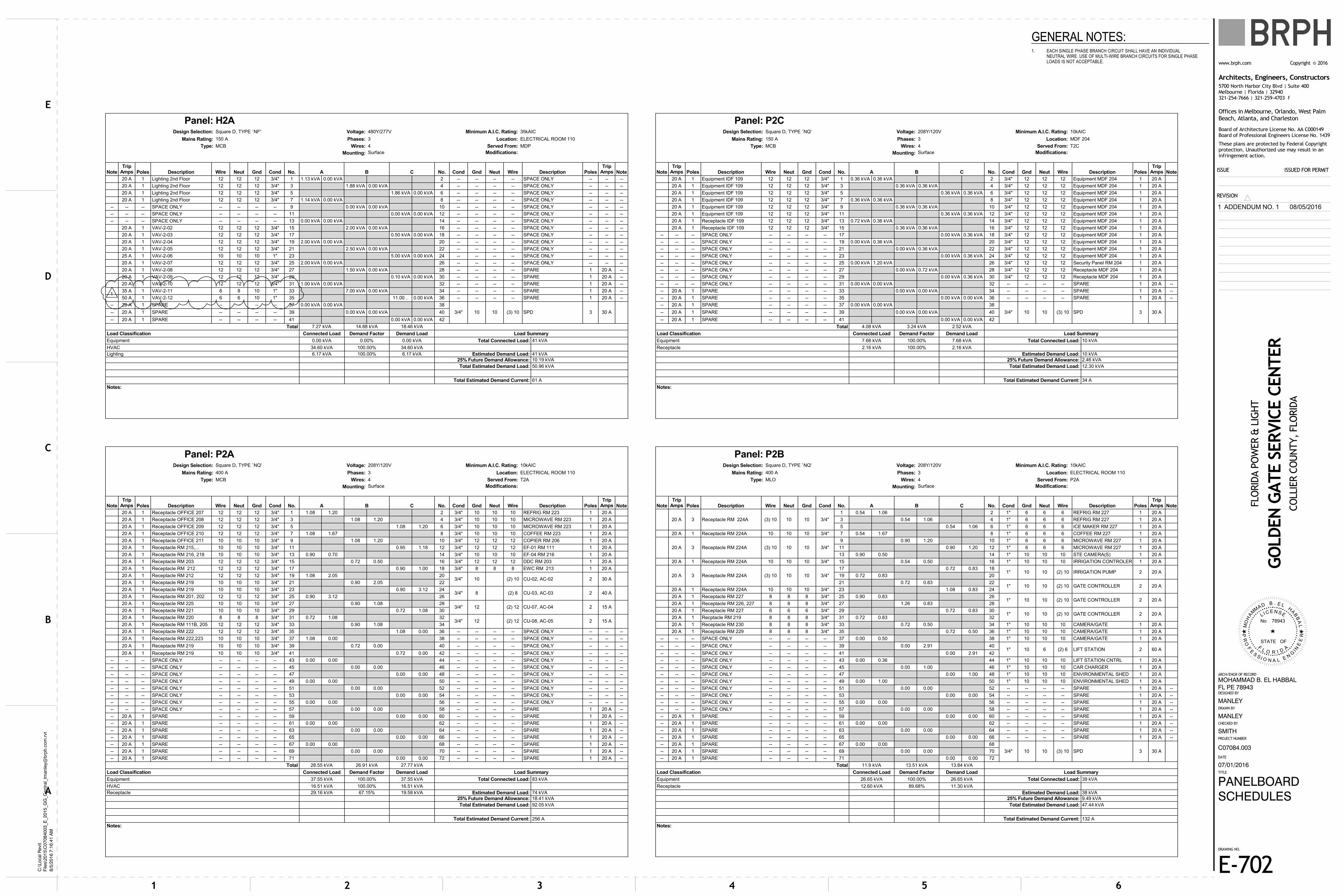
No 78943
M
ESNECIL
ADIROL
FSTATE OF
PR
OF
ES
S I O N A L E NG
I NE
ER
OH
A
MM
AD B . E LH
AB
BA
L
Architects, Engineers, Constructors
These plans are protected by Federal Copyrightprotection. Unauthorized use may result in aninfringement action.
www.brph.com ©Copyright 2016
5700 North Harbor City Blvd | Suite 400Melbourne | Florida | 32940321-254-7666 | 321-259-4703 f
Board of Architecture License No. AA C000149Board of Professional Engineers License No. 1439
Offices in Melbourne, Orlando, West PalmBeach, Atlanta, and Charleston
REVISION
DRAWING NO.
TITLE
PROJECT NUMBER
CHECKED BY
DRAWN BY
DESIGNED BY
ARCH/ENGR OF RECORD
DATE
ISSUE ISSUED FOR PERMIT
54321 6
A
B
C
D
E
C:\
Lo
cal R
evi
tF
iles\
20
15\C
07
08
40
03_E
_2
01
5_G
G_C
en
tral_
tman
ley@
brp
h.c
om
.rvt
8/5
/20
16
7:1
6:4
1 A
M
FLO
RID
A P
OW
ER &
LIG
HT
MANLEY
MANLEY
GO
LDEN
GATE S
ERVIC
E C
EN
TER
CO
LLIE
R C
OU
NTY, FLO
RID
A
C07084.003
E-702
07/01/2016
PANELBOARDSCHEDULES
SMITH
MOHAMMAD B. EL HABBALFL PE 78943
Notes:
Total Estimated Demand Current: 61 A
Total Estimated Demand Load: 50.96 kVA
25% Future Demand Allowance: 10.19 kVA
Lighting 6.17 kVA 100.00% 6.17 kVA Estimated Demand Load: 41 kVA
HVAC 34.60 kVA 100.00% 34.60 kVA
Equipment 0.00 kVA 0.00% 0.00 kVA Total Connected Load: 41 kVA
Load Classification Connected Load Demand Factor Demand Load Load Summary
Total 7.27 kVA 14.88 kVA 18.46 kVA
-- 20 A 1 SPARE -- -- -- -- 41 0.00 kVA 0.00 kVA 42
-- 20 A 1 SPARE -- -- -- -- 39 0.00 kVA 0.00 kVA 40
-- 20 A 1 SPARE -- -- -- -- 37 0.00 kVA 0.00 kVA 38
3/4" 10 10 (3) 10 SPD 3 30 A
50 A 1 VAV-2-12 6 6 10 1" 35 11.00... 0.00 kVA 36 -- -- -- -- SPARE 1 20 A --
35 A 1 VAV-2-11 8 8 10 1" 33 7.00 kVA 0.00 kVA 34 -- -- -- -- SPARE 1 20 A --
20 A 1 VAV-2-10 12 12 12 3/4" 31 1.00 kVA 0.00 kVA 32 -- -- -- -- SPARE 1 20 A --
20 A 1 VAV-2-09 12 12 12 3/4" 29 0.10 kVA 0.00 kVA 30 -- -- -- -- SPARE 1 20 A --
20 A 1 VAV-2-08 12 12 12 3/4" 27 1.50 kVA 0.00 kVA 28 -- -- -- -- SPARE 1 20 A --
20 A 1 VAV-2-07 12 12 12 3/4" 25 2.00 kVA 0.00 kVA 26 -- -- -- -- SPACE ONLY -- -- --
25 A 1 VAV-2-06 10 10 10 1" 23 5.00 kVA 0.00 kVA 24 -- -- -- -- SPACE ONLY -- -- --
20 A 1 VAV-2-05 12 12 12 3/4" 21 2.50 kVA 0.00 kVA 22 -- -- -- -- SPACE ONLY -- -- --
20 A 1 VAV-2-04 12 12 12 3/4" 19 2.00 kVA 0.00 kVA 20 -- -- -- -- SPACE ONLY -- -- --
20 A 1 VAV-2-03 12 12 12 3/4" 17 0.50 kVA 0.00 kVA 18 -- -- -- -- SPACE ONLY -- -- --
20 A 1 VAV-2-02 12 12 12 3/4" 15 2.00 kVA 0.00 kVA 16 -- -- -- -- SPACE ONLY -- -- --
-- -- -- SPACE ONLY -- -- -- -- 13 0.00 kVA 0.00 kVA 14 -- -- -- -- SPACE ONLY -- -- --
-- -- -- SPACE ONLY -- -- -- -- 11 0.00 kVA 0.00 kVA 12 -- -- -- -- SPACE ONLY -- -- --
-- -- -- SPACE ONLY -- -- -- -- 9 0.00 kVA 0.00 kVA 10 -- -- -- -- SPACE ONLY -- -- --
20 A 1 Lighting 2nd Floor 12 12 12 3/4" 7 1.14 kVA 0.00 kVA 8 -- -- -- -- SPACE ONLY -- -- --
20 A 1 Lighting 2nd Floor 12 12 12 3/4" 5 1.86 kVA 0.00 kVA 6 -- -- -- -- SPACE ONLY -- -- --
20 A 1 Lighting 2nd Floor 12 12 12 3/4" 3 1.88 kVA 0.00 kVA 4 -- -- -- -- SPACE ONLY -- -- --
20 A 1 Lighting 2nd Floor 12 12 12 3/4" 1 1.13 kVA 0.00 kVA 2 -- -- -- -- SPACE ONLY -- -- --
NoteTrip
Amps Poles Description Wire Neut Gnd Cond No. A B C No. Cond Gnd Neut Wire Description PolesTrip
Amps Note
Mounting: Surface Modifications:
Type: MCB Wires: 4 Served From: MDP
Mains Rating: 150 A Phases: 3 Location: ELECTRICAL ROOM 110
Design Selection: Square D, TYPE `NF' Voltage: 480Y/277V Minimum A.I.C. Rating: 35kAIC
Panel: H2A
Notes:
Total Estimated Demand Current: 256 A
Total Estimated Demand Load: 92.05 kVA
25% Future Demand Allowance: 18.41 kVA
Receptacle 29.16 kVA 67.15% 19.58 kVA Estimated Demand Load: 74 kVA
HVAC 16.51 kVA 100.00% 16.51 kVA
Equipment 37.55 kVA 100.00% 37.55 kVA Total Connected Load: 83 kVA
Load Classification Connected Load Demand Factor Demand Load Load Summary
Total 28.55 kVA 26.91 kVA 27.77 kVA
-- 20 A 1 SPARE -- -- -- -- 71 0.00 0.00 72 -- -- -- -- SPARE 1 20 A --
-- 20 A 1 SPARE -- -- -- -- 69 0.00 0.00 70 -- -- -- -- SPARE 1 20 A --
-- 20 A 1 SPARE -- -- -- -- 67 0.00 0.00 68 -- -- -- -- SPARE 1 20 A --
-- 20 A 1 SPARE -- -- -- -- 65 0.00 0.00 66 -- -- -- -- SPARE 1 20 A --
-- 20 A 1 SPARE -- -- -- -- 63 0.00 0.00 64 -- -- -- -- SPARE 1 20 A --
-- 20 A 1 SPARE -- -- -- -- 61 0.00 0.00 62 -- -- -- -- SPARE 1 20 A --
-- 20 A 1 SPARE -- -- -- -- 59 0.00 0.00 60 -- -- -- -- SPARE 1 20 A --
-- -- -- SPACE ONLY -- -- -- -- 57 0.00 0.00 58 -- -- -- -- SPARE 1 20 A --
-- -- -- SPACE ONLY -- -- -- -- 55 0.00 0.00 56 -- -- -- -- SPACE ONLY -- -- --
-- -- -- SPACE ONLY -- -- -- -- 53 0.00 0.00 54 -- -- -- -- SPACE ONLY -- -- --
-- -- -- SPACE ONLY -- -- -- -- 51 0.00 0.00 52 -- -- -- -- SPACE ONLY -- -- --
-- -- -- SPACE ONLY -- -- -- -- 49 0.00 0.00 50 -- -- -- -- SPACE ONLY -- -- --
-- -- -- SPACE ONLY -- -- -- -- 47 0.00 0.00 48 -- -- -- -- SPACE ONLY -- -- --
-- -- -- SPACE ONLY -- -- -- -- 45 0.00 0.00 46 -- -- -- -- SPACE ONLY -- -- --
-- -- -- SPACE ONLY -- -- -- -- 43 0.00 0.00 44 -- -- -- -- SPACE ONLY -- -- --
20 A 1 Receptacle RM 219 10 10 10 3/4" 41 0.72 0.00 42 -- -- -- -- SPACE ONLY -- -- --
20 A 1 Receptacle RM 219 10 10 10 3/4" 39 0.72 0.00 40 -- -- -- -- SPACE ONLY -- -- --
20 A 1 Receptacle RM 222,223 10 10 10 3/4" 37 1.08 0.00 38 -- -- -- -- SPACE ONLY -- -- --
20 A 1 Receptacle RM 222 12 12 12 3/4" 35 1.08 0.00 36 -- -- -- -- SPACE ONLY -- -- --
20 A 1 Receptacle RM 111B, 205 12 12 12 3/4" 33 0.90 1.08 34
20 A 1 Receptacle RM 220 8 8 8 3/4" 31 0.72 1.08 323/4" 12 (2) 12 CU-08, AC-05 2 15 A
20 A 1 Receptacle RM 221 10 10 10 3/4" 29 0.72 1.08 30
20 A 1 Receptacle RM 225 10 10 10 3/4" 27 0.90 1.08 283/4" 12 (2) 12 CU-07, AC-04 2 15 A
20 A 1 Receptacle RM 201, 202 12 12 12 3/4" 25 0.90 3.12 26
20 A 1 Receptacle RM 219 10 10 10 3/4" 23 0.90 3.12 243/4" 8 (2) 8 CU-03, AC-03 2 40 A
20 A 1 Receptacle RM 219 10 10 10 3/4" 21 0.90 2.05 22
20 A 1 Receptacle RM 212 12 12 12 3/4" 19 1.08 2.05 203/4" 10 (2) 10 CU-02, AC-02 2 30 A
20 A 1 Receptacle RM 212 12 12 12 3/4" 17 0.90 1.00 18 3/4" 8 8 8 EWC RM 213 1 20 A
20 A 1 Receptacle RM 203 12 12 12 3/4" 15 0.72 0.50 16 3/4" 12 12 12 DDC RM 203 1 20 A
20 A 1 Receptacle RM 216, 218 10 10 10 3/4" 13 0.90 0.70 14 3/4" 10 10 10 EF-04 RM 216 1 20 A
20 A 1 Receptacle RM 215,... 10 10 10 3/4" 11 0.95 1.18 12 3/4" 12 12 12 EF-01 RM 111 1 20 A
20 A 1 Receptacle OFFICE 211 10 10 10 3/4" 9 1.08 1.20 10 3/4" 12 12 12 COPIER RM 206 1 20 A
20 A 1 Receptacle OFFICE 210 12 12 12 3/4" 7 1.08 1.67 8 3/4" 10 10 10 COFFEE RM 223 1 20 A
20 A 1 Receptacle OFFICE 209 12 12 12 3/4" 5 1.08 1.20 6 3/4" 10 10 10 MICROWAVE RM 223 1 20 A
20 A 1 Receptacle OFFICE 208 12 12 12 3/4" 3 1.08 1.20 4 3/4" 10 10 10 MICROWAVE RM 223 1 20 A
20 A 1 Receptacle OFFICE 207 12 12 12 3/4" 1 1.08 1.20 2 3/4" 10 10 10 REFRIG RM 223 1 20 A
NoteTrip
Amps Poles Description Wire Neut Gnd Cond No. A B C No. Cond Gnd Neut Wire Description PolesTrip
Amps Note
Mounting: Surface Modifications:
Type: MCB Wires: 4 Served From: T2A
Mains Rating: 400 A Phases: 3 Location: ELECTRICAL ROOM 110
Design Selection: Square D, TYPE `NQ' Voltage: 208Y/120V Minimum A.I.C. Rating: 10kAIC
Panel: P2A
Notes:
Total Estimated Demand Current: 132 A
Total Estimated Demand Load: 47.44 kVA
25% Future Demand Allowance: 9.49 kVA
Estimated Demand Load: 38 kVA
Receptacle 12.60 kVA 89.68% 11.30 kVA
Equipment 26.65 kVA 100.00% 26.65 kVA Total Connected Load: 39 kVA
Load Classification Connected Load Demand Factor Demand Load Load Summary
Total 11.9 kVA 13.51 kVA 13.84 kVA
-- 20 A 1 SPARE -- -- -- -- 71 0.00 0.00 72
-- 20 A 1 SPARE -- -- -- -- 69 0.00 0.00 70
-- 20 A 1 SPARE -- -- -- -- 67 0.00 0.00 68
3/4" 10 10 (3) 10 SPD 3 30 A
-- 20 A 1 SPARE -- -- -- -- 65 0.00 0.00 66 -- -- -- -- SPARE 1 20 A --
-- 20 A 1 SPARE -- -- -- -- 63 0.00 0.00 64 -- -- -- -- SPARE 1 20 A --
-- 20 A 1 SPARE -- -- -- -- 61 0.00 0.00 62 -- -- -- -- SPARE 1 20 A --
-- 20 A 1 SPARE -- -- -- -- 59 0.00 0.00 60 -- -- -- -- SPARE 1 20 A --
-- -- -- SPACE ONLY -- -- -- -- 57 0.00 0.00 58 -- -- -- -- SPARE 1 20 A --
-- -- -- SPACE ONLY -- -- -- -- 55 0.00 0.00 56 -- -- -- -- SPARE 1 20 A --
-- -- -- SPACE ONLY -- -- -- -- 53 0.00 0.00 54 -- -- -- -- SPARE 1 20 A --
-- -- -- SPACE ONLY -- -- -- -- 51 0.00 0.00 52 -- -- -- -- SPARE 1 20 A --
-- -- -- SPACE ONLY -- -- -- -- 49 0.00 1.00 50 1" 10 10 10 ENVIRONMENTAL SHED 1 20 A
-- -- -- SPACE ONLY -- -- -- -- 47 0.00 1.00 48 1" 10 10 10 ENVIRONMENTAL SHED 1 20 A
-- -- -- SPACE ONLY -- -- -- -- 45 0.00 1.00 46 1" 10 10 10 CAR CHARGER 1 20 A
-- -- -- SPACE ONLY -- -- -- -- 43 0.00 0.36 44 1" 10 10 10 LIFT STATION CNTRL 1 20 A
-- -- -- SPACE ONLY -- -- -- -- 41 0.00 2.91 42
-- -- -- SPACE ONLY -- -- -- -- 39 0.00 2.91 401" 10 6 (2) 6 LIFT STATION 2 60 A
-- -- -- SPACE ONLY -- -- -- -- 37 0.00 0.50 38 1" 10 10 10 CAMERA/GATE 1 20 A
20 A 1 Receptacle RM 229 8 8 8 3/4" 35 0.72 0.50 36 1" 10 10 10 CAMERA/GATE 1 20 A
20 A 1 Receptacle RM 230 8 8 8 3/4" 33 0.72 0.50 34 1" 10 10 10 CAMERA/GATE 1 20 A
20 A 1 Recptacle RM 219 8 8 8 3/4" 31 0.72 0.83 32
20 A 1 Receptacle RM 227 6 6 6 3/4" 29 0.72 0.83 301" 10 10 (2) 10 GATE CONTROLLER 2 20 A
20 A 1 Receptacle RM 226, 227 8 8 8 3/4" 27 1.26 0.83 28
20 A 1 Receptacle RM 227 8 8 8 3/4" 25 0.90 0.83 261" 10 10 (2) 10 GATE CONTROLLER 2 20 A
20 A 1 Receptacle RM 224A 10 10 10 3/4" 23 1.08 0.83 24
21 0.72 0.83 221" 10 10 (2) 10 GATE CONTROLLER 2 20 A
19 0.72 0.83 2020 A 3 Receptacle RM 224A (3) 10 10 10 3/4"
17 0.72 0.83 181" 10 10 (2) 10 IRRIGATION PUMP 2 20 A
20 A 1 Receptacle RM 224A 10 10 10 3/4" 15 0.54 0.50 16 1" 10 10 10 IRRIGATION CONTROLER 1 20 A
13 0.90 0.50 14 1" 10 10 10 STE CAMERA(S) 1 20 A
11 0.90 1.20 12 1" 6 6 6 MICROWAVE RM 227 1 20 A20 A 3 Receptacle RM 224A (3) 10 10 10 3/4"
9 0.90 1.20 10 1" 6 6 6 MICROWAVE RM 227 1 20 A
20 A 1 Receptacle RM 224A 10 10 10 3/4" 7 0.54 1.67 8 1" 6 6 6 COFFEE RM 227 1 20 A
5 0.54 1.06 6 1" 6 6 6 ICE MAKER RM 227 1 20 A
3 0.54 1.06 4 1" 6 6 6 REFRIG RM 227 1 20 A20 A 3 Receptacle RM 224A (3) 10 10 10 3/4"
1 0.54 1.06 2 1" 6 6 6 REFRIG RM 227 1 20 A
NoteTrip
Amps Poles Description Wire Neut Gnd Cond No. A B C No. Cond Gnd Neut Wire Description PolesTrip
Amps Note
Mounting: Surface Modifications:
Type: MLO Wires: 4 Served From: P2A
Mains Rating: 400 A Phases: 3 Location: ELECTRICAL ROOM 110
Design Selection: Square D, TYPE `NQ' Voltage: 208Y/120V Minimum A.I.C. Rating: 10kAIC
Panel: P2B
Notes:
Total Estimated Demand Current: 34 A
Total Estimated Demand Load: 12.30 kVA
25% Future Demand Allowance: 2.46 kVA
Estimated Demand Load: 10 kVA
Receptacle 2.16 kVA 100.00% 2.16 kVA
Equipment 7.68 kVA 100.00% 7.68 kVA Total Connected Load: 10 kVA
Load Classification Connected Load Demand Factor Demand Load Load Summary
Total 4.08 kVA 3.24 kVA 2.52 kVA
-- 20 A 1 SPARE -- -- -- -- 41 0.00 kVA 0.00 kVA 42
-- 20 A 1 SPARE -- -- -- -- 39 0.00 kVA 0.00 kVA 40
-- 20 A 1 SPARE -- -- -- -- 37 0.00 kVA 0.00 kVA 38
3/4" 10 10 (3) 10 SPD 3 30 A
-- 20 A 1 SPARE -- -- -- -- 35 0.00 kVA 0.00 kVA 36 -- -- -- -- SPARE 1 20 A --
-- 20 A 1 SPARE -- -- -- -- 33 0.00 kVA 0.00 kVA 34 -- -- -- -- SPARE 1 20 A --
-- -- -- SPACE ONLY -- -- -- -- 31 0.00 kVA 0.00 kVA 32 -- -- -- -- SPARE 1 20 A --
-- -- -- SPACE ONLY -- -- -- -- 29 0.00 kVA 0.36 kVA 30 3/4" 12 12 12 Receptacle MDF 204 1 20 A
-- -- -- SPACE ONLY -- -- -- -- 27 0.00 kVA 0.72 kVA 28 3/4" 12 12 12 Receptacle MDF 204 1 20 A
-- -- -- SPACE ONLY -- -- -- -- 25 0.00 kVA 1.20 kVA 26 3/4" 12 12 12 Security Panel RM 204 1 20 A
-- -- -- SPACE ONLY -- -- -- -- 23 0.00 kVA 0.36 kVA 24 3/4" 12 12 12 Equipment MDF 204 1 20 A
-- -- -- SPACE ONLY -- -- -- -- 21 0.00 kVA 0.36 kVA 22 3/4" 12 12 12 Equipment MDF 204 1 20 A
-- -- -- SPACE ONLY -- -- -- -- 19 0.00 kVA 0.36 kVA 20 3/4" 12 12 12 Equipment MDF 204 1 20 A
-- -- -- SPACE ONLY -- -- -- -- 17 0.00 kVA 0.36 kVA 18 3/4" 12 12 12 Equipment MDF 204 1 20 A
20 A 1 Receptacle IDF 109 12 12 12 3/4" 15 0.36 kVA 0.36 kVA 16 3/4" 12 12 12 Equipment MDF 204 1 20 A
20 A 1 Receptacle IDF 109 12 12 12 3/4" 13 0.72 kVA 0.36 kVA 14 3/4" 12 12 12 Equipment MDF 204 1 20 A
20 A 1 Equipment IDF 109 12 12 12 3/4" 11 0.36 kVA 0.36 kVA 12 3/4" 12 12 12 Equipment MDF 204 1 20 A
20 A 1 Equipment IDF 109 12 12 12 3/4" 9 0.36 kVA 0.36 kVA 10 3/4" 12 12 12 Equipment MDF 204 1 20 A
20 A 1 Equipment IDF 109 12 12 12 3/4" 7 0.36 kVA 0.36 kVA 8 3/4" 12 12 12 Equipment MDF 204 1 20 A
20 A 1 Equipment IDF 109 12 12 12 3/4" 5 0.36 kVA 0.36 kVA 6 3/4" 12 12 12 Equipment MDF 204 1 20 A
20 A 1 Equipment IDF 109 12 12 12 3/4" 3 0.36 kVA 0.36 kVA 4 3/4" 12 12 12 Equipment MDF 204 1 20 A
20 A 1 Equipment IDF 109 12 12 12 3/4" 1 0.36 kVA 0.36 kVA 2 3/4" 12 12 12 Equipment MDF 204 1 20 A
NoteTrip
Amps Poles Description Wire Neut Gnd Cond No. A B C No. Cond Gnd Neut Wire Description PolesTrip
Amps Note
Mounting: Surface Modifications:
Type: MCB Wires: 4 Served From: T2C
Mains Rating: 150 A Phases: 3 Location: MDF 204
Design Selection: Square D, TYPE `NQ' Voltage: 208Y/120V Minimum A.I.C. Rating: 10kAIC
Panel: P2C
GENERAL NOTES:1. EACH SINGLE PHASE BRANCH CIRCUIT SHALL HAVE AN INDIVIDUAL
NEUTRAL WIRE. USE OF MULTI-WIRE BRANCH CIRCUITS FOR SINGLE PHASELOADS IS NOT ACCEPTABLE.
1 ADDENDUM NO. 1 08/05/2016
1

UP
UP
WD
J
J J
J
J
FB FB
FB
FB
M
FB
J
FB FB
J
J
FB
FB
FB
JJ
J
E-401
1
A
1
D
2 5 6
C
B
43
FOREMAN ROOM
128
SAFETY OFFICE
129
SECURE STORAGE
130
CONFERENCE ROOM
139
CORRIDOR
134
OPEN OFFICE
140
RECEPTION
105
OPERATIONS/SITUATION ROOM
108
DISPATCH
113CONFERENCE ROOM
112
SUPPORT
114
IDF
109
ELECTRICAL ROOM
110
MECHANICAL ROOM
107
FIRE RISER
104
ELEV. MECH.
103
ELEVATOR
102
LOBBY
100
ASSEMBLY ROOM
120
COMM. CORRIDOR
132
STORAGE
131
BREAK ROOM
133
OFFICE
118
OFFICE
117
OFFICE
116
OFFICE
115
LARGE TOOLSTORAGE
111
COPY/MAIL
119
WOMEN'SRESTROOM
121
MEN'S RESTROOM
122
STAIR
101
RESTROOM
106
GF
GF
GF
GF
GF
GF
P1A-1
P1A-1
P1A-1
P1A-3
P1A-3
P1A-3 P1A-5
P1A-5
P1A-5
P1A-7
P1A-7
P1A-7
GF
GF
P1A-9
P1A-9
P1A-9
P1A-9
P1A-9
P1A-9
P1A-11
P1A-11
P1A-11
P1A-13
P1A-13
P1A-13
P1A-15
P1A-15
P1A-15
P1A-17
P1A-17
P1A-17
P1A-17
P1A-33
P1A-17
P1A-19 P1B-13
P1A-19
P1B-29
P1B-13P1B-13
P1B-13
P1B-21
P1B-13
P1B-17 P1B-17
P1B-35
P1A-21
P1A-21
P1A-23 P1A-23 P1A-23
P1A-25
P1A-27
P1A-27
P1A-27
P1A-25
P1A-27
P1A-27
P1B-2
P1B-6
P1B-8
P1B-10P1B-12P1B-14
P1B-21
P1B-21
P1B-21
P1B-23
P1B-23
P1A-2
P1A-33
P1A-33
P1A-33
P1A-33
P1B-1
P1B-1
P1B-1
P1B-3
P1B-5
P1B-5P1B-5
P1B-7
P1B-7 P1B-7
P1B-9
P1B-9P1B-9
P1B-11
P1B-11P1B-11
P1A-17 P1B-33
P1B-33
GF
GFP1A-19
P1B-35
VAV-1-02
VAV-1-04
VAV-1-01
VAV-1-08
VAV-1-10
VAV-1-12
VAV-1-11
VAV-1-06
VAV-1-05
VAV-1-09
CU-05
CU-04CU-01
CU-02
CU-03
EF-03
VAV-1-07
H1A-19
H1A-21
H1A-23
H1A-25
H1A-27
H1A-29
H1A-31
H1A-33H1A-35
H1A-37
H1A-41
P1A-11
26-2
26-126-1
P1B-3 P1B-3
VAV-1-03
P1B-17
P1B-19
P1B-19
P1B-19
P1B-25 P1B-27
P1B-22 P1B-22
P1B-18
P1B-29
P1B-29
P1B-29
CORRIDOR
127
26-1
P1A-4
P1A-6
P1B-33
P1A-8
P1B-33
P1A-10
P1A-12
P1A-14
P1A-16 P1A-18
P1A-37
P1A-37
P1A-37
WP
WP
WP
P1A-35
P1A-35
P1A-35
STAIR
125
FITNESS ROOM
126
OFFICE
136
OFFICE
135
OFFICE
137
OFFICE
138
P1A-11
H1A-39
CU-06
MDP-26,28,30
MDP-20,22,24
MDP-14,16,18
P1B-37,39,41
P1A-35
P1A-19
JANITOR'S CLOSET
123
+75"
+82" +82"
+75"
+75"
+75"
+90"
+75"
4
4
P1B-43
+82"4
4 4
P1A-25
P1A-43
4
P1A-43
4
+75" +75" +75"
+75"
TP-1
TP-2
P1A-1
+86"
P1A-3
+86"
P1A-5
+86"
P1A-7
+86"
4 4
F
F F
+48"
P2A-20,22P1A-34,36
P2A-24,26
CU-08
CU-07
P2A-28,30
P2A-32,34
26-3
P1A-33
26-3
P1B-4GF
26-3
AC-03
26-3
26-3
AC-02
AC-01
AC-05
AC-04WP
WP
P1A-39
P1A-39
P1B-274
F
P1A-41 P1A-41
P1A-40
P1A-42
GE
NE
RA
TO
R
P1B-16
P1B-20
P1B-15
P1B-15
P1B-31 P1B-31
+60"
+60"
WP
WP
WP
WP
WP
WP
WP
WP
CORRIDOR
124
MOUNTED ON FIRSTFLOOR UNDERNEATHMEZZANINE LANDING
P1B-1 P1B-1
SAFETY OFFICE
134A
OFFICE
134B
P1B-26 P1B-28
P1B-28P1B-28
P1B-26P1B-26
P1B-31
P1B-30 P1B-30 P1B-30
CORRIDOR
134
P1B-33
+36" +36" +36"+36" +36" +36"
P1A-44
26-2
No 78943
M
ESNECIL
ADIROL
FSTATE OF
PR
OF
ES
S I O N A L E NG
I NE
ER
OH
A
MM
AD B . E LH
AB
BA
L
TRUE NORTH PLAN NORTH
Architects, Engineers, Constructors
These plans are protected by Federal Copyrightprotection. Unauthorized use may result in aninfringement action.
www.brph.com ©Copyright 2016
5700 North Harbor City Blvd | Suite 400Melbourne | Florida | 32940321-254-7666 | 321-259-4703 f
Board of Architecture License No. AA C000149Board of Professional Engineers License No. 1439
Offices in Melbourne, Orlando, West PalmBeach, Atlanta, and Charleston
REVISION
DRAWING NO.
TITLE
PROJECT NUMBER
CHECKED BY
DRAWN BY
DESIGNED BY
ARCH/ENGR OF RECORD
DATE
ISSUE ISSUED FOR PERMIT
54321 6
A
B
C
D
E
C:\
Lo
cal R
evi
tF
iles\
20
15\C
07
08
40
03_E
_2
01
5_G
G_C
en
tral_
tman
ley@
brp
h.c
om
.rvt
8/5
/20
16
7:1
6:4
3 A
M
FLO
RID
A P
OW
ER &
LIG
HT
MANLEY
MANLEY
GO
LDEN
GATE S
ERVIC
E C
EN
TER
CO
LLIE
R C
OU
NTY, FLO
RID
A
C07084.003
EP-101
07/01/2016
FIRST FLOORPOWER PLAN
SMITH
MOHAMMAD B. EL HABBALFL PE 78943
1/8" = 1'-0"1FIRST FLOOR POWER PLAN
GENERAL NOTES:1.
2.
3.
4.
5.
ALL DISCONNECT SWITCHES, STARTERS, COMBINATION STARTERS, ANDASSOCIATED FUSES FOR MECHANICAL EQUIPMENT SHALL BE FURNISHEDBY DIVISION 23 AND INSTALLED BY DIVISION 26 CONTRACTOR. VERIFY ALLFUSE SIZES WITH THE EQUIPMENT MANUFACTURER PRIOR TOINSTALLATION.
ALL CONTROL WIRING FOR MECHANICAL EQUIPMENT AND SYSTEMS WILLBE PROVIDED BY THE DIVISION 23 CONTRACTOR UNLESS OTHERWISENOTED.
REFER TO SYSTEMS PLANS FOR COMMUNICATIONS DEVICES. WHERE 120VRECEPTACLE ARE IN CLOSE PROXIMITY TO COMMUNICATIONS DEVICES,SUCH DEVICES SHALL BE INSTALLED AT THE SAME HEIGHT ASRECEPTACLES WITH NO MORE THAN 2" OF SEPARATION BETWEEN THEM.
COORDINATE LOCATION OF FLOOR BOXES WITH ARCHITECT, OWNER, ANDFURNITURE PROVIDERS. LOCATIONS SHALL BE APPROVED BY OWNERPRIOR TO INSTALLATION.
COORDINATE LOCATIONS OF TRAP PRIMER CONNECTIONS WITH THEPLUMBING CONTRACTOR.
NOTES:26-1
26-2
26-3
PROVIDE GF TYPE BRANCH CIRCUIT BREAKER AT SOURCE PANELBOARDFOR RECEPTACLES INDICATED.
PROVIDE LINE AND LOAD SIDE CONDUIT, WIRING, AND CONNECTIONS TODOOR CONTROLLER FURNISHED WITH DOOR. PROVIDE ADDITIONALCONDUIT, WIRING, AND CONNECTIONS FOR DOOR CONTROLS ASDIRECTED BY DOOR MANUFACTURER AND INSTALLER.
INSTALL WEATHERPROOF DISCONNECT SWITCH TO BE PROVIDED BY THEDIVISION 23 CONTRACTOR WITH LOAD SIDE CONNECTIONS AND HOME RUNAS INDICATED. ADDITIONALLY, PROVIDE MATCHING CONDUIT AND WIREFOR POWER AND 3/4" CONDUIT WITH CONTROL WIRING FROMCONDENSING UNIT TO AC UNIT INDICATED. COORDINATE ALL WIRING ANDINSTALLATION REQUIREMENTS WITH THE EQUIPMENT MANUFACTURER.
0 4' 8' 16' 24'
1/8" = 1'-0"
1 ADDENDUM NO. 1 08/05/2016
1
ISC - Procurement - Sign & Engraving
http://eweb.fpl.com/bunit/corpservices/isc/Procurement/nameplates.shtml[8/2/2016 9:50:17 PM]
Integrated Supply Chain
Employee ShareNet | HR Direct | Corporate Portal | NextEra University | Contact Us
All of Employee Web
Nameplates
We offer a variety of signage for offices, cubicles, conference rooms, office boards, or any signage that requiresupdating or change. Sign systems can be ordered with holders, wall plates, desk bases or display stands.
To order: Nameplate Order Form
How to Buy Services Corporate Travel Material Operations Supplier Diversity College of Supply Chain