project final report - TRIP · In order to reduce environmental impact from rotorcraft, the Green...
27
ISO 9001 - Cert. n. 5203 Sede Legale: Via Milano, Km. 1,600 70023 Gioia del Colle (BA) Italy A SOCIO UNICO PROJECT FINAL REPORT Grant Agreement number: 267492 Project acronym: MAEM-RO Project title: Methodologies and applications of emission measurements on rotorcraft Funding scheme: FP7-JTI-CS Period covered:: from 01-07-2010 to 31-12-2013 Antonio Ferrante, Project coordinator Centro Combustione Ambiente srl Tel: 0039 080 3480315 Fax: 0039 080 3480300 E-mail: [email protected]
Transcript of project final report - TRIP · In order to reduce environmental impact from rotorcraft, the Green...

ISO 9001 - Cert. n. 5203 Sede Legale: Via Milano, Km. 1,600 70023 Gioia del Colle (BA) Italy A SOCIO UNICO
PROJECT FINAL REPORT
Grant Agreement number: 267492
Project acronym: MAEM-RO
Project title: Methodologies and applications of emission measurements on
rotorcraft
Funding scheme: FP7-JTI-CS Period covered:: from 01-07-2010 to 31-12-2013
Antonio Ferrante, Project coordinator
Centro Combustione Ambiente srl
Tel: 0039 080 3480315
Fax: 0039 080 3480300
E-mail: [email protected]

ISO 9001 - Cert. n. 5203 Sede Legale: Via Milano, Km. 1,600 70023 Gioia del Colle (BA) Italy A SOCIO UNICO
4.1 Final publishable summary report
4.1.1 Executive summary
The air transport industry is paying a lot of attention to growing public concern on the environmental issues of air pollution. Clean Sky is a Joint Technology Initiative that is developing breakthrough technologies to reduce environmental impact. In order to reduce environmental impact from rotorcraft, the Green Rotorcraft integrated technology demonstrator will develop environment-friendly flight paths: they are procedures and mission profiles designed to reduce fuel consumption (and accordingly CO2 emissions) and NOx emissions. To this aim it is necessary to create a data base containing flue emissions by rotorcraft during flight and in different weather conditions. This data base will be used in order to design green mission profiles; to create complete database, a generic rotorcraft engine has been mathematically modeled to calculate flue gas emissions by means of state of art numerical codes. Results from numerical codes always need to be validated by extensive test campaign. In this Project Centro Combustione Ambiente (CCA) has performed flue gas emission measurement on AgustaWestland Pzl SW4 helicopter during several flight missions. In order to perform accurate measurement activity in a not standardized field, CCA has used its broad experience in flue gas measurements from stationary gas turbines. Due to the lack of standard procedures to perform measurements on rotorcraft, CCA has defined the most appropriate methodology and the best practices for the measurements of emissions from aeronautical engines. The equipment defined in the methodology has been suitable to operate properly in flight tests. The guidelines from methodology have driven during test campaign to perform accurate measurements of CO, CO2, NOx, TOC and O2 concentration during flight tests. Using data gathered during flight tests, CCA experts have contributed to edit a report with data related to the environmental flight conditions to be used in the optimisation process of flight paths. The final goal is to participate to reduce environmental impact from one of the human activities.

ISO 9001 - Cert. n. 5203 Sede Legale: Via Milano, Km. 1,600 70023 Gioia del Colle (BA) Italy A SOCIO UNICO
4.1.2 Summary description of project context and objectives
The main task of the project MAEM-RO is the development of a methodology able to provide the guidelines for the measurement of gaseous pollutants emitted by the engine of a helicopter during flight missions. As a result of these methodologies the guidelines will be used for the execution of a number of missions in flight, with different settings of the engine, different flight profiles and with different weather conditions. In order to develop such a methodology is necessary to identify the various parts that integrated together contribute to the achievement of the desired results. For this reason, the development of each part of the project has been divided into work packages. The first work package has the task of identifying the different measurement standards applied in other fields of technology and that can also be used to perform measurements in flight missions. In fact, at the international level, there are no methods for the measurement of exhaust gas in the aircraft industry, but only guidelines or recommendations which, however, are not applicable during flight missions but only for measures on the ground, for example ICAO Annex 16 vol 2 Standards and Recommended Practices. These recommendations have been taken into consideration during the development of the methodology but most of the technical indications came from mature techniques of measurement of gaseous pollutants in the field of plants for the production of energy through the combustion of fossil fuels, in particular the combustion of light fuel oil which is similar to JP1. The second work package has the task of identifying the measuring principle of the flue gas analyzer to be used during the experimental campaign. Currently available is a variety of flue analyzers which operate according to different measurement principles in relation to the chemical species to be measured, the accuracy of the measurement and the conditions under which measurement occurs. In order to design a complete flue gas measurement system for flight tests, many requirements have to be taken into account:
• system has to be robust enough to stand with helicopter vibrations without interfering with measurement accuracy and flight safety;
• it has to be not too much demanding from power point of view; • capability of automatic operation, in order to avoid expert presence during flight; • flight level should be not a issue for analyzer (at helicopter standard flight level); • need of auxiliaries has to be reduced as much as possible; • data acquisition system has to transfer measurements to helicopter acquisition system according to
avionics standards.
These constrains required a deep study for designing each component and the whole system integration can be divided in several tasks:
• probe design The suction probe has to assure homogeneity in sampled gas for accurate measurements, and it must be robust to stand with gas high temperatures and engine vibrations. It has to be intrusive as small as possible, avoiding interference with engine performance and flight safety; that means suction probe should be designed as small as possible, but big enough to sample the right gas flow rate.
• sampling line In case of HC measurements, it is necessary to avoid condensation of water vapor which causes reaction with hydrocarbons to be measured: heated sample line should be used. Its requirements have to be compatible with:

ISO 9001 - Cert. n. 5203 Sede Legale: Via Milano, Km. 1,600 70023 Gioia del Colle (BA) Italy A SOCIO UNICO
1. power supply available on helicopter; 2. external air temperature and pressure; 3. installation path available from sampling probe to the helicopter cabin, where analyzers are installed.
For those reasons sampling line has to be properly designed to take into account mentioned constrains.
• auxiliaries and flue gas conditioning To work properly and for accurate measurements, flue gas analyzers require a certain amount of flow rate and clean sample: in order to satisfy these constrains emission system has as auxiliaries a flow rate control system with pump and filters to remove particles or dust. Also for this task components have to be light, not too much demanding from power point of view, to be the best choice for the integrated system.
• analyzers On the market there are many flue gas analyzers, for example compact multi species analyzers, single species analyzers, based on NDIR principle (for CO, CO2, NOx, SO2), chemiluminescence principle (for NOx), FT-IR etc.. Most of them can be considered at the state of art for this kind of equipment, but usually they have different requirements during operation. For example most of analyzers use optic measuring principle that is sensitive to vibrations. These requirements have to be compatible with helicopter flight conditions while measurements have to be accurate as much as possible. CCA engineers have designed the integration of analyzers in the system taking into account all those constrains, choosing analyzers as more “standard” as possible to keep cost reasonably low, avoiding expensive and not well proofed equipment. Anti vibration mounts could be adopted during flight tests. Another important requirement is the response time of meters: even if only steady state measurements are meaningful, for aeronautic field steady states can be shorter than, e.g., power plants steady state. For this reason fast response analyzers should be adopted, with response time compatible with typical time of helicopter operation, like climb time.
• data acquisition system Output data from analyzers shall be collected from measuring equipments and stored in a data base. The aim of data base is to validate results from numerical codes; each emission measurement set is obviously related to engine condition, e.g. fuel consumption, combustion air temperature, etc.. For this reason data base records have to be strictly related to engine setting in time domain, i.e. synchronisation is necessary. The best way to reach this target is to send emissions data to helicopter data acquisition system using its date stamp. Obviously data have to be sent as fast as possible. CCA engineers are designing a data management system able to:
1. acquire data from analyzers; 2. manage and store warning messages and status messages from analyzers; 3. send data to helicopter data system according to avionics protocol; 4. store all information in computer hard disk for possible checks.
As mentioned before, analyzers with digital output will be chose in order to avoid analog to digital converters; personal computer will be connected to analyzers by RS 232 or RS485 protocols. The task of work package 3 is to design and implement the exhaust sampling line from the sampling point to the analyzer. Even before this, it is important to determine where to sample the exhaust gases of the engine of the helicopter. It must be that the sample is as homogeneous as possible and which avoids backflow from atmosphere that alter the measure. Even the path of the flue gas to the analyzer must be compatible with the requirements of safety during flight.

ISO 9001 - Cert. n. 5203 Sede Legale: Via Milano, Km. 1,600 70023 Gioia del Colle (BA) Italy A SOCIO UNICO
Since the sampling line shall be maintained at a constant temperature of about 180 ° C, it is necessary that the power required for the power supply is compatible with the voltage and power levels available on the helicopter during the flight missions. The task of work package 4 is the design and implementation of a software system for the acquisition of measurements from the analyzer and transfer them on board notebook where data are stored, containing the set-up of the helicopter engine, the weather conditions and the conditions of flight profiles. The data storage on the same computer guarantees the synchronization of the various data collected, allowing in the future the comparison of emission levels with the condition of the engine. The task of work package 5 consists of the installation of all the equipment on board the helicopter at the beginning and test execution on the ground. The ground tests will serve to verify the correct operation of the system, but also to compare later emissions on the ground with those in flight missions. The success of this activity will depend on the correct execution of the preparatory stages of the previous work packages. The flight profiles were selected by AgustaWestland staff according to standard flight procedures and the experiences gained. Once all the scheduled flight missions have done, it will proceed to the preparation of the database containing the measures collected and the condition of the engine and weather conditions. This is the task of work package 6. The task of the database is also to provide a means of verification for the working groups that deal with numerical simulations of the engine of the helicopter inside of GRC.

ISO 9001 - Cert. n. 5203 Sede Legale: Via Milano, Km. 1,600 70023 Gioia del Colle (BA) Italy A SOCIO UNICO
4.1.3 Description of the main S&T results/foregrounds
The first experimental goal of the MAEM-RO project is to identify what kind of fumes analyzer to use during flight missions. The not standard conditions of measurement require that the entire system of measurement experience some requirements peculiar to the environment where the measurements have to be performed. There are portable analyzers using electrochemical cells: they are very versatile and allow to measure many chemical species at the same time, however, their accuracy is quite low. The analyzers more accurate are in general rather heavy and do not allow to measure more than two chemical species for each instrument. They typically rely on the optical principle of the Non-Dispersive Infrared (NDIR) and they are used for the measurement of CO and CO2. A measuring principle widely used for the measurement of NOx is the chemiluminescence: it has become the most widely used NOx emissions monitoring technique in stack emissions and ambient air-monitoring instrumentation. More than 95% of the NOx CEMS used by the electric utility industry , and approximately 99% of the NOx analyzers used for EPA Reference Method 7E and 20 testing employ the chemiluminescence measurement technology. The basic chemiluminescence chemistry was delineated in 1967 by Clough et al:
NO + O3 → NO2*+ O2 NO2* → NO2 + hν (~600 to 3,000nm)
hν = photons. When NO reacts with O3, some electronically-excited NO2* molecules are produced. These molecules may give off energy in the form of light emission with intensity linearly proportional to the concentration of NO. When the emitted radiation is monitored, it becomes a measure of the concentration of the NO in the reacting sample. The light emission occurs between 600 and 3,000 nm, with a peak at about 1,200 nm. Chemiluminescence NOx analyzers measure NO concentrations by using a bandpass filter to select light in the region from about 600 to 900 nm. The major advantages of chemiluminescence method over other measurement methods for NOx monitoring include:
• Increased sensitivity (detection limit) • Improved specificity (accuracy) • Rapid response time (control) • Linearity over a wide dynamic range (precision) • Continuous monitoring (control and reporting) • Simplicity of design (maintenance)
The disadvantage of this principle of measurement is that it can be applied only to the oxides of nitrogen and a few other chemical species. The application of traditional infrared spectroscopy to low concentration measurements, such as ambient air measurements, is limited by several factors. First is the significant presence of water vapour, CO2 and methane, which strongly absorb in many regions of the infrared (IR) spectrum. Consequently, the spectral regions that can

ISO 9001 - Cert. n. 5203 Sede Legale: Via Milano, Km. 1,600 70023 Gioia del Colle (BA) Italy A SOCIO UNICO
easily be used to search for pollutants are limited to 760-1300cm-1 , 2000-2230 cm-1 , and 2390-3000 cm-1 . Another problem is that the sensitivity is not enough to detect very small concentrations in the sub-ppm level. Finally, spectral analysis was difficult since subtraction of background spectra had to be carried out manually. The development of Fourier Transform InfraRed spectroscopy (FTIR) provided a quantum leap in infrared analytical capabilities for monitoring trace pollutants in ambient air. This technique offered a number of advantages over conventional infrared systems, including sensitivity, speed and improved data processing. The basic components of an FTIR are shown schematically in Figure 1 . The infrared source emits a broad band of different wavelength of infrared radiation. The IR source used is a SiC ceramic at a temperature of 1550 K. The IR radiation goes through an interferometer that modulates the infrared radiation. The interferometer performs an optical inverse Fourier transform on the entering IR radiation. The modulated IR beam passes through the gas sample where it is absorbed to various extents at different wavelengths by the various molecules present. Finally the intensity of the IR beam is detected by a detector, which is a liquid-nitrogen cooled MCT (Mercury-Cadmium-Telluride) detector in the case of the GASMET FTIR series. The detected signal is digitized and Fourier transformed by the computer to get the IR spectrum of the sample gas.
Figure 1 Basic components of FTIR
The unique part of an FTIR spectrometer is the interferometer. A Michelson type plane mirror interferometer is displayed in Figure 2 . Infrared radiation from the source is collected and collimated (made parallel) before it strikes the beamsplitter. The beamsplitter ideally transmits one half of the radiation, and reflects the other half. Both transmitted and reflected beams strike mirrors, which reflect the two beams back to the beamsplitter. Thus, one half of the infrared radiation that finally goes to the sample gas has first been reflected from the beamsplitter to the moving mirror, and then back to the beamsplitter. The other half of the infrared radiation going to the sample has first gone through the beamsplitter and then reflected from the fixed mirror back to the beamsplitter. When these two optical paths are reunited, interference occurs at the beamsplitter because of the optical path difference caused by the scanning of the moving mirror.

ISO 9001 - Cert. n. 5203 Sede Legale: Via Milano, Km. 1,600 70023 Gioia del Colle (BA) Italy A SOCIO UNICO
Figure 2 Michelson interferometer
The optical path length difference between the two optical paths of a Michelson interferometer is two times the displacement of the moving mirror. The interference signal measured by the detector as a function of the optical path length difference is called the interferogram. A typical interferogram produced by the interferometer is shown in Figure 3 . The graph shows the intensity of the infrared radiation as a function of the displacement of the moving mirror. At the peak position, the optical path length is exactly the same for the radiation that comes from the moving mirror as it is for the radiation that comes from the fixed mirror.
Figure 3 A typical interferogram
The spectrum can be computed from the interferogram by performing a Fourier transform. The Fourier transform is performed by the same computer that ultimately performs the quantitative analysis of the spectrum. The degree of absorption of infrared radiation at each wavelength is quantitatively related to

ISO 9001 - Cert. n. 5203 Sede Legale: Via Milano, Km. 1,600 70023 Gioia del Colle (BA) Italy A SOCIO UNICO
the number of absorbing molecules in the sample gas. Since there is a linear relationship between the absorbance and the number of absorbing molecules, multicomponent quantitative analysis of gas mixtures is feasible.
To perform multicomponent analysis we start with the sample spectrum. In addition, we need reference spectra of all the gas components that may exist in the sample, if these components are to be analyzed. A reference spectrum is a spectrum of one single gas component of specific concentration. In multicomponent analysis we try to combine these reference spectra with appropriate multipliers in order to get a spectrum that is as close as possible to the sample spectrum. If we succeed in forming a spectrum similar to the sample spectrum, we get the concentration of each gas component in the sample gas using the multipliers of the reference spectra, provided that we know the concentrations of the reference gases.
For example, suppose we have a sample spectrum and reference spectra like those shown in Figure 4 . In this case, we know that the sample gas consists of gases Reference 1 and Reference 2. We have the reference spectra available and we know that these reference spectra represent concentrations of 10 ppm and 8 ppm respectively. To find out the concentration of each component in the sample gas, we try to form the measured sample spectrum using a linear combination of the reference spectra. We find out that if we multiply the spectrum by 5 and the spectrum by 2, and combine these two spectra, we get a spectrum that is similar to the sample spectrum. Accordingly, the sample gas contains reference gas 1 at five times the amount in the reference spectrum 1, and reference gas 2 at two times the amount in the reference spectrum 2. The analysis indicates that the sample indeed consists of these two reference gases. The concentration of the reference gas 1 in the sample is found to be 50 ppm, and the concentration of the reference gas 2 in the sample is 16 ppm.
Figure 4 An example of spectra for multicomponent analysis

Sede Legale: Via Milano, Km. 1,600 70023 Gioia del Colle (BA) Italy A SOCIO UNICO
This multicomponent ability of FTIR means that theoretically, any spectrum obtained with the FTIR can be reprocessed at a future date to determine the concentration of any newly calibrated gases. Therefore it is worth saving the spectra obtained from FTIR since they potentially contain so much information about the sample gas. For flight measurement campaign CCA specialists chose Gasmet DX
As told before, FT-IR analyzers are able to measure several components in about 1 s, and Gasmet DXmeasure wet concentration of:
� SO2
� CO
� CO2
� NO
� NO2
� N2O
� HCl
Figure 5
This multicomponent ability of FTIR means that theoretically, any spectrum obtained with the FTIR can be reprocessed at a future date to determine the concentration of any newly calibrated gases.
re it is worth saving the spectra obtained from FTIR since they potentially contain so much information about the sample gas.
For flight measurement campaign CCA specialists chose Gasmet DX-4000 FT-IR analyzer,
IR analyzers are able to measure several components in about 1 s, and Gasmet DX
ISO 9001 - Cert. n. 5203
This multicomponent ability of FTIR means that theoretically, any spectrum obtained with the FTIR can be reprocessed at a future date to determine the concentration of any newly calibrated gases.
re it is worth saving the spectra obtained from FTIR since they potentially contain so much
IR analyzer, Figure 5.
IR analyzers are able to measure several components in about 1 s, and Gasmet DX-4000 can

ISO 9001 - Cert. n. 5203 Sede Legale: Via Milano, Km. 1,600 70023 Gioia del Colle (BA) Italy A SOCIO UNICO
� H2O
� HF
� CH4
� C2H4
� C3H8 (n propane)
� C6H14 (n hexane)
� HCOH (formaldehyde)
� O2 measurement with ZnO sensor As reported in the previous deliverable, vibration level in helicopter cabin during flight missions is one of the most important issue to consider in the choice of the best measurement set up. Gasmet DX-4000 analyzer performances have been investigated during vibration test according MIL-STD-810F specification, Figure 6. During tests the analyzer has been equipped with a vibration isulator system.
Figure 6
Analyzer has been tested with different environmental conditions:
1. Shock I The test has been performed as a compliance test. The test parameters concerned were as follows: Test method MIL-STD-810F

ISO 9001 - Cert. n. 5203 Sede Legale: Via Milano, Km. 1,600 70023 Gioia del Colle (BA) Italy A SOCIO UNICO
Severity 20 gn, 20 ms, 650 shocks in +Z and –Z direction
Test equipment LDS Vibrator 954 LS Test conditions According to the MIL-STD-810F
normal DX-4000 installed on vibrator table in normal way, and in operation and monitored by PC SW. 2. Shock II The test was performed as a compliance test. The test parameters concerned were as follows: Test method MIL-STD-810F Severity 40 gn,15 ms, 3 shock in
+Z and –Z direction Test equipment LDS Vibrator 954 LS Test conditions According to the MIL-STD-810F normal DX-4000 installed on vibrator table in normal way, and in operation and monitored by PC SW. 3. Vibrations (sinusoidal) The test was performed as a compliance test. The test parameters concerned were as follows: Test method MIL-STD-810F Procedure I
Frequency 5.5 … 200 Hz
Severity 1.5 gn, Z-axis
Test duration 1 h
Test equipment LDS 954LS
Test conditions According to the MIL-STD-810F
DX-4000 installed on vibrator table in normal way, and in operation and monitored by PC SW. 4. Vibrations (random) The test was performed as a compliance test. The test parameters concerned were as follows: Test method MIL-STD-810F Procedure I
Frequency 5.5 … 200 Hz
Severity 0.041 g2/Hz
Test duration 1 h
Test conditions According to the MIL-STD-810F
Test results Shock I

ISO 9001 - Cert. n. 5203 Sede Legale: Via Milano, Km. 1,600 70023 Gioia del Colle (BA) Italy A SOCIO UNICO
Visual inspection No cracks – Pass Normal operation Operates as intended – Pass Shock II Visual inspection No cracks – Pass Normal operation Operates as intended – Pass Vibrations (sinusoidal) Visual inspection No cracks Pass Normal operation Operates as intended – Pass Vibrations (random) Visual inspection No cracks – Pass Normal operation Operates as intended – Pass These tests show that Gasmet DX-4000 FT-IT analyzer, equipped with isulator device, is able to stand and operate properly with typical vibration in helicopters. This statement has been established after data exchange with Partners in AgustaWestland who confirmed that vibration levels tested in the previous investigation are above typical vibration level in helicopter cabin. The complete set up for Gasmet analyzer for proper operations is shown in Figure 7.
Figure 7

ISO 9001 - Cert. n. 5203 Sede Legale: Via Milano, Km. 1,600 70023 Gioia del Colle (BA) Italy A SOCIO UNICO
The set up is composed by:
• sampling probe (to be connected to sampling probe in the stack);
• heated sample lines (n° 2)
• sampling unit;
• analyzer;
• notebook. The sampling unit is used for:
• extracting hot and wet gas emissions and removing particles
• Holding fine particle by means of a filter heated to 180 °C
• carrying sample pump heated to 180 °C and sample flow gas ~ 4 l/min
• holding Automatic zero gas valve for test and calibration
• holding temperature controllers for two heated lines (9 + 1 m maximum)
• holding O2 measurement with zirconium oxide sensor The weights of every device are:
• DX 4000: 13.9 kg
• Portable sampling unit: 12.3 kg
• Heated line: 1 kg/m
• Notebook: ~ 3 kg. Adopting 3+0,5 m heated lines the weight of the complete equipment is 32.6 kg. As told before by using this set up is possible to measure n° 15 chemical species: no other analyzer or systems of analyzers, able to measure 15 species, are as light as the system Gasmet DX-4000. Even on helicopter used for test campaigns power sources are available, there is a low limit to power supply; therefore it should be verified that choose set up is compatible with power available on helicopter. From power point of view the most important power users are:
• DX4000 300 W @ 220Vac
• Portable sampling unit 400 W @ 220Vac
• Heated line 120 W/m @ 220Vac
ISO 9001 - Cert. n. 5203 Sede Legale: Via Milano, Km. 1,600 70023 Gioia del Colle (BA) Italy A SOCIO UNICO
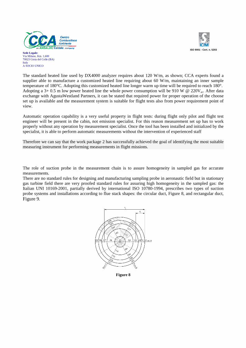
The standard heated line used by DX4000 analyzer requires about 120 W/m, as shown; CCA experts found a supplier able to manufacture a customized heated line requiring about 60 W/m, maintaining an inner sample temperature of 180°C. Adopting this customized heated line longer warm up time will be required to reach 180°. Adopting a 3+ 0.5 m low power heated line the whole power consumption will be 910 W @ 220Vac. After data exchange with AgustaWestland Partners, it can be stated that required power for proper operation of the choose set up is available and the measurement system is suitable for flight tests also from power requirement point of view. Automatic operation capability is a very useful property in flight tests: during flight only pilot and flight test engineer will be present in the cabin, not emission specialist. For this reason measurement set up has to work properly without any operation by measurement specialist. Once the tool has been installed and initialized by the specialist, it is able to perform automatic measurements without the intervention of experienced staff Therefore we can say that the work package 2 has successfully achieved the goal of identifying the most suitable measuring instrument for performing measurements in flight missions. The role of suction probe in the measurement chain is to assure homogeneity in sampled gas for accurate measurements. There are no standard rules for designing and manufacturing sampling probe in aeronautic field but in stationary gas turbine field there are very proofed standard rules for assuring high homogeneity in the sampled gas: the Italian UNI 10169-2001, partially derived by international ISO 10780-1994, prescribes two types of suction probe systems and installations according to flue stack shapes: the circular duct, Figure 8, and rectangular duct, Figure 9.
Figure 8

ISO 9001 - Cert. n. 5203 Sede Legale: Via Milano, Km. 1,600 70023 Gioia del Colle (BA) Italy A SOCIO UNICO
Figure 9
Sampling should take place in a length of straight duct with constant shape and cross sectional area, and as far as possible downstream from any obstruction which may cause a disturbance and produce a change in the direction flow. The cross sectional area must be sufficient large to avoid increasing of duct gas stream velocity by more than 3 % due to blocking effect by sample probe. The minimum number of sampling points is dictated by the dimension of the measuring plane; in general this number increases as stack cross-section increases. The sampling plane should be divided into equal areas and no sampling point shall be located within 20 mm od the duct wall. The measurements have be carried out on AgustaWestland PZL SW4 helicopter, Figure 10, in Swidnik factory; in agreement with AgustaWestland Partners it has been decided to install the sampling probe in left stack of helicopter, Figure 11. The sampling probe, Figure 12, has been built in AISI 304 stainless steel, taking into account the maximum temperature of flue gas coming out from engine turbine. 304 has good oxidation resistance in intermittent service to 870°C and in continuous service to 925°C.
Figure 10

ISO 9001 - Cert. n. 5203 Sede Legale: Via Milano, Km. 1,600 70023 Gioia del Colle (BA) Italy A SOCIO UNICO
The cross sectional area has been divided in three parts, Figure 13, therefore five 3mm sampling points have been drilled on the probe.
Figure 11
Pzl Partners provided CCA Engineers all information, drawings, sizes, in order to design and manufacture the sampling probe able to be mounted on helicopter stack. The sampling probe had to be welded on the stack: the weld procedure has been decided by welding engineer of Ansaldo Caldaie Spa, the holding company of CCA, and qualified for welding procedures. Taking into account the material of stack and the probe, an AISI 309L welding electrode has been used in a TIG (tungsten inert gas) welding procedure.
Figure 12

ISO 9001 - Cert. n. 5203 Sede Legale: Via Milano, Km. 1,600 70023 Gioia del Colle (BA) Italy A SOCIO UNICO
The final result is shown in Figure 14
Figure 13
The quality of the welding procedure has been checked by dye penetrant inspection (DPI), also called liquid penetrant inspection (LPI) or penetrant testing (PT), a widely applied and low-cost inspection method used to locate surface-breaking defects in all non-porous materials.

Sede Legale: Via Milano, Km. 1,600 70023 Gioia del Colle (BA) Italy A SOCIO UNICO
Gasmet DX4000 analyzer utilizes hotthe analysis is done with a representative sample; the corrosion resistant sample cell is heated to 180 °C, which ensures that the sample stays in gaseous phase even with high concentrations of Hto maintain flue gas temperature at 180 °C anto analyzer conditioning system, Figure
Figure 14
Gasmet DX4000 analyzer utilizes hot-and-wet measurement principle (no drying or dilution), which ensures that done with a representative sample; the corrosion resistant sample cell is heated to 180 °C, which
ensures that the sample stays in gaseous phase even with high concentrations of H2O or corrosive gases. In order to maintain flue gas temperature at 180 °C an heated sampling line is used to carry sample from sampling probe
Figure 15.
Figure 15
ISO 9001 - Cert. n. 5203
wet measurement principle (no drying or dilution), which ensures that done with a representative sample; the corrosion resistant sample cell is heated to 180 °C, which
O or corrosive gases. In order heated sampling line is used to carry sample from sampling probe

ISO 9001 - Cert. n. 5203 Sede Legale: Via Milano, Km. 1,600 70023 Gioia del Colle (BA) Italy A SOCIO UNICO
The robust construction of the sampling line, Figure 16, consists of a 6 mm pipe inside a
Figure 16
thermally conductive stainless steel mesh which acts as protection and support. The heat conductor is also coiled around the stainless steel protective mesh followed by a further two layers of thermal insulation. The outer cover is a corrugated tube out of polyamide. The ends of the sampling line are fitted with heat resistant silicone materials, and the entire construction ensures that the complete sampling line is properly heated, including the ends. The line is equipped with a PT100 device for temperature control. The thermal line is powered by sampling unit: in order to maintain power consumption as low as possible, a special low power thermal line has been bought; its consumption is about 60W/m. Pzl Partners drawn the best path in helicopter to connect sampling probe with sampling unit and that length is 5 mt. Vibration level in helicopter cabin during flight missions has been one of the most important issue considered in the development of integration system for the best measurement set up. Gasmet DX-4000 analyzer performances have been investigated by qualified laboratory during vibration test according MIL-STD-810F specification. During tests the analyzer has been equipped with a vibration insulator system to damp dangerous vibration. The damping system depends on frequency and amplitude of vibration. By sensitive data received by Pzl Engineers two plates, Figure 17,
Figure 17

ISO 9001 - Cert. n. 5203 Sede Legale: Via Milano, Km. 1,600 70023 Gioia del Colle (BA) Italy A SOCIO UNICO
for damping oscillation have been produced, taking into account typical level of amplitude in cabin and in a certain range of frequencies. The supplier of damping coils calculated the right models of coils to work properly in our antivibration system, Figure 18
Figure 18
On January 15th-17th 2013 the analyzer system has been installed on SW4 helicopter in Swidnik (Poland). Due to the deep preparation phase the installation has been fast, easy and successful. At first the stack with sampling probe has been connected to the heated line, Figure 19.
Figure 19

ISO 9001 - Cert. n. 5203 Sede Legale: Via Milano, Km. 1,600 70023 Gioia del Colle (BA) Italy A SOCIO UNICO
The heated sampling line has been installed out of the cabin for ground test using cable ties, Figure 20. In Pzl Engineers opinion this solution can be used safely also
Figure 20
for flight tests. The anti vibration plates have been fixed on helicopter floor by bolts, and analyzer and sampling unit have been tightly settled on the plates by straps, Figure 21.
Figure 21

ISO 9001 - Cert. n. 5203 Sede Legale: Via Milano, Km. 1,600 70023 Gioia del Colle (BA) Italy A SOCIO UNICO
The helicopter test notebook, Figure 22, has been connected to analyzer using an RS232 cable and all the system has been checked to verify proper installation.
Figure 22
Fig. 1
Them some measurements in air have been performed confirming the proper installation the measurement system. Test campaign in flight has been performed on October 23rd and 24th following two different flight paths; engine conditions and flight paths have been planned by Experts in PZL and AgustaWestland. The tests have been performed in the helicopter with take-off weight of about 1700 kg resulting from its configuration, crew and amount of fuel necessary for performing the flight. Location of the center of gravity according to SW4 flight manual. Settled states have been kept for about two minutes, when possible. In order to verify the proper operation of the measuring system during flight, two missions have been performed: a short one and an extended mission. The first check mission has been crucial to verify the behavior of equipment at 8000 ft altitude. First flight profile:
1. Starting up the engine; 2. Ground idle; 3. Flight idle;

ISO 9001 - Cert. n. 5203 Sede Legale: Via Milano, Km. 1,600 70023 Gioia del Colle (BA) Italy A SOCIO UNICO
4. Vertical take-off; 5. Hover: H = (1÷1,5) m; 6. Acceleration and ascending at constant max. power at VY (65KIAS) up to H=1000 ft; 7. Horizontal flight at V=(60, 80, 110) KIAS, NR=103%, H=1000 ft; 8. Ascending at V= VY (65KIAS) up to H=8000 ft; 9. Horizontal flight at V=60 KIAS; 10. Engine descending w= -2 m/s, V=60 KIAS, H=(8000 → 1000) ft; 11. Engine descending w= -4 m/s, V=80 KIAS, H=(1000 → 800) ft; 12. Braking to hover, vertical landing; 13. Ground idle, cooling of the engine and shutting down.
Second flight profile:
1. Starting-up the engine; 2. Ground idle; 3. Fluent transition ground idle to flight idle; 4. Flight idle; 5. Vertical take-off; 6. Hover H = (1÷1,5) m. 7. Acceleration and ascending at take-off power at VY (65 KIAS) up to H=1000 ft, NR=103%; 8. Horizontal flight at V= (60, 80, 100, 110, Vmax. ) KIAS, H=1000 ft, NR=103%; 9. Horizontal flight at V=80 KIAS, NR=100%; 10. Ascending w=2 m/s at V=80 KIAS, H= (1000 → 4000) ft, NR=103%; 11. Horizontal flight at V= (60, 80, 100, 110) KIAS, H=4000 ft, NR=103%; 12. Horizontal flight at V=80 KIAS,H=4000 ft, NR=100%; 13. Ascending at constant max. power at VY up to H=8000 ft; 14. Horizontal flight at V= (60, 80, 100, VH ) KIAS, H=8000 ft, NR=103%; 15. Horizontal flight at V=80 KIAS,H=8000 ft, NR=100%; 16. Engine descending w= - 2 m/s at V=80 KIAS, H= (8000 →3000) ft, NR=103%; 17. Engine descending w= -4 m/s at V= 80 KIAS, H= (3000 →1000) ft, NR=103%; 18. Ascending w= 2 m/s at V=80 KIAS, H= (1000 →3000) ft, NR=103%; 19. Engine descending w= - 2 m/s at V= 80 KIAS, H= (3000 →1000) ft, NR=103%; 20. Ascending w= 4 m/s at V=80 KIAS, H= (1000 →3000) ft, NR=103%; 21. Engine descending w= - 2 m/s at V= 100 KIAS, H= (3000 →1000) ft, NR=103%; 22. Ascending at constant max. power at V=80 KIAS, w=2m/s to H=3000 ft; 23. Engine descending w= - 4 m/s at V= 100 KIAS, H= (3000 →1000) ft, NR=103%; 24. Braking to hover, vertical landing; 25. Flight idle, cooling of the engine and shutting-down.
Figure 23shows the trend of normalized CO concentration at different altitude.

ISO 9001 - Cert. n. 5203 Sede Legale: Via Milano, Km. 1,600 70023 Gioia del Colle (BA) Italy A SOCIO UNICO
Figure 23
On October 24th other two missions with different profiles have been performed. First flight profile:
1. Starting-up the engine; 2. Ground idle; 3. Fluent transition: ground idle-flight idle; 4. Flight idle; 5. Vertical take-off; 6. Hover: H = (1÷1,5) m; 7. Acceleration and ascending at constant max. power at VY up to H=6000 ft, NR=103%; 8. Horizontal flight at V= 100 KIAS to agreed upon point at a distance, from the location of take-
off, of about 50 km, H=6000 ft, NR=103%. 9. Engine descending at airspeed V=60 KIAS, H= (6000 → 1000) ft; 10. Turning to the left: 720° with roll: γ=300 at V=60 KIAS, H=1000 ft; 11. Turning to the right: 720° with roll: γ= -300 at V=60 KIAS, H=1000 ft; 12. Ascending at constant max. power at VY up to H=6000 ft; 13. Horizontal flight back to the place of take-off at V=100 KIAS, H=6000 ft; 14. Engine descending for landing; 15. Braking to hover; 16. Vertical landing; 17. Ground idle, cooling of the engine and shutting-down.
0
10
20
30
40
50
60
70
10:00 10:20 10:40 11:00 11:20 11:40 12:00 12:20 12:40 13:00
CO
(a.
u.)
1000 ft
4000 ft
8000 ft
to 3000 ft
to 1000 ft
to 1000 ft
to 3000 ft
to 1000 ft
to 3000 ft
to g
roun
d

ISO 9001 - Cert. n. 5203 Sede Legale: Via Milano, Km. 1,600 70023 Gioia del Colle (BA) Italy A SOCIO UNICO
Second flight profile:
1. Starting-up the engine; 2. Ground idle; 3. Fluent transition: ground idle-flight idle; 4. Flight idle; 5. Vertical take-off; 6. Hover: H = (1÷1,5) m; 7. Acceleration and ascending at constant max. power at VY (65 KIAS) up to H=1000 ft,
NR=103%; 8. Horizontal flight at V= 100 KIAS up to settled point at a distance, from take-off location, of
about 50 km, H=1000 ft, NR=103%; 9. Turning to the left: 720° with roll: γ=300 at V=60 KIAS, H=1000 ft; 10. Turning to the right: 720° with roll: γ = -300 at V=60 KIAS, H=1000 ft; 11. Horizontal flight back to the place of take-off at V=100 KIAS, H=1000 ft; 12. Braking to hover; 13. Vertical landing; 14. Ground idle, cooling of the engine and shutting-down.
During the whole test campaign the equipment worked properly and no problem has been found. In conclusion it is possible to remark the main technical and scientific results achieved by carrying out the project. Regarding the scientific attainments the main result has been the development of a methodology of measurement of exhaust gas of helicopter during flight missions. This methodology has been verified in testing and has shown its complete validity. Regarding the technological achievements they are numerous and consist in the technical solutions designed to integrate the system of measurement in an unconventional setting as a helicopter. Among them we can list:
• the determination of the flue gas sampling point based on considerations of computational fluid dynamic;
• the design of the sampling probe according to standard international; • the choice of material with which the probe was made; • the manufacture of a line thermostatic at low power consumption; • the design and implementation of the system damping vibration in the cabin

ISO 9001 - Cert. n. 5203 Sede Legale: Via Milano, Km. 1,600 70023 Gioia del Colle (BA) Italy A SOCIO UNICO
4.1.4 The potential impact and the main dissemination activities and exploitation of results
It is common experience that currently the choice for the purchase of a common good (car, refrigerator, air conditioner), passes through the analysis of the impact that this has on the environment when it is used. Currently, however, this does not happen in the aviation industry. The project MAEM-RO has developed a methodology for the measurement of gaseous emissions into the atmosphere that can be applied throughout the industry for the helicopter in order to determinate the impact that the flight to the atmosphere. Obviously it is not the task of the project MAEM-RO action on reducing emissions into the atmosphere, but it is a powerful tool on the verification of it.