
PROJECT FINAL REPORT - European Commission...
200
1 | Page PROJECT FINAL REPORT Grant agreement number 246256 Project acronym COEUS TITAN Project title INNOVATIVE SMART COMPOSITE MOULDS FOR COST- EFFECTIVE MANUFACTURING OF PLASTIC AND COMPOSITE COMPONENTS Funding scheme: Collaborative Project targeted to a special group (such as SMEs) Date of latest version of Annex I against which the assessment will be made: 30 August 2013 FINAL REPORT Period covered from 1 st March 2011 to 28 th February 2014 Project co-ordinator name, title and organisation: Dr. Dimitri BOFILIOS, Managing Director, INASCO Tel: +30 210 99 43 427 Fax: +30 210 99 61 019 E-mail: [email protected] Project website address: www.coeus-titan.eu
Transcript of PROJECT FINAL REPORT - European Commission...
1 | P a g e
PROJECT FINAL REPORT Grant agreement number 246256 Project acronym COEUS TITAN Project title INNOVATIVE SMART COMPOSITE MOULDS FOR COST-EFFECTIVE MANUFACTURING OF PLASTIC AND COMPOSITE COMPONENTS Funding scheme: Collaborative Project targeted to a special group (such as SMEs) Date of latest version of Annex I against which the assessment will be made: 30 August 2013
FINAL REPORT Period covered from 1st March 2011 to 28th
February 2014
Project co-ordinator name, title and organisation: Dr. Dimitri BOFILIOS, Managing Director, INASCO Tel: +30 210 99 43 427 Fax: +30 210 99 61 019 E-mail: [email protected] Project website address: www.coeus-titan.eu

2 | P a g e

3 | P a g e
Contents 1.1. Publishable summary .................................................................................................... 131.2. Core of the report for the period: Project objectives, work progress and achievements, project management ............................................................................................................. 20
1.2.1. Project objectives for the period ............................................................................. 201.2.2. Work progress and achievements during the period .............................................. 25
1.2.2.1. WP1 - Definition of functional specifications [M1-M12] .............................. 25Summary of progress towards objectives ............................................................................................... 25Details for each task ................................................................................................................................ 25
Task 1.1: Smart tooling materials database .......................................................... 25Task 1.2: Application of smart tooling concept to plastics and composites manufacturing: a detailed exploitation plan ......................................................... 27Task 1.3: Functional specifications for “smart” tooling technologies implementation ..................................................................................................... 32
Significant results ................................................................................................................................... 38Task 1.1: Smart tooling materials database .......................................................... 38Task 1.2: Application of smart tooling concept to plastics and composites manufacturing: a detailed exploitation plan ......................................................... 38Task 1.3: Functional specifications for “smart” tooling technologies implementation ..................................................................................................... 38
Reasons for Deviations ........................................................................................................................... 39Task 1.1: Smart tooling materials database .......................................................... 39Task 1.2: Application of smart tooling concept to plastics and composites manufacturing: a detailed exploitation plan ......................................................... 39Task 1.3: Functional specifications for “smart” tooling technologies implementation ..................................................................................................... 39
Reasons for failing to achieve critical objectives .................................................................................... 39Task 1.1: Smart tooling materials database .......................................................... 39Task 1.2: Application of smart tooling concept to plastics and composites manufacturing: a detailed exploitation plan ......................................................... 39Task 1.3: Functional specifications for “smart” tooling technologies implementation ..................................................................................................... 39
Use of resources ...................................................................................................................................... 40Corrective actions ................................................................................................................................... 401.2.2.2. WP2 – Heat management technology [M4-M15] ........................................... 41Summary of progress towards objectives ............................................................................................... 41Details for each task ................................................................................................................................ 41
Task 2.1: Modelling, testing, calibration and optimisation of integral heat element configurations for tooling ..................................................................................... 41Task 2.2: Modelling, testing and optimisation of tooling cooling systems .......... 45Task 2.3: Enhancement of tooling materials thermal properties through matrix nano-doping .......................................................................................................... 46
Significant results ................................................................................................................................... 48Task 2.1: Modelling, testing, calibration and optimisation of integral heat element configurations for tooling ..................................................................................... 48Task 2.2: Modelling, testing and optimisation of tooling cooling systems .......... 48Task 2.3: Enhancement of tooling materials thermal properties through matrix nano-doping .......................................................................................................... 48
Reasons for Deviations ........................................................................................................................... 49

4 | P a g e
Task 2.1: Modelling, testing, calibration and optimisation of integral heat element configurations for tooling ..................................................................................... 49Task 2.2: Modelling, testing and optimisation of tooling cooling systems .......... 49Task 2.3: Enhancement of tooling materials thermal properties through matrix nano-doping .......................................................................................................... 49
Reasons for failing to achieve critical objectives .................................................................................... 49Task 2.1: Modelling, testing, calibration and optimisation of integral heat element configurations for tooling ..................................................................................... 49Task 2.2: Modelling, testing and optimisation of tooling cooling systems .......... 49Task 2.3: Enhancement of tooling materials thermal properties through matrix nano-doping .......................................................................................................... 49
Use of resources ...................................................................................................................................... 49Corrective actions ................................................................................................................................... 501.2.2.3. WP3 – Smart tooling surface development [M4-M15] ................................... 51Summary of progress towards objectives ............................................................................................... 51Details for each task ................................................................................................................................ 51
Task 3.1: Tooling surface materials and process definitions ............................... 51Task 3.2: Development of surface configurations (preparation, testing, characterisation, evaluation) ................................................................................. 51Task 3.3: Development of repairable tooling surfaces ......................................... 55
Significant results ................................................................................................................................... 56Task 3.1: Tooling surface materials and process definitions ............................... 56Task 3.2: Development of surface configurations (preparation, testing, characterisation, evaluation) ................................................................................. 56Task 3.3: Development of repairable tooling surfaces ......................................... 56
Reasons for Deviations ........................................................................................................................... 56Task 3.1: Tooling surface materials and process definitions ............................... 56Task 3.2: Development of surface configurations (preparation, testing, characterisation, evaluation) ................................................................................. 56Task 3.3: Development of repairable tooling surfaces ......................................... 57
Reasons for failing to achieve critical objectives .................................................................................... 57Task 3.1: Tooling surface materials and process definitions ............................... 57Task 3.2: Development of surface configurations (preparation, testing, characterisation, evaluation) ................................................................................. 57Task 3.3: Development of repairable tooling surfaces ......................................... 57
Use of resources ...................................................................................................................................... 57Corrective actions ................................................................................................................................... 581.2.2.4. WP4 – Sensor / Actuator Technology [M4-M15] ........................................... 59Summary of progress towards objectives ............................................................................................... 59Details for each task ................................................................................................................................ 60
Task 4.1: Adaptation and testing of integrated flow and reaction sensing .......... 60Task 4.2: Temperature sensing in smart tooling .................................................. 64Task 4.3: Development of in-tool piezo-electric actuation system – De-moulding function ................................................................................................................. 71
Significant results ................................................................................................................................... 74Task 4.1: Adaptation and testing of integrated flow and reaction sensing .......... 74Task 4.2: Temperature sensing in smart tooling .................................................. 74Task 4.3: Development of in-tool piezo-electric actuation system – De-moulding function ................................................................................................................. 75
Reasons for Deviations ........................................................................................................................... 75Task 4.1: Adaptation and testing of integrated flow and reaction sensing .......... 75Task 4.2: Temperature sensing in smart tooling .................................................. 75

5 | P a g e
Task 4.3: Development of in-tool piezo-electric actuation system – De-moulding function ................................................................................................................. 75
Reasons for failing to achieve critical objectives .................................................................................... 75Task 4.1: Adaptation and testing of integrated flow and reaction sensing .......... 75Task 4.2: Temperature sensing in smart tooling .................................................. 75Task 4.3: Development of in-tool piezo-electric actuation system – De-moulding function ................................................................................................................. 75
Use of resources ...................................................................................................................................... 75Corrective actions ................................................................................................................................... 761.2.2.5. WP5 – Software framework for smart tooling design [M4-M18] .................. 77Summary of progress towards objectives ............................................................................................... 77Details for each task ................................................................................................................................ 77
Task 5.1: Design of software structure, numerical tools and interface ................ 78Task 5.2: Incorporation of models for flow, thermal, structural and process control ................................................................................................................... 80Task 5.3: Development of automation functionalities for the smart tooling design software framework .............................................................................................. 80Task 5.4: Implementation and interfacing for techno-economical models .......... 83
Significant results ................................................................................................................................... 84Task 5.1: Design of software structure, numerical tools and interface ................ 85Task 5.2: Incorporation of models for flow, thermal, structural and process control ................................................................................................................... 85Task 5.3: Development of automation functionalities for the smart tooling design software framework .............................................................................................. 85Task 5.4: Implementation and interfacing for techno-economical models .......... 85
Reasons for Deviations ........................................................................................................................... 85Task 5.1: Design of software structure, numerical tools and interface ................ 85Task 5.2: Incorporation of models for flow, thermal, structural and process control ................................................................................................................... 86Task 5.3: Development of automation functionalities for the smart tooling design software framework .............................................................................................. 86Task 5.4: Implementation and interfacing for techno-economical models .......... 86
Reasons for failing to achieve critical objectives .................................................................................... 86Task 5.1: Design of software structure, numerical tools and interface ................ 86Task 5.2: Incorporation of models for flow, thermal, structural and process control ................................................................................................................... 86Task 5.3: Development of automation functionalities for the smart tooling design software framework .............................................................................................. 86Task 5.4: Implementation and interfacing for techno-economical models .......... 86
Use of resources ...................................................................................................................................... 86Corrective actions ................................................................................................................................... 871.2.2.6. WP6 – Smart tooling technology integration to pilot scale [M10-M27] ........ 88Summary of progress towards objectives ............................................................................................... 88Details for each task ................................................................................................................................ 89
Task 6.1: Design of tooling cavity ....................................................................... 89Task 6.2: Automated design of smart tooling components .................................. 90Task 6.3: Integration of heating/cooling systems to smart tooling ...................... 98Task 6.4: Integration of sensors and actuators to smart tooling ......................... 101Task 6.5: Pilot scale smart tooling manufacturing ............................................. 105Task 6.6: Pilot scale testing and evaluation ....................................................... 109
Significant results ................................................................................................................................. 113Task 6.1: Design of tooling cavity ..................................................................... 113

6 | P a g e
Task 6.2: Automated design of smart tooling components ................................ 113Task 6.3: Integration of heating/cooling systems to smart tooling .................... 114Task 6.4: Integration of sensors and actuators to smart tooling ......................... 114Task 6.5: Pilot scale smart tooling manufacturing ............................................. 114Task 6.6: Pilot scale testing and evaluation ....................................................... 115
Reasons for Deviations ......................................................................................................................... 115Task 6.1: Design of tooling cavity ..................................................................... 115Task 6.2: Automated design of smart tooling components ................................ 115Task 6.3: Integration study of heating / cooling systems ................................... 115Task 6.4: Integration study of sensing / actuation systems ................................ 115Task 6.5: Manufacturing of pilot scale tooling and assembly ............................ 115Task 6.6: Pilot scale testing and evaluation ....................................................... 115
Reasons for failing to achieve critical objectives .................................................................................. 115Task 6.1: Design of tooling cavity ..................................................................... 115Task 6.2: Automated design of smart tooling components ................................ 116Task 6.3: Integration study of heating cooling systems ..................................... 116Task 6.4: Integration study of sensing/actuation systems .................................. 116Task 6.5: Manufacturing of pilot scale tooling and assembly ............................ 116Task 6.6: Pilot scale testing and evaluation ....................................................... 116
Use of resources .................................................................................................................................... 116Corrective actions ................................................................................................................................. 1171.2.2.7. WP7 – Smart tooling application studies [M22 – M36] ............................... 118Summary of progress towards objectives ............................................................................................. 118Details for each task .............................................................................................................................. 119
Task 7.1: Definition of application studies for smart tooling concept validation ............................................................................................................................ 119
Task 7.2: Manufacturing and assembly of smart tooling for validation ............ 127Task 7.3: Test Programme Execution ................................................................ 134Task 7.4: Validation of the smart tooling concept ............................................. 141
Significant results ................................................................................................................................. 143Task 7.1: Definition of application studies for smart tooling concept validation
............................................................................................................................ 143Task 7.2: Manufacturing and assembly of smart tooling for validation ............ 143Task 7.3: Test Programme Execution ................................................................ 143Task 7.4: Validation of the smart tooling concept ............................................. 143
Reasons for Deviations ......................................................................................................................... 144Task 7.1: Definition of application studies for smart tooling concept validation
............................................................................................................................ 144Task 7.2: Manufacturing and assembly of smart tooling for validation ............ 144Task 7.3: Test Programme Execution ................................................................ 144Task 7.4: Validation of the smart tooling concept ............................................. 144
Reasons for failing to achieve critical objectives .................................................................................. 144Task 7.1: Definition of application studies for smart tooling concept validation
............................................................................................................................ 144Task 7.2: Manufacturing and assembly of smart tooling for validation ............ 144Task 7.3: Test Programme Execution ................................................................ 144Task 7.4: Validation of the smart tooling concept ............................................. 144
Use of resources .................................................................................................................................... 144Corrective actions ................................................................................................................................. 1451.2.2.8. WP8 – Techno-economical models [M13 – M36] ........................................ 146Summary of progress towards objectives ............................................................................................. 146Details for each task .............................................................................................................................. 147

7 | P a g e
Task 8.1: Development of techno-economical models of individual smart tooling technologies ........................................................................................................ 147Task 8.2: Cost analysis based decision making for selection of smart tooling components ......................................................................................................... 148Task 8.3: Lifecycle Assessment of innovative tooling ...................................... 150
Significant results ................................................................................................................................. 151Task 8.1: Development of techno-economical models of individual smart tooling technologies ........................................................................................................ 151Task 8.2: Cost analysis based decision making for selection of smart tooling components ......................................................................................................... 151Task 8.3: Lifecycle Assessment of innovative tooling ...................................... 151
Reasons for Deviations ......................................................................................................................... 151Task 8.1: Development of techno-economical models of individual smart tooling technologies ........................................................................................................ 151Task 8.2: Cost analysis based decision making for selection of smart tooling components ......................................................................................................... 151Task 8.3: Lifecycle Assessment of innovative tooling ...................................... 151
Reasons for failing to achieve critical objectives .................................................................................. 151Task 8.1: Development of techno-economical models of individual smart tooling technologies ........................................................................................................ 151Task 8.2: Cost analysis based decision making for selection of smart tooling components ......................................................................................................... 151Task 8.3: Lifecycle Assessment of innovative tooling ...................................... 152
Use of resources .................................................................................................................................... 152Corrective actions ................................................................................................................................. 1521.2.2.9. WP9 – Dissemination and Exploitation [M24 – M36] ................................. 153Summary of progress towards objectives ............................................................................................. 153Details for each task .............................................................................................................................. 153
Task 9.1: Technology evaluation ....................................................................... 153Task 9.2: Dissemination activities ..................................................................... 153Task 9.3: Organization and running of industrial seminar ................................. 154
Significant results ................................................................................................................................. 155Task 9.1: Technology evaluation ....................................................................... 155Task 9.2: Dissemination activities ..................................................................... 155Task 9.3: Organization and running of industrial seminar ................................. 155
Reasons for Deviations ......................................................................................................................... 155Task 9.1: Technology evaluation ....................................................................... 155Task 9.2: Dissemination activities ..................................................................... 155Task 9.3: Organization and running of industrial seminar ................................. 155
Reasons for failing to achieve critical objectives .................................................................................. 155Task 9.1: Technology evaluation ....................................................................... 155Task 9.2: Dissemination activities ..................................................................... 156Task 9.3: Organization and running of industrial seminar ................................. 156
Use of resources .................................................................................................................................... 156Corrective actions ................................................................................................................................. 156
1.2.3. Project Management during the period ................................................................ 1571.2.3.1. Consortium management tasks and achievements ........................................ 1571.2.3.2. Problems which have occurred ..................................................................... 1571.2.3.3. Changes in the consortium ............................................................................ 1581.2.3.4. List of project meetings ................................................................................. 1581.2.3.5. Project planning and status ............................................................................ 159

8 | P a g e
1.2.3.6. Impact of possible deviations from the planned milestones and deliverables, if any; ............................................................................................................................. 1651.2.3.7. Any changes to the legal status of any of the beneficiaries, in particular non-profit public bodies, secondary and higher education establishments, research organisations and SMEs; ............................................................................................ 1651.2.3.8. Development of the Project website, if applicable; ....................................... 1651.2.3.9. Use of foreground and dissemination activities ............................................ 1651.2.3.10. Other comments and remarks ...................................................................... 165
1.2.4. Deliverables and milestones tables ...................................................................... 1661.2.5. Explanation of the use of the resources ................................................................ 1701.2.6. Financial statements – Form C and Summary financial report ............................ 200
List of Figures Figure 1 - Materials for Components screenshot ..................................................................... 26Figure 2 - SWOT and Risk Analysis Results ........................................................................... 28Figure 3 - Intervention Priorities .............................................................................................. 31Figure 4 - RTM smart tooling concept for manufacturing an aircraft skin. [KHEGAL] ......... 32Figure 5 - Pultrusion part proposed by EXEL to develop the project smart tooling concept .. 33Figure 6 - Flow Sensor – Preliminary Design (Ref: INASCO) .............................................. 34Figure 7 - Flow Sensor – Preliminary mounting principle ...................................................... 34Figure 8 - Prototype of a piezo-electric patch actuator with 6 ceramics, integrated wiring and electrical terminals (Ref: INVENT GmbH). ............................................................................ 35Figure 9 - Examples of cooling channels in different moulds ................................................. 37Figure 10 - Examples of heating systems for pultrusion postformer dies: Traditional and proposed system ....................................................................................................................... 37Figure 11 - Example of Gel coat application .......................................................................... 38Figure 12 - Typical Thermal spaying system arrangements ................................................... 38Figure 13 - Fibretemp mould. Detail of the power connection ................................................ 41Figure 14 - Schematic of the mould design a) flat mould, b) hat type mould, c) hat type mould with CFRP manufactured part. ................................................................................................. 42Figure 15 - Numerical results and temperature measurements as a function of time for two different power levels at the thermocouples points (Heating phase, cooling phase with or without the use of cooling tubes). ............................................................................................ 43Figure 16 - Cross section of all tested fibretemp moulds ......................................................... 43Figure 17 -Electrical contacts for the thin roving .................................................................... 43Figure 18- Layout of the meander heating element ................................................................ 43Figure 19 - Preparation of carbon heating elements ................................................................. 44Figure 20 - Schematic of the perforated honeycomb active cooling system ........................... 45Figure 21 - Parabeam 3D Glass fabric ..................................................................................... 46Figure 22 - Equivalent circuit for the neat epoxy resin with CNT inclusions ......................... 47Figure 23 - Comparison between data (points) and model (continuous line) for the real and imaginary impedance after the execution of the fitting routine ............................................... 47Figure 24 - Values of inductance L (in equivalent circuit of Figure 3) and temperature T vs. sonication time ......................................................................................................................... 47Figure 25 - Failed infusion trial with the nano-modified resin ................................................ 48Figure 26 – Direct spraying process ......................................................................................... 53

9 | P a g e
Figure 27 - Metallic sprayed coating in the as sprayed condition and after polishing ............ 53Figure 28 - Gelcoated sheet on the metallic coated composite .............................................. 53Figure 29 - Materials selected for master plug construction ................................................... 55Figure 30 – Flow Sensor – Design details ................................................................................ 60Figure 31 – Flow Sensor – Pressure Test Jig ........................................................................... 61Figure 32 – Resin detection graph ........................................................................................... 61Figure 33 - Block diagram to control the Degree of Cure of epoxy resin ................................ 63Figure 34 - Block diagram of the closed-loop control system with PID controller (snapshot during the transient response of the system to a step input) ................................................. 65Figure 35 – Temperature Control Tab and Cure Cycle Set-up ................................................. 65Figure 36- Heat Flux Sensor ...................................................................................................... 67Figure 37- Panel for temperature control specimens .............................................................. 67Figure 38- Coated panel in the as sprayed condition .............................................................. 68Figure 39- Real-time plot of temperature setpoint, actual temperature and filtered temperature (top diagram) and control output (bottom diagram) ......................................... 69Figure 40- Real-time plots (from top to bottom) of temperature parameters (setpoint, actual measurement and filtered value), power parameters (controller output and control signal) and heat flux measurements ................................................................................................... 69Figure 41- Temperature Control System Scheme .................................................................... 69Figure 42- Smart tooling curing set up ..................................................................................... 70Figure 43- Temperature control system hardware .................................................................. 70Figure 44 - Tool design for de-moulding technology development ......................................... 71Figure 45 - Finite Element Model of Tool for De-Moulding Technology Development (INVENT)
.................................................................................................................................................. 72Figure 46 - Sandwich plate with piezoceramic patch actuator (left: FE model, centre: displacement, right: shear stresses at 1139.5Hz) ...................................................................... 72Figure 47 - Sandwich plate with piezoceramic stack actuator (left: FE model, centre: displacement, right: shear stresses at 1250Hz) ......................................................................... 73Figure 48 – Types of applied excitations ................................................................................. 74Figure 49 - “Smart” Tooling Design Process ........................................................................... 79Figure 50 - Reporting Template for “Smart” Tooling Design Process .................................... 79Figure 51 - Framework of 3-tier client\server architecture ...................................................... 81Figure 52 - Integrated Design Environment for the “Smart” Tooling ..................................... 82Figure 53 - Block diagram showing the breakdown of the smart tooling cost in various categories and sub-categories ................................................................................................... 82Figure 54 – Tabs of cost categories for data entry ................................................................... 83Figure 55 - User interface for data entry in the cost category of composite tool ..................... 84Figure 56 - User interface for the estimation of costs in the various cost categories of the smart tooling cost as well as the distribution of the cost to these categories ........................... 84Figure 57 – Pre-design of RTM Pilot Scale Tool ..................................................................... 89Figure 58- Detailed design of pilot scale RTM tool (before stiffener optimization, part cavity shown in red) ............................................................................................................................ 90Figure 59 - Finite Element Model of RTM Pilot scale Tool (left), Stiffener Modelling before Optimization (center) and after (right) ..................................................................................... 90Figure 60 - Overall displacement in mm for injection pressure of 1bar .................................. 91Figure 61 - Detailed Design, Revision with optimized stringer positions ............................... 91Figure 62- Integrated piezoceramic actuators (left: patch actuator, right: stack actuator) ....... 92

10 | P a g e
Figure 63- Displacements caused by piezoceramic actuator (left: patch actuator, right: stack actuator) .................................................................................................................................... 92Figure 64- Revised design option with detachable stiffeners .................................................. 93Figure 65- Displacement caused by stack actuator without ribs below cavity (left) and shear stress (right) .............................................................................................................................. 93Figure 66- Composite pultrusion post former .......................................................................... 93Figure 67- Pultrusion post former, composite detailed design including heating .................... 94Figure 68- Meshed geometry of the part used for the flow simulation analysis ...................... 95Figure 69- Flow simulation analysis results ............................................................................. 96Figure 70- Positions of flow sensors ........................................................................................ 97Figure 71- Positions of all proposed “accessories” .................................................................. 97Figure 72. Manufacturing steps of the heating element of the hat-type mold .......................... 99Figure 73. Manufacturing steps of the sandwich structured flat mold ................................... 100Figure 74: Infusion process to create the heated mould ......................................................... 101Figure 75 – Harmonic analysis results to evaluate patch position performance .................... 102Figure 76 - 5 patches layout ................................................................................................... 102Figure 77 – Design of flow and cure sensor mounts .............................................................. 103Figure 78 – Principle of operation of flow sensor .................................................................. 103Figure 79 – Flow sensor details .............................................................................................. 104Figure 80 – Arrangement of sensors on the tool .................................................................... 104Figure 81 – Flow module start-up screen ............................................................................... 104Figure 82 – Flow measurements ............................................................................................ 105Figure 83 - Manufacturing Workflow of RTM smart tooling ................................................ 106Figure 84 - Manufacturing Workflow of Pultrusion Post Former ......................................... 106Figure 85 - Manufactured master models ............................................................................... 106Figure 86 - Contact tape detail ............................................................................................... 107Figure 87 – Tool manufacturing steps .................................................................................... 108Figure 88 – Lower moulds’ rear with an overview of the piezoelectric patches bond to the surface .................................................................................................................................... 109Figure 89 – Experimental Setup ............................................................................................. 109Figure 90 – Front and Rear of a part made of SET 2 ............................................................. 110Figure 91 – Dimensional mapping of SET 2 .......................................................................... 110Figure 92 – Images obtained from ultrasonic inspection on the concave side of panel SET 2
................................................................................................................................................ 111Figure 93 – Recorded flow and cure data ............................................................................... 111Figure 94 – Explanation Guide for Flow Results from the infusion on the 28-06-2013 (SET 2)
................................................................................................................................................ 112Figure 95 – Patterns for resin arrival times for all infusion tests ........................................... 112Figure 96 - Overall display of patterns for resin arrival times for all infusion tests .............. 113Figure 97 – RTM aerospace Part [INVENT] ......................................................................... 120Figure 98 – Mould with part area ........................................................................................... 120Figure 99 – Cover ................................................................................................................... 121Figure 100 – RTM Tool Schematics ...................................................................................... 121Figure 101 – Placement of flow and cure sensors .................................................................. 123Figure 102 – Assembly of the release module (pre-design) ................................................... 124Figure 103 – Piezo positions top lid ....................................................................................... 124Figure 104 – Piezo positions bottom lid ................................................................................. 124Figure 105 – Self heated infusion tool for a C-stiffener ......................................................... 125Figure 106 – Male infusion tool, C-type CFRP stiffener, resin infusion mesh ...................... 125Figure 107 – Postformer assembling details .......................................................................... 126

11 | P a g e
Figure 108 – Master pattern following cure ........................................................................... 127Figure 109 – Model after surface treatment application ........................................................ 128Figure 110 – Finished RTM mould ........................................................................................ 129Figure 111 – Back side of the heatable mould ....................................................................... 130Figure 112 – Integrated dielectric sensor ............................................................................... 130Figure 113 – Complete pultrusion tool (postformer) ............................................................. 131Figure 114 – Final aspects of the pultrusion tool (postformer) .............................................. 132Figure 115 – Self heated infusion tool with gel coat .............................................................. 132Figure 116 – Manufacturing of the heating element .............................................................. 133Figure 117 – Infusion process of the second manufacturing step at different time instants (Infusion at 80˚C) ................................................................................................................... 133Figure 118 – Tool during injection ........................................................................................ 134Figure 119 – RTM produced parts ......................................................................................... 135Figure 120 – Comparison of two injections with and without piezo assistance .................... 136Figure 121 – Images of the digitalized samples ..................................................................... 136Figure 122 – Comparison of the geometry of one of the digitalized samples (brown) with the nominal geometry (grey) ........................................................................................................ 137Figure 123 – Comparison of the thickness measurements on each sample ........................... 137Figure 124 – Map with the ultrasonic signal on the flat surfaces ........................................... 138Figure 125 – Map of curvature (Top) and dynamic reflection highlights (Bottom) results ... 138Figure 126 – Location of surface defects in specimen 300-335-HZ-01-004 ......................... 139Figure 127 – Infusion process manufacturing setup .............................................................. 139Figure 128 – The positions of two film sensors at the edges of part ...................................... 140Figure 129 – Infusion parts produced .................................................................................... 140Figure 130 – Surface Based Deviation Analysis of the first part Surfaces as created from cloud of points ........................................................................................................................ 141Figure 131 – The two stages approach developed ................................................................. 149Figure 132 – The smart tooling technology ANP model ....................................................... 150Figure 133 – Showcased Technologies .................................................................................. 155
List of Tables Table 1 - Exploitable Results ................................................................................................... 28Table 2 – Risk analysis results ................................................................................................. 29Table 3 – Priority levels of exploitable results ......................................................................... 31Table 4 – Thermal properties of nano-doped L20 epoxy resin ................................................ 46Table 5 - Sensor mounts drawings option 1 and 2 (top row), manufactured samples (bottom row) .......................................................................................................................................... 63Table 6 – US experimental set up ............................................................................................. 63

12 | P a g e

13 | P a g e
1.1. Publishable summary § A summary description of project context and objectives,
Composite tooling is a lightweight solution that has lower thermal mass and thus in terms of thermal expansion this option could be ideal. Additionally, composites are proven to be superior to metals due to their excellent specific mechanical properties (stiffness to mass ratio, strength to mass ratio), corrosion resistance in aggressive chemical environment and their anisotropic nature, which permits the design of preferentially reinforced components in the load bearing directions. However, composite tools tend to have a much shorter useful life than metal tools because they are more susceptible to surface damage during repeated thermal cycling in a production environment. Furthermore, microcracking and porosity in the laminate can lead to loss of vacuum integrity that has a negative impact on the degree of consolidation, resulting in reduced strength and quality in the moulded structure. Inevitably, production must halt for repair or replacement of the tool at much shorter intervals than those required for maintenance or replacement of metal tools. In the long run, this ultimately sacrifices much of the savings/benefits realized with the adoption of composite tooling. Currently, composite moulds are mainly used in open-mould manufacturing processes and in Light RTM (a Low - pressure variation of RTM). The proposed project aims to extend the applicability of composite moulds into the more demanding regime of RTM production, as well as to extend the application of the open mould and light RTM techniques in the field of advanced resin systems, where elevated temperature is required.
Thus, COEUS-TITAN aims to develop innovative, robust and easy to heat composite moulds (both closed and open), through addressing all those issues that currently prevent composite tooling from being viable alternative for the industrial production of plastic and composite parts across a wide range of manufacturing routes.
Most important Innovations are: i. Embedded heating elements, based on the carbon reinforcement of the mould, close to the
mould-part interface demanding less energy. ii. Incorporation of flow, temperature and cure sensors that will enable full automatic control of
the process. iii. Layout of a cooling system consisting of a conformal (following the contour of the part)
tubing network. iv. Use of piezoceramic film actuators which will induce micro-vibrations and thus assist resin
flow inside the cavity. Such actuators on the edges can be used for demoulding and thus reducing tool complexity and demoulding time.
Integration of these functionalities into a single “smart” mould is anticipated to impart a significant advancement of the composite and plastics manufacturing industry. It is obvious that by lowering the cost of the moulds the application of high end composites into the sectors of aerospace and automotive industry widens, serving weight reduction and the greening of the transport sector while extending the use of composites in other industrial sectors such as leisure and sport, the energy sector etc. Managing to develop composite moulds for the demanding RTM field, would automatically make them available for other manufacturing processes for engineering plastics and composites (RIM, Transfer moulding, Resin Infusion). While the current project will occupy itself in the RTM, the Resin Infusion and the pultrusion process, the technologies developed will be applicable in other small and medium temperature and medium pressure manufacturing methods.

14 | P a g e
To summarize the above, the proposed project targets the development of innovative easy to heat composite moulds, both closed and open, for the production of plastic and composite parts. The aspects of this innovative tooling concept that will be the pursued in the course of the project are listed below: § A low cost, thermally insulated GRP/CFRP composite tooling base acting as the structural
reinforcement of the mould cavity.
§ A mould cavity constructed by a doped laminated, thermally conductive thermoset composite, incorporating the following systems: Ø A heating system comprised of the carbon fibre reinforcements situated beneath the mould
surface among a number of high thermal conductivity nano-doped layers that facilitate uniform heating. The heating system will be also a load bearing part of the mould.
Ø A conformal cooling system comprised of a conformal network of channels that circulate a heat transfer fluid.
Ø low friction, high wear-resistant surface layers, implemented either by coating or by doping out of resins with SiC nano-fillers
Ø Piezo-electric actuators that induce micro-vibrations assisting resin flow.
§ A monitoring system comprising of embedded flow, temperature and curing sensors, which will supply data to a central management unit that controls process parameters.
§ A set of analysis tools for tooling design promoting a distributed engineering approach: Ø Heat management and simulation of the heating-cooling procedures Ø Structural and thermal optimisation analysis Ø Resin flow simulation and cavity filling optimisation Ø Process parameter optimisation Ø Sensing and control system design Ø Coupled model for the full system simulation and optimisation
§ A techno-economical model for the selection of the production process and the appropriate level of tooling functionality on the basis of optimum production cost.
§ A description of the work performed since the beginning of the project and the
main results achieved, (NOTE: The work performed in the 2nd period is in blue.)
A. The development of a database so that data relating to material properties will be
recorded in a methodical manner. The database has been developed by TWI with the support of all involved partners. [Task 1.1]
The database will provide access to a record of properties for each material partitioned so as to provide key information in a clear and concise way. This includes the following areas:
Ø Resins – mould construction Ø Carbon Reinforcements – heating elements/mould cavity Ø Reinforcements – mould base Ø Resin fillers – surface layers/heating elements Ø Coatings – mould surface Ø Insulation Ø Resins for part production Ø Reinforcements for part production Ø Auxiliary materials – release agents etc

15 | P a g e
B. The definition of the functional specifications for the smart tooling. They will allow project partners to develop the smart tooling for both processes, RTM and Pultrusion. The lead partner was CIDAUT with the support of all involved partners. [Task 1.3]
These specifications have been analysed taking into account aspects of the smart tooling like heating and cooling systems to be implemented, sensors and actuators that will send information to the control module, the surface technology to be used in the smart tooling, the parts to be manufactured with the smart tooling, and the production targets set by the project partners.
From the 18th month onward the following results was achieved:
C. An overall assessment of the exploitation potential of all technologies developed within
the COEUS TITAN project. The results indicate that some of the technologies have reached a maturity level that will allow their immediate exploitation while some other key technologies need further work. [Task 1.2]
The project output consists of a set of technologies around the design, manufacturing and operation of innovative process tooling for composite materials manufacturing. An exploitation assessment was made using SWOT and risk analysis based on the developed knowledge and technologies; (a) on innovative heating and thermal management methods for the smart tooling, (b) robust surface treatment formulations for the tooling,(c) the implementation of (tool-integrated) process sensing, actuation and control in its operation, (d) the organisation of various design aspects around the tooling functionalities and, finally, (e) the integration and demonstration of the tooling operation. Critical issues may hamper initial exploitation estimates and their introduction into a “smart” tooling in the immediate future. It is recommended that a holistic approach be followed for the introduction and integration of technologies in the “smart” tooling. D. The development of integral heating technology, the evaluation of its performance for the
heating of composite manufacturing tools and the study of its operation. The work was undertaken by UoP, Fibretech and Clerium. [Task 2.1]
The outcome is a detailed evaluation of the different heating element configurations to be used for the selection of the most convenient solution to be applied in the course of the project. The synthesis of the heating and cooling elements was studied and the overall heat management system configuration is reported. Manufacturing details of the combined existence of heating and cooling elements in the same tooling is clarified and potential problems are identified. E. The development of the cooling system for the smart tooling in terms of configuration and
manufacturing procedures, as well as the development of numerical analysis models and tools that enable the design of the smart tooling for the production of a given part. (UoP and Fibretech). [Task 2.2]
The cooling system for the CFRP mould, as an integral part of the mould structure and the heat management system as a key characteristic of the smart mould technology especially for its application on RTM manufacturing, were investigated thoroughly. Fibretech worked on the realization of a cooling system by means of air circulation through a perforated honeycomb core. UoP worked on the integration of a simple cooling system in the form of tubing and its interaction with the heating system operation (reported in D2.1). A big part of the effort was dedicated to the analysis and simulation of the heating system operation and the calibration of the heating elements. Also two simple tools were prepared and performed manufacturing trials of simple parts using these tools. Measurements carried out on these tools were used for the verification of the numerical analysis and the calibration of the heating elements. F. Exploring the potential of nano-doping the CFRP composite that will comprise the cavity of
the mould. The materials that will be considered for doping of the epoxy matrix will be

16 | P a g e
carbon nanotubes and SiC (the same type that will be investigated for the surface of the tooling cavity). (UoP, UoA, Fibretech). [Task2.3]
The aim was to enhance the mould cavity performance and its thermal properties. There was no concrete evidence of the approach since it proved rather difficult to produce LRI parts with nano-doped resins. G. The development of guidelines and methods for tool surface preparation and the
construction of the tool surface. (TECNALIA, CLERIUM, KHEGAL, EXEL). [Task 3.1] Also all possible problems and considerations are included in order to avoid problems when developing the tool surface technology. This could serve as a guide when choosing suitable materials and tool manufacturing methods. H. The development of tool surface configurations to obtain low friction, high wear resistance
tool surfaces based on the formulation of new gelcoats with nanofillers and thermal spray techniques of metallic functional layers. (TECNALIA, CLERIUM, KHEGAL, EXEL). [Task 3.2]
I. The development of repair techniques for the tool surface. (TECNALIA, CLERIUM, KHEGAL,
EXEL). [Task 3.3] J. The development of dielectric cure and flow sensors along with their mounting fixtures and
the relevant Data Acquisition System to monitor in real-time the evolution of degree of cure and resin flow (INASCO). [Task 4.1]
K. The development and test of a tooling temperature control system that will be used during
the operation of smart tooling (UoA, INASCO, and CIDAUT). [Task 4.2] One of the key elements in the proposed Coeus-Titan tooling design is the introduction of adaptive control features. Sensors are bound to play an important role in the achievement of the “smart” functionalities of the mould, and as such, the main targets within this task are related to the temperature sensing in smart tooling. The adaptive characteristics of the system have been set up in parallel with the development of a temperature control system. During this development several characteristics of the smart mould when compared to a conventional mould have been researched and differences highlighted. In the end, software has been produced to control the temperature of the system, and this system has been tested and validated with the developed specimens.
L. The identification and validation of suitable tools to implement the “smart tooling” design,
analysis and simulation design platform. The work has identified both commercial and public domain software tools. (INASCO, TECNALIA, UoP). [Task 5.1].
The review and validation of commercially available software for CAD/CAM/CAE, which implement modules specific for the design and simulation of composites manufacturing processes, has been carried out. A reporting system which will permit the distribution of analysis results to all actors involved in the design cycle of the tooling has been devised. M. The development of the necessary methodologies/modelling insight and guidelines that
allow designing, analyse and finally optimize the composite mould as well as set-up of the processing environment. Analytical predictions have been verified through experimental results. (INASCO, TECNALIA). [Task 5.2]
N. A 3-tier client/server architecture has been selected and implemented to represent an
integrated modular “smart” tooling design environment. Elements of costing have also been included. (INASCO, UoA). [Task 5.3]
A framework of Integrated Design Environment has been proposed. The concept of “smart” tooling design as described above adheres also to the principles of concurrent engineering. The process is an interactive one with continuous feedback. It is left up to the beneficiary’s internal procedures on how to implement it.

17 | P a g e
It was demonstrated that it is possible to apply this chain sequence in order to account for as many parameters and physical effects as possible.
O. The development of techno-economical models implemented in a software framework.
Their function is to be able to run various “smart” tooling scenarios and be able to estimate the total cost of a part's production depending on the design features and the components included in the mould construction (UoA). [Task 5.4]
The total cost of the smart tooling is divided in the following categories: · Composite tool · Power supply and control · Monitoring system · Actuation system · Active cooling system · Labour cost · Other costs
The user interface of the developed software estimates the cost in each category and by summing up computes the total cost of the smart tooling. The software is also able to compute the relative weight of each cost category in the total cost of the smart tooling. This information can be used by the design team of the smart tooling for cost optimisation
P. Design of the pilot scale “smart” tooling has been completed. It incorporates all features,
i.e. surface treatment, heating elements, real-time monitoring sensors as well as demoulding actuators. Elements and concepts developed previously have been used in this “first-time” exercise. (INVENT, Fibretech, TECNALIA, Clerium, INASCO, and KHEGAL). [Task 6.1 and Task 6.2]
Q. The heating system has been integrated into the RTM, infusion and Pultrusion pilot scale “smart” tooling. All elements of process and operational requirements have been taken into account. The integration procedure follows a well defined path of design and manufacturing actions (Fibretech, UoP). [Task 6.3]
The first step in building a heated CFRP mould for the RTM process was to calculate the different layers that will comprise the heating element. In other words the thickness of the carbon fiber layers (in gr/m2), the number and the layup sequence must be determined. In addition to that, the rest of the structure (thermal and electrical insulation, layers for the stiffness etc.) had to be determined as well. The heating-system was then integrated into the mould during the procedure of building the mould. The carbon fibres are used for both: the structure of the mould and additional as resistance heating elements. So the system has a macroscopic effect as a heating panel. For the infusion tool two different sandwich - structured molds were manufactured and studied using the resistive heating method. The first mold is a flat-surfaced mold while the second one is a female, hat-type shape mold. In addition, a study was conducted for the manufacturing of a flat RTM mold using CF fabric as heating element. R. Novel sensors for resin cure and flow monitoring along with the proper data acquisition
systems have been developed. In addition, to assist the demoulding process an actuator network based on piezoelectric patch actuators was developed. Temperature probes (thermocouple, type K) have been integrated during the infusion process of making the tools, in between the heating layers. The signal of the integrated sensors is provided for material curing state control (INASCO, INVENT, Fibretech). [Task 6.4]
These sensor elements for reaction monitoring have been embedded in the smart tooling construction. In order to mount the flow and reaction monitoring sensors appropriately, the sensor adapters that allowed fitting the sensors in the tool were developed and manufactured. By grouping the patches it should be possible to drive 5 patches with just three amplifiers which, means a drastic reduction of the costs for the actuation system.
18 | P a g e
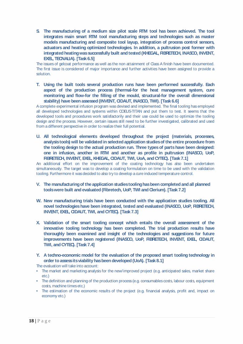
S. The manufacturing of a medium size pilot scale RTM tool has been achieved. The tool integrates main smart RTM tool manufacturing steps and technologies such as master models manufacturing and composite tool layup, integration of process control sensors, actuators and heating optimized technologies. In addition, a pultrusion post former with integrated heating was successfully built and tested (KHEGAL, FIBRETECH, INASCO, INVENT, EXEL, TECNALIA). [Task 6.5]
The issues of gelcoat performance as well as the non attainment of Class A finish have been documented. The first issue is considered of major importance and further activities have been assigned to provide a solution.
T. Using the built tools several production runs have been performed successfully. Each
aspect of the production process (thermal-for the heat management system, cure monitoring and flow-for the filling of the mould, structural-for the overall dimensional stability) have been assessed (INVENT, CIDAUT, INASCO, TWI). [Task 6.6]
A complete experimental infusion program was devised and implemented. The final tooling has employed all developed technologies and systems within COEUS-TITAN and put them to test. It seems that the developed tools and procedures work satisfactorily and their use could be used to optimize the tooling design and the process. However, certain issues still need to be further investigated, calibrated and used from a different perspective in order to realize their full potential.
U. All technological elements developed throughout the project (materials, processes, analysis tools) will be validated in selected application studies of the entire procedure from the tooling design to the actual production run. Three types of parts have been designed: one in infusion, another in RTM and another as profile in pultrusion (INASCO, UoP, FIBRETECH, INVENT, EXEL, KHEGAL, CIDAUT, TWI, UoA, and CYTEC). [Task 7.1]
An additional effort on the improvement of the coating technology has also been undertaken simultaneously. The target was to develop a coating formulation on time to be used with the validation tooling. Furthermore it was decided to also try to develop a cure induced temperature control. V. The manufacturing of the application studies tooling has been completed and all planned
tools were built and evaluated (Fibretech, UoP, TWI and Clerium). [Task 7.2] W. New manufacturing trials have been conducted with the application studies tooling. All
novel technologies have been integrated, tested and evaluated (INASCO, UoP, FIBRETECH, INVENT, EXEL, CIDAUT, TWI, and CYTEC). [Task 7.3]
X. Validation of the smart tooling concept which entails the overall assessment of the
innovative tooling technology has been completed. The trial production results have thoroughly been examined and insight of the technologies and suggestions for future improvements have been registered (INASCO, UoP, FIBRETECH, INVENT, EXEL, CIDAUT, TWI, and CYTEC). [Task 7.4]
Y. A techno-economic model for the evaluation of the proposed smart tooling technology in
order to assess its viability has been developed (UoA). [Task 8.1] The evaluation will take into account: • The market and marketing analysis for the new/improved project (e.g. anticipated sales, market share
etc.) • The definition and planning of the production process (e.g. consumables costs, labour costs, equipment
costs, machine times etc.) • The estimation of the economic results of the project (e.g. financial analysis, profit and, impact on
economy etc.)

19 | P a g e
Z. A cost- based decision making tool for the selection of smart tooling components and of suitable parameters for the production process has been developed and tested (UoA). [Task 8.2]
This supports sustainable production of smart tooling on the basis of tooling functionality and optimum production cost. The analysis for the decision-making tool takes into account a wide range of smart tooling applications (manufacturing processes for reinforced and un-reinforced plastics) from open mould infusion up to close-mould RTM.
AA. Only partial findings concerning the master tool model construction and the process for the
infusion part were recorded and presented as a part of the Lifecycle Assessment of Innovative Tooling (KHEGAL, UoP and INASCO). [Task 8.3]
There was a substantial change of scope from the original planned work due to the necessity of shifting resources to surface coating developments – a key technology for the sustainability of composite “smart” tooling concepts.
BB. An overall technological evaluation of the achieved results and of the technologies
developed and their potential has been performed. Some of the technologies developed have demonstrated both financial and technological benefits, (e.g. master mould tool approach, integrated thermal management and process monitoring) while others, even though have demonstrated their potential, need further work and adaptation (gelcoat, patch and demoulding actuators, process control, etc.) - (INASCO). [Task 9.1]
CC. There were several dissemination activities where the technologies developed and their
potential was presented to industrial partners. Several scientific publications have also been produced (INASCO, UoP, Fibretech, CLERIUM). [Task 9.2]
A dedicated industrial seminar to COEUS-TITAN has not been organized. This can be attributed to the delays resulting from the necessary efforts to resolve problems associated with specific with key technologies; it was deemed more essential to develop the technologies rather than presenting inconclusive results.
§ The address of the project public website, if applicable A public web site has been created. It can be found at:
http://www.coeus-titan.eu The role of the web site is to raise awareness towards our research activities, inform partners and signees to upcoming events as well as post information about activities that include organization and running of an industrial seminar on the smart tooling concept findings.

20 | P a g e
1.2. Core of the report for the period: Project objectives, work progress and achievements, project management
1.2.1. Project objectives for the period The project objectives [OBJ] for the reporting period (M1-M18), on a WP basis, are:
[OBJ-1] Development of “smart” tooling materials database WP1 - Definition of functional specifications [M1-M12]
· Almost every aspect of the innovations proposed in the project relies on material technology. It is therefore necessary to obtain a database of the candidate materials to be utilised for the smart tooling concept in the course of the project.
[OBJ-2] A detailed exploitation plan for the application of “smart” tooling concept to plastics and composites manufacturing
· First, to gather the state-of-the-art in key manufacturing methods currently used for composites and plastics. Identify the use of composite tooling at high end manufacturing processes
· Secondly, consolidate the
and define the extent of application for the smart tooling concept (heating through the carbon reinforcement of CFRP's, modification of surface properties through nano-doping, novel coatings, integrated sensors and actuators).
beneficiaries plans in using the smart tooling concept
[OBJ-3] Functional specifications for “smart” tooling technologies implementation
will be further analysed and the specific actions of the beneficiaries for the exploitation of the COEUS-TITAN technology will be defined.
· The aim of this task is to identify the data required in order to design a tooling for either an open or closed mould process. Existing designs of tools and dies for typical mass production parts and high-tech low production volume parts (e.g. aeronautical) will be examined in terms of their specifications. The definition of the tooling for the application case studies (on RTM and pultrusion) will also be made here, along with the definition of the simpler experimental tooling to be considered for the pilot scale study.
Based on the information gathered the design specifications (heating/cooling system, sensing/actuation and surface configuration) to be satisfied by the proposed development will be analysed.
[OBJ-4] To fully investigate the capabilities of available heating elements and calibrate their use -Modelling, testing, calibration and optimisation of integral heat element configurations for tooling heating systems
WP2 - Heat management technology [M4-M15]
· Heat a composite CFRP structure using the carbon fibres as resistance heating elements. · Detailed evaluation of the different heating element configurations and the selection of the most
convenient solution to be applied in the course of the project · Development of numerical analysis models for the simulation of the heating system operation will be
performed. · Electro-thermal analysis models able to predict the temperature field over the heating element, given
the electrical circuit characteristics [OBJ-5] To determine the parameters of the cooling system operation - Modelling, testing and optimisation of tooling cooling systems
· Investigate a system embedded into the tooling, comprising of a tubing network that will circulate a cooling fluid. The main issue that must be dealt with is possible heat losses from the heating elements due to heat conduction.
· Development of numerical analysis models for the simulation of the cooling system operation [OBJ-6] To optimise the thermal properties of the mould cavity materials - Enhancement of tooling materials thermal properties through matrix nano-doping
21 | P a g e
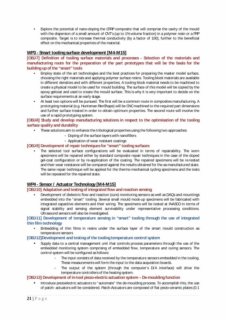
· Explore the potential of nano-doping the CFRP composite that will comprise the cavity of the mould with the dispersion of a small amount of CNT's (up to 1% volume fraction) in a polymer resin or a FRP composite. Target is to increase thermal conductivity (by a factor of 100), further to the beneficial effect on the mechanical properties of the material.
[OBJ-7] Definition of tooling surface materials and processes - Selection of the materials and manufacturing route for the preparation of the part prototypes that will be the basis for the building up of the “smart” tools
WP3 - Smart tooling surface development [M4-M15]
· Employ state of the art technologies and the best practices for preparing the master model surface, choosing the right materials and applying polymer surface resins. Tooling block materials are available in different densities and with different properties. A tooling block material needs to be machined to create a physical model to be used for mould building. The surface of this model will be copied by the epoxy gelcoat and used to create the mould surface. This is why it is very important to decide on the surface requirements at an early stage.
· At least two options will be pursued. The first will be a common route in composites manufacturing. A prototyping material (e.g. Huntsman RenShape) will be CNC machined to the required part dimensions and further surface treated in order to obtain optimum properties. The second route will involve the use of a rapid prototyping system.
[OBJ-8] Study and develop manufacturing solutions in respect to the optimisation of the tooling surface quality and durability
· These solutions aim to enhance the tribological properties using the following two approaches: - Doping of the surface layers with nanofillers - Application of wear resistant coatings
[OBJ-9] Development of repair techniques for “smart” tooling surfaces · The selected tool surface configurations will be evaluated in terms of repairability. The worn
specimens will be repaired either by standard composite repair techniques in the case of the doped gel-coat configuration or by re-application of the coating. The repaired specimens will be re-tested and their wear resistance will be compared against the results obtained for the as-manufactured state. The same repair technique will be applied for the thermo-mechanical cycling specimens and the tests will be repeated for the repaired state.
[OBJ-10] Adaptation and testing of integrated flow and reaction sensing WP4 - Sensor / Actuator Technology [M4-M15]
· Development of dielectric flow and reaction (cure) monitoring sensors as well as DAQs and mountings embedded into the “smart” tooling. Several small mould mock-up specimens will be fabricated with integrated capacitive elements and their wiring. The specimens will be tested at INASCO in terms of signal stability and sensing element survivability under representative processing conditions. Ultrasound sensors will also be investigated.
[OBJ-11] Development of temperature sensing in “smart” tooling through the use of integrated thin film technology
· Embedding of thin films in resins under the surface layer of the smart mould construction as temperature sensors
[OBJ-12]Development and testing of the tooling temperature control system • Supply data to a central management unit that controls process parameters through the use of the
embedded monitoring system comprising of embedded flow, temperature and curing sensors. The control system will be configured as follows:
- The input consists of data received by the temperature sensors embedded in the tooling. These measurements will form the input to the data acquisition boards.
- The output of the system (through the computer’s D/A interface) will drive the temperature controllers of the heating system.
[OBJ-13] Development of in-tool piezo-electric actuation system – De-moulding function • Introduce piezoelectric actuators to “automate” the de-moulding process. To accomplish this, the use
of patch- actuators will be considered. Patch-Actuators are composed of flat piezo-ceramic plates (0.1

22 | P a g e
to 0.5 mm) cased inside a ductile polymer film. By applying a voltage to these patches, they generate a deformation of the ceramic which introduces a shear force into the structure.
[OBJ-14] Review of commercially available software for CAD/CAM/CAE, which implement modules specific for the design and simulation of composites manufacturing processes
WP5 - Software framework for smart tooling design [M4-M18]
• Capabilities of simulation • Input/output file formats • Interfaces with other more generic CAE tools • Complementarity of capabilities • Accuracy • Usability • File interfaces & Capacity for interoperability
[OBJ-15] Incorporation of models for flow, thermal, structural and process control · In order to have an accurate analysis of the novel mould performance, the process suite must be
supplied with data coming from the analysis of the individual mould components, mainly the heat management system, and the structural response of the mould. According to the requirements and capabilities of the process simulation software, the “peripheral” models will be arranged, in terms of data content and format. Optimisation procedures will be implemented.
During a moulding process (either open or closed mould), three stages can be distinguished: 1. Mould / tool preheating 2. Filling process 3. Curing /cooling
[OBJ-16] Development of automation functionalities for the smart tooling design software framework
· The overall outcome intended is to configure the design framework in such a way that it will require just the CAD file of the product, material details, time and cost constraints and any other specifications in order to produce (with minimal user intervention/manipulation) the mould design and the full set of process control parameters. This eventually will lead to a user-defined Integrated Design Environment.
[OBJ-17] Implementation and interfacing for techno- economical models · The developed techno-economical models (from WP8) will be implemented in the software
framework as a separate module. Their function will be to estimate the total cost of a part's production depending on the design features and the components included in the mould construction.
[OBJ-18] Design of tooling cavity for pilot scale implementation WP6 - Smart tooling technology integration to pilot scale [M10-M27]
· The starting point will be the design of the tooling cavity that will include the surface layers, the heating elements and the cooling system. This task will play a crucial role in the fulfillment of the goals set for the project. The aim of this task is to design the tooling cavity of the pilot scale tool. The design aspects to be considered for the manufacturing of the tooling cavity should be able to address:
- Use of a high Tg resin or polymer - Doping of the resin with nano-sized particles - The setup of the heating elements - The incorporation of the cooling system
[OBJ-19] Design a structure that will support the tooling cavity during the high pressure loadings of the RTM and pultrusion processes [OBJ-20] Integration study of heating/cooling systems
· Although the heating elements are essentially the carbon fibres, the realisation of the heating system requires a set of auxiliary components that need to be introduced into the tooling structure. These are the electrodes for the connection to the power source and the wiring of the circuit.

23 | P a g e
· The integration of the cooling system, depending on the form selected will also bear upon the manufacturing procedure. The goal of this task is to provide techniques to combine the fabrication procedure for the tooling cavity with the placement of the components of the cooling system
· The integration of heating and cooling systems will be examined separately for the RTM and pultrusion pilot tools.
.
[OBJ-21] Integration study of sensing/actuation systems · The most demanding task at this stage will be the incorporation of the flow/reaction sensors into
the tooling cavity. Two solutions will be examined. The first is to embed fittings for the attachment of the sensors during the cavity lay-up. The second is to similarly embed cured resin “plugs”, through the thickness of the structure
· The patch-actuators are in fact tailored to be laminated inside a composite structure; therefore their integration in the mould is a trivial task.
. Drilling through these plugs will enable fitting of the sensors without compromising the fibres. The acoustic sensors, if selected for application, will pose no significant problem as they will be fitted in the mould base, just under the cavity layers.
[OBJ-22] Manufacturing of pilot scale tooling and assembly
The accommodation of the required wiring for all active components (sensors/actuators) will also be detailed in this task.
· The work of this task is the actual fabrication of the pilot scale tooling given the design and instructions from Tasks 6.1 and 6.2. During the manufacturing of the pilot scale tooling all potential problems and difficulties will be identified and reported.
[OBJ-23] Pilot scale testing and evaluation • The tooling produced in the previous task will be prepared for test production runs in RTM and
pultrusion respectively. The test production will be limited to 20 RTM parts and 10 meters of profile for the first stage of the task. The parts produced will be thoroughly examined and the efficiency of the mould will be assessed.
[OBJ-24] Three types of parts are to be studied: one in infusion, another in RTM and another as profile in pultrusion.
WP7 - Definition of application studies [M22-M36]
Indicative production requirements such as production volume and time to delivery will be defined here. The Smart Tooling Design Framework and Procedures will be employed for the detailed design of the tooling. The procedure will be similar to that followed in Task 6.2 with the main difference that this time the smart tooling components integration has been performed and the results from Task 6.3 and 6.4 will be used. [OBJ-25] Development of a functional gelcoat for the tool surface The development of a suitable coating for the inner surface of the mould tool presents a challenge in that it should be able to withstand the thermal cycling without degradation, and have sufficiently low surface energy to prevent component adhesion to the tool during de-moulding. Early attempts did not lead to a satisfactory solution. Thus, new efforts have been planned to resolve issues associated with this critical technology needed. [OBJ-26] Manufacturing and assembly of smart tooling The manufacturing of the application studies tooling will be the objective of this task. For all tooling, the fabrication techniques derived from WP6 will be applied. Prior to production all components of the moulds will be tested to guarantee flawless operation. All tools will be examined for dimensional accuracy and surface roughness (Class A requirement will be sought). [OBJ-27] Test program execution The trial production runs will be conducted in this task. Apart from nominal operation the production will include deliberately faulty actions in order to explore the limits of the novel tooling technology developed. [OBJ-28] Validation of the smart tooling concept This task entails the overall assessment of the innovative tooling technology. The first part will involve the trial production results. The second part will emphasize on the validation of the numerical models and tools that comprise the Mould Design Framework. Data recorded during production using the sensing/monitoring equipment will be compared to calculated values obtained from the simulations of the production process. The

24 | P a g e
level of accuracy achieved through the implemented modelling schemes will be determined and possible improvements will be recommended in case of large deviations.
[OBJ-29] To develop a techno-economic model for the evaluation of the proposed smart tooling technology in order to assess its viability
WP8 - Smart tooling technology integration to pilot scale [M13-M36]
The evaluation will take into account:
• The market and marketing analysis for the new/improved project (e.g. anticipated sales, market share etc.)
• The definition and planning of the production process (e.g. consumables costs, labour costs, equipment costs, machine times etc.)
• The estimation of the economic results of the project (e.g. financial analysis, profit and, impact on economy etc.)
[OBJ-30] To propose and develop a cost- based decision making tool for the selection of smart tooling components and of suitable parameters of the production process
· Multicriteria decision analysis problem, including both qualitative and quantitative criteria · Models will be embedded in a robust decision making framework to produce a sound, easy to
use model that will provide practitioners with a powerful decision making tool [OBJ-31] The lifecycle of the tooling will be assessed and provisions for improving its sustainability will be developed
[OBJ-32] To perform an exploitation assessment of the developed technologies WP9 – Dissemination and Exploitation [M24-M36]
To prepare the ground for the exploitation of the project's outcome, this task will closely observe the progress of the technical tasks and perform a detail account of materials, equipment and personnel in order to form a concise view of the operation cost of all methods and procedures. An additional task is to relate the developments and their potential exploitation to their technological readiness level as well. [OBJ-33] To disseminate information about the technological achievements and present the results to stakeholders of the manufacturing sectors (automotive, construction, aerospace, certification organisations etc).

25 | P a g e
1.2.2. Work progress and achievements during the period
1.2.2.1.
Summary of progress towards objectives
WP1 - Definition of functional specifications [M1-M12]
The objectives of WP1 within the COEUS TITAN project were to develop: 1. A “smart” tooling materials database 2. A detailed exploitation plan for the application of “smart” tooling concept to plastics
and composites manufacturing 3. Functional specifications for “smart” tooling technologies implementation and their
technology readiness level (TRL) At the end of the current reporting period (M18), Objectives 1 and 3 have been reached and the corresponding deliverables have been accomplished. The Objective 2, “Exploitation plan for the application of smart tooling concepts” has been delayed for the following reasons:
1. The beneficiary in charge has been given the status of a default party due to non performance
2. The exploitation plan has been decided, in agreement with the PO and the PTA, to be termed as a “live” document to be continuously updated till the end of the project. However, a first version of the exploitation plan will be released at M24.
In addition, the database for the “smart” tooling materials will be continuously updated and enhanced. The work was performed within the budget initially planned for these tasks even though a substantial delay of seven (7) months was imposed on the achievement of Objective 3 and of its corresponding deliverable. The delay of WP1 had an impact on the other activities which were eventually recovered at the most part.
Details for each task
Task 1.1: Smart tooling materials database
The purpose of this task was the development of a “smart” tooling materials database with the objective of providing an easy-to-use repository of material characteristics such that a user is able to attain knowledge of various key properties. [TWI] has developed the structure and layout of the database and various partners have populated it with the corresponding material information [TECNALIA, FIBRETECH and CLERIUM]. [CIDAUT] has checked and assured the coherence of this material database with the functional specifications of the smart tool defined in T1.3. The database provides access to a record of properties for each material partitioned so as to provide key information in a clear and concise way. This includes the following areas:
• Resins – mould construction • Carbon Reinforcements – heating elements/mould cavity • Reinforcements – mould base • Resin fillers – surface layers/heating elements

26 | P a g e
• Coatings – mould surface • Insulation • Resins for part production • Reinforcements for part production • Auxiliary materials – release agents etc.
The database is located at:
http://licensing.twisoftware.com/NDTMaterials
There are two main areas for data. Under Material’s Database, there are Material’s for Tooling and Material’s for Components. A typical screen for Fabric is shown below in Figure 1. Details the lay-out and structure of the materials database are presented in deliverable D1.1
Figure 1 - Materials for Components screenshot

27 | P a g e
Task 1.2: Application of smart tooling concept to plastics and composites manufacturing: a detailed exploitation plan
Table 1 lists a range of exploitable results from this project, their type and the application range, as well as an indication on the beneficiaries who might own the result or the beneficiary leading the exploitation activities. The beneficiaries involved in each exploitable knowledge item are shown at the last column of the Table. Where more than one beneficiary appears, there is shared potential for the exploitation of the particular item.
The project aims to address significant problems related to the following user groups: § the composite materials manufacturers with emphasis on the liquid composite
moulding processes § the design centres for advanced composite production § the SME community of technology providers to the composite materials
manufacturers § the manufacturers of process equipment and systems § the developers and users of process monitoring systems and sensors § the research laboratories and process development sites
Exploitable Knowledge
(description)
Exploitable product(s) or measure(s)
Sector(s) of application
Timetable for commercial
use
Patents or other IPR
protection
Owner & Other
Beneficiary (ies)
involved Tooling heating
technology New tooling, retrofitting existing tools, materials
Composite manufacturing
1 year after end N/A Fibretech,
CYTEC, UoP Innovative
production system Start-up production, set-up of manufacturing line
All composite manufacturing
1 year after end N/A Clerium
Sensors and monitoring system
Improved version of dielectric sensors for
cure and flow
All composite manufacturing
1 year after end Pending
INASCO, Exel, CYTEC, Fibretech,
UoP
Control systems
Integrated control system with material state as the process
parameter
All composite manufacturing
2 years after end Pending
INASCO, Exel, UoA,
CYTEC, Fibretech
Actuators
New design, control technology and
applications on actuator systems
All tooling applications
1 year after end N/A
INVENT, UoP,
Fibretech, CYTEC
Surface coatings New compositions
appropriate for composite tooling
All tooling applications
2 years after end N/A
TECNALIA, Clerium,
UoP, Fibretech,
TWI
Tooling manufacturing
system
New technology and applications on
composite manufacturing tooling
Composite manufacturing
2 years after end N/A
Fibretech, UMECO, INVENT, CIDAUT, Clerium, INASCO
Pultrusion tooling Heating and sensing/control Aerospace 1 year after
end Pending Exel
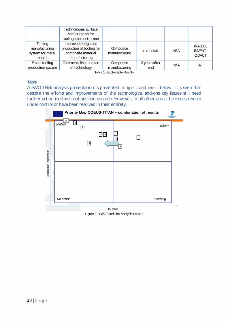
28 | P a g e
technologies, surface configuration for
tooling: die/postformer Tooling
manufacturing system for metal
moulds
Improved design and production of tooling for
composite material manufacturing
Composite manufacturing Immediate N/A
INASCO, INVENT, CIDAUT
Smart tooling production system
Commercialisation plan of technology
Composite manufacturing
2 years after end N/A All
Table 1 - Exploitable Results
A SWOT/Risk analysis presentation is presented in Table
Figure 2 and Table 2 below. It is seen that despite the efforts and improvements of the technological add-ons key issues still need further action (surface coatings and control). However, in all other areas the issues remain under control or have been resolved in their entirety.
Priority Map COEUS-TITAN – combination of results
Risk grade
% su
cces
sof
inte
rven
tion
control action
No action warning
1
2
3
45
6
78 9
10
Figure 2 - SWOT and Risk Analysis Results

29 | P a g e
No. Technology Action
1 Tooling heating technology Status at 18M: Under control Final Status: Resolved
2 Innovative production system Status at 18M : Needs further action to move into “control” Final Status: Needs further action to move into “control”
3 Improved version of dielectric sensors for cure and flow
Status at 18M: Under control Final Status: Under control
4 Integrated control system with material state as the process parameter
Status at 18M: Needs further action to move into “control” Final Status: Needs further action to move into “control”
5 New design, control technology and applications on actuator systems
Status at 18M: Needs immediate action and discussion on the risks of this result and to minimize it.
Final Status: Under control
6 Surface coating configurations RTM Status at 18M: Under control Final Status: Needs further action to move into “control”
7 Surface coating configurations pultrusion Status at 18M: Needs immediate action and discussion on the
risks of this result and to minimize it. Final Status: Needs further action to move into “control”
8 Tooling manufacturing system RTM Status at 18M: Needs further action to move into “control” Final Status: Under control
9 Tooling manufacturing system pultrusion Status at 18M: Needs further action to move into “control” Final Status: Under control
10 Tooling manufacturing system for metal moulds
Status at 18M: Under control Final Status: Resolved
Table 2 – Risk analysis results The comparison of technological priority levels at the 18M check point and at project’s end is shown in Table 3 below. The row with cyan color represents the results at the end of the project.

30 | P a g e
Exploitable Results Findings
IMPORTANCE (Severity Rate)
1-10 1 low
10 high
Rate Of RISK
HAPPENING 1-10
Feasibility of
Intervention 1-10
Scope and type of potential intervention
Priority level
Tooling heating technology 10 4 8
New heating systems, improved control,
better mould design 32.00
Tooling heating technology 10 2 8
New heating systems, improved control,
better mould design 16.00
Innovative production system 10 7 8 Re/visit all different
technologies 56.00
Innovative production system 10 5 8 Re/visit all different
technologies 40.00
Improved version of dielectric sensors for
cure and flow 9 4 8 Re-design the
Mounting 28.80
Improved version of dielectric sensors for
cure and flow 9 3 6 Re-design the
Mounting 16.20
Integrated control system with material state as the process
parameter
9 7 6 Re/design the models, software update and
modification 37.80
Integrated control system with material state as the process
parameter
9 7 6 Re/design the models, software update and
modification 37.80
New design, control technology and applications on
actuator systems
9 7 5 Physics, recycling issues 31.50
New design, control technology and applications on
actuator systems
9 7 5 Physics, recycling issues 31.50
Surface coating configurations RTM 7 3 9 Other alternatives
needed 18.90
Surface coating configurations RTM 10 8 4 Other alternatives
needed 32.00
Surface coating configurations
pultrusion 10 8 4 Other alternatives
needed 32.00
Surface coating configurations
pultrusion 10 8 4 Other alternatives
needed 32.00
Tooling manufacturing system RTM 10 6 8 New tool skin 48.00
Tooling manufacturing system RTM 10 5 6 New tool skin 30.00
Tooling manufacturing system pultrusion 8 9 7 Improve design 50.40

31 | P a g e
Tooling manufacturing system pultrusion 8 5 8 Improve design 32.00
Tooling manufacturing system for metal
moulds 1 2 10 2.00
Tooling manufacturing system for metal
moulds 1 2 10 2.00
Table 3 – Priority levels of exploitable results
The results are also plotted in graphical form and displayed in Figure 3. It is seen that the priority intervention level has been decreased in most of the technologies. This indicates that after the 18M check point the effort spent has led to improvements and better understanding of the technologies involved. However, certain areas still need further work and some of them they may entail technological risks. In any case the technologies already available are a step further towards the “smart” tooling implementation and such key features may be incorporated in the immediate future.
Figure 3 - Intervention Priorities

32 | P a g e
Task 1.3: Functional specifications for “smart” tooling technologies implementation The aim of this task is to identify the data required in order to design a tooling for either an open or closed mould process. Existing designs of tools and dies for typical mass production parts and high-tech low production volume parts (e.g. aeronautical) will be examined in terms of their specifications. The definition of the tooling for the application case studies (on RTM and pultrusion) will also be made here, along with the definition of the simpler experimental tooling to be considered for the pilot scale study. Based on the information gathered the design specifications (heating/cooling system, sensing/actuation and surface configuration) to be satisfied by the proposed development were analysed. Partners in the project decided to focus on two different processes to develop a smart composite tooling capable of producing aerospace components in a faster and cheaper way. Those processes were RTM and Pultrusion.
After selecting the processes that the smart tooling was going to carry out, the component to be manufactured was chosen. [KHEGAL] defined a tooling to manufacture a simple aircraft skin, this is a simple component, but of added value to develop a proof of concept regarding the smart tooling. The RTM tooling defined by KHEGAL is shown in Figure 4
Figure 4 - RTM smart tooling concept for manufacturing an aircraft skin. [KHEGAL]
The component to be produced by pultrusion was defined by [EXEL]; they chose a T section to be the basis for defining the requirements of the smart tooling. As happened with RTM part, this is a simple component to demonstrate the smart tooling concept to be developed in the project. In Figure 5 the part defined by EXEL is shown:

33 | P a g e
Figure 5 - Pultrusion part proposed by EXEL to develop the project smart tooling concept
Finally, the partners defined the main features the smart tooling should have; the result from sharing the knowledge and experience from designers, developers and final users was organized into the following categories:
- Manufacturing process and Component materials [FIBRETECH, ACG/UMECO, CIDAUT, INASCO]
- Materials [ACG/UMECO]
- Sensors and actuators [INASCO, INVENT, UoA]
- Heating/cooling devices [FIBRETECH, UoP]
- Surface technology [TECNALIA, CLERIUM]
CIDAUT was the responsible for the coordination of this task and for the elaboration of its deliverable. The functional specifications for smart tooling for RTM and Pultrusion were defined regarding aspects such as materials, sensors and actuators, heating and cooling systems, surface technology and cost, among others. Input from all the involved partners were gathered and summarized in D1.3. Sensors and Actuators [INASCO, INVENT, UoA]
Real-time and in-situ monitoring is an essential tool for identification and improvement of relevant processing parameters, and thus is a significant step towards quality assurance of the final product in plastics and composites manufacturing. The need for reproducibility, repeatability and reliability of the process is the driving force behind the industrial development of monitoring techniques, which involve measurements of process conditions.
To be able to measure those conditions, the smart tooling incorporates a series of sensors. Embedded dielectric sensors for cure and flow monitoring as well as thermocouples are used to monitor the state of cure, in real time, for epoxy resins. Thus the mould is able to be fitted with the embedded sensor components.
New flow sensors will have to be developed in the project [INASCO]. These new flow sensors should have the following features:
- The sensing element will be a resistive switch hosted on a ceramic substrate capable of measurements up to 220°C.
- The sensor will be tool mounted. The sensor dimensions will be: 16mm outer diameter, 60mm length.
- The sensor will be mounted to the tool with a collet (which is part of the sensor)

34 | P a g e
- For composite moulds a specific mounted assembly and method will have to be developed
- The sensor should be tested up to a pressure of 10 bars successfully - The sensor should be re-usable. Standard cleaning and release agent application
procedures need to be applied prior to use.
Figure 6 - Flow Sensor – Preliminary Design (Ref: INASCO)
Figure 7 - Flow Sensor – Preliminary mounting principle
Another innovation the project is including in the RTM smart mould development the use of piezoceramic (PZT) patch actuators for de-moulding. While these thin actuators are multi-material fibre composite structures they are suitable to be embedded in between or applied to the fibre layers at the moulds back. While connected to an amplifier, capable of driving capacitive loads, these actuators will generate shear forces by contraction and expansion which results in flexural vibrations of the structure. It is planned to build up a network of single actuators and combine them to a multi-ceramic patch module as shown in Figure 8 [INVENT]. INVENT contributed to the Deliverable D1.3 with a detailed specification of piezoceramic actuators to be employed in the smart tool. The specification of the tool manufacturing was commented in detail from an industrial view and experience with respect to the processing topics.

35 | P a g e
Figure 8 - Prototype of a piezo-electric patch actuator with 6 ceramics, integrated wiring and electrical terminals (Ref: INVENT GmbH).
The goal of this task for [UoA] was to define the functional specifications of the smart tooling and in particular of three input technologies of UoA to the smart tooling, namely: the effective nano-doping of the tooling matrix, the embedded sensing of cure and flow in the tooling and finally the temperature control system performance in the smart tooling operation. The specifications in each of these three aspects are described below.
The electrical resistance and the mechanical durability of the tooling are going to be enhanced by doping of the resin matrix with carbon nanotubes. The objective of the research is to define a methodology for the quality check of carbon nanotubes dispersion in the resin matrix during the manufacturing of the smart tooling. The main features of the method are listed below:
Effective nano-doping of the tooling matrix
No. Feature Verification
1 Non-intrusive operation of sensing for measurement dispersion quality
Dielectric sensor placement in the resin blend, sensor not affecting resin composition and not affected by CNT inclusions
2
Definitive quality index of CNTs dispersion in resin matrix (size of agglomerates in the CNT dispersion)
Check of a set of criteria on the equivalent circuit model of the dispersion electrical response
3 Confirmation of effectiveness of quality index
Comparison of the output of the developed method to the experimental observation (by Univ. Patras) on identical samples
The dielectric sensors developed by INASCO on the resin cure and flow monitoring are going to be assessed in terms of accuracy in the determination of the material state, that is degree of cure and viscosity. The objective of this research is to qualify these sensors (sensor placement, operational
Embedded sensing of resin cure and flow in the smart tooling

36 | P a g e
model, accuracy of measurement) for the material-state based control system developed in the following task. The main features of the assessment are listed below:
No. Feature Verification
1 Methodology and accuracy of material-state determination from dielectric measurements
Type of model used for the determination, sources of error in the calculation and model
2 Criticality of sensor placement in the smart tooling
Set of criteria on the sensor placement for effective measurement of material state during smart tooling operation
3 Model of material-state sensor for closed-loop control of material-state in the smart tooling
Transfer function of system and identification of parameters
The control system for the temperature and material-state in smart tooling operation will be developed in terms of design, implementation and testing. There are three steps in the development phase: temperature control of conventional tooling, temperature control of smart tooling and material-state control of smart tooling. In each step there will be a physical model development, construction of control algorithm, simulation of control operation and hardware implementation. The objective of the research is to satisfy the following specifications of the control systems:
Closed-loop control system for temperature and material-state in smart tooling operation
No. Feature Verification
1
Temperature control system for conventional moulds
Substitution of digital temperature controller by software functionality while the control specifications remain unaffected (i.e. steady-state error, absolute error during ramps and dwells, stability in operation under standard disturbance functions, manipulated variable limits in standard process profiles).
2
Temperature control system for smart tooling
Implementation of temperature control system under the design constraints: minimal steady-state error (<0.5 oC), minimal deviation from set-point (<1 oC) during fast ramps (5 oC/min), reduced sensitivity to standard disturbance functions. The smart tooling design should be optimised in order to achieve lower time constants (by an order of magnitude) compared to the conventional tooling.
3
Material-state control system for smart tooling
Implementation of material-state control system under the design constraints: stability in operation, minimal steady-state error (< 0.5 % degree of cure), minimal deviation from set-point (< 2 % degree of cure) during typical process profile, elimination of potential for exothermic events (temperature variation across the part > 15 oC), reduced sensitivity to standard disturbance functions. The control system operation should yield shorter cycle times for equivalent final material properties compared to the operation under the temperature control system.
Heating and cooling systems [FIBRETECH, UoP, EXEL]
RTM processing tools are heated either internally or through their environment (oven, autoclave, press). For the internal integrated heating of moulds and dies, both the processing industry and the mould making industry take cautious measures and precautions for mould heating and controlling. Among the parameters considered for the tool design are material to be processed, production cycle,

37 | P a g e
and part geometry, mould construction, heating elements, temperature controls, zoning and plant standards.
The pultrusion post forming die would be to have three zones, starting at 160˚C / 140˚C / 120˚C [EXEL]. These temperatures will depend upon the resin system to be processed. Once production starts then the temperature will be maintained for the length of the production run. If we assume that this is a full week production then the die would be at this temperature for 5 days / 24hrs. At the end of the week the production would be stopped and the system turned off. The die would be allowed to cool under ambient conditions. At the beginning of the following week, the process would start again and the die heated up in anticipation of production starting.
The heating system of the mould/die, to be used in COEUS-TITAN, is related to the direct resistance heating of the system via the use of the appropriate current density. The direct resistance heating concept is based on the application of electrical current through the carbon fibre bundles, using the electrical resistance to generate heat.
In order for having a heating systems in the smart tooling, the carbon fibres have to be connected and a resistant set up must be implemented in the fabrics. For the cooling system, an active system will be implemented. Alternatives are conformal tubing or perforated honeycomb [FIBRETECH, UoP].
As far as cooling is concerned, the requirement for most existing tools is met by the design and implementation of a network of channels where the coolant flows and draws heat from the tooling. The most prominent cooling system designs include the arrangement of channels in parallel or serial form.
Figure 9 - Examples of cooling channels in different moulds
Figure 10 - Examples of heating systems for pultrusion postformer dies: Traditional and proposed system

38 | P a g e
Surface technology [TECNALIA, CLERIUM]
This part of the work is of significant importance and deals with the surface properties of the mould. COEUS-TITAN aims to study a series of manufacturing solutions in respect to the optimization of the mould surface quality and durability. These solutions include the manufacturing of surface layers using resin doped with nanoparticles and application of wear resistant coatings.
Figure 11 - Example of Gel coat application
Figure 12 - Typical Thermal spaying system arrangements
Significant results
Task 1.1: Smart tooling materials database
A tooling materials database has been created and maintained.
Task 1.2: Application of smart tooling concept to plastics and composites manufacturing: a detailed exploitation plan
The identification of exploitable results and the assignment of risks as well as their prioritization will aid in the development of a valuable exploitation plan for all actors involved. These results will provide insight and guidance for the exploitation activities in short and long term.
Task 1.3: Functional specifications for “smart” tooling technologies implementation

39 | P a g e
The contribution to Task 1.3 was the list of functional specifications of the smart tooling in terms of three input technologies to the smart tooling, namely: the effective nano-doping of the tooling matrix [UoA], the embedded sensing of cure and flow in the tooling [INASCO], the PZT actuators for demoulding [INVENT] and finally the specs for the temperature control system performance in the smart tooling operation [UoA]. In addition to sensors and actuators there were both heating and cooling systems prescribed [FIBRETECH, UoP] and surface treatment approaches [TECNALIA].
Reasons for Deviations
Task 1.1: Smart tooling materials database
The deliverable D1.1 from (TWI) was delivered with 1 month delay at M4. In its current form the database is continuously updated. The reason for the initial small delay was due to lack of data to be uploaded in the database.
Task 1.2: Application of smart tooling concept to plastics and composites manufacturing: a detailed exploitation plan
The deliverable D1.2 (EUREXCEL) has been postponed since the responsible partner has been declared as a default partner. The document D1.2 has been termed as a “live” document and it has been agreed that a first draft will be issued at M24 (CIDAUT). The final deliverable document has been written and issued by INASCO at M36. It represents an overall evaluation of the exploitation potential and the associated risks.
Task 1.3: Functional specifications for “smart” tooling technologies implementation
The deliverable D1.3 (CIDAUT) has been delayed almost 9 months. Partly was due to the lack of commitment from the partners, part to the coordinator’s change and part to the work being there and not being collected and reported. It would have had a great impact on project’s progress if the beneficiaries in related WPs had not started working independently.
Reasons for failing to achieve critical objectives
Task 1.1: Smart tooling materials database
N/A
Task 1.2: Application of smart tooling concept to plastics and composites manufacturing: a detailed exploitation plan N/A
Task 1.3: Functional specifications for “smart” tooling technologies implementation N/A

40 | P a g e
Use of resources Overall WP1 is under spent (by 5%). Even though much effort was devoted to the database development, little effort was spent on the exploitation potential study.
Corrective actions N/A

41 | P a g e
1.2.2.2.
Summary of progress towards objectives
WP2 – Heat management technology [M4-M15]
The objectives of WP2 within the COEUS TITAN project were to develop: 1. To fully investigate the capabilities of available heating elements and calibrate their
use 2. To determine the parameters of the cooling system operation 3. To optimise the thermal properties of the mould cavity materials
At the end of the current reporting period (M18), all objectives have been reached and the corresponding deliverables have been accomplished. It should be noted that D2.1 and D2.2 have been submitted with a delay of 3 months while D2.3 has been submitted with a delay of 1 month. The work was performed within the budget initially planned for these tasks. The delay of WP1 had an impact on the activities which were eventually fully recovered.
Details for each task
Task 2.1: Modelling, testing, calibration and optimisation of integral heat element configurations for tooling
The main objective of this task was to investigate the capabilities of available heating elements and calibrate their use. As it described in the Annex I of the GA, the main concept for the heating element is to utilize a number of carbon fiber layers as a heating element based on Joule or resistance heating principles. This technology, called FIBRETEMP, is patented by FIBRETECH and is currently used mainly for open moulds. According to the best practices established by FIBRETECH, the carbon fiber layers that comprise the heating element along with the rest of the layers are laid on a master model in dry form and a resin infusion technique is used to impregnate the fabrics and create the final tool (Figure 13).
Figure 13 - Fibretemp mould. Detail of the power connection
[UoP] worked on a variant of this method that utilizes pre-pregs instead of dry fabrics. Prior to application specific fiber bundles are connected to a copper electrode in order to allow

42 | P a g e
for the connection of the element to the power source. The pre-pregs are laid on the master model and a vacuum bag is placed on top (similar to the resin infusion process). The heat for the polymerization of the resin is supplied by the heating element itself, allowing for an out-of-autoclave manufacturing of the tool. Two tools were manufactured to evaluate the manufacturing process and perform heating tests; a flat and a “hat shaped” tool (Figure 14). The temperature during manufacturing was monitored and compared against the processing temperature cycle from the pre-preg specifications and an excellent agreement was observed. Degree of curing was also verified by DSC measurements. The two tools were used in experimental manufacturing and critical parameters were recorded (mainly heating rate, temperature distribution etc).
Figure 14 - Schematic of the mould design a) flat mould, b) hat type mould, c) hat type mould with CFRP manufactured part. In parallel, basic material characterization tests were performed in order to obtain key parameter values for analysis and simulation (resistivity, thermal conductivity, diffusivity and specific thermal capacity). To serve a major goal of the project, which is the development of validated design tools, numerical models of the two test tools were created and the manufacturing process was simulated using electro-thermal FEA. The numerical results were compared against the experimental measurements and a good agreement was found (Figure 15). The outcome of this effort is a validated numerical model and analysis procedure that can accurately predict the behavior of the heating elements.

43 | P a g e
Figure 15 - Numerical results and temperature measurements as a function of time for two different power levels at the
thermocouples points (Heating phase, cooling phase with or without the use of cooling tubes). Several CFRP test-moulds were built by [FIBRETECH] to demonstrate carbon heating with different resin systems (Figure 16). There were test-moulds with medium cure temperature as well as one with high cure temperature. The different kind of heating systems tested were:
· with woven carbon (Figure 17) · with UD in meander (Figure 18) · both in different configurations
Figure 16 - Cross section of all tested fibretemp moulds
Figure 17 -Electrical contacts for the thin roving Figure 18- Layout of the meander heating element

44 | P a g e
[FIBRETECH] tested the heating rates, the uniformity of heating on the mould surface and performed the comparison between calculated and actual values. The heating rates were measured by temperature-sensors and the uniformity of heat distribution on the mould surface was determined by using a thermal imaging camera. It could be shown, that the FIBRETEMP-system, using carbon fabrics, achieves the best uniformity of heating and the heating rates reach the maximum possible for the resin-system. Some problems concerning the layout and on the basis of short-circuiting could be observed in the Meander-roving-system. Also, the temperature distribution is not as uniform here. Regarding the meander roving heating element it was shown that it possible to obtain the desired heat energy, although it is necessary to work in normal or high-voltage range. A number of problems were identified:
• Short circuits occur between nearby roving • Current penetration • Relatively thick electrical insulation is required which also results to high thermal insulation. • The heat distribution across the heating zone was not uniform.
Two flat moulds were also built by [CLERIUM] incorporating carbon fiber heating by using two different manufacturing methods. One plate was built without Gelcoat by vacuum bagging and the second plate was built by one shot infusion with a Gelcoat on the tool surface. The core material in both plates was cork. Both plates were cured at 50°C before releasing. The gelcoated plate was post-cured to 150°C. The heating elements of both flat moulds function perfectly. The preparation of the heating elements is shown in Figure 19.
Figure 19 - Preparation of carbon heating elements
The heating is very uniform with temperature deviations of ± 4°C. The maximum heating rate is equivalent to the power supplied to the carbon element and can reach values of 1°C per second. This heating rate is extremely high. Most applications will not require so fast heating, except for high volume production of thermoplastic parts. With good isolation, it is possible to maintain a high temperature with very little energy. It has been demonstrated that a temperature of 190°C can be maintained with 35W.
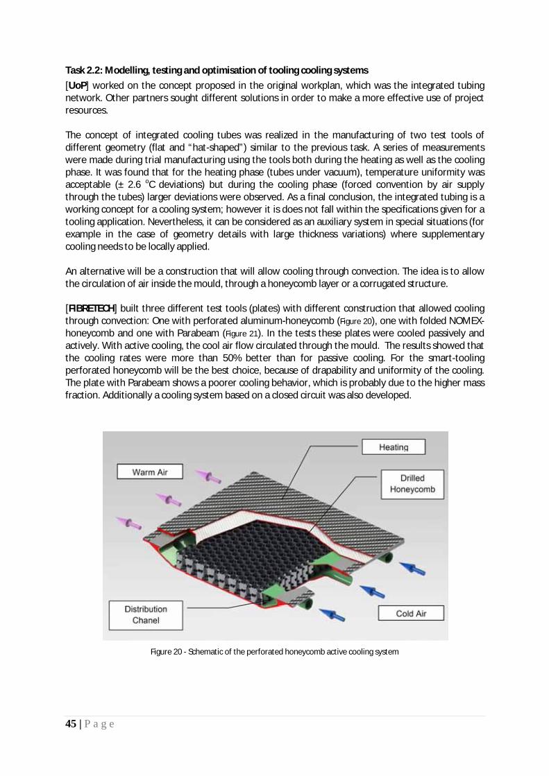
45 | P a g e
Task 2.2: Modelling, testing and optimisation of tooling cooling systems [UoP] worked on the concept proposed in the original workplan, which was the integrated tubing network. Other partners sought different solutions in order to make a more effective use of project resources. The concept of integrated cooling tubes was realized in the manufacturing of two test tools of different geometry (flat and “hat-shaped”) similar to the previous task. A series of measurements were made during trial manufacturing using the tools both during the heating as well as the cooling phase. It was found that for the heating phase (tubes under vacuum), temperature uniformity was acceptable (± 2.6 o
C deviations) but during the cooling phase (forced convention by air supply through the tubes) larger deviations were observed. As a final conclusion, the integrated tubing is a working concept for a cooling system; however it is does not fall within the specifications given for a tooling application. Nevertheless, it can be considered as an auxiliary system in special situations (for example in the case of geometry details with large thickness variations) where supplementary cooling needs to be locally applied.
An alternative will be a construction that will allow cooling through convection. The idea is to allow the circulation of air inside the mould, through a honeycomb layer or a corrugated structure. [FIBRETECH] built three different test tools (plates) with different construction that allowed cooling through convection: One with perforated aluminum-honeycomb (Figure 20), one with folded NOMEX-honeycomb and one with Parabeam (Figure 21). In the tests these plates were cooled passively and actively. With active cooling, the cool air flow circulated through the mould. The results showed that the cooling rates were more than 50% better than for passive cooling. For the smart-tooling perforated honeycomb will be the best choice, because of drapability and uniformity of the cooling. The plate with Parabeam shows a poorer cooling behavior, which is probably due to the higher mass fraction. Additionally a cooling system based on a closed circuit was also developed.
Figure 20 - Schematic of the perforated honeycomb active cooling system

46 | P a g e
Figure 21 - Parabeam 3D Glass fabric
Once the heating and cooling systems were fabricated and tested it was decided to simulate the heating by FEM and evaluate the results by experiment. The FEM-Analysis was done with the ABAQUS FEA. For this test a test-plate with simple geometry was built. The measured and calculated results were then compared and showed very good agreement. Thus, it is possible to simulate the heating of the tool given the electrical circuit characteristics.
Task 2.3: Enhancement of tooling materials thermal properties through matrix nano-doping In the original workplan, use of nano-particles such as CNT and nano-SiC was proposed. [UoP] worked on the thermal characterization epoxy resins doped with various contents of the above nano-dopants compared against the neat resin. Two contents levels were studied (1 and 2 %) for MWCNT and nano-SiC particles for a L20 epoxy resin (aeronautic grade). The mixing procedure followed was according to previous experience and the characterization was performed using a Mathis TCi device. The main finding was that only a marginal increase in thermal properties can be obtained through nano-doping of the specific resin system. The characterization procedure is well established and can be readily and easily applied for any resin system that will be proposed in the course of the project. The results are shown in Table 4 below.
Thermal Properties (Average values)
Material Effusivity Conductivity Specific Heat Capacity Diffusivity
Neat (1) 593,22 0,27 1186,71 2,11E-07
MWCNT1% (2) 620,92 0,29 1163,79 2,25E-07
MWCNT2% (3) 616,53 0,29 1206,44 2,23E-07
NanoSic1% (4) 605,16 0,28 1172,49 2,14E-07
NanoSic2% (5) 614,94 0,29 1184,26 2,20E-07
Table 4 – Thermal properties of nano-doped L20 epoxy resin
[UoA] worked on the thermal characterization of a model epoxy system (Araldite LY564 resin and Aradur 2954 hardener) doped with multi-wall CNTs (MWCNTs). The resin is a typical hot curing low viscosity epoxy system of two compounds. The mixing ratio was 100 wt% epoxy and 35 wt% hardener. The diameter of the tubes ranged from 10 to 15 nm and the length was higher than 500

47 | P a g e
nm. CNTs were supplied by ARKEMA. The prepared nanocomposites contain between 0.1 and 0.5% by weight of dispersed filler. CNTs and LY564 resin were carefully weighed and mixed together in a beaker. A high intensity, ultrasonic probe was employed for the mixing process. In order to avoid overheating and induction of defects on the CNTs surface, the temperature of the mixture was kept low by submerging the container in an ice bath. The duration of the sonication process was 2h and the amplitude of the sonotrode was set at 50%. Impedance measurements were performed and results were fitted to the acquired impedance values for successive scans during the sonication of the mixture were analysed and fitted to the circuit of Figure 22 by employing a complex non linear least square immitance fitting program. The results are shown in Figure 23.
Figure 22 - Equivalent circuit for the neat epoxy resin with CNT inclusions
Figure 23 - Comparison between data (points) and model (continuous line) for the real and imaginary impedance after the
execution of the fitting routine
Figure 24 depicts the variation of inductance L vs. time. In contrast to all other related parameters, the variation of inductance exhibits a monotonic behavior, which may be attributed to the active dispersion and de-agglomeration of the CNTs in the epoxy. The time evolution of the inductance of the system may be divide in three stages, that is the first stage where a rapid decrease in noted, the second stage where the inductance values fluctuate around 10 kHz and the final stage where the inductance stabilizes at approximately 5 kHz.
Figure 24 - Values of inductance L (in equivalent circuit of Figure 3) and temperature T vs. sonication time

48 | P a g e
[FIBRETECH] performed an experiment to evaluate the processability of nano-modified epoxy systems. A standard 2- component epoxy resin system (BLH 200 from Ebalta) was considered as the base material. A resin additive (curing agent) which contains silicone rubber nanoparticles (Albidur XP 1/609 by Evonic nanoresins) was used for the processing of the base system. The resin was processed with the nano-agent with a mixing ratio of BLH 200 to Albidur XP 1/609 of 100 to 60 parts by weight. The resin was mixed with a viscosity of about 3000 mPa·s at room temperature. The resin was preheated to 80 ° C to achieve a better infusion, resulting to a viscosity of about 700 mPa·s. Unfortunately, the pot life was dramatically reduced to approximately 8 min. The result was that the infusion was not completed as the resin started to solidify (see Figure 25)
Figure 25 - Failed infusion trial with the nano-modified resin
Significant results
Task 2.1: Modelling, testing, calibration and optimisation of integral heat element configurations for tooling Following a detailed evaluation of the heating element configurations it was shown that the FIBRETEMP-system, using carbon fabrics as resistance heating elements, achieves the best uniformity of heating and the heating rates reach the maximum possible for the resin-system. In addition, numerical approaches and tools are able to model and predict the temperature field produced.
Task 2.2: Modelling, testing and optimisation of tooling cooling systems It has been demonstrated that for the “smart”-tooling perforated honeycomb will be the best choice for cooling because of its drapability and uniformity. An integrated tubing network of cooling elements does not meet the specifications targeted for the tooling.
Task 2.3: Enhancement of tooling materials thermal properties through matrix nano-doping
The main finding was that only a marginal increase in thermal properties can be obtained through nano-doping of the tested resin systems. However, impedance analysis indicates that dielectric spectroscopy monitoring of real time dispersion processes involving CNTs in epoxies has great potential in (i) elucidating dispersion processes and (ii) providing a means of quantitatively

49 | P a g e
characterizing the dispersion efficiency of CNTs in epoxies with a view to optimization and standardization.
Reasons for Deviations
Task 2.1: Modelling, testing, calibration and optimisation of integral heat element configurations for tooling The task output was accomplished according to the Description of Work (DoW). The timing of the completion of the work was slightly delayed due to the unavailability of the resin system representative of the matrix used in the “smart” tooling fabrication. The deliverable D2.1 (UoP) was issued with a delay of 3 months.
Task 2.2: Modelling, testing and optimisation of tooling cooling systems The work had been completed on time. The delay was associated with the issuance of the deliverable D2.2 which was also delayed by 3 months. It should be noted that the deliverable was issued by the WP leader (UoP) and not the responsible partner (ACG/UMECO). There were no deviations from the DoW.
Task 2.3: Enhancement of tooling materials thermal properties through matrix nano-doping N/A
Reasons for failing to achieve critical objectives
Task 2.1: Modelling, testing, calibration and optimisation of integral heat element configurations for tooling
N/A
Task 2.2: Modelling, testing and optimisation of tooling cooling systems
N/A
Task 2.3: Enhancement of tooling materials thermal properties through matrix nano-doping
N/A
Use of resources Overall WP2 is under spent (by 10%) in terms of person-months effort. This is primarily due to the under spent in Task 2.3 (nano-doping for thermal efficiency) which was not as promising as it was originally thought. The effort in the main tasks, i.e. Task 2.1 and 2.2 has been totally expended. All of the activities described in the DoW have been completed and thoroughly reported.

50 | P a g e
Corrective actions N/A
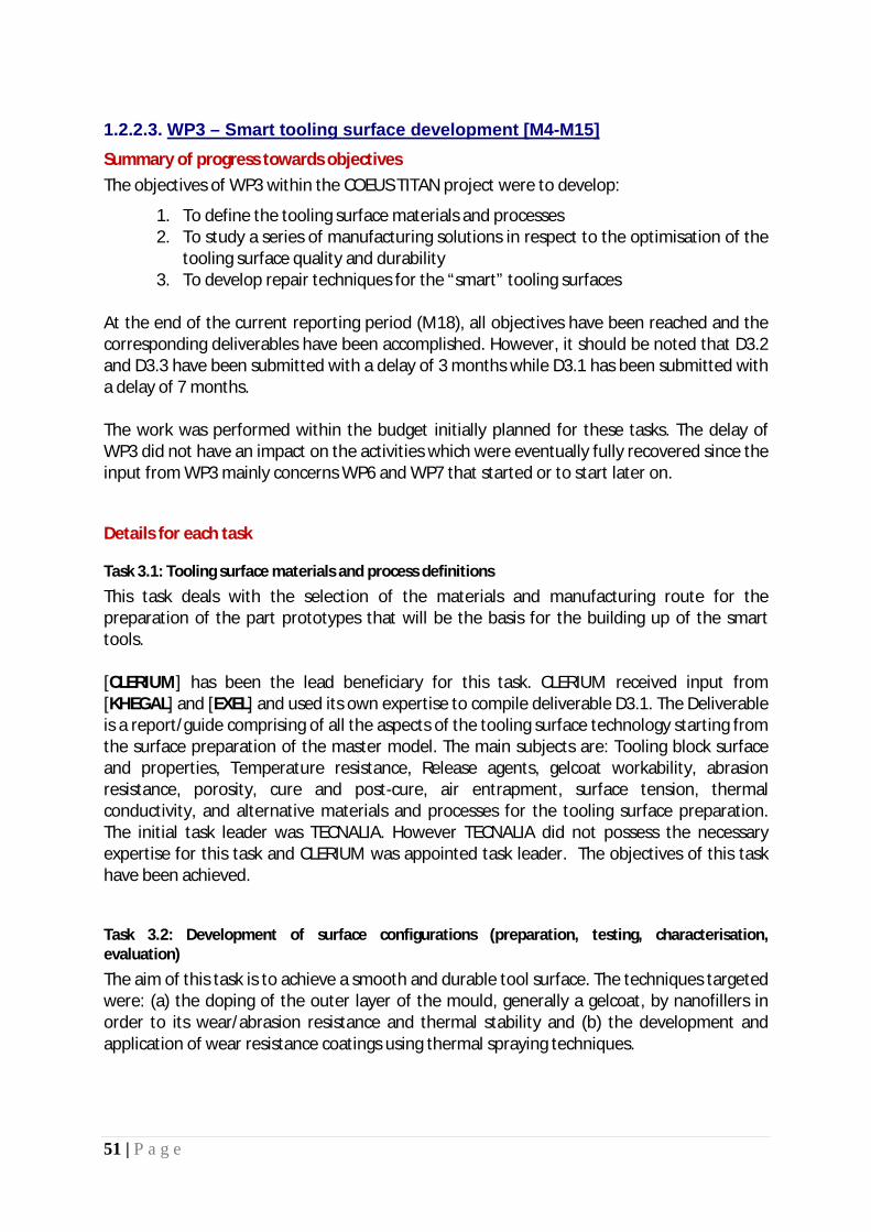
51 | P a g e
1.2.2.3. Summary of progress towards objectives
WP3 – Smart tooling surface development [M4-M15]
The objectives of WP3 within the COEUS TITAN project were to develop:
1. To define the tooling surface materials and processes 2. To study a series of manufacturing solutions in respect to the optimisation of the
tooling surface quality and durability 3. To develop repair techniques for the “smart” tooling surfaces
At the end of the current reporting period (M18), all objectives have been reached and the corresponding deliverables have been accomplished. However, it should be noted that D3.2 and D3.3 have been submitted with a delay of 3 months while D3.1 has been submitted with a delay of 7 months. The work was performed within the budget initially planned for these tasks. The delay of WP3 did not have an impact on the activities which were eventually fully recovered since the input from WP3 mainly concerns WP6 and WP7 that started or to start later on.
Details for each task
Task 3.1: Tooling surface materials and process definitions
This task deals with the selection of the materials and manufacturing route for the preparation of the part prototypes that will be the basis for the building up of the smart tools. [CLERIUM] has been the lead beneficiary for this task. CLERIUM received input from [KHEGAL] and [EXEL] and used its own expertise to compile deliverable D3.1. The Deliverable is a report/guide comprising of all the aspects of the tooling surface technology starting from the surface preparation of the master model. The main subjects are: Tooling block surface and properties, Temperature resistance, Release agents, gelcoat workability, abrasion resistance, porosity, cure and post-cure, air entrapment, surface tension, thermal conductivity, and alternative materials and processes for the tooling surface preparation. The initial task leader was TECNALIA. However TECNALIA did not possess the necessary expertise for this task and CLERIUM was appointed task leader. The objectives of this task have been achieved.
Task 3.2: Development of surface configurations (preparation, testing, characterisation, evaluation)
The aim of this task is to achieve a smooth and durable tool surface. The techniques targeted were: (a) the doping of the outer layer of the mould, generally a gelcoat, by nanofillers in order to its wear/abrasion resistance and thermal stability and (b) the development and application of wear resistance coatings using thermal spraying techniques.

52 | P a g e
The initial plan in the DoW was to add nano-fillers to an existing gelcoat proposed by ACG/UMECO. The glass transition temperature of the Umeco GC331 was not high enough for the specifications of the smart tool. The benefits of the nano-fillers are only attainable with a perfect dispersion in the gelcoat. An existing gelcoat contains many types of filler and has a high viscosity making it impossible to disperse the nano-filler homogenously. After the first attempt with GC331 was unsuccessful, TECNALIA asked CLERIUM’s help in Task 3.2. [CLERIUM] and [TECNALIA] decided that it was necessary to formulate a new gelcoat. In order to achieve a homogenous dispersion of the nano-fillers, it was necessary to start with pure epoxy resin that has a Tg of 200°C or more (VHTemp EP210, a 2-component multi-functional epoxy resin with a final Tg of 215°C after proper post-cure). [TECNALIA] doped the epoxy resin making a master-batch. The master-batch was used to validate the improvements of the tribological properties. The doped resin was then sent to [CLERIUM] who formulated further the tooling gelcoat and performed thermal cycling tests. The findings of the work were the following: · Good dispersion of nanofillers has been achieved by calendaring method · NanoAl2O3 produces lower viscosity than nanoSiO2 · The maximum viscosity achieved with standard epoxy resins doped with nanofillers is lower than 100Pas in
all the shear rate range, so other fillers could be added to formulate new gel coats. · Standard epoxy resins (selected according to functional specifications of COEUS-TITAN) could be used to be
doped with nanofillers · 4% of nanofillers, such as nanoAl2O3 and nanoSiO2, improve the abrasion resistance. · A 20% hardness increasing is observed with a 4 wt.% of nanofillers (nanoAl2O3 and nanoSiO2) · Existing epoxy Gelcoats contain high amounts of fillers and a homogenous dispersion of nano-fillers is very
difficult to achieve. · The best dispersion of nanofillers is possible if the nanofillers are added first to pure resin before
formulating the gelcoat · Existing epoxy gelcoats do not have Tg values high enough for the requirements of COEUS-TITAN · By choosing the specific fillers to achieve the desired properties in the scope of this project, the
formulation of a new Gelcoat is successful. This Gelcoat is unique and does not exist in the market yet
[TECNALIA] undertook the initiative to investigate the next target of this task, being the development of processes to deposit a functional layer on the surface of a composite mould, instead of the traditional gelcoating, through spraying techniques. The steps of the development are shown in Figure 26. Even if these steps are common in any spray coating activity, the specific characteristics of the polymer composites as substrate material forces the development of particular parameters and conditions in each step to manage this type of materials. The steps followed were: Surface activation
Before any thermal spray coating the surfaces must be activated in order to increase the anchorage and bonding of the deposited layer with the substrate.
Intermediate layers
Due to the very different nature of the polymer composites and the functional layers intended to be deposited, the procedure should include the deposition of intermediate buffer coatings able to accommodate both materials; substrate and functional layer. This intermediate coating should be sprayed with low energy
Functional coatings
Surface finishing

53 | P a g e
Usefulness of thermal spray coating for mould applications is mainly related to their surface finishing requirements, forcing the development of specific polishing procedures.
Two main approaches have been considered during this project, firstly the direct polishing of the deposited metallic coatings and secondly, the application of a gelcoat on the hard and rough metallic coatings to generate the required surface (Figure 27 and Figure 28).
Figure 26 – Direct spraying process
Figure 27 - Metallic sprayed coating in the as sprayed condition and after polishing
Figure 28 - Gelcoated sheet on the metallic coated composite
The three main type of coating materials tested correspond to the Zn alloys (Tafalloy 204), the Cu alloys (bronze C45703) and the Mo coating (HCST 105.2). In this procedure the surface to be tested was bonded with an adhesive (Araldite 2012 -50/50) to the standard pins according to the recommended parameters (curing 50ºC 2 hours and 24 hours at 23ºC).
Composite mould : No GelCoat surfaced
Thermal sprayed Plasma spraying Electric wire arc spraying
Surface preparation Blasting Grit paper
Intermediate Bond Coat AlSi- PE (Metco 601)
Functional Layers Zn base alloys Copper base alloys Mo
Finishing Sealing GelCoating Polishing

54 | P a g e
The conditions of testing have been selected for 180ºC during 3 hours with further self cooling to room temperature. The cycle has been repeated 25 times and the coating samples evaluated.
The main conclusions of this approach are the following: • Metallic functional layers can be sprayed on composites for wear protection • An intermediate coating seems necessary to assure the deposition process. • Functional coatings of Zn alloys, Cu alloys and Mo have been deposited and characterized. • Sprayed coatings need to be finished for useful application on mould making. • Mechanical hand polishing and gelcoating have been applied. • Metallic coatings can be plated (Cr, Ni or composites) for further performances. • Deposited systems have been tested for abrasion Taber, adherence and thermal cycling.
Therefore, according to the results, “Direct spraying” technology has been identified as the most convenient for coating planar/flat geometries in composite moulds. This is the case of post-former mould of the Pultrusion process to be developed in WP6.
[CLERIUM] presented the idea of trying to achieve a high gloss surface with thermal spraying by using the thermal spraying coating the same way a Gelcoat is used. Thermal spraying is a pure metallic coating that is sprayed at a relatively high temperature on a surface. When the coating cools, the metal shrinks and if the coating is not anchored on the surface, it will pre-release before the substrate can be laminated. The question is if it is possible to find a suitable surface treatment that will allow release but will provide enough adhesion so the coating will stay in place for mould building. The results were as follows:
Conclusions:
• The surface tension of the composite is not the main factor for the application of thermal spray coatings, as is for polymer coatings.
• The only bonding mechanism is mechanical bonding and not chemical bonding. • The reversal spray method to obtain a high gloss tool surface is feasible for a small surface. When the
surface will be larger, it will be more difficult to avoid pre-release. • If a sealer is not used, the metallic coating will stick to the surface and the tool surface will be
damaged during release of the master model. • The amount of sealer must be very exact, as too much will create pre-release and too little will have
the coating stick to the model. • This is a very interesting technique but will require further testing in order to make it a reliable
method for mould building. At this stage it would be too risky for the RTM tool for COEUS-TITAN.
[KHEGAL] has also developed a test procedure in order to optimise the composite mould surface roughness and performed a series of tests on materials selected for master plug construction and shown in Figure 29

55 | P a g e
Figure 29 - Materials selected for master plug construction
As main conclusions of the present study for the optimisation of the composite mould surface roughness, we can summarize as following:
· Mould surface roughness is affected by master plug milling conditions and master plug material. For a particular milling conditions when the density and hardness of the master plug material increase, the final surface roughness of the mould decrease
· To achieve a “Class A” mould surface a polishing process need to be applied to the master plug surface · The application of Sealer /release system to the master plug affect to the final surface roughness of
the mould · The mould epoxy Gelcoats perfectly reproduce the master plug surface roughness
The selection of the plug materials, milling parameters and manufacturing procedures for master plug and moulds will be heavy dependent on the final surface requirements of the composite part. In that way, the present study has presented the main behaviours and effects of the transmission of the surfaces roughness between master plugs and moulds and the process parameters that mainly affect to the mould surface roughness.
Task 3.3: Development of repairable tooling surfaces
Task 3.3 studies the possibilities to perform repairs on the developed tool surfaces. Both surface types, the gelcoat for RTM and the metallic coatings for Pultrusion exhibit high hardness, excellent durability and very high quality finish. In order to conduct the necessary tests, [TECNALIA] has prepared samples in the form of composite plates coated with gelcoat and others with metallic coatings that were sent to [CLERIUM] and [EXEL] for repairability tests. CLERIUM finalized the formulation of the tooling gelcoat by testing 4 different formulations on a heated plate. The same heated plate was used for repairability tests. CLERIUM intentionally damaged the surface of the 4 gelcoats on the heated plate and carried out repairs by sanding, fine sanding and polishing procedures. CLERIUM used the same repair procedures on the metal coated plates. Conclusions:
· The gelcoat exhibits high hardness and a high Tg which means a high amount of crystallization and mineral fillers. Those elements result in a very durable surface that will not be easily damaged.
· The final gelcoat chosen in Task 3.2 cannot be polished back to high gloss once a repair has been done because of the types of fillers it contains.
· A proposed solution by CLERIUM is to formulate a repair kit gelcoat using other types of fillers making it polishable.
Toolboard Characteristics BM 5055 BM 5460 B 17 BM 5266
Base material Epoxy Polyurethane Polyurethane Polyurethane/Mineral p.
Density (gr/cm3) 0,75 0,7 1,7 1,7
Identificative colour Light green Brown Black Dark grey

56 | P a g e
· The Metallic Thermal Spray coatings can be fine sanded and polished without a problem. Specifically for Molybdenum - which is a wear resistant coating exhibiting a very high hardness - is only polishable by using power tools.
· Metallic coatings are applied in very thin layers. If a deep scratch or damage has occurred it will be necessary to spray more material to perform a repair. In this case Thermal Spraying equipment is needed.
Significant results
Task 3.1: Tooling surface materials and process definitions
A complete guide for tooling surface preparation has been issued. It covers all aspects of the mould surface making.
Task 3.2: Development of surface configurations (preparation, testing, characterisation, evaluation)
A new gelcoat formulation, for the mould surface, has been developed and successfully tested at coupon level. It remains to be seen its application at the actual tool surfaces and its long term behaviour. In addition, thermal spraying techniques have been developed and also successfully tested and characterized. Complete roadmaps for surface configurations have been issued. Finally a procedure for surface optimization has been devised and thoroughly investigated.
Task 3.3: Development of repairable tooling surfaces
Metallic coatings are easily repairable as it was expected. For the gelcoat coatings the situation is not straight forward. The doped gelcoat has a high glass transition temperature, a high surface hardness and good abrasion resistance. The advantage is that it is resistant to scratches and accidental damages. This means that damage is not very likely to occur and that this gelcoat is very difficult to sand and polish to high gloss. If however damage occurs, it can be repaired with a specially formulated repair kit. This is the same tooling gelcoat with different fillers making it polishable.
Reasons for Deviations
Task 3.1: Tooling surface materials and process definitions The task output was accomplished according to the Description of Work (DoW). The timing of the completion of the work was delayed due to the change of the task leader (from TECNALIA to CLERIUM) and the very slow start of the project. The deliverable D3.1 (CLERIUM) was issued with a delay of 7 months.
Task 3.2: Development of surface configurations (preparation, testing, characterisation, evaluation) All targets have been accomplished. Additional work (CLERIUM) has been performed beyond the DoW to cover the application of gelcoat on mould surfaces and a new formulation has been developed by CLERIUM. Still the gelcoat performance will be further evaluated during its use on the actual tools (WP6 and WP7) since all tests have been carried out at coupon level. The deliverable

57 | P a g e
D3.2 (TECNALIA) was issued with a delay of 3 months primarily due to the extension of thermal spraying activities considered important for the ensuing works.
Task 3.3: Development of repairable tooling surfaces The deliverable D3.3 (TECNALIA) was issued with a delay of 3 months primarily due to the work that needed to be done in gelcoat repair by CLERIUM. Overall does not affect the project’s progress of works.
Reasons for failing to achieve critical objectives
Task 3.1: Tooling surface materials and process definitions N/A
Task 3.2: Development of surface configurations (preparation, testing, characterisation, evaluation) N/A
Task 3.3: Development of repairable tooling surfaces The objective has been reached but not as it was outlined in the DoW. It was concluded that the developed gelcoat was not easy to polish after a repair. It was thus necessary to have a slightly altered gelcoat formulation as a repair kit that will be polishable. The inevitable disadvantage is that the repaired spot will not have all the surface properties of the rest of the mould surface and might wear out faster. It is anticipated that further developments will be pursued in conjunction with the tools manufacturing activities taking place in WP6 and WP7.
Use of resources Overall WP3 is fully spent in terms of person-months effort. There was an under spent in Task 3.3 concerning the gelcoat repair (development of repairable tooling surfaces) which was not as promising as it was originally thought. The effort in the main tasks, i.e. Task 3.1 and 3.2 has been over expended.

58 | P a g e
Corrective actions N/A

59 | P a g e
1.2.2.4. Summary of progress towards objectives
WP4 – Sensor / Actuator Technology [M4-M15]
The objectives of WP4 within the COEUS TITAN project were:
1. To adapt existing sensing technologies to the functional specifications of the proposed concept for the “smart” tooling
· Adaptation and testing of integrated flow and reaction sensing · Development of temperature sensing in “smart” tooling through the use of
integrated thin film technology · Development and testing of the tooling temperature control system
2. To explore the possibility of part de-moulding through the use of piezo-
electric actuators At the end of the current reporting period (M18), the following objectives have been reached: [OBJ-10] Adaptation and testing of integrated flow and reaction sensing
· Development of dielectric flow and reaction (cure) monitoring sensors as well as DAQs and mountings embedded into the “smart” tooling. Several small mould mock-up specimens were fabricated with integrated capacitive elements and their wiring. The specimens were tested at INASCO in terms of signal stability and sensing element survivability under representative processing conditions. Ultrasound sensors were also investigated. The sensor and DAQs developments are ready to be introduced into the “smart” mould pilot scale model (WP6). Deliverable D4.1 (INASCO) has been issued at M15 – a 3 month delay
[OBJ-13] Development of in-tool piezo-electric actuation system – De-moulding function • Piezoelectric actuators to “automate” the de-moulding process have been introduced. They are patch-
actuators composed of flat piezo-ceramic plates (0.1 to 0.5 mm) cased inside a ductile polymer film. By applying a voltage to these patches, they generate a deformation of the ceramic which introduces a shear force into the structure. Preliminary testing indicates that are ready for introduction into the pilot scale mould. There are pending some minor issues to be revisited. The deliverable D4.3 (INVENT) will be issued at end of M20 – a delay of 5 months
Regarding the objectives: [OBJ-11] Development of temperature sensing in “smart” tooling through the use of integrated thin film technology
· Embedding of thin films in resins under the surface layer of the smart mould construction as temperature sensors
[OBJ-12]Development and testing of the tooling temperature control system
• Supply data to a central management unit that controls process parameters through the use of the embedded monitoring system comprising of embedded flow, temperature and curing sensors. The control system will be configured as follows:
- The input consists of data received by the temperature sensors embedded in the tooling. These measurements will form the input to the data acquisition boards.
- The output of the system (through the computer’s D/An interface) will drive the temperature controllers of the heating system.

60 | P a g e
The goal of reaching these objectives has suffered a major setback due to the unavailability of the Temperature Sensing Wires (ELLARA) and the lack of proactive response from the project’s side. A new material has been identified and ordered (heat flux sensors) and the fabrication of specimens to test temperature sensing techniques for the validation of temperature control of the smart tooling, is anticipated to start in mid October (ACG/UMECO). The fabricated specimens will then have to be shipped to TECNALIA for coating and to UoA for the controller system set-up and calibration. Once this is completed INASCO will then test the system that will also include flow and cure monitoring sensors under representative processing conditions. The end of activities is planned for mid December 2012. This will constitute a 9 month delay to deliverable D4.2 (CIDAUT).
The development of the temperature sensing and control system is on a critical path. WP6 activities are already underway and they will have to integrate the technology on-time.
Details for each task
Task 4.1: Adaptation and testing of integrated flow and reaction sensing
Within Task 4.1 [INASCO] developed various sensors for flow and cure monitoring which were designed, fabricated, adapted, and tested. Several small mould mock-up specimens as well as complex components have been fabricated and monitored with integrated capacitive elements and their wiring. The specimens have been tested at [INASCO] in terms of signal stability and sensing element survivability under representative processing conditions. The features of the flow sensors developed by [INASCO] are the following:
· The sensing element is a resistive switch hosted on a ceramic substrate capable of measurements up to 220°C (Figure 30).
· The sensor is tool mounted. The sensor dimensions are: 16mm outer diameter, 60mm length. · The sensor is mounted to the tool with a collet (which is part of the sensor) · For composite moulds a specific mounted assembly and method has been developed · The sensor has been tested up to a pressure of 10 bars successfully · The sensor is re-usable. Standard cleaning and release agent application procedures need to
be applied prior to use. Twelve such sensors can be connected to the DiAMon Plus™ core system. In case more sensors are needed then there is the DiAMon Flow™ system were 40 flow sensors and 16 thermocouples could be connected. The DiAMon Flow™ system can provide resin arrival detection and time at any point and a qualitative cure index in “probed” areas of the structure.
Figure 30 – Flow Sensor – Design details

61 | P a g e
[INASCO] has tested the flow sensor and DAQ system under representative processing conditions. The first action was a “Pressure and Temperature Qualification Test of the Flow Sensor”. The test set up is shown in Figure 31. The sensor was successfully performed at a 10 bar pressure and 200 ºC continuous operation.
Figure 31 – Flow Sensor – Pressure Test Jig
After the initial qualification testing [INASCO] decided to perform a test under real processing conditions. The aim was to evaluate the performance of the dielectric flow and cure sensors as well as the performance of the mounting fixtures and the performance of the DAQ. The commercial system of INASCO DiAMon™ Plus equipped with a flow module was used. There were 2 test campaigns followed:
1. Manufacture of a complex component (in that case of an airfoil section) 2. Two composite plates of the same size and thickness following up two different cure
cycles The first campaign was very elaborate and involved all elements of a complete production process (complex mould with heating zones and several venting ports, control driven heating through the DAQ system developed, mounting options of sensors, flow and cure sensors, thermocouples, etc.). The system performed flawlessly and the detection of resin arrival at the flow sensor was clearly indicated and verified (Figure 32).
Figure 32 – Resin detection graph
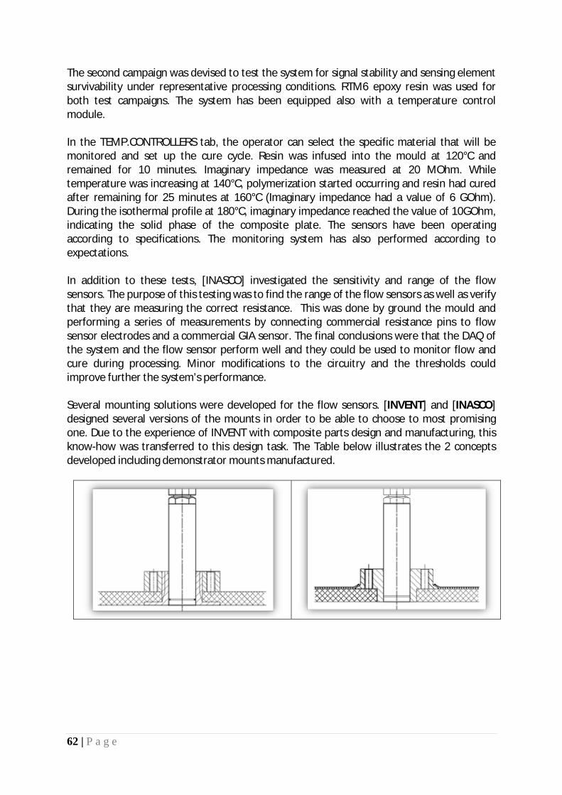
62 | P a g e
The second campaign was devised to test the system for signal stability and sensing element survivability under representative processing conditions. RTM6 epoxy resin was used for both test campaigns. The system has been equipped also with a temperature control module. In the TEMP.CONTROLLERS tab, the operator can select the specific material that will be monitored and set up the cure cycle. Resin was infused into the mould at 120°C and remained for 10 minutes. Imaginary impedance was measured at 20 MOhm. While temperature was increasing at 140°C, polymerization started occurring and resin had cured after remaining for 25 minutes at 160°C (Imaginary impedance had a value of 6 GOhm). During the isothermal profile at 180°C, imaginary impedance reached the value of 10GOhm, indicating the solid phase of the composite plate. The sensors have been operating according to specifications. The monitoring system has also performed according to expectations. In addition to these tests, [INASCO] investigated the sensitivity and range of the flow sensors. The purpose of this testing was to find the range of the flow sensors as well as verify that they are measuring the correct resistance. This was done by ground the mould and performing a series of measurements by connecting commercial resistance pins to flow sensor electrodes and a commercial GIA sensor. The final conclusions were that the DAQ of the system and the flow sensor perform well and they could be used to monitor flow and cure during processing. Minor modifications to the circuitry and the thresholds could improve further the system’s performance. Several mounting solutions were developed for the flow sensors. [INVENT] and [INASCO] designed several versions of the mounts in order to be able to choose to most promising one. Due to the experience of INVENT with composite parts design and manufacturing, this know-how was transferred to this design task. The Table below illustrates the 2 concepts developed including demonstrator mounts manufactured.

63 | P a g e
Table 5 - Sensor mounts drawings option 1 and 2 (top row), manufactured samples (bottom row)
The objective of [UoA] in this task is the design of a control system for the smart tooling operation taking as control parameter the degree of cure of the processed epoxy resin as it is supplied by the in-process sensors (Figure 33). For this purpose the overall control scheme and the development steps required (to be followed in Tasks 4.2 and 5.3) for its integration were presented. The requirements for the sensor modeling for the process control system were specified. Finally, some guidelines were outlined concerning the sensor placement in the “smart” tooling.
Figure 33 - Block diagram to control the Degree of Cure of epoxy resin
Finally [INVENT] investigated the possibility of using Ultra Sound techniques for cure monitoring. In order to be able to evaluate the technology for its employment in composite part manufacturing, a typical technology test setup has been designed and manufactured. The details are shown in Table 6 below.
Table 6 – US experimental set up For manufacturing purposes it is of utter most importance to determine the state of the completed curing. It appears that the technology can deliver this. One would have to calibrate the US measurement equipment before its use in the tooling with the speed of sound of an already cure part. Once, the US signal re-occurs during the part curing this can
Tsetpoint
+-
Controller Mould Heating
c (%)PID Treal
Kinetic function
Translator
asetpoint +-
Mould temperature control system
sK
×+t1
Filter
Reaction mechanism
αreal
SensorAssignment model Zmaxaestimated
Resin EPR L20
Curing agent EPH 960 SL
GF fabric 28 layers of 280g/m² (Aero), twill, FK800, ITG92125
US probe GE α-series 0.25” (2.25MHz and 5MHz)
US analyzer GE Phasor XS

64 | P a g e
be compared to the expected value and gives a reasonably safe indication of the curing about to be complete. The manufacturing process could be stopped when the desired speed of sound is detected. In the work packages dealing with setting up a smart tool it needs to be decided about the implementation of this feature.
Task 4.2: Temperature sensing in smart tooling
The activity in this task will deal with the embedding of thin films in resins under the surface layer of the smart mould construction for temperature sensing. The information will be used, in conjunction with the cure and flow sensing hardware, to develop and test the tooling temperature control system that will be used during the operation of “smart” tooling. The [UoA] has put in place most of the elements of the tooling temperature control system. They refer to:
• The modelling of the heat transfer process as being the main physical process related to the control action: time domain heat transfer model - (differential equation of the system) - and Laplace domain model together with the transfer function of the heating process
• The calculation of power requirements for heating the tooling • The estimation of the parameters of the transfer function defined above for both
conventional and smart tooling based on the calculation of heat transfer parameters for the specific tooling cases mentioned above
The comparison between the system parameters for the conventional
mould and for the smart tooling heating indicates the shorter time constant
of the smart tooling (100 times faster) and the smaller gain of the smart
tooling (requiring 70 times smaller power for the same heating task). Under
these circumstances the smart tooling requires tighter control for the
heating process in comparison to the conventional mould.
• The experimental validation of the transfer function parameters • The design of the temperature control system based on features of the PID control
principle • The implementation of the control system in a simulation platform (Figure 34) • The comparison of the performance of the control system to that of the digital
temperature controller for the case of a conventional mould

65 | P a g e
Figure 34 - Block diagram of the closed-loop control system with PID controller (snapshot during the transient response of
the system to a step input) [INASCO] has the set-up ready for acquiring measurements of temperature (Temperature Controller and Cure Cycle Segment Set-up) The activities performed in developing the control system are as follows: • Instrumentation set up:
o Temperature sensors: Set up, establish communication with the PC, calibration (Done – INASCO)
o Heating system actuators: Set up, establish communication with the PC, program various temperature profiles (Done – INASCO) – Figure 35
o Controller: Develop and run very simple control algorithms (Done – INASCO)
Figure 35 – Temperature Control Tab and Cure Cycle Set-up

66 | P a g e
[CIDAUT] has designed the flat specimens to develop and test the temperature control system. At the very beginning of the work within this task it was found out that the initially proposed sensing technology to be used in the project was no longer commercially available, so a study of similar and promising sensing technologies was made and a sensor was selected after the agreement of all the involved partners. During this task, specimens have been designed to include the new sensing devices. These specimens were later manufactured and given a coating to study and evaluate the performance of the sensing elements within a smart tooling, and compared to a conventional tooling. This work paves the way for the full integration of all the smart sensing capabilities that will be demonstrated during WP6. The adaptative characteristics of the system have been set up in parallel with the development of a temperature control system. During this development several characteristics of the smart mould when compared to a conventional mould have been researched and differences highlighted. In the end, software has been produced to control the temperature of the system, and this system has been tested and validated with the developed specimens. In order to develop an adaptative temperature control system for the smart tool, several small mould mock-up specimens have been designed and manufactured with embedded temperature sensors and active heating elements. After this manufacturing step, two different coating layers have been applied as it will be done with the pilot scale tooling in WP6. The temperature control system has been set up using these specimens. Finally, the temperature control system has been tested in terms of signal stability and sensing element survivability under representative processing conditions. Initially the heat sensor to be used was the Ellara thin film which was discontinued and caused a major delay to the task’s execution (Task 4.2). Subsequently a thin film heat flux sensor was selected to proceed with the developments. Thin Film Heat Flux Sensors: This approach uses thin films with integrated heat flux sensing and temperature sensing which can be embedded in the smart tooling. Each HFS series sensor functions as a self-generating thermopile transducer. It requires no special wiring, reference junctions or signal conditioning. Readout is accomplished by connecting a sensor to any direct reading dc microvoltmeter or recorder. The HFS series is designed for precise measurement of heat loss or gain on any surface. It can be mounted on flat or curved surfaces, and employs butt-bonded junctions with a very low thermal profile for efficient reading. The HFSs utilize a multi-junction thermopile construction and is available in two different sensitivity ranges. The carrier is a polyimide film which is bonded using a PFA lamination process. The sensor also has an integral thermocouple for discrete temperature measurement needed to describe the heat flux. The sensor details are shown in the appended brochure (upper temperature range 200ºC). This technology was readily available and the cost is around 200 Euros per sensor and 400 Euros for the digital meter.

67 | P a g e
Figure 36- Heat Flux Sensor
An easy to manufacture, manipulate and test 150mm x 150mm flat specimen was designed by [CIDAUT] in collaboration with the other involved partners within this task. This design included all the thermal management characteristics of the proposed smart tooling. UMECO’s LTM12 pre-preg series was selected.).The specimens had:
To investigate whether is better to embed the sensor under the surface layer or between the central fabric layers two sensors per specimen have been used. One sensor was embedded at each position.
Embedded temperature sensors
CFRP fibres have been used as resistance heating elements like the pilot scale tool will do in WP6. In the test specimens the first structural carbon fabric layer was used for this purpose and, in order to facilitate the electrical connections to the power supply unit, an extra-length (see 0) has been defined. Given that pre-preg has been used, this extra-length was cleaned from resin to assure a good electrical bonding.
Embedded heating system
One different surface layer type has been applied to each specimen test. The first one, named Specimen-A, was coated with Tafaloy, a Ni based alloy and the second one, Specimen-B has with Mo. Special attention has been paid on the coating-sensor and sensor-resin bondings to assure the surface layer integrity
Surface layer
The specimens were manufactured by [UMECO] and cut out from the plate shown in Figure 37. During this step of the manufacturing process, the surface of the panels has been coated by thermal spray techniques with a protective metallic layer. In this sense, wire electric arc spraying technique has been used for apply the Tafalloy 205 material, as previously described in the WP3 (subtask 3.2).
Figure 37- Panel for temperature control specimens

68 | P a g e
Figure 38- Coated panel in the as sprayed condition
To evaluate the quality of the contact between the copper tape and the carbon fibres a series of measurements were made of the resistance between the pairings of the copper tapes using a multimeter. [UoA] then proceeded with the designing of the temperature control system utilising the features of the PID control principle. The specific control system was then implemented in a simulation platform and its performance was compared to that of the digital temperature controller for the case of a conventional mould. The developments followed the following route:
· The first activity is the modelling of the heat transfer process as being the main physical process related to the control action. For this purpose the time domain heat transfer model - (differential equation of the system) is determined and subsequently the Laplace domain model is developed alongside the transfer function of the heating process. This modelling approach has been equally applied to a conventional mould (i.e. aluminium tooling) and to the smart tooling (composed of a carbon fibre reinforced polymer as skin and a backing structure for support and mechanical strength).
· Following the model development, the calculation of the power requirements to heat the tooling has been
performed. This is necessary as the power is involved in the model as gain definition parameter (the model input is also taken as the percentage of the maximum power). The power calculation is made using a set of specifications and is based on the calculation of power losses during the various heating operations. A specific case is considered for both conventional and smart tooling.
· The next step is the estimation of the parameters of the transfer function defined above for both conventional
and smart tooling based on the calculation of heat transfer parameters for the specific tooling cases mentioned above. The comparison of the parameters will demonstrate the energy efficiency of the smart tooling against conventional tooling solutions
The experimental validation of the transfer function parameters is made using a model set-up with a conventional tooling and a digital controller for measured power input to the system. The temperature control system described in the previous section is then implemented [UoA] using the National Instruments LabView programming environment and more specifically the Control and Simulation toolkit. The objective is to develop the code for a

69 | P a g e
software system that will be capable of: (i) simulating the temperature control process for any type of mould (conventional or smart tool) with a known transfer function and (ii) performing the actual control process when the controller connects to the heating system and the suitable feedback is acquired from the real process on the physical system. The main screen is shown in Figure 39 while real-time parameters are shown in Figure 40
Figure 39- Real-time plot of temperature setpoint, actual temperature and filtered temperature (top diagram) and control output (bottom diagram)
Figure 40- Real-time plots (from top to bottom) of temperature parameters (setpoint, actual measurement and filtered
value), power parameters (controller output and control signal) and heat flux measurements The Hardware implementation of the smart tooling temperature control system then followed [UoA] and was composed of the following hardware sub-systems, as shown in the following figure:
Figure 41- Temperature Control System Scheme

70 | P a g e
The hardware components have been assembled on the lab bench and they form the basis of all the subsequent tests. The functional simulation software was used in the actual operation mode connected to the hardware units presented above. The operation of the temperature control system described above was tested in a representative cure of a laminate on the smart tooling performed at [INASCO]’s laboratory. The smart tooling was used as a bottom plate for the infusion process of a CFRP with a two-component epoxy resin matrix. Seven layers of plain weave (160 g/m2) carbon fabric were cut and laid up in a vacuum bag on the smart tooling. The panel size was 14 x 21 cm. The closed vacuum bag is shown in the Figure 42.
Figure 42- Smart tooling curing set up
The temperature control system hardware and software was installed on the smart tooling, the dielectric cure monitoring system was connected and the vacuum line was operated to infuse resin in the laminate, as shown in the following picture.
Figure 43- Temperature control system hardware

71 | P a g e
The construction of a temperature control system for the smart tooling operation was described at all stages of development. The temperature control system consists of: • controlled power supply to the carbon fabric of the tooling • modelling of the tooling heating process • a thermocouple embedded in the smart tooling for temperature feedback • a PID controller tuned to the specific tooling and heating process • a computer controlled regulation of the power • heat flow signal for the proper operation of control process • dedicated software for the system operation The performance of the system was demonstrated in a representative resin cure process on a smart tooling at lab scale. The system has not been demonstrated at pilot (WP6) or demonstrator scale (WP7) due to the power requirements and the complexity of the moulds.
Task 4.3: Development of in-tool piezo-electric actuation system – De-moulding function
In this task the aim was to develop the technology for de-moulding by employing piezoceramic actuators. [INVENT] used a mould tool designed by [UoP] to serve as a basis for the investigations. Figure 44 shows this tool consisting of CFRP sandwich construction with integrated heating / cooling pipes. The top tool is flat, and the lower tool features a part cavity.
Figure 44 - Tool design for de-moulding technology development
A finite element model was setup by [INVENT] according to the stacking sequence given by [UoP]. Figure 45 illustrates this model. Here, face sheets are 4mm thick.

72 | P a g e
Figure 45 - Finite Element Model of Tool for De-Moulding Technology Development (INVENT)
The idea of using piezoceramic actuators for de-moulding of RTM parts results from a structural dynamics approach. First of all several types of piezoceramic actuators exist. Major types are patch actuators and stack actuators. In order to analyse the effect of both types, they were separately integrated into the finite element model. Before doing so, modal analyses of upper and lower tool with and without part were performed to understand the structural dynamics of the tool. The patch actuator was chosen as the first actuator type to be integrated, and the resulting displacement at the fundamental structural mode as well as the stresses at the interface to the part were analysed. It was expected that this will allow gaining insight how the different actuators work. Figure 46 depicts the FE model with the integrated patch actuator, the displacement as well as the shear stresses (maximum 0.65MPa) calculated. It can be observed that the actuator is capable to excite a global tool vibration. The maximal shear stresses occur in this case on the tool boundaries.
Figure 46 - Sandwich plate with piezoceramic patch actuator (left: FE model, centre: displacement, right: shear stresses at 1139.5Hz)
The same approach was chosen for analysing the stack actuator effect in terms of displacement and interface stresses. The actuator was integrated in a way that the sandwich was cut open from below such that the stack actuator can work against the top face sheet while maintaining an undisturbed tool surface. Figure 47 illustrates the actuator integration,

73 | P a g e
the displacement and shear stresses at a fundamental mode shape. This actuator also excites a global tool vibration but with shear stresses occurring directly around the actuator as well as on the tool boundaries. The maximum shear stress (3.7MPa) is significantly greater than that of the patch actuator.
Figure 47 - Sandwich plate with piezoceramic stack actuator (left: FE model, centre: displacement, right: shear stresses at 1250Hz)
In conclusion it can be summarized that both actuator types are able to cause global tool vibrations, but the stack actuator appears to be more promising due to the greater levels of stresses caused to the part’s interface. Moreover, it generates greater stress levels around its location that might be better suited to break the part loose if controlled correctly. [UoP] has performed a preliminary eigenmode analysis intended for obtaining some basic information regarding the dynamic response of the tool-part system. In this analysis the geometry and manufacturing details of a closed CFRP tool for a simple flat rectangular plate were assumed. The same tool was also designed and built to be available for testing purposes. The tool consists of two parts, a female lower part and a flat upper part. This analysis helped to reveal which modes tend to “open” the cavity and “eject” the part. By exciting these modes using the piezoelectric actuators, demoulding may be assisted. [CIDAUT] has performed numerical simulations to understand the physics of de-moulding process and correctly define the position of the actuators. These simulations were (1) Modal Analysis, (2) Harmonic Analysis and (3) Transient Analysis. In the Modal Analysis two models were analyzed. In the first one the joint part-mould was simulated using rigid links (connector) and in the second one, flexible joints were used. Rigid links were used to obtain reference frequencies and flexible joints were used to obtain relative displacements and forces. In the Harmonic Analysis several models were analyzed taking into account the results from the previous study. The geometry and the material properties were the same as in the modal analysis. The frequency starts at 0Hz up to 10,000Hz. The excitation is applied on several positions, directions and both in phase and out-of phase as shown in Figure 48.

74 | P a g e
Figure 48 – Types of applied excitations
In Transient Analysis investigations were focused to analyze the way part and mould separate. To model the de-moulding process a separation criteria was selected. The connector breaks when its normal force reaches 0.15N. Implicit formulation was selected. In order to improve running time a smaller geometry was modeled. General conclusions from this study have been drawn as general guidelines for the de-moulding process:
· The Eigen frequencies of a structure consisting of a mould and part assembly can help the de-moulding process
· Modal and Harmonic analysis of the structure will support the selection of the modes to be excited. This selection should consist of modes with the highest output interface normal and in-plane forces
· Lower modes have, in general, higher output interface forces. These modes should be excited in case of high adhesion between part and mould
· The highest output forces are obtained close to the actuator location · The de-moulding process always begins at the edges of the part. So, it seems to be
suitable to place piezo-actuators close to the part edges · Once the edges of the part have been de-moulded, and in case that the piezo-electric
actuators can’t complete the de-moulding over the whole part, a plastic wedge could be used to extract the part without damaging it
Significant results
Task 4.1: Adaptation and testing of integrated flow and reaction sensing A new flow sensor and the associated DAQ and S/W [INASCO] have been developed and validated under representative processing conditions. In addition, mounting fixtures for flow and cure sensors have been developed to accommodate their introduction into the “smart” tooling.
Task 4.2: Temperature sensing in smart tooling
The principles and major parts of the temperature control cluster have been developed and tested [UoA and INASCO] under simulated and experimental conditions.

75 | P a g e
Task 4.3: Development of in-tool piezo-electric actuation system – De-moulding function The required analysis steps for the selection of operational and placement characteristics for the de-moulding actuators have been established. Potential types of actuators have been examined and tool response has been estimated [CIDAUT and INVENT].
Reasons for Deviations
Task 4.1: Adaptation and testing of integrated flow and reaction sensing The task output was accomplished according to the Description of Work (DoW) and all objectives reached. There was a delay of 3 months in the issuance of Deliverable 4.1 (INASCO). The reason was the delayed start of the work and the additional experimental activities in qualifying the H/W.
Task 4.2: Temperature sensing in smart tooling The Task 4.2 faced a major delay due to the unavailability of the appropriate temperature sensor to be embedded in the tool –like construction, as the temperature sensing technology needed to be tested. Once the sensing element was selected the temperature control system has been designed and implemented according to the Description of the Work and completed with all temperature sensing issues validated. It should be noted that the completion of this task has suffered a major delay of approximately 9 months
Task 4.3: Development of in-tool piezo-electric actuation system – De-moulding function This task has also been suffered a delay. However, it was fully recovered and all necessary knowledge has been fully demonstrated. The deliverable D4.3 (UoP) was issued at the end of M20 – almost a 5 month delay.
Reasons for failing to achieve critical objectives
Task 4.1: Adaptation and testing of integrated flow and reaction sensing N/A
Task 4.2: Temperature sensing in smart tooling
N/A
Task 4.3: Development of in-tool piezo-electric actuation system – De-moulding function N/A
Use of resources Overall WP4 is over spent (by 10%) in terms of person-months effort. This is primarily due to the effort in Task 4.2 concerning the temperature sensing and control. However, the effort in Task 4.3 has not been totally expended.

76 | P a g e
Corrective actions N/A

77 | P a g e
1.2.2.5. Summary of progress towards objectives
WP5 – Software framework for smart tooling design [M4-M18]
The objectives of WP5 within the COEUS TITAN project were:
1. Review of commercially available software for CAD/CAM/CAE, which implement modules specific for the design and simulation of composites manufacturing processes:
· Capabilities of simulation · Input/output file formats · Interfaces with other more generic CAE tools · Complementarity of capabilities · Accuracy · Usability
2. Incorporation of models for flow, thermal, structural and process control · In order to have an accurate analysis of the novel mould performance, the process suite must be
supplied with data coming from the analysis of the individual mould components, mainly the heat management system, and the structural response of the mould. According to the requirements and capabilities of the process simulation software, the “peripheral” models will be arranged, in terms of data content and format. Optimisation procedures will be implemented.
During a moulding process (either open or closed mould), three stages can be distinguished: 1. Mould / tool preheating 2. Filling process 3. Curing /cooling
3. Development of automation functionalities for the smart tooling design software framework
· The overall outcome intended is to configure the design framework in such a way that it will require just the CAD file of the product, material details, time and cost constraints and any other specifications in order to produce (with minimal user intervention/manipulation) the mould design and the full set of process control parameters. This eventually will lead to a user-defined Integrated Design Environment.
4. Implementation and interfacing for techno- economical models · The developed techno-economical models (from WP8) will be implemented in the software
framework as a separate module. Their function will be to estimate the total cost of a part's production depending on the design features and the components included in the mould construction.
At the end of the current reporting period (M36), ALL objectives have been reached. The focus was on setting up a set of guidelines and procedures for efficiently analyzing and modelling the “tooling” process, i.e. material selection, design, flow, thermal, structural requirements as well as costing principles and identify the “operational” drivers of a synergistic integrated design environment. A set of design and analysis tools has been proposed. A reporting template for the distribution of results has been devised. The implementation of the techno-economic models has been completed receiving input from WP8.
Details for each task

78 | P a g e
Task 5.1: Design of software structure, numerical tools and interface
In Task 5.1 Design of software structure, numerical tools and interface the main objective is to setup an appropriate analysis software structure able to accommodate the procedure for the multidisciplinary design of the novel tools. Specifically,
· Review of commercially available software for CAD/CAM/CAE, which implement modules specific for the design and simulation of composites manufacturing processes
· Select the set of software tools that covers the needs of the project · Decide on the CAD file exchange format · To establish a reporting system which will permit the distribution of analysis results to all actors
involved in the design cycle of the tooling · Implementation of concurrent engineering and practice
[UoP] has contributed to the software review and evaluation process focusing on the ANSYS Workbench and COMSOL Multiphysics software package capabilities. In order to demonstrate the analysis sequence and test the capabilities of the analysis code, the user-friendliness of the interface and the import-export / automation capabilities, a simple design case was run for the ANSYS Workbench software. Within Task 5.1, [TECNALIA] reviewed suitable commercial codes to model a RTM process. As a result of this exercise, two codes were found to be appropriate for the simulation activities to be performed: MSC-Marc and RTM-Worx (both available at TECNALIA). Main reasons for this are listed below:
· MSC-Marc allows one to conduct uncoupled thermal, electrical, mechanical and curing analyses to be carried out within COEUS-TITAN
· MSC-Marc allows one to conduct coupled thermal-electrical, thermal-electrical-mechanical, thermal-curing, thermal-curing-mechanical and thermal-mechanical analyses to be carried out within COEUS-TITAN
· RTM-Worx allows one to model the filling of the cavity, both under isothermal and non-isothermal conditions
· Both codes allow data exchange using common formats · A semi-automated communication between the two commercial codes could be get
Within this task [INASCO] reviewed several available commercial software for the simulation of the Liquid Composite Moulding (LCM) process. However, INASCO’s focus was on the available OPEN source software and their potential. INASCO reviewed and tested a public domain “Mesh Generator and Solver” named Gmsh. Gmsh is a 3D finite element grid generator with a build-in CAD engine and post-processor. The myRTM software package for simulating mould-filling, which is very simple to use and based on the principle of the cellular automat was also tested. There is an automatic communication between myRTM and Gmsh. Based on the above reviews the following CAD exchange formats could be easily supported and transported between the various CAD/CAM/CAE systems: § *.stp (Step, 3D volume geometries) § *.igs (Iges, 2D surface geometries) § *.msh (Gmsh)
§ The CAE tools are: MARC and NASTRAN

79 | P a g e
§ The LCM simulation tools are: RTM-Worx and myRTM
In order to propose a reporting system that will permit the distribution of results in the design cycle of the tooling we have to identify the steps involved in the process. The basic entities of actions are graphically depicted in Figure 49below:
Figure 49 - “Smart” Tooling Design Process
A part of the resulting reporting template is shown in Figure 50below:
Figure 50 - Reporting Template for “Smart” Tooling Design Process

80 | P a g e
The reporting template presented above should be treated as a “live” document. It should be understood that most of the commercial analysis tools examined in the course of the project do provide reporting capabilities and thus could be easily included in the template as tags.
Task 5.2: Incorporation of models for flow, thermal, structural and process control
The main objective of Task 5.2 is to provide the necessary methodologies/modelling insight and guidelines that will allow to design, analyse and finally optimize the composite mould. [INASCO] has focused its activity in Task 5.2 in the use of public domain codes for the design and solver (Gmsh) and the flow simulation software (myRTM). They examined the exchange of information between the two codes as well as their capabilities for addressing the needs of SMEs. The Gmsh code proved to be flexible enough in importing, exporting, manipulating and meshing of the design data. The myRTM code is easy to use but the options are limited in terms of thermal profiles (only implicitly through viscosity). Different sections could be assigned with various properties but it requires an interactive time consuming but straight forward method. Overall the combination of codes seems to work well for preliminary investigations or sizing of problems. [INASCO] also developed a cure and flow monitoring strategy and tools based on the evolution of material state properties and real-time monitoring. The material state model could be used to derive curing profiles and address the curing effects issue. Lastly, based on the optimization platform already existing, with some minor modifications we were able to derive a series of optimum (in terms of Tg) cure cycles. [TECNALIA] has focused its activity within Task 5.2 in the use of MSC-Marc and RTM-Worx commercial codes to model a complete RTM manufacturing process. Communication channel between two codes have been assessed and both coupled and uncoupled numerical analyses have been carried out. Limitations of the commercial codes used have been identified as well. In the whole, it is concluded that MSC-Marc code is appropriate to be used for simulation activities related to RTM. On the other hand, it is found that the current version of RTM-Worx available at TECNALIA might not be powerful enough to model in detail the mould filling. Limitations to exchange data/results between MSC-Marc and RTM-Worx have also been found. [UoP] has contributed by developing and validating models for electro-thermal analysis that will allow for the prediction of the heating element response and the simulation of their operation. Work in the next period (WP6) will include thermal as well as structural/mechanical models for the design of the RTM tools and the Pultrusion dies.
Task 5.3: Development of automation functionalities for the smart tooling design software framework
· The overall outcome intended is to configure the design framework in such a way that it will require just the CAD file of the product, material details, time and cost constraints and any other specifications in order to produce (with minimal user intervention/manipulation) the mould design and the full set of process control parameters.

81 | P a g e
· Collective knowledge gained from experience and work conducted in Task 5.2 will eventually be utilised in order to define parameter ranges associated with each modelling task. Relevance and contribution of the report to the objectives of COEUS TITAN
The development of the creation of the “smart” tooling design platform is based on the use of the following sequential concepts:
[INASCO] has worked in the definition of a design framework platform where all necessary elements and steps involved in the process of the design cycle of the tooling, have been identified and set-up. In this work, 3-tier client/server architecture is selected to represent an integrated modular “smart” tooling design environment. The 3-tier client/server architecture is a new trend of client/server system. The following diagram shows a simplified form of system architecture.
Figure 51 - Framework of 3-tier client\server architecture
Based on the notions described thus far the proposed Integrated Design Environment for the “smart” tooling Figure 52 is graphically depicted in below. The main feature is that the system is neatly and conceptually structured by a well-planned definition of the software boundaries between different tiers.

82 | P a g e
Figure 52 - Integrated Design Environment for the “Smart” Tooling
The main objective of [UoA] in this task is the design of a control system for the smart tooling operation taking as control parameter the degree of cure of the processed epoxy resin as it is supplied by the in-process sensors. However, this development even though was extended into the second half of the project resulted only to an emulation software demonstration that is still away from the real operational specs of such a system.
In addition [UoA] has also worked on the effects of cost constraints on the design of the smart tooling which are presented in the following section.
The key cost elements in the manufacturing of the smart tooling are shown in Figure 53. The smart tooling cost is divided in five sections, where each one of them is further divided in cost sub-categories. The present study aims to identify the key cost elements and how the design of the smart tooling is affected by the cost of the cost categories.
Figure 53 - Block diagram showing the breakdown of the smart tooling cost in various categories and sub-
categories

83 | P a g e
[UoP] has performed simple preliminary analysis demonstrating the automation capabilities of the ANSYS workbench.
Task 5.4: Implementation and interfacing for techno-economical models
The currently under development techno-economical models (from WP8) are implemented in the software framework as a separate module (LabView). Their function will be to estimate the total cost of a part's production depending on the design features and the components included in the mould construction.
Given the part specifications and the production requirements (volume, delivery time) various alternatives for the manufacturing process and the mould design can be assessed in terms of total cost per part.
As a first step the techno-economical analysis rely on semi-empirical rules. At this level the analysis delivers rough cost estimations for the primary selection of process parameters and mould design features. At the next level the mould design framework could be brought into the cost analysis procedure in order to allow for accurate estimations of time and cost or even mould design optimization in terms of cost. The software module was made on National Instruments LabView v.2010 platform. The user interface philosophy is for the operator to enter data on the white coloured boxes at all relevant tabs (Figure 54), while the code calculates all yellow and orange coloured boxes. At the end of each data entry process the button ‘Update’ should be pressed to register the data for the specific cost category and issue the total values in the main part of the window. The total cost of the smart tooling is divided in the following categories:
· Composite tool · Power supply and control · Monitoring system · Actuation system · Active cooling system · Labour cost · Other costs
Figure 54 – Tabs of cost categories for data entry
The input screen for the composite tool is displayed in Figure 55. Similar input screens do exist for all other cost categories shown in Figure 54. Given that all data for a representative smart tooling (designed in WP6.1) have been entered in the tab, the cost categories are computed (as shown in Figure 9) and the total cost of the smart tooling is then estimated. The software computes the relative weight of each cost category in the total cost of the smart tooling. This information is shown at the right hand side of the interface in Figure 56. The visual examination these values show that the monitoring system has the greatest contribution to the overall cost, followed by the other costs category. Also significant is the cost of the actuation system and of the composite tool. This information can be used by the design team of the smart tooling for cost optimisation.

84 | P a g e
Figure 55 - User interface for data entry in the cost category of composite tool
Figure 56 - User interface for the estimation of costs in the various cost categories of the smart tooling cost as well as the distribution of the cost to these categories
Significant results

85 | P a g e
Task 5.1: Design of software structure, numerical tools and interface
A complete analysis sequence that can be used in the design process for the smart mould has been set-up and analyzed. The sequence included all foreseen steps. It was demonstrated that it is possible to apply this chain sequence in order to account for as much parameters and physical effects as possible. Furthermore, a reporting system has been established which will permit the distribution of analysis results to all actors involved in the design cycle of the tooling
Task 5.2: Incorporation of models for flow, thermal, structural and process control Coupled and uncoupled analyses have been carried out to assess thermal, mechanical and electrical behaviour of composite moulds, the filling of the mould and the resin curing process. In addition issues such as cure monitoring, material state models and process optimization have been addressed. Communication channels between different codes have been explored and exhibit sufficient intra-link automation for data exchange and manipulation.
Task 5.3: Development of automation functionalities for the smart tooling design software framework
The work has been focused on the segments of an Integrated Design Environment for a “smart” tooling structure instead of the data management and work flow management automations which are inherent in most of today’s tools and seamlessly integrated into the tools selected in the framework of the COEUS-TITAN project. A framework of Integrated Design Environment has been proposed. The concept of “smart” tooling design as described above adheres also to the principles of concurrent engineering. The process is an interactive one with continuous feedback. It is left up to the beneficiary’s internal procedures on how to implement it. It was demonstrated that it is possible to apply this chain sequence in order to account for as many parameters and physical effects as possible. The document should be treated as one that will involve with the progression of works and needs to be modified accordingly when need be.
Task 5.4: Implementation and interfacing for techno-economical models
S/W implementation of the techno-economic model has been completed. All major categories of the smart tooling cost are included. The operator has a clear view of the most costly element and consideration of how to reduce the cost.
Reasons for Deviations
Task 5.1: Design of software structure, numerical tools and interface The task output was accomplished according to the Description of Work (DoW) and all objectives reached. However, there was a delay of 7 months in the issuance of Deliverable 5.1 (INASCO). The reason was the change of coordination and the lack of any activity for the first year. Objectives have been reached.

86 | P a g e
Task 5.2: Incorporation of models for flow, thermal, structural and process control This task has also suffered a delay of 4 months due to the delay of starting the corresponding activities. However, substantial effort was expended for the recovery. Work has surpassed the activities as they were described in the DoW. The outcome is fully documented in deliverable D5.2 (TECNALIA) and they form a very good basis for the ensuing works. Objectives have been reached.
Task 5.3: Development of automation functionalities for the smart tooling design software framework There was a delay of 2 months in completing this task and issuing the deliverable D5.3 (INASCO). Efforts were made to ameliorate the accumulation of delays from the previous tasks. Due to the inherent automation functionalities in the design and analysis tools identified the effort was concentrated in devising an “integrated design platform”. The objectives where somehow focused in another aspect, that of the structure of a design platform (rules, procedures, data handling, etc.) since most of the automation is inherent.
Task 5.4: Implementation and interfacing for techno-economical models The task was slightly delayed since it relates to the outcome of the WP8.1. The complete software and the associated report were made available at M19, with 1 month delay.
Reasons for failing to achieve critical objectives
Task 5.1: Design of software structure, numerical tools and interface N/A
Task 5.2: Incorporation of models for flow, thermal, structural and process control N/A
Task 5.3: Development of automation functionalities for the smart tooling design software framework N/A
Task 5.4: Implementation and interfacing for techno-economical models
N/A
Use of resources Overall WP5 is under spent (by 12%) in terms of person-months effort. This is evident in most tasks. The reason is that most of the activities described were overestimated at the beginning and serious similar effort has to be allocated to WP6 and WP7 (pilot scale and large scale demonstrators) where most of the tools and sequences will be put to test.

87 | P a g e
Corrective actions N/A

88 | P a g e
1.2.2.6. Summary of progress towards objectives
WP6 – Smart tooling technology integration to pilot scale [M10-M27]
The objectives of WP6 within the COEUS TITAN project entail the integration of the individual technologies (developed in WP2, WP3 and WP4) in respect to the actual tooling fabrication. They are presented in detail below:
1. Design of tooling cavity for pilot scale implementation · The starting point will be the design of the tooling cavity that will include the surface layers, the
heating elements and the cooling system. This task will play a crucial role in the fulfillment of the goals set for the project. The aim of this task is to design the tooling cavity of the pilot scale tool. The design aspects to be considered for the manufacturing of the tooling cavity should be able to address:
- Use of a high Tg resin or polymer - Doping of the resin with nano-sized particles - The setup of the heating elements
2. The aim of this task is to design a structure that will support the tooling cavity
during the high pressure loadings of the RTM and pultrusion processes.
3. Integration study of heating/cooling systems · Although the heating elements are essentially the carbon fibres, the realisation of the heating system
requires a set of auxiliary components that need to be introduced into the tooling structure. These are the electrodes for the connection to the power source and the wiring of the circuit
· The integration of the cooling system, depending on the form selected will also bear upon the manufacturing procedure.
.
The goal of this task is to provide techniques to combine the fabrication procedure for the tooling cavity with the placement of the components of the cooling system
· The integration of heating and cooling systems will be examined separately for the RTM and pultrusion pilot tools.
.
4. Integration study of sensing/actuation systems · The most demanding task at this stage will be the incorporation of the flow/reaction sensors into
the tooling cavity. Two solutions will be examined. The first is to embed fittings for the attachment of the sensors during the cavity lay-up. The second is to similarly embed cured resin “plugs”, through the thickness of the structure
. Drilling through these plugs will enable fitting of the sensors without compromising the fibres. The acoustic sensors, if selected for application, will pose no significant problem as they will be fitted in the mould base, just under the cavity layers.
· The patch-actuators are in fact tailored to be laminated inside a composite structure; therefore their integration in the mould is a trivial task.
The accommodation of the required wiring for all active components (sensors/actuators) will also be detailed in this task.
5. Manufacturing of pilot scale tooling and assembly
· The work of this task is the actual fabrication of the pilot scale tooling given the design and instructions from Tasks 6.1 and 6.2. During the manufacturing of the pilot scale tooling all potential problems and difficulties will be identified and reported.
6. Pilot scale testing and evaluation

89 | P a g e
• The tooling produced in the previous task will be prepared for test production runs in RTM and pultrusion respectively. The test production will be limited to 20 RTM parts and 10 meters of profile for the first stage of the task. The parts produced will be thoroughly examined and the efficiency of the mould will be assessed.
At the end of the current reporting period (M36), all works have been completed as planned.
Details for each task
Task 6.1: Design of tooling cavity
The general work flow in T6.1 was as follows: [KHEGAL] performed a pre-design of the RTM tool. [FIBRETECH] detailed this design taking into account manufacturing and composite material issues and concerns as well as the integration of the heating system. The heating simulation was performed by [FIBRETECH]. The pre-design by [KHEGAL] is shown in Figure 57. It is foreseen to have two vacuum seals around the part cavity as well as a ring injection line. In the centre of the top tool another vacuum port is located.
Figure 57 – Pre-design of RTM Pilot Scale Tool
[FIBRETECH] maintained this pre-design concept and developed the detailed composite design as shown in the Figure 58 below.

90 | P a g e
Figure 58- Detailed design of pilot scale RTM tool (before stiffener optimization, part cavity shown in red)
Task 6.2: Automated design of smart tooling components
A FE model was setup by [INVENT] in order to optimize the stiffener positions and the actuator integration. [INASCO] performed the flow simulation; the surface treatment was adjusted to the pilot scale tool by [TECNALIA & CLERIUM]. The number and position of stiffeners of the tool were optimized by [INVENT]. The FE model used, as well as the before and after optimized option of the stiffeners are shown in Figure 59. The goal of this optimization was to reduce the bending stiffness of the tool as much as possible while maintaining the required shape stability. A more flexible tool is in favour of an improved de-moulding functionality.
Figure 59 - Finite Element Model of RTM Pilot scale Tool (left), Stiffener Modelling before Optimization (center)
and after (right) The optimization of the stringer positions was performed in a way that an injection pressure of 1bar was applied to the tool cavity while the overall displacement was analysed. The maximal allowed displacement was set to 0.5mm. Figure 60 below shows the tool displacement at 1bar injection pressure with the final stringer set.

91 | P a g e
Figure 60 - Overall displacement in mm for injection pressure of 1bar
The number of stringers was reduced from 8 to 4, and the design had to be adjusted according to the revised stiffener positions. Figure 61 below illustrates the revised design by [FIBRETECH].
Figure 61 - Detailed Design, Revision with optimized stringer positions
With the optimization of the ribs performed, the piezoceramic actuators were integrated. As performed in T4.3, both actuator types were integrated (patch & stack actuator). In order to achieve a comparison to the results of T4.3 they were both integrated in the centre of the tool as shown below.

92 | P a g e
Figure 62- Integrated piezoceramic actuators (left: patch actuator, right: stack actuator)
Modal and harmonic analyses were performed with both types of actuators. One can understand from the pictures below that both actuator types are again able to excite global vibrations in the tool cavity. Here, the displacement maxima caused by the stack actuator are greater. Plus, it was observed that the stack actuators generate shear stress an order of magnitude greater than the patch actuators. The behaviour is comparable to the results of T4.3. Here, the stress amplitudes caused by the patch actuator are at 1.8MPa, whereas the stack actuator generated 24.9MPa. It has been decided to include both actuator types in the pilot scale RTM tool in order to validate this behaviour. It is planned to integrate the stack actuator in the tool centre and corner. The patch actuators will be integrated more on the tool vicinity to make room to the flow sensors. The precise placement will be simulated in more detail in T6.4.
Figure 63- Displacements caused by piezoceramic actuator (left: patch actuator, right: stack actuator)
The same motivation, as for optimizing the stringer positions, holds for a design revision with detachable ribs to allow for more efficient de-moulding vibrations. The approach is to fix the stiffeners when needed for injection and curing but remove the ribs for de-moulding. The reduced bending stiffness of the part cavity results in lower natural frequencies and, thus, allows driving the piezoceramic actuators in a lower frequency range. In this frequency range more affordable piezoceramic amplifiers are available which reduces the foreseen costs of the actuation system. Figure 64 below illustrates the revised design with detachable ribs.

93 | P a g e
Figure 64- Revised design option with detachable stiffeners
The displacement caused by piezoceramic stack actuator without ribs below cavity was analysed. The Figure below show the cavity displacement (left) as well as the shear stress (right). While the stress amplitude reduces to 10MPa, the range of its effect was increased.
Figure 65- Displacement caused by stack actuator without ribs below cavity (left) and shear stress (right)
[EXEL] developed a pre-design for a pultrusion post-former as shown below.
Figure 66- Composite pultrusion post former

94 | P a g e
Detailed composite design as well as heating system layout performed by [FIBRETECH] as shown below.
Figure 67- Pultrusion post former, composite detailed design including heating
Work Package 3 focused on the development of the tool surface for the RTM tool and the Pultrusion post-former. The RTM tool surface needs to withstand heating and cooling cycles, have good chemical resistance to the resins used to mould parts and allow the possibility to perform repairs in case of accidental damages. These properties were achieved by formulating a new epoxy Gelcoat with a high Tg by making a custom selection of nano and mineral fillers. The Pultrusion post-former is used under a constant temperature. The main challenge at the post former is the abrasion. The research conducted in Work Package 3 shows that a pure metallic coating is more suitable for the post-former and it can be applied by direct spraying the surface of the ready post former tool. The metallic coating can be sanded and polished to a high gloss. Repairs are possible by spraying more material and repeating the finishing and polishing steps. In placing the flow sensors [INASCO] decided to perform a flow simulation analysis of the infusion process. The part is made of woven carbon fabric (285 g/m2) with the following

95 | P a g e
stacking sequence 6[0/90, +/-45] s for an overall thickness of 3.8 mm. The resin system is an Araldite LY-556. The injection is using a peripheral channel and the injection pressure was set to 1 bar. The software platform RTMWin©
Figure 68
was used for the flow simulation. The geometry input was generated from the CAD files provided by INVENT. A schematic of the part as well as various cross sections are shown in . It is seen that the contours vary in the major directions of the part. In the geometry it is also included the part to be trimmed (it is treated as an infusion enhancer).
Figure 68- Meshed geometry of the part used for the flow simulation analysis
The flow simulation results are shown in Figure 69. The total infusion time is approximately 140 sec ~ 2.5 min. We would like to verify whether the filling pattern is being followed. To capture the events from the four peripheral resin channels the flow sensors should be placed at halfway between the four edges and the central outlet port. In this way, the filling pattern from the “steep” edges should be captured at t=40 sec and at approximately t=80 sec the filling pattern from the smooth edges should also be verified. In selecting the placement of the flow sensors care should be exercised in the possible integration issues (backing tool structure, “wiring” route, placement of other sensors, heating elements, etc.). Based on the current tool design and the placement of other sensors the proposed flow sensor locations are shown in Figure 70. They are depicted in red color. Their relative position in terms of the other “accessories” is shown in Figure 71.

96 | P a g e
Figure 69- Flow simulation analysis results
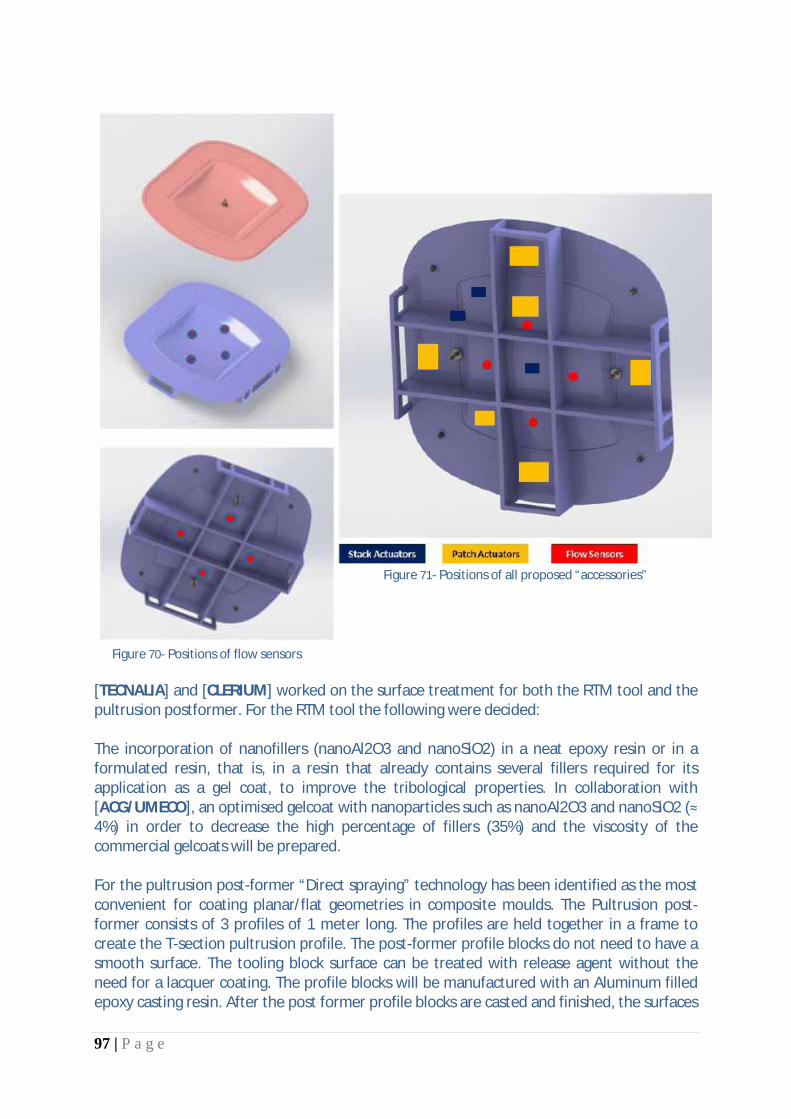
97 | P a g e
Figure 70- Positions of flow sensors
Figure 71- Positions of all proposed “accessories”
[TECNALIA] and [CLERIUM] worked on the surface treatment for both the RTM tool and the pultrusion postformer. For the RTM tool the following were decided: The incorporation of nanofillers (nanoAl2O3 and nanoSiO2) in a neat epoxy resin or in a formulated resin, that is, in a resin that already contains several fillers required for its application as a gel coat, to improve the tribological properties. In collaboration with [ACG/UMECO], an optimised gelcoat with nanoparticles such as nanoAl2O3 and nanoSiO2 (≈ 4%) in order to decrease the high percentage of fillers (35%) and the viscosity of the commercial gelcoats will be prepared. For the pultrusion post-former “Direct spraying” technology has been identified as the most convenient for coating planar/flat geometries in composite moulds. The Pultrusion post-former consists of 3 profiles of 1 meter long. The profiles are held together in a frame to create the T-section pultrusion profile. The post-former profile blocks do not need to have a smooth surface. The tooling block surface can be treated with release agent without the need for a lacquer coating. The profile blocks will be manufactured with an Aluminum filled epoxy casting resin. After the post former profile blocks are casted and finished, the surfaces

98 | P a g e
that are in contact with the pultruded profile will be treated with a thermal spraying coating by [TECNALIA]. The surface will be directly sprayed first with a bonding layer consisting of AlSi-Polyester. This will ensure a good bonding with the final functional metallic coating. The thermal spray coatings with the highest hardness and highest abrasion resistance are molybdenum and cermets of WC-Co. The coating will then be fine sanded and polished to obtain the desired gloss level required by [EXEL].
Task 6.3: Integration of heating/cooling systems to smart tooling
The main activity was the design and integration of the heating and cooling systems in all pilot tools considered (RTM, infusion and Pultrusion Post Former). Despite the fact that the heating elements are essentially the carbon fibres, the realisation of the heating system requires a set of auxiliary components that need to be introduced into the tooling structure. These include the electrodes for the connection to the power source and the wiring of the circuit. The integration of the cooling system will also bear upon the manufacturing procedure. The main goal of this task is to provide technical guideline on the fabrication procedure for the tooling cavity consistent with the placement of the components of the thermal system. The integration of heating and cooling systems is examined separately for the RTM and pultrusion pilot tools. The purpose for the activities carried out by [UoP] in the frame of Task 6.3 was to study the procedure of the tool manufacturing for the infusion pilot trials, try different approaches to it and identify potential problems. Two different sandwiched - structured molds were manufactured and studied using the resistive heating method. The first mold is a flat-surfaced mold while the second one is a female, hat-type shape mold. In addition, a study was conducted for the manufacturing of a flat RTM mold using CF fabric as heating element. The approach followed by UoP was composed of three main steps: (a) The application of the gelcoat, (b) the preparation of the heating element and the (c) construction of the main structure. Gel coat The gel coat application is more or less independent of the actual heating element integration. Heating element construction A gel coat layer is applied on the surface of the master model, which forms the top layer of the innovative mold. The top layer gel coat can be easily repaired, if needed, and offers an excellent surface finish quality. This also electrically insulates the CF heating element of the mold, from the carbon reinforcing preform of the manufacturing CFRP component. After the curing of the gel coat at room temperature the CF prepregs (heating element) are placed, and the copper connections are attached at the edges and between of the heating element

99 | P a g e
layers. By applying pressure using the vacuum bagging technique on the heating element and electric potential difference at the copper electrodes, the CF heating element temperature rises due to the Joule heating effect. Using CF prepregs as heating elements, the temperature profile proposed by the manufacturer of the resin system is being followed providing an almost uniform temperature profile. A non - conductive layer in the form of a thin film or a very thin glass fabric should be applied after the placement of the CF heating element. This is a compulsory step, in order to prevent a short - circuit from the direct contact of the conducting element with the CF skin of the sandwich structure. Indicatively the manufacturing steps for the heating element of the hat-type mould are shown in Figure 72.
Figure 72. Manufacturing steps of the heating element of the hat-type mold
Core and back face - Integration of cooling system One of the major challenges of the related task was the integration of the cooling system. [UoP] has followed the ideas described in the DOW and performed trials with embedding copper tubes inside the tool to facilitate cooling through the flow of a coolant fluid (either air or water) through the tubes. There were several trials performed with different configurations. The most successful was the placement of the cooling tubes in contact with the top face of the tool, embedded in the foam core. The tubes were also effective in conducting heat out of the top face and providing a controlled cooling function. However large temperature differences were observed in the course of the cooling phase. The required reinforcing CFRP layers, the cooling tubes and the necessary pre-cut core material needed for stiffness and strength are being placed as shown in Figure 73. The whole structure is cured under the pressure application of 1atm, using the Joule heating effect. Insulation layers are placed on top of the structure, in order to achieve a relatively uniform temperature distribution through the mold. The final step comprises the demolding of the mold structure and the development of the supporting structure. The resin curing temperature profile (proposed by the manufacturer) can be achieved by accurately providing the required electric power.

100 | P a g e
Figure 73. Manufacturing steps of the sandwich structured flat mold
Two lightweight sandwich structured molds (with embedded cooling tubes and PUR foam), a flat one and one of hat type shape, having CFRP skins, were manufactured using CF prepregs without any external conventional heating element or heating system based on heated fluids embedded channels. The CF reinforcements of the outer CFRP skin of the mold were used as heating elements with ≈130oC maximum operating temperature. Also a flat RTM mold (with embedded cooling tubes and honeycomb) was manufactured using dry CF fabric. The effectiveness of the cooling tubes in the cooling stage has been proved in D2.2 but the incorporation of the cooling tubes in all the cases presents manufacturing difficulties, high manufacturing cost and inaccuracies in the placement. The level of curing of the CFRP product which has been manufactured with the innovative method using the cooling tubes is similar to the level of curing of the respective conventional method. [FIBRETECH] The fibretemp heating-system is integrated into the mould during the procedure of building the mould. The carbon fibres are used for both: the structure of the mould and additional as resistance heating elements. So the system has a macroscopic effect as a heating panel.

101 | P a g e
The heating elements consist of layers of carbon fibre fabric. Along the two opposite edges of the fabric (usually the shorter) an electrode is attached for the connection of the fibres with the power source. Fibretech commonly applies a copper wire electrode which is interwoven with the carbon fabric. The sequence of steps is as follows:
· The first step in the process is the building of a master model of the part to be produced. · After applying the gelcoat on the surface of the master model a layer of glass is placed. This serves two
purposes. It stabilizes the gelcoat, and provides electrical isolation of the heating layer. · The next step is to place the layers including the heating layers. Between the two heating layers the
contact-tape was draped at the edges of the mould. · When all layers are correctly placed, the preform is covered by vacuum bags and the resin feeds are
placed. Vacuum is then applied and the infusion is performed in one shot (Figure 74). · When the mould is consolidated the connection to cables of the power-supply to the heating elements
is established by copper-triangles that are screwed on the contact-tape. · The same procedure is repeated for the cover (male) part of the mould. In the present case a light-
RTM tool is prepared, so the top part does not include any heating elements, it consists only of a few layers of glass fabric.
Figure 74: Infusion process to create the heated mould
Task 6.4: Integration of sensors and actuators to smart tooling [INVENT] contributed to the integration of the piezoceramic actuators. [FIBRETECH] integrated temperature sensors while manufacturing the composite pilot scale tool; designed and manufactured flow and reaction sensor adapters. Furthermore, FIBRETECH advised the partners with details about the manufactured tool. [INASCO] detailed the integration of the flow and reaction monitoring system, whereas UoA transferred its work from WP4 to WP6 and fitted a temperature control to the purposes of the pilot scale smart tool. [INVENT] To assist the demoulding process an actuator network based on piezoelectric patch actuators was developed. Therefore a virtual modal analysis of the tool was performed to

102 | P a g e
determine natural modal shapes which could be excited to assist the demoulding procedure and find the right locations to place the patches. The effectiveness of the patches has than be analyzed and optimized by conducting several virtual harmonic analyses, Figure 75. By grouping the patches it should be possible to drive 5 patches with just three amplifiers which mean a drastic reduction of the costs for the actuation system. The configuration proposed is shown in Figure 76
Figure 75 – Harmonic analysis results to evaluate patch position performance
Figure 76 - 5 patches layout
To assist the demoulding procedure piezo-electric patch actuators were bonded to the rear of the mould. According to the FEA a setup of five piezo patch actuators were employed. These actuators consist of thin piezoceramics (0.2 mm) embedded in a composite housing. Furthermore those piezo-patches are made to be bonded to (non-planar) surfaces because

103 | P a g e
of their flexibility. The connection between patch and surface can be realized with common structural adhesive systems. To drive the patches the E.413.D2 amplifiers made by PI Ceramics has been used. [FIBRETECH] The adapters to mount and fit the flow and reaction monitoring sensors were designed by Fibretech. Since, Fibretech manufactured the composite pilot scale tool with the integrated heating they had all the details at hand in order to analyze and develop the sensor integration method. The adapters were designed as such that the flow sensors can be mounted on one hand. The adapters also allow for the integration in the composite pilot scale tool. The designs are shown in Figure 77
Figure 77 – Design of flow and cure sensor mounts
[INASCO] There are new flow sensors that have been developed for the project. These new flow sensors have the following features:
1. The sensing element is a resistive switch hosted on a ceramic substrate capable of measurements up to 220°C.
2. The sensor is tool mounted. The sensor dimensions are: 16mm outer diameter, 60mm length.
3. The sensor is mounted to the tool with a collet (which is part of the sensor)
4. For composite moulds a specific mounted assembly and method has been developed
5. The sensor has been tested up to a pressure of 10 bars successfully
6. The sensor is re-usable. Standard cleaning and release agent application procedures need to be applied prior to use.
The flow sensors are resistive sensors and their principle of operation is shown in Figure 78
Figure 78 – Principle of operation of flow sensor

104 | P a g e
The flow sensor details are shown in Figure 79 and their placement on the tool is depicted in Figure 80
Figure 79 – Flow sensor details
Figure 80 – Arrangement of sensors on the tool
A software module was developed for the data acquisition from the sensors and its main display is shown in Figure 81
Figure 81 – Flow module start-up screen
The data table displays in analytical form the flow sensor events. When each sensor detects the presence of resin, the respective status cell will turn to Green. The “Arrival Time” of the resin on the sensor will be logged and a timer will record the time that has passed since the

105 | P a g e
arrival of the resin in “Time from Arrival”. A master timer for the initiation of the experiment (Experiment Duration) is incorporated. The last sensor to detect flow is illustrated by having its cell illuminated Orange, as seen in Figure 82, which is an actual display screen.
Figure 82 – Flow measurements
[FIBRETECH] The Fibretemp® heating system was integrated by FIBRETCH. Electrical energy is required to operate a CFRP heating. They are always of the low-resistance type (Ri <1Ω). This is why they are operated at a low voltage (U0< 42V). A switched-mode power supply unit or a transformer was used to generate the low voltage. The regulation of the temperature is by default established through temperature probes (Pt100, Type K or type J) which in combination with the process controllers allow a broad range of functionalities. Because of the design of the RTM-light-test-mould and to minimize the measurement errors it is better to have the sensors directly at the surface of the mould. So it was decided to laminate very thin temperature-sensors Type K between the heating-layers and the surface of the mould. The sensors are placed behind the heating layers with an electrical isolation of one layer of glass, very close to the heating layer.
Task 6.5: Pilot scale smart tooling manufacturing
Based on the design activities performed in T6.1 and T6.2 as well as on the integration activities in T6.3 & T6.4 the manufacturing of the RTM pilot scale tool as well as the pultrusion post former were performed. The tasks in advance to T6.5 formed the manufacturing basis as well as the guidelines for the manufacturing tasks to be performed in T6.5. The illustrations below show the workflow as well as the performed activities.

106 | P a g e
Figure 83 - Manufacturing Workflow of RTM smart tooling
Figure 84 - Manufacturing Workflow of Pultrusion Post Former
[KHEGAL] They have performed an extensive Pilot scale master models manufacturing effort investigating materials and processes in order to arrive to the surface roughness requirements at lowest manufacturing cost. In that way, the pilot scale master models have been manufactured using the following materials and processes:
· BM 5460 and WB 1404 board materials · UNERESIN A50 epoxy adhesive · MC 0.35 milling variables · P600 + 712 EZ + SEALER MARBO+ GRP R.A. counter tool master model surface treatment · P600 to P2000 + POLISH+SEALER MARBO+ GRP R.A. tool master model surface treatment
A couple of manufactured master models (5 in total were made) are shown in Figure 85
Figure 85 - Manufactured master models

107 | P a g e
[TECNALIA] Nanofillers were added to the epoxy part of the resin and the dispersion was carried out by calendering in a three-roll mill. The dispersions obtained by calendering (1 kg in total) were sent with the hardener and mineral filler to Clerium for the formulation of the gel coat. [CLERIUM] The finished master models have been sent to Fibretech in Bremen for the mould construction. Clerium had prepared the necessary materials for the formulation of the gelcoat to be applied first on the master model 1 which was finished by Khegal with a class A surface. First step was the application of a high quality wax based release agent to improve the gloss of the master model. After the release agent was cured, the master model was placed in the oven. The gelcoat was applied in two coats to ensure good coverage. The first batch of gelcoat was formulated on site and applied to the model. The first coat was left to gel for 2 hours at 35°C. Then, the second batch was formulated and applied on the model. Again, the second coat was left to gel at 35°C for 2 hours. 1 layer of fibreglass twill fabric was laminated by hand and peel ply was applied on it to allow secondary bonding with the remaining mould structure. The gelcoat with the first layer of glass was cured in the oven for 10 hours at 40°C. After curing, the peel ply was removed and Fibretech proceeded with the further built of the heating element and mould structure. After demoulding of the finished mould from the model it became immediately apparent that the gelcoat had a bad bonding with the backing laminate. [FIBRETECH, INASCO] After the application of the gel-coat to the master models (both tool and counter tool), Fibretech started with the lay-up (heating system included) and sensors integration. Once applying the gelcoat on the surface of the master mould was completed, two layers of glass fabric were deposited for bounding the gelcoat and provide electrical isolation for the heating layer. The fibretemp heating-system is integrated during the procedure of building the mould. Therefore the contact-tape was draped at the edges of the mould in between the two heating layers made from carbon fibre.
Figure 86 - Contact tape detail
The carbon fibres are used for both: the structure of the mould and additionally as resistance heating elements. So the system has a macroscopic effect as a panel heating. The various steps for manufacturing the tool are shown below:

108 | P a g e
Figure 87 – Tool manufacturing steps
[INVENT] Specially designed piezoelectric patch actuators have been attached to the rear face of the bottom halve of the mould. The aim is to excite the mould after infusion and curing have been completed to assist the demoulding of the part. For this purpose INVENT developed patch actuators with integrated BNC connectors to ensure both, firm connection and electrical insulation. Due to the connectors cables can be unplugged from the actuators during transportation and positioning to reduce weight and improve the handling of the tool. The actuators attached to the back side of the tool are shown below:
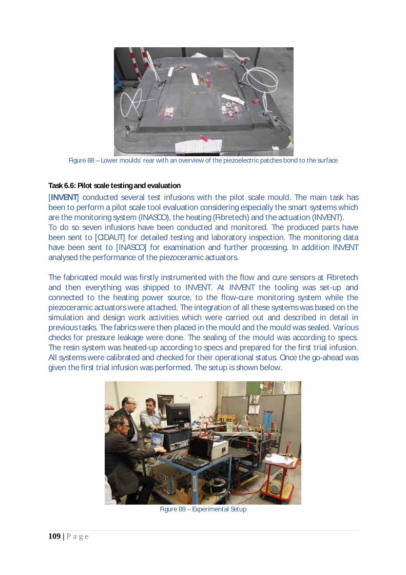
109 | P a g e
Figure 88 – Lower moulds’ rear with an overview of the piezoelectric patches bond to the surface
Task 6.6: Pilot scale testing and evaluation
[INVENT] conducted several test infusions with the pilot scale mould. The main task has been to perform a pilot scale tool evaluation considering especially the smart systems which are the monitoring system (INASCO), the heating (Fibretech) and the actuation (INVENT). To do so seven infusions have been conducted and monitored. The produced parts have been sent to [CIDAUT] for detailed testing and laboratory inspection. The monitoring data have been sent to [INASCO] for examination and further processing. In addition INVENT analysed the performance of the piezoceramic actuators. The fabricated mould was firstly instrumented with the flow and cure sensors at Fibretech and then everything was shipped to INVENT. At INVENT the tooling was set-up and connected to the heating power source, to the flow-cure monitoring system while the piezoceramic actuators were attached. The integration of all these systems was based on the simulation and design work activities which were carried out and described in detail in previous tasks. The fabrics were then placed in the mould and the mould was sealed. Various checks for pressure leakage were done. The sealing of the mould was according to specs. The resin system was heated-up according to specs and prepared for the first trial infusion. All systems were calibrated and checked for their operational status. Once the go-ahead was given the first trial infusion was performed. The setup is shown below.
Figure 89 – Experimental Setup
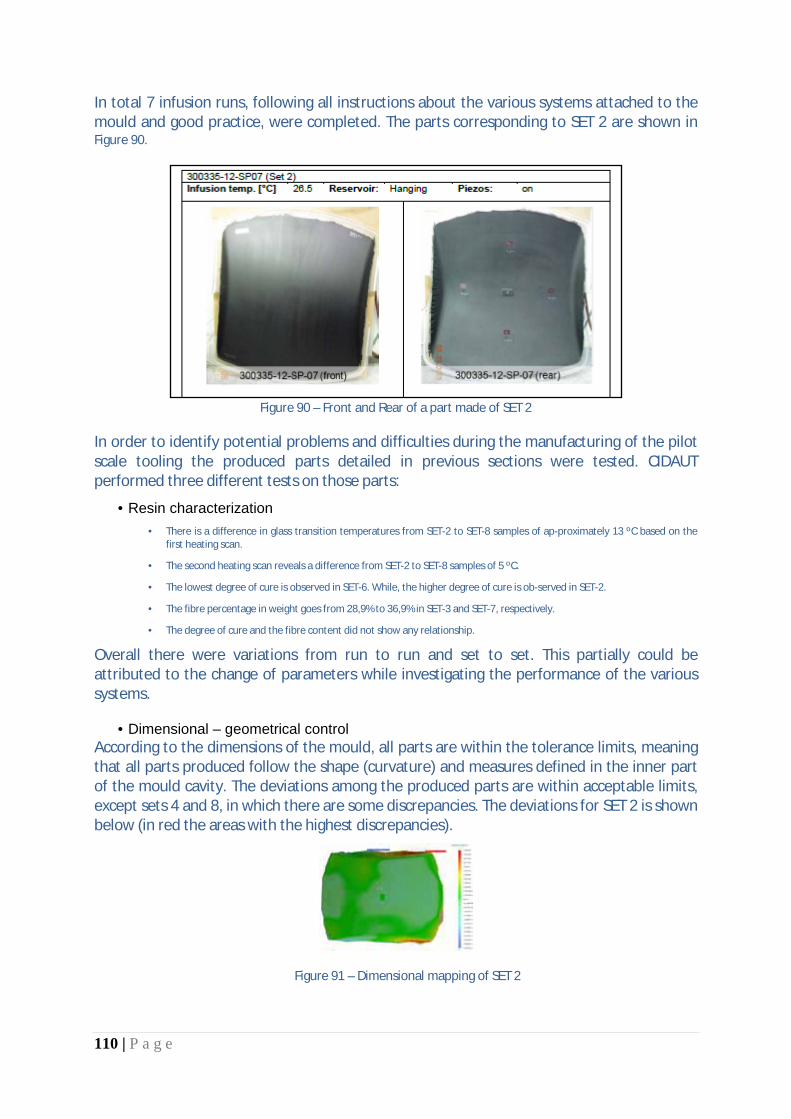
110 | P a g e
In total 7 infusion runs, following all instructions about the various systems attached to the mould and good practice, were completed. The parts corresponding to SET 2 are shown in Figure 90.
Figure 90 – Front and Rear of a part made of SET 2
In order to identify potential problems and difficulties during the manufacturing of the pilot scale tooling the produced parts detailed in previous sections were tested. CIDAUT performed three different tests on those parts:
· Resin characterization · There is a difference in glass transition temperatures from SET-2 to SET-8 samples of ap-proximately 13 ºC based on the
first heating scan.
· The second heating scan reveals a difference from SET-2 to SET-8 samples of 5 ºC.
· The lowest degree of cure is observed in SET-6. While, the higher degree of cure is ob-served in SET-2.
· The fibre percentage in weight goes from 28,9% to 36,9% in SET-3 and SET-7, respectively.
· The degree of cure and the fibre content did not show any relationship.
Overall there were variations from run to run and set to set. This partially could be attributed to the change of parameters while investigating the performance of the various systems.
· Dimensional – geometrical control According to the dimensions of the mould, all parts are within the tolerance limits, meaning that all parts produced follow the shape (curvature) and measures defined in the inner part of the mould cavity. The deviations among the produced parts are within acceptable limits, except sets 4 and 8, in which there are some discrepancies. The deviations for SET 2 is shown below (in red the areas with the highest discrepancies).
Figure 91 – Dimensional mapping of SET 2

111 | P a g e
· Ultrasonic inspection Unfortunately, it has not been possible to extract relevant information from the sensor sweeps. Only the central area from the tested parts has been registered. This is the most suitable area for these tests since it is the thickest one. From those images, no defects are found on the observed areas. The thickness distribution is consistent with a normal curing process.
Figure 92 – Images obtained from ultrasonic inspection on the concave side of panel SET 2
The registered flow and cure data from the sensors were analyzed by INASCO to determine any underlying phenomena of the process. All the flow data (from flow and cure sensors) is tabulated below:
Figure 93 – Recorded flow and cure data

112 | P a g e
Overall, the flow monitoring data depicts accurately the infusion process steps and could identify potential problems.
Figure 94 – Explanation Guide for Flow Results from the infusion on the 28-06-2013 (SET 2)
The results from the infusion show that all three sensors detected the presence of resin (Table 9). The signal from all three sensors passed the -8% threshold region, hence turning on the green GUI indicators. The green indicator for S1, S2 & S3 was momentarily turned on for 17.4’, 8’ & 27.6’respectively. From 189’-191’ there is a noticeable spike possibly caused from the interference of nearby equipment. The data indicate that in the time window between 123’-224’ the signal drops noticeably on all three sensors. This is possibly due to the sudden increase in temperature on the mould/resin which results in a change in the resin’s properties. In Figure 95 the resin arrival times for all infusion tests are plotted (port is at 0.0). It is seen that the filling pattern is not uniform except for the case infusion SET 5, where the resin fronts are in synch. All flow data from the infusion tests is plotted in Figure 96. It is seen that S2 and S3 flow data are very similar while flow data for positions S1 and C exhibit high variability. This could be attributed to the permeability/layup of the fabric in each case as well as variability in the infusion process parameters.
Figure 95 – Patterns for resin arrival times for all infusion tests

113 | P a g e
Figure 96 - Overall display of patterns for resin arrival times for all infusion tests
Significant results
Task 6.1: Design of tooling cavity
After completion of the conventional RTM pre-design of the tool, the composite part was designed. Both designs served as input for the composite tool design, which was additionally optimized for smart features integration. The pultrusion post former consists of 3 solid blocks that are clamped together enveloping the T-section profile. The blocks were designed with a sandwich design approach allowing an efficient manufacturing. The blocks clamping was realized with an external clamping frame.
Task 6.2: Automated design of smart tooling components A. Design of heating and venting system On the basis of the composite tool design, the heating systems were integrated by heating carbon fibres directly. This approach allows for a smooth heat distribution in combination with no additional parts in the tool, since the heating is a structural element as well. For the RTM mould, the desired temperature of 180°C (200°C max) were realized with approximately 15 Volts driving voltage and normal insulation. The heating is approximately rated at about 1.500W/m². In the case of the pultrusion postformer, 10 Volts, minimal insulation and 3 heating segments a temperature distribution from 160°C to 120°C was achieved. This allows for an innovative controlled temperature distribution in the postformer. B. Flow sensors

114 | P a g e
In placing the flow sensors it was decided to perform a flow simulation analysis of the infusion process. The software RTMWin©
was used for the flow simulation, and the geometry was generated based on the CAD files for the part provided by INVENT. The location of the flow sensors should indicate whether the filling progresses as planned in terms of arrival times and within the injection window for the specific resin and process conditions. As a result, the flow simulation was conducted successfully with a filling time of 140s. Furthermore, 4 flow sensors were placed.
C. Piezoceramic Actuation With the performed optimization of the ribs in the RTM tool design, the piezoceramic actuators were then integrated. Both actuator types were integrated (patch & stack actuator). Modal and harmonic analyses were performed with both types of actuators. Close attention was given to the stresses in the interface between tool cavity and part. Both actuation methods for de-moulding were evaluated and the possible stress maxima benchmarked against each other. It was observed that the stack actuators provide stresses in the tool-part interface of an order of magnitude greater than the patch actuators. Since, the patch actuators are more convenient to integrate an require less expensive driving hardware it was decided to integrate both type and benchmark them in the pilot scale part manufacture to verify the simulation results. Therefore, 3 stack actuators and 6 patch actuators at several crucial locations were decided to be integrated in the pilot scale tool. D. Surface Treatment
The RTM tool surface needs to withstand heating and cooling cycles, have good chemical resistance to the resins used to mould parts and allow the possibility to perform repairs in case of accidental damages. These properties were achieved by formulating a new epoxy Gelcoat with a high Tg by making a custom selection of nano and mineral fillers. The Pultrusion post-former is used under a constant temperature. The main challenge at the post former is the abrasion. The research conducted shows that a pure metallic coating is more suitable for the post-former and it can be applied by direct spraying the surface of the ready post former tool. The metallic coating can be sanded and polished to a high gloss. Repairs are possible by spraying more material and repeating the finishing and polishing steps.
Task 6.3: Integration of heating/cooling systems to smart tooling New techniques for the integration of heating and cooling systems have been implemented. The carbon fibers are used as resistive heating elements. In addition all auxiliary systems have also been introduced into the tooling structure. These include the electrodes for the connection to the power source and the wiring of the circuit
Task 6.4: Integration of sensors and actuators to smart tooling
Employing new design approaches and analyses sets of cure/flow monitoring sensors, piezo patches as well as temperature sensors have successfully integrated onto the tooling. This includes all cable routing and new mounts and drivers as well as new DAQs.
Task 6.5: Pilot scale smart tooling manufacturing A pilot RTM tool has been produced which incorporates all developed technologies (thermal management system and control, flow and cure monitoring and piezo actuators for resin facilitation / demoulding). A series of new analysis procedures and tools as well as new data

115 | P a g e
acquisition S/W and H/W have been devised and produced. The first edition of a smart RTM tool has been achieved.
Task 6.6: Pilot scale testing and evaluation A complete experimental infusion program was devised and implemented. The final tooling has employed all developed technologies and systems within COEUS-TITAN and put them to test. It seems that the developed tools and procedures work satisfactorily and their use could be used to optimize the tooling design and the process. However, certain issues still need to be further investigated, calibrated and used from a different perspective in order to realize their full potential. Issues to devote attention for the follow-up full component tests:
1. Standardization of test set-up 2. Standardization of process parameters and procedures 3. Calibration of various sensors and devices according to established procedures 4. Detailed recording of all activities related to the infusion trials
Reasons for Deviations
Task 6.1: Design of tooling cavity The task output was accomplished according to the Description of Work (DoW) and all objectives reached on time. Deliverable D6.1 was issued at M18. Objectives have been reached.
Task 6.2: Automated design of smart tooling components This task was also completed on-time and all objectives reached. It shares a common deliverable, D6.1, with task 6.1.
Task 6.3: Integration study of heating / cooling systems Task completed on-time
Task 6.4: Integration study of sensing / actuation systems Task completed on-time
Task 6.5: Manufacturing of pilot scale tooling and assembly Task completed on-time
Task 6.6: Pilot scale testing and evaluation Task completed on-time
Reasons for failing to achieve critical objectives
Task 6.1: Design of tooling cavity N/A

116 | P a g e
Task 6.2: Automated design of smart tooling components N/A
Task 6.3: Integration study of heating cooling systems N/A
Task 6.4: Integration study of sensing/actuation systems N/A
Task 6.5: Manufacturing of pilot scale tooling and assembly N/A
Task 6.6: Pilot scale testing and evaluation N/A
Use of resources Overall WP6 is over spent in terms of person-months effort. This is evident in most tasks where the new technologies had to be integrated into the pilot demonstrator for the first time.

117 | P a g e
Corrective actions N/A

118 | P a g e
1.2.2.7.
WP7 – Smart tooling application studies [M22 – M36]
Summary of progress towards objectives In this work package the technological elements developed throughout the project (materials, processes and analysis tools) will be validated in selected application studies of the entire procedure from the tooling design to the actual production run. Taken into account will also be the results from the pilot tool activities and runs. The efforts entailed:
· Definition of application studies · Manufacturing and assembly of smart tooling · Test program execution · Validation of the smart tooling concept
The work performed in this task is a continuation to the work done in tasks 6.1 and 6.2.
a) Design of RTM part, the RTM tooling cavity, infusion tool and the pultrusion post former
design of smart tooling components) The design follows the requirements of components for aerospace parts. With the experiences, which were acquired in WP6 the part- and mould design was optimized for the smart features integration such as heating, integration of the sensors and actuators. The pultrusion post former consists of three solid blocks that are clamped together enveloping a T-section profile. The blocks are designed with a solid foam design approach allowing an efficient manufacturing. The blocks clamping is realized with an external clamping frame. b) Design of heating/cooling system [Fibretech / UoP / EXEL]
On the basis of the composite tool design, the heating system is integrated by current-carrying carbon fibres that are part of the mould-structure and at the same time constitute the heating. So no additional heating elements are needed. The desired temperature of 180° C for the RTM-tool with a heating ramp of approximately 5K per minute is realized with 14-15 V driving voltage and normal insulation. The power is rated at about 1.500 W/m². The active cooling will be performed with cold air through the inner honeycomb.
Fibretech RTM-tool
The maximum temperature of the mold is at 196° C, the temperature of the part is at 180° C and the power consumption with a heating ramp of approximately 5K per minute is realized with 14-15 V driving voltage of being approximately 800 W/m². In the case of high temperature manufacturing, the radiation plays important role and cannot be neglected. Using thermal insulation layers or foam blocks above the mold and the part, the energy consumption will be significantly decreased. Using thermal insulation layers (k = 0.05 W/mK) above the CFRP part’s surface, the temperature distribution tends to be more uniform.
UoP Infusion-tool
The pultrusion post former, which is divides into three heating segments (one in each block), will be-come a temperature distribution from 160°C to 120°C. This is achieved by a step of heating power within each heating field with a power of 2.000W/m² - 1.450W/m².
EXEL Post former tool

119 | P a g e
c) Positioning of flow and cure sensors [INASCO] In placing the flow sensors in the RTM tool it was decided to perform a flow simulation analysis of the infusion process. The software RTMWin© was used for the flow simulation, and the geometry was generated based on the CAD files for the part provided by Fibretech. The location of the flow sensors should indicate whether the filling progresses as planned in terms of arrival times and within the injection window for the specific resin and process conditions. As a result, the flow simulation was conducted successfully with a filling pattern determined which led to a minimum of 3 flow sensors being placed. For the pultrusion case, (1) dielectric sensors onto the T-section profile at the die exit as well as in the resin bath will be provided and connected to the DiAMon Plus™ system d) Selection and positioning of piezoceramic Actuators [INVENT] Based on the work done in WP6 the piezoelectric actuation system has be redesigned and added by a new component, the release module. Piezo patch actuators were used to analyze in detail if the excitation of the mould during infusion had significant and measureable influence to:
• The resin distribution Mould is filled faster, curing could be started earlier • The mechanical characteristics of the part
Better performance due to improved resin distribution • assist while demoulding Introduce constant force as an overlay to the force introduced by the release module
e) Description of an alternative mould-technique (ceramic mould) [CYTEC] Cytec have developed BMI tooling prepregs for use with high temperature resin systems but they require processing at temperatures above the capabilities of the epoxy syntactic tooling blocks so an alternative pattern material has been developed based on an oxide-based ceramic. f) Surface treatment (gelcoat) [CLERIUM – TWI] In WP3 there were created new surface protection formulae (gelcoats). For the RTM tool surface the gelcoat had to withstand heating and cooling cycles, have good chemical resistance to the resin used to mould parts and allow the possibility to perform repairs in case of accidental damages. These specifications were tried to be met by formulating a new epoxy gelcoat with a high Tg by making a custom selection of nano and mineral fillers. Unfortunately the gelcoat failed by building the test tool in WP6. After analysing the possible sources of errors for failure the formula was improved (by CLERIUM). Additionally a complete new formula has been developed by TWI.
Details for each task
Task 7.1: Definition of application studies for smart tooling concept validation
To demonstrate the benefit of the smart tool and to show what kind of tooling has got the biggest advantage, a total of four moulds were designed.
· One RTM (light) mould
· One infusion tool
· One RTM-ceramic-tool

120 | P a g e
· One pultrusion tool
On the other hand the failures happened in WP6 (e.g. gelcoat) can be avoided here, for example with the formulation of a new gelcoat. INVENT, Fibretech and Clerium designed a part that follows the typical claims of an aerospace component. It was decided to build an omega-stringer as it is more or less used in several assemblies of an aircraft. The component is shown in Figure 97
Figure 97 – RTM aerospace Part [INVENT]
[Fibretech] designed the RTM mould as a two-part closed mould as it is usual needed for RTM-procedure. Additional to conventional moulds there has to be consideration about the placement of the smart elements such as heating area, sensors and actuators. For example there has to be a wide balancing edge for creating a uniform heating area. The tool surface has a heated area in the middle of the tool which covers the geometry of the part itself including the infusion tracks. The area from the infusion tracks to the edge of the tool is not heated completely.
Figure 98 – Mould with part area
To establish a cooling/venting system a perforated aluminium honeycomb will be integrated.
The 200g/m² woven carbon-fibre is only used in the heated area (as “heating layers”) of the tool. In the un-heated area between the infusion-tracks and the outer edge this is replaced with a 400g/m² woven carbon fibre cloth. In the area of the vacuum-fittings the honeycomb will be filled with epoxy-paste.
The cover of the tool will be unheated.

121 | P a g e
The lid/cover is designed as a thin slightly flexible CRP-shell of approximately 2mm thickness. The additional smart-tooling sensors will be mounted on this part of the RTM-tool.
Figure 99 – Cover
The complete tool schematics are shown below:
Figure 100 – RTM Tool Schematics
Master mould [Khegal]
A complete research and analysis of different industrial solution to avoid master model bonding lines print through on tool surfaces was performed, the Net-shape master model casting technology was used for the manufacturing of final tool master model demonstrator. This technology allows the manufacturing of medium size models in one-piece only, avoiding any bonding line.

122 | P a g e
Heating / venting system [Fibretech]
As already described in previously the heating element is not only additional part of the mould but structural element as well. Carbon fibres are used for the structural reinforcement of the mould and additionally as resistance heating elements.
The mould will be built by infusion technology.
Heating System’s Specifications:
· Operating temperature 180°C with maximum 200°C
· Heating Ramp of 5-8 K/min
· Temperature uniformity to be +/- 3K
As hardware for the heating we can use the same as for the test-mould described in WP6: · Power-supply with max 15V / 100A · Controller · Cable-set · Temperature-sensors plus one safety bimetal switch
The active cooling system is achieved by the perforated aluminum honeycomb, through which cold air is blown.
Flow sensing [INASCO] The location of the flow sensors should indicate whether the filling progresses as planned in terms of arrival times and within the injection window for the specific resin and process conditions. Therefore, we would like to verify whether the filling pattern is being followed. To capture the events from the peripheral resin channels the flow sensors should be placed at the center of the three distinct cavities forming the part. In selecting the placement of the flow sensors care was exercised in the possible integration issues (tool structure, “wiring” route, placement of other sensors, heating elements, etc.). The sensors as well as their mounting procedures and data acquisition platform are the same as the ones used in the demonstration tool runs and described in detail in D6.5.
Based on the current tool design and the placement of other sensors the proposed flow sensor locations are shown in Figure 101. They are depicted in white color and connected to a Data Acquisition Interface. They will be mounted on the unheated tool cover which is a thin CRP-shell lid. Possible some specialized tool-mounting fixtures will have to be designed and fitted. The ones shown are only for explanatory reasons.
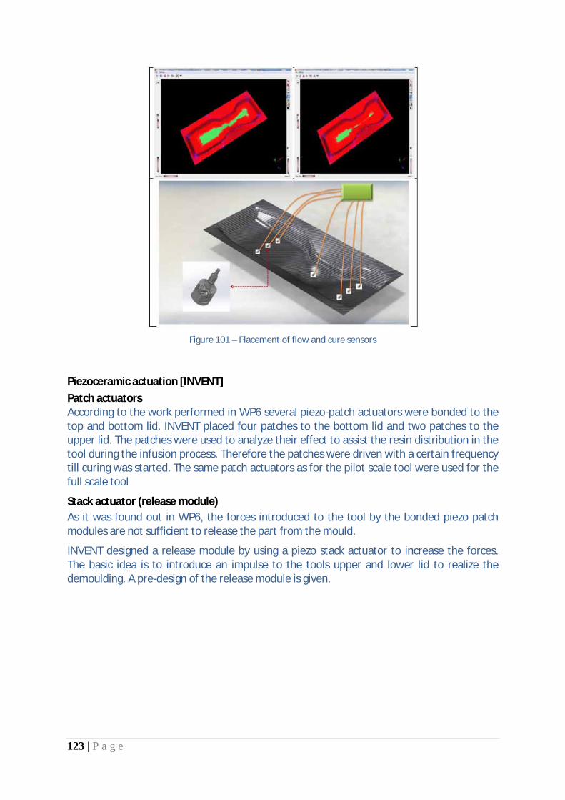
123 | P a g e
Figure 101 – Placement of flow and cure sensors
Piezoceramic actuation [INVENT] Patch actuators According to the work performed in WP6 several piezo-patch actuators were bonded to the top and bottom lid. INVENT placed four patches to the bottom lid and two patches to the upper lid. The patches were used to analyze their effect to assist the resin distribution in the tool during the infusion process. Therefore the patches were driven with a certain frequency till curing was started. The same patch actuators as for the pilot scale tool were used for the full scale tool
Stack actuator (release module) As it was found out in WP6, the forces introduced to the tool by the bonded piezo patch modules are not sufficient to release the part from the mould.
INVENT designed a release module by using a piezo stack actuator to increase the forces. The basic idea is to introduce an impulse to the tools upper and lower lid to realize the demoulding. A pre-design of the release module is given.

124 | P a g e
Figure 102 – Assembly of the release module (pre-design)
Piezo positions The piezo patch modules will be bonded to the outer skin of the lids as in WP6 for the pilot scale tool. The positions at the top and bottom lids are marked in Figure 103 and Figure 104.
Figure 103 – Piezo positions top lid
Figure 104 – Piezo positions bottom lid
Infusion tool [UoP] Tool Design A male tool was designed according to the project’s specifications for the infusion process, shown in Figure 105.TooIing is approximately of 1m length and 0.16m width and it stands on four simple metallic supports. The tool will be manufactured with a sandwich (honeycomb core) structured material to achieve the required stiffness without the need of an external frame or stiffened support.

125 | P a g e
Figure 105 – Self heated infusion tool for a C-stiffener
The length of the infusion tool will be larger than the actual part in order to obtain a uniform temperature field all over the part.
Figure 106 – Male infusion tool, C-type CFRP stiffener, resin infusion mesh
The final infusion setup consisted of the tool, the CFRP part, the infusion peripherals, three (3) thermocouples under the heating element region, and two (2) thin resin cure sensors (film sensors). The thermocouples under the tool were monitoring the maximum developed temperature of the tool during the infusion process. The resin curing sensors were in a film form. Three thermocouples were attached on the upper surface of the CFRP stiffener during the process in order to record the temperature profile during infusion, curing and cooling stages. Also, the aforementioned thermocouples were connected to three solid state relay-controllers that regulated the power.
Pultrusion tool [EXEL]
TYPICAL PULTRUSION DIE SPECIFICATION
· Material: AISI P20 or equivalent · Length: 950mm · Main screws pitched @ 20, 55, 100.....100, 55, 20 (Screw size dependent on cavity size) · 20x10 engineering keys · Jacking holes to facilitate splitting die · Entrance (& exit for reversible dies) radius used R3 and tapered 5° over 25mm · Resin injection cavity & resin feeds if required · Cooling water ports and channels if resin injection used · Cavity parallel within 0.02mm · Parting line mismatch 0.05mm max

126 | P a g e
· Cavity tolerances ±0.15mm typical (dependent on profile requirements) · Cavity polished to 0.2μm RMS or better · Cavity hard chrome plated 38±5μm thick · 25.4x3.2 keyways (or round holes Ø25, 10 deep), 125 from each end on base of die for
mounting · Thermocouple probe holes Ø8, tapped 1/8” BSP, 10 deep, (number, depth and position
dependent on cavity size) · Lifting eye holes tapped M12 or M16, (number and position dependent on die size) Fibretech performed the detailed design work (see figures below) for the pultrusion tool. It will be built in the same way as in WP6. This time the die has got a length of 600mm, the profile that will be produced has got the same geometry as the first one.
Regarding the problems with the stiff backing structure a new material will be used as insulator as well as stiffener. The material is based on SiO and is mechanically strong enough to bear the pressure loading from the clamping shells. It has very low thermal elongation and will not lead to any deformation of the parts themselves due to the hotter temperature on the inside of the die. The thermal elongation is in the area of 2,2E-6K which is similar to that of the CRP of the heating fields.
Furthermore centre elements will provide means for exact positioning of the three parts of the die.
The material for the backing structure can be milled to exact geometry and also allows for integration of further smart components, i.e. cooling channel.
Figure 107 – Postformer assembling details
Ceramic tool as an alternative to epoxy syntactic tooling block [Cytec] Many composite tools are moulded off CNC-machined patterns constructed of epoxy syntactic tooling block such as Cytec’s TB720, a standard grade epoxy syntactic tooling block readily machined into stable, high-accuracy patterns, these tooling blocks offer:
• Excellent machinability with low dust generation on machining; • can be smoothed to a satin finish; • Low coefficient of thermal expansion; • Chemically compatible with LTM® and other tooling prepregs.

127 | P a g e
Figure 108 – Master pattern following cure
TWI: new formulation of gelcoat The team has succeeded in loading the epoxy resin with a very high content of silica nanoparticles in order to reduce the Coefficient of Thermal Expansion (CTE) to the required level. The work was focused on the optimization of the method as well as on the other attributes i.e. the low surface energy (to prevent adhesion to the incoming resin) and the abrasion resistance. Both of these properties have been achieved in other formulations, but, nonetheless, they were checked to ensure that the same can be done with this low CTE resin. For the moment better results were obtained, but they still need to be improved. The innovation in the Coeus-Titan gelcoat (Clerium)
The commercially available gelcoats are both epoxy based resins heavily filled with Aluminium powder. Approximately 50-60%; one product has a Tg of 215°C and the other 220°C. One of the main challenges for a surfacing resin in high temperature applications is the high stress resulting from the repeated thermal expansion and contraction. By using high loads of a soft metal like Aluminium, the metal acts as a buffer by absorbing the stresses due to expansion. This mechanism allows the surface to avoid permanent deformation during expansion and thus is able to contract without cracking or any other damage.
The innovation in the surfacing technology of Coeus-Titan is the development of a gelcoat formulation with a very low coefficient of thermal expansion. This greatly reduces internal stresses instead of using absorbing mechanisms.
Task 7.2: Manufacturing and assembly of smart tooling for validation For all tooling, the fabrication technique derived from WP6 has been applied. Prior to production all component of the mould were tested but unfortunately the gelcoat for the RTM-tool produced by Fibretech failed even after several tests. So it was decided to work with a more or less standard surface. a) Testing of solution for the surface coating

128 | P a g e
Because the results of the tests done in WP 6 and 7.1 that were not finally successful, some more tests were necessary. Unfortunately the results were not as expected. Clerium has been working further on solving the adhesion problems of the gelcoat to the substrate. Because there were still some doubts, it was decided to use a different resin for the gelcoat formulation for the tool of UoP. Clerium visited UoP and applied the gelcoat for the tool successfully. The only issue that was ob-served after releasing the complete tool was entrapment of small air bubbles in the gelcoat layer. This was not anticipated and was due to the mechanical mixing during formulation and is a minor issue that can easily be avoided or repaired. The overall performance of the gelcoat is satisfactory. b) Manufacturing and control of WP 7 master models for RTM-tool The manufacturing of the master model for both, the mould itself and the cover was done by Khegal with the technical support of Invent and Fibretech. Fibretech de-signed the mould and the cover taking into account all smart equipment. c) Production of RTM tool, pultrusion post former and infusion tool The production of the RTM-tool took place at Fibretech including all smart tooling components integrated in the mould. With the support of TWI, Invent, INASCO and Khegal the RTM tool were build by Fibretech. Invent additionally placed some piezo-elements onto the mould and the cover. The pultrusion tool was manufactured at Fibretech as well. For this Fibretech produced three solid blocks with integrated fibretemp-heating. The surface was built by Technalia. The infusion tool was manufactured by UoP with the support of Clerium for the surface and the other partners for the different smart components. Manufacturing of master models for WP7 RTM tool (Khegal) TOOL MASTER MODEL As defined in the previous section, tool master model has been manufactured using a close contour one-shot casting part. After some issues with the raw material due to casting defects on part corners the defined manufacturing procedure has been successfully applied. After surface treatment application a surface roughness test have been developed using a Mitutoyo SJ411 measuring system reporting an overall roughness of Ra=0,16 μm. The following pictures show some steps of the manufacturing procedure.
Figure 109 – Model after surface treatment application
RTM Tool (Fibretech)

129 | P a g e
Mould
1. First the corners were reinforced with carbon fibres so that they are cleanly moulded. 2. After that the application of the glass fibre layers started. The function of these layers
is to act as an electrical insulation and normally to aid in the bonding of the gelcoat. 3. After the application of the insulation layers the heating layers were draped. 4. The heating field is surrounding the resin channels. This way the infused resin can
cure in the whole mould and there are no liquid resin rests when the cured part is removed.
5. The heating system was tested under vacuum pressure before the insulating glass fibre layers were placed on its back.
6. Lastly carbon fibre layers were applied to get a stable structure of the mould. 7. After the infusion the heatable tool was removed from the mould. The rope seal was
glued in place and the locks were installed. 8. The ports for the vacuum and the resin injection were integrated as well.
Figure 110 – Finished RTM mould
For an active cooling a perforated honeycomb is placed on the back side of the mould. Through the holes in the honeycomb it is possible to initiate air to cool down the mould faster. On the one side there are ports for the air connection and on the other side the honeycomb has an outlet through the outer frame. On the back side of the mould there are several ports for temperature sensors. There are three ports which can be used optionally for measuring the temperature in this area (diagonal arrangement). The fourth port is in the corner of the heating field. The temperature sensor which is al-ready installed here is the control sensor for the heating unit.

130 | P a g e
Figure 111 – Back side of the heatable mould
The cover has been built in a similar way to the mould. In the cover a dielectric sensor is integrated. The dielectric sensor is flush with the surface so that there is no reprint in the part in this spot later.
Figure 112 – Integrated dielectric sensor
Pultrusion tool A protective surface layer is required for the working areas of the pultrusion tool. Original epoxy based composite is not considered appropriate regarding wear behaviour and expected durability of the working surfaces of the tool. The hard layer should be equivalent to the Hard-Chromium used in the original metallic tool. Thermal sprayed coatings have showed limited performance from the difficulties to reach useful bonding properties in this type of polymer based substrates, and their real limitations for the necessary machining and polishing steps (local heating and debonding). Only soft materials (Zn based alloys) have reached enough performance for coating at the prototype level (previous prototype done).

131 | P a g e
Successful application of thermal spray coatings is related to the presence of an appropriate substrate for the deposition process, with adequate nature (mainly fibers and not epoxy) and also, with the right dimensional tolerances for the further steps of machining and polishing of the coatings. The heating of the developed tools is done with an electrical resistance circuit involving the cupper contacts and the structural carbon fibers of the composite tool. It is essential that the metallic surface layer was not in electrical contact with the carbon fabric structure of the tool. A glass-epoxy isolation layer is required in between the metallic hard surface layer and the tool body. The pultrusion-tool was built in the same way like the RTM-Tool. The pultrusion-tool consists of three heating fields. Each heating field is integrated in its own profile and connected by an extra power unit. There are two L – profiles and one flat tool with a recess. The profiles can be separated from each other. On the back side of the profiles, massive blocks are installed to prevent torsion or any other kind of deformation.
Figure 113 – Complete pultrusion tool (postformer)
Checking the requirement about the electrical isolation of the surface of the tool with the heating circuit, it appears that in fact, there is electrical contact in the surface of the mold and hence, any metallic layer deposited in this position is going to be part of the heating circuit. This behavior is not acceptable from a functional point of view and a correction was mandatory.

132 | P a g e
Thus it supposes that the Initial prevision for a 105 gr/m2 glass-epoxy layer isolating the heating carbon layers is no more completed in every place and additional isolation layers must be included in the surface of the tools. New constrains regarding dimensional accuracy and geometrical tolerances are included in this point. It was proposed:
· The introduction of a metallic insert, with a polished surface of a hard coating (Cr plating), was electrically isolated from the carbon fabric structure by a glass-epoxy bonding layer.
· Design of the metallic insert as thin as possible (high thermal conductivity) but assuring the geometrical constrains (flatness and parallelism after machining and operations).
The difficulties of the approach are focused on the fabrication of the metallic inserts (long thin pieces) with dimensional tolerances and also, in the integration of these pieces in the own composite tool.
Figure 114 – Final aspects of the pultrusion tool (postformer)
Liquid Resin Infusion Tool – (UoP) Based on the design presented in D7.1 two versions of the male tool of the curved C-section profile were produced. The first one (Version A) was manufactured using a metallic female mock-up and a second tool using a wooden mockup (Version B). It was decided to use Version B to avoid thermal distortions and cover the tool surface with the Clerium gelcoat.
Figure 115 – Self heated infusion tool with gel coat

133 | P a g e
At the second step, the carbon fibre heating element along with the upper (back side) and lower (mock-up side) electrical insulation (glass fibre fabrics) was manufactured using the infusion process. At the third step three thermocouples were attached between the heating element and the lower glass fiber fabrics. The fabrics were impregnated very well without any problems. The upper sandwich layers and core material (honeycomb) and lower sandwich layers were vacuum bagged and cured in an oven. The resin was infused through the fabrics using two injection ports (PTFE tubes) and two vacuum lines at the edges of the part. The temperature of the resin and the preform during the infusion process was approximately 80˚
C.
Figure 116 – Manufacturing of the heating element
Figure 117 – Infusion process of the second manufacturing step at different time instants (Infusion at 80̊ C) Gelcoat development (TWI) An approach has been taken for the development of a gel coat used in the final mould tool of Coeus-Titan project. The high temperature resin, an epoxy resin ToolFusion®3 by Air Tech, was taken as the base material. Nonetheless, a change in the approach was under-taken due to the initial results and the epoxy resin 3,4 – Epoxycyclohexyl-3’4’–epoxycyclohexane carboxylate (DECC), was used as the final core material.

134 | P a g e
Thanks to the technology developed during the project, the addition of 50%wt of functionalised silica into the resin has been possible and it has been confirmed with the TGA results. The successful incorporation of this inorganic compound improved some of the parameters desired: the surface energy of the system was reduced (from 42 to 30mN/m) and the CTE of the developed resin is lower than the non-modified ones when the temperature is below 120°C. Several iterations were undertaken to obtain the inorganic-organic hybrid resin without compromising the stability of the original material, and three test plaques were manufactured in Fibretech Composites GmbH to study the behaviour of the gel coat once it was applied. Unfortunately, none of the manufacturing trials led to a successful gel coat and the final demonstration tool was made without the gel coat layer. It was unfortunate that the need for the gel coat was identified at a late stage in the project and that as a consequence a very short but rapid development programme was needed. The work undertaken in this task shows considerable promise, but was not able to achieve the final objective in the time available. It is expected however, that other opportunities to continue this development pathway will be sought.
Task 7.3: Test Programme Execution
Several parts have been produced with the mould; afterwards these parts have been examined with different procedures to determine the resin cure grade, the fibre percentage, the dimensional accuracy and the fulfillment of several Class A requirements. RTM tests The mould fabricated by Fibretech, has been used by INVENT to produce parts. At INVENT the tooling has been set up, connected to the heat power source and to the flow cure monitoring system. Moreover, the piezoceramic actuators have been used to aid injection and demoulding activities. The integration of all these components is based on former project results.
Figure 118 – Tool during injection

135 | P a g e
There were four (4) injections performed. The produced parts are shown in Figure 119.
1st
injection 2nd Injection
3rd
injection 4th Injection Figure 119 – RTM produced parts
In order to visualize the resin flow front development over time in the tool, two extra injections were conducted with a vacuum bag setting. With this setting the injection process could be caught on camera. The results are shown in Figure 120. The piezo patch actuators were tested during demoulding and injection. The vibrations caused by these patch actuators can provide assistance while demoulding. In their second function, the piezo-patch actuators have shown the potential to significantly reduce the injection duration due to their positive influence on the resin speed and distribution during injection. The tests have shown that the part could be impregnated 25-50% times faster than without micro-vibrations. Since the patch actuators are usable to up to 200°C they might be also a worthy addition for conventional manufacturing methods. In addition they can be applied as a retro-fit to existing moulds.

136 | P a g e
Figure 120 – Comparison of two injections with and without piezo assistance
Examination of the RTM test parts In order to assess the quality of the produced parts and evaluate the production trials, several parts have been tested at CIDAUT. These tests have been selected to evaluate relevant manufacturing data, as the fibre volume content and its homogeneity in the part, and quality data, as the absence of defects or dimensional accuracy. The analysis has shown that the fiber percentage in weight goes from 10.05% to 24.06% Dimensional checks: For this work it has been deemed appropriate to extend the dimensional control to a full digitalization of the produced parts. The following figure shows the digitalization of each of the examined samples:
Figure 121 – Images of the digitalized samples
The results of the dimensional checks are shown in Figure 122.

137 | P a g e
Figure 122 – Comparison of the geometry of one of the digitalized samples (brown) with the nominal geometry
(grey)
In order to reveal how the thickness is distributed over the part, several sections have been applied on the digital part and the thickness has been measured on three points on each section. The following graph summarizes all the measurements together.
Figure 123 – Comparison of the thickness measurements on each sample
The results show that in most of the cases the peaks for one sample are also peaks for the others, while the valleys areas also coincide. This means that the manufacturing process is consistent: all the specimens are manufactured in the same way, though it does not comply with the original geometry. The deviation from the nominal thickness is substantial. Ultrasonic Inspection The parts, as they were received at CIDAUT, were examined in the pulse-echo mode by using one single sensor acting both as emitter and receiver for the ultrasonic signal. In this working mode the dampening of the ultrasonic signal and the time spent in travelling forth and back are measured. This equipment allows to registering defects associated to signal dampening

138 | P a g e
as well as to measure the thickness as a comparison to the average pulse travelling time. The results show a very homogeneous signal map.
Figure 124 – Map with the ultrasonic signal on the flat surfaces
Surface Analysis of the part geometry CATIA V5 has been used to perform the surface analysis of the part geometry, Curvature analysis results as well as dynamic reflection highlights results indicate that the part does not comply with Class A surface requirements.
Figure 125 – Map of curvature (Top) and dynamic reflection highlights (Bottom) results

139 | P a g e
Fulfillment of Class A Aesthetic Requirements
The digitalized specimens have been covered with powder and so the identification of surface defects is easier, because the powder enters the cracks and scratches. This can be seen in the analysis of the second good specimen
Figure 126 – Location of surface defects in specimen 300-335-HZ-01-004
The parts do not comply as well with Class A aesthetic requirements. Parts with the infusion tool [UoP] Five more parts were produced using the gel-coated tool and a sixth part was in process during the preparation of this report. The production of another part is scheduled for the demonstration during the final meeting.
Figure 127 – Infusion process manufacturing setup
The central embedded thermocouple of the tool is connected to the temperature controller which is connected between the power supply and the tool. When the set temperature is reached the controller cuts-off the supply to the tool. The other two embedded thermocouples are connected to an USB Data Acquisition Module which is used to store the temperature readings in a computer file.

140 | P a g e
Three film cure sensors were used so as to monitor the impregnation of upper layer and determine the filling time of the part during the infusion process, using the DiAMon Core system. Specifically, two cure sensors were positioned under the flow mesh and the third one was positioned between the mold’s surface and the lower carbon fabric.
Curing monitoring
Figure 128 – The positions of two film sensors at the edges of part
Infusion Part inspection
Figure 129 – Infusion parts produced
A set of random measurements were recorder for each surface of the tool/part. The coordinates of these points were imported in a CAD environment (Dassault Catia) and a NURB surface was fitted through the point cloud. The NURB surfaces were compared to the actual CAD model and an assessment of the geometric accuracy was performed. Although not exact, the pattern of the measurements was the same. Six lines of points were taken on the horizontal surface along imaginary angled sections and two lines on the side wall vertical surfaces, as shown in Figure 129. With this arrangement of points it was possible to identify the planarity of the horizontal surface compared with the mean plane of the corresponding cloud of points. The side wall surfaces were compared similarly with the fitted cylindrical

141 | P a g e
surfaces. From the analysis, it is clearly seen that the horizontal surfaces of the two parts are slightly twisted while keeping the initial ruffling of the tool surface. The deviation though is around the ideally planar surface.
Figure 130 – Surface Based Deviation Analysis of the first part Surfaces as created from cloud of points
Task 7.4: Validation of the smart tooling concept
The issues occurred during the manufacturing of master mould models could be solved by detailed analyses conducted by KHEGAL. With the use of close-contour one-shot-casting a cost efficient method could be used to produce the raw master mould blocks and simultaneously cut the amount of waste material during machining. Compared to a master mould made from aluminum they were able to cut the costs for the tool master model by approx.40% (close-contour one-shot-casting). By using the revised bonding technique the cost for the counter tool master model could at least reduced by 5%. The time to provide the sufficient polyurethane master models cut reduce by 25% (tool master model) and 12% (counter tool master model) which is also very promising. The mould manufacture during WP 6 was equipped with a metallic surface treatment by FIBRETECH due to the fact that the effort required for the gelcoat development was under estimated. Nevertheless the metallic cover provides a quality cover it but has limitations. As a result of WP 6 TWI joined the gelcoat development for the RTM tool. Both partners TWI and FIBRETECH conducted several development iterations and finally came up with a promising formulation. Despite the encouraging results on lab scale the gelcoat will need some additional modifications to be used for full scale modifications.

142 | P a g e
Although Clerium was not able to build the heated plate with the gelcoat, the gelcoat has shown good adhesion to the substrate if pre-cured and sanded prior to infusion. An advantage with this method is that it allows direct infusion over the gelcoat without hand laminating of a coupling layer and woven glass. The only inconvenience is that the gelcoat has high abrasion resistance and re-quires very good sanding materials to de-glaze. Finally, the last issue of the Coeus-Titan gelcoat has been solved. In order to fully validate these results, it would be necessary to build a heated plate and produce several parts, but Clerium feels very confident that the development of the gel-coat is complete. As in WP6 the tool designed and manufactured in WP 7 was equipped with piezoelectric actuators. The basic motivation was on one hand to assist the part demoulding procedure and on the other hand to quantify the capabilities to assist the resin flow and the part impregnation. To provide an additional approach to the patch actuators used during WP 6 a release module based on a stack actuator was designed and manufactured by INVENT as well as a cost efficient switching box to drive the stack actuator (see D7.3). Both the patch actuator and the stack actuator approaches were tested during part manufacturing in WP7. As in WP6 it turned out, that both techniques are sensitive to even minor variations of part and tool geometry, stiffness and things like that. Since both techniques were designed to excite the natural modes of the mould this could be easily understood. Nevertheless the impulse introduced to the tool by the stack actuator could be generated with the module mounted to the tool. Both systems were tested and had shown that the tool design has relevant influence to the efficiency of the demoulding system. To achieve the full performance of this technique in further tooling it seems to be a good approach to increase the amount of integration. Therefore tool designers need to understand the working principle of the piezo modules and adjust their design guidelines to the new technique. In addition the results regarding the demoulding capabilities the patch actuators have shown promising results during the injection. The time to impregnate the fibres could be reduced by up to 50% during the test campaign. From this point of view the micro vibrations introduced to the tool turned out to be less sensitive to the influencing factors mentioned above and therefore could be deemed as a good addition to the tools. The heating system integrated to in the tool worked as expected. Compared to e.g. the in autoclave technique the main advantage is that the tool is only heated were it needs to be. Combined with the low heat capacity it significantly reduces the amount of energy needed to cure the part. With the use of the cooling system also integrated the parts can be demoulded faster, because the cool down time can be controlled and adjusted. The monitoring system used during WP 7 was essentially the same to the one used during WP 6. This time only one curing sensor and one thermocouple were connected to the
143 | P a g e
system to reduce effort and costs. Nevertheless the system recorded the data from the sensors and the corresponding resistance and temperature plot over time could be plotted . Since the analysis of the data had shown some yet unexplainable occurrences it could also be deemed as satisfactorily because data was recorded and at least the thermocouple data seem to be of sufficient quality. A suitable resin state model provides a sufficient amount of reliable information on the curing state. The University of Patras designed, manufactured and evaluated a RTM tool of a C-type stiffener, to verify their simulations. They also used the DiAMon Plus system provided by INASCO to monitor the infusion process. The experimental infusion almost fits the simulation and therefore their model can be deemed as satisfactorily. Since the L20 resin system was used also more information could be extracted by applying a suitable model.
The work conducted by FIBRETECH and TECNALIA had shown, that it is possible to manufacture carbon-fibre based postformer with integrated heating system which meet the requirements of state-of-the-art systems.
Pultrusion tool
EXEL manufactured the support frame for the postformer and provided detailed specifications. Furthermore a gel testing device was established.
Significant results
Task 7.1: Definition of application studies for smart tooling concept validation
All lessons learnt from the pilot scale investigations have been incorporated into the four final smart tooling demonstrators. Even though the complexity of the parts increased, modifications and developments were smooth.
Task 7.2: Manufacturing and assembly of smart tooling for validation
Four state-of-the-art smart toolings for various composite processing routes have been manufactured. They include all technological add-ons developed in the course of the project.
Task 7.3: Test Programme Execution
A successful test program has been completed. It has provided insight as to the details of the processing conditions and possible future modifications.
Task 7.4: Validation of the smart tooling concept
The technologies have been validated and their classification in terms of TRL has been performed. The campaign proved that the technologies are the stage where they could be introduced into a smart tooling and ready for the production floor.

144 | P a g e
Reasons for Deviations
Task 7.1: Definition of application studies for smart tooling concept validation N/A
Task 7.2: Manufacturing and assembly of smart tooling for validation N/A
Task 7.3: Test Programme Execution N/A
Task 7.4: Validation of the smart tooling concept
N/A
Reasons for failing to achieve critical objectives
Task 7.1: Definition of application studies for smart tooling concept validation N/A
Task 7.2: Manufacturing and assembly of smart tooling for validation N/A
Task 7.3: Test Programme Execution N/A
Task 7.4: Validation of the smart tooling concept N/A
Use of resources Overall WP7 is on target in terms of person-months effort with an overall expenditure of 90%.

145 | P a g e
Corrective actions N/A
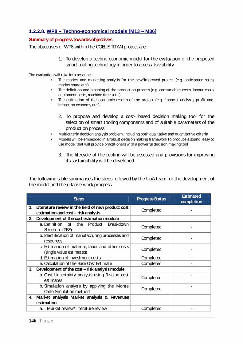
146 | P a g e
1.2.2.8. Summary of progress towards objectives
WP8 – Techno-economical models [M13 – M36]
The objectives of WP8 within the COEUS TITAN project are:
1. To develop a techno-economic model for the evaluation of the proposed smart tooling technology in order to assess its viability
The evaluation will take into account:
• The market and marketing analysis for the new/improved project (e.g. anticipated sales, market share etc.)
• The definition and planning of the production process (e.g. consumables costs, labour costs, equipment costs, machine times etc.)
• The estimation of the economic results of the project (e.g. financial analysis, profit and, impact on economy etc.)
2. To propose and develop a cost- based decision making tool for the
selection of smart tooling components and of suitable parameters of the production process
· Multicriteria decision analysis problem, including both qualitative and quantitative criteria · Models will be embedded in a robust decision making framework to produce a sound, easy to
use model that will provide practitioners with a powerful decision making tool
3. The lifecycle of the tooling will be assessed and provisions for improving its sustainability will be developed
The following table summarises the steps followed by the UoA team for the development of the model and the relative work progress.
Steps Progress Status Estimated completion
1. Literature review in the field of new product cost estimation and cost – risk analysis Completed -
2. Development of the cost estimation module a. Definition of the Product Breakdown
Structure (PBS) Completed -
b. Identification of manufacturing processes and resources Completed -
c. Estimation of material, labor and other costs (single value estimates) Completed -
d. Estimation of investment costs Completed - e. Calculation of the Base Cost Estimate Completed -
3. Development of the cost – risk analysis module a. Cost Uncertainty analysis using 3-value cost
estimates Completed -
b. Simulation analysis by applying the Monte Carlo Simulation method Completed -
4. Market analysis Market analysis & Revenues estimation
a. Market review/ literature review Completed -

147 | P a g e
b. Revenues estimation Completed - 5. Finalisation of the Techno-economic model/
Business Plan Completed -
All objectives have been met.
Details for each task
Task 8.1: Development of techno-economical models of individual smart tooling technologies
[UoA] team used the Product Breakdown Structure as the basis for detailed cost estimation of Smart tooling technology. The Product Breakdown Structure (PBS) is one of the first vital indispensable steps in producing a cost estimate. The technique to develop a Product Breakdown Structure is to subdivide the final product into its sub-assemblies (parts) in order the product decomposition to be defined. This structure is built from the top down to produce a pyramid-like, hierarchical structure where elements at the bottom are used to produce higher elements in the structure. Additionally, an appropriate item code is used for each element of the structure to indicate the decomposition level.
The second major step in cost estimating method that [UoA] followed was the identification of manufacturing processes of Smart tooling technology and the estimation of the required resources. The major manufacturing processes and required materials are presented in the following table:
Item Processes Materials
1. Smart Tooling
Assembly of parts 1.1, 1.2, 1.3, 1.4, 1.5
1.1 Composite tool
Model construction-milling Fiber glass, Resins, Reinforcements, Carbon nanotubes (CNTs)
Pro-curing
Positioning of: Release agents, Surface enhancement, Sensors, Heating elements, Core materials, Backing structure
Release agent, Gel coat, Nanofillers, Wear resistant coating, Inserts for sensors, Contacting elements for the heating process, Core material, Backing laminate
Post-curing
Integration of the support structure Support frame, Wheels
1.2 Power Supply & Control
Installation of power supply and temperature measurement and control devices
Thermocouples, Power supply, Temperature controllers
Connections to power supply and temperature controller
Power cables, Thermocouple extension cable
Programming of power supply and temperature controller
Temperature acquisition and control software, PC system

148 | P a g e
1.3 Monitoring System
Installation of the sensors Cure sensors, Flow sensors
Electrical connection to the sensing system
Measurement system (DAQ or SCADA), Sensors extension cables
1.4 Actuation System
Installation and connection of the actuation system
Actuators, Patches, Power supply, Actuation driving system, Extension cables
1.5 Active Cooling System
Installation of cooling system Channels for cooling, Embedded cooling in backing structure
For the purpose of cost data collection and estimate, a predefined questionnaire accompanied by detailed instructions for its supplementation, was sent to partners. The questionnaire was made in an excel document, which includes four separate sheets.
· The first sheet contains the Smart Tooling System PBS. · The second sheet includes the identified production processes, required resources
and costs · The third part contains the labor cost divided into two different costs: set-up cost and
run-time cost · At the final sheet of the excel document the sum of cost material, labor and other
costs is calculated. The existence of significant uncertainties in Smart Tooling manufacturing affects the ability of experts to perform accurate cost estimation. This is a commonly recognised problem during new technology systems development projects. The use of the cost – risk analysis technique is considered to be an effective way to handle cost uncertainty. In order the technique to be applied in the COEUS-TITAN techno-economic model, the [UoA] team developed a simulation module, using the @Risk Software Tool. This tool is an Excel Add-on S/W, which enable users to define stochastic variables and parameters, perform Monte Carlo simulation and calculate the probability density function of output variables (e.g. total cost).
Task 8.2: Cost analysis based decision making for selection of smart tooling components The approach developed by the University of the Aegean comprises two major stages as follows:
1. Selection and assessment of the smart tooling system components based on the specifications of the composite parts to be produced by the tool itself. Thus, Stage I includes a) the definition of specifications for the production of composite parts, (b) the selection of smart tooling subcomponents based on the defined specifications, (c) the synthesis of three alternative smart tooling systems based on the selected components, all satisfying the defined specifications and (d) the assessment of the alternative systems with respect to robust criteria. This Stage has been implemented in an Excel-based system ('Selection of alternatives').

149 | P a g e
2. Selection of the optimum smart tooling system.; For this purpose, the 'Super Decisions' software created by Saaty (2004) was used in order to assess the three alternative smart tooling systems and select the most suitable one.
Figure 131 – The two stages approach developed
The selection and assessment of the smart tooling components will be performed by the ‘Selection of alternatives’ tool in four steps. This selection will be then given as input to the decision analysis tool. The four steps are: 1. Definition of specifications for the production of composite parts (part to be manufactured by the tool) 2. Selection of smart tooling subcomponents based on the defined part specifications 3. Compilation of three alternative smart tooling systems that satisfy the defined specifications 4. Assessment (marking) of the alternative systems with respect to selection criteria as a prerequisite for the application of multi-criteria decision making process
Based on the part specifications that are provided as inputs to the system and the correlations the selection algorithm defines the exact tooling components, subcomponents or features of a standard system, called Middle range system. Two more systems are also defined that satisfy all specifications. The first is the High end system, which alters the surface technology type and uses nanodoped gelcoat instead of standard gelcoat. The second alternative is created by removing the monitoring and actuation systems from smart tooling components, thus defining the Low end system. The next step in the decision analysis process is the definition of the selected subcomponents/features of each of the three alternative smart tooling systems, so that when the optimum system is selected the composition of the optimal tooling system can be reviewed. In order to assess the three alternative smart tooling technologies generated in the previous stage and select the one most suitable, we have developed a process that comprises seven steps. This process has been implemented in the 'Super Decisions' software

150 | P a g e
created by Saaty (2004) that utilizes the ANP model. The structure of the ANP model presented described by its clusters and elements and the connections between them. These connections indicate the flow of influence among the elements. The resulting model is illustrated in Figure 132.
Figure 132 – The smart tooling technology ANP model
The software used in order to implement the proposed model is “superdecisions”, which is academic software that the reader can easily download through the link http://www.superdecisions.com/. A short description, the serial number and the manual are also available in the same web page. Specifically, the abovementioned software was used for the selection of the optimum smart tooling system. Initially, after the construction of the model (described by its clusters and elements and the connections between them) the user is asked to enter the pair wise comparisons of the three alternative systems (produced by the 'Selection of alternatives' Software with respect to the control criteria. The elements in a cluster are compared by applying Saaty’s 1–9 scale according to their influence on an element in another cluster to which they are connected. Additionally, the relative importance of each criterion with respect to the alternative systems is another input for the software. Based on the above inputs, the output of the software includes the final priorities of the alternative smart tooling technologies which are assessed. The alternative with the highest priority value is the one the most suitable.
Task 8.3: Lifecycle Assessment of innovative tooling There was a substantial change of scope from the original planned work due to the necessity of shifting resources to surface finish developments – a key technology for the sustainability of composite “smart” tooling concepts. From the limited data available it is demonstrated that new approaches for the construction of the master tool model could lead to eventual savings in time and resources (human, energy savings, etc.) when compared to conventional approaches. For the infusion approach it seems that that the energy requirements are comparable to current metallic moulds.

151 | P a g e
Significant results
Task 8.1: Development of techno-economical models of individual smart tooling technologies Development of the cost estimation and cost risk modules
Task 8.2: Cost analysis based decision making for selection of smart tooling components
Development of an assessment and selection tool for smart tooling that uses the “Super Decisions” software to propose the optimum smart tooling based on the user’s requirements.
Task 8.3: Lifecycle Assessment of innovative tooling
From the limited data it seems that the smart tooling could be competitive to conventional tooling with all additional technologies integrated.
Reasons for Deviations
Task 8.1: Development of techno-economical models of individual smart tooling technologies A basic problem that the [UoA] team faced during the development of the model concerned the initial immaturity of the technical solution (Smart Tooling System), which affected the ability of the experts to perform cost estimation. This led to minor delays in collecting technical and cost data. This is a commonly recognized problem during new technology systems development projects. The use of predefined questionnaires and the adoption of the detailed cost estimation and cost-risk analysis method helped to overcome the difficulties and avoid deviations from Annex I targets.
Task 8.2: Cost analysis based decision making for selection of smart tooling components
N/A
Task 8.3: Lifecycle Assessment of innovative tooling
Resources were shifted to other more pressing technological issues (gelcoat development and cure induced control).
Reasons for failing to achieve critical objectives
Task 8.1: Development of techno-economical models of individual smart tooling technologies N/A
Task 8.2: Cost analysis based decision making for selection of smart tooling components
N/A

152 | P a g e
Task 8.3: Lifecycle Assessment of innovative tooling
N/A
Use of resources Overall WP8 is under spent in terms of person-months effort. This is due to the fact that some effort was shifted in WP7 for the development of process control.
Corrective actions N/A

153 | P a g e
1.2.2.9. Summary of progress towards objectives
WP9 – Dissemination and Exploitation [M24 – M36]
Officially this WP would have started at M24. However, due to the default of partner EUREXCEL and the necessity of establishing a project web-site, under the dissemination activities, some effort was expended by partner [CIDAUT] earlier to that. The overall objectives have been achieved. The financial and technological evaluation of all new technologies and what benefits may be derived has been performed. Novel operational add-ons and their efficient management could be a desired feature of such “smart” tooling that could make their introduction and use possible when compared to conventional tools even though their initial cost may be higher. The amortization from their use and the benefits from the quality of parts produced could prove to be an offsetting factor in the initial investment. A limited but much focused dissemination effort has been undertaken. The industrial audiences addressed are the main customers and users of such technologies. Aside for the industrial exposure there were also several scientific publications and presentations to conferences.
Details for each task
Task 9.1: Technology evaluation
All technologies described in the DoW were investigated and have been developed at various levels of technological readiness levels (TRLs). For short term exploitation are the following technologies: • Master Mould Model Making • Composite Mould Thermal Management System • Cure Monitoring System • Patch and Release Actuation Needs further development, having medium term exploitation potential: • Tool surface finish (gelcoat) • Adaptive control of the infusion process The overall picture indicates that, at the current integration level, the integration of the technological developments will most likely lead to higher tooling costs. However, the first results in the energy management and quality of parts produced may offset initial costs and even prove to be cost effective.
Task 9.2: Dissemination activities
Three different web designs and project logos have been created and sent to the partners to be evaluated. A link to Coeus-Titan project was created at [CIDAUT]’s web site once the project’s web site was uploaded. [CIDAUT] will also took care of keeping the website updated, uploading new information regularly and linking to the activity within the LinkedIn

154 | P a g e
Group, so a dynamic view of the project can be offered to the potential people interested in Coeus research. There were several dissemination activities where the technologies developed and their potential was presented to industrial partners. Several scientific publications have also been produced. A dedicated industrial seminar to COEUS-TITAN has not been organized. This can be attributed to the delays resulting from the necessary efforts to resolve problems associated with specific with key technologies; it was deemed more essential to develop the technologies rather than presenting inconclusive results.
Task 9.3: Organization and running of industrial seminar
A dedicated industrial seminar was not organized. [FIBRETECH] presented the topics of the project and some results on various lectures and conferences:
· HDT (Haus der Technik), Essen 20.06.2012 by Jens Brandes · DLR (Deutsches Institut für Luft- und Raumfahrttechnik), Stade 01.03.2013 by Ingo
Gebauer and Jens Brandes · VDI-Wissensforum, Bremen 21.05.2014 - VDI-Fachkonferenz Rotoren und
Rotorblätter von Windenergieanlagen 2014 by Ingo Gebauer At these events, a project overall brief, H/W and parts as well as some key results were presented. The audience was made of representatives from the industry, from research institutions and universities. Primarily, the following key technologies have been showcased:
Mould construction and the Fibretemp mould heating system
Active cooling

155 | P a g e
Cure monitoring based on Dielectric Principles
Figure 133 – Showcased Technologies [Clerium], as partner of the COEUS-TITAN Consortium, has presented the work done in COEUS-TITAN at the Scabro Composites Innovation. Both [INASCO] and [UoP] have presented COEUS-TITAN H/W at the JEC 2014 Paris Exhibition.
Significant results
Task 9.1: Technology evaluation
In depth technological evaluation of the developed technologies was performed. Financial factors have also been investigated.
Task 9.2: Dissemination activities
Several focused dissemination activities have been undertaken in the course of the project.
Task 9.3: Organization and running of industrial seminar
No industrial seminar was organized.
Reasons for Deviations
Task 9.1: Technology evaluation N/A
Task 9.2: Dissemination activities
N/A
Task 9.3: Organization and running of industrial seminar
No seminar was organized. Resources were shifted to resolve more pressing technological issues; it was deemed more essential to develop the technologies rather than presenting inconclusive results.
Reasons for failing to achieve critical objectives
Task 9.1: Technology evaluation

156 | P a g e
N/A
Task 9.2: Dissemination activities N/A
Task 9.3: Organization and running of industrial seminar N/A
Use of resources Overall WP9 expenditure is only at 59%. The activities concerning technology evaluation and dissemination were minimized due to the time devoted to finish pending technological issues.
Corrective actions N/A

157 | P a g e
1.2.3. Project Management during the period
1.2.3.1. Consortium management tasks and achievements Management of COEUS-TITAN has been organised to achieve the planned objectives successfully and in consequence the work package WP10.3 was dedicated to the technical management and the associated administrative support to ensure a smooth running of the program. The Consortium Management Committee (CMC led by INASCO) composed of a representative of Contractors meets every six months in order to address the status of the project progress and compare with the planning. Prospects of exploitation should be critically addressed. In order to make easier the exchange of information within the consortium, a secured ftp site was implemented. It can be reached at the following address: ftp://exchange.inasco.com/coeus-titan/. The tool is active and updated since February 2012 and all partners have received their login and password.
1.2.3.2. Problems which have occurred During the first 9 months of the project the technical activity was almost non-existent. This was due to following factors:
1) Two consecutive changes of the coordination 2) No clear guidance 3) Lack of motivation 4) Lack of communication
The current coordinator, from INASCO, was brought into the project at M11 and he was presented with the delays and the unresponsiveness and the clear warning by the EC officer and the PTO that the whole project is in jeopardy if things do not change drastically from the current situation. Through a series of constructive communications among all actors the M12 meeting was treated as an emergency situation. All beneficiaries present at the meeting have presented their plan of corrective actions as well as their progress at that time. The target set was to bring the project back on track by M18. Due to the urgent of the situation it was decided to have another emergency meeting at M15 to check on the project’s progress and streamline our actions. However, it was evident that even though the work had intensified and focused on producing the required technical achievements, delays on delivering contractual documents would be inevitable. The decision was then to proceed with higher intensity and strict planning to at least have by M18 all deliverables needed and contractually required in place so that pilot scale and full scale demonstrators – the corner stones of the project – do not suffer any more delays. By M18 all of the work has been recovered except T4.2 which has been prolonged to M21 (a 9 month delay). This task was on the critical path and all necessary monitoring actions and planning have been put in place to ensure the reaching of technical results sought. Failing to do so could have an impact to the project since it represents one of the accessories of the so-called “smart” tooling.

158 | P a g e
By M26 the project had another internal review to check on the progress of the demonstrator activities and try to be proactive on issues. One the main still unresolved issues remained the development of the gelcoat for the tooling surface finish. Extra effort was assigned to try to resolve the situation. Eventually progress was made but the end formulation was applied to only on one of the tools (infusion tool).
1.2.3.3. Changes in the consortium There were two changes of the coordinator in less than a year. These changes had their toll in the project and affected its start. Furthermore, one of the beneficiaries (EUREXCEL) never responded to the calls for action and declared by the Consortium as a potential default party following the EC rules and pending actions.
1.2.3.4. List of project meetings 1. The kickoff meeting was organized by INASCO at Athens (Greece) on April 14th 2011 2. The M6 meeting was organized by TECNALIA at Bilbao (Spain) on November 22nd 2011 3. The M12 meeting was organized by FIBRETECH at Bremen (Germany) on March 13th
2012 4. The extra M15 meeting was organized by INASCO at Munich (Germany) on June 13th
2012 5. The M18 meeting was organized by EC at Brussels (Belgium) on September 18th 2012 6. 26M Review meeting at INVENT, Braunschweig (Germany) on 22-24/Apr/2013 7. Final meeting at UoP, Patras (Greece) on 04-06/Apr/2014

159 | P a g e
1.2.3.5. Project planning and status

160 | P a g e

161 | P a g e

162 | P a g e

163 | P a g e

164 | P a g e
From the above project Gantt chart the project has suffered its delays but fortunately we were able to recover the most part of it successfully by the end of M36.

165 | P a g e
1.2.3.6. Impact of possible deviations from the planned milestones and deliverables, if any;
N/A
1.2.3.7. Any changes to the legal status of any of the beneficiaries, in particular non-profit public bodies, secondary and higher education establishments, research organisations and SMEs;
As of April 1st the name of beneficiary Advanced Composite Groups Ltd has changed to Umeco. There was a subsequent change of the same beneficiary to CYTEC.
1.2.3.8. Development of the Project website, if applicable; A project web-site has been established at the following link: www.coeus-titan.eu. The intention was to transfer all of the content from the ftp to the web site which also includes a secure area for deliverables uploading and confidential information. Partners have received their login information. The intention is to keep also the ftp site functional as a back-up option. The duration of the services will be that of the project.
1.2.3.9. Use of foreground and dissemination activities N/A
1.2.3.10. Other comments and remarks There was an amendment to the DoW to incorporate the changes occurred during the first 18 months and reflect the true position of the project.

166 | P a g e
1.2.4. Deliverables and milestones tables

167 | P a g e

168 | P a g e
TABLE 2. MILESTONES
Milestone No.
Milestone name WP Lead
Beneficiary Delivery date from Annex I
Achieved YES/NO
Actual/Forecast achievement
date Comments
MS2 Functional Specifications Completed WP1 EUREXCEL M6 YES M15 CIDAUT has taken over
MS5 Detailed exploitation plan completed WP1 EUREXCEL M12 YES M24/M36 INASCO has
completed the Milestone
MS6 Heating/Cooling system defined, tested and optimised WP2 UoP M12 YES M15
FIBRETECH delivered the work and completed the
Milestone
MS10 Tooling materials thermal properties enhanced by nano-doping WP2 UoP M15 YES M15
MS3 Tooling surface materials and process defined WP3 TECNALIA M6 YES M14
MS11 Tooling surface configurations evaluated and assessed for repairability WP3 TECNALIA M15 YES M15
MS7 In-mould flow, reaction and temperature sensing developed WP4 INASCO M15 YES M22 Due to delay of
Task 4.2
MS12 De-moulding actuators developed WP4 UoP M18 YES M20 Due to delay of drafting the report
MS9 Models for flow, thermal, structural and process control incorporated in the software framework WP5 TECNALIA M15 YES M18
MS13 Automation functionalities implemented in the software framework WP5 INASCO M15 YES M18
MS14 Smart tooling design software completed including techno-economical models WP5 INASCO M18 YES M21 The report is in
draft form MS1 Kick-off meeting execution WP10 INASCO M1 YES M1 MS4 6 month progress status WP10 INASCO M6 YES M6 MS8 12 month progress status WP10 INASCO M12 YES M12
MS15 Period 1 review, 18 month progress status WP10 INASCO M18 YES M20
MS16 Implemented smart tooling design software framework involving techno-economic models WP5 UoA M18 YES M21
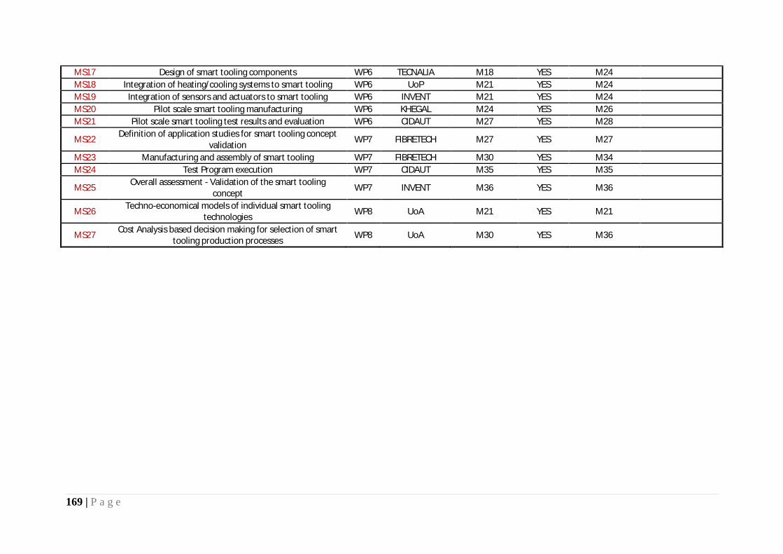
169 | P a g e
MS17 Design of smart tooling components WP6 TECNALIA M18 YES M24 MS18 Integration of heating/cooling systems to smart tooling WP6 UoP M21 YES M24 MS19 Integration of sensors and actuators to smart tooling WP6 INVENT M21 YES M24 MS20 Pilot scale smart tooling manufacturing WP6 KHEGAL M24 YES M26 MS21 Pilot scale smart tooling test results and evaluation WP6 CIDAUT M27 YES M28
MS22 Definition of application studies for smart tooling concept validation WP7 FIBRETECH M27 YES M27
MS23 Manufacturing and assembly of smart tooling WP7 FIBRETECH M30 YES M34 MS24 Test Program execution WP7 CIDAUT M35 YES M35
MS25 Overall assessment - Validation of the smart tooling concept WP7 INVENT M36 YES M36
MS26 Techno-economical models of individual smart tooling technologies WP8 UoA M21 YES M21
MS27 Cost Analysis based decision making for selection of smart tooling production processes WP8 UoA M30 YES M36

170 | P a g e
1.2.5. Explanation of the use of the resources
INASCO TABLE 3.1 PERSONNEL, SUBCONTRACTING AND OTHER MAJOR COST ITEMS FOR PERIOD 1
WP Item Description Amount in € with 2 decimals Explanations
10 Personnel Costs 14,660.19 Salary for the Project Coordinator - Project Management (2.4 PM)
1 Personnel Costs 358.83 Salary for the work of a Project Engineer to outline smart tooling concepts (0.1 PM)
4 Personnel Costs 13,994.46 Salaries for the work of 5 people (Senior Project Engineer, Project Engineer, Materials Scientist, Electronics Engineer, Design Engineer) for the sensors development and testing activities (3.9 PM)
5 Personnel Costs 9,329.64 Salaries for the work of 3 people (2 Project Engineers, Chief Project Engineer) for the integrated design platform development and validation activities (simulation and experimental) (2.6 PM)
6 Personnel Costs 1,794.17 Salaries for the work of 1 person (Design Engineer) for the development of sensor mounts and sensor placement (0.5 PM)
10 Travelling 298.82 Kickoff meeting (INASCO – Athens) – (12-14/04/2011) - Lunch catering expenses [Hosts: G. Maistros, M. Kazilas]
1 Travelling 204.27 Technical Meeting (UoP - Patras) – (15/09/2011) - D. Karagiannis and M. Kazilas
4,10 Travelling 803.12 6M Technical Meeting (TECNALIA – Bilbao) - (22-24/11/2011) – M. Kazilas
4,5,10 Travelling 1,270.25 12M Meeting (FIBRETECH – Bremen) – (12-15/03/2012) – D. Bofilios and C. Koimtzoglou
4,5,6,10 Travelling 1,839.73 15M Review meeting (INASCO – Munich) – (13-16/06/2012) – D. Bofilios and E. Stefatos
4, 6 Consumables 2,550.00 Tubing and mounting flanges for sensors (WP4 and WP6)
4 Consumables 1,585.74 Integrated boards, clamps, resistors and thermocouples, wiring for sensor and DAQ system development (WP4)
Indirect Costs 13,052.65 TOTAL COSTS 61,741.86
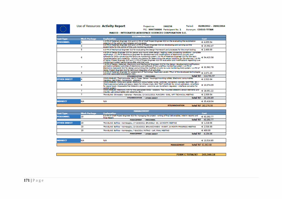
171 | P a g e
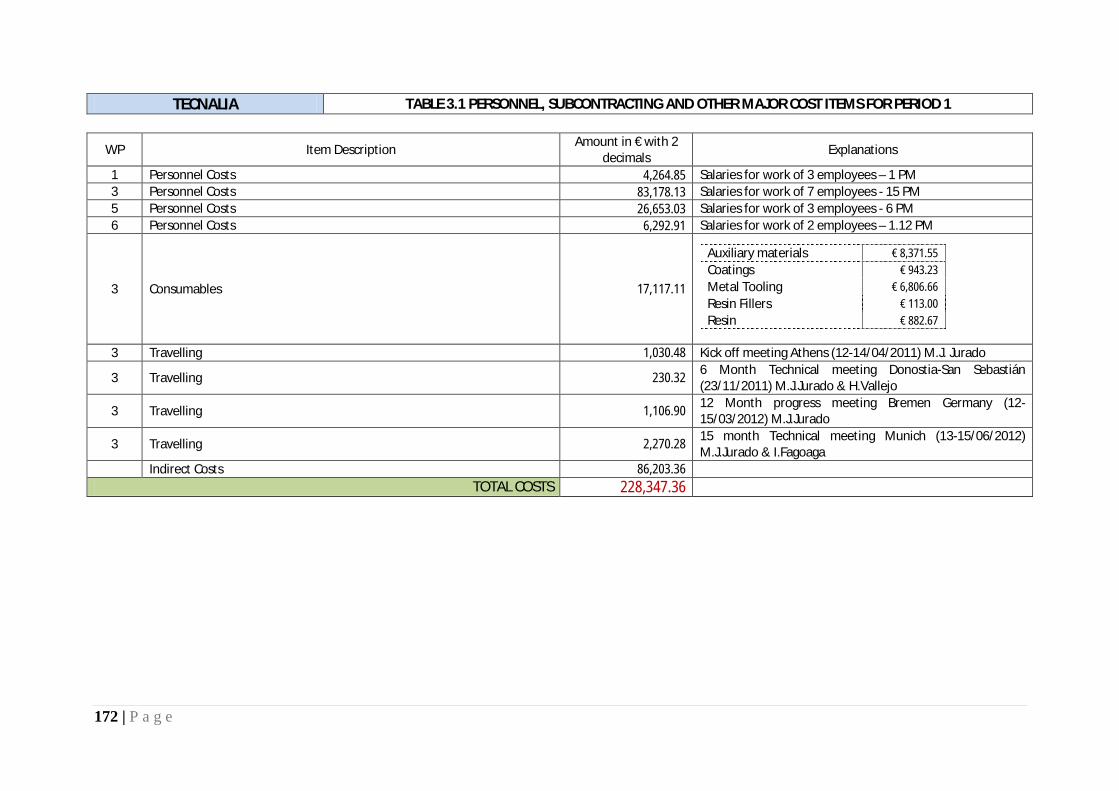
172 | P a g e
TECNALIA TABLE 3.1 PERSONNEL, SUBCONTRACTING AND OTHER MAJOR COST ITEMS FOR PERIOD 1
WP Item Description Amount in € with 2 decimals Explanations
1 Personnel Costs 4,264.85 Salaries for work of 3 employees – 1 PM 3 Personnel Costs 83,178.13 Salaries for work of 7 employees - 15 PM 5 Personnel Costs 26,653.03 Salaries for work of 3 employees - 6 PM 6 Personnel Costs 6,292.91 Salaries for work of 2 employees – 1.12 PM
3 Consumables 17,117.11
Auxiliary materials € 8,371.55 Coatings € 943.23 Metal Tooling € 6,806.66 Resin Fillers € 113.00 Resin € 882.67
3 Travelling 1,030.48 Kick off meeting Athens (12-14/04/2011) M.J. Jurado
3 Travelling 230.32 6 Month Technical meeting Donostia-San Sebastián (23/11/2011) M.J.Jurado & H.Vallejo
3 Travelling 1,106.90 12 Month progress meeting Bremen Germany (12-15/03/2012) M.J.Jurado
3 Travelling 2,270.28 15 month Technical meeting Munich (13-15/06/2012) M.J.Jurado & I.Fagoaga
Indirect Costs 86,203.36 TOTAL COSTS 228,347.36

173 | P a g e

174 | P a g e
UoP TABLE 3.1 PERSONNEL, SUBCONTRACTING AND OTHER MAJOR COST ITEMS FOR PERIOD 1
WP Item Description Amount in € with 2 decimals Explanations
1 Personnel direct costs 7,500.00 Salaries for researchers working in Task 1.2 corresponding to 1.5 pm
2 Personnel direct costs 30,000.00 Salaries for researchers working in Task 2.1 corresponding to 6 pm
2 Personnel direct costs 15,000.00 Salaries for researchers working in Task 2.2 corresponding to 3 pm
2 Personnel direct costs 17,500.00 Salaries for researchers working in Task 2.3 corresponding to 3.5 pm
4 Personnel direct costs 15,000.00 Salaries for researchers working in Task 4.3 corresponding to 3 pm
5 Personnel direct costs 5,000.00 Salaries for researchers working in Task 5.1 corresponding to 1 pm
5 Personnel direct costs 4,794.00 Salaries for researchers working in Task 5.2 corresponding to 0.96 pm
5 Personnel direct costs 5,000.00 Salaries for researchers working in Task 5.3 corresponding to 1 pm
1,2,3,4,5 Travelling 616.43 TRAVEL: Kick-off meeting, Athens 12-14/4/2011 (Vlachos, Athanasopoulos)
2 Travelling 922.02 TRAVEL: Cooperation with Fibretech, Bremen 21-23/11/2011 (Vlachos)
1,2,3,4,5 Travelling 1,399.11 TRAVEL: 12m meeting, Bremen, 13-14/11/2011 (Athanasopoulos)
1,2,3,4,5 Travelling 1,527.97 TRAVEL: 15m meeting, Munich, 13-15/06/2012 (Vlachos)
1,2,3,4,5 Travelling 616.43 TRAVEL: Kick-off meeting, Athens 12-14/4/2011 (Vlachos, Athanasopoulos)
2 Travelling 922.02 TRAVEL: Cooperation with Fibretech, Bremen 21-23/11/2011 (Vlachos)
1,2,3,4,5 Travelling 1,399.11 TRAVEL: 12m meeting, Bremen, 13-14/11/2011 (Athanasopoulos)
2,4,5 Consumables 4,706.00 CONSUMABLES: Raw materials for the manufacturing of test tools

175 | P a g e
2.4 Consumables 1,560.55 CONSUMABLES: Auxiliary materials and various components for the manufacturing of test tools (eg vacuum bags, sealants, electric connectors and wiring)
2.4 Consumables 619.91 CONSUMABLES: Repair of IR camera used for temperature monitoring of self heated tools
2.4 Consumables 1,463.41 CONSUMABLES: Repair of curing oven used in comparative studies and post-curing of composite parts
2.4 Consumables 1,194.00 CONSUMABLES: Computer parts
2,4,5 Consumables 130.08
CONSUMABLES: Machining of aluminum master plugs for tool fabrication. Various trimming and machining operations on composite tools. Copper tubing for cooling system.
2,6,7 Equipment 700.00 EQUIPMENT: Personal computer
2,4,5 Equipment 4,706.00 EQUIPMENT: License of COMSOL Multiphysics FEA software
2,4,5 Equipment 3,414.63 EQUIPMENT: Upgraded software for IR camera 2.4 Indirect costs 72,028.87
TOTAL COSTS 192,076.98

176 | P a g e

177 | P a g e
ACG/UMECO/CYTEC TABLE 3.1 PERSONNEL, SUBCONTRACTING AND OTHER MAJOR COST ITEMS FOR PERIOD 1
WP Item Description Amount in € with 2 decimals Explanations
1 Personnel costs 5,860.00 1 Scientist preparing for and attending meetings 1 MM 1 Personnel costs 8,830.00 1 Manager preparing revised Project Plan 1 MM 1 Personnel costs 5,860.00 1 Scientist preparing data for database 1 MM
2 Personnel costs 5,580.00 2 Scientists and 2 Engineers, manufacture and testing of
composite tools with integral laminated heating 1.2 MM 2 Personnel costs 8,830.00 1 Manager negotiating zonal heating collaboration with SG 1 MM
2 Personnel costs 9,585.00 2 Scientists and 2 Engineers on design and manufacture of tooling
for use with zonal heating 1.8 MM
5 Personnel costs 5,215.00 1 Engineer assessing possible software available for tooling design
0.8 MM 6 Personnel costs 3,970.00 1 Engineer and 1 Scientist investigating design of tooling 0.8 MM
8 Personnel costs 4,416.00 3 Senior Managers for internal discussions on costings and data
availability and commercial sensitivity 0.5 MM 1 Travelling 661.00 Kick-off meeting Athens (INASCO) 1 Travelling 367.00 Meeting Bilbao (6M – TECNALIA) 1 Travelling 702.10 Meeting Munich (15M – INASCO) 2 Consumables 94.79 Consumables Indirect Costs 111,641.71
TOTAL COSTS 171,612.60

178 | P a g e

179 | P a g e
UoA TABLE 3.1 PERSONNEL, SUBCONTRACTING AND OTHER MAJOR COST ITEMS FOR PERIOD 1
WP Item Description Amount in € with 2 decimals Explanations
1 Personnel costs 3,538.62 Salaries for work of 2 professors corresponding to 0.9 PM for defining functional specifications and assessment of economic potential of smart tooling
2 Personnel costs 13,348.15 Salaries for work of 2 professors and 1 researcher corresponding to 3.3 PM for performing the development of a quality control system for the dispersion of CNTs in resin matrix
4 Personnel costs 8,361.44 Salaries for work of 2 researchers corresponding to 2.8 PM for performing development of temperature sensing and control systems in smart tooling operation
5 Personnel costs 5,986.48 Salaries for work of 1 professor and 1 researcher corresponding to 1.45 PM for performing development of control system and interface of techno-economic models to design support tools
8 Personnel costs 8,843.69 Salaries for work of 1 professor and 2 researchers corresponding to 2.45 PM for the development of techno-economic model for the smart tooling production
2 Travelling 3,303.82 Visiting CERN, Geneva (27/5 – 8/6/2011) for investigating method for CNT dispersion quality measurement, Prof. I. Gkialas
2 Travelling 1,019.34 12 M meeting, Bremen, Germany (12-15/03/2012), G. Maistros 4 Travelling 1,386.96 15 M meeting, Munich, Germany (13-15/06/2012), G. Maistros
4 Travelling 3,627.11 Visiting CERN, Geneva (29/7 – 5/8/2012) for preparation of process control in multi-input/single output systems, Prof. K. Papageorgiou and Prof. I. Gkialas
4 Consumables 650.00 Temperature measurement consumables
2 Equipment 2,755.55 High speed oscilloscope, 100% use in project, depreciation for 8 months
2 Equipment 1,967.78 Spectroscopy unit for detecting CNTs dispersion quality, 100% use in project, depreciation for 7 months
Indirect Costs 32,873.36 TOTAL COSTS 87,662.30

180 | P a g e

181 | P a g e

182 | P a g e
CLERIUM TABLE 3.1 PERSONNEL, SUBCONTRACTING AND OTHER MAJOR COST ITEMS FOR PERIOD 1
WP Item Description Amount in € with 2 decimals Explanations
1 Personnel costs 6,500.00 Hourly rate of SME-owner for mainly desk work and communication - 0,52 PM
2 Personnel costs 13,625.00 Hourly rate of SME-owner for producing flat heated mould samples - 1,09 PM
3 Personnel costs 29,875.00 Hourly rate of SME-owner for research, reporting and laboratory work on surface technology - 2,39 PM
6 Personnel costs 4,250.00 Hourly rate of SME-owner for input relevant to Task 6.1 and planning of WP6 - 0,34 PM
8 Personnel costs 3,375.00 Hourly rate of SME-owner for Market Research and Analysis about Smart Tools and competition - 0,27 PM
2.3 Equipment 293.28 DC Power Supply 15V / 60A - Purchased 2.3 Equipment 122.50 Programmable Temperature Controller - Purchased 2.3 Consumables 110.20 Thermocouples and cables - Purchased
2.3 Consumables 1,137.12 Fibreglass reinforcements, epoxy resins, vacuum materials, small tools, etc
Travelling 505.56 Travelling costs Kick-Off Meeting @ Inasco for P. Fasseas Travelling 1,232.04 Travelling costs 6M Meeting @ Tecnalia for P. Fasseas Travelling 540.14 Travelling costs 12M Meeting @ Fibretech for P. Fasseas Travelling 9.50 Travelling costs meeting with Accountants Travelling 988.48 Travelling costs 15M Meeting in Munich for P. Fasseas Indirect costs 166.78
TOTAL COSTS 62,730.60

183 | P a g e

184 | P a g e
FIBRETECH TABLE 3.1 PERSONNEL, SUBCONTRACTING AND OTHER MAJOR COST ITEMS FOR PERIOD 1
WP Item Description Amount in € with 2 decimals Explanations
2,6 Durable Equipment 15,649.67 Power supply, controller, dielectric, resin trap 2,6 Consumables 8,031.59 Resin, Carbon, Reinforcements, fillers, controller, galvanic 4,6 (7) Computing 8,302.10 PC-system for Simulation and construction, CAD-program Travelling
514.78 Kick off meeting Athens (12-14/04/2011) F. Freyer
Travelling 443.56 6 Month Technical meeting Patras , canceled Travelling
398.74 6 Month Technical meeting, Bilbao (22-24/11/2011) F. Freyer
Travelling 238.32
12 Month progress meeting, Bremen Germany (12-15/03/2012) F. Freyer, J. Brandes
Travelling 717.86
15 month Technical meeting Munich (13-15/06/2012) F. Freyer
1 Personnel Costs 10,458.70 Salaries for work of 3 employees, 2,75 PM 2 Personnel Costs 39,964.60 Salaries for work of 5 employees, 10,52 PM 6 Personnel Costs 17,858.10 Salaries for work of 5 employees, 4,7 PM 8 Personnel Costs 1,098.20 Salaries for work of 2 employees, 0,29 PM
Indirect Costs 27,751.84 40% of personal direct costs TOTAL COSTS 131,428.06

185 | P a g e

186 | P a g e
TWI TABLE 3.1 PERSONNEL, SUBCONTRACTING AND OTHER MAJOR COST ITEMS FOR PERIOD 1
WP Item Description Amount in € with 2 decimals Explanations
1 Personnel Costs 8,950.07
Creation of material database for composite material. The deliverable was completed and submitted to the coordinator on March 2012.
1 Travelling 1,785.73 Travel and associated costs relating M6, M12 and M15 meetings in Bilbao, Bremen and Munich.
1 Other 8.00 Postage (courier) costs 1 Indirect Costs 13,826.04
TOTAL COSTS 24,569.84

187 | P a g e

188 | P a g e
INVENT TABLE 3.1 PERSONNEL, SUBCONTRACTING AND OTHER MAJOR COST ITEMS FOR PERIOD 1
WP Item Description Amount in € with 2 decimals Explanations
1 Personnel Costs 6,182.71 Salaries for engineers, skilled workers, 1 technical director, 1 chief executive officer (1.5PM)
4 Personnel Costs 32,817.32 Salaries for engineers, skilled workers, 1 technical director, 1 chief executive officer (8.2PM)
6 Personnel Costs 28,227.47 Salaries for engineers, skilled workers, 1 technical director, 1 chief executive officer (7PM)
8 Personnel Costs 4,102.00 Salaries for engineers, skilled workers, 1 technical director, 1 chief executive officer (1PM)
4 Consumables 107.72 GARANT drill bit, GARANT treading die, GARANT die holder (firm Perschmann)
4 Consumables 1,286.79 PES-fleece with EP-binder, (firm ECC) 4 Consumables 2,201.00 piezoceramic plates (firm PI Ceramic) 4 Consumables 10.00 residual material (firm Wirth)
1 Travelling 976.55 Kick off meeting, Glyfada (Athens, Greece) 2011-04-12 until 2011-04-15, Mr. Kirchner
4 Travelling 1,123.10 6 Month Technical meeting, Donostia-San Sebastián (Spain), 2011-11-22 until 2011-11-24, Mr. Kirchner
6 Travelling 227.94 12 Month progress meeting, Bremen (Germany), 2012-03-13 until 2012-03-14, Dr. Heintze and 2012-03-13 Mr. Kirchner
6 Travelling 727.14 15 month meeting Technical meting Munich (Germany), 2012-06-13 until 2012-06-15, Dr. Heintze
Indirect Costs 48,358.72 TOTAL COSTS 129,028.59

189 | P a g e

190 | P a g e

191 | P a g e
KHEGAL TABLE 3.1 PERSONNEL, SUBCONTRACTING AND OTHER MAJOR COST ITEMS FOR PERIOD 1
WP Item Description Amount in € with 2 decimals Explanations
1 Personnel Costs 6,672.43 Salaries for work of 2 engineer+ 3 more assistance personnel in WP1 gathering data, state of art, and functional specs.
3 Personnel Costs 19,664.05 Salaries for work of 2 engineer+ 3 more assistance personnel in WP3, mainly on pattern and surface state study
6 Personnel Costs 6,907.93 Salaries for work of 2 engineer+ 3 more assistance personnel in WP3, mainly executing preliminary design of molds
3 Consumables 1,173.40 Material (boards) for machining tests
3 Equipment 2,865.40 Rugosimeter for surface characterisation (total cost of 8.185 € - we understand 2.865,40 € are claimable)
1 Travelling 969.06 Kickoff meeting Athens (12-14/04/2011) - O.Jauregui
1 Travelling 187.77 Aborted travel to Patras (non-refundable plane tickets - 20/10/2011) - O.Jauregui
3 Travelling 11.42 6 Month Technical meeting Donostia-San Sebastian (23/11/2011) - O. Jauregui
6 Travelling 768.57 12 Month progress meeting Bremen (12-15/03/2012) - O. Jauregui Indirect Costs 34,906.63 OH rate 105%
TOTAL COSTS 74,126.66

192 | P a g e

193 | P a g e
CIDAUT TABLE 3.1 PERSONNEL, SUBCONTRACTING AND OTHER MAJOR COST ITEMS FOR PERIOD 1
WP Item Description Amount in € with 2 decimals Explanations
1 Personnel Costs 17,658.81 Salaries of the personnel involved in the tasks T1.1 (0,6 PM); T1.2 (0,6 PM) and T1.3 (1,6 PM)
4 Personnel Costs 30,902.92 Salaries of the personnel involved in the tasks T4.2 (2,9 PM) and T4.3 (2,0 PM)
9 Personnel Costs 3,153.36 Salaries of the personnel involved in the task T9.2 (0,5 PM)
9 Travelling 219.21 Travel Expenses; WP9 Project Meeting; Bilbao (Spain); Mr. Luis de Prada; 08/11/2011 - 10/11/2011
1 Travelling 317.26 Travel Expenses; Project Meeting; Patras (Greece); Mr. Luis de Prada; 18/10/2011 - 21/12/2011
1 Travelling 578.98 Travel Expenses; Kick off meeting; Athens (Greece); Mr. Luis de Prada; 12/04/2011 - 15/04/2011
1 Travelling 226.21 Travel Expenses; Project Meeting; Bilbao (Spain); Mr. Luis de Prada; 22/11/2011 - 24/11/2011
1 Travelling 885.87 Travel Expenses; 1st year Project Meeting; Bremen (Germany); Mr. Luis de Prada; 12/03/2012 - 15/03/2012
4 Travelling 773.97 Travel Expenses; Project Meeting; Munich (Germany); Mrs. Blanca Araujo; 12/06/2012 - 15/06/2012
Indirect Costs 38,301.62 TOTAL COSTS 93,018.21
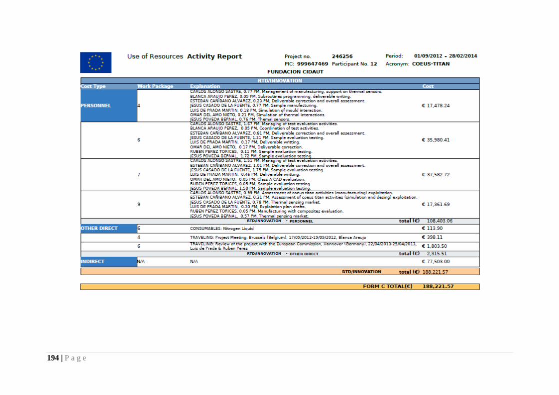
194 | P a g e

195 | P a g e
EUREXCEL TABLE 3.1 PERSONNEL, SUBCONTRACTING AND OTHER MAJOR COST ITEMS FOR PERIOD 1
WP Item Description Amount in € with 2 decimals Explanations
TOTAL COSTS

196 | P a g e
EXEL TABLE 3.1 PERSONNEL, SUBCONTRACTING AND OTHER MAJOR COST ITEMS FOR PERIOD 1
WP Item Description Amount in € with 2 decimals Explanations
1.1 Personnel Costs 2,925.00 Smart tooling database (0.5mm) - collating and provision of information to partners - salaries for personnel - John Hartley (Project coordinator - Exel), Andy Blair (Designer - Exel), Sue Wilson (Purchasing dept- Exel)
1.2 Personnel Costs 5,850.00 Application of smart tooling concept to plastics and composite manufacturing (1mm) - Providing information with regards to Pultrusion conceptual ideas - Salaries of personnel - John Hartley (Project coordinator - Exel), Andy Blair (Designer - Exel)
1.3 Personnel Costs 2,925.00
Functional specifications for smart tooling technologies implementation (0.5mm) - Preparation of deliverable D1.3 in conjunction with partners - Providing information with regards to pultrusion conceptual ideas - salaries of personnel - John Hartley (Project coordinator - Exel), Andy Blair (Designer - Exel)
3.1 Personnel Costs 11,700.00 Mould surface materials and process definitions (2mm) - Salaries of personnel - John Hartley (Project coordinator - Exel), Andy Blair (Designer - Exel), Carl Fletcher (Laboratory - Exel)
3.2 Personnel Costs 2,340.00 Development of Surface configurations (preparation, testing, characterisation, evaluation) (0.4mm) - Salaries of personnel - John Hartley (Project coordinator - Exel), Andy Blair (Designer - Exel), Carl Fletcher (Laboratory - Exel)
3.3 Personnel Costs 585.00 Development of repairable tooling surfaces (0.1mm) - Salaries of personnel - John Hartley (Project coordinator - Exel), Andy Blair (Designer - Exel)
6.1 Personnel Costs 4,095.00 Design of tool cavity (0.7mm) - provision / design of the pultrusion postforming tool - salaries of personnel - John Hartley (Project coordinator - Exel), Andy Blair (Designer - Exel)
6.2 Personnel Costs 2,925.00 Automated design of smart tooling components (0.5mm) - Details of requirements, CAD drawings etc of Pultrusion system - salaries of personnel - John Hartley (Project coordinator - Exel), Andy Blair (Designer - Exel)
Travelling 1,517.00 Project Kick off Meeting at Inasco (Travelling cost + hotel costs etc) - John Hartley (Project coordinator - Exel) - 13&14 April 2012
Travelling 959.64 Project meeting at Munich (Travelling costs + hotel costs etc) - John Hartley (Project coordinator - Exel) - 13 & 14 June 2012

197 | P a g e
Travelling 563.87 Project meeting at Brussels (travelling costs + hotel Costs etc) - John Hartley (Project coordinator - Exel) - 18 & 19 September 2012
Indirect Costs 7,277.10 TOTAL COSTS 43,662.61

198 | P a g e

199 | P a g e

200 | P a g e
1.2.6. Financial statements – Form C and Summary financial report