Project Document Cover Sheet - UKOLN · Project Document Cover Sheet Project Information ... Life,...
44
Project Document Cover Sheet Project Information Project Acronym I2S2 Project Title Infrastructure for Integration in Structural Sciences Start Date 1 st Oct 2009 End Date 31 st March 2011 Lead Institution Universities of Bath and Southampton Project Director Liz Lyon (UKOLN) Project Manager & contact details Manjula Patel 01225 386547; [email protected] Partner Institutions Universities of Bath, Southampton, Cambridge; STFC; Charles Beagrie Ltd. Project Web URL http://www.ukoln.ac.uk/projects/I2S2/ Programme Name (and number) Managing Research Data (Research Data Management Infrastructure) Programme Manager Simon Hodson Document Name Document Title Pilot Implementation Reporting Period N/A Author(s) & project role Erica Yang, Brian Matthews (STFC Rutherford Appleton Laboratory) Date 31 st March 2011 Filename I2S2-WP3-D3.3b- PilotImplementation.doc URL Access Public x General dissemination
Transcript of Project Document Cover Sheet - UKOLN · Project Document Cover Sheet Project Information ... Life,...

Project Document Cover Sheet
Project Information
Project Acronym I2S2
Project Title Infrastructure for Integration in Structural Sciences
Start Date 1st Oct 2009 End Date 31
st March 2011
Lead Institution Universities of Bath and Southampton
Project Director Liz Lyon (UKOLN)
Project Manager &
contact details
Manjula Patel
01225 386547; [email protected]
Partner Institutions Universities of Bath, Southampton, Cambridge; STFC; Charles
Beagrie Ltd.
Project Web URL http://www.ukoln.ac.uk/projects/I2S2/
Programme Name
(and number)
Managing Research Data (Research Data Management
Infrastructure)
Programme Manager Simon Hodson
Document Name
Document Title Pilot Implementation
Reporting Period N/A
Author(s) & project
role
Erica Yang, Brian Matthews (STFC Rutherford Appleton
Laboratory)
Date 31st March 2011 Filename I2S2-WP3-D3.3b-
PilotImplementation.doc
URL
Access Public x General dissemination

2
D3.3 Pilot Implementation
Work Package 3
April 2010 – March 2010
JISC I2S2 Project
Document Details Author: Erica Yang, Brian Matthews (STFC
Rutherford Appleton Laboratory)
Date: 31st March. 2011
Version: 0.4
File Name: I2S2-WP3-D3.3.-
PilotImplementation.doc
Notes:
This work is licensed under a Creative Commons Attribution-Non-Commercial-Share Alike 2.5 UK: Scotland
Licence.

3
Acknowledgements
The Infrastructure for Integration in Structural Sciences (I2S2) Project is funded by the UK’s Joint
Information Systems Committee (JISC); the project manager is Simon Hodson. The I2S2 project
team comprises:
- Liz Lyon (UKOLN, University of Bath & Digital Curation Centre)
- Manjula Patel (UKOLN, University of Bath & Digital Curation Centre)
- Simon Coles (EPSRC National Crystallography Centre, University of Southampton)
- Martin Dove (Earth Sciences, University of Cambridge)
- Peter Murray-Rust (Chemistry, University of Cambridge)
- Brian Matthews (Science & Technology Facilities Council)
- Erica Yang (Science & Technology Facilities Council)
- Juan Bicarregui (Science & Technology Facilities Council)
- Neil Beagrie (Charles Beagrie Ltd.)
The authors would like particularly like to thank Prof Martin Dove from Earth Sciences at the
University of Cambridge, Simon Coles from the UK National Crystallography Service, and Dr. Alan
Soper and Dr. Matt Tucker from STFC ISIS facility for providing case studies of the scientific process
on STFC facilities .
A shorter version of this report has been published at the IEEE e-Science conference 2010, Brisbane,
Australia [23]. A version without appendices has been submitted for publication in Future
Generation Computer Systems.

4
Executive Summary
The Infrastructure for Integration in Structural Sciences (I2S2) Project is funded under the Research
Data Management Infrastructure strand of the JISC's Managing Research Data Programme, with
duration of 18 months (Oct 2009 to March 2011).
One of the main aims of the project is to investigate the research and data management infrastructure
needs of researchers in the Structural Sciences (incorporating a number of disciplines including
Chemistry, Physics, Materials, Earth, Life, Medical, Engineering, and Technology). We define
research infrastructure to encompass physical, informational and human resources essential for
researchers to undertake high-quality research, including: tools, instrumentation, computer systems
and platforms, software, communication networks, technical support (both human and automated);
documentation and metadata.
This deliverable describes the pilot implementation of the I2S2 project.
Document Revision History
Version Date Comments
0.1 15th
October 2010 Scope and initial outline
0.2 18th
October 2010 Added data ingestion XML schema, XML example, MySQL database
schema
0.3 20th
October 2010 Added browser interface, final remarks
0.4 23th
March 2011 Revisit and revise
1.0 6th
April 2011 Final release

Contents
1 Introduction 6
2 Core Scientific MetaData model 7
3 Derived Data in the Analysis Process 103.1 Background . . . . . . . . . . . . . . . . . . . . . . . . . . . . . . . . . . . . . 103.2 Data Analysis . . . . . . . . . . . . . . . . . . . . . . . . . . . . . . . . . . . . 11
3.2.1 Data reduction . . . . . . . . . . . . . . . . . . . . . . . . . . . . . . . 123.2.2 Initial structural model generation . . . . . . . . . . . . . . . . . . . . 123.2.3 Model fitting . . . . . . . . . . . . . . . . . . . . . . . . . . . . . . . . 12
3.3 Discussion . . . . . . . . . . . . . . . . . . . . . . . . . . . . . . . . . . . . . . 13
4 An Enhanced CSMD 134.1 Adding a SoftwareExecution Investigation Type . . . . . . . . . . . . . . . . . 154.2 Linking Software to SoftwareExecution . . . . . . . . . . . . . . . . . . . . . . 164.3 Linking SoftwareExecutions to Datasets . . . . . . . . . . . . . . . . . . . . . 174.4 Associating parameters with a SoftwareExecution . . . . . . . . . . . . . . . . 174.5 Re-introducing Study and Nested Study . . . . . . . . . . . . . . . . . . . . . 174.6 Observation . . . . . . . . . . . . . . . . . . . . . . . . . . . . . . . . . . . . . 18
5 ICAT-personal: A Pilot Implementation 185.1 System Architecture . . . . . . . . . . . . . . . . . . . . . . . . . . . . . . . . 185.2 Derived Data Management . . . . . . . . . . . . . . . . . . . . . . . . . . . . 20
5.2.1 Data ingestion . . . . . . . . . . . . . . . . . . . . . . . . . . . . . . . 205.2.2 Data Browsing . . . . . . . . . . . . . . . . . . . . . . . . . . . . . . . 225.2.3 Data Restoration . . . . . . . . . . . . . . . . . . . . . . . . . . . . . . 22
6 Discussion and Future Work 24
7 Final Remarks 267.1 Stakeholder Engagement . . . . . . . . . . . . . . . . . . . . . . . . . . . . . . 267.2 Stakeholder Feedbacks . . . . . . . . . . . . . . . . . . . . . . . . . . . . . . . 26
5

1 Introduction
Increasing quantities of the raw experimental data generated using large scientific facilities,such as large-scale photon and neutron sources, are being made available in a systematicand secure way. This data is intended for three main users: the experimental scientists whoundertook the study need access to the raw data from their universities in order to analyse itfurther; the facilities managers need access to data to manage the use of their facilities; andother scientists may be able to access the data for re-analysis, either to verify the publishedresults, or to derive new scientific results without the cost of repeating the original experiment,possibly in combination with results from elsewhere.
The Core Scientific MetaData model (CSMD) [20, 10] has been designed to capture in-formation about experiments and the data they produce in what are broadly known as the“structural sciences”, such as chemistry or earth science, which consider the molecular struc-ture of matter. It is used by the data cataloguing system ICAT [5] which is used by the ISISneutron source1 and the Diamond Light Source (DLS)2, both operated at the Harwell Scienceand Innovation Campus in the UK. The DLS synchrotron generates brilliant beams of light,from infra-red to X-rays, which are used in a wide range of applications, from structuralbiology through fundamental physics and chemistry to cultural heritage. The ISIS sourcegenerates beams of neutrons and muons used to investigate the properties of materials atthe scale of atoms for research into subjects ranging from clean energy and the environment,pharmaceuticals and health care, through to nanotechnology, materials engineering and IT.The two target stations of the ISIS neutron source host 30 beamlines with their associatedinstruments, while DLS currently hosts 13 instruments on separate beamlines. The use ofthese facilities is not limited to a small coterie of specialists, but between them these in-struments are used by many thousands of experimental scientists each year from around theworld. As similar large facilities are developed in other countries the data sets they createare becoming more common, and it becomes more urgent to capture that data, and to ensurethat all stages of its analysis are accurately recorded. Consequently, facilities such as the In-stitut Laue-Langevin (ILL)3 are also adopting the ICAT infrastructure, and the PANDATAinitiative4 is developing best practice in data management across facilities internationally.
Data cataloguing systems support access to scientific data, but the present ICAT onlycatalogues the raw data produced by the facility, while derived data is managed locally bythe scientist carrying out the analysis at the facility or in their home institution. This is onan ad hoc basis, and these intermediary derived data sets are not archived for other purposes.Thus the support for the intended users is partial.
In order to improve the support offered by the facilities data management tool such asICAT, its underlying data model, CSMD needs to be extended. Currently, it does not supportaccess to the derived data produced during analysis, nor does it allow the provenance of datasupporting the final publication to be traced through the stages of analysis to the raw data.
Bioscientists have used workflow tools to capture and automate the flow of analyses andthe production of derived data for many years [14] and can now automatically run manycomputational workflows [24]. In other structural sciences, such as chemistry and Earthsciences, the management of derived data is less mature, workflows are not standardised and
1http://www.isis.stfc.ac.uk2http://www.diamond.ac.uk3http://www.ill.eu4PANDATA Photon and Neutron Data Infrastructure. http://www.pan-data.eu/Main Page
6

can less readily be automatically enacted. Rather the data needs to be captured as the analysisproceeds so that scientists do not lose track of what has been done. A data managementsolution is required to capture the data trails that are generated during analysis, with theaim of making the methodologies used by one group of researchers available to others.
Further, the accurate recording of the process so that results can be replicated is essentialto the scientific method. However, when data are collected from large facilities, the expenseof operating the facility means that the raw data collection effectively cannot be repeated.Therefore tests to replicate results has to come from re-analysis of raw data as much asrepetition of the data capture in experiments.
In order to provide support for the analysis undertaken by the experimental scientists; topermit the tracing of the provenance of published data; and to allow access to derived datafor secondary analysis, it is necessary to extend the CSMD to account for derived data andto record the analysis process sufficiently for the needs of each of these use cases. In termsof data provenance [8], the current CSMD approach identifies the source provenance of theresultant data product, but it needs to be extended to describe the transformation provenanceas well.
In this report, after a summary of the existing CSMD, an example scientific process willbe described to motivate the extensions to the CSMD. Section 4 will then detail extensionsto the CSMD to meet these requirements, which are incorporated into the I2S2 InformationModel, before a pilot implementation of the extended CSMD is described using the ICAT datacatalogue system. Finally the limitations of the proposed extensions, practical limitations onthe adoption of the data catalogue system and future work will be considered.
In appendices, we give details of the tools and technologies required to support the ICAT-Personal system.
2 Core Scientific MetaData model
The Core Scientific MetaData model (CSMD) [20] is an extensible model of metadata orig-inally designed to capture a common set of information about the data produced by exper-iments, measurements, and simulations in facilities science. The model is the result of ananalysis of science practice over a number of years and a range of projects, and has proved arobust system.
CSMD was developed primarily to allow facility operators, such as STFC, to introducea systematic approach to manage their data assets across the heterogeneous scientific facil-ities. Although operators may produce data files of different formats and content resultingfrom different equipment, experiments, or disciplines, there are commonalities features of thecontext of the data that can be captured. They include:
1. the description of the data production process (e.g. where/when/by who/how);
2. the format, type, owner, and identifier of the data;
3. the parameters in which the data should be interpreted;
4. the relationships between data.
Having a standardised metadata model underpinning the data management infrastructurethat an operator uses, supports a common strategy towards maintaining, searching, and dis-covering data assets, reducing the overall operating cost. This is important to both facility
7

1. Core
2. Security
1.1 Datafile
1.2 Dataset
1.3 Investigation
1.5 SoftwareVersion
1.6 Parameter
1.4 Investigator
2.2 ICAT_Authorisation
2.1 User_role
1.7 Study
1.8 StudyManager
CSMD
2. Security
3. Communication
5. Search
6. Facility
7. Auxiliary
information
4. Miscellaneous
5.2 Topic
5.1 Keyword
3.1 Publication
2.2 ICAT_Authorisation
2.4 Application
2.3 ICAT_Role
4.1 This_ICAT
6.1 Shift
6.2 Instrument
6.3 Facility_instrument_scientist
6.5 Facility_user
7.2 Sample
7.1 Status
6.4 Facility_cycle
7.3 Format
7.4 Type
Figure 1: A classification of the concepts in CSMD
providers who host a wide range of scientific facilities and to users who utilize multiple facil-ities. Metadata are also crucial for scientists other than the ones who design the equipmentor run the experiment, to interpret, understand and make use of the data.
The model as it currently stands aims to describe the physical raw data files (binary,images, or text containing numeric values) produced by the data acquisition software of adetector within an instrument. These files have formats which depends on the equipment,the facility, or the program that the data is produced from. The Network Common DataFormat (netCDF) [17] and Hierarchical Data Format (HDF) [6] are well defined formats usedby many laboratories, while NeXus [9], derived from HDF5, is a common data format tar-getted at neutron, X-ray, and muon sciences which several facilities have adopted to differentdegrees: not all the data files produced within these communities use this format since manyinstruments still produce older non-standard formats.
In CSMD data files are grouped into datasets, where a dataset is an abstract notionreferring to a set of related data files. How the files are related is determined by the context.For example, if an experiment produces 10 files in a run, which is repeated 100 times indifferent temperatures, 100 datasets can be created, each with the 10 files produced under aspecific temperature. This dataset concept is essential for experiments that produce a largenumber of files in each run.
Datasets are then grouped into investigations, where an investigation - which can be anexperiment, a set of measurements, or a simulation - is defined as a data generation activity.For example an investigation may represent a particular allocation of time on an instrumentto a scientist for the analysis of a sample of a material, which may generate a number ofdata sets each collected at a different experimental parameter setting. Like the dataset,an investigation is not a concept referring to an object of physical presence, but rather anabstract notion referring to a set of related datasets generated from the same data generationactivity.
Investigations are further grouped into studies, where a study is also an abstract notion
8

referring to a set of related investigations, in other words, a set of related data generationactivities. For example, two investigations, an experiment on a sample and a related computersimulation of the experiment, could be grouped together to form a study of the sample.
The CSMD has been implemented and deployed in STFC to support scientific data cata-loguing and management for its major international facilities. The current production imple-mentation of CSMD, ICAT 3.35, is based on the CCLRC Scientific Metadata Model v2 [20]with extensions. This model forms the core of the ICAT infrastructure to catalogue, manageand distribute data for facilities users.
Although CSMD was originally intended to accommodate data collection and processing amuch wider context of scientific studies from raw data collection to downstream data analysis,it is currently only being used to support raw data cataloging. In order to focus on the keydata management issues throughout the data production pipeline and to clarify the extensionsneeded for derived data, we identify the core and optional concepts in the model. The conceptsin CSMD can be classified into six categories (see Figure 1):
Core The concepts which are central to scientific data management. Capturing the dataoutputs involve four data objects: datafile, dataset, investigation, and study. A datafile corre-sponds to a physical data object that is stored on physical storage disks, while datasets, inves-tigations, and studies are abstract data objects that encapsulate other (physical or abstract)data objects as described above. Other core concepts include the Investigator and Study-Manager, representing people associated with an investigation and a study, respectively. TheProcess concept6 captures an activity that produces or consumes data objects, while the Pa-rameter concept captures some value which provides context to the data production process,such as environmental characteristics, instrument settings, or measured quantities.
Search Classifiers which can be assigned to data to facilitate the search and discovery ofcore concepts.
Communication Concepts which link between data and other research outputs so that theprovenance of a research publication can be traced back to the data holdings.
Security Concepts which are used to enforce access control policies on the data holdings.These may vary according to the security context of the facility.
Miscellaneous Meta-entities which identify the specific instance of ICAT metadata cata-logue.
Facility Concepts related to facilities are introduced to capture the contextual informationassociated with the (raw) data collection process, such as which facility and instrument wasused, which cycle, shift or run of the facility, the instrument-scientist (a specialised rolein a large-scale facility) was involved, additional safety information. These concepts arespecialised to facility usage, although there are analogues in other experimental contexts,such as university laboratory experiments.
5http://code.google.com/p/icatproject/6In CSMD 2.0 and ICAT 3.3, the concept Process is called SoftwareVersion.
9

Auxiliary Information Specific information associated with data holdings. It is currentlybeing used to store information related to raw data files, such as the sample under analysis,further parameters (e.g. temperature, humidity), and file format. But it should be possibleto extend or adapt these concepts to store any information related to data holdings producedalong data analysis pipelines.
Two types of information are left out from Figure 1: links between the concepts withina category; and those between the concepts across categories. We address the former in therest of this report. The latter does not directly relate to the report, and we shall not expandon this aspect further.
3 Derived Data in the Analysis Process
In this section we study in detail an example data analysis pipeline from the raw data gatheredat a facility to the final scientific findings suitable for publication.
Along the pipeline, three concepts, raw, derived, and resultant data, are often used todifferentiate the roles of data in different stages of the analysis and to capture the temporalnature of the processes involved. Raw data are the data acquired directly from the instrumenthosted by an facility, in the format support by the detector. Derived data are the result ofprocessing (raw or derived) data by one or more computer programs. Resultant data are thefinal findings of an analysis, for example, the structure and dynamics of a new material beingstudied in an experiment.
3.1 Background
We initially performed a desk study of three experiments involving two different types offacilities: neutron and synchrotron facilities, in the UK. One experiment is in the domainof Chemistry using the Diamond synchrotron and the UK National Crystallography Service(NCS) [4] to determine the structure of atoms in solids using X-ray diffraction. The other twoexperiments aim to determine the structure of atoms of matters (e.g. liquids or solids) usingneutron techniques: one uses the neutron diffraction7 provided by the GEM instrument8
and the other small angle neutron scattering9 offered by the Sandals instrument10. Bothinstruments are located at the ISIS neutron spallation source.
The NCS analysis workflow is the most prescriptive among the three experiments becausethe processes involved are standard and the data formats used are well established [4]. Theanalysis workflows for the other two experiments are more complicated but the nature of theanalysis is similar and both workflows involve
• computationally intensive programs, and
• intensive human oriented activities that demand significant experience and knowledgeto direct the programs.
In practice, it can take months from the point that a scientist collects the raw data to thepoint where the resultant data are obtained. Both workflows overlap in their data correction
7http://www.isis.stfc.ac.uk/instruments/neutron-diffraction2593.html8http://www.isis.stfc.ac.uk/instruments/gem/gem2467.html9http://www.isis.stfc.ac.uk/instruments/small-angle-scattering2573.html
10http://www.isis.stfc.ac.uk/instruments/sandals/sandals6929.html
10

Resultant Data
Correction
DataSample Data Calibration Data
Profile
parameters
Background
parameters
(Initial)
Structure file
Initial configuration
Computed
functions
XML and XHTML
result files
Resultant
configurations
Raw Data
data2config
GSAS
inputs
inputs
Control fileinputs
Control fileinputs
Pair distribution
function
MCGR or STOG
Control fileinputs
Scattering function
ArialGudrun
Diffraction pattern
RMCProfile
Raw
data
Derived
data
Resultant
data
Figure 2: The RMC data analysis flow diagram
process as they use the same set of programs to correct the raw data obtained from theinstruments (e.g. to identify the data resulting from malfunctioning detectors), though thisrepresents only a small part of the respective workflow.
Given these similarities we shall focus on the details of the data analysis flow of the neutronscattering experiment using the GEM instrument to study derived data problem, althoughhierarchical task anlaysis [19] has been applied to all the studies and the abstractions dogeneralise across instruments, techniques, programmes and disciplines.
3.2 Data Analysis
Data analysis is the crucial step transforming raw data into research findings. In a neutronexperiment, the objective of the analysis is to determine the structure or dynamics of materialsunder controlled conditions of temperature and pressure. Figure 2 illustrates a typical flow foranalysing raw data generated from the GEM instrument using Reverse Monte Carlo (RMC)based modelling [22]. The RMC method is probabilistic, which means that a) it can onlydeliver an approximated answer and b) in theory, there is always scope to improve the resultsobtained earlier using the same method.
In the figure, rectangles represent the programs used for the analysis; rounded rectangleswithout shadow represent the data files generated by computer programs; rounded rectangleswith shadow represent data files hand-written by scientists as inputs to the programs; ovalsrepresent human inputs from scientists to drive the programs; solid lined arrows represent theinformation flow from files to programs, from programs to files, or from human to programs;and the dashed lined arrows are included to highlight the human oriented nature of theseprograms demanding significant expertise. This is an iterative process that takes considerablehuman effort.
11

3.2.1 Data reduction
Three types of raw data are input into the data analysis pipeline: sample, correction, andcalibration data. They are first subject to a data reduction process which is facilitated bytwo programs: Gudrun, a Fortran program with a Java GUI, and Arial, a IDL program. Theoutputs from Gudrun11 are a set of scattering functions, one for each bank of detectors. ForArial12, the outputs are a set of diffraction patterns, again, one per bank of detectors.
With Gudrun, the human has to subtract any noise in the data going from scatteringfunction to pair distribution function (through the MCGR or STOG program). Noise can arisefrom several sources, e.g. errors in the program, or noise due to the statistics on the data.In other words, when the other programs use the derived data generated by Gudrun, humanexpertise is required to steer the way the data is used.
3.2.2 Initial structural model generation
The next step is the process of generating the initial configuration of the structure modelthat will be used as the input to the rest of the RMC workflow. This step requires threeprograms (i.e. GSAS, MCGR or STOG, and data2config) to transform the reduced data intostructure models that best fit the experimental data. To do this requires determining thestructural parameters (e.g. atom positions), illustrated as the sets of data files under GSAS,for all the crystalline phases present, which are: profile parameters, background parameters,and (initial) structure file.
Most neutron and synchrotron experiments use the Rietveld regression analysis method torefine crystal structures. Rietveld analysis, implemented in GSAS, is performed to determinethe structural parameters as well as to fit the crystal structure to the diffraction patternsusing regression methods. Like all regression methods, it needs to be steered to prevent itfollowing a byway. Some values in the pair distribution functions produced from MCGR orSTOG are compared with their counterparts in the scattering functions to ensure that they areconsistent. If they are not, the scientist repeats the analysis.
The data2config program takes the configurations generated from GSAS, or from crystalstructure databases to determine the configuration size of the initial structure model.
3.2.3 Model fitting
All the derived data generated up to this point represents an initial configuration of the atoms,random or crystalline, which is fed into the RMCProfile [21] program implementing the RMCmethod to refine models of matter that are mostly consistent with experimental data. It isthe final step in the analysis process to search for a set of parameters that can best describeexperimental data given a defined scope of the search space and computational capacity. Thisis a compute-intensive activity which is likely to take several days of computer time. It isalso a human-oriented activity because human inputs are required to “steer” the refinementof the model.
11http://www.isis.rl.ac.uk/disordered/Manuals/gudrun/gudrun_GEM.htm12http://www.isis.stfc.ac.uk/instruments/osiris/data-analysis/ariel-manual9033.pdf
12

3.3 Discussion
The scientific process under consideration passes through the main phases of sample prepa-ration, raw data collection, data analysis and result gathering. The overall data analysisprocess described above passes through the three phases of data reduction, initial structuralmodel generation, and model fitting. This hierarchical structure is common to the differentprocesses analysed. However, as the detailed example above illustrates, within each of thesephases there are many different programs involved (with potentially different versions), withvarying numbers of input and output objects. Because the analysis method is probabilistic,there is always scope for further improvements to the results so variations on the analysis canalways be undertaken.
Throughout the analysis, many of the intermediate results are useful both for the scientistswho perform the original experiment and others in the scientific community. The investigatorsor others can, for example: use them for reference; revisit them when better resources (morepowerful computers, better analysis methods or better programs) are available; and revisethem when better knowledge about the program behaviours are available.
The scientists consulted are thus not only motivated to publish their final results butalso the raw and derived data generated along the analysis flow. This is especially true fornew analysis methodologies, such as the RMC method described in this paper which is arelatively new method in the neutron scattering community which those who use it wish tohave accepted more widely. In this case, scientists are highly motivated to publish the entiredata trail along the analysis pipeline and publicise the methodology that is used to derivethe resultant data. Making their data available potentially can lead to: more citations totheir published papers and results; awareness and adoption of their methodology; and thediscovery of better atomic models built on the models they have derived.
Data archiving is also of interest to the facilities operators because of the potential ofderived data reuse by other researchers who would add more value to the initial experimentaltime. However, apart from the raw data, neither the ICAT infrastructure nor the CSMDmodel capture derived data whose management is currently left to the experimental scientist.
In the next section we will propose extensions to the CSMD model to capture the deriveddata on the basis of an abstraction of the detailed workflow described here.
4 An Enhanced CSMD
This section presents how we extend the CSMD model to describe the analysis process sothat the provenance of the derived data can be captured. Several factors are important forcapturing data provenance, including:
• the data objects involved;
• the programs that produce or consume data objects;
• the ordering of the programs; and
• the parameters to the programs.
• the people who drive the programs.
In a production system, the people element is as important, if not more important, thanthe others, for accountability, security, attribution, and archival reasons. However, becausethis element has been well captured in the current CSMD model and implemented in ICATversion 3.3, we shall not include it in this presentation of the extended CSMD model.
13

+...()
-id
-name : string
-parameters : Collection
-datasets : Collection
-studies : Collection
-type : string
-...
Investigation
+...()
-id : int
-name : string
-datafiles : Collection
-investigations : Collection
-...
Dataset
+...()
-id : int
-investigations : Collection
-directory : string
-name : string
-location : string
-link : string
-type : string
-version
-...
Software
1..*
1..*
0..*
0..*
+...()
-process : Software
-...
SoftwareExecution
+...()
-id : int
-investigations : Collection
-directory : string
-location : string
-name : string
-...
RuntimeParameter
1..* 0..*
0..*
1
+...()
-id : int
-childrenstudies : Collection
-name : string
-studyxml : string
-...
Study
0..*
0..*
+...()
-id : int
+dataset : Dataset
-description : string
-directory : string
-link : string
-location : string
-name : string
-...
Datafile
1 1..*
Figure 3: An Extended CSMD Object Model for Supporting Derived Data
Figure 3 is a (concise) object model depicting the extensions and modifications to the coreof the existing CSMD model to support derived data13. In order to keep it digestible, theconnections between the entities presented here and those in the current model14 are omitted.For example, in the current model, the entities - datafile and dataset, are linked to theentity parameter (via datafileParameter and datasetParameter) to describe, the set ofinstrument parameter settings related to them.
An object model is an abstraction of the objects involved and the relationship betweenthe objects. In real world systems, the object model is manifested15 as data models, whichcan be implemented in all kinds of object-oriented programming languages (e.g. Java, C++or C#), relational databases (e.g. MySQL, Oracle), RDF, XML Schemas, and even an XMLdatabases (e.g. eXist).
A data model can also be implemented in scripting and interpretive programming lan-guages, such as Perl, PHP, or even Javascript, in a non-object oriented fashion, althoughthis is not recommended because it will lose the benefits of object-orientation. However, thishighlights an important point: the model can be mapped to various data models, as long asthey all conform to the same object model. The benefit of doing so is to enable the inter-operation among the implementations upon the data models. In practical terms, this meansthat the derived data provenance captured in one data model, for example, implemented inJava, can be pushed to a data repository implemented in another data model, for example,implemented as a relational database. Conversely, the provenance stored in a database canbe presented in another data model, for example, in a XML schema. The transformation
13For a complete set of the attributes and operations of each object, readers are referred to the sourceforgewebsite: http://icatlite.sourceforge.net/.
14ICAT 3.3 Database schema: http://icatproject.googlecode.com/svn/icat3_api/trunk/
icat3-database/IcatDB/jdeveloper/icat/schemadiagrams/model/icat_v3.png15Hereafter, we use the following terms interchangeably: manifest and map.
14

between the data models can be facilitated by, for example, Java. In the next section, weshall present our implementation of such an example, showcasing how these mappings can berealised and are used to the benefit of capturing derived data provenance.
Specifically, the extensions and modifications are introduced to the model underpinningICAT 3.3 along the following directions:
• adding a SoftwareExecution subclass of investigation;
• linking program to a software execution;
• linking software executions with datasets;
• associating parameters with a software execution;
• re-introducing the study ; and
• introducing study nesting.
We shall now describe these extensions and the rationales behind them.
4.1 Adding a SoftwareExecution Investigation Type
As discussed in Section 2, an investigation models a data handling activity, which, in thecurrent model, means three types of activities: measurements, experiments, and simulations[10]. None relates to the data handling activities in an data analysis process.
A new type of investigation, SoftwareExecution is introduced to model the executions ofone data analysis task in the process. In modern research, a task is typically the running ofa piece of software. Our model does not mandate what a piece of software might be. It canbe a system of programs, for example MATLAB, which consist of many programs implementingvarious functionalities. Or, it can be one program implementing a specific function as partof a system of programs, for example, a Fast Fourier transformation function in MATLAB. Thedecision of such is left to the users of our software, the researchers, because only they knowabout what is the most suitable and useful representation of the execution of a task in theirdata analysis process.
As illustrated in Figure 4, the SoftwareExecution concept captures the scenario that a pieceof software is executed many times, yielding results, each corresponding to a combination ofthe following components:
• the software used for the execution,
• the parameters (e.g. the settings of experiments or simulations where an input datasetis obtained, or the settings for an analysis methodology),
• the input datasets (e.g. readings captured from instruments or simulations), and
• the output datasets (e.g. the results of an analysis function).
We use an analogy to explain the rationale behind the modelling of this concept. A (re-search) problem can be analogous to a ‘puzzle’, a task the building of a ‘jigsaw’ in order tosolve one part of the ‘puzzle’, and the execution of a task a ‘jigsaw’ built with one combina-tion of parameters, datasets, and program settings to solve that part of the ‘puzzle’. Every
15

Software
Input DatasetParametersP1 DI1
S
DO1
P2 DI1
S
DO2
Output
Dataset
P1 DI2
S
DO3
P2 DI2
S
DO4
a) b)
Figure 4: a) The SoftwareExecution Concept; b) Four SoftwareExecutions depicting thescenario of running the same piece of software four times, each taking a set of parameters andinput datasets, and yielding different output datasets
researcher has an idea of what tasks are required to solve a problem and how to execute thetasks. Because research is often open-ended and iterative, the usefulness and impact of an(early-stage) analysis is often difficult to judge. Therefore, keeping track of all the potentiallyuseful ‘jigsaws’ along a research trial is not only important but also valuable to researchers.
‘Jigsaws’ can be built by the same person or independently by different people in solvinga part of a puzzle. Once the ‘jigsaws’ are built, they can be put together to a) either lead todifferent solutions to the same problem; or b) form new ‘jigsaws’ to solve a different problem,leading to unexpected new discoveries. For the former, judging which solution is the best isan issue beyond the scope of this paper. However, we believe that capturing the different‘paths’ presented in derived data provenance trails can be a powerful approach for addressingresearch problems. Sections 4.5 present how we put these ‘jigsaws’ together to form a bigpicture of a solution to solve a ’puzzle’.
4.2 Linking Software to SoftwareExecution
SoftwareExecution is a runtime notion meaning that it is not only associated with a softwareprogram but also inputs (including data files and the parameters) that drive the program andthe corresponding outputs resulted from running the program using those inputs. A softwareexecution comprises of: one (and only one) program,16 one or more input datasets, one ormore output datasets, and zero or more parameters to the program. Capturing computersoftware related to data is a complex issue; see for example [11, 12] for a consideration of thecomplexity of characterising software. For example, even with the same software, there areoften different versions in existence and they may or may not compatible with each other,and may behave differently in different execution environments. In this paper, we take asimplified view of software by focusing on the data aspect of the derived data provenance
16the program could be formed from a number of programs linked together, but intermediate input andoutputs are not persisted and catalogued.
16

trails. In practical terms, this means that the inputs (parameters or datasets) used for oneversion of a program may not be workable with another one. We are aware of this issue andconsider it a topic for further research.
4.3 Linking SoftwareExecutions to Datasets
Software executions are linked to datasets to capture their context in the provenance processas follows.
Input and output datasets
Two types of datasets are introduced to denote the inputs to and outputs from an executionof a program. Note that they are associated with an execution of a program not the programitself. This is an important aspect of the analysis we would like to capture reflecting the theopen ended nature of scientific research.
Associating Multiple SoftwareExecutions to Input Datasets
In the current model, there is an one to many relationship between investigation and dataset.However, a program can run many times using different sets of parameters but with the sameinput dataset. Hence, the relationship between investigation and dataset is extended to bemany to many so that it accommodates this scenario.
4.4 Associating parameters with a SoftwareExecution
One program can be executed several times resulting in several (program) executions. Allcan correspond to the same input dataset(s) but with different output datasets and runtimeparameters. A program can take zero or more parameters, but a parameter must be associatedwith at least one software execution. The linkage between RuntimeParameter and Programis through SoftwareExecution.
4.5 Re-introducing Study and Nested Study
The Study is a concept designed for grouping related investigations together to capture a com-mon intentionality, such as a research programme, or the analysis of a particular compound.It is a part of the existing CSMD model, although not currently implemented in the currentICAT 3.3 as that it tailored to capture the generation of raw data from a facility instrument,thus each investigation is the unit of intentionality and investigation and study are in a oneto one relationship, so study is seen as superfluous. However, this is not the case when weneed to consider derived data, and we use it to capture the means by which SoftwareExe-cutions are related to each other. For example, in the analysis process, a study is used togroup SoftwareExecutions together in a particular order. The ordering depicts explicitly therelationship between the investigations reflecting the sequence of the data handling activitiesinvolved in a scientific process.
Through a study, SoftwareExecutions can be chained together to form a connected se-quence of analysis activities in the process. For example, using the same set of programs,executions can be chained together to form an analysis flow reflecting the use of a set of inputdata files and parameters. A different chain can be formed reflecting the use of a different
17

set of files and parameters. The exended study concept provides an end-to-end support fordata management covering the experimental data gathered from instruments, to intermediatederived data generated during the analysis process, to the resultant data finally appeared inpapers.
A nested study is a notion for nesting a study inside one or more other studies. Whena study nests inside another study, the former is called a childstudy and the latter aparentstudy. When a study is a child of several studies, the parent studies share the sametask in their analysis process.
It is not uncommon that iterations of analyses are performed before a satisfied set of resultscan be obtained. Several of such “chains” can be formed when conducting an analysis process.A nested study is a notion for grouping related studies (or chains). Such relationship can beadjunctive in that the output from one study is used as the input to another. The studiescan be parameter sweeps in that two studies use the same set of programs and input datafiles but with different runtime parameters. They can also be functionally equivalent whentwo studies use the same set of inputs (data files, parameters) but with a set of functionallyequivalent programs. This last category is particularly interesting because it opens up thepossibility of comparing existing analyses with future analyses. However, this is beyond thescope of this report.
4.6 Observation
Although the extended model we have presented has been developed for solving the datamanagement problem in context of ”big science” carried out in large-scale facilities, we believethat it is a discipline neutral approach that can be used to solve derived data managementproblems in other disciplines, and also in the small-scale context found in the universityresearch laboratory.
5 ICAT-personal: A Pilot Implementation
A pilot implementation of the extended CSMD model has been developed for the purpose ofsupporting the capturing, cataloguing and storing of derived data for individual researchers,typically working in university research laboratories. Such researchers may have limitedcapability for systematic data management, and thus this approach offers a rigorous butfeasible method to capture data generated in laboratory analysis and make it retrievable andreusable. Because it is designed to tackle data management problems of individuals, it isnamed iCat-Personal. It is available through the sourceforge website.17 It is a lightweightversion of ICAT because it implements the core of the extended CSMD model to demonstratethe feasibility of capturing and cataloguing derived data.
We shall describe its design and development focusing on the current capabilities of theimplementation.
5.1 System Architecture
Figure 5 illustrates the system architecture of iCat-Personal, an Java-based implementationfor data ingestion and restoration, and a PHP-based web application for data browsing. It
17http://icatlite.sourceforge.net/
18

Architecture
Deposit & access
Web clientsScripts or
OS context menu
Client
7/26/2010 3I2S2 Pilot Implementation and Planning - Erica Yang
Analysed Data
Data Ingestion(XMLExtractor)
Data Restoration(DataGrabber)
Data Browser(DotGeneration)
System Utility Programs
J2EE (Glassfish, EJB3, JPA), JAXB, Servlets
JDBC
Utilityprograms
DataRepository
Figure 5: ICAT-personal System Architecture
consists of three layers: clients, utility programs, and a repository. Two types of clients aresupported: command line scripts for getting the data into the repository and restoring datafrom a repository, and a web browser interface for browsing and navigating derived data storedin the repository. The utility program transforms the data sent from the script and ingestthem into a persistent data repository through Java entity beans over a Hibernate-basedpersistence layer underpinning by a MySQL relational database.
Three key functions of data management are supported, they are: data ingestion, databrowsing, and data restoration; all are underpinned via a data catalogue. The targetedaudience of this implementation is individual scientists who need a data management toolto assist their research. Future research will investigate how well the model accommodatesissues of remote data storage (instead of storing the data locally on the same computeras the source of the derived data), data reuse (e.g. secondary analysis and cross analysesstudy), and data sharing (e.g. derived data publication, linked data, and its relevance toautomated experimentation). As a pilot implementation, data annotation, searching anddiscovery, although important, are not considered in the implementation.
The object model presented in the previous section is mapped into two data models: aXML schema (see Appendix A for complete transcript of the XML Schema) and a databaseschema (see Appendix B for a complete transcript of the Database Schema). The former isused by the client to guide the ingestion of derived data provenance into an iCAT-Personaldata repository; whilst the latter is the database structure underpinning the repository. Weuse the Gudrun program in the RMC workflow to explain their role in managing derived data.
19

An Example: Gudrun
d1 d2 d3 d4 param1
Gudrun_java
d5
7/27/2010 5I2S2 Pilot Implementation and Planning - Erica Yang
d6
d7
d8
Purge_det
Gudrun_dcs
Figure 6: Derived Data Management: An Example
5.2 Derived Data Management
Figure 6 illustrates the “before” and “after” scenarios of using ICAT-Personal tools to managederived data. The left hand side is a number of hierarchical file folders where scientists storethe programs, scripts, raw data files, instrument settings, and initial parameter inputs toprograms, each in a separate directory. The last one is called a working directory where theparameters (stored in a configuration file), raw data input files, intermediate and final outputfiles reside. Each execution of the programs corresponds to a separate working directory. Aswith the RMC analysis process, many scientific analyses involve several programs. Scientistsoften end up with many working directories, each storing the data resulted from one execution.Managing such working directories is challenging because:
• Most programs are run many times. Until the final results at the end of the analysisprocess are available, it is sometimes difficult to tell which executions are useful. So, allthe potentially useful ones need to be kept.
• Scientists also need to keep track of the relationships between the executions. Again,until the final results are available, all the links (which often mean many directories,and sub-directories) have to be kept.
• Different scientists have their own way of keeping the parameters and settings of eachexecution. These may be stored in annotation files in the working directory, or in apaper lab notebook for example. Without the parameters, it is hard to understand theoutputs from the programs or continue other researchers’ analyses.
As a consequence, even with the raw data, it is difficult for other people to reproduce deriveddata.
5.2.1 Data ingestion
On the right hand side of Figure 6 is a structured representation of the executions of theprograms involved in Gudrun. The structure represents how the executions of different pro-
20

1 <processes><process id="gudrun_java" type="java program">...</process>...</processes>
2 <parameters><parameter id="param1"> ... </parameter> ... </parameters>
3 <datafiles>
4 <datafile id="df1"><name>Gudrun_dcs.txt</name> ... </datafile>
5 ...
6 <datafile id="df18"><name>SLS39542.RAW</name> ... </datafile>
7 </datafiles>
8 <datasets>
9 <dataset id="d1">
10 <datafileref idref="df1"/>
11 <datafileref idref="df6"/>
12 ...
13 </dataset>
14 <dataset id="d2">
15 <datafileref idref="df2"/>
16 </dataset>
17 ...
18 </datasets>
19 <investigations>
20 <investigation id="i1" type="softwareexecution">
21 <processref idref="gudrun_java"/>
22 <datasetref idref="d1" type="output"/>
23 <datasetref idref="d2" type="output"/>
24 </investigation>
25 <investigation id="i2" type="softwareexecution">
26 <datasetref idref="d2" type="input"/>
27 <processref idref="purge_det"/>
28 <datasetref idref="d3" type="output"/>
29 </investigation>
30 ...
31 </investigations>
32 <studies>
33 <study id="s1">
34 <name>Gudrun Data Reduction Study</name>
35 <investigationref idref="i1" />
36 <investigationref idref="i2" />
37 <investigationref idref="i3" />
38 </study>
39 </studies>
Figure 7: Example XML file capturing a Gudrun execution process
grams inside Gudrun are linked together. ICAT-Personal tools store the structure as well asthe contents inside the structure into an ICAT-Personal repository underpinned by the J2EEtechnologies depicted in Figure 5. This process is called ICAT-Personal data ingestion. It isguided by an ICAT-Personal XML schema compliant XML file. Figure 7 illustrates a snippetof such an XML file, which captures:
• programs in the process (line 1),
• inputs, including data files and parameters (or parameter files), to and outputs (e.g.data files, plots) from the programs (lines 2 - 7),
• datasets, the logical groupings of the datafiles (lines 8 - 18),
• SoftwareExecutions and their linkage with datasets (lines 19 - 31), and
• the order of the software executions (lines 32 - 39)
21

A complete transcript of this XML file is given in Appendix B. The XML Schema usedto define this XML format is given in Appendix A.
A Java based XMLExtractor program, built upon the JAXB technology, is used to parsethe XML file and generates Java entity beans from the XML. The beans are ingested into thedatabase via a Hibernate-based persistence layer over MySQL.
5.2.2 Data Browsing
An ICAT-Personal tool, named DotGeneration, provides data browsing capability. It takes anICAT-Personal data ingestion XML file, transforms it into a Graphviz18 dot file, and generatesa flow diagram as depicted on the right hand side of Figure 6. In the current database schema,the dot file and the corresponding snippet of the XML are also ingested into the database.A PHP based web application has also been developed to display the relationship betweenprograms, parameters, datafiles, datasets, SoftwareExecutions and studies.
Datasets, labelled as d1 to d8 in the Figure 6, are used to capture the relationship be-tween data files produced or consumed by one execution. Among all the input data files toGudrun java, four datasets are used, they represent four groups/types of data: raw data, sam-ple and vanadium metadata, instrument data, and neutron/x-ray information, respectively.Other scientists may consider different types of relationships between the files by classifyingthem into three datasets: raw, correction, and calibration data. Such grouping is importantbecause the relationships between the files are not self evident by examining them directly.
Figure 8 depicts another view of the above Gudrun example presented in a Firefox Webbrowser, expanded with the detailed data files involved in each program.
5.2.3 Data Restoration
As presented in the previous section, a SoftwareExecution is an encapsulation of the ob-jects (the program, and the inputs and parameters to and outputs from the program) in-volved in running a software application. Three ordered SoftwareExecutions, correspondingto Gudrun java, Purge det, and Gudrun dcs, respectively, are grouped into one study, whichrepresents an instance of the data reduction process, involving
• all the programs, and
• all the raw and derived data, comprising of:
– all the initial input data files,
– environment and instrument settings,
– parameters that used to drive the programs,
– all the intermediate outputs, and
– finally to the reduced data files.
This process can be repeated many times leading to many studies (i.e. execution instances)of the process. Each corresponds to a combination of three SoftwareExecutions capturedby the ICAT-Personal data management tool. Structured data at various levels (dataset,investigation, and study) can then be restored using the ICAT-Personal DataGrabber toolfrom the repository.
18http://www.graphviz.org
22

Figure 8: The Gudrun example in a Web browser view with details of data files involved
23

6 Discussion and Future Work
The data management approach to handling the analysis process would seem well matched tothe infrastructure supporting structural science in facilities and potentially a wider scientificcommunity. Storing and retrieving data from throughout the scientific process is a commonproblem across many disciplines that exploit computational methodologies and high through-put data handling techniques. The analysis presented here in detail only addresses a singlestudy in earth sciences, while other studies in chemistry and crystallography have contributedto the analysis leading to the proposals for changes to the CSMD, and the approach describedis also now being generalised into a common information model for structural science in theI2S2 project19. This common model combines the expressive power in describing the contextand structure of data collections offered by the CSMD with the conceptual framework formodelling experimental process planning and enactment offered by the ORE-CHEM [3], andmodels a wide range of activities within the scientific life cycle.
It is nevertheless a concern whether the breadth of tasks analysed reflects the wholescope of the target system. At present the usage patterns of the facilities considered arereflected in the sample of tasks analysed, but that may change over time. Other facilities mayneed to be supported by the CSMD which will introduce further disciplines and different datatransformation processes. In particular, if disciplines such as astronomy and earth observationdata were to be included, the data collection and analysis processes from those disciplinesmight lead to further changes to the CSMD.
The changes proposed to the CSMD capture the source of the data, and the transfor-mation process that is has gone through, and reflects the Open Provenance Model [13], butthe implementation does not provide a comprehensive provenance management system. [8]argues that a provenance management system can only be useful for a real world applicationif it allows querying of provenance information for resultant data items. It is unrealistic toexpect a complete provenance management system which will use provenance data to auto-matically recreate resultant data items by executing the transformations that were used inits creation [7].
It would be possible to enhance the ICAT prototype to allow the propagation of the com-plete provenance of resultant data so that researchers can query it for the transformationsused without having to successively unpack the datasets involved. In a simple example, if itbecomes known that a particular version of a piece of software was unsafe for a parameterrange, the provenance could be queried to provide all resulting data that was produced by us-ing that software in its unsafe range. A more complex example would query for a combinationof transformations within the provenance from different datasets in a study, e.g. programsX and Y were used consecutively in the transformation when their underlying models havebeen found to be incompatible and the resultant data could be unsafe. Such advances on thecurrent implementation would clearly add to the safety of the scientific results derived fromthe transformations recorded in the provenance. However, such a query system would requirethe automated splitting of datasets to isolate the transformation data and the subsequentmerging of that transformation data for each stage into a single provenance item describingthe overall process. Such provenance records would then have to be open to be queried forco-occurring transformations or transformation parameter values Such a system is beyondthe scope of the current development, although it could not be attempted without the work
19http://www.ukoln.ac.uk/projects/I2S2/
24

presented here to build upon, and they could be a topic for future work.The tools considered in the analysis simply consume and produce files. Some more sophis-
ticated, but very commonly used, tools such as Chimera [16] offer a Virtual Data Catalog asa relational database for provenance information where users register transformations, dataobjects and derivations. Such records could be incorporated into datasets in CSMD, butto use them profitably would require the access by the appropriate RDBMS to provide aquery interface. This would add further complexity to any attempt to develop a completeprovenance management system around the CSMD.
The scientific process described above was undertaken as publicly funded research forwhich the main security concerns are to embargo release of data until after the scientistsundertaking the experiments have published their results and then to make them as publiclyopen as possible to gain maximum value from the investment. However, large facilities ofthe class considered in this paper are also used by commercial organisations, or academicsfunded by commercial organisations. In these cases there may be more exacting securityconcerns. The modifications proposed here to account for derived data address the Core partof the CSMD only. The second main module of the CSMD addresses security metadata. Itis common in these circumstances for all derived data to be required to be handled as theoriginal data received in which case a single data policy would apply to the whole CSMDrecord. However, security policies are becoming more sophisticated and it is possible for thederivation process to either reduce or, more likely, increase the security constraints on data asit moves through the scientific process and its value increases. When different policies applyto the derived data from the original data then the current single CSMD security node will notbe enough, but would have to link policies to individual datasets. Alternatively, the currentsingle security node could be maintained with the use of more sophisticated policies that referto differently labelled data items explicitly [18]. As commercial use of large facilities becomesmore common security issues will become increasingly important to resolve and standardise.
A recent proposal advocates encapsulating published data files in self-contained units ofknowledge which they term Research Objects - semantically rich aggregations of resources,that possess some scientific intent or support some research objective [1, 2]. A researchobject bundles together essential information relating to experiments and investigations. Thisincludes not only the data used, and methods employed to produce and analyse that data,but also the people involved in the investigation. The authors present a number of principlesthat they expect such objects and their associated services to follow: reusable, repurposeable,repeatable, reproducable, playable, traceable. These are indeed the properties which theCSMD records have in principle after the inclusion of the modifications proposed in thispaper. The authors propose the use of rich ontologies to encode these properties as anessential requirement for their usability. The current CSMD lacks such semantically richencoding, but this again would appear to be a clear direction for further development.
Finally, we should point out that the current work only captures several fairly limitedaspects of software and software executions. At this stage, our aim is to understand its rel-evance to data provenance. It is not our aim to realise the so-called “one-click” executiondimension of scientific process management. We feel that this is just the beginning to unveilthe challenges of dealing with software and executions (e.g. hardware, OS, environment vari-ables, support libraries) in the process, which embrace issues such as handling the relationshipbetween a software execution and a software version, deciding what aspects of a software andexecutions are needed to be captured, and how to capture them.
25

When What Stakeholders
June 2010 Project internal meeting NCS + I2S2 use case investiga-tors/partners
June 2010 1st Demo and basic functionalities ISIS GEM & SANDALS instrument sci-entists
July 2010 Project internal meeting NCS + I2S2 use case investiga-tors/partners
Aug. 2010 Telco I2S2 project manager with JISC pro-gramme manager
Sept. 2010 Demo discussion ISIS GEM instrument scientistOct. 2010 functionality refinement ISIS instrument scientist, facility IT per-
sonnel
Table 1: Stakeholder Engagement
7 Final Remarks
The work described in this report has been presented to and discussed with various stake-holders of the I2S2 project between May 2010- March 2011. The development, especiallythe software design and development, has gone through an iterative process, guided by thecontinuous feedbacks and comments from our stakeholders. Features were planned in about2 months in advance based on the requirements we have gathered in the early stage of theproject (i.e. the requirement deliverable [15, 22]). The features were showcased to perspec-tive stakeholders to gather feedbacks which were fed immediately into the next round of thefeature planning, implementation and revision.
7.1 Stakeholder Engagement
Table 1 describes a list of meetings and informal discussions we have with our stakeholdersrelated to the development of the pilot implementation.
7.2 Stakeholder Feedbacks
This section briefly summaries some desirable features extracted from the discussion we havewith the stakeholders. These features can be used to guide the next phase of the pilot imple-mentation till the end of December 2010, depending on the availability of project resources.
Data Browsing
1. The browsing interface should provide flexibility allowing scientists to have a detailedview of the data files (i.e. zoom in) but also have an abstract view of the dataset (i.e.zoom out). This is not supported by the current implementation (as of October 2010).
2. The interface should also allow scientists to flag up the important components (e.g. keyinputs or key outputs) of an analysis.
26

Data Provenance Versioning Scientists have also commented it would be good to allowthem to ‘roll back’ to a previous version of an analysis. This is because in the day-to-day dataanalysis, it is often in a later stage of an analysis one realises the mistakes they have made inthe early stage of the analysis. The ‘rolling’ back operation would allow them to go back totake a different path (e.g. with different parameters, or reducing the previously unidentifiednoise in raw data files) down the analysis pipeline.
Annotation During the August telco with the JISC programme manager, an interestingcomment upon “automated or guided metadata capture” were raised. The current design andimplementation largely hide the complexity of metadata capturing and ingestion from users.However, by metadata, we mean specifically data provenance. This seems to be sufficientfor the present target users, i.e. individual scientists, as identified in the implementationplan. That is why the tools are call ICAT-“personal”. It is intended for personal use. Hence,there is no security model in place in the current infrastructure design to enforce securityfunctionalities, such as authentication, access control, embargo control.
However, if other types of metadata, like those defined in Dublin Core (e.g. the creator ofa data file), about analysed data are required, more sophisticated infrastructure components(e.g. user identity management, authentication) have to be introduced into the softwaresystem.
27

Appendices
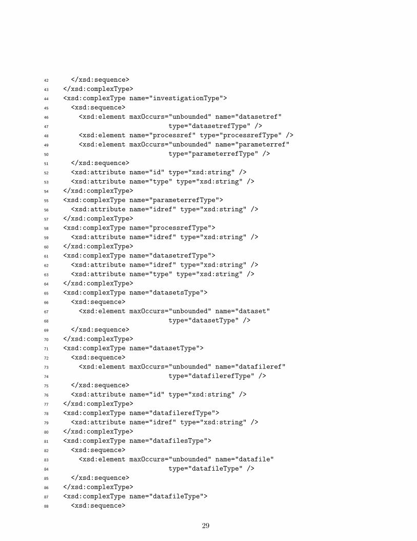
Appendix A: XML Schema for Data Ingestion
This section presents a XML schema based on the extended CSMD model to facilitate thedata ingestion functionality of the ICAT-Personal implementation.
<?xml version="1.0" encoding="utf-16"?>1
<xsd:schema attributeFormDefault="unqualified"2
elementFormDefault="qualified"3
version="1.0"4
xmlns:xsd="http://www.w3.org/2001/XMLSchema"5
>6
<xsd:element name="root" type="rootType" />7
<xsd:complexType name="rootType">8
<xsd:sequence>9
<xsd:element name="processes" type="processesType" />10
<xsd:element name="parameters" type="parametersType" />11
<xsd:element name="datafiles" type="datafilesType" />12
<xsd:element name="datasets" type="datasetsType" />13
<xsd:element name="investigations" type="investigationsType" />14
<xsd:element name="studies" type="studiesType" />15
</xsd:sequence>16
</xsd:complexType>17
<xsd:complexType name="studiesType">18
<xsd:sequence>19
<xsd:element maxOccurs="unbounded" name="study" type="studyType" />20
</xsd:sequence>21
</xsd:complexType>22
<xsd:complexType name="studyType">23
<xsd:sequence>24
<xsd:element maxOccurs="unbounded" name="investigationref"25
type="investigationrefType" />26
<xsd:element maxOccurs="unbounded" name="studyref" type="studyrefType" />27
</xsd:sequence>28
<xsd:attribute name="id" type="xsd:string" />29
<xsd:attribute name="name" type="xsd:string" />30
</xsd:complexType>31
<xsd:complexType name="studyrefType">32
<xsd:attribute name="idref" type="xsd:string" />33
</xsd:complexType>34
<xsd:complexType name="investigationrefType">35
<xsd:attribute name="idref" type="xsd:string" />36
</xsd:complexType>37
<xsd:complexType name="investigationsType">38
<xsd:sequence>39
<xsd:element maxOccurs="unbounded" name="investigation"40
type="investigationType" />41
28
</xsd:sequence>42
</xsd:complexType>43
<xsd:complexType name="investigationType">44
<xsd:sequence>45
<xsd:element maxOccurs="unbounded" name="datasetref"46
type="datasetrefType" />47
<xsd:element name="processref" type="processrefType" />48
<xsd:element maxOccurs="unbounded" name="parameterref"49
type="parameterrefType" />50
</xsd:sequence>51
<xsd:attribute name="id" type="xsd:string" />52
<xsd:attribute name="type" type="xsd:string" />53
</xsd:complexType>54
<xsd:complexType name="parameterrefType">55
<xsd:attribute name="idref" type="xsd:string" />56
</xsd:complexType>57
<xsd:complexType name="processrefType">58
<xsd:attribute name="idref" type="xsd:string" />59
</xsd:complexType>60
<xsd:complexType name="datasetrefType">61
<xsd:attribute name="idref" type="xsd:string" />62
<xsd:attribute name="type" type="xsd:string" />63
</xsd:complexType>64
<xsd:complexType name="datasetsType">65
<xsd:sequence>66
<xsd:element maxOccurs="unbounded" name="dataset"67
type="datasetType" />68
</xsd:sequence>69
</xsd:complexType>70
<xsd:complexType name="datasetType">71
<xsd:sequence>72
<xsd:element maxOccurs="unbounded" name="datafileref"73
type="datafilerefType" />74
</xsd:sequence>75
<xsd:attribute name="id" type="xsd:string" />76
</xsd:complexType>77
<xsd:complexType name="datafilerefType">78
<xsd:attribute name="idref" type="xsd:string" />79
</xsd:complexType>80
<xsd:complexType name="datafilesType">81
<xsd:sequence>82
<xsd:element maxOccurs="unbounded" name="datafile"83
type="datafileType" />84
</xsd:sequence>85
</xsd:complexType>86
<xsd:complexType name="datafileType">87
<xsd:sequence>88
29

<xsd:element name="name" type="xsd:string" />89
<xsd:element minOccurs="0" name="directory" type="xsd:string" />90
<xsd:element minOccurs="0" name="description" type="xsd:string" />91
</xsd:sequence>92
<xsd:attribute name="id" type="xsd:string" />93
</xsd:complexType>94
<xsd:complexType name="parametersType">95
<xsd:sequence>96
<xsd:element maxOccurs="unbounded" name="parameter"97
type="parameterType" />98
</xsd:sequence>99
</xsd:complexType>100
<xsd:complexType name="parameterType">101
<xsd:sequence>102
<xsd:element name="name" type="xsd:string" />103
<xsd:element minOccurs="0" name="directory" type="xsd:string" />104
<xsd:element name="parameterfile" type="xsd:string" />105
</xsd:sequence>106
<xsd:attribute name="id" type="xsd:string" />107
</xsd:complexType>108
<xsd:complexType name="processesType">109
<xsd:sequence>110
<xsd:element maxOccurs="unbounded" name="process"111
type="processType" />112
</xsd:sequence>113
</xsd:complexType>114
<xsd:complexType name="processType">115
<xsd:sequence>116
<xsd:element name="name" type="xsd:string" />117
<xsd:element minOccurs="0" name="directory" type="xsd:string" />118
</xsd:sequence>119
<xsd:attribute name="id" type="xsd:string" />120
<xsd:attribute name="type" type="xsd:string" />121
</xsd:complexType>122
</xsd:schema>123
30

Appendix B: An Example Data Ingestion XML
An example data ingestion XML file is shown below. It corresponds to the diagram on theright hand side of Figure 6.
<?xml version="1.0" encoding="UTF-8"?>124
125
<root id ="An Example Data Ingestion XML">126
<processes>127
<process id="gudrun_java" type="java program">128
<name>GudrunGUI_2.jar</name>129
<directory>GudrunGUI_2</directory>130
</process>131
<process id="purge_det" type="fortran program">132
<name>purge_det.ex</name>133
<directory>GudrunGUI_2</directory>134
</process>135
<process id="gudrun_dcs" type="fortran program">136
<name>Gudrun_dcs.ex</name>137
<directory>GudrunGUI_2</directory>138
</process>139
</processes>140
<parameters>141
<parameter id="param1">142
<parameterfile>143
f1.param144
</parameterfile>145
<name>f1.param</name>146
<directory></directory>147
</parameter>148
<parameter id="param2">149
<parameterfile>150
f2.param151
</parameterfile>152
<name>f2.param</name>153
<directory></directory>154
</parameter>155
<parameter id="param3">156
<parameterfile>157
f3.param158
</parameterfile>159
<name>f3.param</name>160
<directory></directory>161
</parameter>162
<parameter id="param4">163
<parameterfile>164
f4.param165
</parameterfile>166
31

<name>f4.param</name>167
</parameter>168
<parameter id="param5">169
<parameterfile>170
f5.param171
</parameterfile>172
<name>f5.param</name>173
</parameter>174
<parameter id="param6">175
<parameterfile>176
f6.param177
</parameterfile>178
<name>f6.param</name>179
</parameter>180
</parameters>181
<datafiles>182
<datafile id="df1">183
<name>Gudrun_dcs.txt</name>184
<directory>run.SANDALS.Water</directory>185
</datafile>186
<datafile id="df2">187
<name>purge_det.dat</name>188
<directory>run.SANDALS.Water</directory>189
</datafile>190
<datafile id="df3">191
<name>spec.bad</name>192
<directory>run.SANDALS.Water</directory>193
</datafile>194
<datafile id="df4">195
<name>SLS39631.mgor01</name>196
<directory>run.SANDALS.Water</directory>197
</datafile>198
<datafile id="df5">199
<name>SLS39631.mint01</name>200
<directory>run.SANDALS.Water</directory>201
</datafile>202
<datafile id="df6">203
<name>Detector_withNIMROD.dat</name>204
<directory>StartupFiles.SLS</directory>205
<!-- description: Detector calibration file name -->206
</datafile>207
<datafile id="df7">208
<name>groups_18_clean2.dat</name>209
<directory>StartupFiles.SLS</directory>210
<!-- description: Groups file name -->211
</datafile>212
<datafile id="df8">213
32

<name>SLSdeadtime.cor</name>214
<directory>StartupFiles.SLS</directory>215
<!-- description: Deadtime constants file name -->216
</datafile>217
<datafile id="df9">218
<name>sears91_gudrun.dat</name>219
<directory>StartupFiles.SLS</directory>220
<!-- description: Neutron scattering parameters file -->221
</datafile>222
<datafile id="df10">223
<name>spectrum000.dat</name>224
<directory>StartupFiles.SLS</directory>225
<!-- description: Filename containing incident beam spectrum parameters -->226
</datafile>227
<datafile id="df11">228
<name>SLS39629.RAW</name>229
<directory>RawData.SANDALS</directory>230
<!-- description: NORMALISATION data files -->231
</datafile>232
<datafile id="df12">233
<name>SLS39630.RAW</name>234
<directory>RawData.SANDALS</directory>235
<!-- description: NORMALISATION BACKGROUND data files -->236
</datafile>237
<datafile id="df13">238
<name>slsvanadium.bragg</name>239
<directory>StartupFiles.SLS</directory>240
<!-- description: Normalisation differential cross section filename -->241
</datafile>242
<datafile id="df14">243
<name>SLS39621.RAW</name>244
<directory>RawData.SANDALS</directory>245
<!-- description: SAMPLE D2O 25C data files -->246
</datafile>247
<datafile id="df15">248
<name>SLS39637.RAW</name>249
<directory>RawData.SANDALS</directory>250
<!-- description: SAMPLE D2O 25C data files -->251
</datafile>252
<datafile id="df16">253
<name>SLS39641.RAW</name>254
<directory>RawData.SANDALS</directory>255
<!-- description: SAMPLE D2O 25C data files -->256
</datafile>257
<datafile id="df17">258
<name>SLS39534.RAW</name>259
<directory>RawData.SANDALS</directory>260
33

<!-- description: CONTAINER 1mm TiZr can data files -->261
</datafile>262
<datafile id="df18">263
<name>SLS39542.RAW</name>264
<directory>RawData.SANDALS</directory>265
<!-- description: CONTAINER 1mm TiZr can data files -->266
</datafile>267
<datafile id="df19">268
<name>GNUplot.plt</name>269
<directory>run.SANDALS.Water</directory>270
<!-- description: Gnuplot files -->271
</datafile>272
</datafiles>273
<datasets>274
<dataset id="d1">275
<datafileref idref="df1"/>276
<datafileref idref="df6"/>277
<datafileref idref="df7"/>278
<datafileref idref="df8"/>279
<datafileref idref="df9"/>280
<datafileref idref="df10"/>281
<datafileref idref="df11"/>282
<datafileref idref="df12"/>283
<datafileref idref="df13"/>284
<datafileref idref="df14"/>285
<datafileref idref="df15"/>286
<datafileref idref="df16"/>287
<datafileref idref="df17"/>288
<datafileref idref="df18"/>289
<datafileref idref="df19"/>290
</dataset>291
<dataset id="d2">292
<datafileref idref="df2"/>293
</dataset>294
<dataset id="d3">295
<datafileref idref="df3"/>296
</dataset>297
<dataset id="d4">298
<!-- description: -->299
<datafileref idref="df4"/>300
<datafileref idref="df5"/>301
</dataset>302
<dataset id="d5">303
<datafileref idref="df19"/>304
</dataset>305
</datasets>306
<investigations>307
34

<investigation id="i1" type="analysis">308
<processref idref="gudrun_java"/>309
<datasetref idref="d5" type="others"/>310
<datasetref idref="d1" type="output"/>311
<datasetref idref="d2" type="output"/>312
</investigation>313
<investigation id="i2" type="analysis">314
<datasetref idref="d2" type="input"/>315
<processref idref="purge_det"/>316
<datasetref idref="d3" type="output"/>317
</investigation>318
<investigation id="i3" type="analysis">319
<datasetref idref="d1" type="input"/>320
<datasetref idref="d3" type="input"/>321
<processref idref="gudrun_dcs"/>322
<datasetref idref="d4" type="output"/>323
</investigation>324
</investigations>325
<studies>326
<study id="s1">327
<investigationref idref="i1" />328
<investigationref idref="i2" />329
<investigationref idref="i3" />330
</study>331
</studies>332
</root>333
334
35

Appendix C: ICAT-Personal Database Schema
This section presents a database schema (MySQL) based on the extended CSMD model forthe ICAT-Personal implementation.
drop database if exists icatlite;335
create database icatlite;336
337
use icatlite;338
339
create table process (340
id bigint(20) not null auto_increment primary key,341
type varchar(20),342
directory varchar(100),343
name varchar(255),344
location varchar(255),345
link varchar(255),346
creationtime timestamp(8) default now(),347
creator int(20)348
);349
350
create table dataset (351
id bigint(20) not null auto_increment primary key,352
creationtime timestamp(8) default now(),353
creator int(20)354
);355
356
create table investigation (357
id bigint(20) not null auto_increment primary key,358
process bigint(20) not null,359
type varchar(20),360
creationtime timestamp(8) default now(),361
creator int(20),362
foreign key (process) references process(id) on update cascade on delete restrict363
);364
365
create table datafile (366
id bigint(20) not null auto_increment primary key,367
dataset bigint(20) not null,368
directory varchar(255),369
name varchar(255),370
location varchar(255),371
description varchar(255),372
creationtime timestamp(8) default now(),373
creator int(20),374
link varchar(255),375
index (dataset),376
foreign key (dataset) references dataset(id) on update cascade on delete restrict377
36

);378
379
create table parameter (380
id bigint(20) not null auto_increment primary key,381
directory varchar(100),382
location varchar(255),383
name varchar(255),384
creationtime timestamp(8) default now(),385
creator int(20)386
);387
388
create table datafile_parameter (389
datafile bigint(20) not null,390
parameter bigint(20) not null,391
creationtime timestamp(8) default now(),392
creator int(20),393
index(datafile, parameter),394
foreign key (datafile) references datafile(id) on update cascade on delete restrict,395
foreign key (parameter) references parameter(id) on update cascade on delete restrict,396
primary key (datafile, parameter)397
);398
399
400
create table dataset_investigation (401
dataset bigint(20) not null,402
investigation bigint(20) not null,403
type varchar(10),404
creationtime timestamp(8) default now(),405
index(dataset, investigation),406
creator int(20),407
foreign key (dataset) references dataset(id) on update cascade on delete restrict,408
foreign key (investigation) references investigation(id) on update cascade on delete restrict,409
primary key (dataset, investigation)410
);411
412
413
create table dataset_parameter (414
dataset bigint(20) not null,415
parameter bigint(20) not null,416
creationtime timestamp(8) default now(),417
index(dataset, parameter),418
creator int(20),419
foreign key (dataset) references dataset(id) on update cascade on delete restrict,420
foreign key (parameter) references parameter(id) on update cascade on delete restrict,421
primary key (dataset, parameter)422
);423
424
37

create table investigation_parameter (425
investigation bigint(20) not null,426
parameter bigint(20) not null,427
creationtime timestamp(8) default now(),428
creator int(20),429
index(investigation, parameter),430
foreign key (investigation) references investigation(id) on update cascade on delete restrict,431
foreign key (parameter) references parameter(id) on update cascade on delete restrict,432
primary key (investigation, parameter)433
);434
435
create table investigator (436
id bigint(20) not null auto_increment primary key,437
creationtime timestamp(8) default now(),438
creator int(20)439
);440
441
create table investigator_investigation (442
investigator bigint(20) not null,443
investigation bigint(20) not null,444
creationtime timestamp(8) default now(),445
index(investigator, investigation),446
creator int(20),447
foreign key (investigator) references investigator(id) on update cascade on delete restrict,448
foreign key (investigation) references investigation(id) on update cascade on delete restrict,449
primary key (investigator, investigation)450
);451
452
create table study (453
id bigint(20) not null auto_increment primary key,454
manager bigint(20) default null,455
xml blob,456
dot blob,457
name varchar(200),458
creator int(20),459
creationtime timestamp(8) default now()460
);461
462
create table study_childstudy (463
parent_study bigint(20) not null,464
child_study bigint(20) default null,465
creationtime timestamp(8) default now(),466
creator int(20),467
index(parent_study, child_study),468
foreign key (parent_study) references study(id) on update cascade on delete restrict,469
foreign key (child_study) references study(id) on update cascade on delete restrict,470
primary key (parent_study, child_study)471
38

);472
473
create table study_investigation (474
study bigint(20) not null,475
investigation bigint(20) not null,476
creationtime timestamp(8) default now(),477
creator int(20),478
index(study, investigation),479
foreign key (study) references study(id) on update cascade on delete restrict,480
foreign key (investigation) references investigation(id) on update cascade on delete restrict,481
primary key (study, investigation)482
);483
484
create table studyManager (485
id bigint(20) not null auto_increment primary key,486
creationtime timestamp(8) default now(),487
creator int(20)488
);489
490
39
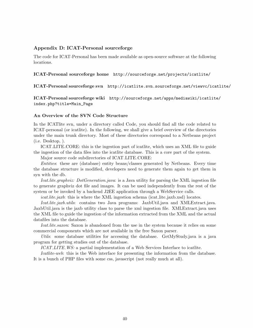
Appendix D: ICAT-Personal sourceforge
The code for ICAT-Personal has been made available as open-source software at the followinglocations.
ICAT-Personal sourceforge home http://sourceforge.net/projects/icatlite/
ICAT-Personal sourceforge svn http://icatlite.svn.sourceforge.net/viewvc/icatlite/
ICAT-Personal sourceforge wiki http://sourceforge.net/apps/mediawiki/icatlite/
index.php?title=Main_Page
An Overview of the SVN Code Structure
In the ICATlite svn, under a directory called Code, you should find all the code related toICAT-personal (or icatlite). In the following, we shall give a brief overview of the directoriesunder the main trunk directory. Most of these directories correspond to a Netbeans project(i.e. Desktop, ).
ICAT LITE CORE: this is the ingestion part of icatlite, which uses an XML file to guidethe ingestion of the data files into the icatlite database. This is a core part of the system.
Major source code subdirectories of ICAT LITE CORE:Entities: these are (database) entity beans/classes generated by Netbeans. Every time
the database structure is modified, developers need to generate them again to get them insyn with the db.
Icat.lite.graphviz: DotGeneration.java: is a Java utility for parsing the XML ingestion fileto generate graphviz dot file and images. It can be used independently from the rest of thesystem or be invoked by a backend J2EE application through a WebService calls.
icat.lite.jaxb: this is where the XML ingestion schema (icat lite jaxb.xsd) locates.Icat.lite.jaxb.utils: contains two Java programs: JaxbUtil.java and XMLExtract.java.
JaxbUtil.java is the jaxb utility class to parse the xml ingestion file. XMLExtract.java usesthe XML file to guide the ingestion of the information extracted from the XML and the actualdatafiles into the database.
Icat.lite.saxon: Saxon is abandoned from the use in the system because it relies on somecommercial components which are not available in the free Saxon parser.
Utils: some database utilities for accessing the database. GetMyStudy.java is a javaprogram for getting studies out of the database.
ICAT LITE WS: a partial implementation of a Web Services Interface to icatlite.Icatlite-web: this is the Web interface for presenting the information from the database.
It is a bunch of PHP files with some css, javascript (not really much at all).
40

Appendix E:Installation Guide to ICAT-Personal
ICAT-personal consists of two functionalities: data ingestion and data presentation. Thisinstruction assumes that both functionalities are installed on the same machine. Prerequisitesoftware for these functionalities are as follows.
ICAT-p Ingestion (ingesting data into the database):
• Mysql server
• Hibernate
• Java (developed on version 1.6/6)
• Mysql jdbc driver
ICAT-p Web (displaying the ingested data in a web browser, tested with firefox):
• Mysql server
• icatlite database script
• Php (http://php.net/)
• Apache
• Graphviz (http://www.graphviz.org/) AND Image graphviz (a php module)
Instructions for installing graphviz and image graphviz: http://drupal.org/project/
graphviz_filter (official instruction, but ubuntu doesnt seem to have Image Graphviz pack-age available 08 Oct. 2010) and http://drupal.org/node/883114
Important settings
• Mysql database name: icatlite
• Dump the data from Mysql database: mysqldump u username p icatlite ¿ icatlite.dump(The file icatlite.dump will be generated in the directory where you run the command)
• Import the data back to mysql database: mysql u username p icatlite ¡ icatlite.dump(Assume the file icatlite.dump exists in the directory where you run the command)
• If there is a problem: permission denied php cannot write to new file. (Solution: weneed to give apache, i.e. www-data, the permission to all the directories and files) seehttp://www.karakas-online.de/forum/viewtopic.php?t=2235
If there are permissions problem, change both user and group to www-data (the defaultsfor apache server) in the web server:
chown www-data directory/
chgrp www-data directory/
Step-by-step instructions
• Download the trunk from the svn
41

• Under a directory called ICAT LITE CORE/database, you should find a script: icatlite-mysql.sql
Set up ICAT-personal demo website.
• Unzip icatlite-web.zip (this is available from the ESC svn under Code/trunk) to anApache accessible directory
• Under the directory, you can find the following php files: clickable svg.php html head.phpsections head.php sidebar.php db fns.php html menu.php sections.php sidebar tail.phpdemo standalone.php html tail.php sections tail.php study svg backup.php demo website.phpindex.php sidebar head.php study svg.php (AND a directory named /web, which holdscss, javascript, and other web page related files.)
• db fns.php: change the mysql database username password in this php
• modify apache httpd.conf so that it can the apache server know how to interpret svgtype
To modify the apache to interpret the SVG type, follow the instructions at http://kaioa.com/node/45. The following are added to the /etc/apache2/apache2.conf:
<IfModule mime_module>
AddType image/svg+xml .svg
AddType image/svg+xml .svgz
AddEncoding gzip .svgz
<FilesMatch \.svgz$>
<IfModule mod_gzip.c>
mod_gzip_on No
</IfModule>
</FilesMatch>
</IfModule>
42

References
[1] S. Bechhofer, D. De Roure, M. Gamble, C. Goble, and I. Buchan. Research Objects:Towards Exchange and Reuse of Digital Knowledge. In: The Future of the Web forCollaborative Science (FWCS 2010), April 2010, Raleigh, NC, USA.
[2] Sean Bechhofer, John Ainsworth, Jiten Bhagat, Iain Buchan, Philip Couch, Don Cruick-shank, David De Roure, Mark Delderfield, Ian Dunlop, Matthew Gamble, Carole Goble,Danius Michaelides, Paolo Missier, Stuart Owen, David Newman, Shoaib Sufi, WhyLinked Data is Not Enough for Scientists, pp. 300-307, 6th IEEE International Confer-ence on e-Science, 2010
[3] Mark Borkum, Carl Lagoze, Jeremy Frey, and Simon Coles. A Semantic eScience Plat-form for Chemistry, pp.316-323, 6th IEEE International Conference on e-Science, 2010
[4] Simon J. Coles, Jeremy G. Frey, Michel B. Hursthouse, Mark E. Light, Andrew J. Mil-sted, Leslie A. Carr, David DeRoure, Christopher J. Gutteridge, Hugo R. Mills, Ken E.Meacham, Michael Surridge, Elizabeth Lyon, Rachel Heery, Monica Duke, and MichaelDay, An E-Science Environment for Service Crystallography - from Submission to Dis-semination, J. Chem. Inf. Model., 2006, 46(3), pp.1006 - 1016.
[5] Damian Flannery, Brian Matthews, Tom Griffin, Juan Bicarregui, Michael Gleaves,Laurent Lerusse, Roger Downing, Alun Ashton, Shoaib Sufi, Glen Drinkwater, KerstinKleese, ICAT: Integrating Data Infrastructure for Facilities Based Science, pp.201-207,5th IEEE International Conference on e-Science, 2009.
[6] M Folk, A Cheng, K Yates (1999) HDF5: A file format and I/O library for high per-formance computing applications, Proceedings of Supercomputing’99, ACM SIGARCHand IEEE, (Portland, OR), Nov. 1999.
[7] Ian T. Foster. The virtual data grid: a new model and architecture for data-intensivecollaboration. In SSDBM 2003: Proceedings of the 15th international conference on Sci-entific and statistical database management, Washington, DC, USA, 2003.
[8] Boris Glavic and Klaus R. Dittrich. Data Provenance: A Categorization of ExistingApproaches. In Datenbanksysteme in Business, Technologie und Web (BTW 2007), pp.227 - 241, 2007.
[9] P. Klosowski, M. Koennecke, J. Z. Tischler and R. Osborn, NeXus: A common formatfor the exchange of neutron and synchroton data, Physica B: Condensed Matter, Vol241-243, Dec 1997, pp151-153, Proceedings of the International Conference on NeutronScattering.
[10] Brian Matthews, Shoaib Sufi, Damian Flannery, Laurent Lerusse, Tom Griffin, MichaelGleaves, Kerstin Kleese. Using a Core Scientific Metadata Model in Large-Scale Facilities.5th International Digital Curation Conference, London, England, 2-4 December 2009.
[11] Brian Matthews, Arif Shaon, Juan Bicarregui, Catherine Jones, Jim Woodcock, EstherConway, Towards a Methodology for Software Preservation. 6th International Conferenceon Preservation of Digital Objects (iPres 2009), San Francisco, USA, 05-06 Oct 2009.
43

[12] Brian Matthews, Arif Shaon, Juan Bicarregui, Catherine Jones, A Framework for Soft-ware Preservation, International Journal of Digital Curation, 5 (1), 2010.
[13] L. Moreau, B. Clifford, J. Freire, J. Futrelle, Y. Gil, P. Groth, N. Kwasnikowska, S. Miles,P. Missier, J. Myers, B. Plale, Y. Simmhan, E. Stephan, and J. Van den Bussche. TheOpen Provenance Model core specification (v1.1). Future Generation Computer Systems,in Press, 2010.
[14] Tom Oinn, Matthew Addis, Justin Ferris, Darren Marvin, Martin Senger, Mark Green-wood, Tim Carver, Kevin Glover, Matthew R. Pocock, Anil Wipat and Peter Li, Taverna:a tool for the composition and enactment of bioinformatics workflows, Bioinformatics,Vol. 20(17) 2004, pp3045-3054.
[15] Manjula Patel Requirements Report, I2S2 project report D1.1, July 2010. http://www.ukoln.ac.uk/projects/I2S2/documents/I2S2-WP1-D1.1-RR-Final-100707.pdf.
[16] Eric F. Pettersen, Thomas D. Goddard, Conrad C. Huang, Gregory S. Couch, Daniel M.Greenblatt, Elaine C. Meng, Thomas E. Ferrin, UCSF Chimera - A visualization systemfor exploratory research and analysis, Journal of Computational Chemistry, 25(13), 1605- 1612, 2004.
[17] R Rew, G Davis, NetCDF: an interface for scientific data access IEEE Computer Graph-ics and Applications, 10(4), 76-82, 1990.
[18] Enrico Scalavino, Vaibhav Gowadia, and Emil C. Lupu (2010) A Labelling System forDerived Data Control, in Sara Foresti and Sushil Jajodia (Eds.) Data and ApplicationsSecurity and Privacy XXIV: Proceedings of DBSec 2010, the 24th Annual IFIP WG 11.3Working Conference, LNCS, Springer-Verlag:Berlin.
[19] Andrew Shepherd (2001) Hierarchical task analysis, Taylor & Francis: London.
[20] Shoaib Sufi and Brian Matthews, A Metadata Model for the Discovery and Exploitationof Scientific Studies. In Domenico Talia, Angelos Bilas and Marios D. Dikaiakos (Eds.)Knowledge and Data Management in GRIDs, 2007, pp135-149, Springer: Berlin.
[21] M.G. Tucker, D.A. Keen, M.T. Dove, A.L. Goodwin and Q. Hui. RMCProfile: ReverseMonte Carlo for polycrystalline materials. Journal of Physics: Condensed Matter 19, artno 335218 (16 pp), 2007, available at: http://wwwisis2.isis.rl.ac.uk/rmc/.
[22] Erica Yang. Martin Dove’s RMC Workflow Diagram. Project RequirementReport (supplementary report) for the I2S2 project, July 2010. Availableat: https://www.jiscmail.ac.uk/cgi-bin/filearea.cgi?LMGT1=I2S2&f=
/Deliverables/RequirementsReport.
[23] Erica Yang, Brian Matthews, Michael Wilson, Enhancing the Core Scientific MetadataModel to Incorporate Derived Data, pp.145-152, 6th IEEE International Conference one-Science, 2010
[24] J. Yu and R. Buyya. A taxonomy of scientific workflow systems for grid computing,SIGMOD Rec. 34, 3 (Sep. 2005), pp44-49, 2005.
44