PROJECT DEVELOPMENT MEMORANDUM NO. 1-2011 TOtransportation.ky.gov/CADD-Standards/Documents/PROJECT...
41
PROJECT DEVELOPMENT MEMORANDUM NO. 1-2011 TO: Chief District Engineers Design Engineers Active Consultants FROM: Kevin Damron, PE Executive Director for Project Development DATE: March 17, 2011 SUBJECT: Policy for Electronically Signed and Sealed Contract Plans The Transportation Cabinet continues to strive to make technological advances to create more efficient, economical and environmentally friendly Highway Plan Sets. As a result, this memorandum establishes a change in policy for the format of the “Final Contract Plans” (i.e., legal, binding set) from being plotted on first-generation Mylar to an electronic plan set in PDF format. A complete electronic plan set requires the addition of electronic and/or digital signatures. There are distinct differences between electronic and digital signatures. The definition of electronic and digital signatures for the purpose of this policy is as follows: An electronic signature may include scanned images of hand written signatures, typed notations or signature blocks without any authentications and/or encryption system included. A digital signature means a signature that meets the standards as set forth in 201 KAR 18:104 as follows: 1) It is unique identification of the signer, 2) It is verifiable, 3) It is under the signer’s direct and exclusive control, 4) It is linked to the electronic document in such a manner that causes changes to be easily determined and visually displayed if any data in the electronic document file is changed subsequent to the digital signature having been affixed to the electronic document; 5) An attempt to change the electronic document after the digital signature is affixed shall cause the digital signature to be removed or altered significantly enough to invalidate the digital signature; and 6) If the electronic document is to be electronically transmitted, the electronic document is converted to a read-only format. In the above definition, the term “digital signature” replaces “electronic signature” in the 201 KAR 18:104. Currently, industry standards use “digital signature” as the digitally encrypted signature.
Transcript of PROJECT DEVELOPMENT MEMORANDUM NO. 1-2011 TOtransportation.ky.gov/CADD-Standards/Documents/PROJECT...
PROJECT DEVELOPMENT MEMORANDUM NO. 1-2011 TO: Chief District Engineers Design Engineers Active Consultants FROM: Kevin Damron, PE Executive Director for Project Development DATE: March 17, 2011 SUBJECT: Policy for Electronically Signed and Sealed Contract Plans The Transportation Cabinet continues to strive to make technological advances to create more efficient, economical and environmentally friendly Highway Plan Sets. As a result, this memorandum establishes a change in policy for the format of the “Final Contract Plans” (i.e., legal, binding set) from being plotted on first-generation Mylar to an electronic plan set in PDF format. A complete electronic plan set requires the addition of electronic and/or digital signatures. There are distinct differences between electronic and digital signatures. The definition of electronic and digital signatures for the purpose of this policy is as follows: An electronic signature may include scanned images of hand written signatures, typed notations or signature blocks without any authentications and/or encryption system included. A digital signature means a signature that meets the standards as set forth in 201 KAR 18:104 as follows:
1) It is unique identification of the signer, 2) It is verifiable, 3) It is under the signer’s direct and exclusive control, 4) It is linked to the electronic document in such a manner that causes changes to be easily
determined and visually displayed if any data in the electronic document file is changed subsequent to the digital signature having been affixed to the electronic document;
5) An attempt to change the electronic document after the digital signature is affixed shall cause the digital signature to be removed or altered significantly enough to invalidate the digital signature; and
6) If the electronic document is to be electronically transmitted, the electronic document is converted to a read-only format.
In the above definition, the term “digital signature” replaces “electronic signature” in the 201 KAR 18:104. Currently, industry standards use “digital signature” as the digitally encrypted signature.
Alex1.Smith
Kevin

Effective with the release of this memo, all Final Contract Plans are to be created and submitted in PDF format. The latest CADD Standards Policy should be followed. Mylar plan sets will no longer be accepted unless an exception is granted by the Plan Processing Branch in the Division of Highway Design. All Final Contract Plans prepared by state forces shall bear the electronic signature of the State Highway Engineer. Final Contract Plans and/or any part thereof prepared by consulting engineering firms shall bear both the electronic signature, electronic stamp of the seal of a professional engineer (civil or highway) licensed in the Commonwealth of Kentucky and his/her digital signature. When engineering work is completed by a sub consultant, the prime consultant shall be responsible for determining whether the prime or sub shall affix the digital signature. For an example see Highway Design Manual HD-206 Pages 5-6 (attached). The Layout Sheet is the designated location for the authorization signatures as detailed above. Two signature lines are included in the lower right-hand corner of the layout sheet. The top line, “Recommended By,” will be for the Project Manager’s name (a signature is no longer required, a typed name is sufficient). The bottom line, “Plan Approved By,” will be for the State Highway Engineer’s electronic signature. The block to the lower right will be used for the consultant information, which includes the firm’s name, project engineer’s electronic signature and an electronic stamp of his/her P.E. seal and digital signature. Also with the release of this memorandum, the respective names of the designers and the date of the final submittal of the Contract Plan Set shall appear on the appropriate page of each subset (Roadway, Geotechnical, Structure, Signing, Signal, Lighting and Cross Section). Revised sheet cells are available in the Sheet Cell Library. For examples of signature and title blocks, see the CADD Standards web page. The design policy document is accessible on the Division of Highway Design web page at: http://transportation.ky.gov/design/designmanual/Design_Manual.html Any questions regarding this memorandum should be directed to the Division of Highway Design.

HD-204
03/11 Page 1 of 25
Chapter
ADMINISTRATIVE PROCEDURES
Subject
Final Design
OVERVIEW: The project moves into the final design phase once a selected alternative
has been chosen and the transportation decision has been documented. Resolutions of project-specific issues or special circumstances identified in the conceptual design phase must be carried through to the final design. The decisions made during the final design phase create the plans needed for right-of-way acquisition, utility relocation, and construction letting. This section contains information regarding the final design process.
RESPONSIBILITIES: Incorporation of design elements into the final design is the responsibility of the designer. The project manager is responsible for assuring this occurs.
REQUEST FOR PAVEMENT DESIGN: The responsibility for designing the pavement depends on the average daily
traffic (ADT), percentage of trucks, and equivalent single axle loads (ESALs). A pavement design submittal folder shall be submitted after a selected alternative has been chosen. For more information on pavement design see HD-1000 of this manual.
ROADWAY SIGN DESIGN: On projects that require signing plans, the roadway designer should
coordinate with the Roadway Sign Design Function before right-of-way plans are submitted to coordinate with utilities and ensure there is adequate space provided for the signs. Signing plans shall be completed to a conceptual stage in time for delivery to the project team prior to the joint inspection in order that right-of-way and utility needs may be accommodated. Conflicts between roadway design elements and the placing of the signs also need to be addressed. The roadway designer should again coordinate with the roadway sign plans before the project letting date so that the signing plans will be completed in time. For more information on signing, see HD-1200 of this manual.
CONT.

ADMINISTRATIVE PROCEDURES—Final Design HD-204
03/11 Page 2 of 25
SOIL & SUBSURFACE EXPLORATION:
Recommendations from the geotechnical report will be used in the final design. (More information on the geotechnical report is described above in the geotechnical overview.) Further geotechnical information may be needed during final design for structural design elements.
SUBSURFACE UTILITY INFORMATION: Complete and concise locations of existing utilities shall be obtained early
in the design process. If during the design process it becomes apparent that roadway construction may conflict with underground utilities, a more accurate location of the utility can be requested. The project team shall determine the quality level of utility locations that are appropriate for the various stages of project development.
For more information on subsurface utility location, see HD-303.
ROADSIDE SAFETY DESIGN: Roadside safety design is a very important component of the total
highway design and should be thoroughly considered during the design process. The goal of roadside safety design is to create a ―forgiving roadside,‖ which allows for errant vehicles leaving the roadway and supports a roadside design where serious consequences are reduced. For more information on roadside safety design, see HD-800.
INTERSECTION DESIGN & SIGNAL PLANS: The designer should use the traffic capacity analysis, site data, and crash
data to prepare studies of alternative configurations/alignments for the intersecting roadways. The intersection’s configuration decision and potential use of traffic control devices should be discussed and decided by the project team on an intersection-by-intersection basis. The project manager is ultimately responsible for making sure the appropriate traffic plans are identified and included in the total plan set. In order to facilitate this process, the project manager should notify the district traffic engineer of project team meetings and inspections as early in the process as feasible. When the project team identifies locations that might require signal, signing, and/or lighting plans, the district traffic engineer should notify central office Traffic in writing and provide appropriate supporting information. For more information on intersection design and signal plans, see HD-900.
CONT.

ADMINISTRATIVE PROCEDURES—Final Design HD-204
03/11 Page 3 of 25
RAILROAD COORDINATION: Coordination with railroad companies must be done when highway
improvements encroach upon railroad facilities. The central office railroad coordinator should be contacted as soon as possible, but no later than the selection of the preferred alternative, in order to facilitate the necessary approvals and identify what additional considerations should be made concerning the potential impacts of the highway on their facilities. The project manager should also ensure that the Preconstruction Project Database documents the need for railroad involvement. This is typically done by adding ―Railroad Involvement‖ in the project concerns area.
For more information on railroad coordination, see HD-1400.
ACCESS MANAGEMENT: Access management includes several principles and techniques that are
designed to increase the capacity of roads, manage congestion, and reduce crashes. Since these are goals in the planning and design of new roads and the reconstruction of existing roads, designers should incorporate access management techniques into project designs.
For more information on access management, see HD-1100.
PEDESTRIAN FACILITIES/BIKE FACILITIES: The project development team (PDT) may need to consider incorporating
pedestrian facilities or bicycle facilities in the project. For guidance on where and when to include pedestrian facilities/bicycle facilities in roadway projects, see HD-1500.
MAINTENANCE OF TRAFFIC: The project team should consider and discuss traffic control procedures
at the preliminary line and grade inspection and address them in the inspection report. The designer should design a detailed suggested sequence of construction for presentation and review at the joint inspection. Maintenance-of-traffic schemes should be developed and placed as drawings and notes on traffic control sheets within the plans. If limited notes are required, place these notes on the General Notes sheet for the project. The maintenance-of-traffic plan is to be developed using the Standard Specifications for Road and Bridge Construction and Standard Drawings as a basis. Write only those requirements not provided in the Standard Specifications for maintaining and controlling traffic into the maintenance-of-traffic plan.
CONT.

ADMINISTRATIVE PROCEDURES—Final Design HD-204
03/11 Page 4 of 25
MAINTENANCE OF TRAFFIC (cont.): The maintenance-of-traffic plan will clearly indicate all required phasing,
method of traffic control, and any time or construction limitations on the contractor. Give attention to developing strategies that will limit impact to the traveling public. As much as possible, maintain the existing number of lanes throughout a construction project, particularly on the interstates and other major routes. Where it is determined that lane restrictions are necessary, consider options that limit closures. Some considerations for these decisions will include restricting work during peak periods of traffic flow on the route and the use of nighttime construction. The maintenance-of-traffic plan should also take into account other adjacent roadway sections that may be under construction and avoid conflict between competing phases of adjacent projects. Approval of the maintenance-of-traffic plans is the responsibility of the project team. The project team will agree upon appropriate documentation for each maintenance-of-traffic plan, but this documentation, at a minimum, should consist of the signatures of the district branch managers for Preconstruction, Construction, and Traffic (and FHWA on interstate projects). This documentation should be placed in the project file within the district, with a copy to the location engineer.
The designer should read the Standard Specifications to become familiar with the requirements for each bid item. Section 112 of the Standard Specifications specifically involves maintenance-of-traffic issues. Bid temporary or permanent signs required for a project on a square-foot basis. This includes those signs shown routinely in the Standard Drawings.
The project team is responsible for developing all permanent and temporary striping plans, including the use of pavement markers if required for the project. For more information on pavement markings, see HD-1201. Other traffic control devices, such as message boards and flashing arrows, must also be identified and bid in adequate numbers for each project.
Diversion Geometric Design - On-site diversions should desirably be constructed to the standards, design speed, and pavement widths that are present on the existing facility. Where this is not feasible, the appropriate speed warning signs should be included in the traffic control plan. Detours – Plans for detours involving road closures should consider the length of the detour route, condition of the detour route, weight limits of structures, and costs of conditioning and maintaining the detour route. A detour map will be included in the plans showing the detour route(s) and the signs necessary. The project team will decide who will be responsible for posting the project’s detour signs.
CONT.

ADMINISTRATIVE PROCEDURES—Final Design HD-204
03/11 Page 5 of 25
MAINTENANCE OF TRAFFIC (cont.): Maintaining Traffic – On projects where plans for maintaining through
traffic and detailed detour plans are not provided, the following note applies:
All main line diversions and specified cross roads constructed to maintain through traffic that are to be used for a period of seven days or more shall be paved as directed by the engineer. Pay the paving at the contract unit prices for the respective materials used. Diversions constructed as a convenience to the contractor that are to be used for a period of seven days or greater shall be paved also; however, the contractor shall bear the total cost.
Maintenance-of-Traffic Bid Items - All projects shall include a bid item for "Maintain and Control Traffic." The unit shall be lump sum. Bid all traffic control items in accordance with the Standard Specifications for Road and Bridge Construction, current edition. All roadway projects that contain a diversion in the plans shall also include a bid item for "Diversions.‖ The lump-sum bid shall include all necessary grading, culverts, and bridges to construct the diversion and shall include removal. Compute earthwork for all diversions shown on the plans and note quantities of excavation and embankment on the plans for the contractor's information only. These quantities shall not be included in the pay items for earthwork. Note the opening for drainage structures in square feet for the contractor's information. Please refer to the Drainage Manual for the proper sizing of drainage structures for a diversion.
As traffic control plans become more extensive and complex, separate pay
items shall be required. These pay items apply to traffic signals, stationary signs, flashing arrows, temporary barrier walls, temporary guardrail, temporary crash cushions, temporary pavement markers, and temporary removable striping tape. The designer should also consider bid items needed for relocating the above features when detailed on the maintenance-of-traffic plans. Other pay items may include variable message signs and any other special or unusually expensive items peculiar to the project, in addition to the "Maintain and Control Traffic" item. Bid all traffic control items in accordance with the Standard Specifications for Road and Bridge Construction, current edition.
INNOVATIVE BID PROCESSES: The designer should carefully consider the impacts of construction on
motorists. Innovative bid processes are recommended to be used only when the public will experience extreme disruption and delays or when the time of completion of a project or an individual phase is particularly critical. Should the designer choose to use this methodology, a well-developed maintenance-of-traffic plan with all phases well thought out and developed is mandatory. Base the rates applicable in each of the following described processes on established practices for benefit/cost ratios based on road user delay costs. The Division of Planning may help in the development of these ratios.
CONT.
ADMINISTRATIVE PROCEDURES—Final Design HD-204
03/11 Page 6 of 25
INNOVATIVE BID PROCESSES (cont.): Incentive/Disincentive - To charge liquidated damages against all project
completion dates is common. Liquidated damages may also be charged in excess of rates established in the Standard Specifications when deemed appropriate and when the expected impacts to the public may be considered to be greater than the damages established by specification. Liquidated damages may also be charged against individual phases of a contract, particularly when the phase is deemed to be particularly critical to the operation of the highway or for the safety of the motoring public. However, the use of incentives/disincentives described below is probably a more effective method to handle the impacts of individual phases.
Incentive/disincentives should be considered on projects having high traffic volumes and involving construction requirements that will greatly restrict or even shift traffic away from the existing facility. The incentive/disincentive contract compensates a contractor the same per day for early completion of a contract or phase as penalizing the contractor for late completion. If a decision is made to apply a different incentive and disincentive cost, the incentive rate shall not be greater than the disincentive. Base the amount applied for the incentive/disincentive on estimates of such items as traffic safety, traffic maintenance, and road-user delay costs. Generally apply incentive/disincentives only to work that directly affects motorists; therefore, this frequently does not replace normal contractual liquidated damages. The incentive/disincentive provision should be of an adequate amount to motivate a contractor to complete the project or phase ahead of schedule.
In considering the use of incentives/disincentives or any of the other innovative practices that follow, the designer must assure that the work zone will be free of delays that will be beyond the contractor's control, e.g., utility work. The use of incentive/disincentive contracts should be based on a calendar day completion or a fixed completion date rather than a workday completion. Therefore, the proposal must address or waive any contractual language that suggests a conflict with the times established for the incentive/disincentive. This includes the end of construction seasons or other seasonal construction limitations and impacts by holidays. Incentive/disincentive contracts should take into account a contractor working beyond a normal 40-hour work week to accomplish the work. Another consideration the project team should discuss is how the construction engineering and inspection (CEI) will be accomplished. The project team should work with the Division of Construction for workload scheduling. There will be occasions when the Cabinet may determine to contract out this service.
CONT.

ADMINISTRATIVE PROCEDURES—Final Design HD-204
03/11 Page 7 of 25
INNOVATIVE BID PROCESSES (cont.): Cost Plus Time Bidding (A+B Bidding) - Cost plus time bidding is
utilized where it is desired for the contractor to develop the most timely method of completing a project. Develop bidding for this type of project by the formula A+B=C.
Where A = the traditional bid for contract items and is the actual contractual amount and B = the total number of calendar days required to complete the project multiplied by a road user cost/day established by the project development team. The contract is awarded based on the total bid, C, made by the contractor. A disincentive is included in the contract. It is based on the established road-user costs and is placed in effect if the number of days bid by the contractor is exceeded. Similarly, an incentive cost is usually included in the contract to reward the contractor for completing the work earlier than the time bid. It is best to use A+B bidding for specific major phases of a contract rather than the entire contract.
Cost plus time bidding is effective when multiple bidders will be involved. If the designer determines that there is a likelihood that a single bidder will be involved for a project, it is more appropriate that one of the other two described innovative bidding processes be utilized for that project.
Lane Rental - The lane rental concept is used to encourage contractors to minimize road-user impacts during construction, while permitting them the greatest flexibility in deciding the appropriate time frames for lane closures and restrictions. In this concept, there is no specific bid item for lane rental. Rather, base the award of the project solely on the contractor's estimated bid price. However, a provision for a lane rental fee assessment based on a road-user cost is included in the contract and is assessed against the contractor's contract on his monthly contract payments. Assess the fee for the time that the contractor occupies or obstructs any part of the roadway. The fee may be specific to certain segments of the contract. The designer may base rental fees on weekly, daily, hourly, or even fractions-of-an-hour rates. Also, consider the lengths of lane closures. Greater fees may be charged for certain times when traffic may be greater; e.g., during rush hours when hourly rates are bid or during holidays when a daily rate is bid. The designer may still make restrictions on lane closures for special events or holidays. Generally, the Department should limit the restrictions placed on the contractor and leave the decision of the best periods for his or her actions within the contractor's judgment. Obviously, critical path method scheduling of this type of an operation is essential for the contractor to assure the economic impact to his or her contract and for the Department’s complete understanding of the schedule on which the contractor will complete the work. Neither the Department nor the contractor will give any indication in the project bid as to the anticipated time for which assessments may occur.
CONT.
ADMINISTRATIVE PROCEDURES—Final Design HD-204
03/11 Page 8 of 25
INNOVATIVE BID PROCESSES (cont.): Consider lane rentals on projects that greatly affect the traveling public.
Major urban projects are prime candidates. The intent of lane rentals is to encourage contractors to schedule their work to keep lane restrictions to a minimum, both in terms of duration and the number of closures or other obstructions that occur. Lane rentals also encourage lane closures at low-volume times. Consider pre-bid conferences whenever using innovative bidding methods. This allows the contractor to understand the established restrictions, the time frames involved in the overall project, and specific phases that require extra control and effort.
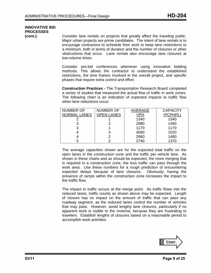
Construction Practices - The Transportation Research Board completed a series of studies that measured the actual flow of traffic in work zones. The following chart is an indication of expected impacts to traffic flow when lane reductions occur: NUMBER OF NORMAL LANES
2 3 3 4 4 5
NUMBER OF OPEN LANES
1 2 1 3 2 2
AVERAGE VPH 1340 2980 1170 4560 2960 2740
CAPACITY (PCPHPL)
1340 1490 1170 1520 1480 1370
The average capacities shown are for the expected total traffic on the open lanes in the construction zone and the traffic per vehicle lane. As shown in these charts and as should be expected, the more merging that is required in a construction zone, the less traffic can pass through the work area. Use these numbers for a rough prediction of encountering expected delays because of lane closures. Obviously, having the presence of ramps within the construction zone increases the impact to the traffic flow. The impact to traffic occurs at the merge point. As traffic flows into the reduced lanes, traffic counts as shown above may be expected. Length of closure has no impact on the amount of traffic that can pass any roadway segment, as the reduced lanes control the number of vehicles that may pass. However, avoid lengthy lane closures, particularly if no apparent work is visible to the motorist, because they are frustrating to travelers. Establish lengths of closures based on a reasonable period to accomplish work activities.
CONT.

ADMINISTRATIVE PROCEDURES—Final Design HD-204
03/11 Page 9 of 25
INNOVATIVE BID PROCESSES (cont.): As discussed previously, lane rentals based on a per-mile basis of
closure may be an effective method to permit the contractor the maximum closure he or she deems feasible in an established period. The designer may consider complete closures of roadways or ramps to finish construction in the shortest periods possible where alternate routes exist. Another consideration would be to permit closures on only one side of the highway at a time. The appearance of work occurring on one side while the other side is restricted with little activity may be discouraging to the motorist. Use two-lane, two-way operation (TLTWO) on one roadway of a normally divided highway only after careful consideration of other available methods of traffic control. The PDT should consider the use of median barrier wall for positive separation of traffic on TLTWO. Generally, a TLTWO should be used on urban-type streets or other low-speed operations and where the driver can see the transition back to normal one-way operations. There may still be some reason the project development team may choose using TLTWO in circumstances other than those cited without the use of barrier wall. In these cases, separate the lanes by tubular markers and pay for in accordance to guidance found in the Standard Specifications. Traffic References - The designer is referred to the Traffic Control through Highway and Street Work Zones Manual, the Standard Drawings Manual, and the Manual on Uniform Traffic Control Devices.
DETERMINATION OF EXCESS EXCAVATION AREAS: Recent experiences by construction contractors in acquiring permanent
excess excavation sites, and corresponding permits required by the U.S. Corps of Engineers, demand that attention be given to the volume of materials generated from the project and the final disposition of those materials. The balance of excavation and embankment within economic limits should be considered in conjunction with all alternate alignments and grades studied. Opportunities to correct any imbalances should also be examined during the final plan reviews.
CONT.

ADMINISTRATIVE PROCEDURES—Final Design HD-204
03/11 Page 10 of 25
DETERMINATION OF EXCESS EXCAVATION AREAS (cont.): Beneficial utilization of excess excavation material within or adjacent to the
right of way is almost limitless. On projects where earthwork distribution indicates excess excavation material will be generated by the project, consideration should first be given to further adjustment of horizontal alignments, vertical grades, and road geometrics to achieve a balanced distribution. Special attention should be given to areas where elimination of guardrail through use of such techniques as flattening of slopes or creation of false cuts may enhance safety. There may be opportunities to adjust the alignment to improve horizontal sight distance, by moving into more of a fill situation or less of a cut. Vertical sight distances may be improved beyond minimum standards by flattening or alternatively raising grades to reduce or lengthen vertical curves, which may subsequently reduce or increase excavation (as the need may be) to meet embankment requirements. Areas for filling between the proposed roadway and existing roads should be explored for opportunities to eliminate hazards or drainage structures, reduce flooding in the area, or enhance overall drainage characteristics. Filling of depressions or depressed properties adjacent to the roadway may enhance drainage and also facilitate utility relocations. Local governments and public agencies may have economically accessible property to fill.
At the earliest stage of project development, the project team should assess earthwork distribution and determine the best method for handling any excess excavation. Due to the economic and time issues involved, this must be part of the decision-making process during the Phase I development and documentation. If it is determined that off-site permanent storage of excess material will be necessary, a sufficient number of reasonably located and economically accessible potential storage sites to accommodate the volume of excess material should be identified and presented to the project team. A determination should then be made by the project team to (a) designate all or part of the fills as part of the plans, or (b) allow the contractor to provide his or her own fill sites. That determination must be based upon an economic benefit to construction of the highway and be supported by an analysis that economically justifies selection of the particular identified fill areas.
Whether or not fill sites are included in the plans, permits required under Section 404 of the Clean Water Act should be obtained from the U.S. Corps of Engineers during project development for all of the identified sites. Corps of Engineers permit applications, including necessary plans, environmental baselines, and other data, should be prepared and ready for submission to the appropriate Corps of Engineers district at the time of right-of-way plan submission to the central office. A permit can be obtained whether or not we intend to purchase the property.
CONT.

ADMINISTRATIVE PROCEDURES—Final Design HD-204
03/11 Page 11 of 25
DETERMINATION OF EXCESS EXCAVATION AREAS (cont.): If the earthwork distribution and economic assessments indicate sufficient
available fill areas, containing adequate storage space, that would allow the contractor flexibility and have a positive effect upon the project bidding, the preferred choice should be to not designate off-site permanent storage areas in the plans. However, the potential sites should be permitted, and identified accordingly in the plans, but it should be left to the discretion of the contractor to dispose of the excess material in accordance with the Department’s Standard Specifications for Road and Bridge Construction. If the contractor chooses not to use the permitted sites, he or she will be responsible for obtaining the necessary permits and for completing the project within the specified contract completion time.
If an adequate number of storage areas are not available that would prevent an individual property owner or bidder from adversely affecting the project cost, or otherwise control the bidding process, the project team should consider including the disposal sites in the plans. The plans will include details showing the original and final configuration of the fill area, any site preparatory work such as benching, and both surface and subsurface drainage. Designated disposal sites may be:
Acquired in fee simple - Excess excavation disposal sites that will be
enhanced by construction of the fill should be purchased in fee simple and constructed in an engineered, controlled manner. Material placed in disposal sites that are selected for development should be:
Constructed with stabilization methods to reduce significant
differential settlement Graded and compacted to facilitate the future development Contoured to minimize water runoff and erosion
In accordance with KRS 176.050 for disposal sites that will provide at least four acres of land and has the potential to be developed into an industrial site, the Department shall consult with legislative bodies affected by the road construction project and solicit local government officials’ preference of sites for such development.
Acquired as a temporary easement - Disposal sites that have geological
accessibility or physical characteristics that may severely limit or preclude enhancement of the property upon construction of the fill should be acquired as a construction easement. Upon completion of the project and expiration of the easement term, control of the property will revert to the landowner.
CONT.

ADMINISTRATIVE PROCEDURES—Final Design HD-204
03/11 Page 12 of 25
DRAINAGE INSPECTIONS & PRELIMINARY DRAINAGE FOLDERS: The purpose of the drainage folder is to support the development of plans
and to serve as a diary of the drainage design process for a highway project. The folder must contain the basis of the total proposed drainage plan for the project. The Transportation Cabinet's policies, specifications, and standards must be reflected through the most economical and hydraulically feasible alternatives for a proposed drainage plan presented in the drainage folder. Each project is to have a drainage inspection. This inspection may be included along with the joint inspection or may be held separately. The minutes of the drainage inspection may be included in the joint inspection report. Drainage folders are required for all drainage structures constructed on a project. This includes any structure that is used to transport water directly through or to delay the flow of water into or away from the highway system, and extensions to existing structures or improvement of those structures or drainage systems. Any item related to a proposed drainage plan on any highway project for which the Division of Highway Design has responsibility is to be coordinated through the central office Drainage Section for approval. This coordination takes the form of the submittal of a drainage folder. Details as to the content of a drainage folder may be found in Chapter 3 of the Division of Highway Design's Drainage Manual. Also, Exhibit 200-18 shows the drainage review process.
Types of Folders: There are two Division of Highway Design drainage folders: the preliminary drainage folder and the final drainage folder. A third folder, the advance situation folder, is primarily a Division of Structural Design document. See the Division of Bridge Design Guidance Manual, Chapter 66-02, for the requirements of the advance situation folder. The preliminary drainage folder will be reviewed to ensure that the proposed drainage plan is consistent with current procedures, accepted methodologies, policies, standards, and specifications. Transmitting Preliminary Drainage Folders: Two preliminary drainage folders should be assembled at the district or, in the case of consultants, will be submitted to the district prior to the joint/drainage inspection. Typically, preliminary drainage folders are not required unless the drainage features for the project include bridges, bridge-sized culverts, storm sewers, major channel changes, etc.
CONT.
ADMINISTRATIVE PROCEDURES—Final Design HD-204
03/11 Page 13 of 25
DRAINAGE INSPECTIONS & PRELIMINARY DRAINAGE FOLDERS (cont.): The district shall review the folders, retain one copy, and transmit the
other to the Drainage Section for review. This allows the drainage engineer ample opportunity to review the folder and coordinate the scheduling of the drainage inspection with all parties. Early submission of the preliminary drainage folder for uncontroversial minor-impact projects also affords the drainage engineer the opportunity to conduct the drainage inspection with the joint inspection for these project types. A set of plans through the pipe sheets should accompany all drainage folder submissions to the Drainage Section. The transmittal may include a request for a drainage inspection. The project manager will set a date for the inspection. Consultant firms shall send all folders to the district office for review and signature. Any folder arriving at the central office that is not endorsed at the district level may be returned to the sender as incomplete.
EROSION CONTROL PLAN: The erosion control plan (ECP) is an essential component of the plan
development process required by the Kentucky Point Discharge Elimination System (KPDES). Site-specific erosion control plans for any particular phase of construction is usually an educated guess by the designer. The contractor and the resident engineer are in the best position to generate effective erosion control plans as the job progresses. Changes, revisions, and additions are needed in order to improve the erosion control plan development process to achieve the best management practices (BMP) plan. The KPDES permit states that the BMP shall include any requirements that have been approved by the local storm water programs. The project manager shall advise the design engineer of this requirement and, upon completion of the ECP, verify that the appropriate local agency is in agreement with the plan. See the following web address for a list of appropriate local agencies: www.kytc.state.ky.us/EnvAnalysis/Stormwaterquality/local_prog_links.htm When developing an erosion control plan, the designer should use the following process:
CONT.
ADMINISTRATIVE PROCEDURES—Final Design HD-204
03/11 Page 14 of 25
EROSION CONTROL PLAN (cont.):
Silt traps are not to be shown on the ECP with some exceptions mentioned below.
The ECP provided by the designer shall show a required volume to
contain sediment prior to discharging onto each adjacent downstream property owner. The required volume and the maximum disturbed acreage in that watershed used to compute the volume shall be shown at the point of containment. The disturbed area is bounded by the clearing and grubbing limits and shall be computed by the designer as the area between the proposed right-of-way limits. Deductions for undisturbed areas may be applied. Any additional areas disturbed during construction must be measured and added to the original amount.
The required volume shall be computed based on 3,600 cubic feet per
disturbed acre as required by the KPDES permit.
A silt trap shall be sized to accommodate the required volume at the point of containment prior to discharge into a stream. Multiple structures may be used to accommodate the total volume requirement. Easements shall be shown as needed to contain all silt control structures. It is recommended that the designer include a sufficient number of silt traps to eliminate or minimize the need for additional right of way.
Per KPDES requirements, a sedimentation basin is recommended, if
possible, when the contributing disturbed drainage area is at least 10 acres. A sedimentation basin shall be designed in accordance with current standard engineering practices. Detailed site plans shall be added to the plan set, which shall include a sedimentation basin detail sheet. Refer to the Drainage Guidance Manual, Chapter 10, ―Erosion Control,‖ for a discussion of the requirements for the design of a sedimentation basin.
The designer shall include in the plans an estimate of the number of
Silt Traps A, B, and C required for the job. The actual number will be determined during construction by the contractor with approval of the engineer. A spreadsheet tool has been placed on the Division of Highway Design’s homepage to assist in the calculation of volumes upstream of silt traps placed in roadway ditches or similar situations.
The designer shall show erosion control features, methods, or
practices that are deemed critical in the development of the best management practices on the erosion control plans.
CONT.

ADMINISTRATIVE PROCEDURES—Final Design HD-204
03/11 Page 15 of 25
EROSION CONTROL PLAN (cont.):
As the job progresses during construction, the erosion control plan shall be modified to reflect specific construction activities or phases. Additional silt control structures may be added or removed as are necessary to accommodate the required volume.
The required volume calculation for silt control structure shall be
determined by the contractor and approved by the engineer. To achieve the BMP, the required volume as shown on the ECP may be reduced by the following amounts:
Areas not disturbed (acres)
Areas that have been reclaimed and protected by erosion control
blanket or other ground protection material (acres).
Areas that have been protected by silt fence (acres). Areas protected by silt fence shall be computed at the rate of 100 sq. ft./linear ft. of silt fence.
Areas that have been protected by silt traps (acres).
Temporary erosion control ditches are not to be shown on the ECP by
the designer unless they are deemed essential to the project. These ditches will be added to the plans during construction as needed for each phase of construction.
Permanent ditches shall be shown on the ECP by the designer.
The CADD standards include a line style for blue-line streams. The
designer shall use this line style to depict all blue-line streams on the project in the ECP.
INITIAL/ULTIMATE DESIGN PLANS: Some projects contain a geometric design typical section calling for
two-lane initial and four-lane ultimate construction.
1. Establish centerline and grade to fit both initial and ultimate construction and to ensure a symmetrical median and conformity to superelevation.
2. Show initial and ultimate construction using solid and broken lines for
all drainage, structures, special detail sheets, and cross section templates.
3. Construction notes, quantities, earthwork distribution, and general
summary are for initial construction only.
CONT.

ADMINISTRATIVE PROCEDURES—Final Design HD-204
03/11 Page 16 of 25
INITIAL/ULTIMATE DESIGN PLANS (cont.):
4. Show disturbance limits for initial construction; however, must determine the outside limits for ultimate construction and show for right-of-way determination.
5. Right-of-way acquisition and utility relocation, if necessary,
shall be for ultimate construction. FINAL INSPECTIONS: All projects shall have a final inspection. The project manager may
combine some conceptual design meetings with the final inspections (e.g., bridge replacement projects). Leave the appearance of a set of plans to the designer except in matters that may have an impact on the contractor’s ultimate bid on the project. All roadway earthwork calculations should be directly shown on the project cross sections. A full set of inspection prints will be submitted to the district design office (and partial sets as required) one to two weeks before the inspection date. Additional full sets may be required if determined necessary by the project manager. One full set of inspection prints is also required for the FHWA and the city or county, when those agencies are involved. The project development team will conduct final inspections on signing and lighting plans if required. This inspection may be included with the final inspection if these plans are essentially complete. A construction cost estimate shall be included with the inspection prints.
Final Inspection Report - The final inspection report shall document the
comments of all members of the final inspection party. The report will document the maintenance-of-traffic methodology and any specific comments made about that plan. In addition, the report will provide a complete list of all box culverts and bridges, a cost estimate comparing the current estimate to the Six-Year Highway Plan, recommendations for any roads to be conveyed to local jurisdictions, any noted environmental effects that might be different from those previously identified, and any recommendations for traffic devices that are not currently existing.
Show the estimates required for inclusion in the inspection reports as follows:
Current Project Estimate Six-Year Highway Plan Budget
Right-of-Way __________ __________ Utility __________ __________ Construction __________ __________ Engineering & Contingency (10% of Construction)
__________ __________
Total ___________ __________
CONT.
ADMINISTRATIVE PROCEDURES—Final Design HD-204
03/11 Page 17 of 25
FINAL INSPECTIONS (cont.): For projects less than $1 million construction, add 15 percent engineering
and contingency. The State Highway Engineer Guidance Manual establishes the policy for project authorization overrun and modifications to project authorization.
At the final inspection stage, the project development team discusses construction time and documents it as part of the report. The project development team will be responsible for setting the number of construction workdays and/or completion dates for all projects. The project manager is required to submit the construction time as part of the submission of final plans. If using construction days, a printout of the workday calculation shall accompany the submission. The project manager should have the recommended construction time approved by the district construction member of the project development team and of other team members as deemed appropriate.
Also, provide an attachment to the final inspection report that addresses
avoidance, minimization, and mitigation. This attachment shall be entitled "Assessment of Water-Related Impacts" and must incorporate the "Avoidance Alternatives to Water-Related Impacts" report prepared with the design executive summary.
Drainage Inspection - The final inspection and the drainage inspection are usually held at the same meeting. The person(s) responsible for writing the final inspection report shall also be responsible for writing the drainage inspection report. The drainage report will preferably be directly included as part of the final inspection report, with drainage comments following final inspection comments. Address all drainage in the report. Those individuals responsible for the review of the drainage, both in the district office and in the central office, shall review and provide necessary comments to the inspection. Review and approval of non-major structures (< 54 inches) shall be the responsibility of the district drainage engineer. It shall be the responsibility of the project manager to see that the central office drainage engineer's endorsement of the comments is included with the report.
To expedite the scour review of proposed bridges, commence the sounding layout after reviewing the bridge location and span arrangement. Document this review in the drainage inspection report. This report will contain the recommended location, span arrangement, abutment type, and the sounding layout for the piers and abutments.
When the drainage inspection is held at a different time than the final
inspection or when otherwise deemed appropriate by the project manager, a separate drainage inspection report may be written.
CONT.

ADMINISTRATIVE PROCEDURES—Final Design HD-204
03/11 Page 18 of 25
FINAL INSPECTIONS (cont.): Right-of-Way Plan Inspection – Due to time constraints involving the
acquisition of right-of-way parcels, the PDT may decide to conduct the right-of-way inspection months prior to the final inspection. A right-of-way inspection is not routinely part of the majority of projects and should be utilized only at the discretion of the project manager to expedite the right-of-way process, i.e., aiding project authorization, initiating total takes, or to accomplish some advance acquisition of properties.
The difference between a right-of-way inspection and a final inspection is
that the final plan design is not as complete. This should be the exception on the majority of our projects. A final inspection is still required on these projects at a later date.
Submittal of Inspection Reports- The consultant or district design
engineer prepares the report and sends it to the project manager. The project manager sends it registered in electronic format to all inspection team members for comment and/or endorsement. The minutes should be sent out within 10 working days after the meeting or inspection. Comments should be returned to the project manager within 10 more working days. The project manager will then work with the consultant or designer to finalize the report. Failure to provide comment will constitute an approval of the document. If more time is required because of conflicts, need for decisions, or other factors, the individual shall advise of the need for additional time and the date that a response may be expected. The project manager decides whether to grant the time extension. Document the time delay in the report and in the consultant’s monthly report, if applicable. Incorporate the comments from the inspection team into the inspection report and redistribute it to the inspection team. Expect no further approval or comments for this report at this time unless the report clearly documents the need for further studies, recommendations, or approvals. In addition to the project development team members, copies of the inspection report shall be sent to other involved divisions such as Structural Design, Environmental Analysis, or Traffic that may not be directly represented on the team. These copies are for information only unless the project development team requests specific direction. On federally funded projects not under certification acceptance, submittal to the FHWA is required for their comments before distribution.
CONT.
ADMINISTRATIVE PROCEDURES—Final Design HD-204
03/11 Page 19 of 25
ENVIRONMENTAL IMPACT CHECKLIST: The applicable environmental impact checklist, TC 61-200 and TC 61-201
(Exhibit 200-19) or TC 61-202 (Exhibit 200-20), will be submitted with right-of-way plans and final plans submission of federally funded projects. Forward the checklist directly to the director of the Division of Environmental Analysis in both cases. Send copies of the checklist to the central office location engineer and the central office programming staff. Also, send a copy to the director of the Division of Right of Way and Utilities with the right-of-way plan submission. Desirably send the checklist 30 days before the actual right-of-way plan submittal to allow review time in advance of the actual demand for the federal funding.
This submission schedule in no way relieves the project development team from recognizing significant project changes during earlier project stages, such as inspections, that may have an impact on the environmental process. The project development team must have an awareness of the environmentally sensitive issues on each project and must notify the Division of Environmental Analysis immediately of any significant changes or awareness of any previously unidentified environmental issues. Early identification of environmental issues will allow lead time to address the concerns and will avoid delays in obtaining funding that may occur later if the issues are not yet resolved. In all cases, the reviewer’s name and date of review shall appear in the upper right-hand corner of the form. Attach these forms to the submittal of right-of-way plans and final plans.
SUBMISSION OF RIGHT-OF-WAY PLANS: Right-of-way plans shall be submitted after a final inspection. At the time
of submission, the final design needs to be complete enough to ensure that adequate right of way or easements are available for side slopes, drainage structures, signs, etc.
See HD-1305 and HD-1306 for more information on right-of-way
submittal.
UTILITY RELOCATION COORDINATION: The relocation of existing utilities is a primary concern during project
development. Complete and concise locations of existing utilities shall be obtained early in the design process.
See HD-303 for more information about locating underground utilities.
CONT.

ADMINISTRATIVE PROCEDURES—Final Design HD-204
03/11 Page 20 of 25
UTILITY RELOCATION COORDINATOR (cont.): At any stage of design, the utility companies should be an integral part of
the design process and should be invited to key meetings to be advised of and consulted about impacts the roadway will have on their facilities. The project manager should utilize the district utility section to coordinate with the utility companies. Invitations to utility companies should be extended for public involvement meetings as well, to afford the companies the opportunity to supply input. The choice of alternatives for the proposed roadway should reflect this information in an effort to first avoid the utility conflict, secondarily minimize the effect, and thirdly mitigate the conflict.
REQUEST FOR PERMITS: Permits are always required for state and federally funded projects that
involve the waters of the United States (lakes, rivers, streams, or wetlands) in the Commonwealth of Kentucky. As early in the project process as practical, the project team should identify the types of resources impacted. Once the project team determines what permit type may be required for the project alternatives, the Division of Environmental Analysis (DEA) shall be notified. Notification should occur during the range-of-alternatives analysis. When right-of-way plans are submitted (or before), the project manager will provide DEA a copy of the plans, drainage folder, and permit drawings. Once a permit is approved, DEA will notify the project manager, PS&E, and the district office. For more information on permits, see Chapter 500 of this manual.
ADVANCE & FINAL DRAINAGE FOLDER: The final drainage folder shall reflect the recommendations of the review
process and become the record document for the project drainage plan. It shall contain all required information to support the selection of drainage items proposed on the plans. Where variations of current practices and standards are incorporated into the drainage plan, those variations shall be fully documented in the final drainage folder. Two copies of the advance situation folder are typically submitted to the district prior to the delivery of the right-of-way plans. This folder should not be submitted until the drainage inspection report is approved. This report will be issued after the formal drainage inspection or review is conducted. When the district has determined the folders to be acceptable, a copy of the folder is to be routed to the central office Drainage Section for review. The central office Drainage Section will complete their review and return the copy of the advance folder to the district with comments, if applicable. After the advance folder has been deemed acceptable by the district, both copies are to be endorsed and routed to the Division of Structural Design. The project manager should secure Central Office Drainage approval of the advance folder before sending it to the Division of Structural Design.
CONT.
ADMINISTRATIVE PROCEDURES—Final Design HD-204
03/11 Page 21 of 25
ADVANCE & FINAL DRAINAGE FOLDER (cont.): The advance folder is considered the ―order form‖ from the project
manager to the Division of Structural Design to begin structure design. The final drainage folder shall be assembled by or submitted to the district prior to the submittal of final plans. The final folder should have district office approval and signatures prior to its arrival in the Drainage Section. When the district has determined the folder to be acceptable, the original final folder shall be endorsed and routed to the Drainage Section. The district should retain the copy until the project is constructed. For further information, please consult Chapter 3 of the Drainage Guidance Manual and Exhibit 200-18 on the drainage review process.
REVIEW OF STRUCTURE PLANS: In an effort to facilitate structure review, the Division of Structural Design
produces a structure plan file to help communicate the design features of all bridges and culverts being designed in-house. This file is made available to the project manager and project team members, which allows coordination of the proposed structure with the project while the final detailing of the structure progresses.
The structure plan file provides details for the proposed bridge or culvert design features in plan view. The structure design features shown will essentially be the plan view of the substructure units (e.g., footers) at their project datum coordinate location values.
Project managers are encouraged to compare this structure plan to the roadway plan to coordinate projects and ensure that structure designs do not conflict with other project details (e.g., utilities, MOT, environmental concerns, etc.).
CHECK PRINTS TO PLAN PROCESSING: Check prints shall be submitted to the Plan Processing Branch of the
Division of Highway Design approximately four months before the scheduled letting date. A cost estimate and estimated completion date for the project shall also be submitted at this time. Plan Processing will return the plans with corrections and comments to the designer. After the corrections are made, the designer returns the set of plans with corrections and comments along with the final plans in a full-size PDF to plan processing. For more information, see HD-206, “Submittal of the Final Contract Plans.‖
CONT.

ADMINISTRATIVE PROCEDURES—Final Design HD-204
03/11 Page 22 of 25
CONSTRUCTIBILITY REVIEWS: Constructibility reviews (CRs) are a means of understanding project
elements through the eyes of construction. Constructibility is defined by AASHTO as "a process that utilizes construction personnel with extensive construction knowledge early in the design stages of projects to ensure that the projects are constructible, while also being cost effective, biddable, and maintainable." The designer uses sound engineering decision-making in development of the design features, while a constructibility review allows those with construction expertise to examine the decisions to provide sound advice in construction phasing, traffic control, ease of construction, environmental considerations, and construction scheduling. To obtain maximum benefits from CR, it should be initiated early in the design process and continue through design and until just before the project is let to contract. A valuable tool in CR is the utilization of lessons learned from past projects, which will reduce significantly the need for change orders during construction.
All KYTC projects will be reviewed for constructibility issues utilizing the CR process. The extent of the review will depend on the complexity of the project. The Division of Highway Design will handle oversight and support of the program, with primary oversight by the Roadway Design Engineering Branch manager and the head of the Value Engineering Section. The responsibility for ensuring that constructibility reviews are conducted in a timely fashion and for gathering of information for delivery to project teams is assigned to the location engineer in cooperation with the project manager for each project. Participation from construction personnel is essential as part of the project team throughout the life of a project, and these constructibility reviews are not intended to replace or supplant this participation. The CR process is simply a resource to the project team to identify issues from a constructibility standpoint. Construction's involvement from the earliest stages of a project allows recommendations at times when key decisions are made to address design issues that could be reconsidered in light of constructibility issues. Constructibility reviews will typically be conducted in a two-stage process, involving two separate constructibility reviews. An outline summary of these two reviews is below.
OUTLINE FOR CONSTRUCTIBILITY REVIEW PROCESS: Purpose: The constructibility review process is being implemented as a
means of minimizing change orders and identifying design errors and omissions before projects are let. The review is intended to contribute to the project development decision-making process at all stages of the project. Constructibility reviews are not intended to replace the project development team process. Participation by Construction, Traffic Operations, Geotechnical, and other disciplines is essential.
CONT.
ADMINISTRATIVE PROCEDURES—Final Design HD-204
03/11 Page 23 of 25
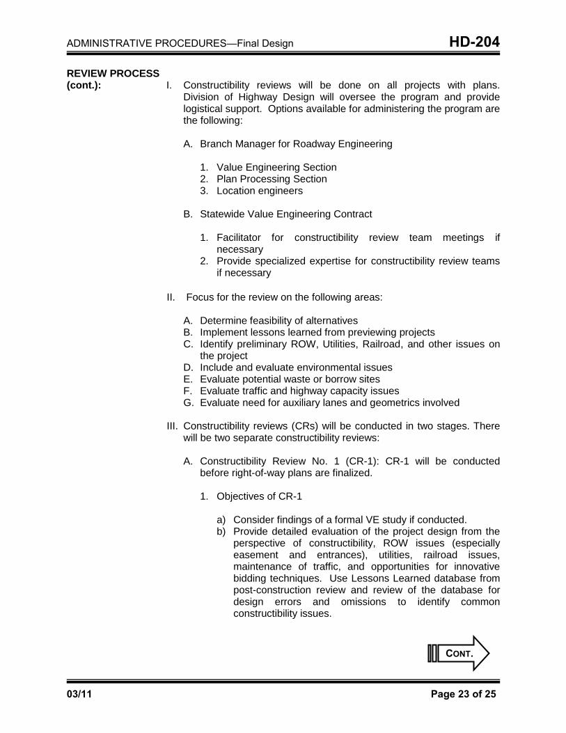
REVIEW PROCESS (cont.): I. Constructibility reviews will be done on all projects with plans.
Division of Highway Design will oversee the program and provide logistical support. Options available for administering the program are the following:
A. Branch Manager for Roadway Engineering
1. Value Engineering Section 2. Plan Processing Section 3. Location engineers
B. Statewide Value Engineering Contract
1. Facilitator for constructibility review team meetings if necessary
2. Provide specialized expertise for constructibility review teams if necessary
II. Focus for the review on the following areas:
A. Determine feasibility of alternatives B. Implement lessons learned from previewing projects C. Identify preliminary ROW, Utilities, Railroad, and other issues on
the project D. Include and evaluate environmental issues E. Evaluate potential waste or borrow sites F. Evaluate traffic and highway capacity issues G. Evaluate need for auxiliary lanes and geometrics involved
III. Constructibility reviews (CRs) will be conducted in two stages. There
will be two separate constructibility reviews:
A. Constructibility Review No. 1 (CR-1): CR-1 will be conducted before right-of-way plans are finalized.
1. Objectives of CR-1
a) Consider findings of a formal VE study if conducted. b) Provide detailed evaluation of the project design from the
perspective of constructibility, ROW issues (especially easement and entrances), utilities, railroad issues, maintenance of traffic, and opportunities for innovative bidding techniques. Use Lessons Learned database from post-construction review and review of the database for design errors and omissions to identify common constructibility issues.
CONT.

ADMINISTRATIVE PROCEDURES—Final Design HD-204
03/11 Page 24 of 25
OUTLINE FOR CONSTRUCTIBILITY REVIEW PROCESS (cont.):
2. Team Composition for CR-1 (for projects over $2 million)
a) Facilitator—Location engineer b) Project manager c) Two construction subject-matter experts (SMEs)—
Resident expected to oversee project and resident from different district with experience on similar type of project
d) Traffic Operation SME e) Right-of-Way SME f) Others as needed dependent upon complexity and
characteristics of project
3. Team Composition for CR-1 (for projects under $2 million):
a) Facilitator—Location engineer b) Project manager c) Two construction SMEs—Resident expected to oversee
project and resident from different district with experience on similar type of project or central office construction liaison for the district
d) Others as needed dependent upon complexity and characteristics of project
4. Location engineer will prepare a constructibility review report
for distribution to the project manager
B. Constructibility Review No. 2 (CR-2): CR-2 will be conducted at the end of final design and will coincide with the submission of ―check prints.‖
1. Objectives of CR-2:
a) Ensure that project plans, specifications, and details are adequate for bidding.
b) Address final issues of constructibility and maintenance of traffic.
c) Review contract time recommendations and any recommendations for innovative contracting.
d) Perform quality assurance check of at least one major bid item for the project. This essentially involves thoroughly checking a randomly selected major bid item for accuracy.
CONT.

ADMINISTRATIVE PROCEDURES—Final Design HD-204
03/11 Page 25 of 25
OUTLINE FOR CONSTRUCTIBILITY REVIEW PROCESS (cont.):
2. CR-2 Team Composition:
a) Facilitation—Value Engineering Section or location engineer
b) Project manager c) Two construction SMEs—Resident expected to oversee
project and resident from different district with experience on similar type project or central office construction liaison for the district
d) Traffic Operations SME e) Plan Processing Section reviewer
3. The branch manager for Roadway Engineering will designate
the appropriate individual to prepare a constructibility review report for distribution to the project manager.
At all stages of constructibility reviews, the Lessons Learned database
should be consulted. The section head of the Value Engineering Section of the Division of Highway Design will be responsible for assuring that information is input into the database. Information gathered from constructibility reviews will be added to this database, along with lessons learned from post-construction reviews, past VE studies, etc. Minutes of all meetings should be sent to the value engineering coordinator's office in Frankfort for inclusion in the Lessons Learned database. The Lessons Learned database is available on the Division of Highway Design's Web page, under Value Engineering.
Practices used for the constructibility review process are to be consistent
in all KYTC districts. CR teams would consist primarily of construction personnel from the districts, central office (as required), and the location engineer. Other disciplines (such as Geotechnical, Pavement Design, Traffic, etc.) may be considered if desired. Construction personnel from other districts may be used as needed, depending on the relative complexity of the project. In cases of major or complex projects, the statewide value engineering consultant can be used to conduct constructibility reviews, along with district Construction personnel. The statewide VE consultant would provide personnel with extensive construction knowledge to assist the CR team. The use of a statewide VE consultant to do constructibility reviews will be at the discretion of the project team and the Division of Highway Design.

HD-206
03/11 Page 1 of 12
Chapter
ADMINISTRATIVE PROCEDURES
Subject
Preparation of Plans
OVERVIEW: Discussed herein are the policies and procedures for the preparation of
Contract Plan Sets and roadway construction plans. Procedures for dealing with the submittal of final contract plan sets are given in this chapter, at HD-207. Procedures for dealing with right-of-way plan submittals and revisions are given in the “Right of Way” chapter in HD-1305 and HD-1306.
CONTRACT PLAN SET: Contract plan sets are the highway plans that are awarded through the
letting process. The contract plan sets are the product of the preconstruction process and comprise the roadway, structures, traffic, and/or utility relocation plans.
The CADD Standards for Highway Plans policy documents the required standards for all electronic files representing submittals of contract plans and proposals to the Kentucky Department of Highways (KDOH). The primary goal of these standards is to ensure the best possible use of these files in the review, publication, construction, and archive processes. The standards presented in the policy represent the minimum requirements that must be met for the development of highway plans. Refer to the CADD Standards for Highway Plans policy for more information: http://www.kytc.state.ky.us/CADDstandards/
SHEETS OF THE PLAN SET: The following guidelines should be followed in the development of plans to
produce legible, reproducible, and permanent documents:
Final contract plans are to be created and submitted in PDF format as described in the latest CADD Standards policy as the record plan set (i.e. legal, binding set).
Plan sheets prepared by either district offices or consultants should be
sized to the proper dimensions (22 inches x 36 inches). Standardized sheets are available from the CADD cell library.
No data shall be outside the inside borderline of the plan sheets.
CONT.

ADMINISTRATIVE PROCEDURES—Preparation of Plans HD-206
03/11 Page 2 of 12
SHEETS OF THE PLAN SET (cont.): All sheets shall contain a sheet information block in the upper right-hand
corner showing the project item number, county, and sheet number. The full construction numbers will be required only on the front layout sheet, the first roadway plan sheet, and the first cross section sheet. The total number of sheets will be shown only on the layout sheet.
A letter designation as illustrated below will be used to denote the various sheet types of the final contract plans. The “sheet type” notation is used to label the sheet number in the sheet information block. The sheets types include the following:
Sheet Types R – Roadway S – Structure T – Traffic U – Utility Relocation X – Roadway Cross Section
Project title blocks shall appear on the first plan sheet and the first cross section sheet. The project title blocks will show the county, state project number, when applicable, the federal project number and the name of the respective designer along with the date the plans are submitted to the Plan Processing Branch. No signatures are required in these title blocks.
CONT.

ADMINISTRATIVE PROCEDURES—Preparation of Plans HD-206
03/11 Page 3 of 12
SHEETS OF THE PLAN SET (cont.): A sheet title box in the lower right corner of all sheets of the plan set is
required. The sheet title box will guide the user when sorting through the sheets. Use station ranges in the sheet title box when applicable (e.g., PLAN SHEET STA. 11+00 TO STA. 20+00)
SHEETS IN THE CONTRACT PLAN SETS: Contract plan sets should be assembled in the following order (when
applicable):
ROADWAY: 1. Layout sheet 2. Right-of-way revision sheet 3. Typical sections, summaries of quantities, and general note sheet 4. Plan and profile sheets 5. Utility reference sheets 6. Right-of-way summary 7. Right-of-way strip maps 8. Detail sheets 9. Maintenance-of-traffic sheets 10. Erosion control 11. Coordinate control sheets 12. Mitigation plans 13. Soil profile sheets 14. Pipe drainage sheets STRUCTURE TRAFFIC UTILITIES RELOCATIONS ROADWAY CROSS SECTION
CONT.

ADMINISTRATIVE PROCEDURES—Preparation of Plans HD-206
03/11 Page 4 of 12
SHEETS IN THE CONTRACT PLAN SETS (cont.):
LAYOUT SHEET: The layout sheet (Exhibit 200-21) is the cover or title sheet for the set of plans. The layout sheet shall contain an area map, including towns and boundaries. Clearly show the project’s construction and right-of-way limits with beginning and ending stations, a north arrow, and the geographic coordinates (latitude and longitude) of the approximate project midpoint to the nearest second. The layout sheet shall include road name, federal and state route numbers, and type of work. Include a notation if the highway is listed on the National Highway System. Note the type of access control proposed for the project on the layout sheet. (See Chapter 1100 to find the different types of access control.) When using alternate funding, show project limits by funding category. If the project is broken out into sections, show breakouts for county lines and separate project numbers. The Standard Drawings used on the project should be shown by drawing number only.
CONT.

ADMINISTRATIVE PROCEDURES—Preparation of Plans HD-206
03/11 Page 5 of 12
LAYOUT SHEET (cont.):
All final contract plans prepared by state forces shall bear the electronic signature of the state highway engineer. Final contract plans prepared by consulting engineering firms shall bear the additional electronic signature and electronic stamp of the seal of a professional engineer (civil or highway) licensed in the Commonwealth of Kentucky. Also for project designed by consultants, digital signatures will be required per 201 KAR 18:104. When engineering work is completed by a sub consultant, the prime consultant shall be responsible for determining whether the prime or sub shall affix the digital signature. The layout sheet is the designated location for the authorization signatures for plan sets as detailed above. Two signature lines are included in the lower right-hand corner of the layout sheet. The top line, “Recommended by,” will be for the project manager’s name (a signature is no longer required, a typed name is sufficient). The bottom, “Plan Approved By,” will be for the state highway engineer’s electronic signature. The block to the right will be used for the consultant information, which includes the firm’s name, project engineer’s electronic signature, an electronic stamp of his/her P.E. seal and digital signature.
CONT.

ADMINISTRATIVE PROCEDURES—Preparation of Plans HD-206
03/11 Page 6 of 12
LAYOUT SHEET (cont.):
Project Lengths - Compute project lengths in miles to three decimal places for project totals. Round to the nearest three decimal places for subsections in such a manner that the totals of the subsections will add to equal the project total. When combining two separate federal projects into one plan, compute each federal project to three decimal places. The total for the two combined projects should be the length in miles, without regard to whether the lengths for the two separate projects add to make the exact total sum computed. Compute lengths for state projects in a similar manner, except make the total for a summation of separate state projects equal the project total by adjusting the individual project lengths as outlined in the first paragraph above for federal projects. That is, adjust all section lengths so that they add up to the total project length, except where two or more federal projects are included in one set of plans. Railroad Track Deductions - Use the following deductions in surfacing lengths for railroad crossings:
Single Track Double Track (feet) (feet) 90 degrees . . . . . . . . . 8.5 . . . . . . . . . 22.5 30 degrees . . . . . . . . . 9.8 . . . . . . . . . 26.0 45 degrees . . . . . . . . 12.0 . . . . . . . . .31.8 60 degrees . . . . . . . . 17.0 . . . . . . . . . 45.0
For skews not shown above, divide the overall railroad width (8.5 feet for single track and 22.5 feet for double track) by the cosine of the skew angle.
CONT.

ADMINISTRATIVE PROCEDURES—Preparation of Plans HD-206
03/11 Page 7 of 12
RIGHT-OF-WAY REVISION SHEET: When a revision occurs, a sheet is added to the right-of-way plans. This
sheet is labeled “Right-of-Way Revision Sheet” and inserted directly after the layout sheet. This sheet shall be numbered as sheet number “R1a.”
Each time a right-of-way revision is processed on the project, a block shall be added to the new sheet showing: Right-of-way revision number Plan revision date Sheets revised Parcels involved Any relevant remarks (See Exhibit 1300-06.) This sheet can be updated electronically, reprinted, and inserted into the plans each time a revision is processed, if desired.
TYPICAL SECTIONS, SUMMARIES OF QUANTITIES, & GENERAL NOTE SHEETS: The typical sections, summaries of quantities, and general note sheets
follow the layout sheet in the roadway construction plans. These sheets are designated as “R2,” “R2a,” “R2b,” “R2c,” etc. Typical Section Sheets - The basic geometric criteria for the functional classification of the roadway generally determine the typical section used on a project. The typical section sheet shows the geometric and pavement details for each project (Exhibit 200-22). In addition to geometrics and pavement details, the typical section sheet should show the pay limits of roadway excavation for solid rock undercut and removal of low bearing soils, utilized in the cross sections. The typical sections sheet(s) included in the roadway construction plans shall depict the typical cross section of the mainline roadway. A normal crown and a superelevated section (if applicable) should be shown, along with a bridge typical section (if applicable). Typical sections of approach roads and entrances should also be included. Summary Sheets – The cell libraries described in the graphic standards shall be used for general summary, pipe drainage summary, right-of-way summary, paving quantities, and paving areas. For smaller projects, combined summaries can be used. All pay items are to be shown on the general summary other than those on the pipe drainage, paving, and bridge and culvert summaries. The structure, utility, and traffic (S, U, and T) summaries should stay with their respective sets.
CONT.

ADMINISTRATIVE PROCEDURES—Preparation of Plans HD-206
03/11 Page 8 of 12
TYPICAL SECTIONS, SUMMARIES OF QUANTITIES, & GENERAL NOTE SHEETS (cont.): Bid item codes and descriptions are maintained by the Plans,
Specifications, and Estimates (PS&E) Branch of the Division of Construction Procurement and should be used on all summary sheets for all bid items. The PS&E Branch assigns code numbers for special or nonrecurring items not included in the current listing after submitting the plans to the Central Office. Summarize pipe quantities to the nearest one-foot length. Vertical elongation of culvert pipe represents an additional cost to the supplier. Therefore, use reference notes to specify when vertical elongation is required, in accordance with current Standard Drawings. Entrance pipe, perforated pipe, and nonperforated pipe does not require being shown by location on the drainage summary but only by quantities. Entrance pipe 36 inches or greater in diameter, which is considered culvert pipe, is to be shown by location, with the quantity listed on the summary as culvert pipe. General Notes Sheets - At least once a year, the Plan Processing Section produces a listing of current special notes, special provisions, and general notes, and issues the list through design memorandum. The designer is to select the project applicable notes from this list and include them on the general note sheet(s).
PLAN & PROFILE SHEETS: Plan sheets may be either a stand-alone sheet with separate profile
sheets or half-plan, half-profile sheets. All graphics shall be represented according to the current version of the CADD standards.
Plan Sheets - The first plan sheet should be numbered "R3" and can
contain the standard symbols (if a separate standard symbols sheet is not used). The first plan/profile sheet will show a list of utility owners (with addresses, contact persons, and phone numbers). A project title block in the lower right-hand corner is required. Show the beginning and ending stations of the project’s construction and right of way on all applicable sheets. When a project begins or ends at an existing road, the station for edge of pavement of the existing road should be the beginning or ending for construction. All plan sheets will have a north arrow and should show station equations for main line and approach intersections, if applicable. The direction of centerline stationing should run in the cardinal directions from south to north and from west to east as the sheets progress. The alignment will show the centerline stationing at 100-foot intervals. An example plan sheet is shown in Exhibit 200-23.
CONT.

ADMINISTRATIVE PROCEDURES—Preparation of Plans HD-206
03/11 Page 9 of 12
PLAN & PROFILE SHEETS (cont.): Show all points of intersection (PI), points on tangent (POT), points on
spiral tangent (POST), and triangulation points. Each tangent shall have its calculated bearing shown. Show the points of curvature (PC), points of tangency (PT), tangent to spiral (TS), spiral to curve (SC), curve to spiral (CS), and spiral to tangent (ST) with the station number. Show curve data for all simple and spiral curves as follows: SIMPLE CURVES PI Station Δ = Delta Angle T = Tangent Distance L = Length of Curve R = Radius of Curve E = External Distance e = Rate of Superelevation Runoff = Superelevation
Runoff Distance Runout = Superelevation
Runout Distance
SPIRAL CURVES PI Station Δ = Delta Angle of the Combination of Circular Curve & Spiral Curves Ts = Tangent Distance Spiral Curve Ls = Length of Spiral Curve Lc = Length of Circular Curve Θs = Spiral Angle LT = Long Tangent Spiral Curve ST = Short Tangent Spiral Curve R = Radius of Circular Curve Es = External Distance of the Combination of Circular & Spiral Curves e = Rate of Superelevation of Circular
Curve Runoff = Superelevation Runoff Distance Runout = Superelevation Runout Distance
Scales - Generally, the alignment and topography on plan sheets are depicted using a scale of 1 inch = 50 feet in rural areas and urban areas of sparse topography. Urban areas of dense topography and city street projects should use a scale of 1 inch = 20 feet.
Profile Sheets - On the profiles, the existing ground line and the proposed grade line should be shown on the same horizontal scale as the plan. The ratio of the vertical scale to the horizontal scale typically is 1:10. Show ground line and grade line elevations at 50-foot intervals. The existing ground line elevations are shown to the tenth of a foot, and the proposed grade line elevations are shown to the hundredth of a foot. Profile sheets should show proposed drainage structures with labeling for the location, type, size and skew, flood evaluation data, profile benching, perforated pipe, surface, and special ditches (along with elevations and slopes shown). In cases where pipes are located parallel to the facility, it may be necessary to provide edge of pavement or gutter line profiles as well. This will be required when indicated by the project manager. Descriptions of all cardinal control points should be shown as well. An example profile sheet is shown in Exhibit 200-24. Diversion plan and profile sheets are to be included and numbered with the plan and profile sheets.
CONT.

ADMINISTRATIVE PROCEDURES—Preparation of Plans HD-206
03/11 Page 10 of 12
UTILITY REFERENCE SHEETS: The utility function goal is to relocate existing utilities prior to roadway
construction. Depending upon the complexity of the project and the number of utilities involved, utility reference sheets may be used to show where the proposed utilities will be located in the field when the road construction begins. The designer should refer to the Utilities Guidance Manual for specific procedures. Consideration should be given to the effect utility installations have on safety, aesthetics, operational characteristics of the highway, construction phasing, and cost of utility construction and maintenance. The designer should coordinate with the district's chief utility agent to assure compliance with all applicable local, state, and federal permits and regulations.
RIGHT-OF-WAY SUMMARY SHEET(S) & STRIP MAP(S): Right-of-way plans are required on all projects. Chapter HD-1300 of this
manual contains details and procedures for the development of right-of-way plans. The right-of-way summary sheet(s) and strip map(s) are included in the roadway construction plans.
DETAIL SHEETS: Detail sheets consist of all other sheets not classified in the index of
sheets on the layout sheet. They include special detail drawings, standard drawings not yet in the Standard Drawings Manual, pavement and superelevation development sheets, interchange and intersection layout sheets, railroad detail sheets, environmental mitigation plans, mineral ownership detail sheets, contour grading schemes, and other sheets that detail aspects of the roadway project’s construction. The PDT will determine which detail sheets are necessary on a project-by-project basis.
Pavement development sheets are very useful for intersection and ramp design. Traditionally pavement development sheets have been created utilizing the “bubble sheet” methodology. The PDT may choose other methods to communicate the intersection design layout and vertical profiles.
MAINTENANCE-OF- TRAFFIC SHEETS:
Maintenance-of-traffic (MOT) sheets show the proposed traffic operations during construction. A discussion of traffic management during construction can be found in HD-204. The PDT will determine whether separate MOT and/or phasing plans sheets are required. The PDT must keep in mind the need to communicate the intent and the details of the MOT scheme. The MOT plans may show typical sections, profiles, roadway construction phasing details, striping plans, traffic control devices, signing, detours, etc.
CONT.
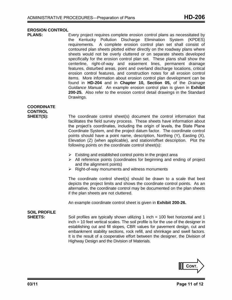
ADMINISTRATIVE PROCEDURES—Preparation of Plans HD-206
03/11 Page 11 of 12
EROSION CONTROL PLANS: Every project requires complete erosion control plans as necessitated by
the Kentucky Pollution Discharge Elimination System (KPDES) requirements. A complete erosion control plan set shall consist of contoured plan sheets plotted either directly on the roadway plans where sheets would not be overly cluttered or on separate sheets developed specifically for the erosion control plan set. These plans shall show the centerline, right-of-way and easement lines, permanent drainage features, disturbed areas, point and overland discharge locations, critical erosion control features, and construction notes for all erosion control items. More information about erosion control plan development can be found in HD-204 and in Chapter 10, Section 05, of the Drainage Guidance Manual. An example erosion control plan is given in Exhibit 200-25. Also refer to the erosion control detail drawings in the Standard Drawings.
COORDINATE CONTROL SHEET(S): The coordinate control sheet(s) document the control information that
facilitates the field survey process. These sheets have information about the project’s coordinates, including the origin of levels, the State Plane Coordinate System, and the project datum factor. The coordinate control points should have a point name, description, Northing (Y), Easting (X), Elevation (Z) (when applicable), and station/offset description. Plot the following points on the coordinate control sheet(s):
Existing and established control points in the project area All reference points (coordinates for beginning and ending of project
and the alignment points) Right-of-way monuments and witness monuments The coordinate control sheet(s) should be drawn to a scale that best depicts the project limits and shows the coordinate control points. As an alternative, the coordinate control may be documented on the plan sheets if the plan sheets are not cluttered. An example coordinate control sheet is given in Exhibit 200-26.
SOIL PROFILE SHEETS: Soil profiles are typically shown utilizing 1 inch = 100 feet horizontal and 1
inch = 10 feet vertical scales. The soil profile is for the use of the designer in establishing cut and fill slopes, CBR values for pavement design, cut and embankment stability sections, rock refill, and shrinkage and swell factors. It is the result of a cooperative effort between the designer, the Division of Highway Design and the Division of Materials.
CONT.

ADMINISTRATIVE PROCEDURES—Preparation of Plans HD-206
03/11 Page 12 of 12
PIPE SHEETS: Plot all inlets, manholes, pipes, and culverts with the exception of entrance pipes and longitudinal pipes on standard cross section sheets with slope lengths and sizes shown. Show pertinent data such as discharge, high-water elevations, flood evaluation data, and material quantities. When appropriate, the limits of flowable fill will be shown. See the Drainage Manual for more detail.
CROSS-SECTION SHEETS: Cross sections are to be plotted at a scale of 1 inch = 10 feet both
horizontally and vertically for all multilane interstate freeways and expressways. A scale of either 1 inch = 10 feet or 1 inch = 5 feet may be used on rural arterial, collector, and local roads; and a scale of 1 inch = 5 feet can be used on urban arterial, collector, and local roads.
These sheets will show the cross-sectional view of the proposed roadway at 50-foot intervals and at critical stations. Each cross section will show the station, offset (left and right) of centerline, the proposed roadway template, permanent drainage features, earthwork quantities, and construction notes. It may be useful to show right-of-way and easement limits, erosion control features, utilities, MOT items, etc.
STRUCTURES, TRAFFIC, & UTILITY RELOCATION PLANS: The contract plan sets may also contain structures, traffic (lighting, signal,
and sign plans), and/or utility relocation plans. The project manager will work with the different subject-matter experts to ensure that the final contract plan set includes all the applicable plans.

HD-207
03/11 Page 1 of 2
Chapter
ADMINISTRATIVE PROCEDURES
Subject
Submittal of the Final Contract Plans
SUBMITTAL OF THE FINAL CONTRACT PLANS: Submitting final contract plans on time is essential to prevent scheduling
problems and delayed lettings. The project manager shall submit final contract plans to the Plan Processing Section a minimum of 90 days in advance of all lettings requiring PS&E, and 60 days in advance for all other projects. The Plan Processing Section will be advised at that time of any additional information that they will be requested to insert into the plans. The project manager confirms that all information (roadway, structures, traffic, and/or utility relocation plans) needed in the final contract plans is submitted on schedule and made available to the contractors. The Plan Processing Section will perform no other activities with the plans after final submittal other that that directly identified by the project manager. All final contract plans prepared by state forces shall bear the electronic signature of the state highway engineer. Final contract plans prepared by consulting engineering firms shall bear both the electronic signature, electronic stamp of the seal of a professional engineer (civil or highway) licensed by the Commonwealth of Kentucky and his/her digital signature. The project manager will include the following items with the submission of final contract plans to the central office Division of Highway Design:
Final contract plans created and submitted in a full-size PDF as called
for in the latest CADD Standards policy as the legally binding set
A completed plans submittal form appropriate for the project—for federal TC 61-10, Exhibit 200-27, and for state, TC 61-11, Exhibit 200-28)
CONT.

ADMINISTRATIVE PROCEDURES—Submittal of the Final Contract Plans HD-207
03/11 Page 2 of 2
SUBMITTAL OF THE FINAL CONTRACT PLANS (cont.):
Information needed to create the proposal, including the following, when applicable:
CAP report (even when there are no entries in the CAP)
Final estimate (including all items in the complete contract plans)
Project construction schedule (fixed completion date or maximum work days)
Permit/water-quality certification
Utility impact notes
Special provisions for protection of railroad interest
Project-specific special notes or specifications
Electronic files representing the contract plans and proposal delivered to central office via ProjectWise (ProjectWise will also be used for internal Cabinet deliveries to the project manager. See the CADD Standards for Highway Plans for more detail.)
The supplemental electronic files (delivered via ProjectWise) as
required by the CADD Standards for Highway Plans. (There shall be an overt distinction between the files that represent the contract plan and supplemental files. Supplemental files are given for informational purposes only.)
A copy of the appropriate environmental checklist (Exhibit 200-19 or
200-20), if required. (Send a separate copy to the Division of Environmental Analysis for their use in any required reevaluation of the environmental approval.)