Project: City Rail Link - Auckland Transport · Phase 3: any further site investigations, detailed...
64
Project: City Rail Link Concept Design Report 2012 Reference: 228072 Prepared for: Auckland Transport Revision: 3 13 August 2012 In association with
Transcript of Project: City Rail Link - Auckland Transport · Phase 3: any further site investigations, detailed...

Project: City Rail Link
Concept Design Report 2012
Reference: 228072
Prepared for: Auckland Transport
Revision: 3
13 August 2012
In association with

Aurecon | Mott MacDonald | Jasmax | Grimshaw Project 228072 | File CRL NoR CDR December 2012 (clean) | 13 August 2012 | Revision 3
Document Control Record
Document prepared by:
Aurecon New Zealand Limited
Level 4, 139 Carlton Gore Road Newmarket Auckland 1023
PO Box 9762 Newmarket Auckland 1149 New Zealand
T
F
E
W
+64 9 520 6019
+64 9 524 7815
aurecongroup.com
A person using Aurecon documents or data accepts the risk of:
a) Using the documents or data in electronic form without requesting and checking them for accuracy against the original hard copy version.
b) Using the documents or data for any purpose not agreed to in writing by Aurecon.
Report Title Concept Design Report 2012
Document ID 228072-AC-RPT-013 Project Number 228072
File Path P:\200000-BST\228072\3. Project Delivery\Reference Material\Concept Design Report 2012 (Planning)\Report Issues\06122012 Issued Updated to AT for no InWI\228072-AC-RPT-013-4.docx
Client Auckland Transport
Rev Date Revision Details/Status
0 20 July 2012 Issued draft for comment and input
1 10 August 2012 Issued draft final for review
2 13 August 2012 Issued for NoR documentation
3 10 December 2012 Removal of NoR 7 and Optimisation of NoR 6
Current Revision 3

Aurecon | Mott MacDonald | Jasmax | Grimshaw Project 228072 | File CRL NoR CDR December 2012 (clean) | 13 August 2012 | Revision 3
Contents 1. Introduction 1
1.1 Report Purpose 1
1.2 Overview of the CRL Concept Design 1
1.3 Auckland Transport 3
1.4 Background 3
2. CRL Concept Design Technical Considerations 6
2.1 Technical Parameters 6
2.2 Maintaining an Operational Rail Network during Construction 8
2.3 Physical Constraints 8
2.4 Risk 12
2.5 Assumptions 13
2.6 Indicative Construction Programme Supporting this Concept Design 14
3. Concept Description 15
3.1 General 15
3.2 Indicative Alignment Design 17
3.3 Indicative Tunnel Design 20
3.4 Indicative Station Design 26
4. Construction Description 33
4.1 Outline 33
4.2 Indicative Construction Methods 33
4.3 Indicative Construction Sequencing 38
4.4 Indicative Construction Programme 48
Abbreviations 53
Glossary of Terms 55

Aurecon | Mott MacDonald | Jasmax | Grimshaw Project 228072 | File CRL NoR CDR December 2012 (clean) | 13 August 2012 | Revision 3
This page has been intentionally left blank

Aurecon | Mott MacDonald | Jasmax | Grimshaw Project 228072 | File CRL NoR CDR December 2012 (clean) | 13 August 2012 | Revision 3 | Page 1
1. Introduction
1.1 Report Purpose
This Concept Design Report (CDR) has been prepared to support Notices of Requirement (NoR) to
designate the City Rail Link (CRL). This report provides a summary of the concept design work
undertaken primarily in 2012 to demonstrate construction and operational feasibility of the CRL,
including the proposed alignment and stations, and to enable an understanding of the effects of
construction and operation sufficient to inform the NoR and supporting Assessment of Environmental
Effects (AEE). The CRL concept design also establishes engineering and architectural design
parameters which will be refined (within the envelope established from the concept design) at the
preliminary and detailed design stages of the project.
Auckland Transport (AT) anticipates that for the project to reach the operational stage it will likely
develop through five phases. The current design phase, Phase 1, comprises:
Protection of the CRL for future construction and operation via a designation;
Engineering and architectural design to a concept design level;
Initial site analysis and investigations;
Development of an Environmental Management Framework to manage the effects of the CRL
through the next phases of design, construction and operation;
Consultation.
Future stages are likely to include1:
Phase 2: further site investigations, preliminary design, preparation and obtaining of resource
consents, on-going consultation;
Phase 3: any further site investigations, detailed design, preparation and obtaining resource
consents (if not undertaken in phase 2), on-going consultation;
Phase 4: construction site investigations and final construction design, any ancillary / minor
resource consents, preparation of Outline Plans, tender and award of the construction
contract, preparation of management plans to manage the effects during construction, on-
going consultation;
Phase 5: On site construction of CRL;
Phase 6: CRL commissioning and operation, preparation of any management plans required
during the operational phase.
1.2 Overview of the CRL Concept Design
The CRL is a predominately a 3.4 km underground passenger railway (including two tracks and three
underground stations) running between Britomart station and the North Auckland Line (NAL) in the
vicinity of the existing Mt Eden station. The CRL also requires an additional 850m of track
modifications within the NAL. For ease of reference in this CDR, the three stations included in the CRL
have been temporarily named Aotea Station, Karangahape Station, and Newton Station. The stations
will be formally named in the future.
1 Refer to Appendix C: Project Delivery Diagram

Aurecon | Mott MacDonald | Jasmax | Grimshaw Project 228072 | File CRL NoR CDR December 2012 (clean) | 13 August 2012 | Revision 3 | Page 2
Figure 1 – 1 CRL Alignment
The concept design for the CRL must overcome the significant engineering challenge of rising 70
vertical metres from track level at Britomart station to the existing alignment of the NAL near Mt Eden
Station while maintaining a vertical gradient for the rail tracks of no greater than 3.5% over this length.
The CRL alignment must also undertake tunnelling activities a safe distance beneath the infrastructure
of the Central Motorway Junction (CMJ). Other constraints for the CRL concept design are described
in Section 2 of this CDR.
Figure 1 – 2 CRL Vertical Alignment
The concept design identifies the footprint and potential configurations required to support
construction and operation of the three proposed underground stations along the alignment.
A variety of construction methodologies suitable for different locations along the CRL alignment have
been identified based on the initial site analysis and investigations, topography and identified
engineering risks and constraints. The most likely methodology to construct the two underground
tunnels will be by an earth pressure balance tunnel boring machine (TBM) launched at the NAL end of
the CRL.

Aurecon | Mott MacDonald | Jasmax | Grimshaw Project 228072 | File CRL NoR CDR December 2012 (clean) | 13 August 2012 | Revision 3 | Page 3
The construction of the tunnels at either end of the CRL (i.e. connection to Britomart and connection to
the NAL) and the construction of Aotea station will likely be by cut and cover methods. The
construction of Karangahape and Newton stations will likely be by cut and cover shafts from the
surface from which the station platform areas will be mined out (this is referred to in this concept
design as mined side platform construction).
1.3 Auckland Transport
AT is the council-controlled organisation (CCO) of Auckland Council responsible for managing and
controlling Auckland's transport system under the Local Government (Auckland Council) Amendment
Act 2009.
Auckland Transport‟s purpose as set out in section 39 of the Local Government Auckland Council
Amendment Act 2009 (LG(AC)AA) is "to contribute to an effective and efficient land transport system
to support Auckland's social, economic, environmental, and cultural well-being".
Sections 45 and 46 of that Act outline Auckland Transport's functions and powers in respect of the
land transport system and AT‟s role as the Road Controlling Authority. AT is also deemed a Requiring
Authority (RA) as a network utility operator, under Section 167 of the Resource Management Act
(RMA) for transport purposes (LG(AC)AA Section 47).
In addition, AT is responsible for preparing the Regional Land Transport Programme for Auckland in
accordance with the Land Transport Management Act 2003 (Section 45(a)).
AT is responsible for delivering the CRL project including the serving of the NoR to designate for the
purpose of construction, operation and maintenance of the twin rail tunnels and three underground
stations at Aotea, Karangahape and Newton.
1.4 Background
1.4.1 Key Studies
This concept design has been informed by previous studies for the CRL. These studies have been
undertaken between 2008 and 2012, and include:
For ARTA: CBD Rail Tunnels – Aotea Station Extension Study, 2008, prepared by Aurecon
(formerly Connell Wagner).
For the New Zealand Railways Corporation (NZRC or KiwiRail) and ARTA: Auckland CBD
Rail Link Study – Option Evaluation Report, 2010, and Concept Design for Preferred
Alignment and Station locations, 2010, prepared by Aecom, Parsons Brinckerhoff and Beca
(APB&B).
These studies define the key concept elements of the CRL rail tunnel alignment and station locations.
The 2008 work undertaken by Aurecon reviewed earlier studies around options for the location of the
CRL alignment, and as a result of this work the CRL alignment was established between Britomart
and Wellesley Street, including a station (Aotea) located under Albert Street between Victoria and
Wellesley Streets. The objective of the 2008 work was to determine minimum acceptable rail geometry
and operational implications in the context of the known constraints from various existing buildings and
developments including buildings under re-development at that time, such as the AMP Tower at 21
Queen St (the Zurich Building).

Aurecon | Mott MacDonald | Jasmax | Grimshaw Project 228072 | File CRL NoR CDR December 2012 (clean) | 13 August 2012 | Revision 3 | Page 4
The alignment design also considered the impacts upon the Downtown Shopping Centre site in
respect of the consented development with the objective of achieving the intended future functionality
of that site and to accommodate the CRL.
The alignment design responded to the impact by exiting the western end of Britomart station,
crossing Queen Elizabeth II Square, and passing through the Downtown Shopping Centre site before
turning south under Albert Street. The CRL “up” alignment, exiting Britomart from track 5 (the
Southern-most platform) has been designed to avoid an existing Britomart lift shaft as well as the
basement of the Zurich Building. To achieve this, the alignment on exit of the station goes through a
right to left hand reverse curve before it meets the tangent heading up Albert Street. The radii in this
reverse curve are 130m with an operating speed of 35km/hr. The curves have been designed so the
change in cant and change in deficiency are consistent between both curves to allow a smooth
constant transition. Clearances based on the structural gauge have been checked to ensure the
alignment has sufficient room past the lift shaft and Zurich Building.
The 2009/2010 option evaluation work undertaken by KiwiRail and ARTA with the assistance of
APB&B considered alignment options and station locations between Wellesley Street and the NAL.
The result of the 2009/10 option evaluation work was the confirmation of a preferred alignment and
station locations (three stations) between Britomart and the NAL in the vicinity of the Mt Eden rail
station. This preferred alignment was: exiting the western end of Britomart station across Queen
Elizabeth II Square and the Downtown Shopping Centre site, turning south under Albert Street until its
intersection with Mayoral Drive, then under Vincent and Pitt Streets, under Karangahape Road and
Mercury Lane and CMJ, under Upper Queen and St Benedict‟s Streets, Symonds Street and then
under private property to the connection with the NAL.
The station locations identified were as follows:
Under Albert Street between Victoria and Wellesley Street (Aotea station);
Under Pitt Street and Beresford Square stretching north from Karangahape Road
(Karangahape station);
Under Symonds Street between its intersection with Khyber Pass / Newton Roads and New
North / Mt Eden Roads, and the Auckland Council car park located on the northeast corner of
Mt Eden Road and Symonds Street.
In 2010 a concept design was developed for this preferred alignment for KiwiRail and ARTA to
demonstrate construction and operational feasibility.
1.4.2 Concept Design
The concept design work undertaken in 2010 was reviewed by the Principal Advisor for Auckland
Transport in 2011/12. Further investigations and technical assessments to progress the concept
design were undertaken by the Principal Advisor in 2012. Key outcomes for the development of the
concept design are:
The alignment between Britomart and NAL for the most part follows the KiwiRail and ARTA
preferred alignment. The general location of stations and related infrastructure has not
changed and remain the principal driver of the alignment. However, further utility constraints at
both ends of the CRL have necessitated changes to the indicative construction methodology.
Alterations to the alignment have occurred as a result of changes to the station form for
Karangahape and Newton Stations and the platform position and entrances for Aotea Station.
The substrata station locations for Karangahape and Newton Stations have been refined, but
are still located in the main area identified as preferred in the 2009/10 option evaluation work.

Aurecon | Mott MacDonald | Jasmax | Grimshaw Project 228072 | File CRL NoR CDR December 2012 (clean) | 13 August 2012 | Revision 3 | Page 5
Given design and construction risks associated with the large caverns proposed in 2010 the
indicative construction methodology for the Karangahape and Newton Stations in this concept
design is based around the construction of two smaller diameter mined side platform tunnels
and associated passageways accessed by shafts from the surface.
1.4.3 Related Projects
The CRL will form an integral part of Auckland‟s rail and transport network and therefore has
significant interaction with existing rail infrastructure and recent investment in regional projects
currently being executed and future projects. Where applicable, information from these projects has
been considered so as not to preclude any future integration.
Table 1 – 1 below sets out those related projects which are currently under execution.
Table 1 – 1 Relevant Related Projects
No. Project Principal Date
1 Electrification and Re-Signalling KiwiRail 2010 – mid 2013
2 Procurement of new Electric Rolling
Stock
Auckland Transport 2010 – mid 2016
3 Third Main – South of Otahuhu KiwiRail 2011 – 2014
4 DART Project KiwiRail 2007 – late 2013
There are three additional key projects currently under preliminary investigation and studies which will,
should they proceed, interact with the CRL, particularly in terms of train operations and passenger
numbers. These projects are being undertaken by other organisations and are listed in Table 1 – 2
below.
Table 1 – 2 Relevant Future Proposed Projects
No. Project Principal Date
1 Additional Waitemata Harbour
Crossing
New Zealand Transport
Authority
Uncommitted
2 Future North Shore Rail Line To be determined Uncommitted
3 Airport Rail Line Auckland Transport and
New Zealand Transport
Authority.
Uncommitted

Aurecon | Mott MacDonald | Jasmax | Grimshaw Project 228072 | File CRL NoR CDR December 2012 (clean) | 13 August 2012 | Revision 3 | Page 6
2. CRL Concept Design Technical
Considerations A number of parameters, constraints, risks and assumptions have influenced the development of the
concept design in terms of rail alignment, station location, engineering design solutions and potential
construction methodologies. These factors range from topography, geology and the existing built
environment to the operational requirements of a rail line and stations.
2.1 Technical Parameters
Parameters are the design requirements needed to provide an operational rail line that meets industry
standards and provide compatibility with the existing Auckland rail network. Table 2 – 1 below contains
the key parameters that have driven the concept design.
Table 2 – 1 Key Technical Parameters
Element Parameter Basis/Reference
Track Alignment and Geometry
Design Speed 50km/h (Target speed
environment)
Maximum vertical grade, running
tunnels
3.5% Rolling stock capabilities
Maximum vertical grade: stations 1%
Rolling Stock
Type Electric Multiple Unit (EMU) The EMU currently being
procured by AT from CAF
Length 144m long EMU specification
Configuration 6 car configuration (2 sets of
3 car units)
Access for mobility impaired Level access to central
coach in each three carriage
set
EMU specification
Seated capacity 468 seats per six car
configuration
EMU specification
Maximum capacity, seated and
standing under normal operation
760 per six car configuration EMU specification

Aurecon | Mott MacDonald | Jasmax | Grimshaw Project 228072 | File CRL NoR CDR December 2012 (clean) | 13 August 2012 | Revision 3 | Page 7
Element Parameter Basis/Reference
Stations
Platform length 150m To suit new 6 car EMUs
Minimum operational platform width 3.3m (width outside of the
busiest platform zones)
Revenue control Electronic gate lines between
station entrance and platform
access
Typical revenue control
measures on underground
railways
Platform Screen Doors Provision for future
installation of platform screen
doors for all sub-surface
stations
Enables retrofit of PSDs in
future
Ticket purchase facilities Ticket vending machines and
customer service desks in
ticket halls/concourses at
each station
Typical practice at stations
Wayfinding Provided at all levels at all
stations
Station control Station control will be by
group control or control room
provided at each station in
addition to a central station
control facility
Typical practice at
underground stations
Station Power
Supply type Two segregated independent
supplies each capable of taking
100% of the load
Standard design practice to
provide robust supply
Traction Power
System type 25kV Overhead System Consistent with current
Auckland Electrification
Project

Aurecon | Mott MacDonald | Jasmax | Grimshaw Project 228072 | File CRL NoR CDR December 2012 (clean) | 13 August 2012 | Revision 3 | Page 8
Element Parameter Basis/Reference
Signalling
System type ETCS Level 1 with Automatic
Train Protection
Consistent with current re-
signalling project
2.2 Maintaining an Operational Rail Network during Construction
Maintaining an operational rail network during the construction of the CRL, particularly at Britomart
and the NAL, is imperative to the overall operation of the Auckland rail network. The ability to continue
to operate the rail network during construction of the CRL has been considered as a base requirement
in the development of the concept design. This is further described in Sections 3 and 4 of this CDR,
but in summary:
It is feasible to maintain pedestrian access into Britomart station via the existing eastern
entrance as a minimum.
It is feasible for the NAL to remain operating while work to connect the CRL tracks to the NAL
tracks is undertaken (through a staged approach and using off-peak operational times and
“block of lines” opportunities).
2.3 Physical Constraints
The dense existing urban environment coupled with the engineering challenges of a tunnelling project
combine to produce a range of physical constraints for the project that require and/or drive
engineering solutions. Key constraints that have influenced this concept design are summarised in the
following sections.
2.3.1 Natural Topography and Rail Gradients
For much of its length the CRL alignment will need to use the maximum acceptable vertical gradient of
3.5%2 This is due to the need to climb approximately 70m from Britomart to connect with the NAL,
while still tunnelling at a safe distance below the CMJ (a low point in the surrounding higher
topography of the Karangahape Road and Newton ridges). Figure 1 – 2 highlights the vertical
alignment of the CRL over its full extent.
2.3.2 Geological Considerations
Previous studies indicate the presence of fill, alluvial clays and silts and below these the East Coast
Bays Formation (ECBF) (in various states of weathering) along the alignment. The ECBF underlies all
of Auckland and is a weak rock well suited to tunnelling using modern tunnel boring machines as has
been observed in the successful delivery of Project Hobson and Project Rosedale.
The ECBF has the complexity of stronger rocks in terms of discontinuities which require careful
consideration during design and construction. Due to the properties of ECBF, temporary ground
support of tunnelling excavations is required at an early stage. This support must be close to the
advancing excavation face, particularly for larger diameter tunnels that do not use a TBM. Generally,
the larger the tunnel diameter, the greater the demand for temporary support of the surrounding soil,
with an associated increase in the permanent lining thickness.
2 Refer to Section 2.1 Technical Parameters
Aurecon | Mott MacDonald | Jasmax | Grimshaw Project 228072 | File CRL NoR CDR December 2012 (clean) | 13 August 2012 | Revision 3 | Page 9
The geological profile has influenced the concept design solutions and construction techniques
proposed along the route. A more detailed study of the specific geological features along the CRL
alignment will be required in future design stages. Once this investigation has been completed, a
suitable basis for design will be derived to enable consideration of cost, and then risk.
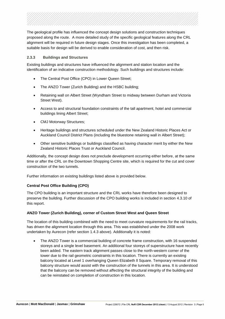
2.3.3 Buildings and Structures
Existing buildings and structures have influenced the alignment and station location and the
identification of an indicative construction methodology. Such buildings and structures include:
The Central Post Office (CPO) in Lower Queen Street;
The ANZO Tower (Zurich Building) and the HSBC building;
Retaining wall on Albert Street (Wyndham Street to midway between Durham and Victoria
Street West).
Access to and structural foundation constraints of the tall apartment, hotel and commercial
buildings lining Albert Street;
CMJ Motorway Structures;
Heritage buildings and structures scheduled under the New Zealand Historic Places Act or
Auckland Council District Plans (including the bluestone retaining wall in Albert Street);
Other sensitive buildings or buildings classified as having character merit by either the New
Zealand Historic Places Trust or Auckland Council.
Additionally, the concept design does not preclude development occurring either before, at the same
time or after the CRL on the Downtown Shopping Centre site, which is required for the cut and cover
construction of the two tunnels.
Further information on existing buildings listed above is provided below.
Central Post Office Building (CPO)
The CPO building is an important structure and the CRL works have therefore been designed to
preserve the building. Further discussion of the CPO building works is included in section 4.3.10 of
this report.
ANZO Tower (Zurich Building), corner of Custom Street West and Queen Street
The location of this building combined with the need to meet curvature requirements for the rail tracks,
has driven the alignment location through this area. This was established under the 2008 work
undertaken by Aurecon (refer section 1.4.3 above). Additionally it is noted:
The ANZO Tower is a commercial building of concrete frame construction, with 16 suspended
storeys and a single level basement. An additional four storeys of superstructure have recently
been added. The eastern track alignment passes close to the north-western corner of the
tower due to the rail geometric constraints in this location. There is currently an existing
balcony located at Level 1 overhanging Queen Elizabeth ll Square. Temporary removal of this
balcony structure would assist with the construction of the tunnels in this area. It is understood
that the balcony can be removed without affecting the structural integrity of the building and
can be reinstated on completion of construction in this location.

Aurecon | Mott MacDonald | Jasmax | Grimshaw Project 228072 | File CRL NoR CDR December 2012 (clean) | 13 August 2012 | Revision 3 | Page 10
Downtown Shopping Centre
The Downtown Shopping Centre is a reinforced concrete frame structure consisting of four suspended
levels above a single basement. The building is founded on bored piles.
Retaining Wall Albert Street (Wyndham Street to midway between Durham & Victoria Streets
West)
An existing historic bluestone retaining wall is located along the eastern side of Albert Street between
Wyndham and Victoria St West. It is a split level section of roadway with the main carriageway being
retained. The slip road off Albert St is up to 5m below the level of the main road alignment. The
proximity of the wall to the cut and cover section of the CRL indicates temporary works will be required
in order to support the retaining wall during construction. Subject to further design and evaluation this
may involve bolting and strapping through the wall connected to retention structures on the Albert
Street side. This is to ensure the wall structure is protected during the construction of the Albert Street
section.
Building Access on Albert Street
A number of buildings and car parks have single access points from Albert Street where the indicative
cut and cover construction technique is proposed. During construction, management of access will be
necessary and may require implementing temporary access measures in some situations.
Management Plans will be prepared that will consider the needs of site users and determine how the
appropriate solutions will be implemented.
CMJ Motorway Structures and Loading
The minimum vertical clearance between the CMJ structural elements and the roof of the proposed
CRL tunnel is around 6.5m. Given the significance of the CMJ to Auckland the impacts of tunnel
construction will be carefully determined at the detailed design and construction phase. This will
involve detailed vulnerability and construction impact assessments aligned with monitoring during
construction to ensure serviceability limits (to be agreed with NZTA) are not exceeded. Initial
discussions have taken place with NZTA on various options on how this can be progressed and will
continue throughout the design phases and during construction. As a result the tunnel alignment is
unlikely to significantly impact this structure.
The CRL tunnels will be required to take into account concentrated loading from the CMJ structures
for its operational design. This will require further consideration at detailed design stage.
2.3.4 Utilities
The location of utilities, particularly those that are large in size and are critical to the Auckland region,
has also influenced the alignment and station locations, and the identification of an indicative
construction methodology.
Utilities are generally located within the road reserve in order to service adjacent properties and avoid
impacting on private property. As the CRL is also generally located within the existing road corridor
there are a number of existing services which are in potential conflict with the CRL tunnels. These
include:
Water supply pipelines
Stormwater and wastewater pipelines

Aurecon | Mott MacDonald | Jasmax | Grimshaw Project 228072 | File CRL NoR CDR December 2012 (clean) | 13 August 2012 | Revision 3 | Page 11
Lighting cables
Gas pipes
Low and high voltage electric cables
Telecommunications and fibre optic cables
The majority of utilities are of a small size and extent, and typically are easily relocated or re-
established as part of construction works.
The presence of larger utilities, particularly at each end of the CRL where the tunnel depth is
shallower, including where the cut and cover method is indicatively proposed, pose more conflicts for
the concept design. In particular the following larger utilities have been considered:
Watercare‟s Orakei Main Sewer – the Watercare Orakei Main wastewater sewer crosses
below the rail alignment at Victoria Street West. The sewer is an ovoid shape and brick lined
and will require localised strengthening work to minimise effects from the tunnel.
Vector Tunnel – the Vector Tunnel crosses the proposed CRL tunnels at Mayoral Drive, but is
significantly deeper than the proposed tunnel alignment. As such the proposed rail tunnels
will not have any impact on the Vector tunnel.
Auckland Council 1500-1665mm stormwater drain in Albert Street – a stormwater line has
been identified from Council Records as being at a similar depth to that proposed for the two
rail tunnels. Consequently it is unlikely TBM tunnelling north down Albert Street beyond Aotea
would be practicable. As a result, between Britomart and Aotea Station, it is proposed to use
cut and cover as the indicative construction methodology. This provides flexibility to deal with
the stormwater utility as it will require diversion (likely from Wellesley Street north) prior to
tunnelling along Albert Street. Until more detailed investigations are undertaken there remains
some uncertainty about using the TBM north of Aotea Station due to the storm water drain.
However, further investigation and more detailed consideration of the construction programme
implications may determine that it is feasible and this will be further examined at the time of
procurement.
Watercare 375mm bulk water supply main in Pitt Street – this utility is within the designation
footprint of the proposed Karangahape Station and will likely require a permanent diversion.
From information known at this time this utility could form part of the central city wide water
supply ring main, and as such is a critical utility. Supplying this central city network through
another water main is not feasible. Consequently this watermain will require diverting and re-
commissioning. Discussion with Watercare will be ongoing to confirm an acceptable solution
at detailed design stage.
Watercare 1300mm bulk water supply main in Nikau and Ruru Streets – this utility will require
localised support to enable the cut and cover works to be carried out.
Auckland Council 1950mm stormwater drain in Nikau and Ruru Streets – a recently installed
(2010) 1950mm diameter pipe stormwater line has been identified within Nikau Street
connecting to an existing 1950mm drain within Ruru Street. This large diameter pipe runs from
Boston Road near Mt Eden Prison through to the Motions Road catchment in the west of the
city. The proposed east and west connections to the NAL currently conflict with this
stormwater pipe in a number of locations at Nikau and Ruru Streets. The solution to this is an
appropriate diversion of this pipe prior to or at the time of CRL construction.

Aurecon | Mott MacDonald | Jasmax | Grimshaw Project 228072 | File CRL NoR CDR December 2012 (clean) | 13 August 2012 | Revision 3 | Page 12
Auckland Transport and the design team will continue to work with Utility owners and operators to
ensure an agreed approach during construction.
2.4 Risk
As is usual with a concept design phase of a project, the design detail is developed at a high level and
accordingly there are a number of risks that have been identified that will be addressed through further
design work. This work may include a combination of further site investigation, including detailed
vulnerability assessments of buildings and utilities, further design and constructability reviews, and
may require the need for resource consents. Some of the key technical risks identified by the concept
design are discussed below.
2.4.1 Ground Conditions
The ECBF weak rock has the complexity of stronger rocks in terms of discontinuities (bedding planes
and faults and shears etc) all of which require careful consideration during design and construction.
The nature of the ECBF requires that tunnelling ground support is installed early and close to the
advancing excavation face particularly for larger diameter tunnels that do not use a TBM. This is
because of the need to manage the health and safety risks of personnel during the construction
process. The larger the tunnel diameter, the greater the demand on the ground and thus the
requirements to provide support to the ground in the form of temporary support (such as rockbolts and
shotcrete) and reinforced concrete for the permanent lining increases.
Although the platform tunnel dimensions have been reduced significantly compared with the previous
cavern design, reducing construction risks considerably, underground excavations of this size are
complex operations, and experienced and competent tunnelling engineers and crew will be needed. A
comprehensive ground investigation will occur as part of future stages of design, resource consenting
and construction. A validation process during construction will likely be used to confirm the ground
conditions encountered are consistent with the design solution.
2.4.2 Construction effects on existing buildings and services
A range of assessments undertaken to date (noise and vibration, heritage and structural engineering)
are preliminary in nature and provide a high level evaluation of the expected impacts upon existing
buildings and structures resulting from tunnelling and cut and cover excavation induced settlements.
Further detailed evaluations will be required at a later stage once the construction aspects of the
project have been finalised. Further detailed review particularly for the more sensitive heritage type
buildings is required, which more accurately accounts for the local soil and ground water conditions,
the building configuration, construction type and condition.
Options for avoiding, remediating or mitigating the adverse effects of excavation induced settlements
on buildings will be by a number of accepted techniques used in New Zealand and internationally. The
techniques used will vary for each building assessed.
2.4.3 Fire and Life Safety Principles
The design provisions for fire and life safety have been developed using established principles from
similar international underground railway systems and with reference to industry guidelines. It is
possible that Fire and Life safety requirements from New Zealand fire authorities may require
additional station and tunnel services and or passenger escape facilities beyond that identified in the
concept design.

Aurecon | Mott MacDonald | Jasmax | Grimshaw Project 228072 | File CRL NoR CDR December 2012 (clean) | 13 August 2012 | Revision 3 | Page 13
The concept has been designed in accordance with appropriate standards for Fire and Life Safety for
underground railways. The design team will continue discussions with Fire Authorities to agree
provisions.
2.4.4 Dimensional and Topographical Data
The survey information available and used at this concept design stage is considered appropriate for
the project for establishing the footprint for the current design stage of the CRL. It is recognised that
more detailed survey work and information will be required in future stages of design to refine the
concept parameters and for robust detailed design to occur.
2.5 Assumptions
The following assumptions have been made in developing the concept design and indicative
construction programme:
The two major utility diversions in Albert and Nikau Streets are assumed to have been
undertaken as advanced work;
All land required is acquired and available for the commencement of CRL works;
Buildings required for the CRL will be available from commencement of the construction
programme;
A TBM will be used sequentially for both up and down tunnels.
If the contractor decides to use two TBM's at the same time, an assessment has been
undertaken to address the prudent traffic effects from truck movements removing spoil and the
construction site footprint. The indicative programme is based on one TBM.
The TBM will take approximately 18 months from order to be delivered on site and a further 2
months before it becomes fully operational;
The TBM drive will average 70m per week;
The excavation of the TBM launching shaft, platform tunnels and TBM retrieving shaft will be
completed ahead of TBM operations. Temporary invert structures will be installed to allow the
TBM to be dragged through the mined tunnels;
TBM tunnel lining segments will be manufactured off-site and segments will be stored in work
site B for transportation into the tunnel using dedicated transporters
The TBM will be retrieved from shafts at the south end of Aotea station. Using a temporary
structure to enable the TBM components to be removed will minimise impacts upon the
surrounding road network.
The south bound (east tunnel) will be bored out first by the TBM to suit the construction
process at Newton and Karangahape Stations i.e. to enable the TBM to pass through (as
opposed to excavate through) the southbound platform tunnel which has already been mined
out by other methods;
A six day production week, (11 shifts) with one day planned for maintenance;
24 hour operation (20 hours TBM tunnelling split over 2 x 10 hour shifts with 4 hour planned
maintenance per day;
Truck and trailer capacity is 15-18m3 or 30 tonnes of spoil material or supplies to be delivered
to/from site;

Aurecon | Mott MacDonald | Jasmax | Grimshaw Project 228072 | File CRL NoR CDR December 2012 (clean) | 13 August 2012 | Revision 3 | Page 14
„Noisy‟ activities such as the handling of spoil from the tunnels and the mined station platforms
will be mitigated through a Construction Noise and Vibration Management Plan. This could
include the use of low noise machinery and noise enclosures where necessary;
Newton and Karangahape Stations will be constructed using a shaft from the surface to then
mine out the side mined platform areas. Batching of shotcrete is assumed to occur off-site
and be trucked in;
Aotea Station and the tunnels along the length of Albert Street and through to Britomart will be
via cut and cover construction;
Rail works (i.e. track laying, signalling, OLE) will be done after the completion of the tunnel
works.
2.6 Indicative Construction Programme Supporting this Concept Design
The following principal constraints have been taken into account in developing an indicative (but
feasible) construction programme:
Existing buildings structures and utilities;
The operation of the existing Britomart Station and adjoining bus facilities;
The operation of the NAL services;
Servicing existing businesses adjacent to the alignment particularly within Albert St;
The operation of major road intersections
Existing NAL alignment between Boston Road and the Dominion Road overbridges.
For the purposes of the NoR and its supporting assessments, a conservative 5 to 6 year construction
programme has been assumed and is described in more detail in section 4.3 of this report.
Aurecon | Mott MacDonald | Jasmax | Grimshaw Project 228072 | File CRL NoR CDR December 2012 (clean) | 13 August 2012 | Revision 3 | Page 15
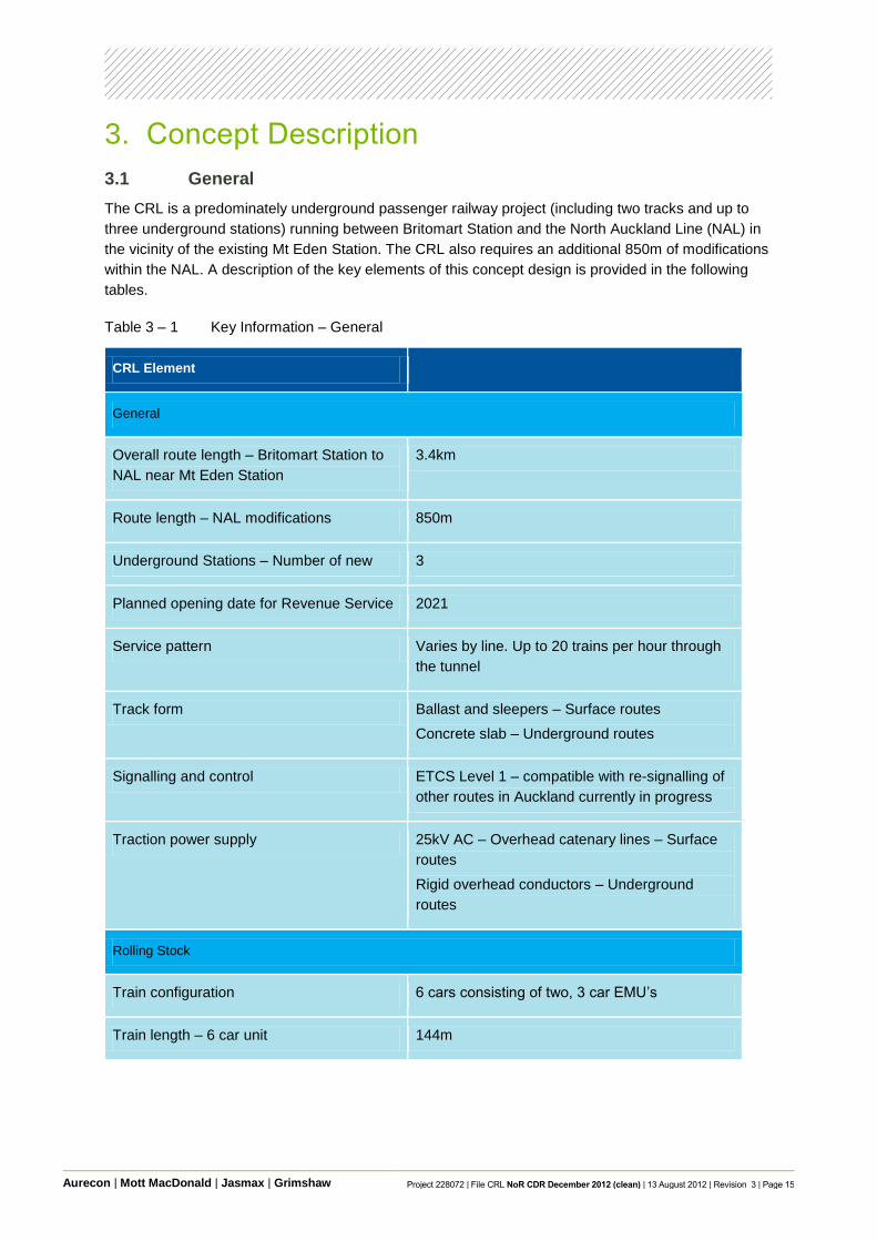
3. Concept Description
3.1 General
The CRL is a predominately underground passenger railway project (including two tracks and up to
three underground stations) running between Britomart Station and the North Auckland Line (NAL) in
the vicinity of the existing Mt Eden Station. The CRL also requires an additional 850m of modifications
within the NAL. A description of the key elements of this concept design is provided in the following
tables.
Table 3 – 1 Key Information – General
CRL Element
General
Overall route length – Britomart Station to
NAL near Mt Eden Station
3.4km
Route length – NAL modifications 850m
Underground Stations – Number of new 3
Planned opening date for Revenue Service 2021
Service pattern Varies by line. Up to 20 trains per hour through
the tunnel
Track form Ballast and sleepers – Surface routes
Concrete slab – Underground routes
Signalling and control ETCS Level 1 – compatible with re-signalling of
other routes in Auckland currently in progress
Traction power supply 25kV AC – Overhead catenary lines – Surface
routes
Rigid overhead conductors – Underground
routes
Rolling Stock
Train configuration 6 cars consisting of two, 3 car EMU‟s
Train length – 6 car unit 144m

Aurecon | Mott MacDonald | Jasmax | Grimshaw Project 228072 | File CRL NoR CDR December 2012 (clean) | 13 August 2012 | Revision 3 | Page 16
Table 3 – 2 Key Information – Surface and Ground Routes
CRL Element Surface Underground
Tunnel diameter N/A 6m Internal Diameter (TBC)
Maximum track gradient 2.7% 3.5%
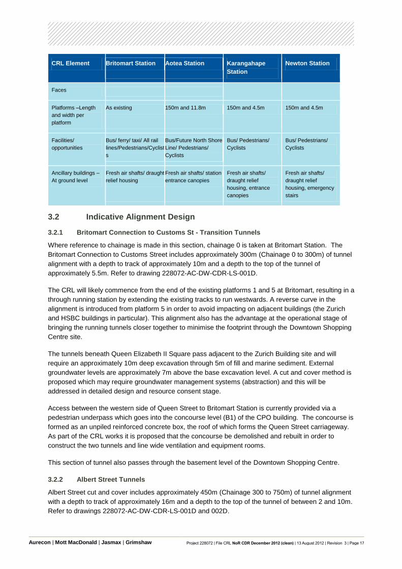
Table 3 – 3 Key Information – Stations
CRL Element Britomart Station Aotea Station Karangahape
Station
Newton Station
Location
Form of construction Existing modified Cut and cover Mined platform
funnels
Mined platform
tunnels
Configuration Likely to be through
platforms 1 and 5
Island platform Side platforms Side platforms
Depth from ground
to rail level
11m 13.5m 33m 42.5m
Entrances - Number 2 4 2 1
Entrances –
Location(s)
Existing maintained Victoria and Wellesley
Street
Beresford Street and
Mercury Lane
Symonds Street
Concourse Existing Yes Yes Yes
Ticketing
arrangement
Automatic ticket vending machines, customer service centre at paid/ unpaid boundary, and
automatic ticket barriers
Passenger
Circulation –
Escalators
As existing 11 16 (Double entrance) Nil
Passenger
Circulation – Lifts
1 4 3 4
Passenger
Circulation – Stairs
As existing 1 entrance is stairs only
access to concourse, 2
entrances have stairs at
escalator positions
Emergency only Emergency only
Number of Platform 5 2 2 2
Albert Street Pitt Street Symonds Street Existing
Aurecon | Mott MacDonald | Jasmax | Grimshaw Project 228072 | File CRL NoR CDR December 2012 (clean) | 13 August 2012 | Revision 3 | Page 17
CRL Element Britomart Station Aotea Station Karangahape
Station
Newton Station
Faces
Platforms –Length
and width per
platform
As existing 150m and 11.8m 150m and 4.5m 150m and 4.5m
Facilities/
opportunities
Bus/ ferry/ taxi/ All rail
lines/Pedestrians/Cyclist
s
Bus/Future North Shore
Line/ Pedestrians/
Cyclists
Bus/ Pedestrians/
Cyclists
Bus/ Pedestrians/
Cyclists
Ancillary buildings –
At ground level
Fresh air shafts/ draught
relief housing
Fresh air shafts/ station
entrance canopies
Fresh air shafts/
draught relief
housing, entrance
canopies
Fresh air shafts/
draught relief
housing, emergency
stairs
3.2 Indicative Alignment Design
3.2.1 Britomart Connection to Customs St - Transition Tunnels
Where reference to chainage is made in this section, chainage 0 is taken at Britomart Station. The
Britomart Connection to Customs Street includes approximately 300m (Chainage 0 to 300m) of tunnel
alignment with a depth to track of approximately 10m and a depth to the top of the tunnel of
approximately 5.5m. Refer to drawing 228072-AC-DW-CDR-LS-001D.
The CRL will likely commence from the end of the existing platforms 1 and 5 at Britomart, resulting in a
through running station by extending the existing tracks to run westwards. A reverse curve in the
alignment is introduced from platform 5 in order to avoid impacting on adjacent buildings (the Zurich
and HSBC buildings in particular). This alignment also has the advantage at the operational stage of
bringing the running tunnels closer together to minimise the footprint through the Downtown Shopping
Centre site.
The tunnels beneath Queen Elizabeth II Square pass adjacent to the Zurich Building site and will
require an approximately 10m deep excavation through 5m of fill and marine sediment. External
groundwater levels are approximately 7m above the base excavation level. A cut and cover method is
proposed which may require groundwater management systems (abstraction) and this will be
addressed in detailed design and resource consent stage.
Access between the western side of Queen Street to Britomart Station is currently provided via a
pedestrian underpass which goes into the concourse level (B1) of the CPO building. The concourse is
formed as an unpiled reinforced concrete box, the roof of which forms the Queen Street carriageway.
As part of the CRL works it is proposed that the concourse be demolished and rebuilt in order to
construct the two tunnels and line wide ventilation and equipment rooms.
This section of tunnel also passes through the basement level of the Downtown Shopping Centre.
3.2.2 Albert Street Tunnels
Albert Street cut and cover includes approximately 450m (Chainage 300 to 750m) of tunnel alignment
with a depth to track of approximately 16m and a depth to the top of the tunnel of between 2 and 10m.
Refer to drawings 228072-AC-DW-CDR-LS-001D and 002D.

Aurecon | Mott MacDonald | Jasmax | Grimshaw Project 228072 | File CRL NoR CDR December 2012 (clean) | 13 August 2012 | Revision 3 | Page 18
The presence of a significant live stormwater service at a depth similar to that required by CRL within
Albert Street (refer Section 2.2.3) constrains the feasibility of using a tunnel boring machine (TBM)
north of Aotea Station.
The construction risks associated with intercepting this service and the relatively shallow cover to the
top (or crown) of the running tunnels (in this concept design), has driven the indicative construction
methodology to adopt the more prudent method of cut and cover construction for this section of works.
While the use of a TBM has not been precluded, at this stage there is uncertainty regarding the
reliability of using a TBM north of Aotea Station. Consequently it is prudent to provide for cut and
cover. Property access can be maintained.
3.2.3 Aotea Station to NAL Portals
Aotea Station to NAL portals includes approximately 2100m (Chainage 750 to 2850m) of tunnel
alignment with a maximum depth to track of approximately 40m and a maximum depth to the top of
the tunnel of approximately 35m. The alignment in this section has a minimum depth to track of
approximately 13m and a minimum depth to the top of the tunnel of approximately 6.5m. Refer to
drawings 228072-AC-DW-CDR-LS-002D to 005D, and 007D.
This section of two tunnels would likely be constructed using an earth pressure balance TBM erecting
pre-cast concrete segments as the TBM progresses along the alignment. The segmental lining
provides the ability for the thrust forces of the TBM cutterhead to be transferred longitudinally and for a
permanent ground support to be provided in what is sometimes referred to as a single-pass lining.
Gaskets between joint faces in the segmental lining allow the lining to be water-proofed against
groundwater ingress.
Once operational, emergency egress is provided via walkways located on the sides of each tunnel.
Cross passages are located at intervals along the alignment to allow for emergency transfer. These
cross passages will also be used for maintenance and operational access.
3.2.4 NAL Portals
The NAL portals (East and West Facing Links) include approximately 1200m (Chainage 2850 to
3450m and 0 to 600m) of tunnel and retaining walls. Refer to drawings 228072-AC-DW-CDR-LS-
005D, 007D, 009D.
The portal headwalls on both the east and west facing connections form the transition from cut and
cover to the at-grade portion of the alignment. The retaining structures that form this transition are
sized based on geomorphological indications of the top of rock such that the open face tunnels would
be constructed with a full face of East Coast Bays Formation (considered as rock). The dive structure
(area where the alignment transitions from the surface to a tunnel underground) is likely to be covered
to minimise rainfall directly onto the tracks and to facilitate reuse of the ground above.
Sumps to intercept rainwater collecting on the dive structures are included at the portal to avoid
pumping from greater depths at the stations. Suitable environmental treatment systems and
connections to existing reticulation will be required at both the east and west facing portal structures.
3.2.5 NAL Connections
General
The NAL connections include approximately 850m (Chainage 10100 to 10950m) of track alignment
which will be lower than the existing track level by approximately 4m. Despite gradually rising to meet

Aurecon | Mott MacDonald | Jasmax | Grimshaw Project 228072 | File CRL NoR CDR December 2012 (clean) | 13 August 2012 | Revision 3 | Page 19
the current NAL grade / level for most of its length, it will be located within a trench. Refer to drawings
228072-AC-DW-CDR-LS-005D to 010D.
The CRL tunnels will connect to the NAL in an east and a west direction in the vicinity of the existing
Mount Eden Station. Two separate tunnels for both the east and west connections (four tunnels in
total underground) are proposed under this concept design. The existing NAL will need to be realigned
to allow the CRL tracks to rise up from underground between the NAL tracks to be positioned at the
centre of the rail corridor.
The CRL east connection to the NAL will diverge (in mined tunnels) from the west connection to the
NAL just south of Newton Station. The west connection of the CRL will involve the tracks continuing to
rise up from underground in a retained trench until just east of Porters Ave. The two CRL tracks will
merge with the two existing NAL tracks west of Porters Ave.
Track Crossings and Structures
A pedestrian level crossing at Ngahura Street crosses the NAL providing pedestrian links to Mt Eden
Station and Fenton Street. The existing at-grade vehicle level crossing at Porters Avenue regulates
vehicles crossing the NAL while at Dominion Road the NAL passes under two bridges which form the
Dominion Road Overbridge.
The existing Porters Avenue vehicle level crossing will need to be altered with a new road bridge
which grade separates it from the NAL and CRL tracks. At this location the CRL is at a similar level to
the NAL tracks. The grade separation of this road has benefits from both a safety and capacity
perspective. It will however require permanent works to both Fenton Street and Haultain Street, and
an individual property access adjacent to the grade separation as the road will no longer be at grade.
These works will require access management solutions during the construction phase and a
permanent solution post construction. Management Plans will be prepared that will determine how the
appropriate solutions will be implemented. Management Plans will also be prepared to provide traffic
management solutions during the construction phase.
It is feasible to maintain traffic flows in this area through creating a temporary level crossing to the east
of the current level crossing and temporarily diverting traffic around this route while the grade
separated bridge is constructed at Porters Avenue.
Further options may be considered at the time of construction.
The pedestrian level crossing at Ngahura Street is proposed to be substituted by a grade separated
crossings to improve pedestrian safety. The new grade separated pedestrian crossing at Ngahura
Street would provide a link onto the west end of Mount Eden Station and Fenton Street south of NAL.
The existing Mt Eden Road Bridge will require modification/ replacement in order to accommodate the
NAL and CRL tracks below it, including excavating and replacing the northern approach embankment.
The existing Normanby Road vehicle level crossing will need to be replaced with a new road bridge
which grade separates it from the NAL and CRL tracks. The grade separation of this road has benefits
from both safety and capacity perspectives. Grade separation of this road will also require permanent
works to individual property accesses adjacent as the road will no longer be at grade. As with Porters
Avenue these works will require access management solutions during the construction phase and a
permanent solution post construction. Management Plans will be prepared that will determine how the

Aurecon | Mott MacDonald | Jasmax | Grimshaw Project 228072 | File CRL NoR CDR December 2012 (clean) | 13 August 2012 | Revision 3 | Page 20
appropriate solutions will be implemented during construction and detailed design will address the
permanent solution.
Construction of the new bridge at Normanby Road and the modifications/ replacement of the Mt Eden
Road Bridge will require traffic management solutions during the construction phase. Management
Plans will be prepared that will determine how the appropriate solutions will be implemented.
As with Porters Avenue It is feasible to maintain traffic flows at Normanby Road through:
Staging the bridge works in halves and retaining traffic with only temporary closures for Mt
Eden Road;
Creating a temporary level crossing to the west of the current level crossing and temporarily
diverting traffic around this route while the grade separated bridge is constructed for
Normanby Road.
Further options may be considered at the time of construction.
3.3 Indicative Tunnel Design
This section outlines the concept design for the two tunnels and general alignment in terms of the
design footprint required to provide for a rail line that meets the key parameters identified in Table 3 –
1 in Section 3.1 above. This has been used to determine the footprint required and may be revised in
the final design.
3.3.1 Running Tunnel Cross Section
Electric Multiple Units
The running tunnel cross section shown below has been designed to suit the new EMU trains.
Over Head Line Equipment
For space proofing purposes allowance has been allowed above the structure gauge of the rolling
stock for a conventional overhead catenary system or rigid overhead conductor.
Track Slab
A non-ballasted concrete track slab is proposed. This is commonly used in tunnels. Additionally, an
embedded sleeper within the concrete track slab is assumed. In the vicinity of vibration sensitive
receivers, track isolation measures may also be employed to mitigate any effects.

Aurecon | Mott MacDonald | Jasmax | Grimshaw Project 228072 | File CRL NoR CDR December 2012 (clean) | 13 August 2012 | Revision 3 | Page 21
Figure 3 – 1 CRL Tunnel Cross Section
Egress and Emergency Access
An emergency evacuation walkway is located on the side of the rail tunnels. The width of the walkway
is proposed to be 850mm subject to confirmation with the NZFS. Cross passages between the
running tunnels are also indicatively shown at 200m spacings although their frequency is to be
determined as part of the fire engineering design process in collaboration with the NZFS.
Ventilation System
The tunnel ventilation system is used to control the environment in the running tunnels and the public
areas of stations. The roles of the tunnel ventilation system are as follows:
Mitigate train-induced air flows and air pressure changes
Control air temperatures during normal, congested and emergency operations
Provide forced ventilation for the control of smoke in the event of train fires
Provide outside air for the physiological needs of passengers and staff
Provide ventilation for maintenance activities (e.g. diesel works trains, dusty works)
Two schematics of the tunnel ventilation system are given in Figure 3 - 2 and Figure 3 - 3. It is noted
that the design of this ventilation system is such that it can be configured to work with and without full-
height platform screen doors on the station platforms.

Aurecon | Mott MacDonald | Jasmax | Grimshaw Project 228072 | File CRL NoR CDR December 2012 (clean) | 13 August 2012 | Revision 3 | Page 22
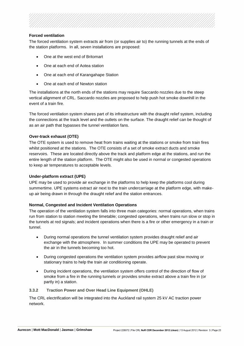
Figure 3 – 2 Ventilation Schematic of the underground part of CRL
Figure 3 – 3 Tunnel ventilation systems at a typical station
The tunnel ventilation system proposed is described in the following.
Draught relief
The draught relief system consists of open air paths at the north and south ends of each station. Their
purpose is to allow trains to push or pull air through the shafts as the trains move through the tunnels.
This has the effect of lowering the amount of air passing through the public areas of the stations.
Aurecon | Mott MacDonald | Jasmax | Grimshaw Project 228072 | File CRL NoR CDR December 2012 (clean) | 13 August 2012 | Revision 3 | Page 23
Forced ventilation
The forced ventilation system extracts air from (or supplies air to) the running tunnels at the ends of
the station platforms. In all, seven installations are proposed:
One at the west end of Britomart
One at each end of Aotea station
One at each end of Karangahape Station
One at each end of Newton station
The installations at the north ends of the stations may require Saccardo nozzles due to the steep
vertical alignment of CRL. Saccardo nozzles are proposed to help push hot smoke downhill in the
event of a train fire.
The forced ventilation system shares part of its infrastructure with the draught relief system, including
the connections at the track level and the outlets on the surface. The draught relief can be thought of
as an air path that bypasses the tunnel ventilation fans.
Over-track exhaust (OTE)
The OTE system is used to remove heat from trains waiting at the stations or smoke from train fires
whilst positioned at the stations. The OTE consists of a set of smoke extract ducts and smoke
reservoirs. These are located directly above the track and platform edge at the stations, and run the
entire length of the station platform. The OTE might also be used in normal or congested operations
to keep air temperatures to acceptable levels.
Under-platform extract (UPE)
UPE may be used to provide air exchange in the platforms to help keep the platforms cool during
summertime. UPE systems extract air next to the train undercarriage at the platform edge, with make-
up air being drawn in through the draught relief and the station entrances.
Normal, Congested and Incident Ventilation Operations
The operation of the ventilation system falls into three main categories: normal operations, when trains
run from station to station meeting the timetable; congested operations, when trains run slow or stop in
the tunnels at red signals; and incident operations when there is a fire or other emergency in a train or
tunnel.
During normal operations the tunnel ventilation system provides draught relief and air
exchange with the atmosphere. In summer conditions the UPE may be operated to prevent
the air in the tunnels becoming too hot.
During congested operations the ventilation system provides airflow past slow moving or
stationary trains to help the train air conditioning operate.
During incident operations, the ventilation system offers control of the direction of flow of
smoke from a fire in the running tunnels or provides smoke extract above a train fire in (or
partly in) a station.
3.3.2 Traction Power and Over Head Line Equipment (OHLE)
The CRL electrification will be integrated into the Auckland rail system 25 kV AC traction power
network.

Aurecon | Mott MacDonald | Jasmax | Grimshaw Project 228072 | File CRL NoR CDR December 2012 (clean) | 13 August 2012 | Revision 3 | Page 24
To provide for the operation of the CRL the Auckland rail electrification network will require an
additional power supply from the main grid. A traction power simulation will be undertaken in future
design stages to confirm the additional feeder substation requirements including where it will be
located within the Auckland rail system.
Electrical Installation: High Voltage Supply and Distribution
The incoming supply network protection and isolation will be designed in coordination with the new
traction power network. The concept design allows for the connection and extension of the traction
supply equipment with local and remote protection and isolation systems. The associated SCADA will
be directly connected through the network wide system and allow for remote monitoring and control.
The station HV power supply is independent of the traction power supply.
Over-Head Line Equipment (OHLE)
The OHLE concept design is integrated with the OHLE system that will be installed at the interfacing
boundaries thus allowing rolling stock to operate throughout the network.
An area is designated in the top or crown of each of the tunnels to provide adequate physical and
electrical clearance for locating the OHLE.
The OHLE is designed to fit within the tunnel and be compliant with the physical and electrical
clearances. A rigid overhead conductor (ROC) contact is used along the CRL tunnel crowns for
traction power distribution to the train pantograph. ROC systems are better suited for tunnel
environments since they offer some spatial reductions, and are more robust compared with catenary
wires. A further advantage of an ROC system is that in the case of an incident or accident the
equipment can be managed locally rather than whole or half tension lengths.
The ROC system can be adapted and tailored to run along the platform tunnels in stations. Further
consideration will be given to electrical clearances and other aspects of that nature in the future design
phases.
Earthing and Bonding
A system wide earthing and bonding strategy will be developed during the next design phase.
The traction power system will require support steel work, the return rails and the supporting systems
need to be adequately bonded. An earth wire will be provided along the tunnel for this purpose.
Touch potential will also be an important consideration in future design phases.
3.3.3 Signalling and Train Control
The signalling system will facilitate the operation of 20 trains per hour per direction as a minimum to
cope with the morning and evening peaks. Modelling of the signalling system will be undertaken in
detailed design. For maximum flexibility both lines could be signalled for full bi-directional running.
The Auckland metropolitan area is in the process of being re-signalled with computer based
interlockings (CBIs) and object controllers. The same technology and system architecture will likely be
adopted. Axle counters are the preferred form of train detection for new electrified lines on the New
Zealand rail network and are likely for CRL.
For integration of train operations with the Fire Life Safety strategy, the concept design proposes that
under normal operating conditions the signalling system will not permit two trains to enter a single

Aurecon | Mott MacDonald | Jasmax | Grimshaw Project 228072 | File CRL NoR CDR December 2012 (clean) | 13 August 2012 | Revision 3 | Page 25
tunnel ventilation section. The system will allow the controller to override this in certain emergency or
failure conditions.
3.3.4 Information and Communication Technologies
As part of electrification of the Auckland network, the existing core communications functional
requirements of voice and data communications, passenger information systems and CCTV, will be
augmented with traction power control and monitoring. This system will be applied to CRL.
Control and Information Systems (CIS) and ICT systems that are pertinent to underground stations
may include the following:
Video surveillance;
Passenger information systems;
Customer Help point;
Public Address system;
Passenger information displays;
Emergency Services radio coverage;
Electronic security;
FM radio re-broadcast, public Wi-Fi/mobile phone coverage;
Telecommunication cabling;
SCADA systems;
Operation and Maintenance Telephone system;
Systems integration;
Staff radio.
All underground areas (tunnel and stations) require specialist ICT tunnel infrastructure. The CIS and
ICT systems that are pertinent to the tunnel are as follows:
Video surveillance;
Emergency call points;
Train Control radio;
SCADA systems;
Traction SCADA;
Telecommunication cabling.
3.3.5 Additional Tunnel Services
There are a number of additional services and systems relevant to the tunnels that will be engineered
at detailed design stage:
Tunnel emergency lighting and small power;
Telecommunications (telephone etc.);
Mechanical services (drainage, fire main, etc.).

Aurecon | Mott MacDonald | Jasmax | Grimshaw Project 228072 | File CRL NoR CDR December 2012 (clean) | 13 August 2012 | Revision 3 | Page 26
3.4 Indicative Station Design
3.4.1 Architectural Approach
The rationale behind the station designs provides the context into which the future design phases will
develop. Principles and typologies have been applied to provide a practical footprint for the stations
with sufficient inherent flexibility within these footprints to allow further refinement of the station design
through the next phases.
The CRL architectural principles are contained within this document while the urban design principles
are contained within the Urban Design Framework developed to support the NoR.
Context
Stations are the 'front doors' to passenger rail transport. The CRL is a significant step forward for
generating a modal shift in Auckland's commuter transport habits: a positive, memorable, efficient and
convenient passenger experience is an essential ingredient in realising that change. Each station,
and indeed the system as a whole, is about the travelling patron, the city visitor, the staff who operate
it and the various communities that are served.
The positive environmental benefits, both to the natural environment and to the human condition, of
compact walkable cities are well researched and documented. Gehl Architects' Auckland Public Life
Survey 2010 is an example of this research. While the CRL provides great demonstrable value
through releasing capacity constraints in the rail network, the potential economic value spurred
through future transport oriented development and the potential for improved urban fabric and public
space around new stations is likely to be significant.
Architectural Principles
Refined design of the stations over the next design phases for the project will create an appropriate
balance between functional design aspirations, engineering demands, performance objectives and
cost, while retaining an appropriate personality that meets the travelling patrons' expectations of a
meaningful and authentic experience.
Principle One: Function
The stations will provide safe, functional and clear transport solutions.
A user friendly experience is one that meets user and transport service expectations.
Movement patterns will be straight forward, appropriate and support changing expectations and the
potential for phased delivery.
Principle Two: Performance
The stations will provide a credible, sustainable design outcome that responds to climate, site and
social economics. The expectations of the operator will need to be met, as will the ability to maximise
patronage, enhance local communities, adapt to climate change, minimise energy consumption and
be maintainable.
Principle Three: Personality
The station designs will provide an expression that contributes to their context and local cultural
identity and responds to an appropriate network wide identity.

Aurecon | Mott MacDonald | Jasmax | Grimshaw Project 228072 | File CRL NoR CDR December 2012 (clean) | 13 August 2012 | Revision 3 | Page 27
3.4.2 Typologies
Two station typologies - the „Cut and Cover‟ and the „Mined Side Platform‟ have been included. These
typologies are common in underground stations worldwide and are described further below.
Cut and Cover Box Arrangement
The cut and cover typology is described as a central deep „shoe-box‟, with the platforms and tracks at
the lowest level, generally containing escalators, station facilities and plant equipment. The size of the
box is determined by the depth of the rail and the length of the platforms.
Where the depth of the rail is relatively shallow (such as at Aotea), additional space is required outside
of the „box‟ to accommodate station functions. This is generally a more economical option than
enlarging the underground space for these functions.
Cut and cover stations can have either side or island platforms. The preferred arrangement adopted
by the CRL is „island platforms‟ because they provide for better wayfinding, an improved platform area,
and reduced vertical circulation elements.
Mined Side Platform
The mined side platform typology is used where track levels and stations are deep and where the
potential effects of cut and cover construction is unacceptable.
Due to construction complexities associated with tunnelling, it is generally preferable to accommodate
services and other station functions outside of the mined areas.
Mined stations often require vertical shafts to be used for construction purposes and to house vertical
circulation and other station functions. These shafts are usually constructed using cut and cover
techniques.
The mined station typology used for the concept design has two side platform caverns joined by
central circulation elements to provide distribution of passengers along the length of the platform.
For Karangahape Road Station, the main shaft is located in Beresford Square with the secondary
shaft being located on private property to be acquired and within the designation footprint on the
western side at the south end of Mercury Lane.
For Newton station the main shaft is located at the corner of Symonds Street and New North Road.
The second smaller shaft for emergency egress and ancillary plant is next to Newton Road and
Dundonald Street.
3.4.3 Indicative Stations Architectural Elements
The indicative architectural requirements of the stations and the approach taken to address these
requirements is explained below:
Entrances
Street level entrances to below ground stations are indicatively provided to optimise accessibility,
visual prominence, personal safety and cost. Entrances to below ground stations have been sized to
meet expected patronage demand.

Aurecon | Mott MacDonald | Jasmax | Grimshaw Project 228072 | File CRL NoR CDR December 2012 (clean) | 13 August 2012 | Revision 3 | Page 28
Concourses
Concourses will be provided at each station for the purpose of orienting passengers, providing
ticketing and other amenities, providing access to multiple entries and for fare control (gatelines).
Concourses will typically be used as the interface between public areas (“free spaces”) and station
operational areas, including “fee paying” spaces.
Gatelines
Each underground station has provision for fare control gates. The number of gates has been
determined by the future patronage that has been predicted at this time.
Platforms
These include:
Each of the CRL underground stations will have two platform faces;
Platforms will be 150m long with a minimum of 3.3m from coping edge to fixed obstruction
(column, escalator, seat etc);
Platforms have a slight gradient over their length due to alignment constraints;
Platforms are sized to accommodate safe loading and unloading of trains, passive provision
for platform screen doors and for other platform furniture and services required.
Platform Screen Doors Space provision has been made in the indicative design for platform screen doors in the station
footprints. These provide a physical barrier between the platform and the train. These will typically
have glazed partitions with automatic doors that align with the carriage doors on opening.
Vertical Transportation and Equitable Access Escalators and lifts provide access between the ground, concourses and platform levels. Clear
intuitive routes provide simple and efficient access for patrons. An accessible means of access has
been provided to all public spaces (including “fee paying”) within the CRL stations.
Lifts provide a quick and accessible route of access between platforms and all main entries. If lifts are
used in later stages of design as the main access from surface to platform, it is recommended that
they be of an open glazed type and maximise visibility to improve passenger safety and security.
Lifts
The following lift characteristics have been adopted to determine the required footprint and may
change through design refinement:
Mobility impaired and evacuation lifts
26 person/2000kg
Speed 1.6m/s
Motor-room-less (MRL) type
High capacity passenger lifts
53 person/3600kg
Speed 2.5m/s - 3.5m/s

Aurecon | Mott MacDonald | Jasmax | Grimshaw Project 228072 | File CRL NoR CDR December 2012 (clean) | 13 August 2012 | Revision 3 | Page 29
Gearless machine room
Escalators
The following escalator characteristics have been adopted to determine the required footprint and may
change through design refinement:
Heavy duty metro type
1000mm step width
Speed of 0.65m/s
Four flat treads at the top and bottom
6000 people/hour (practical handling capacity)
Public Amenities
Space is provided for the provision of public amenities, for example public seating and vending
machines.
Mobile phone coverage can be accommodated throughout stations and running tunnels, giving
coverage throughout the CRL system.
Staff Operational and Amenities Areas
Space has been provided for staff operational areas, for example ticket office, station control room,
staff training/meeting room, staff office space, staff toilets and locker rooms, staff tea room,
maintenance rooms and driver's facilities.
Services Areas
Underground stations require substantial space for mechanical ventilation servicing for the tunnels and
the station areas themselves. In addition to ventilation services, plant area has been provided for other
required operational plant rooms such as signalling and communications, electrical supply and
hydraulic services. Some of this is within the underground space area while others are located at the
surface within the station footprint area.
Fire and Life Safety
Fire and life safety measures can be accommodated within the station areas, and this has been taken
into account in establishing the station footprints and access points. As discussed earlier in relation to
the two tunnels, future stages of design will confirm the final fire and life safety measures.
At Karangahape and Newton Stations where side mined platform cavern stations are proposed, each
station design includes two shaft accesses. At the time of construction both shafts will be constructed
and used for emergency access and egress. Additionally, access space for a lift has been provided
for fire fighter intervention, maintenance and as a means of evacuating persons with impaired mobility.
Refuges have also been provided at platform level in locations accessible by both the intervention lift
and stairs.
Wayfinding
The stations have been designed to accommodate clear, legible layouts to maximise intuitive
wayfinding. The use of sight lines to identifiable landmarks, minimisation of escalator switchbacks and
views to natural daylight all aid intuitive wayfinding.
Aurecon | Mott MacDonald | Jasmax | Grimshaw Project 228072 | File CRL NoR CDR December 2012 (clean) | 13 August 2012 | Revision 3 | Page 30
In addition to intuitive wayfinding, the stations are likely to require signage and passenger information
displays.
Art, Advertising and Commercial Space
Retail spaces can be accommodated within the station design for small concessions such as coffee
shops and newsagents. In addition to their obvious user amenity benefits, retail concessions are an
excellent way to provide activation and passive surveillance within station environments.
In future phases of design, consideration will need to be given to integration of advertising and art
throughout the stations.
Station Location and the Public Realm
Stations have the ability to contribute to the sense of place, life and activation of the urban
environment. Access to the stations by various modes, including walking, cycling, bus, taxi and private
vehicle has been considered in the selection of the station locations, but should continue to be
considered in future stages of design, particularly in relation to final entrances and above ground
station buildings. Stations and station entrances will need to be designed to respond positively to their
individual locations, contribute to the legibility of the urban fabric and provide recognisable station
identities.
In future phases of design, resolution of the provision of bicycle parking, covered access and waiting
areas, appropriate integration into the urban fabric, public furniture and lighting, public art and the
integration of service elements will all need to be considered in detail. Principles for these matters are
included in the Urban Design Framework which has been developed to support the NoR.
Station Facilities
Stations generally contain a range of facilities such as seating, lean bars, ticket machines, fare control
gates, internal claddings, signage and wayfinding elements and so on. Such elements and their
placement within the CRL stations will be a consideration in later stages of design. A common
approach or consistency to these elements will improve station legibility and minimise capital and
maintenance costs.
3.4.4 General Station Services
Electrical Power Supply
Point of supply
The point of supply for all underground CRL stations will likely be via the existing Vector,
Hobson Street high voltage substation facility.
The station HV power supply for the stations will be independent of the traction HV power
supply system.
Power redundancy and reticulation
Two independent 22kV „A‟ and 'B' power supplies will be provided to each station, reticulated
from the point of supply separately through each of the two tunnel corridors.
Both the 'A' and 'B' supplies will be independently capable of providing power to 100% of the
station and tunnel loads.
Two segregated transformer substation locations at each station, to provide an 'A' and 'B'
supply arrangement.

Aurecon | Mott MacDonald | Jasmax | Grimshaw Project 228072 | File CRL NoR CDR December 2012 (clean) | 13 August 2012 | Revision 3 | Page 31
Plant which is required to be used as part of any emergency response, such as station tunnel
ventilation fans, smoke exhaust fans, selected Distribution Boards (DBs), Uninterruptible
Power Supplies (UPS), and lifts, should be provided with 'A' and 'B' supplies with local
change-over facility.
Small power and lighting
Small power and lighting is proposed at this time to be interlaced and alternately connected to
DBs so that a minimum level of service is provided in the event of single equipment failure.
To maintain safe lighting levels in the case of single equipment failure the light fittings in public
spaces are also proposed under this concept design to be interleaved between the „A‟ and „B‟
supplies.
Uninterruptible Power Supply
Uninterruptible power supply (UPS) is suggested for selected life safety and critical loads.
Identification of these supplies will be confirmed in detailed design.
Dedicated UPS may also be provided for signalling and selected communications equipment.
Earthing and bonding
The earthing and bonding strategy will be developed with consideration of traction power
electrical faults, safety and the HV/ LV station power network.
Station exposed metalwork and structural elements residing within, connected to, or near the
rail corridor will also require specific earth bonding and/or enhanced electrical isolation.
There will be two separate earthing systems, one for traction power and one for the station
power. There will be an insulated space on the platform to prevent touch potential between
passengers and conductive equipment (ie PSD). All structural elements in proximity to the
tunnel will be on traction earth.
Tunnel power and lighting
Distribution boards will feed the tunnel power and tunnel lighting services and will be fed from
the station LV networks. These tunnel services will require supply from isolation transformers
and/or enhanced electrical isolation to provide suitable segregation from the traction power
and earthing system.
Heating, Ventilating and Air-Conditioning (HVAC)
Station heating
Heating will be provided to selected office and facilities spaces in the form of warm air
supplied from central air handling units. Air will be heated by a heat pump air conditioning unit.
Identification of the heated spaces and the form of heating will be provided at the next design
stage.
No public areas including platforms are proposed to be heated.
Station cooling and ventilation
This includes:
Mechanical cooling is proposed to selected non-public areas such as staff accommodation,
communications rooms, signalling and plant rooms. Plant rooms located above ground may
be mechanically ventilated only, without mechanical cooling, by supply and extract fans.

Aurecon | Mott MacDonald | Jasmax | Grimshaw Project 228072 | File CRL NoR CDR December 2012 (clean) | 13 August 2012 | Revision 3 | Page 32
Two independent centralised chiller plants may be provided at each station if cooling of public
areas is required. Ground source heat pump systems could be explored during detailed
design in order to provide a source of cooling.
Future proofing for mechanical cooling of the platforms has been allowed for in the station
layouts. Whether air-conditioning will be provided at platform levels will depend on full height
Platform Screen Doors (PSDs) being constructed in the future. Without PSDs, it is intended
that the platforms will be ventilated by train induced air movement or by a combination of train
induced and mechanical ventilation.
Some spaces could be cooled by dedicated heat pump air conditioning units or a variable
refrigerant flow (VRF) system. Identification of the spaces requiring cooling, and the form of
cooling will be confirmed in future design stages.
Air will be distributed to selected spaces from centralised air handling units (AHUs). Three
types of AHU plants have been conceptually provided for:
- AHUs for plant rooms
- AHUs for platform ventilation
- AHUs for station accommodation rooms
Hydraulic Services
Hydraulic services to stations will be provided in the form of potable water, fire fighting water, ground
water drainage, sewer drainage, pumping and retention. Sump pumps will be provided at track level
for each station and at the tunnel portals to remove ground water leakage, stormwater and fire fighting
water. Hot and cold water will be provided to toilets and staff kitchenettes.

Aurecon | Mott MacDonald | Jasmax | Grimshaw Project 228072 | File CRL NoR CDR December 2012 (clean) | 13 August 2012 | Revision 3 | Page 33
4. Construction Description
4.1 Outline
An indicative construction methodology has been developed for the purposes of defining an outline of
the likely construction methods, durations (as a range), anticipated inter-dependencies and
environmental effects. These methods have been identified to enable an assessment of the likely
extent of works required for construction of the CRL. This work has been used for the designation
footprint, and to enable an understanding of the likely environmental effects generated by construction
(to inform an assessment of effects suitable for seeking a designation via the NoR process). This
section discusses the indicative construction methods developed for this concept design, followed by
the indicative construction sequencing and programme.
Where reference to chainage is made in this section, chainage 0 is taken at Britomart Station. Refer
to Figure 4 – 1 which provides an overview to the CRL Indicative Construction Plan developed for this
concept design. The worksites referred to in Figure 4 – 1 are those also referred to in the following
sections.
Figure 4 – 1 CRL Construction Plan
4.2 Indicative Construction Methods
As discussed in Section 2 above, due to the varying constraints along the CRL there are a variety of
construction methods that are likely to be used for actual construction. These are described in the
following sections.
4.2.1 Site Preparation
Prior to the main construction works, site preparation (or enabling works) may be required and involve,
but not be limited to, building demolition, tree removal, diversion and identification of temporary routes
for pedestrians and vehicles, and diversion / relocation of utility services. Identification and relocation
of utilities located immediately below the surface within the CRL footprint (i.e. power and

Aurecon | Mott MacDonald | Jasmax | Grimshaw Project 228072 | File CRL NoR CDR December 2012 (clean) | 13 August 2012 | Revision 3 | Page 34
telecommunications) will also occur where required. Utility diversions are discussed further in Section
2.3.4.
4.2.2 TBM Tunnels
The TBM tunnels are proposed to be excavated using an „earth pressure balance‟ capable tunnel
boring machine(s) launched from the southern end of Newton Station. The key components of a TBM
are the cutterhead, the working chamber (plenum chamber, a pressure chamber also used for „mixing‟
and conditioning the spoil as required), the screw conveyor and the steel shield which contains the
TBM hydraulic plant, precast concrete lining erection equipment, and construction personnel.
An earth pressure balance TBM excavates by rotating and thrusting the cutter head and cutting tools
into the ground using hydraulic rams that push against already constructed pre-cast reinforced
concrete tunnel segments behind the front section of the TBM. The hydraulic rams are longer than the
segment length in the direction of drive. As sufficient ground is excavated, the rams are retracted, the
next ring is erected (and grouted into position) and the cycle begins again.
The process of excavating the soft rocks of Auckland will produce vibrations. The magnitude of these
vibrations and their effects will be assessed by experts and presented as part of the NoR
documentation set.
The pre-cast segmental lining is erected within the tail shield of the TBM and connected with
temporary bolts during construction. The cutter head excavates at a diameter greater than that
necessary for passage of the shield and erection of the permanent works lining. The resulting annulus
between the outside of the segments and the excavation is filled with a cementitious grout. In this way
the tunnel lining is placed and grouted within one to two diameters of the advancing tunnel face.
Joints between the pre-cast lining segments incorporate durable compression gaskets which provide
the tunnel lining with a high degree of water tightness (expected to achieve an average of around
0.2L/m2 of tunnel lining/day).
Pedestrian cross passages to allow access and egress from one tunnel bore to another may be
required as part of the operational emergency scheme. Construction of these cross-passages would
require the „breakout‟ of the tunnel lining for each tunnel bore and mining of the intervening ground
using mechanical methods (excavator or roadheader). This will allow drainage and thus groundwater
„diversion‟ over a period of construction assumed to be two months. Ground treatment may be
required at cross passage locations depending on the ground and groundwater conditions. To
minimise the ground required it is assumed that special steel segments will be installed at the back of
the TBM avoiding the need for rockbolts to support the ring on the opposite side of the cross passage.
Spoil Disposal
It is anticipated that TBM-excavated material will not be suitable for engineered fill. Therefore, it is
assumed that this material will be removed and disposed off-site to a consented disposal location.
For the purposes of providing an envelope of effects associated with the NoR, scenarios of using
either one TBM to construct both tunnels, or two TBMs constructing the two tunnels concurrently, have
been considered.

Aurecon | Mott MacDonald | Jasmax | Grimshaw Project 228072 | File CRL NoR CDR December 2012 (clean) | 13 August 2012 | Revision 3 | Page 35
Truck Movements at Worksite A
Two TBMs constructing the two tunnels concurrently would occur over a shorter duration but would
produce a greater volume of spoil at one time.
This may equate to up to 10 trucks per hour in each direction. The Integrated Transport Assessment
will consider the potential effects of this scenario and provide suitable mitigation measures for
addressing the effects.
Material Supply
Storage of pre-cast segmental concrete linings at Worksite B (refer below)
Similar to spoil disposal, the scenarios of either using one TBM or two TBMs concurrently has been
considered in terms of the supply and storage of pre-cast segmental concrete lining rings to the main
construction site.
The pre-cast segmental concrete linings are assumed to have a width of 1.5m and a length of
approximately 3m in plan. The segments may be stored vertically (stacked segments) and production
worksite would need to receive and store segments from the casting yard continually and deliver
segments into the production cycle i.e., to support the TBM operations. The worksite area has been
sized to accommodate the segment storage in view of the above requirements.
Truck Movements at Worksite A and B (refer below)
Assuming that each pre-cast segmental concrete lining ring would require a single truck movement, at
peak production using two TBM‟s up to 40 truck movements would be generated per day with an
additional 30 or so additional movements per day associated with other material supplies. The
Integrated Transport Assessment will consider the potential effects of this scenario and provide
suitable mitigation measures for addressing the effects.
Ancillary Services
The following approximate values are provided per TBM. If 2 TBMs are used the values will be twice
that indicated below.
Water Supply - Assuming a 40m2 tunnel cross section (7m external diameter) and a 1.5m length ring,
and assuming the „wet‟ spoil conditioning philosophy adopted for Project Hobson and Rosedale the
volume of water required at peak may be up to 300m3 per day. Additional water would be required for
grout batching and washdown etc.
Power Supply - Power requirements for a 7m diameter TBM would be expected to be of the order of 4-
5MVA. The supply transformer is proposed at Worksite B.
4.2.3 Mined (Open Face) Tunnels
This method uses conventional tunnelling methods employing open face excavation using either
mechanical excavators or roadheader type methods and in line temporary support. Excavated from
cut and cover shafts, the tunnels are sufficiently deep that they will be constructed in the underlying
bedrock, the East Coast Bays Formation (ECBF). Temporary support may comprise rockbolts and
sprayed concrete or simply shotcrete placed in sufficient thicknesses to support the ground.
4.2.4 Mined Side Platform Tunnels
This method is proposed for the mined side platform tunnels/station at Karangahape and Newton
stations (Worksites C and D).

Aurecon | Mott MacDonald | Jasmax | Grimshaw Project 228072 | File CRL NoR CDR December 2012 (clean) | 13 August 2012 | Revision 3 | Page 36
Within the mined side platform tunnels/station the tunnel platform will be constructed using similar
techniques to those described for the mined tunnels above. The larger diameter may require a
different staging sequence (i.e. top heading and bench as opposed to a full face excavation) and
greater amounts of temporary support. Permanent support may comprise a cast in-situ reinforced
concrete lining with a waterproofing membrane erected before concrete placement. In this way, the
structures may be designed to resist water ingress.
The platform tunnels are scheduled to be completed prior to the TBM arrival and accessed from
surface top down access shafts. This is preferable from a safety in design perspective as it simplifies
the construction sequence.
4.2.5 Access Shafts
Access to the underground stations at Karangahape and Newton Roads will be from the street level
above, via the construction of top down access shafts. These are indicated in Worksites C and D3.
The indicative construction programme (see section 4.3) assumes that the main and secondary shafts
at these station locations are constructed using diaphragm walls, or secant piles (refer below).
Excavation would likely utilise excavators at the base of the shaft serviced by a track-mounted crane
and skip. This method is similar to the top-down method described below although in more discrete
locations.
4.2.6 Cut and Cover Construction
This method is suitable where there is insufficient/unsuitable ground cover to enable tunnelling via a
TBM with current TBM technology. Cut and cover is proposed for Worksites F and G4 between
Britomart and Aotea Stations.
Cut and cover construction techniques involve the installation of two sheet or secant pile walls (refer
below) after which the ground between is excavated. Depending on the depth of the excavation,
propping may be required across the excavation width at periodic intervals.
4.2.7 Top-Down Construction
The „top-down‟ construction method is a variation of cut and cover tunnelling, again using propped
diaphragm walls (refer below) or, secant pile walls (refer below) through soft ground to penetrate the
bedrock below. It is used where wall deflections are particularly critical or where the surface must be
returned to its former use as soon as possible. This method is indicated for Aotea Station in Worksite
E5 and for the significant Albert Street intersection crossings (Wellesley, Victoria, Customs Streets) in
Worksite F6.
Once the diaphragm walls have been installed, construction of the „roof‟ can commence. The
installation of the roof top slab effectively stiffens the wall and minimises deflections. Upon completion
of the roof, subsequent excavation activities can be undertaken beneath the roof slab from pre-
designated access points through the roof slab.
3 Appendix B Drawings.
4 Appendix A Drawings 228072-AC-DW-CDR-LS-001D and 002D.
5 Appendix A Drawing 228072-AC-DW-CDR-LS-002D and Appendix B Drawings.
6 Appendix A Drawings 228072-AC-DW-CDR-LS-001D and 002D.

Aurecon | Mott MacDonald | Jasmax | Grimshaw Project 228072 | File CRL NoR CDR December 2012 (clean) | 13 August 2012 | Revision 3 | Page 37
4.2.8 Construction of Secant Piles
Secant piles were used extensively during the construction of Britomart station, and many other deep
basement excavations in Auckland.
Secant walls consist of two pile types; soft and hard piles. The primary (soft), unreinforced piles are
bored first. The spacing of the primary piles is such that when the secondary (hard), reinforced piles
are bored, they intersect the primary piles on the secant, so forming an interlocking joint. Both primary
and secondary pile bores are supported with bentonite slurry until this is displaced by the concrete
which is piped (tremied) into the trench. This method could be used at Worksites A, F, G, H, J and K7.
Bentonite slurry is used where a soil is not able to support itself, thus preventing the bored hole from
“caving” into itself and not allowing the pile to be constructed to the required depth or quality due to
possible voids. When the bentonite is in position, the slurry is continuously pumped through cleaning
plant sitting on the surface to remove debris, soil and other contaminants. Once this has been
completed, steel reinforcement can be lowered into the bentonite, and concrete poured into the hole
causing the slurry to displace. The bentonite is collected in storage tanks and used again elsewhere.
In order to ensure the correct alignment of the wall and the extent of over cutting, a guide wall is
typically constructed approximately 0.5m below ground level prior to the commencement of boring
works.
4.2.9 Construction of Diaphragm Walls
Diaphragm wall construction typically proceeds in the following manner:
1. Construction of Guide Wall
A guide wall of approximately 1-1.5m in depth is constructed to set out the position of the diaphragm
walls. Walls are constructed with alternate panels being excavated and constructed first, and then the
remaining panels in between.
2. Excavation of Wall Panel
Excavation can be made with specialist cable grabs, hydraulic grabs or reverse circulation Hydrofraise
equipment. The grab/trench cutter cuts and removes the soil to form the panel. The excavation is
stabilised by filling it with bentonite slurry to support the wall of the excavation. The bentonite is
recycled to remove fine particles, with fresh or treated bentonite returned to the trench to maintain the
overall stability of the excavation. Once the drilling fluid is cleaned and within specification, the
reinforcement cage can be lowered into the trench. In addition to the screens and cyclones required
as part of the recycling plant which are often „containerised‟, slurry ponds are often used.
3. Installation of Reinforcement Cage
Cranes are used to position steel reinforcement-bar cage within the excavation.
4. Concreting of Panel
Concrete is poured into the panel to form the panel wall.
5. Repetition of Process
7 Appendix A: Rail Alignment Concept Drawings and Appendix B: Station Location Drawings

Aurecon | Mott MacDonald | Jasmax | Grimshaw Project 228072 | File CRL NoR CDR December 2012 (clean) | 13 August 2012 | Revision 3 | Page 38
Process 2-4 repeats for the remaining soil in between the panels until a continuous wall has been
constructed. Once the walls panels have reached their design strength, excavation and progressive
propping of the walls can then proceed.
4.2.10 Station Fit Outs
Typically this would comprise construction of the following elements;
Platform front walls and floor slab
Platform tunnel cladding panels and support frames
Station ventilation system
Lighting, signage, seating, CCTV, public address, help points and ancillary fire life safety
systems
Platform access/egress and emergency escape vertical transportation systems
Ticket hall, entrance gating, staff accommodation
Landscaping (if applicable)
Power supply, line wide systems integration
Track
4.3 Indicative Construction Sequencing
This section outlines the indicative construction sequencing assumed to inform the designation
footprint for both the temporary construction works and the operational designation footprint. It also
provides an outline of the range of durations for construction effects.
Figure 4 – 1 shows the indicative construction plan for the alignment in a simplified format.
This section sequentially describes construction activities likely to occur in each of the Worksites A - K.
However this does not preclude construction activities occurring in another order or concurrently to
complete the construction programme. The ultimate construction sequence will be confirmed once a
contractor is appointed and detailed design is complete.
4.3.1 Worksite A and J – Westbound NAL Tie-In
Worksite A (westbound tie in NAL) includes the temporary construction site required between Ruru
Street and Ngahura Street bounded by New North Road and the NAL. It also includes all of the
surface construction works required to install the western connection between CRL and the North
Auckland Line (NAL), between Mount Eden Station and Dominion Road.
The site is surrounded by a mixture of residential and commercial properties. The CRL tunnel will rise
up and meet the NAL in the vicinity of the existing Mt Eden Station. The existing NAL will be realigned
outward allowing the CRL tracks to be positioned at the centre of the rail corridor.
This will require a four track arrangement, which will allow both CRL and NAL tracks to run parallel to
each other east of Porters Ave. The four track layout will reduce to a two track configuration between
Porters Ave and the Dominion Road overbridge. Refer to drawing 228072-AC-DW-CDR-LS-007D.
The temporary construction site will likely be the main site for the CRL works. It will house the main
site offices (likely to be a number of offices), and associated vehicle parking. It will also be used to
store machinery and materials, such as the TBM when it first arrives in a number of containers. It may
Aurecon | Mott MacDonald | Jasmax | Grimshaw Project 228072 | File CRL NoR CDR December 2012 (clean) | 13 August 2012 | Revision 3 | Page 39
also be used to store large pre-cast or fabricated elements which may not be able to be stored at the
individual site storage areas due to size restraints.
It may also be used to store large pre-cast or fabricated elements which may not be able to be stored
at the individual site storage areas along the route due to size restraints. The Worksite is envisaged to
be operating 24 hours a day and would be configured to provide the necessary haul roads to suit a
high capacity tunnelling operation, with tunnelling envisaged up to 20 hours per day with up to 2 TBMs
operating. (The choice of single or double TBM‟s may be dependent on the procurement method. For
example, under some delivery methods a single TBM may be less costly. However, under different
delivery methods, early availability of the facilities may make the use of two TBMs more attractive). A
20 hour per day TBM operation accounts for two 10 hour work shifts and allows for maintenance to be
carried out in the remaining 4 hours if required.
The segments would be constructed off-site in an existing pre-cast concrete facility and then
transported to site to be stockpiled.
Materials stockpiled on site will include;
General storage of construction materials.
Fuel.
Shotcreting plant and associated batching plant and laydown.
Re-bar for diaphragm walls and cut and cover structures.
Bentonite and cement for grout and diaphragm wall construction.
Diaphragm wall props.
Clean fill from excavation within ECBF.
TBM lining segments. Segment rings which form the lining of the tunnel are assumed to have
a width of 1.5m.
The following is a summary of related construction tasks in this area:
Grade separated pedestrian crossing at Ngahura Street.
Grade separated vehicle level crossing at Porters Avenue.
Fenton Street and Haultain Street modifications.
Stage 1 Works
In this stage, the existing NAL tracks will retain their current positions, with Mt Eden Station remaining
operational. A level crossing on Porters Avenue will stay open, while the level crossing at George
Street will be closed to allow the commencement of construction works.
Other works undertaken in this stage include:
Site clearance works and erection of construction site fence along both sides of the rail
corridor.
Service protection or diversion works at Porters Avenue, Fenton Street and Haultain Street.
Development of temporary property accesses along Fenton Street Haultain Street and Porters
Ave.

Aurecon | Mott MacDonald | Jasmax | Grimshaw Project 228072 | File CRL NoR CDR December 2012 (clean) | 13 August 2012 | Revision 3 | Page 40
Stage 2 Works
The existing NAL tracks will be retained at their current positions, with Mt Eden Station remaining
operational. The temporary accesses at Fenton Street, Haultain Street and Porters Ave will be in
operation. Other construction works in this stage include:
Construction of piled retaining walls and headstock along Fenton Street and Haultain Street,
as well as the pile retaining walls and headstock along the north east side of the corridor.
Installation of under track structure east of Ngahura Street over the proposed cut and cover
tunnel for the new NAL down track.
Stage 3 Works
Construction works that will take place in this stage include:
Level crossing at Porters Avenue will be closed for the commencement of excavation for track
formation to the area east of Dominion Road.
Installation of pile walls for CRL west portal/ approach structure.
Excavation of new CRL track formation inside the west portal/ approach structure and
installation of invert slab.
Installation of fibre optic cable trunking for railway control system in front of the southern
retaining walls.
Completion of NAL track structure between Mount Eden Station and Dominion Road to their
final positions.
Installation OHLE supports and signals overlay for NAL tracks between Mount Eden Station
and Dominion Road.
Connect existing NAL up track to the newly installed permanent alignment between Mt Eden
Station and Dominion Road.
Connect existing NAL down track to the newly installed permanent alignment between Mt
Eden Station and Dominion Road.
Switch over of NAL down track to final position.
The existing NAL tracks west of Dominion Road will be retained in their current positions.
Finishing Works
The NAL tracks will be ion their final positions with the CRL track formation completed.
Completion of footbridge at Ngahura Street, and vehicle bridge (grade separation) at Porters
Avenue.
Streetscape at Fenton Street and Haultain Street.
Installation of tracks, signal and OLE works for CRL.
Test and commissioning of system along this section of the CRL.

Aurecon | Mott MacDonald | Jasmax | Grimshaw Project 228072 | File CRL NoR CDR December 2012 (clean) | 13 August 2012 | Revision 3 | Page 41
4.3.2 Worksite K – Eastbound NAL tie in
Worksite K eastbound NAL tie in includes all of the construction works required to install the
connection between CRL and the North Auckland Line (NAL) between Severn Street and Mount Eden
Station. The site is surrounded by a mixture of residential and commercial properties. The CRL tunnel
will rise up and meet the NAL in the vicinity of the existing Mt Eden Road over-rail bridge. The existing
NAL down track will be realigned northward while the up track is retained in its current position,
allowing the CRL tracks to be positioned at the centre of the rail corridor.
This will require a four track arrangement, which will allow both CRL and NAL tracks running parallel to
each other west of the existing Normanby Road level crossing. The four track layout will be converted
into a two track configuration at Normanby Road for the continuation of NAL.
The following is a summary of related construction tasks in this area:
Grade separated vehicle level crossing at Normanby Road.
Strengthening of existing Mt Eden road over rail-bridge to allow the installation of the cut and
cover tunnel.
Construction of the new bridge at Normanby Road and the modifications / replacement of the Mt Eden
Road Bridge are likely to require traffic restrictions. It is proposed that the works are staged so that
only one of the two crossing points is restricted at any given time.
Stage 1 Works
The existing NAL tracks will be retained at their current positions, with Mt Eden Station remaining
operational. The at grade level crossing at Normanby Road will stay open. Other works taking place in
this stage include:
Site clearance works and erection of construction site fence along the north sides of the rail
corridor.
Service protection or diversion works at Mount Eden Road, Normanby Road and along Boston
Road.
Stage 2 Works
The existing NAL tracks will retain their current positions, with Mt Eden Station remaining operational.
The temporary closure of Normanby Road will be enforced with traffic diverted onto Mount Eden Road
for the construction of new retaining walls and road over rail bridge. Other construction works in this
stage include:
Construction of piled retaining walls and headstock along the north edge of the corridor
between Mount Eden Road and Normanby Road, as well as along Boston Road.
Installation of the northern piled walls and section of southern piled walls for CRL east portal/
approach structure.
Installation of under track structure under Mount Eden Road Bridge and over the cut and cover
tunnel for the proposed NAL down track.
Excavation of the proposed NAL down track formation, and installation of tracks with their
associated signalling and traction works to connect the existing NAL down track between
Mount Eden Station and Normanby Road.

Aurecon | Mott MacDonald | Jasmax | Grimshaw Project 228072 | File CRL NoR CDR December 2012 (clean) | 13 August 2012 | Revision 3 | Page 42
Temporary ramp and formation for NAL up track over the CRL up link track to a level to match
the final vertical alignment for the NAL.
Stage 3 Works
The NAL down track will be at the final position with the NAL up track at the temporary location east of
Mount Eden Road. These will allow the construction of retaining walls along the south edge of the
corridor being completed. The construction works can be summarised as below:
Installation of pile walls for the south edge of the corridor and for the remainder of CRL east
portal and approach structure.
Excavate the permanent NAL up track formation.
Installation of fibre optic cable trunking for railway control system in front of the south retaining
walls.
Installation of track, signal and OLE equipment for the final NAL up track.
Construction of road over rail bridge and the associated road works with new access for the
adjoining private properties.
Divert temporary NAL to its final alignment between Mount Eden Road and Severn Street.
Closure of Mount Eden Road and divert traffic over the newly completed Normanby Road
Bridge.
Installation of pile walls and cut and cover tunnel portal around the Mount Eden Road area.
Excavation of new CRL track formation inside the west portal/approach structure, and
installation of base slab.
Finishing Works
The NAL tracks will be in their finial positions with the CRL track formation completed. The following
finishing works will be completed:
Completion of bridge strengthening works for Mount Eden Road overbridge.
Streetscape at Mount Eden Road.
Installation of tracks, signal and OLE works for CRL.
Testing and commissioning of system along this section of CRL.
4.3.3 Worksite B – Cut and Cover and Open Face Tunnels
This Worksite includes the cut and cover structures required for the approach tunnels to Newton
Station and the East and West facing connections. The shaft walls may be constructed using a
combination of vertical retention methods such as sheetpiles, diaphragm walls and secant piles
depending on the geology encountered and the distance between the walls. At the northern end of
the cut and cover tunnels approximately at Nikau Street, driven tunnels connecting to Newton station
are proposed. These would be constructed using open face methods described above.
4.3.4 Worksites B2 & B3 – TBM Driven Tunnel
The majority of the CRL running tunnels will be constructed using an Earth Pressure Balance TBM as
described above. This TBM is likely to be used from Newton Station through to Aotea Station.
Aurecon | Mott MacDonald | Jasmax | Grimshaw Project 228072 | File CRL NoR CDR December 2012 (clean) | 13 August 2012 | Revision 3 | Page 43
The TBM would be partially constructed at worksite B and then assembled at the Northern end of
Newton Station. The TBM would be launched from a launch tunnel of approximately 10m in length. A
steel frame within the station platform tunnel would be used to resist the thrust forces of the
excavating TBM. Excavated spoil would be removed by conveyor to Worksite B for off-site disposal.
Segmental rings would be supplied by rubber mounted vehicles. Grout would be supplied to the TBM
from worksite B to agitator tanks housed on the back of the TBM.
Once the TBM reaches Karangahape station the TBM would be moved through the platform
tunnels to be launched from a similar launch adit and shove frame system described above.
Once the TBM reaches the receiving shaft south of Aotea Station it would be progressively
dis-assembled and removed via a crane and returned to worksite B where it would be
reassembled and moved through Newton Station to be launched from the northern end.
The TBM will then follow a similar process to that outlined above completing works at Aotea
Station.
On completion the TBM will be dismantled, cleaned and shipped back to the TBM supplier as
some of the parts can be re-used. Often a small portion of the cost of the TBM is refunded on
receipt of the TBM to the supplier.
4.3.5 Worksite C – Newton Station
Newton Station is configured with mined side platforms accessed from two shafts. The first shaft
which houses the main station entrances and plant is located at the corner of Symonds Street and
New North Road. The second smaller shaft for emergency egress and ancillary plant is next to
Newton Road and Dundonald Street. The shaft walls would incorporate either secant pile walls or
diaphragm walls. Once installed, excavation would proceed inside the wall perimeter using
mechanical excavators. Props for the walls and associated bracing would be required as the
excavation proceeds subject to further design.
Once established on site, building demolition will be necessary to acquire the space required for the
shaft excavations. Upon completion of this work the shaft walls would be installed and the shafts
excavated.
The shafts will serve to remove excavation spoil and supply the required materials for the station
construction. Limited site laydown space is available at Newton Station albeit some property is
required to facilitate shaft construction. Therefore the carpark on the corner of Newton and Mt Eden
Road is identified to facilitate construction as a lay down area. This construction area will likely contain
a site office, vehicle and machinery parking, and be used for materials storage.
Excavation using roadheaders and excavators with in-line temporary support comprising rockbolts and
shotcrete would then progress to obtain the required excavation diameters. (Off-site batching of
shotcrete is assumed given proximity of „ready mix‟ suppliers).
Permanent lining of reinforced concrete would then be installed.
A Construction Noise and Vibration Management Plan will be established for the site to ensure the
effects of noise and vibration are managed. This could include the use of low noise and low vibration
machinery, and could also include noise enclosures.
4.3.6 Worksite D – Karangahape Station
Karangahape Station like Newton Station is configured with mined side platforms. The principal form
of vertical transportation is escalators and lifts. The work sequence for shafts and tunnels would

Aurecon | Mott MacDonald | Jasmax | Grimshaw Project 228072 | File CRL NoR CDR December 2012 (clean) | 13 August 2012 | Revision 3 | Page 44
follow a similar process as described for Newton Station. The main entrance is in Beresford Square for
which retaining walls extend into Pitt Street with a shaft extending to platform depth. It is proposed to
utilise the Hopetoun Alpha car parking area at the western end of Beresford Square as a localised
construction site for this station. A secondary construction site is required at Mercury Lane for the
construction of the Mercury Lane station access. The construction sites will likely contain site offices,
vehicle and machinery parking, materials storage, and an area to remove spoil from the shaft
excavations to be loaded onto waiting trucks. As it is possible more than one truck may be waiting on
site to remove spoil, a designated parking/ waiting area within the site will also be required.
4.3.7 Worksite E – Aotea Station
Aotea Station is assumed to be constructed using „top down‟ construction methods forming the walls
of the station box before construction of a roof slab. The roof slab provides a running surface for the
street above while excavation of the station occurs within the formed box beneath.
A temporary construction site will be located at the car park on the corner of Wellesley Street West
and Mayoral Drive. It is envisaged that this area will contain site offices, construction vehicle and
machinery parking, and secure materials storage.
Stage 1 Works
The eastern side of the station may be constructed with traffic routed to the west of Albert
Street with two one way lanes.
A road deck could be formed across the Wellesley Street intersection to allow excavation of
the TBM receiving chamber. This temporary road deck would be removed to retrieve the
TBM.
Stage 2 Works
Construction of the west side of the station box with traffic diverted to the east above the
Stage 1 construction.
Stage 3 Works
With the road deck in place above the station structure and utility diversions complete, Stage 3
will comprise excavation and construction of the station structures including entrance and
service shafts and all associated mechanical and electrical plant.
4.3.8 Worksite F – Aotea Station to Lower Albert Street
Predevelopment Works
A large diameter stormwater line is present within Albert Street in direct conflict with the proposed
tunnel alignment from the intersection of Wellesley Street to the northern side of Customs Street. The
stormwater line varies in size along the length of Albert Street from a 1140mm diameter pipe to a 2310
x 1800mm horseshoe tunnel.
Due to the conflict between the proposed tunnel alignment and existing stormwater line, it is proposed
that the stormwater line be diverted prior to the commencement of the CRL construction.

Aurecon | Mott MacDonald | Jasmax | Grimshaw Project 228072 | File CRL NoR CDR December 2012 (clean) | 13 August 2012 | Revision 3 | Page 45
Cut and Cover Tunnel Construction
The Albert Street construction zone is likely to be divided into a number of worksites to reduce
the impact on traffic movements especially at key intersections. Refer to the intersection
methodology below.
A single permanent reinforced concrete structure will be constructed within temporary
excavations to convey both tracks from approximate chainages 360m to chainage 720m.
The construction zone would consist of a 13.5m wide excavation within Albert Street with
sheet pile walls either side of an approximately 11m wide permanent structure housing the
railway.
The traffic management scheme assumes that a service lane for public transport, pedestrian
access and service access to businesses in Albert St are maintained.
The portion of Albert Street between Wyndham Street and Victoria Street which runs at a
lower level would operate as a one way system. Temporary traffic controls at the intersection
of Albert and Durham Street West would be installed to manage traffic flow through this area.
Reduced width footpaths to a minimum 1.5m will be provided.
Works will necessitate the modification or removal of a number of building canopies or
verandas along the length of Albert Street as the current height will not allow adequate
clearance for the required construction beneath. The canopies or verandas will be re-used or
replaced at the end of construction.
Cross intersections at Wolfe Street to Mills Lane, Swanson Street and Wyndham Street will be
closed during construction.
Traffic Intersection methodology
Key Intersections
Three key intersections have been identified along this length of Albert Street namely:
Albert Street and Customs Street West.
Albert Street and Victoria Street West.
Albert Street and Wellesley Street West.
It is assumed that only one of these key intersections will be affected by physical construction
works at any time.
Each intersection will be constructed in a phased manner. Each phase will be constructed in
order to maintain 4 way traffic movements throughout.
Construction will take the form of a top down permanent concrete road deck with a wearing
course.
Other Intersections
Other intersections within this length of Albert Street that convey cross traffic are:
Wyndham Street
Swanson Street
These intersections will be periodically closed during construction. Upon completion traffic will
be re-established.
Aurecon | Mott MacDonald | Jasmax | Grimshaw Project 228072 | File CRL NoR CDR December 2012 (clean) | 13 August 2012 | Revision 3 | Page 46
Construction will take the same form as that of the key intersections using secant piles and a
permanent road deck.
4.3.9 Worksite G – Downtown Shopping Centre
The Downtown Shopping Centre site will be used as a temporary construction site once the existing
buildings have been removed. This area will contain site offices; secure materials storage, and parking
for construction vehicles and machinery.
The use of cut and cover methods is proposed due to the number of existing buildings and services
within this area. The complexity in constructing the tunnels at shallow depth with the constraints of
surrounding structures precludes other construction methodologies.
The cut and cover construction methodology would involve installation of secant pile or diaphragm
walls along the alignment and excavation between the walls to form the base slab. It is envisaged that
any structure required as part of the CRL tunnel construction would be structurally independent of the
surrounding Downtown Shopping Centre structure.
4.3.10 Worksite H – Britomart Station
The Britomart Station worksite has been designated into three different sections namely:
Queen Elizabeth II Square and Queen Street Concourse
CPO Building
Britomart Station
It is proposed that construction works will start at the Downtown Shopping Centre and head east
towards the CPO building including the removal of the Queen Street concourse finishing with the
interface with the existing Britomart Station.
Queen Elizabeth II Square and Queen Street Concourse/CPO Building
A worksite perimeter will be established within the square and the Queen Street Concourse
demolished. Work would then be carried out in accordance with the sequencing in Figure 4 - 2. The
construction of this section would require the temporary closure of Queen Elizabeth II Square and a
staged closure of Queen Street. A reduced level of traffic movement on Queen Street would be
maintained throughout the construction duration however bus stops in this location will require
temporary relocation during construction. Traffic movements within Tyler and Galway Streets will also
be reduced during works around the CPO building and will be sequenced to ensure one of the two
roads is available during the construction phase.
Britomart Station
In order to link the proposed CRL works to the existing Britomart Station remedial works will be
required within the station itself. This will include establishing track slabs beneath Britomart, services
and signal works.
It will be feasible to undertake the breakouts from the Britomart side as there will be sufficient space to
undertake construction clear of operating trains. The breakouts should only occur once an effective
groundwater cut-off has been established.
Groundwater cut-off walls will be placed connecting from the Britomart Station box to the walls
required for Queen Elizabeth II Square cut and cover tunnels one at a time to minimise disruption to
bus services. The foundations of the CPO building will need to be replaced and the building loads
transferred across to the new foundation structures.
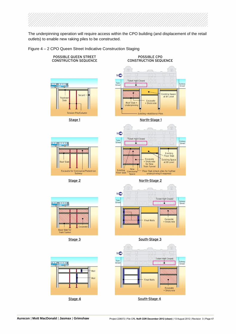
Aurecon | Mott MacDonald | Jasmax | Grimshaw Project 228072 | File CRL NoR CDR December 2012 (clean) | 13 August 2012 | Revision 3 | Page 47
The underpinning operation will require access within the CPO building (and displacement of the retail
outlets) to enable new raking piles to be constructed.
Figure 4 – 2 CPO Queen Street Indicative Construction Staging

Aurecon | Mott MacDonald | Jasmax | Grimshaw Project 228072 | File CRL NoR CDR December 2012 (clean) | 13 August 2012 | Revision 3 | Page 48
4.4 Indicative Construction Programme
An indicative construction programme is set out below in Figure 4 – 3. It has been developed based
on the indicated construction methodology for each work site as described in Section 4.2 above. The
programme logic also considers the assumptions and constraints highlighted throughout this report.
The following construction timeline gives an outline of key construction tasks based on the indicative
construction programme. System and operational handovers have also been included in the
programme. It should be noted that the programme is based on a series of constructability
assumptions. The programme is intended to indicate reasonable and feasible timeframes only, based
on the concept design. Specific durations may vary, but the overall duration is a reliable indicator of
project length.

Aurecon | Mott MacDonald | Jasmax | Grimshaw Project 228072 | File CRL NoR CDR December 2012 (clean) | 13 August 2012 | Revision 3 | Page 49
Figure 4 – 3 Indicative Construction Programme

Aurecon | Mott MacDonald | Jasmax | Grimshaw Project 228072 | File CRL NoR CDR December 2012 (clean) | 13 August 2012 | Revision 3 | Page 50
Year 1
Environmental compliance plan development, site preparation and work site establishment.
Detailed design for temporary and permanent vertical supports.
Advanced design and specification for the procurement of critical and long leading time items.
Tunnel boring machine procurement and manufacturing.
Sinking of shaft at Flower Street for mined tunnel header.
Shaft construction at Newton Station.
Shaft construction at Karangahape Station.
TBM reception pit for TBM at the south end of Aotea Station.
East side of the Aotea Station Box.
Northern section of cut and cover tunnel under Albert Street.
QEII Square, Britomart Station building underpinning.
Installation of wall for south cut and cover tunnels.
Modification works and retaining walls in the middle section of NAL.
Modification works and north side retaining walls in the east section of NAL.
Year 2
Ongoing detailed design of stations.
Offsite production of critical and long leading time items.
Delivery of tunnel boring machine and up main tunnel drive at latter part of the year.
Mined tunnel extended from the shaft at Flower Street into Newton Station up platform tunnel.
Complete down platform mined tunnel and shaft construction for Newton Station.
Complete up and down platforms mined tunnel at Karangahape Station.
Shaft and passage excavation at Beresford Square entrance for Karangahape Station.
East side of the Aotea Station Box.
Middle section of cut and cover tunnel under Albert Street.
West side of Downtown Shopping Centre cut and cover section.
Queen Elizabeth II Square, Britomart Station building and platform box works.
Excavation to the formation of south cut and cover tunnels.
Temporary track on wall at middle section of NAL to allow excavation between walls.
Temporary track along north side allowing wall construction to south of the east NAL section.

Aurecon | Mott MacDonald | Jasmax | Grimshaw Project 228072 | File CRL NoR CDR December 2012 (clean) | 13 August 2012 | Revision 3 | Page 51
Year 3
Completion of station detailed designs.
Offsite production of short leading time items.
Full production for both up and down driven tunnels.
Completion of mined tunnel from Newton Station down platform back to cut and covered box.
Complete structural works for Newton Station.
Commencement of structural works for Mercury Lane entrance at Karangahape Station.
Structural works for Beresford Square entrance for Karangahape Station.
Completion of east side and commencement of west side of the Aotea Station Box.
South section of cut and cover tunnel under Albert Street.
East side of Downtown Shopping Centre cut and cover section.
Queen Elizabeth II Square, Britomart Station building and platform box works.
Structural works of south cut and cover tunnels.
Track works to allow the NAL into its final position at west section of NAL.
NAL up main to its final position and allow excavation of CRL formation on east NAL section.
Complete bridge works at Normanby Road and then under Mt Eden Road over the new tracks.
Year 4
Demobilisation of TBM.
Completion of mined tunnel linings.
Station finish and fit out works for Newton Station.
Completion of structural works for Mercury Lane entrance at Karangahape Station.
Station finish and fit out works for Beresford Square entrance at Karangahape Station.
Completion of station entrance and structural works for the Aotea Station.
Top out over cut and cover tunnel under the Albert Street.
Top out and reinstatement of Downtown Shopping Centre cut and covered section.
Finish station and services works for Queen Elizabeth II Square, Britomart Station building and
platform box.
Top out and back fill of south cut and cover tunnels.
Excavation works for CRL track at east NAL section.
Track slab and rail installation inside the tunnel sections for CRL.

Aurecon | Mott MacDonald | Jasmax | Grimshaw Project 228072 | File CRL NoR CDR December 2012 (clean) | 13 August 2012 | Revision 3 | Page 52
Year 5
E&M works and testing for Newton Station.
E&M works and testing for Karangahape Station.
E&M works and testing for Aotea Station.
Reinstalment of roadway over cut and cover tunnel under the Albert Street.
E&M works and testing at Britomart Station.
Commencement of CRL OLE and signal installations.
Year 5 to Completion
Completion of CRL OLE and signal installations.
Staff training.
Testing and commissioning of railway operational system for CRL.
Testing and commissioning of station system for Stations.
Connection to existing NAL tracks system and handover.
CRL complete.

Aurecon | Mott MacDonald | Jasmax | Grimshaw Project 228072 | File CRL NoR CDR December 2012 (clean) | 13 August 2012 | Revision 3 | Page 53
Abbreviations The following abbreviations have been used throughout the City Rail Link Concept Design Report and
are listed below for reference.
AC Alternating Current
AEE Assessment of Environmental Effects
AHU Air Handling Unit
ARTA (Former) Auckland Regional Transport Authority
AT Auckland Transport
CAF Construcciones Y Auxiliar de Ferrocarriles
CBI Computer Based Interlocking
CCTV Closed Circuit Television
CIS Control Information Systems
CMJ CPO
Central Motorway Junction Central Post Office
CRL City Rail Link
DART Developing Auckland Rail Transport
DB Distribution Boards
ECBF East Coast Bays Formation
EMU Electric Multiple Unit
HV High Voltage
HVAC Heating Ventilation and Air Conditioning
ICT Information Communication Technology
LV Low Voltage
MW megawatt/s
NAL North Auckland Line
NoR Notice of Requirement
NZFS New Zealand Fire Service
NZTA New Zealand Transport Agency
Aurecon | Mott MacDonald | Jasmax | Grimshaw Project 228072 | File CRL NoR CDR December 2012 (clean) | 13 August 2012 | Revision 3 | Page 54
OHLE Overhead Line Equipment
OTE Over Track Exhaust
PA Principal Advisor
PSD Platform Screen Door
RLTS Regional Land Transport Strategy
SCADA Supervisory Control and Data Acquisition
TBM Tunnel Boring Machine
TVS Tunnel Ventilation System
UPE Under Platform Extract
UPS Uninterruptible Power Supply
Aurecon | Mott MacDonald | Jasmax | Grimshaw Project 228072 | File CRL NoR CDR December 2012 (clean) | 13 August 2012 | Revision 3 | Page 55
Glossary of Terms The following glossary of terms has been used throughout the City Rail Link Concept Design Report
and is listed below for reference.
Adit A mined entrance or passage from a mainline underground structure.
Alignment The horizontal position and vertical grade of a railway track, described by horizontal straights and curved track of constant and varying vertical grades, transitions and vertical curves.
Box (i.e. station box) A box-shaped underground structure constructed from the surface.
Cab-signalling A railway signalling system that provides train movement authority indications directly to the driver‟s console.
Cadastral boundary Land boundaries pertaining to an official register of ownership.
Cant The raising of the outer rail on a curve in the track with respect to the inner rail to allow higher speeds than if the two rails were level. Cant compensates for the centrifugal force generated from a train traversing a curve.
Car Individual railway carriage.
Catenary A system of overhead wires to supply electricity to the train.
Catenary/contact system Overhead conduction wire of a railway sometimes referred to as Overhead Line Equipment (OHLE).
Cavern A large underground chamber.
Chainage An imaginary line used to measure distance from a specified starting point.
Commissioning Final project stage that involves full testing of a system or systems bringing them into use.
Concept design First stage of a design that provides a solution to a broad definition of the scope and is limited in detail.
Concourse The main zone in a station where passengers congregate before distributing to the platforms.
Consolidation A process by which water saturated soil reduces in volume due to load application or lowering of groundwater level that causes the water to be squeezed/ removed out and the soil settles.
Consolidation settlement Space deformation induced by consolidation (see „consolidation‟ above).
Cross passages Transverse tunnels connecting main running tunnels. Can be used for escape routes from one tunnel to another in the event of an incident.

Aurecon | Mott MacDonald | Jasmax | Grimshaw Project 228072 | File CRL NoR CDR December 2012 (clean) | 13 August 2012 | Revision 3 | Page 56
Cut and cover tunnel (or boxes)
A form of construction for a box-shaped tunnel where a trench is excavated within which the tunnel is constructed and then the trench is backfilled and the surface restored.
Detraining Evacuation of passengers from train to track in an emergency.
Diaphragm wall A technique for forming retaining walls by constructing a reinforced concrete wall within a trench excavation of the width of the wall. The sides of the trench are generally supported by a thick fluid such as bentonite which allows excavation through it. The fluid is then replaced with concrete through a tremmie pipe which fills from the base of the trench upwards.
Differential settlement Difference in settlement between two adjacent locations.
Dive structure A structure that allows the rail alignment to transition from the surface to an underground tunnel.
Down main running tunnel A tunnel in which trains run from west to east/ south.
Driven tunnels Tunnels constructed using mechanised tunnel boring machine (TBM).
Easement A strip of land registered on the title deed in the office of the Registrar of Titles allowing access or other rights to a public body or party other than the owner of the parcel of land on which the easement exists.
Egress shaft Underground structure with dedicated escape route out to surface.
Fire and Life Safety Fire and Life Safety addresses the design and management of building infrastructure to allow safe and effective evacuation of buildings under all emergency conditions, including fires.
Electrification See ‟catenary‟ above.
Floating track slab Track slab isolated from the ground or supporting structure using resilient bearings or sheet material.
Emergency egress routes Dedicated escape routes to surface in the event of an incident.
EMU (electric multiple unit) A set of electrically powered self-propelling passenger rail vehicles able to operate jointly with other such sets.
Enabling works Works carried out in advance to facilitate ease of permanent works construction.
Escalator and stair run-off areas
Dispersal areas at top and bottom of an escalator or stair.
Fully weight regulated OHLE Both the catenary and contact wires are tensioned with a balance weight assembly.
Grade separation Separation of transport routes that cross each other by locating them at different heights to avoid traffic flow disruption.
Groundwater Water located in pore spaces within the soil mass.
Headway Distance/time between vehicles in a transit system.
Aurecon | Mott MacDonald | Jasmax | Grimshaw Project 228072 | File CRL NoR CDR December 2012 (clean) | 13 August 2012 | Revision 3 | Page 57
In-situ reinforced concrete Cast in place concrete structures with embedded steel reinforcing bars to give it the required strength.
Kinematic envelope Outline of space generated by a moving vehicle, taking into account the maximum dynamic displacement of the vehicle outline and wear effects on rails, wheels, suspension and the like.
Launch shaft/site Structure/working area used for lowering in and launching the Tunnel Boring Machine (TBM).
Lineside signalling Visual signals which are located along the route of a railway (by the side of the line) for observation by the driver.
Lining A layer of concrete installed at the excavation face to provide ground support.
Mainline A principal line of a railway.
Mined Tunnel Tunnelling method utilising a road header or similar technology to create open underground space combined with steel and concrete lining systems and rock bolting installed in a predetermined sequence.
Multi modal study As assessment of employment, population and transport needs for different modes of transportation.
Narrow gauge A distance of 1068mm between the inner sides of the heads of two load bearing parallel rails that form a single railway line.
North Auckland Line (NAL) An existing railway line which runs from Newmarket through to Swanson and beyond.
Notice of Requirement (NoR) The way a Requiring Authority gives notice of its requirement for a designation for a project or work. The Requirement has an interim effect in protecting against other work or development which would prevent or hinder the project or work to which the designation relates.
Overhead line equipment (OHLE)
See „catenary‟ above.
Pantograph A device that collects electric current from overhead lines for trains or trams.
Patronage/ passenger modelling
Study that evaluates the numbers who board/alight from a train, numbers of interchangers at the stations and numbers riding between the stations.
Pile A slender structural element that is driven or bored into the soil to provide vertical or lateral support.
Platform screen door A partition to separate passengers at platform from the moving trains and the platform edge with automated sliding doors to allow access to the trains.
Portal Transition structure at the inlet and outlet of a tunnel.
Pre and post condition surveys
Surveys to establish conditions of existing properties/infrastructures before and after construction activities.
Aurecon | Mott MacDonald | Jasmax | Grimshaw Project 228072 | File CRL NoR CDR December 2012 (clean) | 13 August 2012 | Revision 3 | Page 58
Principal Advisor A consortium of Aurecon, Mott MacDonald, Jasmax and Grimshaw who are an integrated team of consultants to Auckland Transport on engineering and architectural matters.
Property title A record of evidence of property ownership, also showing site dimensions, size, boundaries, and mortgages.
Real time surveys Survey information recorded and read immediately.
Resource Consent A resource consent is required when you wish to build or use land in a manner that does not comply with the rules of the district or regional plans. The type of consent required depends on what you want to do (e.g. a land use activity or subdivision) and how that is classified by the district and or regional plan covering the area where the site is located.
Road header An excavating machine with a rotating head mounted on crawler tracks developed for cutting a wide range of medium to hard rocks in underground mining and tunnelling.
Rock bolt A form of support for broken or jointed rock in excavations. Rock bolts are usually used in conjunction with sprayed concrete lining (see „shotcrete‟ below).
Rolling stock Wheeled vehicles used on a railway such as passenger coaches, freight wagons, multiple units, etc.
Saccardo Nozzle A nozzle injector in which air is taken from outside and discharged into a tunnel at high speed, and at an angle between 16° and 30° from the tunnel axis. The angled jet of air encourages air to flow along the tunnel in the direction of the jet.
Secant pile wall A retaining wall formed by constructing intersecting (secanted) reinforced concrete piles to form a continuous wall.
Segmental concrete lining A circular ring in the form of a number of precast concrete segments. The lining of the tunnel is formed by a continuous build of rings.
Sensitive structures Structures susceptible to ground movements due to tunnel excavations and other construction activities.
Shafts Underground structures excavated from the surface for permanent or temporary access.
Sheet piles Steel interlocking sheets driven into the ground to form a retaining wall to resist lateral pressure of adjacent ground.
Shotcrete A concrete mixture that is sprayed under pressure from a special gun on to a surface.
Sleeper block Tie members laid transverse to support the rails to the correct gauge.
„Soft eye‟ A rectangular zone around the TBM entry and exit point usually constructed without steel reinforcement to facilitate ease of passage of TBM during breakthrough.
Spoil Excavated material.

Aurecon | Mott MacDonald | Jasmax | Grimshaw Project 228072 | File CRL NoR CDR December 2012 (clean) | 13 August 2012 | Revision 3 | Page 59
Stable yard Train parking yard for storage, maintenance and washing activities.
Stabling See „stable yard‟ above.
Station fit-out Completion of fittings and fixtures within a completed structure to meet the functional requirements of a station.
Structure gauge The profile perpendicular to the track into which no part of any structure or fixed equipment may penetrate, taking into account all deformations and movements.
Sump Chamber for storage of drainage water prior to pumping away.
Technical Standards Formal and precise specifications that establish engineering criteria and practices.
Top-down method In the top-down method of construction, the structural roof is constructed first and supported by embedded walls and plunged columns and the ground surface is reinstated except for access openings. This allows early reinstatement of roadways, services and other surface features. The remainder of the excavation and construction is completed downwards constructing the floors as excavation progresses.
Track gauge The distance between the inner faces of the rail heads (Top section of rail) of a railway track, commonly referred to as “the gauge”.
Track junction A junction where more than one rail tracks intersect.
Traction power Electrical power used by the train to move.
Traction substation Electrical substation supplying traction power.
Tremmie A pipe used to place concrete below water level. The end of the pipe is kept immersed in fresh concrete so that the rising concrete displaces the water without washing out the cement content.
Trigeneration plant Plant designed to allow simultaneous production of three useful energies; power, heat and chilled water from one primary fuel source.
Tunnel Boring Machine(TBM) A mechanically operated machine used to excavate a tunnel with a circular cross section through a variety of ground strata.
Tunnel invert Lowest point at a tunnel cross section.
Tunnel Ventilation System (TVS)
A system to provide an acceptable environment in the tunnel in terms of both temperature and air quality and also to remove smoke in the event of a fire.
Underpinning The process of modifying an existing foundation system. This is done to provide vertical support that is not present in the existing structure.
Up main running tunnel A tunnel in which trains run from east/ south to the west.
Waler A horizontal reinforcement utilised to keep newly poured concrete forms from bulging outwards.
Water table The level below which the ground is saturated with water.

Aurecon | Mott MacDonald | Jasmax | Grimshaw Project 228072 | File CRL NoR CDR December 2012 (clean) | 13 August 2012 | Revision 3 | Page 60
Wayfinding Signage within a station and also refers to the ease with which passengers can intuitively find their way.