PROJECT AREA:Yonkers HUDSON VALLEY REGIONAL...
18
PROJECT AREA:Yonkers HUDSON VALLEY REGIONAL COUNCIL 3 Washington Center, Newburgh, NY 12550 http://www.hudsonvalleyregionalcouncil.com/ GREEN INFRASTRUCTURE CONCEPT PLAN FOR JOSEPH CERRATO PARK Project type: Urban park retrofit December 2011 Proposed practices: 1- Tree plantings, 2- Permeable paving, 3- Permeable play surfacing Google Earth 2011
Transcript of PROJECT AREA:Yonkers HUDSON VALLEY REGIONAL...
PROJECT AREA:Yonkers
HUDSON VALLEY REGIONAL COUNCIL
3 Washington Center, Newburgh, NY 12550 http://www.hudsonvalleyregionalcouncil.com/
GREEN INFRASTRUCTURE CONCEPT PLAN FOR JOSEPH CERRATO PARK
Project type: Urban park retrofit December 2011 Proposed practices: 1- Tree plantings, 2- Permeable paving, 3- Permeable play surfacing
Google Earth 2011
PROJECT NUMBER AND NAME
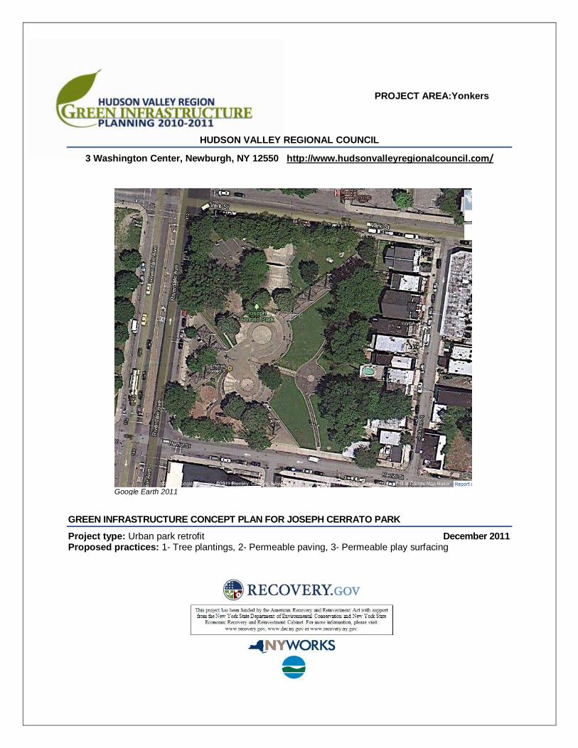
The following draft report describes a schematic landscape design proposal using green infrastructure practices for stormwater management. The illustrated plan and report are intended to give practical guidance for the owner, design professionals, contractors, and other interested parties to use in developing a final design. They are not intended to be used as final design and construction documents.
PROJECT DESCRIPTION
OVERVIEW
Built in 1976, Joseph Cerrato Park is located in southwest Yonkers, one half mile south of Larkin Plaza on a site that is approximately 2.2 acres. The Yonkers Department of Parks, Recreation and Conservation plans to repair and upgrade the park in the near future. Former Commissioner August Cambria requested this conceptual plan, which outlines an approach to including green infrastructure practices. The actual final design of the park will be based on a complete assessment of the site and user needs. Outlined here are the key opportunities for reducing impervious surface and enhancing the tree plantings.
PAVED AREA REDUCTION AND CURB REMOVAL Reduce the width of the four entry paths from 20’ to 12’. Replace handball court and adjacent eroded bank with lawn, trees and shrubs. Remove curbs on selected paths to allow runoff to flow to lawn.
TREE PLANTING Create tree plantings along the four entry paths. Add trees along the upper terrace and paths.
PERMEABLE PAVING AND PLAYGROUND SURFACES Replace deteriorated or damaged concrete and asphalt paving with permeable paving in selected areas.
Add new permeable surfaces to playground
.
LOCATION
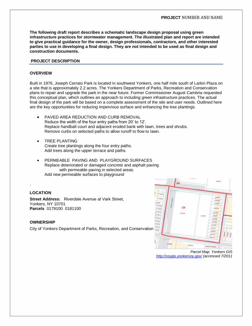
Street Address: Riverdale Avenue at Vark Street, Yonkers, NY 10701 Parcels 0179100 0181100
OWNERSHIP
City of Yonkers Department of Parks, Recreation, and Conservation
Parcel Map. Yonkers GIS http://coygis.yonkersny.gov/ (accessed 7/2011

2
SITE ASSESSMENT
Extensive impervious area in the park includes four 20‘wide concrete pathways that converge on the central plaza. Asphalt paths lead to the ball courts on the north, which are also paved with asphalt, and through the mulched playgrounds on the south. A large lawn occupies the slope between the main plaza and a concrete upper terrace. The playgrounds and ball courts are in poor condition. Wood pergolas over the entrance pathways are deteriorated. Much of the original poured concrete is in good condition, but tree roots have heaved areas of newer concrete pavers. Concrete stairs in the children’s play area are in good condition but the soil erosion has left the sides exposed. The asphalt paths on the upper level and in the children’s playground are in poor condition.
Figure 1 Asphalt around water feature, upper level
Figure 2 Concrete stage and ponded water
Figure 3 Deteriorated pergola over wide path Figure 4 Eroded slope in south playground
Figure 5 Handball court and mulberry tree roots Figure 6 Seating area with stressed and missing trees along Riverdale Avenue

3
SURFACE COVER/CONTRIBUTING AREA
Lawn and landscaped area: approximately 1.25 acres Impervious paving: approximately1 acre
SOILS AND TOPOGRAPHY
The site is steeply sloped and has been terraced. The soil is classified as Urban Land. Several areas on the site are eroded, including the children’s playground areas adjacent to the handball court.
SOLAR AND WIND EXPOSURE
Portions of the site are deeply shaded when the trees are in leaf. The central lawn area, concrete stair, plaza and water play features below are all in full sun. At the entrance to the park along Riverdale Avenue a seating area is shaded by the three trees that remain from the original planting. Pergolas provide some shade on the paths.
VEGETATION
A variety of deciduous shade trees grow in the park, and a complete inventory and assessment will be conducted when the Parks Department develops a plan for repairs and upgrades. This conceptual plan proposes the removal of several trees and indicates cases where a thorough assessment of the benefits, costs, and potential risks of existing trees will help to determine how the final plans are developed.

4
Figure 17 Concept plan (11x17 plan included at the end of the report)

5
THE PROPOSED PRACTICES IN BRIEF
Following is a brief discussion of the concept plan for each of the individual practices. The detailed discussion of design issues, materials, maintenance and costs is provided in the last section
IMPERVIOUS AREA REDUCTION AND CURB REMOVAL
The illustrated plan shows the width of the four entry paths, which are paved with conventional concrete pavers, reduced from 20 feet to 12 feet by removal of a 4 foot strip on each side. This reclaimed pervious area would become part of the extended tree pits for large canopy trees that would eventually shade the path. The existing pergola would be removed. The underutilized handball court would be replaced by lawn and trees. To the west of this, along the basketball court, a row of shrubs is indicated on the plan where there is currently a compacted and eroded slope. Curbs along the edges of the upper path would be removed to allow for the extension of the planting beds into the adjacent landscaped areas. Several areas for paving in the plaza would be converted to permeable paving as described below.
TREE PLANTING
Existing Trees An assessment of the existing trees by a qualified consulting arborist would be the first step in developing an overall plan for improvements to the park. The concept plan shows some possible approaches to working with the existing trees in some locations and removal and replacement in others. New trees in the lawn, along the paths, and in the front seating area are proposed. New Plantings The plan shows locations for new large canopy trees, and strategies to provide good growing conditions. Tree plantings intercept rainfall in the canopy and release it through evapotranspiration. Street tree pits with good quality, uncompacted soil will infiltrate runoff, and tree roots and leaf litter enhance the soil conditions for infiltration. In addition to these stormwater management functions, trees can provide many other benefits including shading and cooling, buffering wind and noise, purifying air and beautification. New trees at the front seating area would be provided with adequate soil volume by using a structural support system below the paving. In lawn areas and along paths next to lawn, adequate soil volume of large canopy trees would be available.
PERMEABLE CONCRETE PAVING AND PERMEABLE RECREATIONAL SURFACING
Permeable concrete pavers allow rain water to pass through the spaces between the units into a stone base, and then infiltrate into the soil below. They are durable, low maintenance, and visually attractive. The plan targets four areas for permeable concrete pavers:
At the front seating area, where the paving would be part of the tree planting system
To replace the concrete stage and surrounding paving
Around the water feature on the upper level
On a new path by the ball courts that would infiltrate runoff from the courts
Playground areas would be surfaced with pervious rubber mats with a gravel base to allow infiltration.

6
A WORD ON COSTS
Green infrastructure costs for retrofits are hard to state accurately. In new construction there is often considerably lower cost up front using and green infrastructure practices and planning versus conventional, big pipe systems. But where that “gray infrastructure” is already in place, assessing the value of adding a gi practice requires a fuller accounting. A recent report by the Center for Clean Air Policy states:
The value of green infrastructure actions is calculated by comparison to the cost of “hard” infrastructure alternatives, the value of avoided damages, or market preferences that enhance value (e.g. property value). Green infrastructure benefits generally can be divided into five categories of environmental protection:
(1) Land-value, (2) Quality of life, (3) Public health, (4) Hazard mitigation, and (5) Regulatory compliance.
The report sites, for example, New York City’s 2010 Green Infrastructure Plan, “which aims to reduce the city’s sewer management costs by $2.4 billion over 20 years. The plan estimates that every fully vegetated acre of green infrastructure would provide total annual benefits of $8,522 in reduced energy demand, $166 in reduced CO2 emissions, $1,044 in improved air quality, and $4,725 in increased property value. It estimates that the city can reduce CSO volumes by 2 billion gallons by 2030, using green practices at a total cost of $1.5 billion less than traditional methods.
1
Two Sources of Cost Data
For installation, maintenance costs and lifespan data for the practices discussed here, the Cost Sheet developed by the Center for Neighborhood Technology (CNT) in collaboration with the US EPA Office of Wetlands, Oceans, and Watersheds (OWOW), Assessment and Watershed Protection Division, Non-Point Source Branch, provides useful information based on examples from various locations. It may be found at their website. http://greenvalues.cnt.org/national/cost_detail.php
Another useful source of cost data can be found in the Center of Watershed Protection's Urban Subwatershed Restoration Manual Series. Manual 3: Urban Stormwater Retrofit Practices, pages E-1 though 14, includes a discussion of costs in terms of the amount of stormwater treated. http://www.cwp.org/categoryblog/92-urban-subwatershed-restoration-manual-series.html
1 The Value of Green Infrastructure for Urban Climate Adaptation. Center for Clean Air Policy. Josh Foster, Ashley Lowe, Steve
Winkelman. February 2011.

7
DESIGN, CONSTRUCTION, AND MAINTENANCE
The following section provides details about the specific design, materials, construction and maintenance considerations and the sizing calculations for each practice.
GREEN INFRASTRUCTURE SIZING AND DESIGN
The green infrastructure practices included in these plans are among those considered acceptable for runoff reduction in the New York State Stormwater Management Design Manual 2010 (Design Manual). The green infrastructure techniques include practices that:
reduce calculated runoff from contributing areas
capture the required water quality volume. The Water Quality Volume (denoted as the WQv) is designed to improve water quality sizing to capture and treat 90% of the average annual stormwater runoff volume. For Yonkers this 90% rainfall number is 1.3 inches. The WQv is directly related to the amount of impervious cover created at a site. The following equation can be used to determine the water quality storage volume WQv (in acre-feet of storage):
WQv = (P) (Rv)(A) 12 where: WQv = water quality volume (in acre-feet) P = 90% Rainfall Event Number Rv = 0.05 + 0.009(I), where I is percent impervious cover A = site area in acres (Contributing area) A minimum Rv of 0.2 will be applied to regulated sites.
1- TREE PLANTINGS
DESIGN
The removal of several trees is indicated on the plan. In the case of the trees in the triangular seating area along Riverdale Avenue, the remaining pin oaks are in decline and would be removed. Along the entrance path from Herriot Street, a different strategy might be used; new and existing trees are shown together in the extended tree pit. After the removal of the curbs and paving, extended planting areas would be provided along the entry paths that would allow new trees to use the adjacent lawn and landscaped areas. A wide mulched area would be provided around the base of each tree. Note that trees would be set back from the edge of paving at least 5’ which would necessitate using turf or other groundcover plants, stone or organic mulch or along the paths. Soil Volume and Tree Size The tree pit design and tree selection should reflect careful consideration of the available soil volume. Soil volume calculations should take into account a variety of specific factors including the soil type, whether the tree is growing in an open space or surrounded by paving, local climate conditions such as reflected heat and from cars, and other factors revealed in the complete site assessment. For the purpose of this plan, a good quality loam soil 3 feet deep is assumed, and healthy, large canopy trees are the goal. The chart below, developed by James Urban, shows that the soil volumes exceeding 1600 cubic feet would be required for trees with an ultimate crown projection over 1200 square feet, or about 40 feet in diameter. A general rule of thumb is a ratio of 2 CF of soil to 1 SF of mature crown spread. (Grabosky

8
and others, 1999; Urban,1999). 2 Another factor to consider is the positive effect of extended pits for
multiple trees -- when trees share soil, the volume of soil per tree is reduced.
Silva Cells or Structural Soil Along the seating area on Riverdale Avenue, no lawn area is available, so the tree pit design could use Silva Cells or structural soil and permeable paving to provide the appropriate conditions for strong and healthy large trees to grow. With Silva Cells more soil would be available for the trees than with structural soil, which comprises gravel and soil with high clay content. Silva Cells are proposed for this plan.
3
The open tree pits that abut each side of the seating area would be 4 x 80 feet, or 320 square feet. Assuming a depth of 3 feet, this would provide only 960 cubic feet of soil, which is not adequate to maximize the long term health of the tree large canopy trees shown. Additional soil volume below the adjacent paving would be provided—4 feet on each side of the open tree pit—increasing the width of the band of soil to 12 feet. This 12 foot wide strip on each 80-foot long side of the triangle for the 7 trees in this area would provide 8,500 cubic feet of soil (270 x 12 x 3), or about 1,200 cubic feet per tree.
This extra soil area would be installed in Silva Cells, which would support the permeable paving above. Beyond the areas allocated to the tree roots conventional paving could be used. The conventional paving would be graded to drain towards the tree pits, and no curbs would be used. For more information on Silva Cells, see DeepRoot at http://www.deeproot.com/products/silva-cell/cost.html. For information on structural soil, the following visit the website of the Urban Horticulture Institute of Cornell University: http://www.hort.cornell.edu/uhi/index.html .
2 In Urban Watershed Forestry Manual Part 3: Urban Tree Planting Guide, United States Department of Agriculture
Forest Service Northeastern Area State and Private Forestry NA-TP-01-06,September 2006, page 26. 3 The proposed green infrastructure plan for Coyne Park, included in this report package includes an infiltration strip
with structural soil and may provide a useful comparison.
The soil volume required for various size trees assumes a soil depth of 3 feet. (Source: James Urban) in Urban Watershed Forestry Manual - Part 3 page 26.)

9
Tree selection Trees would be selected according to aesthetic and functional criteria. Planting a selection of visually compatible trees of several species rather than one species is recommended where there is a desire to avoid planting a monoculture. All selections should be species that can withstand urban stress.
Soil and Soil Amendments Plant selection and planting specifications also would be based on an analysis of the soils to determine pH, wet and dry conditions, and compaction. The soil is classified as Urban Land, indicating that problems of with compaction, aeration, nutrients, drainage are likely to be present. Further, since pavers and gravel base course will be removed in these areas, additional soil will be required. Detailed specifications for soil and soil amendments should be prepared for all new installations.
CONSTRUCTION STEPS
Prepare tree pits according to the final design, including soil amendment and structural cell installation
Plant trees according to approved specification prepared by a qualified design professional
Apply mulch
Plant ground cover or turf as required
Figure 8 Front Seating Area with permeable paving (orange) over structural cells to extend tree pits. Open tree pits shown in green.
Figure 9 Silva Cells below permeable paving Copyright 2008. Casey Trees. Washington D.C.

10
MATERIALS
Soil and Soil Amendments: as required in final design
Structural support for paved areas: Silva cells or structural soil
Deciduous Trees: 38 are shown
Evergreen trees: 13 are shown
Mulch: Three inch layer in area at least 5 feet in diameter around the base of the tree (below the root flare).
MAINTENANCE CONSIDERATIONS
Well-prepared planting areas designed with appropriate plants and soils require routine maintenance. During the establishment period new tree plantings would be watered using water bags and spot watering with a clear understanding of the requirements of the trees to avoid over- or under-watering. Ongoing maintenance for the trees would include occasional pruning and replacements, twice yearly clean up and yearly application of mulch and inspections and treatment for damage and disease.
COST
Silva Cells The following information is provided by DeepRoot, the manufacturer of Silva Cells:
Each Silva Cell installation is unique to existing site requirements. Costs will vary based on characteristics of the site, the quantity of Silva Cells required for the project, the tree size and stormwater treatment goals, and the design objectives. Remember that each frame is 48'' (1200 mm) long x 24'' (600 mm) wide x 16'' (400 mm) high and holds about 10 ft
3 (.28 m
3) of soil.
According to bid tabulations from projects across North America, the Silva Cell system generally costs $14 - $18 per cubic foot installed (that estimate includes everything except the base course,
Structural Soil According to Nina Bassuk of Cornell University’s Urban Horticulture Institute (in CU Structural Soil: An Update after More than a Decade of Use in the Urban Environment, 2008), structural soil costs in the range of $35-42 per ton.
RESOURCES
The following resources on site assessment and tree selection are recommended: From Urban Horticulture Institute of Cornell University at http://www.hort.cornell.edu/uhi/:
Recommended Urban Trees: Site Assessment and Tree Selection for Urban Tolerance. Urban
Horticulture Institute, Department of Horticulture, Cornell University, Ithaca, NY. Visual Similarity and Biological Diversity: Street Tree Selection and Design. Bassuk, Nina,.
Trowbridge, Peter. Grohs, Carol. From the Center for Watershed Protection http://www.cwp.org/documents/cat_view/69-urban-watershed-forestry-manual-series.html

11
Urban Watershed Forestry Manual,Part 3:.Urban Tree Planting Guide. Cappiella, Schueler, Tomlinson, Wright. Center for Watershed Protection and USDA Forest Service, Sept 2006.
PERMEABLE CONCRETE PAVERS
DESIGN
Deteriorated or damaged concrete and asphalt paving can be replaced with permeable paving in selected areas where the benefits would be greatest for tree health, aesthetic improvement and stormwater management. Front seating area As described above, permeable paving in the front seating area would be part of the design for the tree planting. The permeable pavers over the Silva cells would be used in the tree planting areas, and the adjacent paving could be conventional pavers. This would save the cost of the additional excavation and material for the reservoir, while obviously reducing the stormwater runoff reduction benefit. Rain falling directly on the surface, and from nearby impervious paving would flow through the paving and infiltrate the soils provided in the Silva Cells.
Concrete stage area The raised concrete platform could be retained, and the paving around it replaced with permeable pavers that would capture runoff from the stage itself and the adjacent drainage area.
Water feature and circular seating area on the upper level As described above, when the paving is replaced along the upper level, curbs can be removed and the paths graded to drain to the lawn. The circular area could be paved with permeable paving around outside of the water feature curb.
New path by the ball courts While the new basketball and volley ball courts could be surfaced with pervious asphalt, existing tree roots could make it difficult to provide the gravel base course. The option shown on the plan is to use conventional asphalt on the courts and pitch them towards a permeable path along the side, which would have a reservoir sized appropriately.
CONSTRUCTION STEPS
The construction steps would follow specifications developed by a qualified professional. Typical construction steps are as follows:
Excavate to proposed depth and level the bottom of infiltration bed.
Place geotextile if required
Place sub base and base aggregrates as required by final design
Place setting setting bed aggregate
Install edge restraint
Place permeable interlocking pavers
Place joint aggregate
MATERIALS
Typical manufacture’s specifications for permeable interlocking concrete pavers require the following materials.
Concrete pavers
Granular subbase
Granular base

12
Bedding and void opening aggregates
Edge restraints
Underdrain
Geotextile fabric (optional)
MAINTENANCE CONSIDERATIONS
Two excellent fact sheets on permeable and porous paving are available from the NC State University Stormwater Engineering Group at http://www.bae.ncsu.edu/stormwater/pubs.htm:
4
Research Update and Design Implications
Maintaining Permeable Pavements
The paving should be kept clean of debris. Vacuum sweep as needed. Upland and adjacent areas should be kept mowed and bare areas should be seeded.
COST
Costs for permeable pavers are comparable to conventional pavers, but the added excavation and gravel base increases the cost. However, permeable paving also can reduce or eliminate other costs for conventional stormwater for pipes, basins, and additional land.
4 Urban Waterways, NC State University and A&T State University Cooperative Extension.2011.

13
SIZING COMPUTATIONS
Sizing calculations are provided for three permeable paved areas. A- Circular area around the concrete stage Drainage area 5,500 sf Surface area of practice 1,200 sf Surface area required 1,132 sf With gravel base 1.25 feet deep and assumed porosity of .4 the circular area paved with permeable paving would capture and treat the WQv of 216.1 cubic feet.
SIZING CALCULATIONS-A
Total Drainage Area 5500 Ft2
Available Surface Area 1200 Ft2
Step 1: Calculate Water Quality Volume (WQv)
WQv = (P) (Rv) (A) / 12
P = 90% rainfall number = 1.3 inches
Rv = 0.05+0.009 (I), if Rv < 20%, use Rv = 20% 95%
I = percent impervious of area draining to practice = 100%
% of Total area that drains to practice 100%
A = Area draining to practice = 5500 Ft2
WQv = 566.0 Ft3
Step 2: Calculate required surface area for pavement:
Ap = WQv / n x dt
where n = assumed porosity 0.4
dt =trench depth 1.25 ft
AP= 1132 Ft2

14
B- Water feature and circular seating
Drainage area: 2,100 sf Surface area of practice: 770 sf Surface area required 675 sf
With gravel base 10 inches deep and assumed porosity of .4 the circular area paved with permeable paving would be large enough to capture and treat the WQv of 216.1 cubic feet.
SIZING CALCULATIONS-B
Total Drainage Area 2100 Ft2
Surface Area Provided 770 Ft2
Step 1: Calculate Water Quality Volume (WQv)
WQv = (P) (Rv) (A) / 12
P = 90% rainfall number = 1.3 inches
Rv = 0.05+0.009 (I), if Rv < 20%, use Rv = 20% 95%
I = percent impervious of area draining to practice = 100%
% of Total area that drains to practice 100%
A = Area draining to practice = 2100 Ft2
WQv = 216.1 Ft3
Step 2: Calculate required surface area for pavement:
Ap = WQv / n x dt
where n = assumed porosity 0.4
dt =trench depth 0.8 ft
AP= 675 Ft2

15
C- Permeable Path along ball courts Drainage area (the basketball and volleyball courts): Approximately 7,000sf Surface area or permeable path: 1,500 sf Surface area required 1,441 sf
With gravel base 16” inches deep and assumed porosity of .4 the proposed permeable paving path would be large enough to capture and treat the WQv of 720.4 cubic cubic feet from the impervious ball courts. 1
SIZING CALCULATIONS- C
Total Drainage Area 7000 Ft2
Available Surface Area 1500 Ft2
Step 1: Calculate Water Quality Volume (WQv)
WQv = (P) (Rv) (A) / 12
P = 90% rainfall number = 1.3 inches
Rv = 0.05+0.009 (I), if Rv < 20%, use Rv = 20% 95%
I = percent impervious of area draining to practice = 100%
% of Total area that drains to practice 100%
A = Area draining to practice = 7000 Ft2
WQv = 720.4 Ft3
Step 2: Calculate required surface area for pavement:
Ap = WQv / n x dt
where n = assumed porosity 0.4
dt =trench depth 1.25 ft
AP= 1441 Ft2

16
PERMEABLE RECREATIONALSURFACES
DESIGN
The renovated playground terraces can be surfaced with permeable rubber mats. Like permeable paving, a open graded base course would be provided to capture and treat at the least the WQv. An underdrain would be required if the underlying soils would not provide an adequate rate of infiltration.
CONSTRUCTION STEPS
The construction steps would follow specification developed by by a qualified professional. Typical construction steps are as follows:
Excavate to proposed depth and level the bottom of infiltration bed.
Place geotextile
Place sub base and base aggregrates as required by final design
Install edge restraint
Place permeable interlocking rubber mats
MATERIALS
(The detail provided by Viridian Landscape Studio shows the base course materials listed here.)
Rubber mats
8” Clean open graded aggregate
3” Cushion course
3/8” Wearing course
4” Perforated pipe
30 Mil impervious liner (along planting bed)
Non woven geotextile fabric
Figure 10 Porous rubber installation detail used as part of playground retrofits at Greenfield School, Philadelphia. Viridian Landscape Studio Design and Meliora Environmental Design

17
MAINTENANCE CONSIDERATIONS
Permeable surfaces should be kept clean of debris that can clog the pores. See the previous section on permeable concrete pavers for a list of references and recommended maintenance.
COST
As with permeable unit pavers, the cost of the surface material would be comparable to non porous rubber, but the added excavation gravel base increases the cost. However, permeable paving also can reduce or eliminate other costs for conventional stormwater for pipes, basins, and additional land.
SIZING COMPUTATIONS
As shown in the calculations below, if the 7,050 square feet of the playground area shown on the plan were surfaced with permeable rubber mats with a 1 foot deep stone reservoir below, the practice would have the capacity to store 2,820 square feet of runoff, which well exceeds the WQv.
Concept Plan by Marcy Denker
SIZING CALCULATIONS FOR RUBBER MATS
Total Drainage Area 7050 Ft2
Available Surface Area 7050 Ft2
Step 1: Calculate Water Quality Volume (WQv)
WQv = (P) (Rv) (A) / 12
P = 90% rainfall number = 1.3 inches
Rv = 0.05+0.009 (I), if Rv < 20%, use Rv = 20% 95%
I = percent impervious of area draining to practice = 100%
% of Total area that drains to practice 100%
A = Area draining to practice = 7050 Ft2
WQv = 725.6 Ft3
Step 2: Calculate the available storage volume in the storage reservoir:
Storage Volume = Ap*n*dt
where:
n = assumed porosity = 0.4
dt = gravel bed/reservoir depth = 1 Ft
Reservoir Storage Volume = 2820 cf