PROJE T MANUAL IT #2020-002 - Champaign County, Illinois€¦ · GHR No. 7257 / 7261 TABLE OF...
175
GHR No. 7257 / 7261 County of Champaign, Illinois 1776 East Washington Urbana, IL 61802 Ph 217.384.3720 SECURITY CAMERA, DETENTION MONITORING AND CONTROL SYSTEMS UPGRADE AT CHAMPAIGN COUNTY COURTHOUSE 101 EAST MAIN STREET URBANA, ILLINOIS 61801 AND JUVENILE DETENTION CENTER 400 ART BARTELL ROAD URBANA, ILLINOIS 61802 FOR COUNTY OF CHAMPAIGN URBANA, ILLINOIS 61802 PROJECT MANUAL ITB #2020-002 December 4, 2019
Transcript of PROJE T MANUAL IT #2020-002 - Champaign County, Illinois€¦ · GHR No. 7257 / 7261 TABLE OF...
GHR No. 7257 / 7261
County of Champaign, Illinois 1776 East Washington
Urbana, IL 61802 Ph 217.384.3720
SECURITY CAMERA, DETENTION MONITORING AND CONTROL
SYSTEMS UPGRADE
AT
CHAMPAIGN COUNTY COURTHOUSE 101 EAST MAIN STREET
URBANA, ILLINOIS 61801
AND
JUVENILE DETENTION CENTER 400 ART BARTELL ROAD
URBANA, ILLINOIS 61802
FOR
COUNTY OF CHAMPAIGN URBANA, ILLINOIS 61802
PROJECT MANUAL ITB #2020-002
December 4, 2019

GHR No. 7257 / 7261
TABLE OF CONTENTS 00 0100 -1
County of Champaign, Illinois 1776 East Washington
Urbana, IL 61802 Ph217.384.3720
TABLE OF CONTENTS
DIVISION 00 – PROCUREMENT AND CONTRACTING REQUIREMENTS 00 0200 NOTICE TO BIDDERS 00 1116 INVITATION TO BID 00 2213 SUPPLEMENTARY INSTRUCTIONS TO BIDDERS 00 4113 BID FORM – STIPULATED SUM (SINGLE-PRIME CONTRACT) 00 4313 BID SECURITY FORMS DIVISION 01 – GENERAL REQUIREMENTS 01 1000 SUMMARY 01 2000 PRICE AND PAYMENT PROCEDURES 01 2500 SUBSTITION PROCEDURES 01 2500a SUBSTITITION REQUEST FORM 01 2600 CONTRACTOR MODIFICATION PROCEDURES 01 3000 ADMINISTRATIVE REQUIREMENTS 01 4000 QUALITY REQUIREMENTS 01 6000 PRODUCT REQUIREMENTS 01 7000 EXECUTION AND CLOSEOUT REQUIREMENTS 01 7419 CONSTRUCTION WASTE MANAGEMENT AND DISPOSAL DIVISION 26 – ELECTRICAL 26 0519 LOW-VOLTAGE ELECTRICAL POWER CONDUCTORS AND CABLES 26 0526 GROUNDING AND BONDING FOR ELECTRICAL SYSTEMS 26 0529 HANGERS AND SUPORTS FOR ELECRICAL SYSTEMS 26 0533 RACEWAY AND BOXES FOR ELECTRICAL SYSTEMS 26 0544 SLEEVES AND SLEEVE SEALS FOR ELECTRICAL RACEWAYS AND CABLING 26 0553 IDENTIFICATION FOR ELECTRICAL SYSTEMS DIVISION 27 – COMMUNICATIONS 27 1100 COMMUNICATIONS EQUIPMENT ROOM FITTINGS 27 1116 COMMUNICATIONS RACKS, FRAMES AND ENCLOSURES 27 1323 COMMUNICATIONS OPTICAL FIBR BACKBONE CABLING 27 1513 COMMUNICATIONS COPPER HORIZONTAL CABLING DIVISION 28 – ELECTRONIC SAFETY AND SECURITY 28 1300 ACCESS CONTROL SOFTWARE AND DATABASE MANAGEMENT 28 1500 ACCESS CONTROL HARDWARE DEVICES 28 2000 VIDEO SURVEILLANCE 28 5211 DETENTION MONITORING AND CONTROL SYSTEM
GHR No. 7257 / 7261
TABLE OF CONTENTS 00 0100 -2
County of Champaign, Illinois 1776 East Washington
Urbana, IL 61802 Ph217.384.3720
INDEX OF DRAWINGS C100 COVER SHEET T100 COURTHOUSE - TECHNOLOGY NOTES AND SYMBOLS TD102.1 COURTHOUSE - PARTIAL BASEMENT DEMO PLAN - AREA B - TECHNOLOGY TD111.1 COURTHOUSE - PARTIAL FIRST FLOOR DEMO PLAN - AREA A - TECHNOLOGY TD112.1 COURTHOUSE - PARTIAL FIRST FLOOR DEMO PLAN - AREA B - TECHNOLOGY TD121.1 COURTHOUSE - PARTIAL SECOND DEMO PLAN - AREA A - TECHNOLOGY TD122.1 COURTHOUSE - PARTIAL SECOND DEMO PLAN - AREA B - TECHNOLOGY TD131.1 COURTHOUSE - PARTIAL THIRD FLOOR DEMO PLAN - AREA A - TECHNOLOGY TD132.1 COURTHOUSE - PARTIAL THIRD FLOOR DEMO PLAN - AREA B - TECHNOLOGY T102.1 COURTHOUSE - PARTIAL BASEMENT FLOORPLAN - AREA B - TECHNOLOGY T111.1 COURTHOUSE - PARTIAL FIRST FLOOR FLOORPLAN - AREA A - TECHNOLOGY T112.1 COURTHOUSE - PARTIAL FIRST FLOOR FLOORPLAN - AREA B - TECHNOLOGY T121.1 COURTHOUSE - PARTIAL SECOND FLOOR FLOORPLAN - AREA A - TECHNOLOGY T122.1 COURTHOUSE - PARTIAL SECOND FLOOR FLOORPLAN - AREA B - TECHNOLOGY T131.1 COURTHOUSE - PARTIAL THIRD FLOOR FLOORPLAN - AREA A - TECHNOLOGY T132.1 COURTHOUSE - PARTIAL THIRD FLOOR FLOORPLAN - AREA B - TECHNOLOGY TD111.2 J.D.C. - FIRST FLOOR PLAN - DEMOLITION - TECHNOLOGY TD112.2 J.D.C. - MEZANINE PLAN - DEMOLITION - TECHNOLOGY T111.2 J.D.C. - FIRST FLOOR PLAN - NEW WORK - TECHNOLOGY T112.2 J.D.C. - MEZANINE PLAN - NEW WORK - TECHNOLOGY END OF TABLE OF CONTENTS 00 0100

GHR No. 7257 / 7261 NOTICE TO BIDDERS 00 0200 -1
County of Champaign, Illinois 1776 East Washington
Urbana, IL 61802 Ph 217.384.3720
December 4, 2019
BID: County of Champaign, Illinois Security Camera, Detention Monitoring and Control Systems Upgrade at Champaign County Courthouse and Juvenile Detention Center
FRIDAY, JANUARY 3, 2020 1:00 P.M., Public Opening Lyle Shields Conference Room Brookens Administrative Center 1776 East Washington Urbana, Illinois 61802-4581 Dear Bidder: The County of Champaign is inviting the submission of sealed bids for Security Camera and Master Control Systems Upgrade at the Champaign County Courthouse and Champaign County Juvenile Detention Center Project, Urbana, Illinois. Specifications are prepared with the intent of offering equal opportunity to all bidders. No oral interpretations will be given to any bidder as to the meaning of the specifications. Requests for clarification must be submitted in writing via mail, fax or email to:
GHR Engineers and Associates, Inc. Attn.: Lucas McGill 1615 South Neil Street Champaign, IL 61820 Fax: (217) 356-1092 Email: [email protected]
Clarification requests must be received no later than December 23, 2019, 12:00 noon to be considered. Documents can be procured through Dean's Superior Blueprint Online Planroom. Pursuant to the Illinois Prevailing Wage Act (820 ILCS 130/1 et seq.), not less than the prevailing rate of wages as determined by the Illinois Department of Labor, County of Champaign, or court on review shall be paid by the vendor/contractor to all laborers, workers and mechanics performing work under this purchase order.

GHR No. 7257 / 7261 NOTICE TO BIDDERS 00 0200 -2
County of Champaign, Illinois 1776 East Washington
Urbana, IL 61802 Ph 217.384.3720
All bids are to be sealed and in the hands of the undersigned by the due date and time stated above, at which time bids will be publicly opened. There will be no bids accepted after said date and time. Your bid is to be submitted on the bid form provided. The envelope containing your bid is to be sealed and marked in the lower left-hand corner: “Sealed Bid: Security Camera, Detention Monitoring and Control Systems Upgrade, Champaign County Courthouse and Champaign County Juvenile Detention Center”. Bids will not be accepted by FAX mail. The Champaign County Board reserves the right to reject any or all bids, to accept the bids, or to waive any irregularities should it deem to be in the best interest of the County of Champaign to do so. The bids will be awarded to the lowest responsible bidder meeting specifications as determined by the Champaign County Board. Sincerely, Dana Brenner Facilities Director
END OF NOTICE TO BIDDERS 00 0200

GHR No. 7257 / 7261 INVITATION TO BID 00 1116 -1
County of Champaign, Illinois 1776 East Washington
Urbana, IL 61802 Ph 217.384.3720
DOCUMENT 00 1116 - INVITATION TO BID - #2017-003
1.1 PROJECT INFORMATION
A. Notice to Bidders: Qualified bidders are invited to submit bids for Project as described in this Document.
B. Project Identification: Security Camera, Detention Monitoring and Control Systems Upgrade, Champaign County Courthouse and Champaign County Juvenile Detention Center
1. Project Location: Champaign County Courthouse 101 East Main Street Urbana, Illinois 61801 Champaign County Juvenile Detention Center 400 Art Bartell Road Urbana, Illinois 61802
C. Owner: County of Champaign
1. Owner's Representative:
Dana Brenner, Facilities Director 1776 East Washington Urbana, IL 61802-4581 Phone: (217) 384-3765 Fax: (217) 384-3896 Email: [email protected]
D. Project Design Team: GHR Engineers and Associates, Inc.
E. Project Description: Project consists of the following:
1. Removal of both building’s digital video surveillance systems and replacing with completely new IP video surveillance systems.
2. Removal of both building’s detention monitoring and control system and replacing with new touch-screen based system.
3. Integration of all existing control system control points into new system.

GHR No. 7257 / 7261 INVITATION TO BID 00 1116 -2
County of Champaign, Illinois 1776 East Washington
Urbana, IL 61802 Ph 217.384.3720
4. Removal of existing control system at the Juvenile Detention Center and replacing with new.
5. Integration of access control; intercommunication; and video surveillance systems with new detention monitoring and control system.
6. Some Division 26 electrical work: Conduit installation, 120 volt circuit installation, etc.
F. Certification Contract: Bids will be received for the following Work:
1. Single Prime Contract
1.2 BID SUBMITTAL AND OPENING
A. Owner will receive sealed bids until the bid time and date at the location indicated below. Owner will consider bids prepared in compliance with the Contract Documents issued by Owner, and delivered as follows:
1. Bid Date: Friday, January 3, 2020. 2. Bid Time: 1:00 p.m., local time.
Location: Lyle Shields Meeting Room Brookens Administration Center 1776 East Washington Urbana, IL 61802
B. Bids will be thereafter opened in the presence of the bidders and read aloud.
1.3 BID SECURITY
A. Bid security in the form of a bank draft/cashier's check, certified check, U.S. money order, or bid bond payable to County of Champaign shall be submitted with each bid in the amount of ten (10) percent of the bid amount. No bids may be withdrawn for a period of sixty (60) days after opening of bids. Owner reserves the right to reject any and all bids and to waive informalities and irregularities.

GHR No. 7257 / 7261 INVITATION TO BID 00 1116 -3
County of Champaign, Illinois 1776 East Washington
Urbana, IL 61802 Ph 217.384.3720
1.4 PREBID CONFERENCE / SITE VISIT
A. A mandatory prebid conference for all bidders will be held at Lyle Shields Conference Room, Brookens Administration Center, 1776 East Washington Street, Urbana, Illinois on Wednesday, December 18, 2019 at 2:00 pm, local time. Meet at front entrance. Prospective bidders are required to attend.
B. Building access for additional site visits may be made by contacting Owner’s Representative. Dana Brenner, Facilities Director Phone: 217-384-3765 Fax: 217-384-3896 E-mail: [email protected]
1.5 DOCUMENTS
A. Documents can be procured through Dean's Superior Blueprint Online Planroom:
https://www.deansplanroom.com/.
1.6 TIME OF COMPLETION
A. Bidders shall begin the Work on receipt of the Notice to Proceed and shall complete the Work within the Contract Time.
1. Anticipated Award of Contract: Board Meeting, January 27, 2020. 2. Anticipated Letter of Notice of Award: On or about February 3, 2020. 3. Pre-Construction/Pre-Installation Meeting: TBD. 4. Substantial Completion: October 30, 2020. 5. Punch List: Issued on or about November 6, 2020. 6. Final Completion: November 27, 2020.
1.7 BIDDER'S QUALIFICATIONS
A. Bidders must be properly licensed under the laws governing their respective trades and be able to obtain insurance and bonds required for the Work. A Performance Bond, a separate Labor and Material Payment Bond, and Insurance in a form acceptable to Owner will be required of the successful Bidder.
GHR No. 7257 / 7261 INVITATION TO BID 00 1116 -4
County of Champaign, Illinois 1776 East Washington
Urbana, IL 61802 Ph 217.384.3720
1.8 EXAMINATION
A. Bidders shall tour the project location to familiarize themselves with the locations of existing equipment to include all the cost of demo and new work as shown on the drawings.
END OF DOCUMENT 00 1116

GHR No. 7257 / 7261 SUPPLEMENTARY INSTRUCTIONS TO BIDDERS 00 2213 - 1
County of Champaign, Illinois 1776 East Washington
Urbana, IL 61802 Ph 217.384.3720
DOCUMENT 00 2213 - SUPPLEMENTARY INSTRUCTIONS TO BIDDERS
1.1 SUPPLEMENTARY INSTRUCTIONS TO BIDDERS - BIDDER'S REPRESENTATIONS
A. The Bidder has investigated all required fees, permits, and regulatory requirements of authorities having jurisdiction and has properly included in the submitted bid the cost of such fees, permits, and requirements not otherwise indicated as provided by Owner.
1. Permit Application: Complete building permit application and file with
authorities having jurisdiction within five days of the Notice of Award.
B. The Bidder is a properly licensed Contractor according to the laws and regulations of The State of Illinois and meets qualifications indicated in the Procurement and Contracting Documents.
C. The Bidder has incorporated into the Bid adequate sums for work performed by installers whose qualifications meet those indicated in the Procurement and Contracting Documents.
1.2 BIDDING DOCUMENTS
A. Interpretation or Correction of Procurement and Contracting Documents:
1. Submit Bidder's Requests for Interpretation as outlined in the Notice to Bidders.
B. Submit Requests for Substitution on form provided. Substitution requests shall be in advance of bid.
C. Addenda:
1. Addenda may be issued at any time prior to the receipt of bids.
2. Owner may elect to waive the requirement for acknowledging receipt of Addenda as follows:
a. Information received as part of the Bid indicates that the Bid, as submitted, reflects modifications to the Procurement and Contracting Documents included in an unacknowledged Addendum.

GHR No. 7257 / 7261 SUPPLEMENTARY INSTRUCTIONS TO BIDDERS 00 2213 - 2
County of Champaign, Illinois 1776 East Washington
Urbana, IL 61802 Ph 217.384.3720
b. Modifications to the Procurement and Contracting Documents in an unacknowledged Addendum do not, in the opinion of Owner, affect the Contract Sum or Contract Time.
1.3 BIDDING PROCEDURES
A. Preparation of Bids:
1. The Bid shall include unit prices when called for by the Procurement and Contracting Documents. Owner may elect to consider unit prices in the determination of award. Unit prices will be incorporated into the Contract.
2. Owner may elect to disqualify a bid due to failure to submit a bid in the form requested, failure to bid requested alternates or unit prices, failure to complete entries in all blanks in the Bid Form, or inclusion by the Bidder of any alternates, conditions, limitations or provisions not called for.
Retail sales tax will NOT be included in the bid amount. The Owner is exempted by Section 3 of the Illinois Use Tax Act (Section 3, House Bill 1610, approved July 31, 1961, Illinois Revised Statutes 1967, Chapter 120, Section 439.3) from paying any of the taxes imposed by the Act and sales to Owner are exempt by Section 2, House Bill 1609, approved July 31, 1961, Illinois Revised statutes 1967, Chapter 120, Section 441) from any of the taxes imposed by the Act. The Department of Revenue of the State of Illinois under Rule No. 15, issued August 9, 1961, has declared that sales of materials to construction contractors for conversion into real estate for schools, governmental bodies, agencies and instrumentalities are not taxable retail sales. The Contractor shall be responsible for any sales, consumer, use and similar taxes for the Work.
3. Owner is not responsible for any costs incurred by a Contractor in the preparation or delivery of bids. The Contractor shall be responsible for the actual delivery of bids during business hours to the address indicated. Any bid received after the delivery deadline will be disqualified.
4. Owner reserves the right to obtain clarification of any point in a Contractor submittal or to obtain additional information.
FOIA: As an independent Contractor of the District, records in the possession of the Contractor related to this Agreement may be subject to the Illinois Freedom of Information Act (“FOIA”), 5 ILCS 140/5-1 et seq.; 5 ILCS 140/7(2). The Contractor shall immediately provide the District with any such records

GHR No. 7257 / 7261 SUPPLEMENTARY INSTRUCTIONS TO BIDDERS 00 2213 - 3
County of Champaign, Illinois 1776 East Washington
Urbana, IL 61802 Ph 217.384.3720
requested by the District in order to timely respond to any FOIA request received by the District.
B. Subcontractors, Suppliers, and Manufacturers List Bid Supplement:
1. Provide list of major subcontractors, suppliers, and manufacturers furnishing or installing products no later than ten (10) business days following Notice to Proceed. Do not change subcontractors, suppliers, and manufacturers from those submitted without approval of Owner.
1.4 CONSIDERATION OF BIDS
A. Rejection of Bids:
Owner reserves the right to reject a bid based on Owner's and Design Team’s evaluation of qualification information submitted following opening of bids. Owner's evaluation of the Bidder's qualifications will include: status of licensure and record of compliance with licensing requirements, record of quality of completed work, record of Project completion and ability to complete, record of financial management including financial resources available to complete Project and record of timely payment of obligations, record of Project site management including compliance with requirements of authorities having jurisdiction, record of and number of current claims and disputes and the status of their resolution, and qualifications of the Bidder's proposed Project staff and proposed subcontractors.
1.5 PERFORMANCE BOND AND PAYMENT BOND
A. Both a Performance Bond and a Payment Bond will be required, each in an amount equal to 100 percent of the Contract Sum.
B. The Bidder shall deliver the required bonds to Owner no later than ten (10) days after the date of Notice of Intent to Award and no later than the date of execution of the Contract, whichever occurs first. Owner may deem the failure of the Bidder to deliver required bonds within the period of time allowed a default.
C. Bonds shall be executed and be in force on the date of the execution of the Contract.

GHR No. 7257 / 7261 SUPPLEMENTARY INSTRUCTIONS TO BIDDERS 00 2213 - 4
County of Champaign, Illinois 1776 East Washington
Urbana, IL 61802 Ph 217.384.3720
1.6 INSURANCE
GENERAL The successful bidder shall maintain for the duration of the contract and any extensions thereof, at bidder's expense, insurance that includes "Occurrence" basis wording and is issued by a company or companies qualified to do business in the State of Illinois that are acceptable to the County, which generally requires that the company(ies) be assigned a Best's Rating of A or higher with a Best's financial size category of Class A-/VII or higher, in the following types and amounts:
1. Commercial General Liability in a broad form, to include, but not limited to, coverage for the following where exposure exists: Bodily Injury and Property Damage, Premises/Operations, Independent contractors, Products/Completed Operations, Personal Injury and Contractual Liability; limits of liability not less than: $1,000,000 per occurrence and $2,000,000 in the aggregate, and inclusion of a waiver of subrogation in favor of Champaign County;
2. Business Auto Liability to include, but not be limited to, coverage for the following where exposure exists: Owned Vehicles, Hired and Non‐Owned Vehicles and Employee Non‐Ownership; limits of liability not less than: $1,000,000 per occurrence, combined single limit for: Bodily Injury Liability and Property Damage Liability;
3. Workers' Compensation Insurance to cover all employees and meet statutory limits in compliance with applicable state and federal laws. The coverage must also include Employer's Liability with minimum limits of $500,000 for each incident, $500,000 for each disease and $500,000 aggregate, and a waiver of subrogation in favor of Champaign County.
B. EVIDENCE OF INSURANCE The successful bidder agrees that with respect to the above required insurance that: 1. The County of Champaign shall be provided with Certificates of Insurance
evidencing the above required insurance, prior to commencement of the contract and thereafter with certificates evidencing renewals or replacements of said policies of insurance at least fifteen (15) days prior to the expiration or cancellation of any such policies;
2. The contractual liability arising out of the contract shall be acknowledged on the Certificate of Insurance by the insurance company;
3. The County of Champaign shall be provided with thirty (30) days prior notice, in writing, of Notice of Cancellation or material change and said notification requirement shall be stated on the Certificate of Insurance;
4. Subcontractors, if any, shall execute the Subcontractor Agreement provided by Champaign County, and comply with the same insurance requirements as contractors.

GHR No. 7257 / 7261 SUPPLEMENTARY INSTRUCTIONS TO BIDDERS 00 2213 - 5
County of Champaign, Illinois 1776 East Washington
Urbana, IL 61802 Ph 217.384.3720
5. In addition to being named as an additional insured on the Certificate of Insurance, each liability policy shall contain an endorsement naming the County of Champaign as an additional insured. A copy of the endorsement shall be provided to Champaign County along with the Certificate of Insurance; and,
6. Champaign County must be named as an additional insured, on a primary and noncontributory basis, and the address for certificate holder must read exactly as: County of Champaign, a body politic 1776 East Washington Street, Urbana, IL 61802
7. Insurance Notices and Certificates of Insurance shall be provided to: Champaign County, Insurance Specialist, Administrative Services Department, 1776 East Washington Street, Urbana, IL 61802
1.7 STANDARD CONTRACT CONDITIONS
A. This contract shall be governed in all aspects as to validity, construction, capacity, performance, or otherwise by the laws of the State of Illinois.
B. Contractors shall comply with the Civil Rights Act of 1964, as amended, all applicable State and Federal non-discrimination laws including but not limited to the Family and Medical Leave Act, the Americans with Disabilities Act, the Age Discrimination in Employment Act and shall comply with the provisions of the Illinois Human Rights Act.
C. Contractors shall not assign, transfer, convey, sublet, or otherwise dispose of this contract, including any or all of it right, title or interest therein, or its power to execute such contract to any person, company or corporation, without prior written consent of The County of Champaign.
D. By submitting a bid the Contractor certifies that the Contractor is not barred from bidding on this contract as a result of a violation of either the bid-rigging or bid-rotating provisions of Article 33E of the Criminal Code of 1961, as amended.
By submitting a bid, the Contractor, having 25 or more employees, does hereby certify pursuant to Section 3 of the Illinois Drug-Free Workplace Act (30 ILCS 580/3) that it shall provide a drug-free workplace for all employees engaged in the performance of work under the contract by complying with the requirements of the Illinois Drug-Free Workplace Act and, further certifies, that it is not ineligible for award of this contract by reason of debarment for a violation of the Illinois Drug-Free Workplace Act.
E. By submitting a bid, the Contractor does hereby certify pursuant to Section 2-105 of the Illinois Human Rights Act (775 ILCS 5/2-105) that it has a written sexual harassment policy that includes, at a minimum, the following information: (i) the illegality of sexual harassment; (ii) the definition of sexual harassment under State law; (iii) a

GHR No. 7257 / 7261 SUPPLEMENTARY INSTRUCTIONS TO BIDDERS 00 2213 - 6
County of Champaign, Illinois 1776 East Washington
Urbana, IL 61802 Ph 217.384.3720
description of sexual harassment, utilizing examples; (iv) an internal complaint process including penalties; (v) the legal recourse, investigative and complaint process available through the Department of Human Rights and Human Rights Commission; (vi) direction on how to contact the Department of Human Rights and Human Rights Commission; and (vii) protection against retaliation.
1.8 STATEMENT OF NON-DISCRIMINATION
A. The Illinois Human Rights Acts prohibits discrimination on the basis of: “race, color, religion, sex, national origin, ancestry, age, order of protection status, marital status, physical or mental disability, military status, sexual orientation, or unfavorable discharge from military service in connection with employment, real estate transactions, access to financial credit, and the availability of public accommodations.” It also prohibits sexual harassment and discrimination in employment on the basis of citizenship status.
1.9 PREVAILING WAGE
A. This contract calls for the construction of a “public work” within the meaning of the Illinois Prevailing Wage Act, 920 ILCS 130/.01. The Act requires contractors and subcontractors to pay all laborers, workers and mechanics performing services on public works projects no less than the “prevailing rate of wages” (hourly cash wages plus fringe benefits) in the county where the work is performed. Each Contractor and Subcontractor rendering services under this contract must comply with all requirements of this Act. Each Contractor and Subcontractor shall keep records of the prevailing wages paid to their employees, submit a monthly certified payroll to County of Champaign, and make such records available to County of Champaign for inspection upon seven business days notice.
B. For information regarding the current prevailing wage rates for Champaign County, Illinois can be found at:
http://www.illinois.gov/idol/laws-rules/conmed/pages/rates.aspx.
C. Prevailing Wage Rates change periodically. Contractor shall verify and revise the prevailing wages on a regular basis.
1.10 FAILURE TO FULFILL CONTRACT
A. When any Contractor fails to provide a service or provides a service which does not conform to the specifications, County of Champaign may, at its sole discretion, annul

GHR No. 7257 / 7261 SUPPLEMENTARY INSTRUCTIONS TO BIDDERS 00 2213 - 7
County of Champaign, Illinois 1776 East Washington
Urbana, IL 61802 Ph 217.384.3720
and set aside the contract entered into with said Contractor, either in whole or in part, and make and enter into a new contract for the same services in such manner as seems to County of Champaign to be to its best advantage. Any failure to furnish services by reason of the failure of the Contractor, as stated above, shall be a liability against such Contractor and his sureties. County of Champaign reserves the right to cancel, without penalty, any services which the successful Contractor may be unable to furnish because of economic conditions, governmental regulations or other similar causes beyond the control of the Contractor provided satisfactory proof is furnished to County of Champaign if requested.
Without Cause Termination: The County may terminate its contract with the Contractor without cause after providing the Contractor with thirty (30) days written notice.
1.11 EXECUTION OF THE CONTRACT
A. Subsequent to the Notice of Intent to Award, and within ten (10) business days after the prescribed Form of Agreement is presented to the Awardee for signature, the Awardee shall execute and deliver the Agreement to Owner through Engineer, in such number of counterparts as Owner may require.
B. Owner may deem as a default the failure of the Awardee to execute the Contract and to supply the required bonds and insurance when the Agreement is presented for signature within the period of time allowed.
C. Unless otherwise indicated in the Procurement and Contracting Documents of the executed Agreement, the date of commencement of the Work shall be the date of the executed Agreement. In the event of a default, Owner may declare the amount of the Bid security forfeited and elect to either award the Contract to the next responsible bidder or re-advertise for bids.
1.12 INDEMNITY
A. To the fullest extent permitted by law, Contractor shall indemnify and hold harmless the Owner from and against claims, damages, losses and expenses, including but not limited to attorney’s fees, arising out of or resulting from performance of the work provided that such claim, damage, loss or expense is attributable to bodily injury, sickness, disease or death, or to injury to or destruction of tangible property, but only to the extent caused by the negligent acts or omissions of the Contractor, a subcontractor, anyone directly or indirectly employed by them or anyone for whose
GHR No. 7257 / 7261 SUPPLEMENTARY INSTRUCTIONS TO BIDDERS 00 2213 - 8
County of Champaign, Illinois 1776 East Washington
Urbana, IL 61802 Ph 217.384.3720
acts they may be liable, regardless of whether or not such claim damage, loss or expense is caused in part by a party indemnified hereunder.
END OF DOCUMENT 00 2213

GHR No. 7257 / 7261 BID FORM – STIPULATED SUM (SINGLE-PRIME CONTRACT) 00 4113 - 1
County of Champaign, Illinois 1776 East Washington
Urbana, IL 61802 Ph 217.384.3720
DOCUMENT 00 4113 - BID FORM - STIPULATED SUM (SINGLE-PRIME CONTRACT)
1.1 BID INFORMATION
A. Bidder: ____________________________________________________.
B. Project Name: Security Camera, Detention Monitoring and Control Systems Upgrade
C. Project Location: Champaign County Courthouse 101 East Main Street Urbana, Illinois 61801
Champaign County Juvenile Detention Center 400 Art Bartell Road Urbana, Illinois 61802
D. Owner: County of Champaign
E. Building Design Team: GHR Engineers and Associates, Inc.
1.2 CERTIFICATIONS AND BASE BID
A. Owner reserves the right to award bid based on a single facility or combined price for both facilities.
B. Base Bid, Single-Prime (All Trades) Contract: The undersigned Bidder, having carefully examined the Procurement and Contracting Requirements, Conditions of the Contract, Drawings, Specifications, and all subsequent Addenda, as prepared by the Design Team, having visited the site, and being familiar with all conditions and requirements of the Work, hereby agrees to furnish all material, labor, equipment and services, including all scheduled allowances, necessary to complete the construction of the above-named project, according to the requirements of the Procurement and Contracting Documents, for the stipulated sum of:
Champaign County Courthouse Base Bid 1. ___________________________________________Dollars ($______________).
Champaign County Juvenile Detention Center Base Bid 1. ___________________________________________Dollars ($______________).

GHR No. 7257 / 7261 BID FORM – STIPULATED SUM (SINGLE-PRIME CONTRACT) 00 4113 - 2
County of Champaign, Illinois 1776 East Washington
Urbana, IL 61802 Ph 217.384.3720
Champaign County Courthouse and Juvenile Detention Center Base Bid Combined 1. ___________________________________________Dollars ($______________).
1.3 BID GUARANTEE
The undersigned Bidder agrees to execute a contract for this Work in the above amount and to furnish surety as specified within ten (10) days after a written Notice of Award, if offered within sixty (60) days after receipt of bids, and on failure to do so agrees to forfeit to Owner the attached bank draft/cashier's check, certified check, U.S. money order, or bid bond payable to County of Champaign, as liquidated damages for such failure, in an amount constituting ten percent (10%) of the Base Bid amount:
Champaign County Courthouse Base Bid 1. ___________________________________________Dollars ($______________).
Champaign County Juvenile Detention Center Base Bid 1. ___________________________________________Dollars ($______________).
Champaign County Courthouse and Juvenile Detention Center Base Bid Combined 1. ___________________________________________Dollars ($______________).
B. In the event Owner does not offer Notice of Award within the time limits stated above, Owner will return to the undersigned the bank draft/cashier's check, certified check, U.S. money order, or bid bond.
1.4 SUBCONTRACTORS AND SUPPLIERS
A. The following companies shall execute subcontracts for the portions of the Work indicated:
1. General Work:_____________________________________________________. 2. Electrical Work:____________________________________________________. 3. Plumbing Work:____________________________________________________. 4. Fire Protection Work:_______________________________________________.
1.5 TIME OF COMPLETION
A. The undersigned Bidder proposes and agrees hereby to commence the Work of the Contract Documents on a date specified in a written Notice to Proceed to be issued by Owner, and shall fully complete the Work as indicated in the Invitation to Bid.
GHR No. 7257 / 7261 BID FORM – STIPULATED SUM (SINGLE-PRIME CONTRACT) 00 4113 - 3
County of Champaign, Illinois 1776 East Washington
Urbana, IL 61802 Ph 217.384.3720
1.6 ACKNOWLEDGEMENT OF ADDENDA
A. The undersigned Bidder acknowledges receipt of and use of the following Addenda in the preparation of this Bid:
1. Addendum No. 1, dated ____________________. 2. Addendum No. 2, dated ____________________. 3. Addendum No. 3, dated ____________________.
1.7 CONTRACTOR'S LICENSE
A. The undersigned warrants that he/she is duly authorized to bind contractually the entity submitting this bid, to fully perform all duties and to deliver all services in accordance with the terms and conditions set forth herein. All signatures to be sworn before a Notary Public.
GHR No. 7257 / 7261 BID FORM – STIPULATED SUM (SINGLE-PRIME CONTRACT) 00 4113 - 4
County of Champaign, Illinois 1776 East Washington
Urbana, IL 61802 Ph 217.384.3720
1.8 SUBMISSION OF BID
Respectfully submitted this ____ day of ____________, 2020.
Submitted By: _______________________________
(Name of bidding firm or corporation)
Authorized Signature: _______________________________
(Handwritten signature)
Signed By: _______________________________
(Type or print name)
Title: _______________________________
(Owner/Partner/President/Vice President)
Witness By: _______________________________
(Handwritten signature)
Attest: _______________________________
(Handwritten signature)
By: _______________________________
(Type or print name)
Subscribed and sworn to before me this
______Day of ____________________, 2020.
________________________________, Notary Public
(Affix Notary Seal Here)
END OF DOCUMENT 00 4113

GHR No. 7257 / 7261 BID SECURITY FORMS 00 4313 - 1
County of Champaign, Illinois 1776 East Washington
Urbana, IL 61802 Ph 217.384.3720
DOCUMENT 00 4313 - BID SECURITY FORMS
1.1 BID FORM SUPPLEMENT
A. A completed bid bond form is required to be attached to the Bid Form.
1.2 BID BOND FORM
A. AIA Document A310, "Bid Bond," is the recommended form for a bid bond. A bid bond acceptable to Owner, is required to be attached to the Bid Form as a supplement.
B. Copies of AIA standard forms may be obtained from The American Institute of Architects; www.aia.org/contractdocs/purchase/index.htm; email: [email protected]; (800) 942-7732.
END OF DOCUMENT 00 4313


GHR No. 7257 / 7261 SUMMARY 01 1000 -1
County of Champaign, Illinois 1776 East Washington
Urbana, IL 61802 Ph 217.384.3720
SECTION 01 1000 - SUMMARY
PART 1 - GENERAL
1.1 PROJECT INFORMATION
A. Project Identification: Security Camera, Detention Monitoring and Control Systems Upgrade
1. Project Location: Champaign County Courthouse 101 East Main Street Urbana, Illinois 61801 Champaign County Juvenile Detention Center 400 Art Bartell Road Urbana, Illinois 61802
B. Owner: County of Champaign
C. Design Team: GHR Engineers and Associates, Inc.
D. Replacing existing security camera and master control system.
1.2 WORK RESTRICTIONS
A. Contractor's Use of Premises: During construction, Contractor will have limited use of site and building indicated. Contractor's use of premises is limited only by Owner's right to perform work or employ other contractors on portions of Project and as follows: 1. First subparagraph below contains an example of limitations on Contractor's use
of premises; delete if not applicable. Insert other descriptions of areas or types of limited use, requirements for cooperation with Owner's personnel, noninterference with Owner's or public use, and other necessary restrictions if required.
2. Owner will occupy premises during construction. Perform construction only during normal working hours 8 AM to 5 PM Monday thru Friday, other than

GHR No. 7257 / 7261 SUMMARY 01 1000 -2
County of Champaign, Illinois 1776 East Washington
Urbana, IL 61802 Ph 217.384.3720
holidays, unless otherwise agreed to in advance by Owner. Clean up work areas and return to usable condition at the end of each work period.
3. Limits: Limit site disturbance. 4. Driveways, Walkways, and Entrances: Keep driveways, loading areas, and
entrances serving premises clear and available to Owner, Owner's employees, and emergency vehicles at all times. Do not use these areas for parking or storage of materials.
B. On-Site Work Hours: Limit work in the existing building to normal business working hours of 8 AM to 5 PM, Monday through Friday, unless otherwise indicated.
1. Weekend Hours: As permitted by Owner. Coordinate with Owner. 2. Early Morning Hours: 7 AM or as permitted by Owner. Coordinate with Owner.
C. Nonsmoking Building: Smoking is not permitted within the building or on the project site.
PART 2 - PRODUCTS (Not Used)
PART 3 - EXECUTION (Not Used)
END OF SECTION 01 1000

GHR No. 7257 / 7261 PRICE AND PAYMENT PROCEDURES 01 2000 -1
County of Champaign, Illinois 1776 East Washington
Urbana, IL 61802 Ph 217.384.3720
SECTION 01 2000 - PRICE AND PAYMENT PROCEDURES
PART 1 - GENERAL
1.1 PAYMENT PROCEDURES
A. Submit a Schedule of Values at least seven (7) days before the initial Application for Payment. Break down the Contract Sum into at least one line item for each Specification Section in the Project Manual table of contents. Coordinate the schedule of values with Contractor's construction schedule.
1. Arrange schedule of values consistent with format of AIA Document G703. 2. Round amounts to nearest whole dollar; total shall equal the Contract Sum. 3. Provide a separate line item in the schedule of values for each part of the Work
where Applications for Payment may include materials or equipment purchased or fabricated and stored, but not yet installed.
4. Provide separate line items in the schedule of values for initial cost of materials and for total installed value of that part of the Work.
5. Provide a separate line item in the schedule of values for each allowance.
B. Application for Payment Forms: Use AIA Document G702 and AIA Document G703 forms for Applications for Payment.
1. Anticipated Application for Payment Schedule:
a. Contractor shall be permitted to bill monthly provided ample evidence of off-site work.
b. Final Payment: Upon completion of punch list, receipt of all close-out documents and completion of owner training
C. Submit three (3) copies of each application for payment according to the schedule established in Owner/Contractor Agreement.
1. Notarize and execute by a person authorized to sign legal documents on behalf of Contractor.
2. With each Application for Payment, Contractor shall include the Contractor’s waiver of lien for the full amount and partial waivers of mechanic's liens from subcontractors, sub-subcontractors, and suppliers for construction period covered by the previous application.

GHR No. 7257 / 7261 PRICE AND PAYMENT PROCEDURES 01 2000 -2
County of Champaign, Illinois 1776 East Washington
Urbana, IL 61802 Ph 217.384.3720
3. Submit final Application for Payment with or preceded by conditional final waivers from every entity involved with performance of the Work covered by the application who is lawfully entitled to a lien.
a. Include insurance certificates, proof that taxes, fees, and similar obligations were paid, and evidence that claims have been settled.
b. Include affidavit of payment of debts and claims on AIA Document G706. c. Include affidavit of release of liens on AIA Document G706A. d. Include consent of surety to final payment on AIA Document G707.
4. Certified Payroll Statements: The Contractor shall submit Certified Payroll Statements pursuant to Illinois Law-Public Act 94-0515 with each payment application. The Certified Transcript of Payroll statement forms are available through the Illinois Department of Labor website: http://www.state.il.us/agency/idol/forms/pdfs/IL452CM02.pdf. Certified payroll statements are required from the Contractor and each Subcontractor. The statements are to include the time period of the payment application. Payment Applications will not be processed without accompanying Certified Payroll Statements.
PART 2 - PRODUCTS (Not Used)
PART 3 - EXECUTION (Not Used)
END OF SECTION 01 2000

GHR No. 7257 / 7261 SUBSTITUTION PROCEDURES 01 2500 -1
County of Champaign, Illinois 1776 East Washington
Urbana, IL 61802 Ph217.384.3720
SECTION 01 2500 - SUBSTITUTION PROCEDURES
PART 1 - GENERAL
1.1 SUBSTITUTION PROCEDURES
A. Substitutions include changes in products, materials, equipment, and methods of construction from those required by the Contract Documents and proposed by Contractor.
B. Substitution Requests: Identify product or fabrication or installation method to be replaced. Include Specification Section number and title and Drawing numbers and titles. Substitutions will NOT be considered after bidding.
1. Substitution Request Form: Use facsimile of form provided in the Project Manual.
2. Submit requests by noon on May 31, 2017. 3. Identify product to be replaced and show compliance with requirements for
substitutions. Include a detailed comparison of significant qualities of proposed substitution with those of the Work specified, a list of changes needed to other parts of the Work required to accommodate proposed substitution, and any proposed changes in the Contract Sum or the Contract Time should the substitution be accepted.
4. Documentation: Show compliance with requirements for substitutions and the following, as applicable:
a. Statement indicating why specified product or fabrication or installation cannot be provided, if applicable.
b. Coordination information, including a list of changes or revisions needed to other parts of the Work and to construction performed by Owner and separate contractors that will be necessary to accommodate proposed substitution.
c. Detailed comparison of significant qualities of proposed substitution with those of the Work specified. Include annotated copy of applicable Specification Section. Significant qualities may include attributes such as performance, weight, size, durability, visual effect, sustainable design characteristics, warranties, and specific features and requirements indicated. Indicate deviations, if any, from the Work specified.
d. Product Data, including drawings and descriptions of products and fabrication and installation procedures.

GHR No. 7257 / 7261 SUBSTITUTION PROCEDURES 01 2500 -2
County of Champaign, Illinois 1776 East Washington
Urbana, IL 61802 Ph217.384.3720
e. Samples, where applicable or requested:
1) All samples shall be clearly labeled with product information and Vendor contact information.
f. Certificates and qualification data, where applicable or requested. g. List of similar installations for completed projects with project names and
addresses and names and addresses of engineers and owners. h. Material test reports from a qualified testing agency indicating and
interpreting test results for compliance with requirements indicated. i. Research reports evidencing compliance with building code in effect for
Project. j. Detailed comparison of Contractor's construction schedule using proposed
substitution with products specified for the Work, including effect on the overall Contract Time. If specified product or method of construction cannot be provided within the Contract Time, include letter from manufacturer, on manufacturer's letterhead, stating date of receipt of purchase order, lack of availability, or delays in delivery.
k. Cost information, including a proposal of change, if any, in the Contract Sum.
l. Contractor's certification that proposed substitution complies with requirements in the Contract Documents except as indicated in substitution request, is compatible with related materials, and is appropriate for applications indicated.
m. Contractor's waiver of rights to additional payment or time that may subsequently become necessary because of failure of proposed substitution to produce indicated results.
C. Engineer will review proposed substitutions and notify Contractor of their acceptance or rejection via Addendum. If necessary, Engineer will request additional information or documentation for evaluation.
1. Use product specified if Engineer does not issue a decision on use of a proposed substitution within time allocated.
D. Do not submit unapproved substitutions on Shop Drawings or other submittals.

GHR No. 7257 / 7261 SUBSTITUTION PROCEDURES 01 2500 -3
County of Champaign, Illinois 1776 East Washington
Urbana, IL 61802 Ph217.384.3720
PART 2 - PRODUCTS (Not Used)
PART 3 - EXECUTION (Not Used)
END OF SECTION 01 2500

GHR No. 7257 / 7261 SUBSTITUTION REQUEST FORM 01 2500a - 1
County of Champaign, Illinois 1776 East Washington
Urbana, IL 61802 Ph217.384.3720
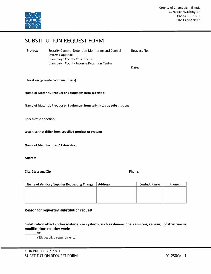
SUBSTITUTION REQUEST FORM
Project:
Security Camera, Detention Monitoring and Control Systems Upgrade Champaign County Courthouse Champaign County Juvenile Detention Center
Request No.:
Date: Location (provide room number(s):
Name of Material, Product or Equipment item specified: Name of Material, Product or Equipment item submitted as substitution:
Specification Section: Qualities that differ from specified product or system:
Name of Manufacturer / Fabricator: Address
City, State and Zip Phone:
Name of Vendor / Supplier Requesting Change Address Contact Name Phone:
Reason for requesting substitution request: Substitution affects other materials or systems, such as dimensional revisions, redesign of structure or modifications to other work: _______NO _______YES; describe requirements:

GHR No. 7257 / 7261 SUBSTITUTION REQUEST FORM 01 2500a - 2
County of Champaign, Illinois 1776 East Washington
Urbana, IL 61802 Ph217.384.3720
If substitution requires modifications to dimensions indicated on drawings, are such modifications clearly indicated on attached data? _______YES _______NO; if NO, explain:
Substitution has an affect on Construction Schedule: _______NO _______YES; describe affect on schedule:
Savings or Credit to Contract Amount for accepting substitute:
____________________________________________________________Dollars ($______________). Note: Show bid amount in both words and figures.
The attached data is furnished herewith for evaluation of the substitution: _______Product Data _______Drawings _______Samples _______Tests _______Reports _______Other Information; describe:
The undersigned hereby certifies:
1. The proposed substitution has been fully investigated and is equal or superior to specified product.
2. The same or better warranty will be furnished for proposed substitution as for specified material, product or equipment.
3. All changes in the work resulting from the use of this substitution, if approved, will be coordinated and completed in all respects and all costs, including, but not limited to, those for additional services rendered by the Owner are the responsibility for this Contractor at no additional cost to the Contract.
____________________________________________ ________________________________________ Contractor Signed by ____________________________________________ Address ____________________________________________ City, State and Zip END OF SUBSTITUTION FORM 01 2500a

GHR No. 7257 / 7261 CONTRACT MODIFICATION PROCEDURES 01 2600 -1
County of Champaign, Illinois 1776 East Washington
Urbana, IL 61802 Ph 217.384.3720
SECTION 01 2600 - CONTRACT MODIFICATION PROCEDURES
PART 1 - GENERAL
1.1 CONTRACT MODIFICATION PROCEDURES
A. Design Team will issue supplemental instructions authorizing minor changes in the Work, not involving adjustment to the Contract Sum or the Contract Time.
B. Owner-Initiated Proposal Requests: Design Team will issue a detailed description of proposed changes in the Work.
1. Proposal Requests are not instructions either to stop work in progress or to execute the proposed change.
2. Within time specified in Proposal Request or 20 days, when not otherwise specified, after receipt of Proposal Request, submit a quotation estimating cost adjustments to the Contract Sum and the Contract Time.
C. Contractor-Initiated Proposals: If latent or changed conditions require modifications to the Contract, Contractor may initiate a claim by submitting a request for a change to Design Team.
D. On Owner's approval of a Proposal Request, Design Team will issue a Change Order for signatures of Owner and Contractor, for all changes to the Contract Sum or the Contract Time.
E. Design Team may issue a Construction Change Directive. Construction Change Directive instructs Contractor to proceed with a change in the Work, for subsequent inclusion in a Change Order.
1. Construction Change Directive contains a complete description of change in the Work. It also designates method to be followed to determine change in the Contract Sum or the Contract Time.
F. Documentation: Maintain detailed records on a time and material basis of work required by the Construction Change Directive. After completion of change, submit an itemized account and supporting data necessary to substantiate cost and time adjustments to the Contract.
GHR No. 7257 / 7261 CONTRACT MODIFICATION PROCEDURES 01 2600 -2
County of Champaign, Illinois 1776 East Washington
Urbana, IL 61802 Ph 217.384.3720
PART 2 - PRODUCTS (Not Used)
PART 3 - EXECUTION (Not Used)
END OF SECTION 01 2600

GHR No. 7257 / 7261 ADMINISTRATIVE REQUIREMENTS 01 3000 -1
County of Champaign, Illinois 1776 East Washington
Urbana, IL 61802 Ph 217.384.3720
SECTION 01 3000 - ADMINISTRATIVE REQUIREMENTS
PART 1 - GENERAL
1.1 PROJECT MANAGEMENT AND COORDINATION
A. Subcontract List: Submit a written summary identifying individuals or firms proposed for each portion of the Work.
B. Key Personnel Names: Within ten (10) days of starting construction operations, submit a list of key personnel assignments, including superintendent and other personnel in attendance at Project site. List e-mail addresses and telephone numbers.
C. Coordinate construction operations included in different Sections of the Specifications to ensure efficient and orderly installation of each part of the Work.
D. Requests for Information (RFIs): On discovery of the need for additional information or interpretation of the Contract Documents, Contractor shall prepare and submit an RFI. Use forms acceptable to Design Team and Owner.
E. Schedule and conduct (2) progress meetings at Project site, coordinated with the Design Team and Owner. Notify Owner of meeting dates and times. Require attendance of each subcontractor or other entity concerned with current progress or involved in planning, coordination, or performance of future activities.
1.2 SUBMITTAL ADMINISTRATIVE REQUIREMENTS
A. Coordinate each submittal with fabrication, purchasing, testing, delivery, other submittals, and related activities that require sequential activity.
1. No extension of the Contract Time will be authorized because of failure to transmit submittals enough in advance of the Work to permit processing, including resubmittals.
2. Submit two copies of each action submittal. Design Team will return one copy. 3. Submit one copy of each informational submittal. Design Team will not return
copies. 4. Design Team will discard submittals received from sources other than
Contractor.
GHR No. 7257 / 7261 ADMINISTRATIVE REQUIREMENTS 01 3000 -2
County of Champaign, Illinois 1776 East Washington
Urbana, IL 61802 Ph 217.384.3720
B. Electronic Submittals: Identify and incorporate information in each electronic submittal file as follows:
1. Assemble complete submittal package into a single indexed file incorporating submittal requirements of a single Specification Section and transmittal form with links enabling navigation to each item.
2. Name file with unique identifier, including project identifier, Specification Section number, and revision identifier.
3. Provide means for insertion to permanently record Contractor's review and approval markings and action taken by Design Team.
C. Identify options requiring selection by Design Team.
D. Identify deviations from the Contract Documents on submittals.
E. Contractor's Construction Schedule Submittal Procedure:
1. Submit required submittals in the following format:
a. PDF electronic file.
2. Coordinate Contractor's construction schedule with the schedule of values, submittal schedule, progress reports, payment requests, and other required schedules and reports.
PART 2 - PRODUCTS
2.1 SUBMITTAL PROCEDURES
A. General Submittal Procedure Requirements: Prepare and submit submittals required by individual Specification Sections.
1. Submit electronic submittals via email as PDF electronic files to Shannon Hicks at GHR Engineers and Associates, Inc.: [email protected].
a. Design Team will return annotated file. Annotate and retain one copy of file as an electronic Project record document file.
2.2 ACTION SUBMITTALS
A. Submit two paper copies of each submittal unless otherwise indicated. Design Team will return one copy.
GHR No. 7257 / 7261 ADMINISTRATIVE REQUIREMENTS 01 3000 -3
County of Champaign, Illinois 1776 East Washington
Urbana, IL 61802 Ph 217.384.3720
B. Product Data: Mark each copy to show applicable products and options. Include the following:
1. Manufacturer's written recommendations, product specifications, and installation instructions.
2. Wiring diagrams showing factory-installed wiring. 3. Printed performance curves and operational range diagrams. 4. Testing by recognized testing agency. 5. Compliance with specified standards and requirements.
C. Shop Drawings: Prepare Project-specific information, drawn accurately to scale. Do not base Shop Drawings on reproductions of the Contract Documents or standard printed data. Submit on sheets at least 8-1/2 by 11 inches but no larger than 30 by 42 inches. Include the following:
1. Dimensions and identification of products. 2. Fabrication and installation drawings and roughing-in and setting diagrams. 3. Wiring diagrams showing field-installed wiring. 4. Notation of coordination requirements. 5. Notation of dimensions established by field measurement.
2.3 INFORMATIONAL SUBMITTALS
A. Informational Submittals: Submit one paper copy of each submittal unless otherwise indicated. Design Team will not return copies.
B. Qualification Data: Include lists of completed projects with project names and addresses, names and addresses of Design Team and owners, and other information specified.
C. Product Certificates: Prepare written statements on manufacturer's letterhead certifying that product complies with requirements in the Contract Documents.
PART 3 - EXECUTION
3.1 SUBMITTAL REVIEW
A. Review each submittal and check for coordination with other Work of the Contract and for compliance with the Contract Documents. Note corrections and field dimensions. Mark with approval stamp before submitting to Design Team.
GHR No. 7257 / 7261 ADMINISTRATIVE REQUIREMENTS 01 3000 -4
County of Champaign, Illinois 1776 East Washington
Urbana, IL 61802 Ph 217.384.3720
B. Design Team will review each action submittal, make marks to indicate corrections or modifications required, will stamp each submittal with an action stamp, and will mark stamp appropriately to indicate action.
C. Informational Submittals: Design Team will review each submittal and will not return it, or will return it if it does not comply with requirements. Design Team will forward each submittal to appropriate party.
D. Submittals not required by the Contract Documents may not be reviewed and may be discarded.
END OF SECTION 01 3000

GHR No. 7257 / 7261 QUALITY REQUIREMENTS 01 4000 -1
County of Champaign, Illinois 1776 East Washington
Urbana, IL 61802 Ph 217.384.3720
SECTION 01 4000 - QUALITY REQUIREMENTS
PART 1 - GENERAL
1.1 SECTION REQUIREMENTS
A. Testing and inspecting services are required to verify compliance with requirements specified or indicated. These services do not relieve Contractor of responsibility for compliance with the Contract Document requirements.
B. Referenced Standards: If compliance with two or more standards is specified and the standards establish different or conflicting requirements, comply with the most stringent requirement. Refer uncertainties to Design Team for a decision.
C. Minimum Quantity or Quality Levels: The quantity or quality level shown or specified shall be the minimum. The actual installation may exceed the minimum within reasonable limits. Indicated numeric values are minimum or maximum, as appropriate, for the context of requirements. Refer uncertainties to Design Team for a decision.
D. Test and Inspection Reports: Prepare and submit certified written reports specified in other Sections. Include the following:
1. Date of issue. 2. Project title and number. 3. Name, address, and telephone number of testing agency. 4. Dates and locations of samples and tests or inspections. 5. Names of individuals making tests and inspections. 6. Description of the Work and test and inspection method. 7. Identification of product and Specification Section. 8. Complete test or inspection data. 9. Test and inspection results and an interpretation of test results. 10. Record of temperature and weather conditions at time of sample taking and
testing and inspecting. 11. Comments or professional opinion on whether tested or inspected Work
complies with the Contract Document requirements. 12. Name and signature of laboratory inspector. 13. Recommendations on retesting and reinspecting.

GHR No. 7257 / 7261 QUALITY REQUIREMENTS 01 4000 -2
County of Champaign, Illinois 1776 East Washington
Urbana, IL 61802 Ph 217.384.3720
E. Permits, Licenses, and Certificates: For Owner's records, submit copies of permits, licenses, certifications, inspection reports, notices, receipts for fee payments, and similar documents, established for compliance with standards and regulations bearing on performance of the Work.
F. Testing Agency Qualifications: An independent agency with the experience and capability to conduct testing and inspecting indicated; and where required by authorities having jurisdiction, that is acceptable to authorities.
G. Retesting / Reinspecting: Regardless of whether original tests or inspections were Contractor’s responsibility, provide quality-control services, including retesting and reinspecting, for construction that replaced work that failed to comply with the Contract Documents.
H. Testing Agency Responsibilities: Cooperate with Design Team and Contractor in performance of duties. Provide qualified personnel to perform required tests and inspections.
1. Notify Design Team and Contractor of irregularities or deficiencies in the work
observed during performance of its services. 2. Do not release, revoke, alter or increase requirements of the Contract
Documents or approve or accept any portion of the work. 3. Do not perform any duties of Contractor.
I. Coordination: Coordinate sequence of activities to accommodate required quality-assurance and -control services with a minimum of delay and to avoid necessity of removing and replacing construction to accommodate testing and inspecting.
1. Schedule times for tests, inspections, obtaining samples, and similar activities.
J. Tests and Inspections: Owner will engage a qualified inspector to conduct inspections required by authorities having jurisdiction.
PART 2 - PRODUCTS (Not Used)

GHR No. 7257 / 7261 QUALITY REQUIREMENTS 01 4000 -3
County of Champaign, Illinois 1776 East Washington
Urbana, IL 61802 Ph 217.384.3720
PART 3 - EXECUTION
3.1 REPAIR AND PROTECTION
A. Repair and protection are Contractor's responsibility, regardless of the assignment of responsibility for quality-control services.
B. Contractor will maintain a safe work site at all times. When the project is complete, Contractor shall return the work site and the surrounding areas to the same condition as they were prior to the beginning of the project.
END OF SECTION 01 4000


GHR No. 7257 / 7261 PRODUCT REQUIREMENTS 01 6000 -1
County of Champaign, Illinois 1776 East Washington
Urbana, IL 61802 Ph 217.384.3720
SECTION 01 6000 - PRODUCT REQUIREMENTS
PART 1 - GENERAL
1.1 SECTION REQUIREMENTS
A. The term "product" includes the terms "material," "equipment," "system," and terms of similar intent.
B. Comparable Product Requests: Submit request for consideration of each comparable product. Identify product or fabrication or installation method to be replaced.
1. Show compliance with requirements for comparable product requests. 2. Design Team will review the proposed product and notify Contractor of its
acceptance or rejection.
C. Basis-of-Design Product Specification Submittal: Show compliance with requirements.
D. Compatibility of Options: If Contractor is given option of selecting between two or more products, select product compatible with products previously selected.
E. Deliver, store, and handle products using means and methods that will prevent damage, deterioration, and loss, including theft. Comply with manufacturer's written instructions.
1. Schedule delivery to minimize long-term storage at Project site and to prevent overcrowding of construction spaces.
2. Deliver products to Project site in manufacturer's original sealed container or packaging, complete with labels and instructions for handling, storing, unpacking, protecting, and installing.
3. Inspect products on delivery to ensure compliance with the Contract Documents and to ensure that products are undamaged and properly protected.
4. Store materials in a manner that will not endanger Project structure. 5. Store products that are subject to damage by the elements, under cover in a
weathertight enclosure above ground, with ventilation adequate to prevent condensation.
F. Warranties specified in other Sections shall be in addition to, and run concurrent with, other warranties required by the Contract Documents. Manufacturer's disclaimers and limitations on product warranties do not relieve Contractor of obligations under requirements of the Contract Documents.
GHR No. 7257 / 7261 PRODUCT REQUIREMENTS 01 6000 -2
County of Champaign, Illinois 1776 East Washington
Urbana, IL 61802 Ph 217.384.3720
PART 2 - PRODUCTS
2.1 PRODUCT SELECTION PROCEDURES
A. Provide products that comply with the Contract Documents, are undamaged, and, unless otherwise indicated, are new at the time of installation.
1. Provide products complete with accessories, trim, finish, and other devices and components needed for a complete installation and the intended use and effect.
2. Where products are accompanied by the term "as selected," Owner will make selection.
3. Descriptive, performance, and reference standard requirements in the Specifications establish salient characteristics of products.
B. Where the following headings are used to list products or manufacturers, the Contractor's options for product selection are as follows:
1. Products:
a. Where requirements include "one of the following," provide one of the products listed that complies with requirements.
b. Where requirements do not include "one of the following," provide one of the products listed that complies with requirements or a comparable product.
2. Manufacturers:
a. Where requirements include "one of the following," provide a product that complies with requirements by one of the listed manufacturers.
b. Where requirements do not include "one of the following," provide a product that complies with requirements by one of the listed manufacturers or another manufacturer.
3. Basis-of-Design Product: Provide the product named, or indicated on the Drawings, or a comparable product by one of the listed manufacturers.
2.2 COMPARABLE PRODUCTS
A. Design Team will consider Contractor's request for comparable product in advance of Bidding only when the following conditions are satisfied:
GHR No. 7257 / 7261 PRODUCT REQUIREMENTS 01 6000 -3
County of Champaign, Illinois 1776 East Washington
Urbana, IL 61802 Ph 217.384.3720
1. Evidence that the proposed product does not require revisions to the Contract Documents, that it is consistent with the Contract Documents and will produce the indicated results, and that it is compatible with other portions of the Work.
2. Detailed comparison of significant qualities of proposed product with those named in the Specifications.
3. List of similar installations for completed projects, if requested. 4. Samples, where applicable.
PART 3 - EXECUTION (Not Used)
END OF SECTION 01 6000


GHR No. 7257 / 7261 EXECUTION AND CLOSEOUT REQUIREMENTS 01 7000 -1
County of Champaign, Illinois 1776 East Washington
Urbana, IL 61802 Ph 217.384.3720
SECTION 01 7000 - EXECUTION AND CLOSEOUT REQUIREMENTS
PART 1 - GENERAL
1.1 EXECUTION REQUIREMENTS
A. Cutting and Patching:
1. Structural Elements: When cutting and patching structural elements, notify Design Team of locations and details of cutting and await directions from Engineer before proceeding. Shore, brace, and support structural elements during cutting and patching.
2. Operational Elements: Do not cut and patch operating elements and related components in a manner that results in reducing their capacity to perform as intended or that results in increased maintenance or decreased operational life or safety.
3. Visual Elements: Do not cut and patch construction in a manner that results in visual evidence of cutting and patching. Do not cut and patch exposed construction in a manner that would, in Engineer's opinion, reduce the building's aesthetic qualities.
B. Manufacturer's Installation Instructions: Obtain and maintain on-site manufacturer's written recommendations and instructions for installation of products and equipment.
1.2 CLOSEOUT SUBMITTALS
A. Contractor's List of Incomplete Items: Initial submittal at Substantial Completion.
B. Certified List of Incomplete Items: Final submittal at Final Completion.
C. Operation and Maintenance Data: Submit two (2) copies of manual.
D. PDF Electronic File: Assemble manual into a composite electronically indexed file. Submit two (2) copies on digital media.
E. Record Product Data: Submit two (2) paper copies and annotated PDF electronic files and directories of each submittal.
GHR No. 7257 / 7261 EXECUTION AND CLOSEOUT REQUIREMENTS 01 7000 -2
County of Champaign, Illinois 1776 East Washington
Urbana, IL 61802 Ph 217.384.3720
1.3 SUBSTANTIAL COMPLETION PROCEDURES
A. Prepare a list of items to be completed and corrected (punch list), the value of items on the list, and reasons why the Work is not complete.
B. Submittals Prior to Substantial Completion: Before requesting Substantial Completion inspection, complete the following:
1. Submit closeout submittals specified in other sections, including project record documents, operation and maintenance manuals, similar final record information, warranties, workmanship bonds, maintenance service agreements, final certifications, and similar documents.
2. Submit maintenance material submittals specified in other sections, including tools, spare parts, extra materials, and similar items, and deliver to location designated by Owner.
3. Submit test/adjust/balance records.
C. Procedures Prior to Substantial Completion: Before requesting Substantial Completion inspection, complete the following:
1. Complete startup and testing of systems and equipment. 2. Perform preventive maintenance on equipment used prior to Substantial
Completion. 3. Remove temporary facilities and controls. 4. Complete final cleaning requirements, including touchup painting. 5. Touch up and otherwise repair and restore marred exposed finishes to eliminate
visual defects.
D. Inspection: Submit a written request for inspection for Substantial Completion. On receipt of request, Engineer will proceed with inspection or advise Contractor of unfulfilled requirements. Engineer will prepare the Certificate of Substantial Completion after inspection or will advise Contractor of items that must be completed or corrected before certificate will be issued.
1.4 FINAL COMPLETION PROCEDURES
A. Submittals Prior to Final Completion: Before requesting inspection for determining final completion, complete the following:
1. Submit a final Application for Payment.

GHR No. 7257 / 7261 EXECUTION AND CLOSEOUT REQUIREMENTS 01 7000 -3
County of Champaign, Illinois 1776 East Washington
Urbana, IL 61802 Ph 217.384.3720
2. Submit certified copy of Engineer's Substantial Completion inspection list of
items to be completed or corrected (punch list), endorsed and dated by Engineer. Certified copy of the list shall state that each item has been completed or otherwise resolved.
B. Submit a written request for final inspection for acceptance. On receipt of request, Design Team will either proceed with inspection or notify Contractor of unfulfilled requirements. Engineer will prepare final Certificate for Payment after inspection or will advise Contractor of items that must be completed or corrected before certificate will be issued.
1. Reinspection: Request reinspection when the Work identified in previous inspections as incomplete is completed or corrected.
PART 2 - PRODUCTS
2.1 MATERIALS
A. In-Place Materials: Use materials for patching identical to in-place materials. For exposed surfaces, use materials that visually match in-place adjacent surfaces to the fullest extent possible.
B. Cleaning Agents: Use cleaning materials and agents recommended by manufacturer or fabricator of the surface to be cleaned. Do not use cleaning agents that are potentially hazardous to health or property or that might damage finished surfaces.
1. Use cleaning products that comply with Green Seal's GS-37, or if GS-37 is not applicable, use products that comply with the California Code of Regulations maximum allowable VOC levels.
2.2 OPERATION AND MAINTENANCE DOCUMENTATION
A. Directory: Prepare a single, comprehensive directory of operation and maintenance data and materials, listing items and their location to facilitate ready access to desired information.
B. Organization: Unless otherwise indicated, organize manual into separate sections for each system and subsystem, and separate sections for each piece of equipment not part of a system.

GHR No. 7257 / 7261 EXECUTION AND CLOSEOUT REQUIREMENTS 01 7000 -4
County of Champaign, Illinois 1776 East Washington
Urbana, IL 61802 Ph 217.384.3720
1. Dividers: Provide heavy paper dividers with celluloid-covered tabs for each separate Section. Mark each tab to indicate contents. Provide a typed description of the product and major parts of equipment included in the Section on each divider.
C. Organize data into three-ring binders with identification on front and spine of each binder, and envelopes for folded drawings. Identify each binder on the front and spine with the printed title “OPERATION AND MAINTENANCE MANUAL”, Project title or name, year and subject matter covered. Indicate volume number for multiple volume sets of manuals. Include the following:
1. Manufacturer's operation and maintenance documentation. 2. Maintenance and service schedules. 3. Maintenance service contracts. Include name and telephone number of service
agent. 4. Emergency instructions. 5. Spare parts list and local sources of maintenance materials. 6. Wiring diagrams. 7. Copies of warranties. Include procedures to follow and required notifications for
warranty claims
2.3 RECORD DRAWINGS
A. Record Prints: Maintain a set of prints of the Contract Drawings and Shop Drawings, incorporating new and revised drawings as modifications are issued. Mark to show actual installation where installation varies from that shown originally. Accurately record information in an acceptable drawing technique.
1. Identify and date each record Drawing; include the designation "PROJECT RECORD DRAWING" in a prominent location.
B. Record Digital Data Files: Immediately before inspection for Certificate of Substantial Completion, review marked-up record prints with Engineer. When authorized, prepare a full set of corrected digital data files of the Contract Drawings.
1. Format: Annotated PDF electronic file.

GHR No. 7257 / 7261 EXECUTION AND CLOSEOUT REQUIREMENTS 01 7000 -5
County of Champaign, Illinois 1776 East Washington
Urbana, IL 61802 Ph 217.384.3720
PART 3 - EXECUTION
3.1 EXAMINATION AND PREPARATION
A. Before proceeding with each component of the Work, examine substrates, areas, and conditions, with Installer or Applicator present where indicated, for compliance with requirements for installation tolerances and other conditions affecting performance.
1. Verify compatibility with and suitability of substrates. 2. Examine roughing-in for mechanical and electrical systems. 3. Examine walls, floors, and roofs for suitable conditions.
B. Proceed with installation only after unsatisfactory conditions have been corrected.
C. Take field measurements as required to fit the Work properly. Where portions of the Work are indicated to fit to other construction, verify dimensions of other construction by field measurements before fabrication.
D. Verify space requirements and dimensions of items shown diagrammatically on Drawings.
3.2 CONSTRUCTION LAYOUT
A. Before proceeding to lay out the Work, verify layout information shown on Drawings.
3.3 INSTALLATION
A. Locate the Work and components of the Work accurately, in correct alignment and elevation, as indicated.
1. Make vertical work plumb and make horizontal work level. 2. Conceal wiring in finished areas unless otherwise indicated. 3. Maintain minimum headroom clearance of 96 inches in occupied spaces and 90
inches in unoccupied spaces.
B. Comply with manufacturer's written instructions and recommendations.
C. Conduct construction operations so no part of the Work is subjected to damaging operations or loading in excess of that expected during normal conditions of occupancy.

GHR No. 7257 / 7261 EXECUTION AND CLOSEOUT REQUIREMENTS 01 7000 -6
County of Champaign, Illinois 1776 East Washington
Urbana, IL 61802 Ph 217.384.3720
D. Templates: Obtain and distribute to the parties involved templates for work specified to be factory prepared and field installed.
E. Attachment: Provide blocking and attachment plates and anchors and fasteners of adequate size and number to securely anchor each component in place. Where size and type of attachments are not indicated, verify size and type required for load conditions.
1. Mounting Heights: Where mounting heights are not indicated, mount components at heights directed by Owner.
F. Joints: Make joints of uniform width. Where joint locations in exposed work are not indicated, arrange joints for the best visual effect. Fit exposed connections together to form hairline joints.
G. Use products, cleaners, and installation materials that are not considered hazardous.
3.4 CUTTING AND PATCHING
A. Provide temporary support of work to be cut.
B. Protection: Protect in-place construction during cutting and patching to prevent damage. Provide protection from adverse weather conditions for portions of Project that might be exposed during cutting and patching operations.
C. Where existing services/systems are required to be removed, relocated, or abandoned, bypass such services/systems before cutting to prevent interruption to occupied areas.
D. Cutting: Cut in-place construction using methods least likely to damage elements retained or adjoining construction.
1. Cut holes and slots neatly to minimum size required, and with minimum disturbance of adjacent surfaces. Temporarily cover openings when not in use.
E. Patch with durable seams that are as invisible as possible. Provide materials and comply with installation requirements specified in other Sections.
1. Restore exposed finishes of patched areas and extend finish restoration into adjoining construction in a manner that will minimize evidence of patching and refinishing.

GHR No. 7257 / 7261 EXECUTION AND CLOSEOUT REQUIREMENTS 01 7000 -7
County of Champaign, Illinois 1776 East Washington
Urbana, IL 61802 Ph 217.384.3720
2. Where walls or partitions that are removed extend one finished area into
another, patch and repair floor and wall surfaces in the new space. Provide an even surface of uniform finish, color, texture, and appearance.
3. Where patching occurs in a painted surface, prepare substrate and apply primer and intermediate paint coats appropriate for substrate over the patch, and apply final paint coat over entire unbroken surface containing the patch. Provide additional coats until patch blends with adjacent surfaces.
3.5 CLEANING
A. Clean Project site and work areas daily, including common areas. Dispose of materials lawfully.
1. Remove liquid spills promptly. 2. Where dust would impair proper execution of the Work, broom-clean or vacuum
the entire work area, as appropriate. 3. Remove debris from concealed spaces before enclosing the space.
B. Complete the following cleaning operations before requesting inspection for certification of Substantial Completion:
1. Clean Project site and grounds, in areas disturbed by construction activities. Sweep paved areas; remove stains, spills, and foreign deposits. Rake grounds that are neither planted nor paved to a smooth, even-textured surface.
2. Sweep paved areas broom clean. Remove spills, stains, and other foreign deposits.
3. Remove labels that are not permanent. 4. Clean transparent materials, including mirrors. Remove excess glazing
compounds. 5. Clean exposed finishes to a dust-free condition, free of stains, films, and foreign
substances. Sweep concrete floors broom clean. 6. Vacuum carpeted surfaces. 7. Wipe surfaces of mechanical and electrical equipment. Remove excess
lubrication and foreign substances. Clean plumbing fixtures. Clean light fixtures, lamps, globes, and reflectors.
3.6 OPERATION AND MAINTENANCE MANUAL PREPARATION
A. Operation and Maintenance Manuals: Assemble a complete set of operation and maintenance data indicating operation and maintenance of each system, subsystem, and piece of equipment not part of a system.

GHR No. 7257 / 7261 EXECUTION AND CLOSEOUT REQUIREMENTS 01 7000 -8
County of Champaign, Illinois 1776 East Washington
Urbana, IL 61802 Ph 217.384.3720
B. Manufacturers' Data: Where manuals contain manufacturers' standard printed data, include only sheets pertinent to product or component installed. Mark each sheet to identify each product or component incorporated into the Work. If data include more than one item in a tabular format, identify each item using appropriate references from the Contract Documents. Identify data applicable to the Work and delete references to information not applicable.
1. Prepare supplementary text if manufacturers' standard printed data are unavailable and where the information is necessary for proper operation and maintenance of equipment or systems.
C. Drawings: Prepare drawings supplementing manufacturers' printed data to illustrate the relationship of component parts of equipment and systems and to illustrate control sequence and flow diagrams.
3.7 DEMONSTRATION AND TRAINING
A. Contractor to instruct Owner's personnel to adjust, operate, and maintain systems, subsystems, and equipment not part of a system. Include a detailed review of the following:
1. Include instruction for basis of system design and operational requirements, review of documentation, emergency procedures, operations, adjustments, troubleshooting, maintenance, and repairs.
B. Contractor shall train Owner’s teaching faculty on the online monitoring functionality of new system.
END OF SECTION 01 7000

GHR No. 7257 / 7261 CONSTRUCTION WASTE MANAGEMENT AND DISPOSAL 01 7419 -1
County of Champaign, Illinois 1776 East Washington
Urbana, IL 61802 Ph 217.384.3720
SECTION 01 7419 - CONSTRUCTION WASTE MANAGEMENT AND DISPOSAL
PART 1 - GENERAL (Not Used)
PART 2 - PRODUCTS (Not Used)
PART 3 - EXECUTION
3.1 PLAN IMPLEMENTATION
A. General: Provide handling, containers, storage, signage, transportation, and other items as required to implement waste management plan during the entire duration of the Contract.
B. Training: Train workers, subcontractors, and suppliers on proper waste management procedures, as appropriate for the Work occurring at Project site.
1. Review locations established for recycling and disposal.
3.2 RECYCLING WASTE
A. Packaging:
1. Cardboard and Boxes: Break down packaging into flat sheets. Bundle and store in a dry location.
2. Polystyrene Packaging: Separate and bag materials. 3. Pallets: As much as possible, require deliveries using pallets to remove pallets
from Project site. For pallets that remain on-site, break down pallets into component wood pieces and comply with requirements for recycling wood.
4. Crates: Break down crates into component wood pieces and comply with requirements for recycling wood.
B. Wood Materials:
1. Sort and stack reusable members according to size, type, and length. Separate lumber, engineered wood products, panel products, and treated wood materials.
2. Clean Cut-Offs of Lumber: Grind or chip into small pieces. 3. Clean Sawdust: Bag sawdust that does not contain painted or treated wood.
C. Metals: Separate metals by type.

GHR No. 7257 / 7261 CONSTRUCTION WASTE MANAGEMENT AND DISPOSAL 01 7419 -2
County of Champaign, Illinois 1776 East Washington
Urbana, IL 61802 Ph 217.384.3720
3.3 DISPOSAL OF WASTE
A. Except for items or materials to be recycled or otherwise reused, remove waste materials from Project site and legally dispose of them in a landfill or incinerator acceptable to authorities having jurisdiction.
B. Recycle recyclable materials off-site.
C. Do not burn waste materials.
END OF SECTION 01 7419

Security Camera, Detention Monitoring and Control Systems Upgrade
1 GHR – 12/19 – LEM 26 0519 – Low-Voltage Electrical Power
DIVISION 26 – ELECTRICAL Section 26 0519 – Low-Voltage Electrical Power Conductors and Cables
PART 1 - GENERAL
1.1 RELATED DOCUMENTS
A. Drawings and general provisions of the Contract, including General and Supplementary Conditions and Division 01 Specification Sections, apply to this Section.
1.2 SUMMARY
A. Section Includes:
1. Building wires and cables rated 600 V and less. 2. Connectors, splices, and terminations rated 600 V and less.
PART 2 - PRODUCTS
2.1 CONDUCTORS AND CABLES
A. Manufacturers: Subject to compliance with requirements, provide products by one of the following:
1. Alpha Wire Company. 2. Belden Inc. 3. Cerro Wire LLC. 4. Cooper Industries, Inc. 5. Encore Wire Corporation. 6. General Cable Technologies Corporation. 7. General Cable; General Cable Corporation. 8. Senator Wire & Cable Company. 9. Service Wire Co. 10. Southwire Company. 11. Thomas & Betts Corporation, A Member of the ABB Group.
B. Copper Conductors: Comply with NEMA WC 70/ICEA S-95-658.
C. Conductor Insulation: Comply with NEMA WC 70/ICEA S-95-658 for Type THHN/THWN-2.
2.2 CONNECTORS AND SPLICES
A. Manufacturers: Subject to compliance with requirements, available manufacturers offering products that may be incorporated into the Work include, but are not limited to the following:
1. 3M. 2. AFC Cable Systems, Inc. 3. Gardner Bender. 4. Hubbell Power Systems, Inc.
Security Camera, Detention Monitoring and Control Systems Upgrade
2 GHR – 12/19 – LEM 26 0519 – Low-Voltage Electrical Power
5. Ideal Industries, Inc. 6. ILSCO. 7. NSi Industries LLC. 8. O-Z/Gedney; a brand of Emerson Industrial Automation. 9. Tyco Electronics Corp.
B. Description: Factory-fabricated connectors and splices of size, ampacity rating, material, type, and class for application and service indicated.
1. Expandable steel spring and polypropylene body type connectors and wire nuts for wire
sizes up to an including No. 10 AWG. 2. Bolt type connectors or mechanical compression crimp type for wire sizes No. 8 AWG
and larger. Cover connectors with three layers of 600 volt tape or heat shrinkable insulation equivalent to 150% conductor insulation.
2.3 SYSTEM DESCRIPTION
A. Electrical Components, Devices, and Accessories: Listed and labeled as defined in NFPA 70, by a qualified testing agency, and marked for intended location and application.
B. Comply with NFPA 70.
PART 3 - EXECUTION
3.1 CONDUCTOR MATERIAL APPLICATIONS
A. Branch Circuits: Copper. Solid for No. 10 AWG and smaller; stranded for No. 8 AWG and larger, except VFC cable, which shall be extra flexible stranded.
3.2 CONDUCTOR INSULATION AND MULTICONDUCTOR CABLE APPLICATIONS AND WIRING METHODS
A. Exposed Branch Circuits, Including in Crawlspaces: Type THHN/THWN-2, single conductors in raceway.
B. Minimum wire size shall be No. 12 except for internal fixture wire which shall be minimum size of No. 14 type SF, SFF, PF, PFF or TFN, 600 volt.
C. All branch circuit wiring and feeder cables for circuits over 20 amps shall be sized as noted on the drawings. If size is not specifically noted, size all branch circuit wiring and feeder cables in accordance with the National Electrical Code.
3.3 INSTALLATION OF CONDUCTORS AND CABLES
A. Complete raceway installation between conductor and cable termination points according to Section 260533 "Raceways and Boxes for Electrical Systems" prior to pulling conductors and cables.
Security Camera, Detention Monitoring and Control Systems Upgrade
3 GHR – 12/19 – LEM 26 0519 – Low-Voltage Electrical Power
B. Use manufacturer-approved pulling compound or lubricant where necessary; compound used must not deteriorate conductor or insulation. Do not exceed manufacturer's recommended maximum pulling tensions and sidewall pressure values.
C. Use pulling means, including fish tape, cable, rope, and basket-weave wire/cable grips, that will not damage cables or raceway.
D. Support cables according to Section 260529 "Hangers and Supports for Electrical Systems."
3.4 CONNECTIONS
A. Tighten electrical connectors and terminals according to manufacturer's published torque-tightening values. If manufacturer's torque values are not indicated, use those specified in UL 486A-486B.
B. Make splices, terminations, and taps that are compatible with conductor material and that possess equivalent or better mechanical strength and insulation ratings than unspliced conductors.
C. Splices and taps in conductors shall be as few in number as practicable.
D. Splices and taps shall be so made that they have an electrical resistance not in excess of that of 2’ of the conductor.
1. Use oxide inhibitor in each splice, termination, and tap for aluminum conductors.
3.5 IDENTIFICATION
A. Identify and color-code conductors and cables according to Section 260553 "Identification for Electrical Systems."
B. Identify each spare conductor at each end with identity number and location of other end of conductor, and identify as spare conductor.
END OF SECTION 26 0519

Security Camera, Detention Monitoring and Control Systems Upgrade
1 GHR – 12/19 – LEM 26 0526 – Grounding and Bonding for Elec Sys
DIVISION 26 – ELECTRICAL Section 26 0526 – Grounding and Bonding for Electrical Systems
PART 1 - GENERAL
1.1 RELATED DOCUMENTS
A. Drawings and general provisions of the Contract, including General and Supplementary Conditions and Division 01 Specification Sections, apply to this Section.
1.2 SUMMARY
A. Section includes grounding and bonding systems and equipment.
1.3 ACTION SUBMITTALS
A. Product Data: For each type of product indicated.
PART 2 - PRODUCTS
2.1 SYSTEM DESCRIPTION
A. Electrical Components, Devices, and Accessories: Listed and labeled as defined in NFPA 70, by a qualified testing agency, and marked for intended location and application.
B. Comply with UL 467 for grounding and bonding materials and equipment.
2.2 CONDUCTORS
A. Insulated Conductors: Copper or tinned-copper wire or cable insulated for 600 V unless otherwise required by applicable Code or authorities having jurisdiction.
B. Bare Copper Conductors:
1. Solid Conductors: ASTM B 3.
2.3 CONNECTORS
A. Listed and labeled by an NRTL acceptable to authorities having jurisdiction for applications in which used and for specific types, sizes, and combinations of conductors and other items connected.
Security Camera, Detention Monitoring and Control Systems Upgrade
2 GHR – 12/19 – LEM 26 0526 – Grounding and Bonding for Elec Sys
PART 3 - EXECUTION
3.1 APPLICATIONS
A. Conductors: Install solid conductor for No. 8 AWG and smaller, and stranded conductors for No. 6 AWG and larger unless otherwise indicated.
3.2 EQUIPMENT GROUNDING
A. Install insulated equipment grounding conductors with all feeders and branch circuits. Separate grounding conductors are not shown on the drawings but shall be included in all raceways as set forth on the drawings.
3.3 INSTALLATION
A. Grounding Conductors: Route along shortest and straightest paths possible unless otherwise indicated or required by Code. Avoid obstructing access or placing conductors where they may be subjected to strain, impact, or damage.
END OF SECTION 26 0526

Security Camera, Detention Monitoring and Control Systems Upgrade
1 GHR – 12/19 – LEM 26 0529 – Hangers and Supports for Elec Sys
DIVISION 26 – ELECTRICAL Section 26 0529 – Hangers and Supports for Electrical Systems
PART 1 - GENERAL
1.1 RELATED DOCUMENTS
A. Drawings and general provisions of the Contract, including General and Supplementary Conditions and Division 01 Specification Sections, apply to this Section.
1.2 SUMMARY
A. Section Includes:
1. Hangers and supports for electrical equipment and systems. 2. Construction requirements for concrete bases.
PART 2 - PRODUCTS
2.1 SUPPORT, ANCHORAGE, AND ATTACHMENT COMPONENTS
A. Steel Slotted Support Systems: Comply with MFMA-4 factory-fabricated components for field assembly.
1. Manufacturers: Subject to compliance with requirements, provide products by one of the following:
a. Allied Tube & Conduit; a part of Atkore International. b. Cooper B-Line, Inc.; a division of Cooper Industries. c. ERICO International Corporation. d. Flex-Strut Inc. e. GS Metals Corp. f. G-Strut. g. Haydon Corporation. h. Metal Ties Innovation. i. Thomas & Betts Corporation, A Member of the ABB Group. j. Unistrut; an Atkore International company.
2. Material: Galvanized steel.
3. Channel Width: 1-5/8 inches. 4. Metallic Coatings: Hot-dip galvanized after fabrication and applied according to MFMA-4.
B. Conduit and Cable Support Devices: Steel hangers, clamps, and associated fittings, designed for types and sizes of raceway or cable to be supported.
C. Mounting, Anchoring, and Attachment Components: Items for fastening electrical items or their supports to building surfaces include the following:
Security Camera, Detention Monitoring and Control Systems Upgrade
2 GHR – 12/19 – LEM 26 0529 – Hangers and Supports for Elec Sys
1. Powder-Actuated Fasteners: Anchors using explosive charges to drive inserts into concrete shall not be used.
2. Clamps for Attachment to Steel Structural Elements: MSS SP-58 units are suitable for attached structural element.
3. Through Bolts: Structural type, hex head, and high strength. Comply with ASTM A 325. 4. Toggle Bolts: All-steel springhead type. 5. Hanger Rods: Threaded steel.
PART 3 - EXECUTION
3.1 APPLICATION
A. Comply with NECA 1 and NECA 101 for application of hangers and supports for electrical equipment and systems unless requirements in this Section are stricter.
B. Comply with requirements for raceways and boxes specified in Section 260533 "Raceways and Boxes for Electrical Systems."
C. Maximum Support Spacing and Minimum Hanger Rod Size for Raceway: Space supports for EMTs, IMCs, and RMCs as required by NFPA 70. Minimum rod size shall be 1/4 inch in diameter.
3.2 SUPPORT INSTALLATION
A. Mounting and Anchorage of Surface-Mounted Equipment and Components: Anchor and fasten electrical items and their supports to building structural elements by the following methods unless otherwise indicated by code:
1. To Steel: Beam clamps (MSS SP-58, Type 19, 21, 23, 25, or 27), complying with
MSS SP-69 or metal framing channel welded to structure. 2. To Light Steel: Sheet metal screws. 3. Items Mounted on Hollow Walls and Nonstructural Building Surfaces: Mount cabinets,
panelboards, disconnect switches, control enclosures, pull and junction boxes, transformers, and other devices on slotted-channel racks attached to substrate by means that comply with seismic-restraint strength and anchorage requirements.
B. Drill holes for expansion anchors in concrete at locations and to depths that avoid the need for reinforcing bars.
END OF SECTION 26 0529
Security Camera, Detention Monitoring and Control Systems Upgrade
1 GHR – 12/19 – LEM 26 0533 – Raceways and Boxes for Elec Sys
DIVISION 26 – ELECTRICAL Section 26 0533 – Raceways and Boxes for Electrical Systems
PART 1 - GENERAL
1.1 RELATED DOCUMENTS
A. Drawings and general provisions of the Contract, including General and Supplementary Conditions and Division 01 Specification Sections, apply to this Section.
1.2 SUMMARY
A. Section Includes:
1. Metal conduits, tubing, and fittings. 2. Nonmetal conduits, tubing, and fittings. 3. Boxes, enclosures, and cabinets.
1.3 DEFINITIONS
A. GRC: Galvanized rigid steel conduit.
PART 2 - PRODUCTS
2.1 METAL CONDUITS, TUBING, AND FITTINGS
A. Manufacturers: Subject to compliance with requirements, provide products by one of the following:
1. AFC Cable Systems, Inc. 2. Allied Tube & Conduit; a part of Atkore International. 3. Anamet Electrical, Inc. 4. Electri-Flex Company. 5. FSR Inc. 6. O-Z/Gedney; a brand of Emerson Industrial Automation. 7. Patriot Aluminum Products, LLC. 8. Picoma Industries, Inc. 9. Republic Conduit. 10. Robroy Industries. 11. Southwire Company. 12. Thomas & Betts Corporation, A Member of the ABB Group. 13. Western Tube and Conduit Corporation.
B. Listing and Labeling: Metal conduits, tubing, and fittings shall be listed and labeled as defined in NFPA 70, by a qualified testing agency, and marked for intended location and application.
C. GRC: Comply with ANSI C80.1 and UL 6.
D. EMT: Comply with ANSI C80.3 and UL 797.
Security Camera, Detention Monitoring and Control Systems Upgrade
2 GHR – 12/19 – LEM 26 0533 – Raceways and Boxes for Elec Sys
E. FMC: Comply with UL 1; zinc-coated steel.
F. LFMC: Flexible steel conduit with PVC jacket and complying with UL 360.
G. Fittings for Metal Conduit: Comply with NEMA FB 1 and UL 514B.
1. Fittings for EMT:
a. Material: Steel. b. Type: Compression.
H. Joint Compound for IMC, GRC, or ARC: Approved, as defined in NFPA 70, by authorities having jurisdiction for use in conduit assemblies, and compounded for use to lubricate and protect threaded conduit joints from corrosion and to enhance their conductivity.
2.2 NONMETALLIC CONDUITS, TUBING, AND FITTINGS
A. Manufacturers: Subject to compliance with requirements, provide products by one of the following:
1. AFC Cable Systems, Inc. 2. Anamet Electrical, Inc. 3. Arnco Corporation. 4. CANTEX INC. 5. CertainTeed Corporation. 6. Condux International, Inc. 7. Electri-Flex Company. 8. Kraloy. 9. Lamson & Sessions. 10. Niedax Inc. 11. RACO; Hubbell.
B. Listing and Labeling: Nonmetallic conduits, tubing, and fittings shall be listed and labeled as defined in NFPA 70, by a qualified testing agency, and marked for intended location and application.
C. ENT: Comply with NEMA TC 13 and UL 1653.
D. RNC: Type EPC-40-PVC, complying with NEMA TC 2 and UL 651 unless otherwise indicated.
E. LFNC: Comply with UL 1660.
F. Fittings for ENT and RNC: Comply with NEMA TC 3; match to conduit or tubing type and material.
G. Fittings for LFNC: Comply with UL 514B.
2.3 BOXES, ENCLOSURES, AND CABINETS
A. Manufacturers: Subject to compliance with requirements, provide products by one of the following:
1. Adalet.
Security Camera, Detention Monitoring and Control Systems Upgrade
3 GHR – 12/19 – LEM 26 0533 – Raceways and Boxes for Elec Sys
2. Cooper Technologies Company. 3. EGS/Appleton Electric. 4. Erickson Electrical Equipment Company. 5. FSR Inc. 6. Hoffman; a brand of Pentair Equipment Protection. 7. Hubbell Incorporated. 8. Kraloy. 9. Milbank Manufacturing Co. 10. MonoSystems, Inc. 11. Oldcastle Enclosure Solutions. 12. O-Z/Gedney; a brand of Emerson Industrial Automation. 13. RACO; Hubbell. 14. Robroy Industries. 15. Spring City Electrical Manufacturing Company. 16. Stahlin Non-Metallic Enclosures. 17. Thomas & Betts Corporation, A Member of the ABB Group.
B. General Requirements for Boxes, Enclosures, and Cabinets: Boxes, enclosures, and cabinets installed in wet locations shall be listed for use in wet locations.
C. Sheet Metal Outlet and Device Boxes: Comply with NEMA OS 1 and UL 514A.
D. Small Sheet Metal Pull and Junction Boxes: NEMA OS 1.
E. Device Box Dimensions: 4 inches square by 2-1/8 inches deep.
F. Gangable boxes are prohibited.
PART 3 - EXECUTION
3.1 RACEWAY APPLICATION
A. Outdoors: Apply raceway products as specified below unless otherwise indicated:
1. Exposed Conduit: GRC. 2. Underground Conduit: RNC, Type EPC-40-PVC,. 3. Boxes and Enclosures, Aboveground: NEMA 250, Type 3R.
B. Indoors: Apply raceway products as specified below unless otherwise indicated:
1. Exposed, Not Subject to Physical Damage: EMT. Boxes and Enclosures: NEMA 250, Type 1.
C. Minimum Raceway Size: 3/4-inch trade size.
D. Raceway Fittings: Compatible with raceways and suitable for use and location.
1. Rigid Conduit: Use threaded rigid steel conduit fittings unless otherwise indicated. Comply with NEMA FB 2.10.
2. EMT: Use compression, steel fittings. Comply with NEMA FB 2.10. 3. Flexible Conduit: Use only fittings listed for use with flexible conduit. Comply with
NEMA FB 2.20.

Security Camera, Detention Monitoring and Control Systems Upgrade
4 GHR – 12/19 – LEM 26 0533 – Raceways and Boxes for Elec Sys
3.2 INSTALLATION
A. Comply with NECA 1 and NECA 101 for installation requirements except where requirements on Drawings or in this article are stricter. Comply with NECA 102 for aluminum conduits. Comply with NFPA 70 limitations for types of raceways allowed in specific occupancies and number of floors.
B. Keep raceways at least 6 inches away from parallel runs of flues and steam or hot-water pipes. Install horizontal raceway runs above water and steam piping.
C. Complete raceway installation before starting conductor installation.
D. Comply with requirements in Section 260529 "Hangers and Supports for Electrical Systems" for hangers and supports.
E. Conduits and raceways shall not be supported from plumbing lines, ductwork or supports for equipment provided by other trades.
F. Arrange stub-ups so curved portions of bends are not visible above finished slab.
G. Install no more than the equivalent of three 90-degree bends in any conduit run except for control wiring conduits, for which fewer bends are allowed. Support within 12 inches of changes in direction.
H. Support conduit within 12 inches of enclosures to which attached.
I. Threaded Conduit Joints, Exposed to Wet, Damp, Corrosive, or Outdoor Conditions: Apply listed compound to threads of raceway and fittings before making up joints. Follow compound manufacturer's written instructions.
J. Coat field-cut threads on PVC-coated raceway with a corrosion-preventing conductive compound prior to assembly.
K. Terminate threaded conduits into threaded hubs or with locknuts on inside and outside of boxes or cabinets. Install bushings on conduits up to 1-1/4-inch trade size and insulated throat metal bushings on 1-1/2-inch trade size and larger conduits terminated with locknuts. Install insulated throat metal grounding bushings on service conduits.
L. Install raceways square to the enclosure and terminate at enclosures with locknuts. Install locknuts hand tight plus 1/4 turn more.
M. Do not rely on locknuts to penetrate nonconductive coatings on enclosures. Remove coatings in the locknut area prior to assembling conduit to enclosure to assure a continuous ground path.
N. Cut conduit perpendicular to the length. For conduits 2-inch trade size and larger, use roll cutter or a guide to make cut straight and perpendicular to the length.
O. Install pull wires in empty raceways. Use polypropylene or monofilament plastic line with not less than 200-lb tensile strength. Leave at least 12 inches of slack at each end of pull wire. Cap underground raceways designated as spare above grade alongside raceways in use.
P. Install raceway sealing fittings at accessible locations according to NFPA 70 and fill them with listed sealing compound. For concealed raceways, install each fitting in a flush steel box with a blank cover plate having a finish similar to that of adjacent plates or surfaces. Install raceway sealing fittings according to NFPA 70.

Security Camera, Detention Monitoring and Control Systems Upgrade
5 GHR – 12/19 – LEM 26 0533 – Raceways and Boxes for Elec Sys
Q. Install devices to seal raceway interiors at accessible locations. Locate seals so no fittings or boxes are between the seal and the following changes of environments. Seal the interior of all raceways at the following points:
1. Where conduits pass from warm to cold locations, such as boundaries of refrigerated spaces.
2. Where an underground service raceway enters a building or structure. 3. Where otherwise required by NFPA 70.
R. Comply with manufacturer's written instructions for solvent welding RNC and fittings.
3.3 INSTALLATION OF UNDERGROUND CONDUIT
A. Direct-Buried Conduit:
1. Excavate trench bottom to provide firm and uniform support for conduit. 2. After installing conduit, backfill and compact. Start at tie-in point, and work toward end of
conduit run, leaving conduit at end of run free to move with expansion and contraction as temperature changes during this process. Firmly hand tamp backfill around conduit to provide maximum supporting strength. After placing controlled backfill to within 12 inches of finished grade, make final conduit connection at end of run and complete backfilling with normal compaction.
3. Install manufactured rigid steel conduit elbows for stub-ups at poles and equipment and at building entrances through floor.
a. Couple steel conduits to ducts with adapters designed for this purpose, and encase coupling with 3 inches of concrete for a minimum of 12 inches on each side of the coupling.
b. For stub-ups at equipment mounted on outdoor concrete bases and where conduits penetrate building foundations, extend steel conduit horizontally a minimum of 60 inches from edge of foundation or equipment base. Install insulated grounding bushings on terminations at equipment.
4. Underground Warning Tape: Comply with requirements in Section 260553 "Identification for Electrical Systems."
3.4 PROTECTION
A. Protect coatings, finishes, and cabinets from damage and deterioration.
1. Repair damage to galvanized finishes with zinc-rich paint recommended by manufacturer.
2. Repair damage to PVC coatings or paint finishes with matching touchup coating recommended by manufacturer.
B. Protect work from injury by keeping all conduit and boxes capped and plugged or otherwise protected. This includes damage by freezing and / or stoppage from building materials, sand, dirt or concrete.
END OF SECTION 26 0533


Security Camera, Detention Monitoring and Control Systems Upgrade
1 GHR – 12/19 – LEM 26 0544 – Sleeves and Sleeve Seals
DIVISION 26 – ELECTRICAL Section 26 0544 – Sleeves and Sleeve Seals for Electrical Raceways and Cabling
PART 1 - GENERAL
1.1 RELATED DOCUMENTS
A. Drawings and general provisions of the Contract, including General and Supplementary Conditions and Division 01 Specification Sections, apply to this Section.
1.2 SUMMARY
A. Section Includes:
1. Sleeve-seal systems. 2. Silicone sealants.
1.3 ACTION SUBMITTALS
A. Product Data: For each type of product.
PART 2 - PRODUCTS
2.1 SLEEVE-SEAL SYSTEMS
A. Description: Modular sealing device, designed for field assembly, to fill annular space between sleeve and raceway or cable.
1. Manufacturers: Subject to compliance with requirements, provide products by one of the following:
a. Advance Products & Systems, Inc. b. CALPICO, Inc. c. Metraflex Company (The). d. Pipeline Seal and Insulator, Inc.
2. Sealing Elements: EPDM rubber interlocking links shaped to fit surface of pipe. Include type and number required for pipe material and size of pipe.
3. Pressure Plates: Stainless steel. 4. Connecting Bolts and Nuts: Stainless steel of length required to secure pressure plates
to sealing elements.
2.2 SILICONE SEALANTS
A. Silicone Sealants: Single-component, silicone-based, neutral-curing elastomeric sealants of grade indicated below.
1. Grade: Pourable (self-leveling) formulation for openings in floors and other horizontal surfaces that are not fire rated.
Security Camera, Detention Monitoring and Control Systems Upgrade
2 GHR – 12/19 – LEM 26 0544 – Sleeves and Sleeve Seals
B. Silicone Foams: Multicomponent, silicone-based liquid elastomers that, when mixed, expand and cure in place to produce a flexible, nonshrinking foam.
PART 3 - EXECUTION
3.1 SLEEVE-SEAL-SYSTEM INSTALLATION
A. Install sleeve-seal systems in sleeves in exterior walls and slabs-on-grade at raceway entries into building.
B. Install type and number of sealing elements recommended by manufacturer for raceway or cable material and size. Position raceway or cable in center of sleeve. Assemble mechanical sleeve seals and install in annular space between raceway or cable and sleeve. Tighten bolts against pressure plates that cause sealing elements to expand and make watertight seal.
END OF SECTION 26 0544

Security Camera, Detention Monitoring and Control Systems Upgrade
1 GHR – 12/19 – LEM 26 0553 – Identification for Electrical Systems
DIVISION 26 – ELECTRICAL Section 26 0553 – Identification for Electrical Systems
PART 1 - GENERAL
1.1 RELATED DOCUMENTS
A. Drawings and general provisions of the Contract, including General and Supplementary Conditions and Division 01 Specification Sections, apply to this Section.
1.2 SUMMARY
A. Section Includes:
1. Identification for raceways. 2. Identification of power and control cables. 3. Identification for conductors. 4. Underground-line warning tape. 5. Warning labels and signs. 6. Instruction signs. 7. Equipment identification labels, including arc-flash warning labels. 8. Miscellaneous identification products.
1.3 ACTION SUBMITTALS
A. Product Data: For each type of product.
1. Include construction details, material descriptions, dimensions of individual components and profiles, and finishes for electrical identification products.
B. Samples: For each type of label and sign to illustrate composition, size, colors, lettering style, mounting provisions, and graphic features of identification products.
C. Identification Schedule: For each piece of electrical equipment and electrical system components to be an index of nomenclature for electrical equipment and system components used in identification signs and labels. Use same designations indicated on Drawings.
D. Delegated-Design Submittal: For arc-flash hazard study.
PART 2 - PRODUCTS
2.1 PERFORMANCE REQUIREMENTS
A. Comply with NFPA 70.

Security Camera, Detention Monitoring and Control Systems Upgrade
2 GHR – 12/19 – LEM 26 0553 – Identification for Electrical Systems
2.2 TAPES AND STENCILS:
A. Underground-Line Warning Tape
1. Manufacturers: Subject to compliance with requirements, provide products by one of the following:
a. Brady Corporation. b. Ideal Industries, Inc. c. LEM Products Inc. d. Marking Services, Inc. e. Reef Industries, Inc.
2. Tape:
a. Recommended by manufacturer for the method of installation and suitable to identify and locate underground electrical and communications utility lines.
b. Printing on tape shall be permanent and shall not be damaged by burial operations.
c. Tape material and ink shall be chemically inert and not subject to degradation when exposed to acids, alkalis, and other destructive substances commonly found in soils.
3. Color and Printing:
a. Comply with ANSI Z535.1, ANSI Z535.2, ANSI Z535.3, ANSI Z535.4, and ANSI Z535.5.
b. Inscriptions for Red-Colored Tapes: "ELECTRIC LINE ".
4. Tape Construction:
a. Detectable three-layer laminate, consisting of a printed pigmented polyolefin film, a solid aluminum-foil core, and a clear protective film that allows inspection of the continuity of the conductive core; bright colored, continuous-printed on one side with the inscription of the utility, compounded for direct-burial service.
b. Width: 3 inches. c. Overall Thickness: 5 mils. d. Foil Core Thickness: 0.35 mil. e. Tensile according to ASTM D 882: 70 lbf and 4600 psi.
2.3 SIGNS
A. Laminated Acrylic or Melamine Plastic Signs:
1. Engraved legend. 2. Thickness:
a. 1/8 inch thick. b. Engraved legend with black letters on white face. c. Punched or drilled for mechanical fasteners. d. Framed with mitered acrylic molding and arranged for attachment at applicable
equipment.

Security Camera, Detention Monitoring and Control Systems Upgrade
3 GHR – 12/19 – LEM 26 0553 – Identification for Electrical Systems
3. Manufacturers: Subject to compliance with requirements, provide products by one of the following:
a. Brady Corporation. b. Carlton Industries, LP. c. emedco.
2.4 MISCELLANEOUS IDENTIFICATION PRODUCTS
A. Fasteners for Labels and Signs: Self-tapping, stainless-steel screws or stainless-steel machine screws with nuts and flat and lock washers.
PART 3 - EXECUTION
3.1 INSTALLATION
A. Verify and coordinate identification names, abbreviations, colors, and other features with requirements in other Sections requiring identification applications, Drawings, Shop Drawings, manufacturer's wiring diagrams, and operation and maintenance manual. Use consistent designations throughout Project.
B. Install identifying devices before installing acoustical ceilings and similar concealment.
C. Verify identity of each item before installing identification products.
D. Install identification materials and devices at locations for most convenient viewing without interference with operation and maintenance of equipment. Install access doors or panels to provide view of identifying devices.
E. Apply identification devices to surfaces that require finish after completing finish work.
F. Attach signs and plastic labels that are not self-adhesive type with mechanical fasteners appropriate to the location and substrate.
G. During backfilling of trenches, install continuous underground-line warning tape directly above cable or raceway at 6 to 8 inches below finished grade. Use multiple tapes where width of multiple lines installed in a common trench or concrete envelope exceeds 16 inches overall.
3.2 IDENTIFICATION SCHEDULE
A. Power-Circuit Conductor Identification, 600 V or Less: For conductors in vaults, pull and junction boxes, manholes, and handholes, use color-coding conductor tape to identify the phase.
1. Color-Coding for Phase- and Voltage-Level Identification, 600 V or Less: Use colors listed below for ungrounded service feeder and branch-circuit conductors.
a. Color shall be factory applied or field applied for sizes larger than No. 8 AWG if authorities having jurisdiction permit.
b. Colors for 208/120-V Circuits:
1) Phase A: Black.

Security Camera, Detention Monitoring and Control Systems Upgrade
4 GHR – 12/19 – LEM 26 0553 – Identification for Electrical Systems
2) Phase B: Red. 3) Phase C: Blue. 4) Neutral: White. 5) Ground: Green.
c. Field-Applied, Color-Coding Conductor Tape: Apply in half-lapped turns for a minimum distance of 6 inches from terminal points and in boxes where splices or taps are made. Apply last two turns of tape with no tension to prevent possible unwinding. Locate bands to avoid obscuring factory cable markings.
B. Locations of Underground Lines: Identify with underground-line warning tape for power, lighting, communication, and control wiring and optical-fiber cable. 1. Install underground-line warning tape for direct-buried cables and cables in raceways.
C. Equipment Identification Labels: On each unit of equipment, install unique designation label that is consistent with wiring diagrams, schedules, and operation and maintenance manual. Apply labels to disconnect switches and protection equipment, central or master units, control panels, control stations, terminal cabinets, and racks of each system. Systems include power, lighting, control, communication, signal, monitoring, and alarm unless equipment is provided with its own identification.
1. Labeling Instructions:
a. Indoor Equipment: Engraved, laminated acrylic or melamine plastic label, punched or drilled for mechanical fasteners. Unless otherwise indicated, provide a single line of text with 1/2-inch-high letters on 1-1/2-inch-high label; where two lines of text are required, use labels 2 inches high.
b. Fasten labels with appropriate mechanical fasteners that do not change the NEMA or NRTL rating of the enclosure.
c. Attach labels with screws and not adhesives.
2. Equipment To Be Labeled:
a. Transfer switches.
END OF SECTION 26 0553
Security Camera, Detention Monitoring and Control Systems Upgrade
1 GHR – 12/19 – LEM 27 1100 – Communications Equipment
Room Fittings
DIVISION 27 – COMMUNICATIONS Section 27 1100 – Communications Equipment Room Fittings
PART 1 - GENERAL
1.1 RELATED DOCUMENTS
A. Drawings and general provisions of the Contract, including General and Supplementary Conditions and Division 01 Specification Sections, apply to this Section.
1.2 SUMMARY
A. Section Includes:
1. Boxes, enclosures, and cabinets. 2. Power strips.
B. Related Requirements:
1. Section 27 1323 "Communications Optical Fiber Backbone Cabling" for optical-fiber data cabling associated with system panels and devices.
2. Section 27 1513 "Communications Copper Horizontal Cabling" for copper data cabling associated with system panels and devices.
1.3 DEFINITIONS
A. Access Provider: An operator that provides a circuit path or facility between the service provider and user. An access provider can also be a service provider.
B. BICSI: Building Industry Consulting Service International.
C. RCDD: Registered communications distribution designer.
D. Service Provider: The operator of a telecommunications transmission service delivered through access provider facilities.
1.4 ACTION SUBMITTALS
A. Product Data: For each type of product.
1. Include construction details, material descriptions, dimensions of individual components and profiles, and finishes for equipment racks and cabinets.
2. Include rated capacities, operating characteristics, electrical characteristics, and furnished specialties and accessories.

Security Camera, Detention Monitoring and Control Systems Upgrade
2 GHR – 12/19 – LEM 27 1100 – Communications Equipment
Room Fittings
PART 2 - PRODUCTS
2.1 BOXES, ENCLOSURES, AND CABINETS
A. Manufacturers: Subject to compliance with requirements, provide products by one of the following:
1. Hubbell Incorporated. 2. MonoSystems, Inc. 3. Spring City Electrical Manufacturing Company. 4. Thomas & Betts Corporation; A Member of the ABB Group.
B. General Requirements for Boxes, Enclosures, and Cabinets: Boxes, enclosures, and cabinets shall be listed and labeled for intended location and use.
C. Sheet Metal Outlet and Device Boxes: Comply with NEMA OS 1 and UL 514A.
D. Small Sheet Metal Pull and Junction Boxes: NEMA OS 1.
E. Box extensions used to accommodate new building finishes shall be of same material as recessed box.
F. Device Box Dimensions: 4 inches square by 2-1/8 inches deep.
G. Hinged-Cover Enclosures: Comply with UL 50 and NEMA 250, Type 1 with continuous-hinge cover with flush latch unless otherwise indicated.
1. Metal Enclosures: Steel, finished inside and out with manufacturer's standard enamel. 2. Interior Panels: Steel; all sides finished with manufacturer's standard enamel.
H. Cabinets:
1. NEMA 250, Type 1 galvanized-steel box with removable interior panel and removable front, finished inside and out with manufacturer's standard enamel.
2. Hinged door in front cover with flush latch and concealed hinge. 3. Key latch to match panelboards. 4. Metal barriers to separate wiring of different systems and voltage.
2.2 POWER STRIPS
A. Comply with requirements in Section 271116 "Communications Racks, Frames, and Enclosures."
B. Power Strips: Comply with UL 1363.
1. Listed and labeled as defined in NFPA 70, by a qualified testing agency, and marked for intended location and application.
2. Rack mounting, with integral flanges. 3. Height: 1 RU.. 4. Housing: Metal Insert material. 5. Six Insert number, 15-A, 120-V ac, NEMA WD 6, Configuration 5-15R 20-A, 120-V ac,
NEMA WD 6, Configuration 5-20R receptacles. 6. Rear-facing receptacles. 7. LED indicator lights for power and protection status. 8. LED indicator lights for reverse polarity and open outlet ground.
Security Camera, Detention Monitoring and Control Systems Upgrade
3 GHR – 12/19 – LEM 27 1100 – Communications Equipment
Room Fittings
9. Cord connected with 15-foot line cord. 10. Rocker-type on-off switch, illuminated when in on position. 11. Surge Protection: UL 1449, Type 3.
a. Maximum Surge Current, Line to Neutral: 27 kA. b. Protection modes shall be line to neutral, line to ground, and neutral to ground. c. UL 1449 Voltage Protection Rating for line to neutral and line to ground shall be
600 V and 500 V. for neutral to ground.
PART 3 - EXECUTION
3.1 INSTALLATION
A. Comply with NECA 1.
B. Comply with BICSI's "Telecommunications Distribution Methods Manual" for layout of communications equipment spaces.
C. Comply with BICSI's "Information Technology Systems Installation Methods Manual" for installation of equipment in communications equipment spaces.
D. Bundle, lace, and train conductors and cables to terminal points without exceeding manufacturer's limitations on bending radii. Install lacing bars and distribution spools.
E. Coordinate layout and installation of communications equipment in tracks and in room. Coordinate service entrance configuration with service provider.
1. Meet jointly with systems providers, equipment suppliers, and Owner to exchange information and agree on details of equipment configurations and installation interfaces.
2. Record agreements reached in meetings and distribute them to other participants. 3. Adjust configurations and locations of distribution frames, cross-connects, and patch
panels in equipment rooms to accommodate and optimize configurations and space requirements of communications equipment.
4. Adjust configurations and locations of equipment with distribution frames, cross-connects, and patch panels of cabling systems of other communications, electronic safety and security, and related systems that share space in equipment room.
F. Coordinate location of power raceways and receptacles with locations of communications equipment requiring electrical power to operate.
END OF SECTION 27 1100


Security Camera, Detention Monitoring and Control Systems Upgrade
1 GHR – 12/19 – LEM 27 1116 – Communications Racks, Frames
and Enclosures
DIVISION 27 – COMMUNICATIONS Section 27 1116 – Communications Racks, Frames and Enclosures
PART 1 - GENERAL
1.1 RELATED DOCUMENTS
A. Drawings and general provisions of the Contract, including General and Supplementary Conditions and Division 01 Specification Sections, apply to this Section.
1.2 SUMMARY
A. Section Includes:
1. 19-inch equipment racks. 2. Grounding. 3. Labeling.
B. Related Requirements:
1. Section 27 1110 "Communications Equipment Room Fittings" for backboards and accessories.
2. Section 27 1323 "Communications Optical Fiber Backbone Cabling" for optical-fiber data cabling associated with system panels and devices.
3. Section 27 1513 "Communications Copper Horizontal Cabling" for copper data cabling associated with system panels and devices.
1.3 DEFINITIONS
A. Access Provider: An operator that provides a circuit path or facility between the service provider and user. An access provider can also be a service provider.
B. BICSI: Building Industry Consulting Service International.
C. LAN: Local area network.
D. RCDD: Registered communications distribution designer.
E. Service Provider: The operator of a telecommunications transmission service delivered through access provider facilities.
F. TGB: Telecommunications grounding bus bar.
G. TMGB: Telecommunications main grounding bus bar.
1.4 ACTION SUBMITTALS
A. Product Data: For each type of product.
1. Include construction details, material descriptions, dimensions of individual components and profiles, and finishes for equipment racks and cabinets.

Security Camera, Detention Monitoring and Control Systems Upgrade
2 GHR – 12/19 – LEM 27 1116 – Communications Racks, Frames
and Enclosures
2. Include rated capacities, operating characteristics, electrical characteristics, certifications, standards compliance, and furnished specialties and accessories.
PART 2 - PRODUCTS
2.1 PERFORMANCE REQUIREMENTS
A. UL listed.
B. RoHS compliant.
2.2 19-INCH EQUIPMENT RACKS
A. Description: Two- post racks with threaded rails designed for mounting telecommunications equipment. Width is compatible with EIA/ECIA 310-E, 19-inch equipment mounting with an opening of 17.72-inches between rails.
B. Manufacturers: Subject to compliance with requirements, provide products by one of the following:
1. Belden Inc. 2. CommScope, Inc. 3. Hubbell Premise Wiring. 4. Legrand NA (Middle Atlantic Products Division). 5. Panduit Corp.
C. General Requirements:
1. Frames: Modular units designed for telecommunications terminal support and coordinated with dimensions of units to be supported.
2. Material: Steel. 3. Finish: Manufacturer's standard, baked-polyester powder coat. 4. Color: Black.
D. Floor-Mounted Racks:
1. Load Rating: 1000 lb. 2. Number of Rack Units per Rack: 45.
a. Numbering: Every five rack units, on interior of rack.
3. Threads: 12-24. 4. Vertical and horizontal cable management channels, top and bottom cable troughs,
grounding lug. 5. Base shall have a minimum of four mounting holes for permanent attachment to floor. 6. Top shall have provisions for attaching to cable tray or ceiling. 7. Self-leveling.
E. Cable Management:
1. Metal, with integral wire retaining fingers. 2. Baked-polyester powder coat finish. 3. Vertical cable management panels shall have front and rear channels, with covers.

Security Camera, Detention Monitoring and Control Systems Upgrade
3 GHR – 12/19 – LEM 27 1116 – Communications Racks, Frames
and Enclosures
4. Provide horizontal crossover cable manager at the top of each relay rack, with a minimum height of two rack units each.
2.3 GROUNDING
A. Rack and Cabinet TGBs: Rectangular bars of hard-drawn solid copper, accepting conductors ranging from No. 14 to No. 2/0 AWG, NRTL listed as complying with UL 467, and complying with TIA-606-B. Predrilling shall be with holes for use with lugs specified in this Section.
1. Cabinet-Mounted TGB: Terminal block, with stainless-steel or copper-plated hardware for attachment to cabinet.
2. Rack-Mounted Horizontal TGB: Designed for mounting in 19- or 23-inch equipment racks. Include a copper splice bar for transitioning to an adjoining rack, and stainless-steel or copper-plated hardware for attachment to the rack.
3. Rack-Mounted Vertical TGB: 72 or 36 inches long, with stainless-steel or copper-plated hardware for attachment to rack.
B. Bond rack-mounted TGB to IDF / MDF ground bar with #3/0 AWG copper conductor.
2.4 LABELING
A. Comply with TIA-606-B and UL 969 for a system of labeling materials, including label stocks, laminating adhesives, and inks used by label printers.
PART 3 - EXECUTION
3.1 INSTALLATION
A. Comply with NECA 1.
B. Comply with BICSI TDMM for layout of communications equipment spaces.
C. Comply with BICSI ITSIMM for installation of communications equipment spaces.
D. Bundle, lace, and train conductors and cables to terminal points without exceeding manufacturer's limitations on bending radii. Install lacing bars and distribution spools.
E. Coordinate layout and installation of communications equipment in racks and room. Coordinate service entrance configuration with service provider.
1. Meet jointly with system providers, equipment suppliers, and Owner to exchange information and agree on details of equipment configurations and installation interfaces.
2. Record agreements reached in meetings and distribute them to other participants. 3. Adjust configurations and locations of distribution frames, cross-connects, and patch
panels in equipment spaces to accommodate and optimize configuration and space requirements of telecommunications equipment.
4. Adjust configurations and locations of equipment with distribution frames, cross-connects, and patch panels of cabling systems of other communications, electronic safety and security, and related systems that share space in equipment room.
F. Coordinate location of power raceways and receptacles with locations of communications equipment requiring electrical power to operate.

Security Camera, Detention Monitoring and Control Systems Upgrade
4 GHR – 12/19 – LEM 27 1116 – Communications Racks, Frames
and Enclosures
3.2 GROUNDING
A. Comply with NECA/BICSI 607.
B. Install grounding according to BICSI ITSIMM, "Bonding, Grounding (Earthing) and Electrical Protection" Ch.
C. Locate TGB to minimize length of bonding conductors. Fasten to wall, allowing at least 2 inches of clearance behind TGB. Connect TGB with a minimum No. 4 AWG grounding electrode conductor to network cabinet / rack.
1. Bond the shield of shielded cable to patch panel, and bond patch panel to TGB or TMGB.
3.3 IDENTIFICATION
A. Coordinate system components, wiring, and cabling complying with TIA-606-B. Comply with requirements in Section 270553 "Identification for Electrical Systems."
B. Comply with requirements in Section 099123 "Interior Painting" for painting backboards. For fire-resistant plywood, do not paint over manufacturer's label.
C. Labels shall be machine printed.
END OF SECTION 27 1116

Security Camera, Detention Monitoring and Control Systems Upgrade
1 GHR – 12/19 – LEM 27 1323 – Communications Optical Fiber
Backbone Cabling
DIVISION 27 – COMMUNICATIONS Section 27 1323 – Communications Optical Fiber Backbone Cabling
PART 1 - GENERAL
1.1 RELATED DOCUMENTS
A. Drawings and general provisions of the Contract, including CDB Standard Documents for Construction, apply to this Section.
1.2 SUMMARY
A. Section Includes:
1. 850 nanometer laser-optimized 50/125 micrometer multimode optical fiber cable (OM3). 2. Optical fiber cable connecting hardware, patch panels, and cross-connects. 3. Cabling identification products.
1.3 DEFINITIONS
A. BICSI: Building Industry Consulting Service International.
B. Cross-Connect: A facility enabling the termination of cable elements and their interconnection or cross-connection.
C. RCDD: Registered Communications Distribution Designer.
1.4 OPTICAL FIBER BACKBONE CABLING DESCRIPTION
A. Optical fiber backbone cabling system shall provide interconnections between communications equipment rooms, main terminal space, and entrance facilities in the telecommunications cabling system structure. Cabling system consists of backbone cables, intermediate and main cross-connects, mechanical terminations, and patch cords or jumpers used for backbone-to-backbone cross-connection.
B. Backbone cabling cross-connects may be located in communications equipment rooms or at entrance facilities. Bridged taps and splitters shall not be used as part of backbone cabling.
1.5 ACTION SUBMITTALS
A. Product Data: For each type of product.
B. Optical fiber cable testing plan.
1.6 INFORMATIONAL SUBMITTALS
A. Qualification Data: For RCDD, Installer, installation supervisor, and field inspector.
B. Field quality-control reports.

Security Camera, Detention Monitoring and Control Systems Upgrade
2 GHR – 12/19 – LEM 27 1323 – Communications Optical Fiber
Backbone Cabling
1.7 CLOSEOUT SUBMITTALS
A. Maintenance Data: For optical fiber cable, splices, and connectors to include in maintenance manuals.
1.8 MAINTENANCE MATERIAL SUBMITTALS
A. Furnish extra materials that match products installed and that are packaged with protective covering for storage and identified with labels describing contents.
1. Patch-Panel Units: One of each type. 2. Plugs: Ten of each type. 3. Jacks: Ten of each type.
1.9 QUALITY ASSURANCE
A. Installer Qualifications: Cabling Installer must have personnel certified by BICSI on staff.
1. Layout Responsibility: Preparation of Shop Drawings, Cabling Administration Drawings, and field testing program development by an RCDD.
2. Installation Supervision: Installation shall be under the direct supervision of Technician, who shall be present at all times when Work of this Section is performed at Project site.
B. Testing Agency Qualifications: Testing agency must have personnel certified by BICSI on staff.
1. Testing Agency's Field Supervisor: Currently certified by BICSI as an RCDD.
1.10 DELIVERY, STORAGE, AND HANDLING
A. Test cables upon receipt at Project site.
1. Test optical fiber cable to determine the continuity of the strand end to end. Use optical fiber flashlight or optical loss test set.
2. Test optical fiber cable while on reels. Use an optical time domain reflectometer to verify the cable length and locate cable defects, splices, and connector, including the loss value of each. Retain test data and include the record in maintenance data.
1.11 PROJECT CONDITIONS
A. Environmental Limitations: Do not deliver or install cables and connecting materials until wet work in spaces is complete and dry, and temporary HVAC system is operating and maintaining ambient temperature and humidity conditions at occupancy levels during the remainder of the construction period.
1.12 COORDINATION
A. Coordinate layout and installation of telecommunications pathways and cabling with Owner's telecommunications and LAN equipment and service suppliers.

Security Camera, Detention Monitoring and Control Systems Upgrade
3 GHR – 12/19 – LEM 27 1323 – Communications Optical Fiber
Backbone Cabling
PART 2 - PRODUCTS
2.1 PERFORMANCE REQUIREMENTS
A. General Performance: Backbone cabling system shall comply with transmission standards in TIA-568-C.1, when tested according to test procedures of this standard.
B. Telecommunications Pathways and Spaces: Comply with TIA-569-D.
C. Grounding: Comply with TIA-607-B.
2.2 850 NANOMETER LASER-OPTIMIZED, 50/125 MICROMETER, MULTIMODE OPTICAL FIBER CABLE (OM3)
A. Description: Multimode, 50/125-micrometer, 12-fiber, nonconductive, tight buffer, optical fiber cable.
B. Manufacturers: Subject to compliance with requirements, provide products by one of the following:
1. Belden CDT Networking Division/NORDX. 2. CommScope, Inc. 3. Corning Cable Systems.
C. Standards:
1. Comply with ICEA S-83-596 for mechanical properties. 2. Comply with TIA-568-C.3 for performance specifications. 3. Comply with TIA-492AAAC for detailed specifications.
D. Conductive cable shall be aluminum armored type.
E. Maximum Attenuation: 3.50 dB/km at 850 nm; 1.5 dB/km at 1300 nm.
F. Minimum Overfilled Modal Bandwidth-length Product: 1500 MHz-km at 850 nm; 500 MHz-km at 1300 nm.
G. Minimum Effective Modal Bandwidth-length Product: 2000 MHz-km at 850 nm.
H. Jacket:
1. Jacket Color: Aqua. 2. Cable cordage jacket, fiber, unit, and group color shall be according to TIA-598-D. 3. Imprinted with fiber count, fiber type, and aggregate length at regular intervals not to
exceed 40 inches.
I. Listed and labeled by an NRTL acceptable to authorities having jurisdiction as complying with UL 444, UL 1651, and NFPA 70 for the following types:
1. Plenum Rated, Nonconductive: Type OFNP, complying with NFPA 262.

Security Camera, Detention Monitoring and Control Systems Upgrade
4 GHR – 12/19 – LEM 27 1323 – Communications Optical Fiber
Backbone Cabling
2.3 OPTICAL FIBER CABLE HARDWARE
A. Manufacturers: Subject to compliance with requirements, provide products by one of the following:
1. Belden CDT Networking Division/NORDX. 2. CommScope. 3. Corning Cable Systems.
B. Standards:
1. Comply with Fiber Optic Connector Intermateability Standard (FOCIS) specifications of the TIA-604 series.
2. Comply with TIA-568-C.3.
C. Cross-Connects and Patch Panels: Modular panels housing multiple-numbered, duplex cable connectors.
D. Patch Cords: Factory-made, dual-fiber cables in 36-inch lengths.
E. Connector Type: Type LC complying with TIA-604-10-B, connectors.
F. Plugs and Plug Assemblies:
1. Male; color-coded modular telecommunications connector designed for termination of a single optical fiber cable.
2. Insertion loss not more than 0.75 dB. 3. Marked to indicate transmission performance.
G. Jacks and Jack Assemblies:
1. Female; quick-connect, simplex and duplex; fixed telecommunications connector designed for termination of a single optical fiber cable.
2. Insertion loss not more than 0.75 dB.
2.4 GROUNDING
A. Comply with requirements in Section 27 0526 "Grounding and Bonding for Communications Systems" for grounding conductors and connectors.
B. Comply with TIA-607-B.
2.5 IDENTIFICATION PRODUCTS
A. Comply with TIA-606-B and UL 969 for a system of labeling materials, including label stocks, laminating adhesives, and inks used by label printers.
Security Camera, Detention Monitoring and Control Systems Upgrade
5 GHR – 12/19 – LEM 27 1323 – Communications Optical Fiber
Backbone Cabling
PART 3 - EXECUTION
3.1 WIRING METHODS
A. Wiring Method: Install cables in raceways and cable trays except within consoles, cabinets, desks, and counters and except in accessible ceiling spaces where unenclosed wiring method may be used. Conceal raceway and cables except in unfinished spaces.
1. Install plenum cable in environmental air spaces, including plenum ceilings.
B. Wiring Method: Conceal conductors and cables in accessible ceilings, walls, and floors where possible.
C. Wiring within Enclosures: Bundle, lace, and train cables within enclosures. Connect to terminal points with no excess and without exceeding manufacturer's limitations on bending radii. Provide and use lacing bars and distribution spools.
3.2 INSTALLATION OF OPTICAL FIBER BACKBONE CABLES
A. Comply with NECA 1, NECA 301, and NECA/BICSI 568.
B. General Requirements for Optical Fiber Cabling Installation:
1. Comply with TIA-568-C.1 and TIA-568-C.3. 2. Comply with BICSI ITSIMM, Ch. 6, "Cable Termination Practices." 3. Terminate all cables; no cable shall contain unterminated elements. Make terminations
only at indicated outlets, terminals, cross-connects, and patch panels. 4. Cables may not be spliced. Secure and support cables at intervals not exceeding 30
inches and not more than 6 inches from cabinets, boxes, fittings, outlets, racks, frames, and terminals.
5. Install lacing bars to restrain cables, to prevent straining connections, and to prevent bending cables to smaller radii than minimums recommended by manufacturer.
6. Bundle, lace, and train cable to terminal points without exceeding manufacturer's limitations on bending radii, but not less than radii specified in BICSI ITSIMM, "Cabling Termination Practices" Chapter. Use lacing bars and distribution spools.
7. Do not install bruised, kinked, scored, deformed, or abraded cable. Do not splice cable between termination, tap, or junction points. Remove and discard cable if damaged during installation and replace it with new cable.
8. Cold-Weather Installation: Bring cable to room temperature before dereeling. Heat lamps shall not be used for heating.
9. In the communications equipment room, provide a 10-foot-long service loop on each end of cable.
10. Pulling Cable: Comply with BICSI ITSIMM, Ch. 4, "Pulling Cable." Monitor cable pull tensions.
11. Cable may be terminated on connecting hardware that is rack or cabinet mounted.
C. Open-Cable Installation:
1. Install cabling with horizontal and vertical cable guides in telecommunications spaces with terminating hardware and interconnection equipment.
2. Cable shall not be run through structural members or in contact with pipes, ducts, or other potentially damaging items.
D. Group connecting hardware for cables into separate logical fields.

Security Camera, Detention Monitoring and Control Systems Upgrade
6 GHR – 12/19 – LEM 27 1323 – Communications Optical Fiber
Backbone Cabling
3.3 FIRESTOPPING
A. Comply with requirements in Section 078413 "Penetration Firestopping."
B. Comply with TIA-569-D, Annex A, "Firestopping."
C. Comply with BICSI ITSIMM, "Firestopping" Chapter.
3.4 GROUNDING
A. Install grounding according to BICSI ITSIMM, "Grounding (Earthing), Bonding, and Electrical Protection" Chapter.
B. Comply with TIA-607-B and NECA/BICSI-607.
C. Locate grounding bus bar to minimize the length of bonding conductors. Fasten to wall allowing at least 2-inch clearance behind the grounding bus bar. Connect grounding bus bar with a minimum No. 4 AWG grounding electrode conductor from grounding bus bar to suitable electrical building ground.
D. Bond metallic equipment to the grounding bus bar, using not smaller than No. 6 AWG equipment grounding conductor.
3.5 IDENTIFICATION
A. Cabling Administration Drawings: Show building floor plans with cabling administration-point labeling. Identify labeling convention and show labels for telecommunications closets, backbone pathways and cables, terminal hardware and positions, horizontal cables, work areas and workstation terminal positions, grounding buses and pathways, and equipment grounding conductors.
B. Cable and Wire Identification:
1. Label each cable within 4 inches of each termination and tap, where it is accessible in a cabinet or junction or outlet box, and elsewhere as indicated.
2. Label each unit and field within distribution racks and frames. 3. Identification within Connector Fields in Equipment Rooms and Wiring Closets: Label
each connector and each discrete unit of cable-terminating and connecting hardware. Where similar jacks and plugs are used for both voice and data communication cabling, use a different color for jacks and plugs of each service.
C. Labels shall be preprinted or computer-printed type with printing area and font color that contrasts with cable jacket color but still complies with requirements in TIA 606-B, for the following:
1. Flexible vinyl or polyester that flexes as cables are bent.
3.6 FIELD QUALITY CONTROL
A. Perform tests and inspections.

Security Camera, Detention Monitoring and Control Systems Upgrade
7 GHR – 12/19 – LEM 27 1323 – Communications Optical Fiber
Backbone Cabling
B. Tests and Inspections:
1. Visually inspect optical fiber jacket materials for NRTL certification markings. Inspect cabling terminations in communications equipment rooms for compliance with color-coding for pin assignments, and inspect cabling connections for compliance with TIA-568-C.1.
2. Visually inspect cable placement, cable termination, grounding and bonding, equipment and patch cords, and labeling of all components.
3. Optical Fiber Cable Tests:
a. Test instruments shall meet or exceed applicable requirements in TIA-568-C.1. Use only test cords and adapters that are qualified by test equipment manufacturer for channel or link test configuration.
b. Link End-to-End Attenuation Tests:
1) Horizontal and multimode backbone link measurements: Test at 850 or 1300 nm in one direction according to TIA-526-14-B, Method B, One Reference Jumper.
2) Attenuation test results for backbone links shall be less than 2.0 dB. Attenuation test results shall be less than those calculated according to equation in TIA-568-C.1.
C. Data for each measurement shall be documented. Data for submittals shall be printed in a summary report that is formatted similar to Table 10.1 in BICSI TDMM, or transferred from the instrument to the computer, saved as text files, and printed and submitted.
D. Remove and replace cabling where test results indicate that it does not comply with specified requirements.
E. End-to-end cabling will be considered defective if it does not pass tests and inspections.
F. Prepare test and inspection reports.
END OF SECTION 27 1323

Security Camera, Detention Monitoring and Control Systems Upgrade
1 GHR – 12/19 – LEM 27 1513 – Communications Copper
Horizontal Cabling
DIVISION 27 – COMMUNICATIONS Section 27 1513 – Communications Copper Horizontal Cabling
PART 1 - GENERAL
1.1 RELATED DOCUMENTS
A. Drawings and general provisions of the Contract, including General and Supplementary Conditions and Division 01 Specification Sections, apply to this Section.
1.2 SUMMARY
A. Section Includes:
1. Category 6 twisted pair cable. 2. Twisted pair cable hardware, including plugs and jacks. 3. Cabling identification products. 4. Grounding provisions for twisted pair cable.
1.3 DEFINITIONS
A. Cross-Connect: A facility enabling the termination of cable elements and their interconnection or cross-connection.
B. EMI: Electromagnetic interference.
C. FTP: Shielded twisted pair.
D. F/FTP: Overall foil screened cable with foil screened twisted pair.
E. F/UTP: Overall foil screened cable with unscreened twisted pair.
F. IDC: Insulation displacement connector.
G. LAN: Local area network.
H. Jack: Also commonly called an "outlet," it is the fixed, female connector.
I. Plug: Also commonly called a "connector," it is the removable, male telecommunications connector.
J. RCDD: Registered Communications Distribution Designer.
K. Screen: A metallic layer, either a foil or braid, placed around a pair or group of conductors.
L. Shield: A metallic layer, either a foil or braid, placed around a pair or group of conductors.
M. S/FTP: Overall braid screened cable with foil screened twisted pair.
N. S/UTP: Overall braid screened cable with unscreened twisted pairs.

Security Camera, Detention Monitoring and Control Systems Upgrade
2 GHR – 12/19 – LEM 27 1513 – Communications Copper
Horizontal Cabling
O. UTP: Unscreened (unshielded) twisted pair.
1.4 ACTION SUBMITTALS
A. Product Data: For each type of product.
B. Twisted pair cable testing plan.
1.5 INFORMATIONAL SUBMITTALS
A. Qualification Data: For RCDD, Installer, installation supervisor, and field inspector.
B. Field quality-control reports.
1.6 CLOSEOUT SUBMITTALS
A. Maintenance Data: For splices and connectors to include in maintenance manuals.
1.7 MAINTENANCE MATERIAL SUBMITTALS
A. Furnish extra materials that match products installed and that are packaged with protective covering for storage and identified with labels describing contents.
1. Connecting Blocks: One of each type. 2. Faceplates: One of each type. 3. Jacks: Ten of each type. 4. Patch-Panel Units: One of each type. 5. Plugs: Ten of each type.
1.8 QUALITY ASSURANCE
A. Installer Qualifications: Cabling Installer must have personnel certified by BICSI on staff.
1. Layout Responsibility: Preparation of Shop Drawings, cabling administration Drawings, and field testing program development by an RCDD.
2. Installation Supervision: Installation shall be under the direct supervision of Technician, who shall be present at all times when Work of this Section is performed at Project site.
B. Testing Agency Qualifications: Testing agency must have personnel certified by BICSI on staff.
1. Testing Agency's Field Supervisor: Currently certified by BICSI as an RCDD.
1.9 PROJECT CONDITIONS
A. Environmental Limitations: Do not deliver or install cables and connecting materials until wet work in spaces is complete and dry, and temporary HVAC system is operating and maintaining ambient temperature and humidity conditions at occupancy levels during the remainder of the construction period.

Security Camera, Detention Monitoring and Control Systems Upgrade
3 GHR – 12/19 – LEM 27 1513 – Communications Copper
Horizontal Cabling
1.10 COORDINATION
A. Coordinate layout and installation of telecommunications pathways and cabling with Owner's telecommunications and LAN equipment and service suppliers.
PART 2 - PRODUCTS
2.1 PERFORMANCE REQUIREMENTS
A. General Performance: Horizontal cabling system shall comply with transmission standards in TIA-568-C.1, when tested according to test procedures of this standard.
B. Telecommunications Pathways and Spaces: Comply with TIA-569-D.
C. Grounding: Comply with TIA-607-B.
2.2 GENERAL CABLE CHARACTERISTICS
A. Listed and labeled by an NRTL acceptable to authorities having jurisdiction as complying with the applicable standard and NFPA 70 for the following types:
1. Communications, Plenum Rated: Type CMP complying with UL 1685.
B. RoHS compliant.
2.3 CATEGORY 6 TWISTED PAIR CABLE
A. Description: Four-pair, balanced-twisted pair cable, certified to meet transmission characteristics of Category 6a cable at frequencies up to 500MHz.
B. Manufacturers: Subject to compliance with requirements, provide products by one of the following:
1. Belden CDT Networking Division/NORDX. 2. CommScope, Inc. 3. Corning.
C. Standard: Comply with TIA-568-C.2 for Category 6a cables.
D. Conductors: 100-ohm, 23 AWG solid copper.
E. Shielding/Screening: Unshielded twisted pairs (UTP).
F. Cable Rating: Plenum.
G. Jacket: PVC.
1. Security Cameras: Purple.

Security Camera, Detention Monitoring and Control Systems Upgrade
4 GHR – 12/19 – LEM 27 1513 – Communications Copper
Horizontal Cabling
2.4 TWISTED PAIR CABLE HARDWARE
A. Description: Hardware designed to connect, splice, and terminate twisted pair copper communications cable.
B. General Requirements for Twisted Pair Cable Hardware:
1. Comply with the performance requirements of Category 6. 2. Comply with TIA-568-C.2, IDC type, with modules designed for punch-down caps or
tools. 3. Cables shall be terminated with connecting hardware of same category or higher.
C. Source Limitations: Obtain twisted pair cable hardware from same manufacturer as twisted pair cable, from single source.
D. Patch Panel: Modular panels housing numbered jack units with IDC-type connectors at each jack location for permanent termination of pair groups of installed cables.
1. Features:
a. Universal T568A and T568B wiring labels. b. Labeling areas adjacent to conductors. c. Replaceable connectors. d. 24 or 48 ports.
2. Construction: 16-gauge steel and mountable on 19-inch equipment racks.
E. Patch Cords: Factory-made, four-pair cables in 36-inchlengths; terminated with an eight-position modular plug at each end.
1. Provide one patch cord for each terminated horizontal cable. 2. Patch cords shall have bend-relief-compliant boots and color-coded icons to ensure
performance. Patch cords shall have latch guards to protect against snagging. 3. Patch cords shall have color-coded boots for circuit identification.
F. Plugs and Plug Assemblies:
1. Male; eight position; color-coded modular telecommunications connector designed for termination of a single four-pair, 100-ohm, unshielded or shielded twisted pair cable.
2. Standard: Comply with TIA-568-C.2.
G. Jacks and Jack Assemblies:
1. Female; eight position; modular; fixed telecommunications connector designed for termination of a single four-pair, 100-ohm, unshielded or shielded twisted pair cable.
2. Designed to snap-in to a patch panel or faceplate. 3. Standard: Comply with TIA-568-C.2. 4. Color to match cable color.
H. Legend:
1. Snap-in, clear-label covers and machine-printed paper inserts.

Security Camera, Detention Monitoring and Control Systems Upgrade
5 GHR – 12/19 – LEM 27 1513 – Communications Copper
Horizontal Cabling
2.5 GROUNDING
A. Comply with requirements in Section 270526 "Grounding and Bonding for Communications Systems" for grounding conductors and connectors.
B. Comply with TIA-607-B.
PART 3 - EXECUTION
3.1 WIRING METHODS
A. Wiring Method: Install cables in raceways and cable trays, except within consoles, cabinets, desks, and counters and except in accessible ceiling spaces where unenclosed wiring method may be used. Conceal raceway and cables, except in unfinished spaces.
1. Install plenum cable in environmental air spaces, including plenum ceilings.
B. Wiring Method: Conceal conductors and cables in accessible ceilings, walls, and floors where possible.
C. Wiring within Enclosures: Bundle, lace, and train cables within enclosures. Connect to terminal points with no excess and without exceeding manufacturer's limitations on bending radii. Provide and use lacing bars and distribution spools. Install conductors parallel with or at right angles to sides and back of enclosure.
3.2 INSTALLATION OF PATHWAYS
A. Comply with requirements for demarcation point, cabinets, and racks specified in Section 27 1100 "Communications Equipment Room Fittings."
B. Comply with Section 27 0528 "Pathways for Communications Systems."
3.3 INSTALLATION OF TWISTED-PAIR HORIZONTAL CABLES
A. Comply with NECA 1 and NECA/BICSI 568.
B. General Requirements for Cabling:
1. Comply with TIA-568-C.0, TIA-568-C.1, and TIA-568-C.2. 2. Comply with BICSI's "Information Transport Systems Installation Methods Manual
(ITSIMM), Ch. 5, "Copper Structured Cabling Systems," "Cable Termination Practices" Section.
3. Install 110-style IDC termination hardware unless otherwise indicated. 4. Do not untwist twisted pair cables more than 1/2 inch from the point of termination to
maintain cable geometry. 5. Terminate all conductors; no cable shall contain unterminated elements. Make
terminations only at indicated outlets, terminals, cross-connects, and patch panels. 6. MUTOA shall not be used as a cross-connect point. 7. Consolidation points may be used only for making a direct connection to equipment
outlets:
Security Camera, Detention Monitoring and Control Systems Upgrade
6 GHR – 12/19 – LEM 27 1513 – Communications Copper
Horizontal Cabling
a. Do not use consolidation point as a cross-connect point, as a patch connection, or for direct connection to workstation equipment.
b. Locate consolidation points for twisted-pair cables at least 49 feet from communications equipment room.
8. Cables may not be spliced. Secure and support cables at intervals not exceeding 30 inches and not more than 6 inches from cabinets, boxes, fittings, outlets, racks, frames, and terminals.
9. Install lacing bars to restrain cables, prevent straining connections, and prevent bending cables to smaller radii than minimums recommended by manufacturer.
10. Bundle, lace, and train conductors to terminal points without exceeding manufacturer's limitations on bending radii, but not less than radii specified in BICSI Information Transport Systems Installation Methods Manual , Ch. 5, "Copper Structured Cabling Systems," "Cable Termination Practices" Section. Use lacing bars and distribution spools.
11. Do not install bruised, kinked, scored, deformed, or abraded cable. Do not splice cable between termination, tap, or junction points. Remove and discard cable if damaged during installation, and replace it with new cable.
12. Cold-Weather Installation: Bring cable to room temperature before dereeling. Heat lamps shall not be used for heating.
13. In the communications equipment room, install a 10-foot-long service loop on each end of cable.
14. Pulling Cable: Comply with BICSI Information Transport Systems Installation Methods Manual, Ch. 5, "Copper Structured Cabling Systems," "Pulling and Installing Cable" Section. Monitor cable pull tensions.
C. Open-Cable Installation:
1. Install cabling with horizontal and vertical cable guides in telecommunications spaces with terminating hardware and interconnection equipment.
2. Suspend twisted pair cabling, not in a wireway or pathway, a minimum of 8 inches above ceilings by cable supports not more than 60 inches apart.
3. Cable shall not be run through structural members or in contact with pipes, ducts, or other potentially damaging items.
D. Group connecting hardware for cables into separate logical fields.
3.4 FIRESTOPPING
A. Comply with requirements in Section 07 8413 "Penetration Firestopping."
B. Comply with TIA-569-D, Annex A, "Firestopping."
C. Comply with "Firestopping Systems" Article in BISCI's "Telecommunications Distribution Methods Manual."
3.5 GROUNDING
A. Install grounding according to the "Grounding, Bonding, and Electrical Protection" chapter in BICSI's "Telecommunications Distribution Methods Manual."
B. Comply with TIA-607-B and NECA/BICSI-607.

Security Camera, Detention Monitoring and Control Systems Upgrade
7 GHR – 12/19 – LEM 27 1513 – Communications Copper
Horizontal Cabling
C. Bond metallic equipment to the grounding bus bar, using not smaller than a No. 6 AWG equipment grounding conductor.
3.6 IDENTIFICATION
A. Cabling Administration Drawings: Show building floor plans with cabling administration-point labeling. Identify labeling convention and show labels for telecommunications closets, terminal hardware and positions, horizontal cables, work areas and workstation terminal positions, grounding buses and pathways, and equipment grounding conductors.
B. Cable and Wire Identification:
1. Label each cable within 4 inches of each termination and tap, where it is accessible in a cabinet or junction or outlet box, and elsewhere as indicated.
2. Label each terminal strip, and screw terminal in each cabinet, rack, or panel.
a. Individually number wiring conductors connected to terminal strips, and identify each cable or wiring group, extended from a panel or cabinet to a building-mounted device, with the name and number of a particular device.
b. Label each unit and field within distribution racks and frames.
3. Identification within Connector Fields in Equipment Rooms and Wiring Closets: Label each connector and each discrete unit of cable-terminating and -connecting hardware. Where similar jacks and plugs are used for both voice and data communication cabling, use a different color for jacks and plugs of each service.
C. Labels shall be preprinted or computer-printed type, with a printing area and font color that contrast with cable jacket color but still comply with TIA-606-B requirements for the following:
1. Cables use flexible vinyl or polyester that flexes as cables are bent.
3.7 FIELD QUALITY CONTROL
A. Testing Agency: Engage a qualified testing agency to perform tests and inspections.
B. Perform tests and inspections.
C. Tests and Inspections:
1. Visually inspect jacket materials for NRTL certification markings. Inspect cabling terminations in communications equipment rooms for compliance with color-coding for pin assignments, and inspect cabling connections for compliance with TIA-568-C.1.
2. Visually inspect cable placement, cable termination, grounding and bonding, equipment and patch cords, and labeling of all components.
3. Test twisted pair cabling for DC loop resistance, shorts, opens, intermittent faults, and polarity between conductors. Test operation of shorting bars in connection blocks. Test cables after termination but not cross-connection.
a. Test instruments shall meet or exceed applicable requirements in TIA-568-C.2. Perform tests with a tester that complies with performance requirements in "Test Instruments (Normative)" Annex, complying with measurement accuracy specified in "Measurement Accuracy (Informative)" Annex. Use only test cords and adapters

Security Camera, Detention Monitoring and Control Systems Upgrade
8 GHR – 12/19 – LEM 27 1513 – Communications Copper
Horizontal Cabling
that are qualified by test equipment manufacturer for channel or link test configuration.
D. Data for each measurement shall be documented. Data for submittals shall be printed in a summary report that is formatted similarly to Table 10.1 in BICSI's "Telecommunications Distribution Methods Manual," or shall be transferred from the instrument to the computer, saved as text files, printed, and submitted.
E. Remove and replace cabling where test results indicate that they do not comply with specified requirements.
F. End-to-end cabling will be considered defective if it does not pass tests and inspections.
G. Prepare test and inspection reports.
END OF SECTION 27 1513
Security Camera, Detention Monitoring and Control Systems Upgrade
1 GHR – 12/19 – LEM 28 1300 – Access Control Software and
Database Management
DIVISION 28 – ELECTRONIC SAFETY AND SECURITY Section 28 1300 – Access Control Software and Database Management
PART 1 - GENERAL
1.1 RELATED DOCUMENTS
A. Drawings and general provisions of the Contract, including General and Supplementary Conditions and Division 01 Specification Sections, apply to this Section.
1.2 SUMMARY
A. Section Includes:
1. Security access operating system and application software. 2. Security access controllers connected to high-speed electronic-data transmission
network.
B. Related Requirements:
1. Section 28 1500 "Access Control System Hardware Devices" for access control system hardware, such as keypads, card readers, and biometric identity devices.
1.3 DEFINITIONS
A. Credential: Data assigned to an entity and used to identify that entity.
B. DTS: Digital Termination Service. A microwave-based, line-of-sight communication provided directly to the end user.
C. Identifier: A credential card; keypad personal identification number; or code, biometric characteristic, or other unique identification entered as data into the entry-control database for the purpose of identifying an individual. Where this term is presented with an initial capital letter, this definition applies.
D. Location: A Location on the network having a workstation-to-controller communications link, with additional controllers at the Location connected to the workstation-to-controller link with a TIA 485-A communications loop. Where this term is presented with an initial capital letter, this definition applies.
E. Workstation: Personal computer. Applies to the central station, workstations, and file servers.
F. RAS: Remote access services.
G. RF: Radio frequency.
H. ROM: Read-only memory. ROM data are maintained through losses of power.
I. TCP/IP: Transport control protocol/Internet protocol.
J. TWAIN: Technology without an Interesting Name. A programming interface that lets a graphics application, such as an image editing program or desktop publishing program, activate a scanner, frame grabber, or other image-capturing device.

Security Camera, Detention Monitoring and Control Systems Upgrade
2 GHR – 12/19 – LEM 28 1300 – Access Control Software and
Database Management
K. WMP: Windows media player.
L. Wiegand: Patented magnetic principle that uses specially treated wires embedded in the credential card.
M. WYSIWYG: What You See Is What You Get. Text and graphics appear on the screen the same as they will in print.
1.4 ACTION SUBMITTALS
A. Product Data: For each type of product indicated. Include rated capacities, operating characteristics, and furnished specialties and accessories. Reference each product to a location on Drawings. Test and evaluation data presented in Product Data shall comply with SIA BIO-01.
B. Shop Drawings: Include plans, elevations, sections, details, and attachments to other work.
1. Diagrams for cable management system. 2. Wiring Diagrams. For power, signal, and control wiring. Show typical wiring schematics
including the following:
a. Workstation outlets, jacks, and jack assemblies. b. Patch cords. c. Patch panels.
3. Cable Administration Drawings: As specified in "Identification" Article. 4. Battery and charger calculations for central station, workstations, and controllers.
C. Product Schedules.
1.5 INFORMATIONAL SUBMITTALS
A. Field quality-control reports.
1.6 CLOSEOUT SUBMITTALS
A. Operation and Maintenance Data: For security system to include in emergency, operation, and maintenance manuals. In addition to items specified in Section 01 7823 "Operation and Maintenance Data," include the following:
1. Workstation operating system documentation. 2. Workstation installation and operating documentation, manuals, and software for the
workstation and all installed peripherals. Software shall include system restore, emergency boot diskettes, and drivers for all installed hardware. Provide separately for each workstation.
3. Hard copies of manufacturer's specification sheets, operating specifications, design guides, user's guides for software and hardware, and PDF files.
4. System installation and setup guides with data forms to plan and record options and setup decisions.
1.7 MAINTENANCE MATERIAL SUBMITTALS
A. Furnish extra materials that match products installed and that are packaged with protective covering for storage and identified with labels describing contents.

Security Camera, Detention Monitoring and Control Systems Upgrade
3 GHR – 12/19 – LEM 28 1300 – Access Control Software and
Database Management
1. Credential card blanks, ready for printing. Include enough credential cards for all
personnel to be enrolled at the site plus an extra 50 percent for future use. 2. Fuses of all kinds, power and electronic, equal to 10 percent of amount installed for each
size used, but no fewer than three units.
1.8 QUALITY ASSURANCE
A. Installer Qualifications: An employer of workers trained and approved by manufacturer.
1. Cable installer must have on staff an RCDD certified by Building Industry Consulting Service International.
B. Source Limitations: Obtain controllers, Identifier readers, and all software through one source from single manufacturer.
1.9 DELIVERY, STORAGE, AND HANDLING
A. Central Station, Workstations, and Controllers:
1. Store in temperature- and humidity-controlled environment in original manufacturer's sealed containers. Maintain ambient temperature between 50 and 85 deg F, and not more than 80 percent relative humidity, noncondensing.
2. Open each container; verify contents against packing list; and file copy of packing list, complete with container identification, for inclusion in operation and maintenance data.
3. Mark packing list with the same designations assigned to materials and equipment for recording in the system labeling schedules that are generated by software specified in "Cable and Asset Management Software" Article.
4. Save original manufacturer's containers and packing materials and deliver as directed under provisions covering extra materials.
1.10 PROJECT CONDITIONS
A. Environmental Conditions: System shall be capable of withstanding the following environmental conditions without mechanical or electrical damage or degradation of operating capability:
1. Control Station: Rated for continuous operation in ambient conditions of 60 to 85 deg F and a relative humidity of 20 to 80 percent, noncondensing.
2. Indoor, Controlled Environment: NEMA 250, Type 1 enclosure. System components, except the central-station control unit, installed in temperature-controlled indoor environments shall be rated for continuous operation in ambient conditions of 36 to 122 deg F dry bulb and 20 to 90 percent relative humidity, noncondensing.
3. Outdoor Environment: NEMA 250, NEMA 250, Type 3R enclosures. System components installed in locations exposed to weather shall be rated for continuous operation in ambient conditions of minus 30 to plus 122 deg F dry bulb and 20 to 90 percent relative humidity, condensing. Rate for continuous operation where exposed to rain as specified in NEMA 250, winds up to 85 mph.

Security Camera, Detention Monitoring and Control Systems Upgrade
4 GHR – 12/19 – LEM 28 1300 – Access Control Software and
Database Management
PART 2 - PRODUCTS
2.1 ACCESS CONTROL SOFTWARE
A. Manufacturers: Subject to compliance with requirements, provide products by one of the following:
1. Lenel-S2. 2. 03 Access System – Delta Controls.
2.2 DESCRIPTION
A. Security Access System: Controller-based system connected by a high-speed electronic-data transmission network. Controllers shall be organized in a tiered arrangement with the following hierarchy:
1. Embedded on the highest tier of system controllers shall be an operating system, a web
server, the security application software, the database of personnel and system activity. 2. The middle tier of system controllers shall make and manage access control decisions
(with data provided by the higher tier); and shall manage the communication between the system contollers. This modular design makes it possible, even during network downtime, for the system to continue to manage access control and store system activity logs. When network connectivity is re-established, the system activity logs are automatically re-integrated.
3. The lowest network controller tier shall be directly connected to access control system hardware devices.
B. Client-server based access control systems that require the access control software to be installed on a PC or server-type machine shall NOT be approved.
C. Systems that utilize serial-based proximity readers with Ethernet-serial converters shall NOT be approved.
D. All equipment and materials used shall be standard components, regularly manufactured, and regularly utilized in the manufacturer’s system.
E. Software shall have the following capabilities:
1. Multiuser and multitasking to allow for independent activities and monitoring to occur simultaneously at different workstations.
2. Graphical user interface to show pull-down menus and a menu-tree format that complies with interface guidelines of the operating system.
3. System license for the entire system including capability for future additions that are within the indicated system size limits specified in this Section.
4. Open-architecture system that allows importing and exporting of data and interfacing with other systems that are compatible with operating system.
5. Password-protected operator login and access. 6. Open-database-connectivity compliant.
F. Network(s) connecting workstations and controllers shall consist of one or more of the following:
1. Local area, IEEE 802.3 Fast Ethernet Gigabit-Ethernet, star topology network based on TCP/IP.

Security Camera, Detention Monitoring and Control Systems Upgrade
5 GHR – 12/19 – LEM 28 1300 – Access Control Software and
Database Management
2.3 OPERATION
A. Security access system shall use a single database for access-control and credential-creation functions.
B. Distributed Processing: A fully distributed processing system.
1. Access-control information, including time, date, valid codes, access levels, and similar data, shall be downloaded to controllers so each controller can make access-control decisions.
2. In the event that communications with the central controller are lost, controllers shall automatically buffer event transactions until communications are restored, at which time buffered events shall be uploaded to the central controller.
C. System Network Requirements:
1. System components shall be interconnected and shall provide automatic communication of status changes, commands, field-initiated interrupts, and other communications required for proper system operation.
2. Communication shall not require operator initiation or response and shall return to normal after partial- or total-network interruption such as power loss or transient upset.
3. System shall automatically annunciate communication failures to the operator and shall identify the communications link that has experienced a partial or total failure.
D. Field equipment shall include controllers, sensors, and controls.
1. Data exchange between the master controller and the slave controllers shall include down-line transmission of commands, software, and databases to controllers.
2. The up-line data exchange between controllers shall include status data such as intrusion alarms, status reports, and entry-control records.
3. Controllers are classified as alarm-annunciation or entry-control type.
E. System Response to Alarms:
1. Field device network shall provide a system end-to-end response time of one second or less for every device connected to the system.
2. Alarms shall be annunciated within one second of the alarm occurring at a controller or at a device controlled by a local controller, and within 100 ms if the alarm occurs at the central station.
3. Alarm and status changes shall be displayed within 100 ms after receipt of data. 4. All graphics shall be displayed, including graphics-generated map displays within five
seconds of alarm receipt at the security console.
F. Error Detection:
1. Use a cyclic code method to detect single- and double-bit errors, burst errors of eight bits or fewer, and at least 99 percent of all other multibit and burst errors between controllers and the central station.
G. Data Line Supervision: System shall initiate an alarm in response to opening, closing, shorting, or grounding of data transmission lines.
H. Door Hardware Interface:
1. Electrical characteristics of controllers shall match the signal and power requirements of door hardware.

Security Camera, Detention Monitoring and Control Systems Upgrade
6 GHR – 12/19 – LEM 28 1300 – Access Control Software and
Database Management
2.4 PERFORMANCE REQUIREMENTS
A. Electrical Components, Devices, and Accessories: Listed and labeled as defined in NFPA 70, by a qualified testing agency, and marked for intended location and application.
B. Comply with NFPA 70, "National Electrical Code."
2.5 APPLICATION SOFTWARE
A. Application Software: Interface between the alarm annunciation and entry-control controllers to monitor sensors, operate displays, report alarms, generate reports, and help train system operators.
1. Reside at the master controller to perform specified functions. 2. Operate and manage peripheral devices. 3. Import custom icons into graphics to represent alarms and I/O devices. 4. Globally link I/O so that any I/O can link to any other I/O without requiring operator
interaction. This operation shall be at the controller. 5. Globally code I/O links so that any access-granted event can link to any I/O without
requiring operator interaction. This operation shall be at the controller. 6. Messages from workstation to controllers and controllers to controllers shall be on a
polled network that utilizes check summing and acknowledgment of each message. Communication shall be automatically verified, buffered, and retransmitted if message is not acknowledged.
7. Selectable poll frequency and message time-out settings shall handle bandwidth and latency issues workstation-to-controller communications methods by changing the polling frequency and the amount of time the system waits for a response.
8. Automatic and encrypted backups for database and history backups shall be automatically stored and encrypted with a nine-character alphanumeric password that must be used to restore or read data contained in backup.
9. Operator audit trail for recording and reporting all changes made to database and system software.
10. Support network protocol and topology, TCP/IP, Novel Netware, Digital Pathworks, Banyan Vines, LAN/WAN, and RAS.
B. Workstation Software:
1. Password levels shall be individually customized at each workstation to allow or disallow operator access to program functions for each Location.
2. Workstation event filtering shall allow user to define events and alarms that will be displayed at each workstation. If an alarm is unacknowledged (not handled by another workstation) for a preset amount of time, the alarm will automatically appear on the filtered workstation.
C. Controller Software:
1. Controllers shall operate as autonomous, intelligent processing units.
a. Controllers shall make decisions about access control, alarm monitoring, linking functions, and door-locking schedules for their operation, independent of other system components.
b. Controllers shall be part of a fully distributed processing-control network. c. The portion of the database associated with a controller, and consisting of
parameters, constraints, and the latest value or status of points connected to that controller, shall be maintained in the controller.

Security Camera, Detention Monitoring and Control Systems Upgrade
7 GHR – 12/19 – LEM 28 1300 – Access Control Software and
Database Management
2. The following functions shall be fully implemented and operational within each controller:
a. Monitoring inputs. b. Controlling outputs. c. Automatically reporting alarms. d. Reporting of sensor and output status. e. Maintaining real time. f. Executing controller resident programs. g. Diagnosing. h. Downloading and uploading data to and from the other controllers.
3. Controller Operations at a Location:
a. Globally operating I/O linking and anti-passback functions between controllers without operator.
b. In the event of communication failure between controllers, there shall be no degradation in operations.
4. Individual Controller Operation:
a. Controllers shall transmit alarms, status changes, and other data upstream when communications circuits are operable. If communications are not available, controllers shall function in a stand-alone mode; operational data, including the status and alarm data normally transmitted upstream, shall be stored for later transmission. Storage capacity for the latest 1024 events shall be provided at each controller.
b. Card-reader ports of a controller shall be custom configurable for at least 120 different card-reader or keypad formats. Multiple reader or keypad formats may be used simultaneously at different controllers or within the same controller.
c. Controllers shall provide a response to card readers or keypad entries in less than 0.25 seconds, regardless of system size.
d. Controllers that are reset, or powered up from a nonpowered state, shall automatically request a parameter download and reboot to their proper working state. This shall happen without any operator intervention.
e. Initial Startup: When controllers are brought on-line, database parameters shall be automatically downloaded to them. After initial download is completed, only database changes shall be downloaded to each controller.
f. On failure for any reason, controllers shall perform an orderly shutdown and force controller outputs to a predetermined failure-mode state, consistent with the failure modes shown and the associated control device.
g. After power is restored, following a power failure, startup software shall initiate self-test diagnostic routines, after which controllers shall resume normal operation.
h. After controller failure, if the database and application software are no longer resident, controllers shall not restart but shall remain in the failure mode until repaired. If database and application programs are resident, controllers shall immediately resume operation. If not, software shall be restored automatically from the central station.
5. Communications Monitoring:
a. System shall monitor and report status communications loop of each Location. b. Communication status window shall display which controllers are currently
communicating, a total count of missed polls since midnight, and which controller last missed a poll.
6. Operating systems shall include a real-time clock function that maintains seconds, minutes, hours, day, date, and month. The real-time clock shall be automatically synchronized with the central station at least once a day to plus or minus 10 seconds.
Security Camera, Detention Monitoring and Control Systems Upgrade
8 GHR – 12/19 – LEM 28 1300 – Access Control Software and
Database Management
The time synchronization shall be automatic, without operator action and without requiring system shutdown.
D. Operator Access Control:
1. Control operator access to system controls through three password-protected operator levels. System operators and managers with appropriate password clearances shall be able to change operator levels for operators.
2. Three successive attempts by an operator to execute functions beyond their defined level during a 24-hour period shall initiate a software tamper alarm.
3. A minimum of 1024 unique user accounts shall be available with the system software. System shall display the operator's name or initials in the console's first field. System shall print the operator's name or initials, action, date, and time on the system printer at login and logoff.
4. The password shall not be displayed or printed. 5. Each password shall be definable and assignable for the following:
a. Selected commands to be usable. b. Access to system software. c. Access to application software. d. Individual zones that are to be accessed. e. Access to database.
E. Operator Commands:
1. Command Input: Plain-language words and acronyms shall allow operators to use the system without extensive training or data-processing backgrounds. System prompts shall be a word, a phrase, or an acronym.
2. Command inputs shall be acknowledged and processing shall start in not less than one second(s).
3. Tasks that are executed by operator's commands shall include the following:
a. Acknowledge Alarms: Used to acknowledge that the operator has observed the alarm message.
b. Place Zone in Access: Used to remotely disable intrusion-alarm circuits emanating from a specific zone. System shall be structured so that console operator cannot disable tamper circuits.
c. Place Zone in Secure: Used to remotely activate intrusion-alarm circuits emanating from a specific zone.
d. System Test: Allows the operator to initiate a system-wide operational test. e. Zone Test: Allows the operator to initiate an operational test for a specific zone. f. Print reports. g. Change Operator: Used for changing operators. h. Security Lighting Controls: Allows the operator to remotely turn on or turn off
security lights. i. Display Graphics: Used to show any graphic displays implemented in the system.
Graphic displays shall be completed within 20 seconds from time of operator command.
j. Run system tests. k. Generate and format reports. l. Request help with the system operation.
1) Include in main menus. 2) Provide unique, descriptive, context-sensitive help for selections and
functions with the press of one function key. 3) Provide navigation to specific topic from within the first help window. 4) Help shall be accessible outside the application program.
Security Camera, Detention Monitoring and Control Systems Upgrade
9 GHR – 12/19 – LEM 28 1300 – Access Control Software and
Database Management
m. Entry-Control Commands:
1) Lock (secure) or unlock (open) each controlled entry and exit up to four times a day through time-zone programming.
2) Arm or disarm each monitored input up to four times a day through time-zone programming.
3) Enable or disable readers or keypads up to two times a day through time-zone programming.
4) Enable or disable cards or codes up to four times a day per entry point through access-level programming.
4. Command Input Errors: Show operator input assistance when a command cannot be executed because of operator input errors. Assistance screen shall use plain-language words and phrases to explain why the command cannot be executed. Error responses that require an operator to look up a code in a manual or other document are not acceptable. Conditions causing operator assistance messages include the following:
a. Command entered is incorrect or incomplete. b. Operator is restricted from using that command. c. Command addresses a point that is disabled or out of service. d. Command addresses a point that does not exist. e. Command is outside the system's capacity.
F. Alarms:
1. System Setup:
a. Assign manual and automatic responses to incoming-point status change or alarms.
b. Automatically respond to input with a link to other inputs, outputs, or operator-response plans; unique sound with use of WAV files; and maps or images that graphically represent the point location.
c. Sixty-character message field for each alarm. d. Operator-response-action messages shall allow message length of at least 65,000
characters, with database storage capacity of up to 32,000 messages. e. Secondary messages shall be assignable by the operator for printing to provide
further information and shall be editable by the operator. f. Allow 25 secondary messages with a field of four lines of 60 characters each. g. Store the most recent 1000 alarms for recall by the operator using the report
generator.
2. Software Tamper:
a. Annunciate a tamper alarm when unauthorized changes to system database files are attempted. Three consecutive unsuccessful attempts to log onto system shall generate a software tamper alarm.
b. Annunciate a software tamper alarm when an operator or other individual makes three consecutive unsuccessful attempts to invoke functions beyond the authorization level.
c. Maintain a transcript file of the last 5000 commands entered at each central station to serve as an audit trail. System shall not allow write access to system transcript files by any person, regardless of their authorization level.
d. Allow only acknowledgment of software tamper alarms.
3. Read access to system transcript files shall be reserved for operators with the highest password authorization level available in system.

Security Camera, Detention Monitoring and Control Systems Upgrade
10 GHR – 12/19 – LEM 28 1300 – Access Control Software and
Database Management
4. Animated Response Graphics: Highlight alarms with flashing icons on graphic maps; display and constantly update the current status of alarm inputs and outputs in real time through animated icons.
5. Alarm Handling: Each input may be configured so that an alarm cannot be cleared unless it has returned to normal, with options of requiring the operator to enter a comment about disposition of alarm. Allow operator to silence alarm sound when alarm is acknowledged.
G. Alarm Monitoring: Monitor sensors, controllers, and DTS circuits and notify operators of an alarm condition. Display higher-priority alarms first and, within alarm priorities, display the oldest unacknowledged alarm first. Operator acknowledgment of one alarm shall not be considered acknowledgment of other alarms nor shall it inhibit reporting of subsequent alarms.
1. Displayed alarm data shall include type of alarm, location of alarm, and secondary alarm messages.
2. Maps shall automatically display the alarm condition for each input assigned to that map if that option is selected for that input location.
3. Alarms initiate a status of "pending" and require the following two handling steps by operators:
a. First Operator Step: "Acknowledged." This action shall silence sounds associated with the alarm. The alarm remains in the system "Acknowledged" but "Un-Resolved."
b. Second Operator Step: Operators enter the resolution or operator comment, giving the disposition of the alarm event. The alarm shall then clear.
4. Each workstation shall display the total pending alarms and total unresolved alarms. 5. Each alarm point shall be programmable to disallow the resolution of alarms until the
alarm point has returned to its normal state. 6. Alarms shall be displayed and managed from a minimum of four different windows.
a. Input Status Window: Overlay status icon with a large red blinking icon. Selecting the icon will acknowledge the alarm.
b. History Log Transaction Window: Display name, time, and date in red text. Selecting red text will acknowledge the alarm.
c. Alarm Log Transaction Window: Display name, time, and date in red. Selecting red text will acknowledge the alarm.
d. Graphic Map Display: Display a steady colored icon representing each alarm input location. Change icon to flashing red when the alarm occurs. Change icon from flashing red to steady red when the alarm is acknowledged.
7. Once an alarm is acknowledged, the operator shall be prompted to enter comments about the nature of the alarm and actions taken. Operator's comments may be manually entered or selected from a programmed predefined list, or a combination of both.
8. For locations where there are regular alarm occurrences, provide programmed comments. Selecting that comment shall clear the alarm.
9. The time and name of the operator who acknowledged and resolved the alarm shall be recorded in the database.
10. Identical alarms from the same alarm point shall be acknowledged at the same time the operator acknowledges the first alarm. Identical alarms shall be resolved when the first alarm is resolved.
11. Alarm functions shall have priority over downloading, retrieving, and updating database from workstations and controllers.
12. When a reader-controlled output (relay) is opened, the corresponding alarm point shall be automatically bypassed.
H. System test software enables operators to initiate a test of the entire system or of a particular portion of the system.
Security Camera, Detention Monitoring and Control Systems Upgrade
11 GHR – 12/19 – LEM 28 1300 – Access Control Software and
Database Management
1. Test Report: The results of each test shall be stored for future display or printout. The report shall document the operational status of system components.
I. Report-Generator Software: Include commands to generate reports for displaying, printing, and storing on disk and tape. Reports shall be stored by type, date, and time. Report printing shall be the lowest-priority activity. Report-generation mode shall be operator selectable but set up initially as periodic, automatic, or on request. Include time and date printed and the name of operator generating the report. Report formats may be configured by operators.
1. Alarm Reports: Reporting shall be automatic as initially set up. Include alarms recorded
by system over the selected time and information about the type of alarm (such as door alarm, intrusion alarm, tamper alarm, etc.), the type of sensor, the location, the time, and the action taken.
2. Access and Secure Reports: Document zones placed in access, the time placed in access, and the time placed in secure mode.
3. Custom Reports: Reports tailored to exact requirements of who, what, when, and where. As an option, custom report formats may be stored for future printing.
4. Automatic History Reports: Named, saved, and scheduled for automatic generation. 5. Cardholder Reports: Include data, or selected parts of the data, as well as the ability to
be sorted by name, card number, imprinted number, or by any of the user-defined fields. 6. Cardholder by Reader Reports: Based on who has access to a specific reader or group
of readers by selecting the readers from a list. 7. Cardholder by Access-Level Reports: Display everyone that has been assigned to the
specified access level. 8. Who Is "In" (Muster) Report:
a. Emergency Muster Report: One-click operation on toolbar launches report. b. Cardholder Report. Contain a count of persons who are "In" at a selected Location
and a detailed listing of name, date, and time of last use, sorted by the last reader used or by the group assignment.
9. Panel Labels Reports: Printout of control-panel field documentation including the actual location of equipment, programming parameters, and wiring identification. Maintain system installation data within system database so that data are available on-site at all times.
10. Activity and Alarm On-Line Printing: Activity printers for use at workstations; prints all events, or alarms only.
11. History Reports: Custom reports that allow the operator to select any date, time, event type, device, output, input, operator, Location, name, or cardholder to be included or excluded from the report.
a. Initially store history on the hard disk of the host workstation. b. Permit viewing of the history on workstations or print history to any system printer. c. The report shall be definable by a range of dates and times with the ability to have
a daily start and stop time over a given date range. d. Each report shall depict the date, time, event type, event description, and device;
or I/O name, cardholder group assignment, and cardholder name or code number. e. Each line of a printed report shall be numbered to ensure that the integrity of the
report has not been compromised. f. Total number of lines of the report shall be given at the end of the report. If the
report is run for a single event such as "Alarms," the total shall reflect how many alarms occurred during that period.
12. Reports shall have the following four options:
a. View on screen. b. Print to system printer. Include automatic print spooling and "Print To" options if
more than one printer is connected to the system.

Security Camera, Detention Monitoring and Control Systems Upgrade
12 GHR – 12/19 – LEM 28 1300 – Access Control Software and
Database Management
c. "Save to File" with full path statement. d. System shall have the ability to produce a report indicating status of system inputs
and outputs or of inputs and outputs that are abnormal, out of time zone, manually overridden, not reporting, or in alarm.
13. Custom Code List Subroutine: Allow the access codes of system to be sorted and printed according to the following criteria:
a. Active, inactive, or future activate or deactivate. b. Code number, name, or imprinted card number. c. Group, Location access levels. d. Start and stop code range. e. Codes that have not been used since a selectable number of days. f. In, out, or either status. g. Codes with trace designation.
14. The reports of system database shall allow options so that every data field may be printed.
15. The reports of system database shall be constructed so that the actual position of the printed data shall closely match the position of the data on the data-entry windows.
J. Anti-Passback:
1. System shall have local anti-passback features. System shall support hard and soft anti-passback.
2. Hard Anti-Passback: Once a credential holder is granted access through a reader with one type of designation (IN or OUT), the credential holder may not pass through that type of reader designation until the credential holder passes through a reader of opposite designation.
3. Soft Anti-Passback: Should a violation of the proper IN or OUT sequence occur, access shall be granted, but a unique alarm shall be transmitted to the control station, reporting the credential holder and the door involved in the violation. A separate report may be run on this event.
4. Timed Anti-Passback: A controller capability that prevents an access code from being used twice at the same device (door) within a user-defined amount of time.
5. The anti-passback schemes shall be definable for each individual door. 6. The Master Access Level shall override anti-passback. 7. System shall have the ability to forgive (or reset) an individual credential holder or the
entire credential-holder population anti-passback status to a neutral status.
K. Visitor Assignment:
1. Provide for and allow an operator to be restricted to only working with visitors. The visitor badging subsystem shall assign credentials and enroll visitors. Allow only those access levels that have been designated as approved for visitors.
2. Provide an automated log of visitor name, time and doors accessed, and name of person contacted.
3. Allow a visitor designation to be assigned to a credential holder. 4. Security access system shall be able to restrict the access levels that may be assigned to
credentials issued to visitors. 5. Allow operator to recall visitors' credential-holder file once a visitor is enrolled in the
system. 6. The operator may designate any reader as one that deactivates the credential after use
at that reader. The history log shall show the return of the credential. 7. System shall have the ability to use the visitor designation in searches and reports.
Reports shall be able to print all or any visitor activity.
L. Time and Attendance:

Security Camera, Detention Monitoring and Control Systems Upgrade
13 GHR – 12/19 – LEM 28 1300 – Access Control Software and
Database Management
1. Time and attendance reporting shall be provided to match IN and OUT reads and display cumulative time in for each day and cumulative time in for length designated in the report.
2. Shall be provided to match IN and OUT reads and display cumulative time in for each day and cumulative time in for length designated in the report.
3. System software setup shall allow designation of selected access-control readers as time and attendance hardware to gather the clock-in and clock-out times of the users at these readers.
a. Reports shall show in and out times for each day, total time in for each day, and a total time in for period specified by the user.
b. Allow the operator to view and print the reports, or save the reports to a file. c. Alphabetically sort reports on the person's last name, by Location or location
group. Include all credential holders or optionally select individual credential holders for the report.
M. Entry-Control Enrollment Software: Database management functions that allow operators to add, delete, and modify access data as needed.
1. Provide multiple, password-protected access levels. Database management and
modification functions shall require a higher operator access level than personnel enrollment functions.
2. The program shall provide means to disable the enrollment station when it is unattended, to prevent unauthorized use.
3. The program shall provide a method to enter personnel identifying information into the entry-control database files through enrollment stations. In the case of personnel identity-verification subsystems, this shall include biometric data. Allow entry of personnel identifying information into the system database using menu selections and data fields. The data field names shall be customized during setup to suit user and site needs. Personnel identity-verification subsystems selected for use with the system shall fully support the enrollment function and shall be compatible with the entry-control database files.
4. Cardholder Data: Provide 99 user-defined fields. System shall have the ability to run searches and reports using any combination of these fields. Each user-defined field shall be configurable, using any combination of the following features:
a. MASK: Determines a specific format with which data must comply. b. REQUIRED: Operator is required to enter data into field before saving. c. UNIQUE: Data entered must be unique. d. DEACTIVATE DATE: Data entered will be evaluated as an additional deactivate
date for all cards assigned to this cardholder. e. NAME ID: Data entered will be considered a unique ID for the cardholder.
5. Personnel Search Engine: A report generator with capabilities such as search by last name, first name, group, or any predetermined user-defined data field; by codes not used in definable number of days; by skills; or by seven other methods.
6. Multiple Deactivate Dates for Cards: User-defined fields to be configured as additional stop dates to deactivate any cards assigned to the cardholder.
7. Batch card printing. 8. Default card data can be programmed to speed data entry for sites where most card data
are similar. 9. Enhanced ASCII File Import Utility: Allows the importing of cardholder data and images. 10. Card Expire Function: Allows readers to be configured to deactivate cards when a card is
used at selected devices.

Security Camera, Detention Monitoring and Control Systems Upgrade
14 GHR – 12/19 – LEM 28 1300 – Access Control Software and
Database Management
2.6 SYSTEM DATABASE
A. Database and database management software shall define and modify each point in database using operator commands. Definition shall include parameters and constraints associated with each system device.
B. Database Operations:
1. System data management shall be in a hierarchical menu-tree format, with navigation through expandable menu branches and manipulated with use of menus and icons in a main menu and system toolbar.
2. Navigational Aids:
a. Toolbar icons for add, delete, copy, print, capture image, activate, deactivate, and muster report.
b. Point and click feature to facilitate data manipulation. c. Next and previous command buttons visible when editing database fields to
facilitate navigation from one record to the next. d. Copy command and copy tool in the toolbar to copy data from one record to create
a new similar record.
3. Data entry shall be automatically checked for duplicate and illegal data and shall be verified for valid format.
4. System shall generate a memo or note field for each item that is stored in database, allowing the storing of information about any defining characteristics of the item. Memo field is used for noting the purpose for which the item was entered, reasons for changes that were made, and the like.
C. File Management:
1. File management shall include database backup and restoration system, allowing selection of storage media.
2. Operations shall be both manual and automatic modes. The number of automatic sequential backups before the oldest backup will be overwritten; FIFO mode shall be operator selectable.
3. Backup program shall provide manual operation from any workstation on the LAN and shall operate while system remains operational.
D. Operator Passwords:
1. Support up to 32,000 individual system operators, each with a unique password. 2. One to eight alphanumeric characters. 3. Allow passwords to be case sensitive. 4. Passwords shall not be displayed when entered. 5. Passwords shall have unique and customizable password profile, and allow several
operators to share a password profile. Include the following features in the password profile:
a. Predetermine the highest-level password profile for access to all functions and areas of program.
b. Allow or disallow operator access to any program operation, including the functions of View, Add, Edit, and Delete.
c. Restrict doors to which an operator can assign access.
6. Operators shall use a user name and password to log on to system. This user name and password shall be used to access database areas and programs as determined by the associated profile.

Security Camera, Detention Monitoring and Control Systems Upgrade
15 GHR – 12/19 – LEM 28 1300 – Access Control Software and
Database Management
7. Make provision to allow the operator to log off without fully exiting program. User may be logged off but program will remain running while displaying the login window for the next operator.
E. Access Card/Code Operation and Management: Access authorization shall be by card, by a manually entered code (PIN), or by a combination of both (card plus PIN).
1. Access authorization shall verify the facility code first, the card or card-and-PIN validation second, and the access level (time of day, day of week, date), anti-passback status, and number of uses last.
2. Use data-entry windows to view, edit, and issue access levels. Access-authorization entry-management system shall maintain and coordinate all access levels to prevent duplication or the incorrect creation of levels.
3. Allow assignment of multiple cards/codes to a cardholder. 4. Allow assignment of up to four access levels for each Location to a cardholder. Each
access level may contain any combination of doors. 5. Each door may be assigned four time zones. 6. Access codes may be up to 11 digits in length. 7. Visitor Access: Issue a visitor badge for data tracking or photo ID purposes without
assigning that person a card or code. 8. Allow each cardholder to be given either an unlimited number of uses or a number from
one to 9999 that regulates the number of times the card can be used before it is automatically deactivated.
9. Provide for cards and codes to be activated and deactivated manually or automatically by date. Provide for multiple deactivate dates to be preprogrammed.
F. Security Access Integration:
1. Photo ID badging and photo verification shall use the same database as the security access and may query data from cardholder, group, and other personal information to build a custom ID badge.
2. Automatic or manual image recall and manual access based on photo verification shall also be a means of access verification and entry.
3. System shall allow sorting of cardholders together by group or other characteristic for a fast and efficient method of reporting on, and enabling or disabling, cards or codes.
G. Key control and tracking shall be an integrated function of cardholder data.
1. Provide the ability to store information about which conventional metal keys are issued and to whom, along with key construction information.
2. Reports shall be designed to list everyone who possesses a specified key.
H. Operator Comments:
1. With the press of one appropriate button on the toolbar, the user shall be permitted to enter operator comments into the history at any time.
2. Automatic prompting of operator comment shall occur before the resolution of each alarm.
3. Operator comments shall be recorded by time, date, and operator number. 4. Comments shall be sorted and viewed through reports and history. 5. The operator may enter comments in two ways; either or both may be used:
a. Manually entered through keyboard data entry (typed), up to 65,000 characters per each alarm.
b. Predefined and stored in database for retrieval on request.
6. System shall have a minimum of 999 predefined operator comments with up to 30 characters per comment.

Security Camera, Detention Monitoring and Control Systems Upgrade
16 GHR – 12/19 – LEM 28 1300 – Access Control Software and
Database Management
I. Group:
1. Group names may be used to sort cardholders into groups that allow the operator to determine the tenant, vendor, contractor, department, division, or any other designation of a group to which the person belongs.
2. System software shall have the capacity to assign one of 32,000 group names to an access authorization.
3. Make provision in software to deactivate and reactivate all access authorizations assigned to a particular group.
4. Allow sorting of history reports and code list printouts by group name.
J. Time Zones:
1. Each zone consists of a start and stop time for seven days of the week and three holiday schedules. A time zone is assigned to inputs, outputs, or access levels to determine when an input shall automatically arm or disarm, when an output automatically opens or secures, or when access authorization assigned to an access level will be denied or granted.
2. Up to four time zones may be assigned to inputs and outputs to allow up to four arm or disarm periods per day or four lock or unlock periods per day; up to three holiday override schedules may be assigned to a time zone.
3. Data-entry window shall display a dynamically linked bar graph showing active and inactive times for each day and holiday, as start and stop times are entered or edited.
K. Holidays:
1. Three different holiday schedules may be assigned to a time zone. Holiday schedule consists of date in format MM/DD/YYYY and a description. When the holiday date matches the current date of the time zone, the holiday schedule replaces the time-zone schedule for that 24-hour period.
2. System shall have the capacity for 32,000 holidays. 3. Three separate holiday schedules may be applied to a time zone. 4. Holidays have an option to be designated as occurring on the designated date each year.
These holidays remain in the system and will not be purged. 5. Holidays not designated to occur each year shall be automatically purged from the
database after the date expires.
L. Access Levels:
1. System shall allow for the creation of up to 32,000 access levels. 2. One level shall be predefined as the Master Access Level. The Master Access Level shall
work at all doors at all times and override any anti-passback. 3. System shall allow for access to be restricted to any area by reader and by time. Access
levels shall determine when and where an Identifier is authorized. 4. System shall be able to create multiple door and time-zone combinations under the same
access level so that an Identifier may be valid during different time periods at different readers even if the readers are on the same controller.
M. User-Defined Fields:
1. System shall provide a minimum of 99 user-defined fields, each with up to 50 characters, for specific information about each credential holder.
2. System shall accommodate a title for each field; field length shall be 20 characters. 3. A "Required" option may be applied to each user-defined field that, when selected, forces
the operator to enter data in the user-defined field before the credential can be saved. 4. A "Unique" option may be applied to each user-defined field that, when selected, will not
allow duplicate data from different credential holders to be entered.
Security Camera, Detention Monitoring and Control Systems Upgrade
17 GHR – 12/19 – LEM 28 1300 – Access Control Software and
Database Management
5. Data format option may be assigned to each user-defined field that will require the data to be entered with certain character types in specific spots in the field entry window.
6. A user-defined field, if selected, will define the field as a deactivate date. The selection shall automatically cause the data to be formatted with the windows MM/DD/YYYY date format. The credential of the holder will be deactivated on that date.
7. A search function shall allow any one user-defined field or combination of user-defined fields to be searched to find the appropriate cardholder. The search function shall include a search for a character string.
8. System shall have the ability to print cardholders based on and organized by the user-defined fields.
2.7 SURGE AND TAMPER PROTECTION
A. Surge Protection: Protect components from voltage surges originating external to equipment housing and entering through power, communication, signal, control, or sensing leads. Include surge protection for external wiring of each conductor-entry connection to components.
1. Minimum Protection for Power Connections 120 V and More: Auxiliary panel suppressors complying with requirements in Section 264313 "Surge Protection for Low-Voltage Electrical Power Circuits."
2. Minimum Protection for Communication, Signal, Control, and Low-Voltage Power Connections: Comply with requirements in Section 264313 "Surge Protection for Low-Voltage Electrical Power Circuits" as recommended by manufacturer for type of line being protected.
B. Tamper Protection: Tamper switches on enclosures, control units, pull boxes, junction boxes, cabinets, and other system components shall initiate a tamper-alarm signal when unit is opened or partially disassembled. Control-station control-unit alarm display shall identify tamper alarms and indicate locations.
2.8 CONTROLLERS
A. Controllers: Intelligent peripheral control unit, complying with UL 294, that stores time, date, valid codes, access levels, and similar data downloaded from the central station or workstation for controlling its operation.
B. Subject to compliance with requirements in this article, manufacturers may use multipurpose controllers.
C. Alarm Annunciation Controller:
1. The controller shall automatically restore communication within 10 seconds after an interruption with the field device network.
a. Inputs: Monitor dry contacts for changes of state that reflect alarm conditions. Provides at least eight alarm inputs, which are suitable for wiring as normally open or normally closed contacts for alarm conditions.
b. Alarm-Line Supervision:
1) Supervise the alarm lines by monitoring each circuit for changes or disturbances in the signal by monitoring for abnormal open, grounded, or shorted conditions using dc change measurements. System shall initiate an alarm in response to an abnormal current, which is a dc change of 10 percent or more for longer than 500 ms.
Security Camera, Detention Monitoring and Control Systems Upgrade
18 GHR – 12/19 – LEM 28 1300 – Access Control Software and
Database Management
2) Transmit alarm-line-supervision alarm to the central station during the next interrogation cycle after the abnormal current condition.
c. Outputs: Managed by software.
2. Auxiliary Equipment Power: A GFI service outlet inside the controller enclosure.
D. Entry-Control Controller:
1. Function: Provide local entry-control functions including one- and two-way communications with access-control devices such as card readers, keypads, biometric personnel identity-verification devices, door strikes, magnetic latches, gate and door operators, and exit push buttons.
a. Operate as a stand-alone portal controller using the downloaded database during periods of communication loss between the controller and the field-device network.
b. Accept information generated by the entry-control devices; automatically process this information to determine valid identification of the individual present at the portal:
1) On authentication of the credentials or information presented, check privileges of the identified individual, allowing only those actions granted as privileges.
2) Privileges shall include, but are not limited to, time of day control, day of week control, group control, and visitor escort control.
c. Maintain a date-, time-, and Location-stamped record of each transaction. A transaction is defined as any successful or unsuccessful attempt to gain access through a controlled portal by the presentation of credentials or other identifying information.
2. Inputs:
a. Data from entry-control devices; use this input to change modes between access and secure.
b. Database downloads and updates from the central station that include enrollment and privilege information.
3. Outputs:
a. Indicate success or failure of attempts to use entry-control devices and make comparisons of presented information with stored identification information.
b. Grant or deny entry by sending control signals to portal-control devices. c. Maintain a date-, time-, and Location-stamped record of each transaction and
transmit transaction records to the central station. d. Door Prop Alarm: If a portal is held open for longer than 20 seconds, alarm
sounds.
4. With power supplies sufficient to power at voltage and frequency required for field devices and portal-control devices.
5. Data Line Problems: For periods of loss of communication with the central station, or when data transmission is degraded and generating continuous checksum errors, the controller shall continue to control entry by accepting identifying information, making authentication decisions, checking privileges, and controlling portal-control devices.

Security Camera, Detention Monitoring and Control Systems Upgrade
19 GHR – 12/19 – LEM 28 1300 – Access Control Software and
Database Management
a. Store up to 1000 transactions during periods of communication loss between the controller and access-control devices for subsequent upload to the central station on restoration of communication.
6. Controller Power: NFPA 70, Class II power-supply transformer, with 12- or 24-V ac secondary, backup battery and charger.
2.9 FIELD-PROCESSING SOFTWARE
A. Operating System:
1. Local processors shall contain an operating system that controls and schedules that local processor's activities in real time.
2. Local processor shall maintain a point database in its memory that includes parameters, constraints, and the latest value or status of all points connected to that local processor.
3. Execution of local processor application programs shall utilize the data in memory resident files.
4. Operating system shall include a real-time clock function that maintains the seconds, minutes, hours, date, and month, including day of the week.
5. Local processor real-time clock shall be automatically synchronized with the central station at least once per day to plus or minus 10 seconds (the time synchronization shall be accomplished automatically, without operator action and without requiring system shutdown).
B. Startup Software:
1. Causes automatic commencement of operation without human intervention, including startup of all connected I/O functions.
2. Local processor restart program based on detection of power failure at the local processor shall be included in the local processor software.
3. Initiates operation of self-test diagnostic routines. 4. Upon failure of the local processor, if the database and application software are no longer
resident, the local processor shall not restart and systems shall remain in the failure mode indicated until the necessary repairs are made.
5. If the database and application programs are resident, the local processor shall immediately resume operation.
C. Operating Mode:
1. Local processors shall control and monitor inputs and outputs as specified, independent of communications with the central station or designated workstations.
2. Alarms, status changes, and other data shall be transmitted to the central station or designated workstations when communications circuits are operable.
3. If communications are not available, each local processor shall function in a stand-alone mode and operational data, including the status and alarm data normally transmitted to the central station or designated workstations, shall be stored for later transmission to the central station or designated workstations.
4. Storage for the latest 4000 events shall be provided at local processors, as a minimum. 5. Local processors shall accept software downloaded from the central station. 6. Panel shall support flash ROM technology to accomplish firmware downloads from a
central location.
D. Failure Mode: Upon failure for any reason, each local processor shall perform an orderly shutdown and force all local processor outputs to a predetermined (failure-mode) state, consistent with the failure modes shown and the associated control device.

Security Camera, Detention Monitoring and Control Systems Upgrade
20 GHR – 12/19 – LEM 28 1300 – Access Control Software and
Database Management
E. Functions:
1. Monitoring of inputs. 2. Control of outputs. 3. Reporting of alarms automatically to the central station. 4. Reporting of sensor and output status to central station upon request. 5. Maintenance of real time, automatically updated by the central station at least once a
day. 6. Communication with the central station. 7. Execution of local processor resident programs. 8. Diagnostics. 9. Download and upload data to and from the central station.
2.10 FIELD-PROCESSING HARDWARE
A. Alarm Annunciation Local Processor:
1. Respond to interrogations from the field device network, recognize and store alarm status inputs until they are transmitted to the central station, and change outputs based on commands received from the central station.
2. Local processor shall also automatically restore communication within 10 seconds after an interruption with the field device network and provide dc line supervision on each of its alarm inputs.
3. Local processor inputs shall monitor dry contacts for changes of state that reflect alarm conditions.
4. Local processor shall have at least eight alarm inputs which allow wiring contacts as normally open or normally closed for alarm conditions; and shall provide line supervision for each input by monitoring each input for abnormal open, grounded, or shorted conditions using dc current change measurements.
5. Local processor shall report line supervision alarms to the central station. 6. Alarms shall be reported for any condition that remains abnormal at an input for longer
than 500 milliseconds. 7. Alarm condition shall be transmitted to the central computer during the next interrogation
cycle. 8. Local processor outputs shall reflect the state of commands issued by the central station. 9. Outputs shall be a form C contact and shall include normally open and normally closed
contacts. 10. Local processor shall have at least four command outputs. 11. Local processor shall be able to communicate with the central station via RS-485 or
TCP/IP as a minimum.
B. Processor Power Supply:
1. Local processor and sensors shall be powered from an uninterruptible power source. 2. Uninterruptible power source shall provide eight hours of battery back-up power in the
event of primary power failure and shall automatically fully recharge the batteries within 12 hours after primary power is restored.
3. If the facility is without an emergency generator, the uninterruptible power source shall provide 24 hours of battery backup power.
4. There shall be no equipment malfunctions or perturbations or loss of data during the switch from primary to battery power and vice versa.
5. Batteries shall be sealed, non-outgassing type. 6. Power supply shall be equipped with an indicator for ac input power and an indicator for
dc output power. 7. Loss of primary power shall be reported to the central station as an alarm.

Security Camera, Detention Monitoring and Control Systems Upgrade
21 GHR – 12/19 – LEM 28 1300 – Access Control Software and
Database Management
C. Auxiliary Equipment Power: A GFI service outlet shall be furnished inside the local processor's enclosure.
D. Entry-Control Local Processor:
1. Entry-control local processor shall respond to interrogations from the field device network, recognize and store alarm status inputs until they are transmitted to the central station, and change outputs based on commands received from the central station.
2. Local processor shall also automatically restore communication within 10 seconds after an interruption with the field device network and provide dc line supervision on each of its alarm inputs.
3. Entry-control local processor shall provide local entry-control functions including communicating with field devices such as card readers, keypads, biometric personnel identity-verification devices, door strikes, magnetic latches, gate and door operators, and exit push buttons.
4. Processor shall also accept data from entry-control field devices as well as database downloads and updates from the central station that include enrollment and privilege information.
5. Processor shall send indications of successful or failed attempts to use entry-control field devices and shall make comparisons of presented information with stored identification information.
6. Processor shall grant or deny entry by sending control signals to portal-control devices and mask intrusion-alarm annunciation from sensors stimulated by authorized entries.
7. Entry-control local processor shall use inputs from entry-control devices to change modes between access and secure.
8. Local processor shall maintain a date-time- and location-stamped record of each transaction and transmit transaction records to the central station.
9. Processor shall operate as a stand-alone portal controller using the downloaded database during periods of communication loss between the local processor and the central station.
10. Processor shall store a minimum of 4000 transactions during periods of communication loss between the local processor and the central station for subsequent upload to the central station upon restoration of communication.
11. Local processor inputs shall monitor dry contacts for changes of state that reflect alarm conditions.
12. Local processor shall have at least eight alarm inputs which allow wiring contacts as normally open or normally closed for alarm conditions; and shall also provide line supervision for each input by monitoring each input for abnormal open, grounded, or shorted conditions using dc current change measurements.
13. Local processor shall report line supervision alarms to the central station. 14. Alarms shall be reported for any condition that remains abnormal at an input for longer
than 500 ms. 15. Alarm condition shall be transmitted to the central station during the next interrogation
cycle. 16. Entry-control local processor shall include the necessary software drivers to
communicate with entry-control field devices. Information generated by the entry-control field devices shall be accepted by the local processor and automatically processed to determine valid identification of the individual present at the portal.
17. Upon authentication of the credentials or information presented, the local processor shall automatically check privileges of the identified individual, allowing only those actions granted as privileges.
18. Privileges shall include, but are not limited to, time of day control, day of week control, group control, and visitor escort control. The local processor shall maintain a date-time- and location-stamped record of each transaction.
19. Transaction is defined as any successful or unsuccessful attempt to gain access through a controlled portal by the presentation of credentials or other identifying information.
20. Local processor outputs shall reflect the state of commands issued by the central station.

Security Camera, Detention Monitoring and Control Systems Upgrade
22 GHR – 12/19 – LEM 28 1300 – Access Control Software and
Database Management
21. Outputs shall be a form C contact and shall include normally open and normally closed contacts.
22. Local processor shall have at least four addressable outputs. 23. The entry-control local processor shall also provide control outputs to portal-control
devices. 24. Local processor shall be able to communicate with the central station via RS-485 or
TCP/IP as a minimum. 25. The system manufacturer shall provide strategies for downloading database information
for panel configurations and cardholder data to minimize the required download time when using IP connectivity.
2.11 TRANSFORMERS
A. NFPA 70, Class II control transformers, NRTL listed. Transformers for security access-control system shall not be shared with any other system.
PART 3 - EXECUTION
3.1 EXAMINATION
A. Examine pathway elements intended for cables. Check raceways, cable trays, and other elements for compliance with space allocations, installation tolerances, hazards to cable installation, and other conditions affecting installation.
B. Examine roughing-in for LAN and control cable conduit systems to workstations, controllers, card readers, and other cable-connected devices to verify actual locations of conduit and back boxes before device installation.
C. Proceed with installation only after unsatisfactory conditions have been corrected.
3.2 PREPARATION
A. Comply with recommendations in SIA CP-01.
B. Comply with TIA 606-B, "Administration Standard for Commercial Telecommunications Infrastructure."
C. Product Schedules: Obtain detailed product schedules from manufacturer of access-control system or develop product schedules to suit Project. Fill in all data available from Project plans and specifications and publish as Product Schedules for review and approval.
1. Record setup data for control station and workstations. 2. For each Location, record setup of controller features and access requirements. 3. Propose start and stop times for time zones and holidays, and match up access levels for
doors. 4. Set up groups, facility codes, linking, and list inputs and outputs for each controller. 5. Assign action message names and compose messages. 6. Set up alarms. Establish interlocks between alarms, intruder detection, and video
surveillance features. 7. Prepare and install alarm graphic maps. 8. Develop user-defined fields. 9. Develop screen layout formats. 10. Propose setups for guard tours and key control.

Security Camera, Detention Monitoring and Control Systems Upgrade
23 GHR – 12/19 – LEM 28 1300 – Access Control Software and
Database Management
11. Discuss badge layout options; design badges. 12. Complete system diagnostics and operation verification. 13. Prepare a specific plan for system testing, startup, and demonstration. 14. Develop acceptance test concept and, on approval, develop specifics of the test. 15. Develop cable and asset-management system details; input data from construction
documents. Include system schematics and Visio Technical Drawings in electronic format.
D. In meetings with Architect and Owner, present Product Schedules and review, adjust, and prepare final setup documents. Use approved, final Product Schedules to set up system software.
3.3 IDENTIFICATION
A. In addition to requirements in this article, comply with applicable requirements in Section 26 0553 "Identification for Electrical Systems" and with TIA 606-B.
B. Label each terminal strip and screw terminal in each cabinet, rack, or panel.
1. All wiring conductors connected to terminal strips shall be individually numbered, and each cable or wiring group being extended from a panel or cabinet to a building-mounted device shall be identified with the name and number of the particular device as shown.
2. Each wire connected to building-mounted devices is not required to be numbered at the device if the color of the wire is consistent with the associated wire connected and numbered within the panel or cabinet.
C. At completion, cable and asset management software shall reflect as-built conditions.
3.4 SYSTEM SOFTWARE AND HARDWARE
A. Develop, install, and test software and hardware, and perform database tests for the complete and proper operation of systems involved. Assign software license to Owner.
3.5 STARTUP SERVICE
A. Engage a factory-authorized service representative to supervise and assist with startup service.
1. Complete installation and startup checks according to approved procedures that were developed in "Preparation" Article and with manufacturer's written instructions.
2. Enroll and prepare badges and access cards for Owner's operators, management, and security personnel.
3.6 PROTECTION
A. Maintain strict security during the installation of equipment and software. Rooms housing the control station, and workstations that have been powered up shall be locked and secured with an activated burglar alarm and access-control system reporting to a central station complying with UL 1610, "Central-Station Burglar-Alarm Units," during periods when a qualified operator in the employ of Contractor is not present.
Security Camera, Detention Monitoring and Control Systems Upgrade
24 GHR – 12/19 – LEM 28 1300 – Access Control Software and
Database Management
3.7 DEMONSTRATION
A. Engage a factory-authorized service representative to train Owner's maintenance personnel to adjust, operate, and maintain security access system. See Section 01 7900 "Demonstration and Training."
B. Develop separate training modules for the following:
1. Computer system administration personnel to manage and repair the LAN and databases and to update and maintain software.
2. Operators who prepare and input credentials to man the control station and workstations and to enroll personnel.
3. Security personnel. 4. Hardware maintenance personnel. 5. Corporate management.
END OF SECTION 28 1300

Security Camera, Detention Monitoring and Control Systems Upgrade
1 GHR – 12/19 – LEM 28 1500 – Access Control Hardware Devices
DIVISION 28 – ELECTRONIC SAFETY AND SECURITY Section 28 1500 – Access Control Hardware Devices
PART 1 - GENERAL
1.1 RELATED DOCUMENTS
A. Drawings and general provisions of the Contract, including General and Supplementary Conditions and Division 01 Specification Sections, apply to this Section.
1.2 SUMMARY
A. Section Includes:
1. Card readers, credential cards, and keypads 2. Biometric identity-verification equipment 3. Cables 4. Transformers
B. Related Requirements:
1. Section 28 1300 "Access Control System Software and Database Management" for control and monitoring applications, workstations, and interfaces.
1.3 DEFINITIONS
A. Credential: Data assigned to an entity and used to identify that entity.
B. DTS: Digital Termination Service. A microwave-based, line-of-sight communication provided directly to the end user.
C. Identifier: A credential card; keypad personal identification number; or code, biometric characteristic, or other unique identification entered as data into the entry-control database for the purpose of identifying an individual. Where this term is presented with an initial capital letter, this definition applies.
D. Location: A Location on the network having a PC-to-controller communications link, with additional controllers at the Location connected to the PC-to-controller link with a TIA 485-A communications loop. Where this term is presented with an initial capital letter, this definition applies.
E. PC: Personal computer. Applies to the central station, workstations, and file servers.
F. RAS: Remote access services.
G. RF: Radio frequency.

Security Camera, Detention Monitoring and Control Systems Upgrade
2 GHR – 12/19 – LEM 28 1500 – Access Control Hardware Devices
H. ROM: Read-only memory. ROM data are maintained through losses of power.
I. TCP/IP: Transport control protocol/Internet protocol.
J. TWAIN: Technology without an Interesting Name. A programming interface that lets a graphics application, such as an image editing program or desktop publishing program, activate a scanner, frame grabber, or other image-capturing device.
K. WMP: Windows media player.
L. Wiegand: Patented magnetic principle that uses specially treated wires embedded in the credential card.
M. WYSIWYG: What You See Is What You Get. Text and graphics appear on the screen the same as they will in print.
1.4 ACTION SUBMITTALS
A. Product Data: For each type of product indicated. Include rated capacities, operating characteristics, and furnished specialties and accessories. Reference each product to a location on Drawings. Test and evaluation data presented in Product Data shall comply with SIA BIO-01.
B. Shop Drawings: Include plans, elevations, sections, details, and attachments to other work.
1. Diagrams for cable management system. 2. System labeling schedules, including electronic copy of labeling schedules that
are part of the cable and asset identification system of the software specified in Parts 2 and 3.
3. Wiring Diagrams. For power, signal, and control wiring. Show typical wiring schematics including the following:
a. Workstation outlets, jacks, and jack assemblies. b. Patch cords. c. Patch panels.
4. Cable Administration Drawings: As specified in "Identification" Article. 5. Battery and charger calculations for central station, workstations, and controllers.
C. Product Schedules.
1.5 INFORMATIONAL SUBMITTALS
A. Field quality-control reports.

Security Camera, Detention Monitoring and Control Systems Upgrade
3 GHR – 12/19 – LEM 28 1500 – Access Control Hardware Devices
1.6 CLOSEOUT SUBMITTALS
A. Operation and Maintenance Data: For security system to include in emergency, operation, and maintenance manuals. In addition to items specified in Section 01 7823 "Operation and Maintenance Data," include the following:
1. Hard copies of manufacturer's specification sheets, operating specifications, design guides, user's guides for software and hardware, and PDF files of the hard-copy submittal.
2. System installation and setup guides with data forms to plan and record options and setup decisions.
1.7 MAINTENANCE MATERIAL SUBMITTALS
A. Furnish extra materials that match products installed and that are packaged with protective covering for storage and identified with labels describing contents.
1. Credential card blanks, ready for printing. Include enough credential cards for all personnel to be enrolled at the site plus an extra 50 percent for future use.
1.8 QUALITY ASSURANCE
A. Installer Qualifications: An employer of workers trained and approved by manufacturer.
B. Source Limitations: Obtain central station, workstations, controllers, Identifier readers, and all software through one source.
1.9 DELIVERY, STORAGE, AND HANDLING
A. Store in temperature- and humidity-controlled environment in original manufacturer's sealed containers. Maintain ambient temperature between 50 and 85 deg F, and not more than 80 percent relative humidity, noncondensing.
B. Open each container; verify contents against packing list; and file copy of packing list, complete with container identification, for inclusion in operation and maintenance data.
C. Mark packing list with the same designations assigned to materials and equipment for recording in the system labeling schedules that are generated by software specified in "Cable and Asset Management Software" Article.
D. Save original manufacturer's containers and packing materials and deliver as directed under provisions covering extra materials.
1.10 PROJECT CONDITIONS
A. Environmental Conditions: System shall be capable of withstanding the following environmental conditions without mechanical or electrical damage or degradation of operating capability:
Security Camera, Detention Monitoring and Control Systems Upgrade
4 GHR – 12/19 – LEM 28 1500 – Access Control Hardware Devices
1. Control Station: Rated for continuous operation in ambient conditions of 60 to 85 deg F and a relative humidity of 20 to 80 percent, noncondensing.
2. Indoor, Controlled Environment: NEMA 250, Type 1 enclosure. System components, except the central-station control unit, installed in temperature-controlled indoor environments shall be rated for continuous operation in ambient conditions of 36 to 122 deg F dry bulb and 20 to 90 percent relative humidity, noncondensing.
3. Outdoor Environment: NEMA 250, NEMA 250, Type 3R enclosures. System components installed in locations exposed to weather shall be rated for continuous operation in ambient conditions of minus 30 to plus 122 deg F dry bulb and 20 to 90 percent relative humidity, condensing. Rate for continuous operation where exposed to rain as specified in NEMA 250, winds up to 85 mph and snow cover up to 24 inches thick.
PART 2 - PRODUCTS
2.1 OPERATION
A. Security access system hardware shall use a single database for access-control and credential-creation functions.
2.2 PERFORMANCE REQUIREMENTS
A. Electrical Components, Devices, and Accessories: Listed and labeled as defined in NFPA 70, by a qualified testing agency, and marked for intended location and application.
B. Comply with NFPA 70, "National Electrical Code."
2.3 PROXIMITY READERS, CREDENTIAL CARDS, AND KEYPADS
A. Manufacturers: Subject to compliance with requirements, provide products by one of the following:
1. HID. 2. Bosch Security Systems, Inc. 3. Hirsch Electronics Corporation. 4. Honeywell International Inc.
B. Proximity readers shall be compatible with Owner’s existing Proximity Cards.
C. Proximity-Reader Power: Powered from its associated controller, including its standby power source, and shall not dissipate more than 5 W.
D. Response Time: Proximity reader shall respond to passage requests by generating a signal that is sent to the controller. Response time shall be 800 ms or less, from the time the card reader finishes reading the credential card until a response signal is generated.

Security Camera, Detention Monitoring and Control Systems Upgrade
5 GHR – 12/19 – LEM 28 1500 – Access Control Hardware Devices
E. Enclosure: Suitable for surface, semi-flush, pedestal, or weatherproof mounting. Mounting types shall additionally be suitable for installation in the following locations:
1. Indoors, controlled environment. 2. Indoors, uncontrolled environment. 3. Outdoors, with built-in heaters or other cold-weather equipment to extend the
operating temperature range as needed for operation at the site.
F. Touch-Plate and Proximity Readers:
1. Active-detection proximity card readers shall provide power to compatible credential cards through magnetic induction, and shall receive and decode a unique identification code number transmitted from the credential card.
2. Passive-detection proximity card readers shall use a swept-frequency, RF field generator to read the resonant frequencies of tuned circuits laminated into compatible credential cards. The resonant frequencies read shall constitute a unique identification code number.
3. The card reader shall read proximity cards in a range from direct contact to at least 6 inches from the reader.
G. Keypads:
1. Entry-control keypads shall use numeric symbols as an Identifier. 2. Communication protocol shall be compatible with the local processor.
H. Keypad Display:
1. Keypads shall include a digital visual indicator and shall provide visible and audible status indications and user prompts.
2. Display shall indicate power on or off and whether user passage requests have been accepted or rejected.
I. Keypad Response Time:
1. The keypad shall respond to passage requests by generating a signal to the local processor. The response time shall be 800 ms or less from the time the last alphanumeric symbol is entered until a response signal is generated.
J. Keypad Power:
1. The keypad shall be powered from the source as shown and shall not dissipate more than 150 W.
K. Keypad Mounting Method:
1. Keypads shall be suitable for surface, semi-flush, pedestal, or weatherproof mounting as required.

Security Camera, Detention Monitoring and Control Systems Upgrade
6 GHR – 12/19 – LEM 28 1500 – Access Control Hardware Devices
L. Keypad Duress Codes:
1. Keypads shall provide a means for users to indicate a duress situation by entering a special code.
M. Keypad and Proximity Reader Combination: Designed to require an entry on the keypad before presenting the credential card.
1. Keypad: Allow the entry of four numeric digits that are associated with a specific credential. Keypads shall contain an integral alphanumeric/special symbol keyboard with symbols arranged in random scrambled order. Keypad display or enclosure shall limit viewing angles of the keypad as follows:
a. Maximum Horizontal Viewing Angle: Plus or minus 5 degrees or less off a vertical plane perpendicular to the plane of the face of the keypad display.
b. Maximum Vertical Viewing Angle: Plus or minus 15 degrees or less off a horizontal plane perpendicular to the plane of the face of the keypad display.
N. Communication Protocol: Compatible with local processor.
O. Touch-Plate and Contactless Card Reader: The reader shall have "flash" download capability to accommodate card format changes. The card reader shall have capability of transmitting data to security control panel and shall comply with ISO/IEC 7816.
P. Credential Cards: Contractor to match Owner’s existing credential cards.
Q. Card Size and Dimensional Stability: Credential cards shall be 2-1/8 by 3-3/8 inches. The credential card material shall be dimensionally stable so that an undamaged card with deformations resulting from normal use shall be readable by the card reader.
R. Card Material: Abrasion resistant, nonflammable, nontoxic, and impervious to solar radiation and effects of ultraviolet light.
S. Card Construction:
1. Core and laminate or monolithic construction. 2. Lettering, logos, and other markings shall be hot stamped into the credential
material or direct printed. 3. Furnish equipment for on-site assembly and lamination of credential cards.
2.4 CABLES
A. General Cable Requirements: Comply with requirements in Section 26 0519 "Low-Voltage Electrical Power Conductors and Cables" and as recommended by system manufacturer for integration requirement.
B. PVC-Jacketed, TIA 232-F.
1. No. 22 AWG, stranded (7x30) tinned copper conductors. 2. Polypropylene insulation.
Security Camera, Detention Monitoring and Control Systems Upgrade
7 GHR – 12/19 – LEM 28 1500 – Access Control Hardware Devices
3. Aluminum foil-polyester tape shield with 100 percent shield coverage. 4. PVC jacket. 5. Conductors are cabled on common axis with No. 24 AWG, stranded (7x32)
tinned copper drain wire. 6. Flame Resistance: Comply with UL 1581.
C. Plenum-Rated TIA 232-F Cables:
1. No. 22 AWG, stranded (7x30) tinned copper conductors. 2. PE insulation. 3. Aluminum foil-polyester tape shield with 100 percent shield coverage. 4. Fluorinated ethylene propylene jacket. 5. Conductors are cabled on common axis with No. 24 AWG, stranded (7x32)
tinned copper drain wire. 6. Flame Resistance: Comply with NFPA 262.
D. PVC-Jacketed, TIA 485-A Cables:
1. Paired, two pairs, twisted, No. 22 AWG, stranded (7x30) tinned copper conductors.
2. PVC insulation. 3. Unshielded. 4. PVC jacket. 5. NFPA 70 Type: Type CM. 6. Flame Resistance: Comply with UL 1581.
E. Plenum-Rated TIA 485-A Cables:
1. Paired, two pairs, No. 22 AWG, stranded (7x30) tinned copper conductors. 2. Fluorinated ethylene propylene insulation. 3. Unshielded. 4. Fluorinated ethylene propylene jacket. 5. NFPA 70 Type: Type CMP 6. Flame Resistance: NFPA 262, Flame Test.
F. Paired, PVC, Reader and Wiegand Keypad Cables:
1. Three pairs, twisted, No. 22 AWG, stranded (7x30) tinned copper conductors, polypropylene insulation, individual aluminum-foil/polyester-tape shielded pairs each with No. 22 AWG, stranded tinned copper drain wire, 100 percent shield coverage, and PVC jacket.
2. NFPA 70, Type CM. 3. Flame Resistance: UL 1581 vertical tray.
G. Paired, PVC, Reader and Wiegand Keypad Cables:
1. Three pairs, twisted, No. 20 AWG, stranded (7x28) tinned copper conductors, polyethylene (polyolefin) insulation, individual aluminum-foil/polyester-tape shielded pairs each with No. 22 AWG, stranded (19x34) tinned copper drain wire, 100 percent shield coverage, and PVC jacket.
2. NFPA 70, Type CM.
Security Camera, Detention Monitoring and Control Systems Upgrade
8 GHR – 12/19 – LEM 28 1500 – Access Control Hardware Devices
3. Flame Resistance: UL 1581 vertical tray.
H. Paired, Plenum-Type, Reader and Wiegand Keypad Cables:
1. Three pairs, No. 22 AWG, stranded (7x30) tinned copper conductors, plastic insulation, individual aluminum-foil/polypropylene-tape shielded pairs each with No. 22 AWG, stranded tinned copper drain wire, 100 percent shield coverage, and fluorinated-ethylene-propylene jacket.
2. NFPA 70, Type CMP. 3. Flame Resistance: NFPA 262 flame test.
I. Multiconductor, Plenum-Type, Reader and Wiegand Keypad Cables:
1. Six conductors, No. 20 AWG, stranded (7x28) tinned copper conductors, fluorinated-ethylene-propylene insulation, overall aluminum-foil/polyester-tape shield with 100 percent shield coverage plus tinned copper braid shield with 85 percent shield coverage, and fluorinated-ethylene-propylene jacket.
2. NFPA 70, Type CMP. 3. Flame Resistance: NFPA 262 flame test.
J. LAN Cabling:
1. Comply with requirements in Section 27 1513 "Communications Copper Horizontal Cabling."
2.5 TRANSFORMERS
A. NFPA 70, Class II control transformers, NRTL listed. Transformers for security access-control system shall not be shared with any other system.
PART 3 - EXECUTION
3.1 EXAMINATION
A. Examine pathway elements intended for cables. Check raceways, cable trays, and other elements for compliance with space allocations, installation tolerances, hazards to cable installation, and other conditions affecting installation.
B. Examine roughing-in for LAN and control cable conduit systems to PCs, controllers, card readers, and other cable-connected devices to verify actual locations of conduit and back boxes before device installation.
C. Proceed with installation only after unsatisfactory conditions have been corrected.
3.2 PREPARATION
A. Comply with recommendations in SIA CP-01.

Security Camera, Detention Monitoring and Control Systems Upgrade
9 GHR – 12/19 – LEM 28 1500 – Access Control Hardware Devices
B. Comply with TIA 606-B, "Administration Standard for Commercial Telecommunications Infrastructure."
C. Product Schedules: Obtain detailed product schedules from manufacturer of access-control system or develop product schedules to suit Project. Fill in all data available from Project plans and specifications and publish as Product Schedules for review and approval.
D. In meetings with Architect and Owner, present Product Schedules and review, adjust, and prepare final setup documents. Use approved, final Product Schedules to set up system software.
3.3 CABLING
A. Comply with NECA 1, "Good Workmanship in Electrical Construction."
B. Install cables and wiring according to requirements in Section 26 0519 "Low-Voltage Electrical Power Conductors and Cables."
C. Wiring Method: Install wiring in raceway unless concealed above lay-in ceiling and supported by J-hooks no more than five feet on center.
D. Install LAN cables using techniques, practices, and methods that are consistent with Category 5e rating of components and optical fiber rating of components, and that ensure Category 6 and optical fiber performance of completed and linked signal paths, end to end.
E. Boxes and enclosures containing security-system components or cabling, and which are easily accessible to employees or to the public, shall be provided with a lock. Boxes above ceiling level in occupied areas of the building shall not be considered accessible. Junction boxes and small device enclosures below ceiling level and easily accessible to employees or the public shall be covered with a suitable cover plate and secured with tamperproof screws.
F. Install end-of-line resistors at the field device location and not at the controller or panel location.
3.4 CABLE APPLICATION
A. Cable application requirements are minimum requirements and shall be exceeded if recommended or required by manufacturer of system hardware.
B. TIA 232-F Cabling: Install at a maximum distance of 50 ft. between terminations.
C. TIA 485-A Cabling: Install at a maximum distance of 4000 ft. between terminations.
D. Card Readers and Keypads:
1. Install number of conductor pairs recommended by manufacturer for the functions specified.
Security Camera, Detention Monitoring and Control Systems Upgrade
10 GHR – 12/19 – LEM 28 1500 – Access Control Hardware Devices
2. Unless manufacturer recommends larger conductors, install No. 22 AWG wire if maximum distance from controller to the reader is 250 ft., and install No. 20 AWG wire if maximum distance is 500 ft..
3. For greater distances, install "extender" or "repeater" modules recommended by manufacturer of the controller.
4. Install minimum No. 18 AWG shielded cable to readers and keypads that draw 50 mA or more.
E. Install minimum No. 16 AWG cable from controller to electrically powered locks. Do not exceed 250 ft. between terminations.
F. Install minimum No. 18 AWG ac power wire from transformer to controller, with a maximum distance of 25 ft. between terminations.
3.5 GROUNDING
A. Comply with Section 270526 "Grounding and Bonding for Communications Systems."
B. Comply with IEEE 1100, "Recommended Practice for Power and Grounding Electronic Equipment."
C. Ground cable shields, drain conductors, and equipment to eliminate shock hazard and to minimize ground loops, common-mode returns, noise pickup, cross talk, and other impairments.
D. Bond shields and drain conductors to ground at only one point in each circuit.
E. Signal Ground:
1. Terminal: Locate in each equipment room and wiring closet; isolate from power system and equipment grounding.
2. Bus: Mount on wall of main equipment room with standoff insulators. 3. Backbone Cable: Extend from signal ground bus to signal ground terminal in
each equipment room and wiring closet.
3.6 INSTALLATION
A. Install card readers, keypads, push buttons, and biometric readers.
3.7 IDENTIFICATION
A. In addition to requirements in this article, comply with applicable requirements in Section 270553 "Identification for Communications Systems" and with TIA 606-B.
B. Label each terminal strip and screw terminal in each cabinet, rack, or panel.
1. All wiring conductors connected to terminal strips shall be individually numbered, and each cable or wiring group being extended from a panel or cabinet to a

Security Camera, Detention Monitoring and Control Systems Upgrade
11 GHR – 12/19 – LEM 28 1500 – Access Control Hardware Devices
building-mounted device shall be identified with the name and number of the particular device as shown.
2. Each wire connected to building-mounted devices is not required to be numbered at the device if the color of the wire is consistent with the associated wire connected and numbered within the panel or cabinet.
C. At completion, cable and asset management software shall reflect as-built conditions.
3.8 SYSTEM SOFTWARE AND HARDWARE
A. Develop, install, and test software and hardware, and perform database tests for the complete and proper operation of systems involved. Assign software license to Owner.
3.9 FIELD QUALITY CONTROL
A. Perform tests and inspections.
1. Manufacturer's Field Service: Engage a factory-authorized service representative to inspect components, assemblies, and equipment installations, including connections, and to assist in testing.
B. Tests and Inspections:
1. LAN Cable Procedures: Inspect for physical damage and test each conductor signal path for continuity and shorts. Use tester approved for type and kind of installed cable. Test for faulty connectors, splices, and terminations. Test according to TIA 568-C.1, "Commercial Building Telecommunications Cabling Standards - Part 1: General Requirements." Link performance for balanced twisted-pair cables must comply with minimum criteria in TIA 568-C.1.
2. Test each circuit and component of each system. Tests shall include, but are not limited to, measurements of power-supply output under maximum load, signal loop resistance, and leakage to ground where applicable. System components with battery backup shall be operated on battery power for a period of not less than 10 percent of the calculated battery operating time. Provide special equipment and software if testing requires special or dedicated equipment.
3. Operational Test: After installation of cables and connectors, demonstrate product capability and compliance with requirements. Test each signal path for end-to-end performance from each end of all pairs installed. Remove temporary connections when tests have been satisfactorily completed.
C. Devices and circuits will be considered defective if they do not pass tests and inspections.
D. Prepare test and inspection reports.
Security Camera, Detention Monitoring and Control Systems Upgrade
12 GHR – 12/19 – LEM 28 1500 – Access Control Hardware Devices
3.10 STARTUP SERVICE
A. Engage a factory-authorized service representative to supervise and assist with startup service.
1. Complete installation and startup checks according to approved procedures that were developed in "Preparation" Article and with manufacturer's written instructions.
2. Enroll and prepare badges and access cards for Owner's operators, management, and security personnel.
3.11 DEMONSTRATION
A. Engage a factory-authorized service representative to train Owner's maintenance personnel to adjust, operate, and maintain security access system. See Section 01 7900 "Demonstration and Training."
B. Develop separate training modules for the following:
1. Computer system administration personnel to manage and repair the LAN and databases and to update and maintain software.
2. Operators who prepare and input credentials to man the control station and workstations and to enroll personnel.
3. Security personnel. 4. Hardware maintenance personnel. 5. Corporate management.
END OF SECTION 28 1500
Security Camera, Detention Monitoring and Control Systems Upgrade
1 GHR – 12/19 – LEM 28 2000 – Video Surveillance
DIVISION 28 – ELECTRONIC SAFETY AND SECURITY Section 28 2000 – Video Surveillance
PART 1 - GENERAL
1.1 RELATED DOCUMENTS
A. Drawings and general provisions of the Contract, including General and Supplementary Conditions and Division 01 Specification Sections, apply to this Section.
1.2 SUMMARY
A. Section includes a video surveillance system consisting of cameras, digital video recorder, data transmission wiring, and a control station with its associated equipment.
B. Related Requirements:
1. Section 28 3100 "Intrusion Detection" to integrate video surveillance used for intrusion detection.
2. Section 28 5121 "Detention Monitoring and Control Systems" to integrate video surveillance with detention monitoring interface and control.
3. This Section includes the requirements for a video surveillance system. The video surveillance system shall be integrated with the overall Electronic Security System.
4. The video management system shall be integrated with the PLC system and GUI software to allow automatic (connecting intercom stations or alarm activities) or manual call-up of any camera connected to the system.
5. The video management system shall include the ability to mask areas of the video images. Contractor shall mask toilet and shower areas of video images from cameras located in the detention areas of the facility. Contractor shall coordinate with the Owner’s requirements during final configuration of the system.
6. The contractor shall provide initial configuration of the camera views for the video client software for each GUI control station location, with input from the Owner.
7. All cameras in the video management system shall be licensed as required for proper viewing and recording.
8. The video management system shall include the required quantity of IP camera servers required to accommodate all cameras, with cameras configured at their maximum allowable resolution and adhering to the following recording parameters: a. 10 IPS per camera b. Record based on motion (assume 50% overall activity level). c. Cameras shall be configured for minimum stored image retention of 90 days.
9. The video surveillance system shall include the following main components: a. Cameras/housings/mounts b. Video Management System c. Video Client Workstations d. Network switches
1.3 DEFINITIONS
A. AGC: Automatic gain control.
B. BNC: Bayonet Neill-Concelman - type of connector.
Security Camera, Detention Monitoring and Control Systems Upgrade
2 GHR – 12/19 – LEM 28 2000 – Video Surveillance
C. B/W: Black and white.
D. CCD: Charge-coupled device.
E. FTP: File transfer protocol.
F. IP: Internet protocol.
G. LAN: Local area network.
H. MPEG: Moving picture experts group.
I. NTSC: National Television System Committee.
J. PC: Personal computer.
K. PTZ: Pan-tilt-zoom.
L. RAID: Redundant array of independent disks.
M. TCP: Transmission control protocol - connects hosts on the Internet.
N. UPS: Uninterruptible power supply.
O. WAN: Wide area network.
1.4 ACTION SUBMITTALS
A. Product Data: For each type of product indicated. Include dimensions and data on features, performance, electrical characteristics, ratings, and finishes.
B. Shop Drawings: For video surveillance. Include plans, elevations, sections, details, and attachments to other work.
1. Detail equipment assemblies and indicate dimensions, weights, loads, required clearances, method of field assembly, components, and location and size of each field connection.
2. Functional Block Diagram: Show single-line interconnections between components for signal transmission and control. Show cable types and sizes.
3. Dimensioned plan and elevations of equipment racks, control panels, and consoles. Show access and workspace requirements.
4. UPS: Sizing calculations. 5. Wiring Diagrams: For power, signal, and control wiring.
C. Design Data: Include an equipment list consisting of every piece of equipment by model number, manufacturer, serial number, location, and date of original installation. Add pretesting record of each piece of equipment, listing name of person testing, date of test, set points of adjustments, name and description of the view of preset positions, description of alarms, and description of unit output responses to an alarm.
1.5 INFORMATIONAL SUBMITTALS
A. Field quality-control reports.
B. Product Warranty: Sample of special warranty.

Security Camera, Detention Monitoring and Control Systems Upgrade
3 GHR – 12/19 – LEM 28 2000 – Video Surveillance
1.6 CLOSEOUT SUBMITTALS
A. Operation and Maintenance Data: For cameras, power supplies, infrared illuminators, monitors, videotape recorders, digital video recorders, video switches, and control-station components to include in emergency, operation, and maintenance manuals. In addition to items specified in Section 01 7823 "Operation and Maintenance Data," include the following:
1. Lists of spare parts and replacement components recommended to be stored at the site for ready access.
1.7 PROJECT CONDITIONS
A. Environmental Conditions: Capable of withstanding the following environmental conditions without mechanical or electrical damage or degradation of operating capability:
1. Control Station: Rated for continuous operation in ambient temperatures of 60 to 85 deg F and a relative humidity of 20 to 80 percent, noncondensing.
2. Interior, Controlled Environment: System components, except central-station control unit, installed in temperature-controlled interior environments shall be rated for continuous operation in ambient temperatures of 36 to 122 deg F dry bulb and 20 to 90 percent relative humidity, noncondensing. Use NEMA 250, Type 1 enclosures.
3. Exterior Environment: System components installed in locations exposed to weather shall be rated for continuous operation in ambient temperatures of minus 30 to plus 122 deg F dry bulb and 20 to 90 percent relative humidity, condensing. Rate for continuous operation when exposed to rain as specified in NEMA 250, winds up to 85 mph. Use NEMA 250, Type 3R enclosures.
4. Security Environment: Camera housing for use in high-risk areas where surveillance equipment may be subject to physical violence.
1.8 WARRANTY
A. Special Warranty: Manufacturer's standard form in which manufacturer agrees to repair or replace components of cameras, equipment related to camera operation, and control-station equipment that fail in materials or workmanship within specified warranty period.
1. Warranty Period: Three years from date of Substantial Completion for cameras. 2. Warranty Period: One year from date of Substantial Completion for software.
PART 2 - PRODUCTS
2.1 SYSTEM REQUIREMENTS
A. Surge Protection: Protect components from voltage surges originating external to equipment housing and entering through power, communication, signal, control, or sensing leads. Include surge protection for external wiring of each conductor's entry connection to components.
1. Minimum Protection for Power Connections 120 V and More: Auxiliary panel suppressors complying with requirements in Section 264313 "Surge Protection for Low-Voltage Electrical Power Circuits."
2. Minimum Protection for Communication, Signal, Control, and Low-Voltage Power Connections: Comply with requirements in Section 264313 "Surge Protection for Low-Voltage Electrical Power Circuits" as recommended by manufacturer for type of line being protected.
Security Camera, Detention Monitoring and Control Systems Upgrade
4 GHR – 12/19 – LEM 28 2000 – Video Surveillance
2.2 PERFORMANCE REQUIREMENTS
A. Electrical Components, Devices, and Accessories: Listed and labeled as defined in NFPA 70, by a qualified testing agency, and marked for intended location and application.
B. Comply with NECA 1.
C. Comply with NFPA 70.
D. Electronic data exchange between video surveillance system with an access-control system shall comply with SIA TVAC.
2.3 STANDARD CAMERAS
A. Manufacturers: Subject to compliance with requirements, provide products by one of the following:
1. Axis Communications. 2. Bosch Security Systems, Inc. 3. Sony. 4. Hanwa
B. Interior Fixed Dome (2MP):
1. Comply with UL 639. 2. Camera shall be rated for indoor use. 3. Resolution: 1920 x 1080 (2 MP), 16:9 aspect ratio, 30 fps. 4. Signal-to-Noise Ratio: Not less than 50 dB, with camera AGC off. 5. With AGC, manually selectable on or off. 6. Sensitivity: Camera shall provide usable color images in low-light conditions, delivering
an image at a scene illumination of 0.16 lux at f/1.4. 7. Camera shall have built-in infrared illuminator. 8. Wide Dynamic Range: 120 dB. 9. Imager: 1 / 2.8-inch CMOS, progressive scan. 10. Shutter Speed: 1.0 to 1 / 66,500 sec. 11. Lens: Automatic varifocal, P-Iris.
a. Focal Length: f/1.4 – f/1.6, 3.0-10.5 mm.
12. Field of View
a. Horizontal: 34° - 103°. b. Vertical: 20° - 54°.
13. Video Encoding: H-264, H-265 and MJPEG. 14. Features
a. Manual pan, tilt and roll. b. IP52-rated, IK08 impact-resistant housing. c. Support for two-way audio when noted on plans.
15. Power Consumption:
a. Typical: 6.1W; minimum: 10.2W.
C. Outdoor Fixed Dome (2MP):
1. Comply with UL 639.

Security Camera, Detention Monitoring and Control Systems Upgrade
5 GHR – 12/19 – LEM 28 2000 – Video Surveillance
2. Camera shall be rated for outdoor use. 3. Resolution: 1920 x 1080 (2 MP), 16:9 aspect ratio, 30 fps. 4. Signal-to-Noise Ratio: Not less than 50 dB, with camera AGC off. 5. With AGC, manually selectable on or off. 6. Sensitivity: Camera shall provide usable color images in low-light conditions, delivering
an image at a scene illumination of 0.16 lux at f/1.4. 7. Camera shall have built-in infrared illuminator. 8. Wide Dynamic Range: 120 dB 9. Imager: 1/2.8-inch CMOS, progressive scan. 10. Shutter Speed: 1 to 1/66,500 sec. 11. Lens: Automatic varifocal, P-Iris.
a. Focal Length: f/1.4 – f/1.6, 3.0-10 mm. b. Remote focus and zoom.
12. Field of View a. Horizontal: 34° - 103°. b. Vertical: 20° - 54°.
13. Video Encoding: H-264, H-265 and MJPEG. 14. Features
a. Manual pan, tilt and roll b. IP66 and NEMA 4X-rated, IK10 impact-resistant housing. c. Temperature range: -40F to 140F d. Weathershield
15. Power Consumption
a. Typical: 7.3W; Maximum: 10.8W.
D. Indoor Fixed Dome (5MP):
1. Comply with UL 639. 2. Camera shall be rated for outdoor use. 3. Resolution: 3072 x 1728 (5 MP), 16:9 aspect ratio, 30 fps. 4. Signal-to-Noise Ratio: Not less than 50 dB, with camera AGC off. 5. With AGC, manually selectable on or off. 6. Sensitivity: Camera shall provide usable color images in low-light conditions, delivering
an image at a scene illumination of 0.18 lux at f/1.7. 7. Camera shall have built-in infrared illuminator. 8. Wide Dynamic Range: 120 dB 9. Imager: 1/2.5-inch CMOS, progressive scan. 10. Shutter Speed: 2 to 1/62,500 sec. 11. Lens: Automatic varifocal, P-Iris.
a. Focal Length: f/1.4 – f/1.7, 3.0-10 mm. b. Remote focus and zoom.
12. Field of View
a. Horizontal: 34° - 103°. b. Vertical: 20° - 54°.
13. Video Encoding: H-264, H-265 and MJPEG. 14. Features
a. Manual pan, tilt and roll
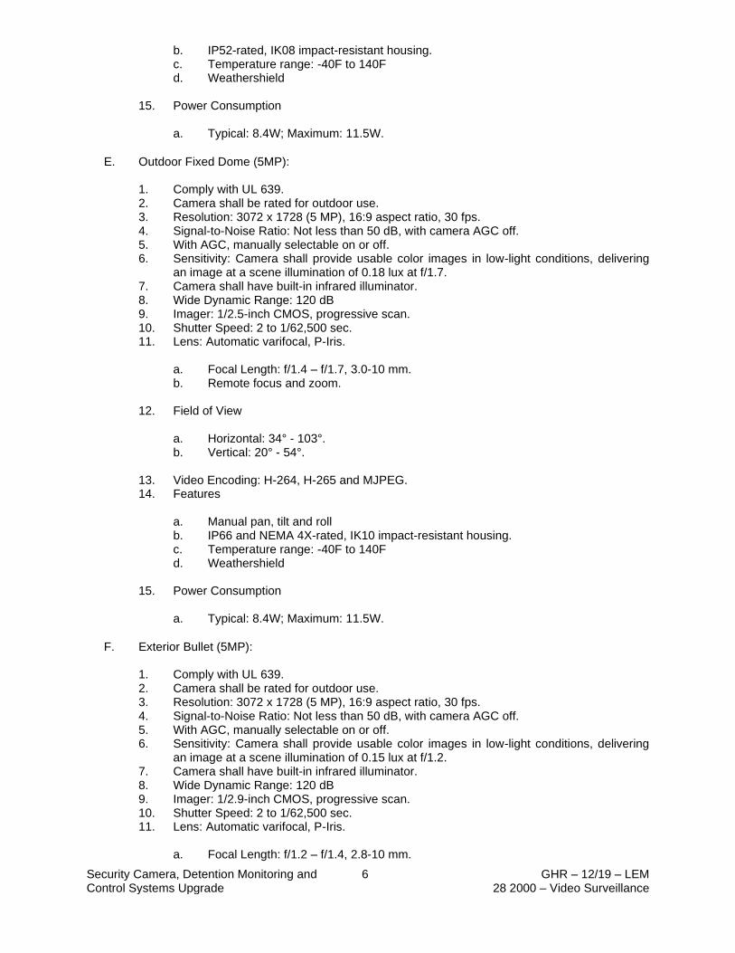
Security Camera, Detention Monitoring and Control Systems Upgrade
6 GHR – 12/19 – LEM 28 2000 – Video Surveillance
b. IP52-rated, IK08 impact-resistant housing. c. Temperature range: -40F to 140F d. Weathershield
15. Power Consumption
a. Typical: 8.4W; Maximum: 11.5W.
E. Outdoor Fixed Dome (5MP):
1. Comply with UL 639. 2. Camera shall be rated for outdoor use. 3. Resolution: 3072 x 1728 (5 MP), 16:9 aspect ratio, 30 fps. 4. Signal-to-Noise Ratio: Not less than 50 dB, with camera AGC off. 5. With AGC, manually selectable on or off. 6. Sensitivity: Camera shall provide usable color images in low-light conditions, delivering
an image at a scene illumination of 0.18 lux at f/1.7. 7. Camera shall have built-in infrared illuminator. 8. Wide Dynamic Range: 120 dB 9. Imager: 1/2.5-inch CMOS, progressive scan. 10. Shutter Speed: 2 to 1/62,500 sec. 11. Lens: Automatic varifocal, P-Iris.
a. Focal Length: f/1.4 – f/1.7, 3.0-10 mm. b. Remote focus and zoom.
12. Field of View
a. Horizontal: 34° - 103°. b. Vertical: 20° - 54°.
13. Video Encoding: H-264, H-265 and MJPEG. 14. Features
a. Manual pan, tilt and roll b. IP66 and NEMA 4X-rated, IK10 impact-resistant housing. c. Temperature range: -40F to 140F d. Weathershield
15. Power Consumption a. Typical: 8.4W; Maximum: 11.5W.
F. Exterior Bullet (5MP):
1. Comply with UL 639. 2. Camera shall be rated for outdoor use. 3. Resolution: 3072 x 1728 (5 MP), 16:9 aspect ratio, 30 fps. 4. Signal-to-Noise Ratio: Not less than 50 dB, with camera AGC off. 5. With AGC, manually selectable on or off. 6. Sensitivity: Camera shall provide usable color images in low-light conditions, delivering
an image at a scene illumination of 0.15 lux at f/1.2. 7. Camera shall have built-in infrared illuminator. 8. Wide Dynamic Range: 120 dB 9. Imager: 1/2.9-inch CMOS, progressive scan. 10. Shutter Speed: 2 to 1/62,500 sec. 11. Lens: Automatic varifocal, P-Iris.
a. Focal Length: f/1.2 – f/1.4, 2.8-10 mm.

Security Camera, Detention Monitoring and Control Systems Upgrade
7 GHR – 12/19 – LEM 28 2000 – Video Surveillance
b. Remote focus and zoom.
12. Field of View
a. Horizontal: 35° - 104°. b. Vertical: 20° - 55°.
13. Video Encoding: H-264, H-265 and MJPEG. 14. Features
a. Manual pan, tilt and roll b. IP66 and NEMA 4X-rated, IK10 impact-resistant housing. c. Temperature range: -40F to 140F d. Weathershield
15. Power Consumption
a. Typical: 6.7W; Maximum: 12.95W.
G. Exterior Panoramic (4x2MP):
1. Comply with UL 639. 2. Camera shall be rated for outdoor use. 3. Resolution: 4320 x 1920 (4x2 MP), 30 fps. 4. Signal-to-Noise Ratio: Not less than 50 dB, with camera AGC off. 5. With AGC, manually selectable on or off. 6. Sensitivity: Camera shall provide usable color images in low-light conditions, delivering
an image at a scene illumination of 0.17 lux at f/2.0. 7. Camera shall have built-in infrared illuminator. 8. Wide Dynamic Range: 120 dB 9. Imager: 4x1/2.9-inch CMOS, progressive scan. 10. Shutter Speed: 1/10 to 1/33,500 sec. 11. Lens: Fixed.
a. Focal Length: f/2.0, 3.2 mm.
12. Field of View
a. Horizontal: 180°. b. Vertical: 90°.
13. Video Encoding: H-264, H-265 and MJPEG. 14. Features
a. Manual pan, tilt and roll b. IP66 and NEMA 4X-rated, IK10 impact-resistant housing. c. Temperature range: -22F to 122F d. Weathershield
15. Power Consumption
a. Typical: 7.0W; Maximum: 12.9W.
H. Exterior Panoramic (3x5MP):
1. Comply with UL 639. 2. Camera shall be rated for outdoor use. 3. Resolution: 3x 2560 x 1920 (3x5 MP), 30 fps. 4. Signal-to-Noise Ratio: Not less than 50 dB, with camera AGC off.

Security Camera, Detention Monitoring and Control Systems Upgrade
8 GHR – 12/19 – LEM 28 2000 – Video Surveillance
5. With AGC, manually selectable on or off. 6. Sensitivity: Camera shall provide usable color images in low-light conditions, delivering
an image at a scene illumination of 0.3 lux at f/2.8. 7. Wide Dynamic Range: 120 dB 8. Imager: 1/1.8-inch CMOS, progressive scan. 9. Shutter Speed: 1 to 1/71,500 sec. 10. Lens: Fixed.
a. Focal Length: f/2.8, 5 mm.
11. Field of View
a. Horizontal: 180° b. Vertical: 90°.
12. Video Encoding: H-264, H-265 and MJPEG. 13. Features
a. Manual pan and tilt b. IP66 and NEMA 4X-rated, IK10 impact-resistant housing. c. Temperature range: -40F to 140F d. Weathershield
14. Power Consumption
a. Typical: 18.3W; Maximum: 22.5W.
2.4 POWER SUPPLIES
A. Low-voltage power supplies matched for voltage and current requirements of cameras and accessories, and of type as recommended by manufacturer of camera, infrared illuminator, and lens.
1. Enclosure: NEMA 250.
a. Type 1 for indoor locations. b. Type 3 for outdoor locations.
2.5 CAMERA-SUPPORTING EQUIPMENT
A. Wall Mount Brackets: Aluminum surface mounted bracket, white powder coated finish, IK10 vandal resistant.
B. Pole Mount Brackets: Aluminum pole mount bracket, white powder coated finish, IK10 vandal resistant, marine grade steel straps.
C. Corner Mount Brackets: Aluminum corner mount bracket, white powder coated finish, IK10 vandal resistant.
D. Recessed Ceiling Mount: White plastic camera holder for easy installation into lay-in ceiling tile.
E. Pendant Mount: Aluminum pipe pendant, white powder coated finish.

Security Camera, Detention Monitoring and Control Systems Upgrade
9 GHR – 12/19 – LEM 28 2000 – Video Surveillance
2.6 VIDEO CLIENT WORKSTATION
A. Manufacturers
1. Dell 2. HP
B. Description: Contractor shall provide video client workstations and coordinate with the Owner for exact locations. Workstation shall be loaded with the specified video management software.
C. Video Client Workstations:
1. The Video Client Workstations shall include the following (minimum) features:
a. Processor: Intel® Core™ i5-8500, 6 Core, 9MB Cache, 3.0GHz b. Operating System: Windows 10 Professional, 64-bit c. Memory: 8GB 1x8GB DDR4 2666MHz UDIMM Non-ECC d. Hard Drive: 2.5” 256GB SATA Class 20 Solid State Drive e. Video Card (4K): NVIDIA Quadro P400 2GB, 3 MDP to DP Adapter f. Optical Drive: 8x DVD+/-RW 9.5mm Optical Disk Drive g. Keyboard: Dell USB Keyboard, English, Black h. Mouse: Dell USB Optical Mouse with Scroll, Black i. Monitor(s): Two 32 inch, high definition monitors. j. Anti-Virus software: Owner shall provide/install anti-virus software
2.7 VIDEO MANAGEMENT SOFTWARE
A. Manufacturers
1. exaqVision 2. Milestone Systems
B. Video Management System (“VMS”)
1. The NVR shall come pre-loaded with VMS server software. 2. The VMS server software shall provide the following features as a minimum:
a. System
1) One server connection per client 2) Browser-based viewing of live and stored video 3) Auto detection of supported cameras 4) Support for fish-eye and panoramic lens cameras 5) Client bandwidth throttling 6) Soft triggers 7) Pre and post alarm recording 8) Continuous motion, time or alarm-based recording, configurable per camera
b. Live video view
1) Multiple monitor view support 2) PTZ control and presets 3) Digital PTZ control and presets 4) Motion and alarm indication 5) Event linking on discrete inputs
c. Search, playback, export, archive
1) Instant replay
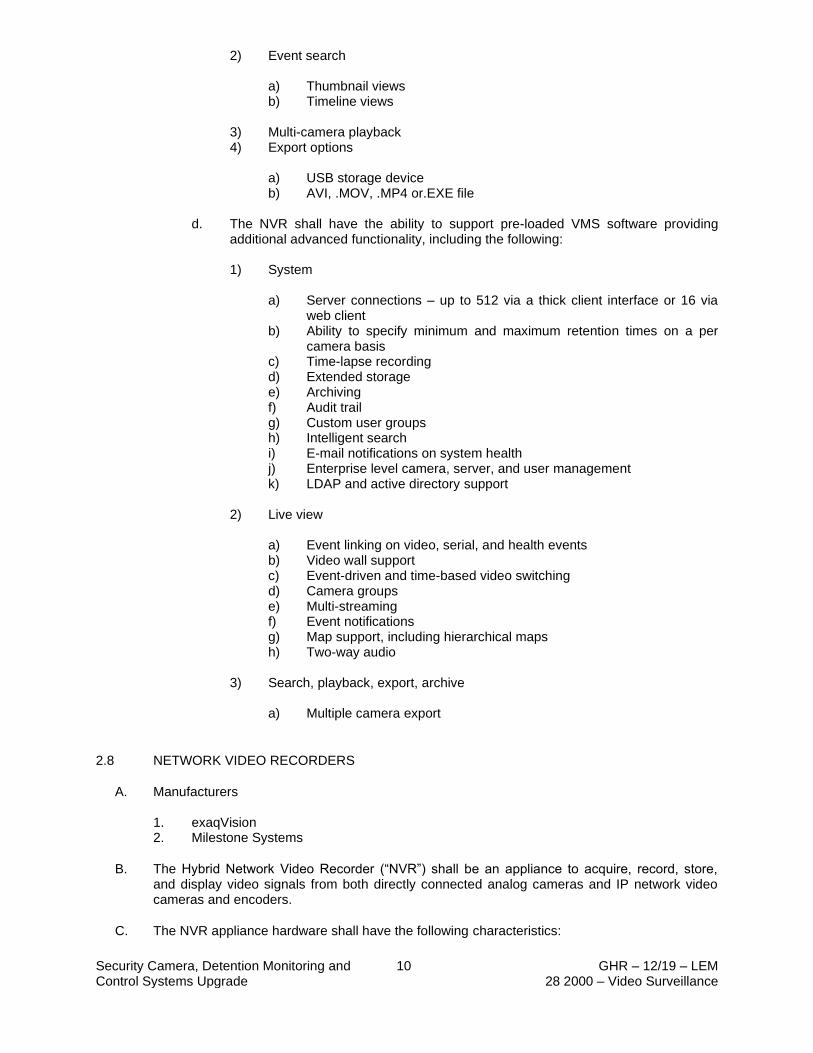
Security Camera, Detention Monitoring and Control Systems Upgrade
10 GHR – 12/19 – LEM 28 2000 – Video Surveillance
2) Event search a) Thumbnail views b) Timeline views
3) Multi-camera playback 4) Export options
a) USB storage device b) AVI, .MOV, .MP4 or.EXE file
d. The NVR shall have the ability to support pre-loaded VMS software providing
additional advanced functionality, including the following:
1) System a) Server connections – up to 512 via a thick client interface or 16 via
web client b) Ability to specify minimum and maximum retention times on a per
camera basis c) Time-lapse recording d) Extended storage e) Archiving f) Audit trail g) Custom user groups h) Intelligent search i) E-mail notifications on system health j) Enterprise level camera, server, and user management k) LDAP and active directory support
2) Live view
a) Event linking on video, serial, and health events b) Video wall support c) Event-driven and time-based video switching d) Camera groups e) Multi-streaming f) Event notifications g) Map support, including hierarchical maps h) Two-way audio
3) Search, playback, export, archive
a) Multiple camera export
2.8 NETWORK VIDEO RECORDERS
A. Manufacturers
1. exaqVision 2. Milestone Systems
B. The Hybrid Network Video Recorder (“NVR”) shall be an appliance to acquire, record, store, and display video signals from both directly connected analog cameras and IP network video cameras and encoders.
C. The NVR appliance hardware shall have the following characteristics:
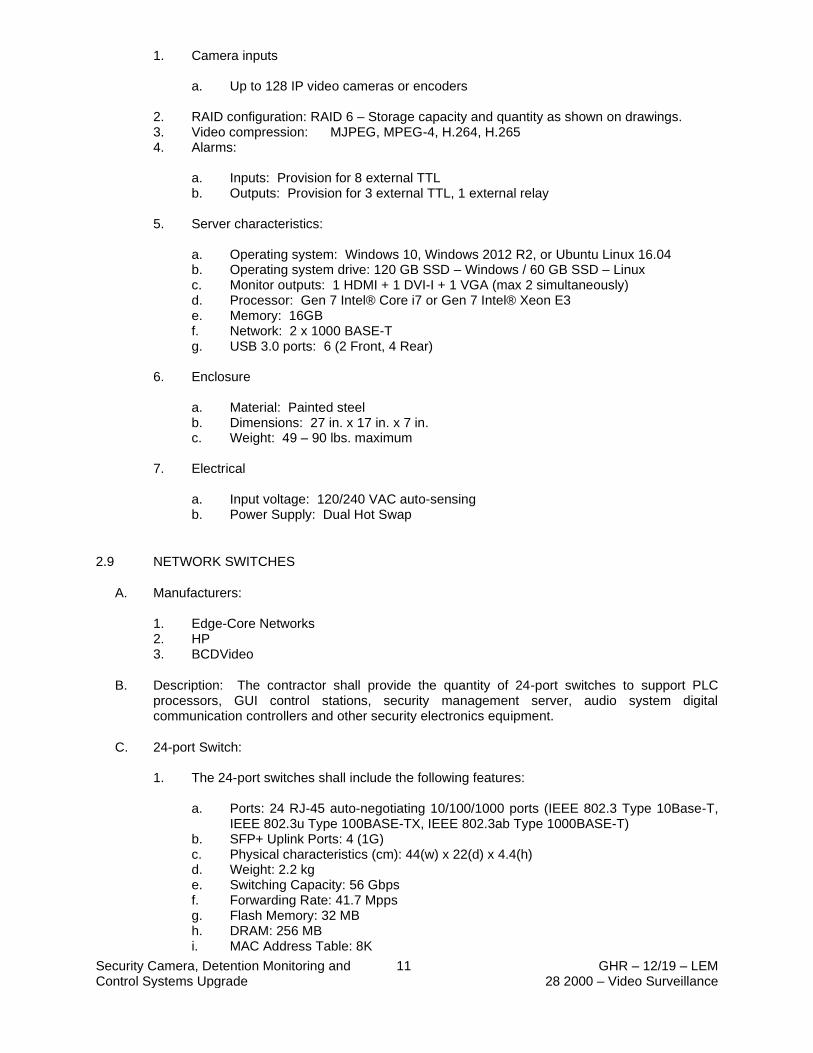
Security Camera, Detention Monitoring and Control Systems Upgrade
11 GHR – 12/19 – LEM 28 2000 – Video Surveillance
1. Camera inputs a. Up to 128 IP video cameras or encoders
2. RAID configuration: RAID 6 – Storage capacity and quantity as shown on drawings. 3. Video compression: MJPEG, MPEG-4, H.264, H.265 4. Alarms:
a. Inputs: Provision for 8 external TTL b. Outputs: Provision for 3 external TTL, 1 external relay
5. Server characteristics:
a. Operating system: Windows 10, Windows 2012 R2, or Ubuntu Linux 16.04 b. Operating system drive: 120 GB SSD – Windows / 60 GB SSD – Linux c. Monitor outputs: 1 HDMI + 1 DVI-I + 1 VGA (max 2 simultaneously) d. Processor: Gen 7 Intel® Core i7 or Gen 7 Intel® Xeon E3 e. Memory: 16GB f. Network: 2 x 1000 BASE-T g. USB 3.0 ports: 6 (2 Front, 4 Rear)
6. Enclosure
a. Material: Painted steel b. Dimensions: 27 in. x 17 in. x 7 in. c. Weight: 49 – 90 lbs. maximum
7. Electrical
a. Input voltage: 120/240 VAC auto-sensing b. Power Supply: Dual Hot Swap
2.9 NETWORK SWITCHES
A. Manufacturers:
1. Edge-Core Networks 2. HP 3. BCDVideo
B. Description: The contractor shall provide the quantity of 24-port switches to support PLC processors, GUI control stations, security management server, audio system digital communication controllers and other security electronics equipment.
C. 24-port Switch:
1. The 24-port switches shall include the following features: a. Ports: 24 RJ-45 auto-negotiating 10/100/1000 ports (IEEE 802.3 Type 10Base-T,
IEEE 802.3u Type 100BASE-TX, IEEE 802.3ab Type 1000BASE-T) b. SFP+ Uplink Ports: 4 (1G) c. Physical characteristics (cm): 44(w) x 22(d) x 4.4(h) d. Weight: 2.2 kg e. Switching Capacity: 56 Gbps f. Forwarding Rate: 41.7 Mpps g. Flash Memory: 32 MB h. DRAM: 256 MB i. MAC Address Table: 8K
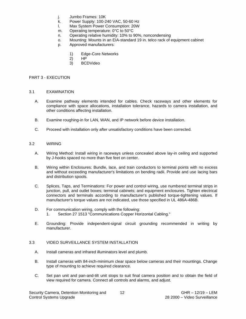
Security Camera, Detention Monitoring and Control Systems Upgrade
12 GHR – 12/19 – LEM 28 2000 – Video Surveillance
j. Jumbo Frames: 10K k. Power Supply: 100-240 VAC, 50-60 Hz l. Max System Power Consumption: 20W m. Operating temperature: 0°C to 50°C n. Operating relative humidity: 10% to 90%, noncondensing o. Mounting: Mounts in an EIA-standard 19 in. telco rack of equipment cabinet p. Approved manufacturers:
1) Edge-Core Networks 2) HP 3) BCDVideo
PART 3 - EXECUTION
3.1 EXAMINATION
A. Examine pathway elements intended for cables. Check raceways and other elements for compliance with space allocations, installation tolerance, hazards to camera installation, and other conditions affecting installation.
B. Examine roughing-in for LAN, WAN, and IP network before device installation.
C. Proceed with installation only after unsatisfactory conditions have been corrected.
3.2 WIRING
A. Wiring Method: Install wiring in raceways unless concealed above lay-in ceiling and supported by J-hooks spaced no more than five feet on center.
B. Wiring within Enclosures: Bundle, lace, and train conductors to terminal points with no excess and without exceeding manufacturer's limitations on bending radii. Provide and use lacing bars and distribution spools.
C. Splices, Taps, and Terminations: For power and control wiring, use numbered terminal strips in junction, pull, and outlet boxes; terminal cabinets; and equipment enclosures. Tighten electrical connectors and terminals according to manufacturer's published torque-tightening values. If manufacturer's torque values are not indicated, use those specified in UL 486A-486B.
D. For communication wiring, comply with the following: 1. Section 27 1513 "Communications Copper Horizontal Cabling."
E. Grounding: Provide independent-signal circuit grounding recommended in writing by manufacturer.
3.3 VIDEO SURVEILLANCE SYSTEM INSTALLATION
A. Install cameras and infrared illuminators level and plumb.
B. Install cameras with 84-inch-minimum clear space below cameras and their mountings. Change type of mounting to achieve required clearance.
C. Set pan unit and pan-and-tilt unit stops to suit final camera position and to obtain the field of view required for camera. Connect all controls and alarms, and adjust.

Security Camera, Detention Monitoring and Control Systems Upgrade
13 GHR – 12/19 – LEM 28 2000 – Video Surveillance
D. Install power supplies and other auxiliary components at control stations unless otherwise indicated.
E. Install tamper switches on components indicated to receive tamper switches, arranged to detect unauthorized entry into system-component enclosures and mounted in self-protected, inconspicuous positions.
F. Avoid ground loops by making ground connections only at the control station.
1. For 12- and 24-V dc cameras, connect the coaxial cable shields only at the monitor end.
G. Identify system components, wiring, cabling, and terminals according to Section 27 0553 "Identification for Communications Systems."
H. All VMS head-end equipment to be contained within equipment racks.
I. Provide adequate ventilation for all heat radiating equipment. SSI shall provide fan kits as required to maintain rated operating temperature of installed equipment.
J. All system equipment and field devices to be held securely in place. Fastenings and supports shall be selected to provide a safety factor of three.
K. All system equipment equipped with plug in power connectors to be connected to a dedicated receptacle. Do not use tap connectors for plugging in multiple plugs into a single receptacle.
L. All cable within equipment racks, and cabinets, or on backboards, to be neatly bundled and secured.
M. Wires shall not be nicked, have strands removed, or have frayed strands when removing insulation or terminating.
N. Seal-tite flexible conduits, NEMA-rated weatherproof junction boxes connectors shall be utilized for exterior camera locations.
3.4 FIELD QUALITY CONTROL
A. Perform tests and inspections.
1. Manufacturer's Field Service: Engage a factory-authorized service representative to inspect components, assemblies, and equipment installations, including connections, and to assist in testing.
B. Tests and Inspections:
1. Inspection: Verify that units and controls are properly installed, connected, and labeled, and that interconnecting wires and terminals are identified.
2. Pretesting: Align and adjust system and pretest components, wiring, and functions to verify that they comply with specified requirements. Conduct tests at varying lighting levels, including day and night scenes as applicable. Prepare video-surveillance equipment for acceptance and operational testing as follows:
a. Prepare equipment list described in "Informational Submittals" Article. b. Verify operation of auto-iris lenses. c. Set back-focus of fixed focal length lenses. At focus set to infinity, simulate
nighttime lighting conditions by using a dark glass filter of a density that produces a clear image. Adjust until image is in focus with and without the filter.

Security Camera, Detention Monitoring and Control Systems Upgrade
14 GHR – 12/19 – LEM 28 2000 – Video Surveillance
d. Set back-focus of zoom lenses. At focus set to infinity, simulate nighttime lighting conditions by using a dark glass filter of a density that produces a clear image. Additionally, set zoom to full wide angle and aim camera at an object 50 to 75 feet away. Adjust until image is in focus from full wide angle to full telephoto, with the filter in place.
e. Set and name all preset positions; consult Owner's personnel. f. Set sensitivity of motion detection. g. Connect and verify responses to alarms. h. Verify operation of control-station equipment.
3. Test Schedule: Schedule tests after pretesting has been successfully completed and system has been in normal functional operation for at least 14 days. Provide a minimum of 10 days' notice of test schedule.
4. Operational Tests: Perform operational system tests to verify that system complies with Specifications. Include all modes of system operation. Test equipment for proper operation in all functional modes.
C. Video surveillance system will be considered defective if it does not pass tests and inspections.
D. Prepare test and inspection reports.
3.5 ADJUSTING
A. Occupancy Adjustments: When requested within 12 months of date of Substantial Completion, provide on-site assistance in adjusting system to suit actual occupied conditions. Provide up to two visits to Project during other-than-normal occupancy hours for this purpose. Tasks shall include, but are not limited to, the following:
1. Check cable connections. 2. Check proper operation of cameras and lenses. Verify operation of auto-iris lenses and
adjust back-focus as needed. 3. Adjust all preset positions; consult Owner's personnel. 4. Recommend changes to cameras, lenses, and associated equipment to improve Owner's
use of video surveillance system. 5. Provide a written report of adjustments and recommendations.
3.6 CLEANING
A. Clean installed items using methods and materials recommended in writing by manufacturer.
B. Clean video-surveillance-system components, including camera-housing windows, lenses, and monitor screens.
3.7 DEMONSTRATION
A. Train Owner's maintenance personnel to adjust, operate, and maintain video-surveillance equipment.
END OF SECTION 28 2000
Security Camera, Detention Monitoring and Control Systems Upgrade
1 GHR – 12/19 – LEM 28 5211 – Detention Monitoring
and Control System
DIVISION 28 – ELECTRONIC SAFETY AND SECURITY Section 28 5211 – Detention Monitoring and Control Systems
PART 1 - GENERAL
1.1 RELATED DOCUMENTS
A. Drawings and general provisions of the Contract, including General and Supplementary Conditions and Division 01 Specification Sections, apply to this Section.
1.2 SUMMARY
A. Section Includes:
1. Component protection. 2. Hard control panels. 3. Touchscreen video control panels. 4. Touchscreen video control software. 5. Touchscreen LAN file server. 6. Administrative management computer. 7. Portable programming computer. 8. PLC system. 9. Data communications. 10. Relays. 11. Printer. 12. Dedicated UPS. 13. Component enclosures. 14. Cables. 15. Accessories. 16. Security fasteners. 17. Sleeves for raceways and cables. 18. Sleeve seals.
B. The scope of this project shall include a retrofit/upgrade of the security electronic control system. The Detention Electronic System Integrator shall retrofit/upgrade the door control, audio communication, touchscreen control and video surveillance systems as specified herein.
C. The Detention Electronic System Integrator shall be responsible for the demolition of unnecessary, existing security electronics head-end equipment and field devices and the installation and terminations of new security electronics.
D. The Detention Electronic System Integrator shall be responsible for the demolition of existing control station equipment, and shall be responsible for the installation and terminations of all new control station equipment, including GUI PCs, monitors and touchscreen master modules.
E. The Detention Electronic System Integrator shall be responsible for the installation of all required conduit/raceway and cabling required for the project. The includes cabling for all control system equipment, new speaker and new network cameras. The Detention Electronic System Integrator shall provide and install new CAT6 cabling for all new network cameras.
F. Where existing circuits are to be extended for connection to other equipment or systems, the Detention Electronic System Integrator shall break existing circuit at an accessible location, install terminal box with terminal strips or connectors and extend circuitry as required.

Security Camera, Detention Monitoring and Control Systems Upgrade
2 GHR – 12/19 – LEM 28 5211 – Detention Monitoring
and Control System
G. Where circuits are to remain in order to maintain operation to remaining devices, the Detention Electronic System Integrator shall verify continuity of circuits after removal of other equipment and/or devices. Where wire, cable and/or raceway modifications are required to maintain circuits, the Detention Electronic System Integrator shall provide such modification as part of the work.
H. During the project, any existing, non-functioning equipment and/or field devices shall be documented by the Detention Electronic System Integrator in a report and provided to the Owner prior to substantial completion. During the review of the report by the Owner, the Owner shall decide as to what action should be taken concerning the non-functioning equipment. The Owner shall have the option of requesting a price from the Detention Electronic System Integrator to repair and/or replace defective equipment.
I. The Owner shall be responsible for providing a high-speed internet connection to the Security Management Server for remote diagnostics by the Detention Electronic System Integrator.
J. The GUI software shall be programmed and configured to provide all functionality as described in this specification section. The GUI software shall communicate with all required security system components to display, control and monitor all security devices as specified.
K. The Detention Electronic System Integrator shall coordinate the control and monitoring configuration of each GUI station in the system with the Owner. Areas of control and monitoring shall be logically configured for each GUI station while considering the security envelope and concerns of each area of control.
L. The Detention Electronic System Integrator shall remove all existing operator control stations and ancillary equipment and turn over to the Owner for their disposal.
M. The new video management system shall be integrated with the PLC system and GUI software to allow automatic (connecting intercom stations or alarm activities) or manual call-up of any camera connected to the system. The Detention Electronic System Integrator shall provide a dedicated network interface card for each server to connect to the PLC/touchscreen system network.
N. The Detention Electronic System Integrator shall provide for the demolition of the existing door control system equipment.
O. The Detention Electronic System Integrator shall re-use the existing door control relays, fuse holders, fuses and power supplies.
P. The Detention Electronic System Integrator shall provide and install a PLC System as specified herein. The system shall include all equipment, installation materials, set up, and testing to form a complete operating system. Independent system functions and integrated system functions to be fully verified as part of system testing and commissioning.
Q. The Detention Electronic System Integrator shall provide all new PLC (programmable logic control) equipment consisting of a new PLC processor, chassis, power supply, communication module, input modules and output modules. The PLC processor shall include a non-volatile memory card to store the program and protect against power and battery failures.
R. All PLC input and output modules shall be distributed and interconnected utilizing an EtherNet/IP communications network.
S. Detention Electronic System Integrator shall verify quantities and provide all necessary equipment and labor in their bid proposal to provide control and monitoring of all existing devices currently controlled and monitored by the existing security electronics control system.
Security Camera, Detention Monitoring and Control Systems Upgrade
3 GHR – 12/19 – LEM 28 5211 – Detention Monitoring
and Control System
1.3 DEFINITIONS
A. I/O: Input/output.
B. LAN: Local Area Network.
C. LED: Light-emitting diode.
D. Monitoring: Acquisition, processing, communication, and display of system and equipment status data and event and alarm signals.
E. MOV: Metal-oxide varistor.
F. Nonsecure: Closed and locked and with no unlock or open commands pending. (For doors and gates.)
G. PLC: Programmable logic controller.
H. Secure: Unlocked or open. (For doors and gates.)
I. Systems Integration: The bringing together of components of several systems containing interacting components to achieve indicated functional operation of combined systems.
J. Zone: A space or area defined on Drawings for a specific purpose.
1.4 ACTION SUBMITTALS
A. Product Data: For components for detention monitoring and control and systems integration. Include dimensions and data on features, performance, electrical characteristics, ratings, and finishes.
B. Shop Drawings: Detail assemblies of standard components that are custom assembled for specific application on this Project.
1. Outline Drawings: Indicate dimensions, weights, arrangement of components, and clearance and access requirements.
2. Control Panel Layout: At full scale, show required artwork and device identification. 3. Wiring Diagrams: Detail specific power, control, signal, communication, and data wiring
and cabling. Coordinate nomenclature and presentation with block diagram. 4. Raceway Riser Diagrams: Detail raceway runs required for detention monitoring and
control and for systems integration. Include designation of devices connected by raceway, raceway type and size, and type and size of wire and cable fill for each raceway run.
1.5 INFORMATIONAL SUBMITTALS
A. Coordination Drawings:
1. Functional Block Diagram: Show single-line interconnections between components including interconnections between components specified in this Section and those furnished under other Sections.
a. Indicate methods used to achieve systems integration. b. Indicate control, signal, and data communication paths and identify PLCs,
networks, control interface devices, and media to be used. c. Describe characteristics of network and other data communication lines.

Security Camera, Detention Monitoring and Control Systems Upgrade
4 GHR – 12/19 – LEM 28 5211 – Detention Monitoring
and Control System
d. Describe methods used to protect against power outages and transient voltages including types and ratings of isolation and surge suppression devices used in data, communication, signal, control, and ac and dc power circuits.
2. Touchscreen Audible Tones and Visual Indications: Include the following material for use at touchscreen video control panels:
a. Audible indication, notification, and alarm tones and voice prompts. b. Visual materials for touchscreen video control panel display screens, complete
with proposed shapes, colors, scale, and textual content, including the following:
1) Graphics, including maps. 2) Icons. 3) Dialog boxes. 4) Help messages, prompts, and instructions.
B. Qualification Data: For Installer and Detention Electronic Systems Integrator.
C. Field quality-control reports.
D. Program documentation, software licenses, and backup copies of software used on Project.
E. Other Information Submittals:
1. Examination reports documenting inspections of substrates, areas, and conditions.
1.6 CLOSEOUT SUBMITTALS
A. Operation and Maintenance Data: For detention monitoring and control equipment components to include in emergency, operation, and maintenance manuals.
1.7 MAINTENANCE MATERIAL SUBMITTALS
A. Furnish extra materials described below that match products installed and that are packaged with protective covering for storage and identified with labels describing contents.
1. Fuses: A quantity equal to 10 percent of each type and rating indicated, but no fewer than 1 of each.
2. Fuse Blocks: Four of each type used. 3. Power Supplies: One of each type installed. 4. Network Interface Cards: One of each type installed. 5. Relays: Two of each type used. 6. Wire and Cable Terminals: Five of each type and size used. 7. PLC Processor: One of each type and configuration used. 8. PLC I/O Modules: One of each type and configuration used. 9. PLC EPROMs: One completely programmed module for each program used. 10. I/O Modules: One for every 10 of each type installed.
1.8 QUALITY ASSURANCE
A. Installer Qualifications: An employer of workers trained and approved by detention door control manufacturer and detention monitoring and control equipment manufacturer and with detention facility construction and systems integration experience with the following electronic systems:
1. Fire alarm.

Security Camera, Detention Monitoring and Control Systems Upgrade
5 GHR – 12/19 – LEM 28 5211 – Detention Monitoring
and Control System
2. Intercommunications. 3. Paging. 4. Remote lighting and power controls. 5. Video surveillance.
B. The following pre-qualified Detention Electronic System Integrators shall be allowed to submit pricing:
1. Security Automation Systems, Inc. (Indianapolis, IN)
C. Approval for Detention Electronic System Integrator
1. Approval of a Detention Electronic System Integrator does not include acceptance or products or procedures, unless approved by the Architect/Engineer.
2. All Detention Electronic System Integrator must adhere to the materials, intent, and design specified herein.
3. Integrator required to have Illinois Private Alarm Contractor Agency License. 4. Firms desiring to bid the Division 28 specifications as an Detention Electronic System
Integrator must submit, at least 10 days prior to the bid, a pre-qualification package that includes the following information:
a. AIA-305A Contractor Qualification Statement. b. A letter from the Detention Electronic System Integrator's surety company
reflecting the surety company's history and experience with the Electronic System Integrator and the current bonding limit for the last 5 years.
c. Organizational chart and resumes of key individuals. d. Company's history of providing security electronic control systems for correctional
facilities. e. Provide a list of at least 5 other projects in within 200 miles of this project location
similar in size and scope to this project (utilizing programmable logic controllers) completed in the last 5 years. For each project list the major subsystems with manufacturers used and the total dollar amount of the project. The current end-user contact (name, address and phone number) shall be listed for each project.
f. List the names and up-to-date phone numbers of the Architect, System Engineer and Owner of ALL Jail/Detention/Corrections projects installed by the submitting Detention Electronic System Integrator within the last 5 years.
g. Provide a narrative description of all software to be utilized, network types, and interfaces with other systems. Any custom software that is to be developed by the Detention Electronic System Integrator shall be described in detail.
h. An explanation of the company's ability to provide service to the Owner and the location and proximity of the company's physical service organization location.
5. Detention Electronic Systems Integrator shall have documented experience exercising full detention electronic systems integration responsibility for no fewer than 10 detention facility projects (jails or prisons) that have been completed and in operation for a minimum of 5 years. At least two projects within 120 miles of this project location.
D. Electrical Components, Devices, and Accessories: Listed and labeled as defined in NFPA 70, by a qualified testing agency, and marked for intended location and application.
1.9 SERVICE CONDITIONS
A. Environmental Service Conditions: Systems, equipment, and components shall be capable of operating continuously in the following conditions without mechanical or electrical damage or degradation of operating capability:
1. Ambient Temperature: 140 deg F. 2. Relative Humidity: 10 to 95 percent, noncondensing.

Security Camera, Detention Monitoring and Control Systems Upgrade
6 GHR – 12/19 – LEM 28 5211 – Detention Monitoring
and Control System
B. Electrical Service Conditions: Equipment shall operate continuously in the following conditions without damage or degradation of operating capability:
1. Voltage Range for Equipment with a Nominal Rating of 120-V AC: 88 to 132 V. 2. Voltage Range for Equipment with a Nominal Rating of 24-V DC: 22 to 85 V. 3. Frequency Range for Equipment with a Nominal Frequency Rating of 60 Hz: 45 to 63 Hz.
1.10 COORDINATION
A. Coordinate Work of this Section with that of Sections specifying systems and components required to be integrated with detention monitoring and control equipment.
B. Coordinate features of detention monitoring and control components with those of related detention electronic systems.
1. Provide integrated interconnections of compatible components. 2. Match components and interconnections for optimum performance of indicated functions.
1.11 MAINTENANCE SERVICE
A. The Detention Electronic System Integrator shall warrant all material and workmanship for a period of twelve (12) months after substantial completion. The warranty shall cover all material and software provided. The Detention Electronic System Integrator shall provide qualified and/or manufacturer-certified technicians capable of diagnosing and repairing the installed system.
B. The Detention Electronic System Integrator shall repair or replace (at no cost to the Owner) any defective materials or work when given written notice during the warranty period. Warranty service shall be provided to the Owner during normal working hours.
C. The Detention Electronic System Integrator shall provide emergency service during the 12-month warranty period. The Detention Electronic System Integrator shall provide the owner a 4-hour phone response time and a one business-day response time for major system failures. Major system failures shall be considered those failures which result in limited or no functionality of major electronic security system components, such as a PLC failure or a GUI failure.
D. The warranty shall exclude acts of vandalism, abuse, neglect, Owner misuse, failure of the Owner to provide continuous environmental conditions for which the installed equipment is rated for, and all other acts beyond the control of the Detention Electronic System Integrator (i.e. – weather damage, floods, fire, lightning, and similar acts).
PART 2 - PRODUCTS
2.1 FUNCTIONAL DESCRIPTION OF SYSTEM
A. Control Panels for Monitoring and Control Operator Interface:
1. Touchscreen video control panels.
B. Normal System and Device Programming Equipment:
1. Dedicated administrative management computer. 2. Touchscreen video control panel.

Security Camera, Detention Monitoring and Control Systems Upgrade
7 GHR – 12/19 – LEM 28 5211 – Detention Monitoring
and Control System
C. Interconnection of PLCs with Each Other and with Control Panels: Through a PLC network.
D. Interface between PLC System and Controlled and Monitored Devices: Relay assemblies.
E. Reliability: Components, arrangement, assembly, construction, wiring, connections, integration, adjustments, and system programming shall have a reliability such that no single malfunction or equipment failure can impair the normal operational control function of more than 20 percent of doors and associated components controlled by the overall system.
F. System Response Time: For indicated items, shall be within the following limits:
1. Mechanical Locking and Unlocking of Doors: Within one second of operator action at control panel.
2. Initiate Mechanical Movement of Electrically Controlled Doors and Gates: Within one second of operator action at control panel.
3. Initiate Audible and Visual Indications at Control Panels: Within one second of change of state of monitored field devices, or of alarm or intercom call-in events.
4. Initiate Automatic Switching: Within one second of occurrence of specified triggering event.
G. Automatic Logging of System Events: To an administrative management computer.
1. All events that take place within the PLC and Electronic Security System shall be logged to an administrative management computer provided by the Detention Electronic System Integrator. The HMI software installed on the GUI stations shall not be dependent on the Administrative Management Computer and software. The loss of functionality of the Administrative Management Computer shall in no way affect the normal operation of the GUI software.
2. The Administrative Management Computer shall have the following features: a. Record Device Events for the following field devices:
1) Doors 2) Intercoms 3) Cameras 4) Utility Control (Lighting, Receptacle) 5) Misc. Alarms 6) Any other project-specific device
b. Record Control Point events for each GUI station. These events shall be visibly
different from Device Events and display which control point and which user initiated the event. A control point shall consist of events generated by a GUI station. Control Point events shall include the following events; 1) Touchscreen Status 2) Interlock Override 3) Emergency Evacuation
c. The software shall allow the user to enter a credential, or 4-digit pin for each GUI
station. d. Event log shall be stored in a SQL database and be archived for retrieval. e. The Administrative Management Computer shall provide the user the ability to
display the previous 100, 50 or 25 events dynamically updating on the screen. f. The Administrative Management Computer shall provide the user the ability to
adjust the refresh rate for the events at a rate of 10 seconds, 30 seconds, 60 seconds or 5 minutes.
g. The user shall be able to filter the dynamic event display by device type. h. The dynamic event display shall display columns for Control Point/User, Recorded
Audio File, Timestamp (the date and time of the event), Device Name, Event Type,

Security Camera, Detention Monitoring and Control Systems Upgrade
8 GHR – 12/19 – LEM 28 5211 – Detention Monitoring
and Control System
Device Description/Note, Device Type, Area Name (location area name the specific device is grouped in).
i. The user shall be able to generate reports based on database queries for event names or time of occurrences. This report shall be displayed on screen and the user should be allowed to print the report.
j. Devices and their associated events shall have the ability to be grouped based on their respective locations in the building. (i.e. Cell Block A, B, C, Booking, etc)
k. The user shall have the ability of performing a search function that looks for keywords such as type of event, area of the building, or device names. The search function will replace the dynamic event view with the returned list based on the search criteria. The user can either choose to see the previous 100 events (based on the search criteria) or all events containing the keyword(s) searched.
l. Provide e-mail notification that includes the following functionality:
1) Manage rule definitions, that when evaluated as true, will send an e-mail. 2) Each rule can be based on any combination of LT Timestamp, Device
Name, Event Name, Device Description, Device Type Name, Area Name, Control Point Name, Username, URL, and Note.
3) Rule start time and end time can be defined. 4) Rules can have custom messages attached to email alert. 5) Each rule can be based on device or control point events. 6) Each rule can be associated with one or more email addresses. 7) Each email can be associated with one or more rules. 8) System shall have the ability to send notification emails to a defined email
server via SMTP. 9) System shall log notification events and the operator shall be able to view
them through the Monitor client application.
m. Provide an audio playback feature that includes the following functionality: 1) Each active audio connection (conversation) between an intercom station
and a GUI station shall be recorded to the Administrative Management Computer as a single MP3 audio file.
2) In the dynamic event display, there shall be a column for a recorded audio conversation. If an audio file is associated with the intercom connect event, the system shall display a speaker symbol.
3) If the speaker icon is selected, a “Play Audio” menu shall be displayed. On the menu screen, the Device Name, the Event Timestamp and the Control Point Name/User shall be displayed.
4) The Play Audio menu shall allow the user the choice of Detention Electronic System Integrator ng “PLAY” to play back the audio file directly on the server, Detention Electronic System Integrator ng “STOP” to stop the playback, or Detention Electronic System Integrator ng “EXPORT AUDIO” to export the audio file to a location on the server selected by the user.
5) Along with the “PLAY” and “STOP” buttons, the Total Duration of the sound file shall be displayed. The Current Position (dynamically displayed) and Current Ending location of the sound file shall also be displayed. All times shall be displayed in minutes and seconds.
6) The Play Audio menu shall include a progress bar that visually indicates where in the recorded audio file the playback is currently at. There shall be two adjustable markers (“start” and “end”) to allow the user the option of customizing where they want the audio to start and stop playing.
7) Provide sufficient hard drive space on the data logging server to store 1000 hours of audio files to the Administrative Management Computer hard drive(s).
H. Audible Tone: A distinctive, audible, confirmation signal tone shall sound locally for 0.25 second each time an operator performs a switching, selection, acknowledgment, silence, reset, or other similar operation at a control panel.
Security Camera, Detention Monitoring and Control Systems Upgrade
9 GHR – 12/19 – LEM 28 5211 – Detention Monitoring
and Control System
2.2 COMPONENT PROTECTION
A. Surge Protection: Protect components from voltage surges originating external to equipment housings and entering through power, communication, signal, control, and sensing leads. Include surge protection for external wiring of each conductor entry connecting to components.
1. Minimum Protection for AC Power Circuits 120 V and More: Multistage surge suppressors, listed under UL 1449, using a combination of inductors and silicon avalanche diodes or equivalent, and with 300-V suppression level and 5-nanosecond maximum response time.
a. Silicon Avalanche Diodes: Bipolar, Grade A, plus or minus 5 percent tolerance. b. Discrete SPD Units External to Protected Equipment: Enclosed modules with
indicating lights labeled "power on" and "failure."
B. Interference Protection: Component function shall be unaffected by radiated-radio-frequency interference and electrical induction of 15 V/m over a frequency range of 10 to 10,000 MHz, or by conducted interference signals up to 0.25-V RMS injected into power supply lines at 10 to 10,000 MHz.
2.3 TOUCHSCREEN VIDEO CONTROL PANELS
A. Manufacturers: Subject to compliance with requirements, provide products by one of the following:
1. Dell. 2. HP.
B. Description: Computer-operated, video control unit complying with 47 CFR 15, Subparts A and B, for Class A and B digital devices and having dynamic presentation of annunciation and controls on a monitor equipped with a touch-sensitive panel overlay on the front of display screen. Include the following minimum features, components, and capabilities:
1. CPU: IBM-compatible computer housed in an industrial chassis and having the following requirements:
a. CPU: Intel Core 15 or better. b. RAM: 16 GB SO-DIMMDDR4. c. Fixed Disk Drive: 128 GB. d. Operating System: Windows 10 Professional, 64 Bit.
2. Monitor and Touchscreen Panel: 24 inches. With 1920 by 1080 resolution.
a. On-Screen Colors: 256. b. Video Card: VRAM with capture. c. Interface Overlay: Capacitive touch switching system.
1) Single, Transparent-Glass, Panel Type: 92 percent light transmission. 2) Touch Position Accuracy: Maximum error; 0.125 in.. 3) Touch Endurance: 2,000,000 finger touches at 12-ounce force pressure at
any selected point, regardless of screen size, without failure or noticeable degradation.
4) Activation Force Required for Switching: 1 to 12 ounces force, software adjustable.

Security Camera, Detention Monitoring and Control Systems Upgrade
10 GHR – 12/19 – LEM 28 5211 – Detention Monitoring
and Control System
3. Peripheral Components:
a. Wireless keyboard and mouse. b. Speakers: Two amplified computer speakers.
C. General Functional Performance:
1. Video display shall be connected so an operator can interact with and control the computer, responding to inputs and creating outputs that control external functions.
2. Data from external sensors and signal sources shall be processed by external I/O units, PLCs, and the computer, and initiate displays of system and equipment status, activity, and other information on the monitor and through related signal devices. Where indicated, data from external sensors and signal sources also initiate automatic system responses.
3. Software correlates various points on the touch-sensitive panel with software-generated graphics so operational outputs are created by touching the screen at locations defined by the graphics.
4. Touch-panel outputs shall be processed by computer and by integrated external I/O modules and PLCs to produce control signals and operating voltages for switching devices and relays that control those devices.
5. Computer software shall provide pop-up and tool-bar-type menus and special icons that guide the operator in responding to events and in switching to different screen displays to obtain access to different control panel functions.
D. Detailed Operational Performance: Include the following control, monitoring, and performance functions by touchscreen video control panels and associated equipment and circuits:
1. Global Functions: Touching the icons or toolbar buttons at the bottom of each graphic screen, and elsewhere as indicated, controls the following functions:
a. Operator Log-On and Log-Off: Dialog box appears for password entry.
1) Logging Off: Dialog box prompts operator to verify intent to log off, and to either exit the process or complete it.
2) Completion of log-off process displays log-on screen for the next operator to access touchscreen functions.
b. Map Finder: Graphic map index appears with provision for the operator to select a map and its associated functions to be displayed.
c. Clean Screen: All icons and graphics are extinguished for 15 seconds to facilitate physical cleaning of control panel screen surface.
d. System Utilities: System management screen appears, presenting functional choices appropriate for the logged-on operator's programmed access level; choices inappropriate for the operator appear in dialog box but are grayed out to indicate they are inactive. Choices include the following:
1) Configure station users. 2) Change password. 3) Calibrate touchscreen. 4) Set date and time.
e. Scroll to Adjacent Area: Four icons, one on each side of the screen, near the edge. Touching these icons selects the screen for adjacent area on that side of area currently displayed.
2. Audible and Visual Alarm Indications and Controls: Red alarm icon flashes and a distinctive tone pulses continuously at control panel when an alarm condition or uncontrolled change of state occurs in controlled or monitored circuits or equipment.
Security Camera, Detention Monitoring and Control Systems Upgrade
11 GHR – 12/19 – LEM 28 5211 – Detention Monitoring
and Control System
a. Tone is silenced by momentary-contact silence control icon, and status icon becomes steady.
b. Depressing the momentary-contact reset control icon extinguishes status icon for alarms that can be reset at control panel.
3. Door Status Visual Indications: Denoted by status icon at door control icon as follows:
a. Nonsecure: Red icon. b. Secure: Green icon. c. Alarm (Door Position or Lock Status Inconsistent with Control Position or Status):
Flashing red icon.
4. Panel-Controlled, Unlocking and Automatic-Locking, Single Swing Doors: Operation of control icon unlocks door for a period programmable from 1/2 to 10 seconds.
5. Power-Operated Door or Gate with Open, Stop, and Close Control: Operation of open control icon applies power, initiating open cycle. Touching the stop control icon while mechanism is in open or close cycle stops motion. Touching the close control icon applies power, initiating close cycle. Limit switch in mechanism stops unit at end of its travel in either direction.
6. Doors with Both Individual and Group Control:
a. Touching the individual door control icon locks or unlocks door, depending on current status.
b. Touching the group control icon locks or unlocks doors assigned for group operation, depending on current group control enablement status of individual doors.
c. Doors are individually enabled for group locking and unlocking using separate group assign and unassign control icon.
7. Assign and Unassign Group-Door Function:
a. Touching the group door assign and unassign control icon lights that icon and a red status icon at each door that is currently assigned for group operation, and permits unassigning any of those doors by touching the associated lock and unlock control icon.
b. Doors not currently assigned are assigned for group operation by touching the associated lock and unlock control icon while group assign and unassign control icon continues to be lighted.
c. Touching the group door assign and unassign control icon again returns system to normal operating mode.
8. Group Door Control, Locking and Unlocking: Touching the group lock and unlock control icon locks doors in group if they are currently unlocked. If doors are locked, action presents a dialog box requiring operator confirmation before unlocking doors assigned to group.
a. Locking or unlocking of doors is performed individually at one-second intervals.
9. Door Interlocking: Interlocks designated groups of doors and gates.
a. Effect: When one door in a group is unlocked or open, the others in the group are prevented from being unlocked or opened.
b. Override When One Door of an Interlocked Group Is Nonsecure: Touching the interlock override control icon presents a dialog box requiring operator confirmation before placing nonsecure interlocked door group in an override mode.
1) Override mode permits doors in group to be unlocked and opened for a time
interval of programmable duration, set at 10 seconds.
Security Camera, Detention Monitoring and Control Systems Upgrade
12 GHR – 12/19 – LEM 28 5211 – Detention Monitoring
and Control System
c. Interlocked Door Indications: The following status indications apply to interlocked doors in addition to specified indications for controlled doors:
1) Door status icons for secure doors light steadily yellow when one door in group is nonsecure; icons flash yellow when group is in override mode.
2) When two or more doors in group are nonsecure, status icons for doors in group flash red; tone pulses; touching the silence control icon silences tone.
10. Operator-Controlled, Emergency Door Release: Operation of emergency-release control icon presents a dialog box requiring operator confirmation before unlocking designated doors. Doors remain unlocked until relocked individually or in groups.
a. Next operation of icon locks door. b. Locking or unlocking of doors is performed individually at one-second intervals. c. Indications: Red status icon at emergency-release control icon is lighted and
sounds a distinctive tone.
1) When emergency-release control icon unlocks doors, status icon flashes continuously five times per second and audible alarm pulses.
2) Touching the silence control icon silences audible alarm. 3) When doors are relocked or alarm-reset control icon is touched, status icon
is extinguished and alarm is silenced.
11. Intercommunication Control:
a. Incoming Intercom Call: When staff or inmate station initiates a call to control panel station, a distinctive tone sounds and green icon at station control icon flashes.
b. Operator acknowledges call by touching the intercom control icon associated with calling station or the acknowledge control icon. Status icon is lighted steadily and tone ceases.
c. Acknowledgment of the call opens an audio path to calling station and permits operator to conduct two-way conversation using push-to-talk switch and microphone.
d. Operating the control icon again, or selecting another station, terminates the connection and the status icon at first station is extinguished.
e. Listening or Outgoing-Call Function: Operator selects staff or inmate station by operating the station select control icon. Operator may listen or proceed with two-way conversation using push-to-talk switch and microphone. Selecting station again, or selecting another station, terminates the connection.
12. Paging: Operator transmits paging announcements by touching a momentary-contact paging control icon, closing a momentary push-to-talk switch, and using microphone. Green status icon lights at paging control icon until it is operated again to terminate the connection. Multiple zones may be paged simultaneously by operating more than one paging zone control icon before transmitting.
13. Audio-Level Alarm: Touching the audio-level-alarm control icon shall place intercom system in monitoring mode for cell noise level.
a. Red icon at audio-level-alarm control icon is lighted when system is in alarm mode. b. When in alarm mode, system alarms when noise level in any cell exceeds an
adjustable preset threshold. Green icon flashes at control panel intercom station control icon for the cell originating the alarm, and audible alarm tone pulses.
c. Touching the silence control icon silences audible alarm and causes green icon to light steadily.
d. When reset control icon is operated, the green status icon is extinguished.

Security Camera, Detention Monitoring and Control Systems Upgrade
13 GHR – 12/19 – LEM 28 5211 – Detention Monitoring
and Control System
14. Video Switching Control:
a. Signal from assigned camera is automatically shown on monitor when the following occurs:
1) Operator selects associated intercommunication station by operating the selector control icon for the station, by acknowledging incoming intercom call, or by touching the camera control icon.
2) A staff-duress signal is initiated in the vicinity of camera.
b. Video signal from assigned camera is manually switched to spot monitor at control station when operator touches camera control icon.
c. Green status icon on the graphic control panel identifies and locates the video camera currently providing the signal for spot monitor at control panel location.
d. The orientation of the camera symbol shall be representative of the actual direction of the camera.
e. Two onscreen video display windows shall be incorporated into the GUI. One window shall be used for manual camera call-up and the other window shall be used for intercom follow. Selecting another camera icon shall cause its camera to become active and cancel the previous camera.
15. Cell Lighting Control: Two control icons for each cell provide on-off and inmate control for lights and receptacles in each cell.
a. Touching the inmate control icon energizes receptacles and enables or disables local control of lighting within cell, depending on current status.
b. Touching the on-off control icon turns lights and receptacles on or off, depending on current condition.
c. Indications: Green icon at on-off control icon is lighted when lighting and power are on; otherwise, icon is not lighted.
16. Electrical Circuit On-Off Switching Control: A control icon for each function toggles between on and off to energize and de-energize circuits.
a. Indications: Green icon at control icon indicates when lighting or power is on.
17. Fire Alarm System Status Indications:
a. Red fire alarm icon flashes when alarm occurs. b. Red icon for each zone flashes when alarm occurs for that zone. c. Red icon for each detection device and each manual station flashes when that
device or station is in an alarm state. d. Audible alarm tone pulses when alarm signal occurs. e. Depressing the silence control icon silences audible tone and causes status icon to
light steadily. After fire alarm system is reset, touching the reset control icon extinguishes status icon.
18. Smoke Control: Touching the smoke control icon initiates a signal to HVAC system controls to start preestablished smoke-control operating mode. Yellow status icon flashes continuously to confirm HVAC system is operating in smoke-control mode.
19. Duress-Status Indications: When staff-duress device for a zone is activated, red staff-duress status icon for that zone flashes and audible alarm tone pulses. Operating the silence control icon silences audible alarm and causes status icon to light steadily. Operating the reset control icon extinguishes status icon.
20. Elevator Security Controls: Control system shall have full elevator control at Champaign County Courthouse.
Security Camera, Detention Monitoring and Control Systems Upgrade
14 GHR – 12/19 – LEM 28 5211 – Detention Monitoring
and Control System
21. Water-Flow Control: On-off control icon at control panel for designated building areas.
a. Touching the water-on control icon opens solenoid valve in supply line. Touching the control icon again closes valve.
b. Indications: Yellow icon is lighted when water is on; otherwise, icon is not lighted.
22. Panel Control-Power Switch: Key-operated switch turns power to control panel on and off and enables operation.
a. Indications: Green power-on status icon is lighted when panel is enabled; otherwise, icon is not lighted.
23. Emergency Features
a. Located on GUI menu shall be a button labeled “EMERGENCY.” Pressing this
button will display the Emergency Menu which consists of various emergency related function buttons. These buttons shall include: RELEASE ALL, and LOCKDOWN.
1) RELEASE ALL button:
a) When pressed, this button shall begin the Emergency Evacuation
sequence and display a window explaining the risk of the action. The GUI shall also audibly warn the operator of the risks involved in continuing the action. On the step 1, window there shall be buttons to CONTINUE and ABORT.
b) If the operator continues, the first window shall disappear and a second window shall again warn of the danger and risks involved in continuing. Also the GUI shall place “E” symbols on all controlled doors that will be released and again warn the operator of the dangers involved in continuing. On the step 2 window, there shall be buttons to CONTINUE and ABORT.
c) If the operator chooses to continue, a full screen window shall appear stating that this is the final warning before release. An audible message shall warn the operator that after this step, all doors with “E” symbols will be released. On the step 3 window, there shall be a button to CONTINUE and the ABORT button should at least 10 times larger in size.
d) Pressing continue will begin the unlocking sequence, all doors with “E” symbols will be released or opened.
2) LOCKDOWN button: The Emergency Window shall contain a LOCKDOWN
button. This button shall lock all held-open swing doors as well as close all sliding and overhead doors
24. Additional Features
a. NAVIGATION PANE – There shall be a portion of the GUI screen dedicated to screen navigation for the Security Automation System. This shall be a graphical representation of the floor layout segmented to represent each screen. This area is also used to display Door Violation Indication, Alarm indication and Pending Intercom indication. When a door on particular screen violates the screen associated with that door flashes red indicating to the operator that their attention is required. Other devices that should be indicated by a red flash in the Navigation Pane include: Fire Alarm System Annunciation. Pending Intercom stations shall flash their respective windows green to help assist the operator in finding the pending station. The current active screen shall be displayed as white allowing the user to see their current location

Security Camera, Detention Monitoring and Control Systems Upgrade
15 GHR – 12/19 – LEM 28 5211 – Detention Monitoring
and Control System
b. ALARM ACKNOWLEDGE - Selecting this icon shall acknowledge and silence the audible notification used to indicate a violated door, intercom station call, or any other alarm.
c. CONTROL ROOM DURESS - Selecting this icon shall immediately DISABLE all functions of the GUI.
d. ADMINISTRATIVE UTILITIES MENU - Located on the menu shall be a button for configuring convenience and maintenance options to the operator.
1) A ‘COMMAND FUNCTIONS’ button shall allow the operator to shut-down
the GUI software applications. Upon selecting the button, the operator is prompted to provide an administrator-level password before the software applications are shut down.
2) A ‘VOICE STYLE’ selection shall allow the operator to select between a female, male, or basic for common GUI functions. For audible alarm indications, the GUI shall play a male or female voice always.
3) A ‘CALIBRATE SCREEN’ button shall allow the operator to calibrate the GUI overlay for proper touch alignment.
4) A ‘CLEAN SCREEN’ button shall allow the operator to clean the surface of the GUI display with a manufacturer approved cleaning product. The screen shall be “blanked” so that no icons or control functions are available to the operator. An onscreen message shall tell the user what types of cleaning products are approved.
2.4 TOUCHSCREEN VIDEO CONTROL SOFTWARE
A. Manufacturers: Subject to compliance with requirements, provide products by one of the following:
1. Indusoftt. 2. Intouch.
B. Description: Custom developed from a detention application package.
C. Features and Functional Performance Requirements:
1. Programmed to provide features and functional performance indicated without use of proprietary software code.
2. Automatic alignment and adjustment of touchscreen interface with video monitor and its graphics.
3. Visual and Audible Presentations: Designed for simplicity and rapid operator orientation, and conducive to operator focus on the highest-priority mission functions assigned to operator and station.
4. Maps: Facility floor and site plans presented in selectable, scaled, on-screen, part-plan increments with the following content:
a. Basic architectural elements depicted with white lines on a black background. b. Floor plan features for which control icons or status indicators are specified,
including doors, gates, intercom stations, paging speakers, video cameras, duress stations, fire alarm stations, smoke detectors, and similar items.
c. Egress paths. d. Control icons represent switches for specified control functions, operating through
integration with the touchscreen interface. e. Indicator icons show status of related feature by changing from nonlighted to
lighted, by flashing, and by changing color.
5. Priority Level Implementation: For processing and registering alarms, device signals, and intercom activity in the following order:

Security Camera, Detention Monitoring and Control Systems Upgrade
16 GHR – 12/19 – LEM 28 5211 – Detention Monitoring
and Control System
a. Fire and other life-safety alarms. b. Staff-duress alarms. c. Inmate sound-level monitoring alarms. d. Door-monitoring and perimeter-security alarms and trouble signals. e. Intercom calls from other master stations. f. Intercom calls from access and inmate-movement control stations. g. Intercom calls from cells. h. System and equipment derangement and trouble alarms.
6. Access Protection: Log-on passwords provide 8 levels of security for access to various functional capabilities provided at each touchscreen station. System shall support 1000 users.
a. Configures, generates, and prints reports, using automatically logged event data. b. Edits and updates programs, databases, system operating variables, point
descriptions, help and operating protocol screens, and icon designations. c. Operator Assistance Material: Provides interactive help messages and other
material, including the following:
1) Descriptions of functions initiated by control icons and menu items. 2) Explanations of conditions denoted by audible and visual indications. 3) Instructions for performing control process. 4) Synopses of policies governing control panel operation and standard
operating procedures.
7. Audible Tones: Multiple computer-generated tones that can be programmed for frequency, volume, duration, and repetition rate and selected for each audio annunciation application.
2.5 ADMINISTRATIVE MANAGEMENT COMPUTER
A. Description: IBM-compatible microcomputer housed in an industrial chassis. Minimum features, components, and capabilities shall be same as specified for touchscreen video control panel central-processing unit, with the following exceptions:
1. Peripheral Components:
a. Monitor: 17 inches. With 1280 by 1024 resolution.
1) On-Screen Colors: 256.
b. Speakers: Two amplified computer speakers. c. Printer: Comply with "Printer" Article.
B. Operational Performance: Same as specified for touchscreen video control panel with the following exceptions and additions:
1. On-Screen Switching and Selection Functions: Performed by mouse-initiated pointing and clicking instead of by touching the screen.
2.6 PLC SYSTEM
A. General-Purpose PLCs:
1. Manufacturers: Subject to compliance with requirements, provide products by one of the following:

Security Camera, Detention Monitoring and Control Systems Upgrade
17 GHR – 12/19 – LEM 28 5211 – Detention Monitoring
and Control System
a. Allen-Bradley/Rockwell Automation. b. Emerson Electric Co. (GE Intelligent Platforms). c. OMRON Corporation.
B. Description: Modular, generic PLCs manufactured for, and in general use in, general-purpose industrial applications; complete with controllers, power supplies, I/O modules, communication links, and housings. Minimum features and functionality include the following:
1. Characteristics: Adequate memory, software, I/O connections, communication capabilities, power capacity, and logic and timing functions to meet indicated requirements.
2. Controller and I/O Uniformity: Manufacturer's different models shall be compatible, sharing common mounting centers, commands, control language, instruction code, and I/O structure.
3. I/O Modules: Same manufacturer as PLCs and applicable within the full range of manufacturer's controller models.
4. Controller Output Capacity: Adequate to drive local I/O within 50 feet of controller without interface modules or additional power supplies. Adequate to drive remote I/O within 1640 feet of controller using remote I/O interface modules and a high-speed data link.
5. Controller EPROM: Stores system application program, operating software, and fixed database.
6. Controller General-Purpose RAM: Provides operational memory and storage for operating database. RAM is backed up by lithium battery of adequate capacity for a 12-month outage.
7. Controller Communication Capability: Serial RS 232, RS 422, or RS 485, plus standard Ethernet LAN, using nonproprietary protocol and copper or optical fiber media.
8. Diagnostics and Failure Response: Controllers and associated I/O devices shall be self-monitoring and self-diagnostic. They shall also monitor their communication links. Failure of any type shall be indicated by LED on the unit, and occurrence of failure shall be communicated to applicable control panel, where it shall result in a failure indication. An analysis of failure shall be registered in PLC memory and shall be remotely software accessible.
9. PLC and Local I/O Power Supply: Regulated dc unit located in the same rack enclosure as units it serves; with 24-V output. Include the following features:
a. Capacity: 150 percent of load. b. Voltage Control and Protection: Remote sensing of voltage at load and internal
overvoltage protection. c. Fault Protection: Fuses and inherent design protect against short circuit and
overload, including shorting of either leg of dc output to conductive material energized intentionally or through malfunction at 120 V.
d. Surge Protection: Protect the power supply and its I/O circuits in all modes of operation.
10. PLC and Local I/O Device Mounting: Rack mounting in ventilated enclosures.
2.7 DATA COMMUNICATIONS
A. Touchscreen video control panels and PLCs shall communicate directly with each other via ethernet communication links.
B. Touchscreen video control panels shall communicate via LANs as follows:
1. Communication between Touchscreen Video Control Panels and PLCs: Via PLC LAN, using PLC network interfaces.
Security Camera, Detention Monitoring and Control Systems Upgrade
18 GHR – 12/19 – LEM 28 5211 – Detention Monitoring
and Control System
2.8 RELAYS
A. Manufacturers: Subject to compliance with requirements, provide products by the following:
a. Allen-Bradley/Rockwell Automation. b. Emerson Electric Co. (GE Intelligent Platforms). c. OMRON Corporation. d. Eaton.
B. Arrange in relay assemblies that have the following features:
1. Fuse and SPD protection. 2. Indicating LED for each relay.
C. Rating: A minimum of 150 percent of the inrush current of controlled device, but not less than 6 A.
2.9 DEDICATED UPS
A. Description: Single-phase units, rated 120 V, 60-Hz input and output:
1. Capacity: Adequate to supply full connected load for a minimum of 10 minutes. 2. SPD: Comply with UL 1449. Provide let-through voltage of 300 V or less. 3. Annunciation of UPS malfunction at control panel. 4. Connected Loads: PLCs and I/O modules both local and remote; operating, control, and
indicating power supplies for control panels.
2.10 COMPONENT ENCLOSURES
A. Description: Metal cabinets, racks, and consoles, with welded frames, complying with UL 1610.
B. Doors, Covers, and Other Access Provisions:
1. Hinged Type: Flanged, with locks and nonremovable pins in hinges. 2. Screw Covers: Secure with security fasteners of type indicated or, if not indicated, flat-
head (countersunk) security fasteners. 3. Locks: Pick-resistant, flush-tumbler type; three-point latching device for hinged doors or
covers with latch edge more than 24 inches long. 4. Keys: Identical, unless otherwise indicated. Removable only when lock is locked.
C. Seismic Hardening: Increase rigidity of frames with additional welding and grinding of seams and addition of gussets at corners. Reinforce mounting and attachment provisions to resist seismic forces.
D. Mounting and Anchoring Provisions: Accessible only when doors or covers are open.
2.11 CABLES
A. Low-Voltage Control Cable: Multiple conductor, color-coded, No. 20 AWG copper, minimum.
B. Balanced Twisted-Pair Cable Comply with Section 271513 "Communications Copper Horizontal Cabling."
C. Optical Fiber Cables and Connectors: Comply with Section 271323 "Communications Optical Fiber Backbone Cabling."

Security Camera, Detention Monitoring and Control Systems Upgrade
19 GHR – 12/19 – LEM 28 5211 – Detention Monitoring
and Control System
2.12 ACCESSORIES
A. Interfaces with equipment specified in other Sections include accessories, adapters, electronic interface units, and connections required for functional performance indicated.
2.13 SOURCE QUALITY CONTROL
A. Prior to the shipment of the PLC and GUI control systems to the project site, the Detention Electronic System Integrator shall provide a full system test of all security electronic control system equipment. All control system hardware head-end equipment shall be tested with the GUI software and Security Management system. The Detention Electronic System Integrator shall make all necessary software modifications/corrections based on the results of the testing. The control systems shall be re-tested after the software modifications/corrections have been made.
PART 3 - EXECUTION
3.1 EXAMINATION
A. Examine substrates, areas, and conditions, with Installer present, for compliance with requirements for installation tolerances and other conditions affecting performance of detention monitoring and control system.
1. Examine roughing-in for embedded and built-in anchors to verify actual locations of system connections before detention monitoring and control system installation.
2. For the record, prepare written report, endorsed by Installer, listing conditions detrimental to performance of detention monitoring and control system.
B. Inspect built-in and cast-in anchor installations, before installing detention monitoring and control system, to verify that anchor installations comply with requirements. Prepare inspection reports.
1. Remove and replace anchors where inspections indicate that they do not comply with requirements. Reinspect after repairs or replacements are made.
2. Perform additional inspections to determine compliance of replaced or additional anchor installations. Prepare inspection reports.
C. For material whose orientation is critical for its performance as a ballistic barrier, verify installation orientation.
D. Proceed with installation only after unsatisfactory conditions have been corrected.
3.2 SYSTEMS INTEGRATION
A. Integrate installations and connections of equipment and systems specified in this Section with those specified in the following Sections:
1. Section 08 7163 "Detention Door Hardware" for detention hardware controlled by detention monitoring and control system.
2. Section 2 75123 "Intercommunications and Program Systems" for intercommunication and paging equipment.
3. Section 28 4621.11 "Addressable Fire-Alarm Systems" and Section 284621.13 "Conventional Fire-Alarm Systems" for fire alarm equipment and devices.
4. Section 28 3121 "Area and Perimeter Intrusion Detection" for detection devices.

Security Camera, Detention Monitoring and Control Systems Upgrade
20 GHR – 12/19 – LEM 28 5211 – Detention Monitoring
and Control System
5. Section 28 2000 "Video Surveillance" for closed-circuit television equipment. 6. Section 32 3113 "Chain Link Fences and Gates" for gate operators and locking devices.
3.3 INSTALLATION
A. Comply with NECA 1.
B. Anchor equipment to building structural elements and support according to requirements in Section 26 0529 "Hangers and Supports for Electrical Systems."
C. Measure indicated mounting heights to bottom of unit for suspended items and to center of unit for wall-mounted items.
D. Headroom Maintenance: If mounting heights or other location criteria are not indicated, arrange and install components and equipment to provide maximum possible headroom consistent with these requirements.
E. Equipment: Install to facilitate service, maintenance, and repair or replacement of components of both electrical equipment and other nearby installations. Connect in such a way as to facilitate future disconnecting with minimum interference with other items in the vicinity.
F. Maintain minimum clearances and workspace at equipment according to manufacturer's written instructions and NFPA 70.
G. Right of Way: Give to raceways and piping systems installed at a required slope.
H. Security Fasteners: Where accessible to inmates, install detention monitoring and control components using security fasteners with head style appropriate for fabrication requirements, strength, and finish of adjacent materials, except that a maximum of two different sets of tools shall be required to operate security fasteners for Project. Provide stainless steel security fasteners in stainless steel materials.
3.4 GROUNDING
A. AC Power and Lighting Circuits: Comply with Section 260526 "Grounding and Bonding for Electrical Systems" for materials and installation requirements.
B. Class 2 Power - Limited Power, Signal, and Control Circuits: Ground systems and equipment according to manufacturer's written instructions.
3.5 INSTALLATION OF WIRES AND CABLES
A. Low-Voltage Analog Circuits: Install wiring as specified in Section 260519 "Low-Voltage Electrical Power Conductors and Cables."
B. Balanced Twisted-Pair Cabling: Install as specified in Section 271513 "Communications Copper Horizontal Cabling."
C. Optical Fiber Cable: Balanced Twisted-Pair Cabling: Install as specified in Section 271323 "Communications Optical Fiber Backbone Cabling."
D. Bundle, train, and support wire and cable in enclosures.
E. Connections: Make connections according to manufacturer's wiring diagrams, unless otherwise indicated.
Security Camera, Detention Monitoring and Control Systems Upgrade
21 GHR – 12/19 – LEM 28 5211 – Detention Monitoring
and Control System
F. Wiring Method: Install wire and cable in metal raceway except where another wiring method is indicated.
3.6 SLEEVE AND SLEEVE-SEAL INSTALLATION FOR ELECTRICAL PENETRATIONS
A. Install sleeves and sleeve seals at penetrations of exterior floor and wall assemblies. Comply with requirements in Section 26 0544 "Sleeves and Sleeve Seals for Electrical Raceways and Cabling."
3.7 FIRESTOPPING
A. Apply firestopping to electrical penetrations of fire-rated floor and wall assemblies to restore original fire-resistance rating of assembly. Comply with requirements in Section 07 8413 "Penetration Firestopping."
3.8 IDENTIFICATION
A. Identify electrical components and power wiring according to Section 260553 "Identification for Electrical Systems."
B. Identify communications components and control wiring according to Section 270553 "Identification for Communications Systems."
C. Label each monitoring and control module and equipment unit with a unique designation that is consistent with wiring diagrams and schedules in operation and maintenance manual. Label conductors and cables at each end and where exposed within troughs and pull-and-junction boxes.
3.9 FIELD QUALITY CONTROL
A. Detention Electronic System Integrator shall perform the following tests and inspections:
1. Schedule visual and mechanical inspections and electrical tests with at least seven days' advance notice.
2. Inspect detention monitoring and control components for defects and physical damage, labeling of testing laboratory, and nameplate compliance with the Contract Documents.
3. Inspect interiors of enclosures, including the following:
a. Integrity of mechanical and electrical connections. b. Component type and labeling verification. c. Ratings of installed components.
4. Electrical Tests: Use caution when testing devices containing solid-state components. Perform the following according to manufacturer's written instructions:
a. Continuity tests of circuits. b. Operational Tests: Set and operate controls at each control panel and at each
monitored and controlled device to demonstrate their functions and capabilities. Use a methodical sequence that cues and reproduces actual operating functions as recommended by manufacturer. Record response to each test command and operation, including logging and printout of events. Record time intervals between initiation of alarm conditions and registration of alarms at control (panel), and between initiation of commands and execution at controlled equipment.
Security Camera, Detention Monitoring and Control Systems Upgrade
22 GHR – 12/19 – LEM 28 5211 – Detention Monitoring
and Control System
1) Coordinate testing required by this Section with that required by Sections specifying equipment being monitored and controlled and systems to be integrated with detention monitoring and control work.
2) Simulate malfunctions to verify protective features and appropriate alarm indications.
5. Seismic-restraint tests and inspections shall include the following:
a. Type, size, quantity, arrangement, and proper installation of mounting or anchorage devices.
b. Test mounting and anchorage devices according to requirements in Section 27 0548.16 "Seismic Controls for Communications Systems."
6. Correct deficiencies, make necessary adjustments, and retest. Verify that specified requirements are met.
7. Test Labeling: After satisfactory completion of tests and inspections, apply a label to tested components indicating test results, date, and responsible agency and representative.
8. Record of Tests and Inspections: Maintain and submit documentation of tests and inspections, including references to manufacturers' written instructions and other test and inspection criteria. Include results of tests, retests, and inspections. Include printout of testing event log, annotated to provide a machine record of testing that corresponds to written test records.
B. Prepare test and inspection reports.
3.10 DEMONSTRATION
A. Detention Electronic System Integrator shall train Owner's staff personnel to adjust, operate, and maintain systems.
B. Provide training covering features, capabilities, and operation of installed control panels. Show cause-and-effect sequences during operation. Cross-reference instruction manuals throughout. Follow same order of presentation as instruction manual. Include the following:
1. Control Panel Operation:
a. Describe and demonstrate indications, controls, and features. b. Demonstrate responses to all indications, call-ins, and emergencies. c. Demonstrate setup of control panels and related equipment. d. Describe and demonstrate safety and security precautions. e. Show how to get help.
2. System and Equipment Maintenance:
a. Describe and demonstrate safety and security precautions. b. Demonstrate basic maintenance; need for qualified technician for internal
maintenance; basic maintenance schedule; techniques for keeping terminals properly tightened, filter screens clean, and overheat sensors checked; and techniques for performing other required servicing.
c. Demonstrate adjustment of controls. Describe warranty and show how to get help.
3. System Troubleshooting:
a. Demonstrate troubleshooting procedure for common software, programming, control panel, communications, and field device problems.

Security Camera, Detention Monitoring and Control Systems Upgrade
23 GHR – 12/19 – LEM 28 5211 – Detention Monitoring
and Control System
3.11 ON-SITE ASSISTANCE
A. Occupancy Adjustments: When requested by Owner, within one year of date of Substantial Completion, provide a minimum of two Project-site visits to adjust and calibrate components, to make programming adjustments and revisions, and to assist Owner's personnel in making program changes and in adjusting equipment and controls. Provide up to 8 hours of services, exclusive of travel time, for these visits. Occupancy adjustment visits as specified here shall be in addition to any required by warranty.
END OF SECTION 28 5211