Proj Guidelines TM3 2 6R00
41
Prepared by for the California High-Speed Rail Authority California High-Speed Train Project TECHNICAL MEMORANDUM Traction Electrification System Requirements for Grounding and Bonding and Protection against Electric Shock TM 3.2.6 Prepared by: Signed document on file 10 Jun10 Michael Hsiao Date Prepared by: Signed document on file 10 Jun10 Vinod Sibal Date Checked by: Signed document on file 11 Jun 10 Richard Schmedes, Systems Manager Date Approved by: Signed document on file 11 Jun 10 Ken Jong, PE, Engineering Manager Date Released by: Signed document on file 14 Jun 10 Anthony Daniels, Program Director Date Revision Date Description 0 11 Jun 10 Initial Release Note: Signatures apply for the latest technical memorandum revision as noted above.
description
Traction Electrification System Requirementsfor Grounding and Bonding and Protectionagainst Electric Shock
Transcript of Proj Guidelines TM3 2 6R00
Prepared by
for the California High-Speed Rail Authority
California High-Speed Train Project
TECHNICAL MEMORANDUM
Traction Electrification System Requirements for Grounding and Bonding and Protection
against Electric Shock TM 3.2.6
Prepared by:
Signed document on file
10 Jun10 Michael Hsiao Date
Prepared by:
Signed document on file
10 Jun10 Vinod Sibal Date
Checked by:
Signed document on file
11 Jun 10 Richard Schmedes, Systems Manager Date
Approved by:
Signed document on file
11 Jun 10 Ken Jong, PE, Engineering Manager Date
Released by:
Signed document on file
14 Jun 10 Anthony Daniels, Program Director Date
Revision Date Description 0 11 Jun 10 Initial Release
Note: Signatures apply for the latest technical memorandum revision as noted above.
California High-Speed Train Project Traction Electrification System Rqmts. for Grounding and Bonding and Protection against Electric Shock, R0
This document has been prepared by Parsons Brinckerhoff for the Cal-ifornia High-Speed Rail Authority and for application to the California High-Speed Train Project. Any use of this document for purposes other than this Project, or the specific portion of the Project stated in the doc-ument, shall be at the sole risk of the user, and without liability to PB for any losses or injuries arising for such use.
California High-Speed Train Project Traction Electrification System Rqmts. for Grounding and Bonding and Protection against Electric Shock, R0
Page i
System Level Technical and Integration Reviews
The purpose of the review is to ensure: - Technical consistency and appropriateness - Check for integration issues and conflicts System level reviews are required for all technical memoranda. Technical Leads for each subsystem are responsible for completing the reviews in a timely manner and identi-fying appropriate senior staff to perform the review. Exemption from the System Level technical and integration review by any Subsystem must be approved by the Engineering Manager.
System Level Technical Reviews by Subsystem:
Systems:
Signed document on file
11 Jun 10 Richard Schmedes Date
Infrastructure:
Signed document on file
26 May 10 John Chirco Date
Operations:
NOT REQUIRED
DD Month YY Print Name: Date
Maintenance:
NOT REQUIRED
DD Month YY Print Name: Date
Rolling Stock:
NOT REQUIRED
DD Month YY Print Name: Date
Note: Signatures apply for the technical memorandum revision corresponding to revision number in header and as noted on cover.
California High-Speed Train Project Traction Electrification System Rqmts. for Grounding and Bonding and Protection against Electric Shock, R0
Page ii
TABLE OF CONTENTS
ABSTRACT .................................................................................................................... 1
1.0 INTRODUCTION .................................................................................................. 2
1.1 PURPOSE OF TECHNICAL MEMORANDUM ............................................................................... 2 1.2 STATEMENT OF TECHNICAL ISSUE ........................................................................................ 3 1.3 GENERAL INFORMATION ...................................................................................................... 3 1.3.1 Definition of Terms ........................................................................................................ 3 1.3.2 Units ............................................................................................................................. 6
2.0 DEFINITION OF TECHNICAL TOPICS ............................................................... 7
2.1 GENERAL ........................................................................................................................... 7 2.2 LAWS, CODES AND STANDARDS ........................................................................................... 7 2.2.1 North American recommended practice and legal requirements in California ................. 7 2.2.2 CHSTP Design Criteria for TES Grounding and Bonding Requirements ........................ 7
3.0 ASSESSMENT / ANALYSIS ................................................................................ 9
3.1 GENERAL ........................................................................................................................... 9 3.2 GENERAL TRACTION ELECTRIFICATION SYSTEM GROUNDING .................................................. 9 3.3 GENERAL TRACTION POWER SUPPLY SYSTEM GROUNDING .................................................. 10 3.4 GENERAL OVERHEAD CONTACT SYSTEM GROUNDING .......................................................... 11 3.5 PLATFORM GROUNDING SYSTEM ........................................................................................ 12 3.6 STRUCTURE GROUNDING AND BONDING REQUIREMENTS ..................................................... 13 3.7 PROTECTION AGAINST ELECTRIC SHOCK ............................................................................ 14 3.7.1 Overhead Contact Line Zone and Pantograph Zone .................................................... 14 3.7.2 Protection by Clearances from Standing Surfaces ....................................................... 15 3.7.3 Protective Screening and Barriers for Standing Surfaces in Public Areas .................... 16 3.7.3 Protective Screening and Barriers for Standing Surfaces in Restricted Areas .............. 18 3.7.4 Additional Requirements for Overhead Structure Protection Barriers and Screens....... 20
4.0 SUMMARY AND RECOMMENDATIONS .......................................................... 21
5.0 SOURCE INFORMATION AND REFERENCES ................................................ 22
6.0 DESIGN CRITERIA MANUAL ........................................................................... 23
6.1 GENERAL TES GROUNDING ............................................................................................... 23 6.2 PLATFORM GROUNDING SYSTEM ........................................................................................ 25 6.3 STRUCTURE GROUNDING AND BONDING REQUIREMENTS ...................................................... 26 6.4 PROTECTION AGAINST ELECTRIC SHOCK ............................................................................ 27 6.4.1 Overhead Contact Line Zone and Pantograph Zone .................................................... 27 6.4.2 Protection by Clearances from Standing Surfaces ....................................................... 28 6.4.3 Protective Screening and Barriers for Standing Surfaces in Public Areas .................... 29 6.4.3 Protective Screening and Barriers for Standing Surfaces in Restricted Areas .............. 31 6.4.4 Additional Requirements for Protection Barriers and Screens ...................................... 33
California High-Speed Train Project Traction Electrification System Rqmts. for Grounding and Bonding and Protection against Electric Shock, R0
Page 1
ABSTRACT
The purpose of this technical memorandum is to review standards and best practices to provide criteria for the traction electrification system (TES) grounding and bonding requirements and for protection against electric shock for the California High Speed Train Project to:
Provide a general system description and define the general topics of the TES grounding and bonding requirements and provisions for protection against electric shock
Define the traction power supply system (TPS) general grounding and bonding require-ments
Define the overhead contact system (OCS) general grounding and bonding requirements Define the passenger station platform grounding and bonding requirements Define the structure grounding and bonding requirements. Define the overhead bridge protection and bonding requirements Define the requirements for protection against electric shock Provide the summary and design criteria for TES grounding and bonding requirements Provide the summary and design criteria for TES provisions for protection against electric
shock
Development of the design criteria for the Traction Electrification System will include review and assessment of, but not be limited to, the following:
Existing FRA, State of California General Orders, NESC, IEEE, NFPA, ASTM, AISC, CBC, TSI, IEC and EN guidelines where applicable.
Existing international standards, codes, best practices and guidelines used for existing High Speed Line Systems and applicable for the Traction Electrification System for appli-cability to the CHSTP.
Other existing international standards, codes, best practices and guidelines applicable for the Traction Electrification System.
The current design practices for high-speed traction electrification systems, presently in operation throughout the world, are considered in the development of the Traction Electrification System for the CHST project.
California High-Speed Train Project Traction Electrification System Rqmts. for Grounding and Bonding and Protection against Electric Shock, R0
Page 2
1.0 INTRODUCTION
1.1 PURPOSE OF TECHNICAL MEMORANDUM The purpose of this technical memorandum is to review standards and best practices to provide criteria for the traction electrification system grounding and bonding requirements for the Califor-nia High Speed Train Project to:
Provide a general system description and define the general grounding and bonding re-quirements of the traction electrification system and provisions for protection against electric shock
Define the traction electrification system (TES) grounding and bonding requirements for the California High Speed Train Project (CHSTP)
Define the structure grounding and bonding, passenger station grounding and bonding, and bridge protection screening and barrier requirements for the California High Speed Train Project (CHSTP)
Define the requirements for protection against electric shock
This memorandum presents data relating to the design of the traction electrification system grounding and bonding requirements that must be satisfied. Where available, it is based on present U.S. Federal and State Orders, guidelines, and practices. Document searches were conducted to identify definitive criteria to be used for the CHSTP application and, in some cases, data were not available. Present practices for high speed railways were reviewed and used to define criteria for the CHST project that are incorporated in this memorandum.
It is anticipated that the design will be advanced consistent with applicable codes of practice, de-sign guidelines and other information that define the CHSTP programmatic, operational, and per-formance requirements.
Following review, specific guidance in this technical memorandum will be excerpted for inclusion in the CHSTP Design Manual.
California High-Speed Train Project Traction Electrification System Rqmts. for Grounding and Bonding and Protection against Electric Shock, R0
Page 3
1.2 STATEMENT OF TECHNICAL ISSUE The high speed traction electrification system is 2x25 kV ac autotransformer feed system with the overhead contact system and parallel “negative” feeders both powered at high voltage 25 kV but at opposite phase polarity. Electrical ground faults, short circuits, lightning, and transients can occur in traction power supply and distribution systems. Grounding systems are intended to help clear faults in the quickest possible manner by providing a low impedance path for fault currents.
In addition to the issue of electrical faults, other technical items related to the requirements of clearances and the provision of protective screening and barriers must be defined for the design, construction and testing to provide personnel safety, and to protect equipment and structures, so that the designed system meets the requirements for safe operation with maximum reliability and maintainability.
1.3 GENERAL INFORMATION 1.3.1 Definition of Terms The following technical terms and acronyms used in this document have specific connotations with regard to California High Speed Train system.
Authority: California High-Speed Rail Authority Authorized Person: Any person, who has been authorized by the Authority to enter restricted areas of
the property Autotransformer: Apparatus which helps to boost the OCS voltage and reduce the running rail re-
turn current in the 2x25 kV autotransformer feed configuration. It uses a single winding having three terminals. The intermediate terminal located at the mid-point of the winding is connected to rail and the two outer terminals are con-nected to the catenary and (negative) feeder wires.
Cantilever: A frame for supporting and registering the OCS conductors, often including solid core insulators; for auto tensioned systems, the cantilever connections at the pole are hinged to accommodate along track movement of the conductors, the-reby allowing the end of the cantilever away from the pole to swing.
Catenary: Mathematical term to describe the shape of a cable sagging under its own un-iformly distributed weight and used in railroad electrification to describe a system consisting of two or more conductors, hangers and in-span hardware of an over-head contact system, excluding supports.
Contact Wire: A solid grooved overhead electrical conductor in an Overhead Contact System with which the pantograph of electric trains makes contact to collect the electrical current.
Contact Wire Height: Height of the underside of the contact wire above top or rail level when not up-lifted by the pantograph of an electric train.
Counterpoise: A buried wire or a configuration of wires that provide a low resistance path to grounded systems.
Disconnect Switch: A no-load interrupting electrical switch for disconnecting electrical power from a line section.
Feeder: A current carrying electrical connection between the OCS and a traction power facility (SS, SWS or PS).
Ground Grid (Mat): A buried grid for installations, such as substations and disconnect switch plat-forms, which provides a low resistance path to ground and reduces touch-and-step potentials for operators of the equipment.
Ground Potential Rise (GPR): The maximum electric potential that a substation grounding grid may attain relative to a distant grounding point assumed to be at the potential of remote earth. The GPR is equal to the maximum grid current times the grid resistance to earth.
Ground Rod: A metal rod with ground wire connection driven into the ground to disperse cur-rents.
California High-Speed Train Project Traction Electrification System Rqmts. for Grounding and Bonding and Protection against Electric Shock, R0
Page 4
Ground Wire: A conductor installed for the purpose of providing electrical continuity between the supporting structures of the overhead contact system or transmission lines and the grounding system.
Grounded: Connected to earth through a ground connection or connections of sufficiently low impedance and having sufficient current-carrying capacity to limit the build-up of voltages to levels below that which may result in undue hazard to persons or to connected equipment.
Impedance Bond: An electrical device located between the rails consisting of a coil with a center tap used to bridge insulated joints in order to prevent track circuit energy from bypassing the insulated joint while allowing the traction return current to bypass the insulated joint. The center tap can also be used to provide a connection from the rails to the static wire and/or traction power facilities for the traction return current.
Live: An electrically energized circuit or component. Messenger Wire: The wire from which the contact wire or auxiliary messenger is suspended by
means of hangers in a catenary OCS. Negative Feeder: The negative feeder is an overhead conductor supported on the same structure
as the OCS, and is at a voltage of 25 kV with respect to ground but 1800 out-of-phase with respect to the voltage on the OCS, i.e., the voltage between the OCS and the negative feeder is 50 kV nominal. The negative feeder connects suc-cessive feeding points, and is connected to one terminal of an autotransformer in the traction power facilities via a circuit breaker or disconnect switch. At these facilities, the other terminal of the autotransformer is connected to a catenary section or sections, via circuit breakers or disconnect switches.
Neutral Section: An arrangement of insulators and grounded or non-energized wires that is lo-cated between two sections of OCS that are fed from different phases or at dif-ferent frequencies or voltages, under which a pantograph may pass without shorting or bridging the phases, frequencies or voltages. Also see Phase Break.
Overhead Contact Line Zone and Pantograph Zone: The zone whose limits, in general, are not exceeded by a broken overhead contact line in the event of dewirement or by a damaged pantograph or broken fragments thereof which are energized.
Overhead Contact System (OCS): It comprises the aerial supply system that delivers 25 kV traction pow-er from substations to the pantographs of high-speed electric trains, comprising messenger and contact wires, their associated supports and structures (including poles and foundations), manually and/or motor operated isolators, insulators, phase breaks and neutral-sections, auto-tensioning devices, and other overhead line hardware and fittings.
Parallel Feeder: See Negative Feeder. Paralleling Station (PS): An installation which helps to boost the OCS voltage and reduce the running rail
return current by means of the autotransformer feed configuration. The negative feeders and the catenary conductors are connected to the two outer terminals of the autotransformer winding at this location. OCS sections can be connected in parallel at PS locations.
Phase Break: An arrangement of insulators and grounded or non-energized wires that is lo-cated between two sections of OCS that are fed from different phases or at dif-ferent frequencies or voltages, under which a pantograph may pass without shorting or bridging the phases, frequencies or voltages. Also see Neutral Sec-tion.
Power Transformer: A device which transforms power on an ac system from one voltage level to another (e.g., from 115 kV to 25 kV).
Public Area: An area where the public is permitted and to which the public has unrestricted access.
Rail Return: The combination of track structure, jumpers, impedance bonds, grounds and cables that provide part of the electrical return path from a train to a substation.
Restricted Areas: An area for which a railroad agency has responsibility and to which access is permitted only to authorized persons.
California High-Speed Train Project Traction Electrification System Rqmts. for Grounding and Bonding and Protection against Electric Shock, R0
Page 5
Return Circuit: All conductors which form the intended path for the traction return current. The conductors may be of the following types: running rails static wires negative feeders rail and track bonds earth
Static Wire: A grounded wire installed adjacent to or above the OCS on the same support structures and electrically connected to the structures, which forms part of the traction power return circuit and is connected to the running rails at periodic in-tervals.
Step Voltage: The difference in surface potential experienced by a person bridging a distance of 1 m (3’- 3”) with the feet without contacting any ground object.
Substation (SS): An electrical installation where power is received at high voltage from the utility power supply network and is transformed to the voltage and characteristics re-quired for the OCS and negative feeders for the nominal 2x25 kV system, con-taining equipment such as transformers, circuit breakers and sectionalizing switches.
Switching Station (SWS): An installation at which electrical energy can be supplied to an adjacent, but normally separated electrical section during contingency power supply condi-tions. It also acts as a PS.
Traction Electrification System (TES): The combination of the traction power supply system (TPS), the overhead contact system (OCS), and the traction power return system (including the negative feeders), together with appropriate interfaces to the supervisory control and data acquisition (SCADA) system, that forms a fully functional 2x25 kV ac traction power supply system, and which provides the electrical traction power to the electrically powered vehicles on the CHSR railway line.
Traction Power Facilities (TPF): A general term that encompasses substations (SS), switching stations (SWS) and paralleling stations (PS).
Traction Power Supply System (TPS): The railway electrical distribution network used to provide energy to high-speed electric trains, which comprises of the following three types of trac-tion power facilities in addition to connections to the OCS and the traction return and grounding system, including the negative feeders: 1. Substations (SS): An installation at which power is converted from high vol-tage to a nominal 2x25 kV railway traction voltage and distributed to the Over-head Contact System (OCS) and the negative feeders, including incoming high voltage (115/230 kV) supplies from the power utility supply network, 2. Switching stations (SWS): An installation at which electrical energy can be supplied to an adjacent, but normally separated electrical section during contin-gency power supply conditions. It also acts as a PS, 3. Paralleling stations (PS): An installation which helps to boost the OCS voltage and reduce the running rail return current by means of the autotransformer feed configuration. The negative feeders and the catenary conductors are connected to the two outer terminals of the autotransformer winding at this location. OCS sections can be connected in parallel at PS locations.
Traction Power Return System: The traction return and grounding system, through which traction current is returned from the wheel-sets of traction units to the substations, and the means of grounding for the electrified railway track, comprises the running rails, negative feeders, aerial static wires (and buried ground conductors), together with all return current bonding and grounding inter-connections.
Touch Voltage: The potential difference between the ground potential rise (GPR) and the surface potential at the point where a person is standing while at the same time having a hand in contact with a grounded structure.
Wayside Power Cubicle (WPC): An enclosure for power supply equipment for operation of motorized dis-connect switches and the associated SCADA equipment located at the wayside.
California High-Speed Train Project Traction Electrification System Rqmts. for Grounding and Bonding and Protection against Electric Shock, R0
Page 6
Acronyms AAR Association of American Railroads AREMA American Railway Engineering and Maintenance of Way Association ac,AC Alternating Current CFR Code of Federal Regulations CHSRA California High-Speed Rail Authority CHST California High-Speed Train CHSTP California High-Speed Train Project CPUC California Public Utilities Commission dc,DC Direct Current EMI Electromagnetic Interference EN European EuroNorm Standards FRA Federal Railroad Administration GO General Order HSR High Speed Rail IEC International Electrotechnical Commission IEEE Institute of Electrical and Electronics Engineers NESC National Electrical Safety Code OCS Overhead Contact System PS Paralleling Station PUC Public Utilities Commission of the State of California SS Traction Power Substation SWS Switching Station THSRP Taiwan High Speed Rail Project TSI Technical Specification for Interoperability of European High-Speed Lines UIC International Union of Railways (Union Internationale des Chemins de Fer)
1.3.2 Units The California High-Speed Train Project is based on U.S. Customary Units consistent with guide-lines prepared by the California Department of Transportation and defined by the National Insti-tute of Standards and Technology (NIST). U.S. Customary Units are officially used in the United States, and are also known in the U.S. as “English” or “Imperial” units. In order to avoid any con-fusion, all formal references to units of measure should be made in terms of U.S. Customary Units.
California High-Speed Train Project Traction Electrification System Rqmts. for Grounding and Bonding and Protection against Electric Shock, R0
Page 7
2.0 DEFINITION OF TECHNICAL TOPICS
2.1 GENERAL Design criteria and other specific requirements related to TES grounding and bonding require-ments and provisions for protection against electric shock must be defined for the design, pro-curement, construction design, and construction and testing of the CHSTP to provide a TES grounding and bonding system that minimizes the hazards of electric shock and provides for safe operation, with maximum reliability and maintainability.
2.2 LAWS, CODES AND STANDARDS 2.2.1 North American recommended practice and legal requirements in California
AREMA Manual for Railway Engineering The primary orientation of the American Railway Engineering and Maintenance of Way Associa-tion Manual for Railway Engineering (AREMA Manual) is to provide guidance for the engineering of railroads moving freight at speeds up to 80 mph (FRA Class 5 track) and passenger trains at speeds up to 90 mph with the exception of the still incomplete Chapter 17, High-Speed Rail Sys-tems.
The material presented in the AREMA Manual varies considerably in level of detail and applicabil-ity to the CHSTP. Therefore, a reference to the AREMA Manual without a more specific designa-tion of applicable chapter and section is not sufficient to describe any requirement.
When using the AREMA Manual, the statement at the beginning of each chapter will assist in un-derstanding the scope, intent, and limitations of this document.
“The material in this and other chapters in the AREMA Manual for Railway Engineering is published as recommended practice to railroads and others concerned with the engineer-ing, design and construction of railroad fixed properties (except signals and communica-tions), and allied services and facilities. For the purpose of this Manual, RECOM-MENDED PRACTICE is defined as a material, device, design, plan, specification, principle or practice recommended to the railways for use as required, either exactly as presented or with such modifications as may be necessary or desirable to meet the needs of individ-ual railways, but in either event, with a view to promoting efficiency and economy in the location, construction operation or maintenance of railways. It is not intended to imply that other practices may not be equally acceptable.”
Legal requirements in California The requirements of California PUC General Orders shall govern regardless of lesser dimensions in other standards or guidelines. Legal minimum clearances around railroad tracks in California are defined in PUC GO 26-D and legal rules for Overhead Electric Line Construction are defined in PUC GO 95. However, the latest issue of PUC GO 95 is not applicable to 25 kV traction elec-trification systems and would need to be amended to cover the construction and operation of 25 kV electrification systems.
2.2.2 CHSTP Design Criteria for TES Grounding and Bonding Requirements Design criteria for the CHSTP are under development. When completed, a CHSTP Design Man-ual will present design standards specifically for the construction and operation of high-speed railways based on international best practices and present US Federal and State standards and codes. Initial high-speed rail design criteria will be issued in technical memoranda that provide guidance and procedures to advance the design of project specific elements. Criteria for design elements not specific to HSR operations will be governed by existing applicable standards, laws and codes.
California High-Speed Train Project Traction Electrification System Rqmts. for Grounding and Bonding and Protection against Electric Shock, R0
Page 8
The development of the CHSTP design criteria applicable to the TES grounding and bonding re-quirements and provisions for protection against electric shock are based on a review and as-sessment of available information, including the following:
AREMA Manual for Railway Engineering California Public Utilities Commission General Orders 95 Amtrak guidelines and present practices Federal and State Orders guidelines and present practices Taiwan High Speed Rail Contract (THSRC) guidelines and present practices Caltrain Design Criteria (April 15, 2007) Energy Technical Specification for Interoperability of European High Speed Rail System EN 50119:2001 EN 50122-1:2001 EN 50124-1:2001 IEC 60479: Effects of Current on Human Beings and Livestock – Part 1 General Aspects IEEE Std 80: IEEE Guide for Safety in AC Substation Grounding IEEE Std 81: IEEE Guide for Measuring Earth Resistivity, Ground Impedance, and Earth
Surface Potentials of a Ground System (Part 1) IEEE Std 81.2: IEEE Guide for Measurement of Impedances and Safety Characteristics
of Large Extended or Interconnected Grounding Systems (Part 2) IEEE Std 142: IEEE Recommended Practice for Grounding of Industrial and Commercial
Power systems (IEEE Green Book) IEEE Standard 837: IEEE Standard for Qualifying Permanent Connections used in Subs-
tation Grounding IEEE Standard C2: National Electrical Safety Code (as applicable) NFPA Standard 70: National Electrical Code (as applicable) NFPA Standard 780: Standard for Installation of Lightning Protection Systems Other existing international standards, codes, best practices and guidelines used for ex-
isting High- Speed Line Systems and applicable to the TES requirements for application to the CHSTP.
The CHSTP design standards and guidelines may differ from local jurisdictions’ codes and stan-dards. In the case of differing values, conflicts in the various requirements for design, or discre-pancies in application of the design guidelines, the standard followed shall be that which results in the highest level of satisfaction for all requirements or that is deemed to be the most appropriate by the California High-Speed Rail Authority. The standard shall be followed as required for secur-ing regulatory approval.
California High-Speed Train Project Traction Electrification System Rqmts. for Grounding and Bonding and Protection against Electric Shock, R0
Page 9
3.0 ASSESSMENT / ANALYSIS
3.1 GENERAL The purpose of this section is to provide criteria for the design of grounding and bonding systems that will:
Minimize the possibility of persons in the vicinity of grounded electrical facilities being ex-posed to unsafe touch and step potentials.
Provide the means to carry electric currents into the earth under normal and fault condi-tions without exceeding any operating and equipment limits or adversely affecting conti-nuity of service.
Provide guidance for establishing protection against electric shock by means of suitable clearances or by the installation of protective barriers or screens.
The grounding and bonding for train control and communications is described in the ‘‘Grounding and Bonding for Train Control and Communications’’ Technical Memoran-dum (TM 3.3.4).
Where insulated cables are used within the TES, they shall be specified and manufac-tured in accordance with the appropriate electrical standards that are applicable to the working environment – voltages, operating and fault currents - to which they will be sub-jected.
The traction return current causes a voltage rise in the running rails, due to the impedance of the rails, resulting in a voltage between the running rails and the surrounding ground or other grounded metallic parts (touch voltages). These touch voltages need to be limited to acceptable values. Hazards due to touch voltages shall be minimized by means of adequate grounding and bonding measures.
Electrical ground faults, short circuits, lightning, and transients can occur in traction power supply and distribution systems. Grounding systems are intended to help clear faults in the quickest possible manner by providing a low impedance path for fault currents.
In addition to grounding and bonding for safety reasons, grounding and bonding contributes to the proper functioning and performance of communications, train control, and other electronic sys-tems.
TES grounding and bonding requirements described in the following sections are mainly based on American standards and guidelines applicable to the CHSTP traction electrification system and were developed along with the CHSTP characteristics and applicable design criteria. Based on those data, the following requirements are considered as guiding criteria for grounding and bonding of the traction electrification system of the CHSTP. These criteria do not include re-quirements for grounding and bonding specific to train control and communications systems which are presented in TM 3.3.4: Grounding and Bonding Requirements for Train Control and Communications.
It is essential, however, that the grounding and bonding requirements for the electric traction sys-tem are coordinated with the grounding and bonding requirements for train control and communi-cations as well as other systems including but not limited to the electric distribution system.
3.2 GENERAL TRACTION ELECTRIFICATION SYSTEM GROUNDING As indicated in TM 3.1.1.1, a 2x25 kV Autotransformer Feed System has been selected for CHSTP. The 2x25 kV Autotransformer Feed System utilizes traction power substations (SS) with main power transformers, and switching stations (SWS) and paralleling stations (PS), both with autotransformers, which provide 25 kV (nominal) voltage to the Overhead Contact System (OCS) with respect to rail/ground and also 25 kV to the along-track negative feeders with respect to rail/ground, with a phase difference between them of 1800. Accordingly, there is a voltage differ-ence of 50 kV (nominal) between the OCS and the negative feeders. The negative feeders are used as the main portion of the return circuit path to increase the spacing of traction power subs-tations, to minimize EMI effects, and to reduce the return current flowing in the running rails (see
California High-Speed Train Project Traction Electrification System Rqmts. for Grounding and Bonding and Protection against Electric Shock, R0
Page 10
Figures 6 and 7 of TM 3.1.1.1). The return circuit also consists of the static wire, the running rails, cable connections from static wire/running rails to the traction power facilities, and the earth. The static wire is connected at regular intervals to the running rails, via impedance bonds, and to the (grounded) center tap of the secondary winding of each traction power transformer and the (grounded) center tap of the winding of each autotransformer. The static wire runs alongside the catenary to inter-connect the OCS supporting structures and brackets, such that all normally non-current carrying metallic supports of the OCS are at the same ground (and track) reference po-tential.
In addition to the grounding of the poles and support brackets through the static wire, the rails are also connected to the static wire through impedance bonds near substations, switching stations, and paralleling stations. Additional periodic connections between the static wire and the rails through impedance bonds may be needed, based on the traction power load flow simulation re-sults related to the touch/step potential analysis. The spacing of these inter-connections to the rails must be coordinated with the operating requirements of the signaling system.
3.3 GENERAL TRACTION POWER SUPPLY SYSTEM GROUNDING The grounding system for each traction power facility (TPF) shall generally comprise a ground grid consisting of grounding conductors installed horizontally in a grid. To minimize the danger of high step and touch voltages at the earth ‘s surface, the grid should be installed at shallow depth [usually 12-18 inches (0.3-0.5 m)] below grade, as stipulated in IEEE 80-2000, Section 9.2. A continuous loop of the grounding conductors should surround the perimeter of the TPF, to which the TPF fence should be bonded at frequent intervals, and within this loop the conductors should be laid in the form of a grid. At the cross-connections, the conductors should be securely bonded together. Ground rods should be installed at grid corners, at junction points along the perimeter, and at major equipment locations with the ground rods being driven vertically into the ground to a depth of not less than 8 feet (2.44 m). Horizontal ground rod configurations may be required where subsurface rock or other obstructions interfere with the placement of vertical ground rods. The ground conductors shall be securely bonded to the ground rods and the equipment to be grounded. The ground conductors may be made of copper or other metals/alloys that will not cor-rode excessively during the expected service life. The ground rods may be made of zinc coated steel, stainless steel, copper-clad or stainless steel-clad steel. A thin layer (3–6 inches [75-150 mm]) of high resistivity material, such as gravel, is often spread on the earth’s surface above the ground grid to increase the contact resistance between the soil and the feet of the persons in the traction power facility. The grounding system shall be designed so that the step and touch poten-tials under fault conditions are within the designated limits.
In areas where soil resistivity is high or the substation space is limited, alternative methods should be considered for obtaining low impedance grounding, such as connections to remote ground grids or wire mesh, deep-driven ground rods or drilled ground wells, plus the use of vari-ous additives and soil treatment methods, etc. Transferred potentials, which can result from inter-connection to remote ground grids, need to be considered
Both static wires and the running rails (the latter through the neutral lead of the impedance bonds) shall be connected to the ground grid and the center tap of the secondary winding of the main power transformers and the center tap of the autotransformers in each TPF, using two inde-pendent connections.
All buried/underground joints in grounding conductors and connections shall be exothermically welded.
All normally-non-current-carrying conductive parts of manholes, handholes, pull boxes, splice boxes, metallic raceway and/or cable tray systems shall be bonded and grounded.
All perimeter fences and gates at TPFs shall be effectively grounded and bonded to the groun-ding system of the TPF. The metallic access control fences along the High Speed Rail right of way shall also be effectively grounded and directly or indirectly bonded to the static wire where the fence lies within the OCS and pantograph zone, as indicated in Section 3.7.1.
California High-Speed Train Project Traction Electrification System Rqmts. for Grounding and Bonding and Protection against Electric Shock, R0
Page 11
Wayside power cubicles (WPC) shall be grounded by separately driven ground rods at opposite corners, and connected to grounding pads.
A ground test station shall be incorporated into the ground grid design at all traction power facili-ties and wayside power cubicles, and these shall be located so that they are accessible to O&M personnel.
Each traction power facility shall be provided with appropriate lightning protection measures, based upon the incidence of lightning strikes in the area local to each TPF. The lightning protec-tion measures shall be grounded in accordance with the recommendations of the equipment manufacturer, NFPA – 780, NEC and NESC.
The electrodes used to ground lightning protection systems shall not be the same as those used for the traction power electrical system grounding, but the electrodes from both systems shall be bonded together.
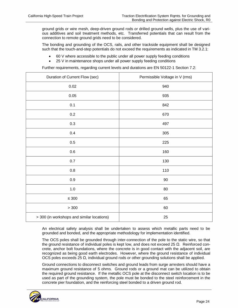
3.4 GENERAL OVERHEAD CONTACT SYSTEM GROUNDING The bonding and grounding of the OCS support structures, rails, and other trackside equipments shall be designed such that the touch-and-step potentials do not exceed the requirements as in-dicated in TM 3.2.1:
60 V where accessible to the public under all power supply feeding conditions 25 V in maintenance shops under all power supply feeding conditions
Further requirements, regarding current levels and durations are detailed in EN 50122-1 Section 7.2:
Duration of Current Flow (sec) Permissible Voltage in V (rms)
0.02 940
0.05 935
0.1 842
0.2 670
0.3 497
0.4 305
0.5 225
0.6 160
0.7 130
0.8 110
0.9 90
1.0 80
300 65
> 300 60
> 300 (in workshops and similar locations) 25
An electrical safety analysis shall be undertaken to assess which metallic parts need to be grounded and bonded, and the appropriate methodology for implementation defined.
Per AREMA Chapter 33, Part 12.3.3.1.17 a, generally, footing resistance of individual structures should be maintained at a maximum of 25 ohms. The bolted base OCS poles shall be grounded through the normal mechanical inter-connection of the pole to its steel reinforced concrete foun-dation, such that the ground resistance of individual poles is kept low, and does not exceed 25 .
California High-Speed Train Project Traction Electrification System Rqmts. for Grounding and Bonding and Protection against Electric Shock, R0
Page 12
Reinforced concrete, anchor bolt foundations, where the concrete is in good contact with the ad-jacent soil, are recognized as being good earth electrodes. However, where the ground resis-tance of individual OCS poles exceeds 25 , individual ground rods or other grounding solutions shall be applied. In addition, all OCS structural supports – poles, wall brackets, drop pipes, etc. – shall be inter-connected to the static wire.
Per AREMA Chapter 33, Part 12.3.3.1.17 b, ground connections to disconnect switches and ground leads from surge arresters should have a maximum ground resistance of 5 ohms. Ground rods or a ground mat can be utilized to obtain the required ground resistance. If the me-tallic OCS pole at the disconnect switch location is to be used as part of the grounding system, the pole must be bonded to the steel reinforcement in the concrete pier foundation, and the rein-forcing steel bonded to a driven ground rod.
There are numerous locations along the CHSTP corridors where transit systems are operated by dc traction power and their tracks are located adjacent to the CHSTP track alignment, such as in San Francisco with MUNI, throughout the Bay area by BART, in Sacramento by RTD, in San Jose by VTA, and in San Diego by MTDB. At these locations, a considerable degree of coordina-tion will be required with the dc traction system operator to minimize the possibility of creating dc stray current circuit paths through the ac system traction power return circuits. To achieve this objective, the static wire in the area affected by dc stray currents shall be electrically insulated from the OCS poles by supporting the static wire on insulators. The OCS poles shall be grounded through inter-connection of the pole, anchor bolts and steel reinforcement of the con-crete foundation so that the ground resistance of individual poles is kept low, and does not ex-ceed 25 . Where the ground resistance of individual OCS poles exceeds 25 , individual ground rods or other grounding solutions shall be applied. Fault conditions shall be evaluated and grounding designs developed such that unsafe touch potentials are not created. Additionally, close coordination shall be maintained with any adjacent dc track authority so that a high level of insulation is maintained between the dc system rails and ground to minimize dc stray current lea-kage.
Further coordination will be needed with the dc system operator where CHSTP passenger plat-forms are located adjacent to dc system tracks. If inadmissible touch/accessible voltages could still occur between the rail and ground, the final designer should investigate whether a voltage-limiting device, such as non-permanent rail to ground connection, should be installed to control touch potential during an ac fault condition and also to limit the uncontrolled dc stray current.
All of the above measures need to be coordinated with the train control system supplier so that the integrity of the train control system is not compromised.
The following items show the general bonding requirements for the traction electrification system:
Exothermically weld buried ground connections. Use terminal lugs to connect grounding conductors to equipment enclosures. Secure
connector or terminal lugs to the conductors in order to engage all strands equally by us-ing tools and pressure recommended by the manufacturer.
Exothermically weld connections to ground rods in manholes or handholes. Splices in grounding conductors shall not be permitted.
3.5 PLATFORM GROUNDING SYSTEM In order to minimize the possibility of interference with broken rail detection, all metallic structures and miscellaneous metallic items located on passenger platforms, including any OCS poles shall be isolated from the static wire and connected to the platform grounding system - counterpoise. The grounding design shall ensure the maximum permissible touch potentials, as specified here-in, are not exceeded and without exception the resistance to ground shall not exceed 5 ohms. Ground rods might need to be installed at the ends of the counterpoise. Where multiple groun-ding rods are required, they shall be installed at 10-foot spacing.
If OCS poles are located on platforms, the OCS structures for each track shall be directly or indi-rectly connected to the adjacent counterpoise. Underground connections to counterpoise con-
California High-Speed Train Project Traction Electrification System Rqmts. for Grounding and Bonding and Protection against Electric Shock, R0
Page 13
ductors and ground rods shall be of the exothermic weld type. Connections to rebar and ground rods to be cast in concrete shall be of the exothermic weld type.
For platform grounding, a counterpoise shall be installed along the entire length of each platform with extensions beyond the end of the platform, and shall be connected to the rails at one end on-ly via an impedance bond with further coordination with train control operation. The counterpoise shall be buried in earth. It could be buried below the platform or, where appropriate behind and clear of the platform to facilitate any required future maintenance, but should not be located on the track-side where it could interfere with the track structure.
According to THSRC, all metallic items within 4 m (13’- 2”) from the centerline of track shall be bonded to the counterpoise. With a 5’- 9” (1.75 m) offset from the centerline of the track to the edge of the passenger platform, this requirement means that all metallic items within 7’- 5” (2.25 m) from the edge of the platform are to be bonded to the counterpoise.
Accordingly, for the CHSTP, all metallic items within 8’ (2.44 m) from the edge of the platform shall be bonded to the counterpoise. The counterpoise-bonded metallic items shall be kept iso-lated from other building steel and particularly from utility grounds.
3.6 STRUCTURE GROUNDING AND BONDING REQUIREMENTS Structure grounding and bonding should create a conductive path that will achieve potential equa-lization of the grounded elements of the railway system. Grounding connections provide for tying lineside normally-non-current-carrying metallic parts located within 13’- 2” (4 m) of the centerline of the track to the return circuit (through OCS poles) and for the electrical interconnection of rein-forcing rods in concrete structures, and in case of other modes of construction, the conductive in-terconnection of the metallic parts. The structure grounding system provides grounding connec-tions for:
high/medium-voltage protective ground low-voltage protective ground lightning protection ground
Signal apparatus, including any wayside signal structures, may be electrically connected to the static wire or to the center taps of impedance bonds by the Train Control System Contractor as called out in the Train Control Design Criteria.
All non-current-carrying structural components that lie within the overhead contact line zone or the pantograph zone (see Section 3.7.1) shall be either directly grounded or be bonded to the static wire to provide for personnel safety.
For tunnel sections, all metallic drop pipes or brackets which support the OCS cantilevers, shall be bonded to the static wire. Where underwater crossings are encountered, the static wire shall be grounded beyond the underwater crossing areas. For long tunnels, additional grounds and/or an additional along-tunnel ground wire(s) might be required to meet the ground resistance re-quirements and/or to minimize the possibility that rail potentials may cause unacceptable touch-and-step voltages. If these additional ground conductors are laid at low level – adjacent to the track or along the walkways – these conductors will also supplement the grounding capability of the system, and fault detection and control in the event of a broken wire condition. In order to provide a sufficiently low ground resistance, it may be necessary to install a ground grid at or near to the tunnel portals. Where the reinforcing rods in the tunnel structures can be inter-connected longitudinally, such as in cut-and-cover construction, or the tunnel is built in sections (with gaps along the length), each section shall be connected to the return circuit static wire or the sections shall be connected together and then connected to the static wire.
For viaduct or under-bridge structures, over which the high speed trains run, the static wire shall be electrically grounded through the bridge columns or the abutments. The bored piles or rein-forcing rods of the viaduct or bridge column foundations can be considered to form the grounding system of viaduct sections. The reinforcement in the support column foundation shall be electri-cally connected to the reinforcement of the column and to the reinforcement in the viaduct seg-ments or beams. The reinforcing rods in each concrete section shall be connected together and
California High-Speed Train Project Traction Electrification System Rqmts. for Grounding and Bonding and Protection against Electric Shock, R0
Page 14
connected to the anchor bolts for the OCS poles, which are also to be connected to the static wire as part of the return circuit.
For personnel safety and lightning protection, all metallic items in tunnels or on viaducts need to be bonded either directly or indirectly to the static wire. To coordinate with the broken rail detec-tion requirements, insulated joints or couplers might need to be installed in longitudinal and trans-verse metallic items, which might connect both tracks or connect both static wires. The grounding and bonding of the emergency walkway area and other publicly accessible areas shall be de-signed to avoid inadmissible touch and step voltages and also to meet the requirements of the signaling system.
At some locations, the CHSTP alignment will pass under existing reinforced concrete over-bridges, Since the bridge structure will lie within the overhead contact line and pantograph zone (see Section 3.7.1), special grounding provisions may be required to protect the structure and ad-jacent third party utility installations. These measures may include provision of:
Galvanized steel strip on both bridge walls, if these are located in the overhead contact line zone
Galvanized steel strip or angle section profile above the overhead line at the start and end of the bridge if the bridge roof is within the pantograph zone
Protective fence or projecting contact protection (as shown in Section 3.7) on the bridge sides
These metallic parts shall be connected at two points to the static wire.
For existing or new steel bridges, the steel girders shall be interconnected and bonded to the stat-ic wire.
For maintenance and storage facilities buildings, grounding devices shall be provided at building entrance points. These shall be in the form of three-position disconnect switches, providing for Closed (to inter-connect to the adjacent electrical section), Open (no electrical inter-connection), and Closed to Ground, with one disconnect per shop track electrical section and with inter-linked indication lights on a per section basis, so that maintenance personnel can see clearly which sec-tions of the OCS are energized and which are grounded. These disconnects shall be provided with bars that will accept multiple locks so that more than one maintainer can apply his/her per-sonal lock to ensure the switches are not operated while someone is working.
3.7 PROTECTION AGAINST ELECTRIC SHOCK Protection against electric shock can be achieved by establishing adequate safety clearances to minimize the possibility of direct contact with energized parts, and/or by erecting suitable barriers or screens to prevent direct contact, and installing appropriate signs warning of the potential dan-gers.
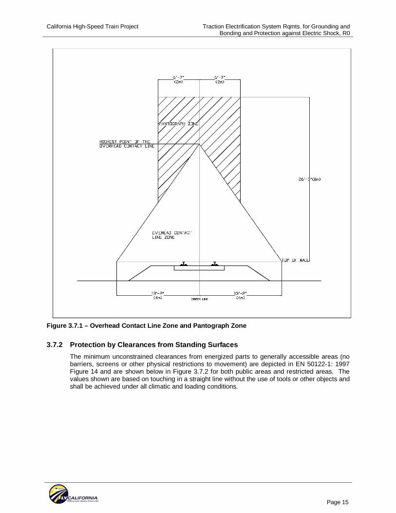
3.7.1 Overhead Contact Line Zone and Pantograph Zone Structures and equipment may accidentally come into contact with a live broken contact line, or with the live parts of a broken or de-wired pantograph or broken fragments. Figure 3.7.1 defines the zone inside which such contact is considered probable and whose limits shall not be ex-ceeded, in general, by a broken overhead contact line or by an energized pantograph. The pan-tograph may be live because it is inter-connected with other energized pantographs or because the train is in regenerative braking mode. The limits of the overhead contact line zone below top of rail extend vertically down to the earth surface, except where the tracks are located on a via-duct. In the case of out of running OCS conductors, the overhead contact line zone shall be ex-tended accordingly.
California High-Speed Train Project Traction Electrification System Rqmts. for Grounding and Bonding and Protection against Electric Shock, R0
Page 15
Figure 3.7.1 – Overhead Contact Line Zone and Pantograph Zone
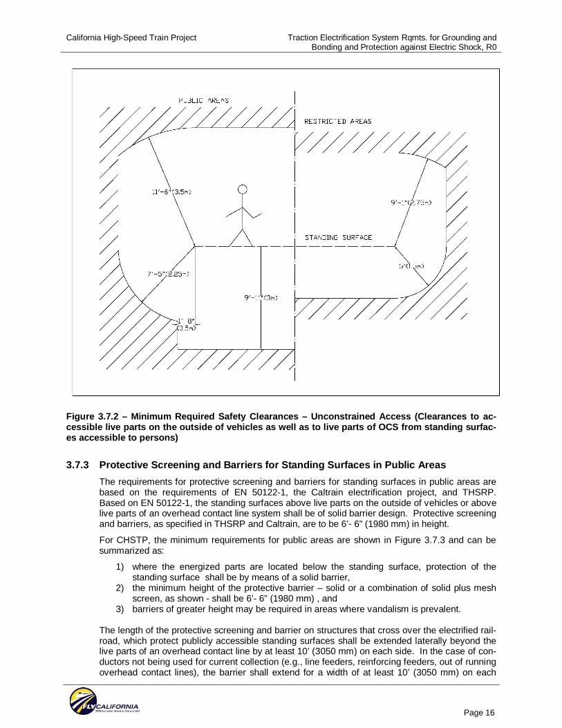
3.7.2 Protection by Clearances from Standing Surfaces The minimum unconstrained clearances from energized parts to generally accessible areas (no barriers, screens or other physical restrictions to movement) are depicted in EN 50122-1: 1997 Figure 14 and are shown below in Figure 3.7.2 for both public areas and restricted areas. The values shown are based on touching in a straight line without the use of tools or other objects and shall be achieved under all climatic and loading conditions.
California High-Speed Train Project Traction Electrification System Rqmts. for Grounding and Bonding and Protection against Electric Shock, R0
Page 16
Figure 3.7.2 – Minimum Required Safety Clearances – Unconstrained Access (Clearances to ac-cessible live parts on the outside of vehicles as well as to live parts of OCS from standing surfac-es accessible to persons)
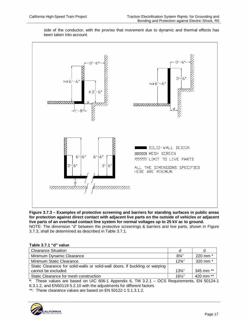
3.7.3 Protective Screening and Barriers for Standing Surfaces in Public Areas The requirements for protective screening and barriers for standing surfaces in public areas are based on the requirements of EN 50122-1, the Caltrain electrification project, and THSRP. Based on EN 50122-1, the standing surfaces above live parts on the outside of vehicles or above live parts of an overhead contact line system shall be of solid barrier design. Protective screening and barriers, as specified in THSRP and Caltrain, are to be 6’- 6” (1980 mm) in height.
For CHSTP, the minimum requirements for public areas are shown in Figure 3.7.3 and can be summarized as:
1) where the energized parts are located below the standing surface, protection of the standing surface shall be by means of a solid barrier,
2) the minimum height of the protective barrier – solid or a combination of solid plus mesh screen, as shown - shall be 6’- 6” (1980 mm) , and
3) barriers of greater height may be required in areas where vandalism is prevalent.
The length of the protective screening and barrier on structures that cross over the electrified rail-road, which protect publicly accessible standing surfaces shall be extended laterally beyond the live parts of an overhead contact line by at least 10’ (3050 mm) on each side. In the case of con-ductors not being used for current collection (e.g., line feeders, reinforcing feeders, out of running overhead contact lines), the barrier shall extend for a width of at least 10’ (3050 mm) on each
California High-Speed Train Project Traction Electrification System Rqmts. for Grounding and Bonding and Protection against Electric Shock, R0
Page 17
side of the conductor, with the proviso that movement due to dynamic and thermal effects has been taken into account.
Figure 3.7.3 – Examples of protective screening and barriers for standing surfaces in public areas for protection against direct contact with adjacent live parts on the outside of vehicles or adjacent live parts of an overhead contact line system for normal voltages up to 25 kV ac to ground. NOTE: The dimension “d” between the protective screenings & barriers and live parts, shown in Figure 3.7.3, shall be determined as described in Table 3.7.1. Table 3.7.1 “d” value Clearance Situation d d Minimum Dynamic Clearance 8¾” 220 mm * Minimum Static Clearance 12¾” 320 mm * Static Clearance for solid-walls or solid-wall doors, if buckling or warping cannot be excluded 13¾” 345 mm ** Static Clearance for mesh construction 16½” 420 mm **
*: These values are based on UIC 606-1 Appendix 6, TM 3.2.1 – OCS Requirements, EN 50124-1 6.3.1.2, and EN50119 5.2.10 with the adjustments for different factors **: These clearance values are based on EN 50122-1 5.1.3.1.2.
California High-Speed Train Project Traction Electrification System Rqmts. for Grounding and Bonding and Protection against Electric Shock, R0
Page 18
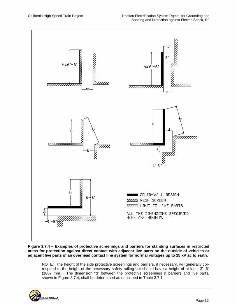
3.7.3 Protective Screening and Barriers for Standing Surfaces in Restricted Areas The requirements for protective screening and barriers for standing surfaces in restricted areas are mainly based on EN 50122-1 and are shown in Figure 3.7.4. For standing surfaces above live parts on the outside of vehicles or above live parts of an overhead contact line system, the protection shall be of solid barrier construction. The length of the solid barrier, protecting the standing surface, shall correspond to the pantograph zone and shall extend beyond the live parts of an overhead contact line by at least 1’- 8” (508 mm). In the case of conductors not being used for current collection (e.g., line feeders, reinforcing feeders, out of running overhead contact lines), the barrier shall extend for a width of at least 1’- 8” (508 mm) on each side of the conduc-tor, with the proviso that movement due to dynamic and thermal effects shall be taken into ac-count. The height “h” of the protective screening and barrier shall be such that a clearance of 5’ (1524 mm) from the top of the protective screening and barrier is maintained (see Figure 3.7.4).
California High-Speed Train Project Traction Electrification System Rqmts. for Grounding and Bonding and Protection against Electric Shock, R0
Page 19
Figure 3.7.4 – Examples of protective screenings and barriers for standing surfaces in restricted areas for protection against direct contact with adjacent live parts on the outside of vehicles or adjacent live parts of an overhead contact line system for normal voltages up to 25 kV ac to earth.
NOTE: The height of the side protective screenings and barriers, if necessary, will generally cor-respond to the height of the necessary safety railing but should have a height of at least 3’- 6” (1067 mm). The dimension “d” between the protective screenings & barriers and live parts, shown in Figure 3.7.4, shall be determined as described in Table 3.7.1.
California High-Speed Train Project Traction Electrification System Rqmts. for Grounding and Bonding and Protection against Electric Shock, R0
Page 20
3.7.4 Additional Requirements for Overhead Structure Protection Barriers and Screens Protection barriers or screens shall be of sufficient strength and shall be supported rigidly and se-curely enough to prevent them from being displaced or dangerously deflected by a person slip-ping or falling against them.
Barriers and screens shall be permanently fixed, and shall be removable only with tools. Barriers in public areas shall employ non-removable, captive fasteners.
Barriers shall be of solid construction and be fabricated from either conductive or non-conductive materials.
Non-conductive barriers shall be surrounded by a grounded, bare conductor that is intercon-nected with the traction system ground, preferably at not less than two locations.
Conductive barriers and mesh screens shall be bonded and grounded by interconnection with the traction system ground, preferably at not less than two locations.
Screens shall be of grounded, conductive, open mesh materials. Non-conductive mesh or plas-tic-coated metal mesh shall not be used.
Conductive mesh screens shall be constructed such that a cylinder, greater than ½ in. (13 mm) in diameter, cannot be pushed through the mesh. Mesh screen construction shall be such that re-quired clearances to energized parts are maintained.
The style of barrier to be employed is dependent upon type of standing surface and its proximity to the energized parts, and whether the surface provides for public or restricted access.
The size of the barrier or screen shall be such that energized parts cannot be touched in a straight line by persons on a standing surface.
Where there is public access or trespass is likely, anti-climbing protection shall be provided at buildings and other structures supporting energized parts of the OCS. The anti-climbing protec-tion should include signs warning of the dangers of high voltage.
Access to fixed ladders, particularly at signal poles and signal gantries, and the means of access to any roof or other place, which could allow non-authorized persons to approach energized parts, shall be secured or otherwise protected.
The design of the protective screens and barriers shall minimize the loading on existing structures and any adverse visual impact.
The metallic part of the overhead bridge screening and barriers shall be bonded to static wires. All other metallic items on the overhead bridge, within a lateral distance of 10 ft. from any ener-gized and uninsulated equipment passing below the structure, shall be directly or indirectly bonded to static wire.
California High-Speed Train Project Traction Electrification System Rqmts. for Grounding and Bonding and Protection against Electric Shock, R0
Page 21
4.0 SUMMARY AND RECOMMENDATIONS
The purpose of this section is to provide criteria for design of grounding and bonding systems that will minimize touch voltages and ground return currents caused by the CHSTP system, so as to provide for the safety of passengers and operating personnel and to minimize the hazards due to electrical shock.
The grounding systems of all traction power facilities shall be designed based on IEEE Standard 80 (and NESC/NEC as applicable).
The OCS poles shall be grounded through the normal mechanical inter-connection of the pole to its steel reinforced concrete foundation, such that the ground resistance of individual poles is kept low, and does not exceed 25 . Where the ground resistance of individual OCS poles exceeds 25 , individual ground rods or other grounding solutions shall be applied. In addition, all OCS structural supports – poles, wall brackets, drop pipes, etc. – shall be inter-connected to the static wire.
The OCS poles shall be bonded to the static wire, except in passenger station platform areas and in the areas affected by dc stray currents. The static wire shall be connected to the track rails through impedance bonds at locations acceptable to the signal system designer. The static wire shall also be connected to the ground grids at traction power substations, switching stations, and paralleling stations through impedance bonds. Additional connections to the rails through imped-ance bonds might be required depending on the traction power load flow simulation results.
There are numerous locations along the CHSTP corridors where transit systems are operated by dc traction power and their tracks are located adjacent to the CHSTP track alignment, such as in San Francisco with MUNI, throughout the Bay area by BART, in Sacramento by RTD, in San Jose by VTA, and in San Diego by MTDB. At these locations, a considerable degree of coordina-tion will be required with the dc traction system operator to minimize the possibility of creating dc stray current circuit paths through the ac system traction power return circuits. To achieve this objective, the static wire in the area affected by dc stray currents shall be electrically insulated from the OCS poles by supporting the static wire on insulators. The OCS poles shall be grounded through inter-connection of the pole, anchor bolts and steel reinforcement of the con-crete foundation so that the ground resistance of individual poles is kept low, and does not ex-ceed 25 . Where the ground resistance of individual OCS poles exceeds 25 , individual ground rods or other grounding solutions shall be applied. Fault conditions shall be evaluated and grounding designs shall be developed such that unsafe touch potentials are not created. Additionally, close coordination shall be maintained with any adjacent dc track authority so that a high level of insulation is maintained between the dc system rails and ground to minimize dc stray current leakage.
A counterpoise grounding system shall be installed for each passenger station platform. All me-tallic items within 8’ (2438 mm) from the track-side edge of the platform, including any OCS poles on the platform, shall be directly or indirectly connected to the counterpoise. Depending on the signaling system, at least one end of the counterpoise would need to be connected to the rail through impedance bonds as coordinated with the train control designer. The static wire on the platform shall be isolated from the poles and the counterpoise.
When the vertical clearance between OCS conductors and overhead concrete bridges is less than 3 ft (915 mm), protection panels shall be installed. Steel overhead bridges shall be bonded to the static wire.
Publicly accessible bridges shall be protected by screening and/or barriers which shall be at least 6’- 6” (1980 mm) high and extend laterally beyond the live parts of an overhead contact line by at least 10’ (3048 mm) on each side. The metallic portion of the screening and barriers shall be bonded to the static wire. All other metallic items on the overhead bridge, within the lateral range of not less than 10 ft. (3048 mm) beyond any energized and uninsulated equipment passing be-low the structure, shall be directly or indirectly bonded to the static wire.
California High-Speed Train Project Traction Electrification System Rqmts. for Grounding and Bonding and Protection against Electric Shock, R0
Page 22
5.0 SOURCE INFORMATION AND REFERENCES
Energy Technical Specification for Interoperability of European High Speed Rail System CHSTP Basis of Design Policy – California High Speed Rail Program – Jan 08 Technical Memorandum TM 1.1.10 Structure Gauge Technical Memorandum TM 3.2.3.3 Pantograph Clearance Envelopes California Public Utilities Commission General Order 26-D California Public Utilities Commission General Order 95 National Electrical Safety Code IEC 60479: Effects of Current on Human Beings and Livestock – Part 1 General Aspects IEEE Std 80: IEEE Guide for Safety in AC Substation Grounding IEEE Std 81: IEEE Guide for Measuring Earth Resistivity, Ground Impedance, and Earth
Surface Potentials of a Ground System (Part 1) IEEE Std 142: IEEE Recommended Practice for Grounding of Industrial and Commercial
Power systems (IEEE Green Book) NFPA Standard 70: National Electrical Code (as applicable) NFPA Standard 780: Standard for Installation of Lightning Protection Systems International Building Code EN 50119:2001 EN 50122-1:2001 EN 50124-1:2001 UIC 606-1 OR The Manual for Railway Engineering of the American Railway Engineering and Mainten-
ance of Way Association (AREMA Manual)
California High-Speed Train Project Traction Electrification System Rqmts. for Grounding and Bonding and Protection against Electric Shock, R0
Page 23
6.0 DESIGN CRITERIA MANUAL
6.1 GENERAL TES GROUNDING The purpose of this section is to provide criteria for the design of grounding and bonding systems that will minimize touch-and-step voltages and ground return currents caused by the CHSTP sys-tem to provide for the safety of passenger and operating personnel and protect them from elec-trical shock. In addition, the grounding and bonding system designs shall provide the means to carry electric currents into the earth under normal and fault conditions without exceeding any op-erating and equipment limits or adversely affecting continuity of service
Where insulated cables are used within the TES, they shall be specified and manufactured in ac-cordance with the appropriate electrical standards that are applicable to the working environment – voltages, operating and fault currents - to which they will be subjected.
The bolted base OCS poles shall be grounded through the normal mechanical inter-connection of the pole to its steel reinforced concrete foundation, such that the ground resistance of individual poles is kept low, and does not exceed 25 . Reinforced concrete, anchor bolt foundations, where the concrete is in good contact with the adjacent soil, are recognized as being good earth electrodes. However, where the ground resistance of individual OCS poles exceeds 25 , indi-vidual ground rods or other grounding solutions shall be applied. In addition, all OCS structural supports – poles, wall brackets, drop pipes, etc. – shall be inter-connected to the static wire.
In addition to the grounding of the OCS poles and support brackets through the static wire, the rails are also connected to the static wire through impedance bonds near substations, switching stations, and paralleling stations. Additional periodic connections between the static wire and the rails through impedance bonds may be needed based on the traction power load flow simulation results and the touch/step analysis. The spacing of these inter-connections to the rails must be coordinated with the operating requirements of the signaling system.
The grounding systems of all traction power facilities shall be designed based on IEEE Standard 80 (and NESC/NEC as applicable).
The ground grid for each TPF and the center tap of the secondary of main power transformers and center tap of autotransformers shall be connected to the rails through impedance bonds, and to both static wires through two independent connections.
All buried/underground joints in grounding conductors and connections shall be exothermically welded.
All normally-non-current-carrying conductive parts of manholes, handholes, pull boxes, splice boxes, metallic raceway and/or cable tray systems shall be bonded and grounded.
All perimeter fences and gates at TPFs shall be effectively grounded and bonded to the groun-ding system of the TPF.
Wayside power cubicles (WPC) shall be grounded by separately driven ground rods at opposite corners, and connected to grounding pads.
Ground test station shall be incorporated into the ground grid design at all traction power facilities and wayside power cubicles, and these shall be located so that they are accessible to O&M per-sonnel.
Each traction power facility shall be provided with appropriate lightning protection measures, based upon the incidence of lightning strikes in the area local to each TPF, and the lightning pro-tection measures shall be grounded in accordance with the recommendations of the equipment manufacturer, NFPA – 780, NEC and NESC.
The electrodes used to ground lightning protection systems shall not be the same as those used for traction power electrical system grounding, but the electrodes from both systems shall be bonded together.
In areas where soil resistivity is high or the substation space is limited, alternative methods should be considered for obtaining low impedance grounding, such as connections to remote
California High-Speed Train Project Traction Electrification System Rqmts. for Grounding and Bonding and Protection against Electric Shock, R0
Page 24
ground grids or wire mesh, deep-driven ground rods or drilled ground wells, plus the use of vari-ous additives and soil treatment methods, etc. Transferred potentials that can result from the connection to remote ground grids need to be considered.
The bonding and grounding of the OCS, rails, and other trackside equipment shall be designed such that the touch-and-step potentials do not exceed the requirements as indicated in TM 3.2.1:
60 V where accessible to the public under all power supply feeding conditions 25 V in maintenance shops under all power supply feeding conditions
Further requirements, regarding current levels and durations are EN 50122-1 Section 7.2:
Duration of Current Flow (sec) Permissible Voltage in V (rms)
0.02 940
0.05 935
0.1 842
0.2 670
0.3 497
0.4 305
0.5 225
0.6 160
0.7 130
0.8 110
0.9 90
1.0 80
300 65
> 300 60
> 300 (in workshops and similar locations) 25
An electrical safety analysis shall be undertaken to assess which metallic parts need to be grounded and bonded, and the appropriate methodology for implementation identified.
The OCS poles shall be grounded through inter-connection of the pole to the static wire, so that the ground resistance of individual poles is kept low, and does not exceed 25 . Reinforced con-crete, anchor bolt foundations, where the concrete is in good contact with the adjacent soil, are recognized as being good earth electrodes. However, where the ground resistance of individual OCS poles exceeds 25 , individual ground rods or other grounding solutions shall be applied.
Ground connections to disconnect switches and ground leads from surge arresters should have a maximum ground resistance of 5 ohms. Ground rods or a ground mat can be utilized to obtain the required ground resistance. If the metallic OCS pole at the disconnect switch location is to be used as part of the grounding system, the pole must be bonded to the steel reinforcement in the concrete pier foundation, and the reinforcing steel bonded to a driven ground rod.
California High-Speed Train Project Traction Electrification System Rqmts. for Grounding and Bonding and Protection against Electric Shock, R0
Page 25
There are numerous locations along the CHSTP corridors where transit systems are operated by dc traction power and their tracks are located adjacent to the CHSTP track alignment, such as in San Francisco with MUNI, throughout the Bay area by BART, in Sacramento by RTD, in San Jose by VTA, and in San Diego by MTDB. At these locations, a considerable degree of coordina-tion will be required with the dc traction system operator to minimize the possibility of creating dc stray current circuit paths through the ac system traction power return circuits. To achieve this objective, the static wire in the area affected by dc stray currents shall be electrically insulated from the OCS poles by supporting the static wire on insulators. The OCS poles shall be grounded through inter-connection of the pole, anchor bolts and steel reinforcement of the con-crete foundation so that the ground resistance of individual poles is kept low, and does not ex-ceed 25 . Where the ground resistance of individual OCS poles exceeds 25 , individual ground rods or other grounding solutions shall be applied. Fault conditions shall be evaluated and grounding designs shall be developed such that unsafe touch potentials are not created. Addi-tionally, close coordination shall be maintained with the dc track authority so that a high level of insulation is maintained between the dc system rails and ground to minimize dc stray current lea-kage.
Further coordination will be needed with the dc system operator where CHSTP passenger plat-forms are located adjacent to dc system tracks. If inadmissible touch/accessible voltages could still occur between the rail and ground, the final designer should investigate whether a voltage-limiting device, such as non-permanent rail to ground connection, should be installed to control touch potential during an ac fault condition and also limit the uncontrolled dc stray current.
All of the above measures need to be coordinated with the train control supplier to assure that the integrity of the train control system is not compromised.
The following items show the general bonding requirements:
Exothermically weld buried ground connections. Use terminal lugs to connect grounding conductors to equipment enclosures. Secure
connector or terminal lugs to the conductors in order to engage all strands equally by us-ing tools and pressure recommended by the manufacturer.
Exothermically weld connections to ground rods in manholes or handholes. Splices in grounding conductors are not permitted.
6.2 PLATFORM GROUNDING SYSTEM All metallic structures and miscellaneous metallic items located on passenger platforms, including any OCS poles, shall be isolated from the static wire and connected to the platform grounding system - counterpoise. The grounding design shall ensure the maximum permissible touch poten-tials, as specified herein, are not exceeded and without exception the resistance to ground shall not exceed 5 ohms. Ground rods might need to be installed at the ends of the counterpoise. Where multiple grounding rods are required, they shall be installed at 10-foot spacing.
If OCS poles are located on platforms, the OCS structures for each track shall be directly or indi-rectly connected to the adjacent counterpoise. Underground connections to counterpoise con-ductors and ground rods shall be of the exothermic weld type. Connections to rebar and ground rods to be cast in concrete shall be of the exothermic weld type.
For platform grounding, a counterpoise shall be installed along the entire length of each platform with extensions beyond the end of the platform, and shall be connected to the rails at one end on-ly via an impedance bond with further coordination with train control operation. The counterpoise shall be buried in earth. It could be buried below the platform or, where appropriate behind and clear of the platform to facilitate any required future maintenance, but should not be located on the track-side where it could interfere with the track structure. All the metallic items within 8’ (2438 mm) from the edge of the platform shall be bonded directly or indirectly to the counterpoise for CHSTP. The counterpoise-bonded metallic items shall be kept isolated from other building steel and particularly from utility grounds
California High-Speed Train Project Traction Electrification System Rqmts. for Grounding and Bonding and Protection against Electric Shock, R0
Page 26
6.3 STRUCTURE GROUNDING AND BONDING REQUIREMENTS Structure grounding and bonding should create a conductive path that will achieve potential equa-lization of the grounded elements of the railway system. Grounding connections provide for tying lineside metallic parts to the return circuit and for the electrical interconnection of reinforcing rods in concrete structures, and in case of other modes of construction, the conductive interconnection of the metallic parts. The structure grounding system provides grounding connections for:
high/medium-voltage protective ground low-voltage protective ground lightning protection ground
Signal apparatus, including any wayside signals, may be electrically connected to the static wire or center taps of impedance bonds by the Train Control Contractor as called out in the Train Con-trol Design Criteria.
Any component of structures within the overhead contact line and pantograph zone (see Section 6.4.1) shall be either directly grounded or be bonded to the static wire to ensure personnel safety.
For tunnel sections, all metallic drop pipes or brackets, which support the OCS cantilevers, shall be bonded to the static wire. Where underwater crossings are encountered, the static wire shall be grounded beyond the underwater crossing areas. For long tunnels, additional grounds and/or an additional along-tunnel ground wire(s) might be required to meet the ground resistance re-quirements and/or to minimize the possibility that rail potentials may cause unacceptable touch voltages. If these additional ground conductors are laid at low level – adjacent to the track or along the walkways – these conductors will also supplement the grounding capability of the sys-tem, and fault detection and control in the event of a broken wire condition. In order to provide a sufficiently low ground resistance, it may be necessary to install a ground grid at or near to the tunnel portals. Where the reinforcing rods in the tunnel structures can be inter-connected longi-tudinally, such as in cut-and-cover construction, or the tunnel is built in sections (with gaps along the length), each section shall be connected to the return circuit static wire, or the sections shall be connected together and then connected to the static wire.
For viaduct or under-bridge structures, over which the high speed trains run, the static wire shall be electrically grounded through the bridge columns or the abutments. The reinforcement in the support column foundation shall be electrically connected to the reinforcement of the column and to the reinforcement in the viaduct segments or beams. The reinforcing rods in each concrete section shall be connected together and connected to the anchor bolts for the OCS poles, which are also connected to the static wire as part of the return circuit.
For personnel safety and lightning protection, all metallic items in tunnels or on viaducts need to be bonded either directly or indirectly to the static wire. To coordinate with the broken rail detec-tion requirements, insulated joints or couplers might need to be installed in longitudinal and trans-verse metallic items, which might connect both tracks or connect both static wires. The grounding and bonding of the emergency walkway area and other publicly accessible areas shall be de-signed to avoid inadmissible touch and step voltages and also to meet the requirements of the signaling system.
If components of overhead bridges lie within the overhead contact line and pantograph zone (see Section 6.4.1), then special grounding provisions are required to ensure personal safety.
Galvanized steel strip on both bridge walls, if these are located in the overhead contact line zone
Galvanized steel strip or angle section profile above the overhead line at the start and end of the bridge if the bridge roof is within the pantograph zone
Protective fence or projecting contact protection (as shown in Section 6.4) on the bridge sides
The metallic parts are connected at two points to the static wire.
For steel bridges, the steel girders shall be interconnected and bonded to the static wire.
California High-Speed Train Project Traction Electrification System Rqmts. for Grounding and Bonding and Protection against Electric Shock, R0
Page 27
For maintenance and storage facilities buildings, grounding devices shall be provided at building entrance points. These shall be in the form of three-position disconnect switches, providing for Closed (to inter-connect to the adjacent electrical section), Open (no electrical inter-connection), and Closed to Ground, with one disconnect per shop track electrical section and with inter-linked indication lights on a per section basis, so that maintenance personnel can see clearly which sec-tions of the OCS are energized and which are grounded. These disconnects shall be provided with bars that will accept multiple locks so that more than one maintainer can apply his/her per-sonal lock to ensure the switches are not operated while someone is working.
6.4 PROTECTION AGAINST ELECTRIC SHOCK Protection against electric shock can be achieved by establishing adequate safety clearances to minimize the possibility of direct contact with energized parts, and/or by erecting suitable barriers or screens to prevent direct contact, and installing appropriate signs warning of the potential dan-gers.
6.4.1 Overhead Contact Line Zone and Pantograph Zone Structures and equipment may accidentally come into contact with a live broken contact line, or with the live parts of a broken or de-wired pantograph or broken fragments. Figure 6.4.1 defines the zone inside which such contact is considered probable and whose limits shall not be ex-ceeded, in general, by a broken overhead contact line or by an energized pantograph. The pan-tograph may be live because it is inter-connected with other energized pantographs or because the train is in regenerative braking mode. The limits of the overhead contact line zone below top of rail extend vertically down to the earth surface, except where the tracks are located on a via-duct. In the case of out of running OCS conductors, the overhead contact line zone shall be ex-tended accordingly.
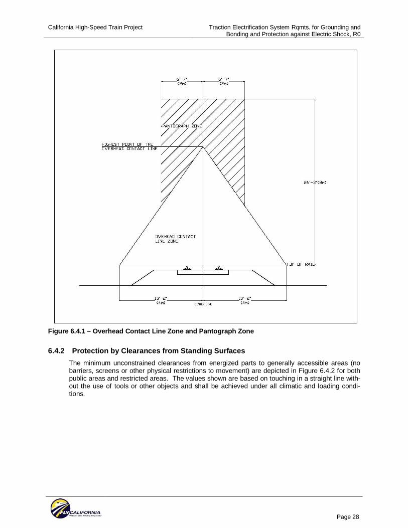
California High-Speed Train Project Traction Electrification System Rqmts. for Grounding and Bonding and Protection against Electric Shock, R0
Page 28
Figure 6.4.1 – Overhead Contact Line Zone and Pantograph Zone
6.4.2 Protection by Clearances from Standing Surfaces The minimum unconstrained clearances from energized parts to generally accessible areas (no barriers, screens or other physical restrictions to movement) are depicted in Figure 6.4.2 for both public areas and restricted areas. The values shown are based on touching in a straight line with-out the use of tools or other objects and shall be achieved under all climatic and loading condi-tions.
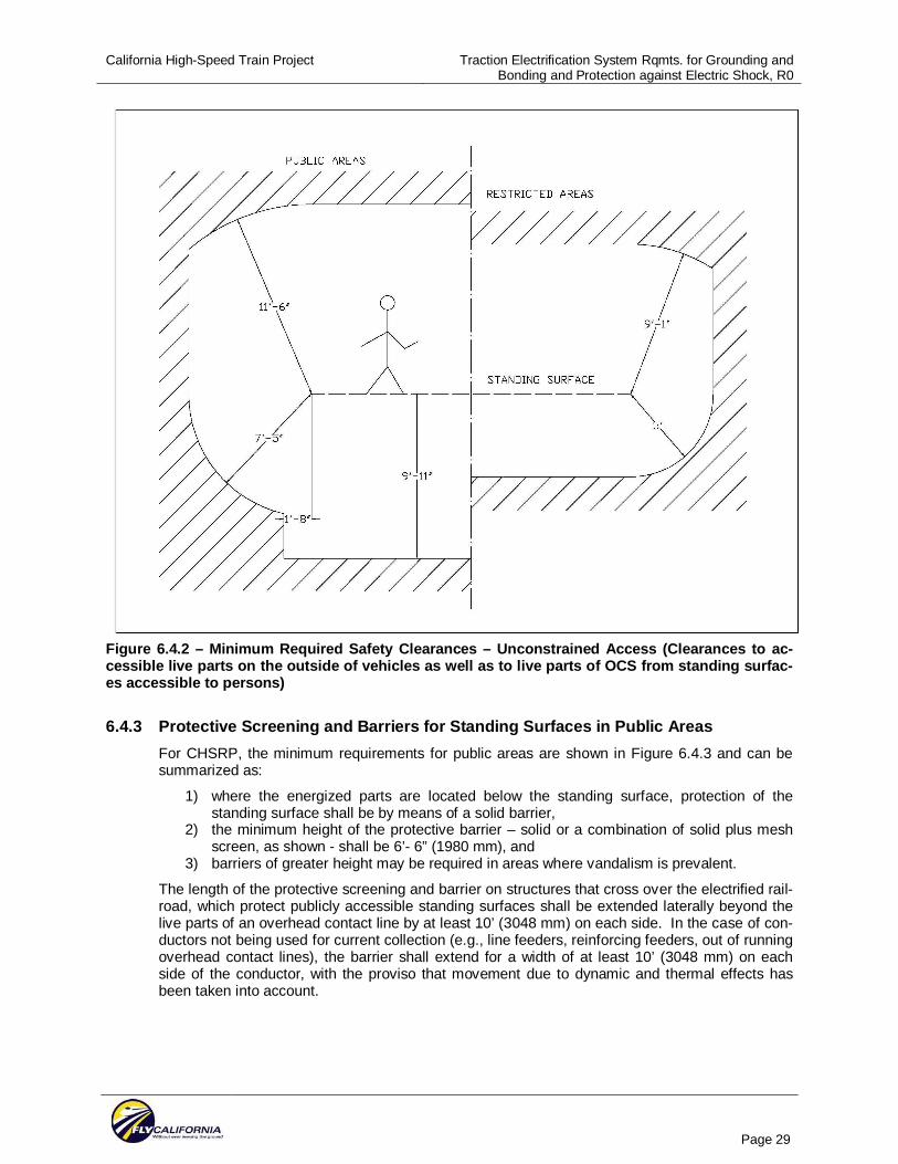
California High-Speed Train Project Traction Electrification System Rqmts. for Grounding and Bonding and Protection against Electric Shock, R0
Page 29
Figure 6.4.2 – Minimum Required Safety Clearances – Unconstrained Access (Clearances to ac-cessible live parts on the outside of vehicles as well as to live parts of OCS from standing surfac-es accessible to persons)
6.4.3 Protective Screening and Barriers for Standing Surfaces in Public Areas For CHSRP, the minimum requirements for public areas are shown in Figure 6.4.3 and can be summarized as:
1) where the energized parts are located below the standing surface, protection of the standing surface shall be by means of a solid barrier,
2) the minimum height of the protective barrier – solid or a combination of solid plus mesh screen, as shown - shall be 6’- 6” (1980 mm), and
3) barriers of greater height may be required in areas where vandalism is prevalent.
The length of the protective screening and barrier on structures that cross over the electrified rail-road, which protect publicly accessible standing surfaces shall be extended laterally beyond the live parts of an overhead contact line by at least 10’ (3048 mm) on each side. In the case of con-ductors not being used for current collection (e.g., line feeders, reinforcing feeders, out of running overhead contact lines), the barrier shall extend for a width of at least 10’ (3048 mm) on each side of the conductor, with the proviso that movement due to dynamic and thermal effects has been taken into account.
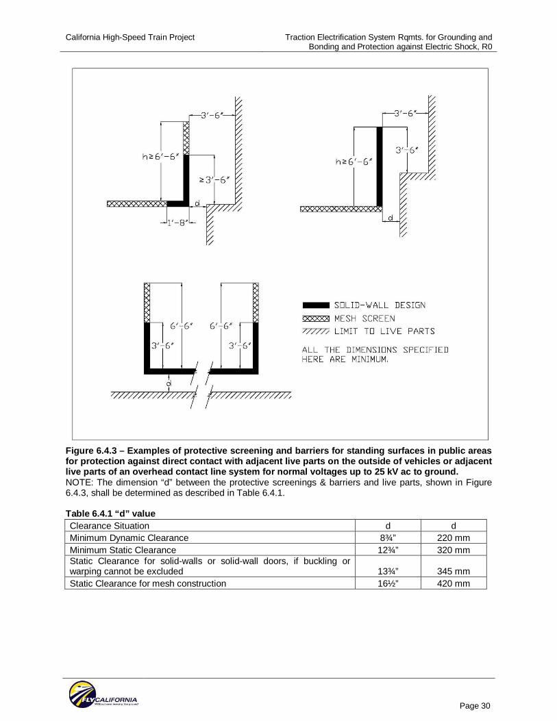
California High-Speed Train Project Traction Electrification System Rqmts. for Grounding and Bonding and Protection against Electric Shock, R0
Page 30
Figure 6.4.3 – Examples of protective screening and barriers for standing surfaces in public areas for protection against direct contact with adjacent live parts on the outside of vehicles or adjacent live parts of an overhead contact line system for normal voltages up to 25 kV ac to ground. NOTE: The dimension “d” between the protective screenings & barriers and live parts, shown in Figure 6.4.3, shall be determined as described in Table 6.4.1. Table 6.4.1 “d” value Clearance Situation d d Minimum Dynamic Clearance 8¾” 220 mm Minimum Static Clearance 12¾” 320 mm Static Clearance for solid-walls or solid-wall doors, if buckling or warping cannot be excluded 13¾” 345 mm Static Clearance for mesh construction 16½” 420 mm
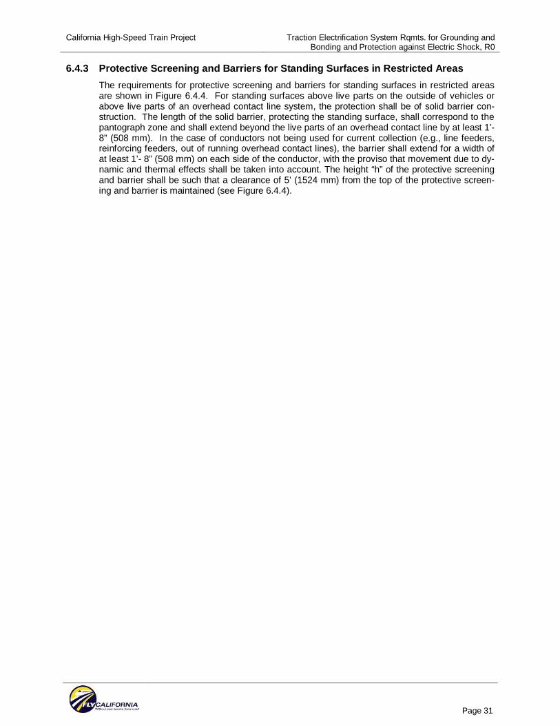
California High-Speed Train Project Traction Electrification System Rqmts. for Grounding and Bonding and Protection against Electric Shock, R0
Page 31
6.4.3 Protective Screening and Barriers for Standing Surfaces in Restricted Areas The requirements for protective screening and barriers for standing surfaces in restricted areas are shown in Figure 6.4.4. For standing surfaces above live parts on the outside of vehicles or above live parts of an overhead contact line system, the protection shall be of solid barrier con-struction. The length of the solid barrier, protecting the standing surface, shall correspond to the pantograph zone and shall extend beyond the live parts of an overhead contact line by at least 1’- 8” (508 mm). In the case of conductors not being used for current collection (e.g., line feeders, reinforcing feeders, out of running overhead contact lines), the barrier shall extend for a width of at least 1’- 8” (508 mm) on each side of the conductor, with the proviso that movement due to dy-namic and thermal effects shall be taken into account. The height “h” of the protective screening and barrier shall be such that a clearance of 5’ (1524 mm) from the top of the protective screen-ing and barrier is maintained (see Figure 6.4.4).
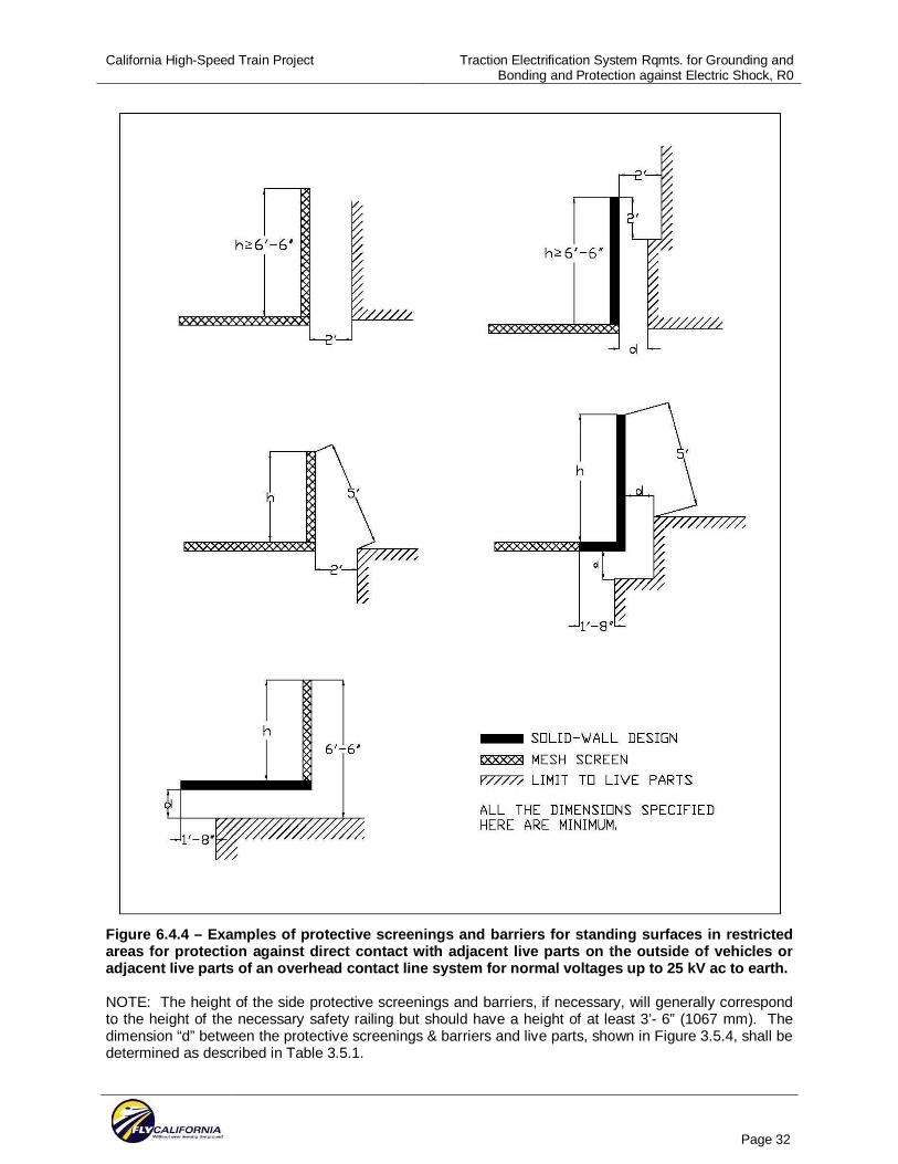
California High-Speed Train Project Traction Electrification System Rqmts. for Grounding and Bonding and Protection against Electric Shock, R0
Page 32
Figure 6.4.4 – Examples of protective screenings and barriers for standing surfaces in restricted areas for protection against direct contact with adjacent live parts on the outside of vehicles or adjacent live parts of an overhead contact line system for normal voltages up to 25 kV ac to earth. NOTE: The height of the side protective screenings and barriers, if necessary, will generally correspond to the height of the necessary safety railing but should have a height of at least 3’- 6” (1067 mm). The dimension “d” between the protective screenings & barriers and live parts, shown in Figure 3.5.4, shall be determined as described in Table 3.5.1.
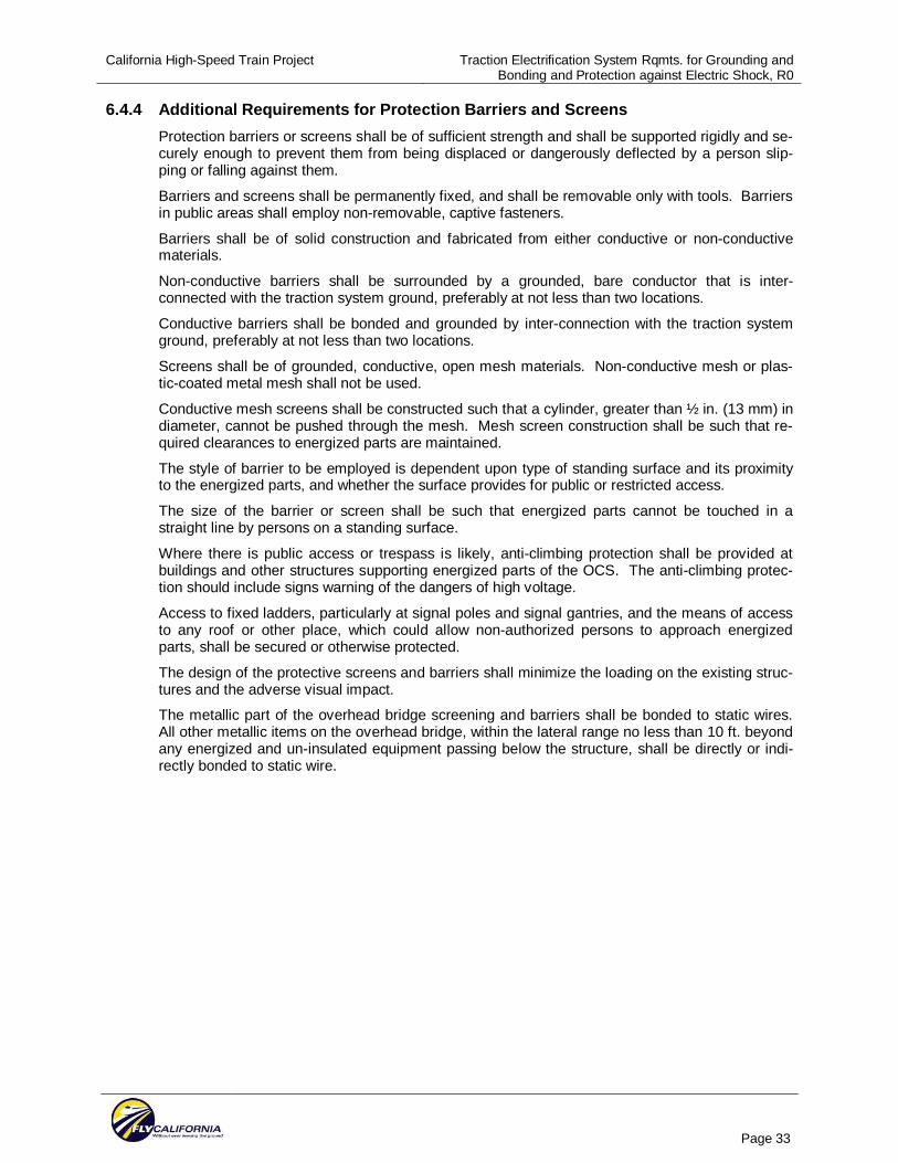
California High-Speed Train Project Traction Electrification System Rqmts. for Grounding and Bonding and Protection against Electric Shock, R0
Page 33
6.4.4 Additional Requirements for Protection Barriers and Screens Protection barriers or screens shall be of sufficient strength and shall be supported rigidly and se-curely enough to prevent them from being displaced or dangerously deflected by a person slip-ping or falling against them.
Barriers and screens shall be permanently fixed, and shall be removable only with tools. Barriers in public areas shall employ non-removable, captive fasteners.
Barriers shall be of solid construction and fabricated from either conductive or non-conductive materials.
Non-conductive barriers shall be surrounded by a grounded, bare conductor that is inter-connected with the traction system ground, preferably at not less than two locations.
Conductive barriers shall be bonded and grounded by inter-connection with the traction system ground, preferably at not less than two locations.
Screens shall be of grounded, conductive, open mesh materials. Non-conductive mesh or plas-tic-coated metal mesh shall not be used.
Conductive mesh screens shall be constructed such that a cylinder, greater than ½ in. (13 mm) in diameter, cannot be pushed through the mesh. Mesh screen construction shall be such that re-quired clearances to energized parts are maintained.
The style of barrier to be employed is dependent upon type of standing surface and its proximity to the energized parts, and whether the surface provides for public or restricted access.
The size of the barrier or screen shall be such that energized parts cannot be touched in a straight line by persons on a standing surface.
Where there is public access or trespass is likely, anti-climbing protection shall be provided at buildings and other structures supporting energized parts of the OCS. The anti-climbing protec-tion should include signs warning of the dangers of high voltage.
Access to fixed ladders, particularly at signal poles and signal gantries, and the means of access to any roof or other place, which could allow non-authorized persons to approach energized parts, shall be secured or otherwise protected.
The design of the protective screens and barriers shall minimize the loading on the existing struc-tures and the adverse visual impact.
The metallic part of the overhead bridge screening and barriers shall be bonded to static wires. All other metallic items on the overhead bridge, within the lateral range no less than 10 ft. beyond any energized and un-insulated equipment passing below the structure, shall be directly or indi-rectly bonded to static wire.
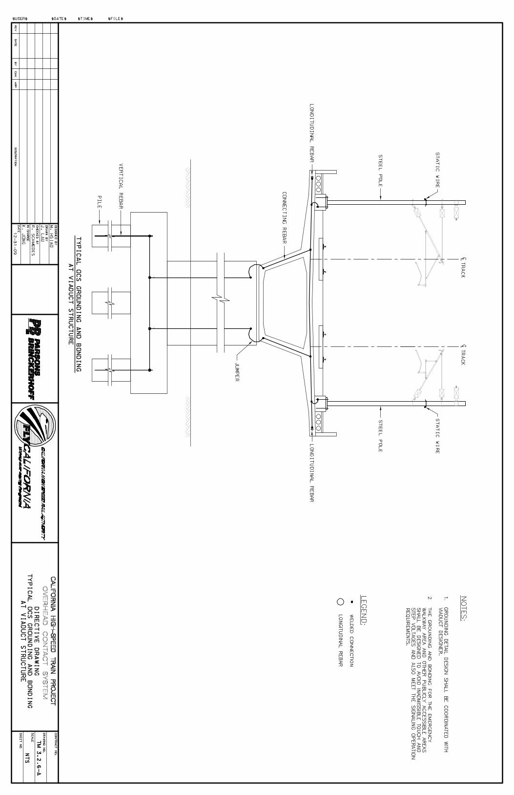
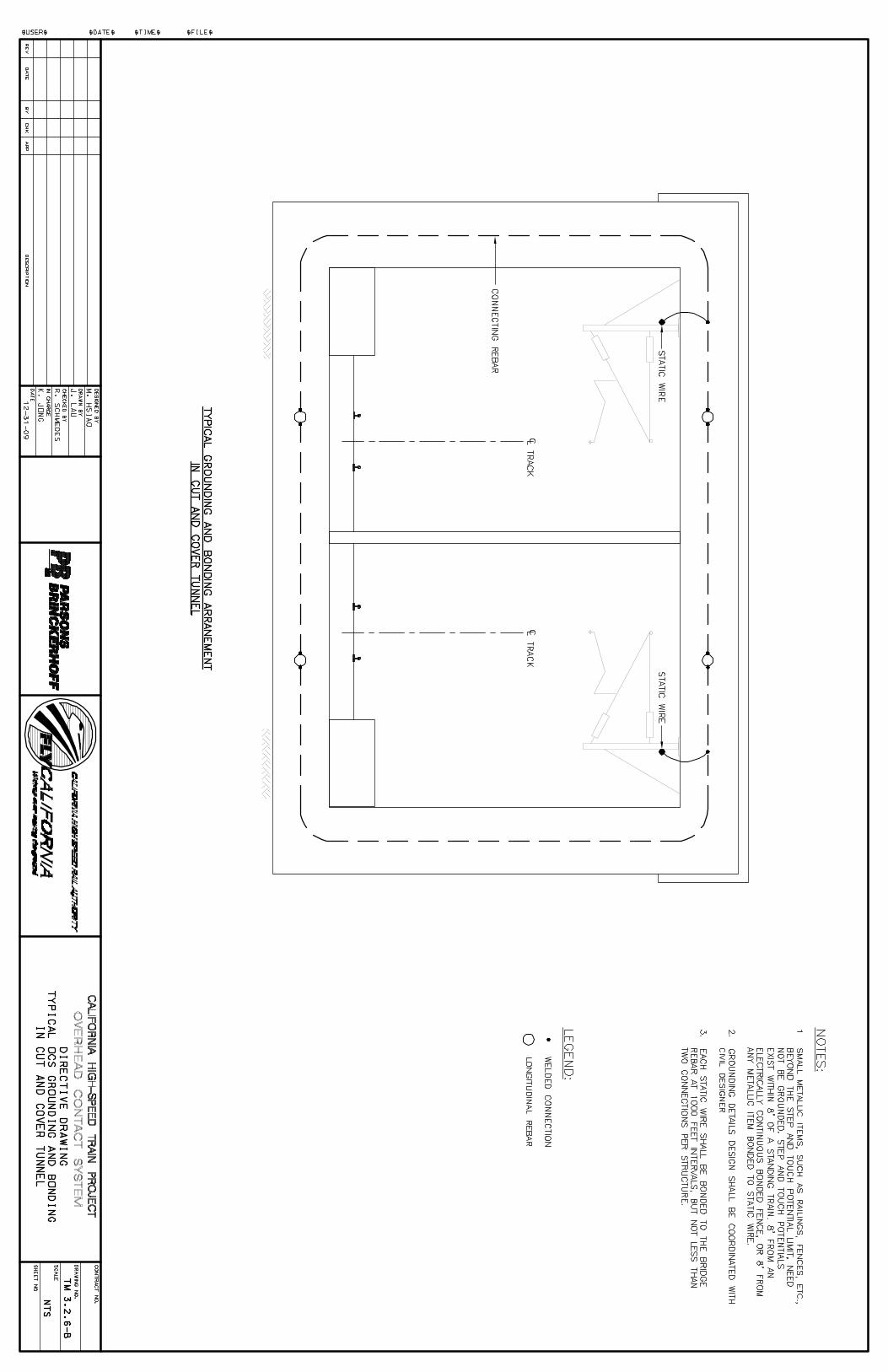
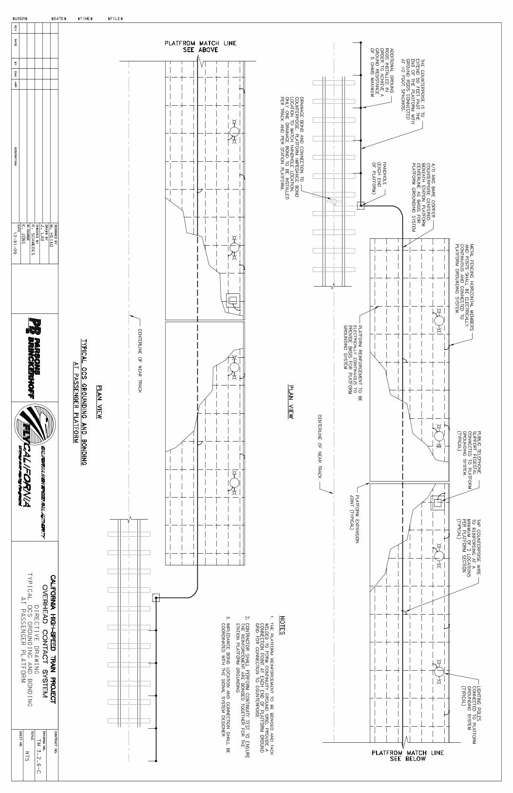
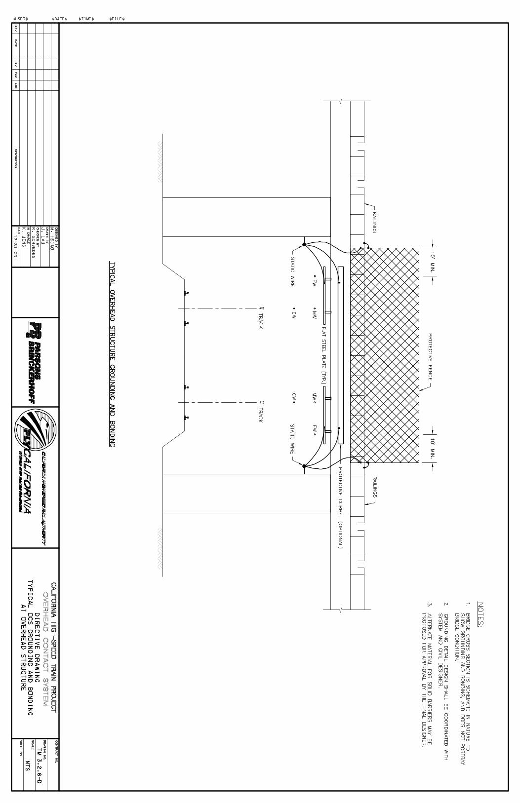
![PPT Konstruksi Mesin [TM3]](https://static.fdocuments.net/doc/165x107/55cf863f550346484b95baf4/ppt-konstruksi-mesin-tm3.jpg)


![Modul Sinematografi [TM3].docx](https://static.fdocuments.net/doc/165x107/577c80c51a28abe054aa1a14/modul-sinematografi-tm3docx.jpg)


