
Progressive collapse risk analysis: literature survey...
80
Report EUR 25625 EN 2012 Seweryn KOKOT George SOLOMOS Administrative Arrangement No JRC 32253-2011 with DG-HOME Activity A5 - Blast Simulation Technology Development Progressive collapse risk analysis: literature survey, relevant construction standards and guidelines
-
Upload
truongliem -
Category
Documents
-
view
243 -
download
2
Transcript of Progressive collapse risk analysis: literature survey...

Report EUR 25625 EN
2 0 1 2
Seweryn KOKOT George SOLOMOS
Administrative Arrangement No JRC 32253-2011 with DG-HOME Activity A5 - Blast Simulation Technology Development
Progressive collapse risk analysis: literature survey, relevant construction standards and guidelines

European Commission Joint Research Centre
Institute for the Protection and Security of the Citizen
Contact information George Solomos Address: Joint Research Centre, Via Enrico Fermi 2749, TP480, 21027 Ispra (VA), Italy
E-mail: [email protected]
Tel.: +39 0332 78 9916
Fax: +39 0332 78 9049
http://ipsc.jrc.ec.europa.eu/
http://www.jrc.ec.europa.eu/
Legal Notice Neither the European Commission nor any person acting on behalf of the Commission
is responsible for the use which might be made of this publication.
Europe Direct is a service to help you find answers to your questions about the European Union
Freephone number (*): 00 800 6 7 8 9 10 11
(*) Certain mobile telephone operators do not allow access to 00 800 numbers or these calls may be billed.
A great deal of additional information on the European Union is available on the Internet.
It can be accessed through the Europa server http://europa.eu/.
JRC73061
EUR 25625 EN
ISBN 978-92-79-27734-4 (pdf)
ISBN 978-92-79-27735-1 (print)
ISSN 1831-9424 (online)
ISSN 1018-5593 (print)
doi:10.2788/70141
Luxembourg: Publications Office of the European Union, 2012
© European Union, 2012
Reproduction is authorised provided the source is acknowledged.
Printed in Italy

Progressive collapse risk analysis:
literature survey, relevant construction standards and guidelines
Administrative Arrangement No JRC 32253-2011
No HOME/2010/CIPS/AA/001-A1, ABAC No 30-CE-0471931/00-60
Activity A5 - Blast Simulation Technology Development
Deliverable D5.1 Technical Report
Seweryn KOKOT George SOLOMOS
European Laboratory for Structural Assessment
November 2012


Executive Summary Progressive collapse of a building can be regarded as the situation where local failure of a primary structural component leads to the collapse of adjoining members and to an overall damage which is disproportionate to the initial cause. The problem of progressive collapse in civil engineering gained interest in 1968, after the partial collapse of the Ronan Point apartment building in London UK. Following this event, intensive research effort led to developing progressive collapse strategies and methods and resulted in the first progressive collapse provisions in the UK standards. Even current methods and strategies benefit to a great extent from the approaches developed at that time. A second and third wave of progressive collapse interest by the civil engineering community appeared after the disproportionate collapse of the A.P. Murrah Federal Building (Oklahoma City, 1995) and the total collapse of the World Trade Center towers, both caused by terrorist attacks. Progressive collapse can be triggered by many different actions. Examples of such actions can be: explosions caused by gas or explosives; impacts of vehicles, ships or planes; earthquakes; human errors in the design or construction phase etc. The prediction of such events and abnormal actions is very difficult and depends on many factors. From the security point of view, progressive collapse is of particular importance as buildings and other critical infrastructures often become the target of terrorist bombing attacks. A structure should be capable to suffer local damage but to prevent excessive spreading of it to other members. However, designing a large building against progressive collapse due to blast loading is quite a challenge because of the several assumptions and unknown parameters involved: the quantity and type of the explosive charge, the distance from the building where the explosive is detonated, whether the blast affects corner or central columns of the building etc. These difficulties make that there are effectively no provisions in the national construction codes and standards for the design of structures to resist external explosions or internal explosions caused by explosives. This report presents several definitions and proposals of robustness measures of structures, and it provides a review of procedures and strategies for progressive collapse design based on selected codes, standards and guidelines mainly from the EU and USA. As shown, the early developed design approaches for progressive collapse mitigation are divided into indirect and direct ones. Indirect approaches consist of applying prescriptive design rules (minimum requirements on strength, continuity, ductility, redundancy), contributing to the resistance to progressive collapse. However progressive collapse behaviour is not addressed explicitly. These indirect design approaches address the problem by identifying and incorporating into the building system characteristics that enhance robustness, without special consideration to loads or events that could trigger disproportionate collapse. On the other hand, direct approaches involve a performance-based design and consist of the specific local resistance method (the design of some “key elements” to resist a sufficiently high pressure) and the alternate load path method. The report also includes some real cases of progressive collapses, it provides a representative view of research efforts in the field, as reported in international journals and conferences, and points out knowledge gaps.


Contents
1. Introduction . . . . . . . . . . . . . . . . . . . . . . . . . . . . . . . . . . . . . 5
2. Terms and definitions . . . . . . . . . . . . . . . . . . . . . . . . . . . . . . . . 7
3. Review of procedures and strategies for progressive collapse design . . 11
3.1. British Standards . . . . . . . . . . . . . . . . . . . . . . . . . . . . . . . . 11
3.1.1. Load combinations . . . . . . . . . . . . . . . . . . . . . . . . . . . 11
3.1.2. Horizontal ties . . . . . . . . . . . . . . . . . . . . . . . . . . . . . . 11
3.1.3. Vertical ties . . . . . . . . . . . . . . . . . . . . . . . . . . . . . . . 12
3.1.4. Design of bridging elements (alternate load path) . . . . . . . . . . 12
3.1.5. Key elements . . . . . . . . . . . . . . . . . . . . . . . . . . . . . . . 13
3.2. Eurocodes . . . . . . . . . . . . . . . . . . . . . . . . . . . . . . . . . . . . . 13
3.2.1. Load combinations . . . . . . . . . . . . . . . . . . . . . . . . . . . 16
3.2.2. Horizontal ties . . . . . . . . . . . . . . . . . . . . . . . . . . . . . . 17
3.2.3. Vertical ties . . . . . . . . . . . . . . . . . . . . . . . . . . . . . . . 18
3.2.4. Key elements . . . . . . . . . . . . . . . . . . . . . . . . . . . . . . . 18
3.2.5. Risk assessment . . . . . . . . . . . . . . . . . . . . . . . . . . . . . 18
3.2.6. Dynamic design against impact . . . . . . . . . . . . . . . . . . . . 19
3.2.7. Internal explosions . . . . . . . . . . . . . . . . . . . . . . . . . . . 20
3.3. ASCE 7-05 . . . . . . . . . . . . . . . . . . . . . . . . . . . . . . . . . . . . 20
3.3.1. Load combinations . . . . . . . . . . . . . . . . . . . . . . . . . . . 21

Contents 2
3.4. GSA Guidelines . . . . . . . . . . . . . . . . . . . . . . . . . . . . . . . . . 21
3.4.1. Design guidance . . . . . . . . . . . . . . . . . . . . . . . . . . . . . 22
3.4.2. Analysis techniques . . . . . . . . . . . . . . . . . . . . . . . . . . . 23
3.4.3. Load combinations . . . . . . . . . . . . . . . . . . . . . . . . . . . 23
3.4.4. Analysis criteria . . . . . . . . . . . . . . . . . . . . . . . . . . . . . 24
3.4.5. Acceptance criteria . . . . . . . . . . . . . . . . . . . . . . . . . . . 24
3.5. UFC 4-023-03 . . . . . . . . . . . . . . . . . . . . . . . . . . . . . . . . . . 25
3.5.1. Load combinations . . . . . . . . . . . . . . . . . . . . . . . . . . . 26
3.5.2. Linear Static Analysis Procedure . . . . . . . . . . . . . . . . . . . 26
3.5.3. Nonlinear Static Analysis Procedure . . . . . . . . . . . . . . . . . . 27
3.5.4. Nonlinear Dynamic Analysis Procedure . . . . . . . . . . . . . . . . 28
3.5.5. Internal ties . . . . . . . . . . . . . . . . . . . . . . . . . . . . . . . 30
3.5.6. Perimeter ties . . . . . . . . . . . . . . . . . . . . . . . . . . . . . . 31
3.5.7. Modelling of plastic hinges . . . . . . . . . . . . . . . . . . . . . . . 31
3.5.8. Updates from 2009 and 2010 . . . . . . . . . . . . . . . . . . . . . . 31
4. Research papers on progressive collapse . . . . . . . . . . . . . . . . . . . . 33
4.1. Probability of progressive collapse . . . . . . . . . . . . . . . . . . . . . . . 33
4.2. Inadequacy of current design methods for progressive collapse resistance . . 34
4.3. Examples of applying different strategies of progressive collapse design . . . 34
4.4. Types of progressive collapses . . . . . . . . . . . . . . . . . . . . . . . . . . 41
4.5. Simplified methods for progressive collapse analysis . . . . . . . . . . . . . 45
4.6. Numerical case studies . . . . . . . . . . . . . . . . . . . . . . . . . . . . . . 46
4.7. Measures of structural robustness and vulnerability . . . . . . . . . . . . . 47
4.7.1. Measures based on structural behaviour . . . . . . . . . . . . . . . . 49
4.7.2. Measures based on structural attributes . . . . . . . . . . . . . . . . 52

Contents 3
4.8. Other topics . . . . . . . . . . . . . . . . . . . . . . . . . . . . . . . . . . . 52
5. Examples of progressive collapse . . . . . . . . . . . . . . . . . . . . . . . . . 54
5.1. Ronan Point . . . . . . . . . . . . . . . . . . . . . . . . . . . . . . . . . . . 54
5.2. Alfred P. Murrah Federal Building . . . . . . . . . . . . . . . . . . . . . . . 54
5.3. L’Ambiance Plaza . . . . . . . . . . . . . . . . . . . . . . . . . . . . . . . . 57
6. Summary and conclusions . . . . . . . . . . . . . . . . . . . . . . . . . . . . . 59
References . . . . . . . . . . . . . . . . . . . . . . . . . . . . . . . . . . . . . . . . . 61
List of Figures . . . . . . . . . . . . . . . . . . . . . . . . . . . . . . . . . . . . . . 65
List of Tables . . . . . . . . . . . . . . . . . . . . . . . . . . . . . . . . . . . . . . . 67
A. Formulas for plastic hinges in beams and columns . . . . . . . . . . . . . 68��
B. Progressive Collapse and Blast Simulation Techniques . . . . . . . . . . . . . . . . . . . . . . . 70 �


1. Introduction
This is an updated version of the previous report on literature survey in robust-ness and progressive collapse of structures, which can be considered as the situationwhere local failure of a primary structural component leads to the collapse of ad-joining members and to an overall damage which is disproportionate to the initialcause.
The problem of progressive collapse in civil engineering gained its interest as earlyas 1968, after the Ronan Point apartment building partial collapse, London, the UK.Right after this event, many research efforts led to developing progressive collapsestrategies and methods as well as resulted in first progressive collapse provisions inthe UK standards. Even current methods and strategies benefit to a great extentfrom the approaches developed in that time. As summarised by Moore [54], thoseprovisions helped in many cases to avoid other progressive collapses, afterwards,in the UK. A second and third wave of progressive collapse interest by the civilengineering community appeared after the disproportionate collapse of the AlfredP. Murrah Federal Building (Oklahoma City, 1995) and the total collapse of theWorld Trade Center towers, both caused by terrorist attacks.
Progressive collapse can be triggered by many different actions. Examples of suchactions can be: explosions caused by gas or explosives; impacts of vehicles, ships orplanes; earthquakes human errors in the design or construction phase etc. Predictionof such abnormal actions is very difficult and depends on many factors. Designingfor example a large frame reinforced concrete building against progressive collapsedue to blast loading is a big challenge. Analysing such a building and checkingif a progressive collapse could happen or not depends on many assumptions. Forexample the major unknowns are: how big the explosive charge is (what is the peakpressure), how far from the building the explosive is detonated, and whether theblast affects the corner load-bearing elements of the building or the ones situated inthe middle of the building’s sides etc.
These difficulties make that there are effectively no provisions in the nationalcodes and standards to design structures to resist external explosions or internalexplosions caused by explosives. Thus instead of explicit analysis of a structure to aspecific blast load, the current codes, standards and guidelines recommend a threatindependent design, that is the design due to an unspecified cause, or to design someelements (key elements) to resist a sufficiently high pressure (e.g. 34 kPa).
Those early developed design approaches for progressive collapse mitigation canbe divided into indirect and direct approaches. Indirect approaches consist in apply-ing prescriptive design rules (minimum requirements on strength, continuity, ductil-ity, redundancy), providing resistance to progressive collapse; however progressivecollapse behaviour is not addressed explicitly. In other words, indirect design ap-proach addresses the problem by identifying and incorporating into the building sys-tem characteristics that enhance robustness, without special consideration of loadsor events that could trigger disproportionate collapse. Direct design approachesinvolve a performance-based approach and consist of the specific local resistancemethod and the alternate load path method.
This report contains 6 Chapters. Chapter 1 is an introduction to the topic.In Chapter 2 the main terms and definitions related to progressive collapse arepresented. Chapter 3 provides a review of procedures and strategies for progressivecollapse design based on selected codes and standards, e.g. ASCE 7 [5], BS 5628[9], BS 5950 [10], BS 6399 [11], BS 8110 [12], EN 1991 [27], and U.S. guidelines, e.g.DoD UFC Guidelines [20], GSA Guidelines [40]. Chapter 4 constitutes a review ofresearch efforts in the field of progressive collapse reported in international journalsand conference papers. Different proposals of robustness measures of structuresare also presented in this chapter. In Chapter 5 a few examples of progressivecollapses of real buildings are described. Finally, Chapter 6 provides a summaryand conclusions. Two appendices, containing respectively some useful elements onplastic analysis and on blast loading of structures, are included.
2
solomos
Text Box

2. Terms and definitions
In different publications, the common used terms regarding progressive collapsecan have broader or narrower scope and are sometimes used with slightly differentmeaning. Therefore, the aim of this chapter is to give a list of the terms with theirdefinitions.
Progressive collapse – the spread of an initial local failure from element toelement, resulting eventually, in the collapse of an entire structure or a dispropor-tionately large part of it (ASCE 7 [5]).
Progressive collapse – the spread of local damage from an initiating event,from element to element, resulting in the collapse of an entire structure or a dispro-portionate large part of it; known as disproportionate collapse (NIST Best Practices[56]).
Progressive collapse – a situation where local failure of a primary structuralcomponent leads to the collapse of adjoining members which, in turn, leads to ad-ditional collapse. Hence, the total damage is disproportionate to the original cause(GSA Guidelines [40]).
Progressive collapse – this term is indirectly defined in the EN 1990 [26],where the code treats the basic requirements a structure should satisfy: “A struc-ture shall be designed and executed in such a way that it will not be damaged byevents such as explosions, impact or the consequences of human errors, to an extentdisproportionate to the original cause.” EN 1990 [26], 2.1(4)
Robustness – the ability of a structure to withstand events like fire, explosions,impact or the consequences of human error, without being damaged to an extentdisproportionate to the original cause (EN 1991-1-7 [28]).
Robustness – the ability of a structure or structural components to resist dam-age without premature and/or brittle failure due to events like explosions, impacts,fire or consequences of human error, due to its vigorous strength and toughness(GSA Guidelines [40]).
Robustness – insensitivity of a structure to local failure, where “insensitivity”and “local failure” are to be quantified by the design objectives (Starossek andHaberland [69]). Defined in this way, robustness is a property of the structure aloneand is independent of possible causes of initial local failure. This definition is incontrast to a broader definition of robustness – as it is given, for instance, in EN

8
1991-1-7 [28] – which does include possible causes of initial failure. Such a broaderdefinition is close to the term collapse resistance as defined below.
Collapse Resistance – insensitivity of a structure to accidental circumstances,which are low probability events and unforeseeable incidents. The accidental cir-cumstances are to be quantified by the design objectives. Collapse resistance is aproperty that is influenced by numerous conditions including both structural fea-tures and possible causes of initial failure. (Starossek [65], Starossek and Haberland[69]).
Key element – a structural member upon which the stability of the remainderof the structure depends (EN 1991-1-7 [28]).
Key element – structural elements whose notional removal would cause collapseof an unacceptable extent. They should therefore be designed for accidental loads,which are specified in several standards as 34 kPa (NIST Best Practices [56]).
Localised failure – the part of a structure that is assumed to have collapsed,or been severely disabled, by an accidental event (EN 1991-1-7 [28]).
Continuity – refers to the continuous connection of components as well as thecontinuous reinforcement of concrete components. Integrity, redundancy and/orlocal resistance can be improved by continuity. Continuity is thus an element ofrobustness (Starossek and Haberland [69]).
Damage tolerance – the term is compatible with the term robustness used byLind [46]. In some other papers, the damage tolerance meaning is narrower andrefers to the ability of a structure to resist a continuous local deterioration due tocorrosion or similar (Starossek and Haberland [69]).
Ductility – the ability of a component or structural system to withstand largeplastic deformations. Ductility has a large influence on progressive collapse and isoften listed as a factor which increases the robustness of the structure (Starossekand Haberland [69]).
Ductility – the ability of a structure to remain stable after large deforma-tions (rotations and deflections). There are different means for steel and reinforcedconcrete structures to provide sufficient ductility. Steel – using steel with hightoughness, connections which exceed the strength of the base material. Reinforcedconcrete structures – confinement of reinforcing steel, continuity through lap splices,maintaining overall structural stability, and creating connections between elementsthat exceed the strength and toughness of the base members etc. (NIST Best Prac-tices [56]).
Integrity – the term is mainly used in U.S. standards such as ACI 318 [2],ASCE 7 [5], often in relation with prescriptive requirements (like requirements forcontinuity, ductility, and redundancy). Integrity implies that the structure and its

9
components remain intact over the intended lifetime of the structure (Starossek andHaberland [69]).
Redundancy – Structural redundancy refers to the multiple availability ofload-carrying components or multiple load paths which can bear additional loads inthe event of a failure. If one or more components fail, the remaining structure isable to redistribute the loads and thus prevent a failure of the entire system. Redun-dancy depends on the geometry of the structure and the properties of the individualload-carrying elements (Frangopol and Curley [39]). It is not synonymous with thestatic indeterminacy. Redundancy is mentioned as an important factor in the designof robust structures and hence the prevention of progressive collapse (EN 1991-1-7[28]). Redundancy refers particularly to the alternate load path method (Starossekand Haberland [69]).
Redundancy – the incorporation of redundant load paths in the vertical loadcarrying system to ensure that alternate load paths are available in the event oflocal failure of structural elements (NIST Best Practices [56]).
Vulnerability – describes the sensitivity of a structure to damage events.A structure is vulnerable if small damages lead to disproportionate consequences.Vulnerability is opposite to robustness and it is a property of the structural system(Starossek and Haberland [69]).
Ties – The loss of a major structural element typically results in load redis-tributions and member deflections. These processes require the transfer of loadsthroughout the structure (vertically and horizontally) through load paths. Theability of a structure to re-distribute or transfer loads along these load paths isbased in large part on the interconnectivity between adjacent members. This isoften called “tying a building together” by using an integrated system of ties inthree directions along the principal lines of structural framing. Fig. 3.4 taken fromDoD UFC Guidelines [20], illustrates the different types of ties that are typicallyincorporated to provide structural integrity to a building (NIST Best Practices [56]).
Direct design for progressive collapse – explicit consideration of progressivecollapse during the design process through either: alternate load path method orspecific local resistance method (ASCE 7 [5]).
Indirect design for progressive collapse – implicit consideration to progres-sive collapse during the design process through the provision of minimum levels ofstrength, continuity and ductility (ASCE 7 [5]).
Specific local resistance method (Key element method) – a method thatseeks to provide sufficient strength to resist failure from accidents or misuse. In otherwords, a critical load bearing element is explicitly designed to resist the prescribedload level (ASCE 7 [5]).
Alternate load path method – a method that allows local failure to occur,

but seeks to provide alternate load paths so that the damage is absorbed and majorcollapse is averted (ASCE 7 [5]).
Risk – a measure of the combination (usually the product) of the probabilities orfrequency of occurrence of a defined hazard and the magnitude of the consequencesof the occurrence (EN 1991-1-7 [28]).
Consequences – a possible result of an event. Consequences may be expressedverbally or numerically in terms of loss of life, injury, economic loss, environmentaldamage, disruption to users and the public, etc. Both immediate consequences andthose that arise after a certain time has elapsed are to be included (EN 1991-1-7[28]).
Risk analysis – a systematic approach for describing and/or calculating risk.Risk analysis involves the identification of undesired events, and the causes andconsequences of these events (EN 1991-1-7 [28]).
Risk evaluation – a comparison of the results of a risk analysis with the ac-ceptance criteria for risk and other decision criteria (EN 1991-1-7 [28]).
Risk management – systematic measures undertaken by an organisation inorder to attain and maintain a level of safety that complies with defined objectives(EN 1991-1-7 [28]).
Risk acceptance criteria – these criteria are normally determined by the au-thorities to reflect the level of risk considered to be acceptable by people and society.They correspond to acceptable limits to probabilities of certain consequences of anundesired event and are expressed in terms of annual frequencies (EN 1991-1-7 [28]).
Deflagration – propagation of a combustion zone at a velocity that is less thanthe speed of sound in the unreacted medium (EN 1991-1-7 [28]).
Detonation – propagation of a combustion zone at a velocity that is greaterthan the speed of sound in the unreacted medium (EN 1991-1-7 [28]).

3. Review of procedures and strategies forprogressive collapse design
3.1. British Standards
The United Kingdom was the first country which incorporated the progressivecollapse provisions to its standards. The need for this kind of regulations emergedafter the Ronan Point partial collapse (see details in Sec. 5.1). General informationon how to design structure against progressive collapse is given in BS 6399 [11], whilespecific provisions for steel, concrete and masonry structures are given in BS 5950[10], BS 8110 [12] and BS 5628 [9], respectively. Below there are presented maintopics of progressive collapse design which can subsequently be used for comparisonwith other documents.
3.1.1. Load combinations
For bridging design (alternate load path method), British Standards recommendapplying the load combinations as follows
D +W/3 + L/3 (3.1)
where: D - dead load, W - wind load, L - imposed load.
3.1.2. Horizontal ties
Steel structures
Steel elements designed as horizontal ties and their end connections should becapable of resisting factored tensile loads as follows:
• internal ties
Ti = 0.5(1.4gk + 1.6qk)stL but not less than 75 kN, (3.2)
where:

British Standards 12
gk – the specified dead load per unit area of the floor or roof,qk – the specified imposed floor or roof load per unit area,L – the span,st – the mean transverse spacing of the ties adjacent to that being checked.
• edge ties
Te = 0.25(1.4gk + 1.6qk)stL but not less than 75 kN. (3.3)
Reinforced concrete structures
• internal ties
Ti =gk + qk7.5
lr5Ft or 1.0Ft (3.4)
where:gk – characteristic dead load (in kN/m2),qk – characteristic imposed floor load,lr – greater of the distances between the centres of the columns, frames or
walls supporting any two adjacent floor spaces in the direction of the tieunder consideration,
Ft – basic strength, lesser of (20 + 4no) or 60 kN,no – number of storeys.
• peripheral tiesAt each floor and roof level an effectively continuous peripheral tie should bedesigned, capable to resist a tensile force of 1.0Ft, located within 1.2m of theedge of the building or within the perimeter wall.
3.1.3. Vertical ties
Vertical ties should ensure continuous tying of the structure from the lowest tothe highest level. The column or a wall designed as a vertical tie should be capableto resist a tensile force equal to the maximum design ultimate dead and imposedload.
3.1.4. Design of bridging elements (alternate load path)
Steel structures
If the conditions for the tie forces cannot be met, the building should be checkedto ensure that the notional removal of a column (at each level, one at a time) willnot lead to disproportionate collapse.

Eurocodes 13
Reinforced concrete structures
For buildings of 5 or more storeys, when the tie forces criteria cannot be met,the structure should be analysed upon removal of a load-bearing element (a columnor a portion of wall between lateral supports).
3.1.5. Key elements
Steel structures
If the conditions for the tie forces are not satisfied and upon a column removalthe building is suspected to total collapse or the area of the collapsed portion isgreater than 15% or 70m2, then that column or element should be designed as a keyelement. The column or element is deemed as key element if it can resist the pressureof 34 kN/m2.
Reinforced concrete structures
Similarly to the steel structures, the key element should be capable to withstanda design ultimate load of 34 kN/m2 from each direction. This design ultimate loadvalue should not include a partial safety factor.
3.2. Eurocodes
The Eurocodes (EN 1990 [26], EN 1991 [27], EN 1992 [29], EN 1993 [30], EN1994 [31], EN 1995 [32], EN 1996 [33], EN 1997 [34], EN 1998 [35], EN 1999 [36])are a set of European codes for designing and constructing civil engineering struc-tures. Accidental actions are specifically dealt in EN 1991-1-7 [28], however sincethe Eurocodes are treated as a whole, there are many references to other parts, inparticular, to EN 1990 [26] and EN 1991 [27] etc.
EN 1991-1-7 [28] gives provisions (strategies and rules) for designing buildingsagainst identifiable and unidentifiable accidental actions. However, as it is written inthe Eurocode, “EN 1991-1-7 does not specifically deal with accidental actions causedby external explosions, warfare and terrorist activities, or the residual stability ofbuildings or other civil engineering works damaged by seismic action or fire etc.”(EN 1991-1-7 [28], 1.1(6)). Thus when designing a structure against a possible threatof a terrorist attack, the design must be conducted according to provisions for anunspecified accidental action. Some of the material below is included in the rulesand other in the informative Annexes.

Eurocodes 14
According to EN 1991-1-7 [28] the strategies for accidental design situations areillustrated in Fig. 3.1. Therefore, if an accidental action is identified we may try to
Figure 3.1. Strategies for accidental design situations (EN 1991-1-7 [28])
prevent or reduce the action by protective measures, we can design the structure forsufficient robustness or to sustain the action. On the other hand, if we allow a localdamage, then the aim of the design is to either enhance structural redundancy byalternate load path method, or to ensure structural integrity and ductility.
Potential damage can be avoided or limited by appropriate choice of one or moreof the following actions:
• avoiding, eliminating or reducing the hazards to which the structure can besubjected,
• selecting a structural form which has low sensitivity to hazards considered,• selecting a structural form and design that can survive adequately the acciden-
tal removal of an individual member or a limited part of the structure, or theoccurrence of acceptable localised damage,
• avoiding as far as possible structural systems that can collapse without warning,• tying the structural members together. EN 1990 [26], 2.1(5)
The strategies for accidental design situations depend on three consequencesclasses defined in EN 1990 [26]. These consequences classes (CC) include:
CC1 – low consequences of failure,CC2 – medium consequences of failure,CC3 – high consequences of failure.
EN 1991 [27] assigns accidental design situations for different consequencesclasses as follows:
CC1 – no particular consideration is necessary for accidental actions other thansatisfying rules for stability and robustness given in other Eurocodes (EN 1990[26] to EN 1999 [36]),

Eurocodes 15
CC2 – depending on specific conditions of the structure, a simplified analysis bystatic equivalent action models may be adopted or prescriptive design and de-tailing rules may be applied,
CC3 – a more detailed consideration of the specific case should be done to determinethe level of reliability and the depth of structural analyses required. A riskassessment as well as advanced analysis method (nonlinear dynamic analysis)may be required.
Annex A of the EN 1991-1-7 [28] gives a categorisation of buildings types withregard to consequences classes. A simplified version of the Table A.1 of EN 1991-1-7[28] can be represented as follows:
CC1 – single occupancy houses not exceeding 4 storeys, agricultural buildings,buildings rarely occupied by people etc.;
CC2a (lower risk group) – 5 storey single occupancy houses, hotels, flats, apart-ments, other residential buildings, offices not exceeding 4 storeys etc.;
CC2b (upper risk group) – hotels, flats, apartments and other residential build-ings greater than 4 storeys but less than 15 storeys etc.;
CC3 – all buildings defined for classes CC2a and CC2b that exceed the limits onarea or number of storeys, all buildings occupied by people in significant numbers,stadia for more than 5000 spectators, buildings containing dangerous substancesand processes etc.
Based on these categorisation, the following strategies are recommended:
a) for buildings in Consequences Class 1: as mentioned before no specific designprocedure is needed other than those for designing and constructing buildings inaccordance with the rules in other Eurocodes,
b) for buildings in Consequences Class 2a (lower group): additional procedure in-clude applying appropriate effective horizontal ties, or effective anchorage of sus-pended walls as defined in 3.2.2,
c) for buildings in Consequences Class 2b (upper group):• horizontal and vertical ties as defined in 3.2.2 and 3.2.3 should be provided;• the building should be analysed to check if the notional removal of each sup-
porting column and each beam supporting a column, or any nominal sectionof load-bearing wall will not cause local damage greater than the specifiedlimits and not cause total collapse. Where the notional removal of suchcolumns and sections of walls would result in exceeding the specified limitsfor local damage, then those elements should be redesigned or designed asa ”key element” (see 3.2.4),
d) for buildings in Consequences Class 3: A systematic risk assessment of the build-ing should be performed, taking into account both foreseeable and unforeseeablehazards according to Annex B of EN 1991-1-7 [28].
In Annex A of the EN 1991-1-7 [28] there are given rules and methods for de-signing buildings to sustain an extent of localised failure from an unspecified causewithout disproportionate collapse.

Eurocodes 16
3.2.1. Load combinations
Accidental actions shall be applied simultaneously in combination with perma-nent and variable loads in accordance with (EN 1990 [26], 6.4.3.3).
Combination of actions for accidental design situations in the ultimate limitstates according to (EN 1990 [26], 6.4.3.3) is as follows
∑
j≥1
Gk,j + P + Ad + (ψ1,1 or ψ2,1)Qk,1 +∑
i>1
ψ2,iQk,i (3.5)
where:G – permanent load (dead load),P – relevant representative value of a prestressing action (see EN 1992 to EN 1996
and EN 1998 to EN 1999),Ad – design accidental action,Q – variable load (live load, snow load, wind load),ψ1 – factor for frequent value of a variable action,ψ2 – factor for quasi-permanent value of a variable action.
Accidental action Ad should be taken as an explicit accidental action Ad for fireor impact or can refer to the situation after an accidental event. In this case Ad
is equal to zero. Recommended values for ψ1 and ψ2, depending on the buildingcategories, can be found in Table A1.1 of Annex A EN 1990 [26].
In the paragraph EN 1990 [26], 4.1.2(8), it reads as follows “For accidental actionsthe design value Ad should be specified for individual projects based on EN 1991[27]”.
When analysing a structure in a quasi-static way, the dynamic effects can beincluded by applying an equivalent dynamic amplification factor to the static actions,EN 1990 [26], 5.1.3(3). However it is not specified in the Eurocodes what value forthe dynamic amplification factor is recommended in the case of accidental actions.
The accidental actions to be considered depend on:
• the measures taken to prevent or reduce the severity of an accidental action,• the probability of occurrence of the identified accidental action,• the consequences of failure due to the identified accidental action,• public perception,• the level of acceptable risk.
A localised failure due to accidental actions may be acceptable, provided it willnot endanger the stability of the whole structure, and that the overall load bearingcapacity of the structure is maintained and allows necessary emergency measures tobe taken.
Measures should be taken to reduce the risk of accidental actions and thesemeasures should include one of more of the following strategies: preventing the

Eurocodes 17
action from occurring, protecting the structure against the effects of an accidentalaction by reducing the effects of the action on the structure, ensuring that thestructure has sufficient robustness.
3.2.2. Horizontal ties
For framed structures, continuous internal ties, including their end connections,should be capable of resisting a design tensile load of a value
Ti = 0.8(gk + ψqk)sL or 75 kN whatever is greater (3.6)
similarly for perimeter ties a design tensile force is given as
Tp = 0.4(gk + ψqk)sL or 75 kN whatever is greater (3.7)
where:s – the spacing of ties,L – the span of the tie,ψ – the relevant factor in the expression for combination of action effects for the
accidental design situation (as in Eq. (3.5)).
For load-bearing walls, how the ties should be incorporated into the buildingdepends on the consequences class. For CC 2 buildings (Lower Risk Group), ade-quate robustness is provided by adopting a cellular form of construction designed tofacilitate interaction of all components including an appropriate means of anchoringthe floor to the walls. For CC 2 buildings (Upper Risk Group), continuous horizon-tal ties should be provided in the floors. These should be internal ties distributedthroughout the floors in both orthogonal directions and peripheral ties extendingaround the perimeter of the floor slabs within 1.2m width of the slab. The designtensile forces in the ties should be calculated as follows:
• for internal ties
Ti =Ft(gk + ψqk)
7.5·z
5or Ti = Ft whatever is greater, (3.8)
• for peripheral ties
Tp = Ft, (3.9)
where:Ft – 60 kN/m or 20 + 4ns [kN/m], whichever is less,ns – number of storeys,z – smaller value of: 5 · H or the greatest distance [m] in the direction of
the tie, between the centers of the columns or other vertical load-bearingmembers whether the distance is spanned by a single slab or by a systemof beams and slabs,
H – clear storey height.

Eurocodes 18
3.2.3. Vertical ties
All vertical ties (for frame and wall structures) should be continuous from thefoundations to the roof level.
For frame structures, vertical ties should be capable to resist an accidental designtensile force equal to the largest design vertical permanent and variable load reactionapplied to the column from any one storey. It should be noted that this accidentaldesign loading should not act simultaneously with permanent and variable actionsthat may be acting on the structure.
For wall structures, vertical ties may be deemed effective if:
a) for masonry walls their thickness is at least 150mm and if they have minimumcompressive strength of 5N/mm2 (see EN 1996 [33]),
b) the clear height of the wall, measured in meters between faces of floors or roofdoes not exceed 20t, where t is the thickness of the wall in meters,
c) if vertical ties resist the following force
T =34A
8000
(
H
t
)2
or 100 kN/m of wall, whichever is greater, (3.10)
where A – the cross-sectional area in mm2 of the wall measured on plan, excludingthe non load bearing leaf of a cavity wall;
d) the vertical ties are grouped at 5m maximum centres along the wall and occurno greater than 2.5m from an unrestrained end of the wall.
3.2.4. Key elements
For building structures, a key element should resist an accidental design actionof Ad applied in horizontal and vertical directions (one direction at a time). Suchaccidental design loading should be applied in accordance with expression (6.11b ofthe EN 1990 [26], here see Eq. (3.5)) and may be concentrated or distributed load.The recommended value of Ad for building structures is 34 kN/m2.
3.2.5. Risk assessment
For category CC3 of buildings, Eurocode EN 1991-1-7 [28] requires a risk as-sessment for a building. Risk is defined as a measure of the combination of theprobability or frequency of occurrence of a defined hazard and the magnitude of theconsequences of the occurrence and is expressed as
R =
NH∑
i=1
p(Hi)
ND∑
j
NS∑
k=1
p(Dj|Hi) · p(Sk|Dj) · C(Sk), (3.11)

Eurocodes 19
where NH – number of different hazards, ND – number of ways the hazards maydamage the structure, NS – number of adverse states (Sk) into which the damagestructure can be discretised, C(Sk) – consequences of an adverse state, P (Hi) – prob-ability of occurrence (within a reference time interval) of the i-th hazard, p(Dj|Hi)– the conditional probability of the j-th damage state of the structure given thei-th hazard and p(Sk|Dj) – the conditional probability of the k-th adverse overallstructural performance S given j-th damage state.
Analysing Eq. (3.11) there are the following possible strategies to control andmitigate the risk:
• reduction of the probability that a hazard occur (reduction of P (H)). For ex-ample if there is a risk that a ship impacts a bridge pier, creation of artificialislands around the bridge pier will mitigate the risk.
• reduction of the probability of significant damages for given hazards (reductionof P (D|H)).
• reduction of the probability of adverse structural performance given structuraldamage (reduction of P (S|H)).
Thus, risk analysis of structures subject to accidental actions involves the fol-lowing steps:
1. Assessment of the probability of occurrence of different hazards with their inten-sities.
2. Assessment of the probability of different states of damage and correspondingconsequences for given hazards.
3. Assessment of the probability of inadequate performance of the damaged struc-ture together with corresponding consequences.
3.2.6. Dynamic design against impact
Annex C of the EN 1991-1-7 [28] gives guidance for the approximate dynamicdesign of structures to accidental impact by road vehicles, rail vehicles and shipsbased on simplified or empirical models.
First, the general impact dynamics theory is considered, where impacts are ide-alised and grouped into two types, namely hard impacts (the energy is dissipated bythe impacting object) and soft impacts (the structure absorbs the impact energy bystructure’s deformation). For hard impacts, EN 1991-1-7 formulates an expressionfor the maximum resulting dynamic interaction force (F ) in function of the objectvelocity at impact (vr), the equivalent elastic stiffness of the object (k) and the massof the impacting object (m). This maximum dynamic interaction force is for theouter surface of the structure, while for the structure itself the dynamic effects canbe greater and should be included by applying the dynamic amplification factor.For soft impacts, the same formula for the maximum dynamic interaction force canbe used, however for k, the stiffness of the structure should be taken. There is also

ASCE 7-05 20
formulated a provision that the structure should have sufficient ductility to be ableto absorb the total kinetic energy by plastic deformation.
The second part of the Annex C of the EN 1991-1-7 is devoted to specific pro-visions for impacts by road vehicles and ships giving formulas or values for thevelocities of impact (vr) and approximate design values for the dynamic interactionforces (Fd) depending on different factors such as: where the vehicles travel, themass of the vehicles, distance of vehicles from the road lanes, size and mass of ships,whether the ships travel on inland or sea waterways etc.
3.2.7. Internal explosions
Annex D of the EN 1991-1-7 [28] provides guidance on how to deal with:
• dust explosions in rooms, vessels and bunkers,• natural gas explosions,• explosions in road and rail tunnels.
For dust explosions in rooms, vessels and bunkers, the EN 1991-1-7 gives:
• material parameters KSt (which characterise the confined explosion behaviour)for most common types of dust and,
• a formula for the venting area of cubic, elongated rooms, vessels and bunkers, aswell as for rectangular enclosures.
For natural gas explosions, EN 1991-1-7 gives formulae for a nominal equivalentstatic pressure as the loading a structure should withstand.
For explosions in road and rail tunnels, EN 1991-1-7 provides expressions for thepressure time function in the cases of detonation and deflagration (see Chapter 2).
3.3. ASCE 7-05
The American Society of Civil Engineers, ASCE 7 [5] discusses general designspecifications for reducing the potential of progressive collapse, however, no specificrequirements are given. Similarly no U.S. building codes provide specific designrequirements with regard to progressive collapse.
The commentary to the ASCE 7 [5] provides detailed discussion on general struc-tural integrity. It gives a list of possible methods for progressive collapse design suchas direct and indirect design approaches. Direct design approaches includes alter-nate load path method and specific local resistance method, whereas indirect designapproach is based on implicit consideration of progressive collapse resistance byensuring minimum levels of strength, continuity and ductility. Similarly to the Eu-

GSA Guidelines 21
rocodes and British Standards, there is no provision on what dynamic amplificationfactor should be used when equivalent static methods are used.
3.3.1. Load combinations
ASCE 7 [5] specifies the following load combinations:
• for specific local resistance method
1.2D + Ak + (0.5L or 0.2S) or (3.12)
(0.9 or 1.2)D + Ak + 0.2Wn, (3.13)
• for alternate load path method (checking if residual load-carrying capacity uponnotional removal of a selected load-bearing element)
(0.9 or 1.2)D + (0.5L or 0.2S) + 0.2Wn, (3.14)
where:D – dead load,L – live load,Wn – wind load,S – snow load,Ak – load effect resulting from an extraordinary event to be specified by the au-
thority having jurisdiction.
3.4. GSA Guidelines
The US General Services Administration (GSA) Guidelines [40] do not mentionanything about designing key elements or designing based on tie forces.
GSA Guidelines permit to perform both linear and nonlinear analysis techniques,however the latter is regarded as much more difficult and can only be performedby experienced structural analyst with advanced structural engineering knowledge.There is only one paragraph devoted to nonlinear procedure with general remarksand no detailed guidance. However acceptance criteria for nonlinear analysis aregiven.
GSA Guidelines provide minimum defended stand-off distances for different typesof construction (reinforced concrete, steel, masonry, precast, wood) depending onrequired level of protections.
GSA Guidelines [40] use a flow-chart methodology to determine if a designedbuilding should have additional resistance for progressive collapse or can be exemptfrom the process of progressive collapse design. The exemption is based on certaincriteria such as building occupancy, building category (reinforced concrete building,

GSA Guidelines 22
steel frame building etc.), number of storeys, seismic zone, local structural featuresand global structural features. Whether positive or negative the answer is, thebuilding is exempt or not, from further consideration of the potential for progres-sive collapse. The purpose of the detailed analysis is to reduce the probability ofprogressive collapse for new construction and identify the potential for progressivecollapse in existing construction.
GSA Guidelines state that low and medium rise buildings can be designed accord-ing to the simplified analysis procedure (linear procedure) while other building (morethan 10 storeys and with atypical structural configuration) should use a nonlinearprocedure.
GSA Guidelines give only general considerations for nonlinear procedure anal-ysis with acceptance criteria for reinforced concrete and steel structures while twoseparate chapters are devoted to linear procedures of reinforced concrete and steelstructures.
There are also presented detailed information on design and analysis of reinforcedconcrete and steel structures. This includes guidance on how to design, model andanalyse the structures.
3.4.1. Design guidance
For reinforced concrete structures special attention should be paid to structuralredundancy, detailing to provide structural continuity and ductility, capacity forresisting load reversals and capacity for preventing shear failure.
Structural redundancy using redundant vertical and lateral force resisting sys-tems enables developing alternate load paths and forming multiple plastic hingeswhich can help to prevent total collapse.
When a vertical load-bearing member is missing it is important that main struc-tural elements are capable to carry two spans. This implies good beam-to-beamcontinuity across removed element and the ability of structural elements to developlarge deformations.
The capacity for resisting load reversals should be achieved in such a way thatstructural members (girders, beams) have additional reinforcement in the zones ofcompressed fibres since, for instance, after removing a column, the previous negativemoment above the column transforms into a positive moment.
For steel structures, the guidelines emphasise such aspects as beam-to-beamcontinuity, connection resilience, connection redundancy, connection rotational ca-pacity.

GSA Guidelines 23
3.4.2. Analysis techniques
The analysis techniques presented in GSA Guidelines should mainly use linearelastic, static analysis preferably on a 3 dimensional models and consist of:
• removing a vertical load-bearing member instantaneously and• applying load combinations multiplied by the factor of 2 accounting for the dy-
namic and nonlinear effects (see 3.4.3 for more details).
3.4.3. Load combinations
The structure should be analysed using the following load combinations appliedto the whole structure together with an instantaneous loss of primary vertical sup-port
2(D + 0.25L) static analysis, (3.15)
D + 0.25L dynamic analysis, (3.16)
where: D - dead load, L - live load.
For frame structures a column removal should be analysed for one floor aboveground. The exterior locations of columns to be removed include:
• the middle of the short side of the building,• the middle of the long side of the building,• the corner of the building.
If there is an underground parking area or uncontrolled public ground floor, thecolumn to be removed should be interior to the perimeter column lines.
For wall structures the considered part of removed load-bearing wall include onestructural bay or 30 ft of an exterior wall section (whichever is less) located at:
• the middle of the short side of the building,• the middle of the long side of the building,• the corner of the building.
Again if there is an underground parking area or uncontrolled public ground floor,the instantaneously removed section should be one bay or 30ft of an interior wallsection (whichever is less) close to the perimeter of the bearing wall line.
The removal of the vertical element for dynamic analysis should be instantaneousand in any case the removal time should not exceed 1/10 of the period correspondingto the structural response mode for the vertical element removal.

GSA Guidelines 24
3.4.4. Analysis criteria
The maximum allowable size of damage caused by the instantaneous removalof a primary exterior vertical member shall be limited to the structural bays di-rectly associated with the instantaneously removed or 1800 ft2 (167m2) at the floorlevel directly above the instantaneously removed vertical member (whichever is thesmaller area).
In the case of the instantaneous removal of a primary interior vertical memberthe corresponding allowable extend of damage should be limited to the structuralbays directly associated with the instantaneously removed or 3600 ft2 (334m2) at thefloor level directly above the instantaneously removed vertical member (whicheveris the smaller area).
The same above requirements are applicable for reinforced concrete and steelstructures.
3.4.5. Acceptance criteria
Satisfying acceptance criteria for linear static analysis consist in obtainingthe actual internal forces caused by load combinations in an analysed structureand compare them with member capacities. To this end, an indicator DCR(Demand-Capacity Ratio) is defined by
DCR =QUD
QCE
(3.17)
where:QCE – expected ultimate, unfactored capacity,QUD – acting force (demand) in structural member or joint (bending moment,
shear or axial force).
For reinforced concrete structures allowable DCR values are as follows: DCR ≤2.0 for typical structural configurations and DCR ≤ 1.5 for atypical structural config-urations. For steel structures allowable DCR values depend on section compactness1
and are in the range (1.0–3.0) for typical structural configurations. The criteria foratypical structural configurations are multiplied by 0.75, but not less than 1.0.
Acceptance criteria for nonlinear analysis in terms of ductility and rotation limitsare defined in table 2.1 of GSA Guidelines. The table gives values in terms ofrotations and ductility for reinforced concrete, steel, unreinforced and reinforcedmasonry as well as for wood structures. Fig. 3.2 and 3.3 illustrate how to definerotations in beams and frames.
1 flange compactness bf/(2tf ), web compactness h/tw, where: bf is the width of the com-pressed flange, tf is the thickness of the compressed flange, h is the height of the section and tw isthe thickness of the web.

UFC 4-023-03 25
L
θ
elastoplastic
Δ
elastic plastic
plastic hinges plastic hinges
Figure 3.2. Measurement of θ after formation of plastic hinges (from GSA Guidelines[40])
θ
A C E
BD F
θ
θ
BA
BA
BDθBD
Figure 3.3. Sideways and member end rotations (θ) for frames (from GSA Guidelines[40])
3.5. UFC 4-023-03
The US Department of Defence, Unified Facilities Criteria, DoD UFC Guidelines[20] give the design requirements to mitigate the potential of progressive collapse fornew and existing DoD facilities and this guidelines follow other documents of DoDsuch as DoD UFC 4-010-01 [18], DoD UFC 4-010-02 [19].
DoD UFC Guidelines [20] provide progressive collapse design procedures of twodifferent levels. The first level of progressive collapse uses the provision of tie forceswhich are based on a catenary response of the structure, while the second level refersto the alternate load path method, in which the building must bridge over a removedelement.
However unlike many other documents, DoD UFC Guidelines [20] do not sayanything about key elements. The guidelines say that even though other designmethod for identified and specific threat is used, the progressive collapse require-ments of these guidelines still must be met.
The applied level of progressive collapse design is related to the level of protectionwhich must be delivered to the designer by the project planning team. DoD UFCGuidelines specify fours level of protection and assigns appropriate progressive col-lapse design procedures. For Very Low Level of Protection (VLLOP) and Low Level

UFC 4-023-03 26
of Protection (LLOP) only indirect design is required, by satisfying given levels oftie forces. However, when this condition cannot be satisfied, then the alternate loadpath method must be used. For Medium Level of Protection (MLOP) and HighLevel of Protection (HLOP), the alternate load path method should be applied inaddition to the tie force method. Moreover for MLOP and HLOP additional duc-tility requirements should be met for ground floor perimeter vertical load-bearingelements.
According to DoD UFC Guidelines the majority of new and existing DoD struc-tures will fall into the group of VLLOP and LLOP. Thus only tie force method willbe used, whose criteria in the majority of the cases will be met without difficulty.
3.5.1. Load combinations
DoD UFC Guidelines [20] define the load combinations indicated below.For static analyses, to account for dynamic effects regarding the removal ofa load-bearing element, the dynamic amplification factor is equal to 2 and the appro-priate load combinations applied only to the elements of bays related to the removedelement and for all storeys of that bays are as follows
2(1.2D + 0.5L+ 0.2W ) (3.18)
2(1.2D + 0.2S + 0.2W ) (3.19)
For other structural elements in the static analyses, the load combinations are
1.2D + 0.5L+ 0.2W (3.20)
1.2D + 0.2S + 0.2W (3.21)
where:D – dead load,L – live load,W – wind load,S – snow load.
For dynamic analyses, the load combinations presented above in Eq. (3.20) or(3.21) should be used.
3.5.2. Linear Static Analysis Procedure
In a Linear Static Analysis, the following steps are performed. it should be notedthat a second order or P-∆ analysis is required.
1. For alternate path analyses for load-bearing elements that do not have adequatevertical tie force capacity, remove the element from the structural model in ac-cordance with the material-specific requirements. For alternate path analyses ofMLOP and HLOP structures, remove the column or load-bearing wall.

UFC 4-023-03 27
2. Apply the loads.3. After the analysis is performed, compare the predicted element and connec-
tion forces and deformations against the acceptability criteria that are showngenerically in Table 3-1 of UFC 4-023-03. To demonstrate compliance with theacceptability criteria, a software package with modules that perform buildingcode checks may be used, providing the modules can be tailored to check the cri-teria in Table 3-1. Confirm that all material-specific code provisions for bracing,compactness, flexural-axial interaction, etc., are met.
4. If none of the structural elements or connections violates the acceptability cri-teria, the analysis is complete and satisfactory resistance to progressive collapsehas been demonstrated. If any of the structural elements or connections violatethe acceptability criteria, perform the following procedure:a) Modify the geometry or material properties of the model, (i.e., remove ele-
ments and/or insert hinges and constant moments).b) If an element was shown to fail, redistribute the element’s loads.c) Re-analyse this modified model and applied loading, starting from the un-
loaded/undeformed condition.d) At the end of the re-analysis, assess the resulting damaged state and com-
pare with the damage limits. If the damage limits are violated, re-designand re-analyse the structure, starting with Step 1. If the damage limits arenot violated, compare the resulting internal forces and deformation of eachelement and connection with the acceptability criteria
e) If any of the acceptability criteria are violated in the new analysis, repeat thisprocess (steps (a) through (e)), until the damage limits are violated or thereare no more violations of the acceptability criteria. If the damage limits areviolated, re-design and reanalyse the structure, starting with Step 1. If thedamage limits are not violated and no new elements failed the acceptabilitycriteria, then the design is adequate
3.5.3. Nonlinear Static Analysis Procedure
In a Nonlinear Static Analysis, the following steps are performed.
1. For alternate path analyses for load-bearing elements that do not have adequatevertical tie force capacity, remove the element from the structural model in ac-cordance with the material-specific requirements. For alternate path analyses ofMLOP and HLOP structures, remove the column or load- bearing wall.
2. Apply the loads using a load history that starts at zero and is increased to thefinal values. Apply at least 10 load steps to reach the total load. The softwaremust be capable of incrementally increasing the load and iteratively reachingconvergence before proceeding to the next load increment.
3. As the analysis is performed, compare the predicted element and connectionforces and deformations against the acceptability criteria that are shown gener-ically in Table 3-1 of UFC 4-023-03. To demonstrate compliance with the ac-ceptability criteria, a software package with modules that perform building codechecks may be used, providing the modules can be tailored to check the crite-

UFC 4-023-03 28
ria in Table 3-1. Confirm that all material-specific code provisions for bracing,compactness, flexural-axial interaction, etc., are met.
4. If none of the structural elements or connections violates the acceptability criteriaduring the loading process, the analysis is complete and satisfactory resistance toprogressive collapse has been demonstrated. If any of the structural elements orconnections violate the acceptability criteria, perform the following procedure:a) At the point in the load history when the element or connection fails the
acceptability criteria, remove the element or connection.b) If an element was shown to fail, redistribute the element’s loads.c) Restart the analysis from the point in the load history at which the element
or connection failed and the model was modified. Increase the load until themaximum load is reached or until another element or connection violates theacceptability criteria.
d) At each point at which the analysis is halted, check the predicted damagestate against the damage limits. If the damage limits are violated, re-designand re-analyse the structure, starting with Step 1.
e) If the damage limits are not violated and the total load has been applied,the design is adequate. If the damage limits are not violated but one ofthe acceptability criteria was violated in the re-started analysis, repeat thisprocess (Steps (a) through (e)), until the total load is applied or the damagelimits are violated.
3.5.4. Nonlinear Dynamic Analysis Procedure
In a Nonlinear Dynamic Analysis, the following steps are performed:
1. Distribute the mass of the structure throughout the model in a realistic man-ner; lumped masses are not allowed, unless to represent mechanical equipment,pumps, architectural features, and similar items. Distribute mass along beamsand column as mass per unit length; for slabs and floors, represent the massas mass per unit area. If any portion of the structure is represented by solidelements, distribute the mass as mass per unit volume.
2. Prior to the removal of the load-bearing element, bring the model to static equi-librium under the loads; the process for reaching equilibrium under gravity loadswill vary with analysis technique.
3. With the model stabilised, remove the appropriate load-bearing element instan-taneously. For alternate path analyses for load-bearing elements that do nothave adequate vertical tie force capacity, remove the element in accordance withthe material-specific requirements. For alternate path analyses of MLOP andHLOP structures, remove the column or load-bearing wall.
4. Continue the dynamic analysis until the structure reaches a steady and stablecondition (i.e., the displacement history of the model reaches a near constantvalue, with very small oscillations and all material and geometric nonlinear pro-cesses have halted).
5. During or after the analysis, compare the predicted element and connection forcesand deformations against the acceptability criteria that are shown generically in

UFC 4-023-03 29
Table 3-1 of UFC 4-023-03. To demonstrate compliance with the acceptabilitycriteria, a software package with modules that perform building code checks maybe used, providing the modules can be tailored to check the criteria in Table3-1. Confirm that all material-specific code provisions for bracing, compactness,flexural-axial interaction, etc, are met.
6. If none of the structural elements or connections violates the acceptability cri-teria during the dynamic motion of the structure, the analysis is complete andsatisfactory resistance to progressive collapse has been demonstrated. If any ofthe structural elements or connections violate the acceptability criteria, performthe following procedure:a) At the point in the load history when the element or connection fails the
acceptability criteria, instantaneously remove the element or connection fromthe model.
b) If an element was shown to fail, redistribute the element’s loads.c) Restart the analysis from the point in the load history at which the element
or connection failed and the model was modified. Continue the analysis untilthe structural model stabilises or until another element or connection violatesthe acceptability criteria.
d) For each time at which the analysis is halted due to violation of an elementacceptability criteria, check the damage limits. If the damage limits areviolated, stop the analysis and re-design and re-analyse the structure, startingwith Step 1.
e) If the damage limits are not violated and the structural model stabilises,the design is adequate. If the damage limits are not violated but one ofthe acceptability criteria was violated in the re-started analysis, repeat thisprocess (Steps A through E) until the structure reaches a stable condition orthe damage limits are violated.
Figure 3.4. Tie forces in a frame structure (UFC 4-023-03)

UFC 4-023-03 30
3.5.5. Internal ties
Specific formulas for internal tie forces are given for different types of structuresas follows:
a) reinforced concrete
Ti =1.0D + 1.0L
7.5
lr5Ft or Ti = 1.0Ft (3.22)
where:D – dead load,L – live load,lr – greater of the distances between the centres of the columns, frames or walls
supporting any two adjacent floor spaces in the direction of the tie underconsideration,
Ft – basic strength, lesser of (20 + 4no) or 60 kN,no – number of storeys
b) steel structures
Ti = 0.5(1.2D + 1.6L)stLl but not less than 75 kN (3.23)
Ll - span, st - mean transverse spacing of the ties adjacent to the ties beingchecked
c) masonry structures
Ti =1.0D + 1.0L
7.5
La
5Ft or Ti = 1.0Ft (3.24)
La - lesser of the greatest distance in the direction of the tie between the centresof columns or the other vertical load-bearing members where this distance isspanned by a single slab or by a system of beams and slabs or 5h (h - clearstorey height) Ft - basic strength, lesser of 20+ 4no or 60 no - number of storeysincluding ground and basement
d) wood structures
Ti =1.0D + 1.0L
3.1
lr4.6
Ft or Ti = 1.0Ft (3.25)
lr - greater of the distances between the centres of the columns, frames or wallssupporting any two adjacent floor spaces in the direction of the tie under consid-eration, Ft - basic strength, lesser of 7.3 + 1.46no or 21.9 no - number of storeys
e) cold-formed steel structures
Ti =1.0D + 1.0L
3.1
lr4.6
Ft or Ti = 1.0Ft (3.26)
lr - greater of the distances between the centres of the columns, frames or wallssupporting any two adjacent floor spaces in the direction of the tie under consid-eration, Ft - basic strength, lesser of 7.3 + 1.46no or 21.9 no - number of storeys
Ft = min : (20 + 4n0) or 60 kN (3.27)

UFC 4-023-03 31
3.5.6. Perimeter ties
Similarly, regulations for perimeter ties are defined for the following types ofstructures:
a) reinforced concrete structuresAt each floor and roof level, ensure a continuous tie of a design strength equalto 1.0Ft located within 1.2m of building edges or within the perimeter wall.Each external column and, if the peripheral tie is not located within the wall,every meter length of external wall carrying vertical load must be anchored ortied horizontally into the structure at each floor or roof level with a requiredtensile strength equal to the greater of• the lesser of 2.0Ft or (ls/2.5)Ft
• 3% of the largest factored vertical load, carried by the column or wall at thatlevel, due to conventional design load combinations
where ls is the floor to floor height.b) steel structures
Tp = 0.25(1.2D + 1.6L)stLl but not less than 75 kN (3.28)
All columns must be continuous through each beam-to-column connection. Allcolumn splices must provide a design tie strength equal to the largest factored ver-tical dead and live load reaction (from all load combinations used in the design)applied to the column at any single floor level located between that column spliceand the next column splice down or the base of the column.
3.5.7. Modelling of plastic hinges
For linear static analysis, if the calculated moment is greater than the nominalmoment strength and it is verified that the element is capable of forming a plastichinge, insert an equivalent plastic hinge into the model by inserting a discrete hingein the member at an offset from the member end and add two constant moments, oneat each side of the new hinge, in the appropriate direction for the acting moment.The magnitude of the constant moments is equal to the determined plastic momentcapacity of the element. For the determination of the plastic hinge the guidelinesrecommend engineering analysis and judgement or the guidance provided for seismicconnections in FEMA [38]. For nonlinear static and dynamic analysis, use softwarecapable of representing post-peak flexural behaviour and considering interactioneffects of axial loads and moment. Ensure that shear failure will not occur beforedeveloping the full flexural design strength.
3.5.8. Updates from 2009 and 2010
DoD UFC Guidelines [21] has been updated two times, however the secondchange is minor. The first update of the document resulted from the new test

data and analytical model for steel beam-to-column connections, wood structureunder blast damage and collapse loading, reinforced concrete slab response to largedeformations, as well as load and dynamic increase factors to account for inertiaforce, nonlinear geometry and material behaviour. The other reasons for the updateconcerned contradictions and ambiguities in terminology for structural concept andguidance for linear static, nonlinear static, linear dynamic and nonlinear dynamicmethods. In particular, the following changes have been made:
• the levels of protection have been replaced by occupancy categories• tie force method have been revised (including force values and locations of tie
forces),• in Occupancy Category II, the alternate load path method can be used instead
of tie force method,• modeling parameters and acceptance criteria have been adopted from ASCE 41
Seismic Rehabilitation of Existing Buildings,• “m-factor” approach for Linear Static analysis has been implemented,• load increase factors for linear static models and dynamic increase factors for
nonlinear static models have been included,• the additional ductility requirements have been replaced with enhanced local
resistance• the three example problems (reinforced concrete, steel, and wood) have been
revised according to the updated UFC 4-023-03.

4. Research papers on progressive collapse
There are already a few literature reviews concerning the problem of progressivecollapse, however each of them, being limited in the number of pages, summarisesonly some aspects of progressive collapse. For example, Mohamed [53] and Nair [55]provide a summary of several research papers on progressive collapse, give a shortcomparison of codes and standards and present the well known examples of progres-sive collapse.
4.1. Probability of progressive collapse
Ellingwood and Dusenberry [25] and Ellingwood [24] introduced a formula toassess the probability of progressive collapse as follows
P (C) = P (C|DH) · P (D|H) · P (H) (4.1)
where:P (C) – the probability of progressive collapse,P (H) – the probability of the occurrence of a hazard H,P (D|H) – the probability of local damage D as a result of a hazard H,P (C|DH) – the probability of progressive collapse C of the structure as a result
of local damage D caused by hazard H.
Starossek and Haberland [69] gave a good illustration of this formula together withassigned appropriate terms (see Fig. 4.1). Considering the above Eq. (4.1) andFig. 4.1, the probability of progressive collapse can be minimised in three ways,namely by: controlling abnormal events, controlling local element behaviour and/orcontrolling global system behaviour. Controlling abnormal events by structuralengineers is normally very difficult. However engineers can influence the local andglobal system behaviour e.i. P (D|H) and P (C|DH).
}} } } }
}robustness
elementbehaviour
event
control
collapse resistance
vulnerability hazard
}
}
maximise
minimise
Figure 4.1. Terms in the context of progressive collapse (from [69])

Inadequacy of current design methods for progressive collapse resistance 34
4.2. Inadequacy of current design methods for progressive
collapse resistance
According to Starossek [65], there is an inadequacy of current design methodsfor progressive collapse resistance which can be summarised as follows:
• Current design codes are based on the consideration of local instead of globalfailure. Global structural safety against the collapse of the entire system or a ma-jor part of it is a function of the safety of all the elements against local failure.Various types of structures can respond differently to local failure. Referringto Eq. (4.1), the part P (C|DH) is not considered in the procedures of currentdesign standards.
• The second shortcoming of current design methods is that low-probability eventsand unforeseeable incidents - i.e., events E for which P(E) is very small - are nottaken into account. Starossek argues that for a slender high-rise building, aninitial local failure is the simultaneous failure of all vertical load-bearing elementsof a storey, thus the probability of collapse is the sum of failure probabilityof all elements. And if the number of storeys is large enough, even very lowprobabilities of local failure resulting from accidental circumstances can sum upto a probability of global failure large enough to be seriously considered.
• The third inadequacy of current design procedures lies in the fact that the prob-abilistic concept requires the specification of acceptable failure probabilities. Sofar the target failure probabilities of probabilistic design codes have been derivedfrom previous deterministic design codes. Taking into account that a potentialprogressive collapse can entail huge losses, it would be difficult to reach consensusfrom the society on acceptable value for the probability of progressive collapse.It seems that this problem can be omitted by not undergoing this question tothe public opinion.
4.3. Examples of applying different strategies of progressivecollapse design
Starossek and Wolff [70] give a concise overview of direct design strategies forprogressive collapse using a simplified model of the Alfred P. Murrah Federal Build-ing (see Fig. 4.2). In the specific local resistance method a local damage is notallowed so critical load-bearing elements must be designed to resist a prescribedlevel of loading. This can be illustrated in Fig. 4.3 where columns of the loweststorey are designed to resist specific accidental action (blast loading, car collisionetc.). Other ways to prevent local failure are to provide minimum stand-off distance(see for example DoD UFC 4-010-02 [19]) by special barriers preventing load-bearingelements of a structure from vehicle impacts or control of public access (see Fig. 4.4).
On the other hand, in the alternate load path method, some local damage isallowed but then the structure must be designed in such a way that a new load path

Examples of applying different strategies of progressive collapse design 35
Figure 4.2. Initial frame structure
Figure 4.3. Specific local resistance
could be developed to bridge over the missing load-bearing member(s) (see Fig. 4.5).Using one of the alternate load path methods can result in either modification ofthe initial structural system, for example, by designing more load-bearing elements(columns) as illustrated in Fig. 4.6 or strengthening the transfer girders as shownin Fig. 4.7
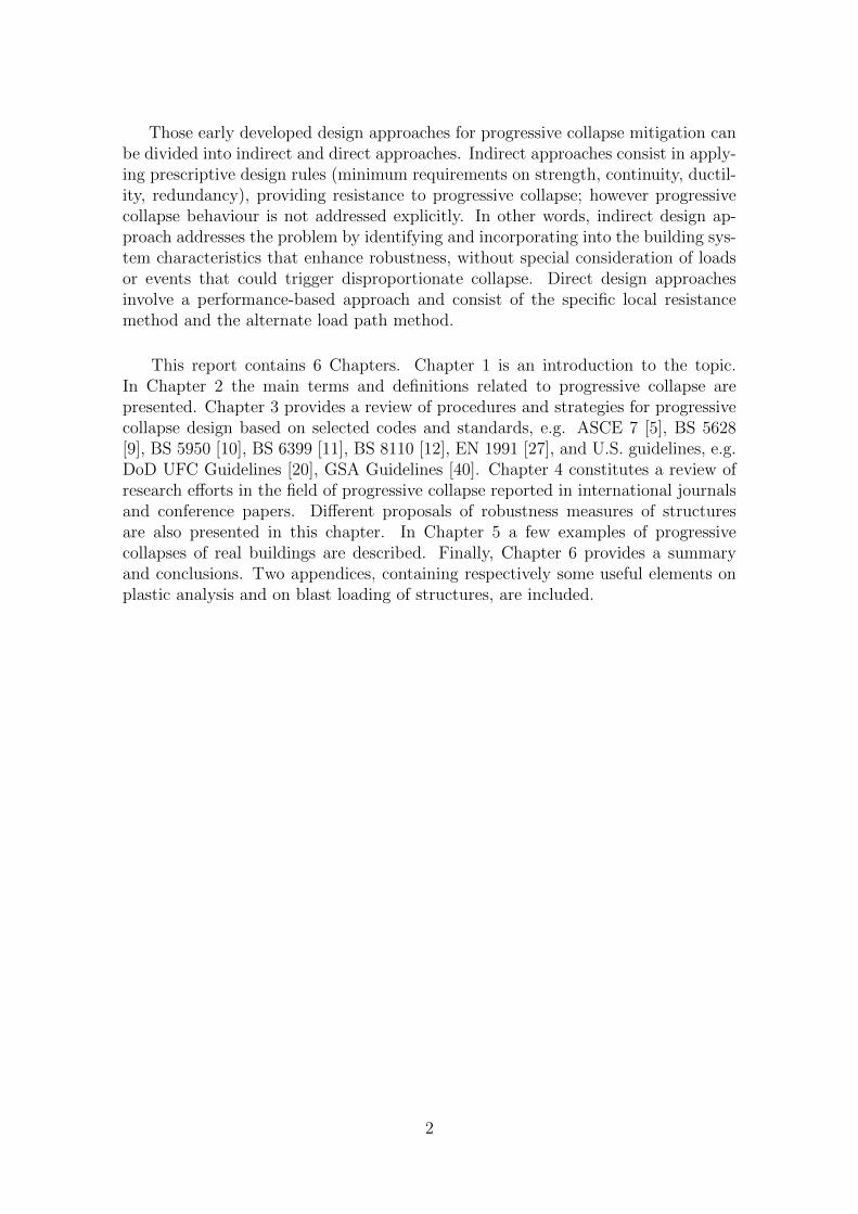
In another paper, Starossek [67] considers complex progressive collapse strate-gies which can be applied to tall buildings. These strategies include: nonstructuralprotective measures, specific local resistance, alternative paths, isolation of collaps-ing sections and prescriptive design rules. For specific local resistance approach,Starossek proposes that a primary load transfer system being a key element couldtake the form of a massive tube as illustrated in Fig. 4.8. The tube core shouldconstitute a high-strength reinforced concrete wall or a steel shape embedded in re-inforced concrete with the wall thickness of the order of 1m or more. As seen in thisFigure, the tube core should not be situated on the outer perimeter of the building,because any openings in the core should be limited to the minimum. There are also
Figure 4.4. Protective barriers

Examples of applying different strategies of progressive collapse design 36
Figure 4.5. Column failure
Figure 4.6. Modification of structural system - more columns
other features which the tube core should possesses that are described thoroughly inthe paper. In addition to the primary load transfer system there is envisaged a sec-ondary load transfer system in a form of cantilever floors fixed to the core. Thesecantilever floors, on the other hand, should be designed according to the alternateload path method, and any local failure should not lead to the partial collapse.Allowable damage scenarios of the secondary load transfer system are presentedin Fig. 4.9. It should be noted that an adequate rotational ductility capacity ofthe plastic hinges should be ensured. Starossek states that the required rotationalductility capacity is difficult to be achieved in reinforced concrete beams and instead,haunched steel girders can be used. Other way to limit the consequences of a localfailure is to design segmentation of the secondary load transfer system by means ofjoints as illustrated in Fig. 4.10. Concerning the alternate load paths approach forthe primary load transfer system, Starossek concludes that it is almost impossibleto achieve for tall buildings nowadays, giving the example of the total collapse ofthe WTC towers. On the other hand, using vertical segmentation approach, thereare chances that an initial local failure can be arrested. An example of such vertical
Figure 4.7. Strengthening of transfer girders
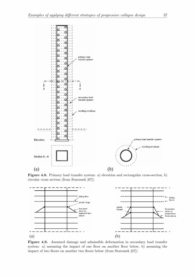
Examples of applying different strategies of progressive collapse design 37
Figure 4.8. Primary load transfer system: a) elevation and rectangular cross-section, b)circular cross section (from Starossek [67])
Figure 4.9. Assumed damage and admissible deformation in secondary load transfersystem: a) assuming the impact of one floor on another floor below, b) assuming theimpact of two floors on another two floors below (from Starossek [67])

Examples of applying different strategies of progressive collapse design 38
Figure 4.10. Segmentation of secondary load transfer system by joints (from Starossek[67])
segmentation in a tall building is given in Fig. 4.11. The height of a segment shouldbe of the order of one tenth of the building height. It is assumed that in the caseof a local failure of one or more floors, the failure front progresses vertically in twodirections (upward and downward) of segment borders. Simultaneously, the upperpart of the building, above the failing segment, moves down as a rigid body. Thelargest forces occur when the upper part together with the falling debris impactsthe lower segment. First solution could be to design thick reinforced or prestressedconcrete slabs. The other more advanced solution would comprise two slabs havingshock-absorbing devices in between (see Fig. 4.11). These envisaged shock-absorbingdevices could consist of telescoping large diameter steel tubes filled with a materialwhich enables high compressive strain, for example using scrap metal or porous tuffgravel (see Fig. 4.11c). Regarding the prescriptive design rules for tall building,Starossek advises against using them since for such large and expensive structuresgeneral rules without performance-based analysis can enhance the continuity, duc-tility and catenary actions in a quantitative way but not in a qualitative one.
DeStefano [17] as a practitioning engineer gives recommendations on how toprovide adequate detailing to prevent progressive collapse without excessive costs.He takes advantage of the fundamental principle of catenary behaviour which can bedeveloped when structural elements originally designed to resist loads in flexure aresubjected to large displacements which in turn causes to develop axial forces in thosestructural elements. For instance when an exterior column is removed from the lowerfloor of the structure, the ring girders act in tension. However, the weakest point inthis consideration is the corner of the building. The author of the paper providesa simple solution by applying diagonal girder in each corner span. There are alsogiven four tips on how to design the structure to allow for catenary behaviour. Theseare: (1) orientation of girders in such a way that the heaviest members are on theperimeter, (2) introduction of diagonal girders in the corner spans, (3) orientationof wide-flange perimeter columns with their strong axis parallel to the exterior wall.This allows the girders to connect directly to the column flange, (4) use of ductilegirder connection to the columns to allow rotations and to resist large axial loads.Seat and one-sided connections should be avoided.

Examples of applying different strategies of progressive collapse design 39
Figure 4.11. Segmentation strategy: (a) overall view of a building with vertical segmen-tation, (b) detail of the shock-absorbing segment, (c) shock-absorbing device: telescopingsteel tubes with compressible filling (from Starossek [67])
Another interesting example of progressive collapse design given in the samepaper by Starossek and Wolff [70] is the approach in the case of the ConfederationBridge in Canada. Designing this kind of bridge in a robust way appeared not tobe feasible, so the actual approach for progressive collapse was to spatially limitpotential local failure by isolating the collapsing section. Avoiding potential totalcollapse of the bridge required an interruption of continuity of prestressed tendons.
An interesting case of removing columns experimentally in an existing buildingwas presented by Sasani and Sagiroglu [62]. The building was the 6-storey HotelSan Diego, San Diego, U.S., planned to be demolished. The height of the first floorwas about 6m, while the height of the other floors and the last floor were 3.2mand 5.13m, respectively. The structural system constituted a non-ductile reinforcedconcrete frame structure with exterior infill walls. The floor system consisted ofone-way joists. Before the experiment, all nonstructural elements, infrastructureand furniture as well as the infill walls of the first and the third floor were removeddeliberately. The plan, south-east view and a 3D model of the Hotel is in Fig. 4.12,4.13 and 4.14.
To evaluate progressive collapse resistance of the building, two columns of thefirst floor (including a corner column) were exploded by implosion. The explo-sives were placed in drilled holes in the columns and the columns were wrapped

Examples of applying different strategies of progressive collapse design 40
Figure 4.12. South-east view of the Hotel San Diego (from Sasani and Sagiroglu [62])
Figure 4.13. Typical plan of the Hotel San Diego (removed columns in circles) [62]

Types of progressive collapses 41
Figure 4.14. 3D model of the Hotel San Diego (from Sasani and Sagiroglu [62])
by protective materials what prevented from air-blast shock waves. The structurewas equipped with strain gauges and potentiometers to measure global and localdeformations in time. The actual sudden removal of the two columns didn’t causeany collapse of the frame. The maximum and the permanent vertical displacementsat points above the removed columns were around 6.1mm, which means that thebeam above the removed columns deflected as a rigid body without deformations.On the other hand, the beams A1-A2 and A3-B3 deformed more significantly withrotations illustrated in Fig. 4.15. The reproduced deformed shape of the framebased on measurements is shown in Fig. 4.16. It is interesting to note that beamsA1-A2 and B3-A3 exhibits double curvature which accounts for the development ofVierendeel frame action in both directions (see also Fig. 4.16)
Abruzzo et al. [1] report the application of progressive collapse procedures toassess an existing reinforced concrete commercial building. The applied progressivecollapse procedures were: ACI 318 [2] structural integrity requirements, tie forceapproach based on DoD UFC Guidelines [20], linear static method based on GSAGuidelines [40] and nonlinear static analysis based on DoD UFC Guidelines [20](using SAP2000). The authors state that the structure would be prone to progressivecollapse when one of the interior columns loses capacity to carry loads. In particular,prescriptive requirement such as those in ACI 318 [2] and DoD UFC Guidelines [20]would not guarantee the prevention of progressive collapse.
4.4. Types of progressive collapses
Starossek [66] in his paper presents six different types and four classes of progres-sive collapse mechanisms. Those mechanisms are described by their characteristicfeatures and then are compared. The motivation for this typology and classifica-

Types of progressive collapses 42
Figure 4.15. Deformed shape of beams A1-A2 and A3-B3 (from Sasani and Sagiroglu[62])
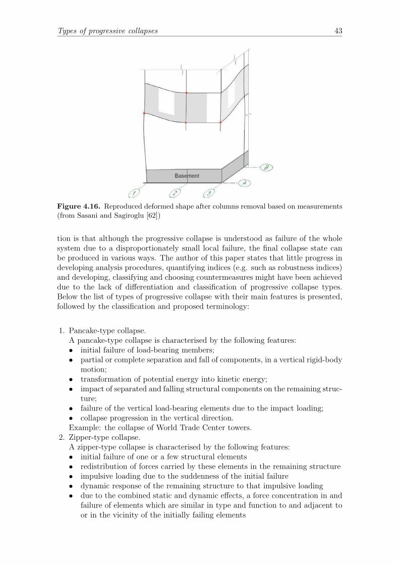
Types of progressive collapses 43
Figure 4.16. Reproduced deformed shape after columns removal based on measurements(from Sasani and Sagiroglu [62])
tion is that although the progressive collapse is understood as failure of the wholesystem due to a disproportionately small local failure, the final collapse state canbe produced in various ways. The author of this paper states that little progress indeveloping analysis procedures, quantifying indices (e.g. such as robustness indices)and developing, classifying and choosing countermeasures might have been achieveddue to the lack of differentiation and classification of progressive collapse types.Below the list of types of progressive collapse with their main features is presented,followed by the classification and proposed terminology:
1. Pancake-type collapse.A pancake-type collapse is characterised by the following features:• initial failure of load-bearing members;• partial or complete separation and fall of components, in a vertical rigid-body
motion;• transformation of potential energy into kinetic energy;• impact of separated and falling structural components on the remaining struc-
ture;• failure of the vertical load-bearing elements due to the impact loading;• collapse progression in the vertical direction.Example: the collapse of World Trade Center towers.
2. Zipper-type collapse.A zipper-type collapse is characterised by the following features:• initial failure of one or a few structural elements• redistribution of forces carried by these elements in the remaining structure• impulsive loading due to the suddenness of the initial failure• dynamic response of the remaining structure to that impulsive loading• due to the combined static and dynamic effects, a force concentration in and
failure of elements which are similar in type and function to and adjacent toor in the vicinity of the initially failing elements

Types of progressive collapses 44
• collapse progression in a direction transverse to the principal forces in thefailing elements
Example: the collapse of Tacoma Narrows Bridge.3. Domino-type collapse.
The list of features characterising a domino-type collapse is as follows:• initial overturning of one element• fall of that element in an angular rigid-body motion around a bottom edge• transformation of potential energy into kinetic energy• abrupt deceleration of the element’s motion through sudden activation of
discrete other elements; the horizontal force induced by that event is of bothstatic and dynamic origin because it results from both the tilting and themotion of the decelerated element
• overturning of other elements due to the horizontal loading from the deceler-ated element
• collapse progression in horizontal direction4. Section-type collapse.
It can be described in the context of a beam in bending or a bar under axialtension. When a cut occurs in a section of the beam, the internal forces must betransmitted by the remaining cross-section. This type of collapse can not usuallybe called a progressive collapse but fast fracture. However it is included in thetypology list to exploit similarities and analogies.
5. Instability-type collapse.An instability-type collapse is characterised by the following features:• initial failure of elements which stabilise load-carrying elements in compres-
sion• instability of the elements in compression that cease to be stabilised• sudden failure of these destabilised elements due to small perturbations• failure progression
6. Mixed-type collapse. Other types of progressive collapse mechanisms which can-not be easily distinguished and described and/or can be a combination of theprevious five types, fall in the mixed-type progressive collapse. As an example ofthis type of progressive collapse, Starossek [66] gives the partial collapse of theAlfred P. Murrah Federal Building (Oklahoma City, 1995) and Haeng-Ju GrandBridge (Seoul, 1992).
Those types of progressive collapse can be further classified by their main features.So zipper-type and section-type collapses can be grouped into the redistributionclass since the remaining structure must redistribute the forces of failed elements.Pancake-type and domino-type collapses are characterised by the fact that the majoramount of potential energy is transformed into kinetic energy. So they can begrouped into the impact class. At last, instability-type and mixed-type collapsesform their own classes having no common features.

Simplified methods for progressive collapse analysis 45
4.5. Simplified methods for progressive collapse analysis
Buscemi and Marjanishvili [13] present a simplified method for assessing the pre-disposition of a structure to progressive collapse. The method is based on pendulumanalogy, reducing the problem to a dynamic analysis of a SDOF system with initialconditions. The authors developed a modelling aid which can be used to determinehow a building is prone to progressive collapse based on maximum ductility andcorresponding rotations of major load-bearing elements.
Pujol and Smith-Pardo [59] present a simplified method for analysing framestructures for progressive collapse when a column is instantaneously removed. Thepurpose of the method is to provide a simple tool for preliminary design and consistsin evaluating a displacement ductility demand (ratio of displacement demand to yielddisplacement – µ = ∆max/∆y) using load factors (ratio of yield resistance to appliedload – LF ). The authors conclude that a floor system will have enough progressivecollapse resistance when one or more supports are removed provided that: (1) thestrength of the floor system, after the removal of support(s), is greater than theapplied loads by more than 50% and (2) the displacement ductility capacity of thefloor system is greater than 1.5. For other ratios of yield resistance to applied load(LF ), the chances of the floor system to survive depends on displacement ductilitydemand (µ) which can be estimated using the following formula
µ =1
2·
LF
LF − 1. (4.2)
Menchel [52] devoted his Ph.D. thesis to progressive collapse. The main contribu-tion is the development of two new quasi-static procedures accounting for dynamicinertial effects more accurately. The first new pushover analysis procedure is basedon a kinetic energy criterion (similar approach can also be found in Izzuddin et al.[43] and Dusenberry and Hamburger [23]) and the second pushover analysis is basedon optimised load amplification factors. The validation of the procedures were per-formed using dynamic nonlinear analyses. Another contribution is to use a morecomplex fibre-based nonlinear beam element (instead of an elastic beam elementwith discrete plastic hinges) to analyse reinforced concrete beams and columns.
Dusenberry and Hamburger [23] introduced a new energy based progressive col-lapse analysis method which creates a bridge between present simplified analysismethods and the best representation of the nonlinear dynamic behaviour that oc-curs during collapse. The energy-based method tracks the energy released by fallingweight and energy absorbed by the structure, a comparison can be made to assessif the failure is arrested. In other words, if the energy absorbed by the structureexceeds the change in potential energy, the structure comes to rest and has potentialto survive.
Vlassis et al. [74] present a new design-oriented methodology for progressivecollapse assessment of multi-storey buildings subjected to impact from the abovefailed floor. The idea is to assess if the lower floor is able to arrest the falling floor

Numerical case studies 46
which depends on the amount of kinetic energy transmitted from the upper floorduring the impact.
Schmidt [63] provides a summary of the methods which enable to define anexternal terrorist bomb threat, estimate structural design loads and analyse thestructure using a simple dynamic model. The effect of a blast is defined throughthe parameter Z = R/W 0.333, where R is a stand-off distance and W is explosivecharge size. The stand-off distance measures how close to the structure, a bomb canexplode and therefore is related to the physical surroundings of the building. W isa corresponding mass or weight of TNT. For other explosives, an adequate scalingfactor relating the heat energy of detonation to that of TNT must be provided.As for blast loading, the shock wave caused by an external blast gives an almostinstantaneous increase in pressure on objects to a maximum value. After reachingthe maximum of the positive phase, the pressure decays and then for longer periodrests in negative phase. For structural analysis, this behaviour can be approximatedby a triangular impulse load with zero or very small rise time and longer lineardecay. The maximum reflected pressure (pr) and total reflected impulse (ir) of theactual load in positive phase should be the basis for the equivalent loading, so thedesign duration be td = 2ir/pr. The negative phase is neglected because it has littleeffect on the maximum response of the structure.
4.6. Numerical case studies
Bao and Li [8] analysed the residual strength of reinforced concrete columnsunder a short stand-off blast loading. A case studies were performed to evaluate theeffects of transverse reinforcement ratio, axial load ratio, longitudinal reinforcementratio and column aspect ratio using the explicit FEM software LS-DYNA. In thepaper the effects of strain rate on concrete and reinforcing steel were taken intoaccount. The numerical simulation of dynamic response revealed that:
• the same axial load ratio is more critical for columns with a low transversereinforcement ratio,
• the ratio of residual axial capacity increases with the longitudinal reinforcementratio,
• the residual axial capacity increases with the decrease of the column aspect ratio,• seismic detailing techniques can significantly reduce the extent of direct blast
induced damage.
Agnew and Marjanishvili [4], Marjanishvili and Agnew [49], Marjanishvili [50]present and compare four methods for progressive collapse analysis by analysinga 9-storey steel moment-resistant frame building. The four methods are: linearstatic, nonlinear static, linear dynamic and nonlinear dynamic methods. The lastpaper gives detailed steps for performing all analyses in SAP 2000 including somescreenshots. Contrary to the GSA Guidelines and DoD UFC guidelines, where theydiscourage to use nonlinear dynamic analysis, the authors of the papers state that

Measures of structural robustness and vulnerability 47
using nonlinear dynamic analysis is not only more accurate but also easy to performby using modern FEM software.
Kaewkulchai and Williamson [44, 45] presented a nonlinear solution procedurefor progressive collapse analysis of planar frame structures. A proposal of a mod-elling strategy to account for the impact of failed members against other structuralcomponents is given. The authors indicate that the impact velocity plays the mostimportant role.
Ruth et al. [61] performed analyses which lead to conclusion that the dynamicfactors of 2 given in GSA Guidelines [40] and DoD UFC Guidelines [20] are too con-servative. Comparison of an equivalent static nonlinear analysis with the dynamicfactor of 1.5 and the dynamic nonlinear analysis shows that enough safety is ensuredand more economic design can be achieved.
Powell [58] also confirms that the static analysis for progressive collapse is tooconservative, also stating that performing dynamic, nonlinear analysis using currentFEM software is no more difficult and gives better accuracy.
Hayes et al. [41] presents studies on how the current seismic design provisions canimprove resistance to blast loads and progressive collapse. The study was carried outon Alfred P. Murrah Federal Building (severely damaged in 1995), where 3 seismicstrengthening techniques and then progressive collapse analysis were performed tocompare progressive collapse resistance of the building. The key finding of thestudy was that strengthening the perimeter element using current seismic detailingtechniques improved the survivability of the building, while strengthening elementsinternal to the building was not effective.
4.7. Measures of structural robustness and vulnerability
According to NIST Best Practices [56], structural robustness for reducing pro-gressive collapse risk can be enhanced by incorporating sufficient: redundancy, ties,ductility, adequate shear strength and capacity for resisting load reversals. Althoughproviding adequate level of these features will improve the robustness of the struc-ture qualitatively, it would be convenient to use a quantitative way to measure andcompare the robustness of different structures.
Starossek and Haberland [68, 69] formulated four general conditions that mea-sures of robustness should satisfy (if possible). These general conditions are:
• expressiveness: the measure should express all important aspects of robustnessand should give a clear difference between robust and non-robust structures;
• objectivity: the measure should be independent of decisions and same resultsshould be obtained for same conditions;
• simplicity: the measure should be as simple as possible;

Measures of structural robustness and vulnerability 48
• calculability: the necessary parameters should be quantifiable and should beobtainable from the data of the structure;
• generality: the measure should be possible to apply for different structures.
Different measures of robustness found in literature can be divided on thosebased on structural behaviour and those based on structural attributes.

Measures of structural robustness and vulnerability 49
4.7.1. Measures based on structural behaviour
Starossek and Haberland [68, 69] proposed three measure of robustness. Twomeasures of robustness fall into this category of measures based on structural be-haviour and the third one is based on structural attributes. The first measure ofrobustness proposed by the authors is based on damage and defined as
Rd = 1−p
plim, (4.3)
where Rd – damage-based robustness measure, p – maximum extent of additionaldamage (maximum damage progression) caused by the assumed initial damage ilim,plim – acceptable damage progression. This measure takes into account design objec-tives such as assumed initial damage and acceptable damage progression. Anotherversion of this measure of robustness can be expressed as
Rd,int = 1− 2
∫
1
0
[d(i)− i]di, (4.4)
where Rd,int – damage-based integral robustness measure, d(i) – maximum extentof total damage caused by and including the initial damage i, based on the corre-sponding value for the intact building, i – extent of initial damage also based on theintact building.
The illustration of damage progression is shown in Fig. 4.17, where curve A rep-resents a non-robust structure showing that even small initial damage can lead tolarge global damage; curve B represents a robust structure – significant damage oc-curs when large initial damage happens. However similar areas between the curvesB and C and line i (for integral in Eq. (4.4)) can be misleading in determininga good robustness measure.
1
1i
d
d(i)
i
Figure 4.17. Damage evolution

Measures of structural robustness and vulnerability 50
The second measure of robustness, based on energy, presented by Starossek andHaberland [68, 69], can be defined as
Re = 1−maxj
Er,j
Es,k
, (4.5)
where Re – energy-based robustness measure, Er,j – energy released by the initialfailure of the structural element j and available for the damage of the next structuralelement k, Es,k – energy required for the failure of the next structural element k.
Lind [46, 47] presents probabilistic definition of vulnerability and damage toler-ance (robustness) and their related measures. The suggested definitions are intendedto be general and applicable to all engineering systems. To define vulnerability, Linddenotes P (r, S) as the probability of failure of the system in a state r for prospectiveloading S, r0 as a pristine system state and rd as a particular damaged state. Thenthe vulnerability is defined as the ratio
V = V (rd, S) =P (rd, S)
P (r0, S). (4.6)
This vulnerability is equal to one if the probability of failure is the same in thedamaged and undamaged states. The measure of damage tolerance is defined as thereciprocal of the vulnerability (Eq. (4.6))
T =P (r0, S)
P (rd, S). (4.7)
As the author states, to have realistic measure of vulnerability and damage tolerance,one needs to assign realistic probability distributions for them.
Baker et al. [7] proposed a framework for assessment of robustness for systemssubject to structural damage. The idea of this framework is to create an event treeas follows. Assume that a certain potentially damaging event (e.g. extreme valuesof snow loads, explosions etc.) occurs in the system. The system can be damaged ornot. If no damage occurs, no further analysis is needed. If damage occurs, differentdamage states can happen. For each damage states assign a probability of failure.Assign also consequences for possible damage and failure scenarios. Direct conse-quences are related to initial damage, whereas indirect consequences are related tosubsequent system failure. Consequences take multiple forms for example: incon-venience to system users, injuries, fatalities and costs and require an introductionof a scalar measure. Having assign all these values, the authors proposed an indexof robustness (which measures the fraction of the total system risk resulting fromdirect consequences) as follows
IR =RDir
RDir +RInd
, (4.8)
where RDir and RInd are direct and indirect risks, respectively. These risks arecalculated by multiplying the consequences of each possible event scenario by itsprobability of occurrence and then integrating over all the random variables in theevent tree. There are in the paper some example calculations for idealised systems,however as the authors state application for real system requires more work.

Measures of structural robustness and vulnerability 51
Wisniewski et al. [75] report load-capacity evaluation of existing railway bridgesby robustness quantification. Bridge robustness is defined as the ability to carryloads after the failure of one of its members. To express robustness of railway bridges,the authors define so-called redundancy factor based on redundancy ratios whichcompare the load-carrying capacity in the limit states to the design load-carryingcapacity. If the calculated redundancy factor is less than 1.0 then the bridge maybe deemed as not safe, for redundancy factor equal or greater than 1.0 the bridgemay be considered as safe.
Maes et al. [48] presented three measures of robustness. The first measure ofrobustness is referred to the assumption that the system’s resistance as a whole canbe maintained to a sufficient degree after a load that makes failure in one of itscomponents i. This measure of robustness can be written as
R1 = mini
RSRi
RSR0
, (4.9)
where RSRi is the reserve strength ratio when member i is impaired, while RSR0
is the reserve strength ratio when no member is impaired.
The second proposed measure of robustness can be expressed in terms of systemreliability as
R2 = mini
Ps0
Psi
, (4.10)
where Ps0 is the system probability of failure of the undamaged system subject tosuch a member design load and Psi is the system probability of failure when elementi is impaired.
The third measure of robustness is based on sample functions of failure conse-quences versus hazard intensity and conditional probability of exceedance versusfailure consequences. Computing the inverse of the tail heaviness H of the men-tioned conditional probability of exceedance versus failure consequences a measureof robustness R3 can be obtained. According to Maes et al. [48], the tail of anygiven probability distribution can be easily computed and if H is less than one, itmeans that the robustness of a structure is very high, if H is one – the robustnessis smaller than before and for large H – the robustness of the structure is very low.
Smith [64] proposed a measure of robustness based on the theory of fast fracturein fracture mechanics. The premise of this approach is as follows: if the energyreleased by loss of a damaged member is greater than the energy absorbed by thetotally damaged member and other partially damaged members, then the progressivecollapse will occur. This approach uses finite element analysis of a structure andgraph theory search to find the sequence of damage events that requires the smallestamount of energy. The minimum damage energy is a measure of robustness ofa structure.
Menchel [52] introduced an indicator of robustness of a structure with respect tothe removal of a column defining it as the maximum load factor that can be appliedto the dead and live loads when applied statically on the structure from which the

Other topics 52
considered column has been removed. The procedure to estimate such an indicatorof robustness is as follows: (1) remove a column from the model, (2) apply theloads statically, multiplying them by an increasing factor, (3) when stresses can nolonger be redistributed, this factor is the indicator of robustness. In other words,the indicator of robustness is a measure of the resistance reserve of a structure withregard to the loads applied to it and for the removal of a specific column.
4.7.2. Measures based on structural attributes
As mentioned before the third measure of robustness defined by Starossek andHaberland [68] falls into the group of measures based on structural attributes, herespecifically on structural stiffness and can be expressed as
Rs = minj
detKj
detK0
(4.11)
where Rs - stiffness-based robustness measure, K0 and Kj – global stiffness matrixof the intact structure and the structure after removal of a structural element ora connection j, respectively. The authors state that there is a relatively low correla-tion between the reduction in load capacity after the loss of structural element andthe assigned measure of robustness Rs. However this formulation has two advantagesnamely: simplicity and ease of calculation. This approach can be appropriate forzipper-type collapse and useless for pancake-type or domino-type collapses as definedin [66] and summarised above in Section 4.4.
Agarwal et al. [3] introduced a topological measure of vulnerability referring tothe theory of form and connectivity. Basically it investigates the potential hazardspresent in the structural form which could be triggered by unexpected events orunforeseen loading conditions. The theory consists of three steps which are: iden-tifying so called structural rings and rounds, creating a hierarchical description ofthe structure and searching through the structural hierarchy to look for vulnerablescenarios. This approach is developed for 2D and 3D frames.
4.8. Other topics
Tagel-Din and Rahman [72] present a new progressive collapse simulation methodbased on the Applied Element Method (AEM). The method takes into account loadthread, separation of structural parts and possible collisions resulting from fallingdebris. In the Applied Element Method, a structure is modelled as an assemblyof small elements connected be a series of springs. Partial connectivity occurringduring progressive collapse is allowed and modelled by means of springs. Whenmodelling a structure, all that is required is to define the material type, or propertyof different interfaces.
Moore [54] presents how provisions in British Standards defined after the RonanPoint collapse improved the situation in the UK. Moore states that engineers mainly

used indirect approach (tie force requirements). In addition, the author proposes toextend the application of the current UK building regulations to all buildings, andnot only to 5 or more storey buildings.
Report NIST Best Practices [56] gives the state-of-the-art on progressive col-lapse, based on British Standards, ASCE, EC and other national and local codestandards as well as based on GSA Guidelines, DoD UFC guidelines. The main top-ics included in the report are: consideration acceptable risk, building vulnerabilities(continuity, load reversals), means of risk reduction (event control, structural analy-sis), detailed description of indirect and direct approaches, extensive comparison ofcode, standards and national guidelines. The document summarises best practicesfor designing different type of structures (r/c, steel, masonry etc.).
In 2011 the COST Action TU0601 group concluded their work on robustness ofstructures in [14]. The purpose of this document is to provide additional informationto designers, structural analysts, regulatory authorities etc. The document is alsoaimed at providing assistance to the committees developing codes and standards(e.g. CEN TC250 and ISO TC98). The particular aspects dealt in this documentcontain:
• failure of more than one load-bearing element, by considering the various typesof loading,
• assessment and quantification of robustness (most of the robustness indices aredescribed in Chapter 4.7),
• risk-based decision-making,• methods for providing robustness (e.g. specific local resistance method, alternate
load path method, tie force method etc.),• robustness during construction,• effects of poor quality and deterioration of material.
In 2011 US Department of Homeland Security [73] issued comprehensive techni-cal report on how to prevent structures from collapsing to limit damage to adjacentstructures and additional loss of life when explosives devices impact highly populatedurban centers. The main focus is on:
• the influence of the presence of buildings on the blast pressures propagating fromexplosions located in urban settings,
• the potential for these blast pressures to damage primary structural members ofbuildings,
• the sensitivity of several common building design types to experience progressivecollapse due to damage of key support members, and
• the likelihood that blast pressures may damage building equipment needed foremergency evacuation, rescue and recovery operations.
The results the studies were integrated in the prototype of a fast running softwareprogram, concentrated on the Manhattan Financial District.
Stevens et al. [71] ...
solomos
Text Box

5. Examples of progressive collapse
This chapter presents selected examples of building progressive collapses. Al-though the number of progressive collapses in the history is quite small, the catas-trophic consequences in terms of fatalities and other losses, which this phenomenonentails, brings a lot of attention in society, governments and community of civilengineers. Moreover, the growing threat of terrorist attacks makes the problem ofprogressive collapse should be considered when designing and constructing buildings.
5.1. Ronan Point
The Ronan Point Apartment building was erected in London between 1966 and1968. It was a 23 storey, and 64m high building. The structural system consistedof precast concrete walls and floors. The floors were supported by the lower storeyswalls. The floors and walls were fitted by slots and bolted together. The connectionswere filled with dry packed mortar. Thus, this structural system was characterisedby very limited ability to redistribute loads and was prone to progressive collapsewhen exposing to a local failure.
On May 16, 1968, an exterior panel of the 18th floor was blown out due toan internal gas explosion of a leaking gas stove. The loss of this panel caused theprogressive collapse of upper floors (19 through 23) and subsequently the fallingdebris invoked the progressive collapse of lower floors down to the ground floor. Theresult of the progressive collapse can be seen in Fig. 5.1.
More details can be found in [56].
5.2. Alfred P. Murrah Federal Building
The Alfred P. Murrah Federal Building located in Oklahoma City was an of-fice building of the U.S. government constructed between 1970 and 1976. It wasa nine-storey, reinforced concrete structure, 61m long, 21.4m wide. The structuralsystem was formed by columns (on 6.1m × 10.7m grid) and a beam/slab system.The regularity of the frame was interrupted on the north elevation where the spanbetween columns was doubled and these columns supported deep transfer girders.

Alfred P. Murrah Federal Building 55
Figure 5.1. Ronan Point Apartment after collapse [16]
It should be noted that the reinforced concrete frame was designed and constructedin a non-ductile manner.
On April 19, 1995, the Alfred P. Murrah Federal Building became the target ofa terrorist attack. The explosive charge was detonated from a truck situated 4mfrom one of the columns. The power of the blast was estimated to 1800 kg of TNTequivalent (see Osteraas [57]). The direct blast destroyed one column, then the blastwave destroyed floors and beams which in turn was the cause for buckling the otherthree columns due to lack of lateral supports. Two illustrations of the Alfred P.Murrah Federal Building after the progressive collapse can be seen in Fig. 5.2 and5.3.
After investigating the Alfred P. Murrah Federal Building case, Osteraas [57]concludes with four statements, which should be applied in progressive collapsedesign, namely:
• avoiding significant irregularities in the layout configuration and using transfergirders, to ensure the possibility of alternative load paths,
• the frame should enable the slabs and walls to fail without destroying the frame,• the frame should be robust and ductile to sustain large deformations,• lower perimeter columns should be designed to resist direct blast waves as much
as possible.
The author states that the third conclusion can entail adopting detailing from seismicengineering and applying it for designing important buildings in nonseismic zones.

Alfred P. Murrah Federal Building 56
Figure 5.2. Alfred P. Murrah Federal Building [60]
Figure 5.3. Alfred P. Murrah Federal Building (Note the brittle failure of the transfergirder due to non-ductile design) [15]

Further details can be found in [56, 57].
5.3. L’Ambiance Plaza
L’Ambiance Plaza in Bridgeport, Connecticut, was a 16-storey apartment build-ing which collapsed in April 1987 while being under construction (see Fig. 5.4). Thebuilding was erected using lift-slab method, which required the slabs to be cast onthe ground and then lifted into place using jacketing operations. The total collapsehappened after finishing one of the jacketing operations (see Fig. 5.5). After theinvestigations of the collapse by Heger [42], there were reported four main struc-tural deficiencies which could cause the collapse, namely: (1) improper placementof post-tensioning tendons adjacent to elevator openings, (2) overstressed concreteslab sections adjacent to two temporary floor slots for cast-in-place shear walls, (3)overstressed and excessively flexible steel lifting angles during slab lifting, and (4)unreliable and inadequate temporary slab-column connections to ensure frame sta-bility. On the other hand, Dusenberry [22] states that possible causes that initiated
Figure 5.4. L’Ambiance Plaza during the construction phase [22]
the collapse were: failure of shear collars, improper configuration of tendons, overallstability, plumbing operation, lateral soil pressure and frozen concrete, while thedirect reason for the complete collapse could be the use of a very mild steel andincomplete construction.
More details can be found in [42, 51, 56].

L’Ambiance Plaza 58
Figure 5.5. L’Ambiance Plaza after the collapse [22]

6. Summary and conclusions
The aim of this report is to review the state-of-the-art of progressive collapse pro-cedures and strategies provided in codes and standards as well as in selected nationalspecific guidelines (e.g. DoD UFC Guidelines [20], GSA Guidelines [40]). Recentgrowing interest in the subject of progressive collapse of civil engineering structures,resulted in an observed increased number of scientific publications. Findings fromseveral important papers are also reviewed in Section 4.
To summarise the provisions raised in the studied documents, selected aspects arepresented in the following tables. A comparison of load combinations for progressivecollapse analysis in the different documents is presented in Table 6.1.
Table 6.1. Comparison of load combinations in different documents
Document Load Combinations Remarks
BS D + L/3 +W/3Eurocode see Eq. (3.5)ASCE 7-05 (0.9 or 1.2)D + (0.5L or 0.2S) + 0.2Wn alternate load path method
1.2D +Ak + (0.5L or 0.2S) specific local resistance m.(0.9 or 1.2)D +Ak + 0.2Wn specific local resistance m.
GSA 2(D + 0.25L) static analysis,D + 0.25L dynamic analysis,
UFC 4-023-03 (0.9 or 1.2)D + (0.5L or 0.2S) + 0.2Wn nonlinear dynamic analysis2[(0.9 or 1.2)D + (0.5L or 0.2S) + 0.2Wn] nonlinear static analysis
D – dead load,L – live load,
W – wind load,S – snow load.
A comparison of accidental loads for designing key elements in the differentdocuments is presented in Table 6.2. It should be noted that the Eurocodes inheritedthe value of 34 kPa from the British Standards. In many places, however, this valueis questioned as being too high. On the other hand, other documents presented inthe table do not specify the value leaving it to the authorities. The U.S. guidelines,overall, prefer the alternate load path method instead of the specific local resistancemethod, and do not mention accidental loads at all.
Table 6.3 presents a comparison of allowable local collapse areas in the selecteddocuments. These limitations are similar, however DoD UFC Guidelines [20] distin-guishes the limitations depending on where the local damage takes place.

Table 6.2. Comparison of accidental loads for designing key elements in different docu-ments
Document Accidental load
BS 34 kPaEurocodes 34 kPaASCE 7-05 Ak (to be specified by the authorities)
GSA -UFC 4-023-03 -
Table 6.3. Comparison of allowable local collapse areas in different documents
BS Eurocodes GSA UFC 4-023-03
15% of floor orroof area or 70m2
(whichever is less).Extent of initialdamage and oneadjacent level eitherabove or below.
The limit of admis-sible local failuremay be differentfor each type ofbuilding. The rec-ommended value is15% of the floor or100m2 (whicheveris smaller) in eachof two adjacentstoreys.
Structural bayassociated with theremoved element.167m2 at the floordirectly abovea removed exteriorcolumn or 334m2
at the floor directlyabove a removedinterior column.
Removal of exteriorcolumn: 70m2
or 15% of thetotal floor area(whichever is less),Removal of interiorcolumn: 140m2
or 30% of thetotal floor area(whichever is less)
For some time, the national codes and standards have included general provisionson how to design structure for progressive collapse resistance. However, they stilllack more detailed guidance for engineers, since some aspects are not explained indepth. It seems that more detailed commentary with calculated examples would berequired. For example, in Eurocode, there is no precise specification what dynamicamplification factor should be used when an equivalent static analysis is employed.This gap is partly fulfilled in U.S. guidelines where more detailed step by stepprocedures for progressive collapse design are given and the dynamic amplificationfactor equal to 2, for quasi-static analysis is provided. A few papers (e.g. Powell[58], Ruth et al. [61]) state that this value is too conservative.
The other problem is the not so clear behaviour of buildings when internal orexternal explosions caused by explosives occur. To shed more light on this issue,appropriate tools should be developed to simulate such phenomena, followed, ifpossible, by validating experiments.

References
[1] J. Abruzzo, A. Matta, and G. Panariello. Study of mitigation strategies forprogressive collapse of a reinforced concrete commercial building. Journal ofPerformance of Constructed Facilities, 20(4):384–390, 2006.
[2] ACI 318. ACI 318: Building code requirements for structural concrete andcommentary. American Concrete Institute, 2005.
[3] J. Agarwal, D. Blockley, and N. Woodman. Vulnerability of structural systems.Structural Safety, 25(263-186), 2003.
[4] E. Agnew and S. Marjanishvili. Dynamic analysis procedures for progressivecollapse. Structure magazine (www.structuremag.org), pages 24–27, Apr 2006.
[5] ASCE 7. ASCE 7: Minimum design loads for buildings and other structures.American Society of Civil Engineers, 2005.
[6] ATC-40. Seismic evaluation and retrofit of concrete buildings. ATC-40 Report.Applied Technology Council, Redwood City, California, 1996.
[7] J. W. Baker, M. Schubert, and M. H. Faber. On the assessment of robustness.Structural Safety, 30(253-267), 2008.
[8] H. Bao and B. Li. Residual strength of blast damaged reinforced concretecolumns. International Journal of Impact Engineering, 37:295–308, 2010.
[9] BS 5628. BS 5628: Code of practice for use of masonry: Part 1: Structural useof unreinforced masonry. British Standards Institute, 1978.
[10] BS 5950. BS 5950: Structural use of steelwork in building: Part 1: Code ofpractice for design – Rolled and welded sections. British Standards Institute,2000.
[11] BS 6399. BS 6399: Loading for buildings: Part 1: Code of practice for deadand imposed loads. British Standards Institute, 1996.
[12] BS 8110. BS 8110: Structural use of concrete: Part 1: Code of practice fordesign and construction. British Standards Institute, 2000.
[13] N. Buscemi and S. M. Marjanishvili. SDOF model for progressive collapseanalysis. In Proceedings of SEI Structures Congress, ASCE, 2005.
[14] T. D. G. Canisius, editor. Structural robustness design for practising engineers,2011. COST Action TU0601.
[15] K. Caruso. The Oklahoma City Bombing. http://www.
oklahomacitybombing.com/oklahoma-city-bombing.html.[16] N. Delatte. The Ronan Point Apartment Tower Case. http://matdl.org/
failurecases/Building\%20Cases/Ronan\%20Point.htm.[17] J. DeStefano. Detailing to prevent progressive collapse. Structure magazine
(www.structuremag.org), 11:66–67, 2006.[18] DoD UFC 4-010-01. DoD Minimum Antiterrorism Standards For Buildings
(UFC) 4-010-01. Department of Defence (DoD), 2003.[19] DoD UFC 4-010-02. DoD Minimum Standoff Distances for Buildings (UFC)

References 62
4-010-02. Department of Defence (DoD), 2003.[20] DoD UFC Guidelines. Design of Buildings to Resist Progressive Collapse, Uni-
fied Facilities Criteria (UFC) 4-023-03. Department of Defence (DoD), 2005.[21] DoD UFC Guidelines. Design of Buildings to Resist Progressive Collapse, Uni-
fied Facilities Criteria (UFC) 4-023-03. Department of Defence (DoD), January2010. With updates from 2009 and 2010.
[22] D. O. Dusenberry. L’ambiance plaza – case study. http:
//www.bfrl.nist.gov/861/861pubs/collapse/workshop/7.L’
AmbiancePlazaCaseStudy060913.pdf.[23] D. O. Dusenberry and R. O. Hamburger. Practical means for energy-based
analyses of disproportionate collapse potential. Journal of Performance of Con-structed Facilities, 20(4):336–348, 2006.
[24] B. R. Ellingwood. Mitigating risk from abnormal loads and progressive collapse.Journal of Performance of Constructed Facilities, 20(4):315–323, 2006.
[25] B. R. Ellingwood and D. O. Dusenberry. Building design for abnormal loadsand progressive collapse. Computer-Aided Civil and Infrastructure Engineering,20(3):194–205, 2005.
[26] EN 1990. Eurocode 0 - EN 1990: Basis of structural design, 2002.[27] EN 1991. Eurocode 1 - EN 1991: Actions on structures, 2004.[28] EN 1991-1-7. Eurocode 1 - EN 1991-1-7: Actions on structures - Part 1-7:
General actions - Accidental actions, 2006.[29] EN 1992. Eurocode 2 - EN 1992: Design of concrete structures, 2004.[30] EN 1993. Eurocode 3 - EN 1993: Design of steel structures, 2004.[31] EN 1994. Eurocode 4 - EN 1994: Design of composite steel and concrete struc-
tures, 2002.[32] EN 1995. Eurocode 5 - EN 1995: Design of timber structures, 2002.[33] EN 1996. Eurocode 6 - EN 1996: Design of masonry structures, 2002.[34] EN 1997. Eurocode 7 - EN 1997: Geotechnical design, 2002.[35] EN 1998. Eurocode 8 - EN 1998: Design of structures for earthquake resistance,
2002.[36] EN 1999. Eurocode 9 - EN 1999: Geotechnical design, 2002.[37] FEMA. FEMA-273 NEHRP Guidelines For The Seismic Rehabilitation Of
Buildings. Federal Emergency Management Agency, Washington, D.C., 1997.[38] FEMA. FEMA-350 Recommended Seismic Design Criteria for New Steel
Moment-Frame Buildings. Federal Emergency Management Agency, 2000.[39] D. M. Frangopol and J. P. Curley. Effects of damage and redundancy on struc-
tural reliability. Journal of Structural Engineering, 113(7):1533–1549, 1987.[40] GSA Guidelines. GSA Progressive Collapse Analysis and Design Guidelines
for New Federal Office Buildings and Major Modernizations Projects. GeneralServices Administration (GSA), 2003.
[41] J. J. R. Hayes, S. C. Woodson, R. G. Pekelnicky, C. D. Poland, W. G. Corley,and M. Sozen. Can strengthening for earthquake improve blast and progressivecollapse resistance? Journal of Structural Engineering, 131(8):1157–1177, 2005.
[42] F. J. Heger. L’ambiance plaza. http://www.engineering.com/Library/
ArticlesPage/tabid/85/PageID/182/ArticleID/168/articleType/
ArticleView/Default.aspx.[43] B. Izzuddin, A. Vlassis, A. Elghazouli, and D. Nethercot. Progressive collapse of
multi-storey buildings due to sudden column loss – Part I: Simplified assessment

References 63
framework. Engineering Structures, 30(5):1308–1318, 2008.[44] G. Kaewkulchai and E. Williamson. Beam element formulation and solution
procedure for dynamic progressive collapse analysis. Computers and Structures,82:639–651, 2004.
[45] G. Kaewkulchai and E. B. Williamson. Modeling the impact of failed membersfor progressive collapse analysis of frame structures. Journal of Performance ofConstructed Facilities, 20(4):375–383, 2006.
[46] N. C. Lind. A measure of vulnerability and damage tolerance. ReliabilityEngineering and Structural Safety, 48(1-6), 1995.
[47] N. C. Lind. Vulnerability of damage-accumulating systems. Reliability Engi-neering and Structural Safety, 53(217-219), 1996.
[48] M. A. Maes, K. E. Fritzsons, and S. Glowienka. Risk-based indicators of struc-tural system robustness. Structural Engineering International, 16(2):101–107,2006.
[49] S. Marjanishvili and E. Agnew. Comparison of various procedures for progres-sive collapse analysis. Journal of Performance of Constructed Facilities, 20(4):365–374, 2006.
[50] S. M. Marjanishvili. Progressive analysis procedure for progressive collapse.Journal of Performance of Constructed Facilities, 18(2):79–85, 2004.
[51] R. Martin. L’ambiance plaza collapse. http://www.eng.uab.edu/
cee/faculty/ndelatte/case_studies_project/L’Ambiance\%20Plaza/
ambiance.htm.[52] K. Menchel. Progressive Collapse: Comparison of Main Standards, Formulation
and Validation of New Computational Procedures. PhD thesis, Universite Librede Bruxelles, 2009.
[53] O. A. Mohamed. Progressive collapse of structures: Annotated bibliographyand comparison of codes and standards. Journal of Performance of ConstructedFacilities, 20(4):418–425, 2006.
[54] D. B. Moore. The UK and European regulations for accidental actions. In Pro-ceedings: Workshop on Prevention of Progressive Collapse, National Instituteof Building Sciences, Washington, D.C., 2002.
[55] R. S. Nair. Preventing disproportionate collapse. Journal of Performance ofConstructed Facilities, 20(4):309–314, 2006.
[56] NIST Best Practices. Best Practices for Reducing the Potential for ProgressiveCollapse in Buildings. U.S. National Institute of Standards and Technology(NIST), Washington, D.C., 2007.
[57] J. D. Osteraas. Murrah Building bombing revisited: A qualitative assessmentof blast damage and collapse patterns. Journal of Performance of ConstructedFacilities, 20(4):330–335, 2006.
[58] G. Powell. Progressive collapse: Case studies using nonlinear analysis. InProceedings of ASCE 2005 Structures Congress: Metropolis and Beyond, NewYork, U. S. A., 2005.
[59] S. Pujol and J. P. Smith-Pardo. A new perspective on the effects of abruptcolumn removal. Engineering Structures, 31:869–874, 2009.
[60] J. Rappoport. The Oklahoma City Bombing. http://911review.com/
precedent/decade/okc.html.[61] P. Ruth, K. A. Marchand, and E. B. Williamson. Static equivalency in progres-
sive collapse alternate path analysis: Reducing conservatism while retaining

structural integrity. Journal of Performance of Constructed Facilities, 20(4):349–364, 2006.
[62] M. Sasani and S. Sagiroglu. Progressive collapse resistance of Hotel San Diego.Journal of Structural Engineering, 134(3):478–488, 2008.
[63] J. A. Schmidt. Structural design for external terrorist bomb attacks. Structuremagazine (www.structuremag.org), 3:14–15, 2003.
[64] J. W. Smith. Structural robustness analysis and the fast fracture analogy.Structural Engineering International, 16(2):118–123, 2006.
[65] U. Starossek. Progressive collapse of structures: nomenclature and procedures.Structural Engineering International, 16(2):113–117, 2006.
[66] U. Starossek. Typology of progressive collapse. Engineering Structures, 29(9):2301–2307, 2007.
[67] U. Starossek. Avoiding disproportionate collapse of tall buildings. StructuralEngineering International, 3:238–245, 2008.
[68] U. Starossek and M. Haberland. Approaches to measures of structural robust-ness. In IABMAS 2008, 4th International Conference on Bridge Maintenance,Seoul, South Korea, 2008.
[69] U. Starossek and M. Haberland. Measures of structural robustness - require-ments and applicaitons. In ASCE SEI 2008 Structures Congress - CrossingBorders, Vancouver, Canada, 2008.
[70] U. Starossek and M. Wolff. Design of collapse-resistant structures. In JCSSand IABSE Workshop on Robustness of Structures, BRE, Garston, Watford,UK, 2005.
[71] D. Stevens, B. Crowder, D. Sunshine, K. Marchand, R. Smilowitz,E. Williamson, and M. Waggoner. DoD research and criteria for the designof buildings to resist progressive collapse. Journal of Structural Engineering,137(9), 2011.
[72] H. Tagel-Din and N. A. Rahman. The Applied Element Method: the ultimateanalysis of progressive collapse. Structure magazine (www.structuremag.org),pages 30–33, Apr 2006.
[73] US Department of Homeland Security. Preventing structures from collapsing tolimit damage to adjacent structures and additional loss of life when explosivesdevices impact highly populated urban centers. Buildings and InfrastructureProtection Series - BIPS 05, US Department of Homeland Security, June 2011.
[74] A. Vlassis, B. Izzuddin, A. Elghazouli, and D. Nethercot. Progressive collapseof multi-storey buildings due to failed floor impact. Engineering Structures, 31(7):1308–1318, 2009.
[75] D. F. Wisniewski, J. R. Casas, and M. Ghosn. Load-capacity evaluation ofexisting railway bridges based on robustness quantification. Structural Engi-neering International, 16(2):161–166, 2006.

List of Figures
3.1. Strategies for accidental design situations (EN 1991-1-7 [28]) . . . . . . . . . . 14
3.2. Measurement of θ after formation of plastic hinges (from GSA Guidelines [40]) 25
3.3. Sideways and member end rotations (θ) for frames (from GSA Guidelines [40]) 25
3.4. Tie forces in a frame structure (UFC 4-023-03) . . . . . . . . . . . . . . . . . . 29
4.1. Terms in the context of progressive collapse (from [69]) . . . . . . . . . . . . . 33
4.2. Initial frame structure . . . . . . . . . . . . . . . . . . . . . . . . . . . . . . . . 35
4.3. Specific local resistance . . . . . . . . . . . . . . . . . . . . . . . . . . . . . . . 35
4.4. Protective barriers . . . . . . . . . . . . . . . . . . . . . . . . . . . . . . . . . . 35
4.5. Column failure . . . . . . . . . . . . . . . . . . . . . . . . . . . . . . . . . . . . 36
4.6. Modification of structural system - more columns . . . . . . . . . . . . . . . . 36
4.7. Strengthening of transfer girders . . . . . . . . . . . . . . . . . . . . . . . . . . 36
4.8. Primary load transfer system: a) elevation and rectangular cross-section, b)circular cross section (from Starossek [67]) . . . . . . . . . . . . . . . . . . . . 37
4.9. Assumed damage and admissible deformation in secondary load transfersystem: a) assuming the impact of one floor on another floor below, b)assuming the impact of two floors on another two floors below (from Starossek[67]) . . . . . . . . . . . . . . . . . . . . . . . . . . . . . . . . . . . . . . . . . . 37
4.10. Segmentation of secondary load transfer system by joints (from Starossek [67]) 38
4.11. Segmentation strategy: (a) overall view of a building with verticalsegmentation, (b) detail of the shock-absorbing segment, (c) shock-absorbingdevice: telescoping steel tubes with compressible filling (from Starossek [67]) . 39
4.12. South-east view of the Hotel San Diego (from Sasani and Sagiroglu [62]) . . . 40
4.13. Typical plan of the Hotel San Diego (removed columns in circles) [62] . . . . . 40

4.14. 3D model of the Hotel San Diego (from Sasani and Sagiroglu [62]) . . . . . . . 41
4.15. Deformed shape of beams A1-A2 and A3-B3 (from Sasani and Sagiroglu [62]) . 42
4.16. Reproduced deformed shape after columns removal based on measurements(from Sasani and Sagiroglu [62]) . . . . . . . . . . . . . . . . . . . . . . . . . . 43
4.17. Damage evolution . . . . . . . . . . . . . . . . . . . . . . . . . . . . . . . . . . 49
5.1. Ronan Point Apartment after collapse [16] . . . . . . . . . . . . . . . . . . . . 55
5.2. Alfred P. Murrah Federal Building [60] . . . . . . . . . . . . . . . . . . . . . . 56
5.3. Alfred P. Murrah Federal Building (Note the brittle failure of the transfergirder due to non-ductile design) [15] . . . . . . . . . . . . . . . . . . . . . . . 56
5.4. L’Ambiance Plaza during the construction phase [22] . . . . . . . . . . . . . . 57
5.5. L’Ambiance Plaza after the collapse [22] . . . . . . . . . . . . . . . . . . . . . . 58
A.1. Definition of chord rotation (∆ - displacement, ∆y - displacement at yield, θ– chord rotation, θy – yield rotation.) . . . . . . . . . . . . . . . . . . . . . . . 69
solomos
Rectangle
solomos
Rectangle

List of Tables
6.1. Comparison of load combinations in different documents . . . . . . . . . . . . 59
6.2. Comparison of accidental loads for designing key elements in differentdocuments . . . . . . . . . . . . . . . . . . . . . . . . . . . . . . . . . . . . . . 60
6.3. Comparison of allowable local collapse areas in different documents . . . . . . 60

A. Formulas for plastic hinges in beams andcolumns
Default plastic hinges properties of SAP 2000 are based on ATC-40 [6] andFEMA [37] criteria using the following formulas for defining the rotation at yield θy:
a) for beams:
θy =ZFyelb6EIb
(A.1)
b) for columns:
θy =ZFyelc6EIc
(1−P
Pye
) (A.2)
These refer to the plastic moment capacity as follows
a) for beams:
QCE =MCE = ZFye (A.3)
b) for columns:
QCE =MCE = 1.18ZFye(1−P
Pye
) ≤ ZFye (A.4)
where:E – modulus of elasticity,Fye – expected yield strength of the material,I – moment of inertia,lb – beam length,lc – column length,MCE – expected moment strength,P – axial force in the member,Pye – expected axial yield force of the member (Pye = AgFye),Q – generalised component load,QCE – generalised component expected strength,θ – chord rotation (see Fig. A.1),θy – yield rotation,Z – plastic section modulus,

69
Fig. A.1 defines chord rotation for beams. So the chord rotation can be estimatedby adding the yield rotation θy to the plastic rotation. Alternatively, the chordrotation can be taken as equal to the storey drift.
L
Δ
Δ
θ
θ=Δ/L
θ =Δ /Ly y
θ
θ=Δ/L
L
a) cantilever example b) frame example
Δy
Figure A.1. Definition of chord rotation (∆ - displacement, ∆y - displacement at yield,θ – chord rotation, θy – yield rotation.)

B. Progressive Collapse and Blast Simulation Techniques Buildings and other critical infrastructures become often the target of terrorist bombing attacks. A typical pressure wave curve [b1], which will eventually load a structure, at some distance from an explosion is shown in Figure B.1. Its main characteristics concerning damaging effects on structures are the magnitude of the overpressure, the duration of the positive phase and especially its impulse, i.e., the area under the curve over the positive phase. This impulsive load will be delivered to a structure in a few milliseconds forcing it to respond or fail in a peculiar mode.
Figure B.1. Blast wave pressure curve characteristics; Ps= maximum overpressure, Po= ambient pressure, ta= arrival time, td= positive phase duration, tn= negative phase duration. A plausible and very likely scenario of failure includes the blasting-off of one or two columns of the building, as schematic shown in Figure B.2, which will trigger excessive deformations and further damage. If not arrested, this may lead to progressive collapse, i.e., the local failure propagates in a disproportionate manner to cause a partial or even global failure. As mentioned above in the report, this was the case of the Government Building collapse at the Oklahoma city bombing. It is important that the mechanical structure itself mitigates some effects of the explosion and certainly escapes progressive collapse, and this necessitates proper design. Several models, numerical simulations and techniques exist today, which can aid and provide the basis for a blast resistant design of structures. A fundamental prerequisite for the use of these tools is that they first must have been thoroughly validated with reliable experimental data from field tests. However, field tests with actual explosions are expensive and are usually performed within military grounds.

71 _______________________________________________________________________
Figure B.2. Schematic loss of the middle column in a reinforced-concrete building frame due to blast pressure p. Thus alternative testing methods are desirable, and this has been the case at the University of California in San Diego (UCSD), where the first blast simulator facility was built in 2006. As claimed, the effects of bomb are generated without the use of explosive materials. The facility produces repeatable, controlled blast load simulations on full-scale columns and other structural components. The simulator recreates the speed and force of explosive shock waves through servo-controlled hydraulic actuators with special masses attached at their ends, that punch properly the test specimens. The impulse delivered resembles that of Figure B.1 of a real explosion. Such an experiment of the simulation of the “column removal” scenario, reproduced from references [b2,b3], is shown in Figure B.3.
Figure B.3. Photo sequence of the evolution of damage in reinforced-concrete column under blast simulator impact at the UCSD facility.
References [b1] C. N. Kingery, G. Bulmash, Airblast parameters from TNT spherical air burst and
hemispherical surface burst, Tech. Report, Defence Technical Information Center, Ballistic Research Laboratory, Aberdeen Proving Ground, Maryland, 1984.

72 _______________________________________________________________________ [b2] M.M. Gram, A.J. Clark, G.A. Hegemier, F. Seible, Laboratory simulation of blast
loading on building and bridge structures, Structures Under Shock and Impact IX, WIT Transactions on The Built Environment, Vol 87, 2006, pp33-44.
[b3] G.A. Hegemier, F. Seible, T. Rodriguez-Nikl, K. Arnett, Blast Mitigation of Critical Infrastructure Components and Systems, FIB Proceedings of the 2nd International Congress, June 5-8 2006, Naples, Italy, paper ID: 11-2.

European Commission
EUR 25625 EN--- Joint Research Centre --- Institute for the Protection and Security of the Citizen
Title: Progressive collapse risk analysis: literature survey, relevant construction standards and guidelines
Authors: Seweryn Kokot, George Solomos
Luxembourg: Publications Office of the European Union
2012 --- 80 pp. --- 21.0 x 29.7 cm
EUR --- Scientific and Technical Research series --- ISSN 1831-9424 (online), ISSN 1018-5593 (print),
ISBN 978-92-79-27734-4 (pdf)
ISBN 978-92-79-27735-1 (print)
doi:10.2788/70141
Abstract A technical literature survey has been conducted concerning the problems of building robustness and progressive collapse. These
issues gained special interest in construction after the partial collapse of the Ronan Point apartment building in London in 1968.
Enhanced interest appeared again after the disproportionate collapse of the A.P. Murrah Federal Building in Oklahoma City in
1995, and the total collapse of the World Trade Center towers in 2001, both caused by terrorist attacks. This report, which is an
updated version of the 2009 one, aims at summarising the state-of-the-art in the subject of progressive collapse risk of civil
engineering structures. First, a list of main terms and definitions related to progressive collapse are presented. Then, a review of
procedures and strategies for progressive collapse avoidance is provided, based on selected EU and US design codes, standards
and guidelines. A review of research efforts and results in the field follows, as reported in international journals and conference
papers. Different proposals of robustness measures of structures are also examined, and some characteristic cases of
progressive collapses of real buildings are presented.

z
As the Commission’s in-house science service, the Joint Research Centre’s mission is to provide EU policies with independent, evidence-based scientific and technical support throughout the whole policy cycle. Working in close cooperation with policy Directorates-General, the JRC addresses key societal challenges while stimulating innovation through developing new standards, methods and tools, and sharing and transferring its know-how to the Member States and international community. Key policy areas include: environment and climate change; energy and transport; agriculture and food security; health and consumer protection; information society and digital agenda; safety and security including nuclear; all supported through a cross-cutting and multi-disciplinary approach.
LB-NA-25625-EN
-N


