


Progress Towards Low-Cost Compact Metric Adaptive Optics ... · [email protected] 1 Progress...
44
[email protected] 1 Progress Towards Low-Cost Compact Metric Adaptive Optics Systems Justin D. Mansell, Brian Henderson, Brennen Wiesner, Robert Praus, and Steve Coy Active Optical Systems, LLC www.aos-llc.com
Transcript of Progress Towards Low-Cost Compact Metric Adaptive Optics ... · [email protected] 1 Progress...

Progress Towards Low-Cost Compact Metric Adaptive
Optics SystemsJustin D. Mansell, Brian Henderson, Brennen
Wiesner, Robert Praus, and Steve Coy
Active Optical Systems, LLCwww.aos-llc.com

Outline• Introduction & Motivation• Low-Cost Component Development
– DMs, Drive Electronics, & AO Controllers• Optical Setup• System Demonstrations
– PC-interfaced System– Microcontroller System
• Evaluation of the Microcontroller SPGD• Conclusions & Future Work
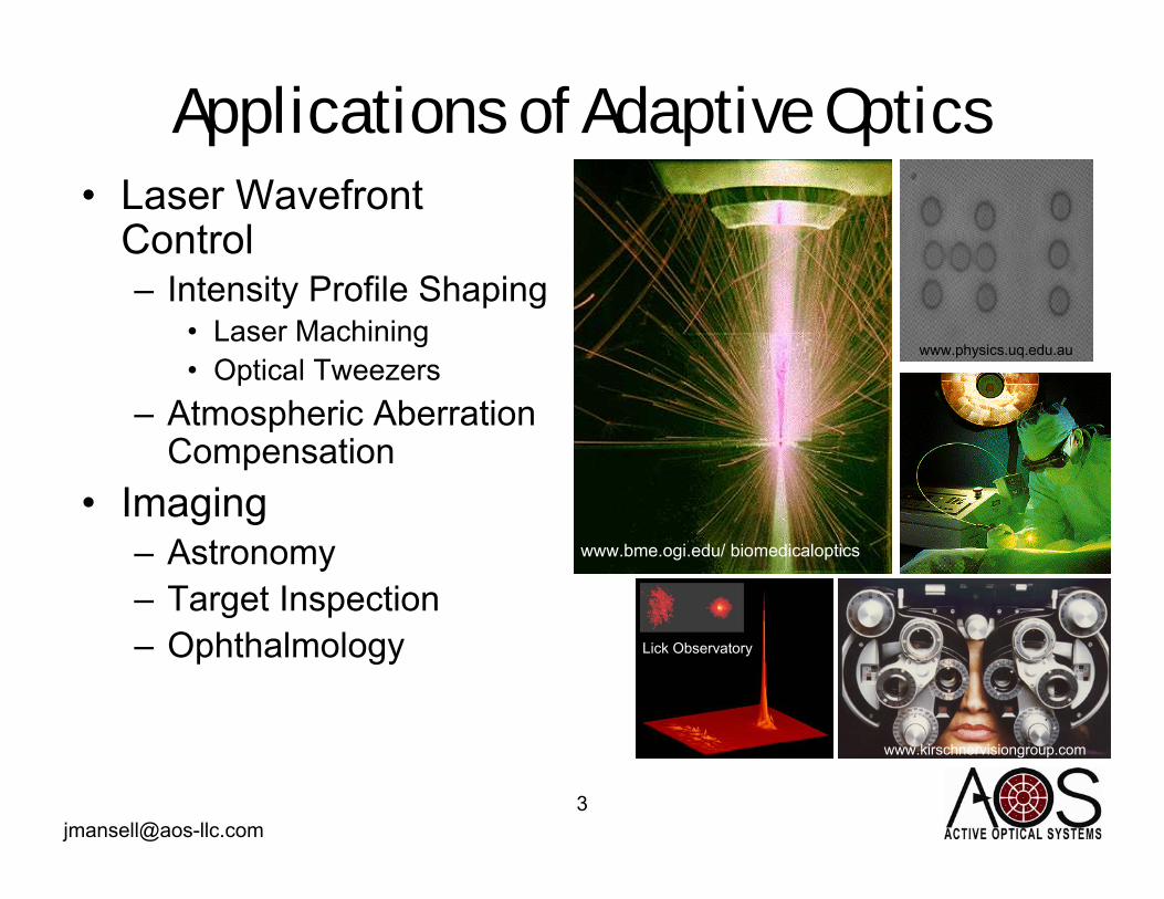
Applications of Adaptive Optics• Laser Wavefront
Control– Intensity Profile Shaping
• Laser Machining• Optical Tweezers
– Atmospheric Aberration Compensation
• Imaging– Astronomy– Target Inspection– Ophthalmology
www.physics.uq.edu.au
www.bme.ogi.edu/ biomedicaloptics
www.kirschnervisiongroup.com
Lick Observatory

Barriers to Mass Usage
AO systems can often relax requirements
and increase system functionality
Inertia
Construction of complete active optical
systemsComplexity
Implementation via our unique compact low-
cost hardwareCost
SolutionBarrier

What is Low Cost?• Patterson published results of
a $25k system in 2000.– $30k in today’s dollars
• Other vendors are selling:– Low Actuator Count DMs for
~$2k– Drive Electronics for ~$5k– Systems for ~$25k+
• We present here a low-cost metric AO system that is commercially available for $7,500 Patterson et al, Optics Express 6, No. 9, 175-85

Outline• Introduction & Motivation• Low-Cost Component Development
– DMs, Drive Electronics, & AO Controllers• Optical Setup• System Demonstrations
– PC-interfaced System– Microcontroller System
• Evaluation of the Microcontroller SPGD• Conclusions & Future Work

Polymer Deformable Mirror
25 mm
DM Prior to Packaging Packaged DM
37-pin D-sub Connector
ThorlabsSM1 Adapter

Membrane Influence Functions (IFs)
-0.5 0 0.5
-0.5
0
0.5 -1
-0.8
-0.6
-0.4
-0.2
0
Ability to achieve high
spatial frequencies
falls off as ~1/r2

0
20
40
60
80
100
120
0 100 200 300
Voltage (V)
Dis
plac
emen
t (m
icro
ns)
Electrostatic Snap-Down
1.4”
Parallel Plate Snap-Down Experiment
Mem
bran
e
Ele
ctro
stat
ic P
ad
Translated under Bias

Snap-Down ResultsBack of Membrane Electrostatic Pad
Snap-down induced “sputtering” of aluminum coating
Achieved ~40μm of Throw at Snap-Down

Resonance Frequency
0
10
20
30
40
50
60
0 500 1000 1500 2000 2500
Frequency (Hz)
Sign
al A
mpl
itude
(a.u
.)
DataFit
Q ~ 2
Because the polymer membranes are currently hand assembled, the resonance frequency changes from device to device.
Tension & Thickness

Pellicle Characteristics• Wavefront Quality : λ/2 per inch
– mostly in an astigmatic term
• Demonstrated high reflectivity coatings– Q-Switched damage at 3.3 J/cm2 (235
MW/cm2)– HR coated membrane demonstrated
survivability under 12 kW CW 1064nm
• Available COTS up to 6” in Diameter
Polymer Membrane
Under 12 kW CW 1-μm Light
Thermally Induced Distortion at 1s

Static Aberrations• Mounting the pellicle to
the substrate can be tricky.– See Dave Dayton’s results
from yesterday• We have developed a
new mounting process at AOS that has dramatically reduced the aberration amplitude created by this process.

Summary of Polymer Membrane DMs
Metal & Dielectric Stacks (12kW cw 1064nm survived, 3.3 J/cm2 Damage Threshold
for Q-Switched)
Coatings6” COTS PartsSize
~40 μm (330VDC at Snap-Down)
Throw~500 HzResonance ValueCharacteristic

Potential Applications for Polymer Membrane DMs
• Good for:– Low-Order Quasi-Static Imaging and
Laser Aberration Compensation• Telescopes, Microscopes, Laser
Machining, etc.– Basic Laser Beam Shaping
• Maybe good for:– Vertical Path Atmospheric
(Astronomy)• Probably not good for:
– Large Telescopes– Megawatt Class Lasers– Long Path Free-Space Optical Comm.

Drive Electronics
ElectronicsPCB
6” 6”
3”
USB Interface
32-Channel Output up to 295 V(scalable to more output channels
and from 8-bit to 16-bits in 2-bit increments)
Packaged Electronics(Internally 3.2x4” Boards)
Optional BNC Input
(not shown)

Converting the Drive Electronics into an AO Controller
• The USB interface chip we chose to use was an inexpensive (~$10) microcontroller that was designed for low-cost applications like toys.
• During the development, we discovered that it had integrated ADCs and sufficient computational capability to do metric adaptive optics.

Outline• Introduction & Motivation• Low-Cost Component Development
– DMs, Drive Electronics, & AO Controllers• Optical Setup• System Demonstrations
– PC-interfaced System– Microcontroller System
• Evaluation of the Microcontroller SPGD• Conclusions & Future Work

Optical Setup Picture
PSFCamera
DM
Drive Electronics with Microcontroller AO
BS
Lens
Photodiode and Pinhole
BS
Photodiode Input

Rise Time
~10% to 90% Fall Time = 144 μs
Rise Time Oscillation ~3.7 kHz
200 μs / div200 μs / div

Outline• Introduction & Motivation• Low-Cost Component Development
– DMs, Drive Electronics, & AO Controllers• Optical Setup• System Demonstrations
– PC-interfaced System– Microcontroller System
• Evaluation of the Microcontroller SPGD• Conclusions & Future Work

Stochastic Parallel Gradient Descent (SPGD) Algorithm
1. Start with a pointin the error space.
2. Take a step in a random direction to another point.
3. Find the “optimum” position based on the gradient.
4. Repeat to 2
4
1 2
3
Starting PointTrial Step (V’)
Final Position (V’’)

SPGD Algorithm Math
( )dVMMVV stepinitial −+= η''
( )
actuators ofnumber theis and 1, to1- fromvector
number random a is rand(...)size, step maximum theis
, where'
N
NranddVdVVV
+
Δ•Δ=
+=Take a Random Trial Step
Take a Step Based on the Trial Result
Step Size
Gain

Brute-Force Searching Algorithm• Choose each actuator and scan over the
entire 255 count range in 5 count intervals and set it to the best value.
• After scanning all the actuators, repeat the scan.

PC-Based Optimization
Added Controls for Optimization Testing in the Existing Drive
Electronics Software

Typical Point Spread Functions
Before AO (Mirror Under Optimal Focal Bias) After AO
NOTE: Fringing due to the window on the camera

Outline• Introduction & Motivation• Low-Cost Component Development
– DMs, Drive Electronics, & AO Controllers• Optical Setup• System Demonstrations
– PC-interfaced System– Microcontroller System
• Evaluation of the Microcontroller SPGD• Conclusions & Future Work

Average Results (30 ms delay, 20 averages, 16s)η=
0.1
η=0.
2η=
0.3
η=0.
4η=
0.5
Δ=4 Δ=6 Δ=8 Δ=10 Δ=12
Key: Average / Std. Dev.
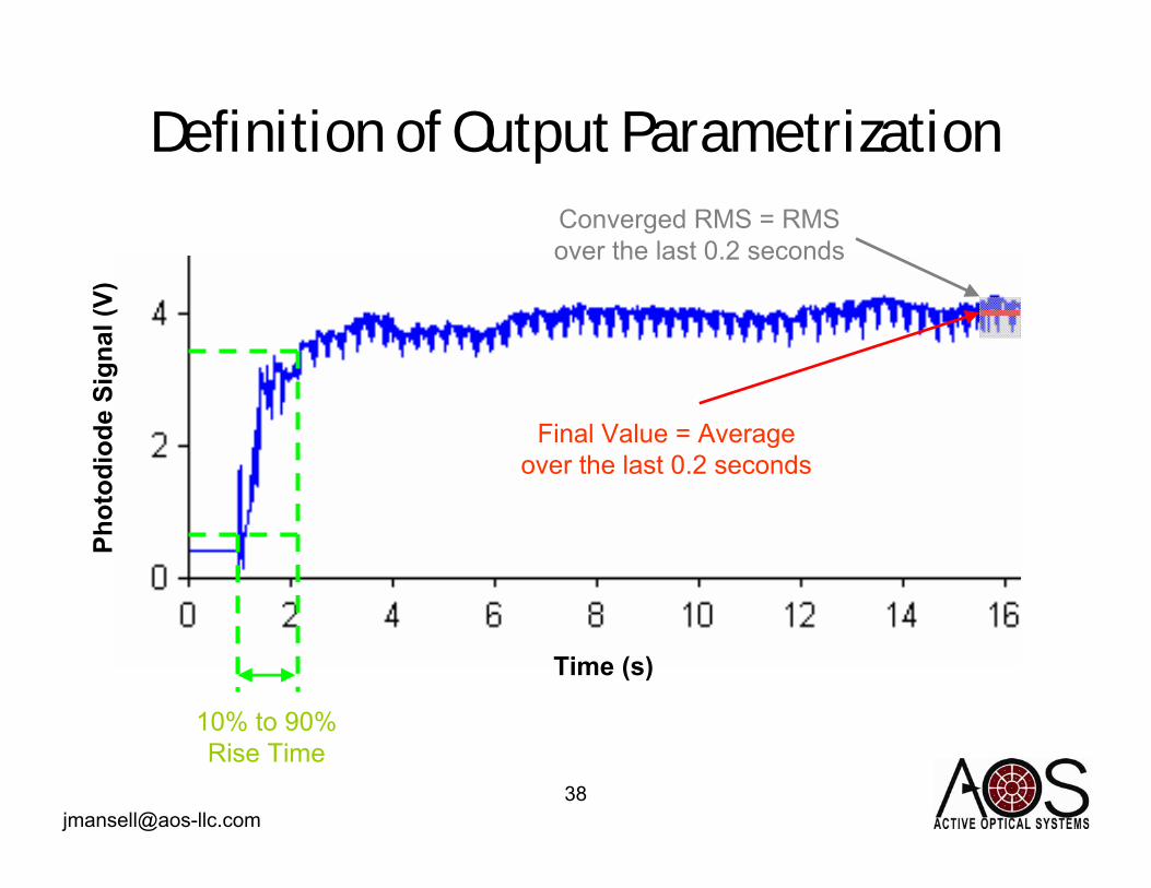
Definition of Output Parametrization
Time (s)
Phot
odio
de S
igna
l (V)
10% to 90% Rise Time
Final Value = Average over the last 0.2 seconds
Converged RMS = RMSover the last 0.2 seconds

Effect of Sample Delay on Final Value
1.9
2
2.1
2.2
2.3
2.4
2.5
0 5 10 15 20 25 30
Delay (ms)
Con
verg
ed F
inal
Ph
otod
iode
Val
ue (V
)
~18 ms

Conclusions• We have developed low cost:
– DMs ($1,500)– USB Interfaced Drive Electronics ($5,000)– Metric Adaptive Optics Systems ($7,500)
• We characterized the parameters of our microcontroller SPGD metric AO system to find the effect of – the gain (η), – the step size (Δ), – and the measurement delay.