PROGRESS TOWARD A MICROFABRICATED GAS TURBINE GENERATOR FOR...
8
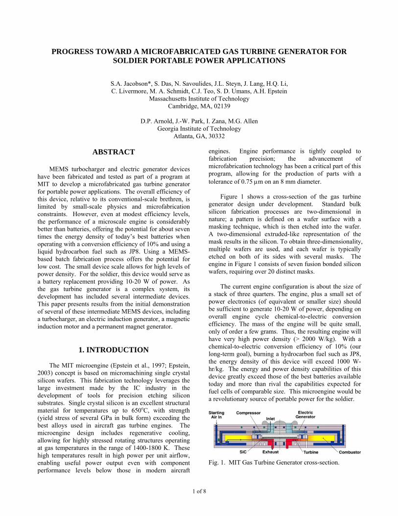
1 of 8 PROGRESS TOWARD A MICROFABRICATED GAS TURBINE GENERATOR FOR SOLDIER PORTABLE POWER APPLICATIONS S.A. Jacobson*, S. Das, N. Savoulides, J.L. Steyn, J. Lang, H.Q. Li, C. Livermore, M. A. Schmidt, C.J. Teo, S. D. Umans, A.H. Epstein Massachusetts Institute of Technology Cambridge, MA, 02139 D.P. Arnold, J.-W. Park, I. Zana, M.G. Allen Georgia Institute of Technology Atlanta, GA, 30332 ABSTRACT MEMS turbocharger and electric generator devices have been fabricated and tested as part of a program at MIT to develop a microfabricated gas turbine generator for portable power applications. The overall efficiency of this device, relative to its conventional-scale brethren, is limited by small-scale physics and microfabrication constraints. However, even at modest efficiency levels, the performance of a microscale engine is considerably better than batteries, offering the potential for about seven times the energy density of today’s best batteries when operating with a conversion efficiency of 10% and using a liquid hydrocarbon fuel such as JP8. Using a MEMS- based batch fabrication process offers the potential for low cost. The small device scale allows for high levels of power density. For the soldier, this device would serve as a battery replacement providing 10-20 W of power. As the gas turbine generator is a complex system, its development has included several intermediate devices. This paper presents results from the initial demonstration of several of these intermediate MEMS devices, including a turbocharger, an electric induction generator, a magnetic induction motor and a permanent magnet generator. 1. INTRODUCTION The MIT microengine (Epstein et al., 1997; Epstein, 2003) concept is based on micromachining single crystal silicon wafers. This fabrication technology leverages the large investment made by the IC industry in the development of tools for precision etching silicon substrates. Single crystal silicon is an excellent structural material for temperatures up to 650 o C, with strength (yield stress of several GPa in bulk form) exceeding the best alloys used in aircraft gas turbine engines. The microengine design includes regenerative cooling, allowing for highly stressed rotating structures operating at gas temperatures in the range of 1400-1800 K. These high temperatures result in high power per unit airflow, enabling useful power output even with component performance levels below those in modern aircraft engines. Engine performance is tightly coupled to fabrication precision; the advancement of microfabrication technology has been a critical part of this program, allowing for the production of parts with a tolerance of 0.75 µm on an 8 mm diameter. Figure 1 shows a cross-section of the gas turbine generator design under development. Standard bulk silicon fabrication processes are two-dimensional in nature; a pattern is defined on a wafer surface with a masking technique, which is then etched into the wafer. A two-dimensional extruded-like representation of the mask results in the silicon. To obtain three-dimensionality, multiple wafers are used, and each wafer is typically etched on both of its sides with several masks. The engine in Figure 1 consists of seven fusion bonded silicon wafers, requiring over 20 distinct masks. The current engine configuration is about the size of a stack of three quarters. The engine, plus a small set of power electronics (of equivalent or smaller size) should be sufficient to generate 10-20 W of power, depending on overall engine cycle chemical-to-electric conversion efficiency. The mass of the engine will be quite small, only of order a few grams. Thus, the resulting engine will have very high power density (> 2000 W/kg). With a chemical-to-electric conversion efficiency of 10% (our long-term goal), burning a hydrocarbon fuel such as JP8, the energy density of this device will exceed 1000 W- hr/kg. The energy and power density capabilities of this device greatly exceed those of the best batteries available today and more than rival the capabilities expected for fuel cells of comparable size. This microengine would be a revolutionary source of portable power for the soldier. Fig. 1. MIT Gas Turbine Generator cross-section.
Transcript of PROGRESS TOWARD A MICROFABRICATED GAS TURBINE GENERATOR FOR...
1 of 8
PROGRESS TOWARD A MICROFABRICATED GAS TURBINE GENERATOR FOR SOLDIER PORTABLE POWER APPLICATIONS
S.A. Jacobson*, S. Das, N. Savoulides, J.L. Steyn, J. Lang, H.Q. Li, C. Livermore, M. A. Schmidt, C.J. Teo, S. D. Umans, A.H. Epstein
Massachusetts Institute of Technology Cambridge, MA, 02139
D.P. Arnold, J.-W. Park, I. Zana, M.G. Allen
Georgia Institute of Technology Atlanta, GA, 30332
ABSTRACT
MEMS turbocharger and electric generator devices
have been fabricated and tested as part of a program at MIT to develop a microfabricated gas turbine generator for portable power applications. The overall efficiency of this device, relative to its conventional-scale brethren, is limited by small-scale physics and microfabrication constraints. However, even at modest efficiency levels, the performance of a microscale engine is considerably better than batteries, offering the potential for about seven times the energy density of today’s best batteries when operating with a conversion efficiency of 10% and using a liquid hydrocarbon fuel such as JP8. Using a MEMS-based batch fabrication process offers the potential for low cost. The small device scale allows for high levels of power density. For the soldier, this device would serve as a battery replacement providing 10-20 W of power. As the gas turbine generator is a complex system, its development has included several intermediate devices. This paper presents results from the initial demonstration of several of these intermediate MEMS devices, including a turbocharger, an electric induction generator, a magnetic induction motor and a permanent magnet generator.
1. INTRODUCTION
The MIT microengine (Epstein et al., 1997; Epstein, 2003) concept is based on micromachining single crystal silicon wafers. This fabrication technology leverages the large investment made by the IC industry in the development of tools for precision etching silicon substrates. Single crystal silicon is an excellent structural material for temperatures up to 650oC, with strength (yield stress of several GPa in bulk form) exceeding the best alloys used in aircraft gas turbine engines. The microengine design includes regenerative cooling, allowing for highly stressed rotating structures operating at gas temperatures in the range of 1400-1800 K. These high temperatures result in high power per unit airflow, enabling useful power output even with component performance levels below those in modern aircraft
engines. Engine performance is tightly coupled to fabrication precision; the advancement of microfabrication technology has been a critical part of this program, allowing for the production of parts with a tolerance of 0.75 µm on an 8 mm diameter.
Figure 1 shows a cross-section of the gas turbine
generator design under development. Standard bulk silicon fabrication processes are two-dimensional in nature; a pattern is defined on a wafer surface with a masking technique, which is then etched into the wafer. A two-dimensional extruded-like representation of the mask results in the silicon. To obtain three-dimensionality, multiple wafers are used, and each wafer is typically etched on both of its sides with several masks. The engine in Figure 1 consists of seven fusion bonded silicon wafers, requiring over 20 distinct masks.
The current engine configuration is about the size of
a stack of three quarters. The engine, plus a small set of power electronics (of equivalent or smaller size) should be sufficient to generate 10-20 W of power, depending on overall engine cycle chemical-to-electric conversion efficiency. The mass of the engine will be quite small, only of order a few grams. Thus, the resulting engine will have very high power density (> 2000 W/kg). With a chemical-to-electric conversion efficiency of 10% (our long-term goal), burning a hydrocarbon fuel such as JP8, the energy density of this device will exceed 1000 W-hr/kg. The energy and power density capabilities of this device greatly exceed those of the best batteries available today and more than rival the capabilities expected for fuel cells of comparable size. This microengine would be a revolutionary source of portable power for the soldier.
Fig. 1. MIT Gas Turbine Generator cross-section.

2 of 8
A series of intermediate-level devices have been built to demonstrate capability while developing the processing technology necessary for a microscale gas turbine generator. This paper will discuss recent results from a turbocharger device and three electric motor/generator devices. For developmental risk reduction, two types of electric generators are under development: electric induction and magnetic.
MIT is leading the electric induction generator
development effort. At the microscale, thermal isolation is difficult, resulting in a high temperature environment for the generator. The electric induction generator contains no magnetics, alleviating Curie temperature concern for high temperature operation. A generator requires high energy density to be practical. Electric induction generators are not viable at the macroscale since their achievable energy density is limited by electric field breakdown in the relatively large gaps that are fabricatable over large areas with precision. At the macroscale, it is much more practical to build a large energy density magnetic machine. However, the ability to generate precision small gaps and thus high electric fields with MEMS processing allows for the creation of electric induction generators with high energy density at the microscale. At the microscale, electric induction machines can be competitive with magnetic machines.
Georgia Institute of Technology (GIT) and MIT are
collaborating on the magnetic generator development effort. Both induction and permanent magnet designs are being investigated. GIT is a world leader in processing magnetic materials at the microscale, including magnetic materials with high temperature capability.
While not discussed in this paper, the microscale gas
bearings that support the rotors in the devices described are a key technical challenge, and have been the subject of considerable research at MIT. The reader is referred to Liu et al. (2003) and Spakovszky and Liu (2003) for further information on the gas bearings.
2. TURBOCHARGER
2.1 Introduction Figure 2 shows a cross-section of the turbocharger
device. The turbocharger was designed to evolve into the gas turbine generator with minimal fabrication process changes. The turbocharger lacks an electric generator and its turbine and compressor flow paths are independent; otherwise, the two devices are virtually identical. As such, the turbocharger is a test vehicle for developing fabrication processes and turbomachinery/bearing technology. The turbocharger device is formed by fusion bonding six silicon wafers. The hatched structure in
Fig. 2. Turbocharger cross-section.
Figure 2 is the rotor, free to spin within the device. The turbocharger die is 23 mm wide by 23 mm long by 2.9 mm thick, with a compressor diameter of 8.2 mm and a turbine diameter of 6.0 mm. The turbocharger has a design rotation rate of 1.2 million rpm and a design compressor pressure ratio of 2.2.
The fabrication of the turbocharger was made
possible by several microfabrication advances. Unlike the turbine-generator (see Section 3) and other devices in this program that have either a compressor or a turbine, the turbocharger rotor is formed from two aligned wafers, one containing a compressor and one containing a turbine. The turbocharger rotor diameter (8.2 mm) is twice that of previous devices. The increased mass of the rotor and its two-wafer design place more stringent requirements on the fabrication process. Journal bearing dimensional control is a key challenge: 15 +/- 0.75 µm in width and 330 +/- 5 µm in depth; the tolerance on the bearing width is half that of previous devices. The higher tolerance journal bearings are achieved through refinements in the etch recipe as well as modifications to the masking material profile. The masking material must be carefully controlled because of its finite etch rate and the effects of sidewall-passivation-layer erosion from ions deflected by the resist slope. The journal bearing specification is met on device wafers with a yield of more than 60%. Another challenge for this device is obtaining a rotor blade height uniformity of about 1%, critical to maintain low levels of imbalance for the two-wafer rotor.
2.2 Turbocharger High Speed Test Results
The turbocharger is operated by supplying
pressurized nitrogen to the turbine inlet, causing the rotor to spin. The device thrust and journal bearings are of a hydrostatic gas bearing design, and these are operated with pressurized nitrogen as well. The compressor inlet is open to atmosphere, ingesting air and exhausting it at an elevated pressure. The compressor exhausts into a throttle valve that drops the air pressure back down to atmospheric pressure.

3 of 8
Fig. 3. Test results for two different compressor throttle settings, showing significant pressure rise and flow rate through the compressor. Uncertainties (primarily from systematic offsets in the transducers): pressure ratio +/- 0.04, flow rate +/- 0.004 g/s.
A turbocharger has been operated to a rotation rate of 480,000 rpm, equivalent to a tip speed of 200 m/s (450 miles per hour) for the 8.2 mm diameter rotor and about 40% of design speed. This turbocharger had its journal bearing located on the compressor rim. Figure 3 shows compressor pressure ratio and mass flow rate measurements for two runs of the same device with different throttle settings. The sharp flow rate changes in Figure 3b occur when the journal bearing pressure is adjusted; the journal bearing flow exhausts into the compressor interrow region, and thus can act as a throttle on the compressor flow. The compressor achieved a pressure ratio of 1.21 (17% of design pressure rise) with a flow rate of 0.14 g/s at its top speed. As expected from a compressor, Figure 3 indicates that at a given speed as the throttle was increased, the pressure ratio increased while the mass flow rate decreased. Figure 4 shows turbine measurements for the same run. As can be seen, at a given speed, the turbine pressure ratio is larger than that of the compressor. Here, the turbine is being run with room temperature pressurized nitrogen, although the turbine was designed for engine operation in which the turbine inlet temperature would be much higher (~1600 K). The
Fig. 4. Turbine test results, same run as Fig. 3. Uncertainties: pressure ratio +/- 0.06, flow rate +/- 0.004 g/s.
pressure and flow characteristics of Figures 3 and 4 are consistent with the design models for this device.
As temperature measurements of the compressor and
turbine exhausts are not available, efficiency can not be calculated specifically for the compressor or turbine. However, an estimate of the product of the turbine and compressor efficiencies can be made. The efficiency product measurement rose with speed, and at 480,000 rpm the efficiency product was approximately 0.24. Based on numerical simulations, the expected efficiency at this speed is about 64% for the turbine and 42% for the compressor, giving an efficiency product of about 0.27. The difference between the model and actual performance is within the expected uncertainty level for the as-fabricated device.
The testing of the turbocharger device discussed
above ended when its rotor destructively crashed at 460,000 rpm. Data suggests that the crash was related to angular motion of the rotor and not to the journal bearing. A five degree-of-freedom (DOF) (the three translational DOFs plus the two rotational DOFs orthogonal to the rotor high speed rotation) model for the rotor and bearing system was developed to understand the cause for this
0 1 2 3 4 5x 10
5
1
1.1
1.2
1.3
1.4
1.5
1.6
1.7
1.8
Rotation Rate (rpm)
Turb
ine
Pres
sure
Rat
io
Throttle 1Throttle 2 (decreased)
0 0.05 0.1 0.15 0.2 0.25 0.31
1.1
1.2
1.3
1.4
1.5
1.6
1.7
1.8
Turbine Mass Flow Rate (g/s)
Turb
ine
Pres
sure
Rat
io
Throttle 1Throttle 2 (decreased)
b)
a)
Turb
ine
Pres
sure
Rat
io
Turb
ine
Pres
sure
Rat
io
Rotation Rate (rpm)
Turbine Mass Flow Rate (g/s)
0 0.5 1 1.5 2 2.5 3 3.5 4 4.5 5x 10⁵
1
1.05
1.1
1.15
1.2
1.25
Rotation Rate (rpm)
Com
pres
sor P
ress
ure
Rat
io Throttle 1Throttle 2 (decreased)
0 0.02 0.04 0.06 0.08 0.1 0.12 0.14 0.161
1.05
1.1
1.15
1.2
1.25
Compressor Mass Flow Rate (g/s)
Com
pres
sor P
ress
ure
Rat
io
Throttle 1Throttle 2 (decreased)
a)
b)
Compressor Mass Flow Rate (g/s)

4 of 8
unexpected angular motion. The results of this study, to be described elsewhere, resulted in an enhanced understanding of the rotor interaction with the full device gas supply system. A second generation turbocharger was designed with an internal bearing gas supply system that should greatly reduce interactions between the stator and the rotor and thus reduce the magnitude of torques that could induce angular motion. This new device is currently being fabricated, with initial testing expected in a few months.
Along the evolutionary path from turbocharger to gas
turbine engine, we plan to test the next turbocharger build with combustion in the internal combustion chamber upstream of the turbine. The combustion tests will add an additional level of complexity to the turbocharger experiments since the fuel can burn only above a certain temperature. Micro-combustor experiments have shown that the minimum temperature is about 1000 K. As a result, during ignition an abrupt thermal transient will occur that could impact the rotordynamic stability. A model for understanding this transient has been developed by Savoulides (2004).
3. ELECTROQUASISTATIC INDUCTION
GENERATOR 3.1 Introduction
As discussed earlier, a major attribute of the microengine is that it is a high power density device. As such, it requires a high power density electric generator for converting shaft power to electricity. One of the high power density micro-generator concepts being pursued is an electroquasistatic (EQS) induction configuration. An EQS generator has been fabricated and tested successfully at MIT. This generator was tested as part of a turbine-generator device. The generator was fabricated on the backside of a 4 mm silicon rotor. A radial inflow turbine was etched on the front side of the rotor. The rotor is supported on gas bearings of similar design to those used on the turbocharger discussed in the previous section. Previous devices fabricated at MIT as part of the Microengine Program include a microfabricated EQS tethered motor (Nagle, 2001), a microfabricated motor-compressor (Fréchette et al., 2001) and a high performance micromotor (Livermore et al., 2004). Although macroscale EQS motors have been reported (e.g. Bollée, 1969), this is the first EQS induction generator known to the authors of any scale in the open literature. A more detailed description of the work described in this section is given in Steyn et al. (2005).
The basic principle of operation of the EQS induction generator is depicted in Figure 5. The device consists of a
Fig. 5. A basic 6-phase machine consists of a stator with a set of electrodes arranged such that every 6th electrode is connected. A sinusoidal voltage on the six electrodes, phased 60 degrees apart, produces a traveling wave.
stator structure with a set of radial electrodes and a rotor structure a small distance (the air gap, ~ 3 µm) away from the stator. In the device reported here, the stator consists of 131 sets of six electrodes, for a total of 786 electrodes. The device is operated as a six-phase machine, with every sixth electrode at the same potential. If the voltages on the electrodes are varied sinusoidally, with each electrode lagging its predecessor by 60 degrees, a traveling wave is created. This stator traveling wave induces a traveling wave on the rotor, a high resistivity polysilicon film in this case. When the rotor traveling wave rotates faster than the rotor itself, the machine acts as a motor. When the rotor speed is greater than the rotor wave speed, the machine acts as a generator.
Figure 6 is a sectioned view of the device. The EQS induction turbine-generator consists of 5 silicon layers. The turbine rotor is located in L3. It is contained axially by thrust bearings in L2 and L4, and radially by a journal bearing in L3. On the backside the turbine disk, the polysilicon rotor film is deposited on a 10 µm thick recessed oxide layer. The stator structure is fabricated on a recessed oxide island on L4. Platinum is used for the leads, electrodes and interconnects. The device discussed here represents the first MEMS EQS induction machine with a metal stator that was fully bonded.
3.2 Results
The machine was tested by attaching 8.2 mH inductors to each of the six phases, and exciting each phase with a function generator. By operating at the resonant electrical frequency of the device, high stator voltage amplitudes are obtained, which increases the power output. The results in Figure 7 were obtained by exciting the generator with 1.6 Vpp at 402.9 kHz. This translates to an average of 29 Vpp on the stator electrodes.

5 of 8
Fig. 6. Two-dimensional and three-dimensional section views of the EQS turbine-generator device. Note that the stator periodicity has been reduced for visual clarity.
Fig. 7. Total power vs. speed for the EQS induction generator. Negative input power implies generation.
A maximum of 108 µW was measured at 245,000 rpm. Figure 7 also shows model results for this device, indicating good agreement.
At higher drive voltages than 1.6 Vpp, a nonlinearity
was encountered that limited machine performance. It is suspected that the rotor conductor film exhibits nonlinear behavior at these voltages. Tests are underway to characterize the rotor conductor film at higher electric fields. Future work will include exciting the generator with self-exciting resonant power electronics. In an attempt to generate more power with this device, a further study of the inductors along with operation at higher speeds will be performed. If this generator were operated
at design speed with design electric field, it would be able to generate of order 100 mW. With further optimization and more generator area (available in the engine device), an electric induction generator should be able to produce electric power > 1 W.
4. MAGNETIC GENERATOR DEVICES
4.1 Introduction
Using novel fabrication techniques, both magnetic induction machines and permanent magnet machines were designed, fabricated, and characterized. Both types of machines used planar geometry (axially directed magnetic fields) and high-temperature-compatible materials for eventual integration with the silicon microengine. More detailed descriptions of the magnetic machine designs and experimental results presented here can be found in Arnold et al. (2004) and Das et al. (2005).
4.2 Magnetic Induction Generator Results
The induction machine consists of a two-phase, eight-pole, laminated stator and a composite, annular rotor, as shown in Figure 8. Electromechanical energy conversion occurs through the interaction of a traveling magnetic wave in the rotor-stator air gap and the magnetic fields induced in the rotor by eddy currents. In motoring mode, a magnetic traveling wave is established by applying two currents in quadrature to the two stator coils, resulting in torque acting on the rotor.
Silicon etching, wafer bonding, and electrodeposition
were used to form all of the magnetic machine components. The stator contains two Cu coils wound in a three-dimensional, vertically laminated, ferromagnetic core (NiFe or CoFeNi), all supported by a silicon frame. The core laminations form onion-like concentric rings, where the lamination thickness is approximately one skin depth (~30 µm) to limit eddy current losses. The rotor is a 250 µm thick ferromagnetic annular ring (10 mm OD, 6 mm ID) with a 20 µm thick overlayer of Cu (12 mm OD, 4 mm ID).
For initial testing purposes, the rotor was suspended
above the stator using flexible silicon tethers that permitted angular rotation and a controllable air gap while avoiding the difficulties of supporting a spinning rotor. Six, 35 µm wide, 2.5 mm long tethers provided a torsional compliance of 25 rad/N·m with an axial stiffness of 4.2 µm/N to prevent rotor pull-in.
For characterization, the motoring torque was
extracted under various excitation currents, as shown in Figure 9. The NiFe machine demonstrated a maximum torque of 2.5 µN·m for a phase excitation of 8 A (peak) at
L1 L2 L3 L4 L5
Electric Induction Generator
Electric Induction Generator

6 of 8
Fig. 8. Renderings of the magnetic induction machine (z-axis expanded by 4x and air gap exaggerated).
Fig. 9. Torque vs. electrical frequency for NiFe induction machine at 50 µm air gap. Measurements at different peak currents are indicated with points, and theory with solid curves.
35 kHz. For an active machine volume of 75 mm3 (10 mm, 6 mm ID, 1.5 mm thick), this corresponds to a torque density of 33 N·m/m3. If this torque were achievable at the design speed of 1 Mrpm (ωm ≈ 1 x 10⁵ rad/sec), it would correspond to a motoring power of 0.25 W. These
induction machines proved the ability to integrate magnetic machine components within silicon, but mechanical-to-electrical power generation has not yet been achieved. 4.3 Permanent Magnet Generator Results
As an alternative to induction machines, permanent magnet (PM) generators were investigated for potential use in the silicon-based micro gas turbine generator. A PM machine rotor contains a permanent flux source and requires no external electrical power for creation of fields in the rotor, as required for an induction machine. As the machine size is reduced, this results in more favorable power densities and efficiencies (Cugat et al., 2003). Also, the larger flux density from the rotor enables a larger air gap and the use of surface wound, rather than recessed, coils, which greatly simplifies the fabrication process.
The PM generators are three-phase, eight-pole
synchronous machines consisting of a surface-wound stator and a PM rotor, as shown in Figure 10. The machine operates by magnetic induction governed by Faraday’s Law. The spinning multi-poled PM rotor
0 10 20 30 40 50 60
0.5
1
1.5
2
2.5
3
Torq
ue ( µ
N-m
)
Electrical Frequency (kHz)
8 Apk6 Apk4 Apk2 Apk
Fusion-BondedStator (cutaway view)
Tethered Rotor
Upper Wafer
Lower Wafer
y z
x Stator Cross-Section
Si Pole
Hat
Back Iron
335 µm
345 µm
320 µm
z x
Vertically laminated NiFe/CoFeNi Core
Double Layer Cu Coils
25-75 µmStator
Rotor
1 mm
270 µm
10 mm
z x
7 of 8
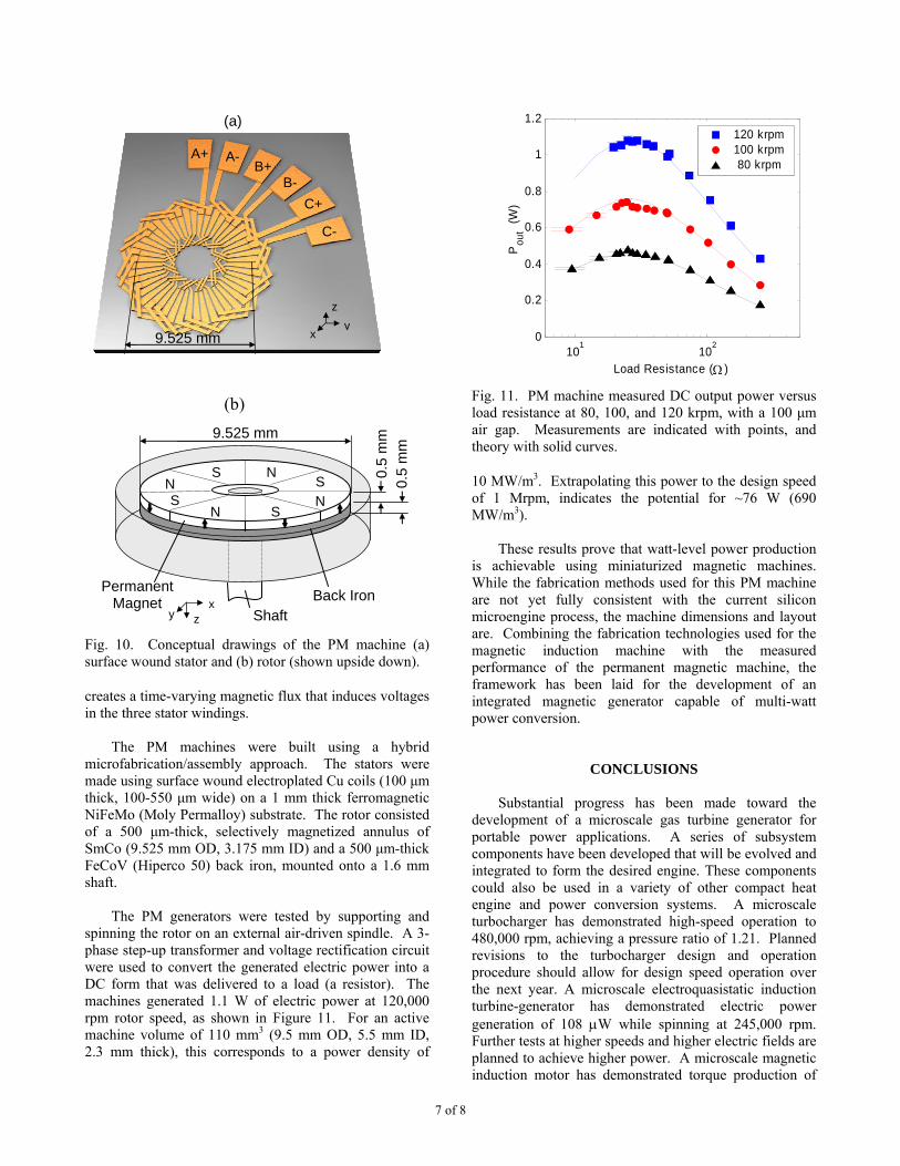
Fig. 10. Conceptual drawings of the PM machine (a) surface wound stator and (b) rotor (shown upside down).
creates a time-varying magnetic flux that induces voltages in the three stator windings.
The PM machines were built using a hybrid
microfabrication/assembly approach. The stators were made using surface wound electroplated Cu coils (100 µm thick, 100-550 µm wide) on a 1 mm thick ferromagnetic NiFeMo (Moly Permalloy) substrate. The rotor consisted of a 500 µm-thick, selectively magnetized annulus of SmCo (9.525 mm OD, 3.175 mm ID) and a 500 µm-thick FeCoV (Hiperco 50) back iron, mounted onto a 1.6 mm shaft.
The PM generators were tested by supporting and
spinning the rotor on an external air-driven spindle. A 3-phase step-up transformer and voltage rectification circuit were used to convert the generated electric power into a DC form that was delivered to a load (a resistor). The machines generated 1.1 W of electric power at 120,000 rpm rotor speed, as shown in Figure 11. For an active machine volume of 110 mm3 (9.5 mm OD, 5.5 mm ID, 2.3 mm thick), this corresponds to a power density of
101
102
0
0.2
0.4
0.6
0.8
1
1.2
Pou
t (W
)
Load Resistance (Ω )
120 krpm100 krpm 80 krpm
Fig. 11. PM machine measured DC output power versus load resistance at 80, 100, and 120 krpm, with a 100 µm air gap. Measurements are indicated with points, and theory with solid curves.
10 MW/m3. Extrapolating this power to the design speed of 1 Mrpm, indicates the potential for ~76 W (690 MW/m3).
These results prove that watt-level power production
is achievable using miniaturized magnetic machines. While the fabrication methods used for this PM machine are not yet fully consistent with the current silicon microengine process, the machine dimensions and layout are. Combining the fabrication technologies used for the magnetic induction machine with the measured performance of the permanent magnetic machine, the framework has been laid for the development of an integrated magnetic generator capable of multi-watt power conversion.
CONCLUSIONS
Substantial progress has been made toward the development of a microscale gas turbine generator for portable power applications. A series of subsystem components have been developed that will be evolved and integrated to form the desired engine. These components could also be used in a variety of other compact heat engine and power conversion systems. A microscale turbocharger has demonstrated high-speed operation to 480,000 rpm, achieving a pressure ratio of 1.21. Planned revisions to the turbocharger design and operation procedure should allow for design speed operation over the next year. A microscale electroquasistatic induction turbine-generator has demonstrated electric power generation of 108 µW while spinning at 245,000 rpm. Further tests at higher speeds and higher electric fields are planned to achieve higher power. A microscale magnetic induction motor has demonstrated torque production of
N S S
S S N
N N
Permanent Magnet Back Iron x
z y Shaft
9.525 mm
0.5
mm
0.
5 m
m
A- A+ B+
B- C+
C-
9.525 mm
(a)
y z
x
(b)

8 of 8
2.5 µN·m. A microscale permanent magnet generator has demonstrated electric power generation of 1.1 W while spinning at 120,000 rpm, supported on an external spindle. Higher speed tests for this device should demonstrate power capabilities well in excess of the desired 10-20 W for the gas turbine generator device. All of these devices will be matured over the next year. The turbocharger will then be evolved into the next major device milestone, which is a self-sustaining gas turbine engine (a turbojet configuration). The self-sustaining engine will be integrated with one of the generators discussed in this paper to form a gas turbine generator. Given sufficient funding, the current plan is to demonstrate a MEMS gas turbine generator in about 2-3 years.
ACKNOWLEDGEMENTS This work was supported by the Army Research
Laboratory (DAAD19-01-2-0010) under the Collaborative Technology Alliance in Power and Energy program, managed by Mr. John Hopkins (ARL) and Dr. Mukund Acharya (Honeywell), and by the Army Research Office (DAAG55-98-1-0292) managed by Dr. Tom Doligalski. The authors wish to thank the remainder of the microengine group at MIT, in particular A.A. Ayon, G. Donahue, F.F. Ehrich, A.R. Forte, Y. Gong, L. Ho, S.H. Kendig, R. Khanna, L. Liu, T.M. Lyszczarz, B. Sirakov, Z. Spakovszky, C. Tan, L. Wang, D. Ward and J.U. Yoon. C. Law provided the 3D solid models and renderings for the EQS device under the MIT UROP program. All microfabrication was performed at the MIT Microsystems Technology Laboratories (MTL), the MIT Lincoln Laboratory Microelectronics Laboratory (MEL), and the Georgia Institute of Technology Microelectronics Research Center. L. Steyn was supported in part by an Applied Materials Graduate Fellowship. The stator wafer for the EQS induction generator was fabricated by Lincoln Laboratory, in collaboration with the authors. The Lincoln Laboratory portion of this work was sponsored by the Defense Advanced Research Projects Agency under Air Force Contract F19628-C-002.
REFERENCES Arnold, D.P., Das, S., Cros, F., Zana, I., Lang, J.H. and
Allen, M.G., 2004: Magnetic Induction Machines Embedded in Fusion-Bonded Silicon, Tech. Dig. Solid-State Sensors and Actuators Workshop, Hilton Head, SC, 129-132.
Bollée, B., 1969: Electrostatic Motors, Philips Technical Review, 30 (6/7), 178-94.
Cugat, O., Delamare, J., and Reyne, G., 2003: Magnetic Micro-Actuators and Systems (MAGMAS), J. Microelectromech. Syst., 39, no. 5, 3607-3612.
Das, S., Arnold, D.P., Zana, I., Park, J.-W., Lang, J.H. and Allen, M.G., 2005: Multi-Watt Electric Power from a Microfabricated Permanent Magnet Generator, to be presented at the 18th IEEE International Conference on Micro Electro Mechanical Systems MEMS 2005, Miami, FL.
Epstein, A.H., Senturia, S.D. et al., 1997: Power MEMS and Microengines, Transducers ’97, The 9th International Conference on Solid-State Sensors and Actuators, Chicago, IL.
Epstein, A.H., 2003: Millimeter-Scale MEMS Gas Turbine Engines, Proceedings of ASME Turbo Expo 2003, Paper GT-2003-38866, Atlanta, GA.
Fréchette, L.G., Nagle, S.F., Ghodssi, R., Umans, S.D., Schmidt, M.A. and Lang, J. H., 2001: An Electrostatic Micromotor Supported on Gas-Lubricated Bearings, 16th IEEE International Conference on Micro Electro Mechanical Systems MEMS 2001, Interlaken, Switzerland.
Liu, L.X, Teo, C.J., Epstein, A.H. and Spakovszky, Z.S., 2003: Hydrostatic Gas Journal Bearings for Micro-Turbomachinery, Proceedings of the ASME Design Engineering Technical Conferences (DETC), Paper DETC2003/VIB-48467, Chicago, IL.
Livermore, C., Forte, A.R., Lyszczarz, T.M., Umans, S.D., Ayon, A.A., Lang, J.H., 2004: A High Power MEMS Electric Induction Motor, J. Microelectromech. Syst., 13, no. 3, 465-471.
Nagle, S.F., 2001: Analysis, Design and Fabrication of an Electric Induction Micromotor for a Micro Gas-Turbine Generator, Ph.D. Thesis, Massachusetts Institute of Technology, Cambridge, MA.
Savoulides, N., 2004: Development of a MEMS Turbocharger and Gas Turbine Engine, Ph.D. Thesis, Massachusetts Institute of Technology, Cambridge, MA.
Spakovszky, Z.S. and Liu, L.X., 2003: Scaling Laws for Ultra-Short Hydrostatic Gas Journal Bearings, Proceedings of the ASME Design Engineering Technical Conferences (DETC), Paper DETC2003/VIB-48468, Chicago, IL.
Steyn, J.L., Kendig, S.H., Khanna, R., Lyszczarz, T.M., Umans, S.D., Yoon, J.U., Livermore, C. and Lang, J.H., 2005: Generating Electric Power with a MEMS ElectroQuasiStatic Induction Turbine-Generator, to be presented at the 18th IEEE International Conference on Micro Electro Mechanical Systems MEMS 2005, Miami, FL.
The views and conclusions contained in this document are those of the authors and should not be interpreted as representing the official policies, either expressed or implied, of the Army Research Laboratory or the U.S. government.