Progress on CEPC High Efficiency Klystron · 5/25/2018 · Strategy and plan from 2016 to 2018...
26
Progress on CEPC High Efficiency Klystron Zusheng ZHOU Institute of High Energy Physics On behalf of klystron development team Università degli Studi Roma Tre 25 May 2018
Transcript of Progress on CEPC High Efficiency Klystron · 5/25/2018 · Strategy and plan from 2016 to 2018...

Progress on CEPC High Efficiency Klystron
Zusheng ZHOU
Institute of High Energy Physics
On behalf of klystron development team
Università degli Studi Roma Tre
25 May 2018
OutlineStrategy and plan
Goal:650MHz/800kW meets CEPC project demands;
Much higher efficiency, less energy consumption;
Evaluation target: >80% efficiency;
1st prototype development progress
Beam dynamic, beam optic and cooling system;
Mechanical design, infrastructure preparation;
High efficiency consideration(2nd&3rd)
Different method comparation;
3 kind of gun schemes;
MBK

Strategy and plan from 2016 to 2018• 3 klystron prototypes in 6 FYs
• FY 2016: done
• Finalize the gun and the collector design of the 1stconventional klystron prototype
• Initialize the dynamics design
• FY 2017: done
• Finalize the cavity chain design of 1st tube
• Preliminary mechanical design
• FY 2018: being carried out
• Finalize the mechanical design and fabrication
• Infrastructure construction
• Design studies on the 2nd and 3rd high efficiencyklystron
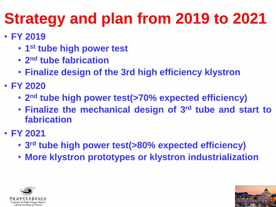
• FY 2019
• 1st tube high power test
• 2nd tube fabrication
• Finalize design of the 3rd high efficiency klystron
• FY 2020
• 2nd tube high power test(>70% expected efficiency)
• Finalize the mechanical design of 3rd tube and start tofabrication
• FY 2021
• 3rd tube high power test(>80% expected efficiency)
• More klystron prototypes or klystron industrialization
Strategy and plan from 2019 to 2021
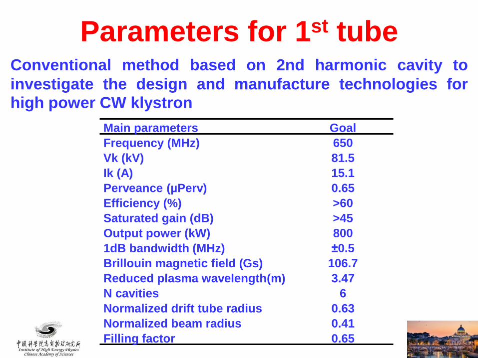
Parameters for 1st tube
Main parameters Goal
Frequency (MHz) 650
Vk (kV) 81.5
Ik (A) 15.1
Perveance (µPerv) 0.65
Efficiency (%) >60
Saturated gain (dB) >45
Output power (kW) 800
1dB bandwidth (MHz) ±0.5
Brillouin magnetic field (Gs) 106.7
Reduced plasma wavelength(m) 3.47
N cavities 6
Normalized drift tube radius 0.63
Normalized beam radius 0.41
Filling factor 0.65
Conventional method based on 2nd harmonic cavity to
investigate the design and manufacture technologies forhigh power CW klystron
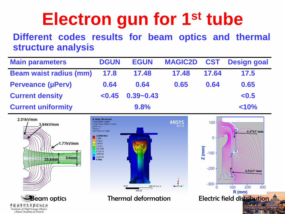
Electron gun for 1st tubeDifferent codes results for beam optics and thermalstructure analysis
Main parameters DGUN EGUN MAGIC2D CST Design goal
Beam waist radius (mm) 17.8 17.48 17.48 17.64 17.5
Perveance (µPerv) 0.64 0.64 0.65 0.64 0.65
Current density <0.45 0.39~0.43 <0.5
Current uniformity 9.8% <10%
Beam optics Thermal deformation Electric field distribution
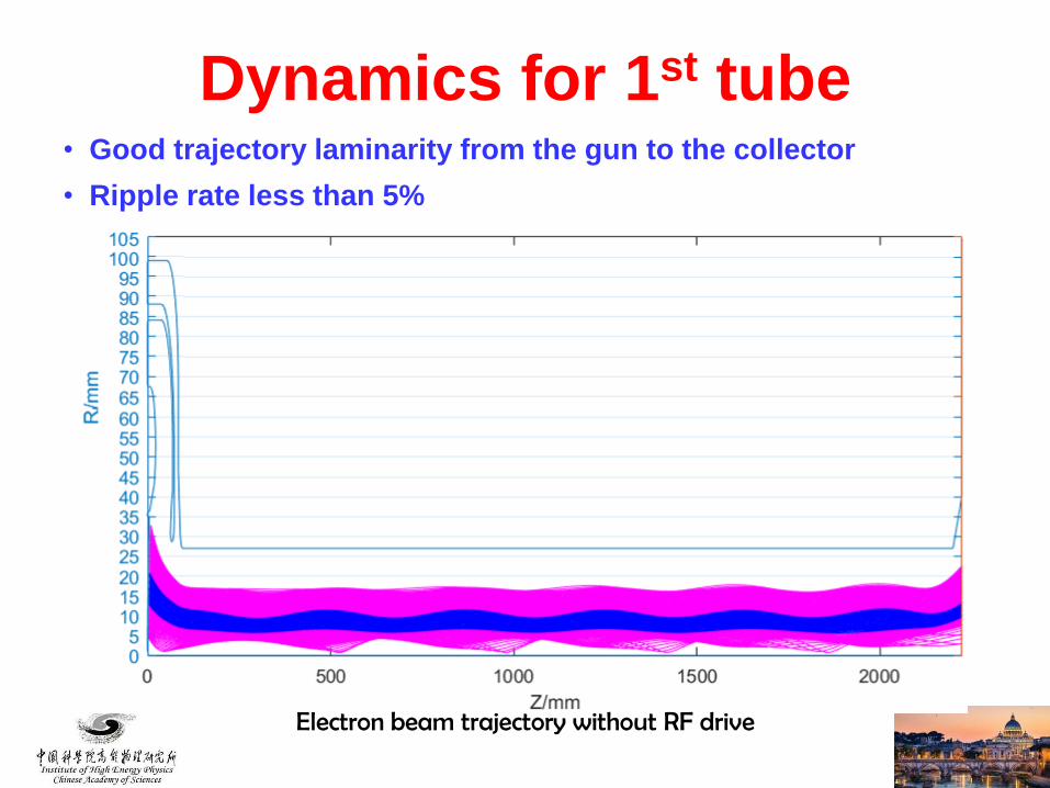
Dynamics for 1st tube• Good trajectory laminarity from the gun to the collector
• Ripple rate less than 5%
Electron beam trajectory without RF drive
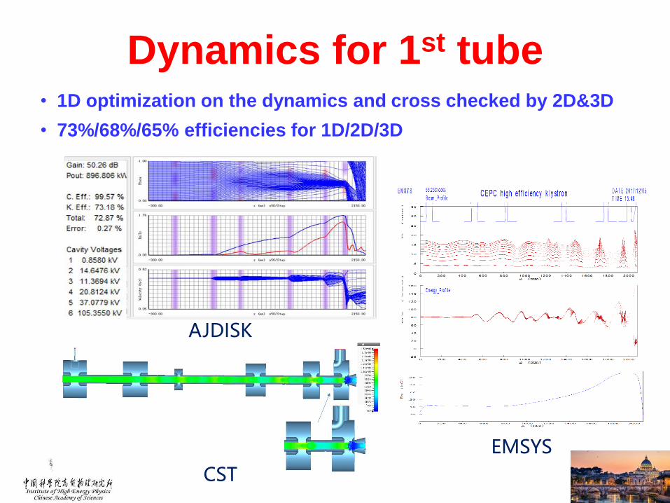
• 1D optimization on the dynamics and cross checked by 2D&3D
• 73%/68%/65% efficiencies for 1D/2D/3D
EMSYS
CST
AJDISK
Dynamics for 1st tube
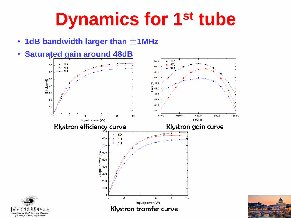
Klystron efficiency curve Klystron gain curve
• 1dB bandwidth larger than ±1MHz
• Saturated gain around 48dB
Klystron transfer curve
Dynamics for 1st tube
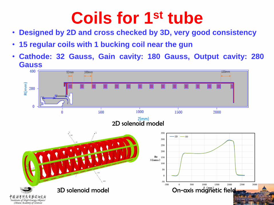
Coils for 1st tube• Designed by 2D and cross checked by 3D, very good consistency
• 15 regular coils with 1 bucking coil near the gun
• Cathode: 32 Gauss, Gain cavity: 180 Gauss, Output cavity: 280Gauss
2D solenoid model
3D solenoid model On-axis magnetic field
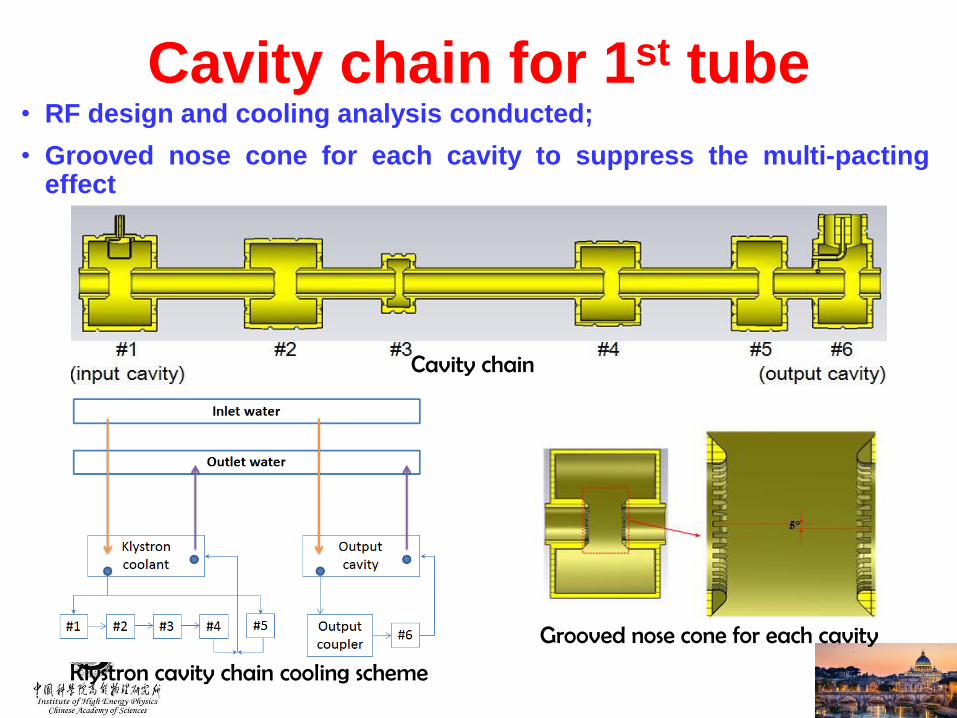
Cavity chain for 1st tube• RF design and cooling analysis conducted;
• Grooved nose cone for each cavity to suppress the multi-pactingeffect
Cavity chain
Klystron cavity chain cooling scheme
Grooved nose cone for each cavity
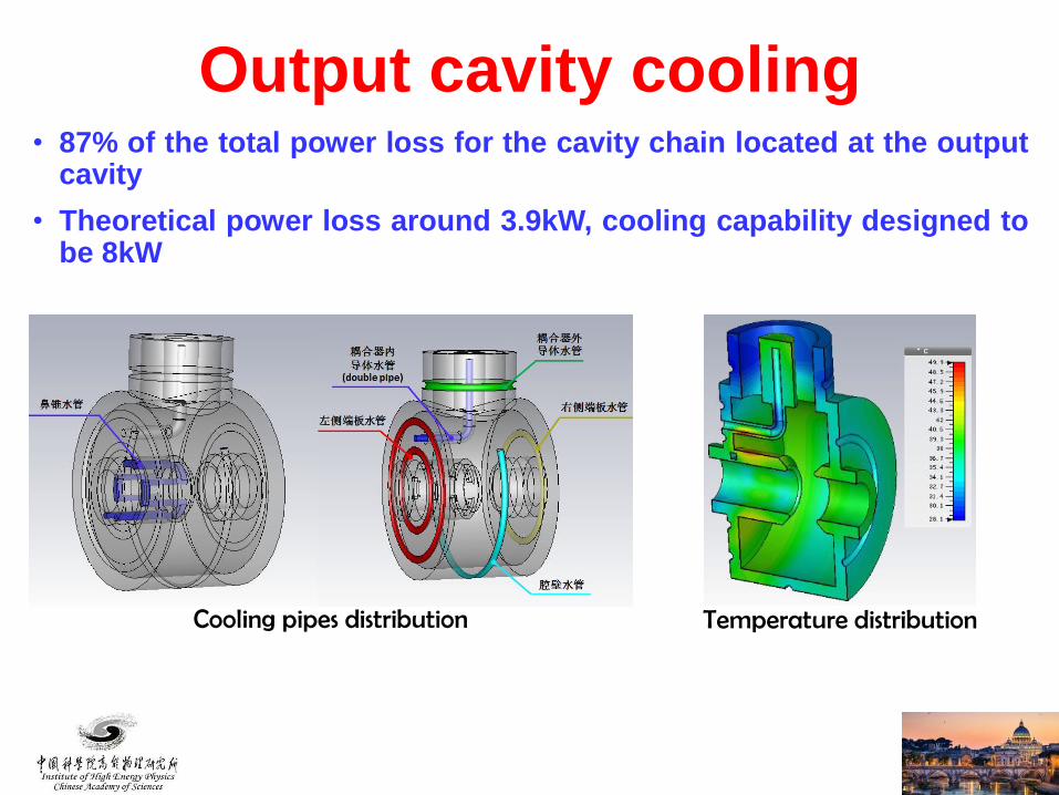
Output cavity cooling• 87% of the total power loss for the cavity chain located at the output
cavity
• Theoretical power loss around 3.9kW, cooling capability designed tobe 8kW
Cooling pipes distribution Temperature distribution
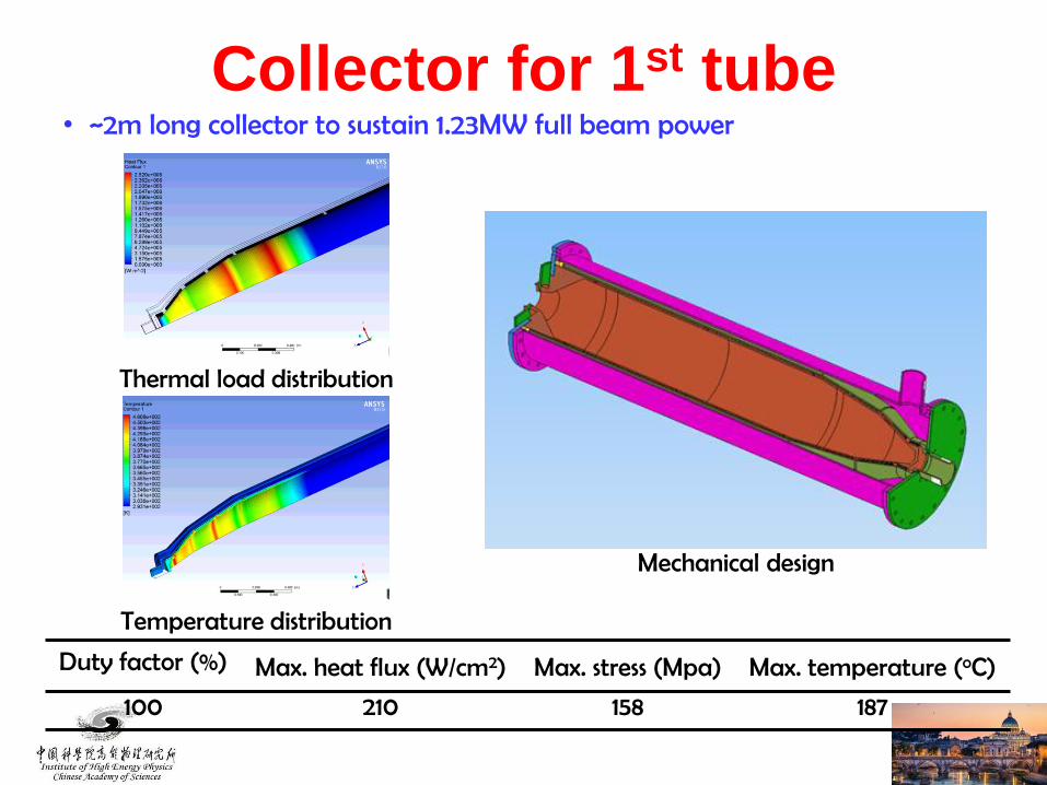
Collector for 1st tube• ~2m long collector to sustain 1.23MW full beam power
Duty factor (%) Max. heat flux (W/cm2) Max. stress (Mpa) Max. temperature (oC)
100 210 158 187
Thermal load distribution
Temperature distribution
Mechanical design

Output window for 1st tube
• Relatively simple design with door knob to facilitate the fabrication
• >800kW sustainable CW RF power @ 650MHz
• <1.05 VSWR @ 650±0.5MHz
Mechanical designTemperature distribution

Mechanical design for 1st tube
• Mechanical design achieved (L×W×H: 5.12m×0.87m×1.56m)
• Discussion on the manufacturing details being conducted

Assembly sequence
Gun
Cavities
center
Support
Collector

High Efficiency Consideration
• 3 design schemes• Scheme 1:optimize cavity chain by using the same gun as 1st tube
• Scheme 2 :with high voltage gun (110kV/9.1A), low perveance
• Scheme 3:MBK, 54kV/20A electron gun
Parameter Scheme1 Scheme2 Scheme3Freq (MHz) 650 650 650Voltage (kV) 81.5 110 54Current (A) 15.1 9.1 20(2.5×8)Beam No. 1 1 8Perveance (µP) 0.65 0.25 1.6(0.2×8)Efficency (%) >70 >80 >80Power(kW) 800 800 800(100×8)
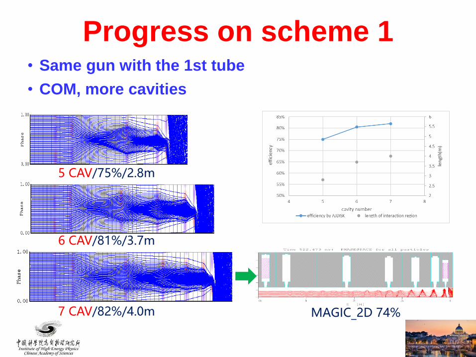
• Same gun with the 1st tube
• COM, more cavities
5 CAV/75%/2.8m
6 CAV/81%/3.7m
7 CAV/82%/4.0m MAGIC_2D 74%
Progress on scheme 1
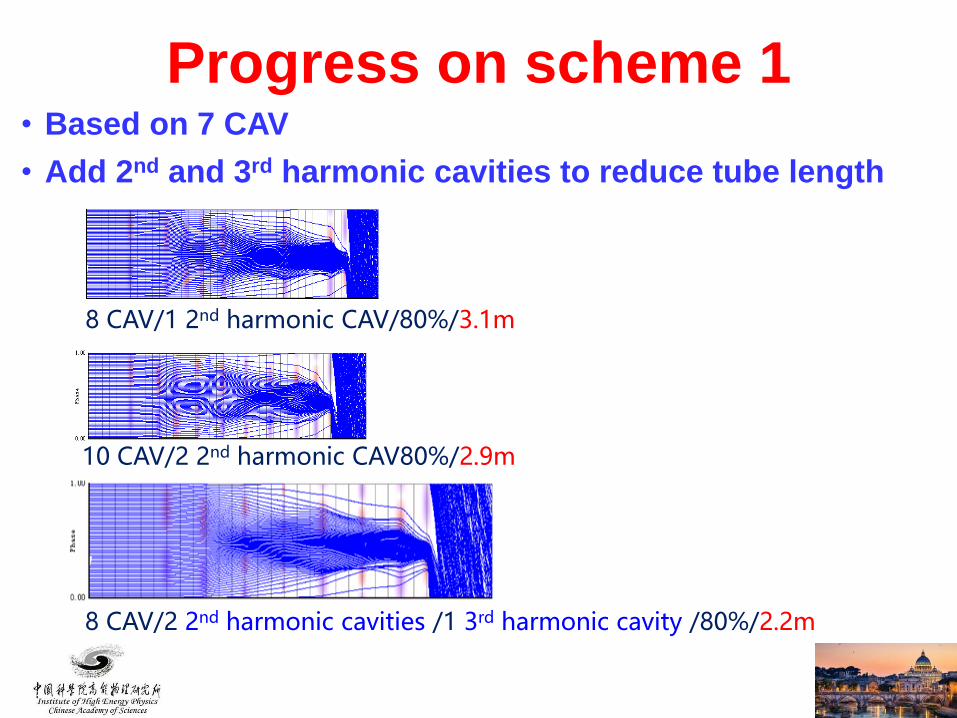
• Based on 7 CAV
• Add 2nd and 3rd harmonic cavities to reduce tube length
8 CAV/1 2nd harmonic CAV/80%/3.1m
10 CAV/2 2nd harmonic CAV80%/2.9m
Progress on scheme 1
8 CAV/2 2nd harmonic cavities /1 3rd harmonic cavity /80%/2.2m
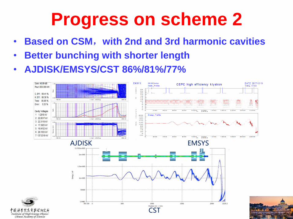
CST
EMSYSAJDISK
• Based on CSM,with 2nd and 3rd harmonic cavities
• Better bunching with shorter length
• AJDISK/EMSYS/CST 86%/81%/77%
Progress on scheme 2
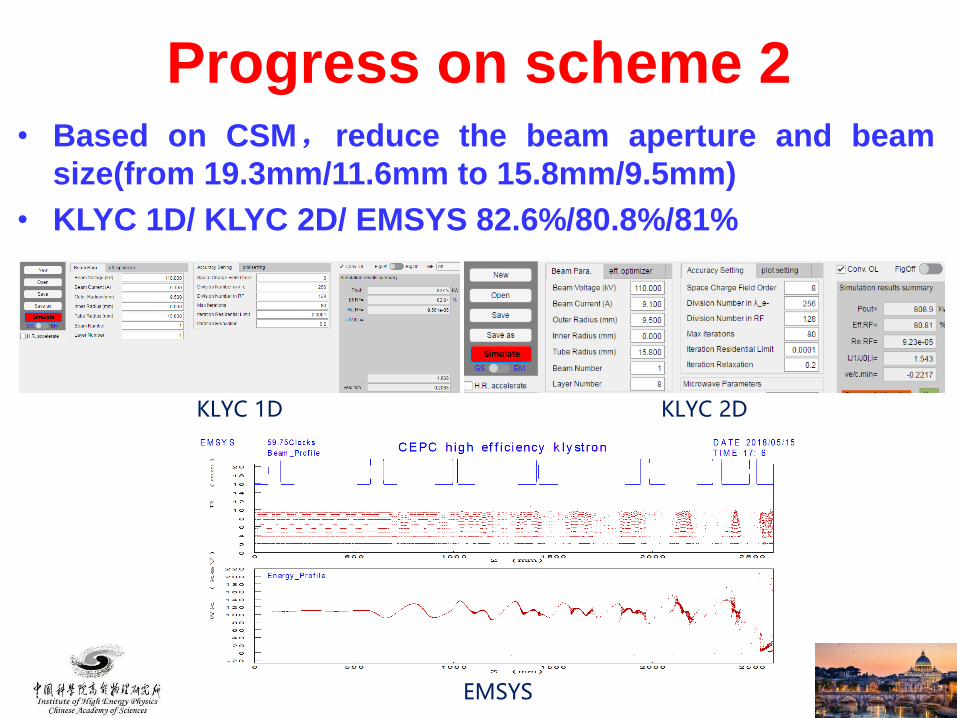
• Based on CSM,reduce the beam aperture and beam
size(from 19.3mm/11.6mm to 15.8mm/9.5mm)
• KLYC 1D/ KLYC 2D/ EMSYS 82.6%/80.8%/81%
KLYC 1D KLYC 2D
EMSYS
Progress on scheme 2
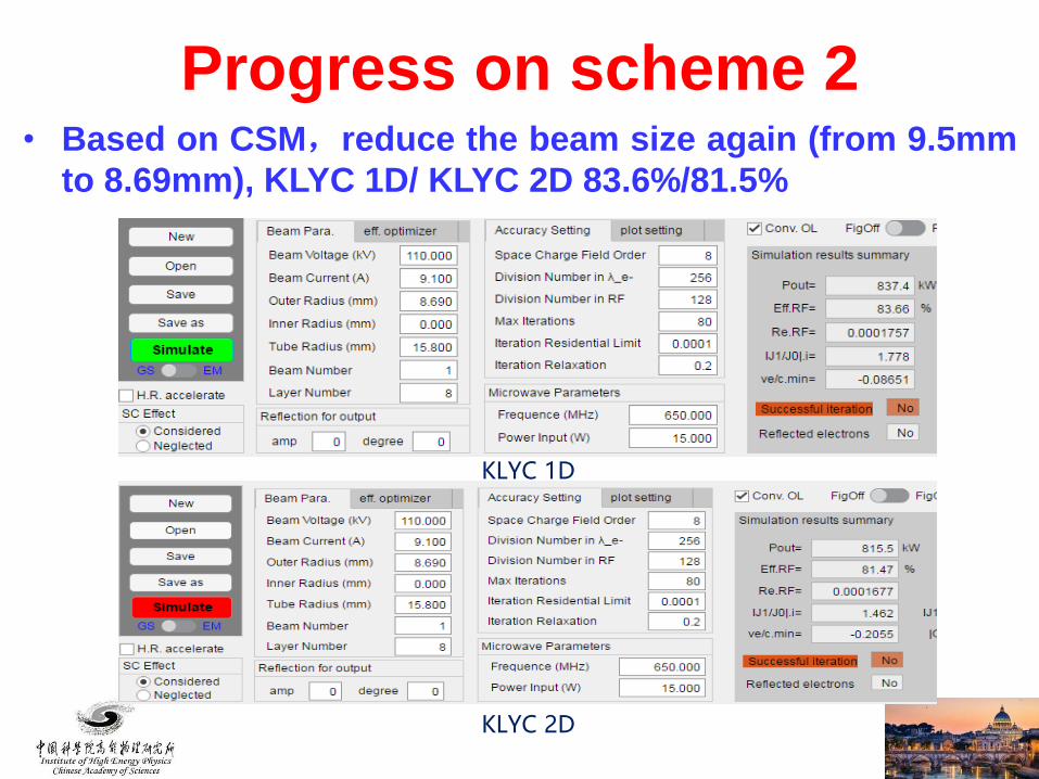
KLYC 1D
KLYC 2D
• Based on CSM,reduce the beam size again (from 9.5mm
to 8.69mm), KLYC 1D/ KLYC 2D 83.6%/81.5%
Progress on scheme 2
Co
lor B
ar fo
r R /Q
Co
lor B
ar fo
r Freq
uen
cy
Co
lor B
ar fo
r R/Q
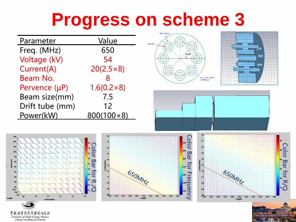
Parameter ValueFreq. (MHz) 650Voltage (kV) 54Current(A) 20(2.5×8)Beam No. 8Pervence (µP) 1.6(0.2×8)Beam size(mm) 7.5Drift tube (mm) 12Power(kW) 800(100×8)
Progress on scheme 3
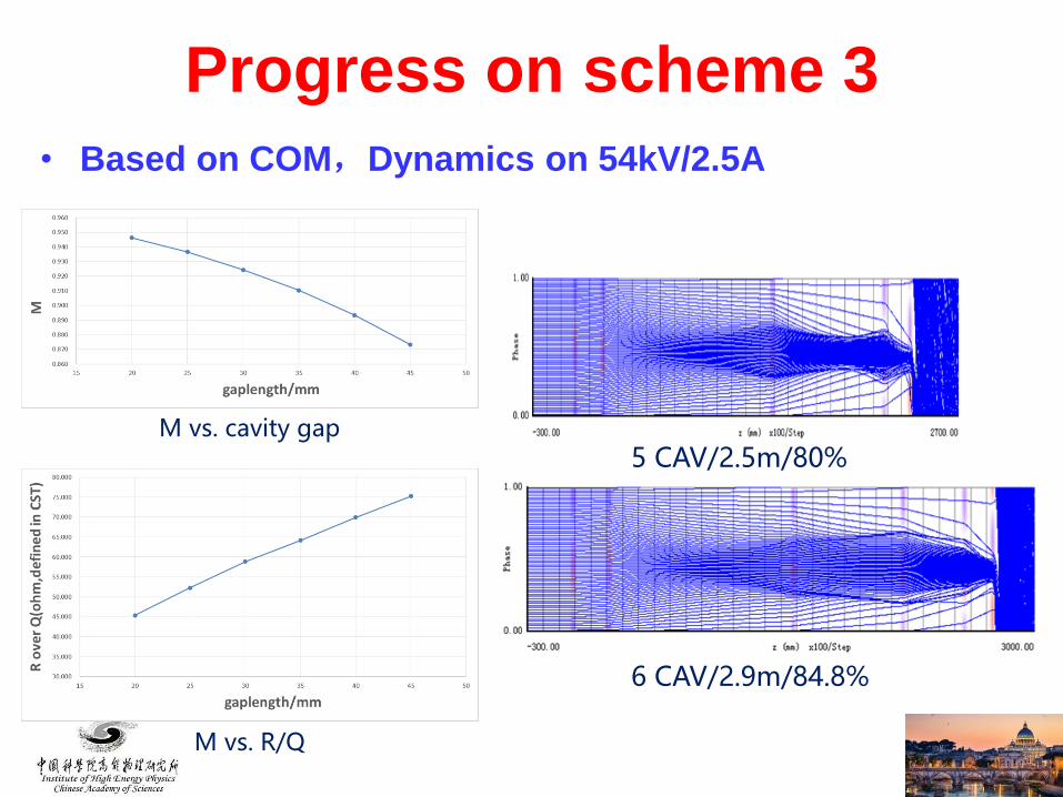
M vs. cavity gap
M vs. R/Q
5 CAV/2.5m/80%
6 CAV/2.9m/84.8%
Progress on scheme 3
• Based on COM,Dynamics on 54kV/2.5A
• Mechanic design on 1st prototype tube will be finished at
the end of this month.
• The manufacture of the 1st tube will be completed this
year and high power test will be started at the beginning
of next year.
• The 3 schemes for the high efficiency design are ongoing
based on 3 different gun design.
• The manufacture of the 2nd prototype will be started
based on the successful high power test of the 1st
prototype.
• MBK design will be gradually stepped up in the near
future.
Summary

Thanks for your attention!