Technological Progress from Ancient Stone Age to Recent Polymer Chemistry World

Progress in Polymer Science 35 (2010) 252–277
Contents lists available at ScienceDirect
Progress in Polymer Science
journa l homepage: www.e lsev ier .com/ locate /ppolysc i
Biomolecular motors at the intersection of nanotechnology andpolymer science
Ashutosh Agarwala, Henry Hessb,∗
a Department of Materials Science and Engineering, University of Florida, Gainesville, FL 32611-6400, USAb Department of Biomedical Engineering, Columbia University, New York, NY 10027, USA
a r t i c l e i n f o
Article history:Received 2 September 2009Received in revised form 9 October 2009Accepted 22 October 2009Available online 3 November 2009
Keywords:BiopolymerHybrid deviceKinesin
a b s t r a c t
The dynamic cytoskeletal components, biomolecular motors and their associated filaments,can be integrated in vitro with synthetic components to enable nanoscale transport sys-tems. These “molecular shuttles” have generated significant scientific interest over thepast decade, resulting in over 200 publications. This review focuses on the contributionsinvolving the use of linear biomolecular motors, kinesin and myosin, and their associatedfilaments, microtubule and actin, in device applications. Exploiting the naturally occurringmotion between the motors and their associated filaments requires an interdisciplinaryunderstanding of the underlying challenges. Three basic topics that most of the experimen-tal contributions have sought to address are: the guiding of shuttle movement, the loading
MyosinMicrotubuleActinMolecular shuttleMolecular motor
and unloading of cargo onto the shuttles, and the control of motor activity. The physicalproperties of motors and filaments determine the engineering solutions to the design chal-lenges. The applications, which center on the basic capability of nanoscale motion, and theroadblocks to their widespread implementation will be discussed in detail.
© 2009 Elsevier Ltd. All rights reserved.
Motor proteinCyotskeletal filamentContents
1. Introduction . . . . . . . . . . . . . . . . . . . . . . . . . . . . . . . . . . . . . . . . . . . . . . . . . . . . . . . . . . . . . . . . . . . . . . . . . . . . . . . . . . . . . . . . . . . . . . . . . . . . . . . . . . . . . . . . . . . . . . . . 2532. Cytoskeletal filaments . . . . . . . . . . . . . . . . . . . . . . . . . . . . . . . . . . . . . . . . . . . . . . . . . . . . . . . . . . . . . . . . . . . . . . . . . . . . . . . . . . . . . . . . . . . . . . . . . . . . . . . . . . . . . 254
2.1. Actin filaments . . . . . . . . . . . . . . . . . . . . . . . . . . . . . . . . . . . . . . . . . . . . . . . . . . . . . . . . . . . . . . . . . . . . . . . . . . . . . . . . . . . . . . . . . . . . . . . . . . . . . . . . . . . . . 2542.2. Microtubules . . . . . . . . . . . . . . . . . . . . . . . . . . . . . . . . . . . . . . . . . . . . . . . . . . . . . . . . . . . . . . . . . . . . . . . . . . . . . . . . . . . . . . . . . . . . . . . . . . . . . . . . . . . . . . . 255
3. Biomolecular motors . . . . . . . . . . . . . . . . . . . . . . . . . . . . . . . . . . . . . . . . . . . . . . . . . . . . . . . . . . . . . . . . . . . . . . . . . . . . . . . . . . . . . . . . . . . . . . . . . . . . . . . . . . . . . . . 2563.1. Myosin . . . . . . . . . . . . . . . . . . . . . . . . . . . . . . . . . . . . . . . . . . . . . . . . . . . . . . . . . . . . . . . . . . . . . . . . . . . . . . . . . . . . . . . . . . . . . . . . . . . . . . . . . . . . . . . . . . . . . . 2573.2. Kinesin . . . . . . . . . . . . . . . . . . . . . . . . . . . . . . . . . . . . . . . . . . . . . . . . . . . . . . . . . . . . . . . . . . . . . . . . . . . . . . . . . . . . . . . . . . . . . . . . . . . . . . . . . . . . . . . . . . . . . . 257
4. From motility assays to nanoscale transport systems. . . . . . . . . . . . . . . . . . . . . . . . . . . . . . . . . . . . . . . . . . . . . . . . . . . . . . . . . . . . . . . . . . . . . . . . . . . . . 2574.1. Bead geometry . . . . . . . . . . . . . . . . . . . . . . . . . . . . . . . . . . . . . . . . . . . . . . . . . . . . . . . . . . . . . . . . . . . . . . . . . . . . . . . . . . . . . . . . . . . . . . . . . . . . . . . . . . . . . 2574.2. Gliding geometry . . . . . . . . . . . . . . . . . . . . . . . . . . . . . . . . . . . . . . . . . . . . . . . . . . . . . . . . . . . . . . . . . . . . . . . . . . . . . . . . . . . . . . . . . . . . . . . . . . . . . . . . . . . 259
4.3. Nanoscale transport by molecular shuttles . . . . . . . . . . . . . . . . .5. Guiding molecular shuttles . . . . . . . . . . . . . . . . . . . . . . . . . . . . . . . . . . . . . . . . .5.1. Guiding using surface topography . . . . . . . . . . . . . . . . . . . . . . . . . .5.2. Guiding using surface chemistry . . . . . . . . . . . . . . . . . . . . . . . . . . . .
∗ Corresponding author. Tel.: +1 212 854 7749; fax: +1 212 854 8725.E-mail address: [email protected] (H. Hess).
0079-6700/$ – see front matter © 2009 Elsevier Ltd. All rights reserved.doi:10.1016/j.progpolymsci.2009.10.007
. . . . . . . . . . . . . . . . . . . . . . . . . . . . . . . . . . . . . . . . . . . . . . . . . . . . . . . . . . . . . . . 259
. . . . . . . . . . . . . . . . . . . . . . . . . . . . . . . . . . . . . . . . . . . . . . . . . . . . . . . . . . . . . . . 259
. . . . . . . . . . . . . . . . . . . . . . . . . . . . . . . . . . . . . . . . . . . . . . . . . . . . . . . . . . . . . . . 260. . . . . . . . . . . . . . . . . . . . . . . . . . . . . . . . . . . . . . . . . . . . . . . . . . . . . . . . . . . . . . . 261
A. Agarwal, H. Hess / Progress in Polymer Science 35 (2010) 252–277 253
5.3. Guiding using surface topography and chemistry . . . . . . . . . . . . . . . . . . . . . . . . . . . . . . . . . . . . . . . . . . . . . . . . . . . . . . . . . . . . . . . . . . . . . . . . . 2615.4. Guiding using flow fields . . . . . . . . . . . . . . . . . . . . . . . . . . . . . . . . . . . . . . . . . . . . . . . . . . . . . . . . . . . . . . . . . . . . . . . . . . . . . . . . . . . . . . . . . . . . . . . . . . . 2625.5. Guiding using electrical fields . . . . . . . . . . . . . . . . . . . . . . . . . . . . . . . . . . . . . . . . . . . . . . . . . . . . . . . . . . . . . . . . . . . . . . . . . . . . . . . . . . . . . . . . . . . . . . 2625.6. Guiding using magnetic fields . . . . . . . . . . . . . . . . . . . . . . . . . . . . . . . . . . . . . . . . . . . . . . . . . . . . . . . . . . . . . . . . . . . . . . . . . . . . . . . . . . . . . . . . . . . . . 2625.7. Summary . . . . . . . . . . . . . . . . . . . . . . . . . . . . . . . . . . . . . . . . . . . . . . . . . . . . . . . . . . . . . . . . . . . . . . . . . . . . . . . . . . . . . . . . . . . . . . . . . . . . . . . . . . . . . . . . . . . 262
6. Loading and unloading of cargo . . . . . . . . . . . . . . . . . . . . . . . . . . . . . . . . . . . . . . . . . . . . . . . . . . . . . . . . . . . . . . . . . . . . . . . . . . . . . . . . . . . . . . . . . . . . . . . . . . . 2636.1. Loading and unloading approaches . . . . . . . . . . . . . . . . . . . . . . . . . . . . . . . . . . . . . . . . . . . . . . . . . . . . . . . . . . . . . . . . . . . . . . . . . . . . . . . . . . . . . . . . 2636.2. Summary . . . . . . . . . . . . . . . . . . . . . . . . . . . . . . . . . . . . . . . . . . . . . . . . . . . . . . . . . . . . . . . . . . . . . . . . . . . . . . . . . . . . . . . . . . . . . . . . . . . . . . . . . . . . . . . . . . . 265
7. Controlling motor activity . . . . . . . . . . . . . . . . . . . . . . . . . . . . . . . . . . . . . . . . . . . . . . . . . . . . . . . . . . . . . . . . . . . . . . . . . . . . . . . . . . . . . . . . . . . . . . . . . . . . . . . . . 2657.1. Activation approaches . . . . . . . . . . . . . . . . . . . . . . . . . . . . . . . . . . . . . . . . . . . . . . . . . . . . . . . . . . . . . . . . . . . . . . . . . . . . . . . . . . . . . . . . . . . . . . . . . . . . . . 2657.2. Summary . . . . . . . . . . . . . . . . . . . . . . . . . . . . . . . . . . . . . . . . . . . . . . . . . . . . . . . . . . . . . . . . . . . . . . . . . . . . . . . . . . . . . . . . . . . . . . . . . . . . . . . . . . . . . . . . . . . 267
8. Applications . . . . . . . . . . . . . . . . . . . . . . . . . . . . . . . . . . . . . . . . . . . . . . . . . . . . . . . . . . . . . . . . . . . . . . . . . . . . . . . . . . . . . . . . . . . . . . . . . . . . . . . . . . . . . . . . . . . . . . . . 2678.1. Manipulation of single molecules . . . . . . . . . . . . . . . . . . . . . . . . . . . . . . . . . . . . . . . . . . . . . . . . . . . . . . . . . . . . . . . . . . . . . . . . . . . . . . . . . . . . . . . . . . 2678.2. Investigation of surface properties . . . . . . . . . . . . . . . . . . . . . . . . . . . . . . . . . . . . . . . . . . . . . . . . . . . . . . . . . . . . . . . . . . . . . . . . . . . . . . . . . . . . . . . . . 2688.3. Self-assembly . . . . . . . . . . . . . . . . . . . . . . . . . . . . . . . . . . . . . . . . . . . . . . . . . . . . . . . . . . . . . . . . . . . . . . . . . . . . . . . . . . . . . . . . . . . . . . . . . . . . . . . . . . . . . . . 2688.4. Biosensing . . . . . . . . . . . . . . . . . . . . . . . . . . . . . . . . . . . . . . . . . . . . . . . . . . . . . . . . . . . . . . . . . . . . . . . . . . . . . . . . . . . . . . . . . . . . . . . . . . . . . . . . . . . . . . . . . . 270
9. Conclusions and outlook . . . . . . . . . . . . . . . . . . . . . . . . . . . . . . . . . . . . . . . . . . . . . . . . . . . . . . . . . . . . . . . . . . . . . . . . . . . . . . . . . . . . . . . . . . . . . . . . . . . . . . . . . . . 271. . . . . . . .. . . . . . . .
1
aatrscrsspcm
mtthatmaycbgh
anphmoc
si
conformation is exploited to block a binding site. How-ever, to actuate the PNIPAM molecule, the stimulus hasto be externally applied to the entire environment ofthe molecule. In contrast, a biomolecular motor operates
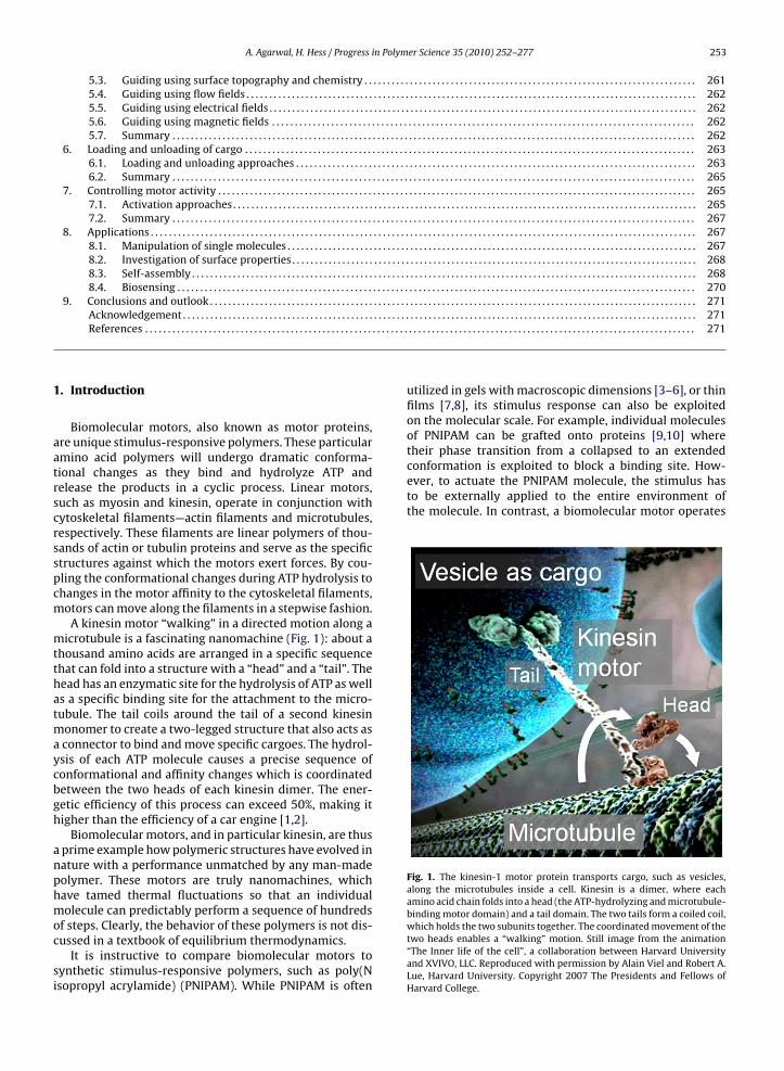
Fig. 1. The kinesin-1 motor protein transports cargo, such as vesicles,along the microtubules inside a cell. Kinesin is a dimer, where eachamino acid chain folds into a head (the ATP-hydrolyzing and microtubule-binding motor domain) and a tail domain. The two tails form a coiled coil,
Acknowledgement . . . . . . . . . . . . . . . . . . . . . . . . . . . . . . . . . . . . . . . . . .References . . . . . . . . . . . . . . . . . . . . . . . . . . . . . . . . . . . . . . . . . . . . . . . . . .
. Introduction
Biomolecular motors, also known as motor proteins,re unique stimulus-responsive polymers. These particularmino acid polymers will undergo dramatic conforma-ional changes as they bind and hydrolyze ATP andelease the products in a cyclic process. Linear motors,uch as myosin and kinesin, operate in conjunction withytoskeletal filaments—actin filaments and microtubules,espectively. These filaments are linear polymers of thou-ands of actin or tubulin proteins and serve as the specifictructures against which the motors exert forces. By cou-ling the conformational changes during ATP hydrolysis tohanges in the motor affinity to the cytoskeletal filaments,otors can move along the filaments in a stepwise fashion.A kinesin motor “walking” in a directed motion along a
icrotubule is a fascinating nanomachine (Fig. 1): about ahousand amino acids are arranged in a specific sequencehat can fold into a structure with a “head” and a “tail”. Theead has an enzymatic site for the hydrolysis of ATP as wells a specific binding site for the attachment to the micro-ubule. The tail coils around the tail of a second kinesin
onomer to create a two-legged structure that also acts asconnector to bind and move specific cargoes. The hydrol-sis of each ATP molecule causes a precise sequence ofonformational and affinity changes which is coordinatedetween the two heads of each kinesin dimer. The ener-etic efficiency of this process can exceed 50%, making itigher than the efficiency of a car engine [1,2].
Biomolecular motors, and in particular kinesin, are thusprime example how polymeric structures have evolved inature with a performance unmatched by any man-madeolymer. These motors are truly nanomachines, whichave tamed thermal fluctuations so that an individualolecule can predictably perform a sequence of hundreds
f steps. Clearly, the behavior of these polymers is not dis-ussed in a textbook of equilibrium thermodynamics.
It is instructive to compare biomolecular motors toynthetic stimulus-responsive polymers, such as poly(Nsopropyl acrylamide) (PNIPAM). While PNIPAM is often
. . . . . . . . . . . . . . . . . . . . . . . . . . . . . . . . . . . . . . . . . . . . . . . . . . . . . . . . . . . . . . . 271. . . . . . . . . . . . . . . . . . . . . . . . . . . . . . . . . . . . . . . . . . . . . . . . . . . . . . . . . . . . . . . 271
utilized in gels with macroscopic dimensions [3–6], or thinfilms [7,8], its stimulus response can also be exploitedon the molecular scale. For example, individual moleculesof PNIPAM can be grafted onto proteins [9,10] wheretheir phase transition from a collapsed to an extended
which holds the two subunits together. The coordinated movement of thetwo heads enables a “walking” motion. Still image from the animation“The Inner life of the cell”, a collaboration between Harvard Universityand XVIVO, LLC. Reproduced with permission by Alain Viel and Robert A.Lue, Harvard University. Copyright 2007 The Presidents and Fellows ofHarvard College.

in Polym
254 A. Agarwal, H. Hess / Progressautonomously in a constant environment. While some arti-ficially designed DNA motors [11,12] have recently beenable to achieve autonomous operation, their speed andefficiency are orders of magnitude lower than those ofbiomolecular motors.
The performance advantages of biomolecular motorsover synthetic stimulus-responsive polymers are main-tained if the motors are integrated into macroscopicstructures, such as a muscle. A muscle, e.g. a biceps, con-tains on the order of 102̂0 myosin motors coupled togetherinto a macroscopic structure, but it still achieves a maximalefficiency exceeding 20% [13]. In contrast, the efficiency ofenergy conversion in a PNIPAM gel has been estimated as0.001% [5].
Beyond evolving a highly functional molecular motor,nature has accomplished other feats of interest to the poly-mer chemist, materials scientist or nanoengineer: myosinmotors have been hierarchically assembled over multiplelength scales into muscle, which is an accomplishmentunmatched by any synthetic polymer system. Control ofmotor activity has been achieved on the macroscale viathe neuromuscular system, as well as on the subcellularscale via a variety of molecular mechanisms [14,15]. Motorsand cytoskeletal filaments combine into a multifunctional,adaptive material [16,17]. Last but not least, applicationshave been found for molecular motors, derived systems,and materials.
Biomolecular motors have attracted tremendous inter-est from physiologists, biologists and biophysicists dueto their central role in the musculoskeletal system.Tens of thousands of publications describe biomolecularmotors from the perspective of the natural sciences andbiomedicine.
This review, in contrast, will describe an engineer-ing frontier, which has emerged in the past ten years:the design of hybrid systems incorporating biomolecularmotors. The focus of this effort is in the realm of nan-otechnology because providing actuation at the nanoscaleis particularly challenging by other means, and becausea functional nanosystem requires fewer molecular scaleparts than a system on the meso- or macroscale. The impor-tance of polymer science concepts will be highlighted, sincethey are encountered at two scales: the molecular scale ofindividual motor proteins and the supramolecular scale ofcytoskeletal filaments, which can be thought of as “poly-mers of polymers”. Systems designed from linear motorsare emphasized here, since the efforts in the utilization ofthe rotary motor F1-ATPase [18–20] have slowed, due tothe difficulty of utilizing this protein in a synthetic envi-ronment.
This review is the latest of a series of efforts to summa-rize the state-of-the-art in the field [21–33], and aims to bean up-to-date and comprehensive overview. The organiza-tion of the manuscript is as follows: after an introductionto the basic properties of cytoskeletal filaments and themotor proteins myosin II and kinesin-1, we will focus on the
design of nanoscale transport systems powered by kinesinand myosin and review the extensive research concerningthese systems. We will conclude with a review of the appli-cations which have been described and a brief outlook intothe future.er Science 35 (2010) 252–277
2. Cytoskeletal filaments
The cytoskeleton consists of a network of actin fila-ments, microtubules and intermediate filaments [34]. Thisprotein scaffold assists the eukaryotic cell in organizing itscytoplasm, in responding to external mechanical stimuli,and in generating motility [35,36].
Actin, one of the most abundant proteins in eukary-otic cells [37], plays both dynamic and structural roles[38]. Along with actin-binding proteins (ABPs), the actincytoskeleton provides mechanical strength to the cell, con-nects transmembrane proteins with cytoplasmic proteins,and generates locomotion in cells [39].
Microtubules are long, stiff, and hollow biopolymersfound in all eukaryotes [40]. They nucleate at and grow outfrom microtubule-organizing centers such as centrosomes[41], span the entire cytoplasm, and provide structural sup-port to the cell [42]. Together with microtubule-associatedproteins (MAPs), these remarkable constructs are involvedin a variety of cellular functions such as intracellular trans-port, cell motility, and mitosis [35].
Intermediate filaments are ropelike polymers com-posed of tetramerized alpha-helical rods with N- andC-terminal domains. The structure and function of inter-mediate filaments depend on their intracellular location[43]. For example, lamin provides stability to the nuclearmembrane, vimentin withstands stresses in the cytoplasmof the cell, and desmin provides linkages within musclefibers.
Since microtubules and actin filaments also serve astracks for motor proteins, their structural organization willbe reviewed in more detail.
2.1. Actin filaments
Actin monomers called G-actin (globular-actin) poly-merize in the presence of ATP and millimolar con-centrations of Ca2+ or Mg2+ to form right-handed,double-stranded helical filaments. These filaments, calledF-actin (filamentous-actin) have a diameter of 8 nm [38]and consist of two strands which cross over every 36 nm,giving a full 360◦ turn every 72 nm [44]. The monomersincorporate into the filament in a specific orientation, thusimparting a structural and functional polarity to the fila-ment. Based on their appearance in electron microscopyimages, when coated with myosin motor domains (myosinsubfragment 1), the fast-growing end is designated asthe “barbed end”, while the slow growing end is referredto as the “pointed end” of the filament. Motor proteinsof the myosin family bind to actin filaments and, gen-erally, move in the direction of the barbed end. In vivo,actin filaments are very dynamic structures which arein a dynamic equilibrium between polymerization anddepolymerization. In vitro however, actin filaments can bestabilized against depolymerization with phalloidin [45].This stabilization is essential for their use in engineered
structures.The wire-like actin filaments with a trajectory persis-tence length of less than 10 �m [46–48] are employed inhybrid devices if myosin motors are preferred or particu-larly flexible filaments are desired.

A. Agarwal, H. Hess / Progress in Polymer Science 35 (2010) 252–277 255
Fig. 2. (a) Schematic representation of a microtubule with 13 protofilaments. Protofilaments are made from tubulin dimers which bind to each other in ah ch resuld bindingt main of[
2
ttdpwmtdigHoftteta
nbmtbGyttdtwti
ead-to-tail fashion. Protofilaments bind to each other with an offset whierived from electron crystallography [49] and shows the GTP and taxolail domain, the coiled coil stalk domain, the neck linker, and the head do50] and shows the ATP binding site in the head domain.
.2. Microtubules
Microtubules are hollow cylinders composed of �,�-ubulin heterodimers [51]. Tubulin dimers bind head-to-ail to form linear protofilaments with an 8 nm repeatistance and a variable number (10–18, often 13) ofrotofilaments and assemble into a cylindrical structureith an outer diameter of about 25 nm and a length of manyicrometers (Fig. 2a) [52]. Since the protofilaments bind
o each other in the same orientation, the microtubule alsoevelops structural polarity. The end exposing �-tubulin
s slow-growing and called the minus end, and the fast-rowing end exposing �-tubulin is named the plus end.owever, protofilaments bind to each other with an offsetf 0.92 nm, which results in an accumulated offset of 12 nmrom 13 protofilaments. This exactly equals the length ofhree monomers and hence, for a 13 protofilament micro-ubule, a discontinuity in the structure or a linear ‘seam’xists. The structural properties of microtubules are criticalo their cellular functions as well as their nanotechnologicalpplications.
During polymerization, microtubules can display a phe-omenon termed dynamic instability: stochastic switchingetween growing and shrinking phases on a timescale ofinutes [53]. When microtubules are in a growth phase,
he tubulin dimers joining the plus end have a GTP moleculeound to them, which they subsequently hydrolyze toDP [54]. If polymerization proceeds faster than hydrol-sis, a “cap” of GTP-tubulins is formed at the microtubuleip, which stabilizes the microtubule. If hydrolysis over-akes polymerization, the GTP cap is destroyed and rapid
epolymerization sets in (a phenomenon known as “catas-rophe”). The depolymerization of the microtubule stopshen a surviving GTP tubulin is encountered in the micro-ubule lattice, which arrests the depolymerization andnitiates a new growth phase (the process is termed “res-
ts in a seam in the microtubule structure. The ribbon diagram (bottom) issites. (b) Schematic representation of kinesin showing the cargo bindingthe molecule. The ribbon diagram is derived from X-ray crystallography
cue”) [55]. Hence, microtubule assembly depends criticallyon the binding, hydrolysis, and exchange of the nucleotideGTP [56], which acts by changing the conformation of thetubulin dimer [57].
Dynamic instability enables cells to perform multipletasks. Regulated assembly and disassembly of micro-tubules can generate pulling and pushing forces [58], andis used by cells to position the mitotic spindle and separatethe two sets of chromosomes into the two daughter cells[59,60]. Dynamic instability also allows cells to recycle thetubulin building blocks. From a materials perspective, con-stantly turning over the subunits of a structural elementmight also allow cells to ensure that these componentsremain defect free [61].
The diversity of tasks that cells are able to fulfill bycontrolling dynamic instability has piqued the imagina-tion of nanotechnologists too. Simulations have shown thatthe seemingly unreliable stochastic process of dynamicassembly can be employed to build a variety of nanostruc-tures [62]. Strategies to sort, pattern, harvest, and delivernanoparticles have been evaluated (Fig. 3a). Reproduciblecontrol over the actions of these nanosystems can be exer-cised only at the “swarm” level, where the stochastic natureof individual elements is averaged [62,67]. The initial stepstowards an experimental demonstration of these conceptshave been taken by assembling three-dimensional polar-oriented synthetic microtubule organizing centers [68].
The reversibility of the actin or tubulin polymeriza-tion is also employed for the preparation and purificationof proteins functionalized with fluorophores or biotin, forexample [69,70]. It is essential that the ability of the protein
to polymerize is not compromised after functionaliza-tion. Hence, microtubules are labeled in the polymer form,excess label is removed and functional protein is selectedby repeated cycles of polymerization, centrifugation anddepolymerization. Nanoparticle-labeled actin monomers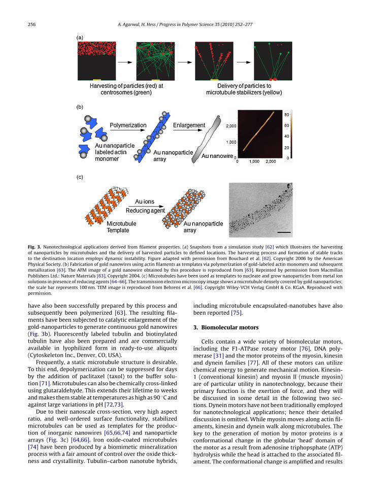
256 A. Agarwal, H. Hess / Progress in Polymer Science 35 (2010) 252–277
Fig. 3. Nanotechnological applications derived from filament properties. (a) Snapshots from a simulation study [62] which illustrates the harvestingof nanoparticles by microtubules and the delivery of harvested particles to defined locations. The harvesting process and formation of stable tracksto the destination location employs dynamic instability. Figure adapted with permission from Bouchard et al. [62]. Copyright 2006 by the AmericanPhysical Society. (b) Fabrication of gold nanowires using actin filaments as templates via polymerization of gold-labeled actin monomers and subsequentmetallization [63]. The AFM image of a gold nanowire obtained by this procedure is reproduced from [63]. Reprinted by permission from Macmillan
have been micros et al.
Publishers Ltd.: Nature Materials [63], Copyright 2004. (c) Microtubulessolutions in presence of reducing agents [64–66]. The transmission electrothe scale bar represents 100 nm. TEM image is reproduced from Behrenpermission.
have also been successfully prepared by this process andsubsequently been polymerized [63]. The resulting fila-ments have been subjected to catalytic enlargement of thegold-nanoparticles to generate continuous gold nanowires(Fig. 3b). Fluorescently labeled tubulin and biotinylatedtubulin have also been prepared and are commerciallyavailable in lyophilized form in ready-to-use aliquots(Cytoskeleton Inc., Denver, CO, USA).
Frequently, a static microtubule structure is desirable.To this end, depolymerization can be suppressed for daysby the addition of paclitaxel (taxol) to the buffer solu-tion [71]. Microtubules can also be chemically cross-linkedusing glutaraldehyde. This extends their lifetime to weeksand makes them stable at temperatures as high as 90 ◦C andagainst large variations in pH [72,73].
Due to their nanoscale cross-section, very high aspectratio, and well-ordered surface functionality, stabilizedmicrotubules can be used as templates for the produc-
tion of inorganic nanowires [65,66,74] and nanoparticlearrays (Fig. 3c) [64,66]. Iron oxide-coated microtubules[74] have been produced by a biomimetic mineralizationprocess with a fair amount of control over the oxide thick-ness and crystallinity. Tubulin–carbon nanotube hybrids,n used as templates to nucleate and grow nanoparticles from metal ionscopy image shows a microtubule densely covered by gold nanoparticles;[66]. Copyright Wiley-VCH Verlag GmbH & Co. KGaA. Reproduced with
including microtubule encapsulated-nanotubes have alsobeen reported [75].
3. Biomolecular motors
Cells contain a wide variety of biomolecular motors,including the F1-ATPase rotary motor [76], DNA poly-merase [31] and the motor proteins of the myosin, kinesinand dynein families [77]. All of these motors can utilizechemical energy to generate mechanical motion. Kinesin-1 (conventional kinesin) and myosin II (muscle myosin)are of particular utility in nanotechnology, because theirprimary function is the exertion of force, and they willbe discussed in some detail in the following two sec-tions. Dynein motors have not been traditionally employedfor nanotechnological applications; hence their detaileddiscussion is omitted. While myosin moves along actin fil-aments, kinesin and dynein walk along microtubules. The
key to the generation of motion by motor proteins is aconformational change in the globular ‘head’ domain ofthe motor as a result from adenosine triphopsphate (ATP)hydrolysis while the head is attached to the associated fil-ament. The conformational change is amplified and results
n Polym
iiid‘ttrt[afrFipl
3
teit[
idbImqpfmsrma
3
lbcKo
tochsomatho
A. Agarwal, H. Hess / Progress i
n movement of the load bearing ‘tail’ region of the motorn a specific direction along the filament. The amplifications provided by the lever arm ‘neck’ domain and dependsirectly on the length of this lever arm [78]. After this
power stroke’, the head detaches, advances and rebinds athe next binding site on the filament. The fraction of timehat each head spends in its attached state is called the dutyatio of the motor. Differences in the duty ratio are impor-ant in determining if the motors are processive or not34]. A non-processive motor detaches from the filamentfter every step while a processive motor stays attachedor multiple steps. Motors have evolved with different dutyatios to serve distinctly different cellular functions [34].or example, highly processive kinesin motors are utilizedndividually by cells for long distance intracellular trans-ort, while non-processive myosins are used in parallel in
arge numbers to produce rapid motion.
.1. Myosin
Myosin motors are involved in intracellular organelleransport [79], cell movement [80], endocytosis andxocytosis [81,82], and mechanotransduction [83]. Mostmportantly, myosin movement along actin filaments ishe force-generating mechanism for muscle contraction84–86].
From the myosin family (myosin I–XXIV [87]), primar-ly myosin II has been chosen for engineering applicationsue to its wide availability [28], although myosin V haseen employed as well [88]. The non-processive myosinI (duty ratio of about 0.05 [89]) works in large arrays in
uscle fibers where each motor contributes a small anduick translocation of the associated actin filament. Therocessive myosin V (duty ratio of 0.7 [90]) is employedor long-distance intracellular cargo transport. The kinetic
echanism of myosins has been modeled as a power-troke model [91] and less frequently as a biased Brownianatchet [92,93]. The in vitro speed of purified myosin IIotors at saturating ATP concentrations is about 6 �m/s,
nd each motor generates a force on the order of 1 pN [34].
.2. Kinesin
Kinesin-1 motors are primarily involved in intracellu-ar transport of vesicles and organelles [95]. Their roleecomes particularly important in neurons because vitalargo has to be transported over large distances [96].inesins are also involved in cell division [97], and therganization of cilia and flagella [98].
Kinesin-1 is a two-headed motor which walks towardshe plus end of the microtubules (Fig. 2b). It is a tetramerf two identical “heavy chains”, and two associated lighthains, which in vivo are responsible for cargo binding. Theeavy chains fold into two globular heads at one end, atalk with a hinge in the middle, and a tail domain at thether end [99]. The heads step on the binding sites along the
icrotubule protofilaments. These sites are spaced 8 nmpart. Each head of the kinesin molecule takes 16 nm steps,hus moving the entire molecule 8 nm in each step in aand-over-hand mechanism [100]. The heads pass eachther on alternating sides to keep the stalk from getting
er Science 35 (2010) 252–277 257
twisted during the walk. For every step, kinesin consumesone ATP molecule [101]. The two heads are tightly coordi-nated so that one head does not detach before the other issecurely attached. This makes kinesin a highly processivemotor [102], allowing it to walk for several microme-ters before detaching. The exact sequence of events inthe mechanochemical cycle of kinesin is still debated butone possible description is depicted in Fig. 4 [94]: the taildomain, if not bound to the cargo, inhibits motor activity bybinding to the motor region, presumably to conserve ATPand maintain the kinesin position near the cargo loadingarea [103].
In vitro, kinesin motors walk along microtubules atspeeds of 1 �m/s (saturating ATP concentrations [34]). Theforce at which the mean velocity drops to zero, the stallforce, is about 8 pN and is independent of ATP concentra-tion [34]. Because of its high degree of processivity, evena single kinesin molecule is capable of propelling micro-tubules along a surface [104].
4. From motility assays to nanoscale transportsystems
Biophysicists have for a long time utilized in vitro assaysto study motor proteins and their associated cytoskele-tal filaments in a synthetic environment [105–108]. These“motility assays” enable the purification and identifica-tion of the involved biological components, the controlledarrangement of biological and synthetic structures, and thesensitive detection of the ensuing events. Motility assayshave been conducted in the “bead geometry” (filamentsstationary, motors moving) and in the “gliding geometry”(filaments moving, motors stationary). Both approacheshave been adopted by engineers aiming to mimic the bio-logical applications of motor proteins, and in particulartheir function as nanoscale transport systems. These nan-otransporters are often referred to as “molecular shuttles”.
4.1. Bead geometry
In the bead geometry, the cytoskeletal filament – oftena microtubule – is immobilized by adsorption to a surfacewhile the motor is attached to a polystyrene microsphere(the “bead”) and walks along the filament. Optical tweezerscan be used to exert precisely calibrated opposing forces onthe bead and consequently on the motor. The displacementof the bead as a function of time reveals the individual stepsof the motor heads. These data helped unravel the walkingmechanism of molecular motors [109–116]. Fusion pro-teins combining a motor with a fluorescent protein enablethe imaging of motor movement with even less interfer-ence, albeit without the ability to exert a defined load.
For processive motors such as kinesin, dynein, andmyosin V, the associated filament is fixed to a slide sur-face while the motor protein is fixed to the trapped beadthrough its tail (Fig. 5a). The trap can now either remain
stationary and exert increasing forces as the motor moveson the filament, or serve as a ‘constant force clamp’ [117]through a feed-back loop that moves the laser focus. Mul-tiple motors of the same [118] or different [119] kind canalso be attached to the same bead to model the transport
258 A. Agarwal, H. Hess / Progress in Polymer Science 35 (2010) 252–277
Fig. 4. Asymmetric hand-over-hand mechanochemical cycle of kinesin [94]. (a) ATP binding to the leading head induces a conformational change in themolecule. This power stroke results in the movement of the trailing head towards the plus end of the microtubule. (b) The trailing head reaches the nextbinding site, 16 nm away on the microtubule lattice, after a diffusional substep. (c) Binding to the microtubule catalyzes ADP release from the new leadinghead. This strains the neck linker region which gates the two head domains in different states. (d) ATP hydrolysis and release of phosphate from the nowtrailing head relieves the strain, freeing the leading head to bind to an ATP molecule to repeat the cycle.
Fig. 5. Design routes for nanotechnological applications. (a) Bead geometry. This is most often employed in an optical tweezer setup utilized by motorbiophysicists. Filaments adsorbed to a substrate serve as tracks for motors. Microsphere cargo is bound to the tail region of the motors and held in placeby a laser trap. (b) Gliding or inverted geometry. Motors are adsorbed to a substrate through their tail domains. The heads project out into the solutionand bind to filaments. The experiments are usually carried out in a “flow” cell which enables solution exchanges (but does not utilize continuous flow) andinvestigation under a microscope.

n Polym
ps
tttofsp
daa
4
itiwstips1
stgtbpwtdace
fWacd[oh
4
aiImatt
A. Agarwal, H. Hess / Progress i
roperties of cargo being propelled by several motors; aituation much closer to the complex traffic inside the cell.
For non-processive motors such as myosin II, the opticalrap setup is usually modified [113,120]. Beads are attachedo the coverslip to provide docking of the motors via theirails. A filament is stretched between two beads via doubleptical tweezers and brought close to the coverslip sur-ace to interact with one or more motors. A recent reviewummarizes the use of optical tweezers in the study of non-rocessive motors [121].
The distance over which the bead is transportedepends on the number of motors connecting the filamentnd the bead [118], but can only exceed the length of the fil-ment if the immobilized filaments are overlapping [122].
.2. Gliding geometry
The gliding geometry (or “inverted geometry”) utilizesmmobilized motors and a moving filament. This is advan-ageous as the filament can move for centimeters withoutnterruption, provided a sufficient area has been covered
ith motors. Furthermore even non-processive motors,uch as myosin II, can transport filaments over long dis-ances since a large number of motors can simultaneouslynteract with the filament [92]. Gliding assays are typicallyerformed in simple ‘flow cells’ assembled from a glasslide and a glass coverslip separated by spacers of roughly00 �m height (Fig. 5b) [108].
The interaction between the motors and the internalurface of the flow cell in a gliding assay has been showno be critical [29,30]. The direct binding of a motor to thelass surface of the coverslip leads typically to denatura-ion of the motor protein with a complete (neither filamentinding nor transport) or partial (binding but not trans-ort) loss of function of the motor. Coating the surfaceith a nitrocellulose film (for myosin) or a blocking pro-
ein such as casein (for kinesin, Fig. 5b) has been shown toramatically enhance the motor activity after non-specificdsorption [108,123]. In addition, strategies to specifi-ally adsorb motors to coatings on the surface have beenxplored [124,125].
The gliding of filaments can be imaged by dark-field, dif-erential interference contrast, or fluorescence microscopy.
hile the filaments appear significantly wider than theyctually are due to the resolution limitations of opti-al microscopy, the position of isolated filaments can beetermined with nanometer accuracy in three dimensions126,127]. For example, it has been established using flu-rescence interference contrast microscopy that kinesinolds the microtubule 17 nm away from the surface [128].
.3. Nanoscale transport by molecular shuttles
While bead and gliding assays reconstitute somespects of in vivo motor functions, they are far from recreat-ng the motor-based transport system of a eukaryotic cell.
n the gel-like cytoplasm of these cells, a rich variety ofotor proteins has evolved to transport specific organellesnd vesicles over large distances from one defined locationo another at controlled rates and well-defined points inimes [129].
er Science 35 (2010) 252–277 259
To mimic the biological transport system, the func-tionality of the bead or gliding assay would have to besignificantly expanded. By integrating directed transportalong predefined paths, loading and unloading of spe-cific cargoes and user-controlled activation of the motorsa fully functional biomimetic nanoscale transport systemcould be created. Such a system, termed “molecular shut-tle” [130,131], was envisioned to serve as a component ofminiaturized devices and functional materials.
In the context of miniaturized devices [132], the criti-cal advantage that motors confer is that there is no needof external pumps to power the mass transport func-tions. The chemical energy derived from ATP molecules,present within the system, is directly harnessed to gen-erate motion. Active transport by molecular shuttles alsocomplements diffusion, pressure-driven flow or electroki-netic transport in micro and nanofluidic devices since itseffectiveness scales differently with the transport distance[21,23,133].
Molecular shuttle designs can be based on either thebead or the gliding assay (Fig. 5), with each configurationoffering distinct advantages.
Control over direction of motion is most elegantlyachieved in the gliding assay. Due to the intrinsic struc-tural polarity of the filaments, the resulting motion in agliding assay is always towards one end of the filament.The gliding filaments can be guided in a specific direc-tion by a variety of techniques, which are discussed inthe next section. For directional control in bead assays,oriented filaments have to be immobilized on the sur-face in high densities. Immobilization has been achievedthrough silane–microtubule interactions [134,135], minusend-specific antibodies [136], immobilizing seeds on thesurface [137], selective DNA hybridization [138], or usingmodified motors that only bind to filaments [139]. Subse-quent alignment is achieved through fluid flow [134–136]or elongation of the immobilized filaments through poly-merization [137,139]. However in the majority of studies,filaments are first aligned using the gliding assay and thenimmobilized to serve as tracks for motor coated beads.
In the gliding assay, diverse cargoes can be attached inhigh density to filaments by conventional bioconjugationtechniques [69]. As discussed earlier, the actin or tubulinsubunits are typically first functionalized and purified, andthen reassembled into filaments with the desired proper-ties. In a bead assay, however, apart from generating densetracks of oriented filament, functional motors need to beadsorbed in high density to the cargo surface [118].
The basic challenges of guiding the movement, loadingthe cargo, and controlling the motors are common to allmolecular shuttle systems, and are reviewed in the fol-lowing sections. However, since the bead geometry hasonly been employed in a few instances [122,140–148], thediscussion will focus on systems utilizing the gliding geom-etry.
5. Guiding molecular shuttles
On planar surfaces uniformly coated with myosin orkinesin motors, actin filaments and microtubules, respec-tively, perform persistent random walks [47,149]. These

in Polym
260 A. Agarwal, H. Hess / Progresspaths result from the Brownian motion of the filament tip,which searches for the next motor as the advancing fila-ment is anchored to the preceding motors. The emergingtrajectory thus can be modeled as a worm-like chain, whosestochastic properties – just as the polymeric filament itself– can be characterized by a persistence length.
While some device designs can take advantage of therandom movement of shuttles [132,150], in most cases it isessential to guide molecular shuttles along predeterminedpaths. In addition, it is desirable to define a specific direc-tion of transport along the path as well as to have the abilityto switch between alternative paths.
The approaches that have been used to design guidingtracks are: (1) physically erecting steep side walls for chan-nels that guide shuttles moving on the bottom surface, (2)chemically defining track regions where motor proteinsare adsorbed and surrounded by non-track regions so thatshuttle motility is restricted within track regions, (3) com-bination of both these techniques, where only the channelbottoms have functional motor proteins and walls do nothave active motors, and active steering of shuttles using (4)flow fields, (5) electric fields and (6) magnetic fields.
5.1. Guiding using surface topography
Surface topography provides physical confinement byimposing barriers to filament motility. When the shuttlescollide with the walls of the barriers, the propelling forceof motor proteins is transformed into bending forces for
the filaments. This results in guiding along the direction ofchannel walls (Fig. 6a) [151,152].The first physical guiding design for both the acto-myosin system [153] and the kinesin–microtubule system[130] were simple ridges and grooves along the shear axis
Fig. 6. Guiding approaches. (a) Guiding using surface topography. The normal foalong the wall. However, a fraction of the filaments, depending on the approach aon the walls. (b) Guiding in the presence of an undercut just below the wall. Filthe channels. (c) Guiding using surface chemistry by generating sufficient contrastrack edge an overhanging tip emerges, which fluctuates under the influence of thbound to a last motor can rotate more freely because motors can swivel around thchemistry of the walls is designed to interfere with either binding or functionalitapproach angles, resulting in superior guiding as compared to surface topograph
er Science 35 (2010) 252–277
of a mechanically deposited PTFE film on glass. The widthsand heights of ridges however, were difficult to control.Replica-molding of polyurethane channel reproduciblyproduces channel geometries [131]. While these openguiding channels have to be sufficiently deep (>200 nm)to prevent the microtubule or actin filament from climb-ing the wall [127,154], the angle of approach is also a keydeterminant of the outcome of filament-sidewall collisions(either guiding or escape) and hence of guiding efficiency[155].
The adsorption of filaments to the guiding channelsin random directions leads to bidirectional movementof shuttles along the tracks. Extraction of unidirectionalmovement was made possible by adding ‘arrowhead’-shaped rectifiers to the tracks [156]. While these rectifiersselected the direction of movement with a 70% success rate,several advanced rectifier designs have now been testedfor rectification efficiency and analyzed for the rectifica-tion mechanism [157,158]. A more detailed understandingof filament gliding trajectories [149] has also enabled sim-ulations aiding the design of tracks for systems based onmicrotubules [159] and actin filaments [47].
Another design advance was the introduction of anundercut at the bottom of the channel wall [160] (Fig. 6b).Microtubules [160] and actin filaments [161] are unableto climb the sidewall and hence preferentially move inthe undercut section of the channel. These undercuts werelater combined with other rectifier designs [122,162] forefficient guiding and generation of unidirectional motion.
Completely enclosed microfluidic channels have alsobeen employed for kinesin–microtubule shuttles [163].While open channels have to guard against the escape offilaments, these capped channels inherently provide three-dimensional confinement. Directional rectifiers have been
rce provided by the walls to the motor propelled filaments bends themngle, are able to climb the walls and escape due the availability of motorsaments that climb the wall are redirected back into the region betweents in motor functionality between two regions. When filaments cross theermal forces until it binds to a motor in the motor-rich region. A filamenteir axis. (d) Guiding using surface topography and chemistry. The surfacey of motors. Filaments are redirected along the walls for steep and smally alone or surface chemistry alone approaches.

n Polym
itc
fiaokinwnapb
5
adm(bcbioBtmslt
boitpb(ufito(sTu[s
teswtk
c
A. Agarwal, H. Hess / Progress i
ncorporated into closed channels [164] and the use of elec-rical fields in closed channels has even enabled dynamicontrol of the filament path [165].
Directional control in bead assays involves laying downlaments in an isopolar orientation, which has beenchieved using the gliding assay. Rectifiers with built-inverhangs were employed in one study [122] to orientinesin-propelled short microtubule seeds. Seeds weremmobilized and extended by polymerization into orientedetworks of microtubules. The oriented microtubule tracksere then shown to support the motility of kinesin-coatedanospheres with a strong directional preference. In anlternative approach [144], surface patterns were used toosition individual microtubules which were then immo-ilized by UV light to serve as tracks in the bead assays.
.2. Guiding using surface chemistry
An alternative to physical barriers that force the fil-ment into the desired direction are patterns in motorensity and/or functionality, which bias the Brownianotion of the filament tip in the direction of the track
Fig. 6c). When a filament moving on a track reaches theoundary of a region which is either free of motors orontains inactive motors, an overhanging filament tip notound to any motors emerges. This tip either keeps grow-
ng in length until it detaches completely from the surfacer it bends back to the motor-rich area as a result of itsrownian motion. It has an increased chance of returningo the motor-rich area when it is held only by the very last
otor, because it can swivel around the motor axis [166]. Amall angle of approach of the filament to the boundary andow filament stiffness facilitate the return of the filamentip to the track [151,152].
Patterns in motor density or functionality can be createdy patterns in the surface chemistry supporting the layerf motor proteins. This approach was first demonstratedn actomyosin systems by fabricating various patterns ofracks of hydrophobic PMMA on a hydrophilic coverslip byhotolithography [167]. In the next report, the hydropho-icity of a copolymer film of tert-butyl-methacrylatetBuMA) and methyl methacrylate (MMA) was modulatedsing e-beam irradiation. Actin motility remained con-ned within the narrow hydrophobic lines correspondingo the unexposed regions of the polymer film [168]. Testingf several materials revealed that a trimethylchlorosilaneTMCS) surface, produced by silanization, is a good sub-trate for myosin binding in the in vitro motility assay [169].MCS/silica micro patterns and nanopatterns were createdsing UV lithography and e-beam lithography respectively170]. Different modes of myosin adsorption on differenturfaces have been identified [171].
Producing contrasts in both, kinesin density and func-ionality, is more challenging because the frequentlymployed casein layer partially shields kinesin from theurface. As a result, microtubule motility is supported on a
ide variety of surfaces. Non-fouling coatings offer a solu-ion, since they suppress the adsorption of both casein andinesin [151,172].
Motor adsorption can also be mediated through spe-ific interactions. For example, patterns of streptavidin
er Science 35 (2010) 252–277 261
have been generated on gold-coated substrates using dip-pen lithography and microcontact printing. Biotinylatedmyosin has then been attached onto these while albuminhas been utilized to avoid non-specific adsorption [173].Biotinylated kinesin has also been used to achieve directedattachment [174]. Nanometer-scale gold lines within thewalls of micrometer-sized chambers have been used togenerate biotin-derivatized SAMs. Biotinylated kinesin hasbeen attached to these SAMs via streptavidin and interme-diate layers of biotinylated albumin. Microtubule slidingis thus confined to these tracks on the walls of the cham-ber. Patterns of carbon nanotube networks have also beenshown to be effective barriers to myosin adsorption andhence the spatial activity of actomyosin [175].
Nanometer-wide tracks of myosin [176] and kinesin[177] have been generated by a biotemplated stampingtechnique. The filament lattice itself was used as a stampto bind and transfer motor proteins to planar surfaces.The deposited motors then released the template filament,leaving behind nanometer wide tracks of motors able tobind and propel filaments in either direction along thetrack.
5.3. Guiding using surface topography and chemistry
Problems with both surface topography and chemi-cal guiding approaches have been already recognized inearly reports [131,168]. In topographical confinement, fila-ments can climb the sidewall (due to motors being presentthere) and escape [131]. When chemically confined, fila-ments crossing the boundary may detach from the surface,because their motion is not redirected by a wall [168].The probability of filament loss in both cases depends pri-marily on the angle of approach to the boundary and thefilament stiffness [151]. The logical solution to these prob-lems is to combine both approaches and confine motoradsorption/functionality only to the bottom surface of theguiding channel. For the kinesin–microtubule system, thiscombination has been achieved by constructing polymerchannels with non-fouling on a glass surface. For the acto-myosin system, a variety of different resist materials withinherently different or modifiable hydrophilic characterhave been employed.
In the first demonstration of guiding by non-foulingtopographical features [156], Triton X-100, a non-ionicdetergent, has been used to render channel walls non-fouling. The study was also the first to introduce theuse of direction rectifiers within guiding channels toextract unidirectional shuttle movement. Since then, non-fouling channel walls have been generated by physisorbingPluronic F108 to hydrophobic SU-8 walls [151] and to poly-mer walls rendered hydrophobic by fluorosilanes [178]. Ina later study [179], it was proven that SU-8 photoresist byitself also does not support kinesin-based motility and canbe used to effectively guide shuttles [180]. Motility has alsobeen achieved on gold patterns etched into a SiO2 surface
which was later functionalized with poly(ethylene glycol)chains [181,182].Combined guiding approaches for the actomyosin sys-tem started with the use of laser ablation as a direct-writetool to define channels with a defined topography and

in Polym
262 A. Agarwal, H. Hess / Progressadsorption contrast [183,184]. A simple wet micro con-tact printing technique has also been employed to generate100 nm high non-adsorbing walls on top of motility-supporting polymer layers [185]. The use of e-beam towrite nanopatterns has been made possible after test-ing various resist polymers for myosin activity [186,187].Motility-resisting polymer has been coated on the top ofmotility supporting polymer so that patterns can be writ-ten on the top layer all the way down to the bottom layer[188]. In the next step, the undercuts developed for thekinesin–microtubule system [160] have also been includedin the design [161]. Generation of unidirectional motion inthe actomyosin system has been achieved by allowing fila-ments to enter narrow tracks through entry zones designedat only the end of the tracks [152]. Filaments enter thetracks in just one direction and cannot take U-turns becausethe tracks are too narrow.
5.4. Guiding using flow fields
Filament alignment using flow fields has been employedeven before the concept of molecular shuttles was intro-duced [189,190]. Shear flow exerts drag forces on theleading tip of the gliding filament. The random tip fluc-tuations develop a bias towards finding a motor in thedirection of the shear flow which ultimately leads topolar alignment of the entire filament in that direction[154]. However, if the pressure-driven shear flow is halted,the direction of filament movement becomes randomizedagain. Oriented filament arrays which support directedtransport in the bead geometry are created by immobilizingthe filaments immediately after alignment.
Flow-oriented microtubule arrays have served as tracksto transport micrometer sized kinesin-coated cargoes onflat surfaces [140] and in microchannels [142]. Both stud-ies were followed by experiments with additional controlover cargo movement via the use of optical tweezers [143]and varying ATP concentration [141]. Polar orientation ofmicrotubules has also been demonstrated in a dynein-based assay [146,191] and used for unidirectional motionof both kinesin-coated and dynein-coated beads [146]. Therate of microtubule alignment at different motor densitiesand shear flow strengths has been investigated in [192],providing a detailed understanding of the physical mecha-nism underlying guiding by flow fields.
5.5. Guiding using electrical fields
Electric fields exert electrophoretic forces on the neg-atively charged actin filaments and microtubules, whichbend the cantilevered tip of the gliding filament towardsthe cathode and over time, reorient the entire structure.Additional forces are exerted by the electroosmotic flow ofcounter ions in the opposite direction. However, the elec-trodes used to generate the electric fields have to be placedfar apart from the filaments to alleviate the effects of heat-
ing and the generation of oxygen, which interferes withfluorescence imaging [193].Initial fundamental studies detailing the effect of elec-trophoretic forces on motor-propelled actin filaments[194] and microtubules [195] have characterized the elec-
er Science 35 (2010) 252–277
trophoretic mobility and charge density of these filaments.Active control over the motion of individual microtubuleshas been achieved with electric fields [165]. In thisstudy, populations of two differently labeled microtubulesapproaching a Y junction have been steered into two differ-ent reservoirs. A color-sensitive camera has been used toidentify each microtubule approaching each junction andto trigger the application of the electric field in the polarityrequired for accurate sorting. Detailed statistical analysisof microtubule guiding by direct current (DC) fields haveproved that the microtubule tip is deflected towards theanode while translocating until it is engaged by anotherkinesin. Hence, kinesin surface density and microtubuletranslocation speed along with electric field strength affectthe rate of redirection of microtubules [196]. In a follow-upstudy, redirection behavior has been used to measure thecharge density and flexural rigidity of microtubules [197].
In the presence of alternating electric (AC) fields,dielectrophoretic forces on moving filaments align themtowards the highest field gradient. Although AC-generatedforce fields are of short range compared to static DCfields, they have been reported to be more effectivethan electrophoretic forces for guiding microtubules [180].Dielectrophoretic guiding of myosin-propelled actin hasalso been demonstrated and analyzed [88].
5.6. Guiding using magnetic fields
Guiding using magnetic fields is made possible [198]by functionalizing filaments with ferritic particles. Micro-tubules functionalized with ferritic particles have beenaligned [199,200] and guided [201] by externally appliedweak magnetic fields. Actin filaments functionalized withsuperparamagnetic microspheres have been used to studythe effect of externally applied loads on the motility of theactomyosin system [202].
5.7. Summary
The random motion of shuttles on the surface needs tobe steered along specified paths to achieve directed trans-port. While initial strategies to generate unidirectionalmotion of shuttles [156] have been utilized to gener-ate oriented and interconnected network of filaments forbead assays [122], strategies to actively control the shuttlemotion by external means have also been demonstrated[165].
The field of guiding shuttles has now reached a maturedstate. The trajectory persistence length of gliding filamentshas been determined experimentally [46–48,149,203,204]and the mechanistic details behind dispersion in shuttlemotion have been understood [47,149]. These develop-ments have made it possible to simulate the motion ofshuttles within the structures [47,159]. Using simulations,it was discovered that the average distance traveled withina channel between two successive U-turns scales with
exp(−0.6Lp/w), where Lp is the persistence length of thefilament and w is the track width (Fig. 7a). The dependenceof guiding efficiencies of simple motifs on the filamentproperties such as persistence length and motor propertiessuch as speed was also established. This in silico approach
A. Agarwal, H. Hess / Progress in Polymer Science 35 (2010) 252–277 263
Fig. 7. (a) Simulations allow the evaluation of a filament trajectory (persistence length, Lp) in a channel (width, w) [47]. The distance between twos ents (sL of guidc uter radw actin filfi with pe
tep
6
6
plicMtatdcm
tiapctwpaNnirb
am
uccessive U-turns, dU-turn scales with exp(−0.6Lp/w). Plots of actin filamp/〈dU-turn〉 = 0.4 exp(−0.6Lp/w). (b) Simulations also allow the evaluationircle is Lp/5, and the width of the inlet channel is Lp/20. Design 2: the oorks well for gliding microtubules (open squares) but poorly for glidinglament confinement is 40-fold improved (solid squares). Figure adapted
ogether with the wealth of information generated by thexperimental studies enables the rational design of devicesowered by biomolecular shuttles.
. Loading and unloading of cargo
.1. Loading and unloading approaches
In nature, kinesin-1 motors serve as motile cargo trans-orters moving along the stationary microtubules. Their
ong (∼60 nm) and flexible tails are well-adapted to grasp-ng cargo [128]. Specialized scaffolding proteins create aonnection between the tail and the specific cargo [205].olecular shuttles, which often utilize the gliding geome-
ry discussed in Section 4.2, require different, engineeredpproaches to connect with and disconnect from variousypes of cargo. Ideally, the cargo attachment is strong,urable, specific, reversible, adaptable to different types ofargo, and does not interfere with gliding motion of fila-ents [131].The cargo-binding strategies and cargo properties have
o take the characteristics of the motor/filament systemnto account. For example, due to their helical structurectin filaments rotate once every micrometer while beingropelled by surface-adhered myosin [206,207]. If boundargo follows the filament rotation, it might interfere withhe actin–myosin interactions. In contrast, microtubulesith 13 protofilaments, which can be obtained by suitableolymerization conditions [208], have their protofilamentligned parallel rather than helical to the microtubule axis.itzsche et al. have shown that these microtubules doot rotate while being propelled by kinesin, and, surpris-
ngly, that attachment of large microspheres interrupts
otation of microtubules with different protofilament num-ers [209].Cargo loading onto molecular shuttles was firstchieved by attaching streptavidin-coated polystyreneicrospheres to kinesin-propelled microtubules [131]. It
olid squares) and microtubules (open squares) fall onto the same line:ing efficiencies of concentrator designs [47]. Design 1: the radius of theius of the ring is Lp/5, and the width of the channel is 250 nm. Design 1aments (solid triangles). By utilizing a ring concentrator (design 2), actinrmission from [47]. Copyright 2008 American Chemical Society.
was discovered early that conjugating biotinylated micro-tubules with cargoes such as avidin [199], streptavidin-coated quantum dots [210] and ferritic particles [200]before introduction into the flow cell precludes subsequentbinding of these filaments to the motors on the surface.To circumvent this problem, filaments can be biotinylatedin segments [201,210] to define cargo binding regions andmotor binding regions (Fig. 8a and b). Alternatively, cargocan be connected to filaments already bound to the surface,although, this also interferes with motor–filament interac-tions [211].
The connection of cargo to filaments attached to thesurface-adhered motors allows for precise control overcargo dosage and localized cargo binding. The filamentsare held to the surface by the motors, hence cargo can beintroduced and removed by buffer exchanges. This tech-nique has enabled the evaluation of the attachment kineticsof streptavidin to biotinylated microtubules [215] and ofthe effect of size and concentration of a variety of cargoes[212] on motility. A precise knowledge of dosage-coveragecharacteristics is critical in applications such as active self-assembly of filaments [216–219]. Localized cargo bindinghas been achieved by defining surface regions with highcargo densities (yellow region in Fig. 8c) [213,220]. Cargohas been specifically immobilized with tethers utiliz-ing reversible chemistries. Kinesin-driven functionalizedmicrotubules have then picked up cargo from these ‘load-ing stations’ and transported it to cargo-free areas. Thisdesign spatially separates cargo pick-up and its subsequentutilization.
Cargo can be attached to filaments using covalent aswell as non-covalent chemistries. However, non-covalentinteractions, such as antibody/antigen bonds are preferred
due to their selectivity and reversibility. In particular thestrong non-covalent bond between biotin and streptavidinis readily integrated into molecular shuttle systems dueto the commercial availability of biotinylated tubulin andactin (Cytoskeleton Inc.).
264 A. Agarwal, H. Hess / Progress in Polymer Science 35 (2010) 252–277
Fig. 8. Considerations for cargo loading onto kinesin driven microtubules. Cargo binding to (a) microtubules [201,210,212] and (b) actin [63] prior to motorbinding precludes filaments from binding to motors. Hence cargo should be bound to filaments in segments with defined regions for cargo binding andmotor binding. (c) Spatial control over cargo binding can be achieved by engineering ‘loading stations’ [213] on a surface. These stations have cargoes
runnerr the tig to the
tethered to the surface by reversible chemistries. Figure adapted from Bpermission. (d) Biotin–streptavidin behaves as a molecular adhesive oveHence, microtubule speed has to be optimized to maximize cargo bindin2009 American Chemical Society.
Biotinylated microtubules, sometimes coated withstreptavidin, have carried a wide variety of streptavidin-functionalized or biotinylated cargoes, including quantumdots [210], micro- and nanospheres [131,212] (Fig. 9a),ferritic particles, [199–201], DNA [221–224] and car-bon nanotubes [225]. Biotinylated microtubules havebeen shown to transport, stretch [221], and manipulate[222,223] biotinylated DNA molecules via streptavidincross-links. DNA-loaded microtubules have been used to
test the sensitivity and selectivity of the capture of com-plementary fluorescent DNA strands (Fig. 9b) [224]. Ina substantially improved design [226], microtubules car-ried single-stranded DNA with a fluorescence tag in thequenched state (a so-called ‘molecular beacon’). Capture ofFig. 9. Examples of loading experiments utilizing the biotin–streptavidin chemattached to streptavidin-coated biotinylated microtubules [214]. (b) Specific capfunctionalized with appropriate probe DNA. The biotinylated probe strands where[224]. (c) A double-antibody-sandwich assay was realized by linking a biotinylatcapturing analytes from solution, and detecting the captured analytes via binding
et al. [213]. Copyright The Royal Society of Chemistry. Reproduced withmescales of binding of surface adsorbed cargo to moving microtubules.
filaments [214]. Figure adapted with permission from [214]. Copyright
complementary strand from solution opened the beacon,thus enhancing its fluorescence.
A surprising dependence of cargo loading on the shuttlespeed has been observed for biotin/streptavidin linkages[214]. Surface-adsorbed biotinylated nanospheres havebeen picked-up by streptavidin-functionalized movingmicrotubules. Cargo attachment is maximal at a speed of∼200 nm/s, which is significantly below the top speed ofthe shuttle. The optimum is a consequence of the complex
binding energy landscape of the biotin–streptavidin link-ages, which gain their ultimate strength on a time scaleof milliseconds. This insight relies on a detailed analysisof the mechanics and chemistry of the binding process,where the flexible biotin linkers on the microtubule andistry. (a) Biotinylated cargo, such as biotinylated nanospheres can beture of fluorophore-linked target DNA has been shown by microtubulesattached to biotinylated microtubules using streptavidin as a cross-linkered antibody to a biotinylated microtubule with streptavidin, selectivelyof antibody-functionalized optical tags [215,227–230].

n Polym
ttid
tf[bwcocmsifflIfllaoba
v[Ms[mcCmbsiwm[pm
smt[isisimmbmnsms
A. Agarwal, H. Hess / Progress i
he nanosphere can stretch from their most probable end-o-end distance to their maximum contour length (shownn Fig. 8d) and where attachment is governed by force-ependent reaction rates.
A major advance in loading cargo onto shuttles has beenhe attachment of cargo without prior biotin/streptavidinunctionalization. Analytes, such as myoglobin proteins215] and virus particles [227], were directly capturedy antibodies attached to the shuttle. In combinationith the pick-up of a second antibody carrying an opti-
al tag, a double-antibody-sandwich has been constructedn gliding microtubules (Fig. 9c). In a related development,apture and transport of engineered cargo such as cowpeaosaic virus (CPMV) particles [228] has been demon-
trated using both avidin–biotin and antibody–antigennteractions. It was envisioned that the quantum dot-unctionalized virus could simultaneously serve as a brightuorescent tag and as a portable scaffold for biomolecules.
n a follow-up study [229], these virus particles have carrieduorescent groups as well as antibodies to a toxin, staphy-
ococcal enterotoxin B (SEB). A double-antibody-sandwichssay was used to successfully load these CPMV particlesnto gliding microtubules. This technology has recentlyeen expanded to multi-analyte assays [230], openingvenues for the design of multiplex biosensors.
Other creative cargo-loading schemes have pro-ided shuttles’ systems with cargo unloading capability220,231,232] and with an in situ supply of fuel [233].
alachite green loaded onto microtubules has beenhown to capture and release malachite green aptamers231]. The aptamer release is triggered by adding excess
alachite green to the motility buffer. In another report,yclodextrin has been loaded onto microtubules [234].yclodextrin molecules can reversibly bind certain guestolecules in their cavity. The capture of 1,8-ANS molecules
y cyclodextrin-loaded microtubules has been demon-trated, although unloading is not yet demonstrated. Forncorporating an in situ supply of fuel, microspheres coated
ith an ATP-generating enzyme have been loaded ontoicrotubules through the biotin–streptavidin chemistry
233]. Unfortunately, the limited amount of enzymeresent restricts the gliding velocities to about 1% of theaximum speed.Cargo loading onto gliding actin filaments has been
hown for a limited number of systems. Polystyreneicrospheres have been coated with gelsolin, a pro-
ein selectively binding to the barbed end of actin235]. Actin filaments loaded these microspheres specif-cally at the trailing end, and glided on myosin-coatedurfaces without any significant reduction in veloc-ty [235,236]. Loading biotinylated actin filaments withtreptavidin-coated quantum dots also preserved the abil-ty to glide [237]. Similar to preparation of segmented
icrotubules with defined regions for cargo binding andotor binding [210], segmented actin filaments [63] have
een prepared from native actin monomers and actin
onomers functionalized with gold nanoparticles. Goldanoparticles have been grown into wires within definedegments of the actin filaments by catalytic enlarge-ent of the nanoparticles (Fig. 8b). About 40% of these
egmented gold nanowire-actin filament polymers are
er Science 35 (2010) 252–277 265
capable of being propelled by surface immobilized myosin[63].
6.2. Summary
Our ability to load cargo onto molecular shuttles hasrapidly advanced. A wide variety of cargo has been suc-cessfully loaded, and the developed techniques have beenintegrated in device applications. In particular, the loadingof DNA molecules [221] and assembly of double-antibody-sandwich assays onto moving shuttles [215,227] haveinspired studies of single molecule manipulation [222]and biosensors [132,238], respectively. In addition, recentstudies have identified the effects of cargo loading on themotility of shuttles [211,212] and the dependence of cargoloading on shuttle speeds [214].
Controlled unloading of cargo would be beneficial forvarious molecular shuttle designs. Shuttles would be ableto transfer cargoes between different stations [213,220],and could also be used multiple times. Initial studiesinto controlled breaking of linkages [239] and interactionsbetween cargo-loaded microtubules [240] provide impor-tant insights for designing such arrangements.
7. Controlling motor activity
7.1. Activation approaches
Biomolecular motors are enzymes of the ATPase fam-ily and can be described by the Michaelis–Menten modelfor enzyme kinetics [241]. Production of motion is typi-cally dependent on ATP consumption, hence controllingATP concentration is a direct route to controlling shuttlevelocity. In addition, the dependence of motor activity on avariety of other factors such as divalent ion concentrations,pH, temperature and motor density has been investigatedfor kinesin [242–244] and myosin [245–248].
Thus, motor activity can be reversibly controlled overtime by changing the concentration of ATP [249–251],by reversibly inhibiting motors with local anesthetics[252,253], or by engineering kinesin mutants with activ-ity depending switch-like on the presence of Ca2+ [254]or Zn2+ [255]. With advanced microfluidic perfusion sys-tems, these concentration changes can be achieved undercomputer control within seconds. For example, kinesin-propelled microtubules can be stopped within 1 s andrestarted within 10 s [256]. However, the use of solutionexchanges to regulate motor activity is inconsistent withthe application of molecular shuttles as an alternative tofluid flow.
An alternative approach to changing the concentra-tion of molecular activators or inhibitors is the useof caged compounds. For example, 1-(4,5-dimethoxy-2-nitrophenyl)ethyl-caged ATP (DMNPE-caged ATP) convertsfrom an inactive to an active state upon exposure toUV light, and the released ATP can be subsequently
sequestered by an ATP-consuming enzyme, such as hex-okinase [131]. This creates a temporary increase in ATPconcentration which translates into shuttle movementover micrometer distances. In a follow up study [258], theoptical and biochemical properties of DMNPE-caged ATP
266 A. Agarwal, H. Hess / Progress in Polymer Science 35 (2010) 252–277
Fig. 10. (a) Light activation and control of molecular shuttles [67]. A cylindrical cone of UV light locally photolyzes caged-ATP to produce ATP. As the ATPe. Additrmissiontubules
ith per
diffuses outward, it is hydrolyzed by kinesin and consumed by hexokinasat the expense of the maximum shuttle speed. Figure reproduced with peof microtubule speeds with electric field [257]. Negatively charged microcompletely stalled in the presence of opposing fields. Figure reproduced w
have been characterized in detail. It has also been demon-strated that DMNPE-caged ATP can be stored in sufficientamounts in a typical device and that the activation can betriggered with a UV lamp or even sunlight. To gain addi-tional spatial and temporal control over motor activity, UVexposure can be carried out in short pulses and throughsmall pinholes (Fig. 10a) [67]. Photolysis of caged inhibitorsto decrease motor speed has also been achieved [259].Based on the knowledge that the kinesin tail domain sup-presses the ATPase activity of the motor domain, cagedpeptides derived from the kinesin tail domain have beenengineered. Upon uncaging by photolysis, these peptidesinterfere with kinesin motility and reduce speeds to 20%within 20–30 s of exposure.
Changes in temperature cause exponential variations inthe enzymatic activity of motors [243,244]. Temperature-pulse microscopy, which utilizes laser light for heating,enables highly localized and rapid temperature changes.The technique has been utilized to control both myosin[260] and kinesin [261] activity. Rapid temperaturechanges have also been realized using an all-electricalsystem [262]. Thin metallic film heaters and thermometershave been fabricated onto a single glass cover slip andbiased by a DC voltage. Electrically controlled thermalactivation of myosin motors has been studied in thetemperature range from 10 ◦C to 50 ◦C [262]. The speed
of microtubules gliding over a kinesin-coated surfacehas also been directly controlled by the application of anelectric field. Negatively charged microtubules experi-ence an electrophoretic attraction towards the cathode(Fig. 10b). Although electric fields have been primarilyion of hexokinase increases the gradient of the ATP concentration profilefrom [67]. Copyright 2008 American Chemical Society. (b) Manipulation
move faster in the presence of assisting fields by a factor of 5 and can bemission from [257]. Copyright 2008 American Chemical Society.
used to guide the direction of filament motion, it wasshown that the microtubule gliding speeds can increasefive-fold by application of assisting fields or decrease tozero for opposing fields [257]. A simple grab-and-releasemodel has been used to explain the velocity change withapplied electric fields.
Smart surfaces coated with stimuli-responsive poly-mers [263] enable elegant alternatives to motor control.Chains of the thermoresponsive polymer poly(N isopropylacrylamide) (PNIPAM) with embedded functional kinesinhave been grafted onto a silicon substrate [264]. Conforma-tional changes have been induced in the PNIPAM chains viaexternal temperature control. Above the lower critical solu-tion temperature (32 ◦C) polymer chains are compactedand microtubules can land and glide on the kinesin sur-face. At lower temperatures, the chains extend to morethan 20 nm above the surface and the microtubules arereleased from the surface. This effect can be understoodto be a result of the geometry of the gliding filament[128]. In a follow-up study [8], PNIPAM polymer chainswith different transition temperatures have been immo-bilized on the surface. This allows for active control overthe size of surface regions in which PNIPAM is swollenor collapsed. A fundamentally different design employsan electrically switchable surface [265]. When the poly-mer (poly(CH2OH-EDOT)) is electrochemically switched
from its semiconducting state to its conducting state, thespeed of microtubule gliding on adsorbed kinesin decreasesreversibly by 35%. This reversible interaction of enzymeactivity with surface properties is a surprising finding ofpossibly far-reaching impact.
n Polym
rvoo[
7
iibcA
mmvodaeom
awemosc
8
cm
FAfwet
A. Agarwal, H. Hess / Progress i
While regulating motor activity is one approach, recenteports have aimed to manipulate filament density andelocity without targeting the motors. Reversible dockingf negatively charged microtubules has been demonstratedn gold microfabricated surfaces by electrostatic fields266].
.2. Summary
Flow-based exchange of buffers can modulate the activ-ty of wild type or mutant kinesins by effecting changesn the buffer composition. However, motor activities cane more elegantly controlled by external stimuli such ashanges in temperature, light-controlled release of cagedTP, and application of electrical fields.
The spatial and temporal resolution of the controlechanism is often limited by diffusion of either contrololecules or heat. In order to control the activity of indi-
idual shuttles, the concentration profile of the activatorr inhibitor molecules needs to be sharpened. To preventiffusion of control molecules beyond the desired zone ofctivation, a sequestration system can be employed. How-ver, the increased spatial control comes at the expensef a reduced efficiency in the utilization of the contrololecules [67].Activation methods based on localized heating are in
ddition limited by the small temperature span withinhich motor proteins retain their functionality. While the
lectric modulation of surface properties [265] to controlotor activity does not yet deliver the desired reduction
f the gliding speed to zero, it likely does not suffer fromimilar constraints with respect to spatial and temporalontrol.
. Applications
In this section we highlight some of the general appli-ation concepts that have emerged from the integration ofolecular motors and synthetic components. There have
ig. 11. Manipulation of single molecules. (a) A cantilevered microtubule is loadeds the stiffness of the microtubule is well characterized, the bending of the micro
orce required to break the linkage [269]. Figure reproduced with permission froith thiol groups at one end were stuck to the surface within defined gold pads
nd onto the gliding biotinylated microtubules. DNA loading onto moving microthe DNA strands [221–223]. Figure adapted from Dinu et al. [222]. Copyright Wile
er Science 35 (2010) 252–277 267
been intriguing reports proposing motor-based nanotech-nologies such as micropumps [267] and biocomputationdevices [268]. Here we focus on experimental demonstra-tions which incorporate the technical approaches outlinedin the preceding sections.
8.1. Manipulation of single molecules
Recent studies [62,67] have argued that shuttles arebest utilized in a ‘swarm’ context rather than as tightlycontrolled individual nanotransporters. Nevertheless, thereproducible and well-characterized nanoscale motiongenerated by motors and the ability to attach cargo via bio-conjugation techniques onto filaments has inspired severalsingle molecule manipulation studies.
Interactions between cargo-carrying shuttles areroutinely studied using fluorescence techniques[240]. In an early study [269], a collision between asurface-immobilized biotinylated microtubule and akinesin-propelled biotinylated microtubule carryinga streptavidin-coated microsphere has been analyzed(Fig. 11a). The clamped microtubule serves as a molecularcantilever and the moving microtubule applies a bendingforce on it once the microsphere attaches to the cantilever.In the event of a transfer of the bead, the bending force canbe estimated using the known stiffness of a microtubule.This arrangement can serve as a versatile forcemeter formeasuring rupture forces of single receptor/ligand pairs inthe pN range.
Significant progress has also been achieved for DNAtransport and manipulation. Kinesin-propelled biotiny-lated microtubules havee been used to transport andstretch individual �-phage DNA molecules [221]. DNAmolecules, biotinylated at their ends, are attached to the
microtubule via a streptavidin linkage. DNA stretching wasachieved when a moving microtubule picked up the end ofanother DNA molecule already attached to the substrateat its other end (via streptavidin or pH-dependent bind-ing to the glass). This design has been further improvedby a kinesin propelled microtubule due to biotin–streptavidin chemistry.tubule at the point where the linkage breaks can be used to estimate them [269]. Copyright 2002 American Chemical Society. (b) DNA molecules. The other end carried biotin–streptavidin, which was used to load thatubules and subsequent transport results in unwinding and stretching ofy-VCH Verlag GmbH & Co. KGaA. Reproduced with permission.

in Polym
268 A. Agarwal, H. Hess / Progressby attaching the stationary end of the DNA double strandto the surface by thiol/gold linkages (Fig. 11b) [222]. Thisallows for greater spatial control over the parallel manip-ulation of DNA molecules between the microfabricatedgold pads and motile microtubules. In a related study[223], DNA molecules have been tethered to the surfaceby antibody–antigen interactions and the other end hasbeen stretched by motile microtubules. The stretched DNAmolecule is then immobilized between the bottom cover-slip and a top polyacrylamide gel and cleaved by an enzymesupplied through the gel.
8.2. Investigation of surface properties
Biomolecular shuttles interface biological and syn-thetic components. While considerable efforts have beenexpended in maintaining the function of the incorporatedproteins in their new environment [29], some studiesexploit the protein functionality to characterize the envi-ronment around them.
In the first report which probed surface topograph-ical features using molecular shuttles [270], fluorescentmicrotubules were propelled randomly by kinesin on atopographically structured surface (Fig. 12a). Microtubulesvisited the elevated portions of the surface less often whichshowed up as dark spots in an image created by overlay-ing hundreds of fluorescence microscopy images acquiredsuccessively from the same surface region.
This concept has been expanded to include local heightinformation with the use of fluorescence-interference
contrast (FLIC) wide-field microscopy. FLIC microscopyencodes height information with nanometer resolutionfor a fluorophore situated above a reflecting surface byexploiting interference effects for excitation and emissionlight. To demonstrate imaging in three dimensions, sur-Fig. 12. Investigation of surface properties using molecular shuttles. (a) Informatof microtubules moving randomly on the surface [270]. Figure reproduced with peheight of the topographical features can also be quantitatively deduced by the utili[127]. Figure reproduced from Kerssemakers et al. [127]. Copyright Wiley-VCH Vof functional kinesin density on a surface [123]. In the first step, the test surfacemicrotubule solution of known concentration. At low kinesin coverages, the landdensity on the surface.
er Science 35 (2010) 252–277
face topographies have been patterned into a silicon oxidelayer [127] (Fig. 12b). Kinesin-driven microtubules crossshallow and deep pits and change their distance from theunderlying reflective silicon substrate. At high motor densi-ties, the trajectories of the flexible microtubules reproducethe topography of the surface, which can be inferred fromthe fluorescence intensities. This parallel process relyingon autonomous, self-propelled nanorobots is a conceptualalternative to the deterministically controlled macroscopiccantilever probes of scanning force microscopes.
The strong interaction between kinesin and micro-tubules has also been explored as a technique forquantifying the surface coverage of functional kinesin atextremely low densities (Fig. 12c). Measuring the rate ofmicrotubule attachment from solution to surface-adheredkinesin enables the determination of motor densities downto a few motors per �m2 [104,108]. Although micro-tubule landing rates have been used to compare functionalkinesin densities on different surfaces for guiding purposes[178,179], an absolute determination of kinesin densitieshas not been attempted. In a recent report [123], func-tional kinesin densities in the range of 0.004–1 ng cm−2
have been measured to evaluate the performance of sev-eral state-of-the-art non-fouling surface chemistries. Thismethod offers a substantial improvement over the detec-tion limit of established characterization techniques, suchas surface plasmon resonance (which is about a ng per cm2).
8.3. Self-assembly
Molecular self-assembly is the spontaneous associa-tion of molecular-scale components into a hierarchicalorganization by attractive forces [271]. Self-assembledstructures can be prepared in large numbers in parallelfrom bottom up and are envisioned to replace the prod-
ion about surface topography can be revealed in a time-integrated imagermission from [270]. Copyright 2002 American Chemical Society. (b) The
zation of fluorescence-interference contrast (FLIC) wide-field microscopyerlag GmbH & Co. KGaA. Reproduced with permission. (c) Quantificationis exposed to a known dosage of kinesin. Kinesin is then exchanged by aing rate of microtubules is directly proportional to the functional kinesin

n Polym
uaSu
oocsbh
FpSr
A. Agarwal, H. Hess / Progress i
cts from serial top down nanofabrication techniques suchs scanning tunneling microscopy and e-beam lithography.elf-assembly, in most cases, does also not require high vac-um, clean room environment or cryogenic temperatures.
Traditionally, self-assembly at the molecular scale reliesn diffusion to bring the building blocks in contact andn thermal activation to break unintended contacts. The
omplex attractive and repulsive interactions required fortructures composed of different building blocks need toe already encoded into the basic units. For example, theighly specific interactions between nucleotides of severalig. 13. Non-equilibrium self-assembled structures obtained from ‘sticky’ microtuartially coated with (a) streptavidin or (b) streptavidin coated microspheres or (cale bars in (b), (c) and (d) represent 2 �m. (a) Reproduced with permission feproduced with permission from [212]. Copyright American Scientific Publisher
er Science 35 (2010) 252–277 269
short DNA strands have been used to generate well defined‘DNA origami’ geometries [272]. In a ‘one-pot’ technique,strands are mixed together at elevated temperatures andleft to anneal for a few hours to self-assemble into thedesired structures.
It has been argued however, that distinct advantagescan be conferred to the assembly process if the building
blocks are actively transported by molecular shuttles [217].Besides accelerating the process for larger structures, itfacilitates the utilization of stronger bonds. Instead of rely-ing on thermal activation to dissociate mismatched parts,bules propelled by kinesin [212,216,218,219]. Biotinylated microtubulesc and d) streptavidin quantum dots result in nanowires and nanospools.rom [216]. Copyright 2005 American Chemical Society; (b), (c) and (d)s.

in Polym
270 A. Agarwal, H. Hess / Progressforce generated by motors can be used to rectify errorsin assembly. Most importantly, it permits the assembly ofstrained, non-equilibrium structures.
Self-assembled strained structures can be produced bykinesin-driven biotinylated microtubules by partially cov-ering the microtubule surface with streptavidin [216,219]or streptavidin-coated quantum dots [212]. The glidingmicrotubules first assemble into ‘nanowires’, which in turnform ‘nanospools’ (Fig. 13). Motors play a crucial role in theassembly of both the structures. All the microtubules in thenanowire are aligned in a unipolar fashion. The motor forceinsures that the initial contacts between wrongly alignedmicrotubules are broken. Motors also provide the bendingforce for stiff microtubules to assemble into nanospools.These final strained structures are stable, because multiplebiotin–streptavidin bonds keep them in place. If however,excess biotin is added after the structures are formed,motor action leads to disassembly [218], revealing thereversibility of the process. Dynamic assembly of thesestructures can thus be understood as an interplay betweenthermodynamic and energy-consuming processes [218].
8.4. Biosensing
The active transport of proteins and viruses enabled bymolecular shuttles is a valuable tool in the context of lab-on-a-chip devices, since it can be exploited to concentrateanalytes [238] or to replace mass transport by pressure-
driven fluid flow or electroosmotic flow [149].The capture and concentration of analytes by molecularshuttles has been experimentally demonstrated by aggre-gating streptavidin (serving as analyte) with biotinylatedmicrotubules moving on a kinesin-coated surface struc-
Fig. 14. (a) A device utilizing active transport can substitute the washing stepsby biomolecular motors. (b) Design of a ‘smart dust’ biosensor which employs bsandwich to capture and tag antigens and moving it to a detection area [132].biotinylated nanospheres (green) travel from the tagging zone into the detectionmicrotubules in the detection zone (under the overhang) is the signal indicative ooptical tags attached to them can be seen in the detection zone. Figure reprinted[132], Copyright 2009. (For interpretation of the references to color in this figure
er Science 35 (2010) 252–277
tured into a large capture area and a small collection area[238]. If carefully designed, such a capture and collectionprocess can accelerate analyte arrival at the sensor site upby orders of magnitude [150].
Replacing other mass transport mechanisms providesa particular benefit for “smart dust” devices [273] whichduring their autonomous operation can ill afford externalelectrical power or external pumps. Based on the molecu-lar shuttle technology described in the preceding sections,a miniaturized integrated analytical device which detectsthe presence of antigen in a complex solution has now beenreported [132].
In a biosensor, analytes are often detected by spe-cific capture with receptor molecules and subsequenttagging with optical tags. A common strategy, especiallyfor protein and virus analytes, is to employ a double-antibody-sandwich assay. In such assays, excess samplesolution has to be removed after the capture processand unbound optical tags have to be removed before thedetection process. These solution exchanges are usuallydriven by external pumps or manual pipetting. Molec-ular shuttles provide the possibility of replacing thecapture–wash–tag–wash–detect sequence in these assayswith a capture–transport–tag–transport–detect sequence(outlined in Fig. 14).
Several key developments have enabled such a design.Successful assembly and transport of double-antibody-sandwich assays by molecular shuttles [215,227,229] has
been demonstrated for a variety of antigen types and now,for different analytes in the same assay [230]. Spatial con-trol over pick up and delivery of cargoes has been achievedby designing loading stations [213]. This is critical becausein the shuttle-based biosensor design, functionalized shut-intrinsic to a double-antibody-sandwich assay with transport mediatediomolecular mediated transport in the formation of a double-antibody-(c) Biotinylated and rhodamine-labeled microtubules (red) loaded withzone and get immobilized there. The accumulation of nanosphere-loadedf the presence of streptavidin. A band of immobilized microtubules withby permission from Macmillan Publishers Ltd.: Nature Nanotechnology
legend, the reader is referred to the web version of the article.)

n Polym
tzttswrmt[
lsSGsGscsbootosschott
9
btortfchg
ficimitcaes
cicb
A. Agarwal, H. Hess / Progress i
les would capture antigens and then move into a taggingone to pick up the optical tags. Shuttles loaded with opticalags can also be collected into a centralized small locationo enhance the signal from the tags. This has been demon-trated [238] by concentrating biotinylated microtubuleshich captured labeled streptavidin at the center of a spi-
al pattern. Challenges regarding controlled activation ofotors [67], maximal loading of shuttles [214], and long
erm storage and operation of the overall hybrid device274,275] have also been investigated in detail.
Successful incorporation of these building blocks hased to the development of a biomolecular motor-poweredmart dust biosensor [132]. In this biosensor, gluthathione--transferase (GST) serves as the analyte. BiotinylatedST antibodies are linked to biotinylated microtubules viatreptavidin, and quantum dots conjugated to the secondST antibody serve as optical tags. A microdevice with thehape of a flat well has been fabricated (Fig. 14b). Opti-al tags remain suspended in the solution and hence aeparation of zones for analyte pick-up and tagging haseen abolished. GST and optical tags have been capturednto functionalized microtubules, which move randomlyn the flat surface of the device and then get immobilized athe sidewall. Furthermore, the sidewall exhibits extendedverhangs, which prevents optical tags from reaching theidewall by diffusion. The surface under the overhangs thuserves as an effective detection zone. GST at nanomolaroncentration has been successfully detected within a fewours. Although there is significant scope for optimizationf device parameters towards improving the sensitivity ofhe device, it represents the first prototype which tags,ransports, deposits and detects unlabeled analytes.
. Conclusions and outlook
Nanoscale engineering with biomolecular motors haslossomed in the past decade, but it still remains a scien-ific frontier. While some technologies proceed in a seriesf incremental steps, where each new device generationesembles the previous generation in its design and func-ion, the field of molecular motor engineering represents aresh approach to the challenge of purposefully convertinghemical energy into mechanical work. As a result, the fieldas to develop an ecosystem of application ideas, whichive direction to its future development.
Two distinct technology trends create a “pull” for theeld. Firstly, the number of motors utilized in our lives isonstantly increasing while their size is steadily decreas-ng. For example, a Ford T model of 1909 had exactly one
otor while a modern car incorporates dozens of motors,ncluding two motors operating the CD player. Creatinghe technology to produce minute amounts of mechani-al work is almost certainly of significant future utility. Thebove-described ‘Smart Dust’ biosensor pushes this to thextreme by utilizing femtoNewtons of force to transport amall number of molecules.
Secondly, the direct and “cold” conversion of chemi-al energy into mechanical work is a so far unused routen technology. The currently dominant path from chemi-al energy over heat to mechanical work is beginning toe replaced by the pathway leading from chemical energy
er Science 35 (2010) 252–277 271
over electricity (via fuel cells) to mechanical work. In com-parison, utilizing macroscopic arrays of molecular motorsmay enable efficiency gains as well as a reduction in thecomplexity of the system.
A third, scientific raison d’être for this work can be seenin the context of synthetic biology. Our ability to designcomplex biological system hinges on our understanding ofthe relevant mechanical engineering issues just as much ason our ability to program the genetic code. The ‘form’ of abiological system is constrained by physical laws as D’ArcyThompson discussed [276], and these, often non-obvious,constraints will also be encountered when designing engi-neered in vitro systems. Mastering the design of hybridsystems will thus enable us to understand the choices madeby evolution in more depth [277].
Nevertheless, significant challenges to real-world appli-cations exist, first and foremost the limited stabilityof the biological components. Biomolecular motors andcytoskeletal filaments have to be maintained in aqueoussolution of precise pH and ionic composition to preventdenaturation. Even under optimal environmental con-ditions, biological components are less stable than theless functional synthetic components and are regularlyreplaced in biological systems. Secondly, the hierarchicalassembly of structures over multiple length scales, whichis so beautifully exhibited by muscle tissue, has not yet beenachieved. These challenges are of a fundamental nature andcommon to many fields within nanobiotechnology. It maytake decades to resolve them or to develop synthetic com-ponents as replacements of the biological parts, just as ithas taken decades to develop other technologies. However,we consider it a privilege to work on large problems.
Despite the interdisciplinary nature of this engineer-ing frontier, polymer science concepts have proven to becritical for an understanding of the observations and con-versely the employed structures illustrate polymer scienceconcepts with particular vividness. The distance between amicrotubule and the kinesin-coated surface is determinedby the radius of gyration of the kinesin tail [128]. The sta-tistical properties of the trajectory of a gliding microtubuleare efficiently described by a persistence length [47]. Theconcept of a molecular weight distribution can be visuallyexperienced by students examining the length distributionof microtubules polymerized from tubulin.
In summary, biomolecular motor engineering is drivenby diverse goals beyond the initial vision of nanoscaletransporters controlling the assembly of molecular build-ing blocks in nanoscale factories. Convergence withefforts to design synthetic molecular motors by bottom-up [12,278] or top-down [279] assembly will furtherstrengthen the vitality of the field.
Acknowledgement
Financial support was provided by NSF grant DMR-0645023.
References
[1] Hunt AJ, Gittes F, Howard J. The force exerted by a single kinesinmolecule against a viscous load. Biophys J 1994;67:766–81.

in Polym
272 A. Agarwal, H. Hess / Progress[2] Schmiedl T, Seifert U. Efficiency of molecular motors at maximumpower. EPL 2008;83, 30005/1–6.
[3] Yoshida R, Sakai T, Ito S, Yamaguchi T. Self-oscillation of polymerchains with rhythmical soluble–insoluble changes. J Am Chem Soc2002;124:8095–8.
[4] Yoshida R, Takei K, Yamaguchi T. Self-beating motion of gels andmodulation of oscillation rhythm synchronized with organic acid.Macromolecules 2003;36:1759–61.
[5] Yeghiazarian L, Mahajan S, Montemagno C, Cohen C, WiesnerU. Directed motion and cargo transport through propaga-tion of polymer-gel volume phase transitions. Adv Mater2005;17:1869–73.
[6] Yeghiazarian L, Arora H, Nistor V, Montemagno C, Wiesner U.Teaching hydrogels how to move like an earthworm. Soft Matter2007;3:939–44.
[7] Ionov L, Sapra S, Synytska A, Rogach AL, Stamm M, Diez S.Fast and spatially resolved environmental probing using stimuli-responsive polymer layers and fluorescent nanocrystals. Adv Mater2006;18:1453–7.
[8] Ionov L, Synytska A, Diez S. Temperature-induced size-control ofbioactive surface patterns. Adv Funct Mater 2008;18:1501–8.
[9] Stayton PS, Shimoboji T, Long C, Chilkoti A, Chen GH, Harris JM, etal. Control of protein–ligand recognition using a stimuli-responsivepolymer. Nature 1995;378:472–4.
[10] Ding ZL, Fong RB, Long CJ, Stayton PS, Hoffman AS. Size-dependentcontrol of the binding of biotinylated proteins to streptavidin usinga polymer shield. Nature 2001;411:59–62.
[11] Chen Y, Wang MS, Mao CD. An autonomous DNA nanomotor pow-ered by a DNA enzyme. Angew Chem Int Ed 2004;43:3554–7.
[12] Bath J, Turberfield AJ. DNA nanomachines. Nat Nanotechnol2007;2:275–84.
[13] Smith NP, Barclay CJ, Loiselle DS. The efficiency of muscle contrac-tion. Prog Biophys Mol Biol 2005;88:1–58.
[14] Dixit R, Ross JL, Goldman YE, Holzbaur ELF. Differential reg-ulation of dynein and kinesin motor proteins by tau. Science2008;319:1086–9.
[15] Gordon AM, Homsher E, Regnier M. Regulation of contraction instriated muscle. Physiol Rev 2000;80:853–924.
[16] Humphrey D, Duggan C, Saha D, Smith D, Kas J. Active flu-idization of polymer networks through molecular motors. Nature2002;416:413–6.
[17] Smith D, Ziebert F, Humphrey D, Duggan C, Steinbeck M,Zimmermann W, et al. Molecular motor-induced instabilitiesand cross-linkers determine biopolymer organization. Biophys J2007;93:4445–52.
[18] Bachand GD, Montemagno CD. Constructing organic/inorganicNEMS devices powered by biomolecular motors. Biomed Microdev2000;2(3):179–84.
[19] Soong RK, Bachand GD, Neves HP, Olkhovets AG, CraigheadHG, Montemagno CD. Powering an inorganic nanodevice with abiomolecular motor. Science 2000;290:1555–8.
[20] York J, Spetzler D, Xiong FS, Frasch WD. Single-molecule detectionof DNA via sequence-specific links between F-1-ATPase motors andgold nanorod sensors. Lab Chip 2008;8:415–9.
[21] Hess H, Vogel V. Molecular shuttles based on motor proteins:active transport in synthetic environments. Rev Mol Biotechnol2001;82:67–85.
[22] Hess H, Bachand GD, Vogel V. Motor proteins in synthetic materialsand devices. In: Schwarz JA, Contescu C, Putyera K, editors. Ency-clopedia of nanoscience and nanotechnology. New York: MarcelDekker; 2004.
[23] Hess H, Bachand GD, Vogel V. Powering nanodevices withbiomolecular motors. Chem Eur J 2004;10:2110–6.
[24] Diez S, Hellenius JH, Howard J. Biomolecular motors operating inengineered environments. In: Niemeyer CM, Mirkin CA, editors.Nanobiotechnology. Weinheim: Wiley-VCH; 2004.
[25] Hess H, Bachand GD. Biomolecular motors. Mater Today2005;8:22–9.
[26] Mansson A, Sundberg M, Bunk R, Balaz M, Nicholls IA, Omling P,et al. Actin-based molecular motors for cargo transportation innanotechnology—potentials and challenges. IEEE Trans Adv Pack-aging 2005;28:547–55.
[27] van den Heuvel MGL, Dekker C. Motor proteins at work for nan-
otechnology. Science 2007;317:333–6.[28] Bakewell DJG, Nicolau DV. Protein linear molecular motor-powerednanodevices. Aust J Chem 2007;60:314–32.
[29] Fischer T, Hess H. Materials chemistry challenges in the design ofhybrid bionanodevices: supporting protein function within artifi-cial environments. J Mater Chem 2007;17:943–51.
er Science 35 (2010) 252–277
[30] Mansson A, Balaz M, Albet-Torres N, Rosengren KJ. In vitro assaysof molecular motors—impact of motor–surface interactions. FrontBiosci 2008;13:5732–54.
[31] Goel A, Vogel V. Harnessing biological motors to engineer sys-tems for nanoscale transport and assembly. Nat Nanotechnol2008;3:465–75.
[32] Fulga F, Nicolau Jr DV. Models of protein linear molecular motorsfor dynamic nanodevices. Integr Biol 2009;1:150–69.
[33] Spetzler D, York J, Dobbin C, Martin J, Ishmukhametov R, Day L, et al.Recent developments of bio-molecular motors as on-chip devicesusing single molecule techniques. Lab Chip 2007;7:1633–43.
[34] Howard J. Mechanics of motor proteins and the cytoskeleton. Sun-derland, MA: Sinauer; 2001.
[35] Alberts B, Johnson A, Lewis J, Raff M, Roberts K, Walter P. Molecularbiology of the cell. 4th ed. New York: Garland; 2002.
[36] Maniotis AJ, Chen CS, Ingber DE. Demonstration of mechanicalconnections between integrins, cytoskeletal filaments, and nucle-oplasm that stabilize nuclear structure. Proc Natl Acad Sci USA1997;94:849–54.
[37] Thomas DD, dos Remedios CG. Results and problems in cell differ-entiation. Molecular interactions of actin: actin–myosin interactionand actin-based regulation. New York: Springer–Verlag; 2002.
[38] Kabsch W, Vandekerckhove J. Structure and function of actin. AnnuRev Biophys Biomol Struct 1992;21:49–76.
[39] Mitchison TJ, Cramer LP. Actin-based cell motility and cell locomo-tion. Cell 1996;84:371–9.
[40] Nogales E. Structural insights into microtubule function. Annu RevBiochem 2000;69:277–302.
[41] Mitchison T, Kirschner M. Microtubule assembly nucleated by iso-lated centrosomes. Nature 1984;312:232–7.
[42] Brangwynne CP, MacKintosh FC, Kumar S, Geisse NA, Talbot J,Mahadevan L, et al. Microtubules can bear enhanced compressiveloads in living cells because of lateral reinforcement. J Cell Biol2006;173:733–41.
[43] Goldman RD, Grin B, Mendez MG, Kuczmarski ER. Intermediate fil-aments: versatile building blocks of cell structure. Curr Opin CellBiol 2008;20:28–34.
[44] Holmes KC, Popp D, Gebhard W, Kabsch W. Atomic model of theactin filament. Nature 1990;347:44–8.
[45] Cooper JA. Effects of cytochalasin and phalloidin on actin. J Cell Biol1987;105:1473–8.
[46] Vikhorev PG, Vikhoreva NN, Sundberg M, Balaz M, Albet-TorresN, Bunk R, et al. Diffusion dynamics of motor-driven transport:gradient production and self-organization of surfaces. Langmuir2008;24:13509–17.
[47] Nitta T, Tanahashi A, Obara Y, Hirano M, Razumova M, Regnier M, etal. Comparing guiding track requirements for myosin- and kinesin-powered molecular shuttles. Nano Lett 2008;8:2305–9.
[48] Vikhorev PG, Vikhoreva NN, Månsson A. Bending flexibilityof actin filaments during motor-induced sliding. Biophys J2008;95:5809–19.
[49] Nogales E, Wolf SG, Downing KH. Structure of the alpha beta tubulindimer by electron crystallography. Nature 1998;391:199–203.
[50] Kozielski F, Sack S, Marx A, Thormahlen M, Schonbrunn E, Biou V,et al. The crystal structure of dimeric kinesin and implications formicrotubule-dependent motility. Cell 1997;91:985–94.
[51] Li HL, DeRosier DJ, Nicholson WV, Nogales E, Downing KH.Microtubule structure at 8 angstrom resolution. Structure2002;10:1317–28.
[52] Chretien D, Metoz F, Verde F, Karsenti E, Wade RH. Lattice defectsin microtubules: protofilament numbers vary within individualmicrotubules. J Cell Biol 1992;117:1031–40.
[53] Mitchison T, Kirschner M. Dynamic instability of microtubulegrowth. Nature 1984;312:237–42.
[54] Nogales E, Whittaker M, Milligan RA, Downing KH. High-resolutionmodel of the microtubule. Cell 1999;96:79–88.
[55] Dimitrov A, Quesnoit M, Moutel S, Cantaloube I, Pous C, Perez F.Detection of GTP-tubulin conformation in vivo reveals a role forGTP remnants in microtubule rescues. Science 2008;322:1353–6.
[56] Nogales E, Wang H-W. Structural mechanisms underlyingnucleotide-dependent self-assembly of tubulin and its relatives.Curr Opin Struct Biol 2006;16:221–9.
[57] Wang H-W, Nogales E. Nucleotide-dependent bending flexibility of
tubulin regulates microtubule assembly. Nature 2005;435:911–5.[58] Dogterom M, Kerssemakers JWJ, Romet-Lemonne G, Janson ME.Force generation by dynamic microtubules. Curr Opin Cell Biol2005;17:67–74.
[59] Westermann S, Wang H-W, Avila-Sakar A, Drubin DG, NogalesE, Barnes G. The Dam1 kinetochore ring complex moves pro-
n Polym
A. Agarwal, H. Hess / Progress icessively on depolymerizing microtubule ends. Nature 2006;440:565–9.
[60] Howard J. Elastic and damping forces generated by confined arraysof dynamic microtubules. Phys Biol 2006;3:54–66.
[61] Davis LJ, Odde DJ, Block SM, Gross SP. The importance of latticedefects in katanin-mediated microtubule severing in vitro. BiophysJ 2002;82:2916–27.
[62] Bouchard AM, Warrender CE, Osbourn GC. Harnessing micro-tubule dynamic instability for nanostructure assembly. Phys RevE 2006;74:041902.
[63] Patolsky F, Weizmann Y, Willner I. Actin-based metallic nanowiresas bio-nanotransporters. Nat Mater 2004;3:692–5.
[64] Behrens S, Rahn K, Habicht W, Böhm K-J, Rösner H, Dinjus E, etal. Nanoscale particle arrays induced by highly ordered proteinassemblies. Adv Mater 2002;14:1621–5.
[65] Behrens S, Wu J, Habicht W, Unger E. Silver nanoparticle andnanowire formation by microtubule templates. Chem Mater2004;16:3085–90.
[66] Behrens S, Habicht W, Wu J, Unger E. Tubulin assembliesas biomolecular templates for nanostructure synthesis: fromnanoparticle arrays to nanowires. Surf Interface Anal 2006;38:1014–8.
[67] Tucker R, Katira P, Hess H. Herding nanotransporters: localized acti-vation via release and sequestration of control molecules. Nano Lett2008;8:221–6.
[68] Spoerke ED, Bachand GD, Liu J, Sasaki D, Bunker BC. Directing thepolar organization of microtubules. Langmuir 2008;24:7039–43.
[69] Hyman AA, Drechsel DN, Kellog D, Salser S, Sawin K, Steffen P, et al.Preparation of modified tubulins. Meth Enzymol 1991;196:478–85.
[70] Peloquin J, Komarova Y, Borisy G. Conjugation of fluorophores totubulin. Nat Meth 2005;2:299–303.
[71] Schiff PB, Fant J, Horwitz SB. Promotion of microtubule assembly invitro by taxol. Nature 1979;277:665–7.
[72] Turner D, Chang C, Fang K, Cuomo P, Murphy D. Kinesinmovement on glutaraldehyde-fixed microtubules. Anal Biochem1996;242:20–5.
[73] Boal AK, Tellez H, Rivera SB, Miller NE, Bachand GD, Bunker BC. Thestability and functionality of chemically crosslinked microtubules.Small 2006;2:793–803.
[74] Boal AK, Headley TJ, Tissot RG, Bunker BC. Microtubule-templatedbiomimetic mineralization of lepidocrocite. Adv Funct Mater2004;14:19–24.
[75] Dinu CZ, Bale SS, Zhu GY, Dordick JS. Tubulin encapsulationof carbon nanotubes into functional hybrid assemblies. Small2009;5:310–5.
[76] Oster G, Wang HY. Rotary protein motors. Trends Cell Biol2003;13:114–21.
[77] Schliwa M, Woehlke G. Molecular motors. Nature 2003;422:759–65.
[78] Case RB, Rice S, Hart CL, Ly B, Vale RD. Role of the kinesin necklinker and catalytic core in microtubule-based motility. Curr Biol2000;10:157–60.
[79] Wu XS, Rao K, Zhang H, Wang F, Sellers JR, Matesic LE, et al. Iden-tification of an organelle receptor for myosin-Va. Nat Cell Biol2002;4:271–8.
[80] Mermall V, Post PL, Mooseker MS. Unconventional myosins incell movement, membrane traffic, and signal transduction. Science1998;279:527–33.
[81] Geli MI, Riezman H. Role of type I myosins in receptor-mediatedendocytosis in yeast. Science 1996;272:533–5.
[82] Schott DH, Collins RN, Bretscher A. Secretory vesicle transportvelocity in living cells depends on the myosin-V lever arm length.J Cell Biol 2002;156:35–40.
[83] Kros CJ, Marcotti W, van Netten SM, Self TJ, Libby RT, BrownSDM, et al. Reduced climbing and increased slipping adaptationin cochlear hair cells of mice with Myo7a mutations. Nat Neurosci2002;5:41–7.
[84] Huxley HE. Mechanism of muscular contraction. Science1969;164:1356–66.
[85] Huxley AF, Simmons RM. Proposed mechanism of force generationin striated muscle. Nature 1971;233:533–8.
[86] Rayment I, Holden HM, Whittaker M, Yohn CB, Lorenz M, HolmesKC, et al. Structure of the actin–myosin complex and its implica-
tions for muscle contraction. Science 1993;261:58–65.[87] Foth BJ, Goedecke MC, Soldati D. New insights into myosin evolu-tion and classification. Proc Natl Acad Sci USA 2006;103:3681–6.
[88] Asokan SB, Jawerth L, Carroll RL, Cheney RE, Washburn S, SuperfineR. Two-dimensional manipulation and orientation of actin–myosinsystems with dielectrophoresis. Nano Lett 2003;3:431–7.
er Science 35 (2010) 252–277 273
[89] Uyeda TQP, Kron SJ, Spudich JA. Myosin step size: estimationfrom slow sliding movement of actin over low densities of heavymeromyosin. J Mol Biol 1990;214:699–710.
[90] De La Cruz EM, Wells AL, Rosenfeld SS, Ostap EM, Sweeney HL.The kinetic mechanism of myosin V. Proc Natl Acad Sci USA1999;96:13726–31.
[91] Vale RD, Milligan RA. The way things move: looking under the hoodof molecular motor proteins. Science 2000;288:88–95.
[92] Harada Y, Sakurada K, Aoki T, Thomas DD, Yanagida T.Mechanochemical coupling in actomyosin energy transductionstudied by in vitro movement assay. J Mol Biol 1990;216:49–68.
[93] Astumian RD. Thermodynamics and kinetics of a Brownian motor.Science 1997;276:917–22.
[94] Block SM. Kinesin motor mechanics: binding, stepping, tracking,gating, and limping. Biophys J 2007;92:2986–95.
[95] Hirokawa N, Takemura R. Kinesin superfamily proteins and theirvarious functions and dynamics. Exp Cell Res 2004;301:50–9.
[96] Gunawardena S, Goldstein LSB. Cargo-carrying motor vehicles onthe neuronal highway: transport pathways and neurodegenerativedisease. J Neurobiol 2004;58:258–71.
[97] Sharp DJ, Rogers GC, Scholey JM. Microtubule motors in mitosis.Nature 2000;407:41–7.
[98] Insinna C, Besharse JC. Intraflagellar transport and the sen-sory outer segment of vertebrate photoreceptors. Dev Dynam2008;237:1982–92.
[99] Hirokawa N, Pfister KK, Yorifuji H, Wagner MC, Brady ST, BloomGS. Submolecular domains of bovine brain kinesin identified byelectron microscopy and monoclonal antibody decoration. Cell1989;56:867–78.
[100] Asbury CL. Kinesin: world’s tiniest biped. Curr Opin Cell Biol2005;17:89–97.
[101] Coy DL, Wagenbach M, Howard J. Kinesin takes one 8-nm step foreach ATP that it hydrolyzes. J Biol Chem 1999;274:3667–71.
[102] Hancock WO, Howard J. Kinesin’s processivity results frommechanical and chemical coordination between the ATP hydrol-ysis cycles of the two motor domains. Proc Natl Acad Sci USA1999;96:13147–52.
[103] Coy DL, Hancock WO, Wagenbach M, Howard J. Kinesin’s taildomain is an inhibitory regulator of the motor domain. Nat CellBiol 1999;1:288–92.
[104] Howard J, Hudspeth AJ, Vale RD. Movement of microtubules bysingle kinesin molecules. Nature 1989;342:154–8.
[105] Yanagida T, Nakase M, Nishiyama K, Oosawa F. Direct observationof motion of single F-actin filaments in the presence of myosin.Nature 1984;307:58–60.
[106] Kron SJ, Spudich JA. Fluorescent actin filaments move on myosinfixed to a glass surface. Proc Natl Acad Sci USA 1986;83:6272–6.
[107] Kron SJ, Toyoshima YY, Uyeda TQP, Spudich JA. Assays for actinsliding movement over myosin-coated surfaces. Meth Enzymol1991;196:399–416.
[108] Howard J, Hunt AJ, Baek S. Assay of microtubule movement drivenby single kinesin molecules. Methods Cell Biol 1993;39:137–47.
[109] Yildiz A, Forkey JN, McKinney SA, Ha T, Goldman YE, Selvin PR, et al.Myosin V walks hand-over-hand: single fluorophore imaging with1.5-nm localization. Science 2003;300:2061–5.
[110] Yildiz A, Tomishige M, Vale RD, Selvin PR. Kinesin walks hand-over-hand. Science 2004;303:676–8.
[111] Reck-Peterson SL, Yildiz A, Carter AP, Gennerich A, Zhang N, ValeRD. Single-molecule analysis of dynein processivity and steppingbehavior. Cell 2006;126:335–48.
[112] Svoboda K, Schmidt CF, Schnapp BJ, Block SM. Direct observa-tion of kinesin stepping by optical trapping interferometry. Nature1993;365:721–7.
[113] Finer JT, Simmons RM, Spudich JA. Single myosin moleculemechanics: piconewton forces and nanometre steps. Nature1994;368:113–9.
[114] Sakakibara H, Kojima H, Sakai Y, Katayama E, Oiwa K. Inner-armdynein c of Chlamydomonas flagella is a single-headed processivemotor. Nature 1999;400:586–90.
[115] Kerssemakers JWJ, Laura Munteanu E, Laan L, Noetzel TL, JansonME, Dogterom M. Assembly dynamics of microtubules at molecularresolution. Nature 2006;442:709–12.
[116] Arai Y, Yasuda R, Akashi K-I, Harada Y, Miyata H, Kinosita K,
et al. Tying a molecular knot with optical tweezers. Nature1999;399:446–8.[117] Visscher K, Schnitzer MJ, Block SM. Single kinesin molecules studiedwith a molecular force clamp. Nature 1999;400:184–9.
[118] Klumpp S, Lipowsky R. Cooperative cargo transport by severalmolecular motors. Proc Natl Acad Sci USA 2005;102:17284–9.

in Polym
274 A. Agarwal, H. Hess / Progress[119] Mueller MJI, Klumpp S, Lipowsky R. Tug-of-war as a cooperativemechanism for bidirectional cargo transport by molecular motors.Proc Natl Acad Sci USA 2008;105:4609–14.
[120] Visscher K, Gross SP, Block SM. Construction of multiple-beamoptical traps with nanometer-resolution position sensing. IEEE JSelected Top Quantum Electron 1996;2:1066–76.
[121] Vanzi F, Capitanio M, Sacconi L, Stringari C, Cicchi R, Canepari M, etal. New techniques in linear and non-linear laser optics in muscleresearch. J Muscle Res Cell Motility 2006;27:469–79.
[122] Doot RK, Hess H, Vogel V. Engineered networks of orientedmicrotubule filaments for directed cargo transport. Soft Matter2007;3:349–56.
[123] Katira P, Agarwal A, Fischer T, Chen H-Y, Jiang X, Lahann J, et al.Quantifying the performance of protein-resisting surfaces at ultra-low protein coverages using kinesin motor proteins as probes. AdvMater 2007;19:3171–6.
[124] Berliner E, Mahtani HK, Karki S, Chu LF, Cronan JE, GellesJ. Microtubule movement by a biotinated kinesin bound to astrepavidin-coated surface. J Biol Chem 1994;269:8610–5.
[125] Yu T, Wang Q, Johnson DS, Wang MD, Ober CK. Functional hydro-gel surfaces: binding kinesin-based molecular motor proteins toselected patterned sites. Adv Funct Mater 2005;15:1303–9.
[126] Leduc C, Ruhnow F, Howard J, Diez S. Detection of fractional stepsin cargo movement by the collective operation of kinesin-1 motors.Proc Natl Acad Sci USA 2007;104:10847–52.
[127] Kerssemakers J, Ionov L, Queitsch U, Luna S, Hess H, Diez S. 3Dnanometer tracking of motile microtubules on reflective surfaces.Small 2009;5:1732–7.
[128] Kerssemakers J, Howard J, Hess H, Diez S. The distance thatkinesin holds its cargo from the microtubule surface measured byfluorescence-interference-contrast microscopy. Proc Natl Acad SciUSA 2006;103:15812–7.
[129] Goldstein LS, Philp AV. The road less traveled: emerging prin-ciples of kinesin motor utilization. Annu Rev Cell Dev Biol1999;15:141–83.
[130] Dennis JR, Howard J, Vogel V. Molecular shuttles: directed motionof microtubules along nanoscale kinesin tracks. Nanotechnology1999;10:232–6.
[131] Hess H, Clemmens J, Qin D, Howard J, Vogel V. Light-controlledmolecular shuttles made from motor proteins carrying cargo onengineered surfaces. Nano Lett 2001;1:235–9.
[132] Fischer T, Agarwal A, Hess H. A smart dust biosensor powered bykinesin motors. Nat Nanotechnol 2009;4:162–6.
[133] Sheehan PE, Whitman LJ. Detection limits for nanoscale biosensors.Nano Lett 2005;5:803–7.
[134] Turner DC, Chang CY, Fang K, Brandow SL, Murphy DB. Selectiveadhesion of functional microtubules to patterned silane surfaces.Biophys J 1995;69:2782–9.
[135] Limberis L, Stewart RJ. Toward kinesin-powered microdevices.Nanotechnology 2000;11:47–51.
[136] Limberis L, Stewart RJ. Polarized alignment and surface immobi-lization of microtubules for kinesin-powered nanodevices. NanoLett 2001;1:277–80.
[137] Brown TB, Hancock WO. A polarized microtubule array for kinesin-powered nanoscale assembly and force generation. Nano Lett2002;2:1131–5.
[138] Muthukrishnan G, Roberts CA, Chen YC, Zahn JD, Hancock WO.Patterning surface-bound microtubules through reversible DNAhybridization. Nano Lett 2004;4:2127–32.
[139] Interliggi KA, Zeile WL, Ciftan-Hens SA, McGuire GE, Purich DL,Dickinson RB. Guidance of actin filament elongation on filament-binding tracks. Langmuir 2007;23:11911–6.
[140] Böhm KJ, Stracke R, Mühlig P, Unger E. Motor protein-driven uni-directional transport of micrometer-sized cargoes across isopolarmicrotubule arrays. Nanotechnology 2001;12:238–44.
[141] Yokokawa R, Takeuchi S, Kon T, Ohkura RAOR, Edamatsu MAEM,Sutoh KASK, et al. Transportation of micromachined structures bybiomolecular linear motors. In: Takeuchi S, editor. Microelectromechanical systems. Kyoto: IEEE; 2003. p. 8.
[142] Yokokawa R, Takeuchi S, Kon T, Nishiura M, Sutoh K, Fujita H.Unidirectional transport of kinesin-coated beads on microtubulesoriented in a microfluidic device. Nano Lett 2004;4:2265–70.
[143] Bohm KJ, Beeg J, Meyer zu Horste G, Stracke RASR, Unger EAUE.
Kinesin-driven sorting machine on large-scale microtubule arrays.Adv Packaging IEEE Trans 2005;28:571–6 [see also Comp PackagingManuf Technol, Part B: Adv Packaging, IEEE Trans].[144] Yokokawa R, Yoshida Y, Takeuchi S, Kon T, Fujita H. Unidirectionaltransport of a bead on a single microtubule immobilized in a sub-micrometre channel. Nanotechnology 2006;17:289–94.
er Science 35 (2010) 252–277
[145] Muthukrishnan G, Hutchins BM, Williams ME, Hancock WO. Trans-port of semiconductor nanocrystals by kinesin molecular motors.Small 2006;2:626–30.
[146] Yokokawa R, Tarhan MC, Kon T, Fujita H. Simultaneous and bidirec-tional transport of kinesin-coated microspheres and dynein-coatedmicrospheres on polarity-oriented microtubules. Biotechnol Bio-eng 2008;101:1–8.
[147] Song WX, He Q, Cui Y, Mohwald H, Diez S, Li JB. Assembled cap-sules transportation driven by motor proteins. Biochem BiophysRes Commun 2009;379:175–8.
[148] Bottier C, Fattaccioli J, Tarhan MC, Yokokawa R, Morin FO, Kim B, etal. Active transport of oil droplets along oriented microtubules bykinesin molecular motors. Lab Chip 2009;9:1694–700.
[149] Nitta T, Hess H. Dispersion in active transport by kinesin-poweredmolecular shuttles. Nano Lett 2005;5:1337–42.
[150] Katira P, Hess H. Two-stage capture employing active transportenables sensitive and fast biosensors, submitted to Nano Letters.
[151] Clemmens J, Hess H, Lipscomb R, Hanein Y, Boehringer KF, MatzkeCM, et al. Mechanisms of microtubule guiding on microfabricatedkinesin-coated surfaces: chemical and topographic surface pat-terns. Langmuir 2003;19:10967–74.
[152] Sundberg M, Bunk R, Albet-Torres N, Kvennefors A, Persson F,Montelius L, et al. Actin filament guidance on a chip: towardhigh-throughput assays and lab-on-a-chip applications. Langmuir2006;22:7286–95.
[153] Suzuki H, Oiwa K, Yamada A, Sakakibara H, Nakayama H, Mashiko S.Linear arrangement of motor protein on a mechanically depositedfluoropolymer thin film. Jpn J Appl Phys Part 1 1995;34:3937–41.
[154] Stracke P, Bohm KJ, Burgold J, Schacht HJ, Unger E. Physical andtechnical parameters determining the functioning of a kinesin-based cell-free motor system. Nanotechnology 2000;11:52–6.
[155] Clemmens J, Hess H, Howard J, Vogel V. Analysis of microtubuleguidance in open microfabricated channels coated with the motorprotein kinesin. Langmuir 2003;19:1738–44.
[156] Hiratsuka Y, Tada T, Oiwa K, Kanayama T, Uyeda TQ. Control-ling the direction of kinesin-driven microtubule movements alongmicrolithographic tracks. Biophys J 2001;81:1555–61.
[157] Hess H, Clemmens J, Matzke CM, Bachand GD, Bunker BC,Vogel V. Ratchet patterns sort molecular shuttles. Appl Phys A2002;75:309–13.
[158] Lin C-T, Kao M-T, Kurabayashi K, Meyhöfer E. Efficient designs forpowering microscale devices with nanoscale biomolecular motors.Small 2006;2:281–7.
[159] Nitta T, Tanahashi A, Hirano M, Hess H. Simulating molecularshuttle movements: towards computer-aided design of nanoscaletransport systems. Lab Chip 2006;6:881–5.
[160] Hess H, Matzke CM, Doot RK, Clemmens J, Bachand GD, BunkerBC, et al. Molecular shuttles operating undercover: a new pho-tolithographic approach for the fabrication of structured surfacessupporting directed motility. Nano Lett 2003;3:1651–5.
[161] Bunk R, Sundberg M, Mansson A, Nicholls IA, Omling P, TagerudS, et al. Guiding motor-propelled molecules with nanoscale pre-cision through silanized bi-channel structures. Nanotechnology2005;16:710–7.
[162] Clemmens J, Hess H, Doot R, Matzke CM, Bachand GD, Vogel V.Motor-protein “roundabouts”: microtubules moving on kinesin-coated tracks through engineered networks. Lab Chip 2004;4:83–6.
[163] Huang YM, Uppalapati M, Hancock WO, Jackson TN. Microfabri-cated capped channels for biomolecular motor-based transport.IEEE Trans Adv Packaging 2005;28:564–70.
[164] Huang YM, Uppalapati M, Hancock WO, Jackson TN. Microtubuletransport, concentration and alignment in enclosed microfluidicchannels. Biomed Microdev 2007;9:175–84.
[165] van den Heuvel MGL, De Graaff MP, Dekker C. Molecular sortingby electrical steering of microtubules in kinesin-coated channels.Science 2006;312:910–4.
[166] Hunt AJ, Howard J. Kinesin swivels to permit microtubule move-ment in any direction. Proc Natl Acad Sci USA 1993;90:11653–7.
[167] Suzuki H, Yamada A, Oiwa K, Nakayama H, Mashiko S. Controlof actin moving trajectory by patterned poly(methylmethacrylate)tracks. Biophys J 1997;72:1997–2001.
[168] Nicolau DV, Suzuki H, Mashiko S, Taguchi T, Yoshikawa S. Actinmotion on microlithographically functionalized myosin surfaces
and tracks. Biophys J 1999;77:1126–34.[169] Sundberg M, Rosengren JP, Bunk R, Lindahl J, Nicholls IA, Tagerud S,et al. Silanized surfaces for in vitro studies of actomyosin functionand nanotechnology applications. Anal Biochem 2003;323:127–38.
[170] Sundberg M, Balaz M, Bunk R, Rosengren-Holmberg JP, Mon-telius L, Nicholls IA, et al. Selective spatial localization of
n Polym
A. Agarwal, H. Hess / Progress iactomyosin motor function by chemical surface patterning. Lang-muir 2006;22:7302–12.
[171] Albet-Torres N, O’Mahony J, Charlton C, Balaz M, Lisboa P, AastrupT, et al. Mode of heavy meromyosin adsorption and motor func-tion correlated with surface hydrophobicity and charge. Langmuir2007;23:11147–56.
[172] Lipscomb RC, Clemmens J, Hanein Y, Holl MR, Vogel V, Ratner BD, etal. Controlled microtubules transport on patterned. Non-adhesivesurfaces. In: Second international IEEE-EMBS special topic confer-ence on microtechnologies in medicine & biology. 2002. p. 21.
[173] Manandhar P, Huang L, Grubich JR, Hutchinson JW, Chase PB, HongSH. Highly selective directed assembly of functional actomyosin onAu surfaces. Langmuir 2005;21:3213–6.
[174] Romet-Lemonne G, VanDuijn M, Dogterom M. Three-dimensionalcontrol of protein patterning in microfabricated devices. Nano Lett2005;5:2350–4.
[175] Byun KE, Kim MG, Chase PB, Hong SH. Selective assembly andguiding of actomyosin using carbon nanotube network monolayerpatterns. Langmuir 2007;23:9535–9.
[176] Yano Toyoshima Y, Toyoshima C, Spudich JA. Bidirectional move-ment of actin filaments along tracks of myosin heads. Nature1989;341:154–6.
[177] Reuther C, Hajdo L, Tucker R, Kasprzak AA, Diez S. Biotemplatednanopatterning of planar surfaces with molecular motors. NanoLett 2006;6:2177–83.
[178] Cheng LJ, Kao MT, Meyhofer E, Guo LJ. Highly efficient guiding ofmicrotubule transport with imprinted CYTOP nanotracks. Small2005;1:409–14.
[179] Moorjani SG, Jia L, Jackson TN, Hancock WO. Lithographicallypatterned channels spatially segregate kinesin motor activ-ity and effectively guide microtubule movements. Nano Lett2003;3:633–7.
[180] Jia L, Moorjani SG, Jackson TN, Hancock WO. Microscale trans-port and sorting by kinesin molecular motors. Biomed Microdev2004;6:67–74.
[181] van den Heuvel MG, Butcher CT, Smeets RM, Diez S, Dekker C. Highrectifying efficiencies of microtubule motility on kinesin-coatedgold nanostructures. Nano Lett 2005;5:1117–22.
[182] Boal AK, Bauer JM, Rivera SB, Manley RG, Manginell RP, BachandGD, et al. Monolayer engineered microchannels for motor proteintransport platforms. Polym Preprints 2004;45:96–7.
[183] Mahanivong C, Wright JP, Kekic M, Pham DK, dos Remedios C, Nico-lau DV. Manipulation of the motility of protein molecular motorson microfabricated substrates. Biomed Microdev 2002;4:111–6.
[184] Wright J, Pham D, Mahanivong C, Nicolau DV, Kekic M, dos Reme-dios CG. Micropatterning of myosin on O-acryloyl acetophenoneoxime (AAPO), layered with bovine serum albumin (BSA). BiomedMicrodev 2002;4:205–11.
[185] Jaber JA, Chase PB, Schlenoff JB. Actomyosin-driven motilityon patterned polyelectrolyte mono- and multilayers. Nano Lett2003;3:1505–9.
[186] Bunk R, Klinth J, Montelius L, Nicholls IA, Omling P, Tagerud S, et al.Actomyosin motility on nanostructured surfaces. Biochem BiophysRes Commun 2003;301:783–8.
[187] Bunk R, Klinth J, Rosengren J, Nicholls I, Tagerud S, Omling P, etal. Towards a ‘nano-traffic’ system powered by molecular motors.Microelectro Eng 2003;67-8:899–904.
[188] Bunk R, Carlberg P, Mansson A, Nicholls IA, Omling P, Sundberg M,et al. Guiding molecular motors with nano-imprinted structures.Jpn J App Phys Part 1 2005;44:3337–40.
[189] Fritzsche W, Bohm K, Unger E, Kohler JM. Making electrical contactto single molecules. Nanotechnology 1998;9:177–83.
[190] Ostap EM, Yanagida T, Thomas DD. Orientational distribution ofspin-labeled actin oriented by flow. Biophys J 1992;63:966–75.
[191] Yokokawa R, Murakami T, Sugie T, Kon T. Polarity orientation ofmicrotubules utilizing a dynein-based gliding assay. Nanotechnol-ogy 2008;19, 125505/1–7.
[192] Kim T, Kao MT, Meyhofer E, Hasselbrink EF. Biomolecular motor-driven microtubule translocation in the presence of shear flow:analysis of redirection behaviours. Nanotechnology 2007;18,025101/1–9.
[193] Brunner C, Hess H, Ernst K-H, Vogel V. Lifetime of biomolecules inhybrid nanodevices. Nanotechnology 2004;15:S540–8.
[194] Riveline D, Ott A, Julicher F, Winkelmann DA, Cardoso O, LacapereJJ, et al. Acting on actin: the electric motility assay. Eur Biophys J1998;27:403–8.
[195] Stracke R, Bohm KJ, Wollweber L, Tuszynski JA, Unger E. Analysisof the migration behaviour of single microtubules in electric fields.Biochem Biophys Res Commun 2002;293:602–9.
er Science 35 (2010) 252–277 275
[196] Kim T, Kao MT, Hasselbrink EF, Meyhofer E. Active alignment ofmicrotubules with electric fields. Nano Lett 2007;7:211–7.
[197] Kim T, Kao MT, Hasselbrink EF, Meyhofer E. Nanomechanical modelof microtubule translocation in the presence of electric fields. Bio-phys J 2008;94:3880–92.
[198] Bras W, Diakun GP, Diaz JF, Maret G, Kramer H, Bordas J, et al.The susceptibility of pure tubulin to high magnetic fields: a mag-netic birefringence and X-ray fiber diffraction study. Biophys J1998;74:1509–21.
[199] Platt M, Hancock WO, Muthukrishnan G, Williams ME. Millimeterscale alignment of magnetic nanoparticle functionalized micro-tubules in magnetic fields. J Am Chem Soc 2005;127:15686–7.
[200] Hutchins BM, Hancock WO, Williams ME. Magnet assisted fabrica-tion of microtubule arrays. Phys Chem Chem Phys 2006;8:3507–9.
[201] Hutchins BM, Platt M, Hancock WO, Williams ME. Directing trans-port of CoFe2O4-functionalized microtubules with magnetic fields.Small 2007;3:126–31.
[202] Holohan SJP, Marston SB. Force–velocity relationship of sin-gle actin filament interacting with immobilised myosin mea-sured by electromagnetic technique. IEE Proc Nanobiotechnol2005;152:113–20.
[203] van den Heuvel MGL, Bolhuis S, Dekker C. Persistence length mea-surements from stochastic single-microtubule trajectories. NanoLett 2007;7:3138–44.
[204] van den Heuvel MGL, de Graaff MR, Dekker C. Microtubule curva-tures under perpendicular electric forces reveal a low persistencelength. Proc Natl Acad Sci USA 2008;105:7941–6.
[205] Hirokawa N, Takemura R. Molecular motors and mechanisms ofdirectional transport in neurons. Nat Rev Neurosci 2005;6:201–14.
[206] Sase I, Miyata H, Ishiwata S, Kinosita K. Axial rotation of sliding actinfilaments revealed by single-fluorophore imaging. Proc Natl AcadSci USA 1997;94:5646–50.
[207] Beausang JF, Schroeder HW, Nelson PC, Goldman YE. Twirling ofactin by myosins II and V observed via polarized TIRF in a modifiedgliding assay. Biophys J 2008;95:5820–31.
[208] Ray S, Meyhofer E, Milligan RA, Howard J. Kinesin follows the micro-tubule’s protofilament axis. J Cell Biol 1993;121:1083–93.
[209] Nitzsche B, Ruhnow F, Diez S. Quantum-dot-assisted charac-terization of microtubule rotations during cargo transport. NatNanotechnol 2008;3:552–6.
[210] Bachand GD, Rivera SB, Boal AK, Gaudioso J, Liu J, BunkerBC. Assembly and transport of nanocrystal CdSe quantum dotnanocomposites using microtubules and kinesin motor proteins.Nano Lett 2004;4:817–21.
[211] Korten T, Diez S. Setting up roadblocks for kinesin-1: mechanismfor the selective speed control of cargo carrying microtubules. LabChip 2008;8:1441–7.
[212] Bachand M, Trent AM, Bunker BC, Bachand GD. Physical factorsaffecting kinesin-based transport of synthetic nanoparticle cargo. JNanosci Nanotechnol 2005;5:718–22.
[213] Brunner C, Wahnes C, Vogel V. Cargo pick-up from engineeredloading stations by kinesin driven molecular shuttles. Lab Chip2007;7:1263–71.
[214] Agarwal A, Katira P, Hess H. Millisecond curing time of a molecu-lar adhesive causes velocity-dependent cargo-loading of molecularshuttles. Nano Lett 2009;9:1170–5.
[215] Ramachandran S, Ernst K-H, Bachand GD, Vogel V, Hess H. Selectiveloading of kinesin-powered molecular shuttles with protein cargoand its application to biosensing. Small 2006;2:330–4.
[216] Hess H, Clemmens J, Brunner C, Doot R, Luna S, Ernst K-H, et al.Molecular self-assembly of “nanowires” and “nanospools” usingactive transport. Nano Lett 2005;5:629–33.
[217] Hess H. Self-assembly driven by molecular motors. Soft Matter2006;2:669–77.
[218] Liu HQ, Spoerke ED, Bachand M, Koch SJ, Bunker BC, BachandGD. Biomolecular motor-powered self-assembly of dissipativenanocomposite rings. Adv Mater 2008;20:4476–81.
[219] Kawamura R, Kakugo A, Shikinaka K, Osada Y, Gong JP. Ring-shapedassembly of microtubules shows preferential counterclockwisemotion. Biomacromolecules 2008;9:2277–82.
[220] Hiyama S, Gojo R, Shima T, Takeuchi S, Sutoh K. Biomolecular-motor-based nano- or microscale particle translocations on DNAmicroarrays. Nano Lett 2009;9:2407–13.
[221] Diez S, Reuther C, Dinu C, Seidel R, Mertig M, Pompe W, et al.Stretching and transporting DNA molecules using motor proteins.Nano Lett 2003;3:1251–4.
[222] Dinu CZ, Opitz J, Pompe W, Howard J, Mertig M, Diez S. Parallelmanipulation of bifunctional DNA molecules on structured surfacesusing kinesin-driven microtubules. Small 2006;2:1090–8.

in Polym
276 A. Agarwal, H. Hess / Progress[223] Yokokawa R, Miwa J, Tarhan MC, Fujita H, Kasahara M. DNAmolecule manipulation by motor proteins for analysis at the single-molecule level. Anal Bioanal Chem 2008;391:2735–43.
[224] Taira S, Du YZ, Hiratsuka Y, Konishi K, Kubo T, Uyeda TQP, et al.Selective detection and transport of fully matched DNA by DNA-loaded microtubule and kinesin motor protein. Biotechnol Bioeng2006;95:533–8.
[225] Dinu CZ, Bale SS, Chrisey DB, Dordick JS. Manipulation of individualcarbon nanotubes by reconstructing the intracellular transport ofa living cell. Adv Mater 2009;21:1182–6.
[226] Raab M, Hancock WO. Transport and detection of unlabelednucleotide targets by microtubules functionalized with molecularbeacons. Biotechnol Bioeng 2008;99:764–73.
[227] Bachand GD, Rivera SB, Carroll-Portillo A, Hess H, Bachand M.Active capture and transport of virus particles using a biomolec-ular motor-driven, nanoscale antibody sandwich assay. Small2006;2:381–5.
[228] Martin BD, Soto CM, Blum AS, Sapsford KE, Whitley JL, Johnson JE,et al. An engineered virus as a bright fluorescent tag and scaffoldfor cargo proteins—capture and transport by gliding microtubules.J Nanosci Nanotechnol 2006;6:2451–60.
[229] Soto CM, Martin BD, Sapsford KE, Blum AS, Ratna BR. Toward sin-gle molecule detection of Staphylococcal enterotoxin B: mobilesandwich immunoassay on gliding microtubules. Anal Chem2008;80:5433–40.
[230] Rios L, Bachand GD. Multiplex transport and detection of cytokinesusing kinesin-driven molecular shuttles. Lab Chip 2009;9:1005–10.
[231] Hirabayashi M, Taira S, Kobayashi S, Konishi K, Katoh K, Hirat-suka Y, et al. Malachite green-conjugated microtubules as mobilebioprobes selective for malachite green aptamers with captur-ing/releasing ability. Biotechnol Bioeng 2006;94:473–80.
[232] Hiyama S, Inoue T, Shima T, Moritani Y, Suda T, Sutoh K.Autonomous loading, transport, and unloading of specified cargoesby using DNA hybridization and biological motor-based motility.Small 2008;4:410–5.
[233] Du YZ, Hiratsuka Y, Taira S, Eguchi M, Uyeda TQP, Yumoto N, et al.Motor protein nano-biomachine powered by self-supplying ATP.Chem Commun 2005:2080–2.
[234] Kato KA, Goto R, Katoh K, Shibakami M. Microtubule–cyclodextrinconjugate: functionalization of motile filament with molecularinclusion ability. Biosci Biotechnol Biochem 2005;69:646–8.
[235] Suzuki N, Miyata H, Ishiwata S, Kinoshita K. Preparation of bead-tailed actin filaments: estimation of the torque produced by thesliding force in an in vitro motility assay. Biophys J 1996;70:401–8.
[236] Kaur H, Das T, Kumar R, Ajore R, Bharadwaj LA. Covalent attachmentof actin filaments to Tween 80 coated polystyrene beads for cargotransportation. Biosystems 2008;92:69–75.
[237] Mansson A, Sundberg M, Balaz M, Bunk R, Nicholls IA, Omling P, etal. In vitro sliding of actin filaments labelled with single quantumdots. Biochem Biophys Res Commun 2004;314:529–34.
[238] Lin CT, Kao MT, Kurabayashi K, Meyhofer E. Self-containedbiomolecular motor-driven protein sorting and concentrating inan ultrasensitive microfluidic chip. Nano Lett 2008;8:1041–6.
[239] Taira S, Du YZ, Hiratsuka Y, Uyeda TQP, Yumoto N, Kodaka M.Loading and unloading of molecular cargo by DNA-conjugatedmicrotubule. Biotechnol Bioeng 2008;99:734–9.
[240] Boal AK, Bachand GD, Rivera SB, Bunker BC. Interactionsbetween cargo-carrying biomolecular shuttles. Nanotechnology2006;17:349–54.
[241] Svoboda K, Mitra PP, Block SM. Fluctuation analysis of motor pro-tein movement and single enzyme kinetics. Proc Natl Acad Sci USA1994;91:11782–6.
[242] Böhm KJ, Stracke R, Unger E. Speeding up kinesin-driven micro-tubule gliding in vitro by variation of cofactor composition andphysicochemical parameters. Cell Biol Int 2000;24:335–41.
[243] Böhm KJ, Stracke R, Baum M, Zieren M, Unger E. Effect of temper-ature on kinesin-driven microtubule gliding and kinesin ATPaseactivity. FEBS Lett 2000;466:59–62.
[244] Kawaguchi K, Ishiwata S. Temperature dependence of force, veloc-ity, and processivity of single kinesin molecules. Biochem BiophysRes Commun 2000;272:895–9.
[245] Kellermayer MSZ, Pollack GH. Rescue of in vitro actin motilityhalted at high ionic strength by reduction of ATP to submicromolar
levels. Biochim BiophysActa Bioenergetics 1996;1277:107–14.[246] Wang F, Chen L, Arcucci O, Harvey EV, Bowers B, Xu Y, et al. Effectof ADP and ionic strength on the kinetic and motile properties ofrecombinant mouse myosin V. J Biol Chem 2000;275:4329–35.
[247] Liang B, Chen Y, Wang CK, Luo ZX, Regnier M, Gordon AM,et al. Ca2+ regulation of rabbit skeletal muscle thin fila-
er Science 35 (2010) 252–277
ment sliding: role of cross-bridge number. Biophys J 2003;85:1775–86.
[248] Kawai M, Kido T, Vogel M, Fink RHA, Ishiwata S. Temperaturechange does not affect force between regulated actin filaments andheavy meromyosin in single-molecule experiments. J Phys Lond2006;574:877–87.
[249] Yokokawa R, Takeuchi S, Kon T, Nishiura M, Ohkura R, Sutoh K, etal. Hybrid nanotransport system by biomolecular linear motors. JMicroelectromech Syst 2004;13:612–9.
[250] Yokokawa R, Takeuchi S, Kon T, Sutoh K, Fujita H. Con-trol techniques of kinesin-driven beads in microfluidic devices.Microtechnology in medicine and biology. In: 3rd IEEE/EMBS spe-cial topic conference. 2005. p. 260–3.
[251] Wasylycia JR, Sapelnikova S, Jeong H, Dragoljic J, Marcus SL, Harri-son DJ. Nano-biopower supplies for biomolecular motors: the use ofmetabolic pathway-based fuel generating systems in microfluidicdevices. Lab Chip 2008;8:979–82.
[252] Tsuda Y, Mashimo T, Yoshiya I, Kaseda K, Harada Y, Yanagida T.Direct inhibition of the actomyosin motility by local anesthetics invitro. Biophys J 1996;71:2733–41.
[253] Miyamoto Y, Muto E, Mashimo T, Iwane AH, Yoshiya I, YanagidaT. Direct inhibition of microtubule-based kinesin motility by localanesthetics. Biophys J 2000;78:940–9.
[254] Konishi K, Uyeda TQP, Kubo T. Genetic engineering of a Ca2+ depen-dent chemical switch into the linear biomotor kinesin. FEBS Lett2006;580:3589–94.
[255] Greene AC, Trent AM, Bachand GD. Controlling kinesin motor pro-teins in nanoengineered systems through a metal-binding on/offswitch. Biotechnol Bioeng 2008;101:478–86.
[256] Gast FU, Dittrich PS, Schwille P, Weigel M, Mertig M, Opitz J, etal. The microscopy cell (MicCell), a versatile modular flowthroughsystem for cell biology, biomaterial research, and nanotechnology.Microfluid Nanofluid 2006;2:21–36.
[257] Dujovne I, van den Heuvel M, Shen Y, de Graaff M, Dekker C.Velocity modulation of microtubules in electric fields. Nano Lett2008;8:4217–20.
[258] Wu D, Tucker R, Hess H. Caged ATP: fuel for bionanodevices. IEEETrans Adv Pack 2005;28:594–9.
[259] Nomura A, Uyeda TQP, Yumoto N, Tatsu Y. Photo-control ofkinesin–microtubule motility using caged peptides derived fromthe kinesin C-terminus domain. Chem Commun 2006:3588–90.
[260] Kato H, Nishizaka T, Iga T, Kinosita Jr K, Ishiwata S. Imaging ofthermal activation of actomyosin motors. Proc Natl Acad Sci USA1999;96:9602–6.
[261] Kawaguchi K, Ishiwata S. Thermal activation of single kinesinmolecules with temperature pulse microscopy. Cell MotilCytoskeleton 2001;49:41–7.
[262] Mihajlovic G, Brunet NM, Trbovic J, Xiong P, von Molnar S, ChasePB. All-electrical switching and control mechanism for actomyosin-powered nanoactuators. Appl Phys Lett 2004;85:1060–2.
[263] Nath N, Chilkoti A. Creating “smart” surfaces using stimuli respon-sive polymers. Adv Mater 2002;14:1243–7.
[264] Ionov L, Stamm M, Diez S. Reversible switching of microtubulemotility using thermoresponsive polymer surfaces. Nano Lett2006;6:1982–7.
[265] Martin BD, Velea LM, Soto CM, Whitaker CM, Gaber BP, RatnaB. Reversible control of kinesin activity and microtubule glidingspeeds by switching the doping states of a conducting polymersupport. Nanotechnology 2007;18, 055103/1–7.
[266] van den Heuvel MGL, Butcher CT, Lemay SG, Diez S, Dekker C.Electrical docking of microtubules for kinesin-driven motility innanostructures. Nano Lett 2005;5:235–41.
[267] Bull JL, Hunt AJ, Meyhofer E. A theoretical model of a molecular-motor-powered pump. Biomed Microdev 2005;7:21–33.
[268] Nicolau DV, Nicolau DV, Solana G, Hanson KL, Filipponi L, WangLS, et al. Molecular motors-based micro- and nano-biocomputationdevices. Microelectron Eng 2006;83:1582–8.
[269] Hess H, Howard J, Vogel V. A piconewton forcemeter assem-bled from microtubules and kinesins. Nano Lett 2002;2:1113–5.
[270] Hess H, Clemmens J, Howard J, Vogel V. Surface imaging by self-propelled nanoscale probes. Nano Lett 2002;2:113–6.
[271] Whitesides GM, Mathias JP, Seto CT. Molecular self-assembly and
nanochemistry: a chemical strategy for the synthesis of nanostruc-tures. Science 1991;254:1312–9.[272] Rothemund PWK. Folding DNA to create nanoscale shapes and pat-terns. Nature 2006;440:297–302.
[273] Sailor MJ, Link JR. “Smart dust”: nanostructured devices in a grainof sand. Chem Commun 2005:1375–83.
n Polym
A. Agarwal, H. Hess / Progress i[274] Seetharam R, Wada Y, Ramachandran S, Hess H, Satir P. Long-termstorage of bionanodevices by freezing and lyophilization. Lab Chip
2006;6:1239–42.[275] Uppalapati M, Huang YM, Jackson TN, Hancock WO. Enhancing thestability of kinesin motors for microscale transport applications.Lab Chip 2008;8:358–61.
[276] Thompson DAW. On growth and form. Cambridge: Cambridge Uni-versity Press; 1961.
er Science 35 (2010) 252–277 277
[277] Vogel V. Reverse engineering: learning from proteins how toenhance the performance of synthetic nanosystems. MRS Bull
2002:972–8.[278] Kay ER, Leigh DA, Zerbetto F. Synthetic molecular motors andmechanical machines. Angew Chem Int Ed 2007;46:72–191.
[279] Fennimore AM, Yuzvinsky TD, Han WQ, Fuhrer MS, Cumings J,Zettl A. Rotational actuators based on carbon nanotubes. Nature2003;424:408–10.