Progress in Materials Science Deformation twinning in ... in NC... · Author's personal copy...
62
Author's personal copy Deformation twinning in nanocrystalline materials Y.T. Zhu a,⇑ , X.Z. Liao b , X.L. Wu c a Department of Materials Science & Engineering, North Carolina State University, Raleigh, NC 27695, USA b School of Aerospace, Mechanical and Mechatronic Engineering, The University of Sydney, NSW 2006, Australia c State Key Laboratory of Nonlinear Mechanics, Institute of Mechanics, Chinese Academy of Sciences, Beijing 100080, China article info Article history: Received 11 November 2010 Received in revised form 28 April 2011 Accepted 28 April 2011 Available online 8 May 2011 abstract Nanocrystalline (nc) materials can be defined as solids with grain sizes in the range of 1–100 nm. Contrary to coarse-grained metals, which become more difficult to twin with decreasing grain size, nanocrystalline face-centered-cubic (fcc) metals become easier to twin with decreasing grain size, reaching a maximum twinning probability, and then become more difficult to twin when the grain size decreases further, i.e. exhibiting an inverse grain-size effect on twinning. Molecular dynamics simulations and experimental observations have revealed that the mechanisms of deformation twinning in nanocrystalline metals are different from those in their coarse-grained counterparts. Consequently, there are several types of deformation twins that are observed in nanocrystalline materi- als, but not in coarse-grained metals. It has also been reported that deformation twinning can be utilized to enhance the strength and ductility of nanocrystalline materials. This paper reviews all aspects of deformation twinning in nanocrystalline metals, includ- ing deformation twins observed by molecular dynamics simula- tions and experiments, twinning mechanisms, factors affecting the twinning, analytical models on the nucleation and growth of deformation twins, interactions between twins and dislocations, and the effects of twins on mechanical and other properties. It is the authors’ intention for this review paper to serve not only as a valuable reference for researchers in the field of nanocrystal- line metals and alloys, but also as a textbook for the education of graduate students. Ó 2011 Elsevier Ltd. All rights reserved. 0079-6425/$ - see front matter Ó 2011 Elsevier Ltd. All rights reserved. doi:10.1016/j.pmatsci.2011.05.001 ⇑ Corresponding author. Tel.: +1 919 513 0559; fax: +1 919 515 3419. E-mail address: [email protected] (Y.T. Zhu). Progress in Materials Science 57 (2012) 1–62 Contents lists available at ScienceDirect Progress in Materials Science journal homepage: www.elsevier.com/locate/pmatsci
Transcript of Progress in Materials Science Deformation twinning in ... in NC... · Author's personal copy...

Author's personal copy
Deformation twinning in nanocrystalline materials
Y.T. Zhu a,⇑, X.Z. Liao b, X.L. Wu c
a Department of Materials Science & Engineering, North Carolina State University, Raleigh, NC 27695, USAb School of Aerospace, Mechanical and Mechatronic Engineering, The University of Sydney, NSW 2006, Australiac State Key Laboratory of Nonlinear Mechanics, Institute of Mechanics, Chinese Academy of Sciences, Beijing 100080, China
a r t i c l e i n f o
Article history:Received 11 November 2010Received in revised form 28 April 2011Accepted 28 April 2011Available online 8 May 2011
a b s t r a c t
Nanocrystalline (nc) materials can be defined as solids with grainsizes in the range of 1–100 nm. Contrary to coarse-grained metals,which become more difficult to twin with decreasing grain size,nanocrystalline face-centered-cubic (fcc) metals become easier totwin with decreasing grain size, reaching a maximum twinningprobability, and then become more difficult to twin when the grainsize decreases further, i.e. exhibiting an inverse grain-size effect ontwinning. Molecular dynamics simulations and experimentalobservations have revealed that the mechanisms of deformationtwinning in nanocrystalline metals are different from those in theircoarse-grained counterparts. Consequently, there are several typesof deformation twins that are observed in nanocrystalline materi-als, but not in coarse-grained metals. It has also been reported thatdeformation twinning can be utilized to enhance the strength andductility of nanocrystalline materials. This paper reviews allaspects of deformation twinning in nanocrystalline metals, includ-ing deformation twins observed by molecular dynamics simula-tions and experiments, twinning mechanisms, factors affectingthe twinning, analytical models on the nucleation and growth ofdeformation twins, interactions between twins and dislocations,and the effects of twins on mechanical and other properties. Itis the authors’ intention for this review paper to serve not onlyas a valuable reference for researchers in the field of nanocrystal-line metals and alloys, but also as a textbook for the education ofgraduate students.
� 2011 Elsevier Ltd. All rights reserved.
0079-6425/$ - see front matter � 2011 Elsevier Ltd. All rights reserved.doi:10.1016/j.pmatsci.2011.05.001
⇑ Corresponding author. Tel.: +1 919 513 0559; fax: +1 919 515 3419.E-mail address: [email protected] (Y.T. Zhu).
Progress in Materials Science 57 (2012) 1–62
Contents lists available at ScienceDirect
Progress in Materials Science
journa l homepage : www.e lsev ie r . com/ loca te /pmatsc i

Author's personal copy
Contents
1. Introduction . . . . . . . . . . . . . . . . . . . . . . . . . . . . . . . . . . . . . . . . . . . . . . . . . . . . . . . . . . . . . . . . . . . . . . . . . . 32. Basics of deformation twinning in fcc metals . . . . . . . . . . . . . . . . . . . . . . . . . . . . . . . . . . . . . . . . . . . . . . . 43. Deformation twinning in coarse-grained fcc metals . . . . . . . . . . . . . . . . . . . . . . . . . . . . . . . . . . . . . . . . . . 6
3.1. Twinning mechanisms in coarse-grained fcc metals. . . . . . . . . . . . . . . . . . . . . . . . . . . . . . . . . . . . . 63.2. Grain size effect. . . . . . . . . . . . . . . . . . . . . . . . . . . . . . . . . . . . . . . . . . . . . . . . . . . . . . . . . . . . . . . . . . 73.3. Temperature and strain rate effect. . . . . . . . . . . . . . . . . . . . . . . . . . . . . . . . . . . . . . . . . . . . . . . . . . . 8
4. Deformation mechanisms in nanocrystalline materials. . . . . . . . . . . . . . . . . . . . . . . . . . . . . . . . . . . . . . . . 94.1. Grain boundary sliding . . . . . . . . . . . . . . . . . . . . . . . . . . . . . . . . . . . . . . . . . . . . . . . . . . . . . . . . . . . 104.2. Grain rotation . . . . . . . . . . . . . . . . . . . . . . . . . . . . . . . . . . . . . . . . . . . . . . . . . . . . . . . . . . . . . . . . . . 104.3. Dislocation emission from grain boundaries . . . . . . . . . . . . . . . . . . . . . . . . . . . . . . . . . . . . . . . . . . 114.4. Stacking fault and deformation twinning . . . . . . . . . . . . . . . . . . . . . . . . . . . . . . . . . . . . . . . . . . . . 12
5. Deformation twinning in nanocrystalline fcc materials. . . . . . . . . . . . . . . . . . . . . . . . . . . . . . . . . . . . . . . 125.1. Molecular dynamics simulations . . . . . . . . . . . . . . . . . . . . . . . . . . . . . . . . . . . . . . . . . . . . . . . . . . . 125.2. Experimental observations . . . . . . . . . . . . . . . . . . . . . . . . . . . . . . . . . . . . . . . . . . . . . . . . . . . . . . . . 145.3. Twinning mechanisms . . . . . . . . . . . . . . . . . . . . . . . . . . . . . . . . . . . . . . . . . . . . . . . . . . . . . . . . . . . 15
5.3.1. Overlapping of stacking fault ribbons . . . . . . . . . . . . . . . . . . . . . . . . . . . . . . . . . . . . . . . . 155.3.2. Partial emission from grain boundaries . . . . . . . . . . . . . . . . . . . . . . . . . . . . . . . . . . . . . . 165.3.3. Twinning with low macroscopic strain . . . . . . . . . . . . . . . . . . . . . . . . . . . . . . . . . . . . . . . 205.3.4. Grain boundary splitting and migration . . . . . . . . . . . . . . . . . . . . . . . . . . . . . . . . . . . . . . 235.3.5. Sequential twinning mechanism . . . . . . . . . . . . . . . . . . . . . . . . . . . . . . . . . . . . . . . . . . . . 235.3.6. Partial multiplication at twin boundaries . . . . . . . . . . . . . . . . . . . . . . . . . . . . . . . . . . . . . 265.3.7. Dislocation rebound mechanism . . . . . . . . . . . . . . . . . . . . . . . . . . . . . . . . . . . . . . . . . . . . 29
5.4. Grain size effect. . . . . . . . . . . . . . . . . . . . . . . . . . . . . . . . . . . . . . . . . . . . . . . . . . . . . . . . . . . . . . . . . 295.5. General planar fault energy effect . . . . . . . . . . . . . . . . . . . . . . . . . . . . . . . . . . . . . . . . . . . . . . . . . . 315.6. Non-equilibrium grain boundary . . . . . . . . . . . . . . . . . . . . . . . . . . . . . . . . . . . . . . . . . . . . . . . . . . . 325.7. Strain rate and temperature effect . . . . . . . . . . . . . . . . . . . . . . . . . . . . . . . . . . . . . . . . . . . . . . . . . . 335.8. Twin nucleation and growth models . . . . . . . . . . . . . . . . . . . . . . . . . . . . . . . . . . . . . . . . . . . . . . . . 34
5.8.1. Conventional dislocation model . . . . . . . . . . . . . . . . . . . . . . . . . . . . . . . . . . . . . . . . . . . . 345.8.2. Partial emission from grain boundaries . . . . . . . . . . . . . . . . . . . . . . . . . . . . . . . . . . . . . . 365.8.3. Twinning partial from grain boundaries . . . . . . . . . . . . . . . . . . . . . . . . . . . . . . . . . . . . . . 365.8.4. General-planar-fault-energy (GPFE) based models. . . . . . . . . . . . . . . . . . . . . . . . . . . . . . 405.8.5. Future issues on modeling . . . . . . . . . . . . . . . . . . . . . . . . . . . . . . . . . . . . . . . . . . . . . . . . . 41
6. Deformation twinning in non-fcc metals . . . . . . . . . . . . . . . . . . . . . . . . . . . . . . . . . . . . . . . . . . . . . . . . . . 416.1. Deformation twinning in nanocrystalline bcc metals . . . . . . . . . . . . . . . . . . . . . . . . . . . . . . . . . . . 416.2. Deformation twinning in nanocrystalline hcp metals. . . . . . . . . . . . . . . . . . . . . . . . . . . . . . . . . . . 41
7. Interaction between dislocations and twin boundaries . . . . . . . . . . . . . . . . . . . . . . . . . . . . . . . . . . . . . . . 437.1. Cross slip of a 30� partial [285] . . . . . . . . . . . . . . . . . . . . . . . . . . . . . . . . . . . . . . . . . . . . . . . . . . . . 437.2. Transmission of a 30� partial across twin boundary . . . . . . . . . . . . . . . . . . . . . . . . . . . . . . . . . . . . 457.3. Reaction of a 90� partial at twin boundary [285] . . . . . . . . . . . . . . . . . . . . . . . . . . . . . . . . . . . . . . 457.4. Reaction of a perfect screw dislocation at twin boundary . . . . . . . . . . . . . . . . . . . . . . . . . . . . . . . 467.5. Reaction of a perfect 60� dislocation at twin boundary . . . . . . . . . . . . . . . . . . . . . . . . . . . . . . . . . 46
7.5.1. Partials first constrict to form a perfect 60� dislocation . . . . . . . . . . . . . . . . . . . . . . . . . 467.5.2. 30� leading partial reacts first at twin boundary . . . . . . . . . . . . . . . . . . . . . . . . . . . . . . . 477.5.3. 90� leading partial reacts first at twin boundary . . . . . . . . . . . . . . . . . . . . . . . . . . . . . . . 48
8. Effect of twinning on properties . . . . . . . . . . . . . . . . . . . . . . . . . . . . . . . . . . . . . . . . . . . . . . . . . . . . . . . . . 498.1. Strain rate sensitivity . . . . . . . . . . . . . . . . . . . . . . . . . . . . . . . . . . . . . . . . . . . . . . . . . . . . . . . . . . . . 498.2. Strain hardening rate . . . . . . . . . . . . . . . . . . . . . . . . . . . . . . . . . . . . . . . . . . . . . . . . . . . . . . . . . . . . 518.3. Strength and ductility . . . . . . . . . . . . . . . . . . . . . . . . . . . . . . . . . . . . . . . . . . . . . . . . . . . . . . . . . . . . 528.4. Fatigue . . . . . . . . . . . . . . . . . . . . . . . . . . . . . . . . . . . . . . . . . . . . . . . . . . . . . . . . . . . . . . . . . . . . . . . . 548.5. Conductivity . . . . . . . . . . . . . . . . . . . . . . . . . . . . . . . . . . . . . . . . . . . . . . . . . . . . . . . . . . . . . . . . . . . 54
9. Outstanding issues . . . . . . . . . . . . . . . . . . . . . . . . . . . . . . . . . . . . . . . . . . . . . . . . . . . . . . . . . . . . . . . . . . . . 5510. Implications of deformation twinning within materials science. . . . . . . . . . . . . . . . . . . . . . . . . . . . . . . 5511. Summary and concluding remarks . . . . . . . . . . . . . . . . . . . . . . . . . . . . . . . . . . . . . . . . . . . . . . . . . . . . . . 56
Acknowledgements . . . . . . . . . . . . . . . . . . . . . . . . . . . . . . . . . . . . . . . . . . . . . . . . . . . . . . . . . . . . . . . . . . . 56References . . . . . . . . . . . . . . . . . . . . . . . . . . . . . . . . . . . . . . . . . . . . . . . . . . . . . . . . . . . . . . . . . . . . . . . . . . 57
2 Y.T. Zhu et al. / Progress in Materials Science 57 (2012) 1–62

Author's personal copy
1. Introduction
When a metal or alloy is plastically deformed, its shear strain is usually produced by dislocationslip and/or deformation twinning, especially at low temperatures and low strain rates [1,2]. Otherdeformation mechanisms include grain rotation, grain boundary sliding, and diffusion, but thesemechanisms only become significant at relatively high temperatures, especially when the grain sizesare large [3]. Deformation twinning is a common and important phenomenon in metals and alloys.The twinning tendency of a face-centered-cubic (fcc) metal is largely determined by its stacking faultenergy. For example, coarse-grained fcc metals with high stacking fault energies such as Al and Ninormally deform by dislocation slip, while fcc metals with low stacking fault energy such as Ag pri-marily deform by twinning [4,5]. The following deformation conditions also promote deformationtwinning [1,2,6–11]: (1) high strain rate and (2) low deformation temperature. Deformation twin-ning in coarse-grained materials has been reviewed by Christian and Mahajan [1], and therefore willnot be reviewed in detail in the present paper. The focus of this paper is on nanocrystalline fcc met-als. Nanocrystalline bcc and hcp metals have not been extensively studied, and will only be brieflydiscussed.
Nanocrystalline (nc) materials can be defined as solids with grain sizes in the range of 1–100 nm[12]. They have been reported to be considerably stronger than their coarse-grained counterparts,but their ductility is usually disappointingly low [13]. Bulk nc materials are usually synthesized byeither two-step approaches such as nano-powder synthesis and consolidation [14,15], or one-step ap-proaches such as severe plastic deformation (SPD) [16–18]. The low ductility of nc materials synthe-sized by the two-step approach is usually attributed to flaws such as cracks, air bubbles, etc. [19]. SPDis capable of synthesizing flaw-free nc materials with higher ductility than those synthesized by nano-powder consolidation. However, even these flaw-free nc materials usually exhibit very low uniformtensile elongation (the strain before necking), which is the measure for useful ductility. It should bealso noted that very small samples are often used to measure the mechanical properties of nc mate-rials, due to the difficulty in synthesizing large nc samples. This presents a serious problem becausesmall sample size (e.g. gauge length smaller than 5 mm) may lead to an artificially high ductility,although the yield strength is not affected [20,21].
The mechanical properties, including ductility, of nc materials are controlled by their uniquedeformation mechanisms [6,9,10,18,22,23]. Deformation mechanisms identified in nc materials in-clude partial dislocation emission from grain boundaries [8,24–31], deformation twinning [8,24–30,32], perfect dislocation slip [24,26,28], grain boundary sliding [24,33–37], and grain rotation[25,28,38,39]. In addition, since deformation twinning usually occurs simultaneously with the slipof perfect and partial dislocations, interactions between twins and gliding dislocations at twin bound-aries inevitably occur and have been observed both experimentally [40–44] and by molecular dynam-ics (MD) simulations [45–50]. These interactions make twins effective in simultaneously increasingthe strength and ductility of nc materials [40,51]. In addition, it is also reported that nc Cu with highdensity of twins have good electrical conductivity and excellent resistance to current-induced diffu-sion [40,52]. Therefore, deformation twinning in nc materials is of both fundamental and practicalimportance, and can be utilized to design nc materials for superior mechanical and physicalproperties.
Significant progress has been made in understanding the deformation twins in the last decade. Inthis paper we review all aspects of deformation twinning in nc metals and alloys, including deforma-tion twins observed by MD simulations and experiments, twinning mechanisms, factors affecting thetwinning, analytical models on the nucleation and growth of deformation twins, and the effects ofdeformation twinning on mechanical and other properties.
This paper is organized in the following way. We will first briefly introduce some basics on thedeformation twinning to help with the reading of the paper, especially for those young scientists suchas graduate students. The deformation twinning in coarse-grained fcc materials will be briefly re-viewed to provide a comparison for the twinning in nc materials. Then the deformation mechanismsin nc materials will be discussed to put the deformation twinning in an appropriate perspective rela-tive to all other active mechanisms in nc materials. This is followed by all aspects of deformation twin-
Y.T. Zhu et al. / Progress in Materials Science 57 (2012) 1–62 3

Author's personal copy
ning in nc materials. The interaction between dislocations and twin boundaries will be reviewed be-cause it significantly affects the mechanical properties of nc materials. Finally, the effect of twinningon the mechanical behaviors and electrical conductivity of nc materials will be discussed.
2. Basics of deformation twinning in fcc metals
Deformation twinning as a common deformation mechanism has been described in textbooks [53]as well as specialized books dealing with dislocations and deformation of metals [54]. Here we willonly briefly describe some selected aspect of it to help with the discussions in the following sectionsof the paper. Conventionally, deformation twins in fcc metals are believed to be formed by the glide ofpartial dislocations with the same Burgers vector on successive [55] planes. This collectively producesa macroscopic strain to accommodate the imposed strain. The twinning partial in fcc metals has a Bur-gers vector of b1 = a/6h1 1 2i with a magnitude of a/
ffiffiffi6p
. As shown in Fig. 1 [56], if deformation twin-ning occurs above the twin boundary a spherical grain via partials with a Burgers vector b1, a grain willbe sheared into a new shape. Note that a grain boundary kink will be produced at the twin boundarywith a kink angle of 141�, which is twice of the angle between two close-packed {1 1 1} planes.
The twinning partial dislocations are all Shockley partials that can glide on the slip plane. There arethree equivalent Shockley partials on each slip plane. For example, as shown in Fig. 2, on the (1 1 1)slip plane the three partials are b1 = Bd = a/6½2 �1 �1�, b2 = Ad = a/6½�12 �1�, and b3 = Cd = a/6½�1 �12�. Note thatthere are also three partials with opposite Burgers vectors, �b1, �b2, and �b3. The implications ofthese partials with opposite Burgers vectors will be discussed later.
Fig. 2b shows the magnitude and orientation of the three Burgers vectors of partial dislocations, b1,b2, and b3, as overlaid on the close-packed atoms in the (1 1 1) slip plane. It also shows the atomicstacking positions A, B, and C. For fcc metals, the stacking sequence of atoms in successive close-packed planes is ABCABCABCABC. When a partial dislocation glides across a slip plane, a stacking faultis produced and all atoms above the stacking fault change their positions. From magnitude and orien-tation of the Burgers vectors shown in Fig. 2b, the atom stacking position shift caused by the gliding ofa partial dislocation can be described below:
Partial b1 : A! B; B! C; C! APartial b2 : A! B; B! C; C! APartial b3 : A! B; B! C; C! A
In other words, although the three Burgers vectors have different orientations, they cause the samestacking position shift. As will be shown later, this has important implications for deformation twin-ning in nc fcc metals. Note that partials with opposite orientations, i.e. �b1, �b 2, and �b3, will shiftthe stacking sequence to the opposite direction, i.e. B ? A, C ? B, A ? C.
Fig. 1. Conventional deformation twinning by the gliding of partials on successive slip planes above the twin boundary changesthe shape of the spherical grain above the twin boundary [56].
4 Y.T. Zhu et al. / Progress in Materials Science 57 (2012) 1–62
Author's personal copy
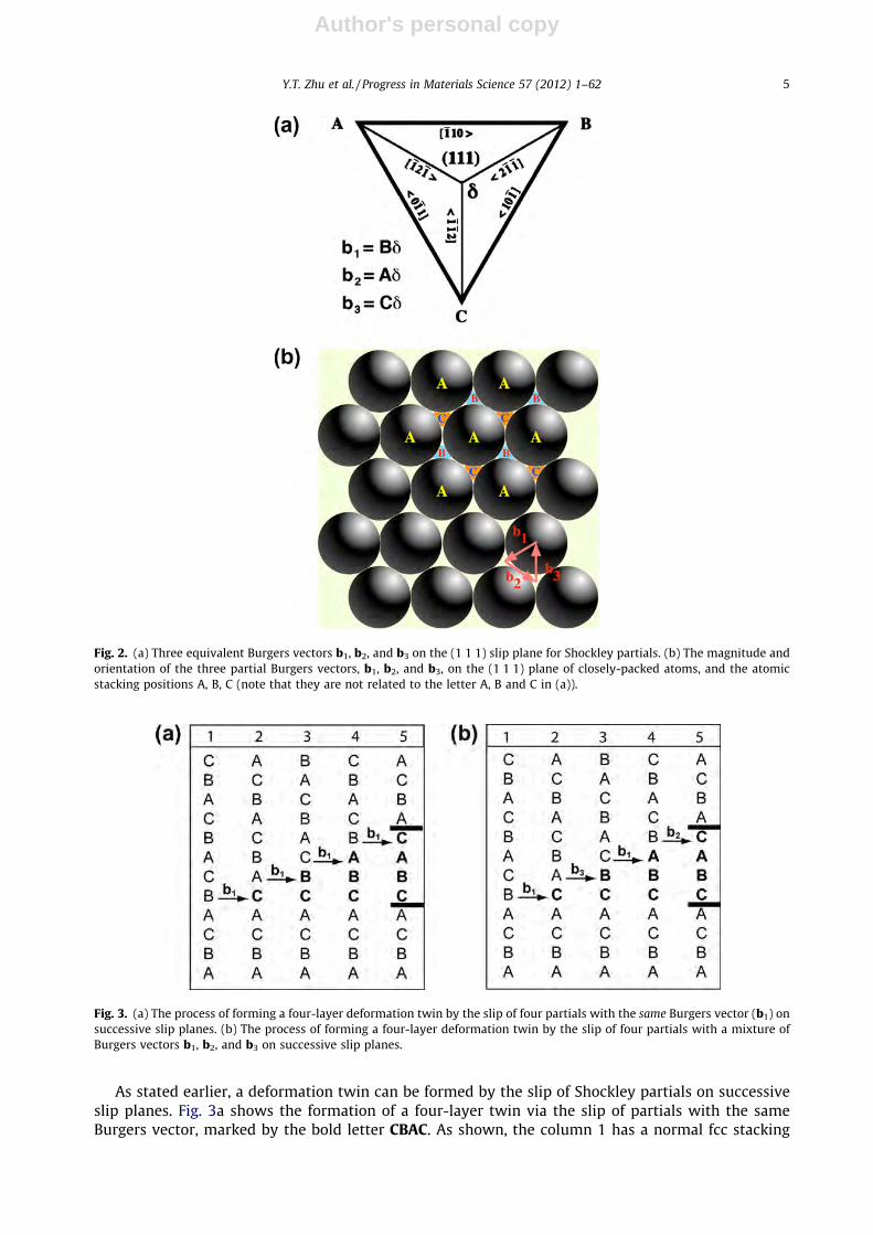
As stated earlier, a deformation twin can be formed by the slip of Shockley partials on successiveslip planes. Fig. 3a shows the formation of a four-layer twin via the slip of partials with the sameBurgers vector, marked by the bold letter CBAC. As shown, the column 1 has a normal fcc stacking
Fig. 2. (a) Three equivalent Burgers vectors b1, b2, and b3 on the (1 1 1) slip plane for Shockley partials. (b) The magnitude andorientation of the three partial Burgers vectors, b1, b2, and b3, on the (1 1 1) plane of closely-packed atoms, and the atomicstacking positions A, B, C (note that they are not related to the letter A, B and C in (a)).
Fig. 3. (a) The process of forming a four-layer deformation twin by the slip of four partials with the same Burgers vector (b1) onsuccessive slip planes. (b) The process of forming a four-layer deformation twin by the slip of four partials with a mixture ofBurgers vectors b1, b2, and b3 on successive slip planes.
Y.T. Zhu et al. / Progress in Materials Science 57 (2012) 1–62 5

Author's personal copy
sequence ABCABCABCABC. The slip of first partial b1 produces an intrinsic stacking fault (see the boldletter C in column 2), which is identical to removing a layer of B atoms. The slip of the second b1 partialon an adjacent slip plane converts the stacking fault into a two-layer twin nucleus (CB, see column 3)[34,42,56–59]. Note that the two-layer twin nucleus is also identical to an extrinsic staking fault, e.g. astacking fault formed by inserting an extra C layer between the A and B layers. [54]. Further slip of b1
partials grows the twin nucleus into a four-layer twin CBAC, with the twin boundaries represented bytwo horizontal lines (see column 5). Since the twinning process described in Fig. 3a involves only par-tials with the same Burgers vector, we name such a process as monotonic twinning process.
Fig. 3b shows that a four-layer twin with identical stacking sequence as in Fig. 3a can also be pro-duced by the slip of four partials with mixture of three Burgers vector (b1, b2, and b3) on successiveslip planes. In other words, a twin can be formed by the slip of identical partials or different partials.This is because the three partials, b1, b2, and b3, produce the same stacking sequence shifts despite oftheir orientation difference.
It should be noted that the macroscopic strain produced by the two twinning processes describedin Fig. 3 are very different. In Fig. 3a, all partials have the same Burgers vector, and therefore produce ashear strain in the same direction. This can collectively produce a relatively large macroscopic strainand change the grain shape as shown in Fig. 1. In contrast, the twinning process described in Fig. 3bwill produce a much smaller macroscopic strain because partials with different Burgers vectors shearthe lattice to different directions.
The two twinning processes described in Fig. 3 will have implications in the twin morphologies. Asdiscussed later, most twinning mechanisms proposed for the fcc metals with coarse grains are consis-tent with the twinning process described in Fig. 3a, while the twinning process described in Fig. 3bcould be very common in nanocrystalline fcc metals. Materials with grain sizes in the range of1 lm to 1000 lm are hereafter defined as coarse-grained materials [3,16,18,28,60–64].
A crystallographic feature of the twin is the mirror symmetry of atomic arrangement across thecoherent twin boundary plane. For an fcc metal, this symmetry can be best viewed along the [1 1 0]orientation that is on the coherent twin boundary plane (see Fig. 4a). As shown, the coherent twinboundary plane is the ð1 �11Þ close-packed plane, and it has a 70.53� angle with other close packedplanes. Each lattice point in the two-dimensional illustration (Fig. 4a) represents an atom column,with the dark circles below the light circle by a distance of atomic radius, i.e. 1/4[1 1 0]. However, un-der the high-resolution electron microscope, these two types of columns give identical images, asshown in Fig. 4b. The mirror symmetry in the high-resolution electron microscopy (HREM) imageshown in Fig. 4b is often used to identify twins in fcc metals.
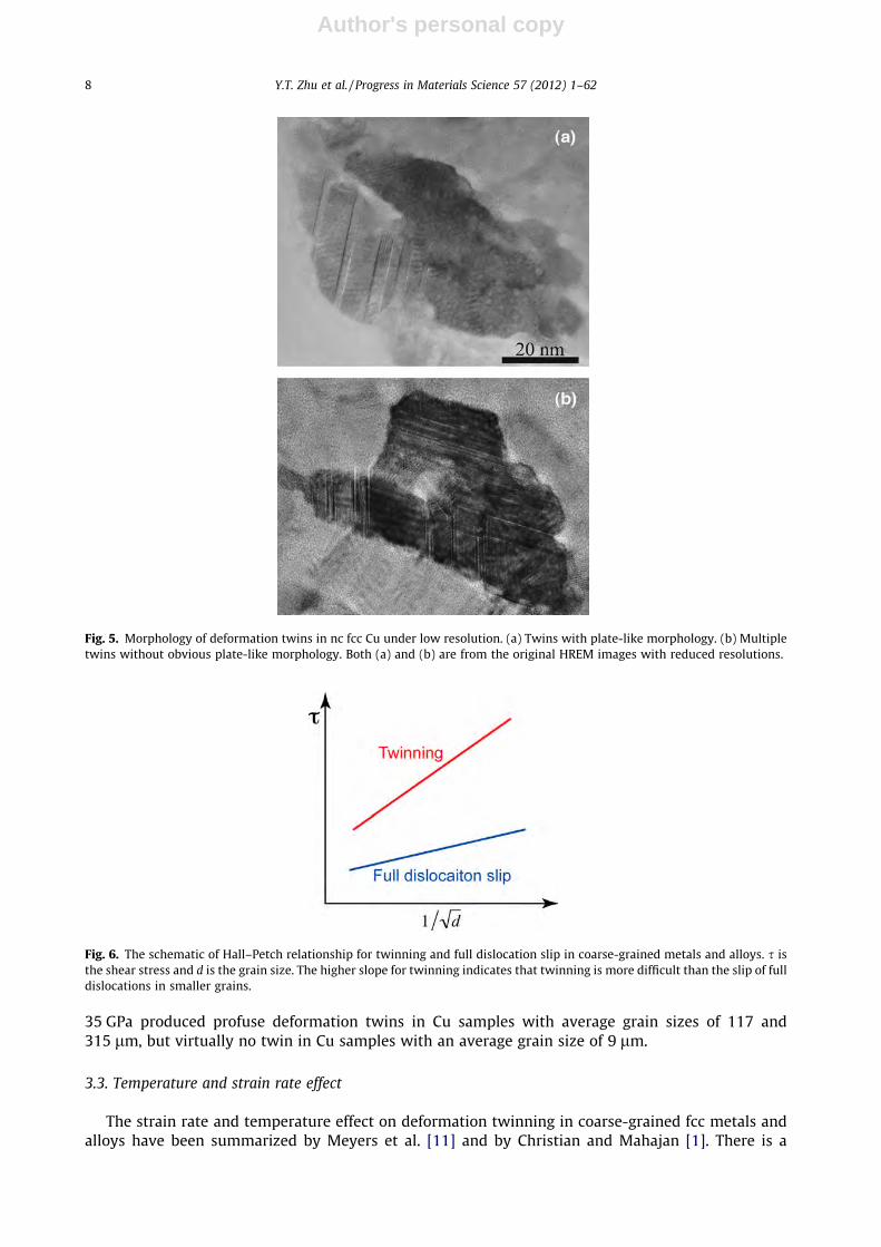
Regular low-resolution transmission electron microcopy (TEM) is also often used to identify defor-mation twins in metals, although it cannot obtain atomic-resolution images. TEM can detect themicrostructural feature of twins, which is often in a plate shape with straight twin boundaries. Exam-ples of low-resolution twin images are shown in Fig. 5a. However, in nc fcc metals, multiple twins of-ten form, which show no obvious plate-like morphology (see Fig. 5b) [34,42,56,65–70]. Under suchcircumstances, HREM is needed to identify and study the deformation twins.
3. Deformation twinning in coarse-grained fcc metals
3.1. Twinning mechanisms in coarse-grained fcc metals
Deformation twinning in coarse-grained fcc metals and alloys has been comprehensively reviewedby Christian and Mahajan [1]. Therefore, we will only give a brief summary here. Coarse-grained fccmetals are believed to twin via several conventional mechanisms including the pole mechanism[71], prismatic glide mechanism [72], faulted dipole mechanism [73], or other mechanisms [74–76].These mechanisms often require a dislocation source in the grain interior to operate. As will be dis-cussed later, this poses a problem for nc metals and alloys since their grain interior are often freeof dislocations [25,61], although dislocations can exist in nc grains under certain deformation condi-tions [77,78]. In addition, the deformation mechanisms in nc materials are dramatically different fromthose in their coarse-grained counterparts due to a strong grain size effect below 100 nm.
6 Y.T. Zhu et al. / Progress in Materials Science 57 (2012) 1–62

Author's personal copy
One exception is a 3-layer twin nucleation model proposed by Mahajan and Chin for fcc metals[74]. In theory, this model can be easily applied to nc metals. Furthermore, Kibey et al. recently calcu-lated the critical stress for the nucleation of such a three-layer twin, incorporating the general planarfault energies (GPFE) obtained from the ab initio density functional theory (DFT) [79]. The predictedstress is very close to experimentally measured values for many fcc metals. However, the ‘‘three-layer’’twin nucleation is yet to be observed in nc fcc metals.
3.2. Grain size effect
According to the experimental results reported in the literature, smaller grain size impedes defor-mation twinning [11,80–83] in coarse-grained metals and alloys, irrespective of their crystal structure.Meyers et al. [11] summarized the Hall–Petch slopes for both perfect dislocation slip and twinning in anumber of coarse-grained metals with fcc, body-centered cubic (bcc) and hexagonal-close-pack (hcp)crystal structures. In each case, the experimentally observed Hall–Petch slope for twinning is muchhigher than that for the slip of perfect dislocations. In other words, for coarse-grained metals, thestress required for activating twinning increases much faster with decreasing grain size than the stressfor perfect dislocation slip, as illustrated in Fig. 6. Therefore, smaller grain size make the deformationtwinning more difficult. The grain size effect was demonstrated in many examples. El-Danaf et al. [81]reported that 70/30 brass showed much greater twin density in samples with the grain size of 250 lmthan in samples with grain sizes of 9 and 30 lm. Meyers et al. [84] observed that shock compression at
Fig. 4. (a) The mirror symmetry of atoms in a twin in fcc metals, when viewed from a [1 1 0] direction that is on the coherenttwin boundary plane. A dark filled circle represents an atom column that is shifted for half an atomic distance below an atomcolumn represented by a light circle. (b) A typical HREM image of a twin in an fcc metal. Columns represented by lighter anddark circles in (a) are not differentiated by HREM in (b).
Y.T. Zhu et al. / Progress in Materials Science 57 (2012) 1–62 7
Author's personal copy
35 GPa produced profuse deformation twins in Cu samples with average grain sizes of 117 and315 lm, but virtually no twin in Cu samples with an average grain size of 9 lm.
3.3. Temperature and strain rate effect
The strain rate and temperature effect on deformation twinning in coarse-grained fcc metals andalloys have been summarized by Meyers et al. [11] and by Christian and Mahajan [1]. There is a
Fig. 5. Morphology of deformation twins in nc fcc Cu under low resolution. (a) Twins with plate-like morphology. (b) Multipletwins without obvious plate-like morphology. Both (a) and (b) are from the original HREM images with reduced resolutions.
Fig. 6. The schematic of Hall–Petch relationship for twinning and full dislocation slip in coarse-grained metals and alloys. s isthe shear stress and d is the grain size. The higher slope for twinning indicates that twinning is more difficult than the slip of fulldislocations in smaller grains.
8 Y.T. Zhu et al. / Progress in Materials Science 57 (2012) 1–62

Author's personal copy
general equivalency of low temperature and high strain rate [1]. Specifically, lower temperature andhigher strain rate usually promote deformation twinning. For example, fcc Cu was found to deform bytwinning at 4 K at a low strain rate [85], although it only deforms by dislocation slip at room temper-ature and low strain rate. Therefore, there is a transition to twinning with decreasing temperature.This transition temperature increases with decreasing stacking fault energy [1]. Generally, the ten-dency for twinning increases rather slowly with decreasing temperature but much faster with increas-ing strain rate. For example, shock deformation has been found to produce twins in metals and alloyswith medium-to-high stacking fault energy [84,86–88], which usually does not deform by twinning atquasi-static strain rate and room temperature.
The observed temperature and strain rate effect can be understood from two aspects. The first ishow the critical twinning stress varies with the temperature and strain rate, and the second is howthe material flow stress changes with the temperature and strain rate. Meyers et al. [11] summarizedthe twinning stress as a function of temperature for a number of single-crystal and polycrystallinemetals and alloys (see Fig. 7), and found that the twinning stress is insensitive to temperature. How-ever, there are debates on this issue [89–92]. Mahajan suggested that the bcc metals have a negativetwinning stress dependence on temperature, while fcc metals have a sight positive twinning stressdependence on temperature [1]. The strain rate effect on twinning stress is not well studied. Harding[93,94] found that the twinning shear stress increased from 170 MPa to 220 MPa when the strain ratewas increased from 10�3 s�1 to 103 s�1.
The flow stress of metals and alloys usually increases with decreasing temperature and/or increas-ing strain rate. The increase in flow stress at low temperature is believed caused, at least in part, by thestrong dependence of the work-hardening on temperature, which may increase the flow stress to thecritical twinning stress. During the deformation process, dynamic hardening and recovery occurssimultaneously. The dynamic recovery process needs the climbing of dislocations, which is a ther-mally activated process [95]. It becomes slower at lower temperatures [28,95–104], and this causeshigher work-hardening rate, and consequently higher flow stress. At higher strain rate the overallwork hardening rate increases because the dislocation generation rate is faster than the dislocationannihilation, which leads to the increase in flow stress. Therefore, the increase in twinning tendencyat low temperatures and higher strain rates can be largely attributed to the increase in flow stress.
4. Deformation mechanisms in nanocrystalline materials
Due to their small grain size, nc materials deform via mechanisms that are different from those intheir coarse-grained counterparts [6,8,9,22–24,27,42,66]. As discussed in the introduction, severaldeformation mechanisms have been identified in nc materials. The significance of each deformation
Fig. 7. Effect of temperature on twinning stress for several single crystalline and polycrystalline metals and alloys [11].
Y.T. Zhu et al. / Progress in Materials Science 57 (2012) 1–62 9

Author's personal copy
mechanism changes with decreasing grain size. For example, for fcc metals and alloys with medium-to-high stacking fault energy, perfect dislocation slip dominates in large grains (e.g. larger than 50 nm)[3]. However, more than one deformation mechanisms may be active at any grain size, although thesignificance of each mechanism changes with grain size. In other words, for each deformation mech-anism, there is a grain size range in which it plays a significant role. In the following subsections, wewill briefly summarize several deformation mechanisms to set the stage for the detailed review ofdeformation twinning in Section 5.
It should be noted that the HREM observations have been extensively used to support proposedtwinning mechanisms. These observations were mostly postmortem because of the difficulty ofin situ HREM. Early HREM observations were mostly used to validate twinning mechanisms observedby molecular dynamics (MD) simulations. New twinning mechanisms were later proposed based onanalysis of postmortem HREM observations. Some of these HREM findings were verified by MD sim-ulations. HREM and MD simulations are complementary means for studying deformation twinning,and then are especially powerful when combined to study deformation mechanisms in nc materials.
4.1. Grain boundary sliding
Grain boundary sliding in nc materials was first observed by MD simulations [24,36,37,105], laterreported experimentally [27,106–108], and modeled analytically [109–112]. Importantly, such grainboundary sliding may occur in a coordinated way [27,105–107,113–115]. For example, shown inFig. 8 is the alignment of grain boundaries of many grains to facilitate the grain boundary sliding[107]. The small grain sizes of nc materials [37] make it easier for the grain alignment [80,116]. Sucha coordinated grain boundary sliding may play a significant role in the deformation of nc materials, asshown in Fig. 9, which reveals prevalent grain boundary aligning in nc Ti. More study is needed on thisissue.
4.2. Grain rotation
Grain rotation in nc metals was first observed under in situ HREM by Ke et al. [38], and later con-firmed by Shan et al. [25,117], Jin et al. [118] and Wang et al. [119]. Grain rotation as a deformationmechanism was also revealed by MD simulations [105,120,121] and has been analytically modeled[111,122,123]. The unambiguous means to observe grain rotation is in situ TEM. However, experimen-tal evidence of grain rotation from such observation is also controversial because the TEM samples arevery thin and may not represent bulk nc materials. More recently, texture measurement confirmedthat grain rotation indeed plays a significant role in the deformation of bulk nc materials [28,124–127]. However, the grain rotation was also found to accompany grain growth during the deformation
Fig. 8. The alignment of grains in nc Pd after deformation by high-pressure torsion, suggesting coordinated grain boundarysliding [107].
10 Y.T. Zhu et al. / Progress in Materials Science 57 (2012) 1–62
Author's personal copy
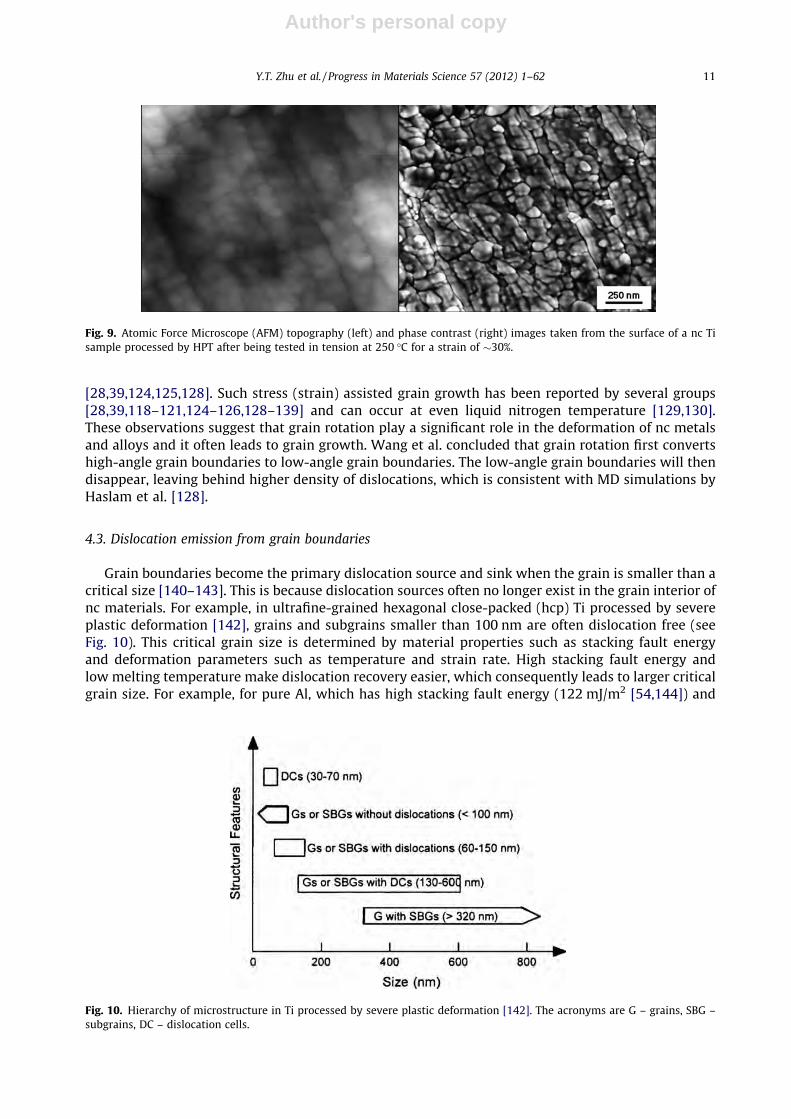
[28,39,124,125,128]. Such stress (strain) assisted grain growth has been reported by several groups[28,39,118–121,124–126,128–139] and can occur at even liquid nitrogen temperature [129,130].These observations suggest that grain rotation play a significant role in the deformation of nc metalsand alloys and it often leads to grain growth. Wang et al. concluded that grain rotation first convertshigh-angle grain boundaries to low-angle grain boundaries. The low-angle grain boundaries will thendisappear, leaving behind higher density of dislocations, which is consistent with MD simulations byHaslam et al. [128].
4.3. Dislocation emission from grain boundaries
Grain boundaries become the primary dislocation source and sink when the grain is smaller than acritical size [140–143]. This is because dislocation sources often no longer exist in the grain interior ofnc materials. For example, in ultrafine-grained hexagonal close-packed (hcp) Ti processed by severeplastic deformation [142], grains and subgrains smaller than 100 nm are often dislocation free (seeFig. 10). This critical grain size is determined by material properties such as stacking fault energyand deformation parameters such as temperature and strain rate. High stacking fault energy andlow melting temperature make dislocation recovery easier, which consequently leads to larger criticalgrain size. For example, for pure Al, which has high stacking fault energy (122 mJ/m2 [54,144]) and
Fig. 9. Atomic Force Microscope (AFM) topography (left) and phase contrast (right) images taken from the surface of a nc Tisample processed by HPT after being tested in tension at 250 �C for a strain of �30%.
Fig. 10. Hierarchy of microstructure in Ti processed by severe plastic deformation [142]. The acronyms are G – grains, SBG –subgrains, DC – dislocation cells.
Y.T. Zhu et al. / Progress in Materials Science 57 (2012) 1–62 11
Author's personal copy
low melting temperature (660.32 �C), the critical grain size is relatively large. Grains of a few hundrednanometers may be dislocation free [145–147]. The lack of dislocation in the grain interior has beenattributed to the lacking of strain hardening in nc materials [51,140,148–154].
When dislocation source is unavailable inside the grain interior, grain boundary becomes the pri-mary source for dislocation generation. Indeed, in situ TEM revealed extensive emission of dislocationsfrom grain boundaries of nc materials [25,143,155,118,156]. However, in situ TEM is often done underlow-resolution mode and cannot differentiate partial dislocations from perfect dislocations. Partialdislocation emissions from grain boundaries were extensively observed by MD simulations[9,10,26,22,144,157,158], and was verified experimentally by ex situ HREM observations [8]. As willbe discussed in later sections, the emission of dislocations from the grain boundaries play a criticalrole in the nucleation and growth of deformation twins in nc fcc metals, and is responsible for severalunique twinning mechanisms.
It should be noted that under certain deformation conditions, high-dislocation density is still pos-sible in nc metals and alloys. For example, high-density of dislocation defect structure was found inthe grain interior of nc Ni deformed under constrained rolling at liquid nitrogen temperature [77].
4.4. Stacking fault and deformation twinning
In coarse-grained fcc and bcc materials, stacking faults and deformation twins usually occur inmetals and alloys with low stacking fault energy, although high strain rate and low deformation tem-perature can significantly promote twinning. In coarse-grained hcp metals and alloys, twinning is acommon deformation mechanism because their small number of slip systems [56,159–170]. In com-parison, nc materials have a very different behavior in the formation of stacking faults and deforma-tion twins. First, nc hcp metals are rarely observed to deform by twinning. Second, nc fcc metals arefound to generally deform by twinning more easily, especially in those fcc metals with medium tohigh stacking fault energy, although twinning may become difficult again at very small grain sizes[171]. Deformation twinning in nc fcc metals and alloys is the focus of this review, and is discussedin detail in the next section.
5. Deformation twinning in nanocrystalline fcc materials
5.1. Molecular dynamics simulations
The MD simulation of deformation twinning in nc fcc materials has been comprehensively re-viewed by Wolf et al. [22]. Here we will only give a brief summary on the features of MD simulationsas well as the major results on deformation twinning obtained by MD simulations. Early insights onthe deformation mechanisms of nc materials are almost exclusively obtained by MD simulations[9,24,26,36,105,144,157,172–176], largely because of the difficulty in synthesizing nc materials forexperimental studies. For example, extensive early studies were performed on nc samples synthesizedby inert gas condensation [15,177–184], which did not have clean grain boundaries and had flawssuch as cracks and pores after consolidation due to the adsorption of O, H, and N atoms during thesynthesis of nano-powders. It is still a challenge even today to synthesize nc materials with certainstructural characteristics to systematically investigate a specific deformation mechanism.
MD simulation has several advantages over experimental investigation, which makes it a powerfultool for studying nc materials [22]. First, MD simulation can elucidate the atomic level deformationmechanisms in nc materials in a degree of detail that cannot be obtained experimentally. Second, itis capable of investigating the real-time deformation behavior, including twinning and detailed defectevolution and interaction, which are not possible by any experimental technique. Third, it can simu-late a well-characterized and idealized model nc system to study specific deformation mechanisms.Fourth, it is capable of deforming samples to very large plastic strains, which make it possible to inves-tigate the deformation behavior under high dislocation densities.
MD simulation also has its own limitations [22]. First it is typically limited to relatively small modelsystems. As a result, many researchers often use model systems with very small grain sizes. This could
12 Y.T. Zhu et al. / Progress in Materials Science 57 (2012) 1–62

Author's personal copy
sometimes lead to serious problems because it is known that grain sizes affect the deformationmechanisms [24,37,57,59,171,185]. For example, it was observed by MD simulations that nc Al, Cuand Ni rarely deform by twinning [10], which contradicts the experimental observations [2,6,23,33–35,66,68,77,186–189]. This controversy was later found caused by the grain size effect, i.e. thesmall grain size used in the MD simulation is so small that the deformation twins are hard to form,due to an inverse grain size effect on twinning [171]. This limitation will be gradually relaxed as fastercomputers become more available to researchers. The second limitations of MD simulations is its shorttime duration [22], which results in extremely high strain rate (typically larger than 107 s�1). Althoughsuch high strain rate is physically plausible [190–192], they are much higher than what we cannormally obtain experimentally. This makes it more complex to compare with experimental results,because it is well known that the strain rate has significant effect on deformation mechanisms.For example, it is generally agreed that higher strain rate promotes deformation twinning[2,11,80,84,171,188,193–195].
MD simulation has revealed many important deformation mechanisms of nc materials despite ofits limitations. Below we will list only a few that are relevant to deformation twinning: First, emissionof Shockley partials from grain boundaries are extensively observed by several groups[9,10,24,26,37,45,46,144,157,158,185,196–210]. Second, three mechanisms for twin nucleation andgrowth were clearly revealed by Yamakov et al. (see Fig. 11) [9]. As shown in Fig. 11, a twin nucleus(marked by A) is formed by the overlapping of two extended dislocations on adjacent slip planes.There are also three other similar twin nuclei in the same grain. A twin marked by B is formed by suc-cessive emission of five Shockley partials from the grain boundary. C represents a twin formed bygrain boundary splitting and migration, which leaves behind a coherent twin boundary (marked bya) and produces another coherent twin boundary (marked by b), while the migrating twin boundary(marked by d) consists of a Shockley partial dislocations.
Fig. 11. Three twinning mechanisms are revealed in this MD simulation snapshot of nc Al with columnar grains [9]. As markedin the figure, A represents a twin nucleus formed by the overlapping of two extended dislocations on adjacent slip planes, Brepresents a twin formed by successive emission of Shockley partials from the grain boundary, and C represents a twin formedby grain boundary splitting and migration. Seven marks a few partial dislocations emitted from the grain boundary.
Y.T. Zhu et al. / Progress in Materials Science 57 (2012) 1–62 13

Author's personal copy
5.2. Experimental observations
The experimental observations of deformation twins were summarized in a previous paper [56].Experimental results can validate and provide input to the MD simulations. Nanocrystalline samplesfor experimental studies are usually much larger and more complex than the model systems used byMD simulations, and therefore may reveal some deformation phenomena that are missed by the MDsimulations. Early experimental observations of deformation twins were limited to the validation ofMD simulation results. Examples include the experimental observation of partial dislocations emittedfrom grain boundaries (see Fig. 12) [6–8,23,186,211,212], and deformation twinning [3,6–8,18,23,31,65,66,186,213,214]. In recent years, several new phenomena have been first revealed byexperimental investigations, including fivefold twins [8,65,70], twins with reduced macroscopic strain[2], inverse grain size effect on twinning [171], V-shaped twins by a self-thickening mechanism[67,69], and reversible twinning process [215]. Interestingly, a proposed formation mechanism [70]based on the experimentally observations for fivefold twins was later verified by MD simulation [216].
Experimental techniques for investigating deformation twinning include HREM, in situ HREM, anddiffraction analysis (X-ray, synchrotron or neutron analysis). HREM is used most because it is easilyaccessible and provides direct atomic-resolution observation of twins. However, it is a postmortemtechnique, which makes the analysis of the twinning process non-trivial. In recent years, in situ HREMhas been used to observe the twinning process, twin-dislocation interactions and other deformationmechanisms in nc materials [119,156,215,217,218]. Such experiments are still relatively difficult,and the quality of the atomic images is expected to improve in the near future. X-ray analysis has beenused to analyze the twin boundary density in nc materials [51,149,153,219–222]. However, such anal-ysis is usually qualitative and the absolute value of density of twin boundaries may depend on themethod/model used in the analysis. Nevertheless, relative comparison of twin densities can be madeif the X-ray diffraction data are taken and analyzed in a consistent manner.
The samples used for experimental studies have been prepared by mechanical attrition [65], phys-ical vapor deposition [6], high-pressure torsion [8], surface mechanical attrition [223], electro-depo-sition [35,40,41,68], inert gas condensation [15], etc. Each of these methods may have its ownintrinsic issue such as impurities, unclean grain boundaries, and non-equilibrium grain boundaries.One common feature of experimental samples is the relatively wide grain size distribution, especiallyin samples produced by deformation methods. In comparison, MD simulations often use relatively
Fig. 12. An HREM image of nc Cu processed by high-pressure torsion (HPT), showing Shockley partial dislocations that wereemitted from the lower grain boundary and stopped in the grain interior before reaching the upper grain boundary, leavingbehind stacking faults [8].
14 Y.T. Zhu et al. / Progress in Materials Science 57 (2012) 1–62

Author's personal copy
uniform grain sizes. The wide grain size distribution may be an advantage in some cases. For example,the inverse grain size effect on deformation twinning was found by statistical HREM investigation ofelectro-deposited Ni with grain sizes ranging from 10 nm to 76 nm [171].
Experimental techniques available so far have much lower spatial and temporal resolutions thanthe MD simulations. It is also a challenge to observe the deformation process and defect evolutionsin real time. Therefore, it would be desirable to combine experiments and MD simulations to probethe deformation process of nc materials.
5.3. Twinning mechanisms
In this section, we will describe the twinning mechanisms that are proposed basing on the exper-imental observations and MD simulation results.
5.3.1. Overlapping of stacking fault ribbonsThe nucleation of deformation twins via overlapping of two stacking fault ribbons are first observed
by MD simulations (see Fig. 11) [9]. Fig. 13 shows an HREM image of such a twin nucleus with a thick-ness of two atomic planes in the interior of a nc Al grain. It was formed by the dynamic overlapping oftwo extended partial dislocations with stacking faults on adjacent slip planes. As shown, the twostacking faults are only partially overlapped. The twin can grow thicker by adding more SFs on eitherside of the twin. However, no deformation twins of this type that are thicker than two layers havebeen reported. Therefore, this twinning mechanism does not play a significant role in the deformationof nc materials. This is because of the lacking of a continuous mechanism for it to grow. It depends onthe incidental overlapping of other slipping dissociated dislocations with stacking fault ribbons togrow.
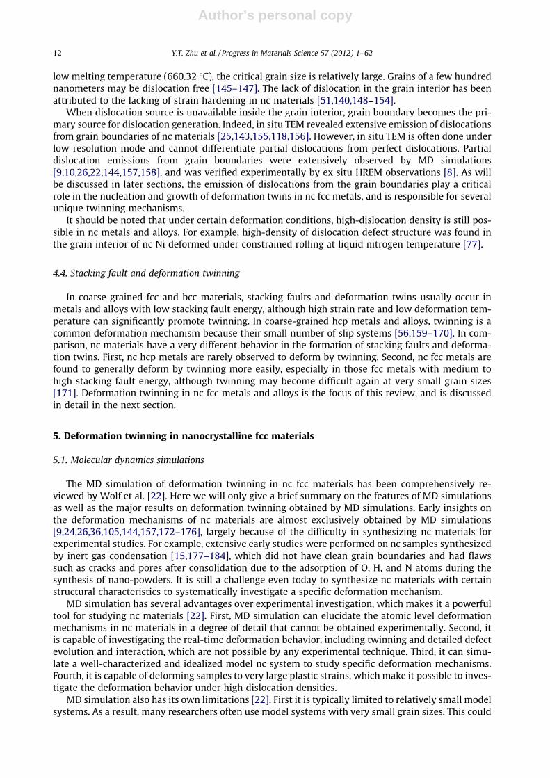
A variant of this twinning mechanism is the overlapping of a dissociated dislocation with a stackingfault connected with the grain boundary [187]. As shown in Fig. 14, close to the grain boundary, thetwo-layer twin nucleus turned into a stacking fault. This suggests that a stacking fault was first formedfrom the grain boundary and extended toward grain interior. A dissociated dislocation with a widestacking fault slipped toward the grain boundary on an adjacent slip plane and then incidentally over-lapped with the stacking fault, forming a two-layer twin nucleus. Such a twin nucleus was also pre-dicted by MD simulation (see Fig. 11).
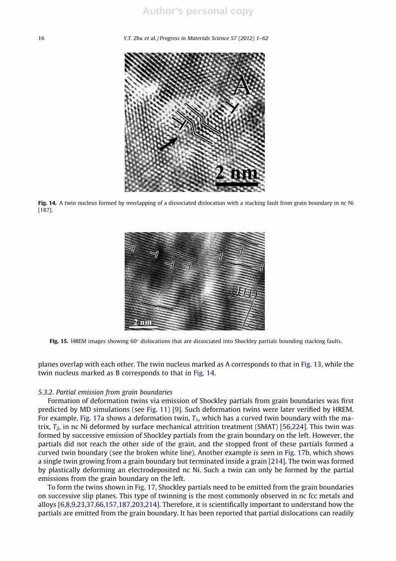
If the leading partial of the dissociated dislocation shown in Fig. 14 reaches the grain boundary, thetwin nucleus will become identical to a normal twin nucleus formed by emission of two Shockley par-tials from the grain boundary. This twin nucleation mechanism could be significant in nc materialswith non-equilibrium grain boundaries. High density of dissociated partials with one end pinned onthe grain boundary has been observed in nc Ni with non-equilibrium grain boundaries (see Fig. 15)[187], which provides a high probability for such a mechanism to operate.
The two scenarios of twin nucleation via overlapping of stacking faults are schematically illustratedin Fig. 16, in which the thin hairlines across the grain represent the slip planes and the thick shorterlines represent the stacking faults. A twin is nucleated when two stacking faults on two adjacent slip
Fig. 13. A deformation twin formed by the overlapping of two extended dislocations on adjacent slip planes in the interior of agrain of nc Al deformed by ball-milling [23].
Y.T. Zhu et al. / Progress in Materials Science 57 (2012) 1–62 15
Author's personal copy
planes overlap with each other. The twin nucleus marked as A corresponds to that in Fig. 13, while thetwin nucleus marked as B corresponds to that in Fig. 14.
5.3.2. Partial emission from grain boundariesFormation of deformation twins via emission of Shockley partials from grain boundaries was first
predicted by MD simulations (see Fig. 11) [9]. Such deformation twins were later verified by HREM.For example, Fig. 17a shows a deformation twin, T1, which has a curved twin boundary with the ma-trix, T2, in nc Ni deformed by surface mechanical attrition treatment (SMAT) [56,224]. This twin wasformed by successive emission of Shockley partials from the grain boundary on the left. However, thepartials did not reach the other side of the grain, and the stopped front of these partials formed acurved twin boundary (see the broken white line). Another example is seen in Fig. 17b, which showsa single twin growing from a grain boundary but terminated inside a grain [214]. The twin was formedby plastically deforming an electrodeposited nc Ni. Such a twin can only be formed by the partialemissions from the grain boundary on the left.
To form the twins shown in Fig. 17, Shockley partials need to be emitted from the grain boundarieson successive slip planes. This type of twinning is the most commonly observed in nc fcc metals andalloys [6,8,9,23,37,66,157,187,203,214]. Therefore, it is scientifically important to understand how thepartials are emitted from the grain boundary. It has been reported that partial dislocations can readily
Fig. 14. A twin nucleus formed by overlapping of a dissociated dislocation with a stacking fault from grain boundary in nc Ni[187].
Fig. 15. HREM images showing 60� dislocations that are dissociated into Shockley partials bounding stacking faults.
16 Y.T. Zhu et al. / Progress in Materials Science 57 (2012) 1–62

Author's personal copy
emit from non-equilibrium grain boundary to nucleate a deformation twin [7,187,225]. However, it isstatistically and practically impossible for a partial dislocation to exist on every slip plane to grow asingle twin. Nucleation of a new partial on every slip plane is difficult because of the required highenergy. Therefore, there must be a partial multiplication mechanism at the grain boundary that willsupply a twinning partial on every successive slip plane for twin nucleation and growth. This has beenproposed recently by Zhu et al. [214], and is delineated below.
Two dislocation reaction and cross-slip mechanisms have been proposed to supply twinning par-tials on successive slip planes from the grain boundary to grow a twin continuously. The first mech-anism involves the emission of partials with the same Burgers vector, while the second mechanisminvolves the emission of partials with two different Burgers vectors, which produce a single twin withreduced shear strain. The details of these two mechanisms are described below.
For simplicity, a square grain is used in the description of the two mechanisms. As shown in Fig. 18,the line parallel to the left grain boundary represents a full dislocation with a Burgers vector of
Fig. 16. Two scenarios of twin nucleation via overlapping of stacking faults. The thin hairlines across the grain represent the slipplanes and the thick shorter lines represent the stacking faults. Each ‘‘L’’ at the end of a stacking fault indicates a partialdislocation. The twin nucleus marked as A corresponds to that in Fig. 13, while the twin nucleus marked as B corresponds tothat in Fig. 14.
Fig. 17. (a) A deformation twin (T1) formed by successive emission of partials on adjacent slip planes from the grain boundaryon the left in nc Ni deformed by surface mechanical attrition treatment [56]. (b) An HREM image of a twin formed by plasticallydeforming electrodeposited nc Ni. The twin was formed by the emission of partials from the grain boundary on the left, and itended in the grain interior as marked by the white asterisks [214].
Y.T. Zhu et al. / Progress in Materials Science 57 (2012) 1–62 17

Author's personal copy
b = 1/2[1 0 1]. The orientation of the dislocation line is [1 1 2]. The plane represented by the square isthe ð11 �1Þ close-packed slip plane. Below we will delineate the first mechanism for Shockley partialmultiplication.
5.3.2.1. Mechanism A: multiplication of partials with the same Burgers vector. Let’s start with Fig. 18, theperfect dislocation, b, dissociates into two partials under an appropriate applied stress,
b! b1 þ b2 ð1Þ
where b1 = 1/6[1 1 2] is parallel to the dislocation line, while b2 = 1/6½2 �11� has a 60� angle with thedislocation line. This dissociation is energetically favorable and therefore can proceed easily. Underan applied shear stress with appropriate orientation, the partial with the Burgers vector b2 glideson the ð11 �1Þ slip plane across the grain to form a stacking fault. Partial b1 is a pure screw partialand cross-slips to the next ð11 �1Þ plane, where it undergoes the following dislocation reaction
b! bþ ð�b2Þ ð2Þ
where �b2 stays at the grain boundary and the perfect dislocation b is driven toward the grain interiorby the applied stress. The reaction in Eq. (2) has a very high energy barrier and therefore needs a largeapplied stress to activate. The b can subsequently dissociate into b1 and b2 according to Eq. (1), form-ing a wide stacking fault ribbon [212]. b2 would be the leading partial because the applied stress fa-vors its slip. The slip of b2 nucleates a single twin, and b1 returns to the grain boundary due toinsufficient resolved shear stress to drive it across the grain. Note that in the above process b1 sepa-rates �b2 and b2 and keeps them at a large distance to reduce their mutual attraction so that b2 caneasily glide away.
Repetition of the above dislocation reactions (Eqs. (1) and (2)) and cross-slip of b1 enables the sin-gle twin to grow continuously. Such a twin growth process leaves a partial �b2 on the left grainboundary and another partial b2 on the right grain boundary on every slip plane in the twin. Thischanges the grain shape from the original square to what is shown in Fig. 19, as viewed in theb0 = [0 1 1] direction, which is perpendicular to b2.
In an HREM micrograph taken from any h1 1 0i direction that is on the twin boundary plane, theatomic-scale image has mirror symmetry across the coherent twin boundary. This is the way to iden-tify a twin using HREM. As shown in Fig. 18, there are three orientations from which a twin with ð11 �1Þtwinning plane can be viewed by HREM: b = 1/2[1 0 1], b0 = 1/2[0 1 1], and also b00 = 1/2½1 �10�. Theview from b0 is illustrated in Fig. 19, which shows a 141� grain boundary kink. However, if the twinis viewed from the b and b00 direction, the projection of the twinning partial b2 on the direction per-pendicular to the b and b00 in the ð11 �1Þ plane will be reduced by half because the b and b00 has a 30�
Fig. 18. Schematics of a square grain with a dislocation line parallel to the grain boundary [207]. The slip plane is ð11 �1Þ, whichis parallel to the page. The dislocation line near at the left grain boundary has a Burgers vector of b = 1/2[1 0 1]. Other Burgersvectors in the figure are b0 = 1/2[0 1 1], b1 = 1/6[1 1 2], b2 = 1/6½2 �11�, b2 = 1/6½�121�, b00 = 1/2½1 �10�.
18 Y.T. Zhu et al. / Progress in Materials Science 57 (2012) 1–62
YTZ
Typewritten Text
YTZ
Typewritten Text
YTZ
Typewritten Text
1

Author's personal copy
angle with the b2. In other words, the grain boundary kink angle will now be increased to 158�, asshown in Fig. 20. This makes twinning strain appear less than what is viewed from b0 orientation(Fig. 19).
5.3.2.2. Mechanism B: multiplication of partials with the two different Burgers vectors. Next we will de-scribe the second twinning mechanism, which involves the emission of partials with two differentBurgers vectors, b2 and b3. It produces less macroscopic strain than the twinning mechanism A.One can see from Fig. 19 that, after cross-slip, the partial b1 under appropriate applied stress can haveanother dislocation reaction:
b1 ! b0 þ ð�b3Þ ð3Þ
where b3 = 1=6½�121� and b0 = 1/2[0 1 1]. The partial �b3 stays at the grain boundary and the perfectdislocation b0 dissociates into b1 and a new partial b3. The applied shear stress drives the new partialb3 away from the grain boundary to glide on the ð11 �1) plane across the grain, which grows the twin.
If the dislocation reactions described in Eqs. (2) and (3) occur on alternative slip planes or occur forapproximately the same number of times, the grain will change its shape along the b1 direction (see
Fig. 19. The grain shape change caused by the first twinning mechanism in which all twinning partials have the same Burgersvector [207]. The 141� grain boundary kink can be seen from an orientation perpendicular to the Burgers vector of the twinningpartial and parallel to the slip plane.
Fig. 20. The grain shape change caused by the first twinning mechanism in which all twinning partials have the same Burgersvector, but viewed from the orientation of b and b00 [207]. The grain boundary kink is 158�. As will be described later, this canalso be caused by the second twinning mechanism in which approximately equal numbers of b2 partials and b3 partials areinvolved. In the second twinning mechanism, the 158� grain boundary kink can be seen from an orientation perpendicular to b1.
Y.T. Zhu et al. / Progress in Materials Science 57 (2012) 1–62 19
Author's personal copy
Fig. 18), but the macroscopic strain will be only half of that shown in Fig. 19. This is because the slip ofthe partial b2 produces a strain of a=
ffiffiffi6p
along the b2 direction, while the slip of the partial b3 producesa strain of a=
ffiffiffi6p
along the b3 direction. From Fig. 18 we have the following relationship b2 + b3 = b1.Therefore, the total strain in every two slip planes is a=
ffiffiffi6p
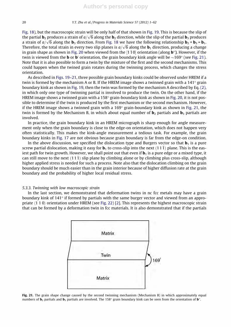
along the b1 direction, producing a changein grain shape as shown in Fig. 20 when viewed from the ½1 �10� orientation (along b0 0). However, if thetwin is viewed from the b or b0 orientation, the grain boundary kink angle will be �169� (see Fig. 21).Note that it is also possible to form a twin by the mixture of the first and the second mechanisms. Thiscould happen when the twined grain rotates during the twinning process, which changes the stressorientation.
As described in Figs. 19–21, three possible grain boundary kinks could be observed under HREM if atwin is formed by the mechanism A or B. If the HREM image shows a twinned grain with a 141� grainboundary kink as shown in Fig. 19, then the twin was formed by the mechanism A described by Eq. (2),in which only one type of twinning partial is involved to produce the twin. On the other hand, if theHREM image shows a twinned grain with a 158� grain-boundary kink as shown in Fig. 20, it is not pos-sible to determine if the twin is produced by the first mechanism or the second mechanism. However,if the HREM image shows a twinned grain with a 169� grain-boundary kink as shown in Fig. 21, thetwin is formed by the Mechanism B, in which about equal number of b2 partials and b3 partials areinvolved.
In practice, the grain boundary kink in an HREM micrograph is sharp enough for angle measure-ment only when the grain boundary is close to the edge-on orientation, which does not happen veryoften statistically. This makes the kink-angle measurement a tedious task. For example, the grainboundary kinks in Fig. 17 are not obvious because grain boundary is far from the edge-on condition.
In the above discussion, we specified the dislocation type and Burgers vector so that b1 is a purescrew partial dislocation, making it easy for b1 to cross-slip into the next ð11 �1Þ plane. This is the eas-iest path for twin growth. However, we shall point out that even if b1 is a pure edge or a mixed type, itcan still move to the next ð11 �1Þ slip plane by climbing alone or by climbing plus cross-slip, althoughhigher applied stress is needed for such a process. Note also that the dislocation climbing on the grainboundary should be much easier than in the grain interior because of higher diffusion rate at the grainboundary and the probability of higher local residual stress.
5.3.3. Twinning with low macroscopic strainIn the last section, we demonstrated that deformation twins in nc fcc metals may have a grain
boundary kink of 141� if formed by partials with the same burger vector and viewed from an appro-priate h1 1 0i orientation under HREM (see Fig. 22) [2]. This represents the highest macroscopic strainthat can be formed by a deformation twin in fcc materials. It is also demonstrated that if the partials
Fig. 21. The grain shape change caused by the second twinning mechanism (Mechanism B) in which approximately equalnumbers of b2 partials and b3 partials are involved. The 158� grain boundary kink can be seen from the orientation of b0 0 .
20 Y.T. Zhu et al. / Progress in Materials Science 57 (2012) 1–62

Author's personal copy
have different Burgers vectors, the macroscopic strain will be lower. In this section, we further delib-erate on the observation and mechanisms of deformation twins with low or even zero macroscopicstrain.
Fig. 23 shows typical HREM images of deformation twins in nc Al, Ni and Cu that were produced bycryogenic milling, cryo-tension, and high-pressure torsion, respectively [2]. As shown, the grainboundary segments are smooth even at locations where they intersect the twin boundaries, suggest-ing that the deformation twins shown in Fig. 23 did not change the morphology of the grains.
It is proposed that the twins shown in Fig. 23 were formed via a twinning mechanism named ran-dom activation of partials (RAP) [2]. Fig. 2 illustrates a set of Shockley partials involved in the RAP pro-cess. As shown, on the (1 1 1) slip plane, there are three Shockley partials, b1 = Bd, b2 = Ad and b3 = Cd.Note that Ad means a Burgers vector that starts at A and ends at d. It is obvious that
b1 þ b2 þ b3 ¼ 0 ð4Þ
As discussed in Section 2 and Fig. 3, a twin can be formed by the slip of identical partials or differentpartials, because the three partials, b1, b2, and b3, produce the same stacking sequence shifts despite oftheir orientation difference. Therefore, if all of the three partials propagate in equal number of times,one after another, there will be no net accumulation of macroscopic strain.
The RAP mechanism involves three Shockley partials with different Burgers vectors. Below we dis-cuss how the emission of three Shockley partials can be realized in a nano grain with the help of
Fig. 23. HREM images of typical deformation twins in three nc fcc metals. (a) Al processed by cryo-milling, (b) electro-depositedNi deformed by cryo-tension, and (c) Cu processed by high-pressure torsion. It is evident that the deformation twins did notchange the shape of the grains. The arrows indicate the twin boundaries. The broken curves indicate grain boundaries. Twinsand matrix are labeled T and M, respectively [2].
Fig. 22. HREM micrograph of a twin in nc Cu synthesized by high-pressure torsion. The arrow indicates the twin boundary. Thegrain boundary has a 141� kink at its intersection with the twin boundary. This twin was formed by partials with the sameBurgers vector [2]. Note that this twin morphology is the same as that of a deformation twins in coarse-grained fcc metals.
Y.T. Zhu et al. / Progress in Materials Science 57 (2012) 1–62 21
Author's personal copy
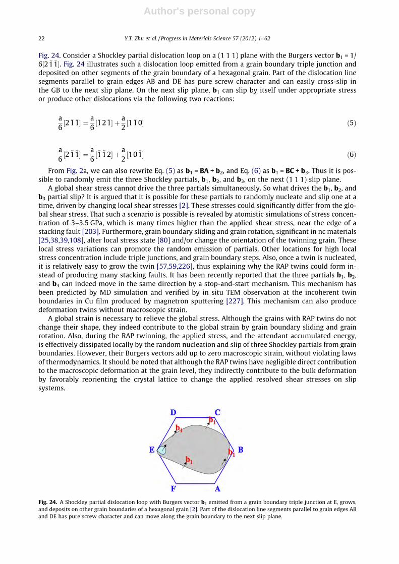
Fig. 24. Consider a Shockley partial dislocation loop on a (1 1 1) plane with the Burgers vector b1 = 1/6½2 �1 �1�. Fig. 24 illustrates such a dislocation loop emitted from a grain boundary triple junction anddeposited on other segments of the grain boundary of a hexagonal grain. Part of the dislocation linesegments parallel to grain edges AB and DE has pure screw character and can easily cross-slip inthe GB to the next slip plane. On the next slip plane, b1 can slip by itself under appropriate stressor produce other dislocations via the following two reactions:
a6½2 �1 �1� ¼ a
6½�12 �1� þ a
2½1 �10� ð5Þ
a6½2 �1 �1� ¼ a
6½�1 �12� þ a
2½10 �1� ð6Þ
From Fig. 2a, we can also rewrite Eq. (5) as b1 = BA + b2, and Eq. (6) as b1 = BC + b3. Thus it is pos-sible to randomly emit the three Shockley partials, b1, b2, and b3, on the next (1 1 1) slip plane.
A global shear stress cannot drive the three partials simultaneously. So what drives the b1, b2, andb3 partial slip? It is argued that it is possible for these partials to randomly nucleate and slip one at atime, driven by changing local shear stresses [2]. These stresses could significantly differ from the glo-bal shear stress. That such a scenario is possible is revealed by atomistic simulations of stress concen-tration of 3–3.5 GPa, which is many times higher than the applied shear stress, near the edge of astacking fault [203]. Furthermore, grain boundary sliding and grain rotation, significant in nc materials[25,38,39,108], alter local stress state [80] and/or change the orientation of the twinning grain. Theselocal stress variations can promote the random emission of partials. Other locations for high localstress concentration include triple junctions, and grain boundary steps. Also, once a twin is nucleated,it is relatively easy to grow the twin [57,59,226], thus explaining why the RAP twins could form in-stead of producing many stacking faults. It has been recently reported that the three partials b1, b2,and b3 can indeed move in the same direction by a stop-and-start mechanism. This mechanism hasbeen predicted by MD simulation and verified by in situ TEM observation at the incoherent twinboundaries in Cu film produced by magnetron sputtering [227]. This mechanism can also producedeformation twins without macroscopic strain.
A global strain is necessary to relieve the global stress. Although the grains with RAP twins do notchange their shape, they indeed contribute to the global strain by grain boundary sliding and grainrotation. Also, during the RAP twinning, the applied stress, and the attendant accumulated energy,is effectively dissipated locally by the random nucleation and slip of three Shockley partials from grainboundaries. However, their Burgers vectors add up to zero macroscopic strain, without violating lawsof thermodynamics. It should be noted that although the RAP twins have negligible direct contributionto the macroscopic deformation at the grain level, they indirectly contribute to the bulk deformationby favorably reorienting the crystal lattice to change the applied resolved shear stresses on slipsystems.
Fig. 24. A Shockley partial dislocation loop with Burgers vector b1 emitted from a grain boundary triple junction at E, grows,and deposits on other grain boundaries of a hexagonal grain [2]. Part of the dislocation line segments parallel to grain edges ABand DE has pure screw character and can move along the grain boundary to the next slip plane.
22 Y.T. Zhu et al. / Progress in Materials Science 57 (2012) 1–62

Author's personal copy
Note that the RAP twins form only if the numbers of b1, b2, and b3 partials are about the same. Ifthis condition is not met, there will be macroscopic strain in the twinned grain. The magnitude of thestrain is determined by the relative numbers of the three partials.
5.3.4. Grain boundary splitting and migrationThis type of twins was first proposed by Ashby and Harper in 1967 [228]. The twinning mechanism
was first verified by the MD simulation [157], and then experimentally observed recently [66]. Thistwinning mechanism was already shown in Fig. 11 and described in Section 5.1. Fig. 25 is an HREMimage of a twin formed by grain boundary splitting and migration in nc Al processed by cryogenic ballmilling. As shown, some segments of the boundary are straight, coherent ð1 �11Þ twin boundaries asindicated by white arrows. Mirror images typical of twins are shown on the two sides of these coher-ent twin boundaries. These segments, which are connected by non-crystallographic segments, form azigzag boundary between the twinned area and the matrix. A twin lamella was formed via the migra-tion of the new twin boundary. The boundaries of twin lamellae formed at different time frames joinedtogether to form the zigzag boundary.
The non-crystallographic segments observed here were actually the new twin boundaries in thismechanism. As discussed earlier in Section 5.1, the non-crystallographic segments are formed byShockley partial dislocations, which exist on every slip plane. It is likely that these partials are b1,b2, and b3 mixed in about the equal numbers, because if all partials have the same Burgers vector,there should be a large strain field in front of the non-crystallographic twin boundary. Such a strainfield should be reflected by lattice distortion and/or high density of dislocations in the matrix in frontof the non-crystallographic twin boundary, which is not observed in Fig. 25.
5.3.5. Sequential twinning mechanismThe mechanism of sequential twinning via emissions of Shockley partials from grain boundaries
and twin boundaries was proposed based on the experimental observation of multifold twins, includ-ing fivefold twins (see Fig. 26) [70]. Fivefold twins were often observed to form by the nucleation andgrowth mechanism in nanosized particles, annealed nc fcc metals, or nano-wires [229–233]. However,these fivefold growth twins are very different from the fivefold deformation twins discussed here,which are formed by the partial-dislocation mediated sequential twinning mechanism. Fivefold defor-mation twins have been observed in an nc Al alloy [65], pure Cu [8,70,234], and an ulrafine-grained Cualloy [235]. In this twinning mechanism, a regular twofold twin will be formed first, and then a three-fold twin is formed by the successive interaction of Shockley partials with the twin boundary. Repe-tition of this process leads to the formation of fourfold and fivefold twins. This twinning mechanismwas later verified by MD simulation [216]. More details are described below.
The first step of this mechanism is the formation of a simple twin with domains I and II (Fig. 27a)via partial dislocation emissions from grain boundaries. Such a type of twins occur frequently in nc fccmetals [7,70,214], and can be formed via several twinning mechanisms [42,214]. The second step(Fig. 27b) starts with the emission of a 90� Shockley partial, b1 = 1=6½�1 �1 �2�, from the upper grainboundary in domain II. The partial glides on a ð11 �1) slip plane toward the twin boundary TB1. A90� Shockley partial has a Burgers vector perpendicular to the dislocation line.
Fig. 25. A deformation twin formed by GB splitting and migration in nc Al deformed by ball milling [66].
Y.T. Zhu et al. / Progress in Materials Science 57 (2012) 1–62 23

Author's personal copy
Fig. 26. A fivefold twin formed by the sequential twinning in nc Cu deformed by high-pressure torsion [70].
Fig. 27. (a) Illustration of a regular twin (step 1). (b) A threefold deformation twin (step 2) formed by the emission of a series of90� partials, b1. These partials form new 90� partials with a Burgers vector b2 on the twin boundary TB1, which glides away fromTB1, forming a new twin boundary TB3. (c) A fourfold deformation twin (step 3) formed from a threefold deformation twin byemitting a series of 90� partials, b3. (d) A fivefold deformation twin (step 4) formed from a fourfold deformation twin byemitting a series of 90� partials, b4. The dotted lines form an angle of 7.33�, which has to be accommodated by elastic strain [70].
24 Y.T. Zhu et al. / Progress in Materials Science 57 (2012) 1–62
Author's personal copy
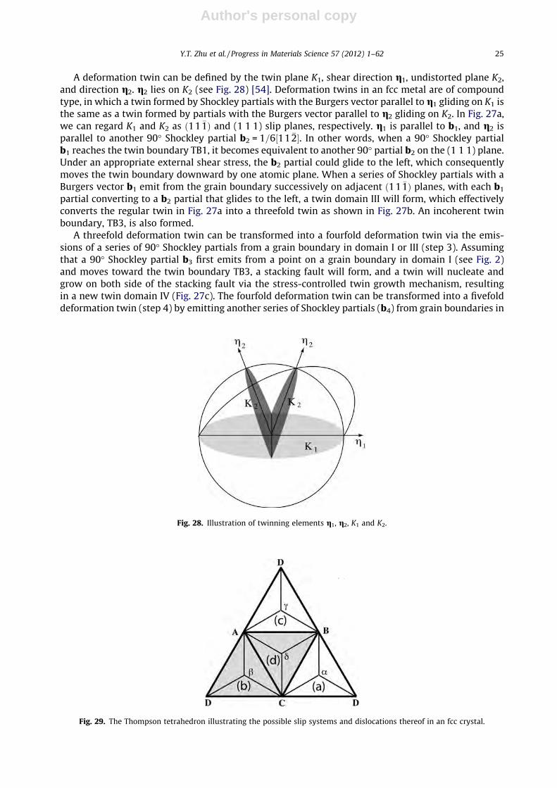
A deformation twin can be defined by the twin plane K1, shear direction g1, undistorted plane K2,and direction g2. g2 lies on K2 (see Fig. 28) [54]. Deformation twins in an fcc metal are of compoundtype, in which a twin formed by Shockley partials with the Burgers vector parallel to g1 gliding on K1 isthe same as a twin formed by partials with the Burgers vector parallel to g2 gliding on K2. In Fig. 27a,we can regard K1 and K2 as ð11 �1Þ and (1 1 1) slip planes, respectively. g1 is parallel to b1, and g2 isparallel to another 90� Shockley partial b2 = 1=6½11 �2�. In other words, when a 90� Shockley partialb1 reaches the twin boundary TB1, it becomes equivalent to another 90� partial b2 on the (1 1 1) plane.Under an appropriate external shear stress, the b2 partial could glide to the left, which consequentlymoves the twin boundary downward by one atomic plane. When a series of Shockley partials with aBurgers vector b1 emit from the grain boundary successively on adjacent ð11 �1Þ planes, with each b1
partial converting to a b2 partial that glides to the left, a twin domain III will form, which effectivelyconverts the regular twin in Fig. 27a into a threefold twin as shown in Fig. 27b. An incoherent twinboundary, TB3, is also formed.
A threefold deformation twin can be transformed into a fourfold deformation twin via the emis-sions of a series of 90� Shockley partials from a grain boundary in domain I or III (step 3). Assumingthat a 90� Shockley partial b3 first emits from a point on a grain boundary in domain I (see Fig. 2)and moves toward the twin boundary TB3, a stacking fault will form, and a twin will nucleate andgrow on both side of the stacking fault via the stress-controlled twin growth mechanism, resultingin a new twin domain IV (Fig. 27c). The fourfold deformation twin can be transformed into a fivefolddeformation twin (step 4) by emitting another series of Shockley partials (b4) from grain boundaries in
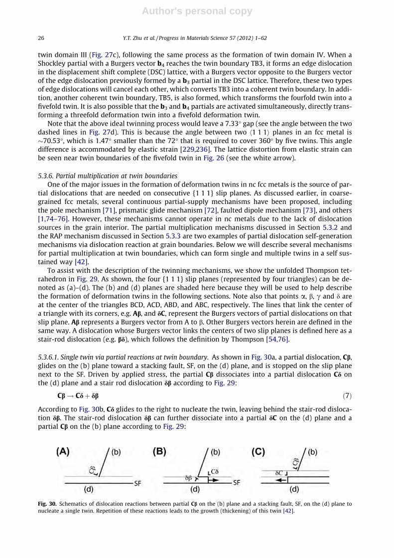
Fig. 29. The Thompson tetrahedron illustrating the possible slip systems and dislocations thereof in an fcc crystal.
Fig. 28. Illustration of twinning elements g1, g2, K1 and K2.
Y.T. Zhu et al. / Progress in Materials Science 57 (2012) 1–62 25
Author's personal copy
twin domain III (Fig. 27c), following the same process as the formation of twin domain IV. When aShockley partial with a Burgers vector b4 reaches the twin boundary TB3, it forms an edge dislocationin the displacement shift complete (DSC) lattice, with a Burgers vector opposite to the Burgers vectorof the edge dislocation previously formed by a b3 partial in the DSC lattice. Therefore, these two typesof edge dislocations will cancel each other, which converts TB3 into a coherent twin boundary. In addi-tion, another coherent twin boundary, TB5, is also formed, which transforms the fourfold twin into afivefold twin. It is also possible that the b3 and b4 partials are activated simultaneously, directly trans-forming a threefold deformation twin into a fivefold deformation twin.
Note that the above ideal twinning process would leave a 7.33� gap (see the angle between the twodashed lines in Fig. 27d). This is because the angle between two h1 1 1i planes in an fcc metal is�70.53�, which is 1.47� smaller than the 72� that is required to cover 360� by five twins. This angledifference is accommodated by elastic strain [229,236]. The lattice distortion from elastic strain canbe seen near twin boundaries of the fivefold twin in Fig. 26 (see the white arrow).
5.3.6. Partial multiplication at twin boundariesOne of the major issues in the formation of deformation twins in nc fcc metals is the source of par-
tial dislocations that are needed on consecutive {1 1 1} slip planes. As discussed earlier, in coarse-grained fcc metals, several continuous partial-supply mechanisms have been proposed, includingthe pole mechanism [71], prismatic glide mechanism [72], faulted dipole mechanism [73], and others[1,74–76]. However, these mechanisms cannot operate in nc metals due to the lack of dislocationsources in the grain interior. The partial multiplication mechanisms discussed in Section 5.3.2 andthe RAP mechanism discussed in Section 5.3.3 are two examples of partial dislocation self-generationmechanisms via dislocation reaction at grain boundaries. Below we will describe several mechanismsfor partial multiplication at twin boundaries, which can form single and multiple twins in a self sus-tained way [42].
To assist with the description of the twinning mechanisms, we show the unfolded Thompson tet-rahedron in Fig. 29. As shown, the four {1 1 1} slip planes (represented by four triangles) can be de-noted as (a)–(d). The (b) and (d) planes are shaded here because they will be used to help describethe formation of deformation twins in the following sections. Note also that points a, b, c and d areat the center of the triangles BCD, ACD, ABD, and ABC, respectively. The lines that link the center ofa triangle with its corners, e.g. Ab, and dC, represent the Burgers vectors of partial dislocations on thatslip plane. Ab represents a Burgers vector from A to b. Other Burgers vectors herein are defined in thesame way. A dislocation whose Burgers vector links the centers of two slip planes is defined here as astair-rod dislocation (e.g. bd), which follows the definition by Thompson [54,76].
5.3.6.1. Single twin via partial reactions at twin boundary. As shown in Fig. 30a, a partial dislocation, Cb,glides on the (b) plane toward a stacking fault, SF, on the (d) plane, and is stopped on the slip planenext to the SF. Driven by applied stress, the partial Cb dissociates into a partial dislocation Cd onthe (d) plane and a stair rod dislocation db according to Fig. 29:
Cb! Cdþ db ð7Þ
According to Fig. 30b, Cd glides to the right to nucleate the twin, leaving behind the stair-rod disloca-tion db. The stair-rod dislocation db can further dissociate into a partial dC on the (d) plane and apartial Cb on the (b) plane according to Fig. 29:
Fig. 30. Schematics of dislocation reactions between partial Cb on the (b) plane and a stacking fault, SF, on the (d) plane tonucleate a single twin. Repetition of these reactions leads to the growth (thickening) of this twin [42].
26 Y.T. Zhu et al. / Progress in Materials Science 57 (2012) 1–62

Author's personal copy
db! dCþ Cb ð8Þ
This reaction, and others to follow, needs applied stress to overcome the energy barrier. As shownin Fig. 30c, dC glides to the left to extend the twin nucleus and the partial Cb glides up by one atomicplane.
The above dislocation reactions at the stacking fault SF nucleate a two-layer twin, and leave behindthe original partial dislocation Cb at the twin boundary. The partial Cb can continue the above dislo-cation reaction and slip with each reaction cycle growing the twin by one slip plane.
In this twinning mechanism, the self partial-multiplication mechanism involves a Shockley partialat the twin boundary (see Fig. 30c). This Shockley partial should be associated with, and located at theend of, a stacking fault. Therefore, we should see a twin in the (d) plane and a stacking fault in the (b)plane. Such a configuration is indeed observed in nc Cu processed by high-pressure torsion, as shownin Fig. 31.
5.3.6.2. V-shaped twin via dislocation reaction andcross-slip [42,67,69]. This mechanism is different fromthe cross-slip mechanism proposed by Fujita and Mori [237]. The latter does not provide for a mech-anism for the twin to grow (thicken) by itself. To describe this mechanism, we start with the situationdescribed in Fig. 30a, in which the partial Cb is stopped at the stacking fault SF. The partial Cb nowdissociates into the following dislocations (see Fig. 29) under an applied stress with appropriate stressmagnitude and orientation:
Cb! CAþ Adþ db ð9Þ
Ad glides to the right to nucleate a twin on the (d) plane, while CA cross-slips to the next intersectionof the (d) and (b) planes (see Fig. 32a). The stair-rod dislocation db is sessile. CA now dissociates intotwo partials on the (b) plane:
CA! Cbþ bA ð10Þ
bA glides upward to nucleate a twin on the (b) plane, forming the nucleus of a V-shaped twofold twin(see Fig. 32b).
The partial Cb can repeat the above dislocation reactions and processes, causing growth (thicken-ing) of the twofold twin, as illustrated in Fig. 32c. As shown, there is a stair-rod dislocation db at everyintersection of the (d) and (b) planes. This results in a high stress at the ends of the stair-rod pileup atthe intersecting boundary of the two twins. When the stress is very high, partial or perfect dislocationscould be emitted or absorbed to relieve these stress concentrations.
Fig. 31. A single twin that is consistent with the self-multiplication mechanism [42].
Y.T. Zhu et al. / Progress in Materials Science 57 (2012) 1–62 27

Author's personal copy
Such a V-shaped twin has been observed in electrodeposited nc Ni after cryo-rolling at liquid nitro-gen temperature [69]. Shown in Fig. 33a is the HREM image of a nc Ni grain marked as A. The imageinside the white frame is shown in Fig. 33b. As shown, two intersecting twins are visible, labeled as T1
and T2, respectively. The T1 is observed to extend all the way from the grain boundary on the right side.One end of the T2 intersects with T1 in the area marked by B, while the other end terminates inside thegrain (marked as D). This V-shaped twin was formed by the dislocation reaction and cross-slip mecha-nism illustrated in Fig. 32.
5.3.6.3. T-shaped twin via dislocation reaction and cross-slip. A T-shaped twin can be formed in a processsimilar to the V-shaped twin. Assuming that a V-shaped twin is already formed (see Fig. 34A). A partialdislocation Cd, emitted from the grain boundary or another source, glides to the right on a (d) planeadjacent to the original stacking fault (see Fig. 34A). The partial Cd is stopped by the twin boundaryand dissociates into the following dislocations (see Fig. 29) under the applied stress:
Cd! CAþ Abþ bd ð11Þ
Ab glides upward to nucleate a twin on the (b) plane, while CA cross-slips to the intersection of thenext (d) plane and (b) plane (similar to that shown in Fig. 32a). The stair-rod dislocation bd is sessileand cannot move. CA now dissociates into two partials on the (d) plane:
CA! Cdþ dA ð12Þ
dA lides to the left to grow the twin on the (d) plane (see Fig. 34B). The partial Cd can repeat the abovedislocation reactions and processes, causing growth (thickening) of the T-shaped twin, as illustrated inFig. 34c.
Fig. 33. HREM images showing (a) a grain that contains a cross-slip twin in the white frame and (b) an enlarged image of thearea in the white frame in (a) [66].
Fig. 32. Schematics of the nucleation and growth of a V-shaped twofold deformation twin by dislocation reaction and cross-slipat the twin boundary. (A) Nucleation of a twin on the (D) plane. (B) Nucleation of the second twin on the (B) plane. (C). A V-shaped twofold twin after some growth. A stair-rod dislocation db is at every intersection of the (D) and (B) planes [42].
28 Y.T. Zhu et al. / Progress in Materials Science 57 (2012) 1–62

Author's personal copy
As shown in Fig. 34C, the above process produces a stair-rod dislocation bd at every intersection of(d) and (b) planes, which is of the opposite sign to the db stair-rod dislocations formed earlier in thetwofold twin. The arrays of bd and db stair-rod dislocations partially cancel each other’s long-rangestress fields [238]. However, the pileup tips would still have local stress concentration. Note that fol-lowing the processes similar to what are described in the Figs. 32 and 34, an X-shaped twin can alsoform [42].
5.3.7. Dislocation rebound mechanismThe single and multiple twins could also be formed by the dislocation rebound mechanism [239].
The elastic field of a partial dislocation is reflected (or partially reflected) at grain boundaries or twinboundaries (analogous to shock wave reflection) [239]. The reverse shear field can aid in nucleation ofan opposite-sign dislocation where the first one impinged, especially if the velocity of the dislocationapproaches the Rayleigh velocity (sound velocity) [42,48,239]. This dislocation rebound mechanismcan produce the single twin, V-shaped twin, T-shaped twin, and X-shaped twins described above[42]. The rebound mechanism is deliberated in the following sections.
As shown in Fig. 35a, a partial, Cd nucleates from the grain boundary on the left, glides to the rightto form a stacking fault. Such events have been observed both in MD simulations [9,10] and by HREM[8]. The elastic field of the partial dislocation is reflected by the grain boundary on the right, whichhelps with the nucleation of a partial dislocation with an opposite sign, dC on the next slip plane. Thispartial glides to the left, nucleating a single twin, as shown in Fig. 35b. Note that the nucleation andglide of dC leaves behind a partial of opposite sign, Cd, on the right grain boundary (see Fig. 35b).
5.4. Grain size effect
Grain size is an essential factor that affects the formation of deformation twins in metals and alloys.It has been extensively reported in the literature that larger grain sizes are more favorable to twinnucleation for conventional coarse-grained (CG) materials [11,240]. This is rationalized as follows.Both the critical stresses r for dislocation slip and twinning follow a Hall–Petch type (H–P) behavior,r ¼ r0 þ kd�a, where d is grain size, r0 and k are constants and a is an exponent typically equal to 0.5.For many CG metals and alloys, the H–P slope for deformation-twinning-mediated plasticity (kDT) is
Fig. 34. Formation of a T-shaped twin. (A) A partial, Cd, slip toward the twin boundary. (B) After the dislocation reactions (Eqs.(5) and (6)), a T-shaped twin is nucleated, leaving behind the partial Cd to repeat another dislocation reaction cycle. (C) The finalT-shaped twin with two arrays of stair-rod dislocations [42].
Fig. 35. The formation of a single twin by the rebound mechanism. (a) A partial Cd glides to the right to form a stacking fault. (b)Cd rebounds as dC from a grain boundary or twin boundary to nucleate a single twin. Two partials Cd are left superposed on thegrain boundary at the right [40].
Y.T. Zhu et al. / Progress in Materials Science 57 (2012) 1–62 29

Author's personal copy
much larger (up to 10 times) than that for dislocation slip (kDS) [11,81]. Therefore, for coarse-grainedmetals and alloys, decreasing grain size favors dislocation slip and makes twinning more difficult. Thephysical reason for such a grain size effect in coarse-grained metals is not understood. Yu et al. [241]recently attempted to explain such a phenomenon by a ‘‘stimulated slip’’ mechanism. More studies areneeded to probe its fundamental physics.
However, when the grain size is further refined down to nanometer regions (below 100 nm), defor-mation twinning has been frequently observed even in materials with medium to high stacking faultenergies such as copper and nickel. Therefore, twinning was considered as one of the major plasticdeformation mechanisms of nanostrutured materials [8,24–30]. The grain size effect on deformationtwinning in the nc fcc Ni was systematically investigated in a recent study [171]. An electrodepositednc-Ni foil with grains in the range of 10–75 nm and an average grain size of �25 nm were deformed atliquid nitrogen temperature at a strain rate of 3 � 10�3 s�1 to a strain of 5.5% and at a flow stress of1.5 GPa. About 130 grains were examined under HREM to check if they contain deformation twinsand stacking faults. Fig. 36 shows the histograms of (a) grain size distribution, (b) the number of grainscontaining stacking faults and twins, and (c) fractions of grains containing stacking faults and twins insamples deformed under tension. Fig. 36b shows that with decreasing grain size the number of grainscontaining twins (hereafter referred to as twinned grains) first increases and then decreases, while thenumber of grains containing stacking faults increases monotonically. The fraction of twinned grains isa good statistical indicator of twinning propensity. Therefore, Fig. 36 indicates that the twinning
Fig. 36. Statistical grain size effect on the formations of stacking faults and deformation twins in nc Ni deformed under tensionat liquid nitrogen temperature. The twin is defined as consisting of two or more layers of stacking faults on consecutive slipplanes. (a) The size distribution of all grains examined under TEM. (b) The number distributions of grains containing stackingfaults and twins. (c) The fraction distribution of grains containing stacking faults and twins. Each fraction was calculated as theratio of the number of grains containing stacking faults and twins to the total number of grains in the corresponding size range[164].
30 Y.T. Zhu et al. / Progress in Materials Science 57 (2012) 1–62
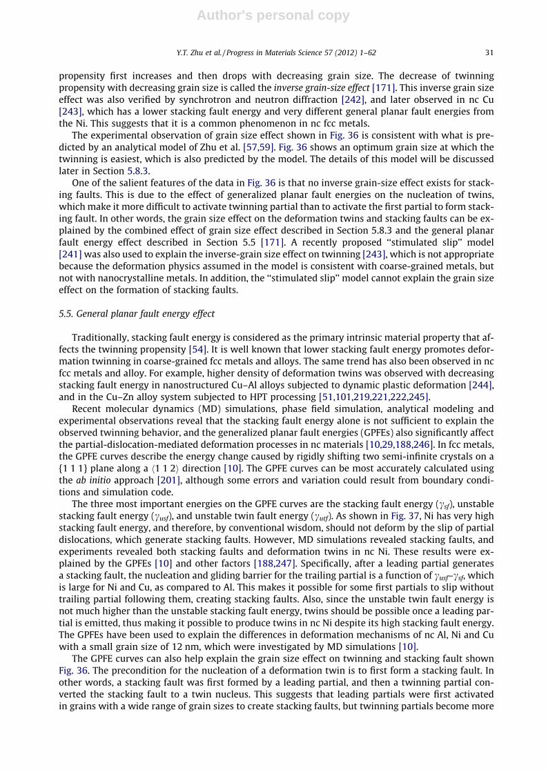
Author's personal copy
propensity first increases and then drops with decreasing grain size. The decrease of twinningpropensity with decreasing grain size is called the inverse grain-size effect [171]. This inverse grain sizeeffect was also verified by synchrotron and neutron diffraction [242], and later observed in nc Cu[243], which has a lower stacking fault energy and very different general planar fault energies fromthe Ni. This suggests that it is a common phenomenon in nc fcc metals.
The experimental observation of grain size effect shown in Fig. 36 is consistent with what is pre-dicted by an analytical model of Zhu et al. [57,59]. Fig. 36 shows an optimum grain size at which thetwinning is easiest, which is also predicted by the model. The details of this model will be discussedlater in Section 5.8.3.
One of the salient features of the data in Fig. 36 is that no inverse grain-size effect exists for stack-ing faults. This is due to the effect of generalized planar fault energies on the nucleation of twins,which make it more difficult to activate twinning partial than to activate the first partial to form stack-ing fault. In other words, the grain size effect on the deformation twins and stacking faults can be ex-plained by the combined effect of grain size effect described in Section 5.8.3 and the general planarfault energy effect described in Section 5.5 [171]. A recently proposed ‘‘stimulated slip’’ model[241] was also used to explain the inverse-grain size effect on twinning [243], which is not appropriatebecause the deformation physics assumed in the model is consistent with coarse-grained metals, butnot with nanocrystalline metals. In addition, the ‘‘stimulated slip’’ model cannot explain the grain sizeeffect on the formation of stacking faults.
5.5. General planar fault energy effect
Traditionally, stacking fault energy is considered as the primary intrinsic material property that af-fects the twinning propensity [54]. It is well known that lower stacking fault energy promotes defor-mation twinning in coarse-grained fcc metals and alloys. The same trend has also been observed in ncfcc metals and alloy. For example, higher density of deformation twins was observed with decreasingstacking fault energy in nanostructured Cu–Al alloys subjected to dynamic plastic deformation [244],and in the Cu–Zn alloy system subjected to HPT processing [51,101,219,221,222,245].
Recent molecular dynamics (MD) simulations, phase field simulation, analytical modeling andexperimental observations reveal that the stacking fault energy alone is not sufficient to explain theobserved twinning behavior, and the generalized planar fault energies (GPFEs) also significantly affectthe partial-dislocation-mediated deformation processes in nc materials [10,29,188,246]. In fcc metals,the GPFE curves describe the energy change caused by rigidly shifting two semi-infinite crystals on a{1 1 1} plane along a h1 1 2i direction [10]. The GPFE curves can be most accurately calculated usingthe ab initio approach [201], although some errors and variation could result from boundary condi-tions and simulation code.
The three most important energies on the GPFE curves are the stacking fault energy (csf), unstablestacking fault energy (cusf), and unstable twin fault energy (cutf). As shown in Fig. 37, Ni has very highstacking fault energy, and therefore, by conventional wisdom, should not deform by the slip of partialdislocations, which generate stacking faults. However, MD simulations revealed stacking faults, andexperiments revealed both stacking faults and deformation twins in nc Ni. These results were ex-plained by the GPFEs [10] and other factors [188,247]. Specifically, after a leading partial generatesa stacking fault, the nucleation and gliding barrier for the trailing partial is a function of cusf–csf, whichis large for Ni and Cu, as compared to Al. This makes it possible for some first partials to slip withouttrailing partial following them, creating stacking faults. Also, since the unstable twin fault energy isnot much higher than the unstable stacking fault energy, twins should be possible once a leading par-tial is emitted, thus making it possible to produce twins in nc Ni despite its high stacking fault energy.The GPFEs have been used to explain the differences in deformation mechanisms of nc Al, Ni and Cuwith a small grain size of 12 nm, which were investigated by MD simulations [10].
The GPFE curves can also help explain the grain size effect on twinning and stacking fault shownFig. 36. The precondition for the nucleation of a deformation twin is to first form a stacking fault. Inother words, a stacking fault was first formed by a leading partial, and then a twinning partial con-verted the stacking fault to a twin nucleus. This suggests that leading partials were first activatedin grains with a wide range of grain sizes to create stacking faults, but twinning partials become more
Y.T. Zhu et al. / Progress in Materials Science 57 (2012) 1–62 31
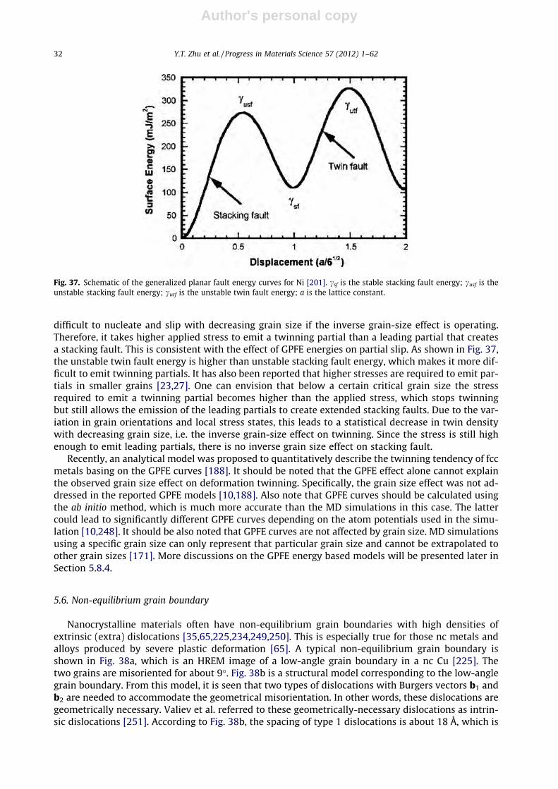
Author's personal copy
difficult to nucleate and slip with decreasing grain size if the inverse grain-size effect is operating.Therefore, it takes higher applied stress to emit a twinning partial than a leading partial that createsa stacking fault. This is consistent with the effect of GPFE energies on partial slip. As shown in Fig. 37,the unstable twin fault energy is higher than unstable stacking fault energy, which makes it more dif-ficult to emit twinning partials. It has also been reported that higher stresses are required to emit par-tials in smaller grains [23,27]. One can envision that below a certain critical grain size the stressrequired to emit a twinning partial becomes higher than the applied stress, which stops twinningbut still allows the emission of the leading partials to create extended stacking faults. Due to the var-iation in grain orientations and local stress states, this leads to a statistical decrease in twin densitywith decreasing grain size, i.e. the inverse grain-size effect on twinning. Since the stress is still highenough to emit leading partials, there is no inverse grain size effect on stacking fault.
Recently, an analytical model was proposed to quantitatively describe the twinning tendency of fccmetals basing on the GPFE curves [188]. It should be noted that the GPFE effect alone cannot explainthe observed grain size effect on deformation twinning. Specifically, the grain size effect was not ad-dressed in the reported GPFE models [10,188]. Also note that GPFE curves should be calculated usingthe ab initio method, which is much more accurate than the MD simulations in this case. The lattercould lead to significantly different GPFE curves depending on the atom potentials used in the simu-lation [10,248]. It should be also noted that GPFE curves are not affected by grain size. MD simulationsusing a specific grain size can only represent that particular grain size and cannot be extrapolated toother grain sizes [171]. More discussions on the GPFE energy based models will be presented later inSection 5.8.4.
5.6. Non-equilibrium grain boundary
Nanocrystalline materials often have non-equilibrium grain boundaries with high densities ofextrinsic (extra) dislocations [35,65,225,234,249,250]. This is especially true for those nc metals andalloys produced by severe plastic deformation [65]. A typical non-equilibrium grain boundary isshown in Fig. 38a, which is an HREM image of a low-angle grain boundary in a nc Cu [225]. Thetwo grains are misoriented for about 9�. Fig. 38b is a structural model corresponding to the low-anglegrain boundary. From this model, it is seen that two types of dislocations with Burgers vectors b1 andb2 are needed to accommodate the geometrical misorientation. In other words, these dislocations aregeometrically necessary. Valiev et al. referred to these geometrically-necessary dislocations as intrin-sic dislocations [251]. According to Fig. 38b, the spacing of type 1 dislocations is about 18 Å, which is
Fig. 37. Schematic of the generalized planar fault energy curves for Ni [201]. csf is the stable stacking fault energy; cusf is theunstable stacking fault energy; cutf is the unstable twin fault energy; a is the lattice constant.
32 Y.T. Zhu et al. / Progress in Materials Science 57 (2012) 1–62
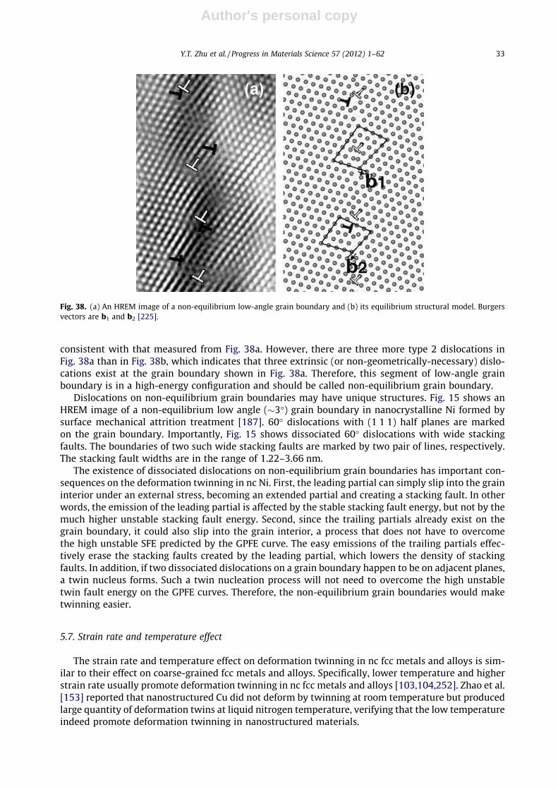
Author's personal copy
consistent with that measured from Fig. 38a. However, there are three more type 2 dislocations inFig. 38a than in Fig. 38b, which indicates that three extrinsic (or non-geometrically-necessary) dislo-cations exist at the grain boundary shown in Fig. 38a. Therefore, this segment of low-angle grainboundary is in a high-energy configuration and should be called non-equilibrium grain boundary.
Dislocations on non-equilibrium grain boundaries may have unique structures. Fig. 15 shows anHREM image of a non-equilibrium low angle (�3�) grain boundary in nanocrystalline Ni formed bysurface mechanical attrition treatment [187]. 60� dislocations with (1 1 1) half planes are markedon the grain boundary. Importantly, Fig. 15 shows dissociated 60� dislocations with wide stackingfaults. The boundaries of two such wide stacking faults are marked by two pair of lines, respectively.The stacking fault widths are in the range of 1.22–3.66 nm.
The existence of dissociated dislocations on non-equilibrium grain boundaries has important con-sequences on the deformation twinning in nc Ni. First, the leading partial can simply slip into the graininterior under an external stress, becoming an extended partial and creating a stacking fault. In otherwords, the emission of the leading partial is affected by the stable stacking fault energy, but not by themuch higher unstable stacking fault energy. Second, since the trailing partials already exist on thegrain boundary, it could also slip into the grain interior, a process that does not have to overcomethe high unstable SFE predicted by the GPFE curve. The easy emissions of the trailing partials effec-tively erase the stacking faults created by the leading partial, which lowers the density of stackingfaults. In addition, if two dissociated dislocations on a grain boundary happen to be on adjacent planes,a twin nucleus forms. Such a twin nucleation process will not need to overcome the high unstabletwin fault energy on the GPFE curves. Therefore, the non-equilibrium grain boundaries would maketwinning easier.
5.7. Strain rate and temperature effect
The strain rate and temperature effect on deformation twinning in nc fcc metals and alloys is sim-ilar to their effect on coarse-grained fcc metals and alloys. Specifically, lower temperature and higherstrain rate usually promote deformation twinning in nc fcc metals and alloys [103,104,252]. Zhao et al.[153] reported that nanostructured Cu did not deform by twinning at room temperature but producedlarge quantity of deformation twins at liquid nitrogen temperature, verifying that the low temperatureindeed promote deformation twinning in nanostructured materials.
Fig. 38. (a) An HREM image of a non-equilibrium low-angle grain boundary and (b) its equilibrium structural model. Burgersvectors are b1 and b2 [225].
Y.T. Zhu et al. / Progress in Materials Science 57 (2012) 1–62 33

Author's personal copy
Wu and Zhu [171] statistically studied the strain rate and strain effect on deformation twinning innc Ni. An electrodeposited nc-Ni foil with grains in the range of 10–75 nm and an average grain size of�25 nm were deformed at liquid nitrogen temperature under three deformation modes with increas-ing strain rate and strain: (1) quasi-static tension at a strain rate of 3 � 10�3 s�1 to a strain of 5.5% andat a flow stress of 1.5 GPa, (2) rolling at a strain rate of 2 � 10�2 s�1 to a strain of 9.8%, and (3) splitHopkinson pressure bar (SHPB) test at a strain rate of �2.6 � 103 s�1 to a strain of 13.5% and a flowstress of �2 GPa. About 130 grains for each sample were examined using HREM to obtain good statis-tics. Shown in Fig. 39 is the fractions of grains that contain at least one twin. The fraction of twinnedgrains increased from 28% under tension to 38% under rolling to 44% under SHPB. The strain rate effectis believed caused by the higher flow stress with higher strain rate [171]. The flow stress under tensionwas 1.5 GPa and this was increased to 2.0 GPa under SHPB [188,193]. Although the flow stress underrolling could not be measured, it should be between 1.5 GPa and 2.0 GPa, because higher stain rateusually leads to higher flow stress. This observation is somewhat different from that in a recent studyusing laser driven compression at an extremely high strain rate of >107 s�1 [189], but consistent with arecent MD simulation on strain rate effect [193,194].
5.8. Twin nucleation and growth models
Several models based on various assumptions have been proposed to describe the formation ofdeformation twins in nc fcc metals. The validity of a model is determined by how much deformationphysics it is based on and it predicts. A model that is not based on the deformation physics observedby experiments or MD simulations is of little scientific value, although it sometimes can be used to fitthe observed experimental data by adjusting the fitting parameters. Such a model can often misleadthe scientific community. Below we discuss a few well-known models and their limitations.
5.8.1. Conventional dislocation modelTwo similar models were proposed to explain the formation of deformation twins in nc metals
[6,65]. In the model by Chen et al. [6], the stress needed to activate a lattice dislocation is described as
sL ¼2gGb
dð13Þ
where g is a parameter that reflects the characteristics of the dislocation (g = 0.5 for an edge disloca-tion and g = 1.5 for a screw dislocation), G is the shear modulus, b is the magnitude of the Burgers vec-tor of the lattice dislocation, d is the grain size. The stress to activate a partial dislocation is describedas
Fig. 39. The fraction of twinned grains in nc Ni deformed at liquid nitrogen temperature under tension, rolling and SHPB.Tension: strain rate = 3 � 10�3 s�1, strain = 5.5%, flow stress = 1.5 GPa; rolling: strain rate = 2 � 10�2 s�1, strain = 9.8%; SHPB:strain rate = �2.6 � 103 s�1, strain = 13.5%, flow stress = �2 GPa [171].
34 Y.T. Zhu et al. / Progress in Materials Science 57 (2012) 1–62

Author's personal copy
sP ¼2gGb1
dþ c
b1ð14Þ
where b1 is the magnitude of the Burgers vector of the partial dislocation, and c is the stacking faultenergy. When g = 0.5, these two equations become identical to those in the work by Liao et al. [65].
Because b > b1, sP will increase at a slower rate than sL, which means that it will be easier to activatea partial dislocation than a perfect dislocation when the grain is below a critical size. These two mod-els seem very straightforward in explaining the activation of partial dislocations, which is a prerequi-site of deformation twinning.
Unfortunately, experimental data show that smaller grain size hinders, not promotes, deformationtwinning [11,81], which directly contradicts these two models [6,65]. It has been found that the crit-ical stress for twinning follows a Hall–Petch relationship [11],
rt ¼ rt0 þ jtd�1=2 ð15Þ
where rt0 is a constant and jt is the Hall–Petch slope for twinning. Eq. (15) is similar to the well-known Hall–Petch relationship for the slip of a perfect dislocation:
rs ¼ rs0 þ jsd�1=2 ð16Þ
where rs0 is a constant and js is the Hall–Petch slope for the slip of a perfect dislocation.Table 1 lists the Hall–Petch slope for both twinning and for slip of lattice dislocations [11]. As
shown, the Hall–Petch slope for twinning is higher than that for the slip of lattice dislocation forbcc, fcc, and hcp metals and alloys. Therefore, the models are not supported by experimental data.Moreover, these two models predict an unrealistically high critical stress for twinning [6], which re-flects their problem. The models also made an inexplicit assumption that activation of partial disloca-tion equals formation of twinning, which, as shown later, is not correct. Another obvious evidence thatthis model cannot account for the deformation physics is that it cannot explain the experimentally ob-served inverse-grain size effect shown in Fig. 36.
The reason for the failure of this model is that Eqs. (13) and (14) are based on an early (1961) workby Venables [72], which did not account for the recently observed deformation physics of nc materials,i.e. the dislocation emission from grain boundaries, as discussed in Section 5.3.2. In other words, thismodel is not based on physics that prevails in nc materials, and therefore is not correct. However,unfortunately, due to its simplicity, this model has been used by many research groups to explainwhy deformation twinning occurs in nc materials [6,65,80].
Table 1The Hall–Petch slopes for bcc, fcc and hcp metals and alloys [11].
Material H–P slope for slip, js (MPa mm1/2) H–P slope for twinning, jt (MPa mm1/2)
bccFe–3 wt.% Si 12 100Armco Fe 20 124Fe–25 at.% Ni 33 100Cr 10.08 67.75Va 3.46 (20 K) 22.37
fccCu 5.4 (RT) 21.66 (77 K)Cu–6 wt.% Sn 7.1 11.8 (77 K), 7.9 (RT)Cu–9 wt.% Sn 8.2 15.77 (77 K)Cu–10 wt.% Zn 7.1 11.8 (77 K)Cu–15 wt.% Zn 8.4 16.7 (295 K)
hcpZr 8.26 79.2Ti 6 (78 K) 18 (4 K)
Y.T. Zhu et al. / Progress in Materials Science 57 (2012) 1–62 35

Author's personal copy
5.8.2. Partial emission from grain boundariesA recent analytical dislocation model by Asaro et al. [253] considered the MD simulation and
experimental results, which indicate partial dislocations emissions from boundaries of nanosizedgrains. The critical stress needed to move a lattice dislocation is described as
sL ¼Gbd
ð17Þ
and the critical stress needed to move a partial dislocation is described as
sP ¼Gb3dþ ð1� dÞ c
Gbð18Þ
where d is the ratio of equilibrium stacking fault width to grain size.This model predicts that below a certain critical grain size partial dislocations from GBs need a low-
er stress to move than lattice dislocations in nc metals. Most importantly, it predicts a realistic, lowtwinning stress that is obtainable under experimental conditions such as ball-milling. However, themodel does not address one critical issue: as shown in Fig. 36, the emission of a partial dislocationdoes not guarantee the nucleation of a deformation twin because the trailing partial could easily fol-low to erase the stacking fault formed by the first partial.
5.8.3. Twinning partial from grain boundariesTo address the above issue in the above model, Zhu et al. recently developed an analytical model to
describe the nucleation and growth of deformation twins in nc fcc metals [57,59]. This model is de-scribed below.
The model assumes a grain with a square (1 1 1) slip plane, as shown in Fig. 40, similar to that usedin a previous study [253]. Under an external shear stress, s, a 30� leading Shockley partial, b1, is emit-ted from grain boundary AB, depositing two segments of partial dislocation lines (Aa and Bb) on thegrain boundaries. s is oriented at an angle a with line ab. A trailing 30� partial, b2, is also emitted (lineAa0b0B). The two partials ab and a’b’ are separated by a stacking fault (Fig. 40a). The two partials reactto form two perfect dislocation segments, Aa0 and Bb0 at the GBs. This dislocation system is called aScrew system hereafter, because the two partials can form a perfect screw dislocation along the grainboundary AB.
To nucleate a deformation twin, a stacking fault needs to be first created. This can occur via: (1)emission of a 30� partial, b1, from grain boundary, (2) extending the stacking fault ribbon inFig. 40a across the grain. Both scenarios may occur depending on the orientation of s. In Fig. 40a,for the partial b1 to move, s has to perform a work to overcome increases in both the stacking faultenergy and dislocation energy from lengthening segments Aa and Bb [54]. The critical stress for mov-ing partial b1 can be derived as [57]:
Fig. 40. A schematic illustration of the dislocation model for the nucleation of deformation twins. (a) a perfect screw dislocationdissociated into two partials b1 and b2; (b) the nucleation of a deformation twin via the emission of a twinning partial on a(1 1 1) plane adjacent to the stacking fault plane; (c) the emission of a trailing partial that removes the stacking fault [57,59].
36 Y.T. Zhu et al. / Progress in Materials Science 57 (2012) 1–62

Author's personal copy
sP ¼1
cosða� 30�Þ
ffiffiffi6p
caþ Gað4� mÞ
8ffiffiffi6p
pð1� mÞdln
ffiffiffi2p
da
" #ð19Þ
where c is the stable stacking fault energy, a is the lattice parameter, m is the Poisson’s ratio, and d isthe grain size defined in Fig. 40.
The s needed to move the leading and trailing partials together is equivalent to s for moving ascrew lattice dislocation. s has to overcome the work needed to lengthen the lattice dislocation seg-ments Aa0 and Bb0, and can be derived as:
sL ¼Ga
2ffiffiffi2p
pð1� mÞd cos aln
ffiffiffi2p
da
ð20Þ
After the stacking fault formation, a twin may nucleate via the emission of a second 30� partial, b1,from the grain boundary on a plane adjacent to the stacking fault (Fig. 40b). On the other hand, a trail-ing partial may also emit on the stacking fault plane and erase the stacking fault in its path (Fig. 40c).The critical twin nucleation stress can be derived as:
stwin ¼Gað4� mÞ
8ffiffiffi6p
pð1� mÞd cosða� 30�Þln
ffiffiffi2p
da
ð21Þ
The trailing partial requires a stress, strail, to move, which can be derived as
strail ¼1
cosðaþ 30�Þ
ffiffiffi6pð8þ mÞGa
48pð1� mÞd ln
ffiffiffi2p
da�
ffiffiffi6p
ca
" #ð22Þ
Once a twin is nucleated, it may grow via the emission of more b1 twinning partials under stressstwin. It may also shrink via the emission of a shrinking partial, b2, on a plane adjacent to the twinboundary but on the twin side. The stress needed to move a shrinking partial can be derived as:
sshrink ¼1
cosðaþ 30�Þ
ffiffiffi6pð8þ mÞGa
48pð1� mÞd ln
ffiffiffi2p
da
ð23Þ
The stresses, sP, sL, stwin, strail, and sshrink, determine the nucleation and growth of a deformationtwin. For example, at sP < sL, partial dislocations will be emitted from the grain boundary, and atstwin < strail, a twin may nucleate. In the following, Al is used as a model material to validate the model[57,59]. For Al, G = 26.5 GPa, m = 0.345, a = 0.404 nm, and c = 122 mJ/m2 [54,144]. In Fig. 41, the stres-ses, sP, sL, stwin, strail, and sshrink, are plotted as a function of grain size d for a = 25�. The point B in Fig. 41represents the critical grain size, dB, below which a deformation twin nucleates because stwin < strail.
Fig. 41. The critical stresses, sP, sL, stwin, strail, and sshrink, as a function of nc Al grain size d for a given a value of 25� [57].
Y.T. Zhu et al. / Progress in Materials Science 57 (2012) 1–62 37

Author's personal copy
However, a deformation twin can nucleate only after the formation of a stacking fault. As shown, atgrain size dB, sL < sP, i.e. the lattice dislocation is operating at point B0. It is also calculated that thestacking fault width at sL is far larger than dB [57]. This means that a deformation twin nucleates aftera stacking fault ribbon spreads across the grain. Interestingly, at point B0 the grain size is larger and thecritical stress is lower for twin nucleation than those for the partial dislocation emission at point A,because the stacking fault of a dissociated lattice dislocation would spread across the grain before apartial is emitted. In other words, a twin will nucleate at the critical grain size dB under the stressof dB at B0.
The above equations and analysis are for the Screw system only. There are two other possible dis-location systems: a 60� I system with a leading 90� partial and a trailing 30� partial, and a 60� II systemwith a leading 30� partial and a trailing 90� partial [57]. These two systems are amenable to the sameprocedure, and therefore we only present the final results. It is found that the 60� II system does notoperate because it requires much higher stress to nucleate a deformation twin. In a polycrystalline ncsample, grains are likely to orient in all orientations. Therefore, a deformation map linking stresses ofdeformation twin nucleation and growth with grain size is very useful and desirable. Such a map canbe constructed by plotting the critical (the lowest) stresses against the critical grain sizes, without thestress orientation information (see Fig. 42).
The deformation map in Fig. 42 reveals that there are optimum grain sizes for deformation twinnucleation (the lowest stress point at cup bottom), which are 4.85 nm and 7.25 nm for the 60� I andScrew systems respectively. The minimum stresses for the 60� I and screw systems in Fig. 42 were de-rived and simplified as [59]
s60� Imin ¼
1:72ð4� 3mÞ2:89� m
ca
ð24Þ
sscrewmin ¼
12:213:73þ m
ca
ð25Þ
As shown in Fig. 42, these two minimum stresses are very close. For simplicity, we use their aver-age as the critical stress for twinning, which can be derived as
sm ¼c
2a1:72ð4� 3mÞ
2:89� mþ 12:21
3:73þ m
� �ð26Þ
Eq. (26) can be approximated and simplified by assuming the value of m in the denominators as0.33, which yields
sm ¼ð5:69� 2:02mÞc
2að27Þ
Calculation shows that the error in Eq. (27) caused by the approximation is less than 2% for a widerange of m values from 0.25 to 0.45. Such a small error is negligible, considering the semi-quantitativenature of the model.
Fig. 42. A deformation map showing the critical stresses for deformation twin nucleation and growth in nc Al as a function ofgrain size for the 60� I and the Screw dislocation systems [57].
38 Y.T. Zhu et al. / Progress in Materials Science 57 (2012) 1–62

Author's personal copy
The optimum grain size for twinning, or the grain size at which the twinning stress is lowest for the60� I and screw systems in Fig. 42 can be calculated from the following simplified equations [59]
d60�Im
lnðffiffiffi2p
d60�Im
.aÞ¼ 2:089� m
54:985ð1� mÞGa2
cð28Þ
dscrewm
lnðffiffiffi2p
dscrewm
�aÞ¼ 3:727þ m
97:053ð1� mÞGa2
cð29Þ
For simplicity, we can use average of the Eqs. (28) and (29) as the critical grain size, dm, fortwinning:
dm
lnðffiffiffi2p
dm=aÞ¼ 9:69� m
253:66ð1� mÞGa2
cð30Þ
The critical stress and optimum grain size for deformation twinning for Al, Cu and Ni calculatedusing Eqs. (27) and (30) are listed in Table 2. The predicted critical twinning stress is obtainable underexperimental conditions and optimum grain size for twinning agrees well with experimental observa-tions [57,59,171].
One of the most significant feature of this model is its successful prediction of normal and inversegrain size effect on deformation twinning [171]. However, it also has a major deficiency: it does notconsider the effect of GPFE’s, which affects the nucleation and gliding of the first and twinning partials.Consequently, this model cannot explain why no inverse grain size effect is observed for stackingfaults (Fig. 36). In addition, this model treated dislocation lines as straight lines for simplicity, whilethey should be curved inside the grain in the real situation. Gu et al. recently developed a curved dis-location-line model to describe the partial emission from the grain boundary to form stacking faults[254], which is an improvement over the previous straight-line model [253]. Another modificationand improvement is the incorporation of interactions between dislocations [255–257], which im-proved the accuracy of the equations, but also significantly increased the complexity of the mathemat-ical equations.
Finally, the most significant contribution of this model is its successful description of the grain sizeeffect on deformation mechanisms. As shown in Fig. 41, the critical stresses for moving all dislocationsincrease with decreasing grains size. However, the rate at which the critical stress increases withdecreasing diameter varies with the type of the dislocation. For example, below a critical grain sizethe critical stress sP for the leading partial will be lower than that for the lattice dislocation sL. Thephysical reason for the grain size effect is the deposition of the dislocation lines (see Fig. 40) on thegrain boundaries as a dislocation glides forward under an applied stress. The deposited dislocationlines add strain energy to the system and act to drag the gliding dislocation. The dragging force doesnot change with grain size d, while the driving force for the dislocation slip is proportional to thelength of the gliding section of the dislocation, which is equal to the grain size d. The difference ingrain size dependences of the dragging and driving forces makes it more difficult for dislocations tomove in smaller grains.
Table 2The critical stress and optimum grain size for the formation of deformation twinning in Ag, Al, Au, Cu and Ni, predicted by thetwinning partial from the grain boundary model (Eqs. (27) and (30)) as well as parameters used for the calculation [54,57,59].
G (GPa) m c (mJ m�2) A (Å) sm (GPa) dm (nm)
Ag 30 0.37 22 4.090 0.16 73Al 26.5 0.345 122 4.04 0.89 6Au 27 0.44 45 4.080 0.31 30Cu 54.6 0.343 45 3.6146 0.37 46Ni 94.7 0.312 125 3.5232 1.06 23
Y.T. Zhu et al. / Progress in Materials Science 57 (2012) 1–62 39

Author's personal copy
5.8.4. General-planar-fault-energy (GPFE) based modelsIt is generally agreed that GPFE curves have significant effect on the deformation twinning of mate-
rials [10,29,35,49,79,171,201,258–264]. However, how the GPFE curves affect the deformation twin-ning in nc materials have not been rigorously modeled. Most modeling works involving GPFEs haveso far either focused on twinning at a crack tip in a single crystal [29,258] or using the GPFE conceptto qualitatively explain MD modeling results [10]. The grain size, which has been experimentally ob-served to significantly affect the twinning, is conspicuously missing in these models. In other words,the GPFE models reported so far are not specific for nc materials and their validity for nc materials maybe limited. For example, the GPFEs alone cannot explain the experimentally observed normal and in-verse grain size effect shown in Fig. 36 and discussed in Section 5.4.
Using Rice’s Peierls approach [30], Tadmor and Hai [258] derived an equation describing the twin-ning criterion:
T ¼ kcrit
ffiffiffiffiffiffiffifficusf
cutf
sð31Þ
where T is the twining tendency, kcrit is dimensionless factor that characterize the extra load to nucle-ate the trailing partial in comparison to the leading partial, cusf and cutf are the unstable stacking faultenergy and the unstable twin fault energy, respectively, as defined in Fig. 37. The value of kcrit dependson the materials parameters cutf, stable stacking fault energy csf, m, and geometric parameters. Moredetails can be found in [258]. A two layer twin can nucleate if T > 1, and a trailing partial will nucleateif T < 1. It should be noted that grain size is not considered in the Eq. (31).
Asaro and Suresh [29] further explored Eq. (31) for a special case where the Burgers vector of theleading partial is orthogonal to the crack front, and applied shear stress is parallel to the Burgers vectorof the leading partial. They developed Eq. (31) into the following equation
T ¼ffiffiffiffiffiffiffiffiffiffiffiffiffiffiffiffiffiffiffiffiffiffiffiffið1þ bÞ
cusf
cutf
sð32Þ
where b = 1 � csf/cusf. Therefore, T is only determined by the GPFEs.Van Swygenhoven et al. [10] used the GPFE curves to explain the differences in deformation mech-
anisms of nc Al, Cu and Ni with a small grain size of 12 nm. Particularly, although both Al and Ni havesimilar high stacking fault energy, csf, they deform via very different mechanisms. Al deforms via lat-tice dislocation slip because its csf/cusf is very small, making the trailing partial easy to nucleate andemit, while Ni deforms via partial slip because csf/cusf is very large, making the trailing partial difficultto nucleate and emit. In addition, twinning is rarely observed in three-dimensional nc Al, Ni and Cubecause of their high unstable twin fault energy, cutf. However, these results from MD simulations can-not be extrapolated to nc materials with larger grain sizes, due to the grain size effect observed exper-imentally [171]. In other words, when the grain sizes become larger and near the optimum grain sizefor twinning, deformation twins were observed [59,171]. Therefore, there is a need to do MD simula-tions in which grain sizes are systematically varied.
Kibey et al. [79,260] recently developed a sequential, multi-scale approach to predict the twinningstress. GPFEs were incorporated into the model, and a closed-form expression for twinning stress wasobtained, which was simplified into the following approximate form:
scrit ¼2
3Nbtwin
3N4� 1
� �cutf þ
2ctsf þ csf
2
� �� 2
3Ncusf þ csf
btwinð33Þ
where N = 3 represents a three-layer critical twin nucleus. ctsf is the energy of the twin boundary. ctsf
can be approximated as half of the stacking fault energy ctsf, but this may not be obeyed by inhomo-geneous alloys [261,265]. It is obvious from Eq. (33) that the grain size effect is not considered in thismodel.
40 Y.T. Zhu et al. / Progress in Materials Science 57 (2012) 1–62

Author's personal copy
5.8.5. Future issues on modelingAs discussed above, both grain size and GPFEs have significant effect on the formation of deforma-
tion twins and stacking faults. None of the current models has considered both factors. One possibleapproach is to incorporate the GPFEs into the analytical model. However, this is not trivial and alsoneeds experimental verification of any assumptions that are used in the analytical model. The GPFEscan affect both the nucleation and glide of the dislocations.
Two fundamental issues need to be investigated. First, how do the GPFEs affect the nucleation offirst partials and twinning partials? This issue needs to be studied experimentally. One question thatremains is if the GPFE curves affect the nucleation of dislocations since the grain boundaries of ncmaterials may be in a non-equilibrium state with excess dislocations existing in them. Second, howdo the GPFEs affect the slip of the first and twinning partials. In other words, how the GPFE curves af-fect the Peierls stresses for these partials. There have been several reports on calculating the Peierlsstresses from GPFEs [264,266–268]. However, a formula for calculating the Peierls stress from theGPFEs remains to be derived.
It should be noted that any analytical descriptions of twinning models should be based on observeddeformation physics instead of on convenient, arbitrary assumptions. The most important quality ofan analytical model is to capture the deformation physics instead of fitting experimental data, becauseonly such models can predict comprehensive experimental phenomena.
For MD simulations, it will be of great interest to systematically vary the grain size from 10 nm to100 nm so that the experimentally observed effect of grain size on twinning can be studied. Ideally,MD simulations can investigate simultaneously the effects of both GPFEs and grain sizes on deforma-tion twinning. However, this could be currently difficult because the computational power available tomost researchers may limit the grain sizes that can be practically investigated.
6. Deformation twinning in non-fcc metals
The study on deformation mechanisms of nc materials has been mostly focused on fcc metals.Nanomaterials with other crystal structures such as nc bcc and hcp metals have not been studiedmuch, although such studies have recently been reported. In this section, we will give a brief overviewon recent progress on the deformation twinning in nc bcc and hcp metals. It should be noted that stud-ies on deformation mechanisms of nc bcc and hcp metals are at their very early stages, and many is-sues and controversies are to be investigated and resolved.
6.1. Deformation twinning in nanocrystalline bcc metals
Compared with the nc fcc metals, the deformation mechanisms of bcc metals are much less stud-ied. Tang and Wang observed twin formation from crack tips in Mo in MD simulations [269].Frederiksen et al. [270] did MD simulation studies of the deformation mechanisms of nc bcc Mo witha grain size of 12 nm, and observed deformation twinning. Although crack formations at grain bound-aries were extensively observed, only some twins were emitted from cracks. Marian et al. [271] mod-eled single crystal bcc Fe using MD simulations and found that with increasing strain rate and shearstress, screw dislocation motion changed from smooth to rough and eventually twinning became thedominant deformation mechanism. Wang et al. [31] deformed nc bcc Ta with grain sizes of 10–30 nmby nano-indentation. Subsequent HREM investigation revealed extensive deformation twins in thenano-sized grains and some grains contain multiple twins with different twin orientations, indicatingthat twinning is a major deformation mechanism in nc Ta. These observations in nc bcc metals areconsistent with observations in nc fcc metals and alloys.
6.2. Deformation twinning in nanocrystalline hcp metals
The twinning behavior of hcp materials is very different from that of fcc metals. As discussed ear-lier, for fcc metals, with decreasing grain size it becomes more difficult to deform by twinning in thecoarse-grain size range [11], but twinning becomes easier once the grain size is smaller than 100 nm
Y.T. Zhu et al. / Progress in Materials Science 57 (2012) 1–62 41

Author's personal copy
[9], although twinning may become difficult again when the grain size is too small (inverse grain sizeeffect) [171]. In contrast, coarse-grained hcp metals usually need twinning to accommodate plasticdeformation in addition to dislocation slip [170,272,273], because there are not five independentdeformation systems, as required by the von Mises criterion for compatibility [165]. However, twin-ning is rarely observed in nc hcp metals and alloys, with an exception of nc Zr processed by surfacemechanical attrition [274]. It appears that the deformation twinning becomes more difficult withdecreasing grain size and twinning is rarely observed below a certain grain size. The reason for theobserved grain size effect on twinning in hcp materials is not clear.
The twinning mechanisms in hcp metals are still under intensive study. Capolungo and Beyerleinproposed a twin-nucleation model based on the nonplanar dissociation of the leading dislocationin a pileup of basal slip dislocations [163]. Wang et al. studied the nucleation of ½10 �12�ð�1012Þ twinin Mg by atomic simulations, and found that the twin nucleus consists of one �50=107½10 �11� partialand multiple 1=15½10 �11� partials [159]. Kucherov and Tadmor revealed twin nucleation formed bypartial emission at a crack tip in their MD simulation [275]. Li and Ma observed deformation twin-ning mediated by the nucleation and glide of zonal dislocations followed by atomic shuffling in hcpMg in their MD simulation [164]. They also found that the most favorable zonal dislocation undercompression has a Burgers vector of 1
212 h10 �1 �2i, i.e. the twinning mode is f10 �11gh10 �1 �2i. This zonal
dislocation involves two ð10 �11Þ planes, forming a two-layer step on the twin boundary. Tomé et al.studied another twinning mode, f10 �12gh10 �11i, in hcp metals by means of ab initio (density func-tion theory) and MD simulations [159,161,276]. Kim et al. recently studied the twinning mecha-nism in nc hcp Mg with ½11 �20� texture (2D columnar structure) [277]. However, no zonaldislocation is involved in the formation of the f10 �12gh10 �11i twin in their simulation results. Itis expected that these issues and controversies will be further clarified and resolved by futureinvestigations.
We have recently observed deformation twins in nc hcp Mg–10 at.% Ti alloy processed by ball mill-ing [278]. Fig. 43 shows the HREM image of a deformation twin in the as-processed nc Mg–Ti alloy.The images are viewed from a ½11 �23� zone axis. Importantly, a two-atomic-layer step (marked by2) and a one-layer step (marked by 1) on the coherent twin boundaries are shown. This is af10 �11gh10 �1 �2i deformation twin, which is consistent with the twinning mode observed in MD sim-ulation of Mg under compression [164]. The two-layer step shown here is consistent with the zonaltwinning dislocation predicted by the MD simulation. The MD simulation also predicted that theone-layer steps are immobile and the four-layer steps are unstable and can spontaneously dissociateinto two two-layer steps [164]. The one-layer step is experimentally observed in Fig. 43, while no four-layer steps have been observed in our samples. Interestingly, this twinning system was also observedin hcp Ti and Zr processed by severe plastic deformation under pressure, although the twinning onlyhappened in large grains [272,279].
Fig. 43. HREM micrograph showing a deformation twin in the nc Mg–Ti alloy, viewed along a ½1 1 �23� zone axis. The twinsystem is f1 0 �11gh1 0 �1 �2i. A two-atomic-layer step and a one-layer step are on the twin boundary [278].
42 Y.T. Zhu et al. / Progress in Materials Science 57 (2012) 1–62

Author's personal copy
7. Interaction between dislocations and twin boundaries
Deformation twinning usually occurs simultaneously with the slip of perfect and partial disloca-tions, making it inevitable to have interactions between twins and gliding dislocations at twin bound-aries, which have been observed both experimentally [40–44,218,280,281] and by moleculardynamics simulations [45–50,282]. These interactions are believed to make twins effective in simul-taneously increasing the strength and ductility of nc materials [40,47,51,153,221,282,283]. When adislocation glides on a slip plane and stops on a twin boundary, the dislocation line becomes parallelto the cross-line between the slip plane and the twin boundary before any dislocation reaction withthe twin boundary occurs. Consequently, in fcc metals there are only four types possible dislocationsto react with the twin boundary: 30� Shockley partial, 90� Shockley partial, screw perfect dislocation,and 60� perfect dislocation. To understand these dislocation-twin boundary reactions, we need to in-voke the double Thompson tetrahedron [217,282,284], which is illustrated in Fig. 44. As shown, theThompson tetrahedron above the (1 1 1) twin boundary represents slip systems in the matrix, whilethe bottom tetrahedron represents slip systems in the twin. The twin boundary plane is shared by thematrix above it and the twin below it. Therefore, the tetrahedron in the matrix and the tetrahedron inthe twin should share the same base, which is ABC, as shown in Fig. 44. In other words, dislocationswith Burgers vectors of AB, BC, CA, Ad, Bd, and Cd can slip both in the matrix and in the twin.
Below we will describe all possible reactions between dislocations and twin boundaries. Any reac-tion could happen provided that applied stress is high enough and in the right orientation. The energybarrier for dislocation reaction could be used to qualitatively measure how easy the reaction is. Nano-crystalline materials have much higher flow stress than their coarse-grained counterparts during plas-tic deformation, which should help overcome the energy barriers. Therefore, some dislocation reactionswith relatively high energy barriers might happen in nc materials but not in coarse-grained materials.
7.1. Cross slip of a 30� partial [285]
When a 30� Shockley partial dislocation cross-slips into the ABC plane at the twin boundary (seeFig. 44), it can react at the twin boundary to grow the twin [42], or cause detwinning [285,286].
Fig. 44. Illustration of a double Thompson tetrahedron. The top tetrahedron above the (1 1 1) twin boundary represents slipsystems in the matrix, while the bottom tetrahedron represents slip systems in the twin [159].
Y.T. Zhu et al. / Progress in Materials Science 57 (2012) 1–62 43
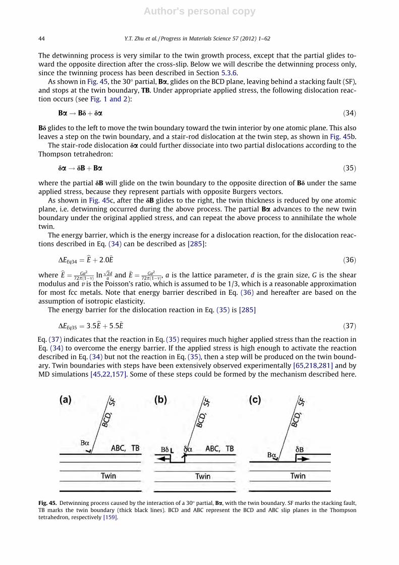
Author's personal copy
The detwinning process is very similar to the twin growth process, except that the partial glides to-ward the opposite direction after the cross-slip. Below we will describe the detwinning process only,since the twinning process has been described in Section 5.3.6.
As shown in Fig. 45, the 30� partial, Ba, glides on the BCD plane, leaving behind a stacking fault (SF),and stops at the twin boundary, TB. Under appropriate applied stress, the following dislocation reac-tion occurs (see Fig. 1 and 2):
Ba! Bdþ da ð34Þ
Bd glides to the left to move the twin boundary toward the twin interior by one atomic plane. This alsoleaves a step on the twin boundary, and a stair-rod dislocation at the twin step, as shown in Fig. 45b.
The stair-rode dislocation da could further dissociate into two partial dislocations according to theThompson tetrahedron:
da! dBþ Ba ð35Þ
where the partial dB will glide on the twin boundary to the opposite direction of Bd under the sameapplied stress, because they represent partials with opposite Burgers vectors.
As shown in Fig. 45c, after the dB glides to the right, the twin thickness is reduced by one atomicplane, i.e. detwinning occurred during the above process. The partial Ba advances to the new twinboundary under the original applied stress, and can repeat the above process to annihilate the wholetwin.
The energy barrier, which is the energy increase for a dislocation reaction, for the dislocation reac-tions described in Eq. (34) can be described as [285]:
DEEq34 ¼ bE þ 2:0~E ð36Þ
where bE ¼ Ga2
72pð1�mÞ lnffiffi2p
da and ~E ¼ Ga2
72pð1�mÞ, a is the lattice parameter, d is the grain size, G is the shearmodulus and v is the Poisson’s ratio, which is assumed to be 1/3, which is a reasonable approximationfor most fcc metals. Note that energy barrier described in Eq. (36) and hereafter are based on theassumption of isotropic elasticity.
The energy barrier for the dislocation reaction in Eq. (35) is [285]
DEEq35 ¼ 3:5bE þ 5:5~E ð37Þ
Eq. (37) indicates that the reaction in Eq. (35) requires much higher applied stress than the reaction inEq. (34) to overcome the energy barrier. If the applied stress is high enough to activate the reactiondescribed in Eq. (34) but not the reaction in Eq. (35), then a step will be produced on the twin bound-ary. Twin boundaries with steps have been extensively observed experimentally [65,218,281] and byMD simulations [45,22,157]. Some of these steps could be formed by the mechanism described here.
Fig. 45. Detwinning process caused by the interaction of a 30� partial, Ba, with the twin boundary. SF marks the stacking fault,TB marks the twin boundary (thick black lines). BCD and ABC represent the BCD and ABC slip planes in the Thompsontetrahedron, respectively [159].
44 Y.T. Zhu et al. / Progress in Materials Science 57 (2012) 1–62

Author's personal copy
7.2. Transmission of a 30� partial across twin boundary
As shown in the double Thompson tetrahedron (Fig. 44), the tetrahedron in the matrix and the tet-rahedron in the twin share the same base, which is ABC, as shown in Fig. 44. In other words, disloca-tions with Burgers vectors of AB, BC, CA, Ad, Bd, and Cd can slip both in the matrix and in the twin. The30� partial, Ba, on the BCD slip plane in the matrix, can have the following dislocation reaction to re-lease another partial in the twin:
Ba! Ba0 þ a0a ð38Þ
where Ba0 is a partial that can slip away in the twin from the twin boundary on the BCD plane, and a0ais a new type of stationary stair-rod dislocation across the twin boundary. The energy barrier of thedislocation reaction described in Eq. (38) can be calculated as
DEEq38 � 2:7bE þ 4:1~E ð39Þ
This indicates that the energy barrier for the 30� partial, Ba, to transmit across the twin boundary isenergetically plausible under appropriate applied stress.
It can be seen from Fig. 44 that a0a is an edge dislocation with its Burgers vector perpendicular toboth the dislocation line BC and the twin boundary (1 1 1). The dislocation configuration after thereaction is illustrated in Fig. 46, which shows two stacking faults from both sides of the twin boundarymeeting at the twin boundary and connected by the stair-rod dislocation a0a.
7.3. Reaction of a 90� partial at twin boundary [285]
The cross-slip of 90� partials at the coherent twin boundary has been described in Section 5.3.5, andtherefore won’t be discussed here. The energy barrier for the cross-slip of the 90� partials is zero [285].
Below we will describe the transmission of 90� partial across the twin boundary. As shown inFig. 44, the 90� partial Da can dissociate as
Da! Ddþ da ð40Þ
The double Thompson tetrahedron indicates that the Burgers vector Dd is identical to the dD0 in thetwin, i.e. Dd = dD0, which can dissociate into a 90� partial a0D0 and a stair-rod dislocation da0, i.e.
Dd ¼ dD0 ! da0 þ a0D0 ð41Þ
Substituting Eq. (41) into Eq. (40) yields:
Da! daþ da0 þ a0D0 ð42Þ
There are two stair-rod dislocations in Eq. (42). Both of them stay at the twin boundary and couldreact to form a dislocation structure with lower energy. With the help of the double Thompson tetra-hedron, the stair-rod reactions can be described below
Fig. 46. The dislocation configuration after the partial Ba penetrates the twin boundary to release another partial Ba0 on theBCD0 plane inside the twin, leaving a stair-rod dislocation a0a on the twin boundary [285].
Y.T. Zhu et al. / Progress in Materials Science 57 (2012) 1–62 45

Author's personal copy
daþ da0 ! 49
Ad ð43Þ
Substituting Eq. (43) into the Eq. (42) yields
Da! 49
Adþ a0D0 ð44Þ
According to Eq. (44), a partial a0D0 will be emitted from the twin boundary to slip on the BCD0
plane. The partial Da can also transmit across the twin boundary to emit a partial on the ACD0 planeor BAD0 plane [285]:
Da! 29
dCþ b0D0 ð45Þ
and
Da! 29
dBþ c0D0 ð46Þ
The energy barrier for reaction in Eq. (44) is
DEEq44 ¼ 0:6bE þ 1:4~E ð47Þ
The energy barriers for the reactions in Eqs. (45) and (46) are
DEEqs45;46 ¼ 0:1bE þ 0:2~E ð48Þ
Therefore, the energy barriers for dislocation reactions in Eqs. (44)–(46) are very low, which makeit easy for the 90� partial Da to transmit across the twin boundary to emit another 90� partial in thetwin.
7.4. Reaction of a perfect screw dislocation at twin boundary
Assume that a perfect screw dislocation BC glides on the BCD plane toward the twin boundary (seeFig. 44.) It could dissociate into two 30� partials with a stacking fault in between, i.e.
BC! Baþ aC ð49Þ
When this dissociated BC reaches the twin boundary, it could constrict to form a perfect dislocationagain. Since BC is parallel to the dislocation line, it can either cross-slip into the ABC plane on the twinboundary, or onto the BCD0 plane in the twin, depending on the orientation of the applied stress.Therefore, a screw dislocation can easily cross-slip on the twin boundary or transmit across the twinboundary.
If the stacking fault energy is very low, a scenario could occur where the leading partial cross-slipsinto the ABC plane while the trailing partial remains on the BCD plane, with a stair-rod dislocation atthe twin boundary linking the stacking fault with the twin boundary.
7.5. Reaction of a perfect 60� dislocation at twin boundary
Assume that a perfect 60� dislocation BD glides on the BCD plane toward the twin boundary (seeFig. 44). It could dissociate into a 30� partial Ba and a 90� partial aD with a stacking fault betweenthem, i.e. BD ? Ba + aD. Partials Ba and aD with a stacking fault ribbon between them glide togethertoward the twin boundary under applied stress. There are several plausible scenarios that could occurat the twin boundary, these are described below.
7.5.1. Partials first constrict to form a perfect 60� dislocationThe first scenario is where the partials are constricted to form the perfect dislocation BD first. Such
a scenario can happen easily when the stacking fault energy is relatively high and the distance of theleading and trailing partials is small. It can be seen from the double Thompson tetrahedron (Fig. 44)
46 Y.T. Zhu et al. / Progress in Materials Science 57 (2012) 1–62

Author's personal copy
that BD has a 60� angle with the dislocation line BC. The dislocation reaction for BD to cross-slip ontothe ABC plane is BD ? BC + CD. The energy barrier for such a reaction is 6bE, which is so high that sucha cross-slip is almost impossible [285].
The perfect 60� dislocation BD can also transmit across the twin boundary to emit a perfect dislo-cation in the twin. The following analysis yields possible dislocation reactions. First, BD can dissociateaccording to
BD! Bdþ dD ð50Þ
where dD is equivalent to D0d, which can further react to emit perfect dislocations in the twin accord-ing to
dD ¼ D0d! D0Bþ Bd ð51Þ
dD ¼ D0d! D0Aþ Ad ð52Þ
dD ¼ D0d! D0Cþ Cd ð53Þ
Substituting Eqs. (51)–(53) into Eq. (50), and also considering Bd + Ad = dC, and Bd + Cd = dA, we have
BD! 2Bdþ D0B ð54Þ
BD! dCþ D0A ð55Þ
BD! dAþ D0C ð56Þ
The energy barrier is �4.5bE for the dislocation reaction in Eq. (54), and 3bE in Eqs. (55) and (56).In reactions described by Eqs. (55) and (56), one partial will glide on the twin plane, which will
grow or shrink the twin by one atomic plane and leave behind a step on the twin boundary dependingon the gliding direction. At the same time a perfect 60� dislocation is emitted in the twin, which willalso produce a step on the twin boundary. In comparison, the dislocation reaction in Eq. (54) will re-lease two partials on the ABC plane to grow or shrink the twin by two atomic planes, which is why ithas higher energy barrier.
7.5.2. 30� leading partial reacts first at twin boundaryThe 60� dislocation BD glides on the BCD plane toward the twin boundary. It can dissociate as
BD ? Ba + aD, with the 30� partial Ba as the leading partial. The leading partial Ba could eithercross-slip onto the twin boundary plane or transmit across the twin boundary. The reaction of theleading partial is identical to what are described in Sections 7.1 and 7.2. The trailing partials can eitherstay on the original slip plane in the matrix, cross-slip onto the twin boundary, or transmit across thetwin boundary. We will discuss these scenarios below.
The first scenario is the cross-slip of leading 30� partial Ba onto the twin boundary plane, while thetrailing 90� partial aD remains on the BCD plane, forming a dislocation structure with a stair-rod dis-location, as shown in Fig. 47a. Such a dislocation structure has been observed both experimentally andby MD simulations [46,47,77]. It has been assumed very effective in blocking other dislocations andconsequently causes strain hardening [77].
As shown in Fig. 47a, under high applied stress, the trailing partial aD may be driven to the twinboundary to react with the stair-rod dislocation da:
daþ aD! dD ð57Þ
From the double Thompson tetrahedron, dD is equivalent to D0d. The latter can dissociate as D0d ?D0a0 + a0d. Therefore, Eq. (57) can be rewritten as
daþ aD! D0a0 þ a0d ð58Þ
The energy barrier for this reaction is 0. This scenario is schematically illustrated in Fig. 47b.
Y.T. Zhu et al. / Progress in Materials Science 57 (2012) 1–62 47

Author's personal copy
The second scenario is for the leading 30� partial Ba to transmit across the twin boundary. As dis-cussed in Section 7.2, the 30� partial Ba may transmit across the twin boundary, leaving behind a largestair rod dislocation aa0. If the trailing partial aD remains on the BCD plane, it will have a unique dis-location configuration where a stacking fault links the aa0 with partial Ba0, and another stacking faultlinks the aa0 with the trailing partial aD, as sown in Fig. 48a. The trailing partial aD can also cross-sliponto the twin boundary plane, becoming a partial dA to slip to the left to increase the twin by oneatomic plane, as shown in Fig. 48b.
The third scenario is for the stair-rode dislocation da in Fig. 47a to further dissociate into two par-tial dislocations, da ? dB + Ba, where the partial dB glides on the twin boundary to the opposite direc-tion of Bd to reduce the twin thickness by one atomic plane, as illustrated in Fig. 47c. Such a processcan be repeated to reduce the twin, as described in Section 7.1. The energy barrier for such a reaction isabout 3.5bE, making it relatively difficult.
The trailing 90� partial aD can also react with the stair-rod aaand transmit across the twin bound-ary [285]. However, the dislocation reactions have very high energy barriers, and are not likely to oc-cur [285]. Therefore, the transmission of the trailing 90� partial will not be discussed in detail here.
7.5.3. 90� leading partial reacts first at twin boundaryIf the 90� partial aD is the leading partial, aD could either cross-slip onto the twin boundary plane
or transmit across the twin boundary. The first scenario is for the 90� leading partial to cross-slip ontothe twin boundary plane ABC, as described in Section 7.3. The trailing partial Ba can also cross-sliponto the twin boundary to form Bd on the ABC plane, following the procedure described in Section7.1, leaving behind a stair-rod dislocation da. Bd and dA can glide together on the twin boundary witha stacking fault between them. On the other hand, the trailing 30� partial Ba can also transmit acrossthe twin boundary to emit a parital Ba0 in the twin, as described in Section 7.2. This leaves behind astair-rod a0a at the twin boundary.
Fig. 47. Reaction of dissociated 60� dislocation BD with a 30� leading partial at the twin boundary. (a) The leading partial cross-slips onto the ABC twin boundary, leaving behind a stair-rod dislocation and the 90� trailing partial still on the original BCD slipplane. (b) After the trailing partial aD reacts with the stair-rod dislocation da and transmit across the twin boundary. (c) Thestair-rod dislocation dissociates according to da ? dB + Ba to reduce the twin by one atomic layer [285].
Fig. 48. (a) Dislocation configuration after the leading 30� partial Ba transmits across twin boundary and the trailing 90� partialaD remains on the BCD plane. (b) After the trailing partial aD cross-slips into the ABC plane to grow the twin by one atomicplane [285].
48 Y.T. Zhu et al. / Progress in Materials Science 57 (2012) 1–62
Author's personal copy
The second scenario is for the leading partial aD to transmit across the twin boundary, as describedin Section 7.3. The 90� partial aD can transmit across the twin boundary after one of the followingreactions:
aD! adþ a0dþ D0a0 ð59Þ
aD! adþ b0dþ D0b0 ð60Þ
and
aD! adþ c0dþ D0c0 ð61Þ
where the partial dislocations D0a0, D0b0, or D0c0 will glide away in the twin, leaving behind two stairrod dislocations at the twin boundary. When the trailing 30� partial Ba reaches the twin boundary, itcan react with stair-rod dislocation, i.e.
Baþ ad! Bd ð62Þ
This reaction is energetically favorable with an energy reduction of �bE. The Bd can glide on the ABCplane, which either increase or reduce the twin thickness by one atomic plane, depending on its slipdirection.
The trailing partial Ba can also react with stair-rod dislocations (as shown in Eqs. (59)–(61)) at thetwin boundary to release a Shockley partial dislocation in the twin:
Baþ adþ a0d! Ba0 þ 2a0d ð63Þ
Baþ adþ b0d! Ba0 þ a0dþ b0d ð64Þ
and
Baþ adþ c0d! Ba0 þ a0dþ c0d ð65Þ
A first inspection suggests that the energy barrier should be zero for the reactions in Eqs. (63)–(65)because the number of partial dislocations and stair-rod dislocations does not change. However, thereacting stair-rod dislocation pairs on the left can combine to form a dislocation with lower energy,while the stair-rod dislocation pairs on the right form a dislocation with higher energy when theycombine together [285]. This energy differences can be regarded as the energy barrier, which areabout 3.4bE for Eq. (63) and 2.8bE for Eqs. (64) and (65). Therefore, the energy barrier for the trailingpartial to transmit across the twin boundary is relatively high.
8. Effect of twinning on properties
The interaction between the twin boundary and dislocations will inevitably affect the mechanicaland physical properties. The existence of twin boundaries significantly increases the dislocation stor-age capability in materials, and twin structure may also affect physical properties. These are discussedin the following sections. Since deformation twins and growth twins should have similar effect on theproperties, no differentiation is made between them in the following discussion.
8.1. Strain rate sensitivity
Strain rate sensitivity (SRS) m is defined as m ¼ @ lnrr@ ln _e
��e;T , where r is the flow stress and _e is the strain
rate [287]. By defining the activation volume, which is the rate of decrease of the activation enthalpywith respect to flow stress at a fixed temperature, m� ¼
ffiffiffi3p
kT @ ln _e@ lnr
, where k is the Boltzmann constant
and T is the absolute temperature, SRS can be re-written as m ¼ffiffi3p
kTrm� [287,288]. Experimental results
have shown that nc materials are highly sensitive to strain rates and that the SRS of nominally defect-free nc Cu and Ni are several times higher than that of their coarse-grained counterparts [289–291].The activation volume of nc materials is about two order of magnitude smaller than that of conven-tional coarse-grained materials [288].
Y.T. Zhu et al. / Progress in Materials Science 57 (2012) 1–62 49

Author's personal copy
Tensile strain rate jump tests of UFG copper with and without nanoscale twins over a wide range ofstrain rates indicated that twinned structures significantly increase the strain rate sensitivity [195].Fig. 49 shows that increasing strain rate reduces moderately the SRS of twinned samples, while theSRS of the untwinned sample is independent of the strain rate. The SRS of nano-twinned Cu samplewith a small twin boundary spacing of 15 nm is significantly higher than that of the nano-twinnedCu sample with a larger twin boundary spacing of 100 nm, while the SRS of the untwinned sampleis the lowest among the three samples.
Lu et al. [292] carried out a series of systematic experiments of depth-sensing instrumented inden-tation with varying loading rates by three orders of magnitude, demonstrating that increasing thedensity of growth twins in UFG pure Cu leads to a significant increase in the strain rate-sensitivity.Fig. 50 shows nanoindentation hardness plotted as a function of loading rate for UFG Cu with differenttwin densities. By assuming indentation hardness and loading rate are equivalent to stress and strainrate, respectively, the SRS m for the three materials are calculated using the relationship of r / _em. Theresults indicate that the SRS m for Cu with a lower twin density (average twin boundary spacing�90 nm) and with a higher twin density (twin boundary spacing �20 nm) is 0.025 ± 0.009 and0.036 ± 0.009, while the SRS for UFG Cu without twin, evaluated from tension tests instead of inden-tation because of the large scatter in the indentation response, is only 0.005 ± 0.001. TEM microstruc-tural investigation suggested that deformation-induced displacement of coherent twin boundaries(CTBs), formation of steps and jogs along CTBs, and blockage of dislocations at CTBs significantly
Fig. 50. The hardness as a function of loading for UFG coppers with no twin, twin boundary spacing is 90 nm, and twinboundary spacing is 20 nm [292].
Fig. 49. The strain rate sensitivity as a function of (a) strain rate and (b) grain size for UFG coppers with no twin, twin boundaryspacing is 100 ± 15 nm, and twin boundary spacing is 15 ± 7 nm [195].
50 Y.T. Zhu et al. / Progress in Materials Science 57 (2012) 1–62

Author's personal copy
influence the evolution of thermal activation volume for plastic flow, which is some three orders ofmagnitude smaller than that known for microcrystalline Cu.
Lu et al. [293] summarized the experimental results on the effect of twin lamellar thickness d (or k)on the strain rate sensitivity m of nano-twinned copper, as shown in Fig. 51. They reported that m canbe one order of magnitude higher than conventional coarse-grained materials when k is reduced downto about 15 nm. For comparison purpose, the m values of nanocrystalline copper, with grain size dreplacing twin lamellar thickness k, are also plotted in the figure. It is very clear that the dependenceof m on k and d are very similar.
Asaro and Suresh [29] proposed that the rate-controlling mechanism for nc materials is grainboundary mediated dislocation activity, which is different from the bulk dislocation–dislocation inter-action (forest hardening) in coarse-grained materials [294]. They developed mechanism-based modelsthat rationalize the distinct deformation characteristics of fcc metals with grain size and twin dimen-sions in the nanometer regime. They developed estimates of flow stress as a function of strain rate andactivation volume by exploring the roles of crystal stacking energies, such as the intrinsic stackingfault and the unstable stacking fault energy, in the process of initiating deformation via the emissionof either partial dislocations or perfect dislocations from the grain or twin boundaries of nc FCC met-als. Results obtained from their models are consistent with available experimental data on activationvolumes and rate sensitivity in both a quantitative and qualitative manner.
8.2. Strain hardening rate
For coarse-grained materials, twinning has been known to contribute significantly to plastic defor-mation in materials with low SFE [295,296]. Higher rates of strain hardening have been reported inlow SFE alloys due to deformation twinning that acts as strong barriers to dislocation motion, whichconsequently resulted in higher tensile ductility [297–302]. Through the analysis of the barriers to slipcaused by twinning in an fcc crystal, Mahajan and Chin [74] predicted that the strain-hardening rateshould be increased by the formation of twins. The prediction was supported by experimental resultson polycrystalline coarse-grained FCC 70/30 brass and MP35 N with low stacking fault energies[81,303]. Ma et al. reported that the strain hardening rate of nano-twinned copper is much higher thanthat of UFG Cu [304].
Chen and Lu [305] measured the strain hardening rates of four UFG Cu samples – nt-Cu-20 withtwin spacing of �20 ± 4 nm (nt = nanotwin), nt-Cu-36 with twin spacing of �36 ± 7 nm, nt-Cu-90 withtwin spacing of 90 ± 26 nm, and UFG-Cu without twin, using uniaxial tensile tests. Fig. 52 shows strainhardening rates plotted against the true strain for the four samples. As shown, the strain-hardeningrate is achieved in nt-Cu-20 at stresses that is higher than that of the other three samples. The higheststrain-hardening rate is also seen in nt-Cu-20 over a range of strains. Comparison of the values of thestrain hardening rates obtained from the three nt-Cu specimens leads to the conclusion that introduc-ing nanoscale twins into UFG grains enhances strain hardening rate significantly.
Fig. 51. The effect of the twin lamellar thickness d (or k) on the strain rate sensitivity m [283].
Y.T. Zhu et al. / Progress in Materials Science 57 (2012) 1–62 51

Author's personal copy
8.3. Strength and ductility
It has been well accepted that twin boundaries are equivalent to conventional grain boundarieswith respect to the H–P effect [306–312], i.e., the same H–P slope for both twin boundaries and grainboundaries [290], because twin boundaries are strong barriers for dislocation motion [310–313]. Sig-nificant enhancement of tensile strength in copper [40,314] and hardness in fcc c phase 330 stainlesssteel thin films [315] as well as fcc Cu/330 stainless steel multilayer films [316,317] was achieved bynano twins. Growth twins in Copper [291] and Nickel [195] and deformation twins in steel [292] withtwin boundary spacing of tens to hundreds of nanometers show H–P behavior.
Nano-twinned FCC 330 stainless steel [294] with an average columnar grain size of �30 nm and anaverage twin spacing of �4 nm is observed to have a hardness of �6.5 GPa, while the hardness of bulkconventional 330 SS is only �200 MPa. However, the hardness value cannot be explained using the H–P relationship extrapolated from data of other similar steels [294]. This phenomenon is explained asthat, instead of dislocation pile-ups at twin boundaries, materials with this extremely fine twin spac-ing are strengthened via single dislocations transmission across twin boundaries, in which the twinboundaries act as strong barriers for the transmission of dislocations. The mechanism has also beenused to explain the observed phenomena that in FCC Cu/330 stainless steel multilayer films with highdensities of twins in the nano Cu and 330 SS layers, the increase of hardness with decreasing layerthickness follows the Hall–Petch law for layer thickness greater than about 50 nm, but at lower layerthickness the hardness saturates to a value of about 5 GPa [296].
Lu et al. [41] reported that reducing the thickness of twins down to 15 nm in nano-twinned (nt) Cusamples resulted in continuous increase in strength. However, further reducing the thickness resultedin softening accompanied by enhanced strain hardening and tensile ductility, i.e., the maximumstrength of nt-Cu samples exists at a twin thickness of 15 nm (see Fig. 53). They suggested that thestrongest twin thickness originates from a transition in the yielding mechanism from the slip transferacross twin boundaries to the activity of preexisting easy dislocation sources. Curves for a twin-freeUFG-Cu with a mean grain size of 500 nm and for a coarse-grained-Cu with a mean grain size of10 mm are included for the comparison purpose.
The maximum strength observed by Lu et al. [41] is consistent with an MD simulation [50],and was further investigated using large-scale MD simulations and a kinetic theory of dislocationnucleation by Li et al. [318]. They proposed a dislocation–nucleation-controlled mechanism in
Fig. 52. The strain hardening rates of four copper samples measured by tensile tests: nano twinned sample with a twin spacingof 20 nm (nt-20 nm), nano twinned sample with a twin spacing of 36 nm (nt-36 nm), nano twinned sample with a twin spacingof 90 nm (nt-90 nm), and UFG sample without twin [305].
52 Y.T. Zhu et al. / Progress in Materials Science 57 (2012) 1–62

Author's personal copy
nano-twinned metals, in which there are plenty of dislocation nucleation sites but dislocation motionis not confined. They showed that dislocation nucleation governs the strength of such materials,resulting in the softening of the materials below a critical twin thickness. They found that there existsa transition in deformation mechanism, occurring at a critical twin-boundary spacing for whichstrength is maximized. At this point, the classical Hall–Petch type of strengthening due to dislocationpile-up and cutting through twin planes switches to a dislocation–nucleation-controlled softeningmechanism with twin-boundary migration resulting from nucleation and motion of partial dislocationsparallel to the twin planes.
Deformation twins produced by plastic deformation can also significantly improve the strength andductility of nanostructured materials [51,153,221,319,320]. It has been reported that lowering SFE cansimultaneously increase the strength and ductility of nanostructured materials [51]. Zhao et al. pro-duced nanostructured Cu, Cu–10 wt.% Zn, and Cu–30 wt.% Zn alloys using HPT to study their mechan-ical properties. Their stacking fault energies decrease with increasing Zn content and are 41 mJ/m2,22 mJ/m2, and 7 mJ/m2, respectively [221,321]. TEM and X-ray analysis revealed that as the stackingfault energy decreased from 41 mJ/m2 to 7 mJ/m2, the grain size decreased from 180 nm to 10 nm, thedislocation density increased from 0.23 � 1015 m�2 to 3.10 � 1015 m�2, and twin density, defined asthe probability of finding a twin boundary between any two adjacent {1 1 1} planes, increased from0.1% to 8.0% [221].
Fig. 54 shows the engineering stress–strain curves of the three samples. As shown, the strength in-creases monotonically with decreasing stacking fault energy. However, the ductility first increases(the Cu–10 wt.% Zn sample) and then decreases, indicating an optimum stacking fault energy forthe best ductility. X-ray analysis revealed that the Cu–10 wt.% Zn sample has the best capability toaccumulate dislocations, twins and stacking faults, and therefore has the highest hardening capabilityduring the tensile testing. On the other hand, the Cu–30 wt.% Zn sample has the highest densities oftwins and dislocations, which are already saturated before the tensile testing, making it impossibleto further accumulate these crystalline defects during the tensile testing. This leads to very low strainhardening rate and consequently low ductility. It will be interesting to see if a controlled annealing ofthe sample could reduce the initial defect density and recover the strain hardening.
Note that the strength increase shown in Fig. 54 is partially caused by the solution hardening of theZn solute. To isolate the effect of stacking fault energy, Sun et al. recently investigated the Co–Ni alloy,which has a systematic decrease in stacking fault energy with increasing Co content, but very littlesolution hardening [319]. The results confirmed that lower stacking fault energy improves both
Fig. 53. Tensile true stress–strain curves of nano twinned copper tested at a strain rate of 6 � 10�2 s�1 [41].
Y.T. Zhu et al. / Progress in Materials Science 57 (2012) 1–62 53

Author's personal copy
strength and ductility of NS materials. These data are very preliminary and further study is needed toprobe this issue, especially when the stacking fault energy is very low.
8.4. Fatigue
This has not been extensively studied. A study on the effect of cyclic deformation on multilayer Cu/Cu samples with nanoscale twinning showed that (1) nano-twinned Cu is much more stable undercyclic deformation than equiaxed nanocrystalline Cu and (2) the fatigue of nano-twinned Cu is im-proved significantly over that of coarse-grained Cu [322]. However, although twin boundaries arestrong in resisting fatigue cracking, it is also observed that some fatigue cracks could propagate alongthe twin boundary [323]. Another recent study found that detwinning happened during the cyclicdeformation of nanocrystalline NiFe [324].
8.5. Conductivity
It is desirable for conducting metals to have both high strength and high electrical conductivity formany applications. However, many strengthening mechanisms including grain size refinement, coldworking and alloying produce crystalline imperfections that serve as the scattering centers for con-duction electrons in metals and therefore lower the conductivity. On the other hand, coherent twinboundaries, which are very effective in increasing strength, have an electron scattering coefficient thatis an order of magnitude lower than that of conventional high-angle grain boundaries. Indeed, Andero-glu et al. reported that single-crystal-like nano-twinned copper films with average twin lamella thick-ness of 7–16 nm produced by magnetron sputtering exhibited much higher ratio of conductivity tostrength as compared to nc columnar, textured, nano-twinned copper [325].
Lu et al. synthesized pure copper samples with a high density of nanoscale growth twins [40]. Theyshowed a tensile strength about 10 times higher than that of conventional coarse-grained copper,while retaining an electrical conductivity comparable to that of pure copper. In comparison, the elec-trical conductivity values of the nc Cu foil without twins were at least one order of magnitude lower.The electrical resistivity can be described using the empirical Matthiessen’s Rule, qtotal = qt + qi + qd,where qtotal is the total resistivity of a metal, qt, qi, and qd are the contributions from vibrations, impu-rities, and lattice defects such as dislocations and grain boundaries, respectively. The difference in thelattice dislocation density among the samples could be ignored, the major factor that contributes tothe difference in electrical resistivity should be grain boundaries and twin boundaries. It has been
Fig. 54. The engineering stress–strain curves Cu, Cu–10 wt.% Zn, and Cu–30 wt.% Zn samples processed by HPT [221]. The gagedimension is 0.15 mm � 2 mm � 10 mm.
54 Y.T. Zhu et al. / Progress in Materials Science 57 (2012) 1–62
Author's personal copy
known that electrical resistivity of grain boundaries [326] and twin boundaries [327] in Cu at 295 K isabout 3.6 � 10�16 X m2 and about 1.7 � 10�17 X m2, respectively. Therefore, the contribution to elec-trical conductivity from twin boundaries is much smaller than that from grain boundaries. This ex-plains why the nano-twinned samples have conductivity that is close to that of the coarse-grained Cu.
9. Outstanding issues
There are still many outstanding issues for the materials community to solve. Most studies ondeformation twinning in nc metals have focused on the fcc systems, while very few studies have con-cerned the nc bcc and hcp metals and alloys. Furthermore, the mechanisms for the formation of defor-mation twins are not very well studied even for coarse-grained bcc and hcp metals and alloys.Although the twinning mechanisms for coarse-grained and nc hcp metals are already under investi-gation [159–161,163,166,170,241,273,277,328–333], it is not clear if the twinning phenomena andmechanisms observed in nc fcc metals also occur in nc bcc and fcc systems. For example, it is un-known if the grain size effect on deformation twinning observed in nc fcc metals also exists in ncbcc and hcp metals. In fact, as discussed in Section 6.2, deformation twinning is rarely observed innc hcp systems. It will take significant efforts by researchers using both MD simulation and experi-mental observations to establish the basic understanding of deformation twinning in nc bcc andhcp metals and alloys.
Even for nc fcc metals and alloys, there are still issues that need further study. As discussed in Sec-tion 5.8.5, to establish a comprehensive model to describe the twinning behavior of nc fcc metals, weneed to understand how the GPFEs affect the nucleation of first partials and twinning partials. Cur-rently, it is not clear if the GPFE curves affect the nucleation of dislocations since non-equilibriumgrain boundaries existing in nc metals can also act as a dislocation source. More experimental studiesare needed to clarify this issue. In addition, the GPFEs may also affect the slip of the first and twinningpartials. Theoretical modeling is needed to develop a formula for calculating the Peierls stress for theslip of these partials from the GPFEs.
Another outstanding issue is the grain size effect on the detwinning in nc metals and alloys.Almost all studies so far have focused on the formation of deformation twins. There have beenrecent studies on the detwinning process in nc materials also occurs in the nc fcc metals[131,156,227,246,285,286,334,335]. However, issues that are of interest for future studies include:(a) more experimental observations on the de-twinning process to compare with the proposed mech-anisms [285,335], (b) the grain size effect of de-twinning, and (c) the existence of an equilibrium twindensity and thickness.
10. Implications of deformation twinning within materials science
The discovery of new mechanisms for the formation of deformation twins in nc fcc metals has sig-nificantly extended our understanding of the deformation physics of metals and alloys as well as therole of grain boundaries in the deformation of fcc metals. It gives us a more complete picture on howthe deformation mechanisms change with grain size [3]. As the grains of an fcc metal become smaller,dislocation sources that are active in coarse-grains, such as the Frank-Reed dislocation source, becomeinactive or more and more marginalized. Concurrently, grain boundary-mediated deformation mech-anisms become active and eventually dominant [336]. In grain size range of a few tens to above100 nm, grain boundaries become the source and sink of dislocations. Particularly, the emission of par-tial dislocations from grain boundaries becomes significant in nc fcc metals, even in systems withmedium to high stacking fault energies. This leads to the formation stacking faults and deformationtwins, which also shows grain size dependence. When the grain sizes decrease further, grain rotationand grain boundary sliding becomes dominant, which may also be assisted by diffusion and disloca-tion activities.
The new deformation mechanisms and deformation twinning discussed in this paper also providefundamental physics for materials scientists to model the mechanical behavior of nc materials. Forexample, the strength of nc materials have been observed to deviate from the Hall–Petch relationship,
Y.T. Zhu et al. / Progress in Materials Science 57 (2012) 1–62 55
Author's personal copy
and even exhibit an inverse Hall–Petch relationship in some cases. Numerous analytical models andcomputational simulations have been carried out to describe and investigate this phenomenon[336–355]. The analytical Hall–Petch models are based on various assumptions and all of them canqualitatively describe the inverse grain size effect on strength. This makes it difficult to judge whichmodels are physically better and more valuable. Any valuable analytical model or computer simula-tion on the mechanical properties must be based on real deformation physics. It is hoped that thedeformation physics and deformation twinning of nc materials discussed in this review will be usefulfor future modeling of mechanical properties.
The deformation twinning also provides an effective approach for simultaneously improve thestrength and ductility of nc materials, as discussed in Section 8.3. Due to the lack of dislocation accu-mulation in the interior of grains, nc materials usually have low tensile ductility. The twins could actas the barrier to dislocation slip and to enable dislocation accumulation, which increases both thestrength and ductility. However, the effect of twins and deformation twinning on many other mechan-ical and physical properties needs to be further studied.
11. Summary and concluding remarks
In summary, nanocrystalline fcc metals deform by twinning more readily than their coarse-grainedcounterparts. Deformation twins in nanocrystalline fcc metals are largely formed by the emissions ofShockley partial dislocations from grain boundaries of nano-sized grains. In other words, the grainboundary acts as the source of partial dislocations in most cases. Another important source for partialdislocations is the dislocation reactions at the twin boundaries, which is the primary mechanism forthe formation of multiple twins. Non-equilibrium grain boundaries play an important role in thedeformation twinning because they may provide ready partials for the nucleation of stacking faultsand twins. The partials emitted from grain boundaries may not have the same Burgers vector, whichleads to twins with reduced or even zero shape change in the twinned grain. This is in sharp contrastto twins formed by mechanisms in coarse-grained metals, which have the same Burgers vector.
Both grain size and generalized stacking fault energy influences the formation of deformation twinsin nanocrystalline fcc metals. There is an optimum grain size in nanocrystalline fcc metals at which thetwinning is easiest, and this optimum grain size can be estimated from an analytical equation. Factorsthat affect the optimum grain size for twinning include the stacking fault energy and the shear mod-ulus. When grains are smaller than the optimized grain size for twinning, an inverse grain size effectexists, where the twinning becomes more difficult with decreasing grain size. However, no inversegrain size effect on stacking fault formation exists. This difference is explained by the generalized pla-nar fault energy effect, where the unstable twin fault energy is higher than unstable stacking fault en-ergy. Therefore, both grain size effect and the generalized planar fault energy effect need to beconsidered in an analytical model to describe more accurately the twinning mechanisms in nanocrys-talline fcc metals. Such a model is yet to be developed.
Deformation twinning and dislocation slip usually occur simultaneously during the deformation ofnanocrystalline metals. The interactions of the dislocations with twins are very complex and the pro-posed interactions need to be further verified experimentally. Twin boundaries are effective barriers todislocation slip, and consequently twins can increase the strength of nanocrystalline and nanostruc-tured materials. Twins are also found to increase the strain hardening rate and the strain rate sensi-tivity, which leads to increase in ductility. Therefore, twinning is a mechanism that cansimultaneously increase the strength and ductility. In the design of new nanocrystalline alloys for highstrength, ductility and toughness, stacking fault energy can be adjusted by alloying to promote defor-mation winning.
Acknowledgements
YTZ acknowledge the support by the US Army Research Office under the Grant W911NF-09-1-0427, and the US Army Research Office under the Grant W911QX-08-C-0083. XZL acknowledge the
56 Y.T. Zhu et al. / Progress in Materials Science 57 (2012) 1–62
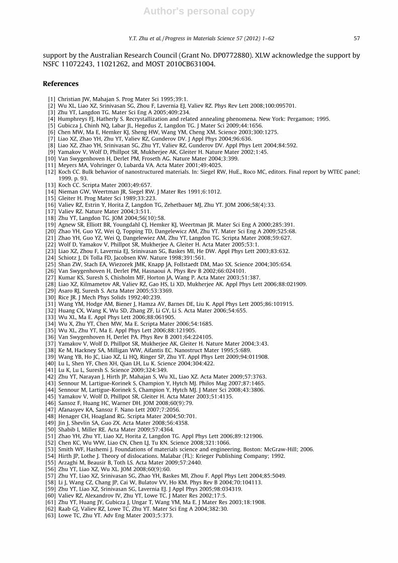
Author's personal copy
support by the Australian Research Council (Grant No. DP0772880). XLW acknowledge the support byNSFC 11072243, 11021262, and MOST 2010CB631004.
References
[1] Christian JW, Mahajan S. Prog Mater Sci 1995;39:1.[2] Wu XL, Liao XZ, Srinivasan SG, Zhou F, Lavernia EJ, Valiev RZ. Phys Rev Lett 2008;100:095701.[3] Zhu YT, Langdon TG. Mater Sci Eng A 2005;409:234.[4] Humphreys FJ, Hatherly S. Recrystallization and related annealing phenomena. New York: Pergamon; 1995.[5] Gubicza J, Chinh NQ, Labar JL, Hegedus Z, Langdon TG. J Mater Sci 2009;44:1656.[6] Chen MW, Ma E, Hemker KJ, Sheng HW, Wang YM, Cheng XM. Science 2003;300:1275.[7] Liao XZ, Zhao YH, Zhu YT, Valiev RZ, Gunderov DV. J Appl Phys 2004;96:636.[8] Liao XZ, Zhao YH, Srinivasan SG, Zhu YT, Valiev RZ, Gunderov DV. Appl Phys Lett 2004;84:592.[9] Yamakov V, Wolf D, Phillpot SR, Mukherjee AK, Gleiter H. Nature Mater 2002;1:45.
[10] Van Swygenhoven H, Derlet PM, Froseth AG. Nature Mater 2004;3:399.[11] Meyers MA, Vohringer O, Lubarda VA. Acta Mater 2001;49:4025.[12] Koch CC. Bulk behavior of nanostructured materials. In: Siegel RW, HuE., Roco MC, editors. Final report by WTEC panel;
1999. p. 93.[13] Koch CC. Scripta Mater 2003;49:657.[14] Nieman GW, Weertman JR, Siegel RW. J Mater Res 1991;6:1012.[15] Gleiter H. Prog Mater Sci 1989;33:223.[16] Valiev RZ, Estrin Y, Horita Z, Langdon TG, Zehetbauer MJ, Zhu YT. JOM 2006;58(4):33.[17] Valiev RZ. Nature Mater 2004;3:511.[18] Zhu YT, Langdon TG. JOM 2004;56(10):58.[19] Agnew SR, Elliott BR, Youngdahl CJ, Hemker KJ, Weertman JR. Mater Sci Eng A 2000;285:391.[20] Zhao YH, Guo YZ, Wei Q, Topping TD, Dangelewicz AM, Zhu YT. Mater Sci Eng A 2009;525:68.[21] Zhao YH, Guo YZ, Wei Q, Dangelewiez AM, Zhu YT, Langdon TG. Scripta Mater 2008;59:627.[22] Wolf D, Yamakov V, Phillpot SR, Mukherjee A, Gleiter H. Acta Mater 2005;53:1.[23] Liao XZ, Zhou F, Lavernia EJ, Srinivasan SG, Baskes MI, He DW. Appl Phys Lett 2003;83:632.[24] Schiotz J, Di Tolla FD, Jacobsen KW. Nature 1998;391:561.[25] Shan ZW, Stach EA, Wiezorek JMK, Knapp JA, Follstaedt DM, Mao SX. Science 2004;305:654.[26] Van Swygenhoven H, Derlet PM, Hasnaoui A. Phys Rev B 2002;66:024101.[27] Kumar KS, Suresh S, Chisholm MF, Horton JA, Wang P. Acta Mater 2003;51:387.[28] Liao XZ, Kilmametov AR, Valiev RZ, Gao HS, Li XD, Mukherjee AK. Appl Phys Lett 2006;88:021909.[29] Asaro RJ, Suresh S. Acta Mater 2005;53:3369.[30] Rice JR. J Mech Phys Solids 1992;40:239.[31] Wang YM, Hodge AM, Biener J, Hamza AV, Barnes DE, Liu K. Appl Phys Lett 2005;86:101915.[32] Huang CX, Wang K, Wu SD, Zhang ZF, Li GY, Li S. Acta Mater 2006;54:655.[33] Wu XL, Ma E. Appl Phys Lett 2006;88:061905.[34] Wu X, Zhu YT, Chen MW, Ma E. Scripta Mater 2006;54:1685.[35] Wu XL, Zhu YT, Ma E. Appl Phys Lett 2006;88:121905.[36] Van Swygenhoven H, Derlet PA. Phys Rev B 2001;64:224105.[37] Yamakov V, Wolf D, Phillpot SR, Mukherjee AK, Gleiter H. Nature Mater 2004;3:43.[38] Ke M, Hackney SA, Milligan WW, Aifantis EC. Nanostruct Mater 1995;5:689.[39] Wang YB, Ho JC, Liao XZ, Li HQ, Ringer SP, Zhu YT. Appl Phys Lett 2009;94:011908.[40] Lu L, Shen YF, Chen XH, Qian LH, Lu K. Science 2004;304:422.[41] Lu K, Lu L, Suresh S. Science 2009;324:349.[42] Zhu YT, Narayan J, Hirth JP, Mahajan S, Wu XL, Liao XZ. Acta Mater 2009;57:3763.[43] Sennour M, Lartigue-Korinek S, Champion Y, Hytch MJ. Philos Mag 2007;87:1465.[44] Sennour M, Lartigue-Korinek S, Champion Y, Hytch MJ. J Mater Sci 2008;43:3806.[45] Yamakov V, Wolf D, Phillpot SR, Gleiter H. Acta Mater 2003;51:4135.[46] Sansoz F, Huang HC, Warner DH. JOM 2008;60(9):79.[47] Afanasyev KA, Sansoz F. Nano Lett 2007;7:2056.[48] Henager CH, Hoagland RG. Scripta Mater 2004;50:701.[49] Jin J, Shevlin SA, Guo ZX. Acta Mater 2008;56:4358.[50] Shabib I, Miller RE. Acta Mater 2009;57:4364.[51] Zhao YH, Zhu YT, Liao XZ, Horita Z, Langdon TG. Appl Phys Lett 2006;89:121906.[52] Chen KC, Wu WW, Liao CN, Chen LJ, Tu KN. Science 2008;321:1066.[53] Smith WF, Hashemi J. Foundations of materials science and engineering. Boston: McGraw-Hill; 2006.[54] Hirth JP, Lothe J. Theory of dislocations. Malabar (FL): Krieger Publishing Company; 1992.[55] Arzaghi M, Beausir B, Toth LS. Acta Mater 2009;57:2440.[56] Zhu YT, Liao XZ, Wu XL. JOM 2008;60(9):60.[57] Zhu YT, Liao XZ, Srinivasan SG, Zhao YH, Baskes MI, Zhou F. Appl Phys Lett 2004;85:5049.[58] Li J, Wang CZ, Chang JP, Cai W, Bulatov VV, Ho KM. Phys Rev B 2004;70:104113.[59] Zhu YT, Liao XZ, Srinivasan SG, Lavernia EJ. J Appl Phys 2005;98:034319.[60] Valiev RZ, Alexandrov IV, Zhu YT, Lowe TC. J Mater Res 2002;17:5.[61] Zhu YT, Huang JY, Gubicza J, Ungar T, Wang YM, Ma E. J Mater Res 2003;18:1908.[62] Raab GJ, Valiev RZ, Lowe TC, Zhu YT. Mater Sci Eng A 2004;382:30.[63] Lowe TC, Zhu YT. Adv Eng Mater 2003;5:373.
Y.T. Zhu et al. / Progress in Materials Science 57 (2012) 1–62 57
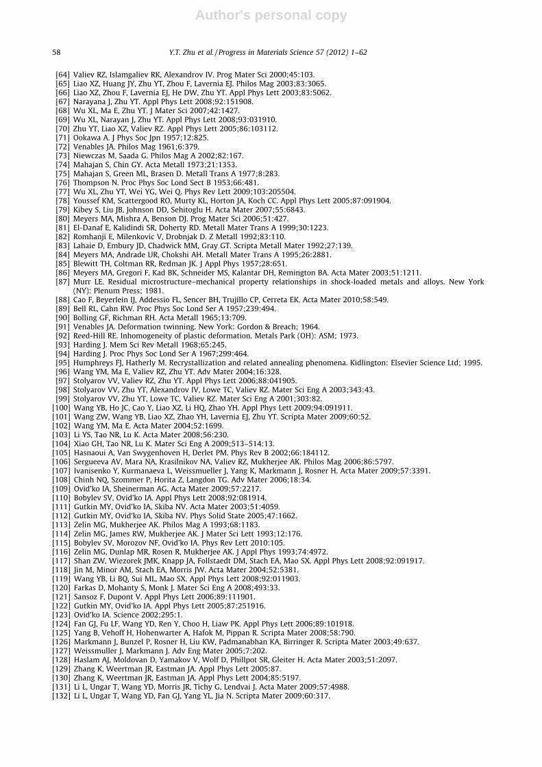
Author's personal copy
[64] Valiev RZ, Islamgaliev RK, Alexandrov IV. Prog Mater Sci 2000;45:103.[65] Liao XZ, Huang JY, Zhu YT, Zhou F, Lavernia EJ. Philos Mag 2003;83:3065.[66] Liao XZ, Zhou F, Lavernia EJ, He DW, Zhu YT. Appl Phys Lett 2003;83:5062.[67] Narayana J, Zhu YT. Appl Phys Lett 2008;92:151908.[68] Wu XL, Ma E, Zhu YT. J Mater Sci 2007;42:1427.[69] Wu XL, Narayan J, Zhu YT. Appl Phys Lett 2008;93:031910.[70] Zhu YT, Liao XZ, Valiev RZ. Appl Phys Lett 2005;86:103112.[71] Ookawa A. J Phys Soc Jpn 1957;12:825.[72] Venables JA. Philos Mag 1961;6:379.[73] Niewczas M, Saada G. Philos Mag A 2002;82:167.[74] Mahajan S, Chin GY. Acta Metall 1973;21:1353.[75] Mahajan S, Green ML, Brasen D. Metall Trans A 1977;8:283.[76] Thompson N. Proc Phys Soc Lond Sect B 1953;66:481.[77] Wu XL, Zhu YT, Wei YG, Wei Q. Phys Rev Lett 2009;103:205504.[78] Youssef KM, Scattergood RO, Murty KL, Horton JA, Koch CC. Appl Phys Lett 2005;87:091904.[79] Kibey S, Liu JB, Johnson DD, Sehitoglu H. Acta Mater 2007;55:6843.[80] Meyers MA, Mishra A, Benson DJ. Prog Mater Sci 2006;51:427.[81] El-Danaf E, Kalidindi SR, Doherty RD. Metall Mater Trans A 1999;30:1223.[82] Romhanji E, Milenkovic V, Drobnjak D. Z Metall 1992;83:110.[83] Lahaie D, Embury JD, Chadwick MM, Gray GT. Scripta Metall Mater 1992;27:139.[84] Meyers MA, Andrade UR, Chokshi AH. Metall Mater Trans A 1995;26:2881.[85] Blewitt TH, Coltman RR, Redman JK. J Appl Phys 1957;28:651.[86] Meyers MA, Gregori F, Kad BK, Schneider MS, Kalantar DH, Remington BA. Acta Mater 2003;51:1211.[87] Murr LE. Residual microstructure–mechanical property relationships in shock-loaded metals and alloys. New York
(NY): Plenum Press; 1981.[88] Cao F, Beyerlein IJ, Addessio FL, Sencer BH, Trujillo CP, Cerreta EK. Acta Mater 2010;58:549.[89] Bell RL, Cahn RW. Proc Phys Soc Lond Ser A 1957;239:494.[90] Bolling GF, Richman RH. Acta Metall 1965;13:709.[91] Venables JA. Deformation twinning. New York: Gordon & Breach; 1964.[92] Reed-Hill RE. Inhomogeneity of plastic deformation. Metals Park (OH): ASM; 1973.[93] Harding J. Mem Sci Rev Metall 1968;65:245.[94] Harding J. Proc Phys Soc Lond Ser A 1967;299:464.[95] Humphreys FJ, Hatherly M. Recrystallization and related annealing phenomena. Kidlington: Elsevier Science Ltd; 1995.[96] Wang YM, Ma E, Valiev RZ, Zhu YT. Adv Mater 2004;16:328.[97] Stolyarov VV, Valiev RZ, Zhu YT. Appl Phys Lett 2006;88:041905.[98] Stolyarov VV, Zhu YT, Alexandrov IV, Lowe TC, Valiev RZ. Mater Sci Eng A 2003;343:43.[99] Stolyarov VV, Zhu YT, Lowe TC, Valiev RZ. Mater Sci Eng A 2001;303:82.
[100] Wang YB, Ho JC, Cao Y, Liao XZ, Li HQ, Zhao YH. Appl Phys Lett 2009;94:091911.[101] Wang ZW, Wang YB, Liao XZ, Zhao YH, Lavernia EJ, Zhu YT. Scripta Mater 2009;60:52.[102] Wang YM, Ma E. Acta Mater 2004;52:1699.[103] Li YS, Tao NR, Lu K. Acta Mater 2008;56:230.[104] Xiao GH, Tao NR, Lu K. Mater Sci Eng A 2009;513–514:13.[105] Hasnaoui A, Van Swygenhoven H, Derlet PM. Phys Rev B 2002;66:184112.[106] Sergueeva AV, Mara NA, Krasilnikov NA, Valiev RZ, Mukherjee AK. Philos Mag 2006;86:5797.[107] Ivanisenko Y, Kurmanaeva L, Weissmueller J, Yang K, Markmann J, Rosner H. Acta Mater 2009;57:3391.[108] Chinh NQ, Szommer P, Horita Z, Langdon TG. Adv Mater 2006;18:34.[109] Ovid’ko IA, Sheinerman AG. Acta Mater 2009;57:2217.[110] Bobylev SV, Ovid’ko IA. Appl Phys Lett 2008;92:081914.[111] Gutkin MY, Ovid’ko IA, Skiba NV. Acta Mater 2003;51:4059.[112] Gutkin MY, Ovid’ko IA, Skiba NV. Phys Solid State 2005;47:1662.[113] Zelin MG, Mukherjee AK. Philos Mag A 1993;68:1183.[114] Zelin MG, James RW, Mukherjee AK. J Mater Sci Lett 1993;12:176.[115] Bobylev SV, Morozov NF, Ovid’ko IA. Phys Rev Lett 2010:105.[116] Zelin MG, Dunlap MR, Rosen R, Mukherjee AK. J Appl Phys 1993;74:4972.[117] Shan ZW, Wiezorek JMK, Knapp JA, Follstaedt DM, Stach EA, Mao SX. Appl Phys Lett 2008;92:091917.[118] Jin M, Minor AM, Stach EA, Morris JW. Acta Mater 2004;52:5381.[119] Wang YB, Li BQ, Sui ML, Mao SX. Appl Phys Lett 2008;92:011903.[120] Farkas D, Mohanty S, Monk J. Mater Sci Eng A 2008;493:33.[121] Sansoz F, Dupont V. Appl Phys Lett 2006;89:111901.[122] Gutkin MY, Ovid’ko IA. Appl Phys Lett 2005;87:251916.[123] Ovid’ko IA. Science 2002;295:1.[124] Fan GJ, Fu LF, Wang YD, Ren Y, Choo H, Liaw PK. Appl Phys Lett 2006;89:101918.[125] Yang B, Vehoff H, Hohenwarter A, Hafok M, Pippan R. Scripta Mater 2008;58:790.[126] Markmann J, Bunzel P, Rosner H, Liu KW, Padmanabhan KA, Birringer R. Scripta Mater 2003;49:637.[127] Weissmuller J, Markmann J. Adv Eng Mater 2005;7:202.[128] Haslam AJ, Moldovan D, Yamakov V, Wolf D, Phillpot SR, Gleiter H. Acta Mater 2003;51:2097.[129] Zhang K, Weertman JR, Eastman JA. Appl Phys Lett 2005:87.[130] Zhang K, Weertman JR, Eastman JA. Appl Phys Lett 2004;85:5197.[131] Li L, Ungar T, Wang YD, Morris JR, Tichy G, Lendvai J. Acta Mater 2009;57:4988.[132] Li L, Ungar T, Wang YD, Fan GJ, Yang YL, Jia N. Scripta Mater 2009;60:317.
58 Y.T. Zhu et al. / Progress in Materials Science 57 (2012) 1–62

Author's personal copy
[133] Legros M, Dehm G, Keller-Flaig RM, Arzt E, Hemker KJ, Suresh S. Mater Sci Eng A 2001;309:463.[134] Gianola DS, Warner DH, Molinari JF, Hemker KJ. Scripta Mater 2006;55:649.[135] Gianola DS, Van Petegem S, Legros M, Brandstetter S, Van Swygenhoven H, Hemker KJ. Acta Mater 2006;54:2253.[136] Fan GJ, Li L, Yang B, Choo H, Liaw PK, Saleh TA. Mater Sci Eng A 2009;506:187.[137] Brandstetter S, Zhang K, Escuadro A, Weertman JR, Van Swygenhoven H. Scripta Mater 2008;58:61.[138] Moldovan D, Yamakov V, Wolf D, Phillpot SR. Phys Rev Lett 2002;89:206101.[139] Sharon JA, Su P-C, Prinz FB, Hemker KJ. Scripta Mater 2011;64:25.[140] Zhu YT, Liao XZ. Nature Mater 2004;3:351.[141] Budrovic Z, Van Swygenhoven H, Derlet PM, Van Petegem S, Schmitt B. Science 2004;304:273.[142] Zhu YT, Kolobov YR, Grabovetskaya GP, Stolyarov VV, Girsova NV, Valiev RZ. J Mater Res 2003;18:1011.[143] Wang LH, Han XD, Liu P, Yue YH, Zhang Z, Ma E. Phys Rev Lett 2010:105.[144] Yamakov V, Wolf D, Salazar M, Phillpot SR, Gleiter H. Acta Mater 2001;49:2713.[145] Xu C, Xia KN, Langdon TG. Acta Mater 2007;55:2351.[146] Harai Y, Ito Y, Horita Z. Scripta Mater 2008;58:469.[147] Xu C, Horita Z, Langdon TG. Acta Mater 2007;55:203.[148] Zhao YH, Zhu YT, Liao XZ, Horita Z, Langdon TG. Mater Sci Eng A 2007;463:22.[149] Zhao YH, Topping T, Bingert JF, Thornton JJ, Dangelewicz AM, Li Y. Adv Mater 2008;20:3028.[150] Zhao YH, Liao XZ, Jin Z, Valiev RZ, Zhu YT. Acta Mater 2004;52:4589.[151] Zhao YH, Liao XZ, Cheng S, Ma E, Zhu YT. Adv Mater 2006;18:2280.[152] Zhao YH, Bingert JF, Zhu YT, Liao XZ, Valiev RZ, Horita Z. Appl Phys Lett 2008;92:081903.[153] Zhao YH, Bingert JE, Liao XZ, Cui BZ, Han K, Sergueeva AV. Adv Mater 2006;18:2949.[154] Mompiou F, Legros M, Caillard D, Mughrabi H. J Phys Conf Ser 2010;240:012137.[155] Shan ZW, Wiezorek JMK, Stach EA, Follstaedt DM, Knapp JA, Mao SX. Phys Rev Lett 2007;98:095502.[156] Wang YB, Sui ML, Ma E. Philos Mag Lett 2007;87:935.[157] Yamakov V, Wolf D, Phillpot SR, Gleiter H. Acta Mater 2002;50:5005.[158] Van Swygenhoven H, Derlet PM, Froseth AG. Acta Mater 2006;54:1975.[159] Wang J, Hoagland RG, Hirth JP, Capolungo L, Beyerlein IJ, Tome CN. Scripta Mater 2009;61:903.[160] Capolungo L, Marshall PE, McCabe RJ, Beyerlein IJ, Tome CN. Acta Mater 2009;57:6047.[161] Capolungo L, Beyerlein IJ, Tome CN. Scripta Mater 2009;60:32.[162] Capolungo L, Beyerlein IJ, Kaschner GC, Tome CN. Mater Sci Eng A – Struct Mater Proper Microstruct Process 2009;513–
514:42.[163] Capolungo L, Beyerlein IJ. Phys Rev B 2008;78:024117.[164] Li B, Ma E. Acta Mater 2009;57:1734.[165] Hosford WF. The mechanics of crystals and textured polycrystals. New York (NY): Oxford University Press; 1993.[166] Chino Y, Kimura K, Mabuchi M. Mater Sci Eng A 2008;486:481.[167] Wang YN, Huang JC. Acta Mater 2007;55:897.[168] Wang YM, Huang JY, Jiao T, Zhu YT, Hamza AV. J Mater Sci 2007;42:1751.[169] Sun HQ, Shi YN, Zhang MA, Lu K. Acta Mater 2007;55:975.[170] Yapici GG, Karaman I, Luo ZP. Acta Mater 2006;54:3755.[171] Wu XL, Zhu YT. Phys Rev Lett 2008;101:025503.[172] Phillpot SR, Wolf D, Gleiter H. Scripta Metall Mater 1995;33:1245.[173] Phillpot SR, Wolf D, Gleiter H. J Appl Phys 1995;78:847.[174] VanSwygenhoven H, Caro A. Appl Phys Lett 1997;71:1652.[175] Yamakov V, Wolf D, Phillpot SR, Gleiter H. Acta Mater 2002;50:61.[176] Hasnaoui A, Van Swygenhoven H, Derlet PM. Acta Mater 2002;50:3927.[177] Gleiter H. Adv Mater 1992;4:474.[178] Gleiter H, Marquardt P. Z Metall 1984;75:263.[179] Gleiter H. Nanostruct Mater 1995;6:3.[180] Nieman GW, Weertman JR, Siegel RW. Scripta Metall 1989;23:2013.[181] Fougere GE, Riester L, Ferber M, Weertman JR, Siegel RW. Mater Sci Eng A 1995;204:1.[182] Fougere GE, Weertman JR, Siegel RW. Nanostruct Mater 1995;5:127.[183] Sanders PG, Witney AB, Weertman JR, Valiev RZ, Siegel RW. Mater Sci Eng A 1995;204:7.[184] Sanders PG, Eastman JA, Weertman JR. Acta Mater 1997;45:4019.[185] Schiotz J, Jacobsen KW. Science 2003;301:1357.[186] Rosner H, Markmann J, Weissmuller J. Philos Mag Lett 2004;84:321.[187] Wu XL, Zhu YT. Appl Phys Lett 2006;89:031922.[188] Wu XL, Qi Y, Zhu YT. Appl Phys Lett 2007;90:221911.[189] Wang YM, Bringa EM, McNaney JM, Victoria M, Caro A, Hodge AM. Appl Phys Lett 2006;88:061917.[190] Karch J, Birringer R, Gleiter H. Nature 1987;330:556.[191] Chokshi AH, Rosen A, Karch J, Gleiter H. Scripta Metall 1989;23:1679.[192] Gertsman VY, Hoffmann M, Gleiter H, Birringer R. Acta Metall Mater 1994;42:3539.[193] Warner DH, Curtin WA, Qu S. Nature Mater 2007;6:876.[194] Yamakov VI, Glaessgen EH. Nature Mater 2007;6:795.[195] Shen YF, Lu L, Dao M, Suresh S. Scripta Mater 2006;55:319.[196] Derlet PM, Van Swygenhoven H, Hasnaoui A. Philos Mag 2003;83:3569.[197] Van Swygenhoven H. Science 2002;296:66.[198] Froseth AG, Derlet PM, Van Swygenhoven H. Acta Mater 2004;52:5863.[199] Hasnaoui A, Derlet PM, Van Swygenhoven H. Acta Mater 2004;52:2251.[200] Farkas D, Van Petegem S, Derlet PM, Van Swygenhoven H. Acta Mater 2005;53:3115.[201] Siegel DJ. Appl Phys Lett 2005;87:121901.
Y.T. Zhu et al. / Progress in Materials Science 57 (2012) 1–62 59
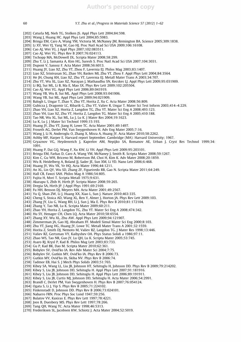
Author's personal copy
[202] Caturla MJ, Nieh TG, Stolken JS. Appl Phys Lett 2004;84:598.[203] Wang J, Huang HC. Appl Phys Lett 2004;85:5983.[204] Bringa EM, Caro A, Wang YM, Victoria M, McNaney JM, Remington BA. Science 2005;309:1838.[205] Li XY, Wei YJ, Yang W, Gao HJ. Proc Natl Acad Sci USA 2009;106:16108.[206] Cao AJ, Wei YG. J Appl Phys 2007;102:083511.[207] Cao AJ, Wei YG. Phys Rev B 2007;76:024113.[208] Tschopp MA, McDowell DL. Scripta Mater 2008;58:299.[209] Zhu T, Li J, Samanta A, Kim HG, Suresh S. Proc Natl Acad Sci USA 2007;104:3031.[210] Dupont V, Sansoz F. Acta Mater 2008;56:6013.[211] Huang JY, Liao XZ, Zhu YT, Zhou F, Lavernia EJ. Philos Mag 2003;83:1407.[212] Liao XZ, Srinivasan SG, Zhao YH, Baskes MI, Zhu YT, Zhou F. Appl Phys Lett 2004;84:3564.[213] He JH, Chung KH, Liao XZ, Zhu YT, Lavernia EJ. Metall Mater Trans A 2003;34:707.[214] Zhu YT, Wu XL, Liao XZ, Narayan J, Mathaudhu SN, Kecskes LJ. Appl Phys Lett 2009;95:031909.[215] Li BQ, Sui ML, Li B, Ma E, Mao SX. Phys Rev Lett 2009;102:205504.[216] Cao AJ, Wei YG. Appl Phys Lett 2006;89:041919.[217] Wang YB, Wu B, Sui ML. Appl Phys Lett 2008;93:041906.[218] Wang YB, Sui ML. Appl Phys Lett 2009;94:021909.[219] Balogh L, Ungar T, Zhao Y, Zhu YT, Horita Z, Xu C. Acta Mater 2008;56:809.[220] Gubicza J, Dragomir LC, Ribarik G, Zhu YT, Valiev R, Ungar T. Mater Sci Test Inform 2003;414–4:229.[221] Zhao YH, Liao XZ, Horita Z, Langdon TG, Zhu YT. Mater Sci Eng A 2008;493:123.[222] Zhao YH, Liao XZ, Zhu YT, Horita Z, Langdon TG. Mater Sci Eng A 2005;410:188.[223] Tao NR, Wu XL, Sui ML, Lu J, Lu K. J Mater Res 2004;19:1623.[224] Lu K, Lu J. J Mater Sci Technol 1999;15:193.[225] Huang JY, Zhu YT, Jiang H, Lowe TC. Acta Mater 2001;49:1497.[226] Froseth AG, Derlet PM, Van Swygenhoven H. Adv Eng Mater 2005;7:16.[227] Wang J, Li N, Anderoglu O, Zhang X, Misra A, Huang JY. Acta Mater 2010;58:2262.[228] Ashby MF, Harper E. Harvard report September. Cambridge (MA): Harvard University; 1967.[229] Gryaznov VG, Heydenreich J, Kaprelov AM, Nepijko SA, Romanov AE, Urban J. Cryst Res Technol 1999;34:
1091.[230] Huang P, Dai GQ, Wang F, Xu KW, Li YH. Appl Phys Lett 2009;95:203101.[231] Bringa EM, Farkas D, Caro A, Wang YM, McNaney J, Smith R. Scripta Mater 2008;59:1267.[232] Kim C, Gu WH, Briceno M, Robertson IM, Choi H, Kim K. Adv Mater 2008;20:1859.[233] Wu B, Heidelberg A, Boland JJ, Sader JE, Sun XM, Li YD. Nano Lett 2006;6:468.[234] Huang JY, Wu YK, Ye HQ. Acta Mater 1996;44:1211.[235] An XL, Lin QY, Wu SD, Zhang ZF, Figueiredo RB, Gao N. Scripta Mater 2011;64:249.[236] Hall CR, Fawzi SAH. Philos Mag A 1986;54:805.[237] Fujita H, Mori T. Scripta Metall 1975;9:631.[238] Akarapu S, Zbib H, Hirth JP. Scripta Mater 2008;59:265.[239] Dregia SA, Hirth JP. J Appl Phys 1991;69:2169.[240] Fu HH, Benson DJ, Meyers MA. Acta Mater 2001;49:2567.[241] Yu Q, Shan ZW, Li J, Huang XX, Xiao L, Sun J. Nature 2010;463:335.[242] Cheng S, Stoica AD, Wang XL, Ren Y, Almer J, Horton JA. Phys Rev Lett 2009:103.[243] Zhang JY, Liu G, Wang RH, Li J, Sun J, Ma E. Phys Rev B 2010;81:172104.[244] Zhang Y, Tao NR, Lu K. Scripta Mater 2009;60:211.[245] Zhao YH, Horita Z, Langdon TG, Zhu YT. Mater Sci Eng A 2008;474:342.[246] Hu SY, Henager CH, Chen LQ. Acta Mater 2010;58:6554.[247] Zhang XY, Wu XL, Zhu AW. Appl Phys Lett 2009;94:121907.[248] Zimmerman JA, Gao HJ, Abraham FF. Modell Simul Mater Sci Eng 2000;8:103.[249] Zhu YT, Jiang HG, Huang JY, Lowe TC. Metall Mater Trans A 2001;32:1559.[250] Horita Z, Smith DJ, Nemoto M, Valiev RZ, Langdon TG. J Mater Res 1998;13:446.[251] Valiev RZ, Gertsman VY, Kaibyshev OA. Phys Status Solidi a 1986;97:11.[252] Zhao WS, Tao NR, Guo JY, Lu QH, Lu K. Scripta Mater 2005;53:745.[253] Asaro RJ, Krysl P, Kad B. Philos Mag Lett 2003;83:733.[254] Gu P, Kad BK, Dao M. Scripta Mater 2010;62:361.[255] Bobylev SV, Ovid’ko IA. Rev Adv Mater Sci 2004;7:75.[256] Bobylev SV, Gutkin MY, Ovid’ko IA. Phys Rev B 2006:73.[257] Gutkin MY, Ovid’ko IA, Skiba NV. Phys Rev B 2006:74.[258] Tadmor EB, Hai S. J Mech Phys Solids 2003;51:765.[259] Kibey SA, Wang LL, Liu JB, Johnson HT, Sehitoglu H, Johnson DD. Phys Rev B 2009;79:214202.[260] Kibey S, Liu JB, Johnson DD, Sehitoglu H. Appl Phys Lett 2007;91:181916.[261] Kibey S, Liu JB, Johnson DD, Sehitoglu H. Appl Phys Lett 2006;89:191911.[262] Kibey S, Liu JB, Curtis MJ, Johnson DD, Sehitoglu H. Acta Mater 2006;54:2991.[263] Brandl C, Derlet PM, Van Swygenhoven H. Phys Rev B 2007;76:054124.[264] Ogata S, Li J, Yip S. Phys Rev B 2005;71:224102.[265] Finkenstadt D, Johnson DD. Phys Rev B 2006;73:024101.[266] Nabarro FRN. Proc Phys Soc Lond 1947;59:256.[267] Bulatov VV, Kaxiras E. Phys Rev Lett 1997;78:4221.[268] Joos B, Duesbery MS. Phys Rev Lett 1997;78:266.[269] Tang QH, Wang TC. Acta Mater 1998;46:5313.[270] Frederiksen SL, Jacobsen KW, Schiotz J. Acta Mater 2004;52:5019.
60 Y.T. Zhu et al. / Progress in Materials Science 57 (2012) 1–62

Author's personal copy
[271] Marian J, Cai W, Bulatov VV. Nature Mater 2004;3:158.[272] Kim I, Kim J, Shin DH, Laio XZ, Zhu YT. Scripta Mater 2003;48:813.[273] Li YJ, Chen YJ, Walmsley JC, Mathinsen RH, Dumoulin S, Roven HJ. Scripta Mater 2010;62:443.[274] Zhang L, Han Y. Mater Sci Eng A 2009;523:130.[275] Kucherov L, Tadmor EB. Acta Mater 2007;55:2065.[276] Wang J, Hirth JP, Tome CN. Acta Mater 2009;57:5521.[277] Kim DH, Manuel MV, Ebrahimi F, Tulenko JS, Phillpot SR. Acta Mater 2010;58:6217.[278] Wu XL, Youssef KM, Koch CC, Mathaudhu SN, Kecskes LJ, Zhu YT. Scripta Mater 2011;64:213.[279] Wang YB, Louie M, Cao Y, Liao XZ, Li HJ, Ringer SP. Scripta Mater 2010;62:214.[280] Marquis EA, Medlin DL, Leonard F. Acta Mater 2007;55:5917.[281] Chen AY, Ruan HH, Wang J, Chan HL, Wang Q, Li Q, et al. Acta Mater 2011:XXX.[282] Wu ZX, Zhang YW, Srolovitz DJ. Acta Mater 2009;57:4508.[283] You ZS, Lu L, Lu K. Scripta Mater 2010;62:415.[284] Hartley CS, Blachon DLA. J Appl Phys 1978;49:4788.[285] Zhu YT, Wu XL, Liao XZ, Narayan J, Kecskes LJ, Mathaudhu SN. Acta Mater 2011;59:812.[286] Wen HM, Zhao YH, Li Y, Ertorer O, Nesterov KM, Islamgaliev RK. Philos Mag 2010;90:4541.[287] Conrad H. In: Zackey VF, editor. High-strength materials. New York (NY): Wiley; 1964.[288] Wei Q, Cheng S, Ramesh KT, Ma E. Mater Sci Eng A 2004;381:71.[289] Lu L, Li SX, Lu K. Scripta Mater 2001;45:1163.[290] Wang YM, Ma E. Appl Phys Lett 2003;83:3165.[291] Schwaiger R, Moser B, Dao M, Chollacoop N, Suresh S. Acta Mater 2003;51:5159.[292] Lu L, Schwaiger R, Shan ZW, Dao M, Lu K, Suresh S. Acta Mater 2005;53:2169.[293] Lu L, Dao M, Zhu T, Li J. Scripta Mater 2009;60:1062.[294] Chen J, Lu L, Lu K. Scripta Mater 2006;54:1913.[295] Sevillano JG, Vanhoutte P, Aernoudt E. Prog Mater Sci 1980;25:71.[296] Hirsch J, Lucke K, Hatherly M. Acta Metall 1988;36:2905.[297] Remy L. Metall Trans A 1981;12:387.[298] Mullner P, Solenthaler C, Speidel MO. Acta Metall Mater 1994;42:1727.[299] Thompson AW, Baskes MI, Flanagan WF. Acta Metall 1973;21:1017.[300] Singh RP, Doherty RD. Metall Trans A 1992;23:307.[301] Remy L. Acta Metall 1978;26:443.[302] Bressane Jp, Moskowit A. Asm Trans Quart 1966;59:223.[303] Asgari S, ElDanaf E, Kalidindi SR, Doherty RD. Metall Mater Trans A 1997;28:1781.[304] Ma E, Wang YM, Lu QH, Sui ML, Lu L, Lu K. Appl Phys Lett 2004;85:4932.[305] Chen XH, Lu L. Scripta Mater 2007;57:133.[306] Babyak WJ, Rhines FN. Trans Am Inst Min Metall Eng 1960;218:21.[307] Merz MD, Dahlgren SD. J Appl Phys 1975;46:3235.[308] Murr LE, Moin E, Greulich F, Staudhammer KP. Scripta Metall 1978;12:1031.[309] Shen YF, Lu L, Lu QH, Jin ZH, Lu K. Scripta Mater 2005;52:989.[310] Youngdahl CJ, Weertman JR, Hugo RC, Kung HH. Scripta Mater 2001;44:1475.[311] Kaschner GC, Tome CN, Beyerlein IJ, Vogel SC, Brown DW, McCabe RJ. Acta Mater 2006;54:2887.[312] Subhash G, Ravichandran G, Pletka BJ. Metall Mater Trans A 1997;28:1479.[313] Sangid MD, Ezaz T, Sehitoglu H, Robertson IM. Acta Mater 2011;59:283.[314] Wang GY, Li GY, Zhao L, Lian JS, Jiang ZH, Jiang Q. Mater Sci Eng A 2010;527:4270.[315] Zhang X, Misra A, Wang H, Nastasi M, Embury JD, Mitchell TE. Appl Phys Lett 2004;84:1096.[316] Zhang X, Misra A, Wang H, Shen TD, Nastasi M, Mitchell TE. Acta Mater 2004;52:995.[317] Misra RDK, Zhang Z, Jia Z, Somani MC, Karjalainen LP. Scripta Mater 2010;63:1057.[318] Li XY, Wei YJ, Lu L, Lu K, Gao HJ. Nature 2010;464:877.[319] Sun PL, Zhao YH, Cooley JC, Kassner ME, Horita Z, Langdon TG. Mater Sci Eng A 2009;525:83.[320] Dao M, Lu L, Shen YF, Suresh S. Acta Mater 2006;54:5421.[321] Carter CB, Ray ILF. Philos Mag 1977;35:189.[322] Shute CJ, Myers BD, Xie S, Barbee TW, Hodge AM, Weertman JR. Scripta Mater 2009;60:1073.[323] Qu S, Zhang P, Wu SD, Zang QS, Zhang ZF. Scripta Mater 2008;59:1131.[324] Cheng S, Zhao YH, Wang YM, Li Y, Wang XL, Liaw PK. Phys Rev Lett 2010:104.[325] Anderoglu O, Misra A, Wang H, Ronning F, Hundley MF, Zhang X. Appl Phys Lett 2008;93:083108.[326] Mannan KM, Karim KR. J Phys F 1975;5:1687.[327] Yoshinag H. Phys Status Solidi 1966;18:625.[328] Capolungo L, Beyerlein IJ, Kaschner GC, Tome CN. Mater Sci Eng A 2009;513–514:42.[329] Yoo MH, Lee JK. Philos Mag A 1991;63:987.[330] Thornburg DR, Piehler HR. Metall Trans A 1975;6:1511.[331] Vaidya S, Mahajan S. Acta Metall 1980;28:1123.[332] Barnett MR. Mater Sci Eng A 2007;464:1.[333] Barnett MR. Mater Sci Eng A 2007;464:8.[334] Li N, Wang J, Huang JY, Misra A, Zhang X. Scripta Mater 2011;64:149.[335] Wei Y. Mater Sci Eng A 2011;528:1558.[336] Malygin GA. Phys Solid State 2008;50:1056.[337] Cho MK, Cho JW, Wu JH, Cho JU, Choi YJ, Kim YK. Curr Appl Phys 2010;10:57.[338] Aifantis KE, Konstantinidis AA. Mater Sci Eng B 2009;163:139.[339] Pande CS, Cooper KP. Prog Mater Sci 2009;54:689.[340] Pan Y, Zhou ZF, Fu SY, Nie YG, Sun CQ. Nano 2008;3:175.
Y.T. Zhu et al. / Progress in Materials Science 57 (2012) 1–62 61

Author's personal copy
[341] Dahlberg CFO, Gudmundson P. Philos Mag 2008:88.[342] Trelewicz JR, Schuh CA. Appl Phys Lett 2008:93.[343] Desai TG, Millett P, Wolf D. Mater Sci Eng A 2008;493:41.[344] Mohammadabadi AS, Dehghani K. J Mater Eng Perform 2008;17:662.[345] Shen TD, Schwarz RB, Feng S, Swadener JG, Huang JY, Tang M. Acta Mater 2007;55:5007.[346] Carlton CE, Ferreira PJ. Acta Mater 2007;55:3749.[347] Jerusalem A, Stainier L, Radovitzky R. Philos Mag 2007;87:2541.[348] Xiang Q, Guo XM. Int J Solids Struct 2006;43:7793.[349] Giga A, Kimoto Y, Takigawa Y, Higashi K. Scripta Mater 2006;55:143.[350] Nieh TG, Wang JG. Intermetallics 2005;13:377.[351] Kadau K, Germann TC, Lomdahl PS, Holian BL, Kadau D, Entel P. Metall Mater Trans A 2004;35A:
2719.[352] Conrad H, Narayan J. Appl Phys Lett 2002;81:2241.[353] Takeuchi S. Scripta Mater 2001;44:1483.[354] Chattopadhyay PP, Pabi SK, Manna I. Z Metall 2000;91:1049.[355] Song HW, Guo SR, Hu ZQ. Nanostruct Mater 1999;11:203.
62 Y.T. Zhu et al. / Progress in Materials Science 57 (2012) 1–62


![Internal strain and texture evolution during deformation twinning …library.nmlindia.org/FullText/MSEA3990511.pdf · situ examinations are even more recent [16]. Magnesium is especially](https://static.fdocuments.net/doc/165x107/5f782f7b94cb87410e1c3c5f/internal-strain-and-texture-evolution-during-deformation-twinning-situ-examinations.jpg)