Progress in design of new amorphous alloy...
13
Progress in design of new amorphous alloy catalysts Jing-Fa Deng a,* , Hexing Li b , Weijiang Wang a a Department of Chemistry, Fudan University, Shanghai 200433, China b Department of Chemistry, Shanghai Normal University, Shanghai 200234, China Abstract Three new kinds of Ni-based amorphous alloy catalysts, Raney type Ni–P(R–Ni–P), Ni–Co–B, and Ni–B(P)/SiO 2 , have been prepared by modification of either the rapid quenching method or chemical reduction. Their amorphous structures have been determined by XRD, EXAFS, and DSC. Their catalytic activities and selectivities have been measured during the hydrogenation of various organic compounds, which demonstrate the great improvement on the catalytic properties in comparison with the corresponding amorphous alloy catalysts prepared by the rapid quenching method or chemical reduction previously reported. These new amorphous catalysts also exhibit superior catalytic properties over the traditional catalysts, such as Raney Ni, Ni/SiO 2 , and Pd/C, making them possible to be used in real industrial catalysis. The relationship between the catalytic properties and the structural properties has been discussed according to various characterizations, including ICP, XPS, EXAFS, XRD, TPD, TPR, hydrogen adsorption, IR, SEM, and TEM, etc. The higher hydrogenation activity of R–Ni–P than the Ni–P amorphous catalyst obtained by rapid quenching is mainly ascribed to the increase of the surface area due to the skeleton structure; the higher activity of Ni–Co–B than the Ni–B amorphous catalyst demonstrates a promoting effect of the additive metal(s); while the higher thermal stability of supported Ni–P(B) than the corresponding unsupported catalysts can be explained by considering the stabilizing effect of the silica support on the amorphous structure. # 1999 Elsevier Science B.V. All rights reserved. Keywords: Hydrogenation; Skeletal Ni–P amorphous catalyst; Ni–Co–B amorphous catalyst; Supported Ni–P(B) amorphous catalyst 1. Introduction Since the introduction of the rapid quenching tech- niques [1] for producing metallic glasses, i.e., the metal–metalloid amorphous alloys, those metastable materials with not long-range ordering but with short- range ordering structure, have attracted a lot of atten- tion from metallurgists, physicists, engineers and material scientists owing to their superior electronic, magnetic, mechanical and chemical properties [2,3]. However, the study of heterogeneous catalysis with amorphous alloys did not come about until 1980 [4]. The classical work of Yamashita and Masumoto et al. [5–15] in the 1980s stimulated fast growth in amor- phous alloy catalysis research. Various amorphous alloys have been prepared and employed in catalysis including electrolysis [16,17], hydrogenation [5–10, 18–35], hydrogenolysis [9,10], oxidation [36–40], isomerization [29,41,42], etc. Among them, the Ni- based amorphous alloys have been studied most thor- oughly. The most widely used techniques for the preparation of amorphous alloy catalysts are classified into (i) the rapid quenching method, and (ii) chemical reduction. Each method has both advantages and disadvantages. Catalysis Today 51 (1999) 113–125 *Corresponding author. 0920-5861/99/$ – see front matter # 1999 Elsevier Science B.V. All rights reserved. PII:S0920-5861(99)00013-9
Transcript of Progress in design of new amorphous alloy...

Progress in design of new amorphous alloy catalysts
Jing-Fa Denga,*, Hexing Lib, Weijiang Wanga
aDepartment of Chemistry, Fudan University, Shanghai 200433, ChinabDepartment of Chemistry, Shanghai Normal University, Shanghai 200234, China
Abstract
Three new kinds of Ni-based amorphous alloy catalysts, Raney type Ni±P(R±Ni±P), Ni±Co±B, and Ni±B(P)/SiO2, have
been prepared by modi®cation of either the rapid quenching method or chemical reduction. Their amorphous structures have
been determined by XRD, EXAFS, and DSC. Their catalytic activities and selectivities have been measured during the
hydrogenation of various organic compounds, which demonstrate the great improvement on the catalytic properties in
comparison with the corresponding amorphous alloy catalysts prepared by the rapid quenching method or chemical reduction
previously reported. These new amorphous catalysts also exhibit superior catalytic properties over the traditional catalysts,
such as Raney Ni, Ni/SiO2, and Pd/C, making them possible to be used in real industrial catalysis. The relationship between
the catalytic properties and the structural properties has been discussed according to various characterizations, including ICP,
XPS, EXAFS, XRD, TPD, TPR, hydrogen adsorption, IR, SEM, and TEM, etc. The higher hydrogenation activity of R±Ni±P
than the Ni±P amorphous catalyst obtained by rapid quenching is mainly ascribed to the increase of the surface area due to the
skeleton structure; the higher activity of Ni±Co±B than the Ni±B amorphous catalyst demonstrates a promoting effect of the
additive metal(s); while the higher thermal stability of supported Ni±P(B) than the corresponding unsupported catalysts can be
explained by considering the stabilizing effect of the silica support on the amorphous structure. # 1999 Elsevier Science B.V.
All rights reserved.
Keywords: Hydrogenation; Skeletal Ni±P amorphous catalyst; Ni±Co±B amorphous catalyst; Supported Ni±P(B) amorphous catalyst
1. Introduction
Since the introduction of the rapid quenching tech-
niques [1] for producing metallic glasses, i.e., the
metal±metalloid amorphous alloys, those metastable
materials with not long-range ordering but with short-
range ordering structure, have attracted a lot of atten-
tion from metallurgists, physicists, engineers and
material scientists owing to their superior electronic,
magnetic, mechanical and chemical properties [2,3].
However, the study of heterogeneous catalysis with
amorphous alloys did not come about until 1980 [4].
The classical work of Yamashita and Masumoto et al.
[5±15] in the 1980s stimulated fast growth in amor-
phous alloy catalysis research. Various amorphous
alloys have been prepared and employed in catalysis
including electrolysis [16,17], hydrogenation [5±10,
18±35], hydrogenolysis [9,10], oxidation [36±40],
isomerization [29,41,42], etc. Among them, the Ni-
based amorphous alloys have been studied most thor-
oughly. The most widely used techniques for the
preparation of amorphous alloy catalysts are classi®ed
into (i) the rapid quenching method, and (ii) chemical
reduction. Each method has both advantages and
disadvantages.
Catalysis Today 51 (1999) 113±125
*Corresponding author.
0920-5861/99/$ ± see front matter # 1999 Elsevier Science B.V. All rights reserved.
PII: S 0 9 2 0 - 5 8 6 1 ( 9 9 ) 0 0 0 1 3 - 9

The rapid quenching method [1±3], which ensures a
cooling rate of at least 105±106 K.sÿ1, is the only
practical way to obtain amorphous alloys in large
quantities. Usually, the resultant specimens are rib-
bons from several millimeters to several centimeters in
length. Such amorphous alloys can be produced with
wide composition ranges not available in crystalline
form, making it easier to adjust their electronic proper-
ties. Their single-phase character and the possible lack
of surface segregation of the alloying elements ensure
that the active sites are in a uniform dispersion in a
homogeneously chemical environment. They also
have a high concentration of coordinatively highly
unsaturated sites, which makes adsorption and surface
reactions easier than on the corresponding crystalline
catalysts. The nonporous structures of those amor-
phous alloys can effectively eliminate the effects of
intraparticle diffusion limitations on surface reactions.
All those features make amorphous alloys attractive
materials in heterogeneous catalysis. However, those
amorphous alloys also have some disadvantages:
1. Special equipment is required in their preparation,
which is not available in most labs.
2. Pretreatment of those amorphous alloys is neces-
sary before a catalytic test.
3. The catalytic reactions must be performed at low
temperatures to avoid the crystallization process,
since the amorphous structure is thermodynami-
cally metastable.
4. Perhaps, the most important disadvantage is the
low surface area of those amorphous alloys, i.e.,
less than 1 m2/g, which is too small to use as an
industrial catalyst because of the low productivity
per unit weight of catalyst.
Several new methods have been developed recently
to prepare amorphous alloys with higher surface areas.
One of the most powerful methods is to prepare the
amorphous alloys by chemical reduction of the metal-
lic ions with hypophosphite (H2POÿ2 ) or borohydride
(BHÿ4 ) to form ultra®ne metal boride or phosphide
amorphous alloy particles, as ®rst reported by van
Wonterghem et al. in 1986 [43] and developed by
Linderoth and Morup et al. [44±50]. Chemical reduc-
tion ensures large surface areas of the resultant amor-
phous alloy catalysts, e.g., the ultra®ne Ni±B
amorphous alloy obtained by chemical reduction in
ethanol solution has a surface area of up to 200 m2/g
[23]. Experimental results demonstrate that their cat-
alytic activities are usually 50±100 times higher than
those of the corresponding amorphous alloys obtained
by the rapid quenching method. These amorphous
alloy particles can be compacted in a variety of forms
suitable for catalysis and can be used in catalytic test
without any pretreatment, which makes them more
convenient in catalytic studies. In addition, the simple
preparation procedure of these amorphous alloys
makes it possible that they are studied widely in many
labs. However, they also have some drawbacks. One is
that the storage of these amorphous alloys is dif®cult,
since they are easily oxidized by air. Another one is
that these amorphous alloys are costly in comparison
with those obtained by the rapid quenching method.
Perhaps, the extremely poor thermal stability of these
amorphous alloys due to the high surface energies of
the ultra®ne particles is the most important factor
limiting their application in industrial processes.
Due to their drawbacks as mentioned above, no
industrially used amorphous alloy catalysts have been
reported so far. Therefore, modi®cation of the present
techniques seems essential to prepare amorphous alloy
catalysts which can be used in industrial processes.
This paper is a brief summary of our research work on
the design of new amorphous alloy catalysts with the
aim of making them suitable for real industrial pro-
cesses. In Section 2, we describe the preparation and
the characterization of three new kinds of as-prepared
Ni-based amorphous catalysts. In Section 3, we
describe their catalytic properties and the potential
application during the hydrogenation of various organic
compounds, such as benzene, nitrobenzene, cyclopen-
tadiene and 4-carboxyl benzaldehyde, etc. The rela-
tionship between the catalytic properties and the
surface structural properties is discussed, in which
emphasis is placed on the stabilizing effect of the silica
support on the Ni±P amorphous structure and the pro-
moting effect of Co in Ni±Co±B amorphous catalysts.
2. Preparation and characterization of thesupported amorphous alloy catalysts
2.1. Preparation methods
A. R±Ni±P amorphous alloy catalyst. A R±Ni±P
amorphous alloy catalyst is prepared by the following
114 J.-F. Deng et al. / Catalysis Today 51 (1999) 113±125

procedure [51]: A Ni±Al±P amorphous alloy with
48.2 wt% Ni, 48.7 wt% Al and 3.1 wt% P, in the form
of ribbons ca. 5 mm wide and 10±20 mm thick, was
prepared by the rapid quenching method using a single
steel roll. The sample is ground to 200 mesh and very
slowly added into 6.0 M NaOH at 273 K, in which the
Al is dissolved by forming NaAlO2. The alkali leach-
ing is continued by stirring at 343 K for 6.0 h in a N2
atmosphere. The resultant amorphous R±Ni±P cata-
lyst is washed free from alkali and aluminate with
distilled water until pH�7. It is further washed with
ethanol(EtOH) to remove water, and ®nally, kept in
EtOH. For comparison, a Raney Ni catalyst is also
prepared in the same way by alkali leaching of a
commercial Ni±Al alloy (Ni/Al 50/50 w/w). A regular
Ni±P amorphous alloy is obtained by the rapid quench
method as described elsewhere [5,6].
B. Supported Ni±B(P) amorphous alloy catalysts. A
Ni±P/SiO2 amorphous catalyst is prepared by the
following procedures [52,53]: 1.0 g SiO2 (198 m2/g,
40±60 mesh) is impregnated overnight with an aqu-
eous NiCl2 solution containing 0.010 g nickel. After
being dried at 373 K and further calcined at 623 K for
2.0 h, the Ni2� on the support is reduced by an alkaline
NaH2PO2 solution (pH�11) at 363 K to create nuclei
on the support. After being washed thoroughly with
distilled water, the sample is transferred to a plating
solution containing 10.0 g/l each of NiCl2�6H2O,
NaH2PO2�6H2O, CH3COONa and sodium citrate,
for electroless plating. During reaction, the mixture
is stirred vigorously at 363 K. The plating process is
continued for about 2.0 h until no signi®cant bubbles
release from the solution. The resulting Ni±P/SiO2
amorphous catalyst with a nickel loading of ca. 5 wt%
is then washed thoroughly with distilled water and
ethanol. Finally, it is stored in EtOH. The loading of
the Ni±P alloy on the support can be adjusted easily by
changing the concentration of the plating solution.
A Ni±B/SiO2 amorphous catalyst is prepared by
impregnating overnight a silica support with an aqu-
eous NiCl2 solution containing the desired amount of
nickel. After being dried at 373 K, it is reduced by
adding a KBH4 solution dropwise at room tempera-
ture. The resulting Ni±B/SiO2 amorphous catalyst is
then washed thoroughly with water and EtOH. Finally,
it is kept in EtOH.
C. Ultra®ne Ni±Co±B amorphous alloy catalysts.
An ultra®ne Ni±Co±B amorphous alloy catalyst is
prepared as reported previously [21,22]. An aqueous
solution of KBH4 (2.0 M) is added dropwise to an
aqueous solution containing both nickel acetate and
cobalt acetate. The initial molar ratio of KBH4 to
metallic salts is 5:2 to ensure complete reduction of
metallic ions in the solution. The solution is kept in an
ice water bath and stirred vigorously by a magnetic
stirrer. The reaction is continued for about 0.5 h until
no more gas is released. The resulting black precipi-
tate is washed several times with distilled water and
subsequently with 99.9% ethanol (EtOH). The ®nal
product is kept in EtOH. The composition of the
samples is adjusted by changing the initial Ni/Co ratio
in the solution. In the extreme, Ni±B and Co±B
amorphous alloys are obtained when single nickel salt
or cobalt salt is used in the solution, respectively.
2.2. Characterization
2.2.1. Amorphous structure
XRD, EXAFS and DSC are used to determine the
amorphous structure of the as-prepared samples.
Sometimes, selected area electronic diffraction
(SAED) is also employed. Fig. 1 shows the XRD
patterns of the as-prepared R±Ni±P, Ni±Co±B, Ni±
P/SiO2, and Ni±B/SiO2 samples. By subtracting a
broad peak around 228 resulting from the amorphous
silica support, the only other broad peak around 458appeared on the XRD pattern of each of these samples
demonstrates the typical amorphous structures [5].
After treatment at high temperature, the various sharp
peaks appearing in the XRD patterns of these samples
indicate the occurrence of crystallization, as found in
Ni±P/SiO2 [54]. The amorphous structure of the as-
prepared samples can be further characterized by
EXAFS spectra, from which the radial distribution
function (RDF) curves can be obtained. A typical
result of the as-prepared Ni±P/SiO2 fresh sample
and the corresponding one after treatment at 873 K
in N2 ¯ow for 2.0 h is shown in Fig. 2. The strength of
the RDF peaks refers to the degree of the ordering
structure, while the number of the RDF peaks refers to
the range of the ordering structure. For the fresh
sample, only one RDF peak is observed, suggesting
that the sample has only a short-range ordering struc-
ture con®ned to the ®rst coordination shell. For the
same sample after treatment at high temperature, both
the intensity and the number of the RDF peaks
J.-F. Deng et al. / Catalysis Today 51 (1999) 113±125 115

increased, indicating the occurrence of crystallization.
The transformation of the amorphous structure during
the heating treatment can also be followed by a DSC
measurement. Typical results of the DSC curves of the
Ni±P, R±Ni±P and Ni±P/SiO2 samples are shown in
Fig. 3. The ®rst endothermic peak is attributed to the
loss of the solvent absorbed by the catalyst. The other
exothermic peaks are attributed to the transformation
from an amorphous to a crystalline structure. Com-
monly, the temperature corresponding to the ®rst
exothermic peak in a DSC curve is de®ned as the
crystallization temperature (Tc). The higher Tc of
R±Ni±P as well as Ni±P/SiO2 than Ni±P indicates
the promoting effect of the skeleton structure or the
silica support on the thermal stability of the amor-
phous structure. The stabilizing effect of the support
will be discussed in the following section.
2.2.2. Surface morphology
The surface morphologies of both the supported and
unsupported amorphous alloy catalysts are determined
Fig. 1. XRD patterns of the as-prepared amorphous alloy catalysts.
Fig. 2. RDF curves of amorphous and crystallized Ni±P/SiO2.
Fig. 3. DSC curves of the as-prepared amorphous alloy catalysts.
116 J.-F. Deng et al. / Catalysis Today 51 (1999) 113±125
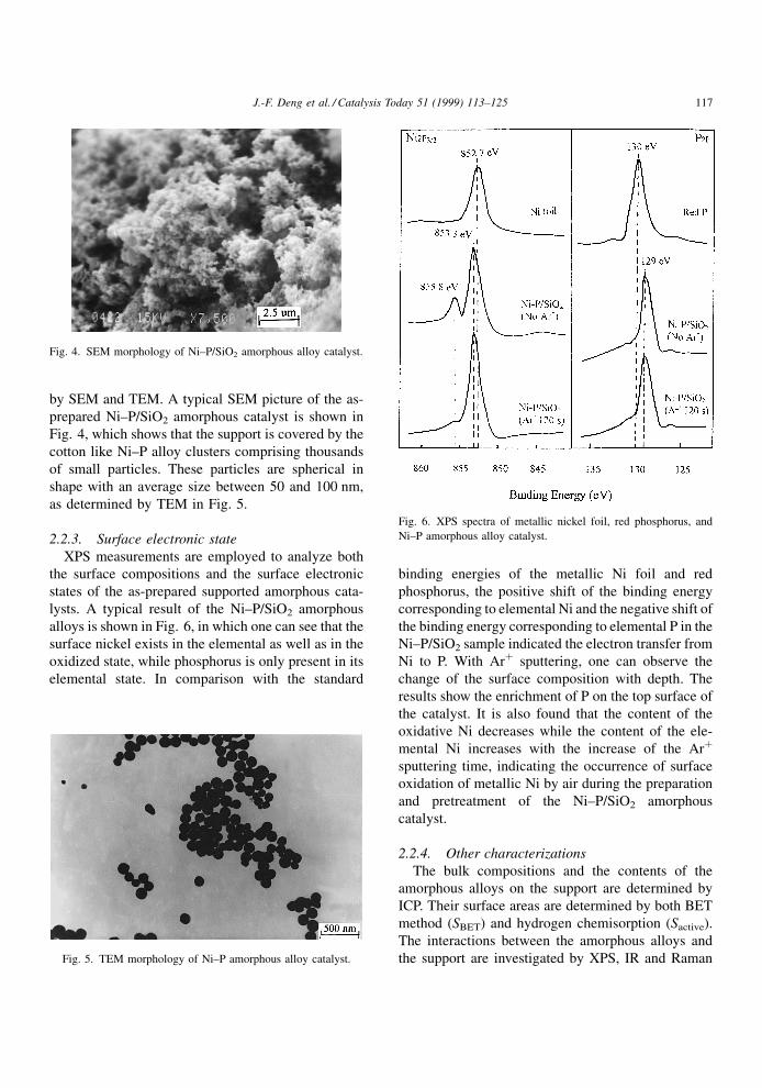
by SEM and TEM. A typical SEM picture of the as-
prepared Ni±P/SiO2 amorphous catalyst is shown in
Fig. 4, which shows that the support is covered by the
cotton like Ni±P alloy clusters comprising thousands
of small particles. These particles are spherical in
shape with an average size between 50 and 100 nm,
as determined by TEM in Fig. 5.
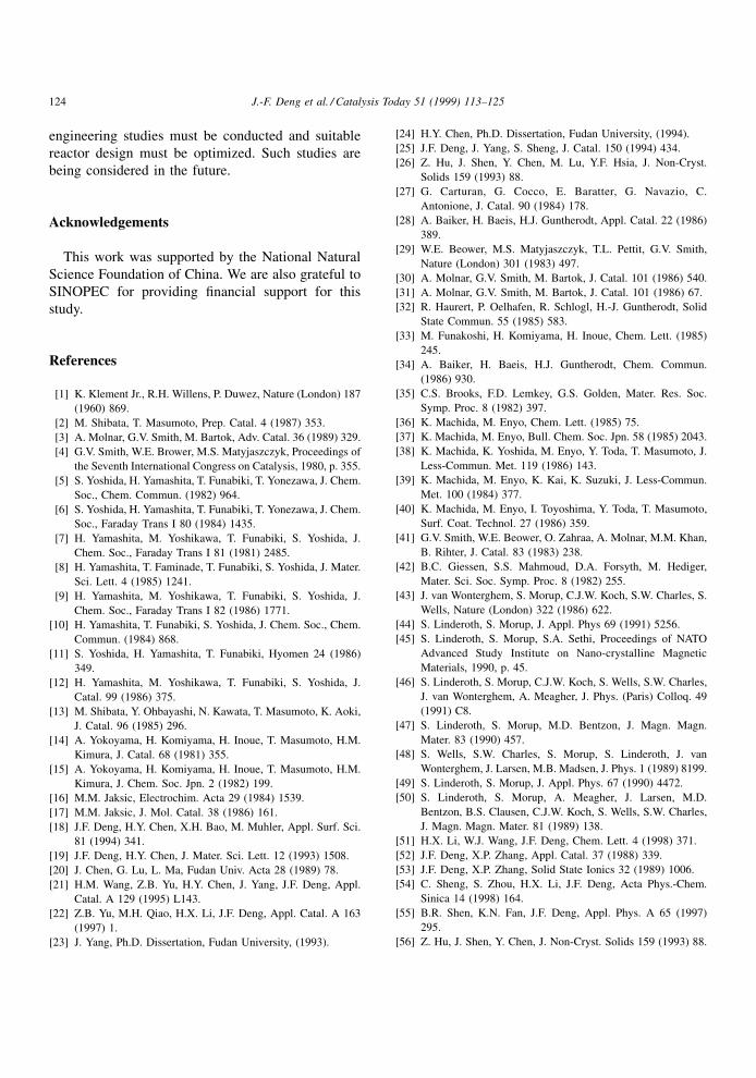
2.2.3. Surface electronic state
XPS measurements are employed to analyze both
the surface compositions and the surface electronic
states of the as-prepared supported amorphous cata-
lysts. A typical result of the Ni±P/SiO2 amorphous
alloys is shown in Fig. 6, in which one can see that the
surface nickel exists in the elemental as well as in the
oxidized state, while phosphorus is only present in its
elemental state. In comparison with the standard
binding energies of the metallic Ni foil and red
phosphorus, the positive shift of the binding energy
corresponding to elemental Ni and the negative shift of
the binding energy corresponding to elemental P in the
Ni±P/SiO2 sample indicated the electron transfer from
Ni to P. With Ar� sputtering, one can observe the
change of the surface composition with depth. The
results show the enrichment of P on the top surface of
the catalyst. It is also found that the content of the
oxidative Ni decreases while the content of the ele-
mental Ni increases with the increase of the Ar�
sputtering time, indicating the occurrence of surface
oxidation of metallic Ni by air during the preparation
and pretreatment of the Ni±P/SiO2 amorphous
catalyst.
2.2.4. Other characterizations
The bulk compositions and the contents of the
amorphous alloys on the support are determined by
ICP. Their surface areas are determined by both BET
method (SBET) and hydrogen chemisorption (Sactive).
The interactions between the amorphous alloys and
the support are investigated by XPS, IR and Raman
Fig. 4. SEM morphology of Ni±P/SiO2 amorphous alloy catalyst.
Fig. 5. TEM morphology of Ni±P amorphous alloy catalyst.
Fig. 6. XPS spectra of metallic nickel foil, red phosphorus, and
Ni±P amorphous alloy catalyst.
J.-F. Deng et al. / Catalysis Today 51 (1999) 113±125 117

spectroscopy. The surface hydrogen adsorption and
desorption are determined by TPR and TPD. Some
properties of Ni±P, R±Ni±P, Ni±Co±B, and Ni±P/SiO2
amorphous alloy catalysts are summarized in Table 1.
3. Activity test
3.1. R±Ni±P amorphous catalyst
The liquid phase hydrogenation of various organic
compounds, including benzene, toluene, and hexane-
dinitrile, is employed to evaluate the catalytic activity
and selectivity of the as-prepared R±Ni±P amorphous
alloy catalyst. A typical result of liquid phase hex-
anedinitrile hydrogenation to 1,6-hexanediamine,
which is an important intermediate in the production
of nylon-6,6, is summarized in Fig. 7. It is found that
both the TOF value and selectivity of R±Ni±P are
almost the same as those of Ni±P owing to their similar
amorphous structures. However, the activity of R±Ni±P
is about 50 times higher than that of Ni±P. This can be
ascribed to the signi®cantly higher surface area, as
shown in Table 1. In comparison with Raney Ni,
which is most widely used in the above hydrogenation
reaction, the R±Ni±P catalyst exhibits an increase of
about 2±3 times in activity and about 40% in selec-
tivity, showing the potential of the R±Ni±P amorphous
catalyst instead of Raney Ni in industrial processes.
The better selectivity of R±Ni±P is mainly attributed
to the promoting effect of its amorphous structure
[2,3]. The higher hydrogenation activity and TOF
value of R±Ni±P compared to Raney Ni can be under-
stood by considering the promoting effects of both the
amorphous structure and the alloying of phosphorus in
the R±Ni±P catalyst. XRD and EXAFS show the
shorter Ni±Ni bond length and more highly unsatu-
rated sites in the R±Ni±P catalyst in comparison with
the Raney Ni catalyst. TPD and SEM as well as
EXAFS reveal that only one kind of active sites are
present in the as-prepared R±Ni±P amorphous alloy
catalyst which are homogeneously dispersed on the
catalyst surface. These factors are claimed favorable
for hydrogenation [2,3,25,55]. In comparison with
pure metal Ni and red P, as shown in Fig. 6 XPS
spectra reveal that a partial electron transfers from Ni
to P, making Ni electron-de®cient, which is also
favorable for the hydrogen adsorption and the hydro-
genation on the surface of Ni active sites [12,56±58].
3.2. Ni±Co±B
The dependence of the hydrogen uptake rate per
gram of Ni±Co±B amorphous alloy catalyst
Table 1
Properties of the as-prepared supported Ni-based amorphous catalysts
Samples Ni loading (wt%)a Composition (atomic ratio) SBET (m2/g) SNi (m2/g) Tc (K)
Ni±P ± Ni88P12 1.2 0.8 593
R±Ni±P ± Ni68Al25P14 87 38 671
Ni±P/SiO2 3.0 Ni86P14 187 25.0 713
Ni±B/SiO2 10.0 Ni76B24 156 22.5 610
Ni±Co±B ± Ni32Co32P36 7.5 6.8 653
a Weight percentage.
Fig. 7. Catalytic activity (mmol H2/h�gNi), selectivity, and TOF
value of the as-prepared R±Ni±P and Ni±P amorphous alloy
catalysts as well as Raney Ni during the liquid phase hydrogenation
of hexanedinitrile (HDN) to 1,6-hexanediamine. Reaction condi-
tions: T�350 K, PH2�4.0 MPa, EtOH/HDN (v/v)�3:1.
118 J.-F. Deng et al. / Catalysis Today 51 (1999) 113±125

(RH mmol/s�gcatalyst) on the molar ratio of Co in the
Ni±Co alloy (�Co) during the liquid benzene hydro-
genation is shown in Fig. 8 [22]. According to the
BET test, the total surface areas of all these Ni±Co±B
samples are around 12.0 m2/g, indicating that the
effect of �Co on the catalyst dispersion is very little.
So the change of the speci®c hydrogen uptake rate
over the unit surface area of Ni±Co±B amorphous
alloy catalysts with �Co is in the same way as that of
the RH. Because no signi®cant activity of the Co±B
amorphous alloy is observed, the higher activity of
Ni±Co±B than Ni±B amorphous alloy catalyst indi-
cates a promoting effect of the Co on the hydrogena-
tion activity. Since XPS spectra show almost the same
binding energy of the elemental Ni in the Ni±B as
those in the Ni±Co±B with different �Co, the modi-
®cation of Co additive on the electronic structure of
surface Ni could be neglected. Therefore, only the
structural modi®cation is responsible for the promo-
tion of Co on the hydrogenation activity. On one hand,
the XPS spectra and hydrogen chemisorption reveal
that the addition of Co to Ni±B amorphous alloy
results in the increase of surface Ni atoms, which
enhance the hydrogenation activity per unit weight of
catalyst since only Ni atoms serve as active sites. On
the other hand, as reported by Shen et al. [55] from an
EXAFS experiment, the addition of Co to the Ni±B
alloy results in the decrease of the Ni±Ni bond length,
indicating an increase in the Ni±Ni interaction. They
also found that the structural disordering extent factor
(�) increased with the addition of Co, corresponding to
a more homogeneous distribution of the active sites.
These results also account for the promoting effect of
Co on the hydrogenation activity [3]. The change of
RH with the �Co in Fig. 8 could be explained as
follows. On one hand, the increase of Co content
(�Co) will increase the hydrogenation activity due
to its promoting effect as mentioned above. On the
other hand, the increase of �Co will decrease the Ni
content per unit weight of the Ni±Co±B alloy, result-
ing in a decrease of the hydrogenation activity since
only Ni atoms serve as the catalytic active centers in
the catalyst. In the beginning, since no signi®cant
decrease of Ni content occurs, the promoting effect
of the Co is dominant, therefore, RH increases with
�Co. When �Co is high enough, the decrease of Ni
content per unit weight of the Ni±Co±B alloy becomes
dominant, resulting in a decrease of RH with �Co, as
shown in Fig. 8. The optimum Ni/Co molar ratio is
determined as 1:1.
3.3. Ni±B/SiO2 amorphous catalyst
Tables 2 and 3 show the application of the Ni±B/
SiO2 amorphous catalyst in the selective hydrogena-
Fig. 8. Dependence of catalytic activity of Ni±Co±B amorphous
alloy catalysts on the Co content in the Ni±Co alloy during liquid
phase benzene hydrogenation. Reaction conditions: T�373 K,
PH2�1.0 MPa, EtOH/benzene (v/v)�4:1.
Table 2
Selective hydrogenation of cyclopentadiene (CPD) to cyclopentene (CPE) at normal pressure and 393 K in a fixed bed
Catalyst H2:CPD (molar ratio) LHSVa (1/h) Conversion (%) Selectivity (%) Lifetime (h)
5%Ni±B/SiO2 1.4 12 100 96 >1000
5%Ni/SiO2 2.0 12 100 80 ±
5%Ni/Al2O3 2.0 12 100 50 ±
0.5% Pd/C 3.0 2 <100 45 ±
a Liquid velocity.
J.-F. Deng et al. / Catalysis Today 51 (1999) 113±125 119

tion of cyclopentadiene to cyclopentene and the
hydrogenation of benzene to cyclohexane in a ®xed
bed at atmospheric pressure [59±61]. These results
show higher catalytic activities and selectivities as
well as longer lifetime of the Ni±B/SiO2 amorphous
catalyst than the corresponding Ni/SiO2 catalyst
obtained by H2 reduction at 723 K. In addition, the
Ni±B/SiO2 amorphous catalyst exhibits higher sulfur
resistance than the corresponding Ni/SiO2 catalyst
since the lifetime of the Ni±B/SiO2 amorphous cata-
lyst is much longer than that of the Ni/SiO2 catalyst
when the same content of CS2 is introduced in the feed
gas [62]. The good catalytic activity and selectivity of
the Ni±B/SiO2 amorphous catalyst are mainly attrib-
uted to the promoting effects of its amorphous struc-
ture, just as that of the unsupported Ni±B amorphous
alloy catalysts as discussed elsewhere [2,3,23,24]. The
excellent sulfur resistance of the Ni±B amorphous
alloy is mainly attributed to the surface electronic
states of Ni±B alloy [62]. According to the XPS
spectra, partial electron transfer from elemental B
to elemental Ni occurs, making Ni electron-rich and
B electron-de®cient [6,59,63,64]. Therefore, sulfur
will be adsorbed reversibly by B prior to Ni, as shown
in Fig. 9, which can protect Ni from sulfur poisoning,
accounting for the superior sulfur resistance of the
Ni±B/SiO2 amorphous catalyst over the corresponding
Ni/SiO2. Such a conclusion is strongly supported by
the fact that no signi®cant improvement in the sulfur
resistance occurs by forming Ni±P amorphous alloy
since the elemental Ni is electron-de®cient in the Ni±P
amorphous alloy owing to the partial electron transfer
from Ni to P, as shown in Fig. 9.
In the liquid phase hydrogenation of nitrobenzene
to aniline, the Ni±B/SiO2 amorphous catalyst also
exhibits superior catalytic activity over the corre-
sponding Ni/SiO2 catalyst [65], as shown in Table 4.
The hydrogenation activity of Ni/SiO2 decreases
rapidly due to the strong adsorption of the resultant
amine on the metallic Ni. However, no signi®cant
decrease in the activity of Ni±B/SiO2 amorphous
catalyst is observed owing to the presence of alloying
B which protects the Ni active sites from amine
poison, as mentioned in the discussion of sulfur
poison.
3.4. Ni±P/SiO2 amorphous catalyst
Terephthalic acid (TA) is an important raw material
in polyester ®ber production. In industry, it is obtained
by oxidation of p-xylene, in which the 4-carboxyl
Table 3
Benzene hydrogenation at normal pressure in a fixed bed
Catalyst LHSVa
(1/h)
H2:benzene T
(K)
Solvent Conversion
(%)
Selectivity
(%)
Sulfur
resistance (ppm)
15% NiB/SiO2 2±3 2±3 423 Benzene 100 100 2000
15% Ni/SiO2 2±3 2±3 423 Benzene 85 100 500
a Liquid velocity.
Fig. 9. Transfer of electrons and the sulfur adsorption.
Table 4
Liquid phase hydrogenation of nitrobenzene to aniline at 1.0 MPa
and 383 K
Catalyst Solvent RNiH
(mmol/h g)
Conversiona
(%)
Selectivity
(%)
10% NiB/SiO2 EtOH (1:3) 174.5 18.5 98
10% Ni/SiO2 EtOH (1:3) 61.0 4.6 76
a 1.0 h.
120 J.-F. Deng et al. / Catalysis Today 51 (1999) 113±125

benzaldehyde (4CBA) is a main side-product. Since
trace 4CBA is harmful to the quality of the polyester
®ber, it must be removed beyond 25 ppm. Commonly,
4CBA is removed by the liquid phase hydrogenation
over a Pd/C catalyst at high pressure and temperature
in which the resulted p-toluic acid can be separated
from TA due to their different solubility in water [66].
The Ni±P/SiO2 amorphous catalyst can be employed
as a catalyst instead of Pd/C in hydrogenation of
4CBA under the same reaction conditions. The results
are summarized in Fig. 10. Since the hydrogenation
has to be performed at high temperature (551 K), the
application of most unsupported Ni-based amorphous
catalysts and even the supported Ni±B amorphous
catalyst are limited due to their poor thermal stability.
XRD experiments show the occurrence of severe
crystallization of those unsupported Ni±P, Ni±B and
supported Ni±B/SiO2 amorphous catalysts after
hydrogenation for 3.0 h, resulting in an abrupt
decrease in their hydrogenation activities [54]. How-
ever, no signi®cant crystallization is observed for the
Ni±P/SiO2 amorphous catalyst, which ensures the
repetitive use of the catalyst during the above hydro-
genation. Its catalytic activity is almost the same as
that of Pd/C, which makes it possible to be used as a
cheap catalyst instead of Pd/C in industrial TA re®ne.
The higher thermal stability of the Ni±P/SiO2 amor-
phous catalyst than that of the Ni±B/SiO2 amorphous
catalyst may be attributed to the higher crystallization
temperature of the Ni±P amorphous alloy than that of
Ni±B [23]. While the higher thermal stability of Ni±P/
SiO2 than that of the unsupported Ni±P is mainly
attributed to the high dispersion of the Ni±P alloy
particles on the support and a strong interaction
between Ni±P alloy and the silica support. The details
are as follows:
1. The high dispersion of the Ni±P alloy on the
support. The crystallization temperatures (Tc) of
Ni±P/SiO2 amorphous alloy catalysts with differ-
ent Ni loadings are determined by DSC analysis.
The Ni loadings are analyzed by ICP. In an
unsupported Ni±P amorphous alloy catalyst, its Ni
loading is considered as 1, since no support
exists. The dispersion of Ni on the surface of Ni±P
alloy are determined by hydrogen chemisorption.
These results are summarized in Table 5, from
which, one can see that the thermal stability of
Ni±P/SiO2 amorphous catalysts decreases with
increasing Ni loading. Since the dispersion of the
Ni±P/SiO2 amorphous alloy catalysts also de-
creases with increasing Ni loading, one can
conclude that the higher the dispersion, the higher
the thermal stability.
2. The strong interaction between the Ni±P alloy and
the support. Fig. 11 shows the IR spectra of fresh
silica and the Ni±P/SiO2 amorphous catalyst with a
Ni loading of 3 wt%. The IR spectrum of the fresh
silica support displays two bands due to �asSi±O
and �sSi±O at 1096 and 802 cmÿ1, respectively
[67]. For the Ni±P/SiO2, the significant decrease in
the strength of those two bands and the appearance
of a new band at 660 cmÿ1 strongly demonstrate
Fig. 10. The conversion of 4-carboxyl benzaldehyde (4CBA) over
different catalysts in liquid phase hydrogenation. Reaction condi-
tions: T�551 K, PH2�6.8 MPa, 4CBA/TA (w/w)�2000 ppm.
Table 5
Properties of Ni±P/SiO2 samples with different Ni loadings
Catalyst Composition Ni Loading
(wt%)
Dispersion
(%)
Tc
(K)
Ni±P-1/SiO2 Ni86P14 3.0 4.0 713
Ni±P-2/SiO2 Ni86P14 5.2 3.0 673
Ni±P-3/SiO2 Ni86P14 12.2 1.2 623
Ni±P Ni87P13 1 ± 558
J.-F. Deng et al. / Catalysis Today 51 (1999) 113±125 121

the interaction between the Ni±P alloy and the
silica support. Additional evidence for the strong
interaction between Ni±P alloy and silica support is
obtained from DSC spectra of Ni±P/SiO2 amor-
phous alloy catalyst and its corresponding unsup-
ported Ni±P amorphous alloy obtained at the same
conditions, as shown in Fig. 3. The higher crystal-
lization temperature of Ni±P/SiO2 sample than that
of Ni±P sample indicates the stabilizing effect of
the silica support on the Ni±P amorphous structure.
In addition, TPO experiment also demonstrates the
stabilizing effect of the silica support on the ele-
mental Ni since no significant oxidation of the Ni±
P/SiO2 amorphous alloy catalyst occurs until
623 K, while the corresponding unsupported
Ni±P sample can be oxidized with sparkle even
at room temperature. A model of the interaction
between Ni metal and silica support is recently
proposed by Ghuge et al. [67].
In order to understand the stabilizing effect of the
support on the amorphous structure, the crystallization
process of the Ni±P amorphous alloy is studied by
XRD and SEM during its heating pretreatment
[68,69]. From the XRD patterns in Fig. 12, one can
observe that the amorphous Ni±P alloy gradually
separates into two crystalline phases, Ni and Ni3P.
During the crystallization process, the gathering of the
small Ni±P alloy particles and the rearrangement of
the Ni±P alloy are also determined by SEM, as shown
in Fig. 13. These results demonstrate that diffusion
and the migration of the composition elements in Ni±P
amorphous alloy are essential during its crystallization
process. Therefore, the thermal stability of the Ni±P
amorphous alloy is greatly improved by the silica
support owing to the effective inhibition of the above
diffusion and migration because of the high dispersion
of Ni±P alloy on the support and the strong interaction
between the Ni±P alloy and the silica support.
Fig. 11. IR spectra of (a) SiO2 and (b) Ni±P/SiO2.
Fig. 12. XRD patterns of a Ni±P amorphous alloy film treated at
different temperatures for 2.0 h (a) room temperature, (b) 580, (c)
590, and (d) 610 K.
122 J.-F. Deng et al. / Catalysis Today 51 (1999) 113±125

4. General summary
Three kinds of supported Ni-based amorphous alloy
catalysts are prepared by modi®cation of either the
rapid quenching method or the chemical reduction
method. These new amorphous catalysts exhibit
higher catalytic activities and selectivities as well as
better sulfur and amine resistance than the correspond-
ing supported Ni catalysts obtained by hydrogen
reduction, which can be explained by the alloying
effect of the metalloids B or P on the surface electronic
states and the surface structural properties. In compar-
ison with the corresponding unsupported Ni-based
amorphous alloy catalysts, the supported ones exhibit
superior thermal stability during hydrogenation,
owing to the stabilizing effect of the support on the
amorphous structure. Addition of another transition
metal to the Ni±B amorphous alloy to form a bime-
tallic amorphous alloy (Ni±Co±B) shows a signi®cant
enhancement in the catalytic activity owing to modi-
®cation of the surface composition and surface struc-
tural properties by the additive metallic promoter.
Those results are exciting because they supply pro-
mising ways to use amorphous alloy catalysts in real
industrial processes. According to these modi®ed
methods, various new and powerful amorphous alloy
catalysts, such as Raney Ni±Co±P, Raney Ni±Cu±P,
Raney Ni±W±P, unsupported and supported Ni±Pd±B,
Ni±Co±B [70], and Ni±Co±W±B [71] can be designed
which are suitable for various heterogeneous catalytic
reactions. Before these new amorphous alloy catalysts
can be utilized in real industrial processes, chemical
Fig. 13. SEM morphologies of a silicon supported Ni±P amorphous alloy treated at different temperatures for 2.0 h (a) room temperature,
(b) 580, (c) 590, and (d) 610 K.
J.-F. Deng et al. / Catalysis Today 51 (1999) 113±125 123
engineering studies must be conducted and suitable
reactor design must be optimized. Such studies are
being considered in the future.
Acknowledgements
This work was supported by the National Natural
Science Foundation of China. We are also grateful to
SINOPEC for providing ®nancial support for this
study.
References
[1] K. Klement Jr., R.H. Willens, P. Duwez, Nature (London) 187
(1960) 869.
[2] M. Shibata, T. Masumoto, Prep. Catal. 4 (1987) 353.
[3] A. Molnar, G.V. Smith, M. Bartok, Adv. Catal. 36 (1989) 329.
[4] G.V. Smith, W.E. Brower, M.S. Matyjaszczyk, Proceedings of
the Seventh International Congress on Catalysis, 1980, p. 355.
[5] S. Yoshida, H. Yamashita, T. Funabiki, T. Yonezawa, J. Chem.
Soc., Chem. Commun. (1982) 964.
[6] S. Yoshida, H. Yamashita, T. Funabiki, T. Yonezawa, J. Chem.
Soc., Faraday Trans I 80 (1984) 1435.
[7] H. Yamashita, M. Yoshikawa, T. Funabiki, S. Yoshida, J.
Chem. Soc., Faraday Trans I 81 (1981) 2485.
[8] H. Yamashita, T. Faminade, T. Funabiki, S. Yoshida, J. Mater.
Sci. Lett. 4 (1985) 1241.
[9] H. Yamashita, M. Yoshikawa, T. Funabiki, S. Yoshida, J.
Chem. Soc., Faraday Trans I 82 (1986) 1771.
[10] H. Yamashita, T. Funabiki, S. Yoshida, J. Chem. Soc., Chem.
Commun. (1984) 868.
[11] S. Yoshida, H. Yamashita, T. Funabiki, Hyomen 24 (1986)
349.
[12] H. Yamashita, M. Yoshikawa, T. Funabiki, S. Yoshida, J.
Catal. 99 (1986) 375.
[13] M. Shibata, Y. Ohbayashi, N. Kawata, T. Masumoto, K. Aoki,
J. Catal. 96 (1985) 296.
[14] A. Yokoyama, H. Komiyama, H. Inoue, T. Masumoto, H.M.
Kimura, J. Catal. 68 (1981) 355.
[15] A. Yokoyama, H. Komiyama, H. Inoue, T. Masumoto, H.M.
Kimura, J. Chem. Soc. Jpn. 2 (1982) 199.
[16] M.M. Jaksic, Electrochim. Acta 29 (1984) 1539.
[17] M.M. Jaksic, J. Mol. Catal. 38 (1986) 161.
[18] J.F. Deng, H.Y. Chen, X.H. Bao, M. Muhler, Appl. Surf. Sci.
81 (1994) 341.
[19] J.F. Deng, H.Y. Chen, J. Mater. Sci. Lett. 12 (1993) 1508.
[20] J. Chen, G. Lu, L. Ma, Fudan Univ. Acta 28 (1989) 78.
[21] H.M. Wang, Z.B. Yu, H.Y. Chen, J. Yang, J.F. Deng, Appl.
Catal. A 129 (1995) L143.
[22] Z.B. Yu, M.H. Qiao, H.X. Li, J.F. Deng, Appl. Catal. A 163
(1997) 1.
[23] J. Yang, Ph.D. Dissertation, Fudan University, (1993).
[24] H.Y. Chen, Ph.D. Dissertation, Fudan University, (1994).
[25] J.F. Deng, J. Yang, S. Sheng, J. Catal. 150 (1994) 434.
[26] Z. Hu, J. Shen, Y. Chen, M. Lu, Y.F. Hsia, J. Non-Cryst.
Solids 159 (1993) 88.
[27] G. Carturan, G. Cocco, E. Baratter, G. Navazio, C.
Antonione, J. Catal. 90 (1984) 178.
[28] A. Baiker, H. Baeis, H.J. Guntherodt, Appl. Catal. 22 (1986)
389.
[29] W.E. Beower, M.S. Matyjaszczyk, T.L. Pettit, G.V. Smith,
Nature (London) 301 (1983) 497.
[30] A. Molnar, G.V. Smith, M. Bartok, J. Catal. 101 (1986) 540.
[31] A. Molnar, G.V. Smith, M. Bartok, J. Catal. 101 (1986) 67.
[32] R. Haurert, P. Oelhafen, R. Schlogl, H.-J. Guntherodt, Solid
State Commun. 55 (1985) 583.
[33] M. Funakoshi, H. Komiyama, H. Inoue, Chem. Lett. (1985)
245.
[34] A. Baiker, H. Baeis, H.J. Guntherodt, Chem. Commun.
(1986) 930.
[35] C.S. Brooks, F.D. Lemkey, G.S. Golden, Mater. Res. Soc.
Symp. Proc. 8 (1982) 397.
[36] K. Machida, M. Enyo, Chem. Lett. (1985) 75.
[37] K. Machida, M. Enyo, Bull. Chem. Soc. Jpn. 58 (1985) 2043.
[38] K. Machida, K. Yoshida, M. Enyo, Y. Toda, T. Masumoto, J.
Less-Commun. Met. 119 (1986) 143.
[39] K. Machida, M. Enyo, K. Kai, K. Suzuki, J. Less-Commun.
Met. 100 (1984) 377.
[40] K. Machida, M. Enyo, I. Toyoshima, Y. Toda, T. Masumoto,
Surf. Coat. Technol. 27 (1986) 359.
[41] G.V. Smith, W.E. Beower, O. Zahraa, A. Molnar, M.M. Khan,
B. Rihter, J. Catal. 83 (1983) 238.
[42] B.C. Giessen, S.S. Mahmoud, D.A. Forsyth, M. Hediger,
Mater. Sci. Soc. Symp. Proc. 8 (1982) 255.
[43] J. van Wonterghem, S. Morup, C.J.W. Koch, S.W. Charles, S.
Wells, Nature (London) 322 (1986) 622.
[44] S. Linderoth, S. Morup, J. Appl. Phys 69 (1991) 5256.
[45] S. Linderoth, S. Morup, S.A. Sethi, Proceedings of NATO
Advanced Study Institute on Nano-crystalline Magnetic
Materials, 1990, p. 45.
[46] S. Linderoth, S. Morup, C.J.W. Koch, S. Wells, S.W. Charles,
J. van Wonterghem, A. Meagher, J. Phys. (Paris) Colloq. 49
(1991) C8.
[47] S. Linderoth, S. Morup, M.D. Bentzon, J. Magn. Magn.
Mater. 83 (1990) 457.
[48] S. Wells, S.W. Charles, S. Morup, S. Linderoth, J. van
Wonterghem, J. Larsen, M.B. Madsen, J. Phys. 1 (1989) 8199.
[49] S. Linderoth, S. Morup, J. Appl. Phys. 67 (1990) 4472.
[50] S. Linderoth, S. Morup, A. Meagher, J. Larsen, M.D.
Bentzon, B.S. Clausen, C.J.W. Koch, S. Wells, S.W. Charles,
J. Magn. Magn. Mater. 81 (1989) 138.
[51] H.X. Li, W.J. Wang, J.F. Deng, Chem. Lett. 4 (1998) 371.
[52] J.F. Deng, X.P. Zhang, Appl. Catal. 37 (1988) 339.
[53] J.F. Deng, X.P. Zhang, Solid State Ionics 32 (1989) 1006.
[54] C. Sheng, S. Zhou, H.X. Li, J.F. Deng, Acta Phys.-Chem.
Sinica 14 (1998) 164.
[55] B.R. Shen, K.N. Fan, J.F. Deng, Appl. Phys. A 65 (1997)
295.
[56] Z. Hu, J. Shen, Y. Chen, J. Non-Cryst. Solids 159 (1993) 88.
124 J.-F. Deng et al. / Catalysis Today 51 (1999) 113±125

[57] J. Shen, Z. Hu, L. Zhang, Z. Li, Y. Chen, Appl. Phys. Lett. 59
(1991) 3545.
[58] Y. Okamoto, Y. Nitta, T. Lmanaka, S. Teranishi, J. Chem.
Soc., Faraday Trans. I 75 (1979) 2027.
[59] W.J. Wang, M.H. Qiao, S.H. Xie, J.F. Deng, Appl. Catal. 167
(1997) 101.
[60] W.J. Wang, M.H. Qiao, H.X. Li, J.F. Deng, Appl. Catal. A.
166 (1998) L243.
[61] W.J. Wang, M.H. Qiao, H.X. Li, J.F. Deng, Appl. Catal. A.
168 (1998) 151.
[62] W.J. Wang, H.X. Li, J.F. Deng, J. Catal., submitted.
[63] N.N. Greenwood, R.V. Parish, P. Thornton, Quart. Rev. 20
(1966) 441.
[64] J.A. Schreifels, P.C. Maybury, W.E. Swartz Jr., J. Catal. 65
(1980) 195.
[65] H.X. Li, H. Li, J.F. Deng, Bull. Sci. China, (1997) in press.
[66] H.X. Li, W.L. Dai, J.F. Deng, Chem. Lett. (1997) 133.
[67] K.D. Ghuge, A.N. Bhat, G.P. Babu, Appl. Catal. 103 (1993)
183.
[68] H.X. Li, H.Y. Chen, J.F. Deng, Appl. Surf. Sci. 25 (1997)
115.
[69] J.S. Yang, S.Z. Dong, H. Li, J.F. Deng, Acta Phys. Sinica 46
(1997) 490.
[70] H.X. Li, Ph.D. Dissertation, Fudan University, (1997).
[71] W.L. Dai, M.H. Qiao, J.F. Deng, Appl. Surf. Sci. 120 (1997)
119.
J.-F. Deng et al. / Catalysis Today 51 (1999) 113±125 125