Programming Guide 2.0 Beta2 PDF
107
Version 2.0 6/7/2008 NVIDIA CUDA Compute Unified Device Architecture Programming Guide
Transcript of Programming Guide 2.0 Beta2 PDF

Version 2.06/7/2008
NVIDIA CUDA Compute Unified Device Architecture
Programming Guide

ii CUDA Programming Guide Version 2.0
CUDA Programming Guide Version 2.0 iii
Table of Contents
Chapter 1. Introduction .....................................................................................1 1.1 CUDA: A Scalable Parallel Programming Model ...............................................1 1.2 GPU: A Highly Parallel, Multithreaded, Manycore Processor .............................1 1.3 Document’s Structure ...................................................................................4
Chapter 2. Programming Model.........................................................................5 2.1 Thread Hierarchy..........................................................................................6 2.2 Memory Hierarchy ........................................................................................8 2.3 Host and Device ...........................................................................................9 2.4 Software Stack ...........................................................................................12 2.5 Compute Capability ....................................................................................12
Chapter 3. GPU Implementation .....................................................................13 3.1 A Set of SIMT Multiprocessors with On-Chip Shared Memory.........................13 3.2 Multiple Devices .........................................................................................16 3.3 Mode Switches ...........................................................................................17
Chapter 4. Application Programming Interface ..............................................19 4.1 An Extension to the C Programming Language .............................................19 4.2 Language Extensions ..................................................................................19
4.2.1 Function Type Qualifiers.......................................................................20 4.2.1.1 __device__................................................................................20
4.2.1.2 __global__................................................................................20
4.2.1.3 __host__....................................................................................20
4.2.1.4 Restrictions...................................................................................20 4.2.2 Variable Type Qualifiers .......................................................................21
4.2.2.1 __device__................................................................................21
4.2.2.2 __constant__............................................................................21
4.2.2.3 __shared__................................................................................21
4.2.2.4 Restrictions...................................................................................22 4.2.3 Execution Configuration .......................................................................23

iv CUDA Programming Guide Version 2.0
4.2.4 Built-in Variables..................................................................................23 4.2.4.1 gridDim......................................................................................23
4.2.4.2 blockIdx....................................................................................24
4.2.4.3 blockDim....................................................................................24
4.2.4.4 threadIdx..................................................................................24
4.2.4.5 warpSize....................................................................................24
4.2.4.6 Restrictions...................................................................................24 4.2.5 Compilation with NVCC ........................................................................24
4.2.5.1 __noinline__............................................................................25
4.2.5.2 #pragma unroll........................................................................25
4.3 Common Runtime Component.....................................................................25 4.3.1 Built-in Vector Types............................................................................25
4.3.1.1 char1, uchar1, char2, uchar2, char3, uchar3, char4, uchar4, short1, ushort1, short2, ushort2, short3, ushort3, short4, ushort4, int1, uint1, int2, uint2, int3, uint3, int4, uint4, long1, ulong1, long2, ulong2, long3, ulong3, long4, ulong4, float1, float2, float3, float4, double2 ........................................................................................25
4.3.1.2 dim3 Type ...................................................................................26
4.3.2 Mathematical Functions........................................................................26 4.3.3 Time Function .....................................................................................26 4.3.4 Texture Type.......................................................................................26
4.3.4.1 Texture Reference Declaration .......................................................27 4.3.4.2 Runtime Texture Reference Attributes ............................................27 4.3.4.3 Texturing from Linear Memory versus CUDA Arrays ........................28
4.4 Device Runtime Component ........................................................................28 4.4.1 Mathematical Functions........................................................................28 4.4.2 Synchronization Function .....................................................................28 4.4.3 Texture Functions ................................................................................29
4.4.3.1 Texturing from Linear Memory.......................................................29 4.4.3.2 Texturing from CUDA Arrays..........................................................29
4.4.4 Atomic Functions .................................................................................30 4.4.5 Warp Vote Functions............................................................................30
4.5 Host Runtime Component ...........................................................................30 4.5.1 Common Concepts...............................................................................31
CUDA Programming Guide Version 2.0 v
4.5.1.1 Device..........................................................................................31 4.5.1.2 Memory........................................................................................31 4.5.1.3 OpenGL Interoperability ................................................................32 4.5.1.4 Direct3D Interoperability ...............................................................32 4.5.1.5 Asynchronous Concurrent Execution...............................................32
4.5.2 Runtime API ........................................................................................34 4.5.2.1 Initialization..................................................................................34 4.5.2.2 Device Management......................................................................34 4.5.2.3 Memory Management....................................................................34 4.5.2.4 Stream Management .....................................................................35 4.5.2.5 Event Management .......................................................................36 4.5.2.6 Texture Reference Management ....................................................37 4.5.2.7 OpenGL Interoperability ................................................................38 4.5.2.8 Direct3D Interoperability ...............................................................38 4.5.2.9 Debugging using the Device Emulation Mode..................................39
4.5.3 Driver API ...........................................................................................41 4.5.3.1 Initialization..................................................................................42 4.5.3.2 Device Management......................................................................42 4.5.3.3 Context Management ....................................................................42 4.5.3.4 Module Management.....................................................................43 4.5.3.5 Execution Control..........................................................................43 4.5.3.6 Memory Management....................................................................44 4.5.3.7 Stream Management .....................................................................45 4.5.3.8 Event Management .......................................................................46 4.5.3.9 Texture Reference Management ....................................................46 4.5.3.10 OpenGL Interoperability ................................................................47 4.5.3.11 Direct3D Interoperability ...............................................................47
Chapter 5. Performance Guidelines.................................................................49 5.1 Instruction Performance .............................................................................49
5.1.1 Instruction Throughput ........................................................................49 5.1.1.1 Arithmetic Instructions ..................................................................49 5.1.1.2 Control Flow Instructions...............................................................50 5.1.1.3 Memory Instructions .....................................................................51

vi CUDA Programming Guide Version 2.0
5.1.1.4 Synchronization Instruction ...........................................................51 5.1.2 Memory Bandwidth ..............................................................................52
5.1.2.1 Global Memory..............................................................................52 5.1.2.2 Local Memory ...............................................................................59 5.1.2.3 Constant Memory..........................................................................59 5.1.2.4 Texture Memory ...........................................................................59 5.1.2.5 Shared Memory ............................................................................60 5.1.2.6 Registers ......................................................................................67
5.2 Number of Threads per Block......................................................................67 5.3 Data Transfer between Host and Device ......................................................68 5.4 Texture Fetch versus Global or Constant Memory Read.................................68 5.5 Overall Performance Optimization Strategies ................................................69
Chapter 6. Example of Matrix Multiplication ...................................................71 6.1 Overview ...................................................................................................71 6.2 Source Code Listing ....................................................................................73 6.3 Source Code Walkthrough...........................................................................75
6.3.1 Mul() ................................................................................................75
6.3.2 Muld() ..............................................................................................75
Appendix A. Technical Specifications ..............................................................77 A.1 General Specifications.................................................................................77
A.1.1 Specifications for Compute Capability 1.0 ..............................................78 A.1.2 Specifications for Compute Capability 1.1 ..............................................79 A.1.3 Specifications for Compute Capability 1.2 ..............................................79 A.1.4 Specifications for Compute Capability 1.3 ..............................................79
A.2 Floating-Point Standard ..............................................................................79 Appendix B. Standard Mathematical Functions...............................................81
B.1 Common Runtime Component.....................................................................81 B.1.1 Single-Precision Floating-Point Functions...............................................81 B.1.2 Double-Precision Floating-Point Functions .............................................83 B.1.3 Integer Functions ................................................................................85
B.2 Device Runtime Component ........................................................................86 B.2.1 Single-Precision Floating-Point Functions...............................................86 B.2.2 Double-Precision Floating-Point Functions .............................................88

CUDA Programming Guide Version 2.0 vii
B.2.3 Integer Functions ................................................................................89 Appendix C. Atomic Functions .........................................................................91
C.1 Arithmetic Functions ...................................................................................91 C.1.1 atomicAdd() ........................................................................................91 C.1.2 atomicSub() ........................................................................................91 C.1.3 atomicExch() .......................................................................................91 C.1.4 atomicMin().........................................................................................92 C.1.5 atomicMax() ........................................................................................92 C.1.6 atomicInc() .........................................................................................92 C.1.7 atomicDec() ........................................................................................92 C.1.8 atomicCAS() ........................................................................................93
C.2 Bitwise Functions........................................................................................93 C.2.1 atomicAnd() ........................................................................................93 C.2.2 atomicOr() ..........................................................................................93 C.2.3 atomicXor() .........................................................................................93
Appendix D. Texture Fetching .........................................................................95 D.1 Nearest-Point Sampling...............................................................................96 D.2 Linear Filtering ...........................................................................................97 D.3 Table Lookup .............................................................................................98

viii CUDA Programming Guide Version 2.0
List of Figures
Figure 1-1. Floating-Point Operations per Second and Memory Bandwidth for the CPU and GPU 2
Figure 1-2. The GPU Devotes More Transistors to Data Processing ............................3 Figure 2-1. Grid of Thread Blocks.............................................................................8 Figure 2-2. Memory Hierarchy .................................................................................9 Figure 2-3. Heterogeneous Programming ...............................................................11 Figure 2-4. Compute Unified Device Architecture Software Stack .............................12 Figure 3-1. Hardware Model ..................................................................................16 Figure 4-1. Library Context Management................................................................43 Figure 5-1. Examples of Coalesced Global Memory Access Patterns..........................55 Figure 5-2. Examples of Global Memory Access Patterns That Are Non-Coalesced for
Devices of Compute Capability 1.0 or 1.1 ...........................................................56 Figure 5-3. Examples of Global Memory Access Patterns That Are Non-Coalesced for
Devices of Compute Capability 1.0 or 1.1 ...........................................................57 Figure 5-4. Examples of Global Memory Access by Devices with Compute Capability
1.2 and Higher..................................................................................................58 Figure 5-5. Examples of Shared Memory Access Patterns without Bank Conflicts .....63 Figure 5-6. Example of a Shared Memory Access Pattern without Bank Conflicts......64 Figure 5-7. Examples of Shared Memory Access Patterns with Bank Conflicts ...........65 Figure 5-8. Example of Shared Memory Read Access Patterns with Broadcast...........66 Figure 6-1. Matrix Multiplication .............................................................................72
CUDA Programming Guide Version 2.0 1
Chapter 1. Introduction
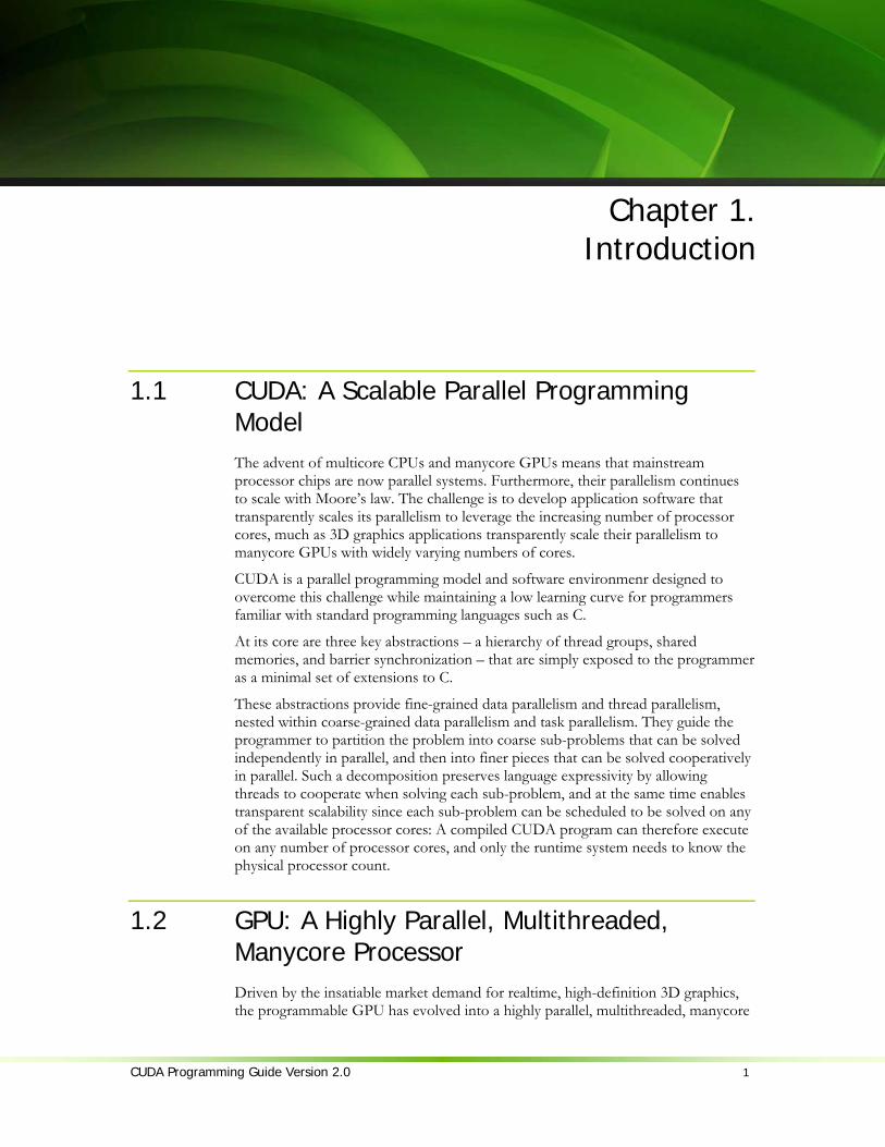
1.1 CUDA: A Scalable Parallel Programming Model The advent of multicore CPUs and manycore GPUs means that mainstream processor chips are now parallel systems. Furthermore, their parallelism continues to scale with Moore’s law. The challenge is to develop application software that transparently scales its parallelism to leverage the increasing number of processor cores, much as 3D graphics applications transparently scale their parallelism to manycore GPUs with widely varying numbers of cores.
CUDA is a parallel programming model and software environmenr designed to overcome this challenge while maintaining a low learning curve for programmers familiar with standard programming languages such as C.
At its core are three key abstractions – a hierarchy of thread groups, shared memories, and barrier synchronization – that are simply exposed to the programmer as a minimal set of extensions to C.
These abstractions provide fine-grained data parallelism and thread parallelism, nested within coarse-grained data parallelism and task parallelism. They guide the programmer to partition the problem into coarse sub-problems that can be solved independently in parallel, and then into finer pieces that can be solved cooperatively in parallel. Such a decomposition preserves language expressivity by allowing threads to cooperate when solving each sub-problem, and at the same time enables transparent scalability since each sub-problem can be scheduled to be solved on any of the available processor cores: A compiled CUDA program can therefore execute on any number of processor cores, and only the runtime system needs to know the physical processor count.
1.2 GPU: A Highly Parallel, Multithreaded, Manycore Processor Driven by the insatiable market demand for realtime, high-definition 3D graphics, the programmable GPU has evolved into a highly parallel, multithreaded, manycore

Chapter 1. Introduction to CUDA
2 CUDA Programming Guide Version 2.0
processor with tremendous computational horsepower and very high memory bandwidth, as illustrated by Figure 1-1.
Figure 1-1. Floating-Point Operations per Second and Memory Bandwidth for the CPU and GPU
The reason behind the discrepancy in floating-point capability between the CPU and the GPU is that the GPU is specialized for compute-intensive, highly parallel
NV30
Jan 2003 Jun Apr
2004 2005 2007 2006 2008
NV35 NV40 G70
G71
G80
G92
GT200
Jun Nov Mar May Jun
GT200 = GeForce GTX 280
G92 = GeForce 9800 GTX
G80 = GeForce 8800 GTX
G71 = GeForce 7900 GTX
G70 = GeForce 7800 GTX
NV40 = GeForce 6800 Ultra
NV35 = GeForce FX 5950 Ultra
NV30 = GeForce FX 5800
3.0 GHz Core2 Duo
3.2 GHz Harpertown
NV30
NV40
G71
G80
G80 Ultra
G80 Ultra
Northwood Prescott EE
Woodcrest Harpertown

Chapter 1. Introduction to CUDA
CUDA Programming Guide Version 2.0 3
computation – exactly what graphics rendering is about – and therefore designed such that more transistors are devoted to data processing rather than data caching and flow control, as schematically illustrated by Figure 1-2.
Figure 1-2. The GPU Devotes More Transistors to Data Processing
More specifically, the GPU is especially well-suited to address problems that can be expressed as data-parallel computations – the same program is executed on many data elements in parallel – with high arithmetic intensity – the ratio of arithmetic operations to memory operations. Because the same program is executed for each data element, there is a lower requirement for sophisticated flow control; and because it is executed on many data elements and has high arithmetic intensity, the memory access latency can be hidden with calculations instead of big data caches.
Data-parallel processing maps data elements to parallel processing threads. Many applications that process large data sets can use a data-parallel programming model to speed up the computations. In 3D rendering large sets of pixels and vertices are mapped to parallel threads. Similarly, image and media processing applications such as post-processing of rendered images, video encoding and decoding, image scaling, stereo vision, and pattern recognition can map image blocks and pixels to parallel processing threads. In fact, many algorithms outside the field of image rendering and processing are accelerated by data-parallel processing, from general signal processing or physics simulation to computational finance or computational biology.
The CUDA programming model is very well suited to expose the parallel capabilities of GPUs. The latest generation of NVIDIA GPUs, based on the Tesla architecture (see Appendix A for a list of all CUDA-capable GPUs), supports the CUDA programming model and tremendously accelerates CUDA applications.
Cache
ALU Control
ALU
ALU
ALU
DRAM
CPU
DRAM
GPU

Chapter 1. Introduction to CUDA
4 CUDA Programming Guide Version 2.0
1.3 Document’s Structure This document is organized into the following chapters:
Chapter 1 is a general introduction to CUDA and GPUs. Chapter 2 outlines the CUDA programming model. Chapter 3 describes its GPU implementation. Chapter 4 describes the CUDA API and runtime. Chapter 5 gives some guidance on how to achieve maximum performance. Chapter 6 illustrates the previous chapters by walking through the code of some
simple example. Appendix A gives the technical specifications of various devices. Appendix B lists the mathematical functions supported in CUDA. Appendix C lists the atomic functions supported in CUDA. Appendix D gives more details on texture fetching.

CUDA Programming Guide Version 2.0 5
Chapter 2. Programming Model
CUDA extends C by allowing the programmer to define C functions, called kernels, that, when called, are executed N times in parallel by N different CUDA threads, as opposed to only once like regular C functions.
A kernel is defined using the __global__ declaration specifier and the number of CUDA threads for each call is specified using a new <<<…>>> syntax: // Kernel definition __global__ void vecAdd(float* A, float* B, float* C) { } int main() { // Kernel invocation vecAdd<<<1, N>>>(A, B, C); }
Each of the threads that execute a kernel is given a unique thread ID that is accessible within the kernel through the built-in threadIdx variable. As an illustration, the following sample code adds two vectors A and B of size N and stores the result into vector C: __global__ void vecAdd(float* A, float* B, float* C) { int i = threadIdx.x; C[i] = A[i] + B[i]; } int main() { // Kernel invocation vecAdd<<<1, N>>>(A, B, C); }
Each of the threads that execute vecAdd() performs one pair-wise addition.

Chapter 3. Hardware Implementation
6 CUDA Programming Guide Version 2.0
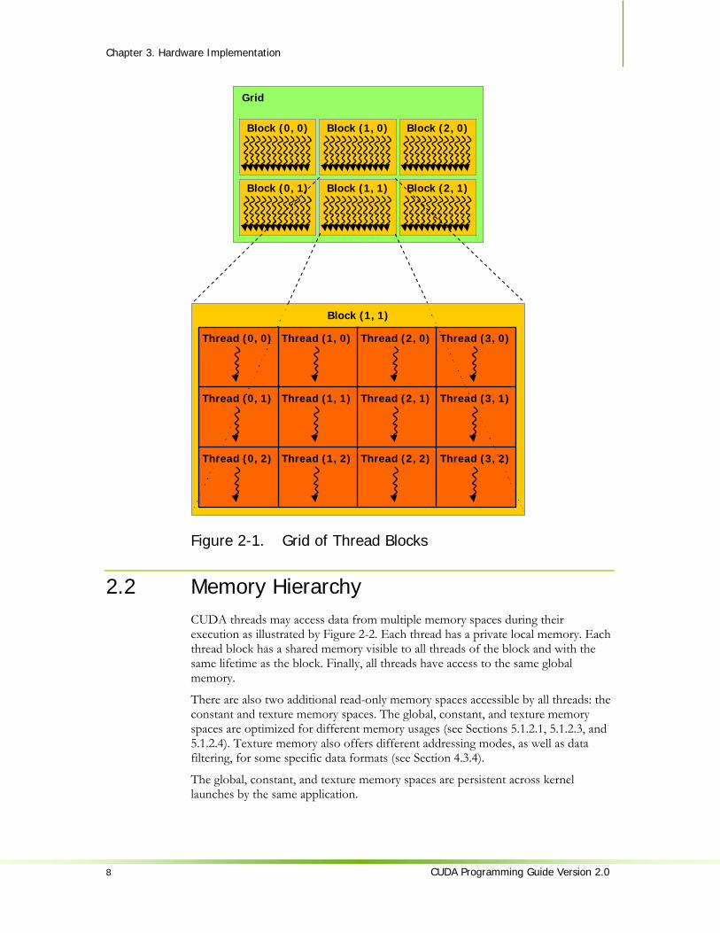
2.1 Thread Hierarchy For convenience, threadIdx is a 3-component vector, so that threads can be identified using a one-dimensional, two-dimensional, or three-dimensional index, forming a one-dimensional, two-dimensional, or three-dimensional thread block. This provides a natural way to invoke computation across the elements in a domain such as a vector, matrix, or field. As an example, the following code adds two matrices A and B of size NxN and stores the result into matrix C: __global__ void matAdd(float A[N][N], float B[N][N], float C[N][N]) { int i = threadIdx.x; int j = threadIdx.y; C[i][j] = A[i][j] + B[i][j]; } int main() { // Kernel invocation dim3 dimBlock(N, N); matAdd<<<1, dimBlock>>>(A, B, C); }
The index of a thread and its thread ID relate to each other in a straightforward way: For a one-dimensional block, they are the same; for a two-dimensional block of size (Dx, Dy), the thread ID of a thread of index (x, y) is (x + y Dx); for a three-dimensional block of size (Dx, Dy, Dz), the thread ID of a thread of index (x, y, z) is (x + y Dx + z Dx Dy).
Threads within a block can cooperate among themselves by sharing data through some shared memory and synchronizing their execution to coordinate memory accesses. More precisely, one can specify synchronization points in the kernel by calling the __syncthreads() intrinsic function; __syncthreads() acts as a barrier at which all threads in the block must wait before any are allowed to proceed.
For efficient cooperation, the shared memory is expected to be a low-latency memory near each processor core, much like an L1 cache, __syncthreads() is expected to be lightweight, and all threads of a block are expected to reside on the same processor core. The number of threads per block is therefore restricted by the limited memory resources of a processor core. On NVIDIA Tesla architecture, a thread block may contain up to 512 threads.
However, a kernel can be executed by multiple equally-shaped thread blocks, so that the total number of threads is equal to the number of threads per block times the number of blocks. These multiple blocks are organized into a one-dimensional or two-dimensional grid of thread blocks as illustrated by Figure 2-1. The dimension of the grid is specified by the first parameter of the <<<…>>> syntax. Each block within the grid can be identified by a one-dimensional or two-dimensional index accessible within the kernel through the built-in blockIdx variable. The dimension of the thread block is accessible within the kernel through the built-in blockDim variable. The previous sample code becomes: __global__ void matAdd(float A[N][N], float B[N][N], float C[N][N])
Chapter 3: Hardware Implementation
CUDA Programming Guide Version 2.0 7
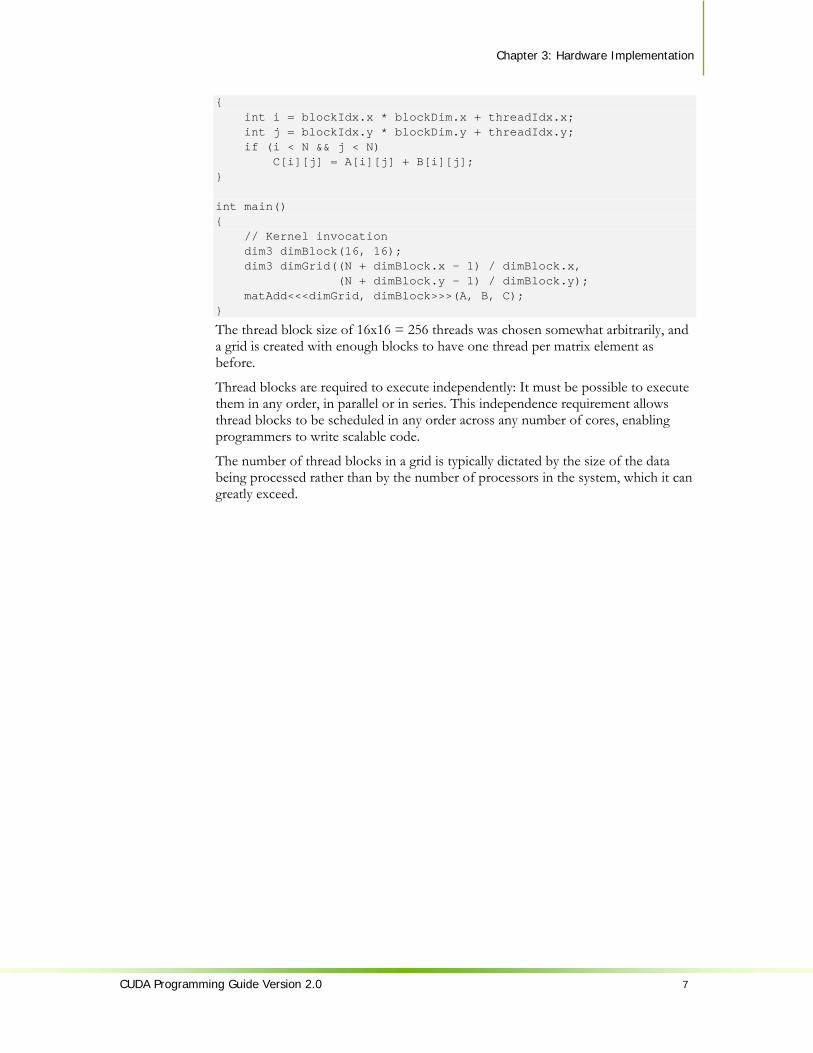
{ int i = blockIdx.x * blockDim.x + threadIdx.x; int j = blockIdx.y * blockDim.y + threadIdx.y; if (i < N && j < N) C[i][j] = A[i][j] + B[i][j]; } int main() { // Kernel invocation dim3 dimBlock(16, 16); dim3 dimGrid((N + dimBlock.x – 1) / dimBlock.x, (N + dimBlock.y – 1) / dimBlock.y); matAdd<<<dimGrid, dimBlock>>>(A, B, C); }
The thread block size of 16x16 = 256 threads was chosen somewhat arbitrarily, and a grid is created with enough blocks to have one thread per matrix element as before.
Thread blocks are required to execute independently: It must be possible to execute them in any order, in parallel or in series. This independence requirement allows thread blocks to be scheduled in any order across any number of cores, enabling programmers to write scalable code.
The number of thread blocks in a grid is typically dictated by the size of the data being processed rather than by the number of processors in the system, which it can greatly exceed.
Chapter 3. Hardware Implementation
8 CUDA Programming Guide Version 2.0
Figure 2-1. Grid of Thread Blocks
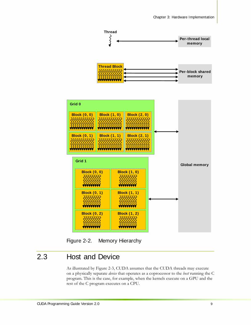
2.2 Memory Hierarchy CUDA threads may access data from multiple memory spaces during their execution as illustrated by Figure 2-2. Each thread has a private local memory. Each thread block has a shared memory visible to all threads of the block and with the same lifetime as the block. Finally, all threads have access to the same global memory.
There are also two additional read-only memory spaces accessible by all threads: the constant and texture memory spaces. The global, constant, and texture memory spaces are optimized for different memory usages (see Sections 5.1.2.1, 5.1.2.3, and 5.1.2.4). Texture memory also offers different addressing modes, as well as data filtering, for some specific data formats (see Section 4.3.4).
The global, constant, and texture memory spaces are persistent across kernel launches by the same application.
Grid
Block (1, 1)
Thread (0, 0) Thread (1, 0) Thread (2, 0) Thread (3, 0)
Thread (0, 1) Thread (1, 1) Thread (2, 1) Thread (3, 1)
Thread (0, 2) Thread (1, 2) Thread (2, 2) Thread (3, 2)
Block (2, 1)Block (1, 1)Block (0, 1)
Block (2, 0)Block (1, 0)Block (0, 0)
Chapter 3: Hardware Implementation
CUDA Programming Guide Version 2.0 9
Figure 2-2. Memory Hierarchy
2.3 Host and Device As illustrated by Figure 2-3, CUDA assumes that the CUDA threads may execute on a physically separate device that operates as a coprocessor to the host running the C program. This is the case, for example, when the kernels execute on a GPU and the rest of the C program executes on a CPU.
Global memory
Grid 0
Block (2, 1)Block (1, 1)Block (0, 1)
Block (2, 0)Block (1, 0)Block (0, 0)
Grid 1
Block (1, 1)
Block (1, 0)
Block (1, 2)
Block (0, 1)
Block (0, 0)
Block (0, 2)
Thread Block Per-block shared
memory
Thread
Per-thread local memory

Chapter 3. Hardware Implementation
10 CUDA Programming Guide Version 2.0
CUDA also assumes that both the host and the device maintain their own DRAM, referred to as host memory and device memory, respectively. Therefore, a program manages the global, constant, and texture memory spaces visible to kernels through calls to the CUDA runtime (described in Chapter 4). This includes device memory allocation and deallocation, as well as data transfer between host and device memory.

Chapter 3: Hardware Implementation
CUDA Programming Guide Version 2.0 11
Serial code executes on the host while parallel code executes on the device.
Figure 2-3. Heterogeneous Programming
Device
Grid 0
Block (2, 1) Block (1, 1)Block (0, 1)
Block (2, 0) Block (1, 0)Block (0, 0)
Host
C Program Sequential Execution
Serial code
Parallel kernel
Kernel0<<<>>>()
Serial code
Parallel kernel
Kernel1<<<>>>()
Host
Device
Grid 1
Block (1, 1)
Block (1, 0)
Block (1, 2)
Block (0, 1)
Block (0, 0)
Block (0, 2)

Chapter 3. Hardware Implementation
12 CUDA Programming Guide Version 2.0
2.4 Software Stack The CUDA software stack is composed of several layers as illustrated in Figure 2-4: a device driver, an application programming interface (API) and its runtime, and two higher-level mathematical libraries of common usage, CUFFT and CUBLAS that are both described in separate documents.
Figure 2-4. Compute Unified Device Architecture Software Stack
2.5 Compute Capability The compute capability of a device is defined by a major revision number and a minor revision number.
Devices with the same major revision number are of the same core architecture. The devices listed in Appendix A are all of compute capability 1.x (Their major revision number is 1).
The minor revision number corresponds to an incremental improvement to the core architecture, possibly including new features.
The technical specifications of the various compute capabilities are given in Appendix A.
Device
Host
CUDA Runtime
CUDA Libraries
CUDA Driver
Application

CUDA Programming Guide Version 2.0 13
Chapter 3. GPU Implementation
Introduced by NVIDIA in November 2006, the Tesla unified graphics and computing architecture significantly extends the GPU beyond graphics; its massively multithreaded processor array becomes a highly efficient unified platform for both graphics and general-purpose parallel computing applications. By scaling the number of processors and memory partitions, the Tesla architecture spans a wide market range, from the high-performance enthusiast GeForce GTX 280 GPU and professional Quadro and Tesla computing products to a variety of inexpensive, mainstream GeForce GPUs (see Appendix A for a list of all CUDA-capable GPUs). Its computing features enable straightforward programming of the GPU cores in C with CUDA. Wide availability in laptops, desktops, workstations, and servers, coupled with C programmability and CUDA software, make the Tesla architecture the first ubiquitous supercomputing platform.
This chapter describes how the CUDA programming model maps to the Tesla architecture.
3.1 A Set of SIMT Multiprocessors with On-Chip Shared Memory The Tesla architecture is built around a scalable array of multithreaded Streaming Multiprocessors (SMs). When a CUDA program on the host CPU invokes a kernel grid, the blocks of the grid are enumerated and distributed to multiprocessors with available execution capacity. The threads of a thread block execute concurrently on one multiprocessor. As thread blocks terminate, new blocks are launched on the vacated multiprocessors.
A multiprocessor consists of eight Scalar Processor (SP) cores, two special function units for transcendentals, a multithreaded instruction unit, and on-chip shared memory. The multiprocessor creates, manages, and executes concurrent threads in hardware with zero scheduling overhead. It implements the __syncthreads() barrier synchronization intrinsic with a single instruction. Fast barrier synchronization together with lightweight thread creation and zero-overhead thread scheduling efficiently support very fine-grained parallelism, allowing, for example, a low granularity decomposition of problems by assigning one thread to each data

Chapter 3. Hardware Implementation
14 CUDA Programming Guide Version 2.0
element (such as a pixel in an image, a voxel in a volume, a cell in a grid-based computation).
To manage hundreds of threads running several different programs, the multiprocessor employs a new architecture we call SIMT (single-instruction, multiple-thread). The multiprocessor maps each thread to one scalar processor core, and each scalar thread executes independently with its own instruction address and register state. The multiprocessor SIMT unit creates, manages, schedules, and executes threads in groups of 32 parallel threads called warps. (This term originates from weaving, the first parallel thread technology. A half-warp is either the first or second half of a warp.) Individual threads composing a SIMT warp start together at the same program address but are otherwise free to branch and execute independently.
When a multiprocessor is given one or more thread blocks to execute, it splits them into warps that get scheduled by the SIMT unit. The way a block is split into warps is always the same; each warp contains threads of consecutive, increasing thread IDs with the first warp containing thread 0. Section 2.1 describes how thread IDs relate to thread indices in the block.
Every instruction issue time, the SIMT unit selects a warp that is ready to execute and issues the next instruction to the active threads of the warp. A warp executes one common instruction at a time, so full efficiency is realized when all 32 threads of a warp agree on their execution path. If threads of a warp diverge via a data-dependent conditional branch, the warp serially executes each branch path taken, disabling threads that are not on that path, and when all paths complete, the threads converge back to the same execution path. Branch divergence occurs only within a warp; different warps execute independently regardless of whether they are executing common or disjointed code paths.
SIMT architecture is akin to SIMD (Single Instruction, Multiple Data) vector organizations in that a single instruction controls multiple processing elements. A key difference is that SIMD vector organizations expose the SIMD width to the software, whereas SIMT instructions specify the execution and branching behavior of a single thread. In contrast with SIMD vector machines, SIMT enables programmers to write thread-level parallel code for independent, scalar threads, as well as data-parallel code for coordinated threads. For the purposes of correctness, the programmer can essentially ignore the SIMT behavior; however, substantial performance improvements can be realized by taking care that the code seldom requires threads in a warp to diverge. In practice, this is analogous to the role of cache lines in traditional code: Cache line size can be safely ignored when designing for correctness but must be considered in the code structure when designing for peak performance. Vector architectures, on the other hand, require the software to coalesce loads into vectors and manage divergence manually.
As illustrated by Figure 3-1, each multiprocessor has on-chip memory of the four following types:
One set of local 32-bit registers per processor, A parallel data cache or shared memory that is shared by all scalar processor cores
and is where the shared memory space resides, A read-only constant cache that is shared by all scalar processor cores and speeds
up reads from the constant memory space, which is a read-only region of device memory,
Chapter 3: Hardware Implementation
CUDA Programming Guide Version 2.0 15
A read-only texture cache that is shared by all scalar processor cores and speeds up reads from the texture memory space, which is a read-only region of device memory; each multiprocessor accesses the texture cache via a texture unit that implements the various addressing modes and data filtering mentioned in Section 4.3.4.
The local and global memory spaces are read-write regions of device memory and are not cached.
How many blocks a multiprocessor can process at once depends on how many registers per thread and how much shared memory per block are required for a given kernel since the multiprocessor’s registers and shared memory are split among all the threads of the batch of blocks. If there are not enough registers or shared memory available per multiprocessor to process at least one block, the kernel will fail to launch. A multiprocessor can execute as many as eight thread blocks concurrently.
If a non-atomic instruction executed by a warp writes to the same location in global or shared memory for more than one of the threads of the warp, the number of serialized writes that occur to that location and the order in which they occur is undefined, but one of the writes is guaranteed to succeed. If an atomic instruction (see Section 4.4.4) executed by a warp reads, modifies, and writes to the same location in global memory for more than one of the threads of the warp, each read, modify, write to that location occurs and they are all serialized, but the order in which they occur is undefined.

Chapter 3. Hardware Implementation
16 CUDA Programming Guide Version 2.0
A set of SIMT multiprocessors with on-chip shared memory.
Figure 3-1. Hardware Model
3.2 Multiple Devices The use of multiple GPUs as CUDA devices by an application running on a multi-GPU system is only guaranteed to work if theses GPUs are of the same type. If the system is in SLI mode however, only one GPU can be used as a CUDA device since all the GPUs are fused at the lowest levels in the driver stack. SLI mode needs to be turned off in the control panel for CUDA to be able to see each GPU as separate devices.
Device
Multiprocessor N
Multiprocessor 2
Multiprocessor 1
Device Memory
Shared Memory
Instruction Unit
Processor 1
Registers
…Processor 2
Registers
Processor M
Registers
Constant Cache
Texture Cache
Chapter 3: Hardware Implementation
CUDA Programming Guide Version 2.0 17
3.3 Mode Switches GPUs dedicate some DRAM memory to the so-called primary surface, which is used to refresh the display device whose output is viewed by the user. When users initiate a mode switch of the display by changing the resolution or bit depth of the display (using NVIDIA control panel or the Display control panel on Windows), the amount of memory needed for the primary surface changes. For example, if the user changes the display resolution from 1280x1024x32-bit to 1600x1200x32-bit, the system must dedicate 7.68 MB to the primary surface rather than 5.24 MB. (Full-screen graphics applications running with anti-aliasing enabled may require much more display memory for the primary surface.) On Windows, other events that may initiate display mode switches include launching a full-screen DirectX application, hitting Alt+Tab to task switch away from a full-screen DirectX application, or hitting Ctrl+Alt+Del to lock the computer.
If a mode switch increases the amount of memory needed for the primary surface, the system may have to cannibalize memory allocations dedicated to CUDA applications, resulting in a crash of these applications.


CUDA Programming Guide Version 2.0 19
Chapter 4. Application Programming Interface
4.1 An Extension to the C Programming Language The goal of the CUDA programming interface is to provide a relatively simple path for users familiar with the C programming language to easily write programs for execution by the device.
It consists of:
A minimal set of extensions to the C language, described in Section 4.2, that allow the programmer to target portions of the source code for execution on the device;
A runtime library split into: A host component, described in Section 4.5, that runs on the host and
provides functions to control and access one or more compute devices from the host;
A device component, described in Section 4.4, that runs on the device and provides device-specific functions;
A common component, described in Section 4.3, that provides built-in vector types and a subset of the C standard library that are supported in both host and device code.
It should be emphasized that the only functions from the C standard library that are supported to run on the device are the functions provided by the common runtime component.
4.2 Language Extensions The extensions to the C programming language are four-fold:
Function type qualifiers to specify whether a function executes on the host or on the device and whether it is callable from the host or from the device (Section 4.2.1);
Variable type qualifiers to specify the memory location on the device of a variable (Section 4.2.2);
Chapter 4. Application Programming Interface
20 CUDA Programming Guide Version 2.0
A new directive to specify how a kernel is executed on the device from the host (Section 4.2.3);
Four built-in variables that specify the grid and block dimensions and the block and thread indices (Section 4.2.4).
Each source file containing these extensions must be compiled with the CUDA compiler nvcc, as briefly described in Section 4.2.5. A detailed description of nvcc can be found in a separate document.
Each of these extensions come with some restrictions described in each of the sections below. nvcc will give an error or a warning on some violations of these restrictions, but some of them cannot be detected.
4.2.1 Function Type Qualifiers 4.2.1.1 __device__
The __device__ qualifier declares a function that is:
Executed on the device Callable from the device only.
4.2.1.2 __global__ The __global__ qualifier declares a function as being a kernel. Such a function is:
Executed on the device, Callable from the host only.
4.2.1.3 __host__ The __host__ qualifier declares a function that is:
Executed on the host, Callable from the host only.
It is equivalent to declare a function with only the __host__ qualifier or to declare it without any of the __host__, __device__, or __global__ qualifier; in either case the function is compiled for the host only.
However, the __host__ qualifier can also be used in combination with the __device__ qualifier, in which case the function is compiled for both the host and the device.
4.2.1.4 Restrictions __device__ and __global__ functions do not support recursion.
__device__ and __global__ functions cannot declare static variables inside their body.
__device__ and __global__ functions cannot have a variable number of arguments.
__device__ functions cannot have their address taken; function pointers to __global__ functions, on the other hand, are supported.
The __global__ and __host__ qualifiers cannot be used together.
Chapter 4. Application Programming Interface
CUDA Programming Guide Version 2.0 21
__global__ functions must have void return type.
Any call to a __global__ function must specify its execution configuration as described in Section 4.2.3.
A call to a __global__ function is asynchronous, meaning it returns before the device has completed its execution.
__global__ function parameters are currently passed via shared memory to the device and limited to 256 bytes.
4.2.2 Variable Type Qualifiers 4.2.2.1 __device__
The __device__ qualifier declares a variable that resides on the device.
At most one of the other type qualifiers defined in the next three sections may be used together with __device__ to further specify which memory space the variable belongs to. If none of them is present, the variable:
Resides in global memory space, Has the lifetime of an application, Is accessible from all the threads within the grid and from the host through the
runtime library.
4.2.2.2 __constant__ The __constant__ qualifier, optionally used together with __device__, declares a variable that:
Resides in constant memory space, Has the lifetime of an application, Is accessible from all the threads within the grid and from the host through the
runtime library.
4.2.2.3 __shared__ The __shared__ qualifier, optionally used together with __device__, declares a variable that:
Resides in the shared memory space of a thread block, Has the lifetime of the block, Is only accessible from all the threads within the block.
Only after the execution of a __syncthreads() (Section 4.4.2) are writes to shared variables guaranteed to be visible by other threads. Unless the variable is declared as volatile, the compiler is free to optimize the reads and writes to shared memory as long as the previous statement is met.
When declaring a variable in shared memory as an external array such as extern __shared__ float shared[];
the size of the array is determined at launch time (see Section 4.2.3). All variables declared in this fashion, start at the same address in memory, so that the layout of

Chapter 4. Application Programming Interface
22 CUDA Programming Guide Version 2.0
the variables in the array must be explicitly managed through offsets. For example, if one wants the equivalent of short array0[128]; float array1[64]; int array2[256];
in dynamically allocated shared memory, one could declare and initialize the arrays the following way: extern __shared__ char array[]; __device__ void func() // __device__ or __global__ function { short* array0 = (short*)array; float* array1 = (float*)&array0[128]; int* array2 = (int*)&array1[64]; }
4.2.2.4 Restrictions These qualifiers are not allowed on struct and union members, on formal parameters and on local variables within a function that executes on the host.
__shared__ and __constant__ variables have implied static storage.
__device__, __shared__ and __constant__ variables cannot be defined as external using the extern keyword.
__device__ and __constant__ variables are only allowed at file scope.
__constant__ variables cannot be assigned to from the device, only from the host through host runtime functions (Sections 4.5.2.3 and 4.5.3.6).
__shared__ variables cannot have an initialization as part of their declaration.
An automatic variable declared in device code without any of these qualifiers generally resides in a register. However in some cases the compiler might choose to place it in local memory. This is often the case for large structures or arrays that would consume too much register space, and arrays for which the compiler cannot determine that they are indexed with constant quantities. Inspection of the ptx assembly code (obtained by compiling with the –ptx or -keep option) will tell if a variable has been placed in local memory during the first compilation phases as it will be declared using the .local mnemonic and accessed using the ld.local and st.local mnemonics. If it has not, subsequent compilation phases might still decide otherwise though if they find it consumes too much register space for the targeted architecture. This can be checked by compiling with the --ptxas-options=-v option that reports local memory usage (lmem).
Pointers in code that is executed on the device are supported as long as the compiler is able to resolve whether they point to either the shared memory space or the global memory space, otherwise they are restricted to only point to memory allocated or declared in the global memory space.
Dereferencing a pointer either to global or shared memory in code that is executed on the host or to host memory in code that is executed on the device results in an undefined behavior, most often in a segmentation fault and application termination.
The address obtained by taking the address of a __device__, __shared__ or __constant__ variable can only be used in device code. The address of a __device__ or __constant__ variable obtained through

Chapter 4. Application Programming Interface
CUDA Programming Guide Version 2.0 23
cudaGetSymbolAddress() as described in Section 4.5.2.3 can only be used in host code.
4.2.3 Execution Configuration Any call to a __global__ function must specify the execution configuration for that call.
The execution configuration defines the dimension of the grid and blocks that will be used to execute the function on the device, as well as the associated stream (see Section 4.5.1.5 for a description of streams). It is specified by inserting an expression of the form <<< Dg, Db, Ns, S >>> between the function name and the parenthesized argument list, where:
Dg is of type dim3 (see Section 4.3.1.2) and specifies the dimension and size of the grid, such that Dg.x * Dg.y equals the number of blocks being launched; Dg.z is unused;
Db is of type dim3 (see Section 4.3.1.2) and specifies the dimension and size of each block, such that Db.x * Db.y * Db.z equals the number of threads per block;
Ns is of type size_t and specifies the number of bytes in shared memory that is dynamically allocated per block for this call in addition to the statically allocated memory; this dynamically allocated memory is used by any of the variables declared as an external array as mentioned in Section 4.2.2.3; Ns is an optional argument which defaults to 0;
S is of type cudaStream_t and specifies the associated stream; S is an optional argument which defaults to 0.
As an example, a function declared as __global__ void Func(float* parameter);
must be called like this: Func<<< Dg, Db, Ns >>>(parameter);
The arguments to the execution configuration are evaluated before the actual function arguments and like the function arguments, are currently passed via shared memory to the device.
The function call will fail if Dg or Db are greater than the maximum sizes allowed for the device as specified in Appendix A.1.1, or if Ns is greater than the maximum amount of shared memory available on the device, minus the amount of shared memory required for static allocation, functions arguments, and execution configuration.
4.2.4 Built-in Variables 4.2.4.1 gridDim
This variable is of type dim3 (see Section 4.3.1.2) and contains the dimensions of the grid.

Chapter 4. Application Programming Interface
24 CUDA Programming Guide Version 2.0
4.2.4.2 blockIdx This variable is of type uint3 (see Section 4.3.1.1) and contains the block index within the grid.
4.2.4.3 blockDim This variable is of type dim3 (see Section 4.3.1.2) and contains the dimensions of the block.
4.2.4.4 threadIdx This variable is of type uint3 (see Section 4.3.1.1) and contains the thread index within the block.
4.2.4.5 warpSize This variable is of type int and contains the warp size in threads.
4.2.4.6 Restrictions It is not allowed to take the address of any of the built-in variables. It is not allowed to assign values to any of the built-in variables.
4.2.5 Compilation with NVCC nvcc is a compiler driver that simplifies the process of compiling CUDA code: It provides simple and familiar command line options and executes them by invoking the collection of tools that implement the different compilation stages.
nvcc’s basic workflow consists in separating device code from host code and compiling the device code into a binary form or cubin object. The generated host code is output either as C code that is left to be compiled using another tool or as object code directly by invoking the host compiler during the last compilation stage.
Applications can either ignore the generated host code and load and execute the cubin object on the device using the CUDA driver API (see Section �), or they can link to the generated host code, which includes the cubin object as a global initialized data array and contains a translation of the execution configuration syntax described in Section 4.2.3 into the necessary CUDA runtime startup code to load and launch each compiled kernel (see Section 4.5.2).
The front end of the compiler processes CUDA source files according to C++ syntax rules. Full C++ is supported for the host code. However, only the C subset of C++ is fully supported for the device code; C++ specific features such as classes, inheritance, or declaration of variables within basic blocks are not. As a consequence of the use of C++ syntax rules, void pointers (e.g. returned by malloc()) cannot be assigned to non-void pointers without a typecast.
A detailed description of nvcc’s workflow and command options can be found in a separate document.
nvcc introduces two compiler directives described in the following sections.
Chapter 4. Application Programming Interface
CUDA Programming Guide Version 2.0 25
4.2.5.1 __noinline__ By default, a __device__ function is always inlined. The __noinline__ function qualifier however can be used as a hint for the compiler not to inline the function if possible. The function body must still be in the same file where it is called.
The compiler will not honor the __noinline__ qualifier for functions with pointer parameters and for functions with large parameter lists.
4.2.5.2 #pragma unroll By default, the compiler unrolls small loops with a known trip count. The #pragma unroll directive however can be used to control unrolling of any given loop. It must be placed immediately before the loop and only applies to that loop. It is optionally followed by a number that specifies how many times the loop must be unrolled.
For example, in this code sample: #pragma unroll 5 for (int i = 0; i < n; ++i)
the loop will be unrolled 5 times. It is up to the programmer to make sure that unrolling will not affect the correctness of the program (which it might, in the above example, if n is smaller than 5).
#pragma unroll 1 will prevent the compiler from ever unrolling a loop.
If no number is specified after #pragma unroll, the loop is completely unrolled if its trip count is constant, otherwise it is not unrolled at all.
4.3 Common Runtime Component The common runtime component can be used by both host and device functions.
4.3.1 Built-in Vector Types 4.3.1.1 char1, uchar1, char2, uchar2, char3, uchar3,
char4, uchar4, short1, ushort1, short2, ushort2, short3, ushort3, short4, ushort4, int1, uint1, int2, uint2, int3, uint3, int4, uint4, long1, ulong1, long2, ulong2, long3, ulong3, long4, ulong4, float1, float2, float3, float4, double2 These are vector types derived from the basic integer and floating-point types. They are structures and the 1st, 2nd, 3rd, and 4th components are accessible through the fields x, y, z, and w, respectively. They all come with a constructor function of the form make_<type name>; for example, int2 make_int2(int x, int y);
which creates a vector of type int2 with value (x, y).

Chapter 4. Application Programming Interface
26 CUDA Programming Guide Version 2.0
4.3.1.2 dim3 Type This type is an integer vector type based on uint3 that is used to specify dimensions. When defining a variable of type dim3, any component left unspecified is initialized to 1.
4.3.2 Mathematical Functions Section B.1 contains a comprehensive list of the C/C++ standard library mathematical functions that are currently supported, along with their respective error bounds when executed on the device.
When executed in host code, a given function uses the C runtime implementation if available.
4.3.3 Time Function clock_t clock();
when executed in device code, returns the value of a per-multiprocessor counter that is incremented every clock cycle. Sampling this counter at the beginning and at the end of a kernel, taking the difference of the two samples, and recording the result per thread provides a measure for each thread of the number of clock cycles taken by the device to completely execute the thread, but not of the number of clock cycles the device actually spent executing thread instructions. The former number is greater that the latter since threads are time sliced.
4.3.4 Texture Type CUDA supports a subset of the texturing hardware that the GPU uses for graphics to access texture memory. Reading data from texture memory instead of global memory can have several performance benefits as described in Section 5.4.
Texture memory is read from kernels using device functions called texture fetches, described in Section 4.4.3. The first parameter of a texture fetch specifies an object called a texture reference.
A texture reference defines which part of texture memory is fetched. It must be bound through host runtime functions (Sections 4.5.2.6 and 4.5.3.9) to some region of memory, called a texture, before it can be used by a kernel. Several distinct texture references might be bound to the same texture or to textures that overlap in memory.
A texture reference has several attributes. One of them is its dimensionality that specifies whether the texture is addressed as a one-dimensional array using one texture coordinate, a two-dimensional array using two texture coordinates, or a three-dimensional array using three texture coordinates. Elements of the array are called texels, short for “texture elements.”
Other attributes define the input and output data types of the texture fetch, as well as how the input coordinates are interpreted and what processing should be done.

Chapter 4. Application Programming Interface
CUDA Programming Guide Version 2.0 27
4.3.4.1 Texture Reference Declaration Some of the attributes of a texture reference are immutable and must be known at compile time; they are specified when declaring the texture reference. A texture reference is declared at file scope as a variable of type texture: texture<Type, Dim, ReadMode> texRef;
where:
Type specifies the type of data that is returned when fetching the texture; Type is restricted to the basic integer and single-precision floating-point types and any of the 1-, 2-, and 4-component vector types defined in Section 4.3.1.1;
Dim specifies the dimensionality of the texture reference and is equal to 1, 2, or 3; Dim is an optional argument which defaults to 1;
ReadMode is equal to cudaReadModeNormalizedFloat or cudaReadModeElementType; if it is cudaReadModeNormalizedFloat and Type is a 16-bit or 8-bit integer type, the value is actually returned as floating-point type and the full range of the integer type is mapped to [0.0, 1.0] for unsigned integer type and [-1.0, 1.0] for signed integer type; for example, an unsigned 8-bit texture element with the value 0xff reads as 1; if it is cudaReadModeElementType, no conversion is performed; ReadMode is an optional argument which defaults to cudaReadModeElementType.
4.3.4.2 Runtime Texture Reference Attributes The other attributes of a texture reference are mutable and can be changed at runtime through the host runtime (Section 4.5.2.6 for the runtime API and Section 4.5.3.9 for the driver API). They specify whether texture coordinates are normalized or not, the addressing mode, and texture filtering, as detailed below.
By default, textures are referenced using floating-point coordinates in the range [0, N) where N is the size of the texture in the dimension corresponding to the coordinate. For example, a texture that is 64×32 in size will be referenced with coordinates in the range [0, 63] and [0, 31] for the x and y dimensions, respectively. Normalized texture coordinates cause the coordinates to be specified in the range [0.0, 1.0) instead of [0, N), so the same 64×32 texture would be addressed by normalized coordinates in the range [0, 1) in both the x and y dimensions. Normalized texture coordinates are a natural fit to some applications’ requirements, if it is preferable for the texture coordinates to be independent of the texture size.
The addressing mode defines what happens when texture coordinates are out of range. When using unnormalized texture coordinates, texture coordinates outside the range [0, N) are clamped: Values below 0 are set to 0 and values greater or equal to N are set to N-1. Clamping is also the default addressing mode when using normalized texture coordinates: Values below 0.0 or above 1.0 are clamped to the range [0.0, 1.0). For normalized coordinates, the “wrap” addressing mode also may be specified. Wrap addressing is usually used when the texture contains a periodic signal. It uses only the fractional part of the texture coordinate; for example, 1.25 is treated the same as 0.25 and -1.25 is treated the same as 0.75.
Linear texture filtering may be done only for textures that are configured to return floating-point data. It performs low-precision interpolation between neighboring texels. When enabled, the texels surrounding a texture fetch location are read and the return value of the texture fetch is interpolated based on where the texture

Chapter 4. Application Programming Interface
28 CUDA Programming Guide Version 2.0
coordinates fell between the texels. Simple linear interpolation is performed for one-dimensional textures and bilinear interpolation is performed for two-dimensional textures.
Appendix D gives more details on texture fetching.
4.3.4.3 Texturing from Linear Memory versus CUDA Arrays A texture can be any region of linear memory or a CUDA array (see Section 4.5.1.2).
Textures allocated in linear memory:
Can only be of dimensionality equal to 1; Do not support texture filtering; Can only be addressed using a non-normalized integer texture coordinate; Do not support the various addressing modes: Out-of-range texture accesses
return zero. The hardware enforces an alignment requirement on texture base addresses. To abstract this alignment requirement from programmers, the functions to bind texture references onto device memory pass back a byte offset that must be applied to texture fetches in order to read from the desired memory. The base pointers returned by CUDA’s allocation routines conform to this alignment constraint, so applications can avoid the offsets altogether by passing allocated pointers to cudaBindTexture()/cuTexRefSetAddress().
4.4 Device Runtime Component The device runtime component can only be used in device functions.
4.4.1 Mathematical Functions For some of the functions of Section B.1, a less accurate, but faster version exists in the device runtime component; it has the same name prefixed with __ (such as __sinf(x)). These intrinsic functions are listed in Section B.2, along with their respective error bounds.
The compiler has an option (-use_fast_math) to force every function to compile to its less accurate counterpart if it exists.
4.4.2 Synchronization Function void __syncthreads();
synchronizes all threads in a block. Once all threads have reached this point, execution resumes normally.
__syncthreads() is used to coordinate communication between the threads of a same block. When some threads within a block access the same addresses in shared or global memory, there are potential read-after-write, write-after-read, or write-after-write hazards for some of these memory accesses. These data hazards can be avoided by synchronizing threads in-between these accesses.

Chapter 4. Application Programming Interface
CUDA Programming Guide Version 2.0 29
__syncthreads() is allowed in conditional code but only if the conditional evaluates identically across the entire thread block, otherwise the code execution is likely to hang or produce unintended side effects.
4.4.3 Texture Functions 4.4.3.1 Texturing from Linear Memory
When texturing from linear memory, the texture is accessed with the tex1Dfetch() family of functions; for example: template<class Type> Type tex1Dfetch( texture<Type, 1, cudaReadModeElementType> texRef, int x); float tex1Dfetch( texture<unsigned char, 1, cudaReadModeNormalizedFloat> texRef, int x); float tex1Dfetch( texture<signed char, 1, cudaReadModeNormalizedFloat> texRef, int x); float tex1Dfetch( texture<unsigned short, 1, cudaReadModeNormalizedFloat> texRef, int x); float tex1Dfetch( texture<signed short, 1, cudaReadModeNormalizedFloat> texRef, int x);
These functions fetch the region of linear memory bound to texture reference texRef using texture coordinate x. No texture filtering and addressing modes are supported. For integer types, these functions may optionally promote the integer to single-precision floating point.
Besides the functions shown above, 2-, and 4-tuples are supported; for example: float4 tex1Dfetch( texture<uchar4, 1, cudaReadModeNormalizedFloat> texRef, int x);
fetches the linear memory bound to texture reference texRef using texture coordinate x.
4.4.3.2 Texturing from CUDA Arrays When texturing from CUDA arrays, the texture is accessed with the tex1D(), tex2D(), or tex3D(): template<class Type, enum cudaTextureReadMode readMode> Type tex1D(texture<Type, 1, readMode> texRef, float x); template<class Type, enum cudaTextureReadMode readMode> Type tex2D(texture<Type, 2, readMode> texRef, float x, float y);
Chapter 4. Application Programming Interface
30 CUDA Programming Guide Version 2.0
template<class Type, enum cudaTextureReadMode readMode> Type tex3D(texture<Type, 3, readMode> texRef, float x, float y, float z);
These functions fetches the CUDA array bound to texture reference texRef using texture coordinates x, y, and z. A combination of the texture reference’s immutable (compile-time) and mutable (runtime) attributes determine how the coordinates are interpreted, what processing occurs during the texture fetch, and the return value delivered by the texture fetch (see Sections 4.3.4.1 and 4.3.4.2).
4.4.4 Atomic Functions An atomic function performs a read-modify-write atomic operation on one 32-bit or 64-bit word residing in global or shared memory. For example, atomicAdd() reads a 32-bit word at some address in global or shared memory, adds an integer to it, and writes the result back to the same address. The operation is atomic in the sense that it is guaranteed to be performed without interference from other threads. In other words, no other thread can access this address until the operation is complete.
Appendix C lists all supported atomic functions. As described in the appendix, they are not supported by all devices. In particular, devices of compute capability 1.0 support none of them.
Atomic operations only work with signed and unsigned integers (with the exception of atomicExch(), which is also supported for single-precision floating-point numbers).
4.4.5 Warp Vote Functions Warp vote functions are only supported by devices of compute capability 1.2 and higher. int __all(int predicate);
evaluates predicate for all threads of the warp and returns non-zero if and only if predicate evaluates to non-zero for all of them. int __any(int predicate);
evaluates predicate for all threads of the warp and returns non-zero if and only if predicate evaluates to non-zero for any of them.
4.5 Host Runtime Component The host runtime component can only be used by host functions.
It provides functions to handle:
Device management, Context management, Memory management, Code module management, Execution control,
Chapter 4. Application Programming Interface
CUDA Programming Guide Version 2.0 31
Texture reference management, Interoperability with OpenGL and Direct3D.
It is composed of two APIs:
A low-level API called the CUDA driver API, A higher-level API called the CUDA runtime API that is implemented on top of
the CUDA driver API. These APIs are mutually exclusive: An application should use either one or the other.
The CUDA runtime eases device code management by providing implicit initialization, context management, and module management. The C host code generated by nvcc is based on the CUDA runtime (see Section 4.2.5), so applications that link to this code must use the CUDA runtime API.
In contrast, the CUDA driver API requires more code, is harder to program and debug, but offers a better level of control and is language-independent since it only deals with cubin objects (see Section 4.2.5). In particular, it is more difficult to configure and launch kernels using the CUDA driver API, since the execution configuration and kernel parameters must be specified with explicit function calls instead of the execution configuration syntax described in Section 4.2.3. Also, device emulation (see Section 4.5.2.9) does not work with the CUDA driver API.
The CUDA driver API is delivered through the nvcuda dynamic library and all its entry points are prefixed with cu.
The CUDA runtime API is delivered through the cudart dynamic library and all its entry points are prefixed with cuda.
4.5.1 Common Concepts 4.5.1.1 Device
Both APIs provide functions to enumerate the devices available on the system, query their properties, and select one of them for kernel executions (see Section 4.5.2.2 for the runtime API and Section 4.5.3.2 for the driver API).
Several host threads can execute device code on the same device, but by design, a host thread can execute device code on only one device. As a consequence, multiple host threads are required to execute device code on multiple devices. Also, any CUDA resources created through the runtime in one host thread cannot be used by the runtime from another host thread.
4.5.1.2 Memory Device memory can be allocated either as linear memory or as CUDA arrays.
Linear memory exists on the device in a 32-bit address space, so separately allocated entities can reference one another via pointers, for example, in a binary tree.
CUDA arrays are opaque memory layouts optimized for texture fetching (see Section 4.3.4). They are one-dimensional, two-dimensional, or three-dimensional and composed of elements, each of which has 1, 2 or 4 components that may be signed or unsigned 8-, 16- or 32-bit integers, 16-bit floats (currently only supported through the driver API), or 32-bit floats. CUDA arrays are only readable by kernels

Chapter 4. Application Programming Interface
32 CUDA Programming Guide Version 2.0
through texture fetching and may only be bound to texture references with the same number of packed components.
Both linear memory and CUDA arrays are readable and writable by the host through the memory copy functions described in Sections 4.5.2.3 and 4.5.3.6.
The host runtime also provides functions to allocate and free page-locked host memory – as opposed to regular pageable host memory allocated by malloc(). One advantage of page-locked memory is that the bandwidth between host memory and device memory is higher if host memory is allocated as page-locked – only for data transfers performed by the host thread that allocated host memory. Page-locked memory is a scarce resource however, so allocations in page-locked memory will start failing long before allocations in pageable memory. In addition, by reducing the amount of physical memory available to the operating system for paging, allocating too much page-locked memory reduces overall system performance.
4.5.1.3 OpenGL Interoperability OpenGL buffer objects may be mapped into the address space of CUDA, either to enable CUDA to read data written by OpenGL or to enable CUDA to write data for consumption by OpenGL. Section 4.5.2.7 describes how this is done with the runtime API and Section 4.5.3.10, with the driver API.
4.5.1.4 Direct3D Interoperability Direct3D resources may be mapped into the address space of CUDA, either to enable CUDA to read data written by Direct3D or to enable CUDA to write data for consumption by Direct3D. Section 4.5.2.8 describes how this is done with the runtime API and Section 4.5.2.8, with the driver API.
There are restrictions on which resources can be mapped as detailed in the reference manual for cudaD3D9RegisterResource() and cuD3D9RegisterResource().
A CUDA context may interoperate with only one Direct3D device at a time and the CUDA context and Direct3D device must be created on the same GPU. Moreover, the Direct3D device must be created with the D3DCREATE_HARDWARE_VERTEXPROCESSING flag.
Direct3D interoperability is currently only supported for Direct3D 9.0.
4.5.1.5 Asynchronous Concurrent Execution In order to facilitate concurrent execution between host and device, some runtime functions are asynchronous: Control is returned to the application before the device has completed the requested task. These are:
Kernel launches through __global__ functions or cuLaunchGrid() and cuLaunchGridAsync();
The functions that perform memory copies and are suffixed with Async; The functions that perform device ↔ device memory copies; The functions that set memory.
Some devices can also perform copies between page-locked host memory and device memory concurrently with kernel execution. Applications may query this capability by calling cudaGetDeviceProperties() and checking

Chapter 4. Application Programming Interface
CUDA Programming Guide Version 2.0 33
deviceOverlap if using the runtime API, or by calling cuDeviceGetAttribute() with CU_DEVICE_ATTRIBUTE_GPU_OVERLAP if using the driver API. This capability is currently supported only for memory copies that do not involve CUDA arrays or 2D arrays allocated through cudaMallocPitch() (see Section 4.5.2.3) or cuMemAllocPitch() (see Section 4.5.3.6).
Applications manage concurrency through streams. A stream is a sequence of operations that execute in order. Different streams, on the other hand, may execute their operations out of order with respect to one another or concurrently.
A stream is defined by creating a stream object and specifying it as the stream parameter to a sequence of kernel launches and host ↔ device memory copies. Section 4.5.2.4 describes how this is done with the runtime API and Section 4.5.3.7, with the driver API.
Any kernel launch, memory set, or memory copy function without a stream parameter or with a zero stream parameter begins only after all preceding operations are done, including operations that are part of streams, and no subsequent operation may begin until it is done. Kernel launches for which no stream parameter is provided and memory copies without an Async suffix are assigned to the default zero stream.
cudaStreamQuery() for the runtime API and cuStreamQuery() for the driver API provide applications with a way to know if all preceding operations in a stream have completed. cudaStreamSynchronize() for the runtime API and cuStreamSynchronize() for the driver API provide a way to explicitly force the runtime to wait until all preceding operations in a stream have completed.
Similarly, with cudaThreadSynchronize() for the runtime API and cuCtxSynchronize() for the driver API applications force the runtime to wait until all preceding device tasks in all streams have completed. To avoid unnecessary slowdowns, these functions are best used for timing purposes or to isolate a launch or memory copy that is failing. cudaStreamDestroy() for the runtime and cuStreamDestroy() for the driver API wait for all preceding tasks in the given stream to complete before destroying the stream and returning control to the host thread.
The runtime also provides a way to closely monitor the device’s progress, as well as perform accurate timing, by letting the application asynchronously record events at any point in the program and query when these events are actually recorded. An event is recorded when all tasks – or optionally, all operations in a given stream – preceding the event have completed. Events in stream zero are recorded after all preceding tasks/operations from all streams are completed by the device. Section 4.5.2.5 describes how this is done with the runtime API and Section 4.5.3.8, with the driver API.
Two operations from different streams cannot run concurrently if either a page-locked host memory allocation, a device memory allocation, a device memory set, a device ↔ device memory copy, or any CUDA operation to stream 0 is called in-between them by the host thread.
Programmers can globally disable asynchronous execution for all CUDA applications running on a system by setting the CUDA_LAUNCH_BLOCKING

Chapter 4. Application Programming Interface
34 CUDA Programming Guide Version 2.0
environment variable to 1. This feature is provided for debugging purposes only and should never be used as a way to make production software run reliably.
4.5.2 Runtime API 4.5.2.1 Initialization
There is no explicit initialization function for the runtime API; it initializes the first time a runtime function is called. One needs to keep this in mind when timing runtime function calls and when interpreting the error code from the first call into the runtime.
4.5.2.2 Device Management cudaGetDeviceCount() and cudaGetDeviceProperties() provide a way to enumerate these devices and retrieve their properties: int deviceCount; cudaGetDeviceCount(&deviceCount); int device; for (device = 0; device < deviceCount; ++device) { cudaDeviceProp deviceProp; cudaGetDeviceProperties(&deviceProp, device); }
cudaSetDevice() is used to select the device associated to the host thread: cudaSetDevice(device);
A device must be selected before any __global__ function or any function from the runtime API is called. If this is not done by an explicit call to cudaSetDevice(), device 0 is automatically selected and any subsequent explicit call to cudaSetDevice() will have no effect.
4.5.2.3 Memory Management Linear memory is allocated using cudaMalloc() or cudaMallocPitch() and freed using cudaFree().
The following code sample allocates an array of 256 floating-point elements in linear memory: float* devPtr; cudaMalloc((void**)&devPtr, 256 * sizeof(float));
cudaMallocPitch() is recommended for allocations of 2D arrays as it makes sure that the allocation is appropriately padded to meet the alignment requirements described in Section 5.1.2.1, therefore ensuring best performance when accessing the row addresses or performing copies between 2D arrays and other regions of device memory (using the cudaMemcpy2D() functions). The returned pitch (or stride) must be used to access array elements. The following code sample allocates a width×height 2D array of floating-point values and shows how to loop over the array elements in device code: // host code float* devPtr; int pitch; cudaMallocPitch((void**)&devPtr, &pitch, width * sizeof(float), height); myKernel<<<100, 512>>>(devPtr, pitch);

Chapter 4. Application Programming Interface
CUDA Programming Guide Version 2.0 35
// device code __global__ void myKernel(float* devPtr, int pitch) { for (int r = 0; r < height; ++r) { float* row = (float*)((char*)devPtr + r * pitch); for (int c = 0; c < width; ++c) { float element = row[c]; } } }
CUDA arrays are allocated using cudaMallocArray() and freed using cudaFreeArray(). cudaMallocArray() requires a format description created using cudaCreateChannelDesc().
The following code sample allocates a width×height CUDA array of one 32-bit floating-point component: cudaChannelFormatDesc channelDesc = cudaCreateChannelDesc<float>(); cudaArray* cuArray; cudaMallocArray(&cuArray, &channelDesc, width, height);
cudaGetSymbolAddress() is used to retrieve the address pointing to the memory allocated for a variable declared in global memory space. The size of the allocated memory is obtained through cudaGetSymbolSize().
The reference manual lists all the various functions used to copy memory between linear memory allocated with cudaMalloc(), linear memory allocated with cudaMallocPitch(), CUDA arrays, and memory allocated for variables declared in global or constant memory space.
The following code sample copies the 2D array to the CUDA array allocated in the previous code samples: cudaMemcpy2DToArray(cuArray, 0, 0, devPtr, pitch, width * sizeof(float), height, cudaMemcpyDeviceToDevice);
The following code sample copies some host memory array to device memory: float data[256]; int size = sizeof(data); float* devPtr; cudaMalloc((void**)&devPtr, size); cudaMemcpy(devPtr, data, size, cudaMemcpyHostToDevice);
The following code sample copies some host memory array to constant memory: __constant__ float constData[256]; float data[256]; cudaMemcpyToSymbol(constData, data, sizeof(data));
4.5.2.4 Stream Management The following code sample creates two streams: cudaStream_t stream[2]; for (int i = 0; i < 2; ++i) cudaStreamCreate(&stream[i]);

Chapter 4. Application Programming Interface
36 CUDA Programming Guide Version 2.0
Each of these streams is defined by the following code sample as a sequence of one memory copy from host to device, one kernel launch, and one memory copy from device to host: for (int i = 0; i < 2; ++i) cudaMemcpyAsync(inputDevPtr + i * size, hostPtr + i * size, size, cudaMemcpyHostToDevice, stream[i]); for (int i = 0; i < 2; ++i) myKernel<<<100, 512, 0, stream[i]>>> (outputDevPtr + i * size, inputDevPtr + i * size, size); for (int i = 0; i < 2; ++i) cudaMemcpyAsync(hostPtr + i * size, outputDevPtr + i * size, size, cudaMemcpyDeviceToHost, stream[i]); cudaThreadSynchronize();
Each stream copies its portion of input array hostPtr to array inputDevPtr in device memory, processes inputDevPtr on the device by calling myKernel(), and copies the result outputDevPtr back to the same portion of hostPtr. Processing hostPtr using two streams allows for the memory copies of one stream to overlap with the kernel execution of the other stream. hostPtr must point to page-locked host memory for any overlap to occur: float* hostPtr; cudaMallocHost((void**)&hostPtr, 2 * size);
cudaThreadSynchronize() is called in the end to make sure all streams are finished before proceeding further. cudaStreamSynchronize() can be used to synchronize the host with a specific stream, allowing other streams to continue executing on the device. Streams are released by calling cudaStreamDestroy().
4.5.2.5 Event Management The following code sample creates two events: cudaEvent_t start, stop; cudaEventCreate(&start); cudaEventCreate(&stop);
These events can be used to time the code sample of the previous section the following way: cudaEventRecord(start, 0); for (int i = 0; i < 2; ++i) cudaMemcpyAsync(inputDev + i * size, inputHost + i * size, size, cudaMemcpyHostToDevice, stream[i]); for (int i = 0; i < 2; ++i) myKernel<<<100, 512, 0, stream[i]>>> (outputDev + i * size, inputDev + i * size, size); for (int i = 0; i < 2; ++i) cudaMemcpyAsync(outputHost + i * size, outputDev + i * size, size, cudaMemcpyDeviceToHost, stream[i]); cudaEventRecord(stop, 0); cudaEventSynchronize(stop); float elapsedTime; cudaEventElapsedTime(&elapsedTime, start, stop); cudaEventDestroy(start); cudaEventDestroy(stop);

Chapter 4. Application Programming Interface
CUDA Programming Guide Version 2.0 37
4.5.2.6 Texture Reference Management The texture type defined by the high-level API is a structure publicly derived from the textureReference type defined by the low-level API as such:
struct textureReference { int normalized; enum cudaTextureFilterMode filterMode; enum cudaTextureAddressMode addressMode[3]; struct cudaChannelFormatDesc channelDesc; }
normalized specifies whether texture coordinates are normalized or not; if it is non-zero, all elements in the texture are addressed with texture coordinates in the range [0,1] rather than in the range [0,width-1], [0,height-1], or [0,depth-1] where width, height, and depth are the texture sizes;
filterMode specifies the filtering mode, that is how the value returned when fetching the texture is computed based on the input texture coordinates; filterMode is equal to cudaFilterModePoint or cudaFilterModeLinear; if it is cudaFilterModePoint, the returned value is the texel whose texture coordinates are the closest to the input texture coordinates; if it is cudaFilterModeLinear, the returned value is the linear interpolation of the two (for a one-dimensional texture), four (for a two-dimensional texture), or eight (for a three-dimensional texture) texels whose texture coordinates are the closest to the input texture coordinates; cudaFilterModeLinear is only valid for returned values of floating-point type;
addressMode specifies the addressing mode, that is how out-of-range texture coordinates are handled; addressMode is an array of size three whose first, second, and third elements specify the addressing mode for the first, second, and third texture coordinates, respectively; the addressing mode is equal to either cudaAddressModeClamp, in which case out-of-range texture coordinates are clamped to the valid range, or cudaAddressModeWrap, in which case out-of-range texture coordinates are wrapped to the valid range; cudaAddressModeWrap is only supported for normalized texture coordinates;
channelDesc describes the format of the value that is returned when fetching the texture; channelDesc is of the following type: struct cudaChannelFormatDesc { int x, y, z, w; enum cudaChannelFormatKind f; };
where x, y, z, and w are equal to the number of bits of each component of the returned value and f is:
cudaChannelFormatKindSigned if these components are of signed integer type,
cudaChannelFormatKindUnsigned if they are of unsigned integer type,
cudaChannelFormatKindFloat if they are of floating point type. normalized, addressMode, and filterMode may be directly modified in host code. They only apply to texture references bound to CUDA arrays.

Chapter 4. Application Programming Interface
38 CUDA Programming Guide Version 2.0
Before a kernel can use a texture reference to read from texture memory, the texture reference must be bound to a texture using cudaBindTexture() or cudaBindTextureToArray().
The following code samples bind a texture reference to linear memory pointed to by devPtr:
Using the low-level API: texture<float, 1, cudaReadModeElementType> texRef; textureReference* texRefPtr; cudaGetTextureReference(&texRefPtr, “texRef”); cudaChannelFormatDesc channelDesc = cudaCreateChannelDesc<float>(); cudaBindTexture(0, texRefPtr, devPtr, &channelDesc, size);
Using the high-level API: texture<float, 1, cudaReadModeElementType> texRef; cudaBindTexture(0, texRef, devPtr, size);
The following code samples bind a texture reference to a CUDA array cuArray:
Using the low-level API: texture<float, 2, cudaReadModeElementType> texRef; textureReference* texRefPtr; cudaGetTextureReference(&texRefPtr, “texRef”); cudaChannelFormatDesc channelDesc; cudaGetChannelDesc(&channelDesc, cuArray); cudaBindTextureToArray(texRef, cuArray, &channelDesc);
Using the high-level API: texture<float, 2, cudaReadModeElementType> texRef; cudaBindTextureToArray(texRef, cuArray);
The format specified when binding a texture to a texture reference must match the parameters specified when declaring the texture reference; otherwise, the results of texture fetches are undefined.
cudaUnbindTexture() is used to unbind a texture reference.
4.5.2.7 OpenGL Interoperability A buffer object must be registered to CUDA before it can be mapped. This is done with cudaGLRegisterBufferObject(): GLuint bufferObj; cudaGLRegisterBufferObject(bufferObj);
Once it is registered, a buffer object can be read from or written to by kernels using the device memory address returned by cudaGLMapBufferObject(): GLuint bufferObj; float* devPtr; cudaGLMapBufferObject((void**)&devPtr, bufferObj);
Unmapping is done with cudaGLUnmapBufferObject() and unregistering with cudaGLUnregisterBufferObject().
4.5.2.8 Direct3D Interoperability Interoperability with Direct3D requires that the Direct3D device be specified by cudaD3D9SetDirect3DDevice() before any other runtime calls.

Chapter 4. Application Programming Interface
CUDA Programming Guide Version 2.0 39
Direct3D resources can then be registered to CUDA using cudaD3D9RegisterResource(): LPDIRECT3DVERTEXBUFFER9 buffer; cudaD3D9RegisterResource(buffer, cudaD3D9RegisterFlagsNone); LPDIRECT3DSURFACE9 surface; cudaD3D9RegisterResource(surface, cudaD3D9RegisterFlagsNone);
cudaD3D9RegisterResource() is potentially high-overhead and typically called only once per resource. Unregistering is done with cudaD3D9UnregisterVertexBuffer().
Once a resource is registered to CUDA, it can be mapped and unmapped as many times as necessary using cudaD3D9MapResources() and cudaD3D9UnmapResources() respectively. A mapped resource can be read from or written to by kernels using the device memory address returned by cudaD3D9ResourceGetMappedPointer() and the size and pitch information returned by cudaD3D9ResourceGetMappedSize(), cudaD3D9ResourceGetMappedPitch(), and cudaD3D9ResourceGetMappedPitchSlice(). Accessing a mapped resource through Direct3D produces undefined results.
This code sample fills a buffer with zeros: void* devPtr; cudaD3D9ResourceGetMappedPointer(&devPtr, buffer); size_t size; cudaD3D9ResourceGetMappedSize(&size, buffer); cudaMemset(devPtr, 0, size);
In the following code sample, each thread accesses one pixel of a 2D surface of size (width, height) and pixel format float4: // host code void* devPtr; cudaD3D9ResourceGetMappedPointer(&devPtr, surface); size_t pitch; cudaD3D9ResourceGetMappedPitch(&pitch, surface); dim3 Db = dim3(16, 16); dim3 Dg = dim3((width+Db.x–1)/Db.x, (height+Db.y–1)/Db.y); myKernel<<<Dg, Db>>>((unsigned char*)devPtr, width, height, pitch); // device code __global__ void myKernel(unsigned char* surface, int width, int height, size_t pitch) { int x = blockIdx.x * blockDim.x + threadIdx.x; int y = blockIdx.y * blockDim.y + threadIdx.y; if (x >= width || y >= height) return; float* pixel = (float*)(surface + y * pitch) + 4 * x; }
4.5.2.9 Debugging using the Device Emulation Mode The programming environment does not include any native debug support for code that runs on the device, but comes with a device emulation mode for the purpose of debugging. When compiling an application in this mode (using the -deviceemu option), the device code is compiled for and runs on the host, allowing the
Chapter 4. Application Programming Interface
40 CUDA Programming Guide Version 2.0
programmer to use the host’s native debugging support to debug the application as if it were a host application. The preprocessor macro __DEVICE_EMULATION__ is defined in this mode. All code for an application, including any libraries used, must be compiled consistently either for device emulation or for device execution. Linking code compiled for device emulation with code compiled for device execution causes the following runtime error to be returned upon initialization: cudaErrorMixedDeviceExecution.
When running an application in device emulation mode, the programming model is emulated by the runtime. For each thread in a thread block, the runtime creates a thread on the host. The programmer needs to make sure that:
The host is able to run up to the maximum number of threads per block, plus one for the master thread.
Enough memory is available to run all threads, knowing that each thread gets 256 KB of stack.
Many features provided through the device emulation mode make it a very effective debugging tool:
By using the host’s native debugging support programmers can use all features that the debugger supports, like setting breakpoints and inspecting data.
Since device code is compiled to run on the host, the code can be augmented with code that cannot run on the device, like input and output operations to files or to the screen (printf(), etc.).
Since all data resides on the host, any device- or host-specific data can be read from either device or host code; similarly, any device or host function can be called from either device or host code.
In case of incorrect usage of the synchronization intrinsic function, the runtime detects dead lock situations.
Programmers must keep in mind that device emulation mode is emulating the device, not simulating it. Therefore, device emulation mode is very useful in finding algorithmic errors, but certain errors are hard to find:
Race conditions are less likely to manifest themselves in device-emulation mode, since the number of threads executing simultaneously is much smaller than on an actual device.
When dereferencing a pointer to global memory on the host or a pointer to host memory on the device, device execution almost certainly fails in some undefined way, whereas device emulation can produce correct results.
Most of the time the same floating-point computation will not produce exactly the same result when performed on the device as when performed on the host in device emulation mode. This is expected since in general, all you need to get different results for the same floating-point computation are slightly different compiler options, let alone different compilers, different instruction sets, or different architectures. In particular, some host platforms store intermediate results of single-precision floating-point calculations in extended precision registers, potentially resulting in significant differences in accuracy when running in device emulation mode. When this occurs, programmers can try any of the following methods, none of which is guaranteed to work:

Chapter 4. Application Programming Interface
CUDA Programming Guide Version 2.0 41
Declare some floating-point variables as volatile to force single-precision storage;
Use the –ffloat-store compiler option of gcc, Use the /Op or /fp compiler options of the Visual C++ compiler, Use _FPU_GETCW() and _FPU_SETCW() on Linux or _controlfp()
on Windows to force single-precision floating-point computation for a portion of the code by surrounding it with unsigned int originalCW;
_FPU_GETCW(originalCW);
unsigned int cw = (originalCW & ~0x300) | 0x000;
_FPU_SETCW(cw);
or unsigned int originalCW = _controlfp(0, 0);
_controlfp(_PC_24, _MCW_PC);
at the beginning, to store the current value of the control word and change it to force the mantissa to be stored in 24 bits using, and with _FPU_SETCW(originalCW);
or _controlfp(originalCW, 0xfffff);
at the end, to restore the original control word.
Also, for single-precision floating-point numbers, unlike compute devices (see Appendix A), host platforms usually support denormalized numbers. This can lead to dramatically different results between device emulation and device execution modes since some computation might produce a finite result in one case and an infinite result in the other.
The warp size is equal to 1 in device emulation mode. Therefore, the warp vote functions produce different results than in device execution mode.
4.5.3 Driver API The driver API is a handle-based, imperative API: Most objects are referenced by opaque handles that may be specified to functions to manipulate the objects.
The objects available in CUDA are summarized in Table 4-1.
Table 4-1. Objects Available in the CUDA Driver API
Object Handle Description Device CUdevice CUDA-capable device
Context CUcontext Roughly equivalent to a CPU process
Module CUmodule Roughly equivalent to a dynamic library
Function CUfunction Kernel
Heap memory CUdeviceptr Pointer to device memory
CUDA array CUarray Opaque container for one-dimensional or two-dimensional data on the device, readable via texture references
Chapter 4. Application Programming Interface
42 CUDA Programming Guide Version 2.0
Texture reference CUtexref Object that describes how to interpret texture memory data
4.5.3.1 Initialization Initialization with cuInit() is required before any function from the driver API is called.
4.5.3.2 Device Management cuDeviceGetCount() and cuDeviceGet() provide a way to enumerate these devices and other functions (described in the reference manual) to retrieve their properties: int deviceCount; cuDeviceGetCount(&deviceCount); int device; for (int device = 0; device < deviceCount; ++device) { CUdevice cuDevice; cuDeviceGet(&cuDevice, device); int major, minor; cuDeviceComputeCapability(&major, &minor, cuDevice); }
4.5.3.3 Context Management A CUDA context is analogous to a CPU process. All resources and actions performed within the driver API are encapsulated inside a CUDA context, and the system automatically cleans up these resources when the context is destroyed. Besides objects such as modules and texture references, each context has its own distinct 32-bit address space. As a result, CUdeviceptr values from different contexts reference different memory locations.
A host thread may have only one device context current at a time. When a context is created with cuCtxCreate(), it is made current to the calling host thread. CUDA functions that operate in a context (most functions that do not involve device enumeration or context management) will return CUDA_ERROR_INVALID_CONTEXT if a valid context is not current to the thread.
Each host thread has a stack of current contexts. cuCtxCreate() pushes the new context onto the top of the stack. cuCtxPopCurrent() may be called to detach the context from the host thread. The context is then "floating" and may be pushed as the current context for any host thread. cuCtxPopCurrent() also restores the previous current context, if any.
A usage count is also maintained for each context. cuCtxCreate() creates a context with a usage count of 1. cuCtxAttach() increments the usage count and cuCtxDetach() decrements it. A context is destroyed when the usage count goes to 0 when calling cuCtxDetach() or cuCtxDestroy().
Usage count facilitates interoperability between third party authored code operating in the same context. For example, if three libraries are loaded to use the same context, each library would call cuCtxAttach() to increment the usage count and cuCtxDetach() to decrement the usage count when the library is done using the context. For most libraries, it is expected that the application will have created a context before loading or initializing the library; that way, the application can create the context using its own heuristics, and the library simply operates on the context handed to it. Libraries that wish to create their own contexts – unbeknownst to their

Chapter 4. Application Programming Interface
CUDA Programming Guide Version 2.0 43
API clients who may or may not have created contexts of their own – would use cuCtxPushCurrent() and cuCtxPopCurrent() as illustrated in Figure 4-1.
Figure 4-1. Library Context Management
4.5.3.4 Module Management Modules are dynamically loadable packages of device code and data, akin to DLLs in Windows, that are output by nvcc (see Section 4.2.5). The names for all symbols, including functions, global variables, and texture references, are maintained at module scope so that modules written by independent third parties may interoperate in the same CUDA context.
This code sample loads a module and retrieves a handle to some kernel: CUmodule cuModule; cuModuleLoad(&cuModule, “myModule.cubin”); CUfunction cuFunction; cuModuleGetFunction(&cuFunction, cuModule, “myKernel”);
4.5.3.5 Execution Control cuFuncSetBlockShape() sets the number of threads per block for a given function, and how their threadIDs are assigned.
cuFuncSetSharedSize() sets the size of shared memory for the function.
The cuParam*() family of functions is used to specify the parameters that will be provided to the kernel the next time cuLaunchGrid() or cuLaunch() is invoked to launch the kernel. The second argument of each of the cuParam*() functions specifies the offset of the parameter in the parameter stack. This offset must match the alignment requirement for the parameter type. This is done in a portable way by using __alignof(): cuFuncSetBlockShape(cuFunction, blockWidth, blockHeight, 1); int offset = 0; int i; cuParamSeti(cuFunction, offset, i); offset += sizeof(i); float f; cuParamSetf(cuFunction, offset, f); offset += sizeof(f);
Library Initialization Call
cuCtxCreate()Initializecontext cuCtxPopCurrent()
Library Call
cuCtxPushCurrent()Use
context cuCtxPopCurrent()

Chapter 4. Application Programming Interface
44 CUDA Programming Guide Version 2.0
char data[32]; cuParamSetv(cuFunction, offset, (void*)data, sizeof(data)); offset += sizeof(data); cuParamSetSize(cuFunction, offset); cuFuncSetSharedSize(cuFunction, numElements * sizeof(float)); cuLaunchGrid(cuFunction, gridWidth, gridHeight);
4.5.3.6 Memory Management Linear memory is allocated using cuMemAlloc() or cuMemAllocPitch() and freed using cuMemFree().
The following code sample allocates an array of 256 floating-point elements in linear memory: CUdeviceptr devPtr; cuMemAlloc(&devPtr, 256 * sizeof(float));
cuMemAllocPitch() is recommended for allocations of 2D arrays as it makes sure that the allocation is appropriately padded to meet the alignment requirements described in Section 5.1.2.1, therefore ensuring best performance when accessing the row addresses or performing copies between 2D arrays and other regions of device memory (using the cuMemcpy2D()). The returned pitch (or stride) must be used to access array elements. The following code sample allocates a width×height 2D array of floating-point values and shows how to loop over the array elements in device code: // host code CUdeviceptr devPtr; int pitch; cuMemAllocPitch(&devPtr, &pitch, width * sizeof(float), height, 4); cuModuleGetFunction(&cuFunction, cuModule, “myKernel”); cuFuncSetBlockShape(cuFunction, 512, 1, 1); cuParamSeti(cuFunction, 0, devPtr); cuParamSetSize(cuFunction, sizeof(devPtr)); cuLaunchGrid(cuFunction, 100, 1); // device code __global__ void myKernel(float* devPtr) { for (int r = 0; r < height; ++r) { float* row = (float*)((char*)devPtr + r * pitch); for (int c = 0; c < width; ++c) { float element = row[c]; } } }
CUDA arrays are created using cuArrayCreate() and destroyed using cuArrayDestroy().
The following code sample allocates a width×height CUDA array of one 32-bit floating-point component: CUDA_ARRAY_DESCRIPTOR desc; desc.Format = CU_AD_FORMAT_FLOAT; desc.NumChannels = 1; desc.Width = width; desc.Height = height;

Chapter 4. Application Programming Interface
CUDA Programming Guide Version 2.0 45
CUarray cuArray; cuArrayCreate(&cuArray, &desc);
The reference manual lists all the various functions used to copy memory between linear memory allocated with cuMemAlloc(), linear memory allocated with cuMemAllocPitch(), and CUDA arrays. The following code sample copies the 2D array to the CUDA array allocated in the previous code samples: CUDA_MEMCPY2D copyParam; memset(©Param, 0, sizeof(copyParam)); copyParam.dstMemoryType = CU_MEMORYTYPE_ARRAY; copyParam.dstArray = cuArray; copyParam.srcMemoryType = CU_MEMORYTYPE_DEVICE; copyParam.srcDevice = devPtr; copyParam.srcPitch = pitch; copyParam.WidthInBytes = width * sizeof(float); copyParam.Height = height; cuMemcpy2D(©Param);
The following code sample copies some host memory array to device memory: float data[256]; int size = sizeof(data); CUdeviceptr devPtr; cuMemAlloc(&devPtr, size); cuMemcpyHtoD(devPtr, data, size);
4.5.3.7 Stream Management The following code sample creates two streams: CUstream stream[2]; for (int i = 0; i < 2; ++i) cuStreamCreate(&stream[i], 0);
Each of these streams is defined by the following code sample as a sequence of one memory copy from host to device, one kernel launch, and one memory copy from device to host: for (int i = 0; i < 2; ++i) cuMemcpyHtoDAsync(inputDevPtr + i * size, hostPtr + i * size, size, stream[i]); for (int i = 0; i < 2; ++i) { cuFuncSetBlockShape(cuFunction, 512, 1, 1); int offset = 0; cuParamSeti(cuFunction, offset, outputDevPtr); offset += sizeof(int); cuParamSeti(cuFunction, offset, inputDevPtr); offset += sizeof(int); cuParamSeti(cuFunction, offset, size); offset += sizeof(int); cuParamSetSize(cuFunction, offset); cuLaunchGridAsync(cuFunction, 100, 1, stream[i]); } for (int i = 0; i < 2; ++i) cuMemcpyDtoHAsync(hostPtr + i * size, outputDevPtr + i * size, size, stream[i]); cudaCtxSynchronize();
Each stream copies its portion of input array hostPtr to array inputDevPtr in device memory, processes inputDevPtr on the device by calling cuFunction, and

Chapter 4. Application Programming Interface
46 CUDA Programming Guide Version 2.0
copies the result outputDevPtr back to the same portion of hostPtr. Processing hostPtr using two streams allows for the memory copies of one stream to potentially overlap with the kernel execution of the other stream. hostPtr must point to page-locked host memory for any overlap to occur: float* hostPtr; cuMemAllocHost((void**)&hostPtr, 2 * size);
cuCtxSynchronize() is called in the end to make sure all streams are finished before proceeding further. Host can be synchronized with a specific stream by calling cuStreamSynchronize(), allowing other streams to continue executing on the device.
4.5.3.8 Event Management The following code sample creates two events: CUevent start, stop; cuEventCreate(&start); cuEventCreate(&stop);
These events can be used to time the code sample of the previous section the following way: cuEventRecord(start, 0); for (int i = 0; i < 2; ++i) cuMemcpyHtoDAsync(inputDevPtr + i * size, hostPtr + i * size, size, stream[i]); for (int i = 0; i < 2; ++i) { cuFuncSetBlockShape(cuFunction, 512, 1, 1); int offset = 0; cuParamSeti(cuFunction, offset, outputDevPtr); offset += sizeof(outputDevPtr); cuParamSeti(cuFunction, offset, inputDevPtr); offset += sizeof(inputDevPtr); cuParamSeti(cuFunction, offset, size); offset += sizeof(size); cuParamSetSize(cuFunction, offset); cuLaunchGridAsync(cuFunction, 100, 1, stream[i]); } for (int i = 0; i < 2; ++i) cuMemcpyDtoHAsync(hostPtr + i * size, outputDevPtr + i * size, size, stream[i]); cuEventRecord(stop, 0); cuEventSynchronize(stop); float elapsedTime; cuEventElapsedTime(&elapsedTime, start, stop); cuEventDestroy(start); cuEventDestroy(stop);
4.5.3.9 Texture Reference Management Before a kernel can use a texture reference to read from texture memory, the texture reference must be bound to a texture using cuTexRefSetAddress() or cuTexRefSetArray().
If a module cuModule contains some texture reference texRef defined as texture<float, 2, cudaReadModeElementType> texRef;
Chapter 4. Application Programming Interface
CUDA Programming Guide Version 2.0 47
the following code sample retrieves texRef‘s handle: CUtexref cuTexRef; cuModuleGetTexRef(&cuTexRef, cuModule, “texRef”);
The following code sample binds texRef to some linear memory pointed to by devPtr: cuTexRefSetAddress(NULL, cuTexRef, devPtr, size);
The following code samples bind texRef to a CUDA array cuArray: cuTexRefSetArray(cuTexRef, cuArray, CU_TRSA_OVERRIDE_FORMAT);
The reference manual lists various functions used to set address mode, filter mode, format, and other flags for some texture reference. The format specified when binding a texture to a texture reference must match the parameters specified when declaring the texture reference; otherwise, the results of texture fetches are undefined.
4.5.3.10 OpenGL Interoperability Interoperability with OpenGL must be initialized using cuGLInit().
A buffer object must be registered to CUDA before it can be mapped. This is done with cuGLRegisterBufferObject(): GLuint bufferObj; cuGLRegisterBufferObject(bufferObj);
Once it is registered, a buffer object can be read from or written to by kernels using the device memory address returned by cuGLMapBufferObject(): GLuint bufferObj; CUdeviceptr devPtr; int size; cuGLMapBufferObject(&devPtr, &size, bufferObj);
Unmapping is done with cuGLUnmapBufferObject() and unregistering with cuGLUnregisterBufferObject().
4.5.3.11 Direct3D Interoperability Interoperability with Direct3D requires that the Direct3D device be specified when the CUDA context is created. This is done by creating the CUDA context using cuD3D9CtxCreate() instead of cuCtxCreate().
Direct3D resources can then be registered to CUDA using cuD3D9RegisterResource(): LPDIRECT3DVERTEXBUFFER9 buffer; cuD3D9RegisterResource(buffer, CU_D3D9_REGISTER_FLAGS_NONE); LPDIRECT3DSURFACE9 surface; cuD3D9RegisterResource(surface, CU_D3D9_REGISTER_FLAGS_NONE);
cuD3D9RegisterResource() is potentially high-overhead and typically called only once per resource. Unregistering is done with cuD3D9UnregisterVertexBuffer().
Once a resource is registered to CUDA, it can be mapped and unmapped as many times as necessary using cuD3D9MapResources() and cuD3D9UnmapResources() respectively. A mapped resource can be read from or written to by kernels using the device memory address returned by cuD3D9ResourceGetMappedPointer() and the size and pitch information

Chapter 4. Application Programming Interface
48 CUDA Programming Guide Version 2.0
returned by cuD3D9ResourceGetMappedSize(), cuD3D9ResourceGetMappedPitch(), and cuD3D9ResourceGetMappedPitchSlice(). Accessing a mapped resource through Direct3D produces undefined results.
This code sample fills a buffer with zeros: CUdeviceptr devPtr; cuD3D9ResourceGetMappedPointer(&devPtr, buffer); size_t size; cuD3D9ResourceGetMappedSize(&size, buffer); cuMemset(devPtr, 0, size);
In the following code sample, each thread accesses one pixel of a 2D surface of size (width, height) and pixel format float4: // host code CUdeviceptr devPtr; cuD3D9ResourceGetMappedPointer(&devPtr, surface); size_t pitch; cuD3D9ResourceGetMappedPitch(&pitch, surface); cuModuleGetFunction(&cuFunction, cuModule, “myKernel”); cuFuncSetBlockShape(cuFunction, 16, 16, 1); int offset = 0; cuParamSeti(cuFunction, offset, devPtr); offset += sizeof(devPtr); cuParamSeti(cuFunction, 0, width); offset += sizeof(width); cuParamSeti(cuFunction, 0, height); offset += sizeof(height); cuParamSeti(cuFunction, 0, pitch); offset += sizeof(pitch); cuParamSetSize(cuFunction, offset); cuLaunchGrid(cuFunction, (width+Db.x–1)/Db.x, (height+Db.y–1)/Db.y); // device code __global__ void myKernel(unsigned char* surface, int width, int height, size_t pitch) { int x = blockIdx.x * blockDim.x + threadIdx.x; int y = blockIdx.y * blockDim.y + threadIdx.y; if (x >= width || y >= height) return; float* pixel = (float*)(surface + y * pitch) + 4 * x; }

CUDA Programming Guide Version 2.0 49
Chapter 5. Performance Guidelines
5.1 Instruction Performance To process an instruction for a warp of threads, a multiprocessor must:
Read the instruction operands for each thread of the warp, Execute the instruction, Write the result for each thread of the warp.
Therefore, the effective instruction throughput depends on the nominal instruction throughput as well as the memory latency and bandwidth. It is maximized by:
Minimizing the use of instructions with low throughput (see Section 5.1.1), Maximizing the use of the available memory bandwidth for each category of
memory (see Section 5.1.2), Allowing the thread scheduler to overlap memory transactions with
mathematical computations as much as possible, which requires that: The program executed by the threads is of high arithmetic intensity, that is,
has a high number of arithmetic operations per memory operation; There are many active threads per multiprocessor, as detailed in Section 5.2.
5.1.1 Instruction Throughput 5.1.1.1 Arithmetic Instructions
To issue one instruction for a warp, a multiprocessor takes:
4 clock cycles for: single-precision floating-point add, multiply, and multiply-add, integer add, bitwise operations, compare, min, max, type conversion instruction;
16 clock cycles for reciprocal, reciprocal square root, __logf(x) (see Section B.2).
32-bit integer multiplication takes 16 clock cycles, but __mul24 and __umul24 (see Appendix B) provide signed and unsigned 24-bit integer multiplication in 4 clock cycles. On future architectures however, __[u]mul24 will be slower than 32-

Chapter 5. Performance Guidelines
50 CUDA Programming Guide Version 2.0
bit integer multiplication, so we recommend to provide two kernels, one using __[u]mul24 and the other using generic 32-bit integer multiplication, to be called appropriately by the application.
Integer division and modulo operation are particularly costly and should be avoided if possible or replaced with bitwise operations whenever possible: If n is a power of 2, (i/n) is equivalent to (i>>log2(n)) and (i%n) is equivalent to (i&(n-1)); the compiler will perform these conversions if n is literal.
Other functions take more clock cycles as they are implemented as combinations of several instructions.
Single-precision floating-point square root is implemented as a reciprocal square root followed by a reciprocal instead of a reciprocal square root followed by a multiplication, so that it gives correct results for 0 and infinity. Therefore, it takes 32 clock cycles for a warp.
Single-precision floating-point division takes 36 clock cycles, but __fdividef(x, y) provides a faster version at 20 clock cycles (see Appendix B).
__sinf(x), __cosf(x), __expf(x) take 32 clock cycles. sinf(x), cosf(x), tanf(x), sincosf(x) are much more expensive and even more so (i.e. about an order of magnitude slower) if the absolute value of x is greater than 48039 (see math_functions.h for more details). Moreover, in this case, the argument reduction code uses local memory, which can affect performance even more because of local memory high latency and bandwidth (see Section 5.1.2.2).
Sometimes, the compiler must insert conversion instructions, introducing additional execution cycles. This is the case for:
Functions operating on char or short whose operands generally need to be converted to int,
Double-precision floating-point constants (defined without any type suffix) used as input to single-precision floating-point computations,
Single-precision floating-point variables used as input parameters to the double-precision version of the mathematical functions defined in Section B.1.2.
The two last cases can be avoided by using:
Single-precision floating-point constants, defined with an f suffix such as 3.141592653589793f, 1.0f, 0.5f,
The single-precision version of the mathematical functions, defined with an f suffix as well, such as sinf(), logf(), expf().
For single-precision code, we highly recommend use of the float type and the single-precision math functions. When compiling for devices without native double-precision support, such as devices of compute capability 1.2 and lower, double-precision arithmetic gets demoted to single-precision arithmetic.
5.1.1.2 Control Flow Instructions Any flow control instruction (if, switch, do, for, while) can significantly impact the effective instruction throughput by causing threads of the same warp to diverge, that is, to follow different execution paths. If this happens, the different executions paths have to be serialized, increasing the total number of instructions executed for this warp. When all the different execution paths have completed, the threads converge back to the same execution path.

Chapter 5. Performance Guidelines
CUDA Programming Guide Version 2.0 51
To obtain best performance in cases where the control flow depends on the thread ID, the controlling condition should be written so as to minimize the number of divergent warps. This is possible because the distribution of the warps across the block is deterministic as mentioned in Section 3.1. A trivial example is when the controlling condition only depends on (threadIdx / WSIZE) where WSIZE is the warp size. In this case, no warp diverges since the controlling condition is perfectly aligned with the warps.
Sometimes, the compiler may unroll loops or it may optimize out if or switch statements by using branch predication instead, as detailed below. In these cases, no warp can ever diverge. The programmer can also control loop unrolling using the #pragma unroll directive (see Section 4.2.5.2).
When using branch predication none of the instructions whose execution depends on the controlling condition gets skipped. Instead, each of them is associated with a per-thread condition code or predicate that is set to true or false based on the controlling condition and although each of these instructions gets scheduled for execution, only the instructions with a true predicate are actually executed. Instructions with a false predicate do not write results, and also do not evaluate addresses or read operands.
The compiler replaces a branch instruction with predicated instructions only if the number of instructions controlled by the branch condition is less or equal to a certain threshold: If the compiler determines that the condition is likely to produce many divergent warps, this threshold is 7, otherwise it is 4.
5.1.1.3 Memory Instructions Memory instructions include any instruction that reads from or writes to shared, local or global memory. Local memory accesses only occur for some automatic variables as detailed in Section 4.2.2.4.
A multiprocessor takes 4 clock cycles to issue one memory instruction for a warp. When accessing local or global memory, there are, in addition, 400 to 600 clock cycles of memory latency.
As an example, the assignment operator in the following sample code: __shared__ float shared[32]; __device__ float device[32]; shared[threadIdx.x] = device[threadIdx.x];
takes 4 clock cycles to issue a read from global memory, 4 clock cycles to issue a write to shared memory, but above all 400 to 600 clock cycles to read a float from global memory.
Much of this global memory latency can be hidden by the thread scheduler if there are sufficient independent arithmetic instructions that can be issued while waiting for the global memory access to complete.
5.1.1.4 Synchronization Instruction __syncthreads takes 4 clock cycles to issue for a warp if no thread has to wait for any other threads.

Chapter 5. Performance Guidelines
52 CUDA Programming Guide Version 2.0
5.1.2 Memory Bandwidth The effective bandwidth of each memory space depends significantly on the memory access pattern as detailed in the following sub-sections.
Since device memory is of much higher latency and lower bandwidth than on-chip memory, device memory accesses should be minimized. A typical programming pattern is to stage data coming from device memory into shared memory; in other words, to have each thread of a block:
Load data from device memory to shared memory, Synchronize with all the other threads of the block so that each thread can safely
read shared memory locations that were written by different threads, Process the data in shared memory, Synchronize again if necessary to make sure that shared memory has been
updated with the results, Write the results back to device memory.
5.1.2.1 Global Memory The global memory space is not cached, so it is all the more important to follow the right access pattern to get maximum memory bandwidth, especially given how costly accesses to device memory are.
First, the device is capable of reading 32-bit, 64-bit, or 128-bit words from global memory into registers in a single instruction. To have assignments such as: __device__ type device[32]; type data = device[tid];
compile to a single load instruction, type must be such that sizeof(type) is equal to 4, 8, or 16 and variables of type type must be aligned to sizeof(type) bytes (that is, have their address be a multiple of sizeof(type)).
The alignment requirement is automatically fulfilled for built-in types of Section 4.3.1.1 like float2 or float4.
For structures, the size and alignment requirements can be enforced by the compiler using the alignment specifiers __align__(8) or __align__(16), such as struct __align__(8) { float a; float b; };
or struct __align__(16) { float a; float b; float c; };
For structures larger than 16 bytes, the compiler generates several load instructions. To ensure that it generates the minimum number of instructions, such structures should be defined with __align__(16) , such as struct __align__(16) { float a; float b;

Chapter 5. Performance Guidelines
CUDA Programming Guide Version 2.0 53
float c; float d; float e; };
which is compiled into two 128-bit load instructions instead of five 32-bit load instructions.
Any address of a variable residing in global memory or returned by one of the memory allocation routines from the driver or runtime API is always aligned to at least 256 bytes.
Second, global memory bandwidth is used most efficiently when the simultaneous memory accesses by threads in a half-warp (during the execution of a single read or write instruction) can be coalesced into a single memory transaction. The size of a memory transaction can be either 32 bytes (for compute capability 1.2 and higher only), 64 bytes, or 128 bytes.
The rest of this section describes the various requirements for memory accesses to coalesce based on the compute capability of the device. If a half-warp fulfills these requirements, coalescing is achieved even if the warp is divergent and some threads of the half-warp do not actually access memory.
For the purpose of the following discussion, global memory is considered to be partitioned into segments of size equal to 32, 64, or 128 bytes and aligned to this size.
Coalescing on Devices with Compute Capability 1.0 and 1.1 The global memory access by all threads of a half-warp is coalesced into one or two memory transactions if it satisfies the following three conditions:
Threads must access Either 32-bit words, resulting in one 64-byte memory transaction, Or 64-bit words, resulting in one 128-byte memory transaction, Or 128-bit words, resulting in two 128-byte memory transactions;
All 16 words must lie in the same segment of size equal to the memory transaction size (or twice the memory transaction size when accessing 128-bit words);
Threads must access the words in sequence: The kth thread in the half-warp must access the kth word.
If a half-warp does not fulfill all the requirements above, a separate memory transaction is issued for each thread and throughput is significantly reduced.
Figure 5-1 shows some examples of coalesced memory accesses, while Figure 5-2 and Figure 5-3 show some examples of memory accesses that are non-coalesced for devices of compute capability 1.0 or 1.1.
Coalesced 64-bit accesses deliver a little lower bandwidth than coalesced 32-bit accesses and coalesced 128-bit accesses deliver a noticeably lower bandwidth than coalesced 32-bit accesses. But, while bandwidth for non-coalesced accesses is around an order of magnitude lower than for coalesced accesses when these accesses are 32-bit, it is only around four times lower when they are 64-bit and around two times when they are 128-bit.

Chapter 5. Performance Guidelines
54 CUDA Programming Guide Version 2.0
Coalescing on Devices with Compute Capability 1.2 and Higher
The global memory access by all threads of a half-warp is coalesced into a single memory transaction as soon as the words accessed by all threads lie in the same segment of size equal to:
32 bytes if all threads access 8-bit words, 64 bytes if all threads access 16-bit words, 128 bytes if all threads access 32-bit or 64-bit words.
Coalescing is achieved for any pattern of addresses requested by the half-warp, including patterns where multiple threads access the same address. This is in contrast with devices of lower compute capabilities where threads need to access words in sequence.
If a half-warp addresses words in n different segments, n memory transactions are issued (one for each segment), whereas devices with lower compute capabilities would issue 16 transactions as soon as n is greater than 1. In particular, if threads access 128-bit words, at least two memory transactions are issued.
Unused words in a memory transaction are still read, so they waste bandwidth. To reduce waste, hardware will automatically issue the smallest memory transaction that contains the requested words. For example, if all the requested words lie in one half of a 128-byte segment, a 64-byte transaction will be issued.
More precisely, the following protocol is used to issue a memory transaction for a half-warp:
Find the memory segment that contains the address requested by the lowest numbered active thread. Segment size is 32 bytes for 8-bit data, 64 bytes for 16-bit data, 128 bytes for 32-, 64- and 128-bit data.
Find all other active threads whose requested address lies in the same segment. Reduce the transaction size, if possible:
If the transation size is 128 bytes and only the lower or upper half is used, reduce the transaction size to 64 bytes;
If the transation size is 64 bytes and only the lower or upper half is used, reduce the transaction sizez to 32 bytes.
Carry out the transaction and mark the serviced threads as inactive. Repeat until all threads in the half-warp are serviced.
Figure 5-4 shows some examples of global memory accesses for devices of compute capability 1.2 and higher.
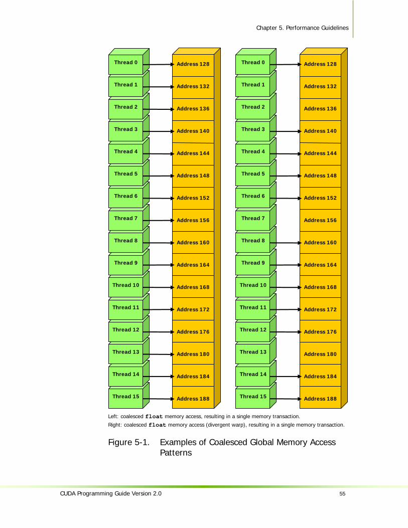
Chapter 5. Performance Guidelines
CUDA Programming Guide Version 2.0 55
Left: coalesced float memory access, resulting in a single memory transaction.
Right: coalesced float memory access (divergent warp), resulting in a single memory transaction.
Figure 5-1. Examples of Coalesced Global Memory Access Patterns
Address 128
Address 132
Address 136
Address 140
Address 144
Address 148
Address 152
Address 156
Address 160
Address 164
Address 168
Address 172
Address 176
Address 180
Address 184
Address 188 Thread 15
Thread 14
Thread 13
Thread 12
Thread 11
Thread 10
Thread 9
Thread 8
Thread 7
Thread 6
Thread 5
Thread 4
Thread 3
Thread 2
Thread 1
Thread 0 Address 128
Address 132
Address 136
Address 140
Address 144
Address 148
Address 152
Address 156
Address 160
Address 164
Address 168
Address 172
Address 176
Address 180
Address 184
Address 188
Thread 15
Thread 14
Thread 13
Thread 12
Thread 11
Thread 10
Thread 9
Thread 8
Thread 7
Thread 6
Thread 5
Thread 4
Thread 3
Thread 2
Thread 1
Thread 0
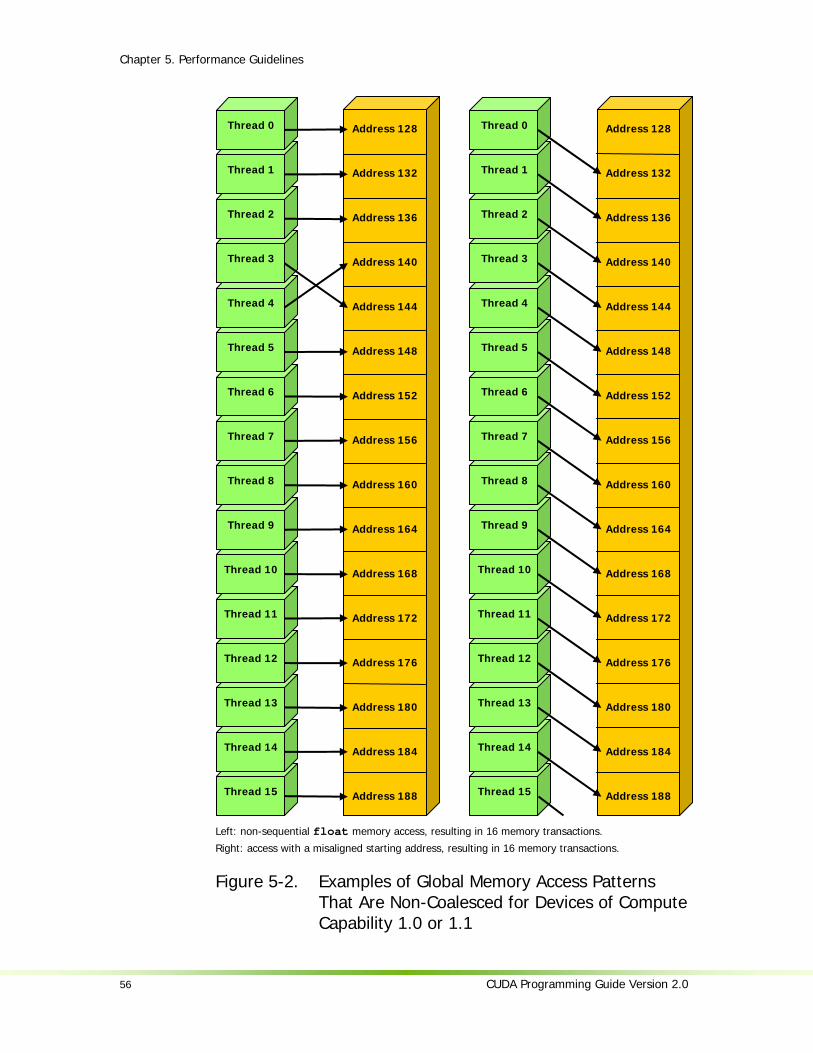
Chapter 5. Performance Guidelines
56 CUDA Programming Guide Version 2.0
Left: non-sequential float memory access, resulting in 16 memory transactions.
Right: access with a misaligned starting address, resulting in 16 memory transactions.
Figure 5-2. Examples of Global Memory Access Patterns That Are Non-Coalesced for Devices of Compute Capability 1.0 or 1.1
Address 128
Address 132
Address 136
Address 140
Address 144
Address 148
Address 152
Address 156
Address 160
Address 164
Address 168
Address 172
Address 176
Address 180
Address 184
Address 188
Thread 15
Thread 14
Thread 13
Thread 12
Thread 11
Thread 10
Thread 9
Thread 8
Thread 7
Thread 6
Thread 5
Thread 4
Thread 3
Thread 2
Thread 1
Thread 0 Address 128
Address 132
Address 136
Address 140
Address 144
Address 148
Address 152
Address 156
Address 160
Address 164
Address 168
Address 172
Address 176
Address 180
Address 184
Address 188 Thread 15
Thread 14
Thread 13
Thread 12
Thread 11
Thread 10
Thread 9
Thread 8
Thread 7
Thread 6
Thread 5
Thread 4
Thread 3
Thread 2
Thread 1
Thread 0
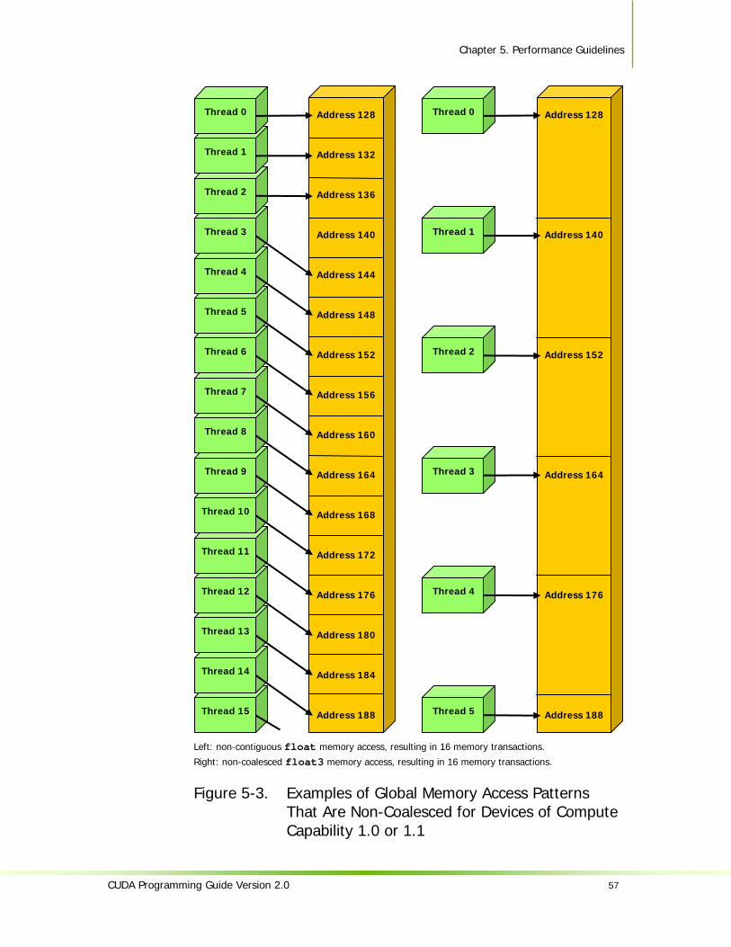
Chapter 5. Performance Guidelines
CUDA Programming Guide Version 2.0 57
Left: non-contiguous float memory access, resulting in 16 memory transactions.
Right: non-coalesced float3 memory access, resulting in 16 memory transactions.
Figure 5-3. Examples of Global Memory Access Patterns That Are Non-Coalesced for Devices of Compute Capability 1.0 or 1.1
Address 128
Address 140
Address 152
Address 164
Address 176
Address 188
Thread 5
Thread 4
Thread 3
Thread 2
Thread 1
Thread 0 Address 128
Address 132
Address 136
Address 140
Address 144
Address 148
Address 152
Address 156
Address 160
Address 164
Address 168
Address 172
Address 176
Address 180
Address 184
Address 188 Thread 15
Thread 14
Thread 13
Thread 12
Thread 11
Thread 10
Thread 9
Thread 8
Thread 7
Thread 6
Thread 5
Thread 4
Thread 3
Thread 2
Thread 1
Thread 0

Chapter 5. Performance Guidelines
58 CUDA Programming Guide Version 2.0
Left: random float memory access within a 64B segment, resulting in one memory transaction.
Center: misaligned float memory access, resulting in one transaction.
Right: misaligned float memory access, resulting in two transactions.
Figure 5-4. Examples of Global Memory Access by Devices with Compute Capability 1.2 and Higher
Thread 15
Thread 14
Thread 13
Thread 12
Thread 11
Thread 10
Thread 9
Thread 8
Thread 7
Thread 6
Thread 5
Thread 4
Thread 3
Thread 2
Thread 1
Thread 0
Address 120
Address 124
Address 128
Address 132
Address 136
Address 140
Address 144
Address 148
Address 152
Address 156
Address 160
Address 164
Address 168
Address 172
Address 176
Address 180
Address 184
Address 188
Address 192
Address 196
Address 200
Address 204
Address 208
Address
212
64
B segm
ent
Thread 15
Thread 14
Thread 13
Thread 12
Thread 11
Thread 10
Thread 9
Thread 8
Thread 7
Thread 6
Thread 5
Thread 4
Thread 3
Thread 2
Thread 1
Thread 0
Address 96
Address 100
Address 104
Address 108
Address 112
Address 116
Address 120
Address 124
Address 128
Address 132
Address 136
Address 140
Address 144
Address 148
Address 152
Address 156
Address 160
Address 164
Address 168
Address 172
Address 176
Address 180
Address 184
Address
188
64
B segm
ent
Thread 15
Thread 14
Thread 13
Thread 12
Thread 11
Thread 10
Thread 9
Thread 8
Thread 7
Thread 6
Thread 5
Thread 4
Thread 3
Thread 2
Thread 1
Thread 0
Address 120
Address 124
Address 128
Address 132
Address 136
Address 140
Address 144
Address 148
Address 152
Address 156
Address 160
Address 164
Address 168
Address 172
Address 176
Address 180
Address 184
Address 188
Address 192
Address 196
…
Address 204
Address 252
Address
256
12
8B
segmen
t
32
B segm
ent

Chapter 5. Performance Guidelines
CUDA Programming Guide Version 2.0 59
Common Access Patterns
A common global memory access pattern is when each thread of thread ID tid accesses one element of an array located at address BaseAddress of type type* using the following address: BaseAddress + tid
To get memory coalescing, type must meet the size and alignment requirements discussed above. In particular, this means that if type is a structure larger than 16 bytes, it should be split into several structures that meet these requirements and the data should be laid out in memory as a list of several arrays of these structures instead of a single array of type type*.
Another common global memory access pattern is when each thread of index (tx,ty) accesses one element of a 2D array located at address BaseAddress of type type* and of width width using the following address: BaseAddress + width * ty + tx
In such a case, one gets memory coalescing for all half-warps of the thread block only if:
The width of the thread block is a multiple of half the warp size; width is a multiple of 16.
In particular, this means that an array whose width is not a multiple of 16 will be accessed much more efficiently if it is actually allocated with a width rounded up to the closest multiple of 16 and its rows padded accordingly. The cudaMallocPitch() and cuMemAllocPitch() functions and associated memory copy functions described in the reference manual enable programmers to write non-hardware-dependent code to allocate arrays that conform to these constraints.
5.1.2.2 Local Memory Local memory accesses only occur for some automatic variables as detailed in Section 4.2.2.4. Like the global memory space, the local memory space is not cached, so accesses to local memory are as expensive as accesses to global memory. Accesses are always coalesced though since they are per-thread by definition.
5.1.2.3 Constant Memory The constant memory space is cached so a read from constant memory costs one memory read from device memory only on a cache miss, otherwise it just costs one read from the constant cache.
For all threads of a half-warp, reading from the constant cache is as fast as reading from a register as long as all threads read the same address. The cost scales linearly with the number of different addresses read by all threads. We recommend having all threads of the entire warp read the same address as opposed to all threads within each of its halves only, as future devices will require it for full speed read.
5.1.2.4 Texture Memory The texture memory space is cached so a texture fetch costs one memory read from device memory only on a cache miss, otherwise it just costs one read from the texture cache. The texture cache is optimized for 2D spatial locality, so threads of

Chapter 5. Performance Guidelines
60 CUDA Programming Guide Version 2.0
the same warp that read texture addresses that are close together will achieve best performance. Also, it is designed for streaming fetches with a constant latency, i.e. a cache hit reduces DRAM bandwidth demand, but not fetch latency.
Reading device memory through texture fetching can be an advantageous alternative to reading device memory from global or constant memory as detailed in Section 5.4.
5.1.2.5 Shared Memory Because it is on-chip, the shared memory space is much faster than the local and global memory spaces. In fact, for all threads of a warp, accessing the shared memory is as fast as accessing a register as long as there are no bank conflicts between the threads, as detailed below.
To achieve high memory bandwidth, shared memory is divided into equally-sized memory modules, called banks, which can be accessed simultaneously. So, any memory read or write request made of n addresses that fall in n distinct memory banks can be serviced simultaneously, yielding an effective bandwidth that is n times as high as the bandwidth of a single module.
However, if two addresses of a memory request fall in the same memory bank, there is a bank conflict and the access has to be serialized. The hardware splits a memory request with bank conflicts into as many separate conflict-free requests as necessary, decreasing the effective bandwidth by a factor equal to the number of separate memory requests. If the number of separate memory requests is n, the initial memory request is said to cause n-way bank conflicts.
To get maximum performance, it is therefore important to understand how memory addresses map to memory banks in order to schedule the memory requests so as to minimize bank conflicts.
In the case of the shared memory space, the banks are organized such that successive 32-bit words are assigned to successive banks and each bank has a bandwidth of 32 bits per two clock cycles.
For devices of compute capability 1.x, the warp size is 32 and the number of banks is 16 (see Section 5.1); a shared memory request for a warp is split into one request for the first half of the warp and one request for the second half of the warp. As a consequence, there can be no bank conflict between a thread belonging to the first half of a warp and a thread belonging to the second half of the same warp.
A common case is for each thread to access a 32-bit word from an array indexed by the thread ID tid and with some stride s: __shared__ float shared[32]; float data = shared[BaseIndex + s * tid];
In this case, the threads tid and tid+n access the same bank whenever s*n is a multiple of the number of banks m or equivalently, whenever n is a multiple of m/d where d is the greatest common divisor of m and s. As a consequence, there will be no bank conflict only if half the warp size is less than or equal to m/d. For devices of compute capability 1.x, this translates to no bank conflict only if d is equal to 1, or in other words, only if s is odd since m is a power of two.
Figure 5-5 and Figure 5-6 show some examples of conflict-free memory accesses while Figure 5-7 shows some examples of memory accesses that cause bank conflicts.

Chapter 5. Performance Guidelines
CUDA Programming Guide Version 2.0 61
Other cases worth mentioning are when each thread accesses an element that is smaller or larger than 32 bits in size. For example, there are bank conflicts if an array of char is accessed the following way: __shared__ char shared[32]; char data = shared[BaseIndex + tid];
because shared[0], shared[1], shared[2], and shared[3], for example, belong to the same bank. There are no bank conflicts however, if the same array is accessed the following way: char data = shared[BaseIndex + 4 * tid];
There are also 2-way bank conflicts for arrays of double: __shared__ double shared[32]; double data = shared[BaseIndex + tid];
since the memory request is compiled into two separate 32-bit requests. One way to avoid bank conflicts in this case is two split the double operands like in the following sample code: __shared__ int shared_lo[32]; __shared__ int shared_hi[32]; double dataIn; shared_lo[BaseIndex + tid] = __double2loint(dataIn); shared_hi[BaseIndex + tid] = __double2hiint(dataIn); double dataOut = __hiloint2double(shared_hi[BaseIndex + tid], shared_lo[BaseIndex + tid]);
It might not always improve performance though and will perform worse on future architectures.
A structure assignment is compiled into as many memory requests as necessary for each member in the structure, so the following code, for example: __shared__ struct type shared[32]; struct type data = shared[BaseIndex + tid];
results in:
Three separate memory reads without bank conflicts if type is defined as struct type { float x, y, z; };
since each member is accessed with a stride of three 32-bit words;
Two separate memory reads with bank conflicts if type is defined as struct type { float x, y; };
since each member is accessed with a stride of two 32-bit words;
Two separate memory reads with bank conflicts if type is defined as struct type { float f; char c; };
Chapter 5. Performance Guidelines
62 CUDA Programming Guide Version 2.0
since each member is accessed with a stride of five bytes.
Finally, shared memory also features a broadcast mechanism whereby a 32-bit word can be read and broadcast to several threads simultaneously when servicing one memory read request. This reduces the number of bank conflicts when several threads of a half-warp read from an address within the same 32-bit word. More precisely, a memory read request made of several addresses is serviced in several steps over time – one step every two clock cycles – by servicing one conflict-free subset of these addresses per step until all addresses have been serviced; at each step, the subset is built from the remaining addresses that have yet to be serviced using the following procedure:
Select one of the words pointed to by the remaining addresses as the broadcast word,
Include in the subset: All addresses that are within the broadcast word, One address for each bank pointed to by the remaining addresses.
Which word is selected as the broadcast word and which address is picked up for each bank at each cycle are unspecified.
A common conflict-free case is when all threads of a half-warp read from an address within the same 32-bit word.
Figure 5-8 shows some examples of memory read accesses that involve the broadcast mechanism.

Chapter 5. Performance Guidelines
CUDA Programming Guide Version 2.0 63
Left: linear addressing with a stride of one 32-bit word. Right: random permutation.
Figure 5-5. Examples of Shared Memory Access Patterns without Bank Conflicts
Thread 15
Thread 14
Thread 13
Thread 12
Thread 11
Thread 10
Thread 9
Thread 8
Thread 7
Thread 6
Thread 5
Thread 4
Thread 3
Thread 2
Thread 1
Thread 0
Bank 15
Bank 14
Bank 13
Bank 12
Bank 11
Bank 10
Bank 9
Bank 8
Bank 7
Bank 6
Bank 5
Bank 4
Bank 3
Bank 2
Bank 1
Bank 0
Thread 15
Thread 14
Thread 13
Thread 12
Thread 11
Thread 10
Thread 9
Thread 8
Thread 7
Thread 6
Thread 5
Thread 4
Thread 3
Thread 2
Thread 1
Thread 0
Bank 15
Bank 14
Bank 13
Bank 12
Bank 11
Bank 10
Bank 9
Bank 8
Bank 7
Bank 6
Bank 5
Bank 4
Bank 3
Bank 2
Bank 1
Bank 0

Chapter 5. Performance Guidelines
64 CUDA Programming Guide Version 2.0
Linear addressing with a stride of three 32-bit words.
Figure 5-6. Example of a Shared Memory Access Pattern without Bank Conflicts
Thread 15
Thread 14
Thread 13
Thread 12
Thread 11
Thread 10
Thread 9
Thread 8
Thread 7
Thread 6
Thread 5
Thread 4
Thread 3
Thread 2
Thread 1
Thread 0
Bank 15
Bank 14
Bank 13
Bank 12
Bank 11
Bank 10
Bank 9
Bank 8
Bank 7
Bank 6
Bank 5
Bank 4
Bank 3
Bank 2
Bank 1
Bank 0

Chapter 5. Performance Guidelines
CUDA Programming Guide Version 2.0 65
Left: Linear addressing with a stride of two 32-bit words causes 2-way bank conflicts. Right: Linear addressing with a stride of eight 32-bit words causes 8-way bank conflicts.
Figure 5-7. Examples of Shared Memory Access Patterns with Bank Conflicts
Thread 15
Thread 14
Thread 13
Thread 12
Thread 11
Thread 10
Thread 9
Thread 8
Thread 7
Thread 6
Thread 5
Thread 4
Thread 3
Thread 2
Thread 1
Thread 0
Bank 15
Bank 14
Bank 13
Bank 12
Bank 11
Bank 10
Bank 9
Bank 8
Bank 7
Bank 6
Bank 5
Bank 4
Bank 3
Bank 2
Bank 1
Bank 0
Thread 15
Thread 14
Thread 13
Thread 12
Thread 11
Thread 10
Thread 9
Thread 8
Thread 7
Thread 6
Thread 5
Thread 4
Thread 3
Thread 2
Thread 1
Thread 0
Bank 15
Bank 14
Bank 13
Bank 12
Bank 11
Bank 10
Bank 9
Bank 8
Bank 7
Bank 6
Bank 5
Bank 4
Bank 3
Bank 2
Bank 1
Bank 0

Chapter 5. Performance Guidelines
66 CUDA Programming Guide Version 2.0
Left: This access pattern is conflict-free since all threads read from an address within the same 32-bit word. Right: This access pattern causes either no bank conflicts if the word from bank 5 is chosen as the broadcast word during the first step or 2-way bank conflicts, otherwise.
Figure 5-8. Example of Shared Memory Read Access Patterns with Broadcast
Thread 15
Thread 14
Thread 13
Thread 12
Thread 11
Thread 10
Thread 9
Thread 8
Thread 7
Thread 6
Thread 5
Thread 4
Thread 3
Thread 2
Thread 1
Thread 0
Bank 15
Bank 14
Bank 13
Bank 12
Bank 11
Bank 10
Bank 9
Bank 8
Bank 7
Bank 6
Bank 5
Bank 4
Bank 3
Bank 2
Bank 1
Bank 0
Thread 15
Thread 14
Thread 13
Thread 12
Thread 11
Thread 10
Thread 9
Thread 8
Thread 7
Thread 6
Thread 5
Thread 4
Thread 3
Thread 2
Thread 1
Thread 0
Bank 15
Bank 14
Bank 13
Bank 12
Bank 11
Bank 10
Bank 9
Bank 8
Bank 7
Bank 6
Bank 5
Bank 4
Bank 3
Bank 2
Bank 1
Bank 0
Chapter 5. Performance Guidelines
CUDA Programming Guide Version 2.0 67
5.1.2.6 Registers Generally, accessing a register is zero extra clock cycles per instruction, but delays may occur due to register read-after-write dependencies and register memory bank conflicts.
The delays introduced by read-after-write dependencies can be ignored as soon as there are at least 192 active threads per multiprocessor to hide them.
The compiler and thread scheduler schedule the instructions as optimally as possible to avoid register memory bank conflicts. They achieve best results when the number of threads per block is a multiple of 64. Other than following this rule, an application has no direct control over these bank conflicts. In particular, there is no need to pack data into float4 or int4 types.
5.2 Number of Threads per Block Given a total number of threads per grid, the number of threads per block, or equivalently the number of blocks, should be chosen to maximize the utilization of the available computing resources. This means that there should be at least as many blocks as there are multiprocessors in the device.
Furthermore, running only one block per multiprocessor will force the multiprocessor to idle during thread synchronization and also during device memory reads if there are not enough threads per block to cover the load latency. It is therefore usually better to allow for two or more blocks to be active on each multiprocessor to allow overlap between blocks that wait and blocks that can run. For this to happen, not only should there be at least twice as many blocks as there are multiprocessors in the device, but also the amount of allocated shared memory per block should be at most half the total amount of shared memory available per multiprocessor (see Section 3.1). More thread blocks stream in pipeline fashion through the device and amortize overhead even more.
The number of blocks per grid should be at least 100 if one wants it to scale to future devices; 1000 blocks will scale across several generations.
With a high enough number of blocks, the number of threads per block should be chosen as a multiple of the warp size to avoid wasting computing resources with under-populated warps, or better, a multiple of 64 for the reason invoked in Section 5.1.2.6.
Allocating more threads per block is better for efficient time slicing, but the more threads per block, the fewer registers are available per thread. This might prevent a kernel invocation from succeeding if the kernel compiles to more registers than are allowed by the execution configuration.
For devices of compute capability 1.x, the number of registers available per thread is equal to:
)32,(R
TceilB×
where R is the total number of registers per multiprocessor given in Appendix A, B is the number of active blocks per multiprocessor, T is the number of threads per block, and ceil(T, 32) is T rounded up to the nearest multiple of 32.

Chapter 5. Performance Guidelines
68 CUDA Programming Guide Version 2.0
The number of registers a kernel compiles to (as well as local, shared, and constant memory usage) is reported by the compiler when compiling with the --ptxas-options=-v option. Note that each double or long long variable uses two registers for devices that natively support these types, namely devices of compute capability 1.2 and higher for long long and devices of compute capability 1.3 and higher for double. However, devices of compute capability 1.2 and higher have twice as many registers per multiprocessor as devices with lower compute capability.
64 threads per block is minimal and makes sense only if there are multiple active blocks per multiprocessor. 192 or 256 threads per block is better and usually allows for enough registers to compile.
The ratio of the number of active warps per multiprocessor to the maximum number of active warps (given in Appendix A) is called the multiprocessor occupancy. In order to maximize occupancy, the compiler attempts to minimize register usage and programmers need to choose execution configurations with care. The CUDA Software Development Kit provides a spreadsheet to assist programmers in choosing thread block size based on shared memory and register requirements.
5.3 Data Transfer between Host and Device The bandwidth between the device and the device memory is much higher than the bandwidth between the device memory and the host memory. Therefore, one should strive to minimize data transfer between the host and the device, for example, by moving more code from the host to the device, even if that means running kernels with low parallelism computations. Intermediate data structures may be created in device memory, operated on by the device, and destroyed without ever being mapped by the host or copied to host memory.
Also, because of the overhead associated with each transfer, batching many small transfers into a big one always performs much better than making each transfer separately.
Finally, higher bandwidth between host and device is achieved when using page-locked memory, as mentioned in Section 4.5.1.2.
5.4 Texture Fetch versus Global or Constant Memory Read Device memory reads through texture fetching present several benefits over reads from global or constant memory:
They are cached, potentially exhibiting higher bandwidth if there is locality in the texture fetches;
They are not subject to the constraints on memory access patterns that global or constant memory reads must respect to get good performance (see Sections 5.1.2.1 and 5.1.2.3);
The latency of addressing calculations is hidden better, possibly improving performance for applications that perform random accesses to the data;

Chapter 5. Performance Guidelines
CUDA Programming Guide Version 2.0 69
Packed data may be broadcast to separate variables in a single operation; 8-bit and 16-bit integer input data may be optionally converted to 32-bit floating-
point values in the range [0.0, 1.0] or [-1.0, 1.0] (see Section 4.3.4.1). If the texture is a CUDA array (see Section 4.3.4.2), the hardware provides other capabilities that may be useful for different applications, especially image processing:
Feature Useful for… Caveat Filtering Fast, low-precision interpolation
between texels Only valid if the texture reference returns floating-point data
Normalized texture coordinates
Resolution-independent coding
Addressing modes Automatic handling of boundary cases Can only be used with normalized texture coordinates
However, within the same kernel call, the texture cache is not kept coherent with respect to global memory writes, so that any texture fetch to an address that has been written to via a global write in the same kernel call returns undefined data. In other words, a thread can safely read via texture some memory location only if this memory location has been updated by a previous kernel call or memory copy, but not if it has been previously updated by the same thread or another thread from the same kernel call. This is only relevant when fetching from linear memory as a kernel cannot write to CUDA arrays anyway.
5.5 Overall Performance Optimization Strategies Performance optimization revolves around three basic strategies:
Maximizing parallel execution; Optimizing memory usage to achieve maximum memory bandwidth; Optimizing instruction usage to achieve maximum instruction throughput.
Maximizing parallel execution starts with structuring the algorithm in a way that exposes as much data parallelism as possible. At points in the algorithm where parallelism is broken because some threads need to synchronize in order to share data between each other, there are two cases: Either these threads belong to the same block, in which case they should use __syncthreads() and share data through shared memory within the same kernel call, or they belong to different blocks, in which case they must share data through global memory using two separate kernel invocations, one for writing to and one for reading from global memory.
Once the parallelism of the algorithm has been exposed it needs to be mapped to the hardware as efficiently as possible. This is done by carefully choosing the execution configuration of each kernel invocation as detailed in Section 5.2.
The application should also maximize parallel execution at a higher level by explicitly exposing concurrent execution on the device through streams, as described in Section 4.5.1.5, as well as maximizing concurrent execution between host and device.

Chapter 5. Performance Guidelines
70 CUDA Programming Guide Version 2.0
Optimizing memory usage starts with minimizing data transfers with low-bandwidth. That means minimizing data transfers between the host and the device, as detailed in Section 5.3, since these have much lower bandwidth than data transfers between the device and global memory. That also means minimizing data transfers between the device and global memory by maximizing use of shared memory on the device, as mentioned in Section 5.1.2. Sometimes, the best optimization might even be to avoid any data transfer in the first place by simply recomputing the data instead whenever it is needed.
As detailed in Sections 5.1.2.1, 5.1.2.3, 5.1.2.4, and 5.1.2.5, the effective bandwidth can vary by an order of magnitude depending on access pattern for each type of memory. The next step in optimizing memory usage is therefore to organize memory accesses as optimally as possible based on the optimal memory access patterns. This optimization is especially important for global memory accesses as global memory bandwidth is low and its latency is hundreds of clock cycles (see Section 5.1.1.3). Shared memory accesses, on the other hand, are usually worth optimizing only in case they have a high degree of bank conflicts.
As for optimizing instruction usage, the use of arithmetic instructions with low throughput (see Section 5.1.1.1) should be minimized. This includes trading precision for speed when it does not affect the end result, such as using intrinsic instead of regular functions (intrinsic functions are listed in Section B.2) or single-precision instead of double-precision. Particular attention must be paid to control flow instructions due to the SIMT nature of the device as detailed in Section 5.1.1.2.
CUDA Programming Guide Version 2.0 71
Chapter 6. Example of Matrix Multiplication
6.1 Overview The task of computing the product C of two matrices A and B of dimensions (wA, hA) and (wB, wA) respectively, is split among several threads in the following way:
Each thread block is responsible for computing one square sub-matrix Csub of C; Each thread within the block is responsible for computing one element of Csub.
The dimension block_size of Csub is chosen equal to 16, so that the number of threads per block is a multiple of the warp size (Section 5.2) and remains below the maximum number of threads per block (Appendix A).
As illustrated in Figure 6-1, Csub is equal to the product of two rectangular matrices: the sub-matrix of A of dimension (wA, block_size) that has the same line indices as Csub, and the sub-matrix of B of dimension (block_size, wA) that has the same column indices as Csub. In order to fit into the device’s resources, these two rectangular matrices are divided into as many square matrices of dimension block_size as necessary and Csub is computed as the sum of the products of these square matrices. Each of these products is performed by first loading the two corresponding square matrices from global memory to shared memory with one thread loading one element of each matrix, and then by having each thread compute one element of the product. Each thread accumulates the result of each of these products into a register and once done writes the result to global memory.
By blocking the computation this way, we take advantage of fast shared memory and save a lot of global memory bandwidth since A and B are read from global memory only (wA / block_size) times.
Nonetheless, this example has been written for clarity of exposition to illustrate various CUDA programming principles, not with the goal of providing a high-performance kernel for generic matrix multiplication and should not be construed as such.

Chapter 6. Example of Matrix Multiplication
72 CUDA Programming Guide Version 2.0
Each thread block computes one sub-matrix Csub of C. Each thread within the block computes one element of Csub.
Figure 6-1. Matrix Multiplication
A
B
C
Csub
hA
BLOCK_SIZE
wB wA
BLOCK_SIZEBLOCK_SIZE
wA
BLO
CK
_SI
ZEB
LOC
K_
SIZE
BLO
CK
_SI
ZE

Chapter 6. Example of Matrix Multiplication
CUDA Programming Guide Version 2.0 73
6.2 Source Code Listing // Thread block size #define BLOCK_SIZE 16 // Forward declaration of the device multiplication function __global__ void Muld(float*, float*, int, int, float*); // Host multiplication function // Compute C = A * B // hA is the height of A // wA is the width of A // wB is the width of B void Mul(const float* A, const float* B, int hA, int wA, int wB, float* C) { int size; // Load A and B to the device float* Ad; size = hA * wA * sizeof(float); cudaMalloc((void**)&Ad, size); cudaMemcpy(Ad, A, size, cudaMemcpyHostToDevice); float* Bd; size = wA * wB * sizeof(float); cudaMalloc((void**)&Bd, size); cudaMemcpy(Bd, B, size, cudaMemcpyHostToDevice); // Allocate C on the device float* Cd; size = hA * wB * sizeof(float); cudaMalloc((void**)&Cd, size); // Compute the execution configuration assuming // the matrix dimensions are multiples of BLOCK_SIZE dim3 dimBlock(BLOCK_SIZE, BLOCK_SIZE); dim3 dimGrid(wB / dimBlock.x, hA / dimBlock.y); // Launch the device computation Muld<<<dimGrid, dimBlock>>>(Ad, Bd, wA, wB, Cd); // Read C from the device cudaMemcpy(C, Cd, size, cudaMemcpyDeviceToHost); // Free device memory cudaFree(Ad); cudaFree(Bd); cudaFree(Cd); }
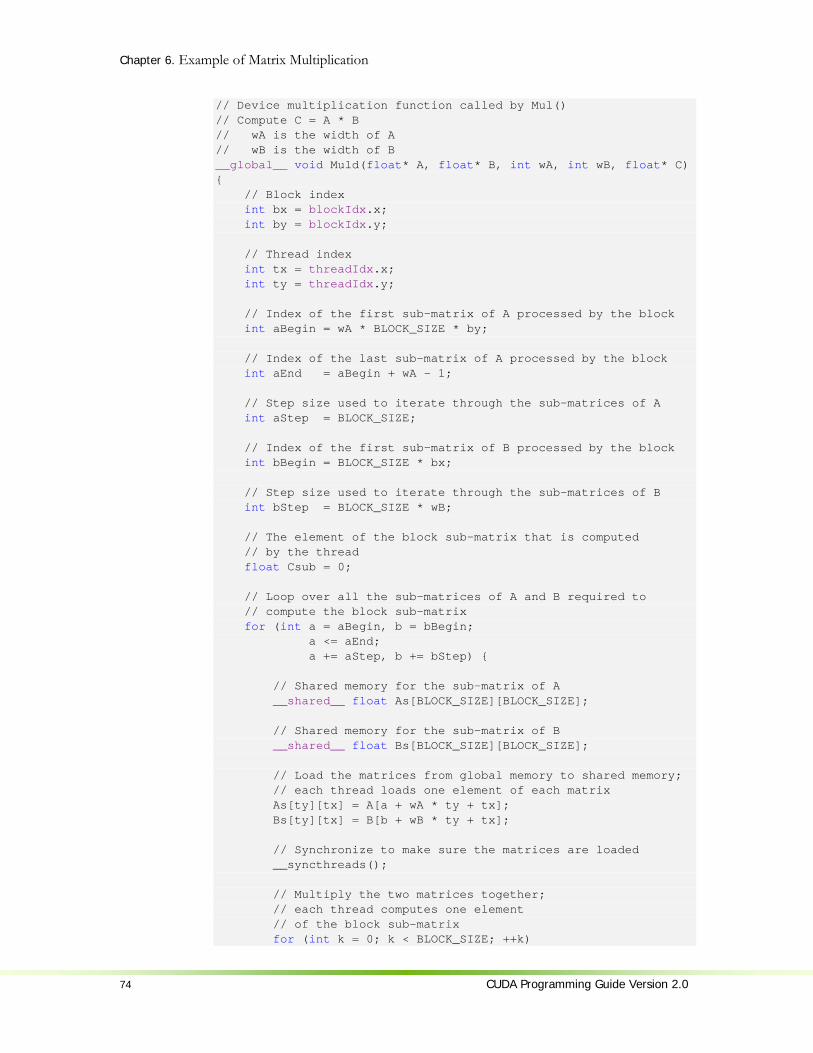
Chapter 6. Example of Matrix Multiplication
74 CUDA Programming Guide Version 2.0
// Device multiplication function called by Mul() // Compute C = A * B // wA is the width of A // wB is the width of B __global__ void Muld(float* A, float* B, int wA, int wB, float* C) { // Block index int bx = blockIdx.x; int by = blockIdx.y; // Thread index int tx = threadIdx.x; int ty = threadIdx.y; // Index of the first sub-matrix of A processed by the block int aBegin = wA * BLOCK_SIZE * by; // Index of the last sub-matrix of A processed by the block int aEnd = aBegin + wA - 1; // Step size used to iterate through the sub-matrices of A int aStep = BLOCK_SIZE; // Index of the first sub-matrix of B processed by the block int bBegin = BLOCK_SIZE * bx; // Step size used to iterate through the sub-matrices of B int bStep = BLOCK_SIZE * wB; // The element of the block sub-matrix that is computed // by the thread float Csub = 0; // Loop over all the sub-matrices of A and B required to // compute the block sub-matrix for (int a = aBegin, b = bBegin; a <= aEnd; a += aStep, b += bStep) { // Shared memory for the sub-matrix of A __shared__ float As[BLOCK_SIZE][BLOCK_SIZE]; // Shared memory for the sub-matrix of B __shared__ float Bs[BLOCK_SIZE][BLOCK_SIZE]; // Load the matrices from global memory to shared memory; // each thread loads one element of each matrix As[ty][tx] = A[a + wA * ty + tx]; Bs[ty][tx] = B[b + wB * ty + tx]; // Synchronize to make sure the matrices are loaded __syncthreads(); // Multiply the two matrices together; // each thread computes one element // of the block sub-matrix for (int k = 0; k < BLOCK_SIZE; ++k)

Chapter 6. Example of Matrix Multiplication
CUDA Programming Guide Version 2.0 75
Csub += As[ty][k] * Bs[k][tx]; // Synchronize to make sure that the preceding // computation is done before loading two new // sub-matrices of A and B in the next iteration __syncthreads(); } // Write the block sub-matrix to global memory; // each thread writes one element int c = wB * BLOCK_SIZE * by + BLOCK_SIZE * bx; C[c + wB * ty + tx] = Csub; }
6.3 Source Code Walkthrough The source code contains two functions:
Mul(), a host function serving as a wrapper to Muld(); Muld(), a kernel that executes the matrix multiplication on the device.
6.3.1 Mul() Mul() takes as input:
Two pointers to host memory that point to the elements of A and B, The height and width of A and the width of B, A pointer to host memory that points where C should be written.
Mul() performs the following operations:
It allocates enough global memory to store A, B, and C using cudaMalloc(); It copies A and B from host memory to global memory using cudaMemcpy(); It calls Muld() to compute C on the device; It copies C from global memory to host memory using cudaMemcpy(); It frees the global memory allocated for A, B, and C using cudaFree().
6.3.2 Muld() Muld() has the same input as Mul(), except that pointers point to device memory instead of host memory.
For each block, Muld()iterates through all the sub-matrices of A and B required to compute Csub. At each iteration:
It loads one sub-matrix of A and one sub-matrix of B from global memory to shared memory;
It synchronizes to make sure that both sub-matrices are fully loaded by all the threads within the block;
It computes the product of the two sub-matrices and adds it to the product obtained during the previous iteration;

Chapter 6. Example of Matrix Multiplication
76 CUDA Programming Guide Version 2.0
It synchronizes again to make sure that the product of the two sub-matrices is done before starting the next iteration.
Once all sub-matrices have been handled, Csub is fully computed and Muld() writes it to global memory.
Muld() is written to maximize memory performance according to Section 5.1.2.1 and 5.1.2.5.
Indeed, assuming that wA and wB are multiples of 16 as suggested in Section 5.1.2.1, global memory coalescing is ensured because a, b, and c are all multiples of BLOCK_SIZE, which is equal to 16.
There is also no shared memory bank conflict since for each half-warp, ty and k are the same for all threads and tx varies from 0 to 15, so each thread accesses a different bank for the memory accesses As[ty][tx], Bs[ty][tx], and Bs[k][tx] and the same bank for the memory access As[ty][k].

CUDA Programming Guide Version 2.0 77
Appendix A. Technical Specifications
A.1 General Specifications The general specifications of a compute device depend on its compute capability (see Section 2.5).
The following sections describe the technical specifications and features associated to each compute capability. The specifications for a given compute capability are the same as for the compute capability just below unless otherwise mentioned. Similarly, any feature supported for a given compute capability is supported for any higher compute capability.
The number of multiprocessors and compute capability of all devices supporting CUDA are given in the following table:
Number of Multiprocessors
Compute Capability
GeForce GTX 280 30 1.3
GeForce GTX 260 24 1.3
GeForce 9800 GX2 2x16 1.1
GeForce 9800 GTX 16 1.1
GeForce 8800 Ultra, 8800 GTX 16 1.0
GeForce 8800 GT 14 1.1
GeForce 9600 GSO, 8800 GS, 8800M GTX 12 1.1
GeForce 8800 GTS 12 1.0
GeForce 9600 GT, 8800M GTS 8 1.1
GeForce 9500 GT, 8600 GTS, 8600 GT, 8700M GT, 8600M GT, 8600M GS
4 1.1
GeForce 8500 GT, 8400 GS, 8400M GT, 8400M GS
2 1.1
GeForce 8400M G 1 1.1
Tesla S1070 4x30 1.3
Tesla C1060 30 1.3
Tesla S870 4x16 1.0

Appendix A. Technical Specifications
78 CUDA Programming Guide Version 2.0
Tesla D870 2x16 1.0
Tesla C870 16 1.0
Quadro Plex 1000 Model S4 4x16 1.0
Quadro Plex 1000 Model IV 2x16 1.0
Quadro FX 5600 16 1.0
Quadro FX 3700 14 1.1
Quadro FX 3600M 12 1.1
Quadro FX 4600 12 1.0
Quadro FX 1700, FX 570, NVS 320M, FX 1600M, FX 570M
4 1.1
Quadro FX 370, NVS 290, NVS 140M, NVS 135M, FX 360M
2 1.1
Quadro NVS 130M 1 1.1
The clock frequency and total amount of device memory can be queried using the runtime (Sections 4.5.2.2 and 4.5.3.2).
A.1.1 Specifications for Compute Capability 1.0 The maximum number of threads per block is 512; The maximum sizes of the x-, y-, and z-dimension of a thread block are 512, 512,
and 64, respectively; The maximum size of each dimension of a grid of thread blocks is 65535; The warp size is 32 threads; The number of registers per multiprocessor is 8192; The amount of shared memory available per multiprocessor is 16 KB organized
into 16 banks (see Section 5.1.2.5); The total amount of constant memory is 64 KB; The cache working set for constant memory is 8 KB per multiprocessor; The cache working set for texture memory varies between 6 and 8 KB per
multiprocessor; The maximum number of active blocks per multiprocessor is 8; The maximum number of active warps per multiprocessor is 24; The maximum number of active threads per multiprocessor is 768; For a texture reference bound to a one-dimensional CUDA array, the maximum
width is 213; For a texture reference bound to a two-dimensional CUDA array, the maximum
width is 216 and the maximum height is 215; For a texture reference bound to a three-dimensional CUDA array, the
maximum width is 211, the maximum height is 211, and the maximum depth is 211;
For a texture reference bound to linear memory, the maximum width is 227; The limit on kernel size is 2 million PTX instructions;
Appendix A. Technical Specifications
CUDA Programming Guide Version 2.0 79
Each multiprocessor is composed of eight processors, so that a multiprocessor is able to process the 32 threads of a warp in four clock cycles.
A.1.2 Specifications for Compute Capability 1.1 Support for atomic functions operating on 32-bit words in global memory (see
Section 4.4.4).
A.1.3 Specifications for Compute Capability 1.2 Support for atomic functions operating in shared memory and atomic functions
operating on 64-bit words in global memory (see Section 4.4.4); Support for warp vote functions (see Section 4.4.5); The number of registers per multiprocessor is 16384; The maximum number of active warps per multiprocessor is 32; The maximum number of active threads per multiprocessor is 1024.
A.1.4 Specifications for Compute Capability 1.3 Support for double-precision floating-point numbers.
A.2 Floating-Point Standard All compute devices follow the IEEE-754 standard for binary floating-point arithmetic with the following deviations:
There is no dynamically configurable rounding mode; however, most of the operations support IEEE rounding modes, exposed via device functions;
There is no mechanism for detecting that a floating-point exception has occurred and all operations behave as if the IEEE-754 exceptions are always masked, and deliver the masked response as defined by IEEE-754 if there is an exceptional event; for the same reason, while SNaN encodings are supported, they are not signaling;
Absolute value and negation are not compliant with IEEE-754 with respect to NaNs; these are passed through unchanged;
For single-precision floating-point numbers only: Addition and multiplication are often combined into a single multiply-add
instruction (FMAD), which truncates the intermediate result of the multiplication;
Division is implemented via the reciprocal in a non-standard-compliant way; Square root is implemented via the reciprocal square root in a non-standard-
compliant way; For addition and multiplication, only round-to-nearest-even and
round-towards-zero are supported via static rounding modes; directed rounding towards +/- infinity is not supported;

Appendix A. Technical Specifications
80 CUDA Programming Guide Version 2.0
Denormalized numbers are not supported; floating-point arithmetic and comparison instructions convert denormalized operands to zero prior to the floating-point operation;
Underflowed results are flushed to zero; The result of an operation involving one or more input NaNs is the quiet
NaN of bit pattern 0x7fffffff; note that; For double-precision floating-point numbers only:
Round-to-nearest-even is the only supported IEEE rounding mode for reciprocal, division, and square root.
In accordance to the IEEE-754R standard, if one of the input parameters to fminf(), fmin(), fmaxf(), or fmax() is NaN, but not the other, the result is the non-NaN parameter.
The conversion of a floating-point value to an integer value in the case where the floating-point value falls outside the range of the integer format is left undefined by IEEE-754. For compute devices, the behavior is to clamp to the end of the supported range. This is unlike the x86 architecture behaves.

CUDA Programming Guide Version 2.0 81
Appendix B. Standard Mathematical Functions
Functions from Section B.1 can be used by both host and device functions whereas functions from Section B.2 can only be used in device functions.
B.1 Common Runtime Component This section lists all the mathematical standard library functions supported by the CUDA runtime library. It also specifies the error bounds of each function when executed on the device. These error bounds also apply when the function is executed on the host in the case where the host does not supply the function. They are generated from extensive but not exhaustive tests, so they are not guaranteed bounds.
B.1.1 Single-Precision Floating-Point Functions Addition and multiplication are IEEE-compliant, so have a maximum error of 0.5 ulp. However, on the device, the compiler often combines them into a single multiply-add instruction (FMAD), which truncates the intermediate result of the multiplication. This combination can be avoided by using the __fadd_rn() and __fmul_rn() intrinsic functions (see Section B.2).
The recommended way to round a single-precision floating-point operand to an integer, with the result being a single-precision floating-point number is rintf(), not roundf(). The reason is that roundf() maps to an 8-instruction sequence on the device, whereas rintf() maps to a single instruction. truncf(), ceilf(), and floorf() each map to a single instruction as well.

Appendix B. Mathematical Functions
82 CUDA Programming Guide Version 2.0
Table B-1. Mathematical Standard Library Functions with Maximum ULP Error The maximum error is stated as the absolute value of the difference in ulps between a correctly rounded single-precision result and the result returned by the CUDA library function.
Function Maximum ulp error x+y 0 (IEEE-754 round-to-nearest-even)
(except when merged into an FMAD)
x*y 0 (IEEE-754 round-to-nearest-even) (except when merged into an FMAD)
x/y 2 (full range)
1/x 1 (full range)
1/sqrtf(x) rsqrtf(x)
2 (full range)
sqrtf(x) 3 (full range)
cbrtf(x) 1 (full range)
hypotf(x,y) 3 (full range)
expf(x) 2 (full range)
exp2f(x) 2 (full range)
exp10f(x) 2 (full range)
expm1f(x) 1 (full range)
logf(x) 1 (full range)
log2f(x) 3 (full range)
log10f(x) 3 (full range)
log1pf(x) 2 (full range)
sinf(x) 2 (full range)
cosf(x) 2 (full range)
tanf(x) 4 (full range)
sincosf(x,sptr,cptr) 2 (full range)
asinf(x) 4 (full range)
acosf(x) 3 (full range)
atanf(x) 2 (full range)
atan2f(y,x) 3 (full range)
sinhf(x) 3 (full range)
coshf(x) 2 (full range)
tanhf(x) 2 (full range)
asinhf(x) 3 (full range)
acoshf(x) 4 (full range)
atanhf(x) 3 (full range)
powf(x,y) 7 (full range)
erff(x) 4 (full range)
erfcf(x) 8 (full range)
lgammaf(x) 6 (outside interval -10.001 ... -2.264; larger inside)

Appendix B. Mathematical Functions
CUDA Programming Guide Version 2.0 83
Function Maximum ulp error tgammaf(x) 11 (full range)
fmaf(x,y,z) 0 (full range)
frexpf(x,exp) 0 (full range)
ldexpf(x,exp) 0 (full range)
scalbnf(x,n) 0 (full range)
scalblnf(x,l) 0 (full range)
logbf(x) 0 (full range)
ilogbf(x) 0 (full range)
fmodf(x,y) 0 (full range)
remainderf(x,y) 0 (full range)
remquof(x,y,iptr) 0 (full range)
modff(x,iptr) 0 (full range)
fdimf(x,y) 0 (full range)
truncf(x) 0 (full range)
roundf(x) 0 (full range)
rintf(x) 0 (full range)
nearbyintf(x) 0 (full range)
ceilf(x) 0 (full range)
floorf(x) 0 (full range)
lrintf(x) 0 (full range)
lroundf(x) 0 (full range)
llrintf(x) 0 (full range)
llroundf(x) 0 (full range)
signbit(x) N/A
isinf(x) N/A
isnan(x) N/A
isfinite(x) N/A
copysignf(x,y) N/A
fminf(x,y) N/A
fmaxf(x,y) N/A
fabsf(x) N/A
nanf(cptr) N/A
nextafterf(x,y) N/A
B.1.2 Double-Precision Floating-Point Functions The errors listed below only apply when compiling for devices with native double-precision support. When compiling for devices without such support, such as devices of compute capability 1.2 and lower, the double type gets demoted to float by default and the double-precision math functions are mapped to their single-precision equivalents.

Appendix B. Mathematical Functions
84 CUDA Programming Guide Version 2.0
The recommended way to round a double-precision floating-point operand to an integer, with the result being a double-precision floating-point number is rint(), not round(). The reason is that round() maps to an 8-instruction sequence on the device, whereas rint() maps to a single instruction. trunc(), ceil(), and floor() each map to a single instruction as well.
Table B-2. Mathematical Standard Library Functions with Maximum ULP Error The maximum error is stated as the absolute value of the difference in ulps between a correctly rounded double-precision result and the result returned by the CUDA library function.
Function Maximum ulp error x+y 0 (IEEE-754 round-to-nearest-even)
x*y 0 (IEEE-754 round-to-nearest-even)
x/y 0 (IEEE-754 round-to-nearest-even)
1/x 0 (IEEE-754 round-to-nearest-even)
sqrt(x) 0 (IEEE-754 round-to-nearest-even)
rsqrt(x) 1 (full range)
cbrt(x) 1 (full range)
hypot(x,y) 2 (full range)
exp(x) 1 (full range)
exp2(x) 1 (full range)
exp10(x) 1 (full range)
expm1(x) 1 (full range)
log(x) 1 (full range)
log2(x) 1 (full range)
log10(x) 1 (full range)
log1px(x) 1 (full range)
sin(x) 2 (full range)
cos(x) 2 (full range)
tan(x) 3 (full range)
sincos(x,sptr,cptr) 2 (full range)
asin(x) 2 (full range)
acos(x) 2 (full range)
atan(x) 3 (full range)
atan2(y,x) 3 (full range)
sinh(x) 1 (full range)
cosh(x) 1 (full range)
tanh(x) 1 (full range)
asinh(x) 2 (full range)
acosh(x) 2 (full range)
atanh(x) 2 (full range)
pow(x,y) 2 (full range)
erf(x) 2 (full range)

Appendix B. Mathematical Functions
CUDA Programming Guide Version 2.0 85
Function Maximum ulp error erfc(x) 6 (full range)
lgamma(x) 4 (outside interval -11.0001 ... -2.2637; larger inside)
tgamma(x) 7 (full range)
fma(x,y,z) 0 (IEEE-754 round-to-nearest-even)
frexp(x,exp) 0 (full range)
ldexp(x,exp) 0 (full range)
scalbn(x,n) 0 (full range)
scalbln(x,l) 0 (full range)
logb(x) 0 (full range)
ilogb(x) 0 (full range)
fmod(x,y) 0 (full range)
remainder(x,y) 0 (full range)
remquo(x,y,iptr) 0 (full range)
modf(x,iptr) 0 (full range)
fdim(x,y) 0 (full range)
trunc(x) 0 (full range)
round(x) 0 (full range)
rint(x) 0 (full range)
nearbyint(x) 0 (full range)
ceil(x) 0 (full range)
floor(x) 0 (full range)
lrint(x) 0 (full range)
lround(x) 0 (full range)
llrint(x) 0 (full range)
llround(x) 0 (full range)
signbit(x) N/A
isinf(x) N/A
isnan(x) N/A
isfinite(x) N/A
copysign(x,y) N/A
fmin(x,y) N/A
fmax(x,y) N/A
fabs(x) N/A
nan(cptr) N/A
nextafter(x,y) N/A
B.1.3 Integer Functions The CUDA runtime library supports integer min(x,y) and max(x,y) which map to a single instruction on the device.

Appendix B. Mathematical Functions
86 CUDA Programming Guide Version 2.0
B.2 Device Runtime Component This section lists the intrinsic functions that are only supported in device code. Among these functions are the less accurate, but faster versions of some of the functions of Section B.1; they have the same name prefixed with __ (such as __sinf(x)).
Functions suffixed with _rn operate using the round-to-nearest-even rounding mode.
Functions suffixed with _rz operate using the round-towards-zero rounding mode.
Functions suffixed with _ru operate using the round-up (to positive infinity) rounding mode.
Functions suffixed with _rz operate using the round-down (to negative infinity) rounding mode.
Unlike type conversion functions (such as __int2float_rn) that convert from one type to another, type casting functions simply perform a type cast on the argument, leaving the value unchanged. For example, __int_as_float(0xC0000000) is equal to -2, __float_as_int(1.0f) is equal to 0x3f800000.
B.2.1 Single-Precision Floating-Point Functions __fadd_rn() and __fmul_rn() map to addition and multiplication operations that the compiler never merges into FMADs. By contrast, additions and multiplications generated from the '*' and '+' operators will frequently be combined into FMADs.
Both the regular floating-point division and __fdividef(x,y) have the same accuracy, but for 2126 < y < 2128, __fdividef(x,y) delivers a result of zero, whereas the regular division delivers the correct result to within the accuracy stated in

Appendix B. Mathematical Functions
CUDA Programming Guide Version 2.0 87
Table B-1. Also, for 2126 < y < 2128, if x is infinity, __fdividef(x,y) delivers a NaN (as a result of multiplying infinity by zero), while the regular division returns infinity.
__[u]mul24(x,y) computes the product of the 24 least significant bits of the integer parameters x and y and delivers the 32 least significant bits of the result. The 8 most significant bits of x or y are ignored.
__[u]mulhi(x,y) computes the product of the integer parameters x and y and delivers the 32 most significant bits of the 64-bit result.
__[u]mul64hi(x,y) computes the product of the 64-bit integer parameters x and y and delivers the 64 most significant bits of the 128-bit result.
__saturate(x) returns 0 if x is less than 0, 1 if x is more than 1, and x otherwise.
__[u]sad(x,y,z) (Sum of Absolute Difference) returns the sum of integer parameter z and the absolute value of the difference between integer parameters x and y.
__clz(x) returns the number, between 0 and 32 inclusive, of consecutive zero bits starting at the most significant bit (i.e. bit 31) of integer parameter x.
__clzll(x) returns the number, between 0 and 64 inclusive, of consecutive zero bits starting at the most significant bit (i.e. bit 63) of 64-bit integer parameter x.
__ffs(x) returns the position of the first (least significant) bit set in integer parameter x. The least significant bit is position 1. If x is 0, __ffs() returns 0. Note that this is identical to the Linux function ffs.
__ffsll(x) returns the position of the first (least significant) bit set in 64-bit integer parameter x. The least significant bit is position 1. If x is 0, __ffsll() returns 0. Note that this is identical to the Linux function ffsll.
Table B-3. Single-Precision Floating-Point Intrinsic Functions Supported by the CUDA Runtime Library with Respective Error Bounds
Function Error bounds __fadd_[rn,rz](x,y) IEEE-compliant.
__fmul_[rn,rz](x,y) IEEE-compliant.
__fdividef(x,y) For y in [2-126, 2126], the maximum ulp error is 2.
__expf(x) The maximum ulp error is 2 + floor(abs(1.16 * x)).
__exp10f(x) The maximum ulp error is 2 + floor(abs(2.95 * x)).
__logf(x) For x in [0.5, 2], the maximum absolute error is 2-
21.41, otherwise, the maximum ulp error is 3.
__log2f(x) For x in [0.5, 2], the maximum absolute error is 2-22, otherwise, the maximum ulp error is 2.
__log10f(x) For x in [0.5, 2], the maximum absolute error is 2-24, otherwise, the maximum ulp error is 3.
__sinf(x) For x in [-π, π], the maximum absolute error is 2-21.41,

Appendix B. Mathematical Functions
88 CUDA Programming Guide Version 2.0
and larger otherwise.
__cosf(x) For x in [-π, π], the maximum absolute error is 2-21.19, and larger otherwise.
__sincosf(x,sptr,cptr) Same as sinf(x) and cosf(x).
__tanf(x) Derived from its implementation as __sinf(x) * (1 / __cosf(x)).
__powf(x, y) Derived from its implementation as exp2f(y * __log2f(x)).
__mul24(x,y) __umul24(x,y)
N/A
__mulhi(x,y) __umulhi(x,y)
N/A
__int_as_float(x) N/A
__float_as_int(x) N/A
__saturate(x) N/A
__sad(x,y,z) __usad(x,y,z)
N/A
__clz(x) N/A
__ffs(x) N/A
__float2int_[rn,rz,ru,rd] N/A
__float2uint_[rn,rz,ru,rd] N/A
__int2float_[rn,rz,ru,rd] N/A
__uint2float_[rn,rz,ru,rd] N/A
B.2.2 Double-Precision Floating-Point Functions __dadd_rn() and __dmul_rn() map to addition and multiplication operations that the compiler never merges into FMADs. By contrast, additions and multiplications generated from the '*' and '+' operators will frequently be combined into FMADs.
Table B-4. Double-Precision Floating-Point Intrinsic Functions Supported by the CUDA Runtime Library with Respective Error Bounds
Function Error bounds __dadd_[rn,rz,ru,rd](x,y) IEEE-compliant.
__dmul_[rn,rz,ru,rd](x,y) IEEE-compliant.
__fma_[rn,rz,ru,rd](x,y,z) IEEE-compliant.
__double2float_[rn,rz](x) N/A
__double2int_[rn,rz,ru,rd](x) N/A
__double2uint_[rn,rz,ru,rd](x) N/A
__double2ll_[rn,rz,ru,rd](x) N/A
__double2ull_[rn,rz,ru,rd](x) N/A
__int2double_rn(x) N/A

Appendix B. Mathematical Functions
CUDA Programming Guide Version 2.0 89
__uint2double_rn(x) N/A
__ll2double_[rn,rz,ru,rd](x) N/A
__ull2double_[rn,rz,ru,rd](x) N/A
__double_as_longlong(x) N/A
__longlong_as_double(x) N/A
__double2hiint(x) N/A
__double2loint(x) N/A
__hiloint2double(x, ys) N/A
B.2.3 Integer Functions __popc(x) returns the number of bits that are set to 1 in the binary representation of 32-bit integer parameter x.
__popcll(x) returns the number of bits that are set to 1 in the binary representation of 64-bit integer parameter x.

CUDA Programming Guide Version 2.0 91
Appendix C. Atomic Functions
Atomic functions can only be used in device functions and are only available for devices of compute capability 1.1 and above.
Atomic functions operating on shared memory and atomic functions operating on 64-bit words are only available for devices of compute capability 1.2 and above.
C.1 Arithmetic Functions
C.1.1 atomicAdd() int atomicAdd(int* address, int val); unsigned int atomicAdd(unsigned int* address, unsigned int val); unsigned long long int atomicAdd(unsigned long long int* address, unsigned long long int val);
reads the 32-bit or 64-bit word old located at the address address in global or shared memory, computes (old + val), and stores the result back to memory at the same address. These three operations are performed in one atomic transaction. The function returns old.
64-bit words are only supported for global memory.
C.1.2 atomicSub() int atomicSub(int* address, int val); unsigned int atomicSub(unsigned int* address, unsigned int val);
reads the 32-bit word old located at the address address in global or shared memory, computes (old - val), and stores the result back to memory at the same address. These three operations are performed in one atomic transaction. The function returns old.
C.1.3 atomicExch() int atomicExch(int* address, int val);
Appendix C. Atomic Functions
92 CUDA Programming Guide Version 2.0
unsigned int atomicExch(unsigned int* address, unsigned int val); unsigned long long int atomicExch(unsigned long long int* address, unsigned long long int val); float atomicExch(float* address, float val);
reads the 32-bit or 64-bit word old located at the address address in global or shared memory and stores val back to memory at the same address. These two operations are performed in one atomic transaction. The function returns old.
64-bit words are only supported for global memory.
C.1.4 atomicMin() int atomicMin(int* address, int val); unsigned int atomicMin(unsigned int* address, unsigned int val);
reads the 32-bit word old located at the address address in global or shared memory, computes the minimum of old and val, and stores the result back to memory at the same address. These three operations are performed in one atomic transaction. The function returns old.
C.1.5 atomicMax() int atomicMax(int* address, int val); unsigned int atomicMax(unsigned int* address, unsigned int val);
reads the 32-bit word old located at the address address in global or shared memory, computes the maximum of old and val, and stores the result back to memory at the same address. These three operations are performed in one atomic transaction. The function returns old.
C.1.6 atomicInc() unsigned int atomicInc(unsigned int* address, unsigned int val);
reads the 32-bit word old located at the address address in global or shared memory, computes ((old >= val) ? 0 : (old+1)), and stores the result back to memory at the same address. These three operations are performed in one atomic transaction. The function returns old.
C.1.7 atomicDec() unsigned int atomicDec(unsigned int* address, unsigned int val);
reads the 32-bit word old located at the address address in global or shared memory, computes (((old == 0) | (old > val)) ? val : (old-1)), and stores the result back to memory at the same address. These three operations are performed in one atomic transaction. The function returns old.

Appendix C. Atomic Functions
CUDA Programming Guide Version 2.0 93
C.1.8 atomicCAS() int atomicCAS(int* address, int compare, int val); unsigned int atomicCAS(unsigned int* address, unsigned int compare, unsigned int val); unsigned long long int atomicCAS(unsigned long long int* address, unsigned long long int compare, unsigned long long int val);
reads the 32-bit or 64-bit word old located at the address address in global or shared memory, computes (old == compare ? val : old), and stores the result back to memory at the same address. These three operations are performed in one atomic transaction. The function returns old (Compare And Swap).
64-bit words are only supported for global memory.
C.2 Bitwise Functions
C.2.1 atomicAnd() int atomicAnd(int* address, int val); unsigned int atomicAnd(unsigned int* address, unsigned int val);
reads the 32-bit word old located at the address address in global or shared memory, computes (old & val), and stores the result back to memory at the same address. These three operations are performed in one atomic transaction. The function returns old.
C.2.2 atomicOr() int atomicOr(int* address, int val); unsigned int atomicOr(unsigned int* address, unsigned int val);
reads the 32-bit word old located at the address address in global or shared memory, computes (old | val), and stores the result back to memory at the same address. These three operations are performed in one atomic transaction. The function returns old.
C.2.3 atomicXor() int atomicXor(int* address, int val); unsigned int atomicXor(unsigned int* address, unsigned int val);
reads the 32-bit word old located at the address address in global or shared memory, computes (old ^ val), and stores the result back to memory at the

Appendix C. Atomic Functions
94 CUDA Programming Guide Version 2.0
same address. These three operations are performed in one atomic transaction. The function returns old.
CUDA Programming Guide Version 2.0 95
Appendix D. Texture Fetching
This appendix gives the formula used to compute the value returned by the texture functions of Section 4.4.3 depending on the various attributes of the texture reference (see Section 4.3.4).
The texture bound to the texture reference is represented as an array T of N texels for a one-dimensional texture, MN × texels for a two-dimensional texture, or
LMN ×× texels for a three-dimensional texture. It is fetched using texture coordinates x , y , and z .
A texture coordinate must fall within T ’s valid addressing range before it can be used to address T . The addressing mode specifies how an out-of-range texture coordinate x is remapped to the valid range. If x is non-normalized, only the clamp addressing mode is supported and x is replaced by 0 if 0<x and 1−N if
xN ≤ . If x is normalized:
In clamp addressing mode, x is replaced by 0 if 0<x and N11− if x≤1 ,
In wrap addressing mode, x is replaced by )(xfrac , where )()( xfloorxxfrac −= and )(xfloor is the largest integer not greater than x .
In the remaining of the appendix, x , y , and z are the non-normalized texture coordinates remapped to T ’s valid addressing range. x , y , and z are derived from the normalized texture coordinates x , y , and z as such: xNx ˆ= , yMy ˆ= , and
zLz ˆ= .

Appendix D. Texture Fetching
96 CUDA Programming Guide Version 2.0
D.1 Nearest-Point Sampling In this filtering mode, the value returned by the texture fetch is
][)( iTxtex = for a one-dimensional texture,
],[),( jiTyxtex = for a two-dimensional texture,
],,[),,( kjiTzyxtex = for a three-dimensional texture,
where )(xfloori = , )(yfloorj = , and )(zfloork = . Figure F-1 illustrates nearest-point sampling for a one-dimensional texture with
4=N .
For integer textures, the value returned by the texture fetch can be optionally remapped to [0.0, 1.0] (see Section 4.3.4.1).
Figure F-1. Nearest-Point Sampling of a One-Dimensional Texture of Four Texels
0 4 1 2 3
T[0]
T[1]
T[2]
T[3]
x
0 1 0.25 0.5 0.75
Non-Normalized
Normalized
tex(x)

Appendix D. Texture Fetching
CUDA Programming Guide Version 2.0 97
D.2 Linear Filtering In this filtering mode, which is only available for floating-point textures, the value returned by the texture fetch is
]1[][)1()( ++−= iTiTxtex αα for a one-dimensional texture,
]1,1[]1,[)1(],1[)1(],[)1)(1(),( ++++−++−+−−= jiTjiTjiTjiTyxtex αββαβαβαfor a two-dimensional texture,
=),,( zyxtex
]1,1,1[]1,1,[)1(]1,,1[)1(]1,,[)1)(1(],1,1[)1(],1,[)1()1(
],,1[)1)(1(],,[)1)(1)(1(
++++++−+++−++−−+++−++−−
++−−+−−−
kjiTkjiTkjiTkjiT
kjiTkjiTkjiTkjiT
αβγβγαγβαγβαγαβγβα
γβαγβα
for a three-dimensional texture, where:
)( Bxfloori = , )( Bxfrac=α , 5.0−= xxB ,
)( Byfloorj = , )( Byfrac=β , 5.0−= yyB ,
)( Bzfloork = , )( Bzfrac=γ , 5.0−= zz B . α , β , and γ are stored in 9-bit fixed point format with 8 bits of fractional value.
Figure F-2 illustrates nearest-point sampling for a one-dimensional texture with 4=N .
Figure F-2. Linear Filtering of a One-Dimensional Texture of Four Texels in Clamp Addressing Mode
0 4 1 2 3
T[0]
T[1]
T[2]
T[3]
tex(x)
x
0 1 0.25 0.5 0.75
Non-Normalized
Normalized

Appendix D. Texture Fetching
98 CUDA Programming Guide Version 2.0
D.3 Table Lookup A table lookup )(xTL where x spans the interval ],0[ R can be implemented as
)5.01()( +−
= xR
NtexxTL in order to ensure that ]0[)0( TTL = and ]1[)( −= NTRTL .
Figure F-3 illustrates the use of texture filtering to implement a table lookup with 4=R or 1=R from a one-dimensional texture with 4=N .
Figure F-3. One-Dimensional Table Lookup Using Linear Filtering
0 4 4/3 8/3
T[0]
T[1]
T[2]
T[3]
TL(x)
x
0 1 1/3 2/3
NVIDIA Corporation 2701 San Tomas Expressway
Santa Clara, CA 95050 www.nvidia.com
Notice
ALL NVIDIA DESIGN SPECIFICATIONS, REFERENCE BOARDS, FILES, DRAWINGS, DIAGNOSTICS, LISTS, AND OTHER DOCUMENTS (TOGETHER AND SEPARATELY, “MATERIALS”) ARE BEING PROVIDED “AS IS.” NVIDIA MAKES NO WARRANTIES, EXPRESSED, IMPLIED, STATUTORY, OR OTHERWISE WITH RESPECT TO THE MATERIALS, AND EXPRESSLY DISCLAIMS ALL IMPLIED WARRANTIES OF NONINFRINGEMENT, MERCHANTABILITY, AND FITNESS FOR A PARTICULAR PURPOSE.
Information furnished is believed to be accurate and reliable. However, NVIDIA Corporation assumes no responsibility for the consequences of use of such information or for any infringement of patents or other rights of third parties that may result from its use. No license is granted by implication or otherwise under any patent or patent rights of NVIDIA Corporation. Specifications mentioned in this publication are subject to change without notice. This publication supersedes and replaces all information previously supplied. NVIDIA Corporation products are not authorized for use as critical components in life support devices or systems without express written approval of NVIDIA Corporation.
Trademarks
NVIDIA, the NVIDIA logo, GeForce, Tesla, and Quadro are trademarks or registered trademarks of NVIDIA Corporation. Other company and product names may be trademarks of the respective companies with which they are associated.
Copyright
© 2007-2008 NVIDIA Corporation. All rights reserved.
This work incorporates portions of on an earlier work: Scalable Parallel Programming with CUDA, in ACM Queue, VOL 6, No. 2 (March/April 2008), © ACM, 2008. http://mags.acm.org/queue/20080304/?u1=texterity"