Beyond Gaming: Programming the PS3 Cell Architecture for ...
by António Menezes Leitão
1 Transformations
1.1 Introduction
Until now, all the objects we created had a definitive nature: the parametersused to build them define univocally the shape of those objects and all we cando is invoke the functions that create these objects with different parameters tobuild different objects.
Although that way of creating objects is powerful enough, there are alternativespotentially more practical that are based in the modification of previouslycreated objects. That modification is performed through the operations oftranslation, rotation, reflection and scale.
It is important to note that these operations do not create new objects, they onlyaffect those to which they are applied. For example, after applying a translationto an object, this object simply changes its position.
However, sometimes we want to apply transformations to objects that producenew objects as a result. For example, we might want to produce a translation ofan object, but leaving the original object in its original place. One way of doingthis will be to apply the translation operation, not to the original object, but to acopy of it. The possibility of creating copies of objects can then be used todistinguish the case where we want the operation to modify an object from thecase where we want the operation to create a new object. For this purpose,Khepri provides the copy_shape operation that receives an object as anargument and returns a copy of that object, situated in the exact same place asthe original. Naturally, in the CAD tool two equal objects will appearoverlapping. Typically, the copied object will subsequently be transformed, forexample, by moving it to another location.
Next we will see which are the transformation operations available in Khepri.
1.2 Translation
Programming for Architecture
Programming for Architecture file:///home/aml/Teaching/ElementosPedagogicos...
1 of 17 12/18/18, 6:12 PM

The translation operation moves an object by adding a vector to all its points,causing all these points to move a certain distance in a determined direction.The vector components indicate what is the displacement in relation to eachcoordinate axis.
To perform this operation, Khepri provides the move operation, that receives oneobject and one displacement vector to perform the translation operation. As anexample, we have:
move(sphere(), xyz(1, 2, 3))
We should note that the function returns the object that suffered the translationto allow its simple linkage with other operations.
It is easy to see that, for the previous example, it is simpler to immediatelyspecify which is the sphere’s centre by writing:
sphere(xyz(1, 2, 3))
However, in more complex cases it can be very advantageous to consider thatthe objects are created at the origin and later they suffer a translation to thedesired position.
One Papal Cross.
Programming for Architecture file:///home/aml/Teaching/ElementosPedagogicos...
2 of 17 12/18/18, 6:12 PM

Let us consider, for example, a Papal Cross, defined by the union of threehorizontal cylinders of progressively decreasing length placed along a verticalcylinder, as can be seen in this figure. It is noteworthy that all the cylinders havethe same radius and that their length and position are in function of that radius.In terms of proportion, the vertical cylinder of the Papal Cross has a lengthequal to radii, while the horizontal cylinders have lengths equal to , and radii and their axis is positioned at a height equal to , and radii.These proportions are implemented by the following function from a referencepoint :
papal_cross(p, radius) = union(cylinder(p, radius, p+vz(20*radius)), cylinder(p+vxz(-7*radius, 9*radius), radius, p+vxz(7*radius, 9*radius)), cylinder(p+vxz(-5*radius, 13*radius), radius, p+vxz(5*radius, 13*radius)), cylinder(p+vxz(-3*radius, 17*radius), radius, p+vxz(3*radius, 17*radius)))
However, if we assume that the cross is initially positioned at the origin, we canslightly simplify the previous definition:
papal_cross(radius) = union(cylinder(u0(), radius, z(20*radius)), cylinder(xz(-7*radius, 9*radius), radius, xz(7*radius, 9*radius)),
20 14 106 9 13 17
p
Programming for Architecture file:///home/aml/Teaching/ElementosPedagogicos...
3 of 17 12/18/18, 6:12 PM

cylinder(xz(-5*radius, 13*radius), radius, xz(5*radius, 13*radius)), cylinder(xz(-3*radius, 17*radius), radius, xz(3*radius, 17*radius)))
Naturally, if we want to place the cross at a specific position, for example, ,we should write:
move(papal_cross(1), xy(1, 2))
1.3 Scale
The scale consists in a transformation that increases or decreases the dimensionof an entity without changing its form. This operation is also called homothety.Although it is conceivable to have a scale operation that modifies eachdimension independently, it is more usual to employ a uniform scale thatmodifies simultaneously the three dimensions, affecting them with the samefactor. If the factor is bigger than one, the size increases. If the fact is smallerthan one, the size decreases.
In the case of Khepri, only a uniform scale operation is provided: scale. It iseasy to see that the scale, besides changing the object’s dimension, can alsochange its position. If that case is not pretended, the obvious solution is topreviously apply a translation to centre the object an the origin, then apply thescale operation and finally apply the inverse translation to "return" the object toits original position.
By using the scale operation, it is possible to further simplify the previousdefinition. In truth, because the cross’s dimension depends only on the radius,we can arbitrate a unitary radius which we can later change through a scaleoperation. That way, we can write:
papal_cross() = union(cylinder(u0(), 1, 20), cylinder(xz(-7, 9), 1, xz(7, 9)), cylinder(xz(-5, 13), 1, xz(5, 13)), cylinder(xz(-3, 17), 1, xz(3, 17)))
If we want to build a Papal Cross with a determined radius , for example,, we need only write:
scale(papal_cross(), 3)
1.4 Rotation
1, 2
rr = 3
Programming for Architecture file:///home/aml/Teaching/ElementosPedagogicos...
4 of 17 12/18/18, 6:12 PM

In the rotation process, all the object’s points move in a circular motion in turnof a point (two dimensions) or an axis (three dimensions). In the general case ofa three dimensional rotation it is usual to decompose this into three successiverotations around the coordinate axes. These rotations around the axes X, Y andZ are called main rotations, by analogy with the concept of main axes thatapplies to X, Y and Z. Each of these rotations is performed by the rotatefunction that receives, as arguments, the object on which the rotation is applied,the rotation angle, and two points that define the rotation axis. By omission,those points are the origin and a point above the previous, which implies that,by omission, the rotation will be performed in relation to the Z axis.
This figure illustrates some combinations of translations, scales and rotations,generated by the following program:
papal_cross()
move(papal_cross(), x(20))
move(scale(papal_cross(), 1.25), x(40))
move(rotate(scale(papal_cross(), 1.5), pi/4), x(60))
move(rotate(scale(papal_cross(), 1.75), pi/4, u0(), ux()), x(80))
From left to right, a Papal cross of unitary radius placed at the origin, followedby a translation, followed by a scale with translation, followed by a scale withrotation and translation and, finally, scale with rotation around the X axis andtranslation.
1.5 Reflection
In addition to the translation, scale and rotation, Khepri also implements thereflection operation, providing for that, the function mirror. This functionreceives, as arguments, the shape to reflect, a reflection plane described by apoint contained in the plane and a normal vector to the plane. By omission, the
Programming for Architecture file:///home/aml/Teaching/ElementosPedagogicos...
5 of 17 12/18/18, 6:12 PM
reflection plane is the XY plane.
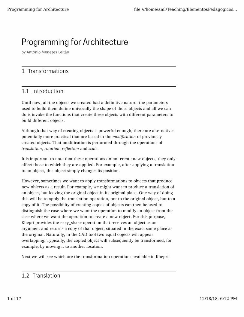
As an example, let us consider the hourglass shown in this figure that has asparameters the hourglass base centre point, the hourglass base radius, thehourglass strangulation radius and the hourglass height.
A hourglass
It is not difficult to conceive this shape as the union of two cone frustums:
hourglass(p, rb, rc, h) = union(cone_frustum(p, rb, p+vz(h/2), rc), cone_frustum(p+vz(h/2), rc, p+vz(h), rb))
However, it is possible we simplify the previous definition through the use of themirror operation:
hourglass(p, rb, rc, h) = mirror(cone_frustum(p, rb, p+vz(h/2), rc), p+vz(h/2))
In the following section we will see an example where these operations will beused for modelling one of the most famous buildings in the world.
1.6 The Sydney Opera House
The Sydney Opera House resulted from an international competition launchedin 1957 for the design of a building dedicated to performances. The winner wasthe project by Jørn Utzon, a Danish architect until then little known. His project,even though it did not fully fulfil the competition requirements, was selected by
Programming for Architecture file:///home/aml/Teaching/ElementosPedagogicos...
6 of 17 12/18/18, 6:12 PM

the famous architect Eero Saarinen, then a member of the jury, thatimmediately considered it as a landmark project. The proposal consisted in a setof structures, shaped like a shell, capable of accommodating various concerthalls. The result of this final proposal is represented in this figure.
The Sydney Opera House. Photograph by Brent Pearson.
Clearly innovative, Utzon’s design was too advanced for the construction andproject design technologies of the time and was by many considered impossible.In the three years that followed the project’s approval, Utzon, along with thestructural engineering team of the company Ove Arup, tried to find amathematical formulation for his hand-drawn shells, having experimented avariety of different approaches, including parabolic, circular and ellipticalshapes, but all of the solutions had, besides enormous technical difficulties, veryhigh costs which were completely incompatible with the approved budget.
In the summer of 1961, Utzon was near the brink of despair and decided todismantle the shells’ perspex model. However, upon packing the shells away, hefound out they fit almost perfectly inside each other, which would only bepossible if the different shells had the same curvature at all its points. Now, thesurface that has the same curvature at all its points is, obviously, the sphere,which led Utzon to think that maybe it would be possible to shape his shells as"cut" triangles on a sphere’s surface. Although this design was not exactly
Programming for Architecture file:///home/aml/Teaching/ElementosPedagogicos...
7 of 17 12/18/18, 6:12 PM
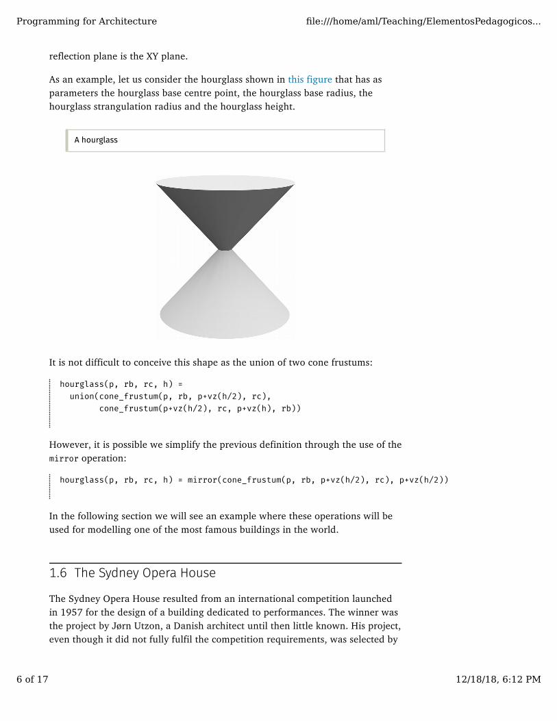
identical to the original drawings, it had the advantage of being calculable incomputers and, more importantly still, to allow its economic construction. OveArup’s collaboration was crucial for Utzon’s idea to be put to practice but thegenius idea that solved the problems of its construction, as well as the originaldesign, belongs to Utzon. Utzon’s idea is explained in a bronze model placednext to the building of the Opera House, as can be see in this figure.
Commemorative plate that explains Utzon’s idea for modelling the shells.Photography by Matt Prebble, UK,December 2006.
Unfortunately, construction delays and the ever accumulating costs, led thegovernment to start questioning the political decision to build the opera houseand forced Utzon to resign when the construction of the interiors was not yetfinished. Utzon was devastated and left Australia in 1966, never to return.Against the wishes of most architects, the masterpiece was completed by PeterHall and inaugurated in 1973 without a single reference made to Utzon.Unfortunately, the work of Peter Hall was not at the same level as Utzon’s andthe contrast between the stunning exteriors and simple interiors led the work tobe considered a "semi-masterpiece".
Programming for Architecture file:///home/aml/Teaching/ElementosPedagogicos...
8 of 17 12/18/18, 6:12 PM
Despite Utzon’s personal drama, this story turned out to have a happy ending:thirty years later, the Australian government remodelled the Sydney OperaHouse to become the true masterpiece recognition that it deserved and gotUtzon, who never got to see his work finished, to accept directing the workaiming to give back its original appearance.
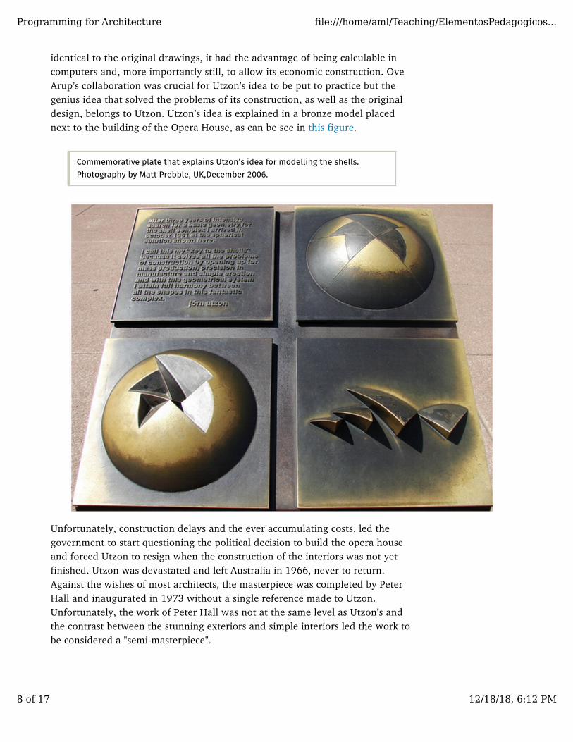
In this section, we will model the shells of the Sydney Opera House followingexactly the same solution proposed by Utzon. All the building shells will bemodelled by spherical triangles obtained by three cuts in a sphere. This figureshows two spheres of equal radius from which we cut a triangle in each, so as toget two of the half-shells that constitute the Sydney Opera House.
Two of the half-shells that constitute the Sydney Opera House overlapping thespheres from where they were obtained by a succession of cuts.
To define the sections we can consider that the building will be aligned in adirection parallel to the axis, so the symmetry axis will therefore correspondsto a section plane of which the normal is the axis, as an be seen in this figure.The two remaining section planes will have normals determined so as toapproximate, as rigorously as we can, the volumes imagined by Utzon. As is alsovisible in this figure, each shell is extracted from a sphere with a fixed radiusbut centred at different points. Thus, to model these half-shells we are going todefine a function that, from the centre of the sphere of radius and thenormals and of the section planes, produces a spherical shell with
YX
p rn1 n2
Programming for Architecture file:///home/aml/Teaching/ElementosPedagogicos...
9 of 17 12/18/18, 6:12 PM

thickness and with the desired shape.
Top view of two of the half-shells that constitute the Sydney Opera Houseoverlapping the spheres from which they were obtained by a succession of cuts.
half_shell(p, r, e, n1, n2) = move(slice(slice(slice(subtraction(sphere(u0(), r),
sphere(u0(), r-e)), u0(), n2), u0(), n1), x(-p.x) -vx()),
p)
As an example, this figure shows a half shell generated by evaluating thefollowing expression:
half_shell(xyz(-45, 0, 0), 75, 2, sph(1, 2.0, 4.6), sph(1, 1.9, 2.6))
A half shell of the Sydney Opera House.
e
Programming for Architecture file:///home/aml/Teaching/ElementosPedagogicos...
10 of 17 12/18/18, 6:12 PM
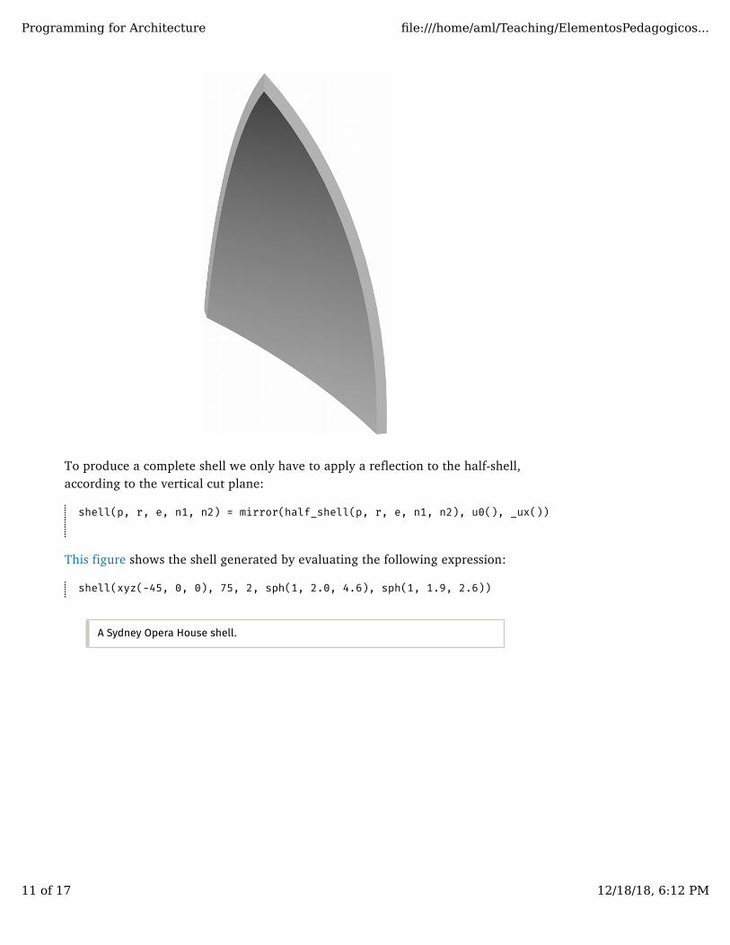
To produce a complete shell we only have to apply a reflection to the half-shell,according to the vertical cut plane:
shell(p, r, e, n1, n2) = mirror(half_shell(p, r, e, n1, n2), u0(), _ux())
This figure shows the shell generated by evaluating the following expression:
shell(xyz(-45, 0, 0), 75, 2, sph(1, 2.0, 4.6), sph(1, 1.9, 2.6))
A Sydney Opera House shell.
Programming for Architecture file:///home/aml/Teaching/ElementosPedagogicos...
11 of 17 12/18/18, 6:12 PM
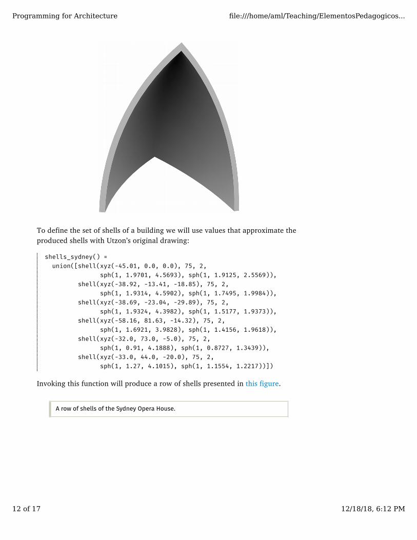
To define the set of shells of a building we will use values that approximate theproduced shells with Utzon’s original drawing:
shells_sydney() = union([shell(xyz(-45.01, 0.0, 0.0), 75, 2, sph(1, 1.9701, 4.5693), sph(1, 1.9125, 2.5569)), shell(xyz(-38.92, -13.41, -18.85), 75, 2, sph(1, 1.9314, 4.5902), sph(1, 1.7495, 1.9984)), shell(xyz(-38.69, -23.04, -29.89), 75, 2, sph(1, 1.9324, 4.3982), sph(1, 1.5177, 1.9373)), shell(xyz(-58.16, 81.63, -14.32), 75, 2, sph(1, 1.6921, 3.9828), sph(1, 1.4156, 1.9618)), shell(xyz(-32.0, 73.0, -5.0), 75, 2, sph(1, 0.91, 4.1888), sph(1, 0.8727, 1.3439)), shell(xyz(-33.0, 44.0, -20.0), 75, 2,
sph(1, 1.27, 4.1015), sph(1, 1.1554, 1.2217))])
Invoking this function will produce a row of shells presented in this figure.
A row of shells of the Sydney Opera House.
Programming for Architecture file:///home/aml/Teaching/ElementosPedagogicos...
12 of 17 12/18/18, 6:12 PM
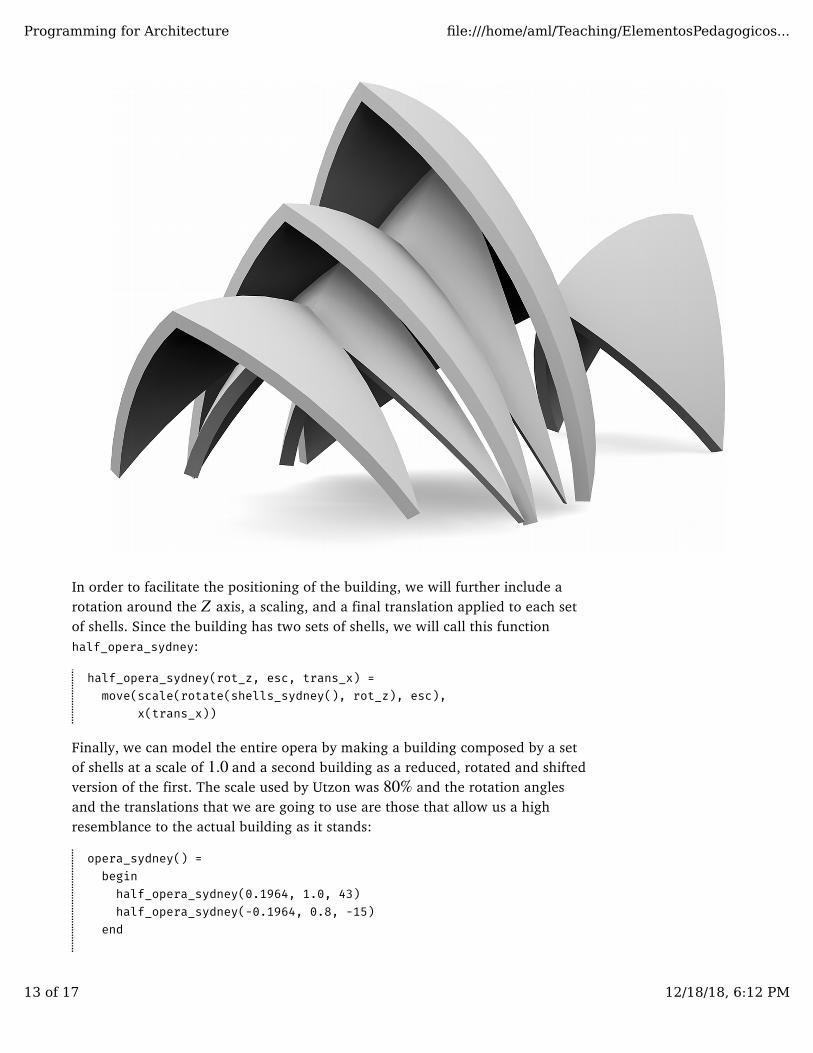
In order to facilitate the positioning of the building, we will further include arotation around the axis, a scaling, and a final translation applied to each setof shells. Since the building has two sets of shells, we will call this functionhalf_opera_sydney:
half_opera_sydney(rot_z, esc, trans_x) = move(scale(rotate(shells_sydney(), rot_z), esc), x(trans_x))
Finally, we can model the entire opera by making a building composed by a setof shells at a scale of and a second building as a reduced, rotated and shiftedversion of the first. The scale used by Utzon was and the rotation anglesand the translations that we are going to use are those that allow us a highresemblance to the actual building as it stands:
opera_sydney() = begin half_opera_sydney(0.1964, 1.0, 43) half_opera_sydney(-0.1964, 0.8, -15) end
Z
1.080%
Programming for Architecture file:///home/aml/Teaching/ElementosPedagogicos...
13 of 17 12/18/18, 6:12 PM
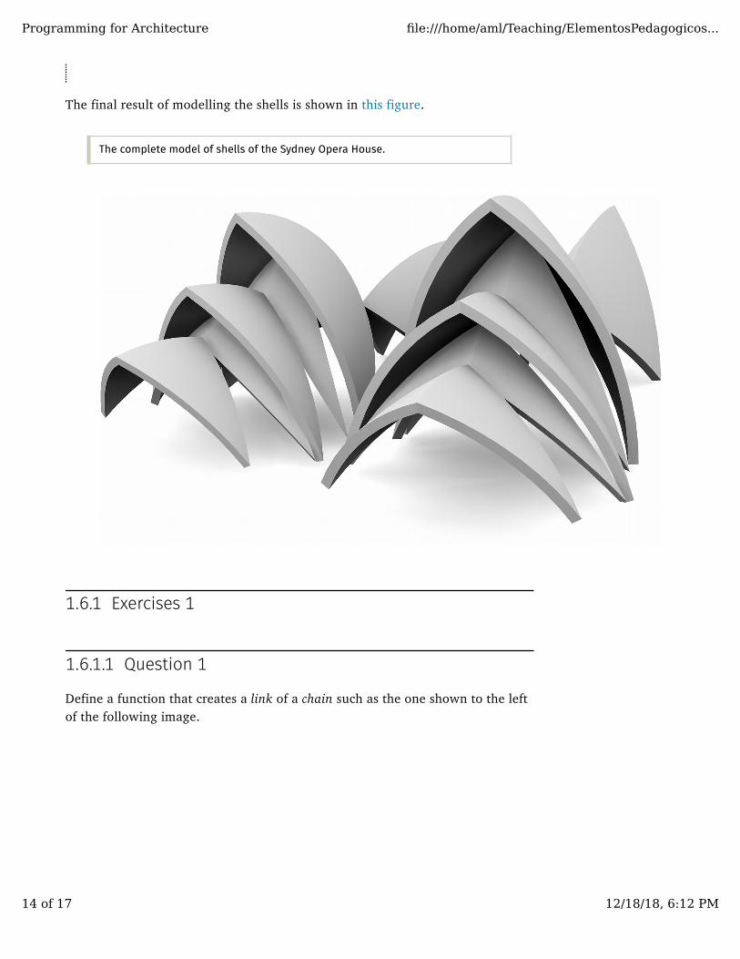
The final result of modelling the shells is shown in this figure.
The complete model of shells of the Sydney Opera House.
1.6.1 Exercises 1
1.6.1.1 Question 1
Define a function that creates a link of a chain such as the one shown to the leftof the following image.
Programming for Architecture file:///home/aml/Teaching/ElementosPedagogicos...
14 of 17 12/18/18, 6:12 PM
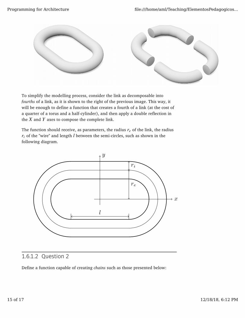
To simplify the modelling process, consider the link as decomposable intofourths of a link, as it is shown to the right of the previous image. This way, itwill be enough to define a function that creates a fourth of a link (at the cost ofa quarter of a torus and a half-cylinder), and then apply a double reflection inthe and axes to compose the complete link.
The function should receive, as parameters, the radius of the link, the radius of the "wire" and length between the semi-circles, such as shown in the
following diagram.
1.6.1.2 Question 2
Define a function capable of creating chains such as those presented below:
X Y
reri l
Programming for Architecture file:///home/aml/Teaching/ElementosPedagogicos...
15 of 17 12/18/18, 6:12 PM

Note that, as the chain is constructed, the links suffer successive rotationsaround the axis.
1.6.1.3 Question 3
Define a function to create closed chains such as the one presented bellow:
X
Programming for Architecture file:///home/aml/Teaching/ElementosPedagogicos...
16 of 17 12/18/18, 6:12 PM

Note that, as the chain is constructed, the links suffer successive rotationsaround the axis.X
Programming for Architecture file:///home/aml/Teaching/ElementosPedagogicos...
17 of 17 12/18/18, 6:12 PM