Learn | EMBEDDED SYSTEMS Online Training USA | EMBEDDED SYSTEMS Trainings

I
ProgrammingEmbeddedSystems I
A 10-week course, using C
40393837363534
1234567
‘8051’
8910
33323130292827262524
11121314151617181920
232221
P3.0
P1.7
RS
T
P1.6
P1.5
P1.4
P1.2
P1.3
P1.1
P1.0
VS
S
XT
L2
XT
L1
P3.7
P3.6
P3.5
P3.3
P3.4
P3
.2
P3.1
/ EA
P0
.6
P0
.7
P0
.5
P0
.4
P0
.3
P0
.1
P0
.2
P0.0
VC
C
P2
.0
P2
.2
P2
.1
P2
.3
P2
.4
P2
.5
P2
.7
P2
.6
/ PS
EN
ALE
Michael J. PontUniversity of Leicester
[v1.2]

II
Copyright © Michael J. Pont, 2002-2003
This document may be freely distributed and copied, provided that copyright notice atthe foot of each OHP page is clearly visible in all copies.

III
Seminar 1: “Hello, Embedded World” 1Overview of this seminar 2Overview of this course 3By the end of the course … 4Main course textbook 5Why use C? 6Pre-requisites! 7The 8051 microcontroller 8The “super loop” software architecture 9Strengths and weaknesseses of “super loops” 10Example: Central-heating controller 11Reading from (and writing to) port pins 12SFRs and ports 13SFRs and ports 14Creating and using sbit variables 15Example: Reading and writing bytes 16Creating “software delays” 17Using the performance analyzer to test software delays 18Strengths and weaknesses of software-only delays 19Preparation for the next seminar 20

IV
Seminar 2: Basic hardware foundations (resets, oscillators and port I/O) 21Review: The 8051 microcontroller 22Review: Central-heating controller 23Overview of this seminar 24Oscillator Hardware 25How to connect a crystal to a microcontroller 27Oscillator frequency and machine cycle period 28Keep the clock frequency as low as possible 29Stability issues 30Improving the stability of a crystal oscillator 31Overall strengths and weaknesses 32Reset Hardware 34More robust reset circuits 35Driving DC Loads 36Use of pull-up resistors 38Driving a low-power load without using a buffer 39Using an IC Buffer 40Example: Buffering three LEDs with a 74HC04 41What is a multi-segment LED? 42Driving a single digit 43Preparation for the next seminar 44

V
Seminar 3: Reading Switches 45Introduction 46Review: Basic techniques for reading from port pins 47Example: Reading and writing bytes (review) 48Example: Reading and writing bits (simple version) 49Example: Reading and writing bits (generic version) 51The need for pull-up resistors 56The need for pull-up resistors 57The need for pull-up resistors 58Dealing with switch bounce 59Example: Reading switch inputs (basic code) 61Example: Counting goats 68Conclusions 74Preparation for the next seminar 75

VI
Seminar 4: Adding Structure to Your Code 77Introduction 78Object-Oriented Programming with C 79Example of “O-O C” 82The Project Header (Main.H) 85The Port Header (Port.H) 92Re-structuring a “Hello World” example 96Example: Re-structuring the Goat-Counting Example 104Preparation for the next seminar 114

VII
Seminar 5: Meeting Real-Time Constraints 115Introduction 116Creating “hardware delays” 118The TCON SFR 119The TMOD SFR 120Two further registers 121Example: Generating a precise 50 ms delay 122Example: Creating a portable hardware delay 126The need for ‘timeout’ mechanisms - example 129Creating loop timeouts 130Example: Testing loop timeouts 132Example: A more reliable switch interface 134Creating hardware timeouts 135Conclusions 137Preparation for the next seminar 138

VIII
Seminar 6: Creating an Embedded Operating System 139Introduction 140Timer-based interrupts (the core of an embedded OS) 144The interrupt service routine (ISR) 145Automatic timer reloads 146Introducing sEOS 147Introducing sEOS 148Tasks, functions and scheduling 153Setting the tick interval 154Saving power 157Using sEOS in your own projects 158Is this approach portable? 159Example: Milk pasteurization 160Conclusions 174Preparation for the next seminar 175

IX
Seminar 7: Multi-State Systems and Function Sequences 177Introduction 178Implementing a Multi-State (Timed) system 180Example: Traffic light sequencing 181Example: Animatronic dinosaur 189Implementing a Multi-State (Input/Timed) system 195Example: Controller for a washing machine 197Conclusions 208Preparation for the next seminar 209

X
Seminar 8: Using the Serial Interface 211Overview of this seminar 212What is ‘RS-232’? 213Basic RS-232 Protocol 214Asynchronous data transmission and baud rates 215RS-232 voltage levels 216The software architecture 217Overview 218Using the on-chip U(S)ART for RS-232 communications 219Serial port registers 220Baud rate generation 221Why use 11.0592 MHz crystals? 222PC Software 223What about printf()? 224RS-232 and 8051: Overall strengths and weaknesses 225Example: Displaying elapsed time on a PC 226Example: Data acquisition 235Conclusions 239Preparation for the next seminar 240

XI
Seminar 9: Case Study: Intruder Alarm System 241Introduction 242System Operation 243Key software components used in this example 244Running the program 245The software 246Extending and modifying the system 260Conclusions 261

XII
Seminar 10: Case Study: Controlling a Mobile Robot 263Overview 264What can the robot do? 265The robot brain 266How does the robot move? 267Pulse-width modulation 268Software PWM 269The resulting code 270More about the robot 271Conclusions 272

COPYRIGHT © MICHAEL J. PONT, 2001-2003. Contains material from:Pont, M.J. (2002) “Embedded C”, Addison-Wesley.
PES I - 1
Seminar 1: “Hello, Embedded
World”
B
E
C
5.5V, 0.3A lamp
ZTX751
4V - 6V (battery)
10 KΩ
10 µF
4 MHz
20
19
18
17
16
15
14
1
2
3
4
5
6
7
Atm
el 2
051
8
9
10
13
12
11GND
P3.4
P3.5
P3.3
P3.2
XTL1
P3.1
XTL2
P3.0
RST
P3.7
P1.1
P1.0
P1.2
P1.3
P1.4
P1.6
P1.5
P1.7
VCC
40393837363534
1234567
‘8051’
8910
33323130292827262524
11121314151617181920
232221
P3.0
P1.7
RS
T
P1.6
P1.5
P1.4
P1.2
P1.3
P1.1
P1.0
VS
S
XT
L2
XT
L1
P3.7
P3.6
P3.5
P3.3
P3.4
P3.2
P3.1
/ EA
P0.6
P0.7
P0.5
P0.4
P0.3
P0.1
P0.2
P0.0
VC
C
P2.0
P2.2
P2.1
P2.3
P2.4
P2.5
P2.7
P2.6
/ PS
EN
ALE

COPYRIGHT © MICHAEL J. PONT, 2001-2003. Contains material from:Pont, M.J. (2002) “Embedded C”, Addison-Wesley.
PES I - 2
Overview of this seminar
This introductory seminar will:
• Provide an overview of this course
• Introduce the 8051 microcontroller
• Present the “Super Loop” software architecture
• Describe how to use port pins
• Consider how you can generate delays (and why you mightneed to).

COPYRIGHT © MICHAEL J. PONT, 2001-2003. Contains material from:Pont, M.J. (2002) “Embedded C”, Addison-Wesley.
PES I - 3
Overview of this course
This course is concerned with the implementation of software (anda small amount of hardware) for embedded systems constructedusing a single microcontroller.
The processors examined in detail are from the 8051 family(including both ‘Standard’ and ‘Small’ devices).
All programming is in the ‘C’ language.

COPYRIGHT © MICHAEL J. PONT, 2001-2003. Contains material from:Pont, M.J. (2002) “Embedded C”, Addison-Wesley.
PES I - 4
By the end of the course …
By the end of the course, you will be able to:
1. Design software for single-processor embedded applicationsbased on small, industry standard, microcontrollers;
2. Implement the above designs using a modern, high-levelprogramming language (‘C’), and
3. Begin to understand issues of reliability and safety and howsoftware design and programming decisions may have apositive or negative impact in this area.

COPYRIGHT © MICHAEL J. PONT, 2001-2003. Contains material from:Pont, M.J. (2002) “Embedded C”, Addison-Wesley.
PES I - 5
Main course textbook
Throughout this course, we will be making heavy use of this book:
Embedded Cby Michael J. Pont (2002)
Addison-Wesley[ISBN: 0-201-79523X]
For further information about this book, please see:
http://www.engg.le.ac.uk/books/Pont/ec51.htm

COPYRIGHT © MICHAEL J. PONT, 2001-2003. Contains material from:Pont, M.J. (2002) “Embedded C”, Addison-Wesley.
PES I - 6
Why use C?
• It is a ‘mid-level’, with ‘high-level’ features (such as supportfor functions and modules), and ‘low-level’ features (such asgood access to hardware via pointers);
• It is very efficient;
• It is popular and well understood;
• Even desktop developers who have used only Java or C++can soon understand C syntax;
• Good, well-proven compilers are available for everyembedded processor (8-bit to 32-bit or more);
• Experienced staff are available;
• Books, training courses, code samples and WWW sitesdiscussing the use of the language are all widely available.
Overall, C may not be an perfect language for developing embeddedsystems, but it is a good choice (and is unlikely that a ‘perfect’ languagewill ever be created).

COPYRIGHT © MICHAEL J. PONT, 2001-2003. Contains material from:Pont, M.J. (2002) “Embedded C”, Addison-Wesley.
PES I - 7
Pre-requisites!
• Throughout this course, it will be assumed that you have hadprevious programming experience: this might be in - forexample - Java or C++.
• For most people with such a background, “getting to grips”with C is straightforward.

COPYRIGHT © MICHAEL J. PONT, 2001-2003. Contains material from:Pont, M.J. (2002) “Embedded C”, Addison-Wesley.
PES I - 8
The 8051 microcontroller
40393837363534
1234567
‘8051’
8910
33323130292827262524
11121314151617181920
232221
P3.0
P1.7
RS
T
P1.6
P1.5
P1.4
P1.2
P1.3
P1.1
P1.0
VS
S
XT
L2
XT
L1
P3.7
P3.6
P3.5
P3.3
P3.4
P3.2
P3.1
/ EA
P0.6
P0.7
P0.5
P0.4
P0.3
P0.1
P0.2
P0.0
VC
C
P2.0
P2.2
P2.1
P2.3
P2.4
P2.5
P2.7
P2.6
/ PS
EN
ALE
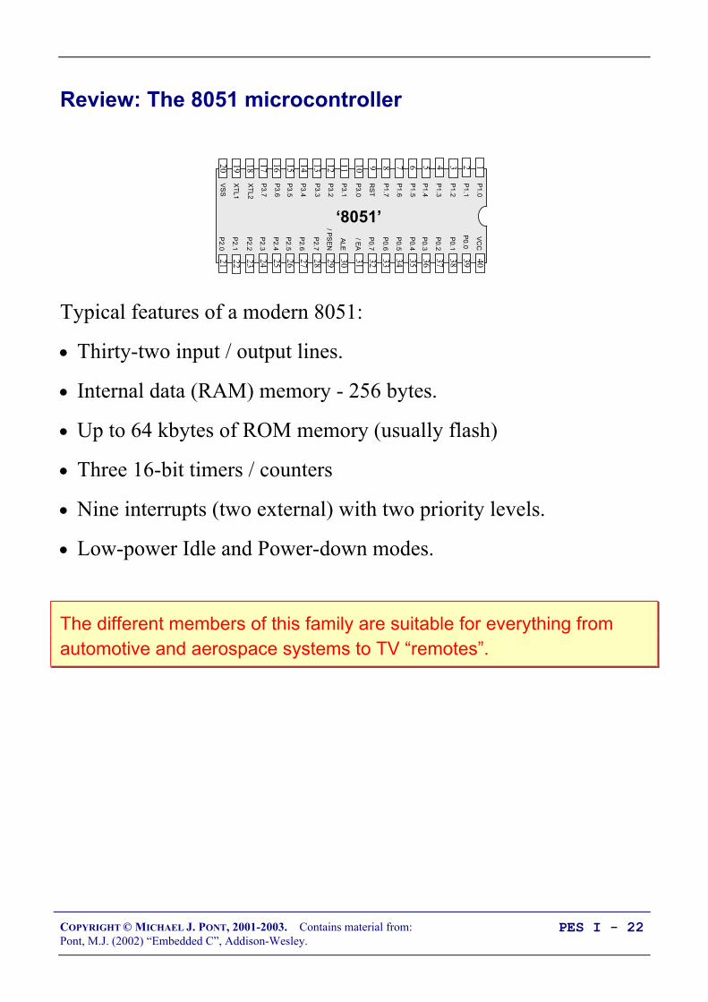
Typical features of a modern 8051:
• Thirty-two input / output lines.
• Internal data (RAM) memory - 256 bytes.
• Up to 64 kbytes of ROM memory (usually flash)
• Three 16-bit timers / counters
• Nine interrupts (two external) with two priority levels.
• Low-power Idle and Power-down modes.
The different members of this family are suitable for everything fromautomotive and aerospace systems to TV “remotes”.

COPYRIGHT © MICHAEL J. PONT, 2001-2003. Contains material from:Pont, M.J. (2002) “Embedded C”, Addison-Wesley.
PES I - 9
The “super loop” software architecture
Problem
What is the minimum software environment you need to create anembedded C program?
Solution
void main(void) /* Prepare for task X */ X_Init();
while(1) /* 'for ever' (Super Loop) */ X(); /* Perform the task */
Crucially, the ‘super loop’, or ‘endless loop’, is required because wehave no operating system to return to: our application will keep loopinguntil the system power is removed.

COPYRIGHT © MICHAEL J. PONT, 2001-2003. Contains material from:Pont, M.J. (2002) “Embedded C”, Addison-Wesley.
PES I - 10
Strengths and weaknesseses of “super loops”
The main strength of Super Loop systems is their simplicity. Thismakes them (comparatively) easy to build, debug, test and maintain.
Super Loops are highly efficient: they have minimal hardwareresource implications.
Super Loops are highly portable.
BUT:
If your application requires accurate timing (for example, you need toacquire data precisely every 2 ms), then this framework will notprovide the accuracy or flexibility you require. The basic Super Loop operates at ‘full power’ (normal operating
mode) at all times. This may not be necessary in all applications, andcan have a dramatic impact on system power consumption.
[As we will see in Seminar 6, a scheduler can address theseproblems.]
COPYRIGHT © MICHAEL J. PONT, 2001-2003. Contains material from:Pont, M.J. (2002) “Embedded C”, Addison-Wesley.
PES I - 11
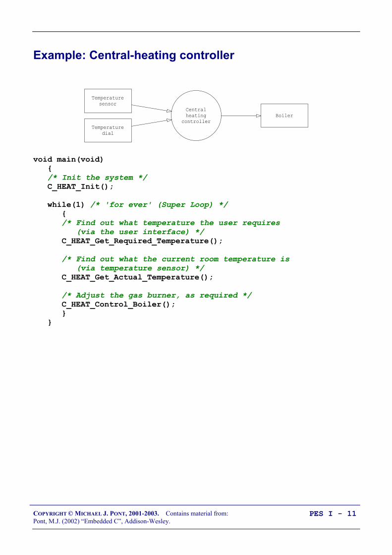
Example: Central-heating controller
Centralheating
controllerBoiler
Temperaturesensor
Temperaturedial
void main(void) /* Init the system */ C_HEAT_Init();
while(1) /* 'for ever' (Super Loop) */ /* Find out what temperature the user requires (via the user interface) */ C_HEAT_Get_Required_Temperature();
/* Find out what the current room temperature is (via temperature sensor) */ C_HEAT_Get_Actual_Temperature();
/* Adjust the gas burner, as required */ C_HEAT_Control_Boiler();
COPYRIGHT © MICHAEL J. PONT, 2001-2003. Contains material from:Pont, M.J. (2002) “Embedded C”, Addison-Wesley.
PES I - 12
Reading from (and writing to) port pins
Problem
How do you write software to read from and /or write to the portson an (8051) microcontroller?
Background
The Standard 8051s have four 8-bit ports.
All of the ports are bidirectional: that is, they may be used for bothinput and output.
COPYRIGHT © MICHAEL J. PONT, 2001-2003. Contains material from:Pont, M.J. (2002) “Embedded C”, Addison-Wesley.
PES I - 13
SFRs and ports
Control of the 8051 ports through software is carried out using whatare known as ‘special function registers’ (SFRs).
Physically, the SFR is a area of memory in internal RAM:
• P0 is at address 0x80
• P1 at address 0x90
• P2 at address 0xA0
• P3 at address 0xB0
NOTE: 0x means that the number format is HEXADECIMAL- see Embedded C, Chapter 2.

COPYRIGHT © MICHAEL J. PONT, 2001-2003. Contains material from:Pont, M.J. (2002) “Embedded C”, Addison-Wesley.
PES I - 14
SFRs and ports
A typical SFR header file for an 8051 family device will contain thelines:
sfr P0 = 0x80;sfr P1 = 0x90;sfr P2 = 0xA0;sfr P3 = 0xB0;
Having declared the SFR variables, we can write to the ports in astraightforward manner. For example, we can send some data toPort 1 as follows:unsigned char Port_data;
Port_data = 0x0F;
P1 = Port_data; /* Write 00001111 to Port 1 */
Similarly, we can read from (for example) Port 1 as follows:unsigned char Port_data;
P1 = 0xFF; /* Set the port to ‘read mode’ */Port_data = P1; /* Read from the port */
Note that, in order to read from a pin, we need to ensure that the lastthing written to the pin was a ‘1’.

COPYRIGHT © MICHAEL J. PONT, 2001-2003. Contains material from:Pont, M.J. (2002) “Embedded C”, Addison-Wesley.
PES I - 15
Creating and using sbit variables
To write to a single pin, we can make use of an sbit variable in theKeil (C51) compiler to provide a finer level of control.
Here’s a clean way of doing this:
#define LED_PORT P3
#define LED_ON 0 /* Easy to change the logic here */#define LED_OFF 1
...
sbit Warning_led = LED_PORT^0; /* LED is connected to pin 3.0 */
...
Warning_led = LED_ON;... /* delay */Warning_led = LED_OFF;... /* delay */Warning_led = LED_ON;... /* etc */
COPYRIGHT © MICHAEL J. PONT, 2001-2003. Contains material from:Pont, M.J. (2002) “Embedded C”, Addison-Wesley.
PES I - 16
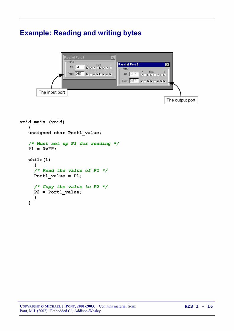
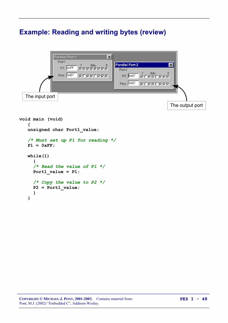
Example: Reading and writing bytes
The input port
The output port
void main (void) unsigned char Port1_value;
/* Must set up P1 for reading */ P1 = 0xFF;
while(1) /* Read the value of P1 */ Port1_value = P1;
/* Copy the value to P2 */ P2 = Port1_value;

COPYRIGHT © MICHAEL J. PONT, 2001-2003. Contains material from:Pont, M.J. (2002) “Embedded C”, Addison-Wesley.
PES I - 17
Creating “software delays”
Problem
How do you create a simple delay without using any hardware(timer) resources?
Solution
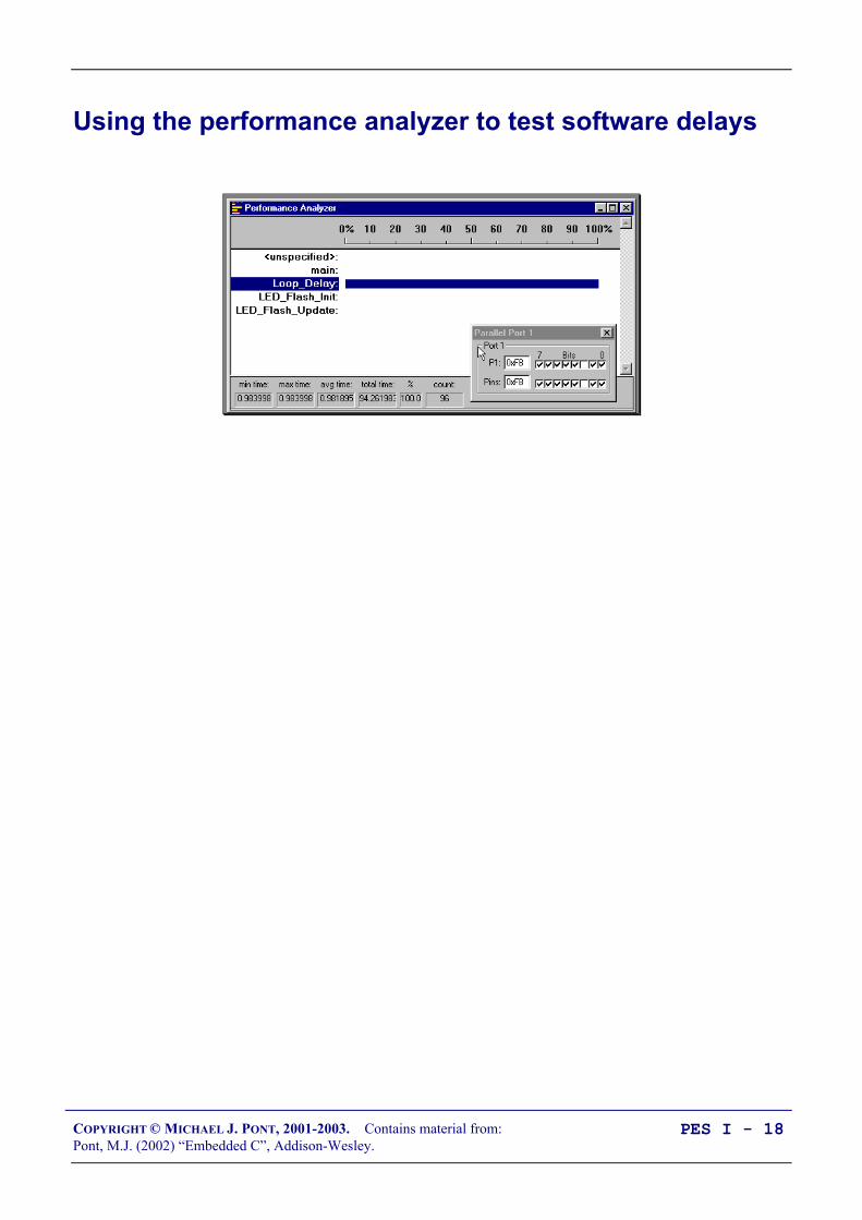
Loop_Delay() unsigned int x,y;
for (x=0; x <= 65535; x++) y++;
Longer_Loop_Delay() unsigned int x, y, z;
for (x=0; x<=65535; x++) for (y=0; y<=65535; y++); z++;
COPYRIGHT © MICHAEL J. PONT, 2001-2003. Contains material from:Pont, M.J. (2002) “Embedded C”, Addison-Wesley.
PES I - 18
Using the performance analyzer to test software delays

COPYRIGHT © MICHAEL J. PONT, 2001-2003. Contains material from:Pont, M.J. (2002) “Embedded C”, Addison-Wesley.
PES I - 19
Strengths and weaknesses of software-only delays
SOFTWARE DELAY can be used to produce very short delays. SOFTWARE DELAY requires no hardware timers. SOFTWARE DELAY will work on any microcontroller.
BUT:
It is very difficult to produce precisely timed delays. The loops must be re-tuned if you decide to use a different processor,
change the clock frequency, or even change the compiler optimisationsettings.

COPYRIGHT © MICHAEL J. PONT, 2001-2003. Contains material from:Pont, M.J. (2002) “Embedded C”, Addison-Wesley.
PES I - 20
Preparation for the next seminar
In the lab session associated with this seminar, you will use ahardware simulator to try out the techniques discussed here. Thiswill give you a chance to focus on the software aspects ofembedded systems, without dealing with hardware problems.
In the next seminar, we will prepare to create your first test systemson “real hardware”.
Please read Chapters 1, 2 and 3before the next seminar

COPYRIGHT © MICHAEL J. PONT, 2001-2003. Contains material from:Pont, M.J. (2002) “Embedded C”, Addison-Wesley.
PES I - 21
Seminar 2: Basic hardware
foundations (resets,oscillators and port
I/O)
Atmel89C52
Vcc
RESET
GND
Vcc
EA
30 pF ±10
30 pF ±10
XTAL 2
XTAL 1
DS1812
12 MHz
COPYRIGHT © MICHAEL J. PONT, 2001-2003. Contains material from:Pont, M.J. (2002) “Embedded C”, Addison-Wesley.
PES I - 22
Review: The 8051 microcontroller
40393837363534
1234567
‘8051’
8910
33323130292827262524
11121314151617181920
232221
P3.0
P1.7
RS
T
P1.6
P1.5
P1.4
P1.2
P1.3
P1.1
P1.0
VS
S
XT
L2
XT
L1
P3.7
P3.6
P3.5
P3.3
P3.4
P3.2
P3.1
/ EA
P0.6
P0.7
P0.5
P0.4
P0.3
P0.1
P0.2
P0.0
VC
C
P2.0
P2.2
P2.1
P2.3
P2.4
P2.5
P2.7
P2.6
/ PS
EN
ALE
Typical features of a modern 8051:
• Thirty-two input / output lines.
• Internal data (RAM) memory - 256 bytes.
• Up to 64 kbytes of ROM memory (usually flash)
• Three 16-bit timers / counters
• Nine interrupts (two external) with two priority levels.
• Low-power Idle and Power-down modes.
The different members of this family are suitable for everything fromautomotive and aerospace systems to TV “remotes”.

COPYRIGHT © MICHAEL J. PONT, 2001-2003. Contains material from:Pont, M.J. (2002) “Embedded C”, Addison-Wesley.
PES I - 23
Review: Central-heating controller
Centralheating
controllerBoiler
Temperaturesensor
Temperaturedial
void main(void) /* Init the system */ C_HEAT_Init();
while(1) /* 'for ever' (Super Loop) */ /* Find out what temperature the user requires (via the user interface) */ C_HEAT_Get_Required_Temperature();
/* Find out what the current room temperature is (via temperature sensor) */ C_HEAT_Get_Actual_Temperature();
/* Adjust the gas burner, as required */ C_HEAT_Control_Boiler();
COPYRIGHT © MICHAEL J. PONT, 2001-2003. Contains material from:Pont, M.J. (2002) “Embedded C”, Addison-Wesley.
PES I - 24
Overview of this seminar
This seminar will:
• Consider the techniques you need to construct your first“real” embedded system (on a breadboard).
Specifically, we’ll look at:
• Oscillator circuits
• Reset circuits
• Controlling LEDs

COPYRIGHT © MICHAEL J. PONT, 2001-2003. Contains material from:Pont, M.J. (2002) “Embedded C”, Addison-Wesley.
PES I - 25
Oscillator Hardware
• All digital computer systems are driven by some form ofoscillator circuit.
• This circuit is the ‘heartbeat’ of the system and is crucial tocorrect operation.
For example:
• If the oscillator fails, the system will not function at all.
• If the oscillator runs irregularly, any timing calculationsperformed by the system will be inaccurate.

COPYRIGHT © MICHAEL J. PONT, 2001-2003. Contains material from:Pont, M.J. (2002) “Embedded C”, Addison-Wesley.
PES I - 26
CRYSTAL OSCILLATOR
Crystals may be used to generate a popular form of oscillator circuitknown as a Pierce oscillator.
C
Crystal
R
JFET
L
Vcc
Oscillator output (to microcontroller)
• A variant of the Pierce oscillator is common in the 8051family. To create such an oscillator, most of the componentsare included on the microcontroller itself.
• The user of this device must generally only supply thecrystal and two small capacitors to complete the oscillatorimplementation.

COPYRIGHT © MICHAEL J. PONT, 2001-2003. Contains material from:Pont, M.J. (2002) “Embedded C”, Addison-Wesley.
PES I - 27
How to connect a crystal to a microcontroller
C
C
8051-familymicrocontroller
GND XTAL
XTAL
In the absence of specific information, a capacitor value of30 pF will perform well in most circumstances.
COPYRIGHT © MICHAEL J. PONT, 2001-2003. Contains material from:Pont, M.J. (2002) “Embedded C”, Addison-Wesley.
PES I - 28
Oscillator frequency and machine cycle period
• In the original members of the 8051 family, the machinecycle takes twelve oscillator periods.
• In later family members, such as the Infineon C515C, amachine cycle takes six oscillator periods; in more recentdevices such as the Dallas 89C420, only one oscillatorperiod is required per machine cycle.
• As a result, the later members of the family operating at thesame clock frequency execute instructions much morerapidly.

COPYRIGHT © MICHAEL J. PONT, 2001-2003. Contains material from:Pont, M.J. (2002) “Embedded C”, Addison-Wesley.
PES I - 29
Keep the clock frequency as low as possible
Many developers select an oscillator / resonator frequency that is ator near the maximum value supported by a particular device.
This can be a mistake:
• Many application do not require the levels of performancethat a modern 8051 device can provide.
• The electromagnetic interference (EMI) generated by acircuit increases with clock frequency.
• In most modern (CMOS-based) 8051s, there is an almostlinear relationship between the oscillator frequency and thepower-supply current. As a result, by using the lowestfrequency necessary it is possible to reduce the powerrequirement: this can be useful in many applications.
• When accessing low-speed peripherals (such as slowmemory, or LCD displays), programming and hardwaredesign can be greatly simplified - and the cost of peripheralcomponents, such as memory latches, can be reduced - if thechip is operating more slowly.
In general, you should operate at the lowest possible oscillatorfrequency compatible with the performance needs of your application.

COPYRIGHT © MICHAEL J. PONT, 2001-2003. Contains material from:Pont, M.J. (2002) “Embedded C”, Addison-Wesley.
PES I - 30
Stability issues
• A key factor in selecting an oscillator for your system is theissue of oscillator stability. In most cases, oscillator stabilityis expressed in figures such as ‘±20 ppm’: ‘20 parts permillion’.
• To see what this means in practice, consider that there areapproximately 32 million seconds in a year. In every millionseconds, your crystal may gain (or lose) 20 seconds. Overthe year, a clock based on a 20 ppm crystal may thereforegain (or lose) about 32 x 20 seconds, or around 10 minutes.
Standard quartz crystals are typically rated from ±10 to ±100 ppm, andso may gain (or lose) from around 5 to 50 minutes per year.

COPYRIGHT © MICHAEL J. PONT, 2001-2003. Contains material from:Pont, M.J. (2002) “Embedded C”, Addison-Wesley.
PES I - 31
Improving the stability of a crystal oscillator
• If you want a general crystal-controlled embedded system tokeep accurate time, you can choose to keep the device in anoven (or fridge) at a fixed temperature, and fine-tune thesoftware to keep accurate time. This is, however, rarelypractical.
• ‘Temperature Compensated Crystal Oscillators’ (TCXOs)are available that provide - in an easy-to-use package - acrystal oscillator, and circuitry that compensates for changesin temperature. Such devices provide stability levels of up to±0.1 ppm (or more): in a clock circuit, this should gain orlose no more than around 1 minute every 20 years.
TCXOs can cost in excess of $100.00 per unit...
• One practical alternative is to determine the temperature-frequency characteristics for your chosen crystal, and includethis information in your application.
For the cost of a small temperature sensor (around $2.00),you can keep track of the temperature and adjust the timingas required.

COPYRIGHT © MICHAEL J. PONT, 2001-2003. Contains material from:Pont, M.J. (2002) “Embedded C”, Addison-Wesley.
PES I - 32
Overall strengths and weaknesses
Crystal oscillators are stable. Typically ±20-100 ppm = ±50 mins peryear (up to ~1 minute / week).
The great majority of 8051-based designs use a variant of the simplecrystal-based oscillator circuit presented here: developers aretherefore familiar with crystal-based designs.
Quartz crystals are available at reasonable cost for most commonfrequencies. The only additional components required are usually twosmall capacitors. Overall, crystal oscillators are more expensive thanceramic resonators.
BUT:
Crystal oscillators are susceptible to vibration. The stability falls with age.

COPYRIGHT © MICHAEL J. PONT, 2001-2003. Contains material from:Pont, M.J. (2002) “Embedded C”, Addison-Wesley.
PES I - 33
CERAMIC RESONATOR
Overall strengths and weaknesses
Cheaper than crystal oscillators. Physically robust: less easily damage by physical vibration (or
dropped equipment, etc) than crystal oscillator. Many resonators contain in-built capacitors, and can be used without
any external components. Small size. About half the size of crystal oscillator.
BUT:
Comparatively low stability: not general appropriate for use whereaccurate timing (over an extended period) is required. Typically ±5000ppm = ±2500 min per year (up to ~50 minutes / week).

COPYRIGHT © MICHAEL J. PONT, 2001-2003. Contains material from:Pont, M.J. (2002) “Embedded C”, Addison-Wesley.
PES I - 34
Reset Hardware
• The process of starting any microcontroller is a non-trivialone.
• The underlying hardware is complex and a small,manufacturer-defined, ‘reset routine’ must be run to placethis hardware into an appropriate state before it can beginexecuting the user program. Running this reset routine takestime, and requires that the microcontroller’s oscillator isoperating.
• An RC reset circuit is usually the simplest way of controllingthe reset behaviour.
Example:
30 pF ±10
30 pF ±10
AT89C2051
Vcc
RESET
GND
Vcc
10 K
10 uF
XTAL 2
XTAL 1

COPYRIGHT © MICHAEL J. PONT, 2001-2003. Contains material from:Pont, M.J. (2002) “Embedded C”, Addison-Wesley.
PES I - 35
More robust reset circuits
Example:
Atmel89C52
Vcc
RESET
GND
Vcc
EA
30 pF ±10
30 pF ±10
XTAL 2
XTAL 1
DS1812
12 MHz

COPYRIGHT © MICHAEL J. PONT, 2001-2003. Contains material from:Pont, M.J. (2002) “Embedded C”, Addison-Wesley.
PES I - 36
Driving DC Loads
• The port pins on a typical 8051 microcontroller can be set atvalues of either 0V or 5V (or, in a 3V system, 0V and 3V)under software control.
• Each pin can typically sink (or source) a current of around10 mA.
• The total current we can source or sink per microcontroller(all 32 pins, where available) is typically 70 mA or less.

COPYRIGHT © MICHAEL J. PONT, 2001-2003. Contains material from:Pont, M.J. (2002) “Embedded C”, Addison-Wesley.
PES I - 37
NAKED LED
Logic 0 (0v) to light LED
Vcc
Rled
diode
diodeccled I
VVR −=
8051 DevicePX.Y
Connecting a single LED directly to a microcomputer port isusually possible.
• Supply voltage, Vcc = 5V,
• LED forward voltage, Vdiode = 2V,
• Required diode current, Idiode = 15 mA (note that the datasheet for your chosen LED will provide this information).
This gives a required R value of 200Ω.

COPYRIGHT © MICHAEL J. PONT, 2001-2003. Contains material from:Pont, M.J. (2002) “Embedded C”, Addison-Wesley.
PES I - 38
Use of pull-up resistors
To adapt circuits for use on pins without internal pull-up resistors isstraightforward: you simply need to add an external pull-up resistor:
Logic 0to light LED
Vcc
Rled
8051 DevicePX.Y
Rpull-up
The value of the pull-up resistor should be between 1K and 10K.This requirement applies to all of the examples on this course.
NOTE:This is usually only necessary on Port 0(see Seminar 3 for further details).

COPYRIGHT © MICHAEL J. PONT, 2001-2003. Contains material from:Pont, M.J. (2002) “Embedded C”, Addison-Wesley.
PES I - 39
Driving a low-power load without using a buffer
Logic 0 (0v) to drive load
Vcc
R
load
loadcc
IVVR −=
8051 Device
PX.Y
Load
Logic 0 (0v) to sound buzzer
Vcc
Piezo-electricbuzzer
8051 Device
PX.Y
See “PATTERNS FOR TIME-TRIGGERED EMBEDDED SYSTEMS”, p.115(NAKED LOAD)

COPYRIGHT © MICHAEL J. PONT, 2001-2003. Contains material from:Pont, M.J. (2002) “Embedded C”, Addison-Wesley.
PES I - 40
Using an IC Buffer
8051 DevicePin X.Y
R
5V
Buf
fer
(CM
OS
)
“Low” output = 0V LED is (fully) ON
“High” output = 5V LED is OFF
Using a CMOS buffer.
8051 DevicePin X.Y
R
5V
Buf
fer
(TT
L)“Low” output = ~1V LED is ON
“High” output = 5V LED is OFFRpull-up
Using a TTL buffer.
It makes sense to use CMOS logic in your buffer designs whereverpossible. You should also make it clear in the designdocumentation that CMOS logic is to be used.
See “PATTERNS FOR TIME-TRIGGERED EMBEDDED SYSTEMS”, p.118 (ICBUFFER)
COPYRIGHT © MICHAEL J. PONT, 2001-2003. Contains material from:Pont, M.J. (2002) “Embedded C”, Addison-Wesley.
PES I - 41
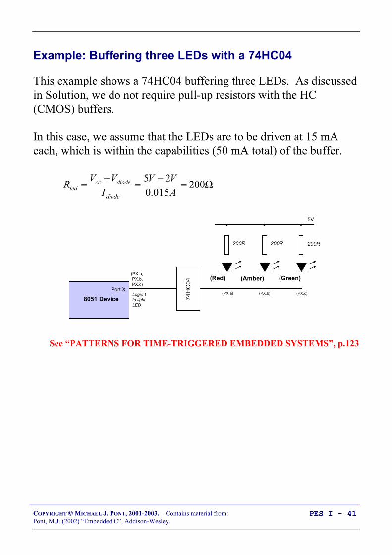
Example: Buffering three LEDs with a 74HC04
This example shows a 74HC04 buffering three LEDs. As discussedin Solution, we do not require pull-up resistors with the HC(CMOS) buffers.
In this case, we assume that the LEDs are to be driven at 15 mAeach, which is within the capabilities (50 mA total) of the buffer.
Ω=−=−= 200015.0
25AVV
IVVR
diode
diodeccled
200R 200R 200R
(PX.a) (PX.b) (PX.c)
8051 DevicePort X
5V
74
HC
04
(PX.a, PX.b, PX.c)
(Red) (Amber) (Green)
Logic 1to lightLED
See “PATTERNS FOR TIME-TRIGGERED EMBEDDED SYSTEMS”, p.123

COPYRIGHT © MICHAEL J. PONT, 2001-2003. Contains material from:Pont, M.J. (2002) “Embedded C”, Addison-Wesley.
PES I - 42
What is a multi-segment LED?
Multiple LEDs are often arranged as multi-segment displays:combinations of eight segments and similar seven-segment displays(without a decimal point) are particularly common.
8 a
b
c
d
e
fg
Such displays are arranged either as ‘common cathode’ or ‘commonanode’ packages:
Cathode (-)
Anode (+)
The required current per segment varies from about 2 mA (verysmall displays) to about 60 mA (very large displays, 100mm ormore).

COPYRIGHT © MICHAEL J. PONT, 2001-2003. Contains material from:Pont, M.J. (2002) “Embedded C”, Addison-Wesley.
PES I - 43
Driving a single digit
• In most cases, we require some form of buffer or driver ICbetween the port and the MS LED.
• For example, we can use UDN2585A.
Each of the (8) channels in this buffer can simultaneouslysource up to 120 mA of current (at up to 25V): this isenough, for example, for even very large LED displays.
10
Vcc
a
b
dp
UDN2585A
c
g 8 PX.0
PX.7R
9
10
• Note that this is an inverting (current source) buffer. Logic 0on the input line will light the corresponding LED segment.

COPYRIGHT © MICHAEL J. PONT, 2001-2003. Contains material from:Pont, M.J. (2002) “Embedded C”, Addison-Wesley.
PES I - 44
Preparation for the next seminar
Please read Chapter 4before the next seminar

COPYRIGHT © MICHAEL J. PONT, 2001-2003. Contains material from:Pont, M.J. (2002) “Embedded C”, Addison-Wesley.
PES I - 45
Seminar 3: Reading Switches
To pin on:
Port 1, Port 2, or Port 3.

COPYRIGHT © MICHAEL J. PONT, 2001-2003. Contains material from:Pont, M.J. (2002) “Embedded C”, Addison-Wesley.
PES I - 46
Introduction
• Embedded systems usually use switches as part of their userinterface.
• This general rule applies from the most basic remote-controlsystem for opening a garage door, right up to the mostsophisticated aircraft autopilot system.
• Whatever the system you create, you need to be able tocreate a reliable switch interface.
1 32
0
4 65
7 98
Enter ><
1 2 3 4 5
StartOffOn
STOP
Engage AP
Temporary Manual
Up and Around
Disengage AP
In this seminar, we consider how you can read inputs frommechanical switches in your embedded application.
Before considering switches themselves, we will consider theprocess of reading the state of port pins.

COPYRIGHT © MICHAEL J. PONT, 2001-2003. Contains material from:Pont, M.J. (2002) “Embedded C”, Addison-Wesley.
PES I - 47
Review: Basic techniques for reading from port pins
We can send some data to Port 1 as follows:sfr P1 = 0x90; /* Usually in header file */
P1 = 0x0F; /* Write 00001111 to Port 1 */
In exactly the same way, we can read from Port 1 as follows:unsigned char Port_data;
P1 = 0xFF; /* Set the port to ‘read mode’ */Port_data = P1; /* Read from the port */
COPYRIGHT © MICHAEL J. PONT, 2001-2003. Contains material from:Pont, M.J. (2002) “Embedded C”, Addison-Wesley.
PES I - 48
Example: Reading and writing bytes (review)
The input port
The output port
void main (void) unsigned char Port1_value;
/* Must set up P1 for reading */ P1 = 0xFF;
while(1) /* Read the value of P1 */ Port1_value = P1;
/* Copy the value to P2 */ P2 = Port1_value;

COPYRIGHT © MICHAEL J. PONT, 2001-2003. Contains material from:Pont, M.J. (2002) “Embedded C”, Addison-Wesley.
PES I - 49
Example: Reading and writing bits (simple version)
/*-------------------------------------------------------------*-
Bits1.C (v1.00)
-*-------------------------------------------------------------*/
#include <Reg52.H>
sbit Switch_pin = P1^0;sbit LED_pin = P1^1;
/* ............................................................... */
void main (void) bit x;
/* Set switch pin for reading */ Switch_pin = 1;
while(1) x = Switch_pin; /* Read Pin 1.0 */ LED_pin = x; /* Write to Pin 1.1 */
/*-------------------------------------------------------------*- ---- END OF FILE ----------------------------------------*-------------------------------------------------------------*/

COPYRIGHT © MICHAEL J. PONT, 2001-2003. Contains material from:Pont, M.J. (2002) “Embedded C”, Addison-Wesley.
PES I - 50
Experienced ‘C’ programmers please note these lines:sbit Switch_pin = P1^0;sbit LED_pin = P1^1;
Here we gain access to two port pins through the use of an sbitvariable declaration. The symbol ‘^’ is used, but the XOR bitwiseoperator is NOT involved.
COPYRIGHT © MICHAEL J. PONT, 2001-2003. Contains material from:Pont, M.J. (2002) “Embedded C”, Addison-Wesley.
PES I - 51
Example: Reading and writing bits (generic version)
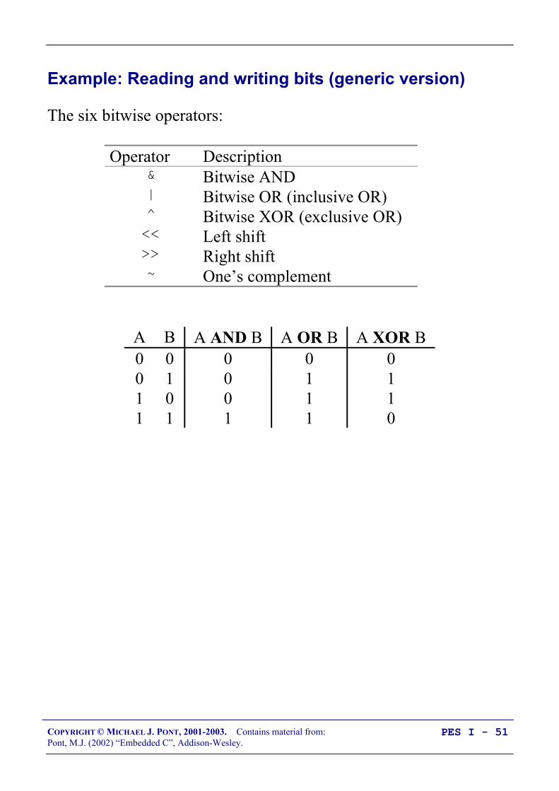
The six bitwise operators:
Operator Description& Bitwise AND| Bitwise OR (inclusive OR)^ Bitwise XOR (exclusive OR)<< Left shift>> Right shift~ One’s complement
A B A AND B A OR B A XOR B0 0 0 0 00 1 0 1 11 0 0 1 11 1 1 1 0

COPYRIGHT © MICHAEL J. PONT, 2001-2003. Contains material from:Pont, M.J. (2002) “Embedded C”, Addison-Wesley.
PES I - 52
/* Desktop program - illustrating the use of bitwise operators */
#include <stdio.h>
void Display_Byte(const unsigned char);
/* ............................................................... */
int main() unsigned char x = 0xFE; unsigned int y = 0x0A0B;
printf("%-35s","x"); Display_Byte(x);
printf("%-35s","1s complement [~x]"); Display_Byte(~x);
printf("%-35s","Bitwise AND [x & 0x0f]"); Display_Byte(x & 0x0f);
printf("%-35s","Bitwise OR [x | 0x0f]"); Display_Byte(x | 0x0f);
printf("%-35s","Bitwise XOR [x ^ 0x0f]"); Display_Byte(x ^ 0x0f);
printf("%-35s","Left shift, 1 place [x <<= 1] "); Display_Byte(x <<= 1);
x = 0xfe; /* Return x to original value */ printf("%-35s","Right shift, 4 places [x >>= 4]"); Display_Byte(x >>= 4);
printf("\n\n");
printf("%-35s","Display MS byte of unsigned int y"); Display_Byte((unsigned char) (y >> 8));
printf("%-35s","Display LS byte of unsigned int y"); Display_Byte((unsigned char) (y & 0xFF));
return 0;

COPYRIGHT © MICHAEL J. PONT, 2001-2003. Contains material from:Pont, M.J. (2002) “Embedded C”, Addison-Wesley.
PES I - 53
/* --------------------------------------------------------------- */
void Display_Byte(const unsigned char CH) unsigned char i, c = CH; unsigned char Mask = 1 << 7;
for (i = 1; i <= 8; i++) putchar(c & Mask ? '1' : '0'); c <<= 1;
putchar('\n');
x 111111101s complement [~x] 00000001Bitwise AND [x & 0x0f] 00001110Bitwise OR [x | 0x0f] 11111111Bitwise XOR [x ^ 0x0f] 11110001Left shift, 1 place [x <<= 1] 11111100Right shift, 4 places [x >>= 4] 00001111
Display MS byte of unsigned int y 00001010Display LS byte of unsigned int y 00001011

COPYRIGHT © MICHAEL J. PONT, 2001-2003. Contains material from:Pont, M.J. (2002) “Embedded C”, Addison-Wesley.
PES I - 54
/*-------------------------------------------------------------*-
Reading and writing individual port pins.
NOTE: Both pins on the same port
-*-------------------------------------------------------------*/
#include <reg52.H>
void Write_Bit_P1(const unsigned char, const bit);bit Read_Bit_P1(const unsigned char);
/* ............................................................... */
void main (void) bit x;
while(1) x = Read_Bit_P1(0); /* Read Port 1, Pin 0 */ Write_Bit_P1(1,x); /* Write to Port 1, Pin 1 */
/* --------------------------------------------------------------- */
void Write_Bit_P1(const unsigned char PIN, const bit VALUE) unsigned char p = 0x01; /* 00000001 */
/* Left shift appropriate number of places */ p <<= PIN;
/* If we want 1 output at this pin */ if (VALUE == 1) P1 |= p; /* Bitwise OR */ return;
/* If we want 0 output at this pin */ p = ~p; /* Complement */ P1 &= p; /* Bitwise AND */

COPYRIGHT © MICHAEL J. PONT, 2001-2003. Contains material from:Pont, M.J. (2002) “Embedded C”, Addison-Wesley.
PES I - 55
/* --------------------------------------------------------------- */
bit Read_Bit_P1(const unsigned char PIN) unsigned char p = 0x01; /* 00000001 */
/* Left shift appropriate number of places */ p <<= PIN;
/* Write a 1 to the pin (to set up for reading) */ Write_Bit_P1(PIN, 1);
/* Read the pin (bitwise AND) and return */ return (P1 & p);
/*-------------------------------------------------------------*- ---- END OF FILE ----------------------------------------*-------------------------------------------------------------*/
COPYRIGHT © MICHAEL J. PONT, 2001-2003. Contains material from:Pont, M.J. (2002) “Embedded C”, Addison-Wesley.
PES I - 56
The need for pull-up resistors
To pin on:
Port 1, Port 2, or Port 3.
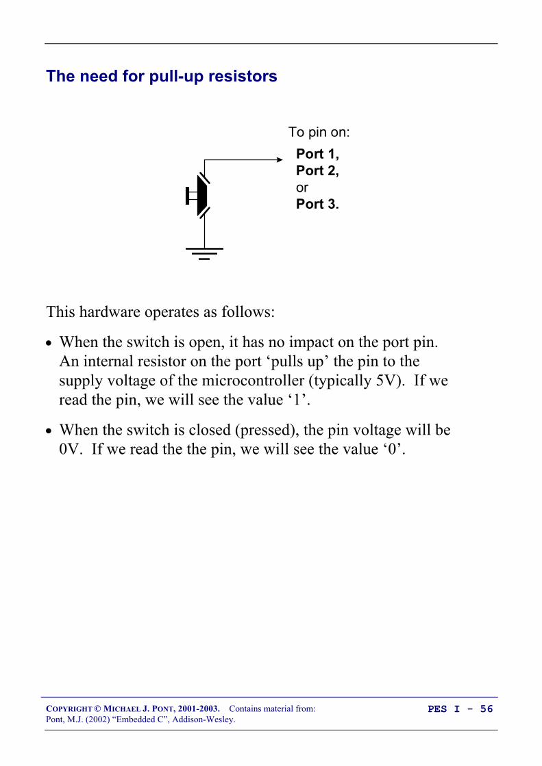
This hardware operates as follows:
• When the switch is open, it has no impact on the port pin.An internal resistor on the port ‘pulls up’ the pin to thesupply voltage of the microcontroller (typically 5V). If weread the pin, we will see the value ‘1’.
• When the switch is closed (pressed), the pin voltage will be0V. If we read the the pin, we will see the value ‘0’.

COPYRIGHT © MICHAEL J. PONT, 2001-2003. Contains material from:Pont, M.J. (2002) “Embedded C”, Addison-Wesley.
PES I - 57
The need for pull-up resistors
We briefly looked at pull-up resistors in Seminar 2.
With pull-ups:
Vcc Vcc
Switch released:Reads ‘1’
Switch pressed:Reads ‘0’
Without pull-ups:
Vcc Vcc
Switch released:Reads ‘0’
Switch pressed:Reads ‘0’

COPYRIGHT © MICHAEL J. PONT, 2001-2003. Contains material from:Pont, M.J. (2002) “Embedded C”, Addison-Wesley.
PES I - 58
The need for pull-up resistors
Vcc
10KΩTo pin on:
Port 0.

COPYRIGHT © MICHAEL J. PONT, 2001-2003. Contains material from:Pont, M.J. (2002) “Embedded C”, Addison-Wesley.
PES I - 59
Dealing with switch bounce
In practice, all mechanical switch contacts bounce (that is, turn onand off, repeatedly, for a short period of time) after the switch isclosed or opened.
+5v
Voltage
Timet1 t2
+5v
As far as the microcontroller is concerned, each ‘bounce’ isequivalent to one press and release of an ‘ideal’ switch. Withoutappropriate software design, this can give rise to a number ofproblems, not least:
• Rather than reading ‘A’ from a keypad, we may read‘AAAAA’
• Counting the number of times that a switch is pressedbecomes extremely difficult.
• If a switch is depressed once, and then released some timelater, the ‘bounce’ may make it appear as if the switch hasbeen pressed again (at the time of release).

COPYRIGHT © MICHAEL J. PONT, 2001-2003. Contains material from:Pont, M.J. (2002) “Embedded C”, Addison-Wesley.
PES I - 60
Creating some simple software to check for a valid switch input isstraightforward:
1. We read the relevant port pin.
2. If we think we have detected a switch depression, we wait for20 ms and then read the pin again.
3. If the second reading confirms the first reading, we assumethe switch really has been depressed.
Note that the figure of ‘20 ms’ will, of course, depend on the switchused.

COPYRIGHT © MICHAEL J. PONT, 2001-2003. Contains material from:Pont, M.J. (2002) “Embedded C”, Addison-Wesley.
PES I - 61
Example: Reading switch inputs (basic code)
This switch-reading code is adequate if we want to performoperations such as:
• Drive a motor while a switch is pressed.
• Switch on a light while a switch is pressed.
• Activate a pump while a switch is pressed.
These operations could be implemented using an electrical switch,without using a microcontroller; however, use of a microcontrollermay well be appropriate if we require more complex behaviour.For example:
• Drive a motor while a switch is pressedCondition: If the safety guard is not in place, don’t turn themotor. Instead sound a buzzer for 2 seconds.
• Switch on a light while a switch is pressedCondition: To save power, ignore requests to turn on thelight during daylight hours.
• Activate a pump while a switch is pressedCondition: If the main water reservoir is below 300 litres,do not start the main pump: instead, start the reserve pumpand draw the water from the emergency tank.

COPYRIGHT © MICHAEL J. PONT, 2001-2003. Contains material from:Pont, M.J. (2002) “Embedded C”, Addison-Wesley.
PES I - 62
/*-------------------------------------------------------------*-
Switch_read.C (v1.00)
--------------------------------------------------------
A simple 'switch input' program for the 8051. - Reads (and debounces) switch input on Pin 1^0 - If switch is pressed, changes Port 3 output
-*-------------------------------------------------------------*/
#include <Reg52.h>
/* Connect switch to this pin */sbit Switch_pin = P1^0;
/* Display switch status on this port */#define Output_port P3
/* Return values from Switch_Get_Input() */#define SWITCH_NOT_PRESSED (bit) 0#define SWITCH_PRESSED (bit) 1
/* Function prototypes */void SWITCH_Init(void);bit SWITCH_Get_Input(const unsigned char DEBOUNCE_PERIOD);void DISPLAY_SWITCH_STATUS_Init(void);void DISPLAY_SWITCH_STATUS_Update(const bit);void DELAY_LOOP_Wait(const unsigned int DELAY_MS);
COPYRIGHT © MICHAEL J. PONT, 2001-2003. Contains material from:Pont, M.J. (2002) “Embedded C”, Addison-Wesley.
PES I - 63
/* ---------------------------------------------------------------- */void main(void) bit Sw_state;
/* Init functions */ SWITCH_Init(); DISPLAY_SWITCH_STATUS_Init();
while(1) Sw_state = SWITCH_Get_Input(30);
DISPLAY_SWITCH_STATUS_Update(Sw_state);
/*-------------------------------------------------------------*-
SWITCH_Init()
Initialisation function for the switch library.
-*-------------------------------------------------------------*/void SWITCH_Init(void) Switch_pin = 1; /* Use this pin for input */

COPYRIGHT © MICHAEL J. PONT, 2001-2003. Contains material from:Pont, M.J. (2002) “Embedded C”, Addison-Wesley.
PES I - 64
/*-------------------------------------------------------------*-
SWITCH_Get_Input()
Reads and debounces a mechanical switch as follows:
1. If switch is not pressed, return SWITCH_NOT_PRESSED.
2. If switch is pressed, wait for the DEBOUNCE_PERIOD (in ms). Then: a. If switch is no longer pressed, return SWITCH_NOT_PRESSED. b. If switch is still pressed, return SWITCH_PRESSED
See Switch_Wait.H for details of return values.
-*-------------------------------------------------------------*/bit SWITCH_Get_Input(const unsigned char DEBOUNCE_PERIOD) bit Return_value = SWITCH_NOT_PRESSED;
if (Switch_pin == 0) /* Switch is pressed */
/* Debounce - just wait... */ DELAY_LOOP_Wait(DEBOUNCE_PERIOD);
/* Check switch again */ if (Switch_pin == 0) Return_value = SWITCH_PRESSED;
/* Now return switch value */ return Return_value;

COPYRIGHT © MICHAEL J. PONT, 2001-2003. Contains material from:Pont, M.J. (2002) “Embedded C”, Addison-Wesley.
PES I - 65
/*-------------------------------------------------------------*-
DISPLAY_SWITCH_STATUS_Init()
Initialization function for the DISPLAY_SWITCH_STATUS library.
-*-------------------------------------------------------------*/void DISPLAY_SWITCH_STATUS_Init(void) Output_port = 0xF0;
/*-------------------------------------------------------------*-
DISPLAY_SWITCH_STATUS_Update()
Simple function to display data (SWITCH_STATUS) on LEDs connected to port (Output_Port)
-*-------------------------------------------------------------*/void DISPLAY_SWITCH_STATUS_Update(const bit SWITCH_STATUS) if (SWITCH_STATUS == SWITCH_PRESSED) Output_port = 0x0F; else Output_port = 0xF0;
COPYRIGHT © MICHAEL J. PONT, 2001-2003. Contains material from:Pont, M.J. (2002) “Embedded C”, Addison-Wesley.
PES I - 66
/*-------------------------------------------------------------*-
DELAY_LOOP_Wait()
Delay duration varies with parameter.
Parameter is, *ROUGHLY*, the delay, in milliseconds, on 12MHz 8051 (12 osc cycles).
You need to adjust the timing for your application!
-*-------------------------------------------------------------*/void DELAY_LOOP_Wait(const unsigned int DELAY_MS) unsigned int x, y;
for (x = 0; x <= DELAY_MS; x++) for (y = 0; y <= 120; y++);

COPYRIGHT © MICHAEL J. PONT, 2001-2003. Contains material from:Pont, M.J. (2002) “Embedded C”, Addison-Wesley.
PES I - 67
The input portThe output port
COPYRIGHT © MICHAEL J. PONT, 2001-2003. Contains material from:Pont, M.J. (2002) “Embedded C”, Addison-Wesley.
PES I - 68
Example: Counting goats
• With the simple code in the previous example, problems canarise whenever a switch is pressed for a period longer thanthe debounce interval.
• This is a concern, because in many cases, users will pressswitches for at least 500 ms (or until they receive feedbackthat the system has detected the switch press). As a result, auser typing “Hello” on a keypad may see:“HHHHHHHHHeeeeeeeeellllllllllllllllooooooooooo”appear on the screen.
One consequence is that this code is not suitable for applicationswhere we need to count the number of times that a switch is pressedand then released.
COPYRIGHT © MICHAEL J. PONT, 2001-2003. Contains material from:Pont, M.J. (2002) “Embedded C”, Addison-Wesley.
PES I - 69
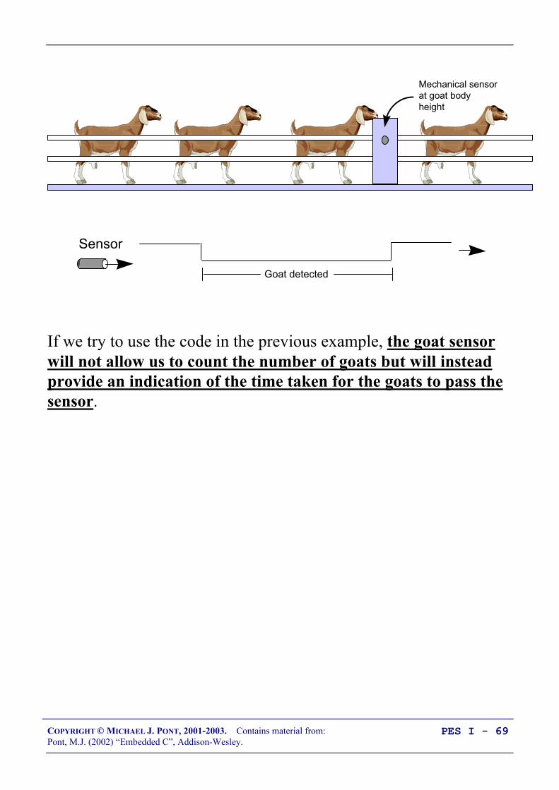
Mechanical sensor at goat body height
Sensor
Goat detected
If we try to use the code in the previous example, the goat sensorwill not allow us to count the number of goats but will insteadprovide an indication of the time taken for the goats to pass thesensor.
COPYRIGHT © MICHAEL J. PONT, 2001-2003. Contains material from:Pont, M.J. (2002) “Embedded C”, Addison-Wesley.
PES I - 70
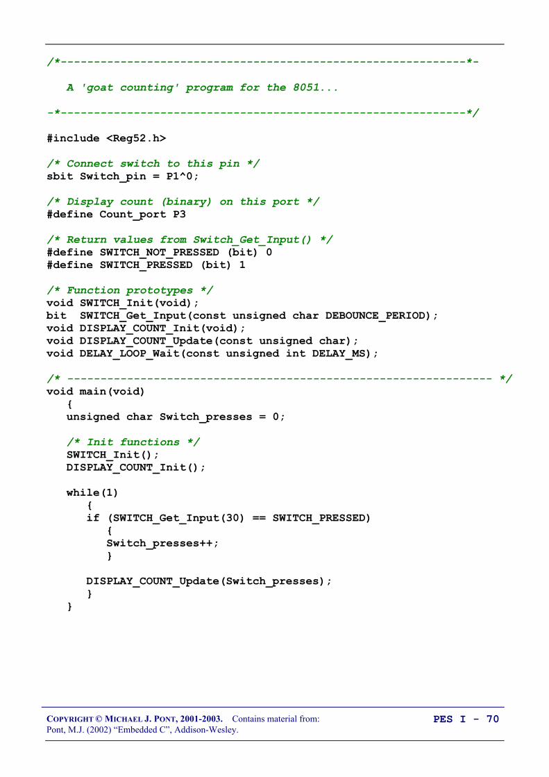
/*-------------------------------------------------------------*-
A 'goat counting' program for the 8051...
-*-------------------------------------------------------------*/
#include <Reg52.h>
/* Connect switch to this pin */sbit Switch_pin = P1^0;
/* Display count (binary) on this port */#define Count_port P3
/* Return values from Switch_Get_Input() */#define SWITCH_NOT_PRESSED (bit) 0#define SWITCH_PRESSED (bit) 1
/* Function prototypes */void SWITCH_Init(void);bit SWITCH_Get_Input(const unsigned char DEBOUNCE_PERIOD);void DISPLAY_COUNT_Init(void);void DISPLAY_COUNT_Update(const unsigned char);void DELAY_LOOP_Wait(const unsigned int DELAY_MS);
/* ---------------------------------------------------------------- */void main(void) unsigned char Switch_presses = 0;
/* Init functions */ SWITCH_Init(); DISPLAY_COUNT_Init();
while(1) if (SWITCH_Get_Input(30) == SWITCH_PRESSED) Switch_presses++;
DISPLAY_COUNT_Update(Switch_presses);

COPYRIGHT © MICHAEL J. PONT, 2001-2003. Contains material from:Pont, M.J. (2002) “Embedded C”, Addison-Wesley.
PES I - 71
/*-------------------------------------------------------------*/
void SWITCH_Init(void) Switch_pin = 1; /* Use this pin for input */
/*-------------------------------------------------------------*-
SWITCH_Get_Input()
Reads and debounces a mechanical switch as follows:
1. If switch is not pressed, return SWITCH_NOT_PRESSED.
2. If switch is pressed, wait for the DEBOUNCE_PERIOD (in ms). Then: a. If switch is no longer pressed, return SWITCH_NOT_PRESSED. b. If switch is still pressed, wait (indefinitely) for switch to be released, *then* return SWITCH_PRESSED
See Switch_Wait.H for details of return values.
-*-------------------------------------------------------------*/bit SWITCH_Get_Input(const unsigned char DEBOUNCE_PERIOD) bit Return_value = SWITCH_NOT_PRESSED;
if (Switch_pin == 0) /* Switch is pressed */
/* Debounce - just wait... */ DELAY_LOOP_Wait(DEBOUNCE_PERIOD);
/* Check switch again */ if (Switch_pin == 0) /* Wait until the switch is released. */ while (Switch_pin == 0); Return_value = SWITCH_PRESSED;
/* Now (finally) return switch value */ return Return_value;

COPYRIGHT © MICHAEL J. PONT, 2001-2003. Contains material from:Pont, M.J. (2002) “Embedded C”, Addison-Wesley.
PES I - 72
/*-------------------------------------------------------------*-
DISPLAY_COUNT_Init()
Initialisation function for the DISPLAY COUNT library.
-*-------------------------------------------------------------*/void DISPLAY_COUNT_Init(void) Count_port = 0x00;
/*-------------------------------------------------------------*-
DISPLAY_COUNT_Update()
Simple function to display tByte data (COUNT) on LEDs connected to port (Count_Port)
-*-------------------------------------------------------------*/void DISPLAY_COUNT_Update(const unsigned char COUNT) Count_port = COUNT;
/*-------------------------------------------------------------*-
DELAY_LOOP_Wait()
Delay duration varies with parameter.
Parameter is, *ROUGHLY*, the delay, in milliseconds, on 12MHz 8051 (12 osc cycles).
You need to adjust the timing for your application!
-*-------------------------------------------------------------*/void DELAY_LOOP_Wait(const unsigned int DELAY_MS) unsigned int x, y;
for (x = 0; x <= DELAY_MS; x++) for (y = 0; y <= 120; y++);
COPYRIGHT © MICHAEL J. PONT, 2001-2003. Contains material from:Pont, M.J. (2002) “Embedded C”, Addison-Wesley.
PES I - 73
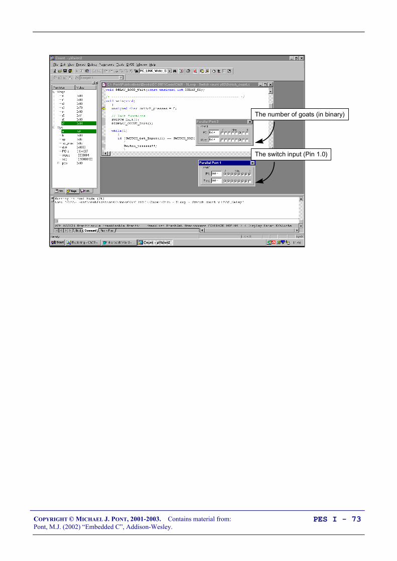
The switch input (Pin 1.0)
The number of goats (in binary)

COPYRIGHT © MICHAEL J. PONT, 2001-2003. Contains material from:Pont, M.J. (2002) “Embedded C”, Addison-Wesley.
PES I - 74
Conclusions
The switch interface code presented and discussed in this seminarhas allowed us to do two things:
• To perform an activity while a switch is depressed;
• To respond to the fact that a user has pressed – and thenreleased – a switch.
In both cases, we have illustrated how the switch may be‘debounced’ in software.

COPYRIGHT © MICHAEL J. PONT, 2001-2003. Contains material from:Pont, M.J. (2002) “Embedded C”, Addison-Wesley.
PES I - 75
Preparation for the next seminar
In the next seminar, we turn our attention to techniques that canhelp you re-use the code you develop in subsequent projects.
Please read Chapter 5before the next seminar

COPYRIGHT © MICHAEL J. PONT, 2001-2003. Contains material from:Pont, M.J. (2002) “Embedded C”, Addison-Wesley.
PES I - 76

COPYRIGHT © MICHAEL J. PONT, 2001-2003. Contains material from:Pont, M.J. (2002) “Embedded C”, Addison-Wesley.
PES I - 77
Seminar 4: Adding Structure to
Your Code
Port Header (Port.H)
DownUp
// Pins 3.0 and 3.1 used// for RS-232 interface
// Switches sbit Sw_up = P1^2; sbit Sw_down = P1^3;

COPYRIGHT © MICHAEL J. PONT, 2001-2003. Contains material from:Pont, M.J. (2002) “Embedded C”, Addison-Wesley.
PES I - 78
Introduction
We will do three things in this seminar:
1. We will describe how to use an object-oriented style ofprogramming with C programs, allowing the creation oflibraries of code that can be easily adapted for use indifferent embedded projects;
2. We will describe how to create and use a ‘Project Header’file. This file encapsulates key aspects of the hardwareenvironment, such as the type of processor to be used, theoscillator frequency and the number of oscillator cyclesrequired to execute each instruction. This helps to documentthe system, and makes it easier to port the code to a differentprocessor.
3. We will describe how to create and use a ‘Port Header’ file.This brings together all details of the port access from thewhole system. Like the Project Header, this helps duringporting and also serves as a means of documenting importantsystem features.
We will use all three of these techniques in the code examplespresented in subsequent seminars.
COPYRIGHT © MICHAEL J. PONT, 2001-2003. Contains material from:Pont, M.J. (2002) “Embedded C”, Addison-Wesley.
PES I - 79
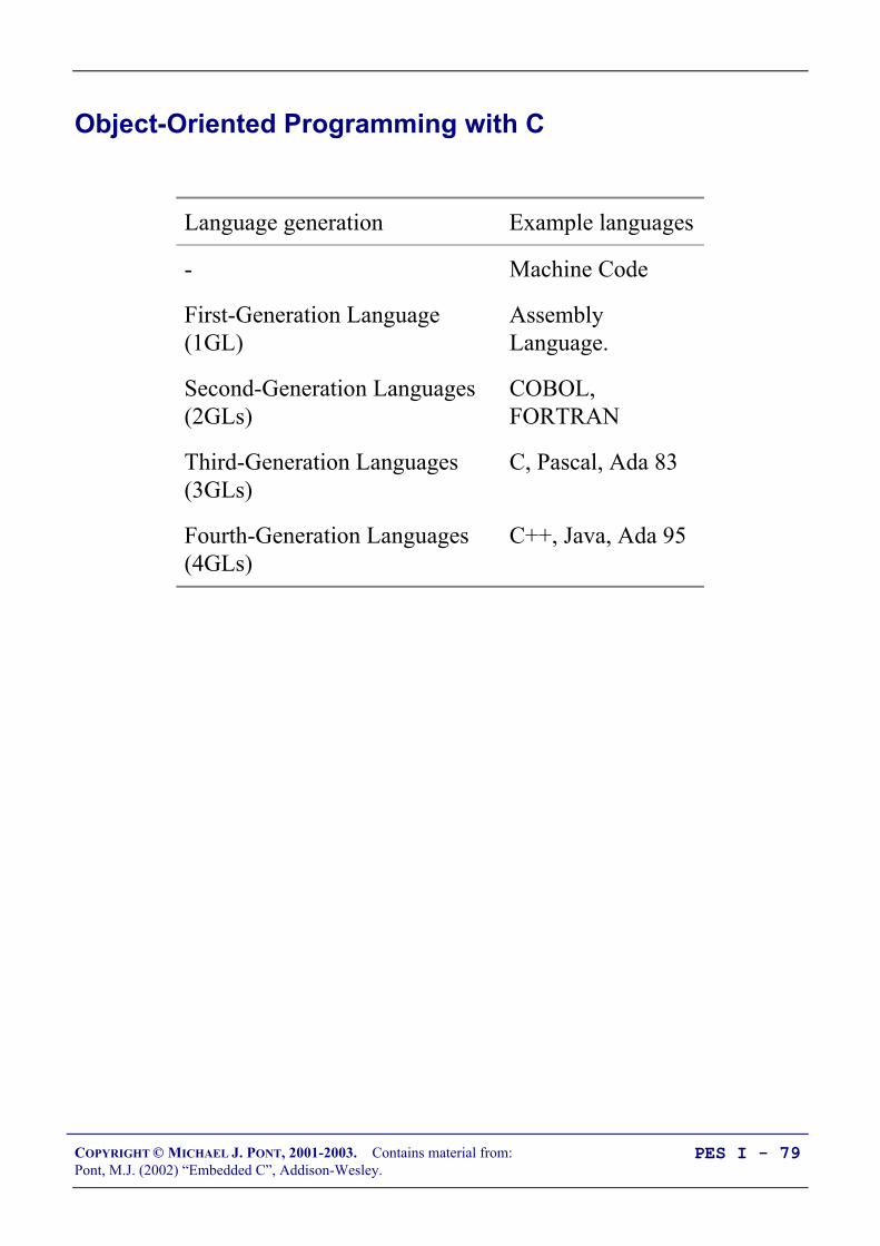
Object-Oriented Programming with C
Language generation Example languages
- Machine Code
First-Generation Language(1GL)
AssemblyLanguage.
Second-Generation Languages(2GLs)
COBOL,FORTRAN
Third-Generation Languages(3GLs)
C, Pascal, Ada 83
Fourth-Generation Languages(4GLs)
C++, Java, Ada 95

COPYRIGHT © MICHAEL J. PONT, 2001-2003. Contains material from:Pont, M.J. (2002) “Embedded C”, Addison-Wesley.
PES I - 80
Graham notes1:
“[The phrase] ‘object-oriented’ has become almostsynonymous with modernity, goodness and worth ininformation technology circles.”
Jalote notes2:
“One main claimed advantage of using object orientationis that an OO model closely represents the problemdomain, which makes it easier to produce and understanddesigns.”
O-O languages are not readily available for small embedded systems,primarily because of the overheads that can result from the use of someof the features of these languages.
1 Graham, I. (1994) “Object-Oriented Methods,” (2nd Ed.) Addison-Wesley. Page
1.2 Jalote, P. (1997) “An Integrated Approach to Software Engineering”, (2nd Ed.)
Springer-Verlag. Page 273.

COPYRIGHT © MICHAEL J. PONT, 2001-2003. Contains material from:Pont, M.J. (2002) “Embedded C”, Addison-Wesley.
PES I - 81
It is possible to create ‘file-based-classes’ in C without imposing asignificant memory or CPU load.
All program
code in a
single source
file
All program
code in a
single source
file
Header file
Serial.CSerial.C
Header file
Switch.CSwitch.C
Header file
sEOS.C sEOS.C

COPYRIGHT © MICHAEL J. PONT, 2001-2003. Contains material from:Pont, M.J. (2002) “Embedded C”, Addison-Wesley.
PES I - 82
Example of “O-O C”
/*-------------------------------------------------------------*-
PC_IO.H (v1.00)
--------------------------------------------------------
- see PC_IO.C for details.
-*-------------------------------------------------------------*/
#ifndef _PC_IO_H#define _PC_IO_H
/* ------ Public constants ------------------------------------ */
/* Value returned by PC_LINK_Get_Char_From_Buffer if no char is available in buffer */#define PC_LINK_IO_NO_CHAR 127
/* ------ Public function prototypes -------------------------- */
void PC_LINK_IO_Write_String_To_Buffer(const char* const);void PC_LINK_IO_Write_Char_To_Buffer(const char);
char PC_LINK_IO_Get_Char_From_Buffer(void);
/* Must regularly call this function... */void PC_LINK_IO_Update(void);
#endif
/*-------------------------------------------------------------*- ---- END OF FILE ----------------------------------------*-------------------------------------------------------------*/

COPYRIGHT © MICHAEL J. PONT, 2001-2003. Contains material from:Pont, M.J. (2002) “Embedded C”, Addison-Wesley.
PES I - 83
/*-------------------------------------------------------------*-
PC_IO.C (v1.00)
--------------------------------------------------------
[INCOMPLETE - STRUCTURE ONLY - see EC Chap 9 for complete library]
-*-------------------------------------------------------------*/
#include "Main.H"#include "PC_IO.H"
/* ------ Public variable definitions ------------------------- */
tByte In_read_index_G; /* Data in buffer that has been read */tByte In_waiting_index_G; /* Data in buffer not yet read */
tByte Out_written_index_G; /* Data in buffer that has been written */tByte Out_waiting_index_G; /* Data in buffer not yet written */
/* ------ Private function prototypes ------------------------- */
static void PC_LINK_IO_Send_Char(const char);
/* ------ Private constants ----------------------------------- */
/* The receive buffer length */#define RECV_BUFFER_LENGTH 8
/* The transmit buffer length */#define TRAN_BUFFER_LENGTH 50
#define XON 0x11#define XOFF 0x13
/* ------ Private variables ----------------------------------- */
static tByte Recv_buffer[RECV_BUFFER_LENGTH];static tByte Tran_buffer[TRAN_BUFFER_LENGTH];
/*-------------------------------------------------------------*/void PC_LINK_IO_Update(...) ...
COPYRIGHT © MICHAEL J. PONT, 2001-2003. Contains material from:Pont, M.J. (2002) “Embedded C”, Addison-Wesley.
PES I - 84
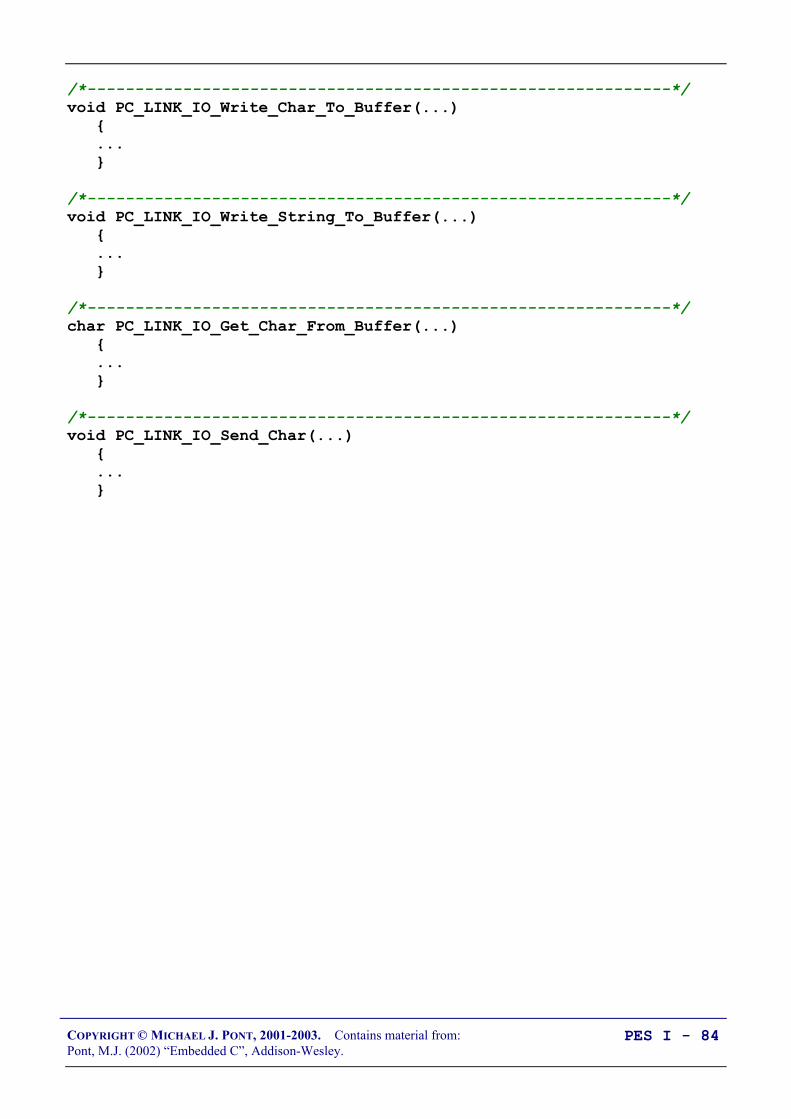
/*-------------------------------------------------------------*/void PC_LINK_IO_Write_Char_To_Buffer(...) ...
/*-------------------------------------------------------------*/void PC_LINK_IO_Write_String_To_Buffer(...) ...
/*-------------------------------------------------------------*/char PC_LINK_IO_Get_Char_From_Buffer(...) ...
/*-------------------------------------------------------------*/void PC_LINK_IO_Send_Char(...) ...

COPYRIGHT © MICHAEL J. PONT, 2001-2003. Contains material from:Pont, M.J. (2002) “Embedded C”, Addison-Wesley.
PES I - 85
The Project Header (Main.H)
Project Header (Main.H)
11.0592 MHz #include <AT89S53.H>...
#define OSC_FREQ (11059200UL)...
typedef unsigned char tByte;...

COPYRIGHT © MICHAEL J. PONT, 2001-2003. Contains material from:Pont, M.J. (2002) “Embedded C”, Addison-Wesley.
PES I - 86
/*-------------------------------------------------------------*-
Main.H (v1.00)
-*-------------------------------------------------------------*/
#ifndef _MAIN_H#define _MAIN_H
/*-------------------------------------------------------- WILL NEED TO EDIT THIS SECTION FOR EVERY PROJECT -------------------------------------------------------- */
/* Must include the appropriate microcontroller header file here */#include <reg52.h>
/* Oscillator / resonator frequency (in Hz) e.g. (11059200UL) */#define OSC_FREQ (12000000UL)
/* Number of oscillations per instruction (12, etc) 12 - Original 8051 / 8052 and numerous modern versions 6 - Various Infineon and Philips devices, etc. 4 - Dallas 320, 520 etc. 1 - Dallas 420, etc. */#define OSC_PER_INST (12)
/* -------------------------------------------------------- SHOULD NOT NEED TO EDIT THE SECTIONS BELOW -------------------------------------------------------- */
/* Typedefs (see Chap 5) */typedef unsigned char tByte;typedef unsigned int tWord;typedef unsigned long tLong;
/* Interrupts (see Chap 7) */#define INTERRUPT_Timer_0_Overflow 1#define INTERRUPT_Timer_1_Overflow 3#define INTERRUPT_Timer_2_Overflow 5
#endif
/*-------------------------------------------------------------*- ---- END OF FILE ----------------------------------------*-------------------------------------------------------------*/

COPYRIGHT © MICHAEL J. PONT, 2001-2003. Contains material from:Pont, M.J. (2002) “Embedded C”, Addison-Wesley.
PES I - 87
The device header
/*---------------------------------------------------------- REG515C.H
Header file for the Infineon C515C
Copyright (c) 1995-1999 Keil Elektronik GmbH All rights reserved.----------------------------------------------------------------*/
...
/* A/D Converter */sfr ADCON0 = 0xD8;...
/* Interrupt System */sfr IEN0 = 0xA8;...
/* Ports */sfr P0 = 0x80;sfr P1 = 0x90;sfr P2 = 0xA0;sfr P3 = 0xB0;sfr P4 = 0xE8;sfr P5 = 0xF8;sfr P6 = 0xDB;sfr P7 = 0xFA;...
/* Serial Channel */sfr SCON = 0x98;...
/* Timer0 / Timer1 */sfr TCON = 0x88;...
/* CAP/COM Unit / Timer2 */sfr CCEN = 0xC1;...

COPYRIGHT © MICHAEL J. PONT, 2001-2003. Contains material from:Pont, M.J. (2002) “Embedded C”, Addison-Wesley.
PES I - 88
Oscillator frequency and oscillations per instruction
/* Oscillator / resonator frequency (in Hz) e.g. (11059200UL) */#define OSC_FREQ (12000000UL)
/* Number of oscillations per instruction (12, etc) 12 - Original 8051 / 8052 and numerous modern versions 6 - Various Infineon and Philips devices, etc. 4 - Dallas 320, 520 etc. 1 - Dallas 420, etc. */#define OSC_PER_INST (12)
We demonstrate how to use this information:
• For creating delays (Embedded C, Chapter 6),
• For controlling timing in an operating system (Chapter 7),and,
• For controlling the baud rate in a serial interface (Chapter 9).

COPYRIGHT © MICHAEL J. PONT, 2001-2003. Contains material from:Pont, M.J. (2002) “Embedded C”, Addison-Wesley.
PES I - 89
Common data types
typedef unsigned char tByte;typedef unsigned int tWord;typedef unsigned long tLong;
In C, the typedef keyword allows us to provide aliases for datatypes: we can then use these aliases in place of the original types.Thus, in the projects you will see code like this:tWord Temperature;
Rather than:unsigned int Temperature;
The main reason for using these typedef statements is to simplify -and promote - the use of unsigned data types.
• The 8051 does not support signed arithmetic and extra codeis required to manipulate signed data: this reduces yourprogram speed and increases the program size.
• Use of bitwise operators generally makes sense only withunsigned data types: use of ‘typedef’ variables reduces thelikelihood that programmers will inadvertently apply theseoperators to signed data.
Finally, as in desktop programming, use of the typedef keyword inthis way can make it easier to adapt your code for use on a differentprocessor.

COPYRIGHT © MICHAEL J. PONT, 2001-2003. Contains material from:Pont, M.J. (2002) “Embedded C”, Addison-Wesley.
PES I - 90
Interrupts
As we noted in “Embedded C” Chapter 2, interrupts are a keycomponent of most embedded systems.
The following lines in the Project Header are intended to make iteasier for you to use (timer-based) interrupts in your projects:#define INTERRUPT_Timer_0_Overflow 1#define INTERRUPT_Timer_1_Overflow 3#define INTERRUPT_Timer_2_Overflow 5
We discuss how to make use of this facility in Embedded C, Ch. 7.

COPYRIGHT © MICHAEL J. PONT, 2001-2003. Contains material from:Pont, M.J. (2002) “Embedded C”, Addison-Wesley.
PES I - 91
Summary: Why use the Project Header?
Use of PROJECT HEADER can help to make your code morereadable, not least because anyone using your projects knows whereto find key information, such as the model of microcontroller andthe oscillator frequency required to execute the software.
The use of a project header can help to make your code more easilyportable, by placing some of the key microcontroller-dependentdata in one place: if you change the processor or the oscillator usedthen - in many cases - you will need to make changes only to theProject Header.

COPYRIGHT © MICHAEL J. PONT, 2001-2003. Contains material from:Pont, M.J. (2002) “Embedded C”, Addison-Wesley.
PES I - 92
The Port Header (Port.H)
Port Header (Port.H)
DownUp
// Pins 3.0 and 3.1 used// for RS-232 interface
// Switches sbit Sw_up = P1^2; sbit Sw_down = P1^3;

COPYRIGHT © MICHAEL J. PONT, 2001-2003. Contains material from:Pont, M.J. (2002) “Embedded C”, Addison-Wesley.
PES I - 93
The Port Header file is simple to understand and easy to apply.
Consider, for example, that we have three C files in a project (A, B,C), each of which require access to one or more port pins, or to acomplete port.
File A may include the following:/* File A */
sbit Pin_A = P3^2;
...
File B may include the following:/* File B */
#define Port_B = P0;
...
File C may include the following:/* File C */
sbit Pin_C = P2^7;
...
In this version of the code, all of the port access requirements arespread over multiple files.

COPYRIGHT © MICHAEL J. PONT, 2001-2003. Contains material from:Pont, M.J. (2002) “Embedded C”, Addison-Wesley.
PES I - 94
There are many advantages obtained by integrating all port accessin a single Port.H header file:
/* ----- Port.H ----- */
/* Port access for File B */#define Port_B = P0;
/* Port access for File A */sbit Pin_A = P3^2;
/* Port access for File C */sbit Pin_C = P2^7;
...

COPYRIGHT © MICHAEL J. PONT, 2001-2003. Contains material from:Pont, M.J. (2002) “Embedded C”, Addison-Wesley.
PES I - 95
/*-------------------------------------------------------------*-
Port.H (v1.01)
--------------------------------------------------------
'Port Header' (see Chap 5) for project DATA_ACQ (see Chap 9)
-*-------------------------------------------------------------*/
#ifndef _PORT_H#define _PORT_H
#include "Main.H"
/* ------ Menu_A.C ----------------------------------------- *//* Uses whole of Port 1 and Port 2 for data acquisition */#define Data_Port1 P1#define Data_Port2 P2
/* ------ PC_IO.C ------------------------------------------ */
/* Pins 3.0 and 3.1 used for RS-232 interface */
#endif
/*-------------------------------------------------------------*- ---- END OF FILE ----------------------------------------*-------------------------------------------------------------*/

COPYRIGHT © MICHAEL J. PONT, 2001-2003. Contains material from:Pont, M.J. (2002) “Embedded C”, Addison-Wesley.
PES I - 96
Re-structuring a “Hello World” example
/*-------------------------------------------------------------*-
Main.H (v1.00)
-*-------------------------------------------------------------*/
#ifndef _MAIN_H#define _MAIN_H
/*-------------------------------------------------------- WILL NEED TO EDIT THIS SECTION FOR EVERY PROJECT -------------------------------------------------------- */
/* Must include the appropriate microcontroller header file here */#include <reg52.h>
/* Oscillator / resonator frequency (in Hz) e.g. (11059200UL) */#define OSC_FREQ (12000000UL)
/* Number of oscillations per instruction (12, etc) 12 - Original 8051 / 8052 and numerous modern versions 6 - Various Infineon and Philips devices, etc. 4 - Dallas 320, 520 etc. 1 - Dallas 420, etc. */#define OSC_PER_INST (12)
/* -------------------------------------------------------- SHOULD NOT NEED TO EDIT THE SECTIONS BELOW -------------------------------------------------------- */
/* Typedefs (see Chap 5) */typedef unsigned char tByte;typedef unsigned int tWord;typedef unsigned long tLong;
/* Interrupts (see Chap 7) */#define INTERRUPT_Timer_0_Overflow 1#define INTERRUPT_Timer_1_Overflow 3#define INTERRUPT_Timer_2_Overflow 5
#endif

COPYRIGHT © MICHAEL J. PONT, 2001-2003. Contains material from:Pont, M.J. (2002) “Embedded C”, Addison-Wesley.
PES I - 97
/*-------------------------------------------------------------*-
Port.H (v1.00)
--------------------------------------------------------
'Port Header' for project HELLO2 (see Chap 5)
-*-------------------------------------------------------------*/
#ifndef _PORT_H#define _PORT_H
/* ------ LED_Flash.C ----------------------------------------- */
/* Connect LED to this pin, via appropriate resistor */sbit LED_pin = P1^5;
#endif
/*-------------------------------------------------------------*- ---- END OF FILE ----------------------------------------*-------------------------------------------------------------*/

COPYRIGHT © MICHAEL J. PONT, 2001-2003. Contains material from:Pont, M.J. (2002) “Embedded C”, Addison-Wesley.
PES I - 98
/*-------------------------------------------------------------*-
Main.C (v1.00)
--------------------------------------------------------
A "Hello Embedded World" test program for 8051.
(Re-structured version - multiple source files)
-*-------------------------------------------------------------*/
#include "Main.H"#include "Port.H"
#include "Delay_Loop.h"#include "LED_Flash.h"
void main(void) LED_FLASH_Init();
while(1) /* Change the LED state (OFF to ON, or vice versa) */ LED_FLASH_Change_State();
/* Delay for *approx* 1000 ms */ DELAY_LOOP_Wait(1000);
/*-------------------------------------------------------------*- ---- END OF FILE ----------------------------------------*-------------------------------------------------------------*/

COPYRIGHT © MICHAEL J. PONT, 2001-2003. Contains material from:Pont, M.J. (2002) “Embedded C”, Addison-Wesley.
PES I - 99
/*-------------------------------------------------------------*-
LED_flash.H (v1.00)
--------------------------------------------------------
- See LED_flash.C for details.
-*-------------------------------------------------------------*/
#ifndef _LED_FLASH_H#define _LED_FLASH_H
/* ------ Public function prototypes -------------------------- */
void LED_FLASH_Init(void);void LED_FLASH_Change_State(void);
#endif
/*-------------------------------------------------------------*- ---- END OF FILE ----------------------------------------*-------------------------------------------------------------*/

COPYRIGHT © MICHAEL J. PONT, 2001-2003. Contains material from:Pont, M.J. (2002) “Embedded C”, Addison-Wesley.
PES I - 100
/*-------------------------------------------------------------*-
LED_flash.C (v1.00)
--------------------------------------------------------
Simple 'Flash LED' test function.
-*-------------------------------------------------------------*/
#include "Main.H"#include "Port.H"
#include "LED_flash.H"
/* ------ Private variable definitions ------------------------ */
static bit LED_state_G;
/*-------------------------------------------------------------*-
LED_FLASH_Init()
Prepare for LED_Change_State() function - see below.
-*-------------------------------------------------------------*/void LED_FLASH_Init(void) LED_state_G = 0;

COPYRIGHT © MICHAEL J. PONT, 2001-2003. Contains material from:Pont, M.J. (2002) “Embedded C”, Addison-Wesley.
PES I - 101
/*-------------------------------------------------------------*-
LED_FLASH_Change_State()
Changes the state of an LED (or pulses a buzzer, etc) on a specified port pin.
Must call at twice the required flash rate: thus, for 1 Hz flash (on for 0.5 seconds, off for 0.5 seconds) must call every 0.5 seconds.
-*-------------------------------------------------------------*/void LED_FLASH_Change_State(void) /* Change the LED from OFF to ON (or vice versa) */ if (LED_state_G == 1) LED_state_G = 0; LED_pin = 0; else LED_state_G = 1; LED_pin = 1;
/*-------------------------------------------------------------*- ---- END OF FILE ----------------------------------------*-------------------------------------------------------------*/

COPYRIGHT © MICHAEL J. PONT, 2001-2003. Contains material from:Pont, M.J. (2002) “Embedded C”, Addison-Wesley.
PES I - 102
/*-------------------------------------------------------------*-
Delay_Loop.H (v1.00)
--------------------------------------------------------
- See Delay_Loop.C for details.
-*-------------------------------------------------------------*/
#ifndef _DELAY_LOOP_H#define _DELAY_LOOP_H
/* ------ Public function prototype --------------------------- */void DELAY_LOOP_Wait(const tWord DELAY_MS);
#endif
/*-------------------------------------------------------------*- ---- END OF FILE ----------------------------------------*-------------------------------------------------------------*/

COPYRIGHT © MICHAEL J. PONT, 2001-2003. Contains material from:Pont, M.J. (2002) “Embedded C”, Addison-Wesley.
PES I - 103
/*-------------------------------------------------------------*-
Delay_Loop.C (v1.00)
--------------------------------------------------------
Create a simple software delay using a loop.
-*-------------------------------------------------------------*/
#include "Main.H"#include "Port.H"
#include "Delay_loop.h"
/*-------------------------------------------------------------*-
DELAY_LOOP_Wait()
Delay duration varies with parameter.
Parameter is, *ROUGHLY*, the delay, in milliseconds, on 12MHz 8051 (12 osc cycles).
You need to adjust the timing for your application!
-*-------------------------------------------------------------*/void DELAY_LOOP_Wait(const tWord DELAY_MS) tWord x, y;
for (x = 0; x <= DELAY_MS; x++) for (y = 0; y <= 120; y++);
/*-------------------------------------------------------------*- ---- END OF FILE ----------------------------------------*-------------------------------------------------------------*/

COPYRIGHT © MICHAEL J. PONT, 2001-2003. Contains material from:Pont, M.J. (2002) “Embedded C”, Addison-Wesley.
PES I - 104
Example: Re-structuring the Goat-Counting Example
/*-------------------------------------------------------------*-
Main.H (v1.00)
-*-------------------------------------------------------------*/
#ifndef _MAIN_H#define _MAIN_H
/*-------------------------------------------------------- WILL NEED TO EDIT THIS SECTION FOR EVERY PROJECT -------------------------------------------------------- */
/* Must include the appropriate microcontroller header file here */#include <reg52.h>
/* Oscillator / resonator frequency (in Hz) e.g. (11059200UL) */#define OSC_FREQ (12000000UL)
/* Number of oscillations per instruction (12, etc) 12 - Original 8051 / 8052 and numerous modern versions 6 - Various Infineon and Philips devices, etc. 4 - Dallas 320, 520 etc. 1 - Dallas 420, etc. */#define OSC_PER_INST (12)
/* -------------------------------------------------------- SHOULD NOT NEED TO EDIT THE SECTIONS BELOW -------------------------------------------------------- */
/* Typedefs (see Chap 5) */typedef unsigned char tByte;typedef unsigned int tWord;typedef unsigned long tLong;
/* Interrupts (see Chap 7) */#define INTERRUPT_Timer_0_Overflow 1#define INTERRUPT_Timer_1_Overflow 3#define INTERRUPT_Timer_2_Overflow 5
#endif
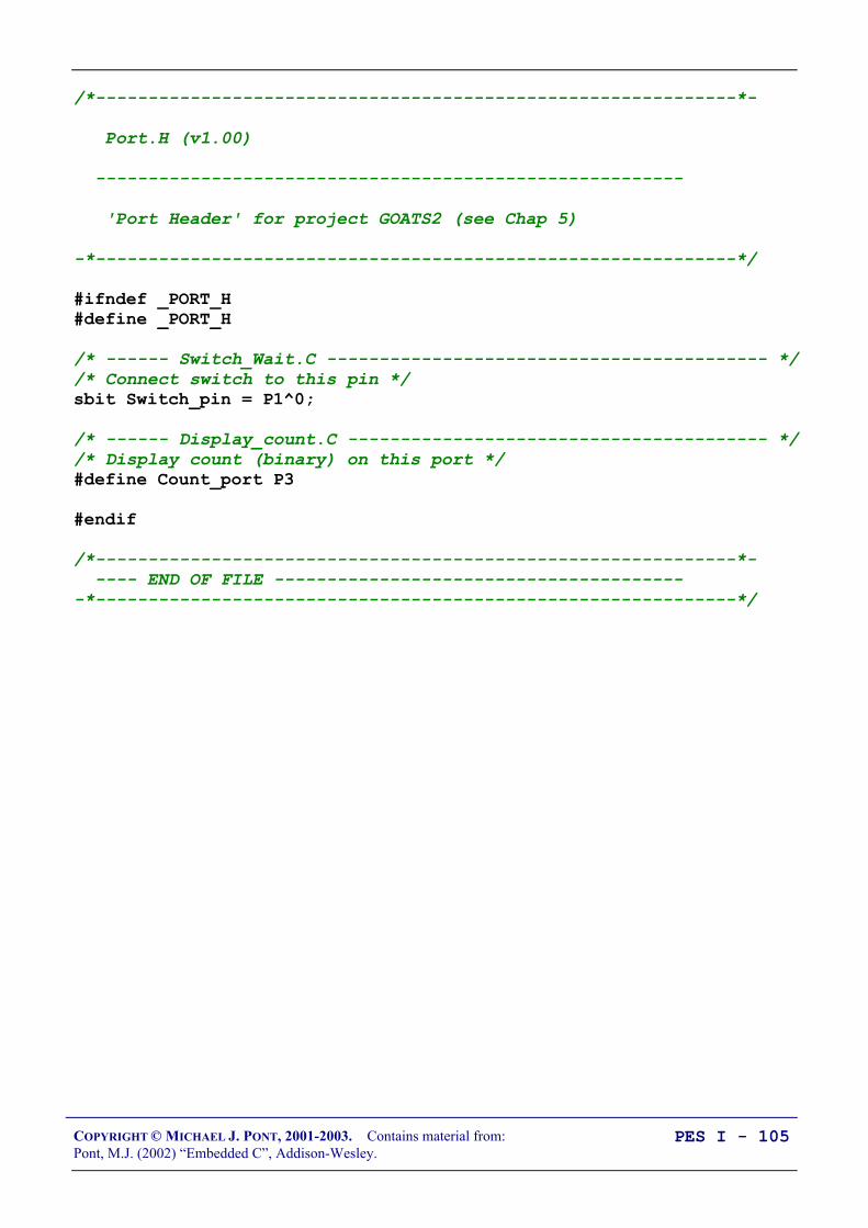
COPYRIGHT © MICHAEL J. PONT, 2001-2003. Contains material from:Pont, M.J. (2002) “Embedded C”, Addison-Wesley.
PES I - 105
/*-------------------------------------------------------------*-
Port.H (v1.00)
--------------------------------------------------------
'Port Header' for project GOATS2 (see Chap 5)
-*-------------------------------------------------------------*/
#ifndef _PORT_H#define _PORT_H
/* ------ Switch_Wait.C ------------------------------------------ *//* Connect switch to this pin */sbit Switch_pin = P1^0;
/* ------ Display_count.C ---------------------------------------- *//* Display count (binary) on this port */#define Count_port P3
#endif
/*-------------------------------------------------------------*- ---- END OF FILE ----------------------------------------*-------------------------------------------------------------*/

COPYRIGHT © MICHAEL J. PONT, 2001-2003. Contains material from:Pont, M.J. (2002) “Embedded C”, Addison-Wesley.
PES I - 106
/*-------------------------------------------------------------*-
Main.C (v1.00)
--------------------------------------------------------
A 'switch count' program for the 8051.
-*-------------------------------------------------------------*/
#include "Main.H"#include "Port.H"
#include "Switch_wait.H"#include "Display_count.H"
/* ---------------------------------------------------------------- */void main(void) tByte Switch_presses = 0;
/* Init functions */ SWITCH_Init(); DISPLAY_COUNT_Init();
while(1) if (SWITCH_Get_Input(30) == SWITCH_PRESSED) Switch_presses++;
DISPLAY_COUNT_Update(Switch_presses);
/*-------------------------------------------------------------*- ---- END OF FILE ----------------------------------------*-------------------------------------------------------------*/

COPYRIGHT © MICHAEL J. PONT, 2001-2003. Contains material from:Pont, M.J. (2002) “Embedded C”, Addison-Wesley.
PES I - 107
/*-------------------------------------------------------------*-
Switch_wait.H (v1.00)
--------------------------------------------------------
- See Switch_wait.C for details.
-*-------------------------------------------------------------*/
#ifndef _SWITCH_WAIT_H#define _SWITCH_WAIT_H
/* ------ Public constants ------------------------------------ *//* Return values from Switch_Get_Input() */#define SWITCH_NOT_PRESSED (bit) 0#define SWITCH_PRESSED (bit) 1
/* ------ Public function prototype --------------------------- */void SWITCH_Init(void);bit SWITCH_Get_Input(const tByte DEBOUNCE_PERIOD);
#endif
/*-------------------------------------------------------------*- ---- END OF FILE ----------------------------------------*-------------------------------------------------------------*/

COPYRIGHT © MICHAEL J. PONT, 2001-2003. Contains material from:Pont, M.J. (2002) “Embedded C”, Addison-Wesley.
PES I - 108
/*-------------------------------------------------------------*-
Switch_Wait.C (v1.00)
--------------------------------------------------------
Simple library for debouncing a switch input.
NOTE: Duration of function is highly variable!
-*-------------------------------------------------------------*/
#include "Main.H"#include "Port.H"
#include "Switch_wait.h"#include "Delay_loop.h"
/*-------------------------------------------------------------*-
SWITCH_Init()
Initialisation function for the switch library.
-*-------------------------------------------------------------*/void SWITCH_Init(void) Switch_pin = 1; /* Use this pin for input */

COPYRIGHT © MICHAEL J. PONT, 2001-2003. Contains material from:Pont, M.J. (2002) “Embedded C”, Addison-Wesley.
PES I - 109
/*-------------------------------------------------------------*-
SWITCH_Get_Input()
Reads and debounces a mechanical switch as follows:
1. If switch is not pressed, return SWITCH_NOT_PRESSED.
2. If switch is pressed, wait for DEBOUNCE_PERIOD (in ms). a. If switch is not pressed, return SWITCH_NOT_PRESSED. b. If switch is pressed, wait (indefinitely) for switch to be released, then return SWITCH_PRESSED
See Switch_Wait.H for details of return values.
-*-------------------------------------------------------------*/bit SWITCH_Get_Input(const tByte DEBOUNCE_PERIOD) bit Return_value = SWITCH_NOT_PRESSED;
if (Switch_pin == 0) /* Switch is pressed */
/* Debounce - just wait... */ DELAY_LOOP_Wait(DEBOUNCE_PERIOD);
/* Check switch again */ if (Switch_pin == 0) /* Wait until the switch is released. */ while (Switch_pin == 0); Return_value = SWITCH_PRESSED;
/* Now (finally) return switch value */ return Return_value;
/*-------------------------------------------------------------*- ---- END OF FILE ----------------------------------------*-------------------------------------------------------------*/

COPYRIGHT © MICHAEL J. PONT, 2001-2003. Contains material from:Pont, M.J. (2002) “Embedded C”, Addison-Wesley.
PES I - 110
/*-------------------------------------------------------------*-
Display_count.H (v1.00)
--------------------------------------------------------
- See Display_count.C for details.
-*-------------------------------------------------------------*/
#ifndef _DISPLAY_COUNT_H#define _DISPLAY_COUNT_H
/* ------ Public function prototypes -------------------------- */void DISPLAY_COUNT_Init(void);void DISPLAY_COUNT_Update(const tByte);
#endif
/*-------------------------------------------------------------*- ---- END OF FILE ----------------------------------------*-------------------------------------------------------------*/

COPYRIGHT © MICHAEL J. PONT, 2001-2003. Contains material from:Pont, M.J. (2002) “Embedded C”, Addison-Wesley.
PES I - 111
/*-------------------------------------------------------------*-
Display_count.C (v1.00)
--------------------------------------------------------
Display an unsigned char on a port.
-*-------------------------------------------------------------*/
#include "Main.H"#include "Port.H"
#include "Display_Count.H"
/*-------------------------------------------------------------*-
DISPLAY_COUNT_Init()
Initialisation function for the DISPLAY COUNT library.
-*-------------------------------------------------------------*/void DISPLAY_COUNT_Init(void) Count_port = 0x00;
/*-------------------------------------------------------------*-
DISPLAY_COUNT_Update()
Simple function to display tByte data (COUNT) on LEDs connected to port (Count_Port)
-*-------------------------------------------------------------*/void DISPLAY_COUNT_Update(const tByte COUNT) Count_port = COUNT;
/*-------------------------------------------------------------*- ---- END OF FILE ----------------------------------------*-------------------------------------------------------------*/
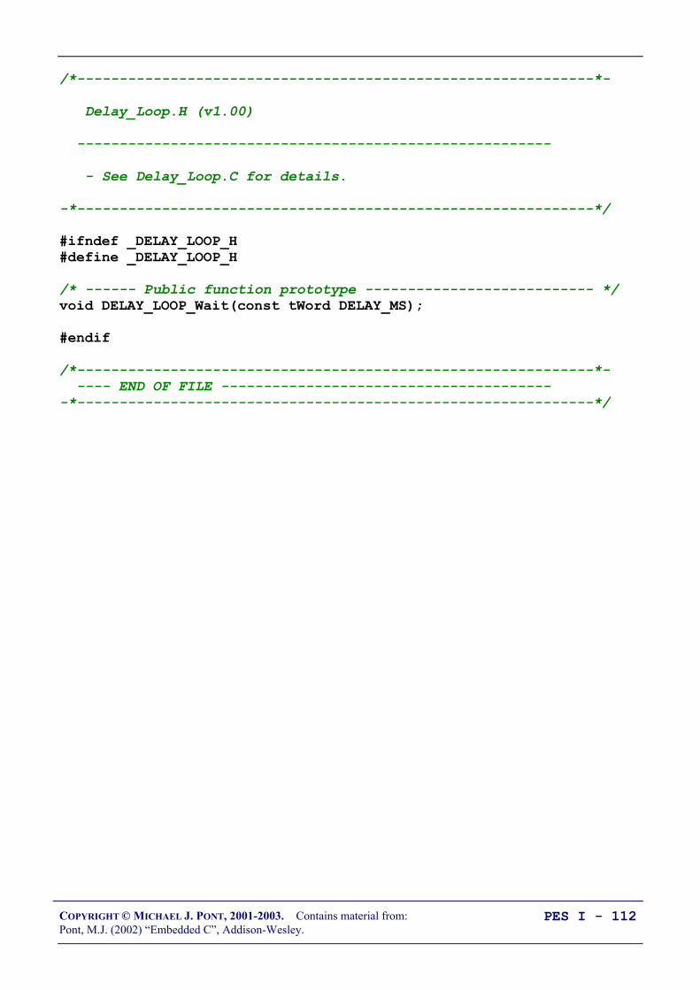
COPYRIGHT © MICHAEL J. PONT, 2001-2003. Contains material from:Pont, M.J. (2002) “Embedded C”, Addison-Wesley.
PES I - 112
/*-------------------------------------------------------------*-
Delay_Loop.H (v1.00)
--------------------------------------------------------
- See Delay_Loop.C for details.
-*-------------------------------------------------------------*/
#ifndef _DELAY_LOOP_H#define _DELAY_LOOP_H
/* ------ Public function prototype --------------------------- */void DELAY_LOOP_Wait(const tWord DELAY_MS);
#endif
/*-------------------------------------------------------------*- ---- END OF FILE ----------------------------------------*-------------------------------------------------------------*/

COPYRIGHT © MICHAEL J. PONT, 2001-2003. Contains material from:Pont, M.J. (2002) “Embedded C”, Addison-Wesley.
PES I - 113
/*-------------------------------------------------------------*-
Delay_Loop.C (v1.00)
--------------------------------------------------------
Create a simple software delay using a loop.
-*-------------------------------------------------------------*/
#include "Main.H"#include "Port.H"
#include "Delay_loop.h"
/*-------------------------------------------------------------*-
DELAY_LOOP_Wait()
Delay duration varies with parameter.
Parameter is, *ROUGHLY*, the delay, in milliseconds, on 12MHz 8051 (12 osc cycles).
You need to adjust the timing for your application!
-*-------------------------------------------------------------*/void DELAY_LOOP_Wait(const tWord DELAY_MS) tWord x, y;
for (x = 0; x <= DELAY_MS; x++) for (y = 0; y <= 120; y++);
/*-------------------------------------------------------------*- ---- END OF FILE ----------------------------------------*-------------------------------------------------------------*/

COPYRIGHT © MICHAEL J. PONT, 2001-2003. Contains material from:Pont, M.J. (2002) “Embedded C”, Addison-Wesley.
PES I - 114
Preparation for the next seminar
Please read Chapter 6before the next seminar

COPYRIGHT © MICHAEL J. PONT, 2001-2003. Contains material from:Pont, M.J. (2002) “Embedded C”, Addison-Wesley.
PES I - 115
Seminar 5: Meeting Real-Time
Constraints

COPYRIGHT © MICHAEL J. PONT, 2001-2003. Contains material from:Pont, M.J. (2002) “Embedded C”, Addison-Wesley.
PES I - 116
Introduction
In this seminar, we begin to consider the issues involved in theaccurate measurement of time.
These issues are important because many embedded systems mustsatisfy real-time constraints.
Rudderδr
Elevatorδe
Aileronδa
p
r
q
x,υ
y,β
z,ϖ
x, y, z = position coordinatesυ, β, ϖ = velocity cordinatesp = roll rateq = pitch rater = yaw rate
AircraftAutopilotSystem
Positionsensors(GPS)
Velocitysensors(3 axes)
Yaw (rate)sensor
Pitch(rate)sensor
Roll(rate)sensor
Mainpilot
controls
Rudder
Elevator
Aileron
Main engine(fuel)
controllers

COPYRIGHT © MICHAEL J. PONT, 2001-2003. Contains material from:Pont, M.J. (2002) “Embedded C”, Addison-Wesley.
PES I - 117
bit SWITCH_Get_Input(const tByte DEBOUNCE_PERIOD) tByte Return_value = SWITCH_NOT_PRESSED;
if (Switch_pin == 0) /* Switch is pressed */
/* Debounce - just wait... */ DELAY_LOOP_Wait(DEBOUNCE_PERIOD); /* POTENTIAL PROBLEM */
/* Check switch again */ if (Switch_pin == 0) /* Wait until the switch is released. */ while (Switch_pin == 0); /* POTENTIAL CATASTROPHE */ Return_value = SWITCH_PRESSED;
/* Now (finally) return switch value */ return Return_value;
The first problem is that we wait for a ‘debounce’ period in order toconfirm that the switch has been pressed. Because this delay isimplemented using a software loop it may not be very preciselytimed.
The second problem is even more serious in a system with real-timecharacteristics: we cause the system to wait - indefinitely - for theuser to release the switch.
We’ll see how to deal with both of these problems in this seminar

COPYRIGHT © MICHAEL J. PONT, 2001-2003. Contains material from:Pont, M.J. (2002) “Embedded C”, Addison-Wesley.
PES I - 118
Creating “hardware delays”
All members of the 8051 family have at least two 16-bit timer /counters, known as Timer 0 and Timer 1.
These timers can be used to generate accurate delays.
/* Configure Timer 0 as a 16-bit timer */ TMOD &= 0xF0; /* Clear all T0 bits (T1 left unchanged) */ TMOD |= 0x01; /* Set required T0 bits (T1 left unchanged) */
ET0 = 0; /* No interrupts */
/* Values for 50 ms delay */ TH0 = 0x3C; /* Timer 0 initial value (High Byte) */ TL0 = 0xB0; /* Timer 0 initial value (Low Byte) */
TF0 = 0; /* Clear overflow flag */ TR0 = 1; /* Start Timer 0 */
while (TF0 == 0); /* Loop until Timer 0 overflows (TF0 == 1) */
TR0 = 0; /* Stop Timer 0 */
Now let’s see how this works…

COPYRIGHT © MICHAEL J. PONT, 2001-2003. Contains material from:Pont, M.J. (2002) “Embedded C”, Addison-Wesley.
PES I - 119
The TCON SFR
Bit 7(msb)
6 5 4 3 2 1 0(lsb)
NAME TF1 TR1 TF0 TR0 IE1 IT1 IE0 IT0
TF1 Timer 1 overflow flagSet by hardware on Timer 1 overflow.(Cleared by hardware if processor vectors to interrupt routine.)
TR1 Timer 1 run control bitSet / cleared by software to turn Timer 1 either ‘ON’ or ‘OFF’.
TF0 Timer 0 overflow flagSet by hardware on Timer 0 overflow.(Cleared by hardware if processor vectors to interrupt routine.)
TR0 Timer 0 run control bitSet / cleared by software to turn Timer 0 either ‘ON’ or ‘OFF’.
Note that the overflow of the timers can be used to generate aninterrupt. We will not make use of this facility in the Hardware Delaycode.
To disable the generation of interrupts, we can use the C statements:
ET0 = 0; /* No interrupts (Timer 0) */ ET1 = 0; /* No interrupts (Timer 1) */

COPYRIGHT © MICHAEL J. PONT, 2001-2003. Contains material from:Pont, M.J. (2002) “Embedded C”, Addison-Wesley.
PES I - 120
The TMOD SFR
Bit 7 6 5 4 3 2 1 0NAME Gate C / T M1 M0 Gate C / T M1 M0
Timer 1 Timer 0
Mode 1 (M1 = 0; M0 = 1)16-bit timer/counter (with manual reload)
Mode 2 (M1 = 1; M0 = 0)8-bit timer/counter (with 8-bit auto-reload)
GATE Gating controlWhen set, timer/counter “x” is enabled only while “INT x” pin is high and “TRx”control bit is set. When cleared timer “x” is enabled whenever “TRx” control bitis set.
C / T Counter or timer select bitSet for counter operation (input from “Tx” input pin).Cleared for timer operation (input from internal system clock).

COPYRIGHT © MICHAEL J. PONT, 2001-2003. Contains material from:Pont, M.J. (2002) “Embedded C”, Addison-Wesley.
PES I - 121
Two further registers
Before we can see how this hardware can be used to create delays,you need to be aware that there are an additional two registersassociated with each timer: these are known as TL0 and TH0, andTL1 and TH1.

COPYRIGHT © MICHAEL J. PONT, 2001-2003. Contains material from:Pont, M.J. (2002) “Embedded C”, Addison-Wesley.
PES I - 122
Example: Generating a precise 50 ms delay
/*-------------------------------------------------------------*-
Hardware_Delay_50ms.C (v1.00)
--------------------------------------------------------
A test program for hardware-based delays.
-*-------------------------------------------------------------*/
#include <reg52.h>
sbit LED_pin = P1^5;bit LED_state_G;
void LED_FLASH_Init(void);void LED_FLASH_Change_State(void);
void DELAY_HARDWARE_One_Second(void);void DELAY_HARDWARE_50ms(void);
/*..................................................................*/
void main(void) LED_FLASH_Init();
while(1) /* Change the LED state (OFF to ON, or vice versa) */ LED_FLASH_Change_State();
/* Delay for approx 1000 ms */ DELAY_HARDWARE_One_Second();

COPYRIGHT © MICHAEL J. PONT, 2001-2003. Contains material from:Pont, M.J. (2002) “Embedded C”, Addison-Wesley.
PES I - 123
/*-------------------------------------------------------------*-
LED_FLASH_Init()
Prepare for LED_Change_State() function - see below.
-*-------------------------------------------------------------*/void LED_FLASH_Init(void) LED_state_G = 0;
/*-------------------------------------------------------------*-
LED_FLASH_Change_State()
Changes the state of an LED (or pulses a buzzer, etc) on a specified port pin.
Must call at twice the required flash rate: thus, for 1 Hz flash (on for 0.5 seconds, off for 0.5 seconds) must call every 0.5 seconds.
-*-------------------------------------------------------------*/void LED_FLASH_Change_State(void) /* Change the LED from OFF to ON (or vice versa) */ if (LED_state_G == 1) LED_state_G = 0; LED_pin = 0; else LED_state_G = 1; LED_pin = 1;

COPYRIGHT © MICHAEL J. PONT, 2001-2003. Contains material from:Pont, M.J. (2002) “Embedded C”, Addison-Wesley.
PES I - 124
/*-------------------------------------------------------------*-
DELAY_HARDWARE_One_Second()
Hardware delay of 1000 ms.
*** Assumes 12MHz 8051 (12 osc cycles) ***
-*-------------------------------------------------------------*/void DELAY_HARDWARE_One_Second(void) unsigned char d;
/* Call DELAY_HARDWARE_50ms() twenty times */ for (d = 0; d < 20; d++) DELAY_HARDWARE_50ms();
/*-------------------------------------------------------------*-
DELAY_HARDWARE_50ms()
*** Assumes 12MHz 8051 (12 osc cycles) ***
-*-------------------------------------------------------------*/void DELAY_HARDWARE_50ms(void) /* Configure Timer 0 as a 16-bit timer */ TMOD &= 0xF0; /* Clear all T0 bits (T1 left unchanged) */ TMOD |= 0x01; /* Set required T0 bits (T1 left unchanged) */
ET0 = 0; /* No interrupts */
/* Values for 50 ms delay */ TH0 = 0x3C; /* Timer 0 initial value (High Byte) */ TL0 = 0xB0; /* Timer 0 initial value (Low Byte) */
TF0 = 0; /* Clear overflow flag */ TR0 = 1; /* Start timer 0 */
while (TF0 == 0); /* Loop until Timer 0 overflows (TF0 == 1) */
TR0 = 0; /* Stop Timer 0 */

COPYRIGHT © MICHAEL J. PONT, 2001-2003. Contains material from:Pont, M.J. (2002) “Embedded C”, Addison-Wesley.
PES I - 125
In this case, we assume - again - the standard 12 MHz / 12oscillations-per-instruction microcontroller environment.
We require a 50 ms delay, so the timer requires the followingnumber of increments before it overflows:
10000001000
50 ×ms
ms= 50000 increments.
The timer overflows when it is incremented from its maximumcount of 65535.
Thus, the initial value we need to load to produce a 50 ms delay is:
65536 - 50000 = 15536 (decimal) = 0x3CB0

COPYRIGHT © MICHAEL J. PONT, 2001-2003. Contains material from:Pont, M.J. (2002) “Embedded C”, Addison-Wesley.
PES I - 126
Example: Creating a portable hardware delay
/*-------------------------------------------------------------*-
Main.C (v1.00)
--------------------------------------------------------
Flashing LED with hardware-based delay (T0).
-*-------------------------------------------------------------*/
#include "Main.H"#include "Port.H"
#include "Delay_T0.h"#include "LED_Flash.h"
void main(void) LED_FLASH_Init();
while(1) /* Change the LED state (OFF to ON, or vice versa) */ LED_FLASH_Change_State();
/* Delay for *approx* 1000 ms */ DELAY_T0_Wait(1000);
/*-------------------------------------------------------------*- ---- END OF FILE ----------------------------------------*-------------------------------------------------------------*/

COPYRIGHT © MICHAEL J. PONT, 2001-2003. Contains material from:Pont, M.J. (2002) “Embedded C”, Addison-Wesley.
PES I - 127
/* Timer preload values for use in simple (hardware) delays - Timers are 16-bit, manual reload ('one shot').
NOTE: These values are portable but timings are *approximate* and *must* be checked by hand if accurate timing is required.
Define Timer 0 / Timer 1 reload values for ~1 msec delay NOTE: Adjustment made to allow for function call overheard etc. */#define PRELOAD01 (65536 - (tWord)(OSC_FREQ / (OSC_PER_INST * 1020)))#define PRELOAD01H (PRELOAD01 / 256)#define PRELOAD01L (PRELOAD01 % 256)
/*-------------------------------------------------------------*/
void DELAY_T0_Wait(const tWord N) tWord ms;
/* Configure Timer 0 as a 16-bit timer */ TMOD &= 0xF0; /* Clear all T0 bits (T1 left unchanged) */ TMOD |= 0x01; /* Set required T0 bits (T1 left unchanged) */
ET0 = 0; /* No interrupts */
/* Delay value is *approximately* 1 ms per loop */ for (ms = 0; ms < N; ms++) TH0 = PRELOAD01H; TL0 = PRELOAD01L;
TF0 = 0; /* Clear overflow flag */ TR0 = 1; /* Start timer 0 */
while (TF0 == 0); /* Loop until Timer 0 overflows (TF0 == 1) */
TR0 = 0; /* Stop Timer 0 */

COPYRIGHT © MICHAEL J. PONT, 2001-2003. Contains material from:Pont, M.J. (2002) “Embedded C”, Addison-Wesley.
PES I - 128

COPYRIGHT © MICHAEL J. PONT, 2001-2003. Contains material from:Pont, M.J. (2002) “Embedded C”, Addison-Wesley.
PES I - 129
The need for ‘timeout’ mechanisms - example
The Philips 8Xc552 is an Extended 8051 device with a number ofon-chip peripherals, including an 8-channel, 10-bit ADC. Philipsprovide an application note (AN93017) that describes how to usethis feature of the microcontroller.
This application note includes the following code:/* Wait until AD conversion finishes (checking ADCI) */while ((ADCON & ADCI) == 0);
Such code is potentially unreliable, because there are circumstancesunder which our application may ‘hang’. This might occur for oneor more of the following reasons:
• If the ADC has been incorrectly initialised, we cannot besure that a data conversion will be carried out.
• If the ADC has been subjected to an excessive input voltage,then it may not operate at all.
• If the variable ADCON or ADCI were not correctlyinitialised, they may not operate as required.
The Philips example is not intended to illustrate ‘production’ code.Unfortunately, however, code in this form is common in embeddedapplications.
Two possible solutions: Loop timeouts and hardware timeouts.

COPYRIGHT © MICHAEL J. PONT, 2001-2003. Contains material from:Pont, M.J. (2002) “Embedded C”, Addison-Wesley.
PES I - 130
Creating loop timeouts
Basis of loop timeout:tWord Timeout_loop = 0;
...
while (++Timeout_loop);
Original ADC code:/* Wait until AD conversion finishes (checking ADCI) */while ((ADCON & ADCI) == 0);
Modified version, with a loop timeout:tWord Timeout_loop = 0;
/* Take sample from ADC Wait until conversion finishes (checking ADCI) - simple loop timeout */while (((ADCON & ADCI) == 0) && (++Timeout_loop != 0));
Note that this alternative implementation is also useful:while (((ADCON & ADCI) == 0) && (Timeout_loop != 0)) Timeout_loop++; /* Disable for use in hardware simulator */

COPYRIGHT © MICHAEL J. PONT, 2001-2003. Contains material from:Pont, M.J. (2002) “Embedded C”, Addison-Wesley.
PES I - 131
/*-------------------------------------------------------------*-
TimeoutL.H (v1.00)
--------------------------------------------------------
Simple software (loop) timeout delays for the 8051 family.
* THESE VALUES ARE NOT PRECISE - YOU MUST ADAPT TO YOUR SYSTEM *
-*-------------------------------------------------------------*/
#ifndef _TIMEOUTL_H#define _TIMEOUTL_H
/* ------ Public constants ------------------------------------ */
/* Vary this value to change the loop duration THESE ARE APPROX VALUES FOR VARIOUS TIMEOUT DELAYS ON 8051, 12 MHz, 12 Osc / cycle
*** MUST BE FINE TUNED FOR YOUR APPLICATION ***
*** Timings vary with compiler optimisation settings *** */
/* tWord */#define LOOP_TIMEOUT_INIT_001ms 65435#define LOOP_TIMEOUT_INIT_010ms 64535#define LOOP_TIMEOUT_INIT_500ms 14535/* tLong */#define LOOP_TIMEOUT_INIT_10000ms 4294795000UL
#endif
/*-------------------------------------------------------------*- ---- END OF FILE ----------------------------------------*-------------------------------------------------------------*/

COPYRIGHT © MICHAEL J. PONT, 2001-2003. Contains material from:Pont, M.J. (2002) “Embedded C”, Addison-Wesley.
PES I - 132
Example: Testing loop timeouts
/*-------------------------------------------------------------*-
Main.C (v1.00)
-*-------------------------------------------------------------*/
#include <reg52.H>
#include "TimeoutL.H"
/* Typedefs (see Chap 5) */typedef unsigned char tByte;typedef unsigned int tWord;typedef unsigned long tLong;
/* Function prototypes */void Test_Timeout(void);
/*-------------------------------------------------------------*/void main(void) while(1) Test_Timeout();
/*-------------------------------------------------------------*/void Test_Timeout(void) tLong Timeout_loop = LOOP_TIMEOUT_INIT_10000ms;
/* Simple loop timeout... */ while (++Timeout_loop != 0);

COPYRIGHT © MICHAEL J. PONT, 2001-2003. Contains material from:Pont, M.J. (2002) “Embedded C”, Addison-Wesley.
PES I - 133
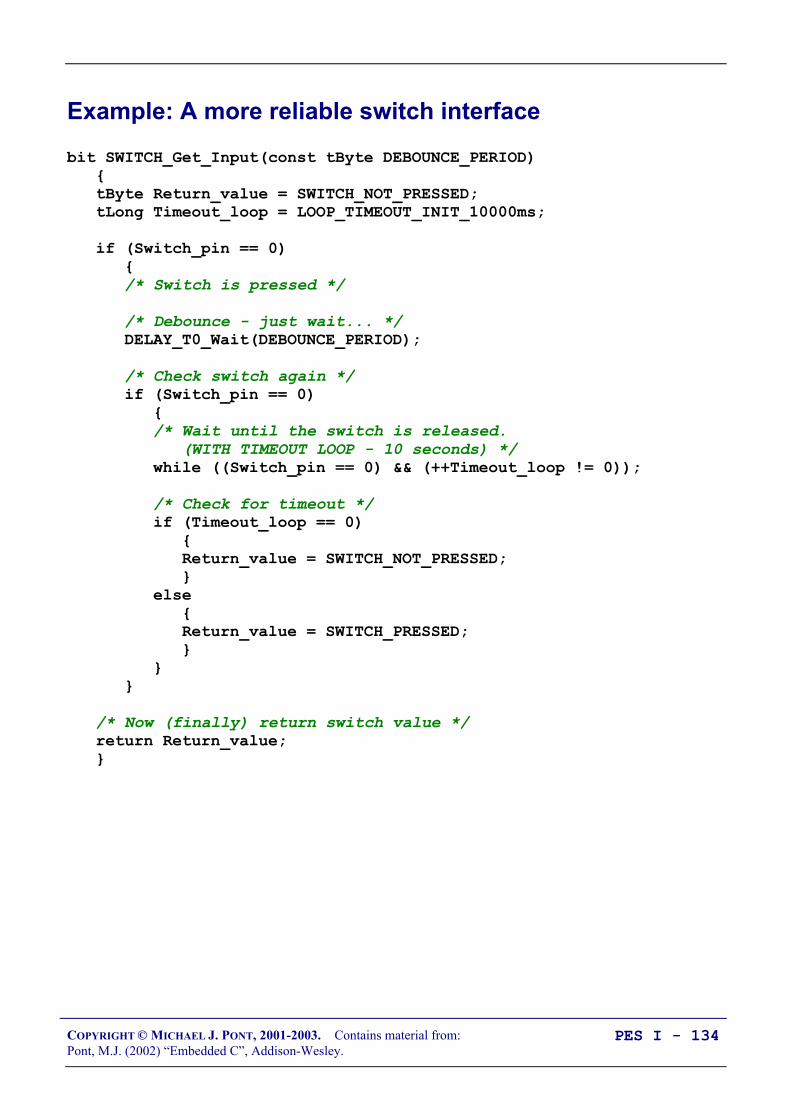
COPYRIGHT © MICHAEL J. PONT, 2001-2003. Contains material from:Pont, M.J. (2002) “Embedded C”, Addison-Wesley.
PES I - 134
Example: A more reliable switch interface
bit SWITCH_Get_Input(const tByte DEBOUNCE_PERIOD) tByte Return_value = SWITCH_NOT_PRESSED; tLong Timeout_loop = LOOP_TIMEOUT_INIT_10000ms;
if (Switch_pin == 0) /* Switch is pressed */
/* Debounce - just wait... */ DELAY_T0_Wait(DEBOUNCE_PERIOD);
/* Check switch again */ if (Switch_pin == 0) /* Wait until the switch is released. (WITH TIMEOUT LOOP - 10 seconds) */ while ((Switch_pin == 0) && (++Timeout_loop != 0));
/* Check for timeout */ if (Timeout_loop == 0) Return_value = SWITCH_NOT_PRESSED; else Return_value = SWITCH_PRESSED;
/* Now (finally) return switch value */ return Return_value;

COPYRIGHT © MICHAEL J. PONT, 2001-2003. Contains material from:Pont, M.J. (2002) “Embedded C”, Addison-Wesley.
PES I - 135
Creating hardware timeouts
/* Configure Timer 0 as a 16-bit timer */TMOD &= 0xF0; /* Clear all T0 bits (T1 left unchanged) */TMOD |= 0x01; /* Set required T0 bits (T1 left unchanged) */
ET0 = 0; /* No interrupts */
/* Simple timeout feature - approx 10 ms */TH0 = PRELOAD_10ms_H; /* See Timeout.H for PRELOAD details */TL0 = PRELOAD_10ms_L;TF0 = 0; /* Clear flag */TR0 = 1; /* Start timer */
while (((ADCON & ADCI) == 0) && !TF0);

COPYRIGHT © MICHAEL J. PONT, 2001-2003. Contains material from:Pont, M.J. (2002) “Embedded C”, Addison-Wesley.
PES I - 136
/*-------------------------------------------------------------*-
TimeoutH.H (v1.00)
-*-------------------------------------------------------------*/
#ifndef _TIMEOUTH_H#define _TIMEOUTH_H
/* ------ Public constants ------------------------------------ */
/* Timer T_ values for use in simple (hardware) timeouts */ - Timers are 16-bit, manual reload ('one shot'). */
NOTE: These macros are portable but timings are *approximate* and *must* be checked by hand for accurate timing. */
/* Define initial Timer 0 / Timer 1 values for ~50 µs delay */#define T_50micros (65536 - (tWord)((OSC_FREQ /26000)/(OSC_PER_INST)))#define T_50micros_H (T_50micros / 256)#define T_50micros_L (T_50micros % 256)
...
/* Define initial Timer 0 / Timer 1 values for ~10 msec delay */#define T_10ms (65536 - (tWord)(OSC_FREQ / (OSC_PER_INST * 100)))#define T_10ms_H (T_10ms / 256)#define T_10ms_L (T_10ms % 256)
/* Define initial Timer 0 / Timer 1 values for ~15 msec delay */#define T_15ms (65536 - (tWord)(OSC_FREQ / (OSC_PER_INST * 67)))#define T_15ms_H (T_15ms / 256)#define T_15ms_L (T_15ms % 256)
/* Define initial Timer 0 / Timer 1 values for ~20 msec delay */#define T_20ms (65536 - (tWord)(OSC_FREQ / (OSC_PER_INST * 50)))#define T_20ms_H (T_20ms / 256)#define T_20ms_L (T_20ms % 256)
/* Define initial Timer 0 / Timer 1 values for ~50 msec delay */#define T_50ms (65536 - (tWord)(OSC_FREQ / (OSC_PER_INST * 20)))#define T_50ms_H (T_50ms / 256)#define T_50ms_L (T_50ms % 256)
#endif

COPYRIGHT © MICHAEL J. PONT, 2001-2003. Contains material from:Pont, M.J. (2002) “Embedded C”, Addison-Wesley.
PES I - 137
Conclusions
The delay and timeout considered in this seminar are widely used inembedded applications.
In the next seminar we go on to consider another key softwarecomponent in many embedded applications: the operating system.

COPYRIGHT © MICHAEL J. PONT, 2001-2003. Contains material from:Pont, M.J. (2002) “Embedded C”, Addison-Wesley.
PES I - 138
Preparation for the next seminar
Please read Chapter 7before the next seminar

COPYRIGHT © MICHAEL J. PONT, 2001-2003. Contains material from:Pont, M.J. (2002) “Embedded C”, Addison-Wesley.
PES I - 139
Seminar 6: Creating an Embedded
Operating System
Milk pasteurisation systemMilk pasteurisation system
Determine flow rate from pulse stream

COPYRIGHT © MICHAEL J. PONT, 2001-2003. Contains material from:Pont, M.J. (2002) “Embedded C”, Addison-Wesley.
PES I - 140
Introduction
void main(void) /* Prepare run function X */ X_Init();
while(1) /* 'for ever' (Super Loop) */ X(); /* Run function X */
A particular limitation with this architecture is that it is verydifficult to execute function X() at precise intervals of time: as wewill see, this is a very significant drawback.
For example …

COPYRIGHT © MICHAEL J. PONT, 2001-2003. Contains material from:Pont, M.J. (2002) “Embedded C”, Addison-Wesley.
PES I - 141
“Item 345 was painted by Selvio Guaranteen early in the 16th century. At this time,Guaranteen, who is generally known as a member of the Slafordic School, was …”
“Now turn to your left, and locate Item 346, a small painting which was until recently alsothought to have been painted by Guarateen but which is now …”.
Time
Signallevel
Time
Signallevel
(c)
Samples = 0.46, 0.42, 0.17, 0.04, 0.00, 0.13, 0.21, 0.53, 0.84, 0.89, 1.00, 1.00, 0.63, 0.42, 0.42, 0.21, 0.00, 0.11, 0.00, 0.42, 0.42, 0.23, 0.46, 0.42, 0.48, 0.52, 0.54, 0.57
(a)
(b)

COPYRIGHT © MICHAEL J. PONT, 2001-2003. Contains material from:Pont, M.J. (2002) “Embedded C”, Addison-Wesley.
PES I - 142
Consider a collection of requirements assembled from a range ofdifferent embedded projects (in no particular order):
• The current speed of the vehicle must be measured at 0.5second intervals.
• The display must be refreshed 40 times every second
• The calculated new throttle setting must be applied every 0.5seconds.
• A time-frequency transform must be performed 20 timesevery second.
• The engine vibration data must be sampled 1000 times persecond.
• The frequency-domain data must be classified 20 timesevery second.
• The keypad must be scanned every 200 ms.
• The master (control) node must communicate with all othernodes (sensor nodes and sounder nodes) once per second.
• The new throttle setting must be calculated every 0.5seconds
• The sensors must be sampled once per second
In practice, many embedded systems must be able to support thistype of ‘periodic function’.

COPYRIGHT © MICHAEL J. PONT, 2001-2003. Contains material from:Pont, M.J. (2002) “Embedded C”, Addison-Wesley.
PES I - 143
void main(void)
Init_System();
while(1) /* 'for ever' (Super Loop) */ X(); /* Call the function (10 ms duration) */ Delay_50ms(); /* Delay for 50 ms */
This will be fine, if:
1. We know the precise duration of function X(), and,
2. This duration never varies.

COPYRIGHT © MICHAEL J. PONT, 2001-2003. Contains material from:Pont, M.J. (2002) “Embedded C”, Addison-Wesley.
PES I - 144
Timer-based interrupts (the core of an embedded OS)
#define INTERRUPT_Timer_2_Overflow 5
...
void main(void) Timer_2_Init(); /* Set up Timer 2 */
EA = 1; /* Globally enable interrupts */
while(1); /* An empty Super Loop */
void Timer_2_Init(void) /* Timer 2 is configured as a 16-bit timer, which is automatically reloaded when it overflows
This code (generic 8051/52) assumes a 12 MHz system osc. The Timer 2 resolution is then 1.000 µs
Reload value is FC18 (hex) = 64536 (decimal) Timer (16-bit) overflows when it reaches 65536 (decimal) Thus, with these setting, timer will overflow every 1 ms */ T2CON = 0x04; /* Load T2 control register */
TH2 = 0xFC; /* Load T2 high byte */ RCAP2H = 0xFC; /* Load T2 reload capt. reg. high byte */ TL2 = 0x18; /* Load T2 low byte */ RCAP2L = 0x18; /* Load T2 reload capt. reg. low byte */
/* Timer 2 interrupt is enabled, and ISR will be called whenever the timer overflows - see below. */ ET2 = 1;
/* Start Timer 2 running */ TR2 = 1;
void X(void) interrupt INTERRUPT_Timer_2_Overflow /* This ISR is called every 1 ms */ /* Place required code here... */

COPYRIGHT © MICHAEL J. PONT, 2001-2003. Contains material from:Pont, M.J. (2002) “Embedded C”, Addison-Wesley.
PES I - 145
The interrupt service routine (ISR)
The interrupt generated by the overflow of Timer 2, invokes theISR:/* --------------------------------------------------------------- */void X(void) interrupt INTERRUPT_Timer_2_Overflow /* This ISR is called every 1 ms */
/* Place required code here... */
The link between this function and the timer overflow is made usingthe Keil keyword interrupt:
void X(void) interrupt INTERRUPT_Timer_2_Overflow
…plus the following #define directive:
#define INTERRUPT_Timer_2_Overflow 5
Interrupt source Address IE IndexPower On Reset 0x00 -External Interrupt 0 0x03 0Timer 0 Overflow 0x0B 1External Interrupt 1 0x13 2Timer 1 Overflow 0x1B 3UART Receive/Transmit 0x23 4Timer 2 Overflow 0x2B 5

COPYRIGHT © MICHAEL J. PONT, 2001-2003. Contains material from:Pont, M.J. (2002) “Embedded C”, Addison-Wesley.
PES I - 146
Automatic timer reloads
/* Preload values for 50 ms delay */TH0 = 0x3C; /* Timer 0 initial value (High Byte) */TL0 = 0xB0; /* Timer 0 initial value (Low Byte) */
TF0 = 0; /* Clear overflow flag */TR0 = 1; /* Start timer 0 */
while (TF0 == 0); /* Loop until Timer 0 overflows (TF0 == 1) */
TR0 = 0; /* Stop Timer 0 */
For our operating system, we have slightly different requirements:
• We require a long series of interrupts, at precisely-determined intervals.
• We would like to generate these interrupts without imposinga significant load on the CPU.
Timer 2 matches these requirements precisely.
In this case, the timer is reloaded using the contents of the ‘capture’registers (note that the names of these registers vary slightlybetween chip manufacturers):RCAP2H = 0xFC; /* Load T2 reload capt. reg. high byte */RCAP2L = 0x18; /* Load T2 reload capt. reg. low byte */
This automatic reload facility ensures that the timer keepsgenerating the required ticks, at precise 1 ms intervals, with verylittle software load, and without any intervention from the user’sprogram.

COPYRIGHT © MICHAEL J. PONT, 2001-2003. Contains material from:Pont, M.J. (2002) “Embedded C”, Addison-Wesley.
PES I - 147
Introducing sEOS
void main(void) Init_System();
while(1) /* 'for ever' (Super Loop) */ X(); /* Call the function (10 ms duration) */ Delay_50ms(); /* Delay for 50 ms */
In this case:
• We use a Super Loop and delay code
• We call X() every 60 ms - approximately.
Now let’s look at a better way of doing this …
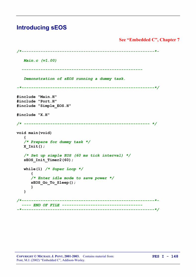
COPYRIGHT © MICHAEL J. PONT, 2001-2003. Contains material from:Pont, M.J. (2002) “Embedded C”, Addison-Wesley.
PES I - 148
Introducing sEOS
See “Embedded C”, Chapter 7
/*--------------------------------------------------------*-
Main.c (v1.00)
---------------------------------------------------
Demonstration of sEOS running a dummy task.
-*--------------------------------------------------------*/
#include "Main.H"#include "Port.H"#include "Simple_EOS.H"
#include "X.H"
/* ----------------------------------------------------- */
void main(void) /* Prepare for dummy task */ X_Init();
/* Set up simple EOS (60 ms tick interval) */ sEOS_Init_Timer2(60);
while(1) /* Super Loop */ /* Enter idle mode to save power */ sEOS_Go_To_Sleep();
/*--------------------------------------------------------*- ---- END OF FILE -----------------------------------*--------------------------------------------------------*/
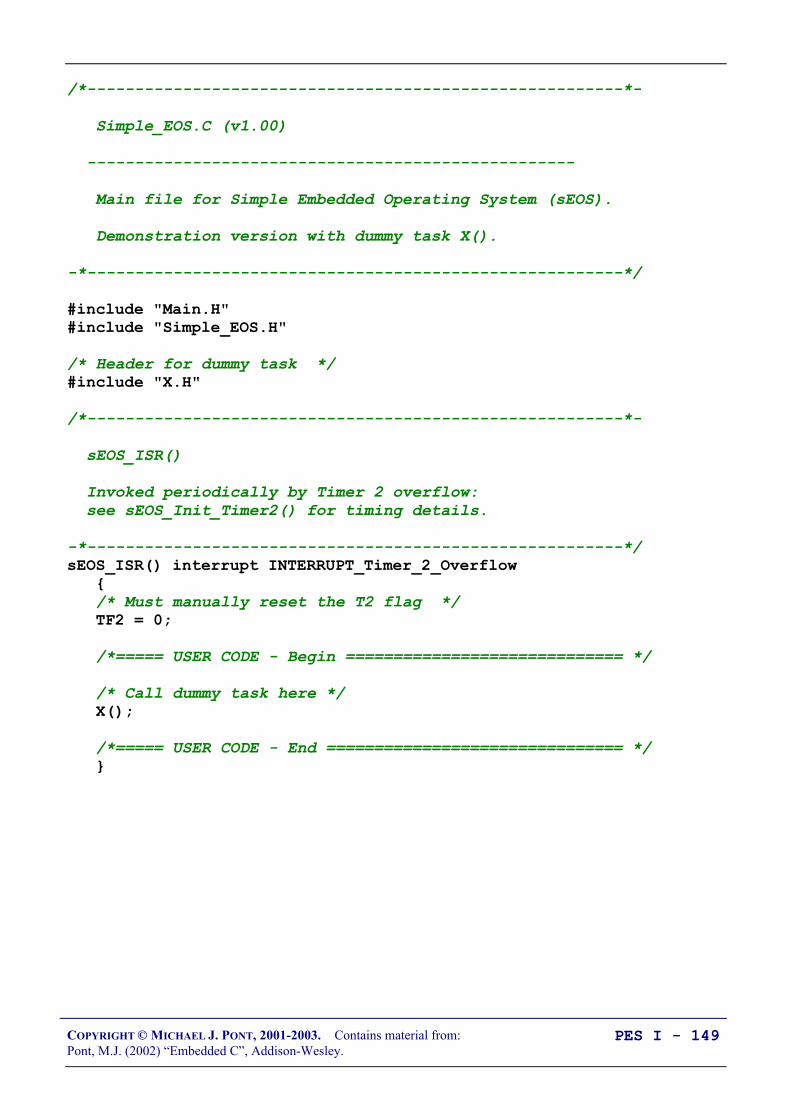
COPYRIGHT © MICHAEL J. PONT, 2001-2003. Contains material from:Pont, M.J. (2002) “Embedded C”, Addison-Wesley.
PES I - 149
/*--------------------------------------------------------*-
Simple_EOS.C (v1.00)
---------------------------------------------------
Main file for Simple Embedded Operating System (sEOS).
Demonstration version with dummy task X().
-*--------------------------------------------------------*/
#include "Main.H"#include "Simple_EOS.H"
/* Header for dummy task */#include "X.H"
/*--------------------------------------------------------*-
sEOS_ISR()
Invoked periodically by Timer 2 overflow: see sEOS_Init_Timer2() for timing details.
-*--------------------------------------------------------*/sEOS_ISR() interrupt INTERRUPT_Timer_2_Overflow /* Must manually reset the T2 flag */ TF2 = 0;
/*===== USER CODE - Begin ============================= */
/* Call dummy task here */ X();
/*===== USER CODE - End =============================== */

COPYRIGHT © MICHAEL J. PONT, 2001-2003. Contains material from:Pont, M.J. (2002) “Embedded C”, Addison-Wesley.
PES I - 150
/*--------------------------------------------------------*-
sEOS_Init_Timer2()
-*--------------------------------------------------------*/void sEOS_Init_Timer2(const tByte TICK_MS) tLong Inc; tWord Reload_16; tByte Reload_08H, Reload_08L;
/* Timer 2 is configured as a 16-bit timer, which is automatically reloaded when it overflows */ T2CON = 0x04; /* Load T2 control register */
/* Number of timer increments required (max 65536) */ Inc = ((tLong)TICK_MS * (OSC_FREQ/1000)) / (tLong)OSC_PER_INST;
/* 16-bit reload value */ Reload_16 = (tWord) (65536UL - Inc);
/* 8-bit reload values (High & Low) */ Reload_08H = (tByte)(Reload_16 / 256); Reload_08L = (tByte)(Reload_16 % 256);
/* Used for manually checking timing (in simulator) */ /*P2 = Reload_08H; */ /*P3 = Reload_08L; */
TH2 = Reload_08H; /* Load T2 high byte */ RCAP2H = Reload_08H; /* Load T2 reload capt. reg h byte */ TL2 = Reload_08L; /* Load T2 low byte */ RCAP2L = Reload_08L; /* Load T2 reload capt. reg l byte */
/* Timer 2 interrupt is enabled, and ISR will be called whenever the timer overflows. */ ET2 = 1;
/* Start Timer 2 running */ TR2 = 1;
EA = 1; /* Globally enable interrupts */

COPYRIGHT © MICHAEL J. PONT, 2001-2003. Contains material from:Pont, M.J. (2002) “Embedded C”, Addison-Wesley.
PES I - 151
/*--------------------------------------------------------*-
sEOS_Go_To_Sleep()
This operating system enters 'idle mode' between clock ticks to save power. The next clock tick will return processor to the normal operating state.
-*--------------------------------------------------------*/void sEOS_Go_To_Sleep(void) PCON |= 0x01; /* Enter idle mode (generic 8051 version) */
/*--------------------------------------------------------*- ---- END OF FILE -----------------------------------*--------------------------------------------------------*/

COPYRIGHT © MICHAEL J. PONT, 2001-2003. Contains material from:Pont, M.J. (2002) “Embedded C”, Addison-Wesley.
PES I - 152
/*--------------------------------------------------------*-
X.C (v1.00)
---------------------------------------------------
Dummy task to introduce sEOS.
-*--------------------------------------------------------*/
#include "X.H"
/*--------------------------------------------------------*-
X_Init()
Dummy task init function.
-*--------------------------------------------------------*/void X_Init(void) /* Dummy task init... */
/*--------------------------------------------------------*-
X()
Dummy task called from sEOS ISR.
-*--------------------------------------------------------*/void X(void) /* Dummy task... */
/*--------------------------------------------------------*- ---- END OF FILE -----------------------------------*--------------------------------------------------------*/

COPYRIGHT © MICHAEL J. PONT, 2001-2003. Contains material from:Pont, M.J. (2002) “Embedded C”, Addison-Wesley.
PES I - 153
Tasks, functions and scheduling
• In discussions about embedded systems, you will frequentlyhear and read about ‘task design’, ‘task execution times’ and‘multi-tasking’ systems.
• In this context, the term ‘task’ is usually used to refer to afunction that is executed on a periodic basis.
• In the case of sEOS, the tasks will be implemented usingfunctions which are called from the timer-driveninterrupt service routine.
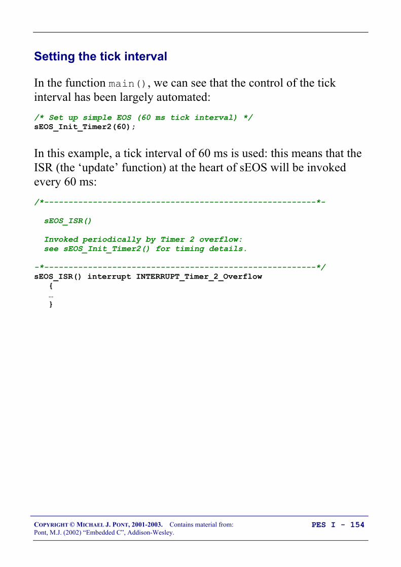
COPYRIGHT © MICHAEL J. PONT, 2001-2003. Contains material from:Pont, M.J. (2002) “Embedded C”, Addison-Wesley.
PES I - 154
Setting the tick interval
In the function main(), we can see that the control of the tickinterval has been largely automated:/* Set up simple EOS (60 ms tick interval) */sEOS_Init_Timer2(60);
In this example, a tick interval of 60 ms is used: this means that theISR (the ‘update’ function) at the heart of sEOS will be invokedevery 60 ms:/*--------------------------------------------------------*-
sEOS_ISR()
Invoked periodically by Timer 2 overflow: see sEOS_Init_Timer2() for timing details.
-*--------------------------------------------------------*/sEOS_ISR() interrupt INTERRUPT_Timer_2_Overflow …

COPYRIGHT © MICHAEL J. PONT, 2001-2003. Contains material from:Pont, M.J. (2002) “Embedded C”, Addison-Wesley.
PES I - 155
The ‘automatic’ tick interval control is achieved using the C pre-processor, and the information included in the project header file(Main.H):/* Oscillator / resonator frequency (in Hz) e.g. (11059200UL) */#define OSC_FREQ (12000000UL)
/* Number of oscillations per instruction (12, etc) */...#define OSC_PER_INST (12)
This information is then used to calculate the required timer reloadvalues in Simple_EOS.C as follows: /* Number of timer increments required (max 65536) */ Inc = ((tLong)TICK_MS * (OSC_FREQ/1000)) / (tLong)OSC_PER_INST;
/* 16-bit reload value */ Reload_16 = (tWord) (65536UL - Inc);
/* 8-bit reload values (High & Low) */ Reload_08H = (tByte)(Reload_16 / 256); Reload_08L = (tByte)(Reload_16 % 256);
…
TH2 = Reload_08H; /* Load T2 high byte */ RCAP2H = Reload_08H; /* Load T2 reload capt. reg h byte */ TL2 = Reload_08L; /* Load T2 low byte */ RCAP2L = Reload_08L; /* Load T2 reload capt. reg l byte */

COPYRIGHT © MICHAEL J. PONT, 2001-2003. Contains material from:Pont, M.J. (2002) “Embedded C”, Addison-Wesley.
PES I - 156
• If using a 12 MHz oscillator, then accurate timing canusually be obtained over a range of tick intervals from 1 msto 60 ms (approximately).
• If using other clock frequencies (e.g. 11.0592 MHz), precisetiming can only be obtained at a much more limited range oftick intervals.
• If you are developing an application where precise timing isrequired, you must check the timing calculations by hand.
/* Used for manually checking timing (in simulator) */P2 = Reload_08H;P3 = Reload_08L;

COPYRIGHT © MICHAEL J. PONT, 2001-2003. Contains material from:Pont, M.J. (2002) “Embedded C”, Addison-Wesley.
PES I - 157
Saving power
Using sEOS, we can reduce the power consumption of theapplication by having the processor enter idle mode when it finishesexecuting the ISR.
This is achieved through the function sEOS_Go_To_Sleep():/*--------------------------------------------------------*-
sEOS_Go_To_Sleep()
This operating system enters 'idle mode' between clock ticks to save power. The next clock tick will return processor to the normal operating state.
-*--------------------------------------------------------*/void sEOS_Go_To_Sleep(void) PCON |= 0x01; /* Enter idle mode (generic 8051 version) */
Note that the processor will automatically return to ‘Normal’ modewhen the timer next overflows (generating an interrupt).
Device Normal Idle Power Down
Atmel 89S53 11 mA 2 mA 60 µA

COPYRIGHT © MICHAEL J. PONT, 2001-2003. Contains material from:Pont, M.J. (2002) “Embedded C”, Addison-Wesley.
PES I - 158
Using sEOS in your own projects
When using sEOS in your own applications, you will need toinclude a copy of the files Simple_EOS.C and Simple_EOS.H in yourproject: the .C file will then need to be edited - in the area indicatedbelow - in order to match your requirements:sEOS_ISR() interrupt INTERRUPT_Timer_2_Overflow /* Must manually reset the T2 flag */ TF2 = 0;
/*===== USER CODE - Begin ============================= */
/* ADD YOUR FUNCTION (TASK) CALLS HERE... */
/*===== USER CODE - End =============================== */
COPYRIGHT © MICHAEL J. PONT, 2001-2003. Contains material from:Pont, M.J. (2002) “Embedded C”, Addison-Wesley.
PES I - 159
Is this approach portable?
• The presence of an on-chip timer which can be used togenerate interrupts in this way is by no means restricted tothe 8051 family: almost all processors intended for use inembedded applications have timers which can be used in amanner very similar to that described here.
• For example, similar timers are included on other 8-bitmicrocontrollers (e.g. Microchip PIC family, the MotorolaHC08 family), and also on 16-bit devices (e.g. the InfineonC167 family) as well as on 32-bit processors (e.g. the ARMfamily, the Motorola MPC500 family).

COPYRIGHT © MICHAEL J. PONT, 2001-2003. Contains material from:Pont, M.J. (2002) “Embedded C”, Addison-Wesley.
PES I - 160
Example: Milk pasteurization
Milk pasteurisation systemMilk pasteurisation system
Determine flow rate from pulse stream
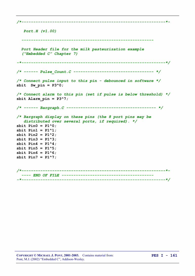
COPYRIGHT © MICHAEL J. PONT, 2001-2003. Contains material from:Pont, M.J. (2002) “Embedded C”, Addison-Wesley.
PES I - 161
/*-------------------------------------------------------------*-
Port.H (v1.00)
--------------------------------------------------------
Port Header file for the milk pasteurization example (“Embedded C” Chapter 7)
-*-------------------------------------------------------------*/
/* ------ Pulse_Count.C ---------------------------------- */
/* Connect pulse input to this pin - debounced in software */sbit Sw_pin = P3^0;
/* Connect alarm to this pin (set if pulse is below threshold) */sbit Alarm_pin = P3^7;
/* ------ Bargraph.C -------------------------------------- */
/* Bargraph display on these pins (the 8 port pins may be distributed over several ports, if required). */sbit Pin0 = P1^0;sbit Pin1 = P1^1;sbit Pin2 = P1^2;sbit Pin3 = P1^3;sbit Pin4 = P1^4;sbit Pin5 = P1^5;sbit Pin6 = P1^6;sbit Pin7 = P1^7;
/*-------------------------------------------------------------*- ---- END OF FILE ----------------------------------------*-------------------------------------------------------------*/
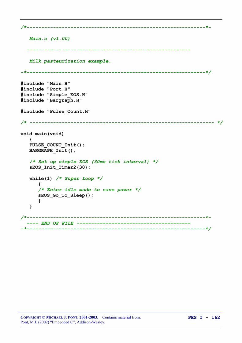
COPYRIGHT © MICHAEL J. PONT, 2001-2003. Contains material from:Pont, M.J. (2002) “Embedded C”, Addison-Wesley.
PES I - 162
/*-------------------------------------------------------------*-
Main.c (v1.00)
--------------------------------------------------------
Milk pasteurization example.
-*-------------------------------------------------------------*/
#include "Main.H"#include "Port.H"#include "Simple_EOS.H"#include "Bargraph.H"
#include "Pulse_Count.H"
/* --------------------------------------------------------------- */
void main(void) PULSE_COUNT_Init(); BARGRAPH_Init();
/* Set up simple EOS (30ms tick interval) */ sEOS_Init_Timer2(30);
while(1) /* Super Loop */ /* Enter idle mode to save power */ sEOS_Go_To_Sleep();
/*-------------------------------------------------------------*- ---- END OF FILE ----------------------------------------*-------------------------------------------------------------*/

COPYRIGHT © MICHAEL J. PONT, 2001-2003. Contains material from:Pont, M.J. (2002) “Embedded C”, Addison-Wesley.
PES I - 163
/*-------------------------------------------------------------*-
Simple_EOS.C (v1.00)
--------------------------------------------------------
Main file for Simple Embedded Operating System (sEOS) for 8051.
-- This version for milk-flow-rate monitoring.
-*-------------------------------------------------------------*/
#include "Main.H"#include "Simple_EOS.H"
#include "Pulse_count.H"
/*-------------------------------------------------------------*-
sEOS_ISR()
Invoked periodically by Timer 2 overflow: see sEOS_Init_Timer2() for timing details.
-*-------------------------------------------------------------*/sEOS_ISR() interrupt INTERRUPT_Timer_2_Overflow /* Must manually reset the T2 flag */ TF2 = 0;
/*===== USER CODE - Begin ================================== */
/* Call 'Update' function here */ PULSE_COUNT_Update();
/*===== USER CODE - End ==================================== */
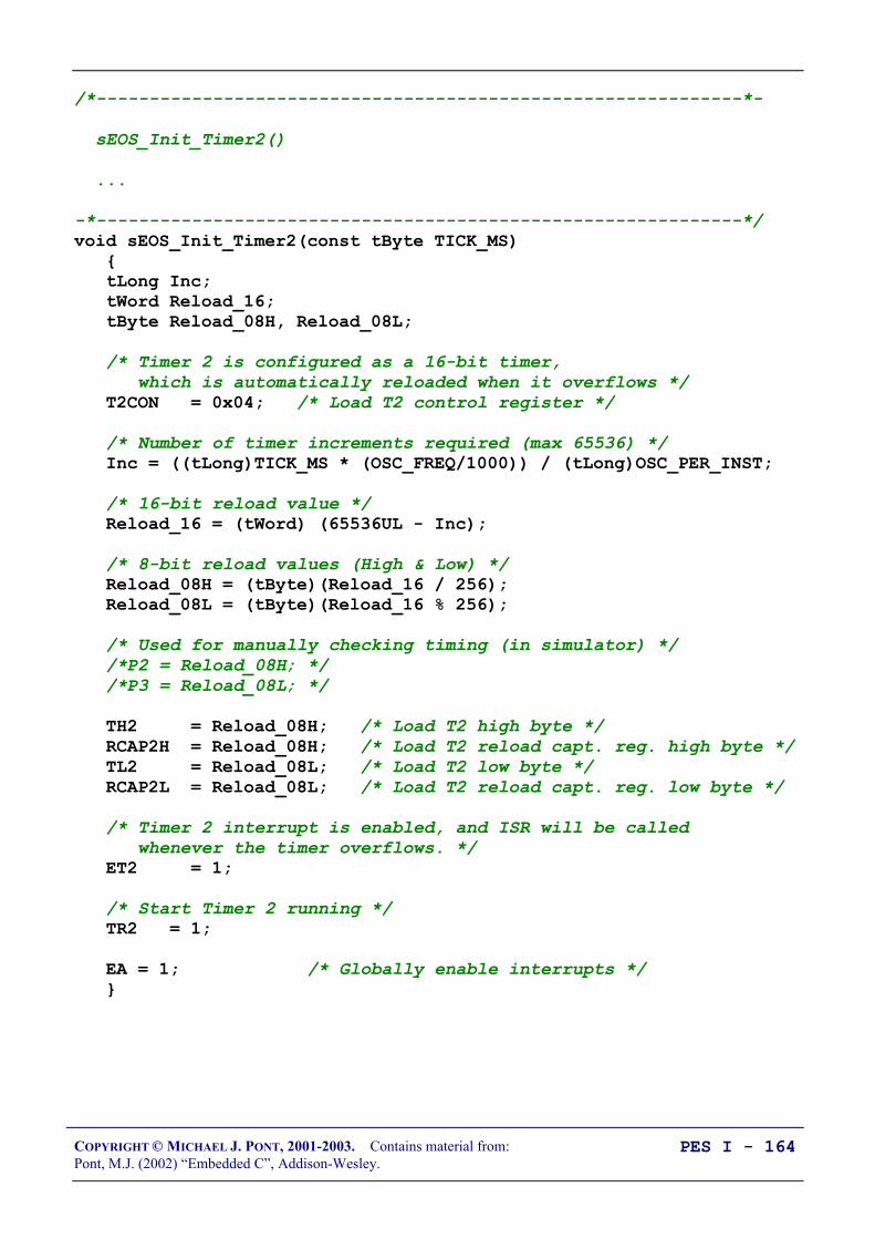
COPYRIGHT © MICHAEL J. PONT, 2001-2003. Contains material from:Pont, M.J. (2002) “Embedded C”, Addison-Wesley.
PES I - 164
/*-------------------------------------------------------------*-
sEOS_Init_Timer2()
...
-*-------------------------------------------------------------*/void sEOS_Init_Timer2(const tByte TICK_MS) tLong Inc; tWord Reload_16; tByte Reload_08H, Reload_08L;
/* Timer 2 is configured as a 16-bit timer, which is automatically reloaded when it overflows */ T2CON = 0x04; /* Load T2 control register */
/* Number of timer increments required (max 65536) */ Inc = ((tLong)TICK_MS * (OSC_FREQ/1000)) / (tLong)OSC_PER_INST;
/* 16-bit reload value */ Reload_16 = (tWord) (65536UL - Inc);
/* 8-bit reload values (High & Low) */ Reload_08H = (tByte)(Reload_16 / 256); Reload_08L = (tByte)(Reload_16 % 256);
/* Used for manually checking timing (in simulator) */ /*P2 = Reload_08H; */ /*P3 = Reload_08L; */
TH2 = Reload_08H; /* Load T2 high byte */ RCAP2H = Reload_08H; /* Load T2 reload capt. reg. high byte */ TL2 = Reload_08L; /* Load T2 low byte */ RCAP2L = Reload_08L; /* Load T2 reload capt. reg. low byte */
/* Timer 2 interrupt is enabled, and ISR will be called whenever the timer overflows. */ ET2 = 1;
/* Start Timer 2 running */ TR2 = 1;
EA = 1; /* Globally enable interrupts */
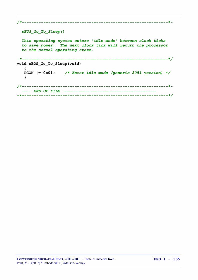
COPYRIGHT © MICHAEL J. PONT, 2001-2003. Contains material from:Pont, M.J. (2002) “Embedded C”, Addison-Wesley.
PES I - 165
/*-------------------------------------------------------------*-
sEOS_Go_To_Sleep()
This operating system enters 'idle mode' between clock ticks to save power. The next clock tick will return the processor to the normal operating state.
-*-------------------------------------------------------------*/void sEOS_Go_To_Sleep(void) PCON |= 0x01; /* Enter idle mode (generic 8051 version) */
/*-------------------------------------------------------------*- ---- END OF FILE ----------------------------------------*-------------------------------------------------------------*/

COPYRIGHT © MICHAEL J. PONT, 2001-2003. Contains material from:Pont, M.J. (2002) “Embedded C”, Addison-Wesley.
PES I - 166
/*-------------------------------------------------------------*-
Pulse_Count.C (v1.00)
--------------------------------------------------------
Count pulses from a mechanical switch or similar device. ___ Responds to falling edge of pulse: |___
-*-------------------------------------------------------------*/
#include "Main.H"#include "Port.H"
#include "Bargraph.H"#include "Pulse_Count.H"
/* ------ Private function prototypes ------------------------- */void PULSE_COUNT_Check_Below_Threshold(const tByte);
/* ------ Public variable declarations ------------------------ *//* The data to be displayed */extern tBargraph Data_G;
/* ------ Public variable definitions -------------------------- *//* Set only after falling edge is detected */bit Falling_edge_G;
/* ------ Private variable definitions ------------------------- *//* The results of successive tests of the pulse signal *//* (NOTE: Can't have arrays of bits...) */static bit Test4, Test3, Test2, Test1, Test0;
static tByte Total_G = 0;static tWord Calls_G = 0;
/* ------ Private constants ----------------------------------- */
/* Allows changed of logic without hardware changes */#define HI_LEVEL (0)#define LO_LEVEL (1)

COPYRIGHT © MICHAEL J. PONT, 2001-2003. Contains material from:Pont, M.J. (2002) “Embedded C”, Addison-Wesley.
PES I - 167
/*-------------------------------------------------------------*-
PULSE_COUNT_Init()
Initialisation function for the switch library.
-*-------------------------------------------------------------*/void PULSE_COUNT_Init(void) Sw_pin = 1; /* Use this pin for input */
/* The tests (see text) */ Test4 = LO_LEVEL; Test3 = LO_LEVEL; Test2 = LO_LEVEL; Test1 = LO_LEVEL; Test0 = LO_LEVEL;
/*-------------------------------------------------------------*-
PULSE_COUNT_Check_Below_Threshold()
Checks to see if pulse count is below a specified threshold value. If it is, the alarm is sounded.
-*-------------------------------------------------------------*/void PULSE_COUNT_Check_Below_Threshold(const tByte THRESHOLD) if (Data_G < THRESHOLD) Alarm_pin = 0; else Alarm_pin = 1;

COPYRIGHT © MICHAEL J. PONT, 2001-2003. Contains material from:Pont, M.J. (2002) “Embedded C”, Addison-Wesley.
PES I - 168
/*-------------------------------------------------------------*-
PULSE_COUNT_Update()
This is the main switch function.
It should be called every 30 ms (to allow for typical 20ms debounce time).
-*-------------------------------------------------------------*/void PULSE_COUNT_Update(void) /* Clear timer flag */ TF2 = 0;
/* Shuffle the test results */ Test4 = Test3; Test3 = Test2; Test2 = Test1; Test1 = Test0;
/* Get latest test result */ Test0 = Sw_pin;
/* Required result: Test4 == HI_LEVEL Test3 == HI_LEVEL Test1 == LO_LEVEL Test0 == LO_LEVEL */
if ((Test4 == HI_LEVEL) && (Test3 == HI_LEVEL) && (Test1 == LO_LEVEL) && (Test0 == LO_LEVEL)) /* Falling edge detected */ Falling_edge_G = 1; else /* Default */ Falling_edge_G = 0;

COPYRIGHT © MICHAEL J. PONT, 2001-2003. Contains material from:Pont, M.J. (2002) “Embedded C”, Addison-Wesley.
PES I - 169
/* Calculate average every 45 calls to this task - maximum count over this period is 9 pulses if (++Calls_G < 45) */
/* 450 used here for test purposes (in simulator) [Because there is a limit to how fast you can simulate pulses by hand...] */ if (++Calls_G < 450) Total_G += (int) Falling_edge_G; else /* Update the display */ Data_G = Total_G; /* Max is 9 */ Total_G = 0; Calls_G = 0; PULSE_COUNT_Check_Below_Threshold(3); BARGRAPH_Update();
/*-------------------------------------------------------------*- ---- END OF FILE ----------------------------------------*-------------------------------------------------------------*/

COPYRIGHT © MICHAEL J. PONT, 2001-2003. Contains material from:Pont, M.J. (2002) “Embedded C”, Addison-Wesley.
PES I - 170
/*-------------------------------------------------------------*-
Bargraph.h (v1.00)
--------------------------------------------------------
- See Bargraph.c for details.
-*-------------------------------------------------------------*/
#include "Main.h"
/* ------ Public data type declarations ----------------------- */
typedef tByte tBargraph;
/* ------ Public function prototypes -------------------------- */
void BARGRAPH_Init(void);void BARGRAPH_Update(void);
/* ------ Public constants ------------------------------------ */
#define BARGRAPH_MAX (9)#define BARGRAPH_MIN (0)
/*-------------------------------------------------------------*- ---- END OF FILE ----------------------------------------*-------------------------------------------------------------*/

COPYRIGHT © MICHAEL J. PONT, 2001-2003. Contains material from:Pont, M.J. (2002) “Embedded C”, Addison-Wesley.
PES I - 171
/*-------------------------------------------------------------*-
Bargraph.c (v1.00)
--------------------------------------------------------
Simple bargraph library.
-*-------------------------------------------------------------*/
#include "Main.h"#include "Port.h"
#include "Bargraph.h"
/* ------ Public variable declarations ------------------------ */
/* The data to be displayed */tBargraph Data_G;
/* ------ Private constants ----------------------------------- */
#define BARGRAPH_ON (1)#define BARGRAPH_OFF (0)
/* ------ Private variables ----------------------------------- */
/* These variables store the thresholds used to update the display */static tBargraph M9_1_G;static tBargraph M9_2_G;static tBargraph M9_3_G;static tBargraph M9_4_G;static tBargraph M9_5_G;static tBargraph M9_6_G;static tBargraph M9_7_G;static tBargraph M9_8_G;

COPYRIGHT © MICHAEL J. PONT, 2001-2003. Contains material from:Pont, M.J. (2002) “Embedded C”, Addison-Wesley.
PES I - 172
/*-------------------------------------------------------------*-
BARGRAPH_Init()
Prepare for the bargraph display.
-*-------------------------------------------------------------*/void BARGRAPH_Init(void) Pin0 = BARGRAPH_OFF; Pin1 = BARGRAPH_OFF; Pin2 = BARGRAPH_OFF; Pin3 = BARGRAPH_OFF; Pin4 = BARGRAPH_OFF; Pin5 = BARGRAPH_OFF; Pin6 = BARGRAPH_OFF; Pin7 = BARGRAPH_OFF;
/* Use a linear scale to display data Remember: *9* possible output states - do all calculations ONCE */ M9_1_G = (BARGRAPH_MAX - BARGRAPH_MIN) / 9; M9_2_G = M9_1_G * 2; M9_3_G = M9_1_G * 3; M9_4_G = M9_1_G * 4; M9_5_G = M9_1_G * 5; M9_6_G = M9_1_G * 6; M9_7_G = M9_1_G * 7; M9_8_G = M9_1_G * 8;

COPYRIGHT © MICHAEL J. PONT, 2001-2003. Contains material from:Pont, M.J. (2002) “Embedded C”, Addison-Wesley.
PES I - 173
/*-------------------------------------------------------------*-
BARGRAPH_Update()
Update the bargraph display.
-*-------------------------------------------------------------*/void BARGRAPH_Update(void) tBargraph Data = Data_G - BARGRAPH_MIN;
Pin0 = ((Data >= M9_1_G) == BARGRAPH_ON); Pin1 = ((Data >= M9_2_G) == BARGRAPH_ON); Pin2 = ((Data >= M9_3_G) == BARGRAPH_ON); Pin3 = ((Data >= M9_4_G) == BARGRAPH_ON); Pin4 = ((Data >= M9_5_G) == BARGRAPH_ON); Pin5 = ((Data >= M9_6_G) == BARGRAPH_ON); Pin6 = ((Data >= M9_7_G) == BARGRAPH_ON); Pin7 = ((Data >= M9_8_G) == BARGRAPH_ON);
/*-------------------------------------------------------------*- ---- END OF FILE ----------------------------------------*-------------------------------------------------------------*/

COPYRIGHT © MICHAEL J. PONT, 2001-2003. Contains material from:Pont, M.J. (2002) “Embedded C”, Addison-Wesley.
PES I - 174
Conclusions
• The simple operating system (‘sEOS’) introduced in thisseminar imposes a very low processor load but is nonethelessflexible and useful.
• The simple nature of sEOS also provides other benefits. Forexample, it means that developers themselves can, veryrapidly, port the OS onto a new microcontrollerenvironment. It also means that the architecture may bereadily adapted to meet the needs of a particular application.
Perhaps the most important side-effect of this form of simple OS is that- unlike a traditional ‘real-time operating system’ - it becomes part of theapplication itself, rather than forming a separate code layer.

COPYRIGHT © MICHAEL J. PONT, 2001-2003. Contains material from:Pont, M.J. (2002) “Embedded C”, Addison-Wesley.
PES I - 175
Preparation for the next seminar
Please read Chapter 8before the next seminar

COPYRIGHT © MICHAEL J. PONT, 2001-2003. Contains material from:Pont, M.J. (2002) “Embedded C”, Addison-Wesley.
PES I - 176

COPYRIGHT © MICHAEL J. PONT, 2001-2003. Contains material from:Pont, M.J. (2002) “Embedded C”, Addison-Wesley.
PES I - 177
Seminar 7: Multi-State Systems
and FunctionSequences
SleepingSleeping
WakingWaking
GrowlingGrowling
AttackingAttacking

COPYRIGHT © MICHAEL J. PONT, 2001-2003. Contains material from:Pont, M.J. (2002) “Embedded C”, Addison-Wesley.
PES I - 178
Introduction
Two broad categories of multi-state systems:
• Multi-State (Timed)In a multi-state (timed) system, the transition between stateswill depend only on the passage of time.
For example, the system might begin in State A, repeatedlyexecuting FunctionA(), for ten seconds. It might then moveinto State B and remain there for 5 seconds, repeatedlyexecuting FunctionB(). It might then move back into StateA, ad infinituum.
A basic traffic-light control system might follow this pattern.
• Multi-State (Input / Timed)This is a more common form of system, in which thetransition between states (and behaviour in each state) willdepend both on the passage of time and on system inputs.
For example, the system might only move between State Aand State B if a particular input is received within X secondsof a system output being generated.
The autopilot system discussed at the start of this seminarmight follow this pattern, as might a control system for awashing machine, or an intruder alarm system.
COPYRIGHT © MICHAEL J. PONT, 2001-2003. Contains material from:Pont, M.J. (2002) “Embedded C”, Addison-Wesley.
PES I - 179
For completeness, we will mention on further possibility:
• Multi-State (Input)This is a comparatively rare form of system, in which thetransition between states (and behaviour in each state)depends only on the system inputs.
For example, the system might only move between State Aand State B if a particular input is received. It will remainindefinitely in State A if this input is not received.
Such systems have no concept of time, and - therefore - noway of implementing timeout or similar behaviours. We willnot consider such systems in this course.
In this seminar, we will consider how the Multi-State (Time) andMulti-State (Input / Time) architectures can be implemented in C.

COPYRIGHT © MICHAEL J. PONT, 2001-2003. Contains material from:Pont, M.J. (2002) “Embedded C”, Addison-Wesley.
PES I - 180
Implementing a Multi-State (Timed) system
We can describe the time-driven, multi-state architecture as follows:
• The system will operate in two or more states.
• Each state may be associated with one or more functioncalls.
• Transitions between states will be controlled by the passageof time.
• Transitions between states may also involve function calls.
Please note that, in order to ease subsequent maintenance tasks, thesystem states should not be arbitrarily named, but should - wherepossible - reflect a physical state observable by the user and / ordeveloper.
Please also note that the system states will usually be representedby means of a switch statement in the operating system ISR.

COPYRIGHT © MICHAEL J. PONT, 2001-2003. Contains material from:Pont, M.J. (2002) “Embedded C”, Addison-Wesley.
PES I - 181
Example: Traffic light sequencing
Red
Amber
Green
Time
Note:European sequence!

COPYRIGHT © MICHAEL J. PONT, 2001-2003. Contains material from:Pont, M.J. (2002) “Embedded C”, Addison-Wesley.
PES I - 182
In this case, the various states are easily identified:
• Red
• Red-Amber
• Green
• Amber
In the code, we will represent these states as follows:/* Possible system states */typedef enum RED, RED_AND_AMBER, GREEN, AMBER eLight_State;
We will store the time to be spent in each state as follows:/* (Times are in seconds) */#define RED_DURATION 20#define RED_AND_AMBER_DURATION 5#define GREEN_DURATION 30#define AMBER_DURATION 5

COPYRIGHT © MICHAEL J. PONT, 2001-2003. Contains material from:Pont, M.J. (2002) “Embedded C”, Addison-Wesley.
PES I - 183
In this simple case, we do not require function calls from (orbetween) system states: the required behaviour will be implementeddirectly through control of the (three) port pins which – in the finalsystem – would be connected to appropriate bulbs.
For example:case RED: Red_light = ON; Amber_light = OFF; Green_light = OFF;
...

COPYRIGHT © MICHAEL J. PONT, 2001-2003. Contains material from:Pont, M.J. (2002) “Embedded C”, Addison-Wesley.
PES I - 184
/*-------------------------------------------------------------*-
Main.c (v1.00)
--------------------------------------------------------
Traffic light example.
-*-------------------------------------------------------------*/
#include "Main.H"#include "Port.H"#include "Simple_EOS.H"
#include "T_Lights.H"
/* --------------------------------------------------------------- */
void main(void) /* Prepare to run traffic sequence */ TRAFFIC_LIGHTS_Init(RED);
/* Set up simple EOS (50 ms ticks) */ sEOS_Init_Timer2(50);
while(1) /* Super Loop */ /* Enter idle mode to save power */ sEOS_Go_To_Sleep();
/*-------------------------------------------------------------*- ---- END OF FILE ----------------------------------------*-------------------------------------------------------------*/

COPYRIGHT © MICHAEL J. PONT, 2001-2003. Contains material from:Pont, M.J. (2002) “Embedded C”, Addison-Wesley.
PES I - 185
/*-------------------------------------------------------------*-
T_Lights.H (v1.00)
--------------------------------------------------------
- See T_Lights.C for details.
-*-------------------------------------------------------------*/
#ifndef _T_LIGHTS_H#define _T_LIGHTS_H
/* ------ Public data type declarations ----------------------- */
/* Possible system states */typedef enum RED, RED_AND_AMBER, GREEN, AMBER eLight_State;
/* ------ Public function prototypes -------------------------- */
void TRAFFIC_LIGHTS_Init(const eLight_State);void TRAFFIC_LIGHTS_Update(void);
#endif
/*-------------------------------------------------------------*- ---- END OF FILE ----------------------------------------*-------------------------------------------------------------*/

COPYRIGHT © MICHAEL J. PONT, 2001-2003. Contains material from:Pont, M.J. (2002) “Embedded C”, Addison-Wesley.
PES I - 186
/*-------------------------------------------------------------*-
T_lights.C (v1.00)
-*-------------------------------------------------------------*/
#include "Main.H"#include "Port.H"
#include "T_lights.H"
/* ------ Private constants ----------------------------------- */
/* Easy to change logic here */#define ON 0#define OFF 1
/* Times in each of the (four) possible light states (Times are in seconds) */#define RED_DURATION 20#define RED_AND_AMBER_DURATION 5#define GREEN_DURATION 30#define AMBER_DURATION 5
/* ------ Private variables ----------------------------------- */
/* The state of the system */static eLight_State Light_state_G;
/* The time in that state */static tLong Time_in_state;
/* Used by sEOS */static tByte Call_count_G = 0;
/*-------------------------------------------------------------*-
TRAFFIC_LIGHTS_Init()
Prepare for traffic light activity.
-*-------------------------------------------------------------*/void TRAFFIC_LIGHTS_Init(const eLight_State START_STATE) Light_state_G = START_STATE; /* Decide on initial state */

COPYRIGHT © MICHAEL J. PONT, 2001-2003. Contains material from:Pont, M.J. (2002) “Embedded C”, Addison-Wesley.
PES I - 187
/*-------------------------------------------------------------*-
TRAFFIC_LIGHTS_Update()
Must be called once per second.
-*-------------------------------------------------------------*/void TRAFFIC_LIGHTS_Update(void) switch (Light_state_G) case RED: Red_light = ON; Amber_light = OFF; Green_light = OFF;
if (++Time_in_state == RED_DURATION) Light_state_G = RED_AND_AMBER; Time_in_state = 0;
break;
case RED_AND_AMBER: Red_light = ON; Amber_light = ON; Green_light = OFF;
if (++Time_in_state == RED_AND_AMBER_DURATION) Light_state_G = GREEN; Time_in_state = 0;
break;

COPYRIGHT © MICHAEL J. PONT, 2001-2003. Contains material from:Pont, M.J. (2002) “Embedded C”, Addison-Wesley.
PES I - 188
case GREEN: Red_light = OFF; Amber_light = OFF; Green_light = ON;
if (++Time_in_state == GREEN_DURATION) Light_state_G = AMBER; Time_in_state = 0;
break;
case AMBER: Red_light = OFF; Amber_light = ON; Green_light = OFF;
if (++Time_in_state == AMBER_DURATION) Light_state_G = RED; Time_in_state = 0;
break;
/*-------------------------------------------------------------*- ---- END OF FILE ----------------------------------------*-------------------------------------------------------------*/

COPYRIGHT © MICHAEL J. PONT, 2001-2003. Contains material from:Pont, M.J. (2002) “Embedded C”, Addison-Wesley.
PES I - 189
Example: Animatronic dinosaur
SleepingSleeping
WakingWaking
GrowlingGrowling
AttackingAttacking

COPYRIGHT © MICHAEL J. PONT, 2001-2003. Contains material from:Pont, M.J. (2002) “Embedded C”, Addison-Wesley.
PES I - 190
The system states
• Sleeping:The dinosaur will be largely motionless, but will beobviously ‘breathing’. Irregular snoring noises, or slightmovements during this time will add interest for theaudience.
• Waking:The dinosaur will begin to wake up. Eyelids will begin toflicker. Breathing will become more rapid.
• Growling:Eyes will suddenly open, and the dinosaur will emit a veryloud growl. Some further movement and growling willfollow.
• Attacking:Rapid ‘random’ movements towards the audience. Lots ofnoise (you should be able to hear this from the next floor inthe museum).
typedef enum SLEEPING, WAKING, GROWLING, ATTACKING eDinosaur_State;
/* Times in each of the (four) possible states *//* (Times are in seconds) */#define SLEEPING_DURATION 255#define WAKING_DURATION 60#define GROWLING_DURATION 40#define ATTACKING_DURATION 120
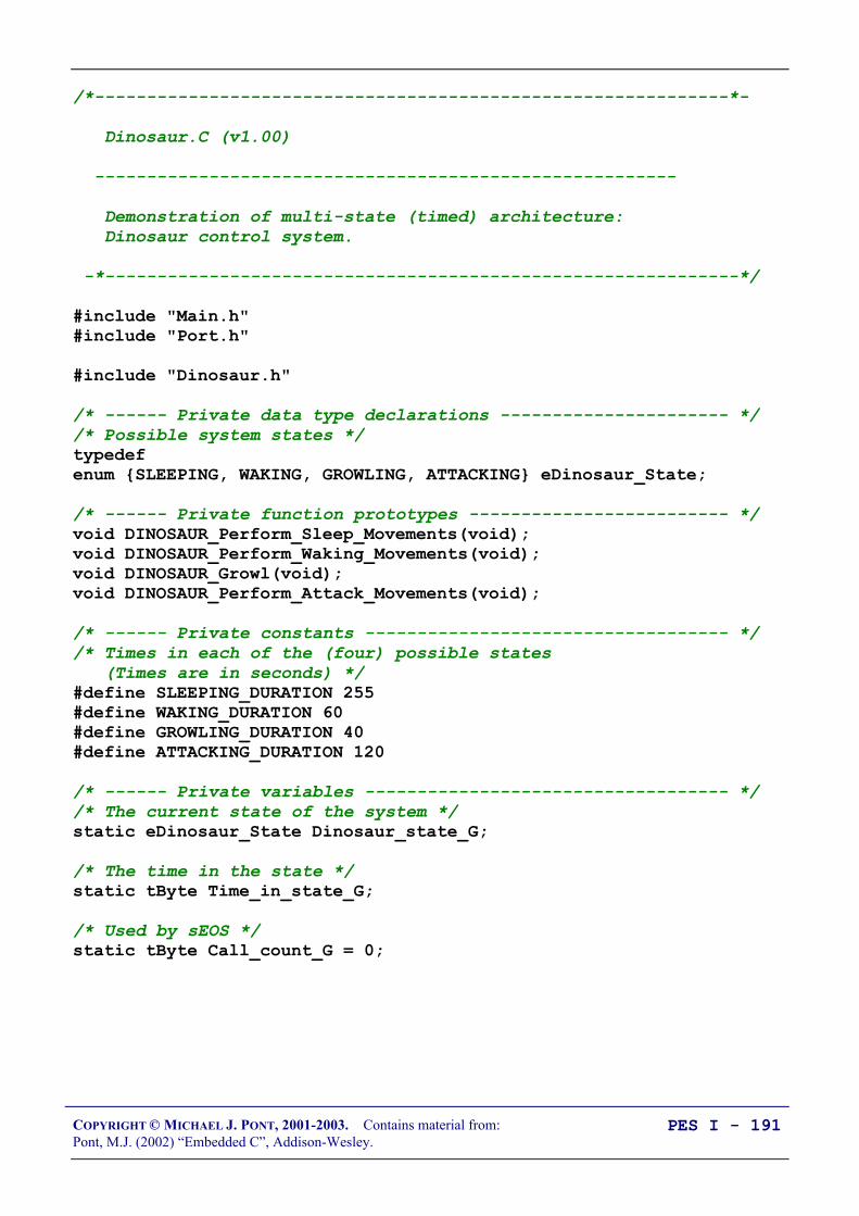
COPYRIGHT © MICHAEL J. PONT, 2001-2003. Contains material from:Pont, M.J. (2002) “Embedded C”, Addison-Wesley.
PES I - 191
/*-------------------------------------------------------------*-
Dinosaur.C (v1.00)
--------------------------------------------------------
Demonstration of multi-state (timed) architecture: Dinosaur control system.
-*-------------------------------------------------------------*/
#include "Main.h"#include "Port.h"
#include "Dinosaur.h"
/* ------ Private data type declarations ---------------------- *//* Possible system states */typedefenum SLEEPING, WAKING, GROWLING, ATTACKING eDinosaur_State;
/* ------ Private function prototypes ------------------------- */void DINOSAUR_Perform_Sleep_Movements(void);void DINOSAUR_Perform_Waking_Movements(void);void DINOSAUR_Growl(void);void DINOSAUR_Perform_Attack_Movements(void);
/* ------ Private constants ----------------------------------- *//* Times in each of the (four) possible states (Times are in seconds) */#define SLEEPING_DURATION 255#define WAKING_DURATION 60#define GROWLING_DURATION 40#define ATTACKING_DURATION 120
/* ------ Private variables ----------------------------------- *//* The current state of the system */static eDinosaur_State Dinosaur_state_G;
/* The time in the state */static tByte Time_in_state_G;
/* Used by sEOS */static tByte Call_count_G = 0;

COPYRIGHT © MICHAEL J. PONT, 2001-2003. Contains material from:Pont, M.J. (2002) “Embedded C”, Addison-Wesley.
PES I - 192
/*-------------------------------------------------------------*- DINOSAUR_Init()-*-------------------------------------------------------------*/void DINOSAUR_Init(void) /* Initial dinosaur state */ Dinosaur_state_G = SLEEPING;
/*-------------------------------------------------------------*-
DINOSAUR_Update()
Must be scheduled once per second (from the sEOS ISR).
-*-------------------------------------------------------------*/void DINOSAUR_Update(void) switch (Dinosaur_state_G) case SLEEPING: /* Call relevant function */ DINOSAUR_Perform_Sleep_Movements();
if (++Time_in_state_G == SLEEPING_DURATION) Dinosaur_state_G = WAKING; Time_in_state_G = 0;
break;
case WAKING: DINOSAUR_Perform_Waking_Movements();
if (++Time_in_state_G == WAKING_DURATION) Dinosaur_state_G = GROWLING; Time_in_state_G = 0;
break;

COPYRIGHT © MICHAEL J. PONT, 2001-2003. Contains material from:Pont, M.J. (2002) “Embedded C”, Addison-Wesley.
PES I - 193
case GROWLING: /* Call relevant function */ DINOSAUR_Growl();
if (++Time_in_state_G == GROWLING_DURATION) Dinosaur_state_G = ATTACKING; Time_in_state_G = 0;
break;
case ATTACKING: /* Call relevant function */ DINOSAUR_Perform_Attack_Movements();
if (++Time_in_state_G == ATTACKING_DURATION) Dinosaur_state_G = SLEEPING; Time_in_state_G = 0;
break;

COPYRIGHT © MICHAEL J. PONT, 2001-2003. Contains material from:Pont, M.J. (2002) “Embedded C”, Addison-Wesley.
PES I - 194
/*-------------------------------------------------------------*/void DINOSAUR_Perform_Sleep_Movements(void) /* Demo only... */ P1 = (tByte) Dinosaur_state_G; P2 = Time_in_state_G;
/*-------------------------------------------------------------*/void DINOSAUR_Perform_Waking_Movements(void) /* Demo only... */ P1 = (tByte) Dinosaur_state_G; P2 = Time_in_state_G;
/*-------------------------------------------------------------*/void DINOSAUR_Growl(void) /* Demo only... */ P1 = (tByte) Dinosaur_state_G; P2 = Time_in_state_G;
/*-------------------------------------------------------------*/void DINOSAUR_Perform_Attack_Movements(void) /* Demo only... */ P1 = (tByte) Dinosaur_state_G; P2 = Time_in_state_G;
/*-------------------------------------------------------------*- ---- END OF FILE ----------------------------------------*-------------------------------------------------------------*/

COPYRIGHT © MICHAEL J. PONT, 2001-2003. Contains material from:Pont, M.J. (2002) “Embedded C”, Addison-Wesley.
PES I - 195
Implementing a Multi-State (Input/Timed) system
• The system will operate in two or more states.
• Each state may be associated with one or more functioncalls.
• Transitions between states may be controlled by the passageof time, by system inputs or a combination of time andinputs.
• Transitions between states may also involve function calls.
COPYRIGHT © MICHAEL J. PONT, 2001-2003. Contains material from:Pont, M.J. (2002) “Embedded C”, Addison-Wesley.
PES I - 196
Implementing state timeouts
Consider the following - informal - system requirements:
• The pump should be run for 10 seconds. If, during this time,no liquid is detected in the outflow tank, then the pumpshould be switched off and ‘low water’ warning should besounded. If liquid is detected, the pump should be run for afurther 45 seconds, or until the ‘high water’ sensor isactivated (whichever is first).
• After the front door is opened, the correct password must beentered on the control panel within 30 seconds or the alarmwill sound.
• The ‘down flap’ signal will be issued. If, after 50 ms, noflap movement is detected, it should be concluded that theflap hydraulics are damaged. The system should then alertthe user and enter manual mode.
To meet this type of requirement, we can do two things:
• Keep track of the time in each system state;
• If the time exceeds a pre-determined error value, then weshould move to a different state.
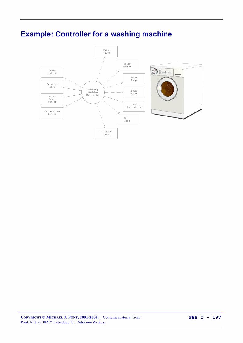
COPYRIGHT © MICHAEL J. PONT, 2001-2003. Contains material from:Pont, M.J. (2002) “Embedded C”, Addison-Wesley.
PES I - 197
Example: Controller for a washing machine
WashingMachine
Controller
WaterValve
StartSwitch
SelectorDial
DrumMotor
Doorlock
LEDindicators
WaterLevelSensor
TemperatureSensor
DetergentHatch
WaterHeater
WaterPump

COPYRIGHT © MICHAEL J. PONT, 2001-2003. Contains material from:Pont, M.J. (2002) “Embedded C”, Addison-Wesley.
PES I - 198
Here is a brief description of the way in which we expect the systemto operate:
1. The user selects a wash program (e.g. ‘Wool’, ‘Cotton’) onthe selector dial.
2. The user presses the ‘Start’ switch.
3. The door lock is engaged.
4. The water valve is opened to allow water into the wash drum.
5. If the wash program involves detergent, the detergent hatch isopened. When the detergent has been released, the detergenthatch is closed.
6. When the ‘full water level’ is sensed, the water valve isclosed.
7. If the wash program involves warm water, the water heater isswitched on. When the water reaches the correcttemperature, the water heater is switched off.
8. The washer motor is turned on to rotate the drum. The motorthen goes through a series of movements, both forward andreverse (at various speeds) to wash the clothes. (The preciseset of movements carried out depends on the wash programthat the user has selected.) At the end of the wash cycle, themotor is stopped.
9. The pump is switched on to drain the drum. When the drumis empty, the pump is switched off.

COPYRIGHT © MICHAEL J. PONT, 2001-2003. Contains material from:Pont, M.J. (2002) “Embedded C”, Addison-Wesley.
PES I - 199
The Input / Timed architecture discussed here is by no means unique to‘white goods’ (such as washing machines).
• For example, the sequence of events used to raise the landinggear in a passenger aircraft will be controlled in a similarmanner. In this case, basic tests (such as ‘WoW’ - ‘Weighton Wheels’) will be used to determine whether the aircraft ison the ground or in the air: these tests will be completedbefore the operation begins.
• Feedback from various door and landing-gear sensors willthen be used to ensure that each phase of the manoeuvrecompletes correctly.

COPYRIGHT © MICHAEL J. PONT, 2001-2003. Contains material from:Pont, M.J. (2002) “Embedded C”, Addison-Wesley.
PES I - 200
/*-------------------------------------------------------------*-
Washer.C (v1.01)
--------------------------------------------------------
Multi-state framework for washing-machine controller.
-*-------------------------------------------------------------*/
#include "Main.H"#include "Port.H"
#include "Washer.H"
/* ------ Private data type declarations ---------------------- */
/* Possible system states */typedef enum INIT, START, FILL_DRUM, HEAT_WATER, WASH_01, WASH_02, ERROR eSystem_state;
/* ------ Private function prototypes ------------------------- */
tByte WASHER_Read_Selector_Dial(void);bit WASHER_Read_Start_Switch(void);bit WASHER_Read_Water_Level(void);bit WASHER_Read_Water_Temperature(void);
void WASHER_Control_Detergent_Hatch(bit);void WASHER_Control_Door_Lock(bit);void WASHER_Control_Motor(bit);void WASHER_Control_Pump(bit);void WASHER_Control_Water_Heater(bit);void WASHER_Control_Water_Valve(bit);
/* ------ Private constants ----------------------------------- */
#define OFF 0#define ON 1
#define MAX_FILL_DURATION (tLong) 1000#define MAX_WATER_HEAT_DURATION (tLong) 1000
#define WASH_01_DURATION 30000
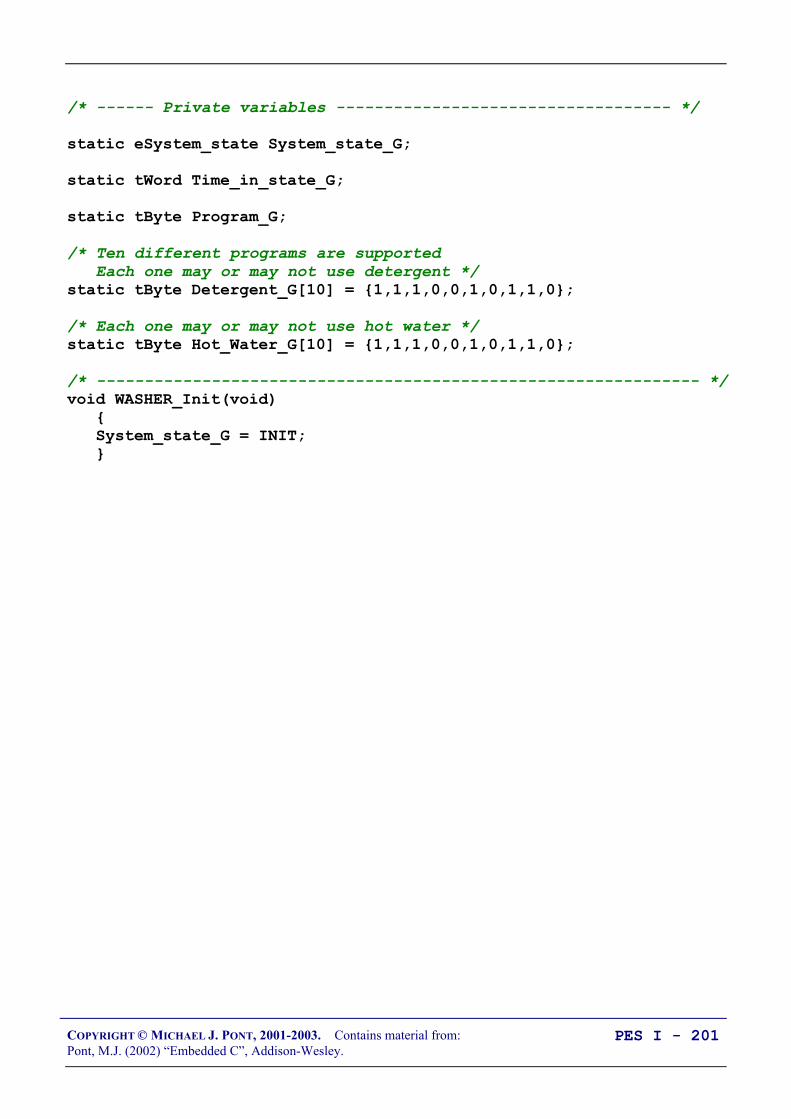
COPYRIGHT © MICHAEL J. PONT, 2001-2003. Contains material from:Pont, M.J. (2002) “Embedded C”, Addison-Wesley.
PES I - 201
/* ------ Private variables ----------------------------------- */
static eSystem_state System_state_G;
static tWord Time_in_state_G;
static tByte Program_G;
/* Ten different programs are supported Each one may or may not use detergent */static tByte Detergent_G[10] = 1,1,1,0,0,1,0,1,1,0;
/* Each one may or may not use hot water */static tByte Hot_Water_G[10] = 1,1,1,0,0,1,0,1,1,0;
/* --------------------------------------------------------------- */void WASHER_Init(void) System_state_G = INIT;
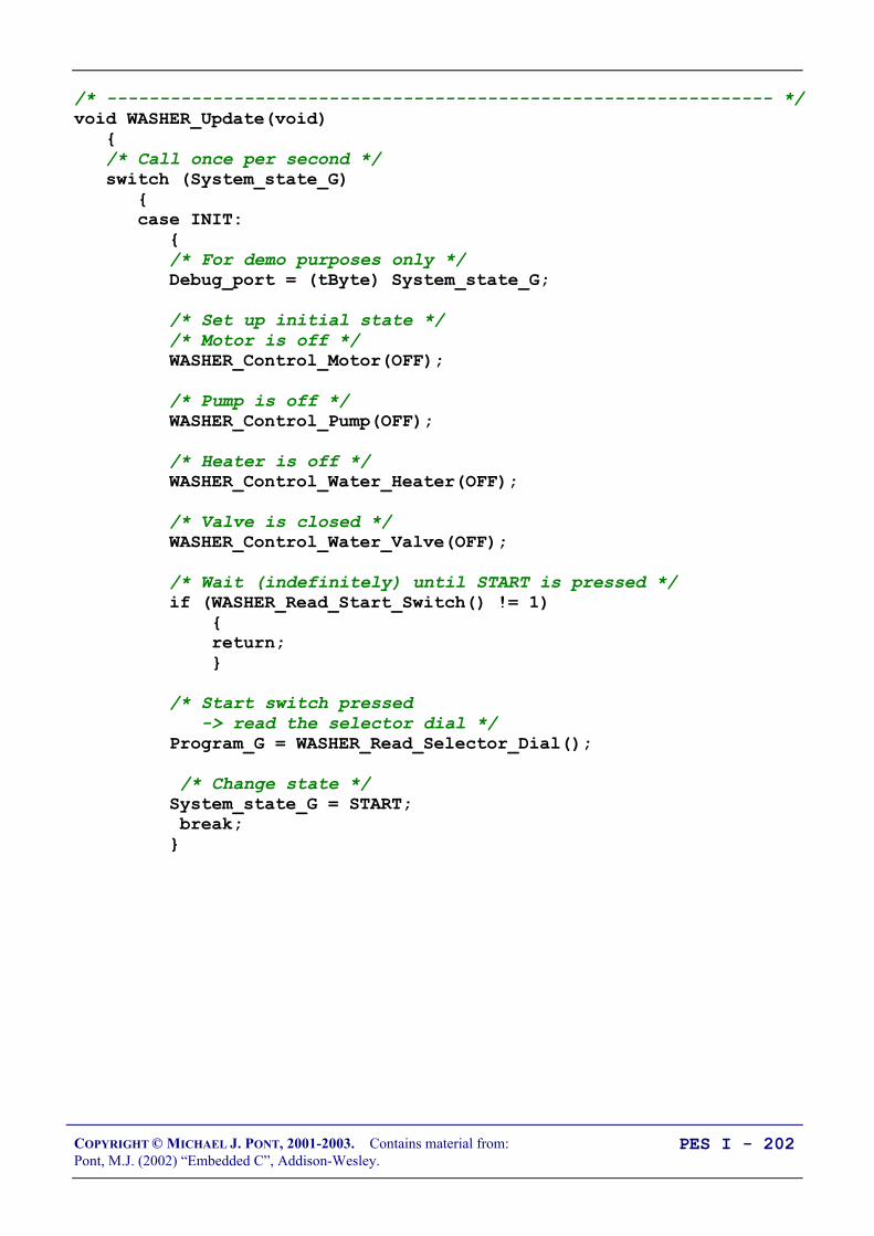
COPYRIGHT © MICHAEL J. PONT, 2001-2003. Contains material from:Pont, M.J. (2002) “Embedded C”, Addison-Wesley.
PES I - 202
/* --------------------------------------------------------------- */void WASHER_Update(void) /* Call once per second */ switch (System_state_G) case INIT: /* For demo purposes only */ Debug_port = (tByte) System_state_G;
/* Set up initial state */ /* Motor is off */ WASHER_Control_Motor(OFF);
/* Pump is off */ WASHER_Control_Pump(OFF);
/* Heater is off */ WASHER_Control_Water_Heater(OFF);
/* Valve is closed */ WASHER_Control_Water_Valve(OFF);
/* Wait (indefinitely) until START is pressed */ if (WASHER_Read_Start_Switch() != 1) return;
/* Start switch pressed -> read the selector dial */ Program_G = WASHER_Read_Selector_Dial();
/* Change state */ System_state_G = START; break;

COPYRIGHT © MICHAEL J. PONT, 2001-2003. Contains material from:Pont, M.J. (2002) “Embedded C”, Addison-Wesley.
PES I - 203
case START: /* For demo purposes only */ Debug_port = (tByte) System_state_G;
/* Lock the door */ WASHER_Control_Door_Lock(ON);
/* Start filling the drum */ WASHER_Control_Water_Valve(ON);
/* Release the detergent (if any) */ if (Detergent_G[Program_G] == 1) WASHER_Control_Detergent_Hatch(ON);
/* Ready to go to next state */ System_state_G = FILL_DRUM; Time_in_state_G = 0;
break;

COPYRIGHT © MICHAEL J. PONT, 2001-2003. Contains material from:Pont, M.J. (2002) “Embedded C”, Addison-Wesley.
PES I - 204
case FILL_DRUM: /* For demo purposes only */ Debug_port = (tByte) System_state_G;
/* Remain in this state until drum is full NOTE: Timeout facility included here */ if (++Time_in_state_G >= MAX_FILL_DURATION) /* Should have filled the drum by now... */ System_state_G = ERROR;
/* Check the water level */ if (WASHER_Read_Water_Level() == 1) /* Drum is full */
/* Does the program require hot water? */ if (Hot_Water_G[Program_G] == 1) WASHER_Control_Water_Heater(ON);
/* Ready to go to next state */ System_state_G = HEAT_WATER; Time_in_state_G = 0; else /* Using cold water only */ /* Ready to go to next state */ System_state_G = WASH_01; Time_in_state_G = 0; break;

COPYRIGHT © MICHAEL J. PONT, 2001-2003. Contains material from:Pont, M.J. (2002) “Embedded C”, Addison-Wesley.
PES I - 205
case HEAT_WATER: /* For demo purposes only */ Debug_port = (tByte) System_state_G;
/* Remain in this state until water is hot NOTE: Timeout facility included here */ if (++Time_in_state_G >= MAX_WATER_HEAT_DURATION) /* Should have warmed the water by now... */ System_state_G = ERROR;
/* Check the water temperature */ if (WASHER_Read_Water_Temperature() == 1) /* Water is at required temperature */ /* Ready to go to next state */ System_state_G = WASH_01; Time_in_state_G = 0;
break;
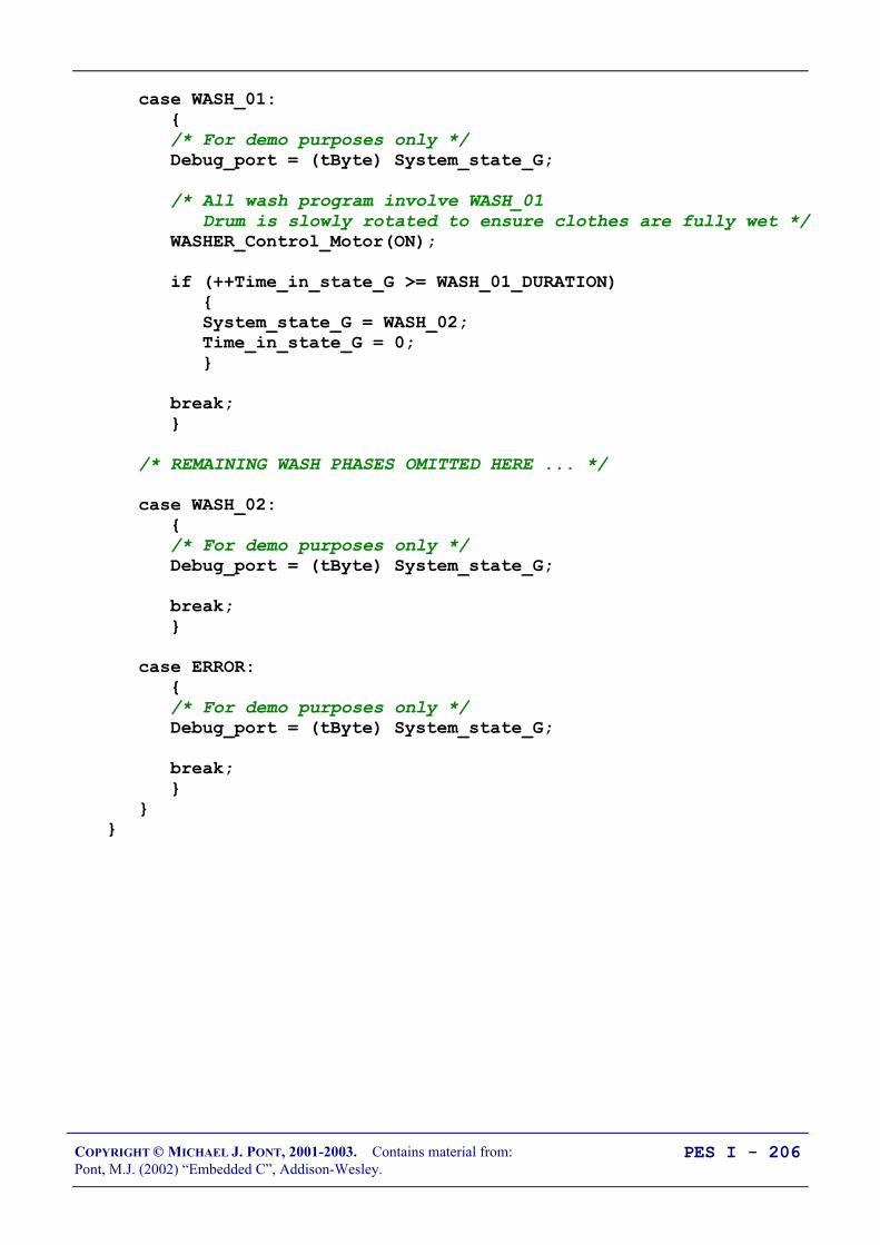
COPYRIGHT © MICHAEL J. PONT, 2001-2003. Contains material from:Pont, M.J. (2002) “Embedded C”, Addison-Wesley.
PES I - 206
case WASH_01: /* For demo purposes only */ Debug_port = (tByte) System_state_G;
/* All wash program involve WASH_01 Drum is slowly rotated to ensure clothes are fully wet */ WASHER_Control_Motor(ON);
if (++Time_in_state_G >= WASH_01_DURATION) System_state_G = WASH_02; Time_in_state_G = 0;
break;
/* REMAINING WASH PHASES OMITTED HERE ... */
case WASH_02: /* For demo purposes only */ Debug_port = (tByte) System_state_G;
break;
case ERROR: /* For demo purposes only */ Debug_port = (tByte) System_state_G;
break;

COPYRIGHT © MICHAEL J. PONT, 2001-2003. Contains material from:Pont, M.J. (2002) “Embedded C”, Addison-Wesley.
PES I - 207
/* --------------------------------------------------------------- */tByte WASHER_Read_Selector_Dial(void) /* User code here... */
return 0;
/* --------------------------------------------------------------- */bit WASHER_Read_Start_Switch(void) /* Simplified for demo ... */
if (Start_pin == 0) /* Start switch pressed */ return 1; else return 0;
/* --------------------------------------------------------------- */bit WASHER_Read_Water_Level(void) /* User code here... */
return 1;
/* --------------------------------------------------------------- */bit WASHER_Read_Water_Temperature(void) /* User code here... */
return 1;
/* --------------------------------------------------------------- */void WASHER_Control_Detergent_Hatch(bit State) bit Tmp = State; /* User code here... */

COPYRIGHT © MICHAEL J. PONT, 2001-2003. Contains material from:Pont, M.J. (2002) “Embedded C”, Addison-Wesley.
PES I - 208
Conclusions
This seminar has discussed the implementation of multi-state(timed) and multi-state (input / timed) systems. Used inconjunction with an operating system like that presented in“Embedded C” Chapter 7, this flexible system architecture is inwidespread use in embedded applications.

COPYRIGHT © MICHAEL J. PONT, 2001-2003. Contains material from:Pont, M.J. (2002) “Embedded C”, Addison-Wesley.
PES I - 209
Preparation for the next seminar
Please read Chapter 9before the next seminar

COPYRIGHT © MICHAEL J. PONT, 2001-2003. Contains material from:Pont, M.J. (2002) “Embedded C”, Addison-Wesley.
PES I - 210

COPYRIGHT © MICHAEL J. PONT, 2001-2003. Contains material from:Pont, M.J. (2002) “Embedded C”, Addison-Wesley.
PES I - 211
Seminar 8: Using the Serial
Interface
15
96
Vcc
MA
X 2
33
1
20
7
18
6, 9Connect together: Pins 12 & 17 Pins 11 & 15 Pins 16 & 10
1.0 µF
19Rx
Tx

COPYRIGHT © MICHAEL J. PONT, 2001-2003. Contains material from:Pont, M.J. (2002) “Embedded C”, Addison-Wesley.
PES I - 212
Overview of this seminar
This seminar will:
• Discuss the RS-232 data communication standard
• Consider how we can use RS-232 to transfer data to andfrom deskbound PCs (and similar devices).
This can be useful, for example:
• In data acquisition applications.
• In control applications (sending controller parameters).
• For general debugging.

COPYRIGHT © MICHAEL J. PONT, 2001-2003. Contains material from:Pont, M.J. (2002) “Embedded C”, Addison-Wesley.
PES I - 213
What is ‘RS-232’?
In 1997 the Telecommunications Industry Association releasedwhat is formally known as TIA-232 Version F, a serialcommunication protocol which has been universally referred to as‘RS-232’ since its first ‘Recommended Standard’ appeared in the1960s. Similar standards (V.28) are published by the InternationalTelecommunications Union (ITU) and by CCITT (The ConsultativeCommittee International Telegraph and Telephone).
The ‘RS-232’ standard includes details of:
• The protocol to be used for data transmission.
• The voltages to be used on the signal lines.
• The connectors to be used to link equipment together.
Overall, the standard is comprehensive and widely used, at datatransfer rates of up to around 115 or 330 kbits / second (115 / 330 kbaud). Data transfer can be over distances of 15 metres or more.
Note that RS-232 is a peer-to-peer communication standard.

COPYRIGHT © MICHAEL J. PONT, 2001-2003. Contains material from:Pont, M.J. (2002) “Embedded C”, Addison-Wesley.
PES I - 214
Basic RS-232 Protocol
RS-232 is a character-oriented protocol. That is, it is intended to beused to send single 8-bit blocks of data. To transmit a byte of dataover an RS-232 link, we generally encode the information asfollows:
• We send a ‘Start’ bit.
• We send the data (8 bits).
• We send a ‘Stop’ bit (or bits).
•
NOTE: The UART takes care of these details!

COPYRIGHT © MICHAEL J. PONT, 2001-2003. Contains material from:Pont, M.J. (2002) “Embedded C”, Addison-Wesley.
PES I - 215
Asynchronous data transmission and baud rates
• RS-232 uses an asynchronous protocol.
• Both ends of the communication link have an internal clock,running at the same rate. The data (in the case of RS-232,the ‘Start’ bit) is then used to synchronise the clocks, ifnecessary, to ensure successful data transfer.
• RS-232 generally operates at one of a (restricted) range ofbaud rates.
• Typically these are: 75, 110, 300, 1200, 2400, 4800, 9600,14400, 19200, 28800, 33600, 56000, 115000 and (rarely)330000 baud.
• 9600 baud is a very ‘safe’ choice, as it is very widelysupported.

COPYRIGHT © MICHAEL J. PONT, 2001-2003. Contains material from:Pont, M.J. (2002) “Embedded C”, Addison-Wesley.
PES I - 216
RS-232 voltage levels
• The threshold levels used by the receiver are +3 V and -3 Vand the lines are inverted.
• The maximum voltage allowed is +/- 15V.
• Note that these voltages cannot be obtained directly from thenaked microcontroller port pins: some form of interfacehardware is required.
• For example, the Maxim Max232 and Max233 are popularand widely-used line driver chips.
15
96
Vcc
Max233 1
20
7
18
6,9Connect together: Pins 12 & 17 Pins 11 & 15 Pins 16 & 10
1.0 µF
19
RxTx
To Tx pin ( P3.1)
To Rx pin ( P3.0)
Using a Max 233 as an RS-232 tranceiver.

COPYRIGHT © MICHAEL J. PONT, 2001-2003. Contains material from:Pont, M.J. (2002) “Embedded C”, Addison-Wesley.
PES I - 217
The software architecture
• Suppose we wish to transfer data to a PC at a standard 9600baud rate; that is, 9600 bits per second. Transmitting eachbyte of data, plus stop and start bits, involves thetransmission of 10 bits of information (assuming a singlestop bit is used). As a result, each byte takes approximately1 ms to transmit.
• Suppose, for example, we wish to send this information tothe PC:
Current core temperature is 36.678 degrees
…then the task sending these 42 characters will take morethan 40 milliseconds to complete. This will - frequently bean unacceptably long duration.
• The most obvious way of solving this problem is to increasethe baud rate; however, this is not always possible (and itdoes not really solve the underlying problem).
A better solution is to write all data to a buffer in the microcontroller.The contents of this buffer will then be sent - usually one byte at a time -to the PC, using a regular, scheduled, task.
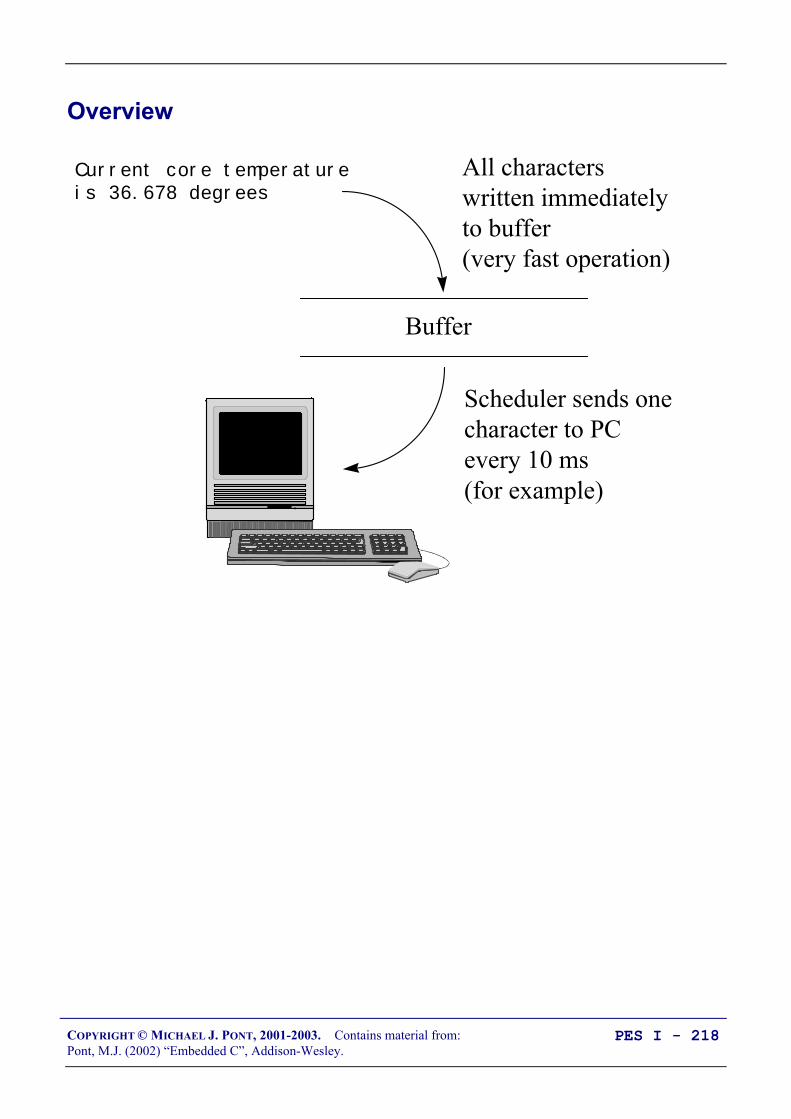
COPYRIGHT © MICHAEL J. PONT, 2001-2003. Contains material from:Pont, M.J. (2002) “Embedded C”, Addison-Wesley.
PES I - 218
Overview
Current core temperature is 36.678 degrees
Buffer
All characterswritten immediatelyto buffer(very fast operation)
Scheduler sends one character to PC every 10 ms (for example)

COPYRIGHT © MICHAEL J. PONT, 2001-2003. Contains material from:Pont, M.J. (2002) “Embedded C”, Addison-Wesley.
PES I - 219
Using the on-chip U(S)ART for RS-232 communications
• The UART is full duplex, meaning it can transmit andreceive simultaneously.
• It is also receive-buffered, meaning it can commencereception of a second byte before a previously received bytehas been read from the receive register.
• The serial port can operate in 4 modes (one synchronousmode, three asynchronous modes).
• We are primarily interested in Mode 1.
• In this mode, 10 bits are transmitted (through TxD) orreceived (through RxD): a start bit (0), 8 data bits (lsb first),and a stop bit (1).
COPYRIGHT © MICHAEL J. PONT, 2001-2003. Contains material from:Pont, M.J. (2002) “Embedded C”, Addison-Wesley.
PES I - 220
Serial port registers
The serial port control and status register is the special functionregister SCON. This register contains the mode selection bits (andthe serial port interrupt bits, TI and RI: not used here).
SBUF is the receive and transmit buffer of serial interface.
Writing to SBUF loads the transmit register and initiatestransmission. SBUF = 0x0D; /* Output CR */
Reading out SBUF accesses a physically separate receive register. /* Read the data from UART */ Data = SBUF;

COPYRIGHT © MICHAEL J. PONT, 2001-2003. Contains material from:Pont, M.J. (2002) “Embedded C”, Addison-Wesley.
PES I - 221
Baud rate generation
• We are primarily concerned here with the use of the serialport in Mode 1.
• In this mode the baud rate is determined by the overflow rateof Timer 1 or Timer 2.
• We focus on the use of Timer 1 for baud rate generation.
The baud rate is determined by the Timer 1 overflow rate and thevalue of SMOD follows:
Baud rate (Mode 1) = )1256(32
2THnsInstructio
Frequency
cycle
oscillatorSMOD
−×××
Where:
SMOD …is the ‘double baud rate’ bit in the PCON register;
oscillatorFrequency …is the oscillator / resonator frequency;
cyclensInstructio …is the number of machine instructions per oscillatorcycle (e.g. 12 or 6)
TH1 …is the reload value for Timer 1
Note that Timer is used in 8-bit auto-reload mode and that interruptgeneration should be disabled.
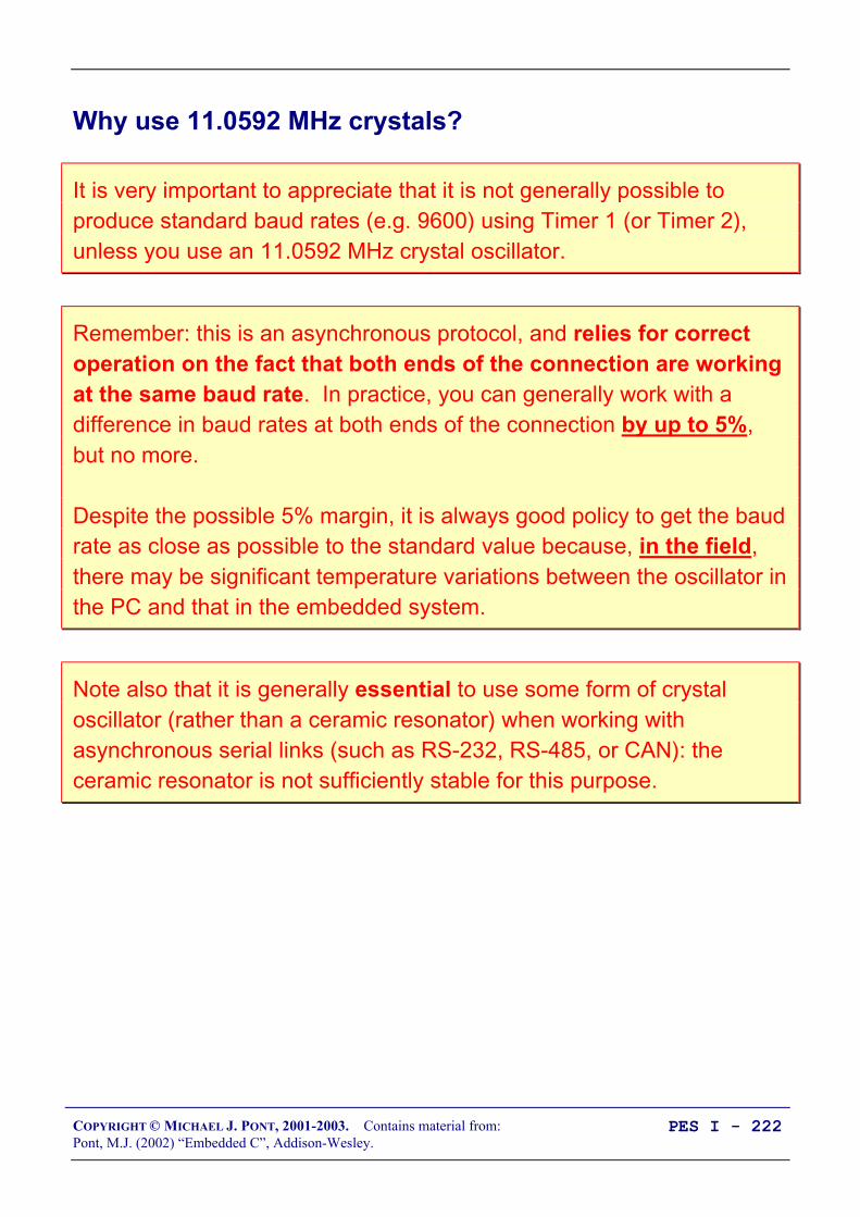
COPYRIGHT © MICHAEL J. PONT, 2001-2003. Contains material from:Pont, M.J. (2002) “Embedded C”, Addison-Wesley.
PES I - 222
Why use 11.0592 MHz crystals?
It is very important to appreciate that it is not generally possible toproduce standard baud rates (e.g. 9600) using Timer 1 (or Timer 2),unless you use an 11.0592 MHz crystal oscillator.
Remember: this is an asynchronous protocol, and relies for correctoperation on the fact that both ends of the connection are workingat the same baud rate. In practice, you can generally work with adifference in baud rates at both ends of the connection by up to 5%,but no more.
Despite the possible 5% margin, it is always good policy to get the baudrate as close as possible to the standard value because, in the field,there may be significant temperature variations between the oscillator inthe PC and that in the embedded system.
Note also that it is generally essential to use some form of crystaloscillator (rather than a ceramic resonator) when working withasynchronous serial links (such as RS-232, RS-485, or CAN): theceramic resonator is not sufficiently stable for this purpose.

COPYRIGHT © MICHAEL J. PONT, 2001-2003. Contains material from:Pont, M.J. (2002) “Embedded C”, Addison-Wesley.
PES I - 223
PC Software
If your desktop computer is running Windows (95, 98, NT, 2000),then a simple but effective option is the ‘Hyperterminal’ applicationwhich is included with all of these operating systems.
COPYRIGHT © MICHAEL J. PONT, 2001-2003. Contains material from:Pont, M.J. (2002) “Embedded C”, Addison-Wesley.
PES I - 224
What about printf()?
We do not generally recommend the use of standard libraryfunction “printf()”, because:
• this function sends data immediately to the UART. As aresult, the duration of the transmission is often too long to besafely handled in a co-operatively scheduled application,and,
• most implementations of printf() do not incorporatetimeouts, making it possible that use of this functions can‘hang’ the whole application if errors occur.

COPYRIGHT © MICHAEL J. PONT, 2001-2003. Contains material from:Pont, M.J. (2002) “Embedded C”, Addison-Wesley.
PES I - 225
RS-232 and 8051: Overall strengths and weaknesses
RS-232 support is part of the 8051 core: applications based on RS-232are very portable.
At the PC end too, RS-232 is ubiquitous: every PC has one or moreRS-232 ports.
Links can - with modern tranceiver chips - be up to 30 m (100 ft) inlength.
Because of the hardware support, RS-232 generally imposes a lowsoftware load.
BUT:
RS-232 is a peer-to-peer protocol (unlike, for example, RS-485): youcan only connect one microcontroller directly (simultaneously) to eachPC. RS-232 has little or no error checking at the hardware level (unlike, for
example, CAN): if you want to be sure that the data you received at thePC is valid, you need to carry out checks in software.

COPYRIGHT © MICHAEL J. PONT, 2001-2003. Contains material from:Pont, M.J. (2002) “Embedded C”, Addison-Wesley.
PES I - 226
Example: Displaying elapsed time on a PC
15
96
Vcc
MA
X 2
33
1
20
7
18
6, 9Connect together: Pins 12 & 17 Pins 11 & 15 Pins 16 & 10
1.0 µF
19Rx
Tx

COPYRIGHT © MICHAEL J. PONT, 2001-2003. Contains material from:Pont, M.J. (2002) “Embedded C”, Addison-Wesley.
PES I - 227

COPYRIGHT © MICHAEL J. PONT, 2001-2003. Contains material from:Pont, M.J. (2002) “Embedded C”, Addison-Wesley.
PES I - 228
/*-------------------------------------------------------------*-
Main.c (v1.00)
--------------------------------------------------------
RS-232 (Elapsed Time) example - sEOS.
-*-------------------------------------------------------------*/
#include "Main.H"#include "Port.H"#include "Simple_EOS.H"
#include "PC_O_T1.h"#include "Elap_232.h"
/* --------------------------------------------------------------- */
void main(void) /* Set baud rate to 9600 */ PC_LINK_O_Init_T1(9600);
/* Prepare for elapsed time measurement */ Elapsed_Time_RS232_Init();
/* Set up simple EOS (5ms tick) */ sEOS_Init_Timer2(5);
while(1) /* Super Loop */ sEOS_Go_To_Sleep(); /* Enter idle mode to save power */
/*-------------------------------------------------------------*- ---- END OF FILE ----------------------------------------*-------------------------------------------------------------*/

COPYRIGHT © MICHAEL J. PONT, 2001-2003. Contains material from:Pont, M.J. (2002) “Embedded C”, Addison-Wesley.
PES I - 229
/*-------------------------------------------------------------*-
Elap_232.C (v1.00)
--------------------------------------------------------
Simple library function for keeping track of elapsed time Demo version to display time on PC screen via RS232 link.
-*-------------------------------------------------------------*/
#include "Main.h"#include "Elap_232.h"#include "PC_O.h"
/* ------ Public variable definitions ------------------------- */
tByte Hou_G;tByte Min_G;tByte Sec_G;
/* ------ Public variable declarations ------------------------ */
/* See Char_Map.c */extern const char code CHAR_MAP_G[10];
/*-------------------------------------------------------------*-
Elapsed_Time_RS232_Init()
Init function for simple library displaying elapsed time on PC via RS-232 link.
-*-------------------------------------------------------------*/void Elapsed_Time_RS232_Init(void) Hou_G = 0; Min_G = 0; Sec_G = 0;

COPYRIGHT © MICHAEL J. PONT, 2001-2003. Contains material from:Pont, M.J. (2002) “Embedded C”, Addison-Wesley.
PES I - 230
/*-------------------------------------------------------------*/
void Elapsed_Time_RS232_Update(void) char Time_Str[30] = "\rElapsed time: ";
if (++Sec_G == 60) Sec_G = 0;
if (++Min_G == 60) Min_G = 0;
if (++Hou_G == 24) Hou_G = 0;
Time_Str[15] = CHAR_MAP_G[Hou_G / 10]; Time_Str[16] = CHAR_MAP_G[Hou_G % 10];
Time_Str[18] = CHAR_MAP_G[Min_G / 10]; Time_Str[19] = CHAR_MAP_G[Min_G % 10];
Time_Str[21] = CHAR_MAP_G[Sec_G / 10]; Time_Str[22] = CHAR_MAP_G[Sec_G % 10];
/* We use the "seconds" data to turn on and off the colon (between hours and minutes) */ if ((Sec_G % 2) == 0) Time_Str[17] = ':'; Time_Str[20] = ':'; else Time_Str[17] = ' '; Time_Str[20] = ' ';
PC_LINK_O_Write_String_To_Buffer(Time_Str);
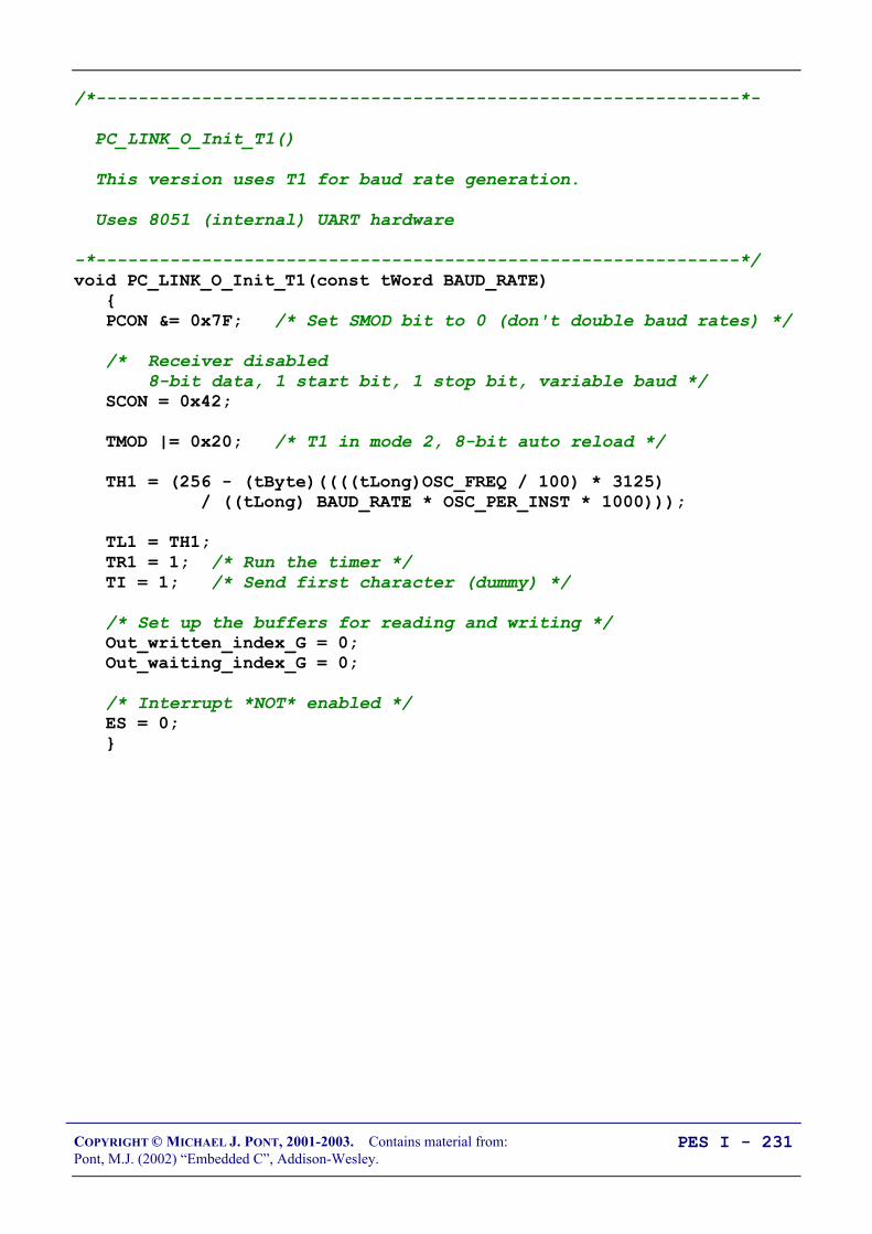
COPYRIGHT © MICHAEL J. PONT, 2001-2003. Contains material from:Pont, M.J. (2002) “Embedded C”, Addison-Wesley.
PES I - 231
/*-------------------------------------------------------------*-
PC_LINK_O_Init_T1()
This version uses T1 for baud rate generation.
Uses 8051 (internal) UART hardware
-*-------------------------------------------------------------*/void PC_LINK_O_Init_T1(const tWord BAUD_RATE) PCON &= 0x7F; /* Set SMOD bit to 0 (don't double baud rates) */
/* Receiver disabled 8-bit data, 1 start bit, 1 stop bit, variable baud */ SCON = 0x42;
TMOD |= 0x20; /* T1 in mode 2, 8-bit auto reload */
TH1 = (256 - (tByte)((((tLong)OSC_FREQ / 100) * 3125) / ((tLong) BAUD_RATE * OSC_PER_INST * 1000)));
TL1 = TH1; TR1 = 1; /* Run the timer */ TI = 1; /* Send first character (dummy) */
/* Set up the buffers for reading and writing */ Out_written_index_G = 0; Out_waiting_index_G = 0;
/* Interrupt *NOT* enabled */ ES = 0;

COPYRIGHT © MICHAEL J. PONT, 2001-2003. Contains material from:Pont, M.J. (2002) “Embedded C”, Addison-Wesley.
PES I - 232
/*-------------------------------------------------------------*/
void PC_LINK_O_Update(void) /* Deal with transmit bytes here. Are there any data ready to send? */ if (Out_written_index_G < Out_waiting_index_G) PC_LINK_O_Send_Char(Tran_buffer[Out_written_index_G]);
Out_written_index_G++; else /* No data to send - just reset the buffer index */ Out_waiting_index_G = 0; Out_written_index_G = 0;
/*-------------------------------------------------------------*/
void PC_LINK_O_Write_String_To_Buffer(const char* const STR_PTR) tByte i = 0;
while (STR_PTR[i] != '\0') PC_LINK_O_Write_Char_To_Buffer(STR_PTR[i]); i++;

COPYRIGHT © MICHAEL J. PONT, 2001-2003. Contains material from:Pont, M.J. (2002) “Embedded C”, Addison-Wesley.
PES I - 233
/*-------------------------------------------------------------*/void PC_LINK_O_Write_Char_To_Buffer(const char CHARACTER) /* Write to the buffer *only* if there is space (No error reporting in this simple library...) */ if (Out_waiting_index_G < TRAN_BUFFER_LENGTH) Tran_buffer[Out_waiting_index_G] = CHARACTER; Out_waiting_index_G++;
/*-------------------------------------------------------------*/void PC_LINK_O_Send_Char(const char CHARACTER) tLong Timeout1 = 0;
if (CHARACTER == '\n') Timeout1 = 0; while ((++Timeout1) && (TI == 0));
if (Timeout1 == 0) /* UART did not respond - error No error reporting in this simple library... */ return;
TI = 0; SBUF = 0x0d; /* Output CR */
Timeout1 = 0; while ((++Timeout1) && (TI == 0));
if (Timeout1 == 0) /* UART did not respond - error No error reporting in this simple library... */ return;
TI = 0;
SBUF = CHARACTER;

COPYRIGHT © MICHAEL J. PONT, 2001-2003. Contains material from:Pont, M.J. (2002) “Embedded C”, Addison-Wesley.
PES I - 234
sEOS_ISR() interrupt INTERRUPT_Timer_2_Overflow TF2 = 0; /* Must manually reset the T2 flag */
/*===== USER CODE - Begin ================================== */ /* Call RS-232 update function every 5ms */ PC_LINK_O_Update();
/* This ISR is called every 5 ms - only want to update time every second */ if (++Call_count_G == 200) /* Time to update time */ Call_count_G = 0;
/* Call time update function */ Elapsed_Time_RS232_Update(); /*===== USER CODE - End ==================================== */
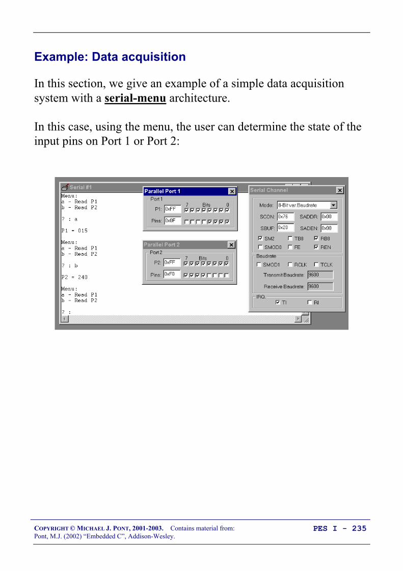
COPYRIGHT © MICHAEL J. PONT, 2001-2003. Contains material from:Pont, M.J. (2002) “Embedded C”, Addison-Wesley.
PES I - 235
Example: Data acquisition
In this section, we give an example of a simple data acquisitionsystem with a serial-menu architecture.
In this case, using the menu, the user can determine the state of theinput pins on Port 1 or Port 2:

COPYRIGHT © MICHAEL J. PONT, 2001-2003. Contains material from:Pont, M.J. (2002) “Embedded C”, Addison-Wesley.
PES I - 236
void MENU_Command_Processor(void) char Ch;
if (First_time_only_G == 0) First_time_only_G = 1; MENU_Show_Menu();
/* Check for user inputs */ PC_LINK_IO_Update();
Ch = PC_LINK_IO_Get_Char_From_Buffer();
if (Ch != PC_LINK_IO_NO_CHAR) MENU_Perform_Task(Ch); MENU_Show_Menu();
void MENU_Show_Menu(void) PC_LINK_IO_Write_String_To_Buffer("Menu:\n"); PC_LINK_IO_Write_String_To_Buffer("a - Read P1\n"); PC_LINK_IO_Write_String_To_Buffer("b - Read P2\n\n"); PC_LINK_IO_Write_String_To_Buffer("? : ");

COPYRIGHT © MICHAEL J. PONT, 2001-2003. Contains material from:Pont, M.J. (2002) “Embedded C”, Addison-Wesley.
PES I - 237
void MENU_Perform_Task(char c) PC_LINK_IO_Write_Char_To_Buffer(c); /* Echo the menu option */ PC_LINK_IO_Write_Char_To_Buffer('\n');
/* Perform the task */ switch (c) case 'a': case 'A': Get_Data_From_Port1(); break;
case 'b': case 'B': Get_Data_From_Port2(); break;
void Get_Data_From_Port1(void) tByte Port1 = Data_Port1; char String[11] = "\nP1 = XXX\n\n";
String[6] = CHAR_MAP_G[Port1 / 100]; String[7] = CHAR_MAP_G[(Port1 / 10) % 10]; String[8] = CHAR_MAP_G[Port1 % 10];
PC_LINK_IO_Write_String_To_Buffer(String);
void Get_Data_From_Port2(void) tByte Port2 = Data_Port2; char String[11] = "\nP2 = XXX\n\n";
String[6] = CHAR_MAP_G[Port2 / 100]; String[7] = CHAR_MAP_G[(Port2 / 10) % 10]; String[8] = CHAR_MAP_G[Port2 % 10];
PC_LINK_IO_Write_String_To_Buffer(String);
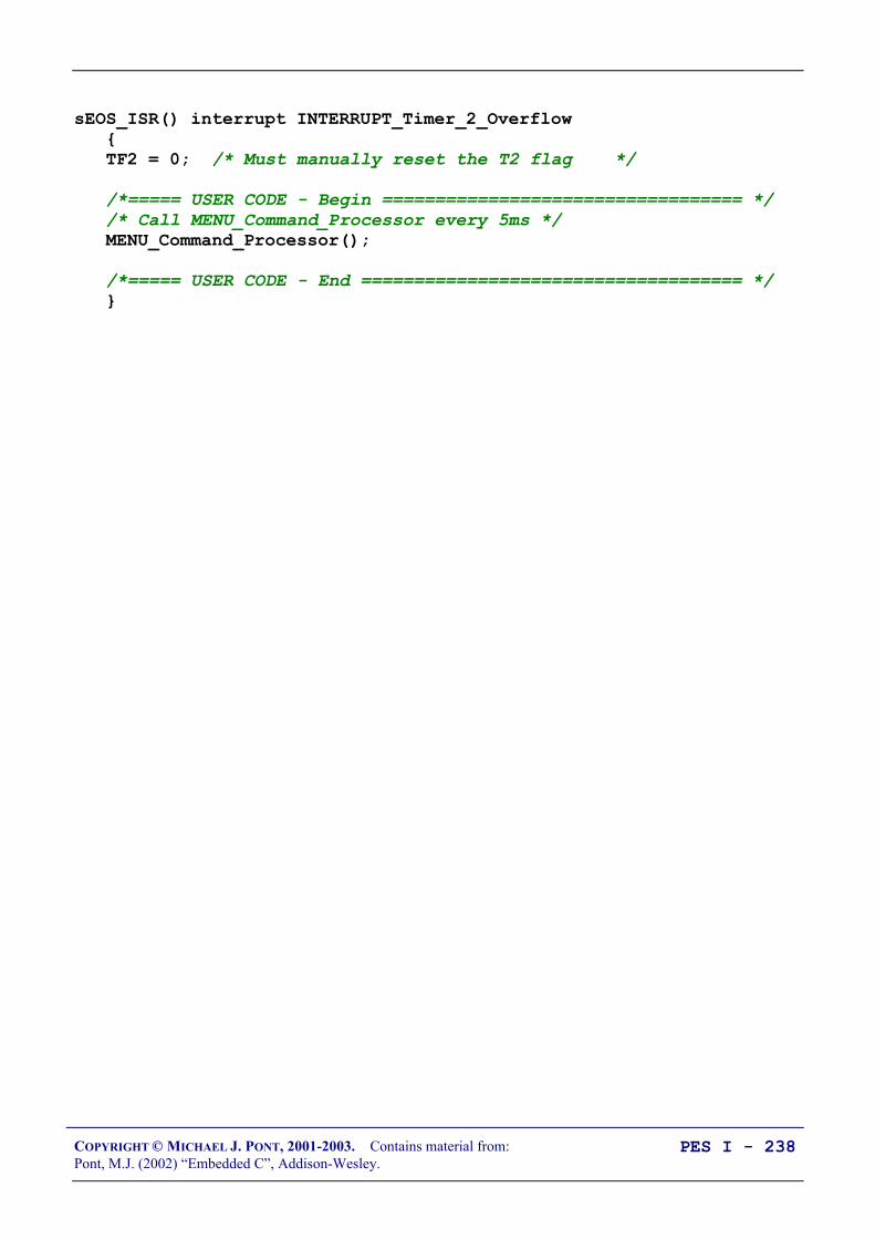
COPYRIGHT © MICHAEL J. PONT, 2001-2003. Contains material from:Pont, M.J. (2002) “Embedded C”, Addison-Wesley.
PES I - 238
sEOS_ISR() interrupt INTERRUPT_Timer_2_Overflow TF2 = 0; /* Must manually reset the T2 flag */
/*===== USER CODE - Begin ================================== */ /* Call MENU_Command_Processor every 5ms */ MENU_Command_Processor();
/*===== USER CODE - End ==================================== */

COPYRIGHT © MICHAEL J. PONT, 2001-2003. Contains material from:Pont, M.J. (2002) “Embedded C”, Addison-Wesley.
PES I - 239
Conclusions
In this seminar, we have illustrated how the serial interface on the8051 microcontroller may be used.
In the next seminar, we will use a case study to illustrate how thevarious techniques discussed in this can be used in practicalapplications.

COPYRIGHT © MICHAEL J. PONT, 2001-2003. Contains material from:Pont, M.J. (2002) “Embedded C”, Addison-Wesley.
PES I - 240
Preparation for the next seminar
Please read Chapter 10before the next seminar

COPYRIGHT © MICHAEL J. PONT, 2001-2003. Contains material from:Pont, M.J. (2002) “Embedded C”, Addison-Wesley.
PES I - 241
Seminar 9: Case Study:
Intruder Alarm System
WindowBell box
Control panel
W
W
W
W
W
Door
D
Statue
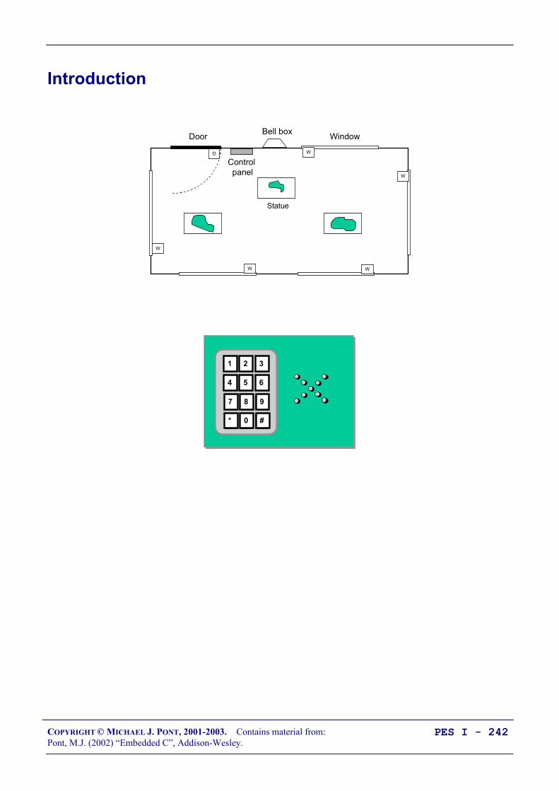
COPYRIGHT © MICHAEL J. PONT, 2001-2003. Contains material from:Pont, M.J. (2002) “Embedded C”, Addison-Wesley.
PES I - 242
Introduction
WindowBell box
Control panel
W
W
W
W
W
Door
D
Statue
1 32
4 65
7 98
* #0

COPYRIGHT © MICHAEL J. PONT, 2001-2003. Contains material from:Pont, M.J. (2002) “Embedded C”, Addison-Wesley.
PES I - 243
System Operation
• When initially activated, the system is in ‘Disarmed’ state.
• In Disarmed state, the sensors are ignored. The alarm doesnot sound. The system remains in this state until the userenters a valid password via the keypad (in our demonstrationsystem, the password is “1234”). When a valid password isentered, the systems enters ‘Arming’ state.
• In Arming state, the system waits for 60 seconds, to allowthe user to leave the area before the monitoring processbegins. After 60 seconds, the system enters ‘Armed’ state.
• In Armed state, the status of the various system sensors ismonitored. If a window sensor is tripped, the system enters‘Intruder’ state. If the door sensor is tripped, the systementers ‘Disarming’ state. The keypad activity is alsomonitored: if a correct password is typed in, the systementers ‘Disarmed’ state.
• In Disarming state, we assume that the door has beenopened by someone who may be an authorised system user.The system remains in this state for up to 60 seconds, afterwhich - by default - it enters Intruder state. If, during the 60-second period, the user enters the correct password, thesystem enters ‘Disarmed’ state.
• In Intruder state, an alarm will sound. The alarm will keepsounding (indefinitely), until the correct password is entered.

COPYRIGHT © MICHAEL J. PONT, 2001-2003. Contains material from:Pont, M.J. (2002) “Embedded C”, Addison-Wesley.
PES I - 244
Key software components used in this example
This case study uses the following software components:
• Software to control external port pins (to activate theexternal bell), as introduced in “Embedded C” Chapter 3.
• Switch reading, as discussed in “Embedded C” Chapter 4, toprocess the inputs from the door and window sensors. Notethat - in this simple example (intended for use in thesimulator) - no switch debouncing is carried out. Thisfeature can be added, if required, without difficulty.
• The embedded operating system, sEOS, introduced in“Embedded C” Chapter 7.
• A simple ‘keypad’ library, based on a bank of switches.Note that - to simplify the use of the keypad library in thesimulator - we have assumed the presence of only eight keysin the example program (0 - 7). This final system wouldprobably use at least 10 keys: support for additional keys canbe easily added if required.
• The RS-232 library (from “Embedded C” Chapter 9) is usedto illustrate the operation of the program. This library wouldnot be necessary in the final system (but it might be useful toretain it, to support system maintenance).

COPYRIGHT © MICHAEL J. PONT, 2001-2003. Contains material from:Pont, M.J. (2002) “Embedded C”, Addison-Wesley.
PES I - 245
Running the program

COPYRIGHT © MICHAEL J. PONT, 2001-2003. Contains material from:Pont, M.J. (2002) “Embedded C”, Addison-Wesley.
PES I - 246
The software
/*-------------------------------------------------------------*-
Port.H (v1.00)
--------------------------------------------------------
'Port Header' (see Chap 5) for project INTRUDER (see Chap 10)
-*-------------------------------------------------------------*/
/* ------ Keypad.C ------------------------------------------- */
#define KEYPAD_PORT P2
sbit K0 = KEYPAD_PORT^0;sbit K1 = KEYPAD_PORT^1;sbit K2 = KEYPAD_PORT^2;sbit K3 = KEYPAD_PORT^3;sbit K4 = KEYPAD_PORT^4;sbit K5 = KEYPAD_PORT^5;sbit K6 = KEYPAD_PORT^6;sbit K7 = KEYPAD_PORT^7;
/* ------ Intruder.C --------------------------------------- */sbit Sensor_pin = P1^0;sbit Sounder_pin = P1^7;
/* ------ Lnk_O.C ------------------------------------------ */
/* Pins 3.0 and 3.1 used for RS-232 interface */
/*-------------------------------------------------------------*- ---- END OF FILE ----------------------------------------*-------------------------------------------------------------*/

COPYRIGHT © MICHAEL J. PONT, 2001-2003. Contains material from:Pont, M.J. (2002) “Embedded C”, Addison-Wesley.
PES I - 247
/*-------------------------------------------------------------*-
Main.c (v1.00)
--------------------------------------------------------
Simple intruder alarm system.
-*-------------------------------------------------------------*/
#include "Main.H"#include "Port.H"#include "Simple_EOS.H"
#include "PC_O_T1.h"#include "Keypad.h"#include "Intruder.h"
/* ............................................................... */
void main(void) /* Set baud rate to 9600 */ PC_LINK_O_Init_T1(9600);
/* Prepare the keypad */ KEYPAD_Init();
/* Prepare the intruder alarm */ INTRUDER_Init();
/* Set up simple EOS (5ms tick) */ sEOS_Init_Timer2(5);
while(1) /* Super Loop */ sEOS_Go_To_Sleep(); /* Enter idle mode to save power */
/*-------------------------------------------------------------*- ---- END OF FILE ----------------------------------------*-------------------------------------------------------------*/

COPYRIGHT © MICHAEL J. PONT, 2001-2003. Contains material from:Pont, M.J. (2002) “Embedded C”, Addison-Wesley.
PES I - 248
/*-------------------------------------------------------------*-
Intruder.C (v1.00)
-*-------------------------------------------------------------*/
...
/* ------ Private data type declarations ---------------------- */
/* Possible system states */typedef enum DISARMED, ARMING, ARMED, DISARMING, INTRUDER eSystem_state;
/* ------ Private function prototypes ------------------------- */
bit INTRUDER_Get_Password_G(void);bit INTRUDER_Check_Window_Sensors(void);bit INTRUDER_Check_Door_Sensor(void);void INTRUDER_Sound_Alarm(void);
...
/* --------------------------------------------------------------- */void INTRUDER_Init(void) /* Set the initial system state (DISARMED) */ System_state_G = DISARMED;
/* Set the 'time in state' variable to 0 */ State_call_count_G = 0;
/* Clear the keypad buffer */ KEYPAD_Clear_Buffer();
/* Set the 'New state' flag */ New_state_G = 1;
/* Set the (two) sensor pins to 'read' mode */ Window_sensor_pin = 1; Sounder_pin = 1;
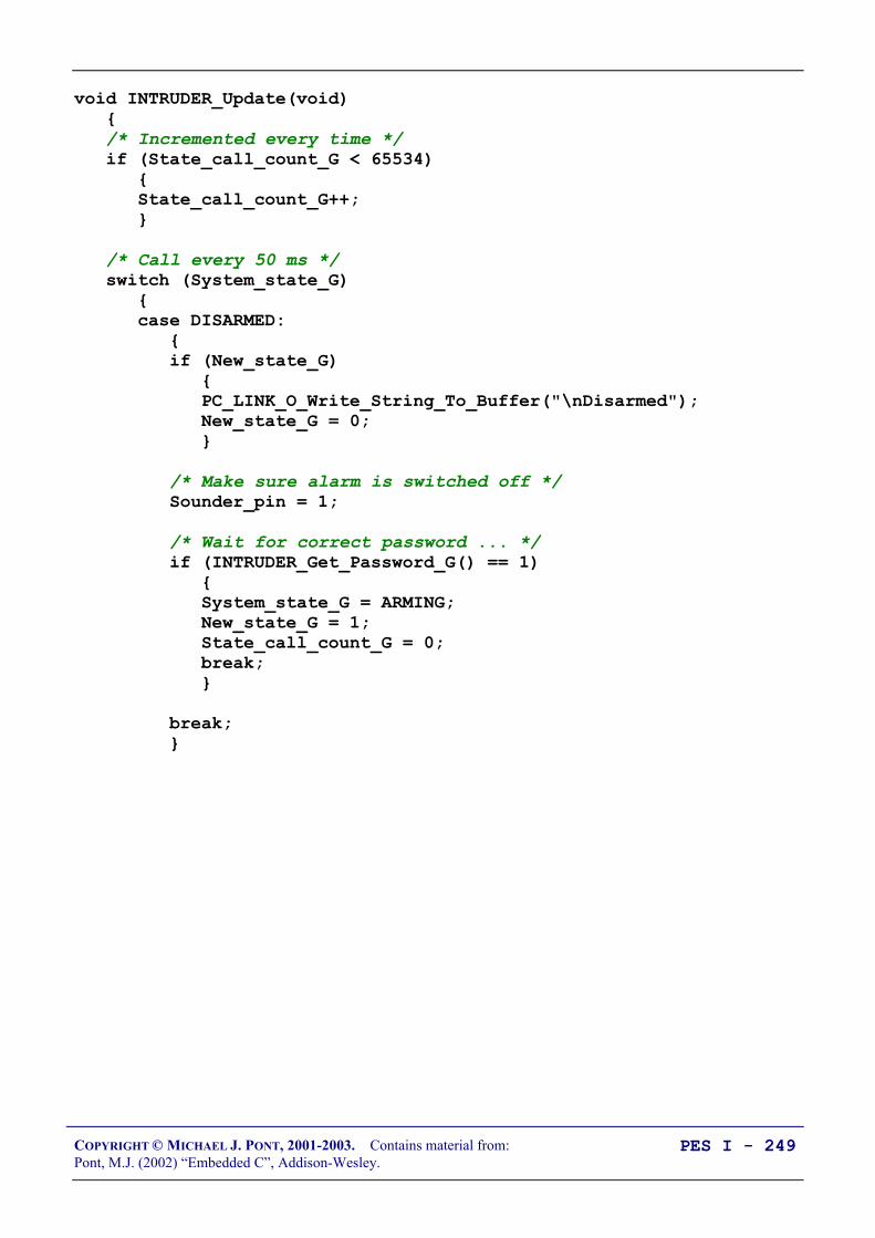
COPYRIGHT © MICHAEL J. PONT, 2001-2003. Contains material from:Pont, M.J. (2002) “Embedded C”, Addison-Wesley.
PES I - 249
void INTRUDER_Update(void) /* Incremented every time */ if (State_call_count_G < 65534) State_call_count_G++;
/* Call every 50 ms */ switch (System_state_G) case DISARMED: if (New_state_G) PC_LINK_O_Write_String_To_Buffer("\nDisarmed"); New_state_G = 0;
/* Make sure alarm is switched off */ Sounder_pin = 1;
/* Wait for correct password ... */ if (INTRUDER_Get_Password_G() == 1) System_state_G = ARMING; New_state_G = 1; State_call_count_G = 0; break;
break;
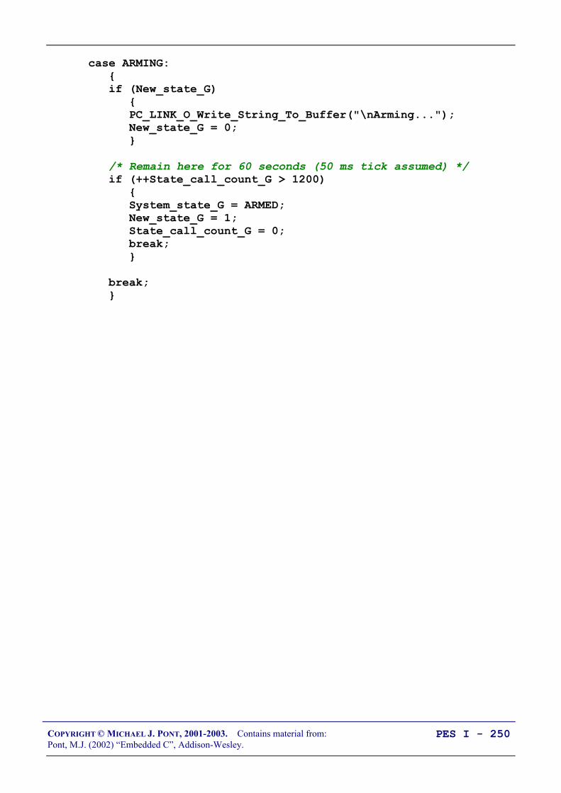
COPYRIGHT © MICHAEL J. PONT, 2001-2003. Contains material from:Pont, M.J. (2002) “Embedded C”, Addison-Wesley.
PES I - 250
case ARMING: if (New_state_G) PC_LINK_O_Write_String_To_Buffer("\nArming..."); New_state_G = 0;
/* Remain here for 60 seconds (50 ms tick assumed) */ if (++State_call_count_G > 1200) System_state_G = ARMED; New_state_G = 1; State_call_count_G = 0; break;
break;

COPYRIGHT © MICHAEL J. PONT, 2001-2003. Contains material from:Pont, M.J. (2002) “Embedded C”, Addison-Wesley.
PES I - 251
case ARMED: if (New_state_G) PC_LINK_O_Write_String_To_Buffer("\nArmed"); New_state_G = 0;
/* First, check the window sensors */ if (INTRUDER_Check_Window_Sensors() == 1) /* An intruder detected */ System_state_G = INTRUDER; New_state_G = 1; State_call_count_G = 0; break;
/* Next, check the door sensors */ if (INTRUDER_Check_Door_Sensor() == 1) /* May be authorised user - go to 'Disarming' state */ System_state_G = DISARMING; New_state_G = 1; State_call_count_G = 0; break;
/* Finally, check for correct password */ if (INTRUDER_Get_Password_G() == 1) System_state_G = DISARMED; New_state_G = 1; State_call_count_G = 0; break;
break;

COPYRIGHT © MICHAEL J. PONT, 2001-2003. Contains material from:Pont, M.J. (2002) “Embedded C”, Addison-Wesley.
PES I - 252
case DISARMING: if (New_state_G) PC_LINK_O_Write_String_To_Buffer("\nDisarming..."); New_state_G = 0;
/* Remain here for 60 seconds (50 ms tick assumed) to allow user to enter the password - after time up, sound alarm. */ if (++State_call_count_G > 1200) System_state_G = INTRUDER; New_state_G = 1; State_call_count_G = 0; break;
/* Still need to check the window sensors */ if (INTRUDER_Check_Window_Sensors() == 1) /* An intruder detected */ System_state_G = INTRUDER; New_state_G = 1; State_call_count_G = 0; break;
/* Finally, check for correct password */ if (INTRUDER_Get_Password_G() == 1) System_state_G = DISARMED; New_state_G = 1; State_call_count_G = 0; break;
break;

COPYRIGHT © MICHAEL J. PONT, 2001-2003. Contains material from:Pont, M.J. (2002) “Embedded C”, Addison-Wesley.
PES I - 253
case INTRUDER: if (New_state_G) PC_LINK_O_Write_String_To_Buffer("\n** INTRUDER! **"); New_state_G = 0;
/* Sound the alarm! */ INTRUDER_Sound_Alarm();
/* Keep sounding alarm until we get correct password */ if (INTRUDER_Get_Password_G() == 1) System_state_G = DISARMED; New_state_G = 1; State_call_count_G = 0;
break;

COPYRIGHT © MICHAEL J. PONT, 2001-2003. Contains material from:Pont, M.J. (2002) “Embedded C”, Addison-Wesley.
PES I - 254
bit INTRUDER_Get_Password_G(void) signed char Key; tByte Password_G_count = 0; tByte i;
/* Update the keypad buffer */ KEYPAD_Update();
/* Are there any new data in the keypad buffer? */ if (KEYPAD_Get_Data_From_Buffer(&Key) == 0) /* No new data - password can't be correct */ return 0;
/* If we are here, a key has been pressed */
/* How long since last key was pressed? Must be pressed within 50 seconds (assume 50 ms 'tick') */ if (State_call_count_G > 1000) /* More than 5 seconds since last key - restart the input process */ State_call_count_G = 0; Position_G = 0;
if (Position_G == 0) PC_LINK_O_Write_Char_To_Buffer('\n');
PC_LINK_O_Write_Char_To_Buffer(Key);
Input_G[Position_G] = Key;

COPYRIGHT © MICHAEL J. PONT, 2001-2003. Contains material from:Pont, M.J. (2002) “Embedded C”, Addison-Wesley.
PES I - 255
/* Have we got four numbers? */ if ((++Position_G) == 4) Position_G = 0; Password_G_count = 0;
/* Check the password */ for (i = 0; i < 4; i++) if (Input_G[i] == Password_G[i]) Password_G_count++;
if (Password_G_count == 4) /* Password correct */ return 1; else /* Password NOT correct */ return 0;

COPYRIGHT © MICHAEL J. PONT, 2001-2003. Contains material from:Pont, M.J. (2002) “Embedded C”, Addison-Wesley.
PES I - 256
bit INTRUDER_Check_Window_Sensors(void) /* Just a single window 'sensor' here - easily extended. */ if (Window_sensor_pin == 0) /* Intruder detected... */ PC_LINK_O_Write_String_To_Buffer("\nWindow damaged"); return 1;
/* Default */ return 0;
/* --------------------------------------------------------------- */bit INTRUDER_Check_Door_Sensor(void) /* Single door sensor (access route) */ if (Door_sensor_pin == 0) /* Someone has opened the door... */ PC_LINK_O_Write_String_To_Buffer("\nDoor open"); return 1;
/* Default */ return 0;
/* --------------------------------------------------------------- */void INTRUDER_Sound_Alarm(void) if (Alarm_bit) /* Alarm connected to this pin */ Sounder_pin = 0; Alarm_bit = 0; else Sounder_pin = 1; Alarm_bit = 1;

COPYRIGHT © MICHAEL J. PONT, 2001-2003. Contains material from:Pont, M.J. (2002) “Embedded C”, Addison-Wesley.
PES I - 257
void KEYPAD_Update(void) char Key;
/* Scan keypad here... */ if (KEYPAD_Scan(&Key) == 0) /* No new key data - just return */ return;
/* Want to read into index 0, if old data has been read (simple ~circular buffer). */ if (KEYPAD_in_waiting_index == KEYPAD_in_read_index) KEYPAD_in_waiting_index = 0; KEYPAD_in_read_index = 0;
/* Load keypad data into buffer */ KEYPAD_recv_buffer[KEYPAD_in_waiting_index] = Key;
if (KEYPAD_in_waiting_index < KEYPAD_RECV_BUFFER_LENGTH) /* Increment without overflowing buffer */ KEYPAD_in_waiting_index++;
bit KEYPAD_Get_Data_From_Buffer(char* const pKey) /* If there is new data in the buffer */ if (KEYPAD_in_read_index < KEYPAD_in_waiting_index) *pKey = KEYPAD_recv_buffer[KEYPAD_in_read_index];
KEYPAD_in_read_index++;
return 1;
return 0;

COPYRIGHT © MICHAEL J. PONT, 2001-2003. Contains material from:Pont, M.J. (2002) “Embedded C”, Addison-Wesley.
PES I - 258
bit KEYPAD_Scan(char* const pKey) char Key = KEYPAD_NO_NEW_DATA;
if (K0 == 0) Key = '0'; if (K1 == 0) Key = '1'; if (K2 == 0) Key = '2'; if (K3 == 0) Key = '3'; if (K4 == 0) Key = '4'; if (K5 == 0) Key = '5'; if (K6 == 0) Key = '6'; if (K7 == 0) Key = '7';
if (Key == KEYPAD_NO_NEW_DATA) /* No key pressed */ Old_key_G = KEYPAD_NO_NEW_DATA; Last_valid_key_G = KEYPAD_NO_NEW_DATA;
return 0; /* No new data */
/* A key has been pressed: debounce by checking twice */ if (Key == Old_key_G) /* A valid (debounced) key press has been detected */
/* Must be a new key to be valid - no 'auto repeat' */ if (Key != Last_valid_key_G) /* New key! */ *pKey = Key; Last_valid_key_G = Key;
return 1;
/* No new data */ Old_key_G = Key; return 0;

COPYRIGHT © MICHAEL J. PONT, 2001-2003. Contains material from:Pont, M.J. (2002) “Embedded C”, Addison-Wesley.
PES I - 259
sEOS_ISR() interrupt INTERRUPT_Timer_2_Overflow TF2 = 0; /* Must manually reset the T2 flag */
/*===== USER CODE - Begin ================================== */ /* Call RS-232 update function every 5ms */ PC_LINK_O_Update();
/* This ISR is called every 5 ms - only want to update intruder every 50 ms. */ if (++Call_count_G == 10) /* Time to update intruder alarm */ Call_count_G = 0;
/* Call intruder update function */ INTRUDER_Update(); /*===== USER CODE - End ==================================== */
COPYRIGHT © MICHAEL J. PONT, 2001-2003. Contains material from:Pont, M.J. (2002) “Embedded C”, Addison-Wesley.
PES I - 260
Extending and modifying the system
• How would you add a “real” keypad?
(See “Patterns for Time-Triggered Embedded Systems, Chap. 20)
• How would you add an LCD display?
(See “Patterns for Time-Triggered Embedded Systems, Chap. 22)
• How would you add additional nodes?
(See “Patterns for Time-Triggered Embedded Systems, Part F)

COPYRIGHT © MICHAEL J. PONT, 2001-2003. Contains material from:Pont, M.J. (2002) “Embedded C”, Addison-Wesley.
PES I - 261
Conclusions
This case study has illustrated most of the key features of embeddedC, as discussed throughout the earlier sessions in this course.
We’ll consider a final case study in the next seminar.

COPYRIGHT © MICHAEL J. PONT, 2001-2003. Contains material from:Pont, M.J. (2002) “Embedded C”, Addison-Wesley.
PES I - 262
COPYRIGHT © MICHAEL J. PONT, 2001-2003. Contains material from:Pont, M.J. (2002) “Embedded C”, Addison-Wesley.
PES I - 263
Seminar 10: Case Study:
Controlling aMobile Robot

COPYRIGHT © MICHAEL J. PONT, 2001-2003. Contains material from:Pont, M.J. (2002) “Embedded C”, Addison-Wesley.
PES I - 264
Overview
In this session, we will discuss the design of software to control asmall mobile robot.
The robot is “Mr Line”
He is produced by “Microrobot NA”
http://www.microrobotna.com

COPYRIGHT © MICHAEL J. PONT, 2001-2003. Contains material from:Pont, M.J. (2002) “Embedded C”, Addison-Wesley.
PES I - 265
What can the robot do?
The robot has IR sensors and transmitters that allow him to detect ablack line on a white surface - and follow it.
http://www.microrobotna.com
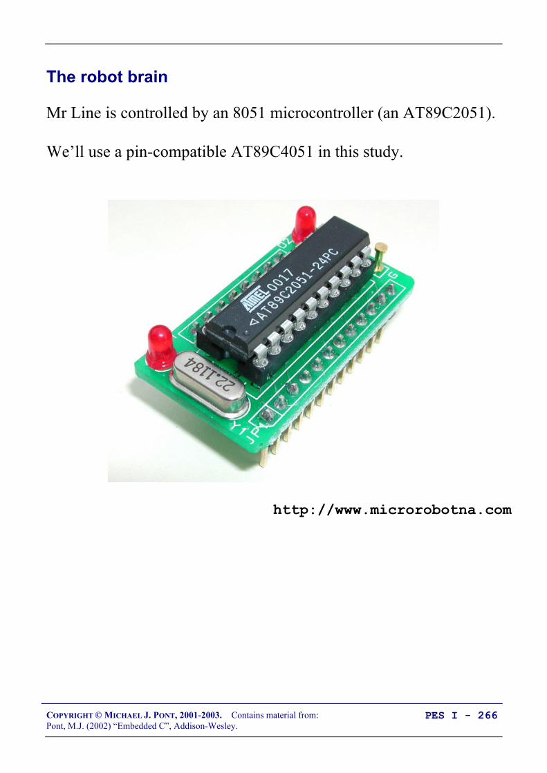
COPYRIGHT © MICHAEL J. PONT, 2001-2003. Contains material from:Pont, M.J. (2002) “Embedded C”, Addison-Wesley.
PES I - 266
The robot brain
Mr Line is controlled by an 8051 microcontroller (an AT89C2051).
We’ll use a pin-compatible AT89C4051 in this study.
http://www.microrobotna.com

COPYRIGHT © MICHAEL J. PONT, 2001-2003. Contains material from:Pont, M.J. (2002) “Embedded C”, Addison-Wesley.
PES I - 267
How does the robot move?
Mr Line has two DC motors: by controlling the relative speed ofthese motors, we can control the speed and direction in which hewill move.
http://www.microrobotna.com
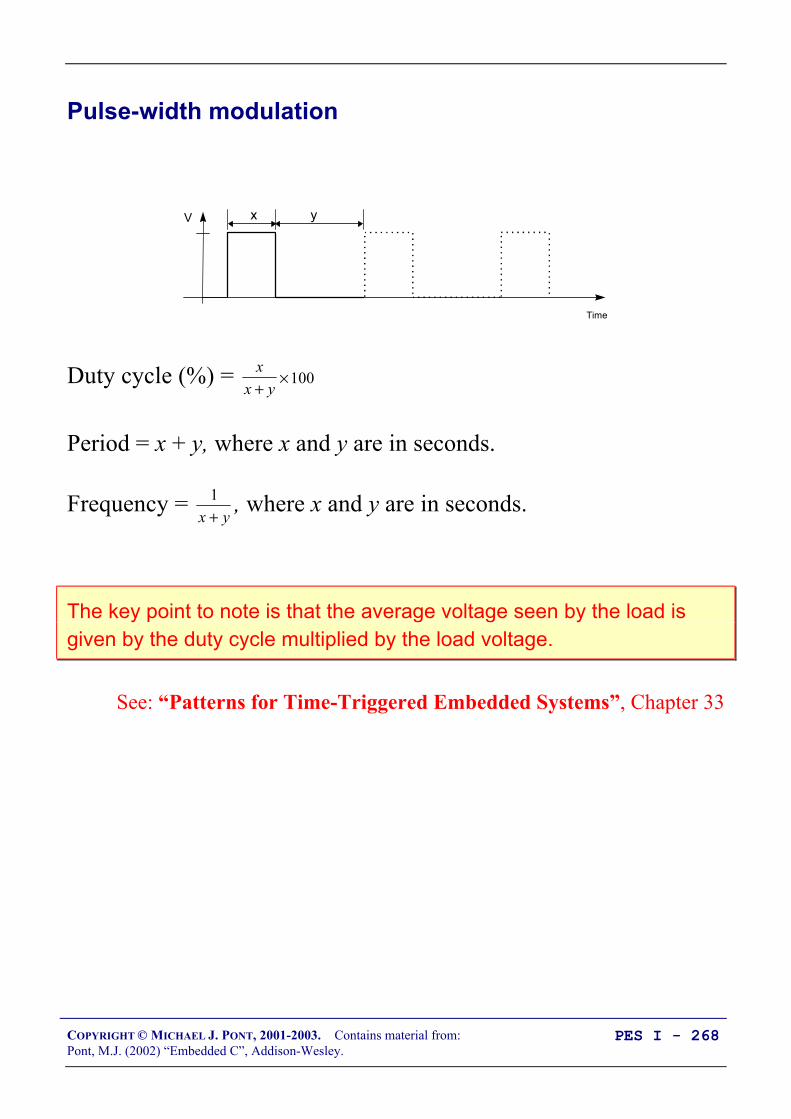
COPYRIGHT © MICHAEL J. PONT, 2001-2003. Contains material from:Pont, M.J. (2002) “Embedded C”, Addison-Wesley.
PES I - 268
Pulse-width modulation
x yV
Time
Duty cycle (%) = xx y+
×100
Period = x + y, where x and y are in seconds.
Frequency = 1x y+
, where x and y are in seconds.
The key point to note is that the average voltage seen by the load isgiven by the duty cycle multiplied by the load voltage.
See: “Patterns for Time-Triggered Embedded Systems”, Chapter 33

COPYRIGHT © MICHAEL J. PONT, 2001-2003. Contains material from:Pont, M.J. (2002) “Embedded C”, Addison-Wesley.
PES I - 269
Software PWM
PWM_PERIOD_G
PWM_position_G
if (PWM_position_G < PWM_G) PWM_pin = PWM_ON; else PWM_pin = PWM_OFF;
PWM_G
See: “Patterns for Time-Triggered Embedded Systems”, Chapter 33
COPYRIGHT © MICHAEL J. PONT, 2001-2003. Contains material from:Pont, M.J. (2002) “Embedded C”, Addison-Wesley.
PES I - 270
The resulting code
< We’ll discuss the resulting code in the lecture … >

COPYRIGHT © MICHAEL J. PONT, 2001-2003. Contains material from:Pont, M.J. (2002) “Embedded C”, Addison-Wesley.
PES I - 271
More about the robot
Please see:
http://www.le.ac.uk/engineering/mjp9/robot.htm

COPYRIGHT © MICHAEL J. PONT, 2001-2003. Contains material from:Pont, M.J. (2002) “Embedded C”, Addison-Wesley.
PES I - 272
Conclusions
That brings us to the end of this course!

I
ProgrammingEmbeddedSystems II
A 10-week course, using C
40393837363534
1234567
‘8051’
8910
33323130292827262524
11121314151617181920
232221
P3.0
P1.7
RS
T
P1.6
P1.5
P1.4
P1.2
P1.3
P1.1
P1.0
VS
S
XTL2
XTL1
P3.7
P3.6
P3.5
P3.3
P3.4
P3.2
P3.1
/ EA
P0.6
P0.7
P0.5
P0.4
P0.3
P0.1
P0.2
P0.0
VC
C
P2.0
P2.2
P2.1
P2.3
P2.4
P2.5
P2.7
P2.6
/ PS
EN
ALE
Michael J. PontUniversity of Leicester
[v2.0]

II
Copyright © Michael J. Pont, 2002-2004
This document may be freely distributed and copied, provided that copyright notice atthe foot of each OHP page is clearly visible in all copies.

III
Seminar 1: 1
Seminar 2: A flexible scheduler for single-processor embedded systems 1Overview of this seminar 2Overview of this course 3By the end of the course you’ll be able to … 4Main course text 5IMPORTANT: Course prerequisites 6Review: Why use C? 7Review: The 8051 microcontroller 8Review: The “super loop” software architecture 9Review: An introduction to schedulers 10Review: Building a scheduler 11Overview of this seminar 12The Co-operative Scheduler 13Overview 14The scheduler data structure and task array 15The size of the task array 16One possible initialisation function: 17IMPORTANT: The ‘one interrupt per microcontroller’ rule! 18The ‘Update’ function 19The ‘Add Task’ function 20The ‘Dispatcher’ 22Function arguments 24Function pointers and Keil linker options 25The ‘Start’ function 28The ‘Delete Task’ function 29Reducing power consumption 30Reporting errors 31Displaying error codes 34Hardware resource implications 35What is the CPU load of the scheduler? 36Determining the required tick interval 38Guidelines for predictable and reliable scheduling 40Overall strengths and weaknesses of the scheduler 41Preparations for the next seminar 42

IV
Seminar 3: Analogue I/O using ADCs and PWM 43Overview of this seminar 44PATTERN: One-Shot ADC 45PATTERN: One-Shot ADC 46Using a microcontroller with on-chip ADC 47Using an external parallel ADC 48Example: Using a Max150 ADC 49Using an external serial ADC 51Example: Using an external SPI ADC 52Overview of SPI 53Back to the example … 54Example: Using an external I2C ADC 55Overview of I2C 56Back to the example … 57What is PWM? 58PATTERN: Software PWM 59Preparations for the next seminar 62

V
Seminar 4: A closer look at co-operative task scheduling (and some alternatives) 63Overview of this seminar 64Review: Co-operative scheduling 65The pre-emptive scheduler 66Why do we avoid pre-emptive schedulers in this course? 67Why is a co-operative scheduler (generally) more reliable? 68Critical sections of code 69How do we deal with critical sections in a pre-emptive system? 70Building a “lock” mechanism 71The “best of both worlds” - a hybrid scheduler 75Creating a hybrid scheduler 76The ‘Update’ function for a hybrid scheduler. 78Reliability and safety issues 81The safest way to use the hybrid scheduler 83Other forms of co-operative scheduler 85PATTERN: 255-TICK SCHEDULER 86PATTERN: ONE-TASK SCHEDULER 87PATTERN: ONE-YEAR SCHEDULER 88PATTERN: STABLE SCHEDULER 89Mix and match … 90Preparations for the next seminar 91

VI
Seminar 5: Improving system reliability using watchdog timers 93Overview of this seminar 94The watchdog analogy 95PATTERN: Watchdog Recovery 96Choice of hardware 97Time-based error detection 98Other uses for watchdog-induced resets 99Recovery behaviour 100Risk assessment 101The limitations of single-processor designs 102Time, time, time … 103Watchdogs: Overall strengths and weaknesses 104PATTERN: Scheduler Watchdog 105Selecting the overflow period - “hard” constraints 106Selecting the overflow period - “soft” constraints 107PATTERN: Program-Flow Watchdog 108Dealing with errors 110Hardware resource implications 111Speeding up the response 112PATTERN: Reset Recovery 114PATTERN: Fail-Silent Recovery 115Example: Fail-Silent behaviour in the Airbus A310 116Example: Fail-Silent behaviour in a steer-by-wire application 117PATTERN: Limp-Home Recovery 118Example: Limp-home behaviour in a steer-by-wire application 119PATTERN: Oscillator Watchdog 122Preparations for the next seminar 124

VII
Seminar 6: Shared-clock schedulers for multi-processor systems 125Overview of this seminar 126Why use more than one processor? 127Additional CPU performance and hardware facilities 128The benefits of modular design 130The benefits of modular design 131So - how do we link more than one processor? 132Synchronising the clocks 133Synchronising the clocks 134Synchronising the clocks - Slave nodes 135Transferring data 136Transferring data (Master to Slave) 137Transferring data (Slave to Master) 138Transferring data (Slave to Master) 139Detecting network and node errors 140Detecting errors in the Slave(s) 141Detecting errors in the Master 142Handling errors detected by the Slave 143Handling errors detected by the Master 144Enter a safe state and shut down the network 145Reset the network 146Engage a backup Slave 147Why additional processors may not improve reliability 148Redundant networks do not guarantee increased reliability 149Replacing the human operator - implications 150Are multi-processor designs ever safe? 151Preparations for the next seminar 152
VIII
Seminar 7: Linking processors using RS-232 and RS-485 protocols 153Review: Shared-clock scheduling 154Overview of this seminar 155Review: What is ‘RS-232’? 156Review: Basic RS-232 Protocol 157Review: Transferring data to a PC using RS-232 158PATTERN: SCU SCHEDULER (LOCAL) 159The message structure 160Determining the required baud rate 163Node Hardware 165Network wiring 166Overall strengths and weaknesses 167PATTERN: SCU Scheduler (RS-232) 168PATTERN: SCU Scheduler (RS-485) 169RS-232 vs RS-485 [number of nodes] 170RS-232 vs RS-485 [range and baud rates] 171RS-232 vs RS-485 [cabling] 172RS-232 vs RS-485 [transceivers] 173Software considerations: enable inputs 174Overall strengths and weaknesses 175Example: Network with Max489 transceivers 176Preparations for the next seminar 177

IX
Seminar 8: Linking processors using the Controller Area Network (CAN) bus 179Overview of this seminar 180PATTERN: SCC Scheduler 181What is CAN? 182CAN 1.0 vs. CAN 2.0 184Basic CAN vs. Full CAN 185Which microcontrollers have support for CAN? 186S-C scheduling over CAN 187The message structure - Tick messages 188The message structure - Ack messages 189Determining the required baud rate 190Transceivers for distributed networks 192Node wiring for distributed networks 193Hardware and wiring for local networks 194Software for the shared-clock CAN scheduler 195Overall strengths and weaknesses 196Example: Creating a CAN-based scheduler using the Infineon C515c 197Master Software 198Slave Software 211What about CAN without on-chip hardware support? 218Preparations for the next seminar 220

X
Seminar 9: Applying “Proportional Integral Differential” (PID) control 221Overview of this seminar 222Why do we need closed-loop control? 223Closed-loop control 227What closed-loop algorithm should you use? 228What is PID control? 229A complete PID control implementation 230Another version 231Dealing with ‘windup’ 232Choosing the controller parameters 233What sample rate? 234Hardware resource implications 235PID: Overall strengths and weaknesses 236Why open-loop controllers are still (sometimes) useful 237Limitations of PID control 238Example: Tuning the parameters of a cruise-control system 239Open-loop test 241Tuning the PID parameters: methodology 242First test 243Example: DC Motor Speed Control 245Alternative: Fuzzy control 248Preparations for the next seminar 249

XI
Seminar 10: Case study: Automotive cruise control using PID and CAN 251Overview of this seminar 252Single-processor system: Overview 253Single-processor system: Code 254Multi-processor design: Overview 255Multi-processor design: Code (PID node) 256Multi-processor design: Code (Speed node) 257Multi-processor design: Code (Throttle node) 258Exploring the impact of network delays 259Example: Impact of network delays on the CCS system 260That’s it! 261

XII

COPYRIGHT © MICHAEL J. PONT, 2001-2004. Contains material from:Pont, M.J. (2001) “Patterns for triggered embedded systems”, Addison-Wesley.
PES II - 1
Seminar 1: Seminar 2:
A flexible schedulerfor single-processor
embedded systems
40393837363534
1234567
‘8051’
8910
33323130292827262524
11121314151617181920
232221
P3.0
P1.7
RS
T
P1.6
P1.5
P1.4
P1.2
P1.3
P1.1
P1.0
VS
S
XTL2
XTL1
P3.7
P3.6
P3.5
P3.3
P3.4
P3.2
P3.1
/ EA
P0.6
P0.7
P0.5
P0.4
P0.3
P0.1
P0.2
P0.0
VC
C
P2.0
P2.2
P2.1
P2.3
P2.4
P2.5
P2.7
P2.6
/ PS
EN
ALE

COPYRIGHT © MICHAEL J. PONT, 2001-2004. Contains material from:Pont, M.J. (2001) “Patterns for triggered embedded systems”, Addison-Wesley.
PES II - 2
Overview of this seminar
This introductory seminar will run over TWO SESSIONS:
It will:
• Provide an overview of this course (this seminar slot)
• Describe the design and implementation of a flexiblescheduler (this slot and the next slot)

COPYRIGHT © MICHAEL J. PONT, 2001-2004. Contains material from:Pont, M.J. (2001) “Patterns for triggered embedded systems”, Addison-Wesley.
PES II - 3
Overview of this course
This course is primarily concerned with the implementation ofsoftware (and a small amount of hardware) for embedded systemsconstructed using more than one microcontroller.
The processors examined in detail will be from the 8051 family.
All programming will be in the ‘C’ language(using the Keil C51 compiler)

COPYRIGHT © MICHAEL J. PONT, 2001-2004. Contains material from:Pont, M.J. (2001) “Patterns for triggered embedded systems”, Addison-Wesley.
PES II - 4
By the end of the course you’ll be able to …
By the end of the course, you will be able to:
1. Design software for multi-processor embedded applicationsbased on small, industry standard, microcontrollers;
2. Implement the above designs using a modern, high-levelprogramming language (‘C’), and
3. Understand more about the effect that software design andprogramming designs can have on the reliability and safetyof multi-processor embedded systems.

COPYRIGHT © MICHAEL J. PONT, 2001-2004. Contains material from:Pont, M.J. (2001) “Patterns for triggered embedded systems”, Addison-Wesley.
PES II - 5
Main course text
Throughout this course, we will be making heavy use of this book:
Patterns for time-triggered embeddedsystems: Building reliable applications withthe 8051 family of microcontrollers,
by Michael J. Pont (2001)
Addison-Wesley / ACM Press.[ISBN: 0-201-331381]
For further details, please see:
http://www.engg.le.ac.uk/books/Pont/pttes.htm
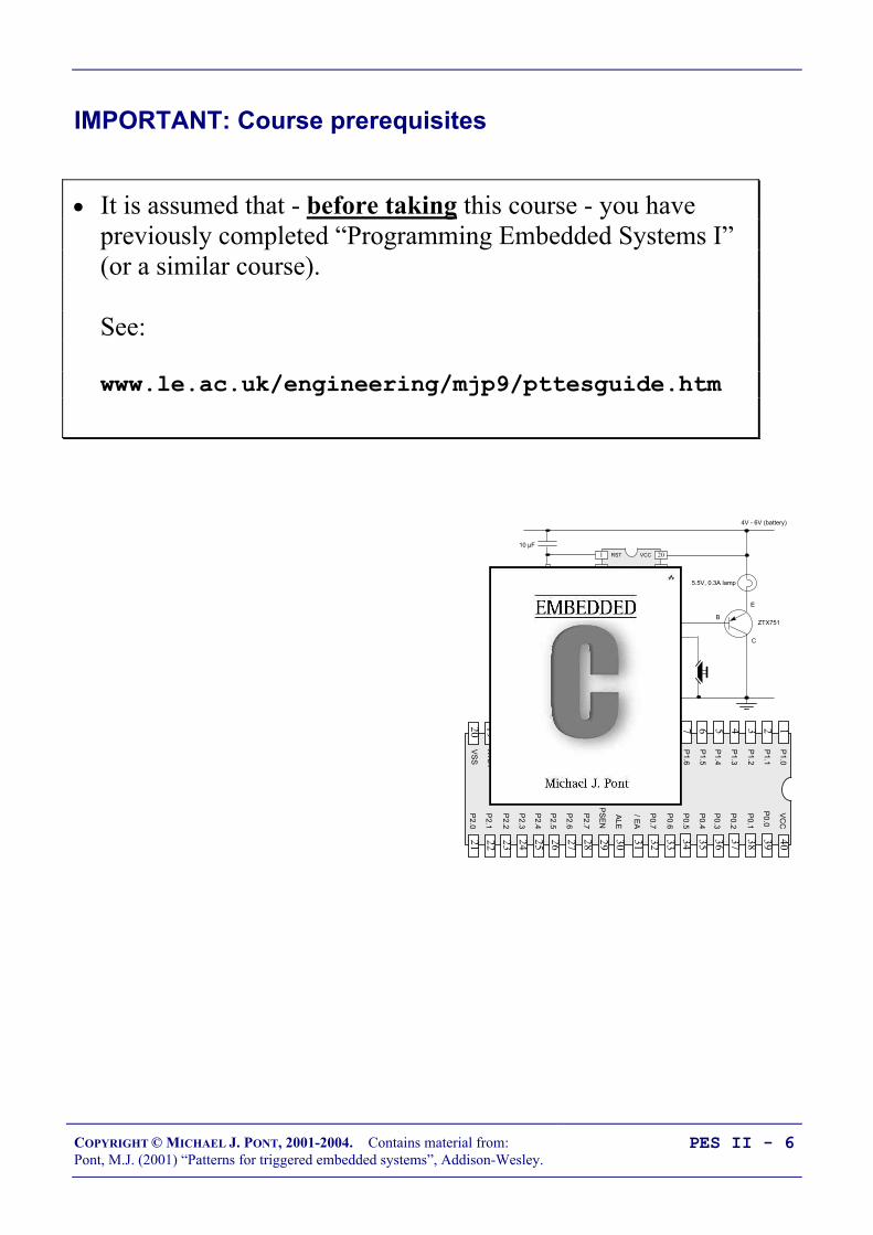
COPYRIGHT © MICHAEL J. PONT, 2001-2004. Contains material from:Pont, M.J. (2001) “Patterns for triggered embedded systems”, Addison-Wesley.
PES II - 6
IMPORTANT: Course prerequisites
• It is assumed that - before taking this course - you havepreviously completed “Programming Embedded Systems I”(or a similar course).
See:
www.le.ac.uk/engineering/mjp9/pttesguide.htm
B
E
C
5.5V, 0.3A lamp
ZTX751
4V - 6V (battery)
10 KΩ
10 µF
4 MHz
20
19
18
17
16
15
14
1
2
3
4
5
6
7A
tmel
205
1
8
9
10
13
12
11GND
P3.4
P3.5
P3.3
P3.2
XTL1
P3.1
XTL2
P3.0
RST
P3.7
P1.1
P1.0
P1.2
P1.3
P1.4
P1.6
P1.5
P1.7
VCC
40393837363534
1234567
‘8051’
8910
33323130292827262524
11121314151617181920
232221
P3.0
P1.7
RST
P1.6
P1.5
P1.4
P1.2
P1.3
P1.1
P1.0
VSS
XTL2
XTL1
P3.7
P3.6
P3.5
P3.3
P3.4
P3.2
P3.1
/ EA
P0.6
P0.7
P0.5
P0.4
P0.3
P0.1
P0.2
P0.0
VCC
P2.0
P2.2
P2.1
P2.3
P2.4
P2.5
P2.7
P2.6
/ PSEN
ALE

COPYRIGHT © MICHAEL J. PONT, 2001-2004. Contains material from:Pont, M.J. (2001) “Patterns for triggered embedded systems”, Addison-Wesley.
PES II - 7
Review: Why use C?
• It is a ‘mid-level’ language, with ‘high-level’ features (suchas support for functions and modules), and ‘low-level’features (such as good access to hardware via pointers);
• It is very efficient;
• It is popular and well understood;
• Even desktop developers who have used only Java or C++can soon understand C syntax;
• Good, well-proven compilers are available for everyembedded processor (8-bit to 32-bit or more);
• Experienced staff are available;
• Books, training courses, code samples and WWW sitesdiscussing the use of the language are all widely available.
Overall, C may not be an ideal language for developing embeddedsystems, but it is a good choice (and is unlikely that a ‘perfect’ languagewill ever be created).
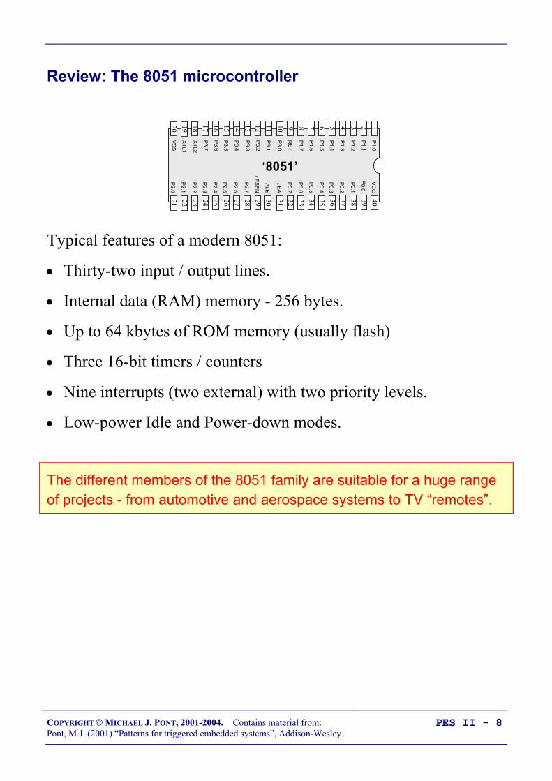
COPYRIGHT © MICHAEL J. PONT, 2001-2004. Contains material from:Pont, M.J. (2001) “Patterns for triggered embedded systems”, Addison-Wesley.
PES II - 8
Review: The 8051 microcontroller
40393837363534
1234567
‘8051’
8910
33323130292827262524
11121314151617181920
232221
P3.0
P1.7
RST
P1.6
P1.5
P1.4
P1.2
P1.3
P1.1
P1.0
VS
S
XTL2
XTL1
P3.7
P3.6
P3.5
P3.3
P3.4
P3.2
P3.1
/ EA
P0.6
P0.7
P0.5
P0.4
P0.3
P0.1
P0.2
P0.0
VCC
P2.0
P2.2
P2.1
P2.3
P2.4
P2.5
P2.7
P2.6
/ PS
EN
ALE
Typical features of a modern 8051:
• Thirty-two input / output lines.
• Internal data (RAM) memory - 256 bytes.
• Up to 64 kbytes of ROM memory (usually flash)
• Three 16-bit timers / counters
• Nine interrupts (two external) with two priority levels.
• Low-power Idle and Power-down modes.
The different members of the 8051 family are suitable for a huge rangeof projects - from automotive and aerospace systems to TV “remotes”.

COPYRIGHT © MICHAEL J. PONT, 2001-2004. Contains material from:Pont, M.J. (2001) “Patterns for triggered embedded systems”, Addison-Wesley.
PES II - 9
Review: The “super loop” software architecture
Problem
What is the minimum software environment you need to create anembedded C program?
Solution
void main(void) /* Prepare for Task X */ X_Init();
while(1) /* 'for ever' (Super Loop) */ X(); /* Perform the task */
Crucially, the ‘super loop’, or ‘endless loop’, is required because wehave no operating system to return to: our application will keep loopinguntil the system power is removed.

COPYRIGHT © MICHAEL J. PONT, 2001-2004. Contains material from:Pont, M.J. (2001) “Patterns for triggered embedded systems”, Addison-Wesley.
PES II - 10
Review: An introduction to schedulers
Operating System
BIOS
Hardware
Word Processor
OS provides ‘common code’ for:• Graphics• Printing• File storage• Sound• ...
Many embedded systems must carry out tasks at particular instantsof time. More specifically, we have two kinds of activity toperform:
• Periodic tasks, to be performed (say) once every 100 ms,and - less commonly -
• One-shot tasks, to be performed once after a delay of (say)50 ms.

COPYRIGHT © MICHAEL J. PONT, 2001-2004. Contains material from:Pont, M.J. (2001) “Patterns for triggered embedded systems”, Addison-Wesley.
PES II - 11
Review: Building a scheduler
void main(void) Timer_2_Init(); /* Set up Timer 2 */
EA = 1; /* Globally enable interrupts */
while(1); /* An empty Super Loop */
void Timer_2_Init(void) /* Timer 2 is configured as a 16-bit timer, which is automatically reloaded when it overflows With these setting, timer will overflow every 1 ms */ T2CON = 0x04; /* Load T2 control register */ T2MOD = 0x00; /* Load T2 mode register */
TH2 = 0xFC; /* Load T2 high byte */ RCAP2H = 0xFC; /* Load T2 reload capt. reg. high byte */ TL2 = 0x18; /* Load T2 low byte */ RCAP2L = 0x18; /* Load T2 reload capt. reg. low byte */
/* Timer 2 interrupt is enabled, and ISR will be called whenever the timer overflows - see below. */ ET2 = 1;
/* Start Timer 2 running */ TR2 = 1;
void X(void) interrupt INTERRUPT_Timer_2_Overflow /* This ISR is called every 1 ms */ /* Place required code here... */

COPYRIGHT © MICHAEL J. PONT, 2001-2004. Contains material from:Pont, M.J. (2001) “Patterns for triggered embedded systems”, Addison-Wesley.
PES II - 12
Overview of this seminar
This seminar will consider the design of a very flexible scheduler.
THE CO-OPERATIVE SCHEDULER
• A co-operative scheduler provides a single-tasking system architectureOperation:
• Tasks are scheduled to run at specific times (either on a one-shot or regular basis)• When a task is scheduled to run it is added to the waiting list• When the CPU is free, the next waiting task (if any) is executed• The task runs to completion, then returns control to the schedulerImplementation:
• The scheduler is simple, and can be implemented in a small amount of code.• The scheduler must allocate memory for only a single task at a time.• The scheduler will generally be written entirely in a high-level language (such as ‘C’).• The scheduler is not a separate application; it becomes part of the developer’s codePerformance:
• Obtain rapid responses to external events requires care at the design stage.Reliability and safety:
• Co-operate scheduling is simple, predictable, reliable and safe.
COPYRIGHT © MICHAEL J. PONT, 2001-2004. Contains material from:Pont, M.J. (2001) “Patterns for triggered embedded systems”, Addison-Wesley.
PES II - 13
The Co-operative Scheduler
A scheduler has the following key components:
• The scheduler data structure.
• An initialisation function.
• A single interrupt service routine (ISR), used to update thescheduler at regular time intervals.
• A function for adding tasks to the scheduler.
• A dispatcher function that causes tasks to be executed whenthey are due to run.
• A function for removing tasks from the scheduler (notrequired in all applications).
We will consider each of the required components in turn.

COPYRIGHT © MICHAEL J. PONT, 2001-2004. Contains material from:Pont, M.J. (2001) “Patterns for triggered embedded systems”, Addison-Wesley.
PES II - 14
Overview
/*--------------------------------------------------------*/void main(void) /* Set up the scheduler */ SCH_Init_T2();
/* Prepare for the 'Flash_LED' task */ LED_Flash_Init();
/* Add the 'Flash LED' task (on for ~1000 ms, off for ~1000 ms) Timings are in ticks (1 ms tick interval) (Max interval / delay is 65535 ticks) */ SCH_Add_Task(LED_Flash_Update, 0, 1000);
/* Start the scheduler */ SCH_Start();
while(1) SCH_Dispatch_Tasks();
/*--------------------------------------------------------*/void SCH_Update(void) interrupt INTERRUPT_Timer_2_Overflow /* Update the task list */ ...

COPYRIGHT © MICHAEL J. PONT, 2001-2004. Contains material from:Pont, M.J. (2001) “Patterns for triggered embedded systems”, Addison-Wesley.
PES II - 15
The scheduler data structure and task array
/* Store in DATA area, if possible, for rapid access Total memory per task is 7 bytes */typedef data struct /* Pointer to the task (must be a 'void (void)' function) */ void (code * pTask)(void);
/* Delay (ticks) until the function will (next) be run - see SCH_Add_Task() for further details */ tWord Delay;
/* Interval (ticks) between subsequent runs. - see SCH_Add_Task() for further details */ tWord Repeat;
/* Incremented (by scheduler) when task is due to execute */ tByte RunMe; sTask;
File Sch51.H also includes the constant SCH_MAX_TASKS:/* The maximum number of tasks required at any one time during the execution of the program
MUST BE ADJUSTED FOR EACH NEW PROJECT */#define SCH_MAX_TASKS (1)
Both the sTask data type and the SCH_MAX_TASKS constant areused to create - in the file Sch51.C - the array of tasks that isreferred to throughout the scheduler:/* The array of tasks */sTask SCH_tasks_G[SCH_MAX_TASKS];

COPYRIGHT © MICHAEL J. PONT, 2001-2004. Contains material from:Pont, M.J. (2001) “Patterns for triggered embedded systems”, Addison-Wesley.
PES II - 16
The size of the task array
You must ensure that the task array is sufficiently large to store thetasks required in your application, by adjusting the value ofSCH_MAX_TASKS.
For example, if you schedule three tasks as follows:
SCH_Add_Task(Function_A, 0, 2); SCH_Add_Task(Function_B, 1, 10); SCH_Add_Task(Function_C, 3, 15);
…then SCH_MAX_TASKS must have a value of 3 (or more) forcorrect operation of the scheduler.
Note also that - if this condition is not satisfied, the scheduler willgenerate an error code (more on this later).

COPYRIGHT © MICHAEL J. PONT, 2001-2004. Contains material from:Pont, M.J. (2001) “Patterns for triggered embedded systems”, Addison-Wesley.
PES II - 17
One possible initialisation function:
/*--------------------------------------------------------*/
void SCH_Init_T2(void) tByte i;
for (i = 0; i < SCH_MAX_TASKS; i++) SCH_Delete_Task(i);
/* SCH_Delete_Task() will generate an error code, because the task array is empty. -> reset the global error variable. */ Error_code_G = 0;
/* Now set up Timer 2 16-bit timer function with automatic reload
Crystal is assumed to be 12 MHz The Timer 2 resolution is 0.000001 seconds (1 µs) The required Timer 2 overflow is 0.001 seconds (1 ms) - this takes 1000 timer ticks Reload value is 65536 - 1000 = 64536 (dec) = 0xFC18 */
T2CON = 0x04; /* Load Timer 2 control register */ T2MOD = 0x00; /* Load Timer 2 mode register */
TH2 = 0xFC; /* Load Timer 2 high byte */ RCAP2H = 0xFC; /* Load Timer 2 reload capture reg, high byte */ TL2 = 0x18; /* Load Timer 2 low byte */ RCAP2L = 0x18; /* Load Timer 2 reload capture reg, low byte */
ET2 = 1; /* Timer 2 interrupt is enabled */
TR2 = 1; /* Start Timer 2 */

COPYRIGHT © MICHAEL J. PONT, 2001-2004. Contains material from:Pont, M.J. (2001) “Patterns for triggered embedded systems”, Addison-Wesley.
PES II - 18
IMPORTANT:The ‘one interrupt per microcontroller’ rule!
The scheduler initialisation function enables the generation of interruptsassociated with the overflow of one of the microcontroller timers.
For reasons discussed in Chapter 1 of PTTES, it is assumedthroughout this course that only the ‘tick’ interrupt source isactive: specifically, it is assumed that no other interrupts areenabled.
If you attempt to use the scheduler code with additional interruptsenabled, the system cannot be guaranteed to operate at all: at best,you will generally obtain very unpredictable - and unreliable - systembehaviour.
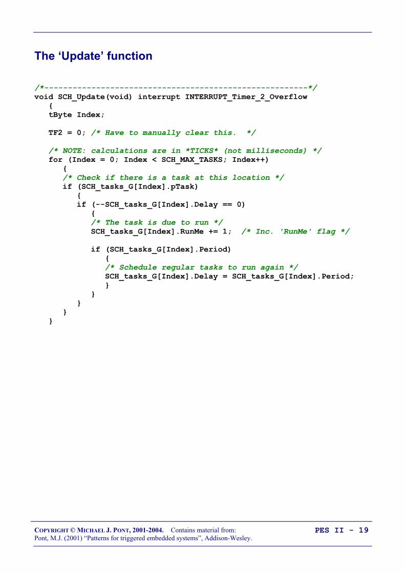
COPYRIGHT © MICHAEL J. PONT, 2001-2004. Contains material from:Pont, M.J. (2001) “Patterns for triggered embedded systems”, Addison-Wesley.
PES II - 19
The ‘Update’ function
/*--------------------------------------------------------*/void SCH_Update(void) interrupt INTERRUPT_Timer_2_Overflow tByte Index;
TF2 = 0; /* Have to manually clear this. */
/* NOTE: calculations are in *TICKS* (not milliseconds) */ for (Index = 0; Index < SCH_MAX_TASKS; Index++) /* Check if there is a task at this location */ if (SCH_tasks_G[Index].pTask) if (--SCH_tasks_G[Index].Delay == 0) /* The task is due to run */ SCH_tasks_G[Index].RunMe += 1; /* Inc. 'RunMe' flag */
if (SCH_tasks_G[Index].Period) /* Schedule regular tasks to run again */ SCH_tasks_G[Index].Delay = SCH_tasks_G[Index].Period;

COPYRIGHT © MICHAEL J. PONT, 2001-2004. Contains material from:Pont, M.J. (2001) “Patterns for triggered embedded systems”, Addison-Wesley.
PES II - 20
The ‘Add Task’ function
Sch_Add_Task(Task_Name, Initial_Delay, Task_Interval);
Task_Name the name of the function (task) that you wish to schedule
Task_Interval the interval (in ticks) between repeated executions of the task.If set to 0, the task is executed only once.
Initial_Delay the delay (in ticks) before task is firstexecuted. If set to 0,the task is executedimmediately.
Examples:SCH_Add_Task(Do_X,1000,0);
Task_ID = SCH_Add_Task(Do_X,1000,0);
SCH_Add_Task(Do_X,0,1000);
This causes the function Do_X() to be executed regularly, every1000 scheduler ticks; task will be first executed at T = 300 ticks,then 1300, 2300, etc:SCH_Add_Task(Do_X,300,1000);

COPYRIGHT © MICHAEL J. PONT, 2001-2004. Contains material from:Pont, M.J. (2001) “Patterns for triggered embedded systems”, Addison-Wesley.
PES II - 21
/*--------------------------------------------------------*-
SCH_Add_Task()
Causes a task (function) to be executed at regular intervals, or after a user-defined delay.
-*--------------------------------------------------------*/tByte SCH_Add_Task(void (code * pFunction)(), const tWord DELAY, const tWord PERIOD) tByte Index = 0;
/* First find a gap in the array (if there is one) */ while ((SCH_tasks_G[Index].pTask != 0) && (Index < SCH_MAX_TASKS)) Index++;
/* Have we reached the end of the list? */ if (Index == SCH_MAX_TASKS) /* Task list is full -> set the global error variable */ Error_code_G = ERROR_SCH_TOO_MANY_TASKS;
/* Also return an error code */ return SCH_MAX_TASKS;
/* If we're here, there is a space in the task array */ SCH_tasks_G[Index].pTask = pFunction;
SCH_tasks_G[Index].Delay = DELAY + 1; SCH_tasks_G[Index].Period = PERIOD;
SCH_tasks_G[Index].RunMe = 0;
return Index; /* return pos. of task (to allow deletion) */
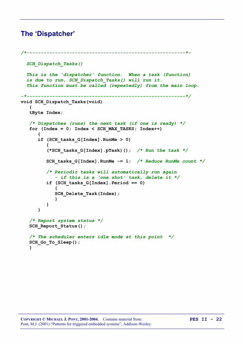
COPYRIGHT © MICHAEL J. PONT, 2001-2004. Contains material from:Pont, M.J. (2001) “Patterns for triggered embedded systems”, Addison-Wesley.
PES II - 22
The ‘Dispatcher’
/*--------------------------------------------------------*-
SCH_Dispatch_Tasks()
This is the 'dispatcher' function. When a task (function) is due to run, SCH_Dispatch_Tasks() will run it. This function must be called (repeatedly) from the main loop.
-*--------------------------------------------------------*/void SCH_Dispatch_Tasks(void) tByte Index;
/* Dispatches (runs) the next task (if one is ready) */ for (Index = 0; Index < SCH_MAX_TASKS; Index++) if (SCH_tasks_G[Index].RunMe > 0) (*SCH_tasks_G[Index].pTask)(); /* Run the task */
SCH_tasks_G[Index].RunMe -= 1; /* Reduce RunMe count */
/* Periodic tasks will automatically run again - if this is a 'one shot' task, delete it */ if (SCH_tasks_G[Index].Period == 0) SCH_Delete_Task(Index);
/* Report system status */ SCH_Report_Status();
/* The scheduler enters idle mode at this point */ SCH_Go_To_Sleep();
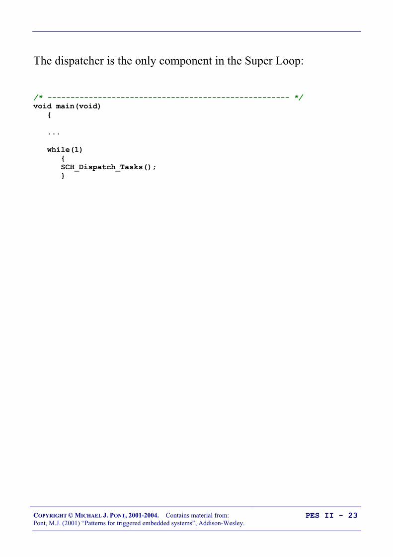
COPYRIGHT © MICHAEL J. PONT, 2001-2004. Contains material from:Pont, M.J. (2001) “Patterns for triggered embedded systems”, Addison-Wesley.
PES II - 23
The dispatcher is the only component in the Super Loop:
/* ----------------------------------------------------- */void main(void)
...
while(1) SCH_Dispatch_Tasks();

COPYRIGHT © MICHAEL J. PONT, 2001-2004. Contains material from:Pont, M.J. (2001) “Patterns for triggered embedded systems”, Addison-Wesley.
PES II - 24
Function arguments
• On desktop systems, function arguments are generallypassed on the stack using the push and pop assemblyinstructions.
• Since the 8051 has a size limited stack (only 128 bytes atbest and as low as 64 bytes on some devices), functionarguments must be passed using a different technique.
• In the case of Keil C51, these arguments are stored in fixedmemory locations.
• When the linker is invoked, it builds a call tree of theprogram, decides which function arguments are mutuallyexclusive (that is, which functions cannot be called at thesame time), and overlays these arguments.

COPYRIGHT © MICHAEL J. PONT, 2001-2004. Contains material from:Pont, M.J. (2001) “Patterns for triggered embedded systems”, Addison-Wesley.
PES II - 25
Function pointers and Keil linker options
When we write:SCH_Add_Task(Do_X,1000,0);
…the first parameter of the ‘Add Task’ function is a pointer to thefunction Do_X().
This function pointer is then passed to the Dispatch function and itis through this function that the task is executed:if (SCH_tasks_G[Index].RunMe > 0) (*SCH_tasks_G[Index].pTask)(); /* Run the task */
BUTThe linker has difficulty determining the correct call tree when functionpointers are used as arguments.

COPYRIGHT © MICHAEL J. PONT, 2001-2004. Contains material from:Pont, M.J. (2001) “Patterns for triggered embedded systems”, Addison-Wesley.
PES II - 26
To deal with this situation, you have two realistic options:
1. You can prevent the compiler from using the OVERLAYdirective by disabling overlays as part of the linker optionsfor your project.
Note that, compared to applications using overlays, you willgenerally require more RAM to run your program.
2. You can tell the linker how to create the correct call tree foryour application by explicitly providing this information inthe linker ‘Additional Options’ dialogue box.
This approach is used in most of the examples in the“PTTES” book.
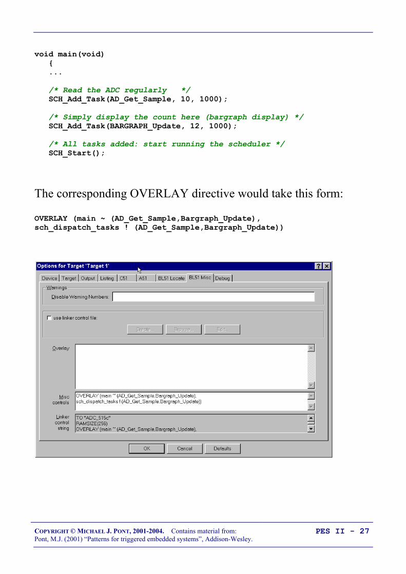
COPYRIGHT © MICHAEL J. PONT, 2001-2004. Contains material from:Pont, M.J. (2001) “Patterns for triggered embedded systems”, Addison-Wesley.
PES II - 27
void main(void) ...
/* Read the ADC regularly */ SCH_Add_Task(AD_Get_Sample, 10, 1000);
/* Simply display the count here (bargraph display) */ SCH_Add_Task(BARGRAPH_Update, 12, 1000);
/* All tasks added: start running the scheduler */ SCH_Start();
The corresponding OVERLAY directive would take this form:
OVERLAY (main ~ (AD_Get_Sample,Bargraph_Update),sch_dispatch_tasks ! (AD_Get_Sample,Bargraph_Update))
COPYRIGHT © MICHAEL J. PONT, 2001-2004. Contains material from:Pont, M.J. (2001) “Patterns for triggered embedded systems”, Addison-Wesley.
PES II - 28
The ‘Start’ function
/*--------------------------------------------------------*/
void SCH_Start(void) EA = 1;

COPYRIGHT © MICHAEL J. PONT, 2001-2004. Contains material from:Pont, M.J. (2001) “Patterns for triggered embedded systems”, Addison-Wesley.
PES II - 29
The ‘Delete Task’ function
When tasks are added to the task array, SCH_Add_Task() returnsthe position in the task array at which the task has been added:Task_ID = SCH_Add_Task(Do_X,1000,0);
Sometimes it can be necessary to delete tasks from the array.
You can do so as follows: SCH_Delete_Task(Task_ID);
bit SCH_Delete_Task(const tByte TASK_INDEX) bit Return_code;
if (SCH_tasks_G[TASK_INDEX].pTask == 0) /* No task at this location... -> set the global error variable */ Error_code_G = ERROR_SCH_CANNOT_DELETE_TASK;
/* ...also return an error code */ Return_code = RETURN_ERROR; else Return_code = RETURN_NORMAL;
SCH_tasks_G[TASK_INDEX].pTask = 0x0000; SCH_tasks_G[TASK_INDEX].Delay = 0; SCH_tasks_G[TASK_INDEX].Period = 0;
SCH_tasks_G[TASK_INDEX].RunMe = 0;
return Return_code; /* return status */

COPYRIGHT © MICHAEL J. PONT, 2001-2004. Contains material from:Pont, M.J. (2001) “Patterns for triggered embedded systems”, Addison-Wesley.
PES II - 30
Reducing power consumption
/*--------------------------------------------------------*/void SCH_Go_To_Sleep() PCON |= 0x01; /* Enter idle mode (generic 8051 version) */
/* Entering idle mode requires TWO consecutive instructions on 80c515 / 80c505 - to avoid accidental triggering. E.g: PCON |= 0x01; PCON |= 0x20; */

COPYRIGHT © MICHAEL J. PONT, 2001-2004. Contains material from:Pont, M.J. (2001) “Patterns for triggered embedded systems”, Addison-Wesley.
PES II - 31
Reporting errors
/* Used to display the error code */tByte Error_code_G = 0;
To record an error we include lines such as:Error_code_G = ERROR_SCH_TOO_MANY_TASKS;Error_code_G = ERROR_SCH_WAITING_FOR_SLAVE_TO_ACK;Error_code_G = ERROR_SCH_WAITING_FOR_START_COMMAND_FROM_MASTER;Error_code_G = ERROR_SCH_ONE_OR_MORE_SLAVES_DID_NOT_START;Error_code_G = ERROR_SCH_LOST_SLAVE;Error_code_G = ERROR_SCH_CAN_BUS_ERROR;Error_code_G = ERROR_I2C_WRITE_BYTE_AT24C64;
To report these error code, the scheduler has a functionSCH_Report_Status(), which is called from the Update function.
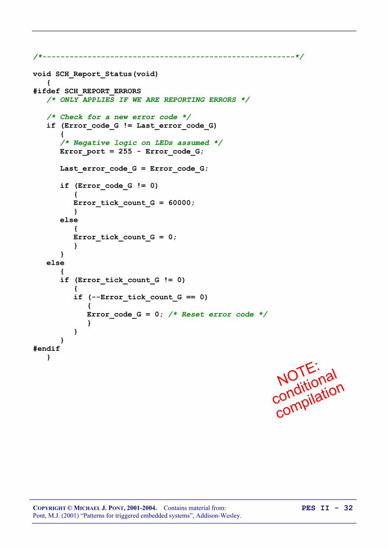
COPYRIGHT © MICHAEL J. PONT, 2001-2004. Contains material from:Pont, M.J. (2001) “Patterns for triggered embedded systems”, Addison-Wesley.
PES II - 32
/*--------------------------------------------------------*/
void SCH_Report_Status(void) #ifdef SCH_REPORT_ERRORS /* ONLY APPLIES IF WE ARE REPORTING ERRORS */
/* Check for a new error code */ if (Error_code_G != Last_error_code_G) /* Negative logic on LEDs assumed */ Error_port = 255 - Error_code_G;
Last_error_code_G = Error_code_G;
if (Error_code_G != 0) Error_tick_count_G = 60000; else Error_tick_count_G = 0; else if (Error_tick_count_G != 0) if (--Error_tick_count_G == 0) Error_code_G = 0; /* Reset error code */ #endif

COPYRIGHT © MICHAEL J. PONT, 2001-2004. Contains material from:Pont, M.J. (2001) “Patterns for triggered embedded systems”, Addison-Wesley.
PES II - 33
Note that error reporting may be disabled via the Port.H headerfile:
/* Comment next line out if error reporting is NOT required *//* #define SCH_REPORT_ERRORS */
Where error reporting is required, the port on which error codes willbe displayed is also determined via Port.H:#ifdef SCH_REPORT_ERRORS/* The port on which error codes will be displayed (ONLY USED IF ERRORS ARE REPORTED) */#define Error_port P1
#endif
Note that, in this implementation, error codes are reported for60,000 ticks (1 minute at a 1 ms tick rate).

COPYRIGHT © MICHAEL J. PONT, 2001-2004. Contains material from:Pont, M.J. (2001) “Patterns for triggered embedded systems”, Addison-Wesley.
PES II - 34
Displaying error codes
Rled Rled Rled Rled Rled Rled Rled Rled
LED 7 LED 6 LED 5 LED 4 LED 3 LED 2 LED 1 LED 0
8051 DevicePort 2
Vcc
ULN
2803
A
9
P2.0 - Pin 8P2.1 - Pin 7P2.2 - Pin 6P2.3 - Pin 5P2.4 - Pin 4P2.5 - Pin 3P2.6 - Pin 2P2.7 - Pin 1
Pin 11 - LED 0Pin 12 - LED 1Pin 13 - LED 2 Pin 14 - LED 3Pin 15 - LED 4 Pin 16 - LED 5Pin 17 - LED 6 Pin 18 - LED 7
For 25mA LEDs, Rled = 120 Ohms
The forms of error reporting discussed here are low-level in nature andare primarily intended to assist the developer of the application, or aqualified service engineer performing system maintenance.
An additional user interface may also be required in your application tonotify the user of errors, in a more user-friendly manner.

COPYRIGHT © MICHAEL J. PONT, 2001-2004. Contains material from:Pont, M.J. (2001) “Patterns for triggered embedded systems”, Addison-Wesley.
PES II - 35
Hardware resource implications
Timer
The scheduler requires one hardware timer. If possible, this shouldbe a 16-bit timer, with auto-reload capabilities (usually Timer 2).
Memory
This main scheduler memory requirement is 7 bytes of memory pertask.
Most applications require around six tasks or less. Even in astandard 8051/8052 with 256 bytes of internal memory the totalmemory overhead is small.

COPYRIGHT © MICHAEL J. PONT, 2001-2004. Contains material from:Pont, M.J. (2001) “Patterns for triggered embedded systems”, Addison-Wesley.
PES II - 36
What is the CPU load of the scheduler?
• A scheduler with 1ms ticks
• 12 Mhz, 12 osc / instruction 8051
• One task is being executed.
• The test reveals that the CPU is 86% idle and that themaximum possible task duration is therefore approximately0.86 ms.

COPYRIGHT © MICHAEL J. PONT, 2001-2004. Contains material from:Pont, M.J. (2001) “Patterns for triggered embedded systems”, Addison-Wesley.
PES II - 37
A scheduler with 1ms ticks,running on a 32 Mhz (4 oscillations per instruction) 8051.
• One task is being executed.
• The CPU is 97% idle and that the maximum possible taskduration is therefore approximately 0.97 ms.
• Twelve tasks are being executed.
• The CPU is 85% idle and that the maximum possible taskduration is therefore approximately 0.85 ms.

COPYRIGHT © MICHAEL J. PONT, 2001-2004. Contains material from:Pont, M.J. (2001) “Patterns for triggered embedded systems”, Addison-Wesley.
PES II - 38
Determining the required tick interval
In most instances, the simplest way of meeting the needs of thevarious task intervals is to allocate a scheduler tick interval of 1 ms.
To keep the scheduler load as low as possible (and to reduce thepower consumption), it can help to use a long tick interval.
If you want to reduce overheads and power consumption to aminimum, the scheduler tick interval should be set to match the‘greatest common factor’ of all the task (and offset intervals).

COPYRIGHT © MICHAEL J. PONT, 2001-2004. Contains material from:Pont, M.J. (2001) “Patterns for triggered embedded systems”, Addison-Wesley.
PES II - 39
Suppose we have three tasks (X,Y,Z), and Task X is to be run every10 ms, Task Y every 30 ms and Task Z every 25 ms. The schedulertick interval needs to be set by determining the relevant factors, asfollows:
• The factors of the Task X interval (10 ms) are: 1 ms, 2ms, 5ms, 10 ms.
• Similarly, the factors of the Task Y interval (30 ms) are asfollows: 1 ms, 2 ms, 3 ms, 5 ms, 6 ms, 10 ms, 15 ms and 30ms.
• Finally, the factors of the Task Z interval (25 ms) are asfollows: 1 ms, 5 ms and 25 ms.
In this case, therefore, the greatest common factor is 5 ms: this is therequired tick interval.

COPYRIGHT © MICHAEL J. PONT, 2001-2004. Contains material from:Pont, M.J. (2001) “Patterns for triggered embedded systems”, Addison-Wesley.
PES II - 40
Guidelines for predictable and reliable scheduling
1. For precise scheduling, the scheduler tick interval should beset to match the ‘greatest common factor’ of all the taskintervals.
2. All tasks should have a duration less than the schedule tickinterval, to ensure that the dispatcher is always free to callany task that is due to execute. Software simulation canoften be used to measure the task duration.
3. In order to meet Condition 2, all tasks must ‘timeout’ sothat they cannot block the scheduler under anycircumstances.
4. The total time required to execute all of the scheduled tasksmust be less than the available processor time. Of course,the total processor time must include both this ‘task time’and the ‘scheduler time’ required to execute the schedulerupdate and dispatcher operations.
5. Tasks should be scheduled so that they are never required toexecute simultaneously: that is, task overlaps should beminimised. Note that where all tasks are of a duration muchless than the scheduler tick interval, and that some task jittercan be tolerated, this problem may not be significant.
COPYRIGHT © MICHAEL J. PONT, 2001-2004. Contains material from:Pont, M.J. (2001) “Patterns for triggered embedded systems”, Addison-Wesley.
PES II - 41
Overall strengths and weaknesses of the scheduler
The scheduler is simple, and can be implemented in a small amount ofcode.
The scheduler is written entirely in ‘C’: it is not a separate application,but becomes part of the developer’s code
The applications based on the scheduler are inherently predictable,safe and reliable.
The scheduler supports team working, since individual tasks can oftenbe developed largely independently and then assembled into the finalsystem.
Obtain rapid responses to external events requires care at the designstage. The tasks cannot safely use interrupts: the only interrupt that should be
used in the application is the timer-related interrupt that drives thescheduler itself.

COPYRIGHT © MICHAEL J. PONT, 2001-2004. Contains material from:Pont, M.J. (2001) “Patterns for triggered embedded systems”, Addison-Wesley.
PES II - 42
Preparations for the next seminar
Please read “PTTES” Chapter 32 before the next seminar.
40393837363534
1234567
‘8051’
8910
33323130292827262524
11121314151617181920
232221
P3.0
P1.7
RS
T
P1.6
P1.5
P1.4
P1.2
P1.3
P1.1
P1.0
VS
S
XTL2
XTL1
P3.7
P3.6
P3.5
P3.3
P3.4
P3.2
P3.1
/ EA
P0.6
P0.7
P0.5
P0.4
P0.3
P0.1
P0.2
P0.0
VC
C
P2.0
P2.2
P2.1
P2.3
P2.4
P2.5
P2.7
P2.6
/ PSE
N
ALE

COPYRIGHT © MICHAEL J. PONT, 2001-2004. Contains material from:Pont, M.J. (2001) “Patterns for triggered embedded systems”, Addison-Wesley.
PES II - 43
Seminar 3: Analogue I/O using
ADCs and PWM
Transmitter (Master)
Transmitter (Master)
Receiver A(Slave)
Receiver A(Slave)
Receiver B(Slave)
Receiver B(Slave)
Receiver C(Slave)
Receiver C(Slave)

COPYRIGHT © MICHAEL J. PONT, 2001-2004. Contains material from:Pont, M.J. (2001) “Patterns for triggered embedded systems”, Addison-Wesley.
PES II - 44
Overview of this seminar
In this seminar, we will begin to consider how to makemeasurements of analogue voltages using a microcontroller.
We’ll also consider how PWM can be used to generate analoguevoltage values.
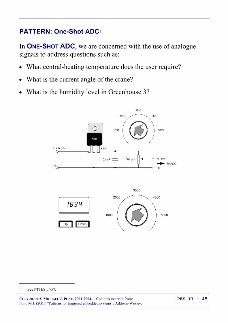
COPYRIGHT © MICHAEL J. PONT, 2001-2004. Contains material from:Pont, M.J. (2001) “Patterns for triggered embedded systems”, Addison-Wesley.
PES II - 45
PATTERN: One-Shot ADC1
In ONE-SHOT ADC, we are concerned with the use of analoguesignals to address questions such as:
• What central-heating temperature does the user require?
• What is the current angle of the crane?
• What is the humidity level in Greenhouse 3?
20oC
15oC 25oC
10oC 30oC
0.1 uF
≤ +24v (DC)
0
50 k pot
+ 5v
0 - 5 v
0
To ADC
7805
1 8 9 4
DownUp
3000
2000 4000
1000 5000
1 See PTTES p.757.
COPYRIGHT © MICHAEL J. PONT, 2001-2004. Contains material from:Pont, M.J. (2001) “Patterns for triggered embedded systems”, Addison-Wesley.
PES II - 46
PATTERN: One-Shot ADC
We begin by considering some of the hardware options that areavailable to allow the measurement of analogue voltage signalsusing a microcontroller.
Specifically, we will consider four options:
• Using a microcontroller with on-chip ADC;
• Using an external serial ADC;
• Using an external parallel ADC;
• Using a current-mode ADC.

COPYRIGHT © MICHAEL J. PONT, 2001-2004. Contains material from:Pont, M.J. (2001) “Patterns for triggered embedded systems”, Addison-Wesley.
PES II - 47
Using a microcontroller with on-chip ADC
Many members of the 8051 family contain on-board ADCs.
In general, use of an internal ADC (rather than an external one) willresult in increased reliability, since both hardware and softwarecomplexity will generally be lower.
In addition, the ‘internal’ solution will usually be physically smaller,and have a lower system cost.

COPYRIGHT © MICHAEL J. PONT, 2001-2004. Contains material from:Pont, M.J. (2001) “Patterns for triggered embedded systems”, Addison-Wesley.
PES II - 48
Using an external parallel ADC
The ‘traditional’ alternative to an on-chip ADC is a parallel ADC.In general, parallel ADCs have the following strengths andweaknesses: They can provide fast data transfers They tend to be inexpensive They require a very simple software framework They tend to require a large number of port pins. In the case of a 16-bit
conversion, the external ADC will require 16 pins for the data transfer, plusbetween 1 and 3 pins to control the data transfers. The wiring complexity can be a source of reliability problems in some
environments.
We give examples of the use of a parallel ADC below.

COPYRIGHT © MICHAEL J. PONT, 2001-2004. Contains material from:Pont, M.J. (2001) “Patterns for triggered embedded systems”, Addison-Wesley.
PES II - 49
Example: Using a Max150 ADC
This example illustrates this use of an 8-bit parallel ADC: theMaxim MAX 150:
To microcontroller‘NOT_RD’ pin
To microcontroller‘NOT_INT’ pin
+5V
To microcontroller‘NOT_WRITE’ pin
+5V
0V
0V
20
19
18
17
16
15
14
1
2
3
4
5
6
7
8
9
10
13
12
11GND
/RD
/INT
MODE
/WR RDY
DB3
DB1
DB2
DB0
Vin
Vref-
/CS
Vref+
DB4
DB5
DB6
/OFL
DB7
TP /RO
Vdd
Max 150
AnalogueInput
To microcontrollerdata port
To microcontrollerdata port
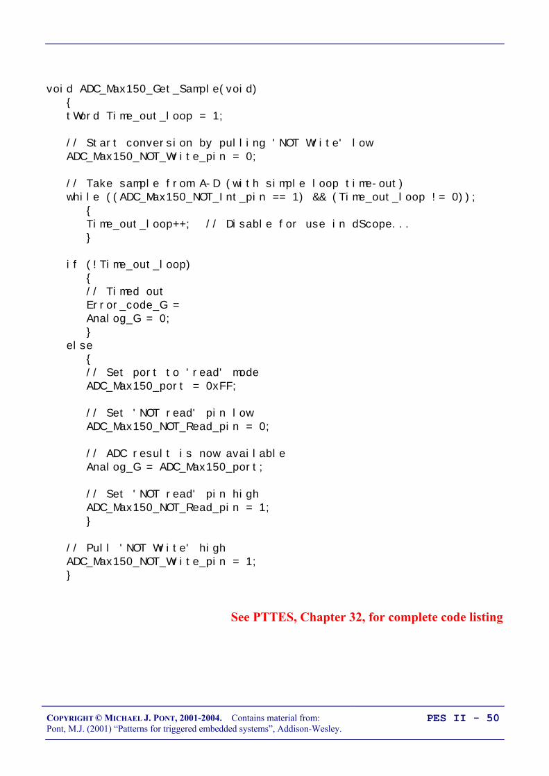
COPYRIGHT © MICHAEL J. PONT, 2001-2004. Contains material from:Pont, M.J. (2001) “Patterns for triggered embedded systems”, Addison-Wesley.
PES II - 50
void ADC_Max150_Get_Sample(void) tWord Time_out_loop = 1;
// Start conversion by pulling 'NOT Write' low ADC_Max150_NOT_Write_pin = 0;
// Take sample from A-D (with simple loop time-out) while ((ADC_Max150_NOT_Int_pin == 1) && (Time_out_loop != 0)); Time_out_loop++; // Disable for use in dScope...
if (!Time_out_loop) // Timed out Error_code_G = Analog_G = 0; else // Set port to 'read' mode ADC_Max150_port = 0xFF;
// Set 'NOT read' pin low ADC_Max150_NOT_Read_pin = 0;
// ADC result is now available Analog_G = ADC_Max150_port;
// Set 'NOT read' pin high ADC_Max150_NOT_Read_pin = 1;
// Pull 'NOT Write' high ADC_Max150_NOT_Write_pin = 1;
See PTTES, Chapter 32, for complete code listing

COPYRIGHT © MICHAEL J. PONT, 2001-2004. Contains material from:Pont, M.J. (2001) “Patterns for triggered embedded systems”, Addison-Wesley.
PES II - 51
Using an external serial ADC
Many more recent ADCs have a serial interface. In general, serialADCs have the following strengths and weaknesses: They require a small number of port pins (between 2 and 4), regardless
of the ADC resolution. They require on-chip support for the serial protocol, or the use of a suitable
software library. The data transfer may be slower than a parallel alternative. They can be comparatively expensive.
We give two examples of the use of serial ADCs below.

COPYRIGHT © MICHAEL J. PONT, 2001-2004. Contains material from:Pont, M.J. (2001) “Patterns for triggered embedded systems”, Addison-Wesley.
PES II - 52
Example: Using an external SPI ADC
This example illustrates the use of an external, serial (SPI) ADC(the SPI protocol is described in detail in PTTES, Chapter 24).
The hardware comprises an Atmel AT89S53 microcontroller, and aMaxim MAX1110 ADC:
12345678
Vcc
P 0.7 (AD7) 32
P 0.6 (AD6) 33
P 0.5 (AD5) 34
P 0.4 (AD4) 35
P 0.3 (AD3) 36
P 0.2 (AD2) 37
P 0.1 (AD1) 38
P 0.0 (AD0) 39
87654321
P 2.7 (A15) 28
P 2.6 (A14) 27
P 2.5 (A13) 26
P 2.4 (A12) 25
P 2.3 (A11) 24
P 2.2 (A10) 23
P 2.1 (A9) 22
P 2.0 (A8) 21
/ PSEN
ALE (/ PROG)
29
30
31
XTL119
XTL218
RST
40
VCC
VSS
AT
89S5
3
Vcc (+5V)
Vcc
30 pF
30 pF
10 µF
10 K
20
P 3.7 (/ RD)P 3.6 (/ WR) P 3.5 (T1)P 3.4 (T0)P 3.3 (/ INT1)P 3.2 (/ INT 0)P 3.1 (TXD)P 3.0 (RXD)
/ EA
1716151413121110
9
P 1.7 (SCK)P 1.6 (MISO)P 1.5 (MOSI)
P 1.4(/SS)P 1.3P 1.2
P 1.1 (T2EX)P 1.0 (T2)
12 MHz
Max
11
10
CH0CH1CH2CH3CH4CH5CH6CH7
AG
ND
DG
ND
CO
M
13 14 9
1 µF
0.1 µF
SCLKDOUTDIN
/CS
191517
18
/SH
DN
20
REF
IN11
Vdd
10
See PTTES, Chapter 32, for code

COPYRIGHT © MICHAEL J. PONT, 2001-2004. Contains material from:Pont, M.J. (2001) “Patterns for triggered embedded systems”, Addison-Wesley.
PES II - 53
Overview of SPI
There are five key features of SPI as far as the developer ofembedded applications is concerned:
• SPI is a protocol designed to allow microcontrollers to belinked to a wide range of different peripherals - memory,displays, ADCs, and similar devices - and requires(typically) three port pins for the bus, plus one chip-selectpin per peripheral.
• There are many SPI-compatible peripherals available forpurchase ‘off the shelf’.
• Increasing numbers of ‘Standard’ and ‘Extended’ 8051devices have hardware support for SPI.
• A common set of software code may be used with all SPIperipherals.
• SPI is compatible with time-triggered architectures and, asimplemented in this course, is faster than I2C (largely due tothe use of on-chip hardware support). Typical data transferrates will be up to 5000 - 10000 bytes / second (with a 1-millisecond scheduler tick).
See PTTES, Chapter 24, for SPI code librariesand more information about this protocol

COPYRIGHT © MICHAEL J. PONT, 2001-2004. Contains material from:Pont, M.J. (2001) “Patterns for triggered embedded systems”, Addison-Wesley.
PES II - 54
Back to the example …
tByte SPI_MAX1110_Read_Byte(void) tByte Data, Data0, Data1;
// 0. Pin /CS is pulled low to select the device SPI_CS = 0;
// 1. Send a MAX1110 control byte // Control byte 0x8F sets single-ended unipolar mode, channel 0 (pin 1) SPI_Exchange_Bytes(0x8F);
// 2. The data requested is shifted out on SO by sending two dummy bytes Data0 = SPI_Exchange_Bytes(0x00); Data1 = SPI_Exchange_Bytes(0x00);
// The data are contained in bits 5-0 of Data0 // and 7-6 of Data1 - shift these bytes to give a combined byte, Data0 <<= 2; Data1 >>= 6; Data = (Data0 | Data1);
// 3. We pull the /CS pin high to complete the operation SPI_CS = 1;
// 4. We return the required data return Data; // Return SPI data byte
See PTTES, Chapter 32, for complete code for this example
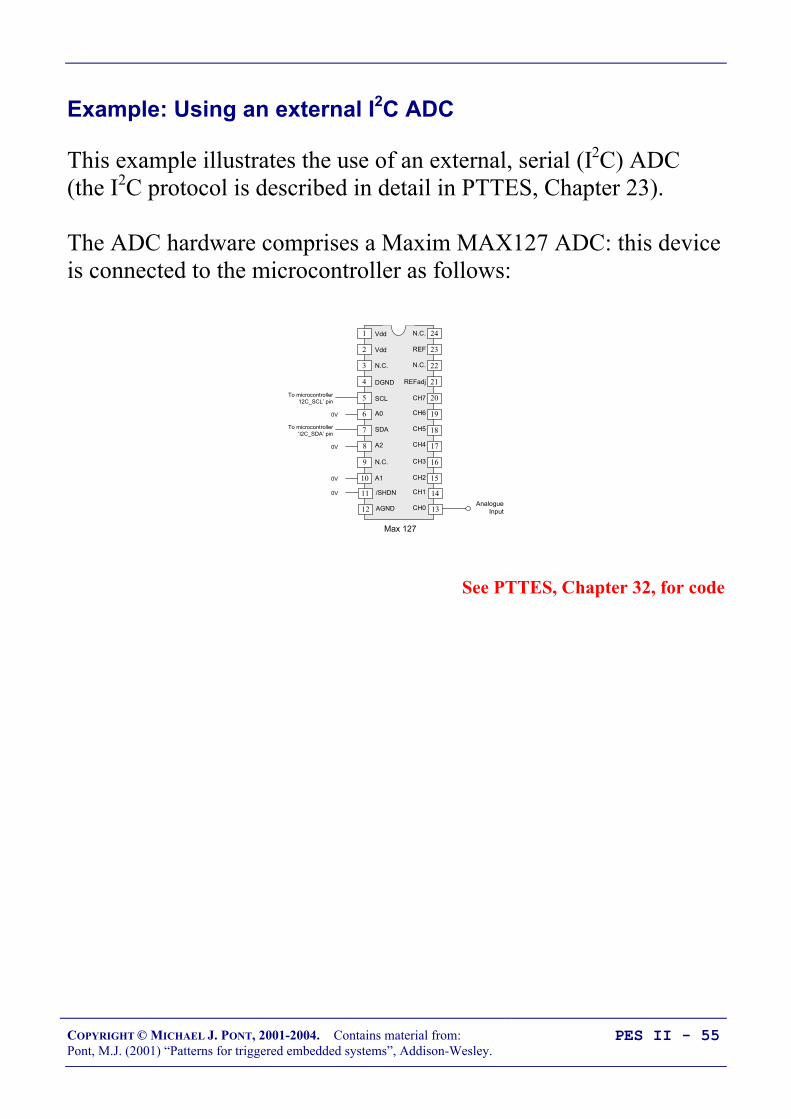
COPYRIGHT © MICHAEL J. PONT, 2001-2004. Contains material from:Pont, M.J. (2001) “Patterns for triggered embedded systems”, Addison-Wesley.
PES II - 55
Example: Using an external I2C ADC
This example illustrates the use of an external, serial (I2C) ADC(the I2C protocol is described in detail in PTTES, Chapter 23).
The ADC hardware comprises a Maxim MAX127 ADC: this deviceis connected to the microcontroller as follows:
AnalogueInput
0V
0V
0V
0V
To microcontroller‘I2C_SCL’ pin
To microcontroller‘I2C_SDA’ pin
24
23
22
21
20
19
1
2
3
4
5
6 A0
SCL
N.C.
DGND
Vdd
Vdd
7 18
8
9
10
17
16
15A1
A2
N.C.
SDA
Max 127
11 14
12 13AGND
/SHDN
CH2
CH4
CH3
CH5
CH6
CH7
N.C.
REFadj
REF
N.C.
CH0
CH1
See PTTES, Chapter 32, for code

COPYRIGHT © MICHAEL J. PONT, 2001-2004. Contains material from:Pont, M.J. (2001) “Patterns for triggered embedded systems”, Addison-Wesley.
PES II - 56
Overview of I2C
There are five key features of I2C as far as the developer ofembedded applications is concerned:
• I2C is a protocol designed to allow microcontrollers to belinked to a wide range of different peripherals - memory,displays, ADCs, and similar devices - and requires only twoport pins to connect to (typically) up to twenty peripherals.
• There are many I2C peripherals available for purchase ‘offthe shelf’.
• I2C is a simple protocol and may be easily generated insoftware. This allows all 8051 devices to communicate witha wide range of peripheral devices.
• A common set of software code may be used with all I2Cperipherals.
• I2C is fast enough (even when generated in software) to becompatible with time-triggered architectures. Typical datatransfer rates will be up to 1000 bytes / second (with a 1-millisecond scheduler tick).
See PTTES, Chapter 23, for I2C code librariesand more information about this protocol

COPYRIGHT © MICHAEL J. PONT, 2001-2004. Contains material from:Pont, M.J. (2001) “Patterns for triggered embedded systems”, Addison-Wesley.
PES II - 57
Back to the example …
void I2C_ADC_Max127_Read(void) I2C_Send_Start(); // Generate I2C START condition
// Send DAC device address (with write access request) if (I2C_Write_Byte(I2C_MAX127_ADDRESS | I2C_WRITE)) Error_code_G = ERROR_I2C_ADC_MAX127; return;
// Set the ADC mode and channel - see above if (I2C_Write_Byte(I2C_MAX127_MODE | I2C_MAX127_Channel_G)) Error_code_G = ERROR_I2C_ADC_MAX127; return;
I2C_Send_Stop(); // Generate STOP condition
I2C_Send_Start(); // Generate START condition (again)
// Send Max127 device address (with READ access request) if (I2C_Write_Byte(I2C_MAX127_ADDRESS | I2C_READ)) Error_code_G = ERROR_I2C_ADC_MAX127; return;
// Receive first (MS) byte from I2C bus ADC_G = I2C_Read_Byte();
I2C_Send_Master_Ack(); // Perform a MASTER ACK
// Here we require temperature only accurate to 1 degree C // - we discard LS byte (perform a dummy read) I2C_Read_Byte();
I2C_Send_Master_NAck(); // Perform a MASTER NACK
I2C_Send_Stop(); // Generate STOP condition
See PTTES, Chapter 32, for complete code for this example

COPYRIGHT © MICHAEL J. PONT, 2001-2004. Contains material from:Pont, M.J. (2001) “Patterns for triggered embedded systems”, Addison-Wesley.
PES II - 58
What is PWM?
x yV
Time
Duty cycle (%) = xx y+
× 100
Period = x + y, where x and y are in seconds.
Frequency = 1x y+
, where x and y are in seconds.
The key point to note is that the average voltage seen by the load isgiven by the duty cycle multiplied by the load voltage.
See PTTES, Chapter 33

COPYRIGHT © MICHAEL J. PONT, 2001-2004. Contains material from:Pont, M.J. (2001) “Patterns for triggered embedded systems”, Addison-Wesley.
PES II - 59
PATTERN: Software PWM
void PWM_Soft_Update(void) // Have we reached the end of the current PWM cycle? if (++PWM_position_G >= PWM_PERIOD) // Reset the PWM position counter PWM_position_G = 0;
// Update the PWM control value PWM_G = PWM_new_G;
// Set the PWM output to ON PWM_pin = PWM_ON;
return;
// We are in a PWM cycle if (PWM_position_G < PWM_G) PWM_pin = PWM_ON; else PWM_pin = PWM_OFF;
See PTTES, Chapter 33, for complete code for this example

COPYRIGHT © MICHAEL J. PONT, 2001-2004. Contains material from:Pont, M.J. (2001) “Patterns for triggered embedded systems”, Addison-Wesley.
PES II - 60
PWM_PERIOD_G
PWM_position_G
if (PWM_position_G < PWM_G) PWM_pin = PWM_ON; else PWM_pin = PWM_OFF;
PWM_G
• PWM_period_G is the current PRM period. Note that if theupdate function is scheduled every millisecond, then thisperiod is in milliseconds. PWM_period_G is fixed duringthe program execution.
• PWM_G represents the current PWM duty cycle
• PWM_new_G is the next PWM duty cycle. This period maybe varied by the user, as required. Note that the ‘new’ valueis only copied to PWM_G at the end of a PWM cycle, to avoidnoise.
• PWM_position_G is the current position in the PWM cycle.This is incremented by the update function. Again, the unitsare milliseconds if the conditions above apply.

COPYRIGHT © MICHAEL J. PONT, 2001-2004. Contains material from:Pont, M.J. (2001) “Patterns for triggered embedded systems”, Addison-Wesley.
PES II - 61
Using a 1 ms scheduler, the PWM frequency (Hz) and PWMresolution (%) we obtain are given by:
NPWMFrequency2
1000=
and,ResolutionPWM 100
21
×= N %
where N is the number of PWM bits you use.
For example, 5-bit PWM allows you to control the output to aresolution of approximately 3%, at a frequency of approximately31Hz.

COPYRIGHT © MICHAEL J. PONT, 2001-2004. Contains material from:Pont, M.J. (2001) “Patterns for triggered embedded systems”, Addison-Wesley.
PES II - 62
Preparations for the next seminar
Please read “PTTES” Chapter 17 (and skim read 36 and 37)before the next seminar.
40393837363534
1234567
‘8051’
8910
33323130292827262524
11121314151617181920
232221
P3.0
P1.7
RS
T
P1.6
P1.5
P1.4
P1.2
P1.3
P1.1
P1.0
VS
S
XTL2
XTL1
P3.7
P3.6
P3.5
P3.3
P3.4
P3.2
P3.1
/ EA
P0.6
P0.7
P0.5
P0.4
P0.3
P0.1
P0.2
P0.0
VC
C
P2.0
P2.2
P2.1
P2.3
P2.4
P2.5
P2.7
P2.6
/ PSE
N
ALE

COPYRIGHT © MICHAEL J. PONT, 2001-2004. Contains material from:Pont, M.J. (2001) “Patterns for triggered embedded systems”, Addison-Wesley.
PES II - 63
Seminar 4: A closer look at co-
operative taskscheduling (and some
alternatives)

COPYRIGHT © MICHAEL J. PONT, 2001-2004. Contains material from:Pont, M.J. (2001) “Patterns for triggered embedded systems”, Addison-Wesley.
PES II - 64
Overview of this seminar
• In this seminar, we’ll review some of the features of the co-operative scheduler discussed in seminars 1 and 2.
• We’ll then consider the features of a pre-emptive scheduler
• We’ll go on to develop a hybrid scheduler, which has manyof the useful features of both co-operative and pre-emptiveschedulers (but is simpler to build - and generally morereliable - than a fully pre-emptive design)
• Finally, we’ll look at a range of different designs for otherforms of (co-operative) scheduler.

COPYRIGHT © MICHAEL J. PONT, 2001-2004. Contains material from:Pont, M.J. (2001) “Patterns for triggered embedded systems”, Addison-Wesley.
PES II - 65
Review: Co-operative scheduling
THE CO-OPERATIVE SCHEDULER
• A co-operative scheduler provides a single-tasking system architectureOperation:
• Tasks are scheduled to run at specific times (either on a one-shot or regular basis)• When a task is scheduled to run it is added to the waiting list• When the CPU is free, the next waiting task (if any) is executed• The task runs to completion, then returns control to the schedulerImplementation:
• The scheduler is simple, and can be implemented in a small amount of code.• The scheduler must allocate memory for only a single task at a time.• The scheduler will generally be written entirely in a high-level language (such as ‘C’).• The scheduler is not a separate application; it becomes part of the developer’s codePerformance:
• Obtain rapid responses to external events requires care at the design stage.Reliability and safety:
• Co-operate scheduling is simple, predictable, reliable and safe.

COPYRIGHT © MICHAEL J. PONT, 2001-2004. Contains material from:Pont, M.J. (2001) “Patterns for triggered embedded systems”, Addison-Wesley.
PES II - 66
The pre-emptive scheduler
Overview:
THE PRE-EMPTIVE SCHEDULER
• A pre-emptive scheduler provides a multi-tasking system architectureOperation:
• Tasks are scheduled to run at specific times (either on a one-shot or regular basis)• When a task is scheduled to run it is added to the waiting list• Waiting tasks (if any) are run for a fixed period then - if not completed - are paused and placed back in the
waiting list. The next waiting task is then run for a fixed period, and so on.Implementation:
• The scheduler is comparatively complicated, not least because features such as semaphores must beimplemented to avoid conflicts when ‘concurrent’ tasks attempt to access shared resources.
• The scheduler must allocate memory is to hold all the intermediate states of pre-empted tasks.• The scheduler will generally be written (at least in part) in assembly language.• The scheduler is generally created as a separate application.Performance:
• Rapid responses to external events can be obtained.Reliability and safety:
• Generally considered to be less predictable, and less reliable, than co-operative approaches.
COPYRIGHT © MICHAEL J. PONT, 2001-2004. Contains material from:Pont, M.J. (2001) “Patterns for triggered embedded systems”, Addison-Wesley.
PES II - 67
Why do we avoid pre-emptive schedulers in this course?
Various research studies have demonstrated that, compared to pre-emptive schedulers, co-operative schedulers have a number ofdesirable features, particularly for use in safety-related systems.
“[Pre-emptive] schedules carry greater runtime overheadsbecause of the need for context switching - storage and retrievalof partially computed results. [Co-operative] algorithms do notincur such overheads. Other advantages of [co-operative]algorithms include their better understandability, greaterpredictability, ease of testing and their inherent capability forguaranteeing exclusive access to any shared resource or data.”.Nissanke (1997, p.237)
“Significant advantages are obtained when using this [co-operative] technique. Since the processes are not interruptable,poor synchronisation does not give rise to the problem of shareddata. Shared subroutines can be implemented withoutproducing re-entrant code or implementing lock and unlockmechanisms”.Allworth (1981, p.53-54)
Compared to pre-emptive alternatives, co-operative schedulershave the following advantages: [1] The scheduler is simpler; [2]The overheads are reduced; [3] Testing is easier; [4]Certification authorities tend to support this form of scheduling.Bate (2000)
[See PTTES, Chapter 13]

COPYRIGHT © MICHAEL J. PONT, 2001-2004. Contains material from:Pont, M.J. (2001) “Patterns for triggered embedded systems”, Addison-Wesley.
PES II - 68
Why is a co-operative scheduler (generally) more reliable?
• The key reason why the co-operative schedulers are bothreliable and predictable is that only one task is active at anypoint in time: this task runs to completion, and then returnscontrol to the scheduler.
• Contrast this with the situation in a fully pre-emptive systemwith more than one active task.
• Suppose one task in such a system which is reading from aport, and the scheduler performs a ‘context switch’, causinga different task to access the same port: under thesecircumstances, unless we take action to prevent it, data maybe lost or corrupted.
This problem arises frequently in multi-tasking environments wherewe have what are known as ‘critical sections’ of code.
Such critical sections are code areas that - once started - must beallowed to run to completion without interruption.

COPYRIGHT © MICHAEL J. PONT, 2001-2004. Contains material from:Pont, M.J. (2001) “Patterns for triggered embedded systems”, Addison-Wesley.
PES II - 69
Critical sections of code
Examples of critical sections include:
• Code which modifies or reads variables, particularly globalvariables used for inter-task communication. In general, thisis the most common form of critical section, since inter-taskcommunication is often a key requirement.
• Code which interfaces to hardware, such as ports, analogue-to-digital converters (ADCs), and so on. What happens, forexample, if the same ADC is used simultaneously by morethan one task?
• Code which calls common functions. What happens, forexample, if the same function is called simultaneously bymore than one task?
In a co-operative system, problems with critical sections do not arise,since only one task is ever active at the same time.

COPYRIGHT © MICHAEL J. PONT, 2001-2004. Contains material from:Pont, M.J. (2001) “Patterns for triggered embedded systems”, Addison-Wesley.
PES II - 70
How do we deal with critical sections in a pre-emptivesystem?
To deal with such critical sections of code in a pre-emptive system,we have two main possibilities:
• ‘Pause’ the scheduling by disabling the scheduler interruptbefore beginning the critical section; re-enable the schedulerinterrupt when we leave the critical section, or;
• Use a ‘lock’ (or some other form of ‘semaphoremechanism’) to achieve a similar result.
The first solution can be implemented as follows:
• When Task A (say) starts accessing the shared resource (sayPort X), we disable the scheduler.
• This solves the immediate problem since Task A will beallowed to run without interruption until it has finished withPort X.
• However, this ‘solution’ is less than perfect. For one thing,by disabling the scheduler, we will no longer be keepingtrack of the elapsed time and all timing functions will beginto drift - in this case by a period up to the duration of Task Aevery time we access Port X. This is not acceptable in mostapplications.

COPYRIGHT © MICHAEL J. PONT, 2001-2004. Contains material from:Pont, M.J. (2001) “Patterns for triggered embedded systems”, Addison-Wesley.
PES II - 71
Building a “lock” mechanism
The use of locks is a better solution.
Before entering the critical section of code, we ‘lock’ the associatedresource; when we have finished with the resource we ‘unlock’ it.While locked, no other process may enter the critical section.
This is one way we might try to achieve this:
1. Task A checks the ‘lock’ for Port X it wishes to access.2. If the section is locked, Task A waits.3. When the port is unlocked, Task A sets the lock and then uses
the port.4. When Task A has finished with the port, it leaves the critical
section and unlocks the port.

COPYRIGHT © MICHAEL J. PONT, 2001-2004. Contains material from:Pont, M.J. (2001) “Patterns for triggered embedded systems”, Addison-Wesley.
PES II - 72
Implementing this algorithm in code also seems straightforward:#define UNLOCKED 0#define LOCKED 1
bit Lock; // Global lock flag
// ...
// Ready to enter critical section// - Wait for lock to become clear// (FOR SIMPLICITY, NO TIMEOUT CAPABILITY IS SHOWN)while(Lock == LOCKED);
// Lock is clear// Enter critical section
// Set the lockLock = LOCKED;
// CRITICAL CODE HERE //
// Ready to leave critical section// Release the lockLock = UNLOCKED;
// ...
A

COPYRIGHT © MICHAEL J. PONT, 2001-2004. Contains material from:Pont, M.J. (2001) “Patterns for triggered embedded systems”, Addison-Wesley.
PES II - 73
However, the above code cannot be guaranteed to work correctlyunder all circumstances.
Consider the part of the code labelled ‘A’. If our system is fullypre-emptive, then our task can reach this point at the same time asthe scheduler performs a context switch and allows (say) Task Baccess to the CPU. If Task Y also wants to access the Port X, wecan then have a situation as follows:
• Task A has checked the lock for Port X and found that theport is available; Task A has, however, not yet changed thelock flag.
• Task B is then ‘switched in’. Task B checks the lock flagand it is still clear. Task B sets the lock flag and begins touse Port X.
• Task A is ‘switched in’ again. As far as Task A isconcerned, the port is not locked; this task therefore sets theflag, and starts to use the port, unaware that Task B isalready doing so.
• …
As we can see, this simple lock code violates the principal of mutualexclusion: that is, it allows more than one task to access a criticalcode section. The problem arises because it is possible for thecontext switch to occur after a task has checked the lock flag butbefore the task changes the lock flag. In other words, the lock‘check and set code’ (designed to control access to a criticalsection of code), is itself a critical section.

COPYRIGHT © MICHAEL J. PONT, 2001-2004. Contains material from:Pont, M.J. (2001) “Patterns for triggered embedded systems”, Addison-Wesley.
PES II - 74
• This problem can be solved.
• For example, because it takes little time to ‘check and set’the lock code, we can disable interrupts for this period.
• However, this is not in itself a complete solution: becausethere is a chance that an interrupt may have occurred even inthe short period of ‘check and set’, we then need to checkthe relevant interrupt flag(s) and - if necessary - call therelevant ISR(s). This can be done, but it adds substantiallyto the complexity of the operating environment.
Even if we build a working lock mechanism, this is only a partial solutionto the problems caused by multi-tasking. If the purpose of Task A is toread from an ADC, and Task B has locked the ADC when the Task A isinvoked, then Task A cannot carry out its required activity. Use of locks(or any other mechanism), can prevent the system from crashing, butcannot allow two tasks to have access to the ADC simultaneously.
When using a co-operative scheduler, such problems do not arise.

COPYRIGHT © MICHAEL J. PONT, 2001-2004. Contains material from:Pont, M.J. (2001) “Patterns for triggered embedded systems”, Addison-Wesley.
PES II - 75
The “best of both worlds” - a hybrid scheduler
THE HYBRID SCHEDULER
• A hybrid scheduler provides limited multi-tasking capabilitiesOperation:
• Supports any number of co-operatively-scheduled tasks• Supports a single pre-emptive task (which can interrupt the co-operative tasks)Implementation:
• The scheduler is simple, and can be implemented in a small amount of code.• The scheduler must allocate memory for - at most - two tasks at a time.• The scheduler will generally be written entirely in a high-level language (such as ‘C’).• The scheduler is not a separate application; it becomes part of the developer’s codePerformance:
• Rapid responses to external events can be obtained.Reliability and safety:
• With careful design, can be as reliable as a (pure) co-operative scheduler.
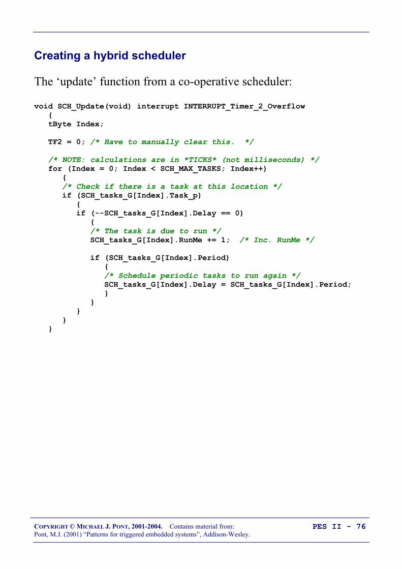
COPYRIGHT © MICHAEL J. PONT, 2001-2004. Contains material from:Pont, M.J. (2001) “Patterns for triggered embedded systems”, Addison-Wesley.
PES II - 76
Creating a hybrid scheduler
The ‘update’ function from a co-operative scheduler:
void SCH_Update(void) interrupt INTERRUPT_Timer_2_Overflow tByte Index;
TF2 = 0; /* Have to manually clear this. */
/* NOTE: calculations are in *TICKS* (not milliseconds) */ for (Index = 0; Index < SCH_MAX_TASKS; Index++) /* Check if there is a task at this location */ if (SCH_tasks_G[Index].Task_p) if (--SCH_tasks_G[Index].Delay == 0) /* The task is due to run */ SCH_tasks_G[Index].RunMe += 1; /* Inc. RunMe */
if (SCH_tasks_G[Index].Period) /* Schedule periodic tasks to run again */ SCH_tasks_G[Index].Delay = SCH_tasks_G[Index].Period;

COPYRIGHT © MICHAEL J. PONT, 2001-2004. Contains material from:Pont, M.J. (2001) “Patterns for triggered embedded systems”, Addison-Wesley.
PES II - 77
The co-operative version assumes a scheduler data type as follows:
/* Store in DATA area, if possible, for rapid access [Total memory per task is 7 bytes] */typedef data struct /* Pointer to the task (must be a 'void (void)' function) */ void (code * Task_p)(void);
/* Delay (ticks) until the function will (next) be run - see SCH_Add_Task() for further details */ tWord Delay;
/* Interval (ticks) between subsequent runs. - see SCH_Add_Task() for further details */ tWord Period;
/* Set to 1 (by scheduler) when task is due to execute */ tByte RunMe; sTask;

COPYRIGHT © MICHAEL J. PONT, 2001-2004. Contains material from:Pont, M.J. (2001) “Patterns for triggered embedded systems”, Addison-Wesley.
PES II - 78
The ‘Update’ function for a hybrid scheduler.
void hSCH_Update(void) interrupt INTERRUPT_Timer_2_Overflow tByte Index;
TF2 = 0; /* Have to manually clear this. */
/* NOTE: calculations are in *TICKS* (not milliseconds) */ for (Index = 0; Index < hSCH_MAX_TASKS; Index++) /* Check if there is a task at this location */ if (hSCH_tasks_G[Index].pTask) if (--hSCH_tasks_G[Index].Delay == 0) /* The task is due to run */ if (hSCH_tasks_G[Index].Co_op) /* If it is co-op, inc. RunMe */ hSCH_tasks_G[Index].RunMe += 1; else /* If it is a pre-emp, run it IMMEDIATELY */ (*hSCH_tasks_G[Index].pTask)();
hSCH_tasks_G[Index].RunMe -= 1; /* Dec RunMe */
/* Periodic tasks will automatically run again - if this is a 'one shot' task, delete it. */ if (hSCH_tasks_G[Index].Period == 0) hSCH_tasks_G[Index].pTask = 0;
if (hSCH_tasks_G[Index].Period) /* Schedule regular tasks to run again */ hSCH_tasks_G[Index].Delay = hSCH_tasks_G[Index].Period;

COPYRIGHT © MICHAEL J. PONT, 2001-2004. Contains material from:Pont, M.J. (2001) “Patterns for triggered embedded systems”, Addison-Wesley.
PES II - 79
The hybrid version assumes a scheduler data type as follows:
/* Store in DATA area, if possible, for rapid access [Total memory per task is 8 bytes] */typedef data struct /* Pointer to the task (must be a 'void (void)' function) */ void (code * Task_p)(void);
/* Delay (ticks) until the function will (next) be run - see SCH_Add_Task() for further details. */ tWord Delay;
/* Interval (ticks) between subsequent runs. - see SCH_Add_Task() for further details. */ tWord Period;
/* Set to 1 (by scheduler) when task is due to execute */ tByte RunMe;
/* Set to 1 if task is co-operative; Set to 0 if task is pre-emptive. */ tByte Co_op; sTask;

COPYRIGHT © MICHAEL J. PONT, 2001-2004. Contains material from:Pont, M.J. (2001) “Patterns for triggered embedded systems”, Addison-Wesley.
PES II - 80
Sch_Add_Task(Task_Name, Initial_Delay, Period);
Task_Name the name of the function (task) that you wish to schedule
Period the interval (in ticks) between repeated executions of the task.If set to 0, the task is executed only once.
Initial_Delay the delay (in ticks) before task is firstexecuted. If set to 0,the task is executedimmediately.
hSCH_Add_Task(Task_Name, Initial_Delay, Period, Co_op);
Task_Name the name of the function (task) that you wish to schedule
Period the interval (ticks) between repeated executions of the task.If set to 0, the task is executed only once.
Initial_Delay the delay (in ticks) before task is firstexecuted. If set to 0,the task is executedimmediately.
Co_op
set to ‘1’ if the task is co-operative;
set to ‘0’ if the task ispre-emptive

COPYRIGHT © MICHAEL J. PONT, 2001-2004. Contains material from:Pont, M.J. (2001) “Patterns for triggered embedded systems”, Addison-Wesley.
PES II - 81
Reliability and safety issues
As we have seen, in order to deal with critical sections of code in afully pre-emptive system, we have two main possibilities:
• ‘Pause’ the scheduling by disabling the scheduler interruptbefore beginning the critical section; re-enable the schedulerinterrupt when we leave the critical section, or;
• Use a ‘lock’ (or some other form of ‘semaphoremechanism’) to achieve a similar result.
Problems occur with the second solution if a task is interrupted afterit reads the lock flag (and finds it unlocked) and before it sets theflag (to indicate that the resource is in use).
// ...
// Ready to enter critical section// - Check lock is clear
if (Lock == LOCKED) return;
// Lock is clear// Enter critical section
// Set the lockLock = LOCKED;
// CRITICAL CODE HERE //
Problems arise if we have a context switch here(between ‘check and ‘set’)

COPYRIGHT © MICHAEL J. PONT, 2001-2004. Contains material from:Pont, M.J. (2001) “Patterns for triggered embedded systems”, Addison-Wesley.
PES II - 82
The problem does not occur in a hybrid scheduler, for the followingreasons:
• In the case of pre-emptive tasks - because they cannot beinterrupted - the ‘interrupt between check and lock’ situationcannot arise.
• In the case of co-operative tasks (which can be interrupted),the problem again cannot occur, for slightly differentreasons.
Co-operative tasks can be interrupted ‘between check andlock’, but only by a pre-emptive task. If the pre-emptivetask interrupts and finds that a critical section is unlocked, itwill set the lock2, use the resource, then clear the lock: thatis, it will run to completion. The co-operative task will thenresume and will find the system in the same state that itwas in before the pre-emptive task interrupted: as aresult, there can be no breach of the mutual exclusion rule.
Note that the hybrid scheduler solves the problem of access tocritical sections of code in a simple way: unlike the complete pre-emptive scheduler, we do not require the creation of complex code‘lock’ or ‘semaphore’ structures.
2 Strictly, setting the lock flag is not necessary, as no interruption is possible.

COPYRIGHT © MICHAEL J. PONT, 2001-2004. Contains material from:Pont, M.J. (2001) “Patterns for triggered embedded systems”, Addison-Wesley.
PES II - 83
The safest way to use the hybrid scheduler
The most reliable way to use the hybrid scheduler is as follows
• Create as many co-operative tasks as you require. It is likelythat you will be using a hybrid scheduler because one ormore of these tasks may have a duration greater than the tickinterval; this can be done safely with a hybrid scheduler, butyou must ensure that the tasks do not overlap.
• Implement one pre-emptive task; typically (but notnecessarily) this will be called at every tick interval. A gooduse of this task is, for example, to check for errors oremergency conditions: this task can thereby be used toensure that your system is able to respond within (say) 10msto an external event, even if its main purpose is to run (say) a1000 ms co-operative task.
• Remember that the pre-emptive task(s) can interrupt the co-operative tasks. If there are critical code sections, you needto implement a simple lock mechanism
• The pre-emptive task must be short (with a maximumduration of around 50% of the tick interval - preferablymuch less), otherwise overall system performance will begreatly impaired.
• Test the application carefully, under a full range of operatingconditions, and monitor for errors.

COPYRIGHT © MICHAEL J. PONT, 2001-2004. Contains material from:Pont, M.J. (2001) “Patterns for triggered embedded systems”, Addison-Wesley.
PES II - 84
Overall strengths and weaknesses
The overall strengths and weaknesses of Hybrid Scheduler may besummarised as follows: Has the ability to deal with both ‘long infrequent tasks’ and (a single)
‘short frequent task’ that cannot be provided by a pure Co-operativeScheduler.
Is safe and predictable, if used according to the guidelines. It must be handled with caution.

COPYRIGHT © MICHAEL J. PONT, 2001-2004. Contains material from:Pont, M.J. (2001) “Patterns for triggered embedded systems”, Addison-Wesley.
PES II - 85
Other forms of co-operative scheduler
• 255-TICK SCHEDULER [PTTES, p.747]A scheduler designed to run multiple tasks, but with reducedmemory (and CPU) overheads. This scheduler operates inthe same way as the standard co-operative schedulers, but allinformation is stored in byte-sized (rather than word-sized)variables: this reduces the required memory for each task byaround 30%.
• ONE-TASK SCHEDULER [PTTES, p.749]A stripped-down, co-operative scheduler able to manage asingle task. This very simple scheduler makes very efficientuse of hardware resources, with the bare minimum of CPUand memory overheads.
• ONE-YEAR SCHEDULER [PTTES, p.755]A scheduler designed for very low-power operation:specifically, it is designed to form the basis of battery-powered applications capable of operating for a year or morefrom a small, low-cost, battery supply.
• STABLE SCHEDULER [PTTES, p.932]is a temperature-compensated scheduler that adjusts itsbehaviour to take into account changes in ambienttemperature.
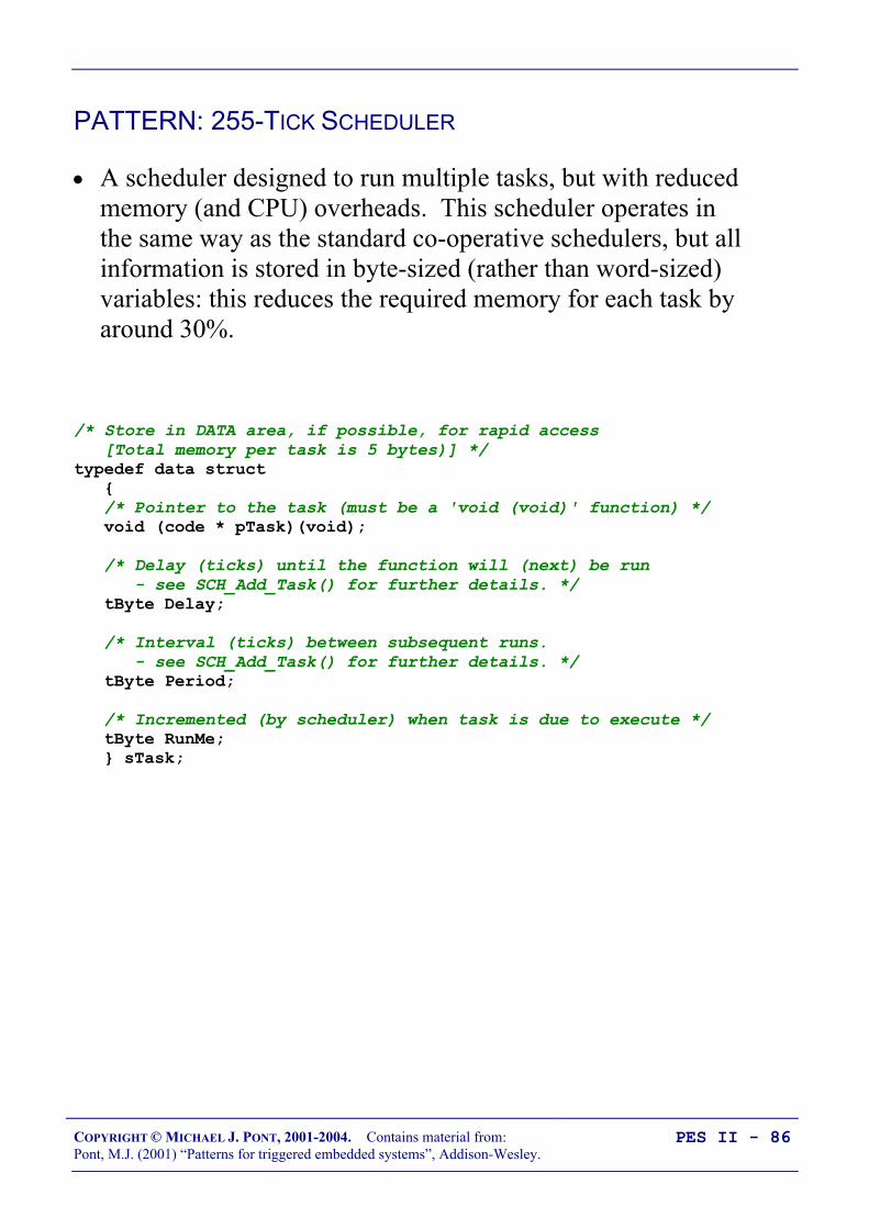
COPYRIGHT © MICHAEL J. PONT, 2001-2004. Contains material from:Pont, M.J. (2001) “Patterns for triggered embedded systems”, Addison-Wesley.
PES II - 86
PATTERN: 255-TICK SCHEDULER
• A scheduler designed to run multiple tasks, but with reducedmemory (and CPU) overheads. This scheduler operates inthe same way as the standard co-operative schedulers, but allinformation is stored in byte-sized (rather than word-sized)variables: this reduces the required memory for each task byaround 30%.
/* Store in DATA area, if possible, for rapid access [Total memory per task is 5 bytes)] */typedef data struct /* Pointer to the task (must be a 'void (void)' function) */ void (code * pTask)(void);
/* Delay (ticks) until the function will (next) be run - see SCH_Add_Task() for further details. */ tByte Delay;
/* Interval (ticks) between subsequent runs. - see SCH_Add_Task() for further details. */ tByte Period;
/* Incremented (by scheduler) when task is due to execute */ tByte RunMe; sTask;

COPYRIGHT © MICHAEL J. PONT, 2001-2004. Contains material from:Pont, M.J. (2001) “Patterns for triggered embedded systems”, Addison-Wesley.
PES II - 87
PATTERN: ONE-TASK SCHEDULER
• A stripped-down, co-operative scheduler able to manage asingle task. This very simple scheduler makes very efficientuse of hardware resources, with the bare minimum of CPUand memory overheads.
• Very similar in structure (and use) to “sEOS” (in PES I).
• The scheduler will consume no significant CPU resources:short of implementing the application as a SUPER LOOP(with all the disadvantages of this rudimentary architecture),there is generally no more efficient way of implementingyour application in a high-level language.
• Allows 0.1 ms tick intervals - even on the most basic8051.
This approach can be both safe and reliable, provided that you do notattempt to ‘shoe-horn’ a multi-task design into this single-taskframework.

COPYRIGHT © MICHAEL J. PONT, 2001-2004. Contains material from:Pont, M.J. (2001) “Patterns for triggered embedded systems”, Addison-Wesley.
PES II - 88
PATTERN: ONE-YEAR SCHEDULER
• A scheduler designed for very low-power operation:specifically, it is designed to form the basis of battery-powered applications capable of operating for a year or morefrom a small, low-cost, battery supply.
• AA cells are particularly popular, are widely availablethroughout the world, and are appropriate for manyapplications. The ubiquitous Duracell MN1500, forexample, has a rating of 1850 mAh. At low currents (anaverage of around 0.3 mA), you can expect to get at least ayear of life from such cells.
• To obtain such current consumption, choose a LOWoperating frequency (e.g. watch crystal, 32 kHz)
• NOTE: Performance will be limited!
B
E
C
5.5V, 0.3A lamp
ZTX751
Vcc
10 K
10 µF
4 MHz
20
19
18
17
16
15
14
1
2
3
4
5
6
7
Atm
el 1
051
8
9
10
13
12
11GND
P3.4
P3.5
P3.3
P3.2
XTL1
P3.1
XTL2
P3.0
RST
P3.7
P1.1
P1.0
P1.2
P1.3
P1.4
P1.6
P1.5
P1.7
VCC

COPYRIGHT © MICHAEL J. PONT, 2001-2004. Contains material from:Pont, M.J. (2001) “Patterns for triggered embedded systems”, Addison-Wesley.
PES II - 89
PATTERN: STABLE SCHEDULER
• A temperature-compensated scheduler that adjusts itsbehaviour to take into account changes in ambienttemperature.
/* The temperature compensation data
The Timer 2 reload values (low and high bytes) are varied depending on the current average temperature.
NOTE (1): Only temperature values from 10 - 30 celsius are considered in this version
NOTE (2): Adjust these values to match your hardware! */tByte code T2_reload_L[21] = /* 10 11 12 13 14 15 16 17 18 19 */ 0xBA,0xB9,0xB8,0xB7,0xB6,0xB5,0xB4,0xB3,0xB2,0xB1, /* 20 21 22 23 24 25 26 27 28 29 30 */ 0xB0,0xAF,0xAE,0xAD,0xAC,0xAB,0xAA,0xA9,0xA8,0xA7,0xA6;
tByte code T2_reload_H[21] = /* 10 11 12 13 14 15 16 17 18 19 */ 0x3C,0x3C,0x3C,0x3C,0x3C,0x3C,0x3C,0x3C,0x3C,0x3C, /* 20 21 22 23 24 25 26 27 28 29 30 */ 0x3C,0x3C,0x3C,0x3C,0x3C,0x3C,0x3C,0x3C,0x3C,0x3C,0x3C;

COPYRIGHT © MICHAEL J. PONT, 2001-2004. Contains material from:Pont, M.J. (2001) “Patterns for triggered embedded systems”, Addison-Wesley.
PES II - 90
Mix and match …
• Many of these different techniques can be combined
• For example, using the one-year and one-task schedulerstogether will further reduce current consumption.
• For example, using the “stable scheduler” as the Masternode in a multi-processor system will improve the time-keeping in the whole network
[More on this in later seminars …]

COPYRIGHT © MICHAEL J. PONT, 2001-2004. Contains material from:Pont, M.J. (2001) “Patterns for triggered embedded systems”, Addison-Wesley.
PES II - 91
Preparations for the next seminar
In the next seminar we’ll discuss the use of watchdog timers withembedded systems.
You’ll find some information about this topic in PTTES (Chapter12).
You’ll find a more detailed version of the material introduced in thenext seminar in this paper:
Pont, M.J. and Ong, H.L.R. (2002) "Using watchdog timers toimprove the reliability of TTCS embedded systems: Seven newpatterns and a case study", to appear in the proceedings ofVikingPLOP 2002, Denmark, September 2002.
A copy is available on the following WWW site:
http://www.engg.le.ac.uk/books/Pont/downloads.htm
You may find it useful to have a copy of this paper with you at theseminar.
40393837363534
1234567
‘8051’
8910
33323130292827262524
11121314151617181920
232221
P3.0
P1.7
RS
T
P1.6
P1.5
P1.4
P1.2
P1.3
P1.1
P1.0
VS
S
XTL2
XTL1
P3.7
P3.6
P3.5
P3.3
P3.4
P3.2
P3.1
/ EA
P0.6
P0.7
P0.5
P0.4
P0.3
P0.1
P0.2
P0.0
VC
C
P2.0
P2.2
P2.1
P2.3
P2.4
P2.5
P2.7
P2.6
/ PSE
N
ALE

COPYRIGHT © MICHAEL J. PONT, 2001-2004. Contains material from:Pont, M.J. (2001) “Patterns for triggered embedded systems”, Addison-Wesley.
PES II - 92

COPYRIGHT © MICHAEL J. PONT, 2001-2004. Contains material from:Pont, M.J. (2001) “Patterns for triggered embedded systems”, Addison-Wesley.
PES II - 93
Seminar 5: Improving systemreliability usingwatchdog timers

COPYRIGHT © MICHAEL J. PONT, 2001-2004. Contains material from:Pont, M.J. (2001) “Patterns for triggered embedded systems”, Addison-Wesley.
PES II - 94
Overview of this seminar
In this seminar we’ll discuss the use of watchdog timers withembedded systems.
You’ll find a more detailed version of the material introduced in thisseminar in this paper:
Pont, M.J. and Ong, H.L.R. (2002) "Using watchdog timers toimprove the reliability of TTCS embedded systems: Seven newpatterns and a case study", to appear in the proceedings ofVikingPLOP 2002, Denmark, September 2002.
A copy is available on the following WWW site:
http://www.engg.le.ac.uk/books/Pont/downloads.htm
You may find it useful to have a copy of this paper with you at theseminar.
COPYRIGHT © MICHAEL J. PONT, 2001-2004. Contains material from:Pont, M.J. (2001) “Patterns for triggered embedded systems”, Addison-Wesley.
PES II - 95
The watchdog analogy
Watchdog timers will - usually - have the following two features:
• The timer must be refreshed at regular, well-defined,intervals.If the timer is not refreshed at the required time it willoverflow, an process which will usually cause the associatedmicrocontroller to be reset.
• When starting up, the microcontroller can determine thecause of the reset.
That is, it can determine if it has been started ‘normally’, orre-started as a result of a watchdog overflow. This meansthat, in the latter case, the programmer can ensure that thesystem will try to handle the error that caused the watchdogoverflow.

COPYRIGHT © MICHAEL J. PONT, 2001-2004. Contains material from:Pont, M.J. (2001) “Patterns for triggered embedded systems”, Addison-Wesley.
PES II - 96
PATTERN: Watchdog Recovery
Understanding the basic operation of watchdog timer hardware isnot difficult.
However, making good use of this hardware in a TTCS applicationrequires some care. As we will see, there are three main issueswhich need to be considered:
• Choice of hardware;
• The watchdog-induced reset;
• The recovery process.

COPYRIGHT © MICHAEL J. PONT, 2001-2004. Contains material from:Pont, M.J. (2001) “Patterns for triggered embedded systems”, Addison-Wesley.
PES II - 97
Choice of hardware
We have seen in many previous cases that, where available, the useof on-chip components is to be preferred to the use of equivalentoff-chip components. Specifically, on-chip components tend tooffer the following benefits:
• Reduced hardware complexity, which tends to result inincreased system reliability.
• Reduced application cost.
• Reduced application size.
These factors also apply when selecting a watchdog timer.
In addition, when implementing WATCHDOG RECOVERY, it isusually important that the system is able to determine - as it beginsoperation - whether it was reset as a result of normal power cycling,or because of a watchdog timeout.
In most cases, only on-chip watchdogs allow you to determine thecause of the reset in a simple and reliable manner.

COPYRIGHT © MICHAEL J. PONT, 2001-2004. Contains material from:Pont, M.J. (2001) “Patterns for triggered embedded systems”, Addison-Wesley.
PES II - 98
Time-based error detection
A key requirement in applications using a co-operative scheduler isthat, for all tasks, under all circumstances, the following conditionmust be adhered to:
<TaskDuration TickInterval
Where: TaskDuration is the task duration, and TickInterval is the system‘tick interval’.
It is possible to use a watchdog timer to detect task overflows, asfollows:
• Set the watchdog timer to overflow at a period greater thanthe tick interval.
• Create a task that will update the watchdog timer shortlybefore it overflows.
• Start the watchdog.
[We’ll say more about this shortly]

COPYRIGHT © MICHAEL J. PONT, 2001-2004. Contains material from:Pont, M.J. (2001) “Patterns for triggered embedded systems”, Addison-Wesley.
PES II - 99
Other uses for watchdog-induced resets
If your system uses timer-based error detection techniques, then itcan make sense to also use watchdog-induced resets to handle othererrors. Doing this means that you can integrate some or all of yourerror-handling mechanisms in a single place (usually in some formof system initialisation function). This can - in many systems -provide a very “clean” and approach to error handling that is easy tounderstand (and maintain).
Note that this combined approach is only appropriate where therecovery behaviour you will implement is the same for the differenterrors you are trying to detect.
Here are some suggestions for the types of errors that can beeffectively handled in this way:
• Failure of on-chip hardware (e.g. analogue-to-digitalconverters, ports).
• Failure of external actuators (e.g. DC motors in an industrialrobot; stepper motors in a printer).
• Failure of external sensors (e.g. ultraviolet sensor in an artgallery; vibration sensor in an automotive system).
• Temporary reduction is power-supply voltage.

COPYRIGHT © MICHAEL J. PONT, 2001-2004. Contains material from:Pont, M.J. (2001) “Patterns for triggered embedded systems”, Addison-Wesley.
PES II - 100
Recovery behaviour
Before we decide whether we need to carry out recovery behaviour,we assume that the system has been reset.
If the reset was “normal” we simply start the scheduler and run thestandard system configuration.
If, instead, the cause of the reset was a watchdog overflow, thenthere are three main options:
• We can simply continue as if the processor had undergonean “ordinary” reset.
• We can try to “freeze” the system in the reset state. Thisoption is known as “fail-silent recovery”.
• We can try to have the system run a different algorithm(typically, a very simple version of the original algorithm,often without using the scheduler). This is often referred toas “limp home recovery”.
COPYRIGHT © MICHAEL J. PONT, 2001-2004. Contains material from:Pont, M.J. (2001) “Patterns for triggered embedded systems”, Addison-Wesley.
PES II - 101
Risk assessment
In safety-related or safety-critical systems, this pattern should not beimplemented before a complete risk-assessment study has beenconducted (by suitably-qualified individuals).
Successful use of this pattern requires a full understanding of the errorsthat are likely to be detected by your error-detection strategies (andthose that will be missed), plus an equal understanding of the recoverystrategy that you have chosen to implement.
Without a complete investigation of these issues, you cannot be surethat implementation of the pattern you will increase (rather thandecrease) the reliability of your application.

COPYRIGHT © MICHAEL J. PONT, 2001-2004. Contains material from:Pont, M.J. (2001) “Patterns for triggered embedded systems”, Addison-Wesley.
PES II - 102
The limitations of single-processor designs
It is important to appreciate that there is a limit to the extent towhich reliability of a single-processor embedded system can beimproved using a watchdog timer.
For example, LIMP-HOME RECOVERY is the most sophisticatedrecovery strategy considered in this seminar.
If implemented with due care, it can prove very effective. However,it relies for its operation on the fact that - even in the presence of anerror - the processor itself (and key support circuitry, such as theoscillator, power supply, etc) still continues to function. If theprocessor or oscillator suffer physical damage, or power is removed,LIMP-HOME RECOVERY cannot help your system to recover.
In the event of physical damage to your “main” processor (or itssupport hardware), you may need to have some means of engaginganother processor to take over the required computational task.
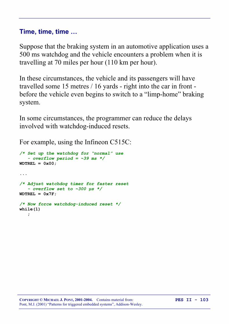
COPYRIGHT © MICHAEL J. PONT, 2001-2004. Contains material from:Pont, M.J. (2001) “Patterns for triggered embedded systems”, Addison-Wesley.
PES II - 103
Time, time, time …
Suppose that the braking system in an automotive application uses a500 ms watchdog and the vehicle encounters a problem when it istravelling at 70 miles per hour (110 km per hour).
In these circumstances, the vehicle and its passengers will havetravelled some 15 metres / 16 yards - right into the car in front -before the vehicle even begins to switch to a “limp-home” brakingsystem.
In some circumstances, the programmer can reduce the delaysinvolved with watchdog-induced resets.
For example, using the Infineon C515C:/* Set up the watchdog for “normal” use - overflow period = ~39 ms */WDTREL = 0x00;
...
/* Adjust watchdog timer for faster reset - overflow set to ~300 µs */WDTREL = 0x7F;
/* Now force watchdog-induced reset */while(1) ;

COPYRIGHT © MICHAEL J. PONT, 2001-2004. Contains material from:Pont, M.J. (2001) “Patterns for triggered embedded systems”, Addison-Wesley.
PES II - 104
Watchdogs: Overall strengths and weaknesses
Watchdogs can provide a ‘last resort’ form of error recovery. If youthink of the use of watchdogs in terms of ‘if all else fails, then we’ll letthe watchdog reset the system’, you are taking a realistic view of thecapabilities of this approach. Use of this technique usually requires an on-chip watchdog. Used without due care at the design phase and / or adequate testing,
watchdogs can reduce the system reliability dramatically. In particular, inthe presence of sustained faults, badly-designed watchdog “recovery”mechanisms can cause your system to repeatedly reset itself. This can bevery dangerous. Watchdogs with long timeout periods are unsuitable for many applications.
COPYRIGHT © MICHAEL J. PONT, 2001-2004. Contains material from:Pont, M.J. (2001) “Patterns for triggered embedded systems”, Addison-Wesley.
PES II - 105
PATTERN: Scheduler Watchdog
As we have mentioned, a key requirement in applications using aco-operative scheduler is that, for all tasks, under all circumstances,the following condition must be adhered to:
<TaskDuration TickInterval
Where: TaskDuration is the task duration, and TickInterval is the system‘tick interval’.
It is possible to use a watchdog timer to detect task overflows, asfollows:
• Set the watchdog timer to overflow at a period greater thanthe tick interval.
• Create a task that will update the watchdog timer shortlybefore it overflows.
• Start the watchdog.
So - how do you select the watchdog overflow period?

COPYRIGHT © MICHAEL J. PONT, 2001-2004. Contains material from:Pont, M.J. (2001) “Patterns for triggered embedded systems”, Addison-Wesley.
PES II - 106
Selecting the overflow period - “hard” constraints
For systems with “hard” timing constraints for one or more tasks, itis usually appropriate to set the watchdog overflow period to a valueslightly greater than the tick interval (e.g. 1.1 ms overflow in asystem with 1 ms ticks).
Please note that to do this, the watchdog timer will usually need tobe driven by a crystal oscillator (or the timing will not besufficiently accurate).
In addition, the watchdog timer will need to give you enoughcontrol over the timer settings, so that the required overflow periodcan be set.
COPYRIGHT © MICHAEL J. PONT, 2001-2004. Contains material from:Pont, M.J. (2001) “Patterns for triggered embedded systems”, Addison-Wesley.
PES II - 107
Selecting the overflow period - “soft” constraints
Many (‘soft’) TTCS systems continue to operate safely and effectively,even if - occasionally - the duration of the task(s) that are scheduled torun at a particular time exceeds the tick interval.
To give a simple example, a scheduler with a 1 ms tick interval can- without problems - schedule a single task with a duration of 10 msthat is called every 20 ms.
Of course, if the same system is also trying to schedule a task ofduration 0.1 ms every 5 ms, then the 0.1 ms task will sometimes beblocked. Often careful design will avoid this blockage but - even ifit occurs - it still may not matter because, although the 0.1 ms willnot always run on time, it will always run (that is, it will run 200times every second, as required).
For some tasks - with soft deadlines - this type of behaviour may beacceptable. If so:
• Set the watchdog to overflow after a period of around 100ms.
• Feed the watchdog every millisecond, using an appropriatetask.
• Only if the scheduling is blocked for more than 100 ms willthe system be reset.

COPYRIGHT © MICHAEL J. PONT, 2001-2004. Contains material from:Pont, M.J. (2001) “Patterns for triggered embedded systems”, Addison-Wesley.
PES II - 108
PATTERN: Program-Flow Watchdog
Use of PROGRAM-FLOW WATCHDOG may help to improvereliability of your system in the presence of program-flow errors(which may, in turn, result from EMI).
Arguably, the most serious form of program-flow error in anembedded microcontroller is corruption of the program counter(PC), also known as the instruction pointer.
Since the PC of the 8051 is a 16-bit wide register, we make thereasonable assumption that – in response to PC corruption – the PCmay take on any value in the range 0 to 65535. In thesecircumstances, the 8051 processor will fetch and execute the nextinstruction from the code memory location pointed to by thecorrupted PC register. This can be very dangerous!

COPYRIGHT © MICHAEL J. PONT, 2001-2004. Contains material from:Pont, M.J. (2001) “Patterns for triggered embedded systems”, Addison-Wesley.
PES II - 109
The most straightforward implementation of PROGRAM-FLOWWATCHDOG involves two stages:
• We fill unused locations at the end of the program codememory with single-byte “No Operation” (NOP), orequivalent, instructions.
• We place a “PC Error Handler” (PCEH) at the end of codememory to deal with the error.

COPYRIGHT © MICHAEL J. PONT, 2001-2004. Contains material from:Pont, M.J. (2001) “Patterns for triggered embedded systems”, Addison-Wesley.
PES II - 110
Dealing with errors
Here, we will assume that the PCEH will consist mainly of a loop:/* Force watchdog timeout */while(1) ;
This means that, as discussed in WATCHDOG RECOVERY [thisseminar] the watchdog timer will force a clean system reset.
Please note that, as also discussed in WATCHDOG RECOVERY, wemay be able to reduce the time taken to reset the processor byadapting the watchdog timing. For example:
/* Set up the watchdog for “normal” use - overflow period = ~39 ms */WDTREL = 0x00;
...
/* Adjust watchdog timer for faster reset - overflow set to ~300 µs */WDTREL = 0x7F;
/* Now force watchdog-induced reset */while(1) ;
After the watchdog-induced reset, we need to implement a suitablerecovery strategy. A range of different options are discussed inRESET RECOVERY [this seminar], FAIL-SILENT RECOVERY [thisseminar] and LIMP-HOME RECOVERY [this seminar].

COPYRIGHT © MICHAEL J. PONT, 2001-2004. Contains material from:Pont, M.J. (2001) “Patterns for triggered embedded systems”, Addison-Wesley.
PES II - 111
Hardware resource implications
PROGRAM-FLOW WATCHDOG can only be guaranteed to workwhere the corrupted PC points to an “empty” memory location.
Maximum effectiveness will therefore be obtained withcomparatively small programs (a few kilobytes of code memory),and larger areas of empty memory.
If devices with less than 64kB of code memory are used, a problemknown as “memory aliasing” can occur:
Code
0kB 2kB 64kB0xA552
64kB physical code memory – no memory aliasing
Code Code Code Code
16kB physical code memory – memory overlap 4 times due to aliasing
0kB 2kB 64kB
0x6552
16kB 18kB 32kB 34kB 48kB 50kB
0xE5520xA5520x2552
Aliased section
If you want to increase the chances of detecting program-flow errorsusing this approach, you need to use the maximum amount of (code)memory that is supported by your processor. In the case of the 8051family, this generally means selecting a device with 64 kB of memory.Clearly, this choice will have cost implications.

COPYRIGHT © MICHAEL J. PONT, 2001-2004. Contains material from:Pont, M.J. (2001) “Patterns for triggered embedded systems”, Addison-Wesley.
PES II - 112
Speeding up the response
We stated in “Solution” that the most straightforwardimplementation of PROGRAM-FLOW WATCHDOG involves twostages:
• We fill unused locations at the end of the program codememory with single-byte “No Operation” (NOP), orequivalent, instructions.
• Second, a small amount of program code, in the form of an“PC Error Handler” (PCEH), is placed at the end of codememory to deal with the error.
Two problems:
• It may take an appreciable period of time for the processor toreach the error handler.
• The time taken to recover from an error is highly variable(since it depends on the value of the corrupted PC).

COPYRIGHT © MICHAEL J. PONT, 2001-2004. Contains material from:Pont, M.J. (2001) “Patterns for triggered embedded systems”, Addison-Wesley.
PES II - 113
An alternative is to fill the memory not with “NOP” instructions butwith “jump” instructions.
(In effect, we want to fill each location with “Jump to address X”instructions, and then place the error handler at address X.)
• In the 8051, the simplest implementation is to fill the emptymemory with “long jump” instructions (0x02).
• The error handler will then be located at address 0x0202.

COPYRIGHT © MICHAEL J. PONT, 2001-2004. Contains material from:Pont, M.J. (2001) “Patterns for triggered embedded systems”, Addison-Wesley.
PES II - 114
PATTERN: Reset Recovery
Using RESET RECOVERY we assume that the best way to deal withan error (the presence of which is indicated by a watchdog-inducedreset) is to re-start the system, in its normal configuration.
Implementation
RESET RECOVERY is very to easy to implement. We require a basicwatchdog timer, such as the common “1232” external device,available from various manufacturers (we show how to use thisdevice in an example below).
Using such a device, the cause of a system reset cannot be easilydetermined. However, this does not present a problem whenimplementing RESET RECOVERY. After any reset, we simply start(or re-start) the scheduler and try to carry out the normal systemoperations.
The particular problem with RESET RECOVERY is that, if the error thatgave rise to the watchdog reset is permanent (or long-lived), then youare likely to lose control of your system as it enters an endless loop(reset, watchdog overflow, reset, watchdog overflow, …).
This lack of control can have disastrous consequences in manysystems.

COPYRIGHT © MICHAEL J. PONT, 2001-2004. Contains material from:Pont, M.J. (2001) “Patterns for triggered embedded systems”, Addison-Wesley.
PES II - 115
PATTERN: Fail-Silent Recovery
When using FAIL-SILENT RECOVERY, our aim is to shut the systemdown after a watchdog-induced reset. This type of response isreferred to as “fail silent” behaviour because the processor becomes“silent” in the event of an error.
FAIL-SILENT RECOVERY is implemented after every “Normal” resetas follows:
• The scheduler is started and program execution is normal.
By contrast, after a watchdog-induced reset, FAIL-SILENTRECOVERY will typically be implemented as follows:
• Any necessary port pins will be set to appropriate levels (forexample, levels which will shut down any attachedmachinery).
• Where required, an error port will be set to report the causeof the error,
• All interrupts will be disabled, and,
• The system will be stopped, either by entering an endlessloop or (preferably) by entering power-down or idle mode.
(Power-down or idle mode is used because, in the event that theproblems were caused by EMI or ESD, this is thought likely tomake the system more robust in the event of another interferenceburst.)

COPYRIGHT © MICHAEL J. PONT, 2001-2004. Contains material from:Pont, M.J. (2001) “Patterns for triggered embedded systems”, Addison-Wesley.
PES II - 116
Example: Fail-Silent behaviour in the Airbus A310
• In the A310 Airbus, the slat and flap control computers forman ‘intelligent’ actuator sub-system.
• If an error is detected during landing, the wings are set to asafe state and then the actuator sub-system shuts itself down(Burns and Wellings, 1997, p.102).
[Please note that the mechanisms underlying this “fail silent”behaviour are unknown.]

COPYRIGHT © MICHAEL J. PONT, 2001-2004. Contains material from:Pont, M.J. (2001) “Patterns for triggered embedded systems”, Addison-Wesley.
PES II - 117
Example: Fail-Silent behaviour in a steer-by-wire application
Suppose that an automotive steer-by-wire system has been createdthat runs a single task, every 10 ms. We will assume that the systemis being monitored to check for task over-runs (see SCHEDULERWATCHDOG [this seminar]). We will also assume that the systemhas been well designed, and has appropriate timeout code, etc,implemented.
Further suppose that a passenger car using this system is beingdriven on a motorway, and that an error is detected, resulting in awatchdog reset. What recovery behaviour should be implemented?
We could simply re-start the scheduler and “hope for the best”.However, this form of “reset recovery” is probably not appropriate.In this case, if we simply perform a reset, we may leave the driverwithout control of their vehicle (see RESET RECOVERY [thisseminar]).
Instead, we could implement a fail-silent strategy. In this case, wewould simply aim to bring the vehicle, slowly, to a halt. To warnother road vehicles that there was a problem, we could choose toflash all the lights on the vehicle on an off (continuously), and topulse the horn. This strategy (which may - in fact - be far fromsilent) is not ideal, because there can be no guarantee that the driverand passengers (or other road vehicles) will survive the incident.However, it the event of a very serious system failure, it may be allthat we can do.

COPYRIGHT © MICHAEL J. PONT, 2001-2004. Contains material from:Pont, M.J. (2001) “Patterns for triggered embedded systems”, Addison-Wesley.
PES II - 118
PATTERN: Limp-Home Recovery
In using LIMP-HOME RECOVERY, we make two assumptions aboutour system:
• A watchdog-induced reset indicates that a significant errorhas occurred.
• Although a full (normal) re-start is considered too risky, itmay still be possible to let the system “limp home” byrunning a simple version of the original algorithm.
Overall, in using this pattern, we are looking for ways of ensuringthat the system continues to function - even in a very limited way -in the event of an error.
LIMP-HOME RECOVERY is implemented after ever “Normal” resetas follows:
• The scheduler is started and program execution is normal.
By contrast, after a watchdog-induced reset, LIMP-HOMERECOVERY will typically be implemented as follows:
• The scheduler will not be started.
• A simple version of the original algorithm will be executed.

COPYRIGHT © MICHAEL J. PONT, 2001-2004. Contains material from:Pont, M.J. (2001) “Patterns for triggered embedded systems”, Addison-Wesley.
PES II - 119
Example: Limp-home behaviour in a steer-by-wireapplication
In FAIL-SILENT RECOVERY [this seminar], we considered onepossible recovery strategy in a steer-by-sire application.
As an alternative to the approach discussed in the previous example,we may wish to consider a limp-home control strategy. In this case,a suitable strategy might involve a code structure like this:
while(1) Update_basic_steering_control(); Software_delay_10ms();
This is a basic software architecture (based on SUPER LOOP[PTTES, p.162]).
In creating this version, we have avoided use of the scheduler code.We might also wish to use a different (simpler) control algorithm atthe heart of this system. For example, the main control algorithmmay use measurements of the current speed, in order to ensure asmooth response even when the vehicle is moving rapidly. Wecould omit this feature in the “limp home” version.
COPYRIGHT © MICHAEL J. PONT, 2001-2004. Contains material from:Pont, M.J. (2001) “Patterns for triggered embedded systems”, Addison-Wesley.
PES II - 120
• Of course, simply using a different software implementationmay still not be enough.
For example, in our steer-by-wire application, we may havea position sensor (attached to the steering column) and anappropriate form of DC motor (attached to the steeringrack). Both the sensor and the actuator would then be linkedto the processor.
• When designing the limp-home controller, we would like tohave an additional sensor and actuator, which are - as far aspossible - independent of the components used in the main(scheduled) system.
• This option makes sense because it is likely to maximise thechances that the Slave node will operate correctly when ittakes over.

COPYRIGHT © MICHAEL J. PONT, 2001-2004. Contains material from:Pont, M.J. (2001) “Patterns for triggered embedded systems”, Addison-Wesley.
PES II - 121
This approach has two main implications:
1. The hardware must ‘fail silently’: for example, if we didadd a backup motor to the steering rack, this would be littleuse if the main motor ‘seized’ when the scheduler task wasshut down.
Note that there may be costs associated with obtaining thisbehaviour. For example, we may need to add some kind ofclutch assembly to the motor output, to ensure that it couldbe disconnected in the event of a motor jam. However, sucha decision would need to be made only after a full riskassessment. For example, it would not make sense to add aclutch unit if a failure of this unit (leading to a loss ofcontrol of steering) was more likely than a motor seizure.
2. The cost of hardware duplication can be significant, and willoften be considerably higher than the cost of a duplicatedprocessor: this may make this approach economicallyunfeasible.
When costs are too high, sometimes a compromise canprove effective. For example, in the steering system, wemight consider adding a second set of windings to the motorfor use by the Slave (rather than adding a complete newmotor assembly). Again, such a decision should be madeonly after a full risk assessment.

COPYRIGHT © MICHAEL J. PONT, 2001-2004. Contains material from:Pont, M.J. (2001) “Patterns for triggered embedded systems”, Addison-Wesley.
PES II - 122
PATTERN: Oscillator Watchdog
People sometimes assume that watchdog timer is a good way ofdetecting oscillator failure. However, a few moments thoughtquickly reveals that this is very rarely the case.
When the oscillator fails, the associated microcontroller will stop.
Even if (by using a watchdog timer, or some other technique) you detectthat the oscillator has failed, you cannot execute any code to deal withthe situation.
In these circumstances, you may be able to improve the reliability ofyour system by using an oscillator watchdog.
The OW operates as follows: if an oscillator failure is detected, themicrocontroller is forced into a reset state: this means that portpins take on their reset values.
The state of the port pins is crucial, since it means that the developerhas a chance to ensure that hardware devices controlled by theprocessor (for example, dangerous machinery) will be shut down if theoscillator fails.

COPYRIGHT © MICHAEL J. PONT, 2001-2004. Contains material from:Pont, M.J. (2001) “Patterns for triggered embedded systems”, Addison-Wesley.
PES II - 123
What happens next?
• In most cases, the microcontroller will be held in a resetstate “for ever”.
• However, most oscillator watchdogs will continue tomonitor the clock input to the chip: if the main oscillator isrestored, the system will leave reset and will begin operatingagain.
COPYRIGHT © MICHAEL J. PONT, 2001-2004. Contains material from:Pont, M.J. (2001) “Patterns for triggered embedded systems”, Addison-Wesley.
PES II - 124
Preparations for the next seminar
In the next seminar, we will begin to consider techniques for linkingtogether multiple processors.
Please read PTTES Chapter 25 before the next seminar.
40393837363534
1234567
‘8051’
8910
33323130292827262524
11121314151617181920
232221
P3.0
P1.7
RS
T
P1.6
P1.5
P1.4
P1.2
P1.3
P1.1
P1.0
VS
S
XTL2
XTL1
P3.7
P3.6
P3.5
P3.3
P3.4
P3.2
P3.1
/ EA
P0.6
P0.7
P0.5
P0.4
P0.3
P0.1
P0.2
P0.0
VC
C
P2.0
P2.2
P2.1
P2.3
P2.4
P2.5
P2.7
P2.6
/ PSE
N
ALE
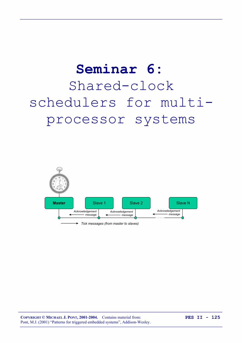
COPYRIGHT © MICHAEL J. PONT, 2001-2004. Contains material from:Pont, M.J. (2001) “Patterns for triggered embedded systems”, Addison-Wesley.
PES II - 125
Seminar 6: Shared-clock
schedulers for multi-processor systems
Master Slave 2Slave 1 Slave N
Tick messages (from master to slaves)
Acknowledgement message
Acknowledgement message
Acknowledgement message

COPYRIGHT © MICHAEL J. PONT, 2001-2004. Contains material from:Pont, M.J. (2001) “Patterns for triggered embedded systems”, Addison-Wesley.
PES II - 126
Overview of this seminar
We now turn our attention to multi-processor applications. As wewill see, an important advantage of the time-triggered (co-operative)scheduling architecture is that it is inherently scaleable, and that itsuse extends naturally to multi-processor environments.
In this seminar:
• We consider some of the advantages - and disadvantages -that can result from the use of multiple processors.
• We introduce the shared-clock scheduler.
• We consider the implementation of shared-clock designsschedulers that are kept synchronised through the use ofexternal interrupts on the Slave microcontrollers.

COPYRIGHT © MICHAEL J. PONT, 2001-2004. Contains material from:Pont, M.J. (2001) “Patterns for triggered embedded systems”, Addison-Wesley.
PES II - 127
Why use more than one processor?
Many modern embedded systems contain more than one processor.
For example, a modern passenger car might contain some forty suchdevices, controlling brakes, door windows and mirrors, steering, airbags, and so forth.
Similarly, an industrial fire detection system might typically have200 or more processors, associated - for example - with a range ofdifferent sensors and actuators.
Two main reasons:
• Additional CPU performance and hardware facilities
• Benefits of modular design

COPYRIGHT © MICHAEL J. PONT, 2001-2004. Contains material from:Pont, M.J. (2001) “Patterns for triggered embedded systems”, Addison-Wesley.
PES II - 128
Additional CPU performance and hardware facilities
Suppose we require a microcontroller with the followingspecification:
• 60+ port pins
• Six timers
• Two USARTS
• 128 kbytes of ROM
• 512 bytes of RAM
• A cost of around $1.00 (US)
… how can we achieve this???

COPYRIGHT © MICHAEL J. PONT, 2001-2004. Contains material from:Pont, M.J. (2001) “Patterns for triggered embedded systems”, Addison-Wesley.
PES II - 129
P 2.7 (A15) 28
P 2.6 (A14) 27
P 2.5 (A13) 26
P 2.4 (A12) 25
P 2.3 (A11) 24
P 2.2 (A10) 23
P 2.1 (A9) 22
P 2.0 (A8) 21
ALE (/PROG)
/ EA
/PSEN
31
30
29
19 XTL1
XTL218
RST9
40
VCC
20
VSS
“805
1”
P 1.7
12345
P 1.567
P 1.0 [T2]P 1.1 [T2EX]P 1.2P 1.3P 1.4
P 1.68
P 3.0 (RXD)P 3.1 (TXD) P 3.2 (/INT0)P 3.3 (/INT1)P 3.4 (T0) P 3.5 (T1) P 3.6 (/WR) P 3.7 (/RD)
1011121314151617
P 0.0 (AD0) 39
P 0.1 (AD1) 38
P 0.2 (AD2) 37
P 0.3 (AD3) 36
P 0.4 (AD4) 35
P 0.5 (AD5) 34
P 0.6 (AD6) 33
P 0.7 (AD7) 32
• A flexible environment with 62 free port pins, 5 free timers,two UARTs, etc.
• Further microcontrollers may be added without difficulty,
• The communication over a single wire (plus ground) willensure that the tasks on all processors are synchronised.
• The two-microcontroller design also has two CPUs:true multi-tasking is possibly.

COPYRIGHT © MICHAEL J. PONT, 2001-2004. Contains material from:Pont, M.J. (2001) “Patterns for triggered embedded systems”, Addison-Wesley.
PES II - 130
The benefits of modular design
Suppose we want to build a range of clocks…
AT MH
Current Time : 01.44
Alarm Time : --:--
We can split the design into ‘display’ and ‘time-keeping’ modules.
This type of modular approach is very common in the automotiveindustry where increasing numbers of microcontroller-basedmodules are used in new vehicle designs.

COPYRIGHT © MICHAEL J. PONT, 2001-2004. Contains material from:Pont, M.J. (2001) “Patterns for triggered embedded systems”, Addison-Wesley.
PES II - 131
The benefits of modular design
Acquisitionsystem
1
Sensor1
Sensor2
Sensor3
PC
An alternative solution:
Acquisitionsystem
1
Sensor1
Sensor2
Sensor3
PC
MCUA
2
MCUB
3
MCUC
4
In the A310 Airbus, the slat and flap control computers form an‘intelligent’ actuator sub-system. If an error is detected duringlanding, the wings are set to a safe state and then the actuator sub-system shuts itself down.

COPYRIGHT © MICHAEL J. PONT, 2001-2004. Contains material from:Pont, M.J. (2001) “Patterns for triggered embedded systems”, Addison-Wesley.
PES II - 132
So - how do we link more than one processor?
Some important questions:
• How do we keep the clocks on the various nodessynchronised?
• How do we transfer data between the various nodes?
• How does one node check for errors on the other nodes?

COPYRIGHT © MICHAEL J. PONT, 2001-2004. Contains material from:Pont, M.J. (2001) “Patterns for triggered embedded systems”, Addison-Wesley.
PES II - 133
Synchronising the clocks
Why do we need to synchronise the tasks running on different partsof a multi-processor system?
Portable Traffic Light Controller
Portable Traffic Light Controller
• We will assume that there will be a microcontroller at eachend of the traffic light application to control the two sets oflights.
• We will also assume that each microcontroller is running ascheduler, and that each is driven by an independent crystaloscillator circuit.
BUT!
Each microcontroller will operate at a different temperature…
The lights will get “out of sync”…

COPYRIGHT © MICHAEL J. PONT, 2001-2004. Contains material from:Pont, M.J. (2001) “Patterns for triggered embedded systems”, Addison-Wesley.
PES II - 134
Synchronising the clocks
The S-C scheduler tackles this problem by sharing a single clockbetween the various processor board:
Master Slave 2Slave 1 Slave N
Tick messages (from Master to Slaves)
Here we have one, accurate, clock on the Master node in thenetwork.
This clock is used to drive the scheduler in the Master node inexactly the manner discussed in Seminar 1 and Seminar 2.

COPYRIGHT © MICHAEL J. PONT, 2001-2004. Contains material from:Pont, M.J. (2001) “Patterns for triggered embedded systems”, Addison-Wesley.
PES II - 135
Synchronising the clocks - Slave nodes
The Slave nodes also have schedulers: however, the interrupts usedto drive these schedulers are derived from ‘tick messages’ generatedby the Master.
Time
TickMessage
TickMessage
TickMessage ...
Master tick (from timer)
Slave tick (from CAN hardware)
This keeps all the nodes running “in phase”
For example:
In the case of the traffic lights considered earlier, changes intemperature will, at worst, cause the lights to cycle more quickly ormore slowly: the two sets of lights will not, however, get out ofsync.

COPYRIGHT © MICHAEL J. PONT, 2001-2004. Contains material from:Pont, M.J. (2001) “Patterns for triggered embedded systems”, Addison-Wesley.
PES II - 136
Transferring data
In many applications, we will also need to transfer data betweenthe tasks running on different processor nodes.
To illustrate this, consider again the traffic-light controller. Supposethat a bulb blows in one of the light units.
• When a bulb is missing, the traffic control signals areambiguous: we therefore need to detect bulb failures on eachnode and, having detected a failure, notify the other nodethat a failure has occurred.
• This will allow us - for example - to extinguish all the(available) bulbs on both nodes, or to flash all the bulbs onboth nodes: in either case, this will inform the road user thatsomething is amiss, and that the road must be negotiatedwith caution.

COPYRIGHT © MICHAEL J. PONT, 2001-2004. Contains material from:Pont, M.J. (2001) “Patterns for triggered embedded systems”, Addison-Wesley.
PES II - 137
Transferring data (Master to Slave)
As we discussed above, the Master sends regular tick messages tothe Slave, typically once per millisecond.
These tick messages can - in most S-C schedulers - include datatransfers: it is therefore straightforward to send an appropriate tickmessage to the Slave to alert it to the bulb failure.

COPYRIGHT © MICHAEL J. PONT, 2001-2004. Contains material from:Pont, M.J. (2001) “Patterns for triggered embedded systems”, Addison-Wesley.
PES II - 138
Transferring data (Slave to Master)
To deal with the transfer of data from the Slave to the Master, weneed an additional mechanism: this is provided through the use of‘Acknowledgement’ messages:
Master Slave 2Slave 1 Slave N
Tick messages (from master to slaves)
Acknowledgement message
Acknowledgement message
Acknowledgement message
This is a ‘time division multiple access’ (TDMA) protocol, in whichthe acknowledgement messages are interleaved with the Tickmessages.

COPYRIGHT © MICHAEL J. PONT, 2001-2004. Contains material from:Pont, M.J. (2001) “Patterns for triggered embedded systems”, Addison-Wesley.
PES II - 139
Transferring data (Slave to Master)
This figure shows the mix of Tick and Acknowledgement messagesthat will typically be transferred in a two-Slave (CAN) network.
Time
TickMessage(Data for S1)
AckMessage
(from S1)
TickMessage(Data for S2)
AckMessage
(from S2)
TickMessage(Data for S1)
AckMessage
(from S1)...
Master tick (from timer)
Slave tick (from CAN hardware)
Note that, in a shared-clock scheduler, all data transfers are carried outusing the interleaved Tick and Acknowledgement messages: noadditional messages are permitted on the bus. As a result, we are ableto determine precisely the network bandwidth required to ensure that allmessages are delivered precisely on time.
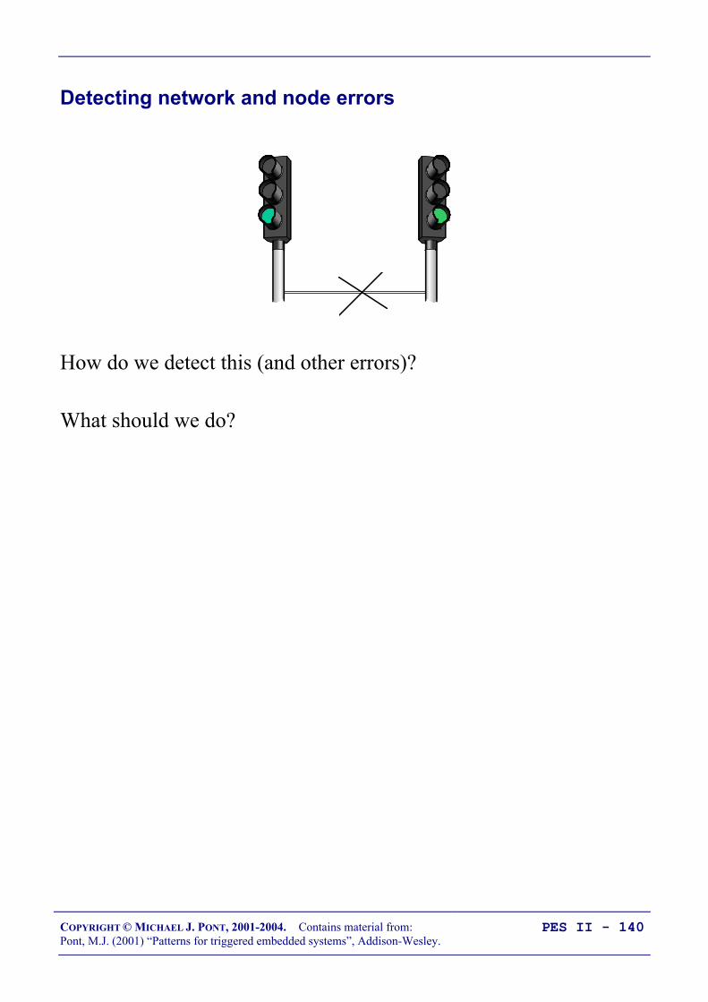
COPYRIGHT © MICHAEL J. PONT, 2001-2004. Contains material from:Pont, M.J. (2001) “Patterns for triggered embedded systems”, Addison-Wesley.
PES II - 140
Detecting network and node errors
How do we detect this (and other errors)?
What should we do?

COPYRIGHT © MICHAEL J. PONT, 2001-2004. Contains material from:Pont, M.J. (2001) “Patterns for triggered embedded systems”, Addison-Wesley.
PES II - 141
Detecting errors in the Slave(s)
• We know from the design specification that the Slave shouldreceive ticks at precise intervals of time (e.g. every 10 ms)
• Because of this, we simply need to measure the time intervalbetween ticks; if a period greater than the specified tickinterval elapses between ticks, we can safely conclude thatan error has occurred.
• In many circumstances an effective way of achieving this isto set a watchdog timer in the Slave to overflow at a periodslightly longer than the tick interval(we’ll discuss watchdog timers in detail in Seminar 10).
• If a tick is not received, then the timer will overflow, and wecan invoke an appropriate error-handling routine.

COPYRIGHT © MICHAEL J. PONT, 2001-2004. Contains material from:Pont, M.J. (2001) “Patterns for triggered embedded systems”, Addison-Wesley.
PES II - 142
Detecting errors in the Master
Detecting errors in the Master node requires that each Slave sendsappropriate acknowledgement messages to the Master at regularintervals.
Considering the operation of a particular 1-Master, 10-Slavenetwork:
• The Master node sends tick messages to all nodes,simultaneously, every millisecond; these messages are usedto invoke the Update function in all Slaves (everymillisecond).
• Each tick message may include data for a particular node. Inthis case, we will assume that the Master sends tickmessages to each of the Slaves in turn; thus, each Slavereceives data in every tenth tick message (every 10milliseconds in this case).
• Each Slave sends an acknowledgement message to theMaster only when it receives a tick message with its ID; itdoes not send an acknowledgement to any other tickmessages.
This arrangement provides the predictable bus loading that we require,and a means of communicating with each Slave individually.
It also means that the Master is able to detect whether or not aparticular Slave has responded to its tick message.

COPYRIGHT © MICHAEL J. PONT, 2001-2004. Contains material from:Pont, M.J. (2001) “Patterns for triggered embedded systems”, Addison-Wesley.
PES II - 143
Handling errors detected by the Slave
We will assume that errors in the Slave are detected with awatchdog timer. To deal with such errors, the shared-clockschedulers considered on this course all operate as follows:
• Whenever the Slave node is reset (either having beenpowered up, or reset as a result of a watchdog overflow), thenode enters a ‘safe state’.
• The node remains in this state until it receives an appropriateseries of ‘start’ commands from the Master.
This form of error handling is easily produced, and is effective inmost circumstances.

COPYRIGHT © MICHAEL J. PONT, 2001-2004. Contains material from:Pont, M.J. (2001) “Patterns for triggered embedded systems”, Addison-Wesley.
PES II - 144
Handling errors detected by the Master
Handling errors detected by the Master is more complicated.
We will consider and illustrate three main options in this course:
• The ‘Enter safe state then shut down’ option, and,
• The ‘Restart the network’ option, and
• The ‘Engage replacement Slave’ option.
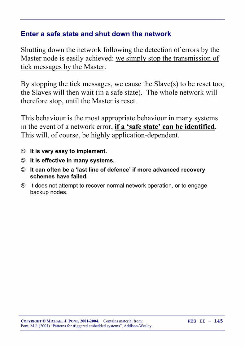
COPYRIGHT © MICHAEL J. PONT, 2001-2004. Contains material from:Pont, M.J. (2001) “Patterns for triggered embedded systems”, Addison-Wesley.
PES II - 145
Enter a safe state and shut down the network
Shutting down the network following the detection of errors by theMaster node is easily achieved: we simply stop the transmission oftick messages by the Master.
By stopping the tick messages, we cause the Slave(s) to be reset too;the Slaves will then wait (in a safe state). The whole network willtherefore stop, until the Master is reset.
This behaviour is the most appropriate behaviour in many systemsin the event of a network error, if a ‘safe state’ can be identified.This will, of course, be highly application-dependent.
It is very easy to implement. It is effective in many systems. It can often be a ‘last line of defence’ if more advanced recovery
schemes have failed. It does not attempt to recover normal network operation, or to engage
backup nodes.

COPYRIGHT © MICHAEL J. PONT, 2001-2004. Contains material from:Pont, M.J. (2001) “Patterns for triggered embedded systems”, Addison-Wesley.
PES II - 146
Reset the network
Another simple way of dealing with errors is to reset the Master and- hence - the whole network.
When it is reset, the Master will attempt to re-establishcommunication with each Slave in turn; if it fails to establishcontact with a particular Slave, it will attempt to connect to thebackup device for that Slave.
This approach is easy to implement and can be effective. Forexample, many designs use ‘N-version’ programming to createbackup versions of key components. By performing a reset, wekeep all the nodes in the network synchronised, and we engage abackup Slave (if one is available).
It allows full use to be made of backup nodes. It may take time (possibly half a second or more) to restart the network;
even if the network becomes fully operational, the delay involved may betoo long (for example, in automotive braking or aerospace flight-controlapplications). With poor design or implementation, errors can cause the network to be
continually reset. This may be rather less safe than the simple ‘enter safestate and shut down’ option.

COPYRIGHT © MICHAEL J. PONT, 2001-2004. Contains material from:Pont, M.J. (2001) “Patterns for triggered embedded systems”, Addison-Wesley.
PES II - 147
Engage a backup Slave
The third and final recovery technique we discuss in this course isas follows.
If a Slave fails, then - rather than restarting the whole network - westart the corresponding backup unit.
The strengths and weaknesses of this approach are as follows: It allows full use to be made of backup nodes. In most circumstances it takes comparatively little time to engage the
backup unit. The underlying coding is more complicated than the other alternatives
discussed in this course.

COPYRIGHT © MICHAEL J. PONT, 2001-2004. Contains material from:Pont, M.J. (2001) “Patterns for triggered embedded systems”, Addison-Wesley.
PES II - 148
Why additional processors may not improve reliability
Suppose that a network has 100 microcontrollers and that each ofthese devices is 99.99% reliable.
If the multi-processor application relies on the correct,simultaneous, operation of all 100 nodes, it will have an overallreliability of 99.99% x 99.99% x 99.99% ….
This is 0.9999100, or approximately 37%.
A 99.99% reliable device might be assumed to fail once in 10,000years, while the corresponding 37% reliable device would then beexpected to fail approximately every 18 months.
It is only where the increase in reliability resulting from the shared-clock design outweighs the reduction in reliability known to arise
from the increased system complexity that an overall increase in systemreliability will be obtained.
Unfortunately, making predictions about the costs and benefits (inreliability terms) of any complex design feature remains - in most non-
trivial systems - something of a black art.
COPYRIGHT © MICHAEL J. PONT, 2001-2004. Contains material from:Pont, M.J. (2001) “Patterns for triggered embedded systems”, Addison-Wesley.
PES II - 149
Redundant networks do not guarantee increased reliability
• In 1974, in a Turkish Airlines DC-10 aircraft, the cargo dooropened at high altitude.
• This event caused the cargo hold to depressurise, which inturn caused the cabin floor to collapse.
• The aircraft contained two (redundant) control lines, inaddition to the main control system - but all three lineswere under the cabin floor.
• Control of the aircraft was therefore lost and it crashedoutside Paris, killing 346 people.

COPYRIGHT © MICHAEL J. PONT, 2001-2004. Contains material from:Pont, M.J. (2001) “Patterns for triggered embedded systems”, Addison-Wesley.
PES II - 150
Replacing the human operator - implications
• In many embedded applications, there is either no humanoperator in attendance, or the time available to switch overto a backup node (or network) is too small to make humanintervention possible.
• In these circumstances, if the component required to detectthe failure of the main node and switch in the backup node iscomplicated (as often proves to be the case), then this‘switch’ component may itself be the source of severereliability problems (see Leveson, 1995).

COPYRIGHT © MICHAEL J. PONT, 2001-2004. Contains material from:Pont, M.J. (2001) “Patterns for triggered embedded systems”, Addison-Wesley.
PES II - 151
Are multi-processor designs ever safe?
These observations should not be taken to mean that multi-processordesigns are inappropriate for use in high-reliability applications.Multiple processors can be (and are) safely used in suchcircumstances.
However, all multi-processor developments must be approached withcaution, and must be subject to particularly rigorous design, review andtesting.

COPYRIGHT © MICHAEL J. PONT, 2001-2004. Contains material from:Pont, M.J. (2001) “Patterns for triggered embedded systems”, Addison-Wesley.
PES II - 152
Preparations for the next seminar
Please read “PTTES” Chapter 27 before the next seminar.
40393837363534
1234567
‘8051’
8910
33323130292827262524
11121314151617181920
232221
P3.0
P1.7
RS
T
P1.6
P1.5
P1.4
P1.2
P1.3
P1.1
P1.0
VS
S
XTL2
XTL1
P3.7
P3.6
P3.5
P3.3
P3.4
P3.2
P3.1
/ EA
P0.6
P0.7
P0.5
P0.4
P0.3
P0.1
P0.2
P0.0
VC
C
P2.0
P2.2
P2.1
P2.3
P2.4
P2.5
P2.7
P2.6
/ PSE
N
ALE

COPYRIGHT © MICHAEL J. PONT, 2001-2004. Contains material from:Pont, M.J. (2001) “Patterns for triggered embedded systems”, Addison-Wesley.
PES II - 153
Seminar 7: Linking processorsusing RS-232 and RS-
485 protocols
A
B
C
Main control& user interface
(Master)
Main control& user interface
(Master)Actuator C
(Slave)Actuator C
(Slave)Actuator B
(Slave)Actuator B
(Slave)Actuator A
(Slave)Actuator A
(Slave)

COPYRIGHT © MICHAEL J. PONT, 2001-2004. Contains material from:Pont, M.J. (2001) “Patterns for triggered embedded systems”, Addison-Wesley.
PES II - 154
Review: Shared-clock scheduling
Master Slave 2Slave 1 Slave N
Tick messages (from master to slaves)
Acknowledgement message
Acknowledgement message
Acknowledgement message
Most S-C schedulers support both ‘Tick’ messages (sent from the Masterto the Slaves), and ‘Acknowledgement’ messages (sent by the Slaves tothe Master).
COPYRIGHT © MICHAEL J. PONT, 2001-2004. Contains material from:Pont, M.J. (2001) “Patterns for triggered embedded systems”, Addison-Wesley.
PES II - 155
Overview of this seminar
In this seminar, we will discuss techniques for linking together two(or more) embedded processors, using the RS-232 and RS-485protocols.

COPYRIGHT © MICHAEL J. PONT, 2001-2004. Contains material from:Pont, M.J. (2001) “Patterns for triggered embedded systems”, Addison-Wesley.
PES II - 156
Review: What is ‘RS-232’?
In 1997 the Telecommunications Industry Association released whatis formally known as TIA-232 Version F, a serial communicationprotocol which has been universally referred to as ‘RS-232’ since itsfirst ‘Recommended Standard’ appeared in the 1960s. Similarstandards (V.28) are published by the InternationalTelecommunications Union (ITU) and by CCITT (The ConsultativeCommittee International Telegraph and Telephone).
The ‘RS-232’ standard includes details of:
• The protocol to be used for data transmission.
• The voltages to be used on the signal lines.
• The connectors to be used to link equipment together.
Overall, the standard is comprehensive and widely used, at datatransfer rates of up to around 115 or 330 kbits / second (115 / 330 kbaud). Data transfer can be over distances of 15 metres or more.
Note that RS-232 is a peer-to-peer communication standard.

COPYRIGHT © MICHAEL J. PONT, 2001-2004. Contains material from:Pont, M.J. (2001) “Patterns for triggered embedded systems”, Addison-Wesley.
PES II - 157
Review: Basic RS-232 Protocol
RS-232 is a character-oriented protocol. That is, it is intended to beused to send single 8-bit blocks of data. To transmit a byte of dataover an RS-232 link, we generally encode the information asfollows:
• We send a ‘Start’ bit.
• We send the data (8 bits).
• We send a ‘Stop’ bit (or bits).
REMEMBER: The UART takes care of these details!
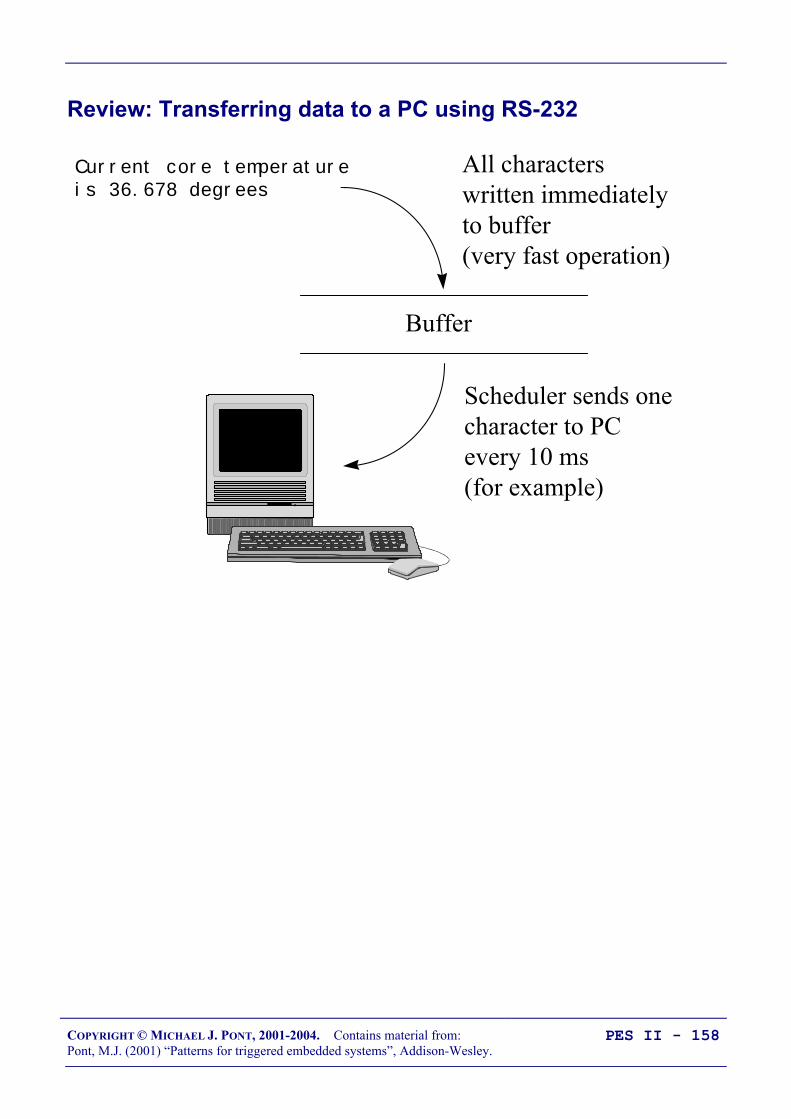
COPYRIGHT © MICHAEL J. PONT, 2001-2004. Contains material from:Pont, M.J. (2001) “Patterns for triggered embedded systems”, Addison-Wesley.
PES II - 158
Review: Transferring data to a PC using RS-232
Current core temperature is 36.678 degrees
Buffer
All characterswritten immediatelyto buffer(very fast operation)
Scheduler sends one character to PC every 10 ms (for example)

COPYRIGHT © MICHAEL J. PONT, 2001-2004. Contains material from:Pont, M.J. (2001) “Patterns for triggered embedded systems”, Addison-Wesley.
PES II - 159
PATTERN: SCU SCHEDULER (LOCAL)
Problem
How do you schedule tasks on (and transfer data over) a localnetwork of two (or more) 8051 microcontrollers connected togethervia their UARTs?
Solution
1. Timer overflow in the Master causes the scheduler ‘Update’function to be invoked. This, in turn, causes a byte of datais sent (via the UART) to all Slaves:
void MASTER_Update_T2(void) interrupt INTERRUPT_Timer_2_Overflow ...
MASTER_Send_Tick_Message(...); ...
2. When these data have been received all Slaves generate aninterrupt; this invokes the ‘Update’ function in the Slaveschedulers. This, in turn, causes one Slave to send an‘Acknowledge’ message back to the Master (again via theUART).
void SLAVE_Update(void) interrupt INTERRUPT_UART_Rx_Tx
... SLAVE_Send_Ack_Message_To_Master(); ...

COPYRIGHT © MICHAEL J. PONT, 2001-2004. Contains material from:Pont, M.J. (2001) “Patterns for triggered embedded systems”, Addison-Wesley.
PES II - 160
The message structure
Here we will assume that we wish to control and monitor threehydraulic actuators to control the operation of a mechanicalexcavator.
A
B
C
Main control& user interface
(Master)
Main control& user interface
(Master)Actuator C
(Slave)Actuator C
(Slave)Actuator B
(Slave)Actuator B
(Slave)Actuator A
(Slave)Actuator A
(Slave)
Suppose we wish to adjust the angle of Actuator A to 90 degrees;how do we do this?
Immediately the 8-bit nature of the UART becomes a limitation,because we need to send a message that identifies both the node tobe adjusted, and the angle itself.
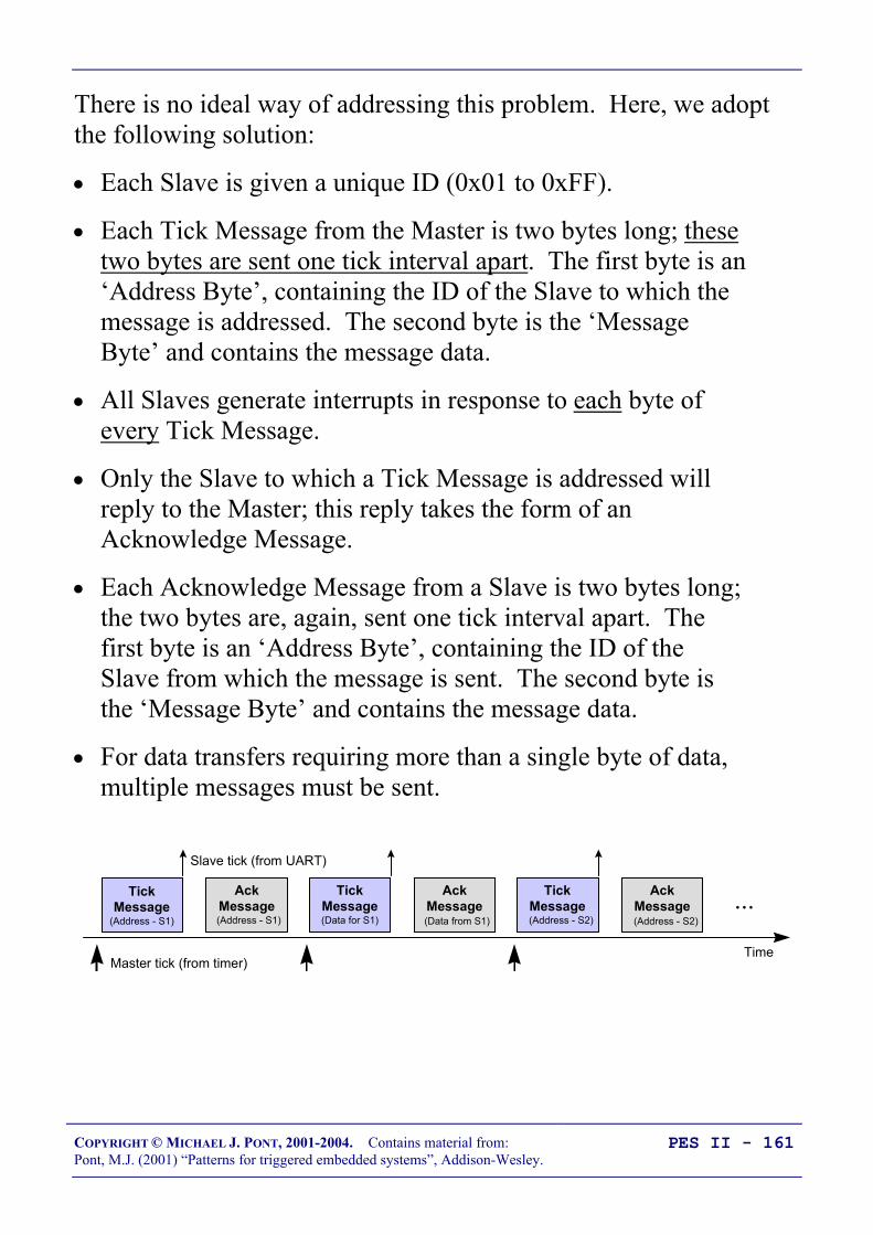
COPYRIGHT © MICHAEL J. PONT, 2001-2004. Contains material from:Pont, M.J. (2001) “Patterns for triggered embedded systems”, Addison-Wesley.
PES II - 161
There is no ideal way of addressing this problem. Here, we adoptthe following solution:
• Each Slave is given a unique ID (0x01 to 0xFF).
• Each Tick Message from the Master is two bytes long; thesetwo bytes are sent one tick interval apart. The first byte is an‘Address Byte’, containing the ID of the Slave to which themessage is addressed. The second byte is the ‘MessageByte’ and contains the message data.
• All Slaves generate interrupts in response to each byte ofevery Tick Message.
• Only the Slave to which a Tick Message is addressed willreply to the Master; this reply takes the form of anAcknowledge Message.
• Each Acknowledge Message from a Slave is two bytes long;the two bytes are, again, sent one tick interval apart. Thefirst byte is an ‘Address Byte’, containing the ID of theSlave from which the message is sent. The second byte isthe ‘Message Byte’ and contains the message data.
• For data transfers requiring more than a single byte of data,multiple messages must be sent.
Time
TickMessage
(Address - S1)
AckMessage(Address - S1)
TickMessage(Data for S1)
AckMessage(Data from S1)
TickMessage(Address - S2)
AckMessage(Address - S2)
...
Master tick (from timer)
Slave tick (from UART)

COPYRIGHT © MICHAEL J. PONT, 2001-2004. Contains material from:Pont, M.J. (2001) “Patterns for triggered embedded systems”, Addison-Wesley.
PES II - 162
We want to be able to distinguish between ‘Address Bytes’and ‘Data Bytes’.
We make use of the fact that the 8051 allows transmission of 9-bitserial data:
Description Size (bits)Data 9 bitsStart bit 1 bitStop bit 1 bitTOTAL 11 bits / message
• In this configuration (typically, the UART used in Mode 3),11 bits are transmitted / received. Note that the 9th bit istransmitted via bit TB8 in the register SCON, and is receivedas bit RB8 in the same register. In this mode, the baud rateis controlled as discussed in PTTES, Chapter 18.
• In the code examples presented here, Address Bytes areidentified by setting the ‘command bit’ (TB8) to 1; DataBytes set this bit to 0.

COPYRIGHT © MICHAEL J. PONT, 2001-2004. Contains material from:Pont, M.J. (2001) “Patterns for triggered embedded systems”, Addison-Wesley.
PES II - 163
Determining the required baud rate
• The timing of timer ticks in the Master is set to a durationsuch that one byte of a Tick Message can be sent (and onebyte of an Acknowledge Message received) between ticks.
• Clearly, this duration depends on the network baud rate.
• As we discussed above, we will use a 9-bit protocol. Takinginto account Start and Stop bits, we require 22 bits (11 forTick message, 11 for Acknowledge message) per schedulertick; that is, the required baud rate is: (Scheduler Ticks persecond) x 22.

COPYRIGHT © MICHAEL J. PONT, 2001-2004. Contains material from:Pont, M.J. (2001) “Patterns for triggered embedded systems”, Addison-Wesley.
PES II - 164
There is a delay between the timer on the Master and the UART-based interrupt on the Slave:
Time
TickMessage(Data for S1)
AckMessage
(from S1)...
Tick latency(varies with baud rate)
As discussed above, most shared-clock applications employ a baudrate of at least 28,800 baud: this gives a tick latency ofapproximately 0.4 ms. At 375,000 baud, this latency becomesapproximately 0.03 ms.
Note that this latency is fixed, and can be accurately predicted onpaper, and then confirmed in simulation and testing. If precisesynchronisation of Master and Slave processing is required, thenplease note that:
• All the Slaves operate - within the limits of measurement -precisely in step.
• To bring the Master in step with the Slaves, it is necessaryonly to add a short delay in the Master ‘Update’ function.

COPYRIGHT © MICHAEL J. PONT, 2001-2004. Contains material from:Pont, M.J. (2001) “Patterns for triggered embedded systems”, Addison-Wesley.
PES II - 165
Node Hardware
Rx
Tx
GND
300Ω
Vcc
10mA LED
300Ω
Vcc
10mA LED
Vcc
P 0.7 (AD7) 32
P 0.6 (AD6) 33
P 0.5 (AD5) 34
P 0.4 (AD4) 35
P 0.3 (AD3) 36
P 0.2 (AD2) 37
P 0.1 (AD1) 38
P 0.0 (AD0) 39
87654321
P 2.7 (A15) 28
P 2.6 (A14) 27
P 2.5 (A13) 26
P 2.4 (A12) 25
P 2.3 (A11) 24
P 2.2 (A10) 23
P 2.1 (A9) 22
P 2.0 (A8) 21
/ PSEN
ALE (/ PROG)
29
30
31
XTL119
XTL218
RST
40
VCC
VSS
‘805
2’
Vcc (+5V)
Cxtal
Cxtal
20
P 3.7 (/ RD)P 3.6 (/ WR) P 3.5 (T1)P 3.4 (T0)P 3.3 (/ INT1)P 3.2 (/ INT 0)P 3.1 (TXD)P 3.0 (RXD)
/ EA
1716151413121110
9
P 1.7P 1.6
P 1.5 P 1.4)P 1.3P 1.2
P 1.1 (T2EX)P 1.0 (T2)
5
8
RSTGND
TD
TOL
Vcc
/STO
/PBRST
1232
FlashLED
ErrorLED
Rx
Tx
GND
Vcc (+5V)
300Ω
Vcc
10mA LED
300Ω
Vcc
10mA LED
Vcc
P 0.7 (AD7) 32
P 0.6 (AD6) 33
P 0.5 (AD5) 34
P 0.4 (AD4) 35
P 0.3 (AD3) 36
P 0.2 (AD2) 37
P 0.1 (AD1) 38
P 0.0 (AD0) 39
87654321
P 2.7 (A15) 28
P 2.6 (A14) 27
P 2.5 (A13) 26
P 2.4 (A12) 25
P 2.3 (A11) 24
P 2.2 (A10) 23
P 2.1 (A9) 22
P 2.0 (A8) 21
/ PSEN
ALE (/ PROG)
29
30
31
XTL119
XTL218
RST
40
VCC
VSS
‘805
2’
Cxtal
Cxtal
20
P 3.7 (/ RD)P 3.6 (/ WR) P 3.5 (T1)P 3.4 (T0)P 3.3 (/ INT1)P 3.2 (/ INT 0)P 3.1 (TXD)P 3.0 (RXD)
/ EA
1716151413121110
9
P 1.7P 1.6
P 1.5 P 1.4)P 1.3P 1.2
P 1.1 (T2EX)P 1.0 (T2)
RSTGND
Vcc
1812
FlashLED
ErrorLED

COPYRIGHT © MICHAEL J. PONT, 2001-2004. Contains material from:Pont, M.J. (2001) “Patterns for triggered embedded systems”, Addison-Wesley.
PES II - 166
Network wiring
Keep the cables short!
P3.0 (Rx)
P3.1 (Tx)
P3.0 (Rx)
P3.1 (Tx)
8051familymicro
SlaveMaster8051familymicro
P3.1 (Tx)
P3.0 (Rx)
8051familymicro
P3.0 (Rx)
P3.1 (Tx)
8051familymicro
P3.0 (Rx)
P3.1 (Tx)
8051familymicro
P3.0 (Rx)
P3.1 (Tx)
Master
Slave 1
Slave ...
Slave N
8051familymicro

COPYRIGHT © MICHAEL J. PONT, 2001-2004. Contains material from:Pont, M.J. (2001) “Patterns for triggered embedded systems”, Addison-Wesley.
PES II - 167
Overall strengths and weaknesses
A simple scheduler for local systems with two or more 8051microcontrollers.
All necessary hardware is part of the 8051 core: as a result, thetechnique is very portable within this family.
Easy to implement with minimal CPU and memory overheads. The UART supports byte-based communications only: data transfer
between Master and Slaves (and vice versa) is limited to 0.5 bytes per clocktick. Uses an important hardware resource (the UART) Most error detection / correction must be carried out in software This pattern is not suitable for distributed systems

COPYRIGHT © MICHAEL J. PONT, 2001-2004. Contains material from:Pont, M.J. (2001) “Patterns for triggered embedded systems”, Addison-Wesley.
PES II - 168
PATTERN: SCU Scheduler (RS-232)
Context
• You are developing an embedded application using morethan one member of the 8051 family of microcontrollers.
• The application has a time-triggered architecture, based on ascheduler.
Problem
How do you schedule tasks on (and transfer data over) a distributednetwork of two 8051 microcontrollers communicating using the RS-232 protocol?
Solution
10mA LED
300Ω
Vcc
300Ω
Vcc
10mA LED
FlashLED
ErrorLED
Vcc
15
96
Vcc
Max233 1
20
7
18
6,9Connect together: Pins 12 & 17 Pins 11 & 15 Pins 16 & 10
1.0 µF
19
RxTx
P 0.7 (AD7) 32
P 0.6 (AD6) 33
P 0.5 (AD5) 34
P 0.4 (AD4) 35
P 0.3 (AD3) 36
P 0.2 (AD2) 37
P 0.1 (AD1) 38
P 0.0 (AD0) 39
87654321
P 2.7 (A15) 28
P 2.6 (A14) 27
P 2.5 (A13) 26
P 2.4 (A12) 25
P 2.3 (A11) 24
P 2.2 (A10) 23
P 2.1 (A9) 22
P 2.0 (A8) 21
/ PSEN
ALE (/ PROG)
29
30
31
XTL119
XTL218
RST
40
VCC
VSS
‘805
2’
Vcc (+5V)
Cxtal
Cxtal
20
P 3.7 (/ RD)P 3.6 (/ WR) P 3.5 (T1)P 3.4 (T0)P 3.3 (/ INT1)P 3.2 (/ INT 0)P 3.1 (TXD)P 3.0 (RXD)
/ EA
1716151413121110
9
P 1.7P 1.6
P 1.5 P 1.4)P 1.3P 1.2
P 1.1 (T2EX)P 1.0 (T2)
5
8
RSTGND
TD
TOL
Vcc
/STO
/PBRST

COPYRIGHT © MICHAEL J. PONT, 2001-2004. Contains material from:Pont, M.J. (2001) “Patterns for triggered embedded systems”, Addison-Wesley.
PES II - 169
PATTERN: SCU Scheduler (RS-485)
The communications standard generally referred to as ‘RS-485’ isan electrical specification for what are often referred to as ‘multi-point’ or ‘multi-drop’ communication systems; for our purposes,this means applications that involve at least three nodes, eachcontaining a microcontroller.
Please note that the specification document (EIA/TIA-485-A)defines the electrical characteristics of the line and its drivers andreceivers: this is limit of the standard. Thus, unlike ‘RS-232’, thereis no discussion of software protocols or of connectors.
There are many similarities between RS-232 and RS-485communication protocols:
• Both are serial standards.
• Both are in widespread use.
• Both involve - for our purposes - the use of an appropriatetransceiver chip connected to a UART.
• Both involve very similar software libraries.

COPYRIGHT © MICHAEL J. PONT, 2001-2004. Contains material from:Pont, M.J. (2001) “Patterns for triggered embedded systems”, Addison-Wesley.
PES II - 170
RS-232 vs RS-485 [number of nodes]
• RS-232 is a peer-to-peer communications standard. For ourpurposes, this means that it is suitable for applications thatinvolve two nodes, each containing a microcontroller (or, aswe saw in PTTES, Chapter 18, for applications where onenode is a desktop, or similar, PC).
• RS-485 is a ‘multi-point’ or ‘multi-drop’ communicationsstandard. For our purposes, this means applications thatinvolve at least three nodes, each containing amicrocontroller. Larger RS-485 networks can have up to 32‘unit loads’: by using high-impedance receivers, you canhave as many as 256 nodes on the network.
COPYRIGHT © MICHAEL J. PONT, 2001-2004. Contains material from:Pont, M.J. (2001) “Patterns for triggered embedded systems”, Addison-Wesley.
PES II - 171
RS-232 vs RS-485 [range and baud rates]
• RS-232 is a single-wire standard (one signal line, perchannel, plus ground). Electrical noise in the environmentcan lead to data corruption. This restricts thecommunication range to a maximum of around 30 metres,and the data rate to around 115 kbaud (with recent drivers).
• RS-485 is a two-wire or differential communicationstandard. This means that, for each channel, two lines carry(1) the required signal and (2) the inverse of the signal. Thereceiver then detects the voltage difference between the twolines. Electrical noise will impact on both lines, and willcancel out when the difference is calculated at the receiver.As a result, an RS-485 network can extend as far as 1 km, ata data rate of 90 kbaud. Faster data rates (up to 10 Mbaud)are possible at shorter distances (up to 15 metres).

COPYRIGHT © MICHAEL J. PONT, 2001-2004. Contains material from:Pont, M.J. (2001) “Patterns for triggered embedded systems”, Addison-Wesley.
PES II - 172
RS-232 vs RS-485 [cabling]
• RS-232 requires low-cost ‘straight’ cables, with three wiresfor fully duplex communications (Tx, Rx, Ground).
• For full performance, RS-485 requires twisted-pair cables,with two twisted pairs, plus ground (and usually a screen).This cabling is more bulky and more expensive than the RS-232 equivalent.
• RS-232 cables do not require terminating resistors.
• RS-485 cables are usually used with 120Ω terminatingresistors (assuming 24-AWG twisted pair cables) connectedin parallel, at or just beyond the final node at both ends ofthe network. The terminations reduce voltage reflectionsthat can otherwise cause the receiver to misread logic levels.
120 Ω120 Ω
Slave 1Slave 1MASTERMASTER Slave 2Slave 2
120 Ω120 Ω
RS-485 Gnd100 Ω 100 Ω 100 Ω

COPYRIGHT © MICHAEL J. PONT, 2001-2004. Contains material from:Pont, M.J. (2001) “Patterns for triggered embedded systems”, Addison-Wesley.
PES II - 173
RS-232 vs RS-485 [transceivers]
• RS-232 transceivers are simple and standard.
• Choice of RS-485 transceivers depends on the application.A common choice for basic systems is the Maxim Max489family. For increased reliability, the Linear TechnologyLTC1482, National Semiconductors DS36276 and theMaxim MAX3080–89 series all have internal circuitry toprotect against cable short circuits. Also, the Maxim MaxMAX1480 contains its own transformer-isolated supply andopto-isolated signal path: this can help avoid interactionbetween power lines and network cables destroying yourmicrocontroller.
P 0.7 (AD7) 32
P 0.6 (AD6) 33
P 0.5 (AD5) 34
P 0.4 (AD4) 35
P 0.3 (AD3) 36
P 0.2 (AD2) 37
P 0.1 (AD1) 38
P 0.0 (AD0) 39
87654321
P 2.7 (A15) 28
P 2.6 (A14) 27
P 2.5 (A13) 26
P 2.4 (A12) 25
P 2.3 (A11) 24
P 2.2 (A10) 23
P 2.1 (A9) 22
P 2.0 (A8) 21
/ PSEN
ALE (/ PROG)
29
30
31
XTL119
XTL218
RST
40
VCC
VSS
AT
89S5
3Vcc (+5V)
Vcc
Cxtal
Cxtal
Creset
Rreset
20
P 3.7 (/ RD)P 3.6 (/ WR) P 3.5 (T1)P 3.4 (T0)P 3.3 (/ INT1)P 3.2 (/ INT 0)P 3.1 (TXD)P 3.0 (RXD)
/ EA
1716151413121110
9
Vcc
Max489 5
2
485-IA
485-IB
485-OA
485-OB
1412
11
9
10
3
6,7
485-GND100 R
4
P 1.7 (SCK)P 1.6 (MISO)P 1.5 (MOSI)
P 1.4(/SS)P 1.3P 1.2
P 1.1 (T2EX)P 1.0 (T2)
COPYRIGHT © MICHAEL J. PONT, 2001-2004. Contains material from:Pont, M.J. (2001) “Patterns for triggered embedded systems”, Addison-Wesley.
PES II - 174
Software considerations: enable inputs
The software required in this pattern is, in almost all respects,identical to that presented in SCU SCHEDULER (LOCAL).
The only exception is the need, in this multi-node system, to control the‘enable’ inputs on the RS-485 transceivers; this is done because onlyone such device can be active on the network at any time.
The time-triggered nature of the shared-clock scheduler makes thecontrolled activation of the various transceivers straightforward.

COPYRIGHT © MICHAEL J. PONT, 2001-2004. Contains material from:Pont, M.J. (2001) “Patterns for triggered embedded systems”, Addison-Wesley.
PES II - 175
Overall strengths and weaknesses
A simple scheduler for distributed systems consisting of multiple 8051microcontrollers.
Easy to implement with low CPU and memory overheads. Twisted-pair cabling and differential signals make this more robust
than RS-232-based alternatives. UART supports byte-based communications only: data transfer between
Master and Slaves (and vice versa) is limited to 0.5 bytes per clock tick Uses an important hardware resource (the UART) The hardware still has a very limited ability to detect errors: most error
detection / correction must be carried out in software
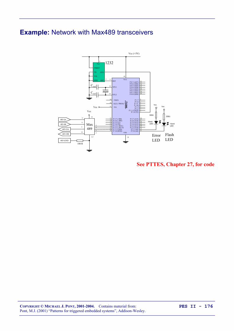
COPYRIGHT © MICHAEL J. PONT, 2001-2004. Contains material from:Pont, M.J. (2001) “Patterns for triggered embedded systems”, Addison-Wesley.
PES II - 176
Example: Network with Max489 transceivers
300Ω
Vcc
10mA LED
300Ω
Vcc
10mA LED
Vcc
Max489
52
485-IA
485-IB
485-OA
485-OB
1412
11
9
10
3
6,7
485-GND100 R
4
Vcc
P 0.7 (AD7) 32
P 0.6 (AD6) 33
P 0.5 (AD5) 34
P 0.4 (AD4) 35
P 0.3 (AD3) 36
P 0.2 (AD2) 37
P 0.1 (AD1) 38
P 0.0 (AD0) 39
87654321
P 2.7 (A15) 28
P 2.6 (A14) 27
P 2.5 (A13) 26
P 2.4 (A12) 25
P 2.3 (A11) 24
P 2.2 (A10) 23
P 2.1 (A9) 22
P 2.0 (A8) 21
/ PSEN
ALE (/ PROG)
29
30
31
XTL119
XTL218
RST
40
VCC
VSS
‘805
2’
Vcc (+5V)
Cxtal
Cxtal
20
P 3.7 (/ RD)P 3.6 (/ WR) P 3.5 (T1)P 3.4 (T0)P 3.3 (/ INT1)P 3.2 (/ INT 0)P 3.1 (TXD)P 3.0 (RXD)
/ EA
1716151413121110
9
P 1.7P 1.6
P 1.5 P 1.4)P 1.3P 1.2
P 1.1 (T2EX)P 1.0 (T2)
5
8
RSTGND
TD
TOL
Vcc
/STO
/PBRST
1232
FlashLED
ErrorLED
See PTTES, Chapter 27, for code

COPYRIGHT © MICHAEL J. PONT, 2001-2004. Contains material from:Pont, M.J. (2001) “Patterns for triggered embedded systems”, Addison-Wesley.
PES II - 177
Preparations for the next seminar
Please read “PTTES” Chapter 28 before the next seminar.
40393837363534
1234567
‘8051’
8910
33323130292827262524
11121314151617181920
232221
P3.0
P1.7
RS
T
P1.6
P1.5
P1.4
P1.2
P1.3
P1.1
P1.0
VS
S
XTL2
XTL1
P3.7
P3.6
P3.5
P3.3
P3.4
P3.2
P3.1
/ EA
P0.6
P0.7
P0.5
P0.4
P0.3
P0.1
P0.2
P0.0
VC
C
P2.0
P2.2
P2.1
P2.3
P2.4
P2.5
P2.7
P2.6
/ PSE
N
ALE

COPYRIGHT © MICHAEL J. PONT, 2001-2004. Contains material from:Pont, M.J. (2001) “Patterns for triggered embedded systems”, Addison-Wesley.
PES II - 178

COPYRIGHT © MICHAEL J. PONT, 2001-2004. Contains material from:Pont, M.J. (2001) “Patterns for triggered embedded systems”, Addison-Wesley.
PES II - 179
Seminar 8: Linking processorsusing the ControllerArea Network (CAN) bus
Node 1 Node 2
120 Ω120 Ω
Can High
Can Low
Node 3

COPYRIGHT © MICHAEL J. PONT, 2001-2004. Contains material from:Pont, M.J. (2001) “Patterns for triggered embedded systems”, Addison-Wesley.
PES II - 180
Overview of this seminar
In this seminar, we will explain how you can schedule tasks on (andtransfer data over) a network of two (or more) 8051microcontrollers communicating using the CAN protocol.

COPYRIGHT © MICHAEL J. PONT, 2001-2004. Contains material from:Pont, M.J. (2001) “Patterns for triggered embedded systems”, Addison-Wesley.
PES II - 181
PATTERN: SCC Scheduler
We can summarise some of the features of CAN as follows: CAN is message-based, and messages can be up to eight bytes in
length. Used in a shared-clock scheduler, the data transfer betweenMaster and Slaves (and vice versa) is up to 7 bytes per clock tick. Thisis adequate for most applications.
The hardware has advanced error detection (and correction) facilitiesbuilt in, further reducing the software load.
CAN may be used for both ‘local’ and ‘distributed’ systems.
A number of 8051 devices have on-chip support for CAN, allowing theprotocol to be used with minimal overheads.
Off-chip CAN transceivers can be used to allow use of this protocolwith a huge range of devices.

COPYRIGHT © MICHAEL J. PONT, 2001-2004. Contains material from:Pont, M.J. (2001) “Patterns for triggered embedded systems”, Addison-Wesley.
PES II - 182
What is CAN?
We begin our discussion of the Controller Area Network (CAN)protocol by highlighting some important features of this standard:
• CAN supports high-speed (1 Mbits/s) data transmission overshort distances (40m) and low-speed (5 kbits/s)transmissions at lengths of up to 10,000m.
• CAN is message based. The data in each message may varyin length between 0 and 8 bytes. This data length is ideal formany embedded applications.
• The receipt of a message can be used to generate aninterrupt. The interrupt will be generated only when acomplete message (up to 8 bytes of data) has been received:this is unlike a UART (for example) which will respond toevery character.
• CAN is a shared broadcast bus: all messages are sent to allnodes. However, each message has an identifier: this can beused to ‘filter’ messages. This means that - by using a ‘FullCAN’ controller (see below) - we can ensure that aparticular node will only respond to ‘relevant’ messages:that is, messages with a particular ID.
This is very powerful. What this means in practice is, forexample, that a Slave node can be set to ignore all messagesdirected from a different Slave to the Master.
• CAN is usually implemented on a simple, low-cost, two-wire differential serial bus system. Other physical mediamay be used, such as fibre optics (but this is comparativelyrare).

COPYRIGHT © MICHAEL J. PONT, 2001-2004. Contains material from:Pont, M.J. (2001) “Patterns for triggered embedded systems”, Addison-Wesley.
PES II - 183
• The maximum number of nodes on a CAN bus is 32.
• Messages can be given an individual priority. This means,for example, that ‘Tick messages’ can be given a higherpriority than ‘Acknowledge messages’.
• CAN is highly fault-tolerant, with powerful error detectionand handling mechanisms built in to the controller.
• Last but not least, microcontrollers with built-in CANcontrollers are available from a range of companies. Forexample, 8051 devices with CAN controllers are availablefrom Infineon (c505c, c515c), Philips (8xC592, 8xC598)and Dallas (80C390).
Overall, the CAN bus provides an excellent foundation for reliabledistributed scheduled applications.
We’ll now take a closer look at CAN…

COPYRIGHT © MICHAEL J. PONT, 2001-2004. Contains material from:Pont, M.J. (2001) “Patterns for triggered embedded systems”, Addison-Wesley.
PES II - 184
CAN 1.0 vs. CAN 2.0
The CAN protocol comes in two versions: CAN 1.0 and CAN 2.0.CAN 2.0 is backwardly compatible with CAN 1.0, and most newcontrollers are CAN 2.0.
In addition, there are two parts to the CAN 2.0 standard: Part A andPart B. With CAN 1.0 and CAN 2.0A, identifiers must be 11-bitslong. With CAN 2.0B identifiers can be 11-bits (a ‘standard’identifier) or 29-bits (an ‘extended’ identifier).
The following basic compatibility rules apply:
• CAN 2.0B active controllers are able to send and receiveboth standard and extended messages.
• CAN 2.0B passive controllers are able to send and receivestandard messages. In addition, they will discard (andignore) extended frames. They will not generate an errorwhen they ‘see’ extended messages.
• CAN 1.0 controllers generate bus errors when they seeextended frames: they cannot be used on networks whereextended identifiers are used.

COPYRIGHT © MICHAEL J. PONT, 2001-2004. Contains material from:Pont, M.J. (2001) “Patterns for triggered embedded systems”, Addison-Wesley.
PES II - 185
Basic CAN vs. Full CAN
There are two main classes of CAN controller available.
(Note that these classes are not covered by the standard, so there issome variation.)
The difference is that Full CAN controllers provide an acceptancefilter that allows a node to ignore irrelevant messages.
This can be very useful.

COPYRIGHT © MICHAEL J. PONT, 2001-2004. Contains material from:Pont, M.J. (2001) “Patterns for triggered embedded systems”, Addison-Wesley.
PES II - 186
Which microcontrollers have support for CAN?
Available devices include:
• Dallas 80c390. Two on-chip CAN modules, eachsupporting CAN 2.0B.
• Infineon C505C. Supports CAN2.0B.
• Infineon C515C. Supports CAN2.0B.
• Philips 8xC591. Supports CAN2.0B.
• Philips 8x592. Supports CAN2.0A.
• Philips 8x598. Supports CAN2.0A.
• Temic T89C51CC01. Supports CAN2.0B.

COPYRIGHT © MICHAEL J. PONT, 2001-2004. Contains material from:Pont, M.J. (2001) “Patterns for triggered embedded systems”, Addison-Wesley.
PES II - 187
S-C scheduling over CAN
Master Slave 2Slave 1 Slave N
Tick messages (from master to slaves)
Acknowledgement message
Acknowledgement message
Acknowledgement message
1. Timer overflow in the Master causes the scheduler ‘Update’function to be invoked. This, in turn, causes a byte of datais sent (via the CAN bus) to all Slaves:
void MASTER_Update_T2(void) interrupt INTERRUPT_Timer_2_Overflow...
2. When these data have been received all Slaves generate aninterrupt; this invokes the ‘Update’ function in the Slaveschedulers. This, in turn, causes one Slave to send an‘Acknowledge’ message back to the Master (again via theCAN bus).
void SLAVE_Update(void) interrupt INTERRUPT_CAN ...

COPYRIGHT © MICHAEL J. PONT, 2001-2004. Contains material from:Pont, M.J. (2001) “Patterns for triggered embedded systems”, Addison-Wesley.
PES II - 188
The message structure - Tick messages
• Up to 31 Slave nodes (and one Master node) may be used ina CAN network. Each Slave is given a unique ID (0x01 to0xFF).
• Each Tick Message from the Master is between one andeight bytes long; all of the bytes are sent in a single tickinterval.
• In all messages, the first byte is the ID of the Slave to whichthe message is addressed; the remaining bytes (if any) arethe message data.
• All Slaves generate interrupts in response to every TickMessage.
Time
TickMessage(Data for S1)
AckMessage
(from S1)
TickMessage(Data for S2)
AckMessage
(from S2)
TickMessage(Data for S1)
AckMessage
(from S1)...
Master tick (from timer)
Slave tick (from CAN hardware)

COPYRIGHT © MICHAEL J. PONT, 2001-2004. Contains material from:Pont, M.J. (2001) “Patterns for triggered embedded systems”, Addison-Wesley.
PES II - 189
The message structure - Ack messages
• Only the Slave to which a Tick Message is addressed willreply to the Master; this reply takes the form of anAcknowledge Message.
• Each Acknowledge Message from a Slave is between oneand eight bytes long; all of the bytes are sent in the tickinterval in which the Tick Message was received.
• The first byte of the Acknowledge Message is the ID of theSlave from which the message was sent; the remaining bytes(if any) are the message data.
Time
TickMessage(Data for S1)
AckMessage
(from S1)
TickMessage(Data for S2)
AckMessage
(from S2)
TickMessage(Data for S1)
AckMessage
(from S1)...
Master tick (from timer)
Slave tick (from CAN hardware)

COPYRIGHT © MICHAEL J. PONT, 2001-2004. Contains material from:Pont, M.J. (2001) “Patterns for triggered embedded systems”, Addison-Wesley.
PES II - 190
Determining the required baud rate
Description Size (bits)Data 64Start bit 1Identifier bits 11SRR bit 1IDE bit 1Identifier bits 18RTR bit 1Control bits 6CRC bits 15Stuff bits (maximum) 23CRC delimiter 1ACK slot 1ACK delimiter 1EOF bits 7IFS bits 3TOTAL 154 bits / message
We require two messages per tick: with 1 ms ticks, we require atleast 308000 baud: allowing 350 000 baud gives a good margin forerror. This is achievable with CAN, at distances up to around 100metres. Should you require larger distances, the tick interval musteither be lengthened, or repeater nodes should be added in thenetwork at 100-metre intervals.

COPYRIGHT © MICHAEL J. PONT, 2001-2004. Contains material from:Pont, M.J. (2001) “Patterns for triggered embedded systems”, Addison-Wesley.
PES II - 191
There is a delay between the timer on the Master and the CAN-based interrupt on the Slave:
Time
TickMessage(Data for S1)
AckMessage
(from S1)...
Tick latency(varies with baud rate)
In the absence of network errors, this delay is fixed, and deriveslargely from the time taken to transmit a message via the CAN bus;that is, it varies with the baud rate.
At a baud rate of 350 kbits/second, the tick is approx. 0.5 ms.
If precise synchronisation of Master and Slave processing isrequired, then please note that:
• All the Slaves are - within the limits of measurement -precisely in step.
• To bring the Master in step with the Slaves, it is necessaryonly to add a short delay in the Master ‘Update’ function.

COPYRIGHT © MICHAEL J. PONT, 2001-2004. Contains material from:Pont, M.J. (2001) “Patterns for triggered embedded systems”, Addison-Wesley.
PES II - 192
Transceivers for distributed networks
The Philips PCA82c250 is a popular tranceiver.

COPYRIGHT © MICHAEL J. PONT, 2001-2004. Contains material from:Pont, M.J. (2001) “Patterns for triggered embedded systems”, Addison-Wesley.
PES II - 193
Node wiring for distributed networks
The most common means of linking together CAN nodes is throughthe use of a two-wire, twisted pair (like RS-485).
In the CAN bus, the two signal lines are termed ‘CAN High’ and‘CAN Low’. In the quiescent state, both lines sit at 2.5V. A ‘1’ istransmitted by raising the voltage of the High line above that ofLow line: this is termed a ‘dominant’ bit. A ‘0’ is represented byraising the voltage of the Low line above that of the High line: thisis termed a ‘recessive’ bit.
Using twisted-pair wiring, the differential CAN inputs successfullycancel out noise. In addition, the CAN networks connected in thisway continue to function even when one of the lines is severed.
Note that, as with the RS-485 cabling, a 120Ω terminating resistor isconnected at each end of the bus:
Node 1 Node 2
120 Ω120 Ω
Can High
Can Low
Node 3

COPYRIGHT © MICHAEL J. PONT, 2001-2004. Contains material from:Pont, M.J. (2001) “Patterns for triggered embedded systems”, Addison-Wesley.
PES II - 194
Hardware and wiring for local networks
Use of a ‘local’ CAN network does not require the use oftransceiver chips.
In most cases, simply connecting together the Tx and Rx lines froma number of CAN-based microcontrollers will allow you to link thedevices.
A better solution (proposed by Barrenscheen, 1996) is based on awired-OR structure.
As no CAN transceiver is used, the maximum wire length is limitedto a maximum of one metre, and disturbances due to noise canoccur.

COPYRIGHT © MICHAEL J. PONT, 2001-2004. Contains material from:Pont, M.J. (2001) “Patterns for triggered embedded systems”, Addison-Wesley.
PES II - 195
Software for the shared-clock CAN scheduler
One important difference between the CAN-based schedulerpresented here and those that were discussed previously chapters isthe error-handling mechanism.
Here, if a Slave fails, then - rather than restarting the whole network- we attempt to start the corresponding backup unit.
The strengths and weaknesses of this approach are as follows: It allows full use to be made of backup nodes. In most circumstances it takes comparatively little time to engage the
backup unit. The underlying coding is more complicated than the other alternatives
discussed in this course.

COPYRIGHT © MICHAEL J. PONT, 2001-2004. Contains material from:Pont, M.J. (2001) “Patterns for triggered embedded systems”, Addison-Wesley.
PES II - 196
Overall strengths and weaknesses
CAN is message-based, and messages can be up to eight bytes inlength. Used in a shared-clock scheduler, the data transfer betweenMaster and Slaves (and vice versa) is up to 7 bytes per clock tick. Thisis more than adequate for the great majority of applications.
A number of 8051 devices have on-chip support for CAN, allowing theprotocol to be used with minimal overheads.
The hardware has advanced error detection (and correction) facilitiesbuilt in, further reducing the software load
CAN may be used for both ‘local’ and ‘distributed’ systems. 8051 devices with CAN support tend to be more expensive than ‘standard’
8051s.

COPYRIGHT © MICHAEL J. PONT, 2001-2004. Contains material from:Pont, M.J. (2001) “Patterns for triggered embedded systems”, Addison-Wesley.
PES II - 197
Example: Creating a CAN-based scheduler using theInfineon C515c
This example illustrates the use of the Infineon c515Cmicrocontroller. This popular device has on-chip CAN hardware.
The code may be used in either a distributed or local network, withthe hardware discussed above.
See PTTES, Chapter 28 for complete code listings

COPYRIGHT © MICHAEL J. PONT, 2001-2004. Contains material from:Pont, M.J. (2001) “Patterns for triggered embedded systems”, Addison-Wesley.
PES II - 198
Master Software
void SCC_A_MASTER_Init_T2_CAN(void) tByte i; tByte Message; tByte Slave_index;
EA = 0; /* No interrupts (yet) */
SCC_A_MASTER_Watchdog_Init(); /* Start the watchdog */
Network_error_pin = NO_NETWORK_ERROR;
for (i = 0; i < SCH_MAX_TASKS; i++) SCH_Delete_Task(i); /* Clear the task array */
/* SCH_Delete_Task() will generate an error code, because the task array is empty. -> reset the global error variable. */ Error_code_G = 0;
/* We allow any combination of ID numbers in slaves */ for (Slave_index =0; Slave_index < NUMBER_OF_SLAVES; Slave_index++) Slave_reset_attempts_G[Slave_index] = 0; Current_Slave_IDs_G[Slave_index] = MAIN_SLAVE_IDs[Slave_index];
/* Get ready to send first tick message */ First_ack_G = 1; Slave_index_G = 0;
/* ------ Set up the CAN link (begin) ------------------------ */
/* ---------------- SYSCON Register -------------- The access to XRAM and CAN controller is enabled. The signals !RD and !WR are not activated during accesses to the XRAM/CAN controller. ALE generation is enabled. */ SYSCON = 0x20;
/* ------------ CAN Control/Status Register -------------- Start to init the CAN module. */ CAN_cr = 0x41; /* INIT and CCE */
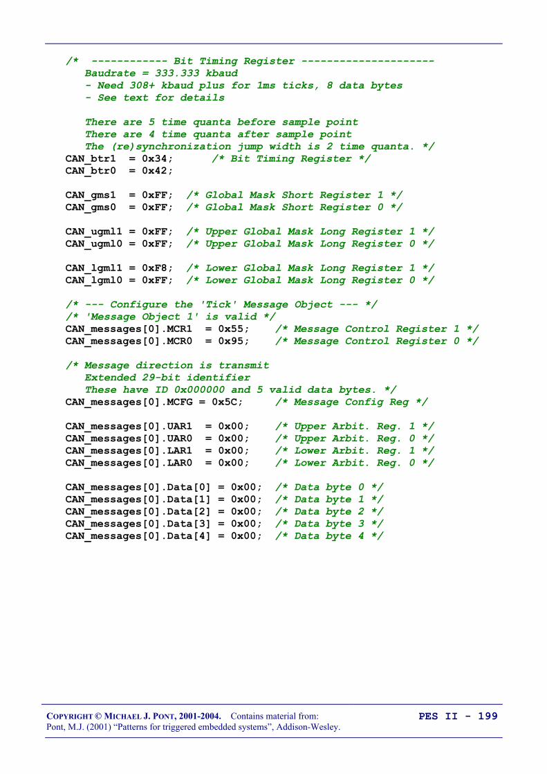
COPYRIGHT © MICHAEL J. PONT, 2001-2004. Contains material from:Pont, M.J. (2001) “Patterns for triggered embedded systems”, Addison-Wesley.
PES II - 199
/* ------------ Bit Timing Register --------------------- Baudrate = 333.333 kbaud - Need 308+ kbaud plus for 1ms ticks, 8 data bytes - See text for details
There are 5 time quanta before sample point There are 4 time quanta after sample point The (re)synchronization jump width is 2 time quanta. */ CAN_btr1 = 0x34; /* Bit Timing Register */ CAN_btr0 = 0x42;
CAN_gms1 = 0xFF; /* Global Mask Short Register 1 */ CAN_gms0 = 0xFF; /* Global Mask Short Register 0 */
CAN_ugml1 = 0xFF; /* Upper Global Mask Long Register 1 */ CAN_ugml0 = 0xFF; /* Upper Global Mask Long Register 0 */
CAN_lgml1 = 0xF8; /* Lower Global Mask Long Register 1 */ CAN_lgml0 = 0xFF; /* Lower Global Mask Long Register 0 */
/* --- Configure the 'Tick' Message Object --- */ /* 'Message Object 1' is valid */ CAN_messages[0].MCR1 = 0x55; /* Message Control Register 1 */ CAN_messages[0].MCR0 = 0x95; /* Message Control Register 0 */
/* Message direction is transmit Extended 29-bit identifier These have ID 0x000000 and 5 valid data bytes. */ CAN_messages[0].MCFG = 0x5C; /* Message Config Reg */
CAN_messages[0].UAR1 = 0x00; /* Upper Arbit. Reg. 1 */ CAN_messages[0].UAR0 = 0x00; /* Upper Arbit. Reg. 0 */ CAN_messages[0].LAR1 = 0x00; /* Lower Arbit. Reg. 1 */ CAN_messages[0].LAR0 = 0x00; /* Lower Arbit. Reg. 0 */
CAN_messages[0].Data[0] = 0x00; /* Data byte 0 */ CAN_messages[0].Data[1] = 0x00; /* Data byte 1 */ CAN_messages[0].Data[2] = 0x00; /* Data byte 2 */ CAN_messages[0].Data[3] = 0x00; /* Data byte 3 */ CAN_messages[0].Data[4] = 0x00; /* Data byte 4 */

COPYRIGHT © MICHAEL J. PONT, 2001-2004. Contains material from:Pont, M.J. (2001) “Patterns for triggered embedded systems”, Addison-Wesley.
PES II - 200
/* --- Configure the 'Ack' Message Object --- */
/* 'Message Object 2' is valid NOTE: Object 2 receives *ALL* ack messages. */ CAN_messages[1].MCR1 = 0x55; /* Message Control Register 1 */ CAN_messages[1].MCR0 = 0x95; /* Message Control Register 0 */
/* Message direction is receive Extended 29-bit identifier These all have ID: 0x000000FF (5 valid data bytes) */ CAN_messages[1].MCFG = 0x04; /* Message Config Reg */
CAN_messages[1].UAR1 = 0x00; /* Upper Arbit. Reg. 1 */ CAN_messages[1].UAR0 = 0x00; /* Upper Arbit. Reg. 0 */ CAN_messages[1].LAR1 = 0xF8; /* Lower Arbit. Reg. 1 */ CAN_messages[1].LAR0 = 0x07; /* Lower Arbit. Reg. 0 */
/* Configure remaining message objects - none is valid */ for (Message = 2; Message <= 14; ++Message) CAN_messages[Message].MCR1 = 0x55; /* Message Control Reg 1 */ CAN_messages[Message].MCR0 = 0x55; /* Message Control Reg 0 */
/* ------------ CAN Control Register --------------------- */ /* Reset CCE and INIT */ CAN_cr = 0x00;
/* ------ Set up the CAN link (end) ---------------------- */
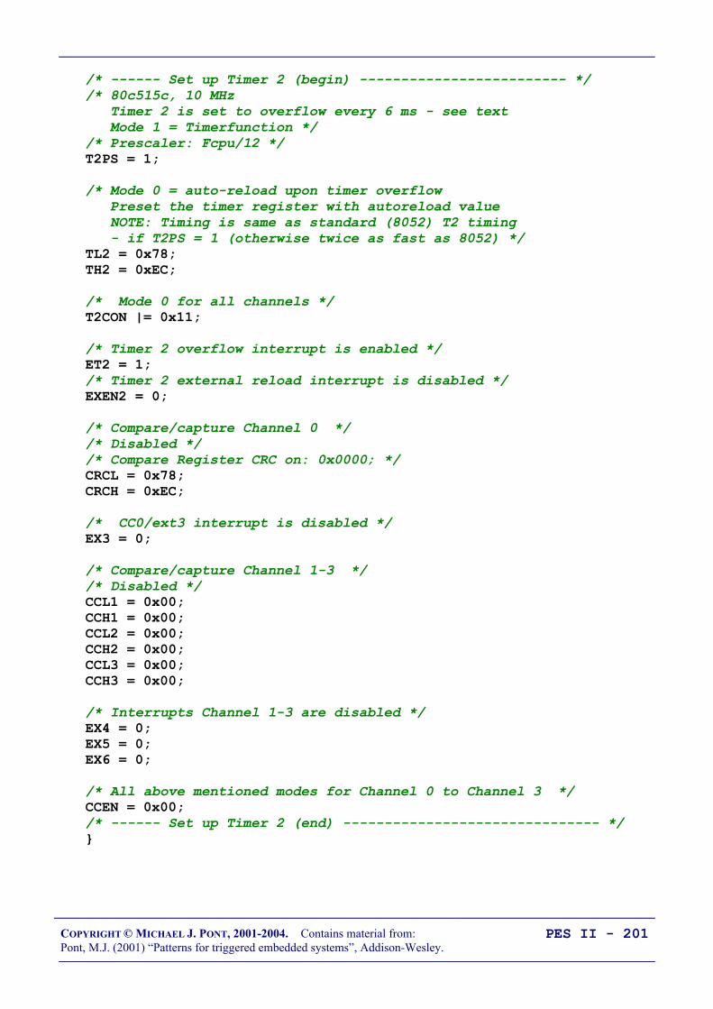
COPYRIGHT © MICHAEL J. PONT, 2001-2004. Contains material from:Pont, M.J. (2001) “Patterns for triggered embedded systems”, Addison-Wesley.
PES II - 201
/* ------ Set up Timer 2 (begin) ------------------------- */ /* 80c515c, 10 MHz Timer 2 is set to overflow every 6 ms - see text Mode 1 = Timerfunction */ /* Prescaler: Fcpu/12 */ T2PS = 1;
/* Mode 0 = auto-reload upon timer overflow Preset the timer register with autoreload value NOTE: Timing is same as standard (8052) T2 timing - if T2PS = 1 (otherwise twice as fast as 8052) */ TL2 = 0x78; TH2 = 0xEC;
/* Mode 0 for all channels */ T2CON |= 0x11;
/* Timer 2 overflow interrupt is enabled */ ET2 = 1; /* Timer 2 external reload interrupt is disabled */ EXEN2 = 0;
/* Compare/capture Channel 0 */ /* Disabled */ /* Compare Register CRC on: 0x0000; */ CRCL = 0x78; CRCH = 0xEC;
/* CC0/ext3 interrupt is disabled */ EX3 = 0;
/* Compare/capture Channel 1-3 */ /* Disabled */ CCL1 = 0x00; CCH1 = 0x00; CCL2 = 0x00; CCH2 = 0x00; CCL3 = 0x00; CCH3 = 0x00;
/* Interrupts Channel 1-3 are disabled */ EX4 = 0; EX5 = 0; EX6 = 0;
/* All above mentioned modes for Channel 0 to Channel 3 */ CCEN = 0x00; /* ------ Set up Timer 2 (end) ------------------------------- */

COPYRIGHT © MICHAEL J. PONT, 2001-2004. Contains material from:Pont, M.J. (2001) “Patterns for triggered embedded systems”, Addison-Wesley.
PES II - 202
void SCC_A_MASTER_Start(void) tByte Num_active_slaves; tByte i; bit Slave_replied_correctly; tByte Slave_index, Slave_ID;
/* Refresh the watchdog */ SCC_A_MASTER_Watchdog_Refresh();
/* Place system in 'safe state' */ SCC_A_MASTER_Enter_Safe_State();
/* Report error as we wait to start */ Network_error_pin = NETWORK_ERROR;
Error_code_G = ERROR_SCH_WAITING_FOR_SLAVE_TO_ACK; SCH_Report_Status(); /* Sch not yet running - do this manually */
/* Pause here (300 ms), to time-out all the slaves (This is the means by which we sync the network) */ for (i = 0; i < 10; i++) Hardware_Delay_T0(30); SCC_A_MASTER_Watchdog_Refresh();
/* Currently disconnected from all slaves */ Num_active_slaves = 0;

COPYRIGHT © MICHAEL J. PONT, 2001-2004. Contains material from:Pont, M.J. (2001) “Patterns for triggered embedded systems”, Addison-Wesley.
PES II - 203
/* After the initial (long) delay, all slaves will have timed out. All operational slaves will now be in the 'READY TO START' state Send them a 'slave id' message to get them started. */ Slave_index = 0; do /* Refresh the watchdog */ SCC_A_MASTER_Watchdog_Refresh();
/* Find the slave ID for this slave */ Slave_ID = (tByte) Current_Slave_IDs_G[Slave_index];
Slave_replied_correctly = SCC_A_MASTER_Start_Slave(Slave_ID);
if (Slave_replied_correctly) Num_active_slaves++; Slave_index++; else /* Slave did not reply correctly - try to switch to backup device (if available) */ if (Current_Slave_IDs_G[Slave_index] != BACKUP_SLAVE_IDs[Slave_index]) /* A backup is available: switch to it and re-try */ Current_Slave_IDs_G[Slave_index] = BACKUP_SLAVE_IDs[Slave_index]; else /* No backup available (or backup failed too) - have to continue */ Slave_index++; while (Slave_index < NUMBER_OF_SLAVES);

COPYRIGHT © MICHAEL J. PONT, 2001-2004. Contains material from:Pont, M.J. (2001) “Patterns for triggered embedded systems”, Addison-Wesley.
PES II - 204
/* DEAL WITH CASE OF MISSING SLAVE(S) HERE ... */ if (Num_active_slaves < NUMBER_OF_SLAVES) /* 1 or more slaves have not replied. In some circumstances you may wish to abort here, or try to reconfigure the network.
Simplest solution is to display an error and carry on (that is what we do here). */ Error_code_G = ERROR_SCH_ONE_OR_MORE_SLAVES_DID_NOT_START; Network_error_pin = NETWORK_ERROR; else Error_code_G = 0; Network_error_pin = NO_NETWORK_ERROR;
/* Start the scheduler */ IRCON = 0; EA = 1;

COPYRIGHT © MICHAEL J. PONT, 2001-2004. Contains material from:Pont, M.J. (2001) “Patterns for triggered embedded systems”, Addison-Wesley.
PES II - 205
void SCC_A_MASTER_Update_T2(void) interrupt INTERRUPT_Timer_2_Overflow tByte Index; tByte Previous_slave_index; bit Slave_replied_correctly;
TF2 = 0; /* Must clear this. */
/* Refresh the watchdog */ SCC_A_MASTER_Watchdog_Refresh();
/* Default */ Network_error_pin = NO_NETWORK_ERROR;
/* Keep track of the current slave (First value of "prev slave" is 0) */ Previous_slave_index = Slave_index_G
if (++Slave_index_G >= NUMBER_OF_SLAVES) Slave_index_G = 0;
/* Check that the approp slave replied to the last message. (If it did, store the data sent by this slave) */ if (SCC_A_MASTER_Process_Ack(Previous_slave_index) == RETURN_ERROR) Error_code_G = ERROR_SCH_LOST_SLAVE; Network_error_pin = NETWORK_ERROR;
/* If we have lost contact with a slave, we attempt to switch to a backup device (if one is available) */ if (Current_Slave_IDs_G[Slave_index_G] != BACKUP_SLAVE_IDs[Slave_index_G]) /* A backup is available: switch to it and re-try */ Current_Slave_IDs_G[Slave_index_G] = BACKUP_SLAVE_IDs[Slave_index_G]; else /* There is no backup available (or we are already using it). Try main device again. */ Current_Slave_IDs_G[Slave_index_G] = MAIN_SLAVE_IDs[Slave_index_G];

COPYRIGHT © MICHAEL J. PONT, 2001-2004. Contains material from:Pont, M.J. (2001) “Patterns for triggered embedded systems”, Addison-Wesley.
PES II - 206
/* Try to connect to the slave */ Slave_replied_correctly = SCC_A_MASTER_Start_Slave(Current_Slave_IDs_G[Slave_index_G]);
if (!Slave_replied_correctly) /* No backup available (or it failed too) - we shut down (OTHER ACTIONS MAY BE MORE APPROPRIATE IN YOUR SYSTEM!) */ SCC_A_MASTER_Shut_Down_the_Network();
/* Send 'tick' message to all connected slaves (sends one data byte to the current slave). */ SCC_A_MASTER_Send_Tick_Message(Slave_index_G);
/* Check the last error codes on the CAN bus */ if ((CAN_sr & 0x07) != 0) Error_code_G = ERROR_SCH_CAN_BUS_ERROR; Network_error_pin = NETWORK_ERROR;
/* See Infineon C515C manual for error code details */ CAN_error_pin0 = ((CAN_sr & 0x01) == 0); CAN_error_pin1 = ((CAN_sr & 0x02) == 0); CAN_error_pin2 = ((CAN_sr & 0x04) == 0); else CAN_error_pin0 = 1; CAN_error_pin1 = 1; CAN_error_pin2 = 1;
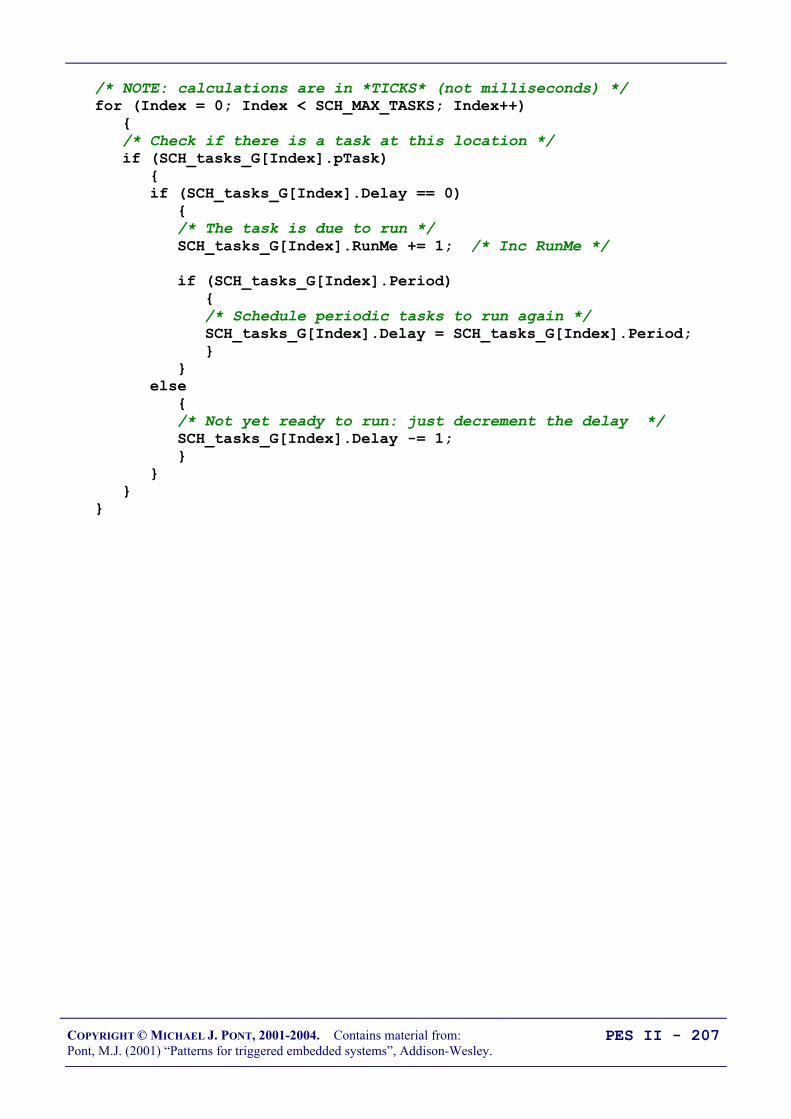
COPYRIGHT © MICHAEL J. PONT, 2001-2004. Contains material from:Pont, M.J. (2001) “Patterns for triggered embedded systems”, Addison-Wesley.
PES II - 207
/* NOTE: calculations are in *TICKS* (not milliseconds) */ for (Index = 0; Index < SCH_MAX_TASKS; Index++) /* Check if there is a task at this location */ if (SCH_tasks_G[Index].pTask) if (SCH_tasks_G[Index].Delay == 0) /* The task is due to run */ SCH_tasks_G[Index].RunMe += 1; /* Inc RunMe */
if (SCH_tasks_G[Index].Period) /* Schedule periodic tasks to run again */ SCH_tasks_G[Index].Delay = SCH_tasks_G[Index].Period; else /* Not yet ready to run: just decrement the delay */ SCH_tasks_G[Index].Delay -= 1;

COPYRIGHT © MICHAEL J. PONT, 2001-2004. Contains material from:Pont, M.J. (2001) “Patterns for triggered embedded systems”, Addison-Wesley.
PES II - 208
void SCC_A_MASTER_Send_Tick_Message(const tByte SLAVE_INDEX) /* Find the slave ID for this slave ALL SLAVES MUST HAVE A UNIQUE (non-zero) ID! */ tByte Slave_ID = (tByte) Current_Slave_IDs_G[SLAVE_INDEX]; CAN_messages[0].Data[0] = Slave_ID;
/* Fill the data fields */ CAN_messages[0].Data[1] = Tick_message_data_G[SLAVE_INDEX][0]; CAN_messages[0].Data[2] = Tick_message_data_G[SLAVE_INDEX][1]; CAN_messages[0].Data[3] = Tick_message_data_G[SLAVE_INDEX][2]; CAN_messages[0].Data[4] = Tick_message_data_G[SLAVE_INDEX][3];
/* Send the message on the CAN bus */ CAN_messages[0].MCR1 = 0xE7; /* TXRQ, reset CPUUPD */

COPYRIGHT © MICHAEL J. PONT, 2001-2004. Contains material from:Pont, M.J. (2001) “Patterns for triggered embedded systems”, Addison-Wesley.
PES II - 209
bit SCC_A_MASTER_Process_Ack(const tByte SLAVE_INDEX) tByte Ack_ID, Slave_ID;
/* First time this is called there is no Ack message to check - we simply return 'OK'. */ if (First_ack_G) First_ack_G = 0; return RETURN_NORMAL;
if ((CAN_messages[1].MCR1 & 0x03) == 0x02) /* if NEWDAT */ /* An ack message was received -> extract the data */ Ack_ID = CAN_messages[1].Data[0]; /* Get data byte 0 */
Ack_message_data_G[SLAVE_INDEX][0] = CAN_messages[1].Data[1]; Ack_message_data_G[SLAVE_INDEX][1] = CAN_messages[1].Data[2]; Ack_message_data_G[SLAVE_INDEX][2] = CAN_messages[1].Data[3]; Ack_message_data_G[SLAVE_INDEX][3] = CAN_messages[1].Data[4];
CAN_messages[1].MCR0 = 0xfd; /* reset NEWDAT, INTPND */ CAN_messages[1].MCR1 = 0xfd;
/* Find the slave ID for this slave */ Slave_ID = (tByte) Current_Slave_IDs_G[SLAVE_INDEX];
if (Ack_ID == Slave_ID) return RETURN_NORMAL;
/* No message, or ID incorrect */ return RETURN_ERROR;

COPYRIGHT © MICHAEL J. PONT, 2001-2004. Contains material from:Pont, M.J. (2001) “Patterns for triggered embedded systems”, Addison-Wesley.
PES II - 210
void SCC_A_MASTER_Shut_Down_the_Network(void) EA = 0;
while(1) SCC_A_MASTER_Watchdog_Refresh();
void SCC_A_MASTER_Enter_Safe_State(void) /* USER DEFINED - Edit as required */
TRAFFIC_LIGHTS_Display_Safe_Output();

COPYRIGHT © MICHAEL J. PONT, 2001-2004. Contains material from:Pont, M.J. (2001) “Patterns for triggered embedded systems”, Addison-Wesley.
PES II - 211
Slave Software
void SCC_A_SLAVE_Init_CAN(void) tByte i; tByte Message;
/* Sort out the tasks */ for (i = 0; i < SCH_MAX_TASKS; i++) SCH_Delete_Task(i);
/* SCH_Delete_Task() will generate an error code, because the task array is empty. -> reset the global error variable. */ Error_code_G = 0;
/* Set the network error pin (reset when tick message received) */ Network_error_pin = NETWORK_ERROR;
/* ------ SYSCON Register The access to XRAM and CAN controller is enabled. The signals !RD and !WR are not activated during accesses to the XRAM/CAN controller. ALE generation is enabled. */ SYSCON = 0x20;
/* ------------ CAN Control/Status Register -------------- */ CAN_cr = 0x41; /* INIT and CCE */
/* ------------ Bit Timing Register --------------------- Baudrate = 333.333 kbaud - Need 308+ kbaud plus for 1ms ticks, 8 data bytes - See text for details
There are 5 time quanta before sample point There are 4 time quanta after sample point The (re)synchronization jump width is 2 time quanta. */ CAN_btr1 = 0x34; /* Bit Timing Register */ CAN_btr0 = 0x42; CAN_gms1 = 0xFF; /* Global Mask Short Register 1 */ CAN_gms0 = 0xFF; /* Global Mask Short Register 0 */ CAN_ugml1 = 0xFF; /* Upper Global Mask Long Register 1 */ CAN_ugml0 = 0xFF; /* Upper Global Mask Long Register 0 */ CAN_lgml1 = 0xF8; /* Lower Global Mask Long Register 1 */ CAN_lgml0 = 0xFF; /* Lower Global Mask Long Register 0 */

COPYRIGHT © MICHAEL J. PONT, 2001-2004. Contains material from:Pont, M.J. (2001) “Patterns for triggered embedded systems”, Addison-Wesley.
PES II - 212
/* ------ Configure 'Tick' Message Object */ /* Message object 1 is valid */ /* Enable receive interrupt */ CAN_messages[0].MCR1 = 0x55; /* Message Ctrl. Reg. 1 */ CAN_messages[0].MCR0 = 0x99; /* Message Ctrl. Reg. 0 */
/* message direction is receive */ /* extended 29-bit identifier */ CAN_messages[0].MCFG = 0x04; /* Message Config. Reg. */
CAN_messages[0].UAR1 = 0x00; /* Upper Arbit. Reg. 1 */ CAN_messages[0].UAR0 = 0x00; /* Upper Arbit. Reg. 0 */ CAN_messages[0].LAR1 = 0x00; /* Lower Arbit. Reg. 1 */ CAN_messages[0].LAR0 = 0x00; /* Lower Arbit. Reg. 0 */
/* ------ Configure 'Ack' Message Object */ CAN_messages[1].MCR1 = 0x55; /* Message Ctrl. Reg. 1 */ CAN_messages[1].MCR0 = 0x95; /* Message Ctrl. Reg. 0 */
/* Message direction is transmit */ /* Extended 29-bit identifier; 5 valid data bytes */ CAN_messages[1].MCFG = 0x5C; /* Message Config. Reg. */ CAN_messages[1].UAR1 = 0x00; /* Upper Arbit. Reg. 1 */ CAN_messages[1].UAR0 = 0x00; /* Upper Arbit. Reg. 0 */ CAN_messages[1].LAR1 = 0xF8; /* Lower Arbit. Reg. 1 */ CAN_messages[1].LAR0 = 0x07; /* Lower Arbit. Reg. 0 */ CAN_messages[1].Data[0] = 0x00; /* Data byte 0 */ CAN_messages[1].Data[1] = 0x00; /* Data byte 1 */ CAN_messages[1].Data[2] = 0x00; /* Data byte 2 */ CAN_messages[1].Data[3] = 0x00; /* Data byte 3 */ CAN_messages[1].Data[4] = 0x00; /* Data byte 4 */
/* ------ Configure other objects --------------------------- */ /* Configure remaining message objects (2-14) - none is valid */ for (Message = 2; Message <= 14; ++Message) CAN_messages[Message].MCR1 = 0x55; /* Message Ctrl. Reg. 1 */ CAN_messages[Message].MCR0 = 0x55; /* Message Ctrl. Reg. 0 */
/* ------------ CAN Ctrl. Reg. --------------------- */ /* Reset CCE and INIT */ /* Enable interrupt generation from CAN Modul */ /* Enable CAN-interrupt of Controller */ CAN_cr = 0x02; IEN2 |= 0x02;
SCC_A_SLAVE_Watchdog_Init(); /* Start the watchdog */

COPYRIGHT © MICHAEL J. PONT, 2001-2004. Contains material from:Pont, M.J. (2001) “Patterns for triggered embedded systems”, Addison-Wesley.
PES II - 213
void SCC_A_SLAVE_Start(void) tByte Tick_00, Tick_ID; bit Start_slave;
/* Disable interrupts */ EA = 0;
/* We can be at this point because: 1. The network has just been powered up 2. An error has occurred in the Master, and it is not gen. ticks 3. The network has been damaged -> no ticks are being recv
Try to make sure the system is in a safe state... NOTE: Interrupts are disabled here!! */ SCC_A_SLAVE_Enter_Safe_State();
Start_slave = 0; Error_code_G = ERROR_SCH_WAITING_FOR_START_COMMAND_FROM_MASTER; SCH_Report_Status(); /* Sch not yet running - do this manually */
/* Now wait (indefinitely) for approp signal from the Master */ do /* Wait for 'Slave ID' message to be received */ do SCC_A_SLAVE_Watchdog_Refresh(); /* Must feed watchdog */ while ((CAN_messages[0].MCR1 & 0x03) != 0x02);
/* Got a message - extract the data */ if ((CAN_messages[0].MCR1 & 0x0c) == 0x08) /* if MSGLST set */ /* Ignore lost message */ CAN_messages[0].MCR1 = 0xf7; /* reset MSGLST */
Tick_00 = (tByte) CAN_messages[0].Data[0]; /* Get Data 0 */ Tick_ID = (tByte) CAN_messages[0].Data[1]; /* Get Data 1 */
CAN_messages[0].MCR0 = 0xfd; /* reset NEWDAT, INTPND */ CAN_messages[0].MCR1 = 0xfd;

COPYRIGHT © MICHAEL J. PONT, 2001-2004. Contains material from:Pont, M.J. (2001) “Patterns for triggered embedded systems”, Addison-Wesley.
PES II - 214
if ((Tick_00 == 0x00) && (Tick_ID == SLAVE_ID)) /* Message is correct */ Start_slave = 1;
/* Send ack */ CAN_messages[1].Data[0] = 0x00; /* Set data byte 0 */ CAN_messages[1].Data[1] = SLAVE_ID; /* Set data byte 1 */ CAN_messages[1].MCR1 = 0xE7; /* Send message */ else /* Not yet received correct message - wait */ Start_slave = 0; while (!Start_slave);
/* Start the scheduler */ IRCON = 0; EA = 1;

COPYRIGHT © MICHAEL J. PONT, 2001-2004. Contains material from:Pont, M.J. (2001) “Patterns for triggered embedded systems”, Addison-Wesley.
PES II - 215
void SCC_A_SLAVE_Update(void) interrupt INTERRUPT_CAN_c515c tByte Index;
/* Reset this when tick is received */ Network_error_pin = NO_NETWORK_ERROR;
/* Check tick data - send ack if necessary NOTE: 'START' message will only be sent after a 'time out' */ if (SCC_A_SLAVE_Process_Tick_Message() == SLAVE_ID) SCC_A_SLAVE_Send_Ack_Message_To_Master();
/* Feed the watchdog ONLY when a *relevant* message is received (Noise on the bus, etc, will not stop the watchdog) START messages will NOT refresh the slave. - Must talk to every slave at suitable intervals. */ SCC_A_SLAVE_Watchdog_Refresh();
/* Check the last error codes on the CAN bus */ if ((CAN_sr & 0x07) != 0) Error_code_G = ERROR_SCH_CAN_BUS_ERROR; Network_error_pin = NETWORK_ERROR;
/* See Infineon c515c manual for error code details */ CAN_error_pin0 = ((CAN_sr & 0x01) == 0); CAN_error_pin1 = ((CAN_sr & 0x02) == 0); CAN_error_pin2 = ((CAN_sr & 0x04) == 0); else CAN_error_pin0 = 1; CAN_error_pin1 = 1; CAN_error_pin2 = 1;

COPYRIGHT © MICHAEL J. PONT, 2001-2004. Contains material from:Pont, M.J. (2001) “Patterns for triggered embedded systems”, Addison-Wesley.
PES II - 216
/* NOTE: calculations are in *TICKS* (not milliseconds) */ for (Index = 0; Index < SCH_MAX_TASKS; Index++) /* Check if there is a task at this location */ if (SCH_tasks_G[Index].pTask) if (SCH_tasks_G[Index].Delay == 0) /* The task is due to run */ SCH_tasks_G[Task_index].RunMe += 1; /* Inc RunMe */
if (SCH_tasks_G[Task_index].Period) /* Schedule periodic tasks to run again */ SCH_tasks_G[Task_index].Delay = SCH_tasks_G[Task_index].Period; else /* Not yet ready to run: just decrement the delay */ SCH_tasks_G[Index].Delay -= 1;

COPYRIGHT © MICHAEL J. PONT, 2001-2004. Contains material from:Pont, M.J. (2001) “Patterns for triggered embedded systems”, Addison-Wesley.
PES II - 217
tByte SCC_A_SLAVE_Process_Tick_Message(void) tByte Tick_ID;
if ((CAN_messages[0].MCR1 & 0x0c) == 0x08) /* If MSGLST set */ /* The CAN controller has stored a new message into this object, while NEWDAT was still set, i.e. the previously stored message is lost. We simply IGNORE this here and reset the flag. */ CAN_messages[0].MCR1 = 0xf7; /* reset MSGLST */
/* The first byte is the ID of the slave for which the data are intended. */ Tick_ID = CAN_messages[0].Data[0]; /* Get Slave ID */
if (Tick_ID == SLAVE_ID) /* Only if there is a match do we need to copy these fields */ Tick_message_data_G[0] = CAN_messages[0].Data[1]; Tick_message_data_G[1] = CAN_messages[0].Data[2]; Tick_message_data_G[2] = CAN_messages[0].Data[3]; Tick_message_data_G[3] = CAN_messages[0].Data[4];
CAN_messages[0].MCR0 = 0xfd; /* reset NEWDAT, INTPND */ CAN_messages[0].MCR1 = 0xfd;
return Tick_ID;
void SCC_A_SLAVE_Send_Ack_Message_To_Master(void) /* First byte of message must be slave ID */ CAN_messages[1].Data[0] = SLAVE_ID; /* data byte 0 */
CAN_messages[1].Data[1] = Ack_message_data_G[0]; CAN_messages[1].Data[2] = Ack_message_data_G[1]; CAN_messages[1].Data[3] = Ack_message_data_G[2]; CAN_messages[1].Data[4] = Ack_message_data_G[3];
/* Send the message on the CAN bus */ CAN_messages[1].MCR1 = 0xE7; /* TXRQ, reset CPUUPD */

COPYRIGHT © MICHAEL J. PONT, 2001-2004. Contains material from:Pont, M.J. (2001) “Patterns for triggered embedded systems”, Addison-Wesley.
PES II - 218
What about CAN without on-chip hardware support?
Master node using Microchip MCP2510 CAN transceiver
40393837363534
123456789
10
333231
30292827262524
11121314151617181920
232221
SCK
MISO
MOSI
/SS
P1.3
XTL1
AT89S53
123456789
181716151413121110
MCP2510
Rx
Tx
SI
SCK
SO
/CS
/RST
Vcc
OSC1
1234
8765
PCA82C250
CANL
CANH
RXD
TXD
To CAN bus
12 MHz

COPYRIGHT © MICHAEL J. PONT, 2001-2004. Contains material from:Pont, M.J. (2001) “Patterns for triggered embedded systems”, Addison-Wesley.
PES II - 219
Slave node using Microchip MCP2510 CAN transceiver
40393837363534
123456789
10
333231
30292827262524
11121314151617181920
232221
SCK
MISO
MOSI
/SS
P1.3
XTL1
/ INT0
AT89S53
123456789
181716151413121110
MCP2510
Rx
Tx
SI
SCK
SO
/CS
/RST
Vcc
OSC1
1234
8765
PCA82C250
CANL
CANH
RXD
TXD
To CAN bus
12 MHz
/INT

COPYRIGHT © MICHAEL J. PONT, 2001-2004. Contains material from:Pont, M.J. (2001) “Patterns for triggered embedded systems”, Addison-Wesley.
PES II - 220
Preparations for the next seminar
Please read PTTES Chapter 35 before the next seminar.
40393837363534
1234567
‘8051’
8910
33323130292827262524
11121314151617181920
232221
P3.0
P1.7
RS
T
P1.6
P1.5
P1.4
P1.2
P1.3
P1.1
P1.0
VS
S
XTL2
XTL1
P3.7
P3.6
P3.5
P3.3
P3.4
P3.2
P3.1
/ EA
P0.6
P0.7
P0.5
P0.4
P0.3
P0.1
P0.2
P0.0
VC
C
P2.0
P2.2
P2.1
P2.3
P2.4
P2.5
P2.7
P2.6
/ PSE
N
ALE

COPYRIGHT © MICHAEL J. PONT, 2001-2004. Contains material from:Pont, M.J. (2001) “Patterns for triggered embedded systems”, Addison-Wesley.
PES II - 221
Seminar 9: Applying “ProportionalIntegral Differential”
(PID) control
−+−
+−
+++−= )2()1(21)(1)1()( ke
TTke
TTke
TT
TTKkuku DDD
I
−+−
+−
+++−= )2()1(21)(1)1()( ke
TTke
TTke
TT
TTKkuku DDD
I
−+−
+−
+++−= )2()1(21)(1)1()( ke
TTke
TTke
TT
TTKkuku DDD
I

COPYRIGHT © MICHAEL J. PONT, 2001-2004. Contains material from:Pont, M.J. (2001) “Patterns for triggered embedded systems”, Addison-Wesley.
PES II - 222
Overview of this seminar
• The focus of this seminar is on Proportional-Integral-Differential (PID) control.
• PID is both simple and effective: as a consequence it is themost widely used control algorithm.
• The focus here will be on techniques for designing andimplementing PID controllers for use in embeddedapplications.

COPYRIGHT © MICHAEL J. PONT, 2001-2004. Contains material from:Pont, M.J. (2001) “Patterns for triggered embedded systems”, Addison-Wesley.
PES II - 223
Why do we need closed-loop control?
Suppose we wish to control the speed of a DC motor, used as part ofan air-traffic control application.
To control this speed, we will assume that we have decided tochange the applied motor voltage using a DAC.
Controlled system
Open-loop controller
Desired output
Actual output

COPYRIGHT © MICHAEL J. PONT, 2001-2004. Contains material from:Pont, M.J. (2001) “Patterns for triggered embedded systems”, Addison-Wesley.
PES II - 224
In an ideal world, this type of open-loop control system would beeasy to design: we would simply have a look-up table linking therequired motor speed to the required output parameters.
Input (v)
Outpu
t (s)
s = 100v
Radar rotation speed (RPM) DAC setting (8-bit)
0 02 514 1026 1538 20410 255
Linear Systemy = ax + b
Output (y)Input (x)
∆y
∆xb
Input (x)
Outpu
t (y)
a = ∆y
∆x
y = ax + b
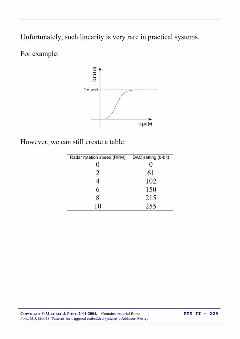
COPYRIGHT © MICHAEL J. PONT, 2001-2004. Contains material from:Pont, M.J. (2001) “Patterns for triggered embedded systems”, Addison-Wesley.
PES II - 225
Unfortunately, such linearity is very rare in practical systems.
For example:
Input (v)
Outpu
t (s)
Max. speed
However, we can still create a table:
Radar rotation speed (RPM) DAC setting (8-bit)
0 02 614 1026 1508 21510 255

COPYRIGHT © MICHAEL J. PONT, 2001-2004. Contains material from:Pont, M.J. (2001) “Patterns for triggered embedded systems”, Addison-Wesley.
PES II - 226
However, this is not the only problem we have to deal with.
Most real systems also demonstrate characteristics which vary withtime.
RadarSpeed
Controller
Userinterface(ADC)
Windspeedsensor
Wind directionsensor
DC MotorInterface
(DAC)
Required speedof rotation
New speedsettingsWind speed
Wind direction
Overall, this approach to control system design quickly becomesimpractical.

COPYRIGHT © MICHAEL J. PONT, 2001-2004. Contains material from:Pont, M.J. (2001) “Patterns for triggered embedded systems”, Addison-Wesley.
PES II - 227
Closed-loop control
RadarSpeed
Controller
Userinterface
(ADC)
DC MotorInterface(DAC)
Speedsensor
Required speedof rotation
New speedsettings
Current speedof rotation
Current speedof rotation
Closed-loop controller
Controlled system
Desired output
Actual output

COPYRIGHT © MICHAEL J. PONT, 2001-2004. Contains material from:Pont, M.J. (2001) “Patterns for triggered embedded systems”, Addison-Wesley.
PES II - 228
What closed-loop algorithm should you use?
There are numerous possible control algorithms that can beemployed in the box marked ‘Closed-loop controller’ on theprevious slide, and the development and evaluation of newalgorithms is an active area of research in many universities.
A detailed discussion of some of the possible algorithms available isgiven by Dutton et al., (1997), Dorf and Bishop (1998) and Nise(1995).
Despite the range of algorithms available, Proportional-Integral-Differential (PID) control is found to be very effective in manycases and - as such - it is generally considered the ‘standard’ againstwhich alternative algorithms are judged.
Without doubt, it is the most widely used control algorithm in theworld at the present time.

COPYRIGHT © MICHAEL J. PONT, 2001-2004. Contains material from:Pont, M.J. (2001) “Patterns for triggered embedded systems”, Addison-Wesley.
PES II - 229
What is PID control?
If you open a textbook on control theory, you will encounter adescription of PID control containing an equation similar to thatshown below:
u k u k KTT
TT
e kTT
e kTT
e kI
D D D( ) ( ) ( ) ( ) (= − + + +
− +
− + −
1 1 1 2 1 2)
Where:
u(k) is the signal sent to the plant, and e(k) is the error signal, both at sample k;T is the sample period (in seconds), and 1/T is the sample rate (in Hz);K is the proportional gain;1/TI is the integral gain;TD is the derivative gain;
This may appear rather complex, but can - in fact - be implementedvery simply.

COPYRIGHT © MICHAEL J. PONT, 2001-2004. Contains material from:Pont, M.J. (2001) “Patterns for triggered embedded systems”, Addison-Wesley.
PES II - 230
A complete PID control implementation
/* Proportional term */Change_in_controller_output = PID_KP * Error;
/* Integral term */Sum += Error;Change_in_controller_output += PID_KI * Sum;
/* Differential term */Change_in_controller_output += (PID_KD * SAMPLE_RATE * (Error -Old_error));
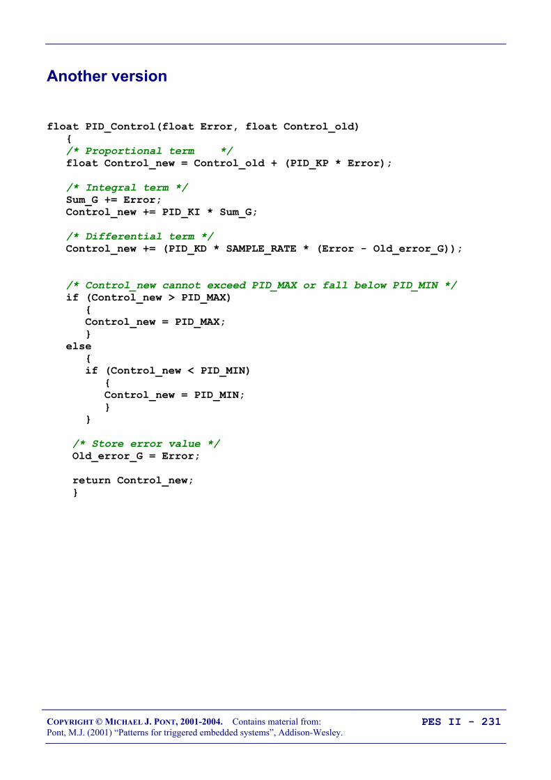
COPYRIGHT © MICHAEL J. PONT, 2001-2004. Contains material from:Pont, M.J. (2001) “Patterns for triggered embedded systems”, Addison-Wesley.
PES II - 231
Another version
float PID_Control(float Error, float Control_old) /* Proportional term */ float Control_new = Control_old + (PID_KP * Error);
/* Integral term */ Sum_G += Error; Control_new += PID_KI * Sum_G;
/* Differential term */ Control_new += (PID_KD * SAMPLE_RATE * (Error - Old_error_G));
/* Control_new cannot exceed PID_MAX or fall below PID_MIN */ if (Control_new > PID_MAX) Control_new = PID_MAX; else if (Control_new < PID_MIN) Control_new = PID_MIN;
/* Store error value */ Old_error_G = Error;
return Control_new;
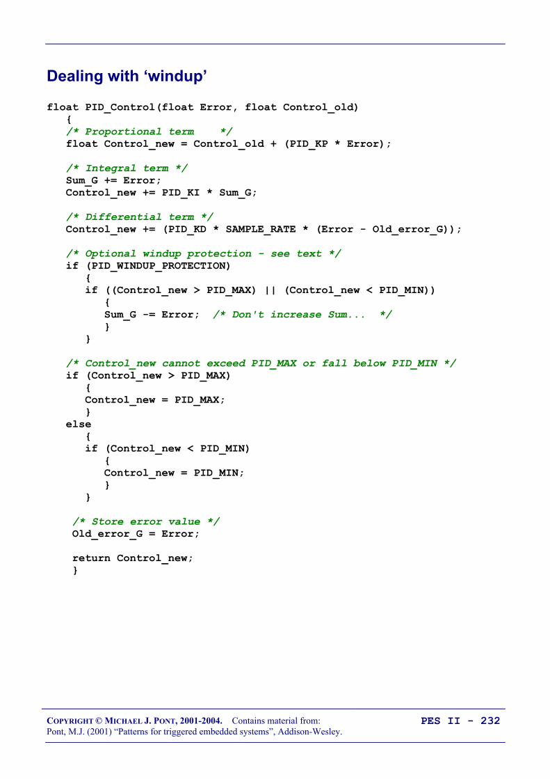
COPYRIGHT © MICHAEL J. PONT, 2001-2004. Contains material from:Pont, M.J. (2001) “Patterns for triggered embedded systems”, Addison-Wesley.
PES II - 232
Dealing with ‘windup’
float PID_Control(float Error, float Control_old) /* Proportional term */ float Control_new = Control_old + (PID_KP * Error);
/* Integral term */ Sum_G += Error; Control_new += PID_KI * Sum_G;
/* Differential term */ Control_new += (PID_KD * SAMPLE_RATE * (Error - Old_error_G));
/* Optional windup protection - see text */ if (PID_WINDUP_PROTECTION) if ((Control_new > PID_MAX) || (Control_new < PID_MIN)) Sum_G -= Error; /* Don't increase Sum... */
/* Control_new cannot exceed PID_MAX or fall below PID_MIN */ if (Control_new > PID_MAX) Control_new = PID_MAX; else if (Control_new < PID_MIN) Control_new = PID_MIN;
/* Store error value */ Old_error_G = Error;
return Control_new;
COPYRIGHT © MICHAEL J. PONT, 2001-2004. Contains material from:Pont, M.J. (2001) “Patterns for triggered embedded systems”, Addison-Wesley.
PES II - 233
Choosing the controller parameters
Two aspects of PID control algorithms deter new users. The first isthat the algorithm is seen to be ‘complex’: as we have demonstratedabove, this is a fallacy, since PID controllers can be very simplyimplemented.
The second concern lies with the tuning of the controllerparameters. Fortunately, such concerns are - again - oftenexagerated.
We suggest the use of the following methodology to tune the PIDparameters:
1. Set the integral (KI) and differential (KD) terms to 0.
2. Increase the proportional term (KP) slowly, until you getcontinuous oscillations.
3. Reduce KP to half the value determined above.
4. If necessary, experiment with small values of KD to damp-out ‘ringing’ in the response.
5. If necessary, experiment with small values of KI to reducethe steady-state error in the system.
6. Always use windup protection if using a non-zero KI value.
Note that steps 1-3 of this technique are a simplified version of theZiegler-Nichols guide to PID tuning; these date from the 1940s (seeZiegler and Nichols, 1942; Ziegler and Nichols, 1943).

COPYRIGHT © MICHAEL J. PONT, 2001-2004. Contains material from:Pont, M.J. (2001) “Patterns for triggered embedded systems”, Addison-Wesley.
PES II - 234
What sample rate?
One effective technique involves the measurement of the systemrise time.
Input
Outpu
t
Rise time
Having determined the rise time (measured in seconds), we can -making some simplifying assumptions - calculate the requiredsample frequency as follows:
Sample frequency = timeRise40
Thus, if the rise time measured was 0.1 second, the required samplefrequency would be around 400 Hz.
Please note that this value is approximate, and involves severalassumptions about the nature of the system. See Franklin et al.(1994), for further details.

COPYRIGHT © MICHAEL J. PONT, 2001-2004. Contains material from:Pont, M.J. (2001) “Patterns for triggered embedded systems”, Addison-Wesley.
PES II - 235
Hardware resource implications
• Implementation of a PID control algorithm requires somefloating-point or integer mathematical operations.
• The precise load will vary with the implementation used, buta typical implementation requires 4 multiplications, 3additions and 2 subtractions.
• With floating-point operations, this amounts to a total ofapproximately 2000 instructions (using the Keil compiler, onan 8051 without hardware maths support).
• This operation can be carried out every millisecond on astandard (12 osc / instruction) 8051 running at 24 MHz, ifthere is no other CPU-intensive processing to be done.
• A one-millisecond loop time is more than adequate for mostcontrol applications, which typically require sample intervalsof several hundred milliseconds or longer.
• Of course, if you require higher performance, then manymore modern implementations of the 8051 microcontrollercan provide this.
• Similarly, devices such as the Infineon 517 and 509, whichhave hardware maths support, will also execute this codemore rapidly, should this be required.

COPYRIGHT © MICHAEL J. PONT, 2001-2004. Contains material from:Pont, M.J. (2001) “Patterns for triggered embedded systems”, Addison-Wesley.
PES II - 236
PID: Overall strengths and weaknesses
Suitable for many single-input, single-output (SISO) systems. Generally effective. Easy to implement. Not (generally) suitable for use in multi-input or multi-output applications. Parameter tuning can be time consuming.

COPYRIGHT © MICHAEL J. PONT, 2001-2004. Contains material from:Pont, M.J. (2001) “Patterns for triggered embedded systems”, Addison-Wesley.
PES II - 237
Why open-loop controllers are still (sometimes) useful
• Open-loop control still has a role to play.
• For example, if we wish to control the speed of an electricfan in an automotive air-conditioning system, we may notneed precise speed control, and an open-loop approachmight be appropriate.
• In addition, it is not always possible to directly measure thequantity we are trying to control, making closed-loop controlimpractical.
• For example, in an insulin delivery system used for patientswith diabetes, we are seeking to control levels of glucose inthe bloodstream. However, glucose sensors are notavailable, so an open-loop controller must be used; pleasesee Dorf and Bishop (1998, p. 22) for further details.
[Similar problems apply throughout much of the processindustry, where sensors are not available to determineproduct quality.]

COPYRIGHT © MICHAEL J. PONT, 2001-2004. Contains material from:Pont, M.J. (2001) “Patterns for triggered embedded systems”, Addison-Wesley.
PES II - 238
Limitations of PID control
• PID control is only suitable for ‘single-input, single-output’(SISO) systems, or for system that can be broken down intoSISO components.
• PID control is not suitable for systems with multiple inputsand / or multiple outputs.
• In addition, even for SISO systems, PID can only control asingle system parameter’ it is not suitable for multi-parameter (sometimes called multi-variable) systems.
Please refer to Dorf and Bishop (1998), Dutton et al., (1997),Franklin et al., (1994), Franklin et al., (1998) and Nise (1995) forfurther discussions on multi-input, multi-output and multi-parametercontrol algorithms.
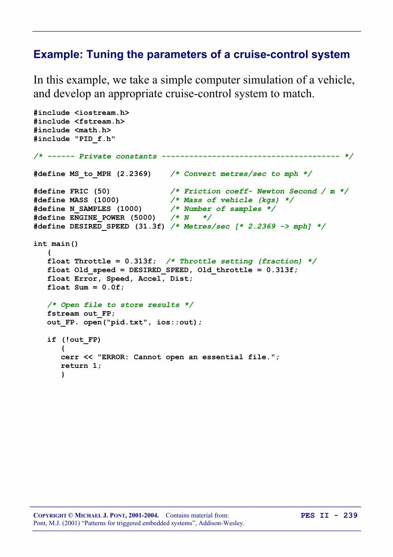
COPYRIGHT © MICHAEL J. PONT, 2001-2004. Contains material from:Pont, M.J. (2001) “Patterns for triggered embedded systems”, Addison-Wesley.
PES II - 239
Example: Tuning the parameters of a cruise-control system
In this example, we take a simple computer simulation of a vehicle,and develop an appropriate cruise-control system to match.#include <iostream.h>#include <fstream.h>#include <math.h>#include "PID_f.h"
/* ------ Private constants --------------------------------------- */
#define MS_to_MPH (2.2369) /* Convert metres/sec to mph */
#define FRIC (50) /* Friction coeff- Newton Second / m */#define MASS (1000) /* Mass of vehicle (kgs) */#define N_SAMPLES (1000) /* Number of samples */#define ENGINE_POWER (5000) /* N */#define DESIRED_SPEED (31.3f) /* Metres/sec [* 2.2369 -> mph] */
int main() float Throttle = 0.313f; /* Throttle setting (fraction) */ float Old_speed = DESIRED_SPEED, Old_throttle = 0.313f; float Error, Speed, Accel, Dist; float Sum = 0.0f;
/* Open file to store results */ fstream out_FP; out_FP. open("pid.txt", ios::out);
if (!out_FP) cerr << "ERROR: Cannot open an essential file."; return 1;

COPYRIGHT © MICHAEL J. PONT, 2001-2004. Contains material from:Pont, M.J. (2001) “Patterns for triggered embedded systems”, Addison-Wesley.
PES II - 240
for (int t = 0; t < N_SAMPLES; t++) /* Error drives the controller */ Error = (DESIRED_SPEED - Old_speed);
/* Calculate throttle setting */ Throttle = PID_Control(Error, Throttle); /* Throttle = 0.313f; - Use for open-loop demo */
/* Simple car model */ Accel = (float)(Throttle * ENGINE_POWER - (FRIC * Old_speed)) / MASS; Dist = Old_speed + Accel * (1.0f / SAMPLE_RATE); Speed = (float) sqrt((Old_speed * Old_speed) + (2 * Accel * Dist));
/* Disturbances */ if (t == 50) Speed = 35.8f; /* Sudden gust of wind into rear of car */
if (t == 550) Speed = 26.8f; /* Sudden gust of wind into front of car */
/* Display speed in miles per hour */ cout << Speed * MS_to_MPH << endl; out_FP << Speed * MS_to_MPH << endl;
/* Ready for next loop */ Old_speed = Speed; Old_throttle = Throttle;
return 0;
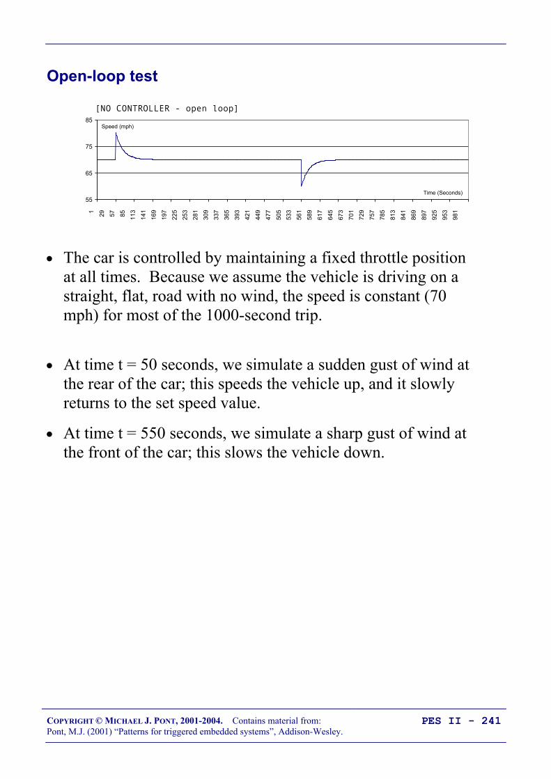
COPYRIGHT © MICHAEL J. PONT, 2001-2004. Contains material from:Pont, M.J. (2001) “Patterns for triggered embedded systems”, Addison-Wesley.
PES II - 241
Open-loop test
55
65
75
85
1 29 57 85 113
141
169
197
225
253
281
309
337
365
393
421
449
477
505
533
561
589
617
645
673
701
729
757
785
813
841
869
897
925
953
981
[NO CONTROLLER - open loop]
Time (Seconds)
Speed (mph)
• The car is controlled by maintaining a fixed throttle positionat all times. Because we assume the vehicle is driving on astraight, flat, road with no wind, the speed is constant (70mph) for most of the 1000-second trip.
• At time t = 50 seconds, we simulate a sudden gust of wind atthe rear of the car; this speeds the vehicle up, and it slowlyreturns to the set speed value.
• At time t = 550 seconds, we simulate a sharp gust of wind atthe front of the car; this slows the vehicle down.

COPYRIGHT © MICHAEL J. PONT, 2001-2004. Contains material from:Pont, M.J. (2001) “Patterns for triggered embedded systems”, Addison-Wesley.
PES II - 242
Tuning the PID parameters: methodology
We will tune a PID algorithm for use with this system by applyingthe following methodology:
1. Set integral (KI) and differential (KD) terms to 0.
2. Increase the proportional term (KP) slowly, until you getcontinuous oscillations.
3. Reduce KP to half the value determined above.
4. If necessary, experiment with small values of KD to damp-out ‘ringing’ in the response.
5. If necessary, experiment with small values of KI to reducethe steady-state error in the system.
6. Always use windup protection if using a non-zero KI value.

COPYRIGHT © MICHAEL J. PONT, 2001-2004. Contains material from:Pont, M.J. (2001) “Patterns for triggered embedded systems”, Addison-Wesley.
PES II - 243
First test
55
65
75
85
1 29 57 85 113
141
169
197
225
253
281
309
337
365
393
421
449
477
505
533
561
589
617
645
673
701
729
757
785
813
841
869
897
925
953
981
#define PID_KP (0.20f)#define PID_KI (0.00f)#define PID_KD (0.00f)
Time (Seconds)
Speed (mph)
Now we increase the value of KP, until we small, constant,oscillations.
55
65
75
85
1 29 57 85 113
141
169
197
225
253
281
309
337
365
393
421
449
477
505
533
561
589
617
645
673
701
729
757
785
813
841
869
897
925
953
981
#define PID_KP (1.00f)#define PID_KI (0.00f)#define PID_KD (0.00f)
Time (Seconds)
Speed (mph)

COPYRIGHT © MICHAEL J. PONT, 2001-2004. Contains material from:Pont, M.J. (2001) “Patterns for triggered embedded systems”, Addison-Wesley.
PES II - 244
The results of this experiment suggest that a value of KP = 0.5 willbe appropriate (that is, half the value used to generate the constantoscillations).
55
65
75
85
1 29 57 85 113
141
169
197
225
253
281
309
337
365
393
421
449
477
505
533
561
589
617
645
673
701
729
757
785
813
841
869
897
925
953
981
#define PID_KP (0.50f)#define PID_KI (0.00f)#define PID_KD (0.00f)
Time (Seconds)
Speed (mph)
We then experiment a little more:
55
65
75
85
1 29 57 85 113
141
169
197
225
253
281
309
337
365
393
421
449
477
505
533
561
589
617
645
673
701
729
757
785
813
841
869
897
925
953
981
#define PID_KP (0.50f)#define PID_KI (0.00f)#define PID_KD (0.10f)
Time (Seconds)
Speed (mph)
• Note that, with these parameters, the system reaches therequired speed within a few seconds of each disturbance.
• Note also that we can reduce the system complexity here byomitting the integral term, and using this PD controller.

COPYRIGHT © MICHAEL J. PONT, 2001-2004. Contains material from:Pont, M.J. (2001) “Patterns for triggered embedded systems”, Addison-Wesley.
PES II - 245
Example: DC Motor Speed Control
Logic 0 (0v) to turn motor
+12 V
74LS06
1K- 10K
IRF540 (or similar)
0 V
M
8051 DeviceP1.1
P3.5
Optical encoder connected here(mounted on motor shaft)
Note that this example uses a different, integer-based, PIDimplementation. As we discussed in ‘Hardware resourceimplications’, integer-based solutions impose a lower CPU loadthan floating-point equivalents.

COPYRIGHT © MICHAEL J. PONT, 2001-2004. Contains material from:Pont, M.J. (2001) “Patterns for triggered embedded systems”, Addison-Wesley.
PES II - 246
void main(void) SCH_Init_T1(); /* Set up the scheduler */ PID_MOTOR_Init();
/* Set baud rate to 9600, using internal baud rate generator */ /* Generic 8051 version */ PC_LINK_Init_Internal(9600);
/* Add a 'pulse count poll' task */ /* TIMING IS IN TICKS (1ms interval) */ /* Every 5 milliseconds (200 times per second) */ SCH_Add_Task(PID_MOTOR_Poll_Speed_Pulse, 1, 1);
SCH_Add_Task(PID_MOTOR_Control_Motor, 300, 1000);
/* Sending data to serial port */ SCH_Add_Task(PC_LINK_Update, 3, 1);
/* All tasks added: start running the scheduler */ SCH_Start();
while(1) SCH_Dispatch_Tasks();
...
#define PULSE_HIGH (0)#define PULSE_LOW (1)
#define PID_PROPORTIONAL (5)#define PID_INTEGRAL (50)#define PID_DIFFERENTIAL (50)
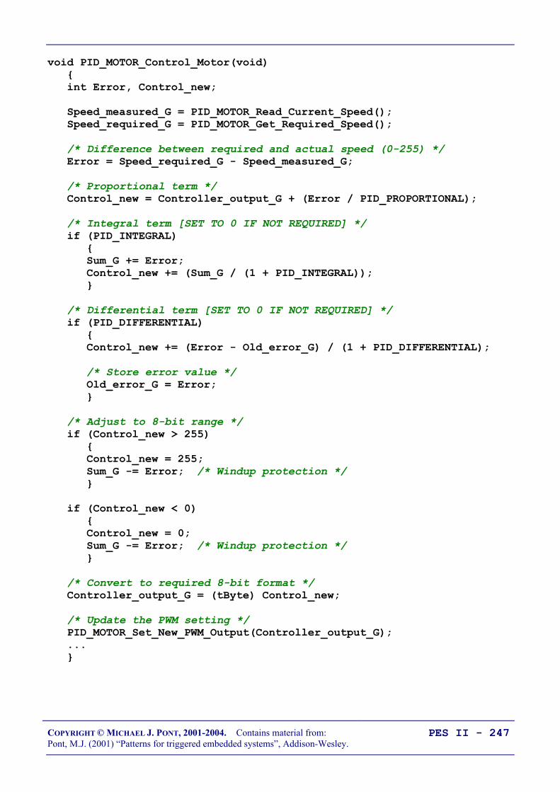
COPYRIGHT © MICHAEL J. PONT, 2001-2004. Contains material from:Pont, M.J. (2001) “Patterns for triggered embedded systems”, Addison-Wesley.
PES II - 247
void PID_MOTOR_Control_Motor(void) int Error, Control_new;
Speed_measured_G = PID_MOTOR_Read_Current_Speed(); Speed_required_G = PID_MOTOR_Get_Required_Speed();
/* Difference between required and actual speed (0-255) */ Error = Speed_required_G - Speed_measured_G;
/* Proportional term */ Control_new = Controller_output_G + (Error / PID_PROPORTIONAL);
/* Integral term [SET TO 0 IF NOT REQUIRED] */ if (PID_INTEGRAL) Sum_G += Error; Control_new += (Sum_G / (1 + PID_INTEGRAL));
/* Differential term [SET TO 0 IF NOT REQUIRED] */ if (PID_DIFFERENTIAL) Control_new += (Error - Old_error_G) / (1 + PID_DIFFERENTIAL);
/* Store error value */ Old_error_G = Error;
/* Adjust to 8-bit range */ if (Control_new > 255) Control_new = 255; Sum_G -= Error; /* Windup protection */
if (Control_new < 0) Control_new = 0; Sum_G -= Error; /* Windup protection */
/* Convert to required 8-bit format */ Controller_output_G = (tByte) Control_new;
/* Update the PWM setting */ PID_MOTOR_Set_New_PWM_Output(Controller_output_G); ...

COPYRIGHT © MICHAEL J. PONT, 2001-2004. Contains material from:Pont, M.J. (2001) “Patterns for triggered embedded systems”, Addison-Wesley.
PES II - 248
Alternative: Fuzzy control
Most available textbooks highlight traditional (mathematically-based) approaches to the design of control systems.
A less formal approach to control system design has emergedrecently: this is known as ‘fuzzy control’ and is suitable for SISO,MISO and MIMO systems, with one or more parameters.
(Refer to Passino and Yurkovich, 1998, for further information onfuzzy control.)

COPYRIGHT © MICHAEL J. PONT, 2001-2004. Contains material from:Pont, M.J. (2001) “Patterns for triggered embedded systems”, Addison-Wesley.
PES II - 249
Preparations for the next seminar
In the final seminar on this course we’ll discuss a case study whichwill pull together some of the key material we have considered inthis (and earlier) seminars.
Please review your notes before the final seminar.

COPYRIGHT © MICHAEL J. PONT, 2001-2004. Contains material from:Pont, M.J. (2001) “Patterns for triggered embedded systems”, Addison-Wesley.
PES II - 250

COPYRIGHT © MICHAEL J. PONT, 2001-2004. Contains material from:Pont, M.J. (2001) “Patterns for triggered embedded systems”, Addison-Wesley.
PES II - 251
Seminar 10: Case study:
Automotive cruisecontrol using PID and
CAN

COPYRIGHT © MICHAEL J. PONT, 2001-2004. Contains material from:Pont, M.J. (2001) “Patterns for triggered embedded systems”, Addison-Wesley.
PES II - 252
Overview of this seminar
We have considered the design of schedulers for multi-processordistributed systems in this module, and looked - briefly - at someelements of control-system design.
In this session, we take the simple cruise-control example discussedin Seminar 8 and convert this into a complete - distributed - system.
We will then use the resulting system as a testbed to explore theimpact of network delays on distributed embedded control systems.
How would I design and implement a cruise control systemfor a car?

COPYRIGHT © MICHAEL J. PONT, 2001-2004. Contains material from:Pont, M.J. (2001) “Patterns for triggered embedded systems”, Addison-Wesley.
PES II - 253
Single-processor system: Overview
Car model
CCS
Throttlesetting
Vehiclespeed (pulses)
(Microcontroller 0)
(Microcontroller 1)

COPYRIGHT © MICHAEL J. PONT, 2001-2004. Contains material from:Pont, M.J. (2001) “Patterns for triggered embedded systems”, Addison-Wesley.
PES II - 254
Single-processor system: Code
[We’ll discuss this in the seminar]

COPYRIGHT © MICHAEL J. PONT, 2001-2004. Contains material from:Pont, M.J. (2001) “Patterns for triggered embedded systems”, Addison-Wesley.
PES II - 255
Multi-processor design: Overview
Car model
Throttlesetting
Vehiclespeed (pulses)
PID node (Master)
PID node (Master)
Throttle node(Slave)
Throttle node(Slave)
Speed node(Slave)
Speed node(Slave)
CAN
(Microcontroller 0)
(Microcontroller 1) (Microcontroller 2) (Microcontroller 3)

COPYRIGHT © MICHAEL J. PONT, 2001-2004. Contains material from:Pont, M.J. (2001) “Patterns for triggered embedded systems”, Addison-Wesley.
PES II - 256
Multi-processor design: Code (PID node)
[We’ll discuss this in the seminar]

COPYRIGHT © MICHAEL J. PONT, 2001-2004. Contains material from:Pont, M.J. (2001) “Patterns for triggered embedded systems”, Addison-Wesley.
PES II - 257
Multi-processor design: Code (Speed node)
[We’ll discuss this in the seminar]

COPYRIGHT © MICHAEL J. PONT, 2001-2004. Contains material from:Pont, M.J. (2001) “Patterns for triggered embedded systems”, Addison-Wesley.
PES II - 258
Multi-processor design: Code (Throttle node)
[We’ll discuss this in the seminar]

COPYRIGHT © MICHAEL J. PONT, 2001-2004. Contains material from:Pont, M.J. (2001) “Patterns for triggered embedded systems”, Addison-Wesley.
PES II - 259
Exploring the impact of network delays
• We discussed in the last seminar how we can calculate therequired sampling rate for a control system.
• When developing a distributed control system, we also needto take into account the network delays.
Time
TickMessage(Data for S1)
AckMessage
(from S1)...
Tick latency(varies with baud rate)
• This is a complex topic…
• Two effective “rules of thumb”:
◊ Make sure the delays are short, when compared with the samplinginterval. Aim for no more than 10% of the sample interval betweensensing (input) and actuation (output).
◊ Make sure the delays are constant - avoid “jitter”.

COPYRIGHT © MICHAEL J. PONT, 2001-2004. Contains material from:Pont, M.J. (2001) “Patterns for triggered embedded systems”, Addison-Wesley.
PES II - 260
Example: Impact of network delays on the CCS system
[We’ll discuss this in the seminar - and you will try it in the lab.]

COPYRIGHT © MICHAEL J. PONT, 2001-2004. Contains material from:Pont, M.J. (2001) “Patterns for triggered embedded systems”, Addison-Wesley.
PES II - 261
That’s it!
This seminar brings us to the end of the course - I hope that youhave enjoyed it (and found it useful).