Programmable controllers - Eliwell€¦ · 2 General description FREE Smart features • User...
20
PROGRAMMABLE CONTROLLERS Programmable controllers The Eliwell solution that combines speed and reliability in a full range of compact, high-performing products. Data Sheet
Transcript of Programmable controllers - Eliwell€¦ · 2 General description FREE Smart features • User...
PRO
GR
AM
MA
BLE
CO
NTR
OLL
ERS
Programmable controllers
The Eliwell solution that combines speed and reliability in a full range of compact, high-performing products. Data Sheet
2
General description
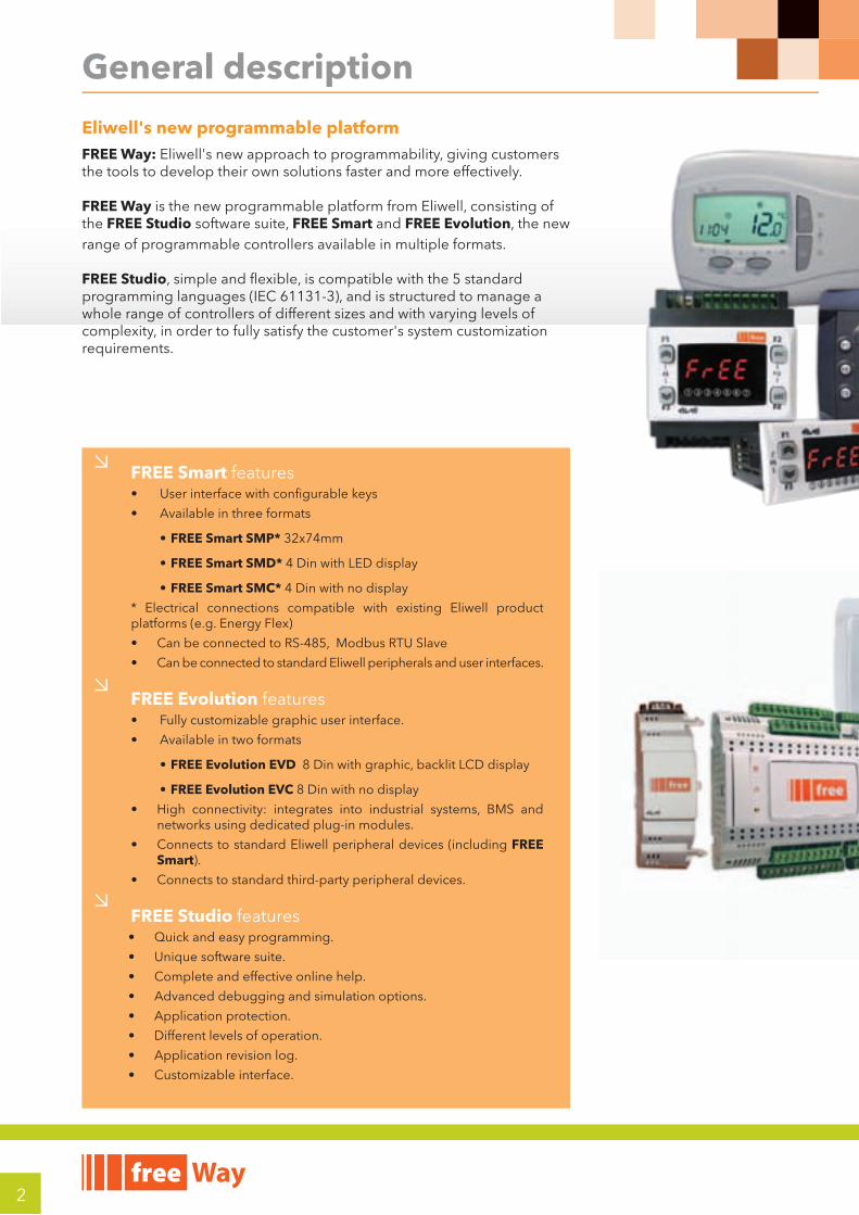
FREE Smart features • User interface with confi gurable keys
• Available in three formats
• FREE Smart SMP* 32x74mm
• FREE Smart SMD* 4 Din with LED display
• FREE Smart SMC* 4 Din with no display
* Electrical connections compatible with existing Eliwell product platforms (e.g. Energy Flex)
• Can be connected to RS-485, Modbus RTU Slave
• Can be connected to standard Eliwell peripherals and user interfaces.
FREE Evolution features• Fully customizable graphic user interface.
• Available in two formats
• FREE Evolution EVD 8 Din with graphic, backlit LCD display
• FREE Evolution EVC 8 Din with no display
• High connectivity: integrates into industrial systems, BMS and networks using dedicated plug-in modules.
• Connects to standard Eliwell peripheral devices (including FREE Smart).
• Connects to standard third-party peripheral devices.
FREE Studio features• Quick and easy programming.
• Unique software suite.
• Complete and effective online help.
• Advanced debugging and simulation options.
• Application protection.
• Different levels of operation.
• Application revision log.
• Customizable interface.
Eliwell's new programmable platformFREE Way: Eliwell's new approach to programmability, giving customers the tools to develop their own solutions faster and more effectively.
FREE Way is the new programmable platform from Eliwell, consisting of the FREE Studio software suite, FREE Smart and FREE Evolution, the new range of programmable controllers available in multiple formats.
FREE Studio, simple and fl exible, is compatible with the 5 standard programming languages (IEC 61131-3), and is structured to manage a whole range of controllers of different sizes and with varying levels of complexity, in order to fully satisfy the customer's system customization requirements.

3
SPEEDOne of the main goals of the FREE programmable platform is to give their own customers the tools to fi nd faster, more effective solutions for their customers. Many features of FREE make it possible to effectively reduce the time between defi ning a new application and rolling it out.
COMPACT
The new FREE programmable platform enables customers to keep costs at a competitive level. The FREE controllers are made with particular emphasis placed on technological solutions and physical size, so that signifi cant results in terms of simplicity, modularity and compactness can be achieved. The integrated solutions and smaller controller size of FREE devices provide real and immediate economic advantages for customers.
EFFICIENCY
The FREE programmable platform, complete and scalable across various levels of complexity, offers customers great freedom in choosing the solution they feel is best suited to their own requirements. This makes it easier to fi nd solutions which take account of costs and/or the reduction of product codes, including solutions which are more open to future development or future system requirements, with particular reference to connectivity.
RELIABILITY
The high quality of the new FREE Way programmable platform allows customers to reduce any costs linked to a lack of quality, during both the production process and on-site installation procedures. The FREE Smart and FREE Evolution controllers and the FREE Studio development environment were designed using innovative but carefully reconstructed criteria, by adopting advanced and stable technological solutions as well as certifi ed and monitored production processes. Eliwell has always been a byword for reliability.
Plus points
Target consumersFREE Way is designed for:
Manufacturers of:
• A.H.U.s (Air Handling Units)
• Chillers
• Heat Pumps
• Rooftops
• Compressor Rooms
• as well as...
Installers/integrators of:
• All air systems
• Hydronic systems
• Combi systems (air/water)
4
FREE Studio
Installation and system requirements
Operating Systems
• Windows 7 Home / Professional / Ultimate
• Windows XP Home / Professional SP2 or SP3
Installation setup, software updates, reference libraries and documentation are also available from the website.
www.eliwell.it once you have registered.
An Internet connection is required for access to software and manual documentation.
Resources AvailableThe IEC programmer includes the following resources:
FREE Smart FREE Evolution
CPU 14.7 MHz 72 MHz, 32MB RAM
Available memory for Application 190KByte 1MByte
Available memory for User Interface - 1MByte
FLASH memory data - 126MByte
RAM Memory* 2300Byte 512KByteRAM Memory** 1024Byte 500 wordEEPROM variables 1024Byte 4000 word* automatic mapping** Modbus mapping
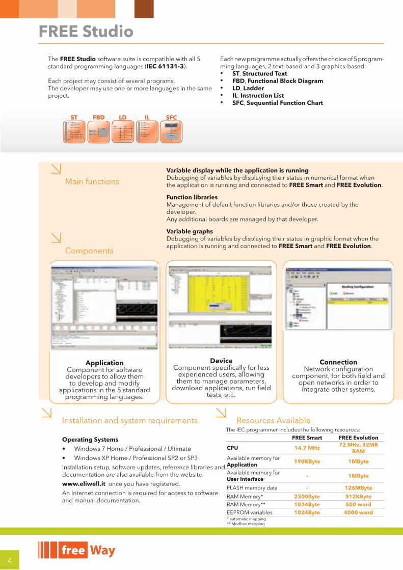
Main functions
Components
The FREE Studio software suite is compatible with all 5 standard programming languages (IEC 61131-3).
Each project may consist of several programs.The developer may use one or more languages in the same project.
Each new programme actually offers the choice of 5 program-ming languages, 2 text-based and 3 graphics-based:• ST, Structured Text • FBD, Functional Block Diagram • LD, Ladder • IL, Instruction List • SFC, Sequential Function Chart
. . . . . .
. . . . . . . .
. . . . . . . .
. . . . . . . .
. . . . . . . .
. . . . . . . .
. . . . . .
Init
Step0
SW1
. . . . . .
. . . . . . . .
. . . . . . . .
. . . . . . . .
. . . . . . . .
. . . . . . . .
. . . . . .
Main Start
En1
En2
En3
N
/
. . . . . .
. . . . . . . .
. . . . . . . .
. . . . . . . .
. . . . . . . .
. . . . . . . .
. . . . . .
MAXIn1
In2
ld truest blinker.runld truest blinker.runcal trigger
ld truest blinker.runcal trigger
var2:=var2+1;if (var2=200) then var2: =0; var1: =not var1;
counter: =counter+1;if (DI2=TRUE) then out1: =counter and 5; out2: =counter and 7; out3: =counter and 12;else
ST FBD IL SFCLD
ConnectionNetwork confi guration
component, for both fi eld and open networks in order to integrate other systems.
Application Component for software developers to allow them
to develop and modify applications in the 5 standard
programming languages.
Device Component specifi cally for less
experienced users, allowing them to manage parameters,
download applications, run fi eld tests, etc.
Variable display while the application is running Debugging of variables by displaying their status in numerical format when the application is running and connected to FREE Smart and FREE Evolution.
Function librariesManagement of default function libraries and/or those created by the developer.Any additional boards are managed by that developer.
Variable graphs Debugging of variables by displaying their status in graphic format when the application is running and connected to FREE Smart and FREE Evolution.
5
FREE Studio
Minimum kit for system developers FREE Smart
• FREE Studio installation setup.
• 1 FREE Smart SMxxxx*
• 1 DMI 100-3 Manufacturer + yellow TTL cable
• 1 optional MFK + blue TTL cable
• FREE Smart* power cables and transformer
* alternatively, request the Demo Case
FREE Evolution
• FREE Studio installation setup
• 1 FREE Evolution EVD7500/U
• USB/RS485 adapter or USB/CAN Open or Ethernet plug-in for PC connection
• FREE Evolution power transformer
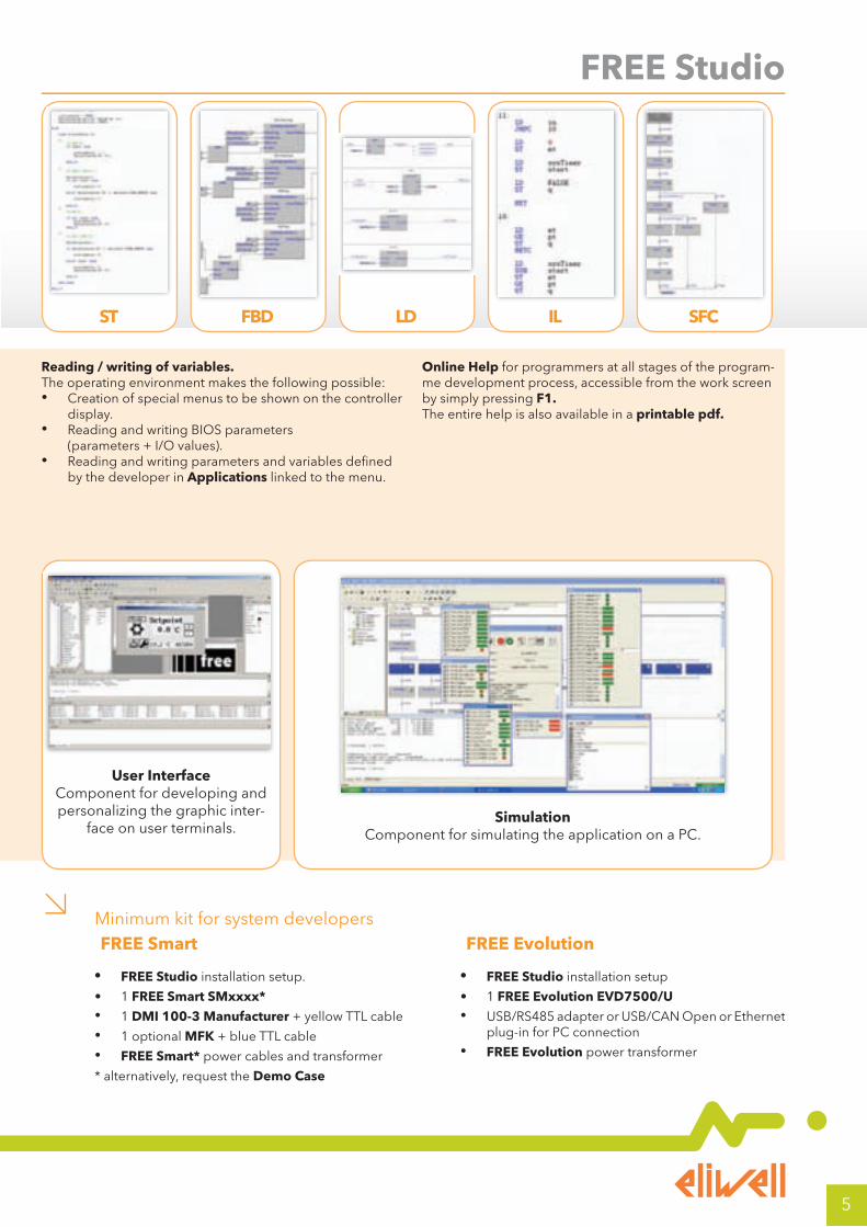
Reading / writing of variables. The operating environment makes the following possible:• Creation of special menus to be shown on the controller
display.• Reading and writing BIOS parameters
(parameters + I/O values).• Reading and writing parameters and variables defi ned
by the developer in Applications linked to the menu.
Online Help for programmers at all stages of the program-me development process, accessible from the work screen by simply pressing F1. The entire help is also available in a printable pdf.
ST LDFBD IL SFC
User InterfaceComponent for developing and personalizing the graphic inter-
face on user terminals.Simulation
Component for simulating the application on a PC.
6
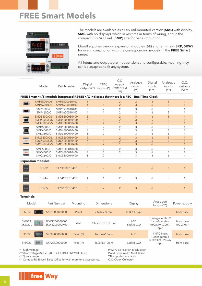
FREE Smart Models
Model Part NumberDigital
outputs (*)TRIAC
outputs (*)
O.C. outputs
PWM / PPM (**)
Analogue outputs
(**)
Digitalinputs(***)
Analogueinputs
(**)
O.C. outputs
PWM
FREE Smart • (/S) models integrated RS485 •/C indicates that there is a RTC – Real Time Clock
SMP5500/C/SSMP4600/C/S
SMP5500050400SMP4600050400
54
-1
22
33
66
55
11
SMP5500/CSMP4600/C
SMP5500010400SMP4600010400
54
-1
22
33
66
55
11
SMD5500/C/SSMD4600/C/SSMD3600/C/S
SMD5500050400SMD4600050400SMD3600050400
543
-12
221
333
666
555
111
SMD5500/CSMD4600/CSMD3600/C
SMD5500010400SMD4600010400SMD3600010400
543
-12
221
333
666
555
111
SMC5500/C/SSMC4600/C/SSMC3600/C/S
SMC5500050400SMC4600050400SMC3600050400
543
-12
221
333
666
555
111
SMC5500/CSMC4600/CSMC3600/C
SMC5500010400SMC4600010400SMC3600010400
543
-12
221
333
666
555
111
Expansion modules
SE632 SE63020310400 3 - 2 - 6 3 1
SE646 SE64123510400 4 1 2 3 6 5 1
SE655 SE65023510400 5 - 2 3 6 5 1
Terminals
Model Part Number Mounting Dimensions DisplayAnalogue Inputs (**)
Power supply
SKP10 SKP1000000000 Panel 74x32x30 mm LED / 4 digit - from base
SKW22SKW22L
SKW2200000000SKW22L0000H00
Wall 137x96.5x31.3 mmLCD
Backlit LCD
1 integrated NTC1 configurable
NTC/DI/4..20mA input
from base100-240V~
SKP22 SKP2200000000 Panel (°) 160x96x10mm LCD 1 NTC input1 configurable
NTC/DI/4...20mA input
from base
SKP22L SKP22L0000000 Panel (°) 160x96x10mm Backlit LCD from base
The models are available as a DIN rail-mounted version (SMD with display, SMC with no display), which saves time in terms of wiring, and in the compact 32x74 Eliwell (SMP) size for panel-mounting.
Eliwell supplies various expansion modules (SE) and terminals (SKP, SKW) for use in conjunction with the corresponding models in the FREE Smart range.
All inputs and outputs are independent and confi gurable, meaning they can be adapted to fi t any system.
(*) high voltage (**) low voltage (SELV: SAFETY EXTRA LOW VOLTAGE) (***) no voltage (°) Contact the Eliwell Sales Office for wall-mounting accessories.
PPM Pulse Position Modulation PWM Pulse Width Modulation TTL supplied as standardO.C. Open Collector
7
FREE Smart Connectivity
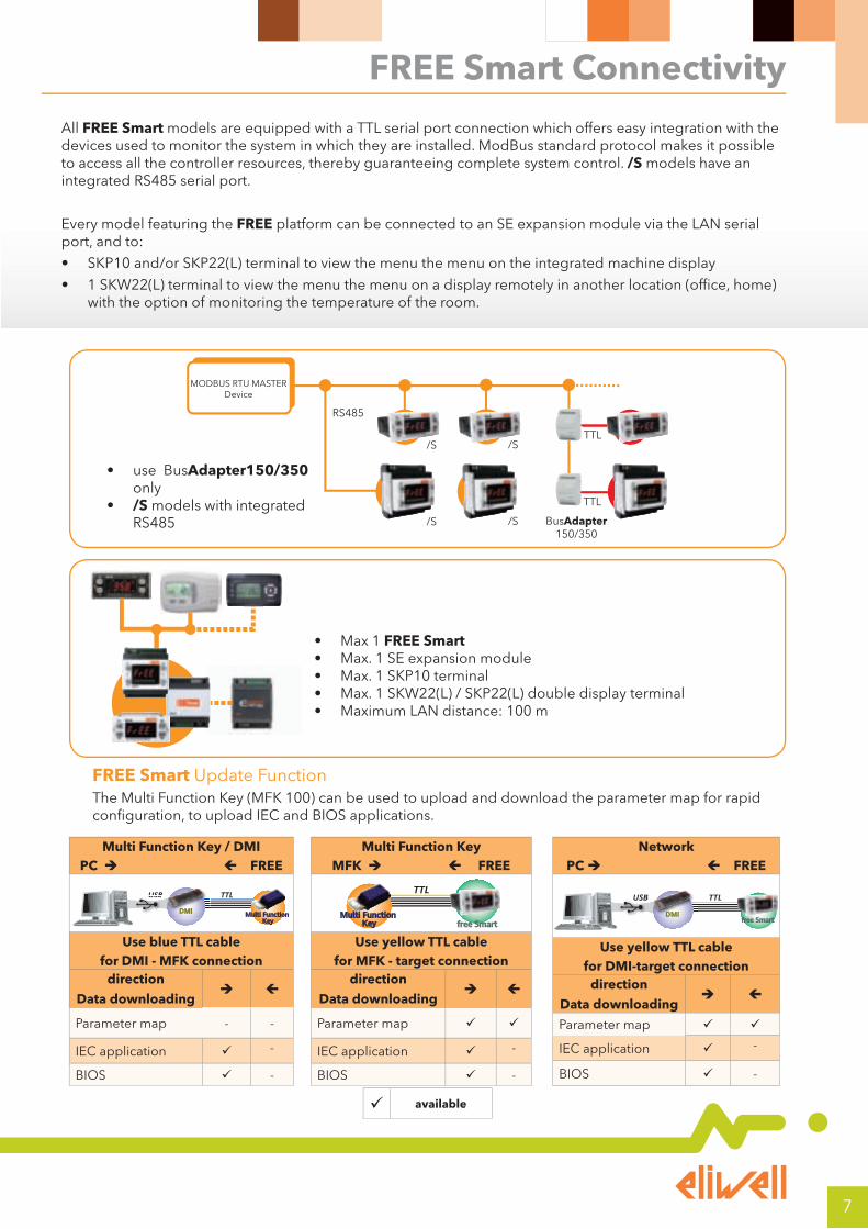
All FREE Smart models are equipped with a TTL serial port connection which offers easy integration with the devices used to monitor the system in which they are installed. ModBus standard protocol makes it possible to access all the controller resources, thereby guaranteeing complete system control. /S models have an integrated RS485 serial port.
Every model featuring the FREE platform can be connected to an SE expansion module via the LAN serial port, and to:
• SKP10 and/or SKP22(L) terminal to view the menu the menu on the integrated machine display
• 1 SKW22(L) terminal to view the menu the menu on a display remotely in another location (office, home) with the option of monitoring the temperature of the room.
• Max 1 FREE Smart• Max. 1 SE expansion module• Max. 1 SKP10 terminal• Max. 1 SKW22(L) / SKP22(L) double display terminal• Maximum LAN distance: 100 m
TTL
TTL
RS485
BusAdapter150/350
/S
/S
MODBUS RTU MASTERDevice
/S
/S
• use BusAdapter150/350 only
• /S models with integrated RS485
Multi Function Key / DMIPC FREE
Multi Function Key
DMI
TTLUSBUSB
Use blue TTL cable for DMI - MFK connection
direction
Data downloading
Parameter map - -
IEC application -
BIOS -
Multi Function Key MFK FREE
Multi Function Key
TTL
free Smart
Use yellow TTL cablefor MFK - target connection
direction
Data downloading
Parameter map
IEC application -
BIOS -
NetworkPC FREE
free SmartDMI
TTLUSBUSB
Use yellow TTL cablefor DMI-target connection
direction
Data downloading
Parameter map
IEC application -
BIOS -
FREE Smart Update FunctionThe Multi Function Key (MFK 100) can be used to upload and download the parameter map for rapid configuration, to upload IEC and BIOS applications.
available
8
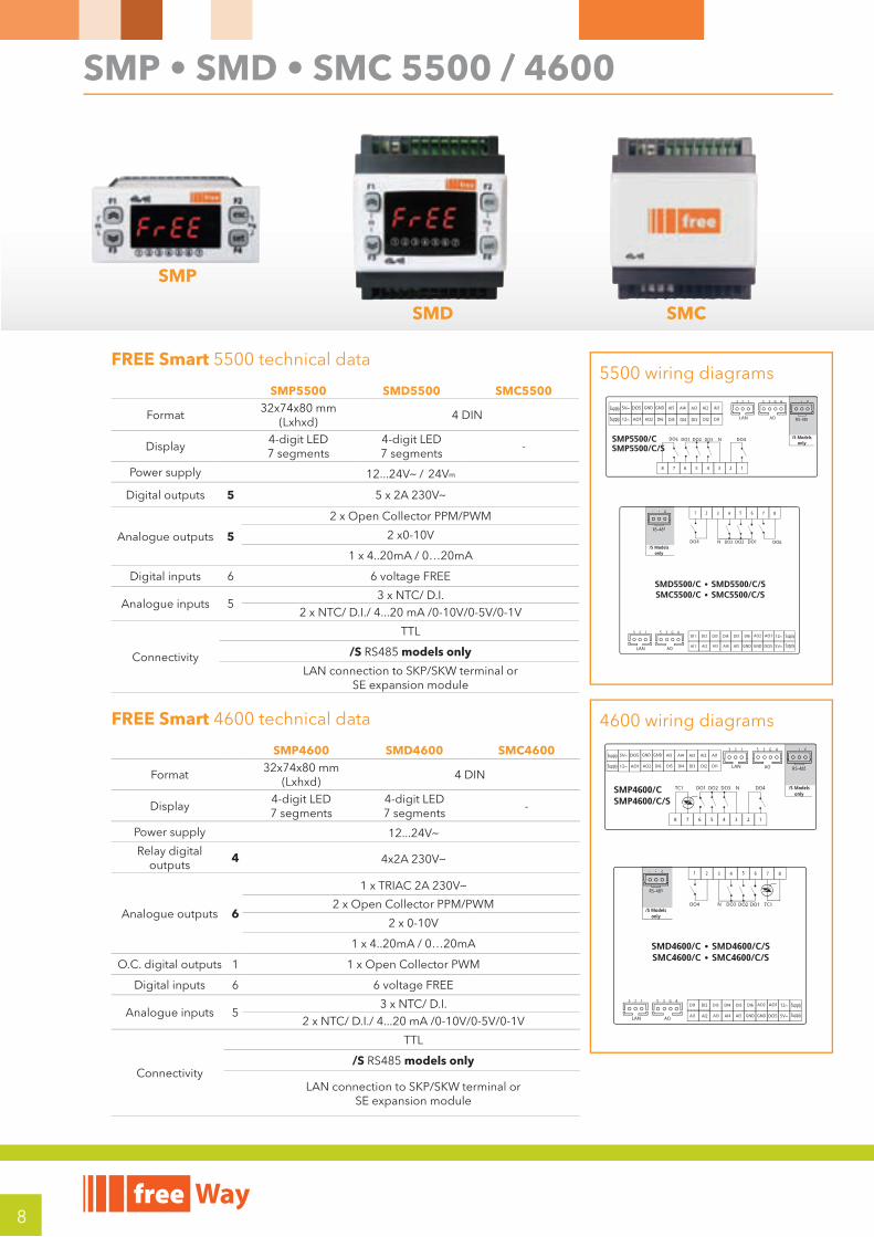
SMP • SMD • SMC 5500 / 4600
FREE Smart 4600 technical data
SMP4600 SMD4600 SMC4600
Format32x74x80 mm
(Lxhxd)4 DIN
Display4-digit LED7 segments
4-digit LED7 segments
-
Power supply 12...24Va
Relay digital outputs
4 4x2A 230Va
Analogue outputs 6
1 x TRIAC 2A 230Va
2 x Open Collector PPM/PWM
2 x 0-10V
1 x 4..20mA / 0…20mA
O.C. digital outputs 1 1 x Open Collector PWM
Digital inputs 6 6 voltage FREE
Analogue inputs 53 x NTC/ D.I.
2 x NTC/ D.I./ 4...20 mA /0-10V/0-5V/0-1V
Connectivity
TTL
/S RS485 models only
LAN connection to SKP/SKW terminal orSE expansion module
4600 wiring diagrams
SMP4600/CSMP4600/C/S
SMD4600/C • SMD4600/C/SSMC4600/C • SMC4600/C/S
Supply
Supply
GND GND AI5
DI1DI2DI3DI4DI5DI6AO2
AI4 AI2AI3 AI1
Supply
Supply
GNDGNDAI5
DI1 DI2 DI3 DI4 DI5 DI6 AO2
AI4AI2 AI3AI1
AO RS-485
G3
/S Modelsonly
5 4 +- G
RS-485
+- GG
AO
RS-485
G3
/S Modelsonly
5 4
4321 8765+- G
RS-485
+- GG
SMC4600/C • SMC4600/C/S
Supply
Supply
GNDGNDAI5
DI1 DI2 DI3 DI4 DI5 DI6 AO2
AI4AI2 AI3AI1AO
RS-485
G3
/S Modelsonly
5 4
4321 8765+- G
RS-485
+- GG
FREE Smart 5500 technical data
SMP5500 SMD5500 SMC5500
Format32x74x80 mm
(Lxhxd)4 DIN
Display4-digit LED7 segments
4-digit LED7 segments
-
Power supply 12...24Va / 24Vc
Digital outputs 5 5 x 2A 230Va
Analogue outputs 5
2 x Open Collector PPM/PWM
2 x0-10V
1 x 4..20mA / 0…20mA
Digital inputs 6 6 voltage FREE
Analogue inputs 53 x NTC/ D.I.
2 x NTC/ D.I./ 4...20 mA /0-10V/0-5V/0-1V
Connectivity
TTL
/S RS485 models only
LAN connection to SKP/SKW terminal orSE expansion module
5500 wiring diagrams
SMP5500/CSMP5500/C/S
Supply
Supply
GND GND AI5
DI1DI2DI3DI4DI5DI6AO2
AI4 AI2AI3 AI1
AO
DO3
DO3
RS-485
G3
/S Modelsonly
5 4 +- G
RS-485
+- GG
SMD5500/C • SMD5500/C/SSMC5500/C • SMC5500/C/S
Supply
Supply
GNDGNDAI5
DI1 DI2 DI3 DI4 DI5 DI6 AO2
AI4AI2 AI3AI1AO
RS-485
G3
/S Modelsonly
5 4
4321 8765+- G
RS-485
+- GG
6
DO3
SMC5500/C • SMC5500/C/S
Supply
Supply
GNDGNDAI5
DI1 DI2 DI3 DI4 DI5 DI6 AO2
AI4AI2 AI3AI1AO
RS-485
G3
/S Modelsonly
5 4
4321 8765+- G
RS-485
+- GG
6
6
SMD SMC
SMP
9
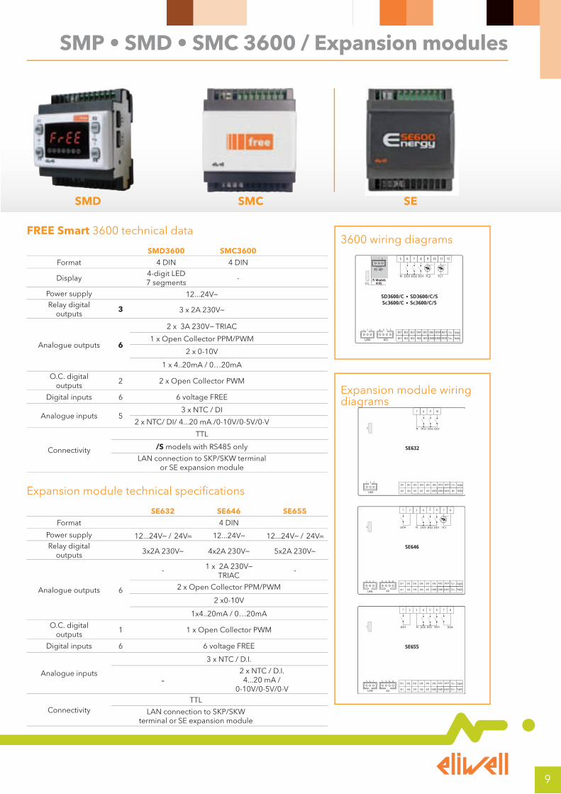
SMP • SMD • SMC 3600 / Expansion modules
FREE Smart 3600 technical data
SMD3600 SMC3600
Format 4 DIN 4 DIN
Display4-digit LED7 segments
-
Power supply 12...24Va
Relay digital outputs
3 3 x 2A 230Va
Analogue outputs 6
2 x 3A 230Va TRIAC
1 x Open Collector PPM/PWM
2 x 0-10V
1 x 4..20mA / 0…20mA
O.C. digitaloutputs
2 2 x Open Collector PWM
Digital inputs 6 6 voltage FREE
Analogue inputs 53 x NTC / DI
2 x NTC/ DI/ 4...20 mA /0-10V/0-5V/0-V
Connectivity
TTL
/S models with RS485 only
LAN connection to SKP/SKW terminal or SE expansion module
3600 wiring diagrams
DO3 DO2 DO1 TC2 TC1N
TTL
SD3600/C • SD3600/C/SSc3600/C • Sc3600/C/S
Supply
Supply
GNDGNDAI5
DI1 DI2 DI3 DI4 DI5 DI6 DO4
DO5
AO1
AI4AI2 AI3AI1
8765 1211109
RS-485
/S Modelsonly
+- G
RS-485
+- GG
AOLAN
G 3 54
DO3 DO2 DO1 TC2 TC1N
TTL
SC3600/C • SC3600/C/S
Supply
Supply
GNDGNDAI5
DI1 DI2 DI3 DI4 DI5 DI6 DO4
DO5
AO1
AI4AI2 AI3AI1
8765 1211109
RS-485
/S Modelsonly
+- G
RS-485
+- GG
AOLAN
G 3 54
Expansion module technical specifications
SE632 SE646 SE655
Format 4 DIN
Power supply 12...24Va / 24Vc 12...24Va 12...24Va / 24Vc
Relay digital outputs 3x2A 230Va 4x2A 230Va 5x2A 230Va
Analogue outputs 6
- 1 x 2A 230Va TRIAC
-
2 x Open Collector PPM/PWM
2 x0-10V
1x4..20mA / 0…20mA
O.C. digital outputs
1 1 x Open Collector PWM
Digital inputs 6 6 voltage FREE
Analogue inputs
3 x NTC / D.I.
-2 x NTC / D.I. 4...20 mA /
0-10V/0-5V/0-V
ConnectivityTTL
LAN connection to SKP/SKW terminal or SE expansion module
Expansion module wiring diagrams
SE646
Supply
Supply
GNDGNDAI5
DI1 DI2 DI3 DI4 DI5 DI6 AO2
AI4AI2 AI3AI1AO
G35 4
4321 8765
SE655
Supply
Supply
GNDGNDAI5
DI1 DI2 DI3 DI4 DI5 DI6 AO2
AI4AI2 AI3AI1AO
G35 4
DO6
4321 8765
SE632
Supply
Supply
GNDGNDAI5
DI1 DI2 DI3 DI4 DI5 DI6 AO2
NC NCAI2 NCAI1
87 109
SMD SMC SE
10
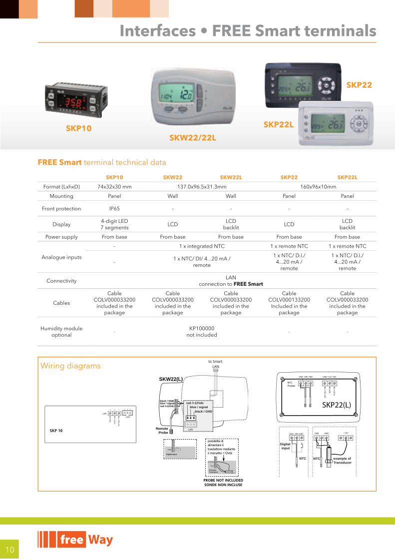
Interfaces • FREE Smart terminals
FREE Smart terminal technical data
SKP10 SKW22 SKW22L SKP22 SKP22L
Format (LxhxD) 74x32x30 mm 137.0x96.5x31.3mm 160x96x10mm
Mounting Panel Wall Wall Panel Panel
Front protection IP65 - - - -
Display4-digit LED7 segments
LCDLCD
backlitLCD
LCD backlit
Power supply From base From base From base From base From base
Analogue inputs
- 1 x integrated NTC 1 x remote NTC 1 x remote NTC
-1 x NTC/ DI/ 4...20 mA /
remote
1 x NTC/ D.I./ 4...20 mA /
remote
1 x NTC/ D.I./ 4...20 mA /
remote
ConnectivityLAN
connection to FREE Smart
Cables
CableCOLV000033200
included in the package
CableCOLV000033200
included in the package
CableCOLV000033200
included in the package
CableCOLV000133200
Included in the package
CableCOLV000033200
included in the package
Humidity module optional
-KP100000
not included- -
Wiring diagrams
SKP 10
BLACK
BLUE
RED
SKW22(L)
black / GNDblue / signalred /+12Vdc
RemoteProbe
LANto Smart
red /+12Vdc
Probe
Pressure Transducer
PROBE NOT INCLUDEDSONDE NON INCLUSE
Probe
Digital input
possibilità di alimentare il trasduttore medianteil morsetto +12Vdc
black / GNDblue / signal
red /+12Vdc
LAN
SKP22(L)
NTCProbes
GND AIR1 AIR2
BLACK
BLUE
RED
GND +12V LAN
GND AIR1 AIR2
Digital input
example ofTransducer
GND AIR2 +12V
NTC NTC
SKP10SKW22/22L
SKP22L
SKP22

11
FREE Smart Mounting
SKW22 / SKW22L mounting SKW22 / SKW22L dimensions
31.3
96.5
mm
137.0 mm
esc set
SMP • SKP10Panel-mounted installation. Drill a 29x71 mm hole and insert the instrument; secure it with the special brackets provided.
SMC • SMDDIN rail installation See mounting of EVD • EVC • EVESKP22/SKP22LSee EVK mounting page 16
SKW22 • SKW22L• (a) Screw connector for connection to FREE Smart.• (a) JST 3-way connector for connection to FREE Smart.The connector is inside the front keypad which is accessed by removing the cover (use a screwdriver or similar). The cables must pass through the hole in the centre of the rear.Make sure that power supply is of the correct voltage for the instrument.If the device is fitted on a metal panel, the panel must be earthed.
SKP10 mounting SKP10 dimensions
74mm
70mm
28m
m
32m
m
29m
m
71mm
30m
m
30mm
56.4mm
5.2mm
87mm
70.2mm61.6mm
43.6mm
70.2mm
SMD SMC SE
74mm
70mm
28m
m
32m
m
29m
m
71mm76m
m
76mm
SMP - SKP10 mounting SMC - SMD mountingSMP - SKP10 dimensions
12
Model Part NumberRelay
outputs (*)
SSR outputs
(§)
Analogue outputs
(**)
Digitalinputs
(**)
Digitalinputs(***)
Analogueinputs
(**)
IntegratedRS485 / MPBUS
FREE Evolution with display • /C indicates that there is an RTC – Real Time Clock • CANOpen integrated as standard
EVD7500/C/UEVD7500/C
EVD7500060B00EVD7500010B00
77
--
55
88
11
66
RS485RS485
EVD75SS/C/UEVD75SS/C
EVD75SS060B00EVD75SS010B00
55
22
55
88
11
66
RS485RS485
EVD75MP/C/UEVD75MP/C
EVD75MP060B00EVD75MP010B00
77
--
55
88
11
66
MPBUSMPBUS
FREE Evolution without display • /C indicates that there is an RTC – Real Time Clock • CANOpen, integrated as standard
EVC7500/C/UEVC7500/C
EVC7500060B00EVC7500010B00
77
--
55
88
11
66
RS485RS485
EVC75SS/C/UEVC75SS/C
EVC75SS060B00EVC75SS010B00
55
22
55
88
11
66
RS485RS485
EVC75MP/C/UEVC75MP/C
EVC75MP060B00EVC75MP010B00
77
--
55
88
11
66
MPBUSMPBUS
Expansion modules • RS485/CANOpen, integrated as standard
EVE7500 EVE7500000B00 7 - 5 8 1 6 RS485
EVE75SS EVE75SS000B00 5 2 5 8 1 6 RS485
FREE Evolution Panel • /C indicates that there is an RTC – Real Time Clock
Model Part number Mounting Dimensions Display Inputs (**) Power supply Serial
EVP3300/C EVP3300010B00 Panel (°) 160x96x10mmLCD
backlit1 NTC +
1 4..20mA 24V~/c - 48VcCANOpen RS485
ETHERNET
Terminals • /C indicates that there is an RTC – Real Time Clock
EVK3300/C EVK3300010B00 Panel (°) 160x96x10mmLCD
backlit1 NTC +
1 4..20mA 24V~/c - 48VcCANOpen RS485
ETHERNET
EVK1000 EVK1000000B00 Panel (°) 160x96x10mmLCD
backlit- From base CANOpen
Plug - in Part number Output (*) Serial Part number Serial Mounting Power supplyEVS EVS10R2000000
EVS00R4000000EVS00CA000000
1--
RS232RS485
CANOpen
EVS00C4000000EVS00ET000000
CANOpen+485ETHERNET
2DIN From base
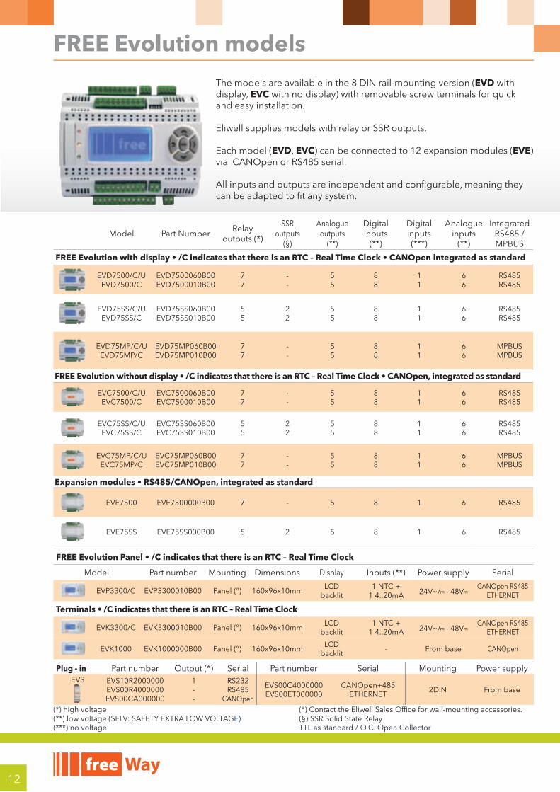
FREE Evolution models
The models are available in the 8 DIN rail-mounting version (EVD with display, EVC with no display) with removable screw terminals for quick and easy installation.
Eliwell supplies models with relay or SSR outputs.
Each model (EVD, EVC) can be connected to 12 expansion modules (EVE) via CANOpen or RS485 serial.
All inputs and outputs are independent and confi gurable, meaning they can be adapted to fi t any system.
(*) high voltage (**) low voltage (SELV: SAFETY EXTRA LOW VOLTAGE) (***) no voltage
(*) Contact the Eliwell Sales Office for wall-mounting accessories.(§) SSR Solid State Relay TTL as standard / O.C. Open Collector
13
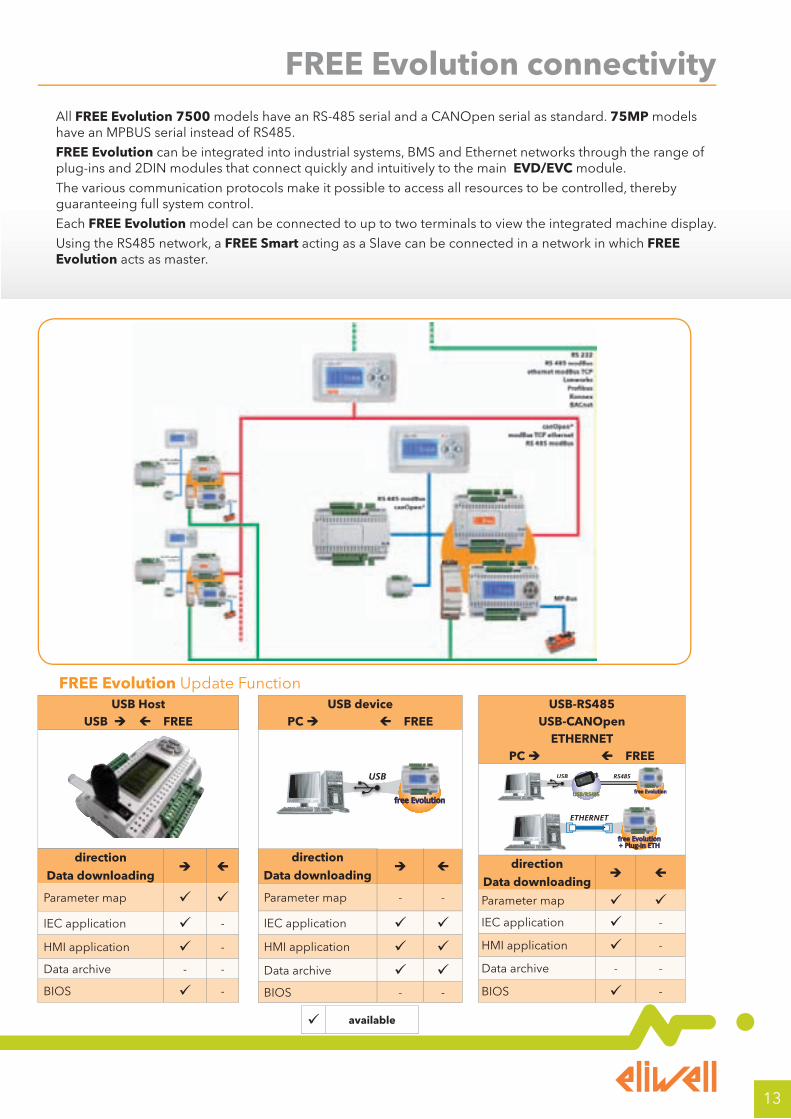
FREE Evolution connectivityAll FREE Evolution 7500 models have an RS-485 serial and a CANOpen serial as standard. 75MP models have an MPBUS serial instead of RS485.
FREE Evolution can be integrated into industrial systems, BMS and Ethernet networks through the range of plug-ins and 2DIN modules that connect quickly and intuitively to the main EVD/EVC module.
The various communication protocols make it possible to access all resources to be controlled, thereby guaranteeing full system control.
Each FREE Evolution model can be connected to up to two terminals to view the integrated machine display.
Using the RS485 network, a FREE Smart acting as a Slave can be connected in a network in which FREE Evolution acts as master.
USB HostUSB FREE
direction
Data downloading
Parameter map
IEC application -
HMI application -
Data archive - -
BIOS -
USB devicePC FREE
free Evolution
USBUSB
direction
Data downloading
Parameter map - -
IEC application HMI application Data archive BIOS - -
USB-RS485 USB-CANOpen
ETHERNETPC FREE
free EvolutionUSB/RS485
RS485USBUSB
free Evolution+ Plug-in ETH
ETHERNET
direction
Data downloading
Parameter map IEC application -
HMI application -
Data archive - -
BIOS -
available
FREE Evolution Update Function
14
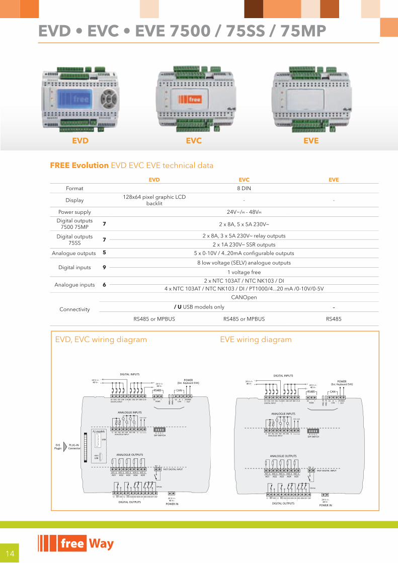
EVD • EVC • EVE 7500 / 75SS / 75MP
FREE Evolution EVD EVC EVE technical data
EVD EVC EVE
Format 8 DIN
Display128x64 pixel graphic LCD
backlit- -
Power supply 24V~/c - 48Vc
Digital outputs7500 75MP
7 2 x 8A, 5 x 5A 230Va
Digital outputs75SS
72 x 8A, 3 x 5A 230Va relay outputs
2 x 1A 230Va SSR outputs
Analogue outputs 5 5 x 0-10V / 4..20mA configurable outputs
Digital inputs 98 low voltage (SELV) analogue outputs
1 voltage free
Analogue inputs 62 x NTC 103AT / NTC NK103 / DI
4 x NTC 103AT / NTC NK103 / DI / PT1000/4...20 mA /0-10V/0-5V
Connectivity
CANOpen
/ U USB models only -RS485 or MPBUS RS485 or MPBUS RS485
EVD, EVC wiring diagram EVE wiring diagram
DI 1DIGITAL INPUT RS485 CAN
DI2 DI3 DI4 C1-4 DI5 DI6 DI7 DI8 C5-8 GS - + GS H L POWER OUT
AI1ANALOGUE INPUT
GAO1 GAO2 GAO3 GAO4 GAO5
GFDI
4 - 3 -2 -1AI2 AI3 AI4 AI5 AI6 12Vout 5Vout
+12V+5V
GG
POWER
POWER INDIGITAL OUTPUTS
DIGITAL INPUTS
ANALOGUE INPUTS
[Ext. Keyboard EVK]24 Va/c48 Vc
-
+ +
-24 Va/c48 Vc
24 Va/c48 Vc
RS485 CAN
DIP SWITCH
DO3 DO4 C34 DO5 DO6 DO7 C567C2 DO2 DO2C1 DO1 DO1
PLUG-IN Connector
EVSPlugin
ANALOGUE OUTPUTS
FAST DIGITAL INPUT
AO1 AO2 AO3 AO4 AO5
+
+ +
+
R TERM
R TERM
/U models
USB
miniUSB
12A max
DI 1DIGITAL INPUT RS485 CAN
DI2 DI3 DI4 C1-4 DI5 DI6 DI7 DI8 C5-8 GS - + GS H L POWER OUT
AI1ANALOGUE INPUT
GAO1 GAO2 GAO3 GAO4 GAO5
GFDI
4 - 3 -2 -1AI2 AI3 AI4 AI5 AI6 12Vout 5Vout
+12V+5V
GG
POWER
POWER INDIGITAL OUTPUTS
DIGITAL INPUTS
ANALOGUE INPUTS
[Ext. Keyboard EVK]24 Va/c48 Vc
-
+ +
-24 Va/c48 Vc
24 Va/c48 Vc
RS485 CAN
DIP SWITCH
DO3 DO4 C34 DO5 DO6 DO7 C567C2 DO2 DO2C1 DO1 DO1
ANALOGUE OUTPUTS
FAST DIGITAL INPUT
AO1 AO2 AO3 AO4 AO5
+
+ +
+
R TERM
R TERM
12A max
EVD EVC EVE
15
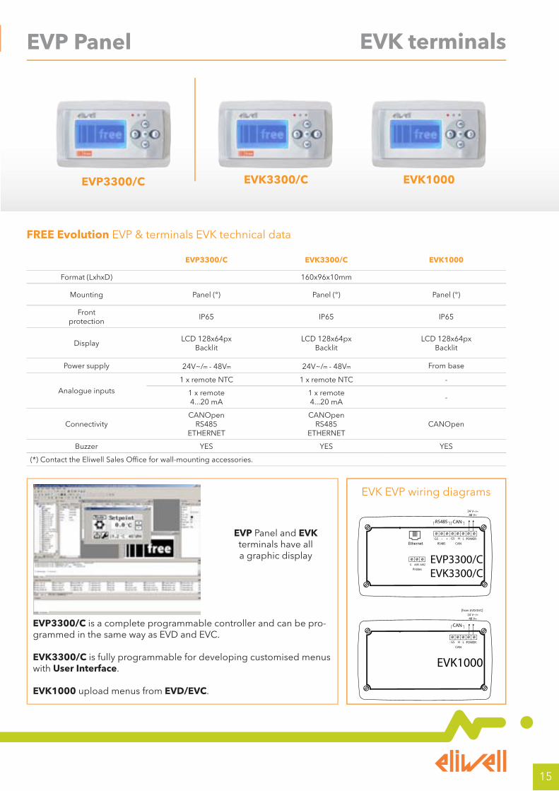
EVK terminalsEVP Panel
FREE Evolution EVP & terminals EVK technical data
EVP3300/C EVK3300/C EVK1000
Format (LxhxD) 160x96x10mm
Mounting Panel (°) Panel (°) Panel (°)
Frontprotection
IP65 IP65 IP65
DisplayLCD 128x64px
BacklitLCD 128x64px
BacklitLCD 128x64px
Backlit
Power supply 24V~/c - 48Vc 24V~/c - 48Vc From base
Analogue inputs1 x remote NTC 1 x remote NTC -
1 x remote 4...20 mA
1 x remote 4...20 mA
-
ConnectivityCANOpen
RS485ETHERNET
CANOpenRS485
ETHERNETCANOpen
Buzzer YES YES YES
(*) Contact the Eliwell Sales Office for wall-mounting accessories.
EVK EVP wiring diagrams
EVK1000
CAN
[from EVD/EVC]24 Va/c48 Vc
CAN
GS H L POWER
EVP3300/CEVK3300/C
RS485 CANGS - +
24 Va/c48 Vc
RS485 CAN
GS H L POWEREthernet
ProbesG AIR1 AIR2
EVP Panel and EVK terminals have all a graphic display
EVP3300/C is a complete programmable controller and can be pro-grammed in the same way as EVD and EVC.
EVK3300/C is fully programmable for developing customised menus with User Interface.
EVK1000 upload menus from EVD/EVC.
EVP3300/C EVK3300/C EVK1000
16
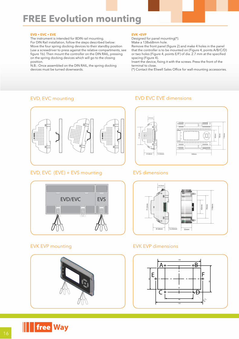
FREE Evolution mounting
EVD, EVC (EVE) + EVS mounting
EVD/EVC EVS
EVK EVP mounting EVK EVP dimensions
68
138
150
90 2.7 (x 6)
84
A B
DC
E F
EVD • EVC • EVEThe instrument is intended for 8DIN rail mounting.For DIN Rail installation, follow the steps described below:Move the four spring docking devices to their standby position (use a screwdriver to press against the relative compartments, see figure 1b). Then mount the controller on the DIN RAIL, pressing on the spring docking devices which will go to the closing position. N.B.: Once assembled on the DIN RAIL, the spring docking devices must be turned downwards.
EVK •EVPDesigned for panel mounting(*). Make a 138x68mm hole. Remove the front panel (figure 2) and make 4 holes in the panel that the controller is to be mounted on (Figure 4, points A/B/C/D) or two holes (Figure 4, points E/F) of dia. 2.7 mm at the specified spacing (Figure 4). Insert the device, fixing it with the screws. Press the front of the terminal to close.(*) Contact the Eliwell Sales Office for wall-mounting accessories.
140mm41.8mm 12.55mm
110m
m
76mm
45mm
24.25mm
71.2mm
EVD, EVC mounting EVD EVC EVE dimensions
EVS dimensions
35mm41.8mm 12.55mm
110m
m
76mm
45mm
24.25mm
71.2mm
17
Accessories
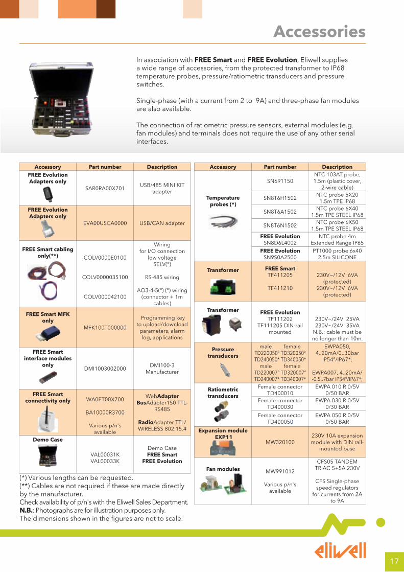
Accessory Part number DescriptionFREE Evolution Adapters only
SAR0RA00X701USB/485 MINI KIT
adapter
FREE Evolution Adapters only
EVA00USCA0000 USB/CAN adapter
FREE Smart cabling only(**)
COLV0000E0100
COLV0000035100
COLV000042100
Wiringfor I/O connection
low voltage SELV(°)
RS-485 wiring
AO3-4-5(°) (°) wiring (connector + 1m
cables)
FREE Smart MFK only
MFK100T000000
Programming key to upload/download
parameters, alarm log, applications
FREE Smart interface modules
only
DMI1003002000DMI100-3
Manufacturer
FREE Smart connectivity only
WA0ET00X700
BA10000R3700
Various p/n's available
WebAdapterBusAdapter150 TTL-
RS485
RadioAdapter TTL/WIRELESS 802.15.4
Demo Case
VAL00031K VAL00033K
Demo CaseFREE Smart
FREE Evolution
Accessory Part number Description
Temperature probes (*)
SN691150NTC 103AT probe, 1.5m (plastic cover,
2-wire cable)
SN8T6H1502NTC probe 5X20
1.5m TPE IP68
SN8T6A1502NTC probe 6X40
1.5m TPE STEEL IP68
SN8T6N1502NTC probe 6X50
1.5m TPE STEEL IP68FREE Evolution
SN8D6L4002NTC probe 4m
Extended Range IP65FREE Evolution
SN9S0A2500PT1000 probe 6x40
2.5m SILICONE
Transformer
FREE SmartTF411205
TF411210
230V~/12V 6VA (protected)
230V~/12V 6VA (protected)
Transformer FREE EvolutionTF111202
TF111205 DIN-rail mounted
230V~/24V 25VA 230V~/24V 35VA
N.B.: cable must be no longer than 10m.
Pressure transducers
male femaleTD220050° TD320050°TD240050* TD340050*
male femaleTD220007° TD320007°TD240007* TD340007*
EWPA050, 4..20mA/0..30bar
IP54°/IP67*;
EWPA007, 4..20mA/-0.5..7bar IP54°/IP67*;
Ratiometric transducers
Female connector TD400010
EWPA 010 R 0/5V 0/50 BAR
Female connector TD400030
EWPA 030 R 0/5V 0/30 BAR
Female connector TD400050
EWPA 050 R 0/5V 0/50 BAR
Expansion module EXP11
MW320100230V 10A expansion module with DIN rail-
mounted base
Fan modules MW991012
Various p/n's available
CFS05 TANDEM TRIAC 5+5A 230V
CFS Single-phase speed regulators
for currents from 2A to 9A
In association with FREE Smart and FREE Evolution, Eliwell supplies a wide range of accessories, from the protected transformer to IP68 temperature probes, pressure/ratiometric transducers and pressure switches.
Single-phase (with a current from 2 to 9A) and three-phase fan modules are also available.
The connection of ratiometric pressure sensors, external modules (e.g. fan modules) and terminals does not require the use of any other serial interfaces.
(*) Various lengths can be requested.(**) Cables are not required if these are made directly by the manufacturer.Check availability of p/n's with the Eliwell Sales Department. N.B.: Photographs are for illustration purposes only. The dimensions shown in the figures are not to scale.
18
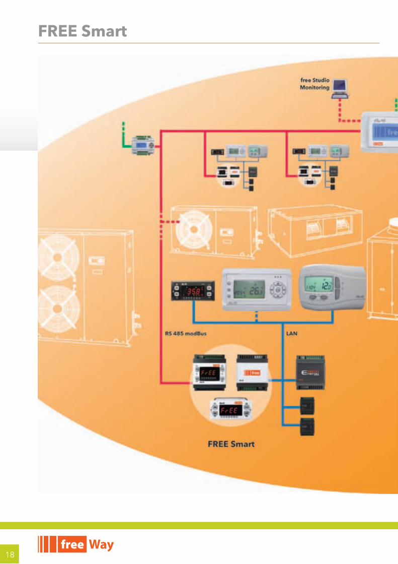
FREE Smart

19
FREE Evolution
Eliwell Controls Srl
Via dell’ Industria, 15 Z. I. Paludi
32010 Pieve d’ Alpago (BL) - Italy
Telephone +39 (0)437 986 111
Facsimile +39 (0)437 989 066
Sales:
+39 (0)437 986 100 (Italy)
+39 (0)437 986 200 (other countries)
Technical helpline: +39 (0)437 986 250
www.eliwell.com
CT122978 - EN • 02/11© Copyright Eliwell Controls s.r.l. 2010-2011 All rights reserved
DISCLAIMERThis document is the exclusive property of Eliwell and cannot be reproduced or circulated unless expressly authorised by Eliwell.All possible care has been taken to ensure the accuracy of this document; nevertheless, Eliwell Controls srl cannot accept liability for any damage resulting from its use.The same applies to any person or company involved in the creation and preparation of this document.Eliwell reserves the right to make aesthetic or functional changes at any time without notice.